5.1
РУКОВОДСТВО ПО УСТРАНЕНИЮ НЕИСПРАВНОСТЕЙ
Неисправность
Не получается запустить двигатель.
Двигатель начинает процесс запуска, но
не включается.
Двигатель сложно включается,
и во время его работы наблюдаются признаки
неполадок .
Переключатель АВТО/ВЫКЛ/РУЧНОЙ
переведен в положение ВЫКЛ, однако,
двигатель продолжает
работать.
На выходе генератора
напряжение переменного тока равно нулю.
При сбое в работе основного источника
переход к резервному
не наступает.
Устройство поглощает
большое количество масла.
двигателя».
Причина
1. Предохранитель перегорел.
2. Проводка аккумулятора не зафиксирована надлежащим
образом, проржавела или имеет какой-либо дефект.
3. Пусковой замыкатель имеет какой-либо дефект. (8 кВт)
4. Мотор стартера имеет какой-либо дефект.
5. Аккумулятор разряжен.
1. Не подается топливо.
2. Топливный соленоид (ТС) имеет какой-либо дефект.
3. Отсоедините провод №14 от
панели управления двигателя.
4. Свечи зажигания засорились.
5. Клапанный зазор не соответствует требуемому значению.
6. Дроссель не работает.
1. Воздушный фильтр закупорен
или поврежден.
2. Свечи зажигания засорились.
3. Давление топлива не соответствует требуемому значению.
4. Топливный селектор стоит в неправильном положении.
5. Дроссель остается в закрытом положении.
1. Переключатель с неполадкой.
2. Проводка переключателя АВТО/ВЫКЛ/РУЧНОЙ
подключена неправильно.
3. Панель управления с неполадкой.
1. Основной прерыватель цепи
в положение ВЫКЛ (или ОТКРЫТОМ положении).
2. Внутренняя ошибка генератора.
1. Катушка индуктивности передаточного ключа с неполадкой.
2. Реле переключения с неполадкой.
3. Контур реле переключения не замкнут.
4. Панель логического устройства управления с неполадкой.
1. Объем залитого в двигатель масла превышает допустимое
значение.
2. Залито масло не той категории или не той степени вязкости.
3. Прокладка, пломба или шланг с дефектом.
4. Сапун двигателя с неполадкой.
* Обратитесь за помощью к ближайшему торговому представителю.
Поиск и устранение неисправностей
Устранение
1. Устраните короткое замыкание, замените в панели
управления генератора предохранитель 7,5 А
.
2. Закрутите, зачистите контакты или замените проводку.
3. *
4. *
5. Зарядите или замените аккумулятор.
1. Пополните запас топлива/Откройте клапан подачи топлива.
2. *
3. *
4. Очистите или замените свечи, отрегулируйте зазор.
5. Выполните регулировку клапанного зазора.
6. Убедитесь в том, что воздушная заслонка двигается
свободно.
1. Проверьте и замените воздушный фильтр.
2. Очистите или замените свечи, отрегулируйте зазор.
3. Убедитесь в том, что давление топлива на регулятор
составляет 10-12 дюймов (25,4-30,48 см) водяного столба
(0,36-0.43 фунтов на кв. дюйм) для ЖП, и 5-7 дюймов (12,7-
17,8 см) водяного столба (0,18-0,25 фунтов на кв. дюйм) для
природного газа.
4. Переведите селектор в правильное положение.
5. Убедитесь в том, что воздушная заслонка двигается свободно.
1. *
2. *
3. *
1. Переведите прерыватель цепи в
положение ВКЛ (или ЗАКРЫТОЕ).
2. *
1. *
2. *
3. *
4. *
1. Отрегулируйте уровень масла.
2. См. раздел «Рекомендации по выбору масла для
3. Убедитесь в отсутствии утечек.
4. *
85
1.7 ИНСТРУКЦИЯ ПО ЭКСПЛУАТАЦИИ — ПАНЕЛЬ УПРАВЛЕНИЯ
Переключатель «AUTO / OFF / MANUAL»
Данный переключатель используется для (а) выбора работы в полностью автоматическом режиме, (b) завода и запуска двигателя вручную, (с) остановки агрегата и предотвращения его автоматического запуска.
- Положение AUTO (Авто)
- Выбирать для работы в полностью автоматическом режиме.
- При выборе режима AUTO со схемной платы ведется мониторинг напряжения с источника электроснабжения.
- При падении напряжения ниже предварительно установленного уровня в течение определенного времени со схемной платы начнется завод и запуск двигателя.
- После запуска двигателя со схемной платы начнется передача электрических нагрузок на «Резервный» источник электроснабжения.
- После восстановления напряжения от сети электроснабжения выше предварительно установленного уровня, со схемной платы начнется перевод электрических нагрузок обратно на «Сеть электроснабжения».
- После перераспределения произойдет отключение двигателя со схемной платы и продолжится отслеживание напряжения от сети электроснабжения.
- Положение Off (Выключить)
- Для остановки работы двигателя установить переключатель в положение Off.
- Для предотвращения автоматического старта установить переключатель в положение Off.
- Положение MANUAL (Ручной)
- Для завода и запуска двигателя вручную установить переключатель в положение «MANUAL».
- Двигатель заводится циклически и запускается (также как при автоматическом запуске, но без перераспределения нагрузки). Перевод электрических нагрузок производится только при отсутствии напряжения от сети электроснабжения.

Рисунок 1.
Панель управления генератора
При наличии автоматического передаточного ключа, установленного вместе с генератором, завод и запуск двигателя может происходить в любое время без предупреждения (если переключатель AUTO/OFF/MANUAL установлен в положение AUTO). Для предотвращения автоматического запуска и возможного нанесения ущерба здоровью человека при работе с оборудованием или рядом с ним, всегда устанавливать переключатель в положение OFF.
Данный предохранитель защищает от превышения нагрузки на контур управления постоянного тока (включая схемную плату). При сгорании элемента предохранителя во время превышения нагрузки прокрутка и запуск двигателя будет невозможен. При необходимости замены предохранителя использовать только идентичный предохранитель 7.5А.
Настройка таймера самотестирования
Газовый генератор оснащен таймером самотестирования. После его настройки, генератор будет запускаться и работать каждые семь дней в день и час, который будет установлен. Во время самотестирования агрегат работает примерно 12 минут, затем останавливается. Перераспределение нагрузки на генератор не происходит, если не будет отключена подача электроснабжения от сети.
При первом подключении генератора на дисплее включается помощник, который подсказывает оператору, как настроить минимальные параметры для эксплуатации. Данные параметры включают: текущую дату / время и дату / время самотестирования. Отсчет времени периодов технического осмотра запускается при первоначальном вводе времени самотестирования (рисунок 3.2).
Настройки времени самотестирования можно изменить в любое время через меню Edit (Редактировать) (смотреть Приложение «Система меню»).
Если отключен аккумулятор 12В или снят предохранитель, то помощник включится только после восстановления электропитания. На дисплее будет отображаться только текущее время и дата.
Если газовый генератор Generac проходит испытания до установки, необходимо нажать кнопку «Enter» (Ввод), чтобы пропустить настройку времени самотестирования. Это позволяет оператору увидеть напоминание о настройке времени самотестирования при подаче питания на газовый генератор Generac на месте установки.
ПРИМЕЧАНИЕ: Самотестирование срабатывает только при режиме AUTO, и не будет действовать, пока не будет произведена процедура настройки. Текущие дату / время следует переустанавливать каждый раз, после отключения и повторного подключения аккумулятора 12В и/или снятия предохранителя.
Источник
Неисправность, Причина, Устранение – Инструкция по эксплуатации Generac 20
Страница 40

Раздел 5 – Поиск и устранение неисправностей
Генераторы с воздушным охлаждением
5.1 РУКОВОДСТВО ПО ПОИСКУ И УСТРАНЕНИЮ НЕИСПРАВНОСТЕЙ
1. Проверить цепь короткого
замыкания
2. Ослаблены, покрыты
коррозией
2. Затянуть, почистить или при
необходимости
3. Неисправен пусковой контактор. (8
кВт
5. Разряжена аккумуляторная
батарея
5. Зарядить или заменить
аккумуляторную
1. Заполнить топливом / Открыть
топливный
2. Неисправен топливный соленоид
(FS).
3. Отсоединен провод #14 от пульта
управления
4. Загрязненные свечи зажигания.
4. Очистить, проверить зазор или
заменить
5. Еще раз отрегулировать зазор
клапан
6. Проверить свободу перемещения
дроссельной
1. Проверить, заменить
воздухоочиститель
1. Забит или поврежден
воздухоочиститель
2. Загрязненные свечи зажигания.
2. Очистить, проверить зазор или
заменить
3. Неправильное давление топлива.
3. Убедиться, что давление топлива
составляет
(0,36 — 0,43 фунтов/ кв.дюйм) для LP, и
0,012 – 0,017 атмосфер (0,18-0,25
фунтов
/ кв.дюйм) для природного газа.
4. Селектор топлива установлен не в
то
4. Передвинуть селектор в нужное
положение
5. Дроссель остается закрытым.
5. Проверить свободу перемещения
дроссельной
1. Неисправен переключатель.
«OFF», но двигатель
продолжает
«AUTO/OFF/MANUAL» подключен не
правильно
1. Автомат цепи основной линии сети
электроснабжения
1. Установить автомат в положение
«ON» (или ЗАКРЫТЫЙ).
Источник
Поиск и устранение неисправностей Генераторы с воздушным .
Раздел 5 – Поиск и устранение неисправностей
Генераторы с воздушным охлаждением
4. Неисправна панель логики
управления
1. В двигатель залито чрезмерно
большое
1. Отрегулировать уровень масла.
2. Неправильный тип или вязкость
масла
2. См. раздел «Рекомендации по
маслу
3. Повреждена прокладка,
уплотнение
3. Проверить наличие утечек масла.
4. Неисправна всасывающая труба
двигателя
*Для оказания помощи связаться с ближайшим дилером.

1 система навигации по меню
Генераторы с воздушным охлаждением
6.1 СИСТЕМА НАВИГАЦИИ ПО
МЕНЮ
попасть на страницу «MENU» (меню) с
страницы, необходимо нажать кнопку
«Esc». Возможно, потребуется нажимать
данную
кнопку несколько раз, прежде чем
на страницу меню. Выбранное на
момент меню отображается в виде
мигать необходимое меню, нажать
меню может быть представлен
вариантов. Для того чтобы выбрать
экран, необходимо использовать
же метод поиска (смотреть «Схему
6.1.1 ИЗМЕНЕНИЕ НАСТРОЕК (МЕНЮ
изменения настроек, указанных на
, необходимо перейти в меню «EDIT»
(редактирование), и с помощью кнопок «+/-»
произвести
«Contrast» – отличные от установленных),
нажать
кнопку «ENTER» для перехода в
новых настроек, нажать кнопку
кнопка «ENTER» не нажимается для
новых настроек, данная настройка
быть сохранена только временно. При
настройка вернется обратно к своему

43 система меню
Раздел 8 – Схема установки
Генераторы с воздушным охлаждением
в режиме тестирования / Время и
– тревога / сообщение о тревоге
– тревога / сообщение о тревоге
двигателя / Пауза на Х секунд
двигателя – тревога / сообщение о

Схема установки Генераторы с воздушным охлаждением .
Раздел 8 – Схема установки
Генераторы с воздушным охлаждением

Схема установки Генераторы с воздушным охлаждением .
Раздел 8 – Схема установки
Генераторы с воздушным охлаждением

Схема установки Генераторы с воздушным охлаждением .
Раздел 8 – Схема установки
Генераторы с воздушным охлаждением
топлива – 12-20кВт (1/2дюйма NPT)
8 и 10кВт (3/4дюйма NPT)
Требуемое
давление топлива: природный газ = 5-7дюймов в.ст.;
пропан в паровой фазе = 10-12дюймов в.ст.

Гарантия Генераторы с воздушным охлаждением .
Генераторы с воздушным охлаждением
: Данное гарантийное обязательство на системы контроля выхлопных газов относится к данному
, только ЕСЛИ данный генератор рассчитан на 15кВт и менее.
ОБЯЗАТЕЛЬСТВА НА СИСТЕМЫ КОНТРОЛЯ ВЫХЛОПНЫХ ГАЗОВ В ШТАТЕ
И ОБЯЗАННОСТИ ПО ВАШЕЙ ГАРАНТИИ
комитет по использованию ресурсов атмосферы (CARB) и компания «Дженерак Пауэр Системс,
» (Generac Power Systems, Inc. (Generac)) рады разъяснить гарантию на системы контроля выхлопных газов
нового двигателя.* В Калифорнии новые источники электроснабжения, а также двигатели оборудования для лужаек
садов должны быть разработаны, сконструированы и оборудованы в соответствии со строгими стандартами по
образования смога. Компания «Дженерак» гарантирует систему контроля выхлопных газов вашего нового
на периоды времени, перечисленные ниже, при условии, что не будут нарушены условия эксплуатации,
технического обслуживания на вашем двигателе.
контроля выхлопных газов на вашем оборудовании может состоять из таких устройств, как карбюратор, система
и выхлопная система. Компания «Дженерак» отремонтирует ваш двигатель бесплатно, это касается
оборудования, замены деталей и проведения работ, если наступит гарантийный случай.
ДЕЙСТВИЯ ГАРАНТИИ ПРОИЗВОДИТЕЛЯ НА СИСТЕМУ КОНТРОЛЯ ВЫХЛОПНЫХ ГАЗОВ:
модели двигателей, выпущенные в 1995 году и позже, гарантия на систему контроля выхлопных газов распространяется
два года, как указано в дальнейшем. Если в течение указанного гарантийного периода на любом из компонентов или
, входящих в систему выхлопных газов будет признана неисправной в отношении материалов или качества
, ремонтные работы или замена деталей будет произведена авторизированной сервисной службой по
ПОКУПАТЕЛЯ / ВЛАДЕЛЬЦА ПО ГАРАНТИИ:
качестве покупателя / владельца, вы несете ответственность за проведение всех необходимых работ по техническому
, описанным в «Руководстве пользователя», предоставленному вам изготовителем. В целях соблюдения
, компания «Дженерак» рекомендует вам сохранять все чеки, покрывающие расходы на техническое
вашего двигателя. Однако, компания «Дженерак» не будет отрицать свои гарантийные обязательства только
-за отсутствия чеков или в случае невозможности выполнения вами всех регламентных работ по техническому
качестве покупателя / владельца, вы, однако, должны осознавать, что компания «Дженерак» может отказаться от
части и/или всех гарантийных обязательств, если ваш двигатель или его деталь / компонент вышли из строя
-за нарушения условий эксплуатации, допущения пренебрежительного отношения, внесения несанкционированных
или неквалифицированного технического обслуживания, а также использования фальшивых деталей, не
и неразрешенных компанией «Дженерак», или деталей, приобретенных на «черном рынке», а не в компании
обязаны незамедлительно обратиться в авторизированную сервисную службу по гарантии компании «Дженерак», как
возникнет неисправность. Гарантийные обязательства по ремонту будут выполнены в разумные сроки, не
обслуживание может быть организовано либо торговым представителем, либо авторизированной сервисной
по гарантии компании «Дженерак». Чтобы узнать о ближайшей авторизированной сервисной службе по гарантии
«Дженерак», позвоните по номеру бесплатного телефона:
ПРИМЕЧАНИЕ: Данное гарантийное обязательство объясняет ваши права и обязанности по гарантии на систему
выхлопных газов (ECS Warranty), которая передана вам компанией «Дженерак» в соответствии с законом
. См. также «Ограниченные гарантии компании «Дженерак» для компании Дженерак Пауэр Системс,
» (Generac Warranty), которые включены в данное руководство на отдельной странице, и также
компанией «Дженерак». Гарантия «ECS Warranty» относится только к системе контроля выхлопных газов на
новом двигателе. При возникновении разногласий в условиях между «ECS Warranty» и «Generac Warranty»,
ссылаться на «ECS Warranty», кроме случаев, когда по гарантии «Generac Warranty» может быть продлен срок
обязательств. И «ECS Warranty», и «Generac Warranty» описывают важные права и обязанности в отношении
обслуживание может быть произведено только авторизированной сервисной службой по гарантии компании
«Дженерак». При запросе гарантийного обслуживания необходимо предоставить подтверждение даты покупки истинным
покупателем
у вас возникли вопросы по поводу ваших прав и обязанностей, необходимо связаться с компанией «Дженерак» по
продукции с воздушным охлаждением .
продукции с охлаждением жидкостью .
ATTENTION WARRANTY DEPARTMENT
ATTENTION WARRANTY DEPARTMENT
GENERAC POWER SYSTEMS, INC.
GENERAC POWER SYSTEMS, INC.

Гарантия Генераторы с воздушным охлаждением .
Генераторы с воздушным охлаждением
НА СИСТЕМУ КОНТРОЛЯ ВЫХЛОПНЫХ ГАЗОВ
на систему контроля выхлопных газов (ECS Warranty) на модели двигателей, выпущенные в 1995 году и позже:
(a) Применимость: Данная гарантия распространяется на модели двигателей, выпущенные в 1995 году и позже. Период
«ECS Warranty» начинается с даты покупки нового двигателя или оборудования истинным покупателем /
и длится в течение 24 месяцев с этой даты.
(b) Область распространения общей гарантии по выхлопным газам: Компания «Дженерак» гарантирует истинному, конечному
/ владельцу нового двигателя или оборудования и каждому промежуточному покупателю / владельцу, что
(1) Разработан, сконструирован и оснащен в соответствии с действующими нормами, установленными комитетом CARB
(2) Не имеет дефектов материалов, и качества изделия, что в течение периода действия гарантии «ECS Warranty» может
причиной отказа детали, на которую распространяется гарантия, и являются сертифицированными деталями,
изготовителем данных деталей двигателя.
(c) Гарантия «ECS Warranty» распространяется только на детали вашего двигателя, относящиеся к системе выхлопных газов,
следующим
(1) Любые детали, относящиеся к системе выхлопных газов, на которые распространяется гарантия, которые не подлежат
согласно графику, представленному в «Руководстве пользователя», должны подлежать гарантии,
на период гарантии «ECS Warranty». Если любая из данных деталей ломается во время периода
«ECS Warranty», она должна быть отремонтирована или заменена компанией «Дженерак», согласно
4, представленному ниже. На любую из отремонтированных или замененных деталей по гарантии «ECS
Warranty» должна распространяться оставшаяся гарантия по сроку гарантии «ECS Warranty».
(2) Любые детали, относящиеся к системе выхлопных газов, на которые распространяется гарантия, подлежат только
проверке по графику, представленному в «Руководстве пользователя» должны подлежать гарантии,
на период гарантии «ECS Warranty». Период гарантии не должен сокращаться, если в письменной
есть предложение, содержащее слова «отремонтировать или заменить при необходимости». На любую из
или замененных деталей по гарантии «ECS Warranty» должна распространяться оставшаяся
по сроку гарантии «ECS Warranty».
(3) Любые детали, относящиеся к системе выхлопных газов, на которые распространяется гарантия, подлежат замене по
, представленному в «Руководстве пользователя» должны подлежать гарантии в период, предшествующий
пункту регламентной замене данной детали. Если деталь ломается до первой замены согласно графику, она
быть отремонтирована или заменена компанией «Дженерак», согласно подразделу 4, представленному ниже. На
из отремонтированных или замененных деталей по гарантии «ECS Warranty» должна распространяться
гарантия по сроку гарантии «ECS Warranty».
(4) Ремонт или замена любых деталей, относящихся к системе выхлопных газов, на которые распространяется гарантия
«ECS Warranty» должны осуществляться бесплатно для владельца в авторизированной сервисной службой по гарантии
компании
(5) При проверке двигателя авторизированной сервисной службой по гарантии компании «Дженерак» владелец не обязан
диагностику, если ремонт относится к гарантийному случаю.
(6) Компания «Дженерак» несет ответственность за все повреждения других оригинальных деталей двигателя или
модификации, вероятно вызванные выходом из строя по гарантийному случаю любой детали,
к системе выхлопных газов, на которые распространяется гарантия «ECS Warranty».
(7) В течение всего периода гарантии «ECS Warranty» компания «Дженерак» должна поставлять подлежащие гарантии
, относящиеся к системе выхлопных газов, в достаточном количестве, чтобы покрыть требуемое количество таких
к системе выхлопных газов деталей.
(8) Любая деталь для замены, относящаяся к системе выхлопных газов, разрешенная и утвержденная компанией
«Дженерак» может быть использована для проведения технического обслуживания или ремонта по гарантии «ECS
Warranty» бесплатно. Такое использование не должно сокращать обязательств по гарантии «ECS Warranty» компании
«Дженерак».
(9) Неутвержденные, дополненные, измененные, фальшивые детали или детали с «черного рынка» не могут быть
для модификации или ремонта двигателей компании «Дженерак». Такое использование аннулирует
«ECS Warranty» и является достаточной причиной, чтобы не признавать требований по гарантии «ECS
Warranty». Компания «Дженерак» не несет обязательств по представленным ниже деталям, подлежащим гарантии,
вышелшим
из строя по причине использования таких неутвержденных, дополненных, измененных, фальшивых деталей
, ОТНОСЯЩИЕСЯ К СИСТЕМЕ ВЫХЛОПНЫХ ГАЗОВ:
1) Измерительная система топлива:
1.2)Узел карбюрации LPG/Natural и внутренние компоненты
) Контроллер топлива (если такой есть в поставке)
) Смеситель и прокладки(если есть в поставке)
) Карбюратор и прокладки (если такой есть в поставке)
) Первичный регулятор газа (если такой есть в поставке)
) Испаритель сжиженного пропана
3) Система зажигания включает:
a) Свечи зажигания
б
4) Глушитель с каталитическим дожигателем (если такой
есть
5) Узел всасывающей трубы картера включает:
а
Источник
-
Contents
-
Table of Contents
-
Troubleshooting
-
Bookmarks
Quick Links
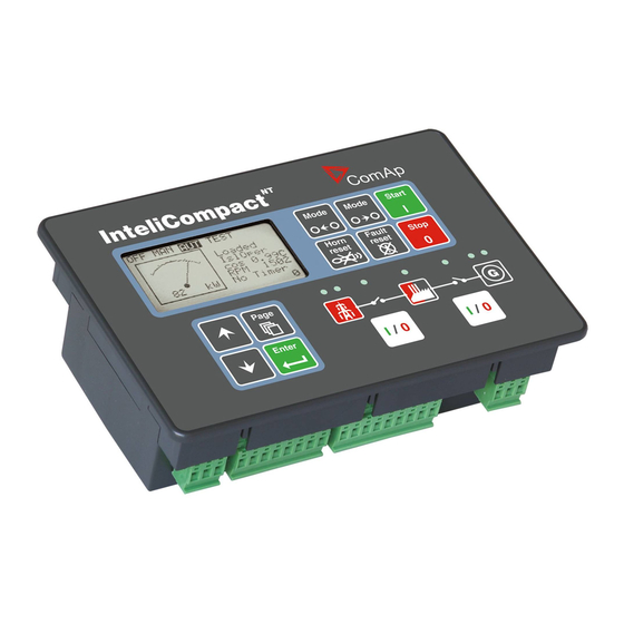
Paralleling gen-set controller
SW version 2.1, May 2016
Reference Guide
Copyright ©2015 ComAp a.s.
ComAp a.s.
Kundratka 17, 180 00 Praha 8, Czech Republic
Tel: +420 246 012 111, Fax: +420 266 316 647
E-mail:info@comap.cz, www.comap.cz
Related Manuals for ComAp InteliCompact NT
Summary of Contents for ComAp InteliCompact NT
-
Page 1
Paralleling gen-set controller SW version 2.1, May 2016 Reference Guide Copyright ©2015 ComAp a.s. ComAp a.s. Kundratka 17, 180 00 Praha 8, Czech Republic Tel: +420 246 012 111, Fax: +420 266 316 647 E-mail:info@comap.cz, www.comap.cz… -
Page 2: Table Of Contents
IL-NT BIO8 ……………………55 3.19.5 IC-NT CT-BIO7 …………………… 57 3.20 Communication modules ………………….59 3.20.1 IL-NT RS232 ……………………59 3.20.2 IL-NT RS232-485 ………………….60 3.20.3 IL-NT S-USB ……………………60 InteliCompact , SW version 2.1 InteliCompact-NT-2.1-Reference Guide.pdf, ©ComAp – May 2015…
-
Page 3
Load control modes ………………….. 102 6.8.3 Power factor control ………………….. 102 6.8.4 Ramping the power down ………………..102 Island operation – SPtM ………………….102 6.9.1 Island to PtM transfers ………………..103 InteliCompact , SW version 2.1 InteliCompact-NT-2.1-Reference Guide.pdf, ©ComAp – May 2015… -
Page 4
Setpoints – Volt/PF Control ………………. 131 7.3.10 Setpoints – ExtI/O Protect ………………… 131 7.3.11 Setpoints – SMS/E-Mail ………………..131 7.3.12 Setpoints – AnalogSwitches ………………132 7.3.13 Setpoints – Date/Time ………………..132 7.3.14 InteliCompact , SW version 2.1 InteliCompact-NT-2.1-Reference Guide.pdf, ©ComAp – May 2015… -
Page 5
14.6 Binary outputs ……………………. 155 14.7 Analog inputs …………………….. 155 14.8 Generator/Mains measurements ……………….. 155 14.9 Pickup input ……………………..156 14.10 Charging alternator pre-excitation circuit …………….156 14.11 AVR output ……………………..156 InteliCompact , SW version 2.1 InteliCompact-NT-2.1-Reference Guide.pdf, ©ComAp – May 2015… -
Page 6
Common functions ………………….252 16.4.2 ECU info ……………………. 260 16.4.3 Alarm mirrors ……………………. 262 16.4.4 MINT specific ……………………. 272 16.4.5 SPtM specific ……………………. 273 16.5 Table of internal alarms ………………….274 InteliCompact , SW version 2.1 InteliCompact-NT-2.1-Reference Guide.pdf, ©ComAp – May 2015… -
Page 7: Document Information
Pressing F1 in the LiteEdit setpoint, values or configuration window will open the help with the context of currently selected setpoint, value and binary input or output function. InteliCompact , SW version 2.1 InteliCompact-NT-2.1-Reference Guide.pdf, ©ComAp – May 2015…
-
Page 8: Clarification Of Notation
EC Low Voltage Directive No: 73/23 / EEC and EC Electromagnetic Compatibility Directive 89/336 / EEC based on its design and type, as brought into circulation by us. InteliCompact , SW version 2.1 InteliCompact-NT-2.1-Reference Guide.pdf, ©ComAp – May 2015…
-
Page 9: System Overview
One of the key features of the controller is the system’s high level of adaptability to the needs of each individual application and wide possibilities for monitoring. This can be achieved by configuring and using the powerful ComAp PC/mobile tools. Supported configuration and monitoring tools: –…
-
Page 10: Liteedit
Offline or online controller configuration Controller firmware upgrade Reading/writing/adjustment of setpoints Reading of measured values Browsing of controller history records Exporting data into a XLS file Controller language translation InteliCompact , SW version 2.1 InteliCompact-NT-2.1-Reference Guide.pdf, ©ComAp – May 2015…
-
Page 11: Intelimonitor
View of actual/historic trends in controller On-line change of controllers’ parameters for easy regulator setup 2.2.4 WebSupervisor Web-based system for monitoring and controlling ComAp controllers. See more at the WebSupervisor webpage. This tool provides the following functions: Site and fleet monitoring…
-
Page 12: Applications Overview
MINT SPEED GOVERNOR CAN2 CAN1 SYS START/STOP GCB FEEDBACK IG-AVRi AVRi InteliCompact GCB CLOSE/OPEN MINT SPEED GOVERNOR CAN2 CAN1 SYS START/STOP START/STOP GCB FEEDBACK SLAND PARALLEL OPERATION WITHOUT MAINS InteliCompact , SW version 2.1 InteliCompact-NT-2.1-Reference Guide.pdf, ©ComAp – May 2015…
-
Page 13: True Rms Measurement
PF 1.00. The higher the deformation, the wider the power factor dead range. If the requested power factor is adjusted inside the dead range, the controller cannot reach the requested value because of this fact. InteliCompact , SW version 2.1 InteliCompact-NT-2.1-Reference Guide.pdf, ©ComAp – May 2015…
-
Page 14: Installation
Recommended tightening torque is 0,15 – 0,2 Nm. Package contents The package contains: Controller Mounting holders Terminal blocks The package does not contain a communication module. The required module should be ordered separately. InteliCompact , SW version 2.1 InteliCompact-NT-2.1-Reference Guide.pdf, ©ComAp – May 2015…
-
Page 15: Dimensions
Dimensions InteliCompact Mounting cutout size: 175 x 115 mm The dimensions are in millimetres and are the same for both versions – SPTM and MINT. InteliCompact , SW version 2.1 InteliCompact-NT-2.1-Reference Guide.pdf, ©ComAp – May 2015…
-
Page 16: Terminal Diagram
Wiring for binary inputs and analog inputs must not be run with power cables. Analog and binary inputs should use shielded cables, especially when the length is more than 3 m. InteliCompact , SW version 2.1 InteliCompact-NT-2.1-Reference Guide.pdf, ©ComAp – May 2015…
-
Page 17: Wiring
The maximum allowable current through the controller’s negative terminal is 4A (this is dependent on binary output load). InteliCompact , SW version 2.1 InteliCompact-NT-2.1-Reference Guide.pdf, ©ComAp – May 2015…
-
Page 18
I-LBA may not eliminate voltage drop when used with the low temperature (-40 °C) version of the controller and the display heating element is on (below 5 °C). The current drain of the heating element exhausts LBA capacitors very fast. InteliCompact , SW version 2.1 InteliCompact-NT-2.1-Reference Guide.pdf, ©ComAp – May 2015… -
Page 19: Power Supply Fusing
Adjust nominal voltage, nominal current, CT ratio and PT ratio by appropriate setpoints in the Basic Settings group. Learn about how to view and change setpoints in the User interface chapter. OLTAGE MEASUREMENT WIRING GENERATOR MAINS / BUS InteliCompact , SW version 2.1 InteliCompact-NT-2.1-Reference Guide.pdf, ©ComAp – May 2015…
-
Page 20
MAINS / BUS GENERATOR MAINS / BUS Wiring to be used with IC-NT- MINT-MonoPhase or IC-NT- SPTM-MonoPhase archive for Mono or Single Phase applications. GENERATOR MAINS / BUS URRENT MEASUREMENT WIRING InteliCompact , SW version 2.1 InteliCompact-NT-2.1-Reference Guide.pdf, ©ComAp – May 2015… -
Page 21: Speed Measurement
Pickup D+ (L) Charging alternator RPM measurement from the pickup. D+ terminal from the charging alternator can be used as additional signal for detection of running engine. InteliCompact , SW version 2.1 InteliCompact-NT-2.1-Reference Guide.pdf, ©ComAp – May 2015…
-
Page 22: Generator Frequency
If you do not know the charging alternator nominal frequency, follow this procedure: 1) Make sure that the starting accumulator is fully charged. 2) Close a fuel valve manually to disable the engine from being started. InteliCompact , SW version 2.1 InteliCompact-NT-2.1-Reference Guide.pdf, ©ComAp – May 2015…
-
Page 23: Binary Inputs
(signalization etc…). The function of each output has to be assigned during configuration. AUTION Use suppression diodes on all relays and other inductive loads! InteliCompact , SW version 2.1 InteliCompact-NT-2.1-Reference Guide.pdf, ©ComAp – May 2015…
-
Page 24: Analog Inputs
Protection of Oil Pressure and the relevant condition of a running engine is joined with AI01 only if: the ECU is not configured the ECU is configured and the AI01 is set to Alarm + ECU. InteliCompact , SW version 2.1 InteliCompact-NT-2.1-Reference Guide.pdf, ©ComAp – May 2015…
-
Page 25: Tristate Inputs
100R – IRING OF ANALOG INPUTS USED AS BINARY OR TRI STATE The name, sensor characteristic and alarm types for each analog input have to be assigned during configuration. InteliCompact , SW version 2.1 InteliCompact-NT-2.1-Reference Guide.pdf, ©ComAp – May 2015…
-
Page 26: Circuit Breakers
2 seconds in the moment the breaker has to be switched off. The output is intended for control of undervoltage coils of circuit breakers. CLOSE/OPEN ON COIL OFF COIL UV COIL FEEDBACK REAKER OUTPUTS TIMING InteliCompact , SW version 2.1 InteliCompact-NT-2.1-Reference Guide.pdf, ©ComAp – May 2015…
-
Page 27: Mcb Special Requirements
IG-AVRi TRANS/LV is a power supply unit for IG-AVRi; it is not included with the IG-AVRi package. OUT1 Output terminals for alternator AVR Output OUT2 Power supply from IG-AVRi TRANS/LV Output level Set output voltage bias AVRI Input signals from the Input controller AO GND InteliCompact , SW version 2.1 InteliCompact-NT-2.1-Reference Guide.pdf, ©ComAp – May 2015…
-
Page 28
GENERATOR VOLTAGE ADJUST VOLTAGE IG-AVR I MODULE WIRING InteliCompact , SW version 2.1 InteliCompact-NT-2.1-Reference Guide.pdf, ©ComAp – May 2015… -
Page 29
AVRi output OUT2 — GND 10 V AVRi trim turned in max. position (clockwise) 100 [%] AVR output AVRi trim turned in min. position (counterclockwise) SYMMETRIC I OUTPUT CHARACTERISTIC InteliCompact , SW version 2.1 InteliCompact-NT-2.1-Reference Guide.pdf, ©ComAp – May 2015… -
Page 30: Avr List
AVRI OCOM AVRI AVR Bias = 50% AO GND OUT1 AVRi output is connected instead of Remote voltage trimmer 470 Ω to terminal J2. Module R726 is not required. InteliCompact , SW version 2.1 InteliCompact-NT-2.1-Reference Guide.pdf, ©ComAp – May 2015…
-
Page 31
LeRoy-Somer: R 250 AVRi trim to minimum counter From 230/400VAC generator 18VAC clockwise. AVRi 0VAC TRANS AO GND Volt/PF ctrl: AVRI OCOM AVRI AVR Bias = 50% AO GND OUT1 InteliCompact , SW version 2.1 InteliCompact-NT-2.1-Reference Guide.pdf, ©ComAp – May 2015… -
Page 32
AVRi 0 VAC TRANS AO GND AVRI AVRI OUT2 AO GND OUT1 Module R726 is not required. AVRi trim to minimum counter clockwise. Volt/PF ctrl: AVR Bias = 50% InteliCompact , SW version 2.1 InteliCompact-NT-2.1-Reference Guide.pdf, ©ComAp – May 2015… -
Page 33
Volt/PF ctrl: 18VAC generator AVRi 0VAC AVR Bias = 30% TRANS AO GND OUT2 AVRI AVRI AO GND OCOM AVRi output is connected instead of external resistor for voltage adjusting. InteliCompact , SW version 2.1 InteliCompact-NT-2.1-Reference Guide.pdf, ©ComAp – May 2015… -
Page 34
Caterpillar CDVR AVRi trim to 50% From 230/400VAC generator 18VAC AVRi 0VAC TRANS Volt/PF ctrl: AO GND AVR Bias = 50% OUT2 AVRI AVRI 12-3 AO GND 12-6 OUT1 InteliCompact , SW version 2.1 InteliCompact-NT-2.1-Reference Guide.pdf, ©ComAp – May 2015… -
Page 35
AVRi 0VAC TRANS AO GND Volt/PF ctrl: OUT2 AVRI AVRI AVR Bias = 50% AO GND OUT1 AVRi output is connected instead of external resistor for voltage adjusting. InteliCompact , SW version 2.1 InteliCompact-NT-2.1-Reference Guide.pdf, ©ComAp – May 2015… -
Page 36
OUT2 AVRI AVRI AO GND OUT1 MarelliMotori (M40FA610A) Volt/PF ctrl: From 230/400VAC AVR Bias = 50% generator 18VAC AVRi 0VAC TRANS AO GND OUT2 AVRI AVRI AO GND OUT1 InteliCompact , SW version 2.1 InteliCompact-NT-2.1-Reference Guide.pdf, ©ComAp – May 2015… -
Page 37
AVRi trim to maximum From 230/400VAC generator clockwise. 18VAC AVRi 0VAC TRANS AO GND Volt/PF ctrl: OUT2 AVRI AVRI AVR Bias = 50% AO GND OUT1 Mecc Alte DER1 InteliCompact , SW version 2.1 InteliCompact-NT-2.1-Reference Guide.pdf, ©ComAp – May 2015… -
Page 38
Changing the DSR parameters requires a PC with dedicated software and a DI1-DSR unit! DSR automatically detects the presence of a transformer for parallel operation (if used it works with droop, if not used then it works isochronous). InteliCompact , SW version 2.1 InteliCompact-NT-2.1-Reference Guide.pdf, ©ComAp – May 2015… -
Page 39
OUT1 Marathon PM100, 200 Volt/PF ctrl: From 230/400VAC generator AVR Bias = 50% 18VAC AVRi 0VAC TRANS AO GND OUT2 AVRI AVRI AO GND OUT1 KATO KATO KCR 360 InteliCompact , SW version 2.1 InteliCompact-NT-2.1-Reference Guide.pdf, ©ComAp – May 2015… -
Page 40
AVRI AVRI AO GND OUT1 ENGGA WT-3 Volt/PF ctrl: From 230/400VAC IG- AVRi generator 18VAC AVR Bias = 50% 0VAC TRANS AO GND AVRI OUT2 AVRI AO GND OUT1 InteliCompact , SW version 2.1 InteliCompact-NT-2.1-Reference Guide.pdf, ©ComAp – May 2015… -
Page 41
Volt/PF ctrl: AVRI AVRI AVR Bias = 50% AO GND OUT1 AVRi output is connected instead of Remote voltage trimmer 470Ω to terminals ST4. Module R726 is not required. InteliCompact , SW version 2.1 InteliCompact-NT-2.1-Reference Guide.pdf, ©ComAp – May 2015… -
Page 42: Speed Governor Interface
The active range of the output can be adapted to the governor input range by setpoints SpeedGovLowLim and SpeedGovHiLim. Some governors may evaluate input voltage out of the allowed range as a faulty condition and their functioning may be blocked. InteliCompact , SW version 2.1 InteliCompact-NT-2.1-Reference Guide.pdf, ©ComAp – May 2015…
-
Page 43: Speed Governor List
SpeedGovLowLim = 0 V SpeedGovHiLim = 2 V From 230/400VAC generator AVRi 0VAC TRANS Sync/Load Ctrl: Speed Gov Bias = 5.00 V OUT2 SpeedGovChar = POSITIVE OUT1 AO COM InteliCompact , SW version 2.1 InteliCompact-NT-2.1-Reference Guide.pdf, ©ComAp – May 2015…
-
Page 44
Sync/Load Ctrl: SG + Speed Gov Bias = 0.00 V AO COM VoutR Cummins Sync/Load Ctrl: SG + Speed Gov Bias = 5.00 V AO COM VoutR SpeedGovChar = POSITIVE InteliCompact , SW version 2.1 InteliCompact-NT-2.1-Reference Guide.pdf, ©ComAp – May 2015… -
Page 45
SpeedGovHiLim = 5 V Sync/Load Ctrl: Speed Gov Bias = 5.00 V 03-11 SG + SpeedGovChar = 03-12 AO COM VoutR POSITIVE SpeedGovLowLim = 2.5 V SpeedGovHiLim = 7.5 V InteliCompact , SW version 2.1 InteliCompact-NT-2.1-Reference Guide.pdf, ©ComAp – May 2015… -
Page 46
Speed Gov Bias = 2.50 V Vout AO COM SpeedGovChar = POSITIVE SpeedGovLowLim = 0.5 V Opened for 0% droop SpeedGovHiLim = 4.5 V Pay attention to the connector and jumper orientation. InteliCompact , SW version 2.1 InteliCompact-NT-2.1-Reference Guide.pdf, ©ComAp – May 2015… -
Page 47
AO COM SpeedGovChar = NEGATIVE Sync/Load Ctrl: Speed Gov Bias = 5.00 V SG + SpeedGovChar = VoutR AO COM NEGATIVE SpeedGovLowLim = 4 V SpeedGovHiLim = 6 V InteliCompact , SW version 2.1 InteliCompact-NT-2.1-Reference Guide.pdf, ©ComAp – May 2015… -
Page 48
SG + Speed Gov Bias = 0.00 V VoutR AO COM SpeedGovChar = POSITIVE Sync/Load Ctrl: SG + Speed Gov Bias = 0.00 V VoutR AO COM SpeedGovChar = POSITIVE InteliCompact , SW version 2.1 InteliCompact-NT-2.1-Reference Guide.pdf, ©ComAp – May 2015… -
Page 49
VoutR SpeedGovChar = POSITIVE ComAp Sync/Load Ctrl: Speed Gov Bias = 5.1 V SG + SpeedGovChar = Vout AO COM POSITIVE SpeedGovLowLim = 0 V SpeedGovHiLim = 10 V InteliCompact , SW version 2.1 InteliCompact-NT-2.1-Reference Guide.pdf, ©ComAp – May 2015… -
Page 50: Can Bus Wiring
≥ 75% (delay ≤ 4.4 ns/m) Propagation velocity ≥ 0.25 mm Wire crosscut ≤ 2dB/100 m Attenuation (@1MHz) 120R 120R BUS TOPOLOGY See the website www.can-cia.org for information about the CAN bus, specifications, etc. InteliCompact , SW version 2.1 InteliCompact-NT-2.1-Reference Guide.pdf, ©ComAp – May 2015…
-
Page 51: Recommended Can/Rs485 Connection
1. For shorter distances: 3105A Paired – EIA Industrial RS-485 PLTC/CM (1×2 conductors) 2. For shorter distances: 3105A Paired – EIA Industrial RS-485 PLTC/CM (1×2 conductors) 3. In case of surge hazard: 3106A Paired – EIA Industrial RS-485 PLTC/CM (1×2+1 conductors) InteliCompact , SW version 2.1 InteliCompact-NT-2.1-Reference Guide.pdf, ©ComAp – May 2015…
-
Page 52
LONGER DISTANCES CONNECTION BETWEEN ROOMS WITHIN ONE BUILDING 120 Ω 120 Ω PT5-HF-12DC-ST (CAN) PT5HF-5DC-ST (RS485) 3 – ICTURE SURGE HAZARD CONNECTION OUT OF BUILDING IN CASE OF STORM ETC InteliCompact , SW version 2.1 InteliCompact-NT-2.1-Reference Guide.pdf, ©ComAp – May 2015… -
Page 53: Extension Modules
The controller selection jumper (iS/iG) must be in the iG position for using the module with the InteliCompact A separate manual for the IGS-PTM module is available for download on the ComAp web site InteliCompact , SW version 2.1 InteliCompact-NT-2.1-Reference Guide.pdf, ©ComAp – May 2015…
-
Page 54: Igl-Ra15 Remote Annunciator
HE ADDRESS SELECTION JUMPERS MUST BE IN THE I POSITION FOR USING THE MODULE WITH THE NTELI OMPACT A separate manual for the IGL-RA15 module is available for download on the ComAp website InteliCompact , SW version 2.1 InteliCompact-NT-2.1-Reference Guide.pdf, ©ComAp – May 2015…
-
Page 55: Il-Nt-Aout8
In the LiteEdit PC configuration tool (version 4.4 and higher) it is possible to easily choose if a particular I/O will be binary input or output. InteliCompact , SW version 2.1 InteliCompact-NT-2.1-Reference Guide.pdf, ©ComAp – May 2015…
-
Page 56
INARY OPEN COLLECTOR OUTPUTS Number of outputs Maximum current per pin 0.5 A Maximum switching common current Maximum switching voltage 36 V DC Binary inputs are not galvanically isolated. InteliCompact , SW version 2.1 InteliCompact-NT-2.1-Reference Guide.pdf, ©ComAp – May 2015… -
Page 57: Ic-Nt Ct-Bio7
Max measured current from CT 10 A Current measurement tolerance 2% from Nominal current Max peak current from CT 150 A / 1 s Max continuous current 10 A (All values in RMS) InteliCompact , SW version 2.1 InteliCompact-NT-2.1-Reference Guide.pdf, ©ComAp – May 2015…
-
Page 58
Im/EF input Earth Fault Sd Time [s] AL Earth Fault Time [s] Earth Fault Del AUTION Earth fault current measurement is not intended to protect human health, but the machines! InteliCompact , SW version 2.1 InteliCompact-NT-2.1-Reference Guide.pdf, ©ComAp – May 2015… -
Page 59: Communication Modules
This module contains a RS232 port with all modem signals connected internally to the COM1 of the controller. DB9M connector is used on the RS232 side. SERIAL “CROSS-WIRED” CABLE To controller To PC COM RS232 port port RS232 P INOUT AND CABLE WIRING InteliCompact , SW version 2.1 InteliCompact-NT-2.1-Reference Guide.pdf, ©ComAp – May 2015…
-
Page 60: Il-Nt Rs232-485
USB hubs, it may be recognized as new hardware and the drivers will be installed again with a different number of the virtual serial port. AUTION Use a shielded USB cable only! InteliCompact , SW version 2.1 InteliCompact-NT-2.1-Reference Guide.pdf, ©ComAp – May 2015…
-
Page 61: Ib-Lite
Use an Ethernet UTP cable with a RJ45 connector for linking the module with your Ethernet network. The module can also be connected directly to a PC using cross-wired UTP cable. RJ45 RJ45 CROSS-WIRED UTP 10/100Mbit CABLE ROSS WIRED CABLE InteliCompact , SW version 2.1 InteliCompact-NT-2.1-Reference Guide.pdf, ©ComAp – May 2015…
-
Page 62: Il-Nt Gprs
CONNECTION SHOULD NOT BE USED FOR THE FIRMWARE UPDATE PROCESS RS232, USB, RS485 IB-L INSTEAD A WIRED CONNECTION LIKE THERNET VIA It is necessary to power the controller and individually the IL-NT GPRS module as well. ARNING InteliCompact , SW version 2.1 InteliCompact-NT-2.1-Reference Guide.pdf, ©ComAp – May 2015…
-
Page 63
Event SMS The InteliCompact controller equipped with the IL-NT GPRS communication module is able to send Event SMS according to the setting in the SMS/Email setpoint group: InteliCompact , SW version 2.1 InteliCompact-NT-2.1-Reference Guide.pdf, ©ComAp – May 2015… -
Page 64: Internetbridge-Nt
Local Area Network. The internet connection can be enabled via the built-in cellular modem supporting 2G and 3G networks or via Ethernet cable. For InteliCompact the following functions are available: Direct Ethernet connection to ComAp configuration and monitoring tools (LiteEdit, InteliMonitor or WebSupervisor) AirGate support…
-
Page 65: Efi Engines
Percentage of load at current speed Analog None Fuel rate Analog None Fuel level Analog Configurable Engine hours Analog None Yellow lamp Binary Warning Red lamp Binary Shutdown Engine hours Analog None InteliCompact , SW version 2.1 InteliCompact-NT-2.1-Reference Guide.pdf, ©ComAp – May 2015…
-
Page 66
Scania S6 Singlespeed Scania S8 Singlespeed Volvo EMSI Singlespeed / EMSII Deutz EMR2 Deutz EMR3 Deutz EMR4 Cummins CM570 Cummins CM850/CM2150/CM2250 Cummins MODBUS MTU ADEC MTU SMART Connect Waukesha ESM InteliCompact , SW version 2.1 InteliCompact-NT-2.1-Reference Guide.pdf, ©ComAp – May 2015… -
Page 67
IC-NT 2.0 Installation Suite. Support of new ECU types is continuously added to the new firmware releases. If you cannot find your ECU type in the list, please download the latest release of the document ComAp Electronic Engines Support from http://www.comap.cz or contact technical support for more information. -
Page 68: Typical Wiring — Efi Engine
3.22 Typical wiring – EFI engine Extension module AO GND AVR+ AI COM RPM GND Communication module YPICAL WIRING OF AN ENGINE IN APPLICATION InteliCompact , SW version 2.1 InteliCompact-NT-2.1-Reference Guide.pdf, ©ComAp – May 2015…
-
Page 69: Typical Wiring — Classic Engine
3.23 Typical wiring – classic engine Extension module AO GND AVR+ AI COM RPM GND Communication module HIS WIRING CORRESPONDS TO FACTORY DEFAULT CONFIGURATION InteliCompact , SW version 2.1 InteliCompact-NT-2.1-Reference Guide.pdf, ©ComAp – May 2015…
-
Page 70
Extension module AO GND AVR+ AI COM RPM GND Communication module MINT HIS WIRING CORRESPONDS TO FACTORY DEFAULT CONFIGURATION InteliCompact , SW version 2.1 InteliCompact-NT-2.1-Reference Guide.pdf, ©ComAp – May 2015… -
Page 71: Emergency Stop
A hard-wired solution, where the button also disconnects the power supply from the controller outputs. — BATT + BATT OUTPUTS SUPPRESION DIODES ARE NOT INDICATED, BUT REQUIRED! WIRED EMERGENCY STOP InteliCompact , SW version 2.1 InteliCompact-NT-2.1-Reference Guide.pdf, ©ComAp – May 2015…
-
Page 72: Putting It Into Operation
Release versions and branches are distributed as import packages that need to be imported into LiteEdit. 2. The latest installation and/or import packages are available for download at www.comap.cz. Please register to get access to the download page. Registration is free.
-
Page 73: Programming A Non-Responsive Controller
5. Follow the instructions in the message that appears and finally press the OK button. 6. Another message will appear when programming is finished. Follow the instructions given there. InteliCompact , SW version 2.1 InteliCompact-NT-2.1-Reference Guide.pdf, ©ComAp – May 2015…
-
Page 74: Factory Default Configuration
Sensor VDO 180 Ohm, warning alarm A wiring diagram that corresponds to the factory default SPtM configuration is available in a separate in the “Installation” section of this manual. chapter InteliCompact , SW version 2.1 InteliCompact-NT-2.1-Reference Guide.pdf, ©ComAp – May 2015…
-
Page 75: Mint
ONFIGURED SENSOR Oil pressure Sensor VDO 10 Bar, warning + shutdown alarm Water temperature Sensor VDO 120 deg, warning + shutdown alarm Fuel level Sensor VDO 180 Ohm, warning alarm InteliCompact , SW version 2.1 InteliCompact-NT-2.1-Reference Guide.pdf, ©ComAp – May 2015…
-
Page 76: Step-By-Step Guide
It supposes that the switchboard wiring has been already checked. This guide is not a handbook for a beginner, but it is focused on things specific for ComAp controllers and expects sufficient knowledge and skills in the field of generating sets!
-
Page 77
14. Adjust the setpoints for power, power factor, load-sharing and VARsharing loops. 15. Check the rest of the setpoints and then save the archive to disk for backup purposes. InteliCompact , SW version 2.1 InteliCompact-NT-2.1-Reference Guide.pdf, ©ComAp – May 2015… -
Page 78: Operator Guide
Learn more about alarms in the Alarm management chapter in the Reference Guide. HORN RESET button. Use this button to deactivate the horn output without acknowledging the alarms. InteliCompact , SW version 2.1 InteliCompact-NT-2.1-Reference Guide.pdf, ©ComAp – May 2015…
-
Page 79
Mains failure. This red indicator starts blinking when mains failure is detected. After the gen-set has started and is about to take the load, it lights up permanently until the mains failure disappears. ISPLAY AND DISPLAY CONTROL BUTTONS OSITION ESCRIPTION InteliCompact , SW version 2.1 InteliCompact-NT-2.1-Reference Guide.pdf, ©ComAp – May 2015… -
Page 80: User Interface Modes
3. The History log page shows the history log in order with the last record displayed first. The picture below shows the structure of displayed data. The contents of each particular screen may be slightly different according to the firmware branch and version. InteliCompact , SW version 2.1 InteliCompact-NT-2.1-Reference Guide.pdf, ©ComAp – May 2015…
-
Page 81
ENGINEER MODE ONLY MEASUREMENT SETPOINTS HISTORY LOG Time Date 16:00:00 16/11/2011 >15:00:00 16/11/2011 14:35:00 16/11/2011 19:20:00 14/11/2011 -1 Time Stamp TRUCTURE OF THE DISPLAYED DATA InteliCompact , SW version 2.1 InteliCompact-NT-2.1-Reference Guide.pdf, ©ComAp – May 2015… -
Page 82: View Measured Values
5. Continue by changing another setpoint or press to return to the list of groups. InteliCompact , SW version 2.1 InteliCompact-NT-2.1-Reference Guide.pdf, ©ComAp – May 2015…
-
Page 83: Browsing The History Log
3. Use the buttons to move over the records. 4. Press the button to select another display page. InteliCompact , SW version 2.1 InteliCompact-NT-2.1-Reference Guide.pdf, ©ComAp – May 2015…
-
Page 84: Browsing Alarms
EngOil Press Selected alarm indicator 000225 (00E1h) 000225 (00E1h) Active confirmed alarm, *000600 (00258h) DTC numeric form ________________________ Inactive unconfirmed alarm, DTC numeric form Selected alarm details ECU A LARM InteliCompact , SW version 2.1 InteliCompact-NT-2.1-Reference Guide.pdf, ©ComAp – May 2015…
-
Page 85: Entering The Password
6. Pressing the button next switches back to the information screen. 7. Press the button to get back to the controller main screen. InteliCompact , SW version 2.1 InteliCompact-NT-2.1-Reference Guide.pdf, ©ComAp – May 2015…
-
Page 86
The information screen contains the following information: Controller Name Firmware identification string Serial number of the controller Firmware version, application version Application type Branch name InteliCompact , SW version 2.1 InteliCompact-NT-2.1-Reference Guide.pdf, ©ComAp – May 2015… -
Page 87: Controller Language Selection
2. Hold down the button and simultaneously press repeatedly to increase or decrease the contrast. InteliCompact , SW version 2.1 InteliCompact-NT-2.1-Reference Guide.pdf, ©ComAp – May 2015…
-
Page 88: Function Description
GCB button in MAN (opening GCB) mode stop sequence Stop command? Gen-set not ready Stop not successful Cooling and stop Fault reset StopFail alarm sequence Stop sequence continues InteliCompact , SW version 2.1 InteliCompact-NT-2.1-Reference Guide.pdf, ©ComAp – May 2015…
-
Page 89: Parallel Operation Flowchart
Soft unloading stop in AUT mode Disconnecting load Gen-set not (opening GCB) ready Fault reset Stop command? Cooling and stop StopFail alarm sequence Stop sequence Stop not successful continues InteliCompact , SW version 2.1 InteliCompact-NT-2.1-Reference Guide.pdf, ©ComAp – May 2015…
-
Page 90: Operating Modes
AUTION The MCB can be opened manually in MAN mode. Accidental opening of the MCB will cause the object (load) to remain without power!!! InteliCompact , SW version 2.1 InteliCompact-NT-2.1-Reference Guide.pdf, ©ComAp – May 2015…
-
Page 91: Aut
Ramp) for unloading and opening of the MCB. The MCB opens when the Import/Export goes below 0 ± 5% of the Nominal Power. If the Load Ramp time elapsed and InteliCompact , SW version 2.1 InteliCompact-NT-2.1-Reference Guide.pdf, ©ComAp – May 2015…
-
Page 92: Engine Start
(as it was during the start). The idle period duration is adjusted by the setpoint Idle Time. 7. After the idle period has finished, the output Idle/Nominal is activated and the start-up sequence is finished. The stabilization phase follows. InteliCompact , SW version 2.1 InteliCompact-NT-2.1-Reference Guide.pdf, ©ComAp – May 2015…
-
Page 93
D+ input activated MaxCrank time elapsed? Last attempt? Start fail alarm Start pause Starting RPM Engine is started reached? MaxCrank time Fuel solenoid RPM Meas Fail alarm elapsed? deactivated InteliCompact , SW version 2.1 InteliCompact-NT-2.1-Reference Guide.pdf, ©ComAp – May 2015… -
Page 94: Gas Engine
(as it was during the start). The idle period duration is adjusted by the setpoint Idle Time. 7. After the idle period has finished, the output Idle/Nominal is activated and the start-up sequence is finished. The stabilization phase follows. InteliCompact , SW version 2.1 InteliCompact-NT-2.1-Reference Guide.pdf, ©ComAp – May 2015…
-
Page 95
30 RPM reached? and Ignition activated Starting RPM Starter Engine is started reached? deactivated MaxCrank time elapsed? Starter, Fuel solenoid, Ingition deactivated Last attempt? Start fail alarm Start pause InteliCompact , SW version 2.1 InteliCompact-NT-2.1-Reference Guide.pdf, ©ComAp – May 2015… -
Page 96: Stabilization
GCB button. The following conditions must be valid: The gen-set is running and the Min Stab Time timer has elapsed. The gen-set voltage and frequency are within limits. InteliCompact , SW version 2.1 InteliCompact-NT-2.1-Reference Guide.pdf, ©ComAp – May 2015…
-
Page 97: Connecting To Dead Bus
Synchroscope screen for the entire duration of synchronization. After synchronization the Synchroscope screen is automatically changed back to the Main Measuring screen. InteliCompact , SW version 2.1 InteliCompact-NT-2.1-Reference Guide.pdf, ©ComAp – May 2015…
-
Page 98: Parallel To Mains Operation — Sptm
The power factor is regulated to a constant value given by the setpoint Base PF. PF regulation loop is active. Regulation adjustment setpoints are available in the Volt/PF control group. InteliCompact , SW version 2.1 InteliCompact-NT-2.1-Reference Guide.pdf, ©ComAp – May 2015…
-
Page 99: Object Load Dependent Auto Start
E.g. if 100 kW has to be covered always by mains the Export kW parameter is set to -100 kW. The rest, all peaks, are then covered by gen-set or by group of gen-sets. InteliCompact , SW version 2.1 InteliCompact-NT-2.1-Reference Guide.pdf, ©ComAp – May 2015…
-
Page 100
Mains cannot be maintained on the constant level and it is starting to lower as well Power imported from Mains – I RINCIPLE OF THE EXPORT LIMIT FUNCTION MPORT InteliCompact , SW version 2.1 InteliCompact-NT-2.1-Reference Guide.pdf, ©ComAp – May 2015… -
Page 101
Required Power from gen-set Gen-set is only exporting below this level Power exported to Mains Negative value of Import is Export – E RINCIPLE OF THE EXPORT LIMIT FUNCTION XPORT InteliCompact , SW version 2.1 InteliCompact-NT-2.1-Reference Guide.pdf, ©ComAp – May 2015… -
Page 102: Parallel To Mains Operation — Mint
This situation will occur in the following cases: 1. The GCB has been closed to a dead bus bar, or 2. The gen-set was running parallel to the mains and the MCB has been opened. InteliCompact , SW version 2.1 InteliCompact-NT-2.1-Reference Guide.pdf, ©ComAp – May 2015…
-
Page 103: Island To Ptm Transfers
When a stop command is received, e.g. from the power management or binary input Sys Start/Stop deactivated or the STOP button is pressed, the GCB will be opened and the gen-set will go to cool down phase. InteliCompact , SW version 2.1 InteliCompact-NT-2.1-Reference Guide.pdf, ©ComAp – May 2015…
-
Page 104: Power Management
The setpoint Pwr Management enables and disables the gen-set to be active within the power management of the group and make automatic load demand start/stop or swap. If the power InteliCompact , SW version 2.1 InteliCompact-NT-2.1-Reference Guide.pdf, ©ComAp – May 2015…
-
Page 105: Reserves, Minimal Running Power
The priority of the gen-set within the group is determined by the setpoint Priority. A lower number represents “higher” priority, i.e. a gen-set with a lower number will start before another one with higher number. InteliCompact , SW version 2.1 InteliCompact-NT-2.1-Reference Guide.pdf, ©ComAp – May 2015…
-
Page 106: Load Demand Start/Stop
When evaluating the stop condition, the controller computes actual reserve without taking in account its own nominal power, i.e. it evaluates how the reserve will be if the respective gen-set stops. InteliCompact , SW version 2.1 InteliCompact-NT-2.1-Reference Guide.pdf, ©ComAp – May 2015…
-
Page 107
< #NextStrt Del Sys Start/Stop #SysAMFstopDel Gen-set 1 #SysAMFstrtDel running Gen-set 2 #NextStrt Del running #NextStop Del Gen-set 3 running #NextStrt Del #NextStop Del OWER MANAGEMENT WITH ABSOLUTE RESERVES InteliCompact , SW version 2.1 InteliCompact-NT-2.1-Reference Guide.pdf, ©ComAp – May 2015… -
Page 108: Reaction To Alarms
The alarm will not be suppressed if there is no other available gen-set that can start. 6.11.7 Related binary inputs Sys Start/Stop Load Reserve 2 Top Priority Min Run Power InteliCompact , SW version 2.1 InteliCompact-NT-2.1-Reference Guide.pdf, ©ComAp – May 2015…
-
Page 109: Related Binary Outputs
If load demand is higher than nominal power of the biggest gen-set, this one is fixed and the whole process repeats from c). e) For gen-sets with the same nominal power also run hour equalization will be performed. InteliCompact , SW version 2.1 InteliCompact-NT-2.1-Reference Guide.pdf, ©ComAp – May 2015…
-
Page 110: Related Binary Inputs
#PriorAutoSwap = EFFICIENT select appropriate load reserve for start (#LoadResStrt 1) select appropriate reserve for stop (#LoadResStop 1) set suitable delay for power band change (PwrBnChngDlUp / PwrBnChngDlDn) InteliCompact , SW version 2.1 InteliCompact-NT-2.1-Reference Guide.pdf, ©ComAp – May 2015…
-
Page 111: Related Setpoints And Values
This change can be measured as a jump of the vector of the generator voltage and evaluated as a symptom of mains failure. The vector shift limit for evaluation of a mains failure is adjustable by the setpoint VectorShiftLim. InteliCompact , SW version 2.1 InteliCompact-NT-2.1-Reference Guide.pdf, ©ComAp – May 2015…
-
Page 112: Healthy Mains Detection
The cool down phase follows after the stop command has been issued and the GCB has been opened. Duration of the cool down phase is determined by the setpoint Cooling Time. InteliCompact , SW version 2.1 InteliCompact-NT-2.1-Reference Guide.pdf, ©ComAp – May 2015…
-
Page 113: Stopped Gen-Set Evaluation
Each alarm causes a record to be written into the history log. Each alarm activates the Alarm and Horn output. Each alarm can cause sending of a SMS message or an e-mail. InteliCompact , SW version 2.1 InteliCompact-NT-2.1-Reference Guide.pdf, ©ComAp – May 2015…
-
Page 114: Alarm Handling
– e.g. if the gen-set drives pumps for fire extinguishers (sprinklers). 6.14.2 Alarm states An alarm can have following states: InteliCompact , SW version 2.1 InteliCompact-NT-2.1-Reference Guide.pdf, ©ComAp – May 2015…
-
Page 115: Alarm Types — Yellow Level
Alarmlist. The valid range is defined by the most-left (R ) and most-right (R ) points of the sensor characteristic ±12.5% from R InteliCompact , SW version 2.1 InteliCompact-NT-2.1-Reference Guide.pdf, ©ComAp – May 2015…
-
Page 116: Remote Alarm Messaging
Controller is capable to detect which communication terminal is connected to the network and send the email/SMS via the active one. InternetBridge-NT is preferred terminal if more possibilities are detected. InteliCompact , SW version 2.1 InteliCompact-NT-2.1-Reference Guide.pdf, ©ComAp – May 2015…
-
Page 117: Alarmlist
The most common fault codes are translated into text form. Other fault codes are displayed as a numeric code and the engine fault codes list must be used to determine the reason. The ECU AlarmList is visible only if an ECU is configured. InteliCompact , SW version 2.1 InteliCompact-NT-2.1-Reference Guide.pdf, ©ComAp – May 2015…
-
Page 118: Built-In Alarms
The event which caused the record (e.g. “Overspeed alarm” or “GCB closed”) The date and time when it was recorded All important data values like RPM, kW, voltages, etc. from the moment that the event occurred. ASIC VALUES InteliCompact , SW version 2.1 InteliCompact-NT-2.1-Reference Guide.pdf, ©ComAp – May 2015…
-
Page 119
Voltage Regulator Output VRO Voltage regulator output (see chapter Interface) ECU values VALUES BBREVIATION ECU Fuel rate ECU Coolant Temperature ECU Intake temperature ECU Oil pressure ECU Oil temperature InteliCompact , SW version 2.1 InteliCompact-NT-2.1-Reference Guide.pdf, ©ComAp – May 2015… -
Page 120
TRPA Overall power from gen-set with its GCB closed Overall reactive power from gen-set with its GCB Running Q-Pwr TRQA closed Running Nominal Power TRPN Total running nominal power InteliCompact , SW version 2.1 InteliCompact-NT-2.1-Reference Guide.pdf, ©ComAp – May 2015… -
Page 121: Exercise Timers
There are two exercise timers available in the controller, which are based on the RTC clock. They are both identical. Each timer has the following settings (in the Date/Time setpoint group). InteliCompact , SW version 2.1 InteliCompact-NT-2.1-Reference Guide.pdf, ©ComAp – May 2015…
-
Page 122: Mint
Associated setpoints are located in the setpoint group Analog switches. binary output is associated with each switch The behaviour of the switch depends on the adjustment of the setpoints. InteliCompact , SW version 2.1 InteliCompact-NT-2.1-Reference Guide.pdf, ©ComAp – May 2015…
-
Page 123: Power Switch
PEED REGULATOR OUTPUT FOR SINGLE GEN SET APPLICATION OADED IN ARALLEL SLAND OADED ISLAND ARALLEL TO AINS AINS Running GCB closed GCB closed Synchronizing GCB opened MCB opened MCB closed InteliCompact , SW version 2.1 InteliCompact-NT-2.1-Reference Guide.pdf, ©ComAp – May 2015…
-
Page 124: Mint
Since IC-NT SW v. 1.4.1 only the first controller (with the lowest address at the CAN has) active voltage control loop. Other controllers are adapting voltage according to bus to the first one. All controllers have active VAr Share regulation loop. InteliCompact , SW version 2.1 InteliCompact-NT-2.1-Reference Guide.pdf, ©ComAp – May 2015…
-
Page 125: Regulation Control Loops Overview
Increase the gain slightly until the controlled quantity starts to oscillate. Then put it back to approx. one half of the value where the oscillations started. InteliCompact , SW version 2.1 InteliCompact-NT-2.1-Reference Guide.pdf, ©ComAp – May 2015…
-
Page 126
0 to disable it. Adjust the setpoint back to its original value after the adjustment is finished. AUTION Be ready to press the emergency stop button in the event that the regulation loop starts to behave unacceptably. InteliCompact , SW version 2.1 InteliCompact-NT-2.1-Reference Guide.pdf, ©ComAp – May 2015… -
Page 127: Setpoints
Modbus) The setpoints are stored in EEPROM memory, which can be overwritten up to times without risk of damage or data loss, but it may become damaged, when the allowed number of writing cycles is exceeded! InteliCompact , SW version 2.1 InteliCompact-NT-2.1-Reference Guide.pdf, ©ComAp – May 2015…
-
Page 128: Setpoints — Process Control
CAN Bus Mode IBLite IP Addr IBLite NetMask IBLite GateIP IBLite DHCP ComAp Port APN Name APN UserName APN UserPass AirGate AirGate IP SMTP UserName SMTP UserPass SMTP Server IP InteliCompact , SW version 2.1 InteliCompact-NT-2.1-Reference Guide.pdf, ©ComAp – May 2015…
-
Page 129: Setpoints — Engine Params
AI3 Del WrnMaintenance Setpoints – Gener Protect 7.3.6 Overload BOC Overload Del Amps IDMT Del Short Crct BOC Short Crct Del Amps Unbal BOC Amps Unbal Del EarthFault Sd InteliCompact , SW version 2.1 InteliCompact-NT-2.1-Reference Guide.pdf, ©ComAp – May 2015…
-
Page 130: Setpoints — Pwr Management
EmergStart Del MainsReturnDel Mains >V Mains <V Mains V Del Mains >Freq Mains <Freq Mains Freq Del VectorShiftLim Transfer Del MCB Close Del MCB Opens On RetFromIsland BreakerOverlap ReturnFromTEST InteliCompact , SW version 2.1 InteliCompact-NT-2.1-Reference Guide.pdf, ©ComAp – May 2015…
-
Page 131: Setpoints — Sync/Load Ctrl
IOM AI3 Yel IOM AI3 Red IOM AI3 Del IOM AI4 Yel IOM AI4 Red IOM AI4 Del 7.3.12 Setpoints – SMS/E-Mail Yel Alarm Msg Red Alarm Msg Event Msg InteliCompact , SW version 2.1 InteliCompact-NT-2.1-Reference Guide.pdf, ©ComAp – May 2015…
-
Page 132: Setpoints — Analogswitches
Timer1 Function Timer2 Repeat Timer2 ON Time Timer2Duration Timer2 Function 7.3.15 Setpoints – Sensors Spec AI1Calibration AI2Calibration AI3Calibration IOM AI1 Calibr IOM AI2 Calibr IOM AI3 Calibr IOM AI4 Calibr InteliCompact , SW version 2.1 InteliCompact-NT-2.1-Reference Guide.pdf, ©ComAp – May 2015…
-
Page 133: Values
Info Values – Engine 8.2.1 W-TerminalFreq ECU State Fuel Rate ECU Cool Temp ECU IntakeTemp ECU Oil Press ECU Oil Temp ECU BoostPress ECU Perc Load ECU FuelLevel ECU InteliCompact , SW version 2.1 InteliCompact-NT-2.1-Reference Guide.pdf, ©ComAp – May 2015…
-
Page 134: Values — Generator
Mains V L3-N Mains V L1-L2 Mains V L2-L3 Mains V L3-L1 Mains A L3/EF Mains kW I Mains kVAr I Mains PF Mains LChr Load kW Load kVAr InteliCompact , SW version 2.1 InteliCompact-NT-2.1-Reference Guide.pdf, ©ComAp – May 2015…
-
Page 135: Values — Bus
Speed Gov Out AVRi Output GSM SignalLvl GSM ErrorRate GSM Diag Code AirGate Diag AirGate ID Modem Status Values – Extension I/O 8.2.7 IOM AI1 IOM AI2 IOM AI3 InteliCompact , SW version 2.1 InteliCompact-NT-2.1-Reference Guide.pdf, ©ComAp – May 2015…
-
Page 136: Values — Statistics
TotFuelConsum PerTotFuelCons Values – Date/Time 8.2.9 Time Date 8.2.10 Values – Info Engine State Breaker State Timer Text Timer Value FW Version FW Branch PasswordDecode CAN16 CAN32 GensLoaded16 GensLoaded32 InteliCompact , SW version 2.1 InteliCompact-NT-2.1-Reference Guide.pdf, ©ComAp – May 2015…
-
Page 137: Binary Input Functions
MINT only Sys Start/Stop Load Reserve 2 Min Run Power Top Priority SPtM specific SPtM only Rem Start/Stop Remote TEST Rem TEST OnLd RevSyncDisable MCB Button Ext MF Relay MainsFailBlock InteliCompact , SW version 2.1 InteliCompact-NT-2.1-Reference Guide.pdf, ©ComAp – May 2015…
-
Page 138: Binary Output Functions
Exerc Timer 1 Exerc Timer 2 Power Switch Neutral CB C/O Breaker Trip kWh pulse 10.2 ECU info ECU Comm OK ECU Comm Error ECU YellowLamp ECU RedLamp ECU PowerRelay InteliCompact , SW version 2.1 InteliCompact-NT-2.1-Reference Guide.pdf, ©ComAp – May 2015…
-
Page 139: Alarm Mirrors
AL IOM AI2 Red AL IOM AI3 Red AL IOM AI4 Red AL Common Wrn AL Common Sd AL Common Stp AL Common BOC AL Common Fls AL Exct Loss InteliCompact , SW version 2.1 InteliCompact-NT-2.1-Reference Guide.pdf, ©ComAp – May 2015…
-
Page 140: Mint Specific
System Ready SystReserve OK EnginesSwapped 10.5 SPtM specific SPtM only MCB Close/Open MCB ON Coil MCB OFF Coil MCB UV Coil Ready To AMF Mains Healthy Mains Fail Mode TEST InteliCompact , SW version 2.1 InteliCompact-NT-2.1-Reference Guide.pdf, ©ComAp – May 2015…
-
Page 141: Communication
The RS232 or USB interface uses COM1 port of the controller. The RS485 uses COM2. Use a cross-wired serial communication cable with DB9 female connectors and signals Rx, Tx, GND for a RS232 connection. InteliCompact , SW version 2.1 InteliCompact-NT-2.1-Reference Guide.pdf, ©ComAp – May 2015…
-
Page 142: Modem Connection
Siemens/Cinterion M20, TC35, TC35i, ES75, MC39 (baud rate 9600 bps) Wavecom M1200/WMOD2 (baud rate 9600 bps) Wavecom Maestro 20 Wavecom Fastrack M1306B (Fastrack M1206B is not recommended) Falcom A2D InteliCompact , SW version 2.1 InteliCompact-NT-2.1-Reference Guide.pdf, ©ComAp – May 2015…
-
Page 143: Modem Setup Procedure
(controller nickname) RJ45 LAN / WAN / IL-NT GPRS INTERNET Non-static non-public IP BTS / Mobile Ethernet Only AirGate ID provider RJ45 (controller nickname) NTERNET CONNECTION FOR SINGLE CONTROLLER InteliCompact , SW version 2.1 InteliCompact-NT-2.1-Reference Guide.pdf, ©ComAp – May 2015…
-
Page 144: Mint
Non-static non-public IP provider Only AirGate ID IB-NT BTS / Mobile LAN / WAN / provider Non-static non-public IP INTERNET Only AirGate ID Ethernet RJ45 NTERNET CONNECTION FOR MULTIPLE CONTROLLERS InteliCompact , SW version 2.1 InteliCompact-NT-2.1-Reference Guide.pdf, ©ComAp – May 2015…
-
Page 145: Using A Web Browser
The default settings of the module are IP = 192.168.1.254, Netmask = 255.255.255.0 and Gateway = 192.168.1.1. The default password for service webpages is “comap” (or “0”). To restore the default settings, close the “restore default setting” jumper located on the module before switching the controller on and remove it few seconds after the controller has been switched on.
-
Page 146: System Integration
SIM card (fixed and public IP), firewalls and difficult communication settings. http://www.comap.cz/news-room/news-and-events/detail/AirGate http://www.comap.cz/news-room/news-and-events/detail/The-Rainbow-rises-for-remotemonitoring- applications/ 11.3.10 Locate The controller supports the technology for GSM localization using an IL-NT-GPRS communication module. It is possible to view the localization in WebSupervisor. InteliCompact , SW version 2.1 InteliCompact-NT-2.1-Reference Guide.pdf, ©ComAp – May 2015…
-
Page 147: Modbus Protocol
Modbus) The setpoints are stored in EEPROM memory, which can be overwritten up to times without risk of damage or data loss, but it may become damaged, when the allowed number of writing cycles is exceeded! InteliCompact , SW version 2.1 InteliCompact-NT-2.1-Reference Guide.pdf, ©ComAp – May 2015…
-
Page 148: Ic-Nt-Rd Remote Display Software
The other IL-NT hardware types have other limitations according to HW variations from IC-NT HW. IC-NT RD SW works analogically to IL-NT RD SW. See IC-NT RD SW website to find out more information about installation and configuration. InteliCompact , SW version 2.1 InteliCompact-NT-2.1-Reference Guide.pdf, ©ComAp – May 2015…
-
Page 149: Maintenance
5. The battery is located in a holder on the circuit board. Remove the old battery with a small sharp screwdriver and push the new battery into the holder with your finger. Use only a CR1225 lithium battery. InteliCompact , SW version 2.1 InteliCompact-NT-2.1-Reference Guide.pdf, ©ComAp – May 2015…
-
Page 150
Stay in the INIT state (not possible to run gen-set) All History records disappear except for the “System log: SetpointCS err” record Time and Date values are set to zero Statistics values are random InteliCompact , SW version 2.1 InteliCompact-NT-2.1-Reference Guide.pdf, ©ComAp – May 2015… -
Page 151: Troubleshooting
The RTC backup battery is empty. An alternative way is checking all setpoints from the front panel. Change at least one of them and then switch the controller off and on. InteliCompact , SW version 2.1 InteliCompact-NT-2.1-Reference Guide.pdf, ©ComAp – May 2015…
-
Page 152
L1 voltage terminal is not the same generator voltage to their CTs. phase as the CT connected to L1 current terminal or the same situation for L2 or L3. InteliCompact , SW version 2.1 InteliCompact-NT-2.1-Reference Guide.pdf, ©ComAp – May 2015… -
Page 153
AUSE OLUTION The wiring of the CAN bus network is not Correct the wiring as described in the chapter provided as linear bus without nodes. CAN bus wiring. InteliCompact , SW version 2.1 InteliCompact-NT-2.1-Reference Guide.pdf, ©ComAp – May 2015… -
Page 154: Technical Data
185x125x60 mm (WxHxD) Weight Mounting cutout size 175×115 mm (WxH) 14.4 Standard conformity Electromagnetic EN 61000-6-1, EN 61000-6-2, EN 61000-6-3, EN 61000-6-4 compatibility Low voltage directive EN 61010-1:95 +A1:97 InteliCompact , SW version 2.1 InteliCompact-NT-2.1-Reference Guide.pdf, ©ComAp – May 2015…
-
Page 155: Binary Inputs
Max. measured voltage 340 V Ph-N Voltage accuracy 1% from the range Current range Max. measured current Max. allowed current 12 A continuous, 50 A/1 Current accuracy 2% from the range InteliCompact , SW version 2.1 InteliCompact-NT-2.1-Reference Guide.pdf, ©ComAp – May 2015…
-
Page 156: Pickup Input
400–480 V AC 400 V AC – 20% Absolute low limit 2 Absolute high limit 2 480 V AC + 20% Frequency 50–60 Hz Secondary voltage 18 V AC, 5 VA InteliCompact , SW version 2.1 InteliCompact-NT-2.1-Reference Guide.pdf, ©ComAp – May 2015…
-
Page 157: Ig-Avri Trans/100
Termination resistor 14.15 Interface to other controllers Type CAN bus, available in MINT type only Galvanic insulation Insulated, 500 V Baud rate 250 kbps Bus length max. 200 m InteliCompact , SW version 2.1 InteliCompact-NT-2.1-Reference Guide.pdf, ©ComAp – May 2015…
-
Page 158: Recommended Can Cables
Lapp Cable Unitronic Bus DeviceNet Trunk Cable Lapp Cable Unitronic Bus DeviceNet Drop Cable Lapp Cable Unitronic Bus CAN Lapp Cable Unitronic-FD Bus P CAN UL/CSA InteliCompact , SW version 2.1 InteliCompact-NT-2.1-Reference Guide.pdf, ©ComAp – May 2015…
-
Page 159: Language Support
Win 1252 – Western Europe, America Win 1254 – Turkish GB2312 – Chinese See the Operator guide for information on how to select the controller front panel language. InteliCompact , SW version 2.1 InteliCompact-NT-2.1-Reference Guide.pdf, ©ComAp – May 2015…
-
Page 160: Appendix
Description Tells controller to activate protection against power export to the Mains. The function limits gen-set requested power to hold export power lower or equal to the setpoint Export InteliCompact , SW version 2.1 InteliCompact-NT-2.1-Reference Guide.pdf, ©ComAp – May 2015…
-
Page 161
Range [units] 0 … 4000 [kW] Related MINT applications Description Required total load of the gen-set group in parallel to mains operation in baseload mode (setpoint #SysLdCtrl PtM = BASELOAD). InteliCompact , SW version 2.1 InteliCompact-NT-2.1-Reference Guide.pdf, ©ComAp – May 2015… -
Page 162
The actual setpoint units and range depend on setting of the Power format (see the LiteEdit manual). It is necessary to use IC-NT CT-BIO7 module and measure 1Ph Mains current. InteliCompact , SW version 2.1 InteliCompact-NT-2.1-Reference Guide.pdf, ©ComAp – May 2015… -
Page 163
Adjusting to “0” causes stop of the gen-set (if there is no other demand for running) and disables the automatic peak shaving start. InteliCompact , SW version 2.1 InteliCompact-NT-2.1-Reference Guide.pdf, ©ComAp – May 2015… -
Page 164: Group: Basic Settings
User-defined name, used for controller identification at remote connections. The name can be max. 15 characters long and must be entered using LiteEdit. The setpoint can’t be changed from the front panel of the controller. InteliCompact , SW version 2.1 InteliCompact-NT-2.1-Reference Guide.pdf, ©ComAp – May 2015…
-
Page 165
Group Basic Settings Range [units] 1 … 10000 [A/5A] Related SPtM applications Description Defines mains current transformer ratio for current measuring input of IC-NT CT-BIO7 extension module if used. InteliCompact , SW version 2.1 InteliCompact-NT-2.1-Reference Guide.pdf, ©ComAp – May 2015… -
Page 166
Setpoint: Vb PT Ratio Group Basic Settings Range [units] 0.1 … 500 [V/V] Related MINT applications Description Bus voltage potential transformers ratio. If no PTs are used, adjust the setpoint to 1. InteliCompact , SW version 2.1 InteliCompact-NT-2.1-Reference Guide.pdf, ©ComAp – May 2015… -
Page 167
Modbus. Use the mode selector on the main screen for changing the mode from the front panel. Use mode selector in the control window for changing the mode from LiteEdit. InteliCompact , SW version 2.1 InteliCompact-NT-2.1-Reference Guide.pdf, ©ComAp – May 2015… -
Page 168: Group: Comms Settings
Do not use the same address for multiple controllers in the same group! Use the proper address when connecting to the controller from LiteEdit. Changing the address remotely (e.g. from LiteEdit) will cause connection loss! InteliCompact , SW version 2.1 InteliCompact-NT-2.1-Reference Guide.pdf, ©ComAp – May 2015…
-
Page 169
DIRECT, MODEM, MODBUS, ECU LINK [-] Related applications Description Communication protocol switch for the COM1 channel. DIRECT: ComAp PC SW communication protocol via direct cable. MODEM: ComAp PC SW communication protocol via modem. MODBUS: Modbus protocol. Find a detailed description in a separate chapter. -
Page 170
Range [units] Related applications Description If DHCP is DISABLED this setpoint is used to adjust the IP address of the gateway of the network segment where the controller is connected. InteliCompact , SW version 2.1 InteliCompact-NT-2.1-Reference Guide.pdf, ©ComAp – May 2015… -
Page 171
PC with any of ComAp PC program (i.e. LiteEdit, InteliMonitor). This setpoint should be adjusted to 23, which is the default port used by all ComAp PC programs. A different value should be used only in special situations such as sharing a single public IP address among many controllers or to overcome firewall restrictions. -
Page 172
Description This setpoint is used for entering the domain name or IP address of the AirGate server. Use the free AirGate server provided by ComAp at airgate.comap.cz if your company does not operate its own AirGate server. InteliCompact , SW version 2.1… -
Page 173
Description Enter an existing e-mail address in this setpoint. This address will be used as the sender address in active e-mails that will be sent from the controller. InteliCompact , SW version 2.1 InteliCompact-NT-2.1-Reference Guide.pdf, ©ComAp – May 2015… -
Page 174: Group: Engine Params
This setpoint defines the “firing” speed level as percent value of the nominal Description speed. If this level is exceeded the engine is considered as started. More information is available in the Engine start chapter. InteliCompact , SW version 2.1 InteliCompact-NT-2.1-Reference Guide.pdf, ©ComAp – May 2015…
-
Page 175
Set it to zero to disable this function. Setpoint: MaxCrank Time Group Engine Params Range [units] 1 … 255 [s] Related applications Description Maximum duration the starter motor is energized. InteliCompact , SW version 2.1 InteliCompact-NT-2.1-Reference Guide.pdf, ©ComAp – May 2015… -
Page 176
When the gen-set has been started and the idle timer has elapsed, the controller will wait for a period adjusted by this setpoint before closing GCB or starting synchronizing, even if the generator voltage and frequency are already in limits. InteliCompact , SW version 2.1 InteliCompact-NT-2.1-Reference Guide.pdf, ©ComAp – May 2015… -
Page 177
The stop solenoid remains energized for the entire stop time period. See the chapter Cool down and stop for details about the stop procedure. InteliCompact , SW version 2.1 InteliCompact-NT-2.1-Reference Guide.pdf, ©ComAp – May 2015… -
Page 178
The nominal speed is selected via the VP Status proprietary frame, parameter “Frequency select”. SCANIA EMS/S6 The nominal speed is selected via parameters “Nominal speed switch 1” and “Nominal speed switch 2” in the DLN1 proprietary frame. InteliCompact , SW version 2.1 InteliCompact-NT-2.1-Reference Guide.pdf, ©ComAp – May 2015… -
Page 179: Group: Engine Protect
Use this setpoint to adjust the delay starting evaluation of engine running only alarms. The delay starts to count down in the moment of transition from starting phase to the idle phase. InteliCompact , SW version 2.1 InteliCompact-NT-2.1-Reference Guide.pdf, ©ComAp – May 2015…
-
Page 180
Setpoint: AI1 Yel Group Engine Protect Range [units] Limits and units depend on analog input configuration Related applications Description Threshold for the yellow alarm configured to the analog input 1. InteliCompact , SW version 2.1 InteliCompact-NT-2.1-Reference Guide.pdf, ©ComAp – May 2015… -
Page 181
Threshold for the red alarm configured to the analog input 2. Setpoint: AI2 Del Group Engine Protect Range [units] 0 … 180 [s] Related applications Description Delay of the alarms configured to the analog input 2. InteliCompact , SW version 2.1 InteliCompact-NT-2.1-Reference Guide.pdf, ©ComAp – May 2015… -
Page 182
This timer is also available in the value group Statistics, but it cannot be modified there. In the event that WrnMaintenance is set to 10000 h the timer is disabled and not visible on the controller display. InteliCompact , SW version 2.1 InteliCompact-NT-2.1-Reference Guide.pdf, ©ComAp – May 2015… -
Page 183: Group: Gener Protect
200% are IDMT Curr Del. Overcurrent ≤ 100% 200% = 101% 110% IDMT Curr 0.2s No action Reaction time No action 200s No action No action 200s (time > 3600s) InteliCompact , SW version 2.1 InteliCompact-NT-2.1-Reference Guide.pdf, ©ComAp – May 2015…
-
Page 184
Setpoint: Amps Unbal BOC Group Gener Protect Range [units] 1 … 200 [%] Related applications Description Threshold for generator current unbalance alarm, relative to the nominal current (setpoint Nomin Current). InteliCompact , SW version 2.1 InteliCompact-NT-2.1-Reference Guide.pdf, ©ComAp – May 2015… -
Page 185
Setpoint: Gen <V BOC Group Gener Protect Range [units] 0 … Gen >V Sd Related applications Description Threshold for generator undervoltage alarm, relative to the nominal voltage (setpoint Nominal Volts). InteliCompact , SW version 2.1 InteliCompact-NT-2.1-Reference Guide.pdf, ©ComAp – May 2015… -
Page 186
Setpoint: Gen <Freq BOC Group Gener Protect Range [units] 50 … Gen >Freq BOC Related applications Description Threshold for generator underfrequency alarm, relative to the nominal frequency (setpoint Nominal Freq). InteliCompact , SW version 2.1 InteliCompact-NT-2.1-Reference Guide.pdf, ©ComAp – May 2015… -
Page 187
Gener Protect Range [units] 0 … 600.0 [s] Related applications Description Delay for generator reverse power alarm. Setpoint: ExcitationLoss Group Gener Protect Range [units] 0 … 150 [%] Related applications InteliCompact , SW version 2.1 InteliCompact-NT-2.1-Reference Guide.pdf, ©ComAp – May 2015… -
Page 188: Group: Pwr Management
Start/Stop will force all gen-sets to start and run for 6 minutes despite of the power management setting. By setting “0” the Power Management function is enabled immediately. Setpoint: #PowerMgmtMode Group Power Management InteliCompact , SW version 2.1 InteliCompact-NT-2.1-Reference Guide.pdf, ©ComAp – May 2015…
-
Page 189
ABS(kW), REL(%) … [-] Related MINT applications Description Use this setpoint to select whether the power management has to be based on absolute reserve (in kW) or relative (in %). InteliCompact , SW version 2.1 InteliCompact-NT-2.1-Reference Guide.pdf, ©ComAp – May 2015… -
Page 190
Run Hours and requested Load reserve. For gen- sets with the same nominal power also run hour equalization is being performed. Binary input Top Priority can be used only if #PriorAutoSwap = DISABLED InteliCompact , SW version 2.1 InteliCompact-NT-2.1-Reference Guide.pdf, ©ComAp – May 2015… -
Page 191
This setpoint adjusts the reserve for start if the set 1 of reserves is selected, i.e. binary input Load Reserve 2 is not active. See the power management description to learn more about reserves. InteliCompact , SW version 2.1 InteliCompact-NT-2.1-Reference Guide.pdf, ©ComAp – May 2015… -
Page 192
Range [units] 0 … 3600 [s] Related MINT applications Description This setpoint adjusts the delay for starting the next gen-set after the reserve has dropped below the reserve for start. InteliCompact , SW version 2.1 InteliCompact-NT-2.1-Reference Guide.pdf, ©ComAp – May 2015… -
Page 193
Gen-set 2 actual Running hours = 2000 h. Adjust RunHourBase for Gen-set 1 = 1000 h and RunHourBase for Gen-set 2 = 2000 h to be on the same base for Running Hours Equalization. InteliCompact , SW version 2.1 InteliCompact-NT-2.1-Reference Guide.pdf, ©ComAp – May 2015… -
Page 194
Power Band Change Delay Down — this setpoint is used for adjusting the delay of changing the power band if the load demand drops below the lower limit of the InteliCompact , SW version 2.1 InteliCompact-NT-2.1-Reference Guide.pdf, ©ComAp – May 2015… -
Page 195: Group: Amf Settings
Threshold for detection of mains failure due to undervoltage. The setpoint is adjusted relative to the generator nominal voltage (setpoint Nominal Volts). Setpoint: Mains V Del Group AMF Settings InteliCompact , SW version 2.1 InteliCompact-NT-2.1-Reference Guide.pdf, ©ComAp – May 2015…
-
Page 196
Vector shift. A mains failure is detected immediately when the vector surge has occurred without any delay. Setpoint: Transfer Del Group AMF Settings Range [units] 0 … 600 [s] InteliCompact , SW version 2.1 InteliCompact-NT-2.1-Reference Guide.pdf, ©ComAp – May 2015… -
Page 197
AUTO: No automatic mode change is performed. Select RetFromIsland = MANUAL in case you need to manually control the moment when the load is transferred back to the mains. InteliCompact , SW version 2.1 InteliCompact-NT-2.1-Reference Guide.pdf, ©ComAp – May 2015… -
Page 198
For safety reasons it is recommended to use negative logic (CLOSE-OFF). Using positive logic could cause the mains to be disconnected accidentally when the controller is switched off or a wire is broken. InteliCompact , SW version 2.1 InteliCompact-NT-2.1-Reference Guide.pdf, ©ComAp – May 2015… -
Page 199: Group: Sync/Load Ctrl
SpeedGovLowLim … 10.00 [V] Range [units] Related applications Description Upper limit of the speed governor output. Use this setpoint to adjust the governor output range according to your governor type. InteliCompact , SW version 2.1 InteliCompact-NT-2.1-Reference Guide.pdf, ©ComAp – May 2015…
-
Page 200
To disable issuing the breaker close command (i.e. for test purpose) adjust this setpoint to 0. Synchronizing will continue until a timeout occurs or the breaker is closed externally. Allowed range of phase angle X = PhaseWindow difference InteliCompact , SW version 2.1 InteliCompact-NT-2.1-Reference Guide.pdf, ©ComAp – May 2015… -
Page 201
During synchronization, first the frequency loop is started to match the generator frequency with the mains or bus and after that the phase angle loop is started to match the phase angle. InteliCompact , SW version 2.1 InteliCompact-NT-2.1-Reference Guide.pdf, ©ComAp – May 2015… -
Page 202
GCB will open. Use this setpoint to adjust the end-point of the ramp, e.g. the load level (in % of Nominal Power) where the GCB will be opened. InteliCompact , SW version 2.1 InteliCompact-NT-2.1-Reference Guide.pdf, ©ComAp – May 2015… -
Page 203
Gain of the load sharing control PI loop. Setpoint: LoadShare Int Group Sync/Load Ctrl Range [units] 0 … 100 [%] Related MINT applications Description Relative integration factor of load sharing control loop. InteliCompact , SW version 2.1 InteliCompact-NT-2.1-Reference Guide.pdf, ©ComAp – May 2015… -
Page 204: Group: Volt/Pf Ctrl
Relative integration factor of the voltage control loop. Setpoint: PF Gain Group Volt/PF Ctrl Range [units] 0 … 200.0 [%] Related applications Description Gain of power factor control PI loop. InteliCompact , SW version 2.1 InteliCompact-NT-2.1-Reference Guide.pdf, ©ComAp – May 2015…
-
Page 205: Group: Exti/O Protect
Limits and units depend on analog input configuration Related applications Description Threshold for the red alarm configured to the analog input 1 of the extension module IG-IOM or IGS-PTM. InteliCompact , SW version 2.1 InteliCompact-NT-2.1-Reference Guide.pdf, ©ComAp – May 2015…
-
Page 206
Limits and units depend on analog input configuration Related applications Description Threshold for the yellow alarm configured to the analog input 3 of the extension module IG-IOM or IGS-PTM. InteliCompact , SW version 2.1 InteliCompact-NT-2.1-Reference Guide.pdf, ©ComAp – May 2015… -
Page 207
Group ExtI/O Protect Range [units] 0 … 180 [s] Related applications Description Delay of the alarms configured to the analog input 4 of the extension module IG-IOM or IGS-PTM. InteliCompact , SW version 2.1 InteliCompact-NT-2.1-Reference Guide.pdf, ©ComAp – May 2015… -
Page 208: Group: Sms/E-Mail
Set this setpoint to ON if you want to get messages when a new event occurs. For target address (GSM phone number or e-mail address) must be set correctly to the setpoint(s) TelNo/Addr Ch1 TelNo/Addr Ch2. InteliCompact , SW version 2.1 InteliCompact-NT-2.1-Reference Guide.pdf, ©ComAp – May 2015…
-
Page 209: Group: Analogswitches
Range [units] Limits and units depend on analog input configuration Related applications Description Threshold level for switching ON the analog switch assigned to the analog input 1 of the controller. InteliCompact , SW version 2.1 InteliCompact-NT-2.1-Reference Guide.pdf, ©ComAp – May 2015…
-
Page 210
Range [units] Limits and units depend on analog input configuration Related applications Description Threshold level for switching OFF the analog switch assigned to the analog input 3 of the controller. InteliCompact , SW version 2.1 InteliCompact-NT-2.1-Reference Guide.pdf, ©ComAp – May 2015… -
Page 211: Group: Date/Time
WINTER-S: southern hemisphere winter time is valid for the current time period. SUMMER-S: southern hemisphere summer (daylight saving) time is valid for the current time period. InteliCompact , SW version 2.1 InteliCompact-NT-2.1-Reference Guide.pdf, ©ComAp – May 2015…
-
Page 212
NONE, MONDAY, TUESDAY, … SUNDAY, MON-FRI, MON-SAT, MON- SUN, SAT-SUN [-] Related applications Description This setpoint adjusts the repetition period of the Timer 1. Learn more about exercise timers in a separate chapter. InteliCompact , SW version 2.1 InteliCompact-NT-2.1-Reference Guide.pdf, ©ComAp – May 2015… -
Page 213
TEST connected to the Remote TEST binary input. TEST When this option is chosen the Timer output is also internally OnLd connected to the Rem TEST OnLd binary input. InteliCompact , SW version 2.1 InteliCompact-NT-2.1-Reference Guide.pdf, ©ComAp – May 2015… -
Page 214
1 … 1440 [min] Range [units] Related applications Description This setpoint adjusts the duration that Timer 2 will be active within one cycle. Learn more about exercise timers in a separate chapter. InteliCompact , SW version 2.1 InteliCompact-NT-2.1-Reference Guide.pdf, ©ComAp – May 2015… -
Page 215: Group: Sensors Spec
(constant) is always added to the measured analog value. It is recommended to perform the calibration under operating conditions, i.e. perform a coolant temperature sensor calibration when the engine is warm, not cold. InteliCompact , SW version 2.1 InteliCompact-NT-2.1-Reference Guide.pdf, ©ComAp – May 2015…
-
Page 216
The setpoint (constant) is always added to the measured analog value. It is recommended to perform the calibration under operating conditions, i.e. perform a coolant temperature sensor calibration when the engine is warm, not cold. InteliCompact , SW version 2.1 InteliCompact-NT-2.1-Reference Guide.pdf, ©ComAp – May 2015… -
Page 217
The setpoint (constant) is always added to the measured analog value. It is recommended to perform the calibration under operating conditions, i.e. perform a coolant temperature sensor calibration when the engine is warm, not cold. InteliCompact , SW version 2.1 InteliCompact-NT-2.1-Reference Guide.pdf, ©ComAp – May 2015… -
Page 218: Table Of Values
L/h or G/h – selectable in configuration (LiteEdit) Units Related applications Description Current fuel consumption obtained from the ECU. Contains invalid flag ECU is not configured or if the particular ECU does not provide this value. InteliCompact , SW version 2.1 InteliCompact-NT-2.1-Reference Guide.pdf, ©ComAp – May 2015…
-
Page 219
Units Related applications Description Engine boost pressure obtained from the ECU. Contains invalid flag if ECU is not configured or if the particular ECU does not provide this value. InteliCompact , SW version 2.1 InteliCompact-NT-2.1-Reference Guide.pdf, ©ComAp – May 2015… -
Page 220
100% 1650 RPM 100% This function (speed adjust via CAN bus) has to be supported by the engine ECU. Without the support, ComAp controllers can not adjust the engine speed. InteliCompact , SW version 2.1 InteliCompact-NT-2.1-Reference Guide.pdf, ©ComAp – May 2015… -
Page 221: Group: Generator
Units Related applications Description Generator active power. Value: Gen kW L1 Group Generator Units Related applications Description Generator active power in phase L1. Value: Gen kW L2 Group Generator InteliCompact , SW version 2.1 InteliCompact-NT-2.1-Reference Guide.pdf, ©ComAp – May 2015…
-
Page 222
Generator Units kVAr Related applications Description Generator reactive power in phase L2. Value: Gen kVAr L3 Group Generator Units kVAr Related applications Description Generator reactive power in phase L3. InteliCompact , SW version 2.1 InteliCompact-NT-2.1-Reference Guide.pdf, ©ComAp – May 2015… -
Page 223
Generator apparent power in phase L2. Value: Gen kVA L3 Group Generator Units Related applications Description Generator apparent power in phase L3. Value: Gen PF Group Generator Units Related applications Description Generator power factor. InteliCompact , SW version 2.1 InteliCompact-NT-2.1-Reference Guide.pdf, ©ComAp – May 2015… -
Page 224
Units Related applications Character of the generator load in the L2 phase. “L” means inductive load, Description “C” is capacitive and “R” is resistive load (power factor = 1). InteliCompact , SW version 2.1 InteliCompact-NT-2.1-Reference Guide.pdf, ©ComAp – May 2015… -
Page 225
Generator frequency taken from phase L3. Value: Gen V L1-N Group Generator Units Related applications Description Generator phase L1 voltage. Value: Gen V L2-N Group Generator Units Related applications Description Generator phase L2 voltage. InteliCompact , SW version 2.1 InteliCompact-NT-2.1-Reference Guide.pdf, ©ComAp – May 2015… -
Page 226
Value: Gen V L3-L1 Group Generator Units Related applications Description Generator phase L3 to phase L1 voltage. Value: Gen A L1 Group Generator Units Related applications Description Generator current phase L1. InteliCompact , SW version 2.1 InteliCompact-NT-2.1-Reference Guide.pdf, ©ComAp – May 2015… -
Page 227: Group: Mains
Value: Mains Freq Group Mains Units Related SPtM applications Description Mains frequency taken from phase L3. Value: Mains V L1-N Group Mains Units Related SPtM applications Description Mains phase L1 voltage. InteliCompact , SW version 2.1 InteliCompact-NT-2.1-Reference Guide.pdf, ©ComAp – May 2015…
-
Page 228
Related SPtM applications Description Mains phase L2 to phase L3 voltage. Value: Mains V L3-L1 Group Mains Units Related SPtM applications Description Mains phase L3 to phase L1 voltage. InteliCompact , SW version 2.1 InteliCompact-NT-2.1-Reference Guide.pdf, ©ComAp – May 2015… -
Page 229
Value: Mains LChr Group Mains Units Related SPtM applications Character of the mains. “L” means inductive load, “C” is capacitive and “R” is Description resistive load (power factor = 1). InteliCompact , SW version 2.1 InteliCompact-NT-2.1-Reference Guide.pdf, ©ComAp – May 2015… -
Page 230
Character of the load. “L” means inductive load, “C” is capacitive and “R” is Description resistive load (power factor = 1). Value: Slip Group Mains Units Related applications Description Differential frequency between the gen-set and the mains. InteliCompact , SW version 2.1 InteliCompact-NT-2.1-Reference Guide.pdf, ©ComAp – May 2015… -
Page 231: Group: Bus
Bus frequency taken from phase L3. Value: Bus V L1-N Group Units Related MINT applications Description Bus phase L1 voltage. Value: Bus V L2-N Group Units Related MINT applications Description Bus phase L2 voltage. InteliCompact , SW version 2.1 InteliCompact-NT-2.1-Reference Guide.pdf, ©ComAp – May 2015…
-
Page 232
Units Related MINT applications Description Bus phase L3 to phase L1 voltage. Value: Slip Group Mains Units Related MINT applications Description Differential frequency between the gen-set and the mains. InteliCompact , SW version 2.1 InteliCompact-NT-2.1-Reference Guide.pdf, ©ComAp – May 2015… -
Page 233: Group: Pwr Management
Sum of active power of all gen-sets within the group that are connected to Description the bus and are performing the power management, i.e. that are in AUT mode and have power management enabled. InteliCompact , SW version 2.1 InteliCompact-NT-2.1-Reference Guide.pdf, ©ComAp – May 2015…
-
Page 234
Value: Act Pwr Band Group Power management Range [units] Related MINT applications Description The values show which gen-sets (controller CAN addresses) are running in current active power band. InteliCompact , SW version 2.1 InteliCompact-NT-2.1-Reference Guide.pdf, ©ComAp – May 2015… -
Page 235: Group: Controller I/O
This is the value of the analog input 2 of the controller. It will contain an invalid flag if the input is not used or sensor fail is detected on it. InteliCompact , SW version 2.1 InteliCompact-NT-2.1-Reference Guide.pdf, ©ComAp – May 2015…
-
Page 236
In the event that the output is switched to PWM mode, the relation is 10V ~ 100% PWM. Value: AVRi Output Group Controller I/O Units InteliCompact , SW version 2.1 InteliCompact-NT-2.1-Reference Guide.pdf, ©ComAp – May 2015… -
Page 237
SIM card is locked (Possibly PIN code required, PIN needs to be deactivated) or unknown status of SIM locking No GSM signal Not possible to read the SIM card parameters InteliCompact , SW version 2.1 InteliCompact-NT-2.1-Reference Guide.pdf, ©ComAp – May 2015… -
Page 238
Related applications Description Status of the modem. “———“ After controller initialization “Trying” Modem active. Trying to establish connection. “Ready” Modem ready. Communication with modem is OK. InteliCompact , SW version 2.1 InteliCompact-NT-2.1-Reference Guide.pdf, ©ComAp – May 2015… -
Page 239: Group: Extension I/O
This is the value of the analog input 4 of the IOM/PTM extension module. It will contain an invalid flag if the input or module is not used or sensor fail is detected on it. InteliCompact , SW version 2.1 InteliCompact-NT-2.1-Reference Guide.pdf, ©ComAp – May 2015…
-
Page 240
Bit0 represents the top left LED, bit14 represents the bottom right LED. and on the controller screen this value is displayed in “normal LiteEdit order”, i.e. bit0 in the leftmost position. InteliCompact , SW version 2.1 InteliCompact-NT-2.1-Reference Guide.pdf, ©ComAp – May 2015… -
Page 241: Group: Statistics
ECU. If the value is not available from the ECU or if an ECU is not configured, the engine hours are incremented in the controller while the engine is running. InteliCompact , SW version 2.1 InteliCompact-NT-2.1-Reference Guide.pdf, ©ComAp – May 2015…
-
Page 242
Shutdown alarms counter. This counter counts all occurrences of a shutdown alarm, not only real shutdowns of the gen-set, i.e. the counter is increased by 2 if two shutdown alarms appear simultaneously. InteliCompact , SW version 2.1 InteliCompact-NT-2.1-Reference Guide.pdf, ©ComAp – May 2015… -
Page 243: Group: Date/Time
16.2.9 Group: Date/Time Value: Time Group Info Units hh:mm:ss Related applications Description Shows setup time. Value: Date Group Info Units dd.mm.yyyy Related applications Description Shows setup date. InteliCompact , SW version 2.1 InteliCompact-NT-2.1-Reference Guide.pdf, ©ComAp – May 2015…
-
Page 244: Group: Info
(also offline with a previously saved archive) and go to the menu Controller -> Generate CFG image. The resulting file will contain the assignment of texts to the codes. InteliCompact , SW version 2.1 InteliCompact-NT-2.1-Reference Guide.pdf, ©ComAp – May 2015…
-
Page 245
Units Related MINT applications Description Each bit of this value shows if a controller with the corresponding address is found on the bus. Bit 0 represents address 1 etc. InteliCompact , SW version 2.1 InteliCompact-NT-2.1-Reference Guide.pdf, ©ComAp – May 2015… -
Page 246: Table Of Binary Input Functions
If the input is active, the controller will consider the GCB as closed and vice versa. If the GCB is not in the expected position, the alarm Fail will occur. InteliCompact , SW version 2.1 InteliCompact-NT-2.1-Reference Guide.pdf, ©ComAp – May 2015…
-
Page 247
Active access lock is indicated by an “L” letter in the upper right corner of the controller main screen. This input does not disable remote changes of setpoints i.e. from LiteEdit. InteliCompact , SW version 2.1 InteliCompact-NT-2.1-Reference Guide.pdf, ©ComAp – May 2015… -
Page 248
If the input is active, the controller will not accept any actions regarding the gen-set control – e.g. writing of commands and setpoint changes – from remote communication interfaces (RS232, Modem, Modbus, iG-IB, i-LB). InteliCompact , SW version 2.1 InteliCompact-NT-2.1-Reference Guide.pdf, ©ComAp – May 2015… -
Page 249
Binary input: HornResButton Related applications Description This input is to be used as an external horn reset button. It works the same way as the horn reset button on the panel. InteliCompact , SW version 2.1 InteliCompact-NT-2.1-Reference Guide.pdf, ©ComAp – May 2015… -
Page 250: Mint Specific
AUT mode. If the power management is disabled by the Pwr Management setpoint, the gen-set is started and stopped only according to this input. InteliCompact , SW version 2.1 InteliCompact-NT-2.1-Reference Guide.pdf, ©ComAp – May 2015…
-
Page 251: Sptm Specific
SPtM applications This input switches the controller into TEST mode like Remote TEST, but Description forces the controller to take the load, i.e. perform the test on load procedure. InteliCompact , SW version 2.1 InteliCompact-NT-2.1-Reference Guide.pdf, ©ComAp – May 2015…
-
Page 252: Table Of Binary Output Functions
16.4 Table of binary output functions 16.4.1 Common functions Binary output: Starter Related applications Description This output is dedicated for starter motor control. Learn more about starting procedure in the chapter Engine start. InteliCompact , SW version 2.1 InteliCompact-NT-2.1-Reference Guide.pdf, ©ComAp – May 2015…
-
Page 253
Binary output: Stop Pulse Related applications Description This output will give a 1 pulse whenever a stop command is issued to the gen-set, i.e. when the binary output Stop Solenoid is activated. InteliCompact , SW version 2.1 InteliCompact-NT-2.1-Reference Guide.pdf, ©ComAp – May 2015… -
Page 254
The output is designed to be used as external alarm indication such as a red bulb in the control room etc. The output is active when at least one unconfirmed alarm is present in the alarmlist. InteliCompact , SW version 2.1 InteliCompact-NT-2.1-Reference Guide.pdf, ©ComAp – May 2015… -
Page 255
This output is to be used for opening the generator circuit breaker via the undervoltage coil. See the chapter Circuit breakers for details about all outputs available for generator/mains power switches. InteliCompact , SW version 2.1 InteliCompact-NT-2.1-Reference Guide.pdf, ©ComAp – May 2015… -
Page 256
AVR does not support analog control. Droop function is required when these outputs are used for power factor control. InteliCompact , SW version 2.1 InteliCompact-NT-2.1-Reference Guide.pdf, ©ComAp – May 2015… -
Page 257
Binary output: AnalogSwitch 1 Related applications Description This is an output from the Analog switch Binary output: AnalogSwitch 2 Related applications Description This is an output from the Analog switch InteliCompact , SW version 2.1 InteliCompact-NT-2.1-Reference Guide.pdf, ©ComAp – May 2015… -
Page 258
Red Alarm is active when either AL Common Sd or AL Common Stp or AL Common BOC is active. Binary output: Mode OFF Related applications Description This output is active whenever the controller is in OFF mode. InteliCompact , SW version 2.1 InteliCompact-NT-2.1-Reference Guide.pdf, ©ComAp – May 2015… -
Page 259
Neutral Circuit Breaker Close/Open output controls the generator Neutral circuit breaker. It is intended for contactors – provides a continual active signal if Neutral CB should be closed. See also setpoint #Neutral cont. InteliCompact , SW version 2.1 InteliCompact-NT-2.1-Reference Guide.pdf, ©ComAp – May 2015… -
Page 260: Ecu Info
This flag is taken from the DM1 frame on standard J1939 ECUs. Some ECUs provide this flag in their own proprietary frames and some do not provide the flag at all. InteliCompact , SW version 2.1 InteliCompact-NT-2.1-Reference Guide.pdf, ©ComAp – May 2015…
-
Page 261
Evaluated Maximum Cranking Time Cranking Fail Pause Engine RPM Starter Starter Prestart Prestart Prestart Time Cranking Fail Pause Engine is running Start Starting RPM Time ECU COMMUNICATION ERROR EVALUATION InteliCompact , SW version 2.1 InteliCompact-NT-2.1-Reference Guide.pdf, ©ComAp – May 2015… -
Page 262: Alarm Mirrors
This output is active when the underspeed alarm is present in the alarmlist. Binary output: AL Overload Related applications Description This output is active when the overload alarm is present in the alarmlist. InteliCompact , SW version 2.1 InteliCompact-NT-2.1-Reference Guide.pdf, ©ComAp – May 2015…
-
Page 263
If the related binary input is configured as functional, the output copies directly the status of the input. InteliCompact , SW version 2.1 InteliCompact-NT-2.1-Reference Guide.pdf, ©ComAp – May 2015… -
Page 264
If the related binary input is configured as functional, the output copies directly the status of the input. InteliCompact , SW version 2.1 InteliCompact-NT-2.1-Reference Guide.pdf, ©ComAp – May 2015… -
Page 265
Binary output: IOM BI1 Status Related applications Description This output gives information about the status of binary input 1 of the extension IOM/PTM module. InteliCompact , SW version 2.1 InteliCompact-NT-2.1-Reference Guide.pdf, ©ComAp – May 2015… -
Page 266
If the related binary input is configured as functional, the output copies directly the status of the input. InteliCompact , SW version 2.1 InteliCompact-NT-2.1-Reference Guide.pdf, ©ComAp – May 2015… -
Page 267
If the related binary input is configured as functional, the output copies directly the status of the input. InteliCompact , SW version 2.1 InteliCompact-NT-2.1-Reference Guide.pdf, ©ComAp – May 2015… -
Page 268
If the related binary input is configured as functional, the output copies directly the status of the input. InteliCompact , SW version 2.1 InteliCompact-NT-2.1-Reference Guide.pdf, ©ComAp – May 2015… -
Page 269
Binary output: AL AI2 Yel Related applications Description The output is closed when there is the yellow alarm from the analog input 2 of the controller present in the alarmlist. InteliCompact , SW version 2.1 InteliCompact-NT-2.1-Reference Guide.pdf, ©ComAp – May 2015… -
Page 270
Binary output: AL IOM AI3 Yel Related applications Description The output is closed when there is the yellow alarm from the analog input 3 of the extension IOM/PTM module present in the alarmlist. InteliCompact , SW version 2.1 InteliCompact-NT-2.1-Reference Guide.pdf, ©ComAp – May 2015… -
Page 271
Binary output: AL Common Sd Related applications Description The output is closed when there is any shutdown type alarm present in the alarmlist. InteliCompact , SW version 2.1 InteliCompact-NT-2.1-Reference Guide.pdf, ©ComAp – May 2015… -
Page 272: Mint Specific
If the output is open, it means the whole gen-set group is overloaded. It will open i.e. if a red alarm occurs on one gen-set and there is no other gen-set available to start instead of the stopped one. InteliCompact , SW version 2.1 InteliCompact-NT-2.1-Reference Guide.pdf, ©ComAp – May 2015…
-
Page 273: Sptm Specific
This output is to be used for control of the OFF coil of the mains circuit breaker. See the chapter Circuit breakers for details about all outputs available for generator/mains power switches. InteliCompact , SW version 2.1 InteliCompact-NT-2.1-Reference Guide.pdf, ©ComAp – May 2015…
-
Page 274: Table Of Internal Alarms
This output is active whenever the controller is in TEST mode. 16.5 Table of internal alarms Alarm: Emergency Stop Alarm type Shutdown Emergency Stop Alarmlist message Alarm evaluated All the time Related applications InteliCompact , SW version 2.1 InteliCompact-NT-2.1-Reference Guide.pdf, ©ComAp – May 2015…
-
Page 275
This alarm will be issued after all attempts to start the gen-set (setpoint Crank Attempts) have run out but the gen-set did not start. See also Engine start chapter. The gen-set cannot be started again until this alarm is reset. InteliCompact , SW version 2.1 InteliCompact-NT-2.1-Reference Guide.pdf, ©ComAp – May 2015… -
Page 276
InteliCompact , SW version 2.1 InteliCompact-NT-2.1-Reference Guide.pdf, ©ComAp – May 2015… -
Page 277
The alarm is issued if the engine speed has not exceeded the Starting RPM within the MaxCrank Time, although some of additional running engine indication sources indicate that the engine has started. InteliCompact , SW version 2.1 InteliCompact-NT-2.1-Reference Guide.pdf, ©ComAp – May 2015… -
Page 278
Closing of GCB is blocked until this alarm becomes inactive. If reverse synchronizing is disabled (binary input RevSyncDisable active) the maximal allowed reaction time is increased to 5. InteliCompact , SW version 2.1 InteliCompact-NT-2.1-Reference Guide.pdf, ©ComAp – May 2015… -
Page 279
Overload Del adjusts the delay. The alarm is issued when the gen-set power is over the limit for time period longer than the delay. InteliCompact , SW version 2.1 InteliCompact-NT-2.1-Reference Guide.pdf, ©ComAp – May 2015… -
Page 280
Volt Unbal BOC adjusts the maximum allowed difference between the highest and lowest phase voltage at any given time. Volt Unbal Del adjusts the alarm delay. InteliCompact , SW version 2.1 InteliCompact-NT-2.1-Reference Guide.pdf, ©ComAp – May 2015… -
Page 281
The nominal current level, where the alarm starts to be evaluated, is given Nomin Current. The reaction time is infinite at this point. InteliCompact , SW version 2.1 InteliCompact-NT-2.1-Reference Guide.pdf, ©ComAp – May 2015… -
Page 282
Amps Unbal BOC adjusts the maximum allowed difference between the highest and lowest phase current at any given time. Amps Unbal Del adjusts the alarm delay. InteliCompact , SW version 2.1 InteliCompact-NT-2.1-Reference Guide.pdf, ©ComAp – May 2015… -
Page 283
80% of the controller supply voltage. This alarm works similar to the red “battery” alarm indicator on a vehicle dashboard. The setpoint D+ Function has to be in CHRGFAIL or ENABLED position to enable this alarm. InteliCompact , SW version 2.1 InteliCompact-NT-2.1-Reference Guide.pdf, ©ComAp – May 2015… -
Page 284
2 . This situation can occur, for example, if the connection of the AVRi output to the AVR is not correct. Alarm: Battery flat Alarm type Shutdown Sd BatteryFlat Alarmlist message Alarm evaluated During cranking Related applications InteliCompact , SW version 2.1 InteliCompact-NT-2.1-Reference Guide.pdf, ©ComAp – May 2015… -
Page 285
Alarmlist message Alarm evaluated All the time Related applications Description This alarm indicates that the water temperature is higher than the set yellow alarm of relevant AI (Water Temp). InteliCompact , SW version 2.1 InteliCompact-NT-2.1-Reference Guide.pdf, ©ComAp – May 2015… -
Page 286
InteliCompact , SW version 2.1 InteliCompact-NT-2.1-Reference Guide.pdf, ©ComAp – May 2015… -
Page 287
“still engine” state within Engine params: Stop time. “Still engine” conditions: – Engine speed (RPM) = 0 and – AI: Oil press < Starting POil and – D+ terminal is not active and InteliCompact , SW version 2.1 InteliCompact-NT-2.1-Reference Guide.pdf, ©ComAp – May 2015… -
Page 288
All the time Related applications Description This alarm occurs when the fuel level value measured at relevant AI (Fuel Level) drops faster than is the limit adjusted by setpoint MaxFuelDrop. InteliCompact , SW version 2.1 InteliCompact-NT-2.1-Reference Guide.pdf, ©ComAp – May 2015… -
Page 289
Sd IOM Fail Alarmlist message Alarm evaluated All the time Related applications Description Communication error between the controller and extension module IG-IOM or IGS-PTM. Alarm: RA Fail Alarm type Warning InteliCompact , SW version 2.1 InteliCompact-NT-2.1-Reference Guide.pdf, ©ComAp – May 2015… -
Page 290
This alarm occurs when an ECU is configured, but the communication with the ECU is not established or has dropped out. Alarm: Active Call Fail Alarm type Warning ActiveCallCH1Fail, CH2Fail, CH3Fail Alarmlist message Alarm evaluated All the time Related applications InteliCompact , SW version 2.1 InteliCompact-NT-2.1-Reference Guide.pdf, ©ComAp – May 2015… -
Page 291
Alarmlist message Alarm evaluated All the time Related SPtM applications The alarm occurs if there is a non-zero mains current if the Load Ramp time Description elapsed during unloading. InteliCompact , SW version 2.1 InteliCompact-NT-2.1-Reference Guide.pdf, ©ComAp – May 2015…
It is impossible to memorize and know all the fault codes for every brand of generator, engine, or appliance. There are just too many of them. But when you can’t remember or do not know what a fault code stands for, you can always track down the list and look it up.
The good news is there are at least 2 places to go to to check what a Generac fault code means. It doesn’t take long to connect to those lists. There is more good news, this list of fault codes is not that long so it may be easier to remember.
To learn about these fault codes and see the list, just continue to read our article. It has the information you want to know about so you can find the reason why your Generac Generator is not working as it should
Generac Generator Fault Codes List
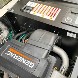
Some of the explanations for this list are quite long, so we will only place the most pertinent information in this list. Unfortunately, the list we found on the Generac website is not as complete as the two we will link to now. The first one is here and the second one is here.
-controller fault- no code number and it is a red alert signal with an alarm
-1100- overcrank- red alert with alarm- a common code where the controller tells the engine to start but it can’t
-1101- overcrank- red alert with alarm but only for the 8 & 9 kW units
-1200- overspeed- red alert with alarm
-1205- overspeed- red alert with alarm
-1207- overspeed- red alert with alarm
-1300- low oil pressure- red alert with alarm
-1400- high temperature- red alert with alarm
-1501- RPM sensor loss- red alert with alarm- 2 cylinder unit already running but lost RPM signal
-1505- RPM sensor loss- red alert with alarm- 2cyl. Unit cranking and lost signal that engine was turning
-1511- RPM sensor loss- red alert with alarm- for 1 cylinder units running and lost RPM signal
-1515- RPM sensor loss- red alert with alarm- 1 cylinder unit cranking and lost signal that said the engine was turning
-1600- underspeed- red alert with alarm- engine slowed down
-1603- underspeed- red alert with alarm- never got to its rated 3600 RP< start up speed
-1800- overvoltage- red alert with alarm- rated voltage output exceeded for a long time
-1900- undervoltage- red alert with alarm- voltage stayed under 80% of rated voltage for over 10 seconds
-1901- undervoltage- red alert with alarm- sudden drop in voltage
-1902- undervoltage- red alert with alarm- two zero crosses are missing
-1906- undervoltage- red alert with alarm- one zero cross is missing
-2099- wiring error- red alert with alarm
-2100- overload remove load
-2102- overload remove load- red alert with alarm-only for the 8 & 9 kW units
-2103- overload remove load- red alert with alarm- only for the 8 & 9 kW
-2299- undervoltage overload- red alert with alarm- generator was started with the load connected
-2399- stepper overcurrent- red alert with alarm-
-2400- fuse problem
-2800- AUX shutdown
-low battery- yellow warning light
-battery problem- yellow warning light
-charger warning- yellow warning light
-missing charger AC- yellow warning light
-2 year maintenance reminder- yellow warning light
-4 year maintenance reminder- yellow warning light
The full explanations will be at the links above. As we said some are quite lengthy. In the following subsections, you will get some full explanations for specific fault codes
Generac Generator Fault Code 1902
Undervoltage 1902- ALARM- Fault is displayed when both zero crosses are missing from the controller’s input for 1.5 seconds or more. Could be a faulty excitation winding, zero cross circuit, loose wiring, or field boost hardware problem. The same applies here, v1.12 or later firmware should be installed
We looked on the Generac website but we did not find an explanation for the ‘zero cross’ phrase.
Fault Code 1904
As you can see by the list, this fault code should not exist and you should not see it on your display screen. That may be because there are 2 fault code lists. One is for the standard Generac generators and the other one is for the following units- Generac Protector Liquid Cooled (Gas/Diesel) Evolution e-Code error code fault list with troubleshooting/repair guide
This list is far longer than the previous one and the 1904 code stands for- undervoltage- red alert with alarm- No field current but controller detects DPE voltage. Should check brush hardware, brushes and check for loose wiring.
You can find this longer list at this link. The previous list we quoted above, is for the Generac Air-Cooled Error Codes as of November 2018. We have not found any updates for that list so far.
If you are unsure of the fault codes we advise you to contact Generac directly.l
Generac Fault Code 2800
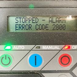
This is the last numbered fault code on the initial list and it states:
“Aux Shutdown 2800- ALARM
This only pertains to units with an external shutdown switch or switches installed. New WiFi units come standard with these switches, some (15kW and above) with 2. One located on the back side of the unit and one inside on the firewall. They must be on for the unit to run. If they are both on, check the wiring and connections for problems.”
The second list says the same thing with a few extra details-
“ESTOP Pressed/Aux Shutdown 2800- ALARM
This ONLY pertains to newer Evolution Protector units with an external shutdown switch installed. Liquid cooled units now have 2 switches installed, 1 in the control panel area under the cover and to the upper corner, and one externally mounted on the removable access panel covering the controller and main breaker. They must be on for the unit to run. If they are both on, check the wiring and connections for problems.”
1600 Fault Code On My Generac Generator
From the first list:
“Underspeed 1600- ALARM
An e-code that’s triggered when the engine speed is slowed to 55Hz for a 60Hz unit for 30 seconds (or 40Hz for a 50Hz unit). Most likely problem is that the unit is overloaded or something has tried to turn on that overloaded the unit. Could also be fuel related or a stepper motor throttle control problem.”
From the second list:
“Underspeed 1600- ALARM
Unit has slowed to <83.3% of its rated speed at 60Hz or <66.6% of rated speed at 50Hz. Most likely problem is that the unit is overloaded or something has tried to turn on that overloaded the unit. Could also be fuel related or a Bosch actuator or throttle linkage issue.”
We include the second list for all those owners of the Solar generator system. It looks like there are slight differences between the two generator series.
Generac Generator Fault Code P2601
This fault code is not on the first list so it will pertain only to the other units made by this company. The second list states this fault code is for:
“Ignition Fault 2601- ALARM
Missing camshaft pulse. Camshaft sensor isn’t sending feedback to controller. Could be a bad sensor, misalignment of the sensor, loose wiring, or an engine issue.”
If you are getting this code on the Generac Air-Cooled Error Codes then we suggest you contact the company or their dealers to find out if it is the same as mentioned immediately above.
When we went to the Generac website, we found only 7 fault codes listed on one of their web pages. You can check the owner’s manual to see if there are more listed on those pages.
Generac Home Generator Fault Code E2800
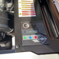
The first thing you should be aware of is that the letter e may be in some explanations but it won’t be on your display screen. It should simply say error code 2800 and then flash aux shutdown.
Here is what the code means on the 2 lists:
The first list:
“Aux Shutdown 2800- ALARM
This only pertains to units with an external Auxiliary Shutdown switch or switches installed. New WiFi units come standard with these switches, some (15kW and above) with 2. One located on the back side of the unit and one inside on the firewall. They must be on for the unit to run. If they are both on, check the wiring and connections for problems”
The second list:
“ESTOP Pressed/Aux Shutdown 2800- ALARM
This ONLY pertains to newer Evolution Protector units with an external shutdown switch installed. Liquid cooled units now have 2 switches installed, 1 in the control panel area under the cover and to the upper corner, and one externally mounted on the removable access panel covering the controller and main breaker. They must be on for the unit to run. If they are both on, check the wiring and connections for problems.”
What Causes The Red Light On The Generac Generator?
This generator operates on a 3-light warning system. The green light, as you would expect, means everything is fine and the generator is working as it should.
The red light is telling you that the generator is in failure mode. This light will remain on until you fix the problem. Then the yellow light is just a warning, much light the traffic light yellow that everyone ignores.
You shouldn’t ignore this yellow light as it is telling you that maintenance is required. It is also a warning light telling you that you may have a battery problem.
When the red light is on, do not expect your generator to work. The light seems to turn the generator off and keeps it off until the repairs are made.
What is The Code For Generac Rpm Loss?
There are several codes for this and they are divided between the 1 and 2-cylinder units. 1501 and 1505 are for the 2-cylinder units and 1511 and 1515 are for the 1-cylinder units. That is from the first list we quoted above.
The list for the Generac Protector Liquid Cooled (Gas/Diesel) Evolution has different 1500 numbers for the same problem. Those numbers are- 1500, 1516, 1517, 1518, 1519, and 1520 with 1520 being the same as 1518.
The 1500 error code says- “RPM Sensor Loss 1500- ALARM
Controller is missing magnetic pickup pulses. Mag pickup should be tested for resistance, alignment, and to make sure no metal shavings or debris have stuck to the sensor pin.”
That will give you a basic foundation for the rest of the fault codes.
How do You Clear The Fault on a Generac Generator?
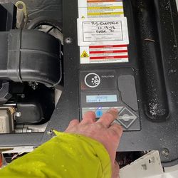
The first linked list above provides a warning that the second list does not. It is important to read the warnings as that information will help you avoid damaging your generator.
The warning states that you should not clear most codes without talking to a Generac dealer first. Once you do that, here are the procedures for the red and yellow codes:
1. Yellow:
-Press the gray colored ‘ENTER’ key once to confirm the
maintenance has been performed.
— Press the gray colored ‘ENTER’ key a second time to
confirm the action, or press ‘ESCAPE’ to cancel and
leave the maintenance reminder active on the screen
2. Red:
— Confirm that the problem has been repaired and no
longer exists.
— Put the unit into ‘OFF’ by pressing the RED button
under the ‘OFF’ red LED
— Push the ‘ENTER’ key to confirm that the alarm has
been repaired
— Put the unit back into either ‘AUTO’ or ‘MANUAL’ depending on which is desired.
(‘MANUAL’ will cause the unit to start and run, ‘AUTO’ will resume automatic standby
functions and wait for the next outage or exercise date)
Some Final Words
Fault codes are never going to go away. It would be a wise move to print out any fault sheets we have linked to and presented in our posts and store them in a safe place.
You may not be able to get to your computer to read those posts and see what the trouble is.
Раздел 5 – Поиск и устранение неисправностей
Генераторы с воздушным охлаждением
40
5.1 РУКОВОДСТВО ПО ПОИСКУ И УСТРАНЕНИЮ НЕИСПРАВНОСТЕЙ
Неисправность
Причина
Устранение
Не
заводится двигатель.
1. Сгорел предохранитель.
1. Проверить цепь короткого
замыкания
, заменить 7,5A
предохранитель
на панели
управления
генератора.
2. Ослаблены, покрыты
коррозией
или неисправны
кабели
аккумуляторной батареи
2. Затянуть, почистить или при
необходимости
заменить.
3. Неисправен пусковой контактор. (8
кВт
)
3. *
4. Неисправен стартёр.
4. *
5. Разряжена аккумуляторная
батарея
.
5. Зарядить или заменить
аккумуляторную
батарею.
Двигатель
заводится, но не
запускается
1. Нет топлива.
1. Заполнить топливом / Открыть
топливный
клапан.
2. Неисправен топливный соленоид
(FS).
2. *
3. Отсоединен провод #14 от пульта
управления
двигателя.
3. *
4. Загрязненные свечи зажигания.
4. Очистить, проверить зазор или
заменить
свечи.
5. Сбился зазор клапана.
5. Еще раз отрегулировать зазор
клапан
.
6. Не работает дроссель.
6. Проверить свободу перемещения
дроссельной
заслонки.
1. Проверить, заменить
воздухоочиститель
.
Двигатель
запускается с
трудом
и работает тяжело.
1. Забит или поврежден
воздухоочиститель
.
2. Загрязненные свечи зажигания.
2. Очистить, проверить зазор или
заменить
свечи.
3. Неправильное давление топлива.
3. Убедиться, что давление топлива
составляет
0,024 — 0,029 атмосфер
(0,36 — 0,43 фунтов/ кв.дюйм) для LP, и
0,012 – 0,017 атмосфер (0,18-0,25
фунтов
/ кв.дюйм) для природного газа.
4. Селектор топлива установлен не в
то
положение.
4. Передвинуть селектор в нужное
положение
.
5. Дроссель остается закрытым.
5. Проверить свободу перемещения
дроссельной
заслонки.
1. Неисправен переключатель.
1. *
Переключатель
«AUTO/OFF/MANUAL»
установлен
в положение
«OFF», но двигатель
продолжает
работать.
2.
Переключатель
«AUTO/OFF/MANUAL» подключен не
правильно
.
3.
Неисправен
пульт управления.
2.
*
3.
*
1. Автомат цепи основной линии сети
электроснабжения
находится в
положении
«OFF» (или ОТКРЫТЫЙ).
1. Установить автомат в положение
«ON» (или ЗАКРЫТЫЙ).
С
генератора не
подается
переменный
ток
.
2. Неисправность внутри генератора.
2. *
1. Неисправен передаточный ключ.
1. *
2. Неисправно передаточное реле.
2. *
Не
происходит
перераспределение
на
резервный
источник во
время
отключения сети
электроснабжения
.
3. Разомкнута цепь передаточного
реле
.
3. *
It’s as simple as flipping a switch!
We purchased a 22KW Home Standby Generator from Generac a few years ago, and it remains one of the best investments we’ve made in our house. With three young children in an area that is prone to losing power, keeping all the lights on and devices powered 24/7 is essential!
One day – about a year after being installed and running smoothly with no issues – our generator shut down and gave a 2800 error code. If this happens to you, there is nothing wrong with your generator and no need to get it serviced! All that happened is one of the auxiliary shutdown switches was accidentally flipped to the off position.
Here I’ll show you what triggers the Error Code 2800 and how to fix it so you can get your generator up and running again!
Generac 22kW Home Standby Generator with Wi-Fi and Transfer Switch

What Error Code 2800 Looks Like in the Mobile Link App
I was first alerted to the fact that the generator was no longer running via Generac’s Mobile Link app. After opening the app, I saw the following error message:

If you click on the Status History page of the app, you’ll see additional error messages and that the generator was shut down due to an alarm:

What Error Code 2800 Looks Like on a Generac Generator
Heading outside to inspect the generator, I saw that the red “Alarm” light was on:

If you open your generator, the control panel interface will cycle between two error messages. The first indicates that the generator has stopped due to an alarm from Error Code 2800:

The second error message indicates that the generator has stopped due to the Auxiliary Shutdown Switch:

Reading these error messages (particularly since the Mobile Link app indicates that the generator needs to be serviced), you might think that something seriously wrong has happened to your generator. Rest assured, your generator is fine! Here’s how to fix Error Code 2800.
Step 1: Locate the Auxiliary Shutdown Switch on the back of the generator
Error Code 2800 is caused by flipping the Auxiliary Shutdown Switch (which probably happened accidentally). All models of Generac generators have an Auxiliary Shutdown Switch on the exterior of the generator. Our model’s Auxiliary Shutdown Switch is located on the back of the generator, in the top-left corner:

The generator will not start if the Auxiliary Shutdown Switch is OPEN (O symbol), and will instead activate an “Auxiliary Shutdown” alarm. So, the generator won’t run and will trigger error code E2800 if the O symbol of the Auxiliary Shutdown Switch is pressed down.
In the below picture, I have zoomed in on the Auxiliary Shutdown Switch in the OPEN (O symbol) position so you can see it more clearly:

Most commonly, the Auxiliary Shutdown Switch on the back of the generator is the culprit behind Error Code 2800. And sure enough, somehow this switch had accidentally been pressed on our generator!
Step 2: Set the Auxiliary Shutdown Switch to the CLOSED (| symbol) position
To fix error code 2800, simply set the Auxiliary Shutdown Switch to the CLOSED (I symbol) position by pressing down the CLOSED (| symbol) side of the switch:

Step 3: If applicable, check the Auxiliary Shutdown Switch on the inside of the generator
Generac generators that are 16 kW or greater have a secondary Auxiliary Shutdown Switch located inside the generator – right by the control panel interface. I’ve highlighted this additional switch in the below picture as an FYI:

It is highly unlikely that this interior Auxiliary Shutdown Switch would have been accidentally flipped since it located under the lid of the generator (and hopefully you lock the lid of your generator too!). Still, it never hurts to check this switch too.
Step 4: Clear the Error Code from the Control Panel
After ensuring that one or both Auxiliary Shutdown Switches are pressed down to the CLOSED (| symbol) position, the control panel interface will prompt you to clear the alarm/error with the following message:

It’s as simple as the message indicates! Simply press the red “OFF” button on the control panel, then press the gray “ENTER” button.
Finally, press the green “AUTO” button to set the generator in fully automatic system operation (allows the generator to automatically start and exercises the generator according to the exercise timer).
The control panel should look like this:

(Optional) Step 5: Run the generator in Manual mode
While you’re technically done and the problem has been solved, I like to run the generator in Manual mode for a minute or two. Especially if the generator has not been running or following its exercise schedule for a little while, it’s always good to make sure it cranks and starts up.
Simply press the blue MANUAL button, and the generator should crank up and run. The control panel will indicate it is in Manual operation with a blue LED light:

Assuming the generator starts up fine, let it run for a minute or two.
(Optional) Step 6: Return the generator to Auto operation
Whenever you’re ready, you can place the generator back into fully automatic system operation by pressing the green “AUTO” button. The generator will stop running and the control panel will look like this again:
How to Prevent Error Code 2800
Children using the generator for a game of hide-and-seek might brush up against and flip the Auxiliary Shutdown Switch. Or a bouncing ball might accidentally flip the switch. In our case, a leaf blower accidentally aimed too high was enough to flip the Auxiliary Shutdown Switch!
I’ll be honest, I was quite surprised by how easily the exterior Auxiliary Shutdown Switch can be flipped. I hope that future models of Generac generators either require more pressure and force to flip this switch, or have an enclosure around the switch to prevent accidental presses.
Until then, there’s little that can be done to prevent this error from happening. Knowledge is your best bet here. Just be aware of anything going on around your generator and know that the Auxiliary Shutdown Switch can be easily flipped.
What if the Auxiliary Shutdown Switch is in the CLOSED (| symbol) Position?
If the Auxiliary Shutdown Switch is already in the CLOSED (| symbol) position, then the switch is either faulty or the wiring to the switch is faulty. In this case, you’ll need to call a professional to get the generator serviced.
More Information on the Auxiliary Shutdown Switch
According to the owner’s manual, all Generac generators are equipped with an external means of shutting down the generator via an auxiliary shutdown switch. This switch is located on the exterior of the generator back panel, and shuts down the generator and disables restarts:

Generac generators that are 16 kW or greater have a secondary Auxiliary Shutdown Switch located inside the generator – right by the control panel interface:

If an auxiliary shutdown switch is activated, the control panel interface displays an “Auxiliary Shutdown” alarm and the red LED “Alarm” light illuminates. The generator will not start if either switch is OPEN (O).
To clear this condition, set the switch or switches to CLOSED (I).
Clear the alarm by pressing the OFF mode button, and then ENTER. The generator can then be placed back in AUTO or MANUAL mode.
How To Find a Generac Generator’s Product Manual
You can find specifications, product/owner’s manuals, and more information for your Generac generator via Generac’s Product Support Lookup page.
Either enter a Model Number/Serial Number, or browse by Product Category (in our case, Standby Generators -> Guardian Series -> 22 kW).
Did this guide help you fix your Generac Generator with Error Code 2800? Have any other Generac generator issues you need help with? Let me know in the comments below!
Explore additional Generac generator posts, and discover even more home improvement projects at ProjectsByPeter.com/Home-Improvement
Post content, images, and featured image © 2022 ProjectsByPeter.com – All rights reserved.