Опубликовано: 28.01.2023
на признак видимых неисправностей. Если результатов не будет нужно искать причину глубже и основные виды неисправностей, причины их появления и методы устранения будут представлены в статье.
Осмотр до пуска

Если произошла поломка дизель-генератора, то необходимо провести его осмотр. При обнаружении вмятин, трещин и других механических повреждений причина поломки может быть именно в этом.
Дополнительно необходимо убедиться, что нет посторонних предметов, которые приводят к неправильной работе. Среди самых частых неисправностей можно выделить:
- Оборудование не включается.
- Генератор работает, но напряжение нет.
- При работе устройство глохнет.
- Увеличен расход масла.
- На включенном генераторе слышно громкие стуки.
- Нестандартный цвет выхлопного газа. Чтобы разобраться со всеми причинами, необходимо детальнее их изучить и узнать возможные методы устранения неисправностей.
Дизель-генератор не запускается

Когда оборудование отказывается запускаться, то причин может быть сразу несколько.
Основные неисправности, к которым приводит отказ запуска:
- Поломка топливного насоса. Такая неисправность, говорит о плохой или неравномерной подаче горючего.
- Не работает устройство холодного запуска. Вероятнее, что произошла парафинизация дизеля, что относится к частой причине во время холода. Для исключения проблемы лучше использовать зимний дизель, а также сократить количество пусков в морозы.
- Плохое горючее. Рекомендуется покупать дизель только в проверенных местах и не пользоваться разбавленным топливом. Подобная экономия может стать причиной многих ошибок дизель-генератора.
- Сбой работы стартера. При такой неисправности вращение будет недостаточным для запуска. Как правило, проблема кроется в слабой батарее или плохом масле.
Устранив одну или несколько описанных причин можно запустить двигатель. После небольшого ремонта все начинает работать.
Оборудование не выдает напряжения
До начала работы с электричеством, следует полностью обесточить дизель-генератор, чтобы не получить удар током. К данной поломке относятся следующие неисправности дизельных генераторов:
- Если устройство работает, но нет напряжения, то может быть проблема с контактами или щетками. В некоторых случаях контакты могут окислиться или часть проводки повреждена. Проверяется целостность проводки, крепежи, а также контакты. Если нужно контакты зачищаются. При сильном износе щеток их следует поменять на новые.
- Возможно, была сильная перегрузка в работе, после чего отключился автомат и сгорели пробки. Для устранения неисправности нужно поменять пробки или просто включить автомат.
- Выход из строя регулятора напряжения не позволит получить напряжение, поэтому проводится ремонт или замена регулятора.
Возможно, при работе постоянно выбивает автомат, в таком случае может быть увеличена допустимая мощность, когда используется много приборов.
Рекомендуется просто отключить часть приборов и все нормализуется. Банальной причиной может стать неисправный удлинитель, который подключается к генератору.
Глохнет во время работы
Если при работе дизель-генератора он практически сразу глохнет, то поломки зачастую не серьезные и легко устранимы. Из основных типов неисправностей следует выделить:
- Недостаток топлива в баке, что не позволяет нормально функционировать устройству.
- Воздух в топливном баке.
- Загрязнение фильтра для дизеля, при такой неисправности нужно заменить элемент на новый.
- Сбой работы или поломка форсунок, рекомендуется их проверить и по необходимости заменить.
- Неверно установлены холостые обороты, потребуется провести настройку.
Как видно почти все виды поломок не представляют сложности для исправления, кроме того, денежные затраты минимальны для устранения неисправностей.
Увеличенный расход масла
Если расход масла при работе электростанций увеличен, необходимо проверить плотность всех соединений системы, возможно, произошла разгерметизация и есть утечка масла. Есть и другие причины:
- Повреждены поршневые кольца или цилиндры. Для устранения поломки надо установить новые кольца и расточить цилиндры.
- При сильном износе масляных колпачков следует провести их замену на новые.
Рекомендуется использовать только качественные виды масел, чтобы обеспечить надежную, бесперебойную работу.
Громкие стуки при работе
Работа дизель-генератора всегда громкая, но если появляются нестандартные звуки или стуки, то вероятнее что износились определенные детали:
- Форсунки.
- Пружины клапанов.
- Поршневые кольца.
- Подшипники.
- Распредвал.
Если все части не имеют износа, то следует отрегулировать зазоры на клапанах, а также выставить правильный момент впрыска горючего.
Во время работы на электрогенераторах может появиться сильный перегрев, что вызван недостаточным натяжением ремня или нехваткой охлаждающей жидкости. Также перегрев появляется, если радиатор дизель-генератора очень грязный и тепло не может нормально выходит наружу. К серьезным причинам перегрева относится выход из строя термостата, а также насоса, который качает тосол или антифриз.
Нестандартный цвет выхлопных газов

При работе дизель-генератора необходимо смотреть на выход газов, а именно на их цвет. Если газы выходят белые, голубые или черные, то, вероятнее всего, устройство работает неправильно и есть поломки.
Часто проблема кроется в грязном воздушном фильтре, но если его поменять и цвет не изменится, то причины следующие:
- Неправильная работа или выход из строя насоса высокого давления, форсунок свечей накала и их реле.
- Не выставлены зазоры на клапанах или неправильно установлен момент впрыска горючего.
- Нет компрессии в двигателе.
- Неверно подобрано масло для дизель-генератора.
Кроме цвета, на неисправность указывает большое количество выходящих выхлопных газов, когда электростанция очень дымит. В целом, причины аналогичны. Современные дизель-генераторы упрощают ремонт и обслуживания владельцам, поскольку на новых моделях может стоять небольшой монитор и компьютер, который показывает коды ошибок дизель-генератора. Зная основные коды, которые можно увидеть в инструкции легко устранить поломку.
К сожалению, многие устройства не имеют такого монитора, владельцам приходится устранять неисправности самостоятельно, исключая каждую причину по отдельности.

Одной из особенностей конструкции автомобилей Вольво является функция ограничения параметров работы узлов, активирующаяся при появлении неполадок в электронике машины. Автомобиль при этом сохраняет подвижность, но не в полном объеме. Понять причину такого поведения помогут коды ошибок Вольво, часть которых водитель может узнать и расшифровать самостоятельно.
Диагностика
Для чтения ошибок, хранящихся в блоках управления машин Вольво, применяется несколько методик:

Разъем для диагностики
На машинах выпуска 1985-1995 годов
Типовой вид раннего варианта разъема Вольво
Назначение разъемов следующее.
| Номер | Секция А | Секция Б |
| 1 | АКПП (коробка автомат) | Система микроклимата (ручная и автоматическая) |
| 2 | Подача топлива | Круиз-контроль |
| 3 | Система АБС | Резерв |
| 4 | Система TCU на АКПП | Подушки безопасности и их блок управления |
| 5 | Система зажигания | Управление параметрами сидений |
| 6 | Исправность щитка приборов | Исправность комбинации приборов |
Для выполнения диагностики необходимо выполнить стандартную тестовую проверку:
- Вставить кабель в гнездо 2 секции А.
- Включить зажигание и кратковременно нажать кнопку запуска теста.
- При отсутствии ошибки светодиод отобьет код 111 (три короткие вспышки с интервалом по 3 секунды). При наличии ошибки она будет сообщена иными комбинациями вспышек.
- Нажать кнопку теста.
Проводить тестирование необходимо до начала повторения списка ошибок. Полученные коды нужно расшифровывать.
На машинах выпуска после 1996 года
Диагностика таких машин может производиться по аналогичной схеме, описанной выше, но с использованием отдельного диода, который подключают к контакту 16 (положительный вывод) и 4. Схема устройства приведена в картинках ниже.

Общая схема разъема OBD-II 
Диод для тестирования Схема устройства
Оба способа диагностики не дают абсолютно точной информации о состоянии систем автомобиля. Более подробную диагностику следует проводить полноценным сканером, который подключают к разъему Volvo.
На машинах выпуска после 2000 года
На более современных машинах начиная с начала 2000-х годов появилась возможность чтения ошибок из блока управления двигателем на приборной панели.
Самостоятельная диагностика кодов ошибок двигателя при загорании лампы Check Engine на Volvo XC90 S60 и S80 дизель или бензин проводится по следующей методике:
- Сесть за руль автомобиля, вставить ключ в замок зажигания и включить двигатель (положение 2).
- Нажать и удерживать кнопку «Read», расположенную на торцевой части левого лепестка подрулевого переключателя.
- На машине 2005 года следует два раза нажать на клавишу включения заднего противотуманного фонаря. На некоторых машинах, например, ХС90 D5 выпуска 2007 года необходимо выполнить троекратное нажатие, это связано с типом блока управления электрикой.
- После второго или третьего нажатия на экране комбинации приборов появится надпись «DTCS in Vehicle».
- Поочередным нажатием кнопки «Read» происходит переключение модулей.
При проведении диагностики и считывания ошибок нужно учитывать, что на современных автомобилях Вольво могут быть различные блоки управления:
При наличии ошибок в любом из модулей, например, ВСМ на экране появится надпись типа «ВСМ DTC SET». При отсутствии ошибки текст будет выглядеть в виде«ВСМ Ready». Если необходим более глубокий анализ блока, на комбинации появится надпись «ВСМ Checking».
На современных грузовых автомобилях Volvo серии FH12 или FH13 ошибки выводятся на панель приборов в виде текстовых сообщений и горящих символов. Для более детального анализа ошибок на блоке подрулевых переключателей имеются несколько клавиш, при помощи которых можно зайти в меню бортового компьютера и прочитать код ошибки. Данный код расшифровывается по таблицам или сообщается при передаче грузовика на сервисное обслуживание.
Автор видео Andrei Bosun демонстрирует чтение ошибок на комбинации приборов грузового автомобиля Вольво.
Расшифровка кодов
Всего существует порядка тысячи различных кодов неисправностей, характерных именно для автомобилей Вольво. Ниже будут рассмотрены ошибки, которые наиболее часто встречаются на машинах.
Датчики
При выходе из строя датчиков нарушаются параметры работы двигателя. В этом случае необходимо добраться до сервиса и произвести ремонт, замену устройств или проводки к ним. Например, одна из частых ошибок самодиагностики с кодом 124 на Вольво ХС90 указывает на повреждение сенсора подушек безопасности.
Распространенные ошибки датчиков Вольво V50 или S40.
На машинах со старой системой диагностики встречаются ошибки.
| Код | Описание |
| 121 | Разрыв цепи датчика расхода воздуха |
| 122 | Отказ датчика измерения температуры воздуха на впуске |
| 123 и 133 | Обрыв цепи датчика температуры двигателя |
| 131 | Нет данных о частоте вращения вала двигателя |
| 132 | Параметры напряжения сети вне поля допуска |
| 143 | Неисправен датчик детонации |
| 212 | Неисправен лямбда-зонд и его проводка |
| 214 | Датчик оборотов коленчатого вала имеет неполадки |
| 221 | Проблема в лямбда-зонде |
| 243 | Нет сигнала от датчика дросселя (не на всех моделях) |
| 312 | Неисправен датчик детонации |
| 344 | Нет сигнала от датчика температуры отработавших газов (только турбо) |
| 332 и 333 | Требуется регулировка положения датчика дроссельной заслонки |

Пример ошибки 124
Для грузовых автомобилей распространены следующие ошибки в работе датчиков.
| Ошибка | Обозначение |
| PID170 и 171 | Выход из строя датчиков температуры в кабине и на улице |
| PID117 и 118 | Поломки датчиков давления в контурах тормозов |
| PID177 | Отказ датчика температуры масла в коробке передач |
Двигатель
На Вольво ХС90 с большими пробегами часто возникает ошибка Р0027, которая указывает на засорение клапанов системы регулировки фаз. Такая проблема исправляется промывкой клапана или заменой на новый. Однако нередки случаи, когда ошибка появляется случайно и после удаления больше не беспокоит владельца.
Есть еще ряд часто встречающихся кодов ошибок на Вольво.
Для старых Вольво (до 1995 года) в работе двигателя наиболее характерны ошибки.
| Код | Описание |
| 112 | Отказ системы управления впрыском топлива |
| 113 | Поломка одной или всех форсунок |
| 134 | Неисправно реле системы впрыска |
| 143 | Неисправен датчик детонации |
| 211 | Регулятор СО (на карбюраторном двигателе) |
| 222 | Отказ реле системы впрыска топлива |
| 223, 232 и 233 | Неисправности системы холостого хода |
Некоторые наиболее распространенные ошибки приведены в таблице.
| Ошибка | Обозначение |
| PID84 | Поломка датчика скорости |
| PID91 | Выход из строя датчика положения педали газа |
| PID94 | Проблемы с давлением в системе подачи топлива |
| PID97 | Попадание воды в систему |
| PID98 | Падение уровня масла |
| PID100 | Снижение давления масла |
| PID102 | Падение давления нагнетаемого воздуха |
| PID108 | Негерметичность блока двигателя (измеряется датчиком давления внутри блока) |
| PID110 | Перегрев двигателя |
| PID190 | Превышение оборотов двигателя |
Видео о сканере для диагностики Вольво поделился пользователь Scantruck.
Другие ошибки
Повреждение датчика или проводки парктроника являются причинами ошибки 106, которая часто встречается на различных легковых Вольво. Исправляется проблема заменой поврежденных деталей. На некоторых ХС90 встречается ошибка 025, которая сопровождается звуковым сигналом и показывается только на комбинации приборов. Причина этой неполадки в повреждении элементов самой комбинации, которые необходимо заменить.
Кроме этого, наиболее распространенные неисправности указаны в таблице.
| Ошибка | Причины |
| Р1672 и 1673 | Снижение напряжения питания |
| Р1680 | Постоянное или частичное пропадание связи с иммобилайзером |
На старых машинах встречаются такие ошибки.
| Код | Описание |
| 132 | Параметры напряжения сети вне поля допуска |
| 311 | Нет сигнала связи со спидометром |
| 321 и 322 | Не работает система подогрева расходомера |
На грузовиках наибольшее распространение имеют следующие ошибки.
| Ошибка | Обозначение |
| PID158 | Падение напряжения ниже допустимого |
| PID252 | Ошибка текущей даты в системе тахографа |
| SID240 и 254 | Поломки охранной сигнализации |
| SID231, 240, 250, 253 | Ошибки в блоке управления светом |
Как стереть?
Удаление ошибок на Вольво 940 выпуска 1995 года со старой системой диагностики выполняется следующим образом:
Для удаления индикации межсервисного интервала на Volvo ХС60, ХС70 и XC90 необходимо:
- Поставить ключ зажигания в положение 1.
- Нажать кнопку сброса пробега и удерживать ее. Данные суточного пробега при этом обнуляются.
- Сразу после сброса (в течение двух секунд) перевести ключ в замке зажигания в положение 2, не отпуская кнопку. Удерживать ее до появления на экране комбинации приборов символа оранжевого треугольника.
- Отпустить кнопку и выключить зажигание.
В случае неожиданного включения символа Check Engine и уверенности, что с системами автомобиля проблем нет, можно попробовать сбросить ошибку.
Процедура выполняется следующим образом:
- Сесть за руль автомобиля и закрыть за собой дверь, остальные двери также должны быть закрыты.
- Вставить ключ в замок зажигания, повернуть в положение 1 и вернуть в нулевую позицию, но не вынимать.
- Нажать кнопку сброса суточного одометра и одновременно повернуть ключ в позицию 1.
- Выждать от 10 до 15 секунд, не отпуская кнопки сброса. Комбинация приборов подаст звуковой и световой сигнал (лампой непристегнутых ремней или подушек безопасности) с продолжительностью около 1 секунды.
- На дисплее в левой части комбинации будут отображены ошибки. Коды разделены между собой запятой. Процесс сброса окончен.
Фотогалерея
На серии фотографий ниже показаны этапы самодиагностики комбинации приборов на Volvo XC90 2004 года выпуска.

Запуск диагностики 
Диагностика блока SRS 
Диагностика блока DIM 
Диагностика блока DDM
Видео «Самодиагностика Вольво»
На данном видео, предоставленном каналом lumega1234, показаны все шаги по проведению самодиагностики на Volvo V50 и S40.

Первый знак – буква, определяющая тип дефектной системы:
- Р – неисправности силового агрегата или трансмиссии (АКПП).
- В – неполадки в работе кузовных систем: подушек безопасности, электрических стеклоподъемников, центрального замка и т. д.;
- С – неисправности в ходовой части транспортного средства;
- U – ошибки, связанные со взаимодействием электронных модулей.
Второй знак – цифра, которая определяет специфичность неисправности:
- 0 – общий символ для OBD колодки;
- 1 и 2 – персональные коды автопроизводителя;
- 3 – зарезервированная информация.
Третий знак определяет тип поломки:
Четвертый и пятый знаки ошибки – это числа, которые соответствуют порядковому номеру неисправности.
Все ошибки в автомобилях Вольво могут выводиться в двух-, трех- и четырехзначном видах, в зависимости от версии блока управления (года производства авто) и метода диагностики. Коды неисправностей для грузовых транспортных средств имеют префикс «PID», который стоит перед цифрами, а ошибки OBD2 всегда выводятся с буквой «P».
Таблица с ошибками
Расшифровка тектовых сообщений
- некорректная работа датчиков, установленных на колесах;
- повреждение проводки или плохой контакт одного из элементов системы с блоком управления антиблокировочной системы;
- неисправность управляющего модуля АБС.
Недостаток антифриза, требуется диагностика системы на предмет утечки
- неисправность радиаторного устройства, связанная с его засорением или повреждением;
- нарушение герметизации в системе охлаждения (утечка хладагента из-за ослабления клапанов, повреждения патрубков, неисправности насоса или крана отопителя);
- выход из строя термостата;
- неисправность в работе помпы;
- выход из строя вентилятора.
К механическим неполадкам относятся:
- дефекты электрической схемы;
- неисправности в работе проводников и системы питания;
- повреждения коммутационного шлейфа.
Описание кодов ошибок
Неисправности топливной системы
Неисправности двигателя
Возможные причины проблемы:
- неисправность свечи зажигания: повреждение ее контакта или образование нагара на устройстве;
- выход из строя распределительного устройства, появление трещин на его корпусе;
- плохая компрессия в цилиндрах силового агрегата;
- отсутствие баланса при формировании топливовоздушной смеси, в частности, недостаток горючего;
- неисправность одной или нескольких топливных форсунок.
Возможные причины неисправности:
- сбои в работе системы распределения фаз CVVT;
- неполадки, зафиксированные в функционировании зубчатого колеса распределительного вала;
- нарушение потока моторной жидкости в камеру поршня VCT;
- повреждение проводки или контактных элементов на колодке подключения системы газораспределения;
- поломка датчика клапана VVT-i в результате засорения или при замене цепи газораспределительного механизма.
Описание ошибок в работе датчиков
- неисправность датчика температуры внешнего воздуха;
- выход из строя контроллера давления горючего.
- неисправность контроллера частоты вращения коленчатого вала;
- выход из строя или некорректное функционирование линейного регулятора давления системы кондиционирования.
Неисправности датчиков системы стабилизации
Ошибки кислородных датчиков
Ошибки антипробуксовочной системы ABS
Ошибки, связанные с работой проводки
Описание ошибок в работе систем связи
- выход из строя управляющего модуля иммобилайзера;
- нарушение связи с антенным модулем;
- поломка элемента питания или батарейки в устройстве;
- неисправность транспондера или электронного ключа;
- окисление контактов на одном из устройств системы блокировки двигателя.
Неисправности модуля управления дверьми Вольво ХС90 с 2002 года выпуска
Неисправности трансмиссии
Возможные причины проблемы:
- использование низкокачественного горючего в трансмиссионном агрегате;
- наличие воды в масле коробки передач;
- некачественный контакт на проводах, подключенных к трансмиссии;
- соленоид S4 коробки или SLU заел в отключенном положении;
- механические неполадки в работе трансмиссии.
Возможные причины проблемы:
- забит радиатор охладительной системы;
- износ расходного материала в результате длительного использования масла;
- буксировка другого транспортного средства или прицепа на автомобиле с АКП;
- пробуксовка в снегу или грязи.
Если ошибка неслучайна, она сопровождается следующими признаками:
- появление толчков при переключении скоростей;
- запах горелой трансмиссионной жидкости;
- сложности при переключении скоростей;
- переключение передач осуществляется при движении на повышенных оборотах;
- на приборной панели появляется значок перегрева, если он предусмотрен.
Трехзначные коды ошибок самодиагностики
Описание сервисных сообщений
Описание ошибок грузовых авто с блоком управления MID 144
Возможные причины проблемы:
- Повышенное давление в ресиверном устройстве. Проблема может заключаться в неисправности клапанов разгрузки компрессорного устройства в головке агрегата, повреждении проводки электромагнитного клапана разгрузки во влагосушителе. Также причина может состоять в контроллере давления воздуха.
- С датчика на управляющий модуль поступает импульс с напряжением менее 3,1 В.
- Обрыв проводки или замыкание контактов.
- Выход из строя клапанных элементов, расположенных в головке компрессорного устройства, элементы могли застрять в закрытом положении.
Код
Описание неисправностей на грузовиках с блоком управления MID 140
Возможные причины проблемы:
- Уровень сопротивления на выходах В13 и А12 управляющего модуля приборной комбинации составил более 1 кОм. Проблема состоит в обрыве сигнального либо отрицательного кабеля, окислении или повреждении контактных элементов на колодке. Возможен выход из строя самого регулятора.
- Величина сопротивления на пинах В13 и А12 провода от модуля контрольного щитка до контроллера в баке составляет более 20 Ом. Проблема состоит в самом регуляторе либо замыкании сигнальной линии на заземление.
Описание ошибок авто с блоком MID 130
- замыкание на линии регулятора на аккумулятор;
- обрыв электролинии контроллера;
- замыкание цепи датчика делителя на заземление;
- контроллер не откалиброван.
Полный список кодов неисправностей с расшифровкой рассмотрен для следующих моделей авто:
- 850;
- 940;
- 960;
- С30;
- С40;
- С60;
- С80;
- FH12 (ФШ12;
- FH13 (ФШ13);
- FH16 (ФШ16);
- FM9 (ФМ9);
- FM13 (ФМ13);
- S40;
- S60;
- S70;
- S80;
- V50 (В 50);
- V70 (В 70);
- VNL 670 (ВНЛ 670);
- ХС60;
- ХС70;
- XC90.
Как диагностировать ошибку?
Самым эффективным способом диагностики кодов ошибок Вольво является компьютерное сканирование, которое позволяет определить тип неполадки и обнаружить конкретную неисправность.
Алгоритм действий при диагностике, выполняющейся с помощью компьютера или сканера:
- Оборудование для проверки подключается к специальному выходу OBD2 в автомобиле.
- Включается зажигание или запускается двигатель (в зависимости от условий, прописанных в сервисном руководстве).
- Производится считывание кодов неисправностей с помощью сканера или специальной программы, установленной на ноутбук.
- Полученные комбинации расшифровываются и устраняются.
Кроме компьютерной проверки, есть другие способы выявления неполадок:
- диагностика с применением приборной комбинации, которая осуществляется с использованием кнопок, расположенных на центральной консоли;
- диагностика с использованием специального разъема тестирования (метод актуален для Volvo, выпущенных в период с 1985 до 1995 гг.), колодка находится либо в районе левого крыла, либо рядом с корпусом воздухофильтра.

Диагностическая колодка на старых версиях автомобилей Volvo
На автомобилях с более ранней версией диагностического разъема проверка производится следующим образом:
- Провод для проверки подключается к контакту 2 на диагностической колодке секции А.
- Выполняется включение зажигания (для этого ключ прокручивается в режим АСС замка).
- Нажимается кнопка начала теста.
- Если ошибок в работе транспортного средства нет, светодиодный индикатор неисправности покажет код 111, который будет выведен в виде трех коротких вспышек с трехсекундной паузой. При наличии неполадок коды выводятся в виде морганий.
- Записываются все коды ошибок. После того, как бортовой компьютер закончит процедуру вывода комбинаций, вспышки начнут повторяться по кругу.
- Для завершения диагностики нажимается кнопка тестирования.
На транспортных средствах, выпущенных после 2000 года, процедура диагностики выполняется следующим образом:
- Автовладелец производит запуск силового агрегата.
- На боковой части лепестка подрулевого переключателя имеется кнопка с надписью «Read», пользователю нужно ее зажать. Если Вольво выпущено в 2005 году, то пользователю необходимо два раза нажать на клавишу включения задних противотуманных огней. Если речь идет о Volvo XC 90 2007 года выпуска, автовладельцу нужно трижды «кликнуть» на данную клавишу.
- На экране приборной комбинации после выполнения этих действий появится значок с надписью «DTCS in Vehicle».
- Переключение блоков при диагностике производится посредством нажатия на клавишу «Read».
Видео: компьютерная диагностика двигателя Вольво
В видеоролике канала «TruckПодбор» продемонстрировано описание процедуры компьютерного тестирования дизельных силовых агрегатов на грузовых автомобилях Volvo.
Как сбросить ошибку?
Для обнуления памяти на автомобилях Volvo 1992г, 1993, 1994 и 1995 годов выпуска со старой системой тестирования производятся следующие действия:
- В автомобиле активируется система зажигания путем прокручивания ключа в замке.
- Нажимается клавиша запуска процесса диагностики, которую необходимо удерживать в течение 6-8 секунд.
- Подождать, пока на бортовом компьютере приборной панели загорится светодиодный индикатор (он должен появиться примерно через 3 секунды).
- Затем клавиша активации процесса тестирования еще раз зажимается на 6-8 секунд, что приведет к отключению диодного элемента.
- Производится проверка наличия кодов неисправностей в памяти блока управления. Если действия по обнулению памяти выполнены правильно, то светодиод подаст код 111.
Если требуется убрать индикатор необходимости проведения межсервисного интервала на автомобилях Вольво ХС60, ХС70 и ХС90, выполняются следующие действия:
- Ключ вставляется в замок и прокручивается в режим «I».
- Кнопка на одометре нажимается и удерживается в течение нескольких секунд, во время которых должен произойти сброс суточных показаний пробега.
- В течение двух секунд после обнуления значений пользователь должен перевести ключ в замке в позицию «II». Кнопку одометра при выполнении этих действий необходимо удерживать, пока на табло приборной панели не появится индикатор в виде оранжевого треугольника.
- Затем клавиша сброса пробега отпускается, а система зажигания отключается. После этого индикация межсервисного интервала должна быть удалена из памяти блока управления.
Для автомобилей Камминз, С 60, С 80, XC70 и других моделей Вольво процедура удаления случайных кодов неисправностей выполняется следующим образом:
- Водитель садится за руль транспортного средства и закрывает за собой дверь. При проведении этой процедуры все дверные замки автомобиля должны быть заперты.
- В замок вставляется ключ и проворачивается сначала в режим «I», а затем возвращается обратно. Извлекать устройство из выключателя не нужно.
- Кнопка сброса суточного пробега на приборной панели нажимается. Одновременно с этим пользователь должен прокрутить ключ в замке в положение «I».
- Затем, удерживая клавишу в зажатом состоянии, пользователь должен выждать 10-15 секунд. На табло должен моргнуть индикатор непристегнутых ремешков безопасности или подушек. Приборная панель издаст звуковой сигнал. Длительность импульсов должна составить около 1 с.
- Затем на панели приборов машины, в левой части дисплея появятся коды неисправностей. Все ошибки разделяются между собой с помощью запятой. На этом процедура сброса ошибок грузовиков и легковых транспортных средств считается завершенной.
Стоимость диагностики ошибок для Volvo на СТО Москвы и Питера
Примерные цены на проведение диагностики с использованием компьютера или специального сканера на станциях техобслуживания Москвы и Санкт-Петербурга:
| Город | Название компании | Адрес | Номер телефона | Цена |
| Москва | Север Моторс | Ул. Дубнинская, 83 | +7 499 685-18-21 | 2500 руб. |
| Серебряный слон | Ул. Пяловская, 7 | +7 499 488-18-88 | 3500 руб. | |
| Санкт-Петербург | Автомагия | Ул. Учительская, 23 | +7 812 701-02-01 | 2000 руб. |
| ClinliCar | Большой Сампсониевский пр., 61к2 | +7 812 200-95-63 | 3000 руб. |
Видео: компьютерная диагностика и расшифровка ошибок
В видеоролике канала «НИКОЛАЙ ПНР» представлена подробная инструкция о том, как считать и расшифровывать комбинации неисправностей в работе автомобилей Вольво.
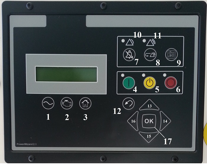
1 – информация по вырабатываемому электрическому току;
2 – информация по работе двигателя;
3 – вход в главное меню;
4 – ручной запуск ДГУ «RUN»;
5 – ввод ДГУ в автоматический режим «AUTO»;
6 – останов ДГУ «STOP»;
7 – кнопка подтверждения аварийного сигнала;
8 – кнопка сброса событий;
9 – кнопка входа в журнал событий;
10 – предупреждающий индикатор желтого цвета;
11 – аварийный индикатор красного цвета;
12 – кнопка возврата в предыдущее меню;
13, 14, 15, 16 – курсоры для передвижения по меню (вверх,вниз,вправо,влево);
17 – кнопка «ENTER» или «ОК» для входа в меню и подтверждения действия
Для запуска ДГУ в ручном режиме необходимо:
- Убедиться что отводящий кабель подсоединен к нагрузке или к АВР;
- Если отводящий кабель не подсоединен к нагрузке или АВР, то необходимо отключить выходной автомат
- Нажать зеленую кнопку «RUN» №4 на панели управления (над ней загорится индикатор), после этого ДГУ должна завестись.
Для перевода ДГУ в автоматический режим необходимо:
- Убедиться, что АВР находится в автоматическом режиме, а выходной автомат в положении включено.
- Нажать на желтую кнопку «AUTO» №5 на панели управления (над ней загорится индикатор) – ДГУ переведена в режим ожидания, после пропадания внешней электроэнергии она заведется автоматически.
Для сброса аварии на ДГУ необходимо:
- Нажать кнопку останова ДГУ «STOP» №6, при этом мигающий индикатор красного цвета №11 должен загореться в постоянном режиме.
- Нажать кнопку №9 для входа в «ГЛАВНОЕ МЕНЮ», затем войти в «ЗАПИСИ СОБЫТИЙ» и найти при помощи кнопок №13 и №15 событие со статусом «АКТИВНЫЙ».
- Устранить, если это необходимо, удалить причины, вызвавшие аварийный останов ДГУ.
- Далее, нажать кнопку «ENTER» или «ОК» №17, на дисплее появится надпись «СБРОС», повторно нажать кнопку «ОК», ошибка удалится, а красный индикатор №11 должен погаснуть.
- Если красный индикатор не погас, необходимо повторить процедуру входа в «ЗАПИСИ СОБЫТИЙ» для поиска «АКТИВНЫХ» событий и сбросить их, как описано в п.4.
- После того как все аварии сброшены и не горит красный индикатор №11, нажать желтую кнопку «AUTO» №5 для перевода генератора в автоматический режим или зеленую кнопку «RUN» №4 для запуска генератора в ручном режиме.
Если же по какой- либо причине авария на ДГУ не сбрасывается, то необходимо связаться с сервисным инженером ТОО «Вильсон Казахстан». Сервисная служба: +7(727)245 81 75, +7777 2737370
Ошибка P0620 указывает на неисправность цепи управления генератором.
Что означает ошибка P0620
Модуль управления силовым агрегатом (PCM) управляет генератором автомобиля через сигнальную цепь включения генератора, что позволяет ему включать и выключать генератор. Для запуска генератора PCM автомобиля отправляет сигнал в 5 вольт через сигнальную цепь включения генератора на регулятор напряжения. Это позволяет регулятору напряжения начать управление цепью возбуждения генератора.
После запуска генератора регулятор напряжения может управлять выходным сигналом генератора независимо от PCM автомобиля. Однако в некоторых случаях при обнаружении неисправности PCM может самостоятельно отключить генератор.
Если PCM автомобиля обнаружит, что напряжение в цепи управления генератором является ненормальным по сравнению со значением, указанным в технических условиях производителя, в его памяти сохранится код ошибки P0620.
Причины возникновения ошибки P0620
Наиболее распространенными причинами возникновения ошибки P0620 являются:
- Неисправность регулятора напряжения
- Неисправность генератора
- Низкий уровень заряда или полный разряд аккумуляторной батареи
- Плохое электрическое соединение в цепи управления генератором
- Короткое замыкание или обрыв электрических проводов, относящихся к генератору
- В редких случаях, неисправность модуля управления силовым агрегатом (PCM)
Каковы симптомы ошибки P0620?
При появлении ошибки P0620 на приборной панели автомобиля загорится индикатор Check Engine, указывающий на наличие неисправности. Как правило, это является единственным признаком возникновения ошибки.
Как механик диагностирует ошибку P0620?
Сначала механик подключит сканер OBD-II к диагностическому разъему автомобиля и считает все сохраненные данные и коды ошибок. Затем он очистит коды ошибок с памяти компьютера и проведет тест-драйв автомобиля, чтобы выяснить, появляется ли код P0620 снова. Если код ошибки появится снова, механик визуально осмотрит генератор, а также проверит соответствующие электрические провода и соединители. При необходимости он отремонтирует или заменит все ослабленные, закороченные, оборванные или поврежденные компоненты. Механик также проверит регулятор напряжения и аккумуляторную батарею.
Если проблему не будет обнаружено, механик проверит и при необходимости перепрограммирует или заменит PCM автомобиля.
Частые ошибки при диагностировании кода P0620
Наиболее распространенной ошибкой при диагностировании кода P0620 является поспешная замена модуля управления силовым агрегатом (PCM) без выполнения тщательной проверки. Следует отметить, что данный модуль управления выходит из строя крайне редко.
Несмотря на то, что в некоторых случаях проблема может заключаться в неисправности PCM автомобиля, перед заменой модуля необходимо выполнить тщательное диагностирование и рассмотреть все возможные причины возникновения ошибки. В первую очередь необходимо проверить генератор, а также соответствующие электрические провода и соединители.
Насколько серьезной является ошибка P0620?
Даже если при появлении ошибки P0620 какие-либо явные признаки наличия неисправности отсутствуют, рекомендуется как можно скорее обратиться к квалифицированному специалисту для диагностирования и устранения ошибки. Это поможет избежать возникновения ряда серьезных неисправностей в дальнейшем. Если проблему долго не решать, автомобиль в конечном итоге не сможет функционировать надлежащим образом.
Для устранения ошибки P0620 может потребоваться:
- Ремонт или замена электрических проводов или соединителей, относящихся к генератору
- Замена регулятора напряжения или генератора
- В редких случаях, перепрограммирование или замена PCM автомобиля
Дополнительные комментарии для устранения ошибки P0620
Даже если при обнаружении ошибки P0620 вы не заметили никаких явных признаков наличия неисправности, рекомендуется как можно скорее обратиться к квалифицированному специалисту для диагностирования и устранения ошибки. Это поможет избежать возникновения серьезных неисправностей в дальнейшем.
Нужна помощь с кодом ошибки P0620?
Компания — CarChek, предлагает услугу — выездная компьютерная диагностика, специалисты нашей компании приедут к вам домой или в офис, чтобы диагностировать и выявлять проблемы вашего автомобиля. Узнайте стоимость и запишитесь на выездную компьютерную диагностику или свяжитесь с консультантом по телефону +7(499)394-47-89
Читайте также:
- Df 037 ошибка рено сценик 2
- Ошибка конектинг файлед в раст легаси
- Ниссан ноте ошибка 501f
- Ошибка 16518 фольксваген пассат б5
- Р1702 ошибка ситроен с3

7/23/2019 AC03 2.0 Reference Guide
http://slidepdf.com/reader/full/ac03-20-reference-guide 1/130
Copyright © 2008 ComAp s.r.o.Written by Petr NovákCustomized by František Poupě Prague, Czech Republic
ComAp, spol. s r.o.Kundratka 2359/17, 180 00 Praha 8, Czech RepublicTel: +420 2 66316661, Fax: +420 2 66316647E-mail: [email protected], www.comap.cz
InteliLiteNT
InteliLite NT AC03Modular Gen-set Controller
Compact Controller for Stand-by Operating Gen-sets
(IL-NT AC03 unit)
SW version 2.0, June 2010
Reference Guide

7/23/2019 AC03 2.0 Reference Guide
http://slidepdf.com/reader/full/ac03-20-reference-guide 2/130
InteliLiteNT
AC03, SW version 2.0, ©ComAp – June 2010 2 AC03-2.0 Reference Guide.pdf
Table of Contents
Table of Contents …………………………………………………………………………………………………………………… 2
General Guidelines…………………………………………………………………………………………………………………. 5
What describes this manual?……………………………………………………………………………………………….. 5
!! Warnings !! ……………………………………………………………………………………………………………………… 5
Text ………………………………………………………………………………………………………………………………….. 5
General Description………………………………………………………………………………………………………………… 7
Description of the controller system (with all options)………………………………………………………………. 7
What is in the package?………………………………………………………………………………………………………. 7
IL-NT RS232 Communication module …………………………………………………………………………………… 7
IL-NT RS232-485 Communication module …………………………………………………………………………… 11
IL-NT S-USB Service USB communication module……………………………………………………………….. 11
IB-Lite Ethernet communication plug-in card ………………………………………………………………………… 12
IL-NT-AOUT8 Gauge driver module ……………………………………………………………………………………. 13
IL-NT RD Remote display software …………………………………………………………………………………….. 14
IL-NT-EFCPM…………………………………………………………………………………………………………………… 14
IL-NT-EFCPM2 ………………………………………………………………………………………………………………… 15
Remote announciator IGL-RA15…………………………………………………………………………………………. 15
IG-IOM/PTM module…………………………………………………………………………………………………………. 16
IG-IB Internet bridge………………………………………………………………………………………………………….. 17
IL-NT Terminals and front fascia…………………………………………………………………………………………….. 18
IL-NT terminals and front fascia………………………………………………………………………………………….. 18
Recommended Wiring…………………………………………………………………………………………………………… 19
AMF — Wiring Diagram……………………………………………………………………………………………………….. 19
Stand-by Applications……………………………………………………………………………………………………………. 20
Contactors (set point MCB Logic = “CLOSE-OFF”)……………………………………………………………….. 20
ATS with two stable positions (set point MCB Logic = “CLOSE-ON”) ………………………………………. 20
ATS with three stable positions (set point MCB Logic = “CLOSE-OFF”)…………………………………… 21
Getting Started …………………………………………………………………………………………………………………….. 22
How to install ……………………………………………………………………………………………………………………. 22
Current measurement ……………………………………………………………………………………………………….. 25
Earth Fault measurement (module) …………………………………………………………………………………….. 26
Voltage measurement and generator connection types …………………………………………………………. 28
Analog inputs……………………………………………………………………………………………………………………. 31
Extension modules (CAN bus) connection …………………………………………………………………………… 34
Inputs and Outputs ……………………………………………………………………………………………………………….. 36
Binary inputs IL-NT — default ……………………………………………………………………………………………… 36
Binary inputs — list……………………………………………………………………………………………………………… 36
Binary outputs IL-NT — default ……………………………………………………………………………………………. 41
Binary outputs — list……………………………………………………………………………………………………………. 41
Analog inputs……………………………………………………………………………………………………………………. 52
Setpoints……………………………………………………………………………………………………………………………… 53
Password…………………………………………………………………………………………………………………………. 53
Basic Settings…………………………………………………………………………………………………………………… 53
Engine Params…………………………………………………………………………………………………………………. 57
Engine Protect………………………………………………………………………………………………………………….. 62
Gener Protect…………………………………………………………………………………………………………………… 64
AMF Settings……………………………………………………………………………………………………………………. 67
Date/Time………………………………………………………………………………………………………………………… 71
Sensors Spec…………………………………………………………………………………………………………………… 73
Extension I/O……………………………………………………………………………………………………………………. 73
SMS/E-Mail ……………………………………………………………………………………………………………………… 74
Man Operations………………………………………………………………………………………………………………… 76
Alternate Cfg ……………………………………………………………………………………………………………………. 77
ECU-controlled engine support ………………………………………………………………………………………………. 79
Values read from ECU ………………………………………………………………………………………………………. 80

7/23/2019 AC03 2.0 Reference Guide
http://slidepdf.com/reader/full/ac03-20-reference-guide 3/130
InteliLiteNT
AC03, SW version 2.0, ©ComAp – June 2010 3 AC03-2.0 Reference Guide.pdf
Diagnostic messages read from ECU………………………………………………………………………………….. 80
Analog inputs……………………………………………………………………………………………………………………. 81
Connection description………………………………………………………………………………………………………. 81
Sensor Specification……………………………………………………………………………………………………………… 84
Background of the sensor calibration…………………………………………………………………………………… 84
Default sensor curves ……………………………………………………………………………………………………….. 84
Function Description……………………………………………………………………………………………………………… 85 OFF Mode ……………………………………………………………………………………………………………………….. 85
MAN Mode ………………………………………………………………………………………………………………………. 85
AUT Mode……………………………………………………………………………………………………………………….. 87
TEST mode……………………………………………………………………………………………………………………… 87
Circuit breakers timing ………………………………………………………………………………………………………. 88
Alarm Management ………………………………………………………………………………………………………………. 90
Sensor Fail (FLS) …………………………………………………………………………………………………………….. 90
Warning (WRN)………………………………………………………………………………………………………………… 90
Breaker open and cooling (BOC)………………………………………………………………………………………… 90
Shut down (SD)………………………………………………………………………………………………………………… 90
Mains failure (MF) …………………………………………………………………………………………………………….. 90
Voltage phase sequence detection……………………………………………………………………………………… 91
Gen-set Operation States………………………………………………………………………………………………………. 93 List of possible events……………………………………………………………………………………………………….. 93
History file………………………………………………………………………………………………………………………… 96
User Interface………………………………………………………………………………………………………………………. 97
Operator Interface AMF…………………………………………………………………………………………………………. 98
Display Screens and Pages Structure ……………………………………………………………………………….. 100
Alarms …………………………………………………………………………………………………………………………… 101
Browsing ECU Alarms……………………………………………………………………………………………………… 101
Earth Fault Protection Test ………………………………………………………………………………………………. 101
Setpoint Change …………………………………………………………………………………………………………….. 102
Entering the Password…………………………………………………………………………………………………….. 102
Controller Information Screen …………………………………………………………………………………………… 103
Display Contrast Adjustment…………………………………………………………………………………………….. 103
Remote Control and Data Logging………………………………………………………………………………………… 104 Direct connection to the PC ……………………………………………………………………………………………… 104
PC software — LiteEdit ……………………………………………………………………………………………………… 104
Modbus protocol……………………………………………………………………………………………………………… 104
Remote Communication………………………………………………………………………………………………………. 112
Internet connection………………………………………………………………………………………………………….. 112
SMS Message Control …………………………………………………………………………………………………….. 112
Recommended ISDN modem…………………………………………………………………………………………… 117
Recommended GSM modem……………………………………………………………………………………………. 117
Mobile SIM card setting……………………………………………………………………………………………………. 117
IL-NT-RD Remote display software……………………………………………………………………………………….. 118
General description…………………………………………………………………………………………………………. 118
Warning ! ……………………………………………………………………………………………………………………….. 118
IL-NT-RD Software installation………………………………………………………………………………………….. 118 IL-NT-RD Wiring……………………………………………………………………………………………………………… 119
Function description………………………………………………………………………………………………………… 121
SW compatibility……………………………………………………………………………………………………………… 121
Maintenance ………………………………………………………………………………………………………………………. 122
Backup battery replacement …………………………………………………………………………………………….. 122
Technical Data……………………………………………………………………………………………………………………. 124
Inputs/Outputs overview…………………………………………………………………………………………………… 124
Generator protections ……………………………………………………………………………………………………… 124
Power supply………………………………………………………………………………………………………………….. 125
Operating conditions ……………………………………………………………………………………………………….. 125
Dimensions and weight ……………………………………………………………………………………………………. 125
Mains and generator ……………………………………………………………………………………………………….. 125
Binary inputs and outputs…………………………………………………………………………………………………. 126 Analog inputs………………………………………………………………………………………………………………….. 126

7/23/2019 AC03 2.0 Reference Guide
http://slidepdf.com/reader/full/ac03-20-reference-guide 4/130
InteliLiteNT
AC03, SW version 2.0, ©ComAp – June 2010 4 AC03-2.0 Reference Guide.pdf
Speed pick-up input ………………………………………………………………………………………………………… 126
D+ Function……………………………………………………………………………………………………………………. 126
CAN bus interface …………………………………………………………………………………………………………… 126
IL-NT RS232 interface (optional card) ……………………………………………………………………………….. 127
IL-NT RS232-485 interface (optional card) …………………………………………………………………………. 127
IL-NT S-USB interface (optional card) ……………………………………………………………………………….. 128
IL-NT-AOUT8 interface (optional card)………………………………………………………………………………. 128 IL-NT-EFCPM interface (optional card) ……………………………………………………………………………… 128
IL-NT-EFCPM2 interface (optional card) ……………………………………………………………………………. 128
IGS-PTM ……………………………………………………………………………………………………………………….. 129
IGL-RA15 ………………………………………………………………………………………………………………………. 129
IG-IB……………………………………………………………………………………………………………………………… 130

7/23/2019 AC03 2.0 Reference Guide
http://slidepdf.com/reader/full/ac03-20-reference-guide 5/130
InteliLiteNT
AC03, SW version 2.0, ©ComAp – June 2010 5 AC03-2.0 Reference Guide.pdf
General Guidelines
What describes this manual?
This manual describes „AC03“ software, which is designed for single set, stand-by applications.What is the purpose of the manual?This manual provides general information how to install and operate InteliLite NT AC03 controller.This manual is dedicated for
Operators of gen-setsGen-set control panel buildersFor everybody who is concerned with installation, operation and maintenance of the gen-set
!! Warnings ! !
Remote contro lInteliLite controller can be remotely controlled. In case of the work on the gen-set check, that nobodycan remotely start the engine.To be sure:
Disconnect remote control via RS232 lineDisconnect input REM START/STOP
orDisconnect output STARTER and outputs GCB CLOSE/OPEN and MCB CLOSE/OPEN
Because of large variety of InteliLiteNT
parameters settings, it is not possible to describe anycombination. Some of InteliLite functions are subject of changes depend on SW version. The data inthis manual only describes the product and are not warranty of performance or characteristic.
Text
PAGE (Capital letters in the frame) buttons on the front panel
Break Return (Italic) set pointsGenerator protections (Bold) Set point groupREMOTE START/STOP (Capital letters) binary inputs and outputsIL-NT-EFCPM2 (Yellow background) new features and text changed from version 1.0
Note:ComAp believes that all information provided herein is correct and reliable and reserves the right toupdate at any time. ComAp does not assume any responsibility for its use unless otherwise expresslyundertaken.
Note:SW and HW must be compatible otherwise the function will be disabled. If wrong software isdownloaded, message HARDWARE INCOMPATIBLE appears on controller screen. In this case useBoot load (jumper) programming – close Boot jumper and follow instructions in LiteEdit, downloadcorrect software.

7/23/2019 AC03 2.0 Reference Guide
http://slidepdf.com/reader/full/ac03-20-reference-guide 6/130
InteliLiteNT
AC03, SW version 2.0, ©ComAp – June 2010 6 AC03-2.0 Reference Guide.pdf
WARNING – VERY IMPORTANT !! !
Every time you want disconnect following InteliLiteNT controller terminals:
Mains voltage measuring and / or
Binary output for MCB control and / or MCB Feedback
Switch InteliLite to MAN or OFF Mode or disconnect the Binary outputs Starter andFuel to avoid unexpected automatic start of gen-set and GCB closing.
All parameters are preadjusted to their typical values. But the set points in the “Basic settings” settingsgroup !!must!! be adjusted before the first startup of the gen-set.
!! ! WRONG ADJUSTMENT OF BASIC PARAMETERSCAN DESTROY THE GEN-SET !!!
The following instructions are for qualified personnel only. To avoid personal injury do
not perform any action not specified in this User guide !!!
In no case touch the terminals for voltage and current measurement! Always connect grounding terminals!In any case do not disconnect InteliLite
NT CT terminals !
Adjust set points
Dangerous voltage
!!! CAUTION !!!

7/23/2019 AC03 2.0 Reference Guide
http://slidepdf.com/reader/full/ac03-20-reference-guide 7/130
InteliLiteNT
AC03, SW version 2.0, ©ComAp – June 2010 7 AC03-2.0 Reference Guide.pdf
General Description
Description of the controller system (with all opt ions)
InteliLiteNT
AC03 is a comprehensive AMF-controller for single generating sets operating in stand-bymode. IL-NT AC03 features extended support of electronic engines and extension modules.InteliLite
NT controllers are equipped with a powerful graphic display showing icons, symbols and bar-
graphs for intuitive operation, which sets, together with high functionality, new standards in Gen-setcontrols.InteliLite
NT automatically starts the Gen-set, closes the Gen-set C.B. when all conditions are met, then
stops the engine on external signal or by pressing push buttons.InteliLite
NT provides gas engine support without ventilation.
The key feature of InteliLiteNT
is its easy-to-use operation and installation. Predefined configurationsfor typical applications are available as well as user-defined configurations for special applications.
What is in the package?
Accessories Description Optional / Obligatory
IL-NT-AC03 InteliLiteNT
central unit Obligatory
IL-NT-RS232 RS232 communication card Optional for AC03
IL-NT-RS232-485 RS232 and RS485 communication card Optional for AC03
IL-NT-S-USB Service USB communication card Optional for AC03
**IB-Lite Ethernet communication card Optional for AC03
**IL-NT-AOUT8 Gauge driver plug-in card Optional for AC03
*IL-NT RD Remote display software Optional for AC03IL-NT-EFCPM Earth Fault Current Protection Module Optional for AC03
**IL-NT-EFCPM2 Earth Fault Current Protection Module Optional for AC03
IGL-RA15 Remote annunciator Optional for AC03
IG-IOM/PTM I/O extension module Optional for AC03
IG-IB Internet communication bridge Optional for AC03
AT-LINK-CONV Service programming RS232 interface Optional for AC03
AT-LINK-CABLE Serial RS232 communication cable 1,8m Optional for AC03
*Remote display for IL-NT controllers uses standard IL-NT controller with Remote display software.
**Supported from version IL-NT-AMF26-P-2.0.
Hint:For detailed information about extension modules used with IL-NT controllers, please see the IL-NT- Accessory Modules manual.
IL-NT RS232 Communication module
IL-NT RS232 is optional plug-in card to enable InteliLiteNT
for RS232 communication. This is requiredfor computer or Modbus connecting. Card inserts into expansion slot back on the controller.To insert the module, you must open the cover first (use screwdriver to open) and then insert the
module into slot. Once you have insert it, the module will snap under plastic teeth. It is supposed to beinstalled permanently. Should you need to remove it, the safest way is to remove whole back coverand then remove module manually.

7/23/2019 AC03 2.0 Reference Guide
http://slidepdf.com/reader/full/ac03-20-reference-guide 8/130
InteliLiteNT
AC03, SW version 2.0, ©ComAp – June 2010 8 AC03-2.0 Reference Guide.pdf
How to install RS 232 communication module:
Hint: The following procedure is analogic also for other communication modules.
1. Insert a screwdriver into the slot of the cover.
2. Move the screwdriver to set apart the small cover. Be careful!
3. Remove the small cover.

7/23/2019 AC03 2.0 Reference Guide
http://slidepdf.com/reader/full/ac03-20-reference-guide 9/130
InteliLiteNT
AC03, SW version 2.0, ©ComAp – June 2010 9 AC03-2.0 Reference Guide.pdf
4. Break apart the small cover into two pieces. Do not throw away the smaller part!
5. Take RS 232 communication module.

7/23/2019 AC03 2.0 Reference Guide
http://slidepdf.com/reader/full/ac03-20-reference-guide 10/130
InteliLiteNT
AC03, SW version 2.0, ©ComAp – June 2010 10 AC03-2.0 Reference Guide.pdf
6. Plug RS 232 communication module into the slot of the controller.7. Put back the small cover.
Hint:When you insert RS 232 communication module, the boot jumper is hidden. For that reason werecommend to use RS 232 communication module with the boot jumper placed on it. See pictures
below:
RS 232 communication module with the boot jumper.

7/23/2019 AC03 2.0 Reference Guide
http://slidepdf.com/reader/full/ac03-20-reference-guide 11/130
InteliLiteNT
AC03, SW version 2.0, ©ComAp – June 2010 11 AC03-2.0 Reference Guide.pdf
IL-NT RS232-485 Communication module
IL-NT RS232-485 is optional plug-in card to enable InteliLiteNT
the RS232 and RS485 communication.This is required for computer or Modbus connection. Card inserts into expansion slot back on thecontroller. The IL-NT RS232-485 is a dual port module with RS232 and RS485 interfaces at
independent COM channels. The RS232 is connected to COM1 and RS485 to COM2.
To insert the module, please follow the instructions for IL-NT RS232 module, procedure is analogous.You must open the cover first (use screwdriver to open) and then insert the module into slot. Once youhave inserted it, the module will snap under plastic teeth. It is supposed to be installed permanently.Should you need to remove it, the safest way is to remove whole back cover and than remove modulemanually.
RS485
Boot jumperRS485 Terminator jumper
RS232
IL-NT S-USB Service USB communication module
IL-NT S-USB is optional plug-in card to enable InteliLiteNT
communication via USB port. This isrequired for computer or Modbus connecting. Card inserts into expansion slot back on the controller.To insert the module, please follow the instructions for IL-NT RS232 module, procedure is analogous.You must open the cover first (use screwdriver to open) and then insert the module into slot. Once youhave inserted it, part of the module will remain over plastic box. It is supposed to be used as a service
tool. When you need to remove it, grab module in cutouts and pull it up manually.

7/23/2019 AC03 2.0 Reference Guide
http://slidepdf.com/reader/full/ac03-20-reference-guide 12/130
InteliLiteNT
AC03, SW version 2.0, ©ComAp – June 2010 12 AC03-2.0 Reference Guide.pdf
Hint:
Use the shielded USB A-B cable with this module! Recommended is ComAp cable – Order code:“USB-LINK CABLE 1.8M”.
IB-Lite Ethernet communication plug-in card
IB-Lite is a plug-in card with Ethernet 10/100 Mbit interface in RJ45 connector. The card is internallyconnected to both COM1 and COM2 serial channels and provides an interface for connecting a PCwith LiteEdit or InteliMonitor through ethernet/internet network, for sending active e-mails and forintegration of the controller into a building management (Modbus TCP protocol).This card also enables to monitor and control the genset over web browser from any location withinternet access using appropriate security measures.
Card inserts into “extension module” slot back on the controller. To insert the module, please followthe instructions for IL-NT RS232 module, procedure is analogical.
Use Ethernet UTP cable with RJ45 connector for connection of the module into your ethernet network.The module can be also connected directly to a PC using cross-wired UTP cable.

7/23/2019 AC03 2.0 Reference Guide
http://slidepdf.com/reader/full/ac03-20-reference-guide 13/130
InteliLiteNT
AC03, SW version 2.0, ©ComAp – June 2010 13 AC03-2.0 Reference Guide.pdf
Hint:Modbus TCP protocol using IB-Lite communication module requires setting COM1 Mode = DIRECTand COM2 Mode = MODBUS.
Hint:The module requires some settings before initial usage. See IB-Lite-1.2-Reference Guide.pdf for moredetails about IB-Lite communication plug-in card.
IL-NT-AOUT8 Gauge driver module
IL-NT-AOUT8 is optional plug-in card. Through this card controller can drive up to 8 VDO styleindustrial/automotive gauges. Noncompensated gauges like 0-10V or 0-20mA are not supported.Gauge type and value are configured in LiteEdit software. Any analog value from controller may beshown in that way.
To insert the module, you must open the cover first (use screwdriver to open) and then insert themodule into slot. Once you have insert it, the module will snap under plastic teeth. It is supposed to beinstalled permanently. Should you need to remove it, the safest way is to remove whole back coverand than remove module manually.Installing IL-NT-AOUT8 module is similar to installing RS 232 module. The difference is that IL-NT- AOUT8 fits to “extension module” slot and after installing IL-NT-AOUT8 you do not put back the smallcover.
PC Installation Suite consist a set of prepared converting curves for basic usage of PWM outputs withautomotive gauges.
IL-NT-AOUT8 module:

7/23/2019 AC03 2.0 Reference Guide
http://slidepdf.com/reader/full/ac03-20-reference-guide 14/130
InteliLiteNT
AC03, SW version 2.0, ©ComAp – June 2010 14 AC03-2.0 Reference Guide.pdf
Typical wiring:
Hint:Please see chapter IL-NT-AOUT8 interface (optional card) for technical details.
IL-NT RD Remote display software
IL-NT RD is remote display software for a controller. Remote display provides the same control andmonitoring functions as controller itself. Remote display for IL-NT controllers uses standard IL-NTcontroller with Remote display software. No further programing of the display is required – unit is self
configurable from the main controller. It is connected with the controller via IL-NT-RS232communication modules using RS232 line. Longer distances (up to 1200m) are possible using IL-NT-RS232-485 communication module or when RS232/RS485 converters are used.
The IL-NT RD hardware type should fit to the master IL-NT.
Hint:Please see the “IL-NT-RD Remote display software” chapter for more details.
IL-NT-EFCPM
The IL-NT-EFCPM (Earth Fault Current Protection Module) is designed as extension unit for IL-NT
controller, connected in EXTENSION MODULE slot. This unit checks any leakage of current towardsearth (Earth Fault protection).

7/23/2019 AC03 2.0 Reference Guide
http://slidepdf.com/reader/full/ac03-20-reference-guide 15/130
InteliLiteNT
AC03, SW version 2.0, ©ComAp – June 2010 15 AC03-2.0 Reference Guide.pdf
To insert the module, you must open the cover first (use screwdriver to open) and then insert themodule into slot. Once you have insert it, the module will snap under plastic teeth. It is supposed to beinstalled permanently. Should you need to remove it, the safest way is to remove whole back coverand than remove module manually.
Installing IL-NT-EFCPM module is similar to installing RS 232 module. The difference is that module
fits to “extension module” slot and after installing IL-NT-EFCPM you do not put back the small cover.
Functionality for IL-NT-PRAMAC-1.0, 1.1 and 1.2 and for IL-NT-AMF26-P-1.0:
When IL-NT-AC03 is switched on presence of IL-NT-EFCPM is detected. When IL-NT-EFCPM is notdetected (at the moment when controller is started) Earth Fault measurement function is not activatedand EFCPM screen is not visible on controller display. When the module is detected Earth Faultmeasurement function is activated, EFCPM screen is visible and works according to Earth Faultmeasurement setting, then IL-NT-EFCPM card shouldn’t be removed till the controller is switched offotherwise the Earth Fault Measurement will not work properly and Emergency Stop Sd (if configuredas normally closed) will be activated.
The plug-in module also provides 1 binary input and 2 binary outputs, which are not configurable.
See more details in Earth Fault measurement chapter.
Functionality for IL-NT-AMF26-P-2.0 and higher:
IL-NT-EFCPM presence and binary input/binary output logical functions assignment can be configuredwithin LiteEdit PC software. There is no more detection during controller start.
See more details in Earth Fault measurement chapter.
IL-NT-EFCPM2
IL-NT-EFCPM2 is optional plug-in card based originally on IL-NT-EFCPM (see more details in the
chapter above IL-NT-EFCPM), but enhanced regarding its inputs and outputs options. Through thiscard controller can accommodate up to 7 binary inputs or outputs. It is possible to easily choose andconfigure if particular I/O will be binary input or output in LiteEdit PC software configuration.
To insert the module, you must open the cover first (use screwdriver to open) and then insert themodule into slot. Once you have insert it, the module will snap under plastic teeth. It is supposed to beinstalled permanently. Should you need to remove it, the safest way is to remove whole back coverand than remove module manually.
Installing IL-NT-EFCPM2 module is similar to installing RS 232 module. The difference is that modulefits to “extension module” slot and after installing IL-NT-EFCPM2 you do not put back the small cover.
See more details in Earth Fault measurement.
Remote announciator IGL-RA15
The remote announciator IGL-RA15 can be connected to the IL-NT unit via CAN bus. Any of thebinary outputs can be configured (using LiteEdit software) to each LED diode on the RA15. Themodule can be also enabled or disabled using LiteEdit software.If IGL-RA15 remote announciator is not communicating with a controller via CAN bus, it activates awarning.
See the documentation of RA15 for the technical and function description.

7/23/2019 AC03 2.0 Reference Guide
http://slidepdf.com/reader/full/ac03-20-reference-guide 16/130
InteliLiteNT
AC03, SW version 2.0, ©ComAp – June 2010 16 AC03-2.0 Reference Guide.pdf
165 (6,5”)
3 8 (
1 , 5
” )
4 0 (
1 , 6
” )
~
7 5 (
3 ,
0 ” )
~
3 5 (
1 , 4
” )
180 (7,1”)
185 (7,3”)
1 0 6
( 4 , 2
” )
44 (1,7”)
54 (2,1”)
~
2 5
( 1 ,
0 ” )
1 2 0
( 4 , 7
” )
1 2 5
( 4 , 9
” )
Cutout
for Remote Announciator
167 x 108 mm(6,6 x 4,3 )”
IG-IOM/PTM module
IG-IOM and IGS-PTM modules are I/O extension modules equipped with 8 binary inputs, 8 binaryoutputs, 4 analog inputs and one analog output. The module can be used for AMF25, MRS15, 16, 19only.
Binary inputs and outputs are configurable the same way like inputs and outputs on iL. Analog inputs are configurable like iL with the limitation that the binary and tristate mode can
not be used on PTM module. The protection of analog IOM/PTM inputs is activated by overcrossing the limits, active only
when the engine is running.
IG-IOM analog inputs are resistive (the same parameters like IL-NT) 0 -2,4 k. The moduleIOM is designed for especially VDO resistive sensors.
IGS-PTM analog inputs are configurable by jumpers to ranges 0-250, 0-100mV, 0-20mA.
The module can be used especially for Pt100 sensors and current sensors. The module PTMis not suitable for VDO temperature sensor.
Hint:- For a description of setting IGS-PTM module with current/voltage sensors please see the Extensionmodules manual.- When module is not configured by LiteEdit SW, controller does not show related values andsetpoints
Hint:If IGS-PTM is not communiating to a controller, ShutDown is activated.

7/23/2019 AC03 2.0 Reference Guide
http://slidepdf.com/reader/full/ac03-20-reference-guide 17/130
InteliLiteNT
AC03, SW version 2.0, ©ComAp – June 2010 17 AC03-2.0 Reference Guide.pdf
See the documentation of IGS-PTM for the technical and function description.
IG-IB Internet bridge
IG-IB Internet bridge enables InteliLiteNT
for Ethernet/Internet communicatons. It is connected tocontroller via RS232 line.
See InteliCommunication Guide for further details.

7/23/2019 AC03 2.0 Reference Guide
http://slidepdf.com/reader/full/ac03-20-reference-guide 18/130
InteliLiteNT
AC03, SW version 2.0, ©ComAp – June 2010 18 AC03-2.0 Reference Guide.pdf
IL-NT Terminals and front fascia
IL-NT terminals and front fascia

7/23/2019 AC03 2.0 Reference Guide
http://slidepdf.com/reader/full/ac03-20-reference-guide 19/130
InteliLiteNT
AC03, SW version 2.0, ©ComAp – June 2010 19 AC03-2.0 Reference Guide.pdf
Recommended Wiring
AMF — Wiring Diagram
L O A D
ACCESSLOCK
EMERGENCYSTOP
CONTROLSIGNALS
GENC.B. FEED-BACK
MAINSC.B. FEED-BACK
D I E S E L / G A S E N G I N E
RPM
G E N E R A T O R
G
+ 2 4 V
L 1
L 2
L 3 N
G e n e r a t o r C . B .
M a i n s C . B .
SPRINKLER
REMOTETEST
R S — 2 3 2 C
I n t e r f a c e
M o d e m o r P C
REMOTEOFF
ALARM
B I N A R Y O U T P U T S
MAINSC.B.
GENC.B.
PRESTART
READYTOLOAD
OILPRESSURE
WATERTEMP
FUELLEVEL
STARTER
BATTERY
— +
FUELSOLENOID
D+
FUELSOLENOID
STARTER
E C U
In case of the wiring above following setting should be used.ConnectionType: 3Ph4Wire, CT location: Gen-Set and Number of CTs: 3CTs
Hint:MCB and GCB is recommended to be mechanically interlocked.It is possible to start Volvo and Scania engines via CAN bus. See Engines started via CAN bus.

7/23/2019 AC03 2.0 Reference Guide
http://slidepdf.com/reader/full/ac03-20-reference-guide 20/130
InteliLiteNT
AC03, SW version 2.0, ©ComAp – June 2010 20 AC03-2.0 Reference Guide.pdf
Stand-by Applications
Contactors (set point MCB Logic = “CLOSE-OFF” )
F E E D B A C K
+24V(12V)
MCGC
K3
G C B
C L O S E / O P E N
GC
MC
M C B
G~
G C B
M C B
F E E D B A C K
C L O S E / O P E N
0V
MC
T
GC
K3
GC
LOAD
MC
K4
K4
ATS with two stable positions (set point MCB Logic = “ CLOSE-ON” )
F E E D B A C K
+24V(12V)
ATS
K3
G C B
M C B
G~
G C B
T
C L O S E / O P E N
ATS
0V
ATS
LOAD
F E E D B A C K
C L O S E / O P E N
M C B
K3

7/23/2019 AC03 2.0 Reference Guide
http://slidepdf.com/reader/full/ac03-20-reference-guide 21/130
InteliLiteNT
AC03, SW version 2.0, ©ComAp – June 2010 21 AC03-2.0 Reference Guide.pdf
ATS with three stable positions(set point MCB Logic = “CLOSE-OFF” )
M C B
F E E D B A C K
ATS ll
G~
ATS l
C L O S E / O P E N
K4 0V
K4
T
+24V(12V)
LOAD
G C B
F E E D B A C K
K3
M C B
ATS
l 0 ll
C L O S E / O P E N
G C B
K3
ATS

7/23/2019 AC03 2.0 Reference Guide
http://slidepdf.com/reader/full/ac03-20-reference-guide 22/130
InteliLiteNT
AC03, SW version 2.0, ©ComAp – June 2010 22 AC03-2.0 Reference Guide.pdf
Getting Started
How to installGeneralTo ensure proper function:
Wiring for binary inputs and analog inputs must not be run with power cables. Analog and binary inputs should use shielded cables, especially when length >3m.
Power supplyTo ensure proper function:Use min. power supply cable of 1,5mm
2
Maximum continuous DC power supply voltage is 36VDC. Maximum allowable power supply voltageis 39VDC. The InteliLite’s power supply terminals are protected against large pulse power
disturbances. When there is a potential risk of the controller being subjected to conditions outside itscapabilities, an outside protection devise should be used.
Hint:The InteliLite controller should be grounded properly in order to protect against lighting strikes!!The maximum allowable current through the controller’s negative terminal is 4A (this is dependent onbinary output load).
For the connections with 12VDC power supply, the InteliLiteNT
includes internal capacitors that allowthe controller to continue operation during cranking if the battery voltage dip occurs. If the voltagebefore dip is 10V, after 100ms the voltage recovers to 7 V, the controller continues operating. Duringthis voltage dip the controller screen backlight can turn off and on but the controller keeps operating.It is possible to further support the controller by connecting the external capacitor and separatingdiode or I-LBA module:
The capacitor size depends on required time. It shall be approximately thousands of microFarads.The capacitor size should be 5 000 microFarad to withstand 150ms voltage dip under followingconditions:Voltage before dip is 12V, after 150ms the voltage recovers to min. allowed voltage, i.e. 8V
Hint:Before the battery is discharged the message «Low BackupBatt» appears.

7/23/2019 AC03 2.0 Reference Guide
http://slidepdf.com/reader/full/ac03-20-reference-guide 23/130
InteliLiteNT
AC03, SW version 2.0, ©ComAp – June 2010 23 AC03-2.0 Reference Guide.pdf
Or by connecting special I-LBA Low Battery Adaptor module:
The I-LBA module ensures min. 350ms voltage dip under following conditions:RS232 and other plug-in module is connected.Voltage before dip is 12V and after 350ms the voltage recovers to min. allowed voltage 5V.The I-LBA enables controller operation from 5VDC (for 10 to 30 sec).
The wiring resistance from battery should be up to 0,1 Ohm for I-LBA proper function.
Hint:I-LBA may not eliminate voltage drop when used with low temperature (-40°C) version of controllerand display heating element is on (below 5°C). Current drain of heating element exhausts LBAcapacitors very fast .
Power supply fusing A one-amp fuse should be connected in-line with the battery positive terminal to the controller andmodules. These items should never be connected directly to the starting battery.Fuse value and type depends on number of connected devices and wire length.Recommended fuse (not fast) type — T1A. Not fast due to internal capacitors charging duringpower up.

7/23/2019 AC03 2.0 Reference Guide
http://slidepdf.com/reader/full/ac03-20-reference-guide 24/130
InteliLiteNT
AC03, SW version 2.0, ©ComAp – June 2010 24 AC03-2.0 Reference Guide.pdf
Binary output protections
Hint Do not connect binary outputs directly to DC relays without protection diodes, even if they are notconnected directly to controller outputs.
GroundingTo ensure proper function:Use as short as possible cable to the grounding point on the switchboardUse cable min. 2,5mm2 The “-“ terminal of the battery has to be properly grounded
Magnetic pick-upTo ensure proper function:Use a shielded cable
+
Battery
—
iL
GACSpeed Control Unit
ESD 5500
MAGNETICPICK-UP
CD
a
b
Signal
Signal
+
+-
—
Power Supply
Power Supply

7/23/2019 AC03 2.0 Reference Guide
http://slidepdf.com/reader/full/ac03-20-reference-guide 25/130
InteliLiteNT
AC03, SW version 2.0, ©ComAp – June 2010 25 AC03-2.0 Reference Guide.pdf
Be aware of interference signal from Speed governor when one speed pick-up is used.If engine will not start:
— Check ground connection from pick-up to controllers, eventually disconnect ground connectionto one of them
— Galvanically separate InteliLite RPM input using ComAp separation transformer RPM-ISO(1:1)
— Use separate pick-up for Speed governor and InteliLite
NT
Hint:In some cases the controller will measure a RPM value even though the gen-set is not running:RPM is measured from the generator voltage (Gear Teeth = 0)IL-NT is measuring some voltage value on input terminals due to open fusing.If RPM > 0 the controller will be put into a Not ready state and the engine will not be allowed to start.
Current measurement
To ensure proper functionUse cables of 2,5mm
2
Use transformers to 5A
Number Of CTs = 3CTs
Connect CT according to following drawings
Number Of CTs = 1CTConnect CT according to following drawings. Terminals L2l and L3l are opened.

7/23/2019 AC03 2.0 Reference Guide
http://slidepdf.com/reader/full/ac03-20-reference-guide 26/130
InteliLiteNT
AC03, SW version 2.0, ©ComAp – June 2010 26 AC03-2.0 Reference Guide.pdf
CT location
There are two options of CT location.a) Loadb) Gen-Set
According to the connection you use you should set either CT location: Load or CT location: Gen-Set.
Earth Fault measurement (module)
The Earth Fault protection is done by extension module IL-NT-EFCPM or IL-NT-EFCPM2.
Technical characteristics- Input current range up to 8,32 mA (IL-NT-EFCPM)- Input current range up to 10 mA (IL-NT-EFCPM2)- Measurement range from 0,03 to 5A- Operating frequency 50 or 60 Hz- Tripping current software programmable from 0,03 to 5 A or DISABLED- Tripping delay software programmable from 0,03 to 5 seconds- Included two binary outputs and one binary input (in case of IL-NT-EFCPM)- Included seven binary inputs or seven binary outputs (in case of IL-NT-EFCPM2)
For more technical details see IL-NT-EFCPM interface and IL-NT-EFCPM2 interface parameters.
Opearting principleThe IL-NT-EFCPM uses toroidal transformer connected to the earth wire (Figure 2). When themeasured current exceeds the set value, this indicates that part of the current is dispersed to earthand after the set Earth Fault Del then Earth Fault Sd protection, AL EARTH FAULT and BREAKERTRIP output are activated. Earth Fault protection is not active when MCB is closed and also when EFProtection: DISABLED.
For manual protection simulation can be used EF Prot Test or Earth Fault Protection Test function.

7/23/2019 AC03 2.0 Reference Guide
http://slidepdf.com/reader/full/ac03-20-reference-guide 27/130
InteliLiteNT
AC03, SW version 2.0, ©ComAp – June 2010 27 AC03-2.0 Reference Guide.pdf
IL-NT-EFCPM wiring
Figure 2: Wiring IL-NT-EFCPM
Wiring of IL-NT-EFCPM2 module is analogical. It is just possible to choose in LiteEdit PC SW whichchannel is used as binary input and which as binary output. The wiring should be accordant with that.
IL-NT-EFCPM
Input Description
0 Input range up to 8,32 mA (earth fault protection input)
1 Common (earth fault protection input)
2 NC
3 NC
4 NC
5 NC
6 Binary input 1 – EMERGENCY STOP*
7 Binary output 1 – PREHEATING*
8 Binary output 2 – BREAKER TRIP*
9 Power supply – Minus
*Untill version IL-NT-AMF26-P-1.0 and LiteEdit-4.4.1 these funcuions are fixed, since IL-NT-AMF26-P-2.0 andLiteEdit-4.4.2 the BI/BOs are fully configurable.

7/23/2019 AC03 2.0 Reference Guide
http://slidepdf.com/reader/full/ac03-20-reference-guide 28/130
InteliLiteNT
AC03, SW version 2.0, ©ComAp – June 2010 28 AC03-2.0 Reference Guide.pdf
IL-NT-EFCPM2
Input Description
CT l Input range up to 10 mA (earth fault protection input)
CT k Common (earth fault protection input)
BIO1 Binary input/output*
BIO2 Binary input/output*
BIO3 Binary input/output*BIO4 Binary input/output*
BIO5 Binary input/output*
BIO6 Binary input/output*
BIO7 Binary input/output*
BATT- Power supply – Minus
*Depends on configuration in LiteEdit PC software (supported from LiteEdit-4.4.2).
Voltage measurement and generator connection types
There are 4 voltage measurement ConnectionType options, every type matches to corresponding
generator connection type.
ConnectionType: 3 Phase 4 Wires
Three phase “wye” measurement – 3PY
3 Phase 4 Wires — STAR Connecti
N
L1
L2
L3
L1
N
L2
L3

7/23/2019 AC03 2.0 Reference Guide
http://slidepdf.com/reader/full/ac03-20-reference-guide 29/130
InteliLiteNT
AC03, SW version 2.0, ©ComAp – June 2010 29 AC03-2.0 Reference Guide.pdf
ConnectionType: 3 Phase 3 Wires
Three phase “delta” measurement – 3PD
3 Phase 3 Wires
– DELTA Connection – EDISON DELTA Connection
208v
Hint:Only L1, L2 and L3 wires should be connected. In case of EDISON DELTA connection the N (neutral)wire (in the diagram connected between T6 and T9) has to be disconnected.No separation transformers for three wires voltage connection (without N) are needed.
ConnectionType: Split Phase

7/23/2019 AC03 2.0 Reference Guide
http://slidepdf.com/reader/full/ac03-20-reference-guide 30/130
InteliLiteNT
AC03, SW version 2.0, ©ComAp – June 2010 30 AC03-2.0 Reference Guide.pdf
Single-phase measurement – 1PH
Split Phase
– DOUBLE DELTA Connection – ZIG ZAG (DOG LEG) Connection
N
L1
L2
N
L2
L1
ConnectionType: Mono Phase
Single-phase measurement – 1PH
Mono Phase – MONOPHASE Connection
L1
N
Hint:Switchboard lighting strike protection according standard regulation is expected for all 4 connectiontypes!!!

7/23/2019 AC03 2.0 Reference Guide
http://slidepdf.com/reader/full/ac03-20-reference-guide 31/130
InteliLiteNT
AC03, SW version 2.0, ©ComAp – June 2010 31 AC03-2.0 Reference Guide.pdf
Analog inputs
Three analog inputs are available on the IL-NT
ConfigurationEach analog input can be configured by LiteEdit software following way.
Analog input item Li teEdit Possibi li ty
Type Type Not used Alarm
Analog input isn’t used
Analog input name Name Up to 14 ASCII characters
Config of input Config Analog
Binary (not supp. by PTM)Tri-state (not supp. by PTM)
ECU
Analog measuring in specifiedrange.Binary: open/close — threshold 750
.Three-state: open/close —
threshold 750 ,Failure <10 or > 2400 Value is read from ECU
Physical dimension Dim bar,%,°C, … Up to 4 ASCII characters (Validonly for analog inputs)
Polarity Contacttype
NC
NO
Valid only for binary and three-state inputsValid only for binary and three-state inputs
Over Overstep. Sensor Fail does notactivate protection.
Over+Fls Overstep and Sensor Failactivates protection.
Under Under step. Sensor Fail does notactivate protection.
Protection direction Protection
Under+Fls Under step and Sensor Failactivates protection.
Sensor characteristic Sensor Predefined user curves User changeable andconfigurable
Resolution Resolution 0 – 0,00001 Sensor resolution(Valid only for analog inputs)
Each Analog input has separate set points for two level alarm setting. Analog input alarm levels anddelay adjust in Extension I/O and Engine Protect group.
Connection of IL-NT analog inputs
A I 1 A I 2
3 x RESISTIVESENSOR
A I 3
C O M
— P O W E R
Standard connection of three resistive sensors toanalog inputs.

7/23/2019 AC03 2.0 Reference Guide
http://slidepdf.com/reader/full/ac03-20-reference-guide 32/130
InteliLiteNT
AC03, SW version 2.0, ©ComAp – June 2010 32 AC03-2.0 Reference Guide.pdf
C O M
— P O W E R
A I 1 A I 2
A I 3
Mixed connection of InteliLite analog inputs:
AI1 – binary input AI2 – three state input AI3 – analog resistive input
Analog inputs are designed for resistive sensors with resistance in range of 0 to 2,4k.To ensure a proper function use shielded cables, especially for length over >3m.
As binary input
Open, close state are detected, threshold level is 750 .
As three state inputOpen, close and failure state are detected. Threshold level is 750 , failure is detected when circuit
resistance is <10 or > 2400 .
Hint:Protections on binary and three state inputs are following:IL-NT: AI1 Shutdown IG-IOM: AI1 Shutdown
AI2 Shutdown AI2 Shutdown AI3 Warning AI3 Shutdown
AI4 Shutdown
Unused analog inputs
Configure Type = Not used
Example of analog input configurationConfigure Water Temp input for measuring in °C, VDO 40-120°C sensor, range -16 to 120 °C. Alarmprotection level set to 90 °C, shut down level 110 °C.Start LiteEdit and select – Controller — Configuration – Modify – Water Temp.Set configuration for Water Temp analog input:
Type: Selection between Not used and Alarm“Not used” – analog input isn’t used”Alarm” – analog input is usedSet to: Alarm
Name: Name of the analog input. Maximally 14 letters.Set to: Water Temp
Config: Selection between Analog, Binary Tri-state input.“Analog” – resistor sensor is connected to Analog input.“Binary” – open/close contact is connected between Analog input and COM terminal of Analog inputs. Analog input detects only open/close state.“Tri-state” – open/close contact is connected parallel to one of two serial resistors between Analoginput and COM terminal of Analog inputs.Set to: Analog
Alarm Propert ies : Selection between different direction of protection – Under Limit, Over Limit orcombination with Fail sensor.
“Engine running only” – check this setting if you wish to active protection on analog input only whileengine is running, not, when it stops.Set to: Over Limit

7/23/2019 AC03 2.0 Reference Guide
http://slidepdf.com/reader/full/ac03-20-reference-guide 33/130
InteliLiteNT
AC03, SW version 2.0, ©ComAp – June 2010 33 AC03-2.0 Reference Guide.pdf
n of polarity only wheContact type: selectio n analog input is configured as Binary or Tri-state. When
ensor : selection of sensor characteristic
is analog input configured as analog this setting has no sense.„NC“ – polarity of binary or tri-state input„NO“ – polarity of binary or tri-state input
S used. On the InteliLite screen is displayed „####“ value, no
predefined on AI1 – AI3:
ensor
hen you choose the predefined or user curve the Sensor Name, Dim and Resolution are setted
ensor Name: Name of used sensor, up to 14 letters can be used.
ured unit (Bar, °C, %, …), up to 4 letters can be used.
esolution
:
g input configuration is finished set the setpoints AI1 Wrn, AI1 Sd, AI1 Del in Engine
ut has separate triplet of setpoints: Wrn level, Sd level, AI del. Names of these
of Wrn level and Sd level is the same as the configured number of decimal
„Unused input“ — when Analog input is notalarm is detected.Default user curves„VDO 10 Bar“ – VDO pressure sensor„VDO 40-120 °C“ – VDO temperature s„VDO level %“ – VDO level sensorSet to: VDO 40-120 °C
Wautomaticly according to curve, user modification is possible.
S
im : Name of measD : setting of resolution of measured value.R
„0“ — e.g. 360 kPa, 100%, 50 C„1“ – e.g. 360,0 kPa„2“- e.g. 360,00 kPa„3“ — e.g. 360,000 kPaSet to 1
hen AnaloWProtect group.Each Analog inpsetpoints are fix defined
Number of decimal pointspoints of measured value.
+
Battery
—
iL
4k7
+ —
Power Supply
Connection of IL-NT binary inputs

7/23/2019 AC03 2.0 Reference Guide
http://slidepdf.com/reader/full/ac03-20-reference-guide 34/130
InteliLiteNT
AC03, SW version 2.0, ©ComAp – June 2010 34 AC03-2.0 Reference Guide.pdf
Connection of IL-NT binary outputs
+
Battery
—
iL
LOAD
+ —
Power Supply
Extension modules (CAN bus) connection
CAN H
CAN L
IGL-RA15 (optional)
CAN H
CAN L
or
C A N L
C A N H
C O M
IGS-PTM (optional)
C A N L
C A N H
C O M
IG-IOM (optional)
59 C A N L
C A N H
120 ohm
EXTENSION
MODULES
H
L
1 2 0 o h m
10 ohm
15nF
COM
IL-NT
EXTENSION
MODULESCOM
CAN H
CAN L
IGL-RA15
(optional)
Engine
Electronic Control Unit
CAN H
CAN L
CAN H
CAN L
H
L
or
1 2 0 o h m
C A N L
C A N H
C O M
IGS-PTM (optional)
C A N L
C A N H
C O M
IG-IOM (optional)
59 C A N L
C A N H
120 ohm
CAN HICAN LO
1 2 0 o h m
10 ohm15nF
COM
IL-NT
Connection rulesCAN bus line must be connected in series, from one unit to the next (no star, no cable stubs, nobranches) both ends must by the 120-ohm (internal or external) resistor terminated. Maximal CAN buslength is up to 200 meters.

7/23/2019 AC03 2.0 Reference Guide
http://slidepdf.com/reader/full/ac03-20-reference-guide 35/130
InteliLiteNT
AC03, SW version 2.0, ©ComAp – June 2010 35 AC03-2.0 Reference Guide.pdf
For CAN data cables details see chapter Technical data – Communication interface. CAN cableshielding connect to IL-NT COM terminal.
IL-NT contains internal fix 120-ohm resistor and must be located on the CAN bus end.
New IG-IOM and IGS-PTM units contain internal jumper removable 120-ohm resistor (in older IOMtypes are fix resistors). To be sure check resistor presence by ohmmeter. Unit with internal resistorconnect to the end of CAN line.
Following connections are supported (IOM, PTM, ECU order is not important).
IL- NT – IG-IOMIL- NT – IGS-PTMIL- NT – IGL-RA15IL- NT – IG-IOM – IGL-RA15IL- NT – IGS-PTM – IGL-RA15
It is possible to connect only one IG-IOM or IGS-PTM and one IGL-RA15 to IL-NT.
Use button in LiteEdit configuration window to activate CAN (J1939) interface.

7/23/2019 AC03 2.0 Reference Guide
http://slidepdf.com/reader/full/ac03-20-reference-guide 36/130
InteliLiteNT
AC03, SW version 2.0, ©ComAp – June 2010 36 AC03-2.0 Reference Guide.pdf
Inputs and OutputsFor Inputs/Outputs overview table see chapter Technical Data.
Hint: Any Binary input or output can be configured to any IL-NT controller terminal or changed to differentfunction by LiteEdit software. There is fix 1 sec delay when any binary input is configured asprotection.
Binary inputs IL-NT — default
BI1 Oil Pressure (Control type)
BI2 High Eng Temp (Control type)
BI3 Not Used
BI4 MCB Feedback (Control type)
BI5 GCB Feedback (Control type)
BI6 Remote Start/Stop (Control type)
BI7 MainsFailBlock (Control type)
Binary inputs — list
Not Used
Binary input has no function. Use this configuration when Binary input is not connected.
Alarm
If the input is closed (or opened) selected alarm is activated.
Binary Alarm configuration items
Name 14 characters ASCII string
NC Normally closedContact type
NO Normally opened
Warning Alarm type
Shut down
All the time Valid if checkbox “Engine runningonly” is not checked
Alarm active
Engine running only Valid if checkbox “Engine runningonly” is checked

7/23/2019 AC03 2.0 Reference Guide
http://slidepdf.com/reader/full/ac03-20-reference-guide 37/130
InteliLiteNT
AC03, SW version 2.0, ©ComAp – June 2010 37 AC03-2.0 Reference Guide.pdf
Control:
There is a list of following (prearranged) logical binary inputs under Control option.
GCB FeedbackUse this input for indication, whether the generator circuit breaker is open or closed.If the feedback is not used, connect this input to the output GCB CLOSE/OPEN
MCB FeedbackThis input indicates whether MCB is closed or opened.
Rem Start/StopExternal request for engine run. AUT mode only.
Hint:If the binary input Rem Start/Stop is active and mains failure occures, the MCB breaker opens, andafter FwRet Brk delay the GCB breaker is closed. Once the mains is OK, the RetTransf delay elaspesand the GCB breaker is opened. Then after FwRet Brk delay is MCB breaker closed. Gen-set remainsrunning as long as Rem Start/Stop is active.
Emergency StopIf the input is opened, shut down is immediately activated. Input is inverted (normally closed) in defaultconfiguration.
Hint:In case of controller hardware or software fail, safe stop of the engine doesn’t have to be ensured. Toback-up the Emergency Stop function it is recommended to connect separate circuit for disconnection
of Fuel Solenoid and Starter signals.
Sd OverrideIf the input is closed all alarms are disabled except the binary input EMERGENCY STOP and «engineoverspeed protection».
all IL alarms are detected,
IL front panel gen-set RED LED blinks or lights,
alarm is recorded on the IL alarm list screen,
BUT gen-set remains running.
Hint:Warning Sd Override is indicated in the AlarmList if Sd Override mode is active to inform the operatorthat the engine is not protected.
Fr Sd OverrideIf the input is closed Engine Temp (AI2) Sd, High Eng Temp (BI2), Oil Pressure (AI1) Sd and OilPressure (BI1) alarms are disabled. When AI1 or AI2 Wrn level is reached FrOvrrdNeeded output isactivated to inform that Fr Sd Override might be needed.
all IL-NT Sd alarms are detected,
IL-NT front panel gen-set RED LED blinks or lights,
alarm is recorded on the IL-NT alarm list screen,
BUT gen-set remains running, even when above mentioned SD alarms are active.
Hint:Warning Fr Sd Override is indicated in the AlarmList if Fr Sd Override mode is active to inform theoperator that the engine is not protected against high engine temperature or low oil pressure.

7/23/2019 AC03 2.0 Reference Guide
http://slidepdf.com/reader/full/ac03-20-reference-guide 38/130
InteliLiteNT
AC03, SW version 2.0, ©ComAp – June 2010 38 AC03-2.0 Reference Guide.pdf
Oil PressureIf the input is closed, gen-set is shut down (except the situation FR SD OVERRIDE is active)
High Eng TempIf the input is closed, gen-set is shut down (except the situation FR SD OVERRIDE is active)
Access LockIf the input is closed, no setpoints can be adjusted from controller front panel and gen-set mode (OFF-MAN-AUT-TEST) cannot be changed.
Hint: Access Lock does not protect setpoints and mode changing from LiteEdit. To avoid unqualifiedchanges the selected setpoints can be password protected. Also the button Fault reset is not blocked at all and buttons Start and Stop in MAN mode are notblocked.
Remote OFF
If closed, iL is switched to OFF mode (there are four modes OFF-MAN-AUT-TEST). When openscontroller is switched back to previous mode.
Hint:This binary input should be connected to schedule timer switch, to avoid start of engine.
Remote MANIf the input is active, MAN mode is forced to the controller independently on the position of the MODEselector.
Remote AUTIf the input is active, AUTO mode is forced to the controller independently on the position of the MODE
selector. If another of „remote“ inputs is active, then the REMOTE AUT input has the lowest priority.
Remote TESTIf closed, IL-NT is switched to TEST mode (there are four modes OFF-MAN-AUT-TEST). When openscontroller is switched back to previous mode.
Rem TEST OnLd Affects the behaviour in TEST mode. When input is closed, the controller automatically transfers loadfrom the mains to the gen-set. Setpoint AMF Sett ings : ReturnFromTEST must be set to MANUAL.Load is automatically transferred back to the mains when any gen-set shut down protection activates.
RemControlLock
If the input is active, setpoints writing or command sending from the external terminal is disabled.
EF Prot TestIf the binary input is activated (edge 0 -> 1 on the binary input is detected) then EF Prot Test isexecuted. This function is the same as the one which can be executed using EF Prot Test commandin Man Operations group or using controller buttons combination. For more details about these optionssee Man Operations: EF Prot Test and Earth Fault Protection Test description.
Hint: Any time binary input EF PROT TEST is activated “Wrn EFProtTest” message appears on controllerdisplay to inform operator that the protection was activated manualy and also that the binary input EFPROT TEST remains in active position. The message is active whole time the binary input is kept inactive position even if Fault Reset acknowledging the Earth Fault Sd protection is pressed. WrnEFProtTest message has only informative character and it is not recorded in the controller history.

7/23/2019 AC03 2.0 Reference Guide
http://slidepdf.com/reader/full/ac03-20-reference-guide 39/130
InteliLiteNT
AC03, SW version 2.0, ©ComAp – June 2010 39 AC03-2.0 Reference Guide.pdf
Emergency MANIf the input is activated the controller behaves like when switched to OFF Mode. Opens all binaryoutputs. There is one exception – STOP SOLENOID doesn’t activate on this transition.
Detection of «running» engine and subsequent alarm message «Sd Stop Fail» is blocked.The controller shows “EmergMan” state and the engine can not be started.
Generator current and power measurement is active in this mode, regardless of the actual state of theengine.
After the input is open again, the controller recovers to previous state and behaves according to theactual situation .Function is active in any controller mode.
Start Button
Binary input has the same function as START BUTTON on the InteliLite front panel. It is active in MAN
mode only.
Stop Button
Binary input has the same function as STOP BUTTON on the InteliLite front panel. It is active in MAN
Mode only.
Hint:Changed function of Stop Button. After the first pressing from running state, there is a standard delayand controller change state to cooling. After holding the button down for 2 seconds controller goes tostop state. The same holds true for BI “Stop Button”.
FaultResButton
Binary input has the same function as FAULT RESET button on the InteliLite front panel.
HornResButtonThis binary input can be used for horn resetting. When Horn binary output is active it can bedeactivated by activating HornResButton input.
GCB Button
Binary input has the same function as GCB button on the InteliLite front panel. It is active in MAN
mode only.
MCB Button
Binary input has the same function as MCB button on the InteliLite front panel. It is active in MAN
mode only.
MainsFailBlockIf the input is closed, the automatic start of the gen-set at Mains failure is blocked. In case of runninggen-set the GCB is opened, gen-set goes to Cooling procedure and stops.The input simulates healthy Mains.
Lang Selection
Not configured
Language selection is done only through the controller display. Pressing ENTER and PAGE buttons
concurrently and then only PAGE button separately.
Configured on any binary inputIf the input is opened the first (default) language is active and if the input is closed then the secondlanguage is active. In case there is more languages available in the controller it is not possible toselect any other language even through the controller display.

7/23/2019 AC03 2.0 Reference Guide
http://slidepdf.com/reader/full/ac03-20-reference-guide 40/130
InteliLiteNT
AC03, SW version 2.0, ©ComAp – June 2010 40 AC03-2.0 Reference Guide.pdf
PreheatingWhen controller receives information that engine preheating is active (binary input PREHEATING isactive) at the moment of Start request, then (after prestart period is finished) prestart timer remains at0 and Start sequence is blocked till the moment the Preheating is deactivated.
Hint:
To secure proper functionality of this function Engine Params: Prestart Time has to be set for at least1 second (Prestart Time >= 1) otherwise there might be not enough time to block the start sequence.
Hint:There is an analogical function implemented in Deutz EMR2 (ECU), where the information aboutpreheating is not shared through binary input but through CAN bus and J1939 protocol. The DeutzEMR2 Preheating function is supported in the controller only in case EMR2Preheating setpoint is setto ENABLED and Deutz EMR2 ECU is configured.
Al tCfgSwitch AIf the input is closed and setpoint Al ternate Cfg: Config Switch is set to BinSelect, the combination of AltCfgSwitch inputs defines what Al ternate Cfg group (of gen-set nominal values) is active.
Al tCfgSwitch BIf the input is closed and setpoint Al ternate Cfg: Config Switch is set to BinSelect, the combination of AltCfgSwitch inputs defines what Al ternate Cfg group (of gen-set nominal values) is active.
AltCfgSwitch A 0 1 0 1
AltCfgSwitch B 0 0 1 1
Chosen Configuration group Basic Settings* Configuration1 Configuration2 Configuration3
*In case of 0,0 combination values are not transfered between Basic Settings and Alt ernate Cfg groups.
For more details about Alternate Configuration see Al ternate Cfg group setpoints description.
Nom Freq 60HzIf the input is closed, Nominal Freq is switched from its current value (Nominal Freq A) to NominalFreq = 60Hz. At the same moment Nominal RPM is switched from its current value (Nominal RPM A)to new value (Nominal RPM B) which is calculated according to the following equation.
Nominal RPM B = Nominal RPM A * 60 / Nominal Freq A
When the input is active it is not possible to change Nominal Freq and Nominal RPM parametersvalues, neither from LiteEdit nor from controller display.
When the input is opened both parameters are switched back to their previous values (Nom Freq Aand Nominal RPM A) and it is again possible to change their values from LiteEdit and/or fromcontroller display.
Hint:The most common example will be switching from 50 to 60Hz and 1500 to 1800 RPM.
Nominal RPM B = 1500 * 60 / 50Nominal RPM B = 1800 RPM

7/23/2019 AC03 2.0 Reference Guide
http://slidepdf.com/reader/full/ac03-20-reference-guide 41/130
InteliLiteNT
AC03, SW version 2.0, ©ComAp – June 2010 41 AC03-2.0 Reference Guide.pdf
Binary outputs IL-NT — default
BO1 Starter
BO2 Fuel Solenoid
BO3 Glow Plugs
BO4 GCB Close/Open
BO5 MCB Close/Open
BO6 Fuel Pump
BO7 Horn
Hint:
The description of binary outputs of a controller relates also to IOM/PTM modules.
Binary outputs — list
Not UsedOutput has no function.
StarterThe closed relay energizes the starter motor.The relay opens if:
the “firing” speed is reached or maximum time of cranking is exceeded or
request to stop comes up
Battery BThis output should be used in case that two batteries for starting are used. Battery B output switchesbetween 2 alternative sources of power battery A and battery B. Battery B output is opened for the firstcranking cycle which is designated for Battery A and closes for the second cranking cycle which isdesignated for Battery B (in case that 2 batteries for cranking are used).
Fuel SolenoidClosed output opens the fuel solenoid and enables the engine start.The output opens if:
EMERGENCY STOP comes or
Cooled gen-set is stopped or
in pause between repeated starts

7/23/2019 AC03 2.0 Reference Guide
http://slidepdf.com/reader/full/ac03-20-reference-guide 42/130
InteliLiteNT
AC03, SW version 2.0, ©ComAp – June 2010 42 AC03-2.0 Reference Guide.pdf
Stop SolenoidThe closed output energizes stop solenoid to stop the engine.The output is active at least for Stop Time, if the stop lasts longer, it stays active until all symptomssay the engine is stopped.
The engine is stopped if:
RPM < 2 andGenerator voltage < 10V andOil pressure < Engine Params: Starting Oil P.
Hint: The engine can be started anytime, if all symptoms say the engine is steady regardless of the fact theStop Solenoid can still be active (in that case it is deactivated before cranking).
Stop PulseThe output is active for 1 second after Stop Solenoid output activation. This signal is sent to ECU incase of engine stop request.
IgnitionThe output closes after reaching value of crank RPM, fixed 30RPM. Opens after stopping of theengine or in pause during repeated start.
PrestartThe output closes prior to the engine start (Prestart) and opens when Starting RPM speed is reached.During Crank Attempts the output is closed too.The output could be used for pre-glow, pre-heat or prelubrication.
Hint:For more information see picture describing Glow Plugs binary output.
Cooling PumpThe output closes when gen-set starts and opens after stop of the engine.
Idle/NominalThe output IDLE/NOMINAL closes after the timer Idle Time elapses. The Idle Time counter starts tocountdown when Starting RPM reached. The Underspeed protection is not evaluated during fixed 5seconds period after reaching Starting RPM. A Start Fail protection occurs if the RPM drop below2RPM during idle.
Hint:Connect Binary output Idle/Nominal to speed governor to switch the speed: opened = IDLE,closed=NOMINAL. If the IDLE contact is not supported on the governor, set the Idle Time
nevertheless to minimum 5s to avoid Underspeed possibly caused by instability of the engine shortafter start.
Air ValvesCloses together with Prestart. Opens after the engine is stopped.Stopped engine conditions: RPM = 0, Engine Params: Starting Oil P, D+ (when enabled).
AlarmThe output closes if :
any alarm comes up or
the gen-set malfunctionsThe output opens if
FAULT RESET is pressedThe output closes again if a new fault comes up.

7/23/2019 AC03 2.0 Reference Guide
http://slidepdf.com/reader/full/ac03-20-reference-guide 43/130
InteliLiteNT
AC03, SW version 2.0, ©ComAp – June 2010 43 AC03-2.0 Reference Guide.pdf
HornThe output closes if:
any alarm comes up or
the gen-set malfunctions
The output opens if:
FAULT RESET is pressed or HornResButton binary input is activated or
Max time of HORN is exceeded (Horn Timeout)The output closes again if a new fault comes up.
Emergency StopThe output closes if:
Emergency Stop is activatedThe output opens if:
alarm is not active and
FAULT RESET is pressed
GCB Close/OpenThe output controls the generator circuit breaker.
Hint:Supposed time to close (reaction time) of GCB is 0,1 sec.
GCB ON CoilThe output activates Generator Circuit Breaker coil.
GCB Off CoilThe output deactivates Generator Circuit Breaker coil.
GCB UV CoilThe output controls Generator Circuit Breaker coil after voltage drop-out.
MCB Close/OpenThe output controls the mains circuit breaker.
MCB On CoilThe output activates Mains Circuit Breaker coil.
MCB Off CoilThe output deactivates Mains Circuit Breaker coil.
MCB UV CoilThe output controls Mains Circuit Breaker coil after voltage drop-out.
Breaker TripThe output is designated for auxiliary breaker tripping.
The output closes if:
any BOC or SD alarm appears
EF PROT TEST binary input is activated
EF Prot Test command (in Man Operations setpoints group) is activated
controller buttons’ combination for Eart Fault Protection Test is usedThe output opens if:
No BOC and SD alarms are active and FAULT RESET is pressed

7/23/2019 AC03 2.0 Reference Guide
http://slidepdf.com/reader/full/ac03-20-reference-guide 44/130
InteliLiteNT
AC03, SW version 2.0, ©ComAp – June 2010 44 AC03-2.0 Reference Guide.pdf
ReadyThe output is closed if following conditions are fulfilled:
Gen-set is not running and
No Shutdown protection is active
Controller is not in OFF Mode
Ready To AMFThe output is active, if the controller is able to start the engine (the output Ready is active) or engine isalready running and simultaneously the controller is in AUT Mode.
Ready To LoadThe output is closed if gen-set is running and all electric values are in limits and no alarm is active — itis possible to close GCB or it is already closed. The output opens during cooling state.
RunningThe output closes if the engine is in Running state.
CoolingThe output closes when gen-set is in Cooling state.
Supplying LoadClosed when the generator current is > 0,5% of the CT ratio.Exact formulas:The output is closed when the current at least in one phase is for 1 sec over CT ratio/200+2The output is opened when the current in all three phases is for 1 sec below CT ratio/200+2
Hint:Values are truncated after division, not rounded.
Fault ResetThe output is a copy of Fault Reset button on controller and binary input FAULTRESBUTTON.
Gen HealthyThe output is a copy of generator status LED on IL-NT front panel. The output is closed if gen-set isrunning and all gen-set electric values are in limits.
Mains HealthyThe output is copy of mains status LED on IL-NT front panel. The output is closed if mains voltage andfrequency are within limits.
Timer 1The output closes when Timer 1 is active.
Timer 2The output closes when Timer 2 is active.
Timer 3The output closes when Timer 3 is active.
For more details about Timer options see Date/Time: Timer1..3Function.
Glow Plugs
The output closes prior to the engine start (by Prestart Time) and opens at the beginning of crankingtime. In case of repeated crank attempts the output doesn’t close again and stays inactive.

7/23/2019 AC03 2.0 Reference Guide
http://slidepdf.com/reader/full/ac03-20-reference-guide 45/130
InteliLiteNT
AC03, SW version 2.0, ©ComAp – June 2010 45 AC03-2.0 Reference Guide.pdf
Fuel Pump
— Automatic cont rolThe output closes when the value of Fuel Level (AI3) drops or lies under the value of Fuel Pump ON setpoint and opens when value of Fuel Pump OFF setpoint is reached.
— Manual Control
The output can be also activated using FUEL PUMP button, which is on the controller front panel next
to the MODE and FAULT RESET buttons. When you press this button the output FUEL PUMP is
activated (for at least 1 second to avoid relay chattering in case of frequent pressing or bad contact)
and stays active till the time you release the FUEL PUMP button or you reach Fuel Pump OFF level,
otherwise it works all the time (even in case of fuel level sensor fail, when the Fuel Pump OFF leveldetection is missing).
Hint:Both controls are independent each other, while at least one of them is active the Fuel Pump output isactivated.
See also Setpoints: Fuel Pump ON/OFF
PreheatingThe output closes when the value of Engine Temp (AI2) drops or lies under the value of PreheatingON setpoint and opens when value of Preheating OFF setpoint is reached.
See also Setpoints: Preheating ON/OFF
Dummy Load 1
When L1 Amps =< DummyLd 1 ON and Dummy Load function is active then Dummy Load 1 =1When L1 Amps >= DummyLd 1 OFF and Dummy Load function is active then Dummy Load 1 = 0
Dummy Load 2When L1 Amps =< DummyLd 2 ON and Dummy Load function is active then Dummy Load 2 =1When L1 Amps >= DummyLd 2 OFF and Dummy Load function is active then Dummy Load 2 = 0
The outputs are activated/deactivated according to Dummy Ld 1..2 ON/ Dummy Ld 1..2 OFFparameters and also according to Dummy Load parameter which determines when the function/outputshould be activated – either when only GCB is closed, only MCB is closed, either GCB or MCB isclosed or controller is in Ready To Load state.
See also Engine Params: Dummy Load ON/OFF

7/23/2019 AC03 2.0 Reference Guide
http://slidepdf.com/reader/full/ac03-20-reference-guide 46/130
InteliLiteNT
AC03, SW version 2.0, ©ComAp – June 2010 46 AC03-2.0 Reference Guide.pdf
MaintenanceThe output closes if the Maintenance alarm activates, i.e. the gen-set has been running for more thanEngine Protect:WrnMaintenance.
The output opens, if:
alarm is not active and
FAULT RESET is pressed
Ctrl HeartBeatThe output signalizes Watchdog Reset. In a healthy state it blinks at 500ms : 500ms rate. WhenWatchdog Reset occurs, it stops blinking.
Mode OFFThe output is closed, if OFF Mode is selected.
Mode MANThe output is closed, if MAN Mode is selected.
Mode AUTThe output is closed, if AUT Mode is selected.
Mode TESTThe output is closed, if TEST mode is selected.The output opens if:
alarm is not active and
FAULT RESET is pressed
AL D+ FailThe output closes if gen-set is running and D+ input not energized.The output opens, if:
alarm is not active and
FAULT RESET is pressed
Hint:Treshhold level for D+ input is 80% supply voltage.
AL Gen >VThe output closes if the generator overvoltage shutdown alarm activates.The output opens, if:
alarm is not active and
FAULT RESET is pressed
AL Gen <VThe output closes if the generator undervoltage shutdown alarm activates.The output opens, if:
alarm is not active and
FAULT RESET is pressed
AL Gen VoltsThe output closes if the generator over/under voltage alarm or voltage asymmetry alarm activates.The output opens, if:
alarm is not active and
FAULT RESET is pressed

7/23/2019 AC03 2.0 Reference Guide
http://slidepdf.com/reader/full/ac03-20-reference-guide 47/130
InteliLiteNT
AC03, SW version 2.0, ©ComAp – June 2010 47 AC03-2.0 Reference Guide.pdf
AL Gen FreqThe output closes if the generator over/under frequency alarm activates.The output opens, if:
alarm is not active and
FAULT RESET is pressed
AL Gen >FreqThe output closes if the generator over frequency alarm activates.The output opens, if:
alarm is not active and
FAULT RESET is pressed
AL Gen <FreqThe output closes if the generator under frequency alarm activates.The output opens, if:
alarm is not active and
FAULT RESET is pressed
AL Mains FailThe output closes if the mains over/under voltage alarm, voltage asymmetry alarm or mainsover/under frequency alarm activates.The output opens, if alarm is not active.
AL Mains Vol tsThe output closes if the mains over/under voltage alarm or voltage asymmetry alarm activates.The output opens, if alarm is not active.
AL Mains Freq
The output closes if the mains over/under frequency alarm activates.The output opens, if alarm is not active.
AL Over loadThe output closes if the generator overload alarm activates.The output opens, if:
alarm is not active and
FAULT RESET is pressed
AL Stop FailThe output closes when the engine have to be stopped, but speed or frequency or voltage or oilpressure is detected. This protection goes active 60s after stop command. With start goes this
protection inactive.The output opens, if:
alarm is not active and
FAULT RESET is pressed
AL OverspeedThe output closes if the gen-set overspeed alarm activates.The output opens, if:
alarm is not active and
FAULT RESET is pressed

7/23/2019 AC03 2.0 Reference Guide
http://slidepdf.com/reader/full/ac03-20-reference-guide 48/130
InteliLiteNT
AC03, SW version 2.0, ©ComAp – June 2010 48 AC03-2.0 Reference Guide.pdf
AL UnderspeedThe output closes if the gen-set underspeed alarm activates.The output opens, if:
alarm is not active and
FAULT RESET is pressed
AL Start FailThe output closes after the gen-set start-up fails.The output opens, if:
alarm is not active and
FAULT RESET is pressed
AL OvercurrentThe output closes if the generator:
IDMT over current or
current unbalance or
short current alarm activates
The output opens, if:
Alarm is not active and
FAULT RESET is pressed
AL BatteryFailThe output closes when IL-NT performs reset during start procedure (probably due to weak battery) orwhen battery under/over voltage warning appears.The output opens, if:
alarm is not active and
FAULT RESET is pressed
AL Earth Faul tThe output closes when Earth Fault Sd alarm appears.The output opens, if:
alarm is not active and
FAULT RESET is pressed
AL GenCCW RotThe output closes when wrong generator phase sequence is detected.The output opens, if:
No warning alarm is active and
FAULT RESET is pressed
AL MainsCCWRotThe output closes when wrong mains phase sequence is detected.The output opens, if:
No warning alarm is active and
FAULT RESET is pressed
AL Common WrnThe output closes when any warning alarm appears.The output opens, if:
No warning alarm is active and
FAULT RESET is pressed

7/23/2019 AC03 2.0 Reference Guide
http://slidepdf.com/reader/full/ac03-20-reference-guide 49/130
InteliLiteNT
AC03, SW version 2.0, ©ComAp – June 2010 49 AC03-2.0 Reference Guide.pdf
AL Common SdThe output closes when any shut-down alarm appears.The output opens, if:
No Sd alarm is active and
FAULT RESET is pressed
AL Common BOCThe output closes when any BOC alarm appears.The output opens, if:
No BOC alarm is active and
FAULT RESET is pressed
AL Common FlsThe output closes when any Sensor Fail alarm appears.The output opens, if:
No warning alarm is active and
FAULT RESET is pressed
AL AI1 SdThe output closes if the oil pressure (if configured to the first analog input) shutdown alarm activates.The output opens, if:
alarm is not active and
FAULT RESET is pressed
AL AI1 WrnThe output closes if the oil pressure (if configured to the first analog input) warning alarm activates.The output opens, if:
alarm is not active and
FAULT RESET is pressed
Hint: AI1 is dedicated, but not used by default for Oil Pressure measurement.
AL AI2 SdThe output closes if the engine temperature (configured to the second analog input) shutdown alarmactivates.The output opens, if:
alarm is not active and
FAULT RESET is pressed
AL AI2 WrnThe output closes if the engine temperature (configured to the second analog input) warning alarm
activates.The output opens, if:
alarm is not active and
FAULT RESET is pressed
Hint: AI2 is used by default for Engine Temp measurement.
AL AI3 SdThe output closes if the Fuel Level (configured to the third analog input) shutdown alarm activates.
AL AI3 WrnThe output closes if the Fuel Level (configured to the third analog input) warning alarm activates.
Hint: AI3 is used by default for Fuel Level measurement.

7/23/2019 AC03 2.0 Reference Guide
http://slidepdf.com/reader/full/ac03-20-reference-guide 50/130
InteliLiteNT
AC03, SW version 2.0, ©ComAp – June 2010 50 AC03-2.0 Reference Guide.pdf
FrOvrrdNeededThe output closes when either Engine Temp (AI2) or Oil Pressure (AI1) warnings are activated andautomatically opens when both warnings are deactivated.
For more details about Fr Sd Override mode see binary input FR SD OVERRIDE description.
BI1..7 Status
IOM BI1..8 StatusThe outputs give an information about the assigned binary input.In case the assigned binary input is configured to alarm type, then the output closes when the alarmactivates. It opens if
alarm is not active and
FAULT RESET is pressed
In case the assigned binary input is configured to any control function, the output propagates the stateof the input.
AL IOM AI1..4 Wrn
The output closes if warning alarm on the appropriate IOM/PTM analog input activates.The output opens, if
alarm is not active and
FAULT RESET is pressed
AL IOM AI1..4 SdThe output closes if shutdown alarm on the appropriate IOM/PTM analog input activates.The output opens, if
alarm is not active and
FAULT RESET is pressed
ECU Comm OK
If the ECU is not communicating and all values from ECU show #### the output is not active. If theECU communicates the output is active.
ECU Comm ErrorThe output is an inversion of binary output ECU COMM OK, i.e. the output is closed when ECU is notcommunicating and all values from ECU show #####. Communication error causes stop of the engine.
ECU YellowLampThe output copies warning information from ECU.
ECU RedLamp
The output copies shutdown information from ECU.
ECU PowerRelayThe output closes at the beginning of prestart and opens if the engine shall be stopped.
This output can be used to indicate when the ECU should be powered up i.e. only while the engine isrunning.
This output also influences evaluation of communication failure with ECU and related FLS alarms fromanalog inputs read from the ECU. If the output is configured (which means configured on physicalbinary output or VPIO output), the issuing of communication error is blocked during Prestart andStopping procedure as shown in the picture.

7/23/2019 AC03 2.0 Reference Guide
http://slidepdf.com/reader/full/ac03-20-reference-guide 51/130
InteliLiteNT
AC03, SW version 2.0, ©ComAp – June 2010 51 AC03-2.0 Reference Guide.pdf
Beginning ofPrestart
Fuelsolenoiddeactivation
ECUcommunicationfailure alarmblocked
End ofPrestart
Enginestopped
t
ECU PwrRelay
Configuration1..3The output closes when respective configuration (of nominal values) in Al ternate Cfg group is activein case Config Switch is set to AutDetect.
Remote ConnectThis output copies state of “R” letter which is visible on controlle display in case any Remoteconnection is active. When “R” is visible the output is active, when not visible the output is not active.

7/23/2019 AC03 2.0 Reference Guide
http://slidepdf.com/reader/full/ac03-20-reference-guide 52/130
InteliLiteNT
AC03, SW version 2.0, ©ComAp – June 2010 52 AC03-2.0 Reference Guide.pdf
Analog inputs
It is possible to configure on each Analog input:
Reading from IL Analog inputs or from Engine Control Unit via CAN bus (J1939)
Sensor characteristics – from the list, or custom sensor curve Value dimension (e.g. psi — bars, F — C, % — l)
Sensor resolutionWarning and shut-down limits are adjusted in Engine Protect group.The analog inputs are configurable. Use LiteEdit software to modify configuration. Defaultconfiguration is:
Not UsedThis input is designed for Oil pressure analog input and is automaticaly connected with internalcontroller logic mainly setpoint Engine Params: Starting Oil P.
Engine Temp
Engine temperature analog input. Default range 40 to 120 C.
Fuel LevelFuel Level analog input. Default VDO sensor 0-180R = 0-100%
Hint:For further information about analog inputs’ configuration see Analog inputs.
CAN J1939 interfaceFollowing values can be received from Engine Control Unit via CAN bus instead of measuring on IL-NT terminals when J1939 interface is enabled.
Value Value is received fromJ1939 enabled J1939 disabled
RPM ECU IL-NT – RPM terminals
Oil pressure ECU or IL-NT AI1 IL-NT AI1 terminals
Engine temperature ECU or IL-NT AI2 IL-NT AI2 terminals
Fuel Level ECU or IL-NT AI3 IL-NT AI3 terminals
ECU State ECU
Fuel Rate ECU
Manifold temp ECU
Boost Pressure ECU
Percent Load ECU
Use LiteEdit to enable/disable J1939 interface and to configure IL-NT analog inputs.
Hint:RPM reading is automatically switched to pickup or generator voltage measuring (depends on BasicSettings: Gear Teeth value) if J1939 fails.

7/23/2019 AC03 2.0 Reference Guide
http://slidepdf.com/reader/full/ac03-20-reference-guide 53/130
InteliLiteNT
AC03, SW version 2.0, ©ComAp – June 2010 53 AC03-2.0 Reference Guide.pdf
Setpoints
PasswordEnterPasswordPassword is a four-digit number. Password enables change of relevant protected setpoints.
Use or keys to set and ENTER key to enter the password.
Hint:There is only 1 level of a password.
ChangePassword
Use or keys to set and ENTER key to change the password.
Hint: At first the password has to be entered before the new password can be changed.
Basic Settings
Gen-set NameUser defined name, used for InteliLite identification at remote phone or mobile connection.Gen-set Name is max 14 characters long and have to be entered using LiteEdit software.
Nominal Power [kW]Nominal power of the generator
Step: 1kWRange: 1 – 5000 kW
Nomin Current [A]It is current limit for generator IDMT over current and short current protection and means maximalcontinuous generator current. See Gener Protect: Amps IDMT Del, GShortCrct Sd setpoints.Nominal Current can be different from generator rated current value.Step: 1 ARange: 1 — 10000 A
CT Ratio [/5A]Gen-set phases current transformers ratio.
Step: 1 ARange: 1 – 5000 A / 5A
Hint:For firmware IL-NT-Pramac-1.0, 1.1, 1.2 and IL-NT-AMF26P-1.0:For CT Ratio <= 250 the values of power and current are displayed in a controller with one decimal.For CT Ratio > 250 the values of power and current are displayed in a controller with integralnumbers. If you change CT Ratio in LiteEdit or directly in the controller, decimal numbers will not bechanged immediately. The change will be executed only by reconfiguring in LiteEdit. The statistics ofpower will be recounted at this time with regards to decimal numbers of power.WARNING! When you change the firmware, statistics can be invalid!WARNING! Change of CT ratio over value 250 without reconfiguring in LiteEdit can causeoverflow of current measurement and improper funct ion of controller!

7/23/2019 AC03 2.0 Reference Guide
http://slidepdf.com/reader/full/ac03-20-reference-guide 54/130
InteliLiteNT
AC03, SW version 2.0, ©ComAp – June 2010 54 AC03-2.0 Reference Guide.pdf
For firmware IL-NT-AMF26P-2.0 and higher:Decimal switching is not done via value of “CT ratio” setpoint, but in configuration window of LiteEditsoftware via icon „Units/Formats“:
Power format switching is available from LiteEdit version 4.4.
EF CT Ratio [/1A]Gen-set earth fault current transformer ratio.Step: 1 ARange: 1 – 2000 A / 1A
PT Ratio [/1]Gen-set potential transformers ratio.Step: 0,1 V / VRange: 0,1 – 500,0 V / V

7/23/2019 AC03 2.0 Reference Guide
http://slidepdf.com/reader/full/ac03-20-reference-guide 55/130
InteliLiteNT
AC03, SW version 2.0, ©ComAp – June 2010 55 AC03-2.0 Reference Guide.pdf
Vm PT Ratio [/1]Mains potential transformers ratio.Step: 0,1 V / VRange: 0,1 – 500,0 V / V
NomVolts Ph-N [V]Nominal generator voltage (phase to neutral)Step: 1VRange: 80 – 20000 V
NomVolts Ph-Ph [V]Nominal generator voltage (phase to phase)Step: 1VRange: 138 – 35000 V
Hint:There is a given ratio between NomVolts Ph-N and NomVolts Ph-Ph, based on ConnectionType
setting. Once you change either NomVolts Ph-N or NomVolts Ph-Ph value, the other value isautomatically recalculated. When you change ConnectionType setpoint new NomVolts Ph-Ph value iscalculated based on NomVolts Ph-N which stays still during switchover between different connectiontypes.
Nominal Freq [Hz]Nominal generator frequency (usually 50 or 60 Hz)Step: 1HzRange: 45 – 65 Hz
Gear Teeth [-]Number of teeth on the engine gear for the pick-up.
Set Gear Teeth to 0, if no pick-up is used. Engine speed is counted from the generator frequency.Step: 1Range: 0 – 500
Hint:Generator frequency can be used only when generator voltage (min 5V) is present before reaching ofthe firing speed (Starting RPM) after start.
Nominal RPM [RPM]Nominal engine speed.Step: 1RPMRange: 100 – 4000 RPM
ControllerMode [OFF / MAN / AUT / TEST]
Equivalent to Controller mode changes by MODE or MODE buttons.
Hint:Controller Mode change can be separately password protected.
Reset To MAN [ENABLED / DISABLED]DISABLED: Controller stays in AUT Mode after Fault Reset .ENABLED: Automatic switch from AUT (or TEST) to MAN Mode after Fault Reset to avoid
automatic engine start. This function is active for Shut down protection only.

7/23/2019 AC03 2.0 Reference Guide
http://slidepdf.com/reader/full/ac03-20-reference-guide 56/130
InteliLiteNT
AC03, SW version 2.0, ©ComAp – June 2010 56 AC03-2.0 Reference Guide.pdf
ControllerAddr (1 .. 32) [-]Controller identification number. It is possible to set controller address different from the default value(1) so that more IL controllers can be interconnected (via RS485) and accessed e.g. from Modbusterminal.
Hint:
When opening connection to the controller it’s address has to correspond with the setting in PC tool.From LiteEdit it is only possible to connect to controllers with address 1.
COM1 Mode [DIRECT / MODEM / MODBUS / ECU LINK]Communication protocol switch for the COM1 channel.DIRECT: LiteEdit communication protocol via direct cable.MODEM: LiteEdit communication protocol via modem.MODBUS: Modbus protocol. See detailed description in InteliCommunication guide.ECU LINK: Protocol for communication with Cummins engines via Modbus.
Hint:For details on communication speed and other technical parameters please see chapter Technical
Data.For detail description see chapter Modbus protocol. Since IL-NT 1.3 controller support registeroriented modbus.
COM2 Mode [DIRECT / MODBUS / ECU LINK]Communication protocol switch for the COM2 channel, if dual communication module is pluged in.DIRECT: LiteEdit communication protocol via direct cable.MODBUS: Modbus protocol. See detailed description in InteliCommunication guide.ECU LINK: Protocol for communication with Cummins engines via Modbus.
Hint: For details on communication speed and other technical parameters please see chapter TechnicalData.For detail description see chapter Modbus protocol. Since IL-NT 1.3 controller support registeroriented modbus.
ModemIniStringIf your modem needs some additional initialization AT commands (i.e. because of national telephonynetwork differencies), it can be entered here. Otherwise leave this setpoint blank.
ModbusComSpeed [9600 / 19200 / 38400 / 57600]If the Modbus mode is selected on COM1 or COM2 channels, the Modbus communication speed inbps can be adjusted here.
ConnectionType [3Ph4Wire / 3Ph3Wire / Split Ph / Mono Ph]3Ph4Wire: STAR Connection, 3 phases and neutral — 4 wires,
Three phase “wye” measurement – 3PY3Ph3Wire: DELTA Connection, 3 Phase without neutral — 3 Wires,
Three phase “delta” measurement – 3PDSplit Phase: DOUBLE DELTA Connection, Split Phase,
Single-phase measurement – 1PHMono Phase: MONOPHASE,
Single-phase measurement – 1PH
Hint: For more details about connection types see Voltage measurement and generator connection types.

7/23/2019 AC03 2.0 Reference Guide
http://slidepdf.com/reader/full/ac03-20-reference-guide 57/130
InteliLiteNT
AC03, SW version 2.0, ©ComAp – June 2010 57 AC03-2.0 Reference Guide.pdf
CT Location [Load / GenSet]
Load: CT (current measurement) is located next to the load.GenSet: CT (current measurement) is located next to the gen-set.
For more details about current measurement location see Current measurement: CT location.
Number Of CTs [3CTs / 1CT]
3CTs:It means that there are 3 CTs used for current measurement. This is valid in case of 3Ph4Wire or3Ph3Wire connection type. This setting should be also used in case of Split Phase connection type,when there are just 2 CTs (as there are just two phases). This setting doesn’t make sense in case ofMono Phase connection type (Even though you can use this setting in case of Mono Phase, but theresult is the same as for 1CT).
1CT:When 1CT is used for current measurement.
For more details about CT connection see Current measurement: Number of CTs = 3CTs/1CT .
CB Feedbacks [ENABLED, DISABLED]When ENABLED (default setting) and MCB and/or GCB configured, the feedback/s are evaluated.When DISABLED then even when MCB and/or GCB configured they are not evaluated.
Engine Params
Starting RPM [%]
“Firing” speed when IL controller stops cranking (starter goes OFF).Step: 1% of nominal RPMRange: 5 – 50 %
Starting Oil P [Bar]When reached controller stops cranking (starter goes OFF).Step: 0,1 barRange: 0,0 – 10,0
Hint:There are three conditions for stop cranking: Starting RPM, Starting Oil P and D+ (when enabled).Starter goes off when any of these conditions is vaid.
Prestart Time [s]Time of closing of the Prestart output prior to the engine start.Set to zero if you want to leave the output Prestart open.Step: 1sRange: 0 – 600 s
Hint:Set Prestart time >=1 when using PREHEATING binary input or Preheating within Deutz EMR2 ECU.
MaxCrank Time [s]Maximum time limit of cranking.
Step: 1sRange: 1 – 60 s

7/23/2019 AC03 2.0 Reference Guide
http://slidepdf.com/reader/full/ac03-20-reference-guide 58/130
InteliLiteNT
AC03, SW version 2.0, ©ComAp – June 2010 58 AC03-2.0 Reference Guide.pdf
CrnkFail Pause [s]Pause between Crank Attempts.Step: 1sRange: 5 – 60 s
Crank Attempts [-]Max number of Crank Attempts.Step: 1Range: 1 – 10
Idle Time [s]Idle time delay starts when RPM exceeds Starting RPM. Start fail is detected when during Idle stateRPM decreases below 2.During the Idle time timer running the binary output IDLE/NOMINAL is opened when it elapses theIDLE/NOMINAL output closes. Binary output IDLE/NOMINAL opens during Cooling period again.Step: 1 sRange: 0 – 600 s
Starting
RPM
R P M
BO Starter
BO IDLE/RATED
RPM = 2
R P M
Start Fail
Idle Time Min Stab TimeElectric protections
active
Hint:If the IDLE function not supported on the governor, set the Idle Time nevertheless to minimum 5s toavoid Underspeed possibly caused by instability of the engine short after start.
Min Stab Time [s]Minimum time after reaching of defined level of RPM to the closing GCB.Step: 1sRange: 1 – 300 (Max Stab Time) s
Max Stab Time [s]Maximum time after start to get proper voltage level of the generator.
Step: 1sRange: 1 (Min Stab Time) – 300 s
Hint:When generator voltage within Max Stab Time does not reach defined limits (Generator protectiongroup) , an alarm occurs and the gen-set will shut down
Cooling Speed [IDLE / NOMINAL]Selects the function of the binary output IDLE/NOMINAL during engine Cooling state.NOMINAL : Cooling is executed at Nominal speed and generator protections are active.IDLE: Cooling is executed at Idle speed and generator protections are switched off.
Hint:Binary output IDLE/NOMINAL must be configured and connected to speed governor. Engine Idlespeed must be adjusted on speed governor

7/23/2019 AC03 2.0 Reference Guide
http://slidepdf.com/reader/full/ac03-20-reference-guide 59/130
InteliLiteNT
AC03, SW version 2.0, ©ComAp – June 2010 59 AC03-2.0 Reference Guide.pdf
Cooling Time [s]Runtime of the unloaded gen-set to cool the engine before stop.Step: 1sRange: 0 – 3600 s
Hint:
Cooling is executed at nominal speed and generator protections are active.
Stop Time [s]Under normal conditions the engine must certainly stop within this period. The period starts by issuingstop command.Step: 1sRange: 0 – 240 s
Hint:Stop of engine is detected when all following conditions are met: RPM <2, Oil pressure < Starting Oil P Generator voltage < 10 VAC and D+ input isn’t active.Stop fail is detected when there is difference between those conditions, e.g RPM<2 and Generatorvoltage > 10V.
Fuel Solenoid [DIESEL / GAS / EFuelFPmp]Determines behavior of the binary output FUEL SOLENOID.DIESEL: The output closes 1 sec before binary output STARTER. The output opens if Emergency
Stop comes or Cooled gen-set is stopped and in pause between repeated starts.GAS: The output closes together with binary output IGNITION if RPM is over the 30 RPM (fix
value).The output opens after stop command or in pause between repeated start.EFuelFPmp:When starting, running, stopping, shutting down, etc. it behaves the same way as Fuel
Solenoid: DIESEL, except following situations:- the output closes
a) at the beginning of prestart orb) in MAN mode when the gen-set is stopped and STOP button is pressed
(..and in the same cases as Fuel Solenoid: DIESEL)- the output opens
a) when controller mode is changed from MAN to any other mode orb) 60 seconds after it was activated by pressing the STOP button in MAN mode (incase it wasn’t deactivated by second STOP button press, by protection alarm or by themode change)(..and in the same cases as Fuel Solenoid: DIESEL)
Hint:Fuel Solenoid — EFuelFPmp signal is used for feeding the fuel in engines that don’t have a manual fuelpump (Electronic Fuel Feed Pump) when the gen-set is starting-up or when they run out of fuel.
D+ Funct ion [ENABLED / CHRGFAIL / DISABLED]
ENABLED: The D+ terminal is used for both functions – “running engine” detection and charge faildetection.
CHRGFAIL: The D+ terminal is used for charge fail detection onlyDISABLED: The D+ terminal is not used.
Hint:The magnetization current is provided independently on this setpoint value.The D+ charge fail protection becomes active after Engine Params:Idle Time reaches zero.
ECU FreqSelect [PRIMARY / SECONDARY / DEFAULT]This setpoint should be used only for Volvo and Scania engines.
Volvo – “Volvo Aux” is selected in ECU configuration:
Primary or secondary engine speed is set by Frequency select bits in VP Status frame.

7/23/2019 AC03 2.0 Reference Guide
http://slidepdf.com/reader/full/ac03-20-reference-guide 60/130
InteliLiteNT
AC03, SW version 2.0, ©ComAp – June 2010 60 AC03-2.0 Reference Guide.pdf
Scania – “ Scania S6 Singlespeed” is selected in ECU configuration:Nominal engine speed is chosen by Nominal speed switch 1 and 2 from DLN1 frame when the engineis running on nominal speed, i.e. binary output IDLE/NOMINAL is active. When the output is not active(engine is running on Idle speed), the setpoint ECU FreqSelect is not taken into account.
Frequency change for Volvo Penta engines with EMS2
This description refers to the Volvo Penta Application bulletin 30-0-003.The procedure for changing engine speed on the D9 and D16 engines is different from the D12engine.There is no system reset on the EMS2 unit; therefore the procedure is changed.
Procedure if ECU not energized:1. Switch the IL controller to MAN Mode.2. Power up the ECU.3. Change the setpoint ECU FreqSelect and confirm it by pressing Enter4. Press the Stop button on the IL controller.
The whole procedure (step 2 to 4) must not exceed 10 seconds.
Procedure with ECU powered on:
1. Switch the IL controller to MAN Mode.2. Press the Stop button on the IL controller.3. Change the setpoint ECU FreqSelect and confirm it by pressing Enter4. Press the Stop button on the IL controller.
The whole procedure (step 2 to 4) must not exceed 10 seconds.
ECU SpeedAdj [%]Enables to adjust engine speed in ECU via CAN bus. Nominal speed corresponds to 50%.Step: 1%Range: 0 – 100%
Hint:
The minumim value 0% is equal to 90% of nominal speed. Maximum value 100% is equal to 110% ofnominal speed.
Fuel Pump ON [%]When the actual value of Fuel Level (AI 3) is lower or equals to this value then the binary output FuelPump is activated.Step: 1Range: 0 – 100 %
Fuel Pump OFF [%]When the actual value of Fuel Level (AI 3) becomes higher or equals to this value then the binaryoutput FUEL PUMP is deactivated.Step: 1Range: 0 – 100 %
Hint:The two setpoints above are compared to Analog Input 3 (usually used for Fuel Level) and they are usedfor automatic Fuel Pump control. There is also possibility of manual Fuel Pump control. For moredetails about Fuel Pump function see description of FUEL PUMP binary output.
Preheating ON [°C]When the actual value of Water Temp (AI 2) is lower or equals to this value then the binary outputPREHEATING is activated.Step: 1
Range: 0 – Preheating OFF °C

7/23/2019 AC03 2.0 Reference Guide
http://slidepdf.com/reader/full/ac03-20-reference-guide 61/130
InteliLiteNT
AC03, SW version 2.0, ©ComAp – June 2010 61 AC03-2.0 Reference Guide.pdf
Preheating OFF [°C]When the actual value of Water Temp (AI 2) becomes higher or equals to this value then the binaryoutput PREHEATING is deactivated.Step: 1
Range: Preheating ON – 100 °C
Hint:Preheating function is switched off when Preheating ON = Preheating OFF.The two setpoints above are compared to Analog Input 2 (usually used for Water Temp)For more details about Preheating function see description of PREHEATING binary output
EMR2Preheating [ENABLED / DISABLED]ENABLED: Should be used when Deutz EMR2 ECU is used and preheating function in its
configuration is activated.DISABLED: Should be used when conditions above are not fulfilled, what means for all the other
ECU types, for mechanical engines and also for Deutz EMR2 when preheatingfunction in its configuration is NOT activated.
For more information about this function see also PREHEATING binary input description.
Dummy Ld 1 ON [A]Limit for Dummy Load 1 activation.Step: 1 ARange: 1 – 10000 A
Dummy Ld 1 OFF [A]Limit for Dummy Load 1 deactivation.Step: 1 ARange: 1 – 10000 A
Dummy Ld 2 ON [A]Limit for Dummy Load 2 activation.Step: 1 ARange: 1 – 10000 A
Dummy Ld 2 OFF [A]Limit for Dummy Load 2 deactivation.Step: 1 ARange: 1 – 10000 A
Dummy Load [GCB, MCB, GCB or MCB, ReadyToLd]Common parameter determining when the Dummy Load function/output is active; either when only
GCB is closed (default setting) or when only MCB is closed or when either GCB or MCB is closed or incase gen-set is in Ready To Load state ( = Ready To Load output is active).
Evaluation of this function is based on L1 current value. There is fixed 15 seconds delay for functionactivation after Dummy Load parameter conditions are fulfilled (GCB and/or MCB closing andswitching to Ready To Load state). Once the function is activated (after 15 seconds delay) DummyLoad ON/OFF limits are evaluated immediately without any delay.
Hint:Dummy Load function is primarily dedicated to secure healthy gen-set running in case gen-set load isnot sufficient (is too low). There are 2 independent parameters for two independent Dummy Loadlevels. Using opposite logic, Dummy Load function can be also used for Load Shedding purpose. Itonly depends on Dummy Ld ON and OFF values. When ON value is higher than OFF value, then the
function can be used for Load Shedding, when lower then fro Dummy Load. See the logic in picturesbelow.

7/23/2019 AC03 2.0 Reference Guide
http://slidepdf.com/reader/full/ac03-20-reference-guide 62/130
InteliLiteNT
AC03, SW version 2.0, ©ComAp – June 2010 62 AC03-2.0 Reference Guide.pdf
Engine Protect
ProtectHoldOff [s]During the start of the gen-set, some engine protections have to be blocked (e.g. Oil pressure).The protections are unblocked after the ProtectHoldOff time. The time starts after reaching StartingRPM.Step: 1sRange: 0 – 300 s
Horn Timeout [s]Max time limit of horn sounding. Set to zero if you want to leave the output HORN open. Horn timeoutstarts again from the beginning if a new alarm appears before previous Horn timeout has elapsed.Step: 1sRange: 0 – 600 s
Overspeed [%]Threshold for over speed protectionStep: 1% of nominal RPMRange: 100 – 150%
Hint:The Overspeed protection value is increasing from 115 % to 125% of nominal RPM for the durationof 5sec (ProtectHoldOff delay). ProtectHoldOff delay takes place during the start of the gen-set when
some engine protections have to be blocked. This delay starts after reaching 25% of nominal RPM. Itholds true if the value GeerTeeth = 0.

7/23/2019 AC03 2.0 Reference Guide
http://slidepdf.com/reader/full/ac03-20-reference-guide 63/130
InteliLiteNT
AC03, SW version 2.0, ©ComAp – June 2010 63 AC03-2.0 Reference Guide.pdf
AI1 Wrn [Bar]Warning threshold level for ANALOG INPUT 1Step: 0,1 barRange: -10 – 1000
AI1 Sd [Bar]Shutdown threshold level for ANALOG INPUT 1Step: 0,1 barRange: -10 – 1000
AI1 Del [s]Delay for ANALOG INPUT 1Step: 1 sRange: 0 – 900 s
AI2 Wrn [ ]Warning threshold level for ANALOG INPUT 2
Step: 1 CRange: -100 – 10000
AI2 Sd [ ]Shutdown threshold level for ANALOG INPUT 2
Step: 1 CRange: -100 – 10000
AI2 Del [s]Delay for ANALOG INPUT 2 alarm.Step: 1 sRange: 0 – 900 s
AI3 Wrn [ ]Warning threshold level for ANALOG INPUT 3Step: 1 %Range: -100 – 10000
AI3 Sd [ ]Shutdown threshold level for ANALOG INPUT 3Step: 1 %Range: -100 – 10000
AI3 Del [s]
Delay for ANALOG INPUT 3Step: 1 sRange: 0 – 900 s
BI6 Delay [s]Delay for binary input number 6.Step: 0,1 sRange: 0 – 3600 s
BI7 Delay [s]Delay for binary input number 6.Step: 0,1 s
Range: 0 – 3600 s

7/23/2019 AC03 2.0 Reference Guide
http://slidepdf.com/reader/full/ac03-20-reference-guide 64/130
InteliLiteNT
AC03, SW version 2.0, ©ComAp – June 2010 64 AC03-2.0 Reference Guide.pdf
Hint:There is a possibility to set programmable delay on alarms configured for binary output 6 and/or 7. Ifset, it blocks alarms of the respective binary input all the time when the delay is active. If the reasonfor the alarm persists after the delay elapses, the alarm is activated. If not, the alarm is not activated.This feature allows user to perform “filtering” of alarms.
Batt Undervolt [V]Warning threshold for low battery voltage.Step: 0,1 VRange: 8V – 40 (Battery >Volts)
Batt Overvolt [V]Warning threshold for hi battery voltage.Step: 0,1 VRange: 8V – 40 (Battery <Volts)
Batt Volt Del [s]Delay for low battery voltage alarm.
Step: 1sRange: 0 – 600 s
Maintenance [h]Counts down when engine running. If reaches zero, an alarm appears. When the value 10000 is set,than the Maintenance function is disabled and counter does not count. Counter value disappears incontrollers statictics.Step: 1hRange: 0 –10000h
Gener Protect
Hint: All electric protections when activated result in shutdown.
Overload BOC [%]Threshold for generator overload (in % of Nominal power)Step: 1% of Nominal powerRange: 0 – 200%
Overload Del [s]Delay for generator overload alarm.Step: 0,1sRange: 0 – 600,0 s
GShortCrct Sd [%]Shutdown occurs when generator current reaches GShortCrct Sd limit.Step: 1 % of Nominal current Range: 100 — 500 %
GShortCrct Del [s]Delay for generator short current alarm.Step: 0,01sRange: 0,00 – 10,00 s

7/23/2019 AC03 2.0 Reference Guide
http://slidepdf.com/reader/full/ac03-20-reference-guide 65/130
InteliLiteNT
AC03, SW version 2.0, ©ComAp – June 2010 65 AC03-2.0 Reference Guide.pdf
Amps IDMT Del [s ]IDMT curve shape selection. Amps IDMT Del is Reaction time of IDMT protection for 200%overcurrent Igen = 2* Nomin Current.Step: 0,1 sRange: 0,1 — 60,0 s
IDMT is “very inverse” generator over current protection. Reaction time is not constant but depends ongenerator over current level according following formula.
Amps IDMT Del * Nomin Current Reaction time =
Igen — Nomin Current
Hint:Reaction time is limited up to 900 sec = 15 minutes. IDMT protection is not active for Reaction time
values longer than 15 minutes.
Igen is maximal value of all measured phases of generator current.
EXAMPLE of Reaction time for different over current levels. Values in column 200% are IDMT CurrDel.
Overcurrent
200 % =IDMT Curr
Del
≤ 100 % 101 % 110 %
0,2 s No action 20 s 2 s
2 s No action 200 s 20 sReaction t ime
20 s No action No action(time > 900 s) 200 s
Igen
Nominal Current Short Crct Sd
Amps IDMT Del
Maximal Reaction time
R e a c t i o n t i m e

7/23/2019 AC03 2.0 Reference Guide
http://slidepdf.com/reader/full/ac03-20-reference-guide 66/130
InteliLiteNT
AC03, SW version 2.0, ©ComAp – June 2010 66 AC03-2.0 Reference Guide.pdf
Amps Unbal Sd [%] Threshold for generator current asymmetry (unbalance).Step: 1% of Nominal currentRange: 1 – 200% of Nominal current
Amps Unbal Del [s]Delay for generator current unbalanceStep: 0,1 sRange: 0,0 – 600,0 s
EF Protection [ENABLED / DISABLED]ENABLED: Earth Fault Protection is evaluated according to Earth Fault Sd and Earth Fault Del
setting. This setting makes sense only in case that IL-NT-EFCPM module is used.DISABLED: Earth Fault Protection is NOT evaluated. This setting should be chosen in case that
IL-NT-EFCPM module is NOT used.
Earth Fault Sd [A]
Treshold for Earth Fault Sd protection.Step: 0,01Range: 0,03 to 5,00
For more information about Earth Fault Protection see Earth Fault measurement.
Earth Fault Del [s ]Delay for Earth Fault Sd evaluationStep: 0,01Range: 0,03 to 5,00
Gen >V Sd [%]Threshold for generator overvoltage. All three phases are checked. Maximum out of three is used.
Step: 1% of Nominal voltageRange: 0(Gen <V Sd) – 200%
Gen <V BOC [%]Threshold for generator undervoltage. All three phases are checked. Minimum out of three is used.Step: 1% of Nominal voltageRange: 0% – 200 (Gen >V Sd)%
Hint:Over- and undervoltage protection is evaluated according to Basic Settings: ConnectionType setting.3Ph4Wire and 3Ph3Wire connections are evaluated according to Ph-Ph nominal voltage (NomVoltsPh-Ph) and Split Phase and Mono Phase connections are evaluated according to Ph-N nominalvoltage (NomVolts Ph-N).
Gen V Del [s]Delay for generator undervoltage and overvoltage alarmStep: 0,1sRange: 0,0 – 600,0 s
Volt Unbal Sd [%]Threshold for generator voltage unbalance alarm.Step: 1% of Nominal voltageRange: 0 – 200% of Nominal voltage
Hint:
Voltage unbalance protection is evaluated the same way as overvoltage (Gen >V Sd) andundervoltage (Gen <V BOC) protections described above.

7/23/2019 AC03 2.0 Reference Guide
http://slidepdf.com/reader/full/ac03-20-reference-guide 67/130
InteliLiteNT
AC03, SW version 2.0, ©ComAp – June 2010 67 AC03-2.0 Reference Guide.pdf
Volt Unbal Del [s]Delay for generator voltage unbalance alarm.Step: 0,1sRange: 0,0 – 600,0 s
Gen >Freq Sd [%]Threshold for generator phase L3 overfrequency.Step: 0,1% of Nominal frequencyRange: 0 (Gen <Freq Sd) – 200,0% of Nominal frequency
Gen <Freq Sd [%]Threshold for generator phase L3 underfrequency.Step: 0,1% of Nominal frequencyRange: 0,0 – 200 (Gen >Freq Sd ) % of Nominal frequency
Gen Freq Del [s]Delay for generator underfrequency and overfrequency alarm.
Step: 0,1sRange: 0,0 – 600,0 s
AMF Set tings
RetFromIsland [MANUAL / AUTO]MANUAL: After closing GCB, IL goes to MAN Mode automatically. AUTO: No automatic switching to MAN Mode.
EmergStart Del [s]Delay after the mains failure to the start of the gen-setStep: 1sRange: 0 – 6000 s
MainsReturnDel [s]Delay after the mains return to the GCB opening.Step: 1sRange: 1 – 3600 s
MFB MReturnDel [s]Delay after the mains return to the GCB opening in case BI: MainsFailBlock is active .Step: 1sRange: 1 – 3600 s
Hint:In case the LBI:MainsFailBlock is activated in AUT mode in Island Operation (IslOper) then AMFSettings: MFB MReturnDel parameter is used instead of AMF Sett ings: MainsReturnDel parameterfor transition to Mains Operation (MainsOper).In case both events (MainsFailBlock and Mains Return) appears concurrently (closely one afteranother) and their delays could overlap each other then the manual control (BI: MainsFailBlock) hashigher priority comparing the real Mains return as shown in the following diagram.

7/23/2019 AC03 2.0 Reference Guide
http://slidepdf.com/reader/full/ac03-20-reference-guide 68/130
InteliLiteNT
AC03, SW version 2.0, ©ComAp – June 2010 68 AC03-2.0 Reference Guide.pdf
Transfer Del [s]Delay after GCB opening to MCB closing during the return procedure.Delay after MCB opening to GCB closing if the setpoint MCB Opens On set to GENRUNStep: 0,1sRange: 0 – 600,0 s
The time charts bellow show recommended setting of AMF Sett ings :Transfer Del setpoint.
If the Transfer Del setpoint is set shorter thanthe time required for opening of the breaker,the controller closes GCB Close/Open outputstraight away (100ms) after the MCB feedback input deactivates.
If some delay between MCB feedback deactivationand closing of GCB Close/Open circuit output isrequired, then the Transfer Del must be set to sumof “MCB opening”+“del” time.

7/23/2019 AC03 2.0 Reference Guide
http://slidepdf.com/reader/full/ac03-20-reference-guide 69/130
InteliLiteNT
AC03, SW version 2.0, ©ComAp – June 2010 69 AC03-2.0 Reference Guide.pdf
MCB Close Del [s]Delay after mains returns to MCB closing, if gen-set is not running(e.g. is in start-up procedure)Step: 0,1s
Range: 0 – 60,0 s
MShortCrct [A]When mains current reaches MShortCrct limit for at least MShortCrct Del time WrnMShort Crct alarmis activated and MCB is opened. This alarm is active (and MCB cannot be closed again) unless
FAULT RESET is pressed.
Step: 1 ARange: 1 — 10000 A
MShortCrct Del [s]Delay for MShortCrct evaluation.Step: 0,01s
Range: 0,00 – 10,00 s
Mains >V [%]Threshold for mains overvoltage. All three phases are checked. Maximum out of three is used.Step: 1% of Nominal voltageRange: 50 (Mains <V) – 150%
Mains <V [%]Threshold for mains undervoltage. All three phases are checked. Maximum out of three is used.Step: 1% of nominal voltageRange: 50% – 150 (Mains >V)%
Mains V Del [s]Delay for mains undervoltage and overvoltageStep: 0,1 sRange: 0 – 600,0 s
Mains V Unbal [%]Threshold for mains voltage unbalanceStep: 1% of Nominal voltageRange: 1 – 150%
Mains VUnb Del [s]Delay for mains voltage unbalance
Step: 0,1 sRange: 0- 60,0

7/23/2019 AC03 2.0 Reference Guide
http://slidepdf.com/reader/full/ac03-20-reference-guide 70/130
InteliLiteNT
AC03, SW version 2.0, ©ComAp – June 2010 70 AC03-2.0 Reference Guide.pdf
Mains >Freq [%]Threshold for mains overfrequency. All three phases are checked. Maximum out of three is used.Step: 0,1% of Nominal frequencyRange: 50 (Mains <Freq) – 150,0%
Mains <Freq [%]Threshold for mains underfrequency. All three phases are checked. Maximum out of three is used.Step: 0,1% of Nominal frequencyRange: 50% – 150,0(Mains >Freq)%
Mains Freq Del [s]Delay for mains underfrequency and overfrequencyStep: 0,1sRange: 0 – 60,0 s
MCB Logic [CLOSE-ON / CLOSE-OFF]The set point influences the behavior of the output MCB CLOSE/OPEN
CLOSE-ON: When the output MCB CLOSE/OPEN is closed – MCB should be closed.CLOSE-OFF: When the output MCB CLOSE/OPEN is closed – MCB should be opened.
iL “ OFF”
MCB logic = ”CLOSE-ON”
iL “ ON” Mains O.K. Mains O.K.
Mains Failure
Signal after externalinverted relay
MCB logic = ”CLOSE-OFF”
+
Battery
—
iLDO 4
MCB
AUX.INVERTING
RELAY
Hint:In the case MCB Logic = “CLOSE-OFF” it is necessary to change externally the polarity of the output
signal.

7/23/2019 AC03 2.0 Reference Guide
http://slidepdf.com/reader/full/ac03-20-reference-guide 71/130
InteliLiteNT
AC03, SW version 2.0, ©ComAp – June 2010 71 AC03-2.0 Reference Guide.pdf
ReturnFromTEST [MANUAL / AUTO]The set point influences the behavior of the TEST mode.
MANUAL:1) Select TEST, gen-sets starts and running unloaded
2) To transfer load from mains to the gen-set press MCB ON/OFF or wait for power-cut.
3) When mains recovers, the gen-set remains running loaded.4) To stop the gen-set select AUTO Mode5) In AUT Mode:
a) After the MainsReturnDel InteliLite opens the GCBb) After the Transfer Del delay InteliLite closes the MCB.c) The gen-set is cooled and stopped
AUT:1) Select TEST, gen-sets starts and running unloaded2) To transfer load from mains to the gen-set wait for the power-cut. the controller does not response
for MCB ON/OFF button.
3) When the mains recovers:a) After the MainsReturnDel the controller opens the GCBb) After the Transfer Del delay the controller closes the MCB.
4) The gen-set remains running.5) To stop the gen-set select a different mode than TEST.
MCB Opens On [MAINSFAIL / GENRUN]MAINSFAIL: The command to open the MCB is given immediately after mains fail condition evaluated.GENRUN: The command to open the MCB is not given till the Gen-set starts (with respecting the
setpoint EmergStart Del), reaches Running state, reaches proper voltage and frequencyand Min Stab Time elapses. After that, the MCB is opened, Transfer Del timer is startedand the GCB is closed after the timer elapses.
Hint:
This option should be used for MCBs using 230V control and not equipped with the undervoltage coil.
Date/Time
Time Stamp Per [min]Time interval for periodic history records.Step: 1 minRange: 0 – 200min
#SummerTimeMod [DISABLED / WINTER / SUMMER/WINTER-S/ SUMMER-S]
DISABLED: Automatic switching between summer and wintertime is disabled.WINTER (SUMMER) : Automatic switching between summer and wintertime is enabled and it
is set to winter (summer) season.WINTER-S (SUMMER-S) : Modification for southern hemisphere.
#Time [HHMMSS]Real time clock adjustment.
#Date [DDMMYYYY] Actual date adjustment.

7/23/2019 AC03 2.0 Reference Guide
http://slidepdf.com/reader/full/ac03-20-reference-guide 72/130
InteliLiteNT
AC03, SW version 2.0, ©ComAp – June 2010 72 AC03-2.0 Reference Guide.pdf
Timer1..3Function [No Func/TEST/TEST OnLd/MFail Blk /Mode OFF]It is possible to choose out of 5 following Timer functions. Binary output TIMER is always activatedwhen Timer is active regardless of chosen Timer function.
No Func: There is no any other function, but binary output TIMER1..3 activation.TEST: When this option is chosen then the Timer output is also internally connected to the
REMOTE TEST binary input.TEST OnLd: When this option is chosen then the Timer output is also internally connected to the
REM TEST ONLD binary input.MFail Blk: When this option is chosen then the Timer output is also internally connected to the
MAINSFAILBLOCK binary input.Mode OFF: When this option is chosen then the Timer output is also internally connected to the
REMOTE OFF binary input.
Timer1..3 Repeat[NONE/MONDAY/TUESDAY/WEDNESDAY/THURSDAY/WEDNESDAY/FRI
DAY/SATURDAY/SUNDAY/MON-FRI/MON-SAT/MON-SUN/SAT-SUN/SUN-MON/12 Hours/8 Hours/6 Hours/4 Hours/3 Hours/2 Hours/1 Hour ]Defines time of TIMER 1..3 activation.
NONE:Timer function is disabled
MONDAY, TUESDAY, WEDNESDAY, THURSDAY, WEDNESDAY, FRIDAY, SATURDAY, SUNDAY:Timer is activated on daily basis.
MON-FRI, MON-SAT, SAT-SUN, SUN-MON:Timer is activated on selected day interval.
12 Hours/8 Hours/6 Hours/4 Hours/3 Hours/2 Hours/1 Hour:Timer is activated at midnight for TimerXDuration time. Then is activated again after period chosen forTimerX Repeat parameter. This cycle will be repeated with the same period.
Example:For instance when Timer1 Repeat = 6 hours and Timer1Duration = 180 minutes then Timer1 Functionis activated periodically every 6 hours starting at midnight and running every time for 180 minutes (3hours). So Timer is active from midnight to 3 am, then from 6 am to 9 am, then from noon to 3 pm,then from 6 pm to 9 pm and then the whole cycle starts again at midnight.Hint:There is an exception in case that TimerXDuration is higher then TimerX Repeat. In this case Timer isstarted again in next full cycle. For instance when you set Timer2 Repeat = 2 hours andTimer2Duration = 180 minutes Timer2 will be activated at midnight for 3 hours and then again at 4 am
again for 3 hours, then next cycles would follow.
Timer1..3 ON TimeDay time when Timer output activates.
Timer1..3DurationSpecify length of Timer activation.Step: 1 minRange: 1 – 1440 s

7/23/2019 AC03 2.0 Reference Guide
http://slidepdf.com/reader/full/ac03-20-reference-guide 73/130
InteliLiteNT
AC03, SW version 2.0, ©ComAp – June 2010 73 AC03-2.0 Reference Guide.pdf
Sensors Spec
AI1,AI2,AI3Calibration […]Calibrating constant to adjust the measured value of IL analog inputs. Physical dimensionof calibrating constant is corresponding to Analog input.
Step: 1Range: -1000 – +1000
Hint:Calibration constants have to be adjusted when measured value is near the alarm levelUser curves can be defined by LiteEdit software.
Extension I/O
IOM AI1..4 Wrn [ ]The warning level for IOM ANALOG INPUT 1..4 alarm detection.Step: 1
Range: -100 – +10000
IOM AI1..4 Sd [ ]The shutdown level for IOM ANALOG INPUT 1..4 alarm detection.Step: 1Range: -100 – +10000
IOM AI1..4 Del [s]Delay for IOM ANALOG INPUT 1..4 alarm.Step: 1 sRange: 0 – 900 s
Hint:IG-IOM/IGS-PTM analog inputs protection alarms can be configured following way.
Configuration Protection
Under Protection is activated only when measured value is under measured level.
Over Protection is activated only when measured value is over measured level.
Under+fls Level 2 protection is activated by Sensor Fail as well.
Over+fls Level 2 protection is activated by Sensor Fail as well.
IOM AI1..4 Calibr […]Calibrating constant to adjust the measured value of IOM/PTM analog inputs. Physical dimension ofcalibrating constant is corresponding to Analog input.Step: 1Range: -1000 – +1000

7/23/2019 AC03 2.0 Reference Guide
http://slidepdf.com/reader/full/ac03-20-reference-guide 74/130
InteliLiteNT
AC03, SW version 2.0, ©ComAp – June 2010 74 AC03-2.0 Reference Guide.pdf
SMS/E-Mail
Remote alarm messagingIf a GSM modem and/or Internet bridge is connected to the controller, the controller can send SMS
messages and/or emails in the moment when a new alarm appears in the Alarm list. The message willcontain a copy of the Alarm list.
To enable this function, you should select with setpoints Yel Alarm Msg and Red Alarm Msg, whichlevels of alarms shall be announced (red/yellow/both) and also enter valid GSM phone number and/ore-mail address to the setpoints TelNo/Addr Ch1 and TelNo/Addr Ch2. It is possible to put either aGSM number or e-mail to both setpoints.
There is also possibility to control the unit (e.g. read and/or write setpoints, send commands, etc.)using sms messages. For more details about this function see SMS Message Control andSMS/Email: Report Period setpoint description.
NOTE:
An internet module must be available for sending of e-mails. Similarly, a GSM modem is necessary forsending of SMS.
Hint:There are 5 attempts for any active call (SMS/E-Mail). Timeout for connection is 90 sec and after 120sec controller starts the next attempt. During the time the IL-NT is trying to send an active call type,incoming calls are blocked.
Yel Alarm Msg [DISABLED / ENABLED]Set this setpoint to YES if you want to get messages when a yellow (warning) alarm occurs.
HintThe target address (GSM phone number or e-mail address) must be set correctly to the setpoint(s)TelNo/Addr Ch1 resp. TelNo/Addr Ch2.
Red Alarm Msg [DISABLED / ENABLED]Set this setpoint to YES if you want to get messages when a red (shutdown) alarm occurs.
HintThe target address (GSM phone number or e-mail address) must be set correctly to the setpoint(s)TelNo/Addr Ch1 resp. TelNo/Addr Ch2.
TelNo/Addr Ch1, 2Enter either a valid GSM phone number or e-mail address to this setpoint, where the alarm messagesshall be sent. Type of active call is considered from the value of this parameter. If it consist „@“ it issupposed to be e-mail address and active e-mail is sent. If the value is number, without „@“, it is
supposed to be the telephone number and active SMS is sent.
Hint:For GSM numbers use either national format (i.e. like number you will dial if you want to make a localcall) or full international format with «+» character followed by international prefix in the begin.
Phone numbers can be modified from contro ller display, but in case of email address thissetpoint can be modified from PC only!
Report Period [h] Automatic periodical SMS report sending period. The period is always counted from 2 AM. When setto 0 the automatic sending is disabled. When analog inputs’ values are out of the range their valuesare not represented by “####” as in LiteEdit or on controller display, but by value -32768. In case the
message is not send following alarm and history record appears SmsRprtCH1Fail or SmsRprtCH2Fail.Step: 1 hRange: 0 – 1000 h

7/23/2019 AC03 2.0 Reference Guide
http://slidepdf.com/reader/full/ac03-20-reference-guide 75/130
InteliLiteNT
AC03, SW version 2.0, ©ComAp – June 2010 75 AC03-2.0 Reference Guide.pdf
Periodical report includes following data:
Value Communicationobject number
Fuel level 8229
Run Hours 8206
Engine Temp 8228
Bat voltage 8213Oil Pressure 8227
Engine state* 8330
Breaker state** 8455
Gen V L1-N 8192
Gen V L2-N 8193
Gen V L3-N 8194
Gen Freq 8210
Gen PF 8204
Mains V L1-N 8195
Mains V L2-N 8196
Mains V L3-N 8197
Mains freq 8211* Engine machine state** Electric machine state
The format of the message is as follows:#<Gen-set name>: <Fuel level>,<Run Hours>,<Engine Temp>,<Bat voltage>,<Oil Pressure>,<Enginestate>,<Breaker state>,<Gen V L1-N>,<Gen V L2-N>,<Gen V L3-N>,<Gen Freq>,<Gen PF>,<MainsV L1-N>,<Mains V L2-N>,<Mains V L3-N>,<Mains freq>
For more details about this function see SMS Message Control.

7/23/2019 AC03 2.0 Reference Guide
http://slidepdf.com/reader/full/ac03-20-reference-guide 76/130
InteliLiteNT
AC03, SW version 2.0, ©ComAp – June 2010 76 AC03-2.0 Reference Guide.pdf
Man Operations
This group doesn’t contain typical setpoints. The two items in this group are commands.
EF Prot TestThis command is normally in OFF state. When you set this command to ON state Earth Faultprotection test is performed and command state is automatically returned to OFF state.This test can be performed anytime (even in OFF mode), when Emergency Man mode is not active.When the test is performed Earth Fault Sd protection, BREAKER TRIP output and Wrn EF Prot Test
alarm message are activated and stay active unless FAULT RESET is pressed.
Hint:When Sd Override is active and EF Prot Test is set to ON, Sd Earth Fault is recorded into the historyfile and appears on controller display, but gen-set remains running and Breaker Trip output is NOT
activated. If you deactivate Sd Override before Sd Earth Fault is acknowledged by pressing FAULT
RESET, then gen-set is immediately stopped and Breaker Trip output is activated.
For more details about Sd Override see Sd Override description.
EF Prot Test command may be also executed using controller buttons combination (see more inchapter Earth Fault Protection Test) or by binary input EF PROT TEST.
RestoreDefaultThis command works the same way as the previous one. Normally is in OFF state. When you want toexecute this command you have to change its value from OFF state either to SET1 or to SET2. Thereare two sets of default parameters. Once you choose one SET controller setpoints are restored torespective default setting and command state is automatically returned to OFF state.Most of the setpoints are restored to default, but not all of them. There are following exceptions.
GenSet name
ControllerMode
ControllerAddress
COM1 mode
COM2 mode
ModemIniString
ModbusComSpeed
Maintenance
SummerTimeMode
Time
Date
Hint:These are the same setpoints which are not overwritten during configuration download.In this particular cases it doesn’t make sense to change the setpoints because of following reasons.GenSet name should be unique name, ControllerMode should stay the same to avoid any unwantedaction, communication setting is usually changed according to the particular application and returningto the default setting would mostly cause lost of communication, time and date are usually up-to-dateand it would set it out-of-date, Maintenance setpoint shouldn’t be obviously changed at all and even ifit should be judged seriously and changed separately and not as a part of restore to default command.

7/23/2019 AC03 2.0 Reference Guide
http://slidepdf.com/reader/full/ac03-20-reference-guide 77/130
InteliLiteNT
AC03, SW version 2.0, ©ComAp – June 2010 77 AC03-2.0 Reference Guide.pdf
Al ternate Cfg
Config Switch [MANUAL/AutDetect/BinSelect]Configuration detection switch. Value of this setpoint cannot be changed when gen-set is running
(since prestart period), setpoint adjustment is taken into account only when gen-set is stopped.
MANUAL: Nominal values of the gen-set are defined by setpoints in Basic Settings group AutDetect: Nominal values of the gen-set are chosen from Al ternate Cfg group during gen-set
starting procedure. Autodetection process is described below.BinSelect: Nominal values of the gen-set are chosen based on Al tCfgSwitch binary inputs
combination.
Autodetect ion process of configuration within Alternate Cfg group
There are three groups of nominal values. The valid nominal values configuration is evaluated duringgen-set starting procedure (just after MinStabTO elapses) in case Config Switch parameter is set to AutDetect.
1) First detection of connection type is made. There are 3 possible groups: a) Mono Ph, b) Split Ph orc) 3Ph4Wire / 3Ph3Wire. Every phase with Gen V < 40V is taken as phase without voltage. Whenthere is no suitable connection type found (within 3 Alternate Cfg groups) then autodetection fail isannounced (GAutDtcFail / MAutDetecFail). In case suitable Connection Type is found autodetectionprocess proceeds to the 2nd step.
2) Detection of nominal voltage. When the measured voltage is within +/- 10V of the nominal voltageof respective group (where suitable Connection Type was found) then this configuration group isconsidered as the valid configuration group and all the nominal values from this group are taken asvalid nominal values (and these values are then copied to the Basic Settings group). When there ismore groups which fit to this criteria then the one with the lowest ordinal number is chosen.
Autodetect ion procedure:
A) Detection is first made on Mains side. Once the detection is finished either one configuration ischosen (then one of the following messages AlterCfg 1 Act, AlterCfg 2 Act or AlterCfg 3 Act is writtento the history and CONFIGURATION 1, 2 or 3 output is activated) or there is a Mains autodetection fail(MAutDetecFail).
B) Then in case MAN mode is active the controller is waiting for manual request for the gen-set startand in the meantime is periodically checking Mains status. In case the controller is in AUT mode gen-set start request is automatically issued.
C) Once the gen-set is started (regardless if in MAN or AUT mode) autodetection on gen-set side isstarted. Autodetection on gen-set side is made during every gen-set start regardless previous(successful or unsuccessful) autodection made on Mains side.
D) Once the detection on gen-set side is finished either one configuration is chosen ( AlterCfg 1 Act, AlterCfg 2 Act or AlterCfg 3 Act written to the history and Configuration 1, 2 or 3 output is activated) orthere is a gen-set autodetection fail (Sd GAutDtcFail) and gen-set is shuted down.
Once the autodetection procedure is successfully finished values from chosen configuration group in Alternate Cfg group are written to the Basic Settings group. The nominal values can be changed theneither from Alternate Cfg group (within the chosen group) or from Basic Settings group. When youchange the values either in Alternate Cfg chosen group or in Basic Settings the setpoints’ values areautomatically changed in both groups simultaneously (till new gen-set start request when newevaluation is started).
Once the autodection is successful on gen-set side the chosen configuration is taken as validconfiguration for the Mains side till next gen-set start (when new evaluation is performed) or till the
controller is switched off. In case you need to make new autodetection on Mains side you have toswitch off and switch on the controller.
NominalPower1..3 [kW]

7/23/2019 AC03 2.0 Reference Guide
http://slidepdf.com/reader/full/ac03-20-reference-guide 78/130
InteliLiteNT
AC03, SW version 2.0, ©ComAp – June 2010 78 AC03-2.0 Reference Guide.pdf
Three possible settings of generator no inal powermStep: 1kWRange: 1 – 5000 kW
Nomin ent1..3Curr [ A ]Three different configuratio f g tor nomns o enera inal current
Step: 1 ARange: 1 – 10000 A
NomVoltsPh-N 1..3 [V]Three different configuration f g tor nos o enera minal voltage (phase to neutral)Step: 1VRange: 80 – 20000 V
NomVoltsPh-Ph1..3 [V]Three different configurations f g tor noo enera minal voltage (phase to phase)Step: 1VRange: 138 – 35000 V
Hint:There is a given ratio between NomVolts Ph-N and NomVolts Ph-Ph, based on ConnectionType setting. Once you change either NomVolts Ph-N or NomVolts Ph-Ph value, the other value isautomatically recalculated. When you change ConnectionType setpoint new NomVolts Ph-Ph value iscalculated based on NomVolts Ph-N which stays still during switchover between different connectiontypes.
Connect Type 1..3 [3Ph4Wire / 3Ph3Wire / Split Ph / Mono Ph]Three different configurations of ge tor nominal voltage (phase to phase)nera3Ph4Wire: STAR Connection, 3 phases and neutral — 4 wires,
Three phase “wye” measurement – 3PY
3Ph3Wire: tral — 3 WireDELTA Connection, 3 Phase without neu s,Three phase “delta” measurement – 3PDSplit Phase: ,DOUBLE DELTA Connection, Split Phase
Single-phase measurement – 1PHMono Phase: MONOPHASE,
Single-phase me
asurement – 1PH
Hint:For more details about connection types see Voltage measurement and generator connection types.

7/23/2019 AC03 2.0 Reference Guide
http://slidepdf.com/reader/full/ac03-20-reference-guide 79/130
InteliLiteNT
AC03, SW version 2.0, ©ComAp – June 2010 79 AC03-2.0 Reference Guide.pdf
ECU-controlled engine support
There exists only one firmware branch for both standard and electronic controlled (monitored)
engines.
Presence of the ECU on the CAN bus/RS232 is configured via LiteEdit like other peripheries (IG-IOM,
IGL-RA15). Pressing the button in Configuration window of LiteEdit opens ECU dialog windowwhere the appropriate engine/ECU type should be selected. The actual list of ECU types is availableon ComAp website in «ECU list — x.y.iwe» package. Download this package and import it into LiteEdit inthe same way as standard firmware IWE package.More information about ECU list packages, configuration and wiring recommendations can be found inComap Electronic Engines Support manual.
If the connected engine is Cummins with GCS engine control unit communicating via Modbus it isnecessary to set the setpoint Basic settings:COM1 Mode = ECU LINK or COM2 Mode = ECU LINK.

7/23/2019 AC03 2.0 Reference Guide
http://slidepdf.com/reader/full/ac03-20-reference-guide 80/130
InteliLiteNT
AC03, SW version 2.0, ©ComAp – June 2010 80 AC03-2.0 Reference Guide.pdf
Loss of communication causes a warning alarm. On the contrary the ECU can be switched off atquiescent engine that means not-communicating ECU is in that moment normal situation. All valuesfrom ECU shall show ####, but no alarm is displayed. The output ECU Comm OK follows the realsituation which means it is not active anytime when the ECU does not communicate.
The output ECU PowerRelay closes at the beginning of prestart and opens if the engine shall bestopped. It can be used to switch the ECU on and off. If the output is configured but not active theECU communication alarm is blocked.
The engine is started via standard contact output or via CAN bus depending on ECU capabilities.
Values read from ECU
There is fixed set of values read from J1939 ECU by IL-NT controller: Engine speed (frame EEC1) Engine oil pressure (frame Engine Fluid Level/Pressure) Engine coolant temperature (frame Engine Temperature) Total engine hours (frame Engine Hours, Revolutions)
Fuel rate (frame Fuel Economy) Boost pressure (frame Inlet/Exhaust Conditions) Intake manifold 1 temperature (frame Inlet/Exhaust Conditions) Engine oil temperature 1 (frame Engine Temperature 1)
When “ECU LINK”-Modbus option is selected, following values are read from Modbus Register Data(for QSX15,QSK45, QSK60):
Engine Speed (Register Address:30001) Oil Pressure (Register Address:30003) Coolant Temperature (Register Address:30002) Engine Running Time (Register Address:30008-30009) Fuel Consumption Rate (Register Address:30018) Intake Manifold Absolute Pressure (Register Address:30530 (QSK45, QSK60 only))
Intake Manifold Temperature (Register Address:30531 (QSK45, QSK60 only))
Hint: Values read from ECU are not written to history besides the fault codes.
Diagnostic messages read from ECU
Diagnostic messages are read and displayed in extra ECU Alarm list. For Standard J1939 SPN(Suspect Parameter Number), FMI (Failure Mode Identifier) and OC (Occurrence Counter) are showntogether with text description if available.One SPN (Suspect Parameter Number) / FMI (Failure Mode Identify) couple describes one failinformation. If FMI is equal to 0 or 1, WRN is displayed in the ECU Alarm list. For any other FMI
values, FLS is displayed.Detail SPN/FMI code specification see in:
SAE Truck and Bus Control and Communications Network Standards Manual, SAE HS-1939Publication
Or refer to corresponding engine manufacturer’s ECU error codes list.
Complete list of text diagnostic messages for each ECU can be found in Comap Electronic EnginesSupport manual.
Hint: InteliLite controller doesn’t support J1587 diagnostic line on Volvo engines. This can cause in somecases a J1939 alarm message FC:000608 due to missing J1587 bus. Contact your Volvo distributor toupdate ECU firmware.
For Scania engines the fault codes are displayed in hexadecimal format.

7/23/2019 AC03 2.0 Reference Guide
http://slidepdf.com/reader/full/ac03-20-reference-guide 81/130
InteliLiteNT
AC03, SW version 2.0, ©ComAp – June 2010 81 AC03-2.0 Reference Guide.pdf
Analog inputs
Reading of mentioned values from ECU enables to use analog inputs of the unit for other purposes,e.g. measuring, displaying and alarm activation related to various quantities. The configuration thusallows to use three analog inputs on the central unit and four analog inputs on IG-IOM/IGS-PTMmodule if connected.
Connection description
The following diagrams show how to connect the engine control unit to the InteliLite controller:
Engines with J1939 support s tarted via CAN busVOLVO PENTA engines (EMS II, EDC III units)
L O A D
ACCESSLOCK
EMERGENCYSTOP
CONTROLSIGNALS
GENC.B. FEED-BACK
MAINSC.B. FEED-BACK
D I E S E L / G A S E N G I N E
RPM
G E N E R A T O R
G
+ 2 4 V
L 1
L 2
L 3 N
G e n e r a t o r C . B .
M a i n s C . B .
SPRINKLER
REMOTETEST
R S — 2 3 2 C
I n t e r f a c e
M o d e m o r P C
REMOTEOFF
ALARM
B I N A R Y
O U T P U T S
MAINSC.B.
GENC.B.
PRESTART
READYTOLOAD
FUELLEVEL
E C U
8 — p o l e D e u t s c h
c o n n e c t o r
8 7 6 5 4 3 2 1
BO ECU PwrRelayBO ECU CommOK (EDCIII) / ECU CommError (EMSII)

7/23/2019 AC03 2.0 Reference Guide
http://slidepdf.com/reader/full/ac03-20-reference-guide 82/130
InteliLiteNT
AC03, SW version 2.0, ©ComAp – June 2010 82 AC03-2.0 Reference Guide.pdf
SCANIA S6
L O A D
ACCESSLOCK
EMERGENCYSTOP
CONTROL
SIGNALS
GENC.B. FEED-BACK
MAINSC.B. FEED-BACK
D I E S E L / G A S E N G I N E
RPM
G E N E R A T O R
G
+ 2 4 V
L 1
L 2
L 3 N
G e n e r a t o r C . B .
M a i n s C . B .
SPRINKLER
REMOTETEST
R S — 2 3 2 C
I n t e r f a c e
M o d e m o r P C
REMOTEOFF
ALARM
B I N A R Y
O U T P U T S
MAINSC.B.
GENC.B.
PRESTART
READYTOLOAD
FUELLEVEL
E C U
1 0 — p i n E M S B 1
c o n n e c t o r
3 4 5 6 7 8 9 1 0
2 1 +24 V DC
GND

7/23/2019 AC03 2.0 Reference Guide
http://slidepdf.com/reader/full/ac03-20-reference-guide 83/130
InteliLiteNT
AC03, SW version 2.0, ©ComAp – June 2010 83 AC03-2.0 Reference Guide.pdf
Cummins engines with MODBUS communicationInteliLite set up:
Basic settings:COM1 Mode = ECU LINK or COM2 Mode = ECU LINKSoftware configuration: ECU → ECU engine is connected→ Type: Cummins MODBUS
RS232/RS485 converter (see following diagram) set up:Data format settings (SW1) 11 bits (1 start bit, 8 data bits, 2 stop bits)Baud rate settings (SW2) 9600 bps
(more info available on http://www.advantech.com/products/Model_Detail.asp?model_id=1-D6FLH)
L O A D
ACCESSLOCK
EMERGENCYSTOP
CONTROLSIGNALS
GENC.B. FEED-BACK
MAINSC.B. FEED-BACK
D I E S E L / G A S E N G I N
E
RPM
G E N E R A T O R
G
+ 2 4 V
L 1
L 2
L 3 N
G e n e r a t o r C . B .
M a i n s C . B .
SPRINKLER
REMOTETEST
REMOTEOFF
ALARM
B I N A R Y O U T P U T S
MAINSC.B.
GENC.B.
PRESTART
READYTOLOAD
STARTER
BATTERY
— +
FUELSOLENOID
D+
FUELSOLENOID
STARTER
E C U
10-30
VDC
GND
RxDTxD
ADAM 4520 RS232/485
CONVERTER
DATA1+
DATA1-RS232
RS485
D — S U B 0 6
C O N N E C T O R RS485 -(PIN 18)
GND (PIN 20)
RS485 + (PIN 21)
TERM2 (PIN 19)
TERM1 (PIN 22)
GND
+Vs

7/23/2019 AC03 2.0 Reference Guide
http://slidepdf.com/reader/full/ac03-20-reference-guide 84/130
InteliLiteNT
AC03, SW version 2.0, ©ComAp – June 2010 84 AC03-2.0 Reference Guide.pdf
Sensor Specification
Background of the sensor calibration
To correct measuring error of each analog input (pressure, temperature, level) calibrating constantswithin 10 % of measure range should be set. Two calibrating constants are set in physical units — bar,oC, % .Calibration is made by adding the value of setpoint AIxCalibration directly to the calculated
value at analog input.
Hint:The calibration must be done at the operational point of the analog input (e.g. 80°C, 4,0Bar etc..)
Default sensor curves
There are 20 resistive curves available. The following table provides information onminimum/maximum values of respective sensors. Actual values especially of temperature curves maydiffer. Meaning is to prolong curve to the lower temperature values, so the cold engine will not raisealarm fail sensor.
Curve Min Value Max Value Unit
Datcon 5 Bar 0 5 Bar
Datcon 7 Bar 0 7 Bar
Datcon 10 Bar 0 10 Bar
Datcon 80 Psi 0 80 Psi
Datcon 100 Psi 0 100 Psi
Datcon 150 Psi 0 150 Psi
Datcon Low °C 25 150 °C
Datcon High °C 25 160 °C
Datcon Low °F 80 300 °F
Datcon High °F 80 320 °F
Datcon Fuel % 0 100 %
VDO 5 Bar 0 5 Bar
VDO 10 Bar 0 10 Bar
VDO 72 Psi 0 72 Psi
VDO 145 Psi 0 145 Psi
VDO 40-120 °C 40 120 °CVDO 50-150 °C 50 150 °C
VDO 100-250 °F 100 250 °F
VDO 120-300°F 120 300 °F
VDO Fuel % 0 100 %
Hint:When measured value is 6% out of range the Sensor Fail FLS is detected. You can find detailedinformation on sensores in LiteEdit Reference Guide.

7/23/2019 AC03 2.0 Reference Guide
http://slidepdf.com/reader/full/ac03-20-reference-guide 85/130
InteliLiteNT
AC03, SW version 2.0, ©ComAp – June 2010 85 AC03-2.0 Reference Guide.pdf
Function Description
OFF Mode
No start of the gen-set is possible. Outputs STARTER, GCB CLOSE/OPEN and FUEL SOLENOID arenot energized.
No reaction if buttons START,STOP,GCB ON/OFF, MCB ON/OFF are pressed.
When power-cut comes, MCB CLOSE/OPEN opens. After mains returns, MCB CLOSE/OPEN closeswith MCB close del.
MAN Mode
START. — starts the gen-set.
GCB ON/OFF The controller closes GCB to dead bus.
The controller opens GCB when closed.
If the generator voltage is out of the limits, the controller does not to respond to the GCB
ON/OFF
MCB ON/OFF
The controller closes MCB to dead bus.
The controller opens MCB when closed.
STOP stops the gen-set.
Hint:The engine can run without load unlimited time.The controller does not automatically stop the running gen-set in MAN Mode.The controller does not start the gen-set when power cut comes. !! The controller provides interlock between GCB and MCB, it means it i s never possible toclose both CB together
Start-stop sequence (simplified)
MODE = MAN (Engine start/stop request is given by pressing buttons START and STOP )
MODE = AUT (Engine start/stop request is evaluated form Mains failure/return)
State Condition of the transition Action Next state
Start request PRESTART onPrestart Time counter
started
Prestart
RPM > 2 or Oil pressure detected or Genvoltage > 10V or D+ active
Stop (Stop fail)
Ready
OFF Mode selected or Shut down alarmactive
Not Ready
Not Ready RPM < 2, Oil pressure not detected, Vgen< 10V, D+ not Active no shutdown alarmactive, other than OFF Mode selected
Ready
Prestart3
Prestart time elapsed STARTER onFUEL SOLENOID on
4
MaxCrank Time counterstarted
Cranking

7/23/2019 AC03 2.0 Reference Guide
http://slidepdf.com/reader/full/ac03-20-reference-guide 86/130
InteliLiteNT
AC03, SW version 2.0, ©ComAp – June 2010 86 AC03-2.0 Reference Guide.pdf
State Condition of the transition Action Next state
RPM> Starting RPM STARTER offPRESTART off
Starting
D+ input activated or oil pressure detectedor Gen voltage > 25% Vgnom or D+ active
for 1s
STARTER offPRESTART off
Cranking
MaxCrank Time elapsed, 1st attempt STARTER offFUEL SOLENOID offSTOP SOLENOID on CrankFail Pause timerstarted
Crank pause
Cranking3
MaxCrank Time elapsed, last attempt STARTER offPRESTART off
Shutdown (Startfail)
Crankpause
3
CrankFail Pause elapsed STARTER onFUEL SOLENOID on
4
STOP SOLENOID off MaxCrank Time counter
started
Cranking
80% Nominal RPM reached READY TO LOAD on1
Min, Max Stab Time counter started
Running
RPM = 0 or any other shutdown condition FUEL SOLENOID offSTOP SOLENOID on
Shutdown
Starting3
60 sec. Elapsed FUEL SOLENOID offSTOP SOLENOID on
Shutdown (Startfail)
Stop request READY TO LOAD offCooling Time timerstarted
Cooling
RPM = 0 or any other shutdown condition READY TO LOAD off2
FUEL SOLENOID offShutdown
Running
GCB CLOSE/OPEN closed LoadedGCB CLOSE/OPEN opened RunningLoaded
RPM = 0 or any other shutdown condition FUEL SOLENOID offSTOP SOLENOID onREADY TO LOAD off
Shutdown
Cooling Time elapsed FUEL SOLENOID offSTOP SOLENOID on
Stop
RPM = 0 or any other shutdown condition FUEL SOLENOID offSTOP SOLENOID on
Shutdown
Cooling
Start request READY TO LOAD on1
Running
RPM = 0, Oil pressure not detected, Vgen <10V, D+ not active
ReadyStop
60 sec. Elapsed Stop (Stop fail)
1 if all generator parameters OK and Min Stab Time elapsed, indicates that GCB is possible to close.
In AUTO Mode closes in this moment GCB automatically.
2If GCB output used GCB opens automatically
3The start-up sequence can be interrupted in any time by comming stop request
4 Fuel solenoid is switched on with time advance of 1s fixed before starter motor is switched on.
Hint:
Threshold level for D+ input is 80% supply voltage, activation delay is 1s (to override short firingsduring cranking – for example in cold conditions).

7/23/2019 AC03 2.0 Reference Guide
http://slidepdf.com/reader/full/ac03-20-reference-guide 87/130
InteliLiteNT
AC03, SW version 2.0, ©ComAp – June 2010 87 AC03-2.0 Reference Guide.pdf
AUT Mode
The controller does not respond to buttons START, STOP, MCB ON/OFF, GCB ON/OFF. Engine
start/stop request is evaluated form Mains failure/return.
AMF sequence (simpl if ied)State Condition of the transition Action Next state
Mains failed1 or MCB feedback dropout
MCB Opens On = MAINSFAILMCB CLOSE/OPEN offEmergStart Del timerstarted
Mains failureMainsoperation
Mains failed1 or MCB feedback dropout
MCB Opens On = GENRUNEmergStart Del timerstarted
Mains failure
Mains voltage and frequency OKMCB Opens On = MAINSFAIL
After elapsing MCB CloseDel MCB CLOSE/OPENon
Mains operation
Mains voltage and frequency OK
MCB Opens On = GENRUN
None Mains operation
EmergStart Del elapsedMCB Opens On = MAINSFAIL
Engine start sequenceperformed, thenGCB CLOSE/OPEN on
2
Island operation
Mainsfailure
EmergStart Del elapsedMCB Opens On = GENRUN
Engine start sequenceperformed, then MCBCLOSE/OPEN off, timedelay Transfer Del performed and GCBCLOSE/OPEN on
2
Island operation
Island
operation
Mains voltage and frequency OK MainsReturnDel timer
started
Mains return
Mains failed Island operationMainsreturn MainsReturnDel elapsed GCB CLOSE/OPEN off,
then after Transfer DelMCB CLOSE/OPEN onand then engine stopsequence performed
3
Mains operation
1 Mains failed means mains over/under -voltage, over/under -frequency, voltage assymetry (preset
delay must elapse)
2If during start-up sequence mains returns, then MCB is reclosed with delay MCB Close Del (if
opened, depending on MCB Opens On setpoint) and start-up sequence is interrupted.
3If mains fails during stop procedure (cooling) again, stop sequence is interrupted, MCB opened and
GCB closed with delay Transfer Del.
See also chapter Circuit breakers timing.
TEST mode
The setpoint ReturnFromTEST influences the behavior of TEST mode.Caution: The gen-set starts automatically and is always running in TEST mode!
The setpoint ReturnFromTEST = MANUALWhile TEST mode is selected, gen-set starts and is running unloaded.

7/23/2019 AC03 2.0 Reference Guide
http://slidepdf.com/reader/full/ac03-20-reference-guide 88/130
InteliLiteNT
AC03, SW version 2.0, ©ComAp – June 2010 88 AC03-2.0 Reference Guide.pdf
To load the gen-seta) Power cut comes or
b) MCB ON/OFF is pressed
When power cut: MCB is opened, after Transfer Del elapses, GCB is closed.When the mains recovers gen-set stays supplying island load. To transfer the load back to the healthlymains, switch the controller to AUT Mode.
Hint:
The controller does not respond to GCB ON/OFF , STOP, START
The load is automatically transferred back to the mains when any gen-set shut down protectionactivates.
Test on loadWhen binary input REM TEST ONLD is closed, the controller automatically (if TEST mode selected)transfers load from the mains to the gen-set. Setpoint AutoMainsFail: ReturnFromTEST must be set toMANUAL.
The setpoint ReturnFromTEST = AUTO
While TEST mode is selected, gen-set is running unloaded.When power cut comes the controller opens MCB. After Return break elapses, GCB is closed.When the mains recovers:
a) After MainsReturn Del the controller opens the GCBb) After Transfer Del delay MCB is closed.c) The engine stays running
To stop the gen-set select other mode than TEST
Hint:
The controller does not respond to GCB ON/OFF , MCB ON/OFF , STOP, START
Circuit breakers timing
Relation between Mains fail and MCB and start of gen-set
MCB Opens On = MAINSFAIL:
Mains fail is detected as Mains <V, Mains >V, Mains V Unbal, Mains <Freq, Mains >Freq. Afterdetection MCB is opened.
Hint: When MCB feedback drop-out and measured mains electrical limits (voltage, frequency) are still inlimits, the controller switches MCB ON again.
EmergStart Del
Mains fail
MCB
opened
Mains V Del or Mains Freq
Del or Mains VUnb Del
genset start

7/23/2019 AC03 2.0 Reference Guide
http://slidepdf.com/reader/full/ac03-20-reference-guide 89/130
InteliLiteNT
AC03, SW version 2.0, ©ComAp – June 2010 89 AC03-2.0 Reference Guide.pdf
MCB Opens On = GENRUN:
The MCB is not opened till the engine starts and gets ready to take the load.
Fwd Return Del
Engine started
MCB opened
Min Stab Time
GCB closed
Max Stab Time
Relation between Mains return and MCBOFF Mode, GCB and MCB are opened
Mains return
MCB closed (only when genset is
not running and GCB is opened)
MCB Close Del
Relation between GCB and MCBConditions: AUTO Mode, Mains =off, MCB = opened, GCB = closed, gen-set loaded.
Mains returns: GCB opens (according 3., MainsReturnDel), MCB closes (Transfer Del)
GCB opened
MCB closed
Fwd Return Del
Relation between GCB and MCB (Test mode)Situation 1: Mains =OK, MCB = closed, GCB = opened, RPM=0.Change mode to TEST: gen-set starts, GCB = opened.Mains cut: MCB opens (according 1.) , GCB closes (Transfer Del)
Situation 2: ReturnFromTEST=MANUAL, Mains =OK, MCB is closed, gen-set is running.
Press MCB on/off -> MCB opens, GCB closes (Transfer Del), gen-set is running loaded.
MCB opened
GCB closed
Fwd Return Del

7/23/2019 AC03 2.0 Reference Guide
http://slidepdf.com/reader/full/ac03-20-reference-guide 90/130
InteliLiteNT
AC03, SW version 2.0, ©ComAp – June 2010 90 AC03-2.0 Reference Guide.pdf
Alarm Management
Following alarms are available:
Sensor Fail
Warning
Breaker open and cooling
Shut down
Mains failure
Sensor Fail (FLS)
Sensor Fail is detected when measured value is 6% out of selected sensor characteristic, or data fromECU is missing. Sensor Fail is indicated by ##### symbol instead measured value.
Warning (WRN)
When warning comes up, only alarm outputs and common warning output are closed.
Possible warnings:See List of possible events
Breaker open and cooling (BOC)
When the BOC alarm comes up, InteliLite opens first output GCB CLOSE/OPEN (as well as binaryoutput BREAKER TRIP is activated) to unload the gen-set and then after cooling time it also stops the
gen-set. Alarm outputs and common shutdown output are activated. Active or not acknowledgedprotection disables gen-set start.
Possible BOC alarms:See List of possible events
Shut down (SD)
When the shut-down alarm comes up, InteliLite opens outputs GCB CLOSE/OPEN, FUELSOLENOID, STARTER and PRESTART to stop the engine immediately. Alarm outputs and commonshutdown output are closed. Active or not reset protection disables start.
Possible shut-down alarms:See List of possible events
Mains failure (MF)
Mains failure detection depends on Auto mains fai lure setpoints (levels and delays) adjusting. Whenthe mains failure comes up, mains circuit breaker is opened.
Possible mains failure reasons:See List of possible events
Hint:Mains failure is not written to alarm list!

7/23/2019 AC03 2.0 Reference Guide
http://slidepdf.com/reader/full/ac03-20-reference-guide 91/130
InteliLiteNT
AC03, SW version 2.0, ©ComAp – June 2010 91 AC03-2.0 Reference Guide.pdf
Alarm t ime chart
«All the time» configured protections, I >, I >>, RPM >>, mains failure detection
G C B o p e n e d
«Engine running only» protections, engine
water temperature luboil pressure
Underspeed
S t o p
S t a r t
S t a r t e r O
F F
ProtectHoldoff
S w i t c h e d
t o
n o m i n a l s p e e d
M i n S t a b T i m e
G C B c l o s
e d
M a x S t a b T i m e
Gen >V, <V,
>Freq, <FreqIdle Time
5 sec
Voltage phase sequence detection
InteliLite controller detects phase sequence on both generator and mains/bus voltage terminals. Thisprotections are important after controller installation to avoid wrong voltage phases phase connection.Following alarms can be detected:
Wrong phase sequenceThere is fix defined phase sequence in InteliLite controller L1, L2, L3. When the phases areconnected in different order (e.g. L1,L3,L2 or L2,L1,L3) following alarms are detected:
Gen CCW Rot = wrong generator phase sequenceMains CCW Rot = wrong mains phase sequence
Sensor Fail detectionSensor Fail Fls is detected when measured value is 6 percent out of range. Controller screen displaysin this case string #### instead measured value.
R1
R2
R3
R4R5
Range of sensor
-6% +6%Range of measurement
100%SensorFailure
Sensor Failure

7/23/2019 AC03 2.0 Reference Guide
http://slidepdf.com/reader/full/ac03-20-reference-guide 92/130
InteliLiteNT
AC03, SW version 2.0, ©ComAp – June 2010 92 AC03-2.0 Reference Guide.pdf
GCB, MCB fail detect ionMCB and/or GCB fail detection is based on binary output CB CLOSE/OPEN comparing with binaryinput MCB and/or GCB FEEDBACK.There are three different time delays for CB fail detection – see following diagrams.
When is BO GCB close/open (MCB Close/Open) in steady state and GCB feedback (MCB feedback)
is changed the GCB fail is detected immediately (no delay).
Alarm: G CB fail
BO G CB close/open
BI GCB f eedback
Alarm detect ion:
immediatelly
active
closed
opened
Alarm: G CB fail
BI GCB feedback
BO G CB c lose/open
Alarm detect ion:
immediatelly
active
opened
closed
When BO GCB close/open (MCB Close/Open) opens there is 5 sec delay for GCB fail (MCB fail)detection.
Alarm: G CB fail
BO G CB c lose/open
BI GCB f eedback
active
opened
opened
Time delay
5 sec
When BO GCB close/open (MCB Close/Open) closes, there is 5sec delay for GCB fail (MCB fail)detection:
Alarm: GC B f ail
BO G CB close/open
BI GCB feedback
active
closed
closed
Time delay5 or 2 sec
Hint:You can solve state of MCB fail by pressing Fault Reset button.

7/23/2019 AC03 2.0 Reference Guide
http://slidepdf.com/reader/full/ac03-20-reference-guide 93/130
InteliLiteNT
AC03, SW version 2.0, ©ComAp – June 2010 93 AC03-2.0 Reference Guide.pdf
Gen-set Operation States
Engine machine stateInit Autotest during controller power on
Not ready Gen-set is not ready to start
Prestart Prestart sequence in process, Prestart output is closed
Cranking Engine is cranking
Pause Pause between start attempts
Starting Starting speed is reached and the Idle timer is running
Running Gen-set is running at nominal speed
Loaded Gen-set is running at nominal speed and GCB OPEN/CLOSE is closed
Stop Stop
Shutdowns Shut-down alarm activated
Ready Gen-set is ready to run
Cooling Gen-set is cooling before stop
EmergMan Emergency Manual gen-set operation
Electric machine state
MainsOper Mains is present
MainsFlt Mains cut off – immediate state
MainsFlt Mains cut off – takes EmergStart del
IslOper Island operation
MainsRet Mains recover
Brks Off GCB, MCB opened
MinStabTO Minimal Stabilization Timeout
MaxStabTO Maximal Stabilization Timeout
Trans Del Forward return break delay. Delay between GCB opening and MCB closing
List of possible events
Eventsspecification
Protectiontype
Information on binaryoutput available (Seelist of Binary outputs)
Description
AI1 Wrn WRN YES Value measured on analog input 1 is lowerthan AI1 Wrn setpoint.
AI1 Sd SD YES Value measured on analog input 1 is lowerthan AI1 Sd setpoint.
AI2 Wrn WRN YES Value measured on analog input 2 is
greater than AI2 Wrn setpoint. AI2 Sd SD YES Value measured on analog input 2 is
greater than AI2 Sd setpoint.
AI3 Wrn WRN YES Value measured on analog input 3 isgreater than AI3 Wrn setpoint.
AI3 Sd SD YES Value measured on analog input 3 isgreater than AI3 Sd setpoint.
Wrn Batt Volt WRN YES Battery voltage is out of limits given by BattUndervolt/Batt OverVolt setpoints.
IOM AIx Wrn WRN YES Warning alarm configurable on the input ofIG-IOM/IGS-PTM.
IOM AIx Sd SD YES Shutdown alarm configurable on the inputof IG-IOM/IGS-PTM.
Binary input WRN/SD/BOC YES Configurable Warning, Shutdown or BOCalarms on the inputs of IL-NT.

7/23/2019 AC03 2.0 Reference Guide
http://slidepdf.com/reader/full/ac03-20-reference-guide 94/130
InteliLiteNT
AC03, SW version 2.0, ©ComAp – June 2010 94 AC03-2.0 Reference Guide.pdf
Eventsspecification
Protectiontype
Information on binaryoutput available (Seelist of Binary outputs)
Description
Emergency Stop SD YES If the input Emergency Stop is openedshutdown is immediately activated.
Sd Override WRN NO The protection is active if the output Sd
Override is closed.Fr Sd Override SD NO This alarm is active when binary input Fr Sd
Override is closed.
Sd Gen Lx > V(Where x=1,2,3)
SD YES The generator voltage is out of limits givenby Gen >V Sd setpoints.
BOC Gen Lx < V(Where x=1,2,3)
BOC YES The generator voltage is out of limits givenby Gen <V BOC setpoints.
Sd Gen V Unbal SD YES The generator voltage is unbalanced morethan the value of Volt Unbal Sd setpoint.
Sd Gen > Freq SD YES The generator frequency is out of limitsgiven by Gen >Freq Sd setpoints.
BOC Gen <Freq BOC YES The generator frequency is out of limitsgiven by Gen <Freq BOC setpoints.
GenParamsFail NONE NO Generator params are not OK, voltage orfrequency are out of limits.
Sd Amps Unbal SD NO The generator current is unbalanced (thereis generator current asymetry).
BOC Amps IDMT BOC NO Generator current exceeds the limit forIDMT protection given by Nominal current and Amps IDMT Del setpoints.
BOC Overload BOC YES The load is greater than the value given byOverload setpoint.
Sd GShort Crct SD NO Short circuit of generator.
Sd Earth Fault SD YES This alarm is activated when Eart Faultvalue exceeds Earth Fault Sd limit for at
least Earth Fault Del period.Sd Overspeed SD YES The protection comes active if the speed isgreater than Overspeed setpoint.
Sd Underspeed SD YES During starting of the engine when the RPMreach the value of Starting RPM setpointthe starter is switched off and the speed ofthe engine can drop under Starting RPM again.Then the Underspeed protectionbecomes active.Protection evaluation starts 5 seconds afterreaching StartingRPM.
Sd BatteryFlat SD YES If the controller switches off during startingsequence due to bad battery condition it
doesn’t try to start again and activates thisprotection.
Sd Start Fail SD YES Gen-set start failed.
Sd Stop Fail SD YES Gen-set stop failed.
GCB Fail SD NO Failure of generator circuit breaker.
MCB Fail WRN NO Failure of mains circuit breaker.
ActCallCH1Fail WRN NO This message appears after unsuccessfulattempt for active call through channel 1.
ActCallCH2Fail WRN NO Channel 2 — analogical to ActCallCH1Fail.
SmsRprtCH1Fail WRN NO This message appears when periodicalSMS report is not successfully sent throughchannel 1.
SmsRprtCH2Fail WRN NO Channel 2 — analogical to ActCallCH1Fail.

7/23/2019 AC03 2.0 Reference Guide
http://slidepdf.com/reader/full/ac03-20-reference-guide 95/130
InteliLiteNT
AC03, SW version 2.0, ©ComAp – June 2010 95 AC03-2.0 Reference Guide.pdf
Eventsspecification
Protectiontype
Information on binaryoutput available (Seelist of Binary outputs)
Description
ParamFail NONE NO Wrong checksum of parameters. Happendstypically after downloading new firmware orchanging of the parameter. The controller
stays in INIT mode. Check all parameters,write at least one new parameter.
Sd RPMMeasFail SD NO Failure of magnetic pick-up sensor forspeed measurement.
ChargeAlt Fail WRN YES Failure of alternator for charging thebattery.
Wrn RA Fail WRN NO Warning alarm in case of lost connection toIGL-RA15 module.
Sd IOM Fail SD NO Shutdown alarm in case of lost connectionto IG-IOM/IGS-PTM module. Only whenconfigured.
Wrn ECU Alarm* WRN NO ECU alarm list is not empty
Wrn ECU
Comm*
WRN NO There is no communication between
controller and ECUGen CCW Rot WRN wrong generator phase sequence detected
Mains CCW Rot WRN wrong Mains phase sequence detected
WrnMShortCrct WRN NO Short circuit of mains.
Mains Lx >,< V(Where x=1,2,3)
MF YES The generator voltage is out of limits givenby Gen <V Sd and Gen >V Sd setpoints.
Mains V Unbal MF YES The generator voltage is unbalanced morethan the value of Volt Unbal Sd setpoint.
Mains >, < Freq MF YES The generator frequency is out of limitsgiven by Gen >Freq Sd and Gen <Freq Sd setpoints.
Low BackupBatt WRN NO RTC backup battery is flat
WrnMaintenance WRN YES The period for servicing is set by theMaintenance setpoint. The protectioncomes active if the running hours of theengine reach this value.
Wrn EFProtTest WRN NO a) Binary output EF PROT TEST is active
(all the time even when performed EF Prot
Test is acknowledged by FAULT RESET)
b) Activated when EF Prot Test is
performed using ENTER + FAULT RESET
button’s combination or by EFProtTestcommand in Man Operations group.
Sd GAutDtcFail SD NO Gen-set autodetection failed = suitableconfiguration not found in Alternate Cfg
group.MAutDetecFail WRN NO Mains autodetection failed = suitable
configuration not found in Alternate Cfggroup.
AlterCfg 1..3 Act Successful autodetection.(chosen configuration group indication)
*Only when ECU is configured

7/23/2019 AC03 2.0 Reference Guide
http://slidepdf.com/reader/full/ac03-20-reference-guide 96/130
InteliLiteNT
AC03, SW version 2.0, ©ComAp – June 2010 96 AC03-2.0 Reference Guide.pdf
History file
InteliLite NT stores a record of each important event into the history file. The history file seats 117records. When the history file is full, the oldest records are removed.
Hint:To force history download in LiteEdit (direct,modem or Internet) open History window and selectHistory | Read history command.
Record structure
Abbreviation Historical value
Num Number of historical event
Reason Event specification
Date Date of historical event in format DD/MM/YY
Time Time of historical event in format HH:MM:SS
Mode Controller’s mode
RPM Engine speedPwr Generator active power
PF Generator PF
LChr Character of the load
Gfrq Generator frequency
Vg1 Generator voltage L1
Vg2 Generator voltage L2
Vg3 Generator voltage L3
IL1 Generator current L1
IL2 Generator current L2
IL3 Generator current L3
EF Earth fault current
Vm1 Mains voltage L1
Vm2 Mains voltage L2
Vm3 Mains voltage L3
Mfrq Mains frequency
UBat Battery voltage
OilP IL-NT Analog input 1 value ( default Oil pressure)
EngT IL-NT Analog input 2 value ( default Engine temperature)
FLvl IL-NT Analog input 3 value ( default Fuel Level)
BIN Binary inputs IL-NT
BOUT Binary outputs IL-NT
FC* ECU alarm FailureCode
FMI* ECUalarm Failure Mode Identifier
AIM1* IG-IOM, IGS-PTM Analog input 1 value (when configured IG-IOM, IGS-PTM)
AIM2* IG-IOM, IGS-PTM Analog input 2 value (when configured IG-IOM, IGS-PTM) AIM3* IG-IOM, IGS-PTM Analog input 3 value (when configured IG-IOM, IGS-PTM)
AIM4* IG-IOM, IGS-PTM Analog input 4 value (when configured IG-IOM, IGS-PTM)
BIM* IG-IOM, IGS-PTM Binary inputs (when configured IG-IOM, IGS-PTM)
BOM* IG-IOM, IGS-PTM Binary outputs (when configured IG-IOM, IGS-PTM)
BIOE* Extension plug-in module inputs and/or outputs
*Depends if enabled in configuration (see more details in LiteEdit-4.4-Reference Guide.pdf)

7/23/2019 AC03 2.0 Reference Guide
http://slidepdf.com/reader/full/ac03-20-reference-guide 97/130
InteliLiteNT
AC03, SW version 2.0, ©ComAp – June 2010 97 AC03-2.0 Reference Guide.pdf
User Interface
InteliLite NT controller enables to choose the user interface as customer prefers. There are two
choices available: USER or ENGINEER interface.
USER interface is ment for customers, who prefer simple and easy menu and don’t wish to list incomplex menu or change the settings of controller. In USER interface controller displays measuring,alarm and init screens.
ENGINEER interface is dedicated for engineers and allow changing the settings of controller,reviewing the history, measurement, alarms and grant the full access to all controllers screens with areavailable. This mode is default.
Changing the mode of User Interface is possible from default measuring screen of controller bysimultaneous pressing the ENTER and PAGE button and than press again PAGE. On screen will bedisplayed the choice of two different User Interfaces.
You can see more in next chapter Operator Interface AMF under Controller Information Screen.

7/23/2019 AC03 2.0 Reference Guide
http://slidepdf.com/reader/full/ac03-20-reference-guide 98/130
InteliLiteNT
AC03, SW version 2.0, ©ComAp – June 2010 98 AC03-2.0 Reference Guide.pdf
Operator Interface AMF
GEN-SET CONTROL BUTTONS
POSITION BUTTON DESCRIPTION
1START button. Works in MAN mode only. Press this button to initiate the startsequence of the engine.
2
STOP button. Works in MAN mode only. Press this button to initiate the stopsequence of the gen-set. Repeated pressing or holding the button for more than2s will cancel current phase of stop sequence (like cooling) and next phase willcontinue.
3
FAULT RESET button. Use this button to deactivate the horn output (1st press)
and acknowledge alarms (2nd
press). Inactive alarms will disappear immediatelyand status of active alarms will be changed to «confirmed» so they will disappearas soon as their reasons dismiss.
4FUEL PUMP button. While this button is pressed FUEL PUMP is activated untilFuel Pump OFF level is reached.
5
MODE LEFT button. Use this button to change the mode. The button works only ifthe main screen with the indicator of currently selected mode is displayed.NOTE:
This button will not work if the controller mode is forced by one of binary inputsRemote OFF, Remote MAN, Remote AUT, Remote TEST.

7/23/2019 AC03 2.0 Reference Guide
http://slidepdf.com/reader/full/ac03-20-reference-guide 99/130
InteliLiteNT
AC03, SW version 2.0, ©ComAp – June 2010 99 AC03-2.0 Reference Guide.pdf
6
MODE RIGHT button. Use this button to change the mode. The button works onlyif the main screen with the indicator of currently selected mode is displayed.NOTE: This button will not work if the controller mode is forced by one of binary inputsRemote OFF, Remote MAN, Remote AUT, Remote TEST.
7GCB button. Works in MAN and TEST modes only. Press this button to open orclose the GCB manually. Note that certain conditions must be valid otherwiseGCB closing is blocked.
8
MCB button. Works in MAN and TEST modes only. Press this button to open orclose the MCB manually.C AUTION! You can disconnect the load from the mains supply with this button! Be sure youknow well what you are about to do!
GEN-SET OPERATION INDICATORS
POSITION
INDICATOR
DESCRIPTION
9Gen-set failure. Red LED starts flashing when gen-set failure occurs. After FAULT RESETbutton is pressed, goes to steady light (if an alarm is still active) or is off (if no alarm is active).
10 Gen-set vo ltage OK. Green LED is on if the generator voltage is present and within limits.
11 GCB ON. Green LED is on, if GCB is closed. It is driven by GCB feedback signal.
12 MCB ON. Green LED is on, if MCB is closed. It is driven by MCB feedback signal.
13 Mains voltage OK. Green LED is on, if mains is present and within limits.
14Mains failure. Red LED starts blinking when the mains failure is detected and after the gen-set has started it lights permanently until the mains failure disappears.
E
DISPLAY AND CONTROL BUTTONS
POSITION BUTTON DESCRIPTION
15 Graphic B/W display, 128×64 pixels
16PAGE button. Use this button to switch over display pages. See Display Screensand Pages Structure chapter below this table for more details.
17 UP button. Use this button to move up or increase a value.
18 DOWN button. Use this button to move down or decrease a value.
19ENTER button. Use this button to finish editing a setpoint or moving right in thehistory page.

7/23/2019 AC03 2.0 Reference Guide
http://slidepdf.com/reader/full/ac03-20-reference-guide 100/130
InteliLiteNT
AC03, SW version 2.0, ©ComAp – June 2010 100 AC03-2.0 Reference Guide.pdf
Display Screens and Pages Structure
The displayed information is structured into «pages» and «screens». Use PAGE button to switch overthe pages.
1. The page Measurement consists of screens which display measured values like voltages,
current, oil pressure etc., computed values like i.e. gen-set power, statistic data and the alarmlist on the last screen.
2. The page Setpoints contains all setpoints organized to groups and also a special group forentering password.
3. The page History log shows the history log in the order that the last record is displayed first.
Measurement Setpoints History log
Generator
L1N 0 L1L2 0V
L1N 0 L1L2 0V
L1N 0 L1L2 0V
Gen freq 0.0Hz
0 0 0 A
OFF MAN AUT TEST !
Not ready
MainsFlt
PF 0.00
RPM 0 No Timer
0 kW 0
ECU AlarmList
>EngOil Press
000225 (000E1h)
FC 100 OC 4 FMI 1
AlarmList 1
Emergency Stop
Password
>Basic Settings
Engine Params
Engine Protect
Gener Protect
AutoMains FailExtension I/O
Date/Time
Page
Gen-set Name
>Nominal Power
200 kW
Nomin Current
350 A
CT Ratio
2000 /5A
Gen-set Name
>Nominal Power
250 200 kW
Nomin Current
350 A
CT Ratio
2000 /5A
No. Reason
> 0 Switched On
-1 Fault reset
-2 Emergency Stop
-3 Wrn RA15 Fail
-4 Sprinkler Set-5 Config Loaded
13:02:17 07/08/2008
Time Date
>13:02:17 07/08/2008
13:00:46 07/08/2008
13:00:46 07/08/2008
13:00:45 07/08/2008
13:00:45 07/08/2008
13:00:43 07/08/2008
0 Switched On
Mode RPM Pwr
> OFF 0 0
OFF 0 0
OFF 0 0
OFF 0 0
OFF 0 0
OFF 0 0
0 Switched On
Page
Page
Page
Page
Page
Page
Page
Enter
Enter
Enter Enter Page
Enter Enter Page
NOTE: History and Setpoints pages are available only when you choose Engineer interface (not User). See Controller Information Screen subchapter below.

7/23/2019 AC03 2.0 Reference Guide
http://slidepdf.com/reader/full/ac03-20-reference-guide 101/130
InteliLiteNT
AC03, SW version 2.0, ©ComAp – June 2010 101 AC03-2.0 Reference Guide.pdf
Alarms
AlarmList 3
*MCB Fail
*Emergency Stop
Sd Override
Inactive unconfirmed alarm
Active unconfirmed alarm
Active confirmed alarm
Browsing ECU Alarms
NOTE: ECU AlarmList page is available only when ECU is configured.
Earth Fault Protection Test
OFF MAN AUT TEST
Not ready
MainsFlt
PF 0.00
RPM 0
No Timer
0 kW 0
3 s
&
BO: Breaker Trip

7/23/2019 AC03 2.0 Reference Guide
http://slidepdf.com/reader/full/ac03-20-reference-guide 102/130
InteliLiteNT
AC03, SW version 2.0, ©ComAp – June 2010 102 AC03-2.0 Reference Guide.pdf
Setpoint Change
Entering the Password
OFF MAN AUT TEST !
Not ready
MainsFlt
PF 0.00
RPM 0
No Timer
0 kW 0
Password
>Basic Settings
Engine Params
Engine Protect
Gener Protect
AutoMains Fail
Extension I/O
Date/Time
Enter Page
Enter Enter Page
Page
Gen-set Name
>Nominal Power
200 kW
*Nomin Current
350 A
CT Ratio
2000 /5A
Gen-set Name
>Nominal Power
250 200 kW
*Nomin Current
350 A
CT Ratio
2000 /5A
NOTE: Cannot change setpoint?Setpoints marked with anasterisk are passwordprotected. Enter passwordas described in the chapterEntering the Password below.
OFF MAN AUT TEST !
Not ready
MainsFlt
PF 0.00
RPM 0
No Timer
0 kW 0
>Password
Basic Settings
Engine Params
Engine Protect
Gener Protect
AutoMains Fail
Extension I/O
Date/Time
>EnterPassword
Changepassword
Enter Page
Enter Enter Page
>EnterPassword
0
Changepassword
Page
NOTE: Lost password? Display theinformation screen containingthe serial number and
password decode number asdescribed in the chapter belowand send them to your localdistributor.

7/23/2019 AC03 2.0 Reference Guide
http://slidepdf.com/reader/full/ac03-20-reference-guide 103/130
InteliLiteNT
AC03, SW version 2.0, ©ComAp – June 2010 103 AC03-2.0 Reference Guide.pdf
tion ScreenControl ler Informa
OFF MAN AUT TEST !
Not ready
MainsFltPF 0.00
RPM 0
No Timer
0 kW 0
Inteli e NT
ComAp 2007-2008
IL-NT-x.Serial:12 678
SW ver: x.y x.y
Appl : AMF25
Branch: Standard
Lit
Display Contrast Adjustment
OFF MAN AUT TEST !
Not ready
MainsFlt
PF 0.00
RPM 0
No Timer
0 kW 0
Enter +
Enter +
OFF MAN AUT TEST !
t ready
MainsFlt
PF 0.00
RPM 0
Timer
0 kW 0
No
No
OFF MAN AUT TEST !
N
R
N
0 kW
ot ready
ainsFlt
F 0.00
PM 0
o Timer
0
M
P
y345
,
Page
Languages
>English
Chinese
Enter + Page
User interfac
User
>Engineer
Serial: 12345678
Pwd. dec.: 1234567890
e:
Page
Page
Enter
Enter

7/23/2019 AC03 2.0 Reference Guide
http://slidepdf.com/reader/full/ac03-20-reference-guide 104/130
InteliLiteNT
AC03, SW version 2.0, ©ComAp – June 2010 104 AC03-2.0 Reference Guide.pdf
Remote Control and Data Logging
irect connection to the PCD InteliLite can be connected directly with PC via optional IL-NT RS232 interface.
se the standard serial cable to connect PC with InteliLite.
int:
U HMake sure the grounding system on controller and PC – COM port (negative of the PC DC supply) areidentical – before the first direct connection. There must not be any voltage between these two pointsotherwise the internal reversible fuse in controller burns out. The simple solution is to assure, that thePC supply 240/20V is ground free (GND terminal is not connected).
5 — GND
2 — RxD
3 — TxD
PC
5 — GND
2 — RxD
3 — TxD
R S 2 3 2
R S 2 3
2
230 VAC
0 V D C
CONTROLLER
+-Battery
Required the same
voltage potential
between GND‘s
RS 232
PC software — LiteEdit
On the PC (for direct or modem connection) has to be installed the ComAp’s software packagendows 95 or newer platform)
iteEdit enables:
read the quantities
adjust all set points
control the engine
configure the controller
select software configuration
modify alarm inputs and outputs
modify password, commands protections
ation
LiteEdit. (based on WiL
direct, modem or Internet communic
Modbus protocol
The selection of the function of iL serial port is done via the setpoint COMx Mode in Basic settings
57600 bps, 8 data bits, 1 stop bit, no parity
Transfer mode RTU
Function 3 (Read Multiply Registers)
Function 6 (Write Single Register)
Function 16 (Write Multiply Registers)
The response to an incoming message is sent with minimum 4,096 ms delay after messagereception
he complete description of Modbus communication protocol can be found in Modbus Protocoleference Guide PI-MBUS-300 and Open Modbus Specification Release 1.0. Both documents areavailable from web site at http://www.modicon.com/openmbus/
TR .

7/23/2019 AC03 2.0 Reference Guide
http://slidepdf.com/reader/full/ac03-20-reference-guide 105/130
InteliLiteNT
AC03, SW version 2.0, ©ComAp – June 2010 105 AC03-2.0 Reference Guide.pdf
Communication object vs. Register All the data intended for communication has its representation as communication objects incontroller. The communication object is represented by the n-byte array in the controller m
theemory and
identified by the unique 16-bit communication object number. The register, according to Modbusyte data and in communication functions is referenced by
iption of communication functions the communicationbject number wi ll always be used as a register address and length of the communication objectbe read or written
communication protocol, represents a two-b
16-bit register address. Further in the descr owill be expressed by number of registers. Just one communication object canby one communication function.
Hint: To obtain communication object numbers it is possible to download the actual controller descriptionon-line from controller or from (ail) archive and use “export data” function from LiteEdit software.
Communication object list (exported from default IL-NT-AC03 archive)
Setpoints of AC03:
Name Firmware ver. Application Date App. ver. Ser. num. Filename
GEN1IL-NT-AMF26-P-2.0 R:2.6.2010 AMF26 7.6.2010 2,0 12345678
IL-NT-AMF26- AMF26-P-
2.0.AIL
Group Name Value Dimension Password Com. obj. Low limit High limit Data type
Basic Settings Gen-set Name GEN1 No 8637 Short string
Basic Settings Nominal Power 33 kW Yes 8276 1 5000 Unsigned 16
Basic Settings Nomin Current 60 A Yes 8275 1 10000 Unsigned 16
Basic Settings CT Ratio 100 /5A Yes 8274 1 5000 Unsigned 16
Basic Settings EF CT Ratio 500 /1A Yes 8566 1 2000 Unsigned 16
Basic Settings PT Ratio 1,0 /1 Yes 9579 0,1 500,0 Unsigned 16
Basic Settings Vm PT Ratio 1,0 V/V Yes 9580 0,1 500,0 Unsigned 16
Basic Settings NomVolts Ph-N 231 V Yes 8277 80 20000 Unsigned 16
Basic Settings NomVolts Ph-Ph 400 V Yes 11657 138 35000 Unsigned 16
Basic Settings Nominal Freq 50 Hz Yes 8278 45 65 Unsigned 16
Basic Settings Gear Teeth 0 Yes 8252 0 500 Unsigned 16
Basic Settings Nominal RPM 1500 RPM Yes 8253 100 4000 Unsigned 16
Basic Settings ControllerMode OFF No 8315 String list
Basic Settings Reset To MAN DISABLED
Yes 9983 String list
Basic Settings ControllerAddr 1 Yes 24537 1 32 Unsigned 8
Basic Settings COM1 Mode DIRECT Yes 24522 String list
Basic Settings COM2 Mode DIRECT Yes 24451 String list
Basic Settings ModemIniString Yes 24436 Long string
Basic Settings ModbusComSpeed
9600 bps Yes 24477 String list
Basic Settings ConnectionType 3Ph4Wire Yes 11628 String list
Basic Settings CT Location GenSet Yes 11625 String list
Basic Settings Number Of CTs 3CTs Yes 11629 String list
Basic Settings CB Feedbacks DISABLE
D
Yes 11771 String list

7/23/2019 AC03 2.0 Reference Guide
http://slidepdf.com/reader/full/ac03-20-reference-guide 106/130
InteliLiteNT
AC03, SW version 2.0, ©ComAp – June 2010 106 AC03-2.0 Reference Guide.pdf
Engine Params Starting RPM 30 % Yes 8254 5 50 Unsigned 8
Engine Params Starting Oil P 4,5 Bar Yes 9681 0,0 10,0 Integer 16
Engine Params Prestart Time 0 s Yes 8394 0 600 Unsigned 16
Engine Params MaxCrank Time 5 s Yes 8256 1 60 Unsigned 8
Engine Params CrnkFail Pause 5 s Yes 8257 5 60 Unsigned 8
Engine Params Crank Attempts 4 Yes 8255 1 10 Unsigned 8
Engine Params Idle Time 5 s Yes 9097 0 600 Unsigned 16
Engine Params Min Stab Time 2 s Yes 8259 1 5 Unsigned 16
Engine Params Max Stab Time 5 s Yes 8313 2 300 Unsigned 16
Engine Params Cooling Speed NOMINAL Yes 10046 String list
Engine Params Cooling Time 120 s Yes 8258 0 3600 Unsigned 16
Engine Params Stop Time 60 s Yes 9815 0 240 Unsigned 16
Engine Params Fuel Solenoid DIESEL Yes 9100 String list
Engine Params D+ Function ENABLED Yes 9683 String list
Engine Params ECU FreqSelect DEFAULT Yes 10266 String list
Engine Params ECU SpeedAdj 50 % Yes 9948 0 100 Unsigned 16
Engine Params Fuel Pump ON 30 % No 10100 -100 80 Integer 16
Engine Params Fuel Pump OFF 80 % No 10101 30 10000 Integer 16
Engine Params Preheating ON 30 °C No 11622 0 40 Unsigned 8
Engine Params Preheating OFF 40 °C No 11623 30 100 Unsigned 8
Engine Params EMR2Preheating DISABLED
Yes 11795 String list
Engine Params Dummy Ld 1 On 9,0 A No 11772 1,0 1000,0 Unsigned 16
Engine Params Dumm Offy Ld 1 19,0 A No 11773 1,0 1000,0 Unsigned 16
Engine Params Dummy Ld 2 On 30,0 A No 11774 1,0 1000,0 Unsigned 16
Engine Params Dumm Offy Ld 2 42,0 A No 11775 1,0 1000,0 Unsigned 16
Engine Params Dummy Load GCB No 11776 String list
Engine Protect ProtectHoldOff 5 s Yes 8262 0 300 Unsigned 16
Engine Protect Horn Timeout 10 s No 8264 0 600 Unsigned 16
Engine Protect Overspeed Sd 115 % Yes 8263 50 150 Unsigned 16
Engine Protect AI1 Wrn 1,5 Bar No 8369 -10,0 1000,0 Integer 16
Engine Protect AI1 Sd 1,0 Bar Yes 8370 -10,0 1000,0 Integer 16
Engine Protect AI1 Del 3 s Yes 8365 0 900 Unsigned 16
Engine Protect AI2 Wrn 110 °C No 8375 -100 10000 Integer 16
Engine Protect AI2 Sd 115 °C Yes 8376 -100 10000 Integer 16
Engine Protect AI2 Del 5 s Yes 8371 0 900 Unsigned 16
Engine Protect AI3 Wrn 10 % No 8381 -100 10000 Integer 16
Engine Protect AI3 Sd 5 % No 8382 -100 10000 Integer 16
Engine Protect AI3 Del 120 s No 8377 0 900 Unsigned 16
Engine Protect BI6 Delay 0,0 s No 10131 0,0 3600,0 Unsigned 16
Engine Protect BI7 Delay 0,0 s No 10132 0,0 3600,0 Unsigned 16
Engine Protect Batt Overvolt 14,5 V Yes 9587 10,5 40,0 Integer 16
Engine Protect Batt Undervolt 10,5 V Yes 8387 8,0 40,0 Integer 16Engine Protect Batt Volt Del 5 s Yes 8383 0 600 Unsigned 16

7/23/2019 AC03 2.0 Reference Guide
http://slidepdf.com/reader/full/ac03-20-reference-guide 107/130
InteliLiteNT
AC03, SW version 2.0, ©ComAp – June 2010 107 AC03-2.0 Reference Guide.pdf
Engine Protect Maintenance 9999 h No 9648 0 10000 Unsigned 16
Gener Protect Overload BOC 105 % Yes 8280 0 200 Unsigned 16
Gener Protect Overload Del 10,0 s Yes 8281 0,0 600,0 Unsigned 16
Gener Protect GShortCrct Sd 300 % Yes 8282 100 500 Unsigned 16
Gener Protect GShortCrct Del 0,00 s Yes 9991 0,00 10,00 Unsigned 16
Gener Protect Amps IDMT Del 4,0 s Yes 8283 1,0 60,0 Unsigned 16
Gener Protect Amps Unbal Sd 50 % Yes 8284 1 200 Unsigned 16
Gener Protect Amps Unbal Del 5,0 s Yes 8285 0,0 600,0 Unsigned 16
Gener Protect EF Protection ENABLED Yes 11631 String list
Gener Protect EarthFault Sd 0,30 A No 11632 0,03 5,00 Unsigned 16
Gener Protect E larthFault De 0,10 s No 11633 0,03 5,00 Unsigned 16
Gener Protect Gen >V Sd 110 % Yes 8291 80 200 Unsigned 16
Gener Protect Gen <V BOC 80 % Yes 8293 0 110 Unsigned 16
Gener Protect Gen V Del 3,0 s Yes 8292 0,0 600,0 Unsigned 16
Gener Protect Volt Unbal Sd 10 % Yes 8288 1 200 Unsigned 16
Gener Protect Volt Unbal Del 3,0 s Yes 8289 0,0 600,0 Unsigned 16
Gener Protect Gen >Freq Sd 110,0 % Yes 8296 90,0 200,0 Unsigned 16
Gener Protect Gen <Freq BOC 90,0 % Yes 8298 0,0 110,0 Unsigned 16
Gener Protect Gen Freq Del 3,0 s Yes 8297 0,0 600,0 Unsigned 16
AMF Settings RetFromIsland AUTO Yes 9590 String list
AMF Settings EmergStart Del 2 s Yes 8301 0 6000 Unsigned 16
AMF Settings MainsReturnDel 60 s Yes 8302 1 3600 Unsigned 16
AMF Settings MFB MReturnDel 60 s Yes 12078 1 3600 Unsigned 16
AMF Settings Transfer Del 1,0 s Yes 8303 0,0 600,0 Unsigned 16
AMF Settings MCB Close Del 1,0 s Yes 8389 0,0 60,0 Unsigned 16
AMF Settings MShortCrct 875,0 A Yes 11626 1,0 1000,0 Unsigned 16
AMF Settings MShortCrct Del 0,00 s Yes 11627 0,00 10,00 Unsigned 16
AMF Settings Mains >V 110 % Yes 8305 80 150 Unsigned 16
AMF Settings Mains <V 80 % Yes 8307 50 110 Unsigned 16
AMF Settings M lains V De 2,0 s Yes 8306 0,0 600,0 Unsigned 16
AMF Settings Mains V Unbal 10 % Yes 8446 1 150 Unsigned 16
AMF Settings Mai elns VUnb D 2,0 s Yes 8447 0,0 60,0 Unsigned 16
AMF Settings Mains >Freq 110,0 % Yes 8310 90,0 150,0 Unsigned 16
AMF Settings Mains <Freq 90,0 % Yes 8312 50,0 110,0 Unsigned 16
AMF Settings Ma elins Freq D 0,5 s Yes 8311 0,0 60,0 Unsigned 16
AMF Settings MCB Logic CLOSE-OF
F
Yes 8444 String list
AMF Settings Retu STrnFromTE MANUAL Yes 8618 String list
AMF Settings MC nB Opens O MAINSFAIL
Yes 9850 String list
Extension I/O IOM AI1 Wrn 0 U4 No 8762 -100 10000 Integer 16
Extension I/O IOM AI1 Sd 0 U4 No 8766 -100 10000 Integer 16
Extension I/O IOM AI1 Del 5 s No 8770 0 900 Unsigned 16

7/23/2019 AC03 2.0 Reference Guide
http://slidepdf.com/reader/full/ac03-20-reference-guide 108/130
InteliLiteNT
AC03, SW version 2.0, ©ComAp – June 2010 108 AC03-2.0 Reference Guide.pdf
Extension I/O IOM AI2 Wrn 0 U5 No 8763 -100 10000 Integer 16
Extension I/O IOM AI2 Sd 0 U5 No 8767 -100 10000 Integer 16
Extension I/O IOM AI2 Del 5 s No 8771 0 900 Unsigned 16
Extension I/O IOM AI3 Wrn 0 U6 No 8764 -100 10000 Integer 16
Extension I/O IOM AI3 Sd 0 U6 No 8768 -100 10000 Integer 16
Extension I/O IOM AI3 Del 5 s No 8772 0 900 Unsigned 16
Extension I/O IOM AI4 Wrn 0 U7 No 8765 -100 10000 Integer 16
Extension I/O IOM AI4 Sd 0 U7 No 8769 -100 10000 Integer 16
Extension I/O IOM AI4 Del 5 s No 8773 0 900 Unsigned 16
Extension I/O IOM AI1 Calibr 0 U4 No 8793 -1000 1000 Integer 16
Extension I/O IOM AI2 Calibr 0 U5 No 8794 -1000 1000 Integer 16
Extension I/O IOM AI3 Calibr 0 U6 No 8795 -1000 1000 Integer 16
Extension I/O IOM AI4 Calibr 0 U7 No 8796 -1000 1000 Integer 16
Date/Time Time Stamp Per 60 min No 8979 0 240 Unsigned 8
Date/Time SummerTimeMod DISABLED
No 8727 String list
Date/Time Time 0:00:00 No 24554 Time
Date/Time Date 1.1.2006 No 24553 Date
Date/Time Timer1Function No Func No 11660 String list
Date/Time Timer1 Repeat NONE No 10045 String list
Date/Time Timer1 ON Time 5:00:00 No 10042 Time
Date/Time Timer1Duration 5 min No 10044 1 1440 Unsigned 16
Date/Time Timer2Function No Func No 11661 String list
Date/Time Timer2 Repeat NONE No 10202 String list
Date/Time Timer2 ON Time 5:00:00 No 10199 Time
Date/Time Timer2Duration 5 min No 10201 1 1440 Unsigned 16
Date/Time Timer3Function No Func No 12166 String list
Date/Time T timer3 Repea NONE No 12169 String list
Date/Time Timer3 ON Time 5:00:00 No 12167 Time
Date/Time Timer3Duration 5 min No 12170 1 1440 Unsigned 16
Sensors Spec AI1Calibration 0,0 Bar No 8431 -100,0 100,0 Integer 16
Sensors Spec AI2Calibration 0 °C No 8407 -1000 1000 Integer 16
Sensors Spec AI3Calibration 0 % No 8467 -1000 1000 Integer 16
SMS/E-Mail Yel Alarm Msg OFF No 8482 String list
SMS/E-Mail Red Alarm Msg OFF No 8484 String list
SMS/E-Mail TelNo/Addr Ch1 No 9597 Long string
SMS/E-Mail TelNo/Addr Ch2 No 9598 Long string
SMS/E-Mail Report Period 24 h No 12079 0 1000 Unsigned 16
Man Operations EF Prot Test OFF No 11630 String list
Man Operations RestoreDefault OFF Yes 11624 String list

7/23/2019 AC03 2.0 Reference Guide
http://slidepdf.com/reader/full/ac03-20-reference-guide 109/130
InteliLiteNT
AC03, SW version 2.0, ©ComAp – June 2010 109 AC03-2.0 Reference Guide.pdf
Alternate Cfg Config Switch Manual Yes 12045 String list
Alternate Cfg NominalPower1 39 kW Yes 12046 1 5000 Unsigned 16
Alternate Cfg Nomin Current1 140 A Yes 12049 1 10000 Unsigned 16
Alternate Cfg NomVoltsPh-N 1 120 V Yes 12052 80 20000 Unsigned 16
Alternate Cfg NomVoltsPh-Ph1 208 V Yes 12055 138 35000 Unsigned 16
Alternate Cfg Connect Type 1 3Ph4Wire Yes 12058 String list
Alternate Cfg NominalPower2 37 kW Yes 12047 1 5000 Unsigned 16
Alternate Cfg Nomin Current2 58 A Yes 12050 1 10000 Unsigned 16
Alternate Cfg NomVoltsPh-N 2 277 V Yes 12053 80 20000 Unsigned 16
Alternate Cfg NomVoltsPh-Ph2 480 V Yes 12056 138 35000 Unsigned 16
Alternate Cfg Connect Type 2 3Ph4Wire Yes 12059 String list
Alternate Cfg NominalPower3 26 kW Yes 12048 1 5000 Unsigned 16
Alternate Cfg Nomin Current3 108 A Yes 12051 1 10000 Unsigned 16
Alternate Cfg NomVoltsPh-N 3 120 V Yes 12054 80 20000 Unsigned 16
Alternate Cfg NomVoltsPh-Ph3 240 V Yes 12057 138 35000 Unsigned 16
Alternate Cfg Connect Type 3 Split Ph Yes 12060 String list
Values of AC03:
Name Firmware ver. Application Date App. ver. Ser. num.
GEN1IL-NT-AMF26-P-2.0
R:2.6.2010 AMF26 7.6.2010 2,0 12345678
Group Name Value Dimension Com. obj. Data type
Engine RPM 1500 RPM 8209 Unsigned 16
Engine ECU State [010] 10034 Binary 8
Engine Fuel Rate ECU 0,0 L/h 9860 Unsigned 16
Engine Cool Temp ECU 22 °C 9855 Integer 16
Engine IntakeTemp ECU 20 °C 9878 Integer 16
Engine Oil Press ECU 0,0 Bar 10354 Integer 16
Engine BoostPress ECU 0,0 Bar 9877 Unsigned 8
Engine Oil T mp ECUe 22 °C 9857 Integer 16
Generator Gen kW 150,0 kW 8202 Integer 16
Generator Gen kW L1 50,0 kW 8524 Integer 16
Gen torera Gen kW L2 50,0 kW 8525 Integer 16
Generator Gen kW L3 50,0 kW 8526 Integer 16
Generator Gen kVAr 15,0 kVAr 8203 Integer 16
Generator Gen kVAr L1 5,0 kVAr 8527 Integer 16
Generator Gen kVAr L2 5,0 kVAr 8528 Integer 16
Generator Gen kVAr L3 5,0 kVAr 8529 Integer 16
Gen torera Gen Output 153,0 kVA 8565 Integer 16
Generator Gen kVA L1 51,0 kVA 8530 Integer 16
Generator Gen kVA L2 51,0 kVA 8531 Integer 16
Gen torera Gen kVA L3 51,0 kVA 8532 Integer 16

7/23/2019 AC03 2.0 Reference Guide
http://slidepdf.com/reader/full/ac03-20-reference-guide 110/130
InteliLiteNT
AC03, SW version 2.0, ©ComAp – June 2010 110 AC03-2.0 Reference Guide.pdf
Generator Gen PF 1,00 8204 Integer 8
Generator Gen Load Char R 8395 Char
Generator Gen PF L1 1,00 8533 Integer 8
Generator Gen Ld Char L1 R 8626 Char
Generator Gen PF L2 1,00 8534 Integer 8
Generator Gen Ld Char L2 R 8627 Char
Generator Gen PF L3 1,00 8535 Integer 8
Generator Gen Ld Char L3 R 8628 Char
Generator Gen Freq 50,0 Hz 8210 Unsigned 16
Generator Gen V L1-N 230 V 8192 Unsigned 16
Generator Gen V L2-N 230 V 8193 Unsigned 16
Generator Gen V L3-N 230 V 8194 Unsigned 16
Generator Gen V L1-L2 398 V 9628 Unsigned 16
Generator Gen V L2-L3 398 V 9629 Unsigned 16
Generator Gen V L3-L1 398 V 9630 Unsigned 16
Generator Earth Fault 0,00 A 8208 Unsigned 16
Load Load Amps L1 41,0 A 8198 Unsigned 16
Load Load Amps L2 41,0 A 8199 Unsigned 16
Load Load Amps L3 41,0 A 8200 Unsigned 16
Mains Mains V L1-N 231 V 8195 Unsigned 16
Mains Mains V L2-N 230 V 8196 Unsigned 16
Mains Mains V L3-N 230 V 8197 Unsigned 16
Mains Mains V L1-L2 398 V 9631 Unsigned 16
Mains Mains V L2-L3 398 V 9632 Unsigned 16
Mains Mains V L3-L1 398 V 9633 Unsigned 16
Mains Mains Freq 50,0 Hz 8211 Unsigned 16
Co Ontroller I/ Battery Volts 24,3 V 8213 Integer 16
Co Ontroller I/ D+ 5,7 V 10603 Integer 16
Controller I/O Oil Pressure 15,6 Bar 8227 Integer 16
Controller I/O Engine Temp 50 °C 8228 Integer 16
Controller I/O Fuel Level 99 % 8229 Integer 16
Controller I/O Bin Inputs [1111001] 8235 Binary 16
Controller I/O Bin Outputs [1111000] 8239 Binary 16
Controller I/O GSM SignalLvl 0 % 11895 Unsigned 16
Extension I/O IOM AI1 10 U4 8978 Integer 16
Extension I/O IOM AI2 20 U5 8759 Integer 16
Extension I/O IOM AI3 30 U6 8760 Integer 16
Extension I/O IOM AI4 40 U7 8761 Integer 16
Extension I/O IOM Bin Inp [01000110] 8602 Binary 16
Extension I/O IOM Bin Out [11011001] 8604 Binary 16

7/23/2019 AC03 2.0 Reference Guide
http://slidepdf.com/reader/full/ac03-20-reference-guide 111/130
InteliLiteNT
AC03, SW version 2.0, ©ComAp – June 2010 111 AC03-2.0 Reference Guide.pdf
Extension I/O R t A Bin Ou [100010010000000] 9849 Binary 16
Extension I/O EFCPM Bin Inp [xxxxxxxx] 11635 Binary 8
Statistics Energy kWh 0,0 8205 Integer 32
Statistics Energy kVArh 0,0 8539 Integer 32
Statistics Run Hours 0,0 h 8206 Integer 32
Statistics Num Starts 0 8207 Unsigned 16
Statistics RunHrsOverride 0,0 h 8536 Integer 32
Statistics Nu sm Override 0 9700 Unsigned 32
Statistics Maintenance 9999 h 9648 Unsigned 16
Statistics Num E-Stops 0 11195 Unsigned 32
Statistics Shutdowns 0 11196 Unsigned 32
IL Info Engine State ##### 8330 Unsigned 16
IL Info Breaker State ##### 8455 Unsigned 16
IL Info Timer Text ##### 8954 Unsigned 16
IL Info Timer Value 0 s 8955 Unsigned 16
IL Info FW Version 0,0 8393 Unsigned 8
IL Info Application 22 8480 Unsigned 8
IL Info FW Branch 17 8707 Unsigned 8
IL Info PasswordDecode ##### 9090 Unsigned 32
Date/Time Time ##### 24554 Time
Date/Time Date ##### 24553 Date

7/23/2019 AC03 2.0 Reference Guide
http://slidepdf.com/reader/full/ac03-20-reference-guide 112/130
InteliLiteNT
AC03, SW version 2.0, ©ComAp – June 2010 112 AC03-2.0 Reference Guide.pdf
Remote Communication
Hint:
Refer to InteliComm guide for all additional in rmation.
In con
unication fo
ternet nection
IL-N lers c itored from LiteE r the Interne n ge (IB-Lite),T control an be mon dit ove t usi g Internet Bridpluge cation slot. (It is also possible to use IG-IB if needed into the controller communi d.)
SMS Message Control
You ntrol an Genset using SMS me s from yo b
can co d setup the ssage ur mo ile phone.
Plea also ad mation about SMS messages in Repo rise see ditional infor rt Pe od description.
SMS message formatSMS message format:
controller address, followed col access code, Start with # character, followed on character and
Commands a separated,are comm
Commands se sensitive,are not ca
Maximum th is limited up to 160 characters,message leng
Controller or I-LB answers only message with valid Access code,
Answer exceeds 160 characters is separated to more messages.
SMS message h eread Every SMS must start with header in format:
#addr ess: access command1, command2
where address is controller address 1 to 32
access is valid access code set-up by PC SW (up to 15 characters length),
# character indicates beginning of message,
: character separates controller address and access code
Hint:For direct communication to one controller is possible skip address setting.
SMS message commands
1. Controller addressController address is unique controller identification number located in setpoint group BasicSettings : Contr addr [1 to 32].
Syntax: #XX
XX … controller address [1 to 32]
Example: #5Message is addressed to controller with address 5.

7/23/2019 AC03 2.0 Reference Guide
http://slidepdf.com/reader/full/ac03-20-reference-guide 113/130
InteliLiteNT
AC03, SW version 2.0, ©ComAp – June 2010 113 AC03-2.0 Reference Guide.pdf
2. Access codeInteliGen / InteliSys Access code is 15 characters length string. Access code is separatedfrom controller address by column.
Syntax: #5:X
X … controller access code up to 15 characters length
Example: #5: accesscodeMessage is addressed to controller with address 5 and its access code is set
to value ‘accesscode’.
3. Read value or setpointCommand for reading of selected value or setpoint. Return value is in appropriate numerical orstring format.
Syntax: r XXXX ( or r XXXX)
r … command XXXX value or setpoint code…
Example: #5: accesscode r 8252 Reading of setpoint 8252 (8252 = Gear teeth)
Hint: Access code can’t contain space character. Access code can be changed in InteliMonitor only.
4. Adjust setpointCommand for adjusting of selected setpoint. Answer message contains only confirmation ofsuccessful adjusting or appropriate error.
Syntax: w XXXX YYYY ( or wXXXX YYYY)
w … command
XXXX… setpoint code
YYYY… value of setpoint in appropriate format
Example: #5: accesscode w 8252 144 Adjusting of setpoint 8252 to value 144 (8252 = Gear teeth).
Return code: ok … adjusting setpoint was correct
w_er r … adjusting setpoint was not successful
er _pass … adjusting setpoint required that valid password was entered
er _ol d … command for adjusting was read out from SMS during
GSM modem initialization – in this case command will notbe served.
5. Enter passwordPassword setting command. Password has to be set before adjusting of protected setpoint orcalling protected gen-set control command. Setting password command is not necessary
before every adjusting. Password is a number in range 0 to 65535 and is valid for all rest ofSMS.
Syntax: p PPPP ( or pPPPP)
p … command PPPP… password
Example: #5: accesscode p 1234, w 8252 144 Setting password before adjusting protected setpoint.
Re ok … setting password was succesturn code: sful
er _pass … setting password is not valid

7/23/2019 AC03 2.0 Reference Guide
http://slidepdf.com/reader/full/ac03-20-reference-guide 114/130
InteliLiteNT
AC03, SW version 2.0, ©ComAp – June 2010 114 AC03-2.0 Reference Guide.pdf
6. Gen-set controlSMS command for invoking gen-set control command as Start, Stop, Fault reset etc.Syntax: c Y (or cY)
c … command Y … type of operation
Y Type of operation Y Type of operation1 Start 7 MCB ON
2 Stop 8 MCB OFF
3 Horn Reset 9 GCB ON/OFF
4 Fault Reset 10 MCB ON/OFF
5 GCB ON 11 Next Mode
6 GCB OFF 12 Previous Mode
Example #5: accesscode p 123: 4, c1 This SMS command invokes genset Start. Password setting is needed in
case of p ssword protection wasa configured for genset commands.
Return code: ok … genset command was accepted
er _pass … valid password was not set before executing the
commandc? … unknown genset command
c_er … gen-set command execution is not allowed in actual state
(e.g. attempt to start the genset in OFF mode).
er _ol d … command was read out from SMS during GSM modem
initialization – in this case command will not be served.
7. rm listRead AlaRead act rm list.ual Ala Syntax: a
a … command
Example: #5: accesscode a Request of actual Alarm list.
Return code: AL=( i t ems of al ar m l i st) … comma separated items of Alarm list.
Exclamation mark in front of Alarm list item indicates inverse record (stillactive alarm).
Note: messag1. Answer e contains at most eight items of Alarm list.2. Alarm list is no o more messages.t separated t
8. Time delayInsert time delay before serving next part of SMS command.
Syntax: d T d … command T … time delay in sec (in range 1 to 600)
Example #5: accesscode d 10 :
Request 10 sec delay before serving next SMS command.
Return code: d_ok … time delay was successful performed
d_over … requested time delay is out of range (1 to 600 sec)
Note: Any other SMS me es are not served during time delassag y!

7/23/2019 AC03 2.0 Reference Guide
http://slidepdf.com/reader/full/ac03-20-reference-guide 115/130
InteliLiteNT
AC03, SW version 2.0, ©ComAp – June 2010 115 AC03-2.0 Reference Guide.pdf
9. Remote switches (IG/IS-NT only)Set or reset RemoteControl1-8 output.
Syntax: s 1/0
s … command
1/0 … set/reset
Example: #5: 1accesscode p0, s 1 Ente ord p0 and se output.rs passw ts RemoteControl1
Return code: p_O
K,s_OK
10. ExtValues (IG/IS-NT only)Enters value to ExtV
alue.
Syntax: e xxx
e … command
xxx … valueExample: #5: accesscode p0, e1 50
Enters password p0 and sets ExtValue1 = 50.
Return code: ,e_OKp_OK
11. Help (IG/IS-NT only)R f supporte S c mmand.equest for list o d SM o
Syntax: ?
Example: #5: accesscode ? Return code: ?=(p <user:>passwd,r comm_obj,w com_obj val,c cmd_num,d sec,a,sx y,ex
y,?)……….. list of supported SMS commands
Note: Return code is not separated to more message.
12. essag Answer m e Answer messag owed by Gen-set name. Colon separates thise start with # character follheader form return codes of SMS commands. Answer message is generated during serving ofreceived message and is sent in case that 160 characters or end of received message areachieved. Answer message is sent to the originator phone number. Tree dots at the end ofmessage indicat d next following message.e separation an
E #5: accesscode r 8252, w8252 100, r 8252xample:
answer message#Gen- set name: 144, ok, 100
13. Examples of SMS commands
Here is f g seveollowin ral examples of SMS messages addresses to controller IG/IS-NT withaddress 5, named ‘Gen-set name’. Access code in this controller is set to ‘accesscode’ andpassword is ‘1234’. In examples are used setpoints and values 8276 – Nomin.power, 10123 –RPM, 8315 – Controller Mode, 8235 ary inputs, 8296 – Gen – bin
> f.
Example 1 – reading valueSMS: #5:accesscod 6 e r827 read value 8276 Answer: #Gen-set na me:100

7/23/2019 AC03 2.0 Reference Guide
http://slidepdf.com/reader/full/ac03-20-reference-guide 116/130
InteliLiteNT
AC03, SW version 2.0, ©ComAp – June 2010 116 AC03-2.0 Reference Guide.pdf
Example 2 – adjusting setpointSMS: #5:accesscode p 1234, r8276,w8276
110,r8276 read value 8276,write 110,read value 8276
Answer: #Gen-set name:ok,100,ok,110 Password was accepted,read value of 8276 is 100,
writing to 8276 was ok,new value of 8276 is 110
If wrong password sent: #Gen-setname:p_er,100, w_pass, 100
Password was not accepted,read value of 8276 is 100writing to 8276 was not successfulread value of 8276 is still 100
Example 3 – Gen-set control and delay timeSMS: #5:a 6,c1,d30,r10123ccesscode r827 read value 8276,
invoke gen-set command START,delay 30 sec,read value 10123
Answer: #Gen-set name:110,ok,d_ok,1499 read value of 8276 is 110,
Gen-set command START wasaccepted,confirm delay command,read value of 10123 is 1499
Example 4 – adjusting special setpointSMS: #5:accesscode r8315,w8315 0,r8315 read value 8315,
write 0 (index of stringlist type),read value 8315
Answer: #Gen-set name:MAN,ok,OFF read value of 8315 as string,writing was ok,read new val
ue of 8315 as string
Hint:Setpoints Stringlist type (e.g. Controller Mode) is read as string and adjusted as index ofstring item in string list. e.g. Controller Mode:
Read value[as string]
Write value [asindex]
OFF 0
MAN 1
SEM 2
AUT 3
TEST 4
Example 5 – reading and writing other type
SMS: #5:accesscode r8235,w8296 110.2 read value 8235,write 110.2 with decimal point
Answer: #Gen-set name:OIIIOOIIO,ok read value of 8235 (binary value),writing was ok
Note: 1. Writing of binary setpoint is not supported.2. Writing of setpoint with decimal po converted toint is automaticallyappropriate number of decimal places.
Example 6 – reading actual Alarm listSMS: #5:accesscode a read actual Alarm list Answer: #Gen-set name:AL=(!Wrn PrimWater
temp, !Wrn SecWater temp, Batt volt) Actual Alarm list contains threeitems.

7/23/2019 AC03 2.0 Reference Guide
http://slidepdf.com/reader/full/ac03-20-reference-guide 117/130
InteliLiteNT
AC03, SW version 2.0, ©ComAp – June 2010 117 AC03-2.0 Reference Guide.pdf
Recommended ISDN modem
Askey TAS-200E
A T
Develo Microlink ISDN i
Recommende
SUScom A-220ST
d GSM modem
Siemens M20, TC35, TC35i, ES75, MC39
Wavecom M1200/WMOD2
z (F NOT recommended)
Wavecom – Maestro 20, dual 900/1800MHz.
W om –avec Fastrack M1306B, dual 900/1800 MH astrack M1206B is
W m –
FALCOM A2D, dual 900/1800MHz.
GSM M s
Prior to start work with GSM modem run following program for Program writes all the necessary AT commands to configure the GSM modem properly for use with IL-NT.This program runs independent on LiteEdit:
_setup.exe.
S G-C
Press S
aveco Fastrack Supreme 10
odem etup
GSM proper setup.
Start MS Windows-Start-Program files — LiteEdit –Gm
Select COM port
elect i U (=IS-CU) or iG-MU unit
etup button
Follow ow
Typical real baud rate for GSM data communication is 80 to 9 Hint
commands in GSM Modem Setup wind
0 Bps.
:
It is strongly recommended to use the same type of modem on the both sides (IL and PC) ofconnectio
Mobile SIM card setting
n.
djust SIM card in GSM modem follo way:
A wing
enable data connection (when required)
no PIN code
Analogmodem
Anamode
logm
GSMmodem
GSMmodemor

7/23/2019 AC03 2.0 Reference Guide
http://slidepdf.com/reader/full/ac03-20-reference-guide 118/130
InteliLiteNT
AC03, SW version 2.0, ©ComAp – June 2010 118 AC03-2.0 Reference Guide.pdf
L-NT-RD Remote display software
splay software IL-NT-RD, which is designed as an remote signalling
and control software for InteliLite-NT and InteliDrive Lite controllers. It is the optional software whichad of standard controller’s firmware.
I
This chapter describes Remote di
is possible to upload into controller inste
General description
Remo display software works as “remote display and contInteliDrive Lite controller. Genset/Engines can be c
te rol” for the master InteliLite-NT or
on both controllers work the same way. All remote displayg LED’s on master controller.
ontrolled from remote display as well as frommaster controller. All remote display screens (Measure, Setpoints and History) displays the same datalike master controller. Front panel buttonsLED’s shows the same state as correspondin
Warning !It is h ighly recommended to use the same type and model of controller for master and remotedisplay. Only in such case is assured the proper function of all buttons, LED diods and display.
odels from Master contro ller and remote display are Another combinations of HW types and mnot supported nor tested!
IL-NT-RD Software installation
TL
he IL-NT-RD remote display firmware is installed in the same way as any other IL-NT firmware usingiteEdit software. Please see LiteEdit Reference guide for details about upgrading firmware. IL-NT-RD
ver when there is IL-NT-RD firmware installed in the controller the procedure to install back the
any type of online connection.
server will try to o connection, but it will write red error mes ther.
moment go to CO R -> PROGRAMMING A ctproper! firmware you want program to the controller. Choosing the wrong type of firmwaremay result in non-functional controller.
consists only firmware, not an archive.
Howe
original standard firmware is following:
Open
DDE pen the fail and sage instatu
In th
s ba
is G -> PROGRAMMING and seleNTROLLE ND CLONIN
Press «OK» button to programm the firmware to the controller.
It may be required to switch off power supply of controller, close the boot jumper and switchon controller again. Follow the information windows accordingly.

7/23/2019 AC03 2.0 Reference Guide
http://slidepdf.com/reader/full/ac03-20-reference-guide 119/130
InteliLiteNT
AC03, SW version 2.0, ©ComAp – June 2010 119 AC03-2.0 Reference Guide.pdf
After programming is finished (it may be required to power off controller, open the boot jumperion processversions.
line and thecontroller is blocked showing «Init» state. Use CONTROLLER -> RESET FROM INIT STATE menu
and power it on again) open configuration window and perform the configuratmanually. There is no compatibility of the configuration between different firmware
In some cases the «wrong setpoints» message can occur in the DDE server status
item to put the controller to normal operation. Be sure you have checked all setpoints before.
C AUTION! Check the statistic value «Engine hours» after firmware upgrade. Readjust the value if necessary.
IL-NT-RD Wiring
IL-NT-RD can be connected to InteliLite-NT or InteliDrive Lite controller via RS232 or RS485communication line. It is possible to connect only up to two remote displays to one master controller, ifthey are using different communication COMs. It is not supported to connect two or more remotedisplays to one communication line, eg. RS485. It is possible to monitorfrom one remote display at the time.
only one master controller
process
During this process is displayed text “Detecting…” on screen and progress bar below counts from 0 tonds. Then is 5 seconds pause and process continues.
r type.
ns why remote display can not connect with master controller:
roller4. Wrong settings of setpoint COMx Mode in master controller5. Wrong connection, wiring, communication fail
Direct RS232 connectionHW module:IL-NT-RS232
Master controller settings:ControllerAddr = 1..32COM1 Mode = DIRECT
Up to 2 meters:It is recommended to use our standard AT-LINK cable.
ConnectionRemote display after power on automaticaly starts to search for any master controller connected. Itstarts to search on COM1 from master controllers address 1 to 32 and later on COM2 from address 1to 32. Remote display tries two communication speeds 38400 bps and 56000bps.
100%. This process takes approx. 10-15 secoagain until compatible master controller is found Not supported types of controllers, not supported application, or controllers that are not properlycomunicating are skipped during the search.
Controller type selectionIL-NT-RD automatically detects controlle
Troubles wi th connectionThere are few reaso
1. Not supported type of controller connected (Eg. IGS-NT, ID-DCU, IC-NT, IGS-CU, etc.)2. Not supported firmware in master controller3. Configuration table error in master cont
IL-NT
ID-Lite
IL-NT-
RS232
IL-NT-
RS232
IL-NT
ID-Lite
Remote Display Master controller
RS 232 (COM1)

7/23/2019 AC03 2.0 Reference Guide
http://slidepdf.com/reader/full/ac03-20-reference-guide 120/130
InteliLiteNT
AC03, SW version 2.0, ©ComAp – June 2010 120 AC03-2.0 Reference Guide.pdf
UpIt is recremote tcom u
D-SUB9 female
to 10 meters:ommended to use standard Null-modem cable for local connection between controller anddisplay, although the three wires (TxD, RxD, GND) RS 232 connection is enough for direc
m nication:
IL-NT/ID-Liteconnector
IL-NT-RD connectorD-SUB9 female
RxD 2 3 TxDTxD 3 2 RxDGND 5 5 GND
Remote RS485 and/or di rect RS232 connectionHW module:IL-NT-RS232-485
Up to 1000 meters (only with RS485):
Case 1) RS232Master controller settings:ControllerAddr = 1..32
COM1 Mode = DIRECT
Case 2) RS485Master controller settings:ControllerAddr = 1..32
COM2 Mode = DIRECT
Case 3) RS232 +RS485Master controller settings:ControllerAddr = 1..32
COM1 Mode = DIRECTCOM2 Mode = DIRECT

7/23/2019 AC03 2.0 Reference Guide
http://slidepdf.com/reader/full/ac03-20-reference-guide 121/130
InteliLiteNT
AC03, SW version 2.0, ©ComAp – June 2010 121 AC03-2.0 Reference Guide.pdf
ke a RS232 direct connection with IL-NT-RS232 module on one side and IL-NT-
onnection us ing external RS232-RS422/485 converter:Recommend ex r: ADVANTECH 520: RS23 converter, DIN rail, automatic RS485 bus
supervision, no control sign , baud rate 38400 or 56000 bps.
Any connected RS 422/48 rter has to be set to passive DSR signal (when DSRconnected) after switch on.
It is possible to maRS232-485 module on the other side.
Al ternat ive cternal converte
– ADAM 4 2 to RS422/485
als, galvanic isolatedexternal data flow
RS 232 to 5 conve
Function description
Remote display IL-ite controller. It is
NT-RD works as remote display and control of the master InteliLite-NT or InteliDrivesupposed and highly recommended that both, remote display and master are using
er types and models of master and remote displayre not supported nor tested. All remote display’s LEDs shows the same state as corresponding LEDs
on master controller. Front panel buttons on both controllers work in the same way. Genset/Engine
can be controlled from remote display as well as from master controller. User can switch screens, setpassword, change setpoints and view history records.
All IL-NT-RD screens Init, Measure, Setpoints and History display the same data like in the mastercontroller.
Master device is always able to work without connected Remote display.
Interruption of the serial line between master device and Remote display has no effect to the mastercontroller.
If the serial line between master device and remote display is interrupted, or communication cannot beestablished, remote display shows it’s Init screen and message “Trying” and all LED’s are off.
Once remote display finds compatible master it shows “Preparing” and downloads configuration tablefrom master controller.
After the configuration from master is downloaded remote display jump to master controllers Initscreen and all LEDs and blinking.
It is possible to switch to remote displays Init screen to check it’s version and serial number of usedcontroller and communication status by pressing PAGE button for 3 seconds.
SW compatibility
Lthe same HW type and model of controller. Anotha
IL-NT-RD sw. version 1.0 is compatible with masters SW:
All InteliLite-NT standard software from ver. 1.1
All ID-Lite standard software from ver. 1.0
Chosen IL-NT and ID-Lite customer branches
Some of the future IL-NT, ID-Lite versions may require upgrade of the IL-NT-RD software.

7/23/2019 AC03 2.0 Reference Guide
http://slidepdf.com/reader/full/ac03-20-reference-guide 122/130
InteliLiteNT
AC03, SW version 2.0, ©ComAp – June 2010 122 AC03-2.0 Reference Guide.pdf
Maintenance
Backup battery replacement
The internal backup battery should be replaced approx. every 5-7 years. Replace the battery, if thealarm Low BackupBatt occurs. Follow these instructions:
from the controller and remove the controller from the switchboard.sing a flat screwdriver or another suitable tool.
1. Disconnect all terminals2. Release the rear cover u
3. Remove all plug-in modules.ted in a holder on the circuit board. Remove the old battery with a smalland push with a finger the new battery into the holder. Use only CR1225
4. The battery is locasharp screwdriverlithium battery.

7/23/2019 AC03 2.0 Reference Guide
http://slidepdf.com/reader/full/ac03-20-reference-guide 123/130
InteliLiteNT
AC03, SW version 2.0, ©ComAp – June 2010 123 AC03-2.0 Reference Guide.pdf
5. Put the rear cover back. Use slight pressure to lock the snaps into the housing. Pay attentionthat the cover is in correct position and not upside down!
6. Plug the modules back into the slots.7. Power the controller on, adjust date and time and check all setpoints.

7/23/2019 AC03 2.0 Reference Guide
http://slidepdf.com/reader/full/ac03-20-reference-guide 124/130
InteliLiteNT
AC03, SW version 2.0, ©ComAp – June 2010 124 AC03-2.0 Reference Guide.pdf
Technical Data
Inputs/Outputs overview
Model BIN BOUT AI COM1 COM2 CAN RPMGen.Voltage
MainsVoltage
Gen.Current
IL-NT-AC03 7+1/7* 7+2/7* 3 Y** Y** Y Y Y Y Y
* With optional IL-NT-EFCPM/IL-NT-EFCPM2 module
** With optional communication plug-in module
Y -Available
N -Not available
Generator protections
ComAp gen-set controllers provide following range of generator protections.For each protection adjustable limit and time delay are available.
Comparison table with ANSI codes:
ANSIcode Protection
IL-NT AMF26P
59 Overvoltage •
27 Undervoltage •
47 Voltage Assymetry •
81H Overfrequency •
81L Underfrequency •
50+51 Overcurrent •46 Current Unbalance •
32 Overload •
51N+64 Earth Fault —
32R Reverse Power —
25 Synchronism Check —
47 Phase Rotation **
37 Undercurrent —
55 Power Factor —
71 Gas (Fuel) Level •
Note:
— Not available
• Available
** Fixed setting

7/23/2019 AC03 2.0 Reference Guide
http://slidepdf.com/reader/full/ac03-20-reference-guide 125/130
InteliLiteNT
AC03, SW version 2.0, ©ComAp – June 2010 125 AC03-2.0 Reference Guide.pdf
Power supply
Voltage supply 8-36V DCConsumption 40-430mA depend on supply voltage and
temperature
onsumption depends on supply voltage 0,104A at 8VDC0,080A at 12VDC0,051A at 24
00,040A at 36VD
100ms from min. 10V, return to min. 8V2 % at 24V
C VDCVDC0,044A at 3
C
Allowed supply voltage drop-out:Battery voltage measurement tolerance
Hint:For the supply voltage less than 7V the backlight of the display is switched off.Short-term voltage drops (e.g. during the engine cranking) do not affect the operation at all.
Operating conditions
Operating temperature IL-NT -20..+70oC
Storage temperature -30..+80oC
Protection front panel IP65Humidity 95% without condensation
nformityltage EN +A1:97
agn ility EN 50081-1:94, EN 50081-2:96EN 082-1:99, EN 50082-2:975 — 25 Hz, ±1,6mm25 — 100 Hz, a = 4 g
s a = 0 m/s2
ons and weight
Standard coLow Vo Directive 61010-1:95Electrom etic Compatib 50Vibration
Shock 20
Dimensi
s 180 20x55mm450
ins an
DimensionWeight
x1g
Ma d generator
al freq 50-uency m lerance 0,2Hz
rent inl inpu CT) 5 A
u ) < 0,1
rd < 0,2 VA per phase (In=5A)r CT 10 A
urrent measurement tolerance 2% from the Nominal currentMax. peak current from CT 150 A / 1sMax. continuous current 12 A
Voltage inputsMeasuring voltage range 0 – 277 VAC phase to neutral
0 – 480 VAC phase to phaseMaximal measured voltage 340 VAC phase to neutral
600 VAC phase to phase
Input resistance 0,6 M phase to phase
0,3 M phase to neutralVoltage measurement tolerance 2 % from the Nominal voltageOvervoltage class III / 2 (EN61010)
Nomin uency 60HzFreq easurement to
Cur putsNomina t current (from
Load (CT o tput impedanceCT input bu enMax. measu ed current fromC

7/23/2019 AC03 2.0 Reference Guide
http://slidepdf.com/reader/full/ac03-20-reference-guide 126/130
InteliLiteNT
AC03, SW version 2.0, ©ComAp – June 2010 126 AC03-2.0 Reference Guide.pdf
nd outputsBinary inputs a
sBinary inputNumber of inputs 7
Input resistance 4,2 k
Input range 0-36 VDCSwitching voltage level for close contact indication 0-2 VMax voltage level for open contact indication 8-36 V
Binary open collector outputs
um switching voltage 36 VDC
Number of outputs 7Maximum current 0,5 AMaxim
Analog inputs
ot electrically separatedNNumber of inputs 3Resolution 10 bits
Maximal resistance range 2500
Resistance measurement tolerance 2 % 2 out of measured value
Speed pick-up input
Type of sensor ction by shieldedd)
Hz to 4 kHz)Maximum input voltage 50 Veff
4 Hz10 kHz (min. input voltage 6Vpk-pk)
magnetic pick-up (conneendecable is recomm
Minimum input voltage 2 Vpk-pk (from 4
Minimum measured frequencyMaximum measured frequencyFrequency measurement tolerance 0,2 %
D+ Function
Max. D+ output current 300 mAGuaranteed level for signal Charging 80% of OK supply voltage
CAN bus interface
Galvanically separatedMaximal CAN bus length 200mSpeed 250kBd
Nominal impedance 120 Cable type twisted pair (shielded)
aram ers are import espe AN bus lengthFollowing dynamic cable p et ant cially for maximal 200 meters Cand 32 iS-COM units connected:Nominal Velocity of Propagation min. 75% (max. 4,4 ns/m)Wire crosscut min.0,25 mm
2
Maximal attenuation (at 1 MHz) 2 dB / 100m

7/23/2019 AC03 2.0 Reference Guide
http://slidepdf.com/reader/full/ac03-20-reference-guide 127/130
InteliLiteNT
AC03, SW version 2.0, ©ComAp – June 2010 127 AC03-2.0 Reference Guide.pdf
rocess Control Cables:Recommended Industrial Automation & PBELDEN (see http://www.belden.com):
3082A DeviceBus for Allen-Bradley DeviceNet
Net
e ceNet
5 cable
3083A DeviceBus for Allen-Bradley DeviceNet
3086A DeviceBus for Honeywell SDS
3087A DeviceBus for Honeywell SDS 3084A DeviceBus for Allen-Bradley Device
3085A DeviceBus for Allen-Bradley D vi
3105A Paired EIA Industrial RS48 LAPP CABLE (see http://www.lappcable.com)
Unitronic BUS DeviceNet Trunk Cable
Unitronic BUS DeviceNet Drop Cable
CAN
US P CAN UL/CSA
Unitronic BUS
Unitronic-FD B
IL-NT RS232 interface (optional card)
Plugs into IL-NT controller ODULE port.COMMUNICATION M
Maximal distance 10mUp to 57,6 kBd (DIRECT), 38,4kBd Analog
57,6 kBd (MODBUS)
ernal converter:20: RS232 to RS422/ onata flow control signals, galvan
sntrol signals, galvanic isolated
Hint:
Maximum Speedmodem, 9,6 kBd digital modem, Recommend ext ADVANTECH – ADAM 45 485 c verter, DIN rail, automatic RS485 bussupervision, no external d ic isolated.
Recommended internal converter:L745S : Dual rt RS4 ADVANTECH – PCL-745B or PC po 22/485 Interface card, automatic RS485 bu
supervision, no external data flow co
For details on all IL-NT extension and communication modules see IL-NT, IC-NT-Accessory Modulesmanual.
With SW version IL-NT 1.2 and older, the communication speeds are 19,2kBd (STD/DIRECT),19,2kBd Analog modem, 9,6 kBd digital m , 9 (MODBUS)odem ,6kBd
erface (opt ional card)IL-NT RS232-485 int
Plugs into IL-NT controller
Maximal distance 10m (RS232), 12
COMMUNICATION MODULE port.
00m (RS485)alogMaximum Speed Up to 57,6 kBd (DIRECT), 38,4kBd An
modem, 9,6 kBd digital modem, 57,6 kBd (MODBUS)
Hint:This module is supported with SW version IL-NT 1.3 and newer.

7/23/2019 AC03 2.0 Reference Guide
http://slidepdf.com/reader/full/ac03-20-reference-guide 128/130
InteliLiteNT
AC03, SW version 2.0, ©ComAp – June 2010 128 AC03-2.0 Reference Guide.pdf
-NT S-USB interface (optional card)IL
Plugs into IL-NT controller COMMUNICATION MODULE port.
5md (DIRECT), 38,4kBd Analog
se only shielded A-B USB cables up to 5m length.
ecommend USB cable:.
Maximal distanceMaximum Speed Up to 57,6 kBmodem, 9,6 kBd digital modem, 57,6 kBd (MODBUS)
U RUSB-LINK CABLE 1.8M – ComAp A-B USB cable
Hint:With SW version IL-NT 1.2 and older, the communication speeds are 19,2kBd (STD/DIRECT),19,2kBd Analog modem, 9,6 kBd digital modem, 9,6kBd (MODBUS)
IL-NT-AOUT8 interface (optional card)
P
lugs into IL-NT controller EXTENSION MODULE port.
Number of PWM o 8utputsPWM frequency 250HzMaximum current 0,5 AMaximum switching voltage 36 VDCOutput resistance 1Ω Resolution 10 bits
IL-NT-EFCPM interface (opt ional card)
imension (WxHxD) 66x37x10 mD m (2,6’x1,45’x0,4’)124gWeight
Interface to controller Direct mountedEarth fault current protection input Not galvanic separated
Input range up to 8,32 mA
0 VDC to 36 VDCBinary outputs (open collector) Not galvanic separated
m current – 1,0 ADC
m switching voltage – 36 VDC1 VDCto + 80°C
Binary Input Not galvanic separatedInput resistance – 4,2kohmInput range –
Maximu
MaximuVoltage dropStorage temperature — 40°COperating temperature — 40°C to + 70°C
IL-NT-EFCPM2 interface (optional card)
Plugs into IL-NT controller EXTENSION MODULE port. It contains 1 current input dedicated for earthfault current protection and 7 dedicated pins which can be configured as binary inputs or outputs.
Dimension (WxHxD) 66x37x10 mm (2,6’x1,45’x0,4’)Weight 124g
Interface to controller Direct mountedStorage temperature — 40°C to + 80°COperating temperature — 40°C to + 70°C

7/23/2019 AC03 2.0 Reference Guide
http://slidepdf.com/reader/full/ac03-20-reference-guide 129/130
InteliLiteNT
AC03, SW version 2.0, ©ComAp – June 2010 129 AC03-2.0 Reference Guide.pdf
Earth Fault Current Protection InputNumber of inputs 1Nominal input current (from CT) 10mAInput resistance <11 Max measured current from CT 11mA
Current measurement tolerance 2% from Nominal currentMax peak current 0,15A / 1sfrom CTMax continuous current 110 mA
Binary inputsNumber of inputs 7Input resistance 4,7k Input range 0-36 VDCVoltage level for close contact indication (Logical 1) <1,5 VDCVoltage level for open contact indication (Logical 0) >1,5 VDCMax voltage level for open contact indication 8-36 VDC
Binary outputs (open collectors)Number of outputs 7Maximum current per pin 0,5 AMaximum switching common current 2 AMaximum switching voltage 36VMaximum voltage drop 1V
Hint: All inputs and outputs are not galvanicaly isolated.
Please see detail about wiring and description at chapter IL-NT-EFCPM2.
IGS-PTM
Voltage supply 8-36V DCon supply voltageConsumption 0,1A depend
Mechanical dimensions: 40 x 95 x 45 mm , DIN rail (35 mm) mounted
Analog inputs
Number of inputs
ResolutionMaximal resistance range
Resistance measurement tolerance 1 % 2 out of measured value
1mV out of measured value
0,5mA out of measured value
Interface to controller CANBinary inputs and outputs see IG-IOM Analog output see IG-IOM
Not electrically separated4
10 bits0 – 250 Maximal voltage range 0 – 100 mVMaximal current range 0 – 20 mA
Voltage measurement tolerance 1,5 %
Current measurement tolerance 2,5 %
IGL-RA15
Power supplyVoltage supply 8-36V DC
ax hor Consumption 0,35-0,1A (+1A m n output)voltageDepend on supply

7/23/2019 AC03 2.0 Reference Guide
http://slidepdf.com/reader/full/ac03-20-reference-guide 130/130
perating conditionso
OOperating temperature -20..+70 CStorage temperature -40..+80
oC
Protection front panel IP65
Dimensions and weightDimensions 180x120x55mmWeight 950g
Horn outputMaximum current 1 AMaximum switching voltage 36 VDC
IG-IB
Voltage supply
Consumption
8-36V DC
0,1A depend on supply voltage43 mm , DIN rail (35 mm) mounted
32eT)
torage temperature -30..+70 C
Mechanical dimensions: 95 x 96 xInterface to controller RS232Interface to modem RS2Interface to Ethernet RJ45 (10basOperating temperature -30..+70
oC
oS
Wrn RA Fail
Alarmlist
message
Alarm evaluated
All the time
Related
All
applications
Description
Communication error between the controller and
RA15.
Alarm: Bad Power Configuration
Alarm type
Warning
Wrn BadPwrCfg
Alarmlist
message
Alarm evaluated
All the time
Related
MINT
applications
Description
This alarm occurs when at least two or more controllers in MINT have a
different power decimals setting.
Alarm: ECU Alarm
Alarm type
Warning
Wrn ECU Alarm
Alarmlist
message
Alarm evaluated
All the time
Related
All
applications
Description
This alarm occurs when an error is logged in ECU Alarm List.
Alarm: ECU Communication
Alarm type
Warning
Wrn ECU Comm
Alarmlist
message
Alarm evaluated
All the time
Related
All
applications
Description
This alarm occurs when an ECU is configured, but the communication with
the ECU is not established or has dropped out.
Alarm: Active Call Fail
Alarm type
Warning
ActiveCallCH1Fail, CH2Fail, CH3Fail
Alarmlist
message
Alarm evaluated
All the time
Related
All
applications
NT
InteliCompact
, SW version 2.1
InteliCompact-NT-2.1-Reference Guide.pdf, ©ComAp – May 2015
extension module
IGL-
290
[POST_VERSION] #DO NOT MOVE OR ALTER THIS LINE# V17.00 P0 E1 W17.00 T1391635708 M17.00 I0 O0
# Post Name : MPFAN.pst
# Product : Mill
# Machine Name : Generic
# Control Name : Fanuc
# Description : Generic 4 Axis Mill Post
# 4-axis/Axis subs. : Yes
# 5-axis : No
# Subprograms : Yes
# Executable : MP 17.0
#
# WARNING: THIS POST IS GENERIC AND IS INTENDED FOR MODIFICATION TO
# THE MACHINE TOOL REQUIREMENTS AND PERSONAL PREFERENCE.
#
# THIS POST REQUIRES A VALID 3 OR 4 AXIS MACHINE DEFINITION.
# YOU WILL RECEIVE AN ERROR MESSAGE IF MORE THAN ONE ROTARY AXIS IS DETECTED IN
# THE ACTIVE AXIS COMBINATION WITH READ_MD SET TO YES.
#
# Associated File List$
#
# Associated File List$
#
#region Revision log
# —————————————————————————
# Revision log:
# —————————————————————————
# CNC 06/09/05 — Initial post setup for Mastercam X
# CNC 10/06/05 — Changed parameter read for min_speed, modified pspindle, pprep$ and pset_mach
# — Modified pset_rot_label to use srot_y for horizontal machines
# — Added call to pset_mach in pq$ to set rotaxtyp$
# CNC 11/18/05 — Added psynclath with call to pset_mach to set rotaxtyp$, removed call from pq$
# CNC 02/03/06 — Added logic for high-speed toolpath tool inspection (see prapidout & plinout)
# CNC 06/26/06 — Initial post setup for Mastercam X2
# CNC 12/15/06 — Modified pset_mach for horizontal rotation when rotating about world Z axis.
# CNC 02/26/07 — Modified pwcs
# CNC 11/02/07 — Added prv_shftdrl$ = zero
# CNC 04/08/08 — X3 release — Removed check for write_ops
# CNC 01/26/09 — Initial post update for Mastercam X4
# CNC 04/15/09 — Added read_md switch to enable or disable setting rotary axis from Machine Definition
# CNC 05/06/09 — Modified pindxcalc to omit ctable check when rotary is not indexer
# CNC 06/09/09 — Updated MD parameters
# CNC 08/31/09 — Added check for read_md in pset_mach
# CNC 02/03/10 — Initial post update for Mastercam X5
# CNC 04/21/10 — Added Toolpath Transform Enhancements
# CNC 08/17/10 — Added fix for canned drill cycle incremental mode code output and Z output in incremental mode
# — Added fix for X coolant output
# — Added fix for MP line break pattern
# — Added fix for stock to leave output in tool table
# — Removed CD_VAR variables
# — Added axis sub direction logic
# CNC 08/23/10 — Added logic to handle axis sub with signed or shortest direction and rotation >= 360 degrees
# CNC 02/17/11 — Added three arctype$ initialization variables that are used for
# full arc and helix arc output, when CD is set to R or signed R
# CNC 05/20/11 — Initial post update for Mastercam X6
# CNC 05/23/11 — Modified pcoutrev to fix potential endless loop when processing axis sub
# CNC 09/01/11 — Modified pcoutrev to fix potential endless loop when processing axis sub for null tool change operation
# CNC 11/21/11 — Modified ptap$ and pmisc2$ logic. Post now uses switch (tap_feedtype) to control
# Feed per Unit (Inch/MM), or Feed per Revolution
# CNC 12/28/11 — Minor spacing change
# CNC 02/21/12 — Added support for CD option ‘Subprograms before / after main program’
# CNC 07/24/12 — X coolant ‘With’ — separated coolant ‘with’ logic from cantext ‘with’ logic to give
# more control over output location of X coolant ‘With’. See pcan1 and pcan1_cool
# CNC 10/16/12 — Initial post update for Mastercam X7
# CNC 04/23/13 — Revised logic for rotary lock / unlock (See use_rot_lock)
# CNC 02/06/14 — Initial post update for Mastercam X8
# CNC 05/09/14 — Added «Convert Rapid To Feed» code
#
#endregion
#region Features, notes
# —————————————————————————
# Features:
# —————————————————————————
# This post supports Generic Fanuc code for 3 and 4 axis milling.
# It is designed to support the features of Mastercam X Mill.
#
# NEW FEATURES FOR X:
# — Sub-program support
# Choose the location of subprogram output using the Control Definition options
# ‘Subprograms after main program’ or ‘Subprograms before main program’
# — Machine definition, control definition and toolpath group parameter read sections added.
# — Post sets rotary «switches» from MD and CD settings. Also sets min/max spindle speed,
# max feed rates and type of feed for rotary motion from MD and CD. Includes option for
# units/min and units/sec for inverse time feed rate.
# — Variable initialization with SET_BY_MD or SET_BY_CD are overwritten in this post by parameter or
# variable settings from MD or CD.
# — Support for rotary axis lock/unlock codes when in index mode (see use_rot_lock)
# — Support for signed rotary axis direction and M-code specified axis direction (see use_rotmcode)
# — Switch to force rotary output to index mode when tool plane positioning with a full rotary (see force_index)
# — Enhanced tool information — Added switch for tool comments only, tooltable in header with no tool
# comments at tool change or tooltable in header with tool comments at tool change (see tool_info)
# Tooltable output includes cutter compensation type and stock to leave information
# — Enhanced tool staging options — enable or disable in CD. Set stagetltype in post for output type:
# Do not stage 1st tool, stage 1st tool at last tool change or stage 1st tool at end of file (peof)
# — Supports X comments including machine name, group name and group comment output (see pcomment2)
# — Additional date, time and data path output options (see pheader)
# — Additional rigid tapping cycle (separate from original tapping cycle) and initial custom drill
# cycle support (see pmisc2$ and pdrlcst$)
# — Support for 10 additional canned text options for X
# — Decimal support for sequence number output (set «Increment sequence number» in CD to a decimal value
# for output. I.E. «Increment sequence number» = .5, «Start sequence number» = 10 : N10, N10.5, N11, N11.5, etc…)
# — Switch for output of M00 or M01 at tool change (3 position switch, off, M00, M01 — see prog_stop)
# — Support for seperate XY, XZ and YZ plane/arc variables (see Arc page in CD)
# — Support for X style coolant. Allows up to 10 different coolants to be turned on/off before, with, or after like
# canned text. Coolant output is handled by «coolant» variable and string selector for V9 style coolant,
# «coolantx» variable and string selector for X style coolant.
#
# —————————————————————————
# Misc. Values:
# —————————————————————————
# Integers:
#
# mi1 — Work coordinate system
# 0 = Reference return is generated and G92 with the
# X, Y and Z home positions at file head.
# 1 = Reference return is generated and G92 with the
# X, Y and Z home positions at each tool.
# 2 = WCS of G54, G55…. based on Mastercam settings.
#
# mi2 — Absolute or Incremental positioning at top level
# 0 = absolute
# 1 = incremental
#
# mi3 — Select G28 or G30 reference point return.
# 0 = G28, 1 = G30
#
# mi4 — mi10 (NOT USED)
#
# Reals:
#
# mr1 — mr10 (NOT USED)
#
# —————————————————————————
#Canned text:
# Entering cantext on a contour point from within Mastercam allows the
# following functions to enable/disable.
# Cantext value:
# 1 = Program Stop = output the «M00» stop code
# 2 = Optional Stop = output the «M01» optional stop code
# 3 = Block Delete on = turn on block delete codes in NC lines
# 4 = Block Delete off = turn off block delete codes in NC lines
#
# —————————————————————————
#Milling toolpaths (4 axis)
#Layout:
# The term «Reference View» refers to the coordinate system associated
# with the Top view (Alt-F9, the upper gnomon of the three displayed).
# Create the part drawing with the axis of rotation about the axis
# of the «Reference View» according to the setting you entered for
# ‘vmc’ (vertical or horizontal) and ‘rot_on_x’ (machine relative
# axis of rotation).
# vmc = 1 (vertical machine) uses the top toolplane as the base machine
# view.
# vmc = 0 (horizontal machine) uses the front toolplane as the base machine
# view.
# Relative to the machine matrix —
# Rotation zero position is on the Z axis for rotation on X axis.
# Rotation zero position is on the Z axis for rotation on Y axis.
# Rotation zero position is on the X axis for rotation on Z axis.
# The machine view rotated about the selected axis as a «single axis
# rotation» are the only legal views for 4 axis milling. Rotation
# direction around the part is positive in the CCW direction when
# viewed from the plus direction of the rotating axis. Set the variable
# ‘rot_ccw_pos’ to indicate the signed direction. Always set the work
# origin at the center of rotation.
#
#Toolplane Positioning:
# Create the Cplane and Tplane as the rotation of the machine view about
# the selected axis of rotation. The toolplane is used to calculate
# the position of the rotary axis. This is the default setting.
#
#3 Axis Rotary (Polar)
# Polar positioning is offered in Mastercam 3 axis toolpaths through the
# rotary axis options dialog. The selected toolpath is converted to angle
# and radius position. The axis of rotation is forced to zero.
#
#Axis substitution:
# Use the Rotary axis substitution by drawing the geometry flattened
# from the cylinder. The rotary axis button must be active for axis
# substitution information to be output to the NCI file. The radius of
# the rotary diameter is added to all the Z positions at output.
#
#Simultaneous 4 Axis (11 gcode):
# Full 4 axis toolpaths can be generated from various toolpaths under the
# ‘multi-axis’ selection (i.e. Rotary 4 axis). All 5 axis paths are
# converted to 4 axis paths where only the angle about the rotation axis
# is resolved.
#
#Drill:
# All drill methods are supported in the post. See Simultaneous 4 Axis.
#
# —————————————————————————
#Additional Notes:
# 1) G54 calls are generated where the work offset entry of 0 = G54,
# 1 = G55, etc.
# 2) Metric is applied from the NCI met_tool variable.
# 3) Incremental mode calculates motion from home position at toolchanges.
# The home position is used to define the last position of the tool
# for all toolchanges.
# 4) The variable ‘absinc’ is now pre-defined, set mi2 (Misc. Integer) for
# the ‘top level’ absolute/incremental program output. Subprograms are
# updated through the Mastercam dialog settings for sub-programs.
# 5) Always avoid machining to the center of rotation with rotary axis!
# 6) Transform subprograms are intended for use with G54.. workshifts.
#
# END_HEADER$
#
#endregion
#region Debugging and factory set program switches
# —————————————————————————
# Debugging and Factory Set Program Switches
# —————————————————————————
#Define Constants
m_one := -1
zero := 0
one := 1
two := 2
three := 3
four := 4
five := 5
c9k := 9999
bug4$ : 1 #Debug output with the tilde ‘~’.
#A value greater the zero applies the variable formatting with
#debug output (default is typically FS 1 but not a guarantee).
#A value of zero gets the value directly with NO formatting.
linktolvar$ : 0 #Associate X tolerance variables to V9- variable?
linkplnvar$ : 0 #Associate X plane specific variables to V9- variable?
skp_lead_flgs$ : 0 #Do NOT use v9 style contour flags
get_1004$ : 1 #Find gcode 1004 with getnextop?
rpd_typ_v7$ : 0 #Use Version 7 style contour flags/processing?
strtool_v7$ : 2 #Use Version 7+ toolname?
tlchng_aft$ : 2 #Delay call to toolchange until move line
cant_tlchng$ : 1 #Ignore cantext entry on move with tlchng_aft
newglobal$ : 1 #Error checking for global variables
getnextop$ : 1 #Build the next variable table
tooltable$ : 3 #Pre-read, call the pwrtt postblock
#endregion
#region General output settings
# —————————————————————————
# General Output Settings
# —————————————————————————
maxfeedpm : 500 #SET_BY_MD Limit for feed in inch/min
ltol_m : 0.05 #Length tolerance for arccheck, metric
vtol_m : 0.0025#System tolerance, metric
maxfeedpm_m : 10000 #SET_BY_MD Limit for feed in mm/min
force_wcs : yes$ #Force WCS output at every toolchange?
stagetool : 0 #SET_BY_CD 0 = Do not pre-stage tools, 1 = Stage tools
stagetltype : 1 #0 = Do not stage 1st tool
#1 = Stage 1st tool at last tool change
#2 = Stage 1st tool at end of file (peof)
use_gear : 0 #Output gear selection code, 0=no, 1=yes
min_speed : 50 #SET_BY_MD Minimum spindle speed
progname$ : 1 #Use uppercase for program name (sprogname)
prog_stop : 1 #Program stop at toolchange: 0=None, 1=M01, 2 = M00
tool_info : 2 #Output tooltable information?
#0 = Off — Do not output any tool comments or tooltable
#1 = Tool comments only
#2 = Tooltable in header — no tool comments at T/C
#3 = Tooltable in header — with tool comments at T/C
tlchg_home : no$ #Zero return X and Y axis prior to tool change?
# The following three initializations are used for full arc and helix arc output when the CD
# is set to output R or signed R for arcs
arctype$ : 2 #Arc center type XY plane 1=abs, 2=St-Ctr, 3=Ctr-St, 4=unsigned inc.
arctypexz$ : 2 #Arc center type XZ plane 1=abs, 2=St-Ctr, 3=Ctr-St, 4=unsigned inc.
arctypeyz$ : 2 #Arc center type YZ plane 1=abs, 2=St-Ctr, 3=Ctr-St, 4=unsigned inc.
#endregion
#region Rotary axis settings
# —————————————————————————
# Rotary Axis Settings
# —————————————————————————
read_md : no$ #Set rotary axis switches by reading Machine Definition?
vmc : 1 #SET_BY_MD 0 = Horizontal Machine, 1 = Vertical Mill
rot_on_x : 1 #SET_BY_MD Default Rotary Axis Orientation
#0 = Off, 1 = About X, 2 = About Y, 3 = About Z
rot_ccw_pos : 0 #SET_BY_MD Axis signed dir, 0 = CW positive, 1 = CCW positive
index : 0 #SET_BY_MD Use index positioning, 0 = Full Rotary, 1 = Index only
ctable : 5 #SET_BY_MD Degrees for each index step with indexing spindle
use_frinv : no$ #SET_BY_CD Use Inverse Time Feedrates in 4 Axis, (0 = no, 1 = yes)
maxfrdeg : 2000 #SET_BY_MD Limit for feed in deg/min
maxfrinv : 999.99#SET_BY_MD Limit for feed inverse time
maxfrinv_m : 99.99 #SET_BY_MD Maximum feedrate — inverse time
frc_cinit : yes$ #Force C axis reset at toolchange
ctol : 225 #Tolerance in deg. before rev flag changes
ixtol : 0.01 #Tolerance in deg. for index error
frdegstp : 10 #Step limit for rotary feed in deg/min
rot_type : 1 #SET_BY_MD Rotary type — 0=signed continuous, 1=signed absolute, 2=shortest direction
force_index : no$ #Force rotary output to index mode when tool plane positioning with a full rotary
use_rotmcode : 0 #Output M-Code for Axis direction (sindx_mc)
#0 = Signed direction (only valid when rot_type = 1)
#1 = M-Code for direction
toolismetric : 0 #flag that tool is metric
tap_feedtype : 1 #0 = Units Per Minute (G94)
#1 = Units Per Revolution (G95)
#Rotary Axis Label options
use_md_rot_label : no$ #Use rotary axis label from machine def? — Leave set to ‘no’ until available
srot_x : «A» #Label applied to rotary axis movement — rotating about X axis — used when use_md_rot_label = no
srot_y : «B» #Label applied to rotary axis movement — rotating about Y axis — used when use_md_rot_label = no
srot_z : «C» #Label applied to rotary axis movement — rotating about Z axis — used when use_md_rot_label = no
sminus : «-» #Address for the rotary axis (signed motion)
#Axis locking
use_rot_lock : no$ #Use rotary axis lock/unlock codes
#endregion
#region Common user-defined variable initializations (not switches!)
# —————————————————————————
# Common User-defined Variable Initializations (not switches!)
# —————————————————————————
xia : 0 #Formatted absolute value for X incremental calculations
yia : 0 #Formatted absolute value for Y incremental calculations
zia : 0 #Formatted absolute value for Z incremental calculations
cia : 0 #Formatted absolute value for C incremental calculations
cuttype : 0 #Cut type flag
#0 = Tool Plane, 1 = Axis Subs, 2 = Polar, 3 = 4/5 axis
bld : 0 #Block delete active
result : 0 #Return value for functions
sav_spc : 0 #Save spaces
sav_gcode : 0 #Gcode saved
sav_absinc : 0 #Absolute/Incremental Saved Value
sav_coolant : 0 #Coolant saved
sav_frc_wcs : 0 #Force work offset flag saved
toolchng : 1 #On a toolchange flag
toolchng0 : 0 #On a null toolchange flag
spdir2 : 1 #Copy for safe spindle direction calculation
#Drill variables
drlgsel : -1 #Drill Select Initialize
drillref : 0 #Select drill reference
drlgcode : 0 #Save Gcode in drill
sav_dgcode : 0 #Drill gcode saved
#Subprogram variables
mr_rt_actv : 0 #Flag to indicate if G51/G68 is active
#0=Off, 1=Rotate initial, 2=G68 Subprogram call/start, 3=Mirror, Neg. enable restore
mr_rt_rst : 0 #Flag to restore abs/inc when G51/G68 is active
rt_csav : 0 #C saved value
end_sub_mny : 0 #Many tool setting captured at transform sub end
#Rotary/Index variables
csav : 0 #C saved value
prvcabs : 0 #Saved cabs from pe_inc_calc,
#Used for rotary feed and direction calculations
cdelta : 0 #Calculation for angle change
cdelta_calc : 0 #Rotation calculation
rev : 0 #Calculation for deg/min
sav_rev : 0 #Saved revolution counter
indx_out : c9k #Rotation direction calculation
fmt 16 indx_mc #Rotation direction calculation
rev_brkflag : 0 #Revolution break flag. 0 = No break, 1 = Break every 90 or 360 degrees (see pmotion_su)
rot_locked : 1 #Flag to track status of rotary lock (0=unlocked, 1=locked), (Not a switch — initialized to 1 to force unlock with first rotary move)
#Vector Constants for Rotatary Calculations
aaxisx : 1 #A axis rotation vector constant
aaxisy : 0 #A axis rotation vector constant
aaxisz : 0 #A axis rotation vector constant
baxisx : 0 #B axis rotation vector constant
baxisy : 1 #B axis rotation vector constant
baxisz : 0 #B axis rotation vector constant
caxisx : 0 #C axis rotation vector constant
caxisy : 0 #C axis rotation vector constant
caxisz : 1 #C axis rotation vector constant
#Feedrate calculation variables
frdelta : 0 #Calculation for deg/min
frinv : 0 #Feedrate inverse time
frdeg : 0 #Feedrate deg/min actual
prvfrdeg : 0 #Feedrate deg/min actual
ldelta : 0 #Calculation for deg/min, linear
cldelta : 0 #Calculation for deg/min, linear and rotary
circum : 0 #Calculation for deg/min
ipr_type : 0 #Feedrate for Rotary, 0 = UPM, 1 = DPM, 2 = Inverse
comp_type : 0 #Cutter compensation type — 0=computer, 1=control, 2=wear, 3=reverse wear, 4=off
subs_before : 0 #Flag to indicate whether subprograms are to be output before or after main program
first_sub : 1 #Flag used to suppress blank line before first sub that gets output with subs before main
#rotary_axis2 values are not consistent with rot_on_x values. Need to add 1 to rotary_axis2 to compare them.
rotary_axis2 : c9k #Rotary axis selected in Multiaxis Drill and Curve 5 Axis, 0=X, 1=Y, 2=Z
#Coolant variables for X style coolant
cant_pos : 0 #Read from current canned text (cant_pos1 — cant_pos20)
coolant_bin : 0 #Binary value for current coolant command
coolant_on : 0 #Binary value holding the sum of all coolants currently on
coolantx : 0 #Selector variable for coolant string selector
local_int : 0 #Local variable for output of coolant off commands
result2 : 0 #Return value for functions
suppress : 0 #Flag used to suppress redundant coolant on commands
all_cool_off : 0 #First coolant off command shuts off ALL coolant options
#Variables to capture parameter values — use to set post switches in pset_mach
rotaxerror : 0 #Error flag
rot_axis : 0 #Axis of rotation — 1=X, 2=Y, 3=Z
rot_dir : 0 #Rotary direction — CW is positive, 0 = false, 1 = true
rot_index : 0 #Index or continuous — 0 = continuous, 1 = index
rot_angle : 0 #Degrees for each index step with indexing spindle
rot_zero : 0 #Rotary zero degree position (NOT CURRENTLY IMPLEMENTED)
rot_ax_cnt : 0 #Rotary axis counter
component_type : 0 #Component type: (See documentation for complete list — )
#0 = MACHINE
#1 = STOCK_COMPONENT
#2 = MISC_COMPONENT
#3 = MACHINE_BASE_COMPONENT
#4 = LINEAR_AXIS_COMPONENT
#5 = ROTARY_AXIS_COMPONENT
#6 = RECT_TABLE_COMPONENT
#12 = CHUCK_COMPONENT
#24 = TOOL_SPINDLE_COMPONENT
#23 = ATC_COMPONENT
z_dir : 0 #Z Axis direction flag
axis_label : 0 #Axis label — 1=X,2=Y,3=Z
srot_label : «» #Rotary Axis label (Generally A, B or C)
sav_srot_label : «» #Store original rotary axis label (required for signed rotation output rot_type = 1)
sav_index : 0 #Store original index value
#endregion
#region String definitions for NC output
# —————————————————————————
#String and string selector definitions for NC output
# —————————————————————————
#Address string definitions
strm : «M»
strn : «N»
stro : «O»
strp : «P»
srad : «R»
srminus : «R-«
sblank : «»
#Cantext string definitions (spaces must be padded here)
sm00 : «M00»
sm01 : «M01»
strtextno : «»
strcantext : «»
#Transform mirror and rotate codes
strns_mir_on : «G51.1» #Programmable mirror image code
strns_mir_off : «G50.1» #Programmable mirror image cancel code
strns_rot_on : «G68» #Coordinate System Rotation
strns_rot_off : «G69» #Coordinate System Rotation Cancel
#Misc. string definitions
sopen_prn : «(» #String for open parenthesis «(»
sclose_prn : «)» #String for close parenthesis «)»
sdelimiter : «|» #String for delimiter
sg95 : «G95» #Feed per rotation
sm29 : «M29» #Rigid tapping preperation support function
sg80 : «G80» #Cancel canned drilling cycle
sg43 : «G43» #Tool length compensation
sg49 : «G49» #Tool length compensation cancel
sg92 : «G92» #Set work piece coordinate system
sm06 : «M6» #Toolchange
#endregion
#region Error messages
# —————————————————————————
# Error messages
# —————————————————————————
saxiserror : «WARNING — DEFINED AXIS OF ROTATION DOES NOT MATCH OPERATION’S AXIS OF ROTATION — OUTPUT MAY BE INVALID»
sindxerror : «WARNING — INDEX ANGLE DOES NOT MATCH POST SETTING (‘ctable’)»
stlorgerr : «ERROR — TOOL ORIGIN DOES NOT MATCH CENTER OF ROTATION IN POLAR MILLING»
shomeserror : «ERROR — WORK OFFSET USAGE DOES NOT SUPPORT TRANSFORM SUBPROGRAM»
sprgnerror : «ERROR — SUBPROGRAM NUMBER MATCHES THE MAIN PROGRAM NUMBER»
srotaxerror : «ERROR — MORE THAN 1 ROTARY AXIS DETECTED IN SELECTED AXIS COMBINATION — OUTPUT MAY BE INVALID»
#endregion
#region String select, lookup tables for NC output
# —————————————————————————
# General G and M Code String select tables
# —————————————————————————
# Motion G code selection
sg00 : «G0» #Rapid
sg01 : «G1» #Linear feed
sg02 : «G2» #Circular interpolation CW
sg03 : «G3» #Circular interpolation CCW
sg04 : «G4» #Dwell
sgcode : «» #Target string
fstrsel sg00 gcode$ sgcode 5 -1
# —————————————————————————
# Select work plane G code
sg17 : «G17» #XY plane code
sg19 : «G19» #YZ plane code
sg18 : «G18» #XZ plane code
sgplane : «» #Target string
fstrsel sg17 plane$ sgplane 3 -1
# —————————————————————————
#Select english/metric code
sg20 : «G20» #Inch code
sg21 : «G21» #Metric code
smetric : «» #Target string
fstrsel sg20 met_tool$ smetric 2 -1
# —————————————————————————
#Select reference return code
sg28 : «G28» #First reference point return
sg30 : «G30» #Second reference point return
sg28ref : «» #Target string
fstrsel sg28 mi3$ sg28ref 2 -1
# —————————————————————————
# Cutter compensation G code selection
scc0 : «G40» #Cancel cutter compensation
scc1 : «G41» #Cutter compensation left
scc2 : «G42» #Cutter compensation right
sccomp : «» #Target string
fstrsel scc0 cc_pos$ sccomp 3 -1
# —————————————————————————
# Canned drill cycle string select
sg81 : «G81» #drill — no dwell
sg81d : «G82» #drill — with dwell
sg83 : «G83» #peck drill — no dwell
sg83d : «G83» #peck drill — with dwell
sg73 : «G73» #chip break — no dwell
sg73d : «G73» #chip break — with dwell
sg84 : «G84» #tap — right hand
sg84d : «G74» #tap — left hand
sg85 : «G85» #bore #1 — no dwell
sg85d : «G89» #bore #1 — with dwell
sg86 : «G86» #bore #2 — no dwell
sg86d : «G86» #bore #2 — with dwell
sgm1 : «G76» #fine bore — no dwell
sgm1d : «G76» #fine bore — with dwell
sgm2 : «G84» #rigid tap — right hand
sgm2d : «G74» #rigid tap — left hand
sgdrill : «» #Target string
fstrsel sg81 drlgsel sgdrill 16 -1
# —————————————————————————
# Select incremental or absolute G code
sg90 : «G90» #Absolute code
sg91 : «G91» #Incremental code
sgabsinc : «» #Target string
fstrsel sg90 absinc$ sgabsinc 2 -1
# —————————————————————————
# Feed mode G code selection
sg94 : «G94» #UPM
sg94d : «G94» #DPM, See pfcalc_deg if you use another gcode
sg93 : «G93» #Inverse
sgfeed : «» #Target string
fstrsel sg94 ipr_type sgfeed 3 -1
# —————————————————————————
#Canned drill cycle reference height
sg98 : «G98» #Reference at initht
sg99 : «G99» #Reference at refht
sgdrlref : «» #Target string
fstrsel sg98 drillref sgdrlref 2 -1
# —————————————————————————
# Generate string for spindle
sm04 : «M4» #Spindle reverse
sm05 : «M5» #Spindle off
sm03 : «M3» #Spindle forward
spindle : «» #Target string
fstrsel sm04 spdir2 spindle 3 -1
# —————————————————————————
# Coolant M code selection for V9 style coolant
# Note: To enable V9 style coolant, click on the General Machine Parameters icon
# in the Machine Definition Manager, Coolant tab, enable first check box
# Output of V9 style coolant commands in this post is controlled by scoolant
sm09 : «M9» #Coolant Off
sm08 : «M8» #Coolant Flood
sm08_1 : «M8» #Coolant Mist
sm08_2 : «M8» #Coolant Tool
scoolant : «» #Target string
fstrsel sm09 coolant$ scoolant 4 -1
# —————————————————————————
# Coolant output code selection for X style coolant
# Note: To enable X style coolant, click on the General Machine Parameters icon
# in the Machine Definition Manager, Coolant tab, disable first check box
# Output of X style coolant commands in this post is controlled by pcan, pcan1, & pcan2
scool50 : «M8» #Coolant 1 on value
scool51 : «M9» #Coolant 1 off value
scool52 : «M7» #Coolant 2 on value
scool53 : «M9» #Coolant 2 off value
scool54 : «M88» #Coolant 3 on value
scool55 : «M89» #Coolant 3 off value
scool56 : «M8(Coolant4=ON)» #Coolant 4 on value
scool57 : «M9(Coolant4=OFF)» #Coolant 4 off value
scool58 : «M8(Coolant5=ON)» #Coolant 5 on value
scool59 : «M9(Coolant5=OFF)» #Coolant 5 off value
scool60 : «M8(Coolant6=ON)» #Coolant 6 on value
scool61 : «M9(Coolant6=OFF)» #Coolant 6 off value
scool62 : «M8(Coolant7=ON)» #Coolant 7 on value
scool63 : «M9(Coolant7=OFF)» #Coolant 7 off value
scool64 : «M8(Coolant8=ON)» #Coolant 8 on value
scool65 : «M9(Coolant8=OFF)» #Coolant 8 off value
scool66 : «M8(Coolant9=ON)» #Coolant 9 on value
scool67 : «M9(Coolant9=OFF)» #Coolant 9 off value
scool68 : «M8(Coolant10=ON)» #Coolant 10 on value
scool69 : «M9(Coolant10=OFF)» #Coolant 10 off value
scoolantx : «» #Target string
fstrsel scool50 coolantx scoolantx 20 -1
# —————————————————————————
#X coolant has the option — First coolant off command shuts off ALL coolant options
sall_cool_off : «M09» #Coolant off command output with all_cool_off
# —————————————————————————
# Table rotation direction, index
sindx_cw : «M22» #Rotate CW code
sindx_ccw : «M21» #Rotate CCW code
sindx_mc : «» #Target string
fstrsel sindx_cw indx_mc sindx_mc 2 -1
# —————————————————————————
# Define the gear selection code
flktbl 1 3 #Lookup table definition — table no. — no. entries
40 0 #Low gear range
41 400 #Med gear range
42 2250 #Hi gear range
# —————————————————————————
# Define coolant binary value for X style coolant
flktbl 2 20 #Lookup table definition — table no. — no. entries
1 50 #Coolant 1 on value
2 51 #Coolant 1 off value
4 52 #Coolant 2 on value
8 53 #Coolant 2 off value
16 54 #Coolant 3 on value
32 55 #Coolant 3 off value
64 56 #Coolant 4 on value
128 57 #Coolant 4 off value
256 58 #Coolant 5 on value
512 59 #Coolant 5 off value
1024 60 #Coolant 6 on value
2048 61 #Coolant 6 off value
4096 62 #Coolant 7 on value
8192 63 #Coolant 7 off value
16384 64 #Coolant 8 on value
32768 65 #Coolant 8 off value
65536 66 #Coolant 9 on value
131072 67 #Coolant 9 off value
262144 68 #Coolant 10 on value
524288 69 #Coolant 10 off value
# —————————————————————————
# Month selector
smon0 : «»
smon1 : «JAN.»
smon2 : «FEB.»
smon3 : «MAR.»
smon4 : «APR.»
smon5 : «MAY.»
smon6 : «JUN.»
smon7 : «JUL.»
smon8 : «AUG.»
smon9 : «SEP.»
smon10 : «OCT.»
smon11 : «NOV.»
smon12 : «DEC.»
smonth : «» #Target string
fstrsel smon0 month$ smonth 13 -1
# —————————————————————————
# Cutter Compensation Type
scomp : «COMPUTER»
scomp1 : «CONTROL COMP»
scomp2 : «WEAR COMP»
scomp3 : «REVERSE WEAR COMP»
scomp4 : «OFF»
scomp_type : «» #Target string
fstrsel scomp comp_type scomp_type 5 -1
# —————————————————————————
# Rotary axis lock/unlock
sunlock : «M11» #Unlock Rotary Axis
slock : «M10» #Lock Rotary Axis
srot_lock : «» #Target string
fstrsel sunlock rot_locked srot_lock 2 -1
#endregion
#region Format statements
# —————————————————————————
# Format statements — n=nonmodal, l=leading, t=trailing, i=inc, d=delta
# —————————————————————————
#Default english/metric position format statements
fs2 1 0.7 0.6 #Decimal, absolute, 7 place, default for initialize (:)
fs2 2 0.4 0.3 #Decimal, absolute, 4/3 place
fs2 3 0.4 0.3d #Decimal, delta, 4/3 place
#Common format statements
fs2 4 1 0 1 0 #Integer, not leading
fs2 5 2 0 2 0l #Integer, force two leading
fs2 6 3 0 3 0l #Integer, force three leading
fs2 7 4 0 4 0l #Integer, force four leading
fs2 9 0.1 0.1 #Decimal, absolute, 1 place
fs2 10 0.2 0.2 #Decimal, absolute, 2 place
fs2 11 0.3 0.3 #Decimal, absolute, 3 place
fs2 12 0.4 0.4 #Decimal, absolute, 4 place
fs2 13 0.5 0.5 #Decimal, absolute, 5 place
fs2 14 0.3 0.3d #Decimal, delta, 3 place
fs2 15 0.2 0.1 #Decimal, absolute, 2/1 place (feedrate)
fs2 16 1 0 1 0n #Integer, forced output
fs2 17 0.2 0.3 #Decimal, absolute, 2/3 place (tapping feedrate)
# These formats used for ‘Date’ & ‘Time’
fs2 18 2.2 2.2lt #Decimal, force two leading & two trailing (time2)
fs2 19 2 0 2 0t #Integer, force trailing (hour)
fs2 20 0 2 0 2lt #Integer, force leading & trailing (min)
# This format statement is used for sequence number output
# Number of places output is determined by value for «Increment Sequence Number» in CD
# Max depth to the right of the decimal point is set in the fs statement below
fs2 21 0^7 0^7 #Decimal, 7 place, omit decimal if integer value
fs2 22 0^3 0^3 #Decimal, 3 place, omit decimal if integer value
#endregion
#region Format assignments
# —————————————————————————
# Toolchange / NC output Variable Formats
# —————————————————————————
fmt «T» 4 t$ #Tool number
fmt «T» 4 first_tool$ #First tool used
fmt «T» 4 next_tool$ #Next tool used
fmt «D» 4 tloffno$ #Diameter offset number
fmt «H» 4 tlngno$ #Length offset number
fmt «G» 4 g_wcs #WCS G address
fmt «P» 4 p_wcs #WCS P address
fmt «S» 4 speed #Spindle Speed
fmt «M» 4 gear #Gear range
# —————————————————————————
fmt «N» 21 n$ #Sequence number
fmt «X» 2 xabs #X position output
fmt «Y» 2 yabs #Y position output
fmt «Z» 2 zabs #Z position output
fmt «X» 3 xinc #X position output
fmt «Y» 3 yinc #Y position output
fmt «Z» 3 zinc #Z position output
fmt «A» 11 cabs #C axis position
fmt «A» 14 cinc #C axis position
fmt «A» 22 indx_out #Index position
fmt «R» 14 rt_cinc #C axis position, G68
fmt «I» 3 iout #Arc center description in X
fmt «J» 3 jout #Arc center description in Y
fmt «K» 3 kout #Arc center description in Z
fmt «R» 2 arcrad$ #Arc Radius
fmt «F» 15 feed #Feedrate
fmt «P» 11 dwell$ #Dwell
fmt «M» 5 cantext$ #Canned text
fmt «F» 2 pitch #Tap pitch (units per thread)
# —————————————————————————
#Move comment (pound) to output colon with program numbers
fmt «O» 7 progno$ #Program number
#fmt «:» 7 progno$ #Program number
fmt «O» 7 main_prg_no$ #Program number
#fmt «:» 7 main_prg_no$ #Program number
fmt «O» 7 sub_prg_no$ #Program number
#fmt «:» 7 sub_prg_no$ #Program number
fmt «X» 2 sub_trnsx$ #Rotation point
fmt «Y» 2 sub_trnsy$ #Rotation point
fmt «Z» 2 sub_trnsz$ #Rotation point
# —————————————————————————
fmt «Q» 2 peck1$ #First peck increment (positive)
fmt «Q» 2 shftdrl$ #Fine bore tool shift
fmt «R» 2 refht_a #Reference height
fmt «R» 2 refht_i #Reference height
# —————————————————————————
fmt «TOOL — » 4 tnote #Note format
fmt «DIA. OFF. — » 4 toffnote #Note format
fmt «LEN. — » 4 tlngnote #Note format
fmt «TOOL DIA. — » 1 tldia$ #Note format
fmt «XY STOCK TO LEAVE — » 2 xy_stock #Note format
fmt «Z STOCK TO LEAVE — » 2 z_stock #Note format
# —————————————————————————
fmt 4 year2 #Calculated year value
fmt 18 time2 #Capture 24-hour time value into ‘time2’ variable
fmt 19 hour #Hour
fmt 20 min #Minutes
year2 = year$ + 2000
#endregion
#region Tool comment, tool table, manual entry output
# —————————————————————————
# Tool Comment / Manual Entry Section
# —————————————————————————
ptoolcomment #Comment for tool
tnote = t$, toffnote = tloffno$, tlngnote = tlngno$
if tool_info = 1 | tool_info = 3,
sopen_prn, pstrtool, sdelimiter, *tnote, sdelimiter, *toffnote, sdelimiter, *tlngnote, sdelimiter, *tldia$, sclose_prn, e$
ptooltable #Tooltable output
sopen_prn, *t$, sdelimiter, pstrtool, sdelimiter, *tlngno$,
[if comp_type > 0 & comp_type < 4, sdelimiter, *tloffno$, sdelimiter, *scomp_type, sdelimiter, *tldia$],
[if xy_stock <> 0 | z_stock <> 0, sdelimiter, *xy_stock, sdelimiter, *z_stock],
sclose_prn, e$
xy_stock = 0 #Reset stock to leave values
z_stock = 0 #Reset stock to leave values
pstrtool #Comment for tool
if strtool$ <> sblank,
[
strtool$ = ucase(strtool$)
*strtool$
]
pcomment$ #Comment from manual entry (must call pcomment2)
pcomment2 #Required if doing boolean ‘if’ logic testing!
pcomment2 #Output Comment from manual entry
scomm$ = ucase (scomm$)
if gcode$ = 1005, sopen_prn, scomm$, sclose_prn, e$ #Manual entry — as comment
if gcode$ = 1006, scomm$, e$ #Manual entry — as code
if gcode$ = 1007, sopen_prn, scomm$, sclose_prn #Manual entry — as comment with move NO e$
if gcode$ = 1026, scomm$ #Manual entry — as code with move NO e$
if gcode$ = 1008, sopen_prn, scomm$, sclose_prn, e$ #Operation comment
if gcode$ = 1051, sopen_prn, scomm$, sclose_prn, e$ #Machine name
if gcode$ = 1052, sopen_prn, scomm$, sclose_prn, e$ #Group comment
if gcode$ = 1053, sopen_prn, scomm$, sclose_prn, e$ #Group name
if gcode$ = 1054, sopen_prn, scomm$, sclose_prn, e$ #File Descriptor
#endregion
#region Header, date/time
# —————————————————————————
# Start of File and Toolchange Setup
# —————————————————————————
ptime #Convert 24-hour time format into 12-hour AM/PM format
if time$ >= 13, time2 = (time$ — 12)
else, time2 = time$
hour = int(time2), min = frac(time2)
*hour, «:», *min,
if time$ > 12, » PM»
else, » AM»
pheader$ #Call before start of file
if subs_before, » «, e$ #header character is output from peof when subs are output before main
else, «%», e$
sav_spc = spaces$
spaces$ = 0
*progno$, sopen_prn, sprogname$, sclose_prn, e$
#sopen_prn, «PROGRAM NAME — «, sprogname$, sclose_prn, e$
sopen_prn, «DATE=DD-MM-YY — «, date$, » TIME=HH:MM — «, time$, sclose_prn, e$ #Date and time output Ex. 12-02-05 15:52
#sopen_prn, «DATE — «, month$, «-«, day$, «-«, year$, sclose_prn, e$ #Date output as month,day,year — Ex. 02-12-05
#sopen_prn, «DATE — «, *smonth, » «, day$, » «, *year2, sclose_prn, e$ #Date output as month,day,year — Ex. Feb. 12 2005
#sopen_prn, «TIME — «, time$, sclose_prn, e$ #24 hour time output — Ex. 15:52
#sopen_prn, «TIME — «, ptime sclose_prn, e$ #12 hour time output 3:52 PM
spathnc$ = ucase(spathnc$)
smcname$ = ucase(smcname$)
stck_matl$ = ucase(stck_matl$)
snamenc$ = ucase(snamenc$)
sopen_prn, «MCX FILE — «, *smcpath$, *smcname$, *smcext$, sclose_prn, e$
sopen_prn, «NC FILE — «, *spathnc$, *snamenc$, *sextnc$, sclose_prn, e$
sopen_prn, «MATERIAL — «, *stck_matl$, sclose_prn, e$
spaces$ = sav_spc
#endregion
#region Start of file
psof0$ #Start of file for tool zero
psof$
psof$ #Start of file for non-zero tool number
pcuttype
toolchng = one
if ntools$ = one,
[
#skip single tool outputs, stagetool must be on
stagetool = m_one
!next_tool$
]
pbld, n$, *smetric, e$
if convert_rpd$, pconvert_rpd
pbld, n$, [if gcode$, *sgfeed], *sgcode, *sgplane, scc0, sg49, sg80, *sgabsinc, [if gcode$, *feed], e$
sav_absinc = absinc$
if mi1$ <= one, #Work coordinate system
[
absinc$ = one
pfbld, n$, sgabsinc, *sg28ref, «Z0.», e$
pfbld, n$, *sg28ref, «X0.», «Y0.», e$
pfbld, n$, sg92, *xh$, *yh$, *zh$, e$
absinc$ = sav_absinc
]
pcom_moveb
pcheckaxis
c_mmlt$ #Multiple tool subprogram call
ptoolcomment
comment$
pcan
pbld, n$, *t$, sm06, e$
pindex
if mi1$ > one, absinc$ = zero
if use_rot_lock & (cuttype <> zero | (index = zero & prv_cabs <> fmtrnd(cabs))), prot_unlock
if convert_rpd$, pconvert_rpd
pcan1, pbld, n$, [if gcode$, *sgfeed], *sgcode, *sgabsinc, pwcs, pfxout, pfyout, pfcout,
[if nextdc$ <> 7, *speed, *spindle], pgear, [if gcode$, *feed], strcantext, e$
if use_rot_lock & cuttype = zero, prot_lock
pbld, n$, sg43, *tlngno$, pfzout, pscool, pstagetool, e$
absinc$ = sav_absinc
pbld, n$, sgabsinc, e$
pcom_movea
toolchng = zero
c_msng$ #Single tool subprogram call
#endregion
#region Tool change
#region Null tool change
ptlchg0$ #Call from NCI null tool change (tool number repeats)
pcuttype
toolchng0 = one
pcom_moveb
pcheckaxis
c_mmlt$ #Multiple tool subprogram call
comment$
pcan
result = newfs(15, feed) #Reset the output format for ‘feed’
pbld, n$, sgplane, e$
pspindchng
pbld, n$, pscool, e$
if use_rot_lock & (cuttype <> zero | (index = zero & prv_cabs <> fmtrnd(cabs))), prot_unlock
if mi1$ > one & workofs$ <> prv_workofs$,
[
sav_absinc = absinc$
absinc$ = zero
pbld, n$, sgabsinc, pwcs, pfxout, pfyout, pfzout, pfcout, e$
pe_inc_calc
ps_inc_calc
absinc$ = sav_absinc
]
if cuttype = zero, ppos_cax_lin
if gcode$ = one, plinout
else, prapidout
if use_rot_lock & cuttype = zero, prot_lock
pcom_movea
toolchng0 = zero
c_msng$ #Single tool subprogram call
!xnci$, !ynci$, !znci$
#endregion
#region Tool change / stage tool
ptlchg$ #Tool change
pcuttype
toolchng = one
if mi1$ = one, #Work coordinate system
[
pfbld, n$, *sg28ref, «X0.», «Y0.», e$
pfbld, n$, sg92, *xh$, *yh$, *zh$, e$
]
if prog_stop = 1, pbld, n$, *sm01, e$
if prog_stop = 2, pbld, n$, *sm00, e$
pcom_moveb
pcheckaxis
c_mmlt$ #Multiple tool subprogram call
ptoolcomment
comment$
pcan
result = newfs(15, feed) #Reset the output format for ‘feed’
pbld, n$, *t$, sm06, e$
pindex
sav_absinc = absinc$
if mi1$ > one, absinc$ = zero
if use_rot_lock & (cuttype <> zero | (index = zero & prv_cabs <> fmtrnd(cabs))), prot_unlock
if convert_rpd$, pconvert_rpd
pcan1, pbld, n$, [if gcode$, *sgfeed], *sgcode, *sgabsinc, pwcs, pfxout, pfyout, pfcout,
[if nextdc$ <> 7, *speed, *spindle], pgear, [if gcode$, *feed], strcantext, e$
if use_rot_lock & cuttype = zero, prot_lock
pbld, n$, sg43, *tlngno$, pfzout, pscool, pstagetool, e$
absinc$ = sav_absinc
pbld, n$, sgabsinc, e$
pcom_movea
toolchng = zero
c_msng$ #Single tool subprogram call
!xnci$, !ynci$, !znci$
pstagetool #Pre-stage tools
if stagetool = 1,
[
if ttblend$, #Check for last toolchange
[
if stagetltype = 1, *next_tool$ #stage first tool at last toolchange
]
else, *next_tool$ #stage tool at every toolchange
]
#endregion
#End of Tool change region
#endregion
#region Retract at end of tool path, reference return
pretract #End of tool path, toolchange
sav_absinc = absinc$
absinc$ = one
sav_coolant = coolant$
coolant$ = zero
# if nextop$ = 1003, #Uncomment this line to leave coolant on until eof unless
[ # explicitely turned off through a canned text edit
if all_cool_off,
[
#all coolant off with a single off code here
if coolant_on, pbld, n$, sall_cool_off, e$
coolant_on = zero
]
else,
[
local_int = zero
coolantx = zero
while local_int < 20 & coolant_on > 0,
[
coolantx = and(2^local_int, coolant_on)
local_int = local_int + one
if coolantx > zero,
[
coolantx = local_int
pbld, n$, scoolantx, e$
]
coolantx = zero
]
coolant_on = zero
]
]
#cc_pos is reset in the toolchange here
cc_pos$ = zero
gcode$ = zero
if use_rot_lock & rot_on_x,
[
if (index = one & (prv_indx_out <> fmtrnd(indx_out)) | (prv_cabs <> fmtrnd(cabs)))
| nextop$ = 1003 | frc_cinit, prot_unlock
]
pbld, n$, sccomp, *sm05, psub_end_mny, e$
if convert_rpd$, pconvert_rpd
pbld, n$, [if gcode$, sgfeed], sgabsinc, sgcode, *sg28ref, «Z0.», [if gcode$, feed], scoolant, e$
if nextop$ = 1003 | tlchg_home, pbld, n$, *sg28ref, «X0.», «Y0.», protretinc, e$
else, pbld, n$, protretinc, e$
absinc$ = sav_absinc
coolant$ = sav_coolant
protretinc #Reset the C axis revolution counter
if frc_cinit & rot_on_x,
[
rev = zero
sav_rev = zero
cabs = zero
csav = zero
indx_out = zero
if index, e$, pindxcalc, pindex
else, *cabs
prvcabs = zero
!csav, !cabs
]
#endregion
#region End-of-file
peof0$ #End of file for tool zero
peof$
peof$ #End of file for non-zero tool
pretract
comment$
if stagetool = 1 & stagetltype = 2, pbld, n$, *first_tool$, e$
n$, «M30», e$
if subs_before, #Merge subs before main program
[ #At this point, the NC / Main program level is blank (Main prg was written to ext with subs before)
subout$ = zero
«%», e$
mergesub$ #Merge transform subs
clearsub$
mergeaux$ #Merge non-transform subs
clearaux$
mergeext$ #Merge NC / Main program
clearext$
]
else, #Merge subs after main program
[ #At this point, the NC / Main program is written (Main prg was written to NC level with subs after)
mergesub$
clearsub$
mergeaux$
clearaux$
]
subout$ = zero
«%», e$
#endregion
#region Work offsets, gear selection
pwcs #G54+ coordinate setting at toolchange
if mi1$ > one,
[
sav_frc_wcs = force_wcs
if sub_level$ > 0, force_wcs = zero
if workofs$ <> prv_workofs$ | (force_wcs & toolchng),
[
if workofs$ < 6,
[
g_wcs = workofs$ + 54
*g_wcs
]
else,
[
p_wcs = workofs$ — five
«G54.1», *p_wcs
]
]
force_wcs = sav_frc_wcs
!workofs$
]
pgear #Find spindle gear from lookup table
if use_gear = one,
[
gear = frange (one, speed)
*gear
]
#endregion
#region Tool change setup, spindle speed, tool end
#Toolchange setup
pspindchng #Spindle speed change
if prv_spdir2 <> spdir2 & prv_speed <> zero, pbld, n$, *sm05, e$
if prv_speed <> speed | prv_spdir2 <> spdir2,
[
if speed, pbld, n$, *speed, *spindle, pgear, e$
]
!speed, !spdir2
pspindle #Spindle speed calculations for RPM
speed = abs(ss$)
if speed,
[
if speed > maxss$, speed = maxss$
if speed < min_speed, speed = min_speed
]
spdir2 = fsg3(spdir$)
pq$ #Setup post based on switch settings
stagetool = bldnxtool$ #Set stagetool from CD setting
result = newfs(11, cdelta_calc) #Format for 3 place precision
ptoolend$ #End of tool path, before reading new tool data
!speed, !spdir2
ptlchg1002$ #Call at actual toolchange, end last path here
if op_id$ <> prv_op_id$, pset_mach #Set rotary switches by reading machine def parameters
if cuttype <> one, sav_rev = rev #Axis Sub does not update to rev
pspindle
whatline$ = four #Required for vector toolpaths
if gcode$ = 1000,
[
#Null toolchange
]
else,
[
#Toolchange and Start of file
if gcode$ = 1002,
[
#Actual toolchange
pretract
]
if stagetool = one, prv_next_tool$ = m_one
prv_xia = vequ(xh$)
prv_feed = c9k
]
!op_id$
#endregion
#region Motion output
# —————————————————————————
# Motion NC output
# —————————————————————————
#region NC output postblocks
# —————————————————————————
#The variables for absolute output are xabs, yabs, zabs.
#The variables for incremental output are xinc, yinc, zinc.
# —————————————————————————
prapidout #Output to NC of linear movement — rapid
if convert_rpd$, pconvert_rpd
pcan1, pbld, n$, [if gcode$, `sgfeed], sgplane, `sgcode, sgabsinc, pccdia,
pxout, pyout, pzout, pcout, [if gcode$, `feed], strcantext, pscool, e$
#Modify following line to customize output for high-speed toolpath
#tool inspection/change points
if rpd_typ$ = 7, pbld, n$, «M00», «(TOOL INSPECTION POINT — POST CUSTOMIZATION REQUIRED)», e$
plinout #Output to NC of linear movement — feed
pcan1, pbld, n$, sgfeed, sgplane, `sgcode, sgabsinc, pccdia,
pxout, pyout, pzout, pcout, feed, strcantext, pscool, e$
#Modify following line to customize output for high-speed toolpath
#tool inspection/change points
if rpd_typ$ = 7, pbld, n$, «M00», «(TOOL INSPECTION POINT — POST CUSTOMIZATION REQUIRED)», e$
pcirout #Output to NC of circular interpolation
pcan1, pbld, n$, `sgfeed, sgplane, sgcode, sgabsinc, pccdia,
pxout, pyout, pzout, pcout, parc, feed, strcantext, pscool, e$
#endregion
#region Motion preparation routines
pcom_moveb #Common motion preparation routines, before
pxyzcout
ps_inc_calc
pncoutput #Movement output
pcom_moveb
comment$
pcan
if mr_rt_actv,
[
!cabs, !cinc #No rotary in sub
]
else,
[
if cuttype = zero, ppos_cax_lin #Toolplane rotary positioning
]
if gcode$ = zero, prapidout
if gcode$ = one, plinout
if gcode$ > one & gcode$ < four, pcirout
if mr_rt_rst, #Restore absolute/incremental for G51/G68
[
absinc$ = sav_absinc
mr_rt_rst = zero
]
pcom_movea
pcom_movea #Common motion preparation routines, after
pcan2
pe_inc_calc
pdwl_spd$ #Call from NCI gcode 4
pspindle
comment$
pspindchng
pcan
if fmtrnd(dwell$), pcan1, pbld, n$, *sgcode, *dwell$, strcantext, e$
else, pcan1, pbld, n$, strcantext, e$
pcan2
prapid$ #Output to NC of linear movement — rapid
pncoutput
pzrapid$ #Output to NC of linear movement — rapid Z only
pncoutput
plin$ #Output to NC of linear movement — feed
pncoutput
pz$ #Output to NC of linear movement — feed Z only
pncoutput
pmx$ #Output to NC of vector NCI
pncoutput
pcir$ #Output to NC of circular interpolation
pncoutput
#Pre-process rotary motion control flags
pmx0$ #5 axis gcode setup
if drillcur$ = zero,
[
if fr$ = -2, gcode$ = zero
else, gcode$ = one
]
plin0$ #Linear movement, mill motion test
pmotion_su
pcir0$ #Circular interpolation, mill arc motion test
pmotion_su
#endregion
#region Motion output components
# —————————————————————————
# Motion output components
# —————————————————————————
pbld #Canned text — block delete
if bld, ‘/’
pfbld #Force — block delete
«/»
pccdia #Cutter Compensation
#Force Dxx#
if prv_cc_pos$ <> cc_pos$ & cc_pos$, prv_tloffno$ = c9k
sccomp
if cc_pos$, tloffno$
pscool #Coolant output
scoolant #Old style coolant — based on NCI variable «coolant$»
pcan1_cool #X style coolant — based on Canned Text coolant
pfxout #Force X axis output
if absinc$ = zero, *xabs, !xinc
else, *xinc, !xabs
pxout #X output
if absinc$ = zero, xabs, !xinc
else, xinc, !xabs
pfyout #Force Y axis output
if absinc$ = zero, *yabs, !yinc
else, *yinc, !yabs
pyout #Y output
if absinc$ = zero, yabs, !yinc
else, yinc, !yabs
pfzout #Force Z axis output
if absinc$ = zero, *zabs, !zinc
else, *zinc, !zabs
pzout #Z output
if absinc$ = zero, zabs, !zinc
else, zinc, !zabs
pfcout #Force C axis output
if index = zero & rot_on_x,
[
if use_rotmcode & cabs <> prv_cabs, *sindx_mc
if absinc$ = zero, *cabs, !cinc
else, *cinc, !cabs
]
pcout #C axis output
if index = zero & rot_on_x,
[
if use_rotmcode & cabs <> prv_cabs, *sindx_mc
if absinc$ = zero, cabs, !cinc
else, cinc, !cabs
]
pindex #Index output
if index & rot_on_x,
[
if (prv_indx_out <> fmtrnd(indx_out)) | (prv_cabs <> fmtrnd(cabs)),
[
if use_rot_lock, prot_unlock
pbld, n$, [if use_rotmcode, `sindx_mc], *indx_out, e$
!cabs, !cinc
]
if use_rot_lock, prot_lock
]
prot_unlock #Unlock Rotary axis
rot_locked = zero
pbld, n$, srot_lock, e$
prot_lock #Lock Rotary axis
if nextop$ <> 1003,
[
rot_locked = one
pbld, n$, srot_lock, e$
]
parc #Select the arc output
if (plane$ = zero & (arctype$ = one | arctype$ = four)) | #XY Plane
(plane$ = one & (arctypeyz$ = one | arctypeyz$ = four)) | #YZ Plane
(plane$ = two & (arctypexz$ = one | arctypexz$ = four)), #XZ Plane
[
result = newfs(two, iout)
result = newfs(two, jout)
result = newfs(two, kout)
]
else,
[
result = newfs(three, iout)
result = newfs(three, jout)
result = newfs(three, kout)
]
if (plane$ = 0 & arctype$ < five) | (plane$ = 1 & arctypeyz$ < five) |
(plane$ = 2 & arctypexz$ < five) | full_arc_flg$ | arc_pitch$,
[
#Arc output for IJK
# If you do NOT want to force out the I,J,K values,
# remove the «*» asterisks on the *i, *j, *k ‘s below…
if plane$ = zero, *iout, *jout, kout #XY plane code — G17
if plane$ = one, iout, *jout, *kout #YZ plane code — G19
if plane$ = two, *iout, jout, *kout #XZ plane code — G18
!i$, !j$, !k$
]
else,
[
#Arc output for R
if abs(sweep$)<=180 | (plane$ = 0 & arctype$ = five) | (plane$ = 1 & arctypeyz$ = five) |
(plane$ = 2 & arctypexz$ = five), result = nwadrs(srad, arcrad$)
else, result = nwadrs(srminus, arcrad$)
*arcrad$
]
ppos_cax_lin #Position the rotary axis before move — rapid
if index, pindex
else,
[
if fmtrnd(prv_cabs) <> fmtrnd(cabs) & rot_on_x,
[
sav_gcode = gcode$
gcode$ = zero
if convert_rpd$, pconvert_rpd
pbld, n$, [if gcode$, sgfeed], sgcode, pcout, [if gcode$, feed], e$
!cia
ps_cinc_calc
gcode$ = sav_gcode
]
]
#endregion
#End of Motion output region
#endregion
#region Drilling
#region Canned drill cycles, pre-process, first hole
# —————————————————————————
# Drilling
# —————————————————————————
pdrill0$ #Pre-process before drill call
sav_dgcode = gcode$ #Capture gcode for 5 axis drill
pdrlcommonb #Canned Drill Cycle common call, before
if initht$ <> refht$, drillref = zero
else, drillref = one
if sav_dgcode = 81,
[
result = newfs(two, zinc)
if drillcyc$ = three | drillcyc$ = 7, drlgsel = fsg1(-ss$) + drillcyc$ * two
else, drlgsel = fsg2(dwell$) + drillcyc$ * two
prv_refht_a = c9k
prv_refht_i = c9k
prv_dwell$ = zero
prv_shftdrl$ = zero
]
if cuttype = three, sav_dgcode = gcode$
else, z$ = depth$
if cuttype = one, prv_zia = refht$ + (rotdia$/two)
else, prv_zia = refht$
pcom_moveb
feed = fr_pos$
comment$
pcan
#5 axis must map the true Z, correct Z calculation here
if cuttype = three,
[
prv_zia = zabs + (-depth$) + refht$
zia = fmtrnd(zabs)
zinc = zia — prv_zia
]
prdrlout #R drill position
if cuttype = one, refht_a = refht$ + (rotdia$ / two)
else, refht_a = refht$
refht_i = refht$ — initht$
if cuttype = three, refht_a = w$
if absinc$ = zero, refht_a, !refht_i
else, refht_i, !refht_a
pdrill$ #Canned Drill Cycle
pdrlcommonb
pcan1, pbld, n$, *sgdrlref, *sgdrill, pxout, pyout, pfzout, pcout,
prdrlout, dwell$, *feed, strcantext, e$
pcom_movea
ppeck$ #Canned Peck Drill Cycle
pdrlcommonb
pcan1, pbld, n$, *sgdrlref, *sgdrill, pxout, pyout, pfzout, pcout,
prdrlout, *peck1$, *feed, strcantext, e$
pcom_movea
pchpbrk$ #Canned Chip Break Cycle
pdrlcommonb
pcan1, pbld, n$, *sgdrlref, *sgdrill, pxout, pyout, pfzout, pcout,
prdrlout, *peck1$, *feed, strcantext, e$
pcom_movea
ptap$ #Canned Tap Cycle
pdrlcommonb
result = newfs(17, feed) # Set for tapping Feedrate format
if met_tool$,
[
if toolismetric, pitch = n_tap_thds$ #Metric NC Code — Metric Tap
else, pitch = (1/n_tap_thds$) * 25.4 #Metric NC Code — English Tap
]
else,
[
if toolismetric, pitch = n_tap_thds$ * (1/25.4) #English NC Code — Metric Tap
else, pitch = 1/n_tap_thds$ #English NC Code — English Tap
]
pitch = pitch * speed #Force Units Per Minute for regular Tap cycle
pbld, n$, sg94, e$
pcan1, pbld, n$, *sgdrlref, *sgdrill, pxout, pyout, pfzout, pcout,
prdrlout, *pitch, !feed, strcantext, e$
pcom_movea
pbore1$ #Canned Bore #1 Cycle
pdrlcommonb
pcan1, pbld, n$, *sgdrlref, *sgdrill, pxout, pyout, pfzout, pcout,
prdrlout, dwell$, *feed, strcantext, e$
pcom_movea
pbore2$ #Canned Bore #2 Cycle
pdrlcommonb
pcan1, pbld, n$, *sgdrlref, *sgdrill, pxout, pyout, pfzout, pcout,
prdrlout, *feed, strcantext, e$
pcom_movea
pmisc1$ #Canned Fine Bore (shift) Cycle
pdrlcommonb
pcan1, pbld, n$, *sgdrlref, *sgdrill, pxout, pyout, pfzout, pcout,
prdrlout, shftdrl$, dwell$, *feed, strcantext, e$
pcom_movea
pmisc2$ #Canned Rigid Tapping Cycle
pdrlcommonb
#RH/LH based on spindle direction
if met_tool$,
[
if toolismetric, pitch = n_tap_thds$ #Metric NC Code — Metric Tap
else, pitch = (1/n_tap_thds$) * 25.4 #Metric NC Code — English Tap
]
else,
[
if toolismetric, pitch = n_tap_thds$ * (1/25.4) #English NC Code — Metric Tap
else, pitch = 1/n_tap_thds$ #English NC Code — English Tap
]
if tap_feedtype = 0,
[
pitch = pitch * speed
pbld, n$, sg94, e$
]
else, pbld, n$, sg95, e$
pbld, n$, sm29, *speed, e$
pcan1, pbld, n$, *sgdrlref, *sgdrill, pxout, pyout, pfzout,
prdrlout, *pitch, !feed, strcantext, e$
pcom_movea
#endregion
#region Custom drill cycles (cycles 8-19), first hole
pdrlcst$ #Custom drill cycles 8 — 19 (user option)
#Use this postblock to customize drilling cycles 8 — 19
if drillcyc$ = 8, pdrlcst8
else,
[
pdrlcommonb
sopen_prn, «CUSTOMIZABLE DRILL CYCLE — NOT CONFIGURED — FIRST HOLE», sclose_prn, e$
pcom_movea
]
pdrlcst8 #Custom drill cycle 8 — example custom cycle
pdrlcommonb
sopen_prn, «CUSTOMIZABLE DRILL CYCLE EXAMPLE — FIRST HOLE», sclose_prn, e$
pcan1, pbld, n$, *sgdrlref, *sgdrill, pxout, pyout, pfzout, pcout,
prdrlout, shftdrl$, dwell$, *feed, strcantext, e$
pcom_movea
#endregion
#region Canned drill cycles (additional holes)
# Additional Holes
pdrill_2$ #Canned Drill Cycle, additional points
pdrlcommonb
pcan1, pbld, n$, pxout, pyout, pzout, pcout, prdrlout, feed, strcantext, e$
pcom_movea
ppeck_2$ #Canned Peck Drill Cycle
pdrill_2$
pchpbrk_2$ #Canned Chip Break Cycle
pdrill_2$
ptap_2$ #Canned Tap Cycle
pdrill_2$
pbore1_2$ #Canned Bore #1 Cycle
pdrill_2$
pbore2_2$ #Canned Bore #2 Cycle
pdrill_2$
pmisc1_2$ #Canned Fine Bore (shift) Cycle
pdrill_2$
pmisc2_2$ #Canned Rigid Tapping Cycle
pdrlcommonb
pcan1, pbld, n$, pxout, pyout, pzout, pcout, prdrlout, strcantext, e$
pcom_movea
#endregion
#region Custom drill cycles (cycles 8-19), additional holes
pdrlcst_2$ #Custom drill cycles 8 — 19, additional points (user option)
#Use this postblock to customize drilling cycles 8 — 19
if drillcyc$ = 8, pdrlcst8_2
else,
[
sopen_prn, «CUSTOMIZABLE DRILL CYCLE — NOT CONFIGURED — NEXT HOLE», sclose_prn, e$
pdrill_2$
]
pdrlcst8_2 #Custom drill cycle 8 — example custom cycle
sopen_prn, «CUSTOMIZABLE DRILL CYCLE EXAMPLE — NEXT HOLE», sclose_prn, e$
pdrill_2$
#endregion
#region Cancel canned drill cycle
pcanceldc$ #Cancel canned drill cycle
result = newfs(three, zinc)
z$ = initht$
if cuttype = one, prv_zia = initht$ + (rotdia$/two)
else, prv_zia = initht$
pxyzcout
!zabs, !zinc
prv_gcode$ = zero
pcan
pcan1, pbld, n$, sg80, strcantext, e$
if (drillcyc$ = 3 | drillcyc$ = 7) & tap_feedtype, pbld, n$, sg94, e$
result = newfs(15, feed) #Reset the output format for ‘feed’
pcan2
#endregion
#end of Drilling region
#endregion
#region Subprograms
# —————————————————————————
#Subprogram postblocks
#sub_trnstyp — 0=mirror, 1=rotate, 2=scale, 3=translate
#sub_trnmthd (mirror) — 0=X axis, 1=Y axis, 2=line
#sub_trnmthd (rotate) — 0=tplane, 1=tplane origin only, 2=coordinates
# —————————————————————————
psub_call_m$ #Call to main level, single tool
psub_call_trans
psub_call_mm$ #Call to main level, multiple tools
psub_call_trans
psub_call_trans #Translate level calls from toolchange, user
if mi1$ <= one, result = mprint(shomeserror)
sav_absinc = absinc$
pindex
#Mirror or Rotate Coord’s
if sub_trnstyp$ = zero, mr_rt_actv = three #Mirror
if mr_rt_actv,
[
if sub_trnstyp$ = zero,
[
#The original pattern is not mirrored
if sub_chn_no$ <> one,
[
absinc$ = zero
psub_mirror
]
]
else,
[
#The original pattern is not rotated, calculate the rotation incremental angle for G68
rt_csav = atan2(sub_m2$, sub_m1$)
if sub_sec_no$,
[
rt_cinc = prv_rt_csav — rt_csav
while rt_cinc > 180, rt_cinc = rt_cinc — 360
while rt_cinc < -180, rt_cinc = rt_cinc + 360
if rot_ccw_pos = one, rt_cinc = -rt_cinc
!rt_csav
absinc$ = zero
psub_rotate
]
else,
[
!rt_csav
]
]
#Set restore flag and sign mr_rt_actv to indicate active
mr_rt_rst = one
mr_rt_actv = -abs(mr_rt_actv)
]
else, #Translate all, Rotate toolplane
[
if sub_mny_t$,
[
if mi1$ > one, absinc$ = zero
if convert_rpd$, pconvert_rpd
pbld, n$, [if gcode$, *sgfeed], *sgcode, *sgabsinc, pwcs, pfxout, pfyout, pfzout, pfcout, [if gcode$, *feed], e$
pe_inc_calc
ps_inc_calc
]
]
absinc$ = sav_absinc
result = nwadrs(strp, main_prg_no$)
if progno$ = main_prg_no$, result = mprint(sprgnerror)
pbld, n$, «M98», *main_prg_no$, e$
prv_feed = c9k #Force feed in sub
psub_mirror #Mirror start code, user
#Mirror Y axis
if sub_trnmthd$, pbld, n$, *sgabsinc, strns_mir_on, *sub_trnsx$, e$
#Mirror X axis
else, pbld, n$, *sgabsinc, strns_mir_on, *sub_trnsy$, e$
psub_rotate #Rotate start code, user
if convert_rpd$, pconvert_rpd
pbld, n$, [if gcode$, *sgfeed], *sgcode, *sgabsinc, strns_rot_on, *sub_trnsx$, *sub_trnsy$,
[absinc$ = one], *sgabsinc, *rt_cinc, [if gcode$, *feed], e$
psub_st_m$ #Header in main level
result = nwadrs(stro, main_prg_no$)
if first_sub & subs_before, first_sub = zero #suppress blank line before first sub with subs before main
else, » «, e$
*main_prg_no$, e$
#G51/G68 requires absolute position on first move
if mr_rt_rst,
[
sav_absinc = absinc$
if absinc$ = one,
[
absinc$ = zero
prv_absinc$ = m_one
prv_xabs = m_one
prv_yabs = m_one
]
]
else, pbld, n$, sgabsinc, e$
psub_end_m$ #End in main level
n$, «M99», e$
prv_absinc$ = m_one
#Reset update variables for subs at main level
#Mirror or Rotate cancel, flagged cleared on return
if mr_rt_actv,
[
subout$ = zero
no_nc_out$ = m_one
sav_absinc = absinc$
if sub_trnstyp$ = zero,
[
#The original pattern is not cancelled
if sub_chn_no$ <> one,
[
absinc$ = zero
pbld, n$, *sgabsinc, strns_mir_off, *sub_trnsx$, *sub_trnsy$, e$
]
]
else, #Rotate
[
#The original pattern is not cancelled
if sub_trnstyp$ = one & sub_trnmthd$ = two & esub_sec_no$,
[
absinc$ = zero
pbld, n$, strns_rot_off, e$
]
]
absinc$ = sav_absinc
no_nc_out$ = zero
mr_rt_rst = zero
mr_rt_actv = zero
]
end_sub_mny = sub_mny_t$
psub_end_mny #End in main level for many tools sub, user
#Check for coming out of xform with stage tool.
if end_sub_mny & stagetool = one,
[
*t$
end_sub_mny = zero
]
psub_call_s$ #Call to sub level
result = nwadrs(strp, sub_prg_no$)
sub_prg_no$ = sub_prg_no$ + 1000 #Add sub number offset
if progno$ = sub_prg_no$, result = mprint(sprgnerror)
pbld, n$, «M98», *sub_prg_no$, e$
psub_st_s$ #Header in sub leveln
result = nwadrs(stro, sub_prg_no$)
if first_sub & subs_before, first_sub = zero #suppress blank line before first sub with subs before main
else, » «, e$
*sub_prg_no$, e$
pbld, n$, sgabsinc, e$
psub_end_s$ #End in sub level
n$, «M99», e$
prv_absinc$ = -1
#endregion
#region Canned text
# —————————————————————————
# Canned Text
# —————————————————————————
pcan #Canned text — before output call
strcantext = sblank
if cant_no$ > zero,
[
if cant_pos1$ = zero | cant_pos1$ = three, pcant_1
if cant_pos2$ = zero | cant_pos2$ = three, pcant_2
if cant_pos3$ = zero | cant_pos3$ = three, pcant_3
if cant_pos4$ = zero | cant_pos4$ = three, pcant_4
if cant_pos5$ = zero | cant_pos5$ = three, pcant_5
if cant_pos6$ = zero | cant_pos6$ = three, pcant_6
if cant_pos7$ = zero | cant_pos7$ = three, pcant_7
if cant_pos8$ = zero | cant_pos8$ = three, pcant_8
if cant_pos9$ = zero | cant_pos9$ = three, pcant_9
if cant_pos10$ = zero | cant_pos10$ = three, pcant_10
if cant_pos11$ = zero | cant_pos11$ = three, pcant_11
if cant_pos12$ = zero | cant_pos12$ = three, pcant_12
if cant_pos13$ = zero | cant_pos13$ = three, pcant_13
if cant_pos14$ = zero | cant_pos14$ = three, pcant_14
if cant_pos15$ = zero | cant_pos15$ = three, pcant_15
if cant_pos16$ = zero | cant_pos16$ = three, pcant_16
if cant_pos17$ = zero | cant_pos17$ = three, pcant_17
if cant_pos18$ = zero | cant_pos18$ = three, pcant_18
if cant_pos19$ = zero | cant_pos19$ = three, pcant_19
if cant_pos20$ = zero | cant_pos20$ = three, pcant_20
pbld, n$, strcantext, e$
strcantext = sblank
]
pcan1 #Canned text — with move
strcantext = sblank
if cant_no$ > zero,
[
if cant_pos1$ = one, pcant_1
if cant_pos2$ = one, pcant_2
if cant_pos3$ = one, pcant_3
if cant_pos4$ = one, pcant_4
if cant_pos5$ = one, pcant_5
if cant_pos6$ = one, pcant_6
if cant_pos7$ = one, pcant_7
if cant_pos8$ = one, pcant_8
if cant_pos9$ = one, pcant_9
if cant_pos10$ = one, pcant_10
if cant_pos11$ = one, pcant_11
if cant_pos12$ = one, pcant_12
if cant_pos13$ = one, pcant_13
if cant_pos14$ = one, pcant_14
if cant_pos15$ = one, pcant_15
if cant_pos16$ = one, pcant_16
if cant_pos17$ = one, pcant_17
if cant_pos18$ = one, pcant_18
if cant_pos19$ = one, pcant_19
if cant_pos20$ = one, pcant_20
]
if cstop$, strcantext = strcantext + sm00
if cgstop$, strcantext = strcantext + sm01
#Output of strcantext occurs at the end of the output line
pcan1_cool #Canned text Coolant — with move
if cant_no$ > zero,
[
if cant_pos1$ = four, pcant_1
if cant_pos2$ = four, pcant_2
if cant_pos3$ = four, pcant_3
if cant_pos4$ = four, pcant_4
if cant_pos5$ = four, pcant_5
if cant_pos6$ = four, pcant_6
if cant_pos7$ = four, pcant_7
if cant_pos8$ = four, pcant_8
if cant_pos9$ = four, pcant_9
if cant_pos10$ = four, pcant_10
if cant_pos11$ = four, pcant_11
if cant_pos12$ = four, pcant_12
if cant_pos13$ = four, pcant_13
if cant_pos14$ = four, pcant_14
if cant_pos15$ = four, pcant_15
if cant_pos16$ = four, pcant_16
if cant_pos17$ = four, pcant_17
if cant_pos18$ = four, pcant_18
if cant_pos19$ = four, pcant_19
if cant_pos20$ = four, pcant_20
]
pcan2 #Canned text — after output call
strcantext = sblank
if cant_no$ > zero,
[
if cant_pos1$ = two | cant_pos1$ = five, pcant_1
if cant_pos2$ = two | cant_pos2$ = five, pcant_2
if cant_pos3$ = two | cant_pos3$ = five, pcant_3
if cant_pos4$ = two | cant_pos4$ = five, pcant_4
if cant_pos5$ = two | cant_pos5$ = five, pcant_5
if cant_pos6$ = two | cant_pos6$ = five, pcant_6
if cant_pos7$ = two | cant_pos7$ = five, pcant_7
if cant_pos8$ = two | cant_pos8$ = five, pcant_8
if cant_pos9$ = two | cant_pos9$ = five, pcant_9
if cant_pos10$ = two | cant_pos10$ = five, pcant_10
if cant_pos11$ = two | cant_pos11$ = five, pcant_11
if cant_pos12$ = two | cant_pos12$ = five, pcant_12
if cant_pos13$ = two | cant_pos13$ = five, pcant_13
if cant_pos14$ = two | cant_pos14$ = five, pcant_14
if cant_pos15$ = two | cant_pos15$ = five, pcant_15
if cant_pos16$ = two | cant_pos16$ = five, pcant_16
if cant_pos17$ = two | cant_pos17$ = five, pcant_17
if cant_pos18$ = two | cant_pos18$ = five, pcant_18
if cant_pos19$ = two | cant_pos19$ = five, pcant_19
if cant_pos20$ = two | cant_pos20$ = five, pcant_20
pbld, n$, strcantext, e$
strcantext = sblank
]
pcant_1 #Canned text — output call
cant_pos = cant_pos1$
cantext$ = cant_val1$
pcant_out
pcant_2 #Canned text — output call
cant_pos = cant_pos2$
cantext$ = cant_val2$
pcant_out
pcant_3 #Canned text — output call
cant_pos = cant_pos3$
cantext$ = cant_val3$
pcant_out
pcant_4 #Canned text — output call
cant_pos = cant_pos4$
cantext$ = cant_val4$
pcant_out
pcant_5 #Canned text — output call
cant_pos = cant_pos5$
cantext$ = cant_val5$
pcant_out
pcant_6 #Canned text — output call
cant_pos = cant_pos6$
cantext$ = cant_val6$
pcant_out
pcant_7 #Canned text — output call
cant_pos = cant_pos7$
cantext$ = cant_val7$
pcant_out
pcant_8 #Canned text — output call
cant_pos = cant_pos8$
cantext$ = cant_val8$
pcant_out
pcant_9 #Canned text — output call
cant_pos = cant_pos9$
cantext$ = cant_val9$
pcant_out
pcant_10 #Canned text — output call
cant_pos = cant_pos10$
cantext$ = cant_val10$
pcant_out
pcant_11 #Canned text — output call
cant_pos = cant_pos11$
cantext$ = cant_val11$
pcant_out
pcant_12 #Canned text — output call
cant_pos = cant_pos12$
cantext$ = cant_val12$
pcant_out
pcant_13 #Canned text — output call
cant_pos = cant_pos13$
cantext$ = cant_val13$
pcant_out
pcant_14 #Canned text — output call
cant_pos = cant_pos14$
cantext$ = cant_val14$
pcant_out
pcant_15 #Canned text — output call
cant_pos = cant_pos15$
cantext$ = cant_val15$
pcant_out
pcant_16 #Canned text — output call
cant_pos = cant_pos16$
cantext$ = cant_val16$
pcant_out
pcant_17 #Canned text — output call
cant_pos = cant_pos17$
cantext$ = cant_val17$
pcant_out
pcant_18 #Canned text — output call
cant_pos = cant_pos18$
cantext$ = cant_val18$
pcant_out
pcant_19 #Canned text — output call
cant_pos = cant_pos19$
cantext$ = cant_val19$
pcant_out
pcant_20 #Canned text — output call
cant_pos = cant_pos20$
cantext$ = cant_val20$
pcant_out
pcant_out #Canned text — build the string for output
#Assign string select type outputs
if cant_pos < three, #cant_pos indicates canned text output
[
if cantext$ = three, bld = one
if cantext$ = four, bld = zero
#Build the cantext string
if cantext$ = one, strcantext = strcantext + sm00
if cantext$ = two, strcantext = strcantext + sm01
if cantext$ > four,
[
strtextno = no2str(cantext$)
strcantext = strcantext + strm + strtextno
]
]
else, #cant_pos indicates coolant output
[
coolant_bin = flook (two, cantext$) #Create binary value for each coolant using lookup table
if frac(cantext$/two), # coolant off
[
if all_cool_off,
[
if coolant_on, pbld, n$, sall_cool_off, e$
coolant_on = zero
]
else,
[
if coolant_on > 0,
[
coolant_on = coolant_on — coolant_bin/2 #Odd = off command, subtract appropriate binary value.
coolantx = cantext$ — 50 #Create a coolantx value for string select
pbld, n$, *scoolantx, e$
]
]
]
else, #Even = on command
[ #Determine if this coolant is already on
local_int = zero
coolantx = zero
suppress = zero
while local_int < 20 & coolant_on > 0,
[
result2 = and(2^local_int, coolant_on)
local_int = local_int + one
if result2 = coolant_bin, suppress = one
]
if suppress <> 1, #Don’t output an on code for a coolant that is already on
[
coolant_on = coolant_on + coolant_bin #Maintain binary sum of all coolants currently on
coolantx = cantext$ — 50 #Create a coolantx value for string select
if cant_pos = four, *scoolantx #Coolant «With»
else, pbld, n$, *scoolantx, e$ #Coolant «Before» or «After»
]
]
]
#endregion
#region Calculations
#region Position calculations
# —————————————————————————
# Position calculations, generally these do not need to be modified
# —————————————————————————
pmiscint$ #Capture the top level absinc for subprograms
if sub_level$ <= zero, absinc$ = mi2$
#Disable cutpos2 if not 4 axis, saves time
if rot_on_x = zero, cutpos2$ = m_one
pmotion_su #Motion Setup (Set brklinestype & linarc)
brklinestype$ = zero
linarc$ = zero
if rot_on_x,
[
if cuttype = one, #Axis Substitution
[
linarc$ = one #Linearize all arcs
if rev_brkflag, #Break rotation flag (set in pcoutrev)
[
brklinestype$ = 11 #Break all lines, use brklineslen$ for segment length
#brklineslen$ = pi$ * rotdia$ #Break every 360 degrees
brklineslen$ = pi$ * rotdia$ / four #Break every 90 degrees
rev_brkflag = zero #Reset flag
]
]
if cuttype = two, #Polar
[
brklinestype$ = rotary_axis$ + three
linarc$ = one
]
]
pcuttype #Determine the cut type
#cuttype (0 = Tool Plane, 1 = Axis Subs, 2 = Polar, 3 = 4/5 axis)
cuttype = rotary_type$
if cuttype = three, cuttype = zero
if mill5$, cuttype = three
if cuttype = zero & force_index, index = 1 #If tool plane positioning & force index mode
else, index = rot_index #otherwise use machine def. rotary axis setting
#Check for Tool Origin in Polar Milling
if cuttype = two & (tox$ | toy$ | toz$), result = mprint(stlorgerr)
#Avoid calling G51/G68 with additional toolchanges
if mr_rt_actv = zero,
[
#Transform Rotate, set mr_rt_actv if user selected ‘coordinates’
#Mirror is set on sub call
if sub_trnstyp$ = one & sub_trnmthd$ = two,
[
if sub_sec_no$, mr_rt_actv = two
else, mr_rt_actv = one
]
]
pfcalc_u_min
pmotion_su
pcheckaxis #Check for valid rotary axis
#If selected axis combination has more than 1 rotary axis and toolpath has rotation
if (cabs | cdelta | cuttype) & rotaxerror = 1, [if mprint(srotaxerror, 2) = 2, exitpost$]
#If machine’s defined axis of rotation does not match operations axis of rotation
# if (rotary_axis$ & (rotary_axis$ <> rot_on_x)) | (rotary_axis2 <> c9k &
# ((rotary_axis2 + 1) <> rot_on_x)), [if mprint(saxiserror, 2) = 2, exitpost$]
# rotary_axis2 = c9k
pxyzcout #Map coordinates
if rot_on_x,
[
if cuttype = zero, pxyzcout0 #Toolplane Positioning
if cuttype = one, pxyzcout1 #Axis Substitution
if cuttype = two, pxyzcout2 #Polar Conversion
if cuttype = three, pxyzcout3 #Simulatneous 4 axis (Multi-axis)
if rot_ccw_pos = one, csav = -csav
if mr_rt_actv <> two,
[
pcoutrev
if index, pindxcalc
pfcalc
]
else, feed = fr_pos$
]
else,
[
xabs = vequ(x$)
iout = vequ(i$)
feed = fr_pos$
]
pxyzcout0 #Toolplane Positioning
xabs = vequ(x$)
iout = vequ(i$)
if rot_on_x = two, csav = -c$
else, csav = c$
pxyzcout1 #Axis substitution
if rot_on_x = one, #X axis substitution
[
xabs = x$
yabs = zero
zabs = z$ + (rotdia$ / two)
csav = y$ * (360 / (pi$ * rotdia$))
]
else, #Y axis substitution
[
xabs = zero
yabs = y$
zabs = z$ + (rotdia$ / two)
csav = x$ * (360 / (pi$ * rotdia$))
]
#Reverse direction if needed
if (rot_ccw_pos = 0 & rotaxis_dir$ = 1) | (rot_ccw_pos = 1 & rotaxis_dir$ = 0), csav = -csav
pxyzcout2 #polar interpolation
#Drill polar is toolplane drilling toward center
#if not a coincident axis
#Also, Capture initial index position for Polar Milling
if (opcode$ = three & rot_on_x <> three), pxyzcout0
else,
[
if rot_on_x = one, #X axis rotation
[
csav = atan2(y$, z$) #Z+ zero
axisx$ = vequ(aaxisx)
xabs = rotp(csav, x$)
]
if rot_on_x = two, #Y axis rotation
[
csav = atan2(-x$, z$) #Z+ zero
axisx$ = vequ(baxisx)
xabs = rotp(csav, x$)
]
if rot_on_x = three, #Z axis rotation
[
csav = atan2(-y$, x$) #X+ zero
axisx$ = vequ(caxisx)
xabs = rotp(csav, x$)
]
csav = csav + c$
]
pxyzcout3 #Multisurf rotary axis motion
if rot_on_x = one, #Multisurf Rotary about X
[
csav = atan2 (vtooly$, vtoolz$)
axisx$ = vequ (aaxisx)
]
if rot_on_x = two, #Multisurf Rotary about Y
[
csav = atan2 (-vtoolx$, vtoolz$)
axisx$ = vequ (baxisx)
]
xabs = rotp (csav, x$)
u$ = rotp (csav, u$)
csav = csav + c$
#endregion
#region Rotary axis revolution / index calculations
pcoutrev #Rotary axis revolution calculation (Modify for wind-up)
cdelta = csav — prv_csav
if cuttype = one & rot_type > zero & not(index) & toolchng = zero & toolchng0 = zero, #Axis sub and signed direction or shortesat direction
[
cdelta_calc = abs(cdelta)
cdelta_calc = fmtrnd(cdelta_calc)
if cdelta_calc > 360, #Break rotary motion
[
rev_brkflag = one #Break every 90 or 360 degrees (see plin0$)
redo_proc$ #Reprocess NCI line
]
]
while abs(cdelta) > ctol, #If motion exceeds ctol, add wind-up
[
if cdelta > zero,
[
rev = rev — one
cdelta = cdelta — 360
]
else,
[
rev = rev + one
cdelta = cdelta + 360
]
]
if cuttype <> one, cabs = rev * 360 + csav
else, cabs = sav_rev * 360 + csav
!csav
if index <> 1 & rot_type > 0, #Signed absolute output or shortest direction
[
#Keep tablebetween 0 — 360
while cabs < 0 & absinc$ <> 1, cabs = cabs + 360
while cabs > 360 & absinc$ <> 1, cabs = cabs — 360
# Calc signed direction. Not sure why I need to flop indx_mc
#Phase shift delta 10 revolutions, check odd/even
if frac(int((cdelta + 3600)/180)/two), indx_mc = zero #indx_mc = one
else, indx_mc = one #indx_mc = zero
if cdelta < 0, indx_mc = zero
else, indx_mc = one
]
if rot_type = 1, pset_rot_label_sign #Set rotary axis label with sign
else, pset_rot_label #Set rotary axis label
pindxcalc #Index move calculations, direction is shortest
#Check if in tolerance when not full rotary
#ie. rotary has been defined as an indexer or force_index is yes$
if rot_index = one,
[
cdelta = frac(abs(csav)/ctable)
if cdelta > ixtol & cdelta < 1-ixtol, result = mprint(sindxerror)
]
cdelta = prvcabs — cabs
#Phase shift delta 10 revolutions, check odd/even
if frac(int((cdelta + 3600)/180)/two), indx_mc = one
else, indx_mc = zero
#Set range 0-360
indx_out = csav
while indx_out < 0, indx_out = indx_out + 360
while indx_out > 360, indx_out = indx_out — 360
if rot_type = 1, pset_rot_label_sign #Set rotary axis label
else, pset_rot_label
#endregion
#region Set rotary axis label and sign
pset_rot_label #Set rotary axis label
if not(use_md_rot_label),
[
if rot_on_x = 1, srot_label = srot_x #Rotating about X axis
if rot_on_x = 2, srot_label = srot_y #Rotating about Y axis
if rot_on_x = 3,
[
if vmc, srot_label = srot_z #Rotating about Z axis — vertical machine
else, srot_label = srot_y #Rotating about Y axis — horizontal machine
]
]
result = nwadrs(srot_label, cabs)
result = nwadrs(srot_label, cinc)
result = nwadrs(srot_label, indx_out)
pset_rot_label_sign #Set rotary axis label for signed output direction
if use_md_rot_label,
[
if not(use_rotmcode),
[
if indx_mc = zero, srot_label = srot_label + sminus
else, srot_label = sav_srot_label
]
]
else,
[
if not(use_rotmcode),
[
if rot_on_x = 1, srot_label = srot_x #Rotating about X axis
if rot_on_x = 2, srot_label = srot_y #Rotating about Y axis
if rot_on_x = 3, srot_label = srot_z #Rotating about Z axis
if indx_mc = zero, srot_label = srot_label + sminus
]
]
result = nwadrs(srot_label, cabs)
result = nwadrs(srot_label, cinc)
result = nwadrs(srot_label, indx_out)
#endregion
#region Feedrate calculations
#Feedrate calculations
pconvert_rpd #Convert rapid motion to linear motion at maximum feedrate when selected in CD
gcode$ = one
feed = pst_rpd_fr$
ipr_type = zero
pfcalc #Feedrate calculations, gcode 0 does not evaluate
if gcode$ <> zero,
[
if fmtrnd(cabs) = prvcabs | index, pfcalc_u_min
else,
[
if (cuttype = one & (cutpos2$ <= one | cutpos2$ = four)) | rotfeed4$ = 0,
pfcalc_u_min
else, pfclc_deg_inv
]
if ipr_type <> prv_ipr_type, prv_feed = c9k
]
pfcalc_u_min #Feedrate unit/min
ipr_type = zero
feed = fr_pos$
if feed > maxfeedpm, feed = maxfeedpm
prvfrdeg = feed
pfclc_deg_inv #Feedrate deg/min
circum = zabs * two * pi$
if circum = zero, circum = c9k #Don’t allow Zero
ldelta = sqrt((xabs-prv_xabs)^2+(yabs-prv_yabs)^2+(zabs-prv_zabs)^2)
cdelta = ((abs(cabs — prvcabs))/360)*circum
if ldelta = zero, cldelta = cdelta
else, cldelta = sqrt(cdelta^two + ldelta^two)
if cldelta = zero, cldelta = c9k
#Set rotary feedrate type from CD variable
if rotfeed4$ = 2, use_frinv = yes$ #Use inverse time feedrate is set in CD
else, use_frinv = no$ #Or not…
if use_frinv,
[
#Feedrate inverse calculation
ipr_type = two
prv_feed = c9k #Always force feed
if cuttype = three, cldelta = sqrt((x$-prv_x$)^2+(y$-prv_y$)^2+(z$-prv_z$)^2)
if inversefeed$, #Feedrate in seconds
[
frinv = (fr_pos$*(1/60))/cldelta
if frinv > (maxfrinv/60), frinv = (maxfrinv/60)
]
else, #Feedrate in minutes
[
frinv = fr_pos$/cldelta
if frinv > maxfrinv, frinv = maxfrinv
]
feed = frinv
]
else,
[
#Feedrate deg/min control and calculation
ipr_type = zero #Change to ipr_type = one to force new DPM
frdeg = abs(cdelta/cldelta) * abs(fr_pos$ * (360/circum))
if abs(frdeg — prvfrdeg) > frdegstp | ipr_type <> prv_ipr_type,
[
#Control output of frdeg
prvfrdeg = frdeg
feed = frdeg
]
if frdeg > maxfrdeg, feed = maxfrdeg
]
#endregion
#region Incremental calculations
#Incremental calculations
ps_inc_calc #Incremental calculations, start
xia = fmtrnd(xabs)
yia = fmtrnd(yabs)
zia = fmtrnd(zabs)
xinc = vsub (xia, prv_xia)
ps_cinc_calc
ps_cinc_calc #Incremental calculations, start rotary
cia = fmtrnd(cabs)
cinc = cia — prv_cia
pe_inc_calc #Incremental calculations, end
prvcabs = fmtrnd(cabs) #Avoid updating until called explicitly
!xia, !yia, !zia, !cia
!x$, !y$, !z$, !cc_pos$, !cutpos2$
#endregion
#end of Calculations region
#endregion
#region Parameter read postblocks, parameter tables
# —————————————————————————
# Parameter read postblocks:
# —————————————————————————
pprep$ #Pre-process postblock — Allows post instructions after the post is parsed but before the NC and NCI file are opened.
#DO NOT ATTEMPT TO OUTPUT TO THE NC FILE IN THIS POSTBLOCK (OR ANY POSTBLOCKS YOU MAY CALL FROM HERE) BECAUSE THE NC OUTPUT FILE IS NOT YET OPENED!
sav_index = index #Save original index value
rd_cd$ #Read CD Parameters
rd_mch_ent_no$ = 0 #Read only the machine base parameters (use to collect common parameters from CNC_MACHINE_TYPE)
rd_md$ #Read machine definition parameters
psynclath$ #Read NCI Axis-Combination (950) line
pset_mach #Set rotary switches by reading machine def parameters
#Rotaxtyp = 1 sets initial matrix to top
#Rotaxtyp = -2 sets initial matrix to front
if vmc, rotaxtyp$ = one
else, rotaxtyp$ = -2
pwrtt$ #Pre-read NCI file
if tool_info > 1 & t$ > 0 & gcode$ <> 1003, ptooltable
pwrttparam$ #Pre-read parameter data
#»pwrttparam», ~prmcode$, ~sparameter$, e$
if prmcode$ = 15346, comp_type = rpar(sparameter$, 1) #Cutter compensation type — 0=computer, 1=control, 2=wear, 3=reverse wear, 4=off
if prmcode$ = 10010, xy_stock = rpar(sparameter$, 1) #Capture stock to leave (XY)
if prmcode$ = 10068, z_stock = rpar(sparameter$, 1) #Capture stock to leave (Z)
pparameter$ #Read operation parameters
#rd_params is used to call pparameter postblock and read the parameters of the operation specified in rd_param_op_no
#»pparameter», ~prmcode$, ~sparameter$, e$
if prmcode$ = 12025, rotary_axis2 = rpar(sparameter$, 1) #Capture the axis of rotation in Multiaxis Drill and Curve 5 Axis
# Check To See if tool is metric
if prmcode$ = 20007, toolismetric = rparsngl(sparameter$, 11)
# —————————————————————————
# Parameter lookup tables — You must adjust the size value if you add any parameters to these tables!
# —————————————————————————
# Machine Definition Parameters
fprmtbl 17000 14 #Table Number, Size
# Param Variable to load value into
17391 axis_label #Axis label — 1=X,2=Y,3=Z
17397 srot_label #Rotary Axis label (Generally A, B or C) — Not yet available.
17401 rot_zero #Rotary zero degree position
17402 rot_dir #Rotary direction
17408 rot_index #Index or continuous
17409 rot_angle #Index step
17410 rot_type #Rotary type
17605 min_speed #Minimum spindle speed
17058 maxfrinv #Maximum feedrate — inverse time — inch — Minimum value from MD as this is inverse time
17066 maxfrinv_m #Maximum feedrate — inverse time — metric — Minimum value from MD as this is inverse time
17992 maxfrdeg #Maximum feedrate deg/min
17055 maxfeedpm #Limit for feed in inch/min
17063 maxfeedpm_m #Limit for feed in mm/min
17101 all_cool_off #First coolant off command shuts off ALL coolant options
# Control Definition Parameters
fprmtbl 18000 1 #Table Number, Size
# Param Variable to load value into
18713 subs_before #Subprograms output before or after main program
# Toolpath Group Parameters
fprmtbl 19000 0 #Table Number, Size
# Param Variable to load value into
# —————————————————————————
pset_mach #Set post switches by reading machine def parameters
rot_ax_cnt = 0
rotaxerror = 0
rot_axis = 0 #Turn off rotary axis unless it is detected in machine read — supresses rotary output in 3 axis machines
#maxfeedpm = 999999 #Uncomment these variables to force use of machine def values as initial lowest max feedrate value
#maxfeedpm_m = 9999999 #Otherwise the default (post) initialization setting is used as initial value
!maxfeedpm, !maxfeedpm_m
rd_mch_ent_no$ = syncaxis$ #Retrieve machine parameters based on current axis combination — read from .nci G950 line
if read_md = yes$, rd_md$ #Read machine definition parameters — calls pmachineinfo$
#We only need these set at toolchange (and start of file). No need to set them each time a user may call rd_md
if read_md = yes$, #Override initial post values if reading Machine Definition
[
rot_on_x = rot_axis
rot_ccw_pos = rot_dir
index = rot_index
if rot_angle = zero, ctable = one #ctable zero will produce a divide by zero error, so force to one if zero in MD
else, ctable = rot_angle
if not(vmc) & rot_on_x = 3, rot_on_x = 2 #If HMC and rotating about world Z axis (machine Y axis)
]
else, rot_index = sav_index
if met_tool$ = 1,
[
maxfrinv = maxfrinv_m #Set limit for feed inverse time
maxfeedpm = maxfeedpm_m #Set limit for feed in mm/min
]
sav_srot_label = srot_label #Backup the original rotary axis label
# —————————————————————————
# Machine definition and control definition parameter capture:
# —————————————————————————
pmachineinfo$ #Machine information parameters postblock
#rd_md is used to call pmachineinfo postblock and read the parameters of the selected axis
#combination machine entity set in rd_mch_ent_no
#rd_cd is used to call pmachineinfo postblock and read the active control definition parameters
#rd_tlpathgrp is used to call pmachineinfo postblock and read the active toolpath group parameters
#»—>pmachineinfo», ~prmcode$, » «, ~sparameter$, e$ #Do not uncomment if being called from pprep$ — see pprep comment
#Read parameter lookup tables —
if prmcode$ >= 17000 & prmcode$ < 18000, result = fprm(17000) #Run the parameter table for Machine Definition Parameters
if prmcode$ >= 18000 & prmcode$ < 19000, result = fprm(18000) #Run the parameter table for Control Definition Parameters
#Leave line below commented until you enter values in related lookup tables
#if prmcode$ >= 19000 & prmcode$ < 19900, result = fprm(19000) #Run the parameter table for Toolpath Group Parameters
#Count rotary axis and output error message if more than one is found in the active axis combination and read_md = yes$
if prmcode$ = 19958,
[
component_type = rpar(sparameter$, 1) #Component type
if component_type = 5 & read_md = yes$,
[
rot_ax_cnt = rot_ax_cnt + 1 #Rotary component
if rot_ax_cnt = 2, rotaxerror = rotaxerror + 1 #Post only supports 1 rotary per axis combination
]
]
#Determine Z direction — set vmc
if prmcode$ = 17392 & axis_label = 3,
[
z_dir = rpar(sparameter$, 1) #Z axis direction — +X=1,+Y=2,+Z=3,-X=7,-Y=8,-Z=9
if z_dir <> 3 & z_dir <> 9, vmc = 0 #0 = Horizontal Machine, 1 = Vertical Mill
else, vmc = 1
]
#Set axis of rotation for rotary component
if prmcode$ = 17399,
[
rot_axis = rpar(sparameter$, 1) #Axis of rotation — +X=1,+Y=2,+Z=3,-X=7,-Y=8,-Z=9
if rot_axis > 3, rot_axis = rot_axis — 6 #Keep value positive (+X,+Y,+Z) for use in rot_on_x
]
#Read Linear Axis parameters — capture lowest feedrate value of all linear axis
if maxfeedpm > prv_maxfeedpm, maxfeedpm = prv_maxfeedpm
if maxfeedpm_m > prv_maxfeedpm_m, maxfeedpm_m = prv_maxfeedpm_m
!maxfeedpm, !maxfeedpm_m
#endregion
#region Post text
# Do not add an #endregion tag — or any other #region tags — below this line.
# —————————————————————————
# POST TEXT
# —————————————————————————
[CTRL_MILL|MPFAN]
[misc integers]
1. «Work Coordinates [0-1=G92, 2=G54’s]»//2
2. «Absolute/Incremental, top level [0=ABS, 1=INC]»
3. «Reference Return [0=G28, 1=G30]»
[simple drill]
1. «Drill/Counterbore»
7. «»
8. «»
9. «»
10. «»
11. «»
[peck drill]
3. «»
7. «Peck»
8. «»
9. «»
10. «»
11. «»
[chip break]
3. «»
7. «Peck»
8. «»
9. «»
10. «»
11. «»
[tap]
3. «»
7. «»
8. «»
9. «»
10. «»
11. «»
[bore1]
1. «Bore #1 (feed-out)»
7. «»
8. «»
9. «»
10. «»
11. «»
[bore2]
1. «Bore #2 (stop spindle, rapid out)»
3. «»
7. «»
8. «»
9. «»
10. «»
11. «»
[misc1]
1. «Fine Bore (shift)»
7. «»
8. «»
9. «»
10. «»
[misc2]
1. «Rigid Tapping Cycle»
3. «»
7. «»
8. «»
9. «»
10. «»
11. «»
[drill cycle descriptions]
7. «Fine bore (shift)»
8. «Rigid Tapping Cycle»
[canned text]
1. «Stop»
2. «Ostop»
3. «Bld on»
4. «bLd off»
5. «M5»
6. «M6»
7. «M7»
8. «M8»
9. «M9»
10. «M10»
[CTRL_MILL|DEFAULT]
[misc integers]
1. «Work Coordinates [0-1=G92, 2=G54’s]»//2
2. «Absolute/Incremental, top level [0=ABS, 1=INC]»
3. «Reference Return [0=G28, 1=G30]»
[simple drill]
1. «Drill/Counterbore»
7. «»
8. «»
9. «»
10. «»
11. «»
[peck drill]
3. «»
7. «Peck»
8. «»
9. «»
10. «»
11. «»
[chip break]
3. «»
7. «Peck»
8. «»
9. «»
10. «»
11. «»
[tap]
3. «»
7. «»
8. «»
9. «»
10. «»
11. «»
[bore1]
1. «Bore #1 (feed-out)»
7. «»
8. «»
9. «»
10. «»
11. «»
[bore2]
1. «Bore #2 (stop spindle, rapid out)»
3. «»
7. «»
8. «»
9. «»
10. «»
11. «»
[misc1]
1. «Fine Bore (shift)»
7. «»
8. «»
9. «»
10. «»
[misc2]
1. «Rigid Tapping Cycle»
3. «»
7. «»
8. «»
9. «»
10. «»
11. «»
[drill cycle descriptions]
7. «Fine bore (shift)»
8. «Rigid Tapping Cycle»
[canned text]
1. «Stop»
2. «Ostop»
3. «Bld on»
4. «bLd off»
5. «M5»
6. «M6»
7. «M7»
8. «M8»
9. «M9»
10. «M10»
[CTRL_TEXT_END]