BSD-ON:10.1
The Control (Center) Thermistor has an open circuit.
Initial Actions
•
Power OFF/ON
Procedure
Check the installation of the Fuser Unit. The Fuser Unit is securely installed.
Y
N
Install the Fuser Unit securely.
Check the resistance of the Center Thermistor between P600-5 and P600-6 (BSD 10.1
2/Flag
3). The resistance is 3k ohms or higher.
Y
N
Replace the Fuser Unit
(PL
5.1).
Check the wire between
P/J410
and
J600
2/Flag
3). The wire between J410 and
short circuit.
Y
N
Repair the open circuit or short circuit.
Replace the Fuser Unit
(PL
5.1). If the problem persists, replace the MCU PWB
Launch Version
WorkCentre 5225, 5230
for an open circuit or a short circuit (BSD 10.1
J600
is conducting without an open circuit or a
(PL
Flag
Flag
9.1).
February, 2008
2-91
Status Indicator Raps
010-313
- Page 1
Service Manual WorkCentre 5222 5225 / 5230 Tabloid Black-and-white Multifunction Printer… -
Page 2: Launch Version
Xerox does not warrant or represent that it will notify or provide to such customer a commercial environment. Operation of this equipment in a residential area is likely to any future change to this documentation.
- Page 3
Introduction About this Manual ………………….Organization……………………How to Use this Documentation………………Symbology and Nomenclature ………………Translated Warnings ………………….. viii Launch Version Introduction February, 2008 WorkCentre 5225, 5230… - Page 4
About this Manual Organization This Service Manual is part of the multinational documentation system for WorkCentre 5225 / This Service Manual is divided into eight sections. The titles of the sections and a description 5230. The Service Documentation is used in order to diagnose machine malfunctions, adjust of the information contained in each section are contained in the following paragraphs: components and has information which is used to maintain the product in superior operating Section 1: Service Call Procedures… - Page 5
Section 7: Wiring Data How to Use this Documentation This section contains drawings, lists of plug/jack locations, and diagrams of the power distribu- The Service Call Procedures in Section 1 describe the sequence of activities used during the tion wire networks in the machine. This section also contains the Block Schematic Diagrams. service call. - Page 6
Symbology and Nomenclature CAUTION The use of controls or adjustments other than those specified in the Laser Safety Training Pro- The following reference symbols are used throughout the documentation. gram may result in an exposure to dangerous laser radiation. For additional information, review the Laser Safety Training program. Warnings, Cautions, and Notes Warnings, Cautions, and Notes will be found throughout the Service Documentation. - Page 7
Electrostatic Discharge (ESD) Field Service Kit The ESD Field Service Kit should be used whenever Printed Wiring Boards or ESD sensitive components are being handled. This includes activities like replacing or reseating of circuit The purpose of the ESD Protection Program is to preserve the inherent reliability and quality of boards or connectors. - Page 8
Signal Nomenclature DC Voltage Measurements in RAPs Refer to Figure 7 for an example of Signal Nomenclature used in Circuit Diagrams and BSDs. The RAPs have been designed so that when it is required to use the DMM to measure a DC voltage, the first test point listed is the location for the red (+) meter lead and the second test point is the location for the black meter lead. - Page 9
Translated Warnings Introduction Launch Version February, 2008 viii WorkCentre 5225, 5230… - Page 10
Quand ces symboles s’affichent le représentant Xerox est prévenu des risques REP 2.6.2 Left Hand (L/H) Upper Cover Unit encourus concernant une exposition au rayon laser. - Page 11
REP 4.1.1 Xero/Developer Cartridge WARNING To avoid personal injury or shock, do not perform repair or adjustment with electrical WARNING power applied to the machine. To avoid personal injury or shock, do not perform repair or adjustment with electrical DANGER: Afin d’eviter des blessures ou des chocs electriques, ne pas effectuer mainte- power applied to the machine. - Page 12
To avoid personal injury or shock, do not perform repair or adjustment with electrical REP 11.6.2 Lamp Wire Harness power applied to the machine. WARNING DANGER: Afin d’eviter des blessures ou des chocs electriques, ne pas effectuer mainte- nance ou reglage avec le cordon d’alimentation branche. To avoid personal injury or shock, do not perform repair or adjustment with electrical REP 11.3.1 Platen Glass… - Page 13
WARNING DANGER: Afin d’eviter des blessures ou des chocs electriques, ne pas effectuer mainte- nance ou reglage avec le cordon d’alimentation branche. To avoid personal injury or shock, do not perform repair or adjustment with electrical REP 15.1.2 DADF Platen Cushion power applied to the machine. - Page 14
WARNING DANGER: Afin d’eviter des blessures ou des chocs electriques, ne pas effectuer mainte- nance ou reglage avec le cordon d’alimentation branche. To avoid personal injury or shock, do not perform repair or adjustment with electrical REP 16.3.1 Booklet PWB power applied to the machine. - Page 15
WARNING DANGER: Afin d’eviter des blessures ou des chocs electriques, ne pas effectuer mainte- nance ou reglage avec le cordon d’alimentation branche. To avoid personal injury or shock, do not perform repair or adjustment with electrical power applied to the machine. DANGER: Afin d’eviter des blessures ou des chocs electriques, ne pas effectuer mainte- nance ou reglage avec le cordon d’alimentation branche. - Page 16
1 Service Call Procedures Service Call Procedures………………..Initial Actions ……………………Call Flow ……………………. Detailed Maintenance Activities (HFSI)…………….Cleaning Procedures………………….. Final Actions……………………Launch Version Service Call Procedures February, 2008 WorkCentre 5225, 5230… - Page 17
Service Call Procedures Launch Version February, 2008 WorkCentre 5225, 5230… - Page 18
Service Manual. Perform each step in order. Inspect any rejected copies. Inquire as to, or otherwise determine, the paper quality and weight, the specified paper for optimum Image Quality, 24# Xerox Color Expres- Initial Actions sions (NASG) or ColorTech+90gsm (ESG). - Page 19
• Original Type — Photo and Text Halftone Call Flow • R/E — Auto This procedure should be performed at every service call. • Lighter/Darker — Auto Contrast • Sharpness — Normal Initial Actions • Preset Color Balance — Normal Ask the operator about the problem. - Page 20
There is a problem with Receive transmission test. Perform Receive trans- Table 1 Other Faults mission tests with other stations within the company. Check that there is Problem Corrective Action no problem with the machine and then ask the customer to check the sta- ADF inoperative after PWB Reload Software 9.3.1. - Page 21
Detailed Maintenance Activities (HFSI) Table 1 High Frequency Service Items Thres- Procedure Counter Name hold Service Action to be performed Access Diagnostic Routines. 955-808 Duplex Feed Counter 912K Replace the Document Nudger Roll, Feed Enter UI Diagnostics (Entering UI Diagnostics in UI Diagnostic Mode). - Page 22
Cleaning Procedures Final Actions Purpose Purpose To provide cleaning procedures to be performed at every service call. To provide a guide for procedures to be done at the end of every service call. Procedure Procedure CAUTION Ensure that the exterior of the copier/printer and the adjacent area are clean. Use a dry cloth or a cloth moistened with water to clean the copier/printer. - Page 23
Service Call Procedures Launch Version February, 2008 Cleaning Procedures, Final Actions WorkCentre 5225, 5230… -
Page 24: Table Of Contents
2 Status Indicator RAPs 002 HDD 003-931 400 DPI Scan RAP……………….. 2-38 003-932 600 DPI Scan RAP……………….. 2-38 002-500 UI Error RAP ………………… 2-15 003-933 300 DPI Scan RAP……………….. 2-39 002-770 Job Template Processing — HD Full RAP …………2-15 003-934 400 DPI Scan RAP………………..
-
Page 25: Table Of Contents
005-197 Prohibit Combine Size JAM RAP …………..2-70 012-280 (A-Finisher) Eject Home Sensor OFF Fail …………2-110 005-198 Too Short Size JAM RAP……………… 2-71 012-283 (A-Finisher) Set Clamp Home Sensor ON Fail ……….2-111 005-199 Too Long Size JAM RAP ……………… 2-72 012-284 (A-Finisher) Set Clamp Home Sensor OFF Fail……….
-
Page 26: Table Of Contents
013 SB-Booklet 016-348 ESS PageMemory Failure-2 RAP …………..2-178 016-350 ESS SEEP-ROM Failure-1 RAP …………… 2-178 013-210 Booklet Staple Move Home SNR ON Fail RAP ……….2-153 016-351 ESS SEEP-ROM Failure-2 RAP …………… 2-179 013-211 Booklet Staple Move Home SNR OFF Fail RAP ……….2-153 016-360 ESS UI Failure-1 RAP………………
-
Page 27: Table Of Contents
016-583 Lock Folder Creation Failure RAP …………..2-204 016-738 PS Booklet Output Size Illegal RAP…………..2-230 016-584 Folder Creation Failure RAP …………….2-204 016-739 Document and Output Mismatch RAP ………….. 2-230 016-585 File Delete Failure RAP ………………2-205 016-740 Output Tray Incorrect RAP…………….2-231 016-586 Lock Folder Delete Failure RAP ……………
-
Page 28: Table Of Contents
016-792 Specified Job RAP ……………….. 2-257 018-706 LDAP RAP ………………….2-282 016-793 MF I/O HD Full RAP………………2-258 018-707 LDAP RAP ………………….2-283 016-799 PLW Print Instruction RAP…………….2-258 018-708 LDAP RAP ………………….2-283 016-981 HDD access error RAP ………………2-259 018-710 LDAP RAP ………………….
-
Page 29: Table Of Contents
021 FAX 024-910 Tray 1 size mismatch RAP…………….2-338 024-911 Tray 2 size mismatch RAP…………….2-339 021-947 Subtractive Accessory Disable (Scan) RAP …………. 2-309 024-912 Tray 3 size mismatch RAP…………….2-340 021-948 Subtractive Accessory Disable (Print) RAP …………2-309 024-913 Tray 4 size mismatch RAP…………….2-341 021-949 Subtractive Accessory Disable RAP …………..
-
Page 30: Table Of Contents
024-917 Stacker Tray Staple Set Over Count RAP …………2-370 027-549 SMB Protocol error 4-009 RAP …………….. 2-397 024-928 Scratch Sheet Compile RAP …………….2-370 027-564 SMB Protocol error 4-024 RAP …………….. 2-397 024-976 Finisher Staple Status Failed RAP…………..2-371 027-565 SMB Protocol error 4-025 RAP ……………..
-
Page 31: Table Of Contents
027-773 SMTP Server Communication Timeout RAP ………… 2-423 034-505 Fax Communication RAP……………… 2-449 027-774 Address Inaccurate Character RAP …………..2-423 034-506 Fax Communication RAP……………… 2-449 027-775 Too Many SMTP Address RAP ……………. 2-424 034-507 Fax Communication RAP……………… 2-450 027-776 SMTP Server Error (EHLO) RAP …………..2-424 034-508 Fax Communication RAP………………
-
Page 32: Table Of Contents
035-715 Fax Protocol RAP ………………… 2-475 042 Drives 035-716 Fax Protocol RAP ………………… 2-475 042-323 Drum K Motor Drive Failure RAP …………..2-501 035-717 Fax Protocol RAP ………………… 2-476 042-325 Main Motor Failure RAP………………2-501 035-718 Fax Protocol RAP ………………… 2-476 047 Communication 035-719 Fax Protocol RAP …………………
-
Page 33: Table Of Contents
073-210 Tray 3 Lift Up Failure RAP …………….2-532 081-799 Registered Destination RAP …………….2-565 073-211 Tray 3 Broken RAP ………………. 2-533 091 Drum 071-940 Tray 3 Lift Up RAP ……………….. 2-533 091-402 Drum Life Over RAP ………………2-567 074 Tray 4 091-441 Drum Life Near End of Life RAP ……………
-
Page 34: Table Of Contents
116-322 WebDAV S/W Fail RAP ………………2-592 116-382 ABL Initialize RAP ………………… 2-618 116-323 ESS NVRAM R/W Check RAP …………….. 2-592 116-385 IDC Software RAP ……………….. 2-618 116-324 System Controller RAP ………………2-593 116-388 MCC RAP………………….2-619 116-325 ESS Fan RAP ………………..2-593 116-389 RAM Install RAP ………………..
-
Page 35: Table Of Contents
123-325 Object Creation RAP………………2-643 124-315 Serial Number Mismatch RAP …………….2-669 123-326 Memory Overflow RAP ………………2-644 124-316 Product Mode RAP ………………. 2-670 123-327 Button Overflow RAP ………………2-644 124-317 All Product Mode RAP ………………2-670 123-328 UI Internal Range RAP ………………2-645 124-318 Product Type Software Key RAP …………..
-
Page 36: Table Of Contents
127 Software 127-310 ESR Task RAP ………………..2-697 127-314 WSD Print S/W Fail RAP ……………… 2-697 127-353 LPD Software RAP ………………. 2-698 127-396 Mail I/O Software RAP ………………2-698 127-398 IPP Software RAP………………… 2-699 127-399 JME Software RAP ………………. 2-699 133 Fax Control 133-210 Fax Parameter RAP ………………
-
Page 37: Workcentre
Status Indicator Raps Launch Version February, 2008 2-14 WorkCentre 5225, 5230…
- Page 38
002-500 UI Error RAP 002-770 Job Template Processing — HD Full RAP UI detection error while in CUI scan job start: Job aborted due to insufficient HDD capacity during Job Template processing. Procedure IIT is occupied. Fault is occurring. Ask customer to separate job into smaller parts. Helpful information may be found in User Service is not CUI. - Page 39
Status Indicator Raps Launch Version February, 2008 002-500, 002-770 2-16 WorkCentre 5225, 5230… - Page 40
003-318 IIT Soft Failure RAP 003-319 IIT Video Driver Detection Failure RAP The IIT software is faulty. A Compression Threshold overflow, DMA Transfer error, or Other compression system errors were detected. Procedure Procedure Check the P/Js on the IIT/IPS PWB 11.3). - Page 41
003-320 IISS-ESS Communication Failure 1 RAP 003-321 IISS-ESS Communication Failure 2 RAP An abnormal parameter is set for the send function. The acknowledgement could not be received after 2 resend attempts. Procedure Procedure Check the P/Js on the IIT/IPS PWB 11.3). - Page 42
003-322 IISS-ESS Communication Failure 3 RAP 003-323 IISS-ESS Communication Failure 4 RAP The Packet number of the sent Message Packet is incorrect. The Message Length of the sent Message Packet is incorrect. Procedure Procedure Check the P/Js on the IIT/IPS PWB 11.3). - Page 43
003-324 IISS-ESS Communication Failure 5 RAP 003-325 IISS-ESS Communication Failure 6 RAP Message Length of the Packet is incorrect. A parity error was detected by hardware in the IIT/IPS PWB. Procedure Procedure Check the P/Js on the IIT/IPS PWB 11.3). Check the P/Js on the IIT/IPS PWB 11.3). - Page 44
003-326 IISS-ESS Communication Failure 7 RAP 003-327 IISS-ESS Communication Failure 8 RAP Framing error was detected by hardware in the IIT/IPS PWB. An overrun error was detected by hardware in the IIT/IPS PWB. Procedure Procedure Check the P/Js on the IIT/IPS PWB 11.3). - Page 45
003-328 IISS-ESS Communication Failure 9 RAP 003-329 IISS-ESS Communication Failure 10 RAP Receive interruption was detected by the IIT/IPS PWB.) A transmission failure occurred. Procedure Procedure Check the P/Js on the IIT/IPS PWB 11.3). Check the P/Js on the IIT/IPS PWB 11.3). - Page 46
003-330 IISS-ESS Communication Failure 11 RAP 003-331 IISS-ESS Communication Failure 12 RAP The Packet number of the received Message Packet is incorrect. The Message Length of the received Message Packet is incorrect. Procedure Procedure Check the P/Js on the IIT/IPS PWB 11.3). - Page 47
003-332 IISS-ESS Communication Failure 13 RAP 003-333 IISS-ESS Communication Failure 14 RAP The Check Code of the received Message Packet is incorrect.) A parity error was detected by the UART. Procedure Procedure Check the P/Js on the IIT/IPS PWB 11.3). Check the P/Js on the IIT/IPS PWB 11.3). - Page 48
003-334 IISS-ESS Communication Failure 15 RAP 003-335 IISS-ESS Communication Failure 16 RAP A framing error was detected by the UART. An overrun error was detected by the UART. Procedure Procedure Check the P/Js on the IIT/IPS PWB 11.3). Check the P/Js on the IIT/IPS PWB 11.3). - Page 49
003-336 IISS-ESS Communication Failure 17 RAP 003-337 IISS-ESS Communication Failure 18 RAP After the header was recognized, it was detected that receiving was aborted. After restoring from Power Saver mode, there was no response to the Power On command sent to the IIT/IPS PWB within the specified time. Procedure Procedure Check the P/Js on the IIT/IPS PWB… - Page 50
003-338 IISS-ESS Communication Failure 19 RAP 003-339 IISS-ESS Communication Failure 20 RAP The driver detected an incorrect send parameter argument from the application. The establishment of PAR transmission failed. Procedure Procedure Disconnect and reconnect the IIT Cable. Disconnect and reconnect the IIT Cable. Check the P/Js on ESS PWB 9.2). - Page 51
003-340 IISS-ESS Communication Failure 21 RAP 003-341 IISS-ESS Communication Failure 22 RAP A PAR synchronization error during send occurred. A PAR transmission error during send occurred. Procedure Procedure Disconnect and reconnect the IIT Cable. Disconnect and reconnect the IIT Cable. Check the P/Js on ESS PWB 9.2). - Page 52
003-342 IISS-ESS Communication Failure 23 RAP 003-343 IISS-ESS Communication Failure 24 RAP The driver detected an incorrect receive parameter argument from the application. A PAR synchronization error during receive occurred. Procedure Procedure Disconnect and reconnect the IIT Cable. Disconnect and reconnect the IIT Cable. Check the P/Js on ESS PWB 9.2). - Page 53
003-702 Different magnification, for surface and back RAP 003-750 Book Duplex-Insufficient Docs RAP Different magnification, for surface and back. No sheets are stored in the setting conditions. Procedure Procedure Change settings so that magnification is the same for both sides of the same document. A menu setup is incorrect. - Page 54
003-751 Under PANTHER Capacity (Scan) RAP 003-752 Cannot scan over 600DPI RAP The processed data is too small (the specified range for the document is too small). The selected resolution was too large for scanning mixed size originals using the document feeder. - Page 55
003-753 Cannot scan over 300DPI RAP 003-754 S2X Recovery RAP The selected resolution was too large for scanning mixed size originals using the document There is a recoverable S2X error. feeder. Initial Actions Procedure Power Off/On A menu setup is incorrect. Refer customer to following User Guide headings: Procedure •… - Page 56
003-755 S2X Command Error RAP 003-756 Blank Originals RAP There is an S2X command error. No image data was scanned from the documents. Initial Actions Initial Actions Power Off/On Power Off/On Procedure Procedure Ask customer to cancel and rerun the job if the error did not clear after the power off/on. Check if the document is comprised of blank sheets, or if the front and back of the documents are correct. - Page 57
003-757 Cannot scan over 400DPI RAP 003-760 Scan Settings Error RAP Non-scannable 400dpi or more resolution detected after DADF Mix Duplex Mode Job is Invalid Scan Job Parameter. accepted. Procedure Procedure Abort job, change parameters and repeat operations. Change to 300dpi or less resolution for scan or change the job to that scannable with Non- Mixed mode. - Page 58
003-761 Incorrect Paper Tray Size RAP 003-763 Adjustment Chart Not Found RAP When the Cover Content Tray or Separator + N set Tray is selected in Auto Paper Selection When Automatic Gradation Correction was executed, the patch for position detection on the the paper size is different from that in the Cover Tray or the Transparency Tray. - Page 59
003-764 Image Overlay RAP 003-780 FAX Scan Compression Error RAP There is an image overlay problem. Compression of scanned data was unsuccessful. Initial Actions Procedure Power Off/On Ask customer to lower the resolution or reduction/enlargement ratio. Or try to break down the size of the original. Procedure Ask customer to verify the job setup and rerun the job. - Page 60
003-795 AMS Limit Error RAP 003-930 300 DPI Scan RAP After auto document detection in Auto Reduce/Enlarge, the Reduce/Enlarge ratio did not fall Cannot scan over 300 DPI. within the specified range (25%~400%). Procedure Procedure Scan at 300 dpi or lower. Ask customer to set the document size manually or change reduction/enlargement ratio. -
Page 61: Dpi Scan Rap
003-931 400 DPI Scan RAP 003-932 600 DPI Scan RAP Cannot scan over 400 DPI. Cannot scan 600 DPI. Procedure Procedure Scan 400 dpi or lower. Scan at under 600 dpi. Status Indicator Raps Launch Version February, 2008 003-931, 003-932 2-38 WorkCentre 5225, 5230…
- Page 62
003-933 300 DPI Scan RAP 003-934 400 DPI Scan RAP Next Documents Cannot scan over 300DPI. Next Documents Cannot scan over 400DPI. Procedure Procedure Scan at 300 dpi or lower. Scan at 400 dpi or lower. Launch Version Status Indicator Raps February, 2008 003-933, 003-934 WorkCentre 5225, 5230… - Page 63
003-935 600 DPI Scan RAP 003-940 Memory RAP Next Documents Cannot scan 600DPI. A scanner memory limit is reached. Procedure Procedure Scan at under 600 dpi. Power Off/On. If the problem persists replace the IIT/IPS PWB 11.3). Status Indicator Raps Launch Version February, 2008 003-935, 003-940… -
Page 64: Document Size Auto Detect Failure Rap
003-942 Document size Auto Detect Failure RAP 003-944 Image repeat count Failure RAP The document size cannot be automatically detected. No complete images are output using Automatic Size. Procedure Procedure Ask customer to set the document size manually. A menu setup is incorrect. Refer customer to User Guide heading Paper Size Settings. Launch Version Status Indicator Raps February, 2008…
-
Page 65: Every Direction Difference (Copy Aps) Rap
003-946 Every direction difference (Copy APS) RAP 003-947 Return Documents counts error RAP Paper size that does not support rotation was selected even though part of the image will be The number of documents returned by the user was less than the number of specified docu- cut off if it is not rotated.
-
Page 66: Return Documents Mismatch Rap
003-948 Return Documents mismatch RAP 003-952 Document Color Mismatch RAP A document that is different (document size/orientation and Color mode in ACS) from the doc- There is a color mismatch among returned documents. ument before document return was loaded. Procedure Procedure Ask customer to cancel the job, check job settings and rerun the job.
-
Page 67: Documents Size Exchange Error Rap
003-955 Documents size exchange error RAP 003-956 Documents size unknown error RAP When loading a document with Mixed Size Originals prohibited, a document of different size/ With Platen selected, the document size could not be identified. (APS, Auto Paper Selection orientation from the initial document was detected.
-
Page 68: No Aps Object Tray Rap
003-963 No APS object Tray RAP 003-965 ATS/APS No Paper (IIT Detect) RAP There was no APS (Auto Paper Selection) compatible tray that could supply paper for printing There was no paper in the tray for APS (Auto Paper Selection). without omitting part of the image.
-
Page 69: Ats/Aps No Destination (Iit) Rap
003-966 ATS/APS No Destination (IIT) RAP 003-967 DADF APS No Destination RAP There was no tray for APS (Auto Paper Selection). • Document size with DADF 8.5×11SEF Document size input not included. • Mix Size is not selected. Procedure • Magnification is variable.
-
Page 70: Punch Position Error Rap
003-968 Punch Position Error RAP 003-969 Punch Size Error RAP Cannot punch for the selected paper size. Cannot punch at selected position. (APS/Tray selection common) Procedure Procedure To designate appropriate Punch position or cancel Punch and restart the job. appropriate posi- To designate the proper Punch position or cancel Punch and restart the job.
-
Page 71: Fax Line Memory Overflow Rap
003-970 FAX Line Memory Overflow RAP 003-971 Prevention Code Detect RAP Document size exceeds scanning capacity. Prevention code detect with the right to cancel. Procedure Procedure A menu setup is incorrect. Refer customer to following User Guide headings: This document cannot be copied; press Cancel / Continue button on panel. •…
-
Page 72: Maximum Stored Page Over Flow Rap
003-972 Maximum Stored Page Over Flow RAP 003-973 Every direction difference RAP The number of scanned pages stored exceeded the maximum number set in the system data. Rotation is not available even though the orientation of the document and the image are differ- ent and part of the image will be omitted if it is not rotated.
-
Page 73: Next Original Specification Rap
003-974 Next Original Specification RAP 003-976 FAX Line Memory Overflow (N up) RAP Scanning has been completed for all loaded documents. Document size exceeds scanning capacity. Procedure Procedure No action required. A menu setup is incorrect. Refer customer to following User Guide headings: •…
-
Page 74: Document Mismatch (Multiple Scan) Rap
003-977 Document Mismatch (Multiple Scan) RAP 003-978 Color Document Miss Match (Multi Scan) RAP The document size differs from the one set previously for the Bound Originals feature. Document Color Mismatch (a change of document in Multi Scan: Procedure 1. A change of documents during scanning a Bound Document/As Book/Poster A menu setup is incorrect.
-
Page 75: Staple Position Error Rap
003-980 Staple position error RAP 003-981 Staple size error RAP Stapling could not be done at the specified position. Stapling on Documents with different widths. Procedure Procedure A menu setup is incorrect. Refer customer to following User Guide headings: Ensure customer selects stapling only when documents are the same width. •…
-
Page 76: Iit Hdd Access Error Rap
003-982 IIT HDD Access Error RAP BSD-ON:3.1/6.2 There is a problem with IIT accessing the Hard Drive. Procedure Disconnect and reconnect the IIT/IPS PWB Harness. Check HDD electrical connections 9.2). If the problem persists reload Software (ADJ 9.3.1). If the problem persists perform Hard Disk Diagnostic Program.
- Page 77
Status Indicator Raps Launch Version February, 2008 003-982 2-54 WorkCentre 5225, 5230… - Page 78
005-121 CVT Feed Sensor On JAM RAP Replace the DADF Feed Motor 15.9). If the problem persists, replace the DADF PWB 15.3). BSD-ON:5.4/5.5 Replace the DADF PWB 15.3). After the first-out feed operation started (Feed Motor On (CW)) in Duplex mode, the DADF Feed Out Sensor did not turn On within the specified time. -
Page 79: Cvt Simplex/Side1 Pre-Registration On Jam Rap
005-122 CVT Simplex/Side1 Pre-Registration On JAM RAP Measure the voltage between the DADF PWB 15.3) P754-1 (+) and GND (-), and between P754-7 (+) and GND (-) (BSD 5.5 Flag 1). The voltage is approx. +24VDC. • After the Pre Feed operation started for the first sheet (DADF Feed Motor On (CW)) in Duplex or Simplex mode, the Pre-Registration Sensor did not turn On within the specified Replace the DADF PWB 15.3).
-
Page 80: Cvt Simplex/Side1 Registration Jam Rap
005-123 CVT Simplex/Side1 Registration JAM RAP Replace the DADF Feed Motor 15.9). If the problem persists, replace the DADF PWB 15.3). After pre-registration started (DADF Feed Motor On (CCW)), the Registration Sensor did not turn On within the specified time. Replace the DADF PWB 15.3).
-
Page 81: Cvt Registration Sensor Off Jam Rap
005-125 CVT Registration Sensor Off JAM RAP Replace the DADF Feed Motor 15.9). If the problem persists, replace the DADF PWB 15.3). After the Pre Registration Sensor turned Off during the Read operation, the DADF Registration Sensor did not turn Off within the specified time. Execute Component Control[005-026].
-
Page 82: Cvt Invert On Jam Rap
005-131 CVT Invert On JAM RAP Replace the DADF Registration Motor 15.9). If the problem persists, replace the DADF PWB 15.3). After the Registration Sensor turned On during Invert operation, the Invert Sensor did not turn On within the specified time. Replace the DADF PWB 15.3).
-
Page 83: Cvt Invert On Jam 2 Rap
005-132 CVT Invert On JAM 2 RAP Replace the DADF Registration Motor 15.9). If the problem persists, replace the DADF PWB 15.3). After the Read Speed Control operation started (Registration Motor On (CCW)), the Invert Sen- sor did not turn On within the specified time. Replace the DADF PWB 15.3).
-
Page 84: Cvt Invert Sensor Off Jam (Inverter) Rap
005-134 CVT Invert Sensor Off JAM (Inverter) RAP Replace the DADF Registration Motor 15.9). If the problem persists, replace the DADF PWB 15.3). After the Registration Sensor turned Off on inverting at Invert, the Invert Sensor did not turn Off within the specified time.
-
Page 85: Cvt Side2 Pre-Registration On Jam Rap
005-135 CVT Side2 Pre-Registration On JAM RAP Measure the voltage between the DADF PWB 15.3) P755-1 (+) and GND (-), and between P755-6 (+) and GND (-) (BSD 5.5 Flag 2). The voltage is approx. +24VDC. After the Invert operation started (Registration Motor On (CW)) at Invert, the DADF Pre Regis- tration Sensor did not turn On within the specified time.
-
Page 86: Cvt Side2 Registration On Jam Rap
005-136 CVT Side2 Registration On JAM RAP Replace the DADF Feed Motor 15.9). If the problem persists, replace the DADF PWB 15.3). After the DADF Pre Registration Sensor turned On at Invert, the DADF Registration Sensor did not turn On within the specified time. Execute Component Control[005-072].
-
Page 87: Cvt Invert Sensor Off Jam Rap
005-139 CVT Invert Sensor Off JAM RAP Measure the voltage between the DADF PWB 15.3) P755-1 (+) and GND (-), and between P755-6 (+) and GND (-) (BSD 5.5 Flag 2). The voltage is approx. +24VDC. After the Registration Sensor turned Off during the Read operation, the Invert Sensor did not turn Off within the specified time.
-
Page 88: Cvt Registration Sensor Off Jam (Invert) Rap
005-145 CVT Registration Sensor Off JAM (Invert) RAP Measure the voltage between the DADF PWB 15.3) P754-1 (+) and GND (-), and between P754-7 (+) and GND (-) (BSD 5.5 Flag 1). The voltage is approx. +24VDC. After the DADF Pre Registration Sensor turned Off at Invert, the Registration Sensor did not turn Off within the specified time.
-
Page 89: Cvt Pre Registration Sensor Off Jam Rap
005-146 CVT Pre Registration Sensor Off JAM RAP Repair the open circuit or short circuit. After the DADF Feed Out Sensor turned Off in 1 Sided mode, the DADF Pre Registration Sensor did not turn Off within the specified time. Measure the voltage between the DADF PWB 15.3) P755-1 (+) and GND (-), and After the DADF Registration Motor turned On in 2 Sided mode, the DADF Pre Registra-…
-
Page 90: Cvt Pre Registration Sensor Off Jam (Invert) Rap
005-147 CVT Pre Registration Sensor Off JAM (Invert) RAP Repair the open circuit or short circuit. After the DADF Registration Motor turned On at Invert, the DADF Pre Registration Sensor did not turn Off within the specified time. Measure the voltage between the DADF PWB 15.3) P755-1 (+) and GND (-), and between P755-6 (+) and GND (-) (BSD 5.5 Flag…
-
Page 91: Size Mismatch Jam On Mix-Size Rap
005-194 Size Mismatch Jam on Mix-size RAP Check the wire between J772 and J759 for an open circuit or a short circuit (BSD 5.1 Flag 3/Flag 4). The wire between J772 and J759 is conducting without an open circuit or In Mixed Size Originals, it was detected that the Fast Scan Direction size was different from the a short circuit.
-
Page 92: Cvt Size Mismatch Jam (No Mix) Rap
005-196 CVT Size Mismatch JAM (No Mix) RAP Measure the voltage between the DADF PWB P759-5 (+) and GND (-) (BSD 5.1 Flag Actuate the DADF Tray Size 2 Sensor with paper. The voltage changes. The second and subsequent documents are different size to the first document. Replace the DADF Tray Size 2 Sensor 15.10).
- Page 93
005-197 Prohibit Combine Size JAM RAP Measure the voltage between the DADF PWB P759-5 (+) and GND (-) (BSD 5.1 Flag Actuate the DADF Tray Size 2 Sensor with paper. The voltage changes. A prohibited size combination was detected. Replace the DADF Tray Size 2 Sensor 15.10). - Page 94
005-198 Too Short Size JAM RAP Measure the voltage between the DADF PWB P761-10 (+) and GND (-) (BSD 5.4 Flag 4). The voltage is approx. +5VDC. The system detected a document with a length shorter than 115mm in the Slow Scan Direction. Replace the DADF PWB 15.3). - Page 95
005-199 Too Long Size JAM RAP Check the connections of P/J781 and P/J761. P/J781 P/J761 are connected cor- The system detected a document with the following length in the Slow Scan Direction: rectly. • Simplex mode: 672.4mm or longer Connect P/J781 and P/J761. - Page 96
005-275 DADF ROM Download Error 005-275 DADF Error There is a download error in the DADF ROM PWB. There is a processing error in the DADF PWB. Procedure Procedure Switch off the power. Ensure the ROM is properly installed in the DADF PWB. Switch on the Switch off the power. - Page 97
005-280 DADF EPROM Failure RAP 005-284 DADF Auto Paper Selection Sensor Logic Failure The DADF-EEPROM failed during the Read/Write operation. The combinations of outputs from the DADF APS 1 Sensor, DADF APS 2 Sensor and DADF Initial Actions APS 3 Sensor are abnormal. •… - Page 98
005-285 DADF Nudger Lift Up Failure RAP Replace the DADF PWB 15.3). After the DADF Nudger Motor started reverse rotation, the DADF Nudger Sensor did not turn On within the specified time. Measure the voltage between the DADF PWB P761-3 (+) and GND (-) (BSD 5.4 Flag Actuate the DADF APS 2 Sensor with paper. - Page 99
Measure the voltage between the DADF PWB 15.3) P786-1 (+) and GND (-) (BSD 5.2 005-286 DADF Feed Out Sensor Failure RAP Flag 5). The voltage is approx. +24VDC. During document transport, before the DADF Feed Out Sensor turned Off, the DADF Pre Reg- istration Sensor turned Off. - Page 100
Replace the DADF PWB 15.3). Measure the voltage between the DADF PWB P761-12 (+) and GND (-) (BSD 5.4 Flag 3). Actuate the DADF Pre Registration Sensor with paper. The voltage changes. Replace the DADF Pre Registration Sensor 15.7). Replace the DADF PWB 15.3). - Page 101
005-305 CVT Feeder Cover Interlock Open (running) RAP 005-306 Tray Interlock Open RAP The system detected that the DADF Interlock was opened while the DADF was running (RUN/ Tray Interlock Open during DADF operation detected. SUSPEND). Procedure Initial Actions To ensure that the Tray is Closed. Check the connections between the Tray Interlock Sensor •… - Page 102
005-309 CVT L/H Interlock Open RAP 005-500 Downloader Failure RAP CVT L/H Interlock Open while running. Detected error while writing DADF-ROM. Cannot work normally because the contents of ROM have been erased. Procedure Procedure Check the following: connector cables (connecting Interlock Switch and DADF-PWBA), or DADF-PWBA. - Page 103
005-906 CVT Feed Sensor Static JAM RAP Paper remains on the DADF Feed Out Sensor. Initial Actions • Refer to BSD 5.4. • Remove the paper. Procedure Execute Component Control[005-205 DADF Feed Out Sensor]. Actuate the DADF Feed Out Sensor 15.9) with paper. - Page 104
005-907 CVT Pre-Registration Sensor Static JAM RAP Paper remains on the DADF Pre Registration Sensor. Initial Actions • Refer to BSD 5.4. • Remove the paper. Procedure Execute Component Control[005-206 DADF Pre Registration Sensor]. Actuate the DADF Pre Registration Sensor 15.7) with paper. - Page 105
005-908 CVT Registration Sensor Static JAM RAP 005-909 DADF Lead Sensor Static Jam Paper remains on the DADF Registration Sensor. Lead Reg Sensor On detected at the timing below: Initial Actions 1. Power On • Refer to BSD 5.4. 2. Feeder Cover Interlock Close •… - Page 106
005-910 DADF Out Sensor Static Jam 005-911 DADF Exit 1 Sensor Static Jam Out Sensor On detected at the timing below: Exit1 Sensor On detected at the timing below: 1. Power On 1. Power On 2. Feeder Cover Interlock Close 2. - Page 107
005-912 DADF Exit 2 Sensor Static Jam 005-913 CVT Invert Sensor Static JAM RAP Exit2 Sensor On detected at the timing below: Paper remains on the DADF Invert Sensor. Initial Actions 1. Power On • Refer to BSD 5.4. 2. Feeder Cover Interlock Close •… - Page 108
005-914 DADF APS1, 2, 3, Sensor Static Jam 005-915 CVT APS No1 Sensor Static JAM RAP APS1, 2, 3, Sensor On detected at the timing below: Paper remains on the APS Sensor 1. Initial Actions 1. Power On • Refer to BSD 5.4. 2. - Page 109
005-916 CVT APS No2 Sensor Static JAM RAP Paper remains on the APS Sensor 2. Initial Actions • Refer to BSD 5.4. • Remove the paper. Procedure Execute Component Control[005-219 DADF APS 2 Sensor]]. Actuate the DADF APS 2 Sensor with paper. - Page 110
005-917 CVT APS No3 Sensor Static JAM RAP 005-918 CVT Invert Sensor Static Jam RAP Paper remains on the APS Sensor 3. CVT Invert Sensor On detected at the timing below: Initial Actions 1. Power On • Refer to BSD 5.4. 2. - Page 111
005-919 DADF Tray Lift Up Failure RAP 005-940 DADF No Original Failure RAP The following detected: Removal of Documents detected. Procedure With the document being set, Level Sensor does not turn On or Bottom Snr does not turn Off in a specified time from start of Tray Lift Up. - Page 112
005-941 DADF Not Enough Documents Failure RAP 005-942 Doc fault loading on DADF RAP After all originals returned, shortage of documents detected. Due to too many document sheets, no documents could not be fed. Procedure Initial Actions Follow instructions on the UI Screen Reduce the number of sheets and repeat the operation. - Page 113
Repair the open circuit or short circuit. Measure the voltage between the DADF PWB 15.3) P786-1 (+) and GND (-) (BSD 5.2 Flag 5). The voltage is approx. +24VDC. Replace the DADF PWB 15.3). Replace the DADF Nudger Motor 15.6). If the problem persists, replace the DADF 15.3). - Page 114
010-313 Control (Center) Thermistor Failure RAP BSD-ON:10.1 The Control (Center) Thermistor has an open circuit. Initial Actions • Power OFF/ON Procedure Check the installation of the Fuser Unit. The Fuser Unit is securely installed. Install the Fuser Unit securely. Check the resistance of the Center Thermistor between P600-5 and P600-6 (BSD 10.1 Flag 2/Flag 3). - Page 115
010-314 Rear Thermistor Failure RAP BSD-ON:10.1 The Rear Thermistor has an open circuit. Initial Actions • Power OFF/ON Procedure Check the installation of the Fuser Unit. The Fuser Unit is securely installed. Install the Fuser Unit securely. Check the resistance of the Rear Thermistor between J600-2 and J600-4 (BSD 10.1 Flag Flag 3). - Page 116
010-318 Hot-Sagging Recovery Failure RAP BSD-ON:4.1/10.1 The Rear Thermistor detected that the machine does not recover from Hot-Sagging in time. Initial Actions • Power OFF/ON Procedure Check for paper on the Fuser. The Fuser has no paper wrapped round it. Remove the paper. - Page 117
010-320 Heat Roll Over Temperature Failure RAP BSD-ON:10.1 • The Control (Center) Thermistor detected a temperature higher than the specified value. • The Rear Thermistor detected a temperature higher than the specified value. Procedure NOTE: When [010-320] occurs, NVM[744-220 FuserOverTemp]=1. After repair, change it to NVM[744-220 FuserOverTemp]=0. - Page 118
010-327 Fuser On Time Failure RAP Replace the Fuser Unit 5.1). BSD-ON:10.1 Check the resistance of the Rear Thermistor between J600-2 and J600-4 (BSD 10.1 Flag • After the Main Lamp turned On during warm up, the Control Thermistor did not detect Flag 3)). - Page 119
010-398 Fuser Lock Failure RAP 010-420 Fuser Near end of life RAP BSD-ON:10.2 BSD-ON:10.3 The Fuser Fan failed. The Fuser is near end of life. Initial Actions Initial Actions • Power OFF/ON • Power Off/On • Clear away foreign substances and dust accumulated at the exhaust. Procedure Procedure Turn on the power. - Page 120
010-421 Fuser end of life RAP BSD-ON:10.2 The Fuser is near end of life. Initial Actions • Power Off/On • Clear away foreign substances and dust accumulated at the exhaust. Procedure Turn on the power. Visually check the rotation of the Fuser Fan. The Fuser Fan is rotating. Measure the voltage between the MCU PWB P/J408-2 (+) and GND (-) (BSD 10.2 Flag 1). - Page 121
Status Indicator Raps Launch Version February, 2008 010-421 2-98 WorkCentre 5225, 5230… - Page 122
012-132 (A-Finisher) Ent Sensor ON Jam Measure the voltage between Finisher PWB J8709-5 (+) and GND (-). Actuate the Fin- isher Entrance Sensor. The voltage changes. BSD-ON:12.3 Replace the Finisher Entrance Sensor 22.5). Finisher Entrance Sensor does not turn On within a specified time after receiving the Sheet Exit command (the sheet to be ejected has turned ON the IOT Exit Sensor 1). -
Page 123: A-Finisher) Compiler Exit Sensor Off Jam
012-151 (A-Finisher) Compiler Exit Sensor OFF Jam Go to Wirenet A-Finisher +5VDC and check the +5VDC circuit. BSD-ON:12.3 Measure the voltage between Finisher PWB J8709-2 (+) and GND (-). Actuate the Com- The Compile Exit Sensor does not turn Off within a specified time after it has turned On. pile Exit Sensor.
-
Page 124: A-Finisher) Compiler Exit Sensor On Jam
012-152 (A-Finisher) Compiler Exit Sensor ON Jam Go to Wirenet A-Finisher +24VDC and check the +24VDC circuit. If the circuit is OK, BSD-ON:12.3 replace the Finisher PWB 22.7). The Compile Exit Sensor does not turn On within a specified time after receiving the Sheet Exit Enter [012-013], measure the voltage between Finisher PWB J8705-2 (+) and GND (-).
-
Page 125: A-Finisher) Set Eject Jam
012-161 (A-Finisher) Set Eject Jam Repair the open or short circuit. BSD-ON:12.3 Measure the voltage between Finisher PWB J8709-3 (+) and GND (-). The voltage is In the Eject Motor’s ejecting operation, Eject Home Sensor ON was detected within a specified approx.
-
Page 126: A-Finisher) Stacker Tray Fail
Check the wires and connectors for an intermittent open or short circuit. If the problem 012-211 (A-Finisher) Stacker Tray Fail continues, replace the Finisher PWB 22.7). BSD-ON:12.8 Enter [012-054] and [012-056] alternately. The Eject Motor rotates. • Within a specified time after the Stacker Tray started lifting up, the Stack Height Sensor did not detect the lifting up of the Stacker Tray.
- Page 127
Enter [012-278]. Block and unblock the Stacker Stack Sensor 1 by rotating the actuator. The Enter [012-060] and [012-061] alternately. The Stacker Motor rotates. display changes. Check the connections of P/J8711 and P/J8736. P/J8711 P/J8736 are securely Check the connections of P/J8707 and P/J8722. -
Page 128: A-Finisher) Front Tamper Home Sensor On Fail
012-221 (A-Finisher) Front Tamper Home Sensor ON Fail Enter [012-020] and [012-023] alternately. The Front Tamper Motor rotates. BSD-ON:12.4 Check the connections of P/J8710, P/J8738A and P/J8738B. P/J8710 P/J8738A and P/J8738B are securely connected. During the moving of the Front Tamper, when the Front Tamper Home Sensor was Off, to the home position, the Front Tamper Home Sensor did not detected turning On within a specified Connect P/J8710, P/J8738A and P/J8738B…
-
Page 129: A-Finisher) Front Tamper Home Sensor Off Fail
012-223 (A-Finisher) Front Tamper Home Sensor OFF Fail Check the wires and connectors for an intermittent open or short circuit. If the problem continues, replace the Finisher PWB 22.7). BSD-ON:12.4 Enter [012-020] and [012-023] alternately. The Front Tamper Motor rotates. •…
-
Page 130: A-Finisher) Rear Tamper Home Sensor Off Fail
012-224 (A-Finisher) Rear Tamper Home Sensor OFF Fail Check the wires and connectors for an intermittent open or short circuit. If the problem continues, replace the Finisher PWB 22.7). BSD-ON:12.4 Enter [012-026] and [012-029] alternately. The Rear Tamper Motor rotates. •…
-
Page 131: A-Finisher) Eject Home Sensor On Fail
012-259 (A-Finisher) Eject Home Sensor ON Fail Check the connections of P/J8706 and P/J8741. P/J8706 P/J8741 are securely BSD-ON:12.6 connected. In the Eject Motor’s initializing operation and ejecting operation, one of the following is met. Connect P/J8706 P/J8741 securely. • With the Eject Home Sensor Off, the Eject Motor started rotating in reverse direction.
-
Page 132: A-Finisher) Rear Tamper Home Sensor On Fail
012-263 (A-Finisher) Rear Tamper Home Sensor ON Fail Enter [012-026] and [012-029] alternately. The Rear Tamper Motor rotates. BSD-ON:12.4 Check the connections of P/J8710, P/J8737A and P/J8737B. P/J8710, P/J8737A and P/J8737B are securely connected. During the moving of the Rear Tamper from when the Rear Tamper Home Sensor was Off to the home position, the Rear Tamper Home Sensor was not detected turning On within a speci- Connect P/J8710, P/J8737A and P/J8737B…
-
Page 133: A-Finisher) Eject Home Sensor Off Fail
012-280 (A-Finisher) Eject Home Sensor OFF Fail Check for an open or short circuit between J8706 and J8741. The wires between J8706 and J8741 are OK. BSD-ON:12.6 Repair the open or short circuit. In the Eject Motor’s initializing operation and ejecting operation, the Eject Motor had rotated forward for a time corresponding to a specified qty of pulses since the Eject Home Sensor was Measure the voltage between Finisher PWB J8706-13 (+) and GND (-), and between On, and then the motor stopped, but then the Eject Home Sensor was not detected turning Off.
-
Page 134: A-Finisher) Set Clamp Home Sensor On Fail
012-283 (A-Finisher) Set Clamp Home Sensor ON Fail Connect P/J8706 P/J8740 securely. BSD-ON:12.7 Check for an open or short circuit between J8706 and J8740. The wires between In the initialize operations each at Power On, when Interlock closed and at the start of a job, J8706 and J8740 are OK.
-
Page 135: A-Finisher) Set Clamp Home Sensor Off Fail
012-284 (A-Finisher) Set Clamp Home Sensor OFF Fail Connect P/J8706 P/J8740 securely. BSD-ON:12.7 Check for an open or short circuit between J8706 and J8740. The wires between In the initialize operations each at Power On, when Interlock closed and at the start of a job, J8706 andJ8740 are OK.
-
Page 136: A-Finisher) Stapler Fail
012-291 (A-Finisher) Stapler Fail Measure the voltage between Finisher PWB P/J8701-5 (+) and GND (-). Enter [012-046] and [012-047] alternately. The voltage changes. BSD-ON:12.5 Replace the Staple Assembly 22.4). Within a specified time after the Staple Motor started rotating in reverse direction, the Staple Head Home Sensor was never detected turning On.
-
Page 137: A-Finisher) Top Cover Interlock Open
012-301 (A-Finisher) Top Cover Interlock OPEN Go to Wirenet A-Finisher +24VDC and check the +24VDC circuit. If the problem contin- BSD-ON:12.1 ues, replace the Finisher PWB 22.7). The Top Cover Interlock Open was detected. Check the wires and connectors for an intermittent open or short circuit. If the problem contin- ues, replace the Finisher PWB 22.7).
-
Page 138: A-Finisher) Front Cover Interlock Open
012-302 (A-Finisher) Front Cover Interlock OPEN 012-903 (A-Finisher) Paper Remains at Compiler Exit Sensor BSD-ON:12.1 BSD-ON:12.3 The Front Cover Interlock Open was detected. • At Power On, the Compile Exit Sensor detected paper. Initial Actions • While the Main Motor was operating at initialization at Power On, the Compile Exit Sensor •…
-
Page 139: A-Finisher) Paper Remains At Ent Sensor
012-935 (A-Finisher) Paper Remains at Ent Sensor BSD-ON:12.3 • At Power On the Finisher Entrance Sensor detected paper. • While the Main Motor was operating at initialization at Power On, the Finisher Entrance Sensor detected paper. • When the Cycle down operation at the end of a job was complete, the Finisher Entrance Sensor was On.
-
Page 140: H-Transport Entrance Sensor Off Jam A Rap
012-111 H-Transport Entrance Sensor Off JAM A RAP Connect P/J8862 and J8987. BSD-ON:12.14 Check the wire between J8862 and J8987 for an open circuit or a short circuit (BSD After the H-Transport Entrance Sensor turned On, the H-Transport Entrance Sensor did not 12.14).
-
Page 141: H-Transport Entrance Sensor On Jam A Rap
012-112 H-Transport Entrance Sensor On JAM A RAP Connect P/J8862 and J8987. BSD-ON:12.14 Check the wire between J8862 and J8987 for an open circuit or a short circuit (BSD After the Engine Fuser Exit Sensor turned On, the H-Transport Entrance Sensor did not turn 12.14).
-
Page 142: H-Transport Entrance. Snr Off Jam B Rap
012-126 H-Transport Entrance. SNR OFF JAM B RAP Connect P/J8862 and J8987. BSD-ON:12.14 Check the wire between J8862 and J8987 for an open circuit or a short circuit (BSD After the H-Transport Entrance Sensor turned On, the H-Transport Entrance Sensor did not 12.14).
-
Page 143: H-Transport Entrance Sensor On Jam B Rap
012-131 H-Transport Entrance Sensor On JAM B RAP Connect P/J8862 and J8987. BSD-ON:12.14 Check the wire between J8862 and J8987 for an open circuit or a short circuit (BSD After the Engine Fuser Exit Sensor turned On, the H-Transport Entrance Sensor did not turn 12.2).
-
Page 144: H-Transport Entrance Sensor On Jam Rap
012-132 H-Transport Entrance Sensor On JAM RAP Connect P/J8862 and J8987. BSD-ON:12.14 Check the wire between J8862 and J8987 for an open circuit or a short circuit (BSD After the Engine Fuser Exit Sensor turned On, the H-Transport Entrance Sensor did not turn 12.14).
-
Page 145: Compile Exit Sensor Off Jam Rap
012-151 Compile Exit Sensor Off JAM RAP Connect P/J8879 and P/J8983. BSD-ON:12.16 Check the wire between J8879 and J8983 for an open circuit or a short circuit (BSD After the Compile Exit Sensor turned On, the Compile Exit Sensor did not turn Off within the 12.16).
-
Page 146: Compile Exit Sensor On Jam Rap
012-152 Compile Exit Sensor On JAM RAP Connect P/J8879 and P/J8983. BSD-ON:12.16 Check the wire between J8879 and J8983 for an open circuit or a short circuit (BSD After the H-Transport Exit Sensor turned On, the Compile Exit Sensor did not turn On within 12.16).
-
Page 147: Finisher Set Eject Jam Rap
012-161 Finisher Set Eject JAM RAP Measure the resistance of the Eject Motor between each point of J8878-1/3/4/6 (BSD 12.22). The resistance is approx. 2Ohm. BSD-ON:12.19/12.22 Replace the Eject Motor 23.11). After the Eject Motor turned On, the Compile No Paper Sensor did not turn Off within the spec- ified time.
-
Page 148: Stacker Tray Failure Rap
012-211 Stacker Tray Failure RAP Check the wire between J8874 and J8988 for an open circuit or a short circuit (BSD 12.24). The wire between J8874 and J8988 is conducting without an open circuit or BSD-ON:12.24 a short circuit. After Stacker Tray started descending, the Stack Height Sensor did not turn Off within the spec- Repair the open circuit or short circuit.
-
Page 149: Stacker Tray Upper Limit Failure Rap
012-212 Stacker Tray Upper Limit Failure RAP Repair the open circuit or short circuit. BSD-ON:12.24 Replace the Stacker Motor 23.7). If the problem persists, replace the Finisher PWB After the Stacker Tray started descending, the Stacker Upper Limit Sensor remained ON. 23.16).
-
Page 150: Stacker Tray Lower Limit Failure Rap
012-213 Stacker Tray Lower Limit Failure RAP Replace the Stacker Motor 23.7). If the problem persists, replace the Finisher PWB 23.16). BSD-ON:12.24 Replace the Finisher PWB 23.16). If the problem persists, replace the MCU PWB 9.1). Stacker descended lower than normal levels, below low limit height. Initial Actions •…
-
Page 151: Front Tamper Home Sensor On Failure Rap
012-221 Front Tamper Home Sensor On Failure RAP Check the wire between J8884 and J8984 for an open circuit or a short circuit (BSD 12.18). The wire between J8884 and J8984 is conducting without an open circuit or BSD-ON:12.18/12.19 a short circuit. After the Front Tamper started moving to the home position, the Front Tamper Home Sensor Repair the open circuit or short circuit.
- Page 152
012-223 Front Tamper Home Sensor Off Failure RAP Check the wire between J8884 and J8984 for an open circuit or a short circuit (BSD 12.18). The wire between J8884 and J8984 is conducting without an open circuit or BSD-ON:12.18/12.19 a short circuit. After the Front Tamper started moving away from the home position, the Front Tamper Home Repair the open circuit or short circuit. - Page 153
012-224 Rear Tamper Home Sensor Off Failure RAP Check the wire between J8883 and J8984 for an open circuit or a short circuit (BSD 12.18). The wire between J8883 and J8984 is conducting without an open circuit or BSD-ON:12.18/12.19 a short circuit. After the Rear Tamper started moving away from the home position, the Rear Tamper Home Repair the open circuit or short circuit. -
Page 154: Puncher Home Sensor On Fail
012-231 Puncher Home Sensor ON Fail BSD-ON:15 The Puncher Home Sensor did not turn ON within the specified time after the Puncher Motor started running. Initial Actions Check the following: • Puncher Home Actuator for deformation • Puncher Home Sensor for proper installation •…
-
Page 155: Booklet Folder Home Sensor On Fail
012-243 Booklet Folder Home Sensor ON Fail BSD-ON:12.17 Folder Home Sensor is not turned on after the lapse of 500ms from Motor ON while Booklet Knife is returning to Home. Initial Actions • The Folder Home Sensor for improper installation •…
- Page 156
012-249 Booklet Front Stapler Fail 012-259 Eject Home Sensor ON Failure RAP BSD-ON:12.17 BSD-ON:12.22 Booklet Staple Mot F cannot clinch properly; Booklet Staple Cam SW F detected not to turn on — Eject Motor operated in reverse motion with Eject Clamp Home Sensor OFF; this sensor not (return to Home position could not be completed) within designated time period after starting detected to turn on subsequently within designated time period reverse motion. -
Page 157: Eject Clamp Home Sensor On Failure Rap
012-260 Eject Clamp Home Sensor ON Failure RAP Connect P/J8878 and P/J8983. BSD-ON:12.22 Check the wire between J8878 and J8983 for an open circuit or a short circuit (BSD After the Eject Clamp started ascending, the Eject Clamp Home Sensor did not turn On within 12.22).
-
Page 158: Rear Tamper Failure Rap
Check the wire between J8878 and J8983 for an open circuit or a short circuit (BSD 012-263 Rear Tamper Failure RAP 12.22). The wire between J8878 and J8983 is conducting without an open circuit or BSD-ON:12.19 a short circuit. After the Rear Tamper started moving to the home position, the Rear Tamper Home Sensor did Repair the open circuit or short circuit.
-
Page 159: Booklet Folder Home Sensor Off Fail
Check the wire between J8883 and J8984 for an open circuit or a short circuit (BSD 012-265 Booklet Folder Home Sensor OFF Fail 12.18). The wire between J8883 and J8984 is conducting without an open circuit or When the Booklet Home moves from Home position, the Folder Home Sensor did not turn OFF a short circuit.
-
Page 160: Booklet Rear Stapler Fail
012-268 Booklet Rear Stapler Fail 012-269 Booklet Sub-CPU Communications Fail BSD-ON:12.27 Communications between the Finisher PWB and the Booklet PWB Failed Initial Actions Booklet Stapler Assembly (Rear), cannot clinch properly; Booklet Rear Staple Home Switch detected not to turn on (return to Home position could not be completed) within designated •…
-
Page 161: Eject Clamp Home Sensor Off Failure Rap
012-282 Eject Clamp Home Sensor Off Failure RAP Check the wire between J8878 and J8983 for an open circuit or a short circuit (BSD 12.22). The wire between J8878 and J8983 is conducting without an open circuit or BSD-ON:12.22 a short circuit. After the Eject Clamp started descending, the Eject Clamp Home Sensor did not turn Off within Repair the open circuit or short circuit.
-
Page 162: Set Clamp Home Sensor On Failure Rap
012-283 Set Clamp Home Sensor On Failure RAP Check the wire between J8878 and J8983 for an open circuit or a short circuit (BSD 12.22). The wire between J8878 and J8983 is conducting without an open circuit or BSD-ON:12.23 a short circuit. After the Set Clamp started operation, the Set Clamp Home Sensor did not turn On within Repair the open circuit or short circuit.
-
Page 163: Set Clamp Home Sensor Off Failure Rap
012-284 Set Clamp Home Sensor Off Failure RAP Check the wire between J8878 and J8983 for an open circuit or a short circuit (BSD 12.22). The wire between J8878 and J8983 is conducting without an open circuit or BSD-ON:12.22/12.23 a short circuit. After the Set Clamp completed operation, the Set Clamp Home Sensor did not turn Off within Repair the open circuit or short circuit.
-
Page 164: Stapler Failure Rap
012-291 Stapler Failure RAP Measure the voltage between the Booklet PWB P8894-5, P8895-12 (+) and GND (-) (BSD 12.26/27). The voltage is approx. +5VDC. BSD-ON:12.26/12.27 Replace the Booklet PWB 23.21). • After the Stapler Motor turned On (Forward rotation), the system did not detect that the Staple Head Home Sensor switched from Off to On within the specified time.
-
Page 165: Staple Move Sensor On Failure Rap
012-295 Staple Move Sensor On Failure RAP Check the wire between J8906 and J8992 for an open circuit or a short circuit (BSD 12.20). The wire between J8906 and J8992 is conducting without an open circuit or BSD-ON:12.20 a short circuit. •…
-
Page 166: Staple Move Sensor Off Failure Rap
012-296 Staple Move Sensor Off Failure RAP Connect the connectors. BSD-ON:12.20 Check the wire between J8906 and J8992 for an open circuit or a short circuit (BSD • After the Stapler started moving to the Staple Position and the Staple Move Sensor turned 12.20).
-
Page 167: Eject Cover Open
012-300 Eject Cover Open BSD-ON:12.12 Eject Cover Switch open was detected. Initial Actions • Ensure that the Eject Cover is down • Check Eject Cover Switch for improper installation • Check Eject Cover Switch connectors for connection failure • Check Actuator part for deformation Procedure Enter Component Control…
-
Page 168: Finisher Front Cover Open Rap
012-302 Finisher Front Cover Open RAP BSD-ON:12.12 The Finisher Front Cover is open. Initial Actions • power OFF/ON • Opening/closing of the Finisher Front Cover. Procedure Check opening/closing of the Finisher Front Cover. The Finisher Front Cover can be opened/closed. Reinstall the Finisher Front Cover correctly.
-
Page 169: Finisher H-Transport Cover Open Rap
012-303 Finisher H-Transport Cover Open RAP 012-334 Download Mode Failure RAP BSD-ON:12.14 Failure in previous download (abnormal termination during download); can only start in Down- load Mode upon turning power on. The Finisher H-Transport Cover is open. Procedure Initial Actions Download defective;…
-
Page 170: Download Failure Rap
012-500 Download Failure RAP 012-700 Punch Dust Nearly Full RAP Detected error while writing to Finisher ROM. Punch Dust Tray nearly full. Procedure Proper operation not available since ROM may have been erased. Empty the Punch Dust Tray. Procedure Retry download. If the problem continues, replace the FInisher ROM 23.16).
-
Page 171: Finisher H-Transport Entrance Sensor Static Jam Rap
012-901 Finisher H-Transport Entrance Sensor Static JAM BSD-ON:12.14 Paper remains on the H-Transport Entrance Sensor. Initial Actions • Remove foreign substances on the sensor. • Power OFF/ON Procedure Execute Component Control[012-190 H-Transport Entrance Sensor]. Actuate the H-Transport Entrance Sensor 23.4) with paper. The display changes. Check the connections of J8861 and J8987.
-
Page 172: Paper Remains At Compiler Exit Sensor Rap
012-903 Paper Remains at Compiler Exit Sensor RAP BSD-ON:12.16 Paper remains on the Compiler Exit Sensor. Initial Actions Remove foreign substances on the sensor. Power OFF/ON Procedure Execute Component Control[012-150 Compile Exit Sensor]. Actuate the Compiler Exit Sensor with paper. The display changes. Check the connections of J8868 and P/J8988.
-
Page 173: Compile Paper Sensor Static Jam Rap
012-905 Compile Paper Sensor Static JAM RAP BSD-ON:12.16 Paper remains on the Compile Paper Sensor. Initial Actions • Remove foreign substances on the sensor. • Power OFF/ON Procedure Execute Component Control[012-150 Compile Exit Sensor]. Actuate the Compiler Exit Sensor with paper. The display changes. Check the connections of J8868 and P/J8988.
-
Page 174: H-Transport Entrance Snr Static Jam B Rap
012-923 H-Transport Entrance SNR static JAM B RAP 012-935 Paper at Xport Entrance Sensor BSD-ON:12.14 BSD-ON:12.16 During standby, paper was detected by the H-Transport Entrance Sensor. Control logic reports paper at the Xport Entrance Sensor. Initial Actions Initial Actions Remove foreign substances on the sensor. •…
-
Page 175: Punch Waste Bin Missing Rap
012-949 Punch Waste Bin Missing RAP Punch Waste Bin Set Snr detected Punch Box to be missing. Initial Actions • Ensure that the Puncher Waste Bin is present and installed properly • The Puncher Waste Bin Set Sensor for improper installation •…
-
Page 176: Booklet Staple Move Home Snr On Fail Rap
013-210 Booklet Staple Move Home SNR ON Fail RAP 013-211 Booklet Staple Move Home SNR OFF Fail RAP BSD-ON:12.25 BSD-ON:12.25 Booklet Staple Move Home SNR does not turn on within designated time period Booklet Staple Move Home SNR does not turn off within designated time period Initial Actions Initial Actions Power Off/On…
-
Page 177: Booklet Staple Move Position Snr On Fail Rap
013-212 Booklet Staple Move Position SNR ON Fail RAP 013-213 Booklet Staple Move Position SNR OFF Fail RAP BSD-ON:12.25 Booklet Staple Move Position SNR does not turn off within designated time period Initial Actions Booklet Staple Move Position SNR does not turn on within designated time period Power Off/On Initial Actions Power Off/On…
-
Page 178: Booklet Fold Detect Fail Rap
013-220 Booklet Fold Detect Fail RAP 013-306 Booklet Safety SW Open RAP BSD-ON:12.17 BSD-ON:12.13 Upon turning power on, a problem is detected in Booklet Unit or Fold Unit Upon turning power on, a problem is detected in Booklet Unit or Fold Unit Initial Actions Initial Actions Power Off/On…
-
Page 179: Booklet Cover Open Rap
013-307 Booklet Cover Open RAP BSD-ON:12.13 Upon turning power on, a problem is detected in Booklet Unit or Fold Unit Initial Actions Ensure the Cover is closed Procedure Check the Booklet Cover Switch for the following: • wiring • connections •…
-
Page 180: Software Option (Hdd Error) Rap
016-211 Software Option (System Memory Low) RAP 016-210 Software Option (HDD Error) RAP One of the Software option functions cannot be executed due to insufficient System Memory One of the Software option functions cannot be executed due to a HDD error or the HDD is not capacity.
-
Page 181: Software Option (Page Memory Low) Rap
016-212 Software Option (Page Memory Low) RAP 016-213 Software Option (Printer PWB) RAP One of the Software option functions cannot be executed due to insufficient Page Memory BSD-ON:16.1 capacity. One of the Software option functions cannot be executed due to a PRT_CARD error or Initial Actions PRT_CARD not installed.
-
Page 182: Serial Number Mismatch Rap
016-214 Serial Number Mismatch RAP 016-215 Software Option RAP The Serial Numbers are not in sync. Functions such as scanner cannot be executed due to an option PWB error. Initial Actions Initial Actions Power Off/On Power Off/On Procedure Procedure Go to Check installation and electrical connections of PWBs on PL 9.1 9.2.
-
Page 183: Software Option Rap
016-216 Software Option RAP 016-217 Software Option RAP Functions such as scanner cannot be executed due to an option PWB error. Functions such as scanner cannot be executed due to an option PWB error. Initial Actions Initial Actions Power Off/On Power Off/On Procedure Procedure…
-
Page 184: Ps Kit Not Exist For Xdod Rap
016-218 PS KIT Not Exist for XDOD RAP 016-219 Software Option RAP Functions such as scanner cannot be executed due to an option PWB error. Functions such as scanner cannot be executed due to an option PWB error. Initial Actions Initial Actions Power Off/On Power Off/On…
-
Page 185: S2X Unrecoverable Error Rap
016-220 S2X Unrecoverable Error RAP 016-221 S2X Communication Error RAP Unrecoverable error sent by S2X. S2X communication error. Initial Actions Initial Actions Power Off/On Power Off/On Procedure Procedure If operation is not normal, replace S2X board. If operation is not normal, replace S2X board. Status Indicator Raps Launch Version February, 2008…
-
Page 186: S2X Self-Diag Error Rap
016-222 S2X self-diag error RAP 016-223 S2X SDRAM Error RAP S2X self-diag error. S2X SDRAM Error. Initial Actions Initial Actions Power Off/On Power Off/On Procedure Procedure If operation is not normal, replace S2X board. Remove then reinsert SDRAM memory to check for proper install. If the problem continues, replace S2X PWBA.
-
Page 187: S2X Pci Reg Error Rap
016-224 S2X PCI Reg Error RAP 016-225 S2X ROM CheckSum Error RAP S2X failed to access Internal PCI space. S2X failed in ROM Checksum test. Initial Actions Initial Actions Power Off/On Power Off/On Procedure Procedure Remove then reinsert SDRAM memory to check for proper install. If the problem continues, Replace S2X board.
-
Page 188: S2X Iit Connection Error Rap
016-226 S2X IIT Connection Error RAP 016-227 S2X DDR Error RAP S2X cannot detect Video Clock sent from IIT. S2X failed in Internal DDR Memory Write/Read Test. Initial Actions Initial Actions Power Off/On Power Off/On Procedure Procedure (1) Check IISS-S2X cable for disconnection. Replace S2X board.
-
Page 189: S2X Image Processing Error Rap
016-228 S2X Image Processing Error RAP 016-240 S2X NVM CheckSum Fail RAP S2X failed in comparison of expected value of High-compression processing result obtained by S2X failed in NVM Checksum test. using Internal Test Pattern. Initial Actions Initial Actions Power Off/On Power Off/On Procedure Procedure…
-
Page 190: Ssmm Job Log Full Rap
016-310 ssmm Job Log Full RAP 016-311 Scanner Install RAP Job log file is not obtained from external application (AWAYS) and the files over specified limit The system detected that the scanner is not installed. (280 files) are stored. Procedure Initial Actions Check the electrical connections between the IIT and the ESS.
-
Page 191: Iit Interface Rap
016-315 IIT Interface RAP 016-316 Page Memory Not Detected RAP BSD-ON:6.2 The system detected that the Page Memory (Standard) of the scanner was not installed. Initial Actions An error was detected in the IF between the IIT and the IOT. Power Off/On Procedure Check the connection of each connector between the IIT and the IOT.
-
Page 192: Page Memory Error- Standard Rap
016-317 Page Memory Error- Standard RAP 016-318 Page Memory Error- Option RAP The system detected an error in the Page Memory (Standard) of the scanner. The system detected an error in the Page Memory (Option) of the scanner. Initial Actions Initial Actions Power Off/On Power Off/On…
-
Page 193: Fax Module Error Rap
016-321 Fax Module Error RAP 016-322 JBA Account Full RAP An error was detected at System Check Fax. The accumulated accounting data in Job Based Accounting reached the specified value (15000). Initial Actions Procedure Power Off/On Switch the power off then on 2 minutes after the job is attempted (after an external Accounting Server has read the accounting data).
-
Page 194: Scheduled Image Overwrite Rap
016-323 Scheduled Image Overwrite RAP 016-324 B Formatter Fatal Error RAP Scheduled Image Overwrite. An internal formatting error occurred. Procedure NOTE: Unrecoverable error was detected within Fax Send image conversion area B-Formatter task from extended mailbox in “Multi-Send using Job Flow Indication” or “UI Multi-Send”. Wait for the completion of Scheduled Image Overwrite to cancel operation, turn Power OFF/ Initial Actions Power Off/On…
-
Page 195: Ess Systemmemory Fail-1 Rap
016-330 ESS SystemMemory Fail-1 RAP 016-332 ESS SystemMemory Fail-3 RAP Capacity of Slot1 loaded memory is out of spec. Capacity of Slot1 and Slot2 loaded memory is out of spec. Initial Actions Initial Actions Power Off/On Power Off/On Procedure Procedure Remove/insert ESS DDR DIMM #1.
-
Page 196: Ess Programrom Fail-1 Rap
016-335 ESS ProgramROM Fail-1 RAP 016-336 ESS ProgramROM Fail-2 RAP Program ROM2 CheckSum is not correct. Program ROM1 Write Command failure. Initial Actions Initial Actions Power Off/On Power Off/On Procedure Procedure Replace ESS ROM DIMM #2 9.2). If the problem continues, replace ESS PWB 9.2).
-
Page 197: Ess Programrom Fail-3 Rap
016-337 ESS ProgramROM Fail-3 RAP 016-338 ESS FontROM Fail-1 RAP Program ROM2 Write Command failure. OnBoard loaded Font ROM ID is out of spec. Initial Actions Initial Actions Power Off/On Power Off/On Procedure Procedure Remove/insert ESS ROM DIMM #2. If the problem continues, replace ESS ROM DIMM #2 Replace Print Kit.
-
Page 198: Ess Fontrom Fail-2 Rap
016-339 ESS FontROM Fail-2 RAP 016-340 ESS FontROM Fail-3 RAP Slot1 loaded Font ROM ID is out of spec. Slot2 loaded Font ROM ID is out of spec. Initial Actions Initial Actions Power Off/On Power Off/On Procedure Procedure Perform the following: Remove/insert ESS FontROM DIMM #2.
-
Page 199: Ess Fontrom Fail-4 Rap
016-341 ESS FontROM Fail-4 RAP 016-342 ESS RTC Failure RAP Slot2 loaded Font ROM CheckSum is out of spec. RTC time range is out of the specified range. (Ex. 13 month 36 day) Time does not go on. Initial Actions Initial Actions Power Off/On Power Off/On…
-
Page 200: Ess Nv-Memory Failure Rap
016-345 ESS NV-Memory Failure RAP 016-347 ESS PageMemory Failure RAP Initial address data is 0x00. Slot2 loaded memory capacity is out of spec. Initial Actions Initial Actions Power Off/On Power Off/On Procedure Procedure Replace the NVM PWB (PL xxx). If the problem continues, replace ESS PWB 9.2).
- Page 201
016-348 ESS PageMemory Failure-2 RAP 016-350 ESS SEEP-ROM Failure-1 RAP W/R/V test error for Page Memory. Product ID cannot be obtained. Initial Actions Initial Actions Power Off/On Power Off/On Procedure Procedure Check the Page Memory connection. If the problem continues, replace PageMemory (Option) Check SEEPROM connection for bent pins. - Page 202
016-351 ESS SEEP-ROM Failure-2 RAP 016-360 ESS UI Failure-1 RAP W/R/V test error. PCI Config space W/R/V test error. Initial Actions Initial Actions Power Off/On Power Off/On Procedure Procedure Check SEEPROM connection for bent pins. Check Controller Board/BP Board Cable connec- Remove/insert UI Card. - Page 203
016-362 ESS UI Failure-2 RAP 016-363 ESS LyraCard Failure RAP UI Communication error VRAM W/R/V test error if Long Boot Mode is entered, Command/Sta- PCI Config space W/R/V test or internal register W/R/V test error. tus line would be normal. Initial Actions Initial Actions Power Off/On… - Page 204
016-364 ESS USB2.0 Host Failure RAP 016-365 ESS USB2.0 Device Failure RAP PCI Config space W/R/V test or internal register W/R/V test error. PCI Config space W/R/V test or internal register W/R/V test error. Initial Actions Initial Actions Power Off/On Power Off/On Procedure Procedure… - Page 205
016-366 ESS HDD Failure-1 RAP 016-367 ESS HDD Failure-2 RAP IDE Controller error (ideDrv equivalent). HDD W/R/V test error. Initial Actions Initial Actions Power Off/On Power Off/On Procedure Procedure Perform the following in order: Perform the following in order: • Remove/insert HDD Cable •… - Page 206
016-368 ESS Torino Failure RAP 016-369 ESS S2X PWB Failure RAP PCI Config space W/R/V test or internal register W/R/V test error. PCI Config space W/R/V test error. Initial Actions Initial Actions Power Off/On Power Off/On Procedure Procedure Perform the following in order: Perform the following in order: •… - Page 207
016-400 802.1x Authentication Failure RAP 016-401 802.1x EAP Type Not Supported RAP (1) User name or password set for M/C is not correct. (1) Fail signal informing that authentication method set for M/C cannot be processed is received from “Authentication device” physically network-connected with M/C. (2) Switch setting of “Authentication device”… - Page 208
016-402 802.1x Authentication Failure by Timing Out RAP 016-403 802.1x Certificate Failure RAP No response signal is received from “Authentication device” physical network-connection with (1) Root certificate is not stored in M/C. the M/C. Authentication timeout. (2) M/C root certificate and authentication server certificate are not the same. Procedure Procedure Check switch setting and network connection of “Authentication device”… - Page 209
016-404 802.1x Inside Failure RAP 016-450 SMB Host Name Duplicated RAP (1) Internal error occurs with 802.1xSupplicant function of M/C. A PC of the same host name exists on the network. Initial Actions (2) Illegal protocol signal is received from authentication server. Power Off/On Procedure To retry the operation. - Page 210
016-453 Dynamic DNS — IPv6 NG RAP 016-454 DNS Dynamic Update RAP Dynamic DNS — IPv6 NG. Unable to retrieve the IP address from DNS. Initial Actions Initial Actions Power Off/On Power Off/On Procedure Procedure 1 Check if DNS server address has been properly set to the device Check the DNS confutation and IP address of the retrieve setting. - Page 211
016-455 SMTP Server Time-out RAP 016-456 SMTP time asynchronous RAP There is no response from the SMTP server within the specified time (60sec). A standard time synchronized source message and an asynchronous message was received from the SMTP server. Initial Actions Initial Actions Power Off/On Power Off/On… - Page 212
016-500 DIMM RAP 016-501 S2X RAP A definition is not available at time of publication. A definition is not available at time of publication. Procedure Procedure A procedure is not available at time of publication. A procedure is not available at time of publication. Launch Version Status Indicator Raps February, 2008… - Page 213
016-502 ROM Write RAP 016-503 SMTP Redirector RAP There is a ROM writing failure in the Controller. The Redirector cannot resolve the SMTP (Simple Mail Transfer Protocol) Server address. Initial Actions Initial Actions Power Off/On Power Off/On Procedure Procedure Remove and replace the DIMM 9.2) Refer customer to System Administrator Guide headings •… - Page 214
016-504 Redirector POP Server RAP 016-505 Redirector POP Authentication RAP The Redirector cannot resolve the POP (Post Office Protocol) Server address. The Redirector cannot pass POP (Post Office Protocol) authentication. Initial Actions Initial Actions Power Off/On Power Off/On Procedure Procedure Specify the correct POP Server name or specify the IP address. - Page 215
016-513 XPS Error RAP 016-514 XPS Error RAP Invalid Schema, parameter error, XPS file breakage and XPS decomposer internal error Invalid Schema, parameter error, XPS file breakage and XPS decomposer internal error occurs while in XPS Bridge is processing. occurs while in XPS Bridge is processing. Procedure Procedure Print using printer driver (ART-EX,PCL etc.) from XPS Viewer. - Page 216
016-515 XPS Short of Memory RAP 016-516 XPS PrintTicket Description Error RAP Memory shortage is detected in XPS Bridge processing. Procedure Check if there is any problem in usage of the application for submitting print job and print Procedure request content. Change print mode to “Standard”… - Page 217
016-517 PS Booklet Illegal Color Mode Change RAP 016-519 Device DV — Reached Limit RAP PSDecomp detects change of ProcessColorModel or resolution/bi-tone/con-tone parameter Device Document Volume — Reached Limit. while in interpretation of job with Booklet designation. Procedure Procedure Change the maximum number of documents that can be printed. Rewrite PostScript file not to change Page Device ProcessColorModel during operation. - Page 218
016-522 LDAP RAP 016-523 LDAP RAP There is a LDAP (Lightweight Directory Access Protocol) server SSL (Secure Socket Layer) There is a LDAP (Lightweight Directory Access Protocol) server SSL (Secure Socket Layer) authentication error. An SSL Client Certificate could not be acquired. authentication error. - Page 219
016-524 LDAP RAP 016-525 LDAP RAP There was a LDAP server SSL authentication error. The server certificate is not yet valid. There was a LDAP server SSL authentication error. The server certificate has expired Initial Actions Initial Actions Power Off/On Power Off/On Procedure Procedure… - Page 220
016-526 LDAP RAP 016-527 LDAP RAP There was a LDAP server SSL authentication error. The server name does not match the cer- There was a LDAP server SSL authentication error. There was an SSL authentication internal tificate. error. Initial Actions Initial Actions Power Off/On Power Off/On… - Page 221
016-533 LDAP RAP 016-534 LDAP RAP There was a Kerberos server authentication protocol error. The machine and the Kerberos There was a Kerberos server authentication protocol error. The realm assigned to the machine server clocks have a time difference that exceeds the Kerberos server clock skew value. does not exist on the Kerberos server or the machine is not connecting to the Kerberos server address. - Page 222
016-539 LDAP RAP 016-574 Host Name Error RAP There was a Kerberos server authentication protocol error. A failure in resolving a problem with a host name in FTP scan Initial Actions Procedure Power Off/On Check the connection to DNS. Or check that the destination server name is entered on DNS. Procedure This error was generated by the software. - Page 223
016-575 DNS Server Error in FTP RAP 016-576 Server Connection Error in FTP RAP In FTP scan, the server was not found on DNS. In FTP scan, there is a problem with the connection to the server. Procedure Procedure Set DNS address. Check that the destination FTP server and this machine are set up so that they can communi- cate with each other on the network. - Page 224
016-577 FTP Service RAP 016-578 Login/Password Error RAP FTP Service has a problem. A login name or password error in FTP scan. Procedure Procedure Check the following: Check the login name (user name) and password are correct. • FTP Service is activated •… - Page 225
016-579 Scanning Picture Error RAP 016-580 File Name Acquisition Failure RAP There is a problem with the place to save images scanned in FTP scan. A failure in acquiring a file name/folder on the FTP scan server. Procedure Procedure Check that the scanned-images saving place on the FTP scan server is correct. Check the right to access the FTP scan server. - Page 226
016-581 File Name Suffix Limit Error RAP 016-582 File Creation Failure RAP The suffix of a FTP scan file name/folder name exceeds the limit. A failure in creating a FTP scan file. Procedure Procedure Change the file name/destination folder, or move or delete the file in the destination folder. Check the following: •… -
Page 227: Lock Folder Creation Failure Rap
016-583 Lock Folder Creation Failure RAP 016-584 Folder Creation Failure RAP A failure in creating a FTP scan lock folder A failure in creating a FTP scan folder Procedure Procedure Check the following: Check the following: • If the existing lock directory (*.LCK) is left on the destination, manually delete it and retry •…
-
Page 228: File Delete Failure Rap
016-585 File Delete Failure RAP 016-586 Lock Folder Delete Failure RAP A failure in deleting a FTP scan file.Check the right to access the server. A failure in deleting a FTP scan lock folder Procedure Procedure Check the right to access the server. Check the following: •…
-
Page 229: Folder Delete Failure Rap
016-587 Folder Delete Failure RAP 016-588 Data Write-in Failure RAP A failure in deleting a FTP scan folder A failure in writing data onto the FTP scan server Procedure Procedure Check the right to access the server. Check that the storage place has some space available. Status Indicator Raps Launch Version February, 2008…
-
Page 230: Data Read Failure Rap
016-589 Data Read Failure RAP 016-590 Data Reading Failure RAP A failure in reading data from the FTP scan server [Overwrite prohibited] is selected as action to be taken when a duplicated FTP scan file name is detected. Procedure Procedure Check that the user has the [right to read data from] folder on the server.
-
Page 231: Scan Filing Policy Injustice Rap
016-591 Scan Filing Policy Injustice RAP 016-592 NEXTNAME.DAT file access error RAP FTP scan filing policy is illegal (when Add selected). NEXTNAME.DAT file access error in FTP scan Procedure Procedure If [Add] is selected as action to be taken when a duplicated file name is detected, check that If [Add] is selected as action to be taken when a duplicated file name is detected, check that the file format is not a multi-page one.
-
Page 232: Internal Scan Error Rap
016-593 Internal Scan Error RAP 016-594 TYPE Command Failure RAP An internal error occurred in FTP scan. In FTP scan, a TYPE command failed. (network error) Procedure Procedure If the same operation causes this to reoccur, contact our Custom Support Center. If the same operation causes this to reoccur, contact our Custom Support Center.
-
Page 233: Port Command Failure Rap
016-595 Port Command Failure RAP 016-596 CDUP Command Failure RAP In FTP scan, a Port command failed. (network error) In FTP scan, a CDUP command failed. (network error) Procedure Procedure If the same operation causes this to reoccur, contact our Custom Support Center. If the same operation causes this to reoccur, contact our Custom Support Center.
-
Page 234: Same Name File Exists Rap
016-597 Same Name File Exists RAP 016-600 Key Operator Authentication Locked RAP FTP scanning stopped because another file (folder) with the same name existed. (CreditMutuel The number of incorrect Key Operator log in attempts reached the limit. specification) Procedure Procedure NOTE: Default is 5 events.
-
Page 235: Illegal Access Detection Rap
016-601 Illegal Access Detection RAP 016-700 Password is Under Minimum RAP The number of incorrect authentication log in attempts reached the limit. Job with password of which number of digit is below the minimum value for a password is received. Procedure Make the minimum number of password digit for Security Print and Authentication Print setta- NOTE: Default is 10 users.
-
Page 236: Art Ex Memory Expended Rap
016-701 ART EX Memory Expended RAP 016-702 Out of Page Buffer RAP Insufficient memory was detected while using the ART EX. Insufficient Print Page Buffer is detected. Initial Actions Initial Actions Power Off/On Power Off/On Procedure Procedure Decrease the resolution setting. Requires Print Page buffer memory expansion, a decrease of resolution, or set to Print Guar- antee mode (Print Guarantee mode is only for PLW).
-
Page 237: E-Mail To Invalid Box Rap
016-703 E-mail To Invalid Box RAP 016-704 Mailbox Full RAP The system detected an unopened or invalid mailbox and aborted a job when receiving an E- When accessing the HD, the control logic detected that the mailbox was full (it exceeded the mail.
-
Page 238: Secure Print Rap
016-705 Secure Print RAP 016-706 Maximum Users Exceeded RAP Registration for Secure Print failed because Security Storage cannot be done without a HD. When accessing the HD, the system detected that the job exceeded the maximum number for users for Proof Prints and aborted the job. Initial Actions Initial Actions Power Off/On…
-
Page 239: Sample Print Rap
016-707 Sample Print RAP 016-708 HDD Full Annotation/Watermark RAP Proof Print Registration failed because it cannot be stored without a HD. When an Annotation/Watermark image was to be stored in the HDD, the Full status was detected and the job was aborted. Initial Actions Initial Actions Power Off/On…
-
Page 240: Art Ex Command Rap
016-709 ART EX Command RAP 016-710 Delayed Print RAP An ART EX command error occurred during PLW processing. • A Delay Print Job was received from the machine that has no HDD installed. • The number of jobs that can be simultaneously received (100 jobs) was exceeded. Initial Actions Initial Actions Power Off/On…
-
Page 241: E-Mail Transmission Size Limit Rap
016-711 E-mail Transmission Size Limit RAP 016-712 Panther Capacity (I-Formatted) RAP The send module (redirector) attempted to send data exceeding the system data size limit for The processed data is too small (the specified range for the document is too small). Scan to E-mail.
-
Page 242: Security Box Password Rap
016-713 Security Box Password RAP 016-714 Security Box Enable RAP There is a password error in the security box. The security box is not enabled. Initial Actions Initial Actions Power Off/On Power Off/On Procedure Procedure A procedure is not available at time of publication. A procedure is not available at time of publication.
-
Page 243: Tiff Data Overflow Rap
016-716 TIFF Data Overflow RAP 016-717 Fax/iFax Send RAP There is a spooling problem with TIFF (Tagged Image File Format) data. The Send Result is not detected. Initial Actions Initial Actions Power Off/On Power Off/On Procedure Procedure Ask customer to cancel and rerun the job. Cancel and rerun the job If the problem persists perform GP 6…
-
Page 244: Pcl6 Memory Rap
016-718 PCL6 Memory RAP 016-719 Out of PCL Memory RAP Insufficient memory was detected while performing Printer COntrol Language functions. Insufficient memory is detected while using PCL. Initial Actions Initial Actions Power Off/On Power Off/On Procedure Procedure Cancel the job, reduce resolution, and rerun the job. The print job exceeded the memory capacity of the print control language driver.
-
Page 245: Pcl Command Rap
016-720 PCL Command RAP 016-722 Staple Position RAP A PCL command error occurred during PCL processing. The job was cancelled when the Staple Position could not be determined. Initial Actions Initial Actions Power Off/On Ensure the staple position selection matches the available staple position in the finisher. Procedure Procedure Ask customer to cancel and rerun the job.
- Page 246
016-723 Punch Position Error RAP 016-724 Staple Position RAP Job Cancel by Punch Position NG. A job was cancelled because the punch position was The staple selection and hole punch selection is not compatible. impossible. Initial Actions Procedure Ensure the staple position selection and hole punch position selection is compatible (no holes •… -
Page 247: B-Formatter Image Rap
016-725 B-Formatter Image RAP 016-727 Printer Request There is a B-Formatter Library image conversion error. The result of a print request is a zero-page document that cannot be stored in a mailbox, and the job is canceled. Initial Actions Initial Actions Power Off/On Power Off/On Procedure…
-
Page 248: Tiff Data Unsupported Rap
016-728 TIFF Data Unsupported RAP 016-729 TIFF Data Size RAP The TIFF (Tagged Image File Format) data contains a tag that is not set in the Image File The specified TIFF (Tagged Image File Format) settings exceed the upper limit of the valid Expansion Library.
-
Page 249: Art Command Unsupported Rap
016-730 ART Command Unsupported RAP 016-731 TIFF Data Invalid RAP A command not supported by the ART was detected. The TIFF (Tagged Image File Format) data is corrupt. Initial Actions Initial Actions Power Off/On Power Off/On Procedure Procedure Ask customer to cancel and rerun the job. Ask customer to cancel and rerun the job.
-
Page 250: Form Not Registered Rap
016-732 Form Not Registered RAP 016-733 Destination Address RAP The decomposer detected that the form specified in emulation is not registered. There is an error in the destination address. Initial Actions Initial Actions Power Off/On Power Off/On Procedure Procedure Rerun the job. Verify the address is correct.
-
Page 251: Transmission Report Rap
016-734 Transmission Report RAP 016-735 Updating Job Template RAP There is a simple transmission report error. The system attempted to output the Job Template List while the Job Template was being updated. Initial Actions Initial Actions Power Off/On Power Off/On Procedure Procedure Ask customer to cancel and rerun the job.
-
Page 252: Remote Directory Lock Rap
016-736 Remote Directory Lock RAP 016-737 Remote Directory Removal RAP There is a lock error in the remote directory. There is a lock removal error in the remote directory. Initial Actions Initial Actions Power Off/On Power Off/On Procedure Procedure Ask the customer to check the directory that is locked and clear that directory. A procedure is not available at time of publication.
-
Page 253: Ps Booklet Output Size Illegal Rap
016-738 PS Booklet Output Size Illegal RAP 016-739 Document and Output Mismatch RAP PS Booklet Print Output Paper Size is illegal. Mismatch between PS Booklet Doc and Output Paper Procedure Procedure Specify the paper size that allows booklet printing. Specify the combination of the document/paper sizes that allows booklet printing. Status Indicator Raps Launch Version February, 2008…
-
Page 254: Output Tray Incorrect Rap
016-740 Output Tray Incorrect RAP 016-741 Cannot Shift to Download Mode Failure RAP PS Booklet Output Tray mismatch. Download Inhibit detected, Download Mode transfer is disabled because a job still remains. Procedure Procedure Specify the tray that allows booklet printing. Enter Tools and enable download mode, ensure that NVM 700-420 is set to 0 and retry.
-
Page 255: Download Data Productid Error Rap
016-742 Download Data ProductID Error RAP 016-743 Download Data Model Mismatch RAP Download data ProductID mismatch. Machine model/Panel type error. Procedure Target download data model does not conform to machine model. Download data is illegal. Obtain the download data again and retry. Procedure Obtain download file of the same model as that of the machine for software upgrade and retry the operation.
-
Page 256: Download Data Checksum Error Rap
016-744 Download Data CheckSum Error RAP 016-745 XPJL Soft Failure RAP Download data CheckSum is not correct. XPJL fatal error in downloading. (Error occurs after XPJL recognizes received data to be down- load data). Procedure Procedure Properly connect the cable to the device and restart the operation. Power OFF/ON.
-
Page 257: Unsupported Pdf File Rap
016-746 Unsupported PDF File RAP 016-747 Insufficient Memory There was transparency or JBIG2 in a PDF version 1.3 file. An error occurred while processing the annotation image data due to insufficient memory Procedure Procedure Ask customer to print using the driver from Acrobat Reader. Take one of the following actions: •…
-
Page 258: Hdd Full Rap
016-748 HDD Full RAP 016-749 Post Script Font RAP HDD Full status was detected and the job was aborted when accessing a mailbox. The specified font is not found in the ROM or the HDD. Initial Actions Initial Actions Power Off/On Power Off/On Procedure Procedure…
-
Page 259: Print Job Rap
016-750 Print Job RAP 016-751 PDF RAP The control logic detected an error in the print job ticket. One of the following errors occurred while performing PDF Bridge processing: • Syntax error Initial Actions • Use of undefined commands Power Off/On •…
-
Page 260: Pdf Memory Limit Rap
016-752 PDF Memory Limit RAP 016-753 PDF Password Mismatch RAP Insufficient memory was detected during PDF Bridge processing. BSD-ON:16.1 Initial Actions When processing a PDF file that is protected by a password, the password in the UI panel set- tings and the password specified using XPJL (set in the Contents Bridge Utility) do not match. Power Off/On Procedure Procedure…
-
Page 261: Pdf Print Prohibited Rap
016-755 PDF Print Prohibited RAP 016-756 Auditron — Prohibit Service RAP The system processed a print prohibited PDF file. The service is prohibited. Procedure Procedure Use Adobe Reader to clear the print prohibition setting and print the PDF file. Ask the key operator or system or account administrator to enable usage of the machine. Status Indicator Raps Launch Version February, 2008…
-
Page 262: Auditron — Invalid User Rap
016-757 Auditron — Invalid User RAP 016-758 Auditron — Disabled Function RAP The account is not registered. An illegal account was detected. Procedure Procedure Ask key operator or system or account administrator to set up the account or check the users Ask the key operator or system or account administrator to add the account rights.
-
Page 263: Auditron — Reached Limit Rap
016-759 Auditron — Reached Limit RAP 016-760 PostScript Decompose RAP The number of pages reached the maximum number of pages for this service. An error occurred in PostScript Decompose processing. Procedure Procedure Ask the key operator or system or account administrator to raise the page limit. Resend the job.
-
Page 264: Fifo Empty Rap
016-761 FIFO Empty RAP 016-762 Print Language RAP There is a FIFO (first in first out) image enlargement error. The specified print language is not installed. Procedure Procedure Print in Fast Print mode. In [Specify Print Mode] under [Port Settings], specify another print language. Set the [Print Mode] to [Normal] and rerun.
-
Page 265: Pop Server Is Not Found Rap
016-763 POP Server is not found RAP 016-764 SMTP Server Connection RAP POP server is not found. SMTP server response code errors. Procedure Procedure Check if the network communication is enabled between transfer destination POP server and Repeat the operation. the device.
-
Page 266: Smtp Server Hdd Full Rap
016-765 SMTP Server HDD Full RAP 016-766 SMTP Server File System RAP Unable to send e-mail due to the Hard Drive on the SMTP server is full. SMTP server response code error. Procedure Procedure Retrieve E-mail in the Server HDD. Reconsider the Server capacity. Contact the SMTP Server Administrator and ask the administrator to reconsider the Server capacity limit.
-
Page 267: Invalid E-Mail Address Rap
016-767 Invalid E-mail Address RAP 016-768 Invalid Sender Address RAP Unable to send e-mail due to an incorrect address. Unable to connect to the SMTP server due to the machines incorrect mail address. Procedure Procedure Check the destination of the E-mail. Check whether the E-mail address is valid within the domain and check the setting of the E- mail address of the machine.
-
Page 268: Smtp Server Unsupported Dsn Rap
016-769 SMTP Server Unsupported DSN RAP 016-770 FAX Function Cancelled RAP SMTP server does not support conformation of mail distribution (DSN) The direct fax function is disabled. Procedure Procedure Enable the most appropriate ESMTP function in the SMTP Server. Or, send the E-mail with Check with the System Administrator whether the function is enabled.
-
Page 269: Jbig Parameter Rap
016-771 JBIG Parameter RAP 016-772 JBIG Parameter RAP There is a JBIG (Joint Bi-level Image Experts Group) parameter error. There is a JBIG (Joint Bi-level Image Experts Group) parameter error. Initial Actions Initial Actions Power Off/On Power Off/On Procedure Procedure Ask customer to cancel and rerun the job.
- Page 270
016-773 JBIG Parameter RAP 016-774 JBIG Parameter RAP There is a JBIG (Joint Bi-level Image Experts Group) parameter error. There is a JBIG (Joint Bi-level Image Experts Group) parameter error. Initial Actions Initial Actions Power Off/On Power Off/On Procedure Procedure Ask customer to cancel and rerun the job. - Page 271
016-775 JBIG Parameter RAP 016-776 JBIG Parameter RAP There is a JBIG (Joint Bi-level Image Experts Group) parameter error. There is a JBIG (Joint Bi-level Image Experts Group) parameter error. Initial Actions Initial Actions Power Off/On Power Off/On Procedure Procedure Ask customer to cancel and rerun the job. - Page 272
016-777 JBIG Parameter RAP 016-778 JBIG Parameter RAP There is a JBIG (Joint Bi-level Image Experts Group) parameter error. There is a JBIG (Joint Bi-level Image Experts Group) parameter error. Initial Actions Initial Actions Power Off/On Power Off/On Procedure Procedure Ask customer to cancel and rerun the job. -
Page 273: Scanned Image Conversion Error Rap
016-779 Scanned Image Conversion Error RAP 016-780 Attached Document TIFF RAP An error occurred due to causes other than HDD access during scanned image conversion There is a TIFF (Tagged Image File Format) error in the attached document. processing in I-Formatted. Procedure Procedure Ask customer to cancel and rerun the job.
-
Page 274: Scan Server Connect Error Rap
016-781 Scan Server Connect Error RAP • If the E-mail Send Authentication setting is set to SMTP AUTH, then an additional setting labeled SMTP AUTH Login Name will appear on page 5 This fault can occur in the following circumstances:. of the report along with the Log in name that the machine will use.
-
Page 275: Scan Server Login Error Rap
016-782 Scan Server Login Error RAP NOTE: Templates that prompt for a password were created as “Private” Templates, which require that a password be entered at the machine UI before the scanning job The machine was unable to log in successfully to the Scan Server during the Network Scan- will start.
-
Page 276: Invalid Server Path Rap
If the 16-782 fault does not occur when disconnecting the customer’s network cable and 016-783 Invalid Server Path RAP attempting a scan job but the 16-782 fault does occur when the machine is connected to The specified path cannot be found during Scan to Server file transfer. the PWS, then there is likely a set up problem with the PWS.
-
Page 277: Server Write Error Rap
016-784 Server Write Error RAP 016-785 Server HD Full RAP The Server cannot be written to during Scan to Server file transfer. The Server File System became full during Scan to Server file transfer. Procedure Procedure Check that “Write Authorization” is established in the Server directory. Check that “Write Authorization”…
-
Page 278: Hd Full-Scan Write Error Rap
016-786 HD Full-Scan Write Error RAP 016-787 Invalid Server IP ADD RAP A temporary file in Scan to Server file transfer cannot be written to the internal HDD. Server IP address was incorrect due to a Job Template syntax error in Scan to Server file transfer.
-
Page 279: Retrieve To Browser Rap
016-788 Retrieve to Browser RAP 016-789 HD Full — Job Memory RAP Failed to retrieve a file from the Web browser. During iFax or sending mail designated for forwarding, the send module (Redirector) attempted to send data exceeding the System Data [Upper Limit of Data Size for Scan to E-mail] to the Procedure internet.
-
Page 280: File Retrieve Rap
016-791 File Retrieve RAP 016-792 Specified Job RAP Failed to access the forwarding destination or the job template save location with [Scan to Failed to get the job history report specified in [Job Counter Report]. FTP/SMB] or [Job Template]. Procedure Procedure The specified job history does not exist.
-
Page 281: Mf I/O Hd Full Rap
016-793 MF I/O HD Full RAP 016-799 PLW Print Instruction RAP Free space is insufficient on the hard disk. An invalid print parameter is included. Procedure Procedure Either remove unnecessary data from the hard disk to increase free disk space, or initialize the Check the print data and options, and print again.
-
Page 282: Hdd Access Error Rap
016-981 HDD access error RAP 016-982 HDD access error 2 RAP HDD Full was detected because Mailbox Scan, Fax Scan, Secure Print, Delay Print, Sample HDD was determined to be Full due to collate, stored or interrupted jobs. Print, or Scheduled Print was specified when the HDD partition/ide0c capacity is small. Procedure Print Job only prints the jobs stored in the HD, so this Fault does not occur for [Job Fail 016- Process or delete the jobs (documents) stored in the same HDD partition, and repeat the oper-…
-
Page 283: Log Image Storage Area On Disk Full Rap
016-983 Log Image Storage Area on Disk Full RAP 016-985 Data size overflow (Scan to E-mail) RAP This is prepared for the user to interfere and cancel a copy/scan job when the log image stor- Due to data size exceeding the upper limit for Scan to E-mail, data could not be sent. age area on the disk becomes full with the level of ensuring creation set to [High].
-
Page 284: Ipsec Error (Configuration Mismatch) Rap
018-400 IPSEC Error (Configuration Mismatch) RAP 018-500 CA Message Receiver Boot Error (S_cert lost) While IPSEC is set to Enable, password is not set in authentication mode= [Pre-shared key] or IPSEC certificate is not set in authentication mode= [Digital signature]. Job cannot be executed with designated combination of parameters (storage file size, paper size, paper tray, Duplex designation, output tray).
-
Page 285: Ca Server Connection Error Rap
018-501 CA Server Connection Error RAP 018-502 Login Failure in SMB RAP When server certificate and secret key are not available at device start, SSL server necessary to CA Limitation of the workstation to log in the server in SMB Scan is detected at SMB server login. cannot be started.
-
Page 286: Ca Message Receiver Timeout Rap
018-503 CA Message Receiver Timeout RAP 018-504 CA SessionID Mismatch RAP At SMB server login, limitation of workstation that can be logged in with SMB scan is detected. When message is received from CA server, no reaction of JRM/UI is made, resulting in timeout. Procedure Procedure Verify designated user property information to check if workstation that can login the server is lim-…
-
Page 287: Smb-Dos Protocol Error Rap
018-505 SMB-DOS protocol error RAP 018-506 CA FieldID Mismatch RAP Unable to authenticate due to an incorrect user name or password.SMB When the fault occurs in SMB authentication: Procedure • Unable to authenticate due to wrong user name or password •…
-
Page 288: Ca Credential Error Rap
018-507 CA Credential Error RAP 018-508 CA Server Fatal Error RAP While in communication with CA server for authentication, FieldID of CA server and FieldID of When CA authentication server requests user information entry, the entered information is judged device are not the same (Communication error, or device internal error, or wrong code). to be inconsistent by the server.
-
Page 289: Template Parameter Conflict Rap
018-509 Template Parameter Conflict RAP 018-509 Template Parameter Conflict RAP 1. In CUI scanning, start of a job designated with template name that does not exit is requested. 1. In CUI scanning, start of a job designated with template name that does not exit is requested. 2.
-
Page 290: Host Name Solution Error In Bmlinks Rap
018-510 Host name solution error in BMLinkS RAP 018-511 DNS server un-sets up in BMLinkS RAP Host name solution error in BMLinkS. DNS server un-sets up in BMLinkS. Procedure Procedure Check if DNS is available; check the following: Set DNS server address. Alternatively, specify transfer destination BMLinkS storage service server using IP address.
-
Page 291: Service Connect Error In Bmlinks Rap
018-512 Service Connect error in BMLinkS RAP 018-513 BMLinkS Service Not Found RAP Service Connect error in BMLinkS. BMLinkS Service Not Found. Procedure Procedure Check if the network communication is enabled between transfer destination BMLinks service Check the following: server and device, check the following: — Search and obtain latest information — search and obtain latest information — If the storage service for relevant user is active in transfer destination BMLinkS storage service…
-
Page 292: Bmlinks Access-Right-Violation Rap
018-514 BMLinkS Access-Right-Violation RAP 018-515 BMLinkS Storage-Access-Error RAP BMLinkS access-right-violation. BMLinkS storage-access-error. Procedure Procedure Check if the login name (username) and password are correct. Check the following: — If specified filename is allowed in storage location — If specified filename is used by any other user Launch Version Status Indicator Raps February, 2008…
-
Page 293: Bmlinks Unsupported-Attribute Rap
018-516 BMLinkS unsupported-attribute RAP 018-517 BMLinkS Storage-Full RAP BMLinkS unsupported-attribute. BMLinkS unsupported-attribute. Procedure Procedure Check the following: Check if there is space left in the storage location. — Whether any characters prohibited in BMLinkS storage service are used in filename; if any exist, change filename accordingly — whether any files/folders with the same name as specified filename exist — configure settings so that upon detection of duplicate filenames, files are overwritten…
-
Page 294: Bmlinks Operation-Not-Available Rap
018-518 BMLinkS Operation-Not-Available RAP 018-519 BMLinkS unknown-error RAP BMLinkS operation-not-available. BMLinkS unknown-error. Procedure Procedure Wait before repeating the same operations. Check the following: — Search and obtain latest information — if the file can be written to BMLinkS server If situation does not improve, contact our telephone center or dealer. Launch Version Status Indicator Raps February, 2008…
-
Page 295: Internal Error In Bmlinks Scan Rap
018-520 Internal error in BMLinkS Scan RAP 018-521 Request Send Failure in BMLinkS RAP Internal error in BMLinkS Scan. Internal error in BMLinkS Scan. Procedure Procedure Repeat the same operations. If situation does not improve, contact our telephone center or dealer. Repeat the same operations.
-
Page 296: Response Receive Failure In Bmlinks Rap
018-522 Response receive failure in BMLinkS RAP 018-523 Image Send Failure in BMLinkS RAP Response receive failure in BMLinkS. Image send failure in BMLinkS. Procedure Procedure Repeat the same operations. If situation does not improve, contact our telephone center or dealer. Repeat the same operations.
-
Page 297: Invalid Device Network Setting Rap
018-524 Invalid Device Network Setting RAP 018-525 HDD Full or HDD Access Error RAP 1. While device DNS is not set, server name is described in job template with FQDN. 1. While in CUI scan start processing, internal HDD Full occurs (job template partition). 2.
-
Page 298: Rejected To Be Refresh Rap
018-526 Rejected to be Refresh RAP 018-527 JT Monitor Internal Error RAP CUI scan start request is received while in job template polling. Job Template Monitor internal error. Procedure Procedure Retry the operation after a short interval. Retry the operation. Launch Version Status Indicator Raps February, 2008…
-
Page 299: Soap Request Error Rap
018-528 Soap Request Error RAP 018-529 Duplicate Scan Request RAP Incorrect argument request is received from Soap client of Custom Service. While in CUI scan start processing requested from Soap client of Custom Service, another CUI scan start request is received. Procedure Procedure Check if the custom service setting is correct.
-
Page 300: Authentication Error Rap
018-530 Authentication Error RAP 018-531 Failed to Create a New Job RAP 1. Limitation of total DV sheet, limitation of DV color mode, limitation of DV service use. Error of JRM detection while in CUI scan job start Procedure 2. Use of unregistered card. Retry the operation.
-
Page 301: Too Many Jobs To Create A New Job Rap
018-532 Too Many Jobs to Create a New Job RAP 018-543 Shared name error in SMB server RAP Error of JRM detection while in CUI scan job start A shared name on the SMB scan server is wrong. Procedure Procedure Retry the operation.
-
Page 302: Number Restriction Over Of Smb Scan Users Rap
018-547 Number restriction over of SMB scan users RAP 018-596 LDAP Protocol Error 596 RAP The limited number of SMB scan users is exceeded. (1) Error other than 018-595 that occurs with authentication LDAP protocol (ProtocolCategory=7) Procedure (2) Protocol type delivered to Coml_Fault_GetNETCeCode(?) is unexpected. 1.
-
Page 303: Ldap Rap
018-701 LDAP RAP 018-702 LDAP RAP There is an error in the Lightweight Directory Access Protocol. There is an error in the Lightweight Directory Access Protocol. Procedure Procedure Verify that print jobs are printing or print a Configuration Report and verify that network setup set- Verify that print jobs are printing or print a Configuration Report and verify that network setup set- tings are indicated.
- Page 304
018-703 LDAP RAP 018-704 LDAP RAP There is an error in the Lightweight Directory Access Protocol. There is an error in the Lightweight Directory Access Protocol. Procedure Procedure Verify that print jobs are printing or print a Configuration Report and verify that network setup set- Verify that print jobs are printing or print a Configuration Report and verify that network setup set- tings are indicated. - Page 305
018-705 LDAP RAP 018-706 LDAP RAP There is an error in the Lightweight Directory Access Protocol. There is an error in the Lightweight Directory Access Protocol. Procedure Procedure Verify that print jobs are printing or print a Configuration Report and verify that network setup set- Verify that print jobs are printing or print a Configuration Report and verify that network setup set- tings are indicated. - Page 306
018-707 LDAP RAP 018-708 LDAP RAP There is an error in the Lightweight Directory Access Protocol. There is an error in the Lightweight Directory Access Protocol. Procedure Procedure Verify that print jobs are printing or print a Configuration Report and verify that network setup set- Verify that print jobs are printing or print a Configuration Report and verify that network setup set- tings are indicated. - Page 307
018-710 LDAP RAP 018-711 LDAP RAP There is an error in the Lightweight Directory Access Protocol. There is an error in the Lightweight Directory Access Protocol. Procedure Procedure Verify that print jobs are printing or print a Configuration Report and verify that network setup set- Verify that print jobs are printing or print a Configuration Report and verify that network setup set- tings are indicated. - Page 308
018-712 LDAP RAP 018-713 LDAP RAP There is an error in the Lightweight Directory Access Protocol. There is an error in the Lightweight Directory Access Protocol. Procedure Procedure Verify that print jobs are printing or print a Configuration Report and verify that network setup set- Verify that print jobs are printing or print a Configuration Report and verify that network setup set- tings are indicated. - Page 309
018-714 LDAP RAP 018-716 LDAP RAP There is an error in the Lightweight Directory Access Protocol. There is an error in the Lightweight Directory Access Protocol. Procedure Procedure Verify that print jobs are printing or print a Configuration Report and verify that network setup set- Verify that print jobs are printing or print a Configuration Report and verify that network setup set- tings are indicated. - Page 310
018-717 LDAP RAP 018-718 LDAP RAP There is an error in the Lightweight Directory Access Protocol. There is an error in the Lightweight Directory Access Protocol. Procedure Procedure Verify that print jobs are printing or print a Configuration Report and verify that network setup set- Verify that print jobs are printing or print a Configuration Report and verify that network setup set- tings are indicated. - Page 311
018-719 LDAP RAP 018-720 LDAP RAP There is an error in the Lightweight Directory Access Protocol. There is an error in the Lightweight Directory Access Protocol. Procedure Procedure Verify that print jobs are printing or print a Configuration Report and verify that network setup set- Verify that print jobs are printing or print a Configuration Report and verify that network setup set- tings are indicated. - Page 312
018-721 LDAP RAP 018-732 LDAP RAP There is an error in the Lightweight Directory Access Protocol. There is an error in the Lightweight Directory Access Protocol. Procedure Procedure Verify that print jobs are printing or print a Configuration Report and verify that network setup set- Verify that print jobs are printing or print a Configuration Report and verify that network setup set- tings are present. - Page 313
018-733 LDAP RAP 018-734 LDAP RAP There is an error in the Lightweight Directory Access Protocol. There is an error in the Lightweight Directory Access Protocol. Procedure Procedure Verify that print jobs are printing or print a Configuration Report and verify that network setup set- Verify that print jobs are printing or print a Configuration Report and verify that network setup set- tings are indicated. - Page 314
018-735 LDAP RAP 018-736 LDAP RAP There is an error in the Lightweight Directory Access Protocol. There is an error in the Lightweight Directory Access Protocol. Procedure Procedure Verify that print jobs are printing or print a Configuration Report and verify that network setup set- Verify that print jobs are printing or print a Configuration Report and verify that network setup set- tings are indicated. - Page 315
018-748 LDAP RAP 018-749 LDAP RAP There is an error in the Lightweight Directory Access Protocol. There is an error in the Lightweight Directory Access Protocol. Procedure Procedure Verify that print jobs are printing or print a Configuration Report and verify that network setup set- Verify that print jobs are printing or print a Configuration Report and verify that network setup set- tings are indicated. - Page 316
018-750 LDAP RAP 018-751 LDAP RAP There is an error in the Lightweight Directory Access Protocol. There is an error in the Lightweight Directory Access Protocol. Procedure Procedure Verify that print jobs are printing or print a Configuration Report and verify that network setup set- Verify that print jobs are printing or print a Configuration Report and verify that network setup set- tings are indicated. - Page 317
018-752 LDAP RAP 018-753 LDAP RAP There is an error in the Lightweight Directory Access Protocol. There is an error in the Lightweight Directory Access Protocol. Procedure Procedure Verify that print jobs are printing or print a Configuration Report and verify that network setup set- Verify that print jobs are printing or print a Configuration Report and verify that network setup set- tings are indicated. - Page 318
018-754 LDAP RAP 018-764 LDAP RAP There is an error in the Lightweight Directory Access Protocol. There is an error in the Lightweight Directory Access Protocol. Procedure Procedure Verify that print jobs are printing or print a Configuration Report and verify that network setup set- Verify that print jobs are printing or print a Configuration Report and verify that network setup set- tings are indicated. - Page 319
018-765 LDAP RAP 018-766 LDAP RAP There is an error in the Lightweight Directory Access Protocol. There is an error in the Lightweight Directory Access Protocol. Procedure Procedure Verify that print jobs are printing or print a Configuration Report and verify that network setup set- Verify that print jobs are printing or print a Configuration Report and verify that network setup set- tings are indicated. - Page 320
018-767 LDAP RAP 018-768 LDAP RAP There is an error in the Lightweight Directory Access Protocol. There is an error in the Lightweight Directory Access Protocol. Procedure Procedure Verify that print jobs are printing or print a Configuration Report and verify that network setup set- Verify that print jobs are printing or print a Configuration Report and verify that network setup set- tings are indicated. - Page 321
018-769 LDAP RAP 018-770 LDAP RAP There is an error in the Lightweight Directory Access Protocol. There is an error in the Lightweight Directory Access Protocol. Procedure Procedure Verify that print jobs are printing or print a Configuration Report and verify that network setup set- Verify that print jobs are printing or print a Configuration Report and verify that network setup set- tings are indicated. - Page 322
018-771 LDAP RAP 018-780 LDAP RAP There is an error in the Lightweight Directory Access Protocol. There is an error in the Lightweight Directory Access Protocol. Procedure Procedure Verify that print jobs are printing or print a Configuration Report and verify that network setup set- Verify that print jobs are printing or print a Configuration Report and verify that network setup set- tings are indicated. - Page 323
018-781 LDAP RAP 018-782 LDAP RAP There is an error in the Lightweight Directory Access Protocol. There is an error in the Lightweight Directory Access Protocol. Procedure Procedure Verify that print jobs are printing or print a Configuration Report and verify that network setup set- Verify that print jobs are printing or print a Configuration Report and verify that network setup set- tings are indicated. - Page 324
018-783 LDAP RAP 018-784 LDAP RAP There is an error in the Lightweight Directory Access Protocol. There is an error in the Lightweight Directory Access Protocol. Procedure Procedure Verify that print jobs are printing or print a Configuration Report and verify that network setup set- Verify that print jobs are printing or print a Configuration Report and verify that network setup set- tings are indicated. - Page 325
018-785 LDAP RAP 018-786 LDAP RAP There is an error in the Lightweight Directory Access Protocol. There is an error in the Lightweight Directory Access Protocol. Procedure Procedure Verify that print jobs are printing or print a Configuration Report and verify that network setup set- Verify that print jobs are printing or print a Configuration Report and verify that network setup set- tings are indicated. - Page 326
018-787 LDAP RAP 018-788 LDAP RAP There is an error in the Lightweight Directory Access Protocol. There is an error in the Lightweight Directory Access Protocol. Procedure Procedure Verify that print jobs are printing or print a Configuration Report and verify that network setup set- Verify that print jobs are printing or print a Configuration Report and verify that network setup set- tings are indicated. - Page 327
018-789 LDAP RAP 018-790 LDAP RAP There is an error in the Lightweight Directory Access Protocol. There is an error in the Lightweight Directory Access Protocol. Procedure Procedure Verify that print jobs are printing or print a Configuration Report and verify that network setup set- Verify that print jobs are printing or print a Configuration Report and verify that network setup set- tings are indicated. - Page 328
018-791 LDAP RAP 018-792 LDAP RAP There is an error in the Lightweight Directory Access Protocol. There is an error in the Lightweight Directory Access Protocol. Procedure Procedure Verify that print jobs are printing or print a Configuration Report and verify that network setup set- Verify that print jobs are printing or print a Configuration Report and verify that network setup set- tings are indicated. - Page 329
018-793 LDAP RAP 018-794 LDAP RAP There is an error in the Lightweight Directory Access Protocol. There is an error in the Lightweight Directory Access Protocol. Procedure Procedure Verify that print jobs are printing or print a Configuration Report and verify that network setup set- Verify that print jobs are printing or print a Configuration Report and verify that network setup set- tings are indicated. - Page 330
018-795 LDAP RAP 018-796 LDAP RAP There is an error in the Lightweight Directory Access Protocol. There is an error in the Lightweight Directory Access Protocol. Procedure Procedure Verify that print jobs are printing or print a Configuration Report and verify that network setup set- Verify that print jobs are printing or print a Configuration Report and verify that network setup set- tings are indicated. - Page 331
018-797 LDAP RAP There is an error in the Lightweight Directory Access Protocol. Procedure Verify that print jobs are printing or print a Configuration Report and verify that network setup set- tings are indicated. The printer is operational or the Config Report indicates valid network settings. -
Page 332: Subtractive Accessory Disable (Scan) Rap
021-947 Subtractive Accessory Disable (Scan) RAP 021-948 Subtractive Accessory Disable (Print) RAP Subtraction-type accessory credit insufficiency (Scan Service Paused By Subtractive Accessory Subtraction-type accessory credit insufficiency (Scan Service Paused By Subtractive Accessory Disable) Disable) NOTE: Occurs while a document is scanned or Direct Copy is in process. NOTE: Occurs while a document is printing or Direct Copy is in process.
-
Page 333: Subtractive Accessory Disable Rap
021-949 Subtractive Accessory Disable RAP Subtraction-type accessory credit insufficiency (Service Paused By Subtractive Accessory Dis- able) NOTE: Occurs only when a Job is Paused. Not occurs while Job is in process. Occurs in the following case: Job stopped due to other than Accessory reason (Jam, No Paper etc.), Card removed, and job restarted.
-
Page 334: A-Finisher) Mix Stack Full
024-916 (A-Finisher) Mix Stack Full Repair the open or short circuit. BSD-ON:12.2, 12.8 Measure the voltage between J8708-3 (+) on the Finisher PWB and GND (-). The volt- In detection of Half Position (Mix Full position), one of the following is met: age is approx.
-
Page 335: A-Finisher) Stacker Tray Staple Set Over Count
Check for an open or short circuit between J8707 and J8721. The wires between 024-917 (A-Finisher) Stacker Tray Staple Set Over Count J8707 and J8721 are OK. BSD-ON:12.2, 12.8 Repair the open or short circuit. While sets of stapled sheets of paper are being ejected, the Staple Set Count for the Stacker Tray exceeded 30.
- Page 336
Enter [012-330]. Rotate the Stacker Stack Sensor 1 actuator by hand to block and unblock the Check the wires and connectors for an intermittent open or short circuit. If the problem sensor. The display changes. continues, replace the Finisher PWB 22.7). -
Page 337: A-Finisher) Scratch Sheet Compile
024-928 (A-Finisher) Scratch Sheet Compile 024-930 (A-Finisher) Stacker Tray Full Stack BSD-ON:12.2 BSD-ON:12.8 Sheet Information command made abnormal paper (scratched paper) reported by the IOT One of the following: ejected into the compiler. • At Power On, the Stack Height Sensor detected the height and the Full position. NOTE: This Fail Code is an operation message.
- Page 338
Measure the voltage between J8708-2 (+) on the Finisher PWB and GND (-). Block and unblock the Stack Height Sensor with a piece of paper. The voltage changes. Go to Wirenet A-Finisher +5VDC and check the +5VDC circuit. Replace the Stack Height Sensor 22.10). -
Page 339: A-Finisher) Staple Ng
024-976 (A-Finisher) Staple NG Measure the voltage between J8701-4 (+) on the Finisher PWB and GND (-). The volt- age is approx. +5VDC. BSD-ON:12.5 Go to Wirenet A-Finisher +5VDC and check the +5VDC circuit. As Staple Head Home Sensor On was not detected within 450msec after the start of the oper- ation of closing the Stapler Head, the reverse rotation started.
-
Page 340: A-Finisher) Stapler Feed Ready Fail
024-977 (A-Finisher) Stapler Feed Ready Fail 024-979 (A-Finisher) Stapler Near Empty BSD-ON:12.5 BSD-ON:12.5 • In the operation of getting the Stapler head ready at initialization, Stapler Ready Sensor One of the following: ON was not detected until a specified number (13) of Head idle-stapling operations. •…
-
Page 341: A-Finisher) Stacker Tray Full Stack
024-980 (A-Finisher) Stacker Tray Full Stack Measure the voltage between J8708-2 (+) on the Finisher PWB and GND (-). Block and unblock the Stack Height Sensor with a piece of paper. The voltage changes. BSD-ON:12.8 Replace the Stack Height Sensor 22.10).
-
Page 342: A-Finisher) Stacker Lower Safety Warning
024-982 (A-Finisher) Stacker Lower Safety Warning Go to Wirenet A-Finisher +5VDC and check the +5VDC circuit. BSD-ON:12.8 Measure the voltage between J8707-2 (+) on the Finisher PWB and GND (-). Rotate the The condition below occurred four consecutive times. Stacker Stack Sensor 2 actuator by hand to block and unblock the sensor. The voltage changes.
- Page 343
Check the wires and connectors for an intermittent open or short circuit. If the problem Measure the voltage between J8707-2(+) on the Finisher PWB and GND (-). Rotate the continues, replace the Finisher PWB 22.7). Stacker Stack Sensor 2 actuator by hand to block and unblock the sensor. The voltage changes. -
Page 344: Iot-Ess Communication Failure 1 Rap
024-340 IOT-ESS Communication Failure 1 RAP 024-341 IOT-ESS Communication Failure 2 RAP An abnormal parameter is set for the send function. A transmission failure occurred, the Sequencing number of the sent Message Packet is incor- rect. Initial Actions Initial Actions Refer to BSD 3.1, 16.1.
-
Page 345: Iot-Ess Communication Failure 3 Rap
024-342 IOT-ESS Communication Failure 3 RAP 024-343 IOT-ESS Communication Failure 4 RAP A transmission failure occurred, the Packet number of the sent Message Packet is incorrect. A transmission failure occurred, the Message Length of the sent Message Packet is incorrect. Initial Actions Initial Actions Refer to BSD 3.1.
-
Page 346: Iot-Ess Communication Failure 5 Rap
024-345 IOT-ESS Communication Failure 5 RAP 024-346 IOT-ESS Communication Failure 6 RAP A transmission failure occurred, the Check Code of the sent Message Packet is incorrect. A transmission failure occurred, a parity error was detected by hardware in the IOT. Initial Actions Initial Actions Refer to BSD 3.1.
-
Page 347: Iot-Ess Communication Failure 7 Rap
024-347 IOT-ESS Communication Failure 7 RAP 024-348 IOT-ESS Communication Failure 8 RAP The ESS PWB detected a communication error between the IOT and the ESS. The ESS PWB detected a communication error between the IOT and the ESS. Procedure Procedure Check that P/Js 402 on the MCU PWB 9.1) and P/J 310 on the ESS PWB 9.2) are…
-
Page 348: Iot-Ess Communication Failure 9 Rap
024-349 IOT-ESS Communication Failure 9 RAP 024-350 IOT-ESS Communication Failure 10 RAP A transmission failure occurred as the acknowledgement could not be received after 2 resend The NAK that notifies of the occurrence of a transmission failure is received. (The Sequencing attempts.
-
Page 349: Iot-Ess Communication Failure 11 Rap
024-351 IOT-ESS Communication Failure 11 RAP 024-354 IOT-ESS Communication Failure 14 RAP The NAK that notifies of the occurrence of a transmission failure is received. (The Packet num- The NAK that notifies of the occurrence of a transmission failure is received. (A parity error was ber of the received Message Packet is incorrect.) detected by hardware of the UART.) Initial Actions…
-
Page 350: Iot-Ess Communication Failure 16 Rap
024-356 IOT-ESS Communication Failure 16 RAP 024-362 Page Sync Illegal Start RAP A transmission failure is received, an overrun error was detected by hardware of the UART. During IOT output, before the output data was written to FIFO Full, Page Sync became active. Even though the system is not easily affected by noise, extreme noise may be the cause.
-
Page 351: Page Sync Illegal Stop Rap
024-363 Page Sync Illegal Stop RAP 024-364 DMA Transfer RAP During IOT output, before output in the specified size, Page Sync was disabled. Reduction/enlargement failed to access the data in Direct Memory Access. Initial Actions Procedure Move away machines that are noisy. NOTE: There is a high probability that the cause is faulty firmware or data corruption (DIMM or HDD).
-
Page 352: Decompress Other Failure Rap
024-367 Decompress Other Failure RAP 024-368 PCI Error RAP Incorrect LINE SYNC was detected. PCI access error occurred due to a faulty PCI bus. Initial Actions Procedure Refer to BSD 3.1, 16.1. Check that P/Js 402 on the MCU PWB 9.1) and P/J 310 on the ESS PWB 9.2) are securely connected.
-
Page 353: Marker Code Detection Failure Rap
024-370 Marker Code Detection Failure RAP 024-371 IOT-ESS Communication Failure 21 RAP During Enlarge, when the file was enlarged only by the specified size, the end code (FF02) When the Controller and IOT are turned On, a response from the IOT to a request to establish cannot be found in the compressed data.
-
Page 354: Iot-Ess Communication Failure 22 Rap
024-372 IOT-ESS Communication Failure 22 RAP 024-373 IOT-ESS Communication Failure 23 RAP An illegal instruction for IOT Port number or time-out timing or the pointer or transfer size was In response to a message packet from the Controller, the acknowledgement packet was not detected.
-
Page 355: Iot-Ess Communication Failure 24 Rap
024-375 IOT-ESS Communication Failure 24 RAP 024-600 Billing Master Counter RAP An illegal instruction for IOT Port number or time-out timing or for the pointer or for transfer size There is a billing master counter error RAP was detected. Procedure Procedure Perform GP 4…
-
Page 356: Billing Backup Counter 1 Rap
024-601 Billing Backup Counter 1 RAP 024-602 Billing Backup Counter 2 RAP There is a billing backup counter error RAP There is a billing backup counter error RAP Procedure Procedure Perform GP 4 Replacing Billing PWBs. Perform GP 4 Replacing Billing PWBs. Launch Version Status Indicator Raps February, 2008…
-
Page 357: Software Key Master Counter Rap
024-603 Software Key Master Counter RAP 024-604 Software Key Backup Counter 1 RAP There is a software key master counter error RAP There is a software key backup counter 1 error RAP Procedure Procedure A procedure is not available at time of publication. A procedure is not available at time of publication.
-
Page 358: Software Key Backup Counter 2 Rap
024-605 Software Key Backup Counter 2 RAP 024-700 Shortage Memory Capacity, or no Hard Disk RAP There is a software key backup counter 2 error RAP Shortage memory capacity, or no Hard Disk. Procedure Procedure A procedure is not available at time of publication. 1) Attach a HDD to ESS PWB (2) Attach the required memory for the operation of enabled SW option mentioned in step 1.
-
Page 359: Output Paper For Booklet, Over Counts Rap
024-742 Output Paper for Booklet, Over Counts RAP 024-746 Print Request Failure-Paper RAP Output paper for Booklet, over counts. The paper type specified by the job is incompatible with options such as Paper Tray, Output Tray, Automatic 2 Sided Print/Staple. Procedure Procedure Configure the settings to create a booklet per maximum sheets allowed for Booklet, or cancel…
-
Page 360: Print Instruction Failure Rap
024-747 Print Instruction Failure RAP 024-748 Bates Numbering Digit Over RAP The specified print parameter is abnormal. Bates Numbering Digit Over. Procedure Procedure The center tray will not receive output, and output goes to Finisher. Reduce the number of document pages so that the user-specified number of digits are not exceeded, or increase number of digits specified by user;…
-
Page 361: Output Paper For Booklet, Over Counts 2 Rap
024-775 Output paper for Booklet, over counts 2 RAP 024-910 Tray 1 size mismatch RAP Print Booklet sheets counts over (Not field attachment). After feeding from Tray 1, the lengths detected by the Registration Sensor and the Tray 1 Size Switch did not match.
-
Page 362: Tray 2 Size Mismatch Rap
Actuate the Registration Sensor with paper. The voltage changes. 024-911 Tray 2 size mismatch RAP After feeding from Tray 2, the lengths detected by the Registration Sensor and the Tray 2 Size Replace the Registration Sensor 2.4). Switch did not match. Replace the MCU PWB 9.1).
-
Page 363: Tray 3 Size Mismatch Rap
Actuate the Registration Sensor with paper. The voltage changes. 024-912 Tray 3 size mismatch RAP After feeding from Tray 3, the lengths detected by the Registration Sensor and the Tray 3 Size Replace the Registration Sensor 2.4). Switch did not match. Replace the MCU PWB 9.1).
-
Page 364: Tray 4 Size Mismatch Rap
Measure the voltage between the MCU PWB P403B-8 (+) and GND (-) (BSD 8.7 Flag 024-913 Tray 4 size mismatch RAP Actuate the Registration Sensor with paper. The voltage changes. After feeding from Tray 4, the lengths detected by the Registration Sensor and the Tray 4 Size Switch did not match.
-
Page 365: Tray 6 Size Mismatch Rap
Actuate the Registration Sensor with paper. The voltage changes. 024-914 Tray 6 size mismatch RAP After feeding from Tray 6, the lengths detected by the Registration Sensor and the Tray 6 Size Replace the Registration Sensor 2.4). Switch did not match. Replace the MCU PWB 9.1).
-
Page 366: Tray 7 Size Mismatch Rap
Actuate the Registration Sensor with paper. The voltage changes. 024-915 Tray 7 size mismatch RAP After feeding from Tray 7, the lengths detected by the Registration Sensor and the Tray 7 Size Replace the Registration Sensor 2.4). Switch did not match. Replace the MCU PWB 9.1).
-
Page 367: Mix Full Stack Rap
Actuate the Registration Sensor with paper. The voltage changes. 024-916 Mix Full Stack RAP The output paper stacked on the Finisher Stacker Tray reaches capacity (for the same paper Replace the Registration Sensor 2.4). size only). Replace the MCU PWB 9.1).
-
Page 368: Stacker Tray Staple Set Over Count Rap
024-917 Stacker Tray Staple Set Over Count RAP Repair the open circuit or short circuit. The number of stapled copies exceeded the capacity of the Stacker Tray. Replace the Stacker Motor 22.8). If the problem persists, replace the Finisher PWB Initial Actions 22.7).
-
Page 369: Face Up Tray Close Rap
024-919 Face UP Tray Close RAP 024-920 Face Down Tray 1 Paper Full RAP When output was sent to the Face Up Tray, the Face Up Tray was detected as closed. Face Down Tray 1 full of output sheets. Initial Actions Initial Actions Open the Face Up Tray.
-
Page 370: Face Up Tray 1 Paper Full
024-921 Face Up Tray 1 Paper Full 024-922 Face Down Tray 2 Paper Full Face Up Tray 1 Full of output sheets Face Down Tray 2 is full of output sheets Initial Actions Initial Actions Remove output sheets from Face Up Tray 1. Remove output sheets from Face Down Tray 2.
-
Page 371: Punch Dust Box Miss Set
024-926 Punch Dust Box Miss Set 024-928 Scratch Sheet Compile Detected the Finisher Punch Dust Box missing Illegal sheet in the output to the Compiler. Initial Actions Initial Actions Install the Finisher Punch Dust Box. Clear Scratch Sheet from the A-Finisher and restart the job. Procedure Procedure Check the Punch Box Set Sensor or proper operation.
-
Page 372: Stacker Tray Full (Large Size Full)
024-930 Stacker Tray Full (Large Size Full) 024-934 Paper kind Mismatch Stack Encoder sensor counted as many sheets as designated as Full Stack for large sized Set was specified OHP film but detection was different. paper. Initial Actions Initial Actions Ensure that specified print media and actual print media is the same.
-
Page 373: Ohp Kind Mismatch
024-939 OHP Kind Mismatch 024-946 Tray 1 Out Of Place RAP OHP file sheet checked by OHP sensor for white edges after feed start. If while edges are The Tray 1 Paper Size Switch detected no tray. detected, a jam occurs. Initial Actions Initial Actions •…
-
Page 374: Tray 2 Out Of Place Rap
024-947 Tray 2 Out Of Place RAP 024-948 Tray 3 Out Of Place RAP The Tray 2 Paper Size Switch detected no tray. The Tray 3 Paper Size Switch detected no tray. Initial Actions Initial Actions • Refer to BSD 7.2. •…
-
Page 375: Tray 4 Out Of Place Rap
024-949 Tray 4 Out Of Place RAP 024-950 Tray 1 Empty RAP The Tray 4 Paper Size Switch detected no tray. Tray 1 has run out of paper. Initial Actions Initial Actions • Refer to BSD 7.4/7.6. • Refer to BSD 7.7. •…
-
Page 376: Tray 2 Empty Rap
024-951 Tray 2 Empty RAP 024-952 Tray 3 Empty RAP Tray 2 has run out of paper. Tray 3 has run out of paper. Initial Actions Initial Actions • Refer to BSD 7.8. • Refer to BSD 7.9/7.11. Procedure Procedure Check the installation of the Tray 2 No Paper Sensor 2.3) and the operation of the actua- Check the installation of the Tray 3 No Paper Sensor…
-
Page 377: Tray 4 Empty Rap
024-953 Tray 4 Empty RAP 024-954 MPT Empty RAP Tray 4 has run out of paper. The MPT has run out of paper. Initial Actions Initial Actions • Refer to BSD 7.10/7.12. • Refer to BSD 7.13. Procedure Procedure Check the installation of the Tray 4 No Paper Sensor (PL 12.3/PL 13.6) and the operation of Check the installation of the MPT No Paper Sensor…
-
Page 378: Tray 6 Empty
024-955 Tray 6 Empty 024-958 MPT Size Failure RAP Tray 6 is empty when attempting to feed from Tray 6. The MPT is unable to detect the paper size. Initial Actions Initial Actions Load paper • Refer to BSD 7.13. •…
-
Page 379: Tray 1 Size Mismatch Rap
024-959 Tray 1 size mismatch RAP 024-960 Tray 2 size mismatch RAP Paper is loaded in Tray 1 but the tray is unable to detect the paper size. Paper is loaded in Tray 2 but the tray is unable to detect the paper size. Initial Actions Initial Actions •…
- Page 380
024-961 Tray 3 size mismatch RAP 024-962 Tray 4 size mismatch RAP Paper is loaded in Tray 3 but the tray is unable to detect the paper size. Paper is loaded in Tray 4 but the tray is unable to detect the paper size. Initial Actions Initial Actions •… -
Page 381: Ats/Aps No Paper (Iot Detect) Rap
024-965 ATS/APS No Paper (IOT detect) RAP Tray 2: MCU PWB P409B-12 (BSD 7.8 Flag Tray 3: TM PWB P549-B12 (BSD 7.9 Flag 4 / BSD 7.10 Flag No paper is loaded in the tray. Tray 4: TM PWB P549-A12 (BSD 7.11 Flag 4 / BSD 7.12 Flag…
-
Page 382: Ats/Aps No Destination Error Rap
024-966 ATS/APS No Destination Error RAP 024-967 Different width Mix Paper detect (Stapler job) RAP APS/ATS is unable to detect the paper size. Paper Width Mix was detected during stapling. Initial Actions Initial Actions • Refer to BSD 7.1- 7.6. •…
-
Page 383: Stapler / Punch Batting
024-968 Stapler / Punch Batting 024-969 Different Width Mix Punch Staple and Punch positions overlap. Paper of different widths detected in Punch Mode output. Initial Actions Initial Actions Cancel Staple, Punch, or both. Cancel Punch operation. Procedure Procedure When copying, user can either specify which has more priority, or cancel both. Use compatible paper sizes.
-
Page 384: Tray 6 Out Of Place
024-970 Tray 6 Out Of Place 024-972 Tray 6 Size Mismatch Tray 6 is out of Place. Paper in Tray 6 is different from that specified for printing. Initial Actions Initial Actions Set Tray 6 into position. Reload appropriate type of paper in Tray 6. Procedure Procedure If failure continues, check for proper operation of Tray 6 In Sensor.
-
Page 385: Copy Booklet Sheets Counts Over
024-975 Copy Booklet Sheets Counts Over 024-976 Finisher Staple Status Failed RAP Number of sheets detected upon start of printing exceeded maximum number sheets allowed • After the Stapler Motor turned On (Forward rotation), the system did not detect that the for Booklet maker.
-
Page 386: Stapler Feed Ready Failure Rap
024-977 Stapler Feed Ready Failure RAP 024-978 Booklet Stapler Fault When starting Staple, Staple Ready Sensor Off was detected. Booklet Maker Stapler not ready. Initial Actions Empty stapling was within 13 times. Check staples, reset the stapler cartridge. Initial Actions Refer to BSD 12.6.
-
Page 387: Stapler Near Empty Rap
024-979 Stapler Near Empty RAP 024-980 Finisher Stacker Tray Full RAP • The Staple Pin is nearly empty. The output paper stacked on the Finisher Stacker Tray reaches capacity (for mixed paper size). • The cartridge has not been installed. Initial Actions Initial Actions •…
-
Page 388: Finisher Top Tray Full
024-981 Finisher Top Tray Full Repair the open circuit or short circuit. Finisher top tray is full Replace the Stacker Motor 22.8). If the problem persists, replace the Finisher PWB Initial Actions 22.7). Remove paper from the Finisher Top Tray. Replace the Finisher PWB 22.7).
-
Page 389: Stacker Lower Safety Warning Rap
024-982 Stacker Lower Safety warning RAP Check the wire between J8847 and P8827 for an open circuit or a short circuit (BSD 12.8). The wire between J8847 and P8827 is conducting without an open circuit or a • After the Stacker Motor turned On (descending), the Stack Height Sensor did not turn On short circuit.
-
Page 390: Mpt Feed Failure Rap
024-985 MPT Feed Failure RAP 024-989 Booklet Low Staple The job was aborted during MPT feed. Booklet Maker Stapler Low Staple signal is detected to be on at Staple operations. Initial Actions Initial Actions • Refer to BSD 7.13. Check staples, set properly or add more staples. •…
- Page 391
Status Indicator Raps Launch Version February, 2008 024-985 , 024-989 2-368 WorkCentre 5225, 5230… - Page 392
024-916 Mix Full Stack RAP Measure the voltage between the Finisher PWB P8988-19 (+) and GND (-) (BSD 12.24). The voltage is approx. +5VDC. BSD-ON:12.24 Replace the Finisher PWB 23.16). The output paper stacked on the Finisher Stacker Tray reaches capacity (for the same paper size only). - Page 393
024-917 Stacker Tray Staple Set Over Count RAP 024-928 Scratch Sheet Compile RAP The number of stapled copies exceeded the capacity of the Stacker Tray. — When the eject cover is opened or closed, Compiler Tray No Paper Sensor has No Paper. Procedure — A set of sheets including scratch sheet is output from compiler tray. -
Page 394: Finisher Staple Status Failed Rap
024-976 Finisher Staple Status Failed RAP 024-977 Stapler Feed Ready Failure RAP BSD-ON:12.21 BSD-ON:12.21 • After the Stapler Motor turned On (Forward rotation), the system did not detect that the When starting Staple, Staple Ready Sensor Off was detected. Staple Head Home Sensor switched from Off to On within the specified time. Empty stapling was within 13 times.
-
Page 395: Booklet Front/Rear Stapler Fail
024-978 Booklet Front/Rear Stapler Fail Replace the Finisher PWB 23.16). BSD-ON:12.27 Select Stop. If the problem continues, replace the Finisher PWB 23.16). Booklet Stapler Assembly (Front/Rear), cannot clinch properly; Booklet Front/Rear Staple Home Switch detected not to turn on (return to Home position could not be completed) within designated time period after starting reverse motion.
- Page 396
024-979 Stapler Near Empty RAP 024-980 Finisher Stacker Tray Full RAP BSD-ON:12.21 BSD-ON:12.24 • The Staple Pin is nearly empty. The output paper stacked on the Finisher Stacker Tray reaches capacity (for mixed paper size). • The cartridge has not been installed. Procedure Procedure Check the tray raise/lower mechanism for foreign substances and distortion. - Page 397
Measure the voltage between the Finisher PWB P8988-19 (+) and GND (-) (BSD 12.24). 024-982 Stacker Lower Safety warning RAP The voltage is approx. +5VDC. BSD-ON:12.24 Replace the Finisher PWB 23.16). • After the Stacker Motor turned On (descending), the Stack Height Sensor did not turn On within the specified time. -
Page 398: Booklet Low Staple F
024-984 Booklet Low Staple F Repair the open circuit or short circuit. BSD-ON:12.26 Measure the voltage between the Finisher PWB P8988-19 (+) and GND (-) (BSD 12.24). Booklet Stapler Low Staple Front signal was detected just before Stapling operation. The voltage is approx. +5VDC. Booklet Stapler Low Staple Front signal was detected at Power ON, at initialization, or when Replace the Finisher PWB 23.16).
-
Page 399: Booklet Low Staple R
024-989 Booklet Low Staple R BSD-ON:12.27 Booklet Stapler Low Staple Rear signal was detected just before Stapling operation. Booklet Stapler Low Staple Rear signal was detected at Power ON, at initialization, or when the interlock was closed. Procedure Supply the staples. The problem is resolved. Enter Component Control [013-108 Rear Low Staple Switch].
-
Page 400: Ldap Protocol Max Error Rap
026-700 LDAP Protocol Max Error RAP 026-702 Address Book Directory Service Overflow RAP In handling Address Book, an out-of-spec LDAP protocol is detected. Address Book Directory Service is overflown. Procedure Procedure The server uses the out-of-spec LDAP protocol not supported by this machine. If trying to repro- Software internal to this machine is defective.
- Page 401
Status Indicator Raps Launch Version February, 2008 026-700, 026-702 2-378 WorkCentre 5225, 5230… -
Page 402: Net Off Line Rap
027-400 Net Off Line RAP 027-442 Duplicate IP Address RAP Net Off Line. Stateless automatic setting IP address1 duplicated. Procedure Procedure If any other messages are displayed, clear the relevant error. (1)Check IP address for which stateless address is automatically set is used anywhere else or not. If panel operations are being carried out, finish these operations.
-
Page 403: Dns Renewal Failure Of Dynamic Rap
027-443 DNS Renewal Failure of Dynamic RAP 027-444 Duplicate IP Address RAP Stateless automatic setting IP address2 duplicated Stateless automatic setting IP address3 duplicated Procedure Procedure (1)Check IP address for which stateless address is automatically set is used anywhere else or not. (1)Check IP address for which stateless address is automatically set is used anywhere else or not.
-
Page 404: Illegal Ip Address Rap
027-445 Illegal IP Address RAP 027-446 Duplicate IP Address RAP Wrong manual setting IP address Manual setting IP address duplicated. Procedure Procedure (1)Check IP address for which stateless address is automatically set is used anywhere else or not. (1)Check IP address for which stateless address is automatically set is used anywhere else or not. (2) Collect failure analysis log and packet.
-
Page 405: Duplicate Ip Address Rap
027-447 Duplicate IP Address RAP 027-452 Duplicate IP Address RAP Link local IP address duplicated. BSD-ON:16.1 Procedure A PC with the same IP address exists on the network. (1)Check IP address for which stateless address is automatically set is used anywhere else or not. Initial Actions (2) Collect failure analysis log and packet.
-
Page 406: Smtp Server Mail I/O Rap
027-500 SMTP Server Mail I/O RAP 027-501 POP Server RAP The Mail I/O cannot resolve the SMTP (Simple Mail Transfer Protocol) Server address. The Mail I/O cannot resolve the POP (Post Office Protocol) Server address. Procedure Initial Actions Specify the correct SMTP Server name or specify the IP address. Power Off/On Procedure Specify the correct POP (Post Office Protocol) Server name or specify the IP address.
-
Page 407: Pop Authentication Rap
027-502 POP Authentication RAP 027-503 POP server communication timeout RAP The Mail I/O cannot pass POP (Post Office Protocol) authentication. POP server communication timeout. Initial Actions Initial Actions Power Off/On Power Off/On Procedure Procedure Check that the login name and password for the POP (Post Office Protocol) Server are correct. Wait a while before repeating the operations.
-
Page 408: Invalid Response Reception From Smtp Server Rap
027-504 Invalid Response Reception from SMTP Server 027-513 SMB Scan Client RAP A SMB scan client does not have the right to access. (Win9x series) Response reception is not expected from server. Initial Actions Initial Actions Power Off/On Power Off/On Procedure Procedure Check if the specified user is allowed to read/write a file in storage place on the SMB server.
-
Page 409: Host Name Solution Error Rap
027-514 Host Name Solution Error RAP 027-515 DNS Server Error in SMB RAP A failure in resolving a problem with a host name in SMB scan In SMB scan, the server was not found on DNS. Initial Actions Procedure Power Off/On Set DNS address.
-
Page 410: Server Connection Error In Smb Rap
027-516 Server Connection Error in SMB RAP 027-518 Login/Password Error RAP In SBM scan, there is a problem with the connection to the server. A login name or password error in SMB scan. Procedure Procedure Check that the destination SMB server and this machine are set up so that they can communicate Check the login name (user name) and password are correct.
-
Page 411: Scanning Picture Error Rap
027-519 Scanning Picture Error RAP 027-520 File Name Acquisition Failure RAP There is a problem with the scanned images saving place SBM scan server. A failure in acquiring a file name/folder on the SMB scan server. Procedure Procedure Check the following:. Check the right to access the SMB scan server.
-
Page 412: File Name Suffix Limit Error Rap
027-521 File Name Suffix Limit Error RAP 027-522 File Creation Failure RAP The suffix of a SMB scan file name/folder name exceeds the limit. A failure in creating a SMB scan file. Procedure Procedure Change the file name/destination folder, or move or delete the file in the destination folder. Check the following: •…
- Page 413
027-523 Lock Folder Creation Failure RAP 027-524 Folder Creation Failure RAP A failure in creating a SMB scan lock folder A failure in creating a SMB scan folder Procedure Procedure Check the following: Check the following: • If the existing lock directory (*.LCK) is left on the destination, manually delete it and retry the •… - Page 414
027-525 File Delete Failure RAP 027-526 Lock Folder Delete Failure RAP A failure in deleting a SMB scan file. A failure in deleting a SMB scan lock folder Procedure Procedure Check that another user does not handle the file in the specified storage place. If the existing lock directory (*.LCK) is left on the destination, manually delete it and retry the job. - Page 415
027-527 Folder Delete Failure RAP 027-528 Data Write-in Failure RAP A failure in deleting a FTP scan folder No space available in the specified storage place on the SMB scan data server. Procedure Procedure Check that another user does not handle the file in the specified storage place. Check that the storage place has some space available. - Page 416
027-529 Data Read Failure RAP 027-530 Data Reading Failure RAP An error internal to SMB Library occurred. [Overwrite prohibited] is selected as action to be taken when a duplicated SMB scan file name is detected. Procedure Procedure Do the same operation again. If this does not resolve the problem, contact our Customer Support Center. - Page 417
027-531 Scan Filing Policy Injustice RAP 027-532 NEXTNAME.DAT file access error RAP SMB scan filing policy is illegal (when Add selected). NEXTNAME.DAT file access error in SMB scan Procedure Procedure If [Add] is selected as action to be taken when a duplicated file name is detected, check that the file If [Add] is selected as action to be taken when a duplicated file name is detected, check that NEXT- format is not a multi-page one. - Page 418
027-533 Internal Scan Error RAP 027-543 Server Name Specification Error RAP An internal error occurred in SMB scan. A specified SMB server (NetBIOS) name is wrong. Procedure Procedure If the same operation causes this to reoccur, contact our Custom Support Center. Check that the SMB server name is correct. -
Page 419: Smb Protocol Error 4-007 Rap
027-547 SMB Protocol error 4-007 RAP 027-548 SMB Protocol error 4-008 RAP SMB protocol error. An invalid character was detected in the specified domain name. SMB protocol error. An invalid character was detected in the specified domain name. Procedure Procedure Check with the network administrator for the domain name.
- Page 420
027-549 SMB Protocol error 4-009 RAP 027-564 SMB Protocol error 4-024 RAP SMB protocol error. SMB protocol error. The SMB server was not found. Procedure Procedure Try again. If the problem persists, contact our Customer Support Center. Check if the connection between the authentication server and the machine has been established via a network. - Page 421
027-565 SMB Protocol error 4-025 RAP 027-566 SMB Protocol error 4-026 RAP SMB protocol error. SMB protocol error. SMB (TCP/IP) is not active. Procedure Procedure Try again. If the problem persists, contact our Customer Support Center. Check on CentreWare Internet Services that SMB (TCP/IP) is active on the [Port Status] screen of the [Properties] tab. - Page 422
027-569 SMB (TCP/IP) is not Started RAP 027-572 SMB Protocol error 4-032 RAP SMB (TCP/IP) has not been started. SMB protocol error. Procedure Procedure Check on CentreWare Internet Services that SMB (TCP/IP) is active on the [Port Status] screen of Try again. - Page 423
027-573 SMB Protocol error 4-033 RAP 027-574 SMB Protocol error 4-034 RAP SMB protocol error. SMB protocol error. Procedure Procedure Try again. If the problem persists, contact our Customer Support Center. Try again. If the problem persists, contact our Customer Support Center. Status Indicator Raps Launch Version February, 2008… - Page 424
027-576 SMB Protocol error 4-036 RAP 027-578 SMB Protocol error 4-038 RAP SMB protocol error. SMB protocol error. Procedure Procedure Try again. If the problem persists, contact our Customer Support Center. Try again. If the problem persists, contact our Customer Support Center. Launch Version Status Indicator Raps February, 2008… - Page 425
027-584 SMB Protocol error 4-044 RAP 027-585 SMB Protocol error 4-045 RAP SMB protocol error. The SMB server is in shared security mode. SMB protocol error. Login disabled period. Procedure Procedure The SMB server may be on Windows 95, Windows 98, or Windows Me OS. Set the SMB server on Check with the system administrator for the login-permitted period. - Page 426
027-586 SMB Protocol error 4-046 RAP 027-587 SMB Protocol error 4-047 RAP SMB protocol error. The password has expired. SMB protocol error. The password must be changed. Procedure Procedure Obtain a valid password from the system administrator. Log in to Windows, and change the password. Ask the system administrator to change the setting so that you do not need to change the login password next time. - Page 427
027-588 SMB Protocol error 4-048 RAP 027-589 SMB Protocol error 4-049 RAP SMB protocol error. The user is invalid. SMB protocol error. The user was locked out. Procedure Procedure Ask the system administrator for validating the user. Ask the system administrator for canceling the lockout status. Status Indicator Raps Launch Version February, 2008… - Page 428
027-590 SMB Protocol error 4-050 RAP 027-591 SMB Protocol error 4-051 RAP SMB protocol error. The user was locked out. SMB protocol error. Users are restricted. A blank password is invalid. Procedure Procedure Obtain a valid user account from the system administrator. Or, ask the system administrator to Set the password for the user. - Page 429
027-599 SMB Protocol error 4-other codes RAP 027-702 Certificate for Recipients, was not Found RAP SMB library internal error other than 27-547 to 27-579 has occurred. Certificate for addresses, was not found. Procedure Procedure Operate again. Store certificate for recipient to the device. Status Indicator Raps Launch Version February, 2008… - Page 430
027-703 Certificate for Recipients, has Expired RAP 027-704 Certificate for Recipients, was Untrusted RAP Certificate for addresses, has expired. Certificate for addresses, was untrusted. Procedure Procedure Store correct certificate for recipient to the device. Check the following: Check certificate path of certificate for recipient, and import the required CA certificate. — Expiration date of certificate — Device time (whether it is correct) Launch Version… - Page 431
027-705 Certificate for Recipients, was revoked RAP 027-706 Certificate RAP Certificate for addresses, was revoked. The authentication certificate is not available. Procedure Procedure Store certificate for recipient that is not included in the CRL to the device. Obtain an authentication certificate. Status Indicator Raps Launch Version February, 2008… - Page 432
027-707 Certificate Expired RAP 027-708 Certificate Valid RAP The authentication certificate expired. The authentication certificate is not credible. Procedure Procedure Obtain new authentication certificate. Check the authentication certificate information and retry. Launch Version Status Indicator Raps February, 2008 027-707, 027-708 WorkCentre 5225, 5230 2-409… - Page 433
027-709 Certificate Revoked RAP 027-710 Invalid S/MIME Mail RAP The authentication certificate is revoked. The Mail I/O received S/MIME (Secure/Multipurpose Internet Mail Extensions) mail even though S/ MIME was set to [Off]. Procedure Procedure Reestablish authentication certificate or obtain a new authentication certificate. Enable S/MIME as required. - Page 434
027-711 S/MIME Mail Certificate RAP 027-712 S/MIME Mail Certificate RAP The Mail I/O received the S/MIME (Secure/Multipurpose Internet Mail Extensions) signature mail The Mail I/O received the S/MIME (Secure/Multipurpose Internet Mail Extensions) signature mail but could not obtain the sender certificate. with valid sender certificate but a signature verification error is detected. - Page 435
027-713 S/MIME Mail Altered RAP 027-714 S/MIME Mail Invalid RAP The Mail I/O received the S/MIME (Secure/Multipurpose Internet Mail Extensions) signature mail The Mail I/O received the S/MIME (Secure/Multipurpose Internet Mail Extensions) signature mail but corrupted mail is detected. with different sender mail address and signature mail address. Procedure Procedure Check the sender as required. - Page 436
027-715 S/MIME Mail Certificate Registration RAP 027-716 Email Signature RAP The certificate supported by S/MIME (Secure/Multipurpose Internet Mail Extensions) encrypted The system detected that prohibited E-mails without a signature were received. mail is not registered in the device. Procedure Procedure Check the E-mail signatures and retry. - Page 437
027-730 SMTP Mail Division Error RAP 027-737 Template Server Read RAP SMTP mail division error. An error was received from the server for one of the following FTP commands: [TYPE A], [LIST] and [RETR] when reading from the Job Template Pool Server. Procedure Procedure Scan document page number exceeds threshold page number for partitioning… - Page 438
027-739 Invalid Template Server Path RAP 027-740 Template Server Login RAP An error was received from the Server for the FTP command [CWD] and the specified path of the Login to the FTP Server failed. Job Template Pool Server cannot be found. Procedure Procedure Set the login name and password in the Job Template file storage destination. - Page 439
027-741 Template Server Connect RAP 027-742 HDD File System RAP The system failed in obtaining data connection or list data while connecting to the Job Template BSD-ON:16.1 Pool Server using the FTP command [LIST]. The HDD is full when writing to a local HDD Job Template or when writing temporary work files. Procedure Initial Actions Connect the network cable from the machine correctly. - Page 440
027-743 Template Server Install RAP 027-744 Template Address RAP The address format of the Job Template Pool Server is incorrect. An error occurred while recalling the DNS Resolution Library. Procedure Procedure Set the parameters related to the Job Template Pool Server. Check the connection to the DNS (Domain Name System). - Page 441
027-745 Template Address Server RAP 027-750 Fax Document Inhibited RAP The DNS Server address is not set during address resolution. iFAX Document E-mail and iFAX Transfer instructions were received when iFAX Document E-mail and iFAX Transfer is prohibited. Initial Actions Procedure Power Off/On Change the transfer setting to receive iFAX. - Page 442
027-751 Job Template Analysis RAP 027-752 Required User Entry Not Entered RAP An error is detected when analyzing the given instruction. The instruction to start the job is issued but the required user entry not entered. Procedure Procedure Verify the job set up selections. Do not link the entry box to instructions that require user entry. - Page 443
027-753 Job Flow Service Disabled RAP 027-754 Job Flow Service File Signature Mismatch RAP The system attempted to create a job to recall an external service while the Job Flow Service is Job flow service File signature setting mismatch. invalid. Procedure Procedure A mismatch of file signatures set by instructions… - Page 444
027-760 XJT Command Fail RAP 027-761 Web Print Time Out RAP XJT Command Fail. Web print job is received but printing cannot be started within “Time limit of on-demand printing”. Procedure Procedure Check the following: Take any of the following actions: — parameters set by XDOD client are within system specification range (1) To retry printing with reduced number of document when on-demand printing is requested for multiple documents using external access function. - Page 445
027-762 Illegal Web Print Job Ticket RAP 027-772 SMTP Server Error (HELO) RAP Web print job is received but attached job execution ticket is not correct. SMTP server error (HELO Command refusal). Procedure NOTE: On-demand print using external access function is requested to M/C but designated job ticket is not correct as follows: If the device hostname is described in non-ASCII characters, set the device hostname using ASCII characters. -
Page 446: Smtp Server Communication Timeout Rap
027-773 SMTP Server Communication Timeout RAP 027-774 Address Inaccurate Character RAP SMTP server communication timeout. SMTP address inaccurate character. Procedure Procedure Timeout in communication with SMTP server Use only ASCII characters for the destination email address. Wait a while before repeating the operations. If the situation does not improve, consult network administrator.
-
Page 447: Too Many Smtp Address Rap
027-775 Too Many SMTP Address RAP 027-776 SMTP Server Error (EHLO) RAP Too many SMTP address. SMTP server error (EHLO Command refusal). Procedure Procedure Reduce the number of destination email addresses. If the device hostname is described in non-ASCII characters, set the device hostname using ASCII characters.
-
Page 448: Smtp Server Un-Supports Smtp-Auth Rap
027-777 SMTP Server Un-Supports SMTP-AUTH RAP 027-778 No Mode Specified by SMTP-AUTH RAP SMTP server un-supports SMTP-AUTH. There is no mode specified by SMTP-AUTH. Procedure Procedure Send email without SMTP-AUTH. Consult the network administrator; check the server SMTP authentication method. If the SMTP-AUTH feature is required, consult system administrator The Device supports the following methods: plain authentication, login (base 64) authentication, and CRAM-MD5 (challenge-response).
-
Page 449: It Attestation-Fails By Smtp-Auth Rap
027-779 It attestation-fails by SMTP-AUTH RAP 027-796 E-mail Not Printed RAP SMTP authentication failure. E-mails without attachments were received when the settings were set to [Do not print header and content]. Procedure Procedure Check if the authentication information (username/password) has been set properly Ask customer to change the settings and repeat the operation.
-
Page 450: Invalid Output Destination Rap
027-797 Invalid Output Destination RAP BSD-ON:16.1 E-mail was received with E-mail to Box and E-mail to Fax not selected. Procedure Change the settings and repeat the operation. If the problem persists check the remote machine. Replace the FAX PWB 9.2) If the problem persists, replace the ESS PWB 9.2).
- Page 451
Status Indicator Raps Launch Version February, 2008 027-797 2-428 WorkCentre 5225, 5230… -
Page 452: Fax Control Rap
033-363 Fax Control RAP 033-710 Fax Control RAP BSD-ON:16.1/17.1 BSD-ON:16.1/17.1 There was an ESS reset when the FAX PWB did not respond. The specified document does not exist. Initial Actions Initial Actions Power Off/On Power Off/On Procedure Procedure Check the electrical connections on the FAX PWB. Ask customer to cancel the job and resend.
- Page 453
033-712 Fax Control RAP 033-713 Fax Control RAP BSD-ON:16.1 BSD-ON:16.1 Memory is at maximum limit. The Chain-Link does not exist. Initial Actions Initial Actions Power Off/On Power Off/On Procedure Procedure Ask customer to cancel the job and resend. Ask customer to cancel the job and resend. Status Indicator Raps Launch Version February, 2008… - Page 454
033-715 Fax Control RAP 033-716 Fax Control RAP BSD-ON:16.1 BSD-ON:16.1 The job cannot be processed with the host in the current status. The specified mailbox does not exist. Initial Actions Initial Actions Power Off/On Power Off/On Procedure Procedure Ask customer to cancel the job and resend. Ask customer to cancel the job and resend. - Page 455
033-717 Fax Control RAP 033-718 Fax Control RAP BSD-ON:16.1/17.1 BSD-ON:16.1/17.1 Verification of the specified password failed. The document does not exist in the Polling Send box or the specified mailbox. Procedure Initial Actions Perform following as required Power Off/On Verify machine is connected to dedicated analog line (not ISDN). Procedure Verify that no password is set. - Page 456
033-719 Fax Control RAP 033-721 Fax Control RAP BSD-ON:16.1/17.1 BSD-ON:16.1/17.1 The document does not exist in the Polling Send box or the specified mailbox. The specified page cannot be created. Procedure Procedure Ask customer to cancel the job and resend. Ask customer to cancel the job and resend. - Page 457
033-722 Fax Control RAP 033-724 Fax Control RAP BSD-ON:16.1/17.1 BSD-ON:16.1/17.1 A stored Fax job is cancelled. The upper limit for image data in a single transmission was exceeded. Procedure Procedure Ask customer to resend. Ask customer to cancel the job and resend in smaller parts. If the problem persists refer customer to User Guide to find information on lowering memory usage. - Page 458
033-725 Fax Control RAP 033-726 Fax Control RAP BSD-ON:16.1/17.1 BSD-ON:16.1/17.1 The HDD was full during Fax Receive, Format or report creation. Two-sided printing is not available when receiving Fax (mixed-size originals for fax). Initial Actions Procedure Power Off/On Ask customer to verify that two-sided printing is not available. Procedure Ask customer to request a re-resend. - Page 459
033-727 Fax Control RAP 033-728 Fax Control RAP BSD-ON:16.1/17.1 BSD-ON:16.1/17.1 Rotation is not available when receiving Fax (insufficient memory). Formatting for Fax Auto Printing was aborted because the instruction for Fax Manual Printing was given during the operation. Initial Actions Procedure Power off/on Ask customer to cancel the job and resend. - Page 460
033-731 Fax Control RAP 033-733 Fax Control RAP BSD-ON:16.1/17.1 BSD-ON:16.1/17.1 When the system was waiting to receive a Fax job, a simultaneous request from the user to stop the The job document number related to the job could not be obtained. job was received. - Page 461
033-734 Fax Control RAP 033-735 Fax Control RAP BSD-ON:16.1/17.1 BSD-ON:16.1/17.1 Fax Print and Fax Auto Report were started at the same time. An error occurred in reserving fax receive memory. Procedure Procedure Ask customer to cancel the job and resend. Ask customer to request a re-resend. - Page 462
033-736 Fax Control RAP 033-737 Fax Control RAP BSD-ON:16.1/17.1 BSD-ON:16.1/17.1 Fax was not transferred as the data capacity exceeded the threshold value while the Fax Transfer The Fax Controller detected a failure and could not continue processing the job. Prohibition Function was activated, based on the data capacity of the Internet Fax Off Ramp. Initial Actions Procedure Power off/on… - Page 463
033-738 Fax Control RAP 033-740 Fax Control RAP BSD-ON:16.1/17.1 BSD-ON:16.1/17.1 The Fax Controller detected an error in JBIG data during coding/decoding of the JBIG data. The user canceled immediate printing upon receiving. Procedure Procedure Ask customer to cancel the job and resend. Ask customer to request a re-resend. - Page 464
033-741 Fax Control RAP 033-742 Fax Control RAP BSD-ON:16.1/17.1 BSD-ON:16.1/17.1 When transferring image data to the FAX PWB, the conditions for sending the response to the FAX When transferring image data to the FAX PWB, the conditions for sending the response to the FAX PWB did not match. - Page 465
033-743 Fax Control RAP 033-744 Fax Control RAP BSD-ON:16.1/17.1 BSD-ON:16.1/17.1 When transferring image data to the FAX PWB, the conditions for sending the response to the FAX When transferring image data to the FAX PWB, the conditions for sending the response to the FAX PWB did not match. - Page 466
033-745 Fax Control RAP 033-746 Fax Control RAP BSD-ON:16.1/17.1 BSD-ON:16.1/17.1 When transferring image data to the FAX PWB, the conditions for sending the response to the FAX When transferring image data to the FAX PWB, the conditions for sending the response to the FAX PWB did not match. - Page 467
033-747 Fax Control RAP 033-749 Fax Control RAP BSD-ON:16.1/17.1 BSD-ON:16.1/17.1 When requesting to start the service from the FAX PWB, the job could not be created due to causes During Fax formatting, the enlarged image data is larger than the reserved memory. such as job number overflow. - Page 468
033-750 Fax Control RAP 033-751 Activity Report suspended RAP BSD-ON:16.1/17.1 When a communication management report occurred at a print prohibited time period, the machine just goes into sleep mode and the report output is postponed. Enlargement of error free image data failed when image data was retrieved from the FAX PWB. Procedure Procedure No action is necessary as it will automatically restart after exiting the print prohibited time period. -
Page 469: Fax Printing Is Canceled Fax Rap
033-755 Fax printing is canceled Fax RAP Because Fax Service did not work, printing a fax document was cancelled. Initial Actions Power Off/On Procedure Check the electrical connections on the FAX PWB. If the problem persists replace the FAX PWB 9.2).
-
Page 470: Fax Communication Rap
034-211 Fax Communication RAP 034-212 Fax Communication RAP BSD-ON:16.1/17.1 BSD-ON:16.1/17.1 Failure was detected on the Fax Option Slot 1 PWB. Failure was detected on the Fax Option Slot 2 PWB. Procedure Procedure Check the installation of the PWB in Slot 1 on the FAX PWB. Check the installation of the PWB in Slot 2 on the FAX PWB.
- Page 471
034-500 Fax Communication RAP 034-501 Fax Communication RAP There is incorrect information in the dial data (Recipient telephone number). BSD-ON:16.1/17.1 Procedure The specified channel is not installed. Ask customer to verify the Fax number and resend. Procedure Ask customer to verify that the specified channel is installed. If the problem persists perform GP 2 Fax Checkout. - Page 472
034-505 Fax Communication RAP 034-506 Fax Communication RAP Transmission exceeded memory capacity. A send error is detected in the Recipients Print Sets function when the receiving Fax does not sup- port remote collating and copying. Procedure Procedure Ask customer to cancel the job and resend. Ask customer to reconfigure the job and resend. - Page 473
034-507 Fax Communication RAP 034-508 Fax Communication RAP One of the following occurred. The Fax controller sent a reject command signal and stopped the transmission. • The password is incorrect. Procedure • An error in the mailbox number is detected. Check the Fax line connection (telephone line). - Page 474
034-509 Fax Communication RAP 034-510 Fax Communication RAP The Fax controller stopped the transmission after receiving the invalid procedure signal from the The Fax controller stopped the transmission after receiving the reject command signal from the receiving Fax. receiving Fax. Procedure Procedure Check the Fax line connection (telephone line). - Page 475
034-511 Fax Communication RAP 034-512 Fax Communication RAP The receiving Fax is unable to send. An infinite loop was detected at the receiving Fax relay broadcast. Procedure Procedure There is a problem with the receiving Fax. Ask customer to cancel the job and then resend. There is a problem with the receiving Fax. - Page 476
034-513 Fax Communication RAP 034-514 Fax Communication RAP The Fax controller received an illegal command from the receiving Fax during remote mainte- The Fax controller received a remote maintenance request from the receiving Fax but the Fax con- nance. troller does not support this function. Procedure Procedure Check the Fax line connection (telephone line). - Page 477
034-515 Fax Communication RAP 034-519 Fax Communication RAP BSD-ON:16.1/17.1 The number of recipients exceeded the limit. Procedure The Fax controller received a DIS signal from the receiving Fax. Ask customer to reduce the number of recipients and then resend. A DCS signal is received when this function is not supported. An illegal command was received. - Page 478
034-520 Fax Communication RAP 034-521 Internal I/F Error RAP The number of services exceeded the limit. Service designated with SI does not exist (This error may not be sent back due to cross sequence fix). Procedure Initial Actions Ask customer to reduce the number of selections and then resend. Power OFF/ON Procedure Verify software version, if required, upgrade to the latest version. - Page 479
034-522 Fax Communication RAP 034-523 Fax Communication RAP BSD-ON:16.1/17.1 The Fax controller was unable to accept the service when it is in a prohibited state. Procedure There is no phone line available for manual transmission when manual transmission is disabled. Ask customer to allow a 5 minute recovery time and then resend. -
Page 480: Dial Control Error Rap
034-527 Dial Control Error RAP 034-528 Fax Communication RAP Dial Control Error A manual transmission was requested during dialing. Initial Actions Procedure Power OFF/ON Ask customer to resend. Procedure Verify software version, if required, upgrade to the latest version. Launch Version Status Indicator Raps February, 2008 034-527, 034-528…
- Page 481
034-529 Fax Communication RAP 034-530 Fax Communication RAP BSD-ON:16.1/17.1 BSD-ON:16.1/17.1 When confirming and receiving print jobs, the jobs cannot be printed when the document size does DTMF I/F Time-out is detected when an operation did not occur within the specified time. not match the paper size. -
Page 482: Write To Faxcard-Rom Error Detection Rap
034-550 Write to FaxCard-ROM error detection RAP 034-700 GCPLock-G3DicepBusy-CodecHang RAP An error has occurred during the process of writing data to the FaxCard-ROM. (During DLD -GCP lock Date task noRTC ACK). Hardware failure, software I/F error. method). -G3 Dicep not changed to idle status, causing timeout. Procedure -CODEC hang-up.
-
Page 483: Software Reset Rap
034-701 Software Reset RAP 034-789 Fax Communication RAP Software Reset. BSD-ON:16.1/17.1 Initial Actions There is a presentation of an illegal event. Power OFF/ON Procedure Check the Fax line connection (telephone line). Procedure Verify software version, if required, upgrade to the latest version. If the problem persists check the connections on the FAX PWB.
-
Page 484: Fax Communication Channel 0 Rap
034-790 Fax Communication Channel 0 RAP 034-791 Fax Communication Channel 1 RAP BSD-ON:16.1/17.1 BSD-ON:16.1/17.1 Channel 0 outside line is not connected. Channel 1 outside line is not connected. Procedure Procedure Check the Fax line connection (telephone line). Check the Fax line connection (telephone line). If the problem persists check the connections on the FAX PWB.
-
Page 485: Fax Communication Channel 2 Rap
034-792 Fax Communication Channel 2 RAP 034-793 Fax Communication Channel 3 RAP BSD-ON:16.1/17.1 BSD-ON:16.1/17.1 Channel 2 outside line is not connected. Channel 3 outside line is not connected. Procedure Procedure Check the Fax line connection (telephone line). Check the Fax line connection (telephone line). If the problem persists check the connections on the FAX PWB.
-
Page 486: Fax Communication Channel 4 Rap
034-794 Fax Communication Channel 4 RAP 034-795 Fax Communication Channel 5 RAP BSD-ON:16.1/17.1 BSD-ON:16.1/17.1 Channel 4 outside line is not connected. Channel 5 outside line is not connected. Procedure Procedure Check the Fax line connection (telephone line). Check the Fax line connection (telephone line). If the problem persists check the connections on the FAX PWB.
-
Page 487: Fax Communication Channel Rap
034-796 Fax Communication Channel RAP 034-797 Communication Parameter Error RAP Incorrect information in the dial data (Recipient Telephone Number). Job error communication option parameter has error. Procedure Initial Actions Ask customer to verify the Fax number and resend. Power OFF/ON Procedure Verify software version, if required, upgrade to the latest version.
-
Page 488: Data Parameter Error Rap
034-798 Data Parameter Error RAP 034-799 Auto Dial Without Dial Data RAP Job error communication data parameter has error. Auto Dial is activated but no dial data is found. Initial Actions Initial Actions Power OFF/ON Power OFF/ON Procedure Procedure Verify software version, if required, upgrade to the latest version. Verify software version, if required, upgrade to the latest version.
- Page 489
Status Indicator Raps Launch Version February, 2008 034-798, 034-799 2-466 WorkCentre 5225, 5230… -
Page 490: Write To Faxg3-Rom Error Detection Rap
035-550 Write to FaxG3-ROM error detection RAP 035-700 Fax Protocol RAP An error has occurred during the process of writing data to the FaxG3-ROM. (During DLD BSD-ON:16.1/17.1 method). A modem error occurred. Procedure Procedure Retry job. If retry failed, replace the FaxG3-ROM and perform VerUP operation on the DLD method again.
-
Page 491: Fax Protocol Rap
035-701 Fax Protocol RAP 035-702 Fax Protocol RAP BSD-ON:16.1/17.1 BSD-ON:16.1/17.1 The disconnect signal was not received from the receiving Fax after transmission was not For the NSS/DTC (Non-Standard Setup/Digital Transmit Command) signal sent from the Fax established, or there is a time-out. controller, the DCN (Disconnect) signal was received from the receiving Fax, or transmission was rejected by the Select Receive function on the receiving Fax.
- Page 492
035-703 Fax Protocol RAP 035-704 Fax Protocol RAP BSD-ON:16.1/17.1 BSD-ON:16.1/17.1 DCN (Distributed Computer Network) signal was received from the receiving Fax when send- Polling could not be done because the receiving Fax does not support Polling Send function, or ing in Phase-B (pre-message processing). the stored document/original was not set. - Page 493
035-705 Fax Protocol RAP 035-706 Fax Protocol RAP BSD-ON:16.1/17.1 BSD-ON:16.1/17.1 The NSS (Non-Standard Facilities Set-up) signal was sent out three times but there was no When sending the NSS (Non-Standard Facilities Set-up) signal, fall back could not be done or response from the receiving Fax, or the DCN (Disconnect) signal was received. - Page 494
035-707 Fax Protocol RAP 035-708 Fax Protocol RAP BSD-ON:16.1/17.1 BSD-ON:16.1/17.1 The password does not exist or it was inconsistent. The post command was sent out three times but there was no response from the receiving Fax, or a DCN (Disconnect) signal was received. Transmission was received from another party other than the selected party for transmission. - Page 495
035-709 Fax Protocol RAP 035-710 Fax Protocol RAP BSD-ON:16.1/17.1 BSD-ON:16.1/17.1 The Fax controller received a RTN (Retrain Negative) signal from the receiving Fax. The Fax controller received a PIN (Procedure Interrupt Negative) signal from the receiving Fax. Procedure Procedure There is a problem with the receiving Fax. Ask customer to cancel the job and resend. There is a problem with the receiving Fax. - Page 496
035-711 Fax Protocol RAP 035-712 Fax Protocol RAP BSD-ON:16.1/17.1 BSD-ON:16.1/17.1 DCN (Disconnect) signal or an invalid command was received from the receiving Fax when A NSC (Non-Standard Facilities Command) signal resulted in one of the following: sending in Phase-D. • The password was incorrect. - Page 497
035-713 Fax Protocol RAP 035-714 Fax Protocol RAP BSD-ON:16.1/17.1 BSD-ON:16.1/17.1 No response signal was returned from the receiving Fax after the FTT (Failure To Train) signal A DCN (Disconnect) signal was returned from the receiving Fax to the NSC/DTC (Non-Stan- was sent. - Page 498
035-715 Fax Protocol RAP 035-716 Fax Protocol RAP BSD-ON:16.1/17.1 BSD-ON:16.1/17.1 A password mismatch interrupted polling. There is a time out or there is no post message. Procedure Procedure Ask customer to cancel the job, verify any passwords, and resend. There is a problem with the receiving Fax. Ask customer to cancel the job and resend. Launch Version Status Indicator Raps February, 2008… - Page 499
035-717 Fax Protocol RAP 035-718 Fax Protocol RAP BSD-ON:16.1/17.1 BSD-ON:16.1/17.1 An RTN (Retrain Negative) signal was sent to the receiving Fax. When no data was sent from the receiving Fax, or after receiving more than 1 page manually, the receiving Fax changed the resolution or the document size and the Fax controller returned Procedure to Phase-B (pre-message processing), but no data was sent from the receiving Fax. - Page 500
035-719 Fax Protocol RAP 035-720 Fax Protocol RAP BSD-ON:16.1/17.1 BSD-ON:16.1/17.1 A busy tone was detected in receive Phase-B (pre-message processing). The receiving Fax has one of the following problems: • A compatibility problem Procedure • Can not receive the DIS/NSF/NSC/DTC (DIgital Identification/Non-Standard Facilities/ There is a problem with the receiving Fax. - Page 501
035-721 Fax Protocol RAP 035-722 Fax Protocol RAP BSD-ON:16.1/17.1 BSD-ON:16.1/17.1 DCN (Disconnect) signal was received from the receiving Fax when receiving in Phase-B (pre- The frame length exceeded 3.45sec in 300bps command/response. message processing). Procedure Procedure Ask customer to cancel the job and resend. There is a problem with the receiving Fax. - Page 502
035-723 Fax Protocol RAP 035-724 Fax Protocol RAP BSD-ON:16.1/17.1 BSD-ON:16.1/17.1 The Fax controller could not receive the CD (Collision Detection) signal within 3mins after The Fax controller sent a FTT (Failure To Train) signal after receiving a DCN (Disconnect) sig- receiving the signal from the receiving Fax. - Page 503
035-725 Fax Protocol RAP 035-726 Fax Protocol RAP BSD-ON:16.1/17.1 BSD-ON:16.1/17.1 The receiving Fax does not support the relay broadcast and mailbox functions. The Fax controller did not receive the TRN (Train) signal within 10 seconds after Phase-C (message transmission). Procedure Procedure There is a problem with the receiving Fax. - Page 504
035-727 Fax Protocol RAP 035-728 Fax Protocol RAP BSD-ON:16.1/17.1 BSD-ON:16.1/17.1 More than 50% of decoding errors were detected when 148mm of G3 image information was One of the following occurred: received in Phase-C (message transmission). • The Fax controller did not detect a normal line within 1 minute after it had begun to receive G3 image information. - Page 505
035-729 Fax Protocol RAP 035-730 Fax Protocol RAP BSD-ON:16.1/17.1 BSD-ON:16.1/17.1 There is a time-out drop-out when receiving the image information. During training or when sending a command in high speed in Phase-C (message transmis- sion), an error is detected when the modem is not turned on when a HDLC (High Level Data Procedure Link Control) signal was sent. - Page 506
035-731 Fax Protocol RAP 035-732 Fax Protocol RAP BSD-ON:16.1/17.1 BSD-ON:16.1/17.1 An error was detected during V.8 internal Fax attributes selections. The V.34 CD (Collision Detection) is off. Procedure Procedure Ask customer to cancel the job and resend. There is a problem with the receiving Fax. Ask customer to cancel the job and resend. Launch Version Status Indicator Raps February, 2008… - Page 507
035-733 Fax Protocol RAP 035-734 Fax Protocol RAP BSD-ON:16.1/17.1 BSD-ON:16.1/17.1 There is an error in V.34 mode (33.6 KBPS rate). During Polling Receive, there was no stored documents/originals for polling, or the polling operation/settings were missed during V.8 internal Fax attributes selections. Procedure Procedure There is a problem with the receiving Fax. - Page 508
035-735 Fax Protocol RAP 035-736 Fax Protocol RAP BSD-ON:16.1/17.1 BSD-ON:16.1/17.1 During Polling Send, there was no stored documents/originals for polling or the polling opera- The Fax controller received the DCN (Disconnect) signal from the receiving Fax, or no tion/settings was missed on the Fax controller during V.8 internal Fax attributes selections. response was returned from the receiving Fax to the CTC (Continue To Correct) signal sent by the Fax controller. - Page 509
035-737 Fax Protocol RAP 035-738 Fax Protocol RAP BSD-ON:16.1/17.1 BSD-ON:16.1/17.1 The Fax controller received the DCN (Disconnect) signal, or no response was returned from The Fax controller received the DCN (Disconnect) signal from the receiving Fax, or no the receiving Fax to the EOR (End Of Retransmission) signal sent by the Fax controller. response was returned from the receiving Fax to the RR (Receive Ready) signal sent by the Fax controller. - Page 510
035-739 Fax Protocol RAP 035-740 Fax Protocol RAP BSD-ON:16.1/17.1 BSD-ON:16.1/17.1 There is a time-out after initial 2 way transmissions are established. After the EOR (End Of Re-transmission) signal was sent, transmission stopped or the EOR- Quit signal was sent from the Fax controller. Procedure Procedure There is a problem with the receiving Fax. - Page 511
035-741 Fax Protocol RAP 035-742 Fax Protocol RAP BSD-ON:16.1/17.1 BSD-ON:16.1/17.1 There is a time-out during Phase-C (message transmission). After the EOR (End of Re-transmission) signal was sent, the ERR (Response For End Of Transmission) signal was returned, or the EOR-Q (End Of Re-transmission-Quit) signal was Procedure received by the Fax controller. - Page 512
035-743 Fax Protocol RAP 035-744 Fax Protocol RAP BSD-ON:16.1/17.1 BSD-ON:16.1/17.1 The receiving Fax can not receive a SUB (Sub-Address). The receiving Fax can not receive a password. Procedure Procedure There is a problem with the receiving Fax. Ask customer to cancel the job and resend. There is a problem with the receiving Fax. - Page 513
035-745 Fax Protocol RAP 035-746 Fax Protocol RAP BSD-ON:16.1/17.1 BSD-ON:16.1/17.1 The receiving Fax does not support the SEP (Separator) function. The Fax controller detected one of the following: • No DT1 signal before dialing. Procedure • A BT1/BT2 signal before dialing. There is a problem with the receiving Fax. - Page 514
035-747 Fax Protocol RAP 035-748 Fax Protocol RAP BSD-ON:16.1/17.1 BSD-ON:16.1/17.1 The operation was stopped during dialing by using the Stop button. The operation was stopped during transmission by using the Stop button. Procedure Procedure The customer terminated the transmission. Ask customer to resend the job. The customer terminated the transmission. - Page 515
035-749 Fax Protocol RAP 035-750 Fax Protocol RAP BSD-ON:16.1/17.1 BSD-ON:16.1/17.1 After dialing, the Fax controller did not receive the CED/DIS (Called Station Identification/Digi- The machine power failed during transmission, causing an error. tal Identification Signal) from the receiving Fax, causing a transmission error or re-dial to exceed the limit. - Page 516
035-751 Fax Protocol RAP 035-752 Fax Protocol RAP BSD-ON:16.1/17.1 BSD-ON:16.1/17.1 The operation was stopped during document sending by using the Stop button. The number of jobs exceeded the limit. Procedure Procedure Ask customer to cancel the job and resend. Ask customer to cancel the job and resend in separate parts. Launch Version Status Indicator Raps February, 2008… -
Page 517: Fax Memory Full Rap
035-753 Fax Memory Full RAP 035-754 File Management Memory Full RAP BSD-ON:16.1/17.1 BSD-ON:16.1/17.1 This fault occurs in Fax receive of 999 sheets or more. Image information memory full, (File File management area full full, append record error) Initial Actions Procedure Power OFF/ON Check with sender to divide the sent job.
-
Page 518: File Add Page Error Rap
035-755 File Add Page Error RAP 035-756 Cannot Add Page RAP BSD-ON:16.1/17.1 BSD-ON:16.1/17.1 File append record error. No additional data of file. Initial Actions Initial Actions Power OFF/ON Power OFF/ON Procedure Procedure Check S/W Version, if required, upgrade to the latest version. Check S/W Version, if required, upgrade to the latest version.
-
Page 519: No Receive Page Rap
035-757 No Receive Page RAP 035-758 No Specified File or Page RAP BSD-ON:16.1/17.1 BSD-ON:16.1/17.1 No received page. No designated file or page. Initial Actions Initial Actions Power OFF/ON Power OFF/ON Procedure Procedure Check S/W Version, if required, upgrade to the latest version. Check S/W Version, if required, upgrade to the latest version.
-
Page 520: No Specified Job Rap
035-759 No Specified Job RAP 035-760 No Specified Job RAP BSD-ON:16.1/17.1 BSD-ON:16.1/17.1 No relevant job at communication, reservation cancel. No relevant job at communication, reservation cancel. Initial Actions Initial Actions Power OFF/ON Power OFF/ON Procedure Procedure Check S/W Version, if required, upgrade to the latest version. Check S/W Version, if required, upgrade to the latest version.
-
Page 521: File Processing Error Rap
035-761 File Processing Error RAP BSD-ON:16.1/17.1 Timeout occurs in file error COMM file access or file handler does not send back error code at error occurrence. Initial Actions Power OFF/ON Procedure Check S/W Version, if required, upgrade to the latest version. Status Indicator Raps Launch Version February, 2008…
-
Page 522: Mcu Pwb Data Rap
041-340 MCU PWB Data RAP 041-500 BSD-ON:3.1 IIOT Memory (DDR DIMM) Fault. Procedure There is a MCU PWB Data failure. Data storage address corruption occurred. Ensure that the DIMM’s are installed correctly. Initial Actions Ensure that the MCU PWB E-PROM is secure on the MCU PWB 9.1).
- Page 523
041-501 IOT NVM Memory (DDR DIMM) Fault. Procedure Ensure that the DIMM’s are installed correctly. If the problem continues, replace the DIMM’s 9.2). If the problem persists, replace the ESS PWB 9.2) Status Indicator Raps Launch Version February, 2008 041-501 2-500 WorkCentre 5225, 5230… - Page 524
042-323 Drum K Motor Drive Failure RAP 042-325 Main Motor Failure RAP BSD-ON:4.1 BSD-ON:4.1 The Drum Motor is not rotating at the specified speed. The Main Motor is not rotating at the specified speed. Initial Actions Initial Actions • Power OFF/ON •… - Page 525
Status Indicator Raps Launch Version February, 2008 042-323, 042-325 2-502 WorkCentre 5225, 5230… - Page 526
047-211 OCT 1 RAP Replace the MCU PWB 9.1). BSD-ON:10.6 the OCT Home Sensor 1 did not actuate in time after the OCT1 Motor energized. Procedure Manually operate the offset mechanism. The offset mechanism moves smoothly. Replace the parts that are interfering with operation 6.2). - Page 527
047-212 OCT 2 RAP Replace the MCUPWB 9.1). BSD-ON:10.7 the OCT Home Sensor 2 did not actuate in time after the OCT2 Motor energized. Procedure Manually operate the offset mechanism. The offset mechanism moves smoothly. Replace the parts that are interfering with operation 6.1). - Page 528
047-213 Different Finisher Detected RAP 047-214 MCU Duplex Module RAP BSD-ON: BSD-ON:1.2/3.2 A Different type of Finisher connection was detected. Communication error occurred between the MCU PWB and the Duplex Module. Initial Actions Initial Actions Power OFF the machine. Disconnect the Tray Module and the Finisher (if the machine has one). Power OFF the machine. - Page 529
047-215 MCU Exit Communication Error RAP 047-216 MCU Finisher Communication RAP BSD-ON:1.2/3.2 BSD-ON:3.4 Communication error occurred between the MCU PWB and the Exit Module. A communication error occurred between the MCU PWB and the Finisher Module. Initial Actions Initial Actions Check the Exit Module harness connections to the IOT. - Page 530
047-217 MCU HCF Communication RAP BSD-ON:3.8 A communication error occurred between the MCU PWB and the HCF Module. Initial Actions Check the HCF harness connections to the IOT. Procedure Check the connection of each MCU PWB connector. The connectors are securely connected. Connect the connectors. - Page 531
Status Indicator Raps Launch Version February, 2008 047-217 2-508 WorkCentre 5225, 5230… - Page 532
061-315 Start Of Scan RAP 061-321 ROS Motor RAP BSD-ON:6.4 BSD-ON:6.4/6.5 The light intensity of the LD2 does not reach the specified value. • The ROS Motor rotation speed does not reach the specified value within the specified time after the ROS Motor started rotating. Procedure •… - Page 533
061-333 ROS Fan Defect RAP Replace the MCU PWB 9.1). BSD-ON:6.5 Replace the ROS Unit 3.1) If the problem persists, replace the MCU PWB 9.1). ROS Fan rotation failure. Initial Actions Clean the fan. Procedure Execute Component Control[042-003 ROS FAN ON].Check for noise in the rotation of the ROS 3.1). - Page 534
062-211 IIT/IPS PWB EEPROM RAP 062-277 IIT/IPS PWB DADF PWB Communication RAP BSD-ON: 3.1 BSD-ON: 3.5 The IPS EEPROM failed during the Read/Write operation. Transmission error occurred between the IIT/IPS PWB and the DADF PWB. Procedure Procedure Check the connection of each IIT/IPS PWB connector. The connectors are securely con- Check the connection of each IIT/IPS PWB connector. - Page 535
062-300 Platen Interlock Open RAP 062-310 IIT/IPS PWB Controller Communication RAP BSD-ON: 6.1 BSD-ON: 3.1 The Platen Interlock is open. Transmission error occurred between the IIT/IPS PWB and the ESS PWB. Procedure Procedure Check opening/closing of the Platen Cover. The Platen Cover can be opened/closed. Check the connection of each IIT/IPS PWB connector. - Page 536
062-311 IIT/IPS Software RAP 062-345 IIT/IPS Subsystem RAP BSD-ON: 6.2 BSD-ON: 3.1 A software error was detected by the IIT/IPS PWB. The IPS EEPROM failed during a read/write operation. Procedure Procedure Perform GP 8 Firmware version. The firmware is the latest version. Check the connection of each IIT/IPS PWB connector. - Page 537
062-357 CCD Fan Failure RAP 062-360 Carriage Position RAP CCD Fan Failure BSD-ON: 6.3 Initial Actions • An error occurred while counting the pulses of the Carriage Motor. • After the Carriage Motor turned On, the IIT Registration Sensor did not turn On within the spec- •… - Page 538
Measure the resistance of the Carriage Motor 11.5). The resistance between J721- 062-371 Lamp Illumination RAP 1/2 and J721-3/4/5/6 is approx. 1Ohm. BSD-ON: 6.3/6.2 Replace the Carriage Motor 11.5). The amount of light from Exposure Lamp is inadequate which gets incident on CCD at the start of scan or at the initialization of IIT after power on. - Page 539
062-380 Platen AGC CH1 RAP 062-386 Platen AOC CH1 RAP BSD-ON: 6.3 BSD-ON: 6.2 At the adjustment of CCD output after power on, CCD does not make a correct output which it At the adjustment of CCD output after power on, CCD does not make a correct output which it should when it receives a specified amount of light. - Page 540
062-389 Carriage Over Run RAP 062-392 IIT/IPS PWB Memory Failure-1 RAP BSD-ON: 3.1 BSD-ON: 3.1 The carriage scanned beyond safe limits. • The IIT/IPS PWB RAM failed during the Read/Write operation. • The Shading Memory failed during the Read/Write operation. Procedure •… - Page 541
062-393 IIT/IPS PWB RAM RAP 062-500 IISS ROM RAP BSD-ON: 6.2 BSD-ON: 6.2 An internal processing error occurred in the IIT/IPS PWB. IISS ROM Failure. Procedure Procedure Check the connection of each IIT/IPS PWB 13.3) connector. The connectors Check the connections on the IIT/IPS PWS 11.3). - Page 542
062-790 Prohibited Document Detection RAP BSD-ON: 6.2 Control logic detects a prohibited document. Procedure Ask the customer to verify that the document is not a prohibited document. Refer to Prohibited Doc- uments in SGS 12. If the document is not prohibited, replace the IIT/IPS PWB 11.3). - Page 543
Status Indicator Raps Launch Version February, 2008 062-790 2-520 WorkCentre 5225, 5230… - Page 544
071-105 Tray 1 Registration Sensor On JAM RAP Check the connections of P/J201, P/J601 and P/J409. P/J201, P/J601 P/J409 BSD-ON:8.7 are connected correctly. After the Tray 1 Feed/Lift Motor turned On, the Registration Sensor did not turn On within the Connect P/J201, P/J601 and P/J409. - Page 545
071-210 Tray 1 Lift Up Failure RAP Connect P/J100, P/J601 and P/J409. BSD-ON:7.7 Check the wire between J100 and J409 for an open circuit or a short circuit (BSD 7.7 Flag After the Tray 1 Feed/Lift Motor turned On, the Tray 1 Level Sensor did not turn On within the 2/Flag 3). - Page 546
071-211 Tray 1 Broken RAP 071-940 Tray 1 Lift Up RAP BSD-ON:7.1 BSD-ON:7.1 The Tray 1 Paper Size Switch failed. The Tray 1 Level Sensor does not turn on within the designated time. Initial Actions Initial Actions • Reload the tray correctly. •… - Page 547
Status Indicator Raps Launch Version February, 2008 071-211, 071-940 2-524 WorkCentre 5225, 5230… - Page 548
072-101 Tray 2 MisFeed JAM RAP Connect P/J202, P/J602 and P/J409. BSD-ON:7.8/8.2 Remove the Tray 2 Feed/Lift Motor 2.3) and the Tray 1 Feed/Lift Motor 2.3). After the Tray 2 Feed/Lift Motor turned On, the Tray 2 Feed Out Sensor did not turn On within Replace the Tray 2 Feed/Lift Motor with the Tray 1 Feed/Lift Motor. - Page 549
072-105 Tray 2 Registration Sensor On JAM RAP Measure the resistance of the Takeaway Roll Clutch 2.4) (BSD 8.2 Flag 3). (Between P204-1 and P204-4) The resistance is approx. 250~100Ohm. BSD-ON:8.2/8.7 Replace the Takeaway Roll Clutch 2.4). After the Tray 2 Feed Out Sensor turned On, the Registration Sensor did not turn On within the specified time. - Page 550
072-210 Tray 2 Lift Up Failure RAP Check the connections of P/J102, P/J602 and P/J409. P/J102, P/J602 P/J409 BSD-ON:7.8 are connected correctly. After the Tray 2 Feed/Lift Motor turned On, the Tray 2 Level Sensor did not turn On within the Connect P/J102, P/J602 and P/J409. - Page 551
072-211 Tray 2 Broken RAP 071-940 Tray 2 Lift Up RAP BSD-ON:7.2 BSD-ON:7.1 The Tray 2 Paper Size Switch failed. The Tray 2 Initial Actions Level Sensor does not turn on within the designated time. • Reload the tray correctly. Initial Actions •… - Page 552
073-101 Tray 3 Miss Feed JAM RAP Measure the voltage between the MCU PWB P413-B4 (+) and GND (-) (BSD 3.3 Flag Actuate the Tray 3 Feed Out Sensor (PL 12.5/PL 13.5) with paper. The voltage BSD-ON:3.3/7.9/8.3 changes. After the Tray 3 Feed/Lift Motor turned On, the Tray 3 Feed Out Sensor did not turn On within Replace the Tray Module PWB (PL 12.6/PL 13.8). - Page 553
073-102 Tray 2 Feed Out Sensor On JAM (Tray 3 Feed) RAP Execute Component Control [073-006 2TM/TTM Takeaway Motor ON]. The 2TM/TTM Take- away Motor (PL 12.6/PL 13.8) can be heard. BSD-ON:8.2/8.4 Check the connections of P/J826 and P/J552. P/J826 P/J552 are connected cor- After the Tray 3 Feed Out Sensor turned On, the Tray 2 Feed Out Sensor did not turn On within… - Page 554
073-105 Tray 3 Registration Sensor On JAM RAP Connect P/J204 and P/J410. BSD-ON:8.2/8.4/8.7 Measure the resistance of the Takeaway Roll Clutch 2.4) (BSD 8.2 Flag 3). (Between After the Tray 3 Feed Out Sensor turned On, the Registration Sensor did not turn On within the P204-1 and P204-2) The resistance is approx. -
Page 555: Tray 3 Lift Up Failure Rap
073-210 Tray 3 Lift Up Failure RAP Execute Component Control [071-208 Tray 3 Level Sensor]. Manually activate the Tray 3 Level Sensor (PL 12.3/PL 13.6). The display changes. BSD-ON:7.9/7.11 Check the connections of P/J101B, P/J661B and P/J549. P/J101B, P/J661B • After the 2TM-Tray 3 Feed/Lift Motor turned On, the 2TM-Tray 3 Level Sensor did not turn J549 are connected correctly.
-
Page 556: Tray 3 Broken Rap
073-211 Tray 3 Broken RAP 071-940 Tray 3 Lift Up RAP BSD-ON:7.3/7.5 BSD-ON:7.1 The Tray 3 Paper Size Switch failed. The Tray 3 Level Sensor does not turn on within the designated time. Initial Actions Initial Actions • Reload the tray correctly. •…
- Page 557
Status Indicator Raps Launch Version February, 2008 073-211 , 071-940 2-534 WorkCentre 5225, 5230… -
Page 558: Tray 4 Miss Feed Jam Rap
074-101 Tray 4 Miss Feed JAM RAP Actuate the Tray 3 Feed Out Sensor (PL 12.5/PL 13.5) with paper. The voltage changes. BSD-ON:3.3/7.10/8.5 Replace the Tray Module PWB (PL 12.6/PL 13.8). After the Tray 4 Feed/Lift Motor turned On, the Tray 4 Feed Out Sensor did not turn On within the specified time.
-
Page 559: Tray 2 Feed Out Sensor On Jam (Tray 4 Feed) Rap
074-102 Tray 2 Feed Out Sensor On JAM (Tray 4 Feed) RAP Connect P/J826 and P/J552. BSD-ON:8.2/8.4 Check the wire between J826 and J552 for an open circuit or a short circuit (BSD 8.4 Flag After the Tray 4 Feed Out Sensor turned On, the Tray 2 Feed Out Sensor did not turn On within / BSD 8.6 Flag 1).
-
Page 560: Tray 3 Feed Out Sensor On Jam (Tray 4 Feed) Rap
074-103 Tray 3 Feed Out Sensor On JAM (Tray 4 Feed) RAP Measure the voltage between the MCU PWB P413-B4 (+) and GND (-) (BSD 3.3 Flag Actuate the Tray 3 Feed Out Sensor (PL 12.5/PL 13.5) with paper. The voltage BSD-ON:3.3/8.3/8.4 changes.
-
Page 561: Tray 4 Registration Sensor On Jam Rap
074-105 Tray 4 Registration Sensor On JAM RAP Measure the resistance of the Takeaway Roll Clutch 2.4) (BSD 8.2 Flag 3). (Between P204-1 and P204-2) The resistance is approx. 250~100Ohm. BSD-ON:7.9/8.2/8.7 Replace the Takeaway Roll Clutch 2.4). After the Tray 2 Feed Out Sensor turned On, the Registration Sensor did not turn On within the specified time.
-
Page 562: Tray 4 Lift Up Failure Rap
074-210 Tray 4 Lift Up Failure RAP Execute Component Control [071-209 Tray 4 Level Sensor]. Manually activate the Tray 4 Level Sensor (PL 12.3/PL 13.6). The display changes. BSD-ON:7.10/7.12 Check the connections of P/J101B, P/J661A and P/J549. P/J101B, P/J661A • After the 2TM-Tray 4 Feed/Lift Motor turned On, the 2TM-Tray 4 Level Sensor did not turn J549 are connected correctly.
-
Page 563: Tray 4 Broken Rap
074-211 Tray 4 Broken RAP 071-940 Tray 4 Lift Up RAP BSD-ON:7.4/7.6 BSD-ON:7.1 The Tray 4 Paper Size Switch failed. The Tray 4 Level Sensor does not turn on within the designated time. Initial Actions Initial Actions • Reload the tray correctly. •…
-
Page 564: Mpt Registration Sensor On Jam Rap
075-135 MPT Registration Sensor On JAM RAP Go to the OF 3 (MAIN DRIVE ASSY RAP). BSD-ON:8.1/8.7 Execute Component Control [071-012 MPT Feed Solenoid ON]. The MPT Feed Solenoid After the MPT Feed Solenoid turned On, the Registration Sensor did not turn On within the 7.2) can be heard.
- Page 565
Status Indicator Raps Launch Version February, 2008 075-135 2-542 WorkCentre 5225, 5230… -
Page 566: Registration Sensor Off Jam Rap
077-101 Registration Sensor Off JAM RAP Connect P/J215 and P/J403. BSD-ON:8.7 Measure the resistance of the Registration Clutch 2.4) between P215-1 and P215-2 After the Registration Clutch turned On, the Registration Sensor did not turn Off within the (BSD 8.7 Flag 3).
-
Page 567: Fuser Exit Sensor Off Jam Rap
077-103 Fuser Exit Sensor Off JAM RAP Replace the Fuser Exit Sensor 5.1). BSD-ON:10.2 Replace the MCU PWB 9.1). After the Fuser Exit Sensor turned On, the Fuser Exit Sensor did not turn Off within the speci- fied time. Execute Component Control [071-036 Main Motor ON].
-
Page 568: Exit Sensor Off (Too Short) Jam Rap
077-104 Exit Sensor off (too short) JAM RAP Replace the MCU PWB 9.1). BSD-ON:10.2 After the Fuser Exit Sensor turned On, the Fuser Exit Sensor turned Off before the specified time. Initial Actions Power OFF/ON Procedure Check the installation of the Fuser. The Fuser is installed correctly. Install the Fuser correctly.
-
Page 569: Fuser Exit Sensor On Jam Rap
077-106 Fuser Exit Sensor On JAM RAP Execute Component Control [091-004 DTS ON]. Measure the voltage between the MCU PWB P/J403A-5 (+) and GND (-) (BSD 9.4 Flag 1). The voltage is approx. +5VDC. BSD-ON:9.4/10.2 Replace the MCU PWB 9.1). After the Registration Clutch turned On, the Fuser Exit Sensor did not turn On within the speci- fied time.
-
Page 570: Iot Exit Sensor On Jam Straight Rap
077-109 IOT Exit Sensor ON JAM Straight RAP Repair the open circuit or short circuit. BSD-ON:10.3/10.4 Measure the resistance of the Exit 2 Motor 6.4) between J208-1 and each point of After the Fuser Exit Sensor turned On, the Exit 2 Sensor did not turn On within the specified J208-2/3/4/5 (BSD 10.4 Flag 2).
-
Page 571: Iot Exit Sensor Off Jam Straight Rap
077-113 IOT Exit Sensor OFF JAM Straight RAP 077-114 Exit 2 Sensor Static JAM RAP BSD-ON:10.3/10.4 BSD-ON:8.7/9.3 After the Exit 2 Sensor turned On, the Exit 2 Sensor did not turn Off within the specified time. Paper remains on the Exit 2 Sensor. Initial Actions Initial Actions •…
-
Page 572: Registration Sensor On Jam (Duplex Feed/Stop Case) Rap
077-129 Registration Sensor On JAM (Duplex Feed/Stop Execute Component Control [073-016 Duplex Motor ON]. The Duplex Motor 8.1) can be heard. Case) RAP BSD-ON:8.7/10.5 Check the wire between P/J212 P/J542 for an open circuit or a short circuit (BSD 10.5 Flag 3).
-
Page 573: Duplex Out Sensor On Jam Rap
077-130 Duplex Out Sensor On JAM RAP Check the wire between P/J123 P/J541 for an open circuit or a short circuit (BSD BSD-ON:8.7/9.3 10.5 Flag 1/Flag 2). The wire between J123 and J541 is conducting without an open circuit or a short circuit. In the case where there is non-stop Duplex feed, the Registration Sensor did not turn On within the specified time after the Duplex Sensor turned On.
-
Page 574: Duplex Wait Sensor On Jam Rap
077-131 Duplex Wait Sensor On JAM RAP Check the wire between P/J208 P/J433 for an open circuit or a short circuit (BSD BSD-ON:10.4/10.5 10.4 Flag 1). The wire between J208 and J433 is conducting without an open circuit or a short circuit. After the Exit 2 Motor turned On, the Duplex Sensor does not turn On within the specified time.
-
Page 575: Detected Different Type Tray Module Rap
077-211 Detected different Type Tray Module RAP 077-300 IOT Front Cover Open RAP BSD-ON:1.2/3.3 BSD-ON:1.3 A Tray Module with different specifications is connected. The IOT Front Cover is open. Initial Actions Initial Actions • Power OFF/ON • Power OFF/ON • Reconnect the connection cable of the TM.
-
Page 576: Left Hand Interlock Open Rap
077-301 Left Hand Interlock Open RAP Check the wire between J526 and J400 for an open circuit or a short circuit (BSD 1.2 Flag 1). The wire between J526 and J400 is conducting without BSD-ON:1.2/1.3 an open circuit or a short circuit. The L/H Cover Assembly is open.
-
Page 577: Tray Module Left Hand Cover Interlock Open Rap
077-305 Tray Module Left Hand Cover Interlock Open RAP 077-307 DUP Cover Open RAP BSD-ON:1.4 BSD-ON:1.4 • The 2TM Cover is open. The DUP Cover is open. • The TTM Cover is open. Initial Actions Initial Actions • Power OFF/ON •…
-
Page 578: Left Hand High Interlock Open Rap
077-308 Left Hand HIGH Interlock Open RAP 077-309 Left Hand Low Interlock Open RAP BSD-ON:1.4 BSD-ON:1.4 The L/H-H Cover is open. The L/H Lower Cover is open. Initial Actions Initial Actions • Power OFF/ON • Power OFF/ON • Opening/closing of the IOT L/H-H Cover. •…
-
Page 579: Controller Failed To Send Image Rap
077-310 Controller Failed to send image RAP 077-329 Main Motor Stop Error RAP BSD-ON:3.1 BSD-ON:3.1 The MCU PWB did not receive the ESS PWB image-ready signal within the specified time. Due to MCU PWB control failure, the Main Motor does not stop when no paper is being fed. Initial Actions Initial Actions •…
-
Page 580: Hcf To Feed Out Sensor Fault Rap
078-101 HCF to Feed Out Sensor Fault RAP 078-102 HCF to Registration Sensor Fault RAP BSD-ON: 8.2 BSD-ON: 8.7 The Tray 2 Feed Out Sensor did not come on within the specified time after the start of feed from The paper transported from HCF did not turn on the Registration Sensor within the specified time. Tray 6 (HCF).
-
Page 581: Hcf Feed Out Sensor Fault Rap
078-104 HCF Feed Out Sensor Fault RAP 078-210 HCF to Tray 1 Lift RAP BSD-ON: 8.9 BSD-ON:7.7 The paper transported from HCF did not turn on the Feed Out Sensor within the specified time. The Tray 1 Level Sensor did not actuate in time after the Tray 1 Feed/Lift Motor energized. Initial Actions Initial Actions •…
-
Page 582: Nvm Read/Write Failure Rap
078-212 NVM Read/Write Failure RAP Repair the open circuit or short circuit. Cannot read from and/or write to the NVM in HCF Module. Measure the voltage between the MCU PWB P/J409-A7 (+) and P/J409-A8 (-) (BSD 7.7 Initial Actions Flag 3).
-
Page 583: Hcf Top Cover Interlock Open Rap
078-300 HCF Top Cover Interlock Open RAP 078-301 HCF Docking interlock Open RAP BSD-ON: BSD-ON: The HCF Top Cover Interlock is open. HCF Docking Interlock Open. The HCF and the IOT were undocked. Procedure Initial Actions Execute Component Control [078-300 HCF Top Cover Interlock]. Open and close the Trans- •…
-
Page 584: Write To Hcf-Rom Error Detection (During Dld Method) Rap
078-500 Write to HCF-ROM error detection (During DLD 078-900 HCF Feed Out Sensor Static Jam RAP method) RAP BSD-ON: 8.9 An error has occurred during the process of writing data to the HCF-ROM. (During DLD method) The tray 6 Feed Out Sensor static jam. Procedure Initial Actions Retry job.
-
Page 585: Hcf Paper Misfeed Rap
078-940 HCF Paper Misfeed RAP 078-941 HCF Paper Tray Size Mismatch RAP BSD-ON:8.9 BSD-ON:7.15 There is a problem with one of the following: HCF Paper Size Mismatch. • HCF Lift, Lift Motor Initial Actions • HCF Feed Motor Use recommended paper sizes Procedure Procedure Enter…
-
Page 586: Ttm Tray 3 Lift Rap
078-945 TTM Tray 3 Lift RAP Measure the voltage between the Tray Module PWB P/J549-7 (+) and P/J549-8 (-) (BSD 7.12 Flag 3). The voltage is approx. +5VDC. BSD-ON:7.9/7.11/7.12 Replace the Tray Module PWB 13.8). There is a problem with the TTM Tray 3 Lift. Measure the voltage between the Tray Module PWB P/J549-9 (+) and GND (-) (BSD Procedure 7.12…
-
Page 587: Ttm Tray 4 Lift Rap
078-946 TTM Tray 4 Lift RAP Measure the voltage between the Tray Module PWB P/J549-7 (+) and P/J549-8 (-) (BSD 7.12 Flag 3). The voltage is approx. +5VDC. BSD-ON:7.9/7.11/7.12 Replace the Tray Module PWB 13.8). There is a problem with the TTM Tray 4 Lift. Measure the voltage between the Tray Module PWB P/J549-9 (+) and GND (-) (BSD Procedure 7.12…
-
Page 588: Registered Destination Rap
081-799 Registered Destination RAP The Fax Send destination telephone number is not registered in the Address Book. Initial Actions Check the entries in the Address Book. Check the Send destination telephone number and repeat the operation. Procedure Pull out and insert the FAX PWB 9.3) Switch on the power.
- Page 589
Status Indicator Raps Launch Version February, 2008 081-799 2-566 WorkCentre 5225, 5230… -
Page 590: Drum Life Over Rap
091-402 Drum Life Over RAP 091-441 Drum Life Near End of Life RAP The Drum Cartridge must be replaced. The Drum Cartridge must be replaced soon. Procedure Procedure Check the HSFI counter. The usage is correct for the life expectancy of the drum. Check the HSFI counter.
-
Page 591: Waste Toner Bottle Position Rap
091-910 Waste Toner Bottle Position RAP 091-911 Waste Toner Full RAP BSD-ON:9.9 BSD-ON:9.9 The Waste Toner Bottle is not in the correct position. The Waste Toner Bottle is full. Procedure Procedure Check the installation of the Waste Toner Bottle. Waste Toner Bottle installation is correct. Check the contents level of the Waste Toner Bottle.
-
Page 592: Xerographics Drum Module Installation Rap
091-912 Xerographics Drum Module Installation RAP 091-913 Drum Cartridge End of Life RAP BSD-ON:9.1/4.1 BSD-ON:9.1 The Xerographics Drum is not installed. It is time to replace the Drum Cartridge. Procedure Initial Actions Check the installation of the Drum Cartridge 4.1). The Drum Cartridge installation is •…
-
Page 593: Xero Crum Comm Rap
091-914 Xero CRUM Comm RAP 091-915 Xero CRUM Data RAP BSD-ON:9.1 BSD-ON:9.1 There is a failure with communication between the Xero CRUM and MCU PWB. The Control Logic detected incorrect data on the Xero CRUM. Procedure Initial Actions Pull out and reinstall the Xerographics Drum Module. The problem persists. Check NVM location 740-047, for Geographic area: Return to Service Call Procedures.
-
Page 594: Xero Crum Match Rap
091-916 Xero CRUM Match RAP BSD-ON:9.1 The Control Logic detected mismatched data on the Xero CRUM. Initial Actions Check NVM location 740-047, for Geographic area: • NA/EU = 3 • DMO-E/W = 12 • All the World = 512 Check NVM location 740-049, for Contact Type: •…
- Page 595
Status Indicator Raps Launch Version February, 2008 091-916 2-572 WorkCentre 5225, 5230… -
Page 596: Temperature Sensor Rap
092-661 Temperature Sensor RAP 092-662 Humidity Sensor RAP BSD-ON:9.4 BSD-ON:9.4 There is a temperature sensor failure. There is a humidity sensor failure. Procedure Procedure Check the operating voltages between the Temperature/Humidity Sensor and the MCU PWB. T h e Check the operating voltages between the Temperature/Humidity Sensor and the MCU PWB. T h e voltages are correct.
- Page 597
Status Indicator Raps Launch Version February, 2008 092-661, 092-662 2-574 WorkCentre 5225, 5230… -
Page 598: Black Toner Near Empty
093-400 Black Toner Near Empty 093-406 Black Toner Pre-Near Empty Black Toner Cartridge is near empty Black Toner Cartridge is Pre-near empty Procedure Procedure Check the following: Check the following: • Replace the Black Toner Cartridge if empty 4.1) • Replace the Black Toner Cartridge if empty 4.1) •…
-
Page 599: Black Toner Empty
093-912 Black Toner Empty 093-924 Toner K Crum Communication Failure Black Toner Cartridge is Empty. BSD-ON:9.1 Initial Actions K Toner CRUM Comm Failure. Check the following: Initial Actions • Replace the Black Toner Cartridge if empty 4.1) • Ensure that the Black Toner Cartridge is seated correctly. •…
-
Page 600: Toner K Crum Data Broken Failure
093-925 Toner K Crum Data Broken Failure 093-926 Toner K Crum Data Mismatch Failure BSD-ON:9.1 BSD-ON:9.1 Initial Actions Initial Actions • Ensure that the Black Toner Cartridge is seated correctly. • Ensure a Black Toner Cartridge is installed in the Black position in the Rotary •…
- Page 601
Status Indicator Raps Launch Version February, 2008 093-925, 093-926 WorkCentre 5225, 5230 2-578… -
Page 602: Btr Unit Pre Warning Rap
094-417 BTR Unit Pre Warning RAP 094-420 BTR Unit Warning RAP The BTR is near end of life. The BTR reached end of life. Procedure Procedure Verify that the BTR is near end of life (Detailed Maintenance Activities). The BTR is near end Verify that the BTR Assembly is at end of life (Detailed Maintenance Activities).
- Page 603
Status Indicator Raps Launch Version February, 2008 094-417, 094-420 2-580 WorkCentre 5225, 5230… -
Page 604: Controller Software Rap
102-356 Controller Software RAP 102-380 UI Control RAP BSD-ON:16.1 BSD-ON:16.1 An internal Controller error shut down the processor. An internal UI controller error shut down the processor. Procedure Initial Actions Check the installation of the P-Kit/HDD-Kit/RAM boards. Power Off/On Reload Software (ADJ 9.3.1).
-
Page 605: Ui Data Link Rap
102-381 UI Data Link RAP 102-382 Application Layer Command RAP BSD-ON:16.1 BSD-ON:16.1 During transmission between the ESS and the UI an initialization send error or a retrieve error for • The required parameters were not sent by the UI. receiving data was detected by the ESS. •…
-
Page 606: Punch Dust Near Full Rap
112-700 Punch Dust Near Full RAP Punch Dust Near Full Procedure When the Punch dust box full is detected, empty the Punch dust box. Launch Version Status Indicator Raps February, 2008 112-700 WorkCentre 5225, 5230 2-583…
- Page 607
Status Indicator Raps Launch Version February, 2008 112-700 2-584 WorkCentre 5225, 5230… -
Page 608: Mediareader Fatal Error Rap
116-210 MediaReader Fatal Error RAP 116-212 MediaLib SW Logic Fail RAP When this error is detected in OSDD. MediaLib internal logic fail occurs. Procedure Initial Actions 1.Power Off/On Ensure that the cable is securely connected. 2.To replace either of Media Reader/USB Cable/Expanded Board for Media Reader connection. Procedure 1.Power Off/On When the problem insists, see “CE Manual reference”…
-
Page 609: Downloader Initialize Fail Rap
116-220 Downloader Initialize Fail RAP. 116-310 ESS Font DIMM #2 RAP Downloader Initialize Fail when going to Download mode. (When in normal mode or in Forced An error is detected in the ESS Font ROM DIMM #2. Download mode.). Initial Actions Procedure Power Off/On No action required since Downloader Fail cannot be displayed on PSW.
-
Page 610: Ess Font Dimm #3 Rap
116-311 ESS Font DIMM #3 RAP 116-312 HDD Encrypt Key RAP An error is detected in the ESS Font ROM DIMM #3. An error in the HDD encryption key is detected during boot. Initial Actions Initial Actions Power Off/On Power Off/On Procedure Procedure Pull out and insert the FAX PWB and the DIMM…
-
Page 611: Hdd Encrypt Setup Rap
116-313 HDD Encrypt Setup RAP 116-314 Ethernet Address RAP The encryption key is set up but the HDD is not encrypted. An Ethernet address error is detected. Procedure Initial Actions Check the HDD electrical connections 9.2). Power Off/On If the problem persists perform Hard Disk Diagnostic Program.
-
Page 612: Ess Ddr Dimm #1 R/W Check Rap
116-315 ESS DDR DIMM #1 R/W Check RAP 116-316 ESS DDR DIMM #2 R/W Check RAP An error is detected during the Read/Write operation of the ESS DDR DIMM #1. An error is detected during the Read/Write operation of the ESS DDR DIMM #2. Initial Actions Initial Actions Power Off/On…
-
Page 613: Ess Rom Dimm #1 Check Rap
116-317 ESS ROM DIMM #1 Check RAP 116-318 ESS ROM DIMM #2 Check RAP An error is detected when the standard ROM DIMM was checked. An error is detected when the option ROM DIMM was checked. Initial Actions Initial Actions Power Off/On Power Off/On Procedure…
-
Page 614: Controller Ui Configuration
116-319 Controller UI Configuration 116-321 System Software RAP There is a configuration mismatch between the Controller ROM and the UI. An internal controller error shut down the processor. Procedure Initial Actions If the Controller or UI was just serviced, check the electrical connections. Power Off/On If the problem occurred during customer usage, replace the Controller ROM.
-
Page 615: Webdav S/W Fail Rap
116-322 WebDAV S/W Fail RAP 116-323 ESS NVRAM R/W Check RAP Due to an error in software processing, subsequent processes cannot be performed. An error is detected during the ESS PWB NVM Read/Write Check. Procedure Initial Actions Power Off/On Power Off/On Procedure Pull out and insert or replace the DIMM 9.2).
-
Page 616: System Controller Rap
116-324 System Controller RAP 116-325 ESS Fan RAP An exceptional Controller error shut down the processor. The ESS fan failed. Initial Actions Procedure Power Off/On Replace the ESS fan 9.2). Procedure Pull out and insert or replace the DIMM 9.2). If the problem persists, replace the ESS PWB 9.2).
-
Page 617: Controller Cache Rap
116-328 Controller Cache RAP 116-329 Serial Software RAP A cache failure is detected in the Controller. A system call error is detected. Initial Actions Initial Actions Power Off/On Power Off/On Procedure Procedure Replace the ESS PWB 9.2). Reload Software (ADJ 9.3.1).
-
Page 618: Hdd File System Rap
116-330 HDD File System RAP 116-331 Invalid Log Information RAP The HDD Check detected an error during power on or the HDD is not formatted. A log error is detected. Initial Actions Initial Actions Power Off/On Power Off/On Procedure Procedure Check the HDD electrical connections 9.2).
-
Page 619: Ess Rom Rap
116-332 ESS ROM RAP 116-333 LocalTalk Software RAP An error is detected in the ESS ROM. A LocalTalk system call error caused a shutdown. Initial Actions Initial Actions Power Off/On Power Off/On Procedure Procedure Reinstall or replace the DIMM 9.2). Reload Software (ADJ 9.3.1).
-
Page 620: Ess Nvram Data Compare Fail Rap
116-334 ESS NVRAM Data Compare Fail RAP 116-335 HDD RAP System Cont detects [ESS-NVRAM with factory settings is installed] or [Illegal ESS-NVRAM The control logic detected that the HDD failed. data is occurring]. Initial Actions Initial Actions Power Off/On Power Off/On Procedure Procedure Check the HDD electrical connections…
-
Page 621: Hdd Access Rap
116-336 HDD Access RAP 116-337 SNTP Software RAP A failure is detected during HDD access An error in SNTP (Simple Network Transfer Processing) caused in internal shutdown. Initial Actions Initial Actions Power Off/On Power Off/On Procedure Procedure Check the HDD electrical connections 9.2).
-
Page 622: Jba Rap
116-338 JBA RAP 116-340 Memory RAP A JBA (Job Based Accounting) processing error caused in internal shutdown. The DDR DIMM, Entry Buffer, and Work Area are insufficient. Initial Actions Initial Actions Power Off/On Power Off/On Procedure Procedure Reload Software (ADJ 9.3.1).
-
Page 623: Rom Version Rap
116-341 ROM Version RAP 116-342 Network Manager RAP • Multiple incorrect versions of the ROM DIMM are installed. An internal shutdown occurred due to an error in processing SNMP (Simple Network Management Protocol). • An invalid combination of ROM DIMMs are installed. Initial Actions Initial Actions Power Off/On…
-
Page 624: Main Pwb Ic Rap
116-343 Main PWB IC RAP 116-346 Formatter RAP An error is detected in the IC in the ESS PWB. Errors are detected by the Formatter. Initial Actions Initial Actions Power Off/On Power Off/On Procedure Procedure Check the connection of each ESS PWB connector. The connectors are securely connected. Pull out and insert or replace the DIMM 9.2).
-
Page 625: Redirector Rap
116-348 Redirector RAP 116-349 SIF RAP A system function recall error is detected by the Redirector. An error occurred using the SIF (Source Input Format) function. Initial Actions Initial Actions Power Off/On Power Off/On Procedure Procedure Pull out and insert or replace the DIMM 9.2).
-
Page 626: Appletalk Software Rap
116-350 AppleTalk Software RAP 116-351 Ether Talk Software RAP An internal shutdown occurred after an AppleTalk processing error. An internal shutdown occurred after an Ether Talk processing error. Initial Actions Initial Actions Power Off/On Power Off/On Procedure Procedure Pull out and insert or replace the DIMM 9.2).
-
Page 627: Netware Software Rap
116-352 NetWare Software RAP 116-353 HDD Mechanical RAP An internal shutdown occurred after a NetWare processing error. A mechanical error occurred in the HDD. Initial Actions Initial Actions Power Off/On Power Off/On Procedure Procedure Pull out and insert or replace the DIMM 9.2).
-
Page 628: Hdd Product Rap
116-354 HDD Product RAP 116-355 Agent Software RAP An error occurred in the HDD. An internal shutdown occurred after an SNMP (Simple Network Management Protocol) processing error. Initial Actions Initial Actions Power Off/On Power Off/On Procedure Procedure Check the connection of each ESS PWB connector. The connectors are correctly connected. Pull out and insert or replace the DIMM 9.2).
-
Page 629: Hdd Format Rap
116-356 HDD Format RAP 116-357 PostScript RAP HDD formatting failed. An internal shutdown occurred after a processing error. Initial Actions Initial Actions Power Off/On Power Off/On Procedure Procedure Check the connection of each ESS PWB connector. The connectors are correctly connected. Pull out and insert or replace the DIMM 9.2).
-
Page 630: Salutation Software Rap
116-358 Salutation Software RAP 116-360 SMB Software RAP An internal shutdown occurred after a Salutation processing error. An internal shutdown occurred after a SMB (Server Message Block) processing error. Initial Actions Initial Actions Power Off/On Power Off/On Procedure Procedure Pull out and insert or replace the DIMM 9.2).
-
Page 631: Spool Hdd Rap
116-361 Spool HDD RAP 116-362 SSDP Software RAP The controller spool detected an error during HDD access. An internal shutdown occurred after an SSDP (Simple Service Discovery Protocol) processing error. Initial Actions Initial Actions Power Off/On Power Off/On Procedure Procedure Check the HDD electrical connections 9.2).
-
Page 632: Print Service Software Rap
116-363 Print Service Software RAP 116-364 Timer RAP An internal shutdown occurred after an SNMP processing error. A timer failure is detected in the ESS PWB. Initial Actions Initial Actions Power Off/On Power Off/On Procedure Procedure Pull out and insert or replace the DIMM 9.2).
-
Page 633: Spool Rap
116-365 Spool RAP 116-366 Software Report RAP An internal shutdown occurred after an SPL processing error. An internal shutdown occurred after a reporting error. Initial Actions Initial Actions Power Off/On Power Off/On Procedure Procedure Pull out and insert or replace the DIMM 9.2).
-
Page 634: Parallel Software Rap
116-367 Parallel Software RAP 116-368 Dump Print RAP An internal shutdown occurred after a processing error. An internal shutdown occurred after a processing error. Initial Actions Initial Actions Power Off/On Power Off/On Procedure Procedure Pull out and insert or replace the DIMM 9.2).
-
Page 635: Xjcl Rap
116-370 XJCL RAP 116-371 PCL Decomposer Software RAP An internal shutdown occurred after a XJCL (X Job Control Language) processing error. An internal shutdown occurred after a PCL (Printer Command Language) processing error. Initial Actions Initial Actions Power Off/On Power Off/On Procedure Procedure Pull out and insert or replace the DIMM…
-
Page 636: Formatter Rap
116-372 Formatter RAP 116-373 Dynamic DNS Software RAP An internal shutdown occurred after a processing error. An internal shutdown occurred after a DDNS (Dynamic Domain Name System) processing error. Initial Actions Initial Actions Power Off/On Power Off/On Procedure Procedure Pull out and insert or replace the DIMM 9.2).
-
Page 637: Auto Switch Rap
116-374 Auto Switch RAP 116-375 Formatter RAP An internal shutdown occurred after a processing error. A response such as system function recall error is detected. Initial Actions Initial Actions Power Off/On Power Off/On Procedure Procedure Pull out and insert or replace the DIMM 9.2).
-
Page 638: Port 9100 Software Rap
116-376 Port 9100 Software RAP 116-377 Video DMA RAP An internal shutdown occurred after a processing error. A Video DMA (Direct Memory Access) failure is detected. Initial Actions Initial Actions Power Off/On Power Off/On Procedure Procedure Pull out and insert or replace the DIMM 9.2).
- Page 639
116-378 Controller Software RAP 116-379 Controller Software RAP An internal shutdown occurred after a processing error. An internal shutdown occurred after an MCC processing error. Initial Actions Initial Actions Power Off/On Power Off/On Procedure Procedure Reinstall or replace the DIMM 9.2). -
Page 640: Ess Font Rom Dimm #1 Rap
116-380 ESS Font ROM DIMM #1 RAP 116-381 ABL Initialize RAP An error is detected when the Font ROM DIMM #1 was checked. Corrupted data is detected in the ABL (Address Book Library). Initial Actions Initial Actions Power Off/On Power Off/On Procedure Procedure Pull out and insert the Printer PWB…
- Page 641
116-382 ABL Initialize RAP 116-385 IDC Software RAP HDD access by the ABL (Address Book Library) failed. An internal shutdown occurred after an IDC (scripting language) processing error. Initial Actions Initial Actions Power Off/On Power Off/On Procedure Procedure Check the connection of each ESS PWB connector. The connectors are securely connected. Reinstall or replace the DIMM 9.2). - Page 642
116-388 MCC RAP 116-389 RAM Install RAP The control logic detected that the HDD is not installed during an MCC operation (Mail Contents The control logic detected that the required RAM capacity is not installed or available. Creator). Initial Actions Initial Actions Power Off/On Power Off/On… - Page 643
116-390 ROM NVM Mismatch RAP 116-391 Country Code RAP Incompatible versions of the standard ROM and NVM are detected. An illegal country code is set. Procedure Procedure If instructions are listed on the UI perform them. Perform GP 7 Country Code Setting. If no instructions are listed on the UI Follow the LCD display and initialize the NVM. - Page 644
116-395 USB Software RAP 116-399 Initialization RAP There is an internal shutdown due to a USB (Universal Serial Bus) related error. Initialization exceeded 10 minutes. Initial Actions Initial Actions Power Off/On Power Off/On Procedure Procedure Reload Software (ADJ 9.3.1). Reload Software (ADJ 9.3.1). - Page 645
116-701 Memory Duplex RAP 116-702 Substitute Font RAP 2 Sided printing requires more memory. The print function is using a substitute font. Initial Actions Initial Actions Power Off/On Power Off/On Procedure Procedure If the problem persists perform Hard Disk Diagnostic Program. - Page 646
116-703 PostScript Language RAP 116-710 HP-GL/2 Memory Overflow RAP There is an error in PostScript grammar interpretation or language interpretation. HP-GL/2 Memory Overflow Initial Actions Procedure Power Off/On Increase HP-GL spool size or mount HDD. Procedure Ask customer to cancel and rerun the job. Launch Version Status Indicator Raps February, 2008… - Page 647
116-713 HDD Job Full RAP 116-714 HP-GL/2 Command RAP The job output was split into batches when HDD capacity was reached. There is a command error in the HP-GL/2 (Hewlett Packard printer control language) Initial Actions Initial Actions Power Off/On Power Off/On Procedure Procedure… - Page 648
116-720 PCL Memory RAP 116-738 Overlay Size Orientation RAP The PCL Printer Control Language) Memory capacity is insufficient. The drawing size/orientation of the form is different from the size/orientation of the paper. Initial Actions Procedure Power Off/On Ask customer to check setups so that the paper is the same size and orientation as the overlay. Procedure Do not start up the ports that are unnecessary. - Page 649
116-739 Form/Logo Capacity RAP 116-740 Arithmetic RAP Form/logo registration was not possible because of insufficient RAM disk or HDD capacity. The number calculated in the interpreter exceeded the limit value. Initial Actions Initial Actions Power Off/On Power Off/On Procedure Procedure Ask customer to check the registered forms/logos using the Operation Panel utility, delete the Ask customer to cancel and rerun the job. - Page 650
116-741 Maximum Forms Data Register RAP 116-742 Max Logo Registered RAP The large quantity of forms put a limit on form data registration. The number of logo data registrations is exceeded. Initial Actions Procedure Power Off/On Ask customer to check the registered logos using the UI utility and delete any unused logos. If the problem persists delete logos that are not required by the print job. - Page 651
116-743 Form/Logo Size Overflow RAP 116-746 Selected Form RAP The received data (form/logo) exceeds the registered buffer size. The selected form is not registered. Initial Actions Procedure Power Off/On Ask customer to use a registered form or register the required form. Procedure Ask customer to increase the size of the Form Registration Area using the UI. - Page 652
116-747 Invalid Page Margin RAP 116-748 Page Image Data RAP Subtracting the paper margin from the valid coordinate area results in a negative value. Drawing data does not exist in the page data. Procedure Initial Actions Ask customer to reset the margins setup. Power Off/On Procedure Ask customer to cancel and rerun the job. - Page 653
116-749 PostScript Font RAP 116-750 Banner Sheet Cancelled RAP The specified font is not found in the ROM or the HDD. Banner Sheet cancelled. Initial Actions Procedure Power Off/On Set the Banner Sheet Feed Tray to normal status (see “Detected when”), or change Banner sheet feed tray. - Page 654
116-752 Print Job Ticket Description Warning RAP 116-771 Invalid JBIG Parameter DL Fixed RAP PDF Print Job Ticket description warning. An incorrect JBIG parameter DL was automatically corrected. Procedure Initial Actions Ask customer to cancel and rerun the job. Power Off/On Procedure No action necessary. - Page 655
116-772 Invalid JBIG Parameter D Fixed RAP 116-773 Invalid JBIG Parameter P Fixed RAP An incorrect JBIG parameter D was automatically corrected. An incorrect JBIG parameter P was automatically corrected. Initial Actions Initial Actions Power Off/On Power Off/On Procedure Procedure No action necessary. - Page 656
116-774 Invalid JBIG Parameter YD Fixed RAP 116-775 Invalid JBIG Parameter L0 Fixed RAP An incorrect JBIG parameter YD was automatically corrected. An incorrect JBIG parameter LO was automatically corrected. Initial Actions Initial Actions Power Off/On Power Off/On Procedure Procedure No action necessary. - Page 657
116-776 Invalid JBIG Parameter MX Fixed RAP 116-777 Invalid JBIG Parameter MY Fixed RAP An incorrect JBIG parameter MX was automatically corrected. An incorrect JBIG parameter MY was automatically corrected. Initial Actions Initial Actions Power Off/On Power Off/On Procedure Procedure No action necessary. - Page 658
116-778 Invalid JBIG Par VLength Fixed RAP 116-780 Attached Document RAP An incorrect JBIG parameter VLENGTH was automatically corrected. There was an error in the document attached to the E-mail to XXX. Initial Actions Initial Actions Power Off/On Power Off/On Procedure Procedure No action necessary. - Page 659
116-790 Stapling Canceled RAP (A-Finisher) 116-790 Stapling Canceled RAP (SB-Finisher) BSD-ON:12.5 BSD-ON:12.21 When Staple was specified, there were no staples. When Staple was specified, there were no staples. Initial Actions Initial Actions Power Off/On Power Off/On Procedure Procedure Execute Component Control [012-242 Low Staple Sensor]. - Page 660
121-314 Customize User Prompts Fail RAP Error occurs due to the setting of impermissible combination below at Power On. IC Card Gate EP accessories other than IC Card Gate are connected (set) or IC Card Gate and other EP accessories are installed together (set). [Authentication/Counting]>… - Page 661
Status Indicator Raps Launch Version February, 2008 121-314 2-638 WorkCentre 5225, 5230… - Page 662
123-207 Communication Manager Target RAP 123-209 Controller UI Communication RAP A mailbox operations value is incorrect. An incorrect check value is received during Controller UI Communications. Initial Actions Initial Actions Power Off/On Power Off/On Procedure Procedure Disconnect and reconnect the electrical connections on the UI PWB 11.2) and P/J388 Disconnect and reconnect the electrical connections on the UI PWB… - Page 663
123-310 Send Queue RAP 123-311 Receive Queue RAP The upper limit of the processing capability for sending data from the UI to the Controller was The data received from the Controller exceeded the upper limit of the processing capability in the exceeded. - Page 664
123-317 Receive Message Queue RAP 123-318 Receive Finish Queue RAP The data received from the Controller exceeded the upper limit of the processing capability in the The data received from the Controller exceeded the upper limit of the processing capability in the Initial Actions Initial Actions Power Off/On… - Page 665
123-320 NVM Initialized for FCW Composition RAP 123-322 UI Target RAP Automatic recovery with detection of incorrect value in system data area that is not compatible Serial transmission failed. between different UI panels (FCW/HB) Initial Actions NOTE: At machine startup and machine booting, the set values are out of range for currently Power Off/On mounted panel has been detected in the system data area that is not compatible between the different UI panel types (HB/FCW/MCW). -
Page 666: Object Creation Rap
123-323 UI Address RAP 123-325 Object Creation RAP Serial transmission failed. The specified object could not be created due to UI software failure and a setting or specification error. Initial Actions Initial Actions Power Off/On Power Off/On Procedure Procedure Disconnect and reconnect the electrical connections on the UI PWB 11.2) and P/J388 the ESS PWB…
-
Page 667: Memory Overflow Rap
123-326 Memory Overflow RAP 123-327 Button Overflow RAP The UI software failed and memory capacity is exceeded. The UI software failed and memory requirements exceeded the upper limit. Initial Actions Initial Actions Power Off/On Power Off/On Procedure Procedure Disconnect and reconnect the electrical connections on the UI PWB 11.2) and P/J388 Disconnect and reconnect the electrical connections on the UI PWB…
-
Page 668: Ui Internal Range Rap
123-328 UI Internal Range RAP 123-329 UI Coordinates RAP UI software failure and a coordinate value outside the range of the display screen is detected. UI software failure and a coordinate value that cannot be displayed is detected. Initial Actions Initial Actions Power Off/On Power Off/On…
-
Page 669: Interface Parameter Rap
123-332 Interface Parameter RAP 123-333 Interface Communication RAP The UI software failed and an incorrect parameter was received by the DM-CP driver interface. The system detected that transmission with the Control Panel could not be established. Initial Actions The H/W connection in the UI is faulty and the internal connection isn’t detected. Power Off/On Initial Actions Power Off/On…
-
Page 670: Frame Data Rap
123-337 Frame Data RAP 123-341 Event Queue RAP The UI software failed and an incorrect data type value is detected. The UI software failed with a full event queue. Initial Actions Initial Actions Power Off/On Power Off/On Procedure Procedure Disconnect and reconnect the electrical connections on the UI PWB 11.2) and P/J388 Disconnect and reconnect the electrical connections on the UI PWB…
-
Page 671: Event Queue Rap
123-342 Event Queue RAP 123-343 Invalid Class RAP The UI software failed with an empty queue. The UI software failed. Initial Actions Initial Actions Power Off/On Power Off/On Procedure Procedure Disconnect and reconnect the electrical connections on the UI PWB 11.2) and P/J388 Disconnect and reconnect the electrical connections on the UI PWB…
-
Page 672: Invalid Type Rap
123-344 Invalid Type RAP 123-345 Timer Queue Full RAP The UI software failed. The UI software failed an event timer. Initial Actions Initial Actions Power Off/On Power Off/On Procedure Procedure Disconnect and reconnect the electrical connections on the UI PWB 11.2) and P/J388 Disconnect and reconnect the electrical connections on the UI PWB…
-
Page 673: Invalid Timer Number Rap
123-346 Invalid Timer Number RAP 123-369 Interface Value RAP The UI software failed a timer routine. The UI software failed with an invalid interface value. Initial Actions Initial Actions Power Off/On Power Off/On Procedure Procedure Disconnect and reconnect the electrical connections on the UI PWB 11.2) and P/J388 Disconnect and reconnect the electrical connections on the UI PWB…
-
Page 674: Interface Length Rap
123-370 Interface Length RAP 123-371 Interface Parameter RAP There is an error in the parameter sent from the Controller. There is an error in the parameter sent from the Controller. Initial Actions Initial Actions Power Off/On Power Off/On Procedure Procedure Disconnect and reconnect the electrical connections on the UI PWB 13.2) and P/J388…
-
Page 675: Interface Sequence Rap
123-372 Interface Sequence RAP 123-373 Channel RAP The initialization command from the Controller was not sent within the specified time. There is an error in the channel sent from the Controller. Initial Actions Initial Actions Power Off/On Power Off/On Procedure Procedure Disconnect and reconnect the electrical connections on the UI PWB 11.2) and…
-
Page 676: User Job Id Rap
123-374 User Job ID RAP 123-375 Internal Resource RAP There is an error in the Job ID parameter sent from the Controller. The UI software failed. Initial Actions Initial Actions Power Off/On Power Off/On Procedure Procedure Disconnect and reconnect the electrical connections on the UI PWB 11.2) and P/J388 Disconnect and reconnect the electrical connections on the UI PWB…
-
Page 677: Internal Memory Rap
123-376 Internal Memory RAP 123-377 UI Timer RAP The UI software failed. The UI software failed. Initial Actions Initial Actions Power Off/On Power Off/On Procedure Procedure Disconnect and reconnect the electrical connections on the UI PWB 11.2) and P/J388 Disconnect and reconnect the electrical connections on the UI PWB 11.2) and P/J388 the ESS PWB…
-
Page 678: Interface Format Rap
123-378 Interface Format RAP 123-379 Dispatch RAP There is an error in the data format sent from the Controller. The UI software failed. Initial Actions Initial Actions Power Off/On Power Off/On Procedure Procedure Disconnect and reconnect the electrical connections on the UI PWB 11.2) and P/J388 Disconnect and reconnect the electrical connections on the UI PWB…
-
Page 679: Copy Interface Rap
123-380 Copy Interface RAP 123-381 Fax Interface RAP The UI software failed. The UI software failed. Initial Actions Initial Actions Power Off/On Power Off/On Procedure Procedure Disconnect and reconnect the electrical connections on the UI PWB 11.2) and P/J388 Disconnect and reconnect the electrical connections on the UI PWB 11.2) and P/J388 the ESS PWB…
-
Page 680: Scanner Interface Rap
123-382 Scanner Interface RAP 123-383 Report Interface RAP The UI software failed. The UI software failed. Initial Actions Initial Actions Power Off/On Power Off/On Procedure Procedure Disconnect and reconnect the electrical connections on the UI PWB 11.2) and P/J388 Disconnect and reconnect the electrical connections on the UI PWB 11.2) and P/J388 the ESS PWB…
-
Page 681: Server Access Rap
123-384 Server Access RAP 123-385 Service Object RAP The UI software failed. There is an invalid service object overflow failure. Initial Actions Initial Actions Power Off/On Power Off/On Procedure Procedure Disconnect and reconnect the electrical connections on the UI PWB 11.2) and P/J388 Disconnect and reconnect the electrical connections on the UI PWB…
-
Page 682: Service Object Rap
123-386 Service Object RAP 123-387 Service Object RAP There is an invalid service object attribute failure. There is an invalid service object attribute failure. Initial Actions Initial Actions Power Off/On Power Off/On Procedure Procedure Disconnect and reconnect the electrical connections on the UI PWB 11.2) and P/J388 Disconnect and reconnect the electrical connections on the UI PWB…
-
Page 683: Attribute Rap
123-388 Attribute RAP 123-389 UI Comparator RAP The UI software failed attribute control. The UI software failed comparator management. Initial Actions Initial Actions Power Off/On Power Off/On Procedure Procedure Disconnect and reconnect the electrical connections on the UI PWB 11.2) and P/J388 Disconnect and reconnect the electrical connections on the UI PWB 11.2) and…
-
Page 684: Job Parameter Rap
123-390 Job Parameter RAP 123-391 Job Parameter RAP The UI software failed job parameter control. The UI software failed job parameter control. Initial Actions Initial Actions Power Off/On Power Off/On Procedure Procedure Disconnect and reconnect the electrical connections on the UI PWB 11.2) and P/J388 Disconnect and reconnect the electrical connections on the UI PWB…
-
Page 685: Auditron Rap
123-392 Auditron RAP 123-394 File Access RAP The UI software failed auditron control. The UI software failed a file access routine. Initial Actions Initial Actions Power Off/On Power Off/On Procedure Procedure Disconnect and reconnect the electrical connections on the UI PWB 11.2) and P/J388 Disconnect and reconnect the electrical connections on the UI PWB…
-
Page 686: Ui Nvm Rap
123-395 UI NVM RAP 123-396 UI Software RAP The UI software failed an NVM access routine. The UI software failed. Initial Actions Initial Actions Power Off/On Power Off/On Procedure Procedure Disconnect and reconnect the electrical connections on the UI PWB 11.2) and P/J388 Disconnect and reconnect the electrical connections on the UI PWB…
-
Page 687: Ui Manager Rap
123-397 UI Manager RAP 123-398 Release Queue RAP The UI software failed. The UI software failed a full queue release. Initial Actions Initial Actions Power Off/On Power Off/On Procedure Procedure Disconnect and reconnect the electrical connections on the UI PWB 11.2) and P/J388 Disconnect and reconnect the electrical connections on the UI PWB…
-
Page 688: Ui Internal Rap
123-399 UI Internal RAP 123-400 Internal Interface RAP The UI software failed. There is insufficient memory capacity or an internal error or invalid interface sequencing or a corrupt parameter was entered. Initial Actions Initial Actions Power Off/On Power Off/On Procedure Procedure Disconnect and reconnect the electrical connections on the UI PWB 11.2) and…
- Page 689
Status Indicator Raps Launch Version February, 2008 123-399, 123-400 2-666 WorkCentre 5225, 5230… -
Page 690: Product Designation Rap
124-310 Product Designation RAP 124-311 Product Serial Number RAP BSD-ON:3.6 BSD-ON:3.6 There is an error in the product designation nomenclature. There is an error in the product serial number. Procedure Procedure Perform GP 4 Replacing Billing PWBs. Perform GP 4 Replacing Billing PWBs.
-
Page 691: Machine Codes Mismatch Rap
124-312 Machine Codes Mismatch RAP 124-313 Serial Number RAP BSD-ON:3.6 BSD-ON:3.6 The machine codes do not match. The serial numbers did not match. Procedure Procedure Perform GP 4 Replacing Billing PWBs. Perform GP 4 Replacing Billing PWBs. Status Indicator Raps Launch Version February, 2008 124-312, 124-313…
-
Page 692: Iot Speed Rap
124-314 IOT Speed RAP 124-315 Serial Number Mismatch RAP The IOT is not running at the correct speed. The Serial Numbers are not in sync. Procedure Initial Actions Check the following for binding: Power Off/On • Fuser/ Main Drive Controls: BSD 4.1, 4.1B Procedure •…
-
Page 693: Product Mode Rap
124-316 Product Mode RAP 124-317 All Product Mode RAP BSD-ON:3.6 BSD-ON:3.6 There is an error in product mode of operation. There is an error in all modes of product operation. Procedure Procedure Perform GP 4 Replacing Billing PWBs. Perform GP 4 Replacing Billing PWBs.
-
Page 694: Product Type Software Key Rap
124-318 Product Type Software Key RAP 124-319 All Product Types Software Key RAP BSD-ON:3.6 BSD-ON:3.6 There is a mismatch between the software key and the type of product. There is a mismatch between the software key and any type of product. Procedure Procedure Perform…
-
Page 695: Eprom Rap
124-320 EPROM RAP 124-321 Backup SRAM RAP BSD-ON:16.1 BSD-ON:3.6 A write error occurred in the ESS PWB SEEPROM. A failure occurred when setting the M/C serial number. Procedure Procedure Replace the ESS PWB 9.2). Check the connection of each ESS PWB 9.2) and FAX PWB 9.1) connector.
-
Page 696: Software Key Rap
124-322 Software Key RAP 124-323 Software Key Registration RAP BSD-ON:16.1 BSD-ON:16.1 There is a software key mismatch. There is a software key registration failure. Procedure Procedure Perform GP 4 Replacing Billing PWBs. Perform GP 4 Replacing Billing PWBs. If the problem persists replace the ESS PWB 9.2).
-
Page 697: All Billings Mismatch Rap
124-324 All Billings Mismatch RAP 124-325 Billing Restoration RAP BSD-ON:16.1 BSD-ON:3.6 The billing counters in multiple locations are all different. Billing counter auto repair failed. Procedure Procedure Power OFF/ON. If the problem persists, perform the following: Execute Serial Number/Billing Meter Data [Billing Data Matching &…
-
Page 698: Iot Speed Not Registered Rap
124-326 IOT Speed Not Registered RAP 124-327 IOT Speed Change SW Failure RAP Status 1 or 2 of speed registration procedure for IOT is detected when the system is booted. Error is detected during IOT Speed change procedure: Procedure Move to Diag Mode fails. IOT Speed change procedure starts with this fault.
-
Page 699: Asic Rap
124-333 ASIC RAP 124-334 Standard Font ROM RAP BSD-ON:16.1 BSD-ON:16.1 A decompression error occurred in an ESS ASIC (Application Specific Integrated Circuit). An error was detected in the standard Built-In Font ROM. Initial Actions Procedure Power Off/On Replace the PS DIMM 9.2) Procedure Pull out and insert the DIMM…
-
Page 700: Font Rom Rap
124-335 Font ROM RAP 124-337 ESS Standard RAM RAP BSD-ON:16.1 BSD-ON:16.1 The Font ROM could not be detected. An error was detected in the ESS Built-In Standard RAM. Initial Actions Procedure Power Off/On Reinstall or replace the DDR DIMM 9.2). If the problem persists replace the ESS PWB 9.2).
-
Page 701: Duplicate Font Roms Rap
124-338 Duplicate Font ROMs RAP 124-339 ROM DIMM Mismatch RAP BSD-ON:16.1 BSD-ON:16.1 The system detected that a duplicate Font ROM is installed. The system detected that an incorrect ROM DIMM is installed. Procedure Procedure Pull out and insert or replace the PS DIMM 9.2).
-
Page 702: Crum Market Rap
124-340 CRUM Market RAP 124-341 CRUM Market MCU RAP BSD-ON:16.1 CRUM control failed on the MCU. Procedure There is a general CRUM control failure. Check the electrical connections on the ESS PWB and MCU PWB. The connectors are securely Procedure connected.
-
Page 703: Crum Market System 1 Rap
124-342 CRUM Market System 1 RAP 124-343 CRUM Market System 2 RAP CRUM control failed in system 1. CRUM control failed in system 2. Procedure Procedure Check the electrical connections on the ESS PWB and MCU PWB. The connectors are securely Check the electrical connections on the ESS PWB and MCU PWB.
-
Page 704: Crum Oem Rap
124-350 CRUM OEM RAP 124-351 CRUM OEM MCU RAP OEM (Original Equipment Manufacturer) CRUM control failed. OEM (Original Equipment Manufacturer) CRUM control failed on the MCU. Procedure Procedure Check the electrical connections on the ESS PWB and MCU PWB. The connectors are securely Check the electrical connections on the ESS PWB and MCU PWB.
-
Page 705: Crum Oem System 1 Rap
124-352 CRUM OEM System 1 RAP 124-353 CRUM OEM System 2 RAP OEM (Original Equipment Manufacturer) CRUM control failed in system 1. OEM (Original Equipment Manufacturer) CRUM control failed in system 2. Procedure Procedure Check the electrical connections on the ESS PWB and MCU PWB. The connectors are securely Check the electrical connections on the ESS PWB and MCU PWB.
-
Page 706: Crum Validation Rap
124-360 CRUM Validation RAP 124-361 CRUM Validation MCU RAP CRUM control failed validation. CRUM control failed validation on the MCU. Procedure Initial Actions Check the electrical connections on the ESS PWB and MCU PWB. The connectors are securely Power Off/On connected.
-
Page 707: Crum Validation System 1 Rap
124-362 CRUM Validation System 1 RAP 124-363 CRUM validation System 2 RAP CRUM control failed in system 1. CRUM control failed in system 2. Initial Actions Procedure Power Off/On Check the electrical connections on the ESS PWB and MCU PWB. The connectors are securely connected.
-
Page 708: Iot Controller Software Rap
124-372 IOT Controller Software RAP 124-373 IOT Manager Software RAP Due to an error in the software of the IOT Controller, subsequent processes cannot be performed. BSD-ON:16.1 Procedure Due to an error in the software of the IOT Manager, subsequent processes cannot be performed. Reload Software (ADJ 9.3.1).
-
Page 709: Iot Im Device Driver Software Rap
124-374 IOT IM Device Driver Software RAP 124-380 CRUM Market (2) BSD-ON:16.1 There is a general CRUM control failure. Procedure Due to an error in the software of the IOT IM Device Driver, subsequent processes cannot be per- formed. Check the electrical connections on the ESS PWB and MCU PWB. The connectors are securely connected.
-
Page 710: Crum Market Mcu (2)
124-381 CRUM Market MCU (2) 124-382 CRUM Market System 1 (2) CRUM control failed on the MCU. Procedure Check the electrical connections on the ESS PWB and MCU PWB. The connectors are securely Procedure connected. Check the electrical connections on the ESS PWB and MCU PWB. The connectors are securely connected.
-
Page 711: Crum Market System 2 (2)
124-383 CRUM Market System 2 (2) 124-390 OEM Market (2) CRUM control failed in system 2. OEM (Original Equipment Manufacturer) CRUM control failed. Procedure Procedure Check the electrical connections on the ESS PWB and MCU PWB. The connectors are securely Check the electrical connections on the ESS PWB and MCU PWB.
-
Page 712: Cru Oem Mcu (2)
124-391 CRU OEM MCU (2) 124-392 CRU OEM System 1 (2) OEM (Original Equipment Manufacturer) CRUM control failed on the MCU. OEM (Original Equipment Manufacturer) CRUM control failed in system 1. Procedure Procedure Check the electrical connections on the ESS PWB and MCU PWB. The connectors are securely Check the electrical connections on the ESS PWB and MCU PWB.
-
Page 713: Cru Oem System 2 (2)
124-393 CRU OEM System 2 (2) 124-701 Side Tray to Center Tray RAP OEM (Original Equipment Manufacturer) CRUM control failed in system 2. The output destination was changed by the customer from the Side Tray to the Center Tray. Procedure Procedure Check the electrical connections on the ESS PWB and MCU PWB.
-
Page 714: Finisher Tray To Center Tray Rap
124-702 Finisher Tray to Center Tray RAP 124-705 Punching Cancelled RAP The output destination was changed by the customer from the Finisher Tray to the Center Tray. Punch request is canceled to continue printing. Procedure Procedure No action necessary. Ask customer to check the job setup. Launch Version Status Indicator Raps February, 2008…
-
Page 715: Folding Cancelled Rap
124-706 Folding Cancelled RAP 124-708 Output Tray Changed to Sub Tray RAP Fold request is canceled to continue printing. Output destination is changed to Sub Tray to continue printing. Procedure Procedure Ask customer to check the job setup. Paper is output to Center Tray instead of designated tray. (1) Paper of different size from paper size designated with duplex designation is fed.
-
Page 716: Side Tray To Center Tray Rap
124-709 Side Tray to Center Tray RAP 124-710 Output Tray Changed from MailBoxSorter RAP The sheets entering the stapler exceeded the maximum. Output Tray changed from MailBoxSorter. Procedure Procedure Ask customer to check the job setup. Output paper that can be output to Mailbox Sorter. Launch Version Status Indicator Raps February, 2008…
- Page 717
Status Indicator Raps Launch Version February, 2008 124-709, 124-710 2-694 WorkCentre 5225, 5230… -
Page 718: Psw Unexpected Fail Rap
125-311 PSW Unexpected Fail RAP PSW Cont Software Failure Due to an error in software processing, subsequent processes cannot be performed. Procedure Power OFF/ON. Check that the latest version of software is installed. Check connections on the ESS PWB. Check the wiring to the ESS PWB. If the above checks are OK, replace the ESS PWB 9.2).
- Page 719
Status Indicator Raps Launch Version February, 2008 125-311 2-696 WorkCentre 5225, 5230… -
Page 720: Esr Task Rap
127-310 ESR Task RAP 127-314 WSD Print S/W Fail RAP BSD-ON:16.1 WSD Print S/W Fail. Procedure A fatal error occurred in an ESR (External Server Request) Task. Power Off/On. Initial Actions Power Off/On Procedure Ask customer to cancel and rerun the job. If the problem persists reload Software (ADJ 9.3.1).
-
Page 721: Lpd Software Rap
127-353 LPD Software RAP 127-396 Mail I/O Software RAP BSD-ON:16.1 BSD-ON:16.1 Due to a fatal error that occurred in processing related to the LPD, subsequent processes cannot be There is an error in Mail I/O processing. performed. Initial Actions Initial Actions Power Off/On Power Off/On Procedure…
-
Page 722: Ipp Software Rap
127-398 IPP Software RAP 127-399 JME Software RAP BSD-ON:16.1 BSD-ON:16.1 There is an IPP (Internet Printing Protocol) error. Due to a fatal error that occurred in processing related to the JME, subsequent processes cannot be performed. Initial Actions Initial Actions Power Off/On Power Off/On Procedure…
- Page 723
Status Indicator Raps Launch Version February, 2008 127-398 , 127-399 2-700 WorkCentre 5225, 5230… -
Page 724: Fax Parameter Rap
133-210 Fax Parameter RAP 133-211 Fax Parameter Value Invalid RAP BSD-ON:17.1 BSD-ON:17.1 The parameter value is incorrect due to reasons such as excessive length. A parameter value exceeds the range or the required parameter is not sent. The required parameter is not sent. Procedure Check the electrical connections on the FAX PWB 9.3)
-
Page 725: Fax Read Error- No Data Rap
133-212 Fax Read Error- No Data RAP 133-213 Fax Read Error- Invalid Data RAP BSD-ON:17.1 BSD-ON:17.1 The specified data does not exist (incorrect number or channel). Corrupted data interrupted a read on the specified data. Procedure Procedure Check the electrical connections on the FAX PWB 9.3) Check the electrical connections on the FAX PWB 9.3)
-
Page 726: Fax Usb Initializing Rap
133-214 Fax USB Initializing RAP 133-215 Fax USB Device RAP BSD-ON:17.1 BSD-ON:17.1 Fax failed initialization. There is an error in the Fax USB interface. Procedure Procedure Check the USB connection. If OK then replace the USB cable 9.3). Check the USB connection. If OK then replace the USB cable 9.3).
-
Page 727: Fax Usb Host Fatal Rap
133-216 Fax USB Host Fatal RAP 133-217 Fax Manager Short of Memory RAP BSD-ON:17.1 There is a Fax/USB processing error. Procedure There is a Fax/USB processing error. Turn the power Off/On. Procedure Check the USB connection. If OK then replace the USB cable 9.3).
-
Page 728: Fax Card Message Library Short Of Memory Rap
133-218 Fax Card Message Library Short of Memory RAP 133-219 Fax Work Memory RAP There is a Fax/USB processing error. Memory capacity reached during Fax processing. Procedure Procedure Turn the power Off/On. Turn the power Off/On. Launch Version Status Indicator Raps February, 2008 133-218 , 133-219 WorkCentre 5225, 5230…
-
Page 729: Fax Control Task Rap
133-220 Fax Control Task RAP 133-221 Fax Card Boot RAP BSD-ON:17.1 BSD-ON:17.1 An error during Fax Controller software processing caused a Fax shutdown. The FAX PWB did not respond within the specified time to boot. Procedure Procedure Check the electrical connections on the FAX PWB 9.3) Check the electrical connections on the FAX PWB 9.3)
-
Page 730: Fax Card Does Not Respond Intervalley Rap
133-222 Fax Card does not respond intervalley RAP 133-223 Fax Card Reset RAP BSD-ON:17.1 BSD-ON:17.1 The FAX PWB did not respond within the specified time. The controller reset when the FAX PWB did not respond. Procedure Procedure Check the electrical connections on the FAX PWB 9.3) Check the electrical connections on the FAX PWB 9.3)
-
Page 731: Controller Rom Fax Card Rom Rap
133-224 Controller ROM Fax Card ROM RAP 133-226 Country Code RAP BSD-ON:17.1 The Controller detects an invalid country code. Procedure The Controller detected a version mismatch. Perform GP 7 Country Code Setting. Procedure Check the electrical connections on the FAX PWB 9.3) If the problem persists reload Software (ADJ…
-
Page 732: Fax Option Slot 1 Board Rap
133-280 Fax Option Slot 1 Board RAP 133-281 Received unknown message RAP BSD-ON:17.1 BSD-ON:17.1 Failure was detected on the Fax Option Slot 1 board. A message not specified in I/F settings was received from the Fax Card. Procedure Procedure Pull out and insert the FAX PWB 9.3) Switch on the power.
-
Page 733: Fax Card Download Rap
133-282 Fax Card Download RAP 133-283 Fax Report Mailbox RAP BSD-ON:17.1 BSD-ON:17.1 An FAX PWB download could not be completed when either a FAX PWB or Fax Controller software The Fax Report mailbox did not open. failure occurred. Procedure Procedure Check the electrical connections on the FAX PWB 9.3) Check the electrical connections on the FAX PWB…
-
Page 734: Staple/Punch Cancelled Rap
133-700 Staple/Punch Cancelled RAP 133-710 Tray Select Fail RAP The Controller cancelled the Staple/Punch operation due to staple relationship with the print paper, Fax receive document is printed with bypass tray when tray inapplicable to Fax is selected. or during data format processing for fax receive document printing in the Controller. NOTE: “Tray mode function in Declaration of Received Paper Size”…
- Page 735
Status Indicator Raps Launch Version February, 2008 133-700 , 133-710 2-712 WorkCentre 5225, 5230… -
Page 736: Fax Controller Parameter Rap
134-210 Fax Controller Parameter RAP 134-211 FAX PWB RAP BSD-ON:17.1 BSD-ON:17.1 The parameter value is incorrect or the required parameter is not sent. A failure is detected on the FAX PWB. Initial Actions Initial Actions Power Off/On Power Off/On Procedure Procedure Pull out and insert the FAX PWB 9.3).
- Page 737
Status Indicator Raps Launch Version February, 2008 134-210, 134-211 2-714 WorkCentre 5225, 5230… -
Page 738: Internal Timer Rap
202-399 Internal Timer RAP An internal error was detected in the machine timer. Initial Actions Power Off/On Procedure Reload Software (ADJ 9.3.1). Launch Version Status Indicator Raps February, 2008 202-399 WorkCentre 5225, 5230 2-715…
- Page 739
Status Indicator Raps Launch Version February, 2008 202-399 2-716 WorkCentre 5225, 5230… -
Page 740: Of 1 Paper Size Mismatch In Width Rap
OF 1 Paper Size Mismatch In Width RAP OF 2 Size Switch Assy RAP The width of the paper size is incorrect. Procedure Manually activate the switches of the relevant Size Sensor. The relevant switches move Initial Actions smoothly. • Power OFF/ON Replace the relevant Size Sensor.
- Page 741
Tray 2: MCU PWB P412-9 The relevant harnesses are conducting without an open circuit or a short circuit. Tray 3: TM PWB P548-14 Repair the open circuit or short circuit. Tray 4: TM PWB P548-7 Measure the voltage between the following points (+) and GND (-). The voltage is the specified value (MCU PWB: approx. -
Page 742: Of 3 Main Drive Assy Rap
OF 3 Main Drive Assy RAP OF 4 Dark / Blank Display RAP Procedure Touch Screen is dark with minimal legibility, or no text or graphics are visible, or text or graph- ics are distorted, or indicator LED’s are not lit. Execute Component Control [071-037 Drum Motor ON].
- Page 743
Check Fuse 2 on the ESS PWB. If OK then replace ESS PWB 9.2). Go to BSD 2.3 and check circuit between P/J1 on Control Panel and P/J388 on ESS PWB. Replace Control Panel 11.1). Check the Touch screen for one of the following: •… -
Page 744: Image Quality
3 Image Quality Image Quality RAPs Light Background Due To Auto Exposure In Copies Of Originals With Frames ….. 3-30 Fluctuation In Auto Exposure Values For Copies Of Originals Of Medium Density ..3-31 IQ1 IOT Image Quality Entry RAP ……………… Gradation Jump In Text &…
- Page 745
Image Quality Launch Version February, 2008 WorkCentre 5225, 5230… -
Page 746: Iq1 Iot Image Quality Entry Rap
IQ1 IOT Image Quality Entry RAP IQ2 IIT Image Quality Entry RAP Initial Actions Initial Actions Determine whether the problem occurs in Copy Mode or Printer Mode. If the problem occurs in Clean the Platen Glass. Copy Mode, go to IIT Image Quality Entry RAP.
- Page 747
IQ3 Low Image Density RAP IQ4 Wrinkled Image RAP Overall low density of images. The printed paper is wrinkled, folded or torn. Procedure Procedure Check for dirt on the Platen Glass. The Platen Glass is clean. Check the paper type. Paper used is within specifications. Clean the Platen Glass. - Page 748
IQ5 Residual Image (Ghosting) RAP IQ6 Background RAP Ghost images appear on the paper. Parts of the previous page or current page appear as ghost Toner smudges appear on the whole or part of the page. The smudges appear as extremely images on the paper. - Page 749
IQ7 Deletion RAP IQ8 Skew/Misregistration RAP Part of the image is missing. Printed images are not parallel to the edges of the paper. Procedure Procedure Check the paper type. Paper used is within specifications. Check the location where the machine is installed. The machine is installed on a stable hor- izontal surface. - Page 750
IQ9 Process Direction Bands, Streaks and Smears RAP Clean the ROS Window. If there is a scratch, replace the ROS Window. Vertical black lines or white streaks running in the direction of the paper orientation. Replace the ROS Unit 3.1). If the problem persists, replace the MCU PWB 9.1). - Page 751
IQ10 Unfused Copy/Toner Offset RAP IQ11 Repeating Bands, Streaks, Spots and Smears RAP Printed images are not properly fused onto the paper. The images come off easily when Horizontal black lines or white streaks running in the direction of the paper orientation. rubbed. - Page 752
IQ12 Mottle RAP IQ13 Spots RAP Uneven printed image density. Toner spots are spread irregularly over the whole page. Procedure Procedure Check the paper type. Paper used is within specifications. Check for dirt on the Platen Glass. The Platen Glass is clean. Use paper within specifications. - Page 753
IQ14 Black Prints RAP IQ15 Blank Image RAP Paper is printed completely black. Paper is printed completely white. Procedure Procedure Check the moving parts of the IIT Carriage for foreign substances and distortion. There Check the installation of the ROS Unit. The ROS Unit is installed correctly. no foreign substances or distortion of the parts. - Page 754
Copy Quality Specifications Test Patterns Procedure Test Patterns The following test patterns are used with those products. Standard Test Pattern: USCO/XCL, 82P524; XL, 82P521. Output Reference Guide: USCO/XL, SIR 542.00. Visual Scale: USCO/XL, 82P448 Standard Test Pattern, 82P524/82P521 Procedure This test pattern is the standard multinational test pattern used for the evaluation of copy quality for those products. - Page 755
Output Reference Guide, SIR542.00 Procedure This test document serves as a reference guide for measuring the solid area density of the Side A copies of the test pattern, 82P524 and 82P521 (Figure Figure 2 Standard Test Pattern (Side B)(j0st3202) Figure 3 Output Reference Guide, SIR542.00 (j0st3203) Image Quality Launch Version February, 2008… - Page 756
IQS1 Solid Area Density Specification IQS2 Uniformity Specification Procedure Procedure Using Side A of the Standard Test Pattern (Figure 1), evalu- Make a copy of Side A of the Standard Test Pattern. ate the solid area density per the following table. The density of all the 1.0 blocks are same (Figure Figure 1 Standard Test Pattern (SideA)(j0st3204) - Page 757
IQS3 Exposure Level Specification IQS4 Lead Edge Registration Specification Procedure Procedure Use Side A of the Standard Test Pattern. Use Side A of the Standard Test Pattern. In the Standard Copy mode, and with the copy darkness con- The center 10 mm reference line on the copy must be 10 mm (plus or minus the ranges listed in the following charts) from the trol set at the middle of the scale, the 0.20G(Or0.20B) line lead edge of a 100% copy (Figure… - Page 758
Table 1 Specification of Lead Edge Registration IQS5 Side Edge Registration Specification Configuration Range Procedure DADF (Simplex) +/-2.2mm Use Side A of the Standard Test Pattern. DADF (Duplex) +/-3.0mm For a copy that is folded in half, the crease in the copy should be within the following ranges from the center line of a 100% copy (Figure Figure 1 Side Edge Registration(j0st3208) Table 1 Specification of Side Edge Registration… - Page 759
Table 1 Specification of Side Edge Registration IQS6 Skew Specification Configuration Range Procedure DADF (Simplex) +/-2.9mm Use Side A of the Standard Test Pattern. DADF (Duplex) +/-3.2mm Skew must be within the following ranges (with respect to each other) at the two 10 mm reference lines shown (Figure Figure 1 1 Skew(j0st3209) Table 1 Specification of Skew… - Page 760
Table 1 Specification of Skew IQS7 Lead Edge Deletion Specification Configuration Range Procedure DADF (Duplex) +/-2.40 Use Side A of the Standard Test Pattern. The image deleted intentionally along the lead edge must be 2.0 mm from the lead edge of the copy (Figure 1).(maximum is 4mm) - Page 761
IQS8 Trail Edge Deletion Specification IQS9 Side Edge Deletion Specification Procedure Procedure Use Side A of the Standard Test Pattern. Use Side A of the Standard Test Pattern. The image deleted intentionally along the trail edge must be The image deleted intentionally along both of side edge must be 2mm from the side edge of the copy (Figure 1). - Page 762
IQS10 Resolution Specification Procedure Use Side B of the Standard Test Pattern. The complete resolution of designated LP/mm lines for spe- cific magnification percentages is listed in Table below. It is also required that the designated LP/mm lines be resolved in the top-to-bottom direction and the side-to-side direction over the entire copy (Figure Figure 1 Resolution(j0st3213) - Page 763
IQS11 Skips And Smears Specification Procedure Use Side B of the Standard Test Pattern. [Reduction] Except for the first 2 mm from the lead edge of the copy, 1.8 ladder chart must be completely resolved. [100% /Enlargement] Except for the first 2 mm from the lead edge of the copy, 2.5 ladder chart must be completely resolved (Figure Figure 1 Skips and Smears(j0st3214) - Page 764
IQS12 Magnification Specification Procedure Use Side B of the Standard Test Pattern. The tolerance for each magnification setting in the lead edge to trail edge direction and the front to rear direction are listed in Table below. Table 1 Magnification Specifications Magnification(%) Measurement 130+/-2mm… - Page 765
IQS13 Background Specification Procedure Use Side A of the Standard Test Pattern. Compare images of the test pattern,(Figure 1) made from the document glass, with the visual scale,82P448. The background of the images must not be darker than the reference area “C” (Figure Figure 1 Test Pattern(j0st3215) Image Quality… - Page 766
Image Defect Samples Auger Mark The following figures contain examples of defects and their possible causes. • Auger Mark • Strobing (28mm or 14mm Pitch Density) • White Streaks (Process Direction) • Black Bands • Toner Contamination • Toner Splattering •… - Page 767
Strobing (28mm or 14mm Pitch White Streaks (Process Direction) Density) Figure 1 White Streaks (Process Direction) Defect Sample (j0st3219) Figure 1 Strobing (28mm or 14mm Pitch Density) Defect Cause Sample (j0st3218) Foreign substances are blocking the ROS Laser. Cause Developer material clogging on the Developer Magnetic Roll due to foreign substances. Developer Magnetic Roll bias. - Page 768
Black Bands Toner Contamination Figure 1 Black Bands Defect Sample (j0st3220) Figure 1 Toner Contamination Defect Sample (j0st3221) Cause Cause The developer material is not well mixed. Cloud toner dropped from the Xero/Developer Cartridge. Corrective Action Corrective Action Mix the developer material by processing blank paper. Mix the developer material by processing blank paper. - Page 769
Toner Splattering White Spots (Irregular) Figure 1 Toner Splattering Defect Sample (j0st3222) Figure 1 White Spots (Irregular) Defect Sample (j0st3223) Cause Cause Paper size mismatch occurred (tray settings and paper The resistance of the paper increased under dry conditions. size are different). Corrective Action The resistance of the paper increased under dry condi- Use paper from a freshly opened packet. - Page 770
Transparency Offset (80mm Pitch Regular Blanks In Process Direction (Spots, Streaks, Bands etc.) Ghosts) Figure 1 Regular Blanks In Process Direction (Spots, Streaks, Bands etc.) Defect Sample (j0st3225) Figure 1 Transparency Offset (80mm Pitch Ghosts) Cause Defect Sample (j0st3224) 94mm pitch -> Drum: Scratches or foreign substances Cause 28mm pitch ->… - Page 771
Regular Toner Contamination In 19mm pitch -> Fuser Roll-Exit: Dirt 44mm pitch -> Registration: Dirt Process Direction (Spots, Streaks, Corrective Action Bands etc.) 1, 4, 5, 6: Clean or replace the Xero/Developer Cartridge or the Fuser Unit. 2, 3: Replace the Xero/Developer Cartridge. Figure 1 Regular Toner Contamination In Process Direc- tion (Spots, Streaks, Bands etc.) Defect Sample (j0st3226) - Page 772
Regular Toner Contamination In Transparency Blocking Process Direction (Side 2) Figure 1 Transparency Blocking Sample Image (j0st3228) Figure 1 Regular Toner Contamination In Process Direc- Cause tion (Side 2) Defect Sample (j0st3227) Transparencies were continuously printed in Plain Paper mode. Cause Corrective Action 94mm pitch ->… - Page 773
Moire Due To Interference With Copy Light Background Due To Auto Exposure In Copies Of Originals With Frames Original When Auto Exposure is turned [On] for originals with dark frames along the Lead Registration Edge, the suppression value is set so large such that areas of medium density appear extremely light. - Page 774
Fluctuation In Auto Exposure Values Gradation Jump In Text & Photo Mode For 100 lpi Photo Originals For Copies Of Originals Of Medium In Text mode, making copies of images of 100 lpi (halftone dot) gradation may result in a tone jump. Density When Auto Exposure is turned [On] for originals with back- ground of medium density (0.5G), the effectiveness of Auto… - Page 775
CVT (Constant Velocity Transport) Scan Streaks Defects Related To Scan Print Streaks may occur in the CVT, even if they do not occur in the Platen. Moire may occur when scanned images are printed. Cause Cause Even though CVT streak detection is performed for both color and B/W scans, there may be Interference with the printer screen and printer driver resolution conversion processing by the cases where foreign substances on the CVT Glass could not be detected and removed. - Page 776
Moire In Text Mode (Fine) B/W Scan/Fax For 133 lpi Black Discoloration Around White Texts In Medium Originals Density Background During Fax Scan and B/W Scan mode, moire occurs in Text mode halftone dot images. Or, Black discoloration occurs around white texts with a certain background density, causing diffi- moire is especially obvious in Text mode (Fine) 133 lpi halftone dot images. - Page 777
Image Quality Launch Version February, 2008 Moire In Text Mode (Fine) B/W Scan/Fax For 133 lpi 3-34 WorkCentre 5225, 5230… - Page 778
4 Repairs and Adjustments 01. Drives REP 10.2.1 Rear Lower Cover………………4-59 REP 1.1.1 Main Drive Assembly ………………11. IIT 02. Paper Transportation REP 11.1.1 Platen Cushion………………… 4-61 REP 11.1.2 Control Panel Assembly…………….4-62 REP 2.1.1 Feeder 1 Assembly………………REP 11.3.1 Platen Glass………………..4-62 REP 2.1.2 Feeder 2 Assembly……………… - Page 779
REP 16.2.2 Front Cover Assembly …………….. 4-134 REP 22.8.3 Stacker Motor………………..4-202 REP 16.2.3 Rear Upper Cover………………4-135 REP 22.8.4 Stacker Stack Sensor ……………… 4-204 REP 16.2.4 Rear Lower Cover………………4-135 REP 22.9.1 Compile Assembly ………………4-204 REP 16.2.5 Eject Cover ………………..4-136 REP 22.9.2 Set Clamp Shaft………………. - Page 780
REP 1.1.1 Main Drive Assembly Remove the Rear Middle Cover. (Figure Remove the screws (x2). Parts List on PL 1.1 Remove the Rear Middle Cover. Removal WARNING To avoid personal injury or shock, do not perform repair or adjustment with electrical power applied to the machine. - Page 781
Open the L/H Upper Cover. Remove the bracket. (Figure Disconnect the belt and connector. (Figure Remove the flange (item 1). Remove the belt (item 2). Disconnect (item 3). Disconnect (item 4). Remove the screws (2) Remove the Bracket Disconnect the wire clamp from the bracket Figure 4 Removing the bracket Remove the Main Drive Assembly. - Page 782
Figure 5 Removing the Main Drive Assembly (j0st40103) Replacement To install, carry out the removal steps in reverse order. Launch Version Repairs and Adjustments February, 2008 REP 1.1.1 WorkCentre 5225, 5230… - Page 783
Repairs and Adjustments Launch Version February, 2008 REP 1.1.1 WorkCentre 5225, 5230… - Page 784
REP 2.1.1 Feeder 1 Assembly Remove the Gear Assembly Disconnect the connector Parts List on PL 2.1 Removal WARNING To avoid personal injury or shock, do not perform repair or adjustment with electrical power applied to the machine. Remove the MPT Assembly. (REP 7.1.1) Disconnect the HCF (Paper Tray 6) and move it aside. - Page 785
Move the Feeder Assembly Remove the Feeder 1 Assembly toward the front Figure 4 Removing the Feeder 1 Assembly Replacement To install, carry out the removal steps in reverse order. Figure 3 Preparing to removing the Feeder 1 Assembly Removing the Feeder 1 Assembly. (Figure Repairs and Adjustments Launch Version… - Page 786
REP 2.1.2 Feeder 2 Assembly Parts List on PL 2.1 Removal WARNING To avoid personal injury or shock, do not perform repair or adjustment with electrical power applied to the machine. Disconnect the HCF (Paper Tray 6) and move it aside. Remove the MPT Assembly. - Page 787
REP 2.3.1 Tray Feed/Nudger/Retard Roll Parts List on PL 2.3 Removal NOTE: Only the replacement procedure for the Tray 1 Feed/Nudger/Retard Roll is described here. Tray 2 Feed/Nudger/Retard Roll replacement is the same as for Tray 1. NOTE: When replacing the Tray 1 Feed/Nudger/Retard Roll, enter Diagnostic mode and clear the counter for the Tray 1 Feed counter (sheets). - Page 788
Figure 1 Sliding the guide to the front (j0st40205) Figure 2 Removing the Feed/Nudger/Retard Roll (j0st40206) Replacement Remove the Feed/Nudger/Retard Roll. (Figure Remove the Feed/Nudger/Retard Roll. To install, carry out the removal steps in reverse order. Launch Version Repairs and Adjustments February, 2008 REP 2.3.1 WorkCentre 5225, 5230… - Page 789
REP 2.4.1 Registration Unit Parts List on PL 2.4 Removal WARNING To avoid personal injury or shock, do not perform repair or adjustment with electrical power applied to the machine. Disconnect the HCF (Paper Tray 6) and move it aside. Remove the L/H Upper Cover Unit. - Page 790
REP 2.5.1 Takeaway Roll Parts List on PL 2.5 Removal WARNING To avoid personal injury or shock, do not perform repair or adjustment with electrical power applied to the machine. Remove the MPT Assembly. (REP 7.1.1) Disconnect the HCF (Paper Tray 6) and move it aside. Remove the L/H Upper Cover. - Page 791
Remove the Gear Assembly Disconnect the connector Disconnect the connector Remove the Gear Assembly Figure 2 Disconnecting the connector Remove the chute. (Figure 1.Remove the screws (x2). Figure 3 Removing the chute (j0st40202) 2.Remove the chute. Remove the Takeaway Roll. (Figure 1.Remove the KL-Clip. - Page 792
REP 2.6.1 BTR Roll Parts List on PL 2.6 Removal WARNING To avoid personal injury or shock, do not perform repair or adjustment with electrical power applied to the machine. Open the L/H Upper Cover. Remove the BTR Roll Assembly. (Figure Remove the BTR Roll Assembly. - Page 793
REP 2.6.2 L/H Upper Cover Unit Parts List on PL 2.6 Removal WARNING To avoid personal injury or shock, do not perform repair or adjustment with electrical power applied to the machine. Open the L/H Upper Cover. Disconnect the Duplex Unit Cable. Remove the screw while holding the L/H Upper Cover. - Page 794
Figure 2 Removing the L/H Upper Cover Unit (j0st40215) Replacement To install, carry out the removal steps in reverse order. Launch Version Repairs and Adjustments February, 2008 REP 2.6.2 WorkCentre 5225, 5230 4-17… - Page 795
Repairs and Adjustments Launch Version February, 2008 REP 2.6.2 4-18 WorkCentre 5225, 5230… - Page 796
REP 3.1.1 ROS Unit Remove the Front Cover and the Inner Cover. (Figure 1.Remove the screws (x3). Parts List on PL 3.1 2.Remove the Inner Cover. Removal WARNING To avoid personal injury or shock, do not perform repair or adjustment with electrical power applied to the machine. - Page 797
Remove the screw (1) Loosen the screw (1) and remove the ROS Shade Figure 4 Removing the ROS Shade Assembly NOTE: There may be toner in the Toner Box and in the tube. If the Toner Box is turned upside down or the tube is disconnected from the Toner Box, toner might spill out. - Page 798
3.Disconnect connector. 4.Disconnect connector. 5. Release the Wire Harness from the clamp. Figure 6 Disconnecting the ROS Unit connectors (x4) (j0st40303) CAUTION Do not touch the ROS Unit window when holding it up. Remove the ROS Fan and move aside. Figure 5 Removing the Toner Box (j0st40302) Disconnect the ROS Unit connectors (x4). - Page 799
Remove the screws (2) Figure 7 Removing the ROS Fan and set it aside Remove the ROS Unit. (Figure 1.Remove the screws (x5). 2.Remove the ROS Unit. Figure 8 Removing the ROS Unit (j0st40304) Replacement CAUTION When connecting the connector of the Toner Crum PWB, be careful not to press too hard such that the PWB is shifted. - Page 800
REP 4.1.1 Xero/Developer Cartridge Parts List on PL 4.1 Removal WARNING To avoid personal injury or shock, do not perform repair or adjustment with electrical power applied to the machine. CAUTION To prevent data loss when the power is turned off, please note the following. FAX Models Check that the “Stored Documents”… - Page 801
REP 4.1.2 Toner Cartridge Parts List on PL 4.1 Removal WARNING To avoid personal injury or shock, do not perform repair or adjustment with electrical power applied to the machine. CAUTION To prevent data loss when the power is turned off, please note the following. FAX Models Check that the “Stored Documents”… - Page 802
REP 4.2.1 Dispense Motor Parts List on PL 4.2 Removal WARNING To avoid personal injury or shock, do not perform repair or adjustment with electrical power applied to the machine. CAUTION To prevent data loss when the power is turned off, please note the following. FAX Models Check that the “Stored Documents”… - Page 803
Figure 2 Disconnecting the connector (j0st40301) Remove the Toner Box. (Figure 1.Loosen the screws (x2). 2.Remove the screw on the hose. 3.Remove the Toner Box. Figure 3 Removing the Toner Box (j0st40302) Remove the Dispense Motor. (Figure 1.Disconnect the connector. 2.Remove the screws (x3). - Page 804
3.Remove the Dispense Motor. Figure 4 Removing the Dispense Motor (j0st40401) Replacement To install, carry out the removal steps in reverse order. Launch Version Repairs and Adjustments February, 2008 REP 4.2.1 WorkCentre 5225, 5230 4-27… - Page 805
Repairs and Adjustments Launch Version February, 2008 REP 4.2.1 4-28 WorkCentre 5225, 5230… - Page 806
REP 5.1.1 Fuser Unit Parts List on PL 5.1 Removal WARNING To avoid personal injury or shock, do not perform repair or adjustment with electrical power applied to the machine. CAUTION To prevent data loss when the power is turned off, please note the following. FAX Models Check that the “Stored Documents”… - Page 807
Repairs and Adjustments Launch Version February, 2008 REP 5.1.1 4-30 WorkCentre 5225, 5230… - Page 808
REP 6.1.1 Exit2 + OCT2 Parts List on PL 6.1 Removal WARNING To avoid personal injury or shock, do not perform repair or adjustment with electrical power applied to the machine. CAUTION To prevent data loss when the power is turned off, please note the following. [FAX Models] Check that the “Stored Documents”… - Page 809
Repairs and Adjustments Launch Version February, 2008 REP 6.1.1 4-32 WorkCentre 5225, 5230… - Page 810
REP 7.1.1 MPT Assembly Parts List on PL 7.1 Removal WARNING To avoid personal injury or shock, do not perform repair or adjustment with electrical power applied to the machine. CAUTION To prevent data loss when the power is turned off, please note the following. [FAX Models] Check that the “Stored Documents”… - Page 811
Figure 2 Disconnecting the connector (j0st40701) Figure 3 Removing the MPT Assembly (j0st40702) Replacement Remove the MPT Assembly. (Figure 1.Remove the screws (x2). To install, carry out the removal steps in reverse order. 2.Remove the MPT Assembly. Repairs and Adjustments Launch Version February, 2008 REP 7.1.1… - Page 812
REP 7.2.1 MPT Feed Roll/Retard Pad Parts List on PL 7.2 Removal NOTE: When replacing the MPT Feed Roll/Retard Pad, enter the Diag. mode and clear the counter for MPT Feed. 741/516] WARNING To avoid personal injury or shock, do not perform repair or adjustment with electrical power applied to the machine. - Page 813
Figure 2 Removing the MPT Feed Roll (j0st40704) Figure 3 Removing the MPT Retard Pad (j0st40705) Replacement Remove the MPT Retard Pad. (Figure 1.Remove the springs (x2). To install, carry out the removal steps in reverse order. 2.Remove the MPT Retard Pad. 3.Pull out the shaft. - Page 814
REP 7.3.1 HCF Tray 6 REP 7.3.2 HCF Feeder Parts List on PL 18.1 Parts List on PL 18.1 Removal Removal WARNING WARNING To avoid personal injury or shock, do not perform repair or adjustment activities with To avoid personal injury or shock, do not perform repair or adjustment activities with the power switch on or electrical power applied to the machine. - Page 815
Slide the HCF Feeder toward you off its rail to remove it from the HCF. REP 7.3.3 HCF Un-docking and Docking Replacement Parts List on PL 18.8 Position the HCF Feeder’s bottom rail-following feet (2) onto the internal HCF rail. Removal Slide the HCF Feeder back into the HCF until it seats. - Page 816
NOTE: Make sure that the Caster of the copier/printer is rotated out of the way (fully REP 7.3.4 HCF Tray Cables rotated underneath the copier/printer) so that it does not interfere with HCF docking. Parts List on PL 18.3 Push the HCF into place against the copier/printer. Removal Reattach the HCF Power Cable to the left rear of the copier/printer. - Page 817
Remove the screws (3) Slide the Bushing away from the frame Remove the gears Tray Cable Pulley Remove the E-ring Figure 2 Lift Shaft rear Tray Cable Pulley Preparing to remove the Rear Tray Cable. (Figure Remove the Gear Remove (2) E-Rings, (2) Wire Guides, and (2) Pulleys. See also Figure 6 (a). - Page 818
Slide the Tray Cable Pulley to the front Remove the cable ends from the shaft Remove the E-Rings (2), Wire Guides (2), and Pulleys (2) Disengage the Lift Shaft from the frame Figure 3 Preparing to remove the Rear Tray Cable Figure 4 Releasing the Cable ends from the Lift Shaft When both sections of the cable are slack, disengage the Lift Shaft from the frame and Removing the Rear Tray Cable. - Page 819
Remove the E-Ring (1), Wire Guide (1), and Pulley (1) Remove the Cables Figure 5 Removing the Rear Tray Cables Figure 6 Rear Tray Cable details PART II Removing the HCF Front Tray Cables Remove the HCF Tray (REP 7.3.1) Remove the (5) screws securing the HCF Tray’s Front Cover. - Page 820
Remove E-Rings (2), Wire Guides (2), and Pulleys (2) Figure 8 Preparing to remove the front Tray Cables Figure 7 Lift Shaft front Tray Cable Pulley Remove the E-Rings, Wire Guides, and Pulleys from the front of the HCF Tray. (Figure When both sections of the cable are slack, disengage the Lift Shaft from the frame and slide the Tray Cable Pulley to the front of the Lift Shaft to release the Rear Lift Cable ends… - Page 821
Remove the E-Ring (1), Wire guide (1), and Pulley (1) Remove the Cables Figure 9 Releasing the Cable ends from the Lift Shaft Figure 10 Removing the front Tray Cables Removing the Front Tray Cables. (Figure Figure Remove (1) E-Ring, (1) Wire Guide, and (1) Pulley. Disengage the Tray Cable from the Bottom Plate in 2 places and remove the Tray Cable. - Page 822
REP 7.3.5 HCF Retard / Feed / Nudger Rolls Parts List on PL 18.5 PL 18.6 Removal NOTE: Remove and replace the Retard/Feed/Nudger Rolls simultaneously. WARNING To avoid personal injury or shock, do not perform repair or adjustment activities with the power switch on or electrical power applied to the machine. - Page 823
Replacement REP 7.3.6 HCF Feed Shaft Install each new roll by squeezing its shaft at both ends and sliding the roll into place. Parts List on PL 18.5 Use your fingers to roll each roll in place to assure its movement. Removal Flip down the Upper Feeder Assembly. - Page 824
REP 7.3.7 HCF Retard Lever Spring Replacement Parts List on PL 18.6 NOTE: Make sure the plastic pads on the Lower Chute fit in the track before pushing it in. Removal To install, carry out the removal steps in reverse order. WARNING To avoid personal injury or shock, do not perform repair or adjustment activities with the power switch on or electrical power applied to the machine. - Page 825
REP 7.3.8 HCF Nudger Bracket/Nudger Lever/Torsion REP 7.3.9 HCF Casters Spring Parts List on PL 18.8 Parts List on PL 18.4 Removal Removal WARNING WARNING To avoid personal injury or shock, do not perform repair or adjustment activities with the power switch on or electrical power applied to the machine. To avoid personal injury or shock, do not perform repair or adjustment activities with Un-dock (remove) the HCF. - Page 826
REP 7.3.10 HCF Takeaway Roll REP 7.3.11 HCF PWB Parts List on PL 18.7 Parts List on PL 18.8 Removal Removal WARNING WARNING To avoid personal injury or shock, do not perform repair or adjustment activities with To avoid personal injury or shock, do not perform repair or adjustment activities with the power switch on or electrical power applied to the machine. - Page 827
REP 7.3.12 HCF Feed Motor NOTE: Be careful when removing the motor as it is meshed to a hidden gear. Parts List on PL 18.4 Removal WARNING To avoid personal injury or shock, do not perform repair or adjustment activities with the power switch on or electrical power applied to the machine. - Page 828
REP 9.1.1 MCU PWB Parts List on PL 9.1 Removal WARNING To avoid personal injury or shock, do not perform repair or adjustment with electrical power applied to the machine. CAUTION Damage to electrical components is likely if static discharge reaches components. ESD proce- dures must be used when removing or replacing PWBs. - Page 829
Replacement Install the MCU PWB and connect P/Js. Install the rear covers. CAUTION Install the Rear Lower Cover 10.2). Fatal error occurs to machine software if MCU PWB is replaced before EPROM is installed on MCU PWB and powered on. Install the Rear Middle Cover 10.2). - Page 830
REP 9.1.2 MCU PWB EPROM Removal CAUTION Damage to electrical components is likely if static discharge reaches components. ESD proce- dures must be used when removing or replacing PWBs. Always wear a wrist strap to protect electrical parts from static damage. If a wrist strap is not available, touch some metallic parts before servicing to discharge the static electricity. - Page 831
REP 9.2.1 ESS PWB Parts List on PL 9.2 Removal WARNING To avoid personal injury or shock, do not perform repair or adjustment with electrical power applied to the machine. CAUTION Damage to electrical components is likely if static discharge reaches components. ESD proce- dures must be used when removing or replacing PWBs. - Page 832
Replacement Install the ESS PWB and connect P/Js. If present, install the Printer PWB. CAUTION Install Printer PWB while connecting it to ESS PWB and tighten thumbscrews. Fatal error occurs to machine software if ESS PWB is replaced before EPROM is installed on ESS PWB and powered on. - Page 833
REP 9.2.2 ESS PWB EPROM Removal CAUTION Damage to electrical components is likely if static discharge reaches components. ESD proce- dures must be used when removing or replacing PWBs. Always wear a wrist strap to protect electrical parts from static damage. If a wrist strap is not available, touch some metallic parts before servicing to discharge the static electricity. - Page 834
REP 10.1.1 Top Cover Assembly Parts List on PL 10.1 Removal WARNING To avoid personal injury or shock, do not perform repair or adjustment with electrical power applied to the machine. CAUTION To prevent data loss when the power is turned off, please note the following. FAX Models Check that the “Stored Documents”… - Page 835
Figure 2 Removing the Paper Weight Assembly (j0st41003) Figure 3 Removing the Top Cover Assembly (j0st41004) Replacement Remove the Top Cover Assembly. (Figure 1.Remove the screws (x2). To install, carry out the removal steps in reverse order. 2.Remove the Top Cover Assembly. Repairs and Adjustments Launch Version February, 2008… - Page 836
REP 10.2.1 Rear Lower Cover Remove the Rear Middle Cover. (Figure 1.Remove the screws (x2). Parts List on PL 10.2 2.Remove the Rear Middle Cover. Removal WARNING To avoid personal injury or shock, do not perform repair or adjustment with electrical power applied to the machine. - Page 837
Figure 3 Removing the cover (j0st41007) Figure 4 Removing the Rear Lower Cover (j0st41008) Replacement Remove the Rear Lower Cover. (Figure 1.Remove the screws (x2). To install, carry out the removal steps in reverse order. 2.Remove the Rear Lower Cover. Repairs and Adjustments Launch Version February, 2008… - Page 838
REP 11.1.1 Platen Cushion Replacement Parts List on PL 11.1 NOTE: Remove all remaining tapes on the Platen Cover after the Platen Cushion has been removed. Removal WARNING Install the Platen Cushion. (Figure Remove the seal. To avoid personal injury or shock, do not perform repair or adjustment with electrical power applied to the machine. - Page 839
REP 11.1.2 Control Panel Assembly REP 11.3.1 Platen Glass Parts List on PL 11.1 Parts List on PL 11.3 Removal Removal WARNING WARNING To avoid personal injury or shock, do not perform repair or adjustment with electrical To avoid personal injury or shock, do not perform repair or adjustment with electrical power applied to the machine. - Page 840
NOTE: To install the Platen Glass, push the Platen Glass in the direction of arrow A and REP 11.3.2 IIT/IPS PWB the plate in the direction of arrow B. (Figure Parts List on PL 11.3 Removal WARNING To avoid personal injury or shock, do not perform repair or adjustment with electrical power applied to the machine. - Page 841
Disconnect the connector. (Figure 1.Disconnect the connectors (x5). Figure 2 Disconnecting the connector (j0st41106) Remove the IIT/IPS PWB. (Figure Remove the screws (x6). Remove the screws (x2). Remove the IIT/IPS PWB. Figure 3 Removing the IIT/IPS PWB (j0st41107) Replacement To install, carry out the removal steps in reverse order. Repairs and Adjustments Launch Version February, 2008… - Page 842
When having replaced the IIT/IPS PWB, install the EP ROM from the old IIT/IPS PWB on REP 11.4.1 Lens Kit Assembly the new IIT/IPS PWB. (Figure Parts List on PL 11.4 Removal WARNING To avoid personal injury or shock, do not perform repair or adjustment with electrical power applied to the machine. - Page 843
2.Remove the Lens Cover. Figure 3 Disconnecting the CCD Flat Cable (j0st41109) Figure 2 Removing the Lens Cover (j0st41135) Replace the Lens Kit Assembly. (Figure Disconnect the CCD Flat Cable. (Figure Remove the screws (x4). 1.Take off the hook. Replace the Lens Kit Assembly. 2.Disconnect the CCD Flat Cable. - Page 844
Turn on the power. Print the Controller built-in Total Chart (Pattern 052) and check that the IOT Lead Edge/Side Edge fall within the specifications. If they do not fall within the speci- fications, perform ADJ 9.1.1 IOT Lead Edge/Side Edge Adjustment. Place the Test Chart (82P521) on the Platen and make a copy. - Page 845
• Rotation: degree NOTE: As it is difficult to control the rotation amount, draw a line on the paper to make a mark at the tip of the Box Driver using tape as shown in the figure below. • Direction: +ve: Right, -ve: Left Table 1 Adjustment Table (Nut Rotation Amount) R0=13 R0=13.5 R0=14 R0=14.5 R0=15 R0=15.5 R0=16 R0=16.5 R0=17 L0=13… - Page 846
17. Reinstall all the parts removed. REP 11.5.1 Carriage Cable Parts List on PL 11.5 Removal NOTE: Only the replacement procedure for the Rear Carriage Cable is described here. The replacement procedure for the Front Carriage Cable is the same as for the Rear Carriage Cable. - Page 847
Remove the following parts: • Platen Glass (REP 11.3.1) • Control Panel (REP 11.1.2) • DADF Assembly (REP 15.1.1) Remove the Left Side Plate. (Figure Remove the screws (x2). Remove the Support Glass on both sides. Remove the Left Side Platen. Figure 2 Removing the Left Side Platen (j0st41139) Unfasten the Full Rate Carriage from the Carriage Cable. - Page 848
Figure 4 Removing the spring (j0st41114) Figure 5 Winding the Carriage Cable around the pulley. 1/3 (j0st41115) Replacement Wind the Carriage Cable around the pulley. (Figure Figure Figure 1.Insert the Carriage Cable ball into the ditch of the pulley. 2.Wind the spring end of the cable around the pulley for 1.5 rounds. 3.Fix the cable at the spring end on the frame with tape. - Page 849
Figure 6 Winding the Carriage Cable around the pulley. 2/3 (j0st41116) Figure 7 Winding the Carriage Cable around the pulley. 3/3 (j0st41117) Repairs and Adjustments Launch Version February, 2008 REP 11.5.1 4-72 WorkCentre 5225, 5230… - Page 850
NOTE: Indicates the number of coils made by the Carriage Cable at the front and rear. (Figure Figure 9 Installing the Carriage Cable (j0st41119) Install the spring end of the Carriage Cable. (Figure Figure 8 The number of coils made by Carriage Cable at the front and rear (j0st41118) 1. - Page 851
Figure 11 Installing the Carriage Cable at the front (j0st41121) Remove the tape used for keeping the cable in place. Adjust the position of Full Rate/Half Rate Carriages. (ADJ 11.6.1) Manually move the Full Rate Carriage to ensure that it moves smoothly. Figure 10 Installing the spring (j0st41120) Fix the Full Rate Carriage at the front side. - Page 852
REP 11.5.2 Carriage Motor Assembly Parts List on PL 11.5 Removal WARNING To avoid personal injury or shock, do not perform repair or adjustment with electrical power applied to the machine. For the DADF models, disconnect the IIT-DATA Cable. (Figure Disconnect the IIT-DATA Cable. - Page 853
Figure 3 Disconnecting the connector (j0st41122) Figure 4 Removing the Carriage Motor Assembly (j0st41123) Replacement Remove the Carriage Motor Assembly. (Figure Remove the screws (x3). To install, carry out the removal steps in reverse order. Remove the Carriage Motor Assembly. Repairs and Adjustments Launch Version February, 2008… - Page 854
REP 11.6.1 Exposure Lamp Replacement To install, carry out the removal steps in reverse order. Parts List on PL 11.6 Removal WARNING To avoid personal injury or shock, do not perform repair or adjustment with electrical power applied to the machine. Open the Platen Cover or DADF. - Page 855
REP 11.6.2 Lamp Wire Harness Disconnect the connector. Pull the connector out of the hole. Parts List on PL 11.6 Release the connector from the hook. Removal WARNING To avoid personal injury or shock, do not perform repair or adjustment with electrical power applied to the machine. - Page 856
Remove the Full Rate Carriage. (Figure Remove the screws (x2). Remove the Full Rate Carriage. Figure 4 Removing the Lamp Wire Harness (j0st41127) Replacement To install, carry out the removal steps in reverse order. Figure 3 Removing the Full Rate Carriage (j0st41126) NOTE: Adjust the positions of the Full Rate/Half Rate Carriages after installation. - Page 857
Repairs and Adjustments Launch Version February, 2008 REP 11.6.2 4-80 WorkCentre 5225, 5230… - Page 858
REP 12.1 Tray 3 Feeder (2TM) Remove the Left Lower Cover. Parts List on PL 12.1 Removal WARNING To avoid personal injury or shock, do not perform repair or adjustment with electrical power applied to the machine. Pull out Tray 3. Remove the Foot Covers. - Page 859
Figure 3 Removing the bracket (j0st41201) Figure 4 Removing the Feed Out Chute (j0st41202) Remove the Feed Out Chute. (Figure Disconnect the connector. (Figure Remove the Feed Out Chute. Disconnect the connector. Release the clamp to remove the wire. Repairs and Adjustments Launch Version February, 2008 REP 12.1… - Page 860
Figure 5 Disconnecting the connector (j0st41203) Figure 6 Removing the Tray 3 Feeder (j0st41204) Replacement Remove the Tray 3 Feeder. (Figure Remove the screws (x2). To install, carry out the removal steps in reverse order. Remove the Tray 3 Feeder. When replacing, enter Diagnostic. - Page 861
REP 12.2 Tray 4 Feeder (2TM) Parts List on PL 12.1 Removal WARNING To avoid personal injury or shock, do not perform repair or adjustment with electrical power applied to the machine. Pull out Tray 3/4. Remove the Foot Covers. (Figure Loosen the screw (1). - Page 862
Figure 3 Removing the screws (j0st41205) Figure 4 Removing the Feed Out Chute (j0st41206) Remove the Feed Out Chute. (Figure Disconnect the connector. (Figure Remove the Feed Out Chute. Disconnect the connector. Release the clamp to remove the wire. Launch Version Repairs and Adjustments February, 2008 REP 12.2… - Page 863
Figure 5 Disconnecting the connector (j0st41207) Figure 6 Removing the Tray 4 Feeder (j0st41208) Replacement Remove the Tray 4 Feeder. (Figure Remove the screws (x2). To install, carry out the removal steps in reverse order. Remove the Tray 4 Feeder. When replacing, enter Diagnostic mode. - Page 864
REP 12.3 Feed/Retard/Nudger Roll (2TM) Remove the Feed/Retard/Nudger Roll. (Figure Release the hooks (x3) to remove the Feed/Retard/Nudger Roll. Parts List on PL 12.3 Removal WARNING To avoid personal injury or shock, do not perform repair or adjustment with electrical power applied to the machine. - Page 865
REP 12.4 2TM PWB Parts List on PL 12.6 Clean Replacement WARNING To avoid personal injury or shock, do not perform repair or adjustment with electrical power applied to the machine. When replacing the 2TM PWB, set the 2TM PWB Dip Switch to the position as shown. (Figure Figure 1 Setting the Dip Switch (j0st41211) Repairs and Adjustments… - Page 866
REP 13.1.1 Tray 3 Assembly (TTM) Parts List on PL 13.1 Removal WARNING To avoid personal injury or shock, do not perform repair or adjustment with electrical power applied to the machine. CAUTION To prevent data loss when the power is turned off, please note the following. FAX Models Check that the “Stored Documents”… - Page 867
REP 13.1.2 Tray 4 Assembly (TTM) Parts List on PL 13.1 Removal WARNING To avoid personal injury or shock, do not perform repair or adjustment with electrical power applied to the machine. CAUTION To prevent data loss when the power is turned off, please note the following. FAX Models Check that the “Stored Documents”… - Page 868
REP 13.3.1 Front/Rear Tray Cable (TTM) Parts List on PL 13.3 Removal WARNING To avoid personal injury or shock, do not perform repair or adjustment with electrical power applied to the machine. CAUTION To prevent data loss when the power is turned off, please note the following. FAX Models Check that the “Stored Documents”… - Page 869
Figure 2 Removing the Tray Cable (j0st41304) Figure 3 Removing the Left Shaft Assembly to remove the Tray Cable (j0st41305) Replacement Remove the Left Shaft Assembly to remove the Tray Cable. (Figure Remove the E-Clip. To install, carry out the removal steps in reverse order. Slide the bearings (x2). - Page 870
REP 13.4.1 Tray 4 Feeder (TTM) Parts List on PL 13.4 Removal WARNING To avoid personal injury or shock, do not perform repair or adjustment with electrical power applied to the machine. CAUTION To prevent data loss when the power is turned off, please note the following. FAX Models Check that the “Stored Documents”… - Page 871
Figure 2 Removing the Stud Bracket (j0st41306) Remove the Tray 4 Feeder Assembly. (Figure Disconnect the connectors (x2). Remove the screws (x2). Remove the Tray 4 Feeder Assembly. Figure 3 Removing the Tray 4 Feeder Assembly (j0st41307) Remove the Tray 4 Feeder. (Figure Remove the screws (x2). - Page 872
Remove the screws (x2). Remove the Lower Chute. Figure 5 Removing the Tray 4 Feeder (j0st41309) Replacement Figure 4 Removing the Lower Chute (j0st41308) To install, carry out the removal steps in reverse order. Remove the Tray 4 Feeder. (Figure When replacing, enter Diag. - Page 873
REP 13.5.1 Tray 3 Feeder (TTM) Parts List on PL 13.5 Removal WARNING To avoid personal injury or shock, do not perform repair or adjustment with electrical power applied to the machine. CAUTION To prevent data loss when the power is turned off, please note the following. FAX Models Check that the “Stored Documents”… - Page 874
Figure 2 Removing the screw (j0st41315) Figure 3 Removing the Tray 3 Assembly (j0st41310) Remove the Tray 3 Feeder Assembly. (Figure Remove the Tray 3 Feeder. (Figure 1. Remove the screws. Remove the screws (x2). Release the Wire Harness from the clamp. Remove the bracket. - Page 875
REP 13.6.1 Feed/Retard/Nudger Roll (TTM) Parts List on PL 13.6 Removal WARNING To avoid personal injury or shock, do not perform repair or adjustment with electrical power applied to the machine. CAUTION To prevent data loss when the power is turned off, please note the following. FAX Models Check that the “Stored Documents”… - Page 876
Figure 1 Moving the Front Chute (j0st41209) Figure 2 Removing the Feed/Retard/Nudger Roll (j0st41210) Replacement Remove the Feed/Retard/Nudger Roll. (Figure Release the hooks (x3) to remove the Feed Roll/Retard/Nudger Roll. To install, carry out the removal steps in reverse order. When replacing, enter Diag. - Page 877
REP 13.8.1 TTM PWB Parts List on PL 13.8 Replacement WARNING To avoid personal injury or shock, do not perform repair or adjustment with electrical power applied to the machine. CAUTION To prevent data loss when the power is turned off, please note the following. FAX Models Check that the “Stored Documents”… - Page 878
REP 15.1.1 DADF Disconnect the connector. (Figure Loosen the screws (x2) and disconnect the connector. Parts List on PL 15.1 Removal WARNING To avoid personal injury or shock, do not perform repair or adjustment with electrical power applied to the machine. CAUTION The DADF is a heavy component. - Page 879
Replacement When installing the DADF, push the DADF to the front, then secure. (Figure Figure 2 Removing the DADF Figure 3 Installing the DADF Repairs and Adjustments Launch Version February, 2008 REP 15.1.1 4-102 WorkCentre 5225, 5230… - Page 880
REP 15.1.2 DADF Platen Cushion Remove the DADF Platen Cushion. (Figure Peel the DADF Platen Cushion from the Velcro Fastening at 10 locations. Parts List on PL 15.1 Removal WARNING To avoid personal injury or shock, do not perform repair or adjustment with electrical power applied to the machine. - Page 881
REP 15.2.1 DADF Document Tray Parts List on PL 15.2 Removal WARNING To avoid personal injury or shock, do not perform repair or adjustment with electrical power applied to the machine. Remove the following parts: • DADF Front Cover (REP 15.2.3) •… - Page 882
Figure 1 Disconnecting the connectors Remove the DADF Document Tray. (Figure Remove the Tapping Screws (1). Remove the Tray Holder. Remove the DADF Document Tray. Figure 2 Removing the DADF Document Tray Pull out the Wire Harness. Replacement To install, carry out the removal steps in reverse order. Launch Version Repairs and Adjustments February, 2008… - Page 883
REP 15.2.2 DADF Feeder Assembly Parts List on PL 15.2 Removal WARNING To avoid personal injury or shock, do not perform repair or adjustment with electrical power applied to the machine. Remove the DADF. (REP 15.1.1) Remove the following covers. •… - Page 884
Figure 2 Removing the Lever and Wire Harness Figure 3 Removing the DADF Feeder Assembly Remove the DADF Feeder Assembly. (Figure Replacement Remove the screw (1). To install, carry out the removal steps in reverse order. Remove the Tapping Screws (6). When replacing, enter Diagnostic mode. - Page 885
REP 15.2.3 DADF Front Cover REP 15.2.4 DADF Rear Cover Parts List on PL 15.2 Parts List on PL 15.2 Removal Removal WARNING WARNING To avoid personal injury or shock, do not perform repair or adjustment with electrical To avoid personal injury or shock, do not perform repair or adjustment with electrical power applied to the machine. - Page 886
Replacement Pull the harness to the notch of the DADF Rear Cover when installing the DADF Rear Cover. (Figure Pull the harness to the notch of DADF Rear Cover. Figure 1 Removing the DADF Rear Cover Figure 2 Installing the DADF Rear Cover Launch Version Repairs and Adjustments February, 2008… - Page 887
REP 15.3.1 DADF PWB Parts List on PL 15.3 Removal WARNING To avoid personal injury or shock, do not perform repair or adjustment with electrical power applied to the machine. Remove the DADF Rear Cover. (REP 15.2.4) Disconnect the DADF PWB connectors. (Figure Disconnect the connectors (13). - Page 888
REP 15.3.2 Left Counter Balance Parts List on PL 15.3 Removal WARNING To avoid personal injury or shock, do not perform repair or adjustment with electrical power applied to the machine. NOTE: Left/Right Counter Balance is identified by Compression Spring pressure. Left Counter Balance: Compression Spring pressure strong Right Counter Balance: Compression Spring pressure weak Remove the DADF. - Page 889
REP 15.3.3 Right Counter Balance Parts List on PL 15.3 Removal WARNING To avoid personal injury or shock, do not perform repair or adjustment with electrical power applied to the machine. NOTE: Left/Right Counter Balance is identified by Compression Spring pressure. Left Counter Balance: Compression Spring pressure strong Right Counter Balance: Compression Spring pressure weak Remove the DADF. - Page 890
REP 15.4.1 Retard Roll Parts List on PL 15.4 Removal NOTE: The Nudger Roll, Feed Roll (REP 15.6.1) and Retard Roll must be replaced at the same time. Open the Top Cover Assembly. (Figure Figure 2 Removing the Right Counter Balance Figure 1 Open the Top Cover Replacement With a 6 inch screwdriver, lift up on the outboard end of the Retard Roll Shaft. - Page 891
Raise the Retard Roll and remove Figure 2 Lift up the Retard Roll Shaft Figure 3 Removing the Retard Roll Remove the Retard Roll. (Figure Replacement Install the Shaft into the Torque Limiter and then into the Retard Roll. (Figure The shaft. - Page 892
REP 15.4.2 Top Cover Assembly Parts List on PL 15.5 Removal WARNING To avoid personal injury or shock, do not perform repair or adjustment with electrical power applied to the machine. Open the Top Cover Assembly. Remove the following covers: •… - Page 893
Figure 2 Removing the Harness Guide Remove the Plate Spring. (Figure Remove the Tapping Screw (2). Remove the Plate Spring. Figure 1 Removing the Feed Upper Chute Remove the Harness Guide. (Figure Loosen the screw. Remove the Earth Wire. Remove the Tapping Screw (1). Unfasten the Harness Guide. - Page 894
Figure 3 Removing the Plate Spring Figure 4 Removing the Top Cover Assembly Remove the Top Cover with the Wire Harness connected. (Figure Unfasten the Wire Harness. (Figure Remove the screw (1). Disconnect the connector. Remove the Stud Bracket. Remove the Topping Screw (1). Remove the stud. - Page 895
Figure 5 Unfastening the Wire Harness Figure 6 Removing the Wire Harness Remove the Wire Harness from the Top Cover. (Figure Disconnect the connector. Remove the Wire Harness from the Harness Guide. Remove the Wire Harnesses (3) from the square hole and remove the Top Cover. Repairs and Adjustments Launch Version February, 2008… - Page 896
Replacement Remove the Wire Harness from the new Top Cover Assembly when installing the cover. Remove the Feed Upper Chute and Plate Spring from the new Top Cover Assembly. (Fig- Remove the screw (1). Remove the Feed Upper Chute. Remove the Tapping Screw (2). Remove the Plate Spring. - Page 897
REP 15.6.1 Nudger Roll, Feed Roll Parts List on PL 15.6 Removal NOTE: The Feed, Retard and Nudger Rolls must be replaced at the same time. Open the Top Cover Assembly. Remove the Feed Upper Chute. (Figure Remove the screw (1). Remove the Feed Upper Chute. - Page 898
Figure 2 Rotate the gear to extend the Retard Roll Lift the retaining clip from the Nudger Roll. (Figure Figure 1 Removing the Feed Upper Chute To remove the Nudger Roll rotate the inboard gear of the Torque Limiter until the Nudger Roll is fully extended. - Page 899
Nudger Roll Shaft Retraining Clip Figure 3 Removing the retaining clip from the Nudger Roll Figure 4 Removing the Nudger Roll shaft and the Nudger Roll Remove the Nudger Roll Shaft and remove the Nudger Roll. (Figure Retract the Nudger Roll by rotating the Torque Limiter inboard gear. To remove the Feed Roll, remove the locking tab. - Page 900
Feed Roll Locking Feed Roll Shaft Figure 5 Removing the Feed Roll Locking Tab Figure 6 Removing the Feed Roll shaft and the Feed Roll Remove the Feed Roll Shaft and remove the Feed Roll. (Figure Replacement Extend the Nudger Roll by rotating the Torque Limiter inboard gear. Install the Nudger Roll and Nudger Roll shaft. - Page 901
Figure 7 Installing the Nudger Roll, Nudger Roll shaft and locking clip Figure 8 Installing the Feed Roll and Feed Roll shaft. Retract the Nudger Roll by rotating the Torque Limiter inboard gear. Observe following while installing Upper Feed Chute. (Figure Install the Feed Roll and Feed Roll shaft. - Page 902
REP 15.8.1 Registration Roll Parts List on PL 15.8 Removal WARNING To avoid personal injury or shock, do not perform repair or adjustment with electrical power applied to the machine. Remove the DADF. (REP 15.1.1) Remove the following covers. • DADF Front Cover (REP 15.2.3) - Page 903
Figure 1 Loosening the belt tension Move the motor unit. (Figure Disconnect the connector. Remove the screws (3). Remove the guide. Remove the Stud Screw. Move the motor unit. Remove the belt. Figure 2 Moving the motor unit Open the chute. Remove the Feed Guide. - Page 904
Figure 3 Removing the Feed Guide Figure 4 Removing the sensor holder 10. Remove the sensor holder. (Figure 11. Loosen the belt tension. (Figure Remove the Tapping Screws (2). Remove the spring. Remove the sensor holder. Loosen the screw. Loosen the belt tension. Remove the E-Clip. - Page 905
Figure 5 Loosening the belt tension Figure 6 Removing the Registration Roll 12. Remove the Registration Roll. (Figure Remove the E-Clip. Remove the bearings (2). Remove the Registration Roll. Repairs and Adjustments Launch Version February, 2008 REP 15.8.1 4-128 WorkCentre 5225, 5230… - Page 906
Replacement When installing the motor unit, pull the Wire Harness as shown in Fig. 7. (Figure Figure 7 Pulling the Wire Harness Launch Version Repairs and Adjustments February, 2008 REP 15.8.1 WorkCentre 5225, 5230 4-129… - Page 907
Repairs and Adjustments Launch Version February, 2008 REP 15.8.1 4-130 WorkCentre 5225, 5230… - Page 908
REP 16.1.1 H-Transport Assembly REP 16.1.2 Hole Punch Assembly Parts List on PL 23.1 Parts List on PL 23.2 Removal Removal WARNING WARNING To avoid personal injury or shock, do not perform repair or adjustment with electrical To avoid personal injury or shock, do not perform repair or adjustment with electrical power applied to the machine. - Page 909
REP 16.1.3 H-Transport Belt REP 16.1.4 H-Transport Motor Parts List on PL 23.4 Parts List on PL 23.4 Removal Removal WARNING WARNING To avoid personal injury or shock, do not perform repair or adjustment with electrical To avoid personal injury or shock, do not perform repair or adjustment with electrical power applied to the machine. - Page 910
REP 16.2.1 SB-Finisher Undocking Parts List on PL 23.1 Removal WARNING To avoid personal injury or shock, do not perform repair or adjustment with electrical power applied to the machine. Switch off the power and disconnect the Printer power cord. Disconnect the Finisher Power Cord, the H-Transport Connector and the Finisher Con- nector from the IOT. - Page 911
REP 16.2.2 Front Cover Assembly Parts List on PL 23.6 Docking latch Removal will move also WARNING To avoid personal injury or shock, do not perform repair or adjustment with electrical power applied to the machine. Undock the Finisher. (REP 16.2.1) CAUTION Do not drop the Booklet Maker Thumb screw into the Finisher. - Page 912
REP 16.2.3 Rear Upper Cover REP 16.2.4 Rear Lower Cover Parts List on PL 23.6 Parts List on PL 23.6 Removal Removal WARNING WARNING To avoid personal injury or shock, do not perform repair or adjustment with electrical To avoid personal injury or shock, do not perform repair or adjustment with electrical power applied to the machine. - Page 913
REP 16.2.5 Eject Cover Replacement Align the Eject Cover with the Pins (2) on both sides, and slide it to the right. (Figure Parts List on PL 23.10 Removal NOTE: The left side of the Cover is now captured by the Pins and cannot be lifted up. WARNING To avoid personal injury or shock, do not perform repair or adjustment with electrical power applied to the machine. - Page 914
Position the Eject Cover so that the Latch is inserted in the hole. (Figure Place the Latch Spring in the position shown. (Figure NOTE: The Latch must be outside the hole. Latch Spring Eject Cover Latch Figure 4 Positioning the Latch Spring (j0st41692) Figure 3 Inserting the Latch through the hole in the Cover (j0st41688) Launch Version Repairs and Adjustments… - Page 915
Make sure the Latch Hook and Latch Pin are positioned as shown. (Figure Install the Retaining Screw (1). (Figure Latch Hook Latch Pin Retaining Screw Figure 5 Positioning the Latch Hook and Latch Pin (j0st41689) Figure 6 Installing the Retaining Screw (j0st41683) Repairs and Adjustments Launch Version February, 2008… - Page 916
REP 16.2.6 Foot Cover REP 16.2.7 Stacker Lower Cover Parts List on PL 23.6 Parts List on PL 23.6 Removal Removal WARNING WARNING To avoid personal injury or shock, do not perform repair or adjustment with electrical To avoid personal injury or shock, do not perform repair or adjustment with electrical power applied to the machine. - Page 917
REP 16.2.8 Stacker Upper Cover REP 16.2.9 Stack Height Sensors 1 and 2 Parts List on PL 23.7 Parts List on PL 23.11 Removal Removal WARNING WARNING To avoid personal injury or shock, do not perform repair or adjustment with electrical To avoid personal injury or shock, do not perform repair or adjustment with electrical power applied to the machine. - Page 918
REP 16.2.10 Sub Paddle Solenoid Assembly REP 16.2.11 Finisher Stapler Move Motor Parts List on PL 23.10 Parts List on PL 23.8 Removal Removal WARNING WARNING To avoid personal injury or shock, do not perform repair or adjustment with electrical To avoid personal injury or shock, do not perform repair or adjustment with electrical power applied to the machine. - Page 919
Remove the Wire Guide. (Figure Remove the Stapler Move Motor. (Figure Pull out the Cable Clamps (3), and remove the wires from the Wire Guide. Remove the wires from the Cable Clamp. Remove the Screws (2). Disconnect the Connector. Remove the Wire Guide. Remove the Screws (2). - Page 920
REP 16.2.12 Finisher Stapler Assembly Remove the Finisher Stapler Assembly. (Figure Disconnect the Connectors (2). Parts List on PL 23.8 Remove the Screws (3). Removal Remove the Finisher Stapler Assembly. WARNING To avoid personal injury or shock, do not perform repair or adjustment with electrical power applied to the machine. - Page 921
REP 16.2.13 Compiler Tray Assembly Slide the Eject Roller shaft toward the front. Remove the Gear, and brass bushing. Parts List on PL 23.12 Remove the Eject Roll from the Finisher. Removal WARNING To avoid personal injury or shock, do not perform repair or adjustment with electrical Remove power applied to the machine. - Page 922
NOTE: Notice the position of the Set Clamp Holders Figure 3 Removing the Compiler Tray screw (j0st41721.jpg) Disconnect spring from the Holders (3) NOTE: Notice the position and orientation of the Set Clamp Holders. 13. Disconnect the springs from the Set Clamp Holders (3). (Figure Figure 4 Disconnecting the Set Clamp Holder springs (3) (j0st41727.jpg) 14. - Page 923
Remove NOTE: the E- Notice ring and the ori- entation bushing of the gears on the shaft Figure 5 Removing the front E-ring from the Set Clamp Shaft (j0st41722)t NOTE: Notice the position and orientation of the Set Clamp Shaft gear and the cam gear that it engages. - Page 924
Slide the Gear away Remove the E-ring Disconnect the Spring Slide the Gear, Spring and Bushing toward Unlock and remove from the frame from the Gear the end of the Shaft the Flag Figure 7 Preparing to remove the Set Clamp Shaft (j0st41723) Figure 8 Preparing to remove the Set Clamp Shaft (j0st41724) 16. - Page 925
Slide the Shaft toward the front Remove the Compiler Tray Assembly Slide the Shaft toward the rear and remove Figure 10 Remove the Compiler Tray Assembly (j0st41723) Figure 9 Removing the Set Clamp Shaft (j0st41725) 19. Usually this level of Compiler Tray Assembly removal is for the purpose of removing the 18. - Page 926
Insert the front end of the shaft into the front frame Insert the rear end of the Shaft into the rear frame Holders and Springs in cor- Figure 11 Installing the Set Clamp Shaft into position (j0st41725) rect location on the Shaft Slide the 3 Set Clamp Holders with Springs into the correct location on the Shaft. - Page 927
Position the 2 Gears into the Rotate shaft until Stack Install the Stack Height Sensor Flag onto Bearing Spring Gear position shown here Height Flag is in position the rear end of the Shaft as shown Figure 13 Installing the Bushing, Spring and Gear onto the rear of the Shaft (j0st41724) Figure 14 Aligning the Gears and Stack Height Sensor Flag (j0st41723) Rotate the Set Clamp Shaft until the Stack Height Sensor Flag is in the position shown in Attach the Spring to the gear and slide the Gear into position. - Page 928
Install Bush- ing and the E- ring Figure 16 Installing the Bushing and E-ring (j0st41722) 11. Ensure that the Set Clamp Holder Springs are connected. (Figure Pinion Gear Shaft Gear Flag Install the E- position position on Pin- ring ion Gear Figure 15 Orientation of 2 Gears and Stack Height Sensor Flag (j0st41728) 10. - Page 929
Spring attaches in 2 spots Eject Roll Shaft in position Figure 17 Attaching the Set Clamp Holder Springs (3) (j0st41727) Figure 18 Preparing to install the Eject Roll Shaft (j0st41732) 12. Install the Eject Roll Shaft. Install the brass bearing, the Gear and the E-ring onto the rear of the Eject Roll Shaft. - Page 930
Install brass Bearing Install the Gear Install the E-ring Figure 20 Installing the brass bearing and E-ring on the front of the Shaft (j0st41719) Figure 19 Installing the Eject Roll Shaft rear parts (j0st41720) 13. Install the Compiler Tray screw (1). Install the brass bearing and E-ring onto the front of the Eject Roll Shaft. - Page 931
REP 16.2.14 Folder Knife Assembly Replacement Parts List on PL 23.14 NOTE: Make sure the Locating Pins (2) are properly engaged. (Figure Removal Reverse the removal procedure for replacement. WARNING To avoid personal injury or shock, do not perform repair or adjustment with electrical power applied to the machine. - Page 932
REP 16.2.15 Stacker Elevator Motor REP 16.2.16 Stacker Tray Parts List on PL 23.7 Parts List on PL 23.7 Removal Removal WARNING WARNING To avoid personal injury or shock, do not perform repair or adjustment with electrical To avoid personal injury or shock, do not perform repair or adjustment with electrical power applied to the machine. - Page 933
REP 16.2.18 Eject Belt REP 16.2.19 Eject Motor Assembly Parts List on PL 23.13 Parts List on PL 23.11 Removal Removal WARNING WARNING To avoid personal injury or shock, do not perform repair or adjustment with electrical To avoid personal injury or shock, do not perform repair or adjustment with electrical power applied to the machine. - Page 934
REP 16.2.21 Finisher PWB REP 16.2.22 Finisher LVPS Parts List on PL 23.16 Parts List on PL 23.16 Removal Removal WARNING WARNING To avoid personal injury or shock, do not perform repair or adjustment with electrical To avoid personal injury or shock, do not perform repair or adjustment with electrical power applied to the machine. - Page 935
REP 16.2.23 Eject Motor REP 16.2.24 Front/Rear Tamper Motor Parts List on PL 23.11 Parts List on PL 23.12 Removal Removal WARNING WARNING To avoid personal injury or shock, do not perform repair or adjustment with electrical To avoid personal injury or shock, do not perform repair or adjustment with electrical power applied to the machine. - Page 936
REP 16.2.25 Front/Rear Tamper Home Sensors REP 16.2.26 Compiler No Paper Sensor Parts List on PL 23.12 Parts List on PL 23.12 Removal Removal WARNING WARNING To avoid personal injury or shock, do not perform repair or adjustment with electrical To avoid personal injury or shock, do not perform repair or adjustment with electrical power applied to the machine. - Page 937
REP 16.2.27 Front/Rear Carriage Assembly Parts List on PL 23.7 Discon- Removal nect the WARNING connec- To avoid personal injury or shock, do not perform repair or adjustment with electrical power applied to the machine. NOTE: Ensure that the Stacker Tray is in the top position. Remove the screw Switch off the power and disconnect the power cord. - Page 938
Replacement REP 16.3.1 Booklet PWB Parts List on PL 23.21 NOTE: Ensure that the Front and Rear Carriage Assemblies are installed at the same height. Removal Install the Front or Rear Carriage Assemblies in the reverse order of removal. WARNING To avoid personal injury or shock, do not perform repair or adjustment with electrical power applied to the machine. - Page 939
REP 16.3.2 Booklet Maker Assembly Screws Parts List on PL 23.6 Removal WARNING To avoid personal injury or shock, do not perform repair or adjustment with electrical power applied to the machine. Unlatch the Eject Cover, and move it all the way to the left. (Figure Remove the Thumbscrews (2). - Page 940
Disconnect the Booklet Maker Assembly from the SB Finisher. Disconnect the Connector. (Figure Remove the Connector Cover. (Figure Pull out the Cable Ties (4). Connector Cable Tie (4) Figure 3 Disconnecting the Booklet Maker Assembly (j0st41667) SB Finisher Connector Cover Figure 2 Connector Cover (j0st41666) Launch Version Repairs and Adjustments… - Page 941
Lift the Booklet Maker Assembly off the Locating Pins (4), and remove. (Figure REP 16.3.3 Booklet Front Cover Parts List on PL 23.17 Booklet Maker Assembly Removal WARNING To avoid personal injury or shock, do not perform repair or adjustment with electrical power applied to the machine. - Page 942
Remove the Screws (2). (Figure REP 16.3.4 Booklet Rear Cover Remove the Booklet Front Cover. Parts List on PL 23.17 Removal WARNING To avoid personal injury or shock, do not perform repair or adjustment with electrical power applied to the machine. Remove the Booklet Maker Assembly from the Finisher. - Page 943
Remove the Screw (1). (Figure Remove the Booklet Rear Cover. Booklet Rear Cover Screw Figure 2 Removing the Booklet Rear Cover (j0st41675) Replacement Reverse the removal procedure for replacement. Repairs and Adjustments Launch Version February, 2008 REP 16.3.4 4-166 WorkCentre 5225, 5230… - Page 944
REP 16.3.5 Booklet Top Cover REP 16.3.6 Booklet PWB Cover Parts List on PL 23.17 Parts List on PL 23.17 Removal Removal WARNING WARNING To avoid personal injury or shock, do not perform repair or adjustment with electrical To avoid personal injury or shock, do not perform repair or adjustment with electrical power applied to the machine. - Page 945
REP 16.3.7 Booklet Left Cover REP 16.3.8 Booklet Front/Rear Stapler Parts List on PL 23.17 Parts List on 23.19, PL 23.20 Removal Removal WARNING WARNING To avoid personal injury or shock, do not perform repairs or adjustments with electrical To avoid personal injury or shock, do not perform repair or adjustment with electrical power applied to the machine. - Page 946
Remove the Stapler Lower Cover. (Figure Remove the Chute. (Figure Remove the Screw (1). Remove the Screw (1). Remove the Stapler Lower Cover. Remove the Chute. Remove the Stapler Rear Cover. (Figure Remove the Screws (2). Screw Stapler Lower Cover Remove the Stapler Rear Cover. - Page 947
Remove the Stapler. (Figure REP 16.3.9 Booklet Stapler Move Motor Release the wires from the Clip. Parts List on PL 23.18 Disconnect the Connector. Removal Remove the Screws (3). WARNING Remove the Stapler. To avoid personal injury or shock, do not perform repair or adjustment with electrical power applied to the machine. - Page 948
Remove the Booklet Stapler Move Motor. (Figure Open the Clip and release the wires. Disconnect the Connector. Remove the Screws (3). Remove the Booklet Stapler Move Motor. Connector Clip Screws Booklet Stapler Move Motor Figure 2 Removing the Booklet Stapler Move Motor (j0st41672) Replacement Reverse the removal procedure for replacement. - Page 949
Repairs and Adjustments Launch Version February, 2008 REP 16.3.9 4-172 WorkCentre 5225, 5230… - Page 950
REP 22.1 A-Finisher Disconnect the A-Finisher Wire Harness. (Figure (1)Remove the Cable Clamp from the hole in the Frame. Parts List on PL 22.1 (2)Disconnect the Connectors (2). Removal WARNING Connectors To avoid personal injury or shock, do not perform repair or adjustment with electrical power applied to the machine. - Page 951
Loosen the Thumb Screws. (Figure Remove the A-Finisher. (Figure (1) Loosen the Thumb Screws (2). A-Finisher Figure 4 Removing the A-Finisher (af422106) Replacement Reverse the removal procedure for replacement. Figure 3 Loosening the Thumb Screws (af422105) Repairs and Adjustments Launch Version February, 2008 REP 22.1 4-174… - Page 952
REP 22.3.1 Paddle Belt Remove the front Bearing. (Figure (1)Remove Bearing. Parts List on PL 22.3 Removal WARNING To avoid personal injury or shock, do not perform repair or adjustment with electrical power applied to the machine. Remove the A-Finisher from the machine. (REP 22.1) Remove the Compile Assembly. - Page 953
Remove the rear Bearing. (Figure Remove the Bearing. (Figure (1)Remove Bearing. (1)Remove E-Clip. (2)Remove Bearing. Figure 6 Removing Bearing (0fa42206) Figure 4 Removing the Bearing (j0fa42204) Remove the Shaft Assembly. (Figure Remove the Paddle Link Assembly. (Figure (1)Remove Paddle Belt from Pulley. (1)Remove Paddle Link Assembly. - Page 954
10. Remove the Paddle Belt. (Figure REP 22.3.2 Sub Paddle Solenoid (1)Remove E-Clips (2). Parts List on PL 22.3 (2)Move Bearings (2) in the direction of the arrows. Removal (3)Remove Sub Paddle Shaft Assembly. WARNING (4)Remove Paddle Belt. To avoid personal injury or shock, do not perform repair or adjustment with electrical power applied to the machine. - Page 955
Remove the Sub Paddle Solenoid Assembly. (Figure Remove the Support. (Figure (1)Disconnect Connector. (1)Remove Screw. (2)Release wires from Hooks. (2)Remove Support. (3)Remove Screws (2). (4)Remove Sub Paddle Solenoid Assembly. Figure 3 Removing the Support (j0fa42212) Remove the Sub Paddle Solenoid. (Figure (1)Remove Screws (2). - Page 956
Replacement REP 22.4.1 Exit Roll Assembly Reverse the removal procedure for replacement. Parts List on PL 22.4 Install the Sub Paddle Assembly as shown in the figure. (Figure Removal WARNING To avoid personal injury or shock, do not perform repair or adjustment with electrical power applied to the machine. - Page 957
Remove the front Bearing. (Figure Remove the rear Bearing. (Figure (1)Remove E-Clip. (1)Remove E-Clip. (2)Remove Bearing. (2)Remove Bearing. Figure 2 Removing the front Bearing (j0fa42216) Figure 3 Removing the rear Bearing (j0fa42217) Repairs and Adjustments Launch Version February, 2008 REP 22.4.1 4-180 WorkCentre 5225, 5230… - Page 958
Remove the Exit Roll Assembly. (Figure REP 22.4.2 Staple Assembly (1)Remove Exit Roll Assembly. Parts List on PL 22.4 Removal WARNING To avoid personal injury or shock, do not perform repair or adjustment with electrical power applied to the machine. Remove the A-Finisher from the machine. - Page 959
Remove the Bracket from the Staple Assembly. (Figure REP 22.4.3 Set Clamp Home Sensor (1)Remove Screws (2). Parts List on PL 22.4 (2)Remove Bracket. Removal WARNING To avoid personal injury or shock, do not perform repair or adjustment with electrical power applied to the machine. - Page 960
Remove the Set Clamp Home Sensor Assembly. (Figure Remove the Set Clamp Home Sensor. (Figure (1)Remove Screw. (1)Remove Set Clamp Home Sensor from Bracket. (2)Remove Set Clamp Home Sensor Assembly. (2)Disconnect Connector. Figure 2 Removing the Set Clamp Home Sensor Assembly (j0fa42222) Figure 3 Removing the Set Clamp Home Sensor (j0fa42223) Replacement Reverse the removal procedure for replacement. - Page 961
REP 22.4.4 Exit Roll Assembly Parts List on PL 22.4 Removal WARNING To avoid personal injury or shock, do not perform repair or adjustment with electrical power applied to the machine. Remove the A-Finisher from the machine. (REP 22.1) Remove the Inner Front Cover. 22.1) Remove the Rear Cover. - Page 962
NOTE: The screws do not thread into the Upper Chute. They are used like pins to secure Remove the Exit Roll Assembly. (Figure the Upper Chute in place. (1)Remove E-ring and Bearing. (2)Remove E-ring and Bearing. Remove the Upper Chute Assembly. (Figure (3)Remove the Exit Roll Assembly. - Page 963
REP 22.5.1 Pinch Roll REP 22.5.2 Finisher Entrance Sensor Parts List on PL 22.5 Parts List on PL 22.5 Removal Removal WARNING WARNING To avoid personal injury or shock, do not perform repair or adjustment with electrical To avoid personal injury or shock, do not perform repair or adjustment with electrical power applied to the machine. - Page 964
Remove the Bottom Plate. (Figure (1)Release Clamps (5) and remove the wires. (2)Disconnect Connectors (8). (3)Remove wires from Hooks (4). (4)Remove Screws (4). (5)Remove Bottom Plate. Figure 3 Removing the Finisher Entrance Sensor Assembly (j0fa42225) Remove the Finisher Entrance Sensor. (Figure (1)Remove Finisher Entrance Sensor from Bracket. - Page 965
REP 22.5.3 Compile Exit Sensor Remove the Bottom Plate. (Figure (1)Release Clamps (5) and remove the wires. Parts List on PL 22.5 (2)Disconnect Connectors (8). Removal (3)Release wires from Hooks (4). WARNING (4)Remove Screws (4). To avoid personal injury or shock, do not perform repair or adjustment with electrical (5)Remove Bottom Plate. - Page 966
Remove the Compile Exit Sensor. (Figure REP 22.5.4 Main Paddle Shaft Assembly (1)Release Clamps (2) and remove the wire. Parts List on PL 22.5 (2)Disconnect Connector. Removal (3)Remove Compile Exit Sensor. WARNING To avoid personal injury or shock, do not perform repair or adjustment with electrical power applied to the machine. - Page 967
Remove the Gear Pulley. (Figure Remove the Support Bearing from the ENT Lower Chute Assembly. (Figure (1)Remove E-Clip. (1)Remove Tapping Screw. (2)Remove Gear. (2)Remove Support Bearing (with Shaft still attached). (3)Remove Belt. (4)Remove Flange. Figure 4 Removing the Support Bearing (j0fa42232) Figure 2 Removing the Gear Pulley (j0fa42293) Remove the Main Paddle Shaft Assembly. - Page 968
Remove the Support Bearing from the Main Paddle Shaft Assembly. (Figure REP 22.5.5 Lower Chute Assembly (1)Remove E-Clip. Parts List on PL 22.5 (2)Remove Support Bearing. Removal WARNING To avoid personal injury or shock, do not perform repair or adjustment with electrical power applied to the machine. - Page 969
Remove the Transport Motor. (Figure Remove the Gears. (Figure (1)Remove Screws (2). (1)Remove E-Clip. (2)Remove Belt from Pulley. (2)Remove Gear. (3)Remove Transport Motor. (3)Remove KL-Clip. (4)Remove Gear. Figure 2 Removing the Transport Motor (j0fa42236) Figure 3 Removing the Gears (j0fa42229) Repairs and Adjustments Launch Version February, 2008… - Page 970
Remove the Gear. (Figure 10. Remove the ENT Lower Chute Assembly. (Figure (1)Remove E-Clip. (1)Remove Screws (2). (2)Pull out Gear. (2)Loosen Screws (2). (3)Release Belt from Gear, and remove Gear. (3)Remove ENT Lower Chute Assembly. (4)Remove Flange. Figure 6 Removing the ENT Lower Chute Assembly (j0fa42237) Figure 4 Removing the Gear (j0fa42230) Replacement Reverse the removal procedure for replacement. - Page 971
REP 22.6.1 ENT Roll Assembly Parts List on PL 22.6 Removal WARNING To avoid personal injury or shock, do not perform repair or adjustment with electrical power applied to the machine. Remove the A-Finisher from the machine. (REP 22.1) Remove the Inner Front Cover. 22.1) Remove the Rear Cover. - Page 972
NOTE: The screws do not thread into the Upper Chute. They are used like pins to secure Remove the ENT Roll Assembly. (Figure the Upper Chute in place. (1)Disconnect Spring. (2)Remove E-Rings (2). Remove the Upper Chute Assembly. (Figure (1)Remove Screws (2). NOTE: Capture the Bearing. - Page 973
REP 22.6.2 Upper Chute Assembly Parts List on PL 22.6 Removal WARNING To avoid personal injury or shock, do not perform repair or adjustment with electrical power applied to the machine. Remove the A-Finisher from the machine. (REP 22.1) Remove the Inner Front Cover. 22.1) Remove the Rear Cover. - Page 974
NOTE: The screws do not thread into the Upper Chute. They are used like pins to secure REP 22.7.1 Finisher Control PWB the Upper Chute in place. Parts List on PL 22.7 Remove the Upper Chute Assembly. (Figure Removal (1)Remove Screws (2). WARNING (2)Remove Screw. - Page 975
REP 22.8.1 Stacker Tray Assembly Release the Clamps and the Hooks to remove the wires. (Figure (1)Release Clamps (5). Parts List on PL 22.8 (2)Remove wires from Hooks. Removal WARNING To avoid personal injury or shock, do not perform repair or adjustment with electrical power applied to the machine. - Page 976
10. Remove the Stacker Tray Assembly. (Figure REP 22.8.2 Stacker Shaft Assembly (1)Remove Screws (5). Parts List on PL 22.8 (2)Remove Stacker Tray Assembly. Removal WARNING To avoid personal injury or shock, do not perform repair or adjustment with electrical power applied to the machine. - Page 977
Remove the front Bracket. (Figure Disconnect Connector. (Figure (1)Remove Screw. (1)Release Clamps (3) and remove the wires. (2)Remove Bracket. (2)Release wires from Hook. (3)Disconnect Connector. Figure 2 Removing the front Bracket (j0fa42253) Remove the Top Tray. (Figure (1)Raise A-Finisher slightly in the direction of the arrow. (2)Remove Top Tray. - Page 978
Remove the Stacker Stack Sensor Assembly. (Figure 10. Remove the Stacker Assembly. (Figure (1)Remove Screw. (1)Remove Tapping Screws (5). (2)Remove Stacker Stack Sensor Assembly. (2)Remove Screw. (3)Remove wires from Clamps (4) (3)Remove Stacker Assembly. Clamp (4) Figure 6 Removing the Stacker Assembly (j0fa42257) Figure 5 Removing the Stacker Stack Sensor Assembly (j0fa42256) 11. - Page 979
12. Move the Bearing. (Figure REP 22.8.3 Stacker Motor (1)Remove E-Clip. Parts List on PL 22.8 (2)Move Bearing in the direction of the arrow. Removal WARNING To avoid personal injury or shock, do not perform repair or adjustment with electrical power applied to the machine. - Page 980
Remove the Bracket. (Figure Remove the Stacker Motor. (Figure (1)Remove Screw. (1)Remove Screws (3). (2)Remove Bracket. (2)Remove Belt from Pulley. (3)Remove Stacker Motor. Figure 4 Removing the Stacker Motor (j0fa42264) Replacement Figure 2 Removing the Bracket (j0fa42262) Reverse the removal procedure for replacement. Remove the Stacker Motor Assembly. - Page 981
REP 22.8.4 Stacker Stack Sensor REP 22.9.1 Compile Assembly Parts List on PL 22.8 Parts List on PL 22.9 Removal Removal WARNING WARNING To avoid personal injury or shock, do not perform repair or adjustment with electrical To avoid personal injury or shock, do not perform repair or adjustment with electrical power applied to the machine. - Page 982
Remove the Bottom Plate. (Figure 10. Remove the Stacker Tray. (Figure (1)Release Clamps (5) and remove the wires. (1)Release wires from Clamps (5). (2)Disconnect Connectors (8). (2)Disconnect the Connector. (3)Remove wires from Hooks (4). (3)Remove Screws (5). (4)Remove Screws (4). (4)Remove the Stacker Tray. - Page 983
12. Remove the rear Screw. (Figure REP 22.9.2 Set Clamp Shaft (1)Remove the rear Screw. Parts List on PL 22.9 Removal WARNING To avoid personal injury or shock, do not perform repair or adjustment with electrical power applied to the machine. Remove the A-Finisher from the machine. - Page 984
Remove the KL-Clips from the Eject Shaft. (Figure Remove the Actuator and the Bearing. (Figure (1)Remove KL-Clips (2). (1)Remove E-Clip. (2)Remove Actuator. (3)Remove E-Clip. (4)Remove Bearing. Figure 2 Removing the KL-Clips (j0fa42273) Remove the Eject Shaft from the Front/Rear Tamper Motor Assembly. (Figure Figure 4 Removing the Actuator and Bearing (j0fa42275) (1)Move Bearings (2) in the direction of the arrows. - Page 985
Remove the Set Clamp Shaft. (Figure REP 22.9.3 Eject Belts (1)Move Set Clamp Shaft in the direction of the arrows. Parts List on PL 22.9 (2)Remove Belts (3) from Pulleys (3). Removal (3)Remove Set Clamp Shaft in the direction of the arrow. WARNING To avoid personal injury or shock, do not perform repair or adjustment with electrical power applied to the machine. - Page 986
Remove the Eject Belts. (Figure REP 22.9.4 Eject/Set Clamp Motor Assembly (1)Move the blades of Set Clamp Shaft in the direction of the arrow. Parts List on PL 22.9 (2)Remove Eject Belts in the direction of the arrow. Removal WARNING To avoid personal injury or shock, do not perform repair or adjustment with electrical power applied to the machine. - Page 987
Remove the Bottom Plate. (Figure Remove the screws securing the Eject/Set Clamp Motor Assembly. (Figure (1)Release Clamps (5) and remove the wires. (1)Release Clamps (2) and remove the wires. (2)Disconnect Connectors (8). (2)Remove Screws (2). (3)Remove wires from Hooks (4). (3)Remove Tapping Screws (2). - Page 988
10. Remove the Eject/Set Clamp Motor Assembly. (Figure REP 22.9.5 Rear Tamper Home Sensor (1)Remove Belts (2) from Pulleys. Parts List on PL 22.10 (2)Remove Eject/Set Clamp Motor Assembly. Removal WARNING To avoid personal injury or shock, do not perform repair or adjustment with electrical power applied to the machine. - Page 989
Remove the Bottom Plate. (Figure Remove the Rear Tamper Home Sensor. (Figure (1)Release Clamps (5) and remove the wires. (1)Remove Rear Tamper Home Sensor from the Bracket. (2)Disconnect Connectors (8). (3)Remove wires from Hooks (4). (4)Remove Screw (4). (5)Remove Bottom Plate. Figure 4 Removing the Rear Tamper Home Sensor (j0fa42284) Replacement Reverse the removal procedure for replacement. - Page 990
REP 22.9.6 Eject Shaft Assembly Remove the KL-Clips from the Eject Shaft. (Figure (1)Remove KL-Clips (2). Parts List on PL 22.9 Removal WARNING To avoid personal injury or shock, do not perform repair or adjustment with electrical power applied to the machine. Remove the A-Finisher from the machine. - Page 991
Replacement REP 22.10.1 Front/Rear Tamper Motor Assembly Reverse the removal procedure for replacement. Parts List on PL 22.10 Install and align the Eject Belts with marks on the Pulleys. (Figure Removal WARNING To avoid personal injury or shock, do not perform repair or adjustment with electrical power applied to the machine. - Page 992
Remove the KL-Clips from the Eject Shaft. (Figure Remove the Front/Rear Tamper Motor Assembly. (Figure (1)Remove KL-Clips (2). (1)Remove Tapping Screws (2). (2)Remove Screw. (3)Remove Front/Rear Tamper Motor Assembly. Figure 4 Removing the Front/Rear Tamper Motor Assembly (j0fa42285) Figure 2 Removing the KL-Clips (j0fa42273) Replacement Remove the Eject Shaft from the Front/Rear Tamper Motor Assembly. - Page 993
REP 22.10.2 Front Tamper Home Sensor Remove the Bottom Plate. (Figure (1)Release Clamps (5) and remove the wires. Parts List on PL 22.10 (2)Disconnect Connectors (8). Removal (3)Remove wires from Hooks (4). WARNING (4)Remove Screws (4). To avoid personal injury or shock, do not perform repair or adjustment with electrical (5)Remove Bottom Plate. - Page 994
Remove the Front Tamper Home Sensor. (Figure REP 22.10.3 Eject Clamp Home Sensor (1)Disconnect Connector. Parts List on PL 22.9 (2)Remove Front Tamper Home Sensor. Removal WARNING To avoid personal injury or shock, do not perform repair or adjustment with electrical power applied to the machine. - Page 995
Remove the Bottom Plate. (Figure Replacement (1)Release Clamps (5) and remove the wires. Reverse the removal procedure for replacement. (2)Disconnect Connectors (8). (3)Remove wires from Hooks (4). (4)Remove Screws (4). (5)Remove Bottom Plate. Figure 2 Removing the Bottom Plate (j0fa42267) Remove the Eject Clamp Home Sensor. - Page 996
REP 22.10.4 Stack Height Sensor Remove the Bottom Plate. (Figure (1)Release Clamps (5) and remove the wires. Parts List on PL 22.10 (2)Disconnect Connectors (8). Removal (3)Remove wires from Hooks (4). WARNING (4)Remove Screws (4). To avoid personal injury or shock, do not perform repair or adjustment with electrical (5)Remove Bottom Plate. - Page 997
Remove the Bracket Assembly. (Figure (1)Release Clamps (2) and remove the wires. (2)Remove Screws (2). (3)Remove Bracket Assembly. Figure 4 Removing the Bracket Assembly (j0fa42272) 10. Remove the Stack Height Sensor. (Figure (1)Remove Clamp. (2)Release Clamps (4) and remove the wires. (3)Disconnect Connector. - Page 998
ADJ 7.1.2 HCF Side Edge Registration Purpose The purpose of this adjustment is to properly align the ROS image to the paper / media, for the High Capacity Feeder, (Tray 6), print and copy modes. This adjustment can only be accom- Measurement points Side plished after the IOT Image Registration, and the IIT Lead Edge/Side Edge Registration. - Page 999
Adjustment NOTE: To enter a negative number (a number less than 0) into NVM, press the Dial Pause button on the Control Panel before entering the New Value. Access Diagnostic Routines. Enter UI Diagnostics (UI Diagnostic Mode). Select NVM Read / Write, and enter Chain-Link for plain paper, side 1 (742-464). Select Conform / Change. - Page 1000
ADJ 9.1.1 IOT Lead Edge/Side Edge Registration Purpose To align the image on the drum with the Lead/Side Edge of the paper. Check Access Diagnostic Routines. Enter UI Diagnostics (UI Diagnostic Mode). Select Print Test Pattern. Load A3 or 11×17 into tray 1 or 2. NOTE: If A3 or 11×17 is not available, set the paper guides in the tray to A3 or 11×17.
Содержание
- 010 327 что за ошибка
- 010 327 что за ошибка
- Xerox WorkCentre Pro 133 — ошибка 010-327
- Tech Support Portal
- Чем мы можем вам сегодня помочь?
- Сброс ошибки 10-327 и других ошибок фьюзера Xerox WorkCentre 5225, 5230 Печать
- Процедура сброса
- Войти в сервисный режим:
- Записать значение 0 в ячейку NVM 744-220:
- Xerox wc 5021 ошибка прогрева 010 327
- Вопрос:
- Ответ:
КОНФЕРЕНЦИЯ СТАРТКОПИ
Принтеры, копировальные аппараты, МФУ, факсы и другая офисная техника:
вопросы ремонта, обслуживания, заправки, выбора
0. TyDa_CyDa 01.08.16 17:17
Добрый день.
Меняли в печке тофлон.
Собрали, запустили, вылетела ошибка.
Сбросили, аппарат завелся. Отпечатали 50 листов, поехали домой.
Сегодня звонит клиент, не печатает. Приезжаем, опять эта ошибка. Сбрасываем, печатаем все хорошо. Уехали, через 2 часа звонят опять тоже самое.
Контакты проверяли, все на месте. Есть мысли что может быть?
2. TyDa_CyDa 01.08.16 22:07
(1)Да вот читал это все, даже в закладки положил.
Но вот менять на новый тефлон это в минус себе, тк поставщик найдет 1000 причин не менять и не возвращать тк покупали не у постоянщиков, а через интерент нашли. + по времени будет долго, а клиенту нужно печатать, печатать, печатать.
Вариант с ячейками интересный, но мне кажется этим заниматься стоит в последнюю очередь? Это ж ксерокс, чего нибудь собьешь и хрен потом его пойми!
3. sahrikov1945 01.08.16 23:26
Если бы для меня был дорог данный клиент — я бы ушел в минус.
Бывает, датчик к тефлону чуть криво прижимается- там пупырышек должен плотно лежать
(2) Кроме варианта (4) и «ячеек» (не вижу проблем с «пониманием хрена» — просто записывайте то, что меняете) — это уже вопрос организационный, а не технический.
Источник
010 327 что за ошибка
КОНФЕРЕНЦИЯ СТАРТКОПИ
Принтеры, копировальные аппараты, МФУ, факсы и другая офисная техника:
вопросы ремонта, обслуживания, заправки, выбора
Xerox WorkCentre 5222 после замены тефлона выпадает в 010-327, в 744-220 всегда прописывается «3». Если печь уже горячая, ошибка не появляется. Если включить холодным — ошибка. Из спящего режима тоже выходит с ошибкой. Прописать руками в 744-220 «0» помогает до тех пор, пока печь не остынет. Сама печь скорее жива, чем мертва: тефлон новый, все чисто, контакты в порядке, нигде ничего не отломано.
Нагуглил, что помогает модификация LVPS, однако фотки перемычки (?) в открытом доступе не нашел. Если кто-то из благородных донов соблаговолит помочь другому не менее благородному дону, то тот, другой, будет весьма признателен. Спасибо.
Жан (0): после замены тефлона.. 126K24993
010 ошибка печки, смотри датчики, чисти, контакты.
Жан (0): контакты в порядке
Все, в порядке? А нет там концевика, который коммутирует напругу на печь, при закрытии дверки?
Добрый вечер. Где — там, прошу прощения? Проверял контакты в печи, ее же ковырял. Лампы греют, термисторы на нагрев отзываются, оба одинаково.
Если бы печь вообще не работала, а то ведь только при холодной траблы. Тепленькая запускается на раз.
Проблема решилась заменой тефлона на вал другого производителя. Тот тефлон, который продает известная московская контора, собравшая неплохую подборку партс-каталогов у себя на сайте, для этой модели не подходит, хотя контора утверждает обратное. Если кому-то поможет, то артикул 1356975 на эту модельку брать не стоит. А вот вал торговой марки Master встает как родной. Правильный вал должен быть тонкостенный с серым покрытием, тверже алюминиевого, похожий на оригинальный.
Спасибо всем откликнувшимся.
Источник
Xerox WorkCentre Pro 133 — ошибка 010-327
Аналогичные аппараты: Copy Centre C123/128, Work Centre M123/128, Work Centre Pro123/128, Copy Center 133, Work Center 133, Work Center Pro 133
010-327 — ошибка печки
После ремонта, измените NVM[744-220 FuserOverTemp]=1 (есть ошибка) на NVM[744-220 FuserOverTemp]=0 (нет ошибки).
Вход в диагностический режим:
1. На панели управления нажмите и удерживайте клавишу «» в течении 5 секунд.
Продолжая удерживать «» нажмите кнопку Start (Пуск).
Появится экран ввода пароля.
2. Введите 6789 и нажмите Confirm (Подтвердить).
Цвета на дисплее поменяются — режим диагностики активирован.
Доступ к диагностическим процедурам:
— На панели управления нажмите кнопку Log In/Out.
— Выберите System Settings.
— Выберите Common Settings (Общие Настройки).
— Выберите Maintenance/Diagnostics (Обслуживания/Диагностики).
Интерфейс экрана: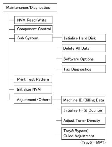
1. Выберите NVM Read/Write.
2. Введите 6 цифр (в нашем случае 744-220).
3. Выберите Confirm/Charge (Подтвердить/Изменить).
4. Отобразится текущее значение («1«).
5. Введите новое значение (««) и нажмите Save (Сохранить).
Источник
Tech Support Portal
Чем мы можем вам сегодня помочь?
Сброс ошибки 10-327 и других ошибок фьюзера Xerox WorkCentre 5225, 5230 Печать
Изменено: Чт, 13 Сен, 2018 at 9:39 AM
Если во фьюзер машины Xerox WorkCentre 5225, 5230 установить нагревательный вал с заметно отличающимися от оригинального вала характеристиками (например, вал от Xerox WorkCentre C118 или некачественный совместимый вал), то довольно часто можно получить ошибку 10-327, которая означает, что машина не сумела нагреть фьюзер до нужной температуры за заданное время.
Устранения причины проблемы заменой вала на «правильный» в данной машине недостаточно для того, чтобы машина вновь заработала — ошибку нужно сбросить из сервисного режима.
Внимание! Перед сбросом ошибки нужно обязательно устранить причину появления этой ошибки! Помимо неподходящего нагревательного вала, ошибки фьюзера могут быть вызваны загрязнением или неисправностью термисторов, неисправностью ламп нагрева, срабатывание термопредохранителя (в этом случае нужно обязательно выяснить, почему он сработал), обрывом или коротким замыканием в цепях лампы или термисторов и в редких случаях неисправностью платы управления.
Процедура сброса
Войти в сервисный режим:
- Нажать и удерживать более 6 секунд кнопку [0] на панели управления. Не отпуская кнопку [0], нажать кнопку [Старт].

- На появившемся экране ввести пароль — 6789 (значение по умолчанию) и нажмите кнопку [Confirm]

- Нажать кнопку информации о машине

Записать значение 0 в ячейку NVM 744-220:
- Выбрать вкладку [Инструменты]

- В разделе [Режимы] выбрать [Обслуживание/диагностика]

- Выбрать раздел [NVM Read / Write. ]

- Введите адрес ячейки 744-220 и нажмите [Confirm / Change]

- Введите [0] в поле [New Value] и нажмите [Save]

- Нажмите [Close], затем [Exit (Keep Log)], затем [Yes]. Машина перезагрузится и выйдет на готовность, если причина проблемы была ранее устранена. Вы можете выбрать пункт [Exit (Clear Log)], если хотите очистить историю неисправностей машины.
Источник
Xerox wc 5021 ошибка прогрева 010 327
| Конференция StartCopy 18.12 | |
| Playful Рязань 15:52 — 18.12 |
Предисловие, пол года назад вылетела ошибка 010-320, сделал сброс в ячейке 744-220, предварительно напаяв перемыку на блоке питания, поставил новую печь, |
5 месяцев спустя раза два в неделю стала выпадать ошибка 010-327, причем после манипуляций типа, высунул вставил печь и включил аппарат она пропадает,
последнюю неделю стало совсем часто выпадать, решили поменять печь, хотя та еще не отработала свое, сегодня поставил новую, и аппарат не выходит в готовность, и снова выдает 010-327
Аналогичные аппараты: Copy Centre C123/128, Work Centre M123/128, Work Centre Pro123/128, Copy Center 133, Work Center 133, Work Center Pro 133
010-327 — ошибка печки
После ремонта, измените NVM[744-220 FuserOverTemp]=1 (есть ошибка) на NVM[744-220 FuserOverTemp]=0 (нет ошибки).
Вход в диагностический режим:
1. На панели управления нажмите и удерживайте клавишу » » в течении 5 секунд.
Продолжая удерживать » » нажмите кнопку Start (Пуск).
Появится экран ввода пароля.
2. Введите 6789 и нажмите Confirm (Подтвердить).
Цвета на дисплее поменяются — режим диагностики активирован.
Доступ к диагностическим процедурам:
— На панели управления нажмите кнопку Log In/Out.
— Выберите System Settings.
— Выберите Common Settings (Общие Настройки).
— Выберите Maintenance/Diagnostics (Обслуживания/Диагностики).
Интерфейс экрана:
1. Выберите NVM Read/Write.
2. Введите 6 цифр (в нашем случае 744-220).
3. Выберите Confirm/Charge (Подтвердить/Изменить).
4. Отобразится текущее значение («1«).
5. Введите новое значение (» «) и нажмите Save (Сохранить).
Вопрос:
У меня на аппарате появилось сообщение «сбой или ошибка код 010-327». Что делать.
Ответ:
010-327. Причина — фьюзер не греется до нужной температуры за определенное время. Возможно, лампы не греются, либо сработал термостат. Действие — попробуйте отключить аппарат, немного подождать и включить его снова. Если это не помогает, обратитесь в сервисный центр, замените фьюзер.
Источник
Содержание
- 010 327 что за ошибка
- 010 327 что за ошибка
- Xerox WorkCentre Pro 133 — ошибка 010-327
- Tech Support Portal
- Чем мы можем вам сегодня помочь?
- Сброс ошибки 10-327 и других ошибок фьюзера Xerox WorkCentre 5225, 5230 Печать
- Процедура сброса
- Войти в сервисный режим:
- Записать значение 0 в ячейку NVM 744-220:
- Xerox wc 5021 ошибка прогрева 010 327
- Вопрос:
- Ответ:
КОНФЕРЕНЦИЯ СТАРТКОПИ
Принтеры, копировальные аппараты, МФУ, факсы и другая офисная техника:
вопросы ремонта, обслуживания, заправки, выбора
0. TyDa_CyDa 01.08.16 17:17
Добрый день.
Меняли в печке тофлон.
Собрали, запустили, вылетела ошибка.
Сбросили, аппарат завелся. Отпечатали 50 листов, поехали домой.
Сегодня звонит клиент, не печатает. Приезжаем, опять эта ошибка. Сбрасываем, печатаем все хорошо. Уехали, через 2 часа звонят опять тоже самое.
Контакты проверяли, все на месте. Есть мысли что может быть?
2. TyDa_CyDa 01.08.16 22:07
(1)Да вот читал это все, даже в закладки положил.
Но вот менять на новый тефлон это в минус себе, тк поставщик найдет 1000 причин не менять и не возвращать тк покупали не у постоянщиков, а через интерент нашли. + по времени будет долго, а клиенту нужно печатать, печатать, печатать.
Вариант с ячейками интересный, но мне кажется этим заниматься стоит в последнюю очередь? Это ж ксерокс, чего нибудь собьешь и хрен потом его пойми!
3. sahrikov1945 01.08.16 23:26
Если бы для меня был дорог данный клиент — я бы ушел в минус.
Бывает, датчик к тефлону чуть криво прижимается- там пупырышек должен плотно лежать
(2) Кроме варианта (4) и «ячеек» (не вижу проблем с «пониманием хрена» — просто записывайте то, что меняете) — это уже вопрос организационный, а не технический.
Источник
010 327 что за ошибка
КОНФЕРЕНЦИЯ СТАРТКОПИ
Принтеры, копировальные аппараты, МФУ, факсы и другая офисная техника:
вопросы ремонта, обслуживания, заправки, выбора
Xerox WorkCentre 5222 после замены тефлона выпадает в 010-327, в 744-220 всегда прописывается «3». Если печь уже горячая, ошибка не появляется. Если включить холодным — ошибка. Из спящего режима тоже выходит с ошибкой. Прописать руками в 744-220 «0» помогает до тех пор, пока печь не остынет. Сама печь скорее жива, чем мертва: тефлон новый, все чисто, контакты в порядке, нигде ничего не отломано.
Нагуглил, что помогает модификация LVPS, однако фотки перемычки (?) в открытом доступе не нашел. Если кто-то из благородных донов соблаговолит помочь другому не менее благородному дону, то тот, другой, будет весьма признателен. Спасибо.
Жан (0): после замены тефлона.. 126K24993
010 ошибка печки, смотри датчики, чисти, контакты.
Жан (0): контакты в порядке
Все, в порядке? А нет там концевика, который коммутирует напругу на печь, при закрытии дверки?
Добрый вечер. Где — там, прошу прощения? Проверял контакты в печи, ее же ковырял. Лампы греют, термисторы на нагрев отзываются, оба одинаково.
Если бы печь вообще не работала, а то ведь только при холодной траблы. Тепленькая запускается на раз.
Проблема решилась заменой тефлона на вал другого производителя. Тот тефлон, который продает известная московская контора, собравшая неплохую подборку партс-каталогов у себя на сайте, для этой модели не подходит, хотя контора утверждает обратное. Если кому-то поможет, то артикул 1356975 на эту модельку брать не стоит. А вот вал торговой марки Master встает как родной. Правильный вал должен быть тонкостенный с серым покрытием, тверже алюминиевого, похожий на оригинальный.
Спасибо всем откликнувшимся.
Источник
Xerox WorkCentre Pro 133 — ошибка 010-327
Аналогичные аппараты: Copy Centre C123/128, Work Centre M123/128, Work Centre Pro123/128, Copy Center 133, Work Center 133, Work Center Pro 133
010-327 — ошибка печки
После ремонта, измените NVM[744-220 FuserOverTemp]=1 (есть ошибка) на NVM[744-220 FuserOverTemp]=0 (нет ошибки).
Вход в диагностический режим:
1. На панели управления нажмите и удерживайте клавишу «» в течении 5 секунд.
Продолжая удерживать «» нажмите кнопку Start (Пуск).
Появится экран ввода пароля.
2. Введите 6789 и нажмите Confirm (Подтвердить).
Цвета на дисплее поменяются — режим диагностики активирован.
Доступ к диагностическим процедурам:
— На панели управления нажмите кнопку Log In/Out.
— Выберите System Settings.
— Выберите Common Settings (Общие Настройки).
— Выберите Maintenance/Diagnostics (Обслуживания/Диагностики).
Интерфейс экрана:
1. Выберите NVM Read/Write.
2. Введите 6 цифр (в нашем случае 744-220).
3. Выберите Confirm/Charge (Подтвердить/Изменить).
4. Отобразится текущее значение («1«).
5. Введите новое значение (««) и нажмите Save (Сохранить).
Источник
Tech Support Portal
Чем мы можем вам сегодня помочь?
Сброс ошибки 10-327 и других ошибок фьюзера Xerox WorkCentre 5225, 5230 Печать
Изменено: Чт, 13 Сен, 2018 at 9:39 AM
Если во фьюзер машины Xerox WorkCentre 5225, 5230 установить нагревательный вал с заметно отличающимися от оригинального вала характеристиками (например, вал от Xerox WorkCentre C118 или некачественный совместимый вал), то довольно часто можно получить ошибку 10-327, которая означает, что машина не сумела нагреть фьюзер до нужной температуры за заданное время.
Устранения причины проблемы заменой вала на «правильный» в данной машине недостаточно для того, чтобы машина вновь заработала — ошибку нужно сбросить из сервисного режима.
Внимание! Перед сбросом ошибки нужно обязательно устранить причину появления этой ошибки! Помимо неподходящего нагревательного вала, ошибки фьюзера могут быть вызваны загрязнением или неисправностью термисторов, неисправностью ламп нагрева, срабатывание термопредохранителя (в этом случае нужно обязательно выяснить, почему он сработал), обрывом или коротким замыканием в цепях лампы или термисторов и в редких случаях неисправностью платы управления.
Процедура сброса
Войти в сервисный режим:
- Нажать и удерживать более 6 секунд кнопку [0] на панели управления. Не отпуская кнопку [0], нажать кнопку [Старт].
- На появившемся экране ввести пароль — 6789 (значение по умолчанию) и нажмите кнопку [Confirm]
- Нажать кнопку информации о машине
Записать значение 0 в ячейку NVM 744-220:
- Выбрать вкладку [Инструменты]
- В разделе [Режимы] выбрать [Обслуживание/диагностика]
- Выбрать раздел [NVM Read / Write. ]
- Введите адрес ячейки 744-220 и нажмите [Confirm / Change]
- Введите [0] в поле [New Value] и нажмите [Save]
- Нажмите [Close], затем [Exit (Keep Log)], затем [Yes]. Машина перезагрузится и выйдет на готовность, если причина проблемы была ранее устранена. Вы можете выбрать пункт [Exit (Clear Log)], если хотите очистить историю неисправностей машины.
Источник
Xerox wc 5021 ошибка прогрева 010 327
| Конференция StartCopy 18.12 | |
| Playful Рязань 15:52 — 18.12 |
Предисловие, пол года назад вылетела ошибка 010-320, сделал сброс в ячейке 744-220, предварительно напаяв перемыку на блоке питания, поставил новую печь, |
5 месяцев спустя раза два в неделю стала выпадать ошибка 010-327, причем после манипуляций типа, высунул вставил печь и включил аппарат она пропадает,
последнюю неделю стало совсем часто выпадать, решили поменять печь, хотя та еще не отработала свое, сегодня поставил новую, и аппарат не выходит в готовность, и снова выдает 010-327
Аналогичные аппараты: Copy Centre C123/128, Work Centre M123/128, Work Centre Pro123/128, Copy Center 133, Work Center 133, Work Center Pro 133
010-327 — ошибка печки
После ремонта, измените NVM[744-220 FuserOverTemp]=1 (есть ошибка) на NVM[744-220 FuserOverTemp]=0 (нет ошибки).
Вход в диагностический режим:
1. На панели управления нажмите и удерживайте клавишу » » в течении 5 секунд.
Продолжая удерживать » » нажмите кнопку Start (Пуск).
Появится экран ввода пароля.
2. Введите 6789 и нажмите Confirm (Подтвердить).
Цвета на дисплее поменяются — режим диагностики активирован.
Доступ к диагностическим процедурам:
— На панели управления нажмите кнопку Log In/Out.
— Выберите System Settings.
— Выберите Common Settings (Общие Настройки).
— Выберите Maintenance/Diagnostics (Обслуживания/Диагностики).
Интерфейс экрана:
1. Выберите NVM Read/Write.
2. Введите 6 цифр (в нашем случае 744-220).
3. Выберите Confirm/Charge (Подтвердить/Изменить).
4. Отобразится текущее значение («1«).
5. Введите новое значение (» «) и нажмите Save (Сохранить).
Вопрос:
У меня на аппарате появилось сообщение «сбой или ошибка код 010-327». Что делать.
Ответ:
010-327. Причина — фьюзер не греется до нужной температуры за определенное время. Возможно, лампы не греются, либо сработал термостат. Действие — попробуйте отключить аппарат, немного подождать и включить его снова. Если это не помогает, обратитесь в сервисный центр, замените фьюзер.
Источник
Во время работы с аппаратом могут возникать проблемы, связанные с неисправностями «железа» или ПО. И если расходные материалы можно просто заменить, то с «мозгами» нужно разбираться. Поэтому, для экономии времени и удобства, ниже представлены возможные коды ошибок (FAULT ERROR CODE), которые показывают Xerox DocuColor DC 240/250/242/252/260 и WorkCentre WC 7655/7665/7675/7755/7765/7775 при неисправности, и их значение:
002-770 ERROR — RAP Insufficient HDD capacity while processing the job template within a job.
003-318 ERROR — RAP IIT software failure.
003-319 ERROR — RAP IIT Video Driver Detection Fail.
003-320 ERROR — RAP IIT-ESS Communication Fail 1.
003-321 ERROR — RAP IIT-ESS Communication Fail 2.
003-322 ERROR — RAP IIT-ESS Communication Fail 3.
003-323 ERROR — RAP IIT-ESS Communication Fail 4.
003-324 ERROR — RAP IIT-ESS Communication Fail 5.
003-325 ERROR — RAP IIT-ESS Communication Fail 6.
003-326 ERROR — RAP IIT-ESS Communication Fail 7.
003-327 ERROR — RAP IIT-ESS Communication Fail 8.
003-328 ERROR — RAP IIT-ESS Communication Fail 9.
003-329 ERROR — RAP IIT-ESS Communication Fail 10.
003-330 ERROR — RAP IIT-ESS Communication Fail 11.
003-331 ERROR — RAP IIT-ESS Communication Fail 12.
003-332 ERROR — RAP IIT-ESS Communication Fail 13.
003-333 ERROR — RAP IIT-ESS Communication Fail 14.
003-334 ERROR — RAP IIT-ESS Communication Fail 15.
003-335 ERROR — RAP IIT-ESS Communication Fail 16.
003-336 ERROR — RAP IIT-ESS Communication Fail 17.
003-337 ERROR — RAP IIT-ESS Communication Fail 18.
003-338 ERROR — RAP IIT-ESS Communication Fail 19.
003-339 ERROR — RAP IIT-ESS Communication Fail 20.
003-340 ERROR — RAP IIT-ESS Communication Fail 21.
003-341 ERROR — RAP IIT-ESS Communication Fail 22.
003-342 ERROR — RAP IIT-ESS Communication Fail 23.
003-343 ERROR — RAP IIT-ESS Communication Fail 24.
003-344 ERROR — RAP Power on hotline failure.
003-345 ERROR — RAP X PIO Unmatch Fail 1.
003-346 ERROR — RAP X PIO Unmatch Fail 2.
003-750 ERROR — RAP Book Duplex-Insufficient Docs.
003-751 ERROR — RAP Under PANTHER Capacity (Scan).
003-752 ERROR — RAP This status code is displayed if 600dpi cannot be scanned (DADF).
003-753 ERROR — RAP This status code is displayed if over 300dpi cannot be scanned (DADF).
003-754 ERROR — RAP S2X Recoverable Error.
003-755 ERROR — RAP S2X Command Error.
003-757 ERROR — RAP This status code is displayed if over 400dpi cannot be scanned (DADF).
003-760 ERROR — RAP Scan Settings Error.
003-761 ERROR — RAP Incorrect Paper Tray Size.
003-763 ERROR — RAP Adjustment Chart Not Found.
003-764 ERROR — RAP Adjustment Chart Not Found.
003-780 ERROR — RAP Scan Image Compression Error.
003-795 ERROR — RAP AMS Limit Error.
003-940 ERROR — RAP DAM Memory is insufficient.
003-942 ERROR — RAP Document Size Error.
003-944 ERROR — RAP Image Repeat Count Fail.
003-946 ERROR — RAP Copy Vertical/Horizontal Difference (APS).
003-947 ERROR — RAP Replaced Original Count Error.
003-948 ERROR — RAP Replaced Original Mismatch.
003-952 ERROR — RAP Return Documents Color mismatch.
003-955 ERROR — RAP Documents Size Exchange Error.
003-956 ERROR — RAP Documents Size Unknown Error.
003-963 ERROR — RAP No APS Object Tray.
003-965 ERROR — RAP ATS/APS No Paper. There is no paper in the trays that can be selected with APS.
003-966 ERROR — RAP AATS/APS No Destination Error.
003-968 ERROR — RAP Punch Position Error.
003-969 ERROR — RAP Punch Size Error.
003-972 ERROR — RAP Maximum Stored Page Over Flow.
003-973 ERROR — RAP Every Direction Difference.
003-974 ERROR — RAP Next Original Specification.
003-977 ERROR — RAP Document Miss Match (Multi Scan).
003-978 ERROR — RAP Color Document Mismatch (Multi Scan).
003-980 ERROR — RAP Staple Position Error.
003-981 ERROR — RAP Staple Size Error.
003-982 ERROR — RAP IITsc HDD Access Error.
005-121 ERROR — RAP DADF Feed Sensor ON Jam.
005-122 ERROR — RAP DADF Simplex/Side 1 Pre Reg Sensor ON Jam.
005-123 ERROR — RAP DADF Simplex/Side 1 Reg Sensor ON Jam.
005-124 ERROR — RAP DADF Lead Reg Sensor ON Jam.
005-125 ERROR — RAP DADF Reg Sensor OFF Jam.
005-126 ERROR — RAP DADF Out Sensor ON Jam.
005-127 ERROR — RAP DADF Out Sensor OFF Jam.
005-128 ERROR — RAP DADF Exit Sensor 1 ON Jam (Simplex Mode).
005-129 ERROR — RAP DADF Exit Sensor 1 OFF Jam (Simplex Mode).
005-130 ERROR — RAP DADF Invert Sensor ON Jam (Duplex Mode).
005-131 ERROR — RAP DADF Invert Sensor On Jam (Inverting).
005-132 ERROR — RAP DADF Invert SNR on Jam 2.
005-133 ERROR — RAP DADF Invert Sensor OFF Jam.
005-134 ERROR — RAP DADF Invert SNR off Jam (Inv).
005-135 ERROR — RAP DADF Pre Reg Sensor ON Jam (Invert).
005-136 ERROR — ERROR — RAP DADF Reg Sensor ON Jam (Invert).
005-137 ERROR — RAP DADF Exit Sensor 2 ON Jam.
005-138 ERROR — RAP DADF Exit Sensor 1 ON Jam.
005-139 ERROR — RAP DADF Invert SNR off Jam.
005-141 ERROR — RAP DADF Feed Sensor OFF Jam.
005-142 ERROR — RAP DADF Exit Sensor 1 OFF Jam (Duplex Mode).
005-143 ERROR — RAP DADF Exit Sensor 2 OFF Jam.
005-144 ERROR — RAP DADF Too First Pre Reg Sensor ON Jam.
005-145 ERROR — RAP DADF Reg Sensor Off Jam (Invert).
005-146 ERROR — RAP DADF Pre Reg Sensor Off Jam.
005-147 ERROR — RAP DADF Pre Reg Sensor Off Jam (Invert).
005-150 ERROR — RAP DADF Feed Sensor OFF Jam (Perforated Original Mode).
005-151 ERROR — RAP DADF Pre Reg Sensor OFF Jam (Perforated Original Mode).
005-152 ERROR — RAP DADF Reg Sensor OFF Jam (Perforated Original Mode).
005-153 ERROR — RAP DADF Reg Sensor OFF Jam (Perforated Original Mode).
005-154 ERROR — RAP DADF Out Sensor OFF Jam (Perforated Original Mode).
005-155 ERROR — RAP DADF Exit Sensor 1 OFF Jam (Perforated Original Mode) (Simplex).
005-156 ERROR — RAP DADF Exit Sensor 1 OFF Jam (Perforated Original Mode) (Duplex).
005-157 ERROR — RAP DADF Invert Sensor OFF Jam (Perforated Original Mode).
005-158 ERROR — RAP DADF Exit Sensor 2 OFF Jam (Perforated Original Mode).
005-160 ERROR — RAP DADF Tray Lift Up Fail (Document Set) (Within Job).
005-190 ERROR — RAP DADF Feed Motor Logic Jam.
005-194 ERROR — RAP Size Mismatch Jam on Slow Scan Mix Size.
005-195 ERROR — RAP Size Mismatch Jam on No Mix Size.
005-196 ERROR — RAP Size Mismatch Jam on No Mix Size.
005-197 ERROR — RAP Prohibit Combine Size Jam.
005-198 ERROR — RAP Too Short Size Jam.
005-199 ERROR — RAP Too Long Size Jam.
005-275 ERROR — RAP DADF RAM Fail.
005-280 ERROR — RAP DADF EEPROM Fail.
005-282 ERROR — RAP DADF Tray Lift Up Fail (No Document).
005-283 ERROR — RAP DADF Stack Height Sensor Logic Fail.
005-284 ERROR — RAP DADF APS Sensor Logic Fail.
005-285 ERROR — RAP DADF Nudger Lift Up Fail.
005-286 ERROR — RAP DADF Feed Out Sensor Fail.
005-303 ERROR — RAP DADF Tray Interlock is open.
005-304 ERROR — RAP Platen Interlock Open.
005-305 ERROR — RAP DADF Feeder Cover Interlock Open (Run).
005-306 ERROR — RAP DADF Tray Interlock Open (Run).
005-308 ERROR — RAP The DADF L/H Cover Interlock is open.
005-309 ERROR — RAP DADF L/H Cover Interlock Open (Run).
005-906 ERROR — RAP DADF Feed Sensor Static Jam.
005-907 ERROR — RAP DADF Pre Reg Sensor Static Jam.
005-908 ERROR — RAP DADF Reg Sensor Static Jam.
005-909 ERROR — RAP DADF Lead Reg Sensor Static Jam..
005-910 ERROR — RAP DADF Out Sensor Static Jam.
005-911 ERROR — RAP DADF Exit Sensor 1 Static Jam.
005-912 ERROR — RAP DADF Exit Sensor 2 Static Jam.
005-913 ERROR — RAP DADF Invert Sensor Static Jam.
005-914 ERROR — RAP DADF No. 1/2/3 APS Sensor Static Jam.
005-915 ERROR — RAP DADF No. 1 APS Sensor Static Jam.
005-916 ERROR — RAP DADF No. 2 APS Sensor Static Jam.
005-917 ERROR — RAP DADF No. 3 APS Sensor Static Jam.
005-918 ERROR — RAP DADF Invert Sensor 2 Static Jam.
005-919 ERROR — RAP DADF Tray Lift Up Fail (Document Set).
005-940 ERROR — RAP DADF No Original Fail.
005-941 ERROR — RAP DADF Not Enough Document.
005-942 ERROR — RAP DADF Tray Stack Over Fail.
010-311 ERROR — RAP Fuser Heat Roll STS-1 Disconnection Fail. It was detected that fuser heat roll STS-1 disconnected.
010-319 ERROR — RAP Fuser NC Sensor Differential Amp Fail.
010-320 ERROR — RAP Heat Roll Over Heat Fail.
010-321 ERROR — RAP Fuser Nip Fail.
010-322 ERROR — RAP Fuser NC Center Sensor Disconnection Fail. (Fuser Temperature Sensor Fail).
010-323 ERROR — RAP Fuser Rear Sensor Disconnection Fail. (Fuser Temperature Sensor Fail).
010-324 ERROR — RAP Fuser NVM Fail.
010-326 ERROR — RAP Wait Heat Roll Fuser On Time Fail.
010-327 ERROR — RAP Standby Heat Roll Fuser On Time Fail.
010-330 ERROR — RAP Fuser Motor Fail.
010-420 ERROR — RAP Fuser Assembly Life Near End.
010-421 ERROR — RAP Fuser Assembly Life End.
012-112 ERROR — RAP Finisher Interface Entrance Sensor ON.
012-113 ERROR — RAP Booklet In Sensor ON Jam.
012-114 ERROR — RAP Booklet In Sensor OFF Jam.
012-115 ERROR — RAP Booklet Folder Roll Exit Sensor ON Jam.
012-125 ERROR — RAP Gate Sensor ON JAM: Finisher.
012-132 ERROR — RAP Finisher Transport Entrance Sensor ON Jam (Long).
012-142 ERROR — RAP Buffer Path Sensor ON Jam A.
012-151 ERROR — RAP Compile Exit Sensor OFF Jam.
012-152 ERROR — RAP Compile Exit Sensor ON Jam A.
012-161 ERROR — RAP Set Eject Jam.
012-162 ERROR — RAP Finisher Interface EXIT. Sensor ON Jam.
012-171 ERROR — RAP Top Tray Exit Sensor ON Jam A.
012-172 ERROR — RAP Top Tray Exit Sensor OFF Jam A.
012-180 ERROR — RAP Booklet Folder Roll Exit Sensor OFF Jam.
012-211 ERROR — RAP Stacker Tray Fail.
012-212 ERROR — RAP Stacker Tray Upper Limit Fail.
012-213 ERROR — RAP Stacker Tray Lower Limit Fail.
012-221 ERROR — RAP Tamper Home Sensor ON Fail.
012-223 ERROR — RAP Tamper Home Sensor OFF Fail.
012-224 ERROR — RAP Rear Tamper Home Sensor OFF Fail.
012-225 ERROR — RAP Booklet Tamper F Home Sensor ON Fail.
012-226 ERROR — RAP Booklet Tamper F Home Sensor OFF Fail.
012-227 ERROR — RAP Booklet End Guide Home Sensor OFF Fail.
012-228 ERROR — RAP Booklet End Guide Home Sensor ON Fail.
012-229 ERROR — RAP Booklet Tamper R Home Sensor ON Fail.
012-230 ERROR — RAP Booklet Tamper R Home Sensor OFF Fail.
012-243 ERROR — RAP Booklet Knife Home Sensor ON Fail.
012-246 ERROR — RAP Booklet Stapler Fail.
012-247 ERROR — RAP Side Regi Sensor OFF Fail.
012-260 ERROR — RAP Eject Clamp Up Sensor ON Fail.
012-261 ERROR — RAP Booklet Knife Folding SNR Fail.
012-263 ERROR — RAP Finisher Rear Tamper Home Sensor ON.
012-264 ERROR — RAP Booklet Drawer Broken Fail.
012-265 ERROR — RAP Booklet Knife Home Sensor OFF Fail.
012-266 ERROR — RAP Booklet Compiler No Paper Sensor Fail.
012-270 ERROR — RAP Top Offset Home Sensor ON Fail: Finisher.
012-271 ERROR — RAP Top Offset Home Sensor OFF Fail: Finisher.
012-282 ERROR — RAP Eject Clamp Up Sensor OFF Fail.
012-283 ERROR — RAP Finisher Set Clamp Home Sensor ON Fail.
012-284 ERROR — RAP Finisher Set Clamp Home Sensor OFF Fail.
012-291 ERROR — RAP Stapler Fail.
012-295 ERROR — RAP Finisher Stapler Move Sensor On Fail.
012-296 ERROR — RAP Finisher Stapler Move Sensor OFF Fail.
012-300 ERROR — RAP Finisher Eject Cover Open (Compiler Cover).
012-302 ERROR — RAP Finisher Front Door Interlock Open.
012-307 ERROR — RAP Booklet Drawer Set Fail.
012-320 ERROR — RAP Punch Home Sensor ON Fail.
012-321 ERROR — RAP Punch Home Sensor OFF Fail.
012-322 ERROR — RAP Puncher Move Home Sensor OFF Fail.
012-323 ERROR — RAP Puncher Move Home Sensor On Fail.
012-325 ERROR — RAP Side Regi Home Sensor On Fail.
012-330 ERROR — RAP Decurler Cam Home Sensor OFF Fail.
012-332 ERROR — RAP Decurler Cam Home Sensor ON Fail.
012-334 ERROR — RAP Download Mode Fail.
012-335 ERROR — RAP Booklet Sub CPU Communication Fail.
012-900 ERROR — RAP Buffer Path Sensor Static Jam.
012-901 ERROR — RAP Finisher Paper Remains at H-Transport Entrance.
012-902 ERROR — RAP Finisher Paper Remains H-Transport Exit.
012-903 ERROR — RAP Compile Exit Sensor Static Jam.
012-905 ERROR — RAP Compile Tray No Paper Sensor Static Jam.
012-907 ERROR — RAP Top Tray Exit Sensor Static Jam.
012-920 ERROR — RAP Gate Sensor static JAM (to Top Tray) A: Finisher.
012-932 ERROR — RAP Gate SNR static JAM (to Stacker Tray) A.
012-934 ERROR — RAP Gate SNR static JAM (to Stacker Tray) C.
012-935 ERROR — RAP Finisher Paper Remains at Transport Entrance Sensor.
012-936 ERROR — RAP Paper Remain at Booklet In SNR A.
012-949 ERROR — RAP Finisher Punch DustBox Miss Set.
013-902 ERROR — RAP Booklet Compile No Paper Sensor Static Jam.
013-903 ERROR — RAP Booklet Folder Roll Exit Sensor Static Jam.
016-210 ERROR — RAP Software Option Fail (HDD Not Exist).
016-211 ERROR — RAP Software Option Fail (System Memory Low Volume).
016-212 ERROR — RAP SW Option Fail (Page Memory Low).
016-213 ERROR — RAP SW Option Fail (Printer CARD Not Exist).
016-215 ERROR — RAP SW Option Fail (JPEG Board Not Exist).
016-216 ERROR — RAP SW Option Fail (Ext Memory Not Exist).
016-217 ERROR — RAP SW Option Fail (Controller ROM not Printer kit).
016-218 ERROR — RAP Because PS Kit is not installed, XDOD functions cannot be fulfilled.
016-219 ERROR — RAP License is required (Printer Kit).
016-220 ERROR — RAP S2X Unrecoverable Error.
016-221 ERROR — RAP S2X Communication Error.
016-222 ERROR — RAP S2X Self-Diag Error.
016-223 ERROR — RAP SS2X SDRAM Error.
016-224 ERROR — RAP S2X PCI Reg Error.
016-225 ERROR — RAP S2X ROM CheckSum Error.
016-226 ERROR — RAP S2X IIT Connection Error.
016-227 ERROR — RAP S2X DDR Error.
016-228 ERROR — RAP S2X Image Processing Error.
016-229 ERROR — RAP SW Option Fail (FCW-UI Not Exist).
016-311 ERROR — RAP The scanner was not detected.
016-315 ERROR — RAP NIIT Interface Fail.
016-316 ERROR — RAP Page Memory Not Detected.
016-317 ERROR — RAP Page Memory Broken-Standard.
016-318 ERROR — RAP Page Memory Broken-Option.
016-320 ERROR — RAP A fatal error with doc conversion software was detected.
016-322 ERROR — RAP JBA Account Full.
016-450 ERROR — RAP SMB Host Name Duplicated.
016-454 ERROR — RAP DNS Renewal Failure of Dynamic.
016-455 ERROR — RAP SNTP Server Time Out.
016-456 ERROR — RAP SNTP Time Asynchronous.
016-503 ERROR — RAP SMTP Server Address Resolution Fail.
016-504 ERROR — RAP POP Server Address Resolution Fail.
016-505 ERROR — RAP POP Authentication Fail.
016-600 ERROR — RAP KO Authentication Locked.
016-601 ERROR — RAP Illegal Access Detection.
016-647 ERROR — RAP With APS selected or with APS set up, there were no trays loaded with paper sizes for Auto Paper Selection.
016-648 ERROR — RAP Job with Booklet selected was discontinued because it had a cover with an image, a divider, or a blank page.
016-701 ERROR — RAP Out of ART EX Memory.
016-702 ERROR — RAP Out of Page Buffer.
016-703 ERROR — RAP Email to Invalid Box.
016-704 ERROR — RAP Mailbox is Full.
016-705 ERROR — RAP Secure Print Fail.
016-706 ERROR — RAP Max. User Number Exceeded.
016-707 ERROR — RAP Sample Print Fail.
016-708 ERROR — RAP HD Full by Annotation/Watermark Image.
016-709 ERROR — RAP ART EX Command Error.
016-710 ERROR — RAP Delayed Print Fail.
016-711 ERROR — RAP Tried to send data whose size is over the system data upper limit.
016-712 ERROR — RAP Under PANTHER Capacity (I-Formatter).
016-713 ERROR — RAP Security Box Password Error.
016-714 ERROR — RAP Security Box is not Enabled.
016-716 ERROR — RAP TIFF Data Overflow.
016-718 ERROR — RAP Out of PCL6 Memory.
016-719 ERROR — RAP Out of PCL Memory.
016-720 ERROR — RAP PCL Command Error.
016-721 ERROR — RAP Other Error.
016-722 ERROR — RAP Job Cancel by Staple Position NG.
016-723 ERROR — RAP Job Cancel by Punch Position NG.
016-724 ERROR — RAP Complex Position Error of Staple and Punch.
016-726 ERROR — RAP PDL Auto Switch Fail.
016-728 ERROR — RAP Unsupported TIFF Data.
016-729 ERROR — RAP TIFF Data Size too Big.
016-730 ERROR — RAP Unsupported ART Command.
016-731 ERROR — RAP Invalid TIFF Data.
016-732 ERROR — RAP Form Not Registered.
016-733 ERROR — RAP Destination Address Resolution Error.
016-734 ERROR — RAP Simple Transmission report invocation error.
016-735 ERROR — RAP Updating Job Template.
016-736 ERROR — RAP Remote directory lock error. Lock directory creation failed.
016-737 ERROR — RAP Remote lock directory remove error.
016-738 ERROR — RAP PS Booklet Print Output Paper Size is illegal.
016-739 ERROR — RAP Mismatch between PS Booklet Doc and Output Paper.
016-740 ERROR — RAP PS Booklet Output Tray is incorrect.
016-746 ERROR — RAP Unsupported PDF File.
016-748 ERROR — RAP HD Full.
016-749 ERROR — RAP JCL Syntax Error.
016-751 ERROR — RAP PDF Error.
016-752 ERROR — RAP PDF Short of Memory.
016-753 ERROR — RAP PDF Password Mismatched.
016-754 ERROR — RAP PDF LZW Not Installed.
016-755 ERROR — RAP PDF Print Prohibited.
016-756 ERROR — RAP Auditron-Prohibit Service.
016-757 ERROR — RAP Auditron-Invalid User.
016-758 ERROR — RAP Auditron-Disabled Function.
016-759 ERROR — RAP Auditron-Reached Limit.
016-760 ERROR — RAP PS Decompose Failure.
016-761 ERROR — RAP FIFO Empty.
016-762 ERROR — RAP Print LANG Not Installed.
016-764 ERROR — RAP SMTP Server Connect Error.
016-765 ERROR — RAP SMTP Server HD Full.
016-766 ERROR — RAP SMTP Server File System Error.
016-767 ERROR — RAP Invalid E-mail Address.
016-768 ERROR — RAP Invalid Sender Address.
016-769 ERROR — RAP SMTP Server Unsupported DSN.
016-771 ERROR — RAP Scan Data Repository ERR.
016-772 ERROR — RAP Scan Data Repository ERR.
016-773 ERROR — RAP Invalid IP Address.
016-774 ERROR — RAP HD Full-Compression Convert.
016-775 ERROR — RAP HD Full-Image Convert.
016-776 ERROR — RAP Image Convert ERR.
016-777 ERROR — RAP HD Access ERR-Image Convert.
016-778 ERROR — RAP HD Full-Scan Image Convert.
016-779 ERROR — RAP Scan Image Conversion Error.
016-780 ERROR — RAP HD Access ERR-Image Convert.
016-781 ERROR — RAP Scan Server Connect ERR.
016-782 ERROR — RAP Scan Server Login ERR.
016-783 ERROR — RAP Invalid Server Path.
016-784 ERROR — RAP Server Write ERR.
016-785 ERROR — RAP Server HD Full.
016-786 ERROR — RAP HD Full-Scan Write ERR.
016-787 ERROR — RAP Invalid Server IP ADD.
016-788 ERROR — RAP Retrieve to Browser Failed.
016-789 ERROR — RAP HD Full-Job Memory.
016-791 ERROR — RAP File Retrieve Fail.
016-792 ERROR — RAP Specified Job Not Found.
016-793 ERROR — RAP MF I/O HD Full.
016-794 ERROR — RAP Media Reader: Media No Insert.
016-795 ERROR — RAP Media Reader: Format Error.
016-796 ERROR — RAP Document insert operation error.
016-797 ERROR — RAP Media Reader: Image File Read Error.
016-798 ERROR — RAP No Trust Marking Option.
016-799 ERROR — RAP Print Instruction Fail.
016-940 ERROR — RAP With Duplex Output selected, a size difference between side 1 and side 2 was detected.
016-941 ERROR — RAP With Booklet selected, mixed-in-size/orientation pages with images were detected.
016-942 ERROR — RAP After a duplexed page was deleted, a size difference between side 1 and side 2 was detected.
016-943 ERROR — RAP After a document or divider was inserted, a size difference between side 1 and side 2 was detected.
016-944 ERROR — RAP Documents were merged, including the cover with an image, or a document with a divider.
016-945 ERROR — RAP A document unavailable for duplex print was inserted after a document available for Duplex was inserted.
016-946 ERROR — RAP A document or a divider was inserted after the cover or divider page.
016-949 ERROR — RAP The user inserted a documnet different in size/orientation from the page to be processed.
016-981 ERROR — RAP A failure in access to HDD.
016-982 ERROR — RAP HDD Access Error 2.
016-985 ERROR — RAP Data Size Over Flow (Scan to Email).
024-340 ERROR — RAP IOT-ESS Communication Failure 1.
024-341 ERROR — RAP IOT-ESS Communication Failure 2.
024-342 ERROR — RAP IOT-ESS Communication Failure 3.
024-343 ERROR — RAP IOT-ESS Communication Failure 4.
024-345 ERROR — RAP IOT-ESS Communication Failure 5.
024-346 ERROR — RAP IOT-ESS Communication Failure 6.
024-347 ERROR — RAP IOT-ESS Communication Failure 7.
024-348 ERROR — RAP IOT-ESS Communication Failure 8.
024-349 ERROR — RAP IOT-ESS Communication Failure 9.
024-350 ERROR — RAP IOT-ESS Communication Failure 10.
024-351 ERROR — RAP IOT-ESS Communication Failure 11.
024-352 ERROR — RAP IOT-ESS Communication Failure 12.
024-353 ERROR — RAP IOT-ESS Communication Failure 13.
024-354 ERROR — RAP IOT-ESS Communication Failure 14.
024-355 ERROR — RAP IOT-ESS Communication Failure 15.
024-356 ERROR — RAP IOT-ESS Communication Failure 16.
024-357 ERROR — RAP IOT-ESS Communication Failure 17.
024-358 ERROR — RAP IOT-ESS Communication Failure 18.
024-359 ERROR — RAP IOT-ESS Communication Failure 19.
024-360 ERROR — RAP IOT-ESS Initialization Failure.
024-361 ERROR — RAP Invalid IOT PaperSizeGroup Information.
024-362 ERROR — RAP Page Sync Illegal Start.
024-363 ERROR — RAP Page Sync Illegal Stop.
024-364 ERROR — RAP DMA Transfer Failure.
024-365 ERROR — RAP Overflow on the Loop Back Write.
024-366 ERROR — RAP JBIG Library Other Failure.
024-367 ERROR — RAP Decompress Other Failure.
024-368 ERROR — RAP PCI Error.
024-370 ERROR — RAP Marker Code Detect Failure.
024-371 ERROR — RAP IOT-ESS Communication Failure 21.
024-372 ERROR — RAP IOT-ESS Communication Failure 22.
024-373 ERROR — RAP IOT-ESS Communication Failure 23.
024-374 ERROR — RAP Regi Con PLL Parameter Failure.
024-375 ERROR — RAP IOT-ESS Communication Failure 24.
024-600 ERROR — RAP Billing master counter repair.
024-601 ERROR — RAP Billing backup counter #1 repair.
024-602 ERROR — RAP Billing backup counter #2 repair.
024-603 ERROR — RAP SWKey master counter repair.
024-604 ERROR — RAP SWKey backup counter #1 repair.
024-605 ERROR — RAP SWKey backup counter #2 repair.
024-606 ERROR — RAP Production Number/Serial Number Failure.
024-746 ERROR — RAP Selected Paper Tray Parameter Mismatch.
024-747 ERROR — RAP Print Instruction Failure.
024-910 ERROR — RAP Tray 1 Size Mismatch.
024-911 ERROR — RAP Tray 2 Size Mismatch.
024-912 ERROR — RAP Tray 3 Size Mismatch.
024-913 ERROR — RAP Tray 4 Size Mismatch.
024-914 ERROR — RAP Tray 6 Size Mismatch.
024-915 ERROR — RAP Tray 7 Size Mismatch.
024-917 ERROR — RAP Stacker Tray Staple Set Over Count.
024-919 ERROR — RAP Face UP Tray Close.
024-920 ERROR — RAP Face Down Tray 1 Paper FULL.
024-922 ERROR — RAP Face Down Tray 2 Paper FULL.
024-923 ERROR — RAP Operation Yellow Toner Empty.
024-924 ERROR — RAP Operation Magenta Toner Empty.
024-925 ERROR — RAP Operation Cyan Toner Empty.
024-926 ERROR — RAP Punch Dust Box Missing Set.
024-927 ERROR — RAP Offset Catch Tray Full Stack.
024-930 ERROR — RAP Stacker Tray Full (Small Size Full).
024-934 ERROR — RAP Paper type mismatch.
024-935 ERROR — RAP Tray 1 Paper Mismatch.
024-936 ERROR — RAP Tray 2 Paper Mismatch.
024-937 ERROR — RAP Tray 3 Paper Mismatch.
024-938 ERROR — RAP OHP kind Mismatch at Tray 4 (Not White Frame OHP).
024-939 ERROR — RAP Transparency type mismatch (No white border).
024-940 ERROR — RAP Folder Tray Out of Place.
024-941 ERROR — RAP Folder Tray Full Stack.
024-942 ERROR — RAP Booklet Sheets Over Count.
024-943 ERROR — RAP Booklet Low Staple.
024-945 ERROR — RAP Booklet Full Stack.
024-946 ERROR — RAP Tray 1 Not In Position.
024-947 ERROR — RAP Tray 2 Not In Position.
024-948 ERROR — RAP Tray 3 Not In Position.
024-949 ERROR — RAP Tray 4 Not In Position.
024-950 ERROR — RAP Tray 1 No Paper.
024-951 ERROR — RAP Tray 2 No Paper.
024-952 ERROR — RAP Tray 3 No Paper.
024-953 ERROR — RAP Tray 4 No Paper.
024-954 ERROR — RAP MSI No Paper.
024-955 ERROR — RAP Tray 6 No Paper.
024-956 ERROR — RAP Tray 7 No Paper.
024-957 ERROR — RAP Interposer No Paper.
024-958 ERROR — RAP MSI Size Mismatch.
024-959 ERROR — RAP Tray 1 Paper Size Mismatch.
024-960 ERROR — RAP Tray 2 Paper Size Mismatch.
024-961 ERROR — RAP Tray 3 Paper Size Mismatch.
024-962 ERROR — RAP Tray 4 Paper Size Mismatch.
024-965 ERROR — RAP ATS/APS No Paper.
024-966 ERROR — RAP ATS/APS No Destination Error.
024-967 ERROR — RAP Different Width Mix Paper Detect (Staple Job).
024-968 ERROR — RAP Stapler/Punch Batting.
024-969 ERROR — RAP Different Width Mix Punch.
024-970 ERROR — RAP Tray 6 Not In Position.
024-971 ERROR — RAP Tray 7 Not In Position.
024-972 ERROR — RAP Tray 6 Paper Size Mismatch.
024-973 ERROR — RAP Tray 7 Paper Size Mismatch.
024-974 ERROR — RAP Interposer Tray Size Mismatch.
024-975 ERROR — RAP Booklet Sheets Over Count (Not Field Attachment).
024-976 ERROR — RAP Finisher Staple Status incorrect.
024-977 ERROR — RAP Stapler Feed Ready Failure.
024-978 ERROR — RAP Booklet Stapler incorrect.
024-979 ERROR — RAP Stapler Near Empty.
024-980 ERROR — RAP Finisher Stacker Tray Full.
024-981 ERROR — RAP Finisher Top Tray Full.
024-982 ERROR — RAP Stacker Lower Safety Warning.
024-983 ERROR — RAP Booklet Tray Full.
024-984 ERROR — RAP Booklet Low Staple F.
024-985 ERROR — RAP SMH Stop Check.
024-987 ERROR — RAP Envelope Folder Tray Full.
024-988 ERROR — RAP Envelope Folder Tray Set Failure.
024-989 ERROR — RAP Booklet Low Staple R.
024-990 ERROR — RAP Punch Dust Full.
025-596 ERROR — RAP Diag HDD Failure 1.
025-597 ERROR — RAP Diag HDD Failure 2.
027-452 ERROR — RAP Duplicate IP address.
027-500 ERROR — RAP SMTP Server Address Resolution Failure.
027-501 ERROR — RAP POP Server Address Resolution Failure.
027-502 ERROR — RAP POP Authentication Failure.
027-700 ERROR — RAP Media Failure.
027-701 ERROR — RAP Media Not Found.
027-702 ERROR — RAP Media Data Not Found / Not Supported.
027-703 ERROR — RAP Media Reader Failure / Disconnected.
027-706 ERROR — RAP Certificate not found.
027-707 ERROR — RAP Certificate expired.
027-708 ERROR — RAP Certificate untrusted.
027-709 ERROR — RAP Certificate revoked.
027-710 ERROR — RAP S/MIME mail was disabled.
027-711 ERROR — RAP S/MIME mail sender certificate not found.
027-712 ERROR — RAP S/MIME mail sender certificate not valid.
027-713 ERROR — RAP S/MIME mail was altered.
027-714 ERROR — RAP S/MIME mail sender impersonation.
027-715 ERROR — RAP S/MIME mail certificate not supported.
027-716 ERROR — RAP No-Signed mail receipt was rejected.
027-720 ERROR — RAP Ext Srv. Host Not Found. A server specified for a remote application was not found, or DNS resolution was not possible.
027-721 ERROR — RAP Ext Srv. Not Found.
027-722 ERROR — RAP Ext Srv. Timeout Failure.
027-723 ERROR — RAP Ext Srv. Authentication Failure.
027-724 ERROR — RAP Ext Srv. Access Failure.
027-725 ERROR — RAP Ext Srv. Operation Failure.
027-726 ERROR — RAP Ext Srv. Unknown State.
027-727 ERROR — RAP Ext Srv. Req Invalid Parameters.
027-728 ERROR — RAP Ext Srv. Required File Exceeded.
027-737 ERROR — RAP Template Server Read Error.
027-739 ERROR — RAP Invalid Template Server Path.
027-740 ERROR — RAP Template Server Login Error.
027-741 ERROR — RAP Template Server Connect Failure.
027-742 ERROR — RAP HD File System Full.
027-743 ERROR — RAP Template Server Install Error.
027-744 ERROR — RAP Template Server ADD Error.
027-745 ERROR — RAP Template Server ADD Error.
027-746 ERROR — RAP Job Template Pool Server Not Ready.
027-751 ERROR — RAP Job Template Analysis Error.
027-752 ERROR — RAP Must User un Inputting.
027-753 ERROR — RAP Job Flow Service Request Disabled.
027-760 ERROR — RAP XJT Command Failure.
027-770 ERROR — RAP PDL Error.
027-771 ERROR — RAP DFE Disk Full.
027-796 ERROR — RAP Email Not Printed.
027-797 ERROR — RAP Invalid Output Destination.
042-313 ERROR — RAP Rear Cooling Fan Failure.
042-320 ERROR — RAP Yellow Drum Motor Drive Failure.
042-321 ERROR — RAP Magenta Drum Motor Drive Failure.
042-322 ERROR — RAP Cyan Drum Motor Drive Failure.
042-323 ERROR — RAP Black Drum Motor Drive Failure.
042-324 ERROR — RAP IBT Drive Motor Failure.
042-325 ERROR — RAP Main Motor Failure.
042-326 ERROR — RAP Belt Home Position too long.
042-327 ERROR — RAP Belt Position Failure.
042-328 ERROR — RAP Belt Edge Sensor Failure.
042-330 ERROR — RAP Fuser Exhaust Fan Failure.
042-331 ERROR — RAP Blower Motor Fan Failure.
042-600 ERROR — RAP Belt Walk Failure.
042-601 ERROR — RAP Belt Edge Learn Failure.
042-602 ERROR — RAP Belt Edge Check Failure.
042-603 ERROR — RAP Suction Filter Life End Failure.
045-310 ERROR — RAP Image Ready NG.
045-311 ERROR — RAP Controller Comm Failure.
045-312 ERROR — RAP Driver Connect Failure.
047-210 ERROR — RAP OCT Offset Failure.
047-310 ERROR — RAP MCU-Finisher Communication Failure.
061-310 ERROR — RAP Clapper 1 Failure.
061-311 ERROR — RAP Clapper 2 Failure.
061-313 ERROR — RAP SOS Long Failure Magenta.
061-315 ERROR — RAP SOS Long Failure Black.
061-317 ERROR — RAP SOS Short Failure.
061-319 ERROR — RAP SOS Short Failure Black.
061-320 ERROR — RAP Polygon Motor Failure.
061-321 ERROR — RAP ROS Motor Failure.
-
Page 1: Multifunction Printer
708P91370 April 2017 Xerox® VersaLink® B7025/B7030/B7035 Multifunction Printer Service Manual…
- Page 2
All service documentation is supplied to Xerox external customers for informational purposes only. Xerox service documentation is intended for use by certified, product trained service per- sonnel only. Xerox does not warrant or represent that it will notify or provide to such customer any future change to this documentation. Customer performed service of equipment, or modules, components or parts of such equipment may affect whether Xerox is responsible to fix machine defects under the warranty offered by Xerox with respect to such equipment. -
Page 3: Table Of Contents
How To Use This Manual ………………..Change History ………………….. Mod/Tag Identification ………………… Voltages Resistances and Tolerances…………….Safety Information ………………….Health and Safety Incident reporting …………….Translation of Warnings ………………..viii Launch Issue Introduction April 2017 Xerox® VersaLink® B7025/B7030/B7035 Multifunction Printer…
- Page 4
Introduction Launch Issue April 2017 Xerox® VersaLink® B7025/B7030/B7035 Multifunction Printer… -
Page 5: About This Manual
This manual is part of a multinational service documentation system that is structured in the Always start with the Service Call Procedures, Section 1. Perform Initial Actions and verify the standard Xerox service manual format. problem, then follow the directions given.
-
Page 6: Change History
These without tag symbols are used to identify the components or configurations that are used when this tag is not fitted. Figure 1 Mod/Tag identification symbols Introduction Launch Issue April 2017 Change History, Mod/Tag Identification Xerox® VersaLink® B7025/B7030/B7035 Multifunction Printer…
-
Page 7: Voltages Resistances And Tolerances
All resistance measurement tolerances are plus or minus 10%, unless otherwise stated in the procedure. DC Signal Nomenclature Figure 1 shows the signal nomenclature used in the BSDs. Figure 1 Signal nomenclature Launch Issue Introduction April 2017 Voltages Resistances and Tolerances Xerox® VersaLink® B7025/B7030/B7035 Multifunction Printer…
-
Page 8: Safety Information
Part Replacement Certain components in this product are susceptible to damage from electrostatic discharge. Only use genuine Xerox approved spare parts or components to maintain compliance with leg- Observe all ESD procedures to avoid component damage. islation and safety certification. Also refer to…
-
Page 9: Health And Safety Incident Reporting
Health and Safety Incident reporting VI. Appendices The Health and Safety Incident Report involving a Xerox Product (Form # EH&S-700) is avail- I. Summary able in the locations that follow: This section defines requirements for notification of health and safety incidents involving Xerox •…
-
Page 10: Translation Of Warnings
Moving parts can cause injury. AVISO: Tenga cuidado al medir la tensión de la línea de alimentación de corriente alterna. La electricidad puede causar lesiones e incluso la muerte. Introduction Launch Issue April 2017 Translation of Warnings viii Xerox® VersaLink® B7025/B7030/B7035 Multifunction Printer…
- Page 11
Do not use the power button as a safety disconnect device. The power button is not a disconnect device. Disconnect the power cord from the supply to isolate the equipment. Launch Issue Introduction April 2017 Translation of Warnings Xerox® VersaLink® B7025/B7030/B7035 Multifunction Printer… - Page 12
Introduction Launch Issue April 2017 Translation of Warnings Xerox® VersaLink® B7025/B7030/B7035 Multifunction Printer… - Page 13
SCP 1 Initial Actions………………….SCP 2 Call Actions………………….SCP 3 Fault Analysis …………………. SCP 4 Subsystem Maintenance ………………SCP 5 Final Actions ………………….SCP 6 Machine Features ………………..Launch Issue Service Call Procedures April 2017 Xerox® VersaLink® B7025/B7030/B7035 Multifunction Printer… - Page 14
Service Call Procedures Launch Issue April 2017 Xerox® VersaLink® B7025/B7030/B7035 Multifunction Printer… -
Page 15: Scp 1 Initial Actions
If telephone line cables are installed, ensure that the customer telephone line is functioning. Check the machine service log book for previous actions that are related to this call. Go to SCP 2 Call Actions. Launch Issue Service Call Procedures April 2017 SCP 1, SCP 2 Xerox® VersaLink® B7025/B7030/B7035 Multifunction Printer…
- Page 16
• GP 6 How to Check a Motor. • GP 7 How to Check a Sensor. • GP 8 How to Check a Solenoid or Clutch. Service Call Procedures Launch Issue April 2017 SCP 3 Xerox® VersaLink® B7025/B7030/B7035 Multifunction Printer… - Page 17
PL 5.65 Item Toner Dispense Units Vacuum the toner dispense units. Jam Sensors Clean the sensors with a dry cotton swab. Scanner Launch Issue Service Call Procedures April 2017 SCP 4 Xerox® VersaLink® B7025/B7030/B7035 Multifunction Printer… - Page 18
12. If necessary, provide the customer with training. 13. Remove and destroy all copies of test patterns. 14. Ensure the machine and service area are clean. Service Call Procedures Launch Issue April 2017 SCP 4, SCP 5 Xerox® VersaLink® B7025/B7030/B7035 Multifunction Printer… - Page 19
• Xerox® VersaLink® B7035 with office finisher LX, booklet maker, HCF and TTM, Figure The Xerox® VersaLink® B7025/B7030/B7035 is available as a basic machine with tray 1. It is also available in various configurations using the options that follow: General For the space requirements, environment range and the print out time. - Page 20
Figure 3 Machine with office finisher LX and 3TM Figure 4 Machine with office finisher LX, booklet maker, HCF and TTM Service Call Procedures Launch Issue April 2017 SCP 6 Xerox® VersaLink® B7025/B7030/B7035 Multifunction Printer… - Page 21
012-152 Compiler Exit Sensor On Jam Entry RAP …………2-60 003-980, 003-981 Staple Error RAP …………….2-36 012-152A Compiler Exit Sensor On Jam RAP …………..2-61 012-161 Set Eject Jam Entry RAP ……………… 2-62 Launch Issue Status Indicator RAPs April 2017 Xerox® VersaLink® B7025/B7030/B7035 Multifunction Printer… - Page 22
016-366, 016-367 Controller HDD Fail RAP …………..2-124 012-905 Compiler Tray No Paper Sensor Static Jam RAP……….2-97 016-368, 369, 370 Controller Diagnostic Fail RAP…………2-125 012-935B Entrance Sensor RAP ………………2-98 Status Indicator RAPs Launch Issue April 2017 Xerox® VersaLink® B7025/B7030/B7035 Multifunction Printer… - Page 23
016-543 Attestation Agent Error 543 RAP …………..2-150 016-706 Maximum User Number Exceeded RAP…………2-176 016-545 Attestation Agent Error 545 RAP …………..2-151 016-707 Sample Print Fail RAP ………………2-177 Launch Issue Status Indicator RAPs April 2017 Xerox® VersaLink® B7025/B7030/B7035 Multifunction Printer… - Page 24
017-750 Custom Transfer Plug-In Internal Fail RAP…………2-228 016-772 Scan Data Repository Error RAP…………..2-202 017-751 Custom Transfer Plug-In Other Fail RAP…………2-229 016-776 Image Conversion Error RAP …………….2-203 Status Indicator RAPs Launch Issue April 2017 Xerox® VersaLink® B7025/B7030/B7035 Multifunction Printer… - Page 25
018-558 HTTP File Not Found RAP…………….2-253 018-785 LDAP Protocol Error 85 RAP …………….2-280 018-559 HTTP File Duplication Fail RAP ……………. 2-254 018-786 LDAP Protocol Errors 86 to 97 RAP …………..2-280 Launch Issue Status Indicator RAPs April 2017 Xerox® VersaLink® B7025/B7030/B7035 Multifunction Printer… - Page 26
024-365 Overflow on Loop Back Write RAP …………..2-306 024-985 Bypass Tray Obstructed RAP …………….2-332 024-366 JBIG Library Other Fail RAP …………….2-306 024-367 Decompress Other Fail RAP…………….2-307 024-368 PCI Error RAP………………..2-307 Status Indicator RAPs Launch Issue April 2017 Xerox® VersaLink® B7025/B7030/B7035 Multifunction Printer… - Page 27
027-523 Lock Folder Creation Failure in SMB RAP…………2-358 027-751 Job Template Analysis Error RAP…………..2-384 027-524 Folder Creation Failure in SMB RAP …………..2-358 027-752 Required User Entry Not Entered RAP …………. 2-384 Launch Issue Status Indicator RAPs April 2017 Xerox® VersaLink® B7025/B7030/B7035 Multifunction Printer… - Page 28
029-719 EIP Print Error With Remote Server RAP …………2-409 033-585 SIP Request Error RAP………………2-435 029-720 EIP Print Error With Server Permission RAP ………… 2-409 033-586 T38 Protocol Not Ready RAP …………….2-435 Status Indicator RAPs Launch Issue April 2017 Xerox® VersaLink® B7025/B7030/B7035 Multifunction Printer… - Page 29
061-357, 365, 369, 373, 393 LPH Communications Fault RAP ……..2-461 061-361 LPH Configuration RAP ………………2-462 062-277 DADF Communication Fail RAP …………… 2-462 062-300 Platen Interlock Open RAP …………….2-463 Launch Issue Status Indicator RAPs April 2017 Xerox® VersaLink® B7025/B7030/B7035 Multifunction Printer… - Page 30
116-386 Fax USB Port RAP……………….. 2-515 117-348 Uninitialized Used SD Card RAP …………..2-541 116-388 No HDD RAP ………………..2-515 117-354, 356, 358 Job Limit System Fail RAP…………..2-542 Status Indicator RAPs Launch Issue April 2017 2-10 Xerox® VersaLink® B7025/B7030/B7035 Multifunction Printer… - Page 31
124-347 Billing CountType Restoration Fail RAP …………2-566 124-349 Modal Break Point Restoration Fail RAP …………2-566 124-350 CRUM OEM Fail RAP ………………2-567 124-372, 373, 374 IOT Soft Fail RAP …………….2-567 Launch Issue Status Indicator RAPs April 2017 Xerox® VersaLink® B7025/B7030/B7035 Multifunction Printer 2-11… - Page 32
Status Indicator RAPs Launch Issue April 2017 2-12 Xerox® VersaLink® B7025/B7030/B7035 Multifunction Printer… -
Page 33: Ac Power Rap
Install new components as necessary: • Main power switch, PL 1.05 Item • LVPS, PL 1.10 Item Check the AC circuit to each component. Refer to the Wiring Diagrams. Launch Issue Status Indicator RAPs April 2017 01A, 01B Xerox® VersaLink® B7025/B7030/B7035 Multifunction Printer 2-13…
-
Page 34: 24Vdc Power Fault Rap
Check the +24VDC circuit for a short circuit to frame. Refer to the Wiring Diagrams. Check the wiring of the suspect component for an open circuit or poor contact. Refer to the Wiring Diagrams. Status Indicator RAPs Launch Issue April 2017 2-14 Xerox® VersaLink® B7025/B7030/B7035 Multifunction Printer…
-
Page 35: Ui Error Rap
Check the wiring between the ESS PWB and the UI assembly. Reload the software, If the fault persists, install a new components as necessary: • UI assembly, PL 2.05 Item • ESS PWB, PL 3.10 Item Launch Issue Status Indicator RAPs April 2017 002-500 Xerox® VersaLink® B7025/B7030/B7035 Multifunction Printer 2-15…
- Page 36
Status Indicator RAPs Launch Issue April 2017 002-500 2-16 Xerox® VersaLink® B7025/B7030/B7035 Multifunction Printer… -
Page 37: Iit Cdi I/F Mismatch Rap
Item 6 are securely connected. Ensure all surface mounted modules on both PWBs are securely connected. Reload the software, Perform the Special Boot Modes RAP. Launch Issue Status Indicator RAPs April 2017 003-311, 003-318, 003-319 Xerox® VersaLink® B7025/B7030/B7035 Multifunction Printer 2-17…
-
Page 38: To 003-343 Iiss-Ess Communication Fail Rap
003-336 IISS receiving error detected by the controller. The NAK that notifies of the occurrence of a transmission failure is received. Status Indicator RAPs Launch Issue April 2017 003-320 to 003-343 2-18 Xerox® VersaLink® B7025/B7030/B7035 Multifunction Printer…
-
Page 39: Hotline Fail Rap
Ensure all surface mounted modules on both PWBs are Perform the Special Boot Modes RAP. securely connected. Reload the software, Perform the Special Boot Modes RAP. Launch Issue Status Indicator RAPs April 2017 003-344, 003-345, 003-346 Xerox® VersaLink® B7025/B7030/B7035 Multifunction Printer 2-19…
-
Page 40: Returned Documents Error Rap
Reload the originals, then re-run the job. Advise the customer not to attempt to copy documents that are restricted. If the fault persists, reload the software, Status Indicator RAPs Launch Issue April 2017 003-700, 003-701 2-20 Xerox® VersaLink® B7025/B7030/B7035 Multifunction Printer…
-
Page 41: Different Magnification Rap
If the fault persists, reload the software, Advise the customer to load the 2 sided simultaneous scan correction chart correctly. If the fault persists, reload the software, Launch Issue Status Indicator RAPs April 2017 003-702, 003-703, 003-704 Xerox® VersaLink® B7025/B7030/B7035 Multifunction Printer 2-21…
-
Page 42: Energy Saving Paper Size Mismatch Rap
Advise the customer to change the parameters, then retry the job. If the fault persists, reload the software, If the fault persists, reload the software, Status Indicator RAPs Launch Issue April 2017 003-705, 003-750 2-22 Xerox® VersaLink® B7025/B7030/B7035 Multifunction Printer…
-
Page 43: Capacity Rap
If the fault persists, reload the software, Perform the steps that follow: Advise the customer to perform scanning below 400 dpi resolution. If the fault persists, reload the software, Launch Issue Status Indicator RAPs April 2017 003-751, 003-752, 932, 935 Xerox® VersaLink® B7025/B7030/B7035 Multifunction Printer 2-23…
-
Page 44: Dpi Cannot Be Scanned Rap
Advise the customer to perform scanning below 200 dpi resolution or perform scanning in other than mixed mode. If the fault persists, reload the software, Status Indicator RAPs Launch Issue April 2017 003-753, 930, 933, 003-754 to 003-756 2-24 Xerox® VersaLink® B7025/B7030/B7035 Multifunction Printer…
- Page 45
Advise the customer to perform scanning below 300 dpi resolution or perform scanning in other than mixed mode. If the fault persists, reload the software, Launch Issue Status Indicator RAPs April 2017 003-757, 931, 934, 003-760, 003-761 Xerox® VersaLink® B7025/B7030/B7035 Multifunction Printer 2-25… -
Page 46: Insufficient Documents Rap
Advise the customer to cancel the job then to change the scan resolution parameter and then retry the job. If the fault persists, reload the software, If the fault persists, reload the software, Status Indicator RAPs Launch Issue April 2017 003-764, 003-780 2-26 Xerox® VersaLink® B7025/B7030/B7035 Multifunction Printer…
-
Page 47: Ams Limit Error Rap
Advise the customer to cancel the job then to clear the B/W setting for color mode or the side 2 cover image setting, then retry the job. If the fault persists, reload the software, If the fault persists, reload the software, Launch Issue Status Indicator RAPs April 2017 003-795, 003-940 Xerox® VersaLink® B7025/B7030/B7035 Multifunction Printer 2-27…
-
Page 48: Insufficient Page Memory Rap
Size Mismatch Jam on SS Mix-Size RAP • 005-196, 198, 199, 946, 948, 949, 950 Size Mismatch Jam RAP If the fault persists, reload the software, Status Indicator RAPs Launch Issue April 2017 003-941, 003-942, 956 2-28 Xerox® VersaLink® B7025/B7030/B7035 Multifunction Printer…
-
Page 49: Repeat Image Count Fail Rap
Advise the customer to manually select an appropriate paper tray, then retry the job. If the fault persists, reload the software, If the fault persists, reload the software, Launch Issue Status Indicator RAPs April 2017 003-944, 003-946 Xerox® VersaLink® B7025/B7030/B7035 Multifunction Printer 2-29…
- Page 50
Advise the customer to reload the correct number and size of documents, and to correctly program the job on the UI. Retry the job. If the fault persists, reload the software, Status Indicator RAPs Launch Issue April 2017 003-947, 948, 951, 955, 003-952 2-30 Xerox® VersaLink® B7025/B7030/B7035 Multifunction Printer… -
Page 51: Aps Rap
Advise the customer to select a tray that has the correct size of paper, then retry the job. If the fault persists, reload the software, Launch Issue Status Indicator RAPs April 2017 003-963, 965, 966, 003-968 Xerox® VersaLink® B7025/B7030/B7035 Multifunction Printer 2-31…
-
Page 52: Punch Size Error Rap
Switch off, then switch on the machine, Ensure the memory SD card, PL 3.10 Item 11 is installed. If the fault persists, reload the software, Status Indicator RAPs Launch Issue April 2017 003-969, 003-970, 003-976 2-32 Xerox® VersaLink® B7025/B7030/B7035 Multifunction Printer…
-
Page 53: Copy Prevention Code Rap
Advise the customer to set the number of pages of the document to be within the maxi- mum number of pages that can be stored. If the fault persists, reload the software, Launch Issue Status Indicator RAPs April 2017 003-971, 003-972 Xerox® VersaLink® B7025/B7030/B7035 Multifunction Printer 2-33…
-
Page 54: Image Rotation Rap
If the fault persists, reload the software, use reduction to make a smaller document, then retry the job. If the fault persists, reload the software, Status Indicator RAPs Launch Issue April 2017 003-973, 003-974 2-34 Xerox® VersaLink® B7025/B7030/B7035 Multifunction Printer…
-
Page 55: Document Mismatch (Multi Scan) Rap
Advise the customer to reload the correct size paper, then retry the job. If the fault persists, reload the software, If the fault persists, reload the software, Launch Issue Status Indicator RAPs April 2017 003-977, 003-978 Xerox® VersaLink® B7025/B7030/B7035 Multifunction Printer 2-35…
-
Page 56: Staple Error Rap
Perform the steps that follow: Advise the customer to specify a staple position again or cancel staple, then retry the job. If the fault persists, reload the software, Status Indicator RAPs Launch Issue April 2017 003-980, 003-981 2-36 Xerox® VersaLink® B7025/B7030/B7035 Multifunction Printer…
-
Page 57: Dadf Simplex/Side 1 Pre Registration Sensor On Jam Rap
If the fault persists, install a new DADF PWB, PL 5.10 Item sary. If the fault persists, install a new DADF PWB, PL 5.10 Item Launch Issue Status Indicator RAPs April 2017 005-122, 005-123 Xerox® VersaLink® B7025/B7030/B7035 Multifunction Printer 2-37…
-
Page 58: Dadf Registration Sensor Off Jam Rap
If the fault persists, install a new DADF PWB, PL 5.10 Item If the fault persists, install a new DADF PWB, PL 5.10 Item Status Indicator RAPs Launch Issue April 2017 005-125, 005-145, 005-131, 005-132 2-38 Xerox® VersaLink® B7025/B7030/B7035 Multifunction Printer…
-
Page 59: Dadf Invert Sensor Off Jam Rap
PL 5.35 for wear or damage. Install new components as neces- sary. If the fault persists, install a new DADF PWB, PL 5.10 Item Launch Issue Status Indicator RAPs April 2017 005-134, 005-139, 005-135 Xerox® VersaLink® B7025/B7030/B7035 Multifunction Printer 2-39…
-
Page 60: Dadf Side 2 Registration Sensor On Jam Rap
If the fault persists, install a new DADF PWB, PL 5.10 Item If the fault persists, install a new DADF PWB, PL 5.10 Item Status Indicator RAPs Launch Issue April 2017 005-136, 005-147 2-40 Xerox® VersaLink® B7025/B7030/B7035 Multifunction Printer…
-
Page 61: Size Mismatch Jam On Ss Mix-Size Rap
Code 005-222, tray size sensor 2, PL 5.55 Item If the fault persists, install a new DADF PWB, PL 5.10 Item Launch Issue Status Indicator RAPs April 2017 005-194, 005-196, 198, 199, 946, 948, 949, 950 Xerox® VersaLink® B7025/B7030/B7035 Multifunction Printer 2-41…
-
Page 62: Prohibited Size Combination Rap
DADF is in download mode. There was an error in DADF download, the ROM is cor- Procedure rupted. Refer the customer to the user documentation regarding document size combinations. Procedure Reload the software, Status Indicator RAPs Launch Issue April 2017 005-197, 005-210 2-42 Xerox® VersaLink® B7025/B7030/B7035 Multifunction Printer…
-
Page 63: Dadf Ram Or Eeprom Write Fail Rap
Enter dC330, code 005-110. Check the DADF registration sensor, PL 5.70 Item If the fault persists, install a new DADF PWB, PL 5.10 Item Launch Issue Status Indicator RAPs April 2017 005-275, 005-280, 005-288 Xerox® VersaLink® B7025/B7030/B7035 Multifunction Printer 2-43…
-
Page 64: Dadf Feeder Cover Interlock Open Rap
Enter dC330, code 005-212. Check the CVT feeder cover sensor, PL 5.10 Item If the fault persists, install a new DADF PWB, PL 5.10 Item Status Indicator RAPs Launch Issue April 2017 005-305, 005-500 2-44 Xerox® VersaLink® B7025/B7030/B7035 Multifunction Printer…
-
Page 65: Dadf Pre Registration Sensor Static Jam Rap
If the fault persists, install a new DADF PWB, PL 5.10 Item 11 If the fault persists, install a new DADF PWB, PL 5.10 Item Launch Issue Status Indicator RAPs April 2017 005-907, 005-908 Xerox® VersaLink® B7025/B7030/B7035 Multifunction Printer 2-45…
-
Page 66: Dadf Invert Sensor Static Jam Rap
PL 5.50 Item If the fault persists, install a new DADF PWB, PL 5.10 Item If the fault persists, install a new DADF PWB, PL 5.10 Item Status Indicator RAPs Launch Issue April 2017 005-913, 005-915 2-46 Xerox® VersaLink® B7025/B7030/B7035 Multifunction Printer…
-
Page 67: Dadf Aps Sensor 2 Static Jam Rap
PL 5.50 Item If the fault persists, install a new DADF PWB, PL 5.10 Item If the fault persists, install a new DADF PWB, PL 5.10 Item Launch Issue Status Indicator RAPs April 2017 005-916, 005-917 Xerox® VersaLink® B7025/B7030/B7035 Multifunction Printer 2-47…
-
Page 68: Letter Sef Detect Error
PL 5.55 Item • Code 005-217, tray APS sensor 3, PL 5.55 Item If the fault persists, install a new DADF PWB, PL 5.10 Item Status Indicator RAPs Launch Issue April 2017 005-921, 005-940 2-48 Xerox® VersaLink® B7025/B7030/B7035 Multifunction Printer…
-
Page 69: Not Enough Documents Rap
005-942 Too many originals are loaded. Procedure Procedure Follow the instructions on the UI to reload the documents. Reduce the number of originals loaded in the input tray. Launch Issue Status Indicator RAPs April 2017 005-941, 005-942 Xerox® VersaLink® B7025/B7030/B7035 Multifunction Printer 2-49…
-
Page 70: Fast Scan Size Mismatch Jam Rap
PL 5.50 Item • Code 005-220, DADF APS sensor 3, PL 5.50 Item If the fault persists, install a new DADF PWB, PL 5.10 Item Status Indicator RAPs Launch Issue April 2017 005-945, 005-947 2-50 Xerox® VersaLink® B7025/B7030/B7035 Multifunction Printer…
-
Page 71: Fusing On Time Fail Rap
PL 3.10 Item • Fuser, PL 10.05 Item • LVPS, PL 1.10 Item • Drive PWB, PL 1.10 Item • ESS PWB, PL 3.10 Item Launch Issue Status Indicator RAPs April 2017 010-327, 010-329 Xerox® VersaLink® B7025/B7030/B7035 Multifunction Printer 2-51…
-
Page 72: Over Temperature Fail Rap
• 3: Abnormal temperature increase of heat roll NC sensor, heat roll thermistor. • 4: Hardware high temperature error of heat roll thermistor. Status Indicator RAPs Launch Issue April 2017 010-331, 010-333, 010-332, 010-379 2-52 Xerox® VersaLink® B7025/B7030/B7035 Multifunction Printer…
-
Page 73: Heat Roll Nc Sensor Fail Rap
PL 10.05 Item • 4: Hardware high temperature error of heat roll thermistor. • Drive PWB, PL 1.10 Item • ESS PWB, PL 3.10 Item Launch Issue Status Indicator RAPs April 2017 010-334, 010-335, 010-337 Xerox® VersaLink® B7025/B7030/B7035 Multifunction Printer 2-53…
-
Page 74: Fuser Web Life End Rap
10. Disconnect the power cord. Electricity can cause death or injury. Moving parts can cause injury. Perform the steps that follow: Install a new fuser, PL 10.05 Item Status Indicator RAPs Launch Issue April 2017 010-414, 010-418, 420 2-54 Xerox® VersaLink® B7025/B7030/B7035 Multifunction Printer…
-
Page 75: Fuser Life Warning Rap
010-421 Fuser Life Warning RAP BSD-ON: BSD 10.2 Fusing Heat Control (2 of 2) 010-421 Fuser replacement time. Procedure Install a new fuser, PL 10.05 Item Launch Issue Status Indicator RAPs April 2017 010-421 Xerox® VersaLink® B7025/B7030/B7035 Multifunction Printer 2-55…
- Page 76
Status Indicator RAPs Launch Issue April 2017 010-421 2-56 Xerox® VersaLink® B7025/B7030/B7035 Multifunction Printer… -
Page 77: Entrance Sensor On Jam Entry Rap
Repair the open or short circuit. Measure the voltage between the finisher PWB P/J8709 pin 6 (+) and ground (-). The voltage is approximately +5VDC. Launch Issue Status Indicator RAPs April 2017 012-132, 012-132A Xerox® VersaLink® B7025/B7030/B7035 Multifunction Printer 2-57…
-
Page 78: Compiler Exit Sensor Off Jam Entry Rap
PL 12.14 Item Check the wires and connectors for an intermittent open or short circuit. If the fault persists, install a new finisher PWB, PL 12.14 Item Status Indicator RAPs Launch Issue April 2017 012-132A, 012-151 2-58 Xerox® VersaLink® B7025/B7030/B7035 Multifunction Printer…
- Page 79
P/J8728. The connectors are good. Check for an open or short circuit between P/J8705 and P/J8734. The wiring is good. Secure the connections. Repair the open or short circuit. Launch Issue Status Indicator RAPs April 2017 012-151A Xerox® VersaLink® B7025/B7030/B7035 Multifunction Printer 2-59… -
Page 80: Compiler Exit Sensor On Jam Entry Rap
PL 12.10 Item Check the wires and connectors for an intermittent open or short circuit. If the fault persists, install a new finisher PWB, PL 12.14 Item Status Indicator RAPs Launch Issue April 2017 012-151A, 012-152 2-60 Xerox® VersaLink® B7025/B7030/B7035 Multifunction Printer…
- Page 81
Check that the finisher is installed correctly. The finisher is correctly installed and correctly connected to the IOT. Reinstall the finisher correctly. Enter dC330 code 012-150. Actuate the compiler exit sensor. The display changes. Launch Issue Status Indicator RAPs April 2017 012-152A Xerox® VersaLink® B7025/B7030/B7035 Multifunction Printer 2-61… -
Page 82: Set Eject Jam Entry Rap
Measure the voltage between the finisher PWB P/J8700 pin 2 (+) and ground (-). Use a piece of paper to actuate the eject home sensor. The voltage changes. Status Indicator RAPs Launch Issue April 2017 012-161, 012-161A 2-62 Xerox® VersaLink® B7025/B7030/B7035 Multifunction Printer…
-
Page 83: Nvm Fail Entry Rap
PL 12.14 Item Check the wires and connectors for an intermittent open or short circuit. If the fault persists, install a new finisher PWB, PL 12.14 Item Launch Issue Status Indicator RAPs April 2017 012-161A, 012-210 Xerox® VersaLink® B7025/B7030/B7035 Multifunction Printer 2-63…
- Page 84
Perform the steps that follow: Check the wiring between the finisher and the IOT. If the fault persists, install a new finisher PWB, PL 12.14 Item Status Indicator RAPs Launch Issue April 2017 012-210A, 012-211 2-64 Xerox® VersaLink® B7025/B7030/B7035 Multifunction Printer… - Page 85
012-060 and 012-061 alternately. The stacker motor runs. sists, install a new finisher PWB, PL 12.14 Item Check the connections of P/J8711 and P/J8736. The connectors are good. Launch Issue Status Indicator RAPs April 2017 012-211A Xerox® VersaLink® B7025/B7030/B7035 Multifunction Printer 2-65… -
Page 86: Front Tamper Home Sensor Fail Entry Rap
Check the wires and connectors for an intermittent open or short circuit. If the fault persists, install a new finisher PWB, PL 12.14 Item Status Indicator RAPs Launch Issue April 2017 012-211A, 012-221, 012-223 2-66 Xerox® VersaLink® B7025/B7030/B7035 Multifunction Printer…
- Page 87
Measure the voltage between the finisher PWB P/J8700 pin 5 (+) and ground (-). Manu- ally move the front tamper to actuate the front tamper home sensor. The voltage changes. Launch Issue Status Indicator RAPs April 2017 012-221A, 012-223A Xerox® VersaLink® B7025/B7030/B7035 Multifunction Printer 2-67… -
Page 88: Rear Tamper Home Sensor Fail Entry Rap
P/J8700 pin 11 (+) and ground (-). Manu- ally move the rear tamper to actuate the front tamper home sensor. The voltage changes. Status Indicator RAPs Launch Issue April 2017 012-224, 012-263, 012-224A, 012-263A 2-68 Xerox® VersaLink® B7025/B7030/B7035 Multifunction Printer…
-
Page 89: Eject Home Sensor Fail Rap
Check the wires and connectors for an intermittent open or short circuit. If the fault per- sists, install a new finisher PWB, PL 12.14 Item Enter dC330 code 012-054 and 012-056 alternately. The eject motor runs. Launch Issue Status Indicator RAPs April 2017 012-224A, 012-263A, 012-259, 012-280 Xerox® VersaLink® B7025/B7030/B7035 Multifunction Printer 2-69…
-
Page 90: Set Clamp Home Sensor Fail Entry Rap
Check the wires and connectors for an intermittent open or short circuit. If the fault persists, install a new finisher PWB, PL 12.14 Item Status Indicator RAPs Launch Issue April 2017 012-259, 012-280, 012-283, 012-284 2-70 Xerox® VersaLink® B7025/B7030/B7035 Multifunction Printer…
- Page 91
Check the wires and connectors for an intermittent open or short circuit. If the fault per- sists, install a new finisher PWB, PL 12.14 Item Launch Issue Status Indicator RAPs April 2017 012-283A, 012-284A Xerox® VersaLink® B7025/B7030/B7035 Multifunction Printer 2-71… -
Page 92: Stapler Fail Entry Rap
Measure the voltage between the finisher PWB P/J8701 pin 9 (+) and ground (-). The voltage is approximately +5VDC. Check the +5VDC circuit. Refer to the Wiring Diagrams. Status Indicator RAPs Launch Issue April 2017 012-291, 012-291A 2-72 Xerox® VersaLink® B7025/B7030/B7035 Multifunction Printer…
-
Page 93: Top Cover Interlock Open Rap
PL 12.14 Item Check the wires and connectors for an intermittent open or short circuit. If the fault persists, install a new finisher PWB, PL 12.14 Item Launch Issue Status Indicator RAPs April 2017 012-291A, 012-301 Xerox® VersaLink® B7025/B7030/B7035 Multifunction Printer 2-73…
-
Page 94: Front Cover Interlock Open Entry Rap
Diagrams. Check the wires and connectors for an intermittent open or short circuit. If the fault persists, install a new finisher PWB, PL 12.14 Item Status Indicator RAPs Launch Issue April 2017 012-302, 012-302A 2-74 Xerox® VersaLink® B7025/B7030/B7035 Multifunction Printer…
-
Page 95: Download Fail Entry Rap
Check the wiring between the finisher and the IOT. Reload the software, GP 4 If the fault persists, install a new finisher PWB, PL 12.14 Item Launch Issue Status Indicator RAPs April 2017 012-334, 012-334A Xerox® VersaLink® B7025/B7030/B7035 Multifunction Printer 2-75…
-
Page 96: Compiler Exit Sensor On Entry Rap
PL 12.14 Item Check the wires and connectors for an intermittent open or short circuit. If the fault persists, install a new finisher PWB, PL 12.14 Item Status Indicator RAPs Launch Issue April 2017 012-903, 012-903A 2-76 Xerox® VersaLink® B7025/B7030/B7035 Multifunction Printer…
-
Page 97: Entrance Sensor Entry Rap
PL 12.14 Item Check the wires and connectors for an intermittent open or short circuit. If the fault persists, install a new finisher PWB, PL 12.14 Item Launch Issue Status Indicator RAPs April 2017 012-935, 012-935A Xerox® VersaLink® B7025/B7030/B7035 Multifunction Printer 2-77…
- Page 98
Status Indicator RAPs Launch Issue April 2017 012-935, 012-935A 2-78 Xerox® VersaLink® B7025/B7030/B7035 Multifunction Printer… -
Page 99: To 012-131 Horizontal Transport Entrance Sensor Jam Rap
10. Open the horizontal transport top cover. Cheat the horizontal transport interlock sensor. Switch on the machine, 10. The horizontal transport belt is driven. Launch Issue Status Indicator RAPs April 2017 012-111 to 012-131 Xerox® VersaLink® B7025/B7030/B7035 Multifunction Printer 2-79…
- Page 100
Install a new transport motor, PL 13.08 Item Install a new finisher PWB, PL 13.45 Item 2. If the fault persists, install a new transport motor, PL 13.08 Item Status Indicator RAPs Launch Issue April 2017 012-132B 2-80 Xerox® VersaLink® B7025/B7030/B7035 Multifunction Printer… - Page 101
Measure the resistance of the transport motor between P/J8879 pin 1, 2, 5 and 6. resistance is approximately 20 Ohms. Install a new transport motor, PL 13.08 Item Launch Issue Status Indicator RAPs April 2017 012-151B, 012-152B Xerox® VersaLink® B7025/B7030/B7035 Multifunction Printer 2-81… - Page 102
Install a new eject motor, PL 13.27 Item Install a new eject motor, PL 13.27 Item 4. If the fault persists, install a new finisher PWB, PL 13.45 Item Status Indicator RAPs Launch Issue April 2017 012-161B 2-82 Xerox® VersaLink® B7025/B7030/B7035 Multifunction Printer… - Page 103
Measure the voltage between P/J8988 pins 22 and 24 on the finisher PWB. The voltage is approximately +5VDC. Install a new finisher PWB, PL 13.45 Item Launch Issue Status Indicator RAPs April 2017 012-210B, 012-211B Xerox® VersaLink® B7025/B7030/B7035 Multifunction Printer 2-83… -
Page 104: Stacker Tray Upper Limit Failure Rap
Measure the voltage between P/J8988 pins 19 and 21 on the finisher PWB. The voltage is approximately +5VDC. Install a new finisher PWB, PL 13.45 Item Status Indicator RAPs Launch Issue April 2017 012-211B, 012-212 2-84 Xerox® VersaLink® B7025/B7030/B7035 Multifunction Printer…
-
Page 105: Stacker Tray Lower Limit Failure Rap
Install a new stacker height sensor 2, PL 13.27 Item Install a new finisher PWB, PL 13.45 Item Install a new finisher PWB, PL 13.45 Item Launch Issue Status Indicator RAPs April 2017 012-212, 012-213 Xerox® VersaLink® B7025/B7030/B7035 Multifunction Printer 2-85…
- Page 106
19 on the finisher PWB and ground. The volt- age is approximately +24VDC. Measure the voltage between J8982 pin 4 on the finisher PWB and ground. The voltage is approximately +24VDC. Status Indicator RAPs Launch Issue April 2017 012-213, 012-221B, 012-223B 2-86 Xerox® VersaLink® B7025/B7030/B7035 Multifunction Printer… - Page 107
+24VDC. Measure the voltage between J8984 pin 4 on the finisher PWB and ground. The voltage is approximately +24VDC. Launch Issue Status Indicator RAPs April 2017 012-221B, 012-223B, 012-224B, 012-263B Xerox® VersaLink® B7025/B7030/B7035 Multifunction Printer 2-87… -
Page 108: Punch Home Sensor Fail Rap
Punch home sensor, PL 13.09 Item • Finisher PWB, PL 13.45 Item If the fault persists, install a new finisher PWB, PL 13.45 Item Status Indicator RAPs Launch Issue April 2017 012-224B, 012-263B, 012-231 2-88 Xerox® VersaLink® B7025/B7030/B7035 Multifunction Printer…
-
Page 109: Booklet Folder Home Sensor Fail Rap
Install a new folder home sensor, PL 13.40 Item Install a new finisher PWB, PL 13.45 Item If the fault persists, install a new finisher PWB, PL 13.45 Item Launch Issue Status Indicator RAPs April 2017 012-243, 012-265, 012-249 Xerox® VersaLink® B7025/B7030/B7035 Multifunction Printer 2-89…
-
Page 110: Eject Clamp Home Sensor Fail Rap
8 on the finisher PWB for an open or short circuit, or loose or damaged connectors. The wiring is good. Reconnect or repair as necessary. Status Indicator RAPs Launch Issue April 2017 012-260, 012-282 2-90 Xerox® VersaLink® B7025/B7030/B7035 Multifunction Printer…
-
Page 111: Booklet Rear Stapler Fail Rap
If the wiring is good, install a new rear booklet stapler assembly, PL 13.65 Item 13. If the problem persists, install a new booklet PWB, PL 13.70 Item Launch Issue Status Indicator RAPs April 2017 012-268, 012-269 Xerox® VersaLink® B7025/B7030/B7035 Multifunction Printer 2-91…
- Page 112
Reconnect or repair as necessary. Measure the resistance of the eject motor between each pin of P/J8878-1, 3, 4 and 6. The resistance is approximately 2 Ohm. Status Indicator RAPs Launch Issue April 2017 012-283B, 012-284B 2-92 Xerox® VersaLink® B7025/B7030/B7035 Multifunction Printer… - Page 113
The voltage changes. Install a new stapler move position sensor, PL 13.20 Item Install a new finisher PWB, PL 13.45 Item Launch Issue Status Indicator RAPs April 2017 012-291B, 012-295, 012-296 Xerox® VersaLink® B7025/B7030/B7035 Multifunction Printer 2-93… -
Page 114: Eject Cover Open Rap
2. The wiring is good. Reconnect or repair as necessary. Install a new finisher PWB, PL 13.45 Item Install a new finisher PWB, PL 13.45 Item Status Indicator RAPs Launch Issue April 2017 012-295, 012-296, 012-300 2-94 Xerox® VersaLink® B7025/B7030/B7035 Multifunction Printer…
- Page 115
Check the actuator for damage or misalignment Check the interlock circuit for an intermittent condition. If the fault persists, install a new finisher PWB, PL 13.45 Item Launch Issue Status Indicator RAPs April 2017 012-302B , 012-303 Xerox® VersaLink® B7025/B7030/B7035 Multifunction Printer 2-95… - Page 116
Check the wiring between the finisher and the IOT. Reload the software, GP 4 If the fault persists, install a new finisher PWB, PL 13.45 Item Status Indicator RAPs Launch Issue April 2017 012-334B, 012-901 2-96 Xerox® VersaLink® B7025/B7030/B7035 Multifunction Printer… - Page 117
PL 13.45 Item If the fault persists, install a new finisher PWB, PL 13.45 Item If the fault persists, install a new finisher PWB, PL 13.45 Item Launch Issue Status Indicator RAPs April 2017 012-903B, 012-905 Xerox® VersaLink® B7025/B7030/B7035 Multifunction Printer 2-97… - Page 118
Install a new transport entrance sensor, PL 13.35 Item 10 Install a new finisher PWB, PL 13.45 Item Install a new finisher PWB, PL 13.45 Item Status Indicator RAPs Launch Issue April 2017 012-935B 2-98 Xerox® VersaLink® B7025/B7030/B7035 Multifunction Printer… -
Page 119: Booklet Staple Move Home Sensor Fail Rap
The wiring is good. Reconnect or repair as necessary. Launch Issue Status Indicator RAPs April 2017 013-210, 013-211 Xerox® VersaLink® B7025/B7030/B7035 Multifunction Printer 2-99…
-
Page 120: Booklet Staple Move Position Sensor Fail Rap
Install a new booklet PWB, PL 13.70 Item 4. If the fault persists, install a new finisher PWB, PL 13.45 Item Install a new finisher PWB, PL 13.45 Item Status Indicator RAPs Launch Issue April 2017 013-212, 013-213 2-100 Xerox® VersaLink® B7025/B7030/B7035 Multifunction Printer…
-
Page 121: Folder Detect Fail Rap
Perform the 013-307 Booklet Cover Open RAP. Check the circuit through the booklet safety switches, PL 13.70 Item Install a new booklet PWB, PL 13.70 Item Launch Issue Status Indicator RAPs April 2017 013-220, 013-306 Xerox® VersaLink® B7025/B7030/B7035 Multifunction Printer 2-101…
-
Page 122: Booklet Left Cover Open Rap
Check the circuit from P/J8993 to and from J8899 on the booklet stapler cover switch, PL 13.70 Item Install a new booklet PWB, PL 13.70 Item Status Indicator RAPs Launch Issue April 2017 013-307 2-102 Xerox® VersaLink® B7025/B7030/B7035 Multifunction Printer…
-
Page 123: Top Cover Interlock Open Rap
014-304 Top Cover Interlock Open RAP 014-304 The top cover interlock open was detected. Procedure Refer to the 012-301 Top Cover Interlock Open RAP. Launch Issue Status Indicator RAPs April 2017 014-304 Xerox® VersaLink® B7025/B7030/B7035 Multifunction Printer 2-103…
- Page 124
Status Indicator RAPs Launch Issue April 2017 014-304 2-104 Xerox® VersaLink® B7025/B7030/B7035 Multifunction Printer… - Page 125
Image Disk Diagnostics. Initialize the Sys — System NVM, refer to dC301. Install a new hard disk, PL 3.10 Item Launch Issue Status Indicator RAPs April 2017 016-210, 506, 777, 780, 798, 016-417 Xerox® VersaLink® B7025/B7030/B7035 Multifunction Printer 2-105… -
Page 126: Sw Option Fail Memory Low Rap
Switch off, then switch on the machine, Switch off, then switch on the machine, Reload the software, Refer the customer to the User Guide to check memory usage. Status Indicator RAPs Launch Issue April 2017 016-211, 016-212, 016-213 2-106 Xerox® VersaLink® B7025/B7030/B7035 Multifunction Printer…
-
Page 127: Sw Option Fail (Fax Card) Rap
Perform the steps that follow: Ensure all fax PWBs are correctly installed, 20.05. Switch off, then switch on the machine, Install a new ESS PWB, PL 3.10 Item Launch Issue Status Indicator RAPs April 2017 016-214, 016-215, 016-216 Xerox® VersaLink® B7025/B7030/B7035 Multifunction Printer 2-107…
-
Page 128: Sw Option Fail (Controller Rom) Rap
Switch off, then switch on the machine, Switch off, then switch on the machine, Reload the software, Advise the customer that the postscript kit is required. Status Indicator RAPs Launch Issue April 2017 016-217, 016-218 2-108 Xerox® VersaLink® B7025/B7030/B7035 Multifunction Printer…
-
Page 129: License Required (Printer Kit) Rap
Switch off, then switch on the machine, Reload the software, If the fault persists, install a new ESS PWB, PL 3.10 Item Launch Issue Status Indicator RAPs April 2017 016-219, 016-220 to 016-226, 240 Xerox® VersaLink® B7025/B7030/B7035 Multifunction Printer 2-109…
-
Page 130: License Required (Ps Image Log Kit) Rap
Moving parts can cause injury. Perform the steps that follow: Switch off, then switch on the machine, Reload the software, Install a new ESS PWB, PL 3.10 Item Status Indicator RAPs Launch Issue April 2017 016-230, 016-232 2-110 Xerox® VersaLink® B7025/B7030/B7035 Multifunction Printer…
-
Page 131: Sw Option Fail (Usb Host Not Installed) Rap
Switch off, then switch on the machine, Reload the software, Initialise the hard disk. Refer to dC355 Hard Disk Diagnostics. Install a new ESS PWB, PL 3.10 Item Launch Issue Status Indicator RAPs April 2017 016-233, 016-234, 016-235 Xerox® VersaLink® B7025/B7030/B7035 Multifunction Printer 2-111…
-
Page 132: System Gmt Clock Fail Rap
Switch off, then switch on the machine, Switch off, then switch on the machine, Reload the software, Install a new ESS PWB, PL 3.10 Item Status Indicator RAPs Launch Issue April 2017 016-242, 016-244 2-112 Xerox® VersaLink® B7025/B7030/B7035 Multifunction Printer…
-
Page 133: Invalid Accessory Mode Rap
Moving parts can cause injury. Perform the steps that follow: Switch off, then switch on the machine, Disconnect the invalid accessory. Launch Issue Status Indicator RAPs April 2017 016-245, 016-246, 016-310 Xerox® VersaLink® B7025/B7030/B7035 Multifunction Printer 2-113…
-
Page 134: Scanner Not Detected Rap
If the fault persists, install a new ESS PWB, PL 3.10 Item Ensure all surface mounted modules are securely connected. Reload the software, Perform the Special Boot Modes RAP. Status Indicator RAPs Launch Issue April 2017 016-311, 315, 319, 016-312, 313, 314 2-114 Xerox® VersaLink® B7025/B7030/B7035 Multifunction Printer…
- Page 135
Ensure all surface mounted modules are securely connected. Reload the software, If the fault persists, install a new ESS PWB, PL 3.10 Item Launch Issue Status Indicator RAPs April 2017 016-316, 317, 318, 329, 333, 334, 016-321 Xerox® VersaLink® B7025/B7030/B7035 Multifunction Printer 2-115… -
Page 136: Jba Account Full Rap
Ensure that all connectors on the ESS PWB, PL 3.10 Item 6 are securely connected. Ensure all surface mounted modules are securely connected. Reload the software, Perform the Special Boot Modes RAP. Status Indicator RAPs Launch Issue April 2017 016-322, 016-323 2-116 Xerox® VersaLink® B7025/B7030/B7035 Multifunction Printer…
-
Page 137: Scheduled Image Overwrite Rap
For information only, no service action necessary. Wait until the Scheduled Image Overwrite to Perform the steps that follow: complete. Enter dC131. Set NVM value 790-389 to 0. Launch Issue Status Indicator RAPs April 2017 016-324, 016-325 Xerox® VersaLink® B7025/B7030/B7035 Multifunction Printer 2-117…
-
Page 138: Ui Cable Connection Fail Rap
Ensure all surface mounted modules are securely connected. Install new components as necessary: Reload the software, • ESS PWB, PL 3.10 Item • UI assembly, PL 2.05 Item Status Indicator RAPs Launch Issue April 2017 016-326, 016-607, 016-327, 016-328 2-118 Xerox® VersaLink® B7025/B7030/B7035 Multifunction Printer…
-
Page 139: Cont System Memory Fail Rap
Ensure all surface mounted modules are securely connected. Reload the software, If the fault persists, install a new ESS PWB, PL 3.10 Item Launch Issue Status Indicator RAPs April 2017 016-330, 331, 332, 016-335 to 016-351 Xerox® VersaLink® B7025/B7030/B7035 Multifunction Printer 2-119…
-
Page 140: Internal Network Initialize Fail Rap
Reload the software, If the fault persists, install a new components as necessary: • ESS PWB, PL 3.10 Item • Drive PWB, PL 1.10 Item Status Indicator RAPs Launch Issue April 2017 016-352, 016-353, 016-354 2-120 Xerox® VersaLink® B7025/B7030/B7035 Multifunction Printer…
-
Page 141: Controller Asic Fail Rap
If the fault persists, install a new ESS PWB, PL 3.10 Item If the fault persists, install a new ESS PWB, PL 3.10 Item Launch Issue Status Indicator RAPs April 2017 016-355, 016-356, 016-357 Xerox® VersaLink® B7025/B7030/B7035 Multifunction Printer 2-121…
-
Page 142: Controller Parallel Card Fail Rap
Perform the steps that follow: Reload the software, Install a new ESS PWB, PL 3.10 Item If the fault persists, install a new ESS PWB, PL 3.10 Item Status Indicator RAPs Launch Issue April 2017 016-358, 016-359, 016-361 2-122 Xerox® VersaLink® B7025/B7030/B7035 Multifunction Printer…
-
Page 143: Controller Ui Fail Rap
If the fault persists, install a new ESS PWB, PL 3.10 Item • ESS PWB, PL 3.10 Item • UI assembly, PL 2.05 Item Launch Issue Status Indicator RAPs April 2017 016-360, 016-362, 016-363 Xerox® VersaLink® B7025/B7030/B7035 Multifunction Printer 2-123…
-
Page 144: Controller Usb 2.0 Fail Rap
If the fault persists, install a new ESS PWB, PL 3.10 Item Install new components as necessary: • PWB,PL 3.10 Item • HDD, PL 3.10 Item Status Indicator RAPs Launch Issue April 2017 016-364, 016-365, 016-366, 016-367 2-124 Xerox® VersaLink® B7025/B7030/B7035 Multifunction Printer…
-
Page 145: Controller Diagnostic Fail Rap
If the fault persists, install a new ESS PWB, PL 3.10 Item If the fault persists, install a new ESS PWB, PL 3.10 Item Launch Issue Status Indicator RAPs April 2017 016-368, 369, 370, 016-371 Xerox® VersaLink® B7025/B7030/B7035 Multifunction Printer 2-125…
-
Page 146: Controller Os Communication Fail Rap
Check the settings in the Authentication Device switch that is physically connected to the machine via the network. Status Indicator RAPs Launch Issue April 2017 016-383, 016-400, 402, 427, 429 2-126 Xerox® VersaLink® B7025/B7030/B7035 Multifunction Printer…
-
Page 147: Eap Type Not Supported Rap
Check the 802.1x authentication method from the UI. If the root certificate of the server certificate cannot be obtained, disable the 802.1x set- ting item ‘Verify Server Certificate’ in the device. Launch Issue Status Indicator RAPs April 2017 016-401, 016-403, 016-430 Xerox® VersaLink® B7025/B7030/B7035 Multifunction Printer 2-127…
- Page 148
Advise the customer to start ‘Initialize certificate’ under Maintenance. incorrect protocol signal was received from the authentication server in network 2. Procedure Advise the customer to repeat the operation. Status Indicator RAPs Launch Issue April 2017 016-404, 016-431, 016-405 2-128 Xerox® VersaLink® B7025/B7030/B7035 Multifunction Printer… -
Page 149: Client Certificate Failure Rap
016-412 The package management function has detected the plug-in has caused an error that is included in a miscellaneous group of errors. Procedure Advise the customer to modify the plug-in, then re-install. Launch Issue Status Indicator RAPs April 2017 016-406, 016-407 to 016-412 Xerox® VersaLink® B7025/B7030/B7035 Multifunction Printer 2-129…
-
Page 150: Input Tray Removed Rap
Perform the steps that follow: If a remote access session in progress, wait for it to end. If the fault persists, switch off, then switch on the machine, Status Indicator RAPs Launch Issue April 2017 016-421, 016-422, 016-423 2-130 Xerox® VersaLink® B7025/B7030/B7035 Multifunction Printer…
-
Page 151: Power Mode Rap
Switch off, then switch on the machine, Procedure Perform the steps that follow: Cancel the power save mode. If the fault persists, switch off, then switch on the machine, Launch Issue Status Indicator RAPs April 2017 016-424, 016-425, 016-426 Xerox® VersaLink® B7025/B7030/B7035 Multifunction Printer 2-131…
-
Page 152: Eap Type Not Supported (Network 2) Rap
If the setting of SSL client certificate cannot be made, select other than (EAP-TLS) as the method as the one set in the authentication server. authentication method. Check the 802.1x authenticating method on the UI. Status Indicator RAPs Launch Issue April 2017 016-428, 016-432 2-132 Xerox® VersaLink® B7025/B7030/B7035 Multifunction Printer…
-
Page 153: Smb Host Name Duplicated Rap
Check with the System Administrator whether the DNS server settings that allow dynamic DNS using IPv6 address have been set. If the fault persists, perform the 016A Workflow Scanning Error Entry RAP. Launch Issue Status Indicator RAPs April 2017 016-450, 016-453, 016-454 Xerox® VersaLink® B7025/B7030/B7035 Multifunction Printer 2-133…
-
Page 154: Sntp Time Out Rap
If the fault persists, perform the 016A Scan to Network Error Entry RAP. deleted in sequence even before they are transferred. If the fault persists, reload the software, Status Indicator RAPs Launch Issue April 2017 016-455, 016-456, 016-461 2-134 Xerox® VersaLink® B7025/B7030/B7035 Multifunction Printer…
-
Page 155: Rom Write Error (During Dld Method) Rap
If the fault persists, install a new ESS PWB, PL 3.10 Item If the fault persists, install a new ESS PWB, PL 3.10 Item Launch Issue Status Indicator RAPs April 2017 016-500, 016-501, 016-502 Xerox® VersaLink® B7025/B7030/B7035 Multifunction Printer 2-135…
-
Page 156: Smtp Server Fail For Redirector Rap
If the fault persists, perform the 016A Scan to Network Error Entry RAP. If the fault persists, perform the 016A Scan to Network Error Entry RAP. Status Indicator RAPs Launch Issue April 2017 016-503, 016-504 2-136 Xerox® VersaLink® B7025/B7030/B7035 Multifunction Printer…
-
Page 157: Pop Authentication Fail For Redirector Rap
Initialise the hard disk. Refer to dC355 Hard Disk Diagnostics. If the fault persists, install a new hard disk, PL 3.10 Item Launch Issue Status Indicator RAPs April 2017 016-505, 016-507, 016-508 Xerox® VersaLink® B7025/B7030/B7035 Multifunction Printer 2-137…
-
Page 158: Image Log No Send Rule Rap
Initialise the hard disk. Refer to dC355 Hard Disk Diagnostics. Install a new hard disk, PL 3.10 Item Install a new hard disk, PL 3.10 Item Status Indicator RAPs Launch Issue April 2017 016-509, 016-510, 016-511, 016-512 2-138 Xerox® VersaLink® B7025/B7030/B7035 Multifunction Printer…
-
Page 159: Smtp Server Reception Error Rap
Ensure all surface mounted modules are securely connected. Reload the software, If the fault persists, perform the 016A Scan to Network Error Entry RAP. Launch Issue Status Indicator RAPs April 2017 016-513, 016-514 Xerox® VersaLink® B7025/B7030/B7035 Multifunction Printer 2-139…
-
Page 160: Xps Short Of Memory
Ensure all surface mounted modules are securely connected. Reload the software, Reload the software, If the fault persists, perform the 016A Scan to Network Error Entry RAP. Status Indicator RAPs Launch Issue April 2017 016-515, 016-516 2-140 Xerox® VersaLink® B7025/B7030/B7035 Multifunction Printer…
-
Page 161: Ps Booklet Illegal Color Mode Change Rap
Ensure all surface mounted modules are securely connected. are securely connected. Ensure all surface mounted modules are securely connected. Reload the software, Reload the software, Launch Issue Status Indicator RAPs April 2017 016-517, 016-518 Xerox® VersaLink® B7025/B7030/B7035 Multifunction Printer 2-141…
-
Page 162: Device Dv Limit Reached Rap
Ensure that all connectors on the ESS PWB, PL 3.10 Item 6 and hard disk, PL 3.10 Item are securely connected. Ensure all surface mounted modules are securely connected. Reload the software, Status Indicator RAPs Launch Issue April 2017 016-519, 016-520 2-142 Xerox® VersaLink® B7025/B7030/B7035 Multifunction Printer…
-
Page 163: Smartcard Not Found Rap
Advise the customer to insert the smart card into the reader then recheck the PIN before performing the personal signature scan. Check the wiring between the card reader and the machine. Launch Issue Status Indicator RAPs April 2017 016-521, 016-522 Xerox® VersaLink® B7025/B7030/B7035 Multifunction Printer 2-143…
-
Page 164: Ldap Ssl Error 113 Rap
LDAP server SSL certificate in the device. Advise the customer to change the LADP server SSL certificate to one that is valid. Status Indicator RAPs Launch Issue April 2017 016-523, 016-524, 016-525 2-144 Xerox® VersaLink® B7025/B7030/B7035 Multifunction Printer…
-
Page 165: Ldap Ssl Error 116 Rap
Advise the customer to ensure that the address of the LDAP server set in the device matches For information only, an internal error has occurred in the program. the address of the LDAP server defined in the SSL certificate. Launch Issue Status Indicator RAPs April 2017 016-526, 016-527 Xerox® VersaLink® B7025/B7030/B7035 Multifunction Printer 2-145…
-
Page 166: Smartcard Not Authorized Rap
Advise the customer to check the PIN, then perform the personal signature scan. Check the network connection. Advise the customer to check that the remote download server is correctly configured and operating on the network. Status Indicator RAPs Launch Issue April 2017 016-528, 016-529 2-146 Xerox® VersaLink® B7025/B7030/B7035 Multifunction Printer…
-
Page 167: Kerberos Attestation Protocol Error 37 Rap
Check that the daylight saving time and time zone settings for the device and the Kerbe- ros server are the same. Launch Issue Status Indicator RAPs April 2017 016-533, 016-534 Xerox® VersaLink® B7025/B7030/B7035 Multifunction Printer 2-147…
-
Page 168: Remote Download File Access Error Rap
Advise the customer to check the remote download server for the FW update file. Procedure Advise the customer to check the connection to the DNS and whether the remote download server name has been registered in the DNS. Status Indicator RAPs Launch Issue April 2017 016-535, 016-536 2-148 Xerox® VersaLink® B7025/B7030/B7035 Multifunction Printer…
-
Page 169: Remote Download Server Connection Error Rap
Initialise the hard disk. Refer to dC355 Hard Disk Diagnostics. Initialize the Sys — System NVM, refer to dC301. Install a new hard disk, PL 3.10 Item Launch Issue Status Indicator RAPs April 2017 016-537, 016-538 Xerox® VersaLink® B7025/B7030/B7035 Multifunction Printer 2-149…
-
Page 170: Kerberos Attestation Other Protocol Error Rap
Press the Authentication Agent button on the Authentication window of the device. The Authentication Agent window appears. Press the Update button. Status Indicator RAPs Launch Issue April 2017 016-539, 016-543 2-150 Xerox® VersaLink® B7025/B7030/B7035 Multifunction Printer…
-
Page 171: Attestation Agent Error 545 Rap
Time Service in the PC where the ApeosWare Authentication Agent is installed is stopped, start it. Switch off, then switch on the machine, Launch Issue Status Indicator RAPs April 2017 016-545, 016-546, 558, 569 Xerox® VersaLink® B7025/B7030/B7035 Multifunction Printer 2-151…
-
Page 172: Attestation Agent Error 548 Rap
The version of the ApeosWare Authentication Agent needs to be upgraded. Advise the cus- tomer to check that the machine is a product that is supported by the upgraded version of the ApeosWare Authentication Agent. Status Indicator RAPs Launch Issue April 2017 016-548, 016-553 2-152 Xerox® VersaLink® B7025/B7030/B7035 Multifunction Printer…
-
Page 173: Attestation Agent Error 554 Rap
Advise the customer to check that the ApeosWare Authentication Agent can connect to the password of the ApeosWare Authentication Agent domain. database or the active directory. Launch Issue Status Indicator RAPs April 2017 016-554, 016-555 Xerox® VersaLink® B7025/B7030/B7035 Multifunction Printer 2-153…
-
Page 174: Attestation Agent Error 556 Rap
Advise the customer to check the ApeosWare Authentication Agent. Advise the customer to wait 5 minutes before authenticating again as the service is over- loaded. Status Indicator RAPs Launch Issue April 2017 016-556, 016-557 2-154 Xerox® VersaLink® B7025/B7030/B7035 Multifunction Printer…
-
Page 175: Remote Download Parameter Error Rap
If DNS address of the server is set as the server name/IP address of the ApeosWare Authentication Agent in the printer function settings list, check that DNS is enabled. Launch Issue Status Indicator RAPs April 2017 016-559, 016-560 Xerox® VersaLink® B7025/B7030/B7035 Multifunction Printer 2-155…
-
Page 176: Detected User Duplication Rap
Authentication Agent do not have the same IC card information. Advise the customer to check that the correct user name and password was specified when accessing the remote download server. Status Indicator RAPs Launch Issue April 2017 016-562, 016-564 2-156 Xerox® VersaLink® B7025/B7030/B7035 Multifunction Printer…
-
Page 177: Backup Restore Error Rap
ESS/IIT/IOT/fax ROM version is still the same as the version used when the backed-up file was created. Furthermore, check the device is the same as the one that generated the backed-up file. Launch Issue Status Indicator RAPs April 2017 016-565, 016-566 Xerox® VersaLink® B7025/B7030/B7035 Multifunction Printer 2-157…
-
Page 178: Backup Capacity Full Rap
When performing restore using USB backup files, check that the USB memory is correctly installed. If the fault persists, delete the backup files. If the problem still persists, use a PC to format the USB memory. Status Indicator RAPs Launch Issue April 2017 016-567, 016-568 2-158 Xerox® VersaLink® B7025/B7030/B7035 Multifunction Printer…
-
Page 179: Job Ticket Out Of Memory Rap
Advise the customer to check for a mismatch between parameters specified by the job ticket. 10. Run the job. Correct the parameters, then resend the job. Launch Issue Status Indicator RAPs April 2017 016-570, 016-571 Xerox® VersaLink® B7025/B7030/B7035 Multifunction Printer 2-159…
-
Page 180: Job Ticket Media Error Rap
Advise the customer to ensure the that software is correctly installed on client that generates properties (size/type/weight/color/punched) are specified by job ticket. job ticket; operational requirements are met; and software version matches device version. Status Indicator RAPs Launch Issue April 2017 016-572, 016-573 2-160 Xerox® VersaLink® B7025/B7030/B7035 Multifunction Printer…
-
Page 181: Ftp Host Name Solution Error Rap
Advise the customer to check the connection to the DNS and whether the destination server Advise the customer to set the DNS address or set the destination server address using IP name has been registered in the DNS. address. Launch Issue Status Indicator RAPs April 2017 016-574, 016-575 Xerox® VersaLink® B7025/B7030/B7035 Multifunction Printer 2-161…
-
Page 182: Ftp Server Connection Error Rap
Check that the server IP address is correct. • Check that the server IP address is correct. Check the connection of the network cables. • Check the connection of network cables. Status Indicator RAPs Launch Issue April 2017 016-576, 016-577 2-162 Xerox® VersaLink® B7025/B7030/B7035 Multifunction Printer…
-
Page 183: Ftp Login Name Or Password Error Rap
Advise the customer to check that the login name (user name) and password are correct. Procedure Advise the customer to check that the scanned image storage destination on the FTP scan server is correct. Launch Issue Status Indicator RAPs April 2017 016-578, 016-579 Xerox® VersaLink® B7025/B7030/B7035 Multifunction Printer 2-163…
-
Page 184: Ftp File Name Acquisition Failure Rap
Advise the customer to check the access rights to the FTP scan server. Advise the customer to change the file name/destination folder or move or delete the files in the destination folder. Status Indicator RAPs Launch Issue April 2017 016-580, 016-581 2-164 Xerox® VersaLink® B7025/B7030/B7035 Multifunction Printer…
-
Page 185: Ftp File Creation Failure Rap
Check whether a folder with the same name as the specified name already exists. Check that the storage destination has enough free space. Launch Issue Status Indicator RAPs April 2017 016-582, 016-588, 016-583, 016-584 Xerox® VersaLink® B7025/B7030/B7035 Multifunction Printer 2-165…
-
Page 186: Ftp File Delete/Read Failure Rap
(save to PC) FTP transfer. Procedure Advise the customer to check whether there is access right to the FTP server and grant the proper rights. Status Indicator RAPs Launch Issue April 2017 016-585, 587, 589, 016-586 2-166 Xerox® VersaLink® B7025/B7030/B7035 Multifunction Printer…
-
Page 187: Ftp Data Reading Failure Rap
Advise the customer to set ‘File Name Conflict’ to other than ‘Cancel Job’. When ‘Add’ is selected for ‘File Name Conflict’, advise the customer to check that the file for- mat is not set to Multi-page. Launch Issue Status Indicator RAPs April 2017 016-590, 016-591 Xerox® VersaLink® B7025/B7030/B7035 Multifunction Printer 2-167…
-
Page 188: Ftp Dat File Access Error Rap
NAME.DAT file is correct. 016-596 The CDUP command has failed after connecting to the FTP server. Procedure Advise the customer to repeat the operation. Status Indicator RAPs Launch Issue April 2017 016-592, 016-593 to 016-596 2-168 Xerox® VersaLink® B7025/B7030/B7035 Multifunction Printer…
-
Page 189: Same File On Ftp Server Rap
Reduce a resolution send parameter (image-to-send quality) then resend the job. Reduce a magnification send parameter, then resend the job. Increase the maximum message size (10MB recommended default). Launch Issue Status Indicator RAPs April 2017 016-597, 016-598, 016-599 Xerox® VersaLink® B7025/B7030/B7035 Multifunction Printer 2-169…
-
Page 190: Ko Authentication Locked Rap
NOTE: Default is 10 users. NVM value 700-564 can be set between 1 to 600 users. With this feature enabled, the machine denies access when an incorrect System Administrator ID is entered the selected number of times. Status Indicator RAPs Launch Issue April 2017 016-600, 016-601 2-170 Xerox® VersaLink® B7025/B7030/B7035 Multifunction Printer…
-
Page 191: Debug Log Created Rap
Reload the software, If the fault persists, install a new components as necessary: • ESS PWB, PL 3.10 Item • Drive PWB, PL 1.10 Item Launch Issue Status Indicator RAPs April 2017 016-604, 016-606, 016-608 Xerox® VersaLink® B7025/B7030/B7035 Multifunction Printer 2-171…
-
Page 192: Pci Option Fail Rap
016-610 PCI EX option no support device fail. Procedure Ensure the SD card, PL 3.10 Item 11 is correctly installed. Procedure Remove unknown PCI or PCIEX option. Status Indicator RAPs Launch Issue April 2017 016-609, 016-610, 016-611 2-172 Xerox® VersaLink® B7025/B7030/B7035 Multifunction Printer…
-
Page 193: Log Image Creation Failure Rap
Procedure Procedure For information only, no service action necessary. Advise the customer to increase the number of password digits for the print job. Launch Issue Status Indicator RAPs April 2017 016-612, 016-700 Xerox® VersaLink® B7025/B7030/B7035 Multifunction Printer 2-173…
-
Page 194: Out Of Art Ex Memory Rap
If the fault persists, reload the software, Execute Image Compression in the Graphics tab of the printer driver. If the fault persists, reload the software, Status Indicator RAPs Launch Issue April 2017 016-701, 016-702 2-174 Xerox® VersaLink® B7025/B7030/B7035 Multifunction Printer…
-
Page 195: Email To Invalid Box Rap
Initialise the hard disk. Refer to dC355 Hard Disk Diagnostics. Initialize the Sys — System NVM, refer to dC301. Install a new hard disk, PL 3.10 Item Launch Issue Status Indicator RAPs April 2017 016-703, 016-704 Xerox® VersaLink® B7025/B7030/B7035 Multifunction Printer 2-175…
-
Page 196: Secure Print Fail Rap
Initialize the Sys — System NVM, refer to dC301. Install new components as necessary: • Hard disk, PL 3.10 Item • ESS PWB, PL 3.10 Item Status Indicator RAPs Launch Issue April 2017 016-705, 016-706 2-176 Xerox® VersaLink® B7025/B7030/B7035 Multifunction Printer…
-
Page 197: Sample Print Fail Rap
If the fault persists, install a new ESS PWB, PL 3.10 Item Install a new hard disk, PL 3.10 Item If the fault persists, install a new ESS PWB, PL 3.10 Item Launch Issue Status Indicator RAPs April 2017 016-707, 016-708 Xerox® VersaLink® B7025/B7030/B7035 Multifunction Printer 2-177…
-
Page 198: Art Ex Command Error Rap
If the fault persists, install a new ESS PWB, PL 3.10 Item Install a new hard disk, PL 3.10 Item If the fault persists, install a new ESS PWB, PL 3.10 Item Status Indicator RAPs Launch Issue April 2017 016-709, 016-710 2-178 Xerox® VersaLink® B7025/B7030/B7035 Multifunction Printer…
-
Page 199: Email Transmission Size Limit Rap
Ensure all surface mounted modules are securely connected. Reload the software, If the fault persists, install a new ESS PWB, PL 3.10 Item Launch Issue Status Indicator RAPs April 2017 016-711, 016-712 Xerox® VersaLink® B7025/B7030/B7035 Multifunction Printer 2-179…
-
Page 200: Security Box Password Error Rap
Reload the software, If the fault persists, install a new ESS PWB, PL 3.10 Item If the fault persists, install a new ESS PWB, PL 3.10 Item Status Indicator RAPs Launch Issue April 2017 016-713, 016-714 2-180 Xerox® VersaLink® B7025/B7030/B7035 Multifunction Printer…
-
Page 201: Escp Form Invalid Password Rap
Initialize the Sys — System NVM, refer to dC301. Install a new hard disk, PL 3.10 Item If the fault persists, install a new ESS PWB, PL 3.10 Item Launch Issue Status Indicator RAPs April 2017 016-715, 016-716 Xerox® VersaLink® B7025/B7030/B7035 Multifunction Printer 2-181…
-
Page 202: Fax Send Result Not Found Rap
Initialize the Sys — System NVM, refer to dC301. Install a new hard disk, PL 3.10 Item If the fault persists, install a new ESS PWB, PL 3.10 Item Status Indicator RAPs Launch Issue April 2017 016-717, 016-718 2-182 Xerox® VersaLink® B7025/B7030/B7035 Multifunction Printer…
-
Page 203: Out Of Pcl Memory Rap
Decomposer in some mea- If the fault persists, reload the software, sure. If the fault persists, reload the software, Launch Issue Status Indicator RAPs April 2017 016-719, 016-720 Xerox® VersaLink® B7025/B7030/B7035 Multifunction Printer 2-183…
-
Page 204: To 016-724 Settings Error Rap
Perform the steps that follow: Advise the customer to correct the settings, then execute the command again. If the fault persists, reload the software, Status Indicator RAPs Launch Issue April 2017 016-721 to 016-724, 016-725 2-184 Xerox® VersaLink® B7025/B7030/B7035 Multifunction Printer…
-
Page 205: Pdl Auto Switch Fail Rap
Advise the customer to switch off paper saving, then print the job again. If the fault persists, reload the software, If the fault persists, reload the software, Launch Issue Status Indicator RAPs April 2017 016-726, 016-727 Xerox® VersaLink® B7025/B7030/B7035 Multifunction Printer 2-185…
-
Page 206: Unsupported Tiff Data Rap
Perform the steps that follow: Advise the customer to refer to the User Guide to correct the valid range. If the fault persists, reload the software, Status Indicator RAPs Launch Issue April 2017 016-728, 016-729 2-186 Xerox® VersaLink® B7025/B7030/B7035 Multifunction Printer…
-
Page 207: Invalid Data Rap
Set a correct DNS server address. If the fault persists, reload the software, Reload the software, If the fault persists, perform the 016A Scan to Network Error Entry RAP. Launch Issue Status Indicator RAPs April 2017 016-731, 016-732, 016-733 Xerox® VersaLink® B7025/B7030/B7035 Multifunction Printer 2-187…
-
Page 208: Updating Job Template Rap
If the fault persists, reload the software, Advise the customer to specify the correct settings that allow booklet printing. If the fault persists, reload the software, Status Indicator RAPs Launch Issue April 2017 016-735, 016-738, 739, 740 2-188 Xerox® VersaLink® B7025/B7030/B7035 Multifunction Printer…
-
Page 209: Download Mode Fail Rap
Advise the customer to cancel the download prohibited mode then check that the jobs have completed before retrying the operation. Enter dC131. Set NVM value 700-420 to 0, the retry the operation. Launch Issue Status Indicator RAPs April 2017 016-741, 016-742 Xerox® VersaLink® B7025/B7030/B7035 Multifunction Printer 2-189…
-
Page 210: Device Model/Panel Type Error Rap
Advise the customer to source a download file that has the same model with the device VerUP Perform the steps that follow: then retry the job. Ensure that the cable connected to the device is secured correctly, then retry the job. Status Indicator RAPs Launch Issue April 2017 016-743, 016-744 2-190 Xerox® VersaLink® B7025/B7030/B7035 Multifunction Printer…
-
Page 211: Download Data Xpjl Fatal Error Rap
Advise the customer to print via the driver from Acrobat Reader. Reload the software, If the fault persists, perform the 016A Scan to Network Error Entry RAP. Launch Issue Status Indicator RAPs April 2017 016-745, 016-746, 016-751 Xerox® VersaLink® B7025/B7030/B7035 Multifunction Printer 2-191…
-
Page 212: Drawing Annotation Memory Rap
Initialize the Sys — System NVM, refer to dC301. Install a new hard disk, PL 3.10 Item If the fault persists, reload the software, Status Indicator RAPs Launch Issue April 2017 016-747, 016-748, 774, 775, 778, 981 2-192 Xerox® VersaLink® B7025/B7030/B7035 Multifunction Printer…
-
Page 213: Jcl Syntax Error Rap
Request the other party to resend the internet fax document using a print language If the fault persists, reload the software, that can be printed by the machine. If the fault persists, reload the software, Launch Issue Status Indicator RAPs April 2017 016-749, 016-750 Xerox® VersaLink® B7025/B7030/B7035 Multifunction Printer 2-193…
-
Page 214: Pdf Short Of Memory Rap
Normal. When the print mode is set to Standard, change the setting to High Speed. If the fault persists, reload the software, Print using a driver from Acrobat Reader. If the fault persists, reload the software, Status Indicator RAPs Launch Issue April 2017 016-752, 016-753 2-194 Xerox® VersaLink® B7025/B7030/B7035 Multifunction Printer…
-
Page 215: Pdf Print Prohibited Rap
Advise the customer to request the Account Administrator for access to use the service. file. If the fault persists, reload the software, If the fault persists, reload the software, Launch Issue Status Indicator RAPs April 2017 016-755, 016-756 Xerox® VersaLink® B7025/B7030/B7035 Multifunction Printer 2-195…
-
Page 216: Auditron Invalid User Rap
Set the new function that is allowed for that account then try again. Request the Account Administrator to add the rights. If the fault persists, reload the software, Status Indicator RAPs Launch Issue April 2017 016-757, 016-758 2-196 Xerox® VersaLink® B7025/B7030/B7035 Multifunction Printer…
-
Page 217: Auditron Limit Reached Rap
Advise the customer to request the Account Administrator to set the number of copies, Advise the customer to resend the job. etc. If the fault persists, reload the software, If the fault persists, reload the software, Launch Issue Status Indicator RAPs April 2017 016-759, 016-760 Xerox® VersaLink® B7025/B7030/B7035 Multifunction Printer 2-197…
-
Page 218: Fifo Empty Rap
Advise the customer to correct then select the decomposer from the UI or with a com- mand. If the fault persists, reload the software, If the fault persists, reload the software, Status Indicator RAPs Launch Issue April 2017 016-761, 016-762 2-198 Xerox® VersaLink® B7025/B7030/B7035 Multifunction Printer…
-
Page 219: Pop Server Connect Rap
If the fault persists, refer the customer to the System Administrator Guide to check that the machine is correctly configured. the machine is correctly configured. Launch Issue Status Indicator RAPs April 2017 016-763, 016-764 Xerox® VersaLink® B7025/B7030/B7035 Multifunction Printer 2-199…
-
Page 220: Smtp Server Error Rap
SMTP (email) server that the server disk drive or mailboxes are full. If the fault persists, refer to the System Administrator Guide to ensure that the machine is configured correctly. Status Indicator RAPs Launch Issue April 2017 016-765, 016-766, 016-767 2-200 Xerox® VersaLink® B7025/B7030/B7035 Multifunction Printer…
-
Page 221: Invalid Sender Address Rap
Advise the customer to check that the sender address is correct. Advise the customer to contact the network administrator for advice and ensure that the SMTP server supports DSN. Launch Issue Status Indicator RAPs April 2017 016-768, 016-769 Xerox® VersaLink® B7025/B7030/B7035 Multifunction Printer 2-201…
-
Page 222: Direct Fax Function Canceled Rap
Advise the customer to set the DNS address. Or, set the scan data repository address using IP address. Reload the software, If the fault persists, perform the 016A Workflow Scanning Error Entry RAP. Status Indicator RAPs Launch Issue April 2017 016-770, 016-772 2-202 Xerox® VersaLink® B7025/B7030/B7035 Multifunction Printer…
-
Page 223: Image Conversion Error Rap
Set to Single File for Each Page, or set the Image Format setting to Drawing Object. If the fault persists, perform the 016A Workflow Scanning Error Entry RAP. Launch Issue Status Indicator RAPs April 2017 016-776, 016-779 Xerox® VersaLink® B7025/B7030/B7035 Multifunction Printer 2-203…
-
Page 224: Server Connect Error Rap
Initialise the hard disk. Refer to dC355 Hard Disk Diagnostics. Initialize the Sys — System NVM, refer to dC301. Reload the software, Install a new hard disk, PL 3.10 Item Status Indicator RAPs Launch Issue April 2017 016-781, 016-786 2-204 Xerox® VersaLink® B7025/B7030/B7035 Multifunction Printer…
-
Page 225: Retrieve To Browser Failed Rap
Scan to Network Error Entry RAP. Check whether there are problems such as duplicated IP addresses. If the fault persists, perform the 016A Scan to Network Error Entry RAP. Launch Issue Status Indicator RAPs April 2017 016-788, 016-790 Xerox® VersaLink® B7025/B7030/B7035 Multifunction Printer 2-205…
-
Page 226: Specified Job Not Found Rap
Advise the customer to repeat the operation. Advise the customer to check that the media is inserted. If the fault persists, reload the software, If the fault persists, reload the software, Status Indicator RAPs Launch Issue April 2017 016-792, 016-794 2-206 Xerox® VersaLink® B7025/B7030/B7035 Multifunction Printer…
-
Page 227: Media Reader Format Error Rap
PC, then reset the settings. reset the settings. If the fault persists, reload the software, If the fault persists, reload the software, Launch Issue Status Indicator RAPs April 2017 016-795, 016-796 Xerox® VersaLink® B7025/B7030/B7035 Multifunction Printer 2-207…
-
Page 228: Image File Read Error Rap
PC, then reset the settings. If the fault persists, perform the 016A Scan to Network Error Entry RAP. If the fault persists, reload the software, Status Indicator RAPs Launch Issue April 2017 016-797, 016-799 2-208 Xerox® VersaLink® B7025/B7030/B7035 Multifunction Printer…
-
Page 229: Required Resource Not Ready Rap
Reload the software, Perform the steps that follow: Advise the customer to correctly load paper or install the staples. If the fault persists, reload the software, Launch Issue Status Indicator RAPs April 2017 016-910, 016-911, 016-920 Xerox® VersaLink® B7025/B7030/B7035 Multifunction Printer 2-209…
-
Page 230: Hdd Access Error 2 Rap
Initialise the hard disk. Refer to dC355 Hard Disk Diagnostics. Initialize the Sys — System NVM, refer to dC301. Install a new hard disk, PL 3.10 Item Status Indicator RAPs Launch Issue April 2017 016-981, 982, 016-983 2-210 Xerox® VersaLink® B7025/B7030/B7035 Multifunction Printer…
-
Page 231: Scan To Email Data Size Rap
NOTE: If the Windows key is enabled (the key located in the lower left corner with the Microsoft logo), hold the Windows key down, press R and release both keys to open the Command window. Launch Issue Status Indicator RAPs April 2017 016-985, 016A Xerox® VersaLink® B7025/B7030/B7035 Multifunction Printer 2-211…
- Page 232
If the IP address is correct, contact 2nd level support. Attempt to send a scan job from the machine, if the scan to job did not complete, contact 2nd level support. Status Indicator RAPs Launch Issue April 2017 016A 2-212 Xerox® VersaLink® B7025/B7030/B7035 Multifunction Printer… -
Page 233: Job Limit Illegal Response Rap
Advise the customer to change the user privileges. Check the job parameter settings, then re-run the job. Check the response packet from the job limit server. Launch Issue Status Indicator RAPs April 2017 017-500, 017-501 Xerox® VersaLink® B7025/B7030/B7035 Multifunction Printer 2-213…
-
Page 234: Password Over Maximum Rap
Advise the customer to lower the number of password digits. Procedure Advise the customer to check the network status and the operating status of JobLimit server. Status Indicator RAPs Launch Issue April 2017 017-503, 017-504, 017-505 2-214 Xerox® VersaLink® B7025/B7030/B7035 Multifunction Printer…
-
Page 235: Job Limit Rejected Rap
Procedure Procedure Advise the customer to contact the System Administrator. Advise the customer to change the SSL operation mode setting to other than STARTTLS mode. Launch Issue Status Indicator RAPs April 2017 017-506, 017-713 Xerox® VersaLink® B7025/B7030/B7035 Multifunction Printer 2-215…
-
Page 236: Smtp Over Ssl Fail Rap
Advise the customer to check if this occurred in TLS Mode, it may be due to an incorrect machine. port number. Check the Port Number settings of the SMTP Server. If the fault persists, reload the software, Status Indicator RAPs Launch Issue April 2017 017-714, 017-715 2-216 Xerox® VersaLink® B7025/B7030/B7035 Multifunction Printer…
-
Page 237: Ssl Certificate (Smtp) Fail Rap
NOTE: This problem can also be fixed by switching off the machines SSL Server Verifica- tion setting. This will render the machine unable to guarantee the authenticity of the SMTP server that it is connecting to. Launch Issue Status Indicator RAPs April 2017 017-716, 717, 718, 017-719 Xerox® VersaLink® B7025/B7030/B7035 Multifunction Printer 2-217…
-
Page 238: Pjl Command Fail Rap
Advise the customer to perform the operation when the value of total impressions is between 0 Procedure and 9,999,900. Advise the customer to correct the contract type or geographic region value specified by PJL command, then try again. Status Indicator RAPs Launch Issue April 2017 017-720, 017-721, 017-722 2-218 Xerox® VersaLink® B7025/B7030/B7035 Multifunction Printer…
-
Page 239: Docuworks Unsupported Character Fail Rap
Advise the customer to print from the DocuWorks viewer using the print driver (ART-EX, If the fault persists, reload the software, PCL, etc.). If the fault persists, reload the software, Launch Issue Status Indicator RAPs April 2017 017-723, 017-725 Xerox® VersaLink® B7025/B7030/B7035 Multifunction Printer 2-219…
-
Page 240: Scan Job Flow Document Fail Rap
Resolution of the document for processing is 300dpi. • Magnification of the of the document for processing is 100%. If the fault persists, reload the software, Status Indicator RAPs Launch Issue April 2017 017-728, 017-729 2-220 Xerox® VersaLink® B7025/B7030/B7035 Multifunction Printer…
-
Page 241: Network Error In Pdl Transfer Rap
Check that the POP server IP address that is set in the machine is correct. Check that the IPP port of the destination machine is enabled. Check the connection of network cables. Launch Issue Status Indicator RAPs April 2017 017-730, 017-731 Xerox® VersaLink® B7025/B7030/B7035 Multifunction Printer 2-221…
-
Page 242: Offline Error In Pdl Transfer Rap
017-733 Unable to send because destination printer is offline. Procedure Procedure Advise the customer to disable the offline status of the destination machine. Advise the customer to repeat the operation. Status Indicator RAPs Launch Issue April 2017 017-732, 017-733 2-222 Xerox® VersaLink® B7025/B7030/B7035 Multifunction Printer…
-
Page 243: Ipp Data Error Rap
Advise the customer to print by using a different print method (printer driver or utility other than print from IPP) that is supported by the machine. If the fault persists, reload the software, Launch Issue Status Indicator RAPs April 2017 017-734, 017-735 Xerox® VersaLink® B7025/B7030/B7035 Multifunction Printer 2-223…
-
Page 244: Custom Transfer Out Of Memory Rap
Initialise the hard disk. Refer to dC355 Image Disk Diagnostics. Initialize the Sys — System NVM, refer to dC301. Initialize the Sys — System NVM, refer to dC301. Status Indicator RAPs Launch Issue April 2017 017-737, 017-738, 017-746 2-224 Xerox® VersaLink® B7025/B7030/B7035 Multifunction Printer…
-
Page 245: Transfer Service Not Available Rap
Check the contents of the instruction set that is being used. If the instruction set was gen- Input the software key for the customization kit. erated by a custom service, revise the custom service contents. Launch Issue Status Indicator RAPs April 2017 017-739, 017-740, 017-741 Xerox® VersaLink® B7025/B7030/B7035 Multifunction Printer 2-225…
- Page 246
Check whether it is possible to log in to the transfer destination server, etc. by using the specified user name and password. Status Indicator RAPs Launch Issue April 2017 017-742, 743, 744, 017-745 2-226 Xerox® VersaLink® B7025/B7030/B7035 Multifunction Printer… -
Page 247: Custom Transfer Plug-In Connection Timeout Rap
Advise the customer to check the machine settings required for file transfer. Wait a while, then re-run the job. If the situation does not improve, consult with the Network Administrator. Launch Issue Status Indicator RAPs April 2017 017-747, 017-748 Xerox® VersaLink® B7025/B7030/B7035 Multifunction Printer 2-227…
-
Page 248: Custom Transfer Plug-In Xml Fail Rap
Advise the customer to check the contents of the instruction set that is being used. If the Switch off, then switch on the machine, instruction set was generated by a custom service, revise the custom service contents. Status Indicator RAPs Launch Issue April 2017 017-749, 017-750 2-228 Xerox® VersaLink® B7025/B7030/B7035 Multifunction Printer…
-
Page 249: Custom Transfer Plug-In Other Fail Rap
Either set the software download via network to allowed or perform the software down- load using a USB. If the fault persists, reload the software, Launch Issue Status Indicator RAPs April 2017 017-751, 017-755 Xerox® VersaLink® B7025/B7030/B7035 Multifunction Printer 2-229…
-
Page 250: Download Data Inspection Error Rap
If this had occurred in TSL mode, it may be due to different port number. Advise the cus- tomer to check the port number settings of the POP server. If the fault persists, reload the software, Status Indicator RAPs Launch Issue April 2017 017-759, 017-760, 017-766 2-230 Xerox® VersaLink® B7025/B7030/B7035 Multifunction Printer…
-
Page 251: Ssl Server Cert Untrusted (Pop) Rap
This will render the machine unable to guarantee the authenticity of the POP server that it is connecting to. Launch Issue Status Indicator RAPs April 2017 017-761, 017-767, 017-762, 763, 764, 768, 769, 770 Xerox® VersaLink® B7025/B7030/B7035 Multifunction Printer 2-231…
-
Page 252: Pop Over Ssl Internal Fail Rap
Procedure Advise the customer to: Procedure Darken the density during scan. Advise the customer to repeat the operation. Turn off the blank suppression instruction. Status Indicator RAPs Launch Issue April 2017 017-765, 017-771, 017-772 2-232 Xerox® VersaLink® B7025/B7030/B7035 Multifunction Printer…
-
Page 253: Netlog Task Error Rap
017-774 Message discard error. Procedure Procedure Advise the customer to check the setting related to the Netlog function. For information only, no service action necessary. Launch Issue Status Indicator RAPs April 2017 017-773, 017-774 Xerox® VersaLink® B7025/B7030/B7035 Multifunction Printer 2-233…
-
Page 254: Network Api Error Rap
Syslog server, or a network cable failure. Status Indicator RAPs Launch Issue April 2017 017-775, 017-776, 017-777 2-234 Xerox® VersaLink® B7025/B7030/B7035 Multifunction Printer…
-
Page 255: Queue Error Rap
Procedure Procedure Check the connection state of the network cable. Advise the customer to check if the IP address of the machine is set. Launch Issue Status Indicator RAPs April 2017 017-778, 017-779 Xerox® VersaLink® B7025/B7030/B7035 Multifunction Printer 2-235…
-
Page 256: Held Job Timeout Rap
Perform the steps that follow: Advise the customer to reinstall after correcting the custom image processing plug-in. Switch off, then switch on the machine, Status Indicator RAPs Launch Issue April 2017 017-780, 017-782, 784, 785, 786 2-236 Xerox® VersaLink® B7025/B7030/B7035 Multifunction Printer…
-
Page 257: Custom Image Processing Memory Rap
Google Cloud Print). Change the output color to black & white. If the fault persists, reload the software, Switch off, then switch on the machine, Launch Issue Status Indicator RAPs April 2017 017-783, 017-787 Xerox® VersaLink® B7025/B7030/B7035 Multifunction Printer 2-237…
-
Page 258: Job Limit Estimation Logic Fail Rap
017-798 Job type print made that is prohibited. 017-799 Single sided print made despite being prohibited. Procedure Advise the customer to set the permissions as required. Status Indicator RAPs Launch Issue April 2017 017-789, 017-790 to 017-799 2-238 Xerox® VersaLink® B7025/B7030/B7035 Multifunction Printer…
-
Page 259: Ipsec Configuration Mismatch Rap
IPSEC certificate is not set because the set to prohibit access from the relevant user. authentication method is set to digital signature. Advise the customer to consult with the Server Administrator. Launch Issue Status Indicator RAPs April 2017 018-400, 018-405 Xerox® VersaLink® B7025/B7030/B7035 Multifunction Printer 2-239…
-
Page 260: Setting Status Of Ip Address (Ipv4) Rap
IP address setting. Advise the customer to change the setting to a different IP address. If the fault persists, perform the 016A Workflow Scanning Error Entry RAP. Status Indicator RAPs Launch Issue April 2017 018-406, 018-407 2-240 Xerox® VersaLink® B7025/B7030/B7035 Multifunction Printer…
-
Page 261: Duplicate Ipv4 Address Rap
Check if the IP address that was set in state-less address auto setting is not used in other places. If the fault persists, perform the 016A Workflow Scanning Error Entry RAP. Launch Issue Status Indicator RAPs April 2017 018-408, 018-409, 412, 413 Xerox® VersaLink® B7025/B7030/B7035 Multifunction Printer 2-241…
-
Page 262: Dynamic Dns Update Failure Rap
If the fault persists, perform the 016A Workflow Scanning Error Entry RAP. If the fault persists, perform the 016A Workflow Scanning Error Entry RAP. Status Indicator RAPs Launch Issue April 2017 018-410, 018-411, 018-414 2-242 Xerox® VersaLink® B7025/B7030/B7035 Multifunction Printer…
-
Page 263: Duplicate Ipv6 Address 3 Rap
Check if the IPv6 address that was automatically set as link local address is not used in other places. If the fault persists, perform the 016A Workflow Scanning Error Entry RAP. Launch Issue Status Indicator RAPs April 2017 018-415, 018-416 Xerox® VersaLink® B7025/B7030/B7035 Multifunction Printer 2-243…
-
Page 264: To 018-426 Wlan Wpa Enterprise Certificate Failure Rap
Procedure Advise the customer to request their network administrator to configure the WPA-Enterprise and validate the server certificate. Status Indicator RAPs Launch Issue April 2017 018-424 to 018-426, 018-427 2-244 Xerox® VersaLink® B7025/B7030/B7035 Multifunction Printer…
-
Page 265: Wlan Module Connection Failure Rap
Advise the customer to request their network administrator to change the IP address of the systems the machine is connected to, to something different. Launch Issue Status Indicator RAPs April 2017 018-428, 018-429 to 018-436 Xerox® VersaLink® B7025/B7030/B7035 Multifunction Printer 2-245…
-
Page 266: Wifi Direct Setting Conflict Rap
Advise the customer to request their network administrator to change the setting for the config- network type to Infrastructure. uration information related to the IP protocol stack to Dual or the IPv4 mode. Status Indicator RAPs Launch Issue April 2017 018-439, 018-440 2-246 Xerox® VersaLink® B7025/B7030/B7035 Multifunction Printer…
-
Page 267: Wifi Direct Setting 5Ghz Conflict Rap
Retry the authentication operation. Enter the correct user name and password. Check the status of the CA server. Reboot it if necessary. Launch Issue Status Indicator RAPs April 2017 018-441, 018-500, 501, 503, 504, 506, 507, 508 Xerox® VersaLink® B7025/B7030/B7035 Multifunction Printer 2-247…
-
Page 268: Smb Login Failure Rap
Advise the customer to check the properties information of the specified user and check word. whether the workstations that can log in to the server are limited. Status Indicator RAPs Launch Issue April 2017 018-502, 018-505 2-248 Xerox® VersaLink® B7025/B7030/B7035 Multifunction Printer…
-
Page 269: Template Parameter Conflict Rap
The transfer repository is not set correctly. Check whether the DNS server setting is correct. A nonexistent template name is specified. Check whether the port for the specified protocol is activate. Launch Issue Status Indicator RAPs April 2017 018-509, 018-524 Xerox® VersaLink® B7025/B7030/B7035 Multifunction Printer 2-249…
-
Page 270: Hdd Full Or Access Error Rap
018-532 Failed to create CUI scan job. Procedure Advise the customer to wait for a while, then perform the same operation again. Status Indicator RAPs Launch Issue April 2017 018-525, 018-526 to 018-529, 531, 532 2-250 Xerox® VersaLink® B7025/B7030/B7035 Multifunction Printer…
-
Page 271: Authentication Error Rap
(color mode, number of sheets, services) that was set by the administrator. Check the shared name specified then set the correct name. Check that the user has the right to access the shared name specified. Launch Issue Status Indicator RAPs April 2017 018-530, 018-543 Xerox® VersaLink® B7025/B7030/B7035 Multifunction Printer 2-251…
-
Page 272: Smb Scan Users Restriction Rap
Check that the drive and directory that are specified in the HTTP server that sends scanned documents are accessible. Check whether the number of users who are concurrently using the server has exceeded the maximum number. Repeat the operation. Status Indicator RAPs Launch Issue April 2017 018-547, 018-556 2-252 Xerox® VersaLink® B7025/B7030/B7035 Multifunction Printer…
-
Page 273: Http Invalid Character In Filename Rap
Check that the directory that is specified in the scanned document destination HTTP server exists. Check that the file name that is specified in the scanned document destination HTTP server exists. Launch Issue Status Indicator RAPs April 2017 018-557, 018-558 Xerox® VersaLink® B7025/B7030/B7035 Multifunction Printer 2-253…
-
Page 274: Http File Duplication Fail Rap
Check the login password. Check the name of scanned document destination HTTP server. Check the server path name of scanned document destination HTTP server. Status Indicator RAPs Launch Issue April 2017 018-559, 018-560 to 018-563 2-254 Xerox® VersaLink® B7025/B7030/B7035 Multifunction Printer…
-
Page 275: Host Name Solution Error In Http Rap
Check whether it is connected to the DNS server. Check whether the DNS server address is set. Check whether the DNS server address is set. Launch Issue Status Indicator RAPs April 2017 018-564, 018-565 Xerox® VersaLink® B7025/B7030/B7035 Multifunction Printer 2-255…
-
Page 276: Server Connect Error In Http Rap
Check whether the scanned document destination HTTP server is accessible from the valid. Check the name of scanned document destination HTTP server. Check the server path name of scanned document destination HTTP server. Status Indicator RAPs Launch Issue April 2017 018-566, 018-567, 018-568 2-256 Xerox® VersaLink® B7025/B7030/B7035 Multifunction Printer…
-
Page 277: Http Server Certificate Fail Rap
The certificate path of the SSL server certificate and import any necessary CA certif- icate. If the certificate is not registered in the scanned document destination HTTP server, dis- able the machine certificate validation. Launch Issue Status Indicator RAPs April 2017 018-569, 018-570 Xerox® VersaLink® B7025/B7030/B7035 Multifunction Printer 2-257…
-
Page 278: Internal Error In Scan Rap
018-587 File name conflict stop. Procedure Procedure Advise the customer to repeat the operation. Advise the customer to set File Name Conflict to other than Cancel Job. Status Indicator RAPs Launch Issue April 2017 018-571, 018-587 2-258 Xerox® VersaLink® B7025/B7030/B7035 Multifunction Printer…
-
Page 279: Scan Filing Policy Invalid Rap
Advise the customer that when Add is selected for File Name Conflict, check that the NEXT- is not set to Multi-page. NAME.DAT file is correct. Launch Issue Status Indicator RAPs April 2017 018-588, 018-589 Xerox® VersaLink® B7025/B7030/B7035 Multifunction Printer 2-259…
-
Page 280: Same Name Exists Rap
Advise the customer to change the file name/destination folder on the scan server. Else, move the same folder in the same server. or delete the files in the destination folder. Status Indicator RAPs Launch Issue April 2017 018-590, 018-591 2-260 Xerox® VersaLink® B7025/B7030/B7035 Multifunction Printer…
-
Page 281: Lock Folder Fail Rap
Check if a lock directory (*.LCK) remains in the transfer destination, delete it manually then retry the job. Check whether there is a folder that has the same name as the specified name. Launch Issue Status Indicator RAPs April 2017 018-592, 018-593, 018-595 Xerox® VersaLink® B7025/B7030/B7035 Multifunction Printer 2-261…
-
Page 282: Network Error Rap
Advise the customer to verify the machine LDAP setups. If the check is good, there may be a problem with the remote LDAP server. Status Indicator RAPs Launch Issue April 2017 018-596, 018-700, 018-701 to 018-705 2-262 Xerox® VersaLink® B7025/B7030/B7035 Multifunction Printer…
-
Page 283: Ldap Protocol Error 06 Rap
Advise the customer to verify the machine LDAP setups. If the check is good, there may be a problem with the remote LDAP server. Launch Issue Status Indicator RAPs April 2017 018-706, 018-707, 018-708 Xerox® VersaLink® B7025/B7030/B7035 Multifunction Printer 2-263…
-
Page 284: Active Communication Is Unavailable Now Fail Rap
Advise the customer to verify the machine LDAP setups. If the check is good, there may be a problem with the remote LDAP server. Status Indicator RAPs Launch Issue April 2017 018-709, 018-710 to 018-714 2-264 Xerox® VersaLink® B7025/B7030/B7035 Multifunction Printer…
-
Page 285: Kerberos Attestation Protocol Error 73 Rap
Advise the customer to verify the machine LDAP setups. If the check is good, there may be a problem with the remote LDAP server. Launch Issue Status Indicator RAPs April 2017 018-715, 018-716 to 018-721 Xerox® VersaLink® B7025/B7030/B7035 Multifunction Printer 2-265…
-
Page 286: Gcp Network Fail Rap
Advise the customer to confirm with the network administrator the correct root CA certifi- cate is present, certificate authentication settings are correct. If the fault persists, reload the software, Status Indicator RAPs Launch Issue April 2017 018-722, 018-723, 018-740 2-266 Xerox® VersaLink® B7025/B7030/B7035 Multifunction Printer…
-
Page 287: Gcp Ssl Connection Fail Rap
Advise the customer to confirm with the network administrator the network (SSL Commu- nication) connection status, SSL settings status. If the fault persists, reload the software, Launch Issue Status Indicator RAPs April 2017 018-724, 018-725 Xerox® VersaLink® B7025/B7030/B7035 Multifunction Printer 2-267…
-
Page 288: Kerberos Attestation Protocol Error 70 Rap
Kerberos server prohibits the use of the certificate, it is nec- essary to ask the server administrator to authorise the server permit it. Status Indicator RAPs Launch Issue April 2017 018-726, 018-727 2-268 Xerox® VersaLink® B7025/B7030/B7035 Multifunction Printer…
-
Page 289: Kerberos Attestation Protocol Error 72 Rap
Advise the customer to check the network connection status, settings status as the net- work might be congested. If the fault persists, reload the software, Launch Issue Status Indicator RAPs April 2017 018-728, 018-729, 730, 738, 739, 743, 744, 745, 746 Xerox® VersaLink® B7025/B7030/B7035 Multifunction Printer 2-269…
-
Page 290: Gcp Hdd Limit Fail Rap
Advise the customer to verify the machine LDAP setups. If the check is good, there may be a problem with the remote LDAP server. Status Indicator RAPs Launch Issue April 2017 018-731, 018-732 to 018-736 2-270 Xerox® VersaLink® B7025/B7030/B7035 Multifunction Printer…
-
Page 291: Gcp Other Fail Rap
Check whether a file can be written to the same storage destination on that SMB server. If write is possible, try to perform the same operation again from the machine. Launch Issue Status Indicator RAPs April 2017 018-737, 018-741, 018-747 Xerox® VersaLink® B7025/B7030/B7035 Multifunction Printer 2-271…
-
Page 292: To 018-754 Ldap Protocol Errors 48, 50 To 36 Rap
Advise the customer to verify the machine LDAP setups. If the check is good, there may be a problem with the remote LDAP server. Status Indicator RAPs Launch Issue April 2017 018-748, 018-750 to 018-754, 018-749 2-272 Xerox® VersaLink® B7025/B7030/B7035 Multifunction Printer…
-
Page 293: Server Connection Error In Smb Rap
NOTE: If the situation does not improve, there is a possibility of bad connection status in the customers environment. Advise them to consult with the System Administrator. Launch Issue Status Indicator RAPs April 2017 018-755, 018-756 Xerox® VersaLink® B7025/B7030/B7035 Multifunction Printer 2-273…
-
Page 294: Host Name Solution Error In Smb Rap
SMB server. If write is possible, try to perform the same operation again from the Check whether the storage destination or file name of the scan image that is set at the machine. main unit contains restricted characters. Status Indicator RAPs Launch Issue April 2017 018-757, 018-758, 018-759 2-274 Xerox® VersaLink® B7025/B7030/B7035 Multifunction Printer…
-
Page 295: Dfs Link Error In Smb Rap
Terminate the applications that are currently not in use. Check the memory usage status and perform upgrades to increase the memory. Reboot the server. Launch Issue Status Indicator RAPs April 2017 018-760, 018-761 Xerox® VersaLink® B7025/B7030/B7035 Multifunction Printer 2-275…
-
Page 296: Server Response Timeout In Smb Rap
Check that there is no cable unplugged or any issues with the router or the hub in the net- If it contains any machine-dependent characters, edit it so that the name no longer con- work route. tain any and operate. Status Indicator RAPs Launch Issue April 2017 018-762, 018-763 2-276 Xerox® VersaLink® B7025/B7030/B7035 Multifunction Printer…
-
Page 297: Ldap Protocol Errors 64 To 69 And 71 Rap
There is a problem with the LDAP setups on the machine or with the remote LDAP server. Advise the customer to verify the machine LDAP setups. If the check is good, there may be a problem with the remote LDAP server. Launch Issue Status Indicator RAPs April 2017 018-764, 018-770 Xerox® VersaLink® B7025/B7030/B7035 Multifunction Printer 2-277…
-
Page 298: Shared Name Not Found In Server Rap
If the transfer destination is a Macintosh, the permission setting must be changed for the user of the shared folder. For the settings, check with the System Administrator. Status Indicator RAPs Launch Issue April 2017 018-772, 018-773 2-278 Xerox® VersaLink® B7025/B7030/B7035 Multifunction Printer…
-
Page 299: To 018-784 Ldap Protocol Errors 80 And 82 To 84 Rap
Advise the customer to verify the machine LDAP setups. If the check is good, there may be a problem with the remote LDAP server. Launch Issue Status Indicator RAPs April 2017 018-780 to 018-784, 018-781 Xerox® VersaLink® B7025/B7030/B7035 Multifunction Printer 2-279…
-
Page 300: Ldap Protocol Error 85 Rap
There is a problem with the LDAP setups on the machine or with the remote LDAP server. Advise the customer to verify the machine LDAP setups. If the check is good, there may be a problem with the remote LDAP server. Status Indicator RAPs Launch Issue April 2017 018-785, 018-786 2-280 Xerox® VersaLink® B7025/B7030/B7035 Multifunction Printer…
-
Page 301: Fax Entry Rap
Unable To Send A Fax To Some Machines RAP. The machine will receive a fax from the remote machine. Perform the 020D Unable To Receive A Fax RAP. Launch Issue Status Indicator RAPs April 2017 020A Xerox® VersaLink® B7025/B7030/B7035 Multifunction Printer 2-281…
-
Page 302: Unable To Send A Fax Rap
The fax is working correctly. Send a 3 page test fax to a known good fax machine. Print a protocol report, 30. Check for errors. Re-enter the details from the Fax options. Status Indicator RAPs Launch Issue April 2017 020B 2-282 Xerox® VersaLink® B7025/B7030/B7035 Multifunction Printer…
-
Page 303: Unable To Send A Fax To Some Machines Rap
23. Select Service Settings / Embedded Fax Set- should report the problem to the telephone company. tings / Transmission Defaults / Automatic Resend. Set the number of resends to 1 or 2. Launch Issue Status Indicator RAPs April 2017 020C, 020D Xerox® VersaLink® B7025/B7030/B7035 Multifunction Printer 2-283…
-
Page 304: Fax Will Not Print Rap
Auto Tray Switching is set to Use Same or Larger Paper Size. • Auto Reduce on Receipt is set to On. • Fax Receive Tray is set to all available trays. Status Indicator RAPs Launch Issue April 2017 020D, 020E 2-284 Xerox® VersaLink® B7025/B7030/B7035 Multifunction Printer…
-
Page 305: Fax App Not Available Rap
PL 20.05 Item • Fax USB harness, PL 20.05 Item Perform SCP 5 Final Actions. • ESS PWB, PL 3.10 Item Perform SCP 5 Final Actions. Launch Issue Status Indicator RAPs April 2017 020F, 020G Xerox® VersaLink® B7025/B7030/B7035 Multifunction Printer 2-285…
-
Page 306: Fax Problems On Digital Networks Rap
‘1111’ (default setting). Select Log In. Select Apps. From the Installed Apps list, select Fax. Disable Super G3. If problems are still not resolved after these actions, escalate the problem using the nor- mal escalation process. Status Indicator RAPs Launch Issue April 2017 020H 2-286 Xerox® VersaLink® B7025/B7030/B7035 Multifunction Printer…
-
Page 307: Usb Ic Card Reader Error Rap
NOTE: Obtain consent from the customer as to the values to set the prices to. If the fault persists, advise the customer that the card reader is faulty. Perform the Special Boot Modes RAP. Launch Issue Status Indicator RAPs April 2017 021-210, 211, 212, 021-213 Xerox® VersaLink® B7025/B7030/B7035 Multifunction Printer 2-287…
-
Page 308: Usb Ic Card Reader Encryption Setting Rap
Or replace the connected accessory with the appropriate one for the setting. Switch off, had its encryption settings initialized as factory default settings to the machine. Switch off, then switch on the machine, then switch on the machine, Status Indicator RAPs Launch Issue April 2017 021-214, 021-215 2-288 Xerox® VersaLink® B7025/B7030/B7035 Multifunction Printer…
-
Page 309: Ep Accessory Fail Rap
Perform the steps that follow: Enter dC131. Ensure NVM value 850-007 is set correctly. If the fault persists, perform the 016-357 Controller EP Communication Fail RAP. Launch Issue Status Indicator RAPs April 2017 021-360, 021-361 Xerox® VersaLink® B7025/B7030/B7035 Multifunction Printer 2-289…
-
Page 310: Usb Ic Card Reader Connection Error Rap
Switch off, then switch on the machine, Advise the customer to disconnect the USB IC card reader that caused this error to occur from the USB connector. Status Indicator RAPs Launch Issue April 2017 021-401, 021-500 2-290 Xerox® VersaLink® B7025/B7030/B7035 Multifunction Printer…
-
Page 311: Invalid Url Detected Rap
Check the connection of the LAN cable. Check the DNS server address settings. Check the default gateway settings. Check the subnet mask settings. Launch Issue Status Indicator RAPs April 2017 021-501, 021-502, 503, 504 Xerox® VersaLink® B7025/B7030/B7035 Multifunction Printer 2-291…
-
Page 312: Ssl Error Rap
Check the EP proxy server authentication password. If the problem persists after checking the settings, there may be a network failure or the proxy server settings may have changed/failed. Status Indicator RAPs Launch Issue April 2017 021-505, 021-506, 021-507 2-292 Xerox® VersaLink® B7025/B7030/B7035 Multifunction Printer…
-
Page 313: Host/Proxy Connection Timed Out Rap
Check the connection of the LAN cable. Switch off, then switch on the machine, Check the default gateway settings. Check the subnet mask settings. Launch Issue Status Indicator RAPs April 2017 021-508, 520, 521, 021-509, 515, 516, 522 Xerox® VersaLink® B7025/B7030/B7035 Multifunction Printer 2-293…
-
Page 314: Soap Fault Rap
Advise the customer to check with the EP Center for the EP contract status, registration status and system operation status. Status Indicator RAPs Launch Issue April 2017 021-510, 021-511, 021-512, 513, 514, 517, 518, 519 2-294 Xerox® VersaLink® B7025/B7030/B7035 Multifunction Printer…
-
Page 315: Internal Error Rap
If the fault persists, switch off, then switch on the machine, 021-527 Invalid communication message (edge server). Procedure Switch off, then switch on the machine, Launch Issue Status Indicator RAPs April 2017 021-523, 021-524 to 012-527 Xerox® VersaLink® B7025/B7030/B7035 Multifunction Printer 2-295…
-
Page 316: Communication Settings Rap
If the fault persists, advise the customer to check with the EP Center for the EP contract status, registration status and system operation status. status, registration status and system operation status. Status Indicator RAPs Launch Issue April 2017 021-528, 021-529, 021-530, 012-531 2-296 Xerox® VersaLink® B7025/B7030/B7035 Multifunction Printer…
-
Page 317: To 021-535 Unsupported Rom Set Rap
RAP. 021-535 An unsupported accessory is detected. If none of the faults are listed, reload the software, Procedure Reload the software, Launch Issue Status Indicator RAPs April 2017 021-532 to 021-535, 021-700 Xerox® VersaLink® B7025/B7030/B7035 Multifunction Printer 2-297…
-
Page 318: Accessory Preparing Rap
If the fault persists, reload the software, Procedure Perform the steps that follow: Advise the customer to insert a Xerox card, copy card or cash into the accessory, and ensure that there are sufficient fees or card value. If the fault persists, reload the software,…
- Page 319
If the fault persists, reload the software, Launch Issue Status Indicator RAPs April 2017 021-733, 742, 942, 944, 946, 021-947, 948, 949 Xerox® VersaLink® B7025/B7030/B7035 Multifunction Printer 2-299… - Page 320
Status Indicator RAPs Launch Issue April 2017 021-733, 742, 942, 944, 946, 021-947, 948, 949 2-300 Xerox® VersaLink® B7025/B7030/B7035 Multifunction Printer… -
Page 321: Ui Rom Download Fail Rap
Moving parts can cause injury. Perform the steps that follow: Reload the software, If the fault persists, install a new UI assembly, PL 2.05 Item Launch Issue Status Indicator RAPs April 2017 023-500, 023-600, 023-601 Xerox® VersaLink® B7025/B7030/B7035 Multifunction Printer 2-301…
- Page 322
Status Indicator RAPs Launch Issue April 2017 023-500, 023-600, 023-601 2-302 Xerox® VersaLink® B7025/B7030/B7035 Multifunction Printer… -
Page 323: Seeprom Refurbish Rap
024-359 Transmission receiving error detected by controller (invalid parameter used). 024-360 Initialization error between IOT and ESS. Launch Issue Status Indicator RAPs April 2017 024-322, 024-323, 024-340 to 024-360 Xerox® VersaLink® B7025/B7030/B7035 Multifunction Printer 2-303…
-
Page 324: Invalid Iot Paper Size Rap
Reload the software, If the fault persists, install new components as necessary: • Drive PWB, PL 1.10 Item • ESS PWB, PL 3.10 Item Status Indicator RAPs Launch Issue April 2017 024-340 to 024-360, 024-361 2-304 Xerox® VersaLink® B7025/B7030/B7035 Multifunction Printer…
-
Page 325: Page Sync Illegal Start Or Stop Rap
Perform the Special Boot Modes RAP. If the fault persists, install new components as necessary: • Drive PWB, PL 1.10 Item • PWB,PL 3.10 Item Launch Issue Status Indicator RAPs April 2017 024-362, 024-363, 024-364 Xerox® VersaLink® B7025/B7030/B7035 Multifunction Printer 2-305…
-
Page 326: Overflow On Loop Back Write Rap
Moving parts can cause injury. Perform the steps that follow: Switch off, then switch on the machine, If the fault persists, install a new ESS PWB, PL 3.10 Item Status Indicator RAPs Launch Issue April 2017 024-365, 024-366 2-306 Xerox® VersaLink® B7025/B7030/B7035 Multifunction Printer…
-
Page 327: Decompress Other Fail Rap
Format the hard disk drive, refer to dC355 Hard Disk Diagnostics. Reload the software, Reload the software, Perform the Special Boot Modes RAP. Perform the Special Boot Modes RAP. Launch Issue Status Indicator RAPs April 2017 024-367, 024-368 Xerox® VersaLink® B7025/B7030/B7035 Multifunction Printer 2-307…
-
Page 328: Marker Code Detection Fail Rap
If the fault persists, install new components as necessary: • SD card, PL 3.10 Item • Drive PWB, PL 1.10 Item • ESS PWB, PL 3.10 Item Status Indicator RAPs Launch Issue April 2017 024-370, 024-371 to 024-373, 024-375 2-308 Xerox® VersaLink® B7025/B7030/B7035 Multifunction Printer…
-
Page 329: Regicon Pll Parameter Fail Rap
ESS PWB, PL 3.10 Item If the fault persists, install new components as necessary: • Drive PWB, PL 1.10 Item • ESS PWB, PL 3.10 Item Launch Issue Status Indicator RAPs April 2017 024-374, 024-376 Xerox® VersaLink® B7025/B7030/B7035 Multifunction Printer 2-309…
-
Page 330: To 024-614 Counter Repair Rap
024-613 Modal break point is automatically repaired (ESS NVM repaired). 024-614 Modal break point is automatically repaired (IOT NVM repaired). Procedure For information only, no service action necessary. Status Indicator RAPs Launch Issue April 2017 024-600 to 024-614, 024-615 2-310 Xerox® VersaLink® B7025/B7030/B7035 Multifunction Printer…
-
Page 331: To 024-621 Serial/Product Number Restore Rap
ESS PWB, 3.10 Item 6 are securely connected. If the fault persists, install a new hard disk drive, PL 3.10 Item Launch Issue Status Indicator RAPs April 2017 024-616 to 024-621, 024-700 Xerox® VersaLink® B7025/B7030/B7035 Multifunction Printer 2-311…
-
Page 332: Invalid Instruction Of Face Inversion Rap
Fuser Unit exit sensor. Refer to the 077-104, 109, 113, 901 Fuser Exit Sensor Jam RAP. • Exit 2 sensor. Refer to the 077-105 Exit Sensor 2 Jam RAP. Status Indicator RAPs Launch Issue April 2017 024-701, 024-702 2-312 Xerox® VersaLink® B7025/B7030/B7035 Multifunction Printer…
-
Page 333: Booklet Sheets Count Over Rap
Advise the customer to use paper of a lighter weight so as not to exceed the maximum output limit or use less pages. If the fault persists, reload the software, Launch Issue Status Indicator RAPs April 2017 024-703, 742, 775, 024-707 Xerox® VersaLink® B7025/B7030/B7035 Multifunction Printer 2-313…
-
Page 334: Duplex Inversion Prohibited (Face Down) Rap
Advise the customer to use paper that is in specification or to print face up. Refer to Procedure Paper and Media Size Specifications. Advise the customer to use the correct print parameters. If the fault persists, reload the software, Status Indicator RAPs Launch Issue April 2017 024-708, 024-746, 024-747 2-314 Xerox® VersaLink® B7025/B7030/B7035 Multifunction Printer…
-
Page 335: Bates Numbering Digit Exceeded Rap
Procedure If the fault persists, reload the software, Perform the 071-212 Tray 1 Paper Size Sensor Fault RAP. Launch Issue Status Indicator RAPs April 2017 024-748, 024-910, 946, 959 Xerox® VersaLink® B7025/B7030/B7035 Multifunction Printer 2-315…
-
Page 336: Tray 2 Size Mismatch Rap
Procedure Perform the 072-212 Tray 2 Paper Size Sensor Fault RAP. Perform the 073-212 Tray 3 Paper Size Sensor Fault RAP. Status Indicator RAPs Launch Issue April 2017 024-911, 947, 960, 024-912, 948, 961 2-316 Xerox® VersaLink® B7025/B7030/B7035 Multifunction Printer…
-
Page 337: Tray 4 Size Mismatch Rap
024-962 Tray 4 size mismatch. Procedure For information only, no service action necessary. Procedure Perform the 074-212 Tray 4 Paper Size Sensor Fault RAP. Launch Issue Status Indicator RAPs April 2017 024-913, 949, 962, 024-914, 915 Xerox® VersaLink® B7025/B7030/B7035 Multifunction Printer 2-317…
-
Page 338: Full Stack Rap
Stacker Tray Upper Limit Failure RAP. 024-980 Finisher stacker tray full stack. 024-981 Finisher top tray paper full. Procedure Perform the 012-211 Stacker Tray Fail Entry RAP. Status Indicator RAPs Launch Issue April 2017 024-916, 980, 981, 024-917 2-318 Xerox® VersaLink® B7025/B7030/B7035 Multifunction Printer…
-
Page 339: Face Up Tray Close Rap
024-920 The paper output to the face down tray 1 is full. Procedure Procedure For information only, no service action necessary. For information only, no service action necessary. Launch Issue Status Indicator RAPs April 2017 024-919, 024-920 Xerox® VersaLink® B7025/B7030/B7035 Multifunction Printer 2-319…
-
Page 340: Puncher Waste Bin Not Set Rap
4. If the fault persists, install a new finisher PWB (integrated office fin- isher), PL 12.14 Item 1 or (office finisher LX), PL 13.45 Item Status Indicator RAPs Launch Issue April 2017 024-926, 963, 990, 024-928 2-320 Xerox® VersaLink® B7025/B7030/B7035 Multifunction Printer…
- Page 341
Switch off, then switch on the machine, 10. Open, then close the eject cover. If the fault persists, install a new finisher PWB, PL 13.45 Item Perform the relevant RAP. Launch Issue Status Indicator RAPs April 2017 024-928A, 024-928B Xerox® VersaLink® B7025/B7030/B7035 Multifunction Printer 2-321… -
Page 342: Paper Type Mismatch Rap
Ensure all surface mounted modules on both PWBs are Item 6 are securely connected. Ensure all surface mounted modules on both PWBs are securely connected. securely connected. Reload the software, Reload the software, Status Indicator RAPs Launch Issue April 2017 024-934, 024-939 2-322 Xerox® VersaLink® B7025/B7030/B7035 Multifunction Printer…
-
Page 343: Booklet Sheet Count Rap
PL 3.10 Item 6 are securely connected. Ensure all surface mounted modules on both PWBs are securely connected. Reload the software, Launch Issue Status Indicator RAPs April 2017 024-942 024-975, 024-943, 978, 984, 989 Xerox® VersaLink® B7025/B7030/B7035 Multifunction Printer 2-323…
-
Page 344: Tray 1 Empty Rap
PL 80.20 Item • 1TM PWB, PL 70.17 Item • 3TM PWB, PL 70.23 Item • STM PWB, PL 70.28 Item • TTM PWB, PL 70.90 Item Status Indicator RAPs Launch Issue April 2017 024-950, 024-951 2-324 Xerox® VersaLink® B7025/B7030/B7035 Multifunction Printer…
-
Page 345: Tray 3 Empty Rap
• 3TM PWB, PL 70.23 Item • 3TM PWB, PL 70.23 Item • TTM PWB, PL 70.90 Item 1 • TTM PWB, PL 70.90 Item Launch Issue Status Indicator RAPs April 2017 024-952, 024-953 Xerox® VersaLink® B7025/B7030/B7035 Multifunction Printer 2-325…
-
Page 346: Bypass Tray Fault Rap
PL 80.61 Item • Bypass tray no paper sensor, PL 70.40 Item • HCF PWB, PL 70.60 Item • Drive PWB, PL 1.10 Item Status Indicator RAPs Launch Issue April 2017 024-954, , 024-955 2-326 Xerox® VersaLink® B7025/B7030/B7035 Multifunction Printer…
-
Page 347: Tray 7 Rap
024-974 Interposer tray size mismatch. 024-973 Tray 7 size mismatch. Procedure For information only, no service action necessary. Procedure For information only, no service action necessary. Launch Issue Status Indicator RAPs April 2017 024-956, 971, 973, 024-957, 024-974 Xerox® VersaLink® B7025/B7030/B7035 Multifunction Printer 2-327…
-
Page 348: Ats/Aps Rap
Ensure all surface mounted modules on both PWBs are securely connected. PWBs are securely connected. Reload the software, Reload the software, Status Indicator RAPs Launch Issue April 2017 024-965, 024-966, 024-967 2-328 Xerox® VersaLink® B7025/B7030/B7035 Multifunction Printer…
-
Page 349: Stapler/Punch Concurrence Rap
If the fault persists, install a new finisher PWB, PL 12.14 Item 1 (integrated office finisher) PL 13.45 Item 2 (office finisher LX). PL 13.45 Item 2 (office finisher LX). Launch Issue Status Indicator RAPs April 2017 024-968, 024-969 Xerox® VersaLink® B7025/B7030/B7035 Multifunction Printer 2-329…
-
Page 350: Tray 6 Out Of Place Rap
Check for damage to the actuator on the HCF tray. If the fault persists, install new components as necessary: • HCF size sensor A, PL 70.60 Item • HCF size sensor B, PL 70.60 Item • HCF PWB, PL 70.60 Item Status Indicator RAPs Launch Issue April 2017 024-970, 024-972 2-330 Xerox® VersaLink® B7025/B7030/B7035 Multifunction Printer…
-
Page 351: Finisher Staple Error Rap
Install a new staple cartridge as necessary, (integrated office finisher), PL 12.11 Item 3 (office finisher LX), PL 13.20 Item If the fault persists, perform the 012-291 Stapler Fail Entry RAP. Launch Issue Status Indicator RAPs April 2017 024-976, 977, 979, 024-982 Xerox® VersaLink® B7025/B7030/B7035 Multifunction Printer 2-331…
-
Page 352: Bypass Tray Obstructed Rap
024-985 Bypass tray stopped due to an obstruction. Procedure Have the customer ensure the correct paper size or type is loaded in the bypass tray in the cor- rect orientation. Resubmit the job. Status Indicator RAPs Launch Issue April 2017 024-985 2-332 Xerox® VersaLink® B7025/B7030/B7035 Multifunction Printer…
-
Page 353: Hdd Diagnostics Rap
025-596 An NG occurred when HDD fail forecast of diagnostics was executed. 025-597 An error occurred when HDD initialization of diagnostics was executed. Procedure Perform the 016-210, 506, 777, 780, 798 HDD Error RAP. Launch Issue Status Indicator RAPs April 2017 025-596, 025-597 Xerox® VersaLink® B7025/B7030/B7035 Multifunction Printer 2-333…
- Page 354
Status Indicator RAPs Launch Issue April 2017 025-596, 025-597 2-334 Xerox® VersaLink® B7025/B7030/B7035 Multifunction Printer… -
Page 355: Usb Host Connection Number Exceeded Rap
Advise the customer to disconnect some of the machines that are connected to this USB host port and ensure that the number of connected machines are below the maximum permissible number of connections. Launch Issue Status Indicator RAPs April 2017 026-400, 026-402 Xerox® VersaLink® B7025/B7030/B7035 Multifunction Printer 2-335…
-
Page 356: Stop Printing And Wait For Toner Cooling Rap
Advise the customer that this fault is caused when the server uses an undefined LDAP protocol that is not supported by the machine. Correct any mistakes in server settings or client operation. If the fault persists, reload the software, Status Indicator RAPs Launch Issue April 2017 026-403, 026-700 2-336 Xerox® VersaLink® B7025/B7030/B7035 Multifunction Printer…
-
Page 357: Address Book Request Overflow Rap
Advise the customer that when performing simultaneous queries on the address book in the machine from multiple machine panel and Web UI input machines, lower the query interval. If the fault persists, reload the software, Launch Issue Status Indicator RAPs April 2017 026-701, 026-702 Xerox® VersaLink® B7025/B7030/B7035 Multifunction Printer 2-337…
-
Page 358: Abort With Logout Rap
Advise the customer to make it impossible for authentication to be cancelled at additional doc- Procedure ument loading. Advise the customer to print from DocuWorks viewer by use of printer driver (ART-EX, PCL, etc.). Status Indicator RAPs Launch Issue April 2017 026-703, 026-704 2-338 Xerox® VersaLink® B7025/B7030/B7035 Multifunction Printer…
-
Page 359: Docuworks Short Of Memory Rap
Advise the customer to: Enter the correct password. Enter Full Access Password, etc. from DocuWorks viewer then disable printing prohibited. Print using printer driver (ART-EX, PCL, etc.). Launch Issue Status Indicator RAPs April 2017 026-705, 026-706, 026-707 Xerox® VersaLink® B7025/B7030/B7035 Multifunction Printer 2-339…
-
Page 360: Url Data Over Size Rap
Reduce a resolution send parameter (image-to-send quality) then re-send the job. the job. Reduce a magnification send parameter, then re-send the job. Increase the maximum file accumulated data size. Status Indicator RAPs Launch Issue April 2017 026-708, 026-709 2-340 Xerox® VersaLink® B7025/B7030/B7035 Multifunction Printer…
-
Page 361: Mime Unsupported Cipher Rap
(3DES), then re-send it. Set FIPS140 Authentication Mode of the machine to off. If the fault persists, perform the 016A Scan to Network Error Entry RAP. Launch Issue Status Indicator RAPs April 2017 026-710, 026-711 Xerox® VersaLink® B7025/B7030/B7035 Multifunction Printer 2-341…
-
Page 362: Http Out Job Overlap Error Rap
If the fault persists, reload the software, Status Indicator RAPs Launch Issue April 2017 026-712, 026-718 2-342 Xerox® VersaLink® B7025/B7030/B7035 Multifunction Printer…
-
Page 363: Internal Error In Scan Rap
Check that the media is neither removed nor reinserted while being referred to or that dur- ing that time, other media is not inserted. Launch Issue Status Indicator RAPs April 2017 026-719, 026-720 to 026-723 Xerox® VersaLink® B7025/B7030/B7035 Multifunction Printer 2-343…
-
Page 364: Remote Download File Error Rap
Advise the customer that it is necessary to check the size of the file registered with the EP cen- ter and the size stored in the SW repository. Status Indicator RAPs Launch Issue April 2017 026-724, 026-725, 026-726 2-344 Xerox® VersaLink® B7025/B7030/B7035 Multifunction Printer…
-
Page 365: Media Filepath Fail Rap
Check the connection of the network cable. When using DADF, perform the scan using Windows Fax & Scan. Or, change to the platen to perform the scan. Launch Issue Status Indicator RAPs April 2017 026-727, 026-728, 026-729 Xerox® VersaLink® B7025/B7030/B7035 Multifunction Printer 2-345…
-
Page 366: Tray Paper Size Not Detected Rap
Procedure Advise the customer to correct the PIN number, print count or password that is specified by PJL Command, then try again. Status Indicator RAPs Launch Issue April 2017 026-730, 026-731 to 026-733 2-346 Xerox® VersaLink® B7025/B7030/B7035 Multifunction Printer…
-
Page 367: Pjl Diag Mode Rap
For one occurrence, take no action. If the fault persists, reload the software, Ensure that the job has completed, then try again. After completing a panel operation, wait at least 1 minute before starting the download operation. Launch Issue Status Indicator RAPs April 2017 026-734, 026-739 Xerox® VersaLink® B7025/B7030/B7035 Multifunction Printer 2-347…
- Page 368
Status Indicator RAPs Launch Issue April 2017 026-734, 026-739 2-348 Xerox® VersaLink® B7025/B7030/B7035 Multifunction Printer… -
Page 369: Duplicate Ip Address 1 Rap
IPv6 address of the other machine on the network. If the fault persists, perform the 016A Scan to Network Error Entry RAP. Launch Issue Status Indicator RAPs April 2017 027-442, 443, 444, 027-445 Xerox® VersaLink® B7025/B7030/B7035 Multifunction Printer 2-349…
-
Page 370: Duplicate Ip Address 2 Rap
If the fault persists, perform the 016A Scan to Network Error Entry RAP. If the fault persists, perform the 016A Scan to Network Error Entry RAP. Status Indicator RAPs Launch Issue April 2017 027-446, 027-447 2-350 Xerox® VersaLink® B7025/B7030/B7035 Multifunction Printer…
-
Page 371: Duplicate Ip Address 4 Rap
When the SMTP server address is specified using FQDN, check that the FQDN name is correct. Also check that a correct DNS server address is set for the machine, and set a correct IP address. Launch Issue Status Indicator RAPs April 2017 027-452, 027-500 Xerox® VersaLink® B7025/B7030/B7035 Multifunction Printer 2-351…
-
Page 372: Pop Server Fail For Mail Io Rap
When the POP server address is specified using FQDN, check that FQDN name is correct. Also check that a correct DNS server address is set for the machine, and set a correct IP address. Status Indicator RAPs Launch Issue April 2017 027-501, 027-502 2-352 Xerox® VersaLink® B7025/B7030/B7035 Multifunction Printer…
- Page 373
027-786 WebDAV server timeout is answered. Procedure Advise the customer to wait for a while, then perform the operation again. Launch Issue Status Indicator RAPs April 2017 027-503, 504, 533, 773, 785, 786, 027-513 Xerox® VersaLink® B7025/B7030/B7035 Multifunction Printer 2-353… -
Page 374: Host Name Solution Error In Smb Rap
Advise the customer to set the DNS server address. Or, set the SMB server address of the name of the transfer destination has been registered in the DNS. transfer destination using IP address. Status Indicator RAPs Launch Issue April 2017 027-514, 027-515 2-354 Xerox® VersaLink® B7025/B7030/B7035 Multifunction Printer…
-
Page 375: Server Connection Error In Smb Rap
For communication that goes beyond the subnet, check the WINS server settings and check whether the server name address can be resolved correctly. Check whether the NetBIOS interface machine at the transfer destination SMB server has started. Launch Issue Status Indicator RAPs April 2017 027-516, 027-518 Xerox® VersaLink® B7025/B7030/B7035 Multifunction Printer 2-355…
-
Page 376: Scanning Picture Preservation Place Error Rap
Check if a prohibited character was detected in the specified storage destination or file name. Check if the specified storage destination is linked to a different shared folder due to the distributed file system (DFS). Status Indicator RAPs Launch Issue April 2017 027-519, 027-520 2-356 Xerox® VersaLink® B7025/B7030/B7035 Multifunction Printer…
-
Page 377: File Name Suffix Limit Over In Smb Rap
Check if the specified file name is in use. Check if the specified file name already exists as a directory. Check if a prohibited character was detected in the specified file name. Launch Issue Status Indicator RAPs April 2017 027-521, 027-522 Xerox® VersaLink® B7025/B7030/B7035 Multifunction Printer 2-357…
-
Page 378: Lock Folder Creation Failure In Smb Rap
SMB server. Manually delete the lock directory (*.LCK) from the transfer destination. Check whether a folder with the same name as the specified name already exists. Status Indicator RAPs Launch Issue April 2017 027-523, 027-524 2-358 Xerox® VersaLink® B7025/B7030/B7035 Multifunction Printer…
-
Page 379: File Delete Failure In Smb Rap
Procedure then retry the job. Advise the customer to check whether the file in the specified storage destination is being used by another user. Launch Issue Status Indicator RAPs April 2017 027-525, 027-527, 027-526 Xerox® VersaLink® B7025/B7030/B7035 Multifunction Printer 2-359…
-
Page 380: Data Write Failure To Smb Server Rap
Advise the customer to log in to the SMB server from another PC using the same user name and check whether they can write a file into the same storage destination on that SMB server. Status Indicator RAPs Launch Issue April 2017 027-528, 027-529 2-360 Xerox® VersaLink® B7025/B7030/B7035 Multifunction Printer…
-
Page 381: File Name Duplicate Failure In Smb Rap
Advise the customer to set File Name Conflict to other than Cancel Job. Advise the customer to check that the file format is not set to Multi-page When Add is selected for File Name Conflict. Launch Issue Status Indicator RAPs April 2017 027-530, 027-531 Xerox® VersaLink® B7025/B7030/B7035 Multifunction Printer 2-361…
-
Page 382: Nextname File Access Error In Smb Rap
Advise the customer to check that the NEXTNAME.DAT file is correct when Add is selected for Advise the customer to check that the server name of the SMB server is correct. File Name Conflict. Status Indicator RAPs Launch Issue April 2017 027-532, 027-543 2-362 Xerox® VersaLink® B7025/B7030/B7035 Multifunction Printer…
-
Page 383: Smb Protocol Errors 1 Rap
027-574 SMB protocol error (4-034), incorrect data size. correctly. 027-576 SMB protocol error (4-036), incorrect domain data size. Procedure Advise the customer to perform the operation again. Launch Issue Status Indicator RAPs April 2017 027-547, 027-548, 027-549, 027-572 to 027-576 Xerox® VersaLink® B7025/B7030/B7035 Multifunction Printer 2-363…
-
Page 384: Smb Protocol Error 4-024 Rap
Check if the NetBIOS over TCP/IP has become enabled at the authentication server set- tings. Check at the Internet connection firewall if the communication through Ports 137, 138 and 139 are not blocked. Status Indicator RAPs Launch Issue April 2017 027-564, 027-565, 027-578 2-364 Xerox® VersaLink® B7025/B7030/B7035 Multifunction Printer…
-
Page 385: Smb Protocol Error 4-026 Rap
027-569 SMB (TCP/IP) is not started Procedure Procedure Advise the customer to check if the SMB client has been started. Advise the customer to check that SMB (TCP/IP) is enabled. Launch Issue Status Indicator RAPs April 2017 027-566, 027-569 Xerox® VersaLink® B7025/B7030/B7035 Multifunction Printer 2-365…
-
Page 386: Smb Protocol Error 4-044 Rap
Advise the customer to check with the system administrator for the time period when logging in Advise the customer to set the authentication server to Windows other than Win95/Win98/Me. is allowed. Status Indicator RAPs Launch Issue April 2017 027-584, 027-585 2-366 Xerox® VersaLink® B7025/B7030/B7035 Multifunction Printer…
-
Page 387: Smb Protocol Error 4-046 Rap
Advise the customer to obtain a valid password from the system administrator. Advise the customer to request the system administrator to disable the change password at next login setting. Launch Issue Status Indicator RAPs April 2017 027-586, 027-587 Xerox® VersaLink® B7025/B7030/B7035 Multifunction Printer 2-367…
-
Page 388: Smb Protocol Errors 3 Rap
Advise the customer to request the system administrator to enable or unlock the user account. as necessary. Status Indicator RAPs Launch Issue April 2017 027-588, 027-589, 027-590 2-368 Xerox® VersaLink® B7025/B7030/B7035 Multifunction Printer…
-
Page 389: Smb Protocol Error 4-051 Rap
027-600 External print check mode error. allowed. Procedure Procedure Switch off, then switch on the machine, Advise the customer to request the system administrator set a user password. Launch Issue Status Indicator RAPs April 2017 027-591, 027-600 Xerox® VersaLink® B7025/B7030/B7035 Multifunction Printer 2-369…
-
Page 390: Mail Address Domain Error Rap
Advise the customer to check that the domain of the destination mail address is not designated Ensure the network cable is connected correctly. as a prohibited domain. Status Indicator RAPs Launch Issue April 2017 027-700, 027-701 2-370 Xerox® VersaLink® B7025/B7030/B7035 Multifunction Printer…
-
Page 391: To 027-709 Certificate For Addresses Error Rap
Check that the mail address written on the machine certificate is the same as that set up on the machine. If the fault persists, reload the software, Launch Issue Status Indicator RAPs April 2017 027-702 to 027-709, 027-710 to 027-715 Xerox® VersaLink® B7025/B7030/B7035 Multifunction Printer 2-371…
-
Page 392: Unsigned Mail Receipt Was Rejected Rap
Check that the DNS server settings of the machine are correctly set. If the fault persists, perform the 016A Scan to Network Error Entry RAP. Status Indicator RAPs Launch Issue April 2017 027-716, 027-717 2-372 Xerox® VersaLink® B7025/B7030/B7035 Multifunction Printer…
-
Page 393: Extension Server Error Rap
To check that the scan document can be uploaded from the PC browser. When uploading is successful, change the application interface timeout value. If the fault persists, reload the software, Launch Issue Status Indicator RAPs April 2017 027-720, 027-721, 027-722 Xerox® VersaLink® B7025/B7030/B7035 Multifunction Printer 2-373…
-
Page 394: Extension Server Authentication Fail Rap
Perform the steps that follow: Advise the customer to check that the application interface is working correctly. If the fault persists, reload the software, Status Indicator RAPs Launch Issue April 2017 027-723, 027-724, 725, 726 2-374 Xerox® VersaLink® B7025/B7030/B7035 Multifunction Printer…
-
Page 395: Extension Server Parameters Rap
Advise the customer to set a job so that the maximum number of files that can be sent will not be exceeded. If the fault persists, reload the software, Launch Issue Status Indicator RAPs April 2017 027-727, 027-728 Xerox® VersaLink® B7025/B7030/B7035 Multifunction Printer 2-375…
-
Page 396: Smtp Mail Division Error Rap
Advise the customer to increase the preset pagination value, or reduce the number of original Advise the customer to check that the server disk is normal and has free space, and then retry pages scanned. the operation. Status Indicator RAPs Launch Issue April 2017 027-730, 027-732 2-376 Xerox® VersaLink® B7025/B7030/B7035 Multifunction Printer…
-
Page 397: Server Ssl Error Rap
The certificate path of the SSL server certificate and import any necessary CA certif- icate. If the certificate is not registered in the job template server, disable the machine certificate validation. Launch Issue Status Indicator RAPs April 2017 027-733, 027-734 Xerox® VersaLink® B7025/B7030/B7035 Multifunction Printer 2-377…
-
Page 398: Machine Ssl Configuration Error Rap
Advise the customer to enable the SSL settings of the machine or specify HTTP as the transfer Advise the customer to enable the server certificate validation settings of the machine or dis- protocol. able the server certificate validation setting during transfer. Status Indicator RAPs Launch Issue April 2017 027-735, 027-736 2-378 Xerox® VersaLink® B7025/B7030/B7035 Multifunction Printer…
-
Page 399: Template Server Read Error Rap
Advise the customer to set the resource of the storage destination path from the client nation server directory set as a resource. If the fault persists, reload the software, If the fault persists, reload the software, Launch Issue Status Indicator RAPs April 2017 027-737, 027-739 Xerox® VersaLink® B7025/B7030/B7035 Multifunction Printer 2-379…
-
Page 400: Template Server Login Error Rap
From a client PC, check that the FTP connection to the destination server is possi- ble. If the fault persists, reload the software, If the fault persists, reload the software, Status Indicator RAPs Launch Issue April 2017 027-740, 027-741 2-380 Xerox® VersaLink® B7025/B7030/B7035 Multifunction Printer…
-
Page 401: Hdd File System Full Rap
Wait a while then try again as scanned images may cause the HDD to be full. Delete the files in the HDD. If the fault persists, perform the 016-210, 506, 777, 780, 798 HDD Error RAP. Launch Issue Status Indicator RAPs April 2017 027-742, 027-743 Xerox® VersaLink® B7025/B7030/B7035 Multifunction Printer 2-381…
-
Page 402: Template Server Error 1 Rap
If the fault persists, perform the 016A Scan to Network Error Entry RAP. If the fault persists, perform the 016A Scan to Network Error Entry RAP. Status Indicator RAPs Launch Issue April 2017 027-744, 027-745 2-382 Xerox® VersaLink® B7025/B7030/B7035 Multifunction Printer…
-
Page 403: Job Template Pool Server Not Ready Rap
If the fault persists, perform the 016A Scan to Network Error Entry RAP. If the fault persists, perform the 016A Scan to Network Error Entry RAP. Launch Issue Status Indicator RAPs April 2017 027-746, 027-750 Xerox® VersaLink® B7025/B7030/B7035 Multifunction Printer 2-383…
-
Page 404: Job Template Analysis Error Rap
If the fault persists, reload the software, Set preset values for the items in the instruction requiring user entry. If the fault persists, reload the software, Status Indicator RAPs Launch Issue April 2017 027-751, 027-752 2-384 Xerox® VersaLink® B7025/B7030/B7035 Multifunction Printer…
-
Page 405: Job Flow Service Request Disabled Rap
If the fault persists, reload the software, from the setting in the instruction, either change the instruction or change the system data. If the fault persists, reload the software, Launch Issue Status Indicator RAPs April 2017 027-753, 027-754 Xerox® VersaLink® B7025/B7030/B7035 Multifunction Printer 2-385…
-
Page 406: Extension Server Ssl Fail Rap
Import the client certificate to the machine and set to use as the client certificate. Check the daylight saving time difference to see if the date/time of the machine is correct. If the fault persists, reload the software, Status Indicator RAPs Launch Issue April 2017 027-757, 027-758 2-386 Xerox® VersaLink® B7025/B7030/B7035 Multifunction Printer…
-
Page 407: Reference Server Connection Error Rap
Check if the parameter setting specified in XDOD client is out of system specifica- to the reference server. tions. Check the XDOD client and controller versions. If the fault persists, reload the software, Launch Issue Status Indicator RAPs April 2017 027-759, 027-760 Xerox® VersaLink® B7025/B7030/B7035 Multifunction Printer 2-387…
-
Page 408: Web Print Timeout Rap
If on-demand print for multiple documents was instructed using the external access func- tion, reduce the number of documents then retry it. Either extend the print on demand print duration or set it to 0. Status Indicator RAPs Launch Issue April 2017 027-761, 027-762 2-388 Xerox® VersaLink® B7025/B7030/B7035 Multifunction Printer…
-
Page 409: Auditron Cannot Verify User Rap
Check whether the AirPrint scan client has enough free capacity. Set up the machine so that it can correctly communicate with the external accounting server. Check the network cable connection. Launch Issue Status Indicator RAPs April 2017 027-763, 027-764 Xerox® VersaLink® B7025/B7030/B7035 Multifunction Printer 2-389…
-
Page 410: Host Name Solution Error In Webdav Rap
Check that the DNS server connection is good. Check that the DNS server is correctly configured. Check that the address of the DNS server is correctly configured. Status Indicator RAPs Launch Issue April 2017 027-765, 027-766 2-390 Xerox® VersaLink® B7025/B7030/B7035 Multifunction Printer…
-
Page 411: Webdav Server Ssl Access Fail Rap
Check the SSL server certificate of the certification path. If the Scan document certificate to the destination WebDAV server is not registered, dis- able the certificate validation of the machine. Launch Issue Status Indicator RAPs April 2017 027-767, 027-768 Xerox® VersaLink® B7025/B7030/B7035 Multifunction Printer 2-391…
-
Page 412: Webdav Server Access Fail Rap
Check the access from the PC to the Scan document destination WebDAV server. If the fault persists, reload the software, Ensure the correct network interface is selected. Status Indicator RAPs Launch Issue April 2017 027-769, 027-770 2-392 Xerox® VersaLink® B7025/B7030/B7035 Multifunction Printer…
-
Page 413: Dfe Disk Full Rap
Advise the customer to use only ASCII letters for the machine host name and destination If the fault persists, reload the software, address. Launch Issue Status Indicator RAPs April 2017 027-771, 027-772, 774, 776 Xerox® VersaLink® B7025/B7030/B7035 Multifunction Printer 2-393…
-
Page 414: Too Many Smtp Addresses Rap
027-777 The SMTP server does not support SMTP-AUTH (after connection to the server). Procedure Procedure Advise the customer to reduce the number of mail addresses. Advise the customer to send mail without setting SMTP-AUTH. Status Indicator RAPs Launch Issue April 2017 027-775, 027-777 2-394 Xerox® VersaLink® B7025/B7030/B7035 Multifunction Printer…
-
Page 415: No Mode Specified By Smtp-Auth Rap
Advise the customer to contact the network administrator to check what SMTP authentication Advise the customer to check if the authentication information (user name/password) has been method the server uses. set correctly. Launch Issue Status Indicator RAPs April 2017 027-778, 027-779 Xerox® VersaLink® B7025/B7030/B7035 Multifunction Printer 2-395…
-
Page 416: Webdav Network Interface Fail Rap
027-781 Writing of scan data spool file failed because the disk is full. Procedure Procedure Advise the customer to select the network interface that can be used. Advise the customer to split the scan data. Status Indicator RAPs Launch Issue April 2017 027-780, 027-781 2-396 Xerox® VersaLink® B7025/B7030/B7035 Multifunction Printer…
-
Page 417: Webdav Server Redirector Limit Rap
Check the access from the PC to the scan document destination WebDAV server. Check the login user name and password. Check the scan document destination WebDAV server name and server path name. Launch Issue Status Indicator RAPs April 2017 027-782, 027-783 Xerox® VersaLink® B7025/B7030/B7035 Multifunction Printer 2-397…
-
Page 418: Webdav Proxy Server Authentication Rap
Advise the customer to set the processing of duplicated filenames at the time of scanning job configured on the machine are correct. execution to anything other than Stop the Job (Not Save). Status Indicator RAPs Launch Issue April 2017 027-784, 027-787 2-398 Xerox® VersaLink® B7025/B7030/B7035 Multifunction Printer…
-
Page 419: Webdav Request Fail Rap
Check the connection to the WebDAV server. Check if read/write access in a file or folder in the specified place is set. Check the specified file path. Launch Issue Status Indicator RAPs April 2017 027-788, 027-793, 027-789, 791, 795 Xerox® VersaLink® B7025/B7030/B7035 Multifunction Printer 2-399…
-
Page 420: Webdav File Not Found Rap
Advise the customer to ensure that the WebDAV storage path and directory specified in the Check the access from the PC to the scan document destination WebDAV server. server exist. Status Indicator RAPs Launch Issue April 2017 027-790, 029-792, 027-794 2-400 Xerox® VersaLink® B7025/B7030/B7035 Multifunction Printer…
-
Page 421: Email Not Printed Rap
Advise the customer to specify the output destination that can be processed by the machine, then repeat the operation. If the fault persists, reload the software, If the fault persists, reload the software, Launch Issue Status Indicator RAPs April 2017 027-796, 027-797 Xerox® VersaLink® B7025/B7030/B7035 Multifunction Printer 2-401…
-
Page 422: Jfs Target Document Not Found Rap
Advise the customer to check whether or not there is free space in the storage location. Advise the customer to select another document, then repeat the operation. If the fault persists, reload the software, Status Indicator RAPs Launch Issue April 2017 027-798, 027-799 2-402 Xerox® VersaLink® B7025/B7030/B7035 Multifunction Printer…
-
Page 423: Wrong Fuser Type Rap
PL 1.10 Item 3 and the ESS PWB, 3.10 Item 6 are securely connected. Ensure all surface mounted modules on both PWBs are securely connected. Reload the software, Launch Issue Status Indicator RAPs April 2017 028-910, 028-987 Xerox® VersaLink® B7025/B7030/B7035 Multifunction Printer 2-403…
- Page 424
Status Indicator RAPs Launch Issue April 2017 028-910, 028-987 2-404 Xerox® VersaLink® B7025/B7030/B7035 Multifunction Printer… -
Page 425: Webdav Server Response Rap
Ensure that the WebDAV server is up and running. Verify the configuration of the server . Check the access from the PC to the scan document destination WebDAV server. Launch Issue Status Indicator RAPs April 2017 029-700, 029-701, 029-702 Xerox® VersaLink® B7025/B7030/B7035 Multifunction Printer 2-405…
-
Page 426: Airprint Scan Client Rap
Advise the customer to check the proxy configuration file that is stored in the HTTP server, it may be an invalid format, such as JavaScript or too large (greater than 64KB). Status Indicator RAPs Launch Issue April 2017 029-703, 029-704, 711 2-406 Xerox® VersaLink® B7025/B7030/B7035 Multifunction Printer…
- Page 427
Check the connection of the network cable. Check the default gateway configuration. Verify the subnet mask setting. Check the DNS server address setting. Launch Issue Status Indicator RAPs April 2017 029-705, 706, 709, 712, 713, 716, 029-707, 029-708, Xerox® VersaLink® B7025/B7030/B7035 Multifunction Printer 2-407… -
Page 428: Pacfile Url Not Found Rap
(WPAD). ation. Procedure Advise the customer to check whether the URL information of the PACFile in the DHCP server is correctly registered. Status Indicator RAPs Launch Issue April 2017 029-710, 0129-717, 029-718 2-408 Xerox® VersaLink® B7025/B7030/B7035 Multifunction Printer…
-
Page 429: Eip Print Error With Remote Server Rap
The file server cannot be accessed. Advise the customer to confirm the proxy server setting, the user name, the password, and the user setting for access again. Launch Issue Status Indicator RAPs April 2017 029-719, 029-720 Xerox® VersaLink® B7025/B7030/B7035 Multifunction Printer 2-409…
-
Page 430: Eip Print Fail Rap
An error related to SSL has occurred. The server cannot be accessed. Advise the customer to munication with server. confirm the access authentication and the SSL setting. Procedure Advise the customer to confirm the server setting and connection status. Status Indicator RAPs Launch Issue April 2017 029-721, 029-722, 029-723 2-410 Xerox® VersaLink® B7025/B7030/B7035 Multifunction Printer…
-
Page 431: Eip Print Other Network Fail Rap
Switch off, then switch on the machine, If the fault persists, advise the customer to contact the System Administrator. Launch Issue Status Indicator RAPs April 2017 029-724, 029-727, 029-725 Xerox® VersaLink® B7025/B7030/B7035 Multifunction Printer 2-411…
-
Page 432: Eip Print Software Error Rap
Procedure Perform the steps that follow: Switch off, then switch on the machine, If the fault persists, advise the customer to contact the System Administrator. Status Indicator RAPs Launch Issue April 2017 029-726 2-412 Xerox® VersaLink® B7025/B7030/B7035 Multifunction Printer…
-
Page 433: Fax Charge Function Fail Rap
033-311 The registered contents in the address book are invalid. Procedure Procedure Advise the customer to switch off the fax send billing function or change to a single-line instal- Perform dC301 NVM initialization. lation. Launch Issue Status Indicator RAPs April 2017 033-310, 033-311 Xerox® VersaLink® B7025/B7030/B7035 Multifunction Printer 2-413…
- Page 434
Switch off, then switch on the machine, Check that the telephone cables and network cable are securely connected. Ensure that the fax PWBs, PL 20.05 are installed correctly. Status Indicator RAPs Launch Issue April 2017 033-312, 033-313, 033-315 to 033-327 2-414 Xerox® VersaLink® B7025/B7030/B7035 Multifunction Printer… -
Page 435: Controller And Fax Card Rom Mismatch Rap
Perform the steps that follow: Perform dC301 NVM Initialization. If the fault persists, perform the 033-312, 033-313, 033-315 to 033-327 Fax Fault RAP. Launch Issue Status Indicator RAPs April 2017 033-314, 033-328, 329, 340 Xerox® VersaLink® B7025/B7030/B7035 Multifunction Printer 2-415…
-
Page 436: To 033-335 Foip Error Rap
033-335 A fault notification due to invalid fault code was received from the fax card or FoIP. Procedure Perform the 033-312, 033-313, 033-315 to 033-327 Fax Fault RAP. Status Indicator RAPs Launch Issue April 2017 033-330 to 033-335, 033-336 2-416 Xerox® VersaLink® B7025/B7030/B7035 Multifunction Printer…
-
Page 437: Fax 2 Not Responding Rap
033-341 Something other than fax kit 3 is connected to the machine. Procedure Procedure Switch off, then switch on the machine, Inform the customer that the line 3 fax kit is required. Launch Issue Status Indicator RAPs April 2017 033-339, 033-341 Xerox® VersaLink® B7025/B7030/B7035 Multifunction Printer 2-417…
-
Page 438: Fax Card Reset (Reboot) Rap
Advise the customer to check the status of the remote machine, If the remote machine is good, repeat the operation. If the fault persists, perform the 033-312, 033-313, 033-315 to 033-327 Fax Fault RAP. Status Indicator RAPs Launch Issue April 2017 033-363, 033-500 to 033-507 2-418 Xerox® VersaLink® B7025/B7030/B7035 Multifunction Printer…
-
Page 439: Destination Polling Error Rap
Then repeat the operation. If the fault persists, perform the 033-312, 033-313, 033-315 to 033-327 Fax Fault RAP. Launch Issue Status Indicator RAPs April 2017 033-508, 033-511, 033-509 Xerox® VersaLink® B7025/B7030/B7035 Multifunction Printer 2-419…
-
Page 440: Fallback Error Rap
Advise the customer to check if the remote machine has the relevant function. If the fault persists, perform the 033-312, 033-313, 033-315 to 033-327 Fax Fault RAP. Status Indicator RAPs Launch Issue April 2017 033-510, 033-512, 513, 518, 519, 520, 534 2-420 Xerox® VersaLink® B7025/B7030/B7035 Multifunction Printer…
- Page 441
Advise the customer to request for the sender to check the remote machine for an error, then re-send. If the fault persists, perform the 033-312, 033-313, 033-315 to 033-327 Fax Fault RAP. Launch Issue Status Indicator RAPs April 2017 033-514, 516, 517, 521, 522, 033-526 to 033-529, 033- Xerox® VersaLink® B7025/B7030/B7035 Multifunction Printer 2-421… -
Page 442: Dtmf Illegal Procedure Rap
Advise the customer to request for the sender to check the remote machine for an error, then re-send. If the fault persists, perform the 033-312, 033-313, 033-315 to 033-327 Fax Fault RAP. Status Indicator RAPs Launch Issue April 2017 033-530, 033-531, 532, 533, 544, 552, 578 2-422 Xerox® VersaLink® B7025/B7030/B7035 Multifunction Printer…
-
Page 443: Dcn Receive At Phase B Send Rap
Advise the customer to repeat the operation. If the fault persists, perform the 033-312, 033-313, 033-315 to 033-327 Fax Fault RAP. Launch Issue Status Indicator RAPs April 2017 033-535, 033-536 to 033-540, 568, 575, 577 Xerox® VersaLink® B7025/B7030/B7035 Multifunction Printer 2-423…
-
Page 444: No Destination Specified Rap
Advise the customer to check the dial data, then repeat the operation. If the fault persists, perform the 033-312, 033-313, 033-315 to 033-327 Fax Fault RAP. Status Indicator RAPs Launch Issue April 2017 033-541, 033-566, 033-543, 567, 576, 702, 703 2-424 Xerox® VersaLink® B7025/B7030/B7035 Multifunction Printer…
-
Page 445: T0 Timeout Rap
Advise the customer to check the address number and whether the remote party is a fax machine. If the fault persists, perform the 033-312, 033-313, 033-315 to 033-327 Fax Fault RAP. Launch Issue Status Indicator RAPs April 2017 033-545, 033-547 Xerox® VersaLink® B7025/B7030/B7035 Multifunction Printer 2-425…
-
Page 446: No Manual Send Line Rap
Advise the customer to wait for a while, then repeat the operation. If the fault persists, perform the 033-312, 033-313, 033-315 to 033-327 Fax Fault RAP. Status Indicator RAPs Launch Issue April 2017 033-548, 033-549, 551, 583 2-426 Xerox® VersaLink® B7025/B7030/B7035 Multifunction Printer…
-
Page 447: Cannot Disable Fax Service Rap
If the fault persists, perform the 033-312, 033-313, 033-315 to 033-327 Fax Fault RAP. If the fault persists, perform the 033-312, 033-313, 033-315 to 033-327 Fax Fault RAP. Launch Issue Status Indicator RAPs April 2017 033-550, 033-553 Xerox® VersaLink® B7025/B7030/B7035 Multifunction Printer 2-427…
-
Page 448: Wrong Password/Receive Banned Rap
Advise the customer to consult with the operator of the remote machine on whether the wrong machine password was input. If the fault persists, perform the 033-312, 033-313, 033-315 to 033-327 Fax Fault RAP. Status Indicator RAPs Launch Issue April 2017 033-554, 033-555, 033-556 2-428 Xerox® VersaLink® B7025/B7030/B7035 Multifunction Printer…
-
Page 449: Destinations Or Services Exceeded Rap
Fax Fault RAP. the number of addresses, then try again. If the fault persists, perform the 033-312, 033-313, 033-315 to 033-327 Fax Fault RAP. Launch Issue Status Indicator RAPs April 2017 033-557, 033-565, 033-558, 033-559 Xerox® VersaLink® B7025/B7030/B7035 Multifunction Printer 2-429…
-
Page 450: Tress/Rcc Rap
033-312, 033-313, 033-315 to 033-327 Fax Fault RAP. If the fault persists, perform the 033-312, 033-313, 033-315 to 033-327 Fax Fault RAP. Status Indicator RAPs Launch Issue April 2017 033-560, 561, 562, 033-563, 033-569 2-430 Xerox® VersaLink® B7025/B7030/B7035 Multifunction Printer…
-
Page 451: Power Off During Transmission Rap
Check the self-terminal status and line status, then perform the operation again. If the fault persists, perform the 033-312, 033-313, 033-315 to 033-327 Fax Fault RAP. Launch Issue Status Indicator RAPs April 2017 033-564, 033-570, 033-571, 033-588 Xerox® VersaLink® B7025/B7030/B7035 Multifunction Printer 2-431…
-
Page 452: Fax Report Print Job Cancelled Rap
If the fault persists, perform the 033-312, 033-313, 033-315 to 033-327 Fax Fault RAP. If the fault persists, perform the 033-312, 033-313, 033-315 to 033-327 Fax Fault RAP. Status Indicator RAPs Launch Issue April 2017 033-572, 033-573 2-432 Xerox® VersaLink® B7025/B7030/B7035 Multifunction Printer…
-
Page 453: Missing Voip Gateway Rap
If the fault persists, perform the 033-312, 033-313, 033-315 to 033-327 Fax Fault RAP. If the fault persists, perform the 033-312, 033-313, 033-315 to 033-327 Fax Fault RAP. Launch Issue Status Indicator RAPs April 2017 033-580, 033-581 Xerox® VersaLink® B7025/B7030/B7035 Multifunction Printer 2-433…
-
Page 454: Mismatched Ability Rap
Check whether the SIP server and the recipient side are able to communicate. If the fault persists, perform the 033-312, 033-313, 033-315 to 033-327 Fax Fault RAP. Status Indicator RAPs Launch Issue April 2017 033-582, 033-584 2-434 Xerox® VersaLink® B7025/B7030/B7035 Multifunction Printer…
-
Page 455: Sip Request Error Rap
Make it so that the IP address can be obtained and registered to the registrar server. If the fault persists, perform the 033-312, 033-313, 033-315 to 033-327 Fax Fault RAP. Launch Issue Status Indicator RAPs April 2017 033-585, 033-586 Xerox® VersaLink® B7025/B7030/B7035 Multifunction Printer 2-435…
- Page 456
Advise the customer to request for the sender to check the remote machine for an error, then re-send. If the fault persists, perform the 033-312, 033-313, 033-315 to 033-327 Fax Fault RAP. Status Indicator RAPs Launch Issue April 2017 033-587, 589, 590, 592, 033-591 2-436 Xerox® VersaLink® B7025/B7030/B7035 Multifunction Printer… -
Page 457: Cancelled By Remote Peer Rap
Request for the sender to re-send if the fault occurs when receiving. Check the remote machine for an error. If the fault persists, perform the 033-312, 033-313, 033-315 to 033-327 Fax Fault RAP. Launch Issue Status Indicator RAPs April 2017 033-593, 033-700 Xerox® VersaLink® B7025/B7030/B7035 Multifunction Printer 2-437…
-
Page 458: Retry Timeout Rap
Advise the customer to repeat the operation. If the fault persists, perform the 033-312, 033-313, 033-315 to 033-327 Fax Fault RAP. Status Indicator RAPs Launch Issue April 2017 033-701, 033-710, 711, 712, 713, 717, 718, 719, 721 2-438 Xerox® VersaLink® B7025/B7030/B7035 Multifunction Printer…
-
Page 459: No Specified Folder Rap
If the fault persists, perform the 033-312, 033-313, 033-315 to 033-327 Fax Fault RAP. If the fault persists, perform the 033-312, 033-313, 033-315 to 033-327 Fax Fault RAP. Launch Issue Status Indicator RAPs April 2017 033-716, 033-724 Xerox® VersaLink® B7025/B7030/B7035 Multifunction Printer 2-439…
-
Page 460: Insufficient Hard Disk Space Rap
For a single occurrence, take no action. If the fault persists, perform the 033-312, 033-313, 033-315 to 033-327 Fax Fault RAP. Status Indicator RAPs Launch Issue April 2017 033-725, 033-742, 033-726, 728, 734, 737, 738, 751 2-440 Xerox® VersaLink® B7025/B7030/B7035 Multifunction Printer…
- Page 461
Advise the customer to repeat the operation. If the fault persists, perform the 033-312, 033-313, 033-315 to 033-327 Fax Fault RAP. Launch Issue Status Indicator RAPs April 2017 033-731, 732, 736, 740, 747, 748, 749, 033-733, 735, Xerox® VersaLink® B7025/B7030/B7035 Multifunction Printer 2-441… - Page 462
Status Indicator RAPs Launch Issue April 2017 033-731, 732, 736, 740, 747, 748, 749, 033-733, 735, 2-442 Xerox® VersaLink® B7025/B7030/B7035 Multifunction Printer… -
Page 463: Im Logic Fail Rap
Drive PWB, PL 1.10 Item After the faulty circuit has been repaired, install a new drive PWB, PL 1.10 Item • ESS PWB, PL 3.10 Item Launch Issue Status Indicator RAPs April 2017 041-310, 041-333 Xerox® VersaLink® B7025/B7030/B7035 Multifunction Printer 2-443…
-
Page 464: Drive Pwb F11 Blown Rap
After the faulty circuit has been repaired, install a new drive PWB, PL 1.10 Item After the faulty circuit has been repaired, install a new drive PWB, PL 1.10 Item Status Indicator RAPs Launch Issue April 2017 041-334, 041-335 2-444 Xerox® VersaLink® B7025/B7030/B7035 Multifunction Printer…
-
Page 465: Drive Pwb Nvm (Eeprom) Fail Rap
NVM Initialization. If the fault persists, install new components as necessary: • Drive PWB, PL 1.10 Item • ESS PWB, PL 3.10 Item Launch Issue Status Indicator RAPs April 2017 041-340, 041-341, 041-371 Xerox® VersaLink® B7025/B7030/B7035 Multifunction Printer 2-445…
-
Page 466: Logic Fail Rap
If the fault persists, install a new ESS PWB, PL 3.10 Item NOTE: The temperature sensor and humidity sensor are both surface mounted on the ESS PWB. Status Indicator RAPs Launch Issue April 2017 041-388, 041-391, 041-603, 041-604 2-446 Xerox® VersaLink® B7025/B7030/B7035 Multifunction Printer…
-
Page 467: Main Motor Fail Rap
PL 1.10 Item Install new components as necessary: • Drive PWB, PL 1.10 Item • ESS PWB, PL 3.10 Item • ESS PWB, PL 3.10 Item Launch Issue Status Indicator RAPs April 2017 042-325, 042-330 Xerox® VersaLink® B7025/B7030/B7035 Multifunction Printer 2-447…
-
Page 468: Deodorant Filter Near Life End Rap
PWB ( P/J413) for open circuit, short circuit or poor contact. Install new components as necessary: • Drive PWB, PL 1.10 Item • ESS PWB, PL 3.10 Item Status Indicator RAPs Launch Issue April 2017 042-406, 043-344 2-448 Xerox® VersaLink® B7025/B7030/B7035 Multifunction Printer…
-
Page 469: Timeout Error Rap
044-313 M software control error was detected (PH). Procedure Switch off, then switch on the machine, Procedure Switch off, then switch on the machine, Reload the software, Launch Issue Status Indicator RAPs April 2017 044-312, 044-313, 044-329 Xerox® VersaLink® B7025/B7030/B7035 Multifunction Printer 2-449…
-
Page 470: Image Ready Rap
Check the connection between the ESS PWB ( P/J1334) and the drive PWB ( P/J401). Install new components as necessary: • ESS PWB, PL 3.10 Item • Drive PWB, PL 1.10 Item Status Indicator RAPs Launch Issue April 2017 045-310, 045-311, 045-396 2-450 Xerox® VersaLink® B7025/B7030/B7035 Multifunction Printer…
-
Page 471: Drive Pwb Nvm (Eeprom) Verify Fail Rap
Check the drive PWB +5V power supply line. If the +5V is not being supplied, install a new LVPS, PL 1.10 Item Install new components as necessary: • ESS PWB, PL 3.10 Item • Drive PWB, PL 1.10 Item Launch Issue Status Indicator RAPs April 2017 045-382, 045-398, 045-399 Xerox® VersaLink® B7025/B7030/B7035 Multifunction Printer 2-451…
-
Page 472: Finisher Communication Rap
• (Integrated office finisher) finisher PWB, PL 12.14 Item • (Office finisher LX) finisher PWB, PL 13.45 Item • Drive PWB, PL 1.10 Item Status Indicator RAPs Launch Issue April 2017 047-213, 047-216, 047-217 2-452 Xerox® VersaLink® B7025/B7030/B7035 Multifunction Printer…
-
Page 473: All Destination Tray Broken Rap
047-320 All Destination Tray Broken RAP 047-320 All trays connected to the IOT have become unusable. Procedure Check the fault history, dC122 for any tray faults. Perform the relevant procedures. Launch Issue Status Indicator RAPs April 2017 047-320 Xerox® VersaLink® B7025/B7030/B7035 Multifunction Printer 2-453…
- Page 474
Status Indicator RAPs Launch Issue April 2017 047-320 2-454 Xerox® VersaLink® B7025/B7030/B7035 Multifunction Printer… -
Page 475: Drive Pwb Communication Fail Rap
Moving parts can cause injury. Switch off, then switch on the machine, If the fault persists, install a new drive PWB, PL 1.10 Item Launch Issue Status Indicator RAPs April 2017 057-310, 057-312, 057-311, 313, 314, 315 Xerox® VersaLink® B7025/B7030/B7035 Multifunction Printer 2-455…
-
Page 476: Drive Pwb F16 Blown Rap
Exit 1 offset solenoid, PL 10.15 Item • Duplex clutch, PL 80.50 Item After the faulty circuit has been repaired, install a new drive PWB, PL 1.10 Item Status Indicator RAPs Launch Issue April 2017 057-316, 057-317 2-456 Xerox® VersaLink® B7025/B7030/B7035 Multifunction Printer…
-
Page 477: To 058-321 Fuser Checkout Rap
Check the connections and wiring between the fuser ( DP612) and the LVPS ( P2) for an open circuit, short circuit or poor contact. Launch Issue Status Indicator RAPs April 2017 058-310 to 058-321 Xerox® VersaLink® B7025/B7030/B7035 Multifunction Printer 2-457…
-
Page 478: Heat Roll Sts Fail Rap
If the wiring is good, install a new drive PWB, PL 1.10 Item tion Error Detection Flag) to 0 (Normal). Switch off, then switch on the machine, Install a new fuser, PL 10.05 Item Status Indicator RAPs Launch Issue April 2017 059-326, 059-372 2-458 Xerox® VersaLink® B7025/B7030/B7035 Multifunction Printer…
-
Page 479: Warm Up Time Fail Rap
J416) for an open circuit, short circuit or poor contact. If the fault persists, install new components as necessary: • Fuser, PL 10.05 Item • LVPS, PL 1.10 Item • Drive PWB, PL 1.10 Item Launch Issue Status Indicator RAPs April 2017 059-383 Xerox® VersaLink® B7025/B7030/B7035 Multifunction Printer 2-459…
- Page 480
Status Indicator RAPs Launch Issue April 2017 059-383 2-460 Xerox® VersaLink® B7025/B7030/B7035 Multifunction Printer… -
Page 481: To 060-356 Lph Fault Rap
Print head assembly, PL 60.35 Item • FFC ribbon cable, PL 60.35 Item • ESS PWB, PL 3.10 Item Launch Issue Status Indicator RAPs April 2017 060-344 to 060-356, 061-357, 365, 369, 373, 393 Xerox® VersaLink® B7025/B7030/B7035 Multifunction Printer 2-461…
-
Page 482: Lph Configuration Rap
• Print head assembly, PL 60.35 Item • DADF PWB, PL 5.10 Item • ESS PWB, PL 3.10 Item • ESS PWB, PL 3.10 Item Status Indicator RAPs Launch Issue April 2017 061-361, 062-277 2-462 Xerox® VersaLink® B7025/B7030/B7035 Multifunction Printer…
-
Page 483: Platen Interlock Open Rap
Check the connections and wiring between the ESS PWB ( P/J750) and the DADF PWB ( P/J751) for an open circuit, short circuit or poor contact. If the fault persists, install a new ESS PWB, PL 3.10 Item Launch Issue Status Indicator RAPs April 2017 062-300, 062-311 Xerox® VersaLink® B7025/B7030/B7035 Multifunction Printer 2-463…
-
Page 484: Iit Eeprom Fail Rap
The fault may be intermittent. If the fault persists, install new components as necessary: • IIT registration sensor, PL 60.30 Item • IIT scan motor, PL 60.30 Item • ESS PWB, PL 3.10 Item Status Indicator RAPs Launch Issue April 2017 062-345, 062-360, 062-389 2-464 Xerox® VersaLink® B7025/B7030/B7035 Multifunction Printer…
-
Page 485: Hard Fail Rap
PL 60.20 Item If the fault persists, install new components as necessary: • Lamp assembly, PL 60.20 Item • ESS PWB, PL 3.10 Item Launch Issue Status Indicator RAPs April 2017 062-362, 062-371, 380, 386, 393 Xerox® VersaLink® B7025/B7030/B7035 Multifunction Printer 2-465…
-
Page 486: Ccd Cable Connection Fail Rap
LPH Fault RAP. Advise the customer to refer to the Legal Notices in the User Guide to check the types of docu- ment available for copying. Status Indicator RAPs Launch Issue April 2017 062-396, 062-790 2-466 Xerox® VersaLink® B7025/B7030/B7035 Multifunction Printer…
-
Page 487: Tray 1 Misfeed Rap
If the fault persists, install new components as necessary: If the fault persists, install a new drive PWB, PL 1.10 Item • Drive PWB, PL 1.10 Item • ESS PWB, PL 3.10 Item Launch Issue Status Indicator RAPs April 2017 071-100, 071-105 Xerox® VersaLink® B7025/B7030/B7035 Multifunction Printer 2-467…
-
Page 488: Tray 1 Lift Fail Rap
Check the drive gears, PL 80.10 for wear or damage. Install new components as neces- sary. If the fault persists, install a new drive PWB, PL 1.10 Item Status Indicator RAPs Launch Issue April 2017 071-210, 071-212 2-468 Xerox® VersaLink® B7025/B7030/B7035 Multifunction Printer…
-
Page 489: Tray 2 Misfeed Rap
If the fault persists, install new components as necessary: • 1TM PWB, PL 70.17 Item • ESS PWB, PL 3.10 Item Launch Issue Status Indicator RAPs April 2017 072-101, 072-900 Xerox® VersaLink® B7025/B7030/B7035 Multifunction Printer 2-469…
-
Page 490: Registration Sensor Jam (Tray 2) Rap
PL 70.23 Item • STM PWB, PL 70.28 Item • TTM PWB, PL 70.90 Item • Drive PWB, PL 1.10 Item • PWB,PL 3.10 Item Status Indicator RAPs Launch Issue April 2017 072-105, 072-210 2-470 Xerox® VersaLink® B7025/B7030/B7035 Multifunction Printer…
-
Page 491: Tray 2 Paper Size Sensor Fault Rap
• TTM PWB, PL 70.90 Item If the fault persists, install new components as necessary: • 3TM PWB, PL 70.23 Item Launch Issue Status Indicator RAPs April 2017 072-212, 073-101, 073-900 Xerox® VersaLink® B7025/B7030/B7035 Multifunction Printer 2-471…
-
Page 492: Registration Sensor Jam (Tray 3) Rap
• 3TM PWB, PL 70.23 Item • TTM PWB, PL 70.90 Item • Drive PWB, PL 1.10 Item • ESS PWB, PL 3.10 Item Status Indicator RAPs Launch Issue April 2017 073-101, 073-900, 073-105 2-472 Xerox® VersaLink® B7025/B7030/B7035 Multifunction Printer…
-
Page 493: Tray 2 Feed Out Sensor Rap
70.66. If the fault persists, install new components as necessary: • 3TM PWB, PL 70.23 Item • TTM PWB, PL 70.90 Item Launch Issue Status Indicator RAPs April 2017 073-106, 073-210 Xerox® VersaLink® B7025/B7030/B7035 Multifunction Printer 2-473…
-
Page 494: Tray 3 Paper Size Sensor Fault Rap
If the fault persists, install new components as necessary: • TTM PWB, PL 70.90 Item • 3TM PWB, PL 70.23 Item • ESS PWB, PL 3.10 Item Status Indicator RAPs Launch Issue April 2017 073-212, 074-101, 103, 900 2-474 Xerox® VersaLink® B7025/B7030/B7035 Multifunction Printer…
-
Page 495: Registration Sensor Jam (Tray 4) Rap
3TM PWB, PL 70.23 Item • TTM PWB, PL 70.90 Item • Drive PWB, PL 1.10 Item • ESS PWB, PL 3.10 Item Launch Issue Status Indicator RAPs April 2017 074-101, 103, 900, 074-105 Xerox® VersaLink® B7025/B7030/B7035 Multifunction Printer 2-475…
-
Page 496: Tray 4 Lift Fail Rap
Reload the software, If the fault persists, install new components as necessary: • Tray 4 size sensor, PL 70.80 Item • TTM PWB, PL 70.90 Item Status Indicator RAPs Launch Issue April 2017 074-210, 074-212 2-476 Xerox® VersaLink® B7025/B7030/B7035 Multifunction Printer…
-
Page 497: Registration Sensor Jam (Bypass Tray) Rap
If the fault persists, install new components as necessary: • ESS PWB, PL 3.10 Item • Drive PWB, PL 1.10 Item • ESS PWB, PL 3.10 Item Launch Issue Status Indicator RAPs April 2017 075-135, 077-101, 077-900 Xerox® VersaLink® B7025/B7030/B7035 Multifunction Printer 2-477…
- Page 498
10. If the fault persists, install new components as necessary: • Drive PWB, PL 1.10 Item • ESS PWB, PL 3.10 Item Status Indicator RAPs Launch Issue April 2017 077-104, 109, 113, 901, 077-105 2-478 Xerox® VersaLink® B7025/B7030/B7035 Multifunction Printer… -
Page 499: Registration Sensor Jam (Duplex) Rap
• Drive PWB, PL 1.10 Item • Drive PWB, PL 1.10 Item • ESS PWB, PL 3.10 Item • ESS PWB, PL 3.10 Item Launch Issue Status Indicator RAPs April 2017 077-123, 077-126, 077-902 Xerox® VersaLink® B7025/B7030/B7035 Multifunction Printer 2-479…
-
Page 500: Tray Module Mismatch Rap
STM PWB, PL 70.28 Item • TTM PWB, PL 70.90 Item • Drive PWB, PL 1.10 Item • ESS PWB, PL 3.10 Item Status Indicator RAPs Launch Issue April 2017 077-211, 077-212, 214, 215, 314 2-480 Xerox® VersaLink® B7025/B7030/B7035 Multifunction Printer…
-
Page 501: Front Cover Open Rap
PL 1.10 Item • Drive PWB, PL 1.10 Item • Drive PWB, PL 1.10 Item • ESS PWB, PL 3.10 Item • ESS PWB, PL 3.10 Item Launch Issue Status Indicator RAPs April 2017 077-300, 077-301 Xerox® VersaLink® B7025/B7030/B7035 Multifunction Printer 2-481…
-
Page 502: Tm Left Cover Open Rap
PL 70.23 Item • STM PWB, PL 70.28 Item • TTM PWB, PL 70.90 Item • Drive PWB, PL 1.10 Item • ESS PWB, PL 3.10 Item Status Indicator RAPs Launch Issue April 2017 077-305, 077-308 2-482 Xerox® VersaLink® B7025/B7030/B7035 Multifunction Printer…
-
Page 503: Registration Sensor Jam (Hcf) Rap
Install a new HCF takeaway motor, PL 70.60 Item Check the voltage between P/J6 pins 9 and 10 and ground. +24V is measured. Check the +24VDC circuit. Launch Issue Status Indicator RAPs April 2017 078-102 Xerox® VersaLink® B7025/B7030/B7035 Multifunction Printer 2-483…
-
Page 504: Hcf Feed Out Sensor Fault Rap
Install a new HCF takeaway motor, PL 70.60 Item Check the voltage between JF06 pins 9 and 10 and ground. +24V is measured. Check the +24VDC circuit. Status Indicator RAPs Launch Issue April 2017 078-104, 078-901 2-484 Xerox® VersaLink® B7025/B7030/B7035 Multifunction Printer…
-
Page 505: Hcf Communication Failure Rap
The sensor and actuator are good. Correctly install the HCF stack height sensor, or install new components as necessary, 80.61. Launch Issue Status Indicator RAPs April 2017 078-216, 078-219, 078-250 Xerox® VersaLink® B7025/B7030/B7035 Multifunction Printer 2-485…
-
Page 506: Hcf Top Cover Interlock Open Rap
70.55. If the fault persists, install a new components as necessary: • HCF PWB, PL 70.60 Item • Drive PWB, PL 1.10 Item Status Indicator RAPs Launch Issue April 2017 078-250, 078-300 2-486 Xerox® VersaLink® B7025/B7030/B7035 Multifunction Printer…
-
Page 507: Hcf Docking Interlock Open Rap
The fault may be intermittent. Check HCF1 side out switch wiring. If the fault persists, install new components as necessary: • HCF1 side out switch, PL 70.60 Item • HCF PWB, PL 70.60 Item Launch Issue Status Indicator RAPs April 2017 078-301, 077-911 Xerox® VersaLink® B7025/B7030/B7035 Multifunction Printer 2-487…
- Page 508
Status Indicator RAPs Launch Issue April 2017 078-301, 077-911 2-488 Xerox® VersaLink® B7025/B7030/B7035 Multifunction Printer… -
Page 509: Rc Data Over Range Rap
Enter dC131. Ensure the NVM values that follow do not exceed 20: • 759-009 (Lead Registration Offset). • 759-011 (Side 1 Registration Offset). • 759-012 (Side 2 Registration Offset). Launch Issue Status Indicator RAPs April 2017 089-617 Xerox® VersaLink® B7025/B7030/B7035 Multifunction Printer 2-489…
- Page 510
Status Indicator RAPs Launch Issue April 2017 089-617 2-490 Xerox® VersaLink® B7025/B7030/B7035 Multifunction Printer… -
Page 511: Drum Crum Communication Error Rap
If the fault persists, Install new components as necessary: • Drum motor, PL PL 40.10 Item • Drive PWB, PL 1.10 Item Launch Issue Status Indicator RAPs April 2017 091-328, 091-921, 091-316 Xerox® VersaLink® B7025/B7030/B7035 Multifunction Printer 2-491…
-
Page 512: Drum Cartridge Near End Of Life Rap
Information only. No service action necessary. Advise the customer that the drum cartridge is Install a new drum cartridge, PL 90.20 Item near end of life. Status Indicator RAPs Launch Issue April 2017 091-401, 091-406, 091-402, 091-913 2-492 Xerox® VersaLink® B7025/B7030/B7035 Multifunction Printer…
-
Page 513: Drum Crum Data Mismatch Rap
Perform the steps that follow: 092-332 ATC test warning. Remove, then reinstall the drum cartridge. If the fault persists, install a genuine Xerox drum cartridge, PL 90.20 Item 092-660 Toner density in the developer unit as detected by the ATC sensor is abnormal. This fault occurs when the difference between the maximum and minimum values in the ATC sen- sor measurement set is lower than the threshold value.
-
Page 514: To 092-914, 093-918, 093-335, 093-916 Toner Crum Communication Error Rap
• Toner CRUM connector assembly, PL 90.10 Item • Drive PWB, PL 1.10 Item • ESS PWB, PL 3.10 Item Status Indicator RAPs Launch Issue April 2017 092-911 to 092-914, 093-918, 093-335, 093-916, 093- 2-494 Xerox® VersaLink® B7025/B7030/B7035 Multifunction Printer…
-
Page 515: Toner Cartridge Empty Rap
Perform the steps that follow: Remove the drum cartridge. Shake, then reinstall the drum cartridge. If the fault persists, install a new drum cartridge, PL 90.20 Item Launch Issue Status Indicator RAPs April 2017 093-912, 093-914 Xerox® VersaLink® B7025/B7030/B7035 Multifunction Printer 2-495…
-
Page 516: Toner Crum Data Mismatch Rap
Billing Plan/Region Conversion Process. If the fault persists and the billing plan and region are correct, install a correct, genuine Xerox toner cartridge, PL 90.05 Item Status Indicator RAPs Launch Issue April 2017 093-926, 094-400 2-496 Xerox® VersaLink® B7025/B7030/B7035 Multifunction Printer…
-
Page 517: Btr End Of Life Rap
Perform the steps that follow procedure as necessary: • 010-327 Fusing On Time Fail RAP. • 010-334, 010-335 Heat Roll NC Sensor Fail RAP. Launch Issue Status Indicator RAPs April 2017 094-402, 099-364 to 099-399 Xerox® VersaLink® B7025/B7030/B7035 Multifunction Printer 2-497…
- Page 518
Status Indicator RAPs Launch Issue April 2017 094-402, 099-364 to 099-399 2-498 Xerox® VersaLink® B7025/B7030/B7035 Multifunction Printer… -
Page 519: To 102-319 Usb Dongle Errors Rap
Ensure all surface mounted modules on both PWBs are securely connected. Reload the software, Perform the Special Boot Modes RAP. Launch Issue Status Indicator RAPs April 2017 102-311 to 102-319, 102-356 Xerox® VersaLink® B7025/B7030/B7035 Multifunction Printer 2-499…
- Page 520
Status Indicator RAPs Launch Issue April 2017 102-311 to 102-319, 102-356 2-500 Xerox® VersaLink® B7025/B7030/B7035 Multifunction Printer… -
Page 521: To 103-313 Hybrid Water Mark Rap
Initialise the hard disk, refer to dC355 Image Disk Diagnostics. Reload the software, If the fault persists, install new ESS PWB, PL 3.10 Item Launch Issue Status Indicator RAPs April 2017 103-310 to 103-313, 103-314 Xerox® VersaLink® B7025/B7030/B7035 Multifunction Printer 2-501…
- Page 522
Status Indicator RAPs Launch Issue April 2017 103-310 to 103-313, 103-314 2-502 Xerox® VersaLink® B7025/B7030/B7035 Multifunction Printer… -
Page 523: Media Reader Error Rap
Ensure all surface mounted modules on both PWBs are securely connected. Reload the software, Perform the Special Boot Modes RAP. Launch Issue Status Indicator RAPs April 2017 116-210, 116-211, 116-212 to 116-311 Xerox® VersaLink® B7025/B7030/B7035 Multifunction Printer 2-503…
-
Page 524: Hdd Encrypt Key Fail Rap
Reload the software, Perform the 016A Scan to Network Error Entry RAP. If the fault persists, install a new ESS PWB, PL 3.10 Item Status Indicator RAPs Launch Issue April 2017 116-312, 116-313, 116-314 2-504 Xerox® VersaLink® B7025/B7030/B7035 Multifunction Printer…
-
Page 525: Controller And Ui Configuration Rap
Reload the software, If the fault persists, install new components as necessary: • UI assembly, PL 2.05 Item • ESS PWB, PL 3.10 Item Launch Issue Status Indicator RAPs April 2017 116-319, 116-320, 116-345 Xerox® VersaLink® B7025/B7030/B7035 Multifunction Printer 2-505…
- Page 526
Ensure all surface mounted modules on both PWBs are securely connected. Reload the software, Perform the Special Boot Modes RAP. Status Indicator RAPs Launch Issue April 2017 116-321, 322, 323, 328, 329, 338, 116-324 2-506 Xerox® VersaLink® B7025/B7030/B7035 Multifunction Printer… -
Page 527: Ess Fan Fail Rap
If the fault persists, install new components as necessary: • ESS fan, PL 3.10 Item • ESS PWB, PL 3.10 Item Launch Issue Status Indicator RAPs April 2017 116-325, 116-330, 331, 336, 337, 339 Xerox® VersaLink® B7025/B7030/B7035 Multifunction Printer 2-507…
-
Page 528: Ess Nvram Data Compare Fail
Item 6 are securely connected. Ensure all surface mounted modules on both PWBs are securely connected. Reload the software, Perform the Special Boot Modes RAP. Status Indicator RAPs Launch Issue April 2017 116-334, 116-340 2-508 Xerox® VersaLink® B7025/B7030/B7035 Multifunction Printer…
- Page 529
Ensure all surface mounted modules on both PWBs are securely connected. Reload the software, Perform the Special Boot Modes RAP. Launch Issue Status Indicator RAPs April 2017 116-341, 342, 393, 394, 116-343, 346, 357, 359 Xerox® VersaLink® B7025/B7030/B7035 Multifunction Printer 2-509… - Page 530
Reload the software, Perform the 016A Scan to Network Error Entry RAP. Perform the Special Boot Modes RAP. Status Indicator RAPs Launch Issue April 2017 116-348, 349, 358, 360, 374, 116-353, 354, 356, 361, 362 2-510 Xerox® VersaLink® B7025/B7030/B7035 Multifunction Printer… - Page 531
Scan to Network Error Entry RAP. securely connected. Perform the Special Boot Modes RAP. Reload the software, Perform the Special Boot Modes RAP. Launch Issue Status Indicator RAPs April 2017 116-355, 363, 367, 370, 373, 376, 116-364, 365, 366, Xerox® VersaLink® B7025/B7030/B7035 Multifunction Printer 2-511… -
Page 532: Mcr/Mcc Soft Fail Rap
Reload the software, Perform the 016A Scan to Network Error Entry RAP. If the fault persists, install a new ESS PWB, PL 3.10 Item Status Indicator RAPs Launch Issue April 2017 116-378, 379, 395, 116-380 2-512 Xerox® VersaLink® B7025/B7030/B7035 Multifunction Printer…
-
Page 533: Abl Version Fail Rap
NOTE: Inform the customer that this will clear all address information. If the fault persists, perform the 016-210, 506, 777, 780, 798 HDD Error RAP. Launch Issue Status Indicator RAPs April 2017 116-381, 116-382 Xerox® VersaLink® B7025/B7030/B7035 Multifunction Printer 2-513…
-
Page 534: Pit Lib Failure Rap
Ensure all surface mounted modules on both PWBs are securely connected. Reload the software, Perform the Special Boot Modes RAP. Status Indicator RAPs Launch Issue April 2017 116-383, 116-384, 385, 387, 389 2-514 Xerox® VersaLink® B7025/B7030/B7035 Multifunction Printer…
-
Page 535: Fax Usb Port Rap
Ensure that the fax USB cable is connected to the correct USB port. If the fault persists, perform the 016-210, 506, 777, 780, 798 HDD Error RAP. Launch Issue Status Indicator RAPs April 2017 116-386, 116-388 Xerox® VersaLink® B7025/B7030/B7035 Multifunction Printer 2-515…
-
Page 536: Rom And Nvm Version Mismatch Rap
Switch off, then switch on the machine, If the fault persists, enter dC131. Ensure NVM values 700-165, 700-338 and 700-402 are correct. Change the values as necessary. Status Indicator RAPs Launch Issue April 2017 116-390, 116-391 2-516 Xerox® VersaLink® B7025/B7030/B7035 Multifunction Printer…
-
Page 537: Machine Code Check Fail Rap
10. Disconnect the power cord. Electricity can cause death or injury. Moving parts can cause injury. Perform the steps that follow: Switch off, then switch on the machine, Reload the software, Launch Issue Status Indicator RAPs April 2017 116-392, 116-396 Xerox® VersaLink® B7025/B7030/B7035 Multifunction Printer 2-517…
-
Page 538: Illegal Setting Area Coverage Threshold Rap
Ensure all surface mounted modules on both PWBs are securely connected. Reload the software, If the fault persists, install a new ESS PWB, PL 3.10 Item Status Indicator RAPs Launch Issue April 2017 116-397, 116-399 2-518 Xerox® VersaLink® B7025/B7030/B7035 Multifunction Printer…
-
Page 539: Out Of Memory Duplex Fail Rap
116-710 HP-GL spool file overflow. Procedure Advise the customer that additional fonts are required. Procedure Advise the customer that the optional hard disk is required. Launch Issue Status Indicator RAPs April 2017 116-701, 116-710, 116-702 Xerox® VersaLink® B7025/B7030/B7035 Multifunction Printer 2-519…
-
Page 540: Postscript Language Rap
Perform the steps that follow: Ensure that all paper trays are loaded with the correct media. Switch off, then switch on the machine, Reload the software, Status Indicator RAPs Launch Issue April 2017 116-703, 116-704 2-520 Xerox® VersaLink® B7025/B7030/B7035 Multifunction Printer…
-
Page 541: To 116-709, 716, 717 Media Reader Format Rap
If the fault persists, inform the customer that the media may be defective. If the fault persists, inform the customer that the media may be defective. Launch Issue Status Indicator RAPs April 2017 116-705 to 116-709, 716, 717, 116-713, 116-751 Xerox® VersaLink® B7025/B7030/B7035 Multifunction Printer 2-521…
-
Page 542: Hp-Gl/2 Command Error Rap
If a HDD is installed, perform the 016-210, 506, 777, 780, 798 HDD Error RAP. If the fault persists, perform the 016A Scan to Network Error Entry RAP. Status Indicator RAPs Launch Issue April 2017 116-714, 116-719 2-522 Xerox® VersaLink® B7025/B7030/B7035 Multifunction Printer…
-
Page 543: Pcl Memory Low Page Simplified Rap
017-727 Single sided print attempted. Output changed to duplex. 017-728 Prohibited print attempted. Output changed to acceptable output. Procedure Advise the customer to set the permissions as required. Launch Issue Status Indicator RAPs April 2017 116-720, 116-721 to 116-724, 726, 727, 728 Xerox® VersaLink® B7025/B7030/B7035 Multifunction Printer 2-523…
-
Page 544: Hdd Image Log Full Rap
Advise the customer to select paper that has the same size and orientation as the registered Rerun the job. form. If the situation persists despite re-attempts, delete unnecessary documents saved in the machine. Status Indicator RAPs Launch Issue April 2017 116-725, 116-738 2-524 Xerox® VersaLink® B7025/B7030/B7035 Multifunction Printer…
- Page 545
Advise the customer to delete the unnecessary forms/logos. Otherwise, if not already installed, inform the customer that the optional hard disk is required, PL 3.10 Item Launch Issue Status Indicator RAPs April 2017 116-739, 741, 742, 743, 116-740 Xerox® VersaLink® B7025/B7030/B7035 Multifunction Printer 2-525… -
Page 546: Selected Form Not Registered Rap
017-748 Drawing data does not exist in the page data. Advise the customer to use a registered form or register the required form. Procedure Advise the customer to repeat the operation. Status Indicator RAPs Launch Issue April 2017 116-746, 116-747, 116-748 2-526 Xerox® VersaLink® B7025/B7030/B7035 Multifunction Printer…
-
Page 547: Postscript Font Error Rap
Advise the customer to add the necessary font, or specify a substitute font. Advise the customer to set the banner sheet feed tray status to normal or change the banner sheet feed tray. Launch Issue Status Indicator RAPs April 2017 116-749, 116-750 Xerox® VersaLink® B7025/B7030/B7035 Multifunction Printer 2-527…
-
Page 548: Print Job Ticket Rap
Ensure all surface mounted modules on both PWBs are securely connected. Procedure Reload the software, For information only. No service action necessary. Status Indicator RAPs Launch Issue April 2017 116-752, 116-771 to 116-780 2-528 Xerox® VersaLink® B7025/B7030/B7035 Multifunction Printer…
-
Page 549: Stapling Canceled Rap
116-790 Stapling Canceled RAP 017-750 Either all or one of the lead stapler is canceled during print. Procedure Advise the customer not to cancel stapling during a job. Launch Issue Status Indicator RAPs April 2017 116-790 Xerox® VersaLink® B7025/B7030/B7035 Multifunction Printer 2-529…
- Page 550
Status Indicator RAPs Launch Issue April 2017 116-790 2-530 Xerox® VersaLink® B7025/B7030/B7035 Multifunction Printer… -
Page 551: Wsd Scan S/W Fail Rap
Item 6 are securely connected. Ensure all surface mounted modules on both PWBs are securely connected. Reload the software, Perform the Special Boot Modes RAP. Launch Issue Status Indicator RAPs April 2017 117-310, 117-311 Xerox® VersaLink® B7025/B7030/B7035 Multifunction Printer 2-531…
-
Page 552: Machine Self Test Error Rap
If the fault persists, install a new ESS PWB, PL 3.10 Item If the fault persists, install a new ESS PWB, PL 3.10 Item Status Indicator RAPs Launch Issue April 2017 117-312, 117-313, 117-314 2-532 Xerox® VersaLink® B7025/B7030/B7035 Multifunction Printer…
-
Page 553: Contract Type/Geographic Region Changed Rap
Advise the customer to install the correct CRUs for the changed geographic region and con- Perform the steps that follow: tract type. Switch off, then switch on the machine, If the fault persists, reload the software, Launch Issue Status Indicator RAPs April 2017 117-315, 117-316 Xerox® VersaLink® B7025/B7030/B7035 Multifunction Printer 2-533…
-
Page 554: Contract Manager Ppp Rap
Item 6 are securely connected. Ensure all surface mounted modules on both PWBs are securely connected. Reload the software, Perform the Special Boot Modes RAP. Status Indicator RAPs Launch Issue April 2017 117-317, 117-318, 117-319 2-534 Xerox® VersaLink® B7025/B7030/B7035 Multifunction Printer…
-
Page 555: To 117-324, 327, 329, 338 Sd Card Fail Rap
If the fault persists, install a new components as necessary: • SD card, PL 3.10 Item • ESS PWB, PL 3.10 Item Launch Issue Status Indicator RAPs April 2017 117-320 to 117-324, 327, 329, 338, 117-325, 117-326 Xerox® VersaLink® B7025/B7030/B7035 Multifunction Printer 2-535…
-
Page 556: Xbds Soft Fail Rap
Reload the software, Perform the 016A Scan to Network Error Entry RAP. If the fault persists, install a new ESS PWB, PL 3.10 Item Status Indicator RAPs Launch Issue April 2017 117-330, 117-331, 117-355 2-536 Xerox® VersaLink® B7025/B7030/B7035 Multifunction Printer…
-
Page 557: Uninitialized Used Nvm Rap
Ensure the PCI(EX) option is supported. Check the PCI(EX) option is correctly installed. If the fault persists, install a new ESS PWB, PL 3.10 Item Launch Issue Status Indicator RAPs April 2017 117-332, 117-335, 117-336, 337 Xerox® VersaLink® B7025/B7030/B7035 Multifunction Printer 2-537…
-
Page 558: Uninitialized Used Sd Card Rap
Hard Disk Diagnostics. Initialize the NVM, perform dC301 NVM Initialization. If a HDD is installed, initialise the HDD, refer to dC355 Hard Disk Diagnostics. Status Indicator RAPs Launch Issue April 2017 117-333, 117-339 2-538 Xerox® VersaLink® B7025/B7030/B7035 Multifunction Printer…
-
Page 559: Other Hdd Fail Rap
Reload the software, Reload the software, If the fault persists, install a new ESS PWB, PL 3.10 Item Perform the Special Boot Modes RAP. Launch Issue Status Indicator RAPs April 2017 117-340, 117-342, 117-343 Xerox® VersaLink® B7025/B7030/B7035 Multifunction Printer 2-539…
-
Page 560: Invalid User Job Type Fail Rap
3.10 Item 6 are securely connected. Ensure all surface mounted modules on both PWBs are securely connected. Reload the software, Perform the Special Boot Modes RAP. Status Indicator RAPs Launch Issue April 2017 117-344, 117-345 2-540 Xerox® VersaLink® B7025/B7030/B7035 Multifunction Printer…
-
Page 561: Service Fail Rap
Ensure all surface mounted modules on both PWBs are securely connected. Reload the software, Perform the Special Boot Modes RAP. Launch Issue Status Indicator RAPs April 2017 117-347, 349, 350, 117-348 Xerox® VersaLink® B7025/B7030/B7035 Multifunction Printer 2-541…
-
Page 562: Job Limit System Fail Rap
Switch off, then switch on the machine, If the fault persists, install a new ESS PWB, PL 3.10 Item Procedure Switch off, then switch on the machine, Status Indicator RAPs Launch Issue April 2017 117-354, 356, 358, 117-357 2-542 Xerox® VersaLink® B7025/B7030/B7035 Multifunction Printer…
-
Page 563: Date Limit Exceeding Fail Rap
Advise the customer to set the correct time and date. Procedure Perform the steps that follow: Switch off, then switch on the machine, Ensure the correct USB dongle is installed. Launch Issue Status Indicator RAPs April 2017 117-360, 117-362, 117-363 Xerox® VersaLink® B7025/B7030/B7035 Multifunction Printer 2-543…
-
Page 564: Key Fail Rap
Check the connection of the WiFi dongle, PL 3.10 Item Switch off, then switch on the machine, If the fault persists install a new WiFi dongle, PL 3.10 Item Status Indicator RAPs Launch Issue April 2017 117-364, 117-365 2-544 Xerox® VersaLink® B7025/B7030/B7035 Multifunction Printer…
-
Page 565: Internal Fail Rap
Item 6 are securely connected. Ensure all surface mounted modules on both PWBs are securely connected. Reload the software, Perform the Special Boot Modes RAP. Launch Issue Status Indicator RAPs April 2017 118-310, 118-311 Xerox® VersaLink® B7025/B7030/B7035 Multifunction Printer 2-545…
- Page 566
Status Indicator RAPs Launch Issue April 2017 118-310, 118-311 2-546 Xerox® VersaLink® B7025/B7030/B7035 Multifunction Printer… -
Page 567: Epsv-Accessory Communication Fail Rap
121-313 IC card auditron config fail 03. Procedure Procedure For information only, no service action necessary. For information only, no service action necessary. Launch Issue Status Indicator RAPs April 2017 121-310, 121-327, 121-311, 312, 313 Xerox® VersaLink® B7025/B7030/B7035 Multifunction Printer 2-547…
-
Page 568: Customize User Prompts Fail Rap
Disconnect the FDI accessory. Set the authentication method to an option other than Secure Access (either Authentica- tion Off, Local Authentication or Remote Authentication). Reconnect the FDI accessory. Status Indicator RAPs Launch Issue April 2017 121-314, 121-316 2-548 Xerox® VersaLink® B7025/B7030/B7035 Multifunction Printer…
-
Page 569: Continuous Job Setting Mismatch Rap
117-317 Prohibited combination of EP accessory connection and secure access authentica- 117-318 Auth/account settings not supported. tion. Procedure Procedure For information only. No service actions necessary. Enter dC131. Set NVM value 700-540 to 1. Launch Issue Status Indicator RAPs April 2017 121-317, 121-318 Xerox® VersaLink® B7025/B7030/B7035 Multifunction Printer 2-549…
-
Page 570: Fax Send Charging And Internet Fax Setting Confliction Rap
For information only. No service actions necessary. Advise the customer to disable the fax send billing function or the internet fax kit functions. Switch off, then switch on the machine, Status Indicator RAPs Launch Issue April 2017 121-319, 121-322 2-550 Xerox® VersaLink® B7025/B7030/B7035 Multifunction Printer…
-
Page 571: Web Ep Software Fail Rap
Enter dC131. Set NVM value 850-021 to 0 to disable fax send charging or set NVM val- ues 820-123 and 790-670 to 0. Switch off, then switch on the machine, Launch Issue Status Indicator RAPs April 2017 121-323, 121-324 Xerox® VersaLink® B7025/B7030/B7035 Multifunction Printer 2-551…
-
Page 572: Iccr And Panel Setting Confliction Rap
117-342 fatal error of related products in the job disable message. 117-343 fatal error of related products in the accessory status message. Procedure For information only. No service actions necessary. Status Indicator RAPs Launch Issue April 2017 121-325, 121-328 to 121-332, 341, 342, 343 2-552 Xerox® VersaLink® B7025/B7030/B7035 Multifunction Printer…
-
Page 573: Price Table Error Rap
Reload the software, If the fault persists, install a new ESS PWB, PL 3.10 Item If the fault persists, install a new ESS PWB, PL 3.10 Item Launch Issue Status Indicator RAPs April 2017 121-339, 121-340 Xerox® VersaLink® B7025/B7030/B7035 Multifunction Printer 2-553…
- Page 574
Status Indicator RAPs Launch Issue April 2017 121-339, 121-340 2-554 Xerox® VersaLink® B7025/B7030/B7035 Multifunction Printer… -
Page 575: To 123-353 Ui Error 1 Rap
UI Error RAP. 123-353 The control panel has detected that the UI cable is disconnected. Procedure Perform the 002-500 UI Error RAP. Launch Issue Status Indicator RAPs April 2017 123-310 to 123-353, 123-354 to 123-381 Xerox® VersaLink® B7025/B7030/B7035 Multifunction Printer 2-555…
-
Page 576: To 123-399 Ui Error 3 Rap
123-397 UI-SW failure in the ESS PWB. 123-398 UI-SW failure in the ESS PWB. 123-399 UI-SW failure in the ESS PWB. Procedure Perform the 002-500 UI Error RAP. Status Indicator RAPs Launch Issue April 2017 123-382 to 123-399 2-556 Xerox® VersaLink® B7025/B7030/B7035 Multifunction Printer…
- Page 577
If the fault persists, install a new components as necessary: • Drive PWB, PL 1.10 Item 3 • ESS PWB, PL 3.10 Item Launch Issue Status Indicator RAPs April 2017 124-310, 311, 314, 316, 318, 322, 324, 344, 380, 124- Xerox® VersaLink® B7025/B7030/B7035 Multifunction Printer 2-557… -
Page 578: Dc132 Error 10 Rap
Install a new drive PWB, PL 1.10 Item 3 and ESS PWB, PL 3.10 Item Perform dC132. Make all three values the same. Status Indicator RAPs Launch Issue April 2017 124-313, 124-356, 124-315, 317, 355 2-558 Xerox® VersaLink® B7025/B7030/B7035 Multifunction Printer…
-
Page 579: Dc132 Error 08 Rap
PL 3.10 Item Install a new drive PWB, PL 1.10 Item 3 and ESS PWB, PL 3.10 Item Perform dC132. Make all three values the same. Launch Issue Status Indicator RAPs April 2017 124-319, 124-320 Xerox® VersaLink® B7025/B7030/B7035 Multifunction Printer 2-559…
-
Page 580: Backup Sram Fail Rap
If the fault persists, install a new ESS PWB, PL 3.10 Item Install a new drive PWB, PL 1.10 Item 3, then a ESS PWB, PL 3.10 Item Status Indicator RAPs Launch Issue April 2017 124-321, 124-323 2-560 Xerox® VersaLink® B7025/B7030/B7035 Multifunction Printer…
-
Page 581: Billing Restoration Fail Rap
ESS PWB, PL 3.10 Item 6 as necessary. Install a new drive PWB, PL 1.10 Item 3, then a ESS PWB, PL 3.10 Item Launch Issue Status Indicator RAPs April 2017 124-325, 124-326 Xerox® VersaLink® B7025/B7030/B7035 Multifunction Printer 2-561…
-
Page 582: Iot Speed Change Fail Rap
Ensure all surface mounted modules are securely connected. Reload the software, If the fault persists, install a new ESS PWB, PL 3.10 Item Status Indicator RAPs Launch Issue April 2017 124-327, 124-328 2-562 Xerox® VersaLink® B7025/B7030/B7035 Multifunction Printer…
-
Page 583: To 124-339 Ess Rom Dimm Rap
Ensure all surface mounted modules on both PWBs are securely connected. Reload the software, If the fault persists, install a new ESS PWB, PL 3.10 Item Launch Issue Status Indicator RAPs April 2017 124-331 to 124-339, 124-340, 360, 390 Xerox® VersaLink® B7025/B7030/B7035 Multifunction Printer 2-563…
- Page 584
PL 3.10 Item 11. The fault persists. Perform SCP 5 Final Actions. Install a new ESS PWB, PL 3.10 Item Status Indicator RAPs Launch Issue April 2017 124-341, 351, 361, 381, 391, 124-342, 343, 352, 353, 2-564 Xerox® VersaLink® B7025/B7030/B7035 Multifunction Printer… -
Page 585: Billing Meter Type Restoration Fail Rap
PL 1.10 Item • ESS PWB, PL 3.10 Item • Drive PWB, PL 1.10 Item Install a new ESS PWB, PL 3.10 Item Launch Issue Status Indicator RAPs April 2017 124-345, 124-346, 348, 354 Xerox® VersaLink® B7025/B7030/B7035 Multifunction Printer 2-565…
-
Page 586: Billing Counttype Restoration Fail Rap
PL 1.10 Item Install a new drive PWB, PL 1.10 Item Install a new ESS PWB, PL 3.10 Item Install a new ESS PWB, PL 3.10 Item Status Indicator RAPs Launch Issue April 2017 124-347, 124-349 2-566 Xerox® VersaLink® B7025/B7030/B7035 Multifunction Printer…
-
Page 587: Crum Oem Fail Rap
If the fault persists, install a new ESS PWB, PL 3.10 Item Ensure all surface mounted modules are securely connected. Reload the software, Perform the Special Boot Modes RAP. Launch Issue Status Indicator RAPs April 2017 124-350, 124-372, 373, 374 Xerox® VersaLink® B7025/B7030/B7035 Multifunction Printer 2-567…
-
Page 588: Output Tray Change Rap
Fault History for associated faults. Perform the relevant RAP. Procedure Advise the customer to use the correct paper type and size for the job. Status Indicator RAPs Launch Issue April 2017 124-701, 702, 710, 124-705, 124-706 2-568 Xerox® VersaLink® B7025/B7030/B7035 Multifunction Printer…
-
Page 589: Changed To Sub Tray Rap
Ensure that the customer is using the correct paper type and size for the job. Check dC120 Fault History for faults 012-231, 012-232, 012-233 or 012-234. If any of the faults is listed, perform the relevant RAP. Launch Issue Status Indicator RAPs April 2017 124-708, 124-709 Xerox® VersaLink® B7025/B7030/B7035 Multifunction Printer 2-569…
- Page 590
Status Indicator RAPs Launch Issue April 2017 124-708, 124-709 2-570 Xerox® VersaLink® B7025/B7030/B7035 Multifunction Printer… -
Page 591: Psw Controller Unexpected Fail Rap
Ensure all surface mounted modules on both PWBs are securely connected. Reload the software, If the fault persists, install a new ESS PWB, PL 3.10 Item Launch Issue Status Indicator RAPs April 2017 125-311 Xerox® VersaLink® B7025/B7030/B7035 Multifunction Printer 2-571…
- Page 592
Status Indicator RAPs Launch Issue April 2017 125-311 2-572 Xerox® VersaLink® B7025/B7030/B7035 Multifunction Printer… -
Page 593: To 127-315, 342 Ess Error Rap
Ensure all surface mounted modules on both PWBs are securely connected. Reload the software, Perform the Special Boot Modes RAP. Launch Issue Status Indicator RAPs April 2017 127-310 to 127-315, 342, 127-320 Xerox® VersaLink® B7025/B7030/B7035 Multifunction Printer 2-573…
-
Page 594: To 127-399 Fatal Error Rap
Special Boot Modes RAP. If the fault persists, install a new components as necessary: • Hard disk, PL 3.10 Item • ESS PWB, PL 3.10 Item Status Indicator RAPs Launch Issue April 2017 127-353 to 127-399, 127-337 2-574 Xerox® VersaLink® B7025/B7030/B7035 Multifunction Printer…
-
Page 595: Sip Registration Fail Rap
127-700 An error has occurred in registering device info with the SIP registration server. Procedure Advise the customer to: Check what the SIP registration server is set to on the device. Check that the SIP registration server is available. Launch Issue Status Indicator RAPs April 2017 127-700 Xerox® VersaLink® B7025/B7030/B7035 Multifunction Printer 2-575…
- Page 596
Status Indicator RAPs Launch Issue April 2017 127-700 2-576 Xerox® VersaLink® B7025/B7030/B7035 Multifunction Printer… -
Page 597: Ui Software Failure Rap
If the fault persists, reinstall the original components. Obtain a device log, refer to GP 19 Obtaining Audit and Device Logs. Escalate the problem to 2nd Level support. Launch Issue Status Indicator RAPs April 2017 132-310, 132-311 Xerox® VersaLink® B7025/B7030/B7035 Multifunction Printer 2-577…
- Page 598
Status Indicator RAPs Launch Issue April 2017 132-310, 132-311 2-578 Xerox® VersaLink® B7025/B7030/B7035 Multifunction Printer… -
Page 599: To 133-217 Fax Parameter Incorrect Rap
133-216 Sent to the FAPE as an asynchronized event. 133-217 Sent to the FAPE as an asynchronized event. Procedure Perform the 033-312, 033-313, 033-315 to 033-327 Fax Fault RAP. Launch Issue Status Indicator RAPs April 2017 133-210 to 133-217, 133-218 Xerox® VersaLink® B7025/B7030/B7035 Multifunction Printer 2-579…
-
Page 600: To 133-223 Fax Card Error 1 Rap
133-222 The fax card did not respond within the specified time. 133-223 Fax card reset. Procedure Perform the 033-312, 033-313, 033-315 to 033-327 Fax Fault RAP. Status Indicator RAPs Launch Issue April 2017 133-219 to 133-223, 133-224 2-580 Xerox® VersaLink® B7025/B7030/B7035 Multifunction Printer…
-
Page 601: Illegal Country Rap
133-283 Mailbox not open was detected when fax report is stored in a mailbox. Procedure Perform the 033-312, 033-313, 033-315 to 033-327 Fax Fault RAP. Launch Issue Status Indicator RAPs April 2017 133-226, 133-280 to 133-283 Xerox® VersaLink® B7025/B7030/B7035 Multifunction Printer 2-581…
-
Page 602: Staple/Punch Canceled Rap
If the customer does not know the type of letter that can be used, advise them to use only alphanumeric characters. If the fault persists, perform the 033-312, 033-313, 033-315 to 033-327 Fax Fault RAP. Status Indicator RAPs Launch Issue April 2017 133-700, 133-701 2-582 Xerox® VersaLink® B7025/B7030/B7035 Multifunction Printer…
-
Page 603: Tray Select Fail Rap
Advise the customer to load the correct the paper size and type for fax printing or specify the tray for fax printing. If the fault persists, perform the steps that follow: Switch off, then switch on the machine, Reload the software, Launch Issue Status Indicator RAPs April 2017 133-710 Xerox® VersaLink® B7025/B7030/B7035 Multifunction Printer 2-583…
- Page 604
Status Indicator RAPs Launch Issue April 2017 133-710 2-584 Xerox® VersaLink® B7025/B7030/B7035 Multifunction Printer… -
Page 605: Dc612 Iot Wait State Rap
Allow the machine to return from the wait state, then re-run the routine. Procedure Load the required number and size of documents, then re-run the routine. Launch Issue Status Indicator RAPs April 2017 500-030, 500-033, 500-035 Xerox® VersaLink® B7025/B7030/B7035 Multifunction Printer 2-585…
-
Page 606: Dc612 Print Error Rap
500-990 DC612 Print Error RAP 500-990 Printing could not start due to unknown reason in dC612 test pattern print, or it was aborted. Procedure Re-run the routine. Status Indicator RAPs Launch Issue April 2017 500-990 2-586 Xerox® VersaLink® B7025/B7030/B7035 Multifunction Printer…
-
Page 607: Of1 Post Error Rap
If the eight LED display indicates a related fault code, perform the relevant RAP. If a related fault code is not listed, perform the Special Boot Modes RAP. Launch Issue Status Indicator RAPs April 2017 OF1, OF2 Xerox® VersaLink® B7025/B7030/B7035 Multifunction Printer 2-587…
- Page 608
Status Indicator RAPs Launch Issue April 2017 OF1, OF2 2-588 Xerox® VersaLink® B7025/B7030/B7035 Multifunction Printer… - Page 609
IQS 3 Fusing ……………………3-24 IQS 4 Resolution ………………….3-25 IQS 5 Skew ……………………3-26 IQS 6 Copy/Print Defects ………………..3-27 IQS 7 Registration ………………….3-28 IQS 8 Magnification ………………….3-29 Launch Issue Imaqe Quality April 2017 Xerox® VersaLink® B7025/B7030/B7035 Multifunction Printer… - Page 610
Imaqe Quality Launch Issue April 2017 Xerox® VersaLink® B7025/B7030/B7035 Multifunction Printer… -
Page 611: Iq1 Image Quality Entry Rap
Screen must be set to Gradation Manufacturing use. or Fineness. Perform the IOT IQ Defects RAP. Total Pattern (600dpi) For Engineering/ Screen must be set to Gradation 11×17 Manufacturing use. or Fineness. Launch Issue Imaqe Quality April 2017 Xerox® VersaLink® B7025/B7030/B7035 Multifunction Printer…
- Page 612
Screen must be set to Copy Error and distortion Diffusion. defects. NOTE: Before printing test pattern 53 or 54, enter dC131. Set the value of NVM location 870- 210 to 0 (1200dpi). Imaqe Quality Launch Issue April 2017 Xerox® VersaLink® B7025/B7030/B7035 Multifunction Printer… -
Page 613: Iq2 Iot Iq Defects Rap
Regular toner contamination in the pro- Xerographics There is regular pitch toner contamination (spots, streaks, bands, etc.) in the process direction. Perform the IQ15 Regular Toner cess direction Contamination in the Process Direction RAP. Launch Issue Imaqe Quality April 2017 Xerox® VersaLink® B7025/B7030/B7035 Multifunction Printer…
- Page 614
Perform the IQ21 Unfused Copy/ Toner Offset RAP. White spots Transfer Toner spots and blank areas are spread irregularly over the whole page. Perform the IQ19 White Spots RAP. Imaqe Quality Launch Issue April 2017 Xerox® VersaLink® B7025/B7030/B7035 Multifunction Printer… -
Page 615: Iq3 Residual Image (Ghosting) Rap
PL 1.10 Item • PWB,PL 3.10 Item Install new components as necessary: • Drive PWB, PL 1.10 Item • HVPS, PL 1.10 Item • ESS PWB, PL 3.10 Item Launch Issue Imaqe Quality April 2017 IQ3, IQ4 Xerox® VersaLink® B7025/B7030/B7035 Multifunction Printer…
-
Page 616: Iq5 Toner Smears Rap
Make 20 blank copies. death or injury. Moving parts can cause injury. If the image quality defect remains, install a new drum cartridge, PL 90.20 Item Check the tray settings. Imaqe Quality Launch Issue April 2017 IQ5, IQ6 Xerox® VersaLink® B7025/B7030/B7035 Multifunction Printer…
-
Page 617: Iq7 Deletions Rap
Check the surface of the BTR for distortion. The surface of the BTR is good. Install a new BTR assembly, PL 90.15 Item Install new components as necessary: • Drive PWB, PL 1.10 Item • ESS PWB, PL 3.10 Item Launch Issue Imaqe Quality April 2017 IQ6, IQ7 Xerox® VersaLink® B7025/B7030/B7035 Multifunction Printer…
-
Page 618: Iq8 Iot Skew Rap
If nec- essary clean the housing or install a new registration chute. • Check the paper path for obstructions. Refer to the IQ20 Print Damage RAP. Imaqe Quality Launch Issue April 2017 IQ8, IQ9 3-10 Xerox® VersaLink® B7025/B7030/B7035 Multifunction Printer…
-
Page 619: Iq10 Black Or White Lines In The Cross Process Direction Rap
• Drive PWB, PL 1.10 Item Clean the fuser heat roll. If necessary, install a new fuser, PL 10.05 Item • ESS PWB, PL 3.10 Item Launch Issue Imaqe Quality April 2017 IQ10, IQ11 Xerox® VersaLink® B7025/B7030/B7035 Multifunction Printer 3-11…
-
Page 620: Iq12 Auger Marks Rap
Install a new drum cartridge, PL 90.20 Item NOTE: This may occur immediately after installing a new drum cartridge. Correct this by mak- ing 10 blank copies. Imaqe Quality Launch Issue April 2017 IQ12, IQ13 3-12 Xerox® VersaLink® B7025/B7030/B7035 Multifunction Printer…
-
Page 621: Iq14 Regular Blank Areas In The Process Direction Rap
31.8mm (1.2 inches) pitch — developer adhesion to the magnetic roll. 37.7mm (1.5 inches) pitch — scratch or foreign substance on the BCR. 82.5mm (3.2 inches) pitch — scratch or foreign substance on the heat roll. Launch Issue Imaqe Quality April 2017 IQ14 Xerox® VersaLink® B7025/B7030/B7035 Multifunction Printer 3-13…
-
Page 622: Iq15 Regular Toner Contamination In The Process Direction Rap
37.7mm (1.5 inches) pitch — scratch or foreign substance on the BCR. 82.5mm (3.2 inches) pitch — scratch or foreign substance on the heat roll. 47.1mm (1.8 inches) pitch — contamination on the exit roll. Imaqe Quality Launch Issue April 2017 IQ15 3-14 Xerox® VersaLink® B7025/B7030/B7035 Multifunction Printer…
-
Page 623: Iq16 Regular Toner Contamination In The Process Direction (Side 2) Rap
95.1mm (3.7 inches) pitch — scratch or foreign substance on the fusing belt. 50.3mm (2 inches) pitch — contamination or scratches on the BTR. Paper size mismatch 37.7mm pitch — contamination on the BCR. Launch Issue Imaqe Quality April 2017 IQ16 Xerox® VersaLink® B7025/B7030/B7035 Multifunction Printer 3-15…
-
Page 624: Iq17 Smear Rap
Table 1. Be aware that: • Lowering the value of NVM 1 will increase smear reduction. Keep the adjustment of NVM 1 to a minimum. Imaqe Quality Launch Issue April 2017 IQ17, IQ18 3-16 Xerox® VersaLink® B7025/B7030/B7035 Multifunction Printer…
-
Page 625: Iq19 White Spots Rap
Remove, then reinstall the drum cartridge, PL 90.20 Item 1. Switch off, then switch on the machine, 10. Make a print. The image quality defect persists. Perform SCP 5 Final Actions. Launch Issue Imaqe Quality April 2017 IQ18, IQ19 Xerox® VersaLink® B7025/B7030/B7035 Multifunction Printer 3-17…
-
Page 626: Iq20 Print Damage Rap
If the paper path and the duplex path are good, check that the paper and other media used, is of the correct weight and size, refer to Imaqe Quality Launch Issue April 2017 IQ19, IQ20 3-18 Xerox® VersaLink® B7025/B7030/B7035 Multifunction Printer…
-
Page 627: Iq21 Unfused Copy/Toner Offset Rap
Install a new fuser, PL 10.05 Item • Print head assembly, PL 60.35 Item • Drive PWB, PL 1.10 Item • ESS PWB, PL 3.10 Item Launch Issue Imaqe Quality April 2017 IQ21, IQ22 Xerox® VersaLink® B7025/B7030/B7035 Multifunction Printer 3-19…
-
Page 628: Iq23 Blank Image Rap
PL 60.35 Item Install new components as necessary: • Print head assembly, PL 60.35 Item • Drive PWB, PL 1.10 Item • ESS PWB, PL 3.10 Item Imaqe Quality Launch Issue April 2017 IQ23 3-20 Xerox® VersaLink® B7025/B7030/B7035 Multifunction Printer…
-
Page 629: Iq24 Toner Streak Rap
A lump of supply toner gets transported on to the magnet roller, then gets developed. Action Leave overnight. Action If necessary, install a new drum cartridge, PL 90.20 Item Feed several blank pages, followed by several high density prints. Launch Issue Imaqe Quality April 2017 IQ24, IQ25 Xerox® VersaLink® B7025/B7030/B7035 Multifunction Printer 3-21…
-
Page 630: Iq26 Dadf, Document Glass And Scanner Rap
Inform the remote user of the required changes to the settings. a new FFC cable, PL 60.35 Item • Check the scan carriage for contamination. Refer to ADJ 60.5 Optics Cleaning Proce- dure. Imaqe Quality Launch Issue April 2017 IQ26, IQ27 3-22 Xerox® VersaLink® B7025/B7030/B7035 Multifunction Printer…
-
Page 631: Iqs 1 Solid Area Density And Tone Reproduction
542.00). The density of the solid areas must be as dark or darker than the 1.3 reference, but less than 1.5. Corrective action If the solid area density specification is not met, perform the IOT IQ Defects RAP. 82E2000 Figure 1 Test patterns Launch Issue Imaqe Quality April 2017 IQS 1 Xerox® VersaLink® B7025/B7030/B7035 Multifunction Printer 3-23…
-
Page 632: Iqs 2 Background
Corrective Action If the fusing specification is not met, perform the IQ21 Unfused Copy/Toner Offset RAP. SIR 494.00 82P448 82E2000 Figure 1 Test pattern Imaqe Quality Launch Issue April 2017 IQS 2, IQS 3 3-24 Xerox® VersaLink® B7025/B7030/B7035 Multifunction Printer…
-
Page 633: Iqs 4 Resolution
IQ17 Smear RAP. Rub these areas with a finger. Fold the print across these solid areas Figure 1 Test pattern Figure 1 Test pattern Launch Issue Imaqe Quality April 2017 IQS 3, IQS 4 Xerox® VersaLink® B7025/B7030/B7035 Multifunction Printer 3-25…
-
Page 634: Iqs 5 Skew
Make a simplex copy of test pattern 82E2000 (A3 and 11×17), 82E2010 (A4) or 82E2020 (8.5×11). Refer to Figure 1. Determine the amount of skew by either: Figure 1 Copy and scan skew measurement Imaqe Quality Launch Issue April 2017 IQS 5 3-26 Xerox® VersaLink® B7025/B7030/B7035 Multifunction Printer…
-
Page 635: Iqs 6 Copy/Print Defects
Show Through paper is stored inside the printer and that the printer is operated within the environmental spec- No show through of the underside of the document handler should be visible when using Xerox ification. 80gsm (20lb) or heavier paper as an input document. The check is made with the document handler closed and in normal copy/print mode.
-
Page 636: Iqs 7 Registration
Top edge registration error on a duplex sheet +/- 2.1 mm (0.082 inch) Registration measurement Make a copy of test pattern 82E2010 (A4) or 82E2020 (8.5×11). Imaqe Quality Launch Issue April 2017 IQS 7 3-28 Xerox® VersaLink® B7025/B7030/B7035 Multifunction Printer…
-
Page 637: Iqs 8 Magnification
Compare the dimensions Lss between the original print and the copies, Figure 1 Figure Figure 1 Registration measurement Corrective action Perform ADJ 60.4 IIT Image Ratio. Launch Issue Imaqe Quality April 2017 IQS 7, IQS 8 Xerox® VersaLink® B7025/B7030/B7035 Multifunction Printer 3-29…
- Page 638
NOTE: There are no cross process direction adjustments. Figure 1 Test pattern side 1 Imaqe Quality Launch Issue April 2017 IQS 8 3-30 Xerox® VersaLink® B7025/B7030/B7035 Multifunction Printer… - Page 639
Figure 2 Test pattern side 2 Launch Issue Imaqe Quality April 2017 IQS 8 Xerox® VersaLink® B7025/B7030/B7035 Multifunction Printer 3-31… - Page 640
Imaqe Quality Launch Issue April 2017 IQS 8 3-32 Xerox® VersaLink® B7025/B7030/B7035 Multifunction Printer… - Page 641
REP 13.23 Finisher PWB ………………..4-119 REP 12.6 Exit Roll Assembly ………………4-63 REP 13.24 Finisher LVPS ………………..4-120 REP 12.7 Nip Roll ………………….4-64 REP 13.25 Eject Motor………………..4-121 Launch Issue Repairs and Adjustments April 2017 Xerox® VersaLink® B7025/B7030/B7035 Multifunction Printer… - Page 642
REP 70.12 Takeaway Clutch and Lock Bearing …………. 4-175 REP 90.3 BTR Assembly ………………..4-220 REP 90.4 Drum Cartridge ………………..4-221 REP 90.5 Reclaim Pipe Assembly ……………… 4-221 REP 90.6 AC Housing Assembly ………………4-222 Repairs and Adjustments Launch Issue April 2017 Xerox® VersaLink® B7025/B7030/B7035 Multifunction Printer… - Page 643
ADJ 60.6 CDD Lens Optical Axis Correction …………..4-238 ADJ 60.7 Image Position………………..4-239 ADJs 90 — Xerographics ADJ 90.1 Edge Erase…………………. 4-241 ADJ 90.2 Marking Refresh ………………..4-241 Launch Issue Repairs and Adjustments April 2017 Xerox® VersaLink® B7025/B7030/B7035 Multifunction Printer… - Page 644
Repairs and Adjustments Launch Issue April 2017 Xerox® VersaLink® B7025/B7030/B7035 Multifunction Printer… -
Page 645: Rep 1.1 Hvps
Remove the ESS PWB chassis assembly, 3.2. Remove the LVPS assembly, 1.4. Disconnect three connectors (1), then release the harness from the clamp (2), Figure Figure 2 Connectors Launch Issue Repairs and Adjustments April 2017 REP 1.1 Xerox® VersaLink® B7025/B7030/B7035 Multifunction Printer…
-
Page 646: Rep 1.2 Drive Pwb
From the user interface Home screen, touch Device, then About. Scroll down to view the Software Version. Remove the upper rear cover, 28.5. Remove the lower rear cover, 28.6. Repairs and Adjustments Launch Issue April 2017 REP 1.1, REP 1.2 Xerox® VersaLink® B7025/B7030/B7035 Multifunction Printer…
- Page 647
If a new drive PWB is to be installed, remove the EEPROM (1) from the old drive PWB, then install it onto the new drive PWB, Figure Figure 3 Connectors Figure 5 EEPROM Launch Issue Repairs and Adjustments April 2017 REP 1.2 Xerox® VersaLink® B7025/B7030/B7035 Multifunction Printer… -
Page 648: Rep 1.3 Lvps
Observe ESD procedures during this procedure. Remove the upper rear cover, 28.5. Remove the lower rear cover, 28.6. Disconnect all connectors from the LVPS, Figure Figure 2 Connectors Repairs and Adjustments Launch Issue April 2017 REP 1.2, REP 1.3 Xerox® VersaLink® B7025/B7030/B7035 Multifunction Printer…
-
Page 649: Rep 1.4 Lvps Assembly
Observe ESD procedures during this procedure. Remove the upper rear cover, 28.5. Replacement Remove the lower rear cover, 28.6. The replacement is the reverse of the removal procedure. Launch Issue Repairs and Adjustments April 2017 REP 1.3, REP 1.4 Xerox® VersaLink® B7025/B7030/B7035 Multifunction Printer…
- Page 650
Remove both harness clamps (3) from the frame. Figure 2 Preparation Remove four screws (1), then the LVPS assembly (2), Figure Figure 3 LVPS removal Repairs and Adjustments Launch Issue April 2017 REP 1.4 4-10 Xerox® VersaLink® B7025/B7030/B7035 Multifunction Printer… -
Page 651: Rep 2.1 User Interface Assembly
NOTE: The ICCR cover is secured by 2 clips at the front. Figure 1 Upper cover Fully raise the UI assembly, then remove the cable cover, PL 2.05 Item Remove the inner cover, PL 2.05 Item Launch Issue Repairs and Adjustments April 2017 REP 2.1 Xerox® VersaLink® B7025/B7030/B7035 Multifunction Printer 4-11…
- Page 652
Check the machines current software level against the software level recorded prior to installation of the new user interface assembly. If necessary, reload the software, Repairs and Adjustments Launch Issue April 2017 REP 2.1 4-12 Xerox® VersaLink® B7025/B7030/B7035 Multifunction Printer… -
Page 653: Rep 3.1 Ess Pwb
From the user interface Home screen, touch Device, then About. Scroll down to view the Software Version. Remove the upper rear cover, 28.5. Figure 3 HDD bracket removal Launch Issue Repairs and Adjustments April 2017 REP 3.1 Xerox® VersaLink® B7025/B7030/B7035 Multifunction Printer 4-13…
- Page 654
Disconnect the USB, DADF I/F and UI cables, Figure Disconnect the USB cable (1). Disconnect the DADF I/F cable. (2). Disconnect the UI cable (3). Figure 7 USB cable Repairs and Adjustments Launch Issue April 2017 REP 3.1 4-14 Xerox® VersaLink® B7025/B7030/B7035 Multifunction Printer… - Page 655
Remove the ESS upper panel (2). Release all remaining harness clamps from the ESS upper panel. Figure 8 Connectors Figure 9 ESS upper panel removal Launch Issue Repairs and Adjustments April 2017 REP 3.1 Xerox® VersaLink® B7025/B7030/B7035 Multifunction Printer 4-15… - Page 656
If fitted, remove the wireless dongle (1). Disconnect the USB cable (2). Remove screw for the USB connector (3). Remove screws for the D-type connector (4). Figure 12 ESS PWB removal Repairs and Adjustments Launch Issue April 2017 REP 3.1 4-16 Xerox® VersaLink® B7025/B7030/B7035 Multifunction Printer… - Page 657
When connecting the ribbon cable, insert it straight into the connector housing until it locks. Ensure that the cable is connected securely at both ends. Launch Issue Repairs and Adjustments April 2017 REP 3.1 Xerox® VersaLink® B7025/B7030/B7035 Multifunction Printer 4-17… -
Page 658: Rep 3.2 Ess Pwb Chassis Assembly
Remove the lower rear cover, 28.6. Remove the RH top cover, PL 28.06 Item Remove the RH rear cover, PL 28.06 Item Figure 3 HDD bracket removal Repairs and Adjustments Launch Issue April 2017 REP 3.2 4-18 Xerox® VersaLink® B7025/B7030/B7035 Multifunction Printer…
- Page 659
Disconnect the USB, DADF I/F and UI cables, Figure Disconnect the USB cable (1). Disconnect the DADF I/F cable. (2). Figure 7 USB cable Disconnect the UI cable (3). Launch Issue Repairs and Adjustments April 2017 REP 3.2 Xerox® VersaLink® B7025/B7030/B7035 Multifunction Printer 4-19… - Page 660
Remove the ESS upper panel (2). Release all remaining harness clamps from the ESS upper panel. Figure 8 Connectors Figure 9 ESS upper panel removal Repairs and Adjustments Launch Issue April 2017 REP 3.2 4-20 Xerox® VersaLink® B7025/B7030/B7035 Multifunction Printer… - Page 661
Figure 10 Cables 14. Carefully flex the corner of the right cover away from the machine, then remove the screw (1), Figure Figure 12 Upper right screws Launch Issue Repairs and Adjustments April 2017 REP 3.2 Xerox® VersaLink® B7025/B7030/B7035 Multifunction Printer 4-21… - Page 662
17. Remove two screws (1), then the ESS PWB chassis assembly (2), Figure Figure 15 USB cable and connector Replacement The replacement is the reverse of the removal procedure. Repairs and Adjustments Launch Issue April 2017 REP 3.2 4-22 Xerox® VersaLink® B7025/B7030/B7035 Multifunction Printer… -
Page 663: Rep 3.3 Sd Card
Figure 1 SD card cover removal Remove the SD card, PL 3.10 Item Replacement The replacement is the reverse of the removal procedure. Reload the software, Launch Issue Repairs and Adjustments April 2017 REP 3.3 Xerox® VersaLink® B7025/B7030/B7035 Multifunction Printer 4-23…
- Page 664
Repairs and Adjustments Launch Issue April 2017 REP 3.3 4-24 Xerox® VersaLink® B7025/B7030/B7035 Multifunction Printer… -
Page 665: Rep 5.1 Dadf Removal
Install the DADF by inserting the tabs of the counter balance into the grooves of the instal- lation holes (1), Figure Figure 1 Connector Figure 3 DADF replacement Launch Issue Repairs and Adjustments April 2017 REP 5.1 Xerox® VersaLink® B7025/B7030/B7035 Multifunction Printer 4-25…
- Page 666
Check the machines current software level against the software level recorded prior to installation of the new DADF. If necessary, reload the software, Figure 4 SEEPROM Repairs and Adjustments Launch Issue April 2017 REP 5.1 4-26 Xerox® VersaLink® B7025/B7030/B7035 Multifunction Printer… -
Page 667: Rep 5.2 Dadf Document Cushion
NOTE: The DADF document cushion is attached with double sided adhesive tape. Peel off the DADF document cushion, Figure Figure 1 Document cushion removal Figure 2 Document cushion installation Launch Issue Repairs and Adjustments April 2017 REP 5.2 Xerox® VersaLink® B7025/B7030/B7035 Multifunction Printer 4-27…
-
Page 668: Rep 5.3 Dadf Front Cover
Remove the DADF front cover in the direction of the arrow. Figure 1 Left screw removal Figure 1 Front cover removal Replacement The replacement is the reverse of the removal procedure. Repairs and Adjustments Launch Issue April 2017 REP 5.3, REP 5.4 4-28 Xerox® VersaLink® B7025/B7030/B7035 Multifunction Printer…
- Page 669
Replacement Release the three hooks (1) that secure the DADF rear cover, Figure The replacement is the reverse of the removal procedure. Figure 3 Hooks Launch Issue Repairs and Adjustments April 2017 REP 5.4 Xerox® VersaLink® B7025/B7030/B7035 Multifunction Printer 4-29… -
Page 670: Rep 5.5 Dadf Pwb
From the user interface Home screen, touch Device, then About. Scroll down to view the Software Version. Remove the DADF rear cover, 5.4. Disconnect six connectors (1), Figure Figure 2 Connectors Repairs and Adjustments Launch Issue April 2017 REP 5.5 4-30 Xerox® VersaLink® B7025/B7030/B7035 Multifunction Printer…
-
Page 671: Rep 5.6 Upper Feeder Assembly
Check the machines current software level against the software level recorded prior to installation of the new DADF PWB. If necessary, reload the software, Launch Issue Repairs and Adjustments April 2017 REP 5.5, REP 5.6 Xerox® VersaLink® B7025/B7030/B7035 Multifunction Printer 4-31…
-
Page 672: Rep 5.7 Dadf Feeder Assembly
NOTE: On some machines, the DADF feeder assembly may be secured by a third screw (2). Figure 2 Upper feeder assembly removal Replacement The replacement is the reverse of the removal procedure. Figure 1 Screw removal Repairs and Adjustments Launch Issue April 2017 REP 5.6, REP 5.7 4-32 Xerox® VersaLink® B7025/B7030/B7035 Multifunction Printer…
-
Page 673: Rep 5.8 Left Counter Balance
The replacement is the reverse of the removal procedure. Figure 3 Removed feeder assembly Replacement The replacement is the reverse of the removal procedure. Launch Issue Repairs and Adjustments April 2017 REP 5.7, REP 5.8 Xerox® VersaLink® B7025/B7030/B7035 Multifunction Printer 4-33…
-
Page 674: Rep 5.9 Right Counter Balance
Record the position of right counter balance, Figure Figure 2 Counter balance removal Replacement The replacement is the reverse of the removal procedure. Figure 1 Position Repairs and Adjustments Launch Issue April 2017 REP 5.9 4-34 Xerox® VersaLink® B7025/B7030/B7035 Multifunction Printer…
-
Page 675: Rep 5.10 Feed/Nudger Roll Assembly
Release the hook to remove the feed front handle (1). Release the hook to remove the nudger CRU housing (2). Remove the roll assemblies (3). Figure 1 Assembly removal Figure 3 Roll assembly removal Launch Issue Repairs and Adjustments April 2017 REP 5.10 Xerox® VersaLink® B7025/B7030/B7035 Multifunction Printer 4-35…
-
Page 676: Rep 5.11 Harness Guide And Wire Harness
Figure 4 Set link alignment If new feed roll assemblies are installed, enter dC135 HFSI Counter. Reset the HFSI counter 955-806. Figure 1 Harness removal Repairs and Adjustments Launch Issue April 2017 REP 5.10, REP 5.11 4-36 Xerox® VersaLink® B7025/B7030/B7035 Multifunction Printer…
- Page 677
Remove the harness from the harness guide (2). Disconnect the DADF feed motor assembly connector (1), Figure Figure 5 DADF feed motor assembly connector Figure 3 Solenoid harness Launch Issue Repairs and Adjustments April 2017 REP 5.11 Xerox® VersaLink® B7025/B7030/B7035 Multifunction Printer 4-37… - Page 678
10. Remove the harness guide and wire harness, Figure Disconnect the ground wire (1). Remove the screw (2). Remove the harness guide and wire harness (3). Figure 7 Harness guide removal Repairs and Adjustments Launch Issue April 2017 REP 5.11 4-38 Xerox® VersaLink® B7025/B7030/B7035 Multifunction Printer… -
Page 679: Rep 5.12 Dadf Feed Motor Assembly
Remove the DADF feed motor assembly, Figure Remove three screws (1). Remove the DADF feed motor assembly (2). Figure 2 Alignment Figure 1 Feed motor assembly removal Launch Issue Repairs and Adjustments April 2017 REP 5.12 Xerox® VersaLink® B7025/B7030/B7035 Multifunction Printer 4-39…
-
Page 680: Rep 5.13 Dadf Drive Belt
Remove the DADF T/A clutch, Figure Remove the E-clip (1). Remove the DADF T/A clutch (2). Figure 1 Stopper link removal Figure 3 T/A clutch removal Repairs and Adjustments Launch Issue April 2017 REP 5.13 4-40 Xerox® VersaLink® B7025/B7030/B7035 Multifunction Printer…
-
Page 681: Rep 5.14 Document Tray
Replacement The replacement is the reverse of the removal procedure. Ensure the belt is fully tensioned before tightening the screw, refer to Figure Launch Issue Repairs and Adjustments April 2017 REP 5.13, REP 5.14 Xerox® VersaLink® B7025/B7030/B7035 Multifunction Printer 4-41…
-
Page 682: Rep 5.15 Retard Chute Assembly
The replacement is the reverse of the removal procedure. Figure 3 Document tray removal Replacement The replacement is the reverse of the removal procedure. Repairs and Adjustments Launch Issue April 2017 REP 5.14, REP 5.15 4-42 Xerox® VersaLink® B7025/B7030/B7035 Multifunction Printer…
-
Page 683: Rep 5.16 Invert Chute Assembly
Remove the stopper link, Figure Figure 1 Invert chute assembly removal Figure 1 Stopper link removal Replacement The replacement is the reverse of the removal procedure. Launch Issue Repairs and Adjustments April 2017 REP 5.16, REP 5.17 Xerox® VersaLink® B7025/B7030/B7035 Multifunction Printer 4-43…
- Page 684
Figure 4 Gear pulley removal 10. Remove the DADF T/A clutch, Figure Remove the E-clip (1). Remove the DADF T/A clutch (2). Figure 3 T/A clutch removal Repairs and Adjustments Launch Issue April 2017 REP 5.17 4-44 Xerox® VersaLink® B7025/B7030/B7035 Multifunction Printer… - Page 685
Remove two screws (1). Loosen the screw (2). Remove the front bracket and ground roll plate (3). Figure 5 Front bracket removal Figure 7 Knob Figure 6 Gear Launch Issue Repairs and Adjustments April 2017 REP 5.17 Xerox® VersaLink® B7025/B7030/B7035 Multifunction Printer 4-45… - Page 686
15. Remove the rear bearing, then the DADF takeaway roll, Figure Remove the E-clip (1). Remove the bearing (2). Remove the DADF takeaway roll (3). Figure 9 Takeaway roll removal Repairs and Adjustments Launch Issue April 2017 REP 5.17 4-46 Xerox® VersaLink® B7025/B7030/B7035 Multifunction Printer… -
Page 687: Rep 5.18 Sensor Bracket Assembly
Disconnect the connector (1). Remove four screws (2). Remove the wire harness (3) through the hole. Remove the sensor bracket assembly (4). Figure 1 Sensor bracket assembly removal Launch Issue Repairs and Adjustments April 2017 REP 5.18 Xerox® VersaLink® B7025/B7030/B7035 Multifunction Printer 4-47…
-
Page 688: Rep 5.19 Retard Roll Assembly
The replacement is the reverse of the removal procedure. If a new retard roll assembly is installed, enter dC135 HFSI Counter. Reset the HFSI counter 955-806. Figure 1 Retard CRU cover assembly Repairs and Adjustments Launch Issue April 2017 REP 5.19 4-48 Xerox® VersaLink® B7025/B7030/B7035 Multifunction Printer…
-
Page 689: Rep 10.1 Exit 1 Oct Assembly
Move the bearing (1) toward the front, Figure Figure 2 Exit 1 OCT assembly removal Replacement The replacement is the reverse of the removal procedure. Figure 1 Bearing Launch Issue Repairs and Adjustments April 2017 REP 10.1 Xerox® VersaLink® B7025/B7030/B7035 Multifunction Printer 4-49…
-
Page 690: Rep 10.2 Exit 2 Roll
Remove the pillar left cover, PL 28.05 Item Open the exit 2 transport assembly. Remove the LH top cover, PL 28.05 Item Figure 3 Transport assembly removal Repairs and Adjustments Launch Issue April 2017 REP 10.2 4-50 Xerox® VersaLink® B7025/B7030/B7035 Multifunction Printer…
- Page 691
Remove the rear bracket and exit 2 motor (5). Disengage the hook to remove the helical gear (3). Figure 7 Helical gear removal Figure 5 Motor removal Launch Issue Repairs and Adjustments April 2017 REP 10.2 Xerox® VersaLink® B7025/B7030/B7035 Multifunction Printer 4-51… -
Page 692: Rep 10.3 Fuser Removal
• Chain Link: 954-850 • Chain Link: 954-851 NOTE: Both counters should be automatically reset when a new fuser is installed. Repairs and Adjustments Launch Issue April 2017 REP 10.2, REP 10.3 4-52 Xerox® VersaLink® B7025/B7030/B7035 Multifunction Printer…
-
Page 693: Rep 10.4 Fuser Fan Duct Assembly
Disengage the right and left hooks (3), then remove the fuser rear duct A (4). Figure 2 Fuser rear duct B removal Replacement The replacement is the reverse of the removal procedure. Figure 1 Fuser rear duct A removal Launch Issue Repairs and Adjustments April 2017 REP 10.4 Xerox® VersaLink® B7025/B7030/B7035 Multifunction Printer 4-53…
- Page 694
Repairs and Adjustments Launch Issue April 2017 REP 10.4 4-54 Xerox® VersaLink® B7025/B7030/B7035 Multifunction Printer… -
Page 695: Rep 12.1 Integrated Office Finisher Removal
Disconnect the integrated office finisher harnesses, Figure Release the cable clamp (1). Disconnect two connectors (2). Figure 2 Finisher removal Replacement Reverse the removal procedure for replacement. Figure 1 Connectors Launch Issue Repairs and Adjustments April 2017 REP 12.1 Xerox® VersaLink® B7025/B7030/B7035 Multifunction Printer 4-55…
-
Page 696: Rep 12.2 Paddle Belts
Figure 2 Front bearing removal Remove the rear gear, Figure Remove the E-clip (1). Remove the rear gear (2). Figure 1 Front pulley removal Figure 3 Rear gear removal Repairs and Adjustments Launch Issue April 2017 REP 12.2 4-56 Xerox® VersaLink® B7025/B7030/B7035 Multifunction Printer…
- Page 697
Remove the paddle belt (1) from the pulley. Remove the shaft assembly (2) in the direction of the arrow. Figure 5 Paddle link assembly removal Figure 7 Shaft assembly removal Launch Issue Repairs and Adjustments April 2017 REP 12.2 Xerox® VersaLink® B7025/B7030/B7035 Multifunction Printer 4-57… - Page 698
Remove the sub paddle shaft assembly (3). Remove the rear paddle belt (4). Figure 9 Paddle link assembly installation Figure 8 Rear paddle belt removal Repairs and Adjustments Launch Issue April 2017 REP 12.2 4-58 Xerox® VersaLink® B7025/B7030/B7035 Multifunction Printer… -
Page 699: Rep 12.3 Sub Paddle Solenoid
Disconnect the connector (1). Release the harness from the retainers (2). Remove two screws (3). Figure 3 Support removal Remove the sub paddle solenoid assembly (4). Launch Issue Repairs and Adjustments April 2017 REP 12.3 Xerox® VersaLink® B7025/B7030/B7035 Multifunction Printer 4-59…
-
Page 700: Rep 12.4 Stapler Assembly
The replacement is the reverse of the removal procedure. Install the sub paddle assembly as shown in Figure Figure 1 Stapler assembly removal Figure 5 Sub paddle assembly installation Repairs and Adjustments Launch Issue April 2017 REP 12.3, REP 12.4 4-60 Xerox® VersaLink® B7025/B7030/B7035 Multifunction Printer…
-
Page 701: Rep 12.5 Set Clamp Home Sensor
Release the harness from the clamps (1). Disconnect the connector (2). Figure 2 Bracket removal Replacement The replacement is the reverse of the removal procedure. Figure 1 Connector Launch Issue Repairs and Adjustments April 2017 REP 12.4, REP 12.5 Xerox® VersaLink® B7025/B7030/B7035 Multifunction Printer 4-61…
- Page 702
Figure 2 Set clamp home sensor assembly removal Figure 3 Set clamp home sensor removal Replacement The replacement is the reverse of the removal procedure. Repairs and Adjustments Launch Issue April 2017 REP 12.5 4-62 Xerox® VersaLink® B7025/B7030/B7035 Multifunction Printer… -
Page 703: Rep 12.6 Exit Roll Assembly
Remove the E-ring, then the bearing (1). Remove the E-ring, then the bearing (2). Remove the exit roll assembly (3). Figure 1 Exit roll assembly removal Launch Issue Repairs and Adjustments April 2017 REP 12.6 Xerox® VersaLink® B7025/B7030/B7035 Multifunction Printer 4-63…
-
Page 704: Rep 12.7 Nip Roll
Remove the connector bracket (4). Figure 1 Nip rolls removal Replacement The replacement is the reverse of the removal procedure. Figure 1 Connector bracket removal Repairs and Adjustments Launch Issue April 2017 REP 12.7, REP 12.8 4-64 Xerox® VersaLink® B7025/B7030/B7035 Multifunction Printer…
- Page 705
Remove the finisher entry sensor (1) from the bracket, Figure Figure 2 Bottom plate removal Figure 4 Finisher entry sensor removal Replacement The replacement is the reverse of the removal procedure. Launch Issue Repairs and Adjustments April 2017 REP 12.8 Xerox® VersaLink® B7025/B7030/B7035 Multifunction Printer 4-65… -
Page 706: Rep 12.9 Compiler Exit Sensor
Remove the compiler exit sensor assembly, Figure Remove the screw (1). Remove the compiler exit sensor assembly (2). Figure 1 Connector bracket removal Figure 3 Compiler exit sensor assembly removal Repairs and Adjustments Launch Issue April 2017 REP 12.9 4-66 Xerox® VersaLink® B7025/B7030/B7035 Multifunction Printer…
-
Page 707: Rep 12.10 Main Paddle Shaft Assembly
Remove the gear (4). Figure 4 Compiler exit sensor removal Replacement The replacement is the reverse of the removal procedure. Figure 1 Gear removal Launch Issue Repairs and Adjustments April 2017 REP 12.9, REP 12.10 Xerox® VersaLink® B7025/B7030/B7035 Multifunction Printer 4-67…
- Page 708
Figure 4 Support bearing removal Remove the bearing, Figure Remove the main paddle shaft assembly, Figure Figure 3 Bearing removal Figure 5 Main paddle shaft assembly removal Repairs and Adjustments Launch Issue April 2017 REP 12.10 4-68 Xerox® VersaLink® B7025/B7030/B7035 Multifunction Printer… -
Page 709: Rep 12.11 Lower Chute Assembly
Figure 1 Transport motor removal Remove the gear, Figure Remove the E-clip (1). Remove the gear (2). Remove the KL-clip (3). Remove the gear (4). Launch Issue Repairs and Adjustments April 2017 REP 12.10, REP 12.11 Xerox® VersaLink® B7025/B7030/B7035 Multifunction Printer 4-69…
- Page 710
Remove the flange (4). Figure 5 Entrance lower chute assembly removal Replacement Figure 3 Gear pulley removal The replacement is the reverse of the removal procedure. Repairs and Adjustments Launch Issue April 2017 REP 12.11 4-70 Xerox® VersaLink® B7025/B7030/B7035 Multifunction Printer… -
Page 711: Rep 12.12 Entry Roll
NOTE: Ensure that the paper guides on the upper chute, PL 12.13 Item 4 are not folded back on top of the exit roll assembly. Launch Issue Repairs and Adjustments April 2017 REP 12.12 Xerox® VersaLink® B7025/B7030/B7035 Multifunction Printer 4-71…
-
Page 712: Rep 12.13 Upper Chute Assembly
NOTE: The screws do not thread into the upper chute. They are used like pins to secure the upper chute in place. Remove two screws (1). Remove the screw (2). Carefully remove the upper chute assembly (3). Repairs and Adjustments Launch Issue April 2017 REP 12.13 4-72 Xerox® VersaLink® B7025/B7030/B7035 Multifunction Printer…
-
Page 713: Rep 12.14 Finisher Pwb
Check the machines current software level against the software level recorded prior to installation of the new finisher PWB. If necessary, reload the software, Launch Issue Repairs and Adjustments April 2017 REP 12.13, REP 12.14 Xerox® VersaLink® B7025/B7030/B7035 Multifunction Printer 4-73…
-
Page 714: Rep 12.15 Stacker Tray Assembly
Remove the screw (1). Remove the stacker sensor assembly (2). Release the four clamps (3). Disconnect two connectors (4). Figure 1 Connector Figure 3 Stacker sensor assembly removal Repairs and Adjustments Launch Issue April 2017 REP 12.15 4-74 Xerox® VersaLink® B7025/B7030/B7035 Multifunction Printer…
-
Page 715: Rep 12.16 Stacker Shaft Assembly
Install the stacker tray assembly and integrated office finisher as shown in Figure Figure 1 Rear bracket removal Figure 5 Stacker tray assembly installation Launch Issue Repairs and Adjustments April 2017 REP 12.15, REP 12.16 Xerox® VersaLink® B7025/B7030/B7035 Multifunction Printer 4-75…
- Page 716
Remove the screw (1). Remove the stacker sensor assembly (2). Disconnect the connectors, then release the harness from the clamps. Figure 5 Stacker assembly removal Repairs and Adjustments Launch Issue April 2017 REP 12.16 4-76 Xerox® VersaLink® B7025/B7030/B7035 Multifunction Printer… - Page 717
Remove the E-clip (1). The replacement is the reverse of the removal procedure. Move the bearing (2) in the direction of the arrow. Figure 7 Preparation Launch Issue Repairs and Adjustments April 2017 REP 12.16 Xerox® VersaLink® B7025/B7030/B7035 Multifunction Printer 4-77… -
Page 718: Rep 12.17 Stacker Motor
Remove the stacker motor assembly, Figure Remove two screws (1). Remove the stacker motor assembly (2). Figure 1 Connector Figure 3 Stacker motor assembly removal Repairs and Adjustments Launch Issue April 2017 REP 12.17 4-78 Xerox® VersaLink® B7025/B7030/B7035 Multifunction Printer…
-
Page 719: Rep 12.18 Stack Sensor 1 And Stack Sensor 2
Install the stacker motor as shown in Figure Figure 1 Stacker sensor assembly removal Figure 5 Stacker motor installation Replacement The replacement is the reverse of the removal procedure. Launch Issue Repairs and Adjustments April 2017 REP 12.17, REP 12.18 Xerox® VersaLink® B7025/B7030/B7035 Multifunction Printer 4-79…
-
Page 720: Rep 12.19 Compiler Assembly
Remove the connector bracket (4). Figure 2 Bottom plate removal Release the harness from the clamp, Figure Figure 1 Connector bracket removal Figure 3 Harness release Repairs and Adjustments Launch Issue April 2017 REP 12.19 4-80 Xerox® VersaLink® B7025/B7030/B7035 Multifunction Printer…
- Page 721
11. Remove the front self-tapping screw (1), Figure Figure 7 Compiler assembly removal Replacement The replacement is the reverse of the removal procedure. Figure 5 Front screw removal Launch Issue Repairs and Adjustments April 2017 REP 12.19 Xerox® VersaLink® B7025/B7030/B7035 Multifunction Printer 4-81… -
Page 722: Rep 12.20 Set Clamp Shaft
Remove the three belts (2) from the pulleys. Remove the set clamp shaft in the direction of the arrow (3). Figure 1 Actuator and bearing removal Figure 3 Set clamp shaft removal Repairs and Adjustments Launch Issue April 2017 REP 12.20 4-82 Xerox® VersaLink® B7025/B7030/B7035 Multifunction Printer…
-
Page 723: Rep 12.21 Eject Belt
Figure Remove the screw (1). Move the eject home sensor assembly (2). Figure 4 Eject belt installation Figure 1 Eject home sensor assembly Launch Issue Repairs and Adjustments April 2017 REP 12.20, REP 12.21 Xerox® VersaLink® B7025/B7030/B7035 Multifunction Printer 4-83…
-
Page 724: Rep 12.22 Eject/Set Clamp Motor Assembly
Disconnect eight connectors (2). Release the harness from the retainer (3). Remove four screws (4). Figure 3 Eject belt installation Remove the bottom plate (5). Repairs and Adjustments Launch Issue April 2017 REP 12.21, REP 12.22 4-84 Xerox® VersaLink® B7025/B7030/B7035 Multifunction Printer…
- Page 725
Release the harness from both clamps (1). The replacement is the reverse of the removal procedure. Remove both screws (2). Remove both self-tapping screws (3). Launch Issue Repairs and Adjustments April 2017 REP 12.22 Xerox® VersaLink® B7025/B7030/B7035 Multifunction Printer 4-85… -
Page 726: Rep 12.23 Rear Tamper Home Sensor
Remove the bottom plate, Figure Release the harness from the 5 clamps (1). Disconnect eight connectors (2). Remove the harness from the retainers (3). Remove four screws (4). Repairs and Adjustments Launch Issue April 2017 REP 12.23 4-86 Xerox® VersaLink® B7025/B7030/B7035 Multifunction Printer…
-
Page 727: Rep 12.24 Eject Shaft Assembly
Remove the bracket assembly (3). Figure 4 Rear tamper home sensor removal Replacement The replacement is the reverse of the removal procedure. Figure 1 Bracket assembly removal Launch Issue Repairs and Adjustments April 2017 REP 12.23, REP 12.24 Xerox® VersaLink® B7025/B7030/B7035 Multifunction Printer 4-87…
- Page 728
Move the bearings (1) in the direction of the arrow. Remove the eject shaft (2) in the direction of the arrow. Remove the belts (3) from the pulley. Figure 3 Eject shaft removal Repairs and Adjustments Launch Issue April 2017 REP 12.24 4-88 Xerox® VersaLink® B7025/B7030/B7035 Multifunction Printer… -
Page 729: Rep 12.25 Front /Rear Tamper Motor Assembly
Remove two self-tapping screws (1). Remove the screw (2). Remove the front/rear tamper motor assembly (3). Figure 2 Eject belt installation Figure 1 Tamper motor assembly removal Launch Issue Repairs and Adjustments April 2017 REP 12.25 Xerox® VersaLink® B7025/B7030/B7035 Multifunction Printer 4-89…
-
Page 730: Rep 12.26 Front Tamper Home Sensor
Remove the screw (1). Remove the front tamper home sensor assembly (2). Figure 1 Connector bracket removal Figure 3 Front tamper home sensor assembly removal Repairs and Adjustments Launch Issue April 2017 REP 12.26 4-90 Xerox® VersaLink® B7025/B7030/B7035 Multifunction Printer…
-
Page 731: Rep 12.27 Eject Home Sensor
Figure 4 Front tamper home sensor removal Remove the connector bracket (4). Replacement The replacement is the reverse of the removal procedure. Figure 1 Connector bracket removal Launch Issue Repairs and Adjustments April 2017 REP 12.26, REP 12.27 Xerox® VersaLink® B7025/B7030/B7035 Multifunction Printer 4-91…
- Page 732
Remove the bottom plate (5). Figure 3 Eject home sensor removal Replacement The replacement is the reverse of the removal procedure. Figure 2 Bottom plate removal Repairs and Adjustments Launch Issue April 2017 REP 12.27 4-92 Xerox® VersaLink® B7025/B7030/B7035 Multifunction Printer… -
Page 733: Rep 12.28 Stack Height Sensor
Release the harness from the three clamps (1). Disconnect the connectors (2). Remove two screws (3). Remove the connector bracket (4). Figure 2 Bottom plate removal Figure 1 Connector bracket removal Launch Issue Repairs and Adjustments April 2017 REP 12.28 Xerox® VersaLink® B7025/B7030/B7035 Multifunction Printer 4-93…
- Page 734
Release the harness from both clamps (1). The replacement is the reverse of the removal procedure. Remove two screws (2). Remove the bracket assembly (3). Figure 4 Bracket assembly removal Repairs and Adjustments Launch Issue April 2017 REP 12.28 4-94 Xerox® VersaLink® B7025/B7030/B7035 Multifunction Printer… -
Page 735: Rep 13.1 H-Transport Assembly
Remove the hole punch assembly (4). Figure 1 H-transport removal Replacement The replacement is the reverse of the removal procedure. Figure 1 Hole punch assembly removal Launch Issue Repairs and Adjustments April 2017 REP 13.1, REP 13.2 Xerox® VersaLink® B7025/B7030/B7035 Multifunction Printer 4-95…
-
Page 736: Rep 13.3 H-Transport Belt
Loosen two screws to release the belt tension (1). Remove the belt (2). Figure 1 H-transport belt removal Replacement The replacement is the reverse of the removal procedure. Repairs and Adjustments Launch Issue April 2017 REP 13.2, REP 13.3 4-96 Xerox® VersaLink® B7025/B7030/B7035 Multifunction Printer…
-
Page 737: Rep 13.4 H-Transport Motor
Figure 1 Finisher feet Open the finisher front door. Figure 1 H-transport motor removal Replacement The replacement is the reverse of the removal procedure. Launch Issue Repairs and Adjustments April 2017 REP 13.4, REP 13.5 Xerox® VersaLink® B7025/B7030/B7035 Multifunction Printer 4-97…
-
Page 738: Rep 13.6 Front Cover
Check that the finisher is firmly latched to the machine. Perform the remainder of the replacement procedure in reverse of the removal procedure. Repairs and Adjustments Launch Issue April 2017 REP 13.5, REP 13.6 4-98 Xerox® VersaLink® B7025/B7030/B7035 Multifunction Printer…
-
Page 739: Rep 13.7 Rear Upper Cover
PL 13.10 Item Replacement Replacement The replacement is the reverse of the removal procedure. The replacement is the reverse of the removal procedure. Launch Issue Repairs and Adjustments April 2017 REP 13.7, REP 13.8 Xerox® VersaLink® B7025/B7030/B7035 Multifunction Printer 4-99…
-
Page 740: Rep 13.9 Eject Cover
Push the latch (3) through the hole in the cover. Remove the cover by moving it to the left. Figure 2 Eject cover alignment Figure 1 Eject cover removal Repairs and Adjustments Launch Issue April 2017 REP 13.9 4-100 Xerox® VersaLink® B7025/B7030/B7035 Multifunction Printer…
- Page 741
Install the retaining screw (1), Figure Figure 3 Inserting the Latch Position the latch spring (1) as shown, Figure Figure 4 Latch spring position Figure 6 Retaining screw Launch Issue Repairs and Adjustments April 2017 REP 13.9 Xerox® VersaLink® B7025/B7030/B7035 Multifunction Printer 4-101… -
Page 742: Rep 13.10 Foot Cover
Figure 1 Stacker lower cover removal Replacement Replacement The replacement is the reverse of the removal procedure. The replacement is the reverse of the removal procedure. Repairs and Adjustments Launch Issue April 2017 REP 13.10, REP 13.11 4-102 Xerox® VersaLink® B7025/B7030/B7035 Multifunction Printer…
-
Page 743: Rep 13.12 Stacker Upper Cover
The replacement is the reverse of the removal procedure. Figure 1 Sensor removal Replacement The replacement is the reverse of the removal procedure. Launch Issue Repairs and Adjustments April 2017 REP 13.12, REP 13.13 Xerox® VersaLink® B7025/B7030/B7035 Multifunction Printer 4-103…
-
Page 744: Rep 13.14 Sub Paddle Solenoid Assembly
Remove the screw (3), then the sub paddle solenoid assembly. Figure 1 Screw removal Figure 1 Sub paddle solenoid assembly removal Replacement The replacement is the reverse of the removal procedure. Repairs and Adjustments Launch Issue April 2017 REP 13.14, REP 13.15 4-104 Xerox® VersaLink® B7025/B7030/B7035 Multifunction Printer…
- Page 745
Remove the stapler motor (4). Figure 2 Wire guide removal Figure 3 Stapler motor removal Replacement The replacement is the reverse of the removal procedure. Launch Issue Repairs and Adjustments April 2017 REP 13.15 Xerox® VersaLink® B7025/B7030/B7035 Multifunction Printer 4-105… -
Page 746: Rep 13.16 Finisher Stapler Assembly
Figure 2 Finisher stapler assembly removal Replacement The replacement is the reverse of the removal procedure. Perform ADJ 13.2 Booklet Folding and Stapling Position. Figure 1 Stapler cover removal Repairs and Adjustments Launch Issue April 2017 REP 13.16 4-106 Xerox® VersaLink® B7025/B7030/B7035 Multifunction Printer…
-
Page 747: Rep 13.17 Compiler Tray Assembly
Remove the E-ring and brass bearing from the front of the shaft (1), Figure Figure 2 Eject roll shaft removal Figure 1 E-ring and bearing removal Launch Issue Repairs and Adjustments April 2017 REP 13.17 Xerox® VersaLink® B7025/B7030/B7035 Multifunction Printer 4-107…
- Page 748
Figure 3 Compiler tray screw removal Figure 4 Set clamp holder springs 13. Remove the front E-ring and the bushing (1) from the set clamp shaft assembly, Figure Repairs and Adjustments Launch Issue April 2017 REP 13.17 4-108 Xerox® VersaLink® B7025/B7030/B7035 Multifunction Printer… - Page 749
(1). When installing the set clamp shaft, these gears must engage in the same manner, Figure Figure 5 Front E-ring removal Figure 6 Gear orientation Launch Issue Repairs and Adjustments April 2017 REP 13.17 Xerox® VersaLink® B7025/B7030/B7035 Multifunction Printer 4-109… - Page 750
Slide the gear, spring and the bushing (2) away from the frame. Disconnect the spring (3) from the gear. Figure 8 Flag removal Figure 7 Prepare to remove the set clamp shaft Repairs and Adjustments Launch Issue April 2017 REP 13.17 4-110 Xerox® VersaLink® B7025/B7030/B7035 Multifunction Printer… - Page 751
Launch Issue Repairs and Adjustments April 2017 REP 13.17 Xerox® VersaLink® B7025/B7030/B7035 Multifunction Printer 4-111… - Page 752
Slide the shaft toward the front until the rear end of the shaft can be inserted into the rear frame (2). Figure 12 Preparing to install the holder springs Figure 11 Set clamp shaft installation Repairs and Adjustments Launch Issue April 2017 REP 13.17 4-112 Xerox® VersaLink® B7025/B7030/B7035 Multifunction Printer… - Page 753
Figure 14 Sensor flag and gear alignment Attach the spring to the gear and slide the gear into position. Figure 13 Bushing, spring and gear installation Launch Issue Repairs and Adjustments April 2017 REP 13.17 Xerox® VersaLink® B7025/B7030/B7035 Multifunction Printer 4-113… - Page 754
10. Ensure that the set clamp holder springs (1) are connected, Figure Figure 15 Gears and stack height sensor flag Figure 17 Set clamp holder springs Repairs and Adjustments Launch Issue April 2017 REP 13.17 4-114 Xerox® VersaLink® B7025/B7030/B7035 Multifunction Printer… - Page 755
12. Install the brass bearing (1), gear (2) and E-ring (3) onto the rear of the eject roll shaft, Figure Figure 19 Eject roll shaft rear components Figure 18 Eject roll shaft installation Launch Issue Repairs and Adjustments April 2017 REP 13.17 Xerox® VersaLink® B7025/B7030/B7035 Multifunction Printer 4-115… -
Page 756: Rep 13.18 Crease Assembly
Figure 20 Eject roll shaft front components 14. Perform the remainder of the replacement procedure in reverse of the removal procedure. Figure 1 Crease assembly removal Repairs and Adjustments Launch Issue April 2017 REP 13.17, REP 13.18 4-116 Xerox® VersaLink® B7025/B7030/B7035 Multifunction Printer…
-
Page 757: Rep 13.19 Stacker Elevator Motor
Remove the stacker elevator motor. Replacement The replacement is the reverse of the removal procedure. Figure 2 Crease assembly Perform ADJ 13.2 Finisher LX Booklet Crease/Staple Position. Launch Issue Repairs and Adjustments April 2017 REP 13.18, REP 13.19 Xerox® VersaLink® B7025/B7030/B7035 Multifunction Printer 4-117…
-
Page 758: Rep 13.20 Stacker Tray
The replacement is the reverse of the removal procedure. Figure 1 Stacker tray removal Replacement The replacement is the reverse of the removal procedure. Repairs and Adjustments Launch Issue April 2017 REP 13.20, REP 13.21 4-118 Xerox® VersaLink® B7025/B7030/B7035 Multifunction Printer…
-
Page 759: Rep 13.22 Eject Motor Assembly
Remove both screws from the harness guide, then move the harness guide aside. Disconnect the spring. Remove four screws, then eject motor assembly. Replacement The replacement is the reverse of the removal procedure. Launch Issue Repairs and Adjustments April 2017 REP 13.22, REP 13.23 Xerox® VersaLink® B7025/B7030/B7035 Multifunction Printer 4-119…
-
Page 760: Rep 13.24 Finisher Lvps
PWB. If necessary, reload the software, Figure 1 Finisher LVPS removal Replacement The replacement is the reverse of the removal procedure. Repairs and Adjustments Launch Issue April 2017 REP 13.23, REP 13.24 4-120 Xerox® VersaLink® B7025/B7030/B7035 Multifunction Printer…
-
Page 761: Rep 13.25 Eject Motor
The replacement is the reverse of the removal procedure. Figure 1 Tamper motor removal Replacement The replacement is the reverse of the removal procedure. Launch Issue Repairs and Adjustments April 2017 REP 13.25, REP 13.26 Xerox® VersaLink® B7025/B7030/B7035 Multifunction Printer 4-121…
-
Page 762: Rep 13.27 Front/Rear Tamper Home Sensors
NOTE: The removal of the rear tamper home sensor is shown in Figure Figure 1 Bracket removal Figure 1 Tamper home sensor removal Replacement The replacement is the reverse of the removal procedure. Repairs and Adjustments Launch Issue April 2017 REP 13.27, REP 13.28 4-122 Xerox® VersaLink® B7025/B7030/B7035 Multifunction Printer…
-
Page 763: Rep 13.29 Front/Rear Carriage Assembly
Ensure that the front and rear carriage assemblies are installed at the same height. The replacement is the reverse of the removal procedure. Launch Issue Repairs and Adjustments April 2017 REP 13.28, REP 13.29 Xerox® VersaLink® B7025/B7030/B7035 Multifunction Printer 4-123…
-
Page 764: Rep 13.30 Booklet Pwb
Disconnect all connectors from the booklet PWB. Remove four screws (1). Remove the booklet PWB (2). Figure 1 Booklet PWB removal Replacement The replacement is the reverse of the removal procedure. Repairs and Adjustments Launch Issue April 2017 REP 13.30 4-124 Xerox® VersaLink® B7025/B7030/B7035 Multifunction Printer…
-
Page 765: Rep 13.31 Booklet Maker Assembly
Unlatch the eject cover (1), then move it all the way to the left. Remove the front and rear thumbscrews (2). Figure 2 Connector cover Figure 1 Preparation Launch Issue Repairs and Adjustments April 2017 REP 13.31 Xerox® VersaLink® B7025/B7030/B7035 Multifunction Printer 4-125…
- Page 766
Pull out the four cable ties (2). Figure 3 Booklet maker assembly disconnection Figure 4 Booklet maker assembly removal Replacement The replacement is the reverse of the removal procedure. Repairs and Adjustments Launch Issue April 2017 REP 13.31 4-126 Xerox® VersaLink® B7025/B7030/B7035 Multifunction Printer… -
Page 767: Rep 13.32 Booklet Front Cover
Remove the screw (1), Figure Figure 2 Booklet front cover removal Replacement The replacement is the reverse of the removal procedure. Figure 1 Screw removal Launch Issue Repairs and Adjustments April 2017 REP 13.32 Xerox® VersaLink® B7025/B7030/B7035 Multifunction Printer 4-127…
-
Page 768: Rep 13.33 Booklet Rear Cover
Remove the booklet side cover (2). Figure 2 Booklet rear cover removal Replacement The replacement is the reverse of the removal procedure. Figure 1 Preparation Repairs and Adjustments Launch Issue April 2017 REP 13.33 4-128 Xerox® VersaLink® B7025/B7030/B7035 Multifunction Printer…
-
Page 769: Rep 13.34 Booklet Top Cover
The replacement is the reverse of the removal procedure. Figure 1 Booklet PWB cover removal Replacement The replacement is the reverse of the removal procedure. Launch Issue Repairs and Adjustments April 2017 REP 13.34, REP 13.35 Xerox® VersaLink® B7025/B7030/B7035 Multifunction Printer 4-129…
-
Page 770: Rep 13.36 Booklet Left Cover
Move the booklet maker left cover by allowing the flats on the mounting pins to slide through the slots in the cover. Replacement The replacement is the reverse of the removal procedure. Figure 1 Stapler guide removal Repairs and Adjustments Launch Issue April 2017 REP 13.36, REP 13.37 4-130 Xerox® VersaLink® B7025/B7030/B7035 Multifunction Printer…
- Page 771
Remove the stapler lower cover (2). Remove the chute (2). Remove both screws (3). Remove the stapler rear cover (4). Figure 2 Stapler lower cover removal Figure 3 Preparation Launch Issue Repairs and Adjustments April 2017 REP 13.37 Xerox® VersaLink® B7025/B7030/B7035 Multifunction Printer 4-131… -
Page 772: Rep 13.38 Booklet Stapler Move Motor
Figure 4 Stapler removal Replacement The replacement is the reverse of the removal procedure. Perform ADJ 13.2 Booklet Folding and Stapling Position. Figure 1 Cover removal Repairs and Adjustments Launch Issue April 2017 REP 13.37, REP 13.38 4-132 Xerox® VersaLink® B7025/B7030/B7035 Multifunction Printer…
- Page 773
Remove three screws (3). Remove the booklet stapler move motor (4). Figure 2 Booklet stapler move motor removal Replacement The replacement is the reverse of the removal procedure. Launch Issue Repairs and Adjustments April 2017 REP 13.38 Xerox® VersaLink® B7025/B7030/B7035 Multifunction Printer 4-133… - Page 774
Repairs and Adjustments Launch Issue April 2017 REP 13.38 4-134 Xerox® VersaLink® B7025/B7030/B7035 Multifunction Printer… -
Page 775: Rep 28.1 Front Cover
Figure 1 Front cover removal Replacement The replacement is the reverse of the removal procedure. Figure 1 CRU handle and bearing removal Remove the top cover, 28.4. Launch Issue Repairs and Adjustments April 2017 REP 28.1, REP 28.2 Xerox® VersaLink® B7025/B7030/B7035 Multifunction Printer 4-135…
-
Page 776: Rep 28.3 Right Cover
The replacement is the reverse of the removal procedure. Figure 1 Right cover removal Replacement The replacement is the reverse of the removal procedure. Repairs and Adjustments Launch Issue April 2017 REP 28.2, REP 28.3 4-136 Xerox® VersaLink® B7025/B7030/B7035 Multifunction Printer…
-
Page 777: Rep 28.4 Top Cover
PL 13.05 Item Docking bracket, PL 13.05 Item Remove the top cover, Figure Remove two screws (1). Remove the top cover (2). Figure 1 Top cover removal Launch Issue Repairs and Adjustments April 2017 REP 28.4 Xerox® VersaLink® B7025/B7030/B7035 Multifunction Printer 4-137…
-
Page 778: Rep 28.5 Upper Rear Cover
Remove the upper rear cover (2). Figure 1 Connector Figure 1 Upper rear cover removal Replacement The replacement is the reverse of the removal procedure. Repairs and Adjustments Launch Issue April 2017 REP 28.5, REP 28.6 4-138 Xerox® VersaLink® B7025/B7030/B7035 Multifunction Printer…
- Page 779
Remove four screws (1). Remove the lower rear cover (2). Figure 2 Lower rear cover removal Replacement The replacement is the reverse of the removal procedure. Launch Issue Repairs and Adjustments April 2017 REP 28.6 Xerox® VersaLink® B7025/B7030/B7035 Multifunction Printer 4-139… - Page 780
Repairs and Adjustments Launch Issue April 2017 REP 28.6 4-140 Xerox® VersaLink® B7025/B7030/B7035 Multifunction Printer… -
Page 781: Rep 40.1 Drive Assembly
Remove the drum cartridge, 90.4. Remove the upper rear cover, 28.5. Remove the lower rear cover, 28.6. Remove the LVPS Assembly, 1.4. Figure 3 Exit 1 transport assembly Launch Issue Repairs and Adjustments April 2017 REP 40.1 Xerox® VersaLink® B7025/B7030/B7035 Multifunction Printer 4-141…
- Page 782
When installing the drive assembly, align the gear (1) with the flat on the shaft (2), Figure Figure 4 Drive assembly removal Figure 5 Gear alignment Repairs and Adjustments Launch Issue April 2017 REP 40.1 4-142 Xerox® VersaLink® B7025/B7030/B7035 Multifunction Printer… -
Page 783: Rep 60.1 Document Glass
Before tightening the two screws, align the document glass in the direction of arrow A and the right plate in the direction of arrow B, Figure Figure 1 APS sensors Figure 1 Alignment Launch Issue Repairs and Adjustments April 2017 REP 60.1, REP 60.2 Xerox® VersaLink® B7025/B7030/B7035 Multifunction Printer 4-143…
- Page 784
Figure 3 CCD lens assembly removal Replacement Reconnect the FFC CCD ribbon cable. Reinstall the APS sensor and lens cover assembly. Reinstall the document glass. Repairs and Adjustments Launch Issue April 2017 REP 60.2 4-144 Xerox® VersaLink® B7025/B7030/B7035 Multifunction Printer… -
Page 785: Rep 60.3 Front/Rear Carriage Cables
Refer to Figure Remove the document glass, 60.1. Remove the UI assembly, 2.1. Remove the left cover, PL 60.05 Item Mark Figure 2 CVT glass removal Launch Issue Repairs and Adjustments April 2017 REP 60.3 Xerox® VersaLink® B7025/B7030/B7035 Multifunction Printer 4-145…
- Page 786
Prepare to remove the carriage cable, Figure Unhook the extension spring (1) from the frame. Detach the cable (2) from the extension spring. Figure 6 Anchor ball Figure 4 Preparation Repairs and Adjustments Launch Issue April 2017 REP 60.3 4-146 Xerox® VersaLink® B7025/B7030/B7035 Multifunction Printer… - Page 787
Wind the cable (1) 3 turns. Use adhesive tape (2) to affix the cable to the capstan. Figure 10 End-ball end installation Figure 8 Capstan winding (2) Launch Issue Repairs and Adjustments April 2017 REP 60.3 Xerox® VersaLink® B7025/B7030/B7035 Multifunction Printer 4-147… - Page 788
Attach the extension spring on the cable and hook it to the Frame (4). Figure 12 Full rate carriage attachment Perform ADJ 60.1 Full/Half Rate Carriage Position Adjustment. Reinstall all removed components. Figure 11 Spring attachment Repairs and Adjustments Launch Issue April 2017 REP 60.3 4-148 Xerox® VersaLink® B7025/B7030/B7035 Multifunction Printer… -
Page 789: Rep 60.4 Lamp Assembly
Remove the lamp assembly, Figure Remove two screws (1). Remove the lamp assembly (2). Figure 3 Lamp assembly removal Figure 1 FFC LED cable assembly Launch Issue Repairs and Adjustments April 2017 REP 60.4 Xerox® VersaLink® B7025/B7030/B7035 Multifunction Printer 4-149…
-
Page 790: Rep 60.5 Ffc Led Cable Assembly
If a new lamp assembly is installed, enter dC135 HFSI Counter. Reset the HFSI counters that follow: • Chain-Link: 956-803 • Chain-Link: 956-804 Figure 1 FFC LED cable assembly Repairs and Adjustments Launch Issue April 2017 REP 60.4, REP 60.5 4-150 Xerox® VersaLink® B7025/B7030/B7035 Multifunction Printer…
- Page 791
Disconnect the FFC LED cable assembly from the full rate carriage, Figure Remove the screw, then remove the plate (1). Disconnect the FFC LED cable assembly (2). Figure 4 Harness guide Launch Issue Repairs and Adjustments April 2017 REP 60.5 Xerox® VersaLink® B7025/B7030/B7035 Multifunction Printer 4-151… -
Page 792: Rep 60.6 Light Guide
Figure 6 Cable assembly disconnection (3) Replacement The replacement is the reverse of the removal procedure. Perform ADJ 60.1 Full/Half Rate Carriage Position Adjustment. Repairs and Adjustments Launch Issue April 2017 REP 60.5, REP 60.6 4-152 Xerox® VersaLink® B7025/B7030/B7035 Multifunction Printer…
-
Page 793: Rep 60.7 Iit Scan Motor Assembly
When installing the light guide, insert the boss into the locating hole in the full rate car- riage. Figure 1 IIT scan motor assembly removal Launch Issue Repairs and Adjustments April 2017 REP 60.6, REP 60.7 Xerox® VersaLink® B7025/B7030/B7035 Multifunction Printer 4-153…
-
Page 794: Rep 60.8 Print Head Assembly
Remove the front cover, 28.1. After installing the IIT scan motor assembly, check that the full rate carriage moves smoothly. Remove the inner cover, 28.2. Repairs and Adjustments Launch Issue April 2017 REP 60.7, REP 60.8 4-154 Xerox® VersaLink® B7025/B7030/B7035 Multifunction Printer…
- Page 795
Pull up the tab (1), move the CRU guide toward the rear, then remove it, Figure Figure 3 CRU guide removal Figure 5 Print head assembly removal Launch Issue Repairs and Adjustments April 2017 REP 60.8 Xerox® VersaLink® B7025/B7030/B7035 Multifunction Printer 4-155… - Page 796
AC spring coil and the metal contact of the CRU upper guide assembly. Figure 6 Block Figure 7 Boss Repairs and Adjustments Launch Issue April 2017 REP 60.8 4-156 Xerox® VersaLink® B7025/B7030/B7035 Multifunction Printer… -
Page 797: Rep 60.9 Ffc Cable
If the machine has an HDD assembly installed, remove the HDD assembly, Figure Disconnect the connectors (1). Remove the HDD assembly (2). Figure 4 FFC cable Figure 2 HDD removal Launch Issue Repairs and Adjustments April 2017 REP 60.9 Xerox® VersaLink® B7025/B7030/B7035 Multifunction Printer 4-157…
- Page 798
Remove the CRU upper guide assembly, Figure Remove the screw (1). Remove the CRU upper guide assembly (2). Figure 8 FFC Cable Figure 6 CRU upper guide removal Repairs and Adjustments Launch Issue April 2017 REP 60.9 4-158 Xerox® VersaLink® B7025/B7030/B7035 Multifunction Printer… - Page 799
12. Remove the FFC cable, Figure Figure 11 Cable replacement Remove the FFC conductor (1). Remove the FFC cable (2). Figure 10 FFC cable removal Launch Issue Repairs and Adjustments April 2017 REP 60.9 Xerox® VersaLink® B7025/B7030/B7035 Multifunction Printer 4-159… - Page 800
Repairs and Adjustments Launch Issue April 2017 REP 60.9 4-160 Xerox® VersaLink® B7025/B7030/B7035 Multifunction Printer… -
Page 801: Rep 70.1 Tray 1 Size Sensor
Figure 1 Hinge rear cover removal Figure 1 Tray 1 size sensor removal Replacement The replacement is the reverse of the removal procedure. Launch Issue Repairs and Adjustments April 2017 REP 70.1, REP 70.2 Xerox® VersaLink® B7025/B7030/B7035 Multifunction Printer 4-161…
- Page 802
Remove two screws (1). After installing bypass tray, open then close the L/H cover unit once. Remove the bypass tray (2). Figure 3 Bypass tray removal Repairs and Adjustments Launch Issue April 2017 REP 70.2 4-162 Xerox® VersaLink® B7025/B7030/B7035 Multifunction Printer… -
Page 803: Rep 70.3 Hcf Tray
Line up the rails of the tray with the adjoining rails of the HCF and push the tray into place. Reload the paper. Figure 1 Docking base Undock the HCF from the machine. Launch Issue Repairs and Adjustments April 2017 REP 70.3, REP 70.4 Xerox® VersaLink® B7025/B7030/B7035 Multifunction Printer 4-163…
-
Page 804: Rep 70.5 Hcf Tray Rear Cables
Remove the oval shaped plate (1). Remove two gears (2). Remove three screws (3). Remove the gear bracket assembly (4). Figure 1 Gear bracket assembly Repairs and Adjustments Launch Issue April 2017 REP 70.4, REP 70.5 4-164 Xerox® VersaLink® B7025/B7030/B7035 Multifunction Printer…
- Page 805
Prepare to remove the tray rear cables. Remove two E-rings, wire guides and pulleys (1), Figure Remove the E-ring (2). Slide the bushing (3) away from the frame. Figure 3 Preparation Figure 2 Tray cable pulley Launch Issue Repairs and Adjustments April 2017 REP 70.5 Xerox® VersaLink® B7025/B7030/B7035 Multifunction Printer 4-165… - Page 806
Figure Remove the cables (2). Figure 4 Releasing the cable ends Figure 5 Rear cables removal Repairs and Adjustments Launch Issue April 2017 REP 70.5 4-166 Xerox® VersaLink® B7025/B7030/B7035 Multifunction Printer… -
Page 807: Rep 70.6 Hcf Tray Front Cables
Slide the bearing (2) to the rear on the lift shaft. Front tray cable pulley (3). Tray cable Bottom plate Figure 6 Replacement Figure 1 Tray cable pulley Launch Issue Repairs and Adjustments April 2017 REP 70.5, REP 70.6 Xerox® VersaLink® B7025/B7030/B7035 Multifunction Printer 4-167…
- Page 808
Figure Figure 2 Preparation Figure 3 Releasing the cable ends Repairs and Adjustments Launch Issue April 2017 REP 70.6 4-168 Xerox® VersaLink® B7025/B7030/B7035 Multifunction Printer… - Page 809
Figure 5 Replacement When reinstalling the HCF tray front cover, raise the gear on the indicator shaft so that it meshes with the adjoining lift shaft gear. Launch Issue Repairs and Adjustments April 2017 REP 70.6 Xerox® VersaLink® B7025/B7030/B7035 Multifunction Printer 4-169… -
Page 810: Rep 70.7 Hcf Casters
Check the machines current software level against the software level recorded prior to installation of the new user interface assembly. If necessary, reload the software, Repairs and Adjustments Launch Issue April 2017 REP 70.7, REP 70.8 4-170 Xerox® VersaLink® B7025/B7030/B7035 Multifunction Printer…
-
Page 811: Rep 70.9 Ttm Tray 3 Lift Shaft And Brake
Remove the E-clip (1). Release the front lift cables (2). Figure 2 Rear cables Remove the E-clip (1), Figure Figure 1 Front cables Figure 3 Rear E-clip Launch Issue Repairs and Adjustments April 2017 REP 70.9 Xerox® VersaLink® B7025/B7030/B7035 Multifunction Printer 4-171…
- Page 812
Ensure the brake (1) is correctly positioned against the tray frame, Figure Figure 4 Lift shaft removal If necessary, remove the front pulley bearing, E-clip and brake. Figure 6 Brake Repairs and Adjustments Launch Issue April 2017 REP 70.9 4-172 Xerox® VersaLink® B7025/B7030/B7035 Multifunction Printer… -
Page 813: Rep 70.10 Ttm Tray 4 Lift Shaft And Brake
Remove the E-clip (1). Release the front lift cables (2). Figure 2 Rear cables Remove the E-clip (1), Figure Figure 1 Front cables Figure 3 Rear E-clip Launch Issue Repairs and Adjustments April 2017 REP 70.10 Xerox® VersaLink® B7025/B7030/B7035 Multifunction Printer 4-173…
- Page 814
Ensure the brake (1) is correctly positioned against the tray frame, Figure Figure 4 Lift shaft removal If necessary, remove the front pulley bearing, E-clip and brake. Figure 6 Brake Repairs and Adjustments Launch Issue April 2017 REP 70.10 4-174 Xerox® VersaLink® B7025/B7030/B7035 Multifunction Printer… -
Page 815: Rep 70.11 Tray 1 Assembly
Disconnect the inline connector (1). Remove six screws (2). Install the RAI cover onto the new tray 1. Install the new tray 1 assembly. Figure 1 Preparation Launch Issue Repairs and Adjustments April 2017 REP 70.11, REP 70.12 Xerox® VersaLink® B7025/B7030/B7035 Multifunction Printer 4-175…
- Page 816
Figure 4 Clutch replacement When re-installing the metal drive plate, ensure all the spindles are correctly aligned with the bearings in the metal drive plate. Repairs and Adjustments Launch Issue April 2017 REP 70.12 4-176 Xerox® VersaLink® B7025/B7030/B7035 Multifunction Printer… -
Page 817: Rep 80.1 Tray 1 Feeder Assembly
Remove the harness holder, Figure Remove the screw (1). Remove the harness holder (2). Figure 1 Bypass tray R cover removal Figure 3 Harness holder removal Launch Issue Repairs and Adjustments April 2017 REP 80.1 Xerox® VersaLink® B7025/B7030/B7035 Multifunction Printer 4-177…
-
Page 818: Rep 80.2 Tray 1 Feed/Retard/Nudger Roll
The replacement is the reverse of the removal procedure. If a new tray 1 feeder assembly is installed, enter dC132 HFSI Counter. Reset the HFSI counter 954-800. Repairs and Adjustments Launch Issue April 2017 REP 80.1, REP 80.2 4-178 Xerox® VersaLink® B7025/B7030/B7035 Multifunction Printer…
-
Page 819: Rep 80.3 Tray 2 Feeder Assembly (1Tm)
The replacement is the reverse of the removal procedure. If a new tray 2 feeder assembly is installed, enter dC135 HFSI Counter. Reset the HFSI counter 954-801. Figure 1 ESD cover removal Launch Issue Repairs and Adjustments April 2017 REP 80.3 Xerox® VersaLink® B7025/B7030/B7035 Multifunction Printer 4-179…
-
Page 820: Rep 80.4 1Tm Pwb
After installing a new 1TM PWB, change the value of NVM ID 742-205 to ‘0’. Remove the rear cover (2). Figure 2 Rear cover removal Repairs and Adjustments Launch Issue April 2017 REP 80.4 4-180 Xerox® VersaLink® B7025/B7030/B7035 Multifunction Printer…
-
Page 821: Rep 80.5 1Tm Takeaway Motor
Remove the rear cover (2). Figure 2 1TM takeaway motor removal Replacement The replacement is the reverse of the removal procedure. Figure 1 Rear cover removal Launch Issue Repairs and Adjustments April 2017 REP 80.5 Xerox® VersaLink® B7025/B7030/B7035 Multifunction Printer 4-181…
-
Page 822: Rep 80.6 Tray 2 Feed/Retard/Nudger Roll (1Tm)
The replacement is the reverse of the removal procedure. If new tray 2 feed, retard and nudger rolls are installed, enter dC135 HFSI Counter. Reset the HFSI counter 954-801. Repairs and Adjustments Launch Issue April 2017 REP 80.6, REP 80.7 4-182 Xerox® VersaLink® B7025/B7030/B7035 Multifunction Printer…
-
Page 823: Rep 80.8 Tray 3 Feeder Assembly (3Tm)
The replacement is the reverse of the removal procedure. If new tray 2 feeder assembly is installed, enter dC135 HFSI Counter. Reset the HFSI counter 954-801. Figure 1 ESD cover removal Launch Issue Repairs and Adjustments April 2017 REP 80.7, REP 80.8 Xerox® VersaLink® B7025/B7030/B7035 Multifunction Printer 4-183…
- Page 824
The replacement is the reverse of the removal procedure. If new tray 3 feeder assembly is installed, enter dC135 HFSI Counter. Reset the HFSI counter 954-802. Repairs and Adjustments Launch Issue April 2017 REP 80.8 4-184 Xerox® VersaLink® B7025/B7030/B7035 Multifunction Printer… -
Page 825: Rep 80.9 Tray 4 Feeder Assembly (3Tm)
Remove the ESD cover, Figure Disengage the hook (1) Remove the ESD cover (2). Figure 2 Tray 4 feeder assembly removal Figure 1 ESD cover removal Launch Issue Repairs and Adjustments April 2017 REP 80.9 Xerox® VersaLink® B7025/B7030/B7035 Multifunction Printer 4-185…
-
Page 826: Rep 80.10 3Tm Pwb
The replacement is the reverse of the removal procedure. If new tray 4 feeder assembly is installed, enter dC135 HFSI Counter. Reset the HFSI counter 954-803. Figure 2 Rear cover removal Repairs and Adjustments Launch Issue April 2017 REP 80.9, REP 80.10 4-186 Xerox® VersaLink® B7025/B7030/B7035 Multifunction Printer…
-
Page 827: Rep 80.11 3Tm Takeaway Motor
The replacement is the reverse of the removal procedure. If a new 3TM PWB is installed, change the value of NVM ID 742-205 to ‘1’. Figure 1 Rear cover removal Launch Issue Repairs and Adjustments April 2017 REP 80.10, REP 80.11 Xerox® VersaLink® B7025/B7030/B7035 Multifunction Printer 4-187…
-
Page 828: Rep 80.12 Tray 2/3/4 Feed/Retard/Nudger Roll (3Tm)
HFSI Counter. Reset the HFSI counters that follow: • Tray 2 Chain-Link: 954-801 • Tray 3 Chain-Link: 954-802 • Tray 4 Chain-Link: 954-803 Repairs and Adjustments Launch Issue April 2017 REP 80.11, REP 80.12 4-188 Xerox® VersaLink® B7025/B7030/B7035 Multifunction Printer…
-
Page 829: Rep 80.13 Stm Pwb
If a new STM PWB is installed, enter dC131. Change the value of NVM location 742-003 to the value recorded at the beginning of this procedure. Launch Issue Repairs and Adjustments April 2017 REP 80.13 Xerox® VersaLink® B7025/B7030/B7035 Multifunction Printer 4-189…
-
Page 830: Rep 80.14 Stm Takeaway Motor
Remove the rear cover (4). Figure 2 STM takeaway motor removal Replacement The replacement is the reverse of the removal procedure. Figure 1 Rear cover removal Repairs and Adjustments Launch Issue April 2017 REP 80.14 4-190 Xerox® VersaLink® B7025/B7030/B7035 Multifunction Printer…
-
Page 831: Rep 80.15 Tray 2 Feed/Retard/Nudger Roll (Stm)
The replacement is the reverse of the removal procedure. If new tray 2 feed, retard and nudger rolls are installed, enter dC135 HFSI Counter. Reset the HFSI counter 954-801. Launch Issue Repairs and Adjustments April 2017 REP 80.15, REP 80.16 Xerox® VersaLink® B7025/B7030/B7035 Multifunction Printer 4-191…
- Page 832
Release the hook, then remove the gear (1). Remove the E-clip (2). Remove the bypass tray feed clutch from the shaft (3). Figure 3 Shaft removal Figure 5 Feed clutch removal Repairs and Adjustments Launch Issue April 2017 REP 80.16 4-192 Xerox® VersaLink® B7025/B7030/B7035 Multifunction Printer… - Page 833
Figure 7 Shaft Figure 9 Feed clutch alignment If new bypass tray feed and nudger rolls are installed, enter dC135 HFSI Counter. Reset the HFSI counter 954-805. Launch Issue Repairs and Adjustments April 2017 REP 80.16 Xerox® VersaLink® B7025/B7030/B7035 Multifunction Printer 4-193… -
Page 834: Rep 80.17 Bypass Tray Retard Pad
Release three hooks (1) and three bosses (2) from the installation holes to open the bypass tray lower cover, Figure Figure 1 Low chute removal Figure 3 Bypass tray lower cover removal Repairs and Adjustments Launch Issue April 2017 REP 80.17 4-194 Xerox® VersaLink® B7025/B7030/B7035 Multifunction Printer…
-
Page 835: Rep 80.18 L/H Cover
The replacement is the reverse of the removal procedure. If new bypass tray retard pad is installed, enter dC135 HFSI Counter. Reset the HFSI counter 954-805. Figure 1 Hinge front cover Launch Issue Repairs and Adjustments April 2017 REP 80.17, REP 80.18 Xerox® VersaLink® B7025/B7030/B7035 Multifunction Printer 4-195…
- Page 836
Figure 2 Hinge front cover removal Disconnect the connector, Figure Release the harness from the retainer (1). Disconnect the connector (2). Figure 4 LH cover removal Figure 3 Connector Repairs and Adjustments Launch Issue April 2017 REP 80.18 4-196 Xerox® VersaLink® B7025/B7030/B7035 Multifunction Printer… -
Page 837: Rep 80.19 Registration Transport Assembly
When reinstalled the LH cover, do not let the rear harness guide (1) contact the bracket. Refer Figure Figure 1 Connector cover removal Figure 6 Harness guide Launch Issue Repairs and Adjustments April 2017 REP 80.18, REP 80.19 Xerox® VersaLink® B7025/B7030/B7035 Multifunction Printer 4-197…
-
Page 838: Rep 80.20 Registration Roll
Paper guide Figure 1 Registration clutch assembly removal Figure 3 Registration transport assembly removal Replacement The replacement is the reverse of the removal procedure. Repairs and Adjustments Launch Issue April 2017 REP 80.19, REP 80.20 4-198 Xerox® VersaLink® B7025/B7030/B7035 Multifunction Printer…
- Page 839
When installing the registration clutch assembly, align the cutout with the harness guide tab, Figure Figure 2 Front bearing removal 10. Remove the rear bearing, Figure Cutout Figure 5 Alignment Figure 3 Rear bearing removal Launch Issue Repairs and Adjustments April 2017 REP 80.20 Xerox® VersaLink® B7025/B7030/B7035 Multifunction Printer 4-199… -
Page 840: Rep 80.21 Hcf Feeder
Remove two screws (1) that secure the HCF feeder to the rail, Figure Figure 1 Feeder securing screws Slide the HCF feeder forwards to remove. Repairs and Adjustments Launch Issue April 2017 REP 80.21 4-200 Xerox® VersaLink® B7025/B7030/B7035 Multifunction Printer…
-
Page 841: Rep 80.22 Hcf Feed, Nudger And Retard Rolls
Install each new roll by squeezing its shaft at both ends and sliding the roll into place. Check that the rolls turn freely. Close the upper feeder assembly. Close the feeder top cover of the HCF. Launch Issue Repairs and Adjustments April 2017 REP 80.22, REP 80.23 Xerox® VersaLink® B7025/B7030/B7035 Multifunction Printer 4-201…
-
Page 842: Rep 80.24 Hcf Retard Lever Spring
The replacement is the reverse of the removal procedure. Ensure that the plastic pads on the lower chute fit in the track before pushing it in. Repairs and Adjustments Launch Issue April 2017 REP 80.24 4-202 Xerox® VersaLink® B7025/B7030/B7035 Multifunction Printer…
-
Page 843: Rep 80.25 Hcf Nudger Bracket/Nudger Lever/Torsion Spring
The replacement is the reverse of the removal procedure. Figure 1 Lower chute removal Replacement The replacement is the reverse of the removal procedure. Launch Issue Repairs and Adjustments April 2017 REP 80.25, REP 80.26 Xerox® VersaLink® B7025/B7030/B7035 Multifunction Printer 4-203…
-
Page 844: Rep 80.27 Hcf Feed/Lift Motor
(1), Figure Figure 1 Belt installation Figure 1 HCF feed/lift motor removal Replacement The replacement is the reverse of the removal procedure. Repairs and Adjustments Launch Issue April 2017 REP 80.27, REP 80.28 4-204 Xerox® VersaLink® B7025/B7030/B7035 Multifunction Printer…
-
Page 845: Rep 80.29 Tray 4 Lower Feed Chute (Ttm)
Figure 1 TTM chute removal Replacement Replacement The replacement is the reverse of the removal procedure. The replacement is the reverse of the removal procedure. Launch Issue Repairs and Adjustments April 2017 REP 80.29, REP 80.30 Xerox® VersaLink® B7025/B7030/B7035 Multifunction Printer 4-205…
-
Page 846: Rep 80.31 Tray 4 Upper Feed Chute (Ttm)
Remove the tray 4 transport assembly (2). Figure 1 Upper feed chute removal Replacement The replacement is the reverse of the removal procedure. Figure 1 Transport assembly removal Repairs and Adjustments Launch Issue April 2017 REP 80.31, REP 80.32 4-206 Xerox® VersaLink® B7025/B7030/B7035 Multifunction Printer…
-
Page 847: Rep 80.33 Tray 2 Feeder Assembly (Ttm)
Remove the ESD cover (1), Figure Figure 2 Nip rolls removal Replacement The replacement is the reverse of the removal procedure. Figure 1 ESD cover removal Launch Issue Repairs and Adjustments April 2017 REP 80.32, REP 80.33 Xerox® VersaLink® B7025/B7030/B7035 Multifunction Printer 4-207…
- Page 848
The replacement is the reverse of the removal procedure. If new tray 2 feeder assembly is installed, enter dC135 HFSI Counter. Reset the HFSI counter 954-801. Figure 3 Door catch Repairs and Adjustments Launch Issue April 2017 REP 80.33 4-208 Xerox® VersaLink® B7025/B7030/B7035 Multifunction Printer… -
Page 849: Rep 80.34 Tray 3 Feeder Assembly (Ttm)
Remove the ESD cover (1) Figure Figure 2 Connectors Remove the lower door catch (1), Figure Figure 1 ESD cover removal Figure 3 Door catch Launch Issue Repairs and Adjustments April 2017 REP 80.34 Xerox® VersaLink® B7025/B7030/B7035 Multifunction Printer 4-209…
- Page 850
The replacement is the reverse of the removal procedure. If new tray 3 feeder assembly is installed, enter dC135 HFSI Counter. Reset the HFSI counter 954-802. Figure 5 Tray 3 feeder assembly removal Repairs and Adjustments Launch Issue April 2017 REP 80.34 4-210 Xerox® VersaLink® B7025/B7030/B7035 Multifunction Printer… -
Page 851: Rep 80.35 Tray 4 Feeder Assembly (Ttm)
Pull out tray 2, 3 and 4. Remove the paper. Lift out tray 3 and 4. Remove tray 2. Remove the support bracket (1), Figure Figure 2 Preparation Figure 1 Support bracket removal Launch Issue Repairs and Adjustments April 2017 REP 80.35 Xerox® VersaLink® B7025/B7030/B7035 Multifunction Printer 4-211…
-
Page 852: Rep 80.36 Tray 2 Feed Out Sensor (Ttm)
The replacement is the reverse of the removal procedure. If new tray 4 feeder assembly is installed, enter dC135 HFSI Counter. Reset the HFSI counter 954-803. Repairs and Adjustments Launch Issue April 2017 REP 80.35, REP 80.36 4-212 Xerox® VersaLink® B7025/B7030/B7035 Multifunction Printer…
-
Page 853: Rep 80.37 Takeaway Motor 2 Assembly (Ttm)
The replacement is the reverse of the removal procedure. Ensure that the drive belt is correctly installed, refer to 80.28. Replacement The replacement is the reverse of the removal procedure. Launch Issue Repairs and Adjustments April 2017 REP 80.36, REP 80.37 Xerox® VersaLink® B7025/B7030/B7035 Multifunction Printer 4-213…
-
Page 854: Rep 80.38 Tray 2 And 3 Feed/Retard/Nudger Roll (Ttm)
If new rolls are installed, enter dC135 HFSI Counter. Reset the HFSI counters that follow: • Tray 2 Chain-Link: 954-801 • Tray 3 Chain-Link: 954-802 Repairs and Adjustments Launch Issue April 2017 REP 80.38, REP 80.39 4-214 Xerox® VersaLink® B7025/B7030/B7035 Multifunction Printer…
-
Page 855: Rep 80.40 Transfer Gear (Ttm)
Remove the rear cover, PL 70.95 Item Remove the takeaway motor assembly, PL 70.85 Item Remove two rear screws (1), Figure Figure 1 Rear screw removal Launch Issue Repairs and Adjustments April 2017 REP 80.40, REP 80.41 Xerox® VersaLink® B7025/B7030/B7035 Multifunction Printer 4-215…
- Page 856
Move the takeaway chute assembly (1) to the right, then release the front of the takeaway roll (2) from the chute, Figure Figure 4 Takeaway roll removal Replacement The replacement is the reverse of the removal procedure. Repairs and Adjustments Launch Issue April 2017 REP 80.41 4-216 Xerox® VersaLink® B7025/B7030/B7035 Multifunction Printer… - Page 857
The replacement is the reverse of the removal procedure. Figure 5 Gear removal Remove the KL-clip (1), then the release the bearing (2), Figure Figure 6 KL-clip removal Launch Issue Repairs and Adjustments April 2017 REP 80.41 Xerox® VersaLink® B7025/B7030/B7035 Multifunction Printer 4-217… -
Page 858: Rep 80.42 Ttm Pwb
Disconnect seven connectors. If a new TTM PWB is installed, change the value of NVM ID 742-205 to 2. Remove six screws. Remove the TTM PWB (1). Repairs and Adjustments Launch Issue April 2017 REP 80.42 4-218 Xerox® VersaLink® B7025/B7030/B7035 Multifunction Printer…
-
Page 859: Rep 90.1 Dispenser Pipe Unit
Remove the dispenser pipe unit (2). Figure 1 Bracket assembly removal Figure 3 Dispenser pipe unit removal Replacement The replacement is the reverse of the removal procedure. Launch Issue Repairs and Adjustments April 2017 REP 90.1 Xerox® VersaLink® B7025/B7030/B7035 Multifunction Printer 4-219…
-
Page 860: Rep 90.2 Dispenser Pipe Assembly
If a new BTR assembly is installed, enter dC135 HFSI Counter. Reset the HFSI counter 954-820. Replacement The replacement is the reverse of the removal procedure. Repairs and Adjustments Launch Issue April 2017 REP 90.2, REP 90.3 4-220 Xerox® VersaLink® B7025/B7030/B7035 Multifunction Printer…
-
Page 861: Rep 90.4 Drum Cartridge
Figure 1 Reclaim pipe assembly removal Replacement The replacement is the reverse of the removal procedure. Replacement The replacement is the reverse of the removal procedure. Launch Issue Repairs and Adjustments April 2017 REP 90.4, REP 90.5 Xerox® VersaLink® B7025/B7030/B7035 Multifunction Printer 4-221…
-
Page 862: Rep 90.6 Ac Housing Assembly
Figure Disengage the hooks (1). Move the harness assembly in the direction of the arrow. Figure 2 Lower guide assembly removal Figure 1 Harness assembly Repairs and Adjustments Launch Issue April 2017 REP 90.6 4-222 Xerox® VersaLink® B7025/B7030/B7035 Multifunction Printer…
- Page 863
Remove the AC housing assembly (2). When installing the lower guide assembly, align the bosses (1) with the holes, Figure Figure 3 AC housing assembly removal Figure 4 Alignment Launch Issue Repairs and Adjustments April 2017 REP 90.6 Xerox® VersaLink® B7025/B7030/B7035 Multifunction Printer 4-223… - Page 864
Repairs and Adjustments Launch Issue April 2017 REP 90.6 4-224 Xerox® VersaLink® B7025/B7030/B7035 Multifunction Printer… -
Page 865: Adj 5.1 Dadf Lead Edge Skew
NOTE: Skew is always measured on the lead edge, irrespective of paper orientation. If necessary, perform the Adjustment. Scale Figure 1 Skew adjustment Figure 2 Direction A Launch Issue Repairs and Adjustments April 2017 ADJ 5.1 Xerox® VersaLink® B7025/B7030/B7035 Multifunction Printer 4-225…
-
Page 866: Adj 5.2 Dadf Side Edge Registration
+/- 2.1 mm (0.082 inch). After adjustment, perform ADJ 5.2 DADF Side Edge Registration and ADJ 5.3 DADF Lead Edge Registration. Repairs and Adjustments Launch Issue April 2017 ADJ 5.1, ADJ 5.2 4-226 Xerox® VersaLink® B7025/B7030/B7035 Multifunction Printer…
- Page 867
Enter dC131. Change NVM value 711-272 to correct side edge registration for all docu- ment sizes. Refer to Table 1. Increasing the NVM value moves the image towards the inboard edge of the copy. Launch Issue Repairs and Adjustments April 2017 ADJ 5.2 Xerox® VersaLink® B7025/B7030/B7035 Multifunction Printer 4-227… -
Page 868: Adj 5.3 Dadf Lead Edge Registration
+/- 1.6 mm (0.063 inch). The displacement measured at A and B should be equal. Repeat the Side 2 Check. Repairs and Adjustments Launch Issue April 2017 ADJ 5.2, ADJ 5.3 4-228 Xerox® VersaLink® B7025/B7030/B7035 Multifunction Printer…
- Page 869
If the measurement is not within the specified range, perform the Side 1 Adjustment. If the measurement is within the specified range go to the Side 2 Check. Launch Issue Repairs and Adjustments April 2017 ADJ 5.3 Xerox® VersaLink® B7025/B7030/B7035 Multifunction Printer 4-229… - Page 870
Repairs and Adjustments Launch Issue April 2017 ADJ 5.3 4-230 Xerox® VersaLink® B7025/B7030/B7035 Multifunction Printer… -
Page 871: Adj 13.1 Hole Punch Position
Touch Hole Punch Position. Touch Fold Position. Follow the on screen instructions. Follow the on screen instructions. Exit Customer Administrator Tools, Exit Customer Administrator Tools, Launch Issue Repairs and Adjustments April 2017 ADJ 13.1, ADJ 13.2 Xerox® VersaLink® B7025/B7030/B7035 Multifunction Printer 4-231…
- Page 872
Repairs and Adjustments Launch Issue April 2017 ADJ 13.1, ADJ 13.2 4-232 Xerox® VersaLink® B7025/B7030/B7035 Multifunction Printer… -
Page 873: Adj 60.1 Full/Half Rate Carriage Position Adjustment
Remove the alignment pins from the lens assembly, Figure Remove two screws (1). Rear Remove the alignment pins (2). Set screws Figure 3 Rear set screws Figure 1 Alignment pins Launch Issue Repairs and Adjustments April 2017 ADJ 60.1 Xerox® VersaLink® B7025/B7030/B7035 Multifunction Printer 4-233…
- Page 874
Figure 5 First rear set screw 12. Adjust the front of the carriages. 13. Restore the tool pins to their original positions. 14. Reinstall the lens cover assembly. Repairs and Adjustments Launch Issue April 2017 ADJ 60.1 4-234 Xerox® VersaLink® B7025/B7030/B7035 Multifunction Printer… -
Page 875: Adj 60.2 Iit Lead Edge Registration
10mm +/- 2.1mm (0.4 inch +/- 0.1 inch) Figure 1 IIT lead edge registration If the value is not within the specified range, perform the Adjustment. Launch Issue Repairs and Adjustments April 2017 ADJ 60.2 Xerox® VersaLink® B7025/B7030/B7035 Multifunction Printer 4-235…
-
Page 876: Adj 60.3 Iit Side Edge Registration
10mm +/- 1.6mm (0.4 inch +/- 0.06 inch) Figure 1 IIT side edge registration If the value is not within the specified range, perform the Adjustment. Repairs and Adjustments Launch Issue April 2017 ADJ 60.3 4-236 Xerox® VersaLink® B7025/B7030/B7035 Multifunction Printer…
-
Page 877: Adj 60.4 Iit Image Ratio
Decrease the value to decrease the in process direction image size. NOTE: An increment of 1 in NVM = 0.1%. Figure 1 Cross process direction magnification Repeat the Check. Launch Issue Repairs and Adjustments April 2017 ADJ 60.4 Xerox® VersaLink® B7025/B7030/B7035 Multifunction Printer 4-237…
-
Page 878: Adj 60.5 Optics Cleaning Procedure
Polish the upper side of document glass and CVT glass using a dry micro fiber wiper. Re-install the remainder of the removed components. Repairs and Adjustments Launch Issue April 2017 ADJ 60.5, ADJ 60.6 4-238 Xerox® VersaLink® B7025/B7030/B7035 Multifunction Printer…
-
Page 879: Adj 60.7 Image Position
Touch Device, then Support. Touch Image Position. Follow the on screen instructions. Exit Customer Administrator Tools, Figure 1 Nut adjustment After the adjustment, perform the Check. Launch Issue Repairs and Adjustments April 2017 ADJ 60.6, ADJ 60.7 Xerox® VersaLink® B7025/B7030/B7035 Multifunction Printer 4-239…
- Page 880
Repairs and Adjustments Launch Issue April 2017 ADJ 60.6, ADJ 60.7 4-240 Xerox® VersaLink® B7025/B7030/B7035 Multifunction Printer… -
Page 881: Adj 90.1 Edge Erase
Lead Image Loss Amount 0.1mm (0.004 inch) 998-036 Side Image Loss Amount 0.1mm (0.004 inch) 998-037 Trail Image Loss Amount 0.1mm (0.004 inch) Repeat the Check. Launch Issue Repairs and Adjustments April 2017 ADJ 90.1, ADJ 90.2 Xerox® VersaLink® B7025/B7030/B7035 Multifunction Printer 4-241…
- Page 882
Repairs and Adjustments Launch Issue April 2017 ADJ 90.1, ADJ 90.2 4-242 Xerox® VersaLink® B7025/B7030/B7035 Multifunction Printer… - Page 883
PL 12.20 Integrated Office Finisher Stacker Tray Assembly ………. 5-36 PL 12.25 Integrated Office Finisher Compile Assembly (1 of 2) ……..5-37 PL 12.26 Integrated Office Finisher Compile Assembly (2 of 2) ……..5-38 Launch Issue Parts Lists April 2017 Xerox® VersaLink® B7025/B7030/B7035 Multifunction Printer… - Page 884
PL 80.25 Tray 2, 3 and 4 Feeder Assembly (2 of 2) …………5-114 PL 80.30 3TM Feeders ………………..5-115 PL 80.35 STM Feeder………………… 5-116 PL 80.40 LH Transport Components …………….5-117 Parts Lists Launch Issue April 2017 Xerox® VersaLink® B7025/B7030/B7035 Multifunction Printer… -
Page 885: 1.05 Electrical Front Upper
PL 1.05 Item 2) – Bracket (Not Spared) 110E15080 Main power switch – Connector panel (Not Spared) – Wire harness (front) (Not Spared) – Wire harness (SW) (Not Spared) Launch Issue Parts Lists April 2017 PL 1.05 Xerox® VersaLink® B7025/B7030/B7035 Multifunction Printer…
-
Page 886: 1.10 Electrical Lower Rear
Fuser unit MM harness assembly (Not Spared) – S3 connector panel (Not Spared) – LVPS (P/O PL 1.10 Item 4) (REP 1.3) – LVPS chassis (P/O PL 1.10 Item 4) Parts Lists Launch Issue April 2017 PL 1.10 Xerox® VersaLink® B7025/B7030/B7035 Multifunction Printer…
-
Page 887: 1.15 Gfi Breaker
Connect bracket (P/O PL 1.15 Item – Inlet bracket (P/O PL 1.15 Item 10) 101K72840 AC chassis assembly 917W03102 Power cord 220V – 917W03005 Power cord 110V Launch Issue Parts Lists April 2017 PL 1.15 Xerox® VersaLink® B7025/B7030/B7035 Multifunction Printer…
-
Page 888: 2.05 User Interface
USB cable assembly – Speaker holder (P/O PL 2.05 Item – Speaker assembly (P/O PL 2.05 Item 19) – Speaker bracket assembly (Not Spared) – Name label (Not Spared) Parts Lists Launch Issue April 2017 PL 2.05 Xerox® VersaLink® B7025/B7030/B7035 Multifunction Printer…
-
Page 889: 3.05 Control Unit
PL 3.05 Control Unit Item Part Description – ESS PWB chassis assembly (REF: PL 3.10) Launch Issue Parts Lists April 2017 PL 3.05 Xerox® VersaLink® B7025/B7030/B7035 Multifunction Printer…
-
Page 890: 3.10 Ess Pwb Chassis Components
ESS fan bracket (P/O PL 3.10 Item 127E87190 ESS fan 101K72680 WiFi dongle 607K03950 SD card (REP 3.3) – ESS PWB chassis assembly (Not Spared) (REP 3.2) Parts Lists Launch Issue April 2017 PL 3.10 Xerox® VersaLink® B7025/B7030/B7035 Multifunction Printer…
-
Page 891: 5.05 Dadf Accessory
5.1, ADJ 5.2, ADJ 5.3) – DADF (REF: PL 5.10) (REP 5.1) – Mix label (P/O PL 5.05 Item 4) 607K02950 DADF kit 859K01912 DADF LH cover Launch Issue Parts Lists April 2017 PL 5.05 Xerox® VersaLink® B7025/B7030/B7035 Multifunction Printer…
-
Page 892: 5.10 Dadf Components
DADF PWB (REP 5.5) – I/F wire harness (P/O PL 5.10 Item – Feeder assembly (P/O PL 5.10 Item 1) (REP 5.7) 930W00121 CVT feeder cover sensor (Q05- 212) Parts Lists Launch Issue April 2017 PL 5.10 5-10 Xerox® VersaLink® B7025/B7030/B7035 Multifunction Printer…
-
Page 893: 5.15 Dadf Base Frame
Shaft (P/O PL 5.15 Item 1) – Spring (P/O PL 5.15 Item 1) – Spring (P/O PL 5.15 Item 1) – DADF counter balance kit (Not Spared) Launch Issue Parts Lists April 2017 PL 5.15 Xerox® VersaLink® B7025/B7030/B7035 Multifunction Printer 5-11…
-
Page 894: 5.20 Upper Feeder
Shaft (P/O PL 5.20 Item 5) – Nip roll (P/O PL 5.20 Item 5) – Nip roll (P/O PL 5.20 Item 5) – Interlock seal assembly (P/O PL 5.20 Item 1) Parts Lists Launch Issue April 2017 PL 5.20 5-12 Xerox® VersaLink® B7025/B7030/B7035 Multifunction Printer…
-
Page 895: 5.25 Feed Roll Nudger Roll Assembly
Item 1) – Feed front handle (P/O PL 5.25 Item 1) – DADF feeder kit (Not Spared) NOTE: HFSI. To reset the HFSI counter, refer to dC135. Launch Issue Parts Lists April 2017 PL 5.25 Xerox® VersaLink® B7025/B7030/B7035 Multifunction Printer 5-13…
-
Page 896: 5.30 Dadf Feed Motor And Harness Guide
Motor bracket assembly (P/O PL 5.30 Item 2) – DADF harness assembly (Not Spared) 930W00121 Document sensor (S05-102) – Wire harness (motor/clutch) (Not Spared) (REP 5.11) Parts Lists Launch Issue April 2017 PL 5.30 5-14 Xerox® VersaLink® B7025/B7030/B7035 Multifunction Printer…
-
Page 897: 5.35 Dadf Feeder Rear Frame
DADF drive belt (REP 5.13) – Tension spring (Not Spared) – Roller (Not Spared) 121K57710 Nip release solenoid assembly – Solenoid bracket (P/O PL 5.35 Item Launch Issue Parts Lists April 2017 PL 5.35 Xerox® VersaLink® B7025/B7030/B7035 Multifunction Printer 5-15…
-
Page 898: 5.40 Dadf Feeder Front Frame
Handle knob bracket (Not Spared) – Gear idler (Not Spared) – Gear handle (Not Spared) – Handle knob (Not Spared) – Registration knob gear (Not Spared) Parts Lists Launch Issue April 2017 PL 5.40 5-16 Xerox® VersaLink® B7025/B7030/B7035 Multifunction Printer…
-
Page 899: 5.45 Dadf Tray And Chute
Retard chute assembly (REF: PL 5.65) (REP 5.15) 054K54860 Invert chute assembly (REF: PL 5.60) (REP 5.16) – FLT chute assembly (Not Spared) – Floating spring (Not Spared) Launch Issue Parts Lists April 2017 PL 5.45 Xerox® VersaLink® B7025/B7030/B7035 Multifunction Printer 5-17…
-
Page 900: 5.50 Dadf Roller And Sensor Bracket
– APS sensor bracket (Not Spared) (REP 5.18) 930W00121 APS sensor 1 (Q05-218)/APS sensor 2 (Q05-219)/APS sensor 3 (Q05-220)/invert sensor (Q05-211) – Ring KL (Not Spared) Parts Lists Launch Issue April 2017 PL 5.50 5-18 Xerox® VersaLink® B7025/B7030/B7035 Multifunction Printer…
-
Page 901: 5.55 Document Tray
Actuator (P/O PL 5.55 Item 1) – Front gear guide (P/O PL 5.55 Item – Rear gear guide (P/O PL 5.55 Item – Document tray harness (P/O PL 5.55 Item 1) Launch Issue Parts Lists April 2017 PL 5.55 Xerox® VersaLink® B7025/B7030/B7035 Multifunction Printer 5-19…
-
Page 902: 5.60 Invert Chute
APS 2 actuator (P/O PL 5.60 Item – APS 2 dummy actuator (P/O PL 5.60 Item 1) – APS 3 actuator (P/O PL 5.60 Item – Spring (P/O PL 5.60 Item 1) Parts Lists Launch Issue April 2017 PL 5.60 5-20 Xerox® VersaLink® B7025/B7030/B7035 Multifunction Printer…
-
Page 903: 5.65 Retard Chute
Exit cam 2 link (P/O PL 5.65 Item 1) – Retard label (P/O PL 5.65 Item 1) 604K97930 DADF feeder kit NOTE: HFSI. To reset the HFSI counter, refer to dC135. Launch Issue Parts Lists April 2017 PL 5.65 Xerox® VersaLink® B7025/B7030/B7035 Multifunction Printer 5-21…
-
Page 904: 5.70 Sensor Bracket
Bracket (P/O PL 5.70 Item 1) 930W00121 Registration sensor (Q05-110)/pre- registration sensor (Q05-206) – Actuator (P/O PL 5.70 Item 1) – Torsion spring (P/O PL 5.70 Item 1) Parts Lists Launch Issue April 2017 PL 5.70 5-22 Xerox® VersaLink® B7025/B7030/B7035 Multifunction Printer…
-
Page 905: 10.05 Fuser
Adjust plate (Not Spared) 115R00115 Fuser 220V (see NOTE) (REP 10.3) – 115R00114 Fuser 110V (see NOTE) (REP 10.3) NOTE: HFSI. To reset the HFSI counter, refer to dC135. Launch Issue Parts Lists April 2017 PL 10.05 Xerox® VersaLink® B7025/B7030/B7035 Multifunction Printer 5-23…
-
Page 906: 10.10 Exit 1
Paper exit 1 weight assembly – Exit 1 CTR guard (Not Spared) – OCT collar (P/O PL 10.10 Item 3) – Nip roll holder (P/O PL 10.10 Item Parts Lists Launch Issue April 2017 PL 10.10 5-24 Xerox® VersaLink® B7025/B7030/B7035 Multifunction Printer…
-
Page 907: 10.15 Exit 1 Base Assembly
Full actuator (P/O PL 10.15 Item 1) – Screw (P/O PL 10.15 Item 1) – Spring pipe (P/O PL 10.15 Item 1) – Spring (P/O PL 10.15 Item 1) Launch Issue Parts Lists April 2017 PL 10.15 Xerox® VersaLink® B7025/B7030/B7035 Multifunction Printer 5-25…
-
Page 908: 10.20 Exit 2 (1 Of 3)
Gear (P/O PL 10.20 Item 1) – Gear cover (P/O PL 10.20 Item 1) 050E32540 Center tray/dual catch tray – Exit 2 guide (P/O PL 10.20 Item 12) Parts Lists Launch Issue April 2017 PL 10.20 5-26 Xerox® VersaLink® B7025/B7030/B7035 Multifunction Printer…
-
Page 909: 10.21 Exit 2 (2 Of 3)
Actuator spring (Not Spared) – Rear cover (Not Spared) – Rear bracket (Not Spared) 930W00123 Exit 2 sensor (Q77-100) – Actuator (Not Spared) – Locking clamp (Not Spared) Launch Issue Parts Lists April 2017 PL 10.21 Xerox® VersaLink® B7025/B7030/B7035 Multifunction Printer 5-27…
-
Page 910: 10.22 Exit 2 (3 Of 3)
Gear 22T (Not Spared) – Exit nip spring (Not Spared) – Inverter nip spring (Not Spared) – Exit guard (Not Spared) – Exit 2 guide harness (Not Spared) Parts Lists Launch Issue April 2017 PL 10.22 5-28 Xerox® VersaLink® B7025/B7030/B7035 Multifunction Printer…
-
Page 911: 12.05 Integrated Office Finisher (1 Of 2)
Magnet (P/O PL 12.05 Item 9) – Rear cover (Not Spared) – Hinge (Not Spared) – IIT cover (Not Spared) – Static eliminator (P/O PL 12.05 Item 9) Launch Issue Parts Lists April 2017 PL 12.05 Xerox® VersaLink® B7025/B7030/B7035 Multifunction Printer 5-29…
-
Page 912: 12.06 Integrated Office Finisher (2 Of 2)
Rear bracket (Not Spared) 962K42291 Wire harness 050K75640 Stacker tray assembly (REP 12.15) – Stacker base assembly (Not Spared) – Extended tray assembly (Not Spared) 826E24180 Thumb screw Parts Lists Launch Issue April 2017 PL 12.06 5-30 Xerox® VersaLink® B7025/B7030/B7035 Multifunction Printer…
-
Page 913: 12.10 Integrated Office Finisher Base Assembly (1 Of 5)
Bracket (P/O PL 12.10 Item 18) 121K34620 Sub paddle solenoid (SOL12-013) (REP 12.3) – Spring (P/O PL 12.10 Item 18) – Finisher top cover interlock sensor (P/O PL 12.10 Item 20) Launch Issue Parts Lists April 2017 PL 12.10 Xerox® VersaLink® B7025/B7030/B7035 Multifunction Printer 5-31…
-
Page 914: 12.11 Integrated Office Finisher Base Assembly (2 Of 5)
Collar (Not Spared) – Gear pulley (16T/18T) (Not Spared) 127K49800 Transport motor (MOT12-095) – Belt (Not Spared) NOTE: Refer to PL 26.05 for the staple refills and cartridge. Parts Lists Launch Issue April 2017 PL 12.11 5-32 Xerox® VersaLink® B7025/B7030/B7035 Multifunction Printer…
-
Page 915: 12.12 Integrated Office Finisher Base Assembly (3 Of 5)
Entry sensor assembly (Q12-140) (REP 12.8) – Entry sensor (Q12-140) (P/O PL 12.12 Item 19) – Compile exit sensor (Q12-150) (P/ O PL 12.12 Item 16) Launch Issue Parts Lists April 2017 PL 12.12 Xerox® VersaLink® B7025/B7030/B7035 Multifunction Printer 5-33…
-
Page 916: 12.13 Integrated Office Finisher Base Assembly (4 Of 5)
Front arm (Not Spared) – Ball bearing (Not Spared) – Spring (Not Spared) – Static eliminator (P/O PL 12.13 Item 3) – Paper guide (P/O PL 12.13 Item 3) Parts Lists Launch Issue April 2017 PL 12.13 5-34 Xerox® VersaLink® B7025/B7030/B7035 Multifunction Printer…
-
Page 917: 12.14 Integrated Office Finisher Base Assembly (5 Of 5)
Wire harness (front sensor) (Not Spared) – Wire harness (compile) (Not Spared) – Wire harness (stacker) (Not Spared) – Bracket (Not Spared) 110E97990 Front door interlock switch (S12- 302) Launch Issue Parts Lists April 2017 PL 12.14 Xerox® VersaLink® B7025/B7030/B7035 Multifunction Printer 5-35…
-
Page 918: 12.20 Integrated Office Finisher Stacker Tray Assembly
Belt (Not Spared) – Bracket (Not Spared) 930W00111 Stack sensor 1 (Q12-278)/stack sensor 2 (Q12-279) (REP 12.18) – Actuator (Not Spared) – Wire harness (Not Spared) Parts Lists Launch Issue April 2017 PL 12.20 5-36 Xerox® VersaLink® B7025/B7030/B7035 Multifunction Printer…
-
Page 919: 12.25 Integrated Office Finisher Compile Assembly (1 Of 2)
– Spring (P/O PL 12.25 Item – Eject motor (MOT12-054)/set clamp motor (MOT12-017) (P/O PL 12.25 Item – Bracket (P/O PL 12.25 Item Launch Issue Parts Lists April 2017 PL 12.25 Xerox® VersaLink® B7025/B7030/B7035 Multifunction Printer 5-37…
-
Page 920: 12.26 Integrated Office Finisher Compile Assembly (2 Of 2)
(MOT12-026) (P/O PL 12.26 Item 14) – Bracket (P/O PL 12.26 Item 14) – Rail (Not Spared) – Front tamper guide (Not Spared) Parts Lists Launch Issue April 2017 PL 12.26 5-38 Xerox® VersaLink® B7025/B7030/B7035 Multifunction Printer…
-
Page 921: 13.05 H-Transport Assembly (1 Of 5)
Thumb screw 868E51550 Docking bracket – Not used – Finisher LX assembly (Not Spared) (REP 13.5) – HTU spacer (Not Spared) – Gap kit (Not Spared) Launch Issue Parts Lists April 2017 PL 13.05 Xerox® VersaLink® B7025/B7030/B7035 Multifunction Printer 5-39…
-
Page 922: 13.06 H-Transport Assembly (2 Of 5)
13.2, ADJ 13.1) 695K19403 Punch box – Wire harness (Not Spared) – Connector cover (Not Spared) NOTE: Refer to PL 31.05 for the punch assembly kits. Parts Lists Launch Issue April 2017 PL 13.06 5-40 Xerox® VersaLink® B7025/B7030/B7035 Multifunction Printer…
-
Page 923: 13.07 H-Transport Assembly (3 Of 5)
Nip spring (P/O PL 13.07 Item 6) – Top cover (Not Spared) – H-Transport counter balance (Not Spared) – Spring (Not Spared) – Spring (Not Spared) Launch Issue Parts Lists April 2017 PL 13.07 Xerox® VersaLink® B7025/B7030/B7035 Multifunction Printer 5-41…
-
Page 924: 13.08 H-Transport Assembly (4 Of 5)
Front cover (Not Spared) – Switch cover (Not Spared) – Cover (Not Spared) – Bracket (Not Spared) – Pinch cushion (Not Spared) – Gasket (Not Spared) Parts Lists Launch Issue April 2017 PL 13.08 5-42 Xerox® VersaLink® B7025/B7030/B7035 Multifunction Printer…
-
Page 925: 13.09 H-Transport Assembly (5 Of 5)
Gear (P/O PL 13.06 Item 10) – Motor bracket (P/O PL 13.06 Item – Punch top cover (P/O PL 13.06 Item 10) – Bracket (P/O PL 13.06 Item 10) Launch Issue Parts Lists April 2017 PL 13.09 Xerox® VersaLink® B7025/B7030/B7035 Multifunction Printer 5-43…
-
Page 926: 13.10 Office Finisher Lx Covers
Lower adjust cover (Not Spared) – Base frame assembly (Not Spared) 835E20050 Gasket – Extension spring (Not Spared) – Paper guide (Not Spared) – Thumb screw (Not Spared) Parts Lists Launch Issue April 2017 PL 13.10 5-44 Xerox® VersaLink® B7025/B7030/B7035 Multifunction Printer…
-
Page 927: 13.15 Office Finisher Lx Stacker
Stacker upper cover (Not Spared) (REP 13.12) – Bearing (Not Spared) 017K96300 Castor assembly – Washer (Not Spared) 017K94901 Adjustable foot assembly 607K04580 Stacker tray kit Launch Issue Parts Lists April 2017 PL 13.15 Xerox® VersaLink® B7025/B7030/B7035 Multifunction Printer 5-45…
-
Page 928: 13.20 Office Finisher Lx Stapler
Wire harness – Label (Not Spared) – Stapler move motor bracket (P/O PL 13.20 Item 9) NOTE: Refer to PL 26.05 for the staple refills and cartridge. Parts Lists Launch Issue April 2017 PL 13.20 5-46 Xerox® VersaLink® B7025/B7030/B7035 Multifunction Printer…
-
Page 929: 13.25 Office Finisher Lx Ejector (1 Of 5)
Clamp arm (P/O PL 13.25 Item 3) – Roll (P/O PL 13.25 Item 3) – Shaft (P/O PL 13.25 Item 3) – Spacer (Not Spared) 962K60433 Wire harness Launch Issue Parts Lists April 2017 PL 13.25 Xerox® VersaLink® B7025/B7030/B7035 Multifunction Printer 5-47…
-
Page 930: 13.26 Office Finisher Lx Ejector (2 Of 5)
006K86690 Eject drive shaft – Bearing (Not Spared) – Bearing (Not Spared) – Eject chute assembly (Not Spared) – Static eliminator (P/O PL 13.26 Item 20) Parts Lists Launch Issue April 2017 PL 13.26 5-48 Xerox® VersaLink® B7025/B7030/B7035 Multifunction Printer…
-
Page 931: 13.27 Office Finisher Lx Ejector (3 Of 5)
Bracket (P/O PL 13.27 Item 34) – Bracket (P/O PL 13.27 Item 37) 068K58742 Eject cover switch assembly 809E79820 Spring 807E22040 Gear (30T) – Belt (Not Spared) Launch Issue Parts Lists April 2017 PL 13.27 Xerox® VersaLink® B7025/B7030/B7035 Multifunction Printer 5-49…
- Page 932
Actuator (P/O PL 13.28 Item 1) – Tamper base (P/O PL 13.28 Item 1) – Front tamper guide (P/O PL 13.28 Item 1) 962K60453 Wire harness Parts Lists Launch Issue April 2017 PL 13.28 5-50 Xerox® VersaLink® B7025/B7030/B7035 Multifunction Printer… -
Page 933: 13.29 Office Finisher Lx Ejector (5 Of 5)
Paddle shaft assembly – Cyclone paddle (P/O PL 13.29 Item – Paddle shaft (P/O PL 13.29 Item 413W75959 Bearing – Eject drive shaft (REF: PL 13.26 Item 28) Launch Issue Parts Lists April 2017 PL 13.29 Xerox® VersaLink® B7025/B7030/B7035 Multifunction Printer 5-51…
-
Page 934: 13.35 Office Finisher Lx Exit And Folder Assembly
Lower chute (P/O PL 13.35 Item – Upper chute (P/O PL 13.35 Item – Thumb screw (P/O PL 13.35 Item – Thumb screw (Not Spared) 695K18692 Crease assembly (Option) (REP 13.18) Parts Lists Launch Issue April 2017 PL 13.35 5-52 Xerox® VersaLink® B7025/B7030/B7035 Multifunction Printer…
-
Page 935: 13.40 Office Finisher Lx Folder Assembly
Gear (12T/27T) (P/O PL 13.35 Item – Gear (12T/30T) (P/O PL 13.35 Item – Gear (12T/51T) (P/O PL 13.35 Item – Wire harness (P/O PL 13.35 Item Launch Issue Parts Lists April 2017 PL 13.40 Xerox® VersaLink® B7025/B7030/B7035 Multifunction Printer 5-53…
-
Page 936: 13.45 Office Finisher Lx Folder Electrical
Thumb Screw (Not Spared) – Knob (Not Spared) 110E97990 Finisher front door interlock switch (S12-302) – Castor (Not Spared) – Core (Not Spared) – Screw (Not Spared) Parts Lists Launch Issue April 2017 PL 13.45 5-54 Xerox® VersaLink® B7025/B7030/B7035 Multifunction Printer…
-
Page 937: 13.50 Office Finisher Lx Booklet Cover
Top cover (Not Spared) (REP 13.34) – Side cover (Not Spared) – PWB cover (Not Spared) (REP 13.35) – Left cover (Not Spared) (REP 13.36) – Harness guide (Not Spared) Launch Issue Parts Lists April 2017 PL 13.50 Xerox® VersaLink® B7025/B7030/B7035 Multifunction Printer 5-55…
-
Page 938: 13.55 Office Finisher Lx Booklet Stapler Assembly
Harness strap (P/O PL 13.55 Item – Locking clamp (P/O PL 13.55 Item – Harness guide (front) (Not Spared) – Harness guide (rear) (Not Spared) – Rear rack guide (Not Spared) Parts Lists Launch Issue April 2017 PL 13.55 5-56 Xerox® VersaLink® B7025/B7030/B7035 Multifunction Printer…
-
Page 939: 13.60 Office Finisher Lx Booklet Front Stapler Assembly
Booklet stapler assembly (P/O PL 13.60 Item 1) (REP 13.37) – Wire harness (P/O PL 13.60 Item 1) – Guide (P/O PL 13.60 Item 1) 008R12964 Booklet staple cassette assembly Launch Issue Parts Lists April 2017 PL 13.60 Xerox® VersaLink® B7025/B7030/B7035 Multifunction Printer 5-57…
-
Page 940: 13.65 Office Finisher Lx Booklet Rear Stapler Assembly
Booklet stapler assembly (P/O PL 13.65 Item 1) (REP 13.37) – Wire harness (P/O PL 13.65 Item 1) – Guide (P/O PL 13.65 Item 1) 008R12964 Booklet staple cassette assembly Parts Lists Launch Issue April 2017 PL 13.65 5-58 Xerox® VersaLink® B7025/B7030/B7035 Multifunction Printer…
-
Page 941: 13.70 Office Finisher Lx Booklet Electrical
– Booklet cover open switch (S13- 300) (P/O PL 13.70 Item – Plate (Not Spared) – Wire harness (Not Spared) – Wire harness (Not Spared) Launch Issue Parts Lists April 2017 PL 13.70 Xerox® VersaLink® B7025/B7030/B7035 Multifunction Printer 5-59…
-
Page 942: 20.05 Fax
FX2A label (P/O PL 20.05 Item 3) – Fax chassis (P/O PL 20.05 Item 3) 960K77540 Line 2/3 fax PWB 960K77550 Riser PWB – Fax kit (Not Spared) 920W01212 Locking clamp Parts Lists Launch Issue April 2017 PL 20.05 5-60 Xerox® VersaLink® B7025/B7030/B7035 Multifunction Printer…
-
Page 943: 25.05 Convenience Stapler
Convenience stapler (110V) – 604K35700 Convenience stapler (220V) NOTE: Refer to PL 31.05 for the convenience stapler kits. Refer to PL 26.05 for the staple refills and cartridge. Launch Issue Parts Lists April 2017 PL 25.05 Xerox® VersaLink® B7025/B7030/B7035 Multifunction Printer 5-61…
-
Page 944: 26.05 Consumables And Tools
Toner cartridge (DMO sold) — 15K 106R03396 Toner cartridge (DMO sold) — 30K 008R12897 Office finisher LX booklet maker staple cartridge 008R12941 Staple refills 008R12964 Staple cartridge Parts Lists Launch Issue April 2017 PL 26.05 5-62 Xerox® VersaLink® B7025/B7030/B7035 Multifunction Printer…
-
Page 945: 28.05 Covers (1 Of 2)
– Screw TP black (Not Spared) 607K02520 Front cover kit 607K03490 Inner cover kit – Work surface (wing table) (P/O PL 31.05 Item 7) 003E63230 Thumbscrew Launch Issue Parts Lists April 2017 PL 28.05 Xerox® VersaLink® B7025/B7030/B7035 Multifunction Printer 5-63…
-
Page 946: 28.06 Covers (2 Of 2)
Data plate (Not Spared) – Upper rear cover (P/O PL 28.06 Item 15) (REP 28.5) – Label-PTT (Not Spared) 826E14330 Thumbscrew – HDD cover (Not Spared) Parts Lists Launch Issue April 2017 PL 28.06 5-64 Xerox® VersaLink® B7025/B7030/B7035 Multifunction Printer…
-
Page 947: 31.05 Maintenance / Installation / Removal Kits
Punch assembly kit (2/4 hole) 498K08250 Convenience stapler kit (110V) 498K08260 Convenience stapler kit (220V) 498K14141 Foreign device interface kit 497K17720 Envelope tray kit 497K04730 Work surface (wing table) kit Launch Issue Parts Lists April 2017 PL 31.05 Xerox® VersaLink® B7025/B7030/B7035 Multifunction Printer 5-65…
-
Page 948: 31.10 1 Line Fax Kits
PL 31.10 1 Line Fax Kits Item Part Description 497K17790 1 Line fax kit (India/Brazil/ Argentina) 497K17750 1 Line fax kit (US/DMO) 497K17770 1 Line fax kit (EU/South Africa) Parts Lists Launch Issue April 2017 PL 31.10 5-66 Xerox® VersaLink® B7025/B7030/B7035 Multifunction Printer…
-
Page 949: 31.15 3 Line Fax Kits
PL 31.15 3 Line Fax Kits Item Part Description 497K17760 3 Line fax kit (US/DMO) 497K17780 3 Line fax kit (XE/South Africa) Launch Issue Parts Lists April 2017 PL 31.15 Xerox® VersaLink® B7025/B7030/B7035 Multifunction Printer 5-67…
-
Page 950: 40.05 Drive Assembly
40.05 Item 7) – Bypass tray idle gear 2 (P/O PL 40.05 Item 7) – Bypass tray gear (Not Spared) 952K21310 Drive assembly harness 607K02460 Drive bracket kit Parts Lists Launch Issue April 2017 PL 40.05 5-68 Xerox® VersaLink® B7025/B7030/B7035 Multifunction Printer…
-
Page 951: 40.10 Drive Component
Motor plate assembly (Not Spared) 413W11660 Lock bearing (REP 70.12) 121K56550 Takeaway clutch (CL77-001) (REP 70.12) – Connector (Not Spared) – Drive assembly (REF: PL 40.05 Item 1) Launch Issue Parts Lists April 2017 PL 40.10 Xerox® VersaLink® B7025/B7030/B7035 Multifunction Printer 5-69…
-
Page 952: 40.15 Nohad
Fuser unit exhaust fan (MOT42- 050) – Not used – CRU Fan duct assembly (Not Spared) – CRU duct (P/O PL 40.15 Item 6) 127K74190 Marking fan (MOT42-052) Parts Lists Launch Issue April 2017 PL 40.15 5-70 Xerox® VersaLink® B7025/B7030/B7035 Multifunction Printer…
-
Page 953: 60.05 Iit Covers
– Rear cover – Caution N label – Not used 062K27502 Scanner (IIT) assembly (ADJ 60.1, ADJ 60.2, ADJ 60.3, ADJ 60.4, ADJ 60.5, ADJ 60.6) Launch Issue Parts Lists April 2017 PL 60.05 Xerox® VersaLink® B7025/B7030/B7035 Multifunction Printer 5-71…
-
Page 954: 60.10 Ccd Lens Assembly/Document Glass
Wire harness assembly (P/O PL 60.10 Item 7) – Not used – Not used – Not used – Not used – Not used 604K97090 Lens kit Parts Lists Launch Issue April 2017 PL 60.10 5-72 Xerox® VersaLink® B7025/B7030/B7035 Multifunction Printer…
-
Page 955: 60.15 Full/Half Rate Carriage/Carriage Cable
Platen angle sensor (Q62-301)/ platen I/L sensor (Q62-300) – Bearing (Not Spared) – Extension spring (Not Spared) NOTE: HFSI. To reset the HFSI count, refer to dC135. Launch Issue Parts Lists April 2017 PL 60.15 Xerox® VersaLink® B7025/B7030/B7035 Multifunction Printer 5-73…
-
Page 956: 60.20 Full Rate Carriage
FFC LED cable assembly (P/O PL 60.20 Item 1) (REP 60.5) – Mirror SL clip (P/O PL 60.20 Item 1) – Full rate carriage (P/O PL 60.20 Item 1) Parts Lists Launch Issue April 2017 PL 60.20 5-74 Xerox® VersaLink® B7025/B7030/B7035 Multifunction Printer…
-
Page 957: 60.25 Half Rate Carriage
– Mirror 2 (P/O PL 60.25 Item 1) – Mirror Sl clip (P/O PL 60.25 Item 1) – Half rate carriage (P/O PL 60.25 Item 1) Launch Issue Parts Lists April 2017 PL 60.25 Xerox® VersaLink® B7025/B7030/B7035 Multifunction Printer 5-75…
-
Page 958: 60.30 Motor/Transport Pwb
IIT registration sensor (Q62-212) – Extension spring 127K76591 IIT scan motor assembly (REP 60.7) – Motor bracket (P/O PL 60.30 Item – Rear cover ground clip (Not Spared) Parts Lists Launch Issue April 2017 PL 60.30 5-76 Xerox® VersaLink® B7025/B7030/B7035 Multifunction Printer…
-
Page 959: 60.35 Lph
FFC cable (P/O PL 60.35 Item 7) (REP 60.9) – FFC conductor (P/O PL 60.35 Item – Not used – Not used – CRU guide (Not Spared) Launch Issue Parts Lists April 2017 PL 60.35 Xerox® VersaLink® B7025/B7030/B7035 Multifunction Printer 5-77…
-
Page 960: 70.05 Tray 1
Tray 1 size sensor (REP 70.1) – Locking clamp (Not Spared) – Not used – Tray 1 assembly (REF: PL 70.10 Item 1) (REP 70.11) – RAI cover (Not Spared) Parts Lists Launch Issue April 2017 PL 70.05 5-78 Xerox® VersaLink® B7025/B7030/B7035 Multifunction Printer…
-
Page 961: 70.10 Tray Component
Spring (P/O PL 70.10 Item 1) 604K20543 Gear kit 607K01941 Front side Guide and pad 607K01951 Front side Guide and pad NOTE: Includes labels for trays 1, 2, 3 and 4. Launch Issue Parts Lists April 2017 PL 70.10 Xerox® VersaLink® B7025/B7030/B7035 Multifunction Printer 5-79…
-
Page 962: 70.15 1Tm (1 Of 3)
Front TM stopper – LTH holder (Not Spared) – Foot right cover (Not Spared) – Frame assembly (Not Spared) – Label (Not Spared) – Handle (Not Spared) Parts Lists Launch Issue April 2017 PL 70.15 5-80 Xerox® VersaLink® B7025/B7030/B7035 Multifunction Printer…
-
Page 963: 70.16 1Tm (2 Of 3)
Hinge bracket assembly (P/O PL 70.16 Item 1) – Spring (P/O PL 70.16 Item 1) – Cover (P/O PL 70.16 Item 1) – Handle (P/O PL 70.16 Item 1) Launch Issue Parts Lists April 2017 PL 70.16 Xerox® VersaLink® B7025/B7030/B7035 Multifunction Printer 5-81…
-
Page 964: 70.17 1Tm (3 Of 3)
Takeaway motor (MOT77-033) (REP 80.5) 960K85452 1TM PWB (REP 80.4) – Screw (Not Spared) 920W01210 Locking clamp – Bracket (Not Spared) 952K20150 Harness 952K20181 Harness 952K20191 Harness Parts Lists Launch Issue April 2017 PL 70.17 5-82 Xerox® VersaLink® B7025/B7030/B7035 Multifunction Printer…
-
Page 965: 70.20 3Tm (1 Of 4)
Front left roller 059E08410 Front right roller 003E75431 Front right TM stopper – Frame assembly (Not Spared) – Not used – Front adjustable foot (Not Spared) Launch Issue Parts Lists April 2017 PL 70.20 Xerox® VersaLink® B7025/B7030/B7035 Multifunction Printer 5-83…
-
Page 966: 70.21 3Tm (2 Of 4)
Hinge bracket assembly (P/O PL 70.21 Item 1) – Spring (P/O PL 70.21 Item 1) – LH cover (P/O PL 70.21 Item 1) – Handle (P/O PL 70.21 Item 1) Parts Lists Launch Issue April 2017 PL 70.21 5-84 Xerox® VersaLink® B7025/B7030/B7035 Multifunction Printer…
-
Page 967: 70.22 3Tm (3 Of 4)
4 paper size sensor – Not used – Not used – Not used – Takeaway roll (P/O PL 70.22 Item – Bearing (P/O PL 70.22 Item 3) Launch Issue Parts Lists April 2017 PL 70.22 Xerox® VersaLink® B7025/B7030/B7035 Multifunction Printer 5-85…
-
Page 968: 70.23 3Tm (4 Of 4)
– Screw (Not Spared) 807E20710 Gear 26T 807E20720 Gear 39T 920W01211 Locking clamp 952K20130 Harness – Harness (Not Spared) – Harness (Not Spared) 920W01210 Locking clamp Parts Lists Launch Issue April 2017 PL 70.23 5-86 Xerox® VersaLink® B7025/B7030/B7035 Multifunction Printer…
-
Page 969: 70.25 Stm (1 Of 4)
Rear cover (Not Spared) – Docking screw (Not Spared) – Docking bracket (Not Spared) 110K17950 Paper size sensor – MA top cover (Not Spared) – Chute (Not Spared) Launch Issue Parts Lists April 2017 PL 70.25 Xerox® VersaLink® B7025/B7030/B7035 Multifunction Printer 5-87…
-
Page 970: 70.26 Stm (2 Of 4)
Gear 16T (P/O PL 70.26 Item 3) – LH harness guide (Not Spared) – Takeaway chute (Not Spared) – Exit chute (Not Spared) 920W01209 Locking clamp Parts Lists Launch Issue April 2017 PL 70.26 5-88 Xerox® VersaLink® B7025/B7030/B7035 Multifunction Printer…
-
Page 971: 70.27 Stm (3 Of 4)
– Top front frame assembly (Not Spared) – RH guide (Not Spared) – Right rail assembly (Not Spared) 059E08410 Front right roller 059E03500 Front left roller Launch Issue Parts Lists April 2017 PL 70.27 Xerox® VersaLink® B7025/B7030/B7035 Multifunction Printer 5-89…
-
Page 972: 70.28 Stm (4 Of 4)
Gear 65/20 049K28360 Takeaway motor (MOT77-033) (REP 80.14) 952K15720 Harness 607K04440 STM PWB (REP 80.13) 952K15700 Harness 952K15710 Harness – Gasket shield (Not Spared) 920W01210 Locking clamp Parts Lists Launch Issue April 2017 PL 70.28 5-90 Xerox® VersaLink® B7025/B7030/B7035 Multifunction Printer…
-
Page 973: 70.30 Bypass Tray
PL 70.30 Item – Bypass tray size label (P/O PL 70.30 Item – Max label (P/O PL 70.30 Item 607K01961 Bypass tray kit Launch Issue Parts Lists April 2017 PL 70.30 Xerox® VersaLink® B7025/B7030/B7035 Multifunction Printer 5-91…
-
Page 974: 70.35 Bypass Tray Components
– No paper sensor actuator (P/O PL 70.35 Item 1) – Spring (P/O PL 70.35 Item 1) – Paper lock stopper (P/O PL 70.35 Item 1) Parts Lists Launch Issue April 2017 PL 70.35 5-92 Xerox® VersaLink® B7025/B7030/B7035 Multifunction Printer…
-
Page 975: 70.40 Bypass Tray Lower Feeder
– Earth plate (Not Spared) 019K12820 Retard pad (See NOTE) (REP 80.17) – Spring (Not Spared) NOTE: HFSI. To reset the HFSI counter, refer to dC135. Launch Issue Parts Lists April 2017 PL 70.40 Xerox® VersaLink® B7025/B7030/B7035 Multifunction Printer 5-93…
-
Page 976: 70.45 Hcf Assembly
Label (tray number) (Not Spared) – Label (size) (Not Spared) – Label (end) (Not Spared) – Frame assembly (Not Spared) – HCF Tray (P/O PL 70.45 Item 5) Parts Lists Launch Issue April 2017 PL 70.45 5-94 Xerox® VersaLink® B7025/B7030/B7035 Multifunction Printer…
-
Page 977: 70.50 Hcf (1 Of 2)
Bracket (P/O PL 70.45 Item 5) – Pin (P/O PL 70.45 Item 5) – Spring (P/O PL 70.45 Item 5) – Top plate (P/O PL 70.45 Item 5) Launch Issue Parts Lists April 2017 PL 70.50 Xerox® VersaLink® B7025/B7030/B7035 Multifunction Printer 5-95…
-
Page 978: 70.51 Hcf (2 Of 2)
Gear (P/O PL 70.51 Item 17) – Brake (P/O PL 70.51 Item 17) – Spring (P/O PL 70.51 Item 17) 807E04500 Lift gear – Plate (P/O PL 70.45 Item 5) Parts Lists Launch Issue April 2017 PL 70.51 5-96 Xerox® VersaLink® B7025/B7030/B7035 Multifunction Printer…
-
Page 979: 70.55 Hcf Top Cover Assembly
Bracket (P/O PL 70.45 Item 5) – Bracket (P/O PL 70.45 Item 16) – Lower chute (P/O PL 70.45 Item 130K88150 HCF feed out sensor (Q78-101) 110E94770 Top cover interlock switch Launch Issue Parts Lists April 2017 PL 70.55 Xerox® VersaLink® B7025/B7030/B7035 Multifunction Printer 5-97…
-
Page 980: 70.60 Hcf Electrical And Rails
HCF PWB (REP 70.8) – Wire Harness (P/O PL 70.45 Item 130K55590 HCF size sensor A (Q78-202)/HCF size sensor B (Q78-203) – Bracket (P/O PL 70.45 Item 5) Parts Lists Launch Issue April 2017 PL 70.60 5-98 Xerox® VersaLink® B7025/B7030/B7035 Multifunction Printer…
-
Page 981: 70.65 Ttm (1 Of 3)
607K08820 Tray 3 cover assembly – Not used – Tray 2 assembly (REF: PL 70.10) – Not used 050K73143 Tray 4 kit 050K73163 Tray 3 kit Launch Issue Parts Lists April 2017 PL 70.65 Xerox® VersaLink® B7025/B7030/B7035 Multifunction Printer 5-99…
-
Page 982: 70.66 Ttm (2 Of 3)
Guide — WF (Not Spared) – Guide — W (Not Spared) – Guide — WL (Not Spared) – Spring (Not Spared) – Front lift cable (short) (Not Spared) Parts Lists Launch Issue April 2017 PL 70.66 5-100 Xerox® VersaLink® B7025/B7030/B7035 Multifunction Printer…
-
Page 983: 70.67 Ttm (3 Of 3)
Lower roller (P/O PL 70.67 Item 27) – Side roller (P/O PL 70.67 Item 27) 019K17181 Brake assembly 604K68260 Rack gear and pinion kit 604K68160 Roller kit Launch Issue Parts Lists April 2017 PL 70.67 Xerox® VersaLink® B7025/B7030/B7035 Multifunction Printer 5-101…
-
Page 984: 70.70 Ttm Left Cover Assembly
Pinch spring (P/O PL 70.70 Item 7) – Not used – Not used – Hinge bracket assembly (P/O PL 70.70 Item 7) – Spring (P/O PL 70.70 Item 7) Parts Lists Launch Issue April 2017 PL 70.70 5-102 Xerox® VersaLink® B7025/B7030/B7035 Multifunction Printer…
-
Page 985: 70.75 Ttm Front Support
– Tray stop (Not Spared) – Not used – Not used 803E09020 Stopper 059E05131 Roller 003E75432 Tray stop 059E03500 Front left roller 059E08410 Front right roller Launch Issue Parts Lists April 2017 PL 70.75 Xerox® VersaLink® B7025/B7030/B7035 Multifunction Printer 5-103…
-
Page 986: 70.80 Ttm Size Sensing
Gear 57T (Not Spared) – Gear 18T (Not Spared) – Gear 51T (Not Spared) – Bracket (Not Spared) – Bracket (Not Spared) 110K11680 Tray 2 paper size sensor Parts Lists Launch Issue April 2017 PL 70.80 5-104 Xerox® VersaLink® B7025/B7030/B7035 Multifunction Printer…
-
Page 987: 70.85 Ttm Drive Components
Gear 81T (P/O PL 70.85 Item 12) – Gear 70T (P/O PL 70.85 Item 12) – Motor bracket (P/O PL 70.85 Item – Spring (Not Spared) Launch Issue Parts Lists April 2017 PL 70.85 Xerox® VersaLink® B7025/B7030/B7035 Multifunction Printer 5-105…
-
Page 988: 70.90 Ttm Electrical
TTM PWB – Flash CPU (Not Spared) – Not used – Not used – Not used 952K20150 IOT harness 952K20160 Sensor harness assembly 952K20170 Motor harness assembly Parts Lists Launch Issue April 2017 PL 70.90 5-106 Xerox® VersaLink® B7025/B7030/B7035 Multifunction Printer…
-
Page 989: 70.95 Ttm Castors
Left foot bracket (Not Spared) – Foot cover (Not Spared) 017K94910 Foot assembly adjuster 017K96680 Front foot assembly adjuster 110E11580 TM left hand interlock switch (77- 306) Launch Issue Parts Lists April 2017 PL 70.95 Xerox® VersaLink® B7025/B7030/B7035 Multifunction Printer 5-107…
-
Page 990: 70.100 Envelope Tray
PL 70.100 Envelope Tray Item Part Description 050K76610 Envelope tray assembly – Envelope tray 038E44700 End guide NOTE: Refer to PL 31.05 for the envelope tray kit. Parts Lists Launch Issue April 2017 PL 70.100 5-108 Xerox® VersaLink® B7025/B7030/B7035 Multifunction Printer…
-
Page 991: 80.05 Tray 1 Feeder
80.10, PL 80.11) (See NOTE) (REP 80.1) 054E33803 Feed out chute – Harness holder (Not Spared) NOTE: HFSI. To reset the HFSI count, refer to dC135. Launch Issue Parts Lists April 2017 PL 80.05 Xerox® VersaLink® B7025/B7030/B7035 Multifunction Printer 5-109…
-
Page 992: 80.10 Tray 1 Feeder Assembly (1 Of 2)
Tray 1 pre feed sensor (Q71-105) (P/O PL 80.10 Item 1) – Pre feed sensor harness (P/O PL 80.10 Item 1) – Plate earth nudger (P/O PL 80.10 Item 1) Parts Lists Launch Issue April 2017 PL 80.10 5-110 Xerox® VersaLink® B7025/B7030/B7035 Multifunction Printer…
-
Page 993: 80.11 Tray 1 Feeder Assembly (2 Of 2)
Lever spring compression (P/O PL 80.10 Item 1) 604K56080 Feed roller kit (see NOTE) (REP 80.2) NOTE: HFSI. To reset the HFSI counter, refer to dC135. Launch Issue Parts Lists April 2017 PL 80.11 Xerox® VersaLink® B7025/B7030/B7035 Multifunction Printer 5-111…
-
Page 994: 80.15 1Tm Feeder
Left front cover assembly – Feed out sensor harness – Tray 2 feed out sensor (Q72-103) NOTE: HFSI. To reset the HFSI counter, refer to dC135. Parts Lists Launch Issue April 2017 PL 80.15 5-112 Xerox® VersaLink® B7025/B7030/B7035 Multifunction Printer…
-
Page 995: 80.20 Tray 2, 3 And 4 Feeder Assembly (1 Of 2)
80.20 Item 1) – Spring (P/O PL 80.20 Item 1) – Roll assembly (P/O PL 80.20 Item – Plate earth nudger (P/O PL 80.20 Item 1) Launch Issue Parts Lists April 2017 PL 80.20 Xerox® VersaLink® B7025/B7030/B7035 Multifunction Printer 5-113…
-
Page 996: 80.25 Tray 2, 3 And 4 Feeder Assembly (2 Of 2)
Lever spring compression (P/O PL 80.20 Item 1) 604K56080 Feed roller kit (see NOTE) (REP 80.6, REP 80.12, REP 80.15) NOTE: HFSI. To reset the HFSI counter, refer to dC135. Parts Lists Launch Issue April 2017 PL 80.25 5-114 Xerox® VersaLink® B7025/B7030/B7035 Multifunction Printer…
-
Page 997: 80.30 3Tm Feeders
IL harness assembly (Not Spared) 110E11580 TM left hand interlock switch (S77- 306) – FDR 2T cover (Not Spared) NOTE: HFSI. To reset the HFSI counter, refer to dC135. Launch Issue Parts Lists April 2017 PL 80.30 Xerox® VersaLink® B7025/B7030/B7035 Multifunction Printer 5-115…
-
Page 998: 80.35 Stm Feeder
TM left hand interlock switch (S77- 306) – ESD STM cover (Not Spared) – Latch bracket assembly (Not Spared) NOTE: HFSI. To reset the HFSI count, refer to dC135. Parts Lists Launch Issue April 2017 PL 80.35 5-116 Xerox® VersaLink® B7025/B7030/B7035 Multifunction Printer…
-
Page 999: 80.40 Lh Transport Components
(Not Spared) – Bypass tray rear frame assembly (Not Spared) – Latch guide (Not Spared) – Number label (5) (Not Spared) 859K05131 L/H cover (REP 80.18) Launch Issue Parts Lists April 2017 PL 80.40 Xerox® VersaLink® B7025/B7030/B7035 Multifunction Printer 5-117…
-
Page 1000: 80.45 Lh Transport Assembly
Holder-out (P/O PL 80.45 Item 1) – Bearing (Not Spared) – Caution label (Not Spared) – Inner label (Not Spared) – Label (Not Spared) – Transfer chute assembly (Not Spared) Parts Lists Launch Issue April 2017 PL 80.45 5-118 Xerox® VersaLink® B7025/B7030/B7035 Multifunction Printer…
Принтер Xerox 5222 – это устройство, которое используется для печати, копирования и сканирования документов. Однако, иногда при использовании данного принтера может возникнуть ошибка с кодом 010 327, которая требует сброса для продолжения работы. В этой статье мы рассмотрим, как решить данную проблему.
Ошибка 010 327 на принтере Xerox 5222 свидетельствует о проблемах с блоком форматирования. Данная ошибка обычно возникает, когда принтер пытается обработать сложный документ или изображение. Чтобы решить проблему, необходимо сбросить принтер в заводские настройки.
Процедуры сброса ошибки могут незначительно различаться в зависимости от модели принтера и версии ПО. Однако, в целом, сброс ошибки на принтере Xerox 5222 осуществляется путем выполнения определенной последовательности действий через меню управления устройством.
Почему появляется ошибка 010 327
Устройство невозможно обнаружить привод диска
Ошибка 010 327 на принтере Xerox 5222 может появляться, когда устройство не обнаруживает привод диска. Это может произойти по нескольким причинам, включая:
- Неисправный привод диска.
- Неправильно подключенные кабели.
- Поврежденный или недостающий файл системы принтера.
Неполадки в работе системного ПО принтера
Кроме того, ошибка может вызвана проблемами в работе системного ПО принтера. Некоторые из потенциальных причин включают:
- Несовместимость драйвера принтера с операционной системой.
- Плохое качество драйвера принтера или ошибки в нем.
- Неисправность жесткого диска, на который установлено ПО принтера.
Этапы для сброса ошибки
Шаг 1: Перезагрузка принтера
Первым шагом для сброса ошибки 010 327 на принтере Xerox 5222 следует перезагрузить устройство. Для этого необходимо нажать кнопку «Включить/Выключить» на передней панели принтера и дождаться его перезагрузки.
Шаг 2: Извлечение тонер-картриджа
Если перезагрузка не помогла, следует извлечь тонер-картридж из принтера. Для этого нужно открыть переднюю крышку и аккуратно извлечь картридж, обращая внимание на его положение и направление.
Шаг 3: Очистка принтера
После извлечения тонер-картриджа необходимо очистить принтер от старого тонера и пыли. Для этого можно воспользоваться специальной щеткой или салфеткой, которые часто идут в комплекте с принтером.
Шаг 4: Установка картриджа
После того, как принтер был очищен, можно установить обратно тонер-картридж в принтер и закрыть переднюю крышку. Убедитесь, что картридж установлен правильно.
Шаг 5: Повторная перезагрузка
Наконец, после установки картриджа следует повторно перезагрузить принтер и проверить, была ли выполнена процедура сброса ошибки 010 327. Если ошибка не исчезла, то ее можно попробовать сбросить, обратившись к инструкции по эксплуатации или техническому специалисту.
Как перезагрузить принтер
1. Выключение и включение
Простейший способ перезагрузить принтер — это выключить его кнопкой питания и затем снова включить. Если принтер завис, это может помочь и вернуть его в рабочее состояние.
2. Использование меню на принтере
Некоторые модели принтеров позволяют перезагрузить через меню на самом принтере. Для этого нужно нажать на кнопку настройки (Setup) и выбрать пункт «Перезагрузить» (Reboot).
3. Сброс настроек
Если принтер все еще работает неправильно после перезагрузки, можно попробовать сбросить его настройки к заводским. Для этого нужно нажать на кнопку настройки (Setup) и выбрать пункт «Сброс настроек» (Factory Reset).
4. Отключение от питания
Если ничего не помогает, можно попробовать отключить принтер от питания на несколько минут. Это поможет очистить память устройства и вернуть его в рабочее состояние.
Перезагрузка принтера может решить множество проблем, которые могут возникнуть в процессе работы устройства. Но если все вышеперечисленные методы не помогли, стоит обратиться за помощью к специалистам.
Как сбросить ошибку при наличии сетевого подключения
Шаг 1: Проверьте сетевое подключение
Первым шагом, при возникновении ошибки на принтере Xerox 5222 с кодом 010 327, необходимо проверить сетевое подключение. Убедитесь, что кабель Ethernet подключен к сетевому порту принтера и к сетевому коммутатору или маршрутизатору.
Шаг 2: Войдите в режим диагностики
Для сброса ошибки необходимо зайти в меню диагностики. Для этого нажмите на кнопку «Меню», затем выберите «Сервис». Из списка выберите «Диагностика», затем «Сброс ошибок».
Шаг 3: Проведите сброс ошибок
Следующим шагом необходимо проведение сброса ошибок. Для этого выберите «Ошибка сетевой платы» и нажмите на кнопку «Сбросить». После этого, принтер выполнит автоматический перезапуск и ошибка должна исчезнуть.
Если это не помогло, возможно потребуется проверка аппаратной части принтера. В этом случае, необходимо обратиться к профессионалам или сервисному центру Xerox.
- Проверьте сетевое подключение
- Войдите в режим диагностики
- Проведите сброс ошибок
Что делать, если сброс ошибки не помогает
Проверьте подключение к сети и к компьютеру
Если после сброса ошибки принтер Xerox 5222 продолжает выдавать ошибку 010 327, может быть проблема в подключении. Проверьте, корректно ли принтер подключен к сети и компьютеру. Убедитесь, что все кабели надежно подключены к портам и не испытывают никакого механического напряжения.
Попробуйте заменить картриджи
Если принтер продолжает выдавать ошибку после проверки подключения, следующим шагом может быть проверка картриджей. Попробуйте заменить картриджи и убедиться, что они правильно установлены. Если это не помогает, возможно, требуется калибровка картриджей или замена запчастей.
Обратитесь в техническую поддержку
Если приведенные выше решения не помогают, может потребоваться обратиться в техническую поддержку Xerox. Технические специалисты смогут произвести диагностику принтера и определить, какой конкретный компонент вызывает ошибку. Следуйте их инструкциям для устранения проблемы.
Надеемся, что приведенные выше шаги помогут вам устранить ошибку на принтере Xerox 5222 с кодом 010 327. Если вы до сих пор сталкиваетесь с проблемой, не стесняйтесь обращаться к технической поддержке для получения более детальной и индивидуальной помощи.
Помощь специалиста
Зачем нужен специалист?
При работе с принтерами Xerox 5222 могут возникать различные ошибки, которые не всегда удается устранить самостоятельно. В таких случаях нужна помощь специалиста, который сможет выявить причину проблемы и провести необходимую диагностику и настройку оборудования.
Что делать, если возникла ошибка 010 327?
Ошибка 010 327 на принтере Xerox 5222 может возникать по разным причинам – от неисправности системы фиксации тонера до ошибки в настройках. Если вы не можете самостоятельно устранить проблему, лучше всего обратиться к специалисту.
- При обращении к специалисту необходимо описать возникшую проблему максимально подробно и точно. Это поможет быстрее выявить причину ошибки и решить проблему.
- Не пытайтесь самостоятельно разбирать и чинить принтер, так как это может привести к еще большим проблемам и дополнительным расходам на ремонт.
Как найти хорошего специалиста?
Выбор специалиста – важный шаг, который может существенно повлиять на качество и скорость устранения проблемы. При выборе специалиста следует обращать внимание на такие факторы, как:
- Опыт работы специалиста с принтерами Xerox 5222.
- Образование и сертификаты, подтверждающие квалификацию.
- Репутация и отзывы предыдущих клиентов.
- Цена на услуги.
Перед тем как доверить ремонт своего принтера специалисту, стоит провести предварительную консультацию и уточнить детали работы и стоимость услуг. Это поможет избежать недоразумений и неожиданных расходов.