|
|
Ремонт Weintek
 Компания «Кернел» производит ремонт Weintek, промышленной электроники и оборудования с 2002 года. За это время мы накопили колоссальный опыт в том числе опыт в ремонте промышленной электроники и оборудования Weintek. Ремонт электроники такого производителя как Weintek ответственное и сложное занятие, требующие максимальной отдачи и профессионализма.
Специалисты нашего сервисного центра уделяют максимальное внимание к качеству исполнения ремонта промышленного оборудования и электроники как Weintek, так и любого другого производителя. Именно поэтому мы смело даем гарантию на ремонт Weintek и запасные части замененные в процессе ремонта шесть месяцев.
Ремонт Weintek, а точнее панелей оператора и промышленных ПК Weintek производится исключительно с использованием оригинальных запасных частей. Ремонт Weintek проводится на компонентном уровне с применением высокотехнологичного оборудования, квалифицированным персоналом с инженерным образованием.
Если на вашем производстве вышла из строя промышленная электроника или оборудование выпущенное под брендом Weintek, обращайтесь в сервисный центр «Кернел». Специалисты нашей компании в минимальные сроки проведут глубокую диагностику и последующий ремонт Weintek не зависимо от того какое именно оборудование данного производителя вышло из строя.
Программирование панели Weintek, настройка
 Сервисный центр «Кернел» предлагает услуги по настройке и программированию панелей Weintek, а также специалисты компании напишут проект визуализации для вашей панели, извлекут или запишут программы в панель оператора Weintek. При необходимости проведем русификацию панели оператора.
Настройка промышленной электроники Weintek (программирование) происходит в рамках установленных производителем правил, существует общий алгоритм по программированию (настройке), относящийся ко всем производителям данного промышленного оборудования.
Панели оператора компании Weintek программируются распространяемым бесплатно программным обеспечением EasyBuilder Pro, данное ПО имеет поддержку русского языка, что немаловажно для российских пользователей.
Программирование Weintek и все тонкости в настройке приведены в технической документации ниже в удобном формате (PDF) который можно скачать на свой компьютер, распечатать или просто открыть на нашем сайте.
Дополнительно вы также можете скачать программное обеспечение для панелей оператора Weintek приведены как для локальной работы так и для удаленного управления и программу для просмотра проектов для панелей и сервера Cloud HMI.
Ошибки панели Weintek
Как и многое другое сложное электронное промышленные оборудование панели оператора Weintek для максимального удобства и простоты общения в случае непредвиденных ситуаций в памяти сохраняют коды ошибок повлекшие за собой внештатную ситуацию
Ниже представлены коды ошибок связи панели оператора Weintek и номер исполняемой команды.
|
Адрес |
Описание |
Read (R) / Write (W) / Control (Y) |
||
|
Локальная панель |
Макросы R/Y |
Удаленная панель R/Y |
||
|
LW-9350 |
(16bit) : номер исполняемой команды в панели HMI |
R |
R |
R |
|
LW-9351 |
(16bit) : номер исполняемой команды в PLC 1 (COM 1) |
R |
R |
R |
|
LW-9352 |
(16bit) : номер исполняемой команды в PLC 2 (COM 2) |
R |
R |
R |
|
LW-9353 |
(16bit) : номер исполняемой команды в PLC 3 (COM 3) |
R |
R |
R |
|
LW-9354 |
(16bit) : номер исполняемой команды в PLC 4 (ethernet) |
R |
R |
R |
|
LW-9355 |
(16bit) : номер исполняемой команды в PLC 5 (ethernet) |
R |
R |
R |
|
LW-9356 |
(16bit) : номер исполняемой команды в PLC 6 (ethernet) |
R |
R |
R |
|
LW-9357 |
(16bit) : номер исполняемой команды в PLC 7 (ethernet) |
R |
R |
R |
|
LW-9390 |
(16bit) : номер исполняемой команды в PLC (USB) |
R |
R |
R |
|
LW-9392 |
(16bit) : номер исполняемой команды вPLC (CAN Bus) |
R |
R |
R |
|
LW-9400 |
(16bit) : код ошибки для PLC 1 |
R |
R |
R |
|
LW-9401 |
(16bit) : код ошибки для PLC 2 |
R |
R |
R |
|
LW-9402 |
(16bit) : код ошибки для PLC 3 |
R |
R |
R |
|
LW-9403 |
(16bit) : код ошибки для PLC 4 |
R |
R |
R |
|
LW-9404 |
(16bit) : код ошибки для PLC 5 |
R |
R |
R |
|
LW-9405 |
(16bit) : код ошибки для PLC 6 |
R |
R |
R |
|
LW-9406 |
(16bit) : код ошибки для PLC 7 |
R |
R |
R |
|
LW-9407 |
(16bit) : код ошибки для PLC 8 |
R |
R |
R |
|
LW-9490 |
(16bit) : код ошибки для USB PLC |
R |
R |
R |
Код ошибки — Error Code
 В активной области, можно найти причину ошибки при помощи списка кодов ошибок:
- 0: Normal — Нормально
- 1: Time out – Превышено время ожидания
- 2: Fail Error – Ошибка исполнения
- 12: Ignore — Игнорировать
При возникновении ошибки, сообщение об ошибке выделяется красным.
- Код ошибки 1 — ПЛК отсоединен от панели.
- Код ошибки 12 – Окно с сообщением “PLC No Response” показано.
Скачать руководство пользователя Weintek, программное обеспечение
| Скачать руководство пользователя EasyBuilder Pro |  Скачать PDF Скачать PDF |
| Программное обеспечение удаленного доступа EasyLauncher для панели cMT-iPC15 |  Скачать ZIP Скачать ZIP |
| Программа просмотра проектов cMT Viewer для панелей и сервера Cloud HMI | Скачать ZIP |
| Программный пакет EasyAccess 2.0. Руководство пользователя. | Скачать PDF |
| Сенсорные панели iE-серии (МТ8050iE). Инструкция по установке. | Скачать PDF |
| Сенсорные панели MT8090XE/MT8091XE. Инструкция по установке. | Скачать PDF |
| Сенсорные панели eМТ3000. Инструкция по установке. | Скачать PDF |
| Машинный TV интерфейс mTV-100. Инструкция по установке. | Скачать PDF |
| Сенсорные панели серии cMT-HDMI. Инструкция по установке. | Скачать PDF |
| Сенсорные панели серии i-серии (МТ6050i, MT8050i). Инструкция по установке. | Скачать PDF |
Ремонт распространенных панелей оператора Weintek
Инженеры сервисного центра выполняют качественный ремонт панелей оператора Weintek всех серий, когда-либо выпускаемых компанией.
 |
ремонт панелей оператора Weintek eMT3070B |
| Панель оператора, дисплей 7″ (840×480), 2 COM-порта, 1 Ethernet, 1 USB-порт | |
 |
ремонт панелей оператора Weintek eMT3150A |
| Панель оператора, дисплей 15″ (1024×768), 2 COM-порта, 1 Ethernet, 1 USB-порт, 2 видеовхода | |
 |
ремонт панелей оператора Weintek eMT3105P |
| Панель оператора, дисплей 10.4″ (840×600), 2 COM-порта, 1 Ethernet, 1 USB-порт | |
 |
ремонт панелей оператора Weintek eMT3120A |
| Панель оператора, дисплей 12.1″ (1024×768), 2 COM-порта, 1 Ethernet, 1 USB-порт, 2 видеовхода | |
 |
ремонт панелей оператора Weintek MT8051iP |
| Панель оператора, дисплей 4.3″ (480×272), 2 COM-порта, 1 Ethernet | |
 |
ремонт панелей оператора Weintek MT8071iP |
| Панель оператора, дисплей 7″ (840×480), 2 COM-порта, 1 Ethernet, 1 USB-порт | |
 |
ремонт панелей оператора Weintek MT8102iP |
| Панель оператора, дисплей 10.1″ (1024×600), 3 COM-порта, 1 USB-порт, 1 Ethernet | |
 |
ремонт панелей оператора Weintek MT8053iE |
| Панель оператора, дисплей 4.3″ (480 x 272), 2 COM-порта, 2 Ethernet, 1 USB-порт | |
 |
ремонт панелей оператора Weintek MT8070iER |
| Встраиваемая панель оператора (без передней панели), дисплей 7″ (840×480), 2 COM-порта, 1 Ethernet, 1 USB-порт | |
 |
ремонт панелей оператора Weintek MT8070iE |
| Панель оператора, дисплей 7″ (840×480), 2 COM-порта, 1 Ethernet, 1 USB-порт | |
 |
ремонт панелей оператора Weintek MT8050iE |
| Панель оператора, дисплей 4.3″ (480×272), 2 COM-порта, 1 Ethernet, 1 USB-порт | |
 |
ремонт панелей оператора Weintek MT8071iE |
| Панель оператора, дисплей 7″ (840×480), 3 COM-порта, 1 Ethernet, 1 USB-порт | |
 |
ремонт панелей оператора Weintek mTV-100 |
| Панель оператора без дисплея (выход HDMI 1280×720) , 3 COM-порта, 1 Ethernet, 1 USB-порт | |
 |
ремонт панелей оператора Weintek MT8150XE |
| Панель оператора, дисплей 15″ (1024×768), 2 COM-порта, 1 Ethernet, 1 USB-порт, 1 слот SD/SDHC | |
 |
ремонт панелей оператора Weintek MT8090XE |
| Панель оператора, дисплей 9.7″ (1024×768), 3 COM-порта, 1 Ethernet, 1 USB-порт | |
|
ремонт панелей оператора Weintek MT8092XE |
| Панель оператора, дисплей 9.7″ (1024×768), 3 COM-порта, 2 Ethernet, 1 USB-порт | |
 |
ремонт панелей оператора Weintek MT8121XE3 |
| Панель оператора, дисплей 12.1″ (1024×768), 2 COM-порта, 1 Ethernet, 1 USB-порт, 1 слот SD/SDHC | |
 |
ремонт панелей оператора Weintek eMT3070B |
| Панель оператора, дисплей 7″ (840×480), 2 COM-порта, 1 Ethernet, 1 USB-порт | |
 |
ремонт панелей оператора Weintek eMT3150A |
| Панель оператора, дисплей 15″ (1024×768), 2 COM-порта, 1 Ethernet, 1 USB-порт, 2 видеовхода | |
 |
ремонт панелей оператора Weintek eMT3105P |
| Панель оператора, дисплей 10.4″ (840×600), 2 COM-порта, 1 Ethernet, 1 USB-порт | |
 |
ремонт панелей оператора Weintek eMT3120A |
| Панель оператора, дисплей 12.1″ (1024×768), 2 COM-порта, 1 Ethernet, 1 USB-порт, 2 видеовхода | |
 |
ремонт модуля HMI Weintek cMT-iV5 |
| Клиентский модуль системы Cloud HMI, дисплей 9.7″ (1024×768), 1 Ethernet | |
 |
ремонт модуля HMI Weintek cMT-iV6 |
| Клиентский модуль системы Cloud HMI, дисплей 9.7″ (1024×768), 1 порт 10/100/1000 Base-T, встроенный монодинамик | |
 |
ремонт контроллера HMI Weintek cMT-CTRL01 |
| Контроллер IIoT Cloud HMI, без дисплея (1920×1080), 3 COM-порта, 1 Ethernet 10/100/1000M и 1 Ethernet 10/100M, 1 USB-порт, 4 Гб Flash | |
 |
ремонт шлюза Weintek cMT-G04 |
| Шлюз протоколов промышленного интернета вещей, без дисплея, 3 Ethernet-порта (2 из которых — Ethernet-коммутатор) | |
 |
ремонт шлюза Weintek cMT-G03 |
| Шлюз протоколов промышленного интернета вещей, без дисплея, 2 COM-порта, 1 Ethernet | |
 |
ремонт модуля HMI Weintek cMT-FHD |
| Модуль системы Cloud HMI, без дисплея (1920×1080), 3 COM-порта, 1 Ethernet 10/100/1000M и 1 Ethernet 10/100M, 1 USB-порт, 4 Гб Flash | |
 |
ремонт панельного компьютера HMI Weintek cMT-iPC10-WES7 |
| Панельный компьютер системы для Cloud HMI, дисплей 9.7″ (1024×768), 2 Ethernet, 3 USB-порта, ОС Windows 7 Embedded |
В таблице выше представлены далеко не все типы панелей оператора, HMI панелей и панельных компьютеров Weintek ремонт которых предлагает сервисный центр «Кернел».
О компании Weintek
![]()
 Китайская компания Weintek была основана в 95-ом году прошлого века, основное направление деятельности компании — это разработка производство и продажа графических, сенсорных панелей оператора с человеко-машинным интерфейсом HMI, а также промышленных планшетных компьютеров работающие под операционной системой Windows.
Благодаря внедрению передовых технологий, качеству выпускаемой продукции, универсальной мировой техподдержке и лояльному ценообразованию компания Weintek практически с момента своего открытия заняла лидирующие позиции на рынке сенсорных панелей оператора Тайваня, а уже через два года Weintek успешно выходит на европейски рынок промышленной электроники.
Компания Weintek выпускает четыре основные серии сенсорных панелей оператора с размерами дисплеев от 4 до 15 дюймов.
- IE – базовая, минимальный набор функциональности, максимальная диагональ дисплей 10 дюймов;
- mTV – копия IE дополнительно оснащен USB и интерфейсом HMI;
- XE – оснащен мощным процессором с улучшенной графикой, максимальный размер дисплея 15 дюймов;
- eMT – обладает максимальной функциональностью, имеет CAN интерфейс, аудио- видео выходы.
Качество выпускаемой продукции компания Weintek ставит на первый план, каждое устройство в обязательном порядке после окончательной сборки проходит серию тестов.
На сегодняшний день продукция компании Weintek пользуется большим спросом не только в России, но и по всему миру. Сервисный центр «Кернел» предлагает услуги по ремонту промышленной электроники (панелей оператора, промышленных ПК) Weintek и других производителей промышленной автоматизации.
Оставьте заявку на ремонт оборудования используя форму на сайте, либо свяжетесь с нашими менеджерами, сделать это очень просто.
Оставить заявку на ремонт Weintek
У вас появились проблемы с промышленной электроникой Weintek? Вы остро нуждаетесь в качественном восстановлении оборудования в кратчайшие сроки? Ремонт Weintek в сервисном центре Кернел-это решение ваших проблем.
Оставьте заявку на ремонт Weintek нашим менеджерам. Связаться с ними вы можете несколькими способами:

- Заказав обратный звонок (кнопка в правом нижнем углу сайта)
- Посредством чата (кнопка расположена с левой стороны сайта)
- Позвонив по номеру телефона:
- +7(8482) 79-78-54;
- +7(8482) 55-96-39;
- +7(917) 121-53-01
- Написав на электронную почту: 89171215301@mail.ru
Далеко не полный список производителей промышленной электроники и оборудования, ремонтируемой в нашей компании.
|
|
 Компания «Кернел» производит ремонт Weintek, промышленной электроники и оборудования с 2002 года. За это время мы накопили колоссальный опыт в том числе опыт в ремонте промышленной электроники и оборудования Weintek. Ремонт электроники такого производителя как Weintek ответственное и сложное занятие, требующие максимальной отдачи и профессионализма.
Специалисты нашего сервисного центра уделяют максимальное внимание к качеству исполнения ремонта промышленного оборудования и электроники как Weintek, так и любого другого производителя. Именно поэтому мы смело даем гарантию на ремонт Weintek и запасные части замененные в процессе ремонта шесть месяцев.
Ремонт Weintek, а точнее панелей оператора и промышленных ПК Weintek производится исключительно с использованием оригинальных запасных частей. Ремонт Weintek проводится на компонентном уровне с применением высокотехнологичного оборудования, квалифицированным персоналом с инженерным образованием.
Если на вашем производстве вышла из строя промышленная электроника или оборудование выпущенное под брендом Weintek, обращайтесь в сервисный центр «Кернел». Специалисты нашей компании в минимальные сроки проведут глубокую диагностику и последующий ремонт Weintek не зависимо от того какое именно оборудование данного производителя вышло из строя.
Программирование панели Weintek, настройка
 Сервисный центр «Кернел» предлагает услуги по настройке и программированию панелей Weintek, а также специалисты компании напишут проект визуализации для вашей панели, извлекут или запишут программы в панель оператора Weintek. При необходимости проведем русификацию панели оператора.
Настройка промышленной электроники Weintek (программирование) происходит в рамках установленных производителем правил, существует общий алгоритм по программированию (настройке), относящийся ко всем производителям данного промышленного оборудования.
Панели оператора компании Weintek программируются распространяемым бесплатно программным обеспечением EasyBuilder Pro, данное ПО имеет поддержку русского языка, что немаловажно для российских пользователей.
Программирование Weintek и все тонкости в настройке приведены в технической документации ниже в удобном формате (PDF) который можно скачать на свой компьютер, распечатать или просто открыть на нашем сайте.
Дополнительно вы также можете скачать программное обеспечение для панелей оператора Weintek приведены как для локальной работы так и для удаленного управления и программу для просмотра проектов для панелей и сервера Cloud HMI.
Ошибки панели Weintek
Как и многое другое сложное электронное промышленные оборудование панели оператора Weintek для максимального удобства и простоты общения в случае непредвиденных ситуаций в памяти сохраняют коды ошибок повлекшие за собой внештатную ситуацию
Ниже представлены коды ошибок связи панели оператора Weintek и номер исполняемой команды.
|
Адрес |
Описание |
Read (R) / Write (W) / Control (Y) |
||
|
Локальная панель |
Макросы R/Y |
Удаленная панель R/Y |
||
|
LW-9350 |
(16bit) : номер исполняемой команды в панели HMI |
R |
R |
R |
|
LW-9351 |
(16bit) : номер исполняемой команды в PLC 1 (COM 1) |
R |
R |
R |
|
LW-9352 |
(16bit) : номер исполняемой команды в PLC 2 (COM 2) |
R |
R |
R |
|
LW-9353 |
(16bit) : номер исполняемой команды в PLC 3 (COM 3) |
R |
R |
R |
|
LW-9354 |
(16bit) : номер исполняемой команды в PLC 4 (ethernet) |
R |
R |
R |
|
LW-9355 |
(16bit) : номер исполняемой команды в PLC 5 (ethernet) |
R |
R |
R |
|
LW-9356 |
(16bit) : номер исполняемой команды в PLC 6 (ethernet) |
R |
R |
R |
|
LW-9357 |
(16bit) : номер исполняемой команды в PLC 7 (ethernet) |
R |
R |
R |
|
LW-9390 |
(16bit) : номер исполняемой команды в PLC (USB) |
R |
R |
R |
|
LW-9392 |
(16bit) : номер исполняемой команды вPLC (CAN Bus) |
R |
R |
R |
|
LW-9400 |
(16bit) : код ошибки для PLC 1 |
R |
R |
R |
|
LW-9401 |
(16bit) : код ошибки для PLC 2 |
R |
R |
R |
|
LW-9402 |
(16bit) : код ошибки для PLC 3 |
R |
R |
R |
|
LW-9403 |
(16bit) : код ошибки для PLC 4 |
R |
R |
R |
|
LW-9404 |
(16bit) : код ошибки для PLC 5 |
R |
R |
R |
|
LW-9405 |
(16bit) : код ошибки для PLC 6 |
R |
R |
R |
|
LW-9406 |
(16bit) : код ошибки для PLC 7 |
R |
R |
R |
|
LW-9407 |
(16bit) : код ошибки для PLC 8 |
R |
R |
R |
|
LW-9490 |
(16bit) : код ошибки для USB PLC |
R |
R |
R |
Код ошибки — Error Code
 В активной области, можно найти причину ошибки при помощи списка кодов ошибок:
- 0: Normal — Нормально
- 1: Time out – Превышено время ожидания
- 2: Fail Error – Ошибка исполнения
- 12: Ignore — Игнорировать
При возникновении ошибки, сообщение об ошибке выделяется красным.
- Код ошибки 1 — ПЛК отсоединен от панели.
- Код ошибки 12 – Окно с сообщением “PLC No Response” показано.
Скачать руководство пользователя Weintek, программное обеспечение
| Скачать руководство пользователя EasyBuilder Pro |  Скачать PDF Скачать PDF |
| Программное обеспечение удаленного доступа EasyLauncher для панели cMT-iPC15 |  Скачать ZIP Скачать ZIP |
| Программа просмотра проектов cMT Viewer для панелей и сервера Cloud HMI | Скачать ZIP |
| Программный пакет EasyAccess 2.0. Руководство пользователя. | Скачать PDF |
| Сенсорные панели iE-серии (МТ8050iE). Инструкция по установке. | Скачать PDF |
| Сенсорные панели MT8090XE/MT8091XE. Инструкция по установке. | Скачать PDF |
| Сенсорные панели eМТ3000. Инструкция по установке. | Скачать PDF |
| Машинный TV интерфейс mTV-100. Инструкция по установке. | Скачать PDF |
| Сенсорные панели серии cMT-HDMI. Инструкция по установке. | Скачать PDF |
| Сенсорные панели серии i-серии (МТ6050i, MT8050i). Инструкция по установке. | Скачать PDF |
Ремонт распространенных панелей оператора Weintek
Инженеры сервисного центра выполняют качественный ремонт панелей оператора Weintek всех серий, когда-либо выпускаемых компанией.
 |
ремонт панелей оператора Weintek eMT3070B |
| Панель оператора, дисплей 7″ (840×480), 2 COM-порта, 1 Ethernet, 1 USB-порт | |
 |
ремонт панелей оператора Weintek eMT3150A |
| Панель оператора, дисплей 15″ (1024×768), 2 COM-порта, 1 Ethernet, 1 USB-порт, 2 видеовхода | |
 |
ремонт панелей оператора Weintek eMT3105P |
| Панель оператора, дисплей 10.4″ (840×600), 2 COM-порта, 1 Ethernet, 1 USB-порт | |
 |
ремонт панелей оператора Weintek eMT3120A |
| Панель оператора, дисплей 12.1″ (1024×768), 2 COM-порта, 1 Ethernet, 1 USB-порт, 2 видеовхода | |
 |
ремонт панелей оператора Weintek MT8051iP |
| Панель оператора, дисплей 4.3″ (480×272), 2 COM-порта, 1 Ethernet | |
 |
ремонт панелей оператора Weintek MT8071iP |
| Панель оператора, дисплей 7″ (840×480), 2 COM-порта, 1 Ethernet, 1 USB-порт | |
 |
ремонт панелей оператора Weintek MT8102iP |
| Панель оператора, дисплей 10.1″ (1024×600), 3 COM-порта, 1 USB-порт, 1 Ethernet | |
 |
ремонт панелей оператора Weintek MT8053iE |
| Панель оператора, дисплей 4.3″ (480 x 272), 2 COM-порта, 2 Ethernet, 1 USB-порт | |
 |
ремонт панелей оператора Weintek MT8070iER |
| Встраиваемая панель оператора (без передней панели), дисплей 7″ (840×480), 2 COM-порта, 1 Ethernet, 1 USB-порт | |
 |
ремонт панелей оператора Weintek MT8070iE |
| Панель оператора, дисплей 7″ (840×480), 2 COM-порта, 1 Ethernet, 1 USB-порт | |
 |
ремонт панелей оператора Weintek MT8050iE |
| Панель оператора, дисплей 4.3″ (480×272), 2 COM-порта, 1 Ethernet, 1 USB-порт | |
 |
ремонт панелей оператора Weintek MT8071iE |
| Панель оператора, дисплей 7″ (840×480), 3 COM-порта, 1 Ethernet, 1 USB-порт | |
 |
ремонт панелей оператора Weintek mTV-100 |
| Панель оператора без дисплея (выход HDMI 1280×720) , 3 COM-порта, 1 Ethernet, 1 USB-порт | |
 |
ремонт панелей оператора Weintek MT8150XE |
| Панель оператора, дисплей 15″ (1024×768), 2 COM-порта, 1 Ethernet, 1 USB-порт, 1 слот SD/SDHC | |
 |
ремонт панелей оператора Weintek MT8090XE |
| Панель оператора, дисплей 9.7″ (1024×768), 3 COM-порта, 1 Ethernet, 1 USB-порт | |
|
ремонт панелей оператора Weintek MT8092XE |
| Панель оператора, дисплей 9.7″ (1024×768), 3 COM-порта, 2 Ethernet, 1 USB-порт | |
 |
ремонт панелей оператора Weintek MT8121XE3 |
| Панель оператора, дисплей 12.1″ (1024×768), 2 COM-порта, 1 Ethernet, 1 USB-порт, 1 слот SD/SDHC | |
 |
ремонт панелей оператора Weintek eMT3070B |
| Панель оператора, дисплей 7″ (840×480), 2 COM-порта, 1 Ethernet, 1 USB-порт | |
 |
ремонт панелей оператора Weintek eMT3150A |
| Панель оператора, дисплей 15″ (1024×768), 2 COM-порта, 1 Ethernet, 1 USB-порт, 2 видеовхода | |
 |
ремонт панелей оператора Weintek eMT3105P |
| Панель оператора, дисплей 10.4″ (840×600), 2 COM-порта, 1 Ethernet, 1 USB-порт | |
 |
ремонт панелей оператора Weintek eMT3120A |
| Панель оператора, дисплей 12.1″ (1024×768), 2 COM-порта, 1 Ethernet, 1 USB-порт, 2 видеовхода | |
 |
ремонт модуля HMI Weintek cMT-iV5 |
| Клиентский модуль системы Cloud HMI, дисплей 9.7″ (1024×768), 1 Ethernet | |
 |
ремонт модуля HMI Weintek cMT-iV6 |
| Клиентский модуль системы Cloud HMI, дисплей 9.7″ (1024×768), 1 порт 10/100/1000 Base-T, встроенный монодинамик | |
 |
ремонт контроллера HMI Weintek cMT-CTRL01 |
| Контроллер IIoT Cloud HMI, без дисплея (1920×1080), 3 COM-порта, 1 Ethernet 10/100/1000M и 1 Ethernet 10/100M, 1 USB-порт, 4 Гб Flash | |
 |
ремонт шлюза Weintek cMT-G04 |
| Шлюз протоколов промышленного интернета вещей, без дисплея, 3 Ethernet-порта (2 из которых — Ethernet-коммутатор) | |
 |
ремонт шлюза Weintek cMT-G03 |
| Шлюз протоколов промышленного интернета вещей, без дисплея, 2 COM-порта, 1 Ethernet | |
 |
ремонт модуля HMI Weintek cMT-FHD |
| Модуль системы Cloud HMI, без дисплея (1920×1080), 3 COM-порта, 1 Ethernet 10/100/1000M и 1 Ethernet 10/100M, 1 USB-порт, 4 Гб Flash | |
 |
ремонт панельного компьютера HMI Weintek cMT-iPC10-WES7 |
| Панельный компьютер системы для Cloud HMI, дисплей 9.7″ (1024×768), 2 Ethernet, 3 USB-порта, ОС Windows 7 Embedded |
В таблице выше представлены далеко не все типы панелей оператора, HMI панелей и панельных компьютеров Weintek ремонт которых предлагает сервисный центр «Кернел».
О компании Weintek
![]()
 Китайская компания Weintek была основана в 95-ом году прошлого века, основное направление деятельности компании — это разработка производство и продажа графических, сенсорных панелей оператора с человеко-машинным интерфейсом HMI, а также промышленных планшетных компьютеров работающие под операционной системой Windows.
Благодаря внедрению передовых технологий, качеству выпускаемой продукции, универсальной мировой техподдержке и лояльному ценообразованию компания Weintek практически с момента своего открытия заняла лидирующие позиции на рынке сенсорных панелей оператора Тайваня, а уже через два года Weintek успешно выходит на европейски рынок промышленной электроники.
Компания Weintek выпускает четыре основные серии сенсорных панелей оператора с размерами дисплеев от 4 до 15 дюймов.
- IE – базовая, минимальный набор функциональности, максимальная диагональ дисплей 10 дюймов;
- mTV – копия IE дополнительно оснащен USB и интерфейсом HMI;
- XE – оснащен мощным процессором с улучшенной графикой, максимальный размер дисплея 15 дюймов;
- eMT – обладает максимальной функциональностью, имеет CAN интерфейс, аудио- видео выходы.
Качество выпускаемой продукции компания Weintek ставит на первый план, каждое устройство в обязательном порядке после окончательной сборки проходит серию тестов.
На сегодняшний день продукция компании Weintek пользуется большим спросом не только в России, но и по всему миру. Сервисный центр «Кернел» предлагает услуги по ремонту промышленной электроники (панелей оператора, промышленных ПК) Weintek и других производителей промышленной автоматизации.
Оставьте заявку на ремонт оборудования используя форму на сайте, либо свяжетесь с нашими менеджерами, сделать это очень просто.
Оставить заявку на ремонт Weintek
У вас появились проблемы с промышленной электроникой Weintek? Вы остро нуждаетесь в качественном восстановлении оборудования в кратчайшие сроки? Ремонт Weintek в сервисном центре Кернел-это решение ваших проблем.
Оставьте заявку на ремонт Weintek нашим менеджерам. Связаться с ними вы можете несколькими способами:

- Заказав обратный звонок (кнопка в правом нижнем углу сайта)
- Посредством чата (кнопка расположена с левой стороны сайта)
- Либо позвонив по номеру: +7(8482) 79-78-54; +7(917) 121-53-01
- Написав на электронную почту: 89171215301@mail.ru
Далеко не полный список производителей промышленной электроники и оборудования, ремонтируемой в нашей компании.
Содержание
- Глава 4 Параметры оборудования
- 4.1 Обзор
- 4.2 Порты входа/выхода панели оператора
- 4.3 Светодиодные индикаторы
- 4.4 Сброс системы в исходное состояние
- 4.5 Панель инструментов системы
- 4.5.1 Настройка системы
- 4.5.2 Информация о системе
- 4.6 Функция «Облегченная настройка системы» [EasySystemSetting]
Глава 4 Параметры оборудования
Данная глава дает описание параметров оборудования.
4.1 Обзор
Данная глава дает описание параметров оборудования.
4.2 Порты входа/выхода панели оператора
Порты Ввода/вывода различны у разных типов панелей. Получить более подробную информацию можно из брошюры, которая поставляется вместе с панелью. Вы можете скачать брошюру в нашем каталоге, в карточке модели товара, во вкладке «Скачать».
Порты входа/выхода содержат:
- Гнездо для SD карты: Загрузка/выгрузка файла проекта с помощью SD карты, включая recipe transfer (передача набора данных), event log (архив событий), data log (архив данных)… и др., сохранение истории и архива данных.
- COM Port: Подключение к ПЛК и др. внешним устройствам. Типы последовательных портов: RS-232, RS-485 2W, RS-485 4W, и CAN Bus.
- Ethernet: Загрузка/выгрузка файла проекта, включая recipe transfer (передача набора данных), event log (архив событий), data log (архив данных)…etc. Подключение к Ethernet устройствам: ПЛК, ноутбуку.
- USB-хост: поддерживает USB-устройства: мышь, клавиатура, USB-диск, принтер или сканер штрих-кодов.
- USB Client: Загрузка/выгрузка проекта с помощью SD карты, включая recipe transfer(передача набора данных ), event log (архив событий), data log (архив данных)…и др.
Перед началом работы с панелью оператора пользователю необходимо сделать системные настройки. После установки панели, создайте пользовательский интерфейс оператора с помощью пакета EasyBuilder Pro.
4.3 Светодиодные индикаторы
Светодиодные индикаторы на панели означают:
Модели MT8121XE, MT8150XE, MT8121iE, MT8150iE:
| Светодиодный индикатор | Описание |
|---|---|
| PWR (Оранжевый) | Обозначает состояние питания. |
| CPU (Зеленый) | Мигает, когда происходит чтение/запись на флеш-память. |
| COM (Синий) | Обозначает состояние подключения COM порта, мигает в процессе подключения. При стабильном подключении может продолжать гореть. (Кроме сетевого подключения) |
| Другие модели: | |
| PWR (Оранжевый) | Обозначает состояние питания. |
| CPU (Зеленый) | Указывает на состояние центрального процессора (ЦП). Мигание или отключение индикатора может свидетельствовать об ошибке ЦП. |
| COM (Синий/красный) | Обозначает состояние подключения, мигает в процессе подключения. При стабильном соединении может продолжать гореть. |
4.4 Сброс системы в исходное состояние
На каждой панели есть кнопка восстановления и комплект DIP-переключателей. При использовании DIP-переключателей для смены режимов запускаются соответствующие функции.
При потере системного пароля необходимо следовать следующим инструкциям для восстановления заводских настроек.
1. Поверните 1-й DIP-переключатель в положение ON (включить), а остальные в положение OFF (выключить), затем перезагрузите панель. Панель переключится в режим калибровки сенсорного экрана.
2. На экране появится знак “+”, коснитесь середины знака. После того, как вы коснетесь всех пяти знаков, “+” исчезнет, и параметры сенсорного экрана сохраняться в системе панели.
3. После калибровки для подтверждения сохранения пароля по умолчанию выберите [Yes].
4. Еще раз подтвердите сохранение пароля по умолчанию, выбрав [Yes] и нажав [OK]. Файлы проекта и архивные записи, сохраненные в панели, будут удалены. (Локальный пароль по умолчанию — 111111. Но другие пароли, такие как пароли загрузки/выгрузки, должны быть переустановлены.)
Положение переключателей DIP-Switch для различных моделей может быть разным. Следуйте соответствующей модели инструкции по установке.
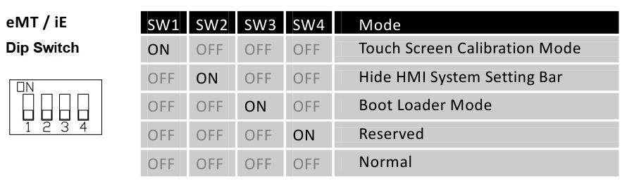
 Положение каждого DIP-переключателя 4 для каждого устройства может быть различным.
4.5 Панель инструментов системы
После перезагрузки панели можно настроить панель инструментов системы [System Toolbar] внизу экрана. Как правило, панель инструментов прячется автоматически. Панель инструментов системы высвечивается при касании иконки со стрелочкой в нижнем правом углу экрана. Справа налево представлены следующие иконки: системные настройки, информация о системе, текстовая клавиатура и цифровая клавиатура.

Как спрятать панель системных настроек:
- Когда переключатель [DIP Switch 2] включен (ON), панель системных настроек не отображается на экране. Когда переключатель выключен (OFF), панель отображается на экране. Чтобы эти настройки сработали, необходимо перезапустить панель.
- Чтобы в серии mTV спрятать панель системных настроек, необходимо переключить переключатель [DIP Switch 1] в положение (ON).
- В зависимости от положения системного тэга [LB-9020] панель системных настроек может также отображаться или не отображаться. Когда [LB-9020] включена (ON), панель отображается, когда выключена (OFF) — панель не отображается.
4.5.1 Настройка системы
Установите или измените системные параметры. Сначала подтвердите пароль безопасности. Заводской пароль по умолчанию — 111111.
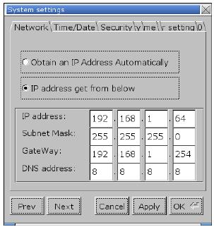 Сеть (Network)
Для загрузки проекта в панель по сети Ethernet необходимо задать IP-адрес панели. IP-адрес может быть назначен автоматически или может быть задан вручную. Чтобы воспользоватья Email и EasyAccess2.0, необходимо задать правильный DNS-адрес.
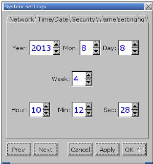 Время/Дата (Time/Date)
Настройка системного времени и даты.
 Защита (Security)
Пароль по умолчанию: 111111. Для установки пароля нажмите на соответствующие кнопки и завершите установку подтверждением пароля.
[Password for entering system] — пароль для входа в систему
[Password for uploading project] — пароль для выгрузки проекта
[Password for downloading project] — пароль для загрузки проекта
[Password for uploading history data] — пароль для выгрузки архивных данных
 Архив (History)
Инструмент для удаления архивных данных из панели оператора.
 Имя панели (HMI name)
Назначьте имя панели для загрузки/выгрузки проекта
 Настройки прошивки (Firmware setting)
[Upgrade OS] Функция обновления прошивки
Обновите прошивку, при этом обязательно обеспечьте включенное состояние во время процесса. Для более подробной информации обратитесь к соответствующему разделу инструкции используемой панели.
[Portrait mode] активация режима «Портрет»
Уставка вертикальной/горизонтальной ориентации экрана. После изменения режима, чтобы настройка вступила в силу, необходимо полностью отключить питание панели и затем включить заново. Если используется портретный режим (90 или 270 градусов), то проект должен быть специально разработан для работы в таком режиме, иначе отображение будет неверным.
 Виртуальный сервер (VNC server)
Удаленное наблюдение и контроль за панелью через Ethernet.
[Start VNC single-connection] позволяет установить соединение с одним VNC-клиентом.
[Start VNC multi-connection] позволяет установить соединение с различными VNC-клинтами. Соединение с большим количеством VNC-клиентов замедляет скорость подключения.
Этапы установки приведены в следующей части.
 Прочее (Miscellaneous)
Используйте колесико для настройки яркости жидкокристаллического дисплея.
Если выбрано [Popup download window] и в панель вставлен USB-диск или SD-карта, отобразится диалоговое окно Загрузки/Выгрузки.
При выборе [Restart after download/upload], панель перезагрузится автоматически после выгрузки/загрузки проекта.
 Misc 2
Если выбрано [Hide mouse cursor], курсор мыши будет скрыт.
Если выбрано [Enable [Reset HMI to default] button in calibration mode], то после калибровки тач-скрина показывается кнопка [Reset HMI to default] — сброс панели в исходное состояние. В режим калибровки тач-скрина панель переходит при нажатии в любом месте экрана более двух секунд.
Если выбрано [FTP client can modify USB/SD data], то данные могут модифицироваться через FTP.
[Modify HMI ports] Изменение номеров портов для загрузки/выгрузки и FTP.
 EasyAccess 2.0
Для активации EasyAccess 2.0.
Этапы установки VNC сервера:
1. Запустите VNC сервер и установите пароль.
2. Установите надстройки Java IE или VNC Viewer на компьютере.
3. Введите IP-адрес панели оператора в интернет браузер. Или В VNC viewer введите IP-адрес панели и пароль.
4.5.2 Информация о системе
Network: Информация о сети, включая IP-адрес панели и др.
Version: Информация о версии системы.
4.6 Функция «Облегченная настройка системы» [EasySystemSetting]
Функция «облегченная настройка системы» позволяет обновить системные настройки оборудования при помощи SD карты или USB-накопителя. Доступно для панелей OS версии 20131106 или более поздних.
[HMI name] Ввод имени панели.
[Back light] Настройка яркости подсветки жидкокристаллического дисплея.
[Time offset] Задайте смещение для RTCпанели. Например, если текущее время RTC -15:00:00, а временное смещение задано-3, обновленное время будет 12:00:00.
[Protrait mode] Установите режим визуального отображения (ориентацию экрана)
| Настройки | Описание |
|---|---|
| Общие | |
| Импорт | Импорт и редактирование существующего файла в формате .conf |
| Экспорт | Экспорт сконфигурированных данных в файл формата.conf |
| По умолчанию | Восстановление исходных параметров |
Далее описано, как обновить IP-адрес панели с использованием SD-карты или USB- накопителя.
1. На панели инструментов EasyBuilder Pro нажмите [Tools] » [Build Download Data for SD / USB Disk] и отметьте «галочкой» [Use system setting].
2. Нажмите на кнопку [Системные настройки], чтобы открыть диалогового окна редактора системных настроек. Укажите информацию о сети панели согласно рисунку, приведенному ниже.
3. Нажмите [Файл]->[Сохранить] для создания файла “systemsetting.conf”.
4. Закройте окно EasySystemSetting (Облегченная настройка системы).
5. Нажмите кнопку [Сформировать] в диалоговом окне [Формирование данных для USB диска/CF карты] для создания загрузочного файла с использованием SD-карты или USB-накопителя.
6. Вставьте запоминающее устройство, которое сохраняет загрузочный файл в панель и появляется диалоговое окно Загрузка/Выгрузка.
7. Нажмите [Load System setting], и появится сообщение [Download Config Settings]. После завершения системных настроек файл проекта будет обновлен.
Источник
Выгрузка проекта из HMI WEINTEK
Сообщение
demonlibra » 09 янв 2016 18:49
Для выгрузки проекта из HMI WEINTEK проще всего использовать usb-flash
— включить HMI и дождаться загрузки
— вставить флэшку в USB-HOST (проверено на 8gb и 16gb разметкой с FAT32)
— выбрать upload
— ввести пароль (по умолчанию 111111)
!!!!!!!!!!!!!!!!!!!!!!!!!!!!!!!!!!!!!!!!!!!!!!!!!!!!!!!!!!!!!!!!!!!!!!!!!!
Если в списке присутствует только два пункта
— upload all project files
— upload history files
то выгрузка проекта из HMI запрещена разработчиком программы
Выбрав функцию «upload all project files» можно выгрузить резервную копию программы
без возможности вносить изменения.
!!!!!!!!!!!!!!!!!!!!!!!!!!!!!!!!!!!!!!!!!!!!!!!!!!!!!!!!!!!!!!!!!!!!!!!!!!
— выбрать «upload project» для выгрузки проекта и получения возможности редактирования программы
— раскрыть список каталогов на носителе «usbdisk» и выбрать каталог для выгрузки проекта
— нажать «OK»
— дождаться завершения копирования
— извлечь флэшку
На флешке будет архив проекта с расширением «exob».
Для открытия проекта, файл с расширением «exob» необходимо декомпилировать. В программе EasyBuilder присутствует соответствующая функция.
— Создать в редакторе проекта данные для импорта с USB носителя
- Tools
Build Data for USB Disk …..
Указать путь
Build
— путь на флешки должен быть следующего вида
- …disk_a_1mt8000ie…
— скопировать полученное содержимое на флэшку
— Включить HMI и дождаться загрузки
— вставить флэшку в USB-HOST (проверено на 8gb и 16gb разметкой с FAT32)
— выбрать «Download»
— ввести пароль 111111
— выбрать «Download project files»
— раскрыть список каталогов на носителе usbdisk
- и выбрать путь с программой …disk_a_1
!!! не выбирать каталог внутри …disk_a_1
— нажать «OK»
— дождаться завершения копирования
— извлечь флэшку
Программу для открытия проекта можно скачать с сайта http://www.weintek.com производителя после прохождения регистрации.
Для eMT3000/IE/mTV/cMT/XE/iER необходимо использовать EasyBuilder Pro,
для MT6000T/i, MT8000T/X/i — EasyBuilder8000.
Не бойся поломать. Бойся не починить ))

“Where” Put touch screens online, they are all at your hand- Easy Access is not so important. EasyAccess User manual http://www.ihmi.net EasyAccess User’s Manual EasyAccess 1. EasyAccess Introduction...........................................................................2 Overview...................................................................................................2 What Can EasyAccess Do?......................................................................2 When to Use EasyAccess and Improve Convenience for Users? ............2 How EasyAccess Differs from VNC ..........................................................2 System Requirements...............................................................................2 How to Start? ............................................................................................3 2. Public/Private IP and NAT Concept ..........................................................4 3. Easy Access Settings ...............................................................................7 Port and System Register Needed in HMI ................................................7 Virtual Server Settings in Router...............................................................8 Check and Memorize Your MAC address .................................................8 Visit www.ihmi.net to Login HMI Info.........................................................9 Open Your Project in EasyBuilder8000...................................................10 A Nickname for Your HMI........................................................................12 Few Points to be Confirmed Again..........................................................13 4. Easy Access Client .................................................................................14 Installing EasyAccess Client ...................................................................14 Executing EasyAccess.exe.....................................................................14 Synchronizing in EasyAccess History.....................................................16 Use EasyAccess in Local Network .........................................................18 Restrictions of Objects When Running Remote Control .........................19 5. Notes(Important) ................................................................................21 1 EasyAccess User’s Manual 1. EasyAccess Introduction Overview The purpose of EasyAccess is for users to control remote HMI instantly and conveniently no matter which corners in the world you are. Via Internet, users can login HMI to Weintek EasyAccess Server. Server then obtains HMI location and related information. You can then use EasyAccess Client on PC to observe all your HMIs on-line, and pick one to execute remote control. What Can EasyAccess Do? Centralized management of multiple HMIs remote or in LAN. Operate HMIs remote (Ex: HMI in a remote factory.) or in LAN on local PC. Remote control with highly efficient Data Transmission (unlike VNC Image File Transmission). Select VNC or Easy Access using Easy Access Client to control HMIs. When to Use EasyAccess and Improve Convenience for Users? When you’d like to manage multiple HMIs in group. (Including Upload/Download project.) When the HMIs you manage are distributed everywhere and all with different IP addresses that are difficult to be memorized and identified. How EasyAccess Differs from VNC EasyAccess is more efficient than VNC in the way of transmission. EasyAccess can centralize management of multiple HMIs. EasyAccess allows users not to memorize IP addresses of HMIs. EasyAccess costs less than VNC in across LAN settings. System Requirements PC ( XP/VISTA/Windows 7) i-Series HMI / X-Series HMI 2 EasyAccess User’s Manual OS image: MT8000i 20100818 or later, MT8000X 20100906 or later. EasyBuilder 8000 4.2.0 or later. How to Start? Firstly, just enable your HMI to connect with Internet. That is to give HMI a Public IP address for external access. Once the network environment of HMI is settled, users can use EasyAccess. The way of setting is similar to using VNC to remote control HMI from another LAN. (Or build a FTP/HTTP server for external access).The steps of web setting are same. If you encounter difficulties in assigning Public IP to HMI, Please refer to 2.Public/Private IP and NAT Concept. If you already know how to assign it, please read from 3. EasyAccess Settings. If your HMI is not connected to Internet through Router/NAT/Firewall, no settings for Router are needed for using EasyAccess. 3 EasyAccess User’s Manual 2. Public/Private IP and NAT Concept Suppose one day you want to invite your colleague in the same office for lunch, usually, you just pick up the phone and dial his extension number (maybe 107) to find him. But for inviting your customer for lunch, you have to call first the main number of his company then extension in order to find him. Similarly, except for service hotline, companies won’t give each of its employees a personal main number in general. Every person outside your company looking for you needs to know the main number of your company and your extension number, only to call you. Let’s get back to the subject. Usually when we communicate with remote PC, 2 types of info are needed: IP and Port. If you access external network through a router, the IP will be separated to Public and Private. Take the phone example above, for outside, Public IP is the main number of the company, and Port is the extension. What about Private IP? It is the extension inside. But how can we tell the difference of Port and Private IP? Please see illustration below. Inside your office (LAN) Kevin Larry Joey IP: 192.168.1.107 Port 21 Port 8000 IP: 192.168.1.118 Port 21 Port 8000 IP: 192.168.1.230 Port 21 Port 8000 There are 3 computers in the same office belong to Kevin, Larry, and Joey. Each of them owns an IP individually, but starts with 192.168.x.x. This is the typical feature of Private IP. In other words, computers in your office may all have IPs with 192.168.x.x. It is possibly the same as for the computers in your customer’s factory. What is more coincident is that, maybe among the computers in your office and your customer’s factory, you both have the computer with IP 192.168.1.107. 4 EasyAccess User’s Manual However, when you get communication with 192.168.1.107, you are linked to Kevin’s computer instead of your customer’s. This is as when calling extension number 107, you can talk with your colleague but not someone who also has extension number 107 in your customer’s office. For more information about Private IP, please refer to RFC1918 - Address Allocation for Private Internets. The illustration above also shows that, even the IP of the 3 computers differ from each other, they are all individually set with Port 21 and Port 8000. Every Port represents one kind of service. Take phone case as example, Port 21 is a typical FTP service port which is not a regulation, but is commonly known. Port 8000 is the default of Weintek HMI set for communication, which is also not the regulation. You can modify this default from 【EasyBuilder 8000 menu Æ Edit (E) Æ System Parameter Settings (Y) Æ ModelÆ Port no. 】. For the following, let’s see the example after adding Firewall/NAT/Router. Your Company Internet Public IP: 202.87.116.20 Port 20021 Port 20022 Port 18000 Port 18001 Firewall / NAT/ Router NAT Port Mapping (Virtual Server) Public IP Private IP Port 20021 Æ 192.168.1.107:21 Port 20022 Æ 192.168.1.118:21 Port 18000 Æ 192.168.1.107:8000 Port 18001 Æ 192.168.1.118:8000 LAN Kevin Larry Private IP: 192.168.1.107 Port 21 Port 8000 Private IP: 192.168.1.118 Port 21 Port 8000 As mentioned, companies won’t assign phone numbers for each employee (too costly). Similarly, every single computer in the office won’t have a Public IP for external access individually in general. Take the extension number example, the receptionist will transfer calls for us only if we have correct extension numbers. As for computer communication, the NAT (Network Address Translation) plays the role of receptionist. NAT not only helps us to reduce the need of precious Public IP, but also blocks we from the attacks of hackers come from Internet, just like a professional receptionist rejecting unnecessary calls from salesmen. 5 EasyAccess User’s Manual Illustration above shows a Firewall, and added another set of Public IP & Ports. With NAT, we can use Port Mapping Table to tell how to transmit packets coming from Public IP to correct Private IP, just like the receptionist always has an extension number list. Of course, if you wish to block away all external connections for one of the ports of your PC, there’s no need to set Port Mapping Table in NAT correspondingly. Most of the router products in the market nowadays have NAT/Firewall/Router function. Please note: the Port Mapping Table mentioned in this manual is called (Virtual Server) in most of routers in the market. From now on in this manual we’ll call it Virtual Server Conclusion: The role of PC in the example shown in this manual can all be viewed as HMI, since HMI itself is a computer, which you can set IP and Port for it. Weintek i/X series HMI currently support EasyAccess function. Except for the HMI port originally set for communication (default: 8000 can be user-defined), FTP port is added (fixed to 21, can’t be changed). The newly added FTP port is allowed for EasyAccess function only. 6 EasyAccess User’s Manual 3. Easy Access Settings Port and System Register Needed in HMI FTP Port No. 21: Standard FTP function,used to transmit XOB file and History file in Easy Access. This port number can't be changed, that is:It will always be 21 in every HMI. Users should set FTP port mapping in Virtual Server. Example: [Public 202.200.13.60:20021] Æ[Private 192.168.1.107:21] HMI Port NO. 8000: It’s the communication port you may know. You can change it from EB8000 menu【Edit (E)Æ System Parameter Settings (Y)ÆModelÆPort no.】. Its role in EasyAccess is to control remote HMI. Users should set HMI port mapping in Virtual Server. Example:[Public 202.200.13.60:18000]Æ[Private 192.168.1.107:8000] VNC Port NO 5900: This Port is unchangeable on HMI, but other port numbers can be set in Virtual Server for mapping. LB9051: Defined as the permission for HMI to log in Easy Access (ON: Login available; OFF: Login unavailable). LB9052: Defined to show if HMI is connected to EasyAccess Server. (ON: Connected; OFF: Disconnected). 7 EasyAccess User’s Manual Virtual Server Settings in Router The illustration below shows a setting example of Virtual Server, it differs in routers from different companies, please refer to each router’s user manual In the blue frame, HMI IP is set as 192.168.10.20, FTP Port as 21, mapped to Public Port 5000, HMI Port as 8000, and mapped to Public Port 8000. Public Private Port 5000 Æ 192.168.10.20:21 Port 8000 Æ 192.168.10.20:8000 Check and Memorize Your MAC address Go to System information/Network in HMI tool bar, check MAC address. It is 00:22:2F:B5:90:05 in this example as shown. Remember the address since it will be used in further settings. Here we remind users to note a common mistake easy to make, B is easily mixed up with 8 and vice versa, please take a second look. 8 EasyAccess User’s Manual Visit www.ihmi.net to Login HMI Info. All the info of HMI related to EasyAccess must be registered in www.ihmi.net. The required info: MAC, FTP Port (Public), HMI Port (Public). Please plan your Port Mapping properly before registration. Firstly, visit www.ihmi.net and input your User ID and Password (the same as in Weintek forum), the following will be shown after login successfully. The illustration below shows there’s one HMI successfully registered. Click +Add in window below. A pop-up window will then be shown. Input HMI MAC ADDRESS and your HMI Port, FTP Port, VNC Port in Virtual Server. Please note again:HMI & FTP & VNC Port here refer to Public Port for external access in Virtual Server. In MODEL TYPE i Series or X Series can be selected, and make notation in NOTE section. Click Save after filling in everything. EasyAccess Server will then allow the HMI to login. 9 EasyAccess User’s Manual Open Your Project in EasyBuilder8000 Go to【Edit (E)Æ System Parameter Settings (Y)ÆModelÆPort no.】and input your planned HMI Port No. Note:HMI Port here is set in your HMI, meaning that adding IP makes it as a Private IP(example:192.168.1.107:8000). In other words, you must match HMI Port No. with the Private IP in Virtual Server as shown below. 10 EasyAccess User’s Manual Then, Check【Edit (E)ÆSystem Parameter Settings (Y)ÆSystem SettingÆLogin EasyAccess Server】. Compile project and download it to HMI. 11 EasyAccess User’s Manual A Nickname for Your HMI Return to HMI setting bar, go to 【System settingsÆHMI name】to input a name for HMI and click OK then Reboot HMI. From now on, when you manage your HMI in EasyAccess, this name will be used to identify HMI. You don’t have to memorize IP address any more. The following shows Default HMI in HMI name, which is the default value. 12 EasyAccess User’s Manual Few Points to be Confirmed Again OS image version (MT8000i 20100818 or later, MT8000X 20100906 or later). EasyBuilder 8000 Version (4.2.0 or later)。 Is the HMI MAC address registered in www.ihmi.net correct? Are the HMI Port, FTP Port registered in www.ihmi.net the externally accessible ports of Virtual Server? Are the Virtual Server HMI Port, FTP Port, and VNC Port for external access correctly mapped to HMI Port, FTP Port, and VNC Port of HMI? Is the number set in【Edit (E)Æ System Parameter Settings (Y)ÆModelÆPort no.】in HMI project the one you planned? Does it match to the setting in Virtual Server? Did you check【Edit (E)ÆSystem Parameter Settings (Y)ÆSystem SettingÆLogin EasyAccess Server】in HMI Project? Does your HMI have a nickname? Did you reboot HMI? Is the status of LB9051 ON? Does the Router you set in Virtual Server need to be rebooted after setting? A while after confirming and rebooting, LB9052 must be ON, which shows HMI login EasyAccess Server in www.ihmi.net successfully. 13 EasyAccess User’s Manual 4. Easy Access Client Installing EasyAccess Client Please go to www.ihmi.net and download EasyAccess Client (ZIP format). Uncompress it, find Setup.exe. The installation procedure is simple and therefore we skip the details here (Just click Next then Next). The default directory is C:EasyAccess. Executing EasyAccess.exe Execute C:EasyAccessEasyAccess.exe (default) then window below is shown. 2 options are provided on top of this dialogue box, Easy Access and Local Network. The former is for operating HMI logged in to Easy Access Server, the later is for operating HMI in LAN. Here we select Easy Access. 14 EasyAccess User’s Manual Input ID and Password in ID: and Password: columns, the same as those in www.ihmi.net then click Search. At this moment, the Grid on the upper right of the window will display all the information of the HMIs you registered on the website. If the HMIs are already logged in to EasyAccess Server, they will be displayed in black font on the upper part of Grid. If the HMIs are not logged in to EasyAccess Server, they will be grayed and are displayed on the lower part with the [off-line] label ahead of the NAME. In the Grid the NAME、HMI PORT、FTP PORT will be displayed. NAME is the Nickname you gave your HMI, you can identify HMI with it so no need to memorize IP. EasyAccess needs XOB file of HMI project to run remote control. If you don't have it, please select Use remote HMI's XOB file then input directory and file name(as shown above). This will be used later when saving project. If you already have XOB file, select Use an existing XOB file, input directory or click Browse to find it. EasyAccess will directly use this project file to run remote control. Click Easy Access to activate remote control. If you select Use remote HMI’s XOB file, before remote controlling, the remote project will be got first. There will be a Progress Bar in the window to show the progress of transmission. The bottom of the window also reports current status. Network Environment Testing… is for testing if the current network environment is able to run EasyAccess. This test is checking the number of router hops. More than one router hop may disable the execution of EasyAccess. There can still be some other reasons EasyAccess cannot be run even to pass this test. Launch VNC enables you to execute VNC simulation for HMIs logged in to EAS server. Firstly, please click VNC executable to specify your VNC executable. Visit EasyAccess website to fill in for HMI the available port that you already opened for VNC on the router. The default VNC port of 15 EasyAccess User’s Manual EasyAccess website is 5900. If you would like to block the external VNC communication with your HMI, please do not open Port mapping on the router. In addition, the default VNC port for communication in LAN is 5900 which can’t be modified, and will be used without any setting. Download is for downloading the xob file to your specified HMI, including the HMIs not logged in to EAS server (must be connected to internet). Synchronizing in EasyAccess History Before you execute EasyAccess, you can choose whether to get history data of remote HMI or not. After getting the data, it will be loaded together when remote controlling. In the red circle, when click Easy Access, if Synchronize history is checked, historical data of remote HMI will be synchronized before running remote control. 16 EasyAccess User’s Manual In EasyAccess main dialogue box, if Synchronize history is checked, Sync. Setting… button will be enabled. Click it to do detailed settings. After pressing Sync. Setting…, EasyAccess Sync History Setting dialogue box will appear as below. If Sync. All history is checked; it means users want to synchronize all historical data. (All data, neglecting dates). If Clear old history is checked, before synchronizing, old historical data in 17 EasyAccess User’s Manual C:EasyAccessHMI_memory(default)will all be erased first. If not checked, old data will be reserved. But the old data will be overwritten by new data in a period of time set by users. Use two Calendar buttons to set time period , Please note that the Start date: goes before the End date: After selecting, press OK to enable synchronizing. Use EasyAccess in Local Network 18 EasyAccess User’s Manual Please click Local Network, the display is shown above. Select Name tab and input the desired name in HMI Name field then click Search. Search All is for viewing all HMIs in LAN. You may select IP tab to specify an IP address to run EasyAccess. The way to operate is same as selecting Easy Access. Restrictions of Objects When Running Remote Control When running remote control, project in remote HMI will run without stopping. You can even run different projects to remote control, which is an advantage of EasyAccess. This section lists the restrictions in objects when remote controlling. Object EasyAccess Animation Backup data is from Recipe or History in PC, not HMI. Backup Bar Graph Bit Lamp Data Block Display History Data Display History data is from PC, not HMI. Data Sampling History data is stored in PC and this won’t change the content of history data in HMI. Data T (Time-based) ransfer Disable Direct Window Alarm Bar PC will only display the alarm triggered after executing EasyAccess. Alarm Display PC will only display the alarm triggered after executing EasyAccess. Event Display Real-Time: PC will only display the alarm triggered after executing EasyAccess. Historical: History data is from PC, not HMI. Event Log History data is stored in PC and this won’t change the content of history data in HMI. Function Key Disable screen hardcopy 19 EasyAccess User’s Manual Object EasyAccess Indirect Window ASCII Input Meter Display Moving Shape Media Player Play the media in PC, not in HMI. Multi State Numeric Input Option List Changing Window: Allow PLC Control Retrieving Current Base Window: Disable General PLC Control: Disable Backlight Control (write back): Disable Backlight Control: Disable Audio Control: Allow Macro: Disable Screen Hardcopy: Disable Data Touch Trigger: Allow Transfer(Trigger-based) Bit Trigger: Disable Scheduler Disable Set Word Disable auto. Slider Timer Disable Set Bit Disable auto. Toggle Switch Trend Display Real-Time: PC will only display the Sampled Data recorded after executing EasyAccess. Historical: History data is from PC, not HMI. Word Lamp XY Plot 20 EasyAccess User’s Manual 5. Notes(Important) When you revise any HMI info in www.ihmi.net (HMI Port or FTP Port), please click Search again in EasyAccess Client to properly update the info. If you change HMI name, the HMI must logout EasyAccess Server then login again. (You may use LB9051 to logout or just reboot HMI.) If your router has DMZ function, disable it. If your router has no ALG (Application Layer Gateway) function, you can only normally run EasyAccess with one HMI. The reason is: Router without ALG limits your Port 21 for external access to be mapped only to Port 21 of one IP in the network. Also, Virtual Server allows only one FTP service to run for external access. The way of using ALG in a router varies from one to other. The extreme case can go:Router limits you to set FTP service to Port 21, which will disable EasyAccess to operate normally. If it doesn’t work for multi-HMI to execute Easy Access following this manual, please refer to manual of each router or enquire the router supplier. The *.xob file uploaded from EasyAccess can be decompiled. If users would like to protect the project from being decompiled for safety, please tick Decompilation is prohibited when compiling the project. Weintek HMI Corp. 48501 Warm Springs Blvd. STE #102 Fremont, CA 94539 Tel:+1 (510) 897-6670 Web: www.weintekhmi.com Email:[email protected] 21
- Manuals
- Brands
- weintek Manuals
- Gateway
- cMT Series
- User manual
-
Contents
-
Table of Contents
-
Bookmarks
Quick Links
Related Manuals for weintek CMT Series
Summary of Contents for weintek CMT Series
-
Page 1
User Manual V1.0.1… -
Page 2: Table Of Contents
Table of Contents Chapter1. Overview ……………………….1 1.1. Specification ……………………….1 1.2. Dimensions ……………………….2 1.3. Pin Assignment ……………………… 3 1.4. Restoring factory default ……………………3 1.5. LED indicator ……………………….3 1.6. Battery …………………………4 1.7. Power connection ……………………..4 1.8.
-
Page 3
Edit Node ……………………….27 6.5. Certificates ……………………….28 6.6. Discovery ……………………….29 6.7. Advanced ……………………….30 Chapter7. Installing Weintek Built-in CODESYS ……………….. 31 Chapter8. Connecting cMT-CTRL01 CODESYS ………………..33 8.1. Connecting Through Network ………………….33 8.2. Creating CODESYS Project …………………… 33 Chapter9. -
Page 4: Overview
cMT-CTRL01 User Manual Chapter1. Overview 1.1. Specification CODESYS PLC with IIoT Gateway Features CODESYS PLC compliant with IEC61131-3 Fan-less Cooling System Built- in 4GB Flash Memory and RTC SD Card Slot Supports SD/SDHC Cards Rich combination of iR Series Modules Gateway …
-
Page 5: Dimensions
cMT-CTRL01 User Manual 英文版 1.2. Dimensions Top View 50mm [1.97″] 81mm [3.19″] Side View Side View Front View Bottom View RUN/STOP switch LAN 1 Reset Button LAN 2 COM1: RS-232, COM2: RS-485 2W/4W, SD Card Slot COM3: RS-485 2W Power Connector Expansion Connector V1.0.1…
-
Page 6: Pin Assignment
cMT-CTRL01 User Manual 1.3. Pin Assignment COM1 [RS232], COM2 [RS-485 2W/4W], COM3 [RS-485 2W], 9 Pin, Male, D-sub COM2 [RS-485] COM1 COM3 PIN# [RS-232] [RS-485] 2W Data+ Data- Data+ Data- 1.4. Restoring factory default Press and hold on the Reset button on the unit for more than a certain period of time when the RUN/Stop toggle switch (CODESYS switch) is in STOP state: Period of time ERR LED…
-
Page 7: Battery
For more information on battery replacement and disposal considerations, please refer to the following link: http://www.weintek.com/download/MT8000/eng/FAQ/FAQ_103_Replace_Battery_en.pdf 1.7. Power connection Power: The unit can be powered by DC power only, the voltage range is compatible with most controller DC systems.
-
Page 8: Power Consumption
cMT-CTRL01 User Manual Power Connector Specifications: Wire AWG: 24~12 Wiring Conductor Minimum Temperature: 75°C Screw Torque: 4.5 lbf-in (max.) Copper conduct only Note: Connect positive DC line to the ‘+’ terminal and the DC ground to the ‘-‘ terminal. 1.8. Power Consumption Type Device Consumption(5V)
-
Page 9: Chapter2. Cmt-Ctrl01 System Setting
Connect cMT-CTRL01 via Ethernet cable, and then configure system settings by the following ways. 2.1. Search for cMT-CTRL01’s IP address Launch UtilityManagerEX. On the top-left menu select cMT Series, and then select a function from Reboot, Download, or Upload. cMT-CTRL01 can be found in the IP/HMI Name group box by using the model’s IP address, even if the PC or laptop is not on the same network.
-
Page 10: System Setting
cMT-CTRL01 User Manual cMT-CTRL01 system information is shown in the Login page, and the language used can be changed in this page. Icon Description Displays HMI name. Displays system date. Displays system time. Please note that by default, LAN 2 is assigned for Gateway (DHCP). 2.3.
-
Page 11: Network
cMT-CTRL01 User Manual Three levels of privileges can be found: [System Setting]: Controls all the settings [Update]: Controls limited items. [History]: Downloads history data (Recipes and Event Logs). 2.3.1. Network Configure Ethernet ports: IP, Mask, Gateway, and DNS. cMT-CTRL01 is equipped with dual Ethernet ports that can be freely assigned as one of the following: One Ethernet port for CODESYS (LAN1, DHCP) and the other one for IIoT Gateway (LAN2 DHCP).
-
Page 12: Hmi Name
cMT-CTRL01 User Manual 2.3.3. HMI Name Enter a name to identify the unit. [Identification light]: The LED indicator of the unit will flash three times when this button is clicked, helping user to find the unit. 2.3.4. History This tab offers settings related to historical data. [Clear]: Clears history data.
-
Page 13: Email
cMT-CTRL01 User Manual 2.3.5. Email This tab offers settings related to email. [SMTP]: Configure email server and relevant settings. [Contacts]: Set email contacts in this tab. [Update Email Contacts]: Import the email contacts built using Administrator Tools. 2.3.6. Project Management This tab offers settings related to project management.
-
Page 14: System Password
cMT-CTRL01 User Manual [Update Project]: Upload the project’s *.cxob file to cMT-CTRL01. [Backup Project]: Backup the project file to this computer. [USB/SD Update]: Use the project file stored in the external device to update the project file on cMT-CTRL01. 2.3.7. System Password Set login password and the password for transferring project file.
-
Page 15: Easyaccess 2.0 (Optional)
cMT-CTRL01 User Manual 2.3.9. EasyAccess 2.0 (Optional) This tab shows Hardware Key, EasyAccess 2.0 activate status, and proxy settings. For more information on EasyAccess 2.0, please see EasyAccess 2.0 User Manual. 2.3.10. OPA UA Configure OPC UA settings. Please see “Chapter 6 OPC UA Web Management Interface” in this manual for details.
-
Page 16
cMT-CTRL01 User Manual V1.0.1… -
Page 17
cMT-CTRL01 User Manual Parameters that can be viewed and modified for a device connected via COM port. Interface Baud rate Data Bits Parity Stop Bits Timeout Parameter 1 Parameter 2 Send ACK Delay Parameters that can be viewed and modified for a device connected via Ethernet. IP Address Port Timeout… -
Page 18: Chapter3
cMT-CTRL01 User Manual Chapter3. Updating Web Package and OS cMT-CTRL01 Web Package and OS can be updated through Ethernet. Launch Utility ManagerEX, select [Gateway Series] » [Maintenance] » [cMT-Gateway OS Update]. 3.1 Updating Web Package 1. Select an HMI to update OS. 2.
-
Page 19
cMT-CTRL01 User Manual 2. Select [OS], a Warning message shows, please read this message carefully before you click [OK]. 3. If you click [OK], the cMT-Gateway OS Update window opens again, browse for the source file, and then click [Update]. 4. -
Page 20
cMT-CTRL01 User Manual V1.0.1… -
Page 21: Chapter4
cMT-CTRL01 User Manual Chapter4. How to create a cMT-CTRL01 project This chapter explains how to create a project when cMT-CTRL01 is used as an OPC UA Server. The basic steps are: 1. Add a driver into Device List in EasyBuilder Pro. 2.
-
Page 22: Download Project To Cmt-Ctrl01
cMT-CTRL01 User Manual Step 3. Click [IIoT/Energy] » [OPC UA Server], and select [Enable] check box to enable OPC UA Server. Step 4. Click [Tags] of the device and then click [New Tag] to add tags monitored using OPC UA. When finished, click [OK] to leave.
-
Page 23
cMT-CTRL01 User Manual [Compile] to compile the project into *.cxob format. When finish compiling, you can download the project to cMT-CTRL01 by two ways. Way 1: Download using EasyBuilder Pro. Click [Project] » [Download(PC->HMI)], and set HMI IP address. The project can be downloaded via Ethernet. Way 2: Download using website. -
Page 24: Monitoring Opc Ua Client
cMT-CTRL01 User Manual 4.3. Monitoring OPC UA Client After downloading the project file, use OPC UA Client software to connect with cMT-CTRL01 to monitor PLC data. Note: The above is a screenshot of UaExpert. For more information on OPC UA Client software settings, please see OPC UA server manual.
-
Page 25
cMT-CTRL01 User Manual Step 3. In On-line Simulation, data in PLC tags will also change. V1.0.1… -
Page 26: Chapter5. Functions Supported By Cmt-Ctrl01
User Manual Chapter5. Functions supported by cMT-CTRL01 OPC UA Server http://www.weintek.com/download/EBPro/Document/UM016009E_OPC_UA_UserManual_en.pdf EasyAccess 2.0 (Optional) http://www.weintek.com/download/EasyAccess20/Manual/eng/EasyAccess2_UserManual_en.pdf Modbus TCP/IP Gateway OPC UA Client MQTT Server / MQTT Subscriber / MQTT Publisher Administrator Tools Time synchronization (NTP) …
-
Page 27: Chapter6
cMT-CTRL01 User Manual Chapter6. OPC UA Web Management Interface 6.1. Introduction cMT-CTRL01 provides a web-based tool for convenient access to OPC UA configurations. Open cMT-CTRL01’s webpage by entering its IP address into the address bar of a web browser. At the entry page, log in with System setting’s password.
-
Page 28: Startup / Shut Down
cMT-CTRL01 User Manual Usage of each window tab: Description Configure server settings such as port, name, security, user Server settings authentication……etc. Edit node Manage tags used by OPC UA server. Certificates Manage certificates used by OPC UA server. Discovery Manage list of discovery server. Advanced Advanced options and features.
-
Page 29
cMT-CTRL01 User Manual General Function Port Access port of the OPC UA server Server name Server name of the OPC UA server Supported security policies. At least one must be selected. Security policy Supported Policy: None, Basic128Rsa15, Basic256, Basic256sha256 Mode: Sign, Sign & Encrypt Automatically Trust all client certificates: by enabling this option, the Option OPC UA server will trust the certificate from any client connection. -
Page 30: Edit Node
cMT-CTRL01 User Manual After completing settings, click the Save button to save the changes. OPC UA server will shut down momentarily and then restart for the changes to take effect. 6.4. Edit Node In this page, the user can view and manage the tags currently available in the OPC UA server. New nodes and groups can be added, while existing nodes and groups can be edited or deleted.
-
Page 31: Certificates
cMT-CTRL01 User Manual Note that all modifications can only be made for existing drivers. It is not possible to change or add other drivers that are not already available. It is also not possible to edit the nodes used by tag PLCs*.
-
Page 32: Discovery
cMT-CTRL01 User Manual Page Description Lists of trusted/rejected client certificates on the server. Trusted Clients Supported operation: Trust/Reject, Remove, Import, Export. Lists of trusted/rejected user certificates on the server. Supported Trusted Users operation: Trust/Reject, Remove, Import, Export. Server’s own certificate. Supported operation: Update, Remove.
-
Page 33: Advanced
cMT-CTRL01 User Manual After completing settings, click the Save button to save the changes. OPC UA server will shut down momentarily and then restart for the changes to take effect. 6.7. Advanced Additional settings can be configured in the Advanced tab. The user can set the trace logging level and specific startup behavior of the OPC UA server.
-
Page 34: Chapter7. Installing Weintek Built-In Codesys
User Manual Chapter7. Installing Weintek Built-in CODESYS Installing Weintek Built-in CODESYS allows users to easily create a cMT+CODESYS project in CODESYS software. Please find the Package file we prepared and follow these steps for quick installation. First, get a copy of CODESYS Package file.
-
Page 35
cMT-CTRL01 User Manual The installed component will be shown in the installation summary. V1.0.1… -
Page 36: Chapter8
cMT-CTRL01 User Manual Chapter8. Connecting cMT-CTRL01 CODESYS 8.1. Connecting Through Network Connect cMT-CTRL01’s LAN 1 port with a router or PC. Open internet browser (IE, Chrome, Firefox, Safari), enter cMT-CTRL01’s IP address (e.g. 192.168.100.1), and then configure cMT-CTRL01 settings. Open CODESYS page to see the IP address. By default DHCP is used for cMT-CTRL01 CODESYS IP.
-
Page 37
User Manual Select Weintek Built-in CODESYS. CODESYS software provides 6 languages that can be selected in [PLC_PRG in:] drop-down list as shown below. Structure Text (ST) is used as an example in this manual. Double-click on Device (Weintek Built-in CODESYS) to open the settings window. -
Page 38
cMT-CTRL01 User Manual The project will connect the selected device. IP address of the device can be entered in the field shown below. V1.0.1… -
Page 39: Chapter9. Creating Easybuilder Project
cMT-CTRL01 User Manual Chapter9. Creating EasyBuilder Project *Please use EasyBuilder Pro v6.04.01 or later versions. 9.1. Creating Tags Create several tags in PLC_PRG tab and make tag “test” accumulate automatically. 9.2. Exporting Tags Right-click on Application in Devices tree and then select [Add Object] » [Symbol Configuration], use defaults.
-
Page 40: Configuring Easybuilder
User Manual 9.3. Configuring EasyBuilder Create a project and select Weintek Built-in CODESYS in the device list. Open Tag Manager and click , and then click [Import Tag] to import the *.xml file built in preceding steps. The CODESYS tags can now be found in Tag Manager.
-
Page 41: Chapter10
cMT-CTRL01 User Manual Chapter10. Connecting cMT-CTRL01 CODESYS to iR Series Modules Right-click on [iBus (iBus)] and then select [Add Device]. Select an iR module and then click [Add Device]. The added device can be found under iBus. You may add more modules with this window is left opened.
-
Page 42
cMT-CTRL01 User Manual Analog modules, other modules, and their settings. iBus has two addresses in BYTE type that show low voltage and I/O error. Open PLC_PRG in Devices tree and configure variables as shown below. In Devices tree double click on an iR module name to open object settings window. In iROption I/O Mapping tab, select a variable for the object. -
Page 43
cMT-CTRL01 User Manual When finished, click [Online] » [Login] to download the project to CODESYS. V1.0.1… -
Page 44: Chapter11
cMT-CTRL01 User Manual Chapter11. Connecting cMT-CTRL01 to iR-ETN 11.1. Connecting cMT-CTRL01 to iR-ETN Right-click on Device (cMT-CTRL01) and then select [Add Device]. Select [Ethernet Adapter] » [Ethernet] and then click [Add Device]. Ethernet (Ethernet) can be found in Devices tree. Double-click on Ethernet with the current window opened in Devices tree or right-click on Ethernet and then select [Add Device].
-
Page 45
cMT-CTRL01 User Manual select [Add Device]. Double click on Ethernet in the Devices tree, enter CODESYS’s IP address in General tab, and then select [Change Operating System Settings]. When [Use operating System Settings] is selected, settings on cMT-CTRL01 will be used without being changed. When CODESYS is already connected, go to General tab and click the […] button near Interface field and select eth0. -
Page 46
cMT-CTRL01 User Manual Open [Modbus Slave Channel] tab and create Modbus Variable. Open PLC_PRG in Devices tree, create tag and set Bool as data type. Write a command as shown below. V1.0.1… -
Page 47: Connecting Codesys And Modbus Tcp/Ip Gateway
cMT-CTRL01 User Manual Open Modbus_TCP_Slave in Devices tree and then go to [Modbus_TCPSlave I/O Mapping] tab to set up iR-ETN’s IP address and Unit ID. When finished, click [Online] » [Login] to download the project to CODESYS. 11.2. Connecting CODESYS and Modbus TCP/IP Gateway cMT-CTRL01 supports Modbus TCP/IP Gateway which allows CODESYS to access Modbus TCP/IP Gateway using Modbus TCP Slave, in order to control the devices connected to Modbus TCP/IP Gateway.
-
Page 48
cMT-CTRL01 User Manual objects to read. When setting Modbus Slave Channel, Cycle Time can be configured to adjust the frequency at which data is written to the registers. For more information on Modbus Gateway, please see EasyBuilder Pro User Manual Chapter 37 MODBUS TCP IP Gateway. -
Page 49: Chapter12
User Manual Chapter12. Removing Weintek Built-in CODESYS Click [Tools] » [Packages Manager]. Find Weintek Built-in CODESYS and then click [Uninstall]. Click [Next] when seeing the window below. Removing the program. Click [Finish]. V1.0.1…
-
Page 50
cMT-CTRL01 User Manual V1.0.1… -
Page 51: Chapter13
cMT-CTRL01 User Manual Chapter13. Frequently Asked Questions 13.1. Questions Related to CODESYS When the indicator of CODESYS Gateway lights up in red, how can I connect to the device? A: When CODESYS Gateway is not properly started or installed, its indicator will light up in red. Please try the following 3 methods to solve this situation.
-
Page 52: Questions Related To Downloading Cmt Codesys File
How to update CODESYS firmware? There are 2 ways to update CODESYS firmware. Launch Utility Manager and select cMT Series » Maintenance » CODESYS Firmware Update. Browse for the firmware file and click [Update]. Enter cMT HMI’s IP address in the website browser and find [CODESYS] » [CODESYS update] tab.
-
Page 53
cMT-CTRL01 User Manual Enter cMT HMI’s IP address in the website browser and find [CODESYS] » [Project update] tab. Select the files generated in the previous step and click [Update]. V1.0.1…
Check error code in «EasyAccess 2.0 Setting» or LW-10829 (16bit)
Please check if your HMI is already activated or not. To activate HMI, please reference How to activate an HMI
Your HMI can not connect to EasyAccess 2.0 server
- Please help check your network settings (Ex: firewall), also check connections to EasyAccess 2.0 server lists.
if your IT environment have strict rule, please add those servers to your firewall white list.
License Key has expired. Please check with your distributor.
Open and close client too frequently.
HMI client will auto-upgrade to make sure compatibility. Please wait until auto-upgrade finish.
HMI client will connect to server again after upgrade finish.
Client program does not exist in HMI memory. Please upgrade OS to solve this issue.
HMI client will auto-upgrade to make sure compatibility. Re-dwnload is scheduled after 10 minutes.
You can also stop EasyAccess 2.0 and start again.
If you still see the same error code. Please check connections to EasyAccess 2.0 account server
- Global
- account.ihmi.net (54.171.161.211:443)
- China
- www.easyaccess.cn (47.98.131.242:443)
Please stop EasyAccess 2.0 and start again when network connection ready.
Your HMI can not connect to EasyAccess 2.0 account server. Please help check your network settings (Ex: firewall).
If your IT environment have strict rule, please add EasyAccess 2.0 account server to your firewall white list.
- Global
- account.ihmi.net (54.171.161.211:443)
- China
- www.easyaccess.cn (47.98.131.242:443)
Please stop EasyAccess 2.0 and start again when network connection ready.
Hardware key can not be generated. Please stop EasyAccess 2.0 and start again.
If you still see the same error code. Please contact our customer service.
Hardware key can not be generated. Please stop EasyAccess 2.0 and start again.
If you still see the same error code. Please contact our customer service.
HMI session id / password can not be generated. Please stop EasyAccess 2.0 and start again.
Please check your network settings
- Gateway setting might be wrong (Ex: 0.0.0.0), please enter correct garteway.
- Check the proxy setting. Error occurs if it is enabled but value doesn’t set. If you don’t use proxy, please keep the Proxy setting «Disable».
Please check you network settings
- DNS setting might be wrong. You can try some public DNS to see if it works.
- Global server
- 8.8.8.8
- China server
- 223.5.5.5
- Global server
Please check your proxy setting
- If you don’t use proxy, please keep the Proxy setting «Disable».
Your HMI can not connect to EasyAccess 2.0 authentication server. Please help check your network settings (Ex: firewall).
If your IT environment have strict rule, please add EasyAccess 2.0 authentication server to your firewall white list.
- Global
- auth.ihmi.net (54.238.174.31:443)
- China
- auth.easyaccess.cn (47.99.111.36:443)
Please stop EasyAccess 2.0 and start again when network connection ready.
Please check if you HMI «Time/Date» setting in system setting is correct.
If problem still happens. Maybe your IT environment have strict rule.
Please add EasyAccess 2.0 server lists to your firewall white list.
Your HMI can not connect to EasyAccess 2.0 account server. Please help check your network settings (Ex: firewall).
If your IT environment have strict rule, please add EasyAccess 2.0 account server to your firewall white list.
- Global
- account.ihmi.net (54.171.161.211:443)
- China
- www.easyaccess.cn (47.98.131.242:443)
Please stop EasyAccess 2.0 and start again when network connection ready.
Click «start» on EasyAccess 2.0 page or system setting to get correct Hardware Key.
After getting the correct Hardware Key. You might see the error code : 1 (Not activated)
Please click «Setup» to scan EA 2.0 QRCode to activate HMI by activation card.
Click «start» on EasyAccess 2.0 page or system setting if HMI is already activated.
1. Check adapters in Network Connections
Press the Windows key and the R key at the same time to open the Run box. Type ncpa.cpl and hit Enter and you can access Network Connections immediately.
2. Check adaptors in Network Connections, if EasyAccess 2.0 driver installed correctly, you should see two adapters : OVPN & EasyAccessVPN
3. Try to uninstall adapters and relaunch EasyAccess 2.0 again to see if the problem solved
- Open «Command Prompt» in administrator mode (Run as administrator)
- Type «cd C:\Program Files (x86)\EasyAccess 2.0\vpn\driver\x64»
- Type «devcon.exe remove tap0901» to remove all adapters
- Relaunch EasyAccess 2.0
4. If problem is not solved, try to install adapters manually might also solve this problem
- Type «devcon.exe remove tap0901» to remove all adapters as in previous step
- Type «devcon.exe install OemWin2k.inf tap0901» to install a new adapter
- Rename new installed adapter to «OVPN»
- Type «devcon.exe install OemWin2k.inf tap0901» to install a new adapter
- Rename new installed adapter to «EasyAccessVPN»
- Open EasyAccess 2.0
На чтение 4 мин Опубликовано Обновлено
Weintek HMI Diagnostic Tool — это важный инструмент для диагностики и исправления ошибок, возникающих в устройствах HMI (Human-Machine Interface) от компании Weintek. В процессе эксплуатации HMI-панелей, возникают различные проблемы, которые можно обнаружить и исправить с помощью этого инструмента.
Коды ошибок Weintek HMI Diagnostic Tool представляют собой числовые или буквенно-числовые комбинации, которые указывают на конкретную проблему в работе устройства. Каждый код ошибки имеет своё описание и соответствующий способ его исправления.
Примеры кодов ошибок включают в себя: «E001», «E102», а также «A10», «B06» и т.д. Для каждого кода ошибки предусмотрен алгоритм действий, который помогает оператору или инженеру быстро определить и исправить проблему.
Например, код ошибки «E001» обычно указывает на проблему с питанием устройства. Для исправления этой ошибки оператору необходимо проверить подключение электропитания и убедиться в стабильности напряжения. Если проблема не устранена, рекомендуется обратиться к специалисту.
Коды ошибок Weintek HMI Diagnostic Tool очень полезны в работе операторов и инженеров, поскольку они помогают быстро и точно определить причину неисправности и принять необходимые меры. Это существенно экономит время и ресурсы, а также повышает эффективность работы всей системы HMI.
Содержание
- Коды ошибок Weintek HMI Diagnostic Tool
- Ошибки и их значения
- Исправление ошибок
В процессе использования Weintek HMI Diagnostic Tool при работе с HMI панелями производителя Weintek могут возникать различные ошибки. Коды ошибок помогают идентифицировать и исправить проблемы, возникшие во время работы с панелей HMI.
Ниже приведены некоторые распространенные коды ошибок Weintek HMI Diagnostic Tool:
| Код ошибки | Описание | Исправление |
|---|---|---|
|
Error 1000 |
Коммуникационная ошибка. Связь между HMI и программным обеспечением Diagnostic Tool прервана или неправильно настроена. |
Проверьте подключение HMI к компьютеру и настройки коммуникационных параметров. Перезапустите Diagnostic Tool. |
|
Error 2000 |
Ошибка чтения или записи данных. Diagnostic Tool не может корректно прочитать или записать данные в HMI. |
Убедитесь, что HMI подключена к компьютеру и работает исправно. Проверьте доступность дискового пространства на компьютере. Перезапустите Diagnostic Tool. |
|
Error 3000 |
Неправильный формат файла проекта. Diagnostic Tool не может открыть или загрузить файл проекта HMI из-за неправильного формата. |
Убедитесь, что файл проекта имеет правильный формат. Если файл поврежден, попробуйте открыть резервную копию проекта. Если проблема сохраняется, обратитесь к разработчикам Diagnostic Tool. |
Обратите внимание, что это лишь некоторые из возможных кодов ошибок Weintek HMI Diagnostic Tool. Если вы столкнулись с другой ошибкой, рекомендуется обратиться к документации производителя или поддержке Weintek для получения дополнительной информации и помощи в решении проблемы.
Ошибки и их значения
При работе с Weintek HMI Diagnostic Tool могут возникать различные ошибки. Здесь представлены наиболее распространенные ошибки и их значения:
- Ошибка 100: Программа не может установить соединение с устройством. Проверьте правильность подключения и настройки соединения.
- Ошибка 200: Неправильный тип устройства или неподдерживаемая версия ПО. Обновите ПО или проверьте совместимость с Вашим устройством.
- Ошибка 300: Ошибка чтения данных с устройства. Проверьте работоспособность устройства и соединения.
- Ошибка 400: Ошибка записи данных на устройство. Проверьте правильность настроек и возможные ограничения на устройстве.
- Ошибка 500: Невозможность запустить команду на устройстве. Проверьте правильность команды и настройки устройства.
Если Вы столкнулись с ошибкой, убедитесь, что Вы внимательно прочитали сообщение ошибки и выполните соответствующие действия для исправления проблемы. Если ошибка не устраняется, обратитесь в техническую поддержку Weintek для получения дальнейшей помощи.
Исправление ошибок
При возникновении ошибок на устройствах Weintek HMI Diagnostic Tool рекомендуется сначала выполнить несколько простых действий для их устранения:
- Перезагрузите устройство: Попробуйте выключить и снова включить Weintek HMI Diagnostic Tool. Это может помочь исправить некоторые временные проблемы.
- Проверьте подключение: Убедитесь, что устройство правильно подключено к источнику питания и другим необходимым компонентам. Проверьте кабели на наличие повреждений или несоответствий.
- Обновите прошивку: Проверьте, что у вас установлена последняя версия прошивки для Weintek HMI Diagnostic Tool. Если нет, обновите ее, следуя инструкциям производителя.
- Проверьте настройки: Проверьте все настройки на устройстве, включая сетевые настройки, настройки языка и другие параметры. Убедитесь, что все настройки соответствуют конфигурации вашей системы.
Если после выполнения вышеуказанных действий проблема не решается, можно обратиться к специалистам Weintek для получения дополнительной поддержки. Перед этим стоит иметь в виду, что они могут потребовать дополнительной информации о вашем оборудовании и настройках, чтобы лучше понять проблему и предложить наиболее эффективное решение.
Важно помнить, что Weintek HMI Diagnostic Tool – это сложное устройство, и его ремонт может потребовать глубоких знаний и опыта. В некоторых случаях может быть необходимо обратиться к производителю или авторизованному сервисному центру для осуществления ремонта или замены деталей.