
61
9 Diagnostics and service
VEGAFLEX 81 • 4 … 20 mA/HART — four-wire
41825-EN-130314
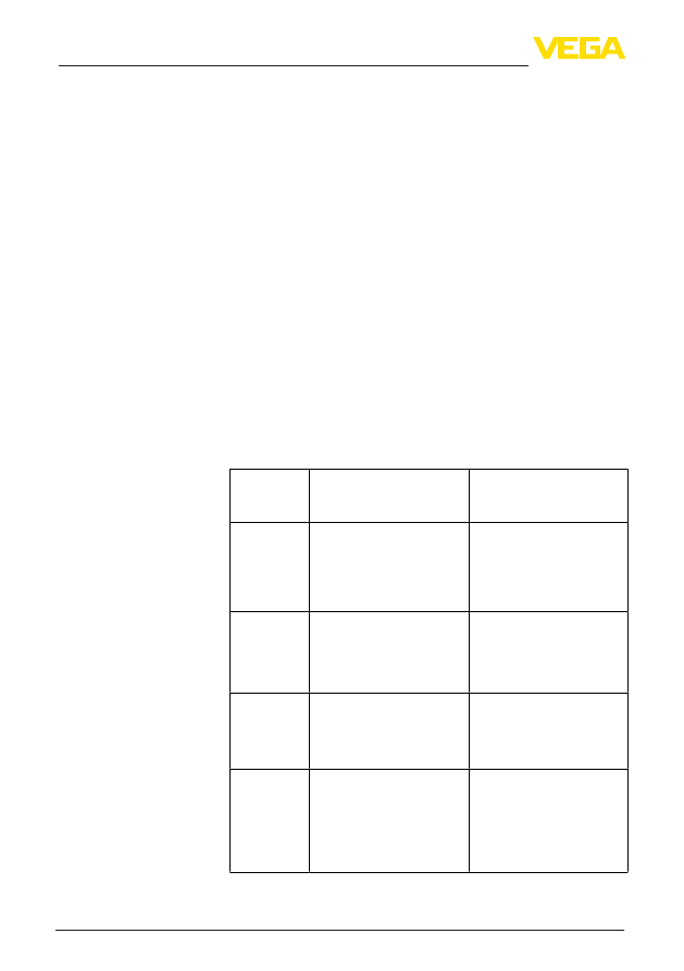
Code
Text mes-
sage
Cause
Rectification
F260
Error in the
calibration
– Error in the calibration car-
ried out in the factory
– Error in the EEPROM
– Exchanging the electronics
– Send instrument for repair
F261
Error in the
instrument
settings
– Error during setup
– Error when carrying out a
reset
– False signal suppression
faulty
– Carry out a reset
– Repeat setup
F264
Installation/
Setup error
– Error during setup
– Check or correct installation
and/or parameter adjust-
ment
– Check probe length
F265
Measurement
function dis-
turbed
– Sensor no longer carries
out a measurement
– Carry out a reset
– Separate operating voltage
briefly
F266
Impermissi-
ble operating
voltage
– Operating voltage below
specified range
– Check electrical connection
– if necessary, increase
operating voltage
F267
No executable
sensor soft-
ware
– Sensor cannot start
– Exchanging the electronics
– Send instrument for repair
The following table shows the error codes and text messages in the
status message «Function check» and provides information on causes
as well as corrective measures.
Code
Text mes-
sage
Cause
Rectification
C700
Simulation ac-
tive
– A simulation is active
– Finish simulation
– Wait for the automatic end
after 60 mins.
The following table shows the error codes and text messages in the
status message «Out of specification» and provides information on
causes as well as corrective measures.
Code
Text mes-
sage
Cause
Rectification
S600
Unpermissi-
ble electronics
temperature
– Temperature of the pro-
cessing electronics in the
non-specified section
– Check ambient temperature
– Isolate electronics
– Use instrument with higher
temperature range
Function check
Out of specification
-
Contents
-
Table of Contents
-
Bookmarks
Quick Links
Operating Instructions
TDR sensor for continuous level and
interface measurement of liquids
VEGAFLEX 81
Profibus PA
Coax probe
Document ID: 44214
Related Manuals for Vega VEGAFLEX 81
Summary of Contents for Vega VEGAFLEX 81
-
Page 1: Operating Instructions
Operating Instructions TDR sensor for continuous level and interface measurement of liquids VEGAFLEX 81 Profibus PA Coax probe Document ID: 44214…
-
Page 2: Table Of Contents
Parameter adjustment with PACTware …………….48 Set up with the quick setup ………………… 49 Saving the parameterisation data ………………. 51 Set up with other systems ………………..52 DD adjustment programs ………………..52 Diagnostics and servicing ………………..53 Maintenance ……………………53 VEGAFLEX 81 • Profibus PA…
-
Page 3
Safety instructions for Ex areas Take note of the Ex specific safety instructions for Ex applications. These instructions are attached as documents to each instrument with Ex approval and are part of the operating instructions manual. Editing status: 2017-09-14 VEGAFLEX 81 • Profibus PA… -
Page 4: About This Document
Symbols used Document ID This symbol on the front page of this instruction refers to the Docu- ment ID. By entering the Document ID on www.vega.com you will reach the document download. Information, tip, note This symbol indicates helpful additional information.
-
Page 5: For Your Safety
During work on and with the device the required personal protective equipment must always be worn. Appropriate use VEGAFLEX 81 is a sensor for continuous level measurement. You can find detailed information about the area of application in chapter «Product description».
-
Page 6: Eu Conformity
The environment management system is certified according to DIN EN ISO 14001. Please help us fulfil this obligation by observing the environmental instructions in this manual: • Chapter «Packaging, transport and storage» • Chapter «Disposal» VEGAFLEX 81 • Profibus PA…
-
Page 7: Product Description
• Order-specific sensor data for an electronics exchange (XML) • Test certificate (PDF) — optional Go to «www.vega.com», «Instrument search (serial number)». Enter the serial number. Alternatively, you can access the data via your smartphone: VEGAFLEX 81 • Profibus PA…
-
Page 8: Principle Of Operation
Principle of operation Application area The VEGAFLEX 81 is a level sensor with coax probe for continuous level or interface measurement, suitable for applications in liquids. Functional principle — High frequency microwave pulses are guided along a steel cable or level measurement a rod.
-
Page 9
Distance to the interface d2 Distance to the level TS Thickness of the upper medium (d1 — d2) h1 Height — Interface h2 Height — Level L1 Lower medium L2 Upper medium L3 Gas phase VEGAFLEX 81 • Profibus PA… -
Page 10: Packaging, Transport And Storage
Ascertained transit damage or con- cealed defects must be appropriately dealt with. Storage Up to the time of installation, the packages must be left closed and stored according to the orientation and storage markings on the outside. VEGAFLEX 81 • Profibus PA…
-
Page 11: Accessories And Replacement Parts
PACTware with VEGA-DTM is required. You can find further information in the operating instructions «Interface adapter VEGACONNECT» (Document-ID 32628). VEGADIS 81 The VEGADIS 81 is an external display and adjustment unit for VEGA plics sensors. ® For sensors with double chamber housing the interface adapter «VEGADIS adapter»…
-
Page 12
10 m (147 ft) to the sensor by using a connection cable. You can find additional information in the operating instructions manual «External housing» (Document-ID 46802). VEGAFLEX 81 • Profibus PA… -
Page 13: Mounting
Make sure before mounting that all parts of the instrument exposed to Suitability for the process conditions the process are suitable for the existing process conditions. These are mainly: • Active measuring component • Process fitting • Process seal Process conditions in particular are: VEGAFLEX 81 • Profibus PA…
-
Page 14: Mounting Instructions
By doing this, you avoid damage to the electronics through inductive coupling. Inflowing medium Do not mount the instruments in or above the filling stream. Make sure that you detect the product surface, not the inflowing product. VEGAFLEX 81 • Profibus PA…
-
Page 15
If there is a danger of the coaxial probe touching the vessel wall, then the probe must be fastened at the bottom end. Keep in mind that measurement is not possible below the fastening point. VEGAFLEX 81 • Profibus PA… -
Page 16
4 Mounting Fig. 6: Fasten the probe 1 Coax probe Retaining sleeve VEGAFLEX 81 • Profibus PA… -
Page 17: Connecting To Power Supply
Prior to setup you have to replace these protective caps with ap- proved cable glands or close the openings with suitable blind plugs. On plastic housings, the NPT cable gland or the Conduit steel tube must be screwed into the threaded insert without grease. VEGAFLEX 81 • Profibus PA…
-
Page 18: Connecting
4. Remove approx. 10 cm (4 in) of the cable mantle, strip approx. 1 cm (0.4 in) of insulation from the ends of the individual wires 5. Insert the cable into the sensor through the cable entry VEGAFLEX 81 • Profibus PA…
-
Page 19
You can find further information on the max. wire cross-section under «Technical data — Electromechanical data». 7. Check the hold of the wires in the terminals by lightly pulling on them 8. Connect the screen to the internal ground terminal, connect the external ground terminal to potential equalisation VEGAFLEX 81 • Profibus PA… -
Page 20: Wiring Plan, Single Chamber Housing
Wiring plan, double chamber housing The following illustrations apply to the non-Ex as well as to the Ex-ia version. Electronics compartment 6 7 8 Fig. 10: Electronics compartment — double chamber housing Internal connection to the terminal compartment 2 Contact pins for the display and adjustment module or interface adapter Selection switch for bus address VEGAFLEX 81 • Profibus PA…
-
Page 21: Double Chamber Housing With Vegadis-Adapter
1 VEGADIS adapter Internal plug connection Plug connector M12 x 1 Assignment of the plug connector Fig. 13: View to the plug connector M12 x 1 Pin 1 Pin 2 Pin 3 Pin 4 VEGAFLEX 81 • Profibus PA…
-
Page 22: Wiring Plan — Version Ip 66/Ip 68, 1 Bar
PACTware/DTM (address setting via software) The hardware addressing is effective if an address <126 is set with Hardware addressing the address selection switches on the instrument. Software address- ing is then no longer effective, the set hardware address applies. VEGAFLEX 81 • Profibus PA…
-
Page 23: Switch-On Phase
The addressing procedure is described in the operating instructions manual «Display and adjustment module. Switch-on phase After VEGAFLEX 81 is connected to the bus system, the instrument carries out a self-test for approx. 30 seconds. The following steps are carried out: •…
-
Page 24: Set Up With The Display And Adjustment Module
The display and adjustment module is powered by the sensor, an ad- ditional connection is not necessary. Fig. 16: Installing the display and adjustment module in the electronics compart- ment of the single chamber housing VEGAFLEX 81 • Profibus PA…
-
Page 25: Adjustment System
If you intend to retrofit the instrument with a display and adjustment module for continuous measured value indication, a higher lid with an inspection glass is required. Adjustment system Fig. 18: Display and adjustment elements 1 LC display Adjustment keys • Key functions [OK] key: VEGAFLEX 81 • Profibus PA…
-
Page 26
Any values not confirmed with [OK] will not be saved. Switch-on phase After switching on, the VEGAFLEX 81 carries out a short self-test where the device software is checked. The output signal transmits a fault signal during the switch-on phase. -
Page 27: Parameter Adjustment — Quick Setup
Display: Language setting, settings for the measured value indication as well as lighting Diagnosis: Information, for example on the instrument status, pointer, reliability, AI FB 1 simulation, echo curve Additional adjustments: Sensor address, PIN, date/time, reset, copy sensor data VEGAFLEX 81 • Profibus PA…
-
Page 28
Hardware addressing is effective if an address less than 126 is set with the address selection switches on the electronics module of VEGAFLEX 81. In such case, software addressing has no effect — only the set hardware address applies. Software addressing Software addressing is only effective if address 126 or higher is set on the instrument with the address selection switches. -
Page 29
Note: The selection of the application has a considerable influence on all other menu items. Keep in mind that as you continue with the param- eter adjustment, individual menu items are only optionally available. VEGAFLEX 81 • Profibus PA… -
Page 30
You can directly enter the dielectric constant of the upper medium or have the value determined by the instrument. If you want the dielectric constant to be determined by the instrument, you have to enter the measured or known distance to the interface. VEGAFLEX 81 • Profibus PA… -
Page 31
The distance refers tot he sensor reference plane (seal surface of the process fitting). Setup — Max. adjustment — This menu item is only available if you have selected interface meas- Interface urement under the menu item «Application». VEGAFLEX 81 • Profibus PA… -
Page 32
This should be done with the lowest possible level so that all potential interfering reflections can be detected. Proceed as follows: Select first if the probe is covered or uncovered. VEGAFLEX 81 • Profibus PA… -
Page 33
«Display». Warning: If a linearisation curve is selected, the measuring signal is no longer necessarily linear to the filling height. This must be considered by the VEGAFLEX 81 • Profibus PA… -
Page 34
D Vessel height +h Positive socket correction value -h Negative socket correction value Setup — AI FB1 Since the adjustment is very comprehensive, the menu points of Function Blocks 1 (FB1) were put together in a submenu. VEGAFLEX 81 • Profibus PA… -
Page 35
The default setting is a damping of 0 s. Lock/unlock setup — Ad- In the menu item «Lock/unlock adjustment», you can protect the sen- justment sor parameters against unauthorized or inadvertent modification. The PIN is activated/deactivated permanently. VEGAFLEX 81 • Profibus PA… -
Page 36
Display — Displayed value In this menu item, you define the indication of the measured value on the display. You can display two different measured values. In this menu item, you define measured value 2. VEGAFLEX 81 • Profibus PA… -
Page 37
«Setup — Application», the peak values of the interface measurement are displayed in addition to the peak values of the level measurement. In another window you can carry out a reset of the two peak values separately. VEGAFLEX 81 • Profibus PA… -
Page 38
Diagnostics — Echo curve The menu item «Echo curve» shows the signal strength of the echoes over the measuring range in V. The signal strength enables an evalua- tion of the quality of the measurement. VEGAFLEX 81 • Profibus PA… -
Page 39
PACTware and the PC, the high-resolution echo curve can be displayed and used to compare the echo curve of the setup with the actual echo curve. The function «Echo curve memory» enables storing echo curves of the measurement. VEGAFLEX 81 • Profibus PA… -
Page 40
The following table shows the default values of the instrument. De- pending on the instrument version or application, all menu items may not be available or some may be differently assigned: VEGAFLEX 81 • Profibus PA… -
Page 41
Distance: Probe length — take dead band into account Setup Integration time — Level 0.0 s Integration time — Interface 0.0 s Setup Linearisation type Linear Linearisation — Socket correction 0 mm Linearisation — Vessel height Probe length VEGAFLEX 81 • Profibus PA… -
Page 42
Electronics temperature Backlight Switched on Menu — Diagnosis Menu Menu item Default value Diagnostics Status signals — Function control Switched on Status signals — Out of specification Switched off Status signals — Maintenance Switched off VEGAFLEX 81 • Profibus PA… -
Page 43
Device memory — Measured value memory — Stop Not active recording when memory is full Menu — Additional adjustments Menu Menu item Default value Additional settings 0000 Date Actual date Time Actual time Time — Format 24 hours Probe type Device-specific VEGAFLEX 81 • Profibus PA… -
Page 44
AI FB3 Hysteresis 0.50 % AI FB3 Fail Safe Mode (behaviour in case of mal- Last Valid Out Value (last valid function) measured value) AI FB3 Fail Safe Value 0.00 % AI FB3 Target Mode Auto VEGAFLEX 81 • Profibus PA… -
Page 45
In exceptional cases, individual parameters can be modified in order to adapt the sensor to special requirements. Change the settings of the special parameters only after having con- tacted our service staff. VEGAFLEX 81 • Profibus PA… -
Page 46: Saving The Parameterisation Data
The following data or settings for adjustment of the display and ad- justment module are saved: • All data of the menu «Setup» and «Display» • The items «Sensor-specific units, temperature unit and linearisa- tion» in the menu «Additional settings». VEGAFLEX 81 • Profibus PA…
-
Page 47
If it is necessary to exchange a sensor, the display and adjustment module is inserted into the replacement instrument and the data are likewise written into the sensor via the menu item «Copy device settings». VEGAFLEX 81 • Profibus PA… -
Page 48: Setup With Pactware
Further setup steps are described in the operating instructions manu- al «DTM Collection/PACTware» attached to each DTM Collection and which can also be downloaded from the Internet. Detailed descrip- tions are available in the online help of PACTware and the DTMs. VEGAFLEX 81 • Profibus PA…
-
Page 49: Set Up With The Quick Setup
The standard version is available as a download under www.vega.com/downloads and «Software». The full version is avail- able on CD from the agency serving you. Set up with the quick setup…
-
Page 50
2 Extended adjustment Maintenance Quick setup With quick setup you can carry out the parameter adjustment of VEGAFLEX 81 for your application in just a few simple steps. The assistant-driven adjustment includes the basic settings for simple, reliable setup and commissioning. Information: If the function is inactive, then possibly no instrument is connected. -
Page 51: Saving The Parameterisation Data
7 Setup with PACTware Saving the parameterisation data We recommend documenting or saving the parameterisation data via PACTware. That way the data are available for multiple use or service purposes. VEGAFLEX 81 • Profibus PA…
-
Page 52: Set Up With Other Systems
Set up with other systems DD adjustment programs Device descriptions as Enhanced Device Description (EDD) are available for DD adjustment programs such as, for example, AMS™ and PDM. The files can be downloaded at www.vega.com/downloads under «Software». VEGAFLEX 81 • Profibus PA…
-
Page 53: Diagnostics And Servicing
Changes in the measure- ment conditions during operation or buildup on the sensor can thus be recognized. The echo curve of the setup is stored via: • PC with PACTware/DTM • Control system with EDD VEGAFLEX 81 • Profibus PA…
-
Page 54: Status Messages
Maintenance: Due to external influences, the instrument function is limited. The measurement is affected, but the measured value is still valid. Plan in maintenance for the instrument because a failure is expected in the near future (e.g. due to buildup). VEGAFLEX 81 • Profibus PA…
-
Page 55
Error in the EEPROM bration • • F261 Error during setup Repeat setup Bit 9 • • False signal suppression faulty Repeat reset Error in the in- • Error when carrying out a reset strument settings VEGAFLEX 81 • Profibus PA… -
Page 56
Remove possible interfering signals in the close range • Use coaxial probe • • S602 Compensation echo superim- 100 % adjustment: Increase value Bit 25 posed by medium Level within the search range, compensation echo VEGAFLEX 81 • Profibus PA… -
Page 57: Rectify Faults
PACTware and the suitable DTM. In many cases, the reasons can be determined in this way and faults rectified. Treatment of measure- The below tables show typical examples for application-relevant ment errors measurement errors. There are two measurement errors: VEGAFLEX 81 • Profibus PA…
-
Page 58
Check parameter «Medium» mains in the area of the than the product echo, for exam- and «Vessel height», adapt if bottom during filling ple, with products with ε < 2.5 necessary oil-based, solvents, etc. time VEGAFLEX 81 • Profibus PA… -
Page 59: Exchanging The Electronics Module
24 hour service hotline Should these measures not be successful, please call in urgent cases the VEGA service hotline under the phone no. +49 1805 858550. The hotline is also available outside normal working hours, seven days a week around the clock.
-
Page 60: Software Update
You can find an instrument return form as well as detailed informa- tion about the procedure in the download area of our homepage: www.vega.com. By doing this you help us carry out the repair quickly and without hav- ing to call back for needed information. VEGAFLEX 81 • Profibus PA…
-
Page 61
Attach the completed form and, if need be, also a safety data sheet outside on the packaging • Please contact the agency serving you to get the address for the return shipment. You can find the agency on our home page www.vega.com. VEGAFLEX 81 • Profibus PA… -
Page 62: Dismount
Pass the instrument directly on to a spe- cialised recycling company and do not use the municipal collecting points. These may be used only for privately used products according to the WEEE directive. VEGAFLEX 81 • Profibus PA…
-
Page 63: Supplement
Ʋ Inspection window in housing cover Polycarbonate (with Ex d version: glass) (optional) Ʋ Ground terminal 316L Ʋ Cable gland PA, stainless steel, brass Ʋ Sealing, cable gland Ʋ Blind plug, cable gland Not suitable for hot steam applications. VEGAFLEX 81 • Profibus PA…
-
Page 64
Ʋ Aluminium/Stainless steel housing max. 50 Nm (36.88 lbf ft) Input variable Measured variable Level of liquids Min. dielectric constant of the medium ε ≥ 1.4 Output variable Output signal digital output signal, format according to IEEE-754 VEGAFLEX 81 • Profibus PA… -
Page 65
Ʋ Medium Water/Oil (dielectric constant ~2.0) Ʋ Mounting Probe end does not touch the vessel bottom Sensor parameter adjustment No gating out of false signals carried out With interface measurement = 2.0. VEGAFLEX 81 • Profibus PA… -
Page 66
Depending on the mounting conditions, deviations can occur which can be rectified by adapting the adjustment or changing the measured value offset in the DTM service mode. The dead bands can be optimized via a false signal suppression. VEGAFLEX 81 • Profibus PA… -
Page 67
The following table shows the resulting deviation for some typical gases and vapours. The specified values refer to the distance. Positive values mean that the measured distance is too large, negative values that the measured distance is too small. VEGAFLEX 81 • Profibus PA… -
Page 68
Time span after a sudden measuring distance change by max. 0.5 m in liquid applications, max 2 m with bulk solids applications, until the output signal has taken for the first time 90 % of the final value (IEC 61298-2). VEGAFLEX 81 • Profibus PA… -
Page 69
-40°C / -40°F Fig. 37: Ambient temperature — process temperature, version with temperature adapter Ambient temperature Process temperature (depending on the seal material) Aluminium housing Plastic housing Stainless steel housing (precision casting) Stainless steel housing (electropolished) VEGAFLEX 81 • Profibus PA… -
Page 70
180 m (590.6 ft) Ʋ Min. bending radius 25 mm (0.984 in) with 25 °C (77 °F) Ʋ Diameter approx. 8 mm (0.315 in) Ʋ Colour — Non-Ex version Black Ʋ Colour — Ex-version Blue VEGAFLEX 81 • Profibus PA… -
Page 71
-40 … +85 °C (-40 … +185 °F) Resolution < 0.1 K Accuracy ±3 K Bluetooth interface (optional) Standard Bluetooth smart Effective range 25 m (82.02 ft) Voltage supply Operating voltage U Ʋ Non-Ex instrument 9 … 32 V DC VEGAFLEX 81 • Profibus PA… -
Page 72
IP 66/IP 68 (0.2 bar) Type 6P IP 68 (1 bar) Connection of the feeding power supply Networks of overvoltage category III unit Altitude above sea level Ʋ by default up to 2000 m (6562 ft) VEGAFLEX 81 • Profibus PA… -
Page 73: Communication Profibus Pa
Instruments with approvals can have different technical specifications depending on the version. For that reason the associated approval documents of these instruments have to be carefully noted. They are part of the delivery or can be downloaded under www.vega.com, «Instrument search (serial number)» as well as in the download area.
-
Page 74
11 Supplement Fig. 38: VEGAFLEX 81: Block diagram with AI FB 1 … AI FB 3 OUT values TB Transducer Block FB 1 … FB 3 Function Block Module of the PA sensors For the cyclic data traffic, VEGAFLEX 81 provides the following modules: • AI FB1 (OUT) – Out value of the AI FB1 after scaling • AI FB2 (OUT) –… -
Page 75
-10 -11 -12 -13 -14 -15 -16 -17 -18 -19 -20 -21 -22 -23 Sign Significant Significant Exponent Significant (Exponent — 127) Value = (-1) (1 + Significant) Fig. 40: Data format of the measured value VEGAFLEX 81 • Profibus PA… -
Page 76
Hi-Alarm tive advisory alarm — high limited 0 x 8d good (non-cascade) — ac- Lo-Lo-Alarm tive critical alarm — low limited 0 x 8e good (non-cascade) — ac- Hi-Hi-Alarm tive critical alarm — high limited VEGAFLEX 81 • Profibus PA… -
Page 77: Dimensions
11 Supplement 11.3 Dimensions The following dimensional drawings represent only an extract of all possible versions. Detailed dimensional drawings can be downloaded at www.vega.com/downloads under «Drawings». Plastic housing ~ 69 mm ~ 84 mm (2.72″) (3.31″) ø 79 mm ø 79 mm (3.11″)
-
Page 78
Fig. 44: Housing versions with protection rating IP 66/IP 68 (0.2 bar) — with integrated display and adjustment module the housing is 9 mm/0.35 in higher Stainless steel single chamber (electropolished) Stainless steel single chamber (precision casting) Stainless steel double chamber housing (precision casting) VEGAFLEX 81 • Profibus PA… -
Page 79
Fig. 45: Housing version with protection rating IP 66/IP 68 (1 bar) — with integrated display and adjustment module the housing is 9 mm/0.35 in higher Stainless steel single chamber (electropolished) Stainless steel single chamber (precision casting) Stainless steel double chamber housing (precision casting) VEGAFLEX 81 • Profibus PA… -
Page 80
SW 46 (1.81″) (G1½, 1½ NPT) G¾, ¾ NPT, G1, 1 NPT, G1½, 1½ NPT G1½, 1½ NPT ø 21,3 mm ø 42,2 mm (0.84″) (1.66″) Fig. 46: VEGAFLEX 81, threaded version Sensor length, see chapter «Technical data» Coaxial version ø 21.3 mm (0.839 in) Coaxial version ø 42.2 mm (1.661 in) VEGAFLEX 81 • Profibus PA… -
Page 81: Industrial Property Rights
Les lignes de produits VEGA sont globalement protégées par des droits de propriété intellec- tuelle. Pour plus d’informations, on pourra se référer au site www.vega.com. VEGA lineas de productos están protegidas por los derechos en el campo de la propiedad indus- trial. Para mayor información revise la pagina web www.vega.com.
-
Page 82
Functional principle 8 – Display and adjustment module with heating 12 Gas phase 30 – Electronics module 12 GSD file 73 Reset 40 Hardware addressing 22, 28 Scaling 35 Scaling unit 35 Sensor characteristics 46 VEGAFLEX 81 • Profibus PA… -
Page 83
INDEX Sensor status 37 Service hotline 59 Simulation 39 Software addressing 23, 28 Special parameters 45 Status bytes PA output value 76 Telegram configuration 75 Type label 7 Type of medium 29 Units 29 VEGAFLEX 81 • Profibus PA… -
Page 84
Subject to change without prior notice © VEGA Grieshaber KG, Schiltach/Germany 2017 VEGA Grieshaber KG Phone +49 7836 50-0 Am Hohenstein 113…
9 Диагностика и сервис
VEGAFLEX 81 • Profibus PA
44217-R
U-130930
Код Текстовое сообщение
Причина
Устранение
DevSpec Diagnosis
F036 Отсутствует исполнимое ПО
– Неудачное или прерванное обновление ПО
– Повторить обновление ПО
– Проверить исполнение электроники
– Заменить электронику
– Отправить устройство на ремонт
Bit 3
F040 Ошибка в электронике
– Аппаратная неисправность
– Заменить электронику
– Отправить устройство на ремонт
Bit 4
F080
– Общая ошибка ПО
– Кратковременно отключить рабочее напряжение
Bit 5
F105 Идет поиск измеренного значения
– Устройство находится в пусковой фазе и измеренное значение пока не может быть обнаружено
– Подождать до завершения пусковой фазы
– Длительность в зависимости от исполнения и параметрирования составляет до 3 мин.
Bit 6
F113 Ошибка связи
– Ошибка во внутренней связи устройства
– Кратковременно отключить рабочее напряжение
– Отправить устройство на ремонт
Bit 7
F125 Недопустимая температура электроники
– Температура электроники не в пределах спецификации
– Проверить температуру окружающей среды
– Изолировать электронику
– Применить устройство с более высоким температурным диапазоном
Bit 8
F260 Ошибка в калибровке
– Ошибка в выполненной на заводе калибровке
– Ошибка в EEPROM
– Заменить электронику
– Отправить устройство на ремонт
Bit 9
F261 Ошибка в конфигурации
– Ошибка при начальной установке
– Ошибки в памяти помех
– Ошибка при выполнении сброса
– Повторить начальную установку
– Повторить сброс
Bit 10
64
9 Диагностика и сервис
VEGAFLEX 81 • HART — со встроенным аккумулятором
44640-R
U-130510
Данное сообщение о статусе по умолчанию неактивно.
Пользователь может активировать его через PACTware/DTM или
EDD.
Вне спецификации (Out of specification): Измеренное
значение ненадежное, так как превышена спецификация
устройства (например температура электроники).
Данное сообщение о статусе по умолчанию неактивно.
Пользователь может активировать его через PACTware/DTM или
EDD.
Требуется обслуживание (Maintenance): Функция устройства
ограничена из-за внешних воздействий. Есть влияние на
измеренное значение, но измеренное значение действительное.
Для предупреждения отказа в ближайшее время (например из-
за налипаний), необходимо запланировать обслуживание.
Данное сообщение о статусе по умолчанию неактивно.
Пользователь может активировать его через PACTware/DTM или
EDD.
В следующей таблице даны коды ошибок и текстовые
сообщения о статусе «Failure» и указаны возможные
причины и меры по их устранению. Следует учитывать, что
некоторые данные действительны только для устройств в
четырехпроводном исполнении.
Код
Текстовое
сообщение
Причина
Устранение
F013
Отсутствует
измеренное
значение
– Датчик не обнаруживает
отраженного сигнала во
время работы
– Загрязнение или дефект
рабочей части или изме-
рительного зонда
– Проверить и исправить
монтаж и/или параметри-
рование
– Очистить или заменить
рабочую часть или изме-
рительный зонд
F017
Диапазон у-
становки
слишком ма-
лый
– Установка вне пределов
спецификации
– Изменить установку в
соответствии с пре-
дельными значениями
(разность между Min. и
Max. ≥ 10 мм)
F025
Ошибка в
таблице ли-
неаризации
– Опорные точки возрас-
тают не в непрерывной
последовательности,
например, из-за нелогич-
ной пары значений
– Проверить значения
таблицы линеаризации
– Таблицу линеаризации
удалить/создать новую
F036
Отсутствует
исполнимо-
е ПО
– Неудачное или прерван-
ное обновление ПО
– Повторить обновление
ПО
– Проверить исполнение
электроники
– Заменить электронику
– Отправить устройство на
ремонт
Failure
11 Supplement
Response:
Parameter
Set Receive to Transmit Delay
Report Receive to Transmit Delay
Request:
Parameter
Report Receive to Transmit Delay
Response:
Parameter
Report Receive to Transmit Delay
Error Code
EE-Error
FR-Error
LV-Error
80
Length
5 characters ASCII
Length
4 characters ASCII
Length
7 characters ASCII
Name
Error While Storing Data in EEPROM
Erorr in Frame (to short, to long, wrong data)
Value out of limits
VEGAFLEX 81 • Modbus and Levelmaster protocol
Code/Data
UuuFn
n = number of measurement values
(0, 1 or 2)
Code/Data
UuuR
Code/Data
UuuRmmm
mmm = milliseconds (50 bis 250),
default = 127 ms