- Главная
- База знаний
- Блок VCM IVECO
Блок VCM (Vehicle Control Module) — модуль управления автомобилем, фактически «половина» к блоку управления двигателем Engine Control Module выполняет несколько функций:
- Функция иммобилайзера— данные с ключа считываются и передаются при помощи шины CAN на блок управления двигателем.
- Функция межсетевого интерфейса— осуществляется обмен данными между различными шинами данных автомобиля.

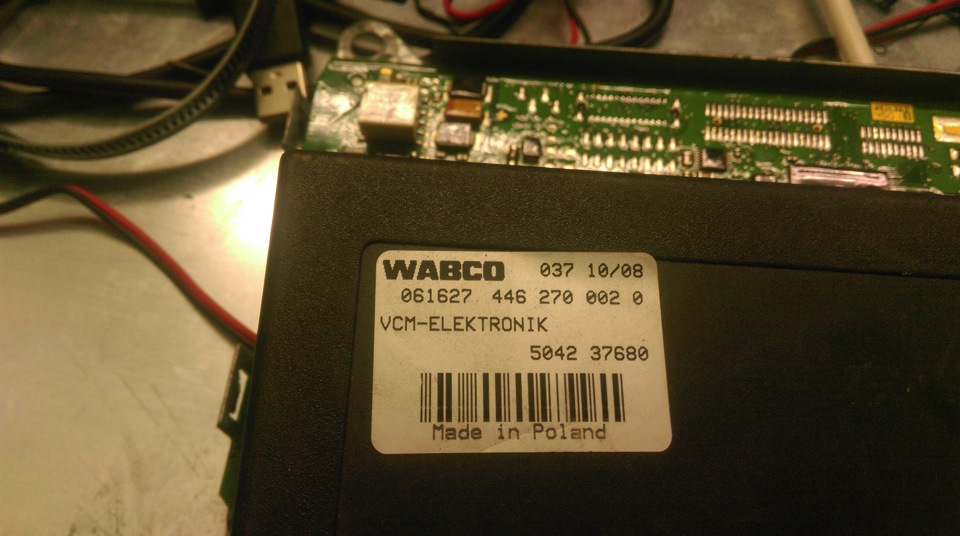
Рис.1- Внешний вид блока VCM.
Постоянно горящие передние фары или стоп-сигналы, сообщение на панели приборов об отсутствии сообщений от VCM являются косвенными признаками выхода блока из строя.

Рис.2- Печатная плата блока VCM.
Ремонт электронных блоков управления автомобилей Iveco – задача, с которой много лет успешно справляются специалисты нашей компании. В СТО «Элекар» вам могут предложить высокое качество оказываемых услуг, оперативность, объективные выводы о рациональности ремонта блоков VCM и ECM Iveco.
Выявление неисправности блоков VCM ECM Iveco, как и любого блока управления грузовым автомобилем, требует наличия комплекса специальных технических средств включающего в себя средства диагностики, модуляции, анализа, измерения и т.д. В СТО «Элекар» эти работы проводятся в специально оборудованной, хорошо оснащенной лаборатории. Имеется, практически, весь спектр дилерского диагностического оборудования.
Ремонт блока управления Iveco в Витебске можно осуществить в нашем автосервисе. На все работы дается гарантия с предоставлением всех необходимых документов.
Стоимость данной операции – договорная. Точную стоимость можно уточнить у менеджеров, позвонив по указанному на сайте номеру, либо, отправив письмо на электронную почту.

Услуги элекар по данной статье
Для того, чтобы определить состояние автомобиля либо значительно облегчить поиск неисправностей его систем владельцы современных автомобилей прибегают к компьютерной диагностике. Эта стадия не является ремонтом, однако не стоит ею пренебрегать…
Запись на ремонт
Заполните форму записи. Если возможно, прикрепите фото и опишите суть проблемы. В течении дня мы свяжемся с Вами и назначим точную дату и время.
|
Iveco Electronics |
ET-TN-440-24 — Iveco LA Vehicles Error Codes |
Page 3 of 16 |
||||||
|
ECU |
SPN |
Fault Component |
Description |
FMI |
FMI |
FMI |
Lamp |
Comment |
|
Name |
[Hex] |
[DEC] |
[HEX] |
Description |
status |
|||
|
2212B |
Brake Air Pressure Sensor Supply (Vc) |
The acquired supply voltage is below or above the thresholds. |
00 |
00 |
6V<V<8V |
|||
|
BC IBC2 |
||||||||
|
01 |
01 |
2V<V<4V |
||||||
|
03 |
03 |
V>8V |
||||||
|
04 |
04 |
V<2V |
||||||
|
BC IBC2 |
2212C |
Vehicle data bus CAN |
No CAN messages on Vehicle data bus or Bus-Off detection.The error |
2 |
02 |
|||
|
can be read on CAN only if the CAN bus resets |
||||||||
|
BC IBC2 |
2212D |
ECU not programmed |
31 |
1F |
||||
|
BC IBC2 |
22130 |
Engine Starter |
03 |
03 |
Voltage Above Normal, Or Shorted To High Source |
|||
|
04 |
04 |
Voltage Below Normal, Or Shorted To Low Source |
||||||
|
BC IBC2 |
22131 |
Cabin Side White Lights (only if on pin E03) |
03 |
03 |
Voltage Above Normal, Or Shorted To High Source |
|||
|
04 |
04 |
Voltage Below Normal, Or Shorted To Low Source |
||||||
|
BC IBC3 |
22100 |
ECU not programmed |
31 |
1F |
Yellow |
|||
|
BC IBC3 |
22101 |
EEPROM checksum error |
12 |
0C |
Yellow |
|||
|
BC IBC3 |
22102 |
ECU Overheating |
The PCB ECU Temperature of the output drivers is greater than max. |
13 |
0D |
Yellow |
||
|
allowed temperature (100°C). |
||||||||
|
BC IBC3 |
22103 |
ECU Secondary Microprocessor Faulty |
The secondary microprocessor that executes the limp-home function is |
14 |
0E |
Yellow |
||
|
faulty |
||||||||
|
BC IBC3 |
2210B |
Vehicle Data Bus CAN |
No CAN messages on Vehicle data bus or Bus-Off detection. |
2 |
02 |
Red |
||
|
The error can be read on VDB CAN only if the VDB CAN bus resets |
||||||||
|
BC IBC3 |
2210C |
Body Control Bus CAN |
No CAN messages on Body control bus or Bus-Off detection. |
2 |
02 |
Red |
||
|
The error can be read on BCB CAN also if the BCB CAN bus is not reset |
||||||||
|
BC IBC3 |
231FF |
Body Control Bus — ECU#1 CAN |
No CAN messages from ECU#1 — Bed Module |
2 |
02 |
Yellow |
||
|
BC IBC3 |
2ECFF |
Body Control Bus — ECU#2 CAN |
No CAN messages from ECU#2 — Driver Door Module |
2 |
02 |
Yellow |
||
|
BC IBC3 |
2EDFF |
Body Control Bus — ECU#3 CAN |
No CAN messages from ECU#3 — Co-Driver Door Module |
2 |
02 |
Yellow |
||
|
BC IBC3 |
245FF |
Body Control Bus — ECU#4 CAN |
No CAN messages from ECU#4 — Additional Heater Air |
2 |
02 |
Yellow |
||
|
BC IBC3 |
244FF |
Body Control Bus — ECU#5 CAN |
No CAN messages from ECU#5 — Additional Heater Water |
2 |
02 |
Yellow |
||
|
BC IBC3 |
2E9FF |
Body Control Bus — ECU#6 CAN |
No CAN messages from ECU#6 — Mirror Controller |
2 |
02 |
Yellow |
||
|
BC IBC3 |
26DFF |
Body Control Bus — ECU#7 CAN |
No CAN messages from ECU#7 — MET |
2 |
02 |
Red |
||
|
BC IBC3 |
219FF |
Body Control Bus — ECU#8 CAN |
No CAN messages from ECU#8 — Climate Control |
2 |
02 |
Yellow |
||
|
BC IBC3 |
22120 |
Fuel Level Interface |
Fuel Level interface failure detected. |
00 |
00 |
00:Delta voltage below normal |
Yellow |
|
|
The input voltage is evaluated for in-range checking: |
01 |
01 |
01:Delta voltage above normal |
|||||
|
BC IBC3 |
22121 |
Engine Oil Level Interface |
Oil Level interface failure detected. |
00 |
00 |
00:Delta voltage below normal |
Yellow |
|
|
The voltage difference between the first and the second acquisition are |
01 |
01 |
01:Delta voltage above normal |
|||||
|
evaluated for in-range checking: |
0F |
15 |
0F:Time/Date from TCO not available |
|||||
|
10 |
10 |
10:Engine Starter Mode or Engine Speed from EDC not available |
||||||
|
12 |
12 |
12:Date could not be stored in EEPROM |
||||||
|
13 |
13 |
13:Time could not be stored in EEPROM |
||||||
|
14 |
14 |
14:Oil Level could not be stored in EEPROM |
||||||
|
BC IBC3 |
22122 |
Ambient Air Temperature Interface |
Ambient Air Temperature interface failure detected. |
03 |
03 |
03:Voltage above normal (s.c. to battery or open circuit) |
Yellow |
|
|
The input voltage is evaluated for in-range checking: |
04 |
04 |
04:Voltage below normal (s.c. to ground) |
|||||
|
BC IBC3 |
22130 |
Windshield Wiper Switches |
Windshield Wiper switches activated at the same time or every faulty on |
2 |
02 |
Yellow |
||
|
Windshield Wiper (engine blocked or short circuited, engine interrupted, |
||||||||
|
cam always to ground, cam always open) |
||||||||
|
BC IBC3 |
22131 |
Diff.Lock.State. Rear Axle1(Rockwell) |
Diff.Lock.State. Rear Axle1-In1 and Diff. Lock State Rear Axle1-In2, are |
2 |
02 |
Yellow |
||
|
Switches |
both activated |
|||||||
|
BC IBC3 |
22140 |
Service Brake Air Pressure Circuit#2 sensor |
Service Brake Air Pressure Circuit#2 interface failure detected. |
03 |
03 |
03:Voltage above normal (s.c. to battery or open circuit) |
Yellow |
|
|
(Front) |
04 |
04 |
04:Voltage below normal (s.c. to ground) |
|||||
|
BC IBC3 |
22141 |
Service Brake Air Pressure Circuit#1 sensor |
Service Brake Air Pressure Circuit#1 interface failure detected. |
03 |
03 |
4:Voltage above normal (s.c. to battery or open circuit) |
Yellow |
|
|
(Rear) |
05 |
05 |
04:Voltage below normal (s.c. to ground) |
|||||
|
BC IBC3 |
22142 |
Service Brake Air Pressure Circuit#2 sensor |
The pressure charging is evaluated for in-range checking |
00 |
00 |
00:Delta voltage below normal |
Red |
|
|
(Front) |
01 |
01 |
01:Delta voltage above normal |
|||||
|
BC IBC3 |
22143 |
Service Brake Air Pressure Circuit#1 sensor |
The pressure charging is evaluated for in-range checking |
00 |
00 |
00:Delta voltage below normal |
Red |
|
|
(Rear) |
01 |
01 |
01:Delta voltage above normal |
|||||
|
BC IBC3 |
22144 |
Service Brake Air Pressure Sensor Supply |
Service Brake Air Pressure Sensor Supply Voltage failure detected. |
00 |
00 |
00: 6V<V<8V |
Yellow |
|
|
Voltage (Vs) |
The error is detected only when the maximum supply voltage is between |
01 |
01 |
01: 2V<V<4V |
||||
|
18V and 32V and Ignition Key 15 is On. |
03 |
03 |
03: V>8V |
|||||
|
04 |
04 |
04: V<2V |
||||||
|
BC IBC3 |
22145 |
Brake Air Dryer |
Pressure plausability: |
01 |
01 |
01:The pressure is not increasing while charge mode |
Yellow |
|
|
00 |
00 |
00:The pressure is not decreasing while rigeneration mode |
||||||
|
02 |
02 |
02:Duty error (air loss because the S2 valve is locked) |
||||||
|
BC IBC3 |
22150 |
Dashboard Backlight & Headbeam Washer |
On/Off Diagnostic: |
6 |
06 |
06:Short circuit to ground or Overload or Overheating protection. |
Yellow |
|
|
Supply & Body Builders Parking Lights |
||||||||
|
BC IBC3 |
22161 |
Marker Front Left & Right Lights |
Analog Diagnostic: The acquired load current is below the threshold (at |
5 |
05 |
05: I < IS |
Yellow |
|
|
least a load on two is a open circuit). |
||||||||
|
The error is detected only when the relative supply voltage is between 18V |
||||||||
|
and 32V. |
||||||||
|
The Marker Front Left & Right Lights fault shall be recognized, stored and |
||||||||
|
reported on DM1 message with a maximum delay of 10sec. |
||||||||
|
BC IBC3 |
22166 |
Additional Lights or Additional Air Heater |
On/Off Diagnostic: |
03 |
03 |
03:Short circuit to battery |
Yellow |
|
|
Disable |
06 |
06 |
06:Short circuit to ground or Overload or Overheating protection |
|||||
|
BC IBC3 |
22163 |
Step Lights |
Analog Diagnostic: The acquired load current is below the threshold (at |
5 |
05 |
05: I < IS |
Yellow |
|
|
least a load on two is a open circuit). |
||||||||
|
The error is detected only when the relative supply voltage is between 18V |
||||||||
|
and 32V. |
||||||||
|
The Step Lights fault shall be recognized, stored and reported on DM1 |
||||||||
|
message with a maximum delay of 10sec. |
||||||||
|
BC IBC3 |
22164 |
Cabin Side Lights |
On/Off Diagnostic: |
03 |
03 |
03:Short circuit to battery |
Yellow |
|
|
06 |
06 |
06:Short circuit to ground or Overload or Overheating protection |
||||||
|
BC IBC3 |
22165 |
Cabin Ceiling Lights |
Analog Diagnostic: The acquired load current is below the threshold (at |
5 |
05 |
05: I < IS |
Yellow |
|
|
least a load on two is a open circuit). |
||||||||
|
The error is detected only when the relative supply voltage is between 18V |
||||||||
|
and 32V. |
||||||||
|
The Cabin Ceiling Lights fault shall be recognized, stored and reported on |
||||||||
|
DM1 message with a maximum delay of 10sec. |
||||||||
|
BC IBC3 |
22180 |
30A |
On/Off Diagnostic: |
4 |
04 |
Voltage below normal |
Yellow |
|
|
BC IBC3 |
22181 |
30B |
On/Off Diagnostic: |
4 |
04 |
Voltage below normal |
Yellow |
|
|
BC IBC3 |
22182 |
30C |
On/Off Diagnostic: |
4 |
04 |
Voltage below normal |
Yellow |
|
|
BC IBC3 |
22183 |
30D |
On/Off Diagnostic: |
4 |
04 |
Voltage below normal |
Yellow |
|
|
BC IBC3 |
22184 |
30E |
On/Off Diagnostic: |
4 |
04 |
Voltage below normal |
Yellow |
|
|
BC IBC3 |
22190 |
+Batt. TCO & +Batt. Spare1 |
On/Off Diagnostic: |
5 |
05 |
Fuse interrupted |
Yellow |
|
|
The internal fuse to ECU can be accidentally interrupted |
||||||||
|
BC IBC3 |
22191 |
30A Cluster |
On/Off Diagnostic: fuse interrupped |
5 |
05 |
Fuse interrupted |
Yellow |
|
|
The internal fuse to ECU can be accidentally interrupted |
||||||||
|
BC IBC3 |
22192 |
30D Body Builders |
On/Off Diagnostic: fuse interrupped |
5 |
05 |
Fuse interrupted |
Yellow |
|
|
The internal fuse to ECU can be accidentally interrupted |
||||||||
|
BC IBC3 |
22193 |
30E ECAS |
On/Off Diagnostic: fuse interrupped |
5 |
05 |
Fuse interrupted |
Yellow |
|
|
The internal fuse to ECU can be accidentally interrupted |
||||||||
|
BC IBC3 |
22194 |
30C VCM |
On/Off Diagnostic: fuse interrupped |
5 |
05 |
Fuse interrupted |
Yellow |
|
|
The internal fuse to ECU can be accidentally interrupted |
||||||||
|
BC IBC3 |
22195 |
30E Cigarette Lighter & 30E Diagnostic |
On/Off Diagnostic: fuse interrupped |
5 |
05 |
Fuse interrupted |
Yellow |
|
|
Connector |
The internal fuse to ECU can be accidentally interrupted |
|||||||
|
BC IBC3 |
22196 |
30C ABS |
On/Off Diagnostic: fuse interrupped |
5 |
05 |
Fuse interrupted |
Yellow |
|
|
The internal fuse to ECU can be accidentally interrupted |
||||||||
|
BC IBC3 |
22197 |
30C ABS Trailer |
On/Off Diagnostic: fuse interrupped |
5 |
05 |
Fuse interrupted |
Yellow |
|
|
The internal fuse to ECU can be accidentally interrupted |
||||||||
|
BC IBC3 |
22198 |
30B Engine Crank |
On/Off Diagnostic: fuse interrupped |
5 |
05 |
Fuse interrupted |
Yellow |
|
|
The internal fuse to ECU can be accidentally interrupted |
||||||||
|
BC IBC3 |
22199 |
30D Acustic Horn |
On/Off Diagnostic: fuse interrupped |
5 |
05 |
Fuse interrupted |
Yellow |
|
|
The internal fuse to ECU can be accidentally interrupted |
||||||||
|
BC IBC3 |
2219A |
30E Voltage Adapter & 30E Bed Lights |
On/Off Diagnostic: fuse interrupped |
5 |
05 |
Fuse interrupted |
Yellow |
|
|
The internal fuse to ECU can be accidentally interrupted |
||||||||
|
BC IBC3 |
2219B |
30B Mirror Heating |
On/Off Diagnostic: fuse interrupped |
5 |
05 |
Fuse interrupted |
Yellow |
|
|
The internal fuse to ECU can be accidentally interrupted |
||||||||
|
BC IBC3 |
221A0 |
15 Mirror Controller & 15 Heated Dryer |
On/Off Diagnostic: fuse interrupped |
5 |
05 |
Fuse interrupted |
Yellow |
|
|
The internal fuse to ECU can be accidentally interrupted |
||||||||
|
BC IBC3 |
221A1 |
15 Alternator |
On/Off Diagnostic: fuse interrupped |
5 |
05 |
Fuse interrupted |
Yellow |
|
|
The internal fuse to ECU can be accidentally interrupted |
||||||||
|
BC IBC3 |
221A2 |
15 TCO & 15 Cluster & 15 MET & 15 UDS |
On/Off Diagnostic: fuse interrupped |
5 |
05 |
Fuse interrupted |
Yellow |
|
|
The internal fuse to ECU can be accidentally interrupted |
||||||||
|
BC IBC3 |
221A3 |
15 VCM & 15 ECM |
On/Off Diagnostic: fuse interrupped |
5 |
05 |
Fuse interrupted |
Yellow |
|
|
The internal fuse to ECU can be accidentally interrupted |
||||||||
|
BC IBC3 |
221A4 |
15 ECAS & 15 ABS |
On/Off Diagnostic: fuse interrupped |
5 |
05 |
Fuse interrupted |
Yellow |
|
|
The internal fuse to ECU can be accidentally interrupted |
||||||||
|
BC IBC3 |
221A5 |
15 Cabin Tilted & 15 Brake Switch & |
On/Off Diagnostic: fuse interrupped |
5 |
05 |
Fuse interrupted |
Yellow |
|
|
15 Headbeam Pot.Supply |
The internal fuse to ECU can be accidentally interrupted |
|||||||
|
BC IBC3 |
221A6 |
15/1A Reverse Gear Lights & 15/1A |
On/Off Diagnostic: fuse interrupped |
5 |
05 |
Fuse interrupted |
Yellow |
|
|
Headbeam Adjustment supply & 15/1A NOX |
The internal fuse to ECU can be accidentally interrupted |
|||||||
|
sensor supply |
||||||||
|
BC IBC3 |
221A7 |
15/1A Cabin Heater & 15/1A Conditioner |
On/Off Diagnostic: fuse interrupped |
5 |
05 |
Fuse interrupted |
Yellow |
|
|
The internal fuse to ECU can be accidentally interrupted |
||||||||
|
BC IBC3 |
221A8 |
15/1B Body Builders |
On/Off Diagnostic: fuse interrupped |
5 |
05 |
Fuse interrupted |
Yellow |
|
|
The internal fuse to ECU can be accidentally interrupted |
||||||||
|
BC IBC3 |
221A9 |
15/1B Electric Windows |
On/Off Diagnostic: fuse interrupped |
5 |
05 |
Fuse interrupted |
Yellow |
|
|
The internal fuse to ECU can be accidentally interrupted |
||||||||
|
BC IBC3 |
221B0 |
Power Steering Circuit #1 or #2 Pressure |
Sensor plausibility: |
2 |
02 |
Flow meter plausibility |
Yellow |
|
|
Low |
— While Engine Speed=0 (and valid) at least one of two pressure switches |
|||||||
|
is in Normal state (open) (pressure above threshold) |
||||||||
|
The ECU waits PSC_TEST_T1 (after Engine Speed =0 or at Ignition Key |
||||||||
|
15) before to start the diagnostics |
||||||||
|
BC IBC3 |
221B2 |
Steering Flow Meter |
Flow meter plausibility: |
2 |
02 |
Flow meter plausibility |
Yellow |
|
|
— When Vehicle Speed < PSC_VEH_SPEED _MIN the flow is in Normal |
||||||||
|
state (open) |
||||||||
|
BC IBC3 |
221C0 |
Windshield Washer & Headbeam Washer |
On/Off Diagnostic: |
03 |
03 |
03:Short circuit to battery |
Yellow |
|
|
06 |
06 |
06:Short circuit to ground or Overload or Overheating protection |
||||||
|
BC IBC3 |
221C1 |
TGC ON |
On/Off Diagnostic: |
03 |
03 |
03:Short circuit to battery |
Yellow |
|
|
06 |
06 |
06:Short circuit to ground or Overload or Overheating protection |
||||||
|
BC IBC3 |
221C2 |
TGC OFF |
On/Off Diagnostic: |
3 |
03 |
03:Short circuit to battery |
Yellow |
|
|
BC IBC3 |
221C3 |
Body Builder Reverse Gear |
On/Off Diagnostic: |
03 |
03 |
03:Short circuit to battery |
Yellow |
|
|
06 |
06 |
06:Short circuit to ground or Overload or Overheating protection |
||||||
Всем привет. Начинаю потихоньку писать про все свои деяния.
Итак пациент Iveco EuroCargo 2007 года, люди обратились за помощью, необходимо произвести замену блока VCM, старый блок был замочен водой и после попытки электриков до меня его оживить блок выдавал множество ошибок и глушил мотор так как является одним из блоком который содержит данные иммо.
Снимаем блок управления двигателя EDC17UC31, считываем Flash и производим изменение области данных связанных с системой AdBlue
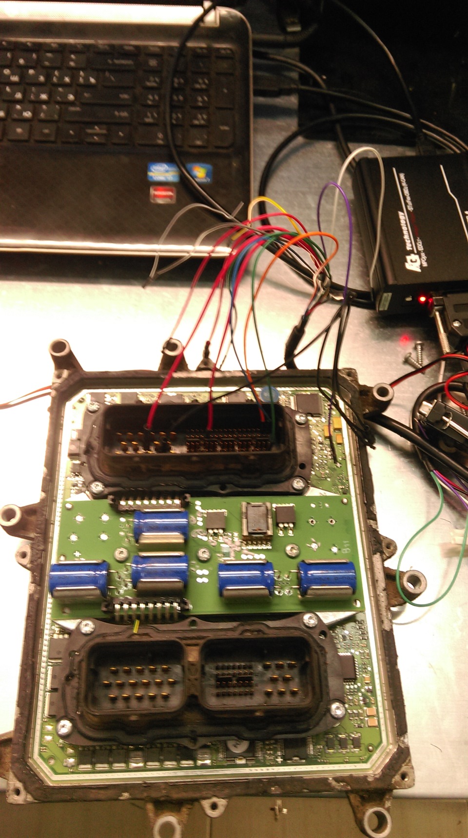
По замене блока VCM все немного сложнее с первого взгляда, для красивой замены необходимо знать пин код, из всего имеющего арсенала выдрать пин код у меня не получилось, ну что ж берем пациента на стол выпаиваем eeprom схему считываем дамп и заливаем в eeprom нового блока.
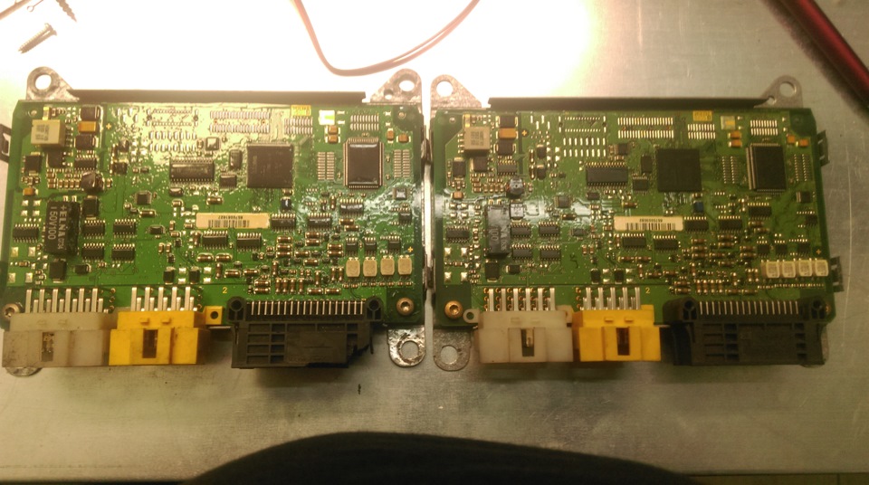
Устанавливаем блоки обратно, в итоге система AdBlue в машине больше не используется и не требует его вечной заправки и обслуживания, другой блок VCM в авто прижился без проблем.
- вопросы и ответы
:
:
Iveco
Что такое коды ECM на Iveco?
ответ: Модуль управления двигателем (ECM) на Iveco — это система, которая управляет и, возможно, сигнализирует с помощью кодов ошибок об аномалиях, обнаружен…
читать все
Опубликовано 28-03-2023
Что означает индикатор масла Iveco?
ответ: Если на приборной панели вашего автомобиля Iveco постоянно горит желтая сигнальная лампа масла, это означает, что пришло время заменить жидкость и соо…
читать все
Опубликовано 17-02-2023
Что означает индикатор Iveco AdBlue?
ответ: Если на приборной панели вашего автомобиля Iveco загорается контрольная лампа AdBlue, это означает, что количество этой загрязняющей жидкости в соотве…
читать все
Опубликовано 14-02-2023
Что означает индикатор VCM на Iveco?
ответ: Когда на автомобиле Iveco загорается контрольная лампа VCM, это означает, что в блоке управления VCM возникла неисправность. В большинстве случаев это…
читать все
Опубликовано 15-07-2022
Где смысл сигнальных ламп Ивеко?
ответ: Если вы ищете значение всех различных сигнальных ламп на панели приборов вашего автомобиля Iveco, вы можете легко найти его в бумажном руководстве или…
читать все
Опубликовано 19-06-2022
Что означает edc на Iveco?
ответ: Аббревиатура edc, которая появляется на Iveco, указывает на отказ двигателя. На основании ассоциированного кода нужно искать, чему он соответствует в …
читать все
Опубликовано 1-12-2021
В чем смысл шпиона edc на Iveco?
ответ: На автомобилях Iveco может загораться красная сигнальная лампа со словом edc. Он соответствует сигнальной лампе отказа двигателя автомобиля и поэтому …
читать все
Опубликовано 6-11-2021
Что означает красный индикатор EDC?
ответ: Когда контрольная лампа EDC на Iveco загорается красным, это означает, что происходит отказ двигателя. При этом необходимо прекратить движение и отпра…
читать все
Опубликовано 20-06-2021
Что означает отказ ECM38 на Iveco?
ответ: Когда на приборной панели нашего Ивеко загорается контрольная лампа ECM38, мы имеем дело с неисправностью модуля управления двигателем. ECM получает и…
читать все
Опубликовано 16-05-2021

DIAGNOSIS
Fault diagnosis comprises two sections:
— The first one, organized by error codes (DTC-FMI), concerns faults that may be identified by the EDC control unit directly . These faults are mainly of an electric — electronic — pneumatic
nature.
— The second one, organized by symptoms, describes the possible faults the electronic control unit cannot identify directly. These faults are mainly of a mechanical — pneumatic nature.
Diagnosis Instruments
MODUS (Maintenance and Diagnostic System)
A computerized fault-diagnosis station dedicated to diagnosing the brake systems, air suspensions, engines and systems controlled electronically.
The station is equipped with auxiliary functions, such as: programming electronic control units, consulting the spare parts catalogue and service time schedules.
The vehicle has a 30-pin diagnosis socket to interface with the instrument
IT 2000 (IVECO Electronic Tester)
This makes it possible to take immediate action on the vehicle, identifying it with the chassis number.
It saves the results of diagnostics actions performed.
It can be used as a portable Personal Computer, too, being fit ted for remote diagnosis.
By using MODUS as the mother station it is possible to update and configure the IT 2000.
IT 2000 interfaces with the vehicle via a 30-pin diagnosis socket.
E.A.SY.
E.A.SY. system allows to simply make the diagnosis and programming of the various electronic central units aboard the vehicle.
E.A.SY. system is made up of ECI module communicating with the electronic central units and of a Panasonic PC.
ECI module, exploiting the Panasonic PC, also allows easy on the road interventions: in particular, thanks to Panasonic PC wireless technologies (e.g. GPRS), diagnostic interventions can be
assisted by a remote expert center


Diagnosis information on the cluster is split into 4 columns:
— First column = central unit.
— Second column = central unit address plus fault order number.
— Third column = failure type.
— Fourth column = failure frequency.
The screen shows three error messages at most, but can store up to eight error messages. For displaying any further messages, just operate ‘Y’ and ‘B’ keys
|
DTC |
Failing component |
Visible failure |
Possible Cause |
Repair action |
|
113 |
ACCELERATOR PEDAL/ BRAKE PEDAL |
Vehicle acceleration very slow. |
Accelerator pedal and brake |
Check the accelerator pedal signal |
|
116 |
CLUTCH SIGNAL SUSPECT |
The parameter reading shows that |
Clutch switch faulty or wiring |
Check clutch pedal switch and |
|
117 |
BRAKE PEDAL SIGNAL ERROR |
Slight power reduction |
Main and secondary brake switch |
Check the synchronisation of both |
|
119 |
PLAUSIBILITY +15 |
Possible mechanical problem (in |
Check wiring. |
|
|
121 |
SPEED LIMITER W/ LIGHT |
Warning light permanently |
Short circuit or defective |
Check wiring. |
|
122 |
WARNING LIGHT EOBD |
Warning light permanently |
Short circuit or defective |
Check wiring. |
|
123 |
EDC LAMP |
Warning light permanently |
Short circuit or defective |
Check wiring. |
|
124 |
COLD START LAMP |
Warning light permanently |
Short circuit or defective |
Check wiring. |
|
125 |
MAIN RELAY DEFECT |
Possible problems during |
Relay short circuit to battery |
Check wiring between ECM and |
|
126 |
BATTERY VOLTAGE |
Possible problems during |
Alternator or battery defective. |
Check wiring. Replace alternator |
|
127 |
ENGINE BRAKE ELECTROVALVE |
Engine brake not |
Relay or wiring short-circuited or |
Check wiring. Replace relay if |
|
128 |
MAIN RELAY — SHORT CIRCUIT TO |
Possible problems during |
Relay short circuit to battery |
Check wiring between ECM and |
|
129 |
AIRCONDITIONER COMPRESSOR |
Possible problems during |
Relay short circuit to battery |
Check wiring between ECM and |
|
12A |
RELAIS FOR ENGINE BRAKE |
Possible problems during |
Relay short circuit to battery |
Check wiring between ECM and |
|
12B |
THERMOSTARTER RELAY 1 |
Heater not working. |
Relay or wiring short-circuited or |
Check wiring. Replace relay if |
|
12C |
THERMOSTARTER RELAY 2 |
Heater not working. |
Relay or wiring short-circuited or |
Check wiring. Replace relay if |
|
12E |
MANAGEMENT SYSTEM PRE/ POSTHEATING |
Grid heater permanently |
Grid heater short circuited to |
Check wiring and component. |
|
131 |
COOLANT TEMPERATURE SENSOR |
No reaction noticeable on behalf |
Sensor short-circuited or value |
Check the wiring. Replace sensor |
|
132 |
COOLANT TEMPERATURE SENSOR |
Slight power reduction. |
Operation in extreme environmental |
Ensure the engine is not working |
|
133 |
AIR TEMPERATURE SENSOR BOOST |
Slight power reduction. |
Sensor short-circuited or value |
Check the wiring. Replace sensor |
|
134 |
BOOST PRESSURE SENSOR |
No reaction perceivable by the |
Sensor short-circuited or |
Check the wiring. Also check the |
|
135 |
FUEL TEMPERATURE SENSOR |
Slight power reduction. |
Sensor short-circuited or value |
Check the wiring. Replace sensor |
|
138 |
OIL PRESSURE SENSOR |
No reaction perceivable by the |
Sensor short-circuited or value |
Check the wiring and oil level. |
|
13A |
OIL TEMPERATURE SENSOR |
No reaction perceivable by the |
Sensor short-circuited or value |
Check the wiring. Replace sensor |
|
13C |
ATMOSPHERIC TEMPERATURE |
No reaction perceivable by the |
Sensor short-circuited or value |
Check the wiring. Replace sensor |
|
DTC |
Failing component |
Visible failure |
Possible Cause |
Repair action |
|
141 |
CRANKSHAFT SPEED |
No reaction noticeable on behalf |
Signal interrupted or wiring |
Check wiring and installation. |
|
142 |
ENGINE WORKING ONLY WITH CAMSHAFT |
No reaction perceivable by the |
Signal interrupted or wiring |
Check wiring and installation. |
|
143 |
CAMSHAFT SENSOR |
No reaction perceivable by the |
Signal interrupted or wiring |
Check wiring and installation. |
|
144 |
FAULT BETWEEN FLYWHEEL SENSOR AND |
No reaction noticeable on behalf |
Signal interrupted or wiring |
Check wiring and installation of |
|
145 |
FAN RELAY |
No reaction perceivable by the |
Short circuit or fan actuator |
Check the wiring and the fan |
|
148 |
AIRCONDITIONER COMPRESSOR |
Air conditioner permanently |
Wiring or relay |
Check the wiring. Replace relay if |
|
149 |
PRE -HEAT — ING RELAY FUEL |
Filter heater not working. |
Wiring or filter heater short |
Check the wiring. Re — place the |
|
151 |
INJECTOR CYLINDER 1 |
The engine runs on 5 |
Injector no.1 electric |
Check correct tightness to torque |
|
152 |
INJECTOR CYLINDER 2 |
The engine runs on 5 |
Injector no.2 electric |
Check correct tightness to torque |
|
153 |
INJECTOR CYLINDER 3 |
The engine runs on 5 |
Injector no.3 electric |
Check correct tightness to torque |
|
154 |
INJECTOR CYLINDER 4 |
The engine runs on 5 |
Injector no.4 electric |
Check correct tightness to torque |
|
155 |
INJECTOR CYLINDER 5 |
The engine runs on 5 |
Injector no.5 electric |
Check correct tightness to torque |
|
156 |
INJECTOR CYLINDER 6 |
The engine runs on 5 |
Injector no.6 electric |
Check correct tightness to torque |
|
161 |
INJECTOR CYLINDER 1 / SHORT |
One or more injectors (bank 1 or |
Possible short circuit in |
Check wiring. Possible internal |
|
162 |
INJECTOR CYLINDER 2 / SHORT |
One or more injectors (bank 1 or |
Possible short circuit in |
Check wiring. Possible internal |
|
163 |
INJECTOR CYLINDER 3 / SHORT |
One or more injectors (bank 1 or |
Possible short circuit in |
Check wiring. Possible internal |
|
164 |
INJECTOR CYLINDER 4 / SHORT |
One or more injectors (bank 1 or |
Possible short circuit in |
Check wiring. Possible internal |
|
165 |
INJECTOR CYLINDER 5 / SHORT |
One or more injectors (bank 1 or |
Possible short circuit in |
Check wiring. Possible internal |
|
166 |
INJECTOR CYLINDER 6 / SHORT |
One or more injectors (bank 1 or |
Possible short circuit in |
Check wiring. Possible internal |
|
167 |
INJECTOR CYLINDER 1 / OPEN |
One or more injectors (bank 1 or |
Possible injector connection |
Check wiring. Possible internal |
|
168 |
INJECTOR CYLINDER 2 / OPEN |
One or more injectors (bank 1 or |
Possible injector connection |
Check wiring. Possible internal |
|
169 |
INJECTOR CYLINDER 3 / OPEN |
One or more injectors (bank 1 or |
Possible injector connection |
Check wiring. Possible internal |
|
16A |
INJECTOR CYLINDER 4 / OPEN |
One or more injectors (bank 1 or |
Possible injector connection |
Check wiring. Possible internal |
|
16B |
INJECTOR CYLINDER 5 / OPEN |
One or more injectors (bank 1 or |
Possible injector connection |
Check wiring. Possible internal |
|
16C |
INJECTOR CYLINDER 6 / OPEN |
One or more injectors (bank 1 or |
Possible injector connection |
Check wiring. Possible internal |
|
16D |
COMPRESSION TEST IN |
Compression Test in |
After carrying out the compression |
|
16E |
THE MINIMUM NUMBER OF INJECTIONS |
More than 2 injectors not |
See individual faults in |
|
|
171 |
BENCH 1 CC |
One or more injectors (bank 1 or |
Possible injector connection |
Check wiring. Possible internal |
|
173 |
BENCH 2 CC |
One or more injectors (bank 1 or |
Possible injector connection |
Check wiring. Possible internal |
|
17C |
BENCH 1 INJECTORS CHECK (INTERNAL |
One or more injectors (bank 1 or |
Fault in control unit. |
Replace the engine control |
|
189 |
EGR POWER ST. SHORT TO |
No fault perceived by the driver. |
Short circuit or EGR actuator |
Check wiring. Replace the EGR |
|
191 |
TURBINE ACTUATOR CONTROL |
Poor performance |
VGT actuator or wiring |
Check VGT wiring and |
|
192 |
TURBINE ACTUATOR CONTROL |
Poor performance |
VGT actuator or wiring |
Check VGT wiring and |
|
193 |
TURBINE WHEEL REVS SENSOR |
Poor performance |
Air filter blocked or turbine rpm |
Check the air filter and check |
|
198 |
FAULT ON AT LEAST TWO OF THE |
Poor performance |
Sensor signal implausible. Sensor |
Determine which turbine component |
|
199 |
TURBOCHARGER CONTROL BOOST |
Poor performance |
Turbo sensor or actuator may be |
Check turbine sensors and actuator |
|
19A |
TURBINE SPEED EXCEEDING EVERY |
Poor performance |
Turbo sensor or actuator may be |
Check turbine sensors and actuator |
|
19B |
TURBINE IN OVERSPEED (THE FAULT IS |
Poor performance |
Air filter blocked or turbine rpm |
Check the air filter and check |
|
19F |
NOx SENSOR ERROR |
No effect perceived by the |
Sensor signal implausible. Nox |
Check the Nox sensor. |
|
1A5 |
TIMEOUT OF CAN MESSAGE |
No effect perceived by the |
Problems in the Denoxtronic (on |
Check wiring. Check and correct |
|
1A6 |
TIMEOUT OF CAN MESSAGE SCR1 |
No effect perceived by the |
CAN configuration incorrect. CAN |
Check CAN line wiring. Check |
|
1AE |
HUMIDITY SENSOR |
No effect perceived by the |
Sensor short-circuited or |
Check wiring Replace sensor if |
|
1AF |
SERIOUS EOBD FAULT FROM |
No effect perceived by the |
Problems in AdBlue dosing |
Check the faults in the |
|
1B1 |
ERROR ON CAN CONTROLLER A |
No effect perceived by the |
CAN configuration incorrect. CAN |
Check CAN line wiring. Check |
|
1B2 |
ERROR ON CAN CONTROLLER B |
No effect perceived by the |
CAN configuration incorrect. CAN |
Check CAN line wiring. Check |
|
1B3 |
ERROR ON CAN CONTROLLER C |
No effect perceived by the |
CAN configuration incorrect. CAN |
Check CAN line wiring. Check |
|
1B4 |
TIMEOUT CAN MESSAGE BC2EDC1 |
No effect perceived by the |
CAN configuration incorrect. CAN |
Check CAN line wiring. Check BC |
|
1B5 |
TIMEOUT CAN MESSAGE VM2EDC |
No effect perceived by the |
CAN configuration incorrect. CAN |
Check CAN line wiring. Check VCM |
|
1B7 |
ERROR ON MESSAGES CAN IN |
No effect perceived by the |
CAN configuration incorrect. CAN |
Check CAN line wiring. Check ECM |
|
1B9 |
ERROR ON THE EOBD LIGHT MANAGED BY |
No effect perceived by the |
MIL/Body Controller warning light |
Consult the Body Controller |
|
1BA |
TIMEOUT CAN MESSAGE DASH |
No effect perceived by the |
CAN messages from VCM |
Consult the VCM troubleshooting |
|
1BC |
TIMEOUT CAN MESSAGE AMBCOND |
No effect perceived by the |
CAN messages from VCM |
Consult the VCM troubleshooting |
|
1BD |
TIMEOUT CAN MESSAGE CCVS |
No effect perceived by the |
CAN messages from VCM or BC |
Consult the VCM/BC troubleshooting |
|
1C2 |
ERROR MESSAGE CAN ETC1 |
No effect perceived by the |
CAN messages from ETC (gearbox) |
Check the ETC connection with the |
|
1C3 |
TIMEOUT IN RECEIVING TC01 CAN |
No effect perceived by the |
CAN messages from TCO |
Check the TCO connection with the |
|
1C6 |
ERROR MESSAGE CAN TSC1-PE |
No effect perceived by the |
CAN messages from TCU |
Check the TCU connection with the |
|
1C8 |
ERROR MESSAGE CAN TSC1-VE |
No effect perceived by the |
CAN messages from TCU |
Check the TCU connection with the |
|
1D1 |
ECU OVERRUN MONITORING |
No effect perceived by the |
Electrical interference or |
If the error persists to replace |
|
1D2 |
ECU OVERRUN MONITORING |
No effect perceived by the |
Poor control unit |
Reprogram the central unit. If the |
|
1D3 |
ECU OVERRUN MONITORING |
No effect perceived by the |
Poor control unit |
Reprogram the central unit. If the |
|
1D4 |
ECU OVERRUN MONITORING |
No effect perceived by the |
Ecu internal failure. |
If the error persists to replace |
|
1D5 |
ECU OVERRUN MONITORING |
No effect perceived by the |
Ecu internal failure. |
If the error persists to replace |
|
1D6 |
ECU INTERNAL ERROR (TPU) |
Control unit deactivation. |
Electronic interference or control |
If the error persists to replace |
|
1D8 |
ECU OVERRUN MONITORING |
No effect perceived by the |
Ecu internal failure. |
If the error persists to replace |
|
1E2 |
IMMOBILIZER |
The engine fails to start. |
Problem in CAN line or immobiliser |
Check the Immobiliser control unit |
|
1E3 |
ERROR FOR ECU INTERNAL |
No effect perceived by the |
Ecu internal failure. |
f the error persists to replace |
|
1E4 |
ERROR FOR ECU INTERNAL |
No effect perceived by the |
Ecu internal failure. |
If the error persists to replace |
|
1E5 |
SENSORS POWER SUPPLY FAULT |
No effect perceived by the |
Excessive/insufficient battery |
Check battery voltage or |
|
1E6 |
SENSOR POWER SUPPLY 1 |
No effect perceived by the |
Excessive/insufficient battery |
Check battery voltage or |
|
1E7 |
SENSOR POWER SUPPLY 2 |
No effect perceived by the |
Excessive/insufficient battery |
Check battery voltage or |
|
1E8 |
SENSOR POWER SUPPLY 3 |
No effect perceived by the |
Excessive/insufficient battery |
Check battery voltage or |
|
1E9 |
ECU OVERRUN MONITORING |
No effect perceived by the |
Excessive/insufficient battery |
Check battery voltage or |
|
1EA |
ECU OVERRUN MONITORING |
No effect perceived by the |
Excessive/insufficient battery |
Check battery voltage or |
|
1EB |
ATMOSPHERIC PRESSURE SENSOR |
No effect perceived by the driver. |
Fault in sensor inside control |
Change ECU. |
|
1FA |
TOO HIGH NUMBER OF REGENERATIONS |
No reaction perceivable by the |
Particulate filter may be |
Check filter. |
|
1FB |
PERMANENT RIGENERATION ON TRAP |
No reaction perceivable by the |
Catalytic converter not installed |
Check catalytic converter |
|
1FC |
FIRST SENSOR EXAUSTED GAS |
No reaction perceivable by the |
Temperature sensors damaged or |
Check information and condition of |
|
21F |
TOO HIGH EFFICIENCY OF CATALYST |
No reaction noticeable on behalf |
Actuator coil faulty or not within |
Check actuator condition. |
|
225 |
INTERRUPTED AFTERRUN |
Slight power reduction. |
The control unit is turned off by |
Check wiring and then replace the |
|
228 |
MAIN RELAY — SHORT CIRCUIT TO |
Slight power reduction. |
Short circuit in main relay or |
Check wiring between battery and |
|
DTC |
Failing component |
Visible failure |
Possible Cause |
Repair action |
|
232 |
COOLANT TEMPERATURE SENSOR |
Slight power reduction |
Extreme environmental conditions |
Ensure the engine is working in |
|
238 |
OIL LOW PRESSURE |
Slight power reduction |
Sensor incorrectly adjusted or |
Check the sensor connections and |
|
23A |
OIL TEMPERATURE ABOVE |
Slight power reduction |
Sensor incorrectly adjusted or |
Check the sensor connections and |
|
27C |
BENCH 2 INJECTORS CHECK (INTERNAL |
One or more injectors (bank 1 or |
Fault in control unit. |
Replace the engine control |
|
292 |
TURBINE ACTUATOR CONTROL |
Poor performance |
VGT actuator or wiring |
Check VGT wiring and |
|
2A6 |
TIMEOUT OF CAN MESSAGE SCR2 |
No effect perceived by the |
Problem in the Denoxtronic (on the |
Check the faults in the |
|
2AF |
SERIOUS EOBD FAULT FROM |
No effect perceived by the |
Problems in AdBlue dosing |
Check the faults in the |
|
2B4 |
TIMEOUT CAN MESSAGE BC2EDC2 |
No effect perceived by the |
CAN configuration incorrect. CAN |
Check CAN line wiring. Check BC |
|
2C6 |
TIMEOUT OF CAN MESSAGE TSC1-PE |
No effect perceived by the |
CAN messages from TCU |
Check the TCU connection with the |
|
2C8 |
ERROR MESSAGE CAN TSC1-VR |
No effect perceived by the |
CAN messages from TCU |
Check the TCU connection with the |
|
2C9 |
ERROR MESSAGE CAN TIMEDATE |
No effect perceived by the |
CAN messages from TC (tachograph) |
Check the tachograph connection |
|
2D3 |
ECU OVERRUN MONITORING |
No effect perceived by the |
Poor control unit |
Reprogram the central unit. If the |
|
2FF |
ERROR CHECK OF CRITICAL TIME FOR |
Slight power reduction |
Oil over-diluted. |
Change the engine oil. |
|
392 |
TURBINE ACTUATOR CONTROL |
Poor performance |
Connection damaged. Battery |
Check VGT connection and |
|
3AF |
SERIOUS EOBD FAULT FROM |
No effect perceived by the |
Problems in AdBlue dosing |
Check the faults in the |
|
3C8 |
TIMEOUT OF CAN MESSAGE TSC1-VE |
No effect perceived by the |
CAN messages from TCU |
Check the TCU connection with the |
|
3C9 |
ERROR MESSAGE CAN HRDV |
No effect perceived by the |
CAN configuration incorrect. CAN |
Check CAN line wiring. Check BC |
|
3D3 |
ECU OVERRUN MONITORING |
No effect perceived by the |
Poor control unit |
Reprogram the central unit. If the |
|
3FA |
REGENERATION DEMAND NUMBER |
No effect perceived by the |
Too many regenerations carried |
Check particulate filter and |
|
4AF |
SERIOUS EOBD FAULT FROM |
No effect perceived by the |
Problems in AdBlue dosing |
Check the faults in the |
|
4C8 |
TIMEOUT OF CAN MESSAGE TSC1-VR |
No effect perceived by the |
CAN messages from TCU |
Check the TCU connection with the |
|
4FA |
REGENERATION DEMAND NUMBER |
No effect perceived by the |
Too many regenerations carried |
Check particulate filter and |
|
5AF |
DM1DCU SPN5 MESSAGE |
No effect perceived by the |
Problems in AdBlue dosing |
Check the faults in the |
|
Visible Failure |
Possible Cause |
Repair action |
|
Engine does not start |
Inefficient battery. |
Pre-heating resistor always on. |
|
Starter inefficient. |
Check / replace. |
|
|
Air heater inefficient. |
Check power supply and ground |
|
|
Main remote control switch (main |
Check fuse efficiency. Check |
|
|
Fuel pump inefficient. |
Check efficiency by checking the |
|
|
Fuel pre-filter — filter |
Check if clogged / change. |
|
|
0.3 bar valve on fuel return |
Check its efficiency. If blocked, |
|
|
Fuel circuit inefficient. |
Check the system tightness and |
|
|
Engine overheating |
Coolant level wrong |
Check possible leaks and restore |
|
Water pump and fan control belts |
Check, adjust tension and change |
|
|
Water pump inefficient |
Overhaul or change the |
|
|
Thermostat inefficient. |
Check if it remains blocked in |
|
|
Radiator inefficient. |
Wash accurately and check if there |
|
|
Air filter and circuit pipes |
Make sure the manifolds and the |
|
|
Cylinder head gasket |
Check the water circuit pressure |
|
|
Fan inefficient. |
Replace. |
|
|
Engine lacks power |
Fuel circuit inefficient. |
Check if the mesh filter in the |
|
Injectors inefficient |
Seizure of the plunger of one of |
|
|
Engine air suction circuit |
Remove circuit necks and replace |
|
|
Exhaust gas circuit |
Eliminate exhaust manifold |
|
|
Working temperature not |
Check cooling system. |
|
|
VGT actuator inefficient. |
Carry out the Engine Test on the |
|
|
Turbo-compressor |
Carry out the Engine Test on the |
|
|
Injection mechanical system |
Check wear of the injector rocker |
|
|
Valve clearance |
Adjust valve clearance. |
|
Engine brake low efficiency |
Head gasket inefficient. |
Head grinding and change |
|
Injector holder inefficient |
Replace it. |
|
|
Turbo-compressor cooling system |
Overhaul turbine. |
|
|
Bad fuel quality. |
Check if there is water in the |
|
|
Engine smoke is light blue |
Piston rings inefficient |
Overhaul piston-cylinder |
|
Turbo-compressor lubrication |
Overhaul turbine. |
|
|
Valve oil seal tightness |
Change valve guide gasket. |
|
|
Engine brake low efficiency |
Engine brake components |
Check correct operation of engine |
|
Turbo-compressor |
VGT blocked in open position. VGT |
|
|
Engine stops |
Fuel in the reservoir. |
Carry out bleeding after |
|
Inefficiency of mesh filter, fuel |
Clean the mesh filter and replace |
|
|
Reservoir pipes not correctly |
If the pipes are inverted, the |
|
Excessive or insufficient oil |
Overpressure valve works not |
Check and replace, if |
|
Oil pump and oil delivery pipes |
Check and replace, if |
|
|
Main journals and connecting rod |
Replace bearings and rectify the |
|
|
Engine oil SAE viscosity not |
Change the engine oil with one |
|
|
Excessive fuel consumption |
Air filter inefficient. |
Change. |
|
Fuel reservoir and pipes |
Eliminate possible leaks and |
Service technicians have no problem recognising breakdowns and carrying out machine diagnostics, Iveco Trakker Fault Codes List, plus they are familiar with equipment from a variety of manufacturers.
| DTC | FMI | Failing component | Type of Failure | Visible failure | Possible Cause | Repair action |
| 123 | Edc lamp | Warning light permanently off. | Short circuit or defective wiring. | Check wiring. | ||
| 124 | Cold start lamp | Warning light permanently off. | Short circuit or defective wiring. | Check wiring. | ||
| 125 | Main relay defect | Possible problems during after-run. | Relay short circuit to battery positive or ground. | Check wiring between ECM and battery. Replace relay if necessary. | ||
| 126 | Battery voltage | Possible problems during after-run. | Alternator or battery defective. Possible wiring problem. | Check wiring. Replace alternator regulator or battery Replace the alternator if necessary. | ||
| 127 | Engine brake electro valve | Engine brake not operational. | Relay or wiring short-circuited or interrupted. | Check wiring. Replace relay if necessary. | ||
| 128 | Main relay – short circuit to battery | Possible problems during after-run. | Relay short circuit to battery positive or ground. Relay may be faulty. | Check wiring between ECM and battery. Replace relay if necessary. | ||
| 129 | Air conditioner compressor relay | Possible problems during after run. | Relay short circuit to battery positive or ground. Relay may be faulty. | Check wiring between ECM and battery. Replace relay if necessary. |

| DTC | FMI | Failing component | Type of Failure | Visible failure | Possible Cause | Repair action |
| 113 | Accelerator pedal/ brake pedal suspect | Vehicle acceleration very slow. Engine idle speed: 500 rpm. | Accelerator pedal and brake pressed simultaneously (for too long); Accelerator pedal blocked or faulty; Incorrect use of vehicle. | Check the accelerator pedal signal and pedal mechanical movement. | ||
| 116 | Clutch signal suspect | The parameter reading shows that the clutch is pressed. | Clutch switch faulty or wiring problems in pedal. | Check clutch pedal switch and wiring. | ||
| 117 | Brake pedal signal error | Slight power re- duction | Main and secondary brake switch not synchronised. One of the two brake pedal switches may be stuck. | Check the synchronisation of both switches (signal) and wiring. | ||
| 119 | Plausibility + 15 | Possible mechanical problem (in pawl) or electrical problem. | Check wiring. | |||
| 121 | Speed limiter w / light | Warning light permanently off. | Short circuit or defective wiring. | Check wiring. | ||
| 122 | Warning light ODB | Warning light permanently off. | Short circuit or defective wiring. | Check wiring. |
| DTC | FMI | Failing component | Type of Failure | Visible failure | Possible Cause | Repair action |
| 12A | Relays for engine brake valve | Possible problems during after run. | Relay short circuit to battery positive or ground. Relay may be faulty. | Check wiring between ECM and battery. Replace relay if necessary. | ||
| 12B | Thermostarter relay 1 (heater) | Heater not working. | Relay or wiring short circuited or interrupted. | Check wiring. Replace relay if necessary. | ||
| 12C | Thermostarter relay 2 | Heater not working. | Relay or wiring short circuited or interrupted. | Check wiring. Replace relay if necessary. | ||
| 12E | Management system pre/ post heating (active) | Grid heater permanently operating. | Grid heater short circuited to ground. | Check wiring and component. | ||
| 131 | Coolant temperature sensor | No reaction noticeable on behalf of the driver. | Sensor short -circuited or value implausible. | Check the wiring. Replace sensor if necessary. | ||
| 132 | Coolant temperature sensor (test) | Slight power reduction. | Operation in extreme environmental conditions or sensor inaccurate. | Ensure the engine is not working in extreme environmental conditions. Check the wiring and the sensor accuracy. Replace sensor if necessary. |
| DTC | FMI | Failing component | Type of Failure | Visible failure | Possible Cause | Repair action |
| 133 | Air temperature sensor boost air | Slight power re- duction. | Sensor short circuited or value implausible. | Check the wiring. Re- place sensor if necessary. | ||
| 134 | Boost pressure sensor | No reaction perceivable by the driver. Parameter recovery value: 2700 mbar. | Sensor short circuited or difference between environmental pressure and turbo pressure implausible. | Check the wiring. Also check the environ- mental pressure sensor. Replace sensor if necessary. | ||
| 135 | Fuel temperature sensor | Slight power re- duction. | Sensor short-circuited or value implausible. | Check the wiring. Re- place sensor if necessary. | ||
| 138 | Oil pressure sensor | No reaction perceivable by the driver. Parameter recovery value: 3000 mbar. | Sensor short-circuited or value implausible. | Check the wiring and oil level. Replace sensor if necessary. | ||
| 13A | Oil temperature sensor | No reaction perceivable by the driver. Parameter recovery value: coolant temperature value (if intact) otherwise 120 C). | Sensor short-circuited or value implausible. | Check the wiring. Replace sensor if necessary. | ||
| 13C | Atmospheric temperature sensor (humidtiy?) | No reaction perceivable by the driver. Parameter recovery value: 40 C. | Sensor short-circuited or value implausible. | Check the wiring. Replace sensor if necessary. |
| DTC | FMI | Failing component | Type of Failure | Visible failure | Possible Cause | Repair action |
| 141 | Crankshaft speed | No reaction noticeable on behalf of the driver. | Signal interrupted or wiring problem. Sensor installation may not be correct. | Check wiring and installation. Replace sensor if necessary. | ||
| 142 | Engine working only With camshaft sensor | No reaction perceivable by the driver. | Signal interrupted or wiring problem. Sensor installation may not be correct. | Check wiring and installation. Replace sensor if necessary. | ||
| 143 | Camshaft sensor | No reaction perceivable by the driver. | Signal interrupted or wiring problem. Sensor installation may not be correct. | Check wiring and installation. Replace sensor if necessary. | ||
| 144 | Fault between fly-Wheel sensor and camshaft | No reaction noticeable on behalf of the driver. | Signal interrupted or wiring problem. Flywheel and timing sensor installation may be incorrect. | Check wiring and installation of both sensors. | ||
| 145 | Fan relay | No reaction perceivable by the driver. Fan off. | Short circuit or fan actuator faulty. | Check the wiring and the fan actuator. Replace the actuator if necessary. | ||
| 148 | Air conditioner compressor relay | Air conditioner permanently off. | Wiring or relay short-circuited. | Check the wiring. Replace relay if necessary. |
| DTC | FMI | Failing component | Type of Failure | Visible failure | Possible Cause | Repair action |
| 149 | Preheating relay fuel Filter | Filter heater not working. | Wiring or filter heater short-circuited. | Check the wiring. Re- place the filter heater if necessary. | ||
| 151 | Injector cylinder 1 | The engine runs on 5 cylinders. | Injector no.1 electric trouble. | Check correct tightness to torque of the connectors on the solenoid valve of the injector (1.36 – 1.92 Nm). Check the integrity of the injector coil and replace the injector if defective. If the coil is integral, check the wiring between the solenoid valve and EDC -connector. | ||
| 152 | Injector cylinder 2 | The engine runs on 5 cylinders. | Injector no.2 electric trouble. | Check correct tightness to torque of the connectors on the solenoid valve of the injector (1.36 – 1.92 Nm). Check the integrity of the injector coil and replace the injector if defective. If the coil is integral, check the wiring between the solenoid valve and EDC connector. | ||
| 153 | Injector cylinder 3 | The engine runs on 5 cylinders. | Injector no.3 electric trouble | Check correct tightness to torque of the connectors on the solenoid valve of the injector (1.36 – 1.92 Nm). Check the integrity of the injector coil and replace the injector if defective. If the coil is integral, check the wiring between the solenoid valve and EDC connector. |
| DTC | FMI | Failing component | Type of Failure | Visible failure | Possible Cause | Repair action |
| 149 | Pre-heating relay fuel Filter | Filter heater not working. | Wiring or filter heater short-circuited. | Check the wiring. Replace the filter heater if necessary. | ||
| 151 | Injector cylinder 1 | The engine runs on 5 cylinders. | Injector no.1 electric trouble. | Check correct tightness to torque of the connectors on the solenoid valve of the injector (1.36 – 1.92 Nm). Check the integrity of the injector coil and replace the injector if defective. If the coil is integral, check the wiring between the solenoid valve and EDC- connector. | ||
| 152 | Injector cylinder 2 | The engine runs on 5 cylinders. | Injector no.2 electric trouble. | Check correct tightness to torque of the connectors on the solenoid valve of the injector (1.36 – 1.92 Nm). Check the integrity of the injector coil and replace the injector if defective. If the coil is integral, check the wiring be- tween the solenoid valve and EDC-connector. | ||
| 153 | Injector cylinder 3 | The engine runs on 5 cylinders. | Injector no.3 electric trouble | Check correct tightness to torque of the connectors on the solenoid valve of the injector (1.36 – 1.92 Nm). Check the integrity of the injector coil and replace the injector if defective. If the coil is integral, check the wiring between the solenoid valve and EDC-connector. |
| DTC | FMI | Failing component | Type of Failure | Visible failure | Possible Cause | Repair action |
| 154 | Injector Cylinder 4 | The engine runs on 5 cylinders | Injector no.4 electric trouble | Check correct tightness to torque of the connectors on the solenoid valve of the injector (1.36 – 1.92 Nm). Check the integrity of the injector coil and replace the injector if defective. If the coil is integral, check the wiring between the solenoid valve and EDC connector. | ||
| 155 | Injector Cylinder 5 | The engine runs on 5 cylinders | Injector no.5 electric trouble | Check correct tightness to torque of the connectors on the solenoid valve of the injector (1.36 – 1.92 Nm). Check the integrity of the injector coil and replace the injector if defective. If the coil is integral, check the wiring between the solenoid valve and EDC connector. | ||
| 156 | Injector Cylinder 6 | The engine runs on 5 cylinders | Injector no.6 electric trouble | Check correct tightness to torque of the connectors on the solenoid valve of the injector (1.36 – 1.92 Nm). Check the integrity of the injector coil and replace the injector if defective. If the coil is integral, check the wiring between the solenoid valve and EDC connector. |
| DTC | FMI | Failing component | Type of Failure | Visible failure | Possible Cause | Repair action |
| 161 | Injector Cylinder 1 / short-Circuit | One or more injectors (bank 1 or bank 2) not operating. | Possible short-circuit in connections. Possible problem in Injector coil . Possible problem in control unit. | Check wiring. Possible internal problem also in ECM. Replace the injector if necessary. | ||
| 162 | Injector Cylinder 2 / short-Circuit | One or more injectors (bank 1 or bank 2) not operating. | Possible short-circuit in connections. Possible problem in injector coil . Possible problem in control unit. | Check wiring. Possible internal problem also in ECM. Replace the injector if necessary. | ||
| 163 | Injector Cylinder 3 / short-Circuit | One or more injectors (bank 1 or bank 2) not operating. | Possible short circuit in connections. Possible problem in injector coil . Possible problem in control unit. | Check wiring. Possible internal problem also in ECM. Replace the injector if necessary. | ||
| 164 | Injector Cylinder 4 / short-Circuit | One or more injectors (bank 1 or bank 2) not operating. | Possible short-circuit in connections. Possible problem in injector coil . Possible problem in control unit. | Check wiring. Possible internal problem also in ECM. Replace the injector if necessary. | ||
| 165 | Injector Cylinder 5 / short-Circuit | One or more injectors (bank 1 or bank 2) not operating. | Possible short circuit in connections. Possible problem in injector coil . Possible problem in control unit. | Check wiring. Possible internal problem also in ECM. Replace the injector if necessary. |
| DTC | FMI | Failing component | Type of Failure | Visible failure | Possible Cause | Repair action |
| 166 | Injector Cylinder 6 / short-Circuit | One or more injectors (bank 1 or bank 2) not operating. | Possible short-circuit in connections. Possible problem in injector coil. Possible problem in control unit. | Check wiring. Possible internal problem also in ECM. Replace the injector if necessary. | ||
| 167 | Injector Cylinder 1 / open circuit | One or more injectors (bank 1 orbank 2) not operating. | Possible injector Connection problem (or disconnected internally). Possible problem in control unit (capacitor). | Check wiring. Possible internal problem also in ECM. Replace the injector if necessary. | ||
| 168 | Injector Cylinder 2 / open Circuit | One or more injectors (bank 1 or bank 2) not operating. | Possible injector connection problem (or disconnected internally). Possible problem in control unit (capacitor). | Check wiring. Possible internal problem also in ECM. Replace the injector if necessary. | ||
| 169 | Injector Cylinder 3 / open Circuit | One or more injectors (bank 1 or bank 2) not operating. | Possible injector connection problem (or disconnected internally). Possible problem in control unit (capacitor). | Check wiring. Possible internal problem also in ECM. Replace the injector if necessary. |
| DTC | FMI | Failing component | Type of Failure | Visible failure | Possible Cause | Repair action |
| 16A | Injector cylinder 4 / open circuit | One or more injectors (bank 1 or bank 2) not operating. | Possible injector connection problem (or disconnected internally). Possible problem in control unit (capacitor). | Check wiring. Possible internal problem also in ECM. Replace the injector if necessary. | ||
| 16B | Injector cylinder 5 / open Circuit | One or more injectors (bank 1 or bank 2) not operating. | Possible injector connection problem (or disconnected internally). Possible problem in control unit (capacitor). | Check wiring. Possible internal problem also in ECM. Replace the injector if necessary. | ||
| 16C | Injector cylinder 6 / open circuit | One or more injectors (bank 1 or bank 2) not operating. | Possible injector connection problem (or disconnected internally). Possible problem in control unit (capacitor). | Check wiring. Possible internal problem also in ECM. Replace the injector if necessary. | ||
| 16D | Compression test in progress | Compression Test in progress. | After carrying out the compression test, turn the key OFF (after-run). |
| DTC | FMI | Failing component | Type of Failure | Visible failure | Possible Cause | Repair action |
| 16E | The minimum number of injections Was not reached: stop the Engine | More than 2 injectors not operating. | See individual faults in injectors. | |||
| 171 | Bench 1 cc | One or more injectors (bank 1 or bank 2) not operating. | Possible injector connection problem. Injectors short-circuited. | Check wiring. Possible internal problem also in ECM. Replace the injector if necessary. | ||
| 173 | Bench 2 cc | One or more injectors (bank 1 or bank 2) not operating. | Possible injector connection problem.
Injectors short-circuited. |
Check wiring. Possible internal problem also in ECM. Replace the injector if necessary. | ||
| 17C | Bench 1 injectors check (internal ecu) | One or more injectors (bank 1 or bank 2) may not be operating. | Fault in control unit. | Replace the engine control unit. | ||
| 189 | Egr power St. Short To batt. | No fault perceived by the driver. EGR not working. | Short circuit or EGR actuator faulty. | Check wiring. Replace the EGR actuator if necessary. | ||
| 191 | Turbine actuator control Electro-valve | Poor performance | VGT actuator or wiring defective. | Check VGT wiring and actuator. |
| DTC | FMI | Failing component | Type of Failure | Visible failure | Possible Cause | Repair action |
| 192 | TURBINE ACTUATOR CONTROL ELECTRO-VALVE SHORT-CIRCUIT TO POSITIVE | Poor performance | VGT actuator or wiring defective. | Check VGT wiring and actuator. | ||
| 193 | TURBINE WHEEL REVS SENSOR | Poor performance | Air filter blocked or turbine rpm sensor signal implausible. | Check the air filter and check parameters linked with the turbine by performing a road test (parameter acquisition). | ||
| 198 | FAULT ON AT LEAST TWO OF THE FOLLOWING SENSORS: TURBINE SPEED, BOOT PRESSUR AND EXHAUST GAS PRESSURE | Poor performance | Sensor signal implausible. Sensor may be faulty. | Determine which turbine component caused the problem. | ||
| 199 | TURBO-CHARGER CONTRO BOOST PRESSURE FAILURE (PCR) | Poor performance | Turbo sensor or actuator may be faulty. Air filter may be blocked. | Check turbine sensors and actuator (parameter acquisition). Check whether air filter is blocked. |
| DTC | FMI | Failing component | Type of Failure | Visible failure | Possible Cause | Repair action |
| 19A | TURBINE SPEED EXCEEDING EVERY PERMITTED RANGE | Poor performance | Turbo sensor or actuator may be faulty. Air filter may be blocked. | Check turbine sensors and actuator (parameter acquisition). Check whether air filter is blocked. | ||
| 19B | TURBINE IN OVERSPEED (THE FAULT IS NOT DISPLAYED IF IT IS CAUSED BY A LOW ATMOSPERIC PRESSURE) | Poor performance | Air filter blocked or turbine rpm sensor signal implausible. | Check the air filter and check parameters linked with the turbine by performing a road test (parameter acquisition). | ||
| 19F | NOx SENSOR ERROR | No effect perceived by the driver. | Sensor signal implausible. Nox sensor may be faulty. | Check the Nox sensor. | ||
| 1A5 | TIMEOUT OF CAN MESSAGE DM1DCU | No effect perceived by the driver. | Problems in the Denoxtronic (on the CAN line). | Check wiring. Check and correct any faults in the Denoxtronic control unit. | ||
| 1A6 | TIMEOUT OF CAN MESSAGE SCR1 | No effect perceived by the driver. | CAN configuration incorrect. CAN connection defective. Terminal resistance not suit-able. | Check CAN line wiring. Check Denoxtronic control unit wiring and operation. | ||
| 1AE | HUMIDITY SENSOR | No effect perceived by the driver. | Sensor short-circuited or faulty. | Check wiring Replace sensor if necessary. |
| DTC | FMI | Failing component | Type of Failure | Visible failure | Possible Cause | Repair action |
| 1AF | SERIOUSE OBD FAULT FROM DENOXTRONIC (EOBD FLASHING LIGHT) | No effect perceived by the driver. | Problems in AdBlue dosing system. | Check the faults in the Denoxtronic and consult the control unit troubleshooting guide. | ||
| 1B1 | ERROR ON CAN CONTROLLER A | No effect perceived by the driver. | CAN configuration incorrect. CAN connections defective. Terminal resistance not suitable. | Check CAN line wiring. Check terminal resistances. | ||
| 1B2 | ERROR ONCAN CONTROLLER B | No effect perceived by the driver. | CAN configuration incorrect. CAN connections defective. Terminal resistance not suitable. | Check CAN line wiring. Check terminal resistances. | ||
| 1B3 | ERROR ON CAN CONTROLLER C | No effect perceived by the driver. | CAN configuration incorrect. CAN connections defective. Terminal resistance not suitable. | Check CAN line wiring. Check terminal resistances. | ||
| 1B4 | TIMEOUT CAN MESSAGE BC2EDC1 | No effect perceived by the driver. | CAN configuration incorrect. CAN connections defective. Terminal resistance not suitable. | Check CAN line wiring. Check BC wiring and operation. |
| DTC | FMI | Failing component | Type of Failure | Visible failure | Possible Cause | Repair action |
| 1B5 | TIMEOUT CAN MESSAGE VM2EDC | No effect perceived by the driver. | CAN configuration incorrect. CAN connections defective. Terminal resistance not suitable. | Check CAN line wiring. Check VCM wiring and operation. | ||
| 1B7 | ERROR ON MESSAGES CAN IN TRANSMISSION | No effect perceived by the driver. | CAN configuration incorrect. CAN connections defective. Terminal resistance not suitable. | Check CAN line wiring. Check ECM wiring and operation. | ||
| 1B9 | ERROR ON THE EOBD LIGHT MANAGED BY THE CLUSTER) | No effect perceived by the driver. | MIL/Body Controller warning light defective. | Consult the Body Controller troubleshooting guide and check the CAN line. | ||
| 1BA | TIMEOUT CAN MESSAGE DASH DISPLAY | No effect perceived by the driver. | CAN messages from VCM inconsistent. | Consult the VCM troubleshooting guide and check the CAN line. | ||
| 1BC | TIMEOUT CAN MESSAGE AMBCOND | No effect perceived by the driver. | CAN messages from VCM in- consistent. | Consult the VCM troubleshooting guide and check the CAN line. | ||
| 1BD | TIMEOUT CAN MESSAGE CCVS | No effect perceived by the driver. | CAN messages from VCM or BC inconsistent. | Consult the VCM /BC troubleshooting guide and check the CAN line. |
| DTC | FMI | Failing component | Type of Failure | Visible failure | Possible Cause | Repair action |
| 1C2 | ERROR MESSAGE CAN ETC1 | No effect perceived by the driver. | CAN messages from ETC (gearbox) inconsistent. | Check the ETC connection with the CAN line. | ||
| 1C3 | TIMEOUT IN RECEIVING TC01 CAN MESSAGE | No effect perceived by the driver. | CAN messages from TCO in- consistent. | Check the TCO connection with the CAN line. | ||
| 1C6 | ERROR MESSAGE CAN TSC1PE | No effect perceived by the driver. | CAN messages from TCU (Transmission Control Unit) inconsistent. | Check the TCU connection with the CAN line. | ||
| 1C8 | ERROR MESSAGE CAN TSC1VE | No effect perceived by the driver. | CAN messages from TCU (Transmission Control Unit) inconsistent. | Check the TCU connection with the CAN line. | ||
| 1D1 | ECU OVERRUN MONITORING ERROR | No effect perceived by the driver. | Electrical interference or internal control unit problems. | If the error persists to replace ECU. | ||
| 1D2 | ECU OVERRUN MONITORING ERROR | No effect perceived by the driver. | Poor control unit programming/flash Possible internal fault. | Reprogram the central unit. If the error is repeated, replace the central unit, if needed. | ||
| 1D3 | ECU OVERRUN MONITORING ERROR | No effect perceived by the driver. | Poor control unit programming/flash Possible internal fault. | Reprogram the central unit. If the error is repeated, replace the central unit, if needed. |
| DTC | FMI | Failing component | Type of Failure | Visible failure | Possible Cause | Repair action |
| 1D4 | ECU OVERRUN MONITORING ERROR | No effect perceived by the driver. | Ecu internal failure. | If the error persists to replace ECU. | ||
| 1D5 | ECU OVERRUN MONI- TORING ERROR | No effect perceived by the driver. | Ecu internal failure. | If the error persists to replace ECU. | ||
| 1D6 | ECU INTERNAL ERROR (TPU) | Control unit deactivation. | Electronic interference or control unit faulty. | If the error persists to replace ECU. | ||
| 1D8 | ECU OVERRUN MONI TORING ERROR | No effect perceived by the driver. | Ecu internal failure. | If the error persists to replace ECU. | ||
| 1E2 | IMMOBILIZER | The engine fails to start. | Problem in CAN line or immobiliser control unit. | Check the Immobiliser control unit is correctly connected. Enter the Immobiliser PIN code during the emergency procedure. | ||
| 1E3 | ERROR FOR ECU INTERNAL MONI TORING | No effect perceived by the driver. | Ecu internal failure. | If the error persists to replace ECU. | ||
| 1E4 | ERROR FOR ECU INTERNAL MONITORING | No effect perceived by the driver. | Ecu internal failure. | If the error persists to replace ECU. |
| DTC | FMI | Failing component | Type of Failure | Visible failure | Possible | Cause | Repair action |
| 1E5 | SENSORS POWER SUPPLY FAULT (12V) | No effect perceived by the driver. | Excessive/insufficient Battery voltage or possible internal control unit problem. | Check battery voltage or connections with the ECM. Replace the control unit if necessary. | |||
| 1E6 | SENSOR POWER SUPPLY 1 | No effect perceived by the driver. | Excessive/insufficient Battery voltage or possible internal control unit problem | Check battery voltage or connections with the ECM. Replace the control unit if necessary. | |||
| 1E7 | SENSOR POWER SUPPLY 2 | No effect perceived by the driver. | Excessive/insufficient Battery voltage or possible internal control unit problem | Check battery voltage or connections with the ECM. Check ECU, if required. | |||
| 1E8 | SENSOR POWER SUPPLY 3 | No effect perceived by the driver. | Excessive/insufficient Battery voltage or possible internal control unit problem | Check battery voltage or connections with the ECM. Replace the control unit if necessary. | |||
| 1E9 | ECU OVERRUN MONITORIN ERROR | No effect perceived by the driver. | Excessive/insufficient Battery voltage or possible internal control unit problem | Check battery voltage or connections with the ECM. Replace the control unit if necessary. | |||
| 1EA | ECU OVERRUN MONITORIN ERROR | No effect perceived by the driver. | Excessive/insufficient Battery voltage or possible internal control unit problem | Check battery voltage or connections with the ECM. Replace the control unit if necessary. | |||
| 1EB | ATMOSPHERIC PRESSURE SENSOR | No effect perceived by the driver. | Excessive/insufficient Battery voltage or possible internal control unit problem | Change ECU. |
| DTC | FMI | Failing component | Type of Failure | Visible failure | Possible Cause | Repair action |
| 1FA | TOO HIGH NUMBER OF REGENERATIONS DEMAND | No reaction perceivable by the driver. Too many filter regenerations carried out. | Particulate filter may be blocked. | Check filter. | ||
| 1FB | PERMANENT RIGENERATION ON TRAP PARTICLE | No reaction perceivable by the driver. | Catalytic converter not installed or damaged. | Check catalytic converter visually. | ||
| 1FC | FIRST SENSOR EXAUSTED GAS TEMPERATURE | No reaction perceivable by the driver. | Temperature sensors damaged or incorrectly fitted. | Check information and condition of sensors. | ||
| 21F | TOO HIGH EFFICIENCY OF CATALYST SYSTEM | No reaction noticeable on behalf of the driver. | Actuator coil faulty or not within specified tolerance limits. | Check actuator condition. | ||
| 225 | INTERRUPTED AFTERRUN | Slight power reduction. | The control unit is turned off by the general switch instead of by the key (k15). Possible problem in main relay or connections. | Check wiring and then replace the main relay. | ||
| 228 | MAIN RELAY – SHORT CIRCUIT TO GROUND | Slight power reduction. | Short circuit in main relay or relay faulty. | Check wiring between battery and ECM and then replace the main relay. |
| DTC | FMI | Failing component | Type of Failure | Visible failure | Possible Cause | Repair action |
| 232 | COOLANT TEMPERATURE SENSOR ABSOLUTE TEST | Slight power reduction | Extreme environmental conditions or sensor incorrectly adjusted. | Ensure the engine is working in non-critical conditions. Check the sensor connections and accuracy. Replace sensor if necessary. | ||
| 238 | OIL LOW PRESSURE | Slight power re- duction | Sensor incorrectly adjusted or faults in lubrication system. | Check the sensor connections and accuracy. Check the lubrication system. | ||
| 23A | OIL TEMPERATURE ABOVE NORMAL | Slight power reduction | Sensor incorrectly adjusted or faults in lubrication system. | Check the sensor connections and accuracy. Check the lubrication system. | ||
| 27C | BENCH 2 INJECTORS CHECK (INTERNAL ECU) | One or more injectors (bank 1 or bank 2) may not be operating | Fault in control unit. | Replace the engine control unit. | ||
| 292 | TURBINE ACTUATOR CONTROL ELECTROVALVE SHORT CIRCUIT TO GROUND | Poor performance | VGT actuator or wiring defective. | Check VGT wiring and actuator. | ||
| 2A6 | TIMEOUT OF CAN MESSAGE SCR2 | No effect perceived by the driver | Problem in the Denoxtronic (on the CAN line). | Check the faults in the Denoxtronic and consult the control unit troubleshooting guide. Check wiring. |
| DTC | FMI | Failing component | Type of Failure | Visible failure | Possible Cause | Repair action |
| 2AF | SERIOUS EOBD FAULT FROM DENOXTRONIC (EOBD FLASHING LIGHT) | No effect perceived by the driver. | Problems in AdBlue dosing system. | Check the faults in the Denoxtronic and consult the control unit troubleshooting guide. | ||
| 2B4 | TIMEOUT CAN MESSAGE BC2EDC2 | No effect perceived by the driver. | CAN configuration incorrect. CAN connections defective. Terminal resistance not suitable. | Check CAN line wiring. Check BC wiring and operation. | ||
| 2C6 | TIMEOUT OF CAN MESSAGE TSC1-PE PASSIVE | No effect perceived by the driver. | CAN messages from TCU (Transmission Control Unit) inconsistent. | Check the TCU connection with the CAN line. | ||
| 2C8 | ERROR MESSAGE CAN TSC1VR | No effect perceived by the driver. | CAN messages from TCU (Transmission Control Unit) inconsistent. | Check the TCU connection with the CAN line. | ||
| 2C9 | ERROR MESSAGE CAN TIMEDATE | No effect perceived by the driver. | CAN messages from TC (tachograph) inconsistent. | Check the tachograph connection with the CAN line. | ||
| 2D3 | ECU OVERRUN MONITORING ERROR | No effect perceived by the driver. | Poor control unit programming/flash Possible internal fault. | Reprogram the central unit. If the error is repeated, replace the central unit, if needed. |
| DTC | FMI | Failing component | Type of Failure | Visible failure | Possible Cause | Repair action |
| 2FF | ERROR CHECK OF CRITICAL TIME FOR OIL DILUTION | Slight power reduction | Oil overdiluted. | Change the engine oil . | ||
| 392 | TURBINE ACTUATOR CONTROL ELECTRO-VALVE | Poor performance | Connection damaged. Battery voltage excessive (ECU overheating). | Check VGT connection and actuator. | ||
| 3AF | SERIOUSE OBD FAULT FROM DENOXTRONIC (EOBD FLASHING LIGHT) | No effect perceived by the driver. | Problems in AdBlue dosing system. | Check the faults in the Denoxtronic and consult the control unit troubleshooting guide. | ||
| 3C8 | TIMEOUT OF CAN MESSAGE TSC1-VE PASSIVE | No effect perceived by the driver. | CAN messages from TCU (Transmission Control Unit) inconsistent. | Check the TCU connection with the CAN line. | ||
| 3C9 | ERROR MESSAGE CAN HRDV | No effect perceived by the driver. | CAN configuration incorrect. CAN connections defective. Terminal resistance not suitable. | Check CAN line wiring. Check BC wiring and operation. | ||
| 3D3 | ECU OVERRUN MONITORING ERROR | No effect perceived by the driver. | Poor control unit programming/flash Possible internal fault. | Reprogram the central unit. If the error is repeated, replace the central unit, if needed. |
| DTC | FMI | Failing component | Type of Failure | Visible failure | Possible Cause | Repair action |
| 3FA | REGENERATION DEMAND NUMBER 2 | No effect perceived by the driver. | Too many regenerations carried out. | Check particulate filter and faults in sensors. | ||
| 4AF | SERIOUSE OBD FAULT FROM DENOXTRONIC (EOBD FLASHING LIGHT) | No effect perceived by the driver. | Problems in AdBlue dosing system. | Check the faults in the Denoxtronic and consult the control unit troubleshooting guide. | ||
| 4C8 | TIMEOUT OF CAN MESSAGE TSC1-VR PASSIVE | No effect perceived by the driver. | CAN messages from TCU (Transmission Control Unit) inconsistent. | Check the TCU connection with the CAN line. | ||
| 4FA | REGENERATION DEMAND NUMBER 3 | No effect perceived by the driver. | Too many regenerations carried out. | Check particulate filter and faults in sensors. | ||
| 5AF | DM1DCU SPN5 MESSAGE | No effect perceived by the driver. | Problems in AdBlue dosing system. | Check the faults in the Denoxtronic and consult the control unit troubleshooting guide. |
The diagnosis tool Iveco Trakker Fault Codes List for trucks provides different possibilities such as information on the use and location of the connectors, detection and description of errors, activation of the fan, compression test and other components, system data information and more.