- Печать
Страницы: 1 … 14 15 [16] 17 18 19 Вниз

Тема: BLT контроллер MPK708C (Прочитано 77592 раз)
0 Пользователей и 1 Гость просматривают эту тему.
хуже не будет
Вы главное определите момент, когда она «зависает». А потом смотреть, что в этот момент включается/отключается

Записан
Уважай лифты: они делают твою жизнь комфортнее
Такая проблема, с пустого места. MPK708C частный привод UNIDRIVE ES2403. В ревизии ходит отлично в оба направления. Вверх на скорости без проблем, но вниз как только стартует, тормоз отходит на частотнике сразу ошибка t071. Провода протянули, разъёмы шевелить. В чем проблема, можете подсказать?
Записан
Проблема с модулем SM-Applications, который устанавливается на частотник. Попробуй заменить с заведомо исправного частотника.
Плюс еще одна информация: вверх лебедка работает в генераторном режиме. Мощность рассеивается на тормозном резисторе. Смотри силовую часть к тормознику (проверь само тормозное сопротивление).
Записан
Уважай лифты: они делают твою жизнь комфортнее
У меня стоят sm-universal encoder plus, sm-i/o plus . Поменяли 3 платы, такая же ерунда.
Сопротивление тормозной 30ом, сразу в частник идет, вроде все норм по нему.
Оказывается он и в ревизии так же t071 кажет.
Во общем в ревизии и нормальной работе ошибка t071, НО когда корректируется вниз то нормально!!!
И еще вопрос, есть у кого документация на Unidrive ES? Может надо револьвер настроить просто. Лебедев безредукторная
« Последнее редактирование: Ноябрь 12, 2019, 11:47:54 от smesharik »
Записан
« Последнее редактирование: Ноябрь 12, 2019, 13:19:06 от alex-chlm »
Записан
Уважай лифты: они делают твою жизнь комфортнее
Можно ее получить?
povsakoi@mail.ru
Записан
Записан
Уважай лифты: они делают твою жизнь комфортнее
Доброго времени суток!
Проблема такая: лифт в нормальной работе ездит хорошо, но стоит перевести в МП начинаются кульбиты, при движении вверх лифт пролетает несколько метров. Такое же происходит при движении на ревизии. Если изначально проехать сначала вниз, а потом вверх то на ревизии не летает. На МП летает постоянно. Надеюсь понятно описал проблему.
Лебедка безредукторная, двигатель синхронный, грузоподъемность 1000кг, остановок 8.
Это происходит с монтажа лифта, специалистов которые могли бы устранить это нет. Если есть прошивка для частотника или какие-нибудь предположения по этому поводу жду вашего ответа. Вопрос очень серьезный.
Записан
«Это происходит с монтажа лифта, специалистов которые могли бы устранить это нет.»
Как можно устранять проблемы на лифте без специалистов? Полное отсутствие страха… Печально
По существу: частотник тут не причем, коль в нормальной работе у вас проблемы нет.
В нормальной работе частотники и система управления «отрабатывает» процедуру остановки лифта: переход с большой скорости на малую, дотягивание до точной остановки, удержание кабины на точной остановке, наложение тормоза, снятие усилия с частотника на лебедку.
В режиме ревизия и управления с машинного помещения удержание частотником «на месте» не производится: остановка происходит только путем снятия усилия по перемещению кабины на скорости ревизии с частотника на лебедку с одновременным наложением тормоза. У вас просто тормоз лебедки не работает должным образом. Причину должен искать специалист.
Эксплуатация такого лифта запрещена.
« Последнее редактирование: Ноябрь 20, 2019, 10:06:13 от alex-chlm »
Записан
Уважай лифты: они делают твою жизнь комфортнее
спасибо
Я как электромеханик, свои обязанности по обслуживанию лифта исполняю. Наладчики, кои у нас имеются в количестве 2-х штук от этого объекта открещиваются, аргументируя это тем, что тут нужно менять все узлы, чуть ли не до лебедки(а по факту они просто не могут выполнить наладку). Начальство также открещивается, т.к. замена лебедки, ПЧ, и контроллера(опять же информация из доклада наладчиков) обойдется в круглую сумму.
Выходит лифт в нормальной работе отрабатывает, и слава богу, никому он не нужен, кроме электромеханика(меня).
В итоге мне остается устранить это своими силами. Либо я мог бы предложить начальству пригласить специалиста со стороны, но таких в нашей области не имеется.
Надеюсь на понимание, сломя голову с молотком и болгаркой наперевес на лифт нападать не собираюсь, просто коль вышла такая ситуация прошу у вас совета, куда копать и что искать.
Удалено цитирование предыдущего сообщения.
« Последнее редактирование: Ноябрь 20, 2019, 13:35:39 от Мишаня »
Записан
Михаил Воскресенский,
Если в норме ездит, то лебедка и пч здесь ни при чем. Менять их точно смысла нет.
Записан
Я понимаю, такую информацию дают начальству наладчики. Они как один из вариантов предлагают заменить ПЧ на unidrive, т.к. есть соседние лифты с таким частотником, соответственно параметры можно было бы скопировать оттуда. Но, начальство отказывается т.к. это дорого
Удалено цитирование предыдущего сообщения.
« Последнее редактирование: Ноябрь 20, 2019, 13:36:25 от Мишаня »
Записан
Какой трындец, «специалисты» на букву х (от слова хреновые) одинаковы с лица. Михаил Воскресенский, из рассказанного вами очевидно, что описанная проблема к преобразователю частоты отношения не имеет. Вы бы хоть указали о каком лифте идёт речь.
alex-chlm, дал вам правильное направление для понимания проблемы. И писали об этом на страницах форума уже не один раз. В ревизии при отпускании кнопки происходит немедленное отключение пускателей привода и тормоза.
Возможные причины протягивания, подскока в режиме ревизии (инспекции):
1) С большой вероятностью катушка тормоза шунтирована диод. За счет протекания тока само ЭДС катушки тормоза через диод, происходит подлипание тормозов на ~ 1 с;
2) катушка тормоза подмагничивает сама по себе (были случаи с китайскими лебедками — приходилось переделывать мостовой выпрямитель на однополупериодный с шунтирующим диодом);
3) тормоза заедают или неправильно отрегулированы.
В результате происходит подскок, так как момента на валу уже нет. В нормальной работе время удержания преобразователем частоты больше чем 1 с и тормоза накладываются раньше чем снимается момент с электродвигателя, поэтому все нормально.
Если шунтирующий диод есть, для уменьшения подмагничивания последовательно с диодом устанавливается мощный резистор ~ 100 -300 Ом, либо диод подключается не непосредственно к катушке, а через блок контакты пускателей привода.
Записан

спасибо
В тему: лифт с частотником но без тормозов
Добавлен тэг youtube. Как вставлять в сообщение видеоролики YouTube
От видео волосы встают «дыбом». А ведь в такой лифт можешь попасть обыкновенным пассажиром. И вспоминается спор на форуме «Может ли лифт ехать с открытыми дверями?». И судя по вопросам таких лифтов не единицы. И сразу в тему вопрос к производителям: почему в заводских инструкциях (на монтаж, наладку, эксплуатацию) отсутствует информация по регулировке тормозов и контрольных размерах. А у обслуги и монтажников принцип такой: лебедка пришла в сборе с завода — трогать/проверять не надо.
« Последнее редактирование: Ноябрь 21, 2019, 17:08:48 от alex-chlm »
Записан
Уважай лифты: они делают твою жизнь комфортнее
Лифт BLT, грузоподъемность 1000кг, 8 остановок, контроллер MPK708C.
Попробую найти диод, он должен быть расположен непосредственно на катушке? Что если попробовать убрать его ради теста, дабы убедиться что дело в нем?
Спасибо за дельные советы, поймите меня правильно, я единственное лицо, которое реально хочет устранить эту проблему, т.к. понимаю что это грубое нарушение и так быть не должно. Даже если я откажусь от объекта(что самое простое в моем случае) его попросту отдадут другому механику, который также ничего с этим не сделает. Поэтому раз так вышло, попытаюсь своими силами, или хотя бы теперь привлеку наших наладчиков с идеей про диод.
P.S: Прилагаю фото тормоза лебедки, который стоит на соседнем лифте
Удалил пустую цитату.
И вот еще схема, не этот ли диод? Если он, то как я понимаю, у меня он установлен на плате вместе с диодным мостом, которая расположена в станции. 
« Последнее редактирование: Ноябрь 21, 2019, 22:02:31 от Михаил Воскресенский »
Записан
- Печать
Страницы: 1 … 14 15 [16] 17 18 19 Вверх
Trip Indications
Understanding trip codes is an important part of keeping your equipment running smoothly. Below are some of the more common codes you may come across when using your Control Techniques Unidrive M700 series drive:
| Trip | Diagnosis |
|---|---|
| Over Volts | DC bus voltage has exceeded the peak level or maximum continuous level for 15 seconds |
| Trip 2 | The Over Volts trip indicates that the DC bus voltage has exceeded the VM_DC_VOLTAGE[MAX] or VM_DC_VOLTAGE_SET[MAX] for 15 s. The trip threshold varies depending on voltage rating of the drive as shown below  Recommended actions: • Increase deceleration ramp (Pr 00.004) • Decrease the braking resistor value (staying above the minimum value) • Check nominal AC supply level • Check for supply disturbances which could cause the DC bus to rise • Check motor insulation using an insulation tester |
| OI ac | OI ac Instantaneous output over current detected |
| Trip 3 | The instantaneous drive output current has exceeded VM_DRIVE_CURRENT[MAX]. This trip cannot be reset until 10 s after the trip was initiated.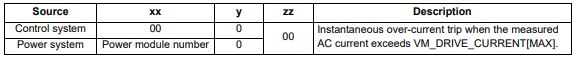 Recommended actions: • Acceleration/deceleration rate is too short • If seen during auto-tune reduce the voltage boost • Check for short circuit on the output cabling • Check integrity of the motor insulation using an insulation tester • Check feedback device wiring • Check feedback device mechanical coupling • Check feedback signals are free from noise • Is motor cable length within limits for the frame size • Reduce the values in the speed loop gain parameters — (Pr 03.010, 03.011, 03.012) or (Pr 03.013, 03.014, 03.015) • Has the phase angle autotune been completed? (RFC-S mode only) • Reduce the values in current loop gain parameters (RFC-A, RFC-S modes only) |
| Inductance | Inductance measurement out of range or motor saturation not detected |
| Trip 8 | This trip occurs in RFC-S mode when the drive has detected that the motor inductances are not suitable for the operation being attempted. The trip is either caused because the ratio or difference between Ld and Lq is too small or because the saturation characteristic of the motor cannot be measured. If the inductance ratio or difference is too small this is because one of the following conditions is true: (No-load Lq (05.072)- Ld (05.024)) / Ld (05.024) < 0.1 (No-load Lq (05.072) — Ld (05.024)) < (K / Full Scale Current Kc (11.061))H where: 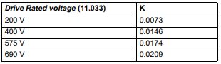 If the saturation characteristic of the motor cannot be measured this is because when the flux in the motor is changed the measured value of Ld does change sufficiently due to saturation to be measured. When half of Rated Current (05.007) is applied in the d axis of the motor in each direction the inductance must fall change at least (K / (2 x Full Scale Current Kc (11.061)). The specific reasons for each of the sub-trips are given in the table below: 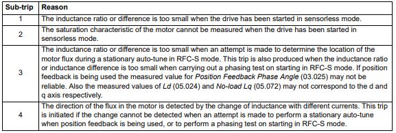 Recommended actions for sub-trip 1: • Ensure that RFC Low Speed Mode (05.064) is set to Non-salient (1), Current (2) or Current No test (3). Recommended actions for sub-trip 2: • Ensure that RFC Low Speed Mode (05.064) is set to Non-salient (1), Current (2) or Current No test (3). Recommended actions for sub-trip 3: • None. The trip acts as a warning. Recommended actions for sub-trip 4: • Stationary autotune is not possible. Perform a minimal movement or rotating autotune. • Phasing test on starting is not possible. Use a position feedback device with commutation signals or absolute position |
| Motor Too Hot | Output current overload timed out (I2t) |
| Trip 20 | The Motor Too Hot trip indicates a motor thermal overload based on the Rated Current (Pr 05.007) and Motor Thermal Time Constant (Pr 04.015). Pr 04.019 displays the motor temperature as a percentage of the maximum value. The drive will trip on Motor Too Hot when Pr 04.019 gets to 100 %. Recommended actions: • Ensure the load is not jammed / sticking • Check the load on the motor has not changed • If seen during an auto-tune test in RFC-S mode, ensure the motor Rated Current in Pr 05.007 is ≤ Heavy duty current rating of the drive • Tune the Rated Speed (Pr 05.008) (RFC-A mode only) • Check feedback signal for noise • Ensure the motor rated current is not zero • This trip can be disabled and current limiting activated on the motor overload by setting thermal protection mode Pr 04.016 to 1. |
| OHt Power | Power stage over temperature |
| Trip 22 | This trip indicates that a power stage over-temperature has been detected. From the sub-trip ‘xxyzz’, the Thermistor location which is indicating the over-temperature is identified by ‘zz’.The thermistor numbering is different for a single module type drive (i.e. no parallel board fitted) and a multi-module type drive (i.e. parallel board fitted with one or more power modules) as shown below: Single module type drive: 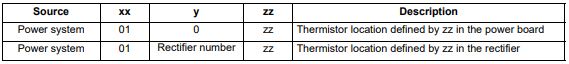 Multi-module type system: 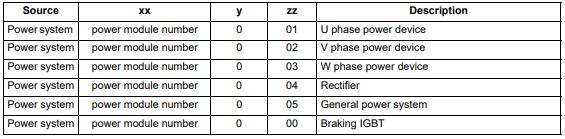 Note that the power module that has caused the trip cannot be identified except for the braking IGBT temperature measurement Recommended actions: • Check enclosure / drive fans are still functioning correctly • Force the heatsink fans to run at maximum speed • Check enclosure ventilation paths • Check enclosure door filters • Increase ventilation • Reduce the drive switching frequency • Reduce duty cycle • Increase acceleration / deceleration rates • Use S ramp (Pr 02.006) • Reduce motor load • Check the derating tables and confirm the drive is correctly sized for the application. • Use a drive with larger current / power rating |
| An Input 1 Loss | Analog input 1 current loss (Unidrive M700 / M701) |
| Trip 28 | An Input 1 Loss trip indicates that a current loss was detected in current mode on Analog input 1 (Terminal 5, 6). In 4-20 mA and 20-4 mA modes loss of input is detected if the current falls below 3 mA. Recommended actions: • Check control wiring is correct • Check control wiring is undamaged • Check the Analog Input 1 Mode (07.007) • Current signal is present and greater than 3 mA |
| Phase Loss | Supply phase loss |
| Trip 32 | The Phase Loss trip indicates that the drive has detected an input phase loss or large supply imbalance. Phase loss can be detected directly from the supply where the drive has a thyristor base charge system (Frame size 8 and above). If phase loss is detected using this method the drive trips immediately and the xx part of the sub-trip is set to 01. In all sizes of drive phase loss is also detected by monitoring the ripple in the DC bus voltage in which case the drive attempts to stop the drive before tripping unless bit 2 of Action On Trip Detection (10.037) is set to one. When phase loss is detected by monitoring the ripple in the DC bus voltage the xx part of the sub-trip is zero.  (1) Input phase loss detection can be disabled when the drive required to operate from the DC supply or from a single phase supply in Input Phase Loss Detection Mode (06.047). (2) For a parallel power-module system the rectifier number will be one as it is not possible to determine which rectifier has detected the fault. This trip does not occur in regen mode. Recommended actions: • Check the AC supply voltage balance and level at full load • Check the DC bus ripple level with an isolated oscilloscope • Check the output current stability • Check for mechanical resonance with the load • Reduce the duty cycle • Reduce the motor load • Disable the phase loss detection, set Pr 06.047 to 2. |
| Out Phase Loss | Output phase loss detected |
| Trip 98 | The Out Phase Loss trip indicates that phase loss has been detected at the drive output.  NOTE: If Pr 05.042 = 1 the physical output phases are reversed, and so sub-trip 3 refers to physical output phase V and sub-trip 2 refers to physical output phase W. Recommended actions: • Check motor and drive connections • To disable the trip set Output Phase Loss Detection Enable (06.059) = 0 |
| OI dc | Power module over current detected from IGBT on state voltage monitoring |
| Trip 109 | The OI dc trip indicates that the short circuit protection for the drive output stage has been activated. The table below shows where the trip has been detected. This trip cannot be reset until 10 s after the trip was initiated. 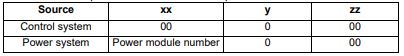 Recommended actions: • Disconnect the motor cable at the drive end and check the motor and cable insulation with an insulation tester • Replace the drive |
| Configuration | The number of power modules installed is different from the modules expected |
| Trip 111 | The Configuration trip indicates that the Number Of Power Modules Detected (11.071) does not match the previous value stored. The sub-trip value indicates the number of power modules expected. Recommended actions: • Ensure that all the power modules are correctly connected • Ensure all the power modules have powered up correctly • Ensure that the value in Pr 11.071 is set to the number of power modules connected • Set Pr 11.035 to 0 to disable the trip if it is not required This trip is also initiated if the number of external rectifiers connected to each power module is less than the number defined by Number Of Rectifiers Expected (11.096). If this is the reason for the trip the sub-trip is 10x where x is the number of external rectifiers that should be connected. Recommended actions: • Ensure that all the external rectifiers are connected correctly • Ensure that the value in Number Of Rectifiers Expected (11.096) is correct |
Alarm Indications
In any mode, an alarm is an indication given on the display by alternating the alarm string with the drive status string on the first row and showing the alarm symbol in the last character in the first row. If an action is not taken to eliminate any alarm except «Auto Tune and Limit Switch» the drive may eventually trip. Alarms are not displayed when a parameter is being edited, but the user will still see the alarm character on the upper row.
| Alarm string | Description |
|---|---|
| Brake Resistor | Brake resistor overload. Braking Resistor Thermal Accumulator (10.039) in the drive has reached 75.0 % of the value at which the drive will trip. |
| Motor Overload | Motor Protection Accumulator (04.019) in the drive has reached 75.0 % of the value at which the drive will trip and the load on the drive is >100 %. |
| Ind Overload | Regen inductor overload. Inductor Protection Accumulator (04.019) in the drive has reached 75.0 % of the value at which the drive will trip and the load on the drive is >100 %. |
| Drive Overload | Drive over temperature. Percentage Of Drive Thermal Trip Level (07.036) in the drive is greater than 90 %. |
| Auto Tune | The autotune procedure has been initialized and an autotune in progress. |
| Limit Switch | Limit switch active. Indicates that a limit switch is active and that is causing the motor to be stopped. |
Status Indications
| Upper row string | Description | Drive output stage |
|---|---|---|
| Inhibit | The drive is inhibited and cannot be run. The Safe Torque Off signal is not applied to Safe Torque Off terminals or Pr 06.015 is set to 0 | Disabled |
| Ready | The drive is ready to run. The drive enable is active, but the drive inverter is not active because the final drive run is not active | Disabled |
| Stop | The drive is stopped / holding zero speed. | Enabled |
| Run | The drive is active and running | Enabled |
| Scan | The drive is enabled in Regen mode and is trying to synchronize to the supply | Enabled |
| Supply Loss | Supply loss condition has been detected | Enabled |
| Deceleration | The motor is being decelerated to zero speed / frequency because the final drive run has been deactivated. | Enabled |
| dc injection | The drive is applying dc injection braking | Enabled |
| Position | Positioning / position control is active during an orientation stop | Enabled |
| Trip | The drive has tripped and no longer controlling the motor. The trip code appears in the lower display | Disabled |
| Active | The regen unit is enabled and synchronized to the supply | Enabled |
| Under Voltage |
The drive is in the under voltage state either in low voltage or high voltage mode | Disabled |
| Heat | The motor pre-heat function is active | Enabled |
| Phasing | The drive is performing a ‘phasing test on enable’ | Enabled |
Option module and NV Media Card and other status indications at power-up
| First row string | Second row string | Status |
|---|---|---|
| Booting | Parameters | Parameters are being loaded |
| Drive parameters are being loaded from a NV Media Card | ||
| Booting | User Program | User program being loaded |
| User program is being loaded from a NV Media Card to the drive | ||
| Booting | Option Program | User program being loaded |
| User program is being loaded from a NV Media Card to the option module in slot X | ||
| Writing To | NV Card | Data being written to NV Media Card |
| Data is being written to a NV Media Card to ensure that its copy of the drive parameters is correct because the drive is in Auto or Boot mode | ||
| Waiting For | Power System | Waiting for power stage |
| The drive is waiting for the processor in the power stage to respond after power-up | ||
| Waiting For | Options | Waiting for an option module |
| The drive is waiting for the Options Modules to respond after power-up | ||
| Uploading From |
Options | Loading parameter database |
| At power-up it may be necessary to update the parameter database held by the drive because an option module has changed or because an applications module has requested changes to the parameter structure. This may involve data transfer between the drive an option modules. During this period ‘Uploading From Options’ is displayed |
Programming error indications
Following are the error message displayed on the drive keypad when an error occurs during programming of drive firmware.
| Error String | Reason | Solution |
|---|---|---|
| Error 1 | There is not enough drive memory requested by all the option modules. | Power down drive and remove some of the option modules until the message disappears. |
| Error 2 | At least one option module did not acknowledge the reset request. | Power cycle drive |
| Error 3 | The boot loader failed to erase the processor flash | Power cycle drive and try again. If problem persists, return drive |
| Error 4 | The boot loader failed to program the processor flash | Power cycle drive and try again. If problem persists, return drive |
| Error 5 | One option module did not initialize correctly. Option module did not set Ready to Run flag. | Remove faulty option module |
Need further help?
If you have an AC / DC drive module breakdown or stability issue our engineers are able to analyse the whole machine to identify where the control issues lie. Our extensive experience in retrofit and new projects means we have the knowledge to look deep into the control system where we commonly find the peripheral devices are faulty rather than the drive module.
Our team of engineers are able to offer on site service and breakdown support throughout the UK to get you up and running again quickly.

Высокопроизводительный привод переменного тока M700
Руководство по вводу в эксплуатацию
с Unidrive M700, M701, M702 без обратной связи по положению
Двигатели от 11 до 240 кВт взаимозаменяемые версии серий 1,500 и 3,000 с приводом
Артикул: 6069 эн – 2022.06/с
ВВЕДЕНИЕ
1 — ВВЕДЕНИЕ
Перед настройкой привода следуйте инструкциям по безопасности и установке для двигателей Dyneo+ и приводов Unidrive M70x, описанным в соответствующих руководствах. Двигатели Dyneo+: http://www.leroy-somer.com/documentation_pdf/5411_en.pdf Привод Unidrive M70x: см. Руководство по началу работы и соответствующее Руководство по установке питания (доступно в Control Techniques). webсайт).
· Установка и ввод в эксплуатацию должны выполняться квалифицированным, компетентным и уполномоченным персоналом.
Затем выполните быстрый ввод в эксплуатацию, описанный в пункте 2, с заводскими настройками.
Требования: · Убедитесь, что на приводе установлена версия микропрограммы, равная или выше V01.20.00.00. · Не включайте процедуру автонастройки. · Параметры, указанные в таблицах данных двигателя из приложения, применимы только к номинальной мощности привода Unidrive M70x, указанной для
каждую строку данных. Если используется привод с другим номиналом, то коэффициент усиления Kp регулятора тока (Pr 04.013) и коэффициент усиления Ki регулятора тока (Pr 04.014) необходимо масштабировать, как описано ниже:
Новое значение = значение приложения x (KC новый привод / KC дополнительный привод) Значения для KC можно найти в Справочном руководстве по параметрам, в разделе «Текущие номиналы» или в интерактивной справке программного обеспечения Control Techniques Connect.
Dyneo+ с Unidrive M70x без обратной связи по положению Руководство по вводу в эксплуатацию
3
6069 эн – 2022.06/с
ВВОД В ЭКСПЛУАТАЦИЮ UNIDRIVE M70X БЕЗ ОБРАТНОЙ СВЯЗИ ПО ПОЛОЖЕНИЮ
2 – ВВОД В ЭКСПЛУАТАЦИЮ С UNIDRIVE M70x БЕЗ ОБРАТНОЙ СВЯЗИ ПО ПОЛОЖЕНИЮ
Режим RFC-S для взаимозаменяемых двигателей Dyneo+ с постоянными магнитами без обратной связи по положению (без датчиков)
Действие
Описание
Перед включением
Убедитесь, что: · Сигнал включения привода не подается (клемма 31 на Unidrive M700/M701 и клеммы 11 и 13 на Unidrive M702) · Сигнал «Работа» не подается · Двигатель подключен
Если при включении привода отображается режим Open Loop или RFC-A:
· Установите Pr 00.048 = RFC-S (3). · Если частота сети 60 Гц, установите Pr 00.000 = 1254, иначе, если частота сети 50 Гц, установите Pr 00.000 = 1253.
Включите привод
Если при включении привода отображается режим RFC-S:
· Если частота сети 60 Гц, установите Pr 00.000 = 1244, иначе, если частота сети 50 Гц, установите Pr 00.000 = 1233.
Доступ к расширенному меню с клавиатуры Установка максимальной скорости
Установите коэффициенты ускорения и замедления
Настройка термистора двигателя
Нажмите красную кнопку сброса или переключите логический вход сброса. Эти действия оставят диск в режиме RFC-S с параметрами по умолчанию. Привод будет находиться в отключенном состоянии, но соответствующие отключения регулируются настройками в рамках этой процедуры.
Чтобы получить доступ ко всем меню, необходимым для ввода в эксплуатацию, установите Pr 00.0049 = Все меню (1).
Напоминание: выберите меню с помощью стрелок влево и вправо. Параметры выбираются стрелками вверх и вниз.
Установите максимальную скорость в Pr 01.006 (об/мин).
Задайте: · Скорость ускорения в Pr 02.011 (с до Pr 01.006) — значение 20 с подходит для большинства приложений. · Скорость замедления в Pr 02.021 (с до Pr 01.006) – значение 20 с подходит для большинства приложений. · Рamp Единицы скорости Pr 02.039 = Вкл. (1)
Если тормозной резистор установлен, установите Pr 02.004 = Fast (0). Также убедитесь, что Pr 10.030, Pr 10.031 и Pr 10.061 установлены правильно, в противном случае могут наблюдаться постоянные отключения «Brake R Too Hot».
Термистор PTC двигателя должен быть подключен к приводу: · M700/M701: Подключите термистор к аналоговому входу 3 (клеммы 8 и 11). · M702 (с кодом даты 1710 или более поздней): Подключите термистор к цифровому входу 5 / аналоговому входу 3 (клеммы 8 и 10).
Чтобы привод управлял термистором: · Установите режим аналогового входа 3 Pr 07.015 = Therm short Cct (7).
Если при подключении термистора недостаточно входов, может потребоваться установка модуля SI-I/O.
4
Dyneo+ с Unidrive M70x без обратной связи по положению Руководство по вводу в эксплуатацию
6069 эн – 2022.06/с
ВВОД В ЭКСПЛУАТАЦИЮ UNIDRIVE M70X БЕЗ ОБРАТНОЙ СВЯЗИ ПО ПОЛОЖЕНИЮ
Действие
Введите данные паспортной таблички двигателя
Описание См. таблицы двигателей Dyneo+ в Приложении. Выберите таблицу, соответствующую диапазону скорости двигателя (1500 или 3000 об/мин). Затем в зависимости от типа двигателя и его мощности выберите строку, которая соответствует объему.tage, частота питания и номинальная скорость приложения. Из этой строки задайте в накопителе значения всех параметров, перечисленных в таблице. Если нагрузка имеет большую инерцию, может потребоваться увеличить Pr 03.010.
ПРИМЕЧАНИЕ. Если тип двигателя не указан в таблице, значит, он принадлежит к компактной серии. В этом случае обратитесь в службу технической поддержки Control Techniques.
Example: Для двигателя серии 1500, ЛШРМ 160МР1 – 11 кВт 400 В – 50 Гц с номинальной скоростью 1500 об/мин, значения параметров, которые необходимо установить в приводе, соответствуют значениям зеленой линии, как показано ниже:
Тип МОТОР
ЛШРМ 160 МР1
ГАММЕ 1500 мин-1
ВАРИАТОР
НАСТРОЙКИ
Муфта
#03.010 #03.011 #04.013 #04.014 #04.015 #05.007 #05.008 #05.009 #05.017 #05.024 #05.033 #05.069 #05.072 #05.075 #05.078 #05.082 #05.084 #05.087
кВт М700
Гц Усиление Усиление Усиление Усиление Константе Курант
Сопротивление
Витесс Напряжение
Ld
Vitesse Vitesse Courant Courant thermoque номинальный (мин-1) (В)
Кр Ки Кр Ки
(S)
(A)
Статор ()
(М)
БЭМП (В/
кммин-1)
Куран де Дефо
(%)
Lq @0A (мГн)
IQ (%)
Lq @ Iq Id (мГн) (%)
Угол
Lq @ Id (мГн)
пара (°)
11 44-00172 У 50 0,005 0,05 152 269 800 21,0 1500 400 0,31582 7,626 72,1 236 68,540 73 44,845 -108 68,540 56
11 44-00172 У 60 0,005 0,05 152 269 800 20,3 1800 400 0,31582 7,626 72,1 244 68,540 73 44,845 -108 68,540 56
12,7 44-00172 У 60 0,005 0,05 152 269 800 21,2 1800 460 0,31582 7,626 72,1 233 68,540 73 44,845 -108 68,540 56
19,1 64-00420 Д 87 0,005 0,05 124 219 800 38,2 2600 400 0,10527 2,542 41,6 218 22,847 73 14,948 -108 22,850 56
Дополнительные настройки
Сохранить параметры
ПРИМЕЧАНИЕ. При настройке Pr 05.069 может потребоваться увеличить введенное значение, чтобы фактическое значение отключения, отображаемое в Pr 05.068, было близко (но не больше) к требуемому значению.
Задавать :
· Режим обратной связи RFC (Pr 03.024) = Без датчика · Уровень обнаружения ошибки P1 (Pr 03.040) = 0 · Обнаружение ошибки термистора P1 (Pr 03.123) = Нет (0) · Ограничение тока двигателя (Pr 04.005) = 120% макс. · Ток рекуперации Предел (Pr 04.006) = 120 % макс · Предел симметричного тока (Pr 04.007) = 120 % макс · Постоянная времени фильтра опорного тока 1 (Pr 04.012) = 1 мс ]
· Режим тепловой защиты (Pr 04.016) = Отключен (4) · Максимальное масштабирование пользовательского тока (Pr 04.024) = макс. 120 % · Количество пар полюсов двигателя (Pr 05.011) = 2 · Максимальная частота коммутации (Pr 05.018) = 3 кГц (1) ) · Включить высокоскоростной режим (Pr 05.022) = Включить (2) · Коэффициент усиления управления потоком (Pr 05.027) = 0.1 · Минимальная частота переключения (Pr 05.038) = 3 кГц (1) · Voltage Запас Pr 05.041 = 5 %. [Не устанавливайте меньшее значение. Увеличьте это значение до 10 %, если двигатель нестабилен в области ослабления поля] · Режим низкой скорости RFC (Pr 05.064) = впрыск · Управление крутящим моментом Saliency Выберите Pr 05.065 = Авто (3) [Убедитесь, что Pr 05.066 = Высокий (2) ) в противном случае проверьте значение, введенное для Pr 05.087 из таблицы] · Инверсная характеристика насыщения (Pr 05.070) = Вкл. (1) · Ток в бессенсорном режиме на низкой скорости (Pr 05.071) = 60 % [Примечание. скорость и 20% от номинальной скорости двигателя]
· Режим остановки (Pr 06.001) = Ramp (1) · Удержание нулевой скорости (Pr 06.008) = отключено (0)
Выберите «Сохранить параметры» в Pr mm.000 и нажмите красную кнопку сброса или переключите цифровой вход сброса.
Привод готов к запуску.
Dyneo+ с Unidrive M70x без обратной связи по положению Руководство по вводу в эксплуатацию
5
6069 эн – 2022.06/с
ВВОД В ЭКСПЛУАТАЦИЮ С UNIDRIAVPEPME7N0DXIX БЕЗ ОБРАТНОЙ СВЯЗИ ПО ПОЛОЖЕНИЮ
Тип двигателя
ПРИВОД кВт
M70x
Связь
1500 об/мин ДИАПАЗОН ПАРАМЕТРОВ
#03.010 #03.011 #04.013 #04.014 #04.015 #05.007 #05.008 #05.009 #05.017 #05.024 #05.033 #05.069 #05.072 #05.075
#05.078
#05.082
# 05.084 # 05.087
Hz
Увеличение скорости Кр
Скорость Ток Ток Тепловой Номинал
Усиление Усиление Усиление постоянный ток
Ки Кр Ки
(S)
(A)
Номинальная скорость (об / мин)
Номинальный статор
обtagе Сопротивление
(V)
()
Ld (мГн)
OverBEMF текущий Lq @0A
(В/об/мин) уровень срабатывания (мГн) (%)
IQ (%)
Lq @ Iq (мГн)
Идентификатор (%)
Lq @ Id (мГн)
Угол крутящего момента
(°)
11 44-00172 Д 50 0.005 0.05 152 269 800 21.0 1500 400 0.31582 7.626 72.1 236 68.540 73
ЛШРМ 160 МР1
11 12.7
44-00172 44-00172
Д 60 0.005 Д 60 0.005
0.05 0.05
152 152
269 269
800 800
20.3 1800 400 0.31582 7.626 72.1 21.2 1800 460 0.31582 7.626 72.1
244 68.540 233 68.540
73 73
19.1 64-00420 Д 87 0.005 0.05 124 219 800 38.2 2600 400 0.10527 2.542 41.6 218 22.847 73
15 54-00300 Д 50 0.005 0.05 304 493 800 27.5 1500 400 0.28454 7.478 78.7 199 67.889 69
ЛШРМ 160 ЛР1
15 17.3
54-00270 54-00270
Д 60 0.005 Д 60 0.005
0.05 0.05
234 234
381 381
800 800
26.8 1800 400 0.28454 7.478 78.7 26.7 1800 460 0.28454 7.478 78.7
204 67.889 204 67.889
69 69
26.0 64-00470 Д 87 0.005 0.05 136 221 800 48.6 2600 400 0.09485 2.493 45.4 189 22.630 69
18.5 64-00420 Д 50 0.03 0.1 277 444 1000 35.9 1500 400 0.2133 5.676 73.1 181 43.301 71
ЛШРМ 180 М1
18.5 21.3
64-00420 64-00420
Д 60 0.03 Д 60 0.03
0.1 0.1
277 444 1000 35.1 1800 400 0.2133 5.676 73.1 277 444 1000 35.5 1800 460 0.2133 5.676 73.1
185 43.301 183 43.301
71 71
32.1 74-00660 Д 87 0.03 0.1 145 232 1000 62.9 2600 400 0.0711 1.892 42.2 174 14.434 71
22 64-00420 Д 50 0.03 0.1 207 281 1000 42.2 1500 400 0.13516 4.253 71.6 196 33.058 73
ЛШРМ 180 Л1
22 25.4
64-00420 64-00420
Д 60 0.03 Д 60 0.03
0.1 0.1
207 281 1000 40.1 1800 400 0.13516 4.253 71.6 207 281 1000 41.1 1800 460 0.13516 4.253 71.6
207 33.058 202 33.058
73 73
38.1 74-00770 Д 87 0.03 0.1 127 172 1000 73.5 2600 400 0.04505 1.418 41.3 189 11.019 73
30 64-00470 Д 50 0.03 0.1 190 252 1000 57.0 1500 400 0.10831 3.492 71.6 174 27.497 69
LSHRM 200 LQ1 30 64-00470 Y 60 0.03 0.1 190 252 1000 54.9 1800 400 0.10831 3.492 71.6 181 27.497 69 34.6 64-00470 Y 60 0.03 0.1 190 252 1000 56.1 1800 460 0.10831 3.492 71.6 177 27.497 69
52 74-01000 Д 87 0.03 0.1 135 179 1000 99.3 2600 400 0.03611 1.164 41.3 168 9.166 69
37 74-00660 Д 50 0.03 0.1 232 290 1000 70.1 1500 400 0.08873 3.028 72.3 164 24.063 69
ЛШРМ 225 СЗ1
37 42.7
74-00660 74-00660
Д 60 0.03 Д 60 0.03
0.1 0.1
232 290 1000 68.4 1800 400 0.08873 3.028 72.3 232 290 1000 69.2 1800 460 0.08873 3.028 72.3
168 24.063 166 24.063
69 69
64.2 84-01340 Д 87 0.03 0.1 157 196 1000 122 2600 400 0.02958 1.009 41.8 157 8.021 69
45 74-00770 Д 50 0.005 0.1 220 172 1200 82.1 1500 400 0.04505 2.467 76.6 201 23.645 67
ЛШРМ 225 МГ
45 54.3
74-00770 74-00770
Д 60 0.005 Д 60 0.005
0.1 0.1
220 172 1200 79.6 1800 400 0.04505 2.467 76.6 220 172 1200 83.1 1800 460 0.04505 2.467 76.6
207 23.645 198 23.645
67 67
79.2 84-01570 Д 87 0.005 0.1 150 117 1200 142 2600 400 0.01502 0.822 44.2 195 7.882 67
55 74-01000 Д 50 0.005 0.1 234 168 1200 99.4 1500 400 0.03388 2.015 76.6 199 19.664 67
LSHRM 250 ME 55 74-01000 y 60 0.005 0.1 234 168 1200 94.7 1800 400 0.03388 2.015 76.6 208 19.664 67 64 74-01000 y 60 0.005 0.1 234 168 1200 97.8 1800 460 0.03388 2.015 76.6 202 19.664 67 XNUMX XNUMX XNUMX XNUMX XNUMX XNUMX XNUMX XNUMX XNUMX XNUMX XNUMX XNUMX XNUMX XNUMX XNUMX XNUMX XNUMX XNUMX XNUMX XNUMX XNUMX XNUMX XNUMX XNUMX XNUMX XNUMX
95 94-02000 Д 87 0.005 0.1 136 98 1200 176 2600 400 0.01129 0.672 44.2 189 6.555 67
75 84-01340 Д 50 0.005 0.1 261 163 1200 134 1500 400 0.02461 1.677 81.7 185 16.736 63
ЛШРМ 280 СД
75 86.4
84-01340 84-01340
Д 60 0.005 Д 60 0.005
0.1 0.1
261 163 1200 130 1800 400 0.02461 1.677 81.7 261 163 1200 131 1800 460 0.02461 1.677 81.7
190 16.736 189 16.736
63 63
131 94-02240 Д 87 0.005 0.1 127 159 1200 231 2600 400 0.00821 0.559 47.2 180 5.579 63
90 84-01570 Д 50 0.005 0.1 261 154 1200 163 1500 400 0.01982 1.432 80.4 174 14.403 63
ЛШРМ 280 МД
90 104
84-01570 84-01570
Д 60 0.005 Д 60 0.005
0.1 0.1
261 154 1200 158 1800 400 0.01982 1.432 80.4 261 154 1200 155 1800 460 0.01982 1.432 80.4
179 14.403 182 14.403
63 63
156 104-02700 Д 87 0.005 0.1 149 177 1200 279 2600 400 0.00661 0.477 46.4 171 4.801 63
110 94-02000 Д 50 0.005 0.1 236 133 1200 199 1500 400 0.01534 1.161 76.6 165 11.750 61
ЛШРМ 315 СН1
110 132
94-02000 94-02240
Д 60 0.005 Д 60 0.005
0.1 0.1
236 133 1200 195 1800 400 0.01534 1.161 76.6 264 149 1200 202 1800 460 0.01534 1.161 76.6
168 11.750 163 11.750
61 61
192 114-04170 Д 87 0.005 0.1 164 185 1200 342 2600 400 0.00511 0.387 44.2 161 3.917 61
132 94-02240 Д 50 0.005 0.1 240 92 1400 235 1500 400 0.00952 1.057 86 194 9.591 59
ЛШРМ 315 МП
132 152
94-02240 94-02240
Д 60 0.005 Д 60 0.005
0.1 0.1
240 240
92 92
1400 234 1800 400 0.00952 1.057 1400 233 1800 460 0.00952 1.057
86 86
195 9.591 196 9.591
59 59
229 114-04170 Д 87 0.005 0.1 149 115 1400 415 2600 400 0.00317 0.352 49.6 186 3.197 59
160 104-03770 Д 50 0.005 0.1 264 96 1400 304 1500 400 0.00604 0.712 75.2 192 6.520 59
ЛШРМ 315 МП 160 104-02700 Y 60 0.005 0.1 223 81 1400 280 1800 400 0.00604 0.712 75.2 209 6.520 59
184 104-03770 Д 60 0.005 0.1 264 96 1400 294 1800 460 0.00604 0.712 75.2 198 6.520 59
200 114-04170 Д 50 0.005 0.1 247 82 1400 377 1500 400 0.00454 0.583 75.8 188 5.413 59
ЛШРМ 315 МР 200 114-04170 Д 60 0.005 0.1 247 82 1400 319 1800 400 0.00454 0.583 75.8 203 5.413 59
230 114-04170 Д 60 0.005 0.1 247 82 1400 366 1800 460 0.00454 0.583 75.8 193 5.413 59
75 84-01340 Д 50 0.005 0.1 261 163 1400 134 1500 400 0.02461 1.677 81.7 185 16.736 63
ФЛШРМ 280 СБ
75 86.4
84-01340 84-01340
Д 60 0.005 Д 60 0.005
0.1 0.1
261 163 1400 130 1800 400 0.02461 1.677 81.7 261 163 1400 131 1800 460 0.02461 1.677 81.7
190 16.736 189 16.736
63 63
131 94-02240 Д 87 0.005 0.1 127 80 1400 231 2600 400 0.0082 0.559 47.2 180 5.579 63
90 84-01570 Д 50 0.005 0.1 261 154 1500 163 1500 400 0.01982 1.432 80.4 174 14.403 63
ФЛШРМ 280 МД
90 104
84-01570 84-01570
Д 60 0.005 Д 60 0.005
0.1 0.1
261 154 1500 158 1800 400 0.01982 1.432 80.4 261 154 1500 155 1800 460 0.01982 1.432 80.4
179 14.403 182 14.403
63 63
156 104-02700 Д 87 0.005 0.1 149 95 1500 279 2600 400 0.00661 0.477 46.4 171 4.801 63
110 94-02000 Д 50 0.005 0.1 236 133 1500 199 1500 400 0.01534 1.161 76.6 165 11.750 61
FLSHRM 315 STB 110 94-02000 Y 60 0.005 0.1 236 133 1500 195 1800 400 0.01534 1.161 76.6 168 11.750 61 131 94-02240 Y 60 0.005 0.1 264 149 1500 202 1800 460 0.01534 1.161 76.6 163 11.750 61
192 114-04170 Д 87 0.005 0.1 164 92 1500 342 2600 400 0.00511 0.387 44.2 161 3.917 61
132 94-02240 Д 50 0.005 0.1 240 92 1600 236 1500 400 0.00952 1.057 86 194 9.591 59
ФЛШРМ 315 М
132 152
94-02240 94-02240
Д 60 0.005 Д 60 0.005
0.1 0.1
240 240
92 92
1600 234 1800 400 0.00952 1.057 1600 233 1800 460 0.00952 1.057
86 86
195 9.591 196 9.591
59 59
229 114-04170 Д 87 0.005 0.1 149 57 1600 415 2600 400 0.00317 0.352 49.6 186 3.197 59
160 104-03770 Д 50 0.005 0.1 264 96 1600 304 1500 400 0.00604 0.712 75.2 192 6.520 59
ФЛШРМ 315 ЛА 160 104-02700 Y 60 0.005 0.1 223 81 1600 280 1800 400 0.00604 0.712 75.2 209 6.520 59
184 104-03770 Д 60 0.005 0.1 264 96 1600 294 1800 460 0.00604 0.712 75.2 198 6.520 59
200 114-04170 Д 50 0.005 0.1 247 82 1600 377 1500 400 0.00454 0.583 75.8 188 5.413 59
ФЛШРМ 315 ЛБ 200 114-04170 Д 60 0.005 0.1 247 82 1600 349 1800 400 0.00454 0.583 75.8 203 5.413 59
230 114-04170 Д 60 0.005 0.1 247 82 1600 366 1800 460 0.00454 0.583 75.8 193 5.413 59
240 114-04800 Д 50 0.005 0.1 241 78 1600 457 1500 400 0.00385 0.512 74.5 172 4.780 59
ФЛШРМ 315 ЛЦ 240 114-04170 Д 60 0.005 0.1 217 70 1600 429 1800 400 0.00385 0.512 74.5 183 4.780 59
276 114-04800 Д 60 0.005 0.1 241 78 1600 443 1800 460 0.00385 0.512 74.5 177 4.780 59
44.845 -108 68.540 56 44.845 -108 68.540 56 44.845 -108 68.540 56 14.948 -108 22.850 56 40.485 -110 67.890 58 40.485 -110 67.890 58 40.485 -110 67.890 58 13.495 -110 22.630 58 31.534 -109 43.300 57 31.534 -109 43.300 57 31.534 -109 43.300 57 10.511 -109 14.430 57 25.019 -108 33.060 56 25.019 -108 33.060 56 25.019 -108 33.060 56 8.340 -108 11.020 56 19.675 -110 27.500 58 19.675 -110 27.500 58 19.675 -110 27.500 58 6.558 -110 9.170 58 16.697 -110 24.060 58 16.697 -110 24.060 58 16.697 -110 24.060 58 5.566 -110 8.020 58 13.172 -111 23.640 59 13.172 -111 23.640 59 13.172 -111 23.640Р59Р4.391Р111Р7.880Р59Р10.923А 111, 19.660 -59 10.923 111 19.660 -59 10.923 111 19.660 -59 3.641 111 6.550 -59 8.988 114 16.740 -61 8.988 114 16.740 -61 8.988 114 16.740 -61 2.996 114 5.580 -61 7.519 114 14.400 -61 7.519 114 14.400 -61 7.519 114 14.400 -61 -2.506 114 -4.800 -61 -6.646 -115 -11.750. 62 -6.646 115 11.750 62 -6.646 115 11.750 62 -2.215 115 3.920 62 -5.620 116 9.590 63 -5.620 116 9.590 63 -5.620 116 9.590 63 -1.873 116 -3.200 63 3.800 116 -6.520 63 3.800 116 -6.520 63 3.800 116 -6.520 63 3.096 116 -5.410 63 3.096 116 -5.410 63 3.096 116 5.410 63
8.988 -114 16.740 61 8.988 -114 16.740 61 8.988 -114 16.740 61 2.996 -114 5.580 61 7.519 -114 14.400 61 7.519 -114 14.400 61 7.519 -114 14.400 61 2.506 -114 4.800 61 6.646. 115 -11.750 62 6.646 115 -11.750 62 6.646 115 -11.750 62 2.215 115 -3.920 62 5.620 116 -9.590 63 5.620 116 -9.590 63 5.620 116 -9.590 63 1.873 116 -3.200 63 3.800 116 -6.520 63 3.800 116 -6.520 63 3.800 116 -6.520 63 3.096 116 -5.410 63 3.096 116 -5.410 63 3.096 116 -5.410 63 2.550 116 -4.780 63 2.550
6
Dyneo+ с Unidrive M70x без обратной связи по положению Руководство по вводу в эксплуатацию
6069 эн – 2022.06/с
ВВОД В ЭКСПЛУАТАЦИЮ С ПОМОЩЬЮ UNIDRIVAEPPME7N0DXIX БЕЗ ОБРАТНОЙ СВЯЗИ ПО ПОЛОЖЕНИЮ
Тип двигателя
ПРИВОД кВт
M70x
Связь
3000 об/мин ДИАПАЗОН ПАРАМЕТРОВ
#03.010 #03.011 #04.013 #04.014 #04.015 #05.007 #05.008 #05.009 #05.017 #05.024 #05.033 #05.069 #05.072 #05.075
#05.078
#05.082
# 05.084 # 05.087
Hz
Увеличение скорости Кр
Скорость Ток Ток Тепловой Номинал
Усиление Усиление Усиление постоянный ток
Ки Кр Ки
(S)
(A)
Номинальная скорость (об / мин)
Номинальный статор
обtagе Сопротивление
(V)
()
Ld (мГн)
OverBEMF текущий Lq @0A
(В/об/мин) уровень срабатывания (мГн) (%)
IQ (%)
Lq @ Iq (мГн)
Идентификатор (%)
Lq @ Id (мГн)
Угол крутящего момента
(°)
11 44-00172 Д 100 0.005 0.05 95 213 800 20.3 3000 400 0.25015 4.781 43.3 238 41.329 73
ЛШРМ 160 МР1
11 12.7
44-00172 44-00172
Д 120 0.005 0.05 Д 120 0.005 0.05
95 95
213 213
800 800
19.8 3600 400 0.25015 4.781 43.3 19.9 3600 460 0.25015 4.781 43.3
244 41.329 243 41.329
73 73
19.1 64-00420 Д 173 0.005 0.05 78 173 800 35.8 5200 400 0.08338 1.594 25 223 13.776 73
15 54-00300 Д 100 0.005 0.05 117 223 800 27.7 3000 400 0.12877 2.884 39.3 254 25.538 75
ЛШРМ 160 МР1
15 17.3
54-00270 64-00350
Д 120 0.005 0.05 Д 120 0.005 0.05
90 117
172 223
800 800
27.1 3600 400 0.12877 2.884 39.3 28.2 3600 460 0.12877 2.884 39.3
259 25.538 249 25.538
75 75
26.0 64-00470 Д 173 0.005 0.05 52 100 800 50.9 5200 400 0.04292 0.961 22.7 226 8.513 75
18.5 64-00350 Д 100 0.005 0.05 117 223 800 33.7 3000 400 0.12877 2.884 39.3 209 25.538 71
ЛШРМ 160 ЛР1
18.5 21.3
64-00350 64-00350
Д 120 0.005 0.05 Д 120 0.005 0.05
117 117
223 223
800 800
32.9 3600 400 0.12877 2.884 39.3 33.1 3600 460 0.12877 2.884 39.3
214 25.538 212 25.538
71 71
32.1 74-00660 Д 173 0.005 0.05 74 140 800 61.8 5200 400 0.0429 0.961 22.7 186 8.513 71
22 64-00420 Д 100 0.03 0.1 104 192 800 41.8 3000 400 0.0925 2.134 38.2 216 15.79 76
ЛШРМ 180 М1
22 25.5
64-00420 64-00420
Д 120 0.03 Д 120 0.03
0.1 0.1
104 104
192 192
800 800
40.2 3600 400 0.0925 2.134 38.2 41.4 3600 460 0.0925 2.134 38.2
224 15.79 218 15.79
76 76
38.1 74-00770 Д 173 0.03 0.1 64 118 800 73.6 5200 400 0.0308 0.711 22 200 5.263 76
30 64-00470 Д 100 0.03 0.1 116 215 800 56.7 3000 400 0.0925 2.134 38.2 159 15.79 69
ЛШРМ 200 LQ1 30 64-00470 Y 120 0.03 0.1 116 215 800 57.1 3600 400 0.0925 2.134 38.2 158 15.79 69
34.7 64-00470 Д 120 0.03 0.1 116 215 800 56.5 3600 460 0.0925 2.134 38.2 160 15.79 69
37 74-00660 Д 100 0.03 0.1 109 174 800 69.9 3000 400 0.05333 1.419 36.6 178 10.825 71
ЛШРМ 200 LQ1 37 74-00660 Y 120 0.03 0.1 109 174 800 68.8 3600 400 0.05333 1.419 36.6 181 10.825 71
42.9 74-00660 Д 120 0.03 0.1 109 174 800 69 3600 460 0.05333 1.419 36.6 181 10.825 71
45 74-00770 Д 100 0.03 0.1 106 142 800 84.1 3000 400 0.03715 1.185 37.8 180 9.208 71
ЛШРМ 225 МГ1 45 74-00770 Y 120 0.03 0.1 106 142 800 82 3600 400 0.03715 1.185 37.8 184 9.208 71
52 74-00770 Д 120 0.03 0.1 106 142 800 83.4 3600 460 0.03715 1.185 37.8 181 9.208 71
55 74-01000 Y 100 0.005 0.1 118 104 1100 100 3000 400 0.02106 1.019 43.4 226 9.52
71
ЛШРМ 250 МЭ 55 74-01000 Y 120 0.005 0.1 118 104 1100 101 3600 400 0.02106 1.019 43.4 225 9.52
71
63.7 74-01000 Y 120 0.005 0.1 118 104 1100 100 3600 460 0.02106 1.019 43.4 226 9.52
71
75 84-01340 Д 100 0.005 0.1 123 109 1100 138 3000 400 0.01637 0.794 38.3 185 7.412 65
ЛШРМ 280 СК 75 84-01340 Д 120 0.005 0.1 123 109 1100 136 3600 400 0.01637 0.794 38.3 187 7.412 65
86.3 84-01340 Д 120 0.005 0.1 123 109 1100 135 3600 460 0.01637 0.794 38.3 189 7.412 65
90 84-01570 Д 100 0.005 0.1 112 88 1100 167 3000 400 0.01125 0.617 38.3 190 5.911 65
ЛШРМ 280 МС 90 84-01570 Y 120 0.005 0.1 112 88 1100 160 3600 400 0.01125 0.617 38.3 198 5.911 65
104 94-02000 Д 120 0.005 0.1 125 98 1100 168 3600 460 0.01125 0.617 38.3 189 5.911 65
110 94-02000 Д 100 0.005 0.1 102 72 1100 201 3000 400 0.00836 0.504 38.3 189 4.916 69
ЛШРМ 315 СН1 110 94-02000 Д 120 0.005 0.1 102 72 1100 195 3600 400 0.00836 0.504 38.3 195 4.916 69
127 94-02000 Д 120 0.005 0.1 102 72 1100 197 3600 460 0.00836 0.504 38.3 193 4.916 69
132 94-02240 Д 100 0.005 0.1 107 70 1100 237 3000 400 0.00722 0.469 40.2 178 4.639 69
ЛШРМ 315 МН1 132 94-02240 Д 120 0.005 0.1 107 70 1100 234 3600 400 0.00722 0.469 40.2 181 4.639 69
152 94-02240 Д 120 0.005 0.1 107 70 1100 232 3600 460 0.00722 0.469 40.2 182 4.639 69
160 104-02700 Д 100 0.005 0.1 112 66 1100 289 3000 400 0.00495 0.358 40.2 188 3.601 65
ЛШРМ 315 МН1 160 104-02700 Д 120 0.005 0.1 112 66 1100 273 3600 400 0.00495 0.358 40.2 199 3.601 65
184 104-02700 Д 120 0.005 0.1 112 66 1100 283 3600 460 0.00495 0.358 40.2 192 3.601 65
200 114-04170 Д 100 0.005 0.1 123 69 1100 366 3000 400 0.00383 0.29 38.3 172 2.937 63
ЛШРМ 315 МН1 200 114-04170 Д 120 0.005 0.1 123 69 1100 365 3600 400 0.00383 0.29 38.3 173 2.937 63
233 114-04170 Д 120 0.005 0.1 123 69 1100 359 3600 460 0.00383 0.29 38.3 175 2.937 63
75 84-01340 y 100 0.005 0.1 123 109 1800 138 3000 400 0.01637 0.794 38.3 185 7.412 65 FLSHRM 280 SA 75 84-01340 Y 120 0.005 0.1 123 109 1800 136 3600 400 0.01637 0.794 38.3 187 7.412 65 XNUMX XNUMX XNUMX XNUMX XNUMX XNUMX XNUMX XNUMX XNUMX XNUMX XNUMX XNUMX XNUMX XNUMX XNUMX XNUMX XNUMX XNUMX XNUMX XNUMX XNUMX XNUMX XNUMX XNUMX XNUMX. XNUMX XNUMX XNUMX XNUMX XNUMX XNUMX XNUMX XNUMX XNUMX XNUMX XNUMX XNUMX XNUMX XNUMX.
86.3 84-01340 y 120 0.005 0.1 123 109 1800 135 3600 460 0.01637 0.794 38.3 189 7.412 65 90 84-01570 y 100 0.005 0.1 112 88 1800 167 3000 400 0.01125 0.617 38.3 190. 5.911 65 280 90 84 01570 120 0.005 0.1 112 88 1800 160 3600 400-0.01125 Y 0.617 38.3 198 5.911 65 108 94 02000 120 0.005 0.1 125 98 1800 168 3600 460-0.01125 Y 0.617 38.3 189 5.911 65 110 94 02000 100 0.005 0.1 102 72 1800 201 FLSHRM 3000 STA 400 0.00836-0.504 Y 38.3 189 4.916 69 315 110 94 02000 120 0.005 0.1 102 72 1800 195 3600 400-0.00836 Y 0.504 38.3 195 4.916 69 127 94 02000 120 0.005 0.1 102 72 1800 197 3600 460-0.00836 Y 0.504 38.3 193 4.916 69 132 94 02240 100 0.005 0.1 107 70 1800 237 FLSHRM 3000 MT 400 0.00722-0.469 Y 40.2 178 4.639 69 315 132 94 02240 120 0.005 0.1 107 70 1800 234 3600 400-0.00722 0.469 40.2. 181 4.639 69 152 94 02240 120 0.005 0.1 107 70 1800 232 3600. 460 0.00722 0.469 40.2 182 4.639 69 160 104 02700 100-0.005 Д 0.1 112 66 1800 289 3000 400 0.00495 0.358 40.2 188 3.601 65ШМ 315 160LTA 104 02700-120 y 0.005 0.1 112 66 1800 273 3600 400 0.00495 0.358 40.2 199 3.601 65 184 104 02700-120 Y 0.005 0.1 112 66 1800 283 3600 460 0.00495 0.358 40.2 192 3.601 65 200 114 04170 100 0.005 0.1 123 69 1800 366-3000 400 0.00383 0.29 38.3 172 2.937 63 315 200 114 04170 120 0.005 0.1 123. 69 1800 365 3600 400 0.00383 0.29 38.3 173 2.937 63 FLSHRM 233 LTB 114 04170-120 y 0.005 0.1 123 69 1800 359 3600 460 0.00383 0.29 38.3 175 2.937 63 XNUMX XNUMX XNUMX-XNUMX y XNUMX XNUMX XNUMX XNUMX-XNUMX y XNUMX XNUMX XNUMX XNUMX XNUMX XNUMX XNUMX XNUMX
27.751 -108 41.329 56
27.751 -108 41.329 56
27.751 -108 41.329 56
9.25 -108 13.776 56
17.72 -106 25.538 55
17.72 -106 25.538 55
17.72 -106 25.538 55
5.907 -106 8.513 55
17.009 -109 25.538 57
17.009 -109 25.538 57
17.009 -109 25.538 57
5.70 -109 8.513 57
12.578 -105 15.79 54
12.578 -105 15.79 54
12.578 -105 15.79 54
4.20 -105 5.263 54
11.032 -110 15.79 58
11.032 -110 15.79 58
11.032 -110 15.79 58
7.982 -109 10.825 57
7.982 -109 10.825 57
7.982 -109 10.825 57
6.802 -109 9.208 57
6.802 -109 9.208 57
6.802 -109 9.208 57
5.657-109
9.52
57
5.657-109
9.52
57
5.657-109
9.52
57
4.063 -113 7.412 60
4.063 -113 7.412 60
4.063 -113 7.412 60
3.648 -113 5.911 60
3.648 -113 5.911 60
3.648 -113 5.911 60
2.56 -110 4.916 58
2.56 -110 4.916 58
2.56 -110 4.916 58
2.28 -110 4.639 58
2.28 -110 4.639 58
2.28 -110 4.639 58
1.989 -113 3.601 60
1.989 -113 3.601 60
1.989 -113 3.601 60
1.734 -114 2.937 61
1.734 -114 2.937 61
1.734 -114 2.937 61
4.063 -113 7.412 60 4.063 -113 7.412 60 4.063 -113 7.412 60 3.648 -113 5.911 60 3.648 -113 5.911 60 3.648 -113 5.911 60 2.56 -110 4.916 58 2.56 -110 4.916 58 2.56 -110 4.916 58 2.28 -110 4.639 58 2.28 -110 4.639 58 2.28 -110 4.639 58 2.21 -113 3.601 60 2.21 -113 3.601 60 2.21 -113 3.601 60 1.734 -114 2.937 61 1.734 -114 2.937 61 1.734
Dyneo+ с Unidrive M70x без обратной связи по положению Руководство по вводу в эксплуатацию
7
6069 эн – 2022.06/с
Штаб-квартира Moteurs Leroy-Somer: бульвар Марселлен Леруа — CS 10015
16915 АНГУЛЕМ Cedex 9
Компания с ограниченной ответственностью с капиталом 38,679,664 338 567 RCS Angoulême 258 XNUMX XNUMX
www.leroy-somer.com
Документы / Ресурсы
 |
Высокопроизводительный привод переменного тока Nidec M700 [pdf] Руководство пользователя Высокопроизводительный привод переменного тока M700, M700, Высокопроизводительный привод переменного тока, Высокопроизводительный привод переменного тока, Привод переменного тока, Высокопроизводительный привод переменного тока M700 |
10
This section of the manual provides basic diagnostic information intended to enable
resolution of the most common problems encountered when setting up the Ethernet
interface on an Ethernet network.
A high percentage of problems reported are basic setup problems that can be avoided
by using the following pages. Start by using the Diagnostic flow chart on page 188 to
determine the possible cause of a problem. If after following the flow chart you are still
experiencing problems please contact your supplier or local drive supplier for support.
Please note that support will be limited to the setting up and networking of the drive and
NOTE
not network infrastructure design.
10.1
LED diagnostics
Each Ethernet connection has an associated LED to aid diagnostics, in the case of the
onboard Ethernet interface, this LED is mounted below the associated RJ45 connector;
the SI-Ethernet option module has two LEDs mounted on the topside of the module
(Figure 2-1 SI-Ethernet on page 8).
The connection status for the first port (nearest the grounding tab) is indicated by LED
«A», and the second port is indicated by LED «B».
The function of these LEDs are described in table 10.1 LED functionality below.
Table 10.1 LED functionality
LED State
Steady green
Flashing green
10.2
Drive trip display codes
If the Ethernet interface detects an error during operation, it will force a trip on the
drive. However, the trip string displayed on the drive will only indicate which slot
initiated the trip, if the error originated from the onboard Ethernet interface then the
default slot will be 4, however, if the SI-Ethernet option module generated the trip then
the slot number will be the slot number the SI-Ethernet option module is fitted to. The
exact reason for the trip will be indicated in the drive trip code parameters (Pr 0.10.020
and Pr 0.10.070).
Table 10.2 Drive trip indications on page 184 following shows the possible trips that will
be displayed on the drive when a problem is detected or the Ethernet interface initiates
a trip.
SI-Ethernet User Guide
Issue: 1
Description
Off
Ethernet connection not detected.
Ethernet connection detected but no data.
Ethernet communication detected and data flow.
183
-
Page 1
User Guide Free Standing Model sizes 6 to 9 Universal Variable Speed AC Drive for induction and servo motors Part Number: 0471-0122-01 Issue: 1 www.controltechniques.com… -
Page 2
General Information The manufacturer accepts no liability for any consequences resulting from inappropriate, negligent or incorrect installation or adjustment of the optional operating parameters of the equipment or from mismatching the variable speed drive with the motor. The contents of this guide are believed to be correct at the time of printing. In the interests of a commitment to a policy of continuous development and improvement, the manufacturer reserves the right to change the specification of the product or its performance, or the contents of the guide, without notice. -
Page 3
How to use this guide This user guide provides complete information for installing and operating the drive from start to finish. The information is in logical order, taking the reader from receiving the drive through to fine tuning the performance. NOTE There are specific safety warnings throughout this guide, located in the relevant sections. -
Page 4: Table Of Contents
4.13 SAFE TORQUE OFF (SECURE DISABLE) ..69 10.4 Getting started ……….126 10.5 Onboard PLC parameters …….. 126 10.6 Onboard PLC trips ……….. 127 10.7 Onboard PLC and the SMARTCARD ….127 Unidrive SP Free Standing User Guide www.controltechniques.com Issue Number: 1…
-
Page 5: Table 2-1 400V Standard (Ip21) Free Standing Drive Table
14.3 AC supply specification ……..260 14.4 Maximum continuous output current ….260 14.5 Safety label …………260 14.6 UL listed accessories ……..260 List of figures ……..261 List of tables ……..263 Index ………..265 Unidrive SP Free Standing User Guide Issue Number: 1 www.controltechniques.com…
-
Page 6
*Clause 5.2.3.8 of EN 61800-5-1:2003 (breakdown of components test) has been amended to eliminate the 30A ground (earth) fuse, in accordance with the draft edition 2 of IEC 61800-5-1 Unidrive SP Free Standing User Guide www.controltechniques.com Issue Number: 1… -
Page 7: Safety Information
The system designer is responsible for ensuring that the complete system is safe and designed correctly according to the relevant safety standards. Independent approval by BGIA has been given. Unidrive SP Free Standing User Guide Issue Number: 1 www.controltechniques.com…
-
Page 8: Product Information
Information Product information Unidrive SP Free Standing cubicles are made up to one or more SPM modules (SPMA / SPM), depending on size and current ratings. Model number The way in which the model numbers for the Unidrive SP range are formed is illustrated below.
-
Page 9: Ratings
Data Information Ratings The Unidrive SP is dual rated. Available output The setting of the motor rated current determines which rating applies — Overload limit — current Heavy Duty Heavy Duty or Normal Duty. Maximum The two ratings are compatible with motors designed to IEC60034.
-
Page 10
690V 575V current current 690V 575V current current 66X1 66X2 76X1 76X2 5 6 5 7 5 8 86X1 86X2 86X3 86X4 96X1 96X3 96X4 96X5 Unidrive SP Free Standing User Guide www.controltechniques.com Issue Number: 1… -
Page 11: Table 2-3 400V Ip23 Free Standing Drive Ratings At
76X2-E23 5 6 5 7 5 8 86X1-E23 86X2-E23 86X3-E23 86X4-E23 96X1-E23 96X3-E23 96X4-E23* 96X5-E23* * Ratings for SP96X4 E23 and SP96X5 E23 are for an ambient temperature of 30°C Unidrive SP Free Standing User Guide Issue Number: 1 www.controltechniques.com…
-
Page 12: Operating Modes
2.3.4 Servo For use with permanent magnet brushless motors with a feedback The Unidrive SP is designed to operate in any of the following modes: device installed. 1. Open loop mode The drive directly controls the speed of the motor using the feedback Open loop vector mode device to ensure the rotor speed is exactly as demanded.
-
Page 13: Drive Features
3 Control terminals Encoder connection Relay terminals Braking terminals (optional) Motor Motor connections connections Ground connections Ground connections Braking terminals (optional) AC supply connections Internal fuse location Internal fuse location Unidrive SP Free Standing User Guide Issue Number: 1 www.controltechniques.com…
-
Page 14: Figure 2-5 Features Of The Size 8 And 9 Free Standing
Relay terminals Brake connections (optional) Brake connections (optional) Motor connections Motor connections 24V power supply Ground connections AC supply connections AC supply connections Internal fuse Internal fuse location location Unidrive SP Free Standing User Guide www.controltechniques.com Issue Number: 1…
-
Page 15: Nameplate Description
Heavy Duty / No. of phases & frequency Normal Duty Typical input current for rating output current Normal Duty rating Options Figure 2-7 Options available with Unidrive SP SMARTCARD* Keypad Feedback Automation Fieldbus CT Comms cable * A SMARTCARD is provided as standard. For further information, refer to Chapter 9 SMARTCARD operation on page 119.
-
Page 16: Table 2-7 Solutions Module Identification
Additional I/O with overvoltage protection up to 48V SM-I/O 24V Cobalt Blue 2 x Analog outputs (current modes) Protected 4 x Digital input / outputs, 3 x Digital inputs, 2 x Relay outputs Unidrive SP Free Standing User Guide www.controltechniques.com Issue Number: 1…
-
Page 17
Pale Green SM-LON LonWorks adapter for communications with the drive SLM interface The SM-SLM allows SLM feedback to be connected directly to the Unidrive SP drive and allows operation in either of the Orange SM-SLM following modes: • Encoder only mode •… -
Page 18: Items Supplied With The Drive
The drive is supplied with a printed manual, a SMARTCARD, a safety information booklet, the Certificate of Quality, and a CD ROM containing all related product documentation and software tools. All accessories (e.g. control connectors) are supplied installed to the drive. Unidrive SP Free Standing User Guide www.controltechniques.com Issue Number: 1…
-
Page 19: Mechanical Installation
Lift the drive by the method detailed in Figure 3-2 on page 20. Do not tilt the drive. The centre of gravity of the unit is high. An overturning unit can cause physical injury. Unidrive SP Free Standing User Guide Issue Number: 1 www.controltechniques.com…
-
Page 20: Planning The Installation
0.5 metres must be maintained between drives. Certain Unidrive SP size 6 and 7 Free Standing drives are fitted with smaller roof fans, baffling should also be fitted if installed side by side Unidrive SP Free Standing User Guide www.controltechniques.com…
-
Page 21: Figure 3-3 Location And Identification Of Terminal Covers For Free Standing Drives
Data Information Figure 3-3 Location and identification of terminal covers for Free Standing drives Control Control Input / output Input / output Input / output Unidrive SP Free Standing User Guide Issue Number: 1 www.controltechniques.com…
-
Page 22: Figure 3-4 Removing The Size 6, 7 And 8 Terminal Covers From The Free Standing Drive
Started parameters the motor operation parameters Data Information Figure 3-4 Removing the size 6, 7 and 8 terminal covers from the Free Standing drive Pozi Pz4 Pozi Pz2 Pozi Pz4 Unidrive SP Free Standing User Guide www.controltechniques.com Issue Number: 1…
-
Page 23: Figure 3-5 Removing The Size 9 Terminal Covers From The Free Standing Drive
Installation Started parameters the motor operation parameters Data Information Figure 3-5 Removing the size 9 terminal covers from the Free Standing drive Pozi Pz4 Pozi Pz2 Pozi Pz4 Pozi Pz4 Unidrive SP Free Standing User Guide Issue Number: 1 www.controltechniques.com…
-
Page 24: Installing Fuses In A Free Standing Drive
3.4.2 Size 8 & 9 (with date code S18 or later) Secure fuse to upper Unidrive SP size 8 and 9 Free Standing with date code of S18 or later mounting stud with M10 nut can accept type DIN80 or type DIN110 fuses.
-
Page 25: Figure 3-10 Preparation For Baying The Incomer/Applications Shell
Data Information Figure 3-10 Preparation for baying the incomer/applications shell An incomer shell is supplied with no side panels. Figure 3-11 Preparation for baying the size 8 Free Standing drive Unidrive SP Free Standing User Guide Issue Number: 1 www.controltechniques.com…
-
Page 26: Figure 3-12 Preparation For Baying The Size 9 Free Standing Drive (Slave And Master)
Lift the drive by the method detailed in Figure 3-2 on page 20. Do not tilt the drive. The centre of gravity of the unit is high. WARNING An overturning unit can cause physical injury. Unidrive SP Free Standing User Guide www.controltechniques.com Issue Number: 1…
-
Page 27: Figure 3-13 Location Of The Rectifier Status Connectors For Size 9 Free Standing Drive
2. M6 star lock washer 3. In comer frame Free Standing drive frame 5. M6 screw Once the Free Standing drive and incomer are in position they must be bolted to the floor Unidrive SP Free Standing User Guide Issue Number: 1 www.controltechniques.com…
-
Page 28: Figure 3-15 Installing The Parallel Cable From A Size 9 Master To Slave
1. Remove size 9 slave interface cover 2. Connect the paralleling cable to the size 9 slave input slot 3. Replace size 9 slave interface cover 4. Replace all size 9 Free Standing drive panels Unidrive SP Free Standing User Guide www.controltechniques.com Issue Number: 1…
-
Page 29: Figure 3-16 Input Busbar Connections Between The
Fit the input parallel busbar with (M8 x 20 screws) (torque 17Nm [12.5 lb ft]); and M6 x 30 insulating spacer with (M6 x 12 screws) (torque 12Nm [8.85 lb ft]) Fit the input parallel busbar with (M8 x 20 screws) (torque 17Nm [12.5 lb ft]) Unidrive SP Free Standing User Guide Issue Number: 1 www.controltechniques.com…
-
Page 30: Figure 3-17 Input Busbar Connections Between The
4. Fit: 2 x 12 pulse busbars, 4 x 30mm insulator, 6 x M6x16 screws, 4 x M8x20 screws, L1(A) terminal marker NOTE Pre-fit insulators to busbars before fitting to cubicle. Unidrive SP Free Standing User Guide www.controltechniques.com Issue Number: 1…
-
Page 31: Figure 3-18 Baying A 6 Pulse Incomer To A 6 Pulse Free Standing Drive (Size 8 Shown)
The images below shows how to remove the gland plate from a Free Standing drive. Figure 3-19 Removing the cable gland plate from the Free Standing drive for «glanding off» the cable Unidrive SP Free Standing User Guide Issue Number: 1…
-
Page 32: Free Standing Drive Dimensions
Data Information Free standing drive dimensions Figure 3-20 Incomer/applications shell dimensions 400mm 600mm (15.748in) (23.622in) ∅20mm (0.787in) 520mm 600mm (20.472in) (23.622in) 315mm (12.402in) 404.6mm (15.929in) Unidrive SP Free Standing User Guide www.controltechniques.com Issue Number: 1…
-
Page 33: Figure 3-21 Size 6 And 7 Drives With Integral Line Side
Started parameters the motor operation parameters Data Information Figure 3-21 Size 6 and 7 drives with integral line side options 400mm 630mm (15.75in) (24.80in) ∅20mm (0.79in) 315mm (12.40in) 404.6mm (15.93in) Unidrive SP Free Standing User Guide Issue Number: 1 www.controltechniques.com…
-
Page 34: Figure 3-22 Size 6, 7 And 8 Free Standing Drive Dimensions
Dimensions for IP23 drives are:- H — 2248.5 mm (88.521 in) D — 653 mm (25.70 in) W =- 404.6 mm (15.929 in) 520mm 600mm (20.472in) (23.622in) 315mm (12.402in) 404.6mm (15.929in) Unidrive SP Free Standing User Guide www.controltechniques.com Issue Number: 1…
-
Page 35: Figure 3-23 Size 9 Free Standing Drive Dimensions
Dimensions for IP23 drives are:- H — 2248.5 mm (88.521 in) D — 653 mm (25.70 in) W — 809.2 mm (31.85 in) 520mm 600mm (20.472in) (23.622in) 89.60mm (3.528in) 719.60mm (28.331in) 809.20mm (31.858in) Unidrive SP Free Standing User Guide Issue Number: 1 www.controltechniques.com…
-
Page 36: External Emc Filter
28 kg (61.7 lb) SP96X5 4200-6814 18 kg (39.7 lb) 4200-6807 28 kg (61.7 lb) NOTE Contact the supplier of the drive for information on EMC filters for 12 pulse drives. Unidrive SP Free Standing User Guide www.controltechniques.com Issue Number: 1…
-
Page 37: Figure 3-24 Size 6 , 7, 8 And 9 Epcos External Emc Filter
42±3 mm 4200 — 6806 260 mm 116 mm 434±3 mm Ø11 350 mm 145±0.5 mm 4200 — 6807 80 mm 275 mm 3 mm 52±3 mm 454±3 mm Ø14 Unidrive SP Free Standing User Guide Issue Number: 1 www.controltechniques.com…
-
Page 38: Figure 3-25 Size 8 And 9 Schaffner External Emc Filter
145±1 mm 280±1 mm 255 mm 50 mm 177 mm 450 mm 4200-6814 3 mm Ø14 4200-6810 400±1 mm 170±1 mm 300±1 mm 275 mm 90 mm 160 mm 580 mm Unidrive SP Free Standing User Guide www.controltechniques.com Issue Number: 1…
-
Page 39: Electrical Terminals
Input terminals M10 nut Internal fuse 17mm AF location M10 nut Internal fuse 17mm AF location M10 nut Input terminals 17mm AF M10 nut 17mm AF Unidrive SP Free Standing User Guide Issue Number: 1 www.controltechniques.com…
-
Page 40: Figure 3-27 Locations Of The Power And Ground Terminals
17mm AF terminals M10 nut 17mm AF Ground stud Ground stud Input busbar 10.5mm Input busbar 10.5mm Internal fuse location M10 nut Internal fuse 17mm AF location M10 nut 17mm AF Unidrive SP Free Standing User Guide www.controltechniques.com Issue Number: 1…
-
Page 41: Table 3-5 Drive Control And Relay Terminal Data
Max torque 4200-6808 48 N m 4200-6811 48 N m 4200-6812 48 N m 4200-6813 48 N m 4200-6809 83 N m 4200-6814 83 N m 4200-6810 83 N m Unidrive SP Free Standing User Guide Issue Number: 1 www.controltechniques.com…
-
Page 42: Solutions Module Installation / Removal
To remove, while pressing the tabs inwards (A), gently lift the keypad in the direction indicated (B). NOTE The keypad can be installed / removed while the drive is powered up and running a motor, providing that the drive is not operating in keypad mode. Unidrive SP Free Standing User Guide www.controltechniques.com Issue Number: 1…
-
Page 43: Routine Maintenance
Ensure all screw terminals remain tight Ensure all crimp terminals remains tight – check for any discoloration which could indicate Crimp terminals overheating Cables Check all cables for signs of damage Unidrive SP Free Standing User Guide Issue Number: 1 www.controltechniques.com…
-
Page 44: Electrical Installation
If the motor load is capable of rotating the motor when the supply is disconnected, then the motor must be isolated from the drive before gaining access to any live parts. Unidrive SP Free Standing User Guide www.controltechniques.com Issue Number: 1…
-
Page 45: Power Connections
Started parameters the motor operation parameters Data Information Power connections 4.1.1 AC and DC connections Figure 4-1 Unidrive SP size 6 Free Standing drive power connections Optional (SPxx1x brake versions only) Thermal overload protection device Motor Optional ground connection Output connections…
-
Page 46: Figure 4-2 Unidrive Sp Size 7 Free Standing Drive Power Connections
Information information Installation Installation Started parameters the motor operation parameters Data Information Figure 4-2 Unidrive SP size 7 Free Standing drive power connections Optional (SP7x1x brake versions only) Thermal overload protection device Motor Optional ground connection Output connections Input connections…
-
Page 47: Figure 4-3 Unidrive Sp Size 8 Free Standing Drive Power Connections
Information information Installation Installation Started parameters the motor operation parameters Data Information Figure 4-3 Unidrive SP size 8 Free Standing drive power connections Per cubicle (SP8x1x brake versions only) Thermal Thermal overload overload protection protection device device Motor Optional ground…
-
Page 48: Figure 4-4 Unidrive Sp Size 9 Free Standing Drive Power Connections
Installation Installation Started parameters the motor operation parameters Data Information Figure 4-4 Unidrive SP size 9 Free Standing drive power connections Per cubicle (SP9x1x brake versions only) Thermal Thermal overload overload protection protection device device Both motor cables must be the same length.
-
Page 49: Figure 4-5 Unidrive Sp Size 6 And 7 Free Standing Drive Ground Connections
Data Information 4.1.2 Ground connections Figure 4-6 Unidrive SP size 8 and 9 Free Standing drive ground connections Figure 4-5 Unidrive SP size 6 and 7 Free Standing drive ground connections Ground Ground connections connections The ground loop impedance must conform to the requirements of local safety regulations.
-
Page 50: Ac Supply Requirements
3.5% negative phase sequence (equivalent to 5% voltage imbalance between phases). Severe disturbances may be caused by the following factors, for example: • Power factor correction equipment connected close to the drive. Unidrive SP Free Standing User Guide www.controltechniques.com Issue Number: 1…
-
Page 51: Auxiliary Power Supply
For all size 6 & 7, and size 8 & 9 units that have a date code of R48 and later, a mains transformer has been introduced for Unidrive SP 8XXX and 9XXX Free Standing drives. The new transformer eliminates the requirement for a separate external 230V power source.
-
Page 52: Figure 4-9 Location Of Size 8 And 9 Free Standing Drive Mains Transformer
Until the cable is moved from the parked position to the terminals identified above, the drive will not power up using the three phase supply. The ground and 0V wires are also pre-fitted and must not be changed. Unidrive SP Free Standing User Guide www.controltechniques.com…
-
Page 53: Control 24Vdc Supply
Data Information Control 24Vdc supply The 24Vdc input on the Unidrive SP has three main functions. • It can be used to supplement the drive’s own internal 24V when multiple SM-Universal Encoder Plus, SM-Encoder Output Plus or SM-I/O Plus or SM-I/O32 modules are being used, and the current drawn by these modules is greater than the drive can supply.
-
Page 54: Table 4-3 400V Free Standing Drive Input Current, Fuse And Cable Size Rating
The Semiconductor IEC class aR fuses for sizes 6, 7, 8 and 9 drives must be installed within the enclosure, see Figure on page 24. These parts may be purchased from Control Techniques, see Table 4-5. Unidrive SP Free Standing User Guide www.controltechniques.com Issue Number: 1…
-
Page 55: Table 4-5 Fuses
To ensure that the motor and cable are protected against overload, the drive must be programmed with the correct motor rated current. Unidrive SP Free Standing User Guide Issue Number: 1 www.controltechniques.com…
-
Page 56: Output Circuit And Motor Protection
This is because of the high rate of change of voltage, in conjunction with the impedance of the motor cable and the distributed nature of the motor winding. Unidrive SP Free Standing User Guide www.controltechniques.com Issue Number: 1…
-
Page 57: Figure 4-11 Preferred Chain Connection For Multiple Motors
The Drive Enable terminal (T31) when opened provides a SECURE DISABLE function. This can in many cases replace output contactors. For further information see section 4.13 SAFE TORQUE OFF (SECURE DISABLE) on page 69. Unidrive SP Free Standing User Guide Issue Number: 1 www.controltechniques.com…
-
Page 58: Braking
Optimization of the braking resistor requires a careful consideration of the braking duty. Unidrive SP Free Standing User Guide www.controltechniques.com Issue Number: 1…
-
Page 59: Ground Leakage
Braking resistor software overload protection WARNING The Unidrive SP software contains an overload protection function for a If an external EMC filter is used, a delay of at least 50ms should be braking resistor. In order to enable and set-up this function, it is incorporated to ensure spurious trips are not seen.
-
Page 60: Figure 4-14 Installation Of Grounding Bracket (Master/Slave)
In these cases all the shields should be connected to ground and 0V at both ends. Unidrive SP Free Standing User Guide www.controltechniques.com Issue Number: 1…
-
Page 61: Figure 4-15 Feedback Cable, Twisted Pair
4.9.3 Compliance with EN 61800-3 (standard for Power Drive Systems) Meeting the requirements of this standard depends on the environment that the drive is intended to operate in, as follows: Unidrive SP Free Standing User Guide Issue Number: 1 www.controltechniques.com…
-
Page 62: Figure 4-17 Connecting The Motor Cable To An Isolator / Disconnect Switch
Figure 4-18 Surge suppression for digital and unipolar inputs and outputs Signal from plant Signal to drive 30V zener diode e.g. 2xBZW50-15 Figure 4-19 Surge suppression for analog and bipolar inputs and Unidrive SP Free Standing User Guide www.controltechniques.com Issue Number: 1…
-
Page 63: Serial Communications Connections
Serial communications connections 4.10.2 Multi-drop network The Unidrive SP can be used on a 2 wire EIA485 multi-drop network The Unidrive SP has a serial communications port (serial port) as using the drive’s serial communications port when the following standard supporting 2 wire EIA485 communications. Please see Table guidelines are adhered to.
-
Page 64: Figure 4-21 Default Terminal Functions
Ensure the logic sense is correct for the control circuit to be Connections for used. Incorrect logic sense could cause the motor to be differential input signal started unexpectedly. Positive logic is the default state for Unidrive SP. CAUTION Analog frequency/speed NOTE reference 2 Any signal cables which are carried inside the motor cable (i.e.
-
Page 65
T8 analog input 3 has a parallel connection to terminal 15 of the drive encoder connector. Unidrive SP Free Standing User Guide Issue Number: 1 www.controltechniques.com… -
Page 66
Maximum output current 240mA (including all digital I/O) 0V common Protection Current limit and trip Common connection for all external Function devices 0V common Common connection for all external Function devices Unidrive SP Free Standing User Guide www.controltechniques.com Issue Number: 1… -
Page 67: Encoder Connections
The UVW commutation signals are used to define the motor position during the first 120° electrical rotation after the drive is powered-up or the encoder is initialized. Unidrive SP Free Standing User Guide Issue Number: 1 www.controltechniques.com…
-
Page 68: Table 4-14 Drive Encoder Connector Details
Line loading <2 unit loads Ω Line termination components (switchable) Working common mode range +12V to –7V Absolute maximum applied voltage ±25V relative to 0V Absolute maximum applied differential ±25V voltage Unidrive SP Free Standing User Guide www.controltechniques.com Issue Number: 1…
-
Page 69: Safe Torque Off (Secure Disable)
±4V ±14V and common mode voltage range relative to 0V For the SinCos encoder to be compatible with Unidrive SP, the output Absolute maximum applied differential ±14V voltage signals from the encoder must be a 1V peak to peak differential voltage (across Sin to Sinref and Cos to Cosref).
-
Page 70: Figure 4-23 Start / Stop Control En954-1 Category
SAFE TORQUE OFF (SECURE DISABLE) does not provide electrical isolation. The supply to the drive must be disconnected by an approved isolation device before gaining access to power connections. WARNING Unidrive SP Free Standing User Guide www.controltechniques.com Issue Number: 1…
-
Page 71: Figure 4-25 Category 3 Interlock Using Safe Torque
The auxiliary relay K2 must be located in the same enclosure and close to the drive, with its coil connected as closely as possible to the drive enable / SAFE TORQUE OFF (SECURE DISABLE) input. Unidrive SP Free Standing User Guide Issue Number: 1 www.controltechniques.com…
-
Page 72: Getting Started
Understanding the display There are two keypads available for the Unidrive SP. The SM-Keypad has an LED display and the SM-Keypad Plus has an LCD display. Both keypads can be installed on the drive but the SM-Keypad Plus can also be remotely mounted on an enclosure door.
-
Page 73: Menu Structure
NOTE For new parameter-values to apply after the AC supply to the drive is interrupted, new values must be saved. Refer to section 5.7 Saving parameters on page 76. Unidrive SP Free Standing User Guide Issue Number: 1 www.controltechniques.com…
-
Page 74: Menu 0
Appropriate parameters are copied from the advanced menus into menu 0 and thus exist in both locations. For further information, refer to Chapter 6 Basic parameters on page 80. Unidrive SP Free Standing User Guide www.controltechniques.com Issue Number: 1…
-
Page 75: Advanced Menus
41.51 Browsing favourites control Normal (0), Filter (1) PLC registers PLC registers PLC registers PLC registers PLC registers Timer function parameters Digital I/O parameters Status parameters General parameters Fast access parameters Unidrive SP Free Standing User Guide Issue Number: 1 www.controltechniques.com…
-
Page 76: Changing The Operating Mode
1. Ensure the drive is not enabled, i.e. terminal 31 is open or Pr 6.15 is Off (0) 2. Enter 1233 (EUR 50Hz settings) or 1244 (USA 60Hz settings) in Pr xx.00. Unidrive SP Free Standing User Guide www.controltechniques.com Issue Number: 1…
-
Page 77: Parameter Access Level And Security
If an incorrect security code is entered the display will revert to parameter view mode. To lock the User Security again, set Pr 0.49 to Loc and press the reset button. Unidrive SP Free Standing User Guide Issue Number: 1 www.controltechniques.com…
-
Page 78: Displaying Parameters With Non-Default Values Only
CT EIA232 Comms cable (CT Part No. 4500-0087) When using one of the above converters or any other suitable converter with the Unidrive SP, it is recommended that no terminating resistors be 0 to 247 connected on the network. It may be necessary to ‘link out’ the terminating resistor within the converter depending on which type is Used to define the unique address for the drive for the serial interface.
-
Page 79
9. Therefore, Pr 0.37 is limited to 99 in this mode. The value 00 is used to globally address all slaves on the system, and x0 is used to address all slaves of group x, therefore these addresses should not be set in this parameter. Unidrive SP Free Standing User Guide Issue Number: 1 www.controltechniques.com… -
Page 80: Basic Parameters
CL> Drive encoder lines per { 3.34 } 0 to 50,000 1024 4096 RW Uni revolution 0.28 Keypad fwd/rev key enable { 6.13 } OFF (0) or On (1) OFF (0) RW Bit Unidrive SP Free Standing User Guide www.controltechniques.com Issue Number: 1…
-
Page 81
V01.08.00 and later, power-down save Destination: This parameter selects the destination of an parameters are also saved in the drive when the user input or logic function. initiates a parameter save. Unidrive SP Free Standing User Guide Issue Number: 1 www.controltechniques.com… -
Page 82: Figure 6-1 Menu 0 Logic Diagram
A2.Pr Preset reference selectors Preset reference selectors Local/Remote Local/Remote Input Read-write (RW) 0.XX terminals parameter Read-only (RO) Output 0.XX parameter terminals The parameters are all shown in their default settings Unidrive SP Free Standing User Guide www.controltechniques.com Issue Number: 1…
-
Page 83
Drive output Drive encoder 0.11 0.27 frequency Overspeed 0.26 threshold OL & VT> Total motor Motor active current current 0.13 0.12 Magnetising 15 way sub-D current connector Resistor optional Unidrive SP Free Standing User Guide Issue Number: 1 www.controltechniques.com… -
Page 84: Full Descriptions
The drive speed reference is scaled between Pr 0.01 and Pr 0.02. [0.01] is a nominal value; slip compensation may cause the actual frequency to be higher. Unidrive SP Free Standing User Guide www.controltechniques.com Issue Number: 1…
-
Page 85
There are six voltage modes available, which fall into two categories, vector control and fixed boost. For further details, refer to section Pr 0.07 {5.14} Voltage mode on page 107. Unidrive SP Free Standing User Guide Issue Number: 1 www.controltechniques.com… -
Page 86: Figure 6-2 Fixed And Variable V/F Characteristics
0 to 65,535 ths of a revolution Servo Pr 0.11 displays the position of the encoder in mechanical values of 0 to 65,535. There are 65,536 units to one mechanical revolution. Unidrive SP Free Standing User Guide www.controltechniques.com Issue Number: 1…
-
Page 87
In modes 2 & 3 a current loop loss trip is generated if the current falls below 3mA. In modes 2 & 4 the analog input level goes to 0.0% if the input current falls below 4mA. Unidrive SP Free Standing User Guide Issue Number: 1 www.controltechniques.com… -
Page 88
Pr 0.22 determines whether the reference is uni-polar or bi-polar as 0 to 50,000 follows: 4096 Pr 0.22 Function Closed-loop Enter in Pr 0.27 the number of lines per revolution of the drive encoder. Unipolar speed/frequency reference Bipolar speed/frequency reference Unidrive SP Free Standing User Guide www.controltechniques.com Issue Number: 1… -
Page 89
Restrictions may be placed on bits, 1 stop bit and even parity; Modbus RTU uses 8 data bits, 2 stops the frequencies detected by the drive as follows: bits and no parity.) Unidrive SP Free Standing User Guide Issue Number: 1 www.controltechniques.com… -
Page 90
A rotating autotune first performs a stationary autotune, before rotating the motor at base speed in the forward direction for approximately 30 seconds. The motor must be free from load for the rotating autotune. Unidrive SP Free Standing User Guide www.controltechniques.com Issue Number: 1… -
Page 91
The full range of switching frequencies is not available on all ratings of (i.e. up to 2 mechanical revolutions) in the forward direction, and Unidrive SP. See section 8.5 Switching frequency on page 117, for the measure the encoder phase angle. The motor must be free from maximum available switching frequency for each drive rating. -
Page 92
0.00 to 40,000.00 rpm USA> 1,770.00 Open-loop This is the speed at which the motor would rotate when supplied with its base frequency at rated voltage, under rated load conditions (= Unidrive SP Free Standing User Guide www.controltechniques.com Issue Number: 1… -
Page 93
Each bit in this parameter has the following functions: Function Stop on non-important trips Disable braking IGBT trips Disable phase loss trip (Unidrive SP size 0 only) Disable braking resistor temperature monitoring failure detection. (Unidrive SP size 0 only) Stop on non-important trips If bit 0 is set to zero then the drive simply trips when a non-important trip occurs. -
Page 94: Running The Motor
Incremental encoder with forward and reverse outputs (F, R with or without Z) • SINCOS encoder (with, or without Stegmann Hiperface, EnDat or SSI communications protocols) • EnDat absolute encoder Unidrive SP Free Standing User Guide www.controltechniques.com Issue Number: 1…
-
Page 95
Safety Mechanical SMARTCARD Onboard Advanced Technical UL Listing Product Electrical Getting Basic Running Optimization Diagnostics Information information Installation Installation Started parameters the motor operation parameters Data Information Unidrive SP Free Standing User Guide Issue Number: 1 www.controltechniques.com… -
Page 96: Figure 7-1 Minimum Connections To Get The Motor Running In Any Operating Mode
Drive 0V open at encoder end Thermal overload for braking resistor to protect against fire risk. This must be wired to interrupt the AC supply in the event of a fault. Unidrive SP Free Standing User Guide www.controltechniques.com Issue Number: 1…
-
Page 97
Data Information +10V Speed reference input RUN FWD RUN REV DRIVE ENABLE L1 L2 L3 SM-Keypad / SM-Keypad Plus. 0.05 Optional item; must be fitted for keypad mode. =PAd (4) Unidrive SP Free Standing User Guide Issue Number: 1 www.controltechniques.com… -
Page 98: Quick Start Commissioning/Start-Up
Enter 1000 in Pr xx.00 Save parameters Press the red reset button or toggle the reset digital input (ensure Pr xx.00 returns to 0) Drive is now ready to run Unidrive SP Free Standing User Guide www.controltechniques.com Issue Number: 1…
-
Page 99
Enter 1000 in Pr xx.00 Save parameters Press the red reset button or toggle the reset digital input (ensure Pr xx.00 returns to 0) Drive is now ready to run Unidrive SP Free Standing User Guide Issue Number: 1 www.controltechniques.com… -
Page 100
0.03 0.04 Unidrive SP is able to perform either a stationary or a rotating autotune. The motor must be at a standstill before an autotune is enabled. A stationary autotune will give moderate performance whereas a rotating autotune will give improved performance as it measures the actual values of the motor parameters required by the drive. -
Page 101
0.04 Unidrive SP is able to perform a short low speed, a normal low speed or a minimal movement autotune. The motor must be at a standstill before an autotune is enabled. A normal low speed autotune will measure the encoder phase offset angle and calculate the current gains. -
Page 102: Quick Start Commissioning/Start-Up (Ctsoft)
Setting up a feedback device This section shows the parameter settings which must be made to use each of the compatible encoder types with Unidrive SP. For more information on the parameters listed here please refer to the Unidrive SP Advanced User Guide.
-
Page 103
Termination resistors must be enabled for wire break detection to operate * These settings should only be used in closed loop vector mode, otherwise a phase offset test must be performed after every power up. Unidrive SP Free Standing User Guide Issue Number: 1… -
Page 104
Absolute Sincos encoder with Hiperface or EnDat serial communications, or Absolute EnDat communications only encoder The Unidrive SP is compatible with the following Hiperface encoders: SCS 60/70, SCM 60/70, SRS 50/60, SRM 50/60, SHS 170, LINCODER, SCS-KIT 101, SKS36, SKM36, SEK-53. -
Page 105
Initialization causes an encoder with communications to be re-initialized and auto-configuration to be performed if selected. After initial is at ion Ab.SErVO, Fd.SErVO and Fr.SErVO encoders will use the UVW commutations signals to give position feedback for the first 120° (electrical) of rotation when the motor is restarted. Unidrive SP Free Standing User Guide Issue Number: 1 www.controltechniques.com… -
Page 106: Optimization
TORQUE OFF (SECURE DISABLE) signal from terminal 31, setting the drive enable parameter Pr 6.15 to OFF (0) or disabling the drive via the control word (Pr 6.42 & Pr 6.43). Unidrive SP Free Standing User Guide www.controltechniques.com Issue Number: 1…
-
Page 107
The synchronous speeds for 50Hz motors with different numbers of poles are as follows: 2 pole = 3000rpm, 4 pole = 1500rpm, 6pole =1000rpm, 8 pole = 750rpm Unidrive SP Free Standing User Guide Issue Number: 1 www.controltechniques.com… -
Page 108
The stator inductance can be measured by the drive by performing a rotating autotune (see Autotune Pr 0.40, later in this table). Unidrive SP Free Standing User Guide www.controltechniques.com… -
Page 109
If the value of this parameter is too large the motor may accelerate from standstill when the drive is enabled. If the value of this parameter is too small the drive will detect the motor speed as zero even if the motor is spinning. Unidrive SP Free Standing User Guide Issue Number: 1… -
Page 110
Pr 3.18 — Motor and load inertia The drive can be made to measure the motor and load inertia by performing an inertia measurement autotune (see Autotune Pr 0.40, earlier in this table). Unidrive SP Free Standing User Guide www.controltechniques.com Issue Number: 1… -
Page 111
The stator inductance can be measured by the drive by performing a rotating autotune (see Autotune Pr 0.40, later in this table). Unidrive SP Free Standing User Guide Issue Number: 1… -
Page 112
In some applications where it is necessary for the reference frame used by the drive to dynamically follow the flux very closely (i.e. high speed closed-loop induction motor applications) the integral gain may need to have a significantly higher value. Unidrive SP Free Standing User Guide www.controltechniques.com… -
Page 113
Pr 3.18 — Motor and load inertia The drive can be made to measure the motor and load inertia by performing an inertia measurement autotune (see Autotune Pr 0.40, earlier in this table). Unidrive SP Free Standing User Guide Issue Number: 1 www.controltechniques.com… -
Page 114
In some applications where it is necessary for the reference frame used by the drive to dynamically follow the flux very closely (i.e. high speed closed-loop induction motor applications) the integral gain may need to have a significantly higher value. Unidrive SP Free Standing User Guide www.controltechniques.com… -
Page 115
Pr 3.18 — Motor and load inertia The drive can be made to measure the motor and load inertia by performing an inertia measurement autotune (see Autotune Pr 0.40, earlier in this table). Unidrive SP Free Standing User Guide Issue Number: 1 www.controltechniques.com… -
Page 116: Maximum Motor Rated Current
0.00 Current limits 50% of base Base speed/ The default settings for the current limit parameters for Unidrive SP size speed/frequency frequency 6 to 9 are: If Pr 4.25 is 0 the characteristic is for a motor which can operate at rated •…
-
Page 117: Switching Frequency
Maximum speed limit (rpm) = ELPR 3.0 x 10 ELPR Where: ELPR is the equivalent encoder lines per revolution and is the number of lines that would be produced by a quadrature encoder. Unidrive SP Free Standing User Guide Issue Number: 1 www.controltechniques.com…
-
Page 118
The additional low order harmonics cause increased losses and heating in the motor. Unidrive SP Free Standing User Guide www.controltechniques.com Issue Number: 1… -
Page 119: Smartcard Operation
SMARTCARD Auto to the SMARTCARD when a parameter when a parameter save is performed Save Auto Save save is performed Pr 0.30 = Auto + Pr 0.30 = boot + Unidrive SP Free Standing User Guide Issue Number: 1 www.controltechniques.com…
-
Page 120: Transferring Data
SMARTCARD when the rating of the destination drive is different from the source drive and the file is a parameter file (i.e. created using the 3yyy transfer method). Unidrive SP Free Standing User Guide www.controltechniques.com Issue Number: 1…
-
Page 121
SMARTCARD will be automatically transferred to the drive at power up if • Setting 9888 in Pr xx.00 will set the read only flag the following are true: • Setting 9777 in Pr xx.00 will clear the read only flag. Unidrive SP Free Standing User Guide Issue Number: 1 www.controltechniques.com… -
Page 122: Data Block Header Information
(Pr 11.40) shows the product identifier (255 = Option A Solutions Module file Unidrive SP, 1 = Commander GP20, 2 = Digitax ST, 3 = Affinity). If there is no data on the card Pr 11.37 can only have values of 0 or 1000 11.39 SMARTCARD data version to 1003.
-
Page 123: Smartcard Trips
SMARTCARD trip: SMARTCARD has the Read only bit set Enter 9777 in Pr xx.00 to allow SMARTCARD Read / Write access Ensure the drive is not writing to data locations 500 to 999 on the card Unidrive SP Free Standing User Guide Issue Number: 1 www.controltechniques.com…
-
Page 124
For further information, please refer to section from the SMARTCARD on every power up (Pr 11.42 = 9.2.3 Auto saving parameter changes (Pr 11.42 = Auto boot (4)) . (3)) . Unidrive SP Free Standing User Guide www.controltechniques.com Issue Number: 1… -
Page 125: Onboard Plc
Ladder diagrams can be created, compiled into user program programs and downloaded to a Unidrive SP or SM-Applications Lite for execution, via the RJ45 serial communications port on the front of the drive. The run-time operation of the compiled ladder diagram on the…
-
Page 126: Getting Started
CAPABILITY 10.5 Onboard PLC parameters SYPTLite can be used with either the Onboard PLC in the Unidrive SP or with SM-Applications Lite to create ladder logic programs. The following parameters are associated with the Onboard PLC SYPT can be used with any of the Applications Modules to create fully program.
-
Page 127: Onboard Plc Trips
4064 bytes and each block can be up to 4064 bytes in size. The maximum size of a user program is 4032 bytes so it is guaranteed that any Onboard PLC program downloaded to a Unidrive SP will fit on to an empty SMARTCARD. A SMARTCARD can contain a number of Onboard PLC programs until the capacity of the card is used.
-
Page 128: Advanced Parameters
In some cases, the function or range of a parameter is affected by the setting of another parameter; the information in the lists relates to the default condition of such parameters. Unidrive SP Free Standing User Guide www.controltechniques.com Issue Number: 1…
-
Page 129: Table 11-3 Feature Look-Up Table
3.16 3.17 3.18 Hard speed reference 3.22 3.23 Heavy duty rating 5.07 11.32 High stability space vector 5.19 modulation I/O sequencer 6.04 6.30 6.31 6.32 6.33 6.34 6.42 6.43 6.41 Unidrive SP Free Standing User Guide Issue Number: 1 www.controltechniques.com…
-
Page 130
Thermal protection — drive 5.18 5.35 7.04 7.05 7.06 7.32 7.35 10.18 Thermal protection — motor 4.15 5.07 4.19 4.16 4.25 7.15 Thermistor input 7.15 7.03 Threshold detector 1 12.01 12.03 to 12.07 Unidrive SP Free Standing User Guide www.controltechniques.com Issue Number: 1… -
Page 131
Voltage controller 5.31 Voltage mode 5.14 5.17 5.23 5.15 Voltage rating 11.33 5.09 5.05 Voltage supply 6.44 6.46 5.05 Warning 10.19 10.12 10.17 10.18 10.40 Zero speed indicator bit 3.05 10.03 Unidrive SP Free Standing User Guide Issue Number: 1 www.controltechniques.com… -
Page 132: Table 11-4 Definition Of Parameter Ranges & Variable Maximums
575V rating drive: 0 to 955V, 690V rating drive: 0 to 1150V Maximum DC bus voltage DC_VOLTAGE_MAX The maximum measurable DC bus voltage. [1190V] 200V drives: 415V, 400V drives: 830V, 575V drives: 990V, 690V drives: 1190V Unidrive SP Free Standing User Guide www.controltechniques.com Issue Number: 1…
-
Page 133
Software V01.07.01 and earlier: POWER_MAX = √3 x AC_VOLTAGE_MAX x RATED_CURRENT x 1.75 Software V01.08.00 and later: POWER_MAX = √3 x AC_VOLTAGE_MAX x DRIVE_CURRENT_MAX The values given in square brackets indicate the absolute maximum value allowed for the variable maximum. Unidrive SP Free Standing User Guide Issue Number: 1 www.controltechniques.com… -
Page 134: Table 11-5 Maximum Motor Rated Current
Maximum Heavy Duty Maximum Normal Duty Model current rating (Pr 11.32) current rating SP64X1 154.2 SP64X2 SP74X1 205.7 SP74X2 248.5 SP84X1 SP84X2 SP84X3 SP84X4 SP94X1 SP94X2 SP94X3 SP94X4 1010 SP94X5 1010 1164 Unidrive SP Free Standing User Guide www.controltechniques.com Issue Number: 1…
-
Page 135
Safety Mechanical Technical UL Listing Product Electrical Getting Basic Running the SMARTCARD Onboard Advanced Diagnostics Optimization Information information Installation Installation Started parameters motor operation parameters Data Information Unidrive SP Free Standing User Guide Issue Number: 1 www.controltechniques.com… -
Page 136: Menu 1: Frequency / Speed Reference
0.XX 1.18 parameter Memory terminals 1.19 Precision The parameters are all shown in their default settings reference trim *For more information, refer to section 11.21.1 Reference modes on page 224 Unidrive SP Free Standing User Guide www.controltechniques.com Issue Number: 1…
-
Page 137
Skip freq./ speed 1 speed 2 speed 3 Velocity feed-forward 1.05 1.30 1.32 1.34 [1.06] reference Skip freq./ Skip freq./ Skip freq./ reference speed band speed band speed band [1.06] [1.07] Unidrive SP Free Standing User Guide Issue Number: 1 www.controltechniques.com… -
Page 138
(0) RW Txt mode reference RW Read / Write Read only Unipolar Bi-polar Bit parameter Text string Filtered Destination Not copied Rating dependent Protected User save Power down save Unidrive SP Free Standing User Guide www.controltechniques.com Issue Number: 1… -
Page 139
Safety Mechanical Technical UL Listing Product Electrical Getting Basic Running the SMARTCARD Onboard Advanced Diagnostics Optimization Information information Installation Installation Started parameters motor operation parameters Data Information Unidrive SP Free Standing User Guide Issue Number: 1 www.controltechniques.com… -
Page 140: Menu 2: Ramps
Ramp mode 1.03 2.04 reference select* *For more information, refer to section 11.21.2 Braking Modes on page 225. **For more information, refer to section 11.21.3 S ramps on page 225. Unidrive SP Free Standing User Guide www.controltechniques.com Issue Number: 1…
-
Page 141
(Closed- loop only) Deceleration Ramps always enabled Post-ramp in Open-loop Ramp control reference 2.06 S-Ramp enable** 2.01 S-Ramp acceleration 2.07 limit 2.08 Standard ramp voltage* 2.38 d/dt Inertia compensation torque (Closed-loop only) Unidrive SP Free Standing User Guide Issue Number: 1 www.controltechniques.com… -
Page 142
Inertia compensation torque ± 1,000.0 % NC PT RW Read / Write Read only Unipolar Bi-polar Bit parameter Text string Filtered Destination Not copied Rating dependent Protected User save Power down save Unidrive SP Free Standing User Guide www.controltechniques.com Issue Number: 1… -
Page 143: Menu 3: Frequency Slaving, Speed Feedback And Speed Control
Read-only (RO) Output 0.XX parameter terminals 3.09 10.07 Absolute at-speed 3.07 Above at-speed The parameters are all shown at their default settings detect mode window indicator At speed upper limit Unidrive SP Free Standing User Guide Issue Number: 1 www.controltechniques.com…
-
Page 144: Figure 11-4 Menu 3 Closed Loop Logic Diagram
Drive encoder ??.?? reference scaling Drive encoder 3.45 3.44 reference ??.?? **If output voltage from the encoder is >5V, then the termination resistors must be disabled Pr 3.39 to 0. NOTE Unidrive SP Free Standing User Guide www.controltechniques.com Issue Number: 1…
-
Page 145
Absolute at-speed window indicator detect mode At speed upper limit Input Read-write (RW) 0.XX terminals parameter Read-only (RO) Output 0.XX parameter terminals The parameters are all shown at their default settings Unidrive SP Free Standing User Guide Issue Number: 1 www.controltechniques.com… -
Page 146
Bit 2 (MSB) = SSI power supply bit monitor Value is binary sum Drive encoder auto-configuration / SSI 3.41 OFF (0) or On (1) OFF (0) RW Bit binary format select Unidrive SP Free Standing User Guide www.controltechniques.com Issue Number: 1… -
Page 147
SMARTCARD. NOTE **If output voltage from the encoder is >5V, then the termination resistors must be disabled Pr 3.39 to Unidrive SP Free Standing User Guide Issue Number: 1 www.controltechniques.com… -
Page 148: Menu 4: Torque And Current Control
0.XX terminals parameter Read-only (RO) Output 0.XX parameter terminals The parameters are all shown at their default settings For more information, refer to section 11.21.4 Torque modes on page 226. Unidrive SP Free Standing User Guide www.controltechniques.com Issue Number: 1…
-
Page 149: Figure 11-6 Menu 4 Closed-Loop Vector Logic Diagram
The parameters are all shown at their default settings *For more information, refer to section 11.21.4 Torque modes on page 226. Unidrive SP Free Standing User Guide Issue Number: 1 www.controltechniques.com…
-
Page 150: Figure 11-7 Menu 4 Servo Logic Diagram
The parameters are all shown at their default settings *For more information, refer to section 11.21.4 Torque modes on page 226. Unidrive SP Free Standing User Guide www.controltechniques.com Issue Number: 1…
-
Page 151
Percentage torque FI NC PT MAX % RW Read / Write Read only Unipolar Bi-polar Bit parameter Text string Filtered Destination Not copied Rating dependent Protected User save Power down save Unidrive SP Free Standing User Guide Issue Number: 1 www.controltechniques.com… -
Page 152: Menu 5: Motor Control
4.01 4.20 Percentage active current 4.17 Motor magnetising current Input Read-write (RW) 0.XX terminals parameter Read-only (RO) Output 0.XX parameter terminals The parameters are all shown at their default settings Unidrive SP Free Standing User Guide www.controltechniques.com Issue Number: 1…
-
Page 153
Safety Mechanical Technical UL Listing Product Electrical Getting Basic Running the SMARTCARD Onboard Advanced Diagnostics Optimization Information information Installation Installation Started parameters motor operation parameters Data Information Unidrive SP Free Standing User Guide Issue Number: 1 www.controltechniques.com… -
Page 154: Figure 11-9 Menu 5 Closed-Loop Logic Diagram
High dynamic performance enable 5.26 Voltage controller gain 5.31 Input Read-write (RW) 0.XX terminals parameter Read-only (RO) Output 0.XX parameter terminals The parameters are all shown at their default settings Unidrive SP Free Standing User Guide www.controltechniques.com Issue Number: 1…
-
Page 155
5.03 rated speed Power calculation (V x 1) 5.16 optimiser enable Servo High speed Motor 5.22 servo mode current enable Motor active magnitude current 4.02 4.01 4.17 Motor magnetising current Unidrive SP Free Standing User Guide Issue Number: 1 www.controltechniques.com… -
Page 156
VT> 0.0 to 10.0 RW Uni RW Read / Write Read only Unipolar Bi-polar Bit parameter Text string Filtered Destination Not copied Rating dependent Protected User save Power down save Unidrive SP Free Standing User Guide www.controltechniques.com Issue Number: 1… -
Page 157: Menu 6: Sequencer And Clock
Drive power supply monitor Active supply 6.44 Low voltage supply Input Read-write (RW) 0.XX terminals parameter Read-only (RO) Output 0.XX parameter terminals The parameters are all shown at their default settings Unidrive SP Free Standing User Guide Issue Number: 1 www.controltechniques.com…
-
Page 158
***For more information, refer to section 11.21.7 Start / stop logic speed if the drive is not in a UU condition. modes on page 230. ****For more information, refer to section 11.21.8 Catch a spinning motor on page 231. Unidrive SP Free Standing User Guide www.controltechniques.com Issue Number: 1… -
Page 159: Menu 7: Analog I/O
??.?? current Read-only (RO) Output 0.XX 7.23 7.24 4.02 parameter terminals Analog Analog ??.?? output 2 output 2 The parameters are all shown at their default settings scaling mode selector Unidrive SP Free Standing User Guide Issue Number: 1 www.controltechniques.com…
-
Page 160
Power circuit temperature 3 -128 to 127 NC PT RW Read / Write Read only Unipolar Bi-polar Bit parameter Text string Filtered Destination Not copied Rating dependent Protected User save Power down save Unidrive SP Free Standing User Guide www.controltechniques.com Issue Number: 1… -
Page 161
Safety Mechanical Technical UL Listing Product Electrical Getting Basic Running the SMARTCARD Onboard Advanced Diagnostics Optimization Information information Installation Installation Started parameters motor operation parameters Data Information Unidrive SP Free Standing User Guide Issue Number: 1 www.controltechniques.com… -
Page 162: Menu 8: Digital I/O
8.13 I/O polarity Open collector unprotected I/O 3 invert select output parameter ??.?? Run forward 6.30 x(-1) ??.?? *For more information, refer to section 11.21.1 Reference modes on page 224. Unidrive SP Free Standing User Guide www.controltechniques.com Issue Number: 1…
-
Page 163
Relay source source invert This logic diagram applies only when all 8.17 8.27 parameters are at their default settings Any bit parameter Relay Drive state ??.?? Healthy 10.01 8.07 ??.?? x(-1) Unidrive SP Free Standing User Guide Issue Number: 1 www.controltechniques.com… -
Page 164
OFF (0) RW Bit selection disable RW Read / Write Read only Unipolar Bi-polar Bit parameter Text string Filtered Destination Not copied Rating dependent Protected User save Power down save Unidrive SP Free Standing User Guide www.controltechniques.com Issue Number: 1… -
Page 165: Menu 9: Programmable Logic, Motorized Pot, Binary Sum And Timers
??.?? ??.?? x(-1) Function-2 input-2 9.16 source parameter Input Read-write (RW) 0.XX terminals parameter Read-only (RO) Output 0.XX parameter terminals The parameters are all shown at their default settings Unidrive SP Free Standing User Guide Issue Number: 1 www.controltechniques.com…
-
Page 166: Figure 11-14 Menu 9 Logic Diagram: Motorized Pot And Binary Sum
9.31 Binary-sum logic fours (MSB) Input Read-write (RW) 0.XX terminals parameter Read-only (RO) Output 0.XX parameter terminals The parameters are all shown at their default settings Unidrive SP Free Standing User Guide www.controltechniques.com Issue Number: 1…
-
Page 167
Binary sum offset 0 to 248 RW Uni RW Read / Write Read only Unipolar Bi-polar Bit parameter Text string Filtered Destination Not copied Rating dependent Protected User save Power down save Unidrive SP Free Standing User Guide Issue Number: 1 www.controltechniques.com… -
Page 168: Menu 10: Status And Trips
Power down save *The value given for the range is that obtained via serial communication. For the text string displayed on the drive, see Chapter 13 Diagnostics on page 276. Unidrive SP Free Standing User Guide www.controltechniques.com Issue Number: 1…
-
Page 169: Menu 11: General Drive Set-Up
* Modes 1 and 2 are not user saved, Modes 0, 3 and 4 are user saved RW Read / Write Read only Unipolar Bi-polar Bit parameter Text string Filtered Destination Not copied Rating dependent Protected User save Power down save Unidrive SP Free Standing User Guide Issue Number: 1 www.controltechniques.com…
-
Page 170: Menu 12: Threshold Detectors, Variable Selectors And Brake Control Function
Threshold Threshold Detector 2 Detector 2 Detector 2 input source hysteresis output invert Hysteresis Input Read-write (RW) Threshold 0.XX terminals parameter level Read-only (RO) Output 0.XX parameter terminals Threshold output Unidrive SP Free Standing User Guide www.controltechniques.com Issue Number: 1…
-
Page 171: Figure 11-16 Menu 12 Logic Diagram (Continued)
Variable selector 2 ??.?? input 2 scaling 12.34 ??.?? Variable selector 2 12.29 input 2 source Input Read-write (RW) 0.XX terminals parameter Read-only (RO) Output 0.XX parameter terminals Unidrive SP Free Standing User Guide Issue Number: 1 www.controltechniques.com…
-
Page 172: Figure 11-17 Open-Loop Brake Function
2. Pre-brake release delay 3. Post-brake release delay 4. Wait for brake apply frequency 5. Wait for zero frequency 6. 1s delay as phase 2 of stopping sequence (Pr 6.01 =1,2 or 3) Unidrive SP Free Standing User Guide www.controltechniques.com Issue Number: 1…
-
Page 173: Figure 11-19 Closed-Loop Brake Function
Pr 12.48 1. Wait for motor fluxed (closed-loop vector only) 2. Post-brake release delay 3. Wait for speed threshold 4. Wait for brake apply speed delay 5. Brake apply delay Unidrive SP Free Standing User Guide Issue Number: 1 www.controltechniques.com…
-
Page 174
OFF (0) RW Bit during brake release RW Read / Write Read only Unipolar Bi-polar Bit parameter Text string Filtered Destination Not copied Rating dependent Protected User save Power down save Unidrive SP Free Standing User Guide www.controltechniques.com Issue Number: 1… -
Page 175
Safety Mechanical Technical UL Listing Product Electrical Getting Basic Running the SMARTCARD Onboard Advanced Diagnostics Optimization Information information Installation Installation Started parameters motor operation parameters Data Information Unidrive SP Free Standing User Guide Issue Number: 1 www.controltechniques.com… -
Page 176: Menu 13: Position Control
Encoder 13.05 Slot 1 15.04 15.05 15.06 Position Slot 2 16.04 16.05 16.06 Slot 3 17.04 17.05 17.06 *For more information, refer to section 11.21.9 Position modes on page 231. Unidrive SP Free Standing User Guide www.controltechniques.com Issue Number: 1…
-
Page 177
13.12 Position controller speed clamp Input Read-write (RW) 0.XX terminals parameter Read-only (RO) Output 0.XX parameter terminals This logic diagram applies only when all parameters are at their default settings Unidrive SP Free Standing User Guide Issue Number: 1 www.controltechniques.com… -
Page 178: Figure 11-22 Menu 13 Closed-Loop Logic Diagram
Slot 2 16.04 16.05 16.06 Limited to ± / rev Slot 3 17.04 17.05 17.06 Orientation position 13.13 reference *For more information, refer to section 11.21.9 Position modes on page 231. Unidrive SP Free Standing User Guide www.controltechniques.com Issue Number: 1…
-
Page 179
3. The absolute mode parameter (Pr 13.11) is changed. The position controller is disabled transiently to reset the error integrator. 4. One of the position sources is invalid. 5. The position feedback initialised parameter (Pr 3.48) is zero. Unidrive SP Free Standing User Guide Issue Number: 1 www.controltechniques.com… -
Page 180
OFF (0) or On (1) OFF (0) RW Bit RW Read / Write Read only Unipolar Bi-polar Bit parameter Text string Filtered Destination Not copied Rating dependent Protected User save Power down save Unidrive SP Free Standing User Guide www.controltechniques.com Issue Number: 1… -
Page 181
Safety Mechanical Technical UL Listing Product Electrical Getting Basic Running the SMARTCARD Onboard Advanced Diagnostics Optimization Information information Installation Installation Started parameters motor operation parameters Data Information Unidrive SP Free Standing User Guide Issue Number: 1 www.controltechniques.com… -
Page 182: Menu 14: User Pid Controller
Any variable parameter feedback ??.?? 14.21 ??.?? x(-1) enable 14.08 Drive normal indicator & 10.01 Logic 1 Any bit parameter ??.?? ??.?? Source 14.09 not used Optional PID enable source parameter Unidrive SP Free Standing User Guide www.controltechniques.com Issue Number: 1…
-
Page 183
PID integral gain 14.01 14.15 14.12 ??.?? PID derivative gain Input Read-write (RW) 0.XX terminals parameter Read-only (RO) Output 0.XX parameter terminals The parameters are all shown at their default settings Unidrive SP Free Standing User Guide Issue Number: 1 www.controltechniques.com… -
Page 184
14.22 PID error ±100.00 % NC PT RW Read / Write Read only Unipolar Bi-polar Bit parameter Text string Filtered Destination Not copied Rating dependent Protected User save Power down save Unidrive SP Free Standing User Guide www.controltechniques.com Issue Number: 1… -
Page 185: Menus 15, 16 And 17: Solutions Module Set-Up
Figure 11-24 Location of Solutions Module slots and their corresponding menu numbers Solutions Module slot 1 (Menu 15) Solutions Module slot 2 (Menu 16) Solutions Module slot 3 (Menu 17) Unidrive SP Free Standing User Guide Issue Number: 1 www.controltechniques.com…
-
Page 186
The SM-Resolver, SM-Encoder Plus, SM-Encoder Output Plus and SM-I/O Plus modules do not contain any software, so Pr x.02 and Pr x.51 either show 0 (software V01.07.01 and earlier) or the parameters do not appear (software V01.08.00 and later). Unidrive SP Free Standing User Guide www.controltechniques.com… -
Page 187
Safety Mechanical Technical UL Listing Product Electrical Getting Basic Running the SMARTCARD Onboard Advanced Diagnostics Optimization Information information Installation Installation Started parameters motor operation parameters Data Information Unidrive SP Free Standing User Guide Issue Number: 1 www.controltechniques.com… -
Page 188: Figure 11-25 Sm-Universal Encoder Plus Logic Diagram
Ab output Fd output SSI output Marker output block input input x.38 Freeze 0V common Data Data Clock (input) RS485 Clock (input) Drive /slot 0V common bus input Freeze Freeze Unidrive SP Free Standing User Guide www.controltechniques.com Issue Number: 1…
-
Page 189
Marker output other slots x.40 Marker Marker Freeze flag Marker x.35 Freeze revolution counter Freeze x.39 x.36 Freeze position Marker x.37 Freeze fine position x(-1) x.41 Freeze invert Unidrive SP Free Standing User Guide Issue Number: 1 www.controltechniques.com… -
Page 190
RW Read / Write Read only Unipolar Bi-polar Bit parameter Text string Filtered Destination Not copied Rating dependent Protected User save Power down save *See trip SLX.Er, Feedback module category on page 285. Unidrive SP Free Standing User Guide www.controltechniques.com Issue Number: 1… -
Page 191
Safety Mechanical Technical UL Listing Product Electrical Getting Basic Running the SMARTCARD Onboard Advanced Diagnostics Optimization Information information Installation Installation Started parameters motor operation parameters Data Information Unidrive SP Free Standing User Guide Issue Number: 1 www.controltechniques.com… -
Page 192: Figure 11-26 Sm-Resolver Logic Diagram
REF HIGH (excitation) REF LOW (excitation) Resolver x.15 poles x.17 Error detection level Freeze positional information Freeze input Freeze Freeze x.35 revolution flag SM-Applications counter x.39 SM-Universal Freeze Encoder Plus x.36 position Unidrive SP Free Standing User Guide www.controltechniques.com Issue Number: 1…
-
Page 193
RW Read / Write Read only Unipolar Bi-polar Bit parameter Text string Filtered Destination Not copied Rating dependent Protected User save Power down save *See trip SLX.Er, Feedback module category on page 285. Unidrive SP Free Standing User Guide Issue Number: 1 www.controltechniques.com… -
Page 194: Figure 11-27 Sm-Encoder Plus Logic Diagram
Marker x.08 x.07 input Marker Marker flag position disable Freeze positional information Freeze input Freeze Freeze x.35 revolution flag SM-Applications counter x.39 SM-Universal Freeze Encoder Plus x.36 position Unidrive SP Free Standing User Guide www.controltechniques.com Issue Number: 1…
-
Page 195
Lock position feedback Revolution counter Position x.04 x.05 Positional information Input Read-write (RW) 0.XX terminals parameter Read-only (RO) Output 0.XX parameter terminals The parameters are all shown at their default settings Unidrive SP Free Standing User Guide Issue Number: 1 www.controltechniques.com… -
Page 196: Figure 11-28 Sm-Encoder Output Plus Logic Diagram
Encoder Plus Freeze x.36 position flag Encoder Encoder simulation simulation mode source Position Encoder simulation Module encoder ratio numerator x.05 port Drive encoder 3.29 port Ab.L Fd.L Drive encoder position Unidrive SP Free Standing User Guide www.controltechniques.com Issue Number: 1…
-
Page 197
Positional information Input Read-write (RW) 0.XX terminals parameter Read-only (RO) Output 0.XX parameter terminals The parameters are all shown at their default settings Solutions Module terminal Ab.L Fd.L PL2 term block Unidrive SP Free Standing User Guide Issue Number: 1 www.controltechniques.com… -
Page 198
*Pr x.13, Pr x.24, Pr x.25 and Pr x.28 are only used when operating with a SM-Encoder Output Plus module. These parameters are not used when operating with a SM-Encoder Plus module **See trip SLX.Er, Feedback module category on page 285. Unidrive SP Free Standing User Guide www.controltechniques.com Issue Number: 1… -
Page 199: Figure 11-29 Sm-I/O Plus Analog Logic Diagram
T10 Analog input 2 invert T12 Analog output 1 Input Read-write (RW) 0.XX terminals parameter Read-only (RO) Output 0.XX parameter terminals The parameters are all shown at their default settings Unidrive SP Free Standing User Guide Issue Number: 1 www.controltechniques.com…
-
Page 200: Figure 11-30 Sm-I/O Plus Digital Logic Diagram 1
I/O 3 invert Positive parameter X.29 logic select ??.?? x(-1) ??.?? Input Read-write (RW) 0.XX terminals parameter Read-only (RO) Output 0.XX parameter terminals The parameters are all shown at their default setting Unidrive SP Free Standing User Guide www.controltechniques.com Issue Number: 1…
-
Page 201: Figure 11-31 Sm-I/O Plus Digital Logic Diagram 2
??.?? X.17 Relay 1 Input terminals Output terminals Read-write 0.XX (RW) Relay 2 parameter Read-only 0.XX (RO) parameter The parameters are all shown at their default setting Unidrive SP Free Standing User Guide Issue Number: 1 www.controltechniques.com…
-
Page 202
Read only Unipolar Bi-polar Bit parameter Text string Filtered Destination Not copied Rating dependent Protected User save Power down save *See trip SLX.Er, Automation (I/O Expansion) module category on page 287. Unidrive SP Free Standing User Guide www.controltechniques.com Issue Number: 1… -
Page 203: Figure 11-32 Sm-I/O Lite & Sm-I/O Timer Digital I/O Logic Diagram
0.00 State Default source x.07 Pr 0.00 21.51 Input Read-write (RW) 0.XX terminals parameter 0.XX Read-only (RO) Output parameter terminals The parameters are all shown at their default settings Unidrive SP Free Standing User Guide Issue Number: 1 www.controltechniques.com…
-
Page 204: Figure 11-33 Sm-I/O Lite & Sm-I/O Timer Analog I/O Logic Diagram
Real time clock x.37 Real time clock +1 hour Input Read-write (RW) 0.XX terminals parameter Read-only (RO) Output 0.XX parameter terminals The parameters are all shown at their default settings Unidrive SP Free Standing User Guide www.controltechniques.com Issue Number: 1…
-
Page 205
Read only Unipolar Bi-polar Bit parameter Text string Filtered Destination Not copied Rating dependent Protected User save Power down save *See trip SLX.Er, Automation (I/O Expansion) module category on page 287. Unidrive SP Free Standing User Guide Issue Number: 1 www.controltechniques.com… -
Page 206: Figure 11-35 Sm-I/O Pelv Digital I/O Logic Diagram
I/O 4 invert unprotected bit parameter ??.?? x(-1) ??.?? Input Read-write (RW) 0.XX terminals parameter Read-only (RO) Output 0.XX parameter terminals The parameters are all shown at their default setting Unidrive SP Free Standing User Guide www.controltechniques.com Issue Number: 1…
-
Page 207: Figure 11-36 Sm-I/O Pelv Digital Input Logic Diagram
1 destination X.40 unprotected X.43 Analog input 1 variable parameter ??.?? X.38 X.41 Analog Analog ??.?? input 1 input 1 x(-1) mode selector scaling X.42 Analog input 1 invert Unidrive SP Free Standing User Guide Issue Number: 1 www.controltechniques.com…
-
Page 208: Figure 11-39 Sm-I/O Pelv Analog Output Logic Diagram
Figure 11-39 SM-I/O PELV analog output logic diagram T10 Analog output 1 T12 Analog output 2 Input Read-write (RW) 0.XX terminals parameter Read-only (RO) Output 0.XX parameter terminals The parameters are all shown at their default settings Unidrive SP Free Standing User Guide www.controltechniques.com Issue Number: 1…
-
Page 209
Read only Unipolar Bi-polar Bit parameter Text string Filtered Destination Not copied Rating dependent Protected User save Power down save *See trip SLX.Er, Automation (I/O Expansion) module category on page 287. Unidrive SP Free Standing User Guide Issue Number: 1 www.controltechniques.com… -
Page 210: Figure 11-40 Sm-I/O 24V Protected Digital I/O Logic
I/O 4 invert Any unprotected parameter ??.?? x(-1) ??.?? Input Read-write (RW) 0.XX terminals parameter Read-only (RO) Output 0.XX parameter terminals The parameters are all shown at their default setting Unidrive SP Free Standing User Guide www.controltechniques.com Issue Number: 1…
-
Page 211: Figure 11-41 Sm-I/O 24V Protected Digital I/O Logic
Relay 1 Any bit or integer parameter Relay 2 Input Read-write (RW) 0.XX terminals parameter Read-only (RO) Output 0.XX parameter terminals The parameters are all shown at their default setting Unidrive SP Free Standing User Guide Issue Number: 1 www.controltechniques.com…
-
Page 212: Figure 11-43 Sm-I/O 24V Protected Analog Output Logic
Pr 0.00 to Pr 21.51 Pr 0.00 x.49 Analog output 1 scaling 0.000 to 4.000 1.000 x.50 Solutions Module error status 0 to 255 x.51 Solutions Module software sub-version 0 to 99 Unidrive SP Free Standing User Guide www.controltechniques.com Issue Number: 1…
-
Page 213: Figure 11-44 Sm-I/O 120V Digital Input Logic Diagram
T8 digital Input 6 x.16 State 0.00 x.06 unprotected parameter x(-1) 21.51 Input Read-write (RW) 0.XX terminals parameter Read-only (RO) Output 0.XX parameter terminals The parameters are all shown at their default settings Unidrive SP Free Standing User Guide Issue Number: 1 www.controltechniques.com…
-
Page 214: Figure 11-45 Sm-I/O 120V Relay Diagram
Read only Unipolar Bi-polar Bit parameter Text string Filtered Destination Not copied Rating dependent Protected User save Power down save *See trip SLX.Er, Automation (I/O Expansion) module category on page 287. Unidrive SP Free Standing User Guide www.controltechniques.com Issue Number: 1…
-
Page 215
Read only Unipolar Bi-polar Bit parameter Text string Filtered Destination Not copied Rating dependent Protected User save Power down save *See trip SLX.Er, Automation (I/O Expansion) module category on page 287. Unidrive SP Free Standing User Guide Issue Number: 1 www.controltechniques.com… -
Page 216
Read only Unipolar Bi-polar Bit parameter Text string Filtered Destination Not copied Rating dependent Protected User save Power down save *See trip SLX.Er, Automation (Applications) module category on page 286. Unidrive SP Free Standing User Guide www.controltechniques.com Issue Number: 1… -
Page 217
Installation Installation Started parameters motor operation parameters Data Information 11.15.4 Fieldbus module category Fieldbus module parameters For information regarding fieldbus module parameters, refer to the appropriate Solutions Module User Guide. Unidrive SP Free Standing User Guide Issue Number: 1 www.controltechniques.com… -
Page 218: Figure 11-46 Sm-Slm Logic Diagram
5.18 = 8kHz 3.26 = SM-SLM slot SAVE Input Read-write (RW) 0.XX terminals parameter Read-only (RO) Output 0.XX parameter terminals The parameters are all shown in their default settings Unidrive SP Free Standing User Guide www.controltechniques.com Issue Number: 1…
-
Page 219
16 Trip Speed x.03 Lock position feedback x.49 x.29 Action read from Revolution Fine SLM EEPROM Position counter position (CT Coder) Autotune mode x.04 x.05 x.06 x.26 Parameters transferred x.28 LOAD Unidrive SP Free Standing User Guide Issue Number: 1 www.controltechniques.com… -
Page 220
User save Power down save * Some of the parameters which are not used will be introduced in scheduled product enhancement. **See trip SLX.Er, SLM module category on page 288. Unidrive SP Free Standing User Guide www.controltechniques.com Issue Number: 1… -
Page 221: Menu 18: Application Menu 1
9.2.1 Writing to the SMARTCARD on page 144 for more information. RW Read / Write Read only Unipolar Bi-polar Bit parameter Text string Filtered Destination Not copied Rating dependent Protected User save Power down save Unidrive SP Free Standing User Guide Issue Number: 1 www.controltechniques.com…
-
Page 222: Menu 21: Second Motor Parameters
Pr 3.25 and Pr 21.20 are not copied to the SMARTCARD. Therefore, Pr 3.25 and Pr 21.20 in the destination would not be changed during a transfer of this data block from the SMARTCARD. Unidrive SP Free Standing User Guide www.controltechniques.com…
-
Page 223: Menu 22: Additional Menu 0 Set-Up
Pr 0.00 RW Uni PT US RW Read / Write Read only Unipolar Bi-polar Bit parameter Text string Filtered Destination Not copied Rating dependent Protected User save Power down save Unidrive SP Free Standing User Guide Issue Number: 1 www.controltechniques.com…
-
Page 224: Advanced Features
1 and preset references 2 to 8 are selected (rdy), inhibit (inh) or trip states. automatically in turn. Pr 1.16 defines the time between each change. Unidrive SP Free Standing User Guide www.controltechniques.com Issue Number: 1…
-
Page 225
25% of the original ramp if S ramp is enabled. modes). The gain of these controllers can be modified with Pr 4.13 and Pr 4.14. Controller operational DC Bus voltage Motor Speed Programmed deceleration rate Unidrive SP Free Standing User Guide Issue Number: 1 www.controltechniques.com… -
Page 226
-5rpm until a stop is applied. The operating area is shown in the reference. following diagram. Unidrive SP Free Standing User Guide www.controltechniques.com Issue Number: 1… -
Page 227
6.06 Injection braking level 0.0 to 150.0 % 100.0 Defines the current level used during DC injection braking as a percentage of motor rated current as defined by Pr 5.07. Unidrive SP Free Standing User Guide Issue Number: 1 www.controltechniques.com… -
Page 228
For example, if the drive is operating at voltage rating. constant frequency and is overloaded the current limit system will try to reduce the output frequency to reduce the load. Unidrive SP Free Standing User Guide www.controltechniques.com Issue Number: 1… -
Page 229
T is the sample time of the current controllers. The drive compensates for any change of sample time, and so it should be assumed that the sample time is equivalent to the lowest sample rate of 167μs. Unidrive SP Free Standing User Guide Issue Number: 1 www.controltechniques.com… -
Page 230: Figure 11-47 Digital Input Connections When Pr 6.04 Is
Pr 6.39. The run permit or not stop input must be made active to allow the drive to run. Making the run permit or not stop input inactive resets the latch and stops the drive. Unidrive SP Free Standing User Guide www.controltechniques.com Issue Number: 1…
-
Page 231
Pr 5.40 Spin start boost from its default value of 1.0 for the drive to successfully detect the motor speed. 5.40 Spin start boost 0.0 to 10.0 Unidrive SP Free Standing User Guide Issue Number: 1 www.controltechniques.com… -
Page 232
3. When the position is within the window defined by Pr 13.14, the orientation complete indication is given in Pr 13.15. The stop mode selected by Pr 6.01 has no effect if orientation is enabled. Unidrive SP Free Standing User Guide www.controltechniques.com Issue Number: 1… -
Page 233: Technical Data
Maximum Permissible continuous Maximum Permissible continuous output output current (A) current (A) 3kHz 4kHz 6kHz 3kHz 4kHz 6kHz SP64X1-E23 SP64X2-E23 SP74X1-E23 SP74X2-E23 SP84X1-E23 SP84X2-E23 SP84X3-E23 SP84X4-E23 SP94X1-E23 SP94X3-E23 SP94X4-E23 SP94X5-E23 1076 Unidrive SP Free Standing User Guide Issue Number: 1 www.controltechniques.com…
-
Page 234: Table 12-4 Maximum Permissible Continuous Output Current @ 50ºc (122ºf) Ambient For 400V Free Standing Drives
7416 8376 SP94X1 8163 8998 10256 7615 8357 9440 SP94X3 10204 11247 12821 9653 10594 11966 SP94X4 11429 12597 14359 10725 11771 13296 SP94X5 13776 15184 17308 12012 13183 14891 Unidrive SP Free Standing User Guide www.controltechniques.com Issue Number: 1…
-
Page 235: Table 12-6 Ip Rating Degrees Of Protection
IP / UL Rating activities and/or heavy traffic, but not in the immediate neighborhood of The Unidrive SP Free Standing drive is rated to IP21 pollution degree 2 industrial sources with chemical emissions. (dry, non-conductive contamination only) (NEMA 1). An IP23 option is also 12.1.10…
-
Page 236: Table 12-8 Roof Mounted Fans
The resolution of the current feedback is 10bit plus sign. The typical accuracy of the current feedback is typically 0% and worst case 5%. 12.1.15 Roof fan Roof mounted fans are only fitted in the following Unidrive SP Free Standing drives. 1173 Table 12-8 Roof mounted fans 12.1.19…
-
Page 237: Table 12-13 400V Free Standing Drive Input Current, Fuse And Cable Size Rating
2 x 630 4 x 240 4 x 240 4 x 500 kcmil SP94X5-P12 2 x 455 2 x 800 4 x 240 4 x 240 4 x 500 kcmil Unidrive SP Free Standing User Guide Issue Number: 1 www.controltechniques.com…
-
Page 238: Table 12-14 690V Free Standing Drive Input Current, Fuse And Cable Size Rating
The Semiconductor IEC class aR fuses for size 8 and 9 drives must be installed within the enclosure section 3.4 Installing fuses in a Free Standing drive on page 24. These parts may be bought from Control Techniques, see Table 12-15. Unidrive SP Free Standing User Guide www.controltechniques.com Issue Number: 1…
-
Page 239: Table 4-9 Minimum Resistance Values And Peak Power Rating For The Braking Resistor At 40°C (104°F)
2 x M10 clearance holes per phase for 15 N m parallel cables. 15 N m (11.1 lb ft) 15 N m Nut and bolt not supplied. ±10% Torque tolerance Unidrive SP Free Standing User Guide Issue Number: 1 www.controltechniques.com…
-
Page 240: Table 12-21 Immunity Compliance
This is a product of the restricted distribution class according to IEC 61800-3. In a residential environment this product may cause radio interference in which case the user may be required to take adequate measures. CAUTION Unidrive SP Free Standing User Guide www.controltechniques.com Issue Number: 1…
-
Page 241: Optional External Emc Filters
11 kg (25.3 lb) 4200-6806 22 kg (48.5 lb) SP96X4 4200-6814 18 kg (39.7 lb) 4200-6807 28 kg (61.7 lb) SP96X5 4200-6814 18 kg (39.7 lb) 4200-6807 28 kg (61.7 lb) Unidrive SP Free Standing User Guide Issue Number: 1 www.controltechniques.com…
-
Page 242: Diagnostics
Has offset measurement test been completed? (servo mode only) Reduce the values in current loop gain parameters — Pr 4.13 and Pr 4.14 (closed loop vector and servo modes only) Unidrive SP Free Standing User Guide www.controltechniques.com Issue Number: 1…
-
Page 243: Table 13-1 Trip Indications
SMARTCARD trip: SMARTCARD has the Read Only bit set Enter 9777 in Pr xx.00 to allow SMARTCARD Read / Write access Ensure the drive is not writing to data locations 500 to 999 on the card Unidrive SP Free Standing User Guide Issue Number: 1 www.controltechniques.com…
-
Page 244
With EnDat encoders, check the comms resolution and/or carry out the auto-configuration Pr 3.41 EnC6 Drive encoder trip: Encoder has indicated an error Replace feedback device With SSI encoders, check the wiring and encoder supply setting Unidrive SP Free Standing User Guide www.controltechniques.com Issue Number: 1… -
Page 245
Enter 12001 in Pr xx.00 and check for parameter controlling Pr 10.32 Ensure Pr 10.32 or Pr 10.38 (=6) are not being controlled by serial comms HF01 Data processing error: CPU address error Hardware fault — return drive to supplier Unidrive SP Free Standing User Guide Issue Number: 1 www.controltechniques.com… -
Page 246
Soft start relay failed to close, soft start monitor failed or braking IGBT short circuit at power up Hardware fault — return drive to supplier HF27 Power stage thermistor 1 fault Hardware fault — return drive to supplier Unidrive SP Free Standing User Guide www.controltechniques.com Issue Number: 1… -
Page 247
Pr 10.31 to 0 to disable the trip L.SYnC Drive failed to synchronize to the supply voltage in Regen mode Refer to the Diagnostics chapter in the Unidrive SP Regen Installation Guide. O.CtL Drive control board over temperature Check enclosure / drive fans are still functioning correctly… -
Page 248
Speed has exceeded 1.2 x Pr 1.06 or Pr 1.07 (open loop mode) Reduce the speed loop P gain (Pr 3.10) to reduce the speed overshoot (closed loop vector and servo modes only) Unidrive SP Free Standing User Guide www.controltechniques.com… -
Page 249
Perform a user save (Pr xx.00 to 1000 or 1001 and reset the drive) or power down the drive normally to ensure this trip does or occur the next time the drive is powered up. Unidrive SP Free Standing User Guide Issue Number: 1… -
Page 250
Reinstall the cable between the drive and keypad Check cable for damage Replace cable Replace keypad SLX.dF Solutions Module slot X trip: Solutions Module type installed in slot X changed 204,209,214 Save parameters and reset Unidrive SP Free Standing User Guide www.controltechniques.com Issue Number: 1… -
Page 251
The number of comms bits per SM-Universal Select a different type of encoder. period for a linear encoder Encoder Plus Faulty encoder. exceeds 255. Check ambient temperature Solutions Module has overheated Check enclosure ventilation Unidrive SP Free Standing User Guide Issue Number: 1 www.controltechniques.com… -
Page 252
Inter-option module comms error with module in slot 2 Inter-option module comms error with module in slot 3 Inter-option module comms error with module unknown slot APC internal error Communications to drive faulty Unidrive SP Free Standing User Guide www.controltechniques.com Issue Number: 1… -
Page 253
Communications error to slot 3 SM-Ethernet, SM-EtherCAT Memory allocation error SM-Ethernet, SM-EtherCAT File system error SM-Ethernet, SM-EtherCAT Configuration file error SM-Ethernet Language file error SM-Ethernet Timed event over-run Internal watchdog error Internal software error Unidrive SP Free Standing User Guide Issue Number: 1 www.controltechniques.com… -
Page 254
SM-Applications program must be interrogated to find the cause of this trip t168 to t174 User defined tripUser trip defined in 2 processor Solutions Module code 168 to 174 SM-Applications program must be interrogated to find the cause of this trip Unidrive SP Free Standing User Guide www.controltechniques.com Issue Number: 1… -
Page 255
Onboard PLC program attempted out of range parameter write Check program UP PAr Onboard PLC program attempted access to a non-existent parameter Check program UP ro Onboard PLC program attempted write to a read-only parameter Check program Unidrive SP Free Standing User Guide Issue Number: 1 www.controltechniques.com… -
Page 256: Table 13-2 Serial Communications Look-Up Table
Enc17 SL3.Er 168 to 174 t168 to t174 SL3.nF C.Prod SL3.dF EnP.Er SL.rtd CL.bit C.boot t216 SAVE.Er C.bUSY 217 to 232 HF17 to HF32 PSAVE.Er C.Chg t038 C.OPtn L.SYnC C.RdO Unidrive SP Free Standing User Guide www.controltechniques.com Issue Number: 1…
-
Page 257: Table 13-3 Trip Categories
4. When the drive is first powered up a UV trip is initiated if the supply voltage is below the restart voltage level and another trip is not active. This does not cause save power down save parameters to be saved at this point. Unidrive SP Free Standing User Guide Issue Number: 1 www.controltechniques.com…
-
Page 258: Alarm Indications
For further information, please refer to section 9.2.3 Auto saving parameter changes (Pr 11.42 = Auto (3)) on page 121. loAding The drive is writing information to a Solutions Module. Unidrive SP Free Standing User Guide www.controltechniques.com Issue Number: 1…
-
Page 259: Displaying The Trip History
OI.Br, PS, It.Br, OV or any HFxx trip. Unidrive SP Free Standing User Guide Issue Number: 1 www.controltechniques.com…
-
Page 260: Ul Listing Information
Class 1 75°C (167°F) copper wire only is used in the installation. Field wiring connectors • UL listed wire connectors are used for terminating power circuit field wiring e.g. llsco TA series. Unidrive SP Free Standing User Guide www.controltechniques.com Issue Number: 1…
-
Page 261: List Of Figures
List of figures Figure 2-1 Unidrive SP Free Standing size 6 and 7 Figure 3-22 Size 6, 7 and 8 Free Standing drive order codes …………8 dimensions …………34 Figure 2-2 Unidrive SP Free Standing size 8 and 9 Figure 3-23 Size 9 Free Standing drive dimensions …
-
Page 262
Figure 10-1 Onboard PLC program scheduling ….125 Figure 11-44 SM-I/O 120V digital input logic diagram ..213 Figure 10-2 Programming options for Unidrive SP ….126 Figure 11-45 SM-I/O 120V relay diagram ……214 Figure 11-1 Menu 1 logic diagram ……..136 Figure 11-46 SM-SLM logic diagram ……..218 Figure 11-2 Menu 2 logic diagram ……..140… -
Page 263: List Of Tables
Restrictions of drive encoder lines per Table 2-5 Typical overload limits for size 6 to 9 ….12 revolution with software version V01.06.01 Table 2-6 Encoders compatible with Unidrive SP …..12 and later …………105 Table 2-7 Solutions Module identification ……16 Table 7-5…
-
Page 264
Trip categories ……….257 Table 13-4 Alarm indications ……….258 Table 13-5 Status indications ………..258 Table 13-6 Solutions Module and SMARTCARD status indications at power-up ……258 Table 14-1 Maximum continuous output current ….260 Unidrive SP Free Standing User Guide www.controltechniques.com Issue Number: 1… -
Page 265: Index
Humidity …………….235 I/O module category parameters ………. 199 Input current ratings ………….. 236 Input inductor calculation …………50 IP Rating (Ingress protection) ……….235 Items supplied with the drive ……….18 Unidrive SP Free Standing User Guide Issue Number: 1 www.controltechniques.com…
-
Page 266
Motor rated speed ……….106 Motor rated speed autotune ……….112 Motor rated voltage ……….106 Motor requirements ……………235 Motor thermal protection …………116 Motor winding voltage ………….56 Multiple motors …………….57 NEMA rating …………….235 Notes ………………7 Unidrive SP Free Standing User Guide www.controltechniques.com Issue Number: 1… -
Page 267
Trip categories …………..257 Trip History …………….259 Trip Indications …………..242 UL Listing Information …………260 User Security …………….77 Variable maximums ……………132 Vibration …………….235 Voltage boost …………….85 Voltage mode …………….107 Warnings ……………….7 Weights ……………..236 Unidrive SP Free Standing User Guide Issue Number: 1 www.controltechniques.com… -
Page 268
0471-0122-01…
Understanding trip codes is an important part of keeping your equipment running smoothly. Below are some of the more common codes you may come across when using your Control Techniques Unidrive M200 series drive:
| Trip Code | Condition | Possible Cause |
|---|---|---|
| C.Acc | NV Media Card Write fail | Unable to access the NV Media Card |
| C.by | NV Media Card cannot be accessed as it is being accessed by an option module |
An attempt has been made to access a file on NV Media Card, but the NV Media Card is already being accessed by an option module. No data is transferred. |
| C.cPr | NV Media Card file/data is different to the one in the drive |
A C.cPr trip is initiated if the parameters on the NV Media Card are different to the drive |
| C.d.E | NV Media Card data location already contains data |
Attempt has been made to store data on a NV Media Card in a data block which already contains data. |
| C.dAt | NV Media Card data not found | Attempt has been made to access non-existent file or block on the NV Media Card. |
| C.Err | NV Media Card data structure error |
Attempt has been made to access the NV Media Card but an error has been detected in the data structure on the card. Resetting the trip will cause the drive to erase and create the correct folder structure. |
| C.FuL | NV Media Card full | There is not enough space left on the card. |
| C.OPt | NV Media Card trip; option modules installed are different between source drive and destination drive |
The parameter data or default difference data is being transferred from the NV Media Card to the drive, but the option module category is different between the source and destination drives. |
| C.Pr | NV Media Card data blocks are not compatible with the drive derivative |
If Drive Derivative is different between the source and target drives. Refer to the Control User Guide. |
| C.rdo | NV Media Card has the Read Only bit set |
Attempt has been made to modify a read-only NV Media Card or a read-only data block. |
| C.rtg | NV Media Card trip; Option module file transfer has failed |
The C.SL trip is initiated, if the transfer of an option module file to or from a module failed because the option module does not respond correctly. |
| C.tyP | NV Media Card parameter set not compatible with current drive mode |
The drive mode in the data block on the NV Media Card is different from the current drive mode. |
| cL.A1 | Analog input 1 current loss | Current loss was detected in current mode on Analog input 1 (Terminal 2). |
| CL.bt | Trip initiated from the Control Word | Initiated by setting bit 12 on the control word when the control word is enabled. Refer to the Parameter Reference Guide |
| Cur.c | Current calibration range | Current calibration range error. |
| Cur.O | Current feedback offset error | Current offset is too large to be trimmed. |
| d.Ch | Drive parameters are being changed |
A user action or a file system write is active that is changing the drive parameters and the drive has been commanded to enable. |
| dEr.E | Derivative file error | Contact the supplier of the drive. |
| dEr.I | Derivative product image error | Contact the supplier of the drive. |
| dESt | Two or more parameters are writing to the same destination parameter |
The dESt trip indicates that destination output parameters of two or more logic functions within the drive are writing to the same parameter. |
| dr.CF | Drive configuration | Contact the supplier of the drive. |
| EEF | Default parameters have been loaded |
The EEF trip indicates that default parameters have been loaded. The exact cause/reason of the trip can be identified from the sub-trip number (Refer to the Control User Guide). |
| Et | An External trip is initiated | The cause of the trip can be identified from the sub trip number displayed after the trip string. Sub-trip = 1 Reason — External Trip =1 Refer to the Control User Guide |
| FAn.F | Fan fail | Indicates the fan or fan circuitry has failed |
| Fi.Ch | File changed | A file has been changed, power cycle to clear the trip |
| FI.In | Firmware Incompatibility | The user firmware is incompatible with the power firmware |
| HFxx trip | Hardware faults | Internal drive hardware fault (Refer to the Control User Guide). |
| It.Ac | Output current overload timed out (I2t) |
The It.Ac trip indicates a motor thermal overload based on the output current and motor thermal time constant. The drive will trip on It.Ac when the accumulator gets to 100 %. This can occur when: • There is excessive mechanical load • Ensure the load is not jammed / sticking • Check the load on the motor has not changed • Ensure the motor rated current is not zero |
| It.br | Braking resistor overload timed out (I2t) |
Braking resistor overload has timed out. This can be caused by excessive braking resistor energy |
| no.PS | No power board | No communication between the power and control boards. |
| O.Ld1 | Digital output overload | The total current drawn from the AI-Adaptor 24 V supply or from the digital output has exceeded the limit. |
| O.SPd | Motor frequency has exceeded the over frequency threshold |
Excessive motor speed (typically caused by mechanical load driving the motor). |
| Oh.dc | DC bus over temperature | DC bus component over temperature based on a software thermal model. |
| Oht.C | Control stage over-temperature | Control stage over-temperature detected. |
| Oht.I | Inverter over temperature based on thermal model |
IGBT junction over-temperature has been detected based on a software thermal model. |
| Oht.P | Power stage over temperature | This trip indicates that a power stage over-temperature has been detected. |
| OI.A1 | Analog input 1 over-current | Current input on analog input 1 exceeds 24 mA. |
| OI.AC | Instantaneous output over current detected |
The instantaneous drive output current has exceeded.The set limit. Possible solutions: • Increase acceleration/deceleration rate • If seen during autotune reduce the voltage boost • Check for short circuit on the output cabling • Check integrity of the motor insulation using an insulation tester • Is the motor cable length within limits for the frame size • Reduce the values in the current loop gain parameters |
| OI.br | Braking IGBT over current detected: short circuit protection for the braking IGBT activated |
Over current has been detected in braking IGBT or braking IGBT protection has been activated. Possible cause: • Check brake resistor wiring • Check braking resistor value is greater than or equal to the minimum resistance value • Check braking resistor insulation |
| OI.SC | Output phase short-circuit | Over-current detected on drive output when enabled. |
| Out.P | Output phase loss detected | Phase loss has been detected at the drive output. |
| OV | DC bus voltage has exceeded the peak level or maximum continuous level for 15 seconds |
The OV trip indicates that the DC bus voltage has exceeded the maximum limit. Possible solutions: • Increase Deceleration Rate 1 (Pr 04) • Decrease the braking resistor value (staying above the minimum value) • Check nominal AC supply level • Check for supply disturbances which could cause the DC bus to rise • Check motor insulation using a insulation tester |
| P.dAt | Power system configuration data error |
Contact the supplier of the drive. |
| PAd | Keypad has been removed | The PAd trip indicates that the drive is in keypad mode and the keypad has been disconnected from the drive. |
| Pb.bt | Power board is in bootloader mode | Power board is in bootloader mode |
| Pb.Er | Communication has been lost / errors detected between power control |
Communications loss between power and control. |
| Pb.HF | Power board HF | Power processor hardware fault — contact the supplier of the drive |
| Pd.S | Power down save error | Error has been detected in the power down save parameters saved in non-volatile memory. |
| PH.Lo | Supply phase loss | The drive has detected an input phase loss or large supply imbalance. |
| PSU | Internal power supply fault | One or more internal power supply rails are outside limits or overloaded. |
| r.All | RAM allocation error | Option module derivative image has requested more parameter RAM than is allowed. |
| r.b.ht | Hot rectifier/brake | Over-temperature detected on input rectifier or braking IGBT. |
| rS | Measured resistance has exceeded the parameter range |
The measured stator resistance during an autotune test has exceeded the maximum possible value of Stator Resistance. Refer to the Control User Guide. |
| SCL | Control word watchdog has timed out |
The control word has been enabled and has timed out |
| SL.dF | Option module in option slot 1 has changed |
Option slot 1 on the drive is a different type to that installed when parameters were last saved on the drive. |
| SL.Er | Option module in option slot 1 has detected a fault |
Option module in option slot 1 on the drive has detected an error |
| SL.HF | Option module 1 hardware fault | Option slot 1 on the drive has indicated a hardware fault. |
| SL.nF | Option module in option slot 1 has been removed |
The option module in option slot 1 on the drive has been removed since the last power up. |
| SL.tO | Option module watchdog function service error |
The option module installed in Slot 1 has started the option watchdog function and then failed to service the watchdog correctly. |
| So.St | Soft start relay failed to close, soft start monitor failed |
Soft start relay in the drive failed to close or the soft start monitoring circuit has failed. |
| St.HF | Hardware trip has occurred during last power down |
Hardware trip (HF01 –HF19) has occurred and the drive has been power cycled. Enter 1299 to Pr 00 or xx.000 to clear trip |
| Sto | No Safe Torque Off board fitted | Internal STO board not fitted correctly. |
| th | Motor thermistor over-temperature | The motor thermistor connected to terminal 14 (digital input 5) on the control connections has indicated a motor over temperature. |
| th.br | Brake resistor over temperature | The th.br trip is initiated if the hardware based braking resistor thermal monitoring is connected and the resistor overheats. |
| tH.Fb | Internal thermistor has failed | Internal thermistor has failed. |
| thS | Motor thermistor short circuit | The motor thermistor connected to terminal 14 (digital input 5) on the control connections, is short circuit or low impedance (<50 Ω). |
| tun.S | Autotune test stopped before completion |
The drive was prevented from completing an autotune test, because either the drive enable or the drive run signals were removed. |
| tun.1 | Autotune 1 | The drive has tripped during a rotating autotune. The cause of the trip can be identified from the sub-trip number. Sub-trip-2 Reason=The motor did not reach the required speed during rotating auto-tune or mechanical load measurement. Refer to the Control User Guide |
| tun.3 | Autotune 3 | RFC-A mode only. The drive has tripped during a rotating auto-tune or mechanical load measurement. The cause of the trip can be identified from the associated sub-trip number Sub-trip-1 Reason=Measured inertia has exceeded the parameter range during a mechanical Sub-trip-3 Reason=The mechanical load test has been unable to identify the motor inertia Refer to the Control User Guide. |
| U.OI | User OI ac | The U.OI trip is initiated if the output current of the drive exceeds the trip level set by User Over Current Trip Level. Refer to the Control User Guide. |
| U.S | User Save error / not completed | The U.S trip indicates that an error has been detected in the user save parameters saved in non-volatile memory. |
| UP.uS | User Program trip | This trip can be initiated from within an onboard user program. Refer to the Control User Guide. |
| UPrG | User Program | An error has been detected in the onboard user program image. Refer to the Control User Guide. |
In any mode, an alarm is an indication given on the display by alternating the alarm string with the drive status string display. If an action is not taken to eliminate any alarm except «tuning”, the drive may eventually trip. Alarms are not displayed when a parameter is being edited.
| Alarm string | Description |
|---|---|
| br.res | Brake resistor overload. Braking Resistor Thermal Accumulator in the drive has reached 75.0 % of the value at which the drive will trip.Refer to the Power Installation Guide. |
| OV.Ld | Motor Protection Accumulator in the drive has reached 75.0 % of the value at which the drive will trip and the load on the drive is >100 %, reduce motor current (load). Refer to the Parameter Reference Guide |
| d.OV.Ld | Drive over temperature. Percentage Of Drive Thermal Trip Level in the drive is greater than 90 %. Refer to the Parameter Reference Guide |
| tuning | The autotune procedure has been initialized and an autotune is in progress. |
| LS | Limit switch active. Indicates that a limit switch is active and that is causing the motor to be stopped |
| Lo.AC | Low voltage mode. See Low AC Alarm in the Control User Guide |
| I.AC.Lt | Current limit active. See Current Limit Active in the Control User Guide |
| 24.LoSt | t 24V backup not present. See 24V Alarm Loss Enable in the Control User Guide |
If you have an AC / DC drive module breakdown or stability issue our engineers are able to analyse the whole machine to identify where the control issues lie. Our extensive experience in retrofit and new projects means we have the knowledge to look deep into the control system where we commonly find the peripheral devices are faulty rather than the drive module.
Telephone support
Where appropriate we are often able to offer technical support by phone, we will need the following information from you:
- Your official Purchase order (this must be received prior to any support).
- Details of the Drive.
- Error Codes.
- We may also need copies of drawings and software to aid diagnosis.
Telephone support rates are £100.00 per hour, with a minimum charge of 1 hour.
Our team of engineers are also able to offer on site service and breakdown support throughout the UK to get you up and running again quickly, please enquire for details.
-
Contents
-
Table of Contents
-
Bookmarks
Quick Links
Advanced User Guide
U
Universal Variable Speed AC
Drive for induction and servo
motors
Part Number: 0471-0002-10
www.controltechniques.com
Related Manuals for Emerson unidrive sp
Summary of Contents for Emerson unidrive sp
-
Page 1
Advanced User Guide Universal Variable Speed AC Drive for induction and servo motors Part Number: 0471-0002-10 Issue: 10 www.controltechniques.com… -
Page 2
General Information The manufacturer accepts no liability for any consequences resulting from inappropriate, negligent or incorrect installation or adjustment of the optional operating parameters of the equipment or from mismatching the variable speed drive with the motor. The contents of this guide are believed to be correct at the time of printing. In the interests of a commitment to a policy of continuous development and improvement, the manufacturer reserves the right to change the specification of the product or its performance, or the contents of the guide, without notice. -
Page 3: Table Of Contents
Menu 4: Torque and current control ………………..88 5.6.1 Open-loop ……………………………. 89 5.6.2 Closed-loop vector …………………………90 5.6.3 Servo …………………………….91 5.6.4 Regen …………………………….92 5.6.5 Parameter descriptions ………………………… 93 Menu 5: Motor control ……………………109 Unidrive SP Advanced User Guide Issue Number: 10 www.controltechniques.com…
-
Page 4: Table Of Contents
Solutions module parameters ……………………..367 Macros ……………………368 Introduction ……………………….368 6.1.1 Fundamental differences between Unidrive SP and Unidrive Classic …………..370 Macro 1 — Easy Mode ……………………371 Macro 2 — Motorized potentiometer ………………..374 Macro 3 — Preset speeds ……………………378 Macro 4 — Torque control ……………………
-
Page 5: Table Of Contents
Speed loop …………………………..413 9.6.2 Current loop …………………………..413 Rotor Flux Control (RFC) mode…………….414 10.1 Introduction ……………………….414 10.2 Setting up the RFC mode ……………………414 10.3 Further Tuning ………………………414 10.4 Other Considerations …………………….414 Unidrive SP Advanced User Guide Issue Number: 10 www.controltechniques.com…
-
Page 6: Parameter Structure
Figure 1-2 Menu structure Menu 0 ..XX.00..0.50 0.49 0.48 0.47 0.46 Moves between parameters 0.05 0.04 0.03 0.02 0.01 Moves between Menus Unidrive SP Advanced User Guide www.controltechniques.com Issue Number: 10…
-
Page 7
Hz/rpm 0.27 CL> Drive encoder lines per {3.34} 0 to 50,000 1024 4096 RW Uni revolution 0.28 Keypad fwd/rev key enable {6.13} OFF (0) or On (1) OFF (0) RW Bit Unidrive SP Advanced User Guide Issue Number: 10 www.controltechniques.com… -
Page 8
Destination: This parameter selects the destination of an software version V01.08.00 and later, power-down save input or logic function. parameters are also saved in the drive when the user initiates a parameter save. Unidrive SP Advanced User Guide www.controltechniques.com Issue Number: 10… -
Page 9: Advanced Menus
Any Solutions Module type is recognized with all drive types in any slots. The relevant template is used to define menu 15 for the module type installed in slot 1, menu 16 for slot 2, and menu 17 for slot 3. Unidrive SP Advanced User Guide Issue Number: 10 www.controltechniques.com…
-
Page 10: Issue
Understanding the display There are two keypads available for the Unidrive SP. The SM-Keypad has an LED display and the SM-Keypad Plus has an LCD display. Both keypads can be installed to the drive but the SM-Keypad Plus can also be remotely mounted on an enclosure door.
-
Page 11: Status Mode
Up key action when the last parameter in a menu is being least significant digit; and secondly by selecting each digit in turn and displayed will cause the parameter number to roll over to Pr x.00. adjusting them to the required value. Unidrive SP Advanced User Guide Issue Number: 10 www.controltechniques.com…
-
Page 12: Sm-Keypad Plus
Unipolar Bi-polar Bit parameter Text string Filtered Destination Not copied Rating dependent Protected User save Power down save For more information about the SM-Keypad Plus, see the SM-Keypad Plus User Guide. Unidrive SP Advanced User Guide www.controltechniques.com Issue Number: 10…
-
Page 13: Parameter Access Level And Security
Access to menu 0 only Access to all menus (menu 0 to menu 22) The Access Level can be changed through the keypad even if the User Security has been set. Unidrive SP Advanced User Guide Issue Number: 10 www.controltechniques.com…
-
Page 14: Alarm And Trip Display
This can be done whether the drive is disabled or running. If the Up or Down keys are held the rate of change of keypad reference increases with time. Unidrive SP Advanced User Guide www.controltechniques.com Issue Number: 10…
-
Page 15: Special Display Functions
This is only carried out loading if the parameter information held by the Solutions Module is for a different drive software version. The drive allows up to five seconds for this process. Unidrive SP Advanced User Guide Issue Number: 10 www.controltechniques.com…
-
Page 16: Parameter X.00
Pr x.00 and Pr 11.42 are then reset to zero. If Pr 11.42 has a value of 3 or 4 it will operate correctly causing parameters to be save to a smart card each time a parameter save is performed. Unidrive SP Advanced User Guide www.controltechniques.com Issue Number: 10…
-
Page 17: Loading Defaults
110zy to parameter x.00 and resetting the drive where z is 0 for the drive or 1, 2 or 3 for Solutions Module slots 1, 2 or 3 respectively. See Chapter 8 Electronic nameplate on page 408 for details. Unidrive SP Advanced User Guide Issue Number: 10 www.controltechniques.com…
-
Page 18: Parameter Description Format
Power-down save: parameter automatically saved in drive EEPROM when the under volts (UV) trip occurs. With software version V01.08.00 and later, power-down save parameters are also saved in the drive when the user initiates a parameter save. Unidrive SP Advanced User Guide www.controltechniques.com Issue Number: 10…
-
Page 19: Parameter Ranges And Variable Maximums
DRIVE_CURRENT_MAX The maximum drive current is the current at the over current trip level and is given by: [9999.99A] DRIVE_CURRENT_MAX = Kc / 0.45 where Kc is the current scaling factor Unidrive SP Advanced User Guide Issue Number: 10 www.controltechniques.com…
-
Page 20
Regen unit rated current is given by Pr 5.07 Maximum output voltage set-point AC_VOLTAGE_SET_MAX Defines the maximum motor voltage that can be selected. [690V] 200V drives: 240V, 400V drives: 480V 575V drives: 575V, 690V drives: 690V Unidrive SP Advanced User Guide www.controltechniques.com Issue Number: 10… -
Page 21
Software V01.07.01 and earlier: POWER_MAX = √3 x AC_VOLTAGE_MAX x Kc x 1.75 Software V01.08.00 and later: POWER_MAX = √3 x AC_VOLTAGE_MAX x DRIVE_CURRENT_MAX The values given in square brackets indicate the absolute maximum value allowed for the variable maximum. Unidrive SP Advanced User Guide Issue Number: 10 www.controltechniques.com… -
Page 22
27.0 27.0 36.0 SP4604 36.0 36.0 43.0 SP4605 43.0 43.0 52.0 SP4606 52.0 52.0 62.0 SP5601 63.0 63.0 84.0 SP5602 85.0 85.0 99.0 SP6601 85.7 100.0 125.0 SP6602 107.1 125.0 144.0 Unidrive SP Advanced User Guide www.controltechniques.com Issue Number: 10… -
Page 23: Default
15 to 17. If a conflict occurs a dESt trip occurs that cannot be reset until the conflict is resolved. Unidrive SP Advanced User Guide Issue Number: 10 www.controltechniques.com…
-
Page 24: Sources And Destinations
0.1rpm units) used when high speed updating is not in Modules (see description for the appropriate Solutions Module). operation. Therefore the absolute scaling of the analog inputs varies slightly between normal and high speed updating. Unidrive SP Advanced User Guide www.controltechniques.com Issue Number: 10…
-
Page 25: Torque Reference Update Rate
The fast update rate is only possible provided the conditions given below are met. Analog inputs 2 or 3 on the drive The analog inputs must be in voltage mode with zero offset. Unidrive SP Advanced User Guide Issue Number: 10 www.controltechniques.com…
-
Page 26: Advanced Parameter Descriptions
Power-down save: parameter automatically saved in drive EEPROM when the under volts (UV) trip occurs. With software version V01.08.00 and later, power-down save parameters are also saved in the drive when the user initiates a parameter save. Unidrive SP Advanced User Guide www.controltechniques.com Issue Number: 10…
-
Page 27: Feature Look-Up Table
3.15 3.16 3.17 3.18 Hard speed reference 3.22 3.23 Heavy duty rating 5.07 11.32 High stability space vector 5.19 modulation I/O sequencer 6.04 6.30 6.31 6.32 6.33 6.34 6.42 6.43 6.41 Unidrive SP Advanced User Guide Issue Number: 10 www.controltechniques.com…
-
Page 28
Thermal protection — drive 5.18 5.35 7.04 7.05 7.06 7.32 7.35 10.18 Thermal protection — motor 4.15 5.07 4.19 4.16 4.25 7.15 Thermistor input 7.15 7.03 Threshold detector 1 12.01 12.03 to 12.07 Unidrive SP Advanced User Guide www.controltechniques.com Issue Number: 10… -
Page 29
Voltage controller 5.31 Voltage mode 5.14 5.17 5.23 5.15 Voltage rating 11.33 5.09 5.05 Voltage supply 6.44 6.46 5.05 Warning 10.19 10.12 10.17 10.18 10.40 Zero speed indicator bit 3.05 10.03 Unidrive SP Advanced User Guide Issue Number: 10 www.controltechniques.com… -
Page 30: Menu 1: Frequency/Speed Reference
Precision reference Read-only (RO) Output 0.XX 1.18 parameter Memory terminals 1.19 Precision The parameters are all shown in their default settings reference trim *Refer to Pr 1.14 on page 35. Unidrive SP Advanced User Guide www.controltechniques.com Issue Number: 10…
-
Page 31
Skip freq./ speed 1 speed 2 speed 3 Velocity feed-forward 1.05 1.30 1.32 1.34 [1.06] reference Skip freq./ Skip freq./ Skip freq./ reference speed band speed band speed band [1.06] [1.07] Unidrive SP Advanced User Guide Issue Number: 10 www.controltechniques.com… -
Page 32
Reference used for jogging. See section 5.8 Menu 6: Sequencer and clock on page 134 for details on when the jog mode can be activated. The jog reference can be used for relative jogging in digital lock mode (see section 5.15 Menu 13: Position control on page 232). Unidrive SP Advanced User Guide www.controltechniques.com… -
Page 33
If Pr 1.08=1: SPEED_FREQ_MAX is Pr 1.06 or -Pr 1.07 whichever is the largest (If the second motor map is selected Pr 21.01 is used instead of Pr 1.06 and Pr 21.02 instead of Pr 1.07) Unidrive SP Advanced User Guide Issue Number: 10… -
Page 34
Pr 1.01 = selected reference x (100 + Pr 1.38) / 100 and when this parameter is 1 the reference is given by Pr 1.01 = selected reference + Pr 1.04 Unidrive SP Advanced User Guide www.controltechniques.com Issue Number: 10… -
Page 35
Preset defined by Pr 1.50 (Pr 1.21 to Pr 1.28) Preset defined by Pr 1.50 (Pr 1.21 to Pr 1.28) Keypad reference (Pr 1.17) Precision reference (Pr 1.18 and Pr 1.19) ** x = any value Unidrive SP Advanced User Guide Issue Number: 10 www.controltechniques.com… -
Page 36
This parameter defines the time between preset reference changes when Pr 1.15 is set to 9. If Pr 1.48 is set to 1 then the preset counter and timer are reset and preset 1 will be selected. Unidrive SP Advanced User Guide www.controltechniques.com… -
Page 37
Closed loop As with open-loop a higher resolution speed reference can be programmed by selecting these parameters. In this case the speed will have a resolution of 0.001 rpm. Unidrive SP Advanced User Guide Issue Number: 10 www.controltechniques.com… -
Page 38
Closed-loop vector and servo DP = 0 Open-loop 0.0 to 3,000.0 Hz Range Closed-loop vector, Servo 0 to 40,000 rpm Open-loop Default Closed-loop vector, Servo Update rate Background read See below. Unidrive SP Advanced User Guide www.controltechniques.com Issue Number: 10… -
Page 39
Txt VM DP ND RA NC NV US RW BU Coding Range Open-loop Closed-loop vector, Servo ±100.00 % Default Open-loop Closed-loop vector, Servo 0.00 Update rate 4ms read See Pr 1.09 on page 34. Unidrive SP Advanced User Guide Issue Number: 10 www.controltechniques.com… -
Page 40
When this flag is set the preset timer for auto preset timer mode (Pr 01.15 = 9) is reset and preset 1 is selected. This can be used to start a new sequence of reference selection by a programmable input terminal or function. When this bit is zero the preset selection will follow the timer even when the drive is disabled. Unidrive SP Advanced User Guide www.controltechniques.com Issue Number: 10… -
Page 41
Update rate Selects the value of the keypad control mode (Pr 1.17) at power-up as follows: rESEt zero LASt last value used before power-down PrS1 Preset 1, Pr 1.21, before power-down Unidrive SP Advanced User Guide Issue Number: 10 www.controltechniques.com… -
Page 42: Menu 2: Ramps
1.50 selected indicator Jog acceleration 2.19 rate Jog selected 1.13 indicator Reverse Forward accel. rate accel. rate Acceleration Ramp control 2.03 Ramp hold Pre-ramp speed Ramp mode 1.03 2.04 reference select* Unidrive SP Advanced User Guide www.controltechniques.com Issue Number: 10…
-
Page 43
(Closed- loop only) Deceleration Ramps always enabled Post-ramp in Open-loop Ramp control reference 2.06 S-Ramp enable** 2.01 S-Ramp acceleration 2.07 limit 2.08 Standard ramp voltage* 2.38 d/dt Inertia compensation torque (Closed-loop only) Unidrive SP Advanced User Guide Issue Number: 10 www.controltechniques.com… -
Page 44
The output of the ramp controller (when active) is a current demand that is fed to the frequency changing current controller (Open-loop mode) or the torque producing current controller (Closed-loop vector or Servo modes). The gain of these controllers can be modified with Pr 4.13 and Pr 4.14. Unidrive SP Advanced User Guide www.controltechniques.com Issue Number: 10… -
Page 45
Where A is the selected ramp rate in s / 1000rpm If the S ramp is enabled (Pr 2.06 = 1) then the ramp time is extended as shown in the diagram below. Unidrive SP Advanced User Guide Issue Number: 10… -
Page 46
OU trip. The minimum level should be greater than the voltage produced on the DC bus by the highest supply voltage. Normally the DC bus voltage will be approximately the rms supply line voltage x √2. Unidrive SP Advanced User Guide www.controltechniques.com… -
Page 47
Since the new ramp rate is selected with the new reference, the acceleration applies towards the selected preset if the motor needs to accelerate to reach the preset. Unidrive SP Advanced User Guide Issue Number: 10… -
Page 48
Ramp rate selection by terminal input 1 — 8 Ramp rate defined by parameter number, i.e. 1 = Pr 2.21, 2 = Pr 2.22, etc. Ramp rate selection by Pr 1.50 Unidrive SP Advanced User Guide www.controltechniques.com Issue Number: 10… -
Page 49
The jog deceleration rate is only used when the drive is changing speed because the jog reference has changed or to stop from the jog reference. It is not used to go from the jog to the run state. This prevents the fast ramps normally used with jog from being used when changing between running and jogging. Unidrive SP Advanced User Guide Issue Number: 10 www.controltechniques.com… -
Page 50
This value can be used as a feed forward term that is added to the speed controller output if Pr 4.22 is set to one. Pr 2.38 shows the torque value as a percentage of rated active current. Unidrive SP Advanced User Guide www.controltechniques.com… -
Page 51: Menu 3: Slave Frequency, Speed Feedback, Speed Control And Regen Operation
100ppm, and so the absolute frequency/speed accuracy is 100ppm (0.01%) of the reference, when a preset speed is used. If an analog input is used the absolute accuracy is further limited by the absolute accuracy and non-linearity of the analog input. Unidrive SP Advanced User Guide Issue Number: 10…
-
Page 52
10.06 Read-only (RO) Output 0.XX parameter terminals 3.09 10.07 Absolute at-speed 3.07 Above at-speed The parameters are all shown at their default settings detect mode window indicator At speed upper limit Unidrive SP Advanced User Guide www.controltechniques.com Issue Number: 10… -
Page 53
At speed upper limit Drive modes Open-loop, Closed-loop vector, Servo Txt VM DP ND RA NC NV US RW BU Coding Range Open-loop 0.0 to 3,000.0 Hz Default Open-loop Update rate Background read Unidrive SP Advanced User Guide Issue Number: 10 www.controltechniques.com… -
Page 54
Coding Default Open-loop Update rate Background read 3.17 Select x2048 output Drive modes Open-loop Txt VM DP ND RA NC NV US RW BU Coding Default Open-loop Update rate Background read Unidrive SP Advanced User Guide www.controltechniques.com Issue Number: 10… -
Page 55
250μs for the direction signal before an edge occurs on the frequency signal. The frequency slaving output operates up to 1000Hz, above this frequency the outputs could be undefined. For further Menu 3 Open-loop parameters, refer to Pr 3.27 on page 67. Unidrive SP Advanced User Guide Issue Number: 10 www.controltechniques.com… -
Page 56
RFC sensorless 3.42 speed feedback calculator Drive encoder Maximum drive reference 3.43 encoder 3.46 destination reference (rpm) Any unprotected variable parameter Drive encoder ??.?? reference scaling Drive encoder 3.45 3.44 reference ??.?? Unidrive SP Advanced User Guide www.controltechniques.com Issue Number: 10… -
Page 57
Absolute at-speed window indicator detect mode At speed upper limit Input Read-write (RW) 0.XX terminals parameter Read-only (RO) Output 0.XX parameter terminals The parameters are all shown at their default settings Unidrive SP Advanced User Guide Issue Number: 10 www.controltechniques.com… -
Page 58
Unidrive SP Advanced User Guide www.controltechniques.com Issue Number: 10… -
Page 59
(If the lower limit is less than zero then zero is used as the lower limit). If Pr 3.09 = 1 absolute window mode is used and the «at speed» condition is true if Pr 3.06 ≤ |Pr 3.02| ≤ Pr 3.07 Unidrive SP Advanced User Guide Issue Number: 10 www.controltechniques.com… -
Page 60
US RW BU Coding Range Closed-loop vector, Servo 0.00 to 655.35 s/rad s Closed-loop vector 0.10 Default Servo 1.00 Second motor Closed-loop vector, Servo Pr 21.18 parameter Update rate Background read Unidrive SP Advanced User Guide www.controltechniques.com Issue Number: 10… -
Page 61
It should be noted that the differential term is limited internally so that it is ineffective if speed in rpm x Kd x Ki is greater than 170. Unidrive SP Advanced User Guide Issue Number: 10… -
Page 62
The Kd gain is not affected. If Pr 3.17 is set to 3 automatic gain set up is not active, but Kp is boosted by a factor of 16. Unidrive SP Advanced User Guide www.controltechniques.com… -
Page 63
The bandwidth is defined as the theoretical 3dB point on the closed-loop gain characteristic of the speed controller as a second order system. At this point the phase shift is approximately 60°. This parameter is used to define the bandwidth used for setting up the speed loop gain parameters automatically when Pr 3.17 = 1. Unidrive SP Advanced User Guide Issue Number: 10 www.controltechniques.com… -
Page 64
6 and 12kHz operation is reduced from 12kHz to 6kHz. Also operation at 4kHz, 8kHz or 16kHz is not possible and if these frequencies are selected the actual switching frequency is switched down to the next lower frequency. Pr 5.37 displays the actual switching frequency being used. Unidrive SP Advanced User Guide www.controltechniques.com Issue Number: 10… -
Page 65
U Encoder commutation signals (high = U > U) Encoder alignment for zero encoder phase angle The encoder can be aligned statically by connecting the motor to a DC power supply as shown: Unidrive SP Advanced User Guide Issue Number: 10 www.controltechniques.com… -
Page 66
If a position feedback category Solutions Module is not installed in slot 1 the drive produces an EnC9 trip. 2, Slot2: Solutions Module in slot 2 3, Slot3: Solutions Module in slot 3 Unidrive SP Advanced User Guide www.controltechniques.com Issue Number: 10… -
Page 67
Therefore if the number of poles is set to two, one revolution is the movement by one pole pitch. Drive encoder marker position reset disable 3.31 Drive modes Open-loop, Closed-loop vector, Servo Txt VM DP ND US RW BU Coding Default Open-loop, Closed-loop vector, Servo Update rate Background read Unidrive SP Advanced User Guide Issue Number: 10 www.controltechniques.com… -
Page 68
(see Pr 3.41). If Pr 3.33 is greater than 16 the number of turns bit is 16. It should be noted that some SSI encoders include leading zeros before the turns information. In this case the number of turns bits should include the leading zeros. Unidrive SP Advanced User Guide www.controltechniques.com Issue Number: 10… -
Page 69
From software version 01.06.01 onwards — SC.Hiper, SC.SSI, Ab.servo, Fr.servo and Fd.servo type encoders. For example — a Unidrive SP with software prior to 1.06.01 in servo mode does not store the phase offset if used with a 2000PPR quadrature encoder When Ab, Fd, Fr, AbServo, Fd.Servo, Fr.Servo, SC, SC.Hiper, SC.EnDat or SC.SSI encoder are used the equivalent number of encoder lines per… -
Page 70
This parameter defines the baud rate for the encoder comms when using SSI or EnDat encoders. However, a fixed baud rate of 9600 baud is used with HIPERFACE encoders and this parameter has no effect. Parameter value Parameter string Baud rate 100k 200k 300k 400k 500k 1000 1500 1.5M 2000 Unidrive SP Advanced User Guide www.controltechniques.com Issue Number: 10… -
Page 71
23μs and 6 or 12kHz switching is used, which have a fast sample rate of 83μs, it is possible for the time allowed for tm to be too short. Therefore if 6 or 12kHz switching are used the total message transfer time should not exceed 53μs unless tm can be guaranteed to be less than 30μs by a suitable margin. Unidrive SP Advanced User Guide Issue Number: 10 www.controltechniques.com… -
Page 72
This type of encoder gives absolute position and can be used for motor control in closed-loop vector or servo modes. The drive can check the position from the sine and cosine waveforms against the internal encoder position using serial communications and if an error occurs the drive initiates a trip. Unidrive SP Advanced User Guide www.controltechniques.com Issue Number: 10… -
Page 73
SSI encoder it is possible to have apparent large change of position, and this can result in the turns information becoming and remaining corrupted until the encoder is re-initialized. Unidrive SP Advanced User Guide Issue Number: 10… -
Page 74
All (Servo mode only) Enc10 Incorrect encoder phasing SC, SC.Hiper, SC.EnDat, SC.SSI Failure of analog position alignment during encoder initialisation Enc11 SC.Hiper The encoder type could not be identified during auto-configuration Enc12 Unidrive SP Advanced User Guide www.controltechniques.com Issue Number: 10… -
Page 75
24V supply within the drive is overloaded (PS.24V trip). The internal 24V supply provides power for the encoder power supply, user 24V output, digital I/O, Solutions Modules etc. Unidrive SP Advanced User Guide Issue Number: 10 www.controltechniques.com… -
Page 76
Under these conditions, without a filter on the feedback, it is possible for the speed loop output to change constantly from one current limit to the other and lock the integral term of the speed controller. Unidrive SP Advanced User Guide www.controltechniques.com… -
Page 77
Txt VM DP ND US RW BU Coding Update rate Background read 3.48 Position feedback initialised Drive modes Open-loop, Closed-loop vector, Servo Txt VM DP ND US RW BU Coding Update rate Background write Unidrive SP Advanced User Guide Issue Number: 10 www.controltechniques.com… -
Page 78: Communication With Hiperface And Endat Encoders
Data can be read from the receive register (Pr 90.23) at any time. If there is receive data in the buffer bit 15 will be set. Once the data has been read the register should be cleared and the drive will then transfer more data. Unidrive SP Advanced User Guide www.controltechniques.com…
-
Page 79
0x42 Read position command 0x8003 0x03 Position byte 0 (MS byte) 0x8059 0x59 Position byte 1 0x8063 0x63 Position byte 2 0x8097 0x97 Position byte 3 (LS byte) 0xc0ac 0xac Checksum Unidrive SP Advanced User Guide Issue Number: 10 www.controltechniques.com… -
Page 80
Example of EnDat transfer: Read position Disable drive encoder position check by setting Pr 90.21 to one. This should be set back to zero at the end of the transfer if encoder position checking is required. Unidrive SP Advanced User Guide www.controltechniques.com Issue Number: 10… -
Page 81
Data read from Pr 90.23 Bit 15 Bit 14 Bit 13 Data 0x8000 0x00 Address 0x8012 0x12 Data 0x8034 0x34 Data The data in the parameter at address zero is 0x1234. Unidrive SP Advanced User Guide Issue Number: 10 www.controltechniques.com… -
Page 82
(i.e. UVW). Either an external soft start resistor or the charging system in the drive may be used. See Unidrive SP Regen Installation Guide for details. When the d.c. link capacitors are charged a contactor, controlled by the drive, is closed to either short out the external charging resistor, or to disconnect the charging system and connect the drive inverter terminals directly to the supply. -
Page 83
Unidrive SP Advanced User Guide Issue Number: 10… -
Page 84
Attempt to synchronize for 30s. If unsuccessful after this time then give a LI.SYnC trip. After a failure during running attempt to re-synchronize for 30s before tripping. 2, triP: immediate trip Attempt to synchronize for 30s. If unsuccessful after this time then give a LI.SYnC trip. After a failure during running, trip immediately. Unidrive SP Advanced User Guide www.controltechniques.com Issue Number: 10… -
Page 85
If the power flow from the supply is reduced (i.e. less power is taken from the supply or more power is fed back into the supply) the DC bus voltage will rise. During a rapid transient the bus will rise and then fall as shown below. Unidrive SP Advanced User Guide Issue Number: 10… -
Page 86
The contactor should be controlled by this parameter. When regen mode is selected this bit is routed to digital I/O7 (T41/42 — relay output) as default. This output, or an alternative output, should be used to control the contactor. Unidrive SP Advanced User Guide www.controltechniques.com… -
Page 87
This parameter defines the strategy used for current trimming in regen mode. If Pr 3.11 = 0 then current trimming is only carried out once after power- up. If Pr 3.11 = 1 current trimming is carried out after power-up and then before the drive runs each time it is enabled. Unidrive SP Advanced User Guide Issue Number: 10… -
Page 88: Menu 4: Torque And Current Control
SP4203 SP3402 SP5201 SP3403 SP5202 SP4401 SPMD1201 133.7 SP4402 SPMD1202 164.5 SP4403 SPMD1203 214.2 SP5401 SPMD1204 248.5 SP5402 SP6401 154.2 SP6402 SPMA1401 154.2 SPMA1402 SPMD1401 154.2 SPMD1402 SPMD1403 205.7 SPMD1404 248.5 Unidrive SP Advanced User Guide www.controltechniques.com Issue Number: 10…
-
Page 89: Open-Loop
This is not the case and the flux producing current will vary as the load is increased. Therefore the maximum current limit may not be reached before the drive reduces the current limit to prevent the peak limit from becoming active. Unidrive SP Advanced User Guide Issue Number: 10…
-
Page 90: Closed-Loop Vector
(V is given by the following equation. σL – 2πf – ϕ -tan ———————————————————- — Unidrive SP Advanced User Guide www.controltechniques.com Issue Number: 10…
-
Page 91: Servo
MOTOR1_CURRENT_LIMIT_MAX is used as the maximum for some parameters such as the user current limits. The current maximum current limit is defined as follows (with a maximum of 1000%): Maximum current × —————————————————— — CURRENT_LIMIT_MAX 100% Motor rated current Unidrive SP Advanced User Guide Issue Number: 10 www.controltechniques.com…
-
Page 92: Regen
It is possible to set a level of reactive current with Pr 4.08 in regen mode. This parameter has a limit defined as REGEN_REACTIVE_MAX that is provided to limit the total current to DRIVE_CURRENT_MAX. × 1.75 Pr 4.07 ⎛ ⎞ × ——————————————————————— — —————— — REGEN_REACTIVE_MAX – 100% ⎝ ⎠ Regen unit rated current Unidrive SP Advanced User Guide www.controltechniques.com Issue Number: 10…
-
Page 93: Parameter Descriptions
Input Read-write (RW) 0.XX terminals parameter Read-only (RO) Output 0.XX parameter terminals The parameters are all shown at their default settings Unidrive SP Advanced User Guide Issue Number: 10 www.controltechniques.com…
-
Page 94
Braking energy Motor Motor current Read-only (RO) Output 0.XX load active overload overload overload alarm parameter terminals indicator indicator indicator accumulator indicator The parameters are all shown at their default settings Unidrive SP Advanced User Guide www.controltechniques.com Issue Number: 10… -
Page 95
Braking energy Motor Motor current Read-only (RO) Output 0.XX load active overload overload overload alarm parameter terminals indicator indicator indicator accumulator indicator The parameters are all shown at their default settings Unidrive SP Advanced User Guide Issue Number: 10 www.controltechniques.com… -
Page 96
4.02 2.01 Percentage load Overload 2.01 4.19 accumulator 4.20 2.01 Input Read-write (RW) 0.XX terminals parameter Read-only (RO) Output 0.XX parameter terminals The parameters are all shown at their default settings Unidrive SP Advanced User Guide www.controltechniques.com Issue Number: 10… -
Page 97
Into supply The active current is aligned with the y axis of the reference frame. The y axis of the reference frame is aligned with the regen unit terminal voltage vector. Unidrive SP Advanced User Guide Issue Number: 10 www.controltechniques.com… -
Page 98
US RW BU Coding Range Open-loop, Closed-loop vector, Servo 0 to MOTOR1_CURRENT_LIMIT_MAX % Open-loop 165.0* Default Closed-loop vector, Servo,Regen 175.0* Second motor Open-loop, Closed-loop vector, Pr 21.28 parameter Servo,Regen Update rate Background read Unidrive SP Advanced User Guide www.controltechniques.com Issue Number: 10… -
Page 99
4.08 Torque reference Drive modes Open-loop, Closed-loop vector, Servo US RW BU Coding Range Open-loop, Closed-loop vector, Servo ±USER_CURRENT_MAX % Default Open-loop, Closed-loop vector, Servo 0.00 Update rate 4ms read Unidrive SP Advanced User Guide Issue Number: 10 www.controltechniques.com… -
Page 100
The current error is passed through proportional and integral terms to give a frequency reference which is limited to the range ±SPEED_FREQ_MAX . Current Frequency demand P Pr 4.13 reference I Pr 4.14 Active current Unidrive SP Advanced User Guide www.controltechniques.com Issue Number: 10… -
Page 101
It is also possible to decelerate the coiler with a negative resultant torque demand. The coiler will decelerate down to — 5rpm until a stop is applied. Unidrive SP Advanced User Guide Issue Number: 10… -
Page 102
Open-loop, Closed-loop vector, Servo, Range 0 to 30,000 Regen Drive voltage rating: 200V 400V 575V 690V Open-loop, Default Closed-loop vector, Servo Regen Closed-loop vector, Servo Pr 21.22 Update rate Background read Unidrive SP Advanced User Guide www.controltechniques.com Issue Number: 10… -
Page 103
To test the controller the supply should be removed while the motor is running. It is likely that the gains can be increased further if required because the DC bus voltage controller has a stabilising effect, provided that the drive is not required to operate in torque control mode. Unidrive SP Advanced User Guide Issue Number: 10… -
Page 104
As already stated, the drive compensates for changes of switching frequency to give similar performance as the switching frequency changes. The following table gives the relationship between the user gain values and the values actually used by the drive for Unidrive and Unidrive SP. Although other scaling values are included in the current controller these values can be used to make a relative comparison between switching frequencies and a relative comparison between Unidrive and Unidrive SP. -
Page 105
K is 1.05, so that above the knee of the characteristics the motor can operate continuously up to 105% current. (In Regen mode K = 1.05 over the whole operating frequency range). Unidrive SP Advanced User Guide Issue Number: 10… -
Page 106
For example, if the drive should trip after supplying 150% overload for 60 seconds with K = 1.05 then Pr 4.15 = -60 / ln(1 — (1.05 / 1.50) ) = 89 Unidrive SP Advanced User Guide www.controltechniques.com Issue Number: 10… -
Page 107
This parameter displays the active current (Pr 4.02) as a percentage of the rated current (Pr 5.07 or Pr 21.07). Positive values indicate power flow from the supply and negative values indicate power into the supply Unidrive SP Advanced User Guide Issue Number: 10… -
Page 108
Below base speed Pr 4.26 is equal to Pr 4.20. Above base speed the percentage torque producing current (shown in Pr 4.20) is adjusted as follows: Pr 4.26 = Pr 4.20 x rated frequency / frequency Unidrive SP Advanced User Guide www.controltechniques.com Issue Number: 10… -
Page 109: Menu 5: Motor Control
4.02 4.01 4.20 Percentage active current 4.17 Motor magnetising current Input Read-write (RW) 0.XX terminals parameter Read-only (RO) Output 0.XX parameter terminals The parameters are all shown at their default settings Unidrive SP Advanced User Guide Issue Number: 10 www.controltechniques.com…
-
Page 110
5.15 High dynamic performance enable 5.26 Voltage controller gain 5.31 Input Read-write (RW) 0.XX terminals parameter Read-only (RO) Output 0.XX parameter terminals The parameters are all shown at their default settings Unidrive SP Advanced User Guide www.controltechniques.com Issue Number: 10… -
Page 111
Motor full load 5.03 rated speed Power calculation (V x 1) 5.16 optimiser enable Servo High speed Motor 5.22 servo mode current enable Motor active magnitude current 4.01 4.02 4.17 Motor magnetising current Unidrive SP Advanced User Guide Issue Number: 10 www.controltechniques.com… -
Page 112
Output power Output Power voltage 5.03 2.01 calculation (v.i) current Input Read-write (RW) 0.XX terminals parameter Read-only (RO) Output 0.XX parameter terminals The parameters are all shown at their default settings Unidrive SP Advanced User Guide www.controltechniques.com Issue Number: 10… -
Page 113
However, in normal operation the result will be reasonably accurate provided that the slip compensation has been set up correctly in the rated full load rpm parameter (Pr 5.08). Unidrive SP Advanced User Guide Issue Number: 10… -
Page 114
Open-loop Vector mode voltage control Slip compensation Dynamic V to F control Current limits Closed-loop vector Motor thermal protection Vector control algorithm Current limits Servo Motor thermal protection Regen Thermal protection Unidrive SP Advanced User Guide www.controltechniques.com Issue Number: 10… -
Page 115
(Rs) compensation is applied. However there is a delay of 0.5s when the drive is enabled during which only partial vector based compensation is applied to allow the machine flux to build up. Unidrive SP Advanced User Guide Issue Number: 10… -
Page 116
Unidrive SP Advanced User Guide www.controltechniques.com Issue Number: 10… -
Page 117
The test will not start unless the drive is disabled before the test is initiated by applying the enable or run, i.e. it will not start if the drive is in the stop state. In closed-loop modes it is not possible to go into the stop state if Pr 5.12 has a non-zero value. Unidrive SP Advanced User Guide Issue Number: 10… -
Page 118
It should be noted that the current loop gains (Pr 4.13 and 4.14) are not updated as part of any test if either the stator resistance or the transient inductance for the active motor map are zero. Unidrive SP Advanced User Guide www.controltechniques.com… -
Page 119
This test takes approximately 2 seconds to complete and can only be used where the rotor settles to a stable position in a short time. • Pr 3.25 is saved to EEPROM. Unidrive SP Advanced User Guide Issue Number: 10 www.controltechniques.com… -
Page 120
Once two valid changes have occurred the test operates in the same way as for other encoder types. Unidrive SP Advanced User Guide www.controltechniques.com… -
Page 121
Pr 5.17. The maximum measurable value for a particular drive size can be calculated from the following formula. = DC_VOLTAGE_MAX x 0.45 / (Kc x √ where Kc is the current scaling factor for the drive Unidrive SP Advanced User Guide Issue Number: 10 www.controltechniques.com… -
Page 122
5: SrE, Square law characteristic Neither the stator resistance nor the voltage offset are used, instead a fixed square law characteristic with boost applied as defined by Pr 5.15 is used. Unidrive SP Advanced User Guide www.controltechniques.com Issue Number: 10… -
Page 123
2 the gain is increased by a factor of 16 to give faster convergence. The rated rpm optimizer is automatically disabled when closed-loop vector RFC mode is selected (Pr 3.24=1 or 3). Unidrive SP Advanced User Guide Issue Number: 10… -
Page 124
Open-loop, Closed-loop vector, Regen 0 (3 kHz) Default Servo 2 (6 kHz) Update rate Background read *The maximum switching frequency available is limited for some drive sizes as shown in the table below. Unidrive SP Advanced User Guide www.controltechniques.com Issue Number: 10… -
Page 125
12 = 83μs Current limit Sequencing and Level 2 250μs Speed controller and ramps and ramps Synchronization Level 3 Voltage controller Level 4 Time critical user interface Background Non-time critical user interface Unidrive SP Advanced User Guide Issue Number: 10 www.controltechniques.com… -
Page 126
A suitable field controller gain is automatically set by the drive from the motor parameters. However it is possible by setting this parameter to a 1 to reduce this gain by a factor of 2 if instability problems occur above base speed. Unidrive SP Advanced User Guide www.controltechniques.com… -
Page 127
The value shown in Pr 5.23 is this offset given in line to line rms volts. It is not possible for the user to measure this voltage easily, and so the automatic measurement procedure should be used (see Pr 5.14 on page 122). Unidrive SP Advanced User Guide Issue Number: 10 www.controltechniques.com… -
Page 128
When this bit is set the drive provides a cross-coupling feed forward voltage as produced by the transient inductance and a frequency based voltage feed forward term. These voltages improve the transient performance of the current controllers Unidrive SP Advanced User Guide www.controltechniques.com… -
Page 129
The rated level of flux in most induction motors causes saturation. Therefore the flux against flux producing current characteristic is non-linear. The effects of saturation are to cause a step increase in torque when operating in torque mode as the speed increases into the field weakening region. Unidrive SP Advanced User Guide Issue Number: 10… -
Page 130
The motor torque per amp (Kt) must be entered in this parameter by the user for the automatic gain calculation system to operate correctly, and to allow the drive to calculate the correct inertia during an inertia auto-tune. Unidrive SP Advanced User Guide www.controltechniques.com… -
Page 131
This parameter should be set up to give the pole pitch of a linear motor, i.e. the movement of the motor for one cycle of the drive power output waveforms, if auto-configuration with a linear EnDat encoder is required. Unidrive SP Advanced User Guide Issue Number: 10… -
Page 132
2, 2 = x 3, and 3 = x 4). Longer pulses should only be used if noise and vibration are a problem and the motor has low friction and low cogging torque. As the torque level is reduced the measurement is likely to be affected by cogging and the results may not be accurate. Unidrive SP Advanced User Guide www.controltechniques.com… -
Page 133
If the value of this parameter is too small the drive will detect the motor speed as zero even if the motor is spinning. Unidrive SP Advanced User Guide Issue Number: 10… -
Page 134: Menu 6: Sequencer And Clock
Drive power supply monitor Active supply 6.44 Low voltage supply Input Read-write (RW) 0.XX terminals parameter Read-only (RO) Output 0.XX parameter terminals The parameters are all shown at their default settings Unidrive SP Advanced User Guide www.controltechniques.com Issue Number: 10…
-
Page 135
There is no mains loss detection and the drive operates normally only as long as the DC bus voltage remains within specification (i.e. >Vuu). Once the voltage falls below Vuu a UU trip occurs and this will reset itself if the voltage rises again above VuuRestart shown in the table below. Unidrive SP Advanced User Guide Issue Number: 10… -
Page 136
To return terminals T25, T26 and T27 to their default functions, one of the following operations should be performed. • Drive defaults should be restored. See section 5.8 Restoring parameter defaults in the Unidrive SP User Guide for details. -
Page 137
When this bit is set the drive remains active even when the run command has been removed and the motor has reached standstill. The drive goes to the ‘StoP’ state instead of the ‘rdy’ state. NOTE Pr 6.08 may be changed by the brake control in menu 12. Unidrive SP Advanced User Guide Issue Number: 10 www.controltechniques.com… -
Page 138
3. OR Run forward and Run reverse are both active and have been for 60ms. 4. The drive is in the UU state. The drive can then be restarted by activating the necessary bits to give a normal start. Unidrive SP Advanced User Guide www.controltechniques.com Issue Number: 10… -
Page 139
US RW BU Coding Open-loop, Closed-loop vector, Servo, Default Regen Update rate Background read If this parameter is one the energy meter (Pr 6.24 and Pr 6.25) is reset and held at zero. Unidrive SP Advanced User Guide Issue Number: 10 www.controltechniques.com… -
Page 140
6.22 Run time: years.days Drive modes Open-loop, Closed-loop vector, Servo, Regen VM DP US RW BU Coding Open-loop, Closed-loop vector, Servo, Range 0 to 9.364 Years.Days Regen Update rate Background write Unidrive SP Advanced User Guide www.controltechniques.com Issue Number: 10… -
Page 141
Open-loop, Closed-loop vector, Servo, Regen VM DP US RW BU Coding Open-loop, Closed-loop vector, Servo, Range 0 to 30,000 hrs Regen Update rate Background read See Pr 6.18 on page 140. Unidrive SP Advanced User Guide Issue Number: 10 www.controltechniques.com… -
Page 142
Open-loop, Closed-loop vector, Servo Update rate 4ms read 6.31 Sequencing bit: Jog Drive modes Open-loop, Closed-loop vector, Servo VM DP US RW BU Coding Default Open-loop, Closed-loop vector, Servo Update rate 4ms read Unidrive SP Advanced User Guide www.controltechniques.com Issue Number: 10… -
Page 143
6.35 Forward limit switch Drive modes Open-loop, Closed-loop vector, Servo VM DP US RW BU Coding Default Open-loop, Closed-loop vector, Servo Update rate 250μs read Unidrive SP Advanced User Guide Issue Number: 10 www.controltechniques.com… -
Page 144
Open-loop, Closed-loop vector, Servo Update rate 4ms read 6.40 Enable sequencer latching Drive modes Open-loop, Closed-loop vector, Servo US RW BU Coding Default Open-loop, Closed-loop vector, Servo Update rate 4ms read Unidrive SP Advanced User Guide www.controltechniques.com Issue Number: 10… -
Page 145
Run reverse Pr 6.32 Forward/reverse Pr 6.33 Pr 6.34 Not stop Pr 6.39 Auto/manual Analog/Preset reference Pr 1.42 Jog reverse Pr 6.37 Reserved Reserved Trip drive Reset drive Pr 10.33 Keypad watchdog Unidrive SP Advanced User Guide Issue Number: 10 www.controltechniques.com… -
Page 146
Voltage level DC_VOLTAGE_MAX Pr 6.46 x 1.45 Braking IGBT threshold voltage Pr 6.46 x 1.325 Under voltage trip level Restart voltage level after UU trip Unidrive SP Advanced User Guide www.controltechniques.com Issue Number: 10… -
Page 147
When the control system is leaving the mains loss ride through condition (ACUU) it is important that no load is applied to the input rectifier until it is fully active. This feature can be disabled by setting this parameter to one. Unidrive SP Advanced User Guide Issue Number: 10… -
Page 148
3. Modbus messages using the CMP protocol can only route messages to nodes within the drive. It will not be possible for these to be routed further, i.e. via CT Net on an SM Applications module. Unidrive SP Advanced User Guide www.controltechniques.com… -
Page 149
DC Bus voltage is above the mains loss detection level. The rectifier may still be phasing forwards and the application of load at this point may cause the DC Bus voltage to fall back below the mains loss detection level again. Unidrive SP Advanced User Guide Issue Number: 10… -
Page 150: Menu 7: Analog I/O
(vsy x isy). Pr 5.03 — output power 10V would be produced when: Active current = Kc / 0.45 Peak phase voltage in phase with the active current = DC_VOLTAGE_MAX / 2 Unidrive SP Advanced User Guide www.controltechniques.com Issue Number: 10…
-
Page 151
??.?? current Read-only (RO) Output 0.XX 7.23 7.24 4.02 parameter terminals Analog Analog ??.?? output 2 output 2 The parameters are all shown at their default settings scaling mode selector Unidrive SP Advanced User Guide Issue Number: 10 www.controltechniques.com… -
Page 152
-20°C to 150°C it is assumed that the monitoring thermistor has failed and a hardware fault trip is initiated (Pr 7.04 — HF27, Pr 7.05 and Pr 7.36 — HF28). Unidrive SP Advanced User Guide www.controltechniques.com… -
Page 153
5. For drive size SP0xxx the fan is always on when the drive or the braking IGBT are enabled and remains on for 10s after the drive or braking IGBT is disabled. Unidrive SP Advanced User Guide Issue Number: 10… -
Page 154
US RW BU Coding Open-loop, Closed-loop vector, Servo, Range Pr 0.00 to Pr 21.51 Regen Open-loop, Closed-loop vector, Servo Pr 1.36 Default Regen Pr 0.00 Update rate Read on drive reset Unidrive SP Advanced User Guide www.controltechniques.com Issue Number: 10… -
Page 155
US RW BU Coding Open-loop, Closed-loop vector, Servo, Range Pr 0.00 to Pr 21.51 Regen Open-loop, Closed-loop vector, Servo Pr 1.37 Default Regen Pr 3.10 Update rate Read on drive reset Unidrive SP Advanced User Guide Issue Number: 10 www.controltechniques.com… -
Page 156
Txt VM DP US RW BU Coding Open-loop, Closed-loop vector, Servo, Range Pr 0.00 to Pr 21.51 Regen Open-loop, Closed-loop vector, Servo, Default Pr 0.00 Regen Update rate Read on drive reset Unidrive SP Advanced User Guide www.controltechniques.com Issue Number: 10… -
Page 157
If speed feedback or power is selected for high speed mode for both analog output 1 and analog output 2 the setting is ignored for analog output 2. If the high speed mode is selected the output is always a voltage signal. Unidrive SP Advanced User Guide Issue Number: 10… -
Page 158
If speed feedback or power is selected for high speed mode for both analog output 1 and analog output 2 the setting is ignored for analog output 2. If the high speed mode is selected the output is always a voltage signal. Unidrive SP Advanced User Guide www.controltechniques.com… -
Page 159
Open-loop, Closed-loop vector, Servo, Regen Txt VM DP ND US RW BU Coding Open-loop, Closed-loop vector, Servo, Range ±100.00 % Regen Open-loop, Closed-loop vector, Servo, Default 0.00 Regen Update rate Background read Unidrive SP Advanced User Guide Issue Number: 10 www.controltechniques.com… -
Page 160
This includes the effects of drive output current and DC bus ripple. The estimated temperature is displayed as a percentage of the trip level in this parameter. If the parameter value reaches 100% an Oht3 trip is initiated. Unidrive SP Advanced User Guide www.controltechniques.com… -
Page 161
An additional thermal monitoring point is provided in SP6xxx and SPMxxxxx drives. The temperature is displayed in this parameter in degrees C. See Pr 7.04 to Pr 7.06 for more details. Unidrive SP Advanced User Guide Issue Number: 10 www.controltechniques.com… -
Page 162: Menu 8: Digital I/O
8ms (maximum 20ms). The digital outputs are updated every 4ms. Any changes to the source/destination parameters only become effective after drive reset is activated. Sample rate Function T24 to T26 Digital input or output T27 to T29 Digital input Relay Background Background 24V output Unidrive SP Advanced User Guide www.controltechniques.com Issue Number: 10…
-
Page 163
Parameter Keypad and Parameter Parameter Advanced parameter Serial comms Electronic Macros Performance RFC mode Menu 8 structure display x.00 description format descriptions protocol nameplate Unidrive SP Advanced User Guide Issue Number: 10 www.controltechniques.com… -
Page 164
6.04 8.23 I/O 3 source/ Start/stop destination 8.29 logic select 8.30 T26 digital 8.13 I/O polarity Open collector unprotected I/O 3 invert select output parameter ??.?? Run forward 6.30 x(-1) ??.?? Unidrive SP Advanced User Guide www.controltechniques.com Issue Number: 10… -
Page 165
Relay source source invert This logic diagram applies only when all 8.27 8.17 parameters are at their default settings Any bit parameter Relay Drive ??.?? state Healthy 10.01 8.07 ??.?? x(-1) Unidrive SP Advanced User Guide Issue Number: 10 www.controltechniques.com… -
Page 166
Txt VM DP RA NC NV US RW BU Coding Open-loop, Closed-loop vector, Servo, Default See table Regen Update rate 4ms write OFF (0) = Terminal inactive On (1) = Terminal active Unidrive SP Advanced User Guide www.controltechniques.com Issue Number: 10… -
Page 167
Background read Unidrive SP has a dedicated hardware enable/secure disable input which always controls Pr 6.29. If the enable is inactive the IGBT firing signals are turned off without software intervention. As default (Pr 8.10 = 0) the drive is in the inhibit mode when the enable is inactive. Setting this parameter to one causes the enable to behave as an Et trip input. -
Page 168
When this parameter is zero digital outputs are in push-pull mode. When this parameter is one either the high-side drive (negative logic polarity) or the low-side driver (positive logic polarity) is disabled. This allows outputs to be connected in a wire-ORed configuration. Unidrive SP Advanced User Guide www.controltechniques.com… -
Page 169
Pr 1.41 — Analog ref 2 select Pr 6.31 — jog 5, Prc Precision reference selected Pr 1.41 — Analog ref 2 select Pr 6.31 — jog This parameter has no effect in Regen mode. Unidrive SP Advanced User Guide Issue Number: 10 www.controltechniques.com… -
Page 170: Menu 9: Programmable Logic, Motorized Pot And Binary Sum
??.?? ??.?? x(-1) Function-2 input-2 9.16 source parameter Input Read-write (RW) 0.XX terminals parameter Read-only (RO) Output 0.XX parameter terminals The parameters are all shown at their default settings Unidrive SP Advanced User Guide www.controltechniques.com Issue Number: 10…
-
Page 171
9 and 12 functions active. The logic functions are active if one or both the sources are routed to a valid parameter. The other functions are active if the output destination is routed to a valid unprotected parameter. Unidrive SP Advanced User Guide Issue Number: 10… -
Page 172
RA NC NV US RW BU Coding Open-loop, Closed-loop vector, Servo, Range Pr 0.00 to Pr 21.51 Regen Open-loop, Closed-loop vector, Servo, Default Pr 0.00 Regen Update rate Read on reset Unidrive SP Advanced User Guide www.controltechniques.com Issue Number: 10… -
Page 173
If the delay parameter is negative, the delay holds the output active for the delay period after the active condition has been removed as shown below. Therefore an active input that lasts for 4ms or more will produce an output that lasts at least as long as the delay time. Input Delay Output Unidrive SP Advanced User Guide Issue Number: 10 www.controltechniques.com… -
Page 174
This parameter defines the time taken for the motorized pot function to ramp from 0 to 100.0%. Twice this time will be taken to adjust the output from -100.0 % to +100.0 %. Unidrive SP Advanced User Guide www.controltechniques.com Issue Number: 10… -
Page 175
These three bits control the motorized pot. The up and down inputs increase and decrease the output at the programmed rate respectively. If both up and down are active together the up function dominates and the output increases. If the reset input is one, the motorized pot output is reset and held at 0.0%. Unidrive SP Advanced User Guide Issue Number: 10 www.controltechniques.com… -
Page 176
RA NC NV US RW BU Coding Open-loop, Closed-loop vector, Servo, Range Pr 0.00 to Pr 21.51 Regen Open-loop, Closed-loop vector, Servo, Default Pr 0.00 Regen Update rate Read on reset Unidrive SP Advanced User Guide www.controltechniques.com Issue Number: 10… -
Page 177
If destination parameter maximum ≤ (7 + Offset): Destination parameter = Binary sum output If destination parameter maximum > (7 + Offset): Destination parameter = Destination parameter maximum x Binary sum output / (7 + Offset) Unidrive SP Advanced User Guide Issue Number: 10 www.controltechniques.com… -
Page 178: Menu 10: Status And Trips
US RW BU Coding Update rate Background write 10.06 At speed Drive modes Open-loop, Closed-loop vector, Servo Txt VM DP ND RA NC NV US RW BU Coding Update rate Background write Unidrive SP Advanced User Guide www.controltechniques.com Issue Number: 10…
-
Page 179
This parameter is set when the braking IGBT is active and the braking energy accumulator is greater than 75%. This parameter is held on for at least 0.5s so that it can be seen on the display. Unidrive SP Advanced User Guide Issue Number: 10… -
Page 180
US RW BU Coding Update rate Background write Indicates that any of the heat sink temperatures (Pr 7.04 or Pr 7.05) or the control board temperature (Pr 7.06) are above their alarm level. Unidrive SP Advanced User Guide www.controltechniques.com Issue Number: 10… -
Page 181
SMARTCARD trip: SMARTCARD can not perform the required function as it is being accessed by a Solutions Module Wait for the Solutions Module to finish accessing the SMARTCARD and then re-attempt the required function Unidrive SP Advanced User Guide Issue Number: 10… -
Page 182
SMARTCARD trip: SMARTCARD has the Read Only bit set Enter 9777 in Pr xx.00 to allow SMARTCARD Read / Write access Ensure the drive is not writing to data locations 500 to 999 on the card Unidrive SP Advanced User Guide www.controltechniques.com Issue Number: 10… -
Page 183
With EnDat encoders, check the comms resolution and/or carry out the auto-configuration Pr 3.41 Checksum / CRC error or SSI not ready at start of position transfer (i.e. data input not one) Unidrive SP Advanced User Guide Issue Number: 10… -
Page 184
Drive encoder trip: The periods per revolution obtained during auto-configuration for a rotary SINCOS encoder is not a Enc17 power of two. Select a different type of encoder. Faulty encoder. EnP.Er Data error from electronic nameplate stored in selected position feedback device Replace feedback device Unidrive SP Advanced User Guide www.controltechniques.com Issue Number: 10… -
Page 185
Power stage recognition: multi module voltage or current rating mismatch Hardware fault — return drive to supplier HF24 Power stage recognition: unrecognised drive size Hardware fault — return drive to supplier Unidrive SP Advanced User Guide Issue Number: 10 www.controltechniques.com… -
Page 186
Pr 10.31 to 0 to disable the trip L.SYnC Drive failed to synchronize to the supply voltage in Regen mode Refer to the Diagnostics chapter in the Unidrive SP Regen Installation Guide. O.CtL Drive control board over temperature Check enclosure / drive fans are still functioning correctly… -
Page 187
Check braking resistor value is greater than or equal to the minimum resistance value Check braking resistor insulation OIdC.P Power module over current detected from IGBT on state voltage monitoring Vce IGBT protection activated. Check motor and cable insulation. Unidrive SP Advanced User Guide Issue Number: 10 www.controltechniques.com… -
Page 188
Universal Encoder Plus encoder supply and the SM-Encoder Output Plus encoder supply. • Reduce load and reset • Provide an external 24V >50W power supply • Remove any Solutions Modules and reset Unidrive SP Advanced User Guide www.controltechniques.com Issue Number: 10… -
Page 189
Reinstall the cable between the drive and keypad Check cable for damage Replace cable Replace keypad SLX.dF Solutions Module slot X trip: Solutions Module type installed in slot X changed 204,209,214 Save parameters and reset Unidrive SP Advanced User Guide Issue Number: 10 www.controltechniques.com… -
Page 190
Select a different type of encoder. period for a linear encoder Encoder Plus Faulty encoder. exceeds 255. SM-Universal Check ambient temperature Encoder Plus & Solutions Module has overheated Check enclosure ventilation SM-Resolver Unidrive SP Advanced User Guide www.controltechniques.com Issue Number: 10… -
Page 191
Inter-Solutions Module comms error with module in slot 2 Inter-Solutions Module comms error with module in slot 3 Inter-Solutions Module comms error with module unknown slot APC internal error Communications to drive faulty Unidrive SP Advanced User Guide Issue Number: 10 www.controltechniques.com… -
Page 192
Communications error to slot 3 SM-Ethernet, SM-EtherCAT Memory allocation error SM-Ethernet, SM-EtherCAT File system error SM-Ethernet, SM-EtherCAT Configuration file error SM-Ethernet Language file error SM-Ethernet Timed event over-run Internal watchdog error Internal software error Unidrive SP Advanced User Guide www.controltechniques.com Issue Number: 10… -
Page 193
Motor object type incorrect Unidrive SP object error Encoder object CRC error Motor object CRC error Performance object CRC error Unidrive SP object CRC error Sequencer timeout Solutions module over temperature SLX.HF Solutions Module slot X trip: Solutions Module X hardware fault… -
Page 194
Onboard PLC program variables and function block calls using more than the allowed RAM space (stack overflow) Check program UP ovr Onboard PLC program attempted out of range parameter write Check program UP PAr Onboard PLC program attempted access to a non-existent parameter Check program Unidrive SP Advanced User Guide www.controltechniques.com Issue Number: 10… -
Page 195
168 to 174 t168 to t174 SL3.nF C.Prod SL3.dF EnP.Er SL.rtd CL.bit C.boot t216 SAVE.Er C.bUSY HF17 PSAVE.Er C.Chg HF18 t038 C.OPtn HF19 L.SYnC C.RdO 220 to 232 HF20 to HF32 Unidrive SP Advanced User Guide Issue Number: 10 www.controltechniques.com… -
Page 196
4. When the drive is first powered up a UU trip is initiated if the supply voltage is below the restart voltage level and another trip is not active. This does not cause save power down save parameters to be saved at this point. Unidrive SP Advanced User Guide www.controltechniques.com… -
Page 197
DE Txt VM DP RA NC NV US RW BU Coding Open-loop, Closed-loop vector, Servo, Range 0.00 to 400.00 s Regen Open-loop, Closed-loop vector, Servo, Default See below Regen Update rate Background read Unidrive SP Advanced User Guide Issue Number: 10 www.controltechniques.com… -
Page 198
All other sizes 200V 2.6s 3.3s 0.00s 400V 1.7s 3.3s 0.00s 575V and 690V 0.00s If Pr 10.31 is set to zero then the braking resistor thermal protection system is disabled. Unidrive SP Advanced User Guide www.controltechniques.com Issue Number: 10… -
Page 199
The braking load will probably not be shared equally between the resistors because of voltage measurement tolerances within the individual drives. However, once a resistor reaches its maximum temperature its load will be reduced, and be taken up by another resistor. Unidrive SP Advanced User Guide Issue Number: 10… -
Page 200
If this parameter is 0 then Pr 10.01 (Drive ok) is cleared every time the drive trips regardless of any auto-reset that may occur. When this parameter is set the ‘Drive ok’ indication is not cleared on a trip if an auto-reset is going to occur. Unidrive SP Advanced User Guide www.controltechniques.com… -
Page 201
If the value is not included in the table a trip is initiated with the same trip number as the value provided the drive is not already tripped. Action Values written to 10.38 Trip code SL1.HF No action SL2.HF SL3.HF 217-245 Drive reset Clear trip and trip time logs 255 Unidrive SP Advanced User Guide Issue Number: 10 www.controltechniques.com… -
Page 202
Drive modes Open-loop, Closed-loop vector, Servo, Regen Txt VM DP RA NC NV US RW BU Coding Open-loop, Closed-loop vector, Servo, Range 00.00 to 23.59 Hours.Minutes Regen Update rate Background write Unidrive SP Advanced User Guide www.controltechniques.com Issue Number: 10… -
Page 203
It is possible that this time difference may be negative, in which case the value will be zero. Unidrive SP Advanced User Guide Issue Number: 10 www.controltechniques.com… -
Page 204: Menu 11: General Drive Set-Up
Pr 6.13 Pr 6.13 Pr 6.13 Pr 0.00 Pr 11.19 Pr 0.29 Pr 11.36 Pr 11.36 Pr 11.36 Pr 11.36 Pr 11.20 Pr 0.30 Pr 11.42 Pr 11.42 Pr 11.42 Pr 11.42 Unidrive SP Advanced User Guide www.controltechniques.com Issue Number: 10…
-
Page 205
The master should wait at least 20ms before sending a new message using the new protocol. (Note: ANSI uses 7 data bits, 1 stop bit and even parity; Modbus RTU uses 8 data bits, 2 stops bits and no parity). Unidrive SP Advanced User Guide Issue Number: 10… -
Page 206
This parameter can be changed via the drive keypad, via a Solutions Module or via the comms interface itself. If it is changed via the comms interface, the response to the command uses the original baud rate. The master should wait at least 20ms before sending a new message using the new baud rate. Unidrive SP Advanced User Guide www.controltechniques.com Issue Number: 10… -
Page 207
Write at power-up If this parameter is zero the drive is a standard Unidrive SP product. If this parameter is non-zero then the product is a derivative product. Derivatives can have different defaults from the standard product and restrictions on the values allowed for some parameters. -
Page 208
Open-loop, Closed-loop vector, Servo, Range 0 (200) to 3 (690) Regen Update rate Write at power-up This parameter has four possible values (200, 400, 575, 690) and indicates the voltage rating of the drive. Unidrive SP Advanced User Guide www.controltechniques.com Issue Number: 10… -
Page 209
This data can be viewed through Pr 11.38 to Pr 11.40 by increasing or decreasing Pr 11.37. This parameter jumps between the data numbers of the data blocks present on the card. Unidrive SP Advanced User Guide Issue Number: 10… -
Page 210
The data density is not as high as a parameter file type data block, but in most cases the number of differences from default is small and the data blocks are therefore smaller. This method can be used, for example, for creating drive macros. Parameter RAM is used as the source of this information. Unidrive SP Advanced User Guide www.controltechniques.com Issue Number: 10… -
Page 211
To ensure that the performance of the destination drive is similar to that of the source drive, the speed controller gains and current controller gains are scaled as shown in the table below. Note that the gain scaling is only applied when the data block number is less than 500. Unidrive SP Advanced User Guide Issue Number: 10… -
Page 212
SMARTCARD data type/mode Drive modes Open-loop, Closed-loop, Servo, Regen Txt VM DP RA NC NV US RW BU Coding Range Open-loop, Closed-loop, Servo, Regen 0 to 18 Update rate Background write Unidrive SP Advanced User Guide www.controltechniques.com Issue Number: 10… -
Page 213
Sets the timeout for the drive display to revert to status mode from edit mode following no key presses. Although this parameter can be set to less than 2s, the minimum timeout is 2s. Unidrive SP Advanced User Guide Issue Number: 10… -
Page 214
Solutions Modules it is possible to fit the required Solutions Modules to a drive (corresponding to the modules installed when the SMART card data was stored) and transfer the parameters to the drive including those for the Solutions Modules. Unidrive SP Advanced User Guide www.controltechniques.com… -
Page 215
Open-loop, Closed-loop vector, Servo, Default Number of defaults loaded, i.e. 1,233 etc. Regen Update rate Background write Displays the number of the last set of defaults loaded, i.e. 1233, 1244, etc. Unidrive SP Advanced User Guide Issue Number: 10 www.controltechniques.com… -
Page 216
0 on dispatch from the factory. If the Drive Onboard Application Lite Ladder Programming Events is greater than the maximum value which may be represented by this parameter the value will be clipped to the maximum value. This parameter is not altered when defaults are loaded. Unidrive SP Advanced User Guide www.controltechniques.com Issue Number: 10… -
Page 217
The Drive Onboard Application Lite Ladder Program first run parameter is set for the duration of the first ladder diagram scan from the ladder diagram stopped state. This enables the user to perform any required initialisation every time the ladder diagram is run. This parameter is set every time the ladder is stopped. Unidrive SP Advanced User Guide Issue Number: 10 www.controltechniques.com… -
Page 218: Menu 12: Threshold Detectors, Variable Selectors And Brake Control Function
Threshold Threshold Threshold Detector 2 Detector 2 Detector 2 hysteresis output invert input source Hysteresis Input Read-write (RW) Threshold 0.XX terminals parameter level Read-only (RO) Output 0.XX parameter terminals Threshold output Unidrive SP Advanced User Guide www.controltechniques.com Issue Number: 10…
-
Page 219
RA NC NV US RW BU Coding Open-loop, Closed-loop vector, Servo, Range Pr 0.00 to Pr 21.51 Regen Open-loop, Closed-loop vector, Servo, Default Pr 0.00 Regen Update rate Read on reset Unidrive SP Advanced User Guide Issue Number: 10 www.controltechniques.com… -
Page 220
The output may be inverted if required by setting the invert flag (Pr 12.06, Pr 12.26). The result is routed to the destination (defined by Pr 12.07, Pr 12.27). Unidrive SP Advanced User Guide www.controltechniques.com… -
Page 221
Txt VM DP RA NC NV US RW BU Coding Open-loop, Closed-loop vector, Servo, Range ±100.00 % Regen Update rate 4ms x number of menu 9 or 12 functions active write Unidrive SP Advanced User Guide Issue Number: 10 www.controltechniques.com… -
Page 222
When the Sectional control mode is selected the function is also reset, and the output is held at zero, when the control (Pr 12.15 or Pr 12.35) is zero. It is active when the control has a non-zero value. Unidrive SP Advanced User Guide www.controltechniques.com… -
Page 223
The diagram below shows how the variable selector in Sectional control mode can be used to provide a position reference for the drive and act as a source for encoder simulation to give the position reference for the next drive in the system. Unidrive SP Advanced User Guide Issue Number: 10… -
Page 224: Brake Control Function
This parameter should be used as a source for a digital output to control an electro-mechanical brake. This parameter is one to release the brake and zero to apply the brake. Digital I/O can be automatically configured to use this parameter as a source (see Pr 12.41). Unidrive SP Advanced User Guide www.controltechniques.com…
-
Page 225
The use of a Smartcard in boot mode or an SM-Applications module can ensure drive parameters are immediately programmed to avoid this situation. WARNING Unidrive SP Advanced User Guide Issue Number: 10 www.controltechniques.com… -
Page 226
2. Pre-brake release delay 3. Post-brake release delay 4. Wait for brake apply frequency 5. Wait for zero frequency 6. 1s delay as phase 2 of stopping sequence (Pr 6.01 =1,2 or 3) Unidrive SP Advanced User Guide www.controltechniques.com Issue Number: 10… -
Page 227
(i.e. reversing direction without stopping), provided the Reference on parameter (Pr 1.11) remains at one, the brake is not applied. This prevents the brake from activating and de-activating as the motor passes through zero speed. Unidrive SP Advanced User Guide Issue Number: 10… -
Page 228
The post-brake release delay is used to allow for the brake release time. During this period the frequency reference is held constant (Pr 2.03 = 1), so that there is no sudden increase in motor speed when the brake actually releases. Unidrive SP Advanced User Guide www.controltechniques.com… -
Page 229
Pr 12.46 Pr 12.48 1. Wait for motor fluxed (closed-loop vector only) 2. Post-brake release delay 3. Wait for speed threshold 4. Wait for brake apply speed delay 5. Brake apply delay Unidrive SP Advanced User Guide Issue Number: 10 www.controltechniques.com… -
Page 230
The brake apply delay is used to allow for the brake application time. During this period the Hold zero speed parameter (Pr 6.08) is one, and so the drive is enabled with zero speed reference. This ensures that the motor remains stationary while the brake is being applied. Unidrive SP Advanced User Guide www.controltechniques.com… -
Page 231
When Pr 12.49 is changed from one to zero Pr 13.04 and Pr 13.10 are automatically set to zero. Unidrive SP Advanced User Guide Issue Number: 10… -
Page 232: Menu 13: Position Control
When the position controller is de-selected (i.e. Pr 13.10 is changed to zero) Pr 1.39, Pr 1.40, Pr 3.22 and Pr 3.23 are set to zero. Unidrive SP Advanced User Guide www.controltechniques.com Issue Number: 10…
-
Page 233
Parameter Keypad and Parameter Parameter Advanced parameter Serial comms Electronic Macros Performance RFC mode Menu 13 structure display x.00 description format descriptions protocol nameplate Unidrive SP Advanced User Guide Issue Number: 10 www.controltechniques.com… -
Page 234
Revolution Position Position Position counter fine controller feedback Drive source 3.28 3.29 3.30 Encoder 13.05 Slot 1 15.04 15.05 15.06 Position Slot 2 16.04 16.05 16.06 Slot 3 17.04 17.05 17.06 Unidrive SP Advanced User Guide www.controltechniques.com Issue Number: 10… -
Page 235
Position 13.12 Position controller speed clamp Input Read-write (RW) 0.XX terminals parameter Read-only (RO) Output 0.XX parameter terminals This logic diagram applies only when all parameters are at their default settings Unidrive SP Advanced User Guide Issue Number: 10 www.controltechniques.com… -
Page 236
3.28 3.29 3.30 Encoder 13.05 Slot 1 15.04 15.05 15.06 Position Slot 2 16.04 16.05 16.06 Limited to ± / rev Slot 3 17.04 17.05 17.06 Orientation position 13.13 reference Unidrive SP Advanced User Guide www.controltechniques.com Issue Number: 10… -
Page 237
3. The absolute mode parameter (Pr 13.11) is changed. The position controller is disabled transiently to reset the error integrator. 4. One of the position sources is invalid. The position feedback initialised parameter (Pr 3.48) is zero. Unidrive SP Advanced User Guide Issue Number: 10 www.controltechniques.com… -
Page 238
If a Solutions Module slot is selected as a source, but the module is not a position feedback category Solutions Module the position controller cannot be enabled. Orientation mode can always be enabled in closed-loop modes. Unidrive SP Advanced User Guide www.controltechniques.com… -
Page 239
Closed-loop vector, Servo 0 to 6 Default Open-loop, Closed-loop vector, Servo Update rate Background read This parameter is used to set the position controller mode as shown in the following table. Unidrive SP Advanced User Guide Issue Number: 10 www.controltechniques.com… -
Page 240
If Pr 13.10 is 6 the drive orientates the motor following a stop command and whenever the drive is enabled provided that hold zero speed is enabled (Pr 6.08 = 1). This ensures that the spindle is always held in the same position following the drive being enabled. Unidrive SP Advanced User Guide www.controltechniques.com… -
Page 241
Orientation position reference Drive modes Closed-loop vector, Servo Txt VM DP RA NC NV US RW BU Coding Range Closed-loop vector, Servo 0 to 65,535 Default Closed-loop vector, Servo Update rate Background read Unidrive SP Advanced User Guide Issue Number: 10 www.controltechniques.com… -
Page 242
Background read 13.18 Relative jog enable Drive modes Open-loop, Closed-loop vector, Servo Txt VM DP RA NC NV US RW BU Coding Default Open-loop, Closed-loop vector, Servo Update rate 4ms read Unidrive SP Advanced User Guide www.controltechniques.com Issue Number: 10… -
Page 243
Open-loop, Closed-loop vector, Servo Update rate 4ms read The local reference can be used to control the position of the motor shaft. If the local reference disable parameter is one the previously written value Unidrive SP Advanced User Guide Issue Number: 10 www.controltechniques.com… -
Page 244
(and not the turns or fine position) is available. This feature is not available when absolute mode is selected (Pr 13.11 = 1). Unidrive SP Advanced User Guide www.controltechniques.com… -
Page 245
Parameter Keypad and Parameter Parameter Advanced parameter Serial comms Electronic Macros Performance RFC mode Menu 14 structure display x.00 description format descriptions protocol nameplate Unidrive SP Advanced User Guide Issue Number: 10 www.controltechniques.com… -
Page 246: Menu 14: User Pid Controller
Any variable parameter feedback ??.?? 14.21 ??.?? x(-1) enable 14.08 Drive normal indicator & 10.01 Logic 1 Any bit parameter ??.?? ??.?? Source 14.09 not used Optional PID enable source parameter Unidrive SP Advanced User Guide www.controltechniques.com Issue Number: 10…
-
Page 247
The parameters are all shown at their default settings *The PID controller is only enabled if Pr 14.16 is set to a non Pr xx.00 and unprotected destination parameter. Unidrive SP Advanced User Guide Issue Number: 10 www.controltechniques.com… -
Page 248
Default Regen Update rate Background read This parameter defines the time taken for the reference input to ramp from 0 to 100.0% following a 0 to 100% step change in input. Unidrive SP Advanced User Guide www.controltechniques.com Issue Number: 10… -
Page 249
Open-loop, Closed-loop vector, Servo, Regen Txt VM DP RA NC NV US RW BU Coding Open-loop, Closed-loop vector, Servo, Range 0.000 to 4.000 Regen Open-loop, Closed-loop vector, Servo, Default 0.000 Regen Update rate Background read Unidrive SP Advanced User Guide Issue Number: 10 www.controltechniques.com… -
Page 250
When this parameter is set to 0 the integrator operates normally. Setting this parameter to 1 will cause the integrator value to be held. Setting this parameter does not prevent the integrator from being reset to zero if the PID controller is disabled. Unidrive SP Advanced User Guide www.controltechniques.com… -
Page 251
PID error Drive modes Open-loop, Closed-loop vector, Servo, Regen Coding Txt VM DP RA NC NV US RW BU Open-loop, Closed-loop vector, Servo, Range ±100.00 % Regen Update rate 4ms write Unidrive SP Advanced User Guide Issue Number: 10 www.controltechniques.com… -
Page 252: Menus 15, 16 And 17: Solutions Module Slots
EEPROM until the user performs a parameter save. Parameters common to all categories Parameter Range Default Type x.01 Solutions Module ID 0 to 599 PT US x.50 Solutions Module error status 0 to 255 NC PT Unidrive SP Advanced User Guide www.controltechniques.com Issue Number: 10…
-
Page 253: Sm-Universal Encoder Plus
It is important that a break in the connections between the drive and the position feedback device can be detected. This feature is provided either directly or indirectly as listed. When the drive is reset this parameter is cleared for the relevant Solutions Module Unidrive SP Advanced User Guide Issue Number: 10 www.controltechniques.com…
-
Page 254
If the clock stops or the data line is disconnected the data input to the drive may stay in one state or the other and cause a trip. Unidrive SP Advanced User Guide www.controltechniques.com… -
Page 255
Parameter Keypad and Parameter Parameter Advanced parameter Serial comms Electronic Menus 15 to 17 Macros Performance RFC mode structure display x.00 description format descriptions protocol nameplate SM-Uni Enc Pl Unidrive SP Advanced User Guide Issue Number: 10 www.controltechniques.com… -
Page 256
Ab output Fd output SSI output Marker output block input input x.38 Freeze 0V common Data Data\ 9-Way Clock\ (input) RS485 Clock (input) Drive /slot 0V common bus input Freeze Freeze\ Unidrive SP Advanced User Guide www.controltechniques.com Issue Number: 10… -
Page 257
Marker output other slots Marker output x.40 Marker Freeze flag Marker output x.35 Freeze revolution counter Freeze x.36 Freeze position x.39 Marker output x.37 Freeze fine position x(-1) x.41 Freeze invert Unidrive SP Advanced User Guide Issue Number: 10 www.controltechniques.com… -
Page 258
Provided the set-up parameters are correct, the position is always converted to units of 1/2 ths of a revolution, but some parts of the value may not be relevant depending on the resolution of the feedback device. Unidrive SP Advanced User Guide www.controltechniques.com Issue Number: 10… -
Page 259
It is possible for this parameter to be obtained automatically from the encoder (see Pr x.18). If Pr x.09 is greater than 16 the number of turns bit is 16. Unidrive SP Advanced User Guide Issue Number: 10… -
Page 260
Pr x.11 must be set to the number of comms bits used to represent one revolution of the encoder. The single turn comms resolution may be higher than the resolution of the sine waves per revolution. Unidrive SP Advanced User Guide www.controltechniques.com… -
Page 261
(position values from the encoder could be used in a position control system). NOTE Also refer to the SM-Universal Encoder Plus User Guide, for further detailed information on operation with encoder serial comms. Unidrive SP Advanced User Guide Issue Number: 10 www.controltechniques.com… -
Page 262
SSI power supply bit monitor This will ensure that the drive remains tripped until the encoder is powered up and the action of resetting the trip will re-initialize the encoder interface. Unidrive SP Advanced User Guide www.controltechniques.com Issue Number: 10… -
Page 263
If the encoder includes a bit that indicates the status of the power supply the power supply monitor should be enabled (see Pr x.17). This will ensure that the drive remains tripped until the encoder is powered up and the action of resetting the trip will reinitialise the encoder interface. Unidrive SP Advanced User Guide Issue Number: 10 www.controltechniques.com… -
Page 264
Solutions Module can auto-configure with any of the following devices. Rotary EndAt encoders The encoder turns, comms resolution and equivalent lines per rev are set up directly using the data read from the encoder. Unidrive SP Advanced User Guide www.controltechniques.com Issue Number: 10… -
Page 265
The resistance value of the thermistor input can be seen in Pr x.21. The motor thermistor resistance value shown in Pr x.21 is shown in 0.1% of 10kΩ units. The position feedback when used as a reference can be viewed here. Unidrive SP Advanced User Guide Issue Number: 10… -
Page 266
Update rate: Read on reset x.25 Encoder simulation ratio numerator 0.0000 to 3.0000 0.2500 Update rate: Background read The simulated encoder output (incremental), Ab, Ab.L, Fd, Fd.L can be scaled using the above parameter. Unidrive SP Advanced User Guide www.controltechniques.com Issue Number: 10… -
Page 267
Also refer to the SM-Universal Encoder Plus User Guide for further detailed information. x.29 Non-marker reset revolution counter 0 to 65535 revolutions Update rate: 4ms write x.30 Non-marker reset position 0 to 65535 (1/2 ths of a revolution) Update rate: 4ms write Unidrive SP Advanced User Guide Issue Number: 10 www.controltechniques.com… -
Page 268
The selection of which mode used is dependent on the value of Pr x.38. The default is 1 that corresponds to only the 24V input to this Solutions Module. The values correspond to the modes as described in the table below: Unidrive SP Advanced User Guide www.controltechniques.com… -
Page 269
If the commutation inputs equalled 110 (which is the 2nd segment) then Pr x.42 would be set to 2110. Segment 9 means that the current commutation input is invalid. All other modes follow the description for Pr x.44. NOTE This parameter has no effect for SC.SErvo encoders. Unidrive SP Advanced User Guide Issue Number: 10 www.controltechniques.com… -
Page 270
An ELPR of 10,000 gives a maximum speed of 3000rpm. NOTE When operating with an Incremental plus commutation (absolute encoder), Ab.SErvo, Fd.SErvo, Fr.SErvo or SC.SErvo this parameter should remain at default (Pr x.46 = 1). Unidrive SP Advanced User Guide www.controltechniques.com Issue Number: 10… -
Page 271
When operating with an Issue 3 SM-Universal Encoder Plus Solutions Module, the software must be V.03.xx.xx. When operating with an Issue 4 SM- Universal Encoder Plus Solutions Module, the software must be V.04.xx.xx Failure to comply with the above can result in Solutions Module failure. Unidrive SP Advanced User Guide Issue Number: 10 www.controltechniques.com… -
Page 272: Sm-Resolver
REF HIGH (excitation) REF LOW (excitation) Resolver x.15 poles x.17 Error detection level Freeze positional information Freeze input Freeze Freeze x.35 revolution flag SM-Applications counter x.39 SM-Universal Freeze Encoder Plus x.36 position Unidrive SP Advanced User Guide www.controltechniques.com Issue Number: 10…
-
Page 273
Revolution counter Position x.29 x.30 Encoder simulation Non marker reset source positional information x.24 Position Ratio numerator Simulated encoder Resolver Term x.05 x.25 output connections source Encoder 3.29 source x.xx Unidrive SP Advanced User Guide Issue Number: 10 www.controltechniques.com… -
Page 274
Provided the set-up parameters for the position feedback are correct this parameter shows the speed in rpm. x.04 Revolution counter 0 to 65,535 revolutions Update rate: 4ms x number of dumb modules x.05 Position 0 to 65,535 (1/2 revolutions) Update rate: 4ms x number of dumb modules Unidrive SP Advanced User Guide www.controltechniques.com Issue Number: 10… -
Page 275
For example with a 6 pole resolver (and 6 pole motor) the resolution is over of a mechanical revolution. Unidrive SP Advanced User Guide Issue Number: 10 www.controltechniques.com… -
Page 276
Wire break detect Error detection disabled Wire break detect Error detection disabled Wire break detect NOTE The wire break trip is not activated provided one signal is >1.5Vrms or both are >0.2Vrms approximately. Unidrive SP Advanced User Guide www.controltechniques.com Issue Number: 10… -
Page 277
If Pr x.24 has any value than those above the encoder simulation outputs are not active. x.29 Non-marker reset revolution counter 0 to 65,535 revolutions Update rate: 4ms x number of dumb modules Unidrive SP Advanced User Guide Issue Number: 10 www.controltechniques.com… -
Page 278
(for a minimum of 10s). If the temperature falls below 90°C, the fan can operate normally again. If the PCB temperature exceeds 100°C, the drive is tripped and the error status is set to 74. Unidrive SP Advanced User Guide www.controltechniques.com… -
Page 279
Parameter Keypad and Parameter Parameter Advanced parameter Serial comms Electronic Menus 15 to 17 Macros Performance RFC mode structure display x.00 description format descriptions protocol nameplate SM-Encoder Pl Unidrive SP Advanced User Guide Issue Number: 10 www.controltechniques.com… -
Page 280: Sm-Encoder Plus / Sm-Encoder Output Plus
Not used x.32 x.33 Marker x.08 x.07 input Marker Marker flag position disable Freeze positional information Freeze input Freeze Freeze x.35 revolution flag SM-Applications counter x.39 SM-Universal Freeze Encoder Plus x.36 position Unidrive SP Advanced User Guide www.controltechniques.com Issue Number: 10…
-
Page 281
Lock position feedback Revolution counter Position x.04 x.05 Positional information Input Read-write (RW) 0.XX terminals parameter Read-only (RO) Output 0.XX parameter terminals The parameters are all shown at their default settings Unidrive SP Advanced User Guide Issue Number: 10 www.controltechniques.com… -
Page 282
Freeze Encoder Plus Freeze x.36 position flag Encoder Encoder simulation simulation mode source Position Encoder simulation Module encoder ratio numerator x.05 port Drive encoder 3.29 port Ab.L Fd.L Drive encoder position Unidrive SP Advanced User Guide www.controltechniques.com Issue Number: 10… -
Page 283
Positional information Input Read-write (RW) 0.XX terminals parameter Read-only (RO) Output 0.XX parameter terminals The parameters are all shown at their default settings Solutions Module terminal Ab.L Fd.L PL2 term block 9-Way Unidrive SP Advanced User Guide Issue Number: 10 www.controltechniques.com… -
Page 284
16 15 Revolutions Position When the feedback device rotates by more than one revolution, the revolutions in Pr x.04 increment or decrement in the form of a sixteen bit roll-over counter. Unidrive SP Advanced User Guide www.controltechniques.com Issue Number: 10… -
Page 285
Update rate: Background read The terminations may be enabled/disabled by this parameter as follows: Encoder input x.16=0 x.16=1 x.16=2 A-A\ Disabled Enabled Enabled B-B\ Disabled Enabled Enabled Z-Z\ Disabled Disabled Enabled Unidrive SP Advanced User Guide Issue Number: 10 www.controltechniques.com… -
Page 286
The ratio between the change of encoder position and the change of encoder simulation output position is defined by Pr x.25. The table below shows the possible ratios. Pr x.25 Ratio 0.0000 to 0.0312 1/32 0.0313 to 0.0625 1/16 0.0626 to 0.1250 0.1251 to 0.2500 0.2501 to 0.5000 0.5001 to 3.0000 Unidrive SP Advanced User Guide www.controltechniques.com Issue Number: 10… -
Page 287
0 to 65535 revolutions Update rate: 4ms x number of dumb modules x.36 Freeze position 0 to 65535 (1/2 ths of a revolution) Update rate: 4ms x number of dumb modules Unidrive SP Advanced User Guide Issue Number: 10 www.controltechniques.com… -
Page 288
(for a minimum of 10s). If the temperature falls below 90°C, the fan can operate normally again. If the PCB temperature exceeds 100°C, the drive is tripped and the error status is set to 74. Unidrive SP Advanced User Guide www.controltechniques.com… -
Page 289: Sm-Io Plus
I/O 3 invert Positive parameter X.29 logic select ??.?? x(-1) ??.?? Input Read-write (RW) 0.XX terminals parameter Read-only (RO) Output 0.XX parameter terminals The parameters are all shown at their default setting Unidrive SP Advanced User Guide Issue Number: 10 www.controltechniques.com…
-
Page 290
This module has three digital input/outputs (DI/O1 to DI/O3), three digital inputs (DI4 to DI6) and two relays outputs (D07 and DO8). The inputs can operate with positive or negative logic (defined by Pr x.29), the outputs operate with positive logic using high side drivers only and the relay outputs operate with positive logic only. Unidrive SP Advanced User Guide www.controltechniques.com Issue Number: 10… -
Page 291
Pr x.05 Pr x.15 Pr x.25 00.00 Pr x.06 Pr x.16 Pr x.26 00.00 T21/T22 DO7(Relay) Pr x.07 Pr x.17 Pr x.27 00.00 T23/T22 DO8(Relay) Pr x.08 Pr x.18 Pr x.28 00.00 Unidrive SP Advanced User Guide Issue Number: 10 www.controltechniques.com… -
Page 292
Terminal Input Input modes Resolution Voltage only 10 bit plus sign Voltage only 10 bit plus sign Terminal Output Output modes Resolution Voltage only 10 bit plus sign Unidrive SP Advanced User Guide www.controltechniques.com Issue Number: 10… -
Page 293
T7 digital input 5 invert x.16 T8 digital input 6 invert x.17 Relay 1 invert x.18 Relay 2 invert OFF (0) or On (1) OFF (0) Update rate: 8ms x number of dumb modules Unidrive SP Advanced User Guide Issue Number: 10 www.controltechniques.com… -
Page 294
I/O 1 Pr x.21 Pr x.09 Pr x.11 Pr x.31 I/O 2 Pr x.22 Pr x.10 Pr x.12 Pr x.32 I/O 3 Pr x.23 Pr x.03 Pr x.13 Pr x.33 Unidrive SP Advanced User Guide www.controltechniques.com Issue Number: 10… -
Page 295
Update rate: Read on reset x.48 Analog output 1 source Pr 0.00 to Pr 21.51 Pr 0.00 Update rate: Read on reset x.49 Analog output 1 scaling 0.000 to 4.000 1.000 Update rate: Background read Unidrive SP Advanced User Guide Issue Number: 10 www.controltechniques.com… -
Page 296
(for a minimum of 10s). If the temperature falls below 90°C, the fan can operate normally again. If the PCB temperature exceeds 100°C, the drive is tripped and the error status is set to 74. Unidrive SP Advanced User Guide www.controltechniques.com… -
Page 297: Sm-Io Lite & Sm-Io Timer
Invert x.17 0.00 State Default source x.07 Pr 0.00 21.51 Input Read-write (RW) 0.XX terminals parameter Read-only (RO) Output 0.XX parameter terminals The parameters are all shown at their default settings Unidrive SP Advanced User Guide Issue Number: 10 www.controltechniques.com…
-
Page 298
Years Real time x.37 clock Real time clock +1 hour Input Read-write (RW) 0.XX terminals parameter Read-only (RO) Output 0.XX parameter terminals The parameters are all shown at their default settings Unidrive SP Advanced User Guide www.controltechniques.com Issue Number: 10… -
Page 299
The digital inputs are set-up in positive logic only. This logic cannot be changed. x.07 Relay state (Terminals T21 and T23) OFF(0) or On(1) Update rate: Background write 0: OFF de-energized 1: On energized This parameter indicates the state of the relay. Unidrive SP Advanced User Guide Issue Number: 10 www.controltechniques.com… -
Page 300
Destination parameters define the parameter each of the programmable inputs is to control. Only parameters that are not protected can be controlled by the programmable digital inputs. If a non-valid parameter is programmed, the digital input is not routed anywhere. Unidrive SP Advanced User Guide www.controltechniques.com… -
Page 301
00.00 Update rate: Background read/write x.37 Real time clock years 2000 to 2099 2000 Update rate: Background read/write NOTE Pr x.34 to Pr x.37 are not available on the SM-I/O Lite. Unidrive SP Advanced User Guide Issue Number: 10 www.controltechniques.com… -
Page 302
This parameter is used to scale the analog input if so desired. However in most cases it is not necessary as each input is automatically scaled such that for 100.0%, the destination parameters (defined by the settings of Pr x.43) will be at maximum. Unidrive SP Advanced User Guide www.controltechniques.com… -
Page 303
When a Solutions Module is installed that does not contain software, both Pr x.02 and Pr x.51 appear as zero. Unidrive SP Advanced User Guide Issue Number: 10 www.controltechniques.com… -
Page 304: Sm-Io Pelv
X.14 I/O 4 invert unprotected bit parameter ??.?? x(-1) ??.?? Input Read-write (RW) 0.XX terminals parameter Read-only (RO) Output 0.XX parameter terminals The parameters are all shown at their default setting Unidrive SP Advanced User Guide www.controltechniques.com Issue Number: 10…
-
Page 305
1 level input 1 destination X.40 unprotected X.43 Analog input 1 variable parameter ??.?? X.38 X.41 Analog Analog ??.?? input 1 input 1 x(-1) mode selector scaling X.42 Analog input 1 invert Unidrive SP Advanced User Guide Issue Number: 10 www.controltechniques.com… -
Page 306
Figure 5-24 SM-I/O PELV analog output logic diagram T10 Analog output 1 T12 Analog output 2 Input Read-write (RW) 0.XX terminals parameter Read-only (RO) Output 0.XX parameter terminals The parameters are all shown at their default settings Unidrive SP Advanced User Guide www.controltechniques.com Issue Number: 10… -
Page 307
T3 digital I/O 1 state x.10 T4 digital I/O 2 state OFF (0) or On (1) Update rate: 4ms write These parameters indicate the input and output states of the terminals. Unidrive SP Advanced User Guide Issue Number: 10 www.controltechniques.com… -
Page 308
A minimum of 500μs must pass between consecutive freeze inputs. If a freeze input should occur less than 500μs after the previous one, the second will be ignored and have no effect on the drive. Unidrive SP Advanced User Guide www.controltechniques.com… -
Page 309
OFF (0) or On (1) OFF (0) Update rate: Background read These parameters select the function of terminals T3 to T5 as follows: OFF (0) = digital input On (1) = digital output Unidrive SP Advanced User Guide Issue Number: 10 www.controltechniques.com… -
Page 310
Pr 0.00 Update rate: Read on reset Only unprotected parameters can be controlled by analog inputs. If a non valid parameter is programmed to the destination, the input is not routed anywhere. Unidrive SP Advanced User Guide www.controltechniques.com Issue Number: 10… -
Page 311
This module contains two processors, and thus two software versions. Pr x.02 shows the version number of the main module processor. Pr x.51, which is normally used to give a sub-version number, shows the software version in the slave processor, which operates on the PELV side of the isolation barrier. Unidrive SP Advanced User Guide Issue Number: 10 www.controltechniques.com… -
Page 312: Sm-Io 120V
T8 digital Input 6 x.16 ??.?? unprotected parameter x(-1) ??.?? Input Read-write (RW) 0.XX terminals parameter Read-only (RO) Output 0.XX parameter terminals The parameters are all shown at their default settings Unidrive SP Advanced User Guide www.controltechniques.com Issue Number: 10…
-
Page 313
EEPROM the option code of the currently installed Solutions Module is saved in EEPROM. If the drive is subsequently powered-up with a different Solutions Module installed, or no Solutions Module installed where one was previously installed, the drive gives a SLx.dF or SLx.nf trip. Unidrive SP Advanced User Guide Issue Number: 10… -
Page 314
This word is used to determine the status of the digital inputs and relays by reading one parameter. The bits in this word reflect the state of Pr x.03 to Pr x.10. Digital input/ relays Digital input 1 Digital input 2 Digital input 3 Digital input 4 Digital input 5 Digital input 6 Relay 1 Relay 2 Unidrive SP Advanced User Guide www.controltechniques.com Issue Number: 10… -
Page 315
This Solutions Module includes a temperature monitoring circuit. If the PCB temperature exceeds 90°C, the drive fan is forced to operate at full speed for a minimum of 10s on Unidrive SP. If the temperature falls below 90°C, the fan can operate normally again. If the PCB temperature exceeds 100°C, the drive is tripped and the error status is set to 74. -
Page 316: Sm-Io 24V Protected
X.14 I/O 4 invert Any unprotected parameter ??.?? x(-1) ??.?? Input Read-write (RW) 0.XX terminals parameter Read-only (RO) Output 0.XX parameter terminals The parameters are all shown at their default setting Unidrive SP Advanced User Guide www.controltechniques.com Issue Number: 10…
-
Page 317
??.?? x(-1) ??.?? T9 digital input 7 state T9 digital T9 digital input 7 input 7 invert destination X.07 X.17 X.27 unprotected T9 digital input 7 parameter ??.?? x(-1) ??.?? Unidrive SP Advanced User Guide Issue Number: 10 www.controltechniques.com… -
Page 318
Figure 5-32 SM-I/O 24V Protected analog output logic diagram T10 Analog output 1 T12 Analog output 2 Input Read-write (RW) 0.XX terminals parameter Read-only (RO) Output 0.XX parameter terminals The parameters are all shown at their default settings Unidrive SP Advanced User Guide www.controltechniques.com Issue Number: 10… -
Page 319
Update rate: Write on power-up On Unidrive SP the menu for the relevant slot appears for the new Solutions Module category with the default parameter values for the new category. When no Solutions Module is installed in the relevant slot this parameter is zero. When a Solutions Module is installed this parameter displays the identification code. -
Page 320
OFF (0) or On (1) OFF (0) Update rate: Background read These parameters select the function of terminals T3 to T5 as follows: OFF (0) = digital input On (1) = digital output Unidrive SP Advanced User Guide www.controltechniques.com Issue Number: 10… -
Page 321
The parameter required to be represented as an analog signal by the analog output on terminal 10, should be programmed into this parameter. x.49 Analog output 1 scaling 0.000 to 4.000 1.000 Update rate: Background read This parameter can be used to scale the analog output if so desired. Unidrive SP Advanced User Guide Issue Number: 10 www.controltechniques.com… -
Page 322
This module contains two processors, and thus two software versions. Pr x.02 shows the version number of the main module processor. Pr x.51, which is normally used to give a sub-version number, shows the software version in the slave processor. Unidrive SP Advanced User Guide www.controltechniques.com… -
Page 323: Sm-Io 32
Update rate: Write on power-up On Unidrive SP the menu for the relevant slot appears for the new Solutions Module category with the default parameter values for the new category. When no Solutions Module is installed in the relevant slot this parameter is zero. When a Solutions Module is installed this parameter displays the identification code.
-
Page 324
Pr x.10 as follows: Digital I/O Parameter DIO1 Pr x.09 DIO2 Pr x.10 DIO3 Pr x.03 DIO4 Pr x.04 DIO5 Pr x.05 DIO6 Pr x.06 DIO7 Pr x.07 DIO8 Pr x.08 Unidrive SP Advanced User Guide www.controltechniques.com Issue Number: 10… -
Page 325
I/O status for all 32 I/O lines will be limited to the read register parameter range before being written to the read register parameter. Unidrive SP Advanced User Guide Issue Number: 10… -
Page 326
Pr x.51 = zz, where: xx specifies a change that affects hardware compatibility yy specifies a change that affects product documentation zz specifies a change that does not affect the product documentation. Unidrive SP Advanced User Guide www.controltechniques.com Issue Number: 10… -
Page 327: Sm-Applications Modules
Failed to update drive parameter database cache in Flash memory. Not Run User program downloaded while drive enabled. Will occur if #MM.37 = 1 and a program is downloaded. Failed to change drive mode ♣♥ Invalid CTNet buffer operation. Unidrive SP Advanced User Guide Issue Number: 10 www.controltechniques.com…
-
Page 328
1-9. Zero is not permitted since it is used by the master for addressing groups of nodes. This parameter has no effect if the EIA-RS485 mode is 25 (CTSync) or 26 (CTSync) Unidrive SP Advanced User Guide www.controltechniques.com… -
Page 329
Mode 78: 1 start bit, 7 data bits, ODD parity, 1 stop bit Applications CT-Sync Master The baud rate is fixed at 896875bps Applications CT-Sync Slave The baud rate is fixed at 896875bps Unidrive SP Advanced User Guide Issue Number: 10 www.controltechniques.com… -
Page 330
Update Rate Initialisation Defines the scheduling period (tick-time), in milliseconds, for the DPL CLOCK task. A value of zero will disable the CLOCK task. NOTE Prior to version 01.05.00 Unidrive SP the default for this parameter was 0ms (disabled). ♦♣♥ x.12… -
Page 331
20 (depending upon the setting of Pr x.21). NOTE Note that this will also cause a reset of the module and this parameter will return back to zero automatically. Also if the Unidrive SP is tripped, it will be reset. Menu 81 will not be saved. -
Page 332
If menu 20 is to be restored on power-up the user must ensure that this parameter is saved in the drive before powering down. Since menu 20 is a global drive menu, only one option installed to the Unidrive SP should be used to store and restore menu 20, therefore if more than one Applications module is installed to the drive only one should have this parameter set otherwise menu 20 will not be restored correctly on power-up. -
Page 333
When this parameter is 0 the drive will trip with runtime error 81 if an APC non-recoverable error occurs, such as use of an initialized CAM function. When this parameter is 1 the drive will not trip when an APC non-recoverable error occurs. Unidrive SP Advanced User Guide Issue Number: 10… -
Page 334
This parameter is dependant on what is running in the module i.e. Indexer ♣ x.46 User Set-Up Parameter 2 Access Range Default Update Rate N/A This parameter is dependant on what is running in the module i.e. Indexer Unidrive SP Advanced User Guide www.controltechniques.com Issue Number: 10… -
Page 335
0 to 99 Default Update Rate N/A Specifies the minor revision number of the operating system of the Applications module. Use in conjunction with Pr x.02 to form the complete version number. Unidrive SP Advanced User Guide Issue Number: 10 www.controltechniques.com… -
Page 336: Sm-Ezmotion
Value Out of Range SP Menu Parameter is out of range. Use the Unidrive SP User Guide to verify the range of the parameter and try again SP Database Setup Error…
-
Page 337
File Corruption Error — Consult Factory File Corruption Error — Consult Factory Program Error — Too Many Wait For No more than nine arguments in Wait Limit # of arguments and redownloads Instructions for Instruction Unidrive SP Advanced User Guide Issue Number: 10 www.controltechniques.com… -
Page 338
Module Output Overload this fault occurs, the digital output SM-EZMotion module digital outputs so that device attached to the module outputs they draw no more than 20mA total. is drawing too much current. Unidrive SP Advanced User Guide www.controltechniques.com Issue Number: 10… -
Page 339
This parameter shows the status of digital Input #2 on the SM-EZMotion module. A value of 1 indicates that the Input is active. A value of 0 indicates that the Input is inactive. This equates Pin # 3 on the EZMotion I/O Connector. Unidrive SP Advanced User Guide Issue Number: 10… -
Page 340
Pr x.48 = 11023 would signify that user programs are currently running on Task 2 and Task 1, and that a Index is running on Profile 1 while a Jog is running on Profile 0. Pr x.48 = 104 would signify that a user program is running on Task 0 and Gearing motion is running on Profile 0. Unidrive SP Advanced User Guide www.controltechniques.com Issue Number: 10… -
Page 341
Pr x.50 = zz. Where xx specifies a change that affects hardware compatibility, yy specifies a change that affects product documentation, and zz specifies a change that does not affect the product documentation. When a module is installed that does not contain software both these parameters appear as zero. Unidrive SP Advanced User Guide Issue Number: 10 www.controltechniques.com… -
Page 342: Sm-Slm
Standalone mode (S.AlonE) — uses the SLM module for position feedback, nameplate data and speed loop control. • Fieldbus mode (FiELd.bS) — uses an external host for the speed demand only. Unidrive SP Advanced User Guide www.controltechniques.com Issue Number: 10…
-
Page 343
Parameter Keypad and Parameter Parameter Advanced parameter Serial comms Electronic Menus 15 to 17 Macros Performance RFC mode structure display x.00 description format descriptions protocol nameplate SM-SLM Unidrive SP Advanced User Guide Issue Number: 10 www.controltechniques.com… -
Page 344
5.18 = 8kHz 3.26 = SM-SLM slot SAVE Input Read-write (RW) 0.XX terminals parameter Read-only (RO) Output 0.XX parameter terminals The parameters are all shown in their default settings Unidrive SP Advanced User Guide www.controltechniques.com Issue Number: 10… -
Page 345
16 Trip Speed x.03 Lock position feedback x.49 x.29 Action read from Revolution Fine SLM EEPROM Position counter position (CT Coder) Autotune mode x.04 x.05 x.06 x.26 Parameters transferred x.28 LOAD Unidrive SP Advanced User Guide Issue Number: 10 www.controltechniques.com… -
Page 346
When the feedback device rotates by more than one revolution, the revolutions in Pr x.04 increment or decrement in the form of a sixteen bit roll-over counter. The marker offset corrects this position. Unidrive SP Advanced User Guide www.controltechniques.com Issue Number: 10… -
Page 347
0 to 5 1 (0.250 s) Drive modes: Encoder only Update rate: Background read This parameter specifies the time delay between the drive power-up and the SLM being available in 250ms units. Unidrive SP Advanced User Guide Issue Number: 10 www.controltechniques.com… -
Page 348
Axis initialisation wait Host mode, wait for SLM to get absolute position SP mode comms set-up Conversion to Unidrive SP type comms SP mode comms set-up wait Host mode, wait for SLM to change to page 2 Wait for hardware enable… -
Page 349
Motor saturation point 1 Pr 5.29 • Motor saturation point 2 Pr 5.30 NOTE In Encoder only mode, a parameter save cannot be performed with the drive in either RUN or STOP. Unidrive SP Advanced User Guide Issue Number: 10 www.controltechniques.com… -
Page 350
Indicates that the axis has been correctly initialized and is ready to run. • Encoder only mode: Axis initialised active from sequencer status • Host mode: Axis initialised active from sequencer plus external motion controller Unidrive SP Advanced User Guide www.controltechniques.com Issue Number: 10… -
Page 351
When a Solutions Module is installed that does not contain software, both Pr x.02 and Pr x.51 appear as zero. Unidrive SP Advanced User Guide Issue Number: 10 www.controltechniques.com… -
Page 352: Fieldbus Module Category Parameters
EEPROM. If the drive is subsequently powered-up with a different Solutions Module installed, or no Solutions Module is installed when one was previously installed, the drive will trip on SLx.dF or SLx.nF. Unidrive SP Advanced User Guide www.controltechniques.com…
-
Page 353
When a Solutions Module is installed that does not contain software, both Pr x.02 and Pr x.51 appear as zero. Unidrive SP Advanced User Guide Issue Number: 10 www.controltechniques.com… -
Page 354: Menu 18: Application Menu 1
Update rate 18.31 to 18.50 Application menu 1 read-write bit Drive modes Open-loop, Closed-loop vector, Servo, Regen Txt VM DP US RW BU Coding Open-loop, Closed-loop vector, Servo, Default Regen Update rate Unidrive SP Advanced User Guide www.controltechniques.com Issue Number: 10…
-
Page 355: Menu 19: Application Menu 2
Update rate 19.31 to 19.50 Application menu 2 read-write bit Drive modes Open-loop, Closed-loop vector, Servo, Regen Txt VM DP US RW BU Coding Open-loop, Closed-loop vector, Servo, Default Regen Update rate Unidrive SP Advanced User Guide Issue Number: 10 www.controltechniques.com…
-
Page 356: Menu 20: Application Menu 3
*Menu 20 parameters are non-clonable and cannot be saved in a full parameter type data block or difference from default data block on a SMART card with software versions before V01.07.00. However, with V01.07.00 onwards these parameters are saved in a difference from defaults type data block if they are not at their default value. Unidrive SP Advanced User Guide www.controltechniques.com Issue Number: 10…
-
Page 357: Menu 21: Second Motor Parameters
Pr 1.14 parameter Update rate 4ms read Unlike the motor 1 (Pr 1.14) this parameter is not used for T28 and T29 digital input auto-selection (see Pr 8.39 on page 169). Unidrive SP Advanced User Guide Issue Number: 10 www.controltechniques.com…
-
Page 358
0.0 to 3200.0 s/100Hz Range Closed-loop vector, Servo 0.000 to 3200.000 s/1000rpm Open-loop Default Closed-loop vector 2.000 Servo 0.200 Normal Open-loop, Closed-loop vector, Servo Pr 2.11 parameter Update rate Background read Unidrive SP Advanced User Guide www.controltechniques.com Issue Number: 10… -
Page 359
0 to 180,000 rpm Range Closed-loop vector, Servo 0.00 to 40,000.00 rpm Open-loop, 1500 Default Closed-loop vector 1450.00 Servo 3000.00 Normal Open-loop, Closed-loop vector, Servo Pr 5.08 parameter Update rate Background read Unidrive SP Advanced User Guide Issue Number: 10 www.controltechniques.com… -
Page 360
The table below shows the units. Therefore 1.000 in the parameter represents the resistance shown in the units column. Units Drive size Ω SP0xxx 10.0 SP1xxx to SP5xxx SP6xxx to SP9xxx and SPMxxxxx 0.01 Unidrive SP Advanced User Guide www.controltechniques.com Issue Number: 10… -
Page 361
Open-loop, Closed-loop vector, Servo, Range 0.0 to 3000.0 Regen Open-loop, 89.0 Closed-loop vector, Default Servo 20.0 Regen 89.0 Normal motor Open-loop, Closed-loop vector, Servo, Pr 4.15 parameter Regen Update rate Background read Unidrive SP Advanced User Guide Issue Number: 10 www.controltechniques.com… -
Page 362
Encoder phase angle Drive modes Servo Txt VM DP US RW BU Coding Range Servo 0.0 to 359.9 ° electrical Default Servo Normal motor Servo Pr 3.25 parameter Update rate Background read Unidrive SP Advanced User Guide www.controltechniques.com Issue Number: 10… -
Page 363
Drive modes Closed-loop vector Txt VM DP US RW BU Coding Range Closed-loop vector 0.00 to 5,000.00 mH Default Closed-loop vector 0.00 Normal Closed-loop vector Pr 5.25 parameter Update rate Background read Unidrive SP Advanced User Guide Issue Number: 10 www.controltechniques.com… -
Page 364
Coding Range Open-loop, Closed-loop vector, Servo 0 to MOTOR2_CURRENT_LIMIT_MAX % Open-loop 165.0* Default Closed-loop vector, Servo, Regen 175.0* Normal Open-loop, Closed-loop vector, Servo, Pr 4.06 parameter Regen Update rate Background read Unidrive SP Advanced User Guide www.controltechniques.com Issue Number: 10… -
Page 365
Txt VM DP US RW BU Coding Range Open-loop, Closed-loop vector, Servo 0 to 655.35mm Default Open-loop, Closed-loop vector, Servo 0.00mm Normal Open-loop, Closed-loop vector, Servo Pr 5.36 parameter Update rate Background read Unidrive SP Advanced User Guide Issue Number: 10 www.controltechniques.com… -
Page 366: Menu 22: Additional Menu 0 Set-Up
SMARTCARD. This ensures that defaults are used for this menu if the saved parameters are from a software version which did not include this menu. Unidrive SP Advanced User Guide www.controltechniques.com…
-
Page 367: Bit Parameters
Pr 160.00 to Pr 161.00 to Pr 162.00 to Pr 163.00 to Pr 164.00 to Pr 165.00 to Pr 160.99 Pr 161.99 Pr 162.99 Pr 163.99 Pr 164.99 Pr 165.99 Menu 165 Unidrive SP Advanced User Guide Issue Number: 10 www.controltechniques.com…
-
Page 368: Macros
The brake control macro configures the drive to apply or release a mechanical brake on a motor in a crane or hoist application. The drive issues a brake release signal via a digital output when the relevant conditions are met. Unidrive SP Advanced User Guide www.controltechniques.com Issue Number: 10…
-
Page 369
1.00 to 99.99 RO Uni NC PT RW Read / Write Read only Unipolar Bi-polar Bit parameter Text string Filtered Destination Not copied Rating dependent Protected User save Power down save Unidrive SP Advanced User Guide Issue Number: 10 www.controltechniques.com… -
Page 370: Fundamental Differences Between Unidrive Sp And Unidrive Classic
• Macro 3 on Unidrive SP works in a slightly different way to Unidrive Classic. In the Unidrive Classic Macro 3, the only way in which the preset speeds can be enabled was to switch digital input F6 to logic 1.
-
Page 371: Macro 1 — Easy Mode
Table 6-2 on page 369, as this is Easy mode. Pr 0.11 to Pr 0.30 are not configured to point to any other parameter in this mode. Table 6-3 Parameter set-up to reproduce Macro 1 on a Unidrive SP Value Parameter 5.14…
-
Page 372
1.17 Keypad control mode reference Precision reference (not used with Menu 0) Input Read-write (RW) 0.XX terminals parameter Read-only (RO) Output 0.XX parameter terminals Menu 0 changes from default configuration Unidrive SP Advanced User Guide www.controltechniques.com Issue Number: 10… -
Page 373
Speed-loop OL> Motor-voltage control 0.09 derivative gain 0.07 Voltage mode selector 0.08 0.10 Boost voltage Estimated motor 0.09 speed Dynamic V/f select Motor speed Power stage 0.10 0.41 PWM switching frequency Unidrive SP Advanced User Guide Issue Number: 10 www.controltechniques.com… -
Page 374: Macro 2 — Motorized Potentiometer
OFF (0) or On (1) OFF (0) RW Bit 0.29 Motorized pot rate {9.23} 0 to 250 s RW Uni 0.30 Motorized pot scale factor {9.24} 0.000 to 4.000 1.000 RW Uni Unidrive SP Advanced User Guide www.controltechniques.com Issue Number: 10…
-
Page 375
RFC mode structure display x.00 description format descriptions protocol nameplate Table 6-5 Parameter set-up to reproduce Macro 2 on a Unidrive SP Value Parameter 7.14 T7 analog input 2 destination Pr 0.00 8.21 T24 digital I/O 1 source / destination Pr 9.26… -
Page 376
0.27 Motorized pot. zero-start select 0.28 Motorized pot. Bipolar select Read-only (RO) 0.29 Motorized pot. rate Output 0.XX parameter 0.30 Motorized pot.output scale factor terminals Menu 0 changes from default configuration Unidrive SP Advanced User Guide www.controltechniques.com Issue Number: 10… -
Page 377
OL> Motor-voltage control 0.09 derivative gain 0.07 Voltage mode selector 0.08 0.10 Boost voltage Estimated motor 0.09 speed Dynamic V/f select Motor Motor speed active-current Power stage 0.10 0.13 0.41 PWM switching frequency Unidrive SP Advanced User Guide Issue Number: 10 www.controltechniques.com… -
Page 378: Macro 3 — Preset Speeds
Preset reference 2 {1.22} ±SPEED_FREQ_MAX Hz/rpm RW Bi 0.27 Preset reference 3 {1.23} ±SPEED_FREQ_MAX Hz/rpm RW Bi 0.28 Preset reference 4 {1.24} ±SPEED_FREQ_MAX Hz/rpm RW Bi 0.29 Not used 0.30 Not used Unidrive SP Advanced User Guide www.controltechniques.com Issue Number: 10…
-
Page 379
RFC mode structure display x.00 description format descriptions protocol nameplate Table 6-7 Parameter set-up to reproduce Macro 3 on a Unidrive SP Value Parameter 8.21 T24 digital I/O 1 source / destination Pr 1.46 8.25 T28 digital input 5 destination Pr 1.45… -
Page 380
0.26 Preset reference 2 0.27 Preset reference 3 0.28 Preset reference 4 Read-only (RO) Output 0.XX 0.29 (Not used) parameter terminals 0.30 (Not used) Menu 0 changes from default configuration Unidrive SP Advanced User Guide www.controltechniques.com Issue Number: 10… -
Page 381
OL> Motor-voltage control 0.09 derivative gain 0.07 Voltage mode selector 0.08 0.10 Boost voltage Motor speed 0.09 Dynamic V/f select Motor Motor speed active-current Power stage 0.10 0.13 0.41 PWM switching frequency Unidrive SP Advanced User Guide Issue Number: 10 www.controltechniques.com… -
Page 382: Macro 4 — Torque Control
0 to 40,000 rpm RW Uni 0.29 T5/6 analog input 1 scaling (7.08) 0 to 4.000 1.000 RW Uni 0.30 T7 analog input 2 scaling (7.12) 0 to 4.000 1.000 RW Uni Unidrive SP Advanced User Guide www.controltechniques.com Issue Number: 10…
-
Page 383
Performance RFC mode structure display x.00 description format descriptions protocol nameplate Table 6-9 Parameter set-up to reproduce Macro 4 on a Unidrive SP Value Parameter 7.10 Analog input 1 destination Pr 4.08 7.14 Analog input 2 destination Pr 1.36 8.22 T25 digital I/O 2 source / destination Pr 10.04… -
Page 384
Analog input 2 (maximum speed override level) 0.28 Over-speed threshold Read-only (RO) Output 0.XX parameter 0.29 Analog input 1 scaling terminals 0.30 Analog input 2 scaling Menu 0 changes from default configuration Unidrive SP Advanced User Guide www.controltechniques.com Issue Number: 10… -
Page 385
OL> Motor-voltage control 0.09 derivative gain 0.07 Voltage mode selector 0.08 0.10 Boost voltage Estimated motor 0.09 speed Dynamic V/f select Motor Motor speed active-current Power stage 0.10 0.13 0.41 PWM switching frequency Unidrive SP Advanced User Guide Issue Number: 10 www.controltechniques.com… -
Page 386: Macro 5 — Pid Control
RW Uni 0.29 T8 analog input 3 scaling (7.16) 0 to 4.000 1.000 RW Uni 0.30 PID optional enable source (14.09) Pr 0.00 to 21.51 Pr 0.00 RW Uni PT US Unidrive SP Advanced User Guide www.controltechniques.com Issue Number: 10…
-
Page 387
Performance RFC mode structure display x.00 description format descriptions protocol nameplate Table 6-11 Parameter set-up to reproduce Macro 5 on a Unidrive SP Value Parameter 7.10 Analog input 1 destination Pr 0.00 7.14 Analog input 2 destination Pr 1.27 7.15… -
Page 388
0.27 Preset reference 8 Read-only (RO) 0.28 Analog input 2 scaling Output 0.XX parameter 0.29 Analog input 3 scaling terminals 0.30 Optional PID-enable source selector Menu 0 changes from default configuration Unidrive SP Advanced User Guide www.controltechniques.com Issue Number: 10… -
Page 389
OL> Motor-voltage control 0.09 derivative gain 0.07 Voltage mode selector 0.08 0.10 Boost voltage Estimated motor 0.09 speed Dynamic V/f select Motor Motor speed active-current Power stage 0.10 0.13 0.41 PWM switching frequency Unidrive SP Advanced User Guide Issue Number: 10 www.controltechniques.com… -
Page 390: Macro 6 — Axis Limit Control
OFF (0) or On (1) OFF (0) RW Bit 0.23 Not used 0.24 Not used 0.25 Not used 0.26 Not used 0.27 Not used 0.28 Not used 0.29 Not used 0.30 Not used Unidrive SP Advanced User Guide www.controltechniques.com Issue Number: 10…
-
Page 391
Electronic Macros Performance RFC mode structure display x.00 description format descriptions protocol nameplate Table 6-13 Parameter set-up to reproduce Macro 6 on a Unidrive SP Value Parameter 1.10 Bipolar select On (1) 2.04 Ramp mode FASt 2.22 Deceleration rate 2 8.39… -
Page 392
(not used) terminals parameter 0.26 (not used) 0.27 (not used) Read-only (RO) 0.28 (not used) Output 0.XX parameter 0.29 (not used) terminals 0.30 (not used) Menu 0 changes from default configuration Unidrive SP Advanced User Guide www.controltechniques.com Issue Number: 10… -
Page 393
OL> Motor-voltage control 0.09 derivative gain 0.07 Voltage mode selector 0.08 0.10 Boost voltage Estimated motor 0.09 speed Dynamic V/f select Motor Motor speed active-current Power stage 0.10 0.13 0.41 PWM switching frequency Unidrive SP Advanced User Guide Issue Number: 10 www.controltechniques.com… -
Page 394: Macro 7 — Brake Control
RW Bi 0.21 Not used 0.22 Not used 0.23 Not used 0.24 Not used 0.25 Not used 0.26 Not used 0.27 Not used 0.28 Not used 0.29 Not used 0.30 Not used Unidrive SP Advanced User Guide www.controltechniques.com Issue Number: 10…
-
Page 395
Macros Performance RFC mode structure display x.00 description format descriptions protocol nameplate Table 6-15 Parameter set-up to reproduce Macro 7 on a Unidrive SP Default( ) Parameter 2.04 Ramp mode FASt (0) 3.05 Zero speed threshold 5.27 Enable slip compensation OFF (0) 6.08… -
Page 396
At zero speed 0.17 delay indicator Reference enabled indicator 1.11 (see the Unidrive Advanced User Guide) 0.20 Brake application At zero speed 0.17 delay indicator Menu 0 changes from default configuration Unidrive SP Advanced User Guide www.controltechniques.com Issue Number: 10… -
Page 397
0.29 (not used) select 0.30 (not used) Motor Motor speed Read-write (RW) active-current 0.XX Power stage parameter 0.10 0.13 0.41 Read-only (RO) 0.XX parameter PWM switching frequency Input terminals Output terminals Unidrive SP Advanced User Guide Issue Number: 10 www.controltechniques.com… -
Page 398: Macro 8 — Digital Lock
RW Txt no.rP (2) 0.29 Revolution counter {x.04} 0 to 65,535 revolutions RO Uni FI NC PT Drive encoder revolution 0.30 {3.28} 0 to 65,535 revolutions RO Uni FI NC PT counter Unidrive SP Advanced User Guide www.controltechniques.com Issue Number: 10…
-
Page 399
Macros Performance RFC mode structure display x.00 description format descriptions protocol nameplate Table 6-17 Parameter set-up to reproduce Macro 8 on a Unidrive SP Value Parameter 2.02 Ramp enable OFF (0) 2.04 Ramp mode FASt 8.21 T24 digital I/O source / destination Pr 13.15… -
Page 400
0.17 Reference encoder/resolver ratio Digital-lock modes: Orientation modes: Feedback-encoder 0.18 speed Feedback encoder 0.30 revolution Orientation counter reference Encoder / feedback 0.19 0.26 position Position 0.20 error Drive encoder input Unidrive SP Advanced User Guide www.controltechniques.com Issue Number: 10… -
Page 401
0.26 Orientation reference 0.27 Orientation acceptance window Read-only (RO) Output 0.XX 0.28 Stop mode selector parameter terminals 0.29 Reference encoder/resolver revolution counter 0.30 Feedback encoder/resolver revolution counter Menu 0 changes from default configuration Unidrive SP Advanced User Guide Issue Number: 10 www.controltechniques.com… -
Page 402: Serial Communications Protocol
Introduction 123456 +123456 Unidrive SP supports an ANSIx3.28 type comms protocol as supported by previous Control Techniques products with some modification to allow If the parameter to be read does not exist the End of transmission access to 32 bit parameters. This chapter describes the implementation character (Ctl D) is returned.
-
Page 403: Drive Address
1. The command is aborted because a non-numerical value is received in the drive address, menu or parameter numbers. Unidrive SP Advanced User Guide Issue Number: 10 www.controltechniques.com…
-
Page 404: Modbus Rtu
0 through 65535. The register address is therefore #menu.param is mapped into the MODBUS register space as menu*100 decremented on the master device before passing to the protocol. + param. Unidrive SP Advanced User Guide www.controltechniques.com Issue Number: 10…
-
Page 405: Data Consistency
Length of register data to write (in bytes) Number of 16bit registers LSB Register data 0 MSB CRC LSB Register data 0 LSB CRC MSB 7+byte count CRC LSB 8+byte count CRC MSB Unidrive SP Advanced User Guide Issue Number: 10 www.controltechniques.com…
-
Page 406: Extended Data Types
#1.29 is a signed 16 bit parameter with a value of 0xABCD, and #1.30 is type. a signed 16 bit parameter with a value of 0x0123. NOTE The selection is applied for the whole block access. Unidrive SP Advanced User Guide www.controltechniques.com Issue Number: 10…
-
Page 407: Exceptions
If a write multiple (FC16 or FC23) request exceeds the slave maximum buffer size then the slave will discard the message. No exception will be transmitted in this case and the master will time out. Unidrive SP Advanced User Guide Issue Number: 10 www.controltechniques.com…
-
Page 408: Electronic Nameplate
Therefore, either the speed controller gains defined in the performance object or those derived from the compliance angle, bandwidth and damping factor parameters are used. Unidrive SP Advanced User Guide www.controltechniques.com Issue Number: 10…
-
Page 409: Motor Object
5.11 Motor poles 5.17 Stator resistance (Rs) 5.24 Transient inductance (Ls’) 5.25 Stator inductance (Ls) 5.29 Motor saturation breakpoint 1 5.30 Motor saturation breakpoint 2 5.32 Motor torque per amp (Kt) Unidrive SP Advanced User Guide Issue Number: 10 www.controltechniques.com…
-
Page 410: Performance Objects
Regen current limit 4.12 Torque demand filter 4.13 Current controller Kp gain 4.14 Current controller Ki gain Spare 0 Spare 1 Spare 2 Spare 3 Spare 4 Spare 5 Spare 6 Spare 7 Unidrive SP Advanced User Guide www.controltechniques.com Issue Number: 10…
-
Page 411
Regen current limit 4.12 Torque demand filter 4.13 Current controller Kp gain 4.14 Current controller Ki gain Spare 0 Spare 1 Spare 2 Spare 3 Spare 4 Spare 5 Spare 6 Spare 7 Unidrive SP Advanced User Guide Issue Number: 10 www.controltechniques.com… -
Page 412: Performance
24-26 as input 250μs 24-26 as output 27-29 250μs 31 (enable) 4ms* 4ms* 31 (disable) <100us <100μs Relay output closing 4ms* 4ms* 4ms* 4ms* Relay output opening 4ms* 4ms* 4ms* 4ms* *software only Unidrive SP Advanced User Guide www.controltechniques.com Issue Number: 10…
-
Page 413: Current Feedback
The phase delay of the current controller has a limiting effect on the response of the outer loop. Unidrive SP Advanced User Guide Issue Number: 10 www.controltechniques.com…
-
Page 414: Rotor Flux Control (Rfc) Mode
To set up the Unidrive SP in RFC mode follow the instructions below. 2. With RFC mode it is possible to switch between closed loop vector mode with a position feedback device and RFC mode while running…
-
Page 415
Brake control function …………218 Drive reset …………..14 Braking IGBT active …………..179 Drive warning ……………. 181 Braking resistor alarm …………179 DRIVE_CURRENT_MAX …………19 Braking time …………….197 Dynamic V to F …………..122 Unidrive SP Advanced User Guide Issue Number: 10 www.controltechniques.com… -
Page 416
Jog acceleration rate …………… 48 Jog deceleration rate ………….. 49 Jog reference …………….32 Keypad ………………10 Keypad control ……………. 14 Keypad control mode reference ……….37 Keypad operation …………..10 Unidrive SP Advanced User Guide www.controltechniques.com Issue Number: 10… -
Page 417
Relay source …………….. 168 Resolution …………….51 Revolution counter …………..67 RFC mode …………….414 Rigid position control …………240 Rotating test …………..118 Run time …………….141 Running cost …………….. 141 Unidrive SP Advanced User Guide Issue Number: 10 www.controltechniques.com… -
Page 418
Stator resistance …………..122 Status mode …………….11 Wire break detect …………..74 Status word …………….202 Stop mode …………….135 Switching frequency — maximum ……….. 124 Zero speed …………….178 Zero speed threshold …………..53 Unidrive SP Advanced User Guide www.controltechniques.com Issue Number: 10… -
Page 420
0471-0002-10…