 Частотные преобразователи относятся к сложной промышленной электронике достаточно дорогой и в тоже время широко распространенной по всему миру. На сегодняшний день трудно себе даже представить какое-либо производство, на котором бы не работало данное промышленное оборудование.
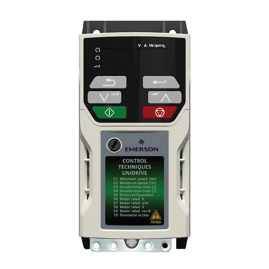
К сожалению, в процессе эксплуатации выходит из строя даже самое надежное промышленное оборудование. В данной статье мы разберем частотный преобразователь Emerson, точнее коды ошибок частотного преобразователя Emerson Unidrive M200/201, с полной расшифровкой. Частотники в наше время нашли широкое применения в абсолютно всех сферах промышленности управляя как мини моторами в оргтехнике, так и гигантскими двигателями в горнодобывающей промышленности.
Для простоты общения со столь сложной электроникой все частотные преобразователи оснащены небольшими дисплеями с помощью которых выводятся информационные сообщения с кодами ошибок, расшифровав которые можно сразу же узнать причину ее возникновения. Если учесть распространенность данной промышленной электроники, то появляется острая нужда в расшифровке кодов ошибок частотных преобразователей.
Данная статья даст вам возможность не совершать ошибок, и в добавок поможет самостоятельно определять и устранять ту или иную причину повлекшую за собой аварийную остановку частотных преобразователей Emerson.
Коды ошибок
Диагностика
C.Acc
- Отказ записи карты памяти
185
- Отключение C.Acc означает, что электропривод не может получить доступ к энергонезависимой карте памяти. Если это отключение возникает при передаче данных на карту, то записанный файл может быть искажен.
- Если это отключение возникает при передаче данных в электропривод, то данные могут быть переданы не полностью. Если в электропривод передается файл параметров и при передаче возникло это отключение, то параметры не сохраняются в энергонезависимой памяти и поэтому можно восстановить начальные значения параметров, для этого надо выключить и снова включить питание электропривода.
Рекомендованные действия:
- Проверьте, что карта памяти установлена и вставлена правильно
- Замените карту памяти
C.bt
- Изменение параметра меню 0 нельзя сохранить в карту памяти
177
- Изменения меню 0 автоматически сохраняются при выходе из режима редактирования.
- Отключение C.bt возникает, если запись в параметр меню 0 была начата посредством панели управления при выходе из режима редактирования и Pr 11.042 установлен в режим авто или загрузки, но необходимый
- загрузочный файл не был создан на карте памяти для получения нового значения параметра. Это происходит, когда Pr 11.042 изменен в режим Авто (3) или Загрузка (4), но после этого электропривод не был сброшен.
Рекомендованные действия:
- Проверьте верную настройку Pr 11.042 и сбросьте электропривод для создания нужного файла на карте памяти
- Заново попробуйте записать в параметр меню 0
C.by
- Нельзя получить доступ к карте памяти, так как доступ к ней проводит дополнительный модуль
178
- Отключение C.by означает, что была сделана попытка доступа к файлу на карте памяти, но к карте памяти уже проводится доступ из дополнительного модуля. Никакие данные не переданы.
Рекомендованные действия:
- Подождите окончания доступа дополнительного модуля к карте памяти и еще раз попробуйте выполнить нужную функцию
C.cPr
- Файл/данные на карте памяти отличаются от аналогичных в электроприводе
188
- Было проведено сравнение с файлом на карте памяти, отключение C.cPr возникает, если параметры на карте памяти отличаются от параметров в электроприводе.
Рекомендованные действия:
- Настройте Pr mm.000 в 0 и сбросьте отключение
- Проверьте, что правильный блок данных на карте памяти используется для сравнения
C.d.E
- В ячейке карты памяти уже содержатся данные
179
- Отключение C.d.E означает, что была сделана попытка сохранить данные на карте памяти в блоке данных, в котором уже есть данные.
Рекомендованные действия:
- Сотрите данные в этой ячейке
- Запишите данные в другую ячейку данных
C.dAt
- Не найдены данные энергонезависимой карты памяти
183
- Отключение C.dAt означает, что была выполнена попытка доступа к несуществующему файлу или блоку данных на карте памяти.
Рекомендованные действия:
- Проверьте правильность номера блока данных
C.Err
- Ошибка структуры данных энергонезависимой карты памяти
182
- Отключение C.Err означает, что была выполнена попытка доступа к карте памяти, но в структуре данных на карте была обнаружена ошибка. Сброс этого отключения заставляет электропривод удалить и создать правильную структуру папки данных. Причину отключения можно определить по дополнительному коду отключения.
|
отключения |
Причина |
|
1 |
Отсутствует нужная папка и структура файла |
|
2 |
Файл HEADER.DAT поврежден |
|
3 |
Два или больше файлов в папке <MCDF\>имеют одинаковые идентификационные номера |
- Рекомендованные действия:
- Уделите все блоки данных и заново выполните процедуру
- Проверьте, что карта вставлена правильно
- Замените карту памяти
C.FuL
- Карта памяти заполнена
184
- Отключение C.FuL означает, что была выполнена попытка создания блока данных на карте памяти, но в карте не хватает свободного места.
Рекомендованные действия:
- Удалите блок данных или все содержимое карты памяти для создания свободного места
- Используйте другую карту памяти
C.OPt
- Отключение карты памяти; несоответствие дополнительных модулей в электроприводах источника и
180
- Отключение C.OPt означает, что данные параметров или данные отличий от заводских установок были переданы из карты памяти в электропривод, но в электроприводах источника и приемника (назначения) установлены разные категории дополнительных модулей. Это отключение не прерывает пересылку данных, но выводится предупреждение, что данные для разных дополнительных модулей будут настроены в значения по умолчанию, а не в данные с карты. Это отключение также возникает при попытке сравнения между блоком данных и электроприводом.
Рекомендованные действия:
- Проверьте, что установлен правильный дополнительный модуль.
- Нажмите красную кнопку сброса для подтверждения, что параметры в дополнительном модуле будут в своих значениях по умолчанию.
- Это отключение можно отменить, если настроить Pr mm.000 в 9666 и выполнить сброс электропривода.
C.Pr
- Блоки данных карты памяти несовместимы с вариантом электропривода
175
- Отключение C.Pr возникает при включении питания или доступе к карте памяти, если параметр Модифицированный электропривод (11.028) имеет разное значение в электроприводах источника и приемника. Это отключение можно сбросить и передавать данные в любом направлении между электроприводом и картой памяти.
Рекомендованные действия:
- Используйте другую карту памяти
- Это отключение можно отменить, если настроить Pr mm.000 в 9666 и выполнить сброс электропривода
C.rdo
- В карте памяти установлен бит только чтение
181
- Отключение C.rdo означает, что была выполнена попытка изменить карту памяти только чтения или блок данных только чтения. Карта памяти работает только для чтения, если в ней установлен флаг только чтение.
Рекомендованные действия:
- Сбросьте флаг только чтения, для этого надо настроить Pr mm.000 в to 9777 и выполнить сброс электропривода. При этом будет сброшен флаг только чтения для всех блоков данных в карте памяти.
C.rtg
- Отключение карты памяти; электроприводы источника и назначения имеют разные номиналы напряжения и (или) тока
186
- Отключение C.rtg означает, что данные параметров передаются из карты памяти в электропривод, но в электроприводах источника и назначения разные номиналы тока и (или) напряжения. Это отключение также действует, если выполнена попытка сравнения (при Pr mm.000 настроенном на 8yyy) между блоком данных на карте памяти и электроприводом. Отключение C.rtg не останавливает передачи данных, но является предупреждением, что зависящие от номиналов параметры с атрибутом RA могут быть не переданы в электропривод назначения.
Рекомендованные действия:
- Выполните сброс электропривода для сброса отключения
- Убедитесь, что зависящие от номиналов параметры были переданы правильно
C.SI
- Отключение карты памяти; отказ передачи файла дополнительного модуля
174
- Отключение C.Sl возникает, если передача файла дополнительного модуля в или из модуля не проведена из-за некорректного ответа дополнительного модуля. Если это отключение произошло, то оно сопровождается дополнительным кодом отключением, указывающим номер слота дополнительного модуля.
C.tyP
- Набор параметров карты памяти несовместим с текущим режимом электропривода
187
- Отключение C.tyP возникает при сравнении, если режим электропривода в блоке данных на карте памяти отличается от текущего режима электропривода. Это отключение также возникает при попытке пересылки параметров из карты памяти в электропривод, если рабочий режим в блоке данных недопустим для этого электропривода.
Рекомендованные действия:
- Убедитесь, что электропривод-приемник поддерживает режим работы из файла параметров.
- Сбросьте значение в Pr mm.000 и выполните сброс электропривода.
- Проверьте, что режим работы электропривода-приемника совпадает с режимом в исходном файле параметров.
cL.A1
- Потеря тока аналогового входа 1
28
- Отключение cL.A1 указывает, что обнаружена потеря тока в токовом режиме работы аналогового входа 1 (клемма 2). В режимах 4-20 мА и 20-4 мА потеря тока обнаруживается, если ток падает ниже 3 мА.
Рекомендованные действия:
- Проверьте правильность подключения электропроводки управления
- Проверьте отсутствие повреждений электропроводки управления
- Проверьте Режим аналогового входа 1 (07.007)
- Сигнал тока присутствует и больше 3 мА
CL.bt
- Отключение инициировано Словом управления (06.042)
35
- Отключение CL.bt запускается при установке бита 12 в слове управления Pr 06.042 при разрешенном слове управления (Pr 06.043 = On).
Рекомендованные действия:
- Проверьте значение в Pr 06.042.
- Запретите слово управления в параметре Включение слова управления (06.043)
- Если бит 12 в слове управления установлен в единицу, от электропривод выполняет отключение по слову управления
- Если слово управления разрешено, то это отключение можно сбросить только сбросом бита 12 в нуль
Cur.c
- Диапазон калибровки тока
231
- Ошибка диапазона калибровки тока.
Cur.O
- Ошибка смещения обратной связи по току
225
- Отключение Cur.O означает, что смещение тока слишком велико для его коррекции.
Рекомендованные действия:
- Убедитесь, что нет никакой возможности протекания то ка в выходных фазах электропривода, если работа электропривода не разрешена
- Отказ аппаратуры — обращайтесь к поставщику электропривода.
d.Ch
- Параметры электропривода изменены
97
- Активно действие пользователя или запись файловой системы, что изменяет параметры электропривода, а на электропривод была подана команда разрешения, т.е. Привод активен (10.002) = 1.
Рекомендованные действия:
- Убедитесь, что работа электропривода не разрешена при загрузке значений по умолчанию
dEr.E
- Ошибка файла модификации
246
|
Доп. код |
Причина |
|
1 |
Файл модификации отличается |
|
2 |
Файл модификации отсутствует |
- Ошибка файла модификации с дополнительными кодами отключения:
dEr.I
- Ошибка образа модифицированного изделия
248
- Отключение dEr.I означает, что в образе модифицированного изделия была обнаружена ошибка. Причину отключения можно определить по дополнительному коду отключения.
|
Доп. код |
Причина |
Комментарии |
|
1 |
Попытка деления на нуль |
|
|
2 |
Неопределенное отключение |
|
|
3 |
Попытка настройки быстрого доступа к параметру для несуществующего параметра |
|
|
4 |
Попытка доступа к несуществующему параметру |
|
|
5 |
Попытка записи в параметр только чтения |
|
|
6 |
Попытка записи значения вне диапазона |
|
|
7 |
Попытка чтения из параметра только записи. |
|
|
30 |
Возник отказ образа, так как либо неверная контрольная сумма CRC, либо в образе меньше 6 байтов или версия заголовка образа ниже 5 |
|
|
31 |
Для образа требуется больший объем ОЗУ для памяти и стека, чем может предоставить электропривод. |
|
|
32 |
Образ запросил вызов функции ОС, который больше максимально разрешенных. |
|
|
33 |
Неверный код ID для образа |
|
|
34 |
Образ модификации был изменен на образ с другим номером модификации |
|
|
40 |
Запланированная задача не завершилась в отведенное время и была приостановлена |
|
|
41 |
Вызвана неопределенная функция, т.е. функция, которая не назначена в векторной таблице системы хоста |
|
|
51 |
Отказ проверки контрольной суммы CRC таблицы настройки главного меню |
|
|
52 |
Отказ проверки контрольной суммы CRC таблицы настройки меню |
|
|
53 |
Изменена таблица настраиваемого меню |
|
|
61 |
Установленный в слоте 1 дополнительный модуль не разрешен для модифицированного образа |
|
|
80 |
Образ не совместим с платой управления |
|
|
81 |
Образ не совместим с заводским номером платы управления |
|
- Рекомендованные действия:
- Обращайтесь в сервисный центр.
dESt
- Два или более параметров записываются в один и тот же параметр назначения
199
- Отключение dest означает, что выходные параметры назначения двух или большего числа логических функций (меню 3, 7, 8, 9, 12 или 14) внутри электропривода записывают в один и тот же параметр.
Рекомендованные действия:
- Настройте Pr mm.000 в ‹Destinations› или 12001 и проверьте все показанные в меню параметры на конфликты записи в параметр
dr.CF
- Конфигурация электропривода
232
- Код ID аппаратуры не соответствует коду ID программы пользователя.
EEF
- Были загружены параметры по умолчанию
31
- Отключение EEF означает, что были загружены значения параметров по умолчанию. Точную причину отключения можно определить по дополнительному коду отключения.
|
Доп. код |
Причина |
|
1 |
|
|
2 |
|
|
3 |
|
|
4 |
|
|
5 |
|
|
6 |
|
|
7 |
|
|
8 |
|
|
9 |
|
- Рекомендованные действия:
- Загрузите в электропривод значения по умолчанию и выполните сброс электропривода
- Подождите достаточное время для выполнения сохранения перед отключением питания электропривода
- Если отключение не устраняется — верните электропривод поставщику
Et
- Запущено внешнее отключение
6
- Произошло внешнее отключение Et. Причину отключения можно определить по дополнительному коду отключения, показанному после строки отключения. Смотрите Таблицу ниже. Внешнее отключение можно также запустить, записав значение 6 в Pr 10.038.
|
Доп. код |
Причина |
|
1 |
|
- Рекомендованные действия:
- Проверьте значение в Pr 06.042.
- Выберите ‹Dest› (или введите 12001) в Pr mm.000 и проверьте параметр, управляющий Pr 10.032.
- Убедитесь, что Pr 10.032 или Pr 10.038 (= 6) не управляется портом последовательной связи
FAN.F
- Отказ вентилятора
173
- Рекомендованные действия:
- Проверьте, что вентилятор правильно установлен и подключен.
- Проверьте, что нет механических помех вращению вентилятора.
- Обращайтесь к поставщику электропривода для замены вентилятора.
Fi.Ch
- Файл изменен
247
- Рекомендованные действия:
- Выключите и включите питание электропривода.
FI.In
- Несовместимость микропрограммы
237
- Отключение FI.In означает что микропрограмма пользователя несовместима с микропрограммой силового модуля.
Рекомендованные действия:
- Перепрограммируйте электропривод с помощью последней версии микропрограммы для электропривода Unidrive M200.
HF01
- Ошибка обработки данных: Аппаратный отказ ЦП
- Отключение HF01 означает, что произошла ошибка адреса ЦП. Это отключение означает отказ платы управления в электроприводе.
Рекомендованные действия:
- Отказ аппаратуры — обраитесь в сервисный центр или к поставщику электропривода.
HF02
- Ошибка обработки данных: Отказ управления памятью ЦП
- Отключение HF02 означает, что произошла ошибка адреса DMAC. Это отключение означает отказ платы управления в электроприводе.
Рекомендованные действия:
- Отказ аппаратуры — обраитесь в сервисный центр или к поставщику электропривода.
HF03
- Ошибка обработки данных: ЦП обнаружил отказ шины
- Отключение HF03 означает, что произошла ошибка шины. Это отключение означает отказ платы управления в электроприводе.
Рекомендованные действия:
- Отказ аппаратуры — обраитесь в сервисный центр или к поставщику электропривода.
HF04
- Ошибка обработки данных: ЦП обнаружил отказ при работе
- Отключение HF04 означает, что обнаружен отказ при работе. Это отключение означает отказ платы управленияв электроприводе.
Рекомендованные действия:
- Отказ аппаратуры — обраитесь в сервисный центр или к поставщику электропривода.
HF07
- Ошибка обработки данных: Отказ сторожевого таймера
- Отключение HF02 означает, что произошла ошибка сторожевого таймера. Это отключение означает отказ платы управления в электроприводе.
Рекомендованные действия:
- Отказ аппаратуры — обраитесь в сервисный центр или к поставщику электропривода.
HF08
- Ошибка обработки данных: Отказ прерывания ЦП
- Отключение HF08 означает, что произошла ошибка обработка прерывания ЦП. Это отключение означает отказ платы управления в электроприводе. Уровень отказа можно определить по дополнительному коду отключения.
Рекомендованные действия:
- Отказ аппаратуры — обраитесь в сервисный центр или к поставщику электропривода.
HF09
- Ошибка обработки данных: Переполнение свободной памяти.
- Отключение HF09 означает, что произошло переполнение свободной памяти.
Рекомендованные действия:
- Отказ аппаратуры — обраитесь в сервисный центр или к поставщику электропривода.
HF11
- Ошибка обработки данных: Ошибка связи с энергонезависимой памятью
- Отключение HF11 означает, что произошла ошибка передачи данных с картой памяти.
|
Доп. код |
Причина |
Рекомендованные действия |
|
1 |
Ошибка связи с энергонезависимой памятью. |
|
|
2 |
Размер ЭППЗУ несовместим с микропрограммой пользователя. |
|
HF12
- Ошибка обработки данных: переполнение стека главной программы
- Отключение HF12 означает, что произошло переполнение стека главной программы. Стек может быть идентифицирован по дополнительному коду отключения. Это отключение означает отказ платы управления в электроприводе.
|
Доп. код |
Стек |
|
1 |
|
|
2 |
|
|
3 |
|
- Рекомендованные действия:
- Отказ аппаратуры — обраитесь в сервисный центр или к поставщику электропривода.
HF16
- Ошибка обработки данных: Ошибка RTOS
- Отключение HF16 означает, что произошла ошибка RTOS. Это отключение означает отказ платы управления в электроприводе.
Рекомендованные действия:
- Отказ аппаратуры — обраитесь в сервисный центр или к поставщику электропривода.
HF18
- Ошибка обработки данных: Отказ внутренней флэш-памяти
- Отключение HF18 означает отказ внутренней флэш-памяти при записи данных параметров дополнительного модуля. Причину отключения можно определить по дополнительному коду отключения.
|
Доп. код |
Причина |
|
1 |
|
|
2 |
|
|
3 |
|
|
4 |
|
|
5 |
|
|
6 |
|
- Рекомендованные действия:
- Отказ аппаратуры — обраитесь в сервисный центр или к поставщику электропривода.
HF19
- Ошибка обработки данных: отказ проверки контрольной суммы CRC микропрограммы
- Отключение HF19 означает отказ проверки контрольной суммы CRC микропрограммы электропривода.
Рекомендованные действия:
- Перепрограммируйте электропривод.
- Отказ аппаратуры — обращайтесь к поставщику электропривода.
It.AC
- Произошла перегрузка по выходному току (I2t)
20
- Отключение It.Ac означает перегрев двигателя согласно выходному току (Pr 05.007) и тепловой постоянной времени двигателя (Pr 04.015). Pr 04.019 показывает температуру двигателя в процентах от максимального значения. Электропривод выполняет отключение It.Ac, если Pr 04.019 достигает 100%.
Рекомендованные действия:
- Убедитесь, что нагрузка не застопорила вал двигателя и не залипла
- Убедитесь, что нагрузка двигателя не изменилась
- Настройте параметр номинальной скорости (Pr 5.008) (только режим RFC-A)
- Проверьте, что номинальный ток ток двигателя не настроен на нуль
It.br
- Произошел перегрев тормозного резистора (I2t)
19
- Отключение It.br означает, перегрев тормозного резистора. Значение в параметре Тепловой интегратор тормозного резистора (10.039) вычисляется с помощью параметров Номинальная мощность тормозного резистора (10.030), Тепловая постоянная времени тормозного резистора (10.031) и Сопротивление тормозного резистора (10.061). Отключение It.br trip запускается, если параметр Тепловой интегратор тормозного резистора (10.039) достигает 100%.
Рекомендованные действия:
- Проверьте, что в Pr 10.030, Pr 10.031 и Pr 10.061 введены правильные значения
- Если используется внешнее устройство защиты от перегрева и не нужен программный контроль перегрузки тормозного резистора, то настройте Pr 10.030, Pr 10.031 или Pr 10.061 в 0 для запрета отключения.
LF.Er
- Была обнаружена потеря связи / ошибки между силовыми модулями, управлением и выпрямителем
90
- Это отключение запускается, если нет связи между модулями — силовым, управления или выпрямителем, или обнаружено большое число ошибок связи. Причину отключения можно определить по дополнительному коду отключения.
|
Источник |
xx |
y |
zz |
Описание |
|
Система управления |
00 |
0 |
01 |
|
|
Система управления |
00 |
0 |
02 |
|
|
Система управления |
01 |
1 |
00 |
|
- Рекомендованные действия:
- Отказ аппаратуры — обращайтесь к поставщику электропривода.
no.PS
- Нет силовой платы
236
- Нет связи между силовой платой и платой управления.
Рекомендованные действия:
- Проверьте соединение между силовой платой и платой управления.
O.Ld1
- Перегрузка цифрового выхода
26
- Отключение O.Ld1 означает, что полный ток, потребляемый от блока питания 24 В пользователя или от цифрового выхода, превысил предел. Отключение запускается при выполнении следующего условия:
- Максимальный выходной ток с одного цифрового выхода равен 100 мА.
- Рекомендованные действия:
- Проверьте полные нагрузки на цифровых выходах
- Проверьте правильность электропроводки управления
- Проверьте отсутствие повреждений электропроводки выходов
O.SPd
- Частота вращения двигателя превысила порог макс. частоты
7
- Если в режиме разомкнутого контура Задание после рампы (02.001) превышает порог в параметре Порог превышения частоты (03.008) в любом направлении, то выполняется отключение O.SPd. Если в режиме RFC-A Расчетная частота (03.002) превышает Порог превышения частоты в Pr 03.008 в любом направлении, то выполняется отключение O.SPd. Если Pr 03.008 настроен в 0,00, то порог будет равен 1,2 x значение параметра Pr 01.006.
Рекомендованные действия:
- Уменьшите Коэфф. усиления пропорционального звена регулятора частоты (03.010) для снижения выброса скорости (только режим RFC-A)
- Проверьте, что двигатель не вращается от механической нагрузки
Oh.br
- Перегрев тормозного IGBT
101
- Отключение перегрева Oh.br означает, что по тепловой программной модели был обнаружен перегрев тормозного IGBT.
Рекомендованные действия:
- Проверьте, что сопротивление тормозного резистора не меньше минимально допустимого значения сопротивления
Oh.dc
- Перегрев звена постоянного тока
27
- Отключение Oh.dc означает перегрев компонентов звена постоянного тока согласно программной тепловой модели. В электроприводе есть система тепловой защиты для защиты компонентов звена постоянного тока.
- Она учитывает влияние выходного тока и колебаний напряжения в звене постоянного тока. Расчетная температура показана в виде процентов от уровня отключения в параметре in Pr 07.035. Если этот параметр достигает 100%, то выполняется отключение Oh.dc. Электропривод пытается остановить двигатель перед отключением.
- Если двигатель не остановится за 10 секунд, то электропривод немедленно отключается.
|
Источник |
xx |
y |
zz |
Описание |
|
Система управления |
00 |
2 |
00 |
|
- Рекомендованные действия:
- Проверьте дисбаланс и уровни напряжения электропитания.
- Проверьте уровень пульсаций на звене пост. тока
- Уменьшите время нагрузки
- Уменьшите нагрузку двигателя
- Проверьте стабильность выходного тока. Если ток нестабилен;
- Сравните настройки карты двигателя с шильдиком двигателя (Pr 05.006, Pr 05.007, Pr 05.008, Pr 05.009, Pr 05.010, Pr 05.011) – (все режимы)
- Запретите компенсацию скольжения (Pr 05.027 = 0) – (разомкнутый контур) Запретите динамический режим работы V/F (Pr 05.013 = 0) — (разомкнутый контур) Выберите неизменную форсировку (Pr 05.014 = Fixed) – (разомкнутый контур)
- Выберите высокостабильную модуляция пространственного вектора (Pr 05.020 = 1) – (разомкнутый контур) Отсоедините нагрузку и выполните автонастройку с вращением вала (Pr 05.012)
- Снизьте коэффициенты усиления регулятора частоты (Pr 03.010, Pr 03.011, Pr 03.012) – (RFC-A)
Oht.C
- Перегрев блока управления
219
- Это отключение указывает, что был обнаружен перегрев платы управления, если параметр управления вентилятором охлаждения (06.045) = 0.
Рекомендованные действия:
- Улучшите вентиляцию за счет настройки управления вентилятора охлаждения (06.045) > 0.
Oht.I
- Перегрев инвертора согласно тепловой модели
21
- Это отключение означает, что согласно тепловой модели был обнаружен перегрев перехода транзистора IGBT.
|
Источник |
xx |
y |
zz |
Описание |
|
Система управления |
00 |
1 |
00 |
|
- Рекомендованные действия:
- Снизьте выбранную частоту ШИМ электропривода
- Проверьте, что запрет автоматического изменения частоты ШИМ (05.035) настроен в OFF
- Уменьшите время нагрузки
- Уменьшите величины ускорения/замедления
- Уменьшите нагрузку двигателя
- Проверьте уровень пульсаций на звене пост. тока
- Проверьте, что все три фазы присутствуют и симметричны
Oht.P
- Перегрев силового каскада
22
- Это отключение означает, что был обнаружен перегрев силового каскада. В дополнительном коде отключения ‹xxyzz› расположение термистора указано символами ‹zz›.
|
Источник |
xx |
y |
zz |
Описание |
|
Силовая система |
01 |
0 |
zz |
|
- Рекомендованные действия:
- Проверьте, что вентиляторы шкафа / электропривода работают нормально
- Задайте принудительную работу вентиляторов радиатора на полной скорости
- Проверьте каналы для вентиляции шкафа
- Проверьте фильтры в дверце шкафа
- Усильте вентиляцию
- Снизьте частоту ШИМ электропривода
- Уменьшите время нагрузки
- Уменьшите величины ускорения/замедления
- Уменьшите нагрузку двигателя
- Проверьте таблицы снижения номиналов и убедитесь, что номиналы электропривода соответствуют системе.
- Используйте электропривод с большими номиналами тока / мощности
Oht.r
- Перегрев выпрямителя
102
- Отключение Oht.r означает, что был обнаружен перегрев выпрямителя. Расположение термистора может быть определено по дополнительному коду отключения.
|
Источник |
xx |
y |
zz |
Описание |
|
Силовая система |
Номер силового модуля |
Номер выпрямителя |
zz |
Размещение термистора, указанное в zz |
- Рекомендованные действия:
- Проверьте изоляцию двигателя и кабеля двигателя с помощью тестера изоляции
- Установите выходной реактор или синусный фильтр
- Заставьте вентиляторы радиатора работать на макс. скорости, настроив Pr 06.045 = 1
- Проверьте, что вентиляторы шкафа / электропривода работают нормально
- Проверьте каналы для вентиляции шкафа
- Проверьте фильтры в дверце шкафа
- Усильте вентиляцию
- Уменьшите величины ускорения/замедления
- Уменьшите время нагрузки
- Уменьшите нагрузку двигателя
OI.A1
- Превышение тока аналогового входа 1
189
- Входной ток на аналоговом входе 1 превысил 24 мА.
OI.AC
- Обнаружено мгновенное превышение выходного тока
3
- Мгновенное значение выходного тока электропривода превысило VM_DRIVE_CURRENT_MAX.
|
Источник |
xx |
y |
zz |
Описание |
|
Система управления |
00 |
0 |
00 |
|
- Рекомендованные действия/проверки:
- Уменьшите величины ускорения/замедления
- Если возникло при автонастройке, снизьте форсировку напряжения
- Проверьте отсутствие короткого замыкания в выходном кабеле
- Проверьте целостность изоляции двигателя с помощью тестера изоляции
- Не превышает ли длина кабеля двигателя предел для данного габарита?
- Снизьте значения параметров коэф. усиления регулятора частоты — (Pr 03.010, 03.011, 03.012) или (Pr 03.013, 03.014, 03.015)
- Снизьте значения параметров коэф. усиления регулятора тока
OI.br
- Обнаружено превышение тока тормозного IGBT: сработала защита от короткого замыкания тормозного IGBT
4
- Отключение OI.br означает, что было обнаружено превышение тока тормозного IGBT или сработала защита тормозного IGBT.
|
Источник |
xx |
y |
zz |
Описание |
|
Силовая система |
01 |
0 |
00 |
|
- Рекомендованные действия:
- Проверьте проводку тормозного резистора
- Проверьте, что сопротивление тормозного резистора не меньше минимально допустимого значения сопротивления
- Проверьте изоляцию тормозного резистора
OI.dC
- Обнаружено превышение тока силового модуля при контроле напряжения на открытом транзисторе IGBT
109
- Отключение OI.dc означает, что сработала защита выходного каскада электропривода от короткого замыкания.
Рекомендованные действия:
- Отсоедините кабель двигателя от электропривода и проверьте изоляцию двигателя и кабеля с помощью тестера изоляции
- Замените электропривод
OI.Sn
- Обнаружено превышение тока подавителя выбросов
92
- Это отключение означает, что в цепи снаббера выпрямителя было обнаружено превышение тока. Причину отключения можно определить по дополнительному коду отключения.
|
Источник |
xx |
y |
zz |
Описание |
|
Силовая система |
01 |
1 |
00 |
|
- Рекомендованные действия:
- Убедитесь, что установлен внутренний фильтр ЭМС
- Убедитесь, что длина кабеля двигателя не превысила максимальную для выбранной частоты ШИМ
- Проверьте дисбаланс фаз питания
- Проверьте отсутствие искажений питания, например, провалов от электропривода постоянного тока
- Проверьте изоляцию двигателя и кабеля двигателя с помощью тестера изоляции
- Установите выходной реактор или синусный фильтр
OI.SC
- Короткое замыкание на выходе фазы
228
- На выходе разрешенного к работе электропривода обнаружено превышение тока. Возможен отказ заземления двигателя.
Рекомендованные действия:
- Проверьте отсутствие короткого замыкания в выходном кабеле
- Проверьте целостность изоляции двигателя с помощью тестера изоляции
- Не превышает ли длина кабеля двигателя предел для данного габарита?
OPt.d
- Дополнительный модуль не выдал подтверждения при переключении режима электропривода
215
- Отключение OPt.d означает, что дополнительный модуль не подал подтверждение в положенное время, уведомляя электропривод об остановке передачи данных при переключении режима электропривода.
Рекомендованные действия:
- Сбросьте отключение
- Если отключение не исчезает, замените дополнительный модуль
Out.P
- Обнаружена потеря фазы на выходе
98
- Отключение Out.P означает, что на выходе электропривода обнаружена потеря фазы. Если Разрешение обнаружения потери фазы на выходе (06.059) = 1, то потеря фазы на выходе обнаруживается так:
- Если работа электропривода разрешена, то подаются короткие импульсы для проверки подключения всех выходных фаз.
- Во время работы контролируется выходной ток и условие потери фазы на выходе обнаруживается, если в токе содержится больше чем (будет указано)% обратной последовательности фаз.
- Рекомендованные действия:
- Проверьте соединения двигателя и электропривода.
- Для запрета отключения настройте Разрешение обнаружения потери фазы на выходе (06.059) = 0
OV
- Напряжение звена постоянного тока превысило пиковый уровень или на 15 секунд превысило
2
- Отключение OV означает, что напряжение звена пост. тока превысило VM_DC_VOLTAGE[MAX] или VM_DC_VOLTAGE_SET[MAX] на 15 сек. Порог отключения зависит от номинального напряжения электропривода, как показано ниже.
|
Номинальное напряжение |
VM_DC_VOLTAGE[MAX] |
VM_DC_VOLTAGE_SET[MAX] |
|
100 |
415 |
410 |
|
200 |
415 |
410 |
|
400 |
830 |
815 |
- Идентификация дополнительного кода отключения
|
Источник |
xx |
y |
zz |
|
Система управления |
00 |
0 |
|
|
Система управления |
00 |
0 |
|
|
Силовая система |
01 |
0 |
|
- Рекомендованные действия:
- Увеличьте рампу замедления (Pr 00.004)
- Уменьшите величину тормозного резистора (но не ниже минимального значения)
- Проверьте колебания питания, которые могут вызвать повышения напряжения звена постоянного тока
- Проверьте дисбаланс питания, который может вызвать повышение напряжения звена пост. тока
- Проверьте изоляцию двигателя с помощью тестера изоляции
P.dAt
- Ошибка данных конфигурации силовой системы
220
- Отключение P.dAt означает, что имеется ошибка в данных конфигурации, хранящемся в силовой системе.
|
Источник |
xx |
y |
zz |
Описание |
|
Система управления |
00 |
0 |
01 |
|
|
Система управления |
00 |
0 |
02 |
|
|
Система управления |
00 |
0 |
03 |
|
|
Система управления |
00 |
0 |
04 |
|
|
Система управления |
00 |
0 |
05 |
|
|
Система управления |
00 |
0 |
06 |
|
|
Система управления |
0 |
0 |
07 |
|
|
Силовая система |
01 |
0 |
00 |
|
|
Силовая система |
01 |
0 |
01 |
|
|
Силовая система |
01 |
0 |
02 |
|
- Рекомендованные действия:
- Отказ аппаратуры — обращайтесь к поставщику электропривода.
PAd
- Панель снята, а электропривод получает задание с панели
34
- Отключение PAd означает, что электропривод находится в режиме управления с панели [Селектор задания (01.014) = 4 или 6] и панель была снята или отсоединена от электропривода.
Рекомендованные действия:
- Установите панель на место и выполните сброс
- Измените Селектор задания (01.014) для выбора задания с другого источника
Pb.bt
- Силовая плата в режиме загрузки
245
- Силовая плата в режиме загрузки
Рекомендованные действия:
- Пошлите на силовую плату файл микропрограммы для перепрограммирования силовой платы и затем выключите, и включите питание электропривода
Pb.Er
- Была обнаружена потеря связи / ошибки между силовыми модулями и управлением
93
- Отключение Pb.Er запускается, если нет передачи данных между силовым блоком и платой управления. Причину отключения можно определить по дополнительному коду отключения.
|
Доп. код |
Причина |
|
1 |
|
|
2 |
|
|
3 |
|
|
4 |
|
- Рекомендованные действия:
- Отказ аппаратуры — обраитесь в сервисный центр или к поставщику электропривода.
Pb.HF
- Аппаратный отказ силовой платы
235
- Отказ аппаратуры процессора силовой платы.
Рекомендованные действия:
- Отказ аппаратуры — обраитесь в сервисный центр или к поставщику электропривода.
Pd.S
- Ошибка сохранения при отключении питания
37
- Отключение Pd.S означает, что при сохранении параметров в энергонезависимой памяти при отключении питания была обнаружена ошибка.
Рекомендованные действия:
- Выполните сохранение 1001 в Pr mm.000, чтобы устранить появление отключения при следующем включении питания электропривода.
PH.Lo
- Потеря фазы питания
32
- Отключение PH.Lo означает, что электропривод обнаружил потерю фазы на входе или большой дисбаланс фаз питания. Электропривод пытается остановить двигатель перед запуском отключения. Если двигатель не остановится за 10 секунд, то немедленно выполняется отключение. Отключение PH.Lo работает за счет контроля уровня пульсации напряжения на звене постоянного тока электропривода, если эти пульсации превысят предел, то электропривод отключится по PH.Lo. Возможными причинами пульсации напряжения на звене постоянного тока являются потеря фазы питания, большой дисбаланс фаз питания и сильная нестабильность выходного тока.
|
Источник |
xx |
y |
zz |
|
Система управления |
00 |
0 |
|
- Обнаружение потери фазы на входе можно запретить, если электропривод должен работать от питания постоянного тока или от однофазного питания в параметре Режим обнаружения потери фазы питания (06.047).
Рекомендованные действия:
- Проверьте дисбаланс и уровни переменного напряжения электропитания при полной нагрузке
- Проверьте уровень пульсаций на звене пост. тока с помощью изолированного осциллографа
- Проверьте стабильность выходного тока.
- Уменьшите время нагрузки
- Уменьшите нагрузку двигателя
- Запретите обнаружение потери фазы, настроив Pr 06.047 в 2.
PSU
- Отказ внутреннего блока питания
5
- Отключение PSU означает, что один или несколько внутренних шин питания вышли за пределы или перегружены.
|
Источник |
xx |
y |
zz |
Описание |
|
Система управления |
00 |
0 |
00 |
|
|
Силовая система |
01 |
1 |
- Рекомендованные действия:
- Снимите дополнительный модуль и выполните сброс
- Аппаратный отказ в электроприводе — верните электропривод поставщику
r.ALL
- Ошибка выделения ОЗУ
227
|
Размер параметра |
Значение |
|
1 бит |
1 |
|
8 бит |
2 |
|
16 бит |
3 |
|
32 бита |
4 |
|
64 бита |
5 |
|
Тип параметра |
Значение |
|
Энергозависимый |
0 |
|
Сохранение пользователем |
1 |
|
Сохранение по отключению |
2 |
|
Подмассив |
Меню |
Значение |
|
Модифицированный образ |
29 |
2 |
|
Настройка дополнительного модуля в слоте 1 |
15 |
4 |
- Отключение r.ALL означает, что дополнительный модуль или модифицированный образ запросил больший объем ОЗУ для параметров, чем разрешено. Распределение ОЗУ проверяется в порядке номеров итоговых дополнительных кодов отключений, так что будет указан отказ с наивысшим дополнительным кодом отключения. Дополнительный код отключения вычисляется как (размер параметра) + (тип параметра) + номер подмассива.
r.b.ht
- Перегрев выпрямителя/тормоза
250
- Обнаружен перегрев входного выпрямителя или тормозного IGBT.
rS
- Измеренное сопротивление превысило диапазон параметра
33
- Отключение rS означает, что измеренное во время теста автонастройки сопротивление статора превысило максимальное возможное значение для Сопротивление статора (05.017).
- Автонастройка с неподвижным валом запускается с помощью функции автонастройки (Pr 05.012) или в векторном режиме с разомкнутым контуром (Pr 05.014) по первой команде работы после включения питания 4 (Ur_I) или при каждой команде работы в режимах 0 (Ur_S) или 3 (Ur_Auto). Это отключение может возникнуть, если двигатель очень мал в сравнении с номиналами электропривода.
Рекомендованные действия:
- Проверьте кабель двигателя/подключения
- Проверьте целостность обмотки статора двигателя с помощью тестера изоляции
- Проверьте сопротивление между фазами двигателя на клеммах электропривода
- Проверьте сопротивление между фазами двигателя на клеммах двигателя
- Убедитесь, что сопротивление статора двигателя попадает в диапазон для этой модели электропривода
- Выберите режим неизменной форсировки (Pr 05.014 = Fd) и проверьте кривые выходного тока на осциллографе
- Замените двигатель
SCL
- Произошел таймаут слова управления сторожевого таймера
30
- Отключение SCL означает, что было разрешено слово управления и время вышло
SL.dF
- Изменился дополнительный модуль в слоте 1
204
- Отключение SL.dF означает, что дополнительный модуль в слоте 1 электропривода имеет другой тип по отношению к установленному, когда параметры последний раз сохранялись в электроприводе. Причину отключения можно определить по дополнительному коду отключения.
|
Доп. код |
Причина |
|
1 |
|
|
2 |
|
|
3 |
|
|
4 |
|
|
>99 |
|
- Рекомендованные действия:
- Выключите питание, проверьте, что в слот установлен правильный дополнительный модуль и вновь включите питание.
- Подтвердите, что установлен правильный дополнительный модуль, убедитесь в правильной настройке параметров дополнительного модуля и выполните сохранение пользователя в Pr mm.000.
SL.Er
- Дополнительный модуль в слоте 1 обнаружил отказ
202
- Отключение SL.Er означает, что дополнительный модуль в слоте 1 электропривода обнаружил ошибку. Причину отключения можно определить по дополнительному коду отключения.
Рекомендованные действия:
- Описание отключения смотрите в соответствующем Руководстве пользователя дополнительного модуля
SL.HF
- Отказ аппаратуры дополнительного модуля 1
200
- Отключение SL.HF означает, что дополнительный модуль в слоте 1 электропривода обнаружил ошибку аппаратуры. Возможные причины отключения можно определить по дополнительному коду отключения.
|
Доп. код |
Причина |
|
1 |
|
|
2 |
|
|
3 |
|
|
4 |
|
|
5 |
|
|
6 |
|
|
7 |
|
- Рекомендованные действия:
- Проверьте правильность установки дополнительного модуля
- Замените дополнительный модуль
- Замените электропривод
SL.nF
- Снят дополнительный модуль в слоте 1
203
- Отключение SL.nF означает, что дополнительный модуль в слоте 1 электропривода был снят после последнего включения питания.
Рекомендованные действия:
- Проверьте правильность установки дополнительного модуля.
- Заново установите дополнительный модуль.
- Для подтверждения того, что снятый дополнительный модуль больше не нужен, выполните функцию сохранения в Pr mm.000.
SL.tO
- Ошибка службы сторожевого таймера дополнительного модуля
201
- Отключение SL.tO означает, что установленный в слоте 1 дополнительный модуль запустил службу сторожевого таймера модуля и затем не смог правильно обслужить сторожевой таймер.
Рекомендованные действия:
- Замените дополнительный модуль
So.St
- Отказ замыкания реле плавного пуска, отказ монитора плавного пуска
226
- Отключение So.St означает, что реле плавного пуска в электроприводе не смогло замкнуться или произошел отказ цепи контроля плавного пуска.
- Причину отключения можно определить по дополнительному коду отключения.
|
Доп. код |
Причина |
|
1 |
|
|
2 |
|
- Рекомендованные действия:
- Отказ аппаратуры — обраитесь в сервисный центр или к поставщику электропривода.
St.HF
- Во время последнего отключения питания произошло аппаратное отключение
221
- Отключение St.HF означает, что произошло аппаратное отключение (HF01 – HF19) и выполнен цикл выключения- включения питания электропривода. Дополнительный код отключения указывает отключение HF, например, запомненное HF.19.
Рекомендованные действия:
- Введите 1299 в Pr mm.000 и нажмите кнопку сброса для сброса отключения
th
- Перегрев термистора двигателя
24
- Отключение th означает, что термистор двигателя, подключенный к клемме 14 (цифровой вход 5) на колодке цепей управления, обнаружил перегрев двигателя.
Рекомендованные действия:
- Проверьте температуру двигателя
- Проверьте целостность цепи термистора
th.br
- Перегрев тормозного резистора
10
- Отключение th.br запускается, если подключена аппаратная система контроля нагрева тормозного резистора и резистор перегрелся. Если тормозной резистор не используется, то это отключение нужно запретить с помощью бита 3 в Действие при обнаружении отключения (10.037) для предотвращения этого отключения.
Рекомендованные действия:
- Проверьте проводку тормозного резистора
- Проверьте, что сопротивление тормозного резистора не меньше минимально допустимого значения сопротивления
- Проверьте изоляцию тормозного резистора
tH.Fb
- Отказ внутреннего термистора
218
- Отключение tH.Fb означает, что произошел отказ внутреннего термистора. Расположение термистора может быть определено по дополнительному коду отключения.
|
Источник |
xx |
y |
zz |
|
Силовая система |
01 |
0 |
|
- Рекомендованные действия:
- Отказ аппаратуры — обраитесь в сервисный центр или к поставщику электропривода.
thS
- Короткое замыкание термистора двигателя
25
- Отключение thS означает, что термистор двигателя, подключенный к клемме 14 (цифровой вход 5) на колодке цепей управления, находится в состоянии короткого замыкания или низкого импеданса (< 50 Ом).
Рекомендованные действия:
- Проверьте целостность цепи термистора
- Замените двигатель / термистор двигателя
tun.S
- Автонастройка остановлена до завершения
18
- Электропривод не смог завершить тест автонастройки, так как был снят сигнал разрешения работы электропривода или пуска электропривода.
Рекомендованные действия:
- Проверьте, что сигнал разрешения (клемма 11) был активен во время процедуры автонастройки
TunE
- Измеренный момент инерции превысил диапазон параметра
13
- Электропривод отключился при выполнении автонастройки с вращением вала или измерения механической нагрузки. Причину отключения можно определить по дополнительному коду отключения.
|
Доп. код |
Причина |
|
1 |
|
- Рекомендованные действия:
- Проверьте правильность подключения кабеля двигателя
U.OI
- OI ac пользователя
8
- Прерывание U.OI запускается, если выходной ток электропривода превышает уровень отключения, заданный в параметре Уровень отключения по сверхтоку пользователя (04.041).
U.S
- Ошибка сохранения пользователя / не выполнено
36
- Отключение U.S означает, что при сохранении параметров пользователя в энергонезависимой памяти была обнаружена ошибка. Например, после команды сохранения пользователя, если питание электропривода было отключено в момент сохранения параметров пользователя.
Рекомендованные действия:
- Выполните сохранение пользователя 1001 в Pr mm.000, чтобы устранить появление отключения при следующем включении питания электропривода.
- Обеспечьте достаточное время для завершения сохранения перед отключением питания электропривода.
US.24
- Питание пользователя 24 В отсутствует на клеммах управления (1, 2)
91
- Отключение US.24 запускается, если параметр Выбор питания пользователя (06.072) настроен в 1 и на входе питания 24 В адаптера AI-Backup нет никакого питаняи пользователя 24 В.
Рекомендованные действия:
- Проверьте, что напряжение питания пользователя 24 В присутствует на клеммах пользователя на адаптере интерфейса.
Таблица отключений (ошибок) частотного преобразователя. Увеличте для просмотра кодов ошибок ЧП Emerson
Компания «Кернел» производит ремонт промышленной электроники и оборудования с 2002 года. За это время мы накопили колоссальный опыт в том числе опыт в ремонте частотных преобразователей. ![]() Ремонт подобной промышленной электроники ответственное и сложное занятие, требующие максимальной отдачи, профессионализма и максимально полной материальной базе.
Ремонт подобной промышленной электроники ответственное и сложное занятие, требующие максимальной отдачи, профессионализма и максимально полной материальной базе.
Специалисты нашего сервисного центра уделяют максимальное внимание к качеству исполнения ремонта, программирования и настройке промышленного преобразователя частоты, не зависимо от производителя данного промышленного оборудования. Именно поэтому мы смело даем гарантию на все выполненные работы шесть месяцев.
Ремонт частотного преобразователя Emerson производится исключительно с использованием оригинальных запасных частей, на компонентном уровне с применением высокотехнологичного оборудования, квалифицированным персоналом с инженерным образованием.
Если на вашем производстве появились проблемы с частотным преобразователем, которые вы не можете решить самостоятельно, мы всегда рады вам помочь. Обращайтесь в сервисный центр «Кернел». Специалисты нашей компании в минимальные сроки проведут глубокую диагностику и последующий ремонт частотного преобразователя. Оставьте заказ на ремонт оборудования используя форму на сайте, либо свяжетесь с нашими менеджерами, сделать это очень просто.
У вас остались вопросы, связанные с ремонтом, сбросом ошибок, программированием и настройкой частотных преобразователей? Задайте их нашим менеджерам. Связаться с ними можно несколькими способами:
Далеко не полный список производителей промышленной электроники и оборудования, ремонтируемой в нашей компании.
Understanding trip codes is an important part of keeping your equipment running smoothly. Below are some of the more common codes you may come across when using your Control Techniques Unidrive M200 series drive:
| Trip Code | Condition | Possible Cause |
|---|---|---|
| C.Acc | NV Media Card Write fail | Unable to access the NV Media Card |
| C.by | NV Media Card cannot be accessed as it is being accessed by an option module |
An attempt has been made to access a file on NV Media Card, but the NV Media Card is already being accessed by an option module. No data is transferred. |
| C.cPr | NV Media Card file/data is different to the one in the drive |
A C.cPr trip is initiated if the parameters on the NV Media Card are different to the drive |
| C.d.E | NV Media Card data location already contains data |
Attempt has been made to store data on a NV Media Card in a data block which already contains data. |
| C.dAt | NV Media Card data not found | Attempt has been made to access non-existent file or block on the NV Media Card. |
| C.Err | NV Media Card data structure error |
Attempt has been made to access the NV Media Card but an error has been detected in the data structure on the card. Resetting the trip will cause the drive to erase and create the correct folder structure. |
| C.FuL | NV Media Card full | There is not enough space left on the card. |
| C.OPt | NV Media Card trip; option modules installed are different between source drive and destination drive |
The parameter data or default difference data is being transferred from the NV Media Card to the drive, but the option module category is different between the source and destination drives. |
| C.Pr | NV Media Card data blocks are not compatible with the drive derivative |
If Drive Derivative is different between the source and target drives. Refer to the Control User Guide. |
| C.rdo | NV Media Card has the Read Only bit set |
Attempt has been made to modify a read-only NV Media Card or a read-only data block. |
| C.rtg | NV Media Card trip; Option module file transfer has failed |
The C.SL trip is initiated, if the transfer of an option module file to or from a module failed because the option module does not respond correctly. |
| C.tyP | NV Media Card parameter set not compatible with current drive mode |
The drive mode in the data block on the NV Media Card is different from the current drive mode. |
| cL.A1 | Analog input 1 current loss | Current loss was detected in current mode on Analog input 1 (Terminal 2). |
| CL.bt | Trip initiated from the Control Word | Initiated by setting bit 12 on the control word when the control word is enabled. Refer to the Parameter Reference Guide |
| Cur.c | Current calibration range | Current calibration range error. |
| Cur.O | Current feedback offset error | Current offset is too large to be trimmed. |
| d.Ch | Drive parameters are being changed |
A user action or a file system write is active that is changing the drive parameters and the drive has been commanded to enable. |
| dEr.E | Derivative file error | Contact the supplier of the drive. |
| dEr.I | Derivative product image error | Contact the supplier of the drive. |
| dESt | Two or more parameters are writing to the same destination parameter |
The dESt trip indicates that destination output parameters of two or more logic functions within the drive are writing to the same parameter. |
| dr.CF | Drive configuration | Contact the supplier of the drive. |
| EEF | Default parameters have been loaded |
The EEF trip indicates that default parameters have been loaded. The exact cause/reason of the trip can be identified from the sub-trip number (Refer to the Control User Guide). |
| Et | An External trip is initiated | The cause of the trip can be identified from the sub trip number displayed after the trip string. Sub-trip = 1 Reason — External Trip =1 Refer to the Control User Guide |
| FAn.F | Fan fail | Indicates the fan or fan circuitry has failed |
| Fi.Ch | File changed | A file has been changed, power cycle to clear the trip |
| FI.In | Firmware Incompatibility | The user firmware is incompatible with the power firmware |
| HFxx trip | Hardware faults | Internal drive hardware fault (Refer to the Control User Guide). |
| It.Ac | Output current overload timed out (I2t) |
The It.Ac trip indicates a motor thermal overload based on the output current and motor thermal time constant. The drive will trip on It.Ac when the accumulator gets to 100 %. This can occur when: • There is excessive mechanical load • Ensure the load is not jammed / sticking • Check the load on the motor has not changed • Ensure the motor rated current is not zero |
| It.br | Braking resistor overload timed out (I2t) |
Braking resistor overload has timed out. This can be caused by excessive braking resistor energy |
| no.PS | No power board | No communication between the power and control boards. |
| O.Ld1 | Digital output overload | The total current drawn from the AI-Adaptor 24 V supply or from the digital output has exceeded the limit. |
| O.SPd | Motor frequency has exceeded the over frequency threshold |
Excessive motor speed (typically caused by mechanical load driving the motor). |
| Oh.dc | DC bus over temperature | DC bus component over temperature based on a software thermal model. |
| Oht.C | Control stage over-temperature | Control stage over-temperature detected. |
| Oht.I | Inverter over temperature based on thermal model |
IGBT junction over-temperature has been detected based on a software thermal model. |
| Oht.P | Power stage over temperature | This trip indicates that a power stage over-temperature has been detected. |
| OI.A1 | Analog input 1 over-current | Current input on analog input 1 exceeds 24 mA. |
| OI.AC | Instantaneous output over current detected |
The instantaneous drive output current has exceeded.The set limit. Possible solutions: • Increase acceleration/deceleration rate • If seen during autotune reduce the voltage boost • Check for short circuit on the output cabling • Check integrity of the motor insulation using an insulation tester • Is the motor cable length within limits for the frame size • Reduce the values in the current loop gain parameters |
| OI.br | Braking IGBT over current detected: short circuit protection for the braking IGBT activated |
Over current has been detected in braking IGBT or braking IGBT protection has been activated. Possible cause: • Check brake resistor wiring • Check braking resistor value is greater than or equal to the minimum resistance value • Check braking resistor insulation |
| OI.SC | Output phase short-circuit | Over-current detected on drive output when enabled. |
| Out.P | Output phase loss detected | Phase loss has been detected at the drive output. |
| OV | DC bus voltage has exceeded the peak level or maximum continuous level for 15 seconds |
The OV trip indicates that the DC bus voltage has exceeded the maximum limit. Possible solutions: • Increase Deceleration Rate 1 (Pr 04) • Decrease the braking resistor value (staying above the minimum value) • Check nominal AC supply level • Check for supply disturbances which could cause the DC bus to rise • Check motor insulation using a insulation tester |
| P.dAt | Power system configuration data error |
Contact the supplier of the drive. |
| PAd | Keypad has been removed | The PAd trip indicates that the drive is in keypad mode and the keypad has been disconnected from the drive. |
| Pb.bt | Power board is in bootloader mode | Power board is in bootloader mode |
| Pb.Er | Communication has been lost / errors detected between power control |
Communications loss between power and control. |
| Pb.HF | Power board HF | Power processor hardware fault — contact the supplier of the drive |
| Pd.S | Power down save error | Error has been detected in the power down save parameters saved in non-volatile memory. |
| PH.Lo | Supply phase loss | The drive has detected an input phase loss or large supply imbalance. |
| PSU | Internal power supply fault | One or more internal power supply rails are outside limits or overloaded. |
| r.All | RAM allocation error | Option module derivative image has requested more parameter RAM than is allowed. |
| r.b.ht | Hot rectifier/brake | Over-temperature detected on input rectifier or braking IGBT. |
| rS | Measured resistance has exceeded the parameter range |
The measured stator resistance during an autotune test has exceeded the maximum possible value of Stator Resistance. Refer to the Control User Guide. |
| SCL | Control word watchdog has timed out |
The control word has been enabled and has timed out |
| SL.dF | Option module in option slot 1 has changed |
Option slot 1 on the drive is a different type to that installed when parameters were last saved on the drive. |
| SL.Er | Option module in option slot 1 has detected a fault |
Option module in option slot 1 on the drive has detected an error |
| SL.HF | Option module 1 hardware fault | Option slot 1 on the drive has indicated a hardware fault. |
| SL.nF | Option module in option slot 1 has been removed |
The option module in option slot 1 on the drive has been removed since the last power up. |
| SL.tO | Option module watchdog function service error |
The option module installed in Slot 1 has started the option watchdog function and then failed to service the watchdog correctly. |
| So.St | Soft start relay failed to close, soft start monitor failed |
Soft start relay in the drive failed to close or the soft start monitoring circuit has failed. |
| St.HF | Hardware trip has occurred during last power down |
Hardware trip (HF01 –HF19) has occurred and the drive has been power cycled. Enter 1299 to Pr 00 or xx.000 to clear trip |
| Sto | No Safe Torque Off board fitted | Internal STO board not fitted correctly. |
| th | Motor thermistor over-temperature | The motor thermistor connected to terminal 14 (digital input 5) on the control connections has indicated a motor over temperature. |
| th.br | Brake resistor over temperature | The th.br trip is initiated if the hardware based braking resistor thermal monitoring is connected and the resistor overheats. |
| tH.Fb | Internal thermistor has failed | Internal thermistor has failed. |
| thS | Motor thermistor short circuit | The motor thermistor connected to terminal 14 (digital input 5) on the control connections, is short circuit or low impedance (<50 Ω). |
| tun.S | Autotune test stopped before completion |
The drive was prevented from completing an autotune test, because either the drive enable or the drive run signals were removed. |
| tun.1 | Autotune 1 | The drive has tripped during a rotating autotune. The cause of the trip can be identified from the sub-trip number. Sub-trip-2 Reason=The motor did not reach the required speed during rotating auto-tune or mechanical load measurement. Refer to the Control User Guide |
| tun.3 | Autotune 3 | RFC-A mode only. The drive has tripped during a rotating auto-tune or mechanical load measurement. The cause of the trip can be identified from the associated sub-trip number Sub-trip-1 Reason=Measured inertia has exceeded the parameter range during a mechanical Sub-trip-3 Reason=The mechanical load test has been unable to identify the motor inertia Refer to the Control User Guide. |
| U.OI | User OI ac | The U.OI trip is initiated if the output current of the drive exceeds the trip level set by User Over Current Trip Level. Refer to the Control User Guide. |
| U.S | User Save error / not completed | The U.S trip indicates that an error has been detected in the user save parameters saved in non-volatile memory. |
| UP.uS | User Program trip | This trip can be initiated from within an onboard user program. Refer to the Control User Guide. |
| UPrG | User Program | An error has been detected in the onboard user program image. Refer to the Control User Guide. |
In any mode, an alarm is an indication given on the display by alternating the alarm string with the drive status string display. If an action is not taken to eliminate any alarm except «tuning”, the drive may eventually trip. Alarms are not displayed when a parameter is being edited.
| Alarm string | Description |
|---|---|
| br.res | Brake resistor overload. Braking Resistor Thermal Accumulator in the drive has reached 75.0 % of the value at which the drive will trip.Refer to the Power Installation Guide. |
| OV.Ld | Motor Protection Accumulator in the drive has reached 75.0 % of the value at which the drive will trip and the load on the drive is >100 %, reduce motor current (load). Refer to the Parameter Reference Guide |
| d.OV.Ld | Drive over temperature. Percentage Of Drive Thermal Trip Level in the drive is greater than 90 %. Refer to the Parameter Reference Guide |
| tuning | The autotune procedure has been initialized and an autotune is in progress. |
| LS | Limit switch active. Indicates that a limit switch is active and that is causing the motor to be stopped |
| Lo.AC | Low voltage mode. See Low AC Alarm in the Control User Guide |
| I.AC.Lt | Current limit active. See Current Limit Active in the Control User Guide |
| 24.LoSt | t 24V backup not present. See 24V Alarm Loss Enable in the Control User Guide |
If you have an AC / DC drive module breakdown or stability issue our engineers are able to analyse the whole machine to identify where the control issues lie. Our extensive experience in retrofit and new projects means we have the knowledge to look deep into the control system where we commonly find the peripheral devices are faulty rather than the drive module.
Telephone support
Where appropriate we are often able to offer technical support by phone, we will need the following information from you:
- Your official Purchase order (this must be received prior to any support).
- Details of the Drive.
- Error Codes.
- We may also need copies of drawings and software to aid diagnosis.
Telephone support rates are £100.00 per hour, with a minimum charge of 1 hour.
Our team of engineers are also able to offer on site service and breakdown support throughout the UK to get you up and running again quickly, please enquire for details.
- Manuals
- Brands
- Emerson Manuals
- DC Drives
- unidrive m200
- User manual
-
Contents
-
Table of Contents
-
Bookmarks
Quick Links
User Guide
Unidrive M200/201
Model size 1 to 6
Variable Speed AC drive for induction
motors
Part Number: 0478-0042-04
Issue: 4
www.controltechniques.com
Related Manuals for Emerson unidrive m200
Summary of Contents for Emerson unidrive m200
-
Page 1
User Guide Unidrive M200/201 Model size 1 to 6 Variable Speed AC drive for induction motors Part Number: 0478-0042-04 Issue: 4 www.controltechniques.com… -
Page 2
General information The manufacturer accepts no liability for any consequences resulting from inappropriate, negligent or incorrect installation or adjustment of the optional operating parameters of the equipment or from mismatching the variable speed drive with the motor. The contents of this guide are believed to be correct at the time of printing. In the interests of a commitment to a policy of continuous development and improvement, the manufacturer reserves the right to change the specification of the product or its performance, or the contents of the guide, without notice. -
Page 3
How to use this guide This user guide provides complete information for installing and operating the drive from start to finish. The information is in logical order, taking the reader from receiving the drive through to fine tuning the performance. NOTE There are specific safety warnings throughout this guide, located in the relevant sections. -
Page 4: Table Of Contents
AC supply requirements ……..49 24 Vdc supply …………52 Ratings …………..53 Output circuit and motor protection …..56 Braking …………..59 Ground leakage ………..61 EMC (Electromagnetic compatibility) ….62 Communications connections ……69 4.10 Control connections ……….69 Unidrive M200 / M201 User Guide Issue Number: 4…
-
Page 5
13.6 Motor overload protection ………199 13.7 Motor overspeed protection ……199 13.8 Thermal memory retention ……..199 13.9 Electrical ratings ……….199 13.10 cUL requirements for frame size 4 ….199 13.11 Group installation ……….199 Unidrive M200 / M201 User Guide Issue Number: 4… -
Page 6
EN 61000-3-3:2008 low-voltage supply systems for equipment with rated current <16 A EN 61000-3-2:2006 Applicable where input current <16 A. No limits apply for professional equipment where input power >1 kW. Unidrive M200 / M201 User Guide Issue Number: 4… -
Page 7: Safety Information
Drives must not be subjected to excessive physical force. Access Drive access must be restricted to authorized personnel only. Safety regulations which apply at the place of use must be complied with. Unidrive M200 / M201 User Guide Issue Number: 4…
-
Page 8: Electrical Installation
Size 1: 0.75 kg (1.65 Ib). Size 2: 1.3 kg (3 lb). Size 3: 1.5 kg (3.3 lb). Size 4: 3.13 kg (6.9 Ib). Size 5: 7.4 kg (16.3 Ib). Size 6: 14 kg (30.9 Ib). Unidrive M200 / M201 User Guide Issue Number: 4…
-
Page 9: Product Information
Heavy Duty current rating x 10 Customer Code: 00 = 50 Hz 01 = 60 Hz Drive Format: A — AC in AC out Documentation: 0 — Supplied separately 1 — English Unidrive M200 / M201 User Guide Issue Number: 4…
-
Page 10: Ratings
The continuous current ratings given are for maximum 40 °C (104 °F), 1000 m altitude and 3.0 kHz switching. Derating is required for higher switching frequencies, ambient temperature >40 °C (104 °F) and high altitude. For further information, refer to Chapter 11 Technical data on page 159. Unidrive M200 / M201 User Guide Issue Number: 4…
-
Page 11
02200056 10.1 02200075 11.3 13.5 Frame size 3 03200100 04200133 13.3 23.9 Frame size 4 04200176 17.6 16.4 31.7 Frame size 5 05200250 37.5 06200330 49.5 Frame size 6 06200440 63.8 Unidrive M200 / M201 User Guide Issue Number: 4… -
Page 12
The time allowed in the overload region is proportionally reduced at very low output frequency on some drive ratings. NOTE The maximum overload level which can be attained is independent of the speed. Unidrive M200 / M201 User Guide Issue Number: 4… -
Page 13: Operating Modes
Rotor flux control provides closed loop control without the need for position feedback by using current, voltages and key motor parameters to estimate the motor speed. It can eliminate instability traditionally associated with open loop control for example when operating large motors with light loads at low frequencies. Unidrive M200 / M201 User Guide Issue Number: 4…
-
Page 14: Drive Features
2. Identification label 6. Braking terminal 10. Motor connections 3. Option module 7. Internal EMC filter screw 11. AC supply connections 4. Relay connections 8. DC bus + 12. Ground connections Unidrive M200 / M201 User Guide Issue Number: 4…
-
Page 15: Keypad And Display
The keypad and display provide information to the user regarding the operating status of the drive and trip codes, and provide the means for changing parameters, stopping and starting the drive, and the ability to perform a drive reset. Figure 2-4 Unidrive M200 keypad detail Figure 2-5 Unidrive M201 keypad detail…
-
Page 16: Nameplate Description
10.4A / 5.4A Typical input current Output voltage Heavy duty Serial output current number Manuals: www.ctmanuals.info Approvals Refer to Figure 2-1 Model number on page 9 for further information relating to the labels. Unidrive M200 / M201 User Guide Issue Number: 4…
-
Page 17: Options
Increases the I/O capability by adding the following combinations: Automation • Digital I/O Orange SI-I/O (I/O expansion) • Digital Inputs • Analog Inputs (differential or single ended) • Analog Output • Relays Unidrive M200 / M201 User Guide Issue Number: 4…
-
Page 18: Items Supplied With The Drive
Size 5 Size 6 Grounding bracket M4 x 8 Double Sem Torx screw Grounding bracket Surface mounting brackets Grounding clamp Terminal nuts M6 x 11 Supply and motor connector Finger guard grommets Unidrive M200 / M201 User Guide Issue Number: 4…
-
Page 19: Mechanical Installation
) B o t t o m o f f i r e e n c l o s u r e Bottom of fire enclosure Unidrive M200 / M201 User Guide Issue Number: 4…
-
Page 20: Terminal Cover Removal
The drives shown in Figure 3-3 have a single removable terminal cover which provides access to all electrical connections, i.e. Control, AC, Motor and Brake functions. Figure 3-5 on page 21 illustrates the three steps required to remove the drive terminal covers. Unidrive M200 / M201 User Guide Issue Number: 4…
-
Page 21
Figure 3-5 Removing the terminal cover (size 1 to 4) 1. Using a flat bladed screwdriver, turn the terminal cover locking clip anti-clockwise by approximately 30° 2. Slide the terminal cover down 3. Remove terminal cover Unidrive M200 / M201 User Guide Issue Number: 4… -
Page 22
Figure 3-7 Removing the size 6 terminal covers Pozi Pz 2 1. Control terminal cover When replacing the terminal covers, the screws should be tightened to a maximum torque of 1 N m (0.7 lb ft). Unidrive M200 / M201 User Guide Issue Number: 4… -
Page 23
Place finger-guard on a flat solid surface and hit relevant break-outs with hammer as shown (1). Continue until all required break-outs are removed (2). Remove any flash / sharp edges once the break-outs are removed. Unidrive M200 / M201 User Guide Issue Number: 4… -
Page 24: Installing / Removing Options
Press down on the tab (1) to release the option module from the drive housing as shown. • Tilt the option module slightly towards you and pull away from the drive housing (2). Unidrive M200 / M201 User Guide Issue Number: 4…
-
Page 25
To release the option module from the drive housing, press down on the tab (1) as shown in detailed view (A). • Tilt the option module towards you as shown in (2). • Remove the option module by lifting away from the drive as shown in (3). Unidrive M200 / M201 User Guide Issue Number: 4… -
Page 26
Press the adaptor downwards (3) until the adaptor connector locates into the drive connection below. Figure 3-14 Removal of the AI-485 adaptor • To remove the AI-Adaptor, pull it up away from the drive in the direction shown (1) Unidrive M200 / M201 User Guide Issue Number: 4… -
Page 27
Press the adaptor downwards (3) until the adaptor connector locates into the drive connection as shown. Figure 3-16 Removal of the AI-Backup adaptor • To remove the AI-Backup adaptor, pull it up away from the drive in the direction shown (1) Unidrive M200 / M201 User Guide Issue Number: 4… -
Page 28: Dimensions And Mounting Methods
Figure 3-17 Surface mounting the size 1 drive 11 mm (0.43 in) Æ5.0 mm 75 mm (3.0 in) 53 mm (2.1 in) (0.2 in) x 4 holes 143 mm (5.63 in) 130 mm (5.12 in) Unidrive M200 / M201 User Guide Issue Number: 4…
-
Page 29
(0.37 in) (0.21 in) 70.7 mm (2.80 in) ∅5.0 mm 90 mm (3.54 in) (0.2 in) x 4 holes 215 mm (8.5 in) 160 mm (6.3 in) 6.0 mm (0.24 in) Unidrive M200 / M201 User Guide Issue Number: 4… -
Page 30
9.0 mm 106 mm (4.17 in) 8.0 mm 192.0 mm (7.60 in) 143.0 mm (5.63 in) (0.35 in) (0.32 in) 375 mm (14.78 in) Æ 6.5 mm (0.30 in) x 4 holes Unidrive M200 / M201 User Guide Issue Number: 4… -
Page 31
Æ5.0 mm (0.20 in) (x 4 holes) 68 mm 68 mm (2.67 in) (2.67 in) Æ 6.5 mm (0.3 in) Radius 1.0 mm 137 mm (5.47 in) (0.04 in) (x 4 holes) Unidrive M200 / M201 User Guide Issue Number: 4… -
Page 32
The outer holes plus the hole located in the center of the bracket are to be used for through panel mounting. Figure 3-25 Size 2 M201 Variant with front panel potentiometer control 150 mm (5.91 in) 11 mm (0.43 in) Unidrive M200 / M201 User Guide Issue Number: 4… -
Page 33
@ 50 °C (122 °F) (size 5 to 6) on page 162. NOTE When through-panel mounted, ideally drives should be spaced 30 mm (1.18 in) to maximize panel stiffness. Unidrive M200 / M201 User Guide Issue Number: 4… -
Page 34: Enclosure For Standard Drives
300 mm (12 in) from the drive and any power cable Table 3-4 Spacing required between drive / enclosure and drive / EMC filter Drive Size Spacing (B) 0 mm (0.00 in) 30 mm (1.18 in) Unidrive M200 / M201 User Guide Issue Number: 4…
-
Page 35
Where: is the air pressure at sea level is the air pressure at the installation Typically use a factor of 1.2 to 1.3, to allow also for pressure-drops in dirty air-filters. Unidrive M200 / M201 User Guide Issue Number: 4… -
Page 36: Enclosure Design And Drive Ambient Temperature
44 for information on fan removal. The size 6 is also installed with a variable speed fan to ventilate the capacitor bank. The heatsink fan on the size 5 to 6 is supplied internally by the drive. Unidrive M200 / M201 User Guide Issue Number: 4…
-
Page 37: Enclosing Size 5 To 6 Drive For High Environmental Protection
IP insert as shown in Figure 3-32. Table 3-5 Through-panel mounting kit part numbers Size CT part number 3470-0067 3470-0055 Unidrive M200 / M201 User Guide Issue Number: 4…
-
Page 38
When designing an IP65 enclosure, refer to Figure 3-29 on page 37 for an example of an IP65 through-panel layout. Consideration should be made with regard to the heat dissipation from the front of the drive. Unidrive M200 / M201 User Guide Issue Number: 4… -
Page 39: External Emc Filter
Figure 3-35 Size 1 to 6 external EMC filter V: Ground stud X: Threaded holes for footprint mounting of the drive Y: Footprint mounting hole diameter Z: Bookcase mounting slot diameter. CS: Cable size Unidrive M200 / M201 User Guide Issue Number: 4…
-
Page 40
210 mm 6.5 mm 6.5 mm 16 mm 4200-4800 (15.43 in) (16.54 in) (7.09 in) (2.36 in) (1.30 in) (0.45 in) (17.09 in) (8.27 in) (0.26 in) (0.26 in) (6 AWG) 4200-3690 Unidrive M200 / M201 User Guide Issue Number: 4… -
Page 41: Electrical Terminals
Figure 3-36 Locations of the power and ground terminals (size 1 to 4) Key: 1. Control terminals 4. AC power terminals 7. DC bus + 2. Relay terminals 5. Motor terminals 8. Brake terminal 3. Ground connections 6. DC bus — Unidrive M200 / M201 User Guide Issue Number: 4…
-
Page 42
Connection type Torque setting Screw terminals 0.2 N m (0.15 lb ft) Table 3-16 Drive relay terminal data Model Connection type Torque setting Screw terminals 0.5 N m (0.4 lb ft) Unidrive M200 / M201 User Guide Issue Number: 4… -
Page 43: Routine Maintenance
Ensure all screw terminals remain tight Ensure all crimp terminals remains tight – check for any discoloration which could indicate Crimp terminals overheating Cables Check all cables for signs of damage Unidrive M200 / M201 User Guide Issue Number: 4…
-
Page 44
C: Depress and hold the locking release on the fan cable lead as shown (2). D: With the locking release depressed (2), take hold of the fan supply cable and carefully pull to separate the connectors. Unidrive M200 / M201 User Guide Issue Number: 4… -
Page 45: Electrical Installation
Fuses Motor Optional ground Mains connection Supply Supply Ground See Figure 4-7 Size 1 to 4 ground connections (size 2 shown) on page 48 for further information on ground connections. Unidrive M200 / M201 User Guide Issue Number: 4…
-
Page 46
See Figure 4-7 Size 1 to 4 ground connections (size 2 shown) on See Figure 4-7 Size 1 to 4 ground connections (size 2 shown) on page 48 for further information on ground connections. page 48 for further information on ground connections. Unidrive M200 / M201 User Guide Issue Number: 4… -
Page 47
Supply Ground The upper terminal block (1) is used for AC supply connection. The lower terminal block (2) is used for Motor connection. Motor Optional ground Mains connection Supply Supply Ground Unidrive M200 / M201 User Guide Issue Number: 4… -
Page 48
” 16 mm > 10 mm phase conductor and ” 35 mm > 16 mm 16 mm Half of the cross-sectional area of the input > 35 mm phase conductor Unidrive M200 / M201 User Guide Issue Number: 4… -
Page 49: Ac Supply Requirements
This may cause nuisance tripping, or in extreme cases, failure of the drive. Drives of low power rating may also be susceptible to disturbance when connected to supplies with a high rated capacity. Unidrive M200 / M201 User Guide Issue Number: 4…
-
Page 50
The reactance values will be higher than 2 % with some of these drives, which may result in a loss of drive output (reduced torque at high speed) because of the voltage drop. Unidrive M200 / M201 User Guide Issue Number: 4… -
Page 51
Mounting slot 4402-0227 17 mm x 7 mm 4402-0228 150 mm (5.91in) 150 mm (5.91in) 120 mm (4.72 in) 47 mm (1.85 in) 90 mm (3.54in) (0.67 in x 0.28 in) 4402-0229 Unidrive M200 / M201 User Guide Issue Number: 4… -
Page 52: Vdc Supply
Minimum and maximum voltage values include ripple and noise. Ripple and noise values must not exceed 5 %. Figure 4-12 Location of the 24 Vdc power supply connection on the AI-Backup adaptor Unidrive M200 / M201 User Guide Issue Number: 4…
-
Page 53: Ratings
10.4/5.4 10.4/7.5 or J 02200056 14.9/7.4 14.9/11.3 02200075 18.1/9.1 18.1/13.5 03200100 23.9/12.8 23.9/17.7 30/25 or J 04200133 23.7/13.5 23.7/16.9 04200176 17.0 21.3 or J 05200250 or J 06200330 06200440 or J Unidrive M200 / M201 User Guide Issue Number: 4…
-
Page 54
CAUTION Table 4-10 Cable ratings (100 V) Cable size (IEC 60364-5-52) Cable size (UL508C) Model Input Output Input Output Nominal Maximum Nominal Maximum Nominal Maximum Nominal Maximum 01100017 01100024 02100042 02100056 Unidrive M200 / M201 User Guide Issue Number: 4… -
Page 55
Cable size (IEC 60364-5-52) Cable size (UL508C) Model Input Output Input Output Nominal Maximum Nominal Maximum Nominal Maximum Nominal Maximum 05500030 0.75 0.75 05500040 05500069 06500100 06500150 06500190 06500230 06500290 06500350 Unidrive M200 / M201 User Guide Issue Number: 4… -
Page 56: Output Circuit And Motor Protection
(41 ft) (30 ft) 01100024 02100042 75 m 50 m 37.5 m 25 m 18 m 100 m (328 ft) (246 ft) (164 ft) (123 ft) (82 ft) (59 ft) 02100056 Unidrive M200 / M201 User Guide Issue Number: 4…
-
Page 57
(165 ft) (120 ft) 05400300 06400350 300 m 200 m 150 m 100 m 75 m 50 m 06400420 (984 ft) (660 ft) (490 ft) (330 ft) (245 ft) (165 ft) 06400470 Unidrive M200 / M201 User Guide Issue Number: 4… -
Page 58
Users of 575 V NEMA rated motors should note that the specification for inverter-rated motors given in NEMA MG1 section 31 is sufficient for Unidrive M200 / M201 User Guide Issue Number: 4… -
Page 59: Braking
When motor braking is applied by the drive, the maximum regenerated power that the drive can absorb is equal to the power dissipation (losses) of the drive. Unidrive M200 / M201 User Guide Issue Number: 4…
-
Page 60
32.7 Thermal Start / Reset protection device Braking resistor See Figure 4-1 on page 45 to Figure 4-6 on page 47 for the location of the +DC and braking resistor connections. Unidrive M200 / M201 User Guide Issue Number: 4… -
Page 61: Ground Leakage
30 mA* AC at 230 V 50 Hz (1 phase, line to neutral supply, star point ground) 50 mA* AC at 400 V 50 Hz (3 phase, star point ground) * Proportional to the supply voltage and frequency. Unidrive M200 / M201 User Guide Issue Number: 4…
-
Page 62: Emc (Electromagnetic Compatibility)
A suitable clamp is the Phoenix DIN rail mounted SK14 cable clamp (for cables with a maximum outer diameter of 14 mm). Unidrive M200 / M201 User Guide Issue Number: 4…
-
Page 63
As shown in Figure 4-21 the size 1 internal EMC filter is removed by removing the screw (1). The supply must be disconnected before removing the internal EMC filter. WARNING Unidrive M200 / M201 User Guide Issue Number: 4… -
Page 64
Figure 4-26 Removal of the size 6 internal EMC filter To electrically disconnect the internal EMC filter, remove the screw as To electrically disconnect the internal EMC filter, remove the screw as shown above (1). shown above (1). Unidrive M200 / M201 User Guide Issue Number: 4… -
Page 65
It must not be connected directly to the power earth busbar. Optional ground connection Unidrive M200 / M201 User Guide Issue Number: 4… -
Page 66
This is a product of the restricted distribution class according to IEC 61800-3 In a residential environment this product may cause radio interference in which case the user may be required to take CAUTION adequate measures. Unidrive M200 / M201 User Guide Issue Number: 4… -
Page 67
1: Ensure direct metal contact at the drive and filter mounting points. Any Figure 4-34. paint must be removed beforehand. Unidrive M200 / M201 User Guide Issue Number: 4… -
Page 68
The shields should be bonded directly to the coupling-bar using uninsulated metal cable-clamps. Keep the length of the exposed power conductors to a minimum and ensure that all sensitive equipment and circuits are at least 0.3 m (12 in) away. Unidrive M200 / M201 User Guide Issue Number: 4… -
Page 69: Communications Connections
RX\ TX\ (if termination resistors are required, link to pin 1) terminal, (the Drive Enable terminal is fixed in Minimum number of connections are 2, 3, 7 and shield. positive logic). All analog terminal functions can be programmed in menu 7. Unidrive M200 / M201 User Guide Issue Number: 4…
-
Page 70
Sample / update period or Pr 06.036, otherwise 6 ms. Run forward Run reverse Analog input 1 select Analog input 1/ input 2 select Analog input 2 select Relay Drive OK (over-voltage category II) Unidrive M200 / M201 User Guide Issue Number: 4… -
Page 71
Impedance 6.8 k Input threshold 10 V ±0.8 V from IEC 61131-2 2 ms when routed to destinations Sample / update period Pr 06.035 or Pr 06.036, otherwise 6 ms. Unidrive M200 / M201 User Guide Issue Number: 4… -
Page 72: Getting Started
192.168 88.1* the power up parameter defined by Parameter Displayed At Power-Up MAC Address 01.02.03 04.05.06* (11.022). Version number 01.23.45 Figure 5-1 Unidrive M200 keypad detail *Alternate display Keypad operation 5.2.1 Control buttons The keypad consists of: • Up and down button — Used to navigate the parameter structure and change parameter values.
-
Page 73
The up and down buttons can only be used to move between menus if Pr 00.010 has been set to show ‘ALL’. Refer to section 5.9 Parameter access level and security on page 76. Unidrive M200 / M201 User Guide Issue Number: 4… -
Page 74: Menu Structure
NOTE For new parameter values to apply after the line power supply to the drive is interrupted, new values must be saved. Refer to section 5.7 Saving parameters on page 75. Unidrive M200 / M201 User Guide Issue Number: 4…
-
Page 75: Advanced Menus
+24 Vdc supply) a value of either in low voltage or high voltage mode. 1001 must be entered into Pr mm.000 to perform a save function. Unidrive M200 / M201 User Guide Issue Number: 4…
-
Page 76: Restoring Parameter Defaults
Pr mm.000 and select ‘none’ (alternatively enter a value of 0). Please note that this function can be affected by the access level enabled, refer to section 5.9 Parameter access level and security on page 76 for further information regarding access level. Unidrive M200 / M201 User Guide Issue Number: 4…
-
Page 77: Displaying Destination Parameters Only
115200 (10) the new baud rate. This parameter defines the Serial Address serial address and an 1 to 247 (11.023) addresses between 1 and 247 are permitted. Unidrive M200 / M201 User Guide Issue Number: 4…
-
Page 78: Basic Parameters
1 to 247 RW Num 00.045 Reset Serial Communications Off (0) or On (1) Off (0) ND NC 00.046 Brake Release Current Threshold 0 to 200 % 50 % RW Num Unidrive M200 / M201 User Guide Issue Number: 4…
-
Page 79
Binary parameter Filtered No default value Not copied Protected parameter Rating dependent User save Power-down save Destination * If this parameter is read via serial communications, it will show pole pairs. Unidrive M200 / M201 User Guide Issue Number: 4… -
Page 80
00.018 Reference 1 AV.Pr AI.Pr Pad.Ref Keypad reference E. Pot Input Read-write (RW) 00.XXX terminals parameter Read-only (RO) Output 00.XXX parameter terminals The parameters are all shown in their default settings Unidrive M200 / M201 User Guide Issue Number: 4… -
Page 81
Voltage Boost Speed 00.032 Dynamic V/f Select Motor Rpm 05.004 Power stage Maximum Switching 00.037 Frequency 05.001 Output Frequency RFC-A Current Torque Magnitude Producing 04.002 04.001 Current Magnetising Current Resistor optional Unidrive M200 / M201 User Guide Issue Number: 4… -
Page 82: Parameter Descriptions
** These functions do not require a drive reset to become active. All other functions require a drive reset to initiate the function. Equivalent values and strings are also provided in the table above. Unidrive M200 / M201 User Guide Issue Number: 4…
-
Page 83: Running The Motor
Table 7-2 Minimum control connection requirements for each mode of operation Operating mode Requirements Open loop mode Induction motor RFC – A mode Induction motor without speed (without speed feedback) feedback Unidrive M200 / M201 User Guide Issue Number: 4…
-
Page 84
U V W Thermal overload for braking resistor Fuses to protect against fire risk. This must be wired to interrupt the AC supply in the event of a fault. Induction motor L1 L2 Unidrive M200 / M201 User Guide Issue Number: 4… -
Page 85
Thermal overload for braking resistor to protect against fire risk. This must be wired to interrupt the AC supply in the event of a fault. U V W Fuses Open loop RFC-A L1 L2 Sensorless Unidrive M200 / M201 User Guide Issue Number: 4… -
Page 86
Thermal overload for braking resistor to protect against fire risk. This must be wired to interrupt the AC supply in the event of a fault. U V W Fuses Open loop L1 L2 RFC-A Sensorless Unidrive M200 / M201 User Guide Issue Number: 4… -
Page 87: Quick Start Commissioning / Start-Up
Remove the drive enable and run signal from the drive. Select ‘Save’ in Pr mm.000 (alternatively enter a value of 1000 in Pr mm.000) and press the red Save parameters reset button. Drive is now ready to run Unidrive M200 / M201 User Guide Issue Number: 4…
-
Page 88
Remove the drive enable and run signal from the drive. Save parameters Select ‘Save’ in Pr mm.000 (alternatively enter a value of 1000 in Pr mm.000) and press red reset button. The drive is now ready to run Unidrive M200 / M201 User Guide Issue Number: 4… -
Page 89: Optimization
It is important that this parameter is set up correctly. The drive can measure the motor rated power factor by performing a rotating autotune (see Autotune (Pr 00.038), below). Unidrive M200 / M201 User Guide Issue Number: 4…
-
Page 90
This mode is suitable for variable torque applications like fans and pumps where the load is proportional to the square of the speed of the motor shaft. This mode should not be used if a high starting torque is required. Unidrive M200 / M201 User Guide Issue Number: 4… -
Page 91
50 Hz motors with different numbers of poles are as follows: 2 pole = 3000 rpm, 4 pole = 1500 rpm, 6pole =1000 rpm, 8 pole = 750 rpm Unidrive M200 / M201 User Guide Issue Number: 4… -
Page 92
The stator inductance can be measured by the drive by performing a rotating autotune (see Autotune (Pr 00.038), later in this table). Unidrive M200 / M201 User Guide Issue Number: 4… -
Page 93
In some applications where it is necessary for the reference frame used by the drive to dynamically follow the flux very closely (i.e. high speed Sensorless RFC-A induction motor applications) the integral gain may need to have a significantly higher value. Unidrive M200 / M201 User Guide Issue Number: 4… -
Page 94
[00.065] The diagram shows the effect of incorrect P and I gain settings as well as the ideal response. Excessive integral gain [00.066] Ideal response Unidrive M200 / M201 User Guide Issue Number: 4… -
Page 95: Maximum Motor Rated Current
150 % for 120 s from cold. = Motor Rated Current (05.007) Rated If Motor Rated Current (05.007) ≤ Maximum Heavy Duty Current (11.032) Unidrive M200 / M201 User Guide Issue Number: 4…
-
Page 96: Switching Frequency
Figure 8-3 Torque and rated voltage against speed Torque Speed Rated voltage Rated speed Speed Care must be taken to ensure the torque available above base speed is sufficient for the application to run satisfactorily. Unidrive M200 / M201 User Guide Issue Number: 4…
-
Page 97: Nv Media Card
It is possible for other data to be stored on the card, but this should not be stored in the <MCDF> folder and it will not be visible via the drive parameter interface. Unidrive M200 / M201 User Guide Issue Number: 4…
-
Page 98
When a macro file is transferred to a drive the drive mode is not changed even if the actual mode is different to that in the file and defaults are not loaded before the parameters are copied from the file to the drive. Unidrive M200 / M201 User Guide Issue Number: 4… -
Page 99: Nv Media Card Parameters
After an attempt to read, write or erase data from a NV Media Card a trip is initiated if there has been a problem with the command. See Chapter 12 Diagnostics on page 179 for more information on NV Media Card trips. Unidrive M200 / M201 User Guide Issue Number: 4…
-
Page 100: Advanced Parameters
Protected: cannot be used as a destination. User save: parameter saved in drive EEPROM when the user initiates a parameter save. Power-down save: parameter automatically saved in drive EEPROM when the under volts (UV) state occurs. Unidrive M200 / M201 User Guide Issue Number: 4…
-
Page 101
06.015 06.038 Estimated frequency 03.002 03.003 03.004 External trip 10.032 Fan speed 06.045 Field weakening — induction 05.029 05.030 01.006 05.028 05.062 05.063 motor Filter change 06.019 06.018 06.021 06.022 06.023 Unidrive M200 / M201 User Guide Issue Number: 4… -
Page 102
Sample rates 05.018 Security code 11.030 11.044 Serial comms 11.023 to 11.027 Skip speeds 01.029 01.030 01.031 01.032 01.033 01.034 01.035 Slip compensation 05.027 05.008 Status word 10.040 Supply 05.005 06.046 Unidrive M200 / M201 User Guide Issue Number: 4… -
Page 103
Range applied to the AC voltage set-up parameters Units Range of [MIN] Range of [MAX] 0 to the value listed below VM_AC_VOLTAGE_SET[MAX] is drive voltage rating dependent. See Table 10-4 Definition VM_AC_VOLTAGE_SET[MIN] = 0 Unidrive M200 / M201 User Guide Issue Number: 4… -
Page 104
VM_HIGH_DC_VOLTAGE[MAX] is the full scale d.c. link voltage feedback for the high d.c. link voltage measurement which can measure the voltage if it goes above the normal full scale value. This level is drive voltage rating dependent. Definition See Table 10-4 VM_HIGH_DC_VOLTAGE[MIN] = 0 Unidrive M200 / M201 User Guide Issue Number: 4… -
Page 105
Limits applied to the positive frequency or speed reference clamp Units Range of [MIN] 0.00 Range of [MAX] 550.00 In all modes VM_POSITIVE_REF_CLAMP[MAX] is fixed at 550.00 Definition In all modes VM_POSITIVE_REF_CLAMP[MIN] is fixed at 0.0 Unidrive M200 / M201 User Guide Issue Number: 4… -
Page 106
If the second motor map is selected (Pr 11.045 = 1) Pr 21.001 is used instead of Pr 01.006 and Pr 21.002 instead of Definition Pr 01.007. VM_SPEED_FREQ_REF[MIN] = -VM_SPEED_FREQ_REF[MAX]. VM_SPEED_FREQ_REF_UNIPOLAR Unipolar version of VM_SPEED_FREQ_REF Units Range of [MIN] 0.00 Range of [MAX] 0.00 to 550.00 VM_SPEED_FREQ_REF_UNIPOLAR[MAX] = VM_SPEED_FREQ_REF[MAX] Definition VM_SPEED_FREQ_REF_UNIPOLAR[MIN] = 0.00 Unidrive M200 / M201 User Guide Issue Number: 4… -
Page 107
Range applied to torque reference and percentage load parameters with one decimal place Units Range of [MIN] -1000.0 to 0.0 Range of [MAX] 0.0 to 1000.0 VM_USER_CURRENT[MAX] = User Current Maximum Scaling (04.024) Definition VM_USER_CURRENT[MIN] = -VM_USER_CURRENT[MAX] Unidrive M200 / M201 User Guide Issue Number: 4… -
Page 108
Table 10-4 Voltage ratings dependant values Voltage level Variable min/max 100 V 200 V 400 V 575 V 690 V VM_DC_VOLTAGE_SET(MAX] 1150 VM_DC_VOLTAGE(MAX] 1190 VM_AC_VOLTAGE_SET(MAX] VM_AC_VOLTAGE[MAX] VM_STD_UNDER_VOLTS[MIN] VM_SUPPLY_LOSS_LEVEL{MIN] VM_HIGH_DC_VOLTAGE 1500 1500 Unidrive M200 / M201 User Guide Issue Number: 4… -
Page 109
Safety Product Mechanical Electrical Getting Basic Running the NV Media Advanced Optimization Technical data Diagnostics UL Listing information information installation installation started parameters motor Card parameters Unidrive M200 / M201 User Guide Issue Number: 4… -
Page 110: Menu 1: Frequency Reference
** Contolled by drive configuration (Pr 11.034 01.051 01.017 Keypad Control Mode Reference Input Read-write (RW) mm.ppp terminals parameter Read-only (RO) Output mm.ppp parameter terminals The parameters are all shown in their default settings Unidrive M200 / M201 User Guide Issue Number: 4…
-
Page 111
Filter Reference [01.007] Pre-ramp 01.002 01.003 reference Menu 2 Reference 01.011 01.029 01.031 01.033 Skip Skip Skip Reference Reference Reference 01.030 01.032 01.034 Skip Skip Skip Reference Reference Reference Band Band Band Unidrive M200 / M201 User Guide Issue Number: 4… -
Page 112
Off (0) or On (1) RW Read / Write Read only Num Number parameter Bit parameter Text string Binary parameter Filtered No default value Not copied Protected parameter Rating dependent User save Power-down save Destination Unidrive M200 / M201 User Guide Issue Number: 4… -
Page 113
Safety Product Mechanical Electrical Getting Basic Running the NV Media Advanced Optimization Technical data Diagnostics UL Listing information information installation installation started parameters motor Card parameters Unidrive M200 / M201 User Guide Issue Number: 4… -
Page 114: Menu 2: Ramps
Forward Accel. Rate Accel. Rate Acceleration Ramp Control 02.003 Ramp Hold Ramp Mode Select 02.004 Pre-Ramp 01.003 Reference Standard Ramp Voltage 02.008 Deceleration Fail 02.009 Detection Disable Ramp Rate Units 02.039 Unidrive M200 / M201 User Guide Issue Number: 4…
-
Page 115
S-Ramp Enable 02.006 02.001 Maximum Rate Of Change 02.007 Of Acceleration 02.040 S-Ramp Percentage Motor And Load 03.018 Inertia S-Ramp Set-up Mode 02.041 02.038 d/dt Torque Per Amp 05.032 Inertia Compensation Torque Unidrive M200 / M201 User Guide Issue Number: 4… -
Page 116
0.0 s²/100 Hz RW Read / Write Read only Num Number parameter Bit parameter Text string Binary parameter Filtered No default value Not copied Protected parameter Rating dependent User save Power-down save Destination Unidrive M200 / M201 User Guide Issue Number: 4… -
Page 117: Menu 3: Frequency Control
Absolute 03.007 At-Frequency Input Read-write (RW) At Frequency mm.ppp Select Above Set-Frequency terminals Upper Limit parameter Read-only (RO) Output mm.ppp parameter terminals The parameters are all shown in their default settings Unidrive M200 / M201 User Guide Issue Number: 4…
-
Page 118
Hard Frequency 03.022 Reference Hard Frequency 03.023 Reference Select Reference 01.011 Post-Ramp VM_SPEED_FREQ_REF[MAX] Final Demand Reference Reference 02.001 03.001 VM_SPEED_FREQ_REF[MIN] 02.005 Disable Ramp Output 03.079 d/dt 03.080 Sensorless Mode Filter Sensorless Position Unidrive M200 / M201 User Guide Issue Number: 4… -
Page 119
Absolute At Frequency 03.007 Select At Frequency Above Set Frequency Upper Limit Input Read-write (RW) mm.ppp terminals parameter Read-only (RO) Output mm.ppp parameter terminals The parameters are all shown in their default settings Unidrive M200 / M201 User Guide Issue Number: 4… -
Page 120
Maximum Output ??.??? PWM Output Scaling Frequency Any valid parameter Input Read-write (RW) mm.ppp terminals parameter Read-only (RO) Output mm.ppp parameter terminals The parameters are all shown in their default settings Unidrive M200 / M201 User Guide Issue Number: 4… -
Page 121
0 to 65535 RW Read / Write Read only Num Number parameter Bit parameter Text string Binary parameter Filtered No default value Not copied Protected parameter Rating dependent User save Power-down save Destination Unidrive M200 / M201 User Guide Issue Number: 4… -
Page 122: Menu 4: Torque And Current Control
Motor Overload Alarm Load Reached Active Thermal Protection Accumulator Accumulator Input Read-write (RW) mm.ppp terminals parameter Read-only (RO) Output mm.ppp parameter terminals The parameters are all shown in their default settings Unidrive M200 / M201 User Guide Issue Number: 4…
-
Page 123
Rated Load Current Limit Braking Resistor Motor Motor Read-only (RO) Reached Active Thermal Protection Overload Output mm.ppp parameter Accumulator Accumulator Alarm terminals The parameters are all shown in their default settings Unidrive M200 / M201 User Guide Issue Number: 4… -
Page 124
100 % RW Read / Write Read only Num Number parameter Bit parameter Text string Binary parameter Filtered No default value Not copied Protected parameter Rating dependent User save Power-down save Destination Unidrive M200 / M201 User Guide Issue Number: 4… -
Page 125: Menu 5: Motor Control
Producing Current 04.002 04.001 04.020 Percentage Load Input 04.017 Read-write (RW) mm.ppp terminals Magnetising parameter Current Read-only (RO) Output mm.ppp parameter terminals The parameters are all shown in their default settings Unidrive M200 / M201 User Guide Issue Number: 4…
-
Page 126
05.015 High Dynamic Performance Enable 05.026 Voltage Controller Gain 05.031 Input Read-write (RW) mm.ppp terminals parameter Read-only (RO) Output mm.ppp parameter terminals The parameters are all shown in their default settings Unidrive M200 / M201 User Guide Issue Number: 4… -
Page 127
Frequency Change Disable Flux Controller 05.009 Motor Rated Voltage Output 05.002 Voltage RFC-A Output Power Flux Optimization 05.013 Select 05.003 Power Calculation (V x I) Current Magnitude 04.002 04.001 04.017 Magnetising Current Unidrive M200 / M201 User Guide Issue Number: 4… -
Page 128
* If this parameter is read via serial communications, it will show pole pairs. RW Read / Write Read only Num Number parameter Bit parameter Text string Binary parameter Filtered No default value Not copied Protected parameter Rating dependent User save Power-down save Destination Unidrive M200 / M201 User Guide Issue Number: 4… -
Page 129: Menu 6: Sequencer And Clock
06.020 Date Format 06.025 Energy Meter Output 06.026 Output 05.003 Power Input Read-write (RW) mm.ppp terminals parameter Read-only (RO) Output mm.ppp parameter terminals The parameters are all shown in their default settings Unidrive M200 / M201 User Guide Issue Number: 4…
-
Page 130
Off (0) RW Read / Write Read only Num Number parameter Bit parameter Text string Binary parameter Filtered No default value Not copied Protected parameter Rating dependent User save Power-down save Destination Unidrive M200 / M201 User Guide Issue Number: 4… -
Page 131: Menu 7: Analog I/O
07.020 02.001 RFC-A> Post-ramp Analog ??.?? reference Output 1 Scaling Input Read-write (RW) mm.ppp terminals parameter Read-only (RO) mm.ppp Output parameter terminals The parameters are all shown in their default settings Unidrive M200 / M201 User Guide Issue Number: 4…
-
Page 132
0.000 to 30.999 RW Read / Write Read only Num Number parameter Bit parameter Text string Binary parameter Filtered No default value Not copied Protected parameter Rating dependent User save Power-down save Destination Unidrive M200 / M201 User Guide Issue Number: 4… -
Page 133
Safety Product Mechanical Electrical Getting Basic Running the NV Media Advanced Optimization Technical data Diagnostics UL Listing information information installation installation started parameters motor Card parameters Unidrive M200 / M201 User Guide Issue Number: 4… -
Page 134: Menu 8: Digital I/O
T11 Digital input 2 bit parameter ??.??? User 06.038 enable x(-1) ??.??? Input Read-write (RW) mm.ppp terminals parameter Read-only (RO) mm.ppp Output parameter terminals The parameters are all shown in their default settings Unidrive M200 / M201 User Guide Issue Number: 4…
-
Page 135
Input 5 Select Input 5 Invert 08.035 08.005 08.015 Any unprotected T14 Digital Input 5 bit parameter Reference ??.??? Select Flag 1 01.041 x(-1) ??.??? 1 to 3 Thermistor mode Frequency input Unidrive M200 / M201 User Guide Issue Number: 4… -
Page 136
Read-write (RW) mm.ppp terminals parameter Read-only (RO) Output mm.ppp parameter terminals The parameters are all shown in their default settings * The auxiliary button will be available with the future remote keypad. Unidrive M200 / M201 User Guide Issue Number: 4… -
Page 137
0.000 RW Read / Write Read only Num Number parameter Bit parameter Text string Binary parameter Filtered No default value Not copied Protected parameter Rating dependent User save Power-down save Destination Unidrive M200 / M201 User Guide Issue Number: 4… -
Page 138: Menu 9: Programmable Logic, Motorized Pot, Binary Sum And Timers
2 Delay ??.??? ??.??? x(-1) 09.016 Logic Function 2 Source 2 Input Read-write (RW) mm.ppp terminals parameter Read-only (RO) Output mm.ppp parameter terminals The parameters are all shown in their default settings Unidrive M200 / M201 User Guide Issue Number: 4…
-
Page 139
Function disabled if set to a non valid destination 09.031 Binary Sum Fours Input Read-write (RW) mm.ppp terminals parameter Read-only (RO) Output mm.ppp parameter terminals The parameters are all shown in their default settings Unidrive M200 / M201 User Guide Issue Number: 4… -
Page 140
Timer 2 Repeat 09.049 to a non valid destination Function Input Read-write (RW) mm.ppp terminals parameter mm.ppp Read-only (RO) Output parameter terminals The parameters are all shown in their default settings Unidrive M200 / M201 User Guide Issue Number: 4… -
Page 141
Binary parameter Filtered No default value Not copied Protected parameter Rating dependent User save Power-down save Destination IP address Mac address Date Date parameter Time Time parameter Slot,menu,parameter Character parameter Version number Unidrive M200 / M201 User Guide Issue Number: 4… -
Page 142: Menu 10: Status And Trips
0.00 to 10000.00 0.00 10.064 Remote Keypad Battery Low Off (0) or On (1) 10.065 Autotune Active Off (0) or On (1) 10.066 Limit Switch Active Off (0) or On (1) Unidrive M200 / M201 User Guide Issue Number: 4…
-
Page 143
Binary parameter Filtered No default value Not copied Protected parameter Rating dependent User save Power-down save Destination IP address Mac address Date Date parameter Time Time parameter Slot,menu,parameter Character parameter Version number Unidrive M200 / M201 User Guide Issue Number: 4… -
Page 144: Menu 11: General Drive Set-Up
Binary parameter Filtered No default value Not copied Protected parameter Rating dependent User save Power-down save Destination IP address Mac address Date Date parameter Time Time parameter Slot,menu,parameter Character parameter Version number Unidrive M200 / M201 User Guide Issue Number: 4…
-
Page 145: Menu 12: Threshold Detectors, Variable Selectors And Brake Control Function
Detector 2 Source Hysteresis Invert Input Read-write (RW) Hysteresis mm.ppp terminals parameter Threshold level Read-only (RO) Output mm.ppp parameter terminals Threshold The parameters are all shown in their default settings output Unidrive M200 / M201 User Guide Issue Number: 4…
-
Page 146
Source 2 Scaling 12.034 ??.??? Input Read-write (RW) Variable Selector 2 mm.ppp 12.029 terminals parameter Source 2 Read-only (RO) mm.ppp Output parameter terminals The parameters are all shown in their default settings Unidrive M200 / M201 User Guide Issue Number: 4… -
Page 147
Reference On BC Brake Apply Through Zero Threshold ( 12.051 Input Read-write (RW) mm.ppp terminals parameter Read-only (RO) Output mm.ppp parameter terminals The parameters are all shown in their default settings Unidrive M200 / M201 User Guide Issue Number: 4… -
Page 148
5. Wait for zero frequency 01.011 Reference On 6. 1s delay as phase 2 of stopping sequence (Pr 06.001 =1,2 or 3) 12.040 Brake Control: Brake Release 02.003 Ramp Hold Pr 12.046 Pr 12.047 Unidrive M200 / M201 User Guide Issue Number: 4… -
Page 149
0.00 Hz RW Read / Write Read only Num Number parameter Bit parameter Text string Binary parameter Filtered No default value Not copied Protected parameter Rating dependent User save Power-down save Destination Unidrive M200 / M201 User Guide Issue Number: 4… -
Page 150: Menu 14: User Pid Controller
14.008 Logic 1 Any bit parameter Logic 1 ??.??? Any bit parameter ??.??? ??.??? Source ??.??? 14.009 not used PID1 Enable Source 1 Source 14.027 not used PID1 Enable Source 2 Unidrive M200 / M201 User Guide Issue Number: 4…
-
Page 151
PID1 Integral Gain 14.001 14.015 14.012 ??.??? PID1 Derivative Gain Input Read-write (RW) mm.ppp terminals parameter Read-only (RO) Output mm.ppp parameter terminals The parameters are all shown in their default settings Unidrive M200 / M201 User Guide Issue Number: 4… -
Page 152
0.000 RW Read / Write Read only Num Number parameter Bit parameter Text string Binary parameter Filtered No default value Not copied Protected parameter Rating dependent User save Power-down save Destination Unidrive M200 / M201 User Guide Issue Number: 4… -
Page 153: Menu 15: Option Module Set-Up
The option module ID indicates the type of module that is installed in the corresponding slot. See the relevant option module user guide for more information regarding the module. Option module ID Module Category No module installed SI-I/O Automation (I/O Expansion) SI-PROFIBUS Fieldbus SI-DeviceNet Fieldbus SI-CANopen Fieldbus Unidrive M200 / M201 User Guide Issue Number: 4…
-
Page 154: Menu 18: Application Menu 1
Application Menu 1 Read-write bit 50 RW Read / Write Read only Num Number parameter Bit parameter Text string Binary parameter Filtered No default value Not copied Protected parameter Rating dependent User save Power-down save Destination Unidrive M200 / M201 User Guide Issue Number: 4…
-
Page 155: Menu 20: Application Menu 2
Application Menu 2 Read-write Long Integer 30 RW Read / Write Read only Num Number parameter Bit parameter Text string Binary parameter Filtered No default value Not copied Protected parameter Rating dependent User save Power-down save Destination Unidrive M200 / M201 User Guide Issue Number: 4…
-
Page 156: Menu 21: Second Motor Parameters
* When read via serial communications, this parameter will show pole pairs. RW Read / Write Read only Num Number parameter Bit parameter Text string Binary parameter Filtered No default value Not copied Protected parameter Rating dependent User save Power-down save Destination Unidrive M200 / M201 User Guide Issue Number: 4…
-
Page 157: Menu 22: Additional Menu 0 Set-Up
Parameter 00.054 Set-up 0.000 to 30.999 12.051 22.055 Parameter 00.055 Set-up 0.000 to 30.999 12.041 22.056 Parameter 00.056 Set-up 0.000 to 30.999 0.000 22.057 Parameter 00.057 Set-up 0.000 to 30.999 0.000 Unidrive M200 / M201 User Guide Issue Number: 4…
-
Page 158
11.044 RW Read / Write Read only Num Number parameter Bit parameter Text string Binary parameter Filtered No default value Not copied Protected parameter Rating dependent User save Power-down save Destination Unidrive M200 / M201 User Guide Issue Number: 4… -
Page 159: Technical Data
0.37 02200033 0.55 0.75 02200042 0.75 02200056 02200075 03200100 04200133 13.3 04200176 17.6 400 V 02400013 0.37 02400018 0.55 0.75 02400023 0.75 02400032 02400041 03400056 03400073 03400094 04400135 13.5 04400170 10.0 Unidrive M200 / M201 User Guide Issue Number: 4…
-
Page 160
400 V 05400270 17.1 15.6 14.4 12.6 11.4 17.3 15.7 14.6 12.7 11.3 05400300 19.8 19.5 18.9 17.7 16.4 11.8 19.8 19.5 18.9 17.7 16.2 13.8 11.7 575 V 05500030 05500040 05500069 Unidrive M200 / M201 User Guide Issue Number: 4… -
Page 161
02100056 200 V 01200017* 01200024* 01200033* 01200042* 02200024 02200033 02200042 02200056 02200075 03200100 04200133 04200176 400 V 02400013 02400018 02400023 02400032 02400041 03400056 03400073 03400094 04400135 04400170 * CI-Keypad not installed. Unidrive M200 / M201 User Guide Issue Number: 4… -
Page 162
21.6 19.0 14.0 11.5 06500290 34.0 28.2 23.5 18.0 15.0 29.0 27.3 22.0 19.0 14.0 11.6 06500350 43.0 41.7 36.1 28.0 23.7 18.0 15.0 35.0 31.2 27.3 21.8 19.0 14.0 11.6 Unidrive M200 / M201 User Guide Issue Number: 4… -
Page 163
01200042 0.75 02200024 0.37 02200033 0.55 0.75 02200042 0.75 02200056 02200075 03200100 04200133 04200176 400 V 02400013 0.37 02400018 0.55 0.75 02400023 0.75 02400032 02400041 03400056 03400073 03400094 04400135 04400170 10.0 Unidrive M200 / M201 User Guide Issue Number: 4… -
Page 164
0.667, 1 0.667, 1 and 2 kHz and 2 kHz 200 V 05200250 400 V 05400270 05400300 575 V 05500030 05500040 05500069 Unidrive M200 / M201 User Guide Issue Number: 4… -
Page 165
01200042 0.75 02200024 0.37 02200033 0.55 0.75 02200042 0.75 02200056 02200075 03200100 04200133 04200176 400 V 02400013 0.37 02400018 0.55 0.75 02400023 0.75 02400032 02400041 03400056 03400073 03400094 04400135 04400170 10.0 Unidrive M200 / M201 User Guide Issue Number: 4… -
Page 166
06400350 06400420 06400470 575 V 05500030 05500040 05500069 06500100 06500150 06500190 06500230 06500290 06500350 Table 11-11 Power losses from the front of the drive when through-panel mounted Frame size Power loss Unidrive M200 / M201 User Guide Issue Number: 4… -
Page 167
575 V drive: 575 V contact to foreign bodies and water. It is stated as IP XX, where the two digits (XX) indicate the degree of protection provided as shown in Table 11-12. Unidrive M200 / M201 User Guide Issue Number: 4… -
Page 168
Duration: 30 minutes in each of 3 mutually perpendicular axes. Table 11-14 gives the sound pressure level at 1 m produced by the drive for the heatsink fan running at the maximum and minimum speeds. Unidrive M200 / M201 User Guide Issue Number: 4… -
Page 169
The values of maximum input current are stated for a supply with a 2 % negative phase-sequence imbalance and rated at the maximum supply fault current given in Table 11-17. Unidrive M200 / M201 User Guide Issue Number: 4… -
Page 170
10.4/5.4 10.4/7.5 or J 02200056 14.9/7.4 14.9/11.3 02200075 18.1/9.1 18.1/13.5 03200100 23.9/12.8 23.9/17.7 30/25 or J 04200133 23.7/13.5 23.7/16.9 04200176 17.0 21.3 or J 05200250 or J 06200330 06200440 or J Unidrive M200 / M201 User Guide Issue Number: 4… -
Page 171
CAUTION Table 11-22 Cable ratings (100 V) Cable size (IEC 60364-5-52) Cable size (UL508C) Model Input Output Input Output Nominal Maximum Nominal Maximum Nominal Maximum Nominal Maximum 01100017 01100024 02100042 02100056 Unidrive M200 / M201 User Guide Issue Number: 4… -
Page 172
Cable size (IEC 60364-5-52) Cable size (UL508C) Model Input Output Input Output Nominal Maximum Nominal Maximum Nominal Maximum Nominal Maximum 05500030 0.75 0.75 05500040 05500069 06500100 06500150 06500190 06500230 06500290 06500350 Unidrive M200 / M201 User Guide Issue Number: 4… -
Page 173
(245 ft) (165 ft) (120 ft) 06200330 300 m 200 m 150 m 100 m 75 m 50 m (330 ft) (245 ft) (165 ft) (984 ft) (660 ft) (490 ft) 06200440 Unidrive M200 / M201 User Guide Issue Number: 4… -
Page 174
The maximum cable length is reduced from that shown in Table 11-27, Table 11-28, Table 11-29 and Table 11-30 if high capacitance motor cables are used. For further information, refer to section 4.5.2 High-capacitance / reduced diameter cables on page 58. Unidrive M200 / M201 User Guide Issue Number: 4… -
Page 175
Model resistance* power rating power rating 02400013 02400018 02400023 02400032 02400041 03400056 03400073 03400094 04400135 12.2 04400170 05400270 31.5 21.5 16.2 05400300 37.5 19.6 06400350 21.6 06400420 39.8 06400470 32.7 Unidrive M200 / M201 User Guide Issue Number: 4… -
Page 176
3:2004 (immunity requirements) second environments See section Surge immunity of control circuits — long cables and connections outside a building on page 68 for control ports for possible Unidrive M200 / M201 User Guide Issue Number: 4… -
Page 177: Optional External Emc Filters
Restricted distribution is defined as a mode of sales distribution in which the manufacturer restricts the supply of equipment to suppliers, customers or users who separately or jointly have technical competence in the EMC requirements of the application of drives. Unidrive M200 / M201 User Guide Issue Number: 4…
-
Page 178
Table 11-44 Optional external EMC Filter terminal data Power connections Ground connections CT part Max cable size Max torque Max torque number Ground stud size Ib ft Ib ft 4200-2300 4200-4800 1.70 4200-3690 Unidrive M200 / M201 User Guide Issue Number: 4… -
Page 179: Diagnostics
Pr 10.020 providing a trip number. It must be noted that the hardware trips (HF01 to HF19) do not have trip numbers. The trip number must be checked in Table 12-3 to identify the specific trip. Unidrive M200 / M201 User Guide Issue Number: 4…
-
Page 180: Trips, Sub-Trip Numbers
Two or more files in the <MCDF\> folder have the same file identification number Recommended actions: • Erase all the data block and re-attempt the process • Ensure the card is located correctly • Replace the NV Media Card Unidrive M200 / M201 User Guide Issue Number: 4…
-
Page 181
Recommended actions: • Check control wiring is correct • Check control wiring is undamaged • Check the Analog Input 1 Mode (07.007) • Current signal is present and greater than 3 mA Unidrive M200 / M201 User Guide Issue Number: 4… -
Page 182
Recommended actions: • Ensure the drive is not enabled when defaults are being loaded dEr.E Derivative file error Derivative file error with sub-trips: Sub-trip Reason Derivative file different Derivative file missing Unidrive M200 / M201 User Guide Issue Number: 4… -
Page 183
Set Pr mm.000 to ‘Destinations’ or 12001 and check all visible parameters in all menus for parameter write conflicts dr.CF Drive configuration The hardware ID does not match the user software ID. Unidrive M200 / M201 User Guide Issue Number: 4… -
Page 184
Firmware Incompatibility The FI.In trip indicates that the user firmware is incompatible with the power firmware. Recommended actions: Re-program the drive with the latest version of the drive firmware for Unidrive M200. HF01 Data processing error: CPU hardware fault The HF01 trip indicates that a CPU address error has occurred. This trip indicates that the control PCB on the drive has failed. -
Page 185
The HF16 trip indicates that a RTOS error has occurred. This trip indicates that the control PCB on the drive has failed. Recommended actions: • Hardware fault – Contact the supplier of the drive HF17 Reserved Unidrive M200 / M201 User Guide Issue Number: 4… -
Page 186
Hardware fault — contact the supplier of the drive. no.PS No power board No communication between the power and control boards. Recommended actions: • Check connection between power and control board. Unidrive M200 / M201 User Guide Issue Number: 4… -
Page 187
Control stage over-temperature This trip indicates that a control stage over-temperature has been detected if Cooling Fan control (06.045) = 0. Recommended actions: Increase ventilation by setting Cooling Fan control (06.045) > 0. Unidrive M200 / M201 User Guide Issue Number: 4… -
Page 188
Check enclosure door filters • Increase ventilation • Increase acceleration / deceleration rates • Reduce duty cycle • Reduce motor load OI.A1 Analog input 1 over-current Current input on analog input 1 exceeds 24mA. Unidrive M200 / M201 User Guide Issue Number: 4… -
Page 189
Check for short circuit on the output cabling • Check integrity of the motor insulation using an insulation tester • Is the motor cable length within limits for the frame size? Unidrive M200 / M201 User Guide Issue Number: 4… -
Page 190
Decrease the braking resistor value (staying above the minimum value) • Check nominal AC supply level • Check for supply disturbances which could cause the DC bus to rise • Check motor insulation using a insulation tester Unidrive M200 / M201 User Guide Issue Number: 4… -
Page 191
The Pd.S trip indicates that an error has been detected in the power down save parameters saved in non-volatile memory. Recommended actions: • Perform a 1001 save in Pr mm.000 to ensure that the trip doesn’t occur the next time the drive is powered up. Unidrive M200 / M201 User Guide Issue Number: 4… -
Page 192
8 bit User save 16 bit Power-down save 32 bit 64 bit Sub-array Menus Value Derivative image Option slot 1 set-up r.b.ht Hot rectifier/brake Over-temperature detected on input rectifier or braking IGBT. Unidrive M200 / M201 User Guide Issue Number: 4… -
Page 193
Turn off the power, ensure the correct option module is installed in the option slot and re-apply the power. • Confirm that the currently installed option module is correct, ensure option module parameters are set correctly and perform a user save in Pr mm.000. Unidrive M200 / M201 User Guide Issue Number: 4… -
Page 194
The th trip indicates that the motor thermistor connected to terminal 14 (digital input 5) on the control connections has indicated a motor over temperature. Recommended actions: • Check motor temperature • Check thermistor continuity Unidrive M200 / M201 User Guide Issue Number: 4… -
Page 195
A US.24 trip is initiated if the User Supply Select (06.072), is set to 1 and no user 24 V supply is present on the user 24 V input on the AI-Backup adaptor. Recommended actions: • Ensure the user 24 V supply is present on the user terminals on the adaptor interface. Unidrive M200 / M201 User Guide Issue Number: 4… -
Page 196
The trips can be grouped into the following categories. It should be noted that a trip can only occur when the drive is not tripped or is already tripped but with a trip with a lower priority number. Unidrive M200 / M201 User Guide Issue Number: 4… -
Page 197: Internal / Hardware Trips
Limit switch active. Indicates that a limit switch is active and that is causing the motor to be stopped. Opt.AI Option slot alarm. Lo.AC Low voltage mode. See Low AC Alarm (10.107). I.AC.Lt Current limit active. See Current Limit Active (10.009). Unidrive M200 / M201 User Guide Issue Number: 4…
-
Page 198: Status Indications
07.002 Analog input 2 07.037 Temperature nearest to trip level If the parameters are not required to be frozen then this can be disabled by setting bit 4 of Pr 10.037. Unidrive M200 / M201 User Guide Issue Number: 4…
-
Page 199: Ul Listing
The drive is installed with solid state motor overspeed protection. accordance with the NEC clause 430.32. However, this feature does not provide the level of protection provided by an independent, high-integrity overspeed protection device. Unidrive M200 / M201 User Guide Issue Number: 4…
-
Page 200
NEC Table: 430.52. Other installations The motor drives described in this user guide are not UL listed for group installation. Unidrive M200 / M201 User Guide Issue Number: 4… -
Page 201
Isolator switch …………….. 68 Destination parameter ………….69 Items supplied with the drive ……….18 Diagnostics …………….179 Dimensions (overall) …………..169 Display ………………72 Keypad ………………. 72 Display messages …………..75 Line reactors …………..49 Unidrive M200 / M201 User Guide Issue Number: 4… -
Page 202
Thermal protection circuit for the braking resistor ….60 Options ………………17 Torque settings ………….. 42 Output contactor …………..59 Trip ………………179 Output frequency …………..168 Trip History …………….198 Trip Indications …………..179 User Security …………….76 Unidrive M200 / M201 User Guide Issue Number: 4… -
Page 203
Ventilation ……………. 32 Vibration …………….168 Voltage mode …………..90 Warnings ……………….7 Weights ……………..169 Unidrive M200 / M201 User Guide Issue Number: 4… -
Page 204
0478-0042-04…
Safety
Product
Mechanical
information
information
installation
12.7
Table 12-6 Status indications
String
The drive is inhibited and cannot be run. Either the drive enable signal is not applied to the drive enable
inh
terminals or Pr 06.015 is set to 0.
The drive is ready to run. The drive enable is active, but the drive inverter is not active because the final
rdy
drive run is not active.
StoP
The drive is stopped / holding zero speed.
S.Loss
Supply loss condition has been detected.
dc.inJ
The drive is applying dc injection braking.
Er
The drive has tripped and no longer controlling the motor. The trip code appears in the display.
UV
The drive is in the under voltage state either in low voltage or high voltage mode.
Table 12-7 Option module and NV Media Card and other status indications at power-up
String
PS.LOAD
Waiting for power stage
The drive is waiting for the processor in the power stage to respond after power-up.
LOAD OPtion
Waiting for an option module
The drive is waiting for the Option Module to respond after power-up.
UPLOAD
Loading parameter database
At power-up it may be necessary to update the parameter database held in the drive because an option module has changed. This may involve data
transfer between the drive and option module. During this period ‘UPLOAD’ is displayed.
12.8
Displaying the trip history
The drive retains a log of the last ten trips that have occurred. Trip 0 (10.020) to Trip 9 (10.029) store the most recent 10 trips that have occurred
where Trip 0 (10.020) is the most recent and Trip 9 (10.029) is the oldest. When a new trip occurs it is written to Trip 0 (10.020) and all the other trips
move down the log, with oldest being lost. The date and time when each trip occurs are also stored in the date and time log, i.e. Trip 0 Date (10.041)
to Trip 9 Time (10.060). The date and time are taken from Date (06.016) and Time (06.017). Some trips have sub-trip numbers which give more detail
about the reason for the trip. If a trip has a sub-trip number its value is stored in the sub-trip log, i.e. Trip 0 Sub-trip Number (10.070) to Trip 9 Sub-trip
Number (10.079). If the trip does not have a sub-trip number then zero is stored in the sub-trip log.
If any parameter between Pr 10.020 and Pr 10.029 inclusive is read by serial communication, then the trip number in Table 12-2 is the value
transmitted.
NOTE
The trip logs can be reset by writing a value of 255 in Pr 10.038.
12.9
Behaviour of the drive when tripped
If the drive trips, the output of the drive is disabled so the load coasts to a stop. If any trip occurs, the following read only parameters are frozen until
the trip is cleared. This is to help diagnose the cause of the trip.
Parameter
01.001
Frequency reference
01.002
Pre-skip filter reference
01.003
Pre-ramp reference
02.001
Post-ramp reference
03.001
Final demand ref
03.002
Estimated frequency
03.003
Frequency error
03.004
Frequency controller output
04.001
Current magnitude
04.002
Active current
04.017
Reactive current
05.001
Output frequency
05.002
Output voltage
05.003
Power
05.005
DC bus voltage
07.001
Analog input 1
07.002
Analog input 2
07.037
Temperature nearest to trip level
If the parameters are not required to be frozen then this can be disabled by setting bit 4 of Pr 10.037.
198
Electrical
Getting
Basic
Running the
installation
started
parameters
Description
Description
NV Media
Optimization
motor
Card
Status
Advanced
Technical data
Diagnostics
parameters
Drive output stage
Disabled
Disabled
Enabled
Enabled
Enabled
Disabled
Disabled
Unidrive M200 / M201 User Guide
Issue Number: 4
UL Listing
(Ocr-Read Summary of Contents of some pages of the Emerson unidrive m200 Document (Main Content), UPD: 09 February 2023)
-
88, Emerson unidrive m200 Safety information Product information Mechanical installation Electrical installation Getting started Basic parameters Running the motor Optimization NV Media Card Advanced parameters Technical data Diagnostics UL Listing 88 Unidrive M200 / M201 User Guide Issue Number: 4 7.3.2 RFC — A mode (without position feedback) Induction motor without position feedback Action Detail Before power-up Ensure: • The drive enable s…
-
162, Safety information Product information Mechanical installation Electrical installation Getting started Basic parameters Running the motor Optimization NV Media Card Advanced parameters Technical data Diagnostics UL Listing 162 Unidrive M200 / M201 User Guide Issue Number: 4 Table 11-5 Maximum permissible continuous output current @ 50 °C (122 °F) (size 5 to 6) Model Normal Duty Heavy Duty…
-
200, Safety information Product information Mechanical installation Electrical installation Getting started Basic parameters Running the motor Optimization NV Media Card Advanced parameters Technical data Diagnostics UL Listing 200 Unidrive M200 / M201 User Guide Issue Number: 4 Smallest motor protected The drives may be used in group installations where the smallest motor is protected by the bra…
-
174, Safety information Product information Mechanical installation Electrical installation Getting started Basic parameters Running the motor Optimization NV Media Card Advanced parameters Technical data Diagnostics UL Listing 174 Unidrive M200 / M201 User Guide Issue Number: 4 Table 11-29 Maximum motor cable lengths (400 V drives) Table 11-30 Maximum motor cable lengt…
-
18, Safety information Product information Mechanical installation Electrical installation Getting started Basic parameters Running the motor Optimization NV Media Card Advanced parameters Technical data Diagnostics UL Listing 18 Unidrive M200 / M201 User Guide Issue Number: 4 Table 2-7 Adaptor Interface (AI) option module identification 2.8 Items supplied with the drive The drive is supplied with a copy of the Quick Start G…
-
3, How to use this guide This user guide provides complete information for installing and operating the drive from start to finish. The information is in logical order, taking the reader from receiving the drive through to fine tuning the performance. There are specific safety warnings throughout this guide, located in the relevant sections. In addition, Chapter 1 Safety information contains general safety information. It…
-
5, Emerson unidrive m200 Unidrive M200 / M201 User Guide 5 Issue Number: 4 10 Advanced parameters …………………..100 10.1 Menu 1: Frequency reference ………………………110 10.2 Menu 2: Ramp…
-
166, Emerson unidrive m200 Safety information Product information Mechanical installation Electrical installation Getting started Basic parameters Running the motor Optimization NV Media Card Advanced parameters Technical data Diagnostics UL Listing 166 Unidrive M200 / M201 User Guide Issue Number: 4 Table 11-10 Losses @ 50°C (122°F) ambient (size 5 to 6) Table 11-11 Power losses from the front of th…
-
36, Safety information Product information Mechanical installation Electrical installation Getting started Basic parameters Running the motor Optimization NV Media Card Advanced parameters Technical data Diagnostics UL Listing 36 Unidrive M200 / M201 User Guide Issue Number: 4 Example To calculate the size of an enclosure for the following: • Three drives operating at the Normal Dut…
-
158, Safety information Product information Mechanical installation Electrical installation Getting started Basic parameters Running the motor Optimization NV Media Card Advanced parameters Technical data Diagnostics UL Listing 158 Unidrive M200 / M201 User Guide Issue Number: 4 22.058 Parameter 00.058 Set-up 0.000 to 30.999 0.000 RW Num PT US 22.059 Parameter 00.059 Set-up 0.000 t…
-
12, Safety information Product information Mechanical installation Electrical installation Getting started Basic parameters Running the motor Optimization NV Media Card Advanced parameters Technical data Diagnostics UL Listing 12 Unidrive M200 / M201 User Guide Issue Number: 4 Table 2-3 400 V drive ratings (380 V to 480 V ±10 %) Table 2-4 575 V drive ratings (500 V to 575 V ±10 %) 2.2.1 Typical short term ov…
-
93, Emerson unidrive m200 Safety information Product information Mechanical installation Electrical installation Getting started Basic parameters Running the motor Optimization NV Media Card Advanced parameters Technical data Diagnostics UL Listing Unidrive M200 / M201 User Guide 93 Issue Number: 4 …
-
116, Safety information Product information Mechanical installation Electrical installation Getting started Basic parameters Running the motor Optimization NV Media Card Advanced parameters Technical data Diagnostics UL Listing 116 Unidrive M200 / M201 User Guide Issue Number: 4 Parameter Range ( Ú ) Default ( Ö ) Type OL RFC-A OL RFC-A 02.001 Post Ramp Reference ±VM_SPEED_FREQ_REF Hz RO Num ND NC PT 02.002…
-
183, Safety information Product information Mechanical installation Electrical installation Getting started Basic parameters Running the motor Optimization NV Media Card Advanced parameters Technical data Diagnostics UL Listing Unidrive M200 / M201 User Guide …
-
7, Safety information Product information Mechanical installation Electrical installation Getting started Basic parameters Running the motor Optimization NV Media Card Advanced parameters Technical data Diagnostics UL Listing Unidrive M200 / M201 User Guide …
-
68, Safety information Product information Mechanical installation Electrical installation Getting started Basic parameters Running the motor Optimization NV Media Card Advanced parameters Technical data Diagnostics UL Listing 68 Unidrive M200 / M201 User Guide Issue Number: 4 Remove the outer insulating cover of the cable to ensure the shield(s) make direct contact with the bracket, but keep the shield(s) intact until as…
-
122, Safety information Product information Mechanical installation Electrical installation Getting started Basic parameters Running the motor Optimization NV Media Card Advanced parameters Technical data Diagnostics UL Listing 122 Unidrive M200 / M201 User Guide Issue Number: 4 10.4 Menu 4: Torque and current control Figure 10-6 Menu 4 Open loop logic …
-
140, Safety information Product information Mechanical installation Electrical installation Getting started Basic parameters Running the motor Optimization NV Media Card Advanced parameters Technical data Diagnostics UL Listing 140 Unidrive M200 / M201 User Guide Issue Number: 4 Figure 10-17 Menu 9 logic diagram: Timers ??.??? Any unprotected bit parameter …