В режиме User Mode, который является обычным режимом работы мотора, Если ошибка FI возникнет, то Вы увидете буквы «FI» на LCD дисплее. Если FI мигает каждые 2 секунды меняясь на время и красный светодиод горит постояннно, то двигатель запуститься в безопасном режиме. Если FI горит постоянно а светодиод мигает, то мотор не запуститься, и не стоит крутить стартером, только аккумулятор посадите.
Dealer Mode (Дилерский режим): Ошибка FI будет сохранена в ECU когда она произойдет, и останется в памяти пока вы не сбросите клемму с аккумулятора или не обесточите ECU.
Следует заметить, что рекомендуется при возникновении ошибки FI сразу же переключиться в Dealer Mode (дилерский режим) чтобы прочитать код ошибки, причем при выключении зажигания ошибка может исчезнуть.
Как только проблема будет решена, она будует удалена из памяти ECU.
Заметка: Вы можете ездить в дилерском режиме, если у Вас возникает ошибка FI, а потом пропадает. Таким образом Во время возникновения очередной ошибки Вы сможете увидеть код ошибки на экране.
Дилерский разъем на всех DL1000 и всех не ABS DL650 находится под левым задних кожухом, прямо за блоком ECU. Та что поменьше с резиновым колпачком и есть диагностический разъем
Дилерский разъем на K7 и всех ABS DL650 находится под бензобаком в его задней правой части, а ABS диагностический разъем ( не двигателя) находится там же где у всех остальных Стромов.
Дилерский режим активируется установкой перемычки между двумя контактами в разъеме. DL1000 02-03 годов выпуска на разъеме имеют всего два контакта
DL1000 начиная с 04 г.в. и все DL650 имеют шестиконтактый разъем с 4 проводами. Во всех слаучаях Вам нужны БелыйЧерный и БелыйКрасный провода. Они находятся с одной стороны, там где два контакта на разъеме. Используйте скрепку или любой другой проводник чтобы замкнуть контакт.
Как только перемычка установлена дилерский режим включен. Когда зажигание будет включено, FI код ошибки будет отображен на одометре(для k2 & K3) или вместо часов ( для всех К4 и старше). Если обнаружено более чем одна ошибка, то они будут меняться каждые 2 секунды. В нормальном состоянии код должен быть -C00.
Перемыку можно вставлять и снимать в люьом положении ключа зажигания
Если ошибка имеет место быть, то вот таблица расшифровки:
C00 No error
C11 Camshaft Position Sensor (CMPS) — 1000 Only
C12 Crankshaft Position Sensor (CKPS)
C13 Intake Air Pressure Sensor (IAPS)
C14 Throttle Position Sensor
C15 Engine Coolant Temp. Sensor (ECTS)
C17 Intake Air Pressure Sensor (IAPS) — 07 & Up 650 Only
C21 Intake Air Temp. Sensor (IATS)
C22 Atmospheric Pressure Sensor (APS) — 1000 Only
C23 Tip Over Sensor (TOS)
C24 Ignition Signal #1 (Front Coil)
C25 Ignition Signal #2 (Rear Coil)
C28 Secondary Throttle Valve Actuator (STVA)
C29 Secondary Throttle Position Sensor (STPS)
C31 Gear Position Sensor (GPS)
C32 Injector Signal #1 ( Front)
C33 Injector Signal #2 (Rear)
C40 ISC Valve — 07 & Up 650 Only
C41 Fuel Pump Control System (Fuel Pump Relay)
C42 Ignition Switch Signal (Anti-Theft)
C44 Heated Oxygen Sensor (HO2S)
C49 PAIR Control Solenoid Valve
PS. Спасибо источнику этого материала. Я лишь перевел его
http://www.vstrom.info/Smf/index.php/topic,7061.msg82938.html#msg82938
сли на приборной панели горит красная лампочка и FI, то электронные «мозги» обнаружили неисправность какого-то датчика или механизма. Чтобы прочитать код ошибки, нужно перевести приборку в диагностический режим. Руководство по ремонту и сервисному обслуживанию утверждает, что нужно вставить в диагностический разъем под пассажирским седлом специальную приблуду и будет счастье. Однако счастье возможно и без этого — достаточно закоротить электрическим проводом два контакта в этом разъеме. Найти диагностический разъем просто — это белый кусок пластмассы с шестью контактами, закрытый куском резины. На фотографии показан его внешний вид и где его искать. Кроме индикации кода ошибки, в диагностическом режиме приборная панель показывает и состояние датчика TPS (Throttle Position Sensor). Этот датчик сообщает «мозгам» положение ручки газа, а вернее воздушных заслонок, поэтому для достижения отпимальной мощности важно, чтобы он показывал правильные значения.
Калибровка достаточно простая — поднимаем бензобак и с правой стороны около воздушных заслонок крутим датчик до тех пор, пока знак «-» перед кодом ошибки (C00 — нет ошибки) не будет посередине. «_» и «?» — некорректные значения.
Ну и немного подробнее, как включить диагностический режим. Для этого нужно выключить зажигание, найти в диагностическом разъеме два крайних контакта, от которых отходят провода (на противоположном крае одного провода не хватает) и закоротить их электропроводом. Интересно, что канцелярская скрепка не справилась с этой задачей, пришлось искать честный провод.  После чего включаем зажигание и смотрим диагностическую информацию.
|
|
#1 |
|
Новичок
Mod вне форума Регистрация: 24.03.2010 Адрес: Темиртау Сообщений: 12 |
Если на приборной панели горит красная лампочка и FI, то электронные «мозги» обнаружили неисправность какого-то датчика или механизма. Чтобы прочитать код ошибки, нужно перевести приборку в диагностический режим. Руководство по ремонту и сервисному обслуживанию утверждает, что нужно вставить в диагностический разъем под пассажирским седлом специальную приблуду и будет счастье. Однако счастье возможно и без этого — достаточно закоротить электрическим проводом два контакта в этом разъеме. Найти диагностический разъем просто — это белый кусок пластмассы с шестью контактами, закрытый куском резины. Миниатюры
__________________ |
|
|


|
|
#2 |
|
Гуру
Sheriff вне форума Регистрация: 06.12.2009 Адрес: Almaty Сообщений: 241 |
На какую модель расчитана данная процедура?
__________________ |
|
|


|
|
#3 |
|
Новичок
Mod вне форума Регистрация: 24.03.2010 Адрес: Темиртау Сообщений: 12 |
Актуально для всех инжекторных джиксеров. То есть модели GSX-R, 600/750/1000/1300 начиная с 2001 года.
__________________ |
|
|
|
|
#4 |
|
Новичок _JD_ вне форума Регистрация: 04.06.2010 Сообщений: 3 |
полезная штукенция эта самодиагностика |
|
|
|
|
#5 |
|
Новичок
Partizan вне форума Регистрация: 05.05.2010 Сообщений: 13 |
Сообщение от _JD_ полезная штукенция эта самодиагностика что значит»самодиагностика»???
__________________ |
|
|


|
|
#6 |
|
Новичок
Mod вне форума Регистрация: 24.03.2010 Адрес: Темиртау Сообщений: 12 |
на приборке будет код ошибки.
__________________ |
|
|
|
|
#7 |
|
Новичок aimper вне форума Регистрация: 06.11.2014 Сообщений: 5 |
Макс здаровчик! принимайте следующего с джиксерклаба)
__________________ |
|
|
|
|
#8 |
|
Гуру
jafar miasnik вне форума Регистрация: 07.04.2011 Адрес: Усть-Каменогорск Сообщений: 589 |
Приветствую! Тут про мотоциклы, мне кажется уж года три никто ничего не пишет!
__________________ |
|
|

 Но все равно приятно бандитовода видеть здесь!

|
|
#9 |
|
Новичок aimper вне форума Регистрация: 06.11.2014 Сообщений: 5 |
Приветствую=))
__________________ |
|
|
|
|
#10 |
|
Новичок ritapk60 вне форума Регистрация: 23.07.2016 Сообщений: 1 |
Brazil shemales |
|
|
Suzuki, при появление ошибки Fi кодов рекомендуют использовать «Специальный инструмент»
Ok, Suzuki говорит о использовании «Специального инструмента» что бы сбросить ошибку FI кодов в мануалеl. Стоимость этого «специального инструмента» у Suzuki составляет $15.99i. На самом деле это устройство представляет собой обычный тумблер с двумя проводами и разъема на конце.
«Специальный инструмент» работает с помощью двух проводов, замыкает контакты между собой и сбрасывает ошибку.
Ok, теперь у меня есть «Специальный инструмент», чуть дешевле $15.99, смотрите фото ниже:

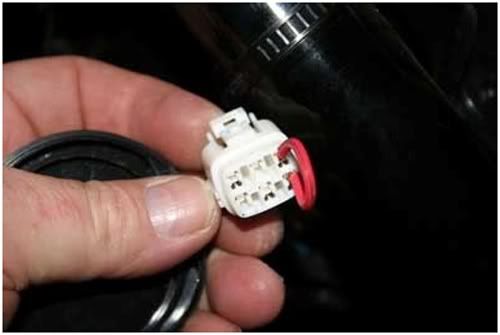
Эта проволочная вставка заменит нам «Специальный инструмент». Снимите левую боковую крышку, под ней будет два не используемых разъема с резиновыми черными заглушками Один черный и один белый. Снимите заглушку с белого разъема.
Что бы, не перепутать какие разъемы замыкать поверните разъем так, что бы «замок» смотрел вверх. Смотри рисунок:
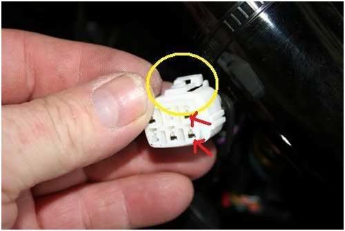
Затем в правую часть разъема вы должны вставить новый «Специальный инструмент».
Поверните ключ зажигания, не заводя мотоцикл. Код Fi, будет отображаться на экране одометра. С ##. Посмотрите код Fi ошибки в руководстве, тогда вы будете точно знать что обозначала данная ошибка с Fi.
Еще один совет по поводу Fi кода в окне одометра. Когда вы видите например код ошибки С46 (EXCVA – выхлопной клапан), в левой части кода будет значок диеза (#). Этот знак показывает нам, положение дроссельной заслонки, процент/позицию ее открытия. Если после этого открыть газ полностью, значок диеза (#) будет двигаться, показывает нам положение открытой и закрытой заслонки. Если она движется, то это означает, что она без проблем откликается на ручку газа и все в порядке.
Вот и все. Удачных поездок!
(перевод Fin)
Suzuki GSX-R 600 motorcycles have engines, which are made up of many different parts.
These parts must work together in order for the engine to function. A problem with one of the
parts can make the engine not run. There are many different parts that make up an engine.
The following suzuki gsx-r 600 faults are the list of some of the parts of a motorcycle engine.
Checking the fault code is one of the most overlooked aspects of maintaining Suzuki GSX-R 600 motorcycle. Many people don’t think about it until something goes wrong. A clogged afuel pump. Now that you know how to stay visible on your bike, and how to stay safe on your Suzuki GSX-R 600 bike, it’s important that you know what you need. When you’re on a bike, the weather is often a factor. Here are a few tips that will help you protect yourself the next time you take your motorcycle out on the road.
Suzuki GSX-R 600 Faults :
Another drawback that may occur along with your bike engine could be a blown gasket. this will cause your engine to overheat and presumably crack the cylinder heads. during this case, it’s best to require your Suzuki GSX-R 600 bike to an expert mechanic to possess it verified. Another common drawback is with the carburettor. The carburettor is that the a part of your bike that mixes air and fuel to make the combustion required to power the engine.
Prior to diagnosis using the mode selection switch or SDS, perform the following visual inspections. The reason for
visual inspection is that mechanical failures (such as oil leakage) cannot be displayed on the screen with the use of
mode selection switch or SDS.
- Engine oil level and leakage.
- Engine coolant level and leakage.
- Fuel level and leakage.
- Clogged air cleaner element.
- Battery condition.
- Throttle cable play.
- Vacuum hose looseness, bend and disconnection.
- Broken fuse.
- Fl indicator light operation.
- Each warning indicator light operation.
- Combination meter operation.
- Exhaust gas leakage and noise.
- Each coupler disconnection.
- Clogged radiator fins.
| Malfunction Code |
Detected Item | Detected Failure Condition | Check For |
|---|---|---|---|
| COO | NO FAULT | — | — |
| C11 | CMP sensor | The signal does not reach ECM for 3 sec. or more, after receiving the starter signal. | CMP sensor wiring and mechanical parts CMP sensor, intake cam pin, wiring/coupler connection |
| P0340 | |||
| C12 | CKP sensor | The signal does not reach ECM for 3 sec. or more, after receiving the starter signal. | CKP sensor wiring and mechanical parts CKP sensor, lead wire/coupler connection |
| P0335 | |||
| C13 | IAP sensor | The sensor should produce following voltage. 0.5 V 5 Sensor voltage < 4.85 V In other than the above range, C13 (P0105) is indicated. |
IAP sensor, lead wire/coupler connection |
| P0105 | 21 | Sensor voltage is higher than specified value. | IAP sensor circuit shorted to VCC or ground circuit open |
| L | Sensor voltage is lower than specified value. | IAP sensor circuit open or shorted to ground or VCC circuit open | |
| C14 | TP sensor | The sensor should produce following voltage. 0.2 V 5 Sensor voltage < 4.8 V In other than the above range, C14 (P0120) is indicated. |
TP sensor, lead wire/coupler connection |
| P0120 | 2 | Sensor voltage is higher than specified value. | TP sensor circuit shorted to VCC or ground circuit open |
| L | Sensor voltage is lower than specified value. | TP sensor circuit open or shorted to ground or VCC circuit open | |
| C15 | ECT sensor indicated. |
The sensor voltage should be the following. 0.15 V 5 Sensor voltage < 4.85 V In other than the above range, C15 (P0115) is i |
ECT sensor, lead wire/coupler connection |
| P0115 | Sensor voltage is higher than specified value. | ECT sensor circuit open or ground circuit open | |
| L | Sensor voltage is lower than specified value. | ECT sensor circuit shorted to ground | |
| C21 | IAT sensor indicated. |
The sensor voltage should be the following. 0.15 V 5 Sensor voltage < 4.85 V In other than the above range, C21 (P0110) is i |
IAT sensor, lead wire/coupler connection |
| P0110 | 1=7 | Sensor voltage is higher than specified value. | IAT sensor circuit open or ground circuit open |
| L | Sensor voltage is lower than specified value. | IAT sensor circuit shorted to ground | |
| C22 | AP sensor | The sensor voltage should be the following. 0.5 V 5 Sensor voltage < 4.85 V In other than the above range, C22 (P1450) is indicated. |
AP sensor, lead wire/coupler connection |
| P1450 | I= | Sensor voltage is higher than specified value. | AP sensor circuit shorted to VCC or ground circuit open |
| L | Sensor voltage is lower than specified value. | AP sensor circuit open or shorted to ground or VCC circuit open | |
| C23 | TO sensor | The sensor voltage should be the following for 2 sec. and more, after ignition switch is turned ON. 0.2 V 5 Sensor voltage < 4.8 V In other than the above value, C23 (P1651) is indicated. |
TO sensor, lead wire/coupler connection |
| P1651 | Sensor voltage is higher than specified value. | TO sensor circuit shorted to VCC or ground circuit open | |
| L | Sensor voltage is lower than specified value. | TO sensor circuit open or shorted to ground or VCC circuit open | |
| C24/C25 C26/C27 |
Ignition signal | CKP sensor (pick-up coil) signal is produced, but signal from ignition coil is interrupted 8 times or more continuously. In this case, the code C24 (P0351), C25 (P0352), C26 (P0353) or C27 (P0354) is indicated. | Ignition coil, wiring/coupler connection, power supply from the battery |
| P0351/P0352 P0353/P0354 |
|||
| C28 | STV actuator | When no actuator control signal is supplied from the ECM, communication signal does not reach ECM or operation voltage does not STVA motor, lead wire/coupler reach STVA motor, C28 (P1655) is indicated. connection STVA can not operate properly or its motor locked. |
|
| P1655 | |||
| C29 | The sensor should produce following voltage. 0.15 V 5 Sensor voltage < 4.85 V STP sensor, lead wire/coupler In other than the above range, C29 (P1654) is connection indicated. |
||
| P1654 | H | STP sensor Sensor voltage is higher than specified value. |
STP sensor circuit shorted to VCC or ground circuit open |
| L | Sensor voltage is lower than specified value. | STP sensor circuit open or shorted to ground or VCC circuit open | |
| C31 | Gear position signal | Gear position signal voltage should be higher than the following for 3 seconds and more. Gear position sensor voltage 0.6 V If lower than the above value, C31 (P0705) is indicated. |
GP switch, wiring/coupler connection, gearshift cam, etc. |
| P0705 | |||
| C32/C33 C34/C35 |
Primary fuel injector | CKP sensor (pickup coil) signal is produced, but fuel injector signal is interrupted 4 times or more continuously. In this case, the code C32 (P0201), C33 (P0202), C34 (P0203) or C35 (P0204) is indicated. | Primary fuel injector, wiring/ coupler connection, power supply to the injector |
| P0201/P0202 P0203/P0204 |
|||
| C36/C37 C38/C39 |
Secondary fuel injector | Some failure exists in the fuel injector signal in a high load, high revolution condition. In this case, the code C36 (P1764), C37 (P1765), C38 (P1766) or C39 (P1767) is indicated. | Secondary fuel injector, wiring/ coupler connection, power supply to the injector |
| P1764/P1765 P1766/P1767 |
|||
| C40/P0505 | ISC valve | The circuit voltage of motor drive is unusual. | ISC valve circuit open or shorted to ground Power source circuit open |
| C40/P0506 | Idle speed is lower than the desired idle speed. | Air passage clogged ISC valve is fixed ISC valve preset position is incorrect |
|
| C40/P0507 | Idle speed is higher than the desired idle speed. | ISC valve hose connection ISC valve is fixed ISC valve preset position is incorrect |
|
| C41 | FP relay | No voltage is applied to the fuel pump, although fuel pump relay is turned ON, or voltage is applied to fuel pump although fuel pump relay is turned OFF. | Fuel pump relay, lead wire/ coupler connection, power source to fuel pump relay and fuel injectors |
| P0230 | H | Voltage is applied to fuel pump although fuel pump relay is turned OFF. | Fuel pump relay switch circuit shorted to power source Fuel pump relay (switch side) |
| No voltage is applied to the fuel pump, p, although fuel pump relay is turned ON. | Fuel shortpump relay circuit open or Fuel pump relay (coil side) |
||
| C41/P2505 | ECM/PCM power input signal | No voltage is applied to the ECM. | Lead wire/coupler connection of ECM terminal to fuel fuse |
| C42 | Ignition switch | Ignition switch signal is not input to the ECM. * When the I.D. agreement is not verified. * ECM does not receive communication signal from the immobilizer antenna. |
Ignition switch, lead wire/ coupler, etc. * Immobilizer/anti-theft system |
| P1650 | |||
| C44/P0130 | H02 sensor | H02 sensor output voltage is not input to ECM during engine operation and running condition. (Sensor voltage > 1.0 V) C44 (P0130) is indicated. |
H02 sensor is circuit open or shorted to the power source |
| C44/P0135 | The Heater can not operate so that heater operation voltage is not supply to the oxygen heater circuit, C44 (P0135) is indicated. | Heated circuit open or shorted to ground Battery voltage supply to the H02 sensor |
|
| C46 | EXCV actuator | EXCVA position sensor produces following voltage. 0.1 V 5 sensor voltage < 4.9 V In other than the above range, C46 (P1675) is indicated. When no actuator control signal is supplied from the ECM, communication signal does not reach ECM or operation voltage does not reach EXCVA motor, C46 (P1658) is indicated. EXCVA can not operate. |
EXCVA, EXCVA lead wire/ coupler |
| P1657 | 2 | EXCVA position sensor voltage is higher than specified value. | EXCVA position sensor circuit shorted to VCC or ground circuit open |
| L | EXCVA position sensor voltage is lower than specified value. | EXCVA position sensor circuit open or shorted to ground or VCC circuit open | |
| P1658 | When no operation voltage reaches EXCVA motor, C46 (P1658) is indicated. EXCVA motor can not be operated. wire/coupler |
EXCVA, EXCVA motor lead | |
| C49 | PAIR control solenoid valve | PAIR control solenoid valve voltage is not input to ECM. | PAIR control solenoid valve, lead wire/coupler connection |
| P1656 | |||
| C60 | Cooling fan relay | Cooling fan relay signal is not input to ECM. | Cooling fan relay, lead wire/ coupler connection |
| PO480 | |||
| C62 | EVAP system purge control solenoid valve (E-33 only) | EVAP system purge control solenoid valve voltage is not input to ECM. | EVAP system purge control solenoid valve, lead wire/ coupler connection |
| PO443 | |||
| C91 | Vehicle speed sensor | Combination meter does not receive signal from the vehicle speed sensor for more than 6 sec. when the motorcycle is running. ECM does not receive signal from the vehicle speed sensor for more than 6 sec. when the motorcycle is running. Failure in communication between ECM and combination meter with reference to vehicle speed. |
Speed sensor and combination meter wiring/coupler connection between ECM and combination meter |
| P0500 | |||
| C93 | Steering damper solenoid valve | Steering damper control current does not flow to the solenoid valve. With IG turned ON, ECM detects a failure of internal circuit element. Solenoid current does not converge to the target value. Battery voltage is 10 V or below with the engine running. |
Steering damper solenoid valve circuit interrupter element shorted, feedback current convergence failure, low battery voltage |
| P1769 | H | Steering damper control current is higher than specified value. An abnormal current is detected during the vehicle standstill. Solenoid current is 0.7 A or above. |
Steering damper solenoid valve circuit shorted to VCC |
| L | Steering damper control current is lower than specified value. With IG turned ON, ECM detects a discontinuity. An abnormal current is detected during the vehicle standstill. |
Steering damper solenoid valve circuit open or shorted |
Suzuki GSX-R 600 Motorcycle Problems :
- Suzuki gsx-r 600 after fire
- Suzuki gsx-r 600 air cleaner clogged, poorly sealed, or missing
- Suzuki gsx-r 600 air cleaner element clogged
- Suzuki gsx-r 600 air duct loose
- Suzuki gsx-r 600 air suction valve trouble
- Suzuki gsx-r 600 air switching valve trouble
- Suzuki gsx-r 600 backfiring when deceleration
- Suzuki gsx-r 600 cracked or obstructed intake air pressure sensor
- Suzuki gsx-r 600 crankshaft sensor trouble
- Suzuki gsx-r 600 eCU ground and power supply trouble
- Suzuki gsx-r 600 eCU trouble
- Suzuki gsx-r 600 engine overheating — Water temperature sensor or crankshaft sensor trouble
- Suzuki gsx-r 600 engine stalls easily
- Suzuki gsx-r 600 engine vacuum not synchronizing
- Suzuki gsx-r 600 exhaust Smokes Excessively
- Suzuki gsx-r 600 firing incorrect
- Suzuki gsx-r 600 fuel filter clogged
- Suzuki gsx-r 600 fuel injector clogged
- Suzuki gsx-r 600 fuel injector O-ring damage
- Suzuki gsx-r 600 fuel injector trouble
- Suzuki gsx-r 600 fuel line clogged
- Suzuki gsx-r 600 fuel poor quality or incorrect
- Suzuki gsx-r 600 fuel pressure regulator trouble
- Suzuki gsx-r 600 fuel pressure too low or too high
- Suzuki gsx-r 600 fuel pump bearings may wear. Replace the fuel pump
- Suzuki gsx-r 600 fuel pump not operating
- Suzuki gsx-r 600 fuel pump operates intermittently and often DFI fuse blows
- Suzuki gsx-r 600 fuel pump relay trouble
- Suzuki gsx-r 600 fuel pump trouble
- Suzuki gsx-r 600 fuel/air mixture incorrect
- Suzuki gsx-r 600 fuel/air mixture incorrect
- Suzuki gsx-r 600 gear position sensor, starter lockout or side stand switch trouble
- Suzuki gsx-r 600 inspect and repair or replace
- Suzuki gsx-r 600 intake air pressure sensor trouble
- Suzuki gsx-r 600 intake air temperature sensor trouble
- Suzuki gsx-r 600 intake air temperature sensor trouble
- Suzuki gsx-r 600 intermittent any DFI fault and its recovery
- Suzuki gsx-r 600 little fuel in tank
- Suzuki gsx-r 600 main throttle sensor trouble
- Suzuki gsx-r 600 no or little fuel in tank
- Suzuki gsx-r 600 poor acceleration
- Suzuki gsx-r 600 spark plug burned or gap maladjusted
- Suzuki gsx-r 600 spark plug dirty, broken or gap maladjusted
- Suzuki gsx-r 600 spark plug incorrect
- Suzuki gsx-r 600 spark weak
- Suzuki gsx-r 600 stick coil shorted or not in good contact
- Suzuki gsx-r 600 stick coil trouble
- Suzuki gsx-r 600 subthrottle sensor trouble
- Suzuki gsx-r 600 subthrottle valve actuator trouble
- Suzuki gsx-r 600 throttle body assy dust seal damage
- Suzuki gsx-r 600 throttle body assy holder loose
- Suzuki gsx-r 600 throttle valves will not fully open
- Suzuki gsx-r 600 unstable (rough) idling
- Suzuki gsx-r 600 unstable fuel pressure
- Suzuki gsx-r 600 vacuum hose
- Suzuki gsx-r 600 vehicle-down sensor trouble
- Suzuki gsx-r 600 water or foreign matter in fuel Change fuel
- Suzuki gsx-r 600 water temperature sensor trouble
The electrical system includes the battery, the charging system, the starters, and the charging system. It is also possible that the electrical system can fail due to a problem with the generator. A good place to start Suzuki GSX-R 600 troubleshooting the electrical system is to check the engine parts. For example, it is possible that the electrical system can fail due to a problem with the generator. A good place to start troubleshooting the electrical system is to check the engine parts.

Suzuki Motors was a transformation of the original Suzuki Loom Works company in 1954, after the textile industry in Japan collapsed. The motorcycle arm of the company rapidly developed powerful and small engines, and today is known for powerhouse motorcycles like the Hayabusa and the GSX-R1000R.
Check other Suzuki fault codes.
These abbreviations, and the accompanying list of trouble codes, can be a
great start when your Suzuki check engine light comes on. As mentioned
above, if you are not comfortable with electrical diagnostic work, a dealership or qualified
technician can offer assistance. Please keep in mind that even though you have the ability to
clear a DTC using the onboard diagnostic feature, you shouldn’t clear the code prior to your
service appointment. Let the technician view and clear the codes as they troubleshoot the issue.
Suzuki and logo are registered trademarks of Suzuki. We are fan of MOTORCYCLES ! We love them.


Электронный диагностический инструмент OBD Tool упростит процедуру диагностики и ремонта мотоцикла.
Доступная цена! : http://www.healtech.ru/obd-tool-diagnostika-motozikla
C14 — ДАТЧИК ПОЗИЦИИ ДРОССЕЛЬНОЙ ЗАСЛОНКИ
C15 — ДАТЧИК ТЕМЕРАТУРЫ ОХЛАЖДАЮЩЕЙ ЖИДКОСТИ
C21 — ДАТЧИК ТЕМПЕРАТУРЫ ВОЗДУХА
C22 — ДАТЧИК АТМОСФЕРНОГО ДАВЛЕНИЯ
C23 — ДАТЧИК ОПРОКИДЫВАНИЯ
C24 — СИГНАЛ ЗАЖИГАНИЯ #1
C25 — СИГНАЛ ЗАЖИГАНИЯ #2
C26 — СИГНАЛ ЗАЖИГАНИЯ #3
C27 — СИГНАЛ ЗАЖИГАНИЯ #4
C28 — ШАГОВЫЙ ДВИГАТЕЛЬ ВТОРИЧНОЙ ДРОССЕЛЬНОЙ ЗАСЛОНКИ
C29 — ДАТЧИК ПОЗИЦИИ ВТОРИЧНОЙ ДРОССЕЛЬНОЙ ЗАСЛОНКИ
C30 — БЛОК УПРАВЛЕНИЯ ВТОРИЧНОЙ ДРОССЕЛЬНОЙ ЗАСЛОНКОЙ
C31 — ДАТЧИК ПЕРЕДАЧИ
C32 — СИГНАЛ ИНЖЕКТОРА #1
C33 — СИГНАЛ ИНЖЕКТОРА#2
C34 — СИГНАЛ ИНЖЕКТОРА#3
C35 — СИГНАЛ ИНЖЕКТОРА#4
C41 — ПОМПА
C42 — СИГНАЛ ВКЛЮЧЕНИЯ ЗАЖИГАНИЯ
C46 — ДВИГАТЕЛЬ ВЫПУСКНОГО КЛАПАНА