Тут все очень просто.
Пока у вас есть ошибки, кран работает в аварийном режиме. Это значит — низкая скорость, низкая грузоподъёмность и ограничение на работу некоторых операций, в частности — выдвижение телескопа.
Как считывать коды
Число с точкой — количество ошибок, далее высвечивается код с минимальным номером. По мере устранения ошибок будут появляться остальные коды. Либо надо подключать компьютер, тогда можно увидеть все ошибки сразу.
То, что число с точкой у вас меняется — значит меняется количество ошибок. Это значит, что какая то неисправность сама «исправляется». Такое может быть, например, при плохом контакте в разъёмах датчиков.
Сами коды:
03 — нажата кнопка «Стоп» или включен режим ДУ, но пульт выключен, или нет связи пульта с краном.
22 — нет датчика наклона второй стрелы.
Остальные по мере устранения первых.
Порядок выдвижения секций телескопа на этом кране произвольный, то есть в начале может выдвинутая последняя (самая тонкая) секция, потом первая (самая толстая).
Все зависит от того, как легко сама секция выдвигается/задвигается. Которая легче, та и выезжает в первую очередь.
HIAB SPACE 4000 System Error Codes Service Manual_EN
Size: 327 KB
Format: PDF
Language: English
Brand: HIAB
Type of machine: HIAB SPACE
Type of document: System Error Codes
Model: HIAB SPACE 4000
Number of pages: 12 pages
YOU WILL RECEIVE SOME LINKS DOWNLOAD AFTER PAYMENT
DETAIL CONTENTS: «CLICK HERE»
20.00$ 10.00$
- Description
Description
HIAB SPACE 4000 System Error Codes Service Manual_EN
Size: 327 KB
Format: PDF
Language: English
Brand: HIAB
Type of machine: HIAB SPACE
Type of document: System Error Codes
Model: HIAB SPACE 4000
Number of pages: 12 pages
4.7
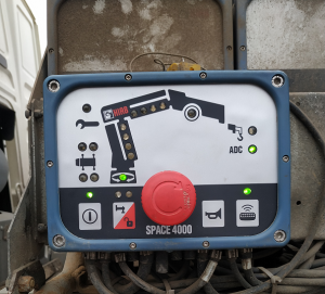
Indicator LEDs on user panel,
SPACE 4000
Power on/off
Stabiliser extension
activation
OLP Release
Manual extensions
Remote control
Parking control
Service
The Safety system
⑭
has been pressed.
lost.
Not active in this configuration.
or stabiliser leg)
been pressed, waiting for connection to hand unit.
Operator’s Manual GB
Green light on: The system is on.
Green light flashing: System on and the stop button
Red light flashing: CAN communication has been
Red light blinking: OLP Release active (crane, VSL
Green light flashing: Critical error.
Green light on: Manual extension mode is active.
Green light on: Remote control is active.
Green light flashing: Button for remote control has
Red light on: Radio interference.
Blue light on: Slew is in parking position.
Green light on: Service needed.
Red light on: Error in the system.
Red light flashing: Critical error.
4.7
45
HIAB
Service Manual Electronics
Error Codes Release date 2007-12-19
www.hiab.com
Service Manual Electronics Error Codes
The manufacturer accepts no liability for any consequences resulting from inappropriate, negligent, or incorrect operation of the equipment or from misuse of the equipment. Every effort has been made to ensure the accuracy the contents of this Manual, however the manufactures, publishers and author accept no liability for any loss, damage or injury caused by any errors in or omissions from the information contained within this document. The contents of this Manual are believed to be correct at the time of printing. In the interests of a commitment to a policy of continuous development and improvement , the manufacturer reserves the right to change the specication of the products or their performance or the contents of this Manual, without notice. All rights reserved. No part of this Manual may be stored, reproduced or transmitted in any form or by any means, electronically or mechanically including photocopying, recording or by any information retrieval system, without permission in writing from the publisher. Copyright © HIAB AB February 2005 HIAB AB SE-824 83 Hudiksvall Sweden Telephone FAX:
+46 (0) 650 91000 +46 (0) 650 12174
Author: After Sales Service Date of Issue: February 2005
2
Service Manual Electronics Error Codes Contents Safety Information …………………………….. ……………………………… …………………………….. ………. 4 Read this for your safety
4
DANGER ……………………………. ……………………………… ………………………….. 4 WARNING ………………………….. ……………………………… ………………………….. 4 CAUTION……………………………………………. ……………………………… ………….. 4 NOTE! …………………………… ……………………………… …………………………….. … 4 TIP! …………………………. …………………………….. ……………………………… ……… 4 Excluded personnel
4
Extract from EN12999:2002 (2004)
4
Extract from EN12644-1 (2001)
4
3
Service Manual Electronics Error Codes Error Decription Codes SPACE General Here follows a list of all the possible error messages from the SPACE systems program, a short description of them and the action taken by the errors. The different actions are: — ERR_BLINK — EMER_STOP — LO_SPEED — LOS_SPEED — LO_LOAD — STOP_OUT — PSBI_DUMP
The error lamp in the PSB blinks Emergency Stop (dumpvalve deactivated) The max allowed speeds are reduced to err_speed (%) The full inner boom LOS speed reduction is set for the different functions ( err_speed used if the crane doesn’t have LOS) The max allowed loads for inner boom, outer boom and jib is reduced to err_load % of what the max allowed speed otherwise should be. The out-direction for the extension and jib-extension are stopped. SPACE asks the PSBI to switch off the dump supply. This action is automatically disabled the rst 10 seconds after power-on.
Most of the errors are reset automatically when the faulty condition disappears, but a few errors requires to be reset manually. A manual reset can be done with the terminal (ERRORS / CLEAR) or by switching the SPACE power off and on.
4
Service Manual Electronics Error Codes SPACE RadioDrive E 0 : Low Power E 1 : Internal Error (Int) E 2 : No I/O-voltage E 3 : No Dump-voltage E 4 : Remote receive error E 5 : Parameter error E 6 : Internal Error (Time) E 7 : No Relay box supply voltage E 8 : System type lost E 9 : Internal Error (PBuf) E 10 : Dump Output Error E 11 : One jib-sensor unconnected E 12 : Both jib and winch connected E 13 : Winch indicator error E 14 : Slewing-sector error E 15 : Inner Boom Pressure error E 16 : Jib Out Pressure error E 17 : Jib In Pressure error E 18 : Internal Error (Log) E 19 : Micro-mode selector error E 20 : System not running E 21 : No Box-supply voltage E 22 : No Outer Boom Tilt Indicator E 23 : No Inner Boom Tilt Indicator E 24 : Outer Boom Pressure error E 25 : IO-voltage in (A1) out of range E 26 : Lever-sensor 7 (A2) out of range E 27 : Lever-sensor 4 (A3) out of range E 28 : Lever-sensor 5 (A4) out of range E 29 : Lever-sensor 6 (A5) out of range E 30 : Lever-sensor 1 (A6) out of range E 31 : Lever-sensor 2 (A7) out of range E 32 : Lever-sensor 3 (A8) out of range E 33 : Outer boom press (B1) out of range E 34 : Outer boom tilt (B2) out of range E 35 : Inner boom angle (B3) out of range E 36 : Jib in pressure (B4) out of range E 37 : Jib out pressure (B5) out of range E 38 : Jib tilt (B6) out of range E 39 : Winch sensors (B7) out of range E 40 : Micro-mode input (B8) out of range E 41 : Relay-box volt out (C1) out of range E 42 : DUMP-voltage in (C2) out of range E 43 : DUMP-voltage out (C3) out of range E 44 : Man/REM-sw (C4) out of range E 45 : Conn-box volt out (C5) out of range, E 46 : Slew angle sens (C6) out of range E 47 : Temp sensor (C7) out of range E 48 : Inner boom press (C8) out of range
EMER_STOP EMER_STOP + ERR_BLINK EMER_STOP ERR_BLINK LO_SPEED + ERR_BLINK EMER_STOP + ERR_BLINK ERR_BLINK EMER_STOP + PSBI_DUMP + ERR_BLINK LO_SPEED + ERR_BLINK LO_SPEED + LO_LOAD + ERR_BLINK LO_SPEED + LO_LOAD + ERR_BLINK LO_SPEED + LO_LOAD + ERR_BLINK LOS_SPEED + ERR_BLINK LO_SPEED + ERR_BLINK LO_SPEED + ERR_BLINK ERR_BLINK LO_SPEED + LO_LOAD + ERR_BLINK ERR_BLINK EMER_STOP + ERR_BLINK LO_SPEED + ERR_BLINK LO_SPEED + ERR_BLINK LO_SPEED + ERR_BLINK LO_SPEED + ERR_BLINK LO_LOAD + ERR_BLINK LO_LOAD + ERR_BLINK LO_LOAD + ERR_BLINK LO_LOAD + ERR_BLINK LO_LOAD + ERR_BLINK LO_LOAD + ERR_BLINK LO_LOAD + ERR_BLINK LO_SPEED + STOP_OUT + ERR_BLINK LO_SPEED + LO_LOAD + ERR_BLINK LO_SPEED + LO_LOAD + ERR_BLINK LO_SPEED + ERR_BLINK LO_SPEED + ERR_BLINK LO_SPEED + LO_LOAD + ERR_BLINK LO_SPEED + LO_LOAD + ERR_BLINK LO_SPEED + LO_LOAD + ERR_BLINK LO_SPEED + ERR_BLINK LO_SPEED + ERR_BLINK ERR_BLINK LO_SPEED + ERR_BLINK LO_SPEED + LO_LOAD + ERR_BLINK LO_SPEED + LO_LOAD + ERR_BLINK LO_SPEED + ERR_BLINK LOS_SPEED + STOP_OUT + ERR_BLINK
5
Service Manual Electronics Error Codes E 49 : Inner Boom Angle error E 50 : No Inner Boom Pressure Sensor E 51 : No Outer Boom Pressure Sensor E 52 : Lever not centered at startup E 53 : Remote lever not centered at startup E 54 : Remote lever error E 55 : Radio protocol missing E 56 : Radio protocol error E 57 : Support legs not set E 58 : Multiplexer 1 error E 59 : Multiplexer 2 error E 60 : Multiplexer 3 error E 61 : Micro ON/OFF-switch error E 62 : A/D-converter 1 error E 63 : A/D-converter 2 error E 64 : A/D-converter 3 error E 65 : Real Time Lost E66: E67: E68: E69: E70: E 71 : PLC Program Lost E 72 : PLC Program Error E 73 : PLC Error 1 E 74 : PLC Error 2 E 75 : PLC Error 3 E 76 : PLC Error 4 E 77 : Remote battery empty E 78 : Remote output open E 79 : Remote output shorted E 80 : Remote output shorted E81: E82: E83: E84: E85: E86: E87: E88: E89:
6
LO_SPEED + ERR_BLINK LOS_SPEED + ERR_BLINK LO_SPEED + ERR_BLINK ERR_BLINK ERR_BLINK LO_SPEED+ERR_BLINK ERR_BLINK ERR_BLINK SUPP_LOAD+ERR_BLINK LO_SPEED + ERR_BLINK LO_SPEED + ERR_BLINK LO_SPEED + ERR_BLINK LO_LOAD + LO_SPEED + ERR_BLINK LO_LOAD + LO_SPEED + ERR_BLINK LO_LOAD + LO_SPEED + ERR_BLINK LO_LOAD + LO_SPEED + ERR_BLINK
ERR_BLINK ERR_BLINK ERR_BLINK ERR_BLINK ERR_BLINK ERR_BLINK ERR_BLINK ERR_BLINK ERR_BLINK ERR_BLINK
Service Manual Electronics Error Codes SPACE 3000/4000 E 0 : Lo power E 1 : I/O-fuse E 2 : DMP-fuse E 3 : Emergency STOP E 4 : DMP-output E 5 : Em Stop Chain E 6 : Column-fuse E 7 : Terminal-fuse E 8 : CAN-fuse E 9 : HORN-output error E 10 : Extended box error E 11 : Internal Error E 12 : Spool sensor 1 (ch0/P1:3) OOR E 13 : Spool sensor 2 (ch1/P1:4) OOR E 14 : Spool sensor 3 (ch2/P1:5) OOR E 15 : Spool sensor 4 (ch3/P1:6) OOR E 16 : Spool sensor 5 (ch4/P2:3) OOR E 17 : Spool sensor 6 (ch5/P2:4) OOR E 18 : Spool sensor 7 (ch6/EXT-P5:3) OOR E 19 : Spool sensor 8 (ch7/EXT-P5:4) OOR E 20 : 2 nd inner boom tilt (ch8/P5:8) OOR E 21 : Winch sensors (ch9/P5:7) OOR E 22 : Inner boom tilt (ch10/P5:6) OOR E 23 : Outer boom tilt (ch11/P5:5) OOR E 24 : Outer boom press (ch12/P5:4) OOR E 25 : I nner boom press (ch13/P5:3) OOR E 26 : Slew indicator (ch14/P6:3) OOR E27: E 28 : Spool sensor 9 (ch16/P5:9) OOR E 2 9 : O n platform ind (ch17/EXT-P4:3) OOR E 30 : Extra ind (ch18/EXT-P10:3) OOR E 31 : Slew sector 1 E 32 : Slew sector 2 E 33 : Slew sector 3 E 34 : Winch Ind E 35 : Parameter E 36 : Lev not cent E 37 : Inner Boom Pressure E 38 : Outer Boom Pressure E 39 : Cover 1 Error E 40 : Cover 2 Error E 41 : Cover 3 Error E 42 : Cover 4 Error E 43 : ADS Valve Error E 44 : ADS P1 Error E 45 : ADS P2 Error E 46 : MSC-output E 47 : DMP2-output E 48 : Not run
EMER_STOP + ERR_LAMP EMER_STOP + ERR_LAMP EMER_STOP + ERR_LAMP EMER_STOP EMER_STOP + PWR_OFF + ERR_LAMP EMER_STOP + ERR_LAMP EMER_STOP + ERR_LAMP EMER_STOP + ERR_LAMP EMER_STOP + ERR_LAMP ERR_LAMP LO_LOAD + ERR_LAMP ERR_LAMP LO_LOAD + ERR_LAMP LO_LOAD + ERR_LAMP LO_LOAD + ERR_LAMP LO_LOAD + ERR_LAMP LO_LOAD + ERR_LAMP LO_LOAD + ERR_LAMP LO_LOAD + ERR_LAMP LO_LOAD + ERR_LAMP LO_SPEED + LO_LOAD + ERR_LAMP LO_SPEED + LO_LOAD + ERR_LAMP LO_SPEED + LO_LOAD + ERR_LAMP LO_SPEED + LO_LOAD + ERR_LAMP LO_SPEED + STOP_OUT + ERR_LAMP LO_SPEED + STOP_OUT + ERR_LAMP LO_SPEED + LO_LOAD + ERR_LAMP LO_SPEED + LO_LOAD + ERR_LAMP LO_SPEED + LO_LOAD + ERR_LAMP LO_SPEED + LO_LOAD + ERR_LAMP LO_SPEED + LO_LOAD + ERR_LAMP LO_SPEED + LO_LOAD + ERR_LAMP LO_SPEED + LO_LOAD + ERR_LAMP LO_SPEED + LO_LOAD + ERR_LAMP EMER_STOP + ERR_LAMP LO_SPEED + ERR_LAMP LO_SPEED + ERR_LAMP ERR_LAMP ERR_LAMP ERR_LAMP ERR_LAMP ERR_LAMP ERR_LAMP ERR_LAMP ERR_LAMP ERR_LAMP EMER_STOP + ERR_LAMP
7
Service Manual Electronics Error Codes E 49 : Service! E 50 : Unknown cover in system E 51 : CAN buffer overrun E 52 : Real Time Lost E 53 : PLC Program Lost E 54 : Remote battery empty E 55 : Remote Contol Unit E 56 : Radio Receiver Error E 57 : Remote Output Unit E 58 : Remote Output Open E 59 : Remote Output Shorted E 60 : PLC Program Error E 61 : PLC Error 1 E 62 : PLC Error 2 E 63 : PLC Error 3 E 64 : PLC Error 4 E 65 : Relay Box Error E 66 : Lever supervision E 67 : Mux Box Error E 68 : Remote Control Missing E 6 9 : P6:3 conict E 70 : IB rod press (ch53/P5:10) OOR E 71 : OB rod press (ch54/P5:11) OOR E 72 : Inner Boom Angle error E 73 : Outer Boom Angle error E 74 : Slew Angle error E 75 : Slew sector 4 E 76 : Slew sector 5 E 77 : Slew sector 6 E 78 : The support legs are not set E79: E80: E81: E82: E83: E84: E85: E86: E87: E88: E89:
8
ERR_LAMP ERR_LAMP ERR_LAMP ERR_LAMP ERR_LAMP ERR_LAMP ERR_LAMP ERR_LAMP ERR_LAMP ERR_LAMP ERR_LAMP ERR_LAMP ERR_LAMP ERR_LAMP ERR_LAMP ERR_LAMP ERR_LAMP ERR_LAMP LO_SPEED + LO_LOAD + ERR_LAMP LO_SPEED + LO_LOAD + ERR_LAMP LO_SPEED + ERR_LAMP LO_SPEED + ERR_LAMP LO_SPEED + ERR_LAMP LO_SPEED + LO_LOAD + ERR_LAMP LO_SPEED + LO_LOAD + ERR_LAMP LO_SPEED + LO_LOAD + ERR_LAMP ERR_LAMP
Service Manual Electronics Error Codes SPACE 5000 E 0 : Low Power E 1 : Internal Error (Int) E 2 : No I/O-voltage E 3 : No Dump-voltage E4 : E 5 : Parameter error E 6 : Internal Error (Time) E 7 : No Relay box supply voltage E 8 : System type lost E 9 : Internal Error (CBuf) E 10 : Dump Output Error E 11 : One jib sensor unconnected E 12 : Both jib and winch connected E 13 : Winch indicator error E 14 : Slewing sector error E 15 : Inner Boom Pressure error E 16 : Jib Boom Pressure error E17: E 18 : Internal Error (Log) E 19 : Micro-mode selector error E 20 : System not running E 21 : No Box supply voltage E 22 : No Outer Boom Tilt Indicator E 23 : No Inner Boom Tilt Indicator E 24 : Outer Boom Pressure error E 25 : Lever sensor 8 (A1) out of range E 26 : Lever sensor 7 (A2) out of range, E 27 : Lever sensor 4 (A3) out of range, E 28 : Lever sensor 5 (A4) out of range E 29 : Lever sensor 6 (A5) out of range E 30 : Lever sensor 1 (A6) out of range E 31 : Lever sensor 2 (A7) out of range E 32 : Lever sensor 3 (A8) out of range E 3 3 : O uter boom press (B1) out of range E 34 : Outer boom tilt (B2) out of range E 35 : Inner boom angle (B3) out of range E 36 : Jib in pressure (B4) out of range E 37 : Jib out pressure (B5) out of range E 38 : Jib tilt (B6) out of range E 39 : Winch sensors (B7) out of range E 40 : Micro-mode input (B8) out of range E 41 : Relay-box volt out (C1) out of range E 42 : DUMP voltage in (C2) out of range E 43 : DUMP-voltage out (C3) out of range E 44 : IO-voltage in (C4) out of range E 45 : Conn box volt out (C5) out of range E 46 : Slew angle sens (C6) out of range E 47 : Temp sensor (C7) out of range E 4 8 : I nner boom press (C8) out of range
EMER_STOP EMER_STOP + ERR_BLINK EMER_STOP LO_SPEED + ERR_BLINK EMER_STOP + ERR_BLINK ERR_BLINK EMER_STOP + PSBI_DUMP + ERR_BLINK LO_SPEED + ERR_BLINK LO_SPEED + LO_LOAD + ERR_BLINK LO_SPEED + LO_LOAD + ERR_BLINK LO_SPEED + LO_LOAD + ERR_BLINK ASC_SPEED + ERR_BLINK LO_SPEED + ERR_BLINK ERR_BLINK LO_SPEED + LO_LOAD + ERR_BLINK ERR_BLINK EMER_STOP + ERR_BLINK LO_SPEED + ERR_BLINK LO_SPEED + ERR_BLINK LO_SPEED + ERR_BLINK LO_LOAD + ERR_BLINK LO_LOAD + ERR_BLINK LO_LOAD + ERR_BLINK LO_LOAD + ERR_BLINK LO_LOAD + ERR_BLINK LO_LOAD + ERR_BLINK LO_LOAD + ERR_BLINK LO_LOAD + ERR_BLINK LO_SPEED + STOP_OUT + ERR_BLINK LO_SPEED + LO_LOAD + ERR_BLINK LO_SPEED + LO_LOAD + ERR_BLINK LO_SPEED + ERR_BLINK LO_SPEED + ERR_BLINK LO_SPEED + LO_LOAD + ERR_BLINK LO_SPEED + LO_LOAD + ERR_BLINK LO_SPEED + LO_LOAD + ERR_BLINK LO_SPEED + ERR_BLINK LO_SPEED + ERR_BLINK ERR_BLINK LO_SPEED + ERR_BLINK LO_SPEED + LO_LOAD + ERR_BLINK LO_SPEED + LO_LOAD + ERR_BLINK LO_SPEED + ERR_BLINK ASC_SPEED + STOP_OUT + ERR_BLINK
9
Service Manual Electronics Error Codes E 49 : Inner Boom Angle error E 50 : No Inner Boom Pressure Sensor E 51 : No Outer Boom Pressure Sensor E 52 : Lever not centered at startup E 53 : Remote control Unit Error E 54 : Power Supply Box Error E 55 : Radio Receiver Error E 56 : DA-module error E 57 : Support legs not set E 58 : Multiplexer 1 error E 59 : Multiplexer 2 error E 60 : Multiplexer 3 error E 61 : Micro ON/OFF-switch error E 62 : A/D-converter 1 error E 63 : A/D-converter 2 error E 64 : A/D-converter 3 error E 65 : Real Time Lost E 66 : Service Interval E 67 : Outer Boom Angle error E68: E69: E70: E 71 : PLC Program Lost E 72 : PLC Program Error E 73 : PLC Error 1 E 74 : PLC Error 2 E 75 : PLC Error 3 E 76 : PLC Error 4 E 77 : Remote battery empty E 78 : CombiDrive Error E79: E 80 : Analog angle sensor 1 error E 81 : Analog angle sensor 2 error E 82 : Analog angle sensor 3 error E 83 : Analog angle sensor 4 error E 84 : Lever supervision E85: E86: E87: E88: E89:
10
LO_SPEED + ERR_BLINK ASC_SPEED + ERR_BLINK LO_SPEED + ERR_BLINK ERR_BLINK ERR_BLINK ERR_BLINK ERR_BLINK ERR_BLINK SUPP_LOAD+ERR_BLINK LO_SPEED + ERR_BLINK LO_SPEED + ERR_BLINK LO_SPEED + ERR_BLINK LO_LOAD + LO_SPEED + ERR_BLINK LO_LOAD + LO_SPEED + ERR_BLINK LO_LOAD + LO_SPEED + ERR_BLINK LO_LOAD + LO_SPEED + ERR_BLINK SERVICE_LAMP LO_SPEED + ERR_BLINK
ERR_BLINK ERR_BLINK ERR_BLINK ERR_BLINK ERR_BLINK ERR_BLINK ERR_BLINK ERR_BLINK LO_SPEED + LO_LOAD + ERR_BLINK LO_SPEED + LO_LOAD + ERR_BLINK LO_SPEED + LO_LOAD + ERR_BLINK LO_SPEED + LO_LOAD + ERR_BLINK
Service Manual Electronics Error Codes
11
Как восстановить панель управления Space 4000.
Современный кран- манипулятор уже давно не мыслим без электроники. Это и системы ограничения грузоподъёмности, и системы дистанционного управления, и многое другое, что помогает оператору быстро, точно и безопасно выполнить работу.
Соответственно, чем сложнее электроника, тем чаще в ней случаются разные неполадки. К счастью, большинство современных электронных систем имеет функцию самодиагностики, что сильно упрощает поиск и устранение неисправностей, но не всегда.
Одна из таких ситуаций – кран просто не включается или не включаются какие-то определенные функции, например, не включается режим дистанционного управления. Система не реагирует на кнопки на панели управления. Очевидная причина – неисправность самих кнопок.
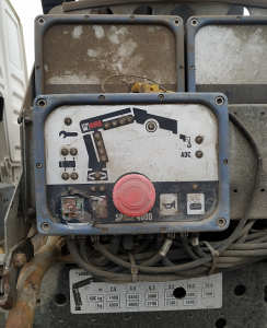
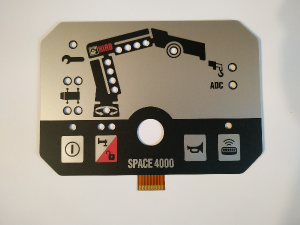
Кнопки на панели управления кранов-манипуляторов HIAB выполнены по технологии «пленочная клавиатура». Это пленка, которая наклеена поверх корпуса блока управления. Внутри, между двух слоев пленки находятся контакты, как в обычной кнопке. Работает такая кнопка так же как и обычная – при нажатии контакты замыкаются, подается сигнал. Со временем под воздействием солнца, дорожной грязи, перепадов температур верхний слой пленки разрушается, внутрь попадает вода, контакты окисляются, и кнопка перестает выполнять свою функцию.
Раньше, для устранения такой неисправности приходилось менять панель управления целиком, что наносило ощутимый удар по карману владельца. Теперь появился более дешевый способ — можно восстановить работоспособность панели.
Можно поменять только пленку с кнопками, так называемую «пленочную клавиатуру». В результате, затраты на ремонт в этом случае в несколько раз дешевле, чем стоимость новой панели управления.
Как восстановить панель управления Space 4000:
Снимаем синюю рамку.
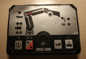
И отдираем старую пленку
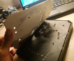
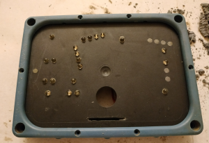
Далее, надо добраться до контактов, к которым припаяна клавиатура. Для этого на обратной стороне надо удалить компаунд, которым залита печатная плата.
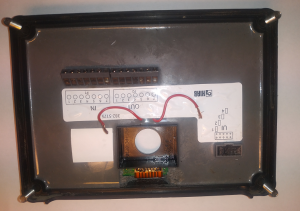
Получаем вот такой голый блок.
Далее наклеиваем новую клавиатуру,
подпаиваем ее к выводам на плате, и заново заливаем плату компаундом.
Панель отремонтирована и радует владельца крана-манипулятора.
По всем вопросам обращайтесь по телефону +7 (916) 147-36-55, WhatsApp, Viber