The laser diode in the optical pick-up block may suffer electrostatic break-down because of the potential difference generated by the charged electrostatic load, etc. on clothing and the human body. During repair, pay attention to electrostatic break-down and also use the procedure in the printed matter which is included in the repair parts. The flexible board is easily damaged and should be handled with care.
The laser beam on this model is concentrated so as to be focused on the disc reflective surface by the objective lens in the optical pickup block. Therefore, when checking the laser diode emission, observe from more than 30 cm away from the objective lens.
Abbreviation
AR : Argentina model
AUS : Australian model
E4 : African model
EA : Saudi Arabia model
LA9 : Latin-American model
MY : Malaysia model
RU : Russian model
TH : Thai model
REPLACING THE IC001, IC002,
IC101, IC105, IC106, IC301, IC302 AND IC303 ON THE MOTHERBOARD BOARD
IC001, IC002, IC101, IC105, IC106, IC301, IC302 and IC303 on the MOTHERBOARD
board cannot exchange with single.
When these parts on the MOTHERBOARD board are damaged, exchange the entire
mounted board.
REPLACEMENT OF THE MS-476 BOARD
When the MS-476 board is defective, exchange the entire LOADING COMPLETE ASSY
RELEASING THE DISC TRAY LOCK
The disc tray lock function for the anti-theft of an demonstration disc in the
store is equipped.
Releasing Procedure
1. Press [Power] button to turn the power on.
2. Press [FUNCTION] button and turn the [MULTI CONTROL)
Knob to select “DVD/CD” function, then press [ENTER] button.
3. Press the [ENTER] button and [VOCAL FADER] button simultaneously and hold
down for around 3 seconds.
4. The message “UNLOCKED” is displayed and the disc tray is unlocked.
Note: When “LOCKED” is displayed, the slot lock is not released by turning
power on/off with the [Power] button.
REPLACING THE IC1001 ON THE DAMP
BOARD AND THE COMPLETE DAMP BOARD
When IC1001 on the DAMP board and the complete DAMP board are replaced, it is
necessary to spread the heat-sink compound between parts and heat sink.
REPLACING MOTHERBOARD BOARD OR
BLUETOOTH MODULE OR RC-S730 (WW) BOARD
When the MOTHERBOARD board or BLUETOOTH module or RC-S730 (WW) board are
replace execute the below service mode.
Pairing this system with a
Bluetooth device
1. Press the [Power] button to turn
the power on.
2. Place the Bluetooth device within 1 meter (3 feet) from the system.
3. Press BLUETOOTH on the unit to select Bluetooth function.
“BT AUDIO” appears in the display panel.
4. Hold down BLUETOOTH on the unit for 2 seconds or more.
“PAIRING” flashes in the display panel.
5. Perform the pairing procedure on the Bluetooth device.
6. Select the model number of the unit on the display of the Bluetooth device.
For example, select “SONY : MHC-GT3D”. If passkey is required on the Bluetooth
device, enter “0000”.
7. Perform the Bluetooth connection on the Bluetooth device.
8. When pairing is completed and the Bluetooth connection is established, the
Bluetooth device name appears in the display panel.
9. To cancel pairing operation, hold down BLUETOOTH on the unit for 2 seconds
or more until “BT AUDIO” appears in the display panel.

Connecting with a Smartphone by one touch (NFC)
[The operation in this mode must use a NFC-compatible Smartphone (Smartphone with a built-in NFC function [OS: Android 2.3.3 or later, excluding Android 3.x])]
1. Press the [Power] button to turn the power on.
2. Download and install the app “NFC Easy Connect”. Download the free Android app from Google Play by searching for “NFC Easy Connect”.
3. Start the app “NFC Easy Connect” on the Smartphone. Make sure that the application screen is displayed.
4. Touch the Smartphone to the N-Mark on the system until the Smartphone vibrates.
Complete the connection by following the instructions displayed on the Smartphone.
5. When pairing is completed and the Bluetooth connection is established, the Bluetooth device name appears in the display panel.
Playing music from a Bluetooth
device
For a Bluetooth device
1. Press the [Power] button to turn the power on.
2. Press BLUETOOTH on the unit to select Bluetooth function. “BT AUDIO” appears
in the display panel.
3. Establish connection with the Bluetooth device. Press BLUETOOTH on the unit to connect to the
last connected Bluetooth device. Perform
the Bluetooth connection from the Bluetooth device if the device is not
connected. Once the connection is
established, the Bluetooth device name appears in the display panel.
4. Press N.
Depending on the Bluetooth device,
> you may have to press N twice.
> you may need to start playback of an audio source on the Bluetooth device.
For an NFC-compatible Smartphone
Press the [Power] button to turn the power on.
Touch the Smartphone to the N-Mark on the system to establish the Bluetooth
connection. Start playback of an audio
source on the Smartphone. For details on playback, refer to the operating
instructions of your Smartphone.
To disconnect the Bluetooth
device For a Bluetooth device
Press BLUETOOTH on the unit.
“BT AUDIO” appears in the display panel.
For an NFC-compatible Smartphone
Touch the Smartphone to the N-Mark on the system again.
To erase all the pairing registration information perform COLD RESET test mode.
COLD RESET
The cold reset clears all data including preset data stored in the data flash to initial conditions included history mode data. Execute this mode when returning the set to the customer.
1. Press [Power] button to turn on the system.
2. Press Stop button and [S4 TUNING + >>] button simultaneously for 3 seconds.
3. “COLD RST” appears on the fluorescent indicator tube.
After that, the fluorescent indicator tube will display “SONY DEMO”. The set will automatically Power ON and Power OFF again, and the system is reset.
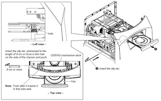
HOW
TO OPEN THE TRAY WHEN POWER SWITCH TURN OFF [No Power]
1: After the side panel and top panel are removed, this work is done.
2: Prepare the thin wire (clip etc. processed to the length of 8 cm or more).
Click on the pictures to Magnify
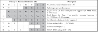
PANEL TEST MODE
This mode is used to check the fluorescent indicator tube, LEDs, keys, [VOLUME/DJ CONTROL] jog, model, destination and software version.
1. Press [Stop] button and [S3 TUNING – <<.] button simultaneously and hold 3 seconds.
2. All LEDs and segments in fluorescent indicator tube are lighted up.
3. When you want to enter to the software version display mode, press [S2 +] button.
The model information appears on the fluorescent indicator tube.
Press [S2+] button again to view the destination information.
4. During the destination information display, press [S2 +] button. Each time [S2 +] button is pressed, the fluorescent indicator tube shows the version of each category software in the following sequence: SC, MTK, OPU, UI, PF, SUB, SYS, CD, CMA, CMB, ST, TA, TM and return back to model information display.
5. When [Stop¬] button is pressed while the version numbers are being displayed except model and destination, the date of the software creation appears. When Stop button is pressed again, the display returns to the software version display.
6. When [ENTER] button is pressed after all LEDs and segments in fluorescent indicator tube light up, alternate segments in fluorescent indicator tube and LEDs would light up, all Party
Light LEDs would light up in red color. If you press [ENTER] button again, another half of alternate segments in fluorescent indicator tube and LEDs would light up, all Party Light LEDs
would light up in green color. Pressing [ENTER] button again would cause all segments in fluorescent indicator tube and LEDs light up, all Party Light LEDs would light up in blue color. Pressing [ENTER] button again would turn off all segments in fluorescent indicator tube and all LEDs including Party Light LEDs.
7. Press [S1 –] button, the key check mode is activated.
8. In the key check mode, the fluorescent indicator tube displays “K0 V0E0”. Each time a button is pressed, “K” value increases. However, once a button has been pressed, it is no longer taken into account. After all the buttons have been pressed, «K» value will toggle between «OK» and «K24».
“V” value increases in the manner of 0, 1, 2, 3 … if [VOLUME/ DJ CONTROL] knob is turned clockwise, or it decreases in the manner of 0, 9, 8, 7 … if [VOLUME/DJ CONTROL] knob is turned counterclockwise.
“E” value increases in the manner of 0, 1, 2, 3 … if [MULTI CONTROL] knob is turned clockwise, or it decreases in the manner of 0, 9, 8, 7 … if [MULTI CONTROL] knob is turned
counterclockwise.
9. To release from this mode, press the buttons in the same manner as step 1, or disconnect the power cord.
USER RESET
The user reset clears all data including preset data stored in the data
flash to initial conditions exclude history mode data.
1. Press [Power] button to turn on the system.
2. Press [ENTER] button and [S4 TUNING +>>] button simultaneously for 3 seconds.
3. “RESET” appears on the fluorescent indicator tube. After that, the fluorescent indicator tube becomes blank for a while, and the system goes to demo mode.
DISC TRAY LOCK MODE
This mode let you lock the disc tray. When this mode is activated, the disc tray will not open when [Eject] button is pressed. The message “LOCKED” will be displayed on the fluorescent indicator
tube. This mode only applied when there is disc on the tray.
1. Press [Power] button to turn on the system.
2. Press [FUNCTION] button and turn the [MULTI CONTROL] knob to select “DVD/CD” function, then press [ENTER] button.
3. Press [ENTER] button and [VOCAL FADER] button simultaneously and hold down until “LOCKED” or “UNLOCKED” displayed on the fluorescent indicator tube (around 3 seconds).
Bluetooth PAIRING HISTORY CLEAR
It can clear the Bluetooth pairing history.
1. Press [Power] button to turn on the system.
2. Press [-PAIRING BLUETOOTH] button to turn the Bluetooth function.
3. Press two buttons of [ENTER] and [S1 –] simultaneously for 3 seconds.
4. The message “BT HIST” è
“CLEAR” is displayed on the fluorescent indicator tube, and the pairing history
of Bluetooth is cleared.
HISTORY MODE
This mode is used to check important data stored in the system when PROTECTOR
happened.
1. During demo mode, press [Stop] button and [S2 +] button for 5 seconds to
mode into history mode.
2. Press the [S4 TUNING +>>|] button or [S3 TUNING – |<<.] button
to check history data stored.
To release from this mode, press
[Power] button.
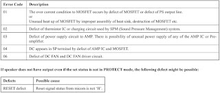
Protect Type & Description
DVD COLOR SYSTEM MODE
This mode let you change the color system of the video output from PAL to NTSC
or vice-versa.
1. Press [Power] button to turn on the system.
2. Press [FUNCTION] button and turn the [MULTI CONTROL] knob to select “DVD/CD”
function, then press [ENTER] button.
3. Press [ENTER] button and [MIC ECHO] button simultaneously and hold for 3
seconds.
4. The message “PAL” or “NTSC” appears on the fluorescent indicator tube.
* To release from DVD Color System Mode
1. Once the color system has been selected, the mode is fixed there after. If
you wish to change the mode again, perform the above item 2 again.
DVD SERVICE MODE
This mode let you make diagnosis and adjustment easily by using the remote
commander and the TV. The instructions, diagnostic results, etc. are given on
the on-screen display.
To enter to DVD Service Mode
1. Press [Power] button to turn on the system.
2. Press [FUNCTION] button and turn the [MULTI CONTROL] knob to select “DVD/CD”
function, then press [ENTER] button.
3. Press [SOUND FIELD] button and [VOCAL FADER] button simultaneously and hold
3 seconds.
4. The message “SERVICE IN” appears on the fluorescent indicator tube.
The display of the “Model Name” of the “Remocon Diagnosis Menu” change with the
model and the destination appears on screen display. Refer to below on the
model name.
MHC-GT3D: GV2
5. To execute each function,
press its number by using numeric button on the remote commander.
6. To release from this mode,
press [Power] button to turn off the system.
Execute IOP Measurement
In order to execute IOP measurement; the following standard procedures must be followed.
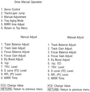
1. From the Top Menu of Remocon Diagnosis Menu, select “2.
Drive Manual Operation” by pressing the [2] button on the remote commander. The following screen appears on the onscreen display.
2. Select “3. Manual Adjustment” by pressing the [3] button on the remote commander. The following screen appears on the on-screen display.
3. Select “6. Iop:” by pressing the [6] button on the remote commander.
4. Wait until a hexadecimal number appears in the on-screen display as below:
5. Convert data from hexadecimal to decimal by using conversion table.
6. Please find the label on the rear of the BU (Base Unit).
The default IOP value is written in the label.
7. Subtract between these two values.
8. If the remainder is smaller than 93 (decimal), then it is OK.
However if the value is higher than 93, then the BU is defective and need to be change.
9. Press [RETURN] button on the remote commander to return to previous menu.
10. Press the [0] button on the remote commander to return to the Top Menu of Remocon Diagnosis Menu.
11. Press [Power] button to turn off the system.
Check Emergency History
To check the emergency history, please follow the following procedure.
1. From the Top Menu of Remocon Diagnosis Menu, select “3. Emergency History” by pressing the [3] button on the remote commander. The following screen appears on the onscreen display.
2. You can check the total time when the laser is turned on during playback of DVD and CD from the above menu. The maximum time, which can be displayed are 999h 59min.
3. You can check the error code of latest 10 emergency history from the above menu. To view the previous or next page of emergency history, press the [|<<] button or [>>|] button on the remote commander. The error code consists of “Error Code”, “Parameter of error code” and “Time of error
Error codes
01: Communication error (No reply from syscon)
02: Syscon hung up
03: Power OFF request when syscon hung up
19: Thermal shutdown
24: MoveSledHome error
25: Mechanical move error (5 Changer)
26: Mechanical move stack error
30: DC motor adjustment error
31: DPD offset adjustment error
32: TE balance adjustment error
33: TE sensor adjustment error
34: TE loop gain adjustment error
35: FE loop gain adjustment error
36: Bad jitter after adjustment
40: Focus NG
42: Focus layer jump NG
51: Spindle stop error
52: Open kick spindle error
60: Focus on error
61: Seek fail error
62: Read Q data/ID error
70: Lead in data read fail
71: TOC read time out (CD)
80: Can’t buffering
81: Unknown media type
To clear the Laser Hours
Press the [ DISPLAY] button and then press the [CLEAR] button. The data for both CD and DVD data are reset.
To clear the Emergency History
Press the [DVD TOP MENU] button and then press the [CLEAR] button.
The error code for all emergency history would be reset.
To clear the Initialize Setup Data
Press the [DVD/TUNER MENU] button and then press the [CLEAR] button on the remote commander.
To return to the Top Menu of Remocon Diagnosis Menu
Press the [0] button on the remote commander.
* Check Version Information
To check the version information, please follow the following procedure.
1. From the Top Menu of Remocon Diagnosis Menu, select “4.
Version information” by pressing the [4] button on the remote commander.
To return to the Top Menu of Remocon Diagnosis Menu, press the [0] button on the remote commander.
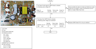
SMPS Board Diagnosis Flow
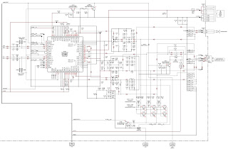
SCHEMATIC DIAGRAM — DAMP Board

This set displays an error code, and a mode code in case of error
on the display tube, if the operation stopped by error.
The following provides description concerned.
Display tube (lower 5 digits)
A
A: Error code ……………………………………………………… Table 6-1
B: Mode code in case of error ……………………………… Table 6-2
These codes are displayed at lower 5-digit positions of display
tube.
In this case, » : » between digits is not displayed.
Table 6-1. Error Codes
Code
0
NO ERROR
1
CAM ENCODER ERROR, LOAD DIRECTION
2
CAM ENCODER ERROR, UNLOAD DIRECTION
3
T REEL ERROR
4
S REEL ERROR
5
CAPSTAN ERROR
6
DRUM ERROR
7
INITIALIZE ERROR
8
CASSETTE UNLOADING ERROR
9
RESERVED
SECTION 6
ERROR CODES
B
Description
SLV-E580/E630/E727/E730/E735/E780
Table 6-2. Mode Codes in Case of Error
Code
0
POWER-ON EJECT
1
POWER-ON INITIAL
2
POWER-OFF EJECT
3
POWER-OFF STOP
4
FF
5
REW
6
REC
7
REC-PAUSE
8
POWER-ON STOP
9
PB
10
FWD R1
11
FWD R2
12
CUE
13
PB-PAUSE
14
RVS-PAUSE
15
RVS R1
16
RVS R2
17
REV
18
POWER-OFF INITIAL
19
MECHA ERROR (POWER OFF)
20
REW PLAY
21
CAS LOADING
22
TAPE LOADING
23
POWER-OFF LOADING
24
MECHA ERROR (POWER ON)
25
POWER-ON EJECT INITIAL
26
POWER-OFF EJECT INITIAL
27
APC REC
28
CAS LOADING (NO AUTO PB CHECK)
6-1 E
Description
- 19 Ноя 2005
DVD SONY DVP-S336 КОД ОШИБКИ «С 13» -???
ЧТО ЭТО ЗНАЧИТ ??
АППАРАТ ВООБЩЕ-ТО ТО ЧИТАЕТ ДИСК ТО НЕ ЧИТАЕТ , ПРИ ЧЁМ ЧТО dvd ЧТО cd ДВИГАТЕЛЬ ШПИНДЕЛЯ ПРОВЕРЕН , ОК!
- 19 Ноя 2005
Проблема с диском. В юзер мануале предлагают чистить диск.
- 19 Ноя 2005
Значит не распознаётся диск…………..в этом аппарате есть фенечка , вот она-то (я подозреваю) и не работает. А фенечка регулирует положение ЛГ относительно площадки двигателя шпинделя.
- 19 Ноя 2005
Я, бы проверил SLED MOTOR.
- 20 Ноя 2005
BBKuser, перемещение работает как надо !!
- 20 Ноя 2005
у моего знакомого 2 с такой проблемой.один диск читается до определённого момента , причём это не драйвер и не движок. можно вытащить диск опять вставить читает примерно до того же момента если диск чуть хуже качества (царапины мелкие) то вообще не видит его возможно проблема связана ближе к тому, что говорит АвтоМаг. получается слабый сигнал с головы , может попробовать угол наклона?
- 20 Ноя 2005
Фигня все это — «регулировки» траверс по отношению к диску .
Ну конечно если нет явных перекосов.
Тем более что всю эту «теорию» легко проверить по размаху сигнала RF, и коррекции фокуса (размах на обмотках)…
- 20 Ноя 2005
Вообще-то угол наклона головки по отношению к диску в данной модели (если не путаю) регулируется специальным мотором по датчику, который к RF не имеет отношение.
В СОНИ очень продвинутый тестовый режим, надо в него войти и выполнить проверку
и аппарат сам покажет, что ему не нравится.
- 22 Ноя 2005
Код ошибки С:13:00, на практике обычно свидетельствует о том что пора менять голову
- 22 Ноя 2005
BBKuser сказал(а):
…угол наклона головки по отношению к диску … регулируется специальным мотором по датчику, который к RF не имеет отношение.
А можно подробнее?!
- 22 Ноя 2005
Тема , которую поднял человек, его уже не интересует
- 23 Ноя 2005
Rottor, Ты таких ещё наверное не видел. Очень интересная конструкция. Но похоже надо действительно менять голову (pik-up) Хотя на двигателе шпинделя при скурпулёзном изучении можно увидеть небольшой люфт.
- 24 Ноя 2005
Вообще-то головку надо менять в первую очередь. Потом смотреть не пропаи, шлейфы, моторы, прошивки. Сони, поставляет весь блок в сборе (и никак иначе), с головкой и моторами. Успехов.
- 24 Ноя 2005
BBKuser сказал(а):
Сони, поставляет весь блок в сборе
Ну да… Если оригинал — не Samsung…
- 24 Ноя 2005
Аппарат действительно SONY , он из Германии привезён .Pik-up KHM-220AAA через своих поставщиков заказать не могу
Принесли ещё один такой же , только DVD SONY DVP-S335 (сделан для России).
- 24 Ноя 2005
АвтоМаг сказал(а):
Rottor, Ты таких ещё наверное не видел. Очень интересная конструкция.
Так что, с твоих слов и понять не возможно того «чего я не видел»?
Надеюсь прояснишь ситуацию с подробностями, или хоть в общих чертах?
- 24 Ноя 2005
- 17 Дек 2005
DVD SONY DVP-S336 Работает !! В сервисном режиме установил ток лазера и значения фокусировки на оптимальный режим . А вот DVD SONY DVP-S335 не хочет
пока. разберусь напишу.