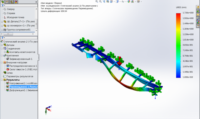
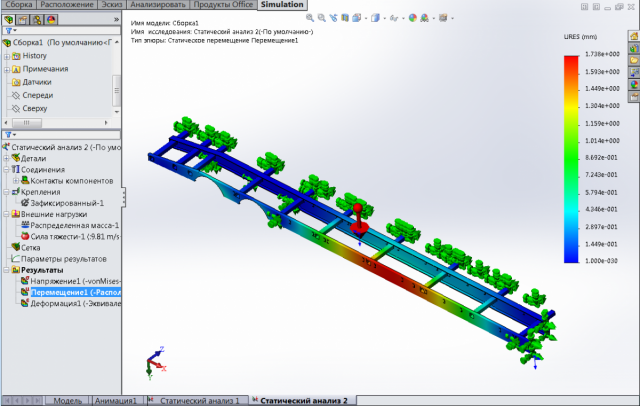
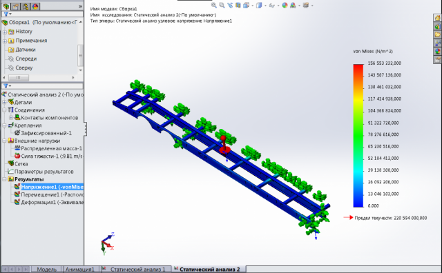
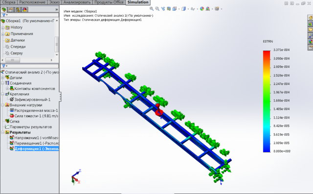
Не стал замарачиваться с исправлением ошибок импортированной геометрии, создал часть конструкции как единое тело в солидворксе. Ошибок после не выдало. То, что конструкторско-технологическая модель сборки малопригодна (непригодна) для расчета методом КЭ, тем более при импорте из другой КАД, понятно. Ибо время, которое нужно затратить на исправление ошибок и приведение модели к понятной для расчета данной программой, себя не оправдывает, по крайней мере, для меня — неопытного расчетчика. Фактически, это первый мой серьезный опыт и все ошибки для меня новы и непонятны. Сам процесс расчета я провел, теперь возникает вопрос, интерпретации его результата «гуманитариям». Приведу скрины результатов «перемещение», «напряжение» и «деформация». Объясните, пожалуйста, с вашей точки зрения:
-правильность использования зафиксированной геометрии для отсутствующей части конструкции (она зеркальная);
-нагрузка задана как «распределенная масса», на поверхности поперечных квадратных труб и швеллеров, на поверхности лонжеронов — эквивалентно ли это реальной нагрузке, в виде техники, загруженной на платформу (понятно, что не все поперечные элементы нагружены одинаково, но это допущение позволительно?);
-критичность возникших перемещений я должен обозначить сам, как конструктор, позволительно ли это в конструкции или нет (насколько мне понятно, например, перемещение -17 мм максимальное значение, для интересующей меня боковой балки)
Изменено пользователем MassO
Сообщение об ошибке — Ошибки сопряжений
Возможные сообщения об ошибках
-
Невозможно создать один из элементов. Геометрия могла измениться или быть не подходящей для сопряжения.
-
Один из элементов сопряжения погашен, недействителен, или больше не существует.
-
Плоские грани параллельны, но неправильно выровнены.
-
Грани не параллельны друг другу. Угол состовляет <n>градусов.
-
Неправильное расстояние между плоскими гранями. Расстояние равно <X>, желаемое расстояние — <Y>.
-
Невозможно решить сопряжение. Подумайте об:
-
-
Удалении этого сопряжения. bsp;
-
Перемещении сборки ближе к желаемой позиции путем перетаскивания. bsp;
-
Добавлении сопряжений для более точного определения сборки. bsp;
-
Изменении схемы сопряжений.
-
-
Это сопряжение переопределяет сборку. Подумайте об удалении некоторых переопределенных сопряжений.
-
Данная ошибка и значки предупреждения в дереве конструирования FeatureManager указывают на ошибку сопряжения.
|
Значок |
Описание |
|
|
Когда он отображается в группе Сопряжений |
|
|
Когда он отображается в группе Сопряжений |
|
Разверните группу Сопряжения |
|
|
Значок |
Состояние сопряжения |
|
<нет> |
Удовлетворенное. Элементы сопряжения существуют, и возможено удовлетворительное сопряжение. |
|
|
Не удовлетворен. Удовлетворительное сопряжение не возможно из соображений геометрии, или элементы сопряжения не существуют, что приведет к подвешенным сопряжениям. |
|
|
Удовлетворенное, но переопределяет сборку. |
Возможные причины и исправления этих сообщений об ошибках
|
Возможные причины появления сообщения об ошибке |
Возможные исправления |
|
Все ошибки сопряжений |
Используйте MateXpert для помощи в исправлении ошибок сопряжения. См. MateXpert. |
|
Конфликтующие или повторяющиеся переопределенные сопряжения |
Удалите или отредактируйте сопряжение, вызывающее ошибку. Рекомендуется исправлять переопределенные сопряжения при их возникновении, а не впоследствии. При наличии конфликтующих сопряжений можно погасить переопределенные сопряжения одно за другим, пока сборка не перестанет быть переопределенной. Такой подход поможет вам выявить причину конфликта. Удалите или отредактируйте такое сопряжение, чтобы устранить конфликт. См. Противоречивые сопряжения. |
|
Подвешенные сопряжения Сопряжение не может найти одну или обе ссылки. Компонент, на который ссылается сопряжение, может быть погашен, удален или изменен таким образом, что решение сопряжения стало невозможным. |
Наиболее распространенным способом исправления таких ошибок является выбор ссылки, заменяющей отсутствующую. См. Заменить объекты сопряжений. См. также Сопряжения для подвешенной геометрии. |
|
Ошибки дизайна, такие как неверная или неправильная геометрия или взаимосвязи Часто встречающаяся ошибка включает концентрическую взаимосвязь двух деталей с отверстиями. В примере ниже, правые стороны отверстий обеих деталей имеют концентрическую взаимосвязь. При попытке добавления второй концентрической взаимосвязи к отверстиям, отображенным зеленым цветом, слева, эскиз становится переопределенным, т.к. расстояние между отверстиями одной детали не совпадает с расстоянием между соответствующими отверстиями второй детали.
|
См. Ошибки проектирования и сопряжения. |
|
Конфликты сопряжения в контексте Вы удалили сопряжение на месте и затем добавили сопряжение между деталью, созданной в контексте сборки, и другим компонентом. Такие конфликты возникают, когда сопряжение конфликтует с существующей в контексте взаимосвязью. Можно создать детали в контексте сборки без ссылки на другую геометрию. Такие детали не приводят к конфликту при удалении сопряжения на месте. |
См. Противоречивые сопряжения, которые необходимо избегать. |
|
Конфликты сопряжений с взаимосвязями эскиза |

Другие ссылки
Разделы оперативной справки SolidWorks:
-
Ошибки сопряжений
Friday June 16, 2017 at 4:21pm
Idealisation Error Within SOLIDWORKS Simulation by Applications Engineer Tom McHale
Idealisation
Error Within SOLIDWORKS Simulation
Introduction
It doesn’t matter how accurately a model is discretised
or how good a solver is, if a mathematical model is poorly idealised, the
solver will always converge on an incorrect solution.
Idealisation errors normally account for the largest source
of error in any simulation and, ironically, they are introduced before Finite Element
Analysis (FEA) is even applied to the model. The good news is that we typically
engineer components with a Factor of Safety large enough to mitigate all three
types of error within simulation. Nevertheless, reducing the magnitude of these
errors will allow component design to be optimised to a greater degree of
accuracy.
Generally, all simulation errors can be attributed to one
of three categories and are introduced at different stages of the analysis
process:

While idealisation errors occur before FEA is introduced,
the creation and preparation of the mathematical model is still heavily reliant
upon both the SOLIDWORKS CAD and SOLIDWORKS Simulation environments. Good
engineering judgement is often required for appropriate idealisation of the mathematical
model and also for interpretation of the results.
Types of Idealisation Error
Idealisation errors typically emerge when the geometry is
created, the material model is defined and when boundary conditions are applied.
All three areas control the degree of resemblance between the mathematical
model and reality.
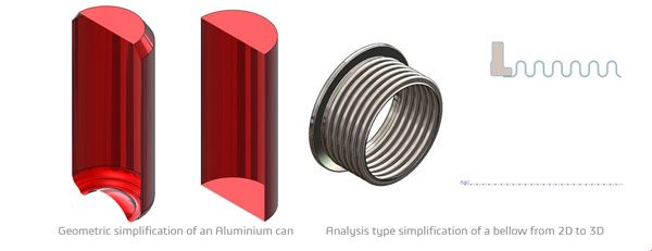
1. Geometric Representation
and Simplification
Geometric simplification is often unavoidable and is
usually necessary for acceptable computation times. It is best practice to
initially use an overly simplified model for any analysis in order to ensure
that the model is behaving as expected. The degree of simplification should
then be reduced: especially in areas of interest in order to get meaningful and
representative results.
Typical simplifications include the removal of features
not important to the analysis – defeaturing. Fillets are a good example of
this. When removed, the mesh will be simpler and therefore will result in
quicker computation times. However, a sharp edge will result in a singularity
so the stresses in the immediate vicinity will be wrong. This is fine if the
stresses in this area are not of interest.
It is also worth noting that defeaturing will often
add/remove material which will affect the stiffness of the model. Again, this
is acceptable if the stiffness in the area of interest is accurate.
Simplification doesn’t have to come in the form of
defeaturing. One of the best ways to simplify a model is to take advantage of
symmetry or to represent a 3D model as 2D. This can significantly reduce
computation time due to the large reduction of elements needed to discretise
the model.
2. Material Model Definition
SOLIDWORKS has a material library containing a sample of
typical materials. It is sometimes easy to take this for granted as many
dedicated simulation packages do not provide this information. SOLIDWORKS materials
will be more than sufficient for many simulations when used correctly. However,
occasionally, the material model may need to be tweaked or a new material
created from scratch using experimental data if an unusual material is required
or it is used in a special situation. For example, consider the points below:
·
If a material is designed to operate below yield
then a plasticity model is not needed
·
If a fatigue cycle is ‘zero based’ then an S-N
curve for a ‘fully reversed’ cycle may not be representative
·
If a material is to operate in a high
temperature environment then the stress-strain curve should be representative
of that temperature
·
Material definitions are unlikely to account for
imperfections
3. Boundary Conditions
Boundary conditions include: fixtures, loads and
contacts. It is normally the poor idealisation of fixtures that will cause the
biggest error in any simulation. In reality, loads will always have some degree
of eccentricity, fixtures are never rigid and contacts can often have some
degree of slide and friction. Constraining too many degrees of freedom is easy
to do and can result in over stiffening.
For example, we know from Euler that the type of fixtures
applied to struts under a buckling condition can result in very different
critical buckling loads. These loads can be calculated by hand in the two cases
below: Fixed-Fixed and Pinned-Pinned. Note that the respective descriptions of
each buckling condition do not correlate to an exact representation of fixtures
applied; the degrees of freedom constrained are stated at each end of the strut
and the respective differences shown in red.
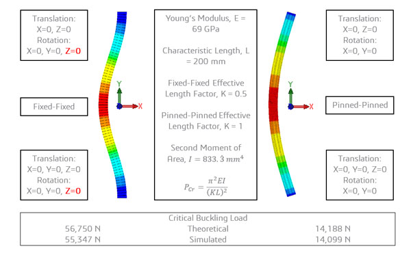
The difference in critical buckling load is significantly
different between the two buckling conditions, yet this difference is entirely
due to how just one degree of freedom has been handled at each end of the beams.
This is an extreme case but it is easy to see how important it is to consider
every degree of freedom when constraining and loading your model.
Again, consider the thoughts below:
·
Is it appropriate to fix an entire face when it
is the edges that are welded in place?
·
Does the applied load always act in the same
direction or does it follow the deformation of the geometry?
·
Using remote mass / distributed mass is a great
way to simplify a model for analysis but they will not account for the
additional stiffness that would have been provided by the missing geometry –
only mass.
Conclusion
The main point to take home from this blog is to always
be perceptive when transitioning between reality and the mathematical model. It
is easy to make quick decisions in the set-up of a study when it should really
be the part of the analysis where most time is spent. By ensuring that simplification
has been achieved intelligently, and that the material model and the boundary
conditions are accurate, the degree of idealisation error will be minimised.
By Tom McHale
Elite Applications Engineer
|
1 / 1 / 0 Регистрация: 16.04.2016 Сообщений: 12 |
|
|
1 |
|
|
08.03.2017, 17:29. Показов 9789. Ответов 5
Добрый день! Необходимо исследовать деформацию и распределение напряжений в чугунной детали под действием силы. Выполнив «Запуск» программа начинает создание сетки и заканчивается ошибкой «Создание сетки не удалось. Прерывание анализа». Что делать???
0 |

|
1473 / 627 / 139 Регистрация: 17.12.2013 Сообщений: 2,380 |
|
|
08.03.2017, 17:59 |
2 |
|
Если сетка не строиться, значит не правильно настроены ее параметры.
0 |
|
1 / 1 / 0 Регистрация: 16.04.2016 Сообщений: 12 |
|
|
08.03.2017, 18:05 [ТС] |
3 |
|
А где их настраивать? В материале?
0 |
|
1473 / 627 / 139 Регистрация: 17.12.2013 Сообщений: 2,380 |
|
|
08.03.2017, 18:13 |
4 |
|
В настройках расчета. Simulation — Сетка — Создать.
0 |
|
1 / 1 / 0 Регистрация: 16.04.2016 Сообщений: 12 |
|
|
08.03.2017, 18:26 [ТС] |
5 |
|
А что значит «В Вашей модели не была найдена интерференция» ?
0 |
|
1473 / 627 / 139 Регистрация: 17.12.2013 Сообщений: 2,380 |
|
|
08.03.2017, 18:28 |
6 |
|
Интерференция это пресечение тел в модели, если она не найдена значит пересечений нет
0 |
INTELLIGENT WORK FORUMS
FOR ENGINEERING PROFESSIONALS
Contact US
Thanks. We have received your request and will respond promptly.
Log In
Come Join Us!
Are you an
Engineering professional?
Join Eng-Tips Forums!
- Talk With Other Members
- Be Notified Of Responses
To Your Posts - Keyword Search
- One-Click Access To Your
Favorite Forums - Automated Signatures
On Your Posts - Best Of All, It’s Free!
*Eng-Tips’s functionality depends on members receiving e-mail. By joining you are opting in to receive e-mail.
Posting Guidelines
Promoting, selling, recruiting, coursework and thesis posting is forbidden.
Students Click Here
SolidWorks Simulation failsSolidWorks Simulation fails(OP) I’m new to this board and to SolidWorks Simulation. I did the static analysis tutorial, and that study worked perfectly. Then I tried a test I-beam to see, how the results of SW Simulation compared to regular non FEA calculations, but now I can’t seem to get it to run the study. I tried with an even simpler system, but the same error pops up (see screenshot below).
The meshing seems to work fine. What puzzles me the most is that I could run the study in the tutorial but not this one. My school has supplied the software license. Does anyone know, what might be wrong with my model? (I am aware that this topic is similar to http://www Red Flag SubmittedThank you for helping keep Eng-Tips Forums free from inappropriate posts. |
Resources
Learn methods and guidelines for using stereolithography (SLA) 3D printed molds in the injection molding process to lower costs and lead time. Discover how this hybrid manufacturing process enables on-demand mold fabrication to quickly produce small batches of thermoplastic parts. Download Now
Examine how the principles of DfAM upend many of the long-standing rules around manufacturability — allowing engineers and designers to place a part’s function at the center of their design considerations. Download Now
Metal 3D printing has rapidly emerged as a key technology in modern design and manufacturing, so it’s critical educational institutions include it in their curricula to avoid leaving students at a disadvantage as they enter the workforce. Download Now
This ebook covers tips for creating and managing workflows, security best practices and protection of intellectual property, Cloud vs. on-premise software solutions, CAD file management, compliance, and more. Download Now |


Join Eng-Tips® Today!
Join your peers on the Internet’s largest technical engineering professional community.
It’s easy to join and it’s free.
Here’s Why Members Love Eng-Tips Forums:
 Talk To Other Members
- Notification Of Responses To Questions
- Favorite Forums One Click Access
- Keyword Search Of All Posts, And More…
 Talk To Other Members
Register now while it’s still free!
Already a member? Close this window and log in.
Join Us Close