|
|
Ремонт SINUMERIK 808D
 Компания «Кернел» производит ремонт ЧПУ с 2002 года. За это время мы накопили колоссальный опыт в том числе опыт в ремонте SINUMERIK 808D такого известного производителя как SIEMENS. Ремонт подобной промышленной электроники ответственное и сложное занятие, требующие максимальной отдачи, профессионализма и максимально полной материальной базе.
Ремонт SINUMERIK 808D в производится как в сервисном центре, так и с выездом специалиста на территорию заказчика. SINUMERIK 808D является крайне сложной промышленной электроникой соответственно ремонт SINUMERIK 808D можно доверить только настоящим профессионалам своего дела с богатым опытом работы в данном направлении.
Все специалисты нашего сервисного центра имеют высшее техническое образование, огромный опыт и максимально полную материальную базу включая новейшее высокотехнологичное диагностическое оборудование благодаря чему ремонт SINUMERIK 808D проходит максимально эффективно.
 Инженеры сервисного центра уделяют максимальное внимание к качеству исполнения ремонта, программирования и настройке ЧПУ, не зависимо от производителя данного промышленного оборудования. Именно поэтому мы смело даем гарантию на ремонт SINUMERIK 808D и замененные в процессе ремонта компоненты шесть месяцев.
Особое внимание заслуживает тот факт, что ремонт SINUMERIK 808D в производится исключительно с использованием оригинальных запасных частей, на компонентном уровне с применением высокотехнологичного оборудования, квалифицированным персоналом с инженерным образованием.
Если на вашем производстве появились проблемы с ЧПУ SINUMERIK 808D, которые вы не можете решить самостоятельно, мы всегда рады вам помочь. Обращайтесь в сервисный центр «Кернел». Специалисты нашей компании в минимальные сроки проведут глубокую диагностику ЧПУ и последующий ремонт SINUMERIK 808D в . Оставьте аявку на ремонт ЧПУ используя форму на сайте.
Ошибки SINUMERIK 808D
Сообщения об ошибках SINUMERIK 808D и обработка ошибок
При возникновении ошибок при выполнении циклов выдается сигнал и выполнение цикла прерывается. Кроме того, сообщения циклов выводятся в строке сообщений СЧПУ. Эти сообщения не прерывают выполнение программы. Ошибки с их действием и сообщениями в строке сообщений СЧПУ описаны совместно с описанием конкретных циклов.
Обработка ошибок SINUMERIK 808D в циклах
В циклах генерируются сообщения об ошибках с номерами от 61000 до 62999. Диапазон номеров, в свою очередь, снова делится в соответствии с реакциями на ошибки и критериями отмены. Текст ошибки, который отображается вместе с номером ошибки, предоставляет более подробную информацию о причине ошибки.
|
Номер ошибки |
Критерий сброса |
Реакция на ошибку |
|
61000 … 61999 |
NC_RESET |
Подготовка кадра в СЧПУ прервана |
|
62000 … 62999 |
Кнопка сброса |
Прерывается подготовка кадра; цикл может быть продолжен нажатием следующей клавиши на MCP после удаления ошибки: |
Обзор ошибок циклов SINUMERIK 808D
Номера ошибок классифицируются следующим образом:
|
6 |
_ |
Х |
_ |
_ |
- X=0 Общие ошибки циклов
- X=1 Ошибки, возникшие при сверлении, фрезеровании
- X=6 Ошибки, возникшие в циклах токарной обработки
Сообщения циклов SINUMERIK 808D
Сообщения циклов выводятся в строке сообщений СЧПУ. Эти сообщения не прерывают выполнение программы. Сообщения предоставляют информацию относительно поведения циклов хода обработки и, как правило, хранятся за пределами рабочей операции или до конца цикла. Пример сообщения: «Глубина: в соответствии со значением относительной глубины» для всех циклов сверления.
Все ошибки SINUMERIK 808D описаны в руководстве пользователя, которое вы можете скачать с нашего сайта в удобном формате- pdf.
Скачать руководство пользователя (диагностика) SINUMERIK 808D мануал.pdf
Устранение причины ошибки и ее сброс на станке оснащенным системой ЧПУ позволит в кратчайшие сроки возобновить работу. К сожалению не все ошибки можно исправить самостоятельно, некоторые ошибки SINUMERIK 808D возможно исправить только в специализированных сервисных центрах.
SINUMERIK 808D программирование
 На ряду с ремонтом, специалисты сервисного центра «Кернел» выполняют программирование SINUMERIK 808D и настройку параметров системы ЧПУ. Подобную услугу мы оказываем не только на территории сервисного центра, также инженер компании может выполнить программирование SINUMERIK 808D на территории заказчика.
Настройка параметров, программирование SINUMERIK 808D является заключительным звеном в процессе ремонта ЧПУ и требует профессионального подхода. Именно финальный этап программирования SINUMERIK 808D наглядно покажет качество выполненного ремонта SINUMERIK 808D.
К слову, мы уделяем особое внимание качеству и смело даем гарантию на все выполненные ремонтно-восстановительные работы шесть месяцев, гарантия так же распространяется на запасные части, которые были заменены в процессе ремонта.
Хочется обратить внимание на то, что мы стараемся провести ремонт и программирование SINUMERIK 808D в максимально сжатые сроки, тем самым минимизируем простой дорогостоящего промышленного оборудования.
Дополнительно можно скачать руководство по программированию SINUMERIK 808D в формате- pdf
Скачать руководство пользователя (программирование) SINUMERIK 808D мануал.pdf
SINUMERIK 808D ввод в эксплуатацию
 Инженеры сервисного центра «Кернел» не только выполняют качественный ремонт SINUMERIK 808D и программирование ЧПУ в . Так же мы предоставляем услугу запуска в эксплуатацию оборудования от стадии проектирования до выпуска первой продукции.
Именно этап запуска в эксплуатацию SINUMERIK 808D отвечает за долгий и безаварийный процесс работы промышленного оборудования, тем самым позволяя получить максимальную прибыль и сэкономить на незапланированном ремонте.
По-настоящему качественный ввод в эксплуатацию SINUMERIK 808D может выполнить только высококвалифицированный специалист с богатым опытом работы в данном направлении. Найти подобного специалиста достаточно сложно, но, если вы обращаетесь в наш сервисный центр вам не придется об этом думать.
В нашей команде работают исключительно профессионалы своего дела, а за время существования нашей компании мы ввели в эксплуатацию не одну сотню систем ЧПУ в том числе и SINUMERIK 808D, с каждым разом получая и накапливая драгоценный опыт.
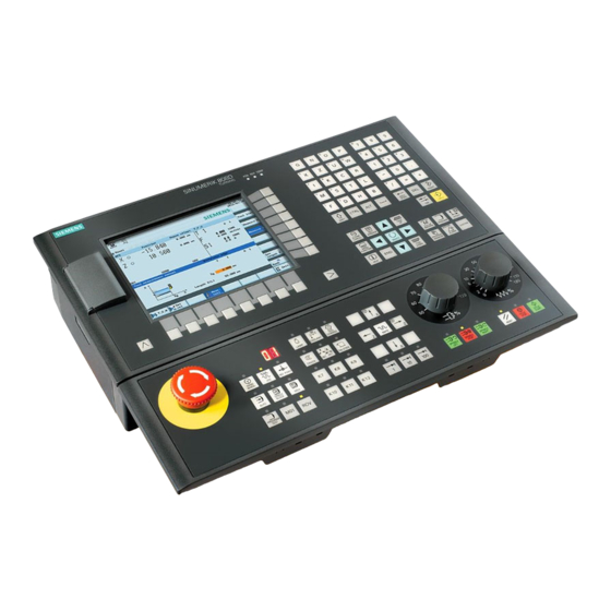
О SINUMERIK 808D
SINUMERIK 808D объединяет в себе качественно сконфигурированную систему ЧПУ предназначенную для работы на фрезерных и токарных станках.
Пример сборки для токарной обработки с помощью SINUMERIK 808D ADVANCED T
|
Описание |
Колл-во |
Артикул |
|
SINUMERIK CNC |
||
|
SINUMERIK 808D ADVANCED T PPU 160.3 vertical, English layout |
1 |
6FC5370-2BT03-0AA0 |
|
SINUMERIK 808D MCP vertical, with handwheel slot, English layout |
1 |
6FC5303-0AF35-3AA0 |
|
Stabilized power supply, SITOP PSU200M 24 V DC, 5 A |
1 |
6EP1333-3BA10 |
|
RS422 (TTL) incremental encoder, 1024 S/R |
1 |
6FX2001-2EB02 |
|
Spring disk coupling, shaft diameter 6 mm/6 mm |
1 |
6FX2001-7KF10 |
|
Clamp strap for encoders with Synchro flange |
3 |
6FX2001-7KP01 |
|
Pre-assembled bus cable PPU 160.3 – SINAMICS V70, length 5 m |
1 |
6FC5548-0BA20-1AF0 |
|
Pre-assembled bus cable SINAMICS V70 – SINAMICS V70, length 0.25 m |
2 |
6FC5548-0BA20-1AA2 |
|
Pre-assembled signal cable PPU 160.3 – handwheel, length 1 m |
1 |
6FX8002-2BB01-1AB0 |
|
Pre-assembled signal cable PPU 160.3 – incremental spindle encoder (TTL), length 5 m |
1 |
6FX8002-2CD01-1AF0 |
|
SINAMICS V70 |
||
|
SINAMICS V70, Irated 3.0 A |
1 |
6SL3210-5DE13-5UA0 |
|
SINAMICS V70, Irated 5.3 A |
1 |
6SL3210-5DE17-8UA0 |
|
SINAMICS V70 spindle1), Irated 19.6 A |
1 |
6SL3210-5DE22-0UA0 |
|
Pre-assembled signal cable SINAMICS V70 – absolute encoder in SIMOTICS S-1FL6 feed motor, length 5 m |
2 |
6FX3002-2DB10-1AF0 |
|
Pre-assembled power cable 4 × 1.5 mm2 |
2 |
6FX3002-5CL02-1AF0 |
|
Pre-assembled power cable 4 × 2.5 mm2 |
1 |
6FX3002-5CL12-1AF0 |
|
Pre-assembled brake cable SINAMICS V70 – brake in SIMOTICS S-1FL6 feed motor with holding brake, length 5 m |
1 |
6FX3002-5BL03-1AF0 |
|
Pre-assembled signal cable SINAMICS V70 – incremental encoder in M-1PH1, length 5 m |
1 |
6FX3002-2CT30-1AF0 |
|
Power cable 4 × 4 mm2, sold by the meter, (optional)2) SINAMICS V70 – SIMOTICS M-1PH1 main spindle motor, length 30 m |
1 |
6FX5008-1BB31-1DA0 |
|
SIMOTICS motors |
||
|
SIMOTICS S-1FL6 feed motor, 4 Nm, 2000 rpm, absolute encoder, plain shaft, without holding brake |
1 |
1FL6061-1AC61-2LG1 |
|
SIMOTICS S-1FL6 feed motor, 11 Nm, 2000 rpm, absolute encoder, plain shaft, with holding brake |
1 |
1FL6066-1AC61-2LH1 |
|
SIMOTICS M-1PH1 main spindle spindle motor, 53 Nm, 1000 rpm, incremental encoder, plain shaft |
1 |
1PH1105-1LD10-0GA0 |
Пример сборки для фрезерования с помощью SINUMERIK 808D ADVANCED M
|
Описание |
Колл-во |
Артикул |
|
SINUMERIK CNC |
||
|
SINUMERIK 808D ADVANCED M PPU 161.3 horizontal, English layout |
1 |
6FC5370-2AM03-0AA0 |
|
SINUMERIK 808D MCP horizontal, English layout |
1 |
6FC5303-0AF35-0AA0 |
|
Electronic handwheel, with front plate 120 mm × 120 mm, with setting wheel, 5 V DC, RS 422 |
1 |
6FC9320-5DB01 |
|
Terminal strip converter 50-pole |
1 |
6EP5406-5AA00 |
|
Cable set, 50-pole ribbon cable, with insulation displacement connectors, 50-pole |
1 |
6EP5306-5BG00 |
|
Stabilized power supply, SITOP PSU200M 24 V DC, 5 A |
1 |
6EP1333-3BA10 |
|
Pre-assembled bus cable PPU 161.3 – SINAMICS V70, length 5 m |
1 |
6FC5548-0BA20-1AF0 |
|
Pre-assembled bus cable SINAMICS V70 – SINAMICS V70, length 0.25 m |
2 |
6FC5548-0BA20-1AA2 |
|
Pre-assembled signal cable PPU 161.3 – handwheel, length 1 m |
1 |
6FX8002-2BB01-1AB0 |
|
Pre-assembled signal cable PPU 161.3 – incremental spindle encoder (TTL), length 7 m |
1 |
6FX8002-2CD01-1AH0 |
|
SINAMICS V70 |
||
|
SINAMICS V70, Irated 4.6 A |
2 |
6SL3210-5DE16-0UA0 |
|
SINAMICS V70, Irated 7.8 A |
1 |
6SL3210-5DE21-0UA0 |
|
SINAMICS V70 spindle1), Irated 19.6 A |
1 |
6SL3210-5DE22-0UA0 |
|
Pre-assembled signal cable SINAMICS V70 – incremental encoder in SIMOTICS S-1FL6 feed motor, length 10 m |
3 |
6FX3002-2CT12-1BA0 |
|
Pre-assembled power cable 4 × 2.5 mm2 |
3 |
6FX3002-5CL12-1BA0 |
|
Pre-assembled signal cable SINAMICS V70 – brake in SIMOTICS S-1FL6 feed motor, length 10 m |
1 |
6FX3002-5BL03-1BA0 |
|
Pre-assembled signal cable SINAMICS V70 – incremental encoder in M-1PH1, length 10 m |
1 |
6FX3002-2CT30-1BA0 |
|
Power cable 4 × 4 mm2, sold by the meter, (optional)2) SINAMICS V70 – SIMOTICS M-1PH1 main spindle motor, length 30 m |
1 |
6FX5008-1BB31-1DA0 |
|
SIMOTICS motors |
||
|
SIMOTICS S-1FL6 feed motor, 8 Nm, 2000 rpm, incremental encoder, plain shaft, without holding brake |
2 |
1FL6064-1AC61-2AG1 |
|
SIMOTICS S-1FL6 feed motor, 15 Nm, 2000 rpm, incremental encoder, plain shaft, with holding brake |
1 |
1FL6067-1AC61-2AH1 |
|
SIMOTICS M-1PH1 main spindle motor, 48 Nm, 1500 rpm, incremental encoder, plain shaft |
1 |
1PH1105-1LF12-0GA0 |
 1) Выбор тормозного резистора см. В приводе шпинделя SINAMICS V70.
2) Перечисленные выше 30-метровые силовые кабели (необработанные) можно выбрать для использования с двигателями 1PH1. Вы должны собрать кабель питания с разъемами самостоятельно. Вы также можете выбрать сторонний кабель питания в соответствии с конфигурацией системы.
SINUMERIK 808D выполнен в двух вариантах:
- Горизонтальное исполнение (SINUMERIK 808D PPU 261.3/PPU 281.3);
- Вертикальное исполнение (SINUMERIK 808D PPU 260.3/PPU 280.3).
SINUMERIK 808D это моноблочная система ЧПУ, объединяющая в одном устройстве все компоненты СЧПУ:
- ЧПУ, PLC, HMI;
- полная клавиатура СЧПУ;
- регулятор для 6 приводов.
Двигатели могут подключаться напрямую через DRIVE-CLiQ к цифровой приводной системе. В комбинации с модульным исполнением приводной системы SINAMICS S120 получается простая и надежная конструкция с минимальным объемом межкомпонентных соединений.
Обзор соединений SINUMERIK 808D


Точно подобранный набор функций системы ЧПУ для стандартных токарных и фрезерных станков отвечает всем требованиям мелко- и крупносерийного производства. Специально подобранные системные параметры для токарной и фрезерной технологии позволяют значительно сократить расходы на ввод станка в эксплуатацию.
Моноблочная система ЧПУ крепится с задней стороны с помощью специальных элементов, входящих в объем поставки.
Линейка промышленной электроники, которую восстанавливают специалисты сервисного центра «Кернел» не имеет ограничений, мы выполняем качественный ремонт промышленной электроники и оборудования абсолютно любых производителей не зависимо от года выпуска и наличия технической документации.
Ниже приведен далеко не полный список ЧПУ SINUMERIK 808D ремонт которых предлагает наш сервисный центр.
|
6FC5370-2BM03-0AA0 6FC5370-2BM03-0CA0 6FC5370-2BT03-0AA0 6FC5370-2BT03-0CA0 |
6FC5370-3BM03-0AA0 6FC5370-3BM03-0CA0 6FC5370-3BT03-0AA0 6FC5370-3BT03-0CA0 |
|
6FC5303-0AF35-0AA0 SINUMERIK 808D Machine control panel 6FC5303-0AF35-2AA0 SINUMERIK 808D Machine control panel vertical 6FC5303-0AF35-3AA0 SINUMERIK 808D Machine control panel vertical |
Оставить заявку на ремонт или программирование SINUMERIK 808D
Оставить заявку на ремонт или программирования SINUMERIK 808D в можно с помощью специальной формы, которая вызывается нажатием одноименной кнопки в верхней части страницы. Все вопросы, связанные с ремонтом SINUMERIK 808D в вы можете задать нашим менеджерам. Связаться с ними можно несколькими способами:

- Заказав обратный звонок (кнопка в правом нижнем углу сайта)
- Посредством чата (кнопка расположена с левой стороны сайта)
- Позвонив по номеру телефона:
- +7(8482) 79-78-54;
- +7(8482) 55-96-39;
- +7(917) 121-53-01
- Написав на электронную почту: 89171215301@mail.ru
Вот далеко не полный список производителей промышленной электроники и оборудования, ремонтируемой в нашей компании.
- Manuals
- Brands
- Siemens Manuals
- Control Unit
- SINUMERIK 808D
- Diagnostic manual
-
Contents
-
Table of Contents
-
Bookmarks
Quick Links
T able of contents
Tables
Figures
SINUMERIK
SINUMERIK 808D ADVANCED
Diagnostics Manual
Diagnostics Manual
08/2013
6FC5398-6DP10-0BA1
Preface
Introduction
Operating in the «SYSTEM»
area
SINUMERIK 808D
ADVANCED alarms
System responses
SINAMICS V70 alarms
Data backup
Updating software
Appendix A
1
2
3
4
5
6
7
A
Related Manuals for Siemens SINUMERIK 808D ADVANCED
Summary of Contents for Siemens SINUMERIK 808D ADVANCED
-
Page 1
T able of contents Tables Figures 1 Introduction Operating in the «SYSTEM» 2 SINUMERIK area SINUMERIK 808D 3 SINUMERIK 808D ADVANCED ADVANCED alarms Diagnostics Manual 4 System responses 5 SINAMICS V70 alarms Diagnostics Manual 6 Data backup 7 Updating software A … -
Page 2
Note the following: WARNING Siemens products may only be used for the applications described in the catalog and in the relevant technical documentation. If products and components from other manufacturers are used, these must be recommended or approved by Siemens. Proper transport, storage, installation, assembly, commissioning, operation and maintenance are required to ensure that the products operate safely and without any problems. -
Page 3: Table Of Contents
Configuring the Ethernet connection ………………46 2.12 Defining the maintenance planner………………… 52 2.13 Alarm display ……………………..53 SINUMERIK 808D ADVANCED alarms ………………..55 System error alarms ……………………55 NCK alarms ……………………..55 Drive alarms ……………………..333 PLC alarms……………………..342 Cycle alarms……………………..346…
-
Page 4
Table of contents PLC user alarms ……………………434 System responses ………………………435 System reactions to SINUMERIK alarms …………….435 Cancel criteria for alarms………………….438 SINAMICS V70 alarms ……………………..439 Overview of alarms ……………………439 Common faults and alarms…………………. 441 Data backup ……………………….453 Overview of internal/external data backup……………. -
Page 5: Preface
Preface Applicable products This manual is applicable to the following control systems: Control system Software version SINUMERIK 808D ADVANCED T (Turning) V4.6 SINUMERIK 808D ADVANCED M (Milling) V4.6 Documentation components and target groups Component Recommended target group User documentation Programming and Operating Manual (Turning)
-
Page 6
EC Declaration of Conformity The EC Declaration of Conformity for the EMC Directive can be found on the Internet at http:/ /support.automation.siemens.com Here, enter the number 15257461 as the search term or contact your local Siemens office. Diagnostics Manual Diagnostics Manual, 08/2013, 6FC5398-6DP10-0BA1… -
Page 7: Introduction
Introduction Structure of the Diagnostics Manual NCK / PLC alarms The descriptions for the alarms can be found in the chapters: • NCK alarms (Page 55) • Drive alarms (Page 333) • PLC alarms (Page 342) • Cycle alarms (Page 346) •…
-
Page 8: Alarm Number Ranges
Introduction 1.2 Alarm number ranges Action list The actions described in the NCK alarm texts («Action %…») are explained in the following Chapter: See Chapter: Cancel criteria for alarms (Page 438) Specification «%» The specification «%» represents variables for an online parameter that is replaced on the control with a corresponding value.
-
Page 9: Operating In The «System» Area
Operating in the «SYSTEM» area Operating area overview Softkey functions Press the keys on the PPU to enter the following operating area. This operating area includes functions required for parameterizing and analyzing the NCK, the PLC and the drive. The start screen displays the machine configuration data and softkeys available.
-
Page 10: Setting Start-Up Function
Operating in the «SYSTEM» area 2.2 Setting start-up function An extended horizontal softkey bar can be accessed via this key on the PPU. Two extended horizontal softkeys are provided: Views the service information Defines the maintenance planner Setting start-up function Functionality This softkey allows you to choose the NC, PLC, and drive start-up modes.
-
Page 11
Operating in the «SYSTEM» area 2.2 Setting start-up function Selecting a PLC restart mode Proceed through the following steps to select a PLC restart mode: Select the desired operating area. Press this softkey. Press this softkey to open the window for selecting the PLC start-up mode. -
Page 12: Setting System Machine Data
Operating in the «SYSTEM» area 2.3 Setting system machine data Select all drives or one specific drive using the cursor keys. Press this softkey to confirm your selection. The selected drive(s) will restart in the mode selected. Setting system machine data Machine data structure Any changes in the machine data have a substantial influence on the machine.
-
Page 13
2.3 Setting system machine data Setting basic machine data The SINUMERIK 808D ADVANCED provides two easy-to-use data lists for beginner users. You can use the basic data list for quick access of common NC data and drive data. Setting basic NC data In the basic NC data list, the general, axis, and channel MD are integrated in one screen. -
Page 14
Operating in the «SYSTEM» area 2.3 Setting system machine data Setting basic drive data Several common drive parameters are provided in the basic drive data list. Proceed through the following steps to set the basic drive data: Select the desired operating area. Enter the window of basic drive data through the following softkey operations: →… -
Page 15
Operating in the «SYSTEM» area 2.3 Setting system machine data Setting machine data in expert list All machine data are divided into five groups described as follows. Setting general machine data Select the desired operating area. Enter the window of general machine data through the following softkey operations: →… -
Page 16
Operating in the «SYSTEM» area 2.3 Setting system machine data Setting channel-specific machine data Select the desired operating area. Enter the window of channel-specific machine data through the following softkey operations: → → Locate the machine data which you desire to set. You can also search for an MD using the following softkeys: Searches for the desired number or the name (or a part of the name) of the machine data… -
Page 17
Operating in the «SYSTEM» area 2.3 Setting system machine data Setting axis-specific machine data Select the desired operating area. Enter the window of axis-specific machine data through the following softkey operations: → → Locate the machine data which you desire to set. You can also search for an MD using the following softkeys: Searches for the desired number or the name (or a part of the name) of the machine data… -
Page 18
Operating in the «SYSTEM» area 2.3 Setting system machine data Setting drive machine data Select the desired operating area. Enter the window of drive machine data through the following softkey operations: → → Locate the machine data which you desire to set. You can also search for an MD using the following softkeys: Searches for the desired number or the name (or a part of the name) of the machine data… -
Page 19
To learn more functions regarding the servo trace, refer to the Section «Servo trace (Page 40)». References You can find a description of the machine data in the following manufacturers’ documents: SINUMERIK 808D ADVANCED Parameter Manual SINUMERIK 808D ADVANCED Function Manual Diagnostics Manual Diagnostics Manual, 08/2013, 6FC5398-6DP10-0BA1… -
Page 20: Configuring The Drive System
Operating in the «SYSTEM» area 2.4 Configuring the drive system Configuring the drive system Pressing this softkey opens the drive system configuration window where you can configure the connected drives and motors. Before starting the drive and motor configuration, you must ensure the Drive Bus addresses are properly set (p0918) via the drive BOPs according to the instructions in the window above.
-
Page 21
Operating in the «SYSTEM» area 2.4 Configuring the drive system Press this softkey to enter the motor configuration window. Select the right motor ID according to the motor rating plate with the cursor keys. Press this softkey to confirm your selection. The selected motor information then displays in the drive list. -
Page 22: Plc Diagnostics
Operating in the «SYSTEM» area 2.5 PLC diagnostics PLC diagnostics Functionality A PLC user program consists to a large degree of logical operations to realize safety functions and to support process sequences. These logical operations include the linking of various contacts and relays. As a rule, the failure of a single contact or relay results in a failure of the whole system/installation.
-
Page 23: Screen Layout
Operating in the «SYSTEM» area 2.5 PLC diagnostics ⑥ ⑬ Displays the list of cross references Displays all symbolic identifiers used in the selected network ⑦ Displays the logic and graphic information of the selected program block 2.5.1 Screen layout Legend Display Meaning…
-
Page 24: Operating Options
Operating in the «SYSTEM» area 2.5 PLC diagnostics 2.5.2 Operating options In addition to the softkeys and the navigation keys, this area provides still further key combinations. Hot keys The cursor keys move the focus over the PLC user program. When reaching the window borders, it is scrolled automatically.
-
Page 25
Operating in the «SYSTEM» area 2.5 PLC diagnostics Key combination Action To the last field of the subroutine Opens the previous program block in the same window Opens the next program block in the same window The function of the Select key depends on the position of the input focus. -
Page 26
Operating in the «SYSTEM» area 2.5 PLC diagnostics Searching for operands In big programs, you can use the search function to quickly reach the desired positions. To search for operands, follow these steps: Use this softkey to switch between the absolute and symbolic representation of the operands. -
Page 27: Displaying Information On The Program Blocks
Operating in the «SYSTEM» area 2.5 PLC diagnostics 2.5.3 Displaying information on the program blocks Functionality You can display any logical and graphical information of a program block in the program windows. The program block is one of the components of the PLC user program. Logic information The logics in the ladder diagram (LAD) display the following: •…
-
Page 28: Displaying Cross-References
Operating in the «SYSTEM» area 2.5 PLC diagnostics Select the desired program block and press this softkey to open it. After the selected program block is opened, you can press the following softkeys to switch the display information. Further softkeys are available in the program block window as follows: Displays additional information of the selected program block Displays the table of local variables of the selected…
-
Page 29: Setting The Hmi Display
Operating in the «SYSTEM» area 2.6 Setting the HMI display Setting the HMI display 2.6.1 Setting the date and time At delivery, the system date and time remain at the factory settings, and thus you must manually modify the date and time in the window as follows. Operating sequence Select the desired operating area on the PPU.
-
Page 30: Adjusting The Screen Brightness
Operating in the «SYSTEM» area 2.6 Setting the HMI display 2.6.2 Adjusting the screen brightness You can open the window for adjusting the brightness of the HMI screen through the following operations: → → Press this softkey to increase the brightness of the HMI screen. Press this softkey to decrease the brightness of the HMI screen.
-
Page 31: Managing The System Data
Operating in the «SYSTEM» area 2.7 Managing the system data Managing the system data Overview By pressing this softkey in the system data management operating area, you can enter the window as follows: Three folders and one file are available in this window. You can import/export the subfolders or single files in this window for backup or other customized purposes.
-
Page 32
You can import/export the subfolders or single files in this window for backup or other customized purposes. For more information, refer to the SINUMERIK 808D ADVANCED Function Manual and SINUMERIK 808D ADVANCED Commissioning Manual. Managing the NCK/PLC data Select this folder and press the key to enter. -
Page 33: Creating Commissioning Archives
Operating in the «SYSTEM» area 2.8 Creating commissioning archives Creating commissioning archives Functionality Pressing this softkey allows you to create or restore a start-up or series start-up archive in the following window. Operating sequence Select the desired operating area on the PPU. Press this horizontal softkey to open the start-up archive window.
-
Page 34: Optimizing Drive Performance
Operating in the «SYSTEM» area 2.9 Optimizing drive performance Press this softkey to confirm and the archive information dialog opens. Specify the properties of the archive and press this softkey to start creating the archive file in the selected folder. Optimizing drive performance The control system provides facilities to optimize the performance of each connected drive by automatically modifying the control loop parameters.
-
Page 35
Operating in the «SYSTEM» area 2.9 Optimizing drive performance Press this softkey to return to the main screen of drive optimization. Press this softkey to enter the preparation screen before the optimization. Switch to «JOG» mode, and use the axis traversing keys to move the axis to a safe position. -
Page 36: Viewing The Service Info
Operating in the «SYSTEM» area 2.10 Viewing the service info Views the optimization results of the previous axis Returns to the main screen of drive optimization. In this case, you may optimize the drive again with either new measurements or last measurement results. 2.10 Viewing the service info You can view the service information through the following operations:…
-
Page 37: Action Log
Operating in the «SYSTEM» area 2.10 Viewing the service info 2.10.1 Action log Overview The action log function is provided for service events. The contents of the action log file can only be accessed through a system password on the HMI. Viewing the action log Select the desired operating area.
-
Page 38
Operating in the «SYSTEM» area 2.10 Viewing the service info Settings for the message sending Proceed through the following steps to configure the settings for the message sending: Select the desired operating area. Press this key to view the extended softkeys. Open the service message window through the following softkey operations: →… -
Page 39: Data Backup
Operating in the «SYSTEM» area 2.10 Viewing the service info Press this softkey to save the settings and return to the service message main screen. Press this softkey to cancel and return to the service message main screen. Note To transfer messages via the RS232 interface, the communication settings from the following are used: →…
-
Page 40: Servo Trace
Operating in the «SYSTEM» area 2.10 Viewing the service info 2.10.3 Servo trace Overview An oscilloscope function is provided for the purpose of optimizing the drives. This enables the following graphical representations: • velocity setpoint • contour violation • following error •…
-
Page 41
Operating in the «SYSTEM» area 2.10 Viewing the service info To analyze the result, you can perform the following operations: • Changing and scaling the abscissa and ordinate values • Measuring a value using the horizontal or vertical marker • Measuring the abscissa and ordinate values as a difference between two markers •… -
Page 42: Version/Hmi Details
Operating in the «SYSTEM» area 2.10 Viewing the service info Press this softkey to return after you set the desired marker steps. If the trace exceeds the current screen, press + cursor movement. When a marker reaches the margin of the diagram, the grid automatically appears in the horizontal or vertical direction.
-
Page 43
Operating in the «SYSTEM» area 2.10 Viewing the service info This window displays the version numbers and the date of creation of the individual CNC components. ① ③ Displays the operator programs with the Activates the licensed optional functions version numbers ②… -
Page 44
Press this softkey to open the dialog for entering the license key Enter the license key in the following dialog: Press this softkey to confirm. Activating the options The following optional functions can be purchased for the SINUMERIK 808D ADVANCED control system. • Additional axes •… -
Page 45
For the other options, press the following key to select: Press this softkey to restart the NCK, so that the licensed options are activated. Reference SINUMERIK 808D ADVANCED Function Manual SINUMERIK 808D ADVANCED Commissioning Manual Diagnostics Manual Diagnostics Manual, 08/2013, 6FC5398-6DP10-0BA1… -
Page 46: Configuring The Ethernet Connection
With the tool Access MyMachine P2P (AMM) installed on your PC/PG, you can enable the Ethernet connection between a SINUMERIK 808D ADVANCED control system and a PC/PG. This tool is available in the SINUMERIK 808D ADVANCED Toolbox and is supported by Windows XP/Vista/Win 7.
-
Page 47
Operating in the «SYSTEM» area 2.11 Configuring the Ethernet connection Select the direct connection option in the following dialog and then click this button. An attempt is made to establish a direct connection. If you have not established any authentication data, the following dialog appears: Select the log-on details and enter the corresponding password or alternatively select a key file in the dialog. -
Page 48
Operating in the «SYSTEM» area 2.11 Configuring the Ethernet connection Enter the main screen of the service control options through the following softkey operations: → Press this softkey to enter the window for the network configuration. Note: make sure the following vertical softkey is not selected: Configure the network as required in the following window: You can configure the DHCP with the following key: Note: if you select «No»… -
Page 49
Operating in the «SYSTEM» area 2.11 Configuring the Ethernet connection Select the new network connection option in the following dialog: This dialog can also be called with the button from the toolbar. The dialog for setting the new network connection appears. Assign the parameters for a new network connection in this dialog: Select the following button to save the settings: Select the following button and the AMM tool connects to the control… -
Page 50
Operating in the «SYSTEM» area 2.11 Configuring the Ethernet connection Creating and connecting a network drive Proceed as follows to create and connect a network drive: Share a directory on your local disk on your PC/PG. Select the desired operating area on the PPU. Press this key to view the extended softkeys. -
Page 51
Operating in the «SYSTEM» area 2.11 Configuring the Ethernet connection Press this softkey to establish the server connection and assign the local shared directory to the network drive. You can disconnect a selected network drive using the following softkey: After you connect a network drive successfully, you may open it directly on the PPU using the following softkey either in the system data management operating area or in the program management operating area:… -
Page 52: Defining The Maintenance Planner
Operating in the «SYSTEM» area 2.12 Defining the maintenance planner 2.12 Defining the maintenance planner Overview This part introduces how to define the maintenance planner. You can enter the maintenance planner main screen through the following operations: → → The maintenance planner window displays the position, task description, interval, first warning time, number of warnings, etc.
-
Page 53: Alarm Display
Operating in the «SYSTEM» area 2.13 Alarm display 2.13 Alarm display Softkey functions Press this key on the PPU to open the alarm window. You can check the NC and drive alarms using the softkeys. PLC alarms are not sorted. ①…
-
Page 54
Operating in the «SYSTEM» area 2.13 Alarm display Diagnostics Manual Diagnostics Manual, 08/2013, 6FC5398-6DP10-0BA1… -
Page 55: Sinumerik 808D Advanced Alarms
This alarm is also caused by PLC stop. (PLC stop with programming tool, PLC stop by commissioning switch, PLC stop by alarm) If none of these cases applies, place a support request with the error text under: http://www.siemens.com/automation/ support-request Program Switch control OFF — ON.
-
Page 56
$MN_PLC_RUNNINGUP_TIMEOUT must be checked and adapted to the first OB1 cycle. — Determine the cause of error in the PLC (loop or stop in the user program) and eliminate it. Place a support request with the error text under: http://www.siemens.com/automation/support-request Program Switch control OFF — ON. -
Page 57
SINUMERIK 808D ADVANCED alarms 3.2 NCK alarms 2900 Reboot is delayed Definitions: This alarm indicates a delayed reboot. This alarm only occurs when reboot was carried out by the HMI and MD10088 $MN_REBOOT_DELAY_TIME was set greater than zero. The alarm can be suppressed with MD11410 $MN_SUPPRESS_ALARM_MASK Bit 20. -
Page 58
SINUMERIK 808D ADVANCED alarms 3.2 NCK alarms Definitions: Only axes that have been activated in the channel by MD20070 $MC_AXCONF_MACHAX_USED [kx]=m may be declared as geometry axes, transformation axes or orientation axes in MD20050 $MC_AXCONF_GEOAX_ASSIGN_TAB [gx]=k. This also applies to MD22420 $MC_FGROUP_DEFAULT_AXES (gx: Geometry axis index, kx: Channel axis index, k: Channel axis no., m: Machine axis no.). -
Page 59
SINUMERIK 808D ADVANCED alarms 3.2 NCK alarms Example: — CHANDATA(2) — $MC_AXCONF_MACHAX_USED[0] = 7 — $MC_AXCONF_MACHAX_USED[1] = 8 — $MC_AXCONF_MACHAX_USED[2] = 0 — $MC_AXCONF_MACHAX_USED[3] = 3 — $MC_AXCONF_MACHAX_USED[4] = 2 — $MC_AXCONF_MACHAX_USED[5] = 0 — $MC_AXCONF_MACHAX_USED[6] = 1 — $MC_AXCONF_MACHAX_USED[7] = 0 This channel uses the five machine axes 1, 2, 3, 8, 7, i.e. -
Page 60
SINUMERIK 808D ADVANCED alarms 3.2 NCK alarms Definitions: When determining a name in the NCK tables (arrays) for: machine axes, Euler angles, direction vectors, normal vectors, interpolation parameters and intermediate point coordinates, one of the following syntax rules for the identifier… -
Page 61
SINUMERIK 808D ADVANCED alarms 3.2 NCK alarms Program Switch control OFF — ON. Continuation: 4020 Identifier %1 used several times in machine data %2 Parameters: %1 = String: Name of identifier %2 = String: MD identifier Definitions: When determining a name in the NCK tables (arrays) for: machine axes, Euler angles, direction vectors, normal vectors, interpolation parameters and intermediate point coordinates, an identifier has been used that already exists in the control. -
Page 62
SINUMERIK 808D ADVANCED alarms 3.2 NCK alarms 4032 [Channel %1: ] Wrong identifier for facing axis in %2 Parameters: %1 = Channel number %2 = String: MD identifier Definitions: According to the axis configuration in MD20150 $MC_GCODE_RESET_VALUES or MD20100 $MC_DIAMETER_AX_DEF, a facing axis identifier is expected at the specified location. -
Page 63
SINUMERIK 808D ADVANCED alarms 3.2 NCK alarms Definitions: Renaming of an NC code was not possible for one of the following reasons: — The old identifier does not exist — The new identifier lies in another type range. NC codes/keywords can be reconfigured via machine data as long as the type range is not abandoned. -
Page 64
SINUMERIK 808D ADVANCED alarms 3.2 NCK alarms Remedy: Restart the control. Program Switch control OFF — ON. Continuation: 4070 Normalizing machine data has been changed Definitions: The control uses internal physical units (mm, degrees, s, for paths, velocities, acceleration, etc.). During programming or data storage, some of these values are input and output using different units (rev./min, m/s2, etc.). -
Page 65
SINUMERIK 808D ADVANCED alarms 3.2 NCK alarms Definitions: On executing a TOA file or when writing data from the part program an attempt has been made to write data with a higher protection level than the access authorization currently set in the control. The data in question have not been written and program execution is continued without hindrance. -
Page 66
SINUMERIK 808D ADVANCED alarms 3.2 NCK alarms 2. MD10910 $MN_INDEX_AX_POS_TAB_1 or MD10930 $MN_INDEX_AX_POS_TAB_2: the contents of the displayed tables are incorrect. — The entered positions must be arranged in increasing size. — A particular position must not be set more than once. -
Page 67
SINUMERIK 808D ADVANCED alarms 3.2 NCK alarms 4112 Servo cycle changed to %1 ms Parameters: %1 = String (new servo cycle time) Definitions: For PROFIBUS/PROFINET only: MD10060 $POSCTRL_SYSCLOCK_TIME_RATIO has been modified because of the modified DP cycle in the SDB (MD10050 $SYSCLOCK_CYCLE_TIME). -
Page 68
SINUMERIK 808D ADVANCED alarms 3.2 NCK alarms MD10718 $MN_M_NO_FCT_CYCLE_PAR contains an invalid array index of MD10715 $MN_M_NO_FCT_CYCLE[n]. Currently, the values 0 to 9 are permissible. The affected machine data is reset to the default value -1. This deactivates the function. -
Page 69
SINUMERIK 808D ADVANCED alarms 3.2 NCK alarms 4180 Invalid M function number assigned to enable ASUP Definitions: An invalid M function number has been assigned for activation of ASUP. An illegal M number has been assigned in MD10804 $MN_EXTERN_M_NO_SET_INT or MD10806 $MN_EXTERN_M_NO_DISABLE_INT for the configuration of the M number range for activation/deactivation of the interrupt program. -
Page 70
SINUMERIK 808D ADVANCED alarms 3.2 NCK alarms NC Start disable in this channel. Interface signals are set. Alarm display. NC Stop on alarm. Remedy: Check the specified machine data and create a unique assignment of M auxiliary function numbers. Program Switch control OFF — ON. -
Page 71
SINUMERIK 808D ADVANCED alarms 3.2 NCK alarms Remedy: Please inform the authorized personnel/service department. Remove rotary axis declaration for this machine axis. For this purpose, the geometry axis index for the displayed geometry axis must be determined by means of MD20060 $MC_AXCONF_GEOAX_NAME_TAB. -
Page 72
SINUMERIK 808D ADVANCED alarms 3.2 NCK alarms 4225 [Channel %1: ] Axis %2 declaration as rotary axis missing Parameters: %1 = Channel number %2 = Axis name, axis number Definitions: The modulo functionality requires a rotary axis (positions in [deg]). -
Page 73
SINUMERIK 808D ADVANCED alarms 3.2 NCK alarms Interface signals are set. Alarm display. NC Stop on alarm. Remedy: Please inform the authorized personnel/service department. Correct machine data. Activate required inputs/outputs via MDs: MD10350 $MN_FASTIO_DIG_NUM_INPUTS MD10360 $MN_FASTIO_DIG_NUM_OUTPUTS MD10300 $MN_FASTIO_ANA_NUM_INPUTS MD10310 $MN_FASTIO_ANA_NUM_OUTPUTS Activation of fast inputs/outputs does not require the corresponding hardware configuration to be available at the control. -
Page 74
SINUMERIK 808D ADVANCED alarms 3.2 NCK alarms 4282 Hardware of external NCK outputs assigned repeatedly Definitions: Several outputs have been configured on the same hardware byte. Reaction: NC not ready. Channel not ready. NC Start disable in this channel. Interface signals are set. -
Page 75
SINUMERIK 808D ADVANCED alarms 3.2 NCK alarms 4340 [Channel %1: ] Block %2 invalid transformation type in transformation no. %3 Parameters: %1 = Channel number %2 = Block number, label %3 = Transformation number Definitions: An invalid, i.e. undefined number was entered in one of the machine data $MC_TRAFO_TYPE_..This alarm also occurs if a certain type of transformation is only impossible on the type of control used (e.g. -
Page 76
SINUMERIK 808D ADVANCED alarms 3.2 NCK alarms Reaction: Correction block is reorganized. Interface signals are set. Alarm display. NC Stop on alarm at block end. Remedy: Set valid machine data. Program Clear alarm with the RESET key. Restart part program… -
Page 77
SINUMERIK 808D ADVANCED alarms 3.2 NCK alarms Definitions: MD2..$MC_TRAFO_AXIS_IN_… contains an invalid entry. The following causes for the error are possible: — The entry refers to a channel axis which does not exist. — The entry is zero (no axis) but the transformation needs the relevant axis as a channel axis. -
Page 78
SINUMERIK 808D ADVANCED alarms 3.2 NCK alarms 77. The 3rd linear axis is not perpendicular to the rotary axis and the first geometry axis. 78. More than one additional linear axis was defined. 79. Illegal kinematic chain element type (e.g. manual rotary axis). -
Page 79
SINUMERIK 808D ADVANCED alarms 3.2 NCK alarms Definitions: A machine data has been altered that configures the buffered memory. If the NCK powers up with the altered data, this will lead to reorganization of the buffered memory and thus to the loss of all buffered user data (part programs, tool data, GUD, leadscrew error compensation, …) -
Page 80
SINUMERIK 808D ADVANCED alarms 3.2 NCK alarms Remedy: H numbers must be assigned only once in a TO unit. Then, MD10890, $MN_EXTERN_TOOLPROG_MODE, bit 3 can be set = 0 and a restart can be performed. Program Clear alarm with the Delete key or NC START. -
Page 81
SINUMERIK 808D ADVANCED alarms 3.2 NCK alarms Definitions: The handwheel input for handwheel %1 requested through MD11352 $MN_HANDWHEEL_INPUT is not available for 802D sl, 828D sl, 808D systems. A maximum of 2 handwheels can be directly linked to 802D sl, 828D sl, 808D systems. -
Page 82
SINUMERIK 808D ADVANCED alarms 3.2 NCK alarms Reaction: Interface signals are set. Alarm display. Remedy: Set machine date MD11351 $MN_HANDWHEEL_MODULE = 1 for the corresponding handwheel. Program Switch control OFF — ON. Continuation: 4641 Invalid handwheel input for handwheel %1… -
Page 83
SINUMERIK 808D ADVANCED alarms 3.2 NCK alarms Definitions: Data management has detected an error during ramp-up. The specified data block may not have been created. The error number specifies the type of error. An error number >100000 indicates a fatal system error. Other error numbers indicate that the user memory area provided is too small. -
Page 84
SINUMERIK 808D ADVANCED alarms 3.2 NCK alarms Reaction: NC not ready. Channel not ready. NC Start disable in this channel. Interface signals are set. Alarm display. NC Stop on alarm. Remedy: Correct the machine data or undo the changes made. -
Page 85
There is no interference with any NCK functions. It shows that the NCK has less free user memory available than specified by Siemens for this control variant. The value of the actually available free user memory can also be taken from the MD18050 $MN_INFO_FREE_MEM_DYNAMIC, MD18060 $MN_INFO_FREE_MEMS_STATIC. -
Page 86
SINUMERIK 808D ADVANCED alarms 3.2 NCK alarms 6437 [Channel %1: ] Block %2 Command ‘%3’ cannot be programmed. Function ‘%4’ is activated. Parameters: %1 = Channel number %2 = Block number, label %3 = Programmed command %4 = Function identifier Definitions: The command cannot be programmed as the specified function is active. -
Page 87
SINUMERIK 808D ADVANCED alarms 3.2 NCK alarms 6520 The value of the machine data %1%2 is too low Parameters: %1 = String: MD identifier %2 = If required, index: MD array Definitions: The MD18370 $MN_MM_PROTOC_NUM_FILES specifies the number of protocol files for the protocol users. -
Page 88
Clear alarm with the Delete key or NC START. Continuation: 6583 NC system memory full Definitions: The DRAM file system of the system area (Siemens) is full. The order cannot be executed. Reaction: Alarm display. Remedy: Delete or unload files (e.g. parts programs) Program Clear alarm with the Delete key or NC START. -
Page 89
Alarm display. Remedy: Modify definition files /_N_DEF_DIR/_N_MACCESS_DEF or /_N_DEF_DIR/_N_UACCESS_DEF-CESS_ DEF. Please see the Siemens Programming Guide or the OEM documentation for the language commands permissible for the relevant system configurations. Program Clear alarm with the RESET key. Restart part program… -
Page 90
SINUMERIK 808D ADVANCED alarms 3.2 NCK alarms Remedy: Please inform the authorized personnel/service department. Do not use rapid interrupt inputs or contact the machine manufacturer with a view to retrofitting this option! Program Clear alarm with the RESET key. Restart part program… -
Page 91
SINUMERIK 808D ADVANCED alarms 3.2 NCK alarms Remedy: Please inform the authorized personnel/service department. — Purchase option — Reset the activation of ‘Advanced Surface’ functionality (MD20606 $MC_PREPDYN_SMOOTHING_ON and/or MD20443 $MC_LOOKAH_FFORM) Program Switch control OFF — ON. Continuation: 8030 [Channel %1: ] Block %2 option ‘interpolation of more than %3 axes’ not set… -
Page 92
3.2 NCK alarms Remedy: Please inform the authorized personnel/service department. For retrofitting the option, please refer to your machine manufacturer or to a sales representative of SIEMENS AG, A&D MC. Program Clear alarm with the Delete key or NC START. -
Page 93
One ore more options were activated, that are not licensed by the license key entered. Reaction: Alarm display. Remedy: Generate a new license key on the internet at http://www.siemens.com/automation/licence and enter it in the operating area «Setup», function (HSK) «Licenses».. Program Clear alarm with the Delete key or NC START. -
Page 94
Reaction: Alarm display. Remedy: Generate a new license key via the Internet at http://www.siemens.com/automation/license and enter in the operating area «Startup», function (HSK) «Licenses». Enter a valid license key in the operating area «Startup», function (HSK) «Licenses». Activate an additional test period… -
Page 95
SINUMERIK 808D ADVANCED alarms 3.2 NCK alarms Reaction: Interpreter stop NC Start disable in this channel. Interface signals are set. Alarm display. NC Stop on alarm. Remedy: Modify part program. Program Clear alarm with the RESET key. Restart part program… -
Page 96
SINUMERIK 808D ADVANCED alarms 3.2 NCK alarms Program Clear alarm with NC START or RESET key and continue the program. Continuation: 10204 [Channel %1: ] User action not possible without reference point (internal action=%2<ALNX>) Parameters: %1 = Channel number %2 = internal action number/internal action name… -
Page 97
SINUMERIK 808D ADVANCED alarms 3.2 NCK alarms Remedy: NC-Start Program Clear alarm with NC START or RESET key and continue the program. Continuation: 10225 [Channel %1: ] command denied Parameters: %1 = Channel number Definitions: The channel has received a command that cannot be executed. -
Page 98
SINUMERIK 808D ADVANCED alarms 3.2 NCK alarms Definitions: This alarm occurs only when several blocks with G33 follow in succession. The block end velocity in the specified block is zero, although a further thread cutting block follows. The reasons for this can be, for instance:… -
Page 99
SINUMERIK 808D ADVANCED alarms 3.2 NCK alarms Remedy: Check and correct the part program (analyze whether motion beyond block boundaries is appropriate here). Prevent block change by means of the keyword WAITP for axes or WAITS for spindles until the positioning axes or positioning spindles have also reached their target position. -
Page 100
SINUMERIK 808D ADVANCED alarms 3.2 NCK alarms 10630 [Channel %1: ] Block %2 axis %3 at working area limit %4 Parameters: %1 = Channel number %2 = Block number, label %3 = Axis, spindle number %4 = String (+ or -) Definitions: The specified axis violates the working area limitation. -
Page 101
SINUMERIK 808D ADVANCED alarms 3.2 NCK alarms Program Alarm display showing cause of alarm disappears. No further operator action necessary. Continuation: 10634 [Channel %1: ] Axis %2, tool radius compensation is inactive for type %3 working area limitation, reason: The tool is not oriented parallel to the axis. -
Page 102
SINUMERIK 808D ADVANCED alarms 3.2 NCK alarms Remedy: The tool radius compensation for working area limitations in JOG mode cannot be taken into account wihout an active tool. Program Clear alarm with the Delete key or NC START. Continuation: 10650… -
Page 103
SINUMERIK 808D ADVANCED alarms 3.2 NCK alarms 13: Slave axis grouping 3 Program Switch control OFF — ON. Continuation: 10652 [Channel %1: ] Axis %2 gantry warning threshold exceeded Parameters: %1 = Channel number %2 = Axis Definitions: The gantry following axis has exceeded the warning limit specified in MD37110 $MA_GANTRY_POS_TOL_WARNING. -
Page 104
SINUMERIK 808D ADVANCED alarms 3.2 NCK alarms Program Alarm display showing cause of alarm disappears. No further operator action necessary. Continuation: 10656 [Channel %1: ] Axis %2 gantry slave axis dynamically overloaded Parameters: %1 = Channel number %2 = Axis Definitions: The indicated gantry slave axis is dynamically overloaded, i.e. -
Page 105
SINUMERIK 808D ADVANCED alarms 3.2 NCK alarms Remedy: Error ID: — 30XX => assign all gantry axes to the current channel, for example via axis exchange. — 40XX => set all axes of the gantry group to the same axis state, for example assign all axes to the NC program, or assign all axes to the PLC. -
Page 106
SINUMERIK 808D ADVANCED alarms 3.2 NCK alarms 10703 [Channel %1: ] Channel-specific protection zone %2 violated during manual mode Parameters: %1 = Channel number %2 = Protection zone number Definitions: The workpiece-related channel-specific protection zone has been violated. Note that another tool-related protection zone is still active. -
Page 107
SINUMERIK 808D ADVANCED alarms 3.2 NCK alarms 10720 [Channel %1: ] Block %3 axis %2 software limit switch %4 Parameters: %1 = Channel number %2 = Axis name, spindle number %3 = Block number, label %4 = String (+ or -) Definitions: The path programmed for the axis violates the currently valid software limit switch. -
Page 108
SINUMERIK 808D ADVANCED alarms 3.2 NCK alarms Definitions: The path programmed for the axis violates the currently valid software limit switch. The alarm is activated when preparing the part program block. This alarm is issued instead of alarm 10720 if bit 11=1 in the MD11411 $MN_ENABLE_ALARM_MASK. Alarm 10722 offers an expanded diagnostics option for the software limit switch violation. -
Page 109
SINUMERIK 808D ADVANCED alarms 3.2 NCK alarms Definitions: This alarm is generated if it is determined during block preparation that the programmed path of the axis violates the working area limitation. If bit 11=0 in machine data MD11411$MN_ENABLE_ALARM_MASK, this alarm is issued instead of alarm 10732. If bit 11 is set in machine dataMD11411 $MN_ENABLE_ALARM_MASK, an expanded diagnostics option is offered for the software limit switch violation. -
Page 110
SINUMERIK 808D ADVANCED alarms 3.2 NCK alarms 10733 [Channel %1: ] Block %5 axis %2 working area limitation violated, residual distance: %6 %3<ALUN> Parameters: %1 = Channel number %2 = Axis name, spindle number %3 = Unit of distance %4 = Block number, label|residual distance Definitions: The motion planned for the axis violates the currently active working area limitation. -
Page 111
SINUMERIK 808D ADVANCED alarms 3.2 NCK alarms Remedy: Determine the cause of the offset from the initial or target position. The REPOS command is executed at the end of an ASUB or system ASUB. See also cross reference from ASUBs. -
Page 112
SINUMERIK 808D ADVANCED alarms 3.2 NCK alarms Definitions: An attempt has been made to activate a WAB motion before a previously activated WAB motion was terminated. Reaction: Correction block is reorganized. Local alarm reaction. Interface signals are set. Alarm display. -
Page 113
SINUMERIK 808D ADVANCED alarms 3.2 NCK alarms 10747 [Channel %1: ] Block %2 retraction direction not defined for WAB Parameters: %1 = Channel number %2 = Block number, label Definitions: In a WAB retraction block with quarter circle or semi-circle (G248 or G348), the end point in the machining plane was not programmed, and either G143 or G140 without tool radius compensation is active. -
Page 114
SINUMERIK 808D ADVANCED alarms 3.2 NCK alarms Definitions: The «Bottleneck detection» (calculation of intersection for the following compensated traversing blocks) has not been able to calculate a point of intersection for the reviewed number of traversing blocks. It is therefore possible that one of the equidistant paths violates the workpiece contour. -
Page 115
SINUMERIK 808D ADVANCED alarms 3.2 NCK alarms 10754 [Channel %1: ] Block %2 deselection of the tool radius compensation only possible in linear block Parameters: %1 = Channel number %2 = Block number, label Definitions: Deselection of tool radius compensation with G40 can only be performed in blocks where the G function G00 (rapid traverse) or G01 (feed) is active. -
Page 116
SINUMERIK 808D ADVANCED alarms 3.2 NCK alarms NC Stop on alarm at block end. Remedy: Place deselection of the CRC such that the programmed end point comes to rest outside the compensation circle around the last active compensation point. The following possibilities are available:… -
Page 117
SINUMERIK 808D ADVANCED alarms 3.2 NCK alarms Reaction: Correction block is reorganized. Local alarm reaction. Interface signals are set. Alarm display. NC Stop on alarm at block end. Remedy: Do not use splines or polynomials when writing the contour section, but straight lines and circles instead. Divide up the tool piece geometry and deselect the cutter radius compensation between the various sections. -
Page 118
SINUMERIK 808D ADVANCED alarms 3.2 NCK alarms Remedy: — Modify part program — Modify machine data — Check whether SBL2 is activated. With SBL2, a block is generated from each part program line which can lead to exceeding the maximum permissible number of empty blocks between two traversing blocks. -
Page 119
SINUMERIK 808D ADVANCED alarms 3.2 NCK alarms 10770 [Channel %1: ] Block %2 change of corner type due to change of orientation with active tool radius compensation Parameters: %1 = Channel number %2 = Block number, label Definitions: The type of a corner (inside or outside corner) depends not only on the programmed path but also on the tool orientation. -
Page 120
SINUMERIK 808D ADVANCED alarms 3.2 NCK alarms 10778 [Channel %1: ] Block %2 preprocessing stop with active tool radius compensation Parameters: %1 = Channel number %2 = Block number, label Definitions: If a preprocessing stop is detected with active tool radius compensation (either programmed by the user or generated… -
Page 121
SINUMERIK 808D ADVANCED alarms 3.2 NCK alarms Alarm display. NC Stop on alarm at block end. Remedy: Modify part program. Program Clear alarm with NC START or RESET key and continue the program. Continuation: 10784 [Channel %1: ] Block %2 illegal tool for tool radius compensation with constraint… -
Page 122
SINUMERIK 808D ADVANCED alarms 3.2 NCK alarms 10792 [Channel %1: ] Block %2 illegal interpolation type during linear programming with angles Parameters: %1 = Channel number %2 = Block number, label Definitions: Only spline or linear interpolation is permitted for programming two straight lines with angle specification. Circular or polynomial interpolation is not allowed. -
Page 123
SINUMERIK 808D ADVANCED alarms 3.2 NCK alarms Definitions: During programming of a straight line, both positions of the active plane and an angle were specified (the position of the end point is over-specified), or the position of the programmed coordinate cannot be reached with the specified angle. -
Page 124
SINUMERIK 808D ADVANCED alarms 3.2 NCK alarms For the definition the MD 20090 $MC_SPIND_DEF_MASTER_SPIND is available for the default or the keyword SETMS in the part program, thus allowing each spindle of the channel to be redefined as master spindle. -
Page 125
SINUMERIK 808D ADVANCED alarms 3.2 NCK alarms 10861 [Channel %1: ] Block %3 velocity of positioning axis %2 is zero Parameters: %1 = Channel number %2 = Axis %3 = Block number, label Definitions: No axis velocity has been programmed and the positioning velocity set in the machine data is zero. -
Page 126
SINUMERIK 808D ADVANCED alarms 3.2 NCK alarms Reaction: Correction block is reorganized. Local alarm reaction. Interface signals are set. Alarm display. NC Stop on alarm. Remedy: Check the NC program for correct tool selection and correct it, if required; then continue the NC program with NC start. -
Page 127
SINUMERIK 808D ADVANCED alarms 3.2 NCK alarms Local alarm reaction. Interface signals are set. Alarm display. Remedy: Modify part program such that the number of dummy blocks is reduced. Program Clear alarm with NC START or RESET key and continue the program. -
Page 128
SINUMERIK 808D ADVANCED alarms 3.2 NCK alarms 10891 [Channel %1: ] Block %2 multiplicity of node is greater than its order Parameters: %1 = Channel number %2 = Block number, label Definitions: In the B spline the distance between nodes PL (node = point on spline at which 2 polynomials meet) has been programmed with zero too often in succession (i.e. -
Page 129
SINUMERIK 808D ADVANCED alarms 3.2 NCK alarms Local alarm reaction. NC Start disable in this channel. Interface signals are set. Alarm display. Remedy: Modify part program. Program Clear alarm with the RESET key. Restart part program Continuation: 10912 [Channel %1: ] Block %2 preprocessing and main run might not be synchronized… -
Page 130
SINUMERIK 808D ADVANCED alarms 3.2 NCK alarms 10915 [Channel %1: ] Block %2 Preparation problem in LookAhead (Identifier %3, Details %4) Parameters: %1 = Channel number %2 = Block number, label %3 = Error code %4 = Error details Definitions: The NCK was incorrectly parameterized (under certain circumstances, the parameterized memory is not sufficient), which is why LookAhead can no longer be operated in the expansion mode. -
Page 131
SINUMERIK 808D ADVANCED alarms 3.2 NCK alarms NC Start disable in this channel. Interface signals are set. Alarm display. Remedy: The errors listed above must be corrected in the subroutine for the stock removal contour. Program Clear alarm with the RESET key. Restart part program… -
Page 132
SINUMERIK 808D ADVANCED alarms 3.2 NCK alarms Definitions: The calculation of the arc length function could not be performed to the required accuracy. Reaction: Alarm display. Warning display. Remedy: The calculation of the arc length function could not be performed to the required accuracy during active polynomial interpolation. -
Page 133
SINUMERIK 808D ADVANCED alarms 3.2 NCK alarms 12000 [Channel %1: ] Block %2 address %3 programmed repeatedly Parameters: %1 = Channel number %2 = Block number, label %3 = Source string of the address Definitions: Most addresses (address types) may only be programmed once in an NC block, so that the block information remains unambiguous (e.g. -
Page 134
SINUMERIK 808D ADVANCED alarms 3.2 NCK alarms Definitions: In polynomial interpolation, polynomials must not be greater than the 3rd degree (refer to Programming Guide). f(p) = a0 + a1 p + a2 p2 + a3 p3 The coefficients a0 (the starting points) are identical to the end points of the preceding block and need not be programmed. -
Page 135
SINUMERIK 808D ADVANCED alarms 3.2 NCK alarms Definitions: The G functions that can be used in the part program are divided into groups that are syntax defining or non-syntax defining. Only one G function may be programmed from each G group. The functions within a group are mutually preclusive. -
Page 136
SINUMERIK 808D ADVANCED alarms 3.2 NCK alarms 12090 [Channel %1: ] Block %2 unexpected parameter %3 Parameters: %1 = Channel number %2 = Block number, label %3 = Disallowed parameters in the text Definitions: The programmed function has been predefined; no parameters are allowed in its call. The first unexpected parameter is displayed. -
Page 137
SINUMERIK 808D ADVANCED alarms 3.2 NCK alarms G92: Spindle speed limitation with v constant STARTFIFO, STOPFIFO: Control of preprocessing buffer E.g. G4 F1000 M100: no M function allowed in the G4 block. Reaction: Correction block is reorganized. Interface signals are set. -
Page 138
SINUMERIK 808D ADVANCED alarms 3.2 NCK alarms Reaction: Correction block is reorganized. Interface signals are set. Alarm display. Remedy: Press the NC Stop key and select the function «Correction block» with the softkey PROGRAM CORRECT. The correction pointer positions on the incorrect block. -
Page 139
SINUMERIK 808D ADVANCED alarms 3.2 NCK alarms 22 Frequency [Hz] 23 Voltage [V] 24 Current [A] 25 Temperature [degrees Celsius] 26 Angle [degrees] 27 KV [ 1000/min ] 28 Linear or angluar position [mm|deg or inch|deg] 29 Cutting velocity [m/min; feet/min] 30 Peripheral velocity [m/s;… -
Page 140
SINUMERIK 808D ADVANCED alarms 3.2 NCK alarms Reaction: Correction block is reorganized. Interface signals are set. Alarm display. Remedy: If access protection in the part program and on the OPI needs to be set to diffferent levels, only the language commands APWP, APWB, APRP and APRB may be used. -
Page 141
SINUMERIK 808D ADVANCED alarms 3.2 NCK alarms 12190 [Channel %1: ] Block %2 variable of type ARRAY has too many dimensions Parameters: %1 = Channel number %2 = Block number, label Definitions: Array with variables of type STRING may be no more than 1-dimensional, and with all other variables no more than 2-dimensional. -
Page 142
SINUMERIK 808D ADVANCED alarms 3.2 NCK alarms Definitions: — In the definition of a STRING type variable, an attempt has been made to initialize more than 200 characters. — In an allocation, it has been found that the string does not fit the given variable. -
Page 143
SINUMERIK 808D ADVANCED alarms 3.2 NCK alarms Definitions: Only 1 tool orientation can be programmed per DIN block. This can either be defined via the 3 Euler angles, or the end points of the axes, or through direction vectors. Reaction: Correction block is reorganized. -
Page 144
SINUMERIK 808D ADVANCED alarms 3.2 NCK alarms Reaction: Correction block is reorganized. Interface signals are set. Alarm display. Remedy: IPerform initialization in separate block in the execution part of the program: DEF FRAME LOCFRAME LOCFRAME = CTRANS(X,200) When using for axis variables:… -
Page 145
SINUMERIK 808D ADVANCED alarms 3.2 NCK alarms Remedy: Press the NC Stop key and select the function «Correction block» with the softkey PROGRAM CORRECT. The correction pointer positions on the incorrect block. Define the required variable in the definition part of the program (possibly in the calling program if it is to be a global variable). -
Page 146
SINUMERIK 808D ADVANCED alarms 3.2 NCK alarms Reaction: Correction block is reorganized. Interface signals are set. Alarm display. Remedy: Press the NC Stop key and select the function «Correction block» with the softkey PROGRAM CORRECT. The correction pointer positions on the incorrect block. -
Page 147
SINUMERIK 808D ADVANCED alarms 3.2 NCK alarms 12340 [Channel %1: ] Block %2 number of parameters too high %3 Parameters: %1 = Channel number %2 = Block number, label %3 = Source string Definitions: When calling a function or a procedure (predefined or user-defined) more parameters were transferred than defined. -
Page 148
SINUMERIK 808D ADVANCED alarms 3.2 NCK alarms 12370 [Channel %1: ] Block %2 range of values %3 not permissible Parameters: %1 = Channel number %2 = Block number, label %3 = Source string Definitions: A variable has been initialized with a value range outside an initialization block. The definition of program-global variables is allowed only in special initialization blocks. -
Page 149
SINUMERIK 808D ADVANCED alarms 3.2 NCK alarms Reaction: Correction block is reorganized. Interface signals are set. Alarm display. Remedy: Press the NC Stop key and select the function «Correction block» with the softkey PROGRAM CORRECT. The correction pointer positions on the incorrect block. -
Page 150
SINUMERIK 808D ADVANCED alarms 3.2 NCK alarms Alarm display. Remedy: Press the NC Stop key and select the function «Correction block» with the softkey PROGRAM CORRECT. The correction pointer positions on the incorrect block. The symbol to be created or the target of program jumps (label) must conform to the system specifications, that means the name must begin with 2 letters (but the 1st sign must not be «$») and may be up to a maximum of 32 characters. -
Page 151
SINUMERIK 808D ADVANCED alarms 3.2 NCK alarms 12460 [Channel %1: ] Block %2 maximum number of symbols exceeded with %3 Parameters: %1 = Channel number %2 = Block number, label %3 = Source string Definitions: The max. number of variable definitions (GUD, LUD), macro definitions, cycle programs and/or cycle parameters (PROC instruction) that the controller’s data management system is able to handle has been exceeded. -
Page 152
SINUMERIK 808D ADVANCED alarms 3.2 NCK alarms Definitions: A non-allowed G function number (parameter 3) has been programmed for a G group with indirect G code programming. Only the G function numbers indicated in the Programming Guide «Fundamentals», Section 12.3 «List of G functions/Path conditions»… -
Page 153
SINUMERIK 808D ADVANCED alarms 3.2 NCK alarms Remedy: Press the NC Stop key and select the function «Correction block» with the softkey PROGRAM CORRECT. The correction pointer positions on the incorrect block. — Use the REDEF instruction only in the INITIAL_INI block… -
Page 154
SINUMERIK 808D ADVANCED alarms 3.2 NCK alarms N … Reaction: Correction block is reorganized. Interface signals are set. Alarm display. Remedy: Press the NC Stop key and select the function «Correction block» with the softkey PROGRAM CORRECT. The correction pointer positions on the incorrect block. -
Page 155
SINUMERIK 808D ADVANCED alarms 3.2 NCK alarms Definitions: The maximum internal block length after translator processing must not exceed 256 characters. After editing, for example, several macros in the block or a multiple nesting, this limit can be exceeded. Reaction: Correction block is reorganized. -
Page 156
SINUMERIK 808D ADVANCED alarms 3.2 NCK alarms 12553 [Channel %1: ] Block %2 name %3 option/function is not active Parameters: %1 = Channel number %2 = Block number, label %3 = Source symbol Definitions: The option (if MD10711 $MN_NC_LANGUAGE_CONFIGURATION = 1) or the NC function (if MD10711 $MN_NC_LANGUAGE_CONFIGURATION = 3) related to this language command is not active. -
Page 157
SINUMERIK 808D ADVANCED alarms 3.2 NCK alarms 12556 [Channel %1: ] Block %2 name %3 Name is already known Parameters: %1 = Channel number %2 = Block number, label %3 = Source symbol Definitions: The name of the symbol to be created is part of the NC language scope and therefore already known. Although the NC function is not active, this name can no longer be used for GUDs, macros and PROC definitions. -
Page 158
SINUMERIK 808D ADVANCED alarms 3.2 NCK alarms 12571 [Channel %1: ] Block %2 %3 not permissible for motion synchronous action Parameters: %1 = Channel number %2 = Block number, label %3 = Source symbol Definitions: The predefined subprogram %3 specified here is not allowed in a block with motion synchronous action. It may only be contained in a «normal»… -
Page 159
SINUMERIK 808D ADVANCED alarms 3.2 NCK alarms 12581 [Channel %1: ] Block %2 invalid read access to %3 while in motion synchronous action Parameters: %1 = Channel number %2 = Block number, label %3 = Source symbol Definitions: In a motion synchronous action, the displayed variable must not be entered as a variable that is to be read online, i.e. -
Page 160
SINUMERIK 808D ADVANCED alarms 3.2 NCK alarms 12584 [Channel %1: ] Block %2 variable %3 cannot be read synchronously with motion Parameters: %1 = Channel number %2 = Block number, label %3 = Source symbol Definitions: In motion synchronous actions on the left side of the compare operation, only special variables are allowed as input variables of SYNFCT and as input variables for PUTFTOCF. -
Page 161
SINUMERIK 808D ADVANCED alarms 3.2 NCK alarms 12587 [Channel %1: ] Block %2 motion synchronous action: operation/function %3 not allowed Parameters: %1 = Channel number %2 = Block number %3 = Operator/function Definitions: The specified function / operator is not permissible for logic operations of real-time variables in motion synchronous actions. -
Page 162
SINUMERIK 808D ADVANCED alarms 3.2 NCK alarms Definitions: The number of global user data blocks is defined in MD18118 $MN_MM_NUM_GUD_MODULES. Here, _N_SGUD_DEF corresponds to block 1, _N_MGUD_DEF corresponds to block 2, _N_UGUD_DEF corresponds to block 3, _N_GUD4_DEF corresponds to block 4 etc. -
Page 163
SINUMERIK 808D ADVANCED alarms 3.2 NCK alarms 12630 [Channel %1: ] Block %2 skip ID/label in control structure not allowed Parameters: %1 = Channel number %2 = Block number Definitions: Blocks with control structures (FOR, ENDIF, etc.) cannot be concealed and must not contain any labels. -
Page 164
The programmed language element is not allowed or unknown in external language mode. Only the language elements from Siemens mode which are used for subprogram calls (except for Lxx) and the language constructs for program repetition with REPEAT (UNTIL) are allowed. -
Page 165
SINUMERIK 808D ADVANCED alarms 3.2 NCK alarms 12722 [Channel %1: ] Block %2 multiple ISO_2/3 macro or cycle calls in the block Parameters: %1 = Channel number %2 = Block number, label Definitions: A mixture of cycle and macro calls are programmed in a block, e.g. cycle calls with G81 — G89 together with an M macro in the block or a G65/G66 macro call together with M macros in the block. -
Page 166
SINUMERIK 808D ADVANCED alarms 3.2 NCK alarms 12730 [Channel %1: ] Block %2 no valid transformation machine data parameterized Parameters: %1 = Channel number %2 = Block number, label Definitions: The machine data MD24100 $MC_TRAFO_TYPE_1, MD24110 $MC_TRAFO_AXES_IN_1[1], MD24210 $MC_TRAFO_AXES_IN_2[1] are incorrectly set for G07.1, G12.1. -
Page 167
SINUMERIK 808D ADVANCED alarms 3.2 NCK alarms Remedy: — correct ISOPRINT command — within an ISOPRINT command, only format instructions of the same type %m.nP or %.nP may be applied Program Clear alarm with NC START or RESET key and continue the program. -
Page 168
SINUMERIK 808D ADVANCED alarms 3.2 NCK alarms 14004 [Channel %1: ] Program %2 cannot be started because of a channel-specific start disable Parameters: %1 = Channel number %2 = (path with program name) Definitions: The selected program %2 in channel%1 cannot be executed because the channel-specific start disable is set for this channel. -
Page 169
SINUMERIK 808D ADVANCED alarms 3.2 NCK alarms Definitions: Program %3 cannot be executed because it has been disabled by another application, for example the HMI Editor. Background: Program %3 is on an external data carrier (CF card, network drive, USB device), and should be executed from there in EES mode (Execution from External Storage). -
Page 170
For interrupt routines, two additional program levels can be used. This means that the total number of program levels is increased to 18. The program levels are jointly used by user programs and Siemens cycles and/or Siemens applications such as ShopMill and ShopTurn. -
Page 171
SINUMERIK 808D ADVANCED alarms 3.2 NCK alarms Definitions: In a subroutine call the programmed number of passes P is zero or negative. Reaction: Correction block is reorganized. Interface signals are set. Alarm display. Remedy: Program number of passes between 1 and 9 999. -
Page 172
Interface signals are set. Alarm display. Remedy: Modify parts program. Please see the Siemens Progamming Guide or OEM documentation for the language commands permissible for the relevant system configuration. Program Clear alarm with NC START or RESET key and continue the program. -
Page 173
SINUMERIK 808D ADVANCED alarms 3.2 NCK alarms Definitions: — An illegal parameter value was specified in a function or procedure call. — An illegal number of actual parameters was programmed in a function or procedure call. Reaction: Correction block is reorganized. -
Page 174
SINUMERIK 808D ADVANCED alarms 3.2 NCK alarms 14025 [Channel %1: ] Block %2 motion synchronous action: illegal modal ID Parameters: %1 = Channel number %2 = Block number, label Definitions: In modal motion synchronous actions an illegal ID number has been assigned. -
Page 175
SINUMERIK 808D ADVANCED alarms 3.2 NCK alarms 14030 [Channel %1: ] Block %2 combine OSCILL and POSP during oscillation with infeedmotion Parameters: %1 = Channel number %2 = Block number, label Definitions: When oscillating controlled by synchronized actions, the assignment of oscillating and infeed axis (OSCILL) as well as the definition of the infeed (POSP) must be carried out in one NC block. -
Page 176
SINUMERIK 808D ADVANCED alarms 3.2 NCK alarms Definitions: With involute interpolation, the end point of the involute must be outside the basic circle. The programmed center point / radius or end point must be adapted accordingly. Reaction: Correction block is reorganized. -
Page 177
SINUMERIK 808D ADVANCED alarms 3.2 NCK alarms An alarm message is issued if the difference between the circle radii is either — greater than the value in the MD21000 $MC_CIRCLE_ERROR_CONST (for small radii, if the programmed radius is smaller than the quotient of the machine data MD21000 $MC_CIRCLE_ERROR_CONST divided by MD21010… -
Page 178
SINUMERIK 808D ADVANCED alarms 3.2 NCK alarms Definitions: For calculating arithmetic expressions in NC blocks, an operand stack with a fixed set size is used. With very complex expressions, this stack can overflow. This may also occur with extensive expressions in synchronized actions. -
Page 179
SINUMERIK 808D ADVANCED alarms 3.2 NCK alarms 14065 [channel %1: ] block %2 error in SPRINT/ISOPRINT command: error code %4 information %3 Parameters: %1 = Channel number %2 = Block number, label %3 = Additional information %4 = Error code… -
Page 180
SINUMERIK 808D ADVANCED alarms 3.2 NCK alarms Program Clear alarm with the RESET key. Restart part program Continuation: 14070 [Channel %1: ] Block %2 memory for variables not sufficient for subroutine call Parameters: %1 = Channel number %2 = Block number, label… -
Page 181
SINUMERIK 808D ADVANCED alarms 3.2 NCK alarms 14085 [Channel %1: ] Block %2 instruction not allowed Parameters: %1 = Channel number %2 = Block number, label Definitions: The instruction ‘TML()’ may only be used in the subprogram, which replaces the T command. -
Page 182
SINUMERIK 808D ADVANCED alarms 3.2 NCK alarms Program Clear alarm with the RESET key. Restart part program Continuation: 14092 [Channel %1: ] Block %2 axis %3 is wrong axis type Parameters: %1 = Channel number %2 = Block number, label… -
Page 183
SINUMERIK 808D ADVANCED alarms 3.2 NCK alarms Definitions: The polynomial degree in the polynomial interpolation is based on the number of programmed coefficients for an axis. The maximum possible polynomial degree is 3, i.e. the axes are according to the function:… -
Page 184
SINUMERIK 808D ADVANCED alarms 3.2 NCK alarms 14097 [Channel %1: ] Block %2 string cannot be converted to AXIS type Parameters: %1 = Channel number %2 = Block number, label Definitions: The called function AXNAME — conversion of the transferred parameters of the STRING type to an axis name (return value) of the AXIS type — has not found this axis identifier in the machine data. -
Page 185
SINUMERIK 808D ADVANCED alarms 3.2 NCK alarms Remedy: Modify part program. Program Clear alarm with NC START or RESET key and continue the program. Continuation: 14103 [Channel %1: ] Block %2 error %3 when calling function CORRTRAFO. Parameters: %1 = Channel number… -
Page 186
SINUMERIK 808D ADVANCED alarms 3.2 NCK alarms Interface signals are set. Alarm display. Remedy: Reduce the number of initialization values. Program Clear alarm with the RESET key. Restart part program Continuation: 14140 [Channel %1: ] Block %2 position programming without transformation not allowed… -
Page 187
SINUMERIK 808D ADVANCED alarms 3.2 NCK alarms 14159 [Channel %1: ] Block %2 more than two angles programmed with ROTS or AROTS Parameters: %1 = Channel number %2 = Block number, label Definitions: Frame rotations are described using space angles with the language commands ROTS or AROTS. A maximum of two angles can be programmed. -
Page 188
SINUMERIK 808D ADVANCED alarms 3.2 NCK alarms 3Tool length offset components have been programmed in one block with both TOFF and TOFFL. 4An index must be declared when a tool length offset is programmed with TOFF, the form TOFF=..is not permissible. -
Page 189
SINUMERIK 808D ADVANCED alarms 3.2 NCK alarms Definitions: A D word and H word have been programmed simultaneously. Reaction: Correction block is reorganized. Local alarm reaction. Interface signals are set. Alarm display. NC Stop on alarm at block end. Remedy: Modify part program. -
Page 190
SINUMERIK 808D ADVANCED alarms 3.2 NCK alarms Program Clear alarm with NC START or RESET key and continue the program. Continuation: 14210 [Channel %1: ] Block %2 polar angle too large Parameters: %1 = Channel number %2 = Block number, label… -
Page 191
SINUMERIK 808D ADVANCED alarms 3.2 NCK alarms Program Clear alarm with NC START or RESET key and continue the program. Continuation: 14270 [Channel %1: ] Block %2 pole programmed incorrectly Parameters: %1 = Channel number %2 = Block number, label Definitions: When defining the pole, an axis was programmed that does not belong to the selected processing level. -
Page 192
SINUMERIK 808D ADVANCED alarms 3.2 NCK alarms Alarm display. Remedy: Modify part program. Program Clear alarm with NC START or RESET key and continue the program. Continuation: 14320 [Channel %3: ] Axis %4: handwheel %1 used twice (%2) Parameters: %1 = Handwheel number… -
Page 193
SINUMERIK 808D ADVANCED alarms 3.2 NCK alarms Remedy: Please inform the authorized personnel/service department. Modify part program; program defined transformations only. Check MD24… $MC_TRAFO_TYPE_… (assigns the transformation to the part program operation). Program Clear alarm with the RESET key. Restart part program… -
Page 194
SINUMERIK 808D ADVANCED alarms 3.2 NCK alarms Reaction: Correction block is reorganized. Interface signals are set. Alarm display. Remedy: Please inform the authorized personnel/service department. Modify part program or machine data. Only with active «OEM transformation» compile cycle: Reference the axes included in the transformation before selecting transformation. -
Page 195
SINUMERIK 808D ADVANCED alarms 3.2 NCK alarms — An attempt was made to remove a geometry axis with the same name as one of the channel axes from the geometry axis grouping. Reaction: Correction block is reorganized. Interface signals are set. -
Page 196
SINUMERIK 808D ADVANCED alarms 3.2 NCK alarms ENDPROC 4. Subroutine structure with keyword and subroutine name (with parameter transfer «call-by-reference»): PROC UPNAME (Typ1 VARNAME1, Typ2 VARNAME2, …) ENDPROC Program Clear alarm with NC START or RESET key and continue the program. -
Page 197
SINUMERIK 808D ADVANCED alarms 3.2 NCK alarms 14601 [Channel %1: ] Block %2 reload buffer could not be deleted Parameters: %1 = Channel number %2 = Block number, label Definitions: The reload buffer for «execute from external» could not be deleted. Possible cause: — HMI/PLC communication was not terminated. -
Page 198
SINUMERIK 808D ADVANCED alarms 3.2 NCK alarms Remedy: — Cancel program with reset. — Correct program on HMI or PC. — Restart reloading (possibly with block search and interrupt location). Program Clear alarm with the RESET key. Restart part program… -
Page 199
If the runtime error occurred as the result of a temporary excessive load on the system (e.g. in the HMI area or in OEM applications) error-free execution is possible on repeating the program or operator action. Otherwise, place a support request with the error text under: http://www.siemens.com/automation/support-request Program Switch control OFF — ON. -
Page 200
SINUMERIK 808D ADVANCED alarms 3.2 NCK alarms 101: Error on selection of tool length compensation 102: Error on selection of transformation 103: Error on selection of synchronized spindle 104: Error on selection of work offset 105: Error after WRITE lock on the selected program Particularly when tool management is active, it is possible that a tool on the spindle or the toolholder is disabled but still needs to be activated. -
Page 201
SINUMERIK 808D ADVANCED alarms 3.2 NCK alarms 14712 [Channel %1: ] Error selecting JOG Retract: error code %4 info %3 Parameters: %1 = Channel number %2 = Is not used %3 = Additional information %4 = Error code Definitions: An error occurred on the selection of JOG Retract, which is described in more detail by the error code (parameter%4):… -
Page 202
SINUMERIK 808D ADVANCED alarms 3.2 NCK alarms Definitions: Processing of motion-synchronous actions requires resources that are configured using MD28060 $MC_MM_IPO_BUFFER_SIZE, MD28070 $MC_MM_NUM_BLOCKS_IN_PREP, MD28251 $MC_MM_NUM_SAFE_SYNC_ELEMENTS, MD28250 $MC_MM_NUM_SYNC_ELEMENTS, and MD28253 $MC_MM_NUM_SYNC_STRINGS. If these resources are insufficient for the execution of the part program, then this alarm is issued. -
Page 203
SINUMERIK 808D ADVANCED alarms 3.2 NCK alarms 14756 [Channel %1: ] Block %2 motion synchronous action: %3 wrong value Parameters: %1 = Channel number %2 = Block number, line number %3 = Synact ID Definitions: Illegal value. Reaction: NC Start disable in this channel. -
Page 204
SINUMERIK 808D ADVANCED alarms 3.2 NCK alarms Program Clear alarm with NC START or RESET key and continue the program. Continuation: 14760 [Channel %1: ] Block %2 auxiliary function of a group programmed repeatedly Parameters: %1 = Channel number %2 = Block number, label Definitions: The M and H functions can be divided up as required over machine data in groups in any variation. -
Page 205
SINUMERIK 808D ADVANCED alarms 3.2 NCK alarms Definitions: A maximum of 5 auxiliary functions of type «M» may be entered in an NC block. The upper limit is the total of programmed and implicitely generated M auxiliary functions. Implicit auxiliary functions M19 and M70 are generated, if in MD35035 $MA_SPIND_FUNCTION_MASK, bit 19 has been set for M19 and/or bit 20 for M70. -
Page 206
SINUMERIK 808D ADVANCED alarms 3.2 NCK alarms SynSpi option Repos option Spline option Involute option Poly option Compress option Masl option ExtLang or ExtLanguage option not activated TechCycle option Liftfast option ProgAccel option AllAsupSynact option CmdAxSpind option Mea2 option ProgAnaOut option… -
Page 207
SINUMERIK 808D ADVANCED alarms 3.2 NCK alarms Masl option ExtLang or ExtLanguage option not activated TechCycle option Liftfast option ProgAccel option AllAsupSynact option CmdAxSpind option Mea2 option ProgAnaOut option OptAaTOff option MachineMaintenance option PathFeedSAInput option ElecTransfer option Cut3D option CDA option… -
Page 208
SINUMERIK 808D ADVANCED alarms 3.2 NCK alarms 14790 [Channel %1: ] Block %2 axis %3 programmed by PLC Parameters: %1 = Channel number %2 = Block number, label %3 = Axis Definitions: In the NC block, an axis has been programmed that is already being traversed by the PLC. -
Page 209
SINUMERIK 808D ADVANCED alarms 3.2 NCK alarms Reaction: Correction block is reorganized. Interface signals are set. Alarm display. Remedy: Adjust the value range in accordance with the Programming Guide. Program Clear alarm with NC START or RESET key and continue the program. -
Page 210
SINUMERIK 808D ADVANCED alarms 3.2 NCK alarms Program Clear alarm with NC START or RESET key and continue the program. Continuation: 14840 [Channel %1: ] Block %2 incorrect value range for constant cutting speed Parameters: %1 = Channel number %2 = Block number, label… -
Page 211
SINUMERIK 808D ADVANCED alarms 3.2 NCK alarms Interface signals are set. Alarm display. Remedy: Select an appropriate tool prior to the SVC instruction. Program Clear alarm with NC START or RESET key and continue the program. Continuation: 14862 [Channel %1: ] Block %2 SVC has been programmed, but the radius of the active tool… -
Page 212
SINUMERIK 808D ADVANCED alarms 3.2 NCK alarms Program Clear alarm with NC START or RESET key and continue the program. Continuation: 14920 [Channel %1: ] Block %2 intermediate point of circle incorrect Parameters: %1 = Channel number %2 = Block number, label… -
Page 213
SINUMERIK 808D ADVANCED alarms 3.2 NCK alarms 15110 [Channel %1: ] Block %2 REORG not possible Parameters: %1 = Channel number %2 = Block number, label Definitions: In order to synchronize the preprocessing run and the main run with REORG, the control accesses modification data which are maintained in a logfile. -
Page 214
Please load a suitable archive file before continuing machining to avoid subsequent problems. Please inform the authorized personnel/service department. File /_N_MPF_DIR/_N_SIEMDIAGMEMPF_MPF contains information that may help Siemens for error diagnostics. Program Clear alarm with the RESET key. Restart part program… -
Page 215
SINUMERIK 808D ADVANCED alarms 3.2 NCK alarms 15165 [Channel %1: ] Block %2 error when translating or interpreting ASUB %3 Parameters: %1 = Channel number %2 = Block number, label %3 = String Definitions: At part program start and at start of an ASUB under Reset condition, the relevant data of all the ASUBs that can be… -
Page 216
Interface signals are set. Alarm display. Remedy: The restore file ‘restoreafs.inm’ was not executed. The file lies on the CF Card under /siemens/sinumerik/sys_cach/ nck/ Remedy: Copy ‘restoreafs.inm’ via HMI to /_N_SYF_DIR/_N_RESTOREAFS_INM before the next restart, and then delete or rename the file on the CF card to prevent the restore file being executed at every restart. -
Page 217
%3 = Path and file name of the modified SIEMENS cycle Definitions: When executing a SIEMENS cycle modified by the user, a cycle alarm was output with SETAL() (see follow-up alarm in the alarm output). Since the SIEMENS cycle was modified by the user (e.g. machine manufacturer), the cause for the cycle alarm must be determined / eliminated by the user who modified the cycle. -
Page 218
SINUMERIK 808D ADVANCED alarms 3.2 NCK alarms Program Clear alarm with the RESET key. Restart part program Continuation: 15187 [Channel %1: ] Error during execution of PROGEVENT file %3. Parameters: %1 = Channel number %2 = Is not used %3 = PROGEVENT file name Definitions: An error has occurred on executing PROGEVENT. -
Page 219
SINUMERIK 808D ADVANCED alarms 3.2 NCK alarms Definitions: The following deadlock has been found in the interpreter: Memory is needed for calling a subroutine. The module memory is, however, empty and there is no prospect of module memory becoming free again by executing the preprocessing/main run queue, because this queue is empty. -
Page 220
SINUMERIK 808D ADVANCED alarms 3.2 NCK alarms Program Clear alarm with the Delete key or NC START. Continuation: 15340 [Channel %1: ] Block %2 invalid label as search target Parameters: %1 = Channel number %2 = Block number, label Definitions: Syntax error! A label must have at least 2 but no more than 32 characters, and the first two characters must be alphabetic or underscore characters. -
Page 221
SINUMERIK 808D ADVANCED alarms 3.2 NCK alarms Remedy: Find search destination in which the axes are programmed using an absolute reference. Deactivate adding of the accumulated search position with SD42444 $SC_TARGET_BLOCK_INCR_PROG = FALSE. Use search run with calculation «at contour». -
Page 222
Definitions: A SETAL command has been programmed with a cycle alarm number smaller than 60 000 or greater than 69 999. Alarm reaction of Siemens standard cycles: Nos. 61 000 -61 999: Interpreter stop; delete with Reset Nos. 62 000 — 62 999: Compensation block; delete with NC Start Reaction: NC Start disable in this channel. -
Page 223
SINUMERIK 808D ADVANCED alarms 3.2 NCK alarms Program Clear alarm with the RESET key. Restart part program Continuation: 15810 [Channel %1: ] Block %2 wrong array dimension for CONTPRON/CONTDCON Parameters: %1 = Channel number %2 = Block number, label Definitions: The number of columns for the array created for CONTPRON/CONTDCON does not conform to the current programming guide. -
Page 224
SINUMERIK 808D ADVANCED alarms 3.2 NCK alarms 15950 [Channel %1: ] Block %2 no traverse motion programmed Parameters: %1 = Channel number %2 = Block number, label Definitions: Measure with deletion of distance-to-go In the part program, no axis or a traversing path of zero has been programmed with the command MEAS (measure with deletion of distance-to-go). -
Page 225
SINUMERIK 808D ADVANCED alarms 3.2 NCK alarms 16010 [Channel %1: ] Block %2 machining stop after lift fast Parameters: %1 = Channel number %2 = Block number, label Definitions: LIFTFAST without interrupt routine (ASUB) has been programmed. The channel is stopped after the lift motion has been carried out. -
Page 226
SINUMERIK 808D ADVANCED alarms 3.2 NCK alarms Overview of reactions of common programming to LIFTFAST: Axis | Synact | Reaction to LIFTFAST —————————————— Path | | STOP + LIFTFAST | STOP + LIFTFAST | non-modal | STOP + LIFTFAST | modal | STOP + LIFTFAST | stati. -
Page 227
SINUMERIK 808D ADVANCED alarms 3.2 NCK alarms Interface signals are set. Alarm display. Remedy: Assign the axes/spindles that are to be repositioned to the channel via GET command prior to the REPOS command. Example: GET(A); assign the A axis to the channel REPOSL A;… -
Page 228
SINUMERIK 808D ADVANCED alarms 3.2 NCK alarms 16200 [Channel %1: ] Block %2 spline and polynominal interpolation not available Parameters: %1 = Channel number %2 = Block number, label Definitions: The spline and polynomial interpolation are options that are not contained in the basic version of the control. -
Page 229
SINUMERIK 808D ADVANCED alarms 3.2 NCK alarms 16420 [Channel %1: ] Block %2 axis %3 programmed repeatedly Parameters: %1 = Channel number %2 = Block number, label %3 = Axis name, spindle number Definitions: It is not allowed to program an axis more than once. -
Page 230
SINUMERIK 808D ADVANCED alarms 3.2 NCK alarms 16510 [Channel %1: ] Block %2 no facing axis for diameter programming available Parameters: %1 = Channel number %2 = Block number, label Definitions: Diameter programming has been activated although no transverse axis with diameter programming has been applied. -
Page 231
SINUMERIK 808D ADVANCED alarms 3.2 NCK alarms 16679 [Channel %1: ] Block %2 Motion synchronized action: %3 Slave spindle/axis %4 not available Parameters: %1 = Channel number %2 = Block number, line number %3 = Synact ID %4 = Axis name, spindle number Definitions: A coupling was switched-in or switched-out, where the slave spindle/axis is presently not available. -
Page 232
SINUMERIK 808D ADVANCED alarms 3.2 NCK alarms Definitions: In the applied function (G74, reference point approach), the spindle must be stationary. Reaction: Correction block is reorganized. Interface signals are set. Alarm display. Remedy: Program M5 or SPOS/SPOSA in front of the defective block in the part program. -
Page 233
SINUMERIK 808D ADVANCED alarms 3.2 NCK alarms Remedy: — check circle programming or — assign pitch parameter to the axis with the longest traversing distance. Program Clear alarm with NC START or RESET key and continue the program. Continuation: 16740… -
Page 234
SINUMERIK 808D ADVANCED alarms 3.2 NCK alarms Remedy: Procedure for automatically engaging the suitable gear stage prior to thread cutting: * Program the spindle speed (S) in a G331 block without axis motions and prior to thread cutting, e.g. G331 S1000. -
Page 235
SINUMERIK 808D ADVANCED alarms 3.2 NCK alarms Definitions: No Stop is needed for the programmed function. A Stop is necessary after SPOSA or after M5 if the next block is to be loaded only after a spindle stop. Reaction: Correction block is reorganized. -
Page 236
SINUMERIK 808D ADVANCED alarms 3.2 NCK alarms Definitions: The following spindle/axis has not been written in the part program. Reaction: NC Start disable in this channel. Interface signals are set. Alarm display. NC Stop on alarm. Remedy: Modify part program. -
Page 237
SINUMERIK 808D ADVANCED alarms 3.2 NCK alarms 16775 [Channel %1: ] Block %2 motion synchronous action: %3 axis %4 no measuring system available Parameters: %1 = Channel number %2 = Block number, line number %3 = Synact ID %4 = Axis name, spindle number… -
Page 238
SINUMERIK 808D ADVANCED alarms 3.2 NCK alarms 16810 [Channel %1: ] Block %2 traverse instruction ACP for axis %3 not allowed Parameters: %1 = Channel number %2 = Block number, label %3 = Axis name, spindle number Definitions: The keyword ACP (Absolute Coordinate Positive) is only allowed for «modulo axes». It causes approach of the programmed absolute position in the specified direction. -
Page 239
SINUMERIK 808D ADVANCED alarms 3.2 NCK alarms Program Clear alarm with the Delete key or NC START. Continuation: 16904 [Channel %1: ] Program control: action %2<ALNX> not allowed in the current state Parameters: %1 = Channel number %2 = Action number/action name Definitions: The operation (program, JOG, block search, reference point, etc.) cannot be started or continued in the current status. -
Page 240
SINUMERIK 808D ADVANCED alarms 3.2 NCK alarms 16909 [Channel %1: ] Action %2<ALNX> not allowed in current mode Parameters: %1 = Channel number %2 = Action number/action name Definitions: A different operating mode must be activated for the activated function. -
Page 241
SINUMERIK 808D ADVANCED alarms 3.2 NCK alarms 16915 [Channel %1: ] Action %2<ALNX> not allowed in the current block Parameters: %1 = Channel number %2 = Action number/action name Definitions: If traversing blocks are interrupted by asynchronous subroutines, then it must be possible for the interrupted program to continue (reorganization of block processing) after termination of the asynchronous subroutine. -
Page 242
SINUMERIK 808D ADVANCED alarms 3.2 NCK alarms Program Clear alarm with the RESET key. Restart part program Continuation: 16923 [Channel %1: ] Program control: action %2<ALNX> not allowed in the current state Parameters: %1 = Channel number %2 = Action number/action name Definitions: The current processing cannot be stopped since a preprocessing process is active. -
Page 243
SINUMERIK 808D ADVANCED alarms 3.2 NCK alarms Definitions: A program interrupt has been activated in a non REORG capable block. Examples of possible program interrupts in this case: — Traversing to fixed stop — Vdi channel delete distance-to-go — Vdi axial delete distance-to-go… -
Page 244
SINUMERIK 808D ADVANCED alarms 3.2 NCK alarms 16932 [Channel %1: ] Conflict when activating user data type %2 Parameters: %1 = Channel number %2 = Data type Definitions: The «activate user data» function (PI service _N_SETUDT) modifies a data block (tool offset, settable work offset or base frame) which is also written by the NC blocks in preparation. -
Page 245
SINUMERIK 808D ADVANCED alarms 3.2 NCK alarms Program Clear alarm with the Delete key or NC START. Continuation: 16936 [Channel %1: ] Action %2<ALNX> not possible due to active dry run Parameters: %1 = Channel number %2 = Action number/action name Definitions: This action is not allowed as dry run feedrate is currently active. -
Page 246
SINUMERIK 808D ADVANCED alarms 3.2 NCK alarms Definitions: Reorganization events are waiting for the end of a gear change. The alarm is displayed during the waiting period. Reaction: Alarm display. Warning display. Remedy: Alarm is suppressed by means of MD11411 $MN_ENABLE_ALARM_MASK bit 1 = 0. -
Page 247
SINUMERIK 808D ADVANCED alarms 3.2 NCK alarms Definitions: The action in the 2nd parameter was rejected, since an asynchronous subprogram is currently active. Currently, only the integrated search run is rejected with this alarm. The integrated search run is activated, if search run is triggered in the Stop program state. -
Page 248
SINUMERIK 808D ADVANCED alarms 3.2 NCK alarms 16946 [Channel %1: ] Start via START is not allowed Parameters: %1 = Channel ID Definitions: This alarm is active with «Group Serupro» only. «Group Serupro» is activated by means of MD10708 $MN_SERUPRO_MASK, Bit 2 and enables the retrace support of entire channel groups during block search. -
Page 249
SINUMERIK 808D ADVANCED alarms 3.2 NCK alarms 16951 [Channel %1: ] Search run in a protected program section. Parameters: %1 = Channel number Definitions: A part programmer can define protected part program sections with the language commands IPTRLOCK and IPTRUNLOCK. Every search run in these program sections will then be acknowledged with alarm 16951. In other words: When the alarm appears, the user has started a search run (Serupro type) and the search target lies in a protected area. -
Page 250
SINUMERIK 808D ADVANCED alarms 3.2 NCK alarms Definitions: In a program area (stop delay area) that is bracketed with DELAYFSTON and DELAYFSTOF, a program command was used that causes a stop. No commands other than G4 are permissible that might cause a stop even though only shortly. -
Page 251
SINUMERIK 808D ADVANCED alarms 3.2 NCK alarms Definitions: The function (2nd parameter) must not be activated during simulation search. Reaction: Alarm display. Remedy: Wait for search end. Program Clear alarm with the Delete key or NC START. Continuation: 16960 [Channel %1: ] Action %2<ALNX> prohibited during EXECUTE PROGRAM AREA. -
Page 252
SINUMERIK 808D ADVANCED alarms 3.2 NCK alarms Remedy: Eliminate pending alarms. Program Switch control OFF — ON. Continuation: 16966 [Channel %1: ] Action %2<ALNX> prohibited during Jog Retract Parameters: %1 = Channel number %2 = Action number/action name Definitions: The function (2nd parameter) must not be activated during Jog Retract. -
Page 253
SINUMERIK 808D ADVANCED alarms 3.2 NCK alarms — If the alarm occurs while writing one of the parameters $TC_MDP1/$TC_MDP2/$TC_MLSR, check whether machine data MD18077 $MN_MM_NUM_DIST_REL_PER_MAGLOC / MD18076$MN_MM_NUM_LOCS_WITH_DISTANCE has been set correctly. MD18077 $MN_MM_NUM_DIST_REL_PER_MAGLOC defines the number of different Index1 statements that may be made for an Index2 value. -
Page 254
SINUMERIK 808D ADVANCED alarms 3.2 NCK alarms Definitions: General: Read or write access has been programmed to an array variable with an illegal 1st array index. The valid array indices must lie within the defined array size and the absolute limits (0 — 32,766). -
Page 255
SINUMERIK 808D ADVANCED alarms 3.2 NCK alarms 17040 [Channel %1: ] Block %2 illegal axis index Parameters: %1 = Channel number %2 = Block number, label Definitions: A read or write access has been programmed to an axial variable in which the axis name cannot be unambiguously imaged on a machine axis. -
Page 256
SINUMERIK 808D ADVANCED alarms 3.2 NCK alarms Program Clear alarm with the RESET key. Restart part program Continuation: 17060 [Channel %1: ] Block %2 requested data area too large Parameters: %1 = Channel number %2 = Block number, label Definitions: The maximum memory space of 8 KB available for a symbol has been exceeded. -
Page 257
SINUMERIK 808D ADVANCED alarms 3.2 NCK alarms 17090 [Channel %1: ] Block %2 %3 value exceeds upper limit Parameters: %1 = Channel number %2 = Block number, label %3 = MD Definitions: An attempt was made to write into a machine data with a value greater than the defined upper limit. -
Page 258
SINUMERIK 808D ADVANCED alarms 3.2 NCK alarms 17120 [Channel %1: ] Block %2 analog input no. %3 not activated Parameters: %1 = Channel number %2 = Block number, label %3 = Input number Definitions: An attempt has been made by means of the system variable $A_INA[n] to read an analog input n that has not been activated by the MD10300 $MN_FASTIO_ANA_NUM_INPUTS. -
Page 259
SINUMERIK 808D ADVANCED alarms 3.2 NCK alarms 17160 [Channel %1: ] Block %2 no tool selected Parameters: %1 = Channel number %2 = Block number, label Definitions: An attempt has been made to access the current tool offset data via the system variables:… -
Page 260
SINUMERIK 808D ADVANCED alarms 3.2 NCK alarms 17181 [Channel %1: ] Block %2 T no.= %3, D no.= %4 not existing Parameters: %1 = Channel number %2 = Block number, label %3 = T number %4 = D number Definitions: A programmed D number was not recognized by the NC. -
Page 261
SINUMERIK 808D ADVANCED alarms 3.2 NCK alarms Alarm display. Remedy: Check tool call in the NC part program: — Correct tool number T.. programmed? — Tool parameters P1 — P25 defined? The dimensions of the tool edge must have been entered previously either through the operator panel or through the V.24 interface. -
Page 262
SINUMERIK 808D ADVANCED alarms 3.2 NCK alarms Definitions: In the displayed block, a tool holder that is not defined is accessed. Reaction: Correction block is reorganized. Interface signals are set. Alarm display. Remedy: Check the programming of the tool holder in the NC program. -
Page 263
SINUMERIK 808D ADVANCED alarms 3.2 NCK alarms 17270 [Channel %1: ] Block %2 call-by-reference: illegal variable Parameters: %1 = Channel number %2 = Block number, label Definitions: Machine data and system variables must not be transferred as call-by-reference parameters. Reaction: Correction block is reorganized. -
Page 264
SINUMERIK 808D ADVANCED alarms 3.2 NCK alarms 17502 [Channel %1: ] Block %2 indexing axis %3 with Hirth tooth system stop is delayed Parameters: %1 = Channel number %2 = Block number, label %3 = Axis name Definitions: For the indexing axis, the ‘Hirth tooth system’ function is activated and the override has been set to 0 or another stop condition (e.g. -
Page 265
SINUMERIK 808D ADVANCED alarms 3.2 NCK alarms Or, an attempt is made with a MOV movement to travel to a position outside the permitted area. Reaction: Interpreter stop NC Start disable in this channel. Interface signals are set. Alarm display. -
Page 266
SINUMERIK 808D ADVANCED alarms 3.2 NCK alarms Remedy: Deselect the transformation with TRAFOOF ahead of time or remove the action from the part program block Program Clear alarm with NC START or RESET key and continue the program. Continuation: 17620… -
Page 267
SINUMERIK 808D ADVANCED alarms 3.2 NCK alarms Program Clear alarm with NC START or RESET key and continue the program. Continuation: 17800 [Channel %1: ] Block %2 illegally coded position programmed Parameters: %1 = Channel number %2 = Block number, label Definitions: The position number n specified with the keyword FP=n is not permissible. -
Page 268
SINUMERIK 808D ADVANCED alarms 3.2 NCK alarms Program Clear alarm with the Delete key or NC START. Continuation: 17813 [Channel %1: ] Axis %2 fixed-point approach in JOG and override motion active Parameters: %1 = Channel number %2 = Axis name, spindle number… -
Page 269
SINUMERIK 808D ADVANCED alarms 3.2 NCK alarms Definitions: A ‘JOG to position’ has been requested for an axis. This is not possible because: Reason 1: The axis is involved in the active transformation. Reason 2: The axis is a following axis in an active coupling. -
Page 270
SINUMERIK 808D ADVANCED alarms 3.2 NCK alarms NC Start disable in this channel. Interface signals are set. Alarm display. NC Stop on alarm. Remedy: Modify SD43320 $SA_JOG_POSITION or indexing positions. Program Clear alarm with the RESET key. Restart part program… -
Page 271
SINUMERIK 808D ADVANCED alarms 3.2 NCK alarms Definitions: At this point, the block context calls for a machine axis. This is the case with: — G74 (reference point approach) — G75 (fixed point approach) — PRESETON/PRESETONS on GANTRY synchronous axis… -
Page 272
SINUMERIK 808D ADVANCED alarms 3.2 NCK alarms 11: Contour definition incorrect or frame activated. 12: Other, not further specified errors. Reaction: Correction block is reorganized. Interface signals are set. Alarm display. Remedy: Please inform the authorized personnel/service department. Modify definition of the protection zone and check MD. -
Page 273
SINUMERIK 808D ADVANCED alarms 3.2 NCK alarms 18003 [Channel %1: ] Block %2 channel-specific protection zone %3 cannot be activated. Error code %4 Parameters: %1 = Channel number %2 = Block number, label %3 = Number of the channel-specific protection zone… -
Page 274
SINUMERIK 808D ADVANCED alarms 3.2 NCK alarms Remedy: — Modify the protection zone definition or do not simultaneously activate protection zones that have different orientations. — Check machine data and modify the protection zone definition if necessary. Program Clear alarm with NC START or RESET key and continue the program. -
Page 275
SINUMERIK 808D ADVANCED alarms 3.2 NCK alarms Definitions: Allocation of a fine shift to settable frames or the basic frame is not possible since MD18600 $MN_MM_FRAME_FINE_TRANS is not equal to 1. Reaction: Interpreter stop Interface signals are set. Alarm display. -
Page 276
SINUMERIK 808D ADVANCED alarms 3.2 NCK alarms Definitions: It is not allowed to change the geometry axis assignment because the current frame contains rotations. Reaction: Interpreter stop NC Start disable in this channel. Interface signals are set. Alarm display. NC Stop on alarm. -
Page 277
SINUMERIK 808D ADVANCED alarms 3.2 NCK alarms Remedy: Please inform the authorized personnel/service department. There are 3 possible causes of error: 1. The value entered in MD34030 $MA_REFP_MAX_CAM_DIST is too small. Determine the maximum possible distance from the beginning of reference motion up to the reduction cam and compare with the value in MD34030 $MA_REFP_MAX_CAM_DIST, increase the value in the MD if necessary. -
Page 278
SINUMERIK 808D ADVANCED alarms 3.2 NCK alarms 20003 [Channel %1: ] Axis %2 measuring system error Parameters: %1 = Channel number %2 = Axis name, spindle number Definitions: In a measuring system with distance-coded reference marks, the distance between two adjacent markers has been found to be more than twice the value entered in MD34300 $MA_ENC_REFP_MARKER_DIST. -
Page 279
SINUMERIK 808D ADVANCED alarms 3.2 NCK alarms Remedy: Please inform the authorized personnel/service department. Check the possible reasons for termination: — Servo enable missing: NC/PLC interface signal DB380x DBX2.1 (Servo enable) — Measuring system switchover: NC/PLC interface signal DB380x DBX1.5 / 1.6 (Position measuring system 1/2) — Traversing key + or — missing: NC/PLC interface signal DB380x DBX4.7 / 4.6 (Traversing keys plus/minus) -
Page 280
SINUMERIK 808D ADVANCED alarms 3.2 NCK alarms Definitions: When setting MD34200 $MA_ENC_REFP_MODE = 6 the 2nd encoder must first be referenced. Reaction: NC Start disable in this channel. Interface signals are set. Alarm display. NC Stop on alarm. Remedy: Modify referencing mode MD34200 $MA_ENC_REFP_MODE or reference 2nd encoder. -
Page 281
SINUMERIK 808D ADVANCED alarms 3.2 NCK alarms Program Clear alarm with the Delete key or NC START. Continuation: 20054 [Channel %1: ] Axis %2 wrong index for indexing axis in JOG mode Parameters: %1 = Channel number %2 = Axis name, spindle number Definitions: 1. -
Page 282
SINUMERIK 808D ADVANCED alarms 3.2 NCK alarms Local alarm reaction. Channel not ready. NC Start disable in this channel. Interface signals are set. Alarm display. NC Stop on alarm. Remedy: Please inform the authorized personnel/service department. — Correct the part program or — Specify the correct feed for PLC axes at the VDI interface, — Specify feed for oscillating axes in the SD43740 $SA_OSCILL_VELO. -
Page 283
SINUMERIK 808D ADVANCED alarms 3.2 NCK alarms 20062 [Channel %1: ] Axis %2 already active Parameters: %1 = Channel number %2 = Axis name, spindle number Definitions: The displayed axis is already traversing as a machine axis. Therefore, it cannot be operated as a geometry axis. -
Page 284
SINUMERIK 808D ADVANCED alarms 3.2 NCK alarms Remedy: Please inform the authorized personnel/service department. Specify smaller target position. Modify MD for SW limit switch. Possibly activate another SW limit switch. Retract axis via JOG. Program Alarm display showing cause of alarm disappears. No further operator action necessary. -
Page 285
SINUMERIK 808D ADVANCED alarms 3.2 NCK alarms Remedy: Please inform the authorized personnel/service department. Check the indexing axis number given by the PLC and correct this if necessary. If the indexing axis number is correct and the alarm results from an indexing position table that has been set too short, check the machine data for indexing axis declaration. -
Page 286
SINUMERIK 808D ADVANCED alarms 3.2 NCK alarms 20085 [Channel %1: ] Contour handwheel: traverse direction or overtravel of beginning of block not allowed Parameters: %1 = Channel number Definitions: Travel takes place on the path with the contour handwheel in the opposite direction to the programmed travel direction and the starting point of the path has been reached at the start of the block. -
Page 287
SINUMERIK 808D ADVANCED alarms 3.2 NCK alarms Alarm display. Remedy: Please inform the authorized personnel/service department. Check and correct the characteristic data in the compensation table ($AN_CEC_OUTPUT_AXIS and $AN_CEC_MULT_BY_TABLE). If the error cannot be found, the alarm can be suppressed by switching off the compensation in the axis ($MA_CEC_ENABLE) or the tables, ($SN_CEC_TABLE_ENABLE). -
Page 288
SINUMERIK 808D ADVANCED alarms 3.2 NCK alarms Interface signals are set. Alarm display. NC Stop on alarm. Remedy: SETM(): use marker in valid value range; do not set the marker again. CLEARM(): use marker in valid value range. Program Clear alarm with the RESET key. Restart part program… -
Page 289
SINUMERIK 808D ADVANCED alarms 3.2 NCK alarms 20144 [Channel %1: ] Block %2 motion synchronous action: %3 system variable cannot be accessed Parameters: %1 = Channel number %2 = Block number, line number %3 = Synact ID Definitions: When using system variables, it is assumed that a read/write operation can access the required data successfully. In accesses to encoder actual values or digital I/Os, the result depends on the availability of the corresponding hardware components. -
Page 290
SINUMERIK 808D ADVANCED alarms 3.2 NCK alarms — MEASA was programmed in a synchronized action — Measurement is already active — Programming error (see alarm 21701) Reaction: NC Start disable in this channel. Interface signals are set. Alarm display. NC Stop on alarm. -
Page 291
SINUMERIK 808D ADVANCED alarms 3.2 NCK alarms Interface signals are set. Alarm display. Remedy: Please inform the authorized personnel/service department. Increase the number of the R variables or reduce the FIFO elements. MD28050 $MC_MM_NUM_R_PARAM = MD28262 $MC_START_AC_FIFO + MD28260 $MC_NUM_AC_FIFO *… -
Page 292
SINUMERIK 808D ADVANCED alarms 3.2 NCK alarms 20308 [Channel %1: ] Manual traverse in the SZS coodinate system is not possible Parameters: %1 = Channel number %2 = Axis name, spindle number Definitions: Manual traverse in the SZS coodinate system is not possible in JOG Retract mode. -
Page 293
SINUMERIK 808D ADVANCED alarms 3.2 NCK alarms 21610 [Channel %1: ] Axis %2 encoder %3 frequency exceeded Parameters: %1 = Channel number %2 = Axis name, spindle number %3 = String (encoder number) Definitions: The maximum permissible frequency of the currently active encoder (axis-specific interface signal DB380x DBX1.5 / 1.6 (position measuring system 1/2)) in the axis-specific MD36300 $MA_ENC_FREQ_LIMIT [n] (n … -
Page 294
SINUMERIK 808D ADVANCED alarms 3.2 NCK alarms NC Stop on alarm. Remedy: Please inform the authorized personnel/service department. Check the interface signals DB380x DBX2.1 (Servo enable), DB380x DBX4001.7 (Pulse enable), check the drive signals DB390x DBX4001.7 (Pulses enabled), DB390x DBX4001.5 (Drive ready) for example with the PLC status display in the DIAGNOSTICS operating area. -
Page 295
SINUMERIK 808D ADVANCED alarms 3.2 NCK alarms 21616 [Channel %1: ] Block %2 overlaid motion active at transformation switchover Parameters: %1 = Channel number %2 = Block number, label Definitions: The overlaid motion in the BCS changes its significance because of the transformation change and can therefore lead to undesired axis movements. -
Page 296
SINUMERIK 808D ADVANCED alarms 3.2 NCK alarms Remedy: Modify part program. Change the incorrectly specified tool length compensation. Note: RESET alone is not enough if transformation also remains active during RESET. Program Clear alarm with the RESET key. Restart part program… -
Page 297
SINUMERIK 808D ADVANCED alarms 3.2 NCK alarms 21665 [Channel %1: ] $AA_TOFF cleared Parameters: %1 = Channel number Definitions: If the tool position is changed with RESET and $AA_TOFF is active during RESET, the position offset ($AA_TOFF) is cleared. Reaction: Correction block is reorganized. -
Page 298
SINUMERIK 808D ADVANCED alarms 3.2 NCK alarms Definitions: Measurement level 2 (MEASA, MEAWA, MEAC). There is an error in the programmed measurement task. Possible causes: — Invalid measurement mode — Invalid probe — Invalid encoder — Invalid number of measurement signal edges… -
Page 299
SINUMERIK 808D ADVANCED alarms 3.2 NCK alarms NC Stop on alarm. Remedy: — Check probe — Check start positioning for measuring — Check program Program Clear alarm with the RESET key. Restart part program Continuation: 21740 Output value at analog output no. %1 has been limited Parameters: %1 = No. -
Page 300
SINUMERIK 808D ADVANCED alarms 3.2 NCK alarms 22000 [Channel %1: ] Block %2 Spindle %3 Gear stage change in %4 not possible Parameters: %1 = Channel number %2 = Block number, label %3 = Spindle number %4 = Gear stage… -
Page 301
SINUMERIK 808D ADVANCED alarms 3.2 NCK alarms Remedy: The gear stage is to be set prior to the corresponding machining step. If it is necessary, however, to change the gear stage within one of the above mentioned functions, this function must be switched off for the time of the gear stage change. -
Page 302
SINUMERIK 808D ADVANCED alarms 3.2 NCK alarms Definitions: The gear stage required for axis mode has not been installed. A gear stage has been configured in MD35014 $MA_GEAR_STEP_USED_IN_AXISMODE, in which the spindle is to be in axis mode. This gear stage is checked whenever the spindle is switched into axis mode. The configured gear stage is compared with the gear stage output by the PLC (NC/PLC interface signal DB380x DBX2000.0 — .2 (Actual… -
Page 303
SINUMERIK 808D ADVANCED alarms 3.2 NCK alarms Definitions: — An oriented spindle stop (SPOS/SPOSA) has been programmed or the position control of the spindle was switched on with SPCON but no spindle encoder has been defined. — When switching on the position control, the spindle speed is greater than the limiting speed of the measuring system. -
Page 304
SINUMERIK 808D ADVANCED alarms 3.2 NCK alarms Definitions: In the case of SPOS/SPOSA with an absolute encoder, only the referencing mode MD34200 $MA_ENC_REFP_MODE = 2 is supported! SPOS/SPOSA does not support MD34200 $MA_ENC_REFP_MODE = 6 at all! Reaction: NC Start disable in this channel. -
Page 305
SINUMERIK 808D ADVANCED alarms 3.2 NCK alarms Definitions: The configured zero marker search velocity is too high. The encoder limit frequency is exceeded for the active measuring system. Reaction: NC Start disable in this channel. Interface signals are set. Alarm display. -
Page 306
SINUMERIK 808D ADVANCED alarms 3.2 NCK alarms Definitions: The thread cutting axis has been stopped while a thread block was active. The stop can be caused by VDI signals that cause the feed to be interrupted. Reaction: NC Start disable in this channel. -
Page 307
SINUMERIK 808D ADVANCED alarms 3.2 NCK alarms Program Clear alarm with the Delete key or NC START. Continuation: 22272 [channel %1: ] block %2 axis %3 thread cutting: block length %4 too short for predefined thread pitch Parameters: %1 = Channel number… -
Page 308
SINUMERIK 808D ADVANCED alarms 3.2 NCK alarms — Error code 13 : DB380x DBX5006.2 (Spindle start counterclockwise rotation; — Error code 14 : DB380x DBX5006.4 (Spindle positioning). Reaction: NC Start disable in this channel. Interface signals are set. Alarm display. -
Page 309
SINUMERIK 808D ADVANCED alarms 3.2 NCK alarms Remedy: Remedy conflict. Program Clear alarm with the Delete key or NC START. Continuation: 22296 [Channel %1: ] Spindle %2 Error on gear stage change (cause: error code %3) Parameters: %1 = Channel number… -
Page 310
SINUMERIK 808D ADVANCED alarms 3.2 NCK alarms 22321 [Channel %1: ] Axis %2 PRESET not allowed during traverse motion Parameters: %1 = Channel number %2 = Block number, label Definitions: A preset command was sent from the HMI or PLC while an axis was traveling in JOG mode. -
Page 311
SINUMERIK 808D ADVANCED alarms 3.2 NCK alarms Program Clear alarm with the Delete key or NC START. Continuation: 25000 Axis %1 hardware fault of active encoder Parameters: %1 = Axis name, spindle number Definitions: The signals of the currently active position actual value encoder (NC/PLC interface signal DB380x DBX1.5 = 1 (Position measuring system 1) or DB380x DBX1.6 = 1 (Position measuring system 2)) are missing, do not have the… -
Page 312
SINUMERIK 808D ADVANCED alarms 3.2 NCK alarms NC Stop on alarm. Channel not ready. Remedy: Please inform the authorized personnel/service department. Check the measuring system in accordance with the instructions given by the measuring device manufacturer. Monitoring can be switched off by setting MD36310 $MA_ENC_ZERO_MONITORING[n] to 100 (n = encoder number: 1,2). -
Page 313
SINUMERIK 808D ADVANCED alarms 3.2 NCK alarms 25021 Axis %1 zero mark monitoring of passive encoder Parameters: %1 = Axis name, spindle number Definitions: Monitoring relates to the encoder that is not used by the position control. (NC-PLC interface signal DB380x DBX1.5 = 0 (Position measuring system 1) or DB380x DBX1.6 = 0 (Position measuring system 2)) -
Page 314
SINUMERIK 808D ADVANCED alarms 3.2 NCK alarms Interface signals are set. Alarm display. NC Stop on alarm. Channel not ready. Remedy: Please inform the authorized personnel/service department. — Check the speed setpoint cable (bus cable). — Check the actual values and direction of position control. -
Page 315
SINUMERIK 808D ADVANCED alarms 3.2 NCK alarms Definitions: The NCK calculates for each interpolation point (setpoint) of an axis the actual value that should result based on an internal model. If this calculated actual value and the true machine actual value differ by a larger amount than given in the MD36400 $MA_CONTOUR_TOL, then the program is canceled and the alarm message is issued. -
Page 316
SINUMERIK 808D ADVANCED alarms 3.2 NCK alarms A static offset can be added to the speed setpoint in the MD36720 $MA_DRIFT_VALUE. This is not included in the drift monitoring because it acts like a voltage work offset. Reaction: Alarm display. -
Page 317
SINUMERIK 808D ADVANCED alarms 3.2 NCK alarms 25105 Axis %1 measuring systems differ considerably Parameters: %1 = Axis name, spindle number Definitions: The two measuring systems differ considerably, i.e. the cyclically monitored actual value difference between the two measuring systems is greater than the associated tolerance value set in the machine data MD36510 $MA_ENC_DIFF_TOL. -
Page 318
SINUMERIK 808D ADVANCED alarms 3.2 NCK alarms Definitions: For PROFIdrive: The drive signals a serious fault which prevents the drive from being ready. The exact cause of the fault can be found by evaluating the additionally output drive alarms (It may be necessary to activate these diagnostic alarms by parameterizing the MDs DRIVE_FUNCTION_MASK, PROFIBUS_ALARM_ACCESS etc): Alarms 380500 and 380501 (or the corresponding alarm numbers implemented on the HMI side). -
Page 319
SINUMERIK 808D ADVANCED alarms 3.2 NCK alarms Definitions: The clamped axis has been pushed out of its setpoint position. The permissible difference is defined in the axis-specific MD36050 $MA_CLAMP_POS_TOL. Clamping an axis is activated with the axis-specific interface signal DB380x DBX2.3 (Clamping process active). -
Page 320
SINUMERIK 808D ADVANCED alarms 3.2 NCK alarms * In the case of rotary absolue encoders behind the gears (and activer traversing range extension in accordance with $MA_ENC_ABS_BUFFERING): Absolute position format (in Gx_XIST2) is complete/sufficient for position reconstruction via PowerOff in accordance with the following condition: $MA_ENC_RESOL*$MA_ENC_PULSE_MULT*$MA_ENC_ABS_TURNS_MODULO must not be smaller than 2**32. -
Page 321
SINUMERIK 808D ADVANCED alarms 3.2 NCK alarms Program Switch control OFF — ON. Continuation: 26005 Axis %1 parameterization error: output rating Parameters: %1 = Axis name, spindle number Definitions: For analog drives: The output evaluation of the analog speed setpoint set in the MD32250 $MA_RATED_OUTVAL or in MD 32260 $MA_RATED_VELO is zero. -
Page 322
SINUMERIK 808D ADVANCED alarms 3.2 NCK alarms 26014 Axis %1 machine data %2 invalid value Parameters: %1 = Axis name, spindle number %2 = String: MD identifier Definitions: Machine data includes a value that is not valid. Reaction: NC not ready. -
Page 323
SINUMERIK 808D ADVANCED alarms 3.2 NCK alarms Interface signals are set. Alarm display. NC Stop on alarm. Remedy: Repeat entry with correct value and then Reset. Program Restart part program.Clear alarm with the RESET key in all channels of this mode group. Restart part program. -
Page 324
SINUMERIK 808D ADVANCED alarms 3.2 NCK alarms NC Stop on alarm. Channel not ready. Remedy: Please inform the authorized personnel/service department. Rectify hardware error, replace encoder if necessary. Program Switch control OFF — ON. Continuation: 26022 Axis %1 encoder %2 measurement with simulated encoder not possible… -
Page 325
SINUMERIK 808D ADVANCED alarms 3.2 NCK alarms Alarm display. NC Stop on alarm. Remedy: — Set P2038 = 1 or — Set P0922 = 100…199 or — Set bit 15 of MD13070 $MN_DRIVE_FUNCTION_MASK (note the boundary conditions, see above) and execute a Power ON in each case. -
Page 326
Another possible cause is that a synchronized action needs to be finished before the path interpolation continues. The alarm is only output if MD11400 $MN_TRACE_SELECT = ‘H400’. The alarm output is normally suppressed. — MD11400 $MN_TRACE_SELECT has SIEMENS password protection. Reaction: Alarm display. -
Page 327
SINUMERIK 808D ADVANCED alarms 3.2 NCK alarms The path interpolation stops abruptly at the end of the block indicated in the message (regenerative stop). Alarm 21620 is often triggered as a follow-up alarm. If not, the path continues after the block change. -
Page 328
SINUMERIK 808D ADVANCED alarms 3.2 NCK alarms Definitions: Axis cannot be made a PLC-controlled axis. For the time being, the axis cannot be controlled at any state from the PLC. Reaction: Interface signals are set. Alarm display. Remedy: Use Release or Waitp to make the axis a neutral one. -
Page 329
SINUMERIK 808D ADVANCED alarms 3.2 NCK alarms 26081 [Channel %1: ] Axis trigger of axis %2 was activated, but axis is not PLC-controlled Parameters: %1 = Channel %2 = Axis, spindle Definitions: The axis trigger for single axis was initiated. However, the axis is not PLC-controlled at the trigger time (therefore no single axis) or the position became invalid. -
Page 330
SINUMERIK 808D ADVANCED alarms 3.2 NCK alarms Program Clear alarm with the RESET key. Restart part program Continuation: 26102 Axis %1 drive %2 sign of life missing Parameters: %1 = Axis name, spindle number %2 = Drive number Definitions: For PROFIdrive only: The sign-of-life cell is no longer being updated by the drive. -
Page 331
SINUMERIK 808D ADVANCED alarms 3.2 NCK alarms Alarm display. NC Stop on alarm. Remedy: Possible causes: — MD 30240 $MA_ENC_TYPE not equal to 0 as a result of an oversight; the encoder should actually be simulated (= 0). — MD 30220 $MA_ENC_MODULE_NR entered incorrectly, i.e. the logical drive numbers were transposed and an invalid value is stored for this drive in MD 13050 $MN_DRIVE_LOGIC_ADDRESS (see next paragraph), or a drive number which does not exist on the bus was entered (check the number for slaves, for example). -
Page 332
SINUMERIK 808D ADVANCED alarms 3.2 NCK alarms Definitions: With $AA_ESR_ENABLE[Achse] = 1 axis exchange not permitted. Reaction: Interpreter stop NC Start disable in this channel. Interface signals are set. Alarm display. NC Stop on alarm. Remedy: Set $AA_ESR_ENABLE[axis] = 0 before axis exchange. -
Page 333: Drive Alarms
NC Start disable in this channel. Interface signals are set. Alarm display. NC Stop on alarm. Remedy: Place a support request with the error text under: http://www.siemens.com/automation/support-request Program Switch control OFF — ON. Continuation: 300406 Problem in the non-cyclic communication for basic address %1, additional information…
-
Page 334
SINUMERIK 808D ADVANCED alarms 3.3 Drive alarms Remedy: — Please inform the authorized personnel/service department. — Create more space in the file system. It is normally sufficient to delete 2 NC programs or to free 4 — 8 Kbytes of memory. -
Page 335
SINUMERIK 808D ADVANCED alarms 3.3 Drive alarms Definitions: An error occurred during startup of the PROFIBUS/PROFINET master. Overview: Cause of the error, Par 1, Par 2, Par 3: — 01 = DPM version, DPM version, DPA version, — — 02 = DPM ramp-up timeout, DPM actual value status, DPM setpoint value status, —… -
Page 336
SINUMERIK 808D ADVANCED alarms 3.3 Drive alarms 380003 PROFIBUS/PROFINET: Operating error, reason %1 parameter %2 %3 %4. Parameters: %1 = Cause of the error %2 = Parameter 1 %3 = Parameter 2 %4 = Parameter 3 Definitions: An operating error occurred on the PROFIBUS/PROFINET in cyclic mode. -
Page 337
— 05 = Source is not present. SDB source: — 99 = Passive file system: _N_SDB_DIR — 100 = CF card: /siemens/sinumerik/sdb/… — 101 = CF card: /addon/sinumerik/sdb/… — 102 = CF card: /oem/sinumerik/sdb/… — 103 = CF card: /user/sinumerik/sdb/… -
Page 338
SINUMERIK 808D ADVANCED alarms 3.3 Drive alarms Definitions: The generation of the PROFIBUS/PROFINET in the SDB does not conform to the configuration specifications of the NC in use. Overview: Cause of the error, par 1: — 01 = SDB contains slave/device without diagnostics slot, slave/device address… -
Page 339
SINUMERIK 808D ADVANCED alarms 3.3 Drive alarms If no inconsistencies can be found in the parameters, compare these machine data with the configuration in SDB (STEP 7 project). In particular, check that the lengths configured for the individual slots do not result in area overlaps. -
Page 340
SINUMERIK 808D ADVANCED alarms 3.3 Drive alarms Remedy: Enter correct base addresses in the machine data: — For length=1: Correct machine data MN_HW_ASSIGN_DIG_FASTIN. — For length=2: Correct machine data MN_HW_ASSIGN_ANA_FASTIN. — NCK restart If the error cannot be eliminated by this procedure, please make a note of the error text and contact the control system manufacturer. -
Page 341
SINUMERIK 808D ADVANCED alarms 3.3 Drive alarms Program Alarm display showing cause of alarm disappears. No further operator action necessary. Continuation: 380076 PROFIBUS/PROFINET: No DO1 message frame: Bus %2 slave/device %1 Parameters: %1 = Slave/device address %2 = Number of the affected bus… -
Page 342: Plc Alarms
With this alarm, internal alarm states are displayed that, in conjunction with the transferred error text, provide information about the cause and location of the error. Reaction: PLC Stop Remedy: Notify Siemens of this error together with the error message. Program Switch control OFF — ON. Continuation: Diagnostics Manual…
-
Page 343
With this alarm, internal alarm states are displayed that, in conjunction with the transferred error number, provide information on the cause and location of the error. Reaction: PLC Stop Remedy: Report this error to Siemens along with the type number. Program Switch control OFF — ON. Continuation: 400003… -
Page 344
SINUMERIK 808D ADVANCED alarms 3.4 PLC alarms 400008 Programming tool — version is not compatible %1 %2 Parameters: %1 = Programming tool version Definitions: This version is not compatible with the product level of the controller. Reaction: PLC Stop Remedy: Translate the user program using a suitable programming tool version and load in the control. -
Page 345
SINUMERIK 808D ADVANCED alarms 3.4 PLC alarms Program Switch control OFF — ON. Continuation: 400017 PLC TOOLMAN: missing table in DB9900 Definitions: The PLC TOOLMAN cannot find one of the tables 9900, 9901 or 9902. Reaction: PLC Stop Remedy: Create the missing table(s). -
Page 346: Cycle Alarms
SINUMERIK 808D ADVANCED alarms 3.5 Cycle alarms 400024 Dynamically managed memory used up, area %1 Definitions: Memory overflow in area corresponding to memory area identification %1= 1xx: dynamic RAM, xx refers to internal RAM class %1= 2: MMF (user project)
-
Page 347
SINUMERIK 808D ADVANCED alarms 3.5 Cycle alarms 61002 %[[Channel %1: ] Block %2: %]Type of machining incorrectly defined Parameters: %1 = Channel number %2 = Block number, label Definitions: Remedy: Modify VARI parameter. 61003 %[[Channel %1: ] Block %2: %]No feed programmed in cycle… -
Page 348
SINUMERIK 808D ADVANCED alarms 3.5 Cycle alarms 61010 [Channel %1: ] Block %2: Finishing allowance too large Parameters: %1 = Channel number %2 = Block number, label Definitions: The finishing allowance for the base is greater than the total depth. -
Page 349
SINUMERIK 808D ADVANCED alarms 3.5 Cycle alarms 61018 [Channel %1: ] Block %2: function %4 not executable with NCK Parameters: %1 = Channel number %2 = Block number, label channel number Definitions: Remedy: 61019 %[[Channel %1: ] Block %2: %]Parameter %4 incorrectly defined… -
Page 350
SINUMERIK 808D ADVANCED alarms 3.5 Cycle alarms Remedy: 61025 [Channel %1: ] Block %2: Check tool carrier position Parameters: %1 = Channel number %2 = Block number, label channel number Definitions: Remedy: 61026 [Channel %1: ] Block %2: Cycle cannot be executed with NC function %4. -
Page 351
SINUMERIK 808D ADVANCED alarms 3.5 Cycle alarms Remedy: 61033 [Channel %1: ] Block %2: Incorrect file type: %4 Parameters: %1 = Channel number %2 = Block number, label Definitions: Remedy: 61034 [Channel %1: ] Block %2: File is full: %4… -
Page 352
SINUMERIK 808D ADVANCED alarms 3.5 Cycle alarms 61041 [Channel %1: ] Block %2: Line range too large: %4 Parameters: %1 = Channel number %2 = Block number, label Definitions: Remedy: 61042 [Channel %1: ] Block %2: Program name %4 illegal… -
Page 353
SINUMERIK 808D ADVANCED alarms 3.5 Cycle alarms Definitions: Remedy: Part program (main program) not found in specified job list in respective channel. Check name and contents of job list. 61047 [Channel %1: ] Block %2: Label name %4 too long… -
Page 354
SINUMERIK 808D ADVANCED alarms 3.5 Cycle alarms 61054 [Channel %1: ] Block %2: Programs started from various job lists: %4 Parameters: %1 = Channel number %2 = Block number, label Definitions: Programs from various job lists were started simultaneously. This is illegal. All programs must be assigned to the same job list. -
Page 355
SINUMERIK 808D ADVANCED alarms 3.5 Cycle alarms 61062 %[[Channel %1: ] Block %2: %]Axis position %4incorrectly programmed Parameters: %1 = Channel number %2 = Block number, label Definitions: Remedy: Check the last programmed axis position 61063 %[[Channel %1: ] Block %2: %]Tool at magazine location %4 is not a multitool… -
Page 356
SINUMERIK 808D ADVANCED alarms 3.5 Cycle alarms 61102 %[[Channel %1: ] Block %2: %]No spindle direction programmed Parameters: %1 = Channel number %2 = Block number, label Definitions: Remedy: Parameter SDIR (or SDR in CYCLE840) must be programmed. 61103 [Channel %1: ] Block %2: Number of holes is zero… -
Page 357
SINUMERIK 808D ADVANCED alarms 3.5 Cycle alarms Remedy: — Change milling direction. — During pocket machining (CYCLE63), the selected milling direction must match the milling direction of centering/ rough drilling. 61110 [Channel %1: ] Block %2: Finishing allowance at the base is greater than the depth… -
Page 358
SINUMERIK 808D ADVANCED alarms 3.5 Cycle alarms Definitions: The radius of the active tool is negative or zero. Remedy: Modify radius. 61118 [Channel %1: ] Block %2: Length or width = 0 Parameters: %1 = Channel number %2 = Block number, label Definitions: The length or width of the milling area is illegal. -
Page 359
SINUMERIK 808D ADVANCED alarms 3.5 Cycle alarms 61126 [Channel %1: ] Block %2: Thread length too short Parameters: %1 = Channel number %2 = Block number, label Definitions: Remedy: Program lower spindle speed or raise reference point (reference plane). 61127… -
Page 360
SINUMERIK 808D ADVANCED alarms 3.5 Cycle alarms 61133 [Channel %1: ] Block %2: 3rd parallel axis parameter incorrect, check axis name or GUD _SCW_N[] Parameters: %1 = Channel number %2 = Block number, label Definitions: Remedy: 61134 [Channel %1: ] Block %2: Rotary axis parameters incorrect, check values for rotary… -
Page 361
SINUMERIK 808D ADVANCED alarms 3.5 Cycle alarms 61140 [Channel %1: ] Block %2: Main spindle is not set up correctly Parameters: %1 = Channel number %2 = Block number, label Definitions: Remedy: Check the set up of the main spindle. -
Page 362
SINUMERIK 808D ADVANCED alarms 3.5 Cycle alarms 61147 [Channel %1: ] Block %2: Transformation not active: %4 Parameters: %1 = Channel number %2 = Block number, label Definitions: Remedy: The stated transformation is not active. You have to activate the transformation before you can use it. -
Page 363
SINUMERIK 808D ADVANCED alarms 3.5 Cycle alarms Remedy: Error causes: 1. Error code = A -> no tool or no cutting edge (D1..) active 2. Error code = B -> swivel «no» and swivel «direct», swivel plane «additive» not permitted 3. -
Page 364
SINUMERIK 808D ADVANCED alarms 3.5 Cycle alarms Remedy: Reduce plane infeed or slot width, or use milling cutter with larger diameter 61161 [Channel %1: ] Block %2: Centering diameter or tool parameter (diameter, tip angle) are incorrect Parameters: %1 = Channel number… -
Page 365
SINUMERIK 808D ADVANCED alarms 3.5 Cycle alarms 61168 [Channel %1: ] Block %2: Incorrect machining plane: %4 Parameters: %1 = Channel number %2 = Block number, label Definitions: Remedy: The machining plane is incorrect. Program correct machining plane. 61169 [Channel %1: ] Block %2: Spindle incorrectly programmed… -
Page 366
SINUMERIK 808D ADVANCED alarms 3.5 Cycle alarms 61176 [Channel %1: ] Block %2: text length programmed too small Parameters: %1 = Channel number %2 = Block number, label Definitions: The text length (_DF) in the engraving cycle is too short. This means that the text for engraving is longer than the specified text length. -
Page 367
SINUMERIK 808D ADVANCED alarms 3.5 Cycle alarms Remedy: Swivel CYCLE800: Check transfer parameter _FR. Value range 0 to 8 61184 [Channel %1: ] Block %2: No solution possible with current input angle values Parameters: %1 = Channel number %2 = Block number, label Definitions: The surface defined via the input angle cannot be processed with the machine. -
Page 368
SINUMERIK 808D ADVANCED alarms 3.5 Cycle alarms Remedy: Swivel mode direct: check the input values of the rotary axes or commissioning for swivel CYCLE800. Check angular range of rotary axes in swivel data record n: Rotary axis 1: $TC_CARR30[n], $TC_CARR32[n]… -
Page 369
SINUMERIK 808D ADVANCED alarms 3.5 Cycle alarms 61195 [Channel %1: ] Block %2: Aligning a turning tool is only possible with active turning tool Parameters: %1 = Channel number %2 = Block number, label Definitions: Aligning turning tools is only possible with one active turning tool. -
Page 370
SINUMERIK 808D ADVANCED alarms 3.5 Cycle alarms Definitions: No technology cycle was programmed in the machining block. Remedy: Program a technology block. 61203 [Channel %1: ] Block %2: No position cycle Parameters: %1 = Channel number %2 = Block number, label Definitions: No positioning cycle was programmed in the machining block. -
Page 371
SINUMERIK 808D ADVANCED alarms 3.5 Cycle alarms Remedy: Repeat block search. 61211 [Channel %1: ] Block %2: Absolute reference missing Parameters: %1 = Channel number %2 = Block number, label Definitions: An incremental indication was made, but the absolute reference is unknown. -
Page 372
SINUMERIK 808D ADVANCED alarms 3.5 Cycle alarms 61219 [Channel %1: ] Block %2: Tool radius too large Parameters: %1 = Channel number %2 = Block number, label Definitions: The tool radius is too large for machining. Remedy: Select a suitable tool. -
Page 373
SINUMERIK 808D ADVANCED alarms 3.5 Cycle alarms 61227 [Channel %1: ] Block %2: Target position cannot be reached: %4 Parameters: %1 = Channel number %2 = Block number, label Definitions: The target position of the approach motion is outside the software limit switch. This situation may arise from swiveling or coordinate rotations. -
Page 374
%2 = Block number, label Definitions: The direction of the next machining is unknown. Remedy: Please contact the responsible Siemens regional office. 61239 [Channel %1: ] Block %2: Tool change point lies within retraction area! Parameters: %1 = Channel number… -
Page 375
SINUMERIK 808D ADVANCED alarms 3.5 Cycle alarms 61241 [Channel %1: ] Block %2: Retraction plane not defined for this machining direction Parameters: %1 = Channel number %2 = Block number, label Definitions: No retraction plane has been defined for the selected machining direction. -
Page 376
SINUMERIK 808D ADVANCED alarms 3.5 Cycle alarms 61249 [Channel %1: ] Block %2: Number of edges too small Parameters: %1 = Channel number %2 = Block number, label Definitions: The number of edges is too small. Remedy: Increase number of edges. -
Page 377
SINUMERIK 808D ADVANCED alarms 3.5 Cycle alarms 61257 [Channel %1: ] Block %2: incomplete setup of counterspindle Parameters: %1 = Channel number %2 = Block number, label Definitions: Setup of the counterspindle is incomplete. Remedy: The following machine and setting data must be set for the counterspindle:… -
Page 378
SINUMERIK 808D ADVANCED alarms 3.5 Cycle alarms 61264 [Channel %1: ] Block %2: Chained ShopTurn program blocks not permissible in subprogram on pos. pattern Parameters: %1 = Channel number %2 = Block number, label Definitions: If a subroutine is called from a position pattern, the subroutine itself must not include a position pattern. -
Page 379
SINUMERIK 808D ADVANCED alarms 3.5 Cycle alarms 61272 %[[Channel %1: ] Block %2: %]Insertion depth too small Parameters: %1 = Channel number %2 = Block number, label Definitions: Insertion depth on chamfering too small. Remedy: Increase the insertion depth. 61273… -
Page 380
SINUMERIK 808D ADVANCED alarms 3.5 Cycle alarms 61280 [Channel %1: ] Block %2: %4- Mirroring missing in work offset for counterspindle Parameters: %1 = Channel number %2 = Block number, label Definitions: The work offset for counterspindle machining does not have Z mirroring. -
Page 381
SINUMERIK 808D ADVANCED alarms 3.5 Cycle alarms 61288 [Channel %1: ] Block %2: Main spindle not set up Parameters: %1 = Channel number %2 = Block number, label Definitions: Remedy: Set up main spindle in MD52206 $MCS_AXIS_USAGE. 61289 [Channel %1: ] Block %2: Counterspindle not set up… -
Page 382
SINUMERIK 808D ADVANCED alarms 3.5 Cycle alarms 61296 [Channel %1: ] Block %2: Blank programmed incorrectly Parameters: %1 = Channel number %2 = Block number, label Definitions: The blank has been programmed incorrectly. Remedy: Correct the blank. 61297 [Channel %1: ] Block %2: Reference for incremental retraction plane missing… -
Page 383
SINUMERIK 808D ADVANCED alarms 3.5 Cycle alarms Remedy: For 840D sl — up to SW 2.6 SP1 and for 828D — up to SW 4.3: — Check setpoint value and parameter _TSA For 840D sl — as from SW 2.7 and for 828D — as from SW 4.4:… -
Page 384
SINUMERIK 808D ADVANCED alarms 3.5 Cycle alarms 61309 [Channel %1: ] Block %2: Check probe type Parameters: %1 = Channel number %2 = Block number, label Definitions: Remedy: Measurement of workpiece: Check tool type of measuring probe in TOOLMAN. When measuring workpiece milling, it is preferred to use tool types 710, 712, 713 or 714. But a type 1xy can also be used. -
Page 385
SINUMERIK 808D ADVANCED alarms 3.5 Cycle alarms Measure tool: Tool type impermissible for calibration (adjustment) of the tool probe. 61315 [Channel %1: ] Block %2: Check position of cutting edge Parameters: %1 = Channel number %2 = Block number, label Definitions: When measuring the workpiece in turning, cutting edge positions 7 and 8 are allowed for probe type 580. -
Page 386
SINUMERIK 808D ADVANCED alarms 3.5 Cycle alarms 61321 [Channel %1: ] Block %2: Check WO memory number Parameters: %1 = Channel number %2 = Block number, label Definitions: Remedy: For 840D sl — up to SW 2.6 SP1 and for 828D — up to SW 4.3: — Check parameter _KNUM For 840D sl — as from SW 2.7 and for 828D — as from SW 4.4:… -
Page 387
SINUMERIK 808D ADVANCED alarms 3.5 Cycle alarms — Check the actual pre-position of the workpiece probe with reference to the entered inner or outer measurement. 61327 [Channel %1: ] Block %2: Program reset required Parameters: %1 = Channel number %2 = Block number, label Definitions: NC reset required. -
Page 388
SINUMERIK 808D ADVANCED alarms 3.5 Cycle alarms Definitions: Remedy: Parameter _CALNUM is too large, reduce it to a permissible value For 840D sl — up to SW 1.x: — Increase the maximum value of _CVAL[2] in GUD6 For 840D sl/828D — as from SW 2.5:… -
Page 389
SINUMERIK 808D ADVANCED alarms 3.5 Cycle alarms Remedy: For 840D sl — up to SW 1.x: Check parameter _SPEED[0] in GUD6 For 840D sl/828D — as from SW 2.5: Check setting data 55630 $SCS_MEA_FEED_RAPID_IN_PERCENT For 840D sl/828D — as from SW 4.4: Check setting data 55632 $SCS_MEA_FEED_RAPID_IN_PERCENT… -
Page 390
SINUMERIK 808D ADVANCED alarms 3.5 Cycle alarms Remedy: For 840D sl — up to SW 2.6 SP1 and for 828D — up to SW 4.3: : — Parameter _SETV[0] or _SETV[1] is empty or less than 0. For 840D sl — as from SW 2.7 and for 828D — as from SW 4.4: : — Parameter X1 or X2 is empty or less than 0. -
Page 391
SINUMERIK 808D ADVANCED alarms 3.5 Cycle alarms Remedy: Check parameter _PROTNAME[1] 61353 [Channel %1: ] Block %2: Path for logfile not found Parameters: %1 = Channel number %2 = Block number, label channel number Definitions: The specified directory does not exist or the specified path is incorrect. -
Page 392
SINUMERIK 808D ADVANCED alarms 3.5 Cycle alarms Definitions: Cycle CYCLE106 was called by an incorrect parameter. Remedy: Check cycle call for CYCLE106, specifically the call parameter. 61361 [Channel %1: ] Block %2: Variable cannot be recorded Parameters: %1 = Channel number… -
Page 393
SINUMERIK 808D ADVANCED alarms 3.5 Cycle alarms 61367 [channel %1: ] block %2: parameters %4 are identical Parameters: %1 = Channel number %2 = Block number, label channel number Definitions: Remedy: For 840D sl — up to SW 2.6 SP1 and for 828D — up tp SW 4.3: — Specify different positions for the relevant points of _SETV[0…7]… -
Page 394
SINUMERIK 808D ADVANCED alarms 3.5 Cycle alarms Definitions: Remedy: — Check configuration/parameterization of the spindle axis — If the intention to use a 3D workpiece probe at a «non-SPOS capable spindle», then check the setting of MD 52207 $MCS_AXIS_USAGE_ATTRIB[n], bit 9 (also see Commissioning instructions,… -
Page 395
SINUMERIK 808D ADVANCED alarms 3.5 Cycle alarms Remedy: Check the following machine or setting data: 51781 $MNS_MEA_T_PROBE_THICKNESS[n] 61381 [Channel %1: ] Block %2: Coupling the spindle position with coordinate rotation around Z not executable Parameters: %1 = Channel number %2 = Block number, label channel number Definitions: The alarm relates to the cross-measuring tasks measuring cycle function «Coupling of spindle position with coordinate… -
Page 396
SINUMERIK 808D ADVANCED alarms 3.5 Cycle alarms Definitions: Remedy: For 840D sl — up to SW 2.6 SP1 and for 828D — up to SW 4.3: — Check parameter _DLNUM For 840D sl — as from SW 2.7 and for 828D — as from SW 4.4: — Check parameter DL Check the number of the sum offset and that of the setup offset. -
Page 397
SINUMERIK 808D ADVANCED alarms 3.5 Cycle alarms 61414 [Channel %1: ] Block %2 : distortion of triangle over limit Parameters: %1 = Channel number %2 = Block number, label channel number Definitions: Remedy: Check the setpoint and actual values 61415… -
Page 398
SINUMERIK 808D ADVANCED alarms 3.5 Cycle alarms 61420 [Channel %1: ] Block %2: Check calibration of multi/mono probes. Parameters: %1 = Channel number %2 = Block number, label channel number Definitions: Remedy: The workpiece probe must be calibrated according to its type and use. -
Page 399
SINUMERIK 808D ADVANCED alarms 3.5 Cycle alarms 61425 [Channel %1: ] Block %2: Parameter for measuring axis rotary axis 1 or 2 incorrect — Error code: %4 Parameters: %1 = Channel number %2 = Block number, label channel number Definitions:… -
Page 400
SINUMERIK 808D ADVANCED alarms 3.5 Cycle alarms 4. Error code = D -> Rotary axis 1 not rotated for the 2nd or 3rd measurement with reference to the 1st measurement- > see parameter_OVR[60 to 62] 61430 [Channel %1: ] Block %2: Kinematic vectors not computed — Error code: %4… -
Page 401
SINUMERIK 808D ADVANCED alarms 3.5 Cycle alarms Definitions: Remedy: For 840D sl — up to SW 2.6 SP1 and for 828D — up to SW 4.3: — Check the value in the parameter advance angle _INCA! — If 3-point measurement is selected, _INCA must not be greater/less than +/-120°, and with 4-point measurement _INCA must not be greater/less than +/-90°. -
Page 402
SINUMERIK 808D ADVANCED alarms 3.5 Cycle alarms 61503 [Channel %1: ] Block %2: tool nose radius compensation left or right Parameters: %1 = Channel number %2 = Block number, label channel number Definitions: Remedy: A tool offset value has to be programmed… -
Page 403
SINUMERIK 808D ADVANCED alarms 3.5 Cycle alarms 61511 [Channel %1: ] Block %2: Incorrect shoulder position or tool edge D1/D2 Parameters: %1 = Channel number %2 = Block number, label channel number Definitions: Remedy: 61512 [Channel %1: ] Block %2: Incorrect longitudinal position… -
Page 404
SINUMERIK 808D ADVANCED alarms 3.5 Cycle alarms 61520 [Channel %1: ] Block %2: Additional offsets not set Parameters: %1 = Channel number %2 = Block number, label channel number Definitions: Remedy: Set MD18094 MM_NUM_CC_TDA_PARAM=10 61521 [Channel %1: ] Block %2: Current grinding wheel too wide… -
Page 405
SINUMERIK 808D ADVANCED alarms 3.5 Cycle alarms 61529 [Channel %1: ] Block %2: Dimensional notation INCH programmed Parameters: %1 = Channel number %2 = Block number, label channel number Definitions: Remedy: Basic system MD $MN_SCALING_SYSTEM_IS_METRIC does not correspond to programmed G command (G group 13). -
Page 406
SINUMERIK 808D ADVANCED alarms 3.5 Cycle alarms 61543 [Channel %1: ] Block %2: Incorrect dresser selected when selecting the dresser coordinate system Parameters: %1 = Channel number %2 = Block number, label channel number Definitions: Remedy: A dresser number >0 and <4 must be selected… -
Page 407
SINUMERIK 808D ADVANCED alarms 3.5 Cycle alarms 61556 [Channel %1: ] Block %2: Impossible chamfer and radius of left edge of wheel Parameters: %1 = Channel number %2 = Block number, label channel number Definitions: Remedy: Check values in grinding wheel data… -
Page 408
SINUMERIK 808D ADVANCED alarms 3.5 Cycle alarms 61564 %[[Channel %1: ] Block %2: %]Feed insertion is smaller than or equal to zero Parameters: %1 = Channel number %2 = Block number, label channel number Definitions: Remedy: Check values in grinding wheel data… -
Page 409
SINUMERIK 808D ADVANCED alarms 3.5 Cycle alarms 61605 [Channel %1: ] Block %2: Contour incorrectly programmed Parameters: %1 = Channel number %2 = Block number, label Definitions: Illegal relief cut element detected. Remedy: Check contour program. 61606 [Channel %1: ] Block %2: Error during contour preparation… -
Page 410
SINUMERIK 808D ADVANCED alarms 3.5 Cycle alarms — It is not permissible that rotation is active. If required, deselect thread synchronization. 61613 [Channel %1: ] Block %2: Undercut position incorrectly defined Parameters: %1 = Channel number %2 = Block number, label… -
Page 411
SINUMERIK 808D ADVANCED alarms 3.5 Cycle alarms 61620 [Channel %1: ] Block %2: %4-Mirroring for the linear axis of the counter spindle not permitted Parameters: %1 = Channel number %2 = Block number, label Definitions: It is not permissible that the linear axis of the counterspindle machining has Z mirroring. -
Page 412
SINUMERIK 808D ADVANCED alarms 3.5 Cycle alarms 61700 %[[Channel %1: ] Block %2: %]Name of program to be generated is missing Parameters: %1 = Channel number %2 = Block number, label Definitions: Remedy: — Check parameter PRG 61701 %[[Channel %1: ] Block %2: %]Contour %4 does not exist… -
Page 413
SINUMERIK 808D ADVANCED alarms 3.5 Cycle alarms 61708 %[[Channel %1: ] Block %2: %]Too many contours specified Parameters: %1 = Channel number %2 = Block number, label Definitions: Remedy: — Check number of contours — Max. two contours (machined part and blank contours) — Min. -
Page 414
SINUMERIK 808D ADVANCED alarms 3.5 Cycle alarms 61731 %[[Channel %1: ] Block %2: %]Unable to determine contour direction Parameters: %1 = Channel number %2 = Block number, label Definitions: Remedy: — Check contours — Check whether the contour starting point exists… -
Page 415
SINUMERIK 808D ADVANCED alarms 3.5 Cycle alarms Remedy: — Check cutting edge position in tool management 61739 %[[Channel %1: ] Block %2: %]Blank must be closed contour Parameters: %1 = Channel number %2 = Block number, label Definitions: Remedy: — Check whether the blank contour is closed… -
Page 416
SINUMERIK 808D ADVANCED alarms 3.5 Cycle alarms Definitions: Remedy: — Check if two-channel cutting is active simultaneously in more than two channels. — Two channels only may be active simultaneously: a guide and a following channel. 61747 %[[channel %1: ] block %2: %]Incorrect guide channel for two-channel cutting (%4) -
Page 417
SINUMERIK 808D ADVANCED alarms 3.5 Cycle alarms 61754 %[[channel %1: ] block %2: %]Tool radii must have same size for rough cutting Parameters: %1 = Channel number %2 = Block number, label Definitions: Remedy: — Check if tool radii have the same size in guide and following channel. -
Page 418
SINUMERIK 808D ADVANCED alarms 3.5 Cycle alarms 61802 [Channel %1: ] Block %2: Wrong axis type Parameters: %1 = Channel number %2 = Block number, label Definitions: The programmed axis is assigned to a spindle Remedy: 61803 [Channel %1: ] Block %2: Programmed axis not available… -
Page 419
SINUMERIK 808D ADVANCED alarms 3.5 Cycle alarms 61810 [Channel %1: ] Block %2: ISO G code not possible Parameters: %1 = Channel number %2 = Block number, label Definitions: In the call block an impermissible ISO axis name was programmed. -
Page 420
SINUMERIK 808D ADVANCED alarms 3.5 Cycle alarms Definitions: Remedy: 61819 [Channel %1: ] Block %2: Risk of collision on retraction: tool violates programmed contour Parameters: %1 = Channel number %2 = Block number, label Definitions: With G70 in ISO mode, the contour is violated during retraction to the starting point. -
Page 421
SINUMERIK 808D ADVANCED alarms 3.5 Cycle alarms Remedy: 52212 $MCS_FUNCTION_MASK_TECH Bit 6: work offset value WO cannot be entered as absolute value (ShopTurn). 61857 [Channel %1: ] Block %2: No rotary axis to accept a blank has been set up… -
Page 422
SINUMERIK 808D ADVANCED alarms 3.5 Cycle alarms 61864 [Channel %1: ] Block %2: The selection, tailstock yes/no must be identical in all channels Parameters: %1 = Channel number %2 = Block number, label Definitions: The selection, tailstock yes/no in the program header must be identical in all channels. -
Page 423
SINUMERIK 808D ADVANCED alarms 3.5 Cycle alarms Remedy: — Check contour call — Check whether the contours exist in the program storage (workpieces, subroutines or part programs) 61902 %[[Channel %1: ] Block %2: %]Label %4 not existing in the pocket contour… -
Page 424
SINUMERIK 808D ADVANCED alarms 3.5 Cycle alarms 61910 %[[Channel %1: ] Block %2: %]Error in the blank contour %4 Parameters: %1 = Channel number %2 = Block number, label Definitions: Remedy: — Check programming of the blank contour 61911 %[[Channel %1: ] Block %2: %]Error in island contour %4… -
Page 425
SINUMERIK 808D ADVANCED alarms 3.5 Cycle alarms 61918 %[[Channel %1: ] Block %2: %]Cut. radius for residual mach. must be smaller than cut. radius for ref. tool Parameters: %1 = Channel number %2 = Block number, label Definitions: Remedy: — Check cutter radius for residual machining which must be smaller than cutter radius for reference tool ! -
Page 426
SINUMERIK 808D ADVANCED alarms 3.5 Cycle alarms Remedy: — Modify contour programming 61935 %[[Channel %1: ] Block %2: %]Programming of inch/metric measuring system not allowed here Parameters: %1 = Channel number %2 = Block number, label Definitions: Remedy: — Modify contour programming… -
Page 427
SINUMERIK 808D ADVANCED alarms 3.5 Cycle alarms 61942 %[[Channel %1: ] Block %2: %]Helix violates contour Parameters: %1 = Channel number %2 = Block number, label Definitions: Remedy: — Check helix radius and reduce in size, if possible 61943 %[[Channel %1: ] Block %2: %]Approach/retract motion violates contour… -
Page 428
SINUMERIK 808D ADVANCED alarms 3.5 Cycle alarms Definitions: Remedy: — Check programming of the island/pocket contour 61950 %[[Channel %1: ] Block %2: %]No residual material available Parameters: %1 = Channel number %2 = Block number, label Definitions: Remedy: 61951 %[[Channel %1: ] Block %2: %]Cutter radius for residual material too large… -
Page 429
SINUMERIK 808D ADVANCED alarms 3.5 Cycle alarms Definitions: Remedy: 62103 [Channel %1: ] Block %2: No finishing allowance programmed Parameters: %1 = Channel number %2 = Block number, label Definitions: No finishing allowance is programmed, although it is necessary for this machining. -
Page 430
SINUMERIK 808D ADVANCED alarms 3.5 Cycle alarms 62181 [Channel %1: ] Block %2: Set rotary axis %4 [deg] Parameters: %1 = Channel number %2 = Block number, label Definitions: Sample display of the swivel angle to be set for a manual rotary axis in CYCLE800: 62181 «Set rotary axis B: 32.5 [grd]»… -
Page 431
SINUMERIK 808D ADVANCED alarms 3.5 Cycle alarms 62200 [Channel %1: ] Block %2: Start spindle Parameters: %1 = Channel number %2 = Block number, label Definitions: Stop prior to thread machining, as the spindle is in stop position. Remedy: Start the tool spindle before machining the thread. -
Page 432
SINUMERIK 808D ADVANCED alarms 3.5 Cycle alarms 62306 [Channel %1: ] Block %2: Permissible measuring difference exceeded Parameters: %1 = Channel number %2 = Block number, label channel number Definitions: Remedy: The difference between actual and setpoint value is larger than tolerance parameter _TDIF, tool data are not corrected. -
Page 433
SINUMERIK 808D ADVANCED alarms 3.5 Cycle alarms Definitions: Remedy: Check _PROTFORM[0] in the program. 62314 [Channel %1: ] Block %2: Traverse path limitation via software end position, collision detection activated, continue with NC START / cancel with RESET. Parameters: %1 = Channel number… -
Page 434: Plc User Alarms
SINUMERIK 808D ADVANCED alarms 3.6 PLC user alarms Remedy: Measurement of the individual edges shows that the specified number of edges lies outside the dimensional difference. A decision has to be made: whether or not one can continue working with this tool.
-
Page 435: System Responses
System responses System reactions to SINUMERIK alarms Identifier COMPBLOCKWITHREORG Effects Block preparation has detected an error, which can be rectified by modifying the program. Reorganization is performed after a program modification. • Correction block with reorganization. Identifier COMPENSATIONBLOCK Effects Block preparation has detected an error, which can be rectified by modifying the program. •…
-
Page 436
System responses 4.1 System reactions to SINUMERIK alarms Identifier NOREADY | BAGREACTIONVIEW Effects Mode group ready off: Active fast braking (i.e. with maximum braking current) of the drives in this mode group, the controller enable of the NC axes involved is deleted. •… -
Page 437
System responses 4.1 System reactions to SINUMERIK alarms Identifier SHOWALARMAUTO Effects The alarm is displayed whenever bit 0 of machine data ENABLE_ALARM_MASK is set. The reaction should be set whenever an alarm should only occur during automatic mode without manual operation by the user. -
Page 438: Cancel Criteria For Alarms
System responses 4.2 Cancel criteria for alarms Cancel criteria for alarms Identifier CANCELCLEAR Effects The alarm is cleared in any channel when the Cancel key is pressed. It is also cleared by the Start part program key. • Clear the alarm with the «ALARM CANCEL» key or with the «CYCLE START» key. Identifier CLEARHIMSELF Effects…
-
Page 439: Sinamics V70 Alarms
SINAMICS V70 alarms Overview of alarms Differences between faults and alarms The differences between faults and alarms are as follows: Type Description Faults What happens when a fault occurs? • If the servo motor is running, it stops running. • If the servo motor is not running, it cannot run.
-
Page 440
SINAMICS V70 alarms 5.1 Overview of alarms Fault acknowledgements The acknowledgement methods for faults are specified as follows: Acknowledgement Description POWER ON The fault is acknowledged by a POWER ON (switch servo drive off and on again). NOTE: If this action has not eliminated the fault cause, the fault is displayed again immediately after power-on. -
Page 441: Common Faults And Alarms
SINAMICS V70 alarms 5.2 Common faults and alarms Status indicator Color Status Description Communication with CNC is not active Green Flash at 0.5 Hz Communication with CNC is active Flash at 2 Hz SD card operating (read or write) Continuously lit Communication with CNC is in error Common faults and alarms This section lists common faults and alarms that may occur on the SINAMICS V70.
-
Page 442
SINAMICS V70 alarms 5.2 Common faults and alarms Fault Cause Remedy F1018: Booting has been Module booting was interrupted several • Carry out a POWER ON (power off/on). interrupted several times times. As a consequence, the module After switching on, the module reboots from boots with the factory setting. -
Page 443
SINAMICS V70 alarms 5.2 Common faults and alarms Fault Cause Remedy F7011: Motor • • Motor overloaded Reduce the motor load. overtemperature • • Motor ambient temperature too high Check the ambient temperature and the Reaction: OFF2 motor ventilation. • Wire breakage or sensor not connected •… -
Page 444
SINAMICS V70 alarms 5.2 Common faults and alarms Fault Cause Remedy F7412: Commutation angle An incorrect commutation angle was • If the encoder mounting was changed, re- incorrect (motor model) detected that can result in a positive adjust the encoder. coupling in the speed controller. -
Page 445
SINAMICS V70 alarms 5.2 Common faults and alarms Fault Cause Remedy F7452: Following error too The difference between the position Check the causes and resolve. high setpoint position actual value (following error dynamic model) is greater than the Reaction: OFF1 tolerance. -
Page 446
SINAMICS V70 alarms 5.2 Common faults and alarms Fault Cause Remedy F7995: Pole position The pole position identification routine was Contact the Hotline. identification not successful unsuccessful. Reaction: OFF2 Acknowledgement: IMMEDIATELY • F30001: Power unit: The power unit has detected an Check the motor data — if required, carry out Overcurrent overcurrent condition. -
Page 447
SINAMICS V70 alarms 5.2 Common faults and alarms Fault Cause Remedy F30011: Line phase failure in At the power unit, the DC link voltage ripple • Check the main circuit fuses. main circuit has exceeded the permissible limit value. • Check whether a single-phase load is Reaction: OFF2 Possible causes:… -
Page 448
SINAMICS V70 alarms 5.2 Common faults and alarms Fault Cause Remedy F30036: Internal The temperature inside the drive converter • Check whether the fan is running. overtemperature has exceeded the permissible temperature • Check the fan elements. limit. Reaction: OFF2 •… -
Page 449
SINAMICS V70 alarms 5.2 Common faults and alarms Fault Cause Remedy F52980: Absolute encoder The servo motor with absolute encoder is The servo motor will be automatically motor changed changed. Actual motor ID is different from configured after the acknowledgement of this commissioned motor ID. -
Page 450
SINAMICS V70 alarms 5.2 Common faults and alarms A1032: All parameters The parameters of an individual drive object Save all parameters. must be saved were saved, although there is still no backup of all drive system parameters. The saved object-specific parameters are not loaded the next time that the system powers For the system to successfully power up, all of the parameters must have been completely… -
Page 451
SINAMICS V70 alarms 5.2 Common faults and alarms A7991: Motor data The motor data ident. routine is activated. The alarm automatically disappears after the identification activated motor data identification routine has been The motor data identification routine is carried successfully completed. out at the next power-on command. -
Page 452
SINAMICS V70 alarms 5.2 Common faults and alarms Diagnostics Manual Diagnostics Manual, 08/2013, 6FC5398-6DP10-0BA1… -
Page 453: Data Backup
Data backup Overview of internal/external data backup You can back up user data internally or externally on the control system. Note Archiving/data backup It is recommended that you regularly back up the internal SINUMERIK memory on a USB stick. You can transfer the backed up data to the SINUMERIK later on. In this way you can restore the previous status of the unit.
-
Page 454
Data backup 6.2 Internal data backup Note While making an internal data backup, you must neither operate nor turn off the control system. Loading internally backed-up data To load the internally backed-up data, proceed as follows: Select the desired operating area. Open the window for selecting the start up modes. -
Page 455: External Data Backup
Data backup 6.3 External data backup External data backup 6.3.1 External data backup in a data archive Operating sequence Select the desired operating area. Press this softkey to open the window for creating or restoring a start-up archive. There are three options for creating a data archive: ①…
-
Page 456
Data backup 6.3 External data backup ① The following takes option as an example, and the name of the data archive is «arc_series.arc» by default. You can use your favourite name for it. Select your desired folder and press the following key to open it: Press this softkey to confirm and the archive information dialog opens. -
Page 457: External Data Backup Of Files
Data backup 6.3 External data backup 6.3.2 External data backup of files Operating sequence Select the desired operating area. Press this horizontal softkey to open the system data window. Three folders and one file are available in this window. Select a desired folder and press this key to open it. Select the file that you desire to back up, and press this softkey.
-
Page 458: External Data Backup In Case Of Backlight Failure
To enable the RS232 communication between a controller and a PC/PG, you must have the RS232 communication tool SinuComPCIN installed on your PC/PG. You can get this tool from the SINUMERIK 808D ADVANCED Toolbox. Data transferring with an RS232 cable and communication settings Proceed as follows to transfer data via the RS232 interface: Connect the control system with the PC/PG using an RS232 cable.
-
Page 459
Data backup 6.3 External data backup Use this key to set the values in the following window as required: Press this softkey to save your settings. If desired, you can press the following softkey to reset the settings to defaults: Return to the RS232 main screen. -
Page 460: External Data Backup Through The Ethernet Interface
Ethernet connection between a controller and a PC/PG (refer to Section «Configuring the Ethernet connection (Page 46)»). This tool is available in the SINUMERIK 808D ADVANCED Toolbox and is supported by Windows XP/Vista/Win 7. For more information about the AMM tool, refer to the SINUMERIK 808D ADVANCED Commissioning Manual.
-
Page 461
Data backup 6.3 External data backup Operating sequence: Open the main screen of the AMM tool on your PC. Select a desired file to be backed up (for example, Test.mpf) from the NC file system. Copy the program file with the toolbar button , keyboard shortcuts (Ctrl + C), or from the context menu. -
Page 462: Loading Externally Backed-Up Data
Data backup 6.3 External data backup Operating sequence: Select the desired operating area on the PPU. Navigate to the NC file that you desire to back up, and copy it to the buffer memory on the control system with this softkey. Press this softkey to view the network drive(s) created.
-
Page 463
Data backup 6.3 External data backup Loading separate files Select the desired operating area. Press this softkey to open the system data window. Press a softkey according to the backup path of the file. Find the file backed up and press this softkey. For the RS232 directory, press the following softkey instead: Press this softkey. -
Page 464
Data backup 6.3 External data backup Diagnostics Manual Diagnostics Manual, 08/2013, 6FC5398-6DP10-0BA1… -
Page 465: Updating Software
Updating software You can update the control system using a USB stick connected via the USB interface at the front of the control system. Note You must back up the data of the control system (NC/PLC/HMI) before you start the update! For information about the data back-up, see section «Data backup (Page 453)».
-
Page 466
Updating software The update process has been completed when these two error messages appear. Press this key or the key combination below to clear the alarms. → Diagnostics Manual Diagnostics Manual, 08/2013, 6FC5398-6DP10-0BA1… -
Page 467
Appendix A List of abbreviations Abbreviation Source of abbreviation Meaning ASCII American Standard Code for Information American coding standard for the exchange of Interchange information AUTO Operating mode «Automatic» ASUP Asynchronous subprogram AUXFU Auxiliary Function Auxiliary function Binary file Computerized Numerical Control Computerized numerical control Central Processing Unit Central processing unit… -
Page 468
Appendix A Abbreviation Source of abbreviation Meaning Ladder Diagram Ladder diagram Light Emitting Diode Light emitting diode Local User Data Local user data Machine Control Panel Machine control panel Machine Data Machine data Manual Data Automatic Manual input Machine Coordinate System Machine coordinate system Main Program File Main program (NC part program) -
Page 469
Appendix A Abbreviation Source of abbreviation Meaning Smooth approach and retraction Work Workpiece coordinate system Tool Tool Tool Length Compensation Tool length compensation Tool Change Tool change Tool Management Tool management Diagnostics Manual Diagnostics Manual, 08/2013, 6FC5398-6DP10-0BA1… -
Page 470
Appendix A Diagnostics Manual Diagnostics Manual, 08/2013, 6FC5398-6DP10-0BA1… -
Page 471: Index
Index System reactions to SINUMERIK alarms, 435 Cancel criteria for alarms, 438 update the control system, 465 Uploading backed-up data, 462 Data Backup Internal, 453 External data backup of files, 457 General information about faults and alarms Differences between faults and alarms, 439 Fault acknowledgements, 440 Fault reactions, 439 List of abbreviations, 467…
-
Page 472
Index Diagnostics Manual Diagnostics Manual, 08/2013, 6FC5398-6DP10-0BA1…
5.1
System error alarms
The following alarms are system errors:
1000
1001
1002
1003
These system error alarms are not described in detail. If such a system error occurs, contact
the hotline and indicate the following details:
● Alarm number
● Alarm text
● Internal system error number (contained in the alarm text)
5.2
NCK alarms
To view detailed description about individual alarms directly on the PPU, proceed as follows:
2000
PLC sign-of-life monitoring
Explanation:
The PLC must give a sign of life within a defined period of time (MD10100 $MN_PLC_CYCLIC_TIMEOUT). If this does
not occur, the alarm is triggered.
The sign of life is a counter reading on the internal NC/PLC interface which the PLC causes to count up with the 10 ms
time alarm. The NCK also tests cyclically whether the counter reading has changed.
The PLC must give a sign of life within a defined period of time. If this does not occur, this alarm is triggered.
Reaction:
NC not ready.
Local alarm reaction.
Channel not ready.
NC Start disable in this channel.
Interface signals are set.
Alarm display.
NC Stop on alarm.
Diagnostics Manual
Diagnostics Manual, 06/2015, 6FC5398-6DP10-0BA2
1005
1010
1011
1012
1.
Press this key on the PPU to enter the alarm operating area.
2.
Select the desired alarm.
3.
Press this key to open the online help for the selected alarm.
1013
1014
1015
1016
5
1017
1018
1019
1160
47
|
|
Ремонт SINUMERIK 808D
Компания «Кернел» производит ремонт ЧПУ с 2002 года. За это время мы накопили колоссальный опыт в том числе опыт в ремонте SINUMERIK 808D такого известного производителя как SIEMENS. Ремонт подобной промышленной электроники ответственное и сложное занятие, требующие максимальной отдачи, профессионализма и максимально полной материальной базе.
Ремонт SINUMERIK 808D в производится как в сервисном центре, так и с выездом специалиста на территорию заказчика. SINUMERIK 808D является крайне сложной промышленной электроникой соответственно ремонт SINUMERIK 808D можно доверить только настоящим профессионалам своего дела с богатым опытом работы в данном направлении.
Все специалисты нашего сервисного центра имеют высшее техническое образование, огромный опыт и максимально полную материальную базу включая новейшее высокотехнологичное диагностическое оборудование благодаря чему ремонт SINUMERIK 808D проходит максимально эффективно.
Инженеры сервисного центра уделяют максимальное внимание к качеству исполнения ремонта, программирования и настройке ЧПУ, не зависимо от производителя данного промышленного оборудования. Именно поэтому мы смело даем гарантию на ремонт SINUMERIK 808D и замененные в процессе ремонта компоненты шесть месяцев.
Особое внимание заслуживает тот факт, что ремонт SINUMERIK 808D в производится исключительно с использованием оригинальных запасных частей, на компонентном уровне с применением высокотехнологичного оборудования, квалифицированным персоналом с инженерным образованием.
Если на вашем производстве появились проблемы с ЧПУ SINUMERIK 808D, которые вы не можете решить самостоятельно, мы всегда рады вам помочь. Обращайтесь в сервисный центр «Кернел». Специалисты нашей компании в минимальные сроки проведут глубокую диагностику ЧПУ и последующий ремонт SINUMERIK 808D в . Оставьте аявку на ремонт ЧПУ используя форму на сайте.
Ошибки SINUMERIK 808D
Сообщения об ошибках SINUMERIK 808D и обработка ошибок
При возникновении ошибок при выполнении циклов выдается сигнал и выполнение цикла прерывается. Кроме того, сообщения циклов выводятся в строке сообщений СЧПУ. Эти сообщения не прерывают выполнение программы. Ошибки с их действием и сообщениями в строке сообщений СЧПУ описаны совместно с описанием конкретных циклов.
Обработка ошибок SINUMERIK 808D в циклах
В циклах генерируются сообщения об ошибках с номерами от 61000 до 62999. Диапазон номеров, в свою очередь, снова делится в соответствии с реакциями на ошибки и критериями отмены. Текст ошибки, который отображается вместе с номером ошибки, предоставляет более подробную информацию о причине ошибки.
|
Номер ошибки |
Критерий сброса |
Реакция на ошибку |
|
61000 … 61999 |
NC_RESET |
Подготовка кадра в СЧПУ прервана |
|
62000 … 62999 |
Кнопка сброса |
Прерывается подготовка кадра; цикл может быть продолжен нажатием следующей клавиши на MCP после удаления ошибки: |
Обзор ошибок циклов SINUMERIK 808D
Номера ошибок классифицируются следующим образом:
|
6 |
_ |
Х |
_ |
_ |
- X=0 Общие ошибки циклов
- X=1 Ошибки, возникшие при сверлении, фрезеровании
- X=6 Ошибки, возникшие в циклах токарной обработки
Сообщения циклов SINUMERIK 808D
Сообщения циклов выводятся в строке сообщений СЧПУ. Эти сообщения не прерывают выполнение программы. Сообщения предоставляют информацию относительно поведения циклов хода обработки и, как правило, хранятся за пределами рабочей операции или до конца цикла. Пример сообщения: «Глубина: в соответствии со значением относительной глубины» для всех циклов сверления.
Все ошибки SINUMERIK 808D описаны в руководстве пользователя, которое вы можете скачать с нашего сайта в удобном формате- pdf.
Скачать руководство пользователя (диагностика) SINUMERIK 808D мануал.pdf
Устранение причины ошибки и ее сброс на станке оснащенным системой ЧПУ позволит в кратчайшие сроки возобновить работу. К сожалению не все ошибки можно исправить самостоятельно, некоторые ошибки SINUMERIK 808D возможно исправить только в специализированных сервисных центрах.
SINUMERIK 808D программирование
На ряду с ремонтом, специалисты сервисного центра «Кернел» выполняют программирование SINUMERIK 808D и настройку параметров системы ЧПУ. Подобную услугу мы оказываем не только на территории сервисного центра, также инженер компании может выполнить программирование SINUMERIK 808D на территории заказчика.
Настройка параметров, программирование SINUMERIK 808D является заключительным звеном в процессе ремонта ЧПУ и требует профессионального подхода. Именно финальный этап программирования SINUMERIK 808D наглядно покажет качество выполненного ремонта SINUMERIK 808D.
К слову, мы уделяем особое внимание качеству и смело даем гарантию на все выполненные ремонтно-восстановительные работы шесть месяцев, гарантия так же распространяется на запасные части, которые были заменены в процессе ремонта.
Хочется обратить внимание на то, что мы стараемся провести ремонт и программирование SINUMERIK 808D в максимально сжатые сроки, тем самым минимизируем простой дорогостоящего промышленного оборудования.
Дополнительно можно скачать руководство по программированию SINUMERIK 808D в формате- pdf
Скачать руководство пользователя (программирование) SINUMERIK 808D мануал.pdf
SINUMERIK 808D ввод в эксплуатацию
Инженеры сервисного центра «Кернел» не только выполняют качественный ремонт SINUMERIK 808D и программирование ЧПУ в . Так же мы предоставляем услугу запуска в эксплуатацию оборудования от стадии проектирования до выпуска первой продукции.
Именно этап запуска в эксплуатацию SINUMERIK 808D отвечает за долгий и безаварийный процесс работы промышленного оборудования, тем самым позволяя получить максимальную прибыль и сэкономить на незапланированном ремонте.
По-настоящему качественный ввод в эксплуатацию SINUMERIK 808D может выполнить только высококвалифицированный специалист с богатым опытом работы в данном направлении. Найти подобного специалиста достаточно сложно, но, если вы обращаетесь в наш сервисный центр вам не придется об этом думать.
В нашей команде работают исключительно профессионалы своего дела, а за время существования нашей компании мы ввели в эксплуатацию не одну сотню систем ЧПУ в том числе и SINUMERIK 808D, с каждым разом получая и накапливая драгоценный опыт.
О SINUMERIK 808D
SINUMERIK 808D объединяет в себе качественно сконфигурированную систему ЧПУ предназначенную для работы на фрезерных и токарных станках.
Пример сборки для токарной обработки с помощью SINUMERIK 808D ADVANCED T
|
Описание |
Колл-во |
Артикул |
|
SINUMERIK CNC |
||
|
SINUMERIK 808D ADVANCED T PPU 160.3 vertical, English layout |
1 |
6FC5370-2BT03-0AA0 |
|
SINUMERIK 808D MCP vertical, with handwheel slot, English layout |
1 |
6FC5303-0AF35-3AA0 |
|
Stabilized power supply, SITOP PSU200M 24 V DC, 5 A |
1 |
6EP1333-3BA10 |
|
RS422 (TTL) incremental encoder, 1024 S/R |
1 |
6FX2001-2EB02 |
|
Spring disk coupling, shaft diameter 6 mm/6 mm |
1 |
6FX2001-7KF10 |
|
Clamp strap for encoders with Synchro flange |
3 |
6FX2001-7KP01 |
|
Pre-assembled bus cable PPU 160.3 – SINAMICS V70, length 5 m |
1 |
6FC5548-0BA20-1AF0 |
|
Pre-assembled bus cable SINAMICS V70 – SINAMICS V70, length 0.25 m |
2 |
6FC5548-0BA20-1AA2 |
|
Pre-assembled signal cable PPU 160.3 – handwheel, length 1 m |
1 |
6FX8002-2BB01-1AB0 |
|
Pre-assembled signal cable PPU 160.3 – incremental spindle encoder (TTL), length 5 m |
1 |
6FX8002-2CD01-1AF0 |
|
SINAMICS V70 |
||
|
SINAMICS V70, Irated 3.0 A |
1 |
6SL3210-5DE13-5UA0 |
|
SINAMICS V70, Irated 5.3 A |
1 |
6SL3210-5DE17-8UA0 |
|
SINAMICS V70 spindle1), Irated 19.6 A |
1 |
6SL3210-5DE22-0UA0 |
|
Pre-assembled signal cable SINAMICS V70 – absolute encoder in SIMOTICS S-1FL6 feed motor, length 5 m |
2 |
6FX3002-2DB10-1AF0 |
|
Pre-assembled power cable 4 × 1.5 mm2 |
2 |
6FX3002-5CL02-1AF0 |
|
Pre-assembled power cable 4 × 2.5 mm2 |
1 |
6FX3002-5CL12-1AF0 |
|
Pre-assembled brake cable SINAMICS V70 – brake in SIMOTICS S-1FL6 feed motor with holding brake, length 5 m |
1 |
6FX3002-5BL03-1AF0 |
|
Pre-assembled signal cable SINAMICS V70 – incremental encoder in M-1PH1, length 5 m |
1 |
6FX3002-2CT30-1AF0 |
|
Power cable 4 × 4 mm2, sold by the meter, (optional)2) SINAMICS V70 – SIMOTICS M-1PH1 main spindle motor, length 30 m |
1 |
6FX5008-1BB31-1DA0 |
|
SIMOTICS motors |
||
|
SIMOTICS S-1FL6 feed motor, 4 Nm, 2000 rpm, absolute encoder, plain shaft, without holding brake |
1 |
1FL6061-1AC61-2LG1 |
|
SIMOTICS S-1FL6 feed motor, 11 Nm, 2000 rpm, absolute encoder, plain shaft, with holding brake |
1 |
1FL6066-1AC61-2LH1 |
|
SIMOTICS M-1PH1 main spindle spindle motor, 53 Nm, 1000 rpm, incremental encoder, plain shaft |
1 |
1PH1105-1LD10-0GA0 |
Пример сборки для фрезерования с помощью SINUMERIK 808D ADVANCED M
|
Описание |
Колл-во |
Артикул |
|
SINUMERIK CNC |
||
|
SINUMERIK 808D ADVANCED M PPU 161.3 horizontal, English layout |
1 |
6FC5370-2AM03-0AA0 |
|
SINUMERIK 808D MCP horizontal, English layout |
1 |
6FC5303-0AF35-0AA0 |
|
Electronic handwheel, with front plate 120 mm × 120 mm, with setting wheel, 5 V DC, RS 422 |
1 |
6FC9320-5DB01 |
|
Terminal strip converter 50-pole |
1 |
6EP5406-5AA00 |
|
Cable set, 50-pole ribbon cable, with insulation displacement connectors, 50-pole |
1 |
6EP5306-5BG00 |
|
Stabilized power supply, SITOP PSU200M 24 V DC, 5 A |
1 |
6EP1333-3BA10 |
|
Pre-assembled bus cable PPU 161.3 – SINAMICS V70, length 5 m |
1 |
6FC5548-0BA20-1AF0 |
|
Pre-assembled bus cable SINAMICS V70 – SINAMICS V70, length 0.25 m |
2 |
6FC5548-0BA20-1AA2 |
|
Pre-assembled signal cable PPU 161.3 – handwheel, length 1 m |
1 |
6FX8002-2BB01-1AB0 |
|
Pre-assembled signal cable PPU 161.3 – incremental spindle encoder (TTL), length 7 m |
1 |
6FX8002-2CD01-1AH0 |
|
SINAMICS V70 |
||
|
SINAMICS V70, Irated 4.6 A |
2 |
6SL3210-5DE16-0UA0 |
|
SINAMICS V70, Irated 7.8 A |
1 |
6SL3210-5DE21-0UA0 |
|
SINAMICS V70 spindle1), Irated 19.6 A |
1 |
6SL3210-5DE22-0UA0 |
|
Pre-assembled signal cable SINAMICS V70 – incremental encoder in SIMOTICS S-1FL6 feed motor, length 10 m |
3 |
6FX3002-2CT12-1BA0 |
|
Pre-assembled power cable 4 × 2.5 mm2 |
3 |
6FX3002-5CL12-1BA0 |
|
Pre-assembled signal cable SINAMICS V70 – brake in SIMOTICS S-1FL6 feed motor, length 10 m |
1 |
6FX3002-5BL03-1BA0 |
|
Pre-assembled signal cable SINAMICS V70 – incremental encoder in M-1PH1, length 10 m |
1 |
6FX3002-2CT30-1BA0 |
|
Power cable 4 × 4 mm2, sold by the meter, (optional)2) SINAMICS V70 – SIMOTICS M-1PH1 main spindle motor, length 30 m |
1 |
6FX5008-1BB31-1DA0 |
|
SIMOTICS motors |
||
|
SIMOTICS S-1FL6 feed motor, 8 Nm, 2000 rpm, incremental encoder, plain shaft, without holding brake |
2 |
1FL6064-1AC61-2AG1 |
|
SIMOTICS S-1FL6 feed motor, 15 Nm, 2000 rpm, incremental encoder, plain shaft, with holding brake |
1 |
1FL6067-1AC61-2AH1 |
|
SIMOTICS M-1PH1 main spindle motor, 48 Nm, 1500 rpm, incremental encoder, plain shaft |
1 |
1PH1105-1LF12-0GA0 |
1) Выбор тормозного резистора см. В приводе шпинделя SINAMICS V70.
2) Перечисленные выше 30-метровые силовые кабели (необработанные) можно выбрать для использования с двигателями 1PH1. Вы должны собрать кабель питания с разъемами самостоятельно. Вы также можете выбрать сторонний кабель питания в соответствии с конфигурацией системы.
SINUMERIK 808D выполнен в двух вариантах:
- Горизонтальное исполнение (SINUMERIK 808D PPU 261.3/PPU 281.3);
- Вертикальное исполнение (SINUMERIK 808D PPU 260.3/PPU 280.3).
SINUMERIK 808D это моноблочная система ЧПУ, объединяющая в одном устройстве все компоненты СЧПУ:
- ЧПУ, PLC, HMI;
- полная клавиатура СЧПУ;
- регулятор для 6 приводов.
Двигатели могут подключаться напрямую через DRIVE-CLiQ к цифровой приводной системе. В комбинации с модульным исполнением приводной системы SINAMICS S120 получается простая и надежная конструкция с минимальным объемом межкомпонентных соединений.
Обзор соединений SINUMERIK 808D
Точно подобранный набор функций системы ЧПУ для стандартных токарных и фрезерных станков отвечает всем требованиям мелко- и крупносерийного производства. Специально подобранные системные параметры для токарной и фрезерной технологии позволяют значительно сократить расходы на ввод станка в эксплуатацию.
Моноблочная система ЧПУ крепится с задней стороны с помощью специальных элементов, входящих в объем поставки.
Линейка промышленной электроники, которую восстанавливают специалисты сервисного центра «Кернел» не имеет ограничений, мы выполняем качественный ремонт промышленной электроники и оборудования абсолютно любых производителей не зависимо от года выпуска и наличия технической документации.
Ниже приведен далеко не полный список ЧПУ SINUMERIK 808D ремонт которых предлагает наш сервисный центр.
|
6FC5370-2BM03-0AA0 6FC5370-2BM03-0CA0 6FC5370-2BT03-0AA0 6FC5370-2BT03-0CA0 |
6FC5370-3BM03-0AA0 6FC5370-3BM03-0CA0 6FC5370-3BT03-0AA0 6FC5370-3BT03-0CA0 |
|
6FC5303-0AF35-0AA0 SINUMERIK 808D Machine control panel 6FC5303-0AF35-2AA0 SINUMERIK 808D Machine control panel vertical 6FC5303-0AF35-3AA0 SINUMERIK 808D Machine control panel vertical |
Оставить заявку на ремонт или программирование SINUMERIK 808D
Оставить заявку на ремонт или программирования SINUMERIK 808D в можно с помощью специальной формы, которая вызывается нажатием одноименной кнопки в верхней части страницы. Все вопросы, связанные с ремонтом SINUMERIK 808D в вы можете задать нашим менеджерам. Связаться с ними можно несколькими способами:
- Заказав обратный звонок (кнопка в правом нижнем углу сайта)
- Посредством чата (кнопка расположена с левой стороны сайта)
- Позвонив по номеру телефона: +7(8482) 79-78-54; +7(917) 121-53-01
- Написав на электронную почту: 89171215301@mail.ru
Вот далеко не полный список производителей промышленной электроники и оборудования, ремонтируемой в нашей компании.
Полный список M-Code и G-Code Siemens Sinumerik для станков с ЧПУ / программистов с ЧПУ, которые работают в режиме диалекта ISO.
Сводная таблица команд G-кодов
| Подготовительные (основные) команды / Коды | Описание |
|---|---|
| G00-G04 | Позиционирование инструмента |
| G17-G19 | Переключение рабочих плоскостей (XY, XZ, YZ) |
| G20-G21 | Не стандаризовано |
| G40-G44 | Компенсация размера различных частей инструмента (длина, диаметр) |
| G53-G59 | Переключение систем координат |
| G80-G84 | Циклы сверления, нарезания резьбы |
| G90-G92 | Переключение систем координат (абсолютная, относительная) |

G Code Siemens Sinumerik 808D(режим диалекта ISO)
| G код | Описание |
| G00 | Быстрый ход |
| G01 | Линейное движение |
| G02 | Круг / спираль по часовой стрелке |
| G03 | Круг / спираль против часовой стрелки |
| G04 | Время ожидания в [с] или оборотов шпинделя |
| G05 | Высокоскоростной цикл резки |
| G05.1 | Высокоскоростной цикл -> Вызов CYCLE305 |
| G08 | Предварительное управление ВКЛ / ВЫКЛ G15 Полярные координаты отключены |
| G09 | Точная остановка |
| G10 | Записать смещение нулевой точки / смещение инструмента |
| G10.6 | Отвод от контура (POLF) |
| G11 | Завершить ввод параметра |
| G16 | Полярные координаты |
| G17 | Плоскость XY |
| G18 | Плоскость ZX |
| G19 | Плоскость т YZ |
| G20 | Дюймовая система ввода |
| G21 | Метрическая система ввода |
| G27 | Проверка референтной позиции |
| G28 | 1. Приближение к ориентиру. |
| G30 | 2./3./4. Приближение к ориентиру |
| G30.1 | Положение контрольной точки |
| G31 | Измерение с «удалением оставшегося пути» |
| G40 | Отмена выбора компенсации радиуса фрезы |
| G41 | Компенсация слева от контура |
| G42 | Компенсация справа от контура |
| G43 | Положительная компенсация длины инструмента включена |
| G44 | Отрицательная коррекция длины инструмента включена |
| G49 | Компенсация длины инструмента выключена |
| G50 | Масштабирование отмена |
| G51 | Масштабирование |
| G50.1 | Зеркальное отображение запрограммированной оси ВЫКЛ. |
| G51.1 | Зеркальное отображение запрограммированной оси ВКЛ. |
| G52 | Программируемое смещение нулевой точки |
| G53 | Позиция подхода в системе координат станка |
| G54 P0 | Внешнее смещение нулевой точки |
| G54 | Выбор рабочего смещения |
| G55 | Выбор рабочего смещения |
| G56 | Выбор рабочего смещения |
| G57 | Выбор рабочего смещения |
| G58 | Выбор рабочего смещения |
| G59 | Выбор рабочего смещения |
| G60 | Направленное позиционирование |
| G61 | Режим точной остановки |
| G63 | Режим нажатия |
| G64 | Режим непрерывного пути G66 Вызов модуля макроса |
| G65 | Макро-вызов |
| G67 | Удалить вызов модуля макроса |
| G68 | Вращение ВКЛ, 2D / 3D |
| G69 | Вращение ВЫКЛ. |
| G72.1 | Повторение контура с вращением |
| G72.2 | Повторение линейного контура |
| G73 | Цикл высокоскоростного сверления глубоких отверстий со стружкодроблением |
| G74 | Цикл левого нарезания резьбы |
| G76 | Цикл точного сверления |
| G80 | Цикл выключен |
| G81 | Простой цикл сверления |
| G82 | Цикл сверления зенковки |
| G83 | Цикл сверления глубоких отверстий с удалением стружки |
| G84 | Цикл правого нарезания резьбы |
| G85 | Цикл растачивания, отвод с G01 после достижения конца по оси Z, без остановки шпинделя |
| G86 | Цикл растачивания, шпиндель останавливается, а затем отвод с G00 после достижения конца по оси Z |
| G87 | Обратное зенкование |
| G89 | Цикл растачивания, выдержка на некоторое время, затем отвод с помощью G01, без изменения направления вращения шпинделя |
| G90 | Абсолютное программирование |
| G91 | Инкрементальное программирование |
| G92 | Установка фактического значения |
| G92.1 | Удалить фактическое значение, сбросить WKS |
| G93 | обратнозависимая скорость подачи (1 / мин) |
| G94 | Скорость подачи в [мм / мин, дюйм / мин] |
| G95 | Революционная скорость подачи в [мм / об, дюймах / об] |
| G96 | Постоянная поверхностная скорость |
| G97 | Постоянная скорость резки |
| G98 | Возврат к исходной точке через фиксированные циклы |
| G99 | Возвращение в точку R через фиксированные циклы |
| G290 | Выбор режима Сименс |
| G291 | Выбор режима диалекта ISO |
Таблица технологических кодов M-Code Siemens Sinumerik
Технологические команды M-Code Siemens Sinumerik начинаются с буквы М. Включают такие действия, как:
- Сменить инструмент
- Включить/выключить шпиндель
- Включить/выключить охлаждение
- Вызвать/закончить подпрограмму
Вспомогательные (технологические) команды
| Код | Описание | Пример |
|---|---|---|
| M00 | Приостановить работу станка до нажатия кнопки «старт» на пульте управления, так называемый «технологический останов» | G0 X0 Y0 Z100 M0; |
| M01 | Приостановить работу станка до нажатия кнопки «старт», если включен режим подтверждения останова | G0 X0 Y0 Z100 M1; |
| M02 | Конец программы | M02; |
| M03 | Начать вращение шпинделя по часовой стрелке | M3 S2000; |
| M04 | Начать вращение шпинделя против часовой стрелки | M4 S2000; |
| M05 | Остановить вращение шпинделя | M5; |
| M06 | Сменить инструмент | M6 T15; |
| M07 | Включить дополнительное охлаждение | M3 S2000 M7; |
| M08 | Включить основное охлаждение | M3 S2000 M8; |
| M09 | Выключить охлаждение | G0 X0 Y0 Z100 M5 M9; |
| M30 | Конец информации | M30; |
| M98 | Вызов подпрограммы | M98 P101; |
| M99 | Конец подпрограммы, возврат к основной программе | M99; |
Параметры команд задаются буквами латинского алфавита
| Код константы | Описание | Пример |
|---|---|---|
| X | Координата точки траектории по оси X | G0 X0 Y0 Z100 |
| Y | Координата точки траектории по оси Y | G0 X0 Y0 Z100 |
| Z | Координата точки траектории по оси Z | G0 X0 Y0 Z100 |
| F | Скорость рабочей подачи | G1 G91 X10 F100 |
| S | Скорость вращения шпинделя | S3000 M3 |
| R | Радиус или параметр стандартного цикла | G1 G91 X12.5 R12.5 или G81 R1 0 R2 -10 F50 |
| D | Параметр коррекции выбранного инструмента | M06 T1 D1 |
| P | Величина задержки или число вызовов подпрограммы | M04 P101 или G82 R3 Z-10 P1000 F50 |
| I,J,K | Параметры дуги при круговой интерполяции | G03 X10 Y10 I0 J0 F10 |
| L | Вызов подпрограммы с данной меткой | L12 P3 |
Представлено значение индикаторов (состояние светодиодов, коды ошибок, сообщения на дисплеях) ПЛК Siemens Simatic:
— серия Simatic TI
— серия Simatic S5
— серия Simatic S7
==================================== Simatic TI ========================================
Simatic TI435 (Texas Instrument)
| Состояние светодиода | Описание |
|---|---|
| PWR горит | Питание в порядке. |
| RUN горит | Модуль в режиме RUN. |
| CPU горит | Отсутствуют ошибки CPU. |
| BAT мигает | Батарейка разряжена. |
Simatic TI505 Basic
| Состояние светодиода | Описание |
|---|---|
| MOD GOOD горит | Отсутствуют ошибки. |
| BATT GOOD горит | Батарейка установлена и не разряжена. |
| RUN MODE горит | Модуль в режиме RUN. |
| TEST MODE горит | Модуль в режиме диагностики. |
| STAT 1, STAT 2 | Не используются. |
Simatic TI525, TI535
| Состояние светодиода | Описание |
|---|---|
| RUN горит | Модуль в режиме RUN. |
| BATTERY GOOD горит | Батарейка установлена и не разряжена. |
| P/C GOOD горит | Отсутствуют ошибки. |
Simatic TI545, TI555
| Состояние светодиода | Описание |
|---|---|
| RUN горит | Модуль в режиме RUN. |
| RUN мигает | Аналоги в режиме RUN, дискреты в режиме PROG |
| BAT GOOD горит | Батарейка установлена и не разряжена. |
| BAT GOOD мигает | Батарейка разряжена. |
| CPU GOOD горит | Отсутствуют ошибки. |
Simatic TI505 RBC (Remote Base Controller)
| Номер на дисплее | Описание |
|---|---|
|
0 |
Отсутствуют ошибки. |
|
1 |
В процессе самодиагностики выявлены ошибки. |
|
2 |
Несответствие модуля. |
|
3 |
Превышен интервал ожидания входов/выходов. |
|
4 |
Ошибка чётности RAM. |
|
5 |
Модуль не законфигурирован, в режиме ожидания. |
|
6 |
Несответствие адреса. |
|
7 |
Модуль не законфигурирован, связь установлена. |
|
8 |
Сработал сторожевой таймер. |
|
С |
Модуль законфигурирован, в режиме ожидания. |
{banner_rca-news-1-1}
Simatic TI560, TI565
| Состояние светодиода | Описание |
|---|---|
| POWER GOOD горит | Питание в порядке. |
| BATTERY GOOD горит | Батарейка установлена и не разряжена ниже 2.4В. |
| P/C GOOD горит | Отсутствуют ошибки всех модулей в корзине. |
| CPU GOOD горит | Отсутствуют ошибки CPU. |
| PROG RUN горит | CPU в режиме RUN. |
| MEM GOOD горит | Нет ошибок в модуле памяти. |
| RCC GOOD горит | Контроллер удалённого канала успешно прошёл самодиагностику. |
| Channel горит | Индикация передачи данных по каналу. |
| ACTIVE горит | Индикация активного модуля. |
| STBY горит | Индикация модуля в режиме ожидания. |
| RBU GOOD горит | Индикация сохранности данных модуля. |
| COMGOOD горит | Коммуникации HBU в порядке. |
Simatic TI575
| Состояние светодиода | Описание |
|---|---|
| PCG горит | Отсутствуют ошибки CPU. |
| RUN горит | Модуль в режиме RUN. |
| RUN мигает | Аналоги в режиме RUN, дискреты в режиме PROG |
| BAT горит | Батарейка установлена и не разряжена ниже 2.4В. |
| BAT мигает | Батарейка разряжена. |
| WDT горит | Сработал сторожевой таймер. |
| MOB горит | CPU является активным VME мастером на шине. |
| SYF горит | Проводится самодиагностика после подачи питания либо сбой CPU. |
==================================== Simatic S5 ========================================
Simatic S5 PLC: S5-90U, S5-95U, S5-95F;
Simatic S5-100U: (CPU100, CPU102, CPU103)
| Состояние светодиода при положении переключателя «Run» | Описание |
|---|---|
| RUN зеленый горит, однако ПЛК функционирует неправильно | Ошибка в программе либо сбой входов/выходов. Провести процедуру проверки аппаратной части согласно руководству по ПЛК. |
| STOP красный горит | Неработоспособность ПЛК. Для детальной диагностики необходимо подключение программатора. |
| STOP красный мигает | Ошибка во время загрузки или сохранения программы. |
| BATTERY OFF / LOW горит | Батарейка либо отсутствует, либо установлена неправильно, либо разрядилась ниже 2.8 В. |
Блоки питания S5 PS
| Состояние светодиода PS | Описание |
|---|---|
| POWER SUPPLY OK зеленый горит | Питание в норме. |
| VOLTAGE LOW красный горит | Напряжение на выходе снизилось до недопустимого уровня. |
| FAN FAULT красный горит | Сбой вентилятора. |
| BATT. LOW (BATTERY LOW) желтый горит | Батарейка либо отсутствует, либо установлена неправильно, либо разрядилась ниже 2.7В. |
{banner_rca-news-1-2}
Simatic S5-115U PLC: CPU941, CPU942
| Состояние светодиода | Описание |
|---|---|
| RN зеленый горит | ПЛК в режиме RUN. |
| ST красный горит | После подачи питания — запуск CPU. Всё время — ПЛК в режиме STOP, либо неисправность CPU при команде RUN. |
| ST красный мигает | Аппаратный сбой, ошибка в программе. |
Simatic S5-115U PLC: CPU943, CPU944
| Состояние светодиода | Описание |
|---|---|
| RN зеленый горит | ПЛК в режиме RUN. |
| ST красный горит | ПЛК в режиме STOP, либо неисправность CPU при команде RUN. |
| QVZ (QV) красный горит | Задержка квитирования. ПЛК в режиме STOP. |
| ZYK (ZY) красный горит | Сработал сторожевой таймер. ПЛК в режиме STOP. |
| BASP (BA) красный горит | Блокированы дискретные выходы. ПЛК в режиме запуска или STOP. |
| QVZ (QV), ZYK (ZY), BASP (BA)мигают | Запуск CPU. |
| ST красный мигает | Аппаратный сбой, ошибка памяти. |
Simatic S5-115U PLC: CPU945
| Состояние светодиода | Описание |
|---|---|
| RN зеленый горит | ПЛК в режиме RUN. |
| ST красный горит | ПЛК в режиме STOP, либо неисправность CPU при команде RUN. |
| QVZ красный горит | Задержка квитирования. ПЛК в режиме STOP. |
| ZYK красный горит | Сработал сторожевой таймер. ПЛК в режиме STOP. |
| BASP красный горит | Блокированы дискретные выходы. ПЛК в режиме запуска или STOP. |
| STOP красный медленно мигает | Аппаратный сбой. |
| STOP красный быстро мигает | Необходим общий перезапуск. |
Simatic S5-135U PLC: S-processor CPU921, R-processor CPU922, CPU928
| Состояние светодиода | Описание |
|---|---|
| RUN зеленый горит | ПЛК в режиме RUN. |
| STOP красный горит | ПЛК в режиме STOP, либо неисправность CPU при команде RUN. |
| QVZ, ADF красный горит | Задержка квитирования — не отвечает какой-то из периферийных модулей. ПЛК в режиме STOP. |
| ZYK красный горит | Сработал сторожевой таймер. ПЛК в режиме STOP. |
| BASP красный горит | Блокированы дискретные выходы. ПЛК в режиме запуска или STOP. |
| STOP красный медленно мигает | Ошибка в программа либо произошла запрограммированная остановка CPU. |
| STOP красный быстро мигает | Необходим общий перезапуск, нет модуля памяти либо управляющая программа утеряна. |
Simatic S5-150U PLC: Central unit 924, 925, 926, 927
(6ES5 924-3SA11, 6ES5 925-3SA11, 6ES5 926-3SA11, 6ES5 927-ЗSA11)
| Состояние светодиода | Описание |
|---|---|
| BETRIEB зеленый горит | ПЛК в режиме RUN. |
| STOP красный горит | ПЛК в режиме STOP. |
| NEUSTART ERFODALE желтый горит | Необходим общий перезапуск. |
{banner_rca-news-1-3}
Simatic S5-155U PLC: CPU948
| Состояние светодиода | Описание |
|---|---|
| RUN зеленый горит | ПЛК в режиме RUN. |
| STOP красный горит | ПЛК в режиме STOP. |
| SYS FAULT красный горит | Аппаратный сбой. |
| QVZ, ADF красный горит | Задержка квитирования — не отвечает какой-то из периферийных модулей. ПЛК в режиме STOP. |
| ZYK красный горит | Сработал сторожевой таймер. ПЛК в режиме STOP. |
| BASP красный горит | Блокированы дискретные выходы. ПЛК в режиме запуска или STOP. |
| INIT красный горит | Индикация самодиагностики короткое время после подачи питания. Индикация системных сбоев при свечении во время работы. |
| SI1, SI2 красные горят | Передача данных невозможна по соответствующему порту. Внутренний сбой. |
| STOP красный медленно мигает | Ошибка в программа либо произошла запрограммированная остановка CPU. |
| STOP красный быстро мигает | Необходим общий перезапуск, нет модуля памяти либо управляющая программа утеряна. |
==================================== Simatic S7 ========================================
Simatic S7-200 PLC: CPU212, CPU214, CPU215, CPU216, CPU221, CPU222, CPU224, CPU226
| Состояние светодиода | Описание |
|---|---|
| RUN зеленый горит | ПЛК в режиме RUN. |
| STOP красный горит | ПЛК в режиме STOP. |
| SF (SF/DIAG) горит красным | Аппаратный сбой, ошибка памяти, сработал сторожевой таймер, ошибка программы. |
| SF (SF/DIAG) горит жёлтым | Диагностика либо режим форсирования. |
Simatic S7-1200 PLC: CPU 1211C, CPU1212C, CPU1214C
| Состояние светодиода | Описание |
|---|---|
| STOP/RUN горит зелёным | ПЛК в режиме RUN. |
| STOP/RUN горит оранжевым | ПЛК в режиме STOP. |
| MAINT желтый мигает, STOP/RUN горит оранжевым | Необходимо извлечь карту памяти. |
| STOP/RUN мигает | Загрузка, самодиагностика, обновление прошивки |
| ERROR красный мигает | Ошибка. |
| ERROR красный горит | Аппаратный сбой. |
| MAINT желтый горит | Запрос на обслуживание (необходим сброс памяти). |
| STOP/RUN, ERROR, MAINT мигают | Тест светодиодов либо сбой прошивки. |
Simatic S7-300 PLC: CPU312C, CPU 312 IFM, CPU313, CPU313C, CPU313C-2 DP, CPUCPU314, CPU314C-2 DP, CPU314 IFM, CPU315, CPU315–2 DP, CPU316, CPU316-2 DP, CPU317-2, CPU318-2, CPU319-3
| Состояние светодиода | Описание |
|---|---|
| SF красный горит | Аппаратный сбой, ошибка памяти, сработал сторожевой таймер, ошибка программы, ошибка периферии. |
| BAT F красный горит | Батарейка либо отсутствует, либо установлена неправильно, либо разрядилась. |
| BF красный горит | Ошибка шины на интерфейсе DP. |
| BF1, BF2, BF3 | Ошибка шины на интерфейсе 1, 2, 3. |
| SF DP, BUS F красные горят или мигают | Аппаратный сбой шины, заданы разные скорости обмена, неверная конфигурация, нерабочая станция, slave-устройство не отвечает. |
| DC 5V зеленый горит | Питание +5В в порядке. |
| FRCE жёлтый горит | ПЛК в режиме форсирования. |
| RUN зеленый горит | ПЛК в режиме RUN. |
| STOP жёлтый горит | ПЛК в режиме STOP. |
| STOP жёлтый мигает | Требуется общее стирание CPU. |
Simatic S7-400 PLC: CPU 412-1, CPU412-2 DP, CPU413-1, CPU413-2 DP, CPU414-1, CPU414-2 DP, CPU414-3 DP, CPU416-1, CPU416-2 DP, CPU416-3 DP, CPU417-4
| Состояние светодиода | Описание |
|---|---|
| INTF красный горит | Внутренняя ошибка. |
| EXTF красный горит | Внешняя ошибка. |
| BUS1F красный горит | Ошибка шины на интерфейсе 1 MPI/PROFIBUS DP. |
| BUS2F красный горит | Ошибка шины на интерфейсе 2 PROFIBUS DP. |
| BUS5F красный горит | Ошибка шины на интерфейсе PROFINET. |
| IFM1F, IFM2F красный горит | Ошибка на интерфейсном модуле 1, 2. |
| MAINT жёлтый горит | Запрос на обслуживание (необходим сброс памяти). |
| FRCE жёлтый горит | ПЛК в режиме форсирования. |
| RUN зеленый горит | ПЛК в режиме RUN. |
| STOP жёлтый горит | ПЛК в режиме STOP. |
| STOP жёлтый мигает |
Требуется общее стирание CPU. |
Источник: /engine/api/go.php?go=https://promservis-rostov.ru/
Обсудить на форуме
|
|
Компания «Кернел» производит ремонт ЧПУ с 2002 года. За это время мы накопили колоссальный опыт в том числе опыт в ремонте SINUMERIK 808D такого известного производителя как SIEMENS. Ремонт подобной промышленной электроники ответственное и сложное занятие, требующие максимальной отдачи, профессионализма и максимально полной материальной базе.
Ремонт SINUMERIK 808D в производится как в сервисном центре, так и с выездом специалиста на территорию заказчика. SINUMERIK 808D является крайне сложной промышленной электроникой соответственно ремонт SINUMERIK 808D можно доверить только настоящим профессионалам своего дела с богатым опытом работы в данном направлении.
Все специалисты нашего сервисного центра имеют высшее техническое образование, огромный опыт и максимально полную материальную базу включая новейшее высокотехнологичное диагностическое оборудование благодаря чему ремонт SINUMERIK 808D проходит максимально эффективно.
Инженеры сервисного центра уделяют максимальное внимание к качеству исполнения ремонта, программирования и настройке ЧПУ, не зависимо от производителя данного промышленного оборудования. Именно поэтому мы смело даем гарантию на ремонт SINUMERIK 808D и замененные в процессе ремонта компоненты шесть месяцев.
Особое внимание заслуживает тот факт, что ремонт SINUMERIK 808D в производится исключительно с использованием оригинальных запасных частей, на компонентном уровне с применением высокотехнологичного оборудования, квалифицированным персоналом с инженерным образованием.
Если на вашем производстве появились проблемы с ЧПУ SINUMERIK 808D, которые вы не можете решить самостоятельно, мы всегда рады вам помочь. Обращайтесь в сервисный центр «Кернел». Специалисты нашей компании в минимальные сроки проведут глубокую диагностику ЧПУ и последующий ремонт SINUMERIK 808D в . Оставьте аявку на ремонт ЧПУ используя форму на сайте.
Ошибки SINUMERIK 808D
Сообщения об ошибках SINUMERIK 808D и обработка ошибок
При возникновении ошибок при выполнении циклов выдается сигнал и выполнение цикла прерывается. Кроме того, сообщения циклов выводятся в строке сообщений СЧПУ. Эти сообщения не прерывают выполнение программы. Ошибки с их действием и сообщениями в строке сообщений СЧПУ описаны совместно с описанием конкретных циклов.
Обработка ошибок SINUMERIK 808D в циклах
В циклах генерируются сообщения об ошибках с номерами от 61000 до 62999. Диапазон номеров, в свою очередь, снова делится в соответствии с реакциями на ошибки и критериями отмены. Текст ошибки, который отображается вместе с номером ошибки, предоставляет более подробную информацию о причине ошибки.
|
Номер ошибки |
Критерий сброса |
Реакция на ошибку |
|
61000 … 61999 |
NC_RESET |
Подготовка кадра в СЧПУ прервана |
|
62000 … 62999 |
Кнопка сброса |
Прерывается подготовка кадра; цикл может быть продолжен нажатием следующей клавиши на MCP после удаления ошибки: |
Обзор ошибок циклов SINUMERIK 808D
Номера ошибок классифицируются следующим образом:
|
6 |
_ |
Х |
_ |
_ |
- X=0 Общие ошибки циклов
- X=1 Ошибки, возникшие при сверлении, фрезеровании
- X=6 Ошибки, возникшие в циклах токарной обработки
Сообщения циклов SINUMERIK 808D
Сообщения циклов выводятся в строке сообщений СЧПУ. Эти сообщения не прерывают выполнение программы. Сообщения предоставляют информацию относительно поведения циклов хода обработки и, как правило, хранятся за пределами рабочей операции или до конца цикла. Пример сообщения: «Глубина: в соответствии со значением относительной глубины» для всех циклов сверления.
Все ошибки SINUMERIK 808D описаны в руководстве пользователя, которое вы можете скачать с нашего сайта в удобном формате- pdf.
Скачать руководство пользователя (диагностика) SINUMERIK 808D мануал.pdf
Устранение причины ошибки и ее сброс на станке оснащенным системой ЧПУ позволит в кратчайшие сроки возобновить работу. К сожалению не все ошибки можно исправить самостоятельно, некоторые ошибки SINUMERIK 808D возможно исправить только в специализированных сервисных центрах.
SINUMERIK 808D программирование
На ряду с ремонтом, специалисты сервисного центра «Кернел» выполняют программирование SINUMERIK 808D и настройку параметров системы ЧПУ. Подобную услугу мы оказываем не только на территории сервисного центра, также инженер компании может выполнить программирование SINUMERIK 808D на территории заказчика.
Настройка параметров, программирование SINUMERIK 808D является заключительным звеном в процессе ремонта ЧПУ и требует профессионального подхода. Именно финальный этап программирования SINUMERIK 808D наглядно покажет качество выполненного ремонта SINUMERIK 808D.
К слову, мы уделяем особое внимание качеству и смело даем гарантию на все выполненные ремонтно-восстановительные работы шесть месяцев, гарантия так же распространяется на запасные части, которые были заменены в процессе ремонта.
Хочется обратить внимание на то, что мы стараемся провести ремонт и программирование SINUMERIK 808D в максимально сжатые сроки, тем самым минимизируем простой дорогостоящего промышленного оборудования.
Дополнительно можно скачать руководство по программированию SINUMERIK 808D в формате- pdf
Скачать руководство пользователя (программирование) SINUMERIK 808D мануал.pdf
SINUMERIK 808D ввод в эксплуатацию
Инженеры сервисного центра «Кернел» не только выполняют качественный ремонт SINUMERIK 808D и программирование ЧПУ в . Так же мы предоставляем услугу запуска в эксплуатацию оборудования от стадии проектирования до выпуска первой продукции.
Именно этап запуска в эксплуатацию SINUMERIK 808D отвечает за долгий и безаварийный процесс работы промышленного оборудования, тем самым позволяя получить максимальную прибыль и сэкономить на незапланированном ремонте.
По-настоящему качественный ввод в эксплуатацию SINUMERIK 808D может выполнить только высококвалифицированный специалист с богатым опытом работы в данном направлении. Найти подобного специалиста достаточно сложно, но, если вы обращаетесь в наш сервисный центр вам не придется об этом думать.
В нашей команде работают исключительно профессионалы своего дела, а за время существования нашей компании мы ввели в эксплуатацию не одну сотню систем ЧПУ в том числе и SINUMERIK 808D, с каждым разом получая и накапливая драгоценный опыт.
О SINUMERIK 808D
SINUMERIK 808D объединяет в себе качественно сконфигурированную систему ЧПУ предназначенную для работы на фрезерных и токарных станках.
Пример сборки для токарной обработки с помощью SINUMERIK 808D ADVANCED T
|
Описание |
Колл-во |
Артикул |
|
SINUMERIK CNC |
||
|
SINUMERIK 808D ADVANCED T PPU 160.3 vertical, English layout |
1 |
6FC5370-2BT03-0AA0 |
|
SINUMERIK 808D MCP vertical, with handwheel slot, English layout |
1 |
6FC5303-0AF35-3AA0 |
|
Stabilized power supply, SITOP PSU200M 24 V DC, 5 A |
1 |
6EP1333-3BA10 |
|
RS422 (TTL) incremental encoder, 1024 S/R |
1 |
6FX2001-2EB02 |
|
Spring disk coupling, shaft diameter 6 mm/6 mm |
1 |
6FX2001-7KF10 |
|
Clamp strap for encoders with Synchro flange |
3 |
6FX2001-7KP01 |
|
Pre-assembled bus cable PPU 160.3 – SINAMICS V70, length 5 m |
1 |
6FC5548-0BA20-1AF0 |
|
Pre-assembled bus cable SINAMICS V70 – SINAMICS V70, length 0.25 m |
2 |
6FC5548-0BA20-1AA2 |
|
Pre-assembled signal cable PPU 160.3 – handwheel, length 1 m |
1 |
6FX8002-2BB01-1AB0 |
|
Pre-assembled signal cable PPU 160.3 – incremental spindle encoder (TTL), length 5 m |
1 |
6FX8002-2CD01-1AF0 |
|
SINAMICS V70 |
||
|
SINAMICS V70, Irated 3.0 A |
1 |
6SL3210-5DE13-5UA0 |
|
SINAMICS V70, Irated 5.3 A |
1 |
6SL3210-5DE17-8UA0 |
|
SINAMICS V70 spindle1), Irated 19.6 A |
1 |
6SL3210-5DE22-0UA0 |
|
Pre-assembled signal cable SINAMICS V70 – absolute encoder in SIMOTICS S-1FL6 feed motor, length 5 m |
2 |
6FX3002-2DB10-1AF0 |
|
Pre-assembled power cable 4 × 1.5 mm2 |
2 |
6FX3002-5CL02-1AF0 |
|
Pre-assembled power cable 4 × 2.5 mm2 |
1 |
6FX3002-5CL12-1AF0 |
|
Pre-assembled brake cable SINAMICS V70 – brake in SIMOTICS S-1FL6 feed motor with holding brake, length 5 m |
1 |
6FX3002-5BL03-1AF0 |
|
Pre-assembled signal cable SINAMICS V70 – incremental encoder in M-1PH1, length 5 m |
1 |
6FX3002-2CT30-1AF0 |
|
Power cable 4 × 4 mm2, sold by the meter, (optional)2) SINAMICS V70 – SIMOTICS M-1PH1 main spindle motor, length 30 m |
1 |
6FX5008-1BB31-1DA0 |
|
SIMOTICS motors |
||
|
SIMOTICS S-1FL6 feed motor, 4 Nm, 2000 rpm, absolute encoder, plain shaft, without holding brake |
1 |
1FL6061-1AC61-2LG1 |
|
SIMOTICS S-1FL6 feed motor, 11 Nm, 2000 rpm, absolute encoder, plain shaft, with holding brake |
1 |
1FL6066-1AC61-2LH1 |
|
SIMOTICS M-1PH1 main spindle spindle motor, 53 Nm, 1000 rpm, incremental encoder, plain shaft |
1 |
1PH1105-1LD10-0GA0 |
Пример сборки для фрезерования с помощью SINUMERIK 808D ADVANCED M
|
Описание |
Колл-во |
Артикул |
|
SINUMERIK CNC |
||
|
SINUMERIK 808D ADVANCED M PPU 161.3 horizontal, English layout |
1 |
6FC5370-2AM03-0AA0 |
|
SINUMERIK 808D MCP horizontal, English layout |
1 |
6FC5303-0AF35-0AA0 |
|
Electronic handwheel, with front plate 120 mm × 120 mm, with setting wheel, 5 V DC, RS 422 |
1 |
6FC9320-5DB01 |
|
Terminal strip converter 50-pole |
1 |
6EP5406-5AA00 |
|
Cable set, 50-pole ribbon cable, with insulation displacement connectors, 50-pole |
1 |
6EP5306-5BG00 |
|
Stabilized power supply, SITOP PSU200M 24 V DC, 5 A |
1 |
6EP1333-3BA10 |
|
Pre-assembled bus cable PPU 161.3 – SINAMICS V70, length 5 m |
1 |
6FC5548-0BA20-1AF0 |
|
Pre-assembled bus cable SINAMICS V70 – SINAMICS V70, length 0.25 m |
2 |
6FC5548-0BA20-1AA2 |
|
Pre-assembled signal cable PPU 161.3 – handwheel, length 1 m |
1 |
6FX8002-2BB01-1AB0 |
|
Pre-assembled signal cable PPU 161.3 – incremental spindle encoder (TTL), length 7 m |
1 |
6FX8002-2CD01-1AH0 |
|
SINAMICS V70 |
||
|
SINAMICS V70, Irated 4.6 A |
2 |
6SL3210-5DE16-0UA0 |
|
SINAMICS V70, Irated 7.8 A |
1 |
6SL3210-5DE21-0UA0 |
|
SINAMICS V70 spindle1), Irated 19.6 A |
1 |
6SL3210-5DE22-0UA0 |
|
Pre-assembled signal cable SINAMICS V70 – incremental encoder in SIMOTICS S-1FL6 feed motor, length 10 m |
3 |
6FX3002-2CT12-1BA0 |
|
Pre-assembled power cable 4 × 2.5 mm2 |
3 |
6FX3002-5CL12-1BA0 |
|
Pre-assembled signal cable SINAMICS V70 – brake in SIMOTICS S-1FL6 feed motor, length 10 m |
1 |
6FX3002-5BL03-1BA0 |
|
Pre-assembled signal cable SINAMICS V70 – incremental encoder in M-1PH1, length 10 m |
1 |
6FX3002-2CT30-1BA0 |
|
Power cable 4 × 4 mm2, sold by the meter, (optional)2) SINAMICS V70 – SIMOTICS M-1PH1 main spindle motor, length 30 m |
1 |
6FX5008-1BB31-1DA0 |
|
SIMOTICS motors |
||
|
SIMOTICS S-1FL6 feed motor, 8 Nm, 2000 rpm, incremental encoder, plain shaft, without holding brake |
2 |
1FL6064-1AC61-2AG1 |
|
SIMOTICS S-1FL6 feed motor, 15 Nm, 2000 rpm, incremental encoder, plain shaft, with holding brake |
1 |
1FL6067-1AC61-2AH1 |
|
SIMOTICS M-1PH1 main spindle motor, 48 Nm, 1500 rpm, incremental encoder, plain shaft |
1 |
1PH1105-1LF12-0GA0 |
1) Выбор тормозного резистора см. В приводе шпинделя SINAMICS V70.
2) Перечисленные выше 30-метровые силовые кабели (необработанные) можно выбрать для использования с двигателями 1PH1. Вы должны собрать кабель питания с разъемами самостоятельно. Вы также можете выбрать сторонний кабель питания в соответствии с конфигурацией системы.
SINUMERIK 808D выполнен в двух вариантах:
- Горизонтальное исполнение (SINUMERIK 808D PPU 261.3/PPU 281.3);
- Вертикальное исполнение (SINUMERIK 808D PPU 260.3/PPU 280.3).
SINUMERIK 808D это моноблочная система ЧПУ, объединяющая в одном устройстве все компоненты СЧПУ:
- ЧПУ, PLC, HMI;
- полная клавиатура СЧПУ;
- регулятор для 6 приводов.
Двигатели могут подключаться напрямую через DRIVE-CLiQ к цифровой приводной системе. В комбинации с модульным исполнением приводной системы SINAMICS S120 получается простая и надежная конструкция с минимальным объемом межкомпонентных соединений.
Обзор соединений SINUMERIK 808D
Точно подобранный набор функций системы ЧПУ для стандартных токарных и фрезерных станков отвечает всем требованиям мелко- и крупносерийного производства. Специально подобранные системные параметры для токарной и фрезерной технологии позволяют значительно сократить расходы на ввод станка в эксплуатацию.
Моноблочная система ЧПУ крепится с задней стороны с помощью специальных элементов, входящих в объем поставки.
Линейка промышленной электроники, которую восстанавливают специалисты сервисного центра «Кернел» не имеет ограничений, мы выполняем качественный ремонт промышленной электроники и оборудования абсолютно любых производителей не зависимо от года выпуска и наличия технической документации.
Ниже приведен далеко не полный список ЧПУ SINUMERIK 808D ремонт которых предлагает наш сервисный центр.
|
6FC5370-2BM03-0AA0 6FC5370-2BM03-0CA0 6FC5370-2BT03-0AA0 6FC5370-2BT03-0CA0 |
6FC5370-3BM03-0AA0 6FC5370-3BM03-0CA0 6FC5370-3BT03-0AA0 6FC5370-3BT03-0CA0 |
|
6FC5303-0AF35-0AA0 SINUMERIK 808D Machine control panel 6FC5303-0AF35-2AA0 SINUMERIK 808D Machine control panel vertical 6FC5303-0AF35-3AA0 SINUMERIK 808D Machine control panel vertical |
Оставить заявку на ремонт или программирование SINUMERIK 808D
Оставить заявку на ремонт или программирования SINUMERIK 808D в можно с помощью специальной формы, которая вызывается нажатием одноименной кнопки в верхней части страницы. Все вопросы, связанные с ремонтом SINUMERIK 808D в вы можете задать нашим менеджерам. Связаться с ними можно несколькими способами:
- Заказав обратный звонок (кнопка в правом нижнем углу сайта)
- Посредством чата (кнопка расположена с левой стороны сайта)
- Позвонив по номеру телефона:
- +7(8482) 79-78-54;
- +7(8482) 55-96-39;
- +7(917) 121-53-01
- Написав на электронную почту: 89171215301@mail.ru
Вот далеко не полный список производителей промышленной электроники и оборудования, ремонтируемой в нашей компании.

www.siemens.com.cn/808D
西门子建筑电气SINUMERIK 808D Service guide
Training handbook
Version: 05.2012


808D turning and milling Service guide
List
For
Please refer to thealarm handbook
Go to page 23
Go to page 5Service case ofhardware fault
Service case ofPLC alarm
Service case ofNC program
alarm
For
For
End


page 5808D turning and milling Service guide
Service caseof hardware
fault
For normal hardware faults, we provide the basic service diagnostic stepsand detecting procedures which are only for Siemens service engineers,OEM service engineers and Siemens authorized service engineers.
Case 1
Case 7
Case 8
Case 9
Case 10
Case 11
Case 12
Case 13
Go to page 7
Go to page 12
Go to page 12
Go to page 13
Go to page 14
Go to page 14
Go to page 15
Go to page 15
Go to page 7
Go to page 8
Go to page 9
Go to page 10
Go to page 11
Startup cannotlog into
the system
Spindleencoder
alarm
Handwheelfault
Feed axisfault
Change ofdirection
is notpossible
Positioningerror
Tool changeis not possible
Startupprocesscrashes
Batteryalarm
MCP is notavailable
MCPbutton
press fault
RS232transmission
fault
Spindlefault
Case 2
Case 3
Case 4
Case 5
Case 6

Service guide 808D turning and millingpage 6
Case 14
Case 15
Case 16
Case 17
Case 18
Go to page 16
Go to page 16
Go to page 18
Go to page 18
Go to page 20
Hardwarelimit switch
fault
Startup cannot return to
the referencepoint
PPU/HMIfault
Drivealarm
Overload
End
Service caseof hardware
fault

page 7808D turning and milling Service guide
车削与铣削车削与铣削车削与铣削车削与铣削 第第第第页页页页 服务指南服务指南服务指南服务指南
硬件故障硬件故障硬件故障硬件故障服务案例服务案例服务案例服务案例
故障现象描述故障现象描述故障现象描述故障现象描述:
上电后无法进入系统,常见现象为出现黑屏无任何显示。
诊断步骤
检查 面板上的“电源”指示灯是否点亮
开机不能开机不能开机不能开机不能
进入系统进入系统进入系统进入系统
如果指示灯亮
断电检查 卡是否插
紧,重新上电开机,观察
故障是否解除。
如果指示灯不亮
检查 PPU 后侧 X1 电源插头接口
1. 接线是否松动
2. 24v 端子是否与接口相符
3. 用万用表测量是否有 DC24V
故障现象描述故障现象描述故障现象描述故障现象描述:
系统出现电池报警
诊断步骤
电池报警电池报警电池报警电池报警
系统出现电池报警时,说明系统电池电
量不足,需要更换电池。
请在系统上电状态下将电池拔出,进行
电池更换!
如果上述检查之后故障仍然存在,则很可能是系统主板 () 损坏,需要
进行更换或维修
电池报警号为 002100:此报警表明系统电池电量已经不足,应在出现该
报警的 6 周之内更换电池,否则可能会导致数据丢失。
电池报警号为 002101:此报警表明系统电池电量即将用尽,需立即更换
电池,否则可能会导致数据丢失。
Startup cannot
log into thesystem
Batteryalarm
Fault description:
Cannot log into the system after power on; normally black screen, nodisplay at all.
Fault description:
The system issues a battery alarm.
Check the power indicator light on the PPU panel:
Replacement and maintenance are necessary if the fault still exists afterthe above inspection, because it is probable that the PPU is damaged.
Battery alarm number 002100: This alarm indicates that the batterypower of the system is low. In this case, replace the battery within sixweeks, otherwise it may cause data loss.
Battery alarm number 002101: This alarm indicates that the batterypower of the system will soon be used up. In this case, replace the batteryimmediately, otherwise it may cause data loss.
If the indicator light is off:
Check the X1 power plug interface on the back of the PPU1. Whether the connection is loose.2. Whether the 24 V terminal matchesthe interface.3. Whether 24 VDC is available by measuring with a multi- meter.
If the indicator light is on:
Power off and check whetherthe CF card is inserted correctly,then power on andrestart, observe whether thefault is eliminated.
Service caseof hardware
fault
Diagnostic stepsDiagnostic steps
Replace the battery when the systemissues the alarm “shortage of electricity”.
Remove the battery and replace it inthe power-on state.

Service guide 808D turning and millingpage 8
服务指南服务指南服务指南服务指南 第第第第页页页页 车削与铣削车削与铣削车削与铣削车削与铣削
硬件故障硬件故障硬件故障硬件故障服务案例服务案例服务案例服务案例
故障现象描述故障现象描述故障现象描述故障现象描述:
1. 上电后 MCP 无任何反应,
所有指示灯均未点亮,所有操
作均无法进行。
2. 上电后 MCP 全部指示灯
都在不停闪动。
注注注注::::此时 此时 此时 此时 上可能出现的报警号为 上可能出现的报警号为 上可能出现的报警号为 上可能出现的报警号为
面板不可用面板不可用面板不可用面板不可用
诊断步骤
检查 MCP 与 PPU 之间的连线
1.连线是否断开
2.连接线本身是否损坏或接触不良
(另换一条完好的连接线连接,查看故障是否解决)
检查 PPU 后侧 X30 接口是否损坏
或接触不良(另换一条完好的连接
线连接,查看故障是否解决)
检查 MCP后侧 X10 接口是否损坏
或接触不良(另换一条完好的连接
线连接,查看故障是否解决)
如果上述检查之后故障仍然存在,则很可能是系统 PPU 或 MCP 损坏,需
要进行更换或维修
PLC 编程错误也会导致 MCP 全部指示灯不停闪动,此时应确认 PLC 编写
是否存在问题。
MCP is notavailable
Fault description:
1. MCP does not respond afterpower on, all the indicator lightsare off and all the operations arenot available.
2. All the indicator lights of MCPare flashing all the time.
Note: In this case, the alarm number on the PPU may be 400003.
Diagnostic steps
Check the connections between the MCP and the PPU1. Whether the connections are disconnected.2. Whether the connections are damaged or have a faulty contact.(Check whether the fault is resolved by replacement with a new wire.)
A PLC program fault can also cause flashing of all the MCP indicatorlights. In this case, check whether there is problem in the PLC program.
Replacement and maintenance are necessary if the fault still exists afterthe above inspection, because it is probable that the PPU or MCP is damaged.
Check whether the interface ofX30 on the back of the PPU isdamaged or there is a faulty contact.(Check whether the fault isresolved by replacement with anew wire.)
Check whether the interface ofX10 on the back of theMCP isdamaged or there is a faulty contact.(Check whether the fault isresolved by replacement with anew wire.)
Service caseof hardware
fault

page 9808D turning and milling Service guide
MCPbutton
press fault
Diagnostic steps
Fault description:
Some buttons on the MCP do not respond.(Common buttons with faults: «Cycle start» button and «Reset» button.)
车削与铣削车削与铣削车削与铣削车削与铣削 第第第第页页页页 服务指南服务指南服务指南服务指南
硬件故障硬件故障硬件故障硬件故障服务案例服务案例服务案例服务案例
检测 输入 输出状态
““““复位复位复位复位””””键地址 键地址 键地址 键地址 ““““循环启动循环启动循环启动循环启动””””键地址 键地址 键地址 键地址
故障现象描述故障现象描述故障现象描述故障现象描述:
MCP 上个别按键没有反应
(常见故障按键:“循环启动”键 /“复位”键)
按键故障按键故障按键故障按键故障
诊断步骤
若按键对应的 状态位有变化
按键正常,需要进一步观察系
统是否存在其他报警或 程序
其他位置的编写是否正确。
若按键对应的 状态位无变化
按键损坏,需进行更换或维修
PLC 状态监控举例
附注附注附注附注::::在 在 在 在 上进入 上进入 上进入 上进入 状态监控界面的操作步骤状态监控界面的操作步骤状态监控界面的操作步骤状态监控界面的操作步骤
+ 2.同时按 PPU 上的“上档 + 诊断”键
3.按 PPU 上的“PLC”键
4.按 PPU 上的“PLC 状态”键
1.按 PPU 上的“加工操作”键
Note: The steps for entering the PLC status monitoring interface onthe PPU:
1.Press the“Machine”button on the PPU.
2.Press the“Shift+ Alarm”buttons at the same time.
3.Press the“PLC”softkey on the PPU.
4.Press the soft key of“state of PLC”on PPU.
Check the state of the PLC input/output.
If the PLC status bit corresponding tothe buttons changes
MCP buttons function correctly. Inthis case, make further observationto see if there are otheralarms or whether the PLC programis correct in a different position.
If the PLC status bit correspondingto the buttons does notchange
Replacement and maintenanceare necessary because the MCPbuttons are damaged.
Example of PLCstatus monitoring
Address of the “Reset” button:DB1000.DBX3.5Address of the “Cycle start”button: DB1000.DBX3.3
Service caseof hardware
fault

Service guide 808D turning and millingpage 10
服务指南服务指南服务指南服务指南 第第第第页页页页 车削与铣削车削与铣削车削与铣削车削与铣削
硬件故障硬件故障硬件故障硬件故障服务案例服务案例服务案例服务案例
故障现象描述故障现象描述故障现象描述故障现象描述:
使用 RS232 无法进行数据通信传输。
诊断步骤
检查 PPU 面板上 X2 接口是否松动
传输故障传输故障传输故障传输故障
如果上述检查之后故障仍然存在,则很可能是系统主板 (PPU) 损坏,需要
进行更换或维修
检查所使用的 RS232 电缆是否损坏
检查 PPU 中的 RS232 通讯设置
1.通讯是否激活
2.通讯参数设置是否与 PC 端匹配
检查所使用 PC 端的 RS232 接口是否损坏
附注附注附注附注::::在 在 在 在 上进入 上进入 上进入 上进入 通讯界面的操作步骤通讯界面的操作步骤通讯界面的操作步骤通讯界面的操作步骤
….使用 使用 使用 使用 进行 进行 进行 进行 连接时连接时连接时连接时
+ 2.同时按 PPU 上的“上档 + 诊断”键
3.按 PPU 上的“PLC”键
4.按 PPU 上的“STEP7 连接”键
1.按 PPU 上的“加工操作”键
5.合理设置通讯数据后,按 PPU 上的
“STEP7 连接”键
….使用 使用 使用 使用 进行 进行 进行 进行 连接时连接时连接时连接时
1.按 PPU 上的 “程序管理”
2.按 PPU 上的 “RS232” 软键
3.按 PPU 上的 “设置” 软键
4.调整 “通讯设置” 中的参数,与电脑上
通信软件的参数配置完全相同即可
注注注注::::使用 使用 使用 使用 时必须确保 时必须确保 时必须确保 时必须确保 已关闭已关闭已关闭已关闭,,,,否则会出现通讯故障否则会出现通讯故障否则会出现通讯故障否则会出现通讯故障
使用 使用 使用 使用 时请先确保系统中时请先确保系统中时请先确保系统中时请先确保系统中
的 的 的 的 处于关闭处于关闭处于关闭处于关闭(((())))状态状态状态状态!!!!
RS232transmission
fault
Fault description:
Data communication is not possible via RS232.
Check the RS232 communication settings on the PPU
1. Whether the communication is activated.
2. Whether the communication parameters match the PC terminal.
3. Whether the X2 interface on the PPU panel is loose.
4. Whether the cable of RS232 is damaged.
5. Whether the RS232 interface of the PC terminal is damaged.
Replacement and maintenance are necessary if the fault still exists afterthe above inspection, because it is probable that the PPU is damaged.
Note: When you use WINPCIN, please make sure that STEP 7 isclosed otherwise this may cause a communication fault.
Note: The steps for entering the RS232communication interface on the PPU:
a. Using RS232 to establish the PLC programming tool connection
1. Press the“Machine”button on the PPU.
2. Press the“Shift+ Alarm”buttons at the same time
3. Press the“PLC”button on the PPU.
4. Press the“STEP 7 connect”softkey on the PPU.
5. Press the“Connect. ON”softkey on the PPUafter setting up the communications data.
b. Using RS232 to establish the WINPCIN connection
1. Press the“Program management”button on the PPU.
2. Press the“RS232”softkey on the PPU.
3. Press the“Setup”softkey on the PPU.
4. Adjust the“Communications settings”parameters until they are exactly the sameas the configuration parameters in the computer communication software.
Please make sure that STEP7 isclosed (OFF) before usingWINPCIN !
Diagnostic steps
Service caseof hardware
fault

page 11808D turning and milling Service guide
车削与铣削车削与铣削车削与铣削车削与铣削 第第第第页页页页 服务指南服务指南服务指南服务指南
硬件故障硬件故障硬件故障硬件故障服务案例服务案例服务案例服务案例
检查机床数据 MD30200 设置(主轴有编码器设为 , 无编码器设为 )
检查连接线之间是否存在干扰(强弱电连接线最好分开)
若故障为:主轴无法转动 / PPU 屏幕提示“等待主轴”
故障现象描述故障现象描述故障现象描述故障现象描述:
1.主轴无法转动 / PPU 屏幕提示等待主轴,且屏幕中无报警提示。
2.屏幕有主轴数值,实际主轴不动,且屏幕中无报警提示。
3.主轴转度不稳定(时快时慢)
诊断步骤
检查 PPU 后侧主轴接口 X54 1.接口是否松动或损坏
2.启动主轴后用万用表测量 X54 的引脚 1 和 9,观察是否有电压输出
检查 主轴与变频器的连接电缆是否完好
如果上述检查之后故障仍然存在,则很可能是系统主板 (PPU) 损坏,需要
进行更换或维修
若故障为:屏幕有主轴转速数值,实际主轴不动
检查机床数据 MD30130 / MD30240 / MD30134 / MD32250 / MD32260 / MD35150 的设置是否正确 1.MD30130=1 / MD30240=2 2.MD30134 → 主轴输出极性(可在 0~2 之间设置)
0 →双极性,1 / 2 → 单极性(由实际情况确定)
3.MD32250=100 / MD32260与实际电机额定转速保持一致
情况1
检查所使用的主轴变频器是否出现故障
情况2
若故障为:主轴转度不稳定(时快时慢) 情况3
检查 PPU 后侧 X54 接口
1.接线是否松动
2.是否接触不良
检查主轴变频器连接线是否松动 / 变频器是否故障
主轴故障主轴故障主轴故障主轴故障
检查 PPU 上是否处于程序测试状态
1.MCP 上的“程序测试”按键指示灯是
否点亮(不可点亮) 2.PPU 屏幕上“PRT”指示符是否激活
(不可激活)
如故障仍存在,可根据“情况”中提及的检查步骤顺次进行检查
Spindlefault
Fault description:
1. The spindle cannot move, the PPU screen shows the waiting for spindlesignal and the screen has no alarm prompt.2. The screen has spindle values, but the actual spindle cannot move andthe screen has no alarm prompt.3. The spindle angle of rotation is not steady (varies during rotation).
If the fault is:The spindle cannot move, the PPU screen showsthe waiting for spindle signal.
If the fault is:The screen has spindle values, but the actualspindle cannot move.
If the fault is:The spindle angle of rotation is not steady (variesduring rotation)
Check whether there is an interference between the connections (it isbetter to separate thicker and thinner wires).
Check the interface of X54 on the back of the PPU1.Whether the interface is loose.2.Whether the connections have a faulty contact.
Please check whether the connection of the spindle converter isloose or whether the converter is damaged.
Please check whether the PPU is in the programtest state.1. Whether the indicator light of the“Program test”key on MCP is on or not (itshould not be on).2. Whether the“PRT”indicator on the PPUscreen is activated or not (it should not be acti-
Use the diagnostic steps of“Case1”mentionedabove to check the spindle if the fault still exists.
Check the settings of machine data MD30200 (spindle is set to 1 if it has anencoder, otherwise 0).
Check the spindle interface of X54 on the back of the PPU1. Whether the interface is loose or damaged.2. Measure pins 1 and 9 of X54 with a multi-meter afterstarting the spindle, then observe if there is voltage output.
Check whether the connection cable between the PPU,spindle and encoder is good.
Check whether the settings of machine data MD30130/MD30240/MD30134/MD32250/MD32260/MD35150 are correct.1. MD30130 = 1 / MD30240 = 22. MD30134 — spindle output polarity (set between 0 ~ 2 )0-dual polarity, 1/2-single polarity (depends on the actual situation)3. MD32250 = 100 / MD32260, it is consistent with actual motor ratedspeed.
Check whether the spindle converter shows a fault or not.
Replacement and maintenance are necessary if the fault still exists afterthe above inspection, because it is probable that the PPU is damaged.
Diagnostic steps
Case1
Case2
Case3
Service caseof hardware
fault

Service guide 808D turning and millingpage 12
服务指南服务指南服务指南服务指南 第第第第页页页页 车削与铣削车削与铣削车削与铣削车削与铣削
硬件故障硬件故障硬件故障硬件故障服务案例服务案例服务案例服务案例
手轮故障手轮故障手轮故障手轮故障
故障现象描述故障现象描述故障现象描述故障现象描述:
手轮不可用 / 轴选无效。
诊断步骤
检查 PPU 面板上 X10 接口
1.连接线是否松动
2.接口本身是否损坏
3.检查 X10 接口(端子 5 / 6)是否有 5V 电压输出
如果上述检查之后故障仍然存在,则很可能是系统主板 (PPU) 损坏,需要
进行更换或维修
检查手轮上的连线是否正确,相邻连线是否出现短接等问题
检查操作过程是否正确,确认是否已在
“手轮”状态下选中要操作的进给轴。
检查所使用的手轮是否损坏
故障现象描述故障现象描述故障现象描述故障现象描述:
主轴无法转动,
同时屏幕上方 025000 报警
诊断步骤
主轴主轴主轴主轴
编码器报警编码器报警编码器报警编码器报警
检查 PPU 后侧主轴编码器接口
X60 是否松动或损坏。
检查 PPU 中的参数 MD30200 / MD30240 设置是否正确
1.MD30200:主轴有编码器时设为 1, 主轴无编码器时设为 0 2.MD30240=2
检查 主轴编码器连接线是否损坏 接线是否出错
检查主轴编码器是否损坏,更换一个完好的编码器后重新检测
如果上述检查之后故障仍然存在,则很可能是系统主板 (PPU) 损坏,需要
进行更换或维修
使用 PLC 监控检测轴选键的 PLC 输入 / 输出状态
Spindleencoder
alarm
Handwheelfault
Fault description:
The spindle cannot move, and the 025000 alarm appears on thescreen at the same time.
Fault description:
Handwheel is not available / axis is not selected.
Check the spindle encoder interface on the back of the PPU.
Check whether the connection of the PPU spindleencoder is damaged or the connection is correct.
Check whether the settings of machine data MD30200 / MD30240 in thePPU are correct.1. MD30200: Spindle is set to 1 if it has an encoder, otherwise 0.2. MD30240=2
Check whether the spindle encoder is damaged, replace it with a new encoder and test it again.
Replacement and maintenance are necessary if the fault still exists after the above inspection, because it is probable that the PPU is damaged.
Check whether the process is correct, and confirmwhether the feed axis has been selected for operation in the“Handwheel”state.
Use the PLC input/output for monitoring the axis inspectionwith the selected key.
Check whether the connections on the handwheel are correct, and observeif there are short-circuits to adjacent connections.
Check the X10 interface on the front of the PPU.1. Whether the connection is loose.2. Whether the connection is damaged.3. Check the X10 interface (terminal 5/6) andobserve if there is 5 V output.
Check whether the handwheel is damaged.
Replacement and maintenance are necessary if the fault still exists afterthe above inspection, because it is probable that the PPU is damaged.
Diagnostic steps
Diagnostic steps
Service caseof hardware
fault

page 13808D turning and milling Service guide
If the fault is:The screen can display feed axis data, but the actual machine cannot move.
车削与铣削车削与铣削车削与铣削车削与铣削 第第第第页页页页 服务指南服务指南服务指南服务指南
硬件故障硬件故障硬件故障硬件故障服务案例服务案例服务案例服务案例
若故障为:机床实际移动方向与操作方向相反 / 机床实际移动方向
与屏幕显示方向相反
情况2
检查 V60 驱动器上的方向键连接线是否正确
端子 DR / DR 的接线与实际相比是否接反
检查机床数据 MD32100 / MD32110 设置是否正确
MD32100:轴反向键(默认值 =1,根据需要可调整为 1) MD32110:编码器位置反馈极性键(默认值 =1,根据需要可调整为 1)
故障现象描述故障现象描述故障现象描述故障现象描述:
系统已完成回参考点状态
1.屏幕上有进给轴移动数值显示,但实际机械不动
2.机床实际移动方向与操作方向相反 / 机床实际移动方向与屏幕显示方向相反
进给轴故障进给轴故障进给轴故障进给轴故障
诊断步骤
如使用第三方驱动器,检查驱动器上是否存在报警
如果上述检查之后故障仍然存在,则很可能是系统主板 (PPU) 损坏,需要
进行更换或维修
检查机械上的联轴器是否松动
检查 PPU 上是否处于程序测试状态
1.MCP 上的“程序测试”按键指示灯是
否点亮(不可点亮) 2.PPU 屏幕上“PRT”指示符是否激活
(不可激活)
若故障为:屏幕上有进给轴移动数值显示,但实际机械不动 情况1
检查轴信号与驱动器连接是否良好:V60 驱动器上的端子是否插紧 / 损坏
Feed axisfault
Please check whether the PPU is in the programtest state.1. Whether the indicator light of the»Program test» button on the MCP is on (itshould not be on).2. Whether the «PRT» indicator on the PPUscreen is activated (it should not be activated).
Check whether the mechanical coupling is loose.
Check whether the connection between the axis signal and the drive is good, and whether the pins on the V60 are tight/damaged.
Check whether there are alarms on the drive if using a third-party drive.
Replacement and maintenance are necessary if the fault still exists after the above inspection, because it is probable that the PPU is damaged.
Check whether the connections of the direction keys on the V60 drive are correct.Check whether the wiring of terminal + DIR / — DIR is correct depending on the actual situation.
Check whether the settings of machine data MD32100 / MD32110 arecorrect.MD32100:Axis reverse key (The implied value = 1. It is permitted tochange to -1 according to the actual situation.)MD32110:Encoder position feedback polarity key (The implied value= 1. It is permitted to change to -1 according to the actual situation.)
Diagnostic steps
Fault description:
The system has completed the state of returning to the reference point1. The screen can display feed axis data, but the actual machine cannot move2. The actual direction of motion is opposite to the operational direction ofthe machine / is opposite to the direction of screen display.
Case1
Case2 If the fault is: The actual direction of motion is opposite to theoperational direction of the machine / is opposite to the directionof screen display.
Service caseof hardware
fault

Service guide 808D turning and millingpage 14
Change ofdirection
is notpossible
Positioningerror
Fault description:
The machine can only move in one direction when the Shaft + (or shaft-)key is used in «Manual» mode, and the direction cannot be changed.
Fault description:
The operating position of the machine coordinate system is not accurate.
Diagnostic steps
Diagnostic steps
Check whether the drive is damaged.
If using a third-party drive, it is necessary to verify the compatibility betweenthe system and the drive.
Check whether the settings of machine parameters MD31030/MD31050/MD31060/MD31020/MD31400 are consistent with the actual mechanicalparameters.1. MD31030 → leadscrew pitch value storage2. MD31050/MD31060 → shaft deceleration rate3. MD31020 = MD31400 → encoder line number (set to 10000 whenusing the V60 drive)Note: Check whether there is play on the drive encoder.
Check the drive parameters. Do not set up the deceleration rate parametersin the drive.
Check whether the machine installation is stable.
Check whether the mechanical coupling is loose / the belt is slipping.
Check whether it is necessary to adjust the compensation of the leadscrewpitch and the backlash.
Service caseof hardware
fault

page 15808D turning and milling Service guide
Check whether the connected sequence of machine source / tool motor is correct.
Check the tool rotation signal output on the back of the PPU /input points interface of the tool signal in place1. Whether it is damaged.2. Whether the wire is loose.3. Terminal no. 1/10 is connected to 24 V / 0 V.4. Whether the connection is correct or different in the settingsof PLC program.
Check whether the wires between the tool signal input /output point on the back of the PPU and the connectionsbetween the tools are loose or damaged.
Check whether the signal code wheel of the machine is damaged.
Replacement and maintenance are necessary if the fault still exists afterthe above inspection, because it is probably the fault of the PPU.
车削与铣削车削与铣削车削与铣削车削与铣削 第第第第页页页页 服务指南服务指南服务指南服务指南
硬件故障硬件故障硬件故障硬件故障服务案例服务案例服务案例服务案例
不能换刀不能换刀不能换刀不能换刀
故障现象描述故障现象描述故障现象描述故障现象描述:
机床无法进行换刀 / 机床换刀错误 / 刀架不停转动
诊断步骤
检查机床电源 刀架电机的连接相序是否正确
如果上述检查之后故障仍然存在,则很可能是系统主板 () 故障,需要
进行更换或维修
检查 PPU 后侧刀架转动信号输出点 / 刀架到位信号输入点接口
1.是否损坏
2.接线是否松动
3.端子 1 / 10 号口与 24V / 0V 连接 4.接点是否接错或与 PLC 程序中设置不符
检查机床刀架信号码盘是否损坏
检查 后侧刀架信号输入输出点与刀架之间的连接线是否松动或损坏
使用到的接口使用到的接口使用到的接口使用到的接口
故障现象描述故障现象描述故障现象描述故障现象描述:
开机时,系统加载过程中出现死机(常见为加载至 40% 时死机)
诊断步骤
断电,检查 卡是否插紧或接触
不良,然后重新上电观察故障是否
排除
启动过程启动过程启动过程启动过程
死机死机死机死机
如果上述检查之后故障仍然存在,则很可能是系统主板 (PPU) 损坏,需要
进行更换或维修
断电重启,观察故障是否解决
断电,在上电开机的过程中按 PPU 上的“选择”键进入菜单选择“缺
省值启动”
注注注注::::此步骤会丢失所有机床数据此步骤会丢失所有机床数据此步骤会丢失所有机床数据此步骤会丢失所有机床数据,,,,请确请确请确请确
保操作前已有相关备份保操作前已有相关备份保操作前已有相关备份保操作前已有相关备份!!!!
Diagnostic stepsDiagnostic steps
Power off and restart. Check whether the fault is resolved.
Power off and check whether theCF card is inserted correctly orhas a faulty contact, then poweron again to check whether thefault is resolved.
Power off and press the“Selection”button on the PPU during power-upto open the menu, then select“Startup with default data”.
Note: All machine data is lostduring this operation. Pleaseensure that there is an appropriatebackup.
Replacement and maintenance are necessary if the fault still exists afterthe above inspection, because it is probable that the PPU is damaged.
Startup processcrashes
Fault description:
Machine cannot change tools / tool change error / tools keep rotating.
Fault description:
The system loading process crashes during startup (usually it freezeswhen loading at 40%).
Connectedinterface
Service caseof hardware
fault
Tool changeis not possible

Service guide 808D turning and millingpage 16
Hardware limitswitch fault
Startup cannotreturn to the
reference point
Fault description:
1. Hardware limit switch alarm appears on the PPU.2. The machine has crossed the hardware limit switch, but can still move, noalarm.
If the fault is: Hardwarelimit switch alarm appearson the PPU.
If the fault is:Press the axis + (or axis-) key, the screen coordinatesdo not change and the machine does not move.
If the fault is:The machine has crossed the hardware limitswitch, but can still move, no alarm.
Fault description:
1. Press the axis + (or axis-) key, the screen coordinates do not change andthe machine does not move.2. Press the axis + (or axis-) key, screen coordinates change but the machinedoes not move.3. Press the axis + (or axis-) key, the machine can move until the hardwarelimit switch alarm appears.4. Press the axis + (or axis-) key, the machine is always moving in the oppositedirection.5. Press the axis + (or axis-) key, the machine moves only a short distance.6. Press the axis + (or axis-) key, the machine alarm 20002 appears after exitingthe slowdown switch.7. Press the axis + (or axis-) key, the start point and automatic processingprogram are running normally, but the system does not respond when returningto the reference point.
Diagnostic steps
Diagnostic steps
Case1
Case1
Case2
Service caseof hardware
fault
Press the «Reset» button on the PPU and press the direction key controllingthe feed shaft movement on the PPU at the same time to make thefeed axis move in the opposite direction and break away from the hardwarelimit switch. The alarm can then be cleared.
The hardware limit switches on the machine must be checked if thesemethods do not resolve the fault.1. Use a multi-meter to check whether the hardware limit switch connection is good.2. Check whether the hardware limit switches are damaged.
Check if there is an alarm number on the PPU screen, continue operationafter eliminating the alarm via the“Reset”key.
The machine data is lost if the alarm numbers 004060/004062/004065appear; in this case, it is necessary to back up the data and restart afterpower-off to check whether the fault has been eliminated.
Check whether the hardware limit switch connection is short-circuitedwith the high level.
Check whether the hardware limit switches are damaged.

page 17808D turning and milling Service guide
Case3
Case2 If the fault is:Press the axis + (or axis-) key, screen coordinateschange but the machine does not move.
If the fault is:Press the axis + (or axis-) key, the machine canmove until the hardware limit switch alarm appears.
If the fault is:Press the axis + (or axis-) key, the machine is alwaysmoving in the opposite direction.
Case4
Service caseof hardware
fault
Check whether the PPU is in the program teststate.1. Whether the indicator light of the»Program test» key on MCP is on (it should notbe on).2. Whether the «PRT» indicator on the PPUscreen is activated (it should not be activated).
Check whether the machine deceleration switches and their related connections are broken.
Check whether the machine deceleration switches can bounce.
Check whether the machine deceleration switches and their related connectionsare broken.
Case5 If the fault is:Press the axis + (or axis-) key, the machine movesonly a short distance.
If the fault is:Press the axis + (or axis-) key, the machine alarm20002 appears after exiting the slowdown switch.
If the fault is:Press the axis + (or axis-) key, the start point andautomatic processing program are running normally, but thesystem does not respond when returning to the reference point.
Case6
Case7
Check whether the settings of machine data MD34000 are correct (themachine deceleration switches are not available when 34000=0).
Check whether the machine approaching switch and its related connectionsare damaged.
Check whether the settings of machine data MD34060 are correct.
Check whether the encoder corresponding to the feed axis and its relatedconnections are damaged.
Check whether the settings of machine data MD30200 are correct (itcannot return to the reference point when 30200=0).
Check whether the settings of machine data MD30130/MD30240/MD30350 are correct.1. Feed axis MD30130=2 / MD30240=32. MD30350=0

Service guide 808D turning and millingpage 18
PPU/HMIfault
Drivealarm
Fault description:
PPU button is defect / HMI screen is defect
Fault description:
The system issues a drive-related alarm.The V60 drive also issues an alarm, the common alarm numbers are A05/A06/A07/A08/A09
This section discusses only the SiemensSINAMICS V60 drive
A05 alarm
Check whether it is in the crashed state. If so, power off and on, thencheck whether the fault still exists.
Replacement and maintenance are necessary if the fault still exists after the above operation, because it is probable that the PPU is damaged.
IGBT overcurrent → appears when power is obtained fromthe line supply / appears during motor operation.
Check the U, V, W, PE connections on the drive1. Whether connections among different phases are short-circuited.2. Whether the grounding connection is incorrect or has bad grounding.3. Whether the connection is damaged.Power on again and observe whether the fault still exists after verification.
If the fault still exists after the above operation, check the insulation of themotor and see if it is damaged. The motor can be changed when necessary.Then power on again and observe whether the fault still exists.
Replacement and maintenance are necessary if the fault still exists afterthe above operation, because it is probable that the drive is damaged.
Service caseof hardware
fault
Diagnostic steps
Diagnostic steps
服务指南服务指南服务指南服务指南 第第第第页页页页 车削与铣削车削与铣削车削与铣削车削与铣削
故障故障故障故障服务案例服务案例服务案例服务案例
报警名称报警名称报警名称报警名称:
手持单元激活。
报警名称报警名称报警名称报警名称:
主轴制动中。
报警解说
PLC 信息
PLC 地址:DB1600.DBX1.2 子程序段名称:MINI_HHU(SBR 41)
非故障,此报警作为提示信息,提示“手轮”已激活
(报警出现条件:手轮功能激活且手轮上已经进行轴选择操作)
报警解说
PLC 信息
PLC 地址:DB1600.DBX1.4 子程序段名称:SPINDLE(SBR 42)
非故障,此报警作为提示信息,提示主轴正在进行刹车
等待主轴刹车结束,该报警会消失
不需进行特别处理,当取消手轮功能 取消手轮轴选 之后该报警自动消失。
处理方法
等待主轴刹车结束,该报警会消失
处理方法

page 19808D turning and milling Service guide
A06 alarm
A07 alarm
车削与铣削车削与铣削车削与铣削车削与铣削 第第第第页页页页 服务指南服务指南服务指南服务指南
硬件故障硬件故障硬件故障硬件故障服务案例服务案例服务案例服务案例
如果上述操作之后故障仍然存在,则很可能是驱动器损坏,需要进行更换或
维修。
检查驱动器 、、、之间的连接线
不同相位之间的连线是否短接
检查 、、是否有一相断开
线路接地是否错误或接地不良
连接线本身是否损坏
核查后重新上电观察故障是否还存在。
如果上述操作后故障仍在,则需要检查电机的绝缘是否损坏,必要时可更换
电机,重新上电后观察故障是否存在。
内部芯片过电流 → 接通主电源时出现 / 电机运行过程中出现 A06 报警
如果上述操作之后故障仍然存在,则很可能是驱动器内部 模块损坏,
需要进行更换或维修。
检查驱动器 、、、之间的连接线
不同相位之间的连线是否短接
核查后重新上电观察故障是否还存在。
接地短路 → 接通主电源时出现 / 电机运行过程中出现 A07 报警
如果上述操作之后故障仍然存在,则很可能是电机内部的编码器损坏,需要
进行更换或维修。
检查驱动器与电机之间的信号电缆(从驱动器到电机的编码器)
是否存在电缆内部线路接触不良
是否存在电缆屏蔽不良
屏蔽地线是否接好
核查后重新上电观察故障是否还存在。
如果上述操作后故障仍在,则需要检查编码器的接口电路是否出现故障
编码器 U / V / W 错误 A08 报警
如果上述操作之后故障仍然存在,则很可能是电机内部的编码器损坏,需要
进行更换或维修。
检查驱动器与电机之间的信号电缆(从驱动器到电机的编码器)
编码器电缆连接是否正确是否存在电缆内部线路接触不良
是否存在电缆屏蔽不良
屏蔽地线是否接好
核查后重新上电观察故障是否还存在。
如果上述操作后故障仍在,则需要检查编码器的接口电路是否出现故障
编码器 TTL 脉冲错误 A09 报警
Internal chip overcurrent → appears when power is obtainedfrom the line supply / appears during motor operation.
The ground circuit is short-circuited → appears whenpower is obtained from the line supply / appears duringmotor operation.
Check the U, V, W, PE connections on the drive1. Whether connections between different phasesare short-circuited.2. Whether a U, V, W phase is disconnected.3. Whether the grounding connection is incorrect or has bad grounding.4. Whether the connection is damaged.
Power on again and observe whether the fault still exists after verification.
Check the U, V, W, PE connections on the drive1. Whether connections among different phases are short-circuited.Power on again and observe whether the fault still exists after verification.
Replacement and maintenance are necessary if the fault still exists afterthe above operation, because it is probable that the IGBT module in thedrive is damaged.
If the fault still exists after the above operation, check the insulation of themotor and see if it is damaged. The motor can be changed when necessary.Then power on again and observe whether the fault still exists.
Replacement and maintenance are necessary if the fault still exists afterthe above operation, because it is probable that the drive is damaged.
A08 alarm
A09 alarm
The encoder U/V/W connections are incorrect.
The encoder TTL has pulse faults.
Check the signal cable between the motor and the drive (the encoderfrom the drive to the motor)1. Whether the internal cable connections have faulty contacts.2. Whether the cable shielding is poor.3. Whether the shielded ground cable is connected correctly.Power on again and observe whether the fault still exists after verification.
Check the signal cable between the motor and the drive (the encoderfrom the drive to the motor)1. Whether the connection of the encoder cable is correct.2. Whether the internal cable connections have faulty contacts.3. Whether the cable shielding is poor.4. Whether the shielded ground cable is connected correctly.Power on again and observe whether the fault still exists after verification.
The interface circuit of the encoder must be checked if the fault still exists after the above operation.
Replacement and maintenance are necessary if the fault still exists afterthe above operation, because it is probable that the encoder in the driveis damaged.
The interface circuit of the encoder must be checked if the fault still existsafter the above operation.
Replacement and maintenance are necessary if the fault still exists afterthe above operation, because it is probable that the encoder on the driveis damaged.
Service caseof hardware
fault

Service guide 808D turning and millingpage 20
Overload
Fault description:
The machine cannot move or moves difficultly because of overload (thedrive may issue an overload alarm).
Diagnostic steps
Check whether the guide lubrication is sufficient1. Whether the tubing/nozzle is unimpeded.2. Whether the setting of the lubrication interval time is sufficient (theinterval should not be too long).
Stop the machine and check whether the guides / the screw are blocked by the machining waste. If so, it may need proper cleaning.
Check the connection of the shaft coupling1. Whether the connection is too tight.2. Whether the connection is concentric.
Service caseof hardware
fault

page 21808D turning and milling Service guide
Notes

Service guide 808D turning and millingpage 22
Notes

page 23808D turning and milling Service guide
Service caseof PLC alarm
We provide guidance in analyzing and diagnosing alarms caused by thestandard PLC in the 808D which are only for Siemens service engineers,OEM service engineers and Siemens authorized service engineers.
Turning/millinggeneral alarms
Case 1
Case 2
Case 3
Case 4 700015
700014
700018
700021
700027
700029
700030
700060
End
700012
700010
700016Case 5
Go to page 26
Go to page 26
Go to page 27
Go to page 27
Go to page 28
Case 6
Case 7
Case 8
Case 9
Case 10
Case 11
Go to page 28
Go to page 29
Go to page 29
Go to page 30
Go to page 30
Go to page 31

Service guide 808D turning and millingpage 24
Service caseof PLC alarm
Specific millingalarms
Case 1
Case 7
Case 2
Case 8
Case 3
Case 9
Case 4 700032
700031
700059
End
700020
700036700019
700035
700033Case 5
Go to page 32
Go to page 35
Go to page 32
Go to page 35
Go to page 33
Go to page 36
Go to page 33
Go to page 34
700034Case 6 Go to page 34

page 25808D turning and milling Service guide
Specific turningalarms
Service caseof PLC alarm
Case 2
Case 3
Case 4
Case 5 700024
700023
700026
700028
700022
700017
700025Case 6
Go to page 37
Case 1 700013 Go to page 37
Go to page 38
Go to page 38
Go to page 39
Go to page 39
Case 7
Case 8
Go to page 40
Go to page 40
End

Service guide 808D turning and millingpage 26
700010 700012
服务指南服务指南服务指南服务指南 第第第第页页页页 车削与铣削车削与铣削车削与铣削车削与铣削
故障故障故障故障服务案例服务案例服务案例服务案例
报警名称报警名称报警名称报警名称:
手持单元激活。
报警名称报警名称报警名称报警名称:
主轴制动中。
报警解说
PLC 信息
PLC 地址:DB1600.DBX1.2 子程序段名称:MINI_HHU(SBR 41)
非故障,此报警作为提示信息,提示“手轮”已激活
(报警出现条件:手轮功能激活且手轮上已经进行轴选择操作)
报警解说
PLC 信息
PLC 地址:DB1600.DBX1.4 子程序段名称:SPINDLE(SBR 42)
非故障,此报警作为提示信息,提示主轴正在进行刹车
等待主轴刹车结束,该报警会消失
不需进行特别处理,当取消手轮功能 取消手轮轴选 之后该报警自动消失。
处理方法
等待主轴刹车结束,该报警会消失
处理方法
Name of alarm:
HHU is active
Address of PLC: DB1600.DBX1.2Name of subprogram: MINI_HHU(SBR 41)
It is not a fault, the alarm acts as a reminder and points out that the handwheel is activated.
(Conditions for the alarm to appear: The handwheel function has beenactivated and the axis selection operation is already in progress.)
No special action is required; the alarm will disappear after cancellationof the handwheel function / cancellation of the handwheel selection.
PLC information
Alarm comment
Processing method
Address of PLC: DB1600.DBX1.4Name of subprogram: SPINDLE(SBR 42)
It is not a fault, the alarm acts as a reminder and points out that the spindleis braking.
Please wait for the end of spindle braking, the alarm will disappear.
PLC information
Alarm comment
Processing method
Name of alarm:
Spindle in braking progress
Service caseof PLC alarm

page 27808D turning and milling Service guide
700014 700015
服务指南服务指南服务指南服务指南 第第第第页页页页 车削与铣削车削与铣削车削与铣削车削与铣削
故障故障故障故障服务案例服务案例服务案例服务案例
报警名称报警名称报警名称报警名称:
手持单元激活。
报警名称报警名称报警名称报警名称:
主轴制动中。
报警解说
PLC 信息
PLC 地址:DB1600.DBX1.2 子程序段名称:MINI_HHU(SBR 41)
非故障,此报警作为提示信息,提示“手轮”已激活
(报警出现条件:手轮功能激活且手轮上已经进行轴选择操作)
报警解说
PLC 信息
PLC 地址:DB1600.DBX1.4 子程序段名称:SPINDLE(SBR 42)
非故障,此报警作为提示信息,提示主轴正在进行刹车
等待主轴刹车结束,该报警会消失
不需进行特别处理,当取消手轮功能 取消手轮轴选 之后该报警自动消失。
处理方法
等待主轴刹车结束,该报警会消失
处理方法
Name of alarm:
Gear-change timeout
Address of PLC: DB1600.DBX1.6Name of subprogram: GearChg1_Auto(SBR 49)
Fault, the spindle shift time is beyond the permitted limit.
Check whether the gear-change monitoring time of MD14510[x] is set toolow.
Check whether the spindle gearbox has mechanical problems.
PLC information
Alarm comment
Processing method
服务指南服务指南服务指南服务指南 第第第第页页页页 车削与铣削车削与铣削车削与铣削车削与铣削
故障故障故障故障服务案例服务案例服务案例服务案例
报警名称报警名称报警名称报警名称:
手持单元激活。
报警名称报警名称报警名称报警名称:
主轴制动中。
报警解说
PLC 信息
PLC 地址:DB1600.DBX1.2 子程序段名称:MINI_HHU(SBR 41)
非故障,此报警作为提示信息,提示“手轮”已激活
(报警出现条件:手轮功能激活且手轮上已经进行轴选择操作)
报警解说
PLC 信息
PLC 地址:DB1600.DBX1.4 子程序段名称:SPINDLE(SBR 42)
非故障,此报警作为提示信息,提示主轴正在进行刹车
等待主轴刹车结束,该报警会消失
不需进行特别处理,当取消手轮功能 取消手轮轴选 之后该报警自动消失。
处理方法
等待主轴刹车结束,该报警会消失
处理方法
Name of alarm:
Gear level position error
Address of PLC: DB1600.DBX1.7Name of subprogram: GearChg1_Auto(SBR 49)
Fault, the control cannot accept the gear level signal / the control acceptsthe wrong gear level signal.
Check the related parts of the gear level signal1.Use PLC monitoring to detect if there is an input signal at the gear levelsignal’s relevant input points.2.Check whether the input terminals of the interface on the back of thePPU are damaged/loose or the wiring is damaged.
Check whether the spindle gearbox has mechanical problems.
PLC information
Alarm comment
Processing method
Service caseof PLC alarm

Service guide 808D turning and millingpage 28
服务指南服务指南服务指南服务指南 第第第第页页页页 车削与铣削车削与铣削车削与铣削车削与铣削
故障故障故障故障服务案例服务案例服务案例服务案例
检查 PPU 后侧端子 X102 1.引脚 7 接线是否松动 / 断线。
2.确认引脚 10 是否与 0V 正常连接
报警名称报警名称报警名称报警名称:
驱动器未就绪。
报警名称报警名称报警名称报警名称:
冷却电机过载。
报警解说
PLC 信息
PLC 地址:DB1600.DBX2.0 子程序段名称:EMG_STOP(SBR 33)
故障,运行准备过程中驱动器没有准备就绪
注注注注::::该报警必然伴随该报警必然伴随该报警必然伴随该报警必然伴随““““急停报警急停报警急停报警急停报警””””
报警解说
PLC 信息
PLC 地址:DB1600.DBX2.2 子程序段名称:COOLING(SBR 44)
故障,冷却液电机过载,冷却液功能无法正常使用,系统出现报警。
处理方法
检查电柜中冷却电机的过载保护开关是否动作。
处理方法
检查驱动器
1.X6 端子是否插紧 / 接线是否松动或断开 / 65 使能
与 M24 引脚是否故障 2.驱动器是否存在报警 / 未启动
3.驱动器是否损坏
检测是否由于系统存在急停报警而导致该报警发生
700016 700018
服务指南服务指南服务指南服务指南 第第第第页页页页 车削与铣削车削与铣削车削与铣削车削与铣削
故障故障故障故障服务案例服务案例服务案例服务案例
报警名称报警名称报警名称报警名称:
手持单元激活。
报警名称报警名称报警名称报警名称:
主轴制动中。
报警解说
PLC 信息
PLC 地址:DB1600.DBX1.2 子程序段名称:MINI_HHU(SBR 41)
非故障,此报警作为提示信息,提示“手轮”已激活
(报警出现条件:手轮功能激活且手轮上已经进行轴选择操作)
报警解说
PLC 信息
PLC 地址:DB1600.DBX1.4 子程序段名称:SPINDLE(SBR 42)
非故障,此报警作为提示信息,提示主轴正在进行刹车
等待主轴刹车结束,该报警会消失
不需进行特别处理,当取消手轮功能 取消手轮轴选 之后该报警自动消失。
处理方法
等待主轴刹车结束,该报警会消失
处理方法
Name of alarm:
Drives not ready
Address of PLC: DB1600.DBX2.0Name of subprogram: EMG_STOP(SBR 33)
Fault, the drive is not ready for operation or preparation.Note: This alarm always appears for an «emergency stop».
Check whether an emergency stop alarm has caused this alarm.
Check the drive1. Whether the terminal of X6 is tight / wiring is loose or disconnected / 65 enable and M24 pins are faulted.2. Whether a drive alarm exists / no startup.3. Whether the drive is damaged.
PLC information
Alarm comment
Processing method
Name of alarm:
Cooling motor overload
Address of PLC: DB1600.DBX2.2Name of subprogram: COOLING(SBR 44)
Fault, cooling motor overload, cooling fluid function cannot be used normally, the system issues an alarm.
Check whether the cooling motor’s overload protection switch is operable.
Check the terminal of X102 on the back of the PPU1. Whether the connection of pin 7 is loose/disconnected.2. Confirm that pin 10 is connected normally with 0 V.
PLC information
Alarm comment
Processing method
服务指南服务指南服务指南服务指南 第第第第页页页页 车削与铣削车削与铣削车削与铣削车削与铣削
故障故障故障故障服务案例服务案例服务案例服务案例
报警名称报警名称报警名称报警名称:
手持单元激活。
报警名称报警名称报警名称报警名称:
主轴制动中。
报警解说
PLC 信息
PLC 地址:DB1600.DBX1.2 子程序段名称:MINI_HHU(SBR 41)
非故障,此报警作为提示信息,提示“手轮”已激活
(报警出现条件:手轮功能激活且手轮上已经进行轴选择操作)
报警解说
PLC 信息
PLC 地址:DB1600.DBX1.4 子程序段名称:SPINDLE(SBR 42)
非故障,此报警作为提示信息,提示主轴正在进行刹车
等待主轴刹车结束,该报警会消失
不需进行特别处理,当取消手轮功能 取消手轮轴选 之后该报警自动消失。
处理方法
等待主轴刹车结束,该报警会消失
处理方法
Service caseof PLC alarm

page 29808D turning and milling Service guide
700021 700027
车削与铣削车削与铣削车削与铣削车削与铣削 第第第第页页页页 服务指南服务指南服务指南服务指南
故障故障故障故障服务案例服务案例服务案例服务案例
报警名称报警名称报警名称报警名称:
润滑油油位低。
报警名称报警名称报警名称报警名称:
旋转监控触发,
请重新返回参考点。
报警解说
PLC 信息
PLC 地址:DB1600.DBX2.5 子程序段名称:LUBRICAT(SBR 45)
故障,油箱中的润滑油低于最低设定值导致该报警产生,若不及时处理,有可
能造成机床的机械损坏。
报警解说
PLC 信息
PLC 地址:DB1600.DBX3.3 子程序段名称:AXIS_CTL(SBR 46)
故障,驱动器丢步导致(多为电机高速运行中发生)。
表现为系统运行程序终止,同时参考点丢失。
检查润滑油是否太少,并及时添加润滑油
处理方法
断电后重新上电观察故障是否排除。
处理方法
在可能范围内适当降低加工速度。
检查 PPU 后侧的相关端子
1.输入点是否损坏 / 松动
2.引脚 10 是否与 0V 正常连接
如果该故障频繁发生,有可能是驱动器出现问题,需要进行更换或维修。
检查驱动器上的 X6 端子中的 24V 24 1.连接是否正确。
2.接线是否断开 / 损坏
服务指南服务指南服务指南服务指南 第第第第页页页页 车削与铣削车削与铣削车削与铣削车削与铣削
故障故障故障故障服务案例服务案例服务案例服务案例
报警名称报警名称报警名称报警名称:
手持单元激活。
报警名称报警名称报警名称报警名称:
主轴制动中。
报警解说
PLC 信息
PLC 地址:DB1600.DBX1.2 子程序段名称:MINI_HHU(SBR 41)
非故障,此报警作为提示信息,提示“手轮”已激活
(报警出现条件:手轮功能激活且手轮上已经进行轴选择操作)
报警解说
PLC 信息
PLC 地址:DB1600.DBX1.4 子程序段名称:SPINDLE(SBR 42)
非故障,此报警作为提示信息,提示主轴正在进行刹车
等待主轴刹车结束,该报警会消失
不需进行特别处理,当取消手轮功能 取消手轮轴选 之后该报警自动消失。
处理方法
等待主轴刹车结束,该报警会消失
处理方法
Name of alarm:
Lubricant liquid position in low level
Address of PLC: DB1600.DBX2.5Name of subprogram: LUBRICAT(SBR 45)
Fault, the lubricating oil level in the oil box is lower than the lowest setvalue and this results in the alarm; it may cause mechanical damage ifnot corrected in time.
Check whether the lubricating oil level is too low and add lubricating oil in time.
Check the relevant terminals on the back of the PPU1. Whether the input point is damaged/loose.2. Whether pin10 is connected normally with 0 V.
PLC information
Alarm comment
Processing method
Name of alarm:
Approach ref point again after rot. monitoring
Address of PLC: DB1600.DBX3.3Name of subprogram: AXIS_CTL(SBR 46)
Fault caused by a drive stage loss (this usually occurs during motor highspeed operation ).The result is that the running program is terminated and thereference points are lost.
Check the +24 V, Z-M, M24 of the X6 cable on the drive1.Whether the connection is correct.2.Whether the connection has been cut / damaged.
Power on again and observe whether the fault is eliminated after power off.
You can reduce the machining speed in the permitted range.
Replacement and maintenance are necessary if the fault occurs frequently,because it is probable that the drive has a problem.
PLC information
Alarm comment
Processing method
服务指南服务指南服务指南服务指南 第第第第页页页页 车削与铣削车削与铣削车削与铣削车削与铣削
故障故障故障故障服务案例服务案例服务案例服务案例
报警名称报警名称报警名称报警名称:
手持单元激活。
报警名称报警名称报警名称报警名称:
主轴制动中。
报警解说
PLC 信息
PLC 地址:DB1600.DBX1.2 子程序段名称:MINI_HHU(SBR 41)
非故障,此报警作为提示信息,提示“手轮”已激活
(报警出现条件:手轮功能激活且手轮上已经进行轴选择操作)
报警解说
PLC 信息
PLC 地址:DB1600.DBX1.4 子程序段名称:SPINDLE(SBR 42)
非故障,此报警作为提示信息,提示主轴正在进行刹车
等待主轴刹车结束,该报警会消失
不需进行特别处理,当取消手轮功能 取消手轮轴选 之后该报警自动消失。
处理方法
等待主轴刹车结束,该报警会消失
处理方法
Service caseof PLC alarm

Service guide 808D turning and millingpage 30
700029 700030
服务指南服务指南服务指南服务指南 第第第第页页页页 车削与铣削车削与铣削车削与铣削车削与铣削
故障故障故障故障服务案例服务案例服务案例服务案例
报警名称报警名称报警名称报警名称:
第一个维修任务提示信息
报警名称报警名称报警名称报警名称:
第一个维修任务报警。
报警解说
PLC 信息
PLC 地址:DB1600.DBX3.5 子程序段名称:PI_SERVICE(SBR 46)
非故障,此报警作为提示信息。该报警出现时表明:预先在系统中设置好的
第一个维修计划即将到来,请做好准备。
报警解说
PLC 信息
PLC 地址:DB1600.DBX3.6 子程序段名称:PI_SERVICE(SBR 46)
非故障,此报警作为提示信息。该报警出现时表明:预先在系统中设置好的
第一个维修计划已到,请马上执行相关服务计划。
核查预先设定好的服务维护计划,做好相关准备
处理方法 处理方法
按 PPU 上的“任务完成”键可清除该报警
执行相关的服务维护计划后,按“服务计划”
界面下的“任务完成”软键可清除该报警。
附注附注附注附注::::进入进入进入进入““““服务计划服务计划服务计划服务计划””””界面的操作步骤如下界面的操作步骤如下界面的操作步骤如下界面的操作步骤如下
+ 1.同时按 PPU 上的“上档 + 诊断”键
2.按 PPU 上的“服务计划”键
服务指南服务指南服务指南服务指南 第第第第页页页页 车削与铣削车削与铣削车削与铣削车削与铣削
故障故障故障故障服务案例服务案例服务案例服务案例
报警名称报警名称报警名称报警名称:
手持单元激活。
报警名称报警名称报警名称报警名称:
主轴制动中。
报警解说
PLC 信息
PLC 地址:DB1600.DBX1.2 子程序段名称:MINI_HHU(SBR 41)
非故障,此报警作为提示信息,提示“手轮”已激活
(报警出现条件:手轮功能激活且手轮上已经进行轴选择操作)
报警解说
PLC 信息
PLC 地址:DB1600.DBX1.4 子程序段名称:SPINDLE(SBR 42)
非故障,此报警作为提示信息,提示主轴正在进行刹车
等待主轴刹车结束,该报警会消失
不需进行特别处理,当取消手轮功能 取消手轮轴选 之后该报警自动消失。
处理方法
等待主轴刹车结束,该报警会消失
处理方法
Name of alarm:
Reminding information for 1st service plan
Address of PLC: DB1600.DBX3.5Name of subprogram: PI_SERVICE(SBR 46)
It is not a fault, the alarm acts as a reminder. The appearance of thisalarm shows that the reminding information for the 1st service plan whichis set ahead of time is arriving.
Check the predetermined service maintenance plan and make the relevant preparations.
Press the“Task completed”softkey on the PPU to eliminate the alarm.
PLC information
Alarm comment
Processing method
服务指南服务指南服务指南服务指南 第第第第页页页页 车削与铣削车削与铣削车削与铣削车削与铣削
故障故障故障故障服务案例服务案例服务案例服务案例
报警名称报警名称报警名称报警名称:
手持单元激活。
报警名称报警名称报警名称报警名称:
主轴制动中。
报警解说
PLC 信息
PLC 地址:DB1600.DBX1.2 子程序段名称:MINI_HHU(SBR 41)
非故障,此报警作为提示信息,提示“手轮”已激活
(报警出现条件:手轮功能激活且手轮上已经进行轴选择操作)
报警解说
PLC 信息
PLC 地址:DB1600.DBX1.4 子程序段名称:SPINDLE(SBR 42)
非故障,此报警作为提示信息,提示主轴正在进行刹车
等待主轴刹车结束,该报警会消失
不需进行特别处理,当取消手轮功能 取消手轮轴选 之后该报警自动消失。
处理方法
等待主轴刹车结束,该报警会消失
处理方法
Name of alarm:
Alarm for 1st service plan
Address of PLC: DB1600.DBX3.6Name of subprogram: PI_SERVICE(SBR 46)
It is not a fault, the alarm acts as a reminder. The appearance of thisalarm shows that the reminding information for the 1st service plan whichis set ahead of time has arrived, please execute the relevant service planimmediately.
Press the“Task completed”softkey on the“Serviceplan”interface after executing the relevant serviceplan to eliminate the alarm.
Note: The steps on the «Service plan» interface are as follows
1. Press the“Shift + Diagnosis”buttons at the same time.2. Press the“Service plan”softkey on the PPU.
PLC information
Alarm comment
Processing method
Service caseof PLC alarm

page 31808D turning and milling Service guide
车削与铣削车削与铣削车削与铣削车削与铣削 第第第第页页页页 服务指南服务指南服务指南服务指南
故障故障故障故障服务案例服务案例服务案例服务案例
报警名称报警名称报警名称报警名称:
通道未复位,
不能改变 PRT 状态。
报警解说
PLC 信息
PLC 地址:DB1600.DBX7.4 子程序段名称:MCP_NCK(SBR 37)
故障,程序运行过程中,不可使用
“程序测试”键改变此状态,必须
先把系统置于“复位”状态。
处理方法 处理方法
也可以按“复位”键取消该报警
(注注注注::::此时所执行的程序也被复位了此时所执行的程序也被复位了此时所执行的程序也被复位了此时所执行的程序也被复位了)
按“报警清除”键可取消该报警,程序会继续执行
700060
Name of alarm:
Channel not in reset, change PRT not possible.
Address of PLC: DB1600.DBX7.4Name of subprogram: MCP_NCK(SBR 37)
Fault, the“Program test”softkey tochange this state is not availableduring the program operation so thesystem must first be switched to the“Reset”state.
Press the“Alarm cancel”button to cancel the alarm,the program will continue.
You can also press the“Reset”button to cancel the alarm.(Note: the implemented program is also reset at this time.)
PLC information
Alarm comment
Processing method
服务指南服务指南服务指南服务指南 第第第第页页页页 车削与铣削车削与铣削车削与铣削车削与铣削
故障故障故障故障服务案例服务案例服务案例服务案例
报警名称报警名称报警名称报警名称:
手持单元激活。
报警名称报警名称报警名称报警名称:
主轴制动中。
报警解说
PLC 信息
PLC 地址:DB1600.DBX1.2 子程序段名称:MINI_HHU(SBR 41)
非故障,此报警作为提示信息,提示“手轮”已激活
(报警出现条件:手轮功能激活且手轮上已经进行轴选择操作)
报警解说
PLC 信息
PLC 地址:DB1600.DBX1.4 子程序段名称:SPINDLE(SBR 42)
非故障,此报警作为提示信息,提示主轴正在进行刹车
等待主轴刹车结束,该报警会消失
不需进行特别处理,当取消手轮功能 取消手轮轴选 之后该报警自动消失。
处理方法
等待主轴刹车结束,该报警会消失
处理方法
Service caseof PLC alarm

Service guide 808D turning and millingpage 32
700019 700020
服务指南服务指南服务指南服务指南 第第第第页页页页 车削与铣削车削与铣削车削与铣削车削与铣削
故障故障故障故障服务案例服务案例服务案例服务案例
报警名称报警名称报警名称报警名称:
手持单元激活。
报警名称报警名称报警名称报警名称:
主轴制动中。
报警解说
PLC 信息
PLC 地址:DB1600.DBX1.2 子程序段名称:MINI_HHU(SBR 41)
非故障,此报警作为提示信息,提示“手轮”已激活
(报警出现条件:手轮功能激活且手轮上已经进行轴选择操作)
报警解说
PLC 信息
PLC 地址:DB1600.DBX1.4 子程序段名称:SPINDLE(SBR 42)
非故障,此报警作为提示信息,提示主轴正在进行刹车
等待主轴刹车结束,该报警会消失
不需进行特别处理,当取消手轮功能 取消手轮轴选 之后该报警自动消失。
处理方法
等待主轴刹车结束,该报警会消失
处理方法
Name of alarm:
Coolant liquid position in low level
Address of PLC: DB1600.DBX2.3Name of subprogram: COOLING(SBR 44)
Fault, the coolant liquid position in the machine is lower than the lowestset value and this alarm is issued; it can cause mechanical damage if notcorrected in time.
Check whether the lubricating oil level is too low and add lubricating oil in time.
Check terminal X102 on the back of the PPU1. Whether the connection of pin 6 is loose/disconnected.2. Whether pin10 has been connected normally to 0 V.
PLC information
Alarm comment
Processing method
服务指南服务指南服务指南服务指南 第第第第页页页页 车削与铣削车削与铣削车削与铣削车削与铣削
故障故障故障故障服务案例服务案例服务案例服务案例
报警名称报警名称报警名称报警名称:
手持单元激活。
报警名称报警名称报警名称报警名称:
主轴制动中。
报警解说
PLC 信息
PLC 地址:DB1600.DBX1.2 子程序段名称:MINI_HHU(SBR 41)
非故障,此报警作为提示信息,提示“手轮”已激活
(报警出现条件:手轮功能激活且手轮上已经进行轴选择操作)
报警解说
PLC 信息
PLC 地址:DB1600.DBX1.4 子程序段名称:SPINDLE(SBR 42)
非故障,此报警作为提示信息,提示主轴正在进行刹车
等待主轴刹车结束,该报警会消失
不需进行特别处理,当取消手轮功能 取消手轮轴选 之后该报警自动消失。
处理方法
等待主轴刹车结束,该报警会消失
处理方法
Name of alarm:
Lubricating motor overload
of PLC :DB1600.DBX2.4name of subroutine:LUBRICAT(SBR 45)
Fault, lubricating motor overload, lubricating fluid function cannot be usednormally, the system issues an alarm.
Check whether the motor’s lubricating overload protection switch is operable or not.
Check the relevant terminals on the back of the PPU1. Whether the input point is damaged/loose.2. Whether pin 10 is connected normally to 0 V.
PLC information
Alarm comment
Processing method
Service caseof PLC alarm

page 33808D turning and milling Service guide
车削与铣削车削与铣削车削与铣削车削与铣削 第第第第页页页页 服务指南服务指南服务指南服务指南
故障故障故障故障服务案例服务案例服务案例服务案例
检查刀库气压是否偏低。
检查刀库推出到位和退回到位的检测开关是否故障。
注注注注::::当刀库回到正确位置之后当刀库回到正确位置之后当刀库回到正确位置之后当刀库回到正确位置之后,,,,按按按按““““复位复位复位复位””””键可消除报警键可消除报警键可消除报警键可消除报警
报警名称报警名称报警名称报警名称:
刀库不在主轴及原始位置。
报警解说
PLC 信息
PLC 地址:DB1600.DBX3.7 子程序段名称:DISK_MGZ_M(SBR 60)
故障,刀库既不在主轴位置,也不在原始位置。
此时换刀动作停止。
PLC 信息
PLC 地址:DB1600.DBX4.0 子程序段名称:DISK_MGZ_M(SBR 60)
处理方法
检查 PPU 后侧端子 X101 1.使用 PLC 状态监控检测 I1.3 / I1.4 的输入状态 2.引脚 5 和 6 接线是否松动 / 断线。
3.确认引脚 10 是否与 0V 正常连接
报警名称报警名称报警名称报警名称:
刀库在主轴位及原始位置。
检查刀库推出到位和退回到位的检测开关是否故障。
注注注注::::当刀库回到正确位置之后当刀库回到正确位置之后当刀库回到正确位置之后当刀库回到正确位置之后,,,,按按按按““““复位复位复位复位””””键可消除报警键可消除报警键可消除报警键可消除报警
报警解说
故障,系统检测到刀库同时位于主轴位置和原始位置。
此时刀库动作停止。
处理方法
检查 PPU 后侧端子 X101 1.使用 PLC 状态监控检测 I1.3 / I1.4 的输入状态 2.引脚 5 和 6 接线是否松动 / 断线。
3.确认引脚 10 是否与 0V 正常连接
Name of alarm:
Magazine not in spindle pos. or original pos.
Name of alarm:
Magazine in spindle pos. and original pos.
700031 700032
Address of PLC: DB1600.DBX3.7Name of subprogram: DISK_MGZ_M(SBR 60)
Fault, the magazine is not in the spindle position or the original position,the changing of tool is stopped at this time.
Check terminal X101 on the back of the PPU1. Use the PLC status monitoring to detect the inputstate of I1.3 / I1.42. Whether the connections of pin 5 and pin 6 areloose/disconnected.3. Whether pin 10 is connected normally to 0 V.
Check whether the magazine air pressure is low.
Check whether the test switches of the magazine’s extrusion limit andwithdrawal limit are faulty.
Note: Press the «Reset» button to eliminate the alarm after themagazine has returned to the correct position.
PLC information
Alarm comment
Processing method
Address of PLC: DB1600.DBX4.0Name of subprogram: DISK_MGZ_M(SBR 60)
Fault, the system detects that the magazine is in the spindle position andthe original position; the action of the magazine is stopped at this time.
Check terminal X101 on the back of the PPU1. Use the PLC status monitoring to detect the input state of I1.3 / I1.42. Whether the connections of pin 5 and pin 6 are loose/disconnected.3. Whether pin 10 is connected normally to 0 V.
Check whether the test switches of the magazine’s extrusion limit and withdrawal limit are faulty.
Note: Press the «Reset» button to eliminate the alarm after themagazine has returned to the correct position.
PLC information
Alarm comment
Processing method
Service caseof PLC alarm

Service guide 808D turning and millingpage 34
700033 700034
服务指南服务指南服务指南服务指南 第第第第页页页页 车削与铣削车削与铣削车削与铣削车削与铣削
故障故障故障故障服务案例服务案例服务案例服务案例
注注注注::::常见的不可移动刀库的状态常见的不可移动刀库的状态常见的不可移动刀库的状态常见的不可移动刀库的状态
主轴正旋转主轴正旋转主轴正旋转主轴正旋转
刀库正在执行正转 刀库正在执行正转 刀库正在执行正转 刀库正在执行正转 反转指令反转指令反转指令反转指令
主轴正在执行松刀指令主轴正在执行松刀指令主轴正在执行松刀指令主轴正在执行松刀指令
系统急停状态激活系统急停状态激活系统急停状态激活系统急停状态激活
报警名称报警名称报警名称报警名称:
刀库或主轴未就绪时,
启动刀库运转。
报警解说
PLC 信息
PLC 地址:DB1600.DBX4.1 子程序段名称:DISK_MGZ_M(SBR 60)
故障,刀库或者主轴未准备就绪的时候,按下了刀库移动键。
表现为刀库不可移动。
PLC 信息
PLC 地址:DB1600.DBX4.2 子程序段名称:DISK_MGZ_M(SBR 60)
处理方法
报警名称报警名称报警名称报警名称:
程序段搜索后,
主轴不等于编程刀号。
检查当前程序中即将激活的刀具号选择是否与当前主轴上装载的刀具一致
报警解说
故障,主轴上的刀号与程序中编程刀号不一致。
表现为出现报警,程序不可继续执行。
处理方法
确认已使用正确的“程序搜索”方法重启程序 按“复位”键可取消该报警,然后继续进行操作
所有信息核对正确后,可按“复位”键取消该报警
Name of alarm:
Magazine turn key when magazine or sp. not ready
Address of PLC: DB1600.DBX4.1Name of subprogram: DISK_MGZ_M(SBR 60)
Fault, the“Move magazine”button is pressed when the magazine or thespindle is not ready; the result is that the magazine cannot move.
Press the“Reset”button to cancel the alarm, then continue.
Note:The magazine cannot be moved in the following cases1. The spindle is turning in the positive direction.2. The magazine is executing the forward rotation / reverse rotationcommand.3. The spindle is executing the tool-release command.4. The emergency stop state is activated.
PLC information
Alarm comment
Processing method
Name of alarm:
Block search, tool in spindle <> programmed tool
Address of PLC: DB1600.DBX4.2Name of subprogram: DISK_MGZ_M(SBR 60)
Fault, the spindle tool number is not equal to the program tool number;the result is that an alarm is issued and the program cannot be executed.
Make sure that you have used the correct «Program search» method to restart the program.
Check whether the tool number selection in the current program which is to be activated is consistent with the current spindle load tool.
Cancel this alarm by pressing the“Reset”button after making sure that the entire information is correct.
PLC information
Alarm comment
Processing method
Service caseof PLC alarm

page 35808D turning and milling Service guide
Name of alarm:
Spindle not reach tool-release pos. in time
Address of PLC: DB1600.DBX4.3Name of subprogram: DISK_MGZ_M(SBR 60)
Fault, the tool-release process takes longer than the monitoring time; thisresults in the failure of the spindle tool release.
Check terminal X101 on the back of the PPU1. Use the PLC status monitoring to detect the inputstate of I1.52. Whether the connections of pin 7 are loose/disconnected?
Check whether the setting of the tool-release monitoring timer (T19) in the PLC is correct.
Check whether the air pressure is sufficient.Check whether the spindle tool-release switch is normal.Note: Press the“Reset”button to eliminate the alarm after eliminatingthe actual fault.
700035 700036
PLC information
Alarm comment
Processing method
Name of alarm:
Spindle not reach tool-lock pos. in time
Address of PLC: DB1600.DBX4.4Name of subprogram: DISK_MGZ_M(SBR 60)
Fault, the tool-lock process takes longer than the monitoring time; thisresults in the failure of the spindle tool lock.
Check terminal X101 on the back of the PPU1. Use the PLC status monitoring to detect the input state of I1.6.2. Whether the connections of pin 8 are loose/disconnected.3. Whether pin 10 is connected normally to 0 V.
Check whether the setting of the tool-lock monitoring timer (T20) in PLC is reasonable.
Check whether the air pressure is sufficient.Check whether the spindle tool-lock switch is normal.Note: Press the «Reset» button to eliminate the alarm after eliminatingthe actual fault.
PLC information
Alarm comment
Processing method
Service caseof PLC alarm

Service guide 808D turning and millingpage 36
700059
Name of alarm:
Safety door not closed, NC start not possible.
Address of PLC: DB1600.DBX7.3Name of subprogram: AUX_MCP(SBR 20)
Fault, running the program without closing the safety door; the result isthat the program cannot be executed.
Check whether the safety door is closed (if usingthe safety door control key on the MCP, pleasecheck whether this button is activated).
If the safety door has been closed, please check the following:
Check terminal X102 on the back of the PPU1. Whether the connections of pin 7 are loose/disconnected.
Check whether the door-closed limit switch is normal.
Note: Press the“Reset”button to eliminate the alarmafter eliminating the actual fault.
PLC information
Alarm comment
Processing method
服务指南服务指南服务指南服务指南 第第第第页页页页 车削与铣削车削与铣削车削与铣削车削与铣削
故障故障故障故障服务案例服务案例服务案例服务案例
注注注注::::常见的不可移动刀库的状态常见的不可移动刀库的状态常见的不可移动刀库的状态常见的不可移动刀库的状态
主轴正旋转主轴正旋转主轴正旋转主轴正旋转
刀库正在执行正转 刀库正在执行正转 刀库正在执行正转 刀库正在执行正转 反转指令反转指令反转指令反转指令
主轴正在执行松刀指令主轴正在执行松刀指令主轴正在执行松刀指令主轴正在执行松刀指令
系统急停状态激活系统急停状态激活系统急停状态激活系统急停状态激活
报警名称报警名称报警名称报警名称:
刀库或主轴未就绪时,
启动刀库运转。
报警解说
PLC 信息
PLC 地址:DB1600.DBX4.1 子程序段名称:DISK_MGZ_M(SBR 60)
故障,刀库或者主轴未准备就绪的时候,按下了刀库移动键。
表现为刀库不可移动。
PLC 信息
PLC 地址:DB1600.DBX4.2 子程序段名称:DISK_MGZ_M(SBR 60)
处理方法
报警名称报警名称报警名称报警名称:
程序段搜索后,
主轴不等于编程刀号。
检查当前程序中即将激活的刀具号选择是否与当前主轴上装载的刀具一致
报警解说
故障,主轴上的刀号与程序中编程刀号不一致。
表现为出现报警,程序不可继续执行。
处理方法
确认已使用正确的“程序搜索”方法重启程序 按“复位”键可取消该报警,然后继续进行操作
所有信息核对正确后,可按“复位”键取消该报警
Service caseof PLC alarm

page 37808D turning and milling Service guide
700013 700017
车削与铣削车削与铣削车削与铣削车削与铣削 第第第第页页页页 服务指南服务指南服务指南服务指南
故障故障故障故障服务案例服务案例服务案例服务案例
检查 MCP 上的“卡盘夹紧”指示灯是否点亮 该报警产生是由于操作故障,请注意不要在程序运行 主轴转动时对卡盘功
能进行操作!
报警名称报警名称报警名称报警名称:
卡盘放松状态,操作禁止。
报警解说
PLC 信息
PLC 地址:DB1600.DBX1.5 子程序段名称:Lock_unlock _T(SBR 56)
故障,没有锁紧卡盘,不允许循环启动以及主轴正反转操作。
PLC 信息
PLC 地址:DB1600.DBX2.1 子程序段名称:MAIN(OB1)
处理方法
报警名称报警名称报警名称报警名称:
主轴或程序运行时,
卡盘操作禁止。
报警解说
故障,在程序运行或主轴转动时不可以对“卡盘夹紧”键进行操作。
处理方法
检查实际机床上的工件是否在卡盘上卡紧。
检查 PPU 后侧端子 X102 1.引脚 5 接线是否松动 / 断线。
2.确认引脚 10 是否与 0V 正常连接 也可以按“复位”键取消该报警
(注注注注::::此时所执行的命令动作也被复位了此时所执行的命令动作也被复位了此时所执行的命令动作也被复位了此时所执行的命令动作也被复位了)
按“报警清除”键可取消该报警,所执行的命令动
作会继续执行。
Name of alarm:
Operation while chuck is not locked
Address of PLC: DB1600.DBX1.5Name of subprogram: Lock_ unlock _T(SBR 56)
Fault, the chuck is not locked tightly and the cycle start as well as thespindle forward/reverse operation is not permitted.
Check whether the MCP «Chuck open» indicator lightis on.
Check whether the actual machine parts are clamped in the chuck.
Check terminal X102 on the back of the PPU1. Whether the connections of pin 5 are loose/disconnected.2. Whether pin 10 is connected normally to 0 V.
PLC information
Alarm comment
Processing method
Name of alarm:
Operate chuck when sp. or part prog. is running
Address of PLC: DB1600.DBX2.1Name of subprogram: MAIN(OB1)
Fault, no“Chuck open”operation when spindle or program is running.
The fault causes the issuing of this alarm. Please notice that there is nochuck operation when the spindle / program is running.
Press the“Alarm cancel”button to cancel thealarm, the action will continue.
You can also press the“Reset”button to cancel the alarm.(Note: The action is also reset at this time.)
PLC information
Alarm comment
Processing method
Service caseof PLC alarm

Service guide 808D turning and millingpage 38
服务指南服务指南服务指南服务指南 第第第第页页页页 车削与铣削车削与铣削车削与铣削车削与铣削
故障故障故障故障服务案例服务案例服务案例服务案例
报警名称报警名称报警名称报警名称:
刀架电机过载。
报警解说
PLC 信息
PLC 地址:DB1600.DBX2.6 子程序段名称:MAIN(OB1)
故障,刀架电机过载,刀架功能无法正常使用,系统出现报警。
表现为所有操作无法执行。
PLC 信息
PLC 地址:DB1600.DBX2.7 子程序段名称:MAIN(OB1)
处理方法
报警名称报警名称报警名称报警名称:
编程刀位,大于最大刀位数。
报警解说
故障,编程错误。
处理方法
核对加工程序内容,根据实际建立刀具数进行编程。
检查 PPU 后侧端子 X102 1.引脚 2 接线是否松动 / 断线。
2.确认引脚 10 是否与 0V 正常连接
检查电柜中刀架电机的过载保护开关是否动作。
700022 700023
Name of alarm:
Turret motor overload
Address of PLC: DB1600.DBX2.6Name of subprogram: MAIN(OB1)
Fault, the turret motor is overloaded, the function cannot be used normally,the system issues the alarm; the result is that all operations arenot available.
Check whether the motor overload protection switchIs operable.
Check terminal X102 on the back of the PPU1. Whether the connections of pin 2 are loose/disconnected.2. Whether pin 10 is connected normally with 0 V.
PLC information
Alarm comment
Processing method
Name of alarm:
Programmed tool num. > max. tool number
Address of PLC: DB1600.DBX2.7Name of subprogram: MAIN(OB1)
Fault, because the program is incorrect.
Check the content of the machining program, then set the program toolnumber according to actual situation.
PLC information
Alarm comment
Processing method
服务指南服务指南服务指南服务指南 第第第第页页页页 车削与铣削车削与铣削车削与铣削车削与铣削
故障故障故障故障服务案例服务案例服务案例服务案例
注注注注::::常见的不可移动刀库的状态常见的不可移动刀库的状态常见的不可移动刀库的状态常见的不可移动刀库的状态
主轴正旋转主轴正旋转主轴正旋转主轴正旋转
刀库正在执行正转 刀库正在执行正转 刀库正在执行正转 刀库正在执行正转 反转指令反转指令反转指令反转指令
主轴正在执行松刀指令主轴正在执行松刀指令主轴正在执行松刀指令主轴正在执行松刀指令
系统急停状态激活系统急停状态激活系统急停状态激活系统急停状态激活
报警名称报警名称报警名称报警名称:
刀库或主轴未就绪时,
启动刀库运转。
报警解说
PLC 信息
PLC 地址:DB1600.DBX4.1 子程序段名称:DISK_MGZ_M(SBR 60)
故障,刀库或者主轴未准备就绪的时候,按下了刀库移动键。
表现为刀库不可移动。
PLC 信息
PLC 地址:DB1600.DBX4.2 子程序段名称:DISK_MGZ_M(SBR 60)
处理方法
报警名称报警名称报警名称报警名称:
程序段搜索后,
主轴不等于编程刀号。
检查当前程序中即将激活的刀具号选择是否与当前主轴上装载的刀具一致
报警解说
故障,主轴上的刀号与程序中编程刀号不一致。
表现为出现报警,程序不可继续执行。
处理方法
确认已使用正确的“程序搜索”方法重启程序 按“复位”键可取消该报警,然后继续进行操作
所有信息核对正确后,可按“复位”键取消该报警
Service caseof PLC alarm

page 39808D turning and milling Service guide
700024 700025
车削与铣削车削与铣削车削与铣削车削与铣削 第第第第页页页页 服务指南服务指南服务指南服务指南
故障故障故障故障服务案例服务案例服务案例服务案例
报警名称报警名称报警名称报警名称:
最大刀位数设置错误。
报警解说
PLC 信息
PLC 地址:DB1600.DBX3.0 子程序段名称:MAIN(OB1)
故障,系统中设置的最大刀位数不合适。
正确的设置数目为:4 或 6
PLC 信息
PLC 地址:DB1600.DBX3.1 子程序段名称:MAIN(OB1)
处理方法
报警名称报警名称报警名称报警名称:
无刀位信号。
报警解说
故障,系统任何刀位信号都无法检测到。
处理方法
检查参数 MD14510[20] (最大刀位数) 设置是否合理。
检查 PPU 后侧对应的 I/O 口端子
1.连接线是否断开 / 松动
2.端子是否损坏 / 松动
3.端子上的 M 点是否与 0V 正确连接
检查刀架码盘
1.刀架信号点是否损坏
2.刀架本身是否故障
Name of alarm:
Max. tool number setting error
Address of PLC: DB1600.DBX3.0Name of subprogram: MAIN(OB1)
Fault, the setting of the max. tool number in the system is not correct.The correct setting number is:4 or 6
Check whether the settings of parameters MD14510[20] (max. tool number)are correct.
PLC information
Alarm comment
Processing method
Name of alarm:
No position signals from turret
Address of PLC: DB1600.DBX3.1Name of subprogram: MAIN(OB1)
Fault, no position signals can be detected from the turret.
Check the tool code wheel1.Whether the tool signal point is damaged.2.Whether the tool itself is faulty.
Check the corresponding terminals of theI/O interface on the back of the PPU1. Whether the connections are disconnected/loose.2. Whether the terminals are damaged/loose?3. Whether the point of mon. terminal is connected normallyto 0 V.
PLC information
Alarm comment
Processing method
Service caseof PLC alarm

Service guide 808D turning and millingpage 40
700026 700028
Name of alarm:
Not able to find expected tool in monitor time
Address of PLC: DB1600.DBX3.2Name of subprogram: MAIN(OB1)
Fault, the alarm appears because no tool position is detected in the timelimit.
Check the tool code wheel1.Whether the tool signal point is damaged.2.Whether the tool itself is faulty.
Check the corresponding terminals of the I/O interface on the back of the PPU1. Whether the connections are disconnected/loose.2. Whether the terminals are damaged/loose.3. Whether the point of the mon. terminal are connectednormally to 0 V.
Check whether the settings of MD14510[22] are correct (thevalue can be increased appropriately).
PLC information
Alarm comment
Processing method
服务指南服务指南服务指南服务指南 第第第第页页页页 车削与铣削车削与铣削车削与铣削车削与铣削
故障故障故障故障服务案例服务案例服务案例服务案例
注注注注::::常见的不可移动刀库的状态常见的不可移动刀库的状态常见的不可移动刀库的状态常见的不可移动刀库的状态
主轴正旋转主轴正旋转主轴正旋转主轴正旋转
刀库正在执行正转 刀库正在执行正转 刀库正在执行正转 刀库正在执行正转 反转指令反转指令反转指令反转指令
主轴正在执行松刀指令主轴正在执行松刀指令主轴正在执行松刀指令主轴正在执行松刀指令
系统急停状态激活系统急停状态激活系统急停状态激活系统急停状态激活
报警名称报警名称报警名称报警名称:
刀库或主轴未就绪时,
启动刀库运转。
报警解说
PLC 信息
PLC 地址:DB1600.DBX4.1 子程序段名称:DISK_MGZ_M(SBR 60)
故障,刀库或者主轴未准备就绪的时候,按下了刀库移动键。
表现为刀库不可移动。
PLC 信息
PLC 地址:DB1600.DBX4.2 子程序段名称:DISK_MGZ_M(SBR 60)
处理方法
报警名称报警名称报警名称报警名称:
程序段搜索后,
主轴不等于编程刀号。
检查当前程序中即将激活的刀具号选择是否与当前主轴上装载的刀具一致
报警解说
故障,主轴上的刀号与程序中编程刀号不一致。
表现为出现报警,程序不可继续执行。
处理方法
确认已使用正确的“程序搜索”方法重启程序 按“复位”键可取消该报警,然后继续进行操作
所有信息核对正确后,可按“复位”键取消该报警
Name of alarm:
Tool is not locked
Address of PLC: DB1600.DBX3.4Name of subprogram: Turret3_CODE_T(SBR 53)
Fault, the tool-locked signal is not in the system and therefore the tool isnot locked tightly.
Check the tool-locked signal1.Whether the relevant input terminals on the back of the PPU are loose/damaged.2.Whether the connections of relevant input terminals on the back of thePPU are damaged/disconnected.3. Use the PLC monitoring to detect whether the corresponding input pointof this signal has input signals.
PLC information
Alarm comment
Processing method
服务指南服务指南服务指南服务指南 第第第第页页页页 车削与铣削车削与铣削车削与铣削车削与铣削
故障故障故障故障服务案例服务案例服务案例服务案例
注注注注::::常见的不可移动刀库的状态常见的不可移动刀库的状态常见的不可移动刀库的状态常见的不可移动刀库的状态
主轴正旋转主轴正旋转主轴正旋转主轴正旋转
刀库正在执行正转 刀库正在执行正转 刀库正在执行正转 刀库正在执行正转 反转指令反转指令反转指令反转指令
主轴正在执行松刀指令主轴正在执行松刀指令主轴正在执行松刀指令主轴正在执行松刀指令
系统急停状态激活系统急停状态激活系统急停状态激活系统急停状态激活
报警名称报警名称报警名称报警名称:
刀库或主轴未就绪时,
启动刀库运转。
报警解说
PLC 信息
PLC 地址:DB1600.DBX4.1 子程序段名称:DISK_MGZ_M(SBR 60)
故障,刀库或者主轴未准备就绪的时候,按下了刀库移动键。
表现为刀库不可移动。
PLC 信息
PLC 地址:DB1600.DBX4.2 子程序段名称:DISK_MGZ_M(SBR 60)
处理方法
报警名称报警名称报警名称报警名称:
程序段搜索后,
主轴不等于编程刀号。
检查当前程序中即将激活的刀具号选择是否与当前主轴上装载的刀具一致
报警解说
故障,主轴上的刀号与程序中编程刀号不一致。
表现为出现报警,程序不可继续执行。
处理方法
确认已使用正确的“程序搜索”方法重启程序 按“复位”键可取消该报警,然后继续进行操作
所有信息核对正确后,可按“复位”键取消该报警
Service caseof PLC alarm

page 41808D turning and milling Service guide
Notes

Notes
Service guide 808D turning and millingpage 42

Notes
page 43808D turning and milling Service guide

Notes
Service guide 808D turning and millingpage 44


Everything ever wanted to know about SINUMERIK 808D: www.siemens.com.cn/808D
Everything about shopfloor manufacturing: www.siemens.com/cnc4you
Everything about the SINUMERIK Manufacturing Excellence portfolio of services:www.siemens.com/sinumerik/manufacturing-excellence
Information about CNC training: www.siemens.com/sinumerik/training
Subject to change without prior noticeOrder No.: Dispostelle 06311WÜ/35557 WERK.52.2.01 WS 11113.0Printed in Germany© Siemens AG 2012
Siemens AGIndustry SectorMotion Control SystemsP.O.Box 318091050 ERLANGENGERMANY
The information provided in this brochure contains merely general descriptions or characteristics of performance which in actual case of use do not always apply as described or which may change as a result of further development of the products. An obligation to provide the respective characteristics shall only exist if expressly agreed in the terms of contract.
All product designations may be trademarks or product names of Siemens AG or supplier companies whose use by third parties for their own purposes could violate the rights of the owners.