|
|
Ремонт сервопривода SINAMICS S110 в
 Компания «Кернел» производит ремонт сервоприводов SINAMICS S110 в с 2002 года. За это время мы накопили колоссальный опыт, в том числе опыт в ремонте SINAMICS S110 такого известного производителя как SIEMENS. Ремонт подобной промышленной электроники ответственное и сложное занятие, требующие максимальной отдачи, профессионализма и максимально полной материальной базе.
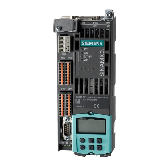
Серворивод SINAMICS S110, как и другие его собратья оснащен информационной панелью, призванной сделать общение оператора и сервопривода максимально легким и комфортным. При вводе в эксплуатацию оборудования с помощью данной панели устройство программируется и настраивается, а в случае непредвиденной ситуации на панель сервопривода выводится ошибка, вызвавшая аварийную остановку оборудования. В таблицах ниже приведены все возможные предупреждения и ошибки SINAMICS S110. Устранение причины ошибки и ее сброс на приводе позволит в кратчайшие сроки возобновить работу. К сожалению не все ошибки можно исправить самостоятельно, некоторые ошибки SINAMICS S110 возможно исправить только в специализированных сервисных центрах, проведя качественный ремонт.
 Специалисты нашего сервисного центра уделяют максимальное внимание к качеству исполнения ремонта, программирования и настройке сервоприводов, не зависимо от производителя данного промышленного оборудования. Именно поэтому мы смело даем гарантию на ремонт сервопривода SINAMICS S110 и замененные в процессе ремонта компоненты шесть месяцев.
Ремонт SINAMICS S110 в производится исключительно с использованием оригинальных запасных частей, на компонентном уровне с применением высокотехнологичного оборудования, квалифицированным персоналом с инженерным образованием.
Если на вашем производстве появились проблемы с сервоприводом SINAMICS S110, которые вы не можете решить самостоятельно, мы всегда рады вам помочь. Обращайтесь в сервисный центр «Кернел». Специалисты нашей компании в минимальные сроки проведут глубокую диагностику и последующий ремонт сервопривода SINAMICS S110 в . Оставить заявку на ремонт сервопривода SINAMICS S110 можно используя форму на сайте.
Ремонт сервопривода SINAMICS S110 в СЦ «Кернел»
 Инженеры сервисного центра Кернел выполнят ремонт SINAMICS S110 в максимально сжатые сроки. При ремонте сервопривода SINAMICS S110 в вы гарантированно получаете:
- Глубокую диагностику с выявлением всех неисправных компонентов;
- Замену неисправных компонентов на новые;
- Ремонт сервопривода SINAMICS S110 в максимально сжатые сроки;
- Проверку отремонтированного сервопривода на специальном стенде;
- Оригинальные запасные части;
- Гарантию на ремонт сервопривода SINAMICS S110 шесть месяцев;
- Полугодовую гарантию на запасные части замененные в процессе ремонта.
Компания «Кернел» предлагает квалифицированный ремонт сервоприводов SINAMICS S110 в сжатые сроки по цене 20% — 40% от стоимости нового сервопривода. За время существования компании, наши инженеры отремонтировали не одну тысячу единиц промышленного оборудования, постоянно повышая свою квалификацию. Вот далеко не полный список сервоприводов SINAMICS серии S110 ремонт которых предлагает наш сервисный центр.
Типы ремонтируемых сервоприводов SINAMICS S110
Сервисный центр «Керлен» выполняет ремонт всех сервоприводов SINAMICS S110 когда либо выпущеных компанией SIEMENS, ниже приведен неполный список сервоприводов SINAMICS S110 ремонт которых проводили специалисты сервисного центра.

6SL3210-1PB13-0AL0; 6SL3210-1PB13-0UL0; 6SL3210-1PB13-8AL0; 6SL3210-1PB13-8UL0; 6SL3210-1PB15-5AL0; 6SL3210-1PB15-5UL0; 6SL3210-1PB17-4AL0; 6SL3210-1PB17-4UL0; 6SL3210-1PB21-0AL0; 6SL3210-1PB21-0UL0; 6SL3210-1PB21-4AL0; 6SL3210-1PB21-4UL0; 6SL3210-1PB21-8AL0; 6SL3210-1PB21-8UL0; 6SL3210-1PE11-8AL1; 6SL3210-1PE11-8UL1; 6SL3210-1PE12-3AL1; 6SL3210-1PE12-3UL1; 6SL3210-1PE13-2AL1; 6SL3210-1PE13-2UL1; 6SL3210-1PE14-3AL1; 6SL3210-1PE14-3UL1; 6SL3210-1PE16-1AL1; 6SL3210-1PE16-1UL1; 6SL3210-1PE18-0AL1; 6SL3210-1PE18-0UL1; 6SL3210-1PE21-1AL0; 6SL3210-1PE21-1UL0; 6SL3210-1PE21-4AL0; 6SL3210-1PE21-4UL0; 6SL3210-1PE21-8AL0; 6SL3210-1PE21-8UL0; 6SL3210-1PE22-7AL0; 6SL3210-1PE22-7UL0; 6SL3210-1PE23-3AL0; 6SL3210-1PE23-3UL0; 6SL3210-1PE23-8AL0; 6SL3210-1PE23-8UL0; 6SL3210-1PE24-5AL0; 6SL3210-1PE24-5UL0; 6SL3210-1PE26-0AL0; 6SL3210-1PE26-0UL0; 6SL3210-1PE27-5AL0; 6SL3210-1PE27-5UL0; 6SL3210-1PE28-8AL0; 6SL3210-1PE28-8UL0; 6SL3210-1PE31-1AL0; 6SL3210-1PE31-1UL0; 6SL3210-1PE31-5AL0; 6SL3210-1PE31-5UL0; 6SL3210-1PE31-8AL0; 6SL3210-1PE31-8UL0; 6SL3210-1PE32-1AL0; 6SL3210-1PE32-1UL0; 6SL3210-1PE32-5AL0; 6SL3210-1PE32-5UL0; 6SL3040-0JA00-0AA0; 6SL3040-0JA01-0AA0
 К сожалению, от поломок дорогостоящего оборудования никто не застрахован. В зависимости от разных факторов, рано или поздно, любое, даже самое надежное промышленное оборудование выходит из строя, сервопривод SINAMICS S110 не исключение. В данной ситуации на помощь придут инженеры нашей компании, профессионализм которых не ставится под сомнение.
Благодаря новейшему инновационному диагностическому оборудованию инженеры сервисного центра в кратчайшие сроки проведут глубокую диагностику вышедшего из строя сервопривода SINAMICS S110 найдут неисправный компонент и заменят его на новый.
Еще раз хочется подчеркнуть тот факт, что, производя ремонт SINAMICS S110 в мы используем только оригинальные запасные части и даем гарантию не только на проведенные ремонтно-восстановительные работы, но и на запасные части, которые были заменены в процессе ремонта сервопривода шесть месяцев.
Менеджеры и специалисты нашего сервисного центра всегда стараются входить в положение заказчика и выполнить ремонт SINAMICS S110 в максимально кратчайшие сроки тем самым минимизировать простой оборудования.
Мы ценим своих клиентов и делаем упор на качество выполненных работ, и конечно же время его выполнения. Сберегите свой бюджет, обратитесь за ремонтом сервопривода SINAMICS S110 в нашу компанию.
Предупреждения и ошибки SINAMICS S110
Индикация неисправностей и аварийных сигналов
При возникновении неисправности привод сигнализирует об этом, выдавая соответствующие ошибки и/или сигналы тревоги. Для отображения неисправностей и аварийных сигналов существуют следующие способы:
- Отображение через буфер неисправностей и аварийных сигналов по сети PROFIBUS
- Отображение в режиме онлайн через программу ввода в эксплуатацию.
Различия между неисправностями и аварийными сигналами заключаются в следующем:
| Type | Description |
|---|---|
| Faults |
What happens when a fault occurs?
How are faults eliminated?
|
| Alarms |
What happens when an alarm occurs?
How are alarms eliminated?
|
Определены следующие реакции на неисправности:
| List | PROFI-drive | Reaction | Description |
|---|---|---|---|
| NONE | — | None |
No reaction when a fault occurs Note: When the «Basic positioner» function module is activated (r0108.4 = 1), the following applies: |
| OFF1 | ON/OFF | Brake along the ramp-function generator down ramp followed by pulse inhibit |
Closed-loop speed control (p1300 = 20, 21)
Closed-loop torque control (p1300 = 23)
|
| OFF1_ DELAYED |
— | As for OFF1, but delayed |
Faults with this fault reaction do not become effective until after the delay time set in p3136. The remaining time up to OFF1 is displayed in r3137. |
| OFF2 | COAST STOP |
Internal/external pulse inhibit |
Closed-loop speed and torque control
|
| OFF3 | QUICK STOP |
Brake along the OFF3 down ramp followed by pulse inhibit |
Closed-loop speed control (p1300 = 20, 21)
Closed-loop torque control (p1300 = 23)
|
| STOP1 | — | — | Under development |
| STOP2 | — | n_set = 0 |
|
| IASC/ DCBRAKE |
— | — |
DC braking must have been commissioned (p1232, p1233, p1234). |
| ENCODER | — | Internal/external pulse inhibit (p0491) |
The fault reaction ENCODER is applied as a function of the setting in p0491. Factory setting: p0491 = 0 —> Encoder fault causes OFF2 Notice: When changing p0491, it is imperative that the information in the description of this parameter is carefully observed. |
В списке неисправностей и аварийных сигналов указано, как квитировать каждую неисправность после устранения ее причины.
| Acknowledgment | Description |
|---|---|
| POWER ON |
The fault is acknowledged by a POWER ON (switch drive unit off and on again). Note: If this action has not eliminated the fault cause, the fault is displayed again immediately after power up. |
| IMMEDIATELY |
Faults can be acknowledged on one drive object (Points 1 to 3) or on all drive objects (Point 4) as follows:
Note:
|
| PULSE INHIBIT |
The fault can only be acknowledged with a pulse inhibit (r0899.11 = 0). The same options are available for acknowledging as described under acknowledgment with IMMEDIATELY. |
Список неисправностей и аварий имеет следующую структуру:
|
Axxxxx (F, N) Message value: Drive object: Reaction: Acknowledge: Cause: Remedy: Acknowl. upon F: Reaction upon N: Acknowl. upon N: |
Fault location (optional): Name Component number: %1, cause of fault: %2 List of objects. NONE NONE Description of possible causes Description of possible remedies A_INFEED: OFF2 (OFF1, NONE) IMMEDIATELY (POWER ON) NONE NONE |
Axxxxx Тревога xxxxx
Axxxxx (F, N) Alarm xxxxx (тип сообщения может быть изменен на F или N)
Fxxxxx Неисправность xxxxx
Fxxxxx (A, N) Неисправность xxxxx (тип сообщения может быть изменен на A или N)
Nxxxxx Нет сообщения
Nxxxxx (A) Нет сообщения (тип сообщения может быть изменен на A)
Cxxxxx Сообщение о безопасности (отдельный буфер сообщений)
Сообщение состоит из буквы, за которой следует соответствующая цифра. Буквы имеют следующие значения:
- A — означает «Тревога».
- F — означает «Неисправность».
- N — означает «Нет сообщения» или «Внутреннее сообщение».
- C — означает «Сообщение о безопасности».
Необязательные круглые скобки указывают на то, можно ли изменить тип, заданный для данного сообщения и какие типы сообщений могут быть настроены с помощью параметров (p2118, p2119).
Информация о реакции и квитировании указывается независимо для сообщения с настраиваемым типом сообщения (например, реакция на F, подтверждение для F).
Список неисправностей и аварийных сигналов
| F01000 Message value: Drive object: Reaction: Acknowledge: Cause: Remedy: |
Internal software error %1 All objects OFF2 POWER ON An internal software error has occurred. Fault value (r0949, interpret hexadecimal): Only for internal Siemens troubleshooting. — evaluate fault buffer (r0945). — carry out a POWER ON (power off/on) for all components. — upgrade firmware to later version. — contact the Hotline. — replace the Control Unit. |
| F01001 Message value: Drive object: Reaction: Acknowledge: Cause: Remedy: |
FloatingPoint exception %1 All objects OFF2 POWER ON An exception occurred during an operation with the FloatingPoint data type. The error may be caused by the base system or an OA application (e.g., FBLOCKS, DCC). Fault value (r0949, interpret hexadecimal): Only for internal Siemens troubleshooting. Note: Refer to r9999 for further information about this fault. r9999[0]: Fault number. r9999[1]: Program counter at the time when the exception occurred. r9999[2]: Cause of the FloatingPoint exception. Bit 0 = 1: Operation invalid Bit 1 = 1: Division by zero Bit 2 = 1: Overflow Bit 3 = 1: Underflow Bit 4 = 1: Imprecise result — carry out a POWER ON (power off/on) for all components. — check configuration and signals of the blocks in FBLOCKS. — check configuration and signals of DCC charts. — upgrade firmware to later version. — contact the Hotline. |
| F01002 Message value: Drive object: Reaction: Acknowledge: Cause: Remedy: |
Internal software error %1 All objects OFF2 IMMEDIATELY An internal software error has occurred. Fault value (r0949, interpret hexadecimal): Only for internal Siemens troubleshooting. — carry out a POWER ON (power off/on) for all components. — upgrade firmware to later version. — contact the Hotline. |
| F01003 Message value: Drive object: Reaction: Acknowledge: Cause: Remedy: |
Acknowledgement delay when accessing the memory %1 All objects OFF2 IMMEDIATELY A memory area was accessed that does not return a «READY». Fault value (r0949, interpret hexadecimal): Only for internal Siemens troubleshooting. — carry out a POWER ON (power off/on) for all components. — contact the Hotline. |
| N01004 (F, A) Message value: Drive object: Reaction: Acknowledge: Cause: Remedy: Reaction upon F: Acknowl. upon F: Reaction upon A: Acknowl. upon A: |
Internal software error %1 All objects NONE NONE An internal software error has occurred. Fault value (r0949, hexadecimal): Only for internal Siemens troubleshooting. — read out diagnostics parameter (r9999). — contact the Hotline. OFF2 POWER ON NONE NONE |
| F01005 Message value: Drive object: Reaction: Acknowledge: Cause: Remedy: |
Firmware download for DRIVE-CLiQ component unsuccessful Component number: %1, fault cause: %2 All objects NONE IMMEDIATELY It was not possible to download the firmware to a DRIVE-CLiQ component. Fault value (r0949, interpret hexadecimal): yyxxxx hex: yy = component number, xxxx = fault cause xxxx = 000B hex = 11 dec: DRIVE-CLiQ component has detected a checksum error. xxxx = 000F hex = 15 dec: The selected DRIVE-CLiQ component did not accept the contents of the firmware file. xxxx = 0012 hex = 18 dec: Firmware version is too old and is not accepted by the component. xxxx = 0013 hex = 19 dec: Firmware version is not suitable for the hardware release of the component. xxxx = 0065 hex = 101 dec: After several communication attempts, no response from the DRIVE-CLiQ component. xxxx = 008B hex = 139 dec: Initially, a new boot loader is loaded (must be repeated after POWER ON). xxxx = 008C hex = 140 dec: Firmware file for the DRIVE-CLiQ component not available on the memory card. xxxx = 008D hex = 141 dec: An inconsistent length of the firmware file was signaled. The firmware download may have been caused by a loss of connection to the firmware file. This can occur during a project download/reset in the case of a SINAMICS Integrated Control Unit, for example. xxxx = 008F hex = 143 dec: Component has not changed to the mode for firmware download. It was not possible to delete the existing firmware. xxxx = 0090 hex = 144 dec: When checking the firmware that was downloaded (checksum), the component detected a fault. It is possible that the file on the memory card is defective. xxxx = 0091 hex = 145 dec: Checking the loaded firmware (checksum) was not completed by the component in the appropriate time. xxxx = 009C hex = 156 dec: Component with the specified component number is not available (p7828). xxxx = Additional values: Only for internal Siemens troubleshooting. — check the selected component number (p7828). — check the DRIVE-CLiQ connection. — save suitable firmware file for download in the directory «/siemens/sinamics/code/sac/». — use a component with a suitable hardware version — after POWER ON has been carried out again for the DRIVE-CLiQ component, download the firmware again. Depending on p7826, the firmware will be automatically downloaded. |
| A01006 Message value: Drive object: Reaction: Acknowledge: Cause: Remedy: |
Firmware update for DRIVE-CLiQ component required Component number: %1 All objects NONE NONE The firmware of a DRIVE-CLiQ component must be updated as there is no suitable firmware or firmware version in the component for operation with the Control Unit. Alarm value (r2124, interpret decimal): Component number of the DRIVE-CLiQ component. Firmware update using the commissioning software: The firmware version of all of the components on the «Version overview» page can be read in the Project Navigator under «Configuration» of the associated drive unit and an appropriate firmware update can be carried out. Firmware update via parameter: — take the component number from the alarm value and enter into p7828. — start the firmware download with p7829 = 1. |
| A01007 Message value: Drive object: Reaction: Acknowledge: Cause: Remedy: |
POWER ON for DRIVE-CLiQ component required Component number: %1 All objects NONE NONE A DRIVE-CLiQ component must be powered up again (POWER ON) (e.g. due to a firmware update). Alarm value (r2124, interpret decimal): Component number of the DRIVE-CLiQ component. Note: For a component number = 1, a POWER ON of the Control Unit is required. Switch off the power supply of the specified DRIVE-CLiQ component and switch it on again. |
| A01009 (N) Message value: Drive object: Reaction: Acknowledge: Cause: Remedy: Reaction upon N: |
CU: Control module overtemperature — All objects NONE NONE The temperature (r0037[0]) of the control module (Control Unit) has exceeded the specified limit value. — check the Control Unit fan. Note: The alarm automatically disappears after the limit value has been undershot. NONE NONE |
| F01010 Message value: Drive object: Reaction: Acknowledge: Cause: Remedy: |
Drive type unknown %1 All objects NONE IMMEDIATELY An unknown drive type was found. Fault value (r0949, decimal interpretation): Drive obje- replace Power Module. — carry out a POWER ON (power off/on) for all components. — upgrade firmware to later version. — contact the Hotline.ct number (refer to p0101, p0107). |
| F01011 (N) Message value: Drive object: Reaction: Acknowledge: Cause: Remedy: Reaction upon N: |
Download interrupted %1 All objects NONE IMMEDIATELY The project download was interrupted. Fault value (r0949, decimal interpretation): 1: The user prematurely interrupted the project download. 2: The communication cable was interrupted (e.g. cable breakage, cable withdrawn). 3: The project download was prematurely ended by the commissioning software (e.g. STARTER, SCOUT). 100: Different versions between the firmware version and project files «Download from card». Note: The response to an interrupted download is the state «first commissioning». — check the communication cable. — download the project again. — boot from previously saved files (power-down/power-up or p0976). — when downloading from the card, use the matching version. NONE NONE |
| F01012 (N) Message value: Drive object: Reaction: Acknowledge: Cause: Remedy: Reaction upon N: |
Project conversion error %1 SERVO_S110-CAN, SERVO_S110-DP, SERVO_S110-PN OFF2 (NONE) IMMEDIATELY When converting the project of an older firmware version, an error occurred. Fault value (r0949, decimal interpretation): Parameter number of the parameter causing the error. For fault value = 600, the following applies: The temperature evaluation is no longer assigned to the power unit but to the encoder evaluation. Notice: Monitoring of the motor temperature is no longer ensured. Check the parameter indicated in the fault value and correctly adjust it accordingly. For fault value = 600: Parameter p0600 must be set to the values 1, 2 or 3 in accordance with the assignment of the internal encoder evaluation to the encoder interface. Value 1 means: The internal encoder evaluation is assigned to the encoder interface 1 via p0187. Value 2 means: The internal encoder evaluation is assigned to the encoder interface 2 via p0188. Value 3 means: The internal encoder evaluation is assigned to the encoder interface 3 via p0189. — If necessary, the internal encoder evaluation must be assigned to an encoder interface via parameters p0187, p0188 or p0189 accordingly. — If necessary, upgrade the firmware to a later version. NONE NONE |
| F01015 Message value: Drive object: Reaction: Acknowledge: Cause: Remedy: |
Internal software error %1 All objects OFF2 POWER ON An internal software error has occurred. Fault value (r0949, decimal interpretation): Only for internal Siemens troubleshooting. — carry out a POWER ON (power off/on) for all components. — upgrade firmware to later version. — contact the Hotline. |
| A01016 (F) Message value: Drive object: Reaction: Acknowledge: Cause: Remedy: Reaction upon F: |
Firmware changed %1 All objects NONE NONE At least one firmware file in the directory /SIEMENS/SINAMICS/ has been changed without authorization with respect to the version shipped from the factory. No changes are permitted in this directory. Alarm value (r2124, interpret decimal): 0: Checksum of one file is incorrect. 1: File missing. 2: Too many files. 3: Incorrect firmware version. 4: Incorrect checksum of the back-up file. See also: r9925 (Firmware file incorrect) For the non-volatile memory for the firmware (memory card/device memory), restore the delivery condition. Note: The file involved can be read out using parameter r9925. See also: r9926 (Firmware check status) OFF2 POWER ON |
| A01017 Message value: Drive object: Reaction: Acknowledge: Cause: Remedy: |
Component lists changed %1 All objects NONE NONE On the memory card, one file in the directory /SIEMENS/SINAMICS/DATA or /ADDON/SINAMICS/DATA has been illegally changed with respect to that supplied from the factory. No changes are permitted in this directory. Alarm value (r2124, interpret decimal): zyx dec: x = Problem, y = Directory, z = File name x = 1: File does not exist. x = 2: Firmware version of the file does not match the software version. x = 3: File checksum is incorrect. y = 0: Directory /SIEMENS/SINAMICS/DATA/ y = 1: Directory /ADDON/SINAMICS/DATA/ z = 0: File MOTARM.ACX z = 1: File MOTSRM.ACX z = 2: File MOTSLM.ACX z = 3: File ENCDATA.ACX z = 4: File FILTDATA.ACX z = 5: File BRKDATA.ACX z = 6: File DAT_BEAR.ACX z = 7: File CFG_BEAR.ACX z = 8: File ENC_GEAR.ACX For the file on the memory card involved, restore the status originally supplied from the factory. |
| F01018 Message value: Drive object: Reaction: Acknowledge: Cause: Remedy: |
Booting has been interrupted several times — All objects NONE POWER ON Module booting was interrupted several times. Possible reasons for booting being interrupted: — POWER OFF of the module. — CPU crash. — USER data invalid. After this fault is output, then the module is booted with the factory settings. Power down the module and power it up again. Note: After switching on, the module reboots from the USER data (if available). If the fault situation is repeated, then this fault is again output after several interrupted boots. |
| A01019 Message value: Drive object: Reaction: Acknowledge: Cause: Remedy: |
Writing to the removable data medium unsuccessful — All objects NONE NONE The write access to the removable data medium was unsuccessful. Remove and check the removable data medium. Then run the data backup again. |
| A01020 Message value: Drive object: Reaction: Acknowledge: Cause: Remedy: |
Write to RAM disk unsuccessful — All objects NONE NONE The write access to the internal RAM disk was unsuccessful. Adapt the size of the system logbook (p9930) to the internal RAM disk. |
Все возможные ошибки и предупреждения сервопривода SINAMICS S110
Скачать мануал, руководство пользователя SINAMICS S110 в формате PDF
Оставить заявку на ремонт сервопривода SINAMICS S110
Оставить заявку на ремонт сервопривода SINAMICS S110 в можно с помощью специальной формы, которая вызывается нажатием одноименной кнопки в верхней части страницы. Все вопросы, связанные с ремонтом сервопривода SINAMICS S110 в , вы можете задать нашим менеджерам. Связаться с ними можно несколькими способами:

- Заказав обратный звонок (кнопка в правом нижнем углу сайта)
- Посредством чата (кнопка расположена с левой стороны сайта)
- Позвонив по номеру телефона:
- +7(8482) 79-78-54;
- +7(8482) 55-96-39;
- +7(917) 121-53-01
- Написав на электронную почту: 89171215301@mail.ru
- В начало статьи
Вот далеко не полный список производителей промышленной электроники и оборудования, ремонтируемой в нашей компании.
5.3
5.3.1
General information about faults and alarms
Description
The errors and states detected by the individual components of the drive system are
indicated by messages.
The messages are categorized into faults and alarms.
Note
The individual faults and alarms are described in the SINAMICS S110 List Manual in the
section titled «Faults and Alarms». Here you can also find a chapter titled «Function
diagrams» → «Faults and alarms», which contains function diagrams for the fault buffer, alarm
buffer, fault trigger, and fault configuration.
Properties of faults and alarms
● Faults
● Alarms
Function Manual
Function Manual, 01/2011, 6SL3097-4AB10-0BP3
– Are identified by Fxxxxx.
– Can lead to a fault reaction.
– Must be acknowledged once the cause has been remedied.
– Status via Control Unit and LED RDY.
– Status via PROFIBUS status signal ZSW1.3 (fault active).
– Entry in the fault buffer.
– Are identified by Axxxxx.
– Have no further effect on the drive.
– The alarms are automatically reset once the cause has been remedied. No
acknowledgment is required.
– Status via PROFIBUS status signal ZSW1.7 (alarm active).
– Entry in the alarm buffer.
Diagnostics
5.3 Fault and alarm messages
105
- Manuals
- Brands
- Siemens Manuals
- Media Converter
- SINAMICS S110
- Manual
-
Contents
-
Table of Contents
-
Bookmarks
Quick Links
Related Manuals for Siemens SINAMICS S110
Summary of Contents for Siemens SINAMICS S110
-
Page 3
___________________ SINAMICS S110 Preface ___________________ Fundamental safety instructions ___________________ SINAMICS System overview ___________________ Mains connection and line- side power components S110 SINAMICS S110 ___________________ Blocksize Power Modules (PM240-2) ___________________ DC link components Manual ___________________ Power components on the motor side… -
Page 4: Legal Information
Note the following: WARNING Siemens products may only be used for the applications described in the catalog and in the relevant technical documentation. If products and components from other manufacturers are used, these must be recommended or approved by Siemens. Proper transport, storage, installation, assembly, commissioning, operation and maintenance are required to ensure that the products operate safely and without any problems.
-
Page 5: Preface
(mailto:docu.motioncontrol@siemens.com). My Documentation Manager At the following address (http://www.siemens.com/mdm), you can find information on how to create your own individual documentation based on Siemens’ content, and adapt it for your own machine documentation. Training At the following address (http://www.siemens.com/sitrain), you can find information about SITRAIN (Siemens training on products, systems and solutions for automation and drives).
-
Page 6
Installation/assembly SINAMICS S110 Manual • Commissioning STARTER commissioning tool • SINAMICS S110 Getting Started • SINAMICS S110 Function Manual Drive Functions • SINAMICS S110 List Manual • Usage/operation SINAMICS S110 Function Manual Drive Functions • SINAMICS S110 List Manual •… -
Page 7: Manual, 07/2015, 6Sl3097-4Ac10-0Bp5
(https://support.industry.siemens.com/cs/ww/en/ps/13231/cert). You can obtain an up-to-date list of currently certified components on request from your local Siemens office. If you have any questions relating to certifications that have not yet been completed, please ask your Siemens contact person.
-
Page 8
Spare parts Spare parts are available on the Internet at the following address (https://support.industry.siemens.com/sc/ww/en/sc/2110). Ground symbols Table 2 Symbols Symbol Meaning Connection for protective conductor (PE) Ground (e.g. M 24 V) Connection for function potential bonding SINAMICS S110 Manual, 07/2015, 6SL3097-4AC10-0BP5… -
Page 9
DC link and the output (> 1 MΩ) so that the possible voltage as result of the voltage divider with the impedance of the ground connection between the motor and converter is less than 50 VAC or 120 VDC. SINAMICS S110 Manual, 07/2015, 6SL3097-4AC10-0BP5… -
Page 10
Preface SINAMICS S110 Manual, 07/2015, 6SL3097-4AC10-0BP5… -
Page 11: Table Of Contents
Residual risks of power drive systems ………………23 System overview ……………………… 25 Field of application ……………………25 Platform Concept and Totally Integrated Automation …………. 26 Overview of SINAMICS S110 ………………..28 System data ……………………..29 Derating ……………………..31 Mains connection and line-side power components …………….35 Introduction ……………………..
-
Page 12
Motor reactors ……………………119 6.1.1 Description ……………………… 119 6.1.2 Safety instructions for motor reactors ……………… 119 6.1.3 Dimension drawings ………………….121 6.1.4 Mounting ……………………..125 6.1.5 Electrical connection ………………….126 6.1.6 Technical data ……………………127 SINAMICS S110 Manual, 07/2015, 6SL3097-4AC10-0BP5… -
Page 13
Interface description ………………….165 8.1.3 Installation ……………………..168 Sensor Module Cabinet-Mounted SMC10 …………….170 8.2.1 Description ……………………..170 8.2.2 Safety instructions for Sensor Modules Cabinet-Mounted ……….. 170 8.2.3 Interface description ………………….172 8.2.3.1 Overview ……………………..172 SINAMICS S110 Manual, 07/2015, 6SL3097-4AC10-0BP5… -
Page 14
Dimension drawing ………………….211 8.5.6 Mounting ……………………..211 8.5.7 Technical data ……………………211 Accessories ……………………….213 DRIVE-CLiQ cabinet bushing ………………..213 9.1.1 Description ……………………… 213 9.1.2 Safety Information …………………… 213 9.1.3 Interface description ………………….214 SINAMICS S110 Manual, 07/2015, 6SL3097-4AC10-0BP5… -
Page 15
Safety instructions for service and maintenance …………..245 11.2 Service and maintenance for components, Blocksize format ……….246 11.2.1 Replacing hardware components ………………246 11.2.2 Replacing the fan on the PM240-2 ………………246 11.3 Forming the DC link capacitors ………………… 248 SINAMICS S110 Manual, 07/2015, 6SL3097-4AC10-0BP5… -
Page 16
Table of contents 11.4 Spare parts ……………………… 251 11.5 Recycling and disposal ………………….251 Annex …………………………253 List of abbreviations ………………….253 Documentation overview …………………. 262 Spring-type terminals/screw-type terminals …………….. 263 Index …………………………265 SINAMICS S110 Manual, 07/2015, 6SL3097-4AC10-0BP5… -
Page 17: Fundamental Safety Instructions
Touching live components can result in death or severe injury. • Only use power supplies that provide SELV (Safety Extra Low Voltage) or PELV- (Protective Extra Low Voltage) output voltages for all connections and terminals of the electronics modules. SINAMICS S110 Manual, 07/2015, 6SL3097-4AC10-0BP5…
-
Page 18
When opening plug connections in operation, arcs can result in severe injury or death. • Only open plug connections when the equipment is in a no-voltage state, unless it has been explicitly stated that they can be opened in operation. SINAMICS S110 Manual, 07/2015, 6SL3097-4AC10-0BP5… -
Page 19
This can cause severe injury or even death. This can also result in increased downtime and reduced service lives for devices/systems. • Ensure compliance with the specified minimum clearance as ventilation clearance for the respective component. SINAMICS S110 Manual, 07/2015, 6SL3097-4AC10-0BP5… -
Page 20
• Only put your plant into live operation once you have guaranteed that the functions relevant to safety are running correctly. Note Important safety notices for Safety Integrated functions If you want to use Safety Integrated functions, you must observe the safety notices in the Safety Integrated manuals. SINAMICS S110 Manual, 07/2015, 6SL3097-4AC10-0BP5… -
Page 21: Safety Instructions For Electromagnetic Fields (Emf)
– Wearing ESD shoes or ESD grounding straps in ESD areas with conductive flooring • Only place electronic components, modules or devices on conductive surfaces (table with ESD surface, conductive ESD foam, ESD packaging, ESD transport container). SINAMICS S110 Manual, 07/2015, 6SL3097-4AC10-0BP5…
-
Page 22: Industrial Security
Siemens recommends strongly that you regularly check for product updates. For the secure operation of Siemens products and solutions, it is necessary to take suitable preventive action (e.g. cell protection concept) and integrate each component into a holistic, state-of-the-art industrial security concept.
-
Page 23: Residual Risks Of Power Drive Systems
Inverters of the Open Type/IP20 degree of protection must be installed in a metal control cabinet (or protected by another equivalent measure) such that contact with fire inside and outside the inverter is not possible. SINAMICS S110 Manual, 07/2015, 6SL3097-4AC10-0BP5…
-
Page 24
Assuming that conductive contamination at the installation site can definitely be excluded, a lower degree of cabinet protection may be permitted. For more information about residual risks of the components in a drive system, see the relevant sections in the technical user documentation. SINAMICS S110 Manual, 07/2015, 6SL3097-4AC10-0BP5… -
Page 25: System Overview
System overview Field of application SINAMICS is the family of drives from Siemens designed for machine and plant engineering applications. SINAMICS offers solutions for all drive tasks: ● Simple pump and fan applications in the process industry. ● Complex individual drives in centrifuges, presses, extruders, elevators, as well as conveyor and transport systems.
-
Page 26: Platform Concept And Totally Integrated Automation
SINAMICS S110 supports PROFIBUS DP, the standard field bus of the TIA system. It provides a high-performance, system-wide communication network which links all automation components: HMI, controls, drives and I/O devices.
-
Page 27
System overview 2.2 Platform Concept and Totally Integrated Automation Figure 2-2 SINAMICS as part of the Siemens modular automation system SINAMICS S110 Manual, 07/2015, 6SL3097-4AC10-0BP5… -
Page 28: Overview Of Sinamics S110
2.3 Overview of SINAMICS S110 Overview of SINAMICS S110 SINAMICS S110 is the «simple servo» in the range of SINAMICS AC Drives. As a modular drive system for single axes in «servo» control mode, it is primarily used for simple positioning tasks in a wide range of industrial applications.
-
Page 29: System Data
1.1 … 447 kW: 65 kA in accordance with UL508C (up to 600 V) UL approval applies only in conjunction with the fuses prescribed by Siemens and not with other types or circuit breakers alone. EMC Directive Category C3 (option) acc.
-
Page 30
CE (Low Voltage, EMC, and Machinery Directives) Approvals cULus acc. to UL 61800-5-1 CSA only with external surge protection devices C-Tick SEMI F47 KCC only with internal or external line filters WEEE (Waste Electrical & Electronic Equipment) RoHS SINAMICS S110 Manual, 07/2015, 6SL3097-4AC10-0BP5… -
Page 31: Derating
2000 m. If the neutral point is not grounded, you must connect an isolating transformer upstream, the secondary side of which is then grounded at the neutral point. A reduction of the line voltage phase-phase is not necessary. SINAMICS S110 Manual, 07/2015, 6SL3097-4AC10-0BP5…
-
Page 32
You will find the rated pulse frequency in the Technical Data of the relevant Power Module. Figure 2-5 Reduction of the output current as a function of the quotient of the pulse frequency and rated pulse frequency SINAMICS S110 Manual, 07/2015, 6SL3097-4AC10-0BP5… -
Page 33
Short-time duty operating state permissible for less than 2% of the operating time Sporadic short-time duty operating state only permissible for less than 1 % of the operating time SINAMICS S110 Manual, 07/2015, 6SL3097-4AC10-0BP5… -
Page 34
System overview 2.5 Derating SINAMICS S110 Manual, 07/2015, 6SL3097-4AC10-0BP5… -
Page 35: Mains Connection And Line-Side Power Components
Available line filter variants: ● Integrated (to achieve EMC category C2 or C3) ● External (to achieve EMC category C1) Figure 3-1 Example of a line connection for Power Modules Blocksize with no integrated line filter SINAMICS S110 Manual, 07/2015, 6SL3097-4AC10-0BP5…
-
Page 36: Information On The Disconnector Unit
• In TT systems, besides suitable overcurrent protection equipment, also use residual current devices (RCD) and, as of an infeed power of 55 kW or in extensive installations, also use residual current monitors (RCM). SINAMICS S110 Manual, 07/2015, 6SL3097-4AC10-0BP5…
-
Page 37
1PB21-4UL0 1PB21-8UL0 1PB21-8UL0 with integrated line filter 1PB21-4AL0 1PB21-8AL0 1PB21-8AL0 Fuses UL Class J AJT50 AJT50 AJT50 Rated current Short-circuit current rating SCCR Fuses 3NE1817-0 3NE1818-0 3NE1818-0 NH IEC 60947 Rated current SINAMICS S110 Manual, 07/2015, 6SL3097-4AC10-0BP5… -
Page 38
1PE21-4UL0 1PE21-8UL0 1PE21-8UL0 with integrated line filter 1PE21-1AL0 1PE21-4AL0 1PE21-8AL0 1PE21-8AL0 Fuses UL Class J AJT35 AJT35 AJT35 AJT35 Rated current Short-circuit current rating SCCR Fuses 3NE1814-0 3NE1815-0 3NE1803-0 3NE1803-0 NH IEC 60947 Rated current SINAMICS S110 Manual, 07/2015, 6SL3097-4AC10-0BP5… -
Page 39
AJT150 Rated current Short-circuit current rating SCCR Fuses 3NA3832 3NA3836 NH IEC 60947 Rated current Fuses 3NE1022-0 3NE1224-0 UL Class J/NH IEC 60947 Rated current Line protection Line protection and protection of the Power Module SINAMICS S110 Manual, 07/2015, 6SL3097-4AC10-0BP5… -
Page 40: Using Residual-Current Devices
If no residual current device is used, touch protection can be ensured by means of double insulation or by isolating the Power Module from the supply system through a transformer. SINAMICS S110 Manual, 07/2015, 6SL3097-4AC10-0BP5…
-
Page 41: Overvoltage Protection
(on the line side of the main disconnect switch). To comply with the requirements of CSA C22.2 No. 14-05, a type VZCA7 or VZCA8 surge arrester is absolutely mandatory. The Raycap company has suitable surge arresters. SINAMICS S110 Manual, 07/2015, 6SL3097-4AC10-0BP5…
-
Page 42: Line Contactors
To limit the switching overvoltage, the contactor coil must be connected to an overvoltage limiter (e.g. freewheeling diode or varistor). When the digital output is used to control the line contactor, you must consider the make/break capacity. SINAMICS S110 Manual, 07/2015, 6SL3097-4AC10-0BP5…
-
Page 43: Line Filter
Insufficient ventilation clearances result in overheating with danger to persons as a result of smoke and fire. Further, the line filter can be thermally damaged. • Ensure 100-mm ventilation clearances above and below the line filter. SINAMICS S110 Manual, 07/2015, 6SL3097-4AC10-0BP5…
-
Page 44: Classification Of Emc Behavior
Damage of further loads due to incorrect line filters Unsuitable line filters can cause line harmonics, which damage or destroy loads connected to the same line supply. • Only use line filters released by Siemens for SINAMICS. 3.7.3 Classification of EMC behavior…
-
Page 45
Drive systems which correspond to category C4 may only be installed in the second environment. Note Expert An expert is a person or organization with the necessary experience for installing and/or commissioning drive systems (Power Drive Systems — PDS), including the associated EMC aspects. SINAMICS S110 Manual, 07/2015, 6SL3097-4AC10-0BP5… -
Page 46: Electromagnetic Compatibility (Emc) Of The System
Power Modules of the Blocksize series are all available in variants with an integrated line filter. The Power Modules of Category C3 and can only be used in the second environment. Category C4 Unfiltered Power Modules meet Category C4 and can only be used in the second environment. SINAMICS S110 Manual, 07/2015, 6SL3097-4AC10-0BP5…
-
Page 47: Dimension Drawings
Mains connection and line-side power components 3.7 Line filter 3.7.5 Dimension drawings Blocksize line filter Figure 3-2 Dimension drawing of the line filter, Power Module PM240-2 frame size FSA, all data in mm (inches) SINAMICS S110 Manual, 07/2015, 6SL3097-4AC10-0BP5…
-
Page 48
Mains connection and line-side power components 3.7 Line filter Figure 3-3 Dimension drawing of the line filter, Power Module PM240-2 frame size FSB, all data in mm (inches) SINAMICS S110 Manual, 07/2015, 6SL3097-4AC10-0BP5… -
Page 49
Mains connection and line-side power components 3.7 Line filter Figure 3-4 Dimension drawing of the line filter, Power Module PM240-2 frame size FSC, all data in mm (inches) SINAMICS S110 Manual, 07/2015, 6SL3097-4AC10-0BP5… -
Page 50: Mounting
Installation example: Power Module PM240-2 (frame size FSA) with screening kit and line filter Table 3- 10 Connecting the line filter for the PM240-2 on the mounting surface Frame size Fastening Tightening torque 4 x M4 bolts 2.5 Nm 4 x M5 bolts 3 Nm SINAMICS S110 Manual, 07/2015, 6SL3097-4AC10-0BP5…
-
Page 51: Technical Data
6SL3210- 1PE11-8UL1 1PE21-1UL0 1PE22-7UL0 1PE12-3UL1 1PE21-4UL0 1PE23-3UL0 1PE13-2UL1 1PE21-8UL0 1PE14-3UL1 1PE16-1UL1 1PE18-0UL1 6SL3211- 6SL3211- 6SL3211- 1PE18-0UL1 1PE21-8UL0 1PE23-3UL0 Frame size Unit rating of the Power Module 0.55 … 3.0 4.0 … 7.5 11 … 15 SINAMICS S110 Manual, 07/2015, 6SL3097-4AC10-0BP5…
-
Page 52: Line Reactors
Insufficient ventilation clearances can result in overheating with danger to persons as a result of smoke and fire. Further, increased failures can occur and the service life of components shortened. • Ensure 100-mm ventilation clearances above and below the component. SINAMICS S110 Manual, 07/2015, 6SL3097-4AC10-0BP5…
-
Page 53
Damage to the system due to impermissible line reactors An impermissible line reactor may cause damage to the system and any further loads operated on the same power network. • Only use line reactors that Siemens has authorized for SINAMICS. NOTICE Line reactor damage due to interchanged connections Interchanging the input and output connections will damage the line reactor. -
Page 54: Dimension Drawings
Dimension drawing of line reactors, PM240-2 frame size FSA, 1.5 … 4.0 kW, all dimensions in mm and (inch) Figure 3-8 Dimension drawing of line reactors, PM240-2, frame size FSB, 4.0 … 7.5 kW, all dimensions in mm and (inch) SINAMICS S110 Manual, 07/2015, 6SL3097-4AC10-0BP5…
-
Page 55: Mounting
Connecting the line reactor for the PM240-2 on the mounting surface Frame size Fastening Tightening torque 4 x M5 screws 6 Nm 4 x M5 nuts 4 x M5 washers 4 x M6 screws 10 Nm 4 x M6 nuts 4 x M6 washers SINAMICS S110 Manual, 07/2015, 6SL3097-4AC10-0BP5…
-
Page 56: Electrical Connection
Electrical Connection Line/load connection ① Line reactor ② Power Module Figure 3-10 Power Module with line filter ① Line reactor ② Line filter ③ Power Module Figure 3-11 Power Module with line reactor and line filter SINAMICS S110 Manual, 07/2015, 6SL3097-4AC10-0BP5…
-
Page 57: Technical Data
Unit rating of the Power 0.55 … 1.1 1.1 … 3.0 3.0 … 7.5 5.5 … 15 Module x = A: Power Module with integrated line filter, x = U: Power Module without integrated line filter SINAMICS S110 Manual, 07/2015, 6SL3097-4AC10-0BP5…
-
Page 58: Line Connection Variants
● Power Modules without line filter are permitted to be operated on all TN systems. ● Power Modules with integrated or external line filter are permitted to be operated only on TN systems with a grounded neutral point. SINAMICS S110 Manual, 07/2015, 6SL3097-4AC10-0BP5…
-
Page 59
Figure 3-14 IT system ● Power Modules without a line filter can be operated in all IT systems. ● Power Modules with an integrated or external line filter can be operated only in IT systems. SINAMICS S110 Manual, 07/2015, 6SL3097-4AC10-0BP5… -
Page 60
If the drive unit is operated without a motor reactor in an IT system, a ground fault on the motor side of the Power Modules can cause damage to the drive line-up or trip the overcurrent protective equipment. • Always operate the Power Modules in an IT system with motor reactors. SINAMICS S110 Manual, 07/2015, 6SL3097-4AC10-0BP5… -
Page 61: Methods Of Line Connection
● Direct operation of the power supply connection components on the supply system ● Operation of the line connection components via an autotransformer ● Operation of the line connection components via an isolating transformer Figure 3-15 Overview of line connection variants for SINAMICS S110 SINAMICS S110 Manual, 07/2015, 6SL3097-4AC10-0BP5…
-
Page 62
(secondary side) must be connected between the supply and the drive system to protect the motor insulation from continuous excessive stress. SINAMICS S110 Manual, 07/2015, 6SL3097-4AC10-0BP5… -
Page 63: Operation Of The Line Connection Components On The Supply Line
Operation of the line connection components on the supply line The SINAMICS S110 drive system is designed to be directly connected to TN and TT systems with a grounded neutral point as well as to IT systems without a line filter with rated voltages from 3-phase 380 V to 480 V AC and 1-phase 200 V to 240 V AC.
-
Page 64: Operation Of The Line Connection Components Via An Autotransformer
An autotransformer can be used to adapt the voltage in the range up to 3-phase 480 VAC +10% or 240 VAC +10%. Application example: ● The motor insulation must be protected from excessive voltages. Figure 3-18 Auto-transformers SINAMICS S110 Manual, 07/2015, 6SL3097-4AC10-0BP5…
-
Page 65: Operation Of The Line Connection Components Via An Isolating Transformer
● The installation altitude is greater than 2000 m above sea level. ● A line filter should always be used for all systems that are not TN or TT systems with grounded neutral point. Figure 3-19 Isolating transformer SINAMICS S110 Manual, 07/2015, 6SL3097-4AC10-0BP5…
-
Page 66
Mains connection and line-side power components 3.9 Line connection variants SINAMICS S110 Manual, 07/2015, 6SL3097-4AC10-0BP5… -
Page 67: Blocksize Power Modules (Pm240-2)
Table 4- 1 Overview of PM240-2 Power Modules (selection) Power Module frame size FSA, with and with- Push Through Power Module frame size FSA, with out an integrated line filter and without an integrated line filter SINAMICS S110 Manual, 07/2015, 6SL3097-4AC10-0BP5…
-
Page 68
Power Module frame size FSC, with and with- Push Through Power Module frame size FSC, with out integrated line filter and without an integrated line filter Power Module frame size FSD with and with- out an integrated line filter SINAMICS S110 Manual, 07/2015, 6SL3097-4AC10-0BP5… -
Page 69
Blocksize Power Modules (PM240-2) 4.1 Description Power Module frame size FSE with and with- out an integrated line filter SINAMICS S110 Manual, 07/2015, 6SL3097-4AC10-0BP5… -
Page 70: Safety Instructions For Blocksize Power Modules (Pm240-2)
Danger to life due to hazardous voltage when an unsuitable power supply is connected Death or serious injury can result when live parts are touched in the event of a fault. • Only use the intended supply voltage to operate the Power Modules. SINAMICS S110 Manual, 07/2015, 6SL3097-4AC10-0BP5…
-
Page 71
— Front: 100 mm (3.94 inch) • Only install devices in this area that do not obstruct the flow of cooling air. • Ensure that the cooling air can flow through the Power Modules unobstructed. SINAMICS S110 Manual, 07/2015, 6SL3097-4AC10-0BP5… -
Page 72
• In the case of plug-in power terminals, check that the interlock of the connectors on the converter housing is intact. Note Malfunctions on non-Siemens equipment caused by high-frequency faults in residential environments In the first environment, Category C2 according to EMC product standard IEC 61800-3 (residential, commercial and industrial sector), the device may cause high-frequency disturbance, which can result in malfunctions in other equipment. -
Page 73: Interface Description
Blocksize Power Modules (PM240-2) 4.3 Interface description Interface description 4.3.1 Overview Figure 4-1 PM240-2, frame size FSA (view from below and front) SINAMICS S110 Manual, 07/2015, 6SL3097-4AC10-0BP5…
-
Page 74
Blocksize Power Modules (PM240-2) 4.3 Interface description Figure 4-2 PM240-2, frame size FSB (view from below and front) Figure 4-3 PM240-2, frame size FSC (view from below and front) SINAMICS S110 Manual, 07/2015, 6SL3097-4AC10-0BP5… -
Page 75
PM240-2, frame size FSD (view from below and front) Note Use of the safety function «STO» via PM terminals with SINAMICS S110 With enabled Safety Integrated functions of the CU305, a simultaneously active STO function via PM terminals causes error messages to be output (see Chapter STO connection via PM terminals (Page 82)). -
Page 76
PM240-2, frame size FSE (view from below and front) Note Use of the safety function «STO» via PM terminals with SINAMICS S110 With enabled Safety Integrated functions of the CU305, a simultaneously active STO function via PM terminals causes error messages to be output (see Chapter STO connection via PM terminals (Page 82)). -
Page 77: Connection Example
Blocksize Power Modules (PM240-2) 4.3 Interface description 4.3.2 Connection example Figure 4-6 Connection example Power Modules PM240-2 (for FSA to FSC) SINAMICS S110 Manual, 07/2015, 6SL3097-4AC10-0BP5…
-
Page 78: Line Supply Connection
Line conductor L2 Line conductor L3 PE connection Power Modules PM240-2: FSD and FSE Table 4- 3 Line supply connection terminal Terminals Signal name Technical data PE connection Line conductor L1 Line conductor L2 Line conductor L3 SINAMICS S110 Manual, 07/2015, 6SL3097-4AC10-0BP5…
-
Page 79: Motor Connection
Motor phase U Motor phase V Motor phase W Power Modules PM240-2: FSD and FSE Table 4- 5 Motor terminals Terminal Signal name Technical data PE connection Motor phase U Motor phase V Motor phase W SINAMICS S110 Manual, 07/2015, 6SL3097-4AC10-0BP5…
-
Page 80: Braking Resistor And Dc Link Connection
Power Modules PM240-2: FSE Table 4- 9 DC link terminals Terminal Signal name Technical data DC link negative DC link positive SINAMICS S110 Manual, 07/2015, 6SL3097-4AC10-0BP5…
-
Page 81: Safe Brake Relay Connection
Connector Terminal Designation Technical data Low signal Safe Brake Relay to PM240-2 High High signal Safe Brake Relay to PM240-2 Note You will find more information in Chapter Option module Safe Brake Relay (Page 208). SINAMICS S110 Manual, 07/2015, 6SL3097-4AC10-0BP5…
-
Page 82: Sto Connection Via Pm Terminals
For the Power Modules PM240-2 with frame sizes FSD and FSE, this functionality can be implemented in the hardware via the PM terminals STO_A/STO_B. However, with SINAMICS S110, «Safe Torque Off» via PM terminals can only be used if the Safety Integrated functions of the CU305 are deactivated.
-
Page 83: Dimension Drawings
Depth [mm] Power Module Shield plate at Shield plate at Total the top the bottom 83.5 707.5 122.5 849.5 Figure 4-7 Dimension drawing of PM240-2 Power Modules, frame size FSA, all data in mm (inches) SINAMICS S110 Manual, 07/2015, 6SL3097-4AC10-0BP5…
-
Page 84
Blocksize Power Modules (PM240-2) 4.4 Dimension drawings Figure 4-8 Dimension drawing of PM240-2 Power Modules, frame size FSB, all data in mm (inches) SINAMICS S110 Manual, 07/2015, 6SL3097-4AC10-0BP5… -
Page 85
Blocksize Power Modules (PM240-2) 4.4 Dimension drawings Figure 4-9 Dimension drawing of PM240-2 Power Modules, frame size FSC, all data in mm (inches) SINAMICS S110 Manual, 07/2015, 6SL3097-4AC10-0BP5… -
Page 86
Blocksize Power Modules (PM240-2) 4.4 Dimension drawings Figure 4-10 Dimension drawing of PM240-2 Power Modules, frame size FSD, all data in mm (inches) SINAMICS S110 Manual, 07/2015, 6SL3097-4AC10-0BP5… -
Page 87
Blocksize Power Modules (PM240-2) 4.4 Dimension drawings Figure 4-11 Dimension drawing of PM240-2 Power Modules, frame size FSE, all data in mm (inches) SINAMICS S110 Manual, 07/2015, 6SL3097-4AC10-0BP5… -
Page 88
The Power Modules can be mounted side by side. For tolerance reasons, we recommend a lateral clearance of 1 mm. For PT modules, the maximum wall thickness of the cabinet is 3.5 mm. Figure 4-12 Dimension drawing of PM240-2 Push Through Power Modules, frame size FSA, all data in mm (inches) SINAMICS S110 Manual, 07/2015, 6SL3097-4AC10-0BP5… -
Page 89
Blocksize Power Modules (PM240-2) 4.4 Dimension drawings Figure 4-13 Dimension drawing of PM240-2 Push Through Power Modules, frame size FSB, all data in mm (inches) SINAMICS S110 Manual, 07/2015, 6SL3097-4AC10-0BP5… -
Page 90
Blocksize Power Modules (PM240-2) 4.4 Dimension drawings Figure 4-14 Dimension drawing of PM240-2 Push Through Power Modules, frame size FSC, all data in mm (inches) SINAMICS S110 Manual, 07/2015, 6SL3097-4AC10-0BP5… -
Page 91: Drilling Patterns
Blocksize Power Modules (PM240-2) 4.4 Dimension drawings 4.4.2 Drilling patterns Power Modules frame sizes FSA / FSB / FSC Figure 4-15 Drilling patterns of PM240-2 Power Modules, frame sizes FSA, FSB, FSC; all data in mm and (inches) SINAMICS S110 Manual, 07/2015, 6SL3097-4AC10-0BP5…
-
Page 92
Drilling patterns of PM240-2 Power Modules, frame sizes FSD, FSE; all data in mm and (inches) Power Modules, Push Through, frame sizes FSA / FSB / FSC Drilling patterns for Power Modules, Push Through, FSA — FSC, see Chapter Mounting rack/dimension drawings. SINAMICS S110 Manual, 07/2015, 6SL3097-4AC10-0BP5… -
Page 93: Mounting
This mounting frame includes the necessary seals and frame to ensure compliance with degree of protection IP54. If you do not use the mounting frames, you must ensure that the required degree of protection is complied with using other appropriate measures. SINAMICS S110 Manual, 07/2015, 6SL3097-4AC10-0BP5…
-
Page 94: Mounting Dimensions And Tightening Torques
411 x 200 x 171 500 x 200 x 171 8 x M5 studs, 3.5 Nm with 8 x M5 nuts, washers Inch 16.18 x 7.87 x 6.73 19.69 x 7.87 x 6.73 8 x M5 washers inserted SINAMICS S110 Manual, 07/2015, 6SL3097-4AC10-0BP5…
-
Page 95: Mounting The Shield Connection Plate
Tools required: ● Torx screwdriver T20 Figure 4-17 Mounting the shield connection plate on Power Modules PM240-2 FSA, FSB, and FSC Figure 4-18 Mounting the shield connection plate on Power Modules PM240-2 FSD and FSE SINAMICS S110 Manual, 07/2015, 6SL3097-4AC10-0BP5…
-
Page 96: Technical Data
IP55 using a suitable mounting frame and seals, the Power Modules also comply with this degree of protection. According to UL, the Power Modules meet the requirements for an open type component, external type 12. SINAMICS S110 Manual, 07/2015, 6SL3097-4AC10-0BP5…
-
Page 97: 200 V Power Modules
(shielded) is the max. motor cable length. A cable length up to 150 m is possible for C2 if you use an unfiltered Power Module with an external line filter class B and a motor reactor. Power loss in the cabinet: 0.02 kW. The remaining power loss is dissipated through the heat sink. SINAMICS S110 Manual, 07/2015, 6SL3097-4AC10-0BP5…
-
Page 98
(shielded) is the max. motor cable length. A cable length up to 150 m is possible for C2 if you use an unfiltered Power Module with an external line filter class B and a motor reactor. Power loss in the cabinet: 0,045 kW. The remaining power loss is dissipated through the heat sink. SINAMICS S110 Manual, 07/2015, 6SL3097-4AC10-0BP5… -
Page 99
(shielded) is the max. motor cable length. A cable length up to 150 m is possible for C2 if you use an unfiltered Power Module with an external line filter class B and a motor reactor. Power loss in the cabinet: 0.075 kW. The remaining power loss is dissipated through the heat sink. SINAMICS S110 Manual, 07/2015, 6SL3097-4AC10-0BP5… -
Page 100: Power Modules
(shielded) is the max. motor cable length. A cable length up to 150 m is possible for C2 if you use an unfiltered Power Module with an external line filter class B and a motor reactor. SINAMICS S110 Manual, 07/2015, 6SL3097-4AC10-0BP5…
-
Page 101
(shielded) is the max. motor cable length. A cable length up to 150 m is possible for C2 if you use an unfiltered Power Module with an external line filter class B and a motor reactor. Power loss in the cabinet: 0.02 kW. The remaining power loss is dissipated through the heat sink. SINAMICS S110 Manual, 07/2015, 6SL3097-4AC10-0BP5… -
Page 102
(shielded) is the max. motor cable length. A cable length up to 150 m is possible for C2 if you use an unfiltered Power Module with an external line filter class B and a motor reactor. Power loss in the cabinet: 0,045 kW. The remaining power loss is dissipated through the heat sink. SINAMICS S110 Manual, 07/2015, 6SL3097-4AC10-0BP5… -
Page 103
(shielded) is the max. motor cable length. A cable length up to 150 m is possible for C2 if you use an unfiltered Power Module with an external line filter class B and a motor reactor. Power loss in the cabinet: 0.075 kW. The remaining power loss is dissipated through the heat sink. SINAMICS S110 Manual, 07/2015, 6SL3097-4AC10-0BP5… -
Page 104
) for a line impedance corresponding to u = 1%. rated To observe the limit values of EN 61800-3 category C2, for Power Modules PM240-2 with integrated line filter 150 m (shielded) it the max. motor cable length. SINAMICS S110 Manual, 07/2015, 6SL3097-4AC10-0BP5… -
Page 105
) for a line impedance corresponding to u = 1%. rated To observe the limit values of EN 61800-3 category C2, for Power Modules PM240-2 with integrated line filter 150 m (shielded) it the max. motor cable length. SINAMICS S110 Manual, 07/2015, 6SL3097-4AC10-0BP5… -
Page 106: Characteristics
You will find the derating characteristics in Chapter Derating (Page 31). Overload capability Figure 4-20 Duty cycle with initial load (for servo drives) Figure 4-21 Duty cycle without initial load (for servo drives) Figure 4-22 S6 duty cycle with initial load (for servo drives) SINAMICS S110 Manual, 07/2015, 6SL3097-4AC10-0BP5…
-
Page 107
Figure 4-25 Duty cycle with 30 s overload with a duty cycle duration of 300 s Note The short leading edges of the duty cycles shown can only be achieved using speed or torque control. SINAMICS S110 Manual, 07/2015, 6SL3097-4AC10-0BP5… -
Page 108
Blocksize Power Modules (PM240-2) 4.6 Technical data SINAMICS S110 Manual, 07/2015, 6SL3097-4AC10-0BP5… -
Page 109: Dc Link Components
A thermostatic switch monitors the braking resistor for overtemperature and issues a signal on an isolated contact if the limit value is exceeded. SINAMICS S110 Manual, 07/2015, 6SL3097-4AC10-0BP5…
-
Page 110: Safety Instructions For Blocksize Braking Resistors
• In addition, apply one of the following measures: – Using cables with double insulation. – Observe adequate clearances, e.g. through the use of spacers. – Route the cables in separate cable ducts or pipes. SINAMICS S110 Manual, 07/2015, 6SL3097-4AC10-0BP5…
-
Page 111: Connection Examples
Connect the thermostatic switch to a free digital input of the Control Unit. Set the function of this digital input to the OFF2 command. If the braking resistor overheats, the Power Module is disconnected from the power supply. SINAMICS S110 Manual, 07/2015, 6SL3097-4AC10-0BP5…
-
Page 112: Dimension Drawings
Connecting the thermostatic switch on the braking resistor to a Control Unit 5.2.4 Dimension drawings Braking resistors for PM240-2 Power Modules Figure 5-2 Dimension drawing of braking resistor for PM240-2, frame size FSA, 0.55 … 1.5 kW, all dimensions in mm and (inch) SINAMICS S110 Manual, 07/2015, 6SL3097-4AC10-0BP5…
-
Page 113
Dimension drawing of braking resistor for PM240-2, frame size FSA, 2.2 … 3.0 kW, all dimensions in mm and (inch) Figure 5-4 Dimension drawing braking resistor for PM240-2, frame size FSB, all data in mm (inches) SINAMICS S110 Manual, 07/2015, 6SL3097-4AC10-0BP5… -
Page 114
DC link components 5.2 Braking resistors Figure 5-5 Dimension drawing of PM240-2, frame size FSC, all data in mm (inches) SINAMICS S110 Manual, 07/2015, 6SL3097-4AC10-0BP5… -
Page 115: Installation
The PE conductor in the pigtail is, in this case, not to be used, but can be suitably tied off or cut off. For frame sizes FSD and FSE, PE connection of the braking resistor is achieved via the shield connection plate above terminals R1 and R2. SINAMICS S110 Manual, 07/2015, 6SL3097-4AC10-0BP5…
-
Page 116: Technical Data
Frame size Unit rating of the Power Module 0.55 … 0.75 1.1 … 2.2 3.0 … 4.0 x = A: Power Module with integrated line filter, x = U: Power Module without integrated line filter SINAMICS S110 Manual, 07/2015, 6SL3097-4AC10-0BP5…
-
Page 117
Braking resistors for Blocksize PM240-2, 400 V, FSD — FSE Article No. 6SE6400- 4BD21-2DA0 4BD22-2EA1 4BD24-0FA0 Resistance Ω Unit rating P Peak power P Load duration for peak power T Period duration of braking duty cycle Degree of protection IP20 IP20 IP20 SINAMICS S110 Manual, 07/2015, 6SL3097-4AC10-0BP5… -
Page 118
Load diagram for the braking resistor, in Blocksize format T [s]: Period duration of braking duty cycle [s]: Duration of load with peak power [kW]: Unit rating of the braking resistor [kW]: Peak power of the braking resistor SINAMICS S110 Manual, 07/2015, 6SL3097-4AC10-0BP5… -
Page 119: Power Components On The Motor Side
Further, increased failures can occur and the service life of units/systems may be shortened. • It is essential that you maintain 100 mm ventilation clearances above and below the component. SINAMICS S110 Manual, 07/2015, 6SL3097-4AC10-0BP5…
-
Page 120
There is a risk that the motor reactor will be thermally damaged. • Use only motor reactors that have been approved for SINAMICS by Siemens. NOTICE Damage to the motor reactor if the maximum output frequency is exceeded The maximum permissible output frequency when motor reactors are used is 150 Hz. -
Page 121: Dimension Drawings
Power components on the motor side 6.1 Motor reactors 6.1.3 Dimension drawings Motor reactors 6SL3202-0AE16-1AC0 and 6SL3202-0AE18-8CA0 for PM240-2, FSA or FSB Figure 6-1 Dimension drawing motor reactors for PM240-2, FSA or FSB, all data in mm and (inch) SINAMICS S110 Manual, 07/2015, 6SL3097-4AC10-0BP5…
-
Page 122
Power components on the motor side 6.1 Motor reactors Motor reactors 6SL3202-0AE21-8AC0 for PM240-2, FSB or FSC Figure 6-2 Dimension drawing motor reactors for PM240-2, FSB or FSC, all data in mm and (inch) SINAMICS S110 Manual, 07/2015, 6SL3097-4AC10-0BP5… -
Page 123
Power components on the motor side 6.1 Motor reactors Motor reactors 6SL3202-0AE23-8AC0 for PM240-2, FSC or FSD Figure 6-3 Dimension drawing motor reactors for PM240-2, FSC or FSD, all data in mm and (inch) SINAMICS S110 Manual, 07/2015, 6SL3097-4AC10-0BP5… -
Page 124
Dimension drawing motor reactors for PM240-2, FSD, all data in mm and (inch) Motor reactors 6SE6400-3TC07-5ED0 for PM240-2, FSD or FSE ① PE terminal M6 x 12 Figure 6-5 Dimension drawing motor reactors for PM240-2, FSD or FSE, all data in mm and (inch) SINAMICS S110 Manual, 07/2015, 6SL3097-4AC10-0BP5… -
Page 125: Mounting
4 x M5 nuts 4 x M5 washers 4 x M6 screws 8 Nm 4 x M6 nuts 4 x M6 washers 4 x M8 screws 10 Nm 4 x M8 nuts 4 x M8 washers SINAMICS S110 Manual, 07/2015, 6SL3097-4AC10-0BP5…
-
Page 126: Electrical Connection
1.5 … 1.8 Nm M5 screw 5 Nm 16 mm 2.0 … 4.0 Nm M5 screw 5 Nm 35 mm² 2.5 … 4.5 Nm M6 screw 8 Nm 70 mm² 8 … 10 Nm M8 screw 10 Nm SINAMICS S110 Manual, 07/2015, 6SL3097-4AC10-0BP5…
-
Page 127: Technical Data
1PE24-5xL0 1PE26-0xL0 1PE31-1xL0 1PE27-5xL0 1PE28-8xL0 Frame size FSD/FSE Unit rating of the Power Module 30 … 45 x = A: Power Module with integrated line filter, x = U: Power Module without integrated line filter SINAMICS S110 Manual, 07/2015, 6SL3097-4AC10-0BP5…
-
Page 128
Power components on the motor side 6.1 Motor reactors SINAMICS S110 Manual, 07/2015, 6SL3097-4AC10-0BP5… -
Page 129: Cu305 Control Units
If the safety functions of the Control Unit are not being used, the failsafe digital inputs can be used as 6 additional electrically isolated digital inputs. If the safety functions of the Control Unit are not being used, the failsafe digital input can be used as 1 additional electrically isolated digital input. SINAMICS S110 Manual, 07/2015, 6SL3097-4AC10-0BP5…
-
Page 130: Safety Instructions For Control Unit Cu305
Incorrect parameter assignment can cause machines to malfunction, which can lead to injuries or death. • Protect files stored on exchangeable storage media from malicious software using appropriate protection measures, e.g. virus scanners. SINAMICS S110 Manual, 07/2015, 6SL3097-4AC10-0BP5…
-
Page 131
Damage caused by the use of unsuitable DRIVE-CLiQ cables If unsuitable DRIVE-CLiQ cables are used, damage or malfunctions can occur in the devices or the system itself. • Use only appropriate DRIVE-CLiQ cables that have been approved by Siemens for the use case in question. Note Functional faults caused by dirty DRIVE-CLiQ interfaces Malfunctions can occur in the system due to use of dirty DRIVE-CLiQ interfaces. -
Page 132: Interface Description
Electronics power supply X130 Fail-safe digital inputs X131 Fail-safe digital inputs/outputs X132 Digital inputs/outputs, analog input X133 Digital inputs, temperature sensor input Encoder interface (HTL/TTL/SSI) Serial interface (RS232) X520 / X521 / X522 Measuring sockets SINAMICS S110 Manual, 07/2015, 6SL3097-4AC10-0BP5…
-
Page 133: Cu305 Pn (Profinet)
CU305 Control Units 7.3 Interface description 7.3.2 CU305 PN (PROFINET) 7.3.2.1 Overview Figure 7-1 Interface overview for CU305 PN SINAMICS S110 Manual, 07/2015, 6SL3097-4AC10-0BP5…
-
Page 134: X150 P1 / P2 Profinet
LNKx Missing or faulty link Green Flashing light 0.5 Hz Connection establishment Continuous light 10 or 100 Mbit link available ACTx No activity Yellow Flashing light Data is being received or sent at port x SINAMICS S110 Manual, 07/2015, 6SL3097-4AC10-0BP5…
-
Page 135: Cu305 Dp (Profibus)
CU305 Control Units 7.3 Interface description 7.3.3 CU305 DP (PROFIBUS) 7.3.3.1 Overview Figure 7-2 Description of the CU305 DP interfaces (ports) SINAMICS S110 Manual, 07/2015, 6SL3097-4AC10-0BP5…
-
Page 136: X126 Profibus/Uss Interface
STARTER software is used to change the PROFIBUS factory setting to USS. For operation as a USS interface, only terminals 3, 5, and 8 are used. You will find information on configuration in the SINAMICS S110 Function Manual. 7.3.3.3 PROFIBUS/USS address switch With the CU305 DP, the address switch can be used to set both PROFIBUS addresses and USS addresses.
-
Page 137
= 64 Setting the PROFIBUS address 1. Setting via the corresponding parameters (see SINAMICS S110 List Manual) – The STARTER is used to set the bus address for a PROFIBUS node to a value between 1 and 126. This is only possible if the address switch is set to 0 or 127 (factory setting). -
Page 138: Cu305 Can
CU305 Control Units 7.3 Interface description 7.3.4 CU305 CAN 7.3.4.1 Overview Figure 7-3 Interface description CU305 CAN SINAMICS S110 Manual, 07/2015, 6SL3097-4AC10-0BP5…
-
Page 139: X126 Can Interface
• Do not connect a PROFIBUS connector to the CAN interface. 7.3.4.3 S100 DIP switch Table 7- 8 DIP switch Switch Function Switch setting Default Bus terminating Inactive resistor Active 120 Ohm Operation Ungrounded opera- with/without ground tion Grounded opera- tion SINAMICS S110 Manual, 07/2015, 6SL3097-4AC10-0BP5…
-
Page 140: Identical Interfaces For Cu305 Pn / Dp / Can
B track negative B track positive AN_SSI_XDAT A track negative / SSI data negative AP_SSI_DAT A track positive / SSI data positive Connector type 15-pin sub D connector Measuring current via temperature sensor connection: 2 mA SINAMICS S110 Manual, 07/2015, 6SL3097-4AC10-0BP5…
-
Page 141
If a KTY temperature sensor is connected with incorrect polarity, it is not possible to detect when the motor overheats. Overheating can cause damage to the motor. • Connect a KTY temperature sensor with the correct polarity. SINAMICS S110 Manual, 07/2015, 6SL3097-4AC10-0BP5… -
Page 142
AN_SSI_XDAT, BN, RN not connected to X23 For the relevant parameters for setting the mode, see the SINAMICS S110 List Manual Other signal levels according to the RS422 specification. The absolute level of the individual signals varies between 0 V and V of the measuring system. -
Page 143
Connection example 2: HTL encoder, unipolar, with reference signal Because the physical transmission media is more robust, the bipolar connection should always be used. The unipolar connection should only be used if the encoder type does not output push-pull signals. SINAMICS S110 Manual, 07/2015, 6SL3097-4AC10-0BP5… -
Page 144: Pulse/Direction Interface
7.3.5.3 Pulse/direction interface Setpoint value specification with HTL level Thanks to the pulse/direction interface, SINAMICS S110 can be used for simple positioning tasks on a controller. Connection to the controller is via internal encoder interface X23 of the CU305. The controller gives the drive two signals: A pulse sequence with a pulse/pause ratio of 50:50 and a directional signal.
-
Page 145
Type: 15-pin SUB D connector The required settings for the pulse/direction interface need to be made in the STARTER. Please refer to the SINAMICS S110 Function Manual for details. Connection example The image below shows an example of how to connect TTL encoders to interface X23 of a Control Unit CU305 for setpoint value specification via A track and B track. -
Page 146: X100 Drive-Cliq Interface
Max. cross section that can be connected: 2.5 mm The maximum cable length that can be connected is 30 m. Note The two «+» or «M» terminals are jumpered in the connector. This ensures that the supply voltage is looped through. SINAMICS S110 Manual, 07/2015, 6SL3097-4AC10-0BP5…
-
Page 147: X130 Fail-Safe Digital Inputs
An F-DI consists of two digital inputs. The cathode of the optocoupler is additionally connected to one of these. Note An open input is interpreted as «low.» Note If M1 is connected to M (X124 or X132), the system is no longer electrically isolated. SINAMICS S110 Manual, 07/2015, 6SL3097-4AC10-0BP5…
-
Page 148: X131 Fail-Safe Digital Inputs/Outputs
The F-DO comprises two digital outputs each connected with an external 24 V supply. Note The fail-safe digital output (DO 16+, DO 16-) switches off retentively in the event of a short- circuit. SINAMICS S110 Manual, 07/2015, 6SL3097-4AC10-0BP5…
-
Page 149: X132 Digital Inputs/Outputs, Analog Input
The common mode range may not be violated. This means that the analog differential voltage signals can have a maximum offset voltage of ±15 V with respect to the reference potential. If the range is infringed, incorrect results may occur during analog/digital conversion. SINAMICS S110 Manual, 07/2015, 6SL3097-4AC10-0BP5…
-
Page 150: X133 Digital Inputs/Temperature Sensor Input
Max. cross section that can be connected: 1.5 mm Measuring current via the temperature sensor connection: 2 mA DI: Digital input The maximum cable length that can be connected is 30 m. Note An open input is interpreted as «low.» SINAMICS S110 Manual, 07/2015, 6SL3097-4AC10-0BP5…
-
Page 151: X520/X521/X522 Test Sockets
Ground for measuring sockets Continued-short-circuit-proof The measuring sockets are only suitable for bunch pin plugs with a diameter of 2 mm. Note The measuring sockets support commissioning and diagnostic functions. It must not be connected for normal operation. SINAMICS S110 Manual, 07/2015, 6SL3097-4AC10-0BP5…
-
Page 152: Slot For The Memory Card
Incorrect parameter assignment can cause machines to malfunction, which can lead to injuries or death. • Protect files stored on exchangeable storage media from malicious software using appropriate protection measures, e.g. virus scanners. SINAMICS S110 Manual, 07/2015, 6SL3097-4AC10-0BP5…
-
Page 153
The memory card may only be inserted as shown in the figure (arrow top right). Working with the memory card If you return a defective CU305 to Siemens, remove the memory card and keep it in a safe place. When you commission the replacement device, all stored data (firmware, licenses, parameters) will be available to you again. -
Page 154: Connection Examples
CU305 Control Units 7.4 Connection examples Connection examples Connection examples without a safety function Figure 7-9 Internal connections of the CU305 without the safety function SINAMICS S110 Manual, 07/2015, 6SL3097-4AC10-0BP5…
-
Page 155
CU305 Control Units 7.4 Connection examples Figure 7-10 Example of circuits for the DI/DO without the safety function SINAMICS S110 Manual, 07/2015, 6SL3097-4AC10-0BP5… -
Page 156
CU305 Control Units 7.4 Connection examples Connection example with a safety function Figure 7-11 Connection example, CU305 with safety function You will find more information about connections in the manual: SINAMICS S110 Function Manual, Drive Functions SINAMICS S110 Manual, 07/2015, 6SL3097-4AC10-0BP5… -
Page 157: Meaning Of Leds
The system is ready to operate when the «RDY» LED lights up green permanently. All the LEDs are controlled by the software loaded during operation (see Behavior of the LEDs in the operating state (Page 159)). SINAMICS S110 Manual, 07/2015, 6SL3097-4AC10-0BP5…
-
Page 158: Reaction Of The Leds During Power Up
Firmware update from memory card Status Comment OUT>5V Orange Firmware update COM-LED flashing without specific flashing frequency Red 2 Hz Firmware update Check whether the memory failed card is inserted or replace the memory card. SINAMICS S110 Manual, 07/2015, 6SL3097-4AC10-0BP5…
-
Page 159: Behavior Of The Leds In The Operating State
Waiting for POWER ON of the corre- nent. sponding component. Green/ 2 Hz Recognition of components via LED is activat- Orange flashing light Note: Red/ Both options depend on the LED status when Orange activated. SINAMICS S110 Manual, 07/2015, 6SL3097-4AC10-0BP5…
-
Page 160
Continuous light The voltage of the electronics power supply for the measuring system is 24 V. Operating state (reserved) For activation of component recognition via LED, see the SINAMICS S110 List Manual Possible causes: — The controller is not transferring any setpoints. -
Page 161: Dimension Drawings
• Only connect an encoder to 24 V that is rated for a voltage of 24 V. Dimension drawings 7.6.1 Dimension drawing, CU305 PN Figure 7-12 Dimension drawing of Control UnitCU305 PN, all data in mm and (inches) SINAMICS S110 Manual, 07/2015, 6SL3097-4AC10-0BP5…
-
Page 162: Dimension Drawing Cu305 Dp/Can
CU305 Control Units 7.6 Dimension drawings 7.6.2 Dimension drawing CU305 DP/CAN Figure 7-13 Dimension drawing of Control Unit CU305 DP and CU305 CAN, all data in mm and (inches) SINAMICS S110 Manual, 07/2015, 6SL3097-4AC10-0BP5…
-
Page 163: Installation
Removing the CU305 from the Power Module (frame size FSA) To remove the Control Unit from the Power Module, press the blue release lever, shown in the diagram, downward and swing the Control Unit out to the front. SINAMICS S110 Manual, 07/2015, 6SL3097-4AC10-0BP5…
-
Page 164: Technical Data
Current 0.35 PE/ground connection On the housing with M4 screw Tightening torque: 3 Nm Response time The response time of digital inputs/outputs depends on the evaluation (see SINAMICS S110 List Manual, Function Diagrams). Weight 0.95 SINAMICS S110 Manual, 07/2015, 6SL3097-4AC10-0BP5…
-
Page 165: Supplementary System Components And Encoder System Integration
SINAMICS Control Unit and operated. The following functions are possible with the BOP: ● Input of parameters and activation of functions ● Display of operating modes, parameters, alarms and faults 8.1.2 Interface description Figure 8-1 Basic Operator Panel BOP20 SINAMICS S110 Manual, 07/2015, 6SL3097-4AC10-0BP5…
-
Page 166
P key. Is light (bright) if at least one parameter was changed and the calculation for con- sistent data management has still not been initiated. Below, Displays, e.g. parameters, indices, faults and alarms. 6 position SINAMICS S110 Manual, 07/2015, 6SL3097-4AC10-0BP5… -
Page 167
The effectiveness of this key to acknowledge faults can be defined using the appropriate BICO parameterization. Parameter The meaning of these keys depends on the actual display. Raise The keys are dependent on the actual display and are used to raise or lower values. Lower SINAMICS S110 Manual, 07/2015, 6SL3097-4AC10-0BP5… -
Page 168: Installation
Mounting The photographs show how to mount the Basic Operator Panel BOP20 on a CU305. 1. BOP20 and Control Unit CU305 2. Press the latching cams of the cover together simultane- ously. SINAMICS S110 Manual, 07/2015, 6SL3097-4AC10-0BP5…
-
Page 169
2. Keep the latching cams pressed together and pull the BOP20 straight out. 3. Insert the blanking cover. Displays and operator controls of the BOP20 You will find information on the displays and operator controls of the BOP20 in the SINAMICS S110 Function Manual. SINAMICS S110 Manual, 07/2015, 6SL3097-4AC10-0BP5… -
Page 170: Sensor Module Cabinet-Mounted Smc10
When opening plug connections in operation, arcs can result in severe injury or death. • Disconnect or connect the encoder cables to Siemens motors, which are not expressly released for connecting and disconnecting during operation, in a deenergized condition only.
-
Page 171
Damage caused by the use of incorrect DRIVE-CLiQ cables The use of incorrect or not released DRIVE-CLiQ cables can cause damage or functional faults to devices or the system. • Use only appropriate DRIVE-CLiQ cables that have been approved by Siemens for the use case in question. Note… -
Page 172: Interface Description
Supplementary system components and encoder system integration 8.2 Sensor Module Cabinet-Mounted SMC10 8.2.3 Interface description 8.2.3.1 Overview Figure 8-3 Interface overview for the SMC10 SINAMICS S110 Manual, 07/2015, 6SL3097-4AC10-0BP5…
-
Page 173: X500 Drive-Cliq Interface
Reserved, do not use Reserved, do not use M (0 V) Electronics ground Connector DRIVE-CLiQ socket type The blanking cover for the DRIVE-CLiQ port is included in the scope of delivery. Blanking covers (50 x) Article No:: 6SL3066-4CA00-0AA0 SINAMICS S110 Manual, 07/2015, 6SL3097-4AC10-0BP5…
-
Page 174: X520 Encoder System Interface
Temperature sensor KTY84-1C130 / PTC Connector type: 25-pin SUB D connector Measuring current via temperature sensor connection: 2 mA Accuracy of temperature measurement: — KTY: ±7 °C (incl. evaluation) — PTC: ±5 °C (incl. evaluation) SINAMICS S110 Manual, 07/2015, 6SL3097-4AC10-0BP5…
-
Page 175: X524 Electronics Power Supply
Max. cross section that can be connected: 2.5 mm² The maximum cable length that can be connected is 30 m. Note The two «+» or «M» terminals are jumpered in the connector. This ensures that the supply voltage is looped through. SINAMICS S110 Manual, 07/2015, 6SL3097-4AC10-0BP5…
-
Page 176: Meaning Of The Led
Red/ orange See SINAMICS S110 List Manual for the parameters to activate component recognition via LED Cause and rectification of faults The following documents contain information about the cause of faults and how they can be rectified: ●…
-
Page 177: Dimension Drawing
Supplementary system components and encoder system integration 8.2 Sensor Module Cabinet-Mounted SMC10 8.2.5 Dimension drawing Figure 8-4 Dimension drawing of the Sensor Module Cabinet SMC10, all dimensions in mm and (inches) SINAMICS S110 Manual, 07/2015, 6SL3097-4AC10-0BP5…
-
Page 178: Mounting
1. First shift the mounting slide downwards at the lug to release the interlocking with the mounting rail. 2. Swivel the component to the front and withdraw it upwards from the DIN rail. ① Mounting slide ② Mounting rail Figure 8-5 Removing from a DIN mounting rail SINAMICS S110 Manual, 07/2015, 6SL3097-4AC10-0BP5…
-
Page 179: Technical Data
15000 rpm 7500 rpm The ratio between the ohmic resistance R and the inductance L (the primary winding of the resolver) determines whether the resolver can be evaluated with the SMC10. See the following diagram: SINAMICS S110 Manual, 07/2015, 6SL3097-4AC10-0BP5…
-
Page 180
Rotor impedances that can be connected with excitation frequency f = 5000 Hz To check as shown in the figure above, the impedances Z or Z (impedance between R1 and R2 with short-circuited or open outputs) from the encoder manufacturer’s data sheet must be used. SINAMICS S110 Manual, 07/2015, 6SL3097-4AC10-0BP5… -
Page 181: Sensor Module Cabinet-Mounted Smc20
Danger to life due to failure to heed the specific safety instructions for Sensor Modules Failure to heed the Specific safety instructions for Sensor Modules (Page 170) can result in accidents causing severe injuries or death. • Heed the Specific safety instructions for Sensor Modules. SINAMICS S110 Manual, 07/2015, 6SL3097-4AC10-0BP5…
-
Page 182: Interface Description
Supplementary system components and encoder system integration 8.3 Sensor Module Cabinet-Mounted SMC20 8.3.3 Interface description 8.3.3.1 Overview Figure 8-7 Interface description of the SMC20 SINAMICS S110 Manual, 07/2015, 6SL3097-4AC10-0BP5…
-
Page 183: X500 Drive-Cliq Interface
Reserved, do not use Reserved, do not use M (0 V) Electronics ground Connector DRIVE-CLiQ socket type The blanking cover for the DRIVE-CLiQ port is included in the scope of delivery. Blanking covers (50 x) Article No:: 6SL3066-4CA00-0AA0 SINAMICS S110 Manual, 07/2015, 6SL3097-4AC10-0BP5…
-
Page 184: X520 Encoder System Interface
Temperature sensor KTY84-1C130 / PTC Connector type: 25-pin SUB D connector Measuring current via temperature sensor connection: 2 mA Accuracy of temperature measurement: — KTY: ±7 °C (incl. evaluation) — PTC: ±5 °C (incl. evaluation) SINAMICS S110 Manual, 07/2015, 6SL3097-4AC10-0BP5…
-
Page 185: X524 Electronics Power Supply
Max. cross section that can be connected: 2.5 mm² The maximum cable length that can be connected is 30 m. Note The two «+» or «M» terminals are jumpered in the connector. This ensures that the supply voltage is looped through. SINAMICS S110 Manual, 07/2015, 6SL3097-4AC10-0BP5…
-
Page 186: Meaning Of The Led
Red / Orange See SINAMICS S110 List Manual for the parameters to activate component recognition via LED Cause and rectification of faults The following documents contain information about the cause of faults and how they can be rectified: ●…
-
Page 187: Dimension Drawing
Supplementary system components and encoder system integration 8.3 Sensor Module Cabinet-Mounted SMC20 8.3.5 Dimension drawing Figure 8-8 Dimension drawing of the Sensor Module Cabinet SMC20, all data in mm and (inches) SINAMICS S110 Manual, 07/2015, 6SL3097-4AC10-0BP5…
-
Page 188: Mounting
1. First shift the mounting slide downwards at the lug to release the interlocking with the mounting rail. 2. Swivel the component to the front and withdraw it upwards from the DIN rail. ① Mounting slide ② Mounting rail Figure 8-9 Removing from a DIN mounting rail SINAMICS S110 Manual, 07/2015, 6SL3097-4AC10-0BP5…
-
Page 189: Technical Data
Current controller clock cycle For a current controller cycle clock of 31.25 µs, use an SMC20 with Article No. 6SL3055- 0AA00-5BA3. Figure 8-10 Maximum cable lengths depending on the SSI baud rate for SSI encoders SINAMICS S110 Manual, 07/2015, 6SL3097-4AC10-0BP5…
-
Page 190: Sensor Module Cabinet-Mounted Smc30
Danger to life due to failure to heed the specific safety instructions for Sensor Modules Failure to heed the Specific safety instructions for Sensor Modules (Page 170) can result in accidents causing severe injuries or death. • Heed the Specific safety instructions for Sensor Modules. SINAMICS S110 Manual, 07/2015, 6SL3097-4AC10-0BP5…
-
Page 191: Interface Description
Supplementary system components and encoder system integration 8.4 Sensor Module Cabinet-Mounted SMC30 8.4.3 Interface description 8.4.3.1 Overview Figure 8-11 Interface description of the SMC30 SINAMICS S110 Manual, 07/2015, 6SL3097-4AC10-0BP5…
-
Page 192: X500 Drive-Cliq Interface
Reserved, do not use Reserved, do not use M (0 V) Electronics ground Connector DRIVE-CLiQ socket type The blanking cover for the DRIVE-CLiQ port is included in the scope of delivery. Blanking covers (50 x) Article No:: 6SL3066-4CA00-0AA0 SINAMICS S110 Manual, 07/2015, 6SL3097-4AC10-0BP5…
-
Page 193: X520 Encoder System Interface
Overheating can cause damage to the motor. • Connect a KTY temperature sensor with the correct polarity. Details on the parameterization of the KTY temperature sensor can be found in the SINAMICS S110 Function Manual. SINAMICS S110 Manual, 07/2015, 6SL3097-4AC10-0BP5…
-
Page 194
• Only use temperature sensors that fully comply with the specifications of the safety isolation. • If safe electrical separation cannot be guaranteed (for linear motors or third-party motors, for example), use a Sensor Module External (SME120 or SME125) or Terminal Module TM120. SINAMICS S110 Manual, 07/2015, 6SL3097-4AC10-0BP5… -
Page 195: X521 / X531 Alternative Encoder System Interface
Danger to life through electric shock due to unconnected cable shields Hazardous touch voltages can occur through capacitive cross-coupling due to unconnected cable shields. • Attach the cable shield to the component for the encoder system connection at the terminals. SINAMICS S110 Manual, 07/2015, 6SL3097-4AC10-0BP5…
-
Page 196
• Connect a KTY temperature sensor with the correct polarity. Details on the parameterization of the KTY temperature sensor can be found in the SINAMICS S110 Function Manual. Note The maximum length of the temperature sensor cable is 100 m. The cables must be shielded. -
Page 197: X524 Electronics Power Supply
Connection examples Connection example 1: HTL encoder, bipolar, with reference signal Figure 8-12 Connection example 1: HTL encoder, bipolar, with reference signal Signal cables must be twisted in pairs to improve immunity to induced noise. SINAMICS S110 Manual, 07/2015, 6SL3097-4AC10-0BP5…
-
Page 198
The unipolar connection should only be used if the encoder type does not output push-pull signals. Figure 8-14 Photo of connection example 2: SMC30, 30 mm wide The photo above shows the wire jumpers for connecting unipolar HTL encoders with a reference signal. SINAMICS S110 Manual, 07/2015, 6SL3097-4AC10-0BP5… -
Page 199: Meaning Of Leds
Power supply > 5 V Data on the parameters for activating the component recognition via LED, see SINAMICS S110 List Manual NOTICE Damage to the encoder electronics due to incorrect voltage supply If an encoder that is designed for a 5 V supply is operated with a 24 V supply, this can destroy the encoder electronics.
-
Page 200: Dimension Drawing
Supplementary system components and encoder system integration 8.4 Sensor Module Cabinet-Mounted SMC30 8.4.6 Dimension drawing Figure 8-15 Dimension drawing of the Sensor Module Cabinet SMC30, all data in mm and (inches) SINAMICS S110 Manual, 07/2015, 6SL3097-4AC10-0BP5…
-
Page 201: Mounting
1. First shift the mounting slide downwards at the lug to release the interlocking with the mounting rail. 2. Swivel the component to the front and withdraw it upwards from the DIN rail. ① Mounting slide ② Mounting rail Figure 8-16 Removing from a DIN mounting rail SINAMICS S110 Manual, 07/2015, 6SL3097-4AC10-0BP5…
-
Page 202: Protective Conductor Connection And Shield Support
If the correct shielding procedures or the permissible cable lengths are not observed, it can cause damage or the machine may malfunction. • Only use shielded cables. • Do not exceed the cable lengths stated in the technical data. SINAMICS S110 Manual, 07/2015, 6SL3097-4AC10-0BP5…
-
Page 203: Technical Data
High signal level Hdiff (HTL bipolar) Low signal level Ldiff (HTL bipolar) High signal level Hdiff (SSI bipolar at X520 or X521/X531) Low signal level Ldiff (SSI bipolar at X520 or X521/X531) Signal frequency Edge clearance SINAMICS S110 Manual, 07/2015, 6SL3097-4AC10-0BP5…
-
Page 204
(only for 5 V encoder system power supply). SINAMICS S110 Manual, 07/2015, 6SL3097-4AC10-0BP5… -
Page 205
The unipolar connection should only be used if the encoder type does not output push-pull signals. See the diagram «Maximum cable length depending on the SSI baud rate for SSI encoders» SSI encoder Figure 8-18 Maximum cable lengths depending on the SSI baud rate for SSI encoders SINAMICS S110 Manual, 07/2015, 6SL3097-4AC10-0BP5… -
Page 206
For encoders with a 5 V supply at X521/X531, the cable length depends on the encoder current (for 0.5 mm conductor cross sections): Figure 8-19 Max. cable length as a function of the encoder current drawn SINAMICS S110 Manual, 07/2015, 6SL3097-4AC10-0BP5… -
Page 207
100 m max. because the voltage drop depends on the cable length and the encoder current. Figure 8-20 Signal characteristic of track A and track B between two edges: Time between two edges with pulse encoders Figure 8-21 Position of the zero pulse to the track signals SINAMICS S110 Manual, 07/2015, 6SL3097-4AC10-0BP5… -
Page 208: Option Module Safe Brake Relay
• Set the DC power supply to 26 V. This ensures that the power supply for the brake remains within the permissible range when the following conditions are met: – Use of Siemens three-phase motors – Use of Siemens MOTION-CONNECT power cables – Motor cable lengths: max. 100 m SINAMICS S110…
-
Page 209: Interface Description
Max. cross section that can be connected: 2.5 mm² The maximum cable length that can be connected is 30 m. Note The two «+» or «M» terminals are jumpered in the connector. This ensures that the supply voltage is looped through. SINAMICS S110 Manual, 07/2015, 6SL3097-4AC10-0BP5…
-
Page 210: Brake Connection
8.5 Option module Safe Brake Relay 8.5.3.3 Brake connection Table 8- 25 Connector Designation Technical specifications Brake connection Relay output (close) PE connection M4 / 3 Nm 8.5.4 Connection example Figure 8-23 Safe Brake Relay connection example SINAMICS S110 Manual, 07/2015, 6SL3097-4AC10-0BP5…
-
Page 211: Dimension Drawing
Current requirement, max. Motor brake at 24 V DC 0.05 + current requirement of the motor brake Conductor cross section, max. Dimensions (W x H x D) 69 x 63 x 33 Weight approx. 0.17 SINAMICS S110 Manual, 07/2015, 6SL3097-4AC10-0BP5…
-
Page 212
Supplementary system components and encoder system integration 8.5 Option module Safe Brake Relay SINAMICS S110 Manual, 07/2015, 6SL3097-4AC10-0BP5… -
Page 213: Accessories
The use of incorrect or not released DRIVE-CLiQ cables can cause damage or functional faults to devices or the system. • Use only appropriate DRIVE-CLiQ cables that have been approved by Siemens for the use case in question. SINAMICS S110…
-
Page 214: Interface Description
① DRIVE-CLiQ interface with M12 socket (8-pin) ② Flange, SW18 ③ Seal ④ DRIVE-CLiQ interface with M12 plug (8-pin) ⑤ O ring, SW20, tightening torque: 3-4 Nm Figure 9-2 Interface overview, DRIVE-CLiQ cabinet bushing M12 SINAMICS S110 Manual, 07/2015, 6SL3097-4AC10-0BP5…
-
Page 215: Dimension Drawings
Dimension drawing of the DRIVE-CLiQ cabinet gland, all dimensions in mm and (inches) ① Cabinet panel ② Flange, SW18 Figure 9-4 Dimension drawing of the DRIVE-CLiQ cabinet bushing M12, all dimensions in mm and (inches) SINAMICS S110 Manual, 07/2015, 6SL3097-4AC10-0BP5…
-
Page 216: Mounting
In order to install the DRIVE-CLiQ cabinet gland, you must make a cutout in the control cabinet panel as shown in the diagram below. Figure 9-5 Cutout in the control cabinet, all dimensions in mm and (inches) SINAMICS S110 Manual, 07/2015, 6SL3097-4AC10-0BP5…
-
Page 217
① Control cabinet panel ② M3 screw, tightening torque 0.8 Nm ③ DRIVE-CLiQ cabinet bushing Figure 9-6 Installing the DRIVE-CLiQ cabinet bushing for cables with DRIVE-CLiQ connectors SINAMICS S110 Manual, 07/2015, 6SL3097-4AC10-0BP5… -
Page 218: Drive-Cliq Cabinet Bushing For Cables With M12 Plug/Socket
Mounting from the outside using an O ring that can be screwed ① Threaded hole with chamfer Figure 9-8 Threaded hole for mounting the DRIVE-CLiQ cabinet bushing M12 with an O-ring that can be screwed from the outside SINAMICS S110 Manual, 07/2015, 6SL3097-4AC10-0BP5…
-
Page 219: Technical Data
Table 9- 1 Technical data of DRIVE-CLiQ cabinet bushings Unit 6SL3066-2DA00-0AA0 6FX2003-0DT67 DRIVE-CLiQ Weight 0.165 0.035 Degree of protection IP54 outside the control cabinet IP67 according to IP20 or IPXXB inside the con- EN 60529 trol cabinet SINAMICS S110 Manual, 07/2015, 6SL3097-4AC10-0BP5…
-
Page 220: Drive-Cliq Coupling
Damage caused by the use of incorrect DRIVE-CLiQ cables The use of incorrect or not released DRIVE-CLiQ cables can cause damage or functional faults to devices or the system. • Use only appropriate DRIVE-CLiQ cables that have been approved by Siemens for the use case in question. 9.2.3 Interface description 9.2.3.1…
-
Page 221: Dimension Drawing
Accessories 9.2 DRIVE-CLiQ coupling 9.2.4 Dimension drawing Figure 9-11 Dimension drawing of the DRIVE-CLiQ coupling, all dimensions in mm and (inches) 9.2.5 Mounting ① Contact surface Figure 9-12 Hole drilling pattern for installation SINAMICS S110 Manual, 07/2015, 6SL3097-4AC10-0BP5…
-
Page 222: Technical Data
Degree of protection IP67 acc. to EN 60529 Mounting frame 9.3.1 Description With the use and proper installation of Siemens mounting frames, the Power Modules Push Through achieve degree of protection IP55. Article Nos. ● FSA: 6SL3260-6AA00-0DA0 ● FSB: 6SL3260-6AB00-0DA0 ●…
-
Page 223: Dimension Drawings
Accessories 9.3 Mounting frame 9.3.2 Dimension drawings Dimension drawings of mounting frame, frame sizes FSA to FSC Figure 9-13 Dimension drawing of mounting frame, frame size FSA and FSB, all data in mm and (inches) SINAMICS S110 Manual, 07/2015, 6SL3097-4AC10-0BP5…
-
Page 224
Accessories 9.3 Mounting frame Figure 9-14 Dimension drawing of mounting frame, frame size FSC, all data in mm and (inches) SINAMICS S110 Manual, 07/2015, 6SL3097-4AC10-0BP5… -
Page 225: Mounting
2. Fasten the mounting frame to the outer wall of the cabinet. Tighten the 2 screws finger- tight. 3. Attach the seal to the inner side of the cabinet. 4. Fasten the Power Module. Tighten the screws finger-tight. 5. Tighten all screws with a torque of 3.5 Nm. SINAMICS S110 Manual, 07/2015, 6SL3097-4AC10-0BP5…
-
Page 226
Accessories 9.3 Mounting frame SINAMICS S110 Manual, 07/2015, 6SL3097-4AC10-0BP5… -
Page 227: Cabinet Design And Emc For Components, Blocksize Format
Electrical equipment of machines Part 1: General requirements All information for device selection in this section applies to: ● Operation in a TN system ● Operating voltage range from 1-phase 200 VAC to 3-phase 440 VAC SINAMICS S110 Manual, 07/2015, 6SL3097-4AC10-0BP5…
-
Page 228: Safety Instructions For Control Panel Manufacturing
Fire hazard due to overheating when permissible cable lengths are exceeded Excessively long power cables can cause overheating of components with resulting fire and smoke development. • The cable lengths (e.g. motor cable, DC-link cable) listed in the technical data must not be exceeded. SINAMICS S110 Manual, 07/2015, 6SL3097-4AC10-0BP5…
-
Page 229: Information On Electromagnetic Compatibility (Emc)
● SINAMICS line filter ● Observance of information about cable shielding and equipotential bonding ● Only the recommended Siemens power and signal cables are used ● Only cables from Siemens may be used for DRIVE-CLiQ connections You will find MOTION-CONNECT cables in catalog PM21.
-
Page 230: Cable Shielding And Routing
The cable shields must be connected as close to the conductor terminal connections as possible to ensure a low-impedance connection with cabinet ground. SINAMICS S110 Manual, 07/2015, 6SL3097-4AC10-0BP5…
-
Page 231
Signal cables (shielded and unshielded) connected to the drive line-up must be laid at a great distance from strong external magnetic sources (e.g. transformers, line reactors). In both cases, a distance of ≥ 300 mm is usually sufficient. SINAMICS S110 Manual, 07/2015, 6SL3097-4AC10-0BP5… -
Page 232: Dc Supply Voltage
– Using the digital outputs CU305 2. The electronics of Sensor Modules 3. The Safe Brake Relay (motor holding brakes) Other loads must only be connected to these power supply units if they are separately protected from overcurrent. SINAMICS S110 Manual, 07/2015, 6SL3097-4AC10-0BP5…
-
Page 233
The DC power supply should be set to 26 V. This ensures that the power supply for the brake remains within the permissible range when the following conditions are fulfilled: • Use of Siemens three-phase motors • Use of Siemens MOTION-CONNECT power cables • Motor cable lengths: max. 100 m SINAMICS S110… -
Page 234: Overcurrent Protection
● Cable routing method according to EN 60204-1 The overcurrent protection devices can be determined according to EN 60204-1, Section 14. Circuit-breakers from Siemens Catalogs LV 1 and LV 1T are recommended as overcurrent protection devices on the primary side.
-
Page 235: Overvoltage Protection
Typical 24 V current consumption of the components A separate 24 V power supply must be used for the SINAMICS S110 drive line-up. The following table can be used to calculate the 24 V DC power supply. The values for typical current consumption are used as a basis for configuration.
-
Page 236: Selecting Power Supply Units
3-phase 380 V AC -10 % (-15 % < 24 6SL3100-1DE22-0AAx < 1 min) to 480 V AC +10% DC 300 … 800 You will find more information on power supply units in catalogs PM21 and NC61. SINAMICS S110 Manual, 07/2015, 6SL3097-4AC10-0BP5…
-
Page 237: Protective Connection And Equipotential Bonding
Copper cables with appropriate cross sections (>2.5 mm²) must be used for the ground connection of PROFIBUS nodes. For more information about grounding PROFIBUS, see: http://www.profibus.com/fileadmin/media/wbt/WBT_Assembly_V10_Dec06/start.html SINAMICS S110 Manual, 07/2015, 6SL3097-4AC10-0BP5…
-
Page 238
Failure to heed the information provided above for functional equipotential bonding can cause the faults in devices and disturb fieldbus interfaces. Note PROFINET You will find installation guidelines and information on protective grounding and equipotential bonding for all PROFINET types and topologies under DOWNLOADS at: http://www.profibus.com SINAMICS S110 Manual, 07/2015, 6SL3097-4AC10-0BP5… -
Page 239: Notes On Electrical Cabinet Cooling
PM240-2 Blocksize, frame size FSD … FSE Above: 300 (11.81) 100 (3.94) Below: 350 (13.78) Motor reactor 100 (3.94) Braking resistor (vertical installation) Above: 1000 (39.37) All around: 100 (3.94) Braking resistor (horizontal installation) Above: 1000 (39.37) All around: 250 (9.84) SINAMICS S110 Manual, 07/2015, 6SL3097-4AC10-0BP5…
-
Page 240: Ventilation
If filtered fans, heat exchangers, or air conditioners are used, you must ensure that the air is flowing in the right direction. You must also ensure that the warm air can escape at the top. The ventilation clearance above and below must be ensured. SINAMICS S110 Manual, 07/2015, 6SL3097-4AC10-0BP5…
-
Page 241
• Ensure that the cooling air flow is not blocked by other devices or mix with the exhaust air from other devices. If necessary, insert air baffles. ① Cooling unit ② Cabinet Figure 10-3 Examples of cabinet ventilation SINAMICS S110 Manual, 07/2015, 6SL3097-4AC10-0BP5… -
Page 242: Power Loss Of Components During Rated Operation
– 1/3 AC 200 … 240 V with permissible deviation – 3 AC 380 … 480 V with permissible deviation ● Rated pulse frequency of the Power Modules ● Operating components at their unit rating SINAMICS S110 Manual, 07/2015, 6SL3097-4AC10-0BP5…
-
Page 243: Power Loss For Control Units And Sensor Modules
24.0 A / 2.2 kW 1/3 AC 200 … 240 V 0.12 35.9 A / 3.0 kW 1/3 AC 200 … 240 V 0.14 43.0 A / 4.0 kW 1/3 AC 200 … 240 V 0.18 SINAMICS S110 Manual, 07/2015, 6SL3097-4AC10-0BP5…
-
Page 244: Power Losses For Motor Reactors
3-phase 380 … 480 V AC 0.11 45 A 3-phase 380 … 480 V AC 0.20 90 A FSD/FSE 3-phase 380 … 480 V AC 0.27 178 A 3-phase 380 … 480 V AC 0.47 SINAMICS S110 Manual, 07/2015, 6SL3097-4AC10-0BP5…
-
Page 245: Service And Maintenance
If the auxiliary 230 VAC supplies are present, then a hazardous voltage is present at the components even when the main switch is in the open state. Death or serious injury can result when live parts are touched. • Disconnect the existing auxiliary supply circuits from the supply. SINAMICS S110 Manual, 07/2015, 6SL3097-4AC10-0BP5…
-
Page 246: Service And Maintenance For Components, Blocksize Format
1. Switch-off the inverter, and wait 5 minutes until the DC link capacitors have been discharged. 2. Withdraw the line and motor cable connectors and, if available, remove the braking resistor from the Power Module. 3. Remove the shield plate from the Power Module. SINAMICS S110 Manual, 07/2015, 6SL3097-4AC10-0BP5…
-
Page 247
2. Pull the fan module out of the Power Module. No tools are required for this. Pulling out the fan module also disconnects the electrical connections. Figure 11-2 Removing the fan from PM240-2 FSD and FSE 3. Install the new fan module in the inverse sequence. SINAMICS S110 Manual, 07/2015, 6SL3097-4AC10-0BP5… -
Page 248: Forming The Dc Link Capacitors
When DC link capacitors are formed, a defined voltage is connected to them and a defined current flows so that the appropriate capacitor characteristics are restored for them to be re- used as DC link capacitors. SINAMICS S110 Manual, 07/2015, 6SL3097-4AC10-0BP5…
-
Page 249
Alternatively, use 2 resistors of 1 kΩ / 100 W each (e.g. GWK150J1001KLX000 from Vishay) instead of the incandescent lamps. ● Sundry accessories, such as lamp socket, etc. Figure 11-3 Forming circuit for 3-phase AC Power Modules with incandescent lamps SINAMICS S110 Manual, 07/2015, 6SL3097-4AC10-0BP5… -
Page 250
Service and maintenance 11.3 Forming the DC link capacitors Figure 11-4 Forming circuit for 3-phase AC Power Modules with resistors Figure 11-5 Forming circuit for 1-phase AC Power Modules with resistors SINAMICS S110 Manual, 07/2015, 6SL3097-4AC10-0BP5… -
Page 251: Spare Parts
The products described in this Equipment Manual are extensively recyclable on account of the low-toxic composition of the materials used. To recycle and dispose of your old device in an environmentally friendly way, please contact a company that disposes of electronic waste. SINAMICS S110 Manual, 07/2015, 6SL3097-4AC10-0BP5…
-
Page 252
Service and maintenance 11.5 Recycling and disposal SINAMICS S110 Manual, 07/2015, 6SL3097-4AC10-0BP5… -
Page 253: Annex
Annex List of abbreviations SINAMICS S110 Manual, 07/2015, 6SL3097-4AC10-0BP5…
-
Page 254
Annex A.1 List of abbreviations SINAMICS S110 Manual, 07/2015, 6SL3097-4AC10-0BP5… -
Page 255
Annex A.1 List of abbreviations SINAMICS S110 Manual, 07/2015, 6SL3097-4AC10-0BP5… -
Page 256
Annex A.1 List of abbreviations SINAMICS S110 Manual, 07/2015, 6SL3097-4AC10-0BP5… -
Page 257
Annex A.1 List of abbreviations SINAMICS S110 Manual, 07/2015, 6SL3097-4AC10-0BP5… -
Page 258
Annex A.1 List of abbreviations SINAMICS S110 Manual, 07/2015, 6SL3097-4AC10-0BP5… -
Page 259
Annex A.1 List of abbreviations SINAMICS S110 Manual, 07/2015, 6SL3097-4AC10-0BP5… -
Page 260
Annex A.1 List of abbreviations SINAMICS S110 Manual, 07/2015, 6SL3097-4AC10-0BP5… -
Page 261
Annex A.1 List of abbreviations SINAMICS S110 Manual, 07/2015, 6SL3097-4AC10-0BP5… -
Page 262: Documentation Overview
Annex A.2 Documentation overview Documentation overview SINAMICS S110 Manual, 07/2015, 6SL3097-4AC10-0BP5…
-
Page 263: Spring-Type Terminals/Screw-Type Terminals
0.2 … 2.5 mm Flexible with end sleeve with plastic sleeve 0.2 … 1.5 mm AWG/kcmil 22 … 12 Stripped lengths 6 … 7 mm Tool Screwdriver 0.5 x 3 mm Tightening torque 0.4 to 0.5 Nm SINAMICS S110 Manual, 07/2015, 6SL3097-4AC10-0BP5…
-
Page 264
Annex A.3 Spring-type terminals/screw-type terminals SINAMICS S110 Manual, 07/2015, 6SL3097-4AC10-0BP5… -
Page 265: Index
Sensor Module Cabinet-Mounted SMC10, 170 Forming the DC-link capacitors, 248 Sensor Module Cabinet-Mounted SMC20, 181 Fuse, 36 Sensor Module Cabinet-Mounted SMC30, 190 DC link, 109 Connection Braking resistors in Blocksize format, 111 Line reactors, 56 Motor reactors, Blocksize, 126 SINAMICS S110 Manual, 07/2015, 6SL3097-4AC10-0BP5…
-
Page 266
Cabinet design, 228 Braking resistors in Blocksize format, 115 Line filter, 43 Control Unit CU305 PN, 163 Line reactors, 52 CU305 CAN Control Unit, 163 Motor reactors, 119 CU305 DP Control Unit, 163 Power Modules, 70 SINAMICS S110 Manual, 07/2015, 6SL3097-4AC10-0BP5… -
Page 267
Sensor Module Cabinet SMC10, 179 Sensor Module Cabinet SMC20, 189 Sensor Module Cabinet SMC30, 203 TN system, 58 TT system, 58 Typical 24 V current consumption, 235 Ventilation, 240 Ventilation clearances, 239 PM240-2 Blocksize Power Modules, 71 SINAMICS S110 Manual, 07/2015, 6SL3097-4AC10-0BP5…
В общем ситуация следующая:
1. По поводу шкалы acyclic communication
Добрый день.
Почему шкала acyclic communication полная. Пробовал загрузить пустой проект без программы, шкала остается полной
Помогите разобраться с этой ошибкой.Заранее благодарен
Полная шкала в данном случае — это хорошо, а не плохо! Посмотрите на поясняющую картинку рядом со шкалой и всё станет понятно. Вот для первых индикаторов — это плохо.
Так и есть) спасибо что ткнул пальцем, куда смотреть
2. Квитирование через дискретный вход так же получилось сделать
mr_frodo писал(а):
Итак, подключаетесь в онлайн с пустым проектом, сканируете сеть, акцептируйте найденный ПЧ (он появляется в дереве проекта), сохраняете проект, выгружаете конфигурацию из привода, сохраняете проект (у Вас теперь актуальная конфигурация параметров). Затем в онлайне же заходите в группу входов, меняете настройки требуемого входа, аткивируете сохранение ram>rom (из озу в пзу), выгружаете конфигурацию ещё раз в проект, сохраняете. Всё. У Вас есть актуальный изменённый проект с требуемыми настройками и запараметрированный ПЧ для функции сброса через дискретный вход.
Все так как и написал mr_frodo, получилось присвоить дискретному входу Sinamics S110, но только в On-line, потом процедура ram>rom и Upload to PG.
3. Решетки вместо значений на HMI, после изменения проекта в Scout.
slong писал(а):
Появилась очень неприятная ситуация, опишу:
Когда добавляю в проект хотя бы 1 бит, ну или слово, не важно INTERFACE — > Var_global
Изображение
и прогружаю изменения в Simotion, то связь с панелью оператора пропадает и вместо значений появляются ### решетки
Здесь помог CHANt, посдсказал правильное решение.
стоит откомпилировать конфигурацию связи, а может и хардваре, и залить заново на все устройства и панель в том числе…
Смысл в том что при изменении проекта в Simotion Scout, и загрузке его в контроллер, еще нужно при необходимости открыть проект WinCC Flexible, скомпилировать его и прогрузить в панель оператора.
Спасибо за помощь.
Информация
Малогабаритная версия управления по эксплуатации оценивает огромную долю обычных приложений. Она реальная для преобразователей с версиями микропрограммного обеспечивания 1.0 и 1.1. Всю прочую доскональную информацию возможно получить из управления по эксплуатации и перечня характеристик.

| Клемма | Обозначение | Функция |
| 1 | DOUT- | Цифровой выход (-) |
| 2 | DOUT+ | Цифровой выход (+) |
| 3 | DIN0 | Цифровой вход 0 |
| 4 | DIN1 | Цифровой вход 1 |
| 5 | DIN2 | Цифровой вход 2 |
| 6 | — | Выход +24 В / макс. 50 мА |
| 7 | — | Выход 0 В |
| 8 | — | Выход +10 В RS485 P+ |
| 9 | ADC1 | Аналоговый вход RS485 N- |
| 10 | — | Выход 0 В |
Принципиальная схема
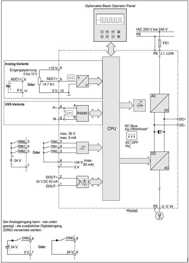
Заводские установки
Преобразователь SINAMICS G110 предустановлен на заводе для нормальных приложений U/f с 4-полюсным трехфазным асинхронным движком с рабочими чертами, схожими преобразователю.
| Источник команд | P0700 см. раздел 3.1/ 3.2 |
| Источник заданного значения | P1000 см. раздел 3.1/ 3.2 |
| Самовентилируемый двигатель | P0335 = 0 |
| Коэффициент перегрузки двигателя | P0640 = 150% |
| Мин. частота | P1080 = 0 Гц |
| Макс. частота | P1082 = 50 Гц |
| Время разгона | P1120 = 10 сек |
| Время торможения | P1121 = 10 сек |
| Управление U/f | P1300 = 0 |
Своеобразные заводские установки для аналогового входа
| Цифровые входы | Клеммы | Параметр | Функция |
| Источник команд | 3, 4, 5 | P0700 = 2 | Цифровой вход |
| Источник заданного значения | 9 | P1000 = 2 | Аналоговый вход |
| Цифровой вход 0 | 3 | P0701 = 1 | ВКЛ / ВЫКЛ1 (I/O) |
| Цифровой вход 1 | 4 | P0702 = 12 | Реверсирование |
| Цифровой вход 2 | 5 | P0703 = 9 | Квитирование ошибок (Ack) |
| Метод управления | — | P0727 = 0 | Стандартное управление Siemens |
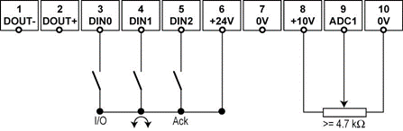
Внешний вид панели управления
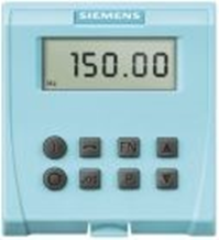
| Панель управления/клавиша | Функция | Действия |
| Индикациясостояния | LCD демонстрирует установки, с которыми преобразователь трудится в аутентичный момент. | |
| Запустить двигатель | Нажатием данной кнопки запускается преобразователь. В предустановке данная кнопка деактивирована. Активация клавиши: P0700 = 1 или P0719 = 10 … 15 | |
| Остановить двигатель | OFF1 Нажатие этой кнопки останавливает двигатель на выбранное время торможения. Деактивирована через предустановку. Активация клавиши: P0700 = 1 или P0719 = 10 … 15 ВЫКЛ2 Двукратное нажатие (или однократное длительное нажатие) клавиши вызывает свободный выбег двигателя до состояния покоя. Эта функция активирована всегда. |
|
| Реверсирование | Нажмите эту кнопку, чтобы изменить направление вращения двигателя. отображается знаком минус (-) или мигающей десятичной точкой. Активация клавиши: P0700 = 1 или P0719 = 10 … 15. | |
| Периодический режим работы двигателя | В состоянии „Включен/готов“ нажатие данной кнопки вызывает пуск и вращение мотора с предустановленной частотой шага. При отпускании кнопки движок замирает. Нажатие данной кнопки при вращающемся движке остается без результатов. | |
| Функции | С помощью этой клавиши можно вывести на экран дополнительную информацию. Если во время работы клавиша нажата в течение двух секунд, то независимо от соответствующего параметра отображается следующая информация: Напряжение звена постоянного тока (обозначается символом d — единица измерения В). Выходная частота (Гц) Выходное напряжение (обозначается o — единица измерения В). Значение, выбранное в P0005 (если P0005 настроен на отображение одного из у.е. данных. (от 1 до 3), соответствующее значение больше не появится). При повторном нажатии вышеуказанные индикаторы последовательно меняются. Находясь в любом параметре (rxxxxx или Pxxxxx), кратковременное нажатие клавиши Fn приведет вас непосредственно к r0000. Затем можно изменить следующий параметр по мере необходимости. После возврата к r0000 нажатие клавиши Fn возвращает вас в исходную точку. Подтверждение Если появляются предупреждения и сообщения об ошибках, их можно подтвердить, нажав клавишу Fn. | |
| Доступ к параметрам | Нажатием этой клавиши можно обращаться к параметрам. |
Ввод в эксплуатацию
Быстрый ввод в эксплуатацию
Быстрый запуск позволяет согласовать инвертор с двигателем и установить важные параметры процесса. Если используется 4-полюсный стандартный двигатель Siemens 1LA7, соответствующий данным заводской таблички преобразователя, не проводите быстрый запуск.
Для доступа ко всем параметрам двигателя рекомендуется уровень доступа P0003=3 (5.2).
Параметры, отмеченные *, имеют больше вариантов настройки, чем указано здесь. Другие варианты настройки м. в списке параметров.
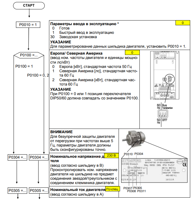
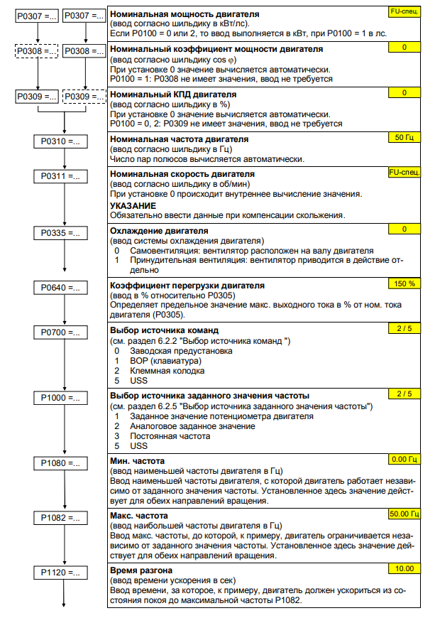
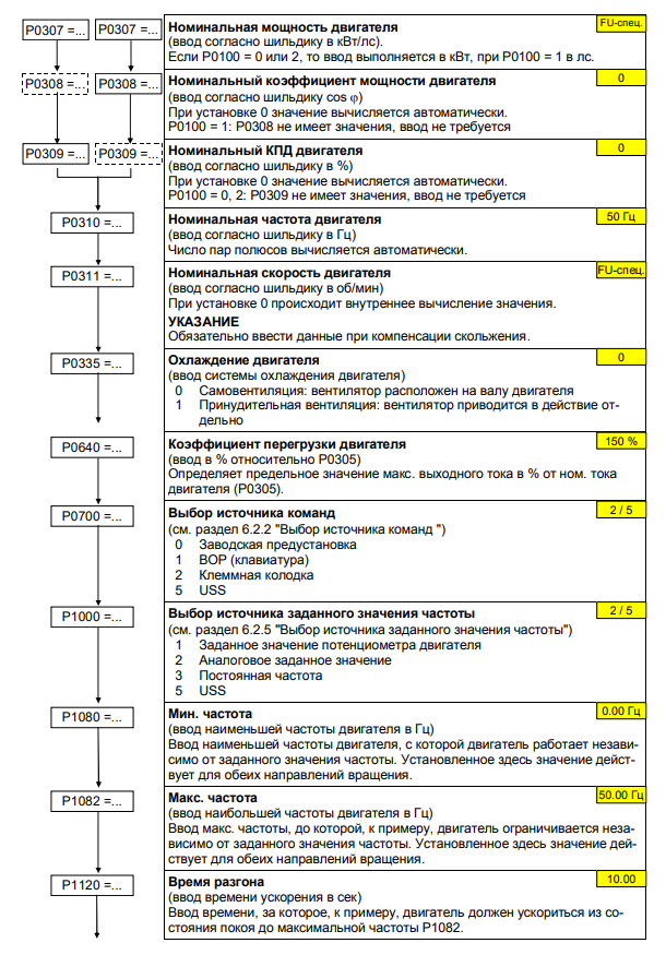
Прикладной ввод в эксплуатацию
Ввод в эксплуатацию используется для адаптации/оптимизации комбинации инвертор/двигатель к условиям эксплуатации. Инвертор имеет множество функций, не все из которых необходимы для конкретного применения. Эти функции могут быть опущены при запуске приложения. Здесь описано большинство возможных функций; другие функции. см. список параметров. Список параметров.
Параметры, отмеченные *, имеют больше вариантов конфигурации, чем те, которые перечислены здесь. Другие параметры настройки м. в списке параметров.
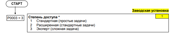
Последовательный интерфейс (USS)
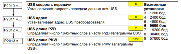
Выбор источника команд
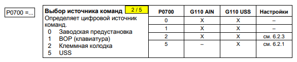
Цифровые входы (DIN)
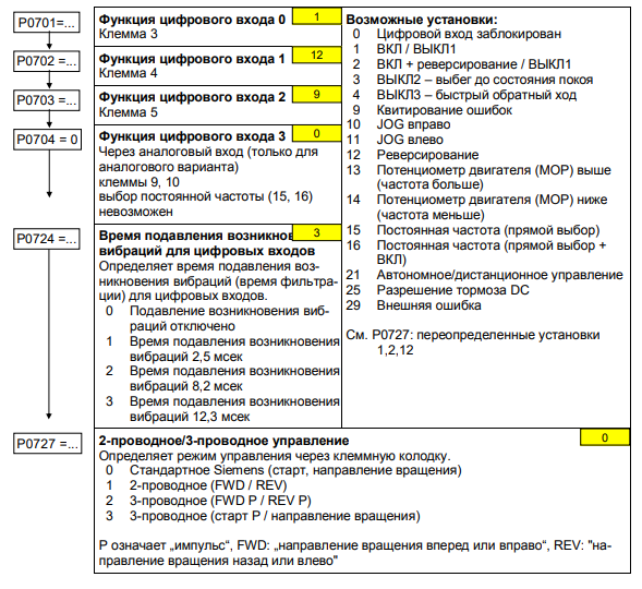
Цифровой выход (DOUT)
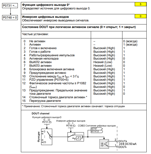
Выбор источника заданного значения частоты
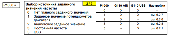
Аналоговый вход (ADC)
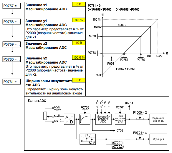
Потенциометр двигателя (MOP)
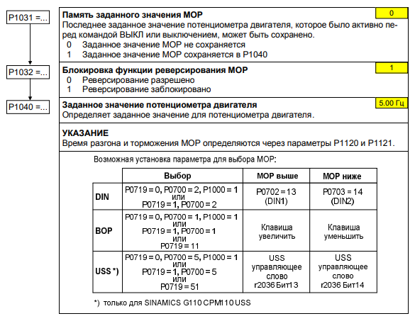
Постоянные частоты (FF)
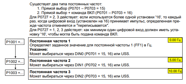
Исходные/граничные частоты
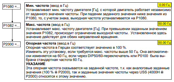
Управление двигателем
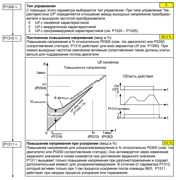
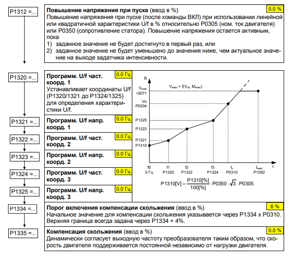
Защита преобразователя/двигателя
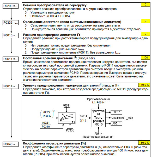
Стояночный тормоз двигателя
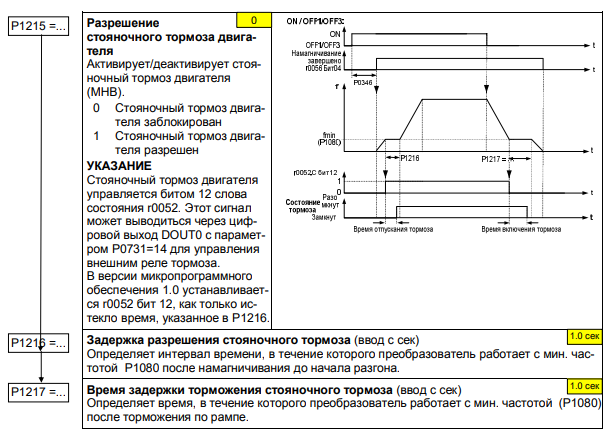
Тормоз DC смешанный тормоз
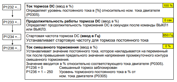
Регулятор VDC
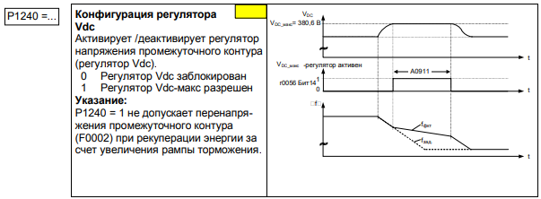
Сброс параметров к заводским установкам
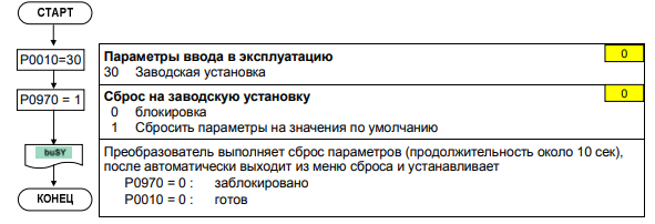
Список ошибок
| Ошибка | Значение |
| F0001 | Ток перегрузки |
| F0002 | Перенапряжение |
| F0003 | Пониженное напряжение |
| F0004 | Перегрев преобразователя |
| F0005 | Преобразователь I2t |
| F0011 | Перегрев двигателя I2t |
| F0051 | Ошибка параметров EEPROM |
| F0052 | Ошибка питания |
| F0060 | Переполнение слотов Asic |
| F0072 | Ошибка заданного значения USS |
| F0085 | Внешняя ошибка |
| Предупреждения | Значение |
| A0501 | Предельное значение тока |
| A0502 | Предельное значение перенапряжения |
| A0503 | Предельное значение пониженного напряжения |
| A0505 | Преобразователь I2t |
| A0511 | Перегрев двигателя I2t |
| A0910 | Регулятор Vdc-макс отключен |
| A0911 | Регулятор Vdc-макс активен |
| A0920 | Параметры ADC установлены неправильно |
| A0923 | Как JOG влево, так и JOG вправо запрошены |
Скачать документацию.
RU