-
Page 1
Operating Instructions SIMOREG DC-MASTER Converter Commutation Protector (SIMOREG CCP) Edition 04 Order No. 6RX1700-0DD74… -
Page 2
When using a SIMOREG DC-MASTER as basic converter unit: The SIMOREG DC-MASTER must have software release 2.2 or higher. The software release of the SIMOREG DC-MASTER can be read-out at parameters r060 and r065, the software release of the associated SIMOREG CCP can be read-out at parameter n560. -
Page 3: Table Of Contents
Connecting the Firing Unit Trigger Board …………….36 Fuses ……………………….37 Arrangement of the terminals, connectors and fuses………….37 Terminal assignment, connectors……………….38 Commissioning ……………………….41 Operation via the basic unit (SIMOREG DC-MASTER or SINAMICS DCM) ……42 7.1.1 SIMOREG DC-MASTER parameters ………………42 7.1.2 SINAMICS DCM parameters ………………..48 7.1.3…
-
Page 4
Table of Contents 12.2010 Appendix ………………………….73 11.1 Characteristic diagrams ………………….73 11.2 Relevant standards …………………….91 11.3 Certification ……………………..91 11.4 Abbreviations, terminology………………….91 11.5 Environmental compatibility ………………..92 ENGLISH Siemens AG 6RX1700-0DD74 SIMOREG DC-MASTER Converter Commutation Protector Operating Instructions… -
Page 5: Notes
Note the following: WARNING Siemens products are only permitted to be used for the applications listed in the catalog and in the associated technical documentation. If third-party products and components are used, they must be recommended or approved by Siemens. These products can only function correctly and safely if they are transported, stored, set up, mounted, installed, commissioned, operated and maintained correctly.
-
Page 6: Warning Notes
Furthermore, the contents of these operating instructions shall not become a part of or modify any prior or existing agreement, commitment, or legal relationship. The Purchase Agreement contains the complete and exclusive obligations of Siemens, including the warranty provisions. Any statements contained in these operating instructions neither expand nor restrict the scope of these contractual warranty conditions.
-
Page 7
Operating the unit in the immediate vicinity (< 1.5 m) of mobile telephones with a transmitter power of > 1 W may lead to incorrect operation of the unit. Siemens AG 6RX1700-0DD74 ENGLISH SIMOREG DC-MASTER Converter Commutation Protector Operating Instructions… -
Page 8: Electrostatic Sensitive Devices (Esd)
The necessary ESD protective measures are illustrated once again in the following diagram: Seated Standing Seated/standing a conductive floor b ESD table c ESD footwear d ESD overall e ESD wrist strap cabinet ground connection ENGLISH Siemens AG 6RX1700-0DD74 SIMOREG DC-MASTER Converter Commutation Protector Operating Instructions…
-
Page 9: Type Spectrum, Ordering Information
Item Order No. (MLFB) Operating instructions for 6RX1700-0AD64 SIMOREG DC-MASTER and SIMOREG CCP and DriveMonitor in all of the available languages on CD-ROM Operating instructions for 6RX1800-0AD64 SINAMICS DCM and SIMOREG CCP in all of the available languages on DVD…
-
Page 10
Item Order No. (MLFB) Patch cable UTP CAT5 acc. to ANSI/EIA/TIA 568 6RY1707-0AA08 Parallel cable for SIMOREG DC-MASTER 6RA70 / SINAMICS DCM and SIMOREG CCP approx. 5 m Connecting cable, pulse turn-off interface to the parallel SIMOREG CCP connection Connecting cable, summed firing pulse interface to the SIMOREG DC-MASTER (CUD2) Connecting cable «fast pulse cancellation interface»… -
Page 11: Selecting A Suitable Simoreg Ccp
12.2010 Type spectrum, ordering information Selecting a suitable SIMOREG CCP The rated unit data (taking into account the relevant limit values) of the SIMOREG DC-MASTER or SINAMICS DCM and SIMOREG CCP components form the basis for the selection table. 2.3.1 Selection table for 4Q basic units Converter Commutation Protector SIMOREG CCP 6RA70…
-
Page 12
For system configurations, with reduced rate values (e.g. DC rating, US rating, voltage derating), under certain circumstances, suitable combinations of units can be found that are not listed in the table. ENGLISH Siemens AG 6RX1700-0DD74 SIMOREG DC-MASTER Converter Commutation Protector Operating Instructions… -
Page 13: Selection Table For 2Q Basic Units
1000 V / 1500 A 6RA7095-4LS22-0 1000 V / 1900 A 6RA7095-4LS22-5 1000 V / 1900 A 6RA7096-4MS22-0 1140 V / 2200 A = suitable = not suitable (see note) Siemens AG 6RX1700-0DD74 ENGLISH SIMOREG DC-MASTER Converter Commutation Protector Operating Instructions…
-
Page 14
For system configurations, with reduced rate values (e.g. DC rating, US rating, voltage derating), under certain circumstances, suitable combinations of units can be found that are not listed in the table. ENGLISH Siemens AG 6RX1700-0DD74 SIMOREG DC-MASTER Converter Commutation Protector Operating Instructions… -
Page 15: Rating Plate, Packaging Label
Q6 ..QTY 1 VERSION E-STATUS (Version) (Version) Q ..MADE IN EU (AUSTRIA) Packaging label Siemens AG 6RX1700-0DD74 ENGLISH SIMOREG DC-MASTER Converter Commutation Protector Operating Instructions…
-
Page 16: Description, Technical Data
If this is the case, then the following occurs: 1. The firing pulses are immediately disabled in the SIMOREG DC-MASTER or SINAMICS DCM. 2. The basic converter unit sends a turn-off command to the SIMOREG CCP (via the serial interface) 3.
-
Page 17: Technical Data
This is calculated using a software algorithm, and depending on the energy that is dissipated during the quenching operation, is up to approx. 20 min. Siemens AG 6RX1700-0DD74 ENGLISH SIMOREG DC-MASTER Converter Commutation Protector Operating Instructions…
-
Page 18: Block Diagram
Description, technical data 12.2010 Block diagram ENGLISH Siemens AG 6RX1700-0DD74 SIMOREG DC-MASTER Converter Commutation Protector Operating Instructions…
-
Page 19
Units 6RA70…95-6FC00-0 / …95-6KC00-0 (all 2000 A) K2 G2 G1 K1 K2 G2 G1 K1 K1 G1 G2 K2 K1 G1 G2 K2 X 33 X 31 (1C1) (1D1) Siemens AG 6RX1700-0DD74 ENGLISH SIMOREG DC-MASTER Converter Commutation Protector Operating Instructions… -
Page 20: Transport, Unpacking
The packaging materials consist of a cardboard box and corrugated cardboard, and can be disposed of in accordance with local regulations for cardboard packaging materials. If you identify any damage that has occurred in transit, please inform your shipping agent immediately. ENGLISH Siemens AG 6RX1700-0DD74 SIMOREG DC-MASTER Converter Commutation Protector Operating Instructions…
-
Page 21: Installation
UL 508 C. To install the unit, the cabinet must have minimum dimensions of 2200 mm x 600 mm x 600 mm (H x W x D). Siemens AG 6RX1700-0DD74 ENGLISH SIMOREG DC-MASTER Converter Commutation Protector Operating Instructions…
-
Page 22: Dimension Drawing
Installation 12.2010 Dimension drawing 600 A / 1000 A / 1200 A — units: ENGLISH Siemens AG 6RX1700-0DD74 SIMOREG DC-MASTER Converter Commutation Protector Operating Instructions…
-
Page 23
12.2010 Installation 2000 A — units: Siemens AG 6RX1700-0DD74 ENGLISH SIMOREG DC-MASTER Converter Commutation Protector Operating Instructions… -
Page 24: Sinamics Dcm — Installing The Firing Unit Trigger Board
Unit Trigger Board) (Order No.: 6RY1803-0CP00). See chapter 6.3.2. CAUTION Please observe the information provided on «Electrostatic sensitive devices (ESD)» in Chapter 1. WARNING Always carry out the work with the SINAMICS DCM in a no-voltage condition! ENGLISH Siemens AG 6RX1700-0DD74 SIMOREG DC-MASTER Converter Commutation Protector Operating Instructions…
-
Page 25
The BOP holder can be released at the side and swung upwards to route the connecting cable • After connecting the cable (see Chapter 6.3.3) relocate the front cover of the SINAMICS DCM and fasten using all of the screws Siemens AG 6RX1700-0DD74 ENGLISH SIMOREG DC-MASTER Converter Commutation Protector Operating Instructions… -
Page 26: Connecting
Also observe all of the safety instructions in the converter unit operating instructions. Note Please observe the installation instructions for EMC-compliant design of drives in Chapter 6.1 of the operating instructions of the basic SIMOREG DC-MASTER or SINAMICS DCM unit. ENGLISH Siemens AG…
-
Page 27: Cable Lengths
SIMOREG CCP Cable length to connect the AC / SINAMICS DCM connections ..l 1C1 1D1 1C1 1D1 Cable length to connect the DC connections ..l l <1> Siemens AG 6RX1700-0DD74 ENGLISH SIMOREG DC-MASTER Converter Commutation Protector Operating Instructions…
-
Page 28
The minimum required cable length l_min is 3 m. Use 3m lengths each for 1U1, 1V1, 1W1, 1C1, 1D1. Or: e.g. use 1m lengths each for 1U1, 1V1, 1W1 and 5 m lengths each for 1C1, 1D1 ENGLISH Siemens AG 6RX1700-0DD74 SIMOREG DC-MASTER Converter Commutation Protector Operating Instructions… -
Page 29: Recommended Connection
In addition, it must be carefully observed that the total of the delay times of all of the switching elements in the control circuit must not exceed the time set at parameter P089. Siemens AG 6RX1700-0DD74 ENGLISH SIMOREG DC-MASTER Converter Commutation Protector Operating Instructions…
-
Page 30: Connecting A Sinamics Dcm
In addition, it must be carefully observed that the total of the delay times of all of the switching elements in the control circuit must not exceed the time set at parameter P50089. ENGLISH Siemens AG 6RX1700-0DD74 SIMOREG DC-MASTER Converter Commutation Protector Operating Instructions…
-
Page 31: Versions To Interconnect The Main Contactor (Circuit Breaker) K1
SINAMICS DCM SINAMICS DCM 6.2.4 Recommended connection when using a Siemens 3WL circuit breaker If circuit breakers from other manufacturers are used, then the recommended connection described here applies accordingly. It should be noted that the circuit breaker is equipped with a ready to close signal contact (S20,…
-
Page 32
Control voltage -X_SCHÜTZ:4 Fault inv. -X171:46 -X_SCHÜTZ:5 -X171:47 e.g. Relais DC 24 V SIMOREG DC-MASTER B0107 SINAMICS DCM r2139.03 -S11 -S20 Siemens U< Circuit breaker 3WL control unit Control voltage ENGLISH Siemens AG 6RX1700-0DD74 SIMOREG DC-MASTER Converter Commutation Protector Operating Instructions… -
Page 33: Connecting Units In Parallel
12.2010 Connecting Connecting units in parallel 6.3.1 Parallel connection of SIMOREG DC-MASTER units A SIMOREG CCP is directly connected in parallel to each of the converter units connected in parallel (SIMOREG DC-MASTER). X30_PAR X29_PAR X172 X300 X165 1D1 (1C1) 1C1 (1D1)
-
Page 34: Parallel Connection Of Sinamics Dcm Units
The firing pulses are disabled via the fast pulse cancellation interface 3.4. CAUTION The parallel interface (X165, X166) at the SINAMICS DCM is not compatible to the parallel interface (X165) at the SIMOREG DC-MASTER CCP. It is not permissible that both connectors are connected. ENGLISH…
-
Page 35
1D1 (1C1) 1C1 (1D1) 1D1 (1C1) 1C1 (1D1) X166 X165 X177 X165_2 X30_PAR X29_PAR X172 X300 X165 1D1 (1C1) 1C1 (1D1) 1D1 (1C1) 1C1 (1D1) X166 X165 X177 X165_2 Siemens AG 6RX1700-0DD74 ENGLISH SIMOREG DC-MASTER Converter Commutation Protector Operating Instructions… -
Page 36: 6.3.3 Connecting The Firing Unit Trigger Board
6.3.3 Connecting the Firing Unit Trigger Board Routing of the connecting cable «fast pulse cancellation interface» to the SINAMICS DCM with shield support: ① Firing Unit Trigger Board ② Connector X165_2 ③ Shield support ENGLISH Siemens AG 6RX1700-0DD74 SIMOREG DC-MASTER Converter Commutation Protector Operating Instructions…
-
Page 37: Fuses
12.2010 Connecting Fuses Fuses in the armature circuit and in the motor circuit Recommended Siemens semiconductor fuses (depending on the SIMOREG CCP used): Unit Order No. Rated Rated Fuses Fuses (MLFB) current voltage 1U1, 1V1, 1W1 1C1, 1D1 6RA7085-6FC00-0 600 A…
-
Page 38: Terminal Assignment, Connectors
Connection values the same as for the power unit SIMOREG CCP (see above) Control circuit for Wiring, main contactor/circuit breaker main contactor / (see the recommended connection in Chapter 6.2) circuit breaker ENGLISH Siemens AG 6RX1700-0DD74 SIMOREG DC-MASTER Converter Commutation Protector Operating Instructions…
-
Page 39
-7 V/+12 V. Equipotential bonding must be implemented if this cannot be guaranteed. Activating the serial interface by setting the protocol at parameter P790 or p50790. Siemens AG 6RX1700-0DD74 ENGLISH SIMOREG DC-MASTER Converter Commutation Protector Operating Instructions… -
Page 40
Connecting 12.2010 Connecting to a SIMOREG DC-MASTER: X172 X172 MINI-COMBICON MINI-COMBICON Connecting to a SINAMICS DCM: SIMOREG CPP SINAMICS DCM X-172 X-177 MINI COMBICON Connector Board Programming interface for the software update X300 Serial interface RS232 9-pin SUBMIN D socket… -
Page 41: Commissioning
If you encounter specific problems that have not been handled in enough detail for the purposes of the buyer, then please contact your local Siemens office. The use of non-approved parts for carrying out repair work on the unit or handling of the unit by inadequately qualified personnel will result in dangerous conditions with the risk of death, serious physical injury, or extensive damage to equipment.
-
Page 42: Operation Via The Basic Unit (Simoreg Dc-Master Or Sinamics Dcm)
Response of the commutation monitoring U583 Test command for the SIMOREG CCP *) For a description of these parameters, see the operating instructions SIMOREG DC-MASTER Chapter 11 Detailed description of parameters The specified software release refers to the software release of the SIMOREG DC-MASTER…
-
Page 43
Display of the I2t value [from SW 2.1] 0 to 100 Ind: None P052 = 3 (2576) of the voltage limitingchoppers 2 of the SIMOREG CCP Type: O2 Siemens AG 6RX1700-0DD74 ENGLISH SIMOREG DC-MASTER Converter Commutation Protector Operating Instructions… -
Page 44
2500 6RA7093-4LV62-0 2500 6RA7095-4LV62-0 2500 6RA7018-6DS22-0 1300 6RA7025-6DS22-0 1300 6RA7028-6DS22-0 1300 6RA7031-6DS22-0 1300 6RA7075-6DS22-0 1300 6RA7078-6DS22-0 1300 6RA7081-6DS22-0 1300 6RA7085-6DS22-0 1300 6RA7087-6DS22-0 1300 6RA7091-6DS22-0 1300 6RA7093-4DS22-0 1500 6RA7095-4DS22-0 1500 ENGLISH Siemens AG 6RX1700-0DD74 SIMOREG DC-MASTER Converter Commutation Protector Operating Instructions… -
Page 45
1100 6RA7090-6KC00-0 1600 6RA7095-6KC00-0 1600 Note: The setting value for U577 according to the table above defines the maximum permissible value of the voltage limit for the particular unit. Siemens AG 6RX1700-0DD74 ENGLISH SIMOREG DC-MASTER Converter Commutation Protector Operating Instructions… -
Page 46
P351 = -20 % of P078i001 (according to the factory setting). The following upper limit applies for a value of P351 that deviates from the factory setting: ⎛ ⎞ ∗ ∗ ⎜ ⎜ ⎟ ⎟ ⎝ ⎠ Upper limit = ENGLISH Siemens AG 6RX1700-0DD74 SIMOREG DC-MASTER Converter Commutation Protector Operating Instructions… -
Page 47
Type: O2 This memory is updated each time that fault message F030 is output. It includes more detailed information about the cause of the commutation fault, which can be evaluated by Siemens experts. Siemens AG 6RX1700-0DD74 ENGLISH SIMOREG DC-MASTER Converter Commutation Protector… -
Page 48: Sinamics Dcm Parameters
CCP chopper voltage setpoint, upper response threshold p51578 CCP quenching capacitor pre-charging voltage setpoint r51579.0…7 CO/BO: CCP command p51580 Commutation monitoring, control word p51583 CCP test turn-off command ENGLISH Siemens AG 6RX1700-0DD74 SIMOREG DC-MASTER Converter Commutation Protector Operating Instructions…
-
Page 49
Description: Sets the bus termination for the peer-to-peer interface and the interface to the SIMOREG CCP. Value: 0: off 1: on Note: CCP: Converter Commutation Protector P2P: Peer-to-peer interface Siemens AG 6RX1700-0DD74 ENGLISH SIMOREG DC-MASTER Converter Commutation Protector Operating Instructions… -
Page 50
Displays the software version for the Converter Communication Protector (CCP). Index: [0] = version release of the CCP software [1] = version release of the software of the CCP boot sector ENGLISH Siemens AG 6RX1700-0DD74 SIMOREG DC-MASTER Converter Commutation Protector Operating Instructions… -
Page 51
CO: CCP I2t value voltage limiting chopper 2 / CCP I2t chopper 2 Description: Displays the I2t value for voltage limiting chopper 2 for the Converter Commutation Protector (CCP). Siemens AG 6RX1700-0DD74 ENGLISH SIMOREG DC-MASTER Converter Commutation Protector Operating Instructions… -
Page 52
1700 6RA8090-6GV62-0AA0 1700 6RA8093-4GV62-0AA0 1700 6RA8095-4GV62-0AA0 1700 6RA8096-4GV62-0AA0 1700 6RA8097-4GV62-0AA0 1700 6RA8086-6KV62-0AA0 2100 6RA8090-6KV62-0AA0 2100 6RA8093-4KV62-0AA0 2100 6RA8095-4KV62-0AA0 2100 6RA8097-4KV62-0AA0 2100 6RA8088-6LV62-0AA0 2500 6RA8093-4LV62-0AA0 2500 6RA8095-4LV62-0AA0 2500 6RA8096-4MV62-0AA0 2900 ENGLISH Siemens AG 6RX1700-0DD74 SIMOREG DC-MASTER Converter Commutation Protector Operating Instructions… -
Page 53
The parameter is automatically set for the «Optimization run for CCP» (p50051 = 30). The correct setting for this parameter can be taken from the following reference: SIMOREG CCP operating instructions Siemens AG 6RX1700-0DD74 ENGLISH SIMOREG DC-MASTER Converter Commutation Protector Operating Instructions… -
Page 54
-20 % of p50078[0] (according to the factory setting). The following upper limit applies for a value of p50351 that deviates from the factory setting: ⎛ ⎞ 50351 ⎜ ⎜ ⎟ ⎟ ∗ ∗ 50078 ⎝ ⎠ Upper limit = ENGLISH Siemens AG 6RX1700-0DD74 SIMOREG DC-MASTER Converter Commutation Protector Operating Instructions… -
Page 55
Using this parameter, these can be individually set for test purposes. If several decision-making criteria are to be evaluated, then the sum of the corresponding numbers should be set. Siemens AG 6RX1700-0DD74 ENGLISH SIMOREG DC-MASTER Converter Commutation Protector Operating Instructions… -
Page 56: Simoreg Dc-Master Connectors
(U800 = 0 OR U800 = 1 OR [U800 = 2 AND U806 > 10]) Note: Bits 8 and 9 are always updated. For all other a bits, the following applies: The bits after the first bit with the value zero are invalid! ENGLISH Siemens AG 6RX1700-0DD74 SIMOREG DC-MASTER Converter Commutation Protector Operating Instructions…
-
Page 57: Simoreg Dc-Master Faults
Field current actual value (K0265) for a fault situation i006 Pulse number (K0105) for a fault situation A SIMOREG DC-MASTER connected in parallel has detected a commutation fault or an overcurrent condition Test command was entered via U583…
-
Page 58: Sinamics Dcm Faults
= actual CD voltage r50047[2] = actual delay angle r50047[3] = actual firing instant r50047[4] = actual EMF r50047[5] = actual Ia sampling value r50047[6] = torque direction when triggering ENGLISH Siemens AG 6RX1700-0DD74 SIMOREG DC-MASTER Converter Commutation Protector Operating Instructions…
-
Page 59
The pre-charging of the chopper capacitors was not able to be completed within the time set in p50089 — or the condition according to fault value 5 is fulfilled. Trigger time: 20 ms. Siemens AG 6RX1700-0DD74 ENGLISH SIMOREG DC-MASTER Converter Commutation Protector Operating Instructions… -
Page 60
Note regarding fault value = 707: r50047[1]: Calculated Vmax r50047[2]: Parameter p51578 maximum possible value Note regarding fault value = 708: r50047[1]: Calculated chopper energy r50047[2]: maximum possible chopper energy for SIMOREG ENGLISH Siemens AG 6RX1700-0DD74 SIMOREG DC-MASTER Converter Commutation Protector Operating Instructions… -
Page 61: Simoreg Dc-Master Alarms
Voltage not available at the connections U, V, W of the SIMOREG CCP • Voltage at C-D at the SIMOREG CCP does not match the voltage C-D at the SIMOREG DC-MASTER • The quenching capacitors of the SIMOREG CCP have not reached the setpoint voltage •…
-
Page 62: Commissioning Steps
Determining the setting value for parameter U577 (factory setting = 1600) Required parameter values: r070…MLFB (characteristic number) of the SIMOREG DC-MASTER n570…MLFB (characteristic number) of the SIMOREG CCP ⇒ Determining the setting value according to the parameter description for U577 Commission the basic converter unit according to the operating instructions SIMOREG DC- MASTER, Chapter 7.
-
Page 63
16.0 1.) Rated DC voltage according to the motor rating plate (the values are typical rated data for Siemens DC motors from the product catalog DA12 2.) The characteristic diagrams are provided in the appendix to these operating instructions If the graphically determined value lies below the limit line W_max, then the energy reduction in the armature circuit is assured using the SIMOREG CCP. -
Page 64: Sinamics Dcm Commissioning Steps
This is the reason that before performing the optimization run, the actual value of p50111 should be noted and only set again after the SIMOREG CCP commissioning has been completed. ENGLISH Siemens AG 6RX1700-0DD74 SIMOREG DC-MASTER Converter Commutation Protector Operating Instructions…
-
Page 65
16.0 1.) Rated DC voltage according to the motor rating plate (the values are typical rated data for Siemens DC motors from the product catalog DA12 2.) The characteristic diagrams are provided in the appendix to these operating instructions If the graphically determined value lies below the limit line W_max, then the energy reduction in the armature circuit is assured using the SIMOREG CCP. -
Page 66: Maintenance
12 months. The unit should be cleaned using dry compressed air, max. 1 bar, or using a vacuum cleaner. ENGLISH Siemens AG 6RX1700-0DD74 SIMOREG DC-MASTER Converter Commutation Protector Operating Instructions…
-
Page 67: Software Update Of The Simoreg Ccp
Step 4. monitoring LED at the SIMOREG CCP flashes slowly if communication with the basic unit has been established). Check the new software release at 560 or r51560[0]. Siemens AG 6RX1700-0DD74 ENGLISH SIMOREG DC-MASTER Converter Commutation Protector Operating Instructions…
-
Page 68: Replacing Components
Replace the module(s) Chopper Unit 460 V: MLFB = 6RY1703-0FC01 690 V: MLFB = 6RY1703-0FC02 Note For units 6RA7085-6FC00-0, 6RA7091-6FC00-0 and 6RA7090-6KC00-0, there is only one chopper unit (Item A) ENGLISH Siemens AG 6RX1700-0DD74 SIMOREG DC-MASTER Converter Commutation Protector Operating Instructions…
-
Page 69: Replacing Diode, Thyristor And Igbt Modules
Module design Tightening torque, module: 6 Nm Tightening torque, module: 3,5 Nm Tightening torque of the power connections: 12 Nm Tightening torque of the power connections: 5 Nm Siemens AG 6RX1700-0DD74 ENGLISH SIMOREG DC-MASTER Converter Commutation Protector Operating Instructions…
-
Page 70
The sequence when bolting the IGBT modules can be seen in the adjacent diagram and this must be maintained under all circumstances. Tightening torque, IGBT: 5 Nm Tightening torque of the busbars: 5 Nm ENGLISH Siemens AG 6RX1700-0DD74 SIMOREG DC-MASTER Converter Commutation Protector Operating Instructions… -
Page 71: Service, Technical Support
Our technical support service can provide you with technical assistance for products, systems, and solutions. http://www.siemens.de/automation/support-request (German) http://www.siemens.com/automation/support-request (English) Central hotlines for technical support for SIMOREG CCP / SIMOREG DC-MASTER / SINAMICS DCM: Time zone Tel: +49 (0)911 895 7222 8:00 to 17:00 CET Europe and Africa Fax: +49 (0)911 895 7223 mailto:support.automation@siemens.com…
-
Page 72: Spare Parts
Thyristor module 115x52x50 0,75 6SY7010-0AA22 ..95-6FC00-0 V32+33, MCC312-18io1 V35+38, V36+37, V39, V40 F1, F2 Fuses 20×5 0,002 6RY1702-0BA00 ..85-6FC00-0 on the Power- ..91-6FC00-0 Interface printed ..90-6KC00-0 circuit board ..95-6FC00-0 ..95-6KC00-0 ENGLISH Siemens AG 6RX1700-0DD74 SIMOREG DC-MASTER Converter Commutation Protector Operating Instructions…
-
Page 73: Appendix
Characteristic diagrams to define the voltage setpoint for the pre-charging of the SIMOREG CCP quenching capacitors (parameter U578 for SIMOREG DC-MASTER or p51578 for SINAMICS DCM) using the armature circuit inductance (P111 for SIMOREG DC-MASTER or p50111 for SINAMICS DCM) and the actual unit rated DC armature current (r072i002 for SIMOREG DC- MASTER or r50072[1] for SINAMICS DCM) <…
-
Page 74
6RA7085-6FC00-0 for motors with rated armature voltage 420 V (P101 or p50101) 400A 300A 200A 200A 300A 400A 500A 600A Untergrenze Obergrenze 0.03 0.04 0.05 0.06 0.07 0.08 0.09 Armature circuit inductance in mH (P111 or p50111) ENGLISH Siemens AG 6RX1700-0DD74 SIMOREG DC-MASTER Converter Commutation Protector Operating Instructions… -
Page 75
6RA7085-6FC00-0 for motors with rated armature voltage 470 V (P101 or p50101) 500A 400A 300A 200A 200A 300A 400A 500A 600A Untergrenze Obergrenze 0.03 0.04 0.05 0.06 0.07 0.08 0.09 Armature circuit inductance in mH (P111 or p50111) Siemens AG 6RX1700-0DD74 ENGLISH SIMOREG DC-MASTER Converter Commutation Protector Operating Instructions… -
Page 76
800A 700A 600A 500A 500A 600A 700A 800A 900A 1000A 1100A 1200A Untergrenze Obergrenze 0.03 0.04 0.05 0.06 0.07 0.08 0.09 Armature circuit inductance in mH (P111 or p50111) ENGLISH Siemens AG 6RX1700-0DD74 SIMOREG DC-MASTER Converter Commutation Protector Operating Instructions… -
Page 77
800A 700A 600A 500A 500A 600A 700A 800A 900A 1000A 1100A 1200A Untergrenze Obergrenze 0.03 0.04 0.05 0.06 0.07 0.08 0.09 Armature circuit inductance in mH (P111 or p50111) Siemens AG 6RX1700-0DD74 ENGLISH SIMOREG DC-MASTER Converter Commutation Protector Operating Instructions… -
Page 78
6RA7095-6FC00-0 for motors with rated armature voltage 420 V (P101 or p50101) 1800A 1600A 1400A 1200A 1000A 1000A 1200A 1400A 1600A 1800A 2000A Untergrenze Obergrenze 0.03 0.04 0.05 0.06 0.07 0.08 0.09 Armature circuit inductance in mH (P111 or p50111) ENGLISH Siemens AG 6RX1700-0DD74 SIMOREG DC-MASTER Converter Commutation Protector Operating Instructions… -
Page 79
1000A 1200A 1400A 1600A 2000A 1800A 2000A Untergrenze Obergrenze 1800A 1600A 1400A 1200A 1000A 0.03 0.04 0.05 0.06 0.07 0.08 0.09 Armature circuit inductance in mH (P111 or p50111) Siemens AG 6RX1700-0DD74 ENGLISH SIMOREG DC-MASTER Converter Commutation Protector Operating Instructions… -
Page 80
600A 500A 400A 300A 300A 400A 500A 600A 700A 800A 900A 1000A Untergrenze Obergrenze 0.03 0.04 0.05 0.06 0.07 0.08 0.09 Armature circuit inductance in mH (P111 or p50111) ENGLISH Siemens AG 6RX1700-0DD74 SIMOREG DC-MASTER Converter Commutation Protector Operating Instructions… -
Page 81
600A 500A 400A 300A 300A 400A 500A 600A 700A 800A 900A 1000A Untergrenze Obergrenze 0.03 0.04 0.05 0.06 0.07 0.08 0.09 Armature circuit inductance in mH (P111 or p50111) Siemens AG 6RX1700-0DD74 ENGLISH SIMOREG DC-MASTER Converter Commutation Protector Operating Instructions… -
Page 82
600A 500A 400A 300A 300A 400A 500A 600A 700A 800A 900A 1000A Untergrenze Obergrenze 0.03 0.04 0.05 0.06 0.07 0.08 0.09 Armature circuit inductance in mH (P111 or p50111) ENGLISH Siemens AG 6RX1700-0DD74 SIMOREG DC-MASTER Converter Commutation Protector Operating Instructions… -
Page 83
6RA7095-6KC00-0 for motors with rated armature voltage 600 V (P101 or p50101) 1600A 1400A 1200A 1000A 1000A 1200A 1400A 1600A 1800A 2000A 2200A Untergrenze Obergrenze 0.03 0.04 0.05 0.06 0.07 0.08 0.09 Armature circuit inductance in mH (P111 or p50111) Siemens AG 6RX1700-0DD74 ENGLISH SIMOREG DC-MASTER Converter Commutation Protector Operating Instructions… -
Page 84
6RA7095-6KC00-0 for motors with rated armature voltage 600 V (P101 or p50101) 1600A 1400A 1200A 1000A 1000A 1200A 1400A 1600A 1800A 2000A 2200A Untergrenze Obergrenze 0.03 0.04 0.05 0.06 0.07 0.08 0.09 Armature circuit inductance in mH (P111 or p50111) ENGLISH Siemens AG 6RX1700-0DD74 SIMOREG DC-MASTER Converter Commutation Protector Operating Instructions… -
Page 85
2000A 1800A 1600A 1400A 1200A 1000A 1000A 1200A 1400A 1600A 1800A 2000A Untergrenze Obergrenze 0.03 0.04 0.05 0.06 0.07 0.08 0.09 Armature circuit inductance in mH (P111 or p50111) Siemens AG 6RX1700-0DD74 ENGLISH SIMOREG DC-MASTER Converter Commutation Protector Operating Instructions… -
Page 86
10 mH 8 mH 4 mH 6 mH 8 mH 10 mH 4 mH 2 mH 1000 1100 1200 Actual unit rated DC armature current in A (r072i002 or r50072[1]) ENGLISH Siemens AG 6RX1700-0DD74 SIMOREG DC-MASTER Converter Commutation Protector Operating Instructions… -
Page 87
10 mH 4 mH 8 mH 6 mH 8 mH 10 mH 6 mH 4 mH 2 mH 1000 Actual unit rated DC armature current in A (r072i002 or r50072[1]) Siemens AG 6RX1700-0DD74 ENGLISH SIMOREG DC-MASTER Converter Commutation Protector Operating Instructions… -
Page 88
W_max 2 mH 4 mH 6 mH 8 mH 6 mH 10 mH 4 mH 2 mH 1000 Actual unit rated DC armature current in A (r072i002 or r50072[1]) ENGLISH Siemens AG 6RX1700-0DD74 SIMOREG DC-MASTER Converter Commutation Protector Operating Instructions… -
Page 89
6 mH 8 mH 10 mH 2 mH 1000 1100 1200 1300 1400 1500 1600 1700 1800 1900 2000 Actual unit rated DC armature current in A (r072i002 or r50072[1]) Siemens AG 6RX1700-0DD74 ENGLISH SIMOREG DC-MASTER Converter Commutation Protector Operating Instructions… -
Page 90
6 mH 8 mH 10 mH 2 mH 1000 1100 1200 1300 1400 1500 1600 1700 1800 1900 2000 Actual unit rated DC armature current in A (r072i002 or r50072[1]) ENGLISH Siemens AG 6RX1700-0DD74 SIMOREG DC-MASTER Converter Commutation Protector Operating Instructions… -
Page 91: Relevant Standards
Abbreviations, terminology Communauté Européenne cULus for ready-to-connect products, tested by UL in accordance with the UL and CSA standards Underwriters Laboratories Converter Commutation Protector IGBT insulated gate bipolar transistor Siemens AG 6RX1700-0DD74 ENGLISH SIMOREG DC-MASTER Converter Commutation Protector Operating Instructions…
-
Page 92: Environmental Compatibility
The printed circuit boards may be used in recycling processes involving energy recovery. The proportion of components containing hazardous substances is low. ENGLISH Siemens AG 6RX1700-0DD74 SIMOREG DC-MASTER Converter Commutation Protector Operating Instructions…
-
Page 94
The following versions have appeared so far: Version Internal Part No. C98130-A7046-A1-01-7419 C98130-A7046-A1-02-7419 C98130-A7046-A1-03-7419 C98130-A7046-A1-04-7419 SIMEA © Siemens AG, 2005-2010 Siemens Industrial Manufacturing, Subject to change without notice Engineering and Applications Order No.: 6RX1700-0DD74 Postfach 83, A-1211 Wien Printed in EU (Austria)
F030 fault in DC drive Simoreg 6RA70:dc master
Problem:
During running condition DC motor tripped showing “F030” fault.
Description:
I work in a Steel mill. And it is one of the renowned Steel mills in my country. Previously it was 18 stand mills but after some correction it is now 20 stand mill and for this purpose we changed one of DC motor named shear#2 or flying shear. We replaced it with 250KW DC motor. Previously it was 170KW. After changing this we faced with this new problem. It some times tripped in running condition especially in 3X12mm rolling showing F030 fault. We used DC drives from siemens and the model was Simoreg 6RA70.
The fault code was 2.
Analysis:
From simoreg DC master 6RA70 manual we see F30 means the followings
From fault code we see the root cause of this fault trigger is “The current crest curve breaks upwards” as our fault code is 2 (two).
Now the interesting part, from this we understand that this problem must related to some monitoring function. As Shear#2 does not run all the time and only used for cobble chopping and optimization chopping, it is probable that it may take some extra current for very short time.
Then we found the particular monitoring parameter. It is U580 (2580) “Control word for commutation monitoring”.

By this parameter we define which commutation monitoring criteria the drive will use. In our drive it was select in 4. So Decision criterion 3 that means maximum current actual value is evaluated. That’s the reason as it was reaching the limit as it tripped.
Then we changed the parameter from 4 to 7 means all three criterion will be used.
Then the problem solved.
Regarding the manual and figure: 2
Each decision criterion has a numeric code.
If more than one decision criterion is to be evaluated, the sum of the relevant digits must be entered.
There also rules for selecting the parameter. If u select 0 then “none of the three criteria are evaluated” will be selected. If u select 1 then “Decision criterion 1 (sufficient voltage time area for commutation) is evaluated” will be selected. If u select 2 then “Decision criterion 2 (curvature of the current crest curve) is evaluated” will be selected. If u select 4 then “Decision criterion 3 (maximum current actual value) is evaluated” will be selected.
Now if you want to select both criterions 1 & 2 then enter value 3. If you want to select both criterions 2 & 4 then select 6. If you want to select all of the criterions then select 7, the sum of all codes.
12.2010
7.1.4
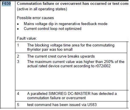
F030
Commutation fault or an overcurrent condition has occurred — or a test command was issued via U583
(active in all operating states)
Possible error causes
•
Line voltage dip during regenerative operation
•
Current control loop not optimized
Fault value:
1
The blocking voltage-time integral for the commutating
thyristor pair was too small
2
The current cusp breaks upwards
3
The amplitude of the current cusp was higher than 250%
of the actual rated unit current according to r072i002
4
A SIMOREG DC-MASTER connected in parallel has
detected a commutation fault or an overcurrent condition
5
Test command was entered via U583
F032
SIMOREG CCP not ready
(active for operating states < o4.0)
Possible error causes
•
Missing connection or interrupted cable at X172 (G-SST2)
•
For a parallel connection, missing connection or interrupted cable at X165 (parallel interface, master)
•
For a parallel connection, missing connection or interrupted cable at X29_PAR or X30_PAR (turn-off pulse interface)
•
Hardware defect in the charge circuit of the quenching capacitors
•
Ruptured fuse in the armature circuit, either line side or motor side
•
Ruptured fuse in the pre-charging circuit for the chopper capacitors
•
presently in the cooling-down phase necessary for the chopper resistors
•
MLFB data of the SIMOREG CCP (n570, n571, n572) invalid or not available
Fault value:
1
Voltage not available at the connections U, V, W of the
SIMOREG CCP
2
Voltage at C-D at the SIMOREG CCP does not match the
voltage C-D at the SIMOREG DC-MASTER
3
The quenching capacitors of the SIMOREG CCP have
not reached the setpoint voltage
4
The parallel interface cable is not connected at the
SIMOREG CCP, which is assigned the parallel switching
master
5
No connection between the SIMOREG DC-MASTER and
SIMOREG CCP via the serial interface G-SST2
(r799.i001 is not incremented)
6
No connection between parallel SIMOREG CCP units
7
Contents of the memory of the technical data of the
SIMOREG CCP (MLFB, rated values, serial number)
invalid
11
The I2t value (n575) of the voltage limiting chopper 1 is
too high (> 100%)
12
The I2t value (n576) of the voltage limiting chopper 2 is
too high (> 50%)
20
The pre-charging of the chopper capacitors was not able
to be completed within the time set in P089 — or the
condition according to fault value 5 is fulfilled
Siemens AG
6RX1700-0DD74
SIMOREG DC-MASTER Converter Commutation Protector
r047 indices 002 to 016:
for i001= 1 to 3 and 5, i002 to i006 are valid
for i001= 4, i002 to i015 are invalid
i002 delay angle (K0100) for a fault situation
i003 EMF actual value (K0287) for a fault situation
i004 Gating unit diagnostics (K0989) for a fault situation
i005 Field current actual value (K0265) for a fault situation
i006 Pulse number (K0105) for a fault situation
r047 indices 002 to 016:
for i001= 1 to 12, i002 to i006 are valid
for i001= 20, only i002 is valid
i002 state of the SIMOREG CCP (K0574) for a fault situation
i003 I2t value of chopper 1 (K0575) for a fault situation
i004 I2t value of chopper 2 (K0576) for a fault situation
i005 armature voltage actual value (r038) for a fault situation
in 0.1 V for i005 > 32767 the following applies:
V
[V] = (65536-r047i005)/10
ARMATURE
i006 effective time until a fault is initiated in 20 ms
Operating Instructions
Commissioning
57
ENGLISH
| Интеграция | Технические данные | Чертеж | Схема подключения |
 SIMOREG CCP
SIMOREG CCP (устройство защиты коммутации) служит для защиты управляемого сетью SIMOREG 6RA70 DC MASTER от срыва коммутации
В управляемых сетью преобразователях для коммутации отдельных силовых полупроводниковых элементов требуется соответствующее обратное напряжение. Совершение коммутации может быть сорвано (срыв коммутации инвертора) в результате неуправляемых переключений, вызванных падением/перекосом напряжения в питающей сети (например, слабые сети, грозы и т.д.). Образуется большой ток в обратном направлении (в сеть питания), или внутри преобразователя. Это может в свою очередь привести к перегоранию предохранителей или, при определенных условиях, к разрушению силовых полупроводниковых элементов.
С помощью расширенного ПО для SIMOREG DC MASTER, срыв коммутации быстро обнаруживается, и в модуль SIMOREG CCP посылается сигнал на отключение силовых полупроводниковых ключей базового модуля. SIMOREG CCP отключает силовые полупроводниковые ключи, удостоверяется о соблюдении условий для снижения тока двигателя и поглощает запасенную в двигателе магнитную энергию, переводя её в электрическую.
Особенности
| Интеграция | Технические данные | Чертеж | Схема подключения |
SIMOREG CCP
SIMOREG CCP ограничивает ток, образующийся при срыве коммутации инвертора, до безопасных для устройства значений, обеспечивая защиту тиристоров и соответствующих сверхбыстродействующих предохранителей. Вследствие этого, отпадает необходимость в трудоемкой и дорогостоящей процедуре смены предохранителей.
Нельзя предотвратить срыв коммутации, но можно предотвратить его последствия.
• Любой приводной механизм защищен от недопустимо больших скачков момента в случае сбоев путем обесточивания цепей заблаговременно, до достижения током максимальных значений.
• До настоящего времени для защиты предохранителей от перегорания при высоких номинальных токах в системе использовались быстродействующие выключатели постоянного тока. Использование SIMOREG CCP обеспечивает экономически эффективную защиту даже в случае меньших номинальных токов; SIMOREG CCP обладает следующими преимуществами перед быстродействующими выключателями:
— Защита от уравнительных токов
— Меньшая стоимость системы
— Меньшие габариты
— Нет необходимости в дополнительных реакторах без стали для уменьшения скорости нарастания тока в случае сбоев
— Меньшая стоимость эксплуатации, т.к. не требуется обслуживание
— Лучшая работоспособность
Область применения
| Интеграция | Технические данные | Чертеж | Схема подключения |
SIMOREG CCP
SIMOREG CCP (устройство защиты коммутации) применяется для защиты управляемых сетью преобразователей SIMOREG DC MASTER, работающих в режиме инвертора. В таком режиме сбои в сети могут повлечь за собой срыв коммутации инвертора (отсутствие запирания полупроводниковых элементов).
Устройство защиты коммутации ограничивает недопустимо большие токи в случае такого сбоя и, следовательно, предотвращает разрушение предохранителей и тиристоров.
Дизайн
| Интеграция | Технические данные | Чертеж | Схема подключения |
SIMOREG CCP
SIMOREG CCP отличается компактной, экономящей место конструкцией.
Данные о напряжении и токе в сети, напряжении на якоре записываются в базовом модуле. Эти значения используются, чтобы обнаружить срыв коммутации (отсутствие запирания полупроводниковых элементов).
В случае обнаружения происходит следующее:
1. Немедленно блокируются отпирающие импульсы в SIMOREG DC MASTER.
2. SIMOREG DC MASTER посылает (через последовательный интерфейс) команду «заглушить» (“extinguish command”) на модуль SIMOREG CCP.
3. SIMOREG CCP запирает тиристоры, подключая к каждому заранее заряженные коммутирующие конденсаторы встречно-параллельно. В результате, из преобразователя в модуль SIMOREG CCP протекает ток. Демпфирующие конденсаторы сначала будут разряжены принятым током, а затем заряжены с противоположной полярностью. Как только демпфирующие конденсаторы зарядятся до напряжения, равного ЭДС двигателя, ток якоря начинает снижаться. Напряжение якоря, тем не менее, продолжает расти. Когда оно достигает предельного значения, подключаются резисторы, которые принимают возвращаемую из двигателя энергию всё оставшееся время при снижении тока.
4. Включается индикация ошибки F030 в SIMOREG DC MASTER.
5. SIMOREG CCP перезаряжает коммутирующие конденсаторы с нужной полярностью, обеспечивая возможность новой операции отключения.
Каждый раз при включении SIMOREG CCP (т.е. при замыкании контактора) требуется приблизительно 3 секунды на подготовку к работе, чтобы зарядились коммутирующие конденсаторы.
После одной операции отключения SIMOREG CCP требуется определённое время для восстановления работоспособности модуля. Длительность зависит от процессов, происходящих во время операции отключения и сразу после неё. Во-первых, демпфирующие конденсаторы должны зарядиться до требуемого уровня (около 10 сек.). Во-вторых, резисторы, подключаемые во время снижения тока для рассеивания энергии в форме тепла, должны охладиться; требуемое для этого время рассчитывается по программному алгоритму. В зависимости от количества рассеиваемой энергии, оно может достигать 20-ти минут.
SIMOREG DC MASTER содержит параметры настройки и отображения данных для ввода в эксплуатацию, управления, мониторинга и диагностики модуля SIMOREG CCP. SIMOREG CCP через соединительные кабели сообщает о своём текущем состоянии; при аварийных состояниях передаются сигналы ошибки или предупреждения.
Передача всех необходимых данных между SIMOREG DC MASTER и SIMOREG CCP происходит через последовательный интерфейс.
Интеграция
| Интеграция | Технические данные | Чертеж | Схема подключения |
SIMOREG CCP
Выбор должен производиться не только исходя из номинальных данных (учитывая также предельные значения) компонентов SIMOREG DC MASTER и SIMOREG CCP, но и номинальных данных для двигателей постоянного тока из каталога DA 12 • 2004.
Замечание:
Для конфигураций оборудования с заниженными номинальными значениями (такими как сниженный номинальный ток – DC режимы и US режимы, снижение напряжения), в определенных условиях могут быть подобраны сочетания устройств, не указанные в вышеприведенной таблице.
В случае необходимости специалисты поддержки помогут вам в инженерном проектировании и выборе CCP. При связи с нашими представителями необходимо уточнить следующие данные оборудования / системы:
• Напряжение питающей сети силовой части устройства
• Требуемый диапазон понижения напряжения силовой части устройства
• Номинальное напряжение якоря двигателя
• Номинальный ток двигателя
• Информация касательно требуемой перегрузочной способности (амплитуда, циклограмма)
• Индуктивность нагрузки (двигатель, кабель и, если установлен, сглаживающий реактор)
Технические данные
| Интеграция | Технические данные | Чертеж | Схема подключения |
SIMOREG CCP
Таблица: Технические характеристики
|
Тип |
6RA70-6FC00-0 |
6RA70-6KC00-0 |
||||
|---|---|---|---|---|---|---|
|
85 |
91 |
95 |
90 |
95 |
||
|
Номинальное напряжение |
В |
460 (+15% / -20%) |
690 (+10% / -20%) |
|||
|
Номинальный ток |
A |
600 |
1200 |
2000 |
1000 |
2000 |
|
Рабочий диапазон тока1) |
A |
до 600 |
до 1200 |
до 2000 |
до 1000 |
до 2000 |
|
Номинальное напряжение источника питания электроники |
В |
2-ф. AC 380 (-20%) … 460 (+15%); In = 1 A или 1-ф. AC 190 (-20%) … 230 (+15%); In = 2 A |
||||
|
Номинальная частота |
Гц |
45 … 65 |
||||
|
Power loss |
Вт |
100 |
100 |
100 |
100 |
100 |
|
Operational ambient temperature |
°C |
0 … 55 |
||||
|
Температура хранения и транспортировки |
°C |
-25 … +70 |
||||
|
Высота над уровнем моря |
м |
≤ 1000 |
||||
|
Класс окружающей среды |
3K3 согласно DIN IEC 60 721-3-3 |
|||||
|
Степень загрязнения |
2 согласно EN 60178 2) |
|||||
|
Степень защиты |
IP00 согласно DIN EN 60529 |
|||||
|
Вес (прибл.) |
кг |
35 |
35 |
55 |
45 |
75 |
|
Предохранители для клемм 1U1, 1V1, 1W1 и 1C1, 1D1 |
3NA3 365-6 1 пред. на клемму |
3NA3 365-6 1 пред. на клемму |
3NA3 365-6 2 пред. на клемму |
3NA3 365-6 1 пред. на клемму |
3NA3 365-6 2 пред. на клемму |
|
|
Предохранители для клемм 2U1, 2V1, 2W1 (защита линии 10 A) |
A |
Diazed 5SD604 |
1) Обеспечиваемый диапазон токов соответствует фактическому номинальному току через 6RA70 SIMOREG DC MASTER (отображаемый параметр r072.02).Если номинальный ток уменьшен заданием параметра P076.01 и/или P067, полученное таким образом сниженное значение допустимо. Таким образом, модуль CCP может быть использован вместе с SIMOREG DC MASTER, номинальный ток которого соответственно шильдику больше 2000 A, (например, необходимо гарантировать большую по времени перегрузочную способность), если фактический номинальный ток в соответствии с настройкой параметра не превосходит 2000 A. Дополнительно в процессе работы может быть использована возможность 1.8-кратной перегрузки фактического номинального тока.
2) Определение класса загрязнения 2: При нормальных условиях образуется только непроводящие частицы. Изредка частицы могут становиться проводящими на период времени, когда оборудование отключено.
Чертеж
| Интеграция | Технические данные | Чертеж | Схема подключения |
SIMOREG CCP
Схема подключения
| Интеграция | Технические данные | Чертеж | Схема подключения |
SIMOREG CCP
Заказные данные
| Интеграция | Технические данные | Чертеж | Схема подключения |
Цена на сайте указана розничная в ЕВРО без учета НДС.Для уточнения цены и размера предоставляемой скидки — звоните или присылайте заявки
| Заказной номер | PG | Описание продукта | Цена |
| 6RA7085-6FC00-0 | 691 | БЛОК ЗАЩИТЫ ПРЕОБРАЗОВАТЕЛЯ CCP-6RA70 600A/460V C98130-A7046-A5 | 9504.10 |
| 6RA7090-6KC00-0 | 691 | БЛОК ЗАЩИТЫ ПРЕОБРАЗОВАТЕЛЯ CCP-6RA70 1000A/690V C98130-A7046-A2 | 15150.00 |
| 6RA7091-6FC00-0 | 691 | БЛОК ЗАЩИТЫ ПРЕОБРАЗОВАТЕЛЯ CCP-6RA70 1200A/460V C98130-A7046-A4 | 11514.00 |
| 6RA7095-6FC00-0 | 691 | БЛОК ЗАЩИТЫ ПРЕОБРАЗОВАТЕЛЯ CCP-6RA70 2000A/460V C98130-A7046-A3 | 18584.00 |
| 6RA7095-6KC00-0 | 691 | БЛОК ЗАЩИТЫ ПРЕОБРАЗОВАТЕЛЯ CCP-6RA70 2000A/690V C98130-A7046-A1 | 24341.00 |
| 6RX1700-0AD64 | 691 | ИНСТРУКЦИЯ ПО ЭКСПЛУАТАЦИИ GERMAN, ENGLISH, FRENCH, SPANISH ВКЛ. CD-ROM ITALIAN | 239.37 |
Fault Description No. Cause as a function of fault value (r047.001, r949.001 or r949.009 with acknowledged error) F029 Motor overtemperature (active in all operating states) Select via P493=2 or 3 (temperature sensor at terminals 22 / 23) or P494=2 or 3 (temperature sensor at terminals 204 / 205) Further information (r047.002 to r047.016) When parameter P490.01=1 (KTY84 at terminals 22 / 23) or P490.02=1 (KTY84 at terminals 204 / 205): The fault message is activated if the motor temperature reaches or exceeds the value set in parameter P492. When parameter P490.01=2, 3, 4 or 5 (PTC thermistor at terminals 22 / 23) or P490.02=2, 3, 4 or 5 (PTC thermistor at terminals 204/ 205): The fault message is activated if the motor temperature reaches or exceeds the response value of the selected PTC thermistor. Fault value: 1 Fault activation through temperature sensor at terminals 22 / 23 2 Fault activation through temperature sensor at terminals 204 / 205 9.1.2.5 <strong>Drive</strong> faults NOTICE The monitoring functions F031, F035, F036, and F037 are deactivated in the delivery state. They can be activated via parameter P820. F030 Commutation failure or overcurrent has occurred (active in operating states of – –, I, II) Possible error causes ♦ Mains voltage dip in regenerative feedback mode ♦ Current control loop not optimized Fault value: r047 Index 002 to 016: 1 The blocking voltage time area for the commutating i002 Delay angle (K0100) in case of error thyristor pair was too small i003 Actual EMF (K0287) in case of error 2 The current crest curve breaks upwards i004 Trigger circuitry diagnostics (K0989) in case of error 3 The maximum current value was higher than 250% of rated device current i005 Actual field current (K0265) in case of error i006 Number of pulses (K0105) in case of error 4 A paralleled <strong>SIMOREG</strong> <strong>DC</strong> <strong>Master</strong> has detected a commutation failure or overcurrent F031 Speed controller monitoring (active in operating states of – –, I, II) The monitor responds when the difference between the connectors selected in P590 and P591 (factory setting: Setpoint/actual value difference of speed controller) exceeds the limit set in parameter P388 for longer than the time set in parameter P390. Possible fault causes ♦ Open control loop ♦ Controller not optimized ♦ P590 or P591 is not correctly parameterized 9.1.2.6 External faults F033 Fault message from free function block FB4 (active in all operating states) Fault value: 1 the binector wired via parameter U102 Index.001 is in the state log.”1” 2 the binector wired via parameter U102 Index.002 is in the state log.”1” 3 the binector wired via parameter U102 Index.003 is in the state log.”1” 4 the binector wired via parameter U102 Index.004 is in the state log.”1” <strong>Siemens</strong> Energy & Automation 9-9 <strong>SIMOREG</strong> <strong>DC</strong> <strong>Master</strong> <strong>Base</strong> <strong>Drive</strong> Panel Operating <strong>Instructions</strong>
Fault Description No. Cause as a function of fault value (r047.001, r949.001 or r949.009 with acknowledged error) F034 Fault message from free function block FB5 (active in all operating states) Fault value: 1 the binector wired via parameter U103 Index.001 is in the state log.”1” 2 the binector wired via parameter U103 Index.002 is in the state log.”1” 3 the binector wired via parameter U103 Index.003 is in the state log.”1” 4 the binector wired via parameter U103 Index.004 is in the state log.”1” 9.1.2.7 <strong>Drive</strong> faults F035 <strong>Drive</strong> is blocked (active in operating states of – –, I, II) Further information (r047.002 to r047.016) This monitoring function responds if the following conditions are fulfilled for longer than the period set in parameter P355: ♦ Positive or negative torque or armature current limit ♦ The armature current is higher than 1% of the converter rated armature <strong>DC</strong> current ♦ The actual speed is less than 0.4% of maximum speed Possible fault causes ♦ <strong>Drive</strong> is blocked F036 No armature current is flowing (active in operating states of – –, I, II) This monitoring function responds if the armature firing angle is at the rectifier stability limit for more than 500 ms and the armature current is less than 1% of the converter rated armature <strong>DC</strong> current. Possible fault causes ♦ Armature circuit is open (e.g. <strong>DC</strong> fuses have blown, open circuit, etc.) ♦ Rectifier stability limit αG (P150) is incorrectly set ♦ <strong>Drive</strong> is operating at αG limit (e.g. due to supplyundervoltage ♦ EMF is too high because maximum speed setting is too high, refer to P083, P115, P143, P741) ♦ EMF is too high because field weakening is not selected (refer to P082) ♦ EMF is too high because field current is set too high (refer to P102) ♦ EMF is too high because transition speed for field weakening is set too high (refer to P101) ?? F037 I2t motor monitor has responded (active in operating states of – –, I, II) This monitoring function responds when an I2t value is reached which corresponds to the final temperature at 110% of the rated motor armature current. Possible fault causes ♦ Parameter P114 is incorrectly set ♦ <strong>Drive</strong> has been operating for too long at >110% of rated motor armature current F038 Overspeed (active in operating states of – –, I, II) This fault message is activated if the actual speed value (selected in P595) exceeds the positive (P380) or negative (P381) threshold by 0.5%. Possible fault causes ♦ Lower current limit has been input ♦ Current-controlled operation ♦ P512, P513 are set too low ♦ Tachometer cable contact fault in operation close to maximum speed 9-10 <strong>Siemens</strong> Energy & Automation <strong>SIMOREG</strong> <strong>DC</strong> <strong>Master</strong> <strong>Base</strong> <strong>Drive</strong> Panel Operating <strong>Instructions</strong>
- Page 1 and 2:
SIMOREG DC Master 6RA70 Series Base
- Page 3 and 4:
0 Contents 1 Safety information 1-1
- Page 5 and 6:
10.24 Motorized potentiometer 10-49
- Page 7 and 8:
NOTE These operating instructions d
- Page 9 and 10:
NOTES: 1-4 Siemens Energy & Automat
- Page 11 and 12:
The power section for the armature
- Page 13 and 14:
3.2 Service Spare Parts An excellen
- Page 15 and 16:
3.4 Spare Parts Printed Circuit Boa
- Page 17 and 18:
Armature Converter Thyristor Module
- Page 19 and 20:
Field Converter AC Line Fuses (1 &
- Page 21 and 22:
3.5 Standard Terms and Conditions o
- Page 23 and 24:
NOTES: 3-12 Siemens Energy & Automa
- Page 25 and 26:
NOTES: 4-2 Siemens Energy & Automat
- Page 27 and 28:
5.2 140ADC to 850ADC Base Drive Pan
- Page 29 and 30:
Notes: 1) Operation with reduced in
- Page 31 and 32:
NOTES: 5-6 Siemens Energy & Automat
- Page 33 and 34:
6.2 Base Drive Panel Outlines: Dime
- Page 35 and 36:
Dimensions are mm (inches) 339 (13.
- Page 37 and 38:
Dimensions are mm (inches) 326(12.8
- Page 39 and 40:
Dimensions are mm (inches) 1200 (47
- Page 41 and 42:
Dimensions are mm (inches) 425 (16.
- Page 43 and 44:
Dimensions are mm (inches) 1981 (78
- Page 45 and 46:
NOTES: 6-14 Siemens Energy & Automa
- Page 47 and 48: 7.1 Base Drive Panel Schematics BAS
- Page 49 and 50: BASE DRIVE PANEL, 60 AMPS, 1 & 4 QU
- Page 51 and 52: BASE DRIVE PANEL, 140 AMPS, 1 & 4 Q
- Page 53 and 54: BASE DRIVE PANEL, 255 AMPS, 1 & 4 Q
- Page 55 and 56: BASE DRIVE PANEL, 510 AMPS, 1 & 4 Q
- Page 57 and 58: BASE DRIVE PANEL, 1180 AMPS, 1 & 4
- Page 59 and 60: BASE DRIVE PANEL, 1680 AMPS, 1 & 4
- Page 61 and 62: 7.2 Control Connections CUD1 SPEED
- Page 63 and 64: 7.3 Control Connections CUD2 INPUTS
- Page 65 and 66: 7.4 Description of Power/Control Te
- Page 67 and 68: Motor Armature circuit Function Ter
- Page 69 and 70: NOTES: 7-24 Siemens Energy & Automa
- Page 71 and 72: 8.2 Operator control panels The bas
- Page 73 and 74: 8.3 Parameterization procedure Para
- Page 75 and 76: 8.4 Typical Connection Diagrams 8.4
- Page 77 and 78: 8.5 Reset to factory default values
- Page 79 and 80: 1 Access authorization P051 . . . K
- Page 81 and 82: 6 Field data 6.1 Field control P082
- Page 83 and 84: P051 = 26 Speed controller optimiza
- Page 85 and 86: NOTE Optimization runs should be ex
- Page 87 and 88: 9.3 Jog (Inching) Configuration If
- Page 89 and 90: NOTES: 8-20 Siemens Energy & Automa
- Page 91 and 92: elevant terminal in the case of F01
- Page 93 and 94: Fault Description No. Cause as a fu
- Page 95 and 96: Fault Description No. Cause as a fu
- Page 97: Fault Description No. Cause as a fu
- Page 101 and 102: Fault Description No. Cause as a fu
- Page 103 and 104: Fault Description No. Cause as a fu
- Page 105 and 106: Fault Description No. Cause as a fu
- Page 107 and 108: Fault Description No. Cause as a fu
- Page 109 and 110: Fault Description No. Cause as a fu
- Page 111 and 112: Fault Description No. Cause as a fu
- Page 113 and 114: Fault Description No. Cause as a fu
- Page 115 and 116: Fault Description No. Cause as a fu
- Page 117 and 118: 9.2 Alarm messages Alarm message di
- Page 119 and 120: Alarm No. A033 Alarm message from f
- Page 121 and 122: NOTES: 9-32 Siemens Energy & Automa
- Page 123 and 124: Range of parameter numbers Function
- Page 125 and 126: NOTES: 10-4 SIEMENS Energy & Automa
- Page 127 and 128: PNU Description Value range [Unit]
- Page 129 and 130: PNU r011 (G112) (G117) r012 (G185)
- Page 131 and 132: PNU Description Value range [Unit]
- Page 133 and 134: PNU P053 * Description Value range
- Page 135 and 136: PNU r064 (G101) r065 (G101) P067 *
- Page 137 and 138: PNU P076 * (G101) P077 (G101) (G161
- Page 139 and 140: PNU P082 * (G166) Description Value
- Page 141 and 142: PNU Description Value range [Unit]
- Page 143 and 144: PNU P097 * (G166) P098 * Descriptio
- Page 145 and 146: PNU P119 FDS (G165) Description Val
- Page 147 and 148: PNU Description Value range [Unit]
- Page 149 and 150:
PNU Description Value range [Unit]
- Page 151 and 152:
PNU P147 * FDS (G145) P148 * FDS (G
- Page 153 and 154:
PNU P163 * FDS (G162) P164 * FDS (G
- Page 155 and 156:
PNU P184 FDS (G160) P190 FDS (G162)
- Page 157 and 158:
PNU P229 * FDS (G152) P230 FDS (G15
- Page 159 and 160:
PNU Description Value range [Unit]
- Page 161 and 162:
PNU Description Value range [Unit]
- Page 163 and 164:
PNU P321 FDS (G135) P322 * FDS (G13
- Page 165 and 166:
PNU P373 FDS (G187) P374 FDS (G187)
- Page 167 and 168:
PNU P411 FDS (G120) P412 FDS (G120)
- Page 169 and 170:
PNU P441 * (G130) P442 * (G130) P44
- Page 171 and 172:
PNU P464 FDS (G126) P465 * FDS (G12
- Page 173 and 174:
PNU P492 FDS (G185) P493 * FDS (G18
- Page 175 and 176:
PNU Description Value range [Unit]
- Page 177 and 178:
PNU Description Value range [Unit]
- Page 179 and 180:
PNU Description Value range [Unit]
- Page 181 and 182:
PNU P601 * (G160) (G161) (G162) P60
- Page 183 and 184:
PNU Speed controller P609 * (G151)
- Page 185 and 186:
PNU (G152) Description Value range
- Page 187 and 188:
PNU P641 * BDS (G136) P642 * (G135)
- Page 189 and 190:
PNU r653 (G183) Description Value r
- Page 191 and 192:
PNU P689 * BDS (G181) P690 * (G181)
- Page 193 and 194:
PNU P706 * (G113) P707 * (G113) Des
- Page 195 and 196:
PNU Description Value range [Unit]
- Page 197 and 198:
PNU P758 (G115) P759 (G115) Descrip
- Page 199 and 200:
PNU Description Value range [Unit]
- Page 201 and 202:
PNU P791 * (G171) (G173) P792 * (G1
- Page 203 and 204:
PNU r799 (G171) (G173) Description
- Page 205 and 206:
PNU P807 (G172) (G174) P808 * (G172
- Page 207 and 208:
PNU r814 (G172) (G174) r815 (G172)
- Page 209 and 210:
PNU Description Value range [Unit]
- Page 211 and 212:
PNU Description Value range [Unit]
- Page 213 and 214:
PNU Description Value range [Unit]
- Page 215 and 216:
NOTES: 10-94 SIEMENS Energy & Autom
- Page 217 and 218:
Sheet 1 Legend 8 7 4 5 6 6RA70 DC M
- Page 219 and 220:
Sheet 3 Speed Controller and Curren
- Page 221 and 222:
Sheet 5 EMF and Field Current Contr
- Page 223 and 224:
Sheet 7 USS Interface 2 ( X172 ) 8
- Page 225 and 226:
Sheet 9 Data Exchange CB / TB to Ba
- Page 227 and 228:
Sheet 11 Control Word 2 8 7 5 6 4 3
- Page 229 and 230:
Sheet 13 Status Word 2 8 7 5 6 4 3
- Page 231 and 232:
Sheet 15 Miscellaneous 8 7 5 6 4 3