Сам с подобной проблемой не сталкивался, может поможет описание ошибок. Думаю, имеет смысл проверить значения ускорений. Удачи!
25000 Ось %1 Сбой аппаратуры активного датчика
Объяснение:
%1 = Название оси, номер шпинделя
Сигналы активного в данный момент датчика фактического положения
(интерфейсный сигнал V 380×0001.5) отсутствуют, не являются синфазными
или обнаруживают замыкание на корпус/короткое замыкание.
Реакция:
ЧПУ не готово к работе.
Блокировка запуска ЧПУ.
Останов ЧПУ при аварийном сигнале.
ЧПУ переключается в следящий режим.
Индикация аварийного сигнала.
Устанавливаются сигналы интерфейса.
Оси больше не синхронизированы с фактическим значением станка (точка
отсчета).
Устранение:
Проверьте штекер измерительной цепи на правильность замыкания
контактов. Проверьте сигналы датчика, в случае ошибок замените
измерительный датчик.
Продолжение программы Выключить-включить систему управления.
25050 Ось %1 Контроль контура
Объяснение:
%1 = Название оси, номер шпинделя
ЧПУ рассчитывает для каждой опорной точки интерполяции в оси (заданное
значение) действительное значение, которое должно получаться на
основании внутренней модели. Если это расчетное действительное значение
и фактическое значение станка отличаются друг от друга на величину,
превышающую значение параметра станка 36400 CONTOUR_TOL, то
происходит прерывание программы с выдачей аварийного сигнала.
Реакция:
ЧПУ не готово к работе.
При известных условиях возможность переключения в канале через MD.
Канал не готов к работе.
Блокировка запуска ЧПУ.
Останов ЧПУ при аварийном сигнале.
ЧПУ переключается в следящий режим.
Индикация аварийного сигнала.
Устанавливаются сигналы интерфейса.
Устранение:
• Проверьте значение допуска в MD 36400 CONTOUR_TOL, возможно,
было предусмотрено слишком малое значение.
• Проверьте оптимальность позиционного регулятора (Kv-
коэффициент в параметре станка 32200 POSCTRL_GAIN), следует ли
ось установке заданного значения без перерегулирования. В противном
случае нужно улучшить оптимальность регулятора частоты вращения
или уменьшить Kv-коэффициент.
• Проверьте ускорение в MD 32300 MAX_AX_ACCEL. Если вследствие
слишком высокого ускорения достигаются пределы тока, то из-за этого
отключается позиционное регулирование. “Пропавшее“ фактическое
значение нагоняется снова в форме выброса при перерегулировании, как
только контур регулирования опять замкнется.
• Улучшение оптимальности регулятора частоты вращения.
• Проверьте механику (легкость хода, инерционная масса).
Продолжение программы Удалить сообщение с помощью клавиши RESET. Снова запустить программу
обработки деталей.
25060 Ось %1 Ограничение заданного значения частоты вращения
Объяснение:
%1 = Название оси, номер шпинделя
Заданное значение частоты вращения превысило свой верхний предел
дольше допустимого времени.
Максимальное заданное значение частоты вращения ограничивается
специфическим для осей параметром станка 36210 CTRLOUT_LIMIT в
процентах. Вводимое значение 100% соответствует номинальной частоте
вращения электродвигателя и тем самым скорости быстрого хода.
Кратковременные превышения допускаются, если они длятся не дольше,
разрешено значением параметра MD 36220 CTRLOUT_LIMIT_TIME,
специфического для осей. В течение этого времени заданное значение
ограничивается до установленного максимального значения (MD 36210
CTRLOUT_LIMIT).
Реакция:
ЧПУ не готово к работе.
При известных условиях возможность переключения в канале через MD.
Блокировка запуска ЧПУ.
Останов ЧПУ при аварийном сигнале.
ЧПУ переключается в следящий режим.
Индикация аварийного сигнала.
Устанавливаются сигналы интерфейса.
Устранение:
Этот аварийный сигнал не должен появляться в случае правильно
настроенного регулятора привода и обычных соотношений обработки.
• Проверьте фактические значения: локальное затруднение хода
салазок [суппорта], возмущение частоты вращения из-за выброса
момента при контакте с заготовкой/инструментом, наезд на жесткое
препятствие и др.
• Проверьте направление регулирования: Ось проходит бесконтрольно?
• Проверьте кабель заданного значения частоты вращения.
Продолжение программы Удалить сообщение с помощью клавиши RESET.
Sinumerik Alarm 25000 Axis %1 hardware fault of active encoder
Parameters:
%1 = Axis name, spindle number
Definitions:
The signals of the currently active position actual value encoder (interface signal DB 31 – 48, DBX 1.5 = 1 or DBX 1.6 = 1) are missing, do not have the same phase, or exhibit grounding/short-circuit. The alarm can be reprogrammed in the MD ALARM_REACTION_CHAN_NOREADY (channel not ready).
Reactions:
– Mode group not ready.
– Channel not ready.
– If the axis is a single axis when this alarm is triggered, the alarm is only effective for this axis (not effective for e.g. the channel or mode group)
– Channel not ready.
– NC Start disable in this channel.
– NC Stop on alarm.
– The NC switches to follow-up mode.
– Alarm display.
– Interface signals are set.
– Axes of this channel must be re-referenced.
Remedy:
Please inform the authorized personnel/service department. Check measuring circuit connectors for correct contacting. Check encoder signals and replace the encoder if faults are found.
Program Continuation:
Switch control OFF – ON.
References
- Siemens Diagnostics Guide by Siemens
Sinumerik Alarm 25000 Axis %1 hardware fault of active encoder
- 24 Авг 2016
andreieinav сказал(а):
Добрый день!
На станке с Sinumerik 840d проблема — ошибка 25000 — энкодер или связь с энкодером
Но может ли быть проблема в том что ремень двигатель-ось был растянут и ослаб, произошла рассинхронизация линейного и кругового перемещения?
Где хранятся данные с линеек и энкодеров в ЧПУ?
Хочу попробовать восстановить из архива.
Спасибо!
Если это линейная ось,то такая неисправность говорит об отсутствии фидбека(обратной связи) с ведущим энкодером Если в комплект входит оптическая линейка,то ,как правило,-это она!Оборванный ремень движка к таким сбоям привести не может т к при референсе оси,ведомый энкодер обнуляется Ищи проблему в линейке,-могут быть следующие варианты:
1 Убитые подшипники оси —>увеличенный зазор между головкой линейки и корпусом
2 Оборванный коннектор энкодера на линейке,или в шкафу
3 Проблема в плате драйвера энкодера (см по книжке его адрес,но не перепутай с ведомым!)
В общем,-кусок работы у тебя есть! Удачи!
Дело оказалось в отсутствующем болте на головке линейки… из-за этого был перекос….как болтик выкрутился?…может рабочие выкрутили ибо то провод в станке выпадет самозажимной колодки, то плк слетит в ноль, то вот это
Спасибо!
- 25 Авг 2016
andreieinav, Siemens 840C Сделал сброс ,ввод в эксплуатацию ,пролил все файлы.Машина включается ,загружается,подключаются привода,включается гидравлика.
Светится кнопка оси X ,другие не выбираются и ни одна ось не двигается.Все сигналы на контроллер приходят конечники,гидравлики и т.д.Что ей не хватает для движения??
- 26 Авг 2016
san-vai сказал(а):
andreieinav, Siemens 840C Сделал сброс ,ввод в эксплуатацию ,пролил все файлы.Машина включается ,загружается,подключаются привода,включается гидравлика.
Светится кнопка оси X ,другие не выбираются и ни одна ось не двигается.Все сигналы на контроллер приходят конечники,гидравлики и т.д.Что ей не хватает для движения??
А ошибок никаких не выдаёт?
Я не эксперт, но попробовать другой архив PLC залить, если нет других, то снова этот же перезалить. Думаю обработка кнопок и команд идет от PLC.
- 28 Авг 2016
san-vai сказал(а):
andreieinav, Siemens 840C Сделал сброс ,ввод в эксплуатацию ,пролил все файлы.Машина включается ,загружается,подключаются привода,включается гидравлика.
Светится кнопка оси X ,другие не выбираются и ни одна ось не двигается.Все сигналы на контроллер приходят конечники,гидравлики и т.д.Что ей не хватает для движения??
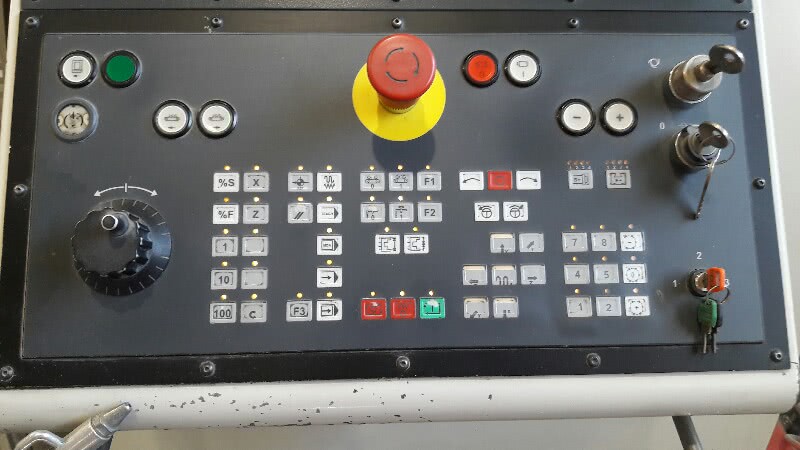
Проверь,-реагирует ли машина на переключение скорости подачи,-на пульте это должно быть видно в правом верхнем углу экрана!
- 29 Авг 2016
Добрый день!
На станке с Sinumerik 840d проблема — ошибка 400260
Machine control panel (MCP) at machine control panel interface 1 has failed. Timer of FB1 parameter MCP1Timeout has expired.Reactions:- Alarm display.Remedy:Check the connection with the MCP. Do not use timer T0 through T9 in the user program. Increase the value of timer parameter MCP1Timeout. Set MCP1Cycl to the default value.
Как следует из описания, что-то не в порядке с тайм-аутом при работе со станочной панелью. При этом панель подвешивается намертво и не реагирует не на одну кнопку.
После перезагрузки станка или выдергивания разъёма питания на панели работоспособность восстанавливается. За день работы выскакивает раз 5-6, абсолютно непредсказуемо. Подсоединение разъёмов проверяли. Подскажите что еще надо проверить.
- 30 Авг 2016
Лежат на стеллаже 2 шт. — дефект тот же. Одна ещё реагировала на охлаждение снегом в районе МС контроллера — помогает только замена — увы ((((
- 30 Авг 2016
anatoly_k_57, Спасибо.
Будем заказывать.
- 30 Авг 2016
andreieinav, Частично разобрался с выносного пульта управляются все оси ,а с панели нет ,также горит ось X другие не выбираются.Может что не прописано ?
- 2 Сен 2016
Доброго дня
Станок gildemeister ctx400serie2
Sinumerik 810d
Небольшая предистория
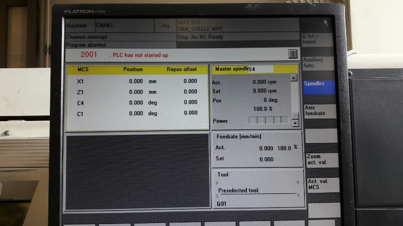
Работал нормально, пол дня стоял включеным без работы, появилась ошибка «plc нет связи, ждите». Выключил машину на пару минут, включил- все ок, проработал неделю, потом неделя простоя.
Включаю опять ошибка «plc не стартовал», перезагрузка больше не помогает, все кнопки пульта мигают. Батарейку меняли 2 месяца назад.
На мой взгляд нестандартная ситуация, когда во время работы теряется plc, потом опять находится после перезагрузки, а потом теряется напрочь.
Где в первую очередь искать причину? Может контакт гденибудь в электроавтоматике теряется. Помогите кто чем может. Заранее благодарен
- 5 Сен 2016
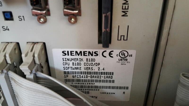
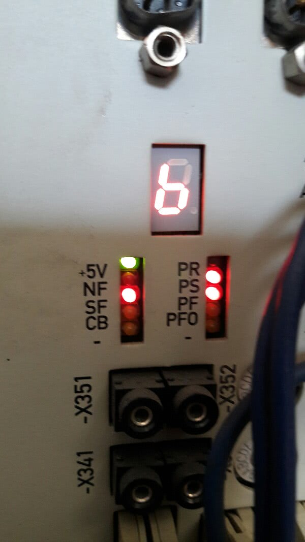
Добрый день,есть турецкий станок для резки стекла CMSmachine FLC 3225 на базе sinumerik 810d, на блоке CCU горит индикатор «6» светодиод 5+, SF , PR, на HMI пишет ошибка 120202 STOP:No NC Ready,при нажатии сброса NCK CCU щелкает реле и горит желтая надпись NC Communication failed. Батарейка 3,07 вольта. Шпиндели обесточены,при перемещении каретки руками,на главном экране стоят нули,система не видит где находится каретка,на пульт не реагирует Прошу помощи.Есть два архива,е ли полазить через MMC но содержимое не знаю,как можно сделать бекап того что сейчас есть и опробовать эти архивы?
- 7 Сен 2016
СашаМ сказал(а):
Доброго дня
Станок gildemeister ctx400serie2
Sinumerik 810d
Небольшая предистория
Работал нормально, пол дня стоял включеным без работы, появилась ошибка «plc нет связи, ждите». Выключил машину на пару минут, включил- все ок, проработал неделю, потом неделя простоя.
Включаю опять ошибка «plc не стартовал», перезагрузка больше не помогает, все кнопки пульта мигают. Батарейку меняли 2 месяца назад.
На мой взгляд нестандартная ситуация, когда во время работы теряется plc, потом опять находится после перезагрузки, а потом теряется напрочь.
Где в первую очередь искать причину? Может контакт гденибудь в электроавтоматике теряется. Помогите кто чем может. Заранее благодарен
Значит так,
1Причиной падения интерфейсов не всегда является батарейка,-это могут быть
а)плохо сдящая в коннекторе заглушка
б)остановка одного из перефкрийных осцилляторов
с)плохой контакт на батарейке поддержки протоколов интерфейса
д)наводки от неисправного контура заземления ,или реактора приводов
2 Так как интерфейсы у тебя упали и бояться больше нечего ,сделай следуюшее,
а)пробегись по всему кабелю,проверь коннекторы и заглушки
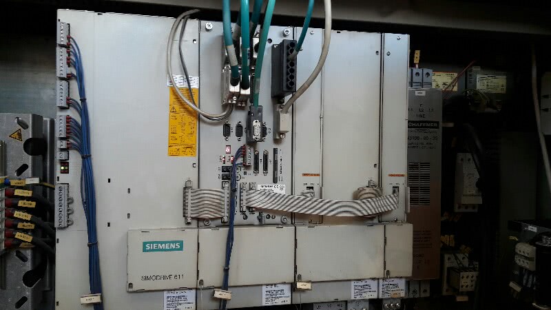
б)под высоковольтными шинами,под CPU,должна находиться батарейка и вентилятор охлаждения Надо это все аккуратно вытащить и проверить!Учти,-коннекторы хлипкие,действуй осторожно!
с)Когда все проверки закончишь,-внимательно почитай темку,проверь наличие архивов ,и,обязательно выполни процедуру полной чистки регистров!Не экономь время,делай все пошагово,не торопясь!
Удачи тебе!
Добавлено 07-09-2016 14:35
AntonovA сказал(а):
Добрый день,есть турецкий станок для резки стекла CMSmachine FLC 3225 на базе sinumerik 810d, на блоке CCU горит индикатор «6» светодиод 5+, SF , PR, на HMI пишет ошибка 120202 STOP:No NC Ready,при нажатии сброса NCK CCU щелкает реле и горит желтая надпись NC Communication failed. Батарейка 3,07 вольта. Шпиндели обесточены,при перемещении каретки руками,на главном экране стоят нули,система не видит где находится каретка,на пульт не реагирует Прошу помощи.Есть два архива,е ли полазить через MMC но содержимое не знаю,как можно сделать бекап того что сейчас есть и опробовать эти архивы?
Все это уже обсуждалось много раз,в разных вариациях!
Завари себе кофейку,закури сигаретку и,потрать часик,-почитай эту темку!Найдешь ответ в куче вариантов!
- 7 Сен 2016
Сейчас пишет 300701,300739,при ручном движении стола руками,по трем осям пишет 0.0000мм,PLC в составе блока работает. До этого через адаптер CP5512 Profibus и step-7 был слит проект трехсотого,и через программу SinuCom NC создан архив. Уровень доступа manufacturing. Пароль не вводился.В созданном архиве две папки NC и PLC.Вес архива 200кб.Не знаю достаточно этого или нет.Все ли данные выгрузил.
- 12 Сен 2016
andreieinav, Андрей добрый день.Давно читаю эту тему.много полезного.спасибо вам за это большое.Сейчас возникла конкретная проблема.
Имеем станок лазерной резки TRUMPF 3050 2000 г.в. SIMENS 840D. Есть острая необходимость опустить ось z на 3-4 мм. При попытке это сделать требует пароль второго уровня.Нужно бы поскорей.стоим. если можете то позвоните 8 916 681 09 61. С уважением Юрий.
- 12 Сен 2016
yura262 сказал(а):
.Давно читаю эту тему.много полезного.спасибо вам за это большое.Сейчас возникла конкретная проблема.
Имеем станок лазерной резки TRUMPF 3050 2000 г.в. SIMENS 840D. Есть острая необходимость опустить ось z на 3-4 мм. При попытке это сделать требует пароль второго уровня.Нужно бы поскорей.стоим. если можете то позвоните 8 916 681 09 61. С уважением Юрий.
Добрый день. Попробуйте SUNRISE. Это пароль производителя. Должен подойти ко всем уровням.
- 12 Сен 2016
Это пароль второго уровня?
Добавлено 12-09-2016 11:54
Дело в том что есть первый пароль.он позволяет менять референт оси x и y.а вот чтобы изменить этот параметр оси z требует пароль второго уровня.
Добавлено 12-09-2016 12:01
Похоже общие пароли не подходят.здесь какие то свои. Проблема.
- 12 Сен 2016
У нас 2 шт. 7020, но оболочка для 3010, 7040 — ни какого пароля не спрашивает. Может имеется в виду положение ключа? У наших своя панель, не Сименс…
- 14 Сен 2016
yura262 сказал(а):
Это пароль второго уровня?
Добавлено 12-09-2016 11:54
Дело в том что есть первый пароль.он позволяет менять референт оси x и y.а вот чтобы изменить этот параметр оси z требует пароль второго уровня.
Добавлено 12-09-2016 12:01
Похоже общие пароли не подходят.здесь какие то свои. Проблема.
Значит так,-SUNRISE ты уже пробовал,-теперь попробуй эту парочку;
1 EVENING
2 CUCTOMER
Может еще какие-то пароли есть,-надо поспрашивать!
И еще,-при вводе пароля,попробуй постоянно удерживать кнопку переключения регистров ^!
- 14 Сен 2016
Спасибо за ответ.попробуем.Актуальность пропала правда.ремонтируем ось.Есть надежда что сможем отремонтировать мотор линейного привода.простоим несколько дней.но все равно рано или поздно это нужно было делать.
- 15 Сен 2016
Здравствуйте, у нас siemens sinumerik 810m, заменили севшие батарейки, не могу разобраться с файлами на диске, там их 6 штук:
F5FC14.CMP
F5FJ70.01
F5FJ7001.KD
F5FJ7001.NC -T E A 1
F5FJ7001.PLC -T E A 2
F5FJ7001.PRG -P C P
Подскажите какие из них мне нужны? и что есть что?)
Заранее, благодарен…
► F5FJ7001.rar
- 20 Сен 2016
DJPuma сказал(а):
Здравствуйте, у нас siemens sinumerik 810m, заменили севшие батарейки, не могу разобраться с файлами на диске, там их 6 штук:
F5FC14.CMP
F5FJ70.01
F5FJ7001.KD
F5FJ7001.NC -T E A 1
F5FJ7001.PLC -T E A 2
F5FJ7001.PRG -P C P
Подскажите какие из них мне нужны? и что есть что?)
Заранее, благодарен…
Я не могу распокавать твой rar!Но,судя по расширениям,тебе нужны
1 ТЕА 1
2 ТЕА 2
3 РСР
и именно в такой последовательности!Проверь эти файлы обычными текстовыми редакторами NOTEPAD ,или WORDPAD!Остальное + инструкции есть в теме .Удачи!
- 30 Сен 2016
Добрый день, друзья!
Подскажите пожалуйста какая батарейка ставится на sinumerik 810d. Стояла 6в сименс, когда вылезла ошибка «слабая батарейка» поменял на аналогичную, но не сименс, хватило на два месяца- поменял, через два месяца ситуация повторилась. Может батарейка должна быть 3.6в?
Заранее благодарен!
- 30 Сен 2016
Батарейка SAFT- 3,6в, они отличаются малым током саморазряда, большой ёмкостью и НЕ ПРИЕМЛЮТ короткое! Дорогие, сцуко — 25 евро два года назад — сейчас не знаю….
- 2 Окт 2016
День добрый.
Много искал, но кроме как переустановка, не чего не нашёл. Возможно я плохо искал.Проблема такая. Я по невнимательности нажал кнопку подтверждения вместо отмены и по менял bus note с 13 на 6. Теперь пишет ошибку 120202 Wait for connection to NC/PLC. Есть ли возможность его поменять обратно. Без переустановки? Есть кабеля под сименс 200 300 400 серий, но чувствую, что они не подойдут. Сам станок chiron sinumerik 840d. Mmc 103. В загрузочном окне написано mmc 101/102 Regie.
С ув. Руслан.
П.с. Синумерик ново для меня. Если что извиняюсь за глупый вопрос.
- 6 Окт 2016
СашаМ сказал(а):
Добрый день, друзья!
Подскажите пожалуйста какая батарейка ставится на sinumerik 810d. Стояла 6в сименс, когда вылезла ошибка «слабая батарейка» поменял на аналогичную, но не сименс, хватило на два месяца- поменял, через два месяца ситуация повторилась. Может батарейка должна быть 3.6в?
Заранее благодарен!
Оно без «может»!3.6v и только литевая!
Добавлено 06-10-2016 14:20
Tehnikvg сказал(а):
День добрый.
Много искал, но кроме как переустановка, не чего не нашёл. Возможно я плохо искал.Проблема такая. Я по невнимательности нажал кнопку подтверждения вместо отмены и по менял bus note с 13 на 6. Теперь пишет ошибку 120202 Wait for connection to NC/PLC. Есть ли возможность его поменять обратно. Без переустановки? Есть кабеля под сименс 200 300 400 серий, но чувствую, что они не подойдут. Сам станок chiron sinumerik 840d. Mmc 103. В загрузочном окне написано mmc 101/102 Regie.
С ув. Руслан.П.с. Синумерик ново для меня. Если что извиняюсь за глупый вопрос.
Скажи,а какой PLC у тебя?Если в комплекте PCU-50,то вернуть можно быстро ,за счет архивов
P S Извиняюсь коллеги за задержку с ответами,-праздники+ модернизация завода!
- 13 Окт 2016
Спасибо за ответ. Сам контроллер я не нашел. В зависимости, что имеется ввиду для синумерика. Блоки входов выходов 300 — сименса и блоки связи. ПСУ нигде такого не обнаружил. Но машина старая 96(97)- 2002 года выпуска. Если надо, могу выложить полный фото-отчет по машине.
п.с. Праздники хорошо! Отдыхать тоже надо. А модернизация сама по себе приятна). У самого такая работа) Но синумерик это мой личный станок). и с ним не сталкивался.
- Manuals
- Brands
- Siemens Manuals
- Control Unit
- SINUMERIK 808D
- Diagnostic manual
-
Contents
-
Table of Contents
-
Bookmarks
Quick Links
T able of contents
Tables
Figures
SINUMERIK
SINUMERIK 808D ADVANCED
Diagnostics Manual
Diagnostics Manual
08/2013
6FC5398-6DP10-0BA1
Preface
Introduction
Operating in the «SYSTEM»
area
SINUMERIK 808D
ADVANCED alarms
System responses
SINAMICS V70 alarms
Data backup
Updating software
Appendix A
1
2
3
4
5
6
7
A
Related Manuals for Siemens SINUMERIK 808D ADVANCED
Summary of Contents for Siemens SINUMERIK 808D ADVANCED
-
Page 1
T able of contents Tables Figures 1 Introduction Operating in the «SYSTEM» 2 SINUMERIK area SINUMERIK 808D 3 SINUMERIK 808D ADVANCED ADVANCED alarms Diagnostics Manual 4 System responses 5 SINAMICS V70 alarms Diagnostics Manual 6 Data backup 7 Updating software A … -
Page 2
Note the following: WARNING Siemens products may only be used for the applications described in the catalog and in the relevant technical documentation. If products and components from other manufacturers are used, these must be recommended or approved by Siemens. Proper transport, storage, installation, assembly, commissioning, operation and maintenance are required to ensure that the products operate safely and without any problems. -
Page 3: Table Of Contents
Configuring the Ethernet connection ………………46 2.12 Defining the maintenance planner………………… 52 2.13 Alarm display ……………………..53 SINUMERIK 808D ADVANCED alarms ………………..55 System error alarms ……………………55 NCK alarms ……………………..55 Drive alarms ……………………..333 PLC alarms……………………..342 Cycle alarms……………………..346…
-
Page 4
Table of contents PLC user alarms ……………………434 System responses ………………………435 System reactions to SINUMERIK alarms …………….435 Cancel criteria for alarms………………….438 SINAMICS V70 alarms ……………………..439 Overview of alarms ……………………439 Common faults and alarms…………………. 441 Data backup ……………………….453 Overview of internal/external data backup……………. -
Page 5: Preface
Preface Applicable products This manual is applicable to the following control systems: Control system Software version SINUMERIK 808D ADVANCED T (Turning) V4.6 SINUMERIK 808D ADVANCED M (Milling) V4.6 Documentation components and target groups Component Recommended target group User documentation Programming and Operating Manual (Turning)
-
Page 6
EC Declaration of Conformity The EC Declaration of Conformity for the EMC Directive can be found on the Internet at http:/ /support.automation.siemens.com Here, enter the number 15257461 as the search term or contact your local Siemens office. Diagnostics Manual Diagnostics Manual, 08/2013, 6FC5398-6DP10-0BA1… -
Page 7: Introduction
Introduction Structure of the Diagnostics Manual NCK / PLC alarms The descriptions for the alarms can be found in the chapters: • NCK alarms (Page 55) • Drive alarms (Page 333) • PLC alarms (Page 342) • Cycle alarms (Page 346) •…
-
Page 8: Alarm Number Ranges
Introduction 1.2 Alarm number ranges Action list The actions described in the NCK alarm texts («Action %…») are explained in the following Chapter: See Chapter: Cancel criteria for alarms (Page 438) Specification «%» The specification «%» represents variables for an online parameter that is replaced on the control with a corresponding value.
-
Page 9: Operating In The «System» Area
Operating in the «SYSTEM» area Operating area overview Softkey functions Press the keys on the PPU to enter the following operating area. This operating area includes functions required for parameterizing and analyzing the NCK, the PLC and the drive. The start screen displays the machine configuration data and softkeys available.
-
Page 10: Setting Start-Up Function
Operating in the «SYSTEM» area 2.2 Setting start-up function An extended horizontal softkey bar can be accessed via this key on the PPU. Two extended horizontal softkeys are provided: Views the service information Defines the maintenance planner Setting start-up function Functionality This softkey allows you to choose the NC, PLC, and drive start-up modes.
-
Page 11
Operating in the «SYSTEM» area 2.2 Setting start-up function Selecting a PLC restart mode Proceed through the following steps to select a PLC restart mode: Select the desired operating area. Press this softkey. Press this softkey to open the window for selecting the PLC start-up mode. -
Page 12: Setting System Machine Data
Operating in the «SYSTEM» area 2.3 Setting system machine data Select all drives or one specific drive using the cursor keys. Press this softkey to confirm your selection. The selected drive(s) will restart in the mode selected. Setting system machine data Machine data structure Any changes in the machine data have a substantial influence on the machine.
-
Page 13
2.3 Setting system machine data Setting basic machine data The SINUMERIK 808D ADVANCED provides two easy-to-use data lists for beginner users. You can use the basic data list for quick access of common NC data and drive data. Setting basic NC data In the basic NC data list, the general, axis, and channel MD are integrated in one screen. -
Page 14
Operating in the «SYSTEM» area 2.3 Setting system machine data Setting basic drive data Several common drive parameters are provided in the basic drive data list. Proceed through the following steps to set the basic drive data: Select the desired operating area. Enter the window of basic drive data through the following softkey operations: →… -
Page 15
Operating in the «SYSTEM» area 2.3 Setting system machine data Setting machine data in expert list All machine data are divided into five groups described as follows. Setting general machine data Select the desired operating area. Enter the window of general machine data through the following softkey operations: →… -
Page 16
Operating in the «SYSTEM» area 2.3 Setting system machine data Setting channel-specific machine data Select the desired operating area. Enter the window of channel-specific machine data through the following softkey operations: → → Locate the machine data which you desire to set. You can also search for an MD using the following softkeys: Searches for the desired number or the name (or a part of the name) of the machine data… -
Page 17
Operating in the «SYSTEM» area 2.3 Setting system machine data Setting axis-specific machine data Select the desired operating area. Enter the window of axis-specific machine data through the following softkey operations: → → Locate the machine data which you desire to set. You can also search for an MD using the following softkeys: Searches for the desired number or the name (or a part of the name) of the machine data… -
Page 18
Operating in the «SYSTEM» area 2.3 Setting system machine data Setting drive machine data Select the desired operating area. Enter the window of drive machine data through the following softkey operations: → → Locate the machine data which you desire to set. You can also search for an MD using the following softkeys: Searches for the desired number or the name (or a part of the name) of the machine data… -
Page 19
To learn more functions regarding the servo trace, refer to the Section «Servo trace (Page 40)». References You can find a description of the machine data in the following manufacturers’ documents: SINUMERIK 808D ADVANCED Parameter Manual SINUMERIK 808D ADVANCED Function Manual Diagnostics Manual Diagnostics Manual, 08/2013, 6FC5398-6DP10-0BA1… -
Page 20: Configuring The Drive System
Operating in the «SYSTEM» area 2.4 Configuring the drive system Configuring the drive system Pressing this softkey opens the drive system configuration window where you can configure the connected drives and motors. Before starting the drive and motor configuration, you must ensure the Drive Bus addresses are properly set (p0918) via the drive BOPs according to the instructions in the window above.
-
Page 21
Operating in the «SYSTEM» area 2.4 Configuring the drive system Press this softkey to enter the motor configuration window. Select the right motor ID according to the motor rating plate with the cursor keys. Press this softkey to confirm your selection. The selected motor information then displays in the drive list. -
Page 22: Plc Diagnostics
Operating in the «SYSTEM» area 2.5 PLC diagnostics PLC diagnostics Functionality A PLC user program consists to a large degree of logical operations to realize safety functions and to support process sequences. These logical operations include the linking of various contacts and relays. As a rule, the failure of a single contact or relay results in a failure of the whole system/installation.
-
Page 23: Screen Layout
Operating in the «SYSTEM» area 2.5 PLC diagnostics ⑥ ⑬ Displays the list of cross references Displays all symbolic identifiers used in the selected network ⑦ Displays the logic and graphic information of the selected program block 2.5.1 Screen layout Legend Display Meaning…
-
Page 24: Operating Options
Operating in the «SYSTEM» area 2.5 PLC diagnostics 2.5.2 Operating options In addition to the softkeys and the navigation keys, this area provides still further key combinations. Hot keys The cursor keys move the focus over the PLC user program. When reaching the window borders, it is scrolled automatically.
-
Page 25
Operating in the «SYSTEM» area 2.5 PLC diagnostics Key combination Action To the last field of the subroutine Opens the previous program block in the same window Opens the next program block in the same window The function of the Select key depends on the position of the input focus. -
Page 26
Operating in the «SYSTEM» area 2.5 PLC diagnostics Searching for operands In big programs, you can use the search function to quickly reach the desired positions. To search for operands, follow these steps: Use this softkey to switch between the absolute and symbolic representation of the operands. -
Page 27: Displaying Information On The Program Blocks
Operating in the «SYSTEM» area 2.5 PLC diagnostics 2.5.3 Displaying information on the program blocks Functionality You can display any logical and graphical information of a program block in the program windows. The program block is one of the components of the PLC user program. Logic information The logics in the ladder diagram (LAD) display the following: •…
-
Page 28: Displaying Cross-References
Operating in the «SYSTEM» area 2.5 PLC diagnostics Select the desired program block and press this softkey to open it. After the selected program block is opened, you can press the following softkeys to switch the display information. Further softkeys are available in the program block window as follows: Displays additional information of the selected program block Displays the table of local variables of the selected…
-
Page 29: Setting The Hmi Display
Operating in the «SYSTEM» area 2.6 Setting the HMI display Setting the HMI display 2.6.1 Setting the date and time At delivery, the system date and time remain at the factory settings, and thus you must manually modify the date and time in the window as follows. Operating sequence Select the desired operating area on the PPU.
-
Page 30: Adjusting The Screen Brightness
Operating in the «SYSTEM» area 2.6 Setting the HMI display 2.6.2 Adjusting the screen brightness You can open the window for adjusting the brightness of the HMI screen through the following operations: → → Press this softkey to increase the brightness of the HMI screen. Press this softkey to decrease the brightness of the HMI screen.
-
Page 31: Managing The System Data
Operating in the «SYSTEM» area 2.7 Managing the system data Managing the system data Overview By pressing this softkey in the system data management operating area, you can enter the window as follows: Three folders and one file are available in this window. You can import/export the subfolders or single files in this window for backup or other customized purposes.
-
Page 32
You can import/export the subfolders or single files in this window for backup or other customized purposes. For more information, refer to the SINUMERIK 808D ADVANCED Function Manual and SINUMERIK 808D ADVANCED Commissioning Manual. Managing the NCK/PLC data Select this folder and press the key to enter. -
Page 33: Creating Commissioning Archives
Operating in the «SYSTEM» area 2.8 Creating commissioning archives Creating commissioning archives Functionality Pressing this softkey allows you to create or restore a start-up or series start-up archive in the following window. Operating sequence Select the desired operating area on the PPU. Press this horizontal softkey to open the start-up archive window.
-
Page 34: Optimizing Drive Performance
Operating in the «SYSTEM» area 2.9 Optimizing drive performance Press this softkey to confirm and the archive information dialog opens. Specify the properties of the archive and press this softkey to start creating the archive file in the selected folder. Optimizing drive performance The control system provides facilities to optimize the performance of each connected drive by automatically modifying the control loop parameters.
-
Page 35
Operating in the «SYSTEM» area 2.9 Optimizing drive performance Press this softkey to return to the main screen of drive optimization. Press this softkey to enter the preparation screen before the optimization. Switch to «JOG» mode, and use the axis traversing keys to move the axis to a safe position. -
Page 36: Viewing The Service Info
Operating in the «SYSTEM» area 2.10 Viewing the service info Views the optimization results of the previous axis Returns to the main screen of drive optimization. In this case, you may optimize the drive again with either new measurements or last measurement results. 2.10 Viewing the service info You can view the service information through the following operations:…
-
Page 37: Action Log
Operating in the «SYSTEM» area 2.10 Viewing the service info 2.10.1 Action log Overview The action log function is provided for service events. The contents of the action log file can only be accessed through a system password on the HMI. Viewing the action log Select the desired operating area.
-
Page 38
Operating in the «SYSTEM» area 2.10 Viewing the service info Settings for the message sending Proceed through the following steps to configure the settings for the message sending: Select the desired operating area. Press this key to view the extended softkeys. Open the service message window through the following softkey operations: →… -
Page 39: Data Backup
Operating in the «SYSTEM» area 2.10 Viewing the service info Press this softkey to save the settings and return to the service message main screen. Press this softkey to cancel and return to the service message main screen. Note To transfer messages via the RS232 interface, the communication settings from the following are used: →…
-
Page 40: Servo Trace
Operating in the «SYSTEM» area 2.10 Viewing the service info 2.10.3 Servo trace Overview An oscilloscope function is provided for the purpose of optimizing the drives. This enables the following graphical representations: • velocity setpoint • contour violation • following error •…
-
Page 41
Operating in the «SYSTEM» area 2.10 Viewing the service info To analyze the result, you can perform the following operations: • Changing and scaling the abscissa and ordinate values • Measuring a value using the horizontal or vertical marker • Measuring the abscissa and ordinate values as a difference between two markers •… -
Page 42: Version/Hmi Details
Operating in the «SYSTEM» area 2.10 Viewing the service info Press this softkey to return after you set the desired marker steps. If the trace exceeds the current screen, press + cursor movement. When a marker reaches the margin of the diagram, the grid automatically appears in the horizontal or vertical direction.
-
Page 43
Operating in the «SYSTEM» area 2.10 Viewing the service info This window displays the version numbers and the date of creation of the individual CNC components. ① ③ Displays the operator programs with the Activates the licensed optional functions version numbers ②… -
Page 44
Press this softkey to open the dialog for entering the license key Enter the license key in the following dialog: Press this softkey to confirm. Activating the options The following optional functions can be purchased for the SINUMERIK 808D ADVANCED control system. • Additional axes •… -
Page 45
For the other options, press the following key to select: Press this softkey to restart the NCK, so that the licensed options are activated. Reference SINUMERIK 808D ADVANCED Function Manual SINUMERIK 808D ADVANCED Commissioning Manual Diagnostics Manual Diagnostics Manual, 08/2013, 6FC5398-6DP10-0BA1… -
Page 46: Configuring The Ethernet Connection
With the tool Access MyMachine P2P (AMM) installed on your PC/PG, you can enable the Ethernet connection between a SINUMERIK 808D ADVANCED control system and a PC/PG. This tool is available in the SINUMERIK 808D ADVANCED Toolbox and is supported by Windows XP/Vista/Win 7.
-
Page 47
Operating in the «SYSTEM» area 2.11 Configuring the Ethernet connection Select the direct connection option in the following dialog and then click this button. An attempt is made to establish a direct connection. If you have not established any authentication data, the following dialog appears: Select the log-on details and enter the corresponding password or alternatively select a key file in the dialog. -
Page 48
Operating in the «SYSTEM» area 2.11 Configuring the Ethernet connection Enter the main screen of the service control options through the following softkey operations: → Press this softkey to enter the window for the network configuration. Note: make sure the following vertical softkey is not selected: Configure the network as required in the following window: You can configure the DHCP with the following key: Note: if you select «No»… -
Page 49
Operating in the «SYSTEM» area 2.11 Configuring the Ethernet connection Select the new network connection option in the following dialog: This dialog can also be called with the button from the toolbar. The dialog for setting the new network connection appears. Assign the parameters for a new network connection in this dialog: Select the following button to save the settings: Select the following button and the AMM tool connects to the control… -
Page 50
Operating in the «SYSTEM» area 2.11 Configuring the Ethernet connection Creating and connecting a network drive Proceed as follows to create and connect a network drive: Share a directory on your local disk on your PC/PG. Select the desired operating area on the PPU. Press this key to view the extended softkeys. -
Page 51
Operating in the «SYSTEM» area 2.11 Configuring the Ethernet connection Press this softkey to establish the server connection and assign the local shared directory to the network drive. You can disconnect a selected network drive using the following softkey: After you connect a network drive successfully, you may open it directly on the PPU using the following softkey either in the system data management operating area or in the program management operating area:… -
Page 52: Defining The Maintenance Planner
Operating in the «SYSTEM» area 2.12 Defining the maintenance planner 2.12 Defining the maintenance planner Overview This part introduces how to define the maintenance planner. You can enter the maintenance planner main screen through the following operations: → → The maintenance planner window displays the position, task description, interval, first warning time, number of warnings, etc.
-
Page 53: Alarm Display
Operating in the «SYSTEM» area 2.13 Alarm display 2.13 Alarm display Softkey functions Press this key on the PPU to open the alarm window. You can check the NC and drive alarms using the softkeys. PLC alarms are not sorted. ①…
-
Page 54
Operating in the «SYSTEM» area 2.13 Alarm display Diagnostics Manual Diagnostics Manual, 08/2013, 6FC5398-6DP10-0BA1… -
Page 55: Sinumerik 808D Advanced Alarms
This alarm is also caused by PLC stop. (PLC stop with programming tool, PLC stop by commissioning switch, PLC stop by alarm) If none of these cases applies, place a support request with the error text under: http://www.siemens.com/automation/ support-request Program Switch control OFF — ON.
-
Page 56
$MN_PLC_RUNNINGUP_TIMEOUT must be checked and adapted to the first OB1 cycle. — Determine the cause of error in the PLC (loop or stop in the user program) and eliminate it. Place a support request with the error text under: http://www.siemens.com/automation/support-request Program Switch control OFF — ON. -
Page 57
SINUMERIK 808D ADVANCED alarms 3.2 NCK alarms 2900 Reboot is delayed Definitions: This alarm indicates a delayed reboot. This alarm only occurs when reboot was carried out by the HMI and MD10088 $MN_REBOOT_DELAY_TIME was set greater than zero. The alarm can be suppressed with MD11410 $MN_SUPPRESS_ALARM_MASK Bit 20. -
Page 58
SINUMERIK 808D ADVANCED alarms 3.2 NCK alarms Definitions: Only axes that have been activated in the channel by MD20070 $MC_AXCONF_MACHAX_USED [kx]=m may be declared as geometry axes, transformation axes or orientation axes in MD20050 $MC_AXCONF_GEOAX_ASSIGN_TAB [gx]=k. This also applies to MD22420 $MC_FGROUP_DEFAULT_AXES (gx: Geometry axis index, kx: Channel axis index, k: Channel axis no., m: Machine axis no.). -
Page 59
SINUMERIK 808D ADVANCED alarms 3.2 NCK alarms Example: — CHANDATA(2) — $MC_AXCONF_MACHAX_USED[0] = 7 — $MC_AXCONF_MACHAX_USED[1] = 8 — $MC_AXCONF_MACHAX_USED[2] = 0 — $MC_AXCONF_MACHAX_USED[3] = 3 — $MC_AXCONF_MACHAX_USED[4] = 2 — $MC_AXCONF_MACHAX_USED[5] = 0 — $MC_AXCONF_MACHAX_USED[6] = 1 — $MC_AXCONF_MACHAX_USED[7] = 0 This channel uses the five machine axes 1, 2, 3, 8, 7, i.e. -
Page 60
SINUMERIK 808D ADVANCED alarms 3.2 NCK alarms Definitions: When determining a name in the NCK tables (arrays) for: machine axes, Euler angles, direction vectors, normal vectors, interpolation parameters and intermediate point coordinates, one of the following syntax rules for the identifier… -
Page 61
SINUMERIK 808D ADVANCED alarms 3.2 NCK alarms Program Switch control OFF — ON. Continuation: 4020 Identifier %1 used several times in machine data %2 Parameters: %1 = String: Name of identifier %2 = String: MD identifier Definitions: When determining a name in the NCK tables (arrays) for: machine axes, Euler angles, direction vectors, normal vectors, interpolation parameters and intermediate point coordinates, an identifier has been used that already exists in the control. -
Page 62
SINUMERIK 808D ADVANCED alarms 3.2 NCK alarms 4032 [Channel %1: ] Wrong identifier for facing axis in %2 Parameters: %1 = Channel number %2 = String: MD identifier Definitions: According to the axis configuration in MD20150 $MC_GCODE_RESET_VALUES or MD20100 $MC_DIAMETER_AX_DEF, a facing axis identifier is expected at the specified location. -
Page 63
SINUMERIK 808D ADVANCED alarms 3.2 NCK alarms Definitions: Renaming of an NC code was not possible for one of the following reasons: — The old identifier does not exist — The new identifier lies in another type range. NC codes/keywords can be reconfigured via machine data as long as the type range is not abandoned. -
Page 64
SINUMERIK 808D ADVANCED alarms 3.2 NCK alarms Remedy: Restart the control. Program Switch control OFF — ON. Continuation: 4070 Normalizing machine data has been changed Definitions: The control uses internal physical units (mm, degrees, s, for paths, velocities, acceleration, etc.). During programming or data storage, some of these values are input and output using different units (rev./min, m/s2, etc.). -
Page 65
SINUMERIK 808D ADVANCED alarms 3.2 NCK alarms Definitions: On executing a TOA file or when writing data from the part program an attempt has been made to write data with a higher protection level than the access authorization currently set in the control. The data in question have not been written and program execution is continued without hindrance. -
Page 66
SINUMERIK 808D ADVANCED alarms 3.2 NCK alarms 2. MD10910 $MN_INDEX_AX_POS_TAB_1 or MD10930 $MN_INDEX_AX_POS_TAB_2: the contents of the displayed tables are incorrect. — The entered positions must be arranged in increasing size. — A particular position must not be set more than once. -
Page 67
SINUMERIK 808D ADVANCED alarms 3.2 NCK alarms 4112 Servo cycle changed to %1 ms Parameters: %1 = String (new servo cycle time) Definitions: For PROFIBUS/PROFINET only: MD10060 $POSCTRL_SYSCLOCK_TIME_RATIO has been modified because of the modified DP cycle in the SDB (MD10050 $SYSCLOCK_CYCLE_TIME). -
Page 68
SINUMERIK 808D ADVANCED alarms 3.2 NCK alarms MD10718 $MN_M_NO_FCT_CYCLE_PAR contains an invalid array index of MD10715 $MN_M_NO_FCT_CYCLE[n]. Currently, the values 0 to 9 are permissible. The affected machine data is reset to the default value -1. This deactivates the function. -
Page 69
SINUMERIK 808D ADVANCED alarms 3.2 NCK alarms 4180 Invalid M function number assigned to enable ASUP Definitions: An invalid M function number has been assigned for activation of ASUP. An illegal M number has been assigned in MD10804 $MN_EXTERN_M_NO_SET_INT or MD10806 $MN_EXTERN_M_NO_DISABLE_INT for the configuration of the M number range for activation/deactivation of the interrupt program. -
Page 70
SINUMERIK 808D ADVANCED alarms 3.2 NCK alarms NC Start disable in this channel. Interface signals are set. Alarm display. NC Stop on alarm. Remedy: Check the specified machine data and create a unique assignment of M auxiliary function numbers. Program Switch control OFF — ON. -
Page 71
SINUMERIK 808D ADVANCED alarms 3.2 NCK alarms Remedy: Please inform the authorized personnel/service department. Remove rotary axis declaration for this machine axis. For this purpose, the geometry axis index for the displayed geometry axis must be determined by means of MD20060 $MC_AXCONF_GEOAX_NAME_TAB. -
Page 72
SINUMERIK 808D ADVANCED alarms 3.2 NCK alarms 4225 [Channel %1: ] Axis %2 declaration as rotary axis missing Parameters: %1 = Channel number %2 = Axis name, axis number Definitions: The modulo functionality requires a rotary axis (positions in [deg]). -
Page 73
SINUMERIK 808D ADVANCED alarms 3.2 NCK alarms Interface signals are set. Alarm display. NC Stop on alarm. Remedy: Please inform the authorized personnel/service department. Correct machine data. Activate required inputs/outputs via MDs: MD10350 $MN_FASTIO_DIG_NUM_INPUTS MD10360 $MN_FASTIO_DIG_NUM_OUTPUTS MD10300 $MN_FASTIO_ANA_NUM_INPUTS MD10310 $MN_FASTIO_ANA_NUM_OUTPUTS Activation of fast inputs/outputs does not require the corresponding hardware configuration to be available at the control. -
Page 74
SINUMERIK 808D ADVANCED alarms 3.2 NCK alarms 4282 Hardware of external NCK outputs assigned repeatedly Definitions: Several outputs have been configured on the same hardware byte. Reaction: NC not ready. Channel not ready. NC Start disable in this channel. Interface signals are set. -
Page 75
SINUMERIK 808D ADVANCED alarms 3.2 NCK alarms 4340 [Channel %1: ] Block %2 invalid transformation type in transformation no. %3 Parameters: %1 = Channel number %2 = Block number, label %3 = Transformation number Definitions: An invalid, i.e. undefined number was entered in one of the machine data $MC_TRAFO_TYPE_..This alarm also occurs if a certain type of transformation is only impossible on the type of control used (e.g. -
Page 76
SINUMERIK 808D ADVANCED alarms 3.2 NCK alarms Reaction: Correction block is reorganized. Interface signals are set. Alarm display. NC Stop on alarm at block end. Remedy: Set valid machine data. Program Clear alarm with the RESET key. Restart part program… -
Page 77
SINUMERIK 808D ADVANCED alarms 3.2 NCK alarms Definitions: MD2..$MC_TRAFO_AXIS_IN_… contains an invalid entry. The following causes for the error are possible: — The entry refers to a channel axis which does not exist. — The entry is zero (no axis) but the transformation needs the relevant axis as a channel axis. -
Page 78
SINUMERIK 808D ADVANCED alarms 3.2 NCK alarms 77. The 3rd linear axis is not perpendicular to the rotary axis and the first geometry axis. 78. More than one additional linear axis was defined. 79. Illegal kinematic chain element type (e.g. manual rotary axis). -
Page 79
SINUMERIK 808D ADVANCED alarms 3.2 NCK alarms Definitions: A machine data has been altered that configures the buffered memory. If the NCK powers up with the altered data, this will lead to reorganization of the buffered memory and thus to the loss of all buffered user data (part programs, tool data, GUD, leadscrew error compensation, …) -
Page 80
SINUMERIK 808D ADVANCED alarms 3.2 NCK alarms Remedy: H numbers must be assigned only once in a TO unit. Then, MD10890, $MN_EXTERN_TOOLPROG_MODE, bit 3 can be set = 0 and a restart can be performed. Program Clear alarm with the Delete key or NC START. -
Page 81
SINUMERIK 808D ADVANCED alarms 3.2 NCK alarms Definitions: The handwheel input for handwheel %1 requested through MD11352 $MN_HANDWHEEL_INPUT is not available for 802D sl, 828D sl, 808D systems. A maximum of 2 handwheels can be directly linked to 802D sl, 828D sl, 808D systems. -
Page 82
SINUMERIK 808D ADVANCED alarms 3.2 NCK alarms Reaction: Interface signals are set. Alarm display. Remedy: Set machine date MD11351 $MN_HANDWHEEL_MODULE = 1 for the corresponding handwheel. Program Switch control OFF — ON. Continuation: 4641 Invalid handwheel input for handwheel %1… -
Page 83
SINUMERIK 808D ADVANCED alarms 3.2 NCK alarms Definitions: Data management has detected an error during ramp-up. The specified data block may not have been created. The error number specifies the type of error. An error number >100000 indicates a fatal system error. Other error numbers indicate that the user memory area provided is too small. -
Page 84
SINUMERIK 808D ADVANCED alarms 3.2 NCK alarms Reaction: NC not ready. Channel not ready. NC Start disable in this channel. Interface signals are set. Alarm display. NC Stop on alarm. Remedy: Correct the machine data or undo the changes made. -
Page 85
There is no interference with any NCK functions. It shows that the NCK has less free user memory available than specified by Siemens for this control variant. The value of the actually available free user memory can also be taken from the MD18050 $MN_INFO_FREE_MEM_DYNAMIC, MD18060 $MN_INFO_FREE_MEMS_STATIC. -
Page 86
SINUMERIK 808D ADVANCED alarms 3.2 NCK alarms 6437 [Channel %1: ] Block %2 Command ‘%3’ cannot be programmed. Function ‘%4’ is activated. Parameters: %1 = Channel number %2 = Block number, label %3 = Programmed command %4 = Function identifier Definitions: The command cannot be programmed as the specified function is active. -
Page 87
SINUMERIK 808D ADVANCED alarms 3.2 NCK alarms 6520 The value of the machine data %1%2 is too low Parameters: %1 = String: MD identifier %2 = If required, index: MD array Definitions: The MD18370 $MN_MM_PROTOC_NUM_FILES specifies the number of protocol files for the protocol users. -
Page 88
Clear alarm with the Delete key or NC START. Continuation: 6583 NC system memory full Definitions: The DRAM file system of the system area (Siemens) is full. The order cannot be executed. Reaction: Alarm display. Remedy: Delete or unload files (e.g. parts programs) Program Clear alarm with the Delete key or NC START. -
Page 89
Alarm display. Remedy: Modify definition files /_N_DEF_DIR/_N_MACCESS_DEF or /_N_DEF_DIR/_N_UACCESS_DEF-CESS_ DEF. Please see the Siemens Programming Guide or the OEM documentation for the language commands permissible for the relevant system configurations. Program Clear alarm with the RESET key. Restart part program… -
Page 90
SINUMERIK 808D ADVANCED alarms 3.2 NCK alarms Remedy: Please inform the authorized personnel/service department. Do not use rapid interrupt inputs or contact the machine manufacturer with a view to retrofitting this option! Program Clear alarm with the RESET key. Restart part program… -
Page 91
SINUMERIK 808D ADVANCED alarms 3.2 NCK alarms Remedy: Please inform the authorized personnel/service department. — Purchase option — Reset the activation of ‘Advanced Surface’ functionality (MD20606 $MC_PREPDYN_SMOOTHING_ON and/or MD20443 $MC_LOOKAH_FFORM) Program Switch control OFF — ON. Continuation: 8030 [Channel %1: ] Block %2 option ‘interpolation of more than %3 axes’ not set… -
Page 92
3.2 NCK alarms Remedy: Please inform the authorized personnel/service department. For retrofitting the option, please refer to your machine manufacturer or to a sales representative of SIEMENS AG, A&D MC. Program Clear alarm with the Delete key or NC START. -
Page 93
One ore more options were activated, that are not licensed by the license key entered. Reaction: Alarm display. Remedy: Generate a new license key on the internet at http://www.siemens.com/automation/licence and enter it in the operating area «Setup», function (HSK) «Licenses».. Program Clear alarm with the Delete key or NC START. -
Page 94
Reaction: Alarm display. Remedy: Generate a new license key via the Internet at http://www.siemens.com/automation/license and enter in the operating area «Startup», function (HSK) «Licenses». Enter a valid license key in the operating area «Startup», function (HSK) «Licenses». Activate an additional test period… -
Page 95
SINUMERIK 808D ADVANCED alarms 3.2 NCK alarms Reaction: Interpreter stop NC Start disable in this channel. Interface signals are set. Alarm display. NC Stop on alarm. Remedy: Modify part program. Program Clear alarm with the RESET key. Restart part program… -
Page 96
SINUMERIK 808D ADVANCED alarms 3.2 NCK alarms Program Clear alarm with NC START or RESET key and continue the program. Continuation: 10204 [Channel %1: ] User action not possible without reference point (internal action=%2<ALNX>) Parameters: %1 = Channel number %2 = internal action number/internal action name… -
Page 97
SINUMERIK 808D ADVANCED alarms 3.2 NCK alarms Remedy: NC-Start Program Clear alarm with NC START or RESET key and continue the program. Continuation: 10225 [Channel %1: ] command denied Parameters: %1 = Channel number Definitions: The channel has received a command that cannot be executed. -
Page 98
SINUMERIK 808D ADVANCED alarms 3.2 NCK alarms Definitions: This alarm occurs only when several blocks with G33 follow in succession. The block end velocity in the specified block is zero, although a further thread cutting block follows. The reasons for this can be, for instance:… -
Page 99
SINUMERIK 808D ADVANCED alarms 3.2 NCK alarms Remedy: Check and correct the part program (analyze whether motion beyond block boundaries is appropriate here). Prevent block change by means of the keyword WAITP for axes or WAITS for spindles until the positioning axes or positioning spindles have also reached their target position. -
Page 100
SINUMERIK 808D ADVANCED alarms 3.2 NCK alarms 10630 [Channel %1: ] Block %2 axis %3 at working area limit %4 Parameters: %1 = Channel number %2 = Block number, label %3 = Axis, spindle number %4 = String (+ or -) Definitions: The specified axis violates the working area limitation. -
Page 101
SINUMERIK 808D ADVANCED alarms 3.2 NCK alarms Program Alarm display showing cause of alarm disappears. No further operator action necessary. Continuation: 10634 [Channel %1: ] Axis %2, tool radius compensation is inactive for type %3 working area limitation, reason: The tool is not oriented parallel to the axis. -
Page 102
SINUMERIK 808D ADVANCED alarms 3.2 NCK alarms Remedy: The tool radius compensation for working area limitations in JOG mode cannot be taken into account wihout an active tool. Program Clear alarm with the Delete key or NC START. Continuation: 10650… -
Page 103
SINUMERIK 808D ADVANCED alarms 3.2 NCK alarms 13: Slave axis grouping 3 Program Switch control OFF — ON. Continuation: 10652 [Channel %1: ] Axis %2 gantry warning threshold exceeded Parameters: %1 = Channel number %2 = Axis Definitions: The gantry following axis has exceeded the warning limit specified in MD37110 $MA_GANTRY_POS_TOL_WARNING. -
Page 104
SINUMERIK 808D ADVANCED alarms 3.2 NCK alarms Program Alarm display showing cause of alarm disappears. No further operator action necessary. Continuation: 10656 [Channel %1: ] Axis %2 gantry slave axis dynamically overloaded Parameters: %1 = Channel number %2 = Axis Definitions: The indicated gantry slave axis is dynamically overloaded, i.e. -
Page 105
SINUMERIK 808D ADVANCED alarms 3.2 NCK alarms Remedy: Error ID: — 30XX => assign all gantry axes to the current channel, for example via axis exchange. — 40XX => set all axes of the gantry group to the same axis state, for example assign all axes to the NC program, or assign all axes to the PLC. -
Page 106
SINUMERIK 808D ADVANCED alarms 3.2 NCK alarms 10703 [Channel %1: ] Channel-specific protection zone %2 violated during manual mode Parameters: %1 = Channel number %2 = Protection zone number Definitions: The workpiece-related channel-specific protection zone has been violated. Note that another tool-related protection zone is still active. -
Page 107
SINUMERIK 808D ADVANCED alarms 3.2 NCK alarms 10720 [Channel %1: ] Block %3 axis %2 software limit switch %4 Parameters: %1 = Channel number %2 = Axis name, spindle number %3 = Block number, label %4 = String (+ or -) Definitions: The path programmed for the axis violates the currently valid software limit switch. -
Page 108
SINUMERIK 808D ADVANCED alarms 3.2 NCK alarms Definitions: The path programmed for the axis violates the currently valid software limit switch. The alarm is activated when preparing the part program block. This alarm is issued instead of alarm 10720 if bit 11=1 in the MD11411 $MN_ENABLE_ALARM_MASK. Alarm 10722 offers an expanded diagnostics option for the software limit switch violation. -
Page 109
SINUMERIK 808D ADVANCED alarms 3.2 NCK alarms Definitions: This alarm is generated if it is determined during block preparation that the programmed path of the axis violates the working area limitation. If bit 11=0 in machine data MD11411$MN_ENABLE_ALARM_MASK, this alarm is issued instead of alarm 10732. If bit 11 is set in machine dataMD11411 $MN_ENABLE_ALARM_MASK, an expanded diagnostics option is offered for the software limit switch violation. -
Page 110
SINUMERIK 808D ADVANCED alarms 3.2 NCK alarms 10733 [Channel %1: ] Block %5 axis %2 working area limitation violated, residual distance: %6 %3<ALUN> Parameters: %1 = Channel number %2 = Axis name, spindle number %3 = Unit of distance %4 = Block number, label|residual distance Definitions: The motion planned for the axis violates the currently active working area limitation. -
Page 111
SINUMERIK 808D ADVANCED alarms 3.2 NCK alarms Remedy: Determine the cause of the offset from the initial or target position. The REPOS command is executed at the end of an ASUB or system ASUB. See also cross reference from ASUBs. -
Page 112
SINUMERIK 808D ADVANCED alarms 3.2 NCK alarms Definitions: An attempt has been made to activate a WAB motion before a previously activated WAB motion was terminated. Reaction: Correction block is reorganized. Local alarm reaction. Interface signals are set. Alarm display. -
Page 113
SINUMERIK 808D ADVANCED alarms 3.2 NCK alarms 10747 [Channel %1: ] Block %2 retraction direction not defined for WAB Parameters: %1 = Channel number %2 = Block number, label Definitions: In a WAB retraction block with quarter circle or semi-circle (G248 or G348), the end point in the machining plane was not programmed, and either G143 or G140 without tool radius compensation is active. -
Page 114
SINUMERIK 808D ADVANCED alarms 3.2 NCK alarms Definitions: The «Bottleneck detection» (calculation of intersection for the following compensated traversing blocks) has not been able to calculate a point of intersection for the reviewed number of traversing blocks. It is therefore possible that one of the equidistant paths violates the workpiece contour. -
Page 115
SINUMERIK 808D ADVANCED alarms 3.2 NCK alarms 10754 [Channel %1: ] Block %2 deselection of the tool radius compensation only possible in linear block Parameters: %1 = Channel number %2 = Block number, label Definitions: Deselection of tool radius compensation with G40 can only be performed in blocks where the G function G00 (rapid traverse) or G01 (feed) is active. -
Page 116
SINUMERIK 808D ADVANCED alarms 3.2 NCK alarms NC Stop on alarm at block end. Remedy: Place deselection of the CRC such that the programmed end point comes to rest outside the compensation circle around the last active compensation point. The following possibilities are available:… -
Page 117
SINUMERIK 808D ADVANCED alarms 3.2 NCK alarms Reaction: Correction block is reorganized. Local alarm reaction. Interface signals are set. Alarm display. NC Stop on alarm at block end. Remedy: Do not use splines or polynomials when writing the contour section, but straight lines and circles instead. Divide up the tool piece geometry and deselect the cutter radius compensation between the various sections. -
Page 118
SINUMERIK 808D ADVANCED alarms 3.2 NCK alarms Remedy: — Modify part program — Modify machine data — Check whether SBL2 is activated. With SBL2, a block is generated from each part program line which can lead to exceeding the maximum permissible number of empty blocks between two traversing blocks. -
Page 119
SINUMERIK 808D ADVANCED alarms 3.2 NCK alarms 10770 [Channel %1: ] Block %2 change of corner type due to change of orientation with active tool radius compensation Parameters: %1 = Channel number %2 = Block number, label Definitions: The type of a corner (inside or outside corner) depends not only on the programmed path but also on the tool orientation. -
Page 120
SINUMERIK 808D ADVANCED alarms 3.2 NCK alarms 10778 [Channel %1: ] Block %2 preprocessing stop with active tool radius compensation Parameters: %1 = Channel number %2 = Block number, label Definitions: If a preprocessing stop is detected with active tool radius compensation (either programmed by the user or generated… -
Page 121
SINUMERIK 808D ADVANCED alarms 3.2 NCK alarms Alarm display. NC Stop on alarm at block end. Remedy: Modify part program. Program Clear alarm with NC START or RESET key and continue the program. Continuation: 10784 [Channel %1: ] Block %2 illegal tool for tool radius compensation with constraint… -
Page 122
SINUMERIK 808D ADVANCED alarms 3.2 NCK alarms 10792 [Channel %1: ] Block %2 illegal interpolation type during linear programming with angles Parameters: %1 = Channel number %2 = Block number, label Definitions: Only spline or linear interpolation is permitted for programming two straight lines with angle specification. Circular or polynomial interpolation is not allowed. -
Page 123
SINUMERIK 808D ADVANCED alarms 3.2 NCK alarms Definitions: During programming of a straight line, both positions of the active plane and an angle were specified (the position of the end point is over-specified), or the position of the programmed coordinate cannot be reached with the specified angle. -
Page 124
SINUMERIK 808D ADVANCED alarms 3.2 NCK alarms For the definition the MD 20090 $MC_SPIND_DEF_MASTER_SPIND is available for the default or the keyword SETMS in the part program, thus allowing each spindle of the channel to be redefined as master spindle. -
Page 125
SINUMERIK 808D ADVANCED alarms 3.2 NCK alarms 10861 [Channel %1: ] Block %3 velocity of positioning axis %2 is zero Parameters: %1 = Channel number %2 = Axis %3 = Block number, label Definitions: No axis velocity has been programmed and the positioning velocity set in the machine data is zero. -
Page 126
SINUMERIK 808D ADVANCED alarms 3.2 NCK alarms Reaction: Correction block is reorganized. Local alarm reaction. Interface signals are set. Alarm display. NC Stop on alarm. Remedy: Check the NC program for correct tool selection and correct it, if required; then continue the NC program with NC start. -
Page 127
SINUMERIK 808D ADVANCED alarms 3.2 NCK alarms Local alarm reaction. Interface signals are set. Alarm display. Remedy: Modify part program such that the number of dummy blocks is reduced. Program Clear alarm with NC START or RESET key and continue the program. -
Page 128
SINUMERIK 808D ADVANCED alarms 3.2 NCK alarms 10891 [Channel %1: ] Block %2 multiplicity of node is greater than its order Parameters: %1 = Channel number %2 = Block number, label Definitions: In the B spline the distance between nodes PL (node = point on spline at which 2 polynomials meet) has been programmed with zero too often in succession (i.e. -
Page 129
SINUMERIK 808D ADVANCED alarms 3.2 NCK alarms Local alarm reaction. NC Start disable in this channel. Interface signals are set. Alarm display. Remedy: Modify part program. Program Clear alarm with the RESET key. Restart part program Continuation: 10912 [Channel %1: ] Block %2 preprocessing and main run might not be synchronized… -
Page 130
SINUMERIK 808D ADVANCED alarms 3.2 NCK alarms 10915 [Channel %1: ] Block %2 Preparation problem in LookAhead (Identifier %3, Details %4) Parameters: %1 = Channel number %2 = Block number, label %3 = Error code %4 = Error details Definitions: The NCK was incorrectly parameterized (under certain circumstances, the parameterized memory is not sufficient), which is why LookAhead can no longer be operated in the expansion mode. -
Page 131
SINUMERIK 808D ADVANCED alarms 3.2 NCK alarms NC Start disable in this channel. Interface signals are set. Alarm display. Remedy: The errors listed above must be corrected in the subroutine for the stock removal contour. Program Clear alarm with the RESET key. Restart part program… -
Page 132
SINUMERIK 808D ADVANCED alarms 3.2 NCK alarms Definitions: The calculation of the arc length function could not be performed to the required accuracy. Reaction: Alarm display. Warning display. Remedy: The calculation of the arc length function could not be performed to the required accuracy during active polynomial interpolation. -
Page 133
SINUMERIK 808D ADVANCED alarms 3.2 NCK alarms 12000 [Channel %1: ] Block %2 address %3 programmed repeatedly Parameters: %1 = Channel number %2 = Block number, label %3 = Source string of the address Definitions: Most addresses (address types) may only be programmed once in an NC block, so that the block information remains unambiguous (e.g. -
Page 134
SINUMERIK 808D ADVANCED alarms 3.2 NCK alarms Definitions: In polynomial interpolation, polynomials must not be greater than the 3rd degree (refer to Programming Guide). f(p) = a0 + a1 p + a2 p2 + a3 p3 The coefficients a0 (the starting points) are identical to the end points of the preceding block and need not be programmed. -
Page 135
SINUMERIK 808D ADVANCED alarms 3.2 NCK alarms Definitions: The G functions that can be used in the part program are divided into groups that are syntax defining or non-syntax defining. Only one G function may be programmed from each G group. The functions within a group are mutually preclusive. -
Page 136
SINUMERIK 808D ADVANCED alarms 3.2 NCK alarms 12090 [Channel %1: ] Block %2 unexpected parameter %3 Parameters: %1 = Channel number %2 = Block number, label %3 = Disallowed parameters in the text Definitions: The programmed function has been predefined; no parameters are allowed in its call. The first unexpected parameter is displayed. -
Page 137
SINUMERIK 808D ADVANCED alarms 3.2 NCK alarms G92: Spindle speed limitation with v constant STARTFIFO, STOPFIFO: Control of preprocessing buffer E.g. G4 F1000 M100: no M function allowed in the G4 block. Reaction: Correction block is reorganized. Interface signals are set. -
Page 138
SINUMERIK 808D ADVANCED alarms 3.2 NCK alarms Reaction: Correction block is reorganized. Interface signals are set. Alarm display. Remedy: Press the NC Stop key and select the function «Correction block» with the softkey PROGRAM CORRECT. The correction pointer positions on the incorrect block. -
Page 139
SINUMERIK 808D ADVANCED alarms 3.2 NCK alarms 22 Frequency [Hz] 23 Voltage [V] 24 Current [A] 25 Temperature [degrees Celsius] 26 Angle [degrees] 27 KV [ 1000/min ] 28 Linear or angluar position [mm|deg or inch|deg] 29 Cutting velocity [m/min; feet/min] 30 Peripheral velocity [m/s;… -
Page 140
SINUMERIK 808D ADVANCED alarms 3.2 NCK alarms Reaction: Correction block is reorganized. Interface signals are set. Alarm display. Remedy: If access protection in the part program and on the OPI needs to be set to diffferent levels, only the language commands APWP, APWB, APRP and APRB may be used. -
Page 141
SINUMERIK 808D ADVANCED alarms 3.2 NCK alarms 12190 [Channel %1: ] Block %2 variable of type ARRAY has too many dimensions Parameters: %1 = Channel number %2 = Block number, label Definitions: Array with variables of type STRING may be no more than 1-dimensional, and with all other variables no more than 2-dimensional. -
Page 142
SINUMERIK 808D ADVANCED alarms 3.2 NCK alarms Definitions: — In the definition of a STRING type variable, an attempt has been made to initialize more than 200 characters. — In an allocation, it has been found that the string does not fit the given variable. -
Page 143
SINUMERIK 808D ADVANCED alarms 3.2 NCK alarms Definitions: Only 1 tool orientation can be programmed per DIN block. This can either be defined via the 3 Euler angles, or the end points of the axes, or through direction vectors. Reaction: Correction block is reorganized. -
Page 144
SINUMERIK 808D ADVANCED alarms 3.2 NCK alarms Reaction: Correction block is reorganized. Interface signals are set. Alarm display. Remedy: IPerform initialization in separate block in the execution part of the program: DEF FRAME LOCFRAME LOCFRAME = CTRANS(X,200) When using for axis variables:… -
Page 145
SINUMERIK 808D ADVANCED alarms 3.2 NCK alarms Remedy: Press the NC Stop key and select the function «Correction block» with the softkey PROGRAM CORRECT. The correction pointer positions on the incorrect block. Define the required variable in the definition part of the program (possibly in the calling program if it is to be a global variable). -
Page 146
SINUMERIK 808D ADVANCED alarms 3.2 NCK alarms Reaction: Correction block is reorganized. Interface signals are set. Alarm display. Remedy: Press the NC Stop key and select the function «Correction block» with the softkey PROGRAM CORRECT. The correction pointer positions on the incorrect block. -
Page 147
SINUMERIK 808D ADVANCED alarms 3.2 NCK alarms 12340 [Channel %1: ] Block %2 number of parameters too high %3 Parameters: %1 = Channel number %2 = Block number, label %3 = Source string Definitions: When calling a function or a procedure (predefined or user-defined) more parameters were transferred than defined. -
Page 148
SINUMERIK 808D ADVANCED alarms 3.2 NCK alarms 12370 [Channel %1: ] Block %2 range of values %3 not permissible Parameters: %1 = Channel number %2 = Block number, label %3 = Source string Definitions: A variable has been initialized with a value range outside an initialization block. The definition of program-global variables is allowed only in special initialization blocks. -
Page 149
SINUMERIK 808D ADVANCED alarms 3.2 NCK alarms Reaction: Correction block is reorganized. Interface signals are set. Alarm display. Remedy: Press the NC Stop key and select the function «Correction block» with the softkey PROGRAM CORRECT. The correction pointer positions on the incorrect block. -
Page 150
SINUMERIK 808D ADVANCED alarms 3.2 NCK alarms Alarm display. Remedy: Press the NC Stop key and select the function «Correction block» with the softkey PROGRAM CORRECT. The correction pointer positions on the incorrect block. The symbol to be created or the target of program jumps (label) must conform to the system specifications, that means the name must begin with 2 letters (but the 1st sign must not be «$») and may be up to a maximum of 32 characters. -
Page 151
SINUMERIK 808D ADVANCED alarms 3.2 NCK alarms 12460 [Channel %1: ] Block %2 maximum number of symbols exceeded with %3 Parameters: %1 = Channel number %2 = Block number, label %3 = Source string Definitions: The max. number of variable definitions (GUD, LUD), macro definitions, cycle programs and/or cycle parameters (PROC instruction) that the controller’s data management system is able to handle has been exceeded. -
Page 152
SINUMERIK 808D ADVANCED alarms 3.2 NCK alarms Definitions: A non-allowed G function number (parameter 3) has been programmed for a G group with indirect G code programming. Only the G function numbers indicated in the Programming Guide «Fundamentals», Section 12.3 «List of G functions/Path conditions»… -
Page 153
SINUMERIK 808D ADVANCED alarms 3.2 NCK alarms Remedy: Press the NC Stop key and select the function «Correction block» with the softkey PROGRAM CORRECT. The correction pointer positions on the incorrect block. — Use the REDEF instruction only in the INITIAL_INI block… -
Page 154
SINUMERIK 808D ADVANCED alarms 3.2 NCK alarms N … Reaction: Correction block is reorganized. Interface signals are set. Alarm display. Remedy: Press the NC Stop key and select the function «Correction block» with the softkey PROGRAM CORRECT. The correction pointer positions on the incorrect block. -
Page 155
SINUMERIK 808D ADVANCED alarms 3.2 NCK alarms Definitions: The maximum internal block length after translator processing must not exceed 256 characters. After editing, for example, several macros in the block or a multiple nesting, this limit can be exceeded. Reaction: Correction block is reorganized. -
Page 156
SINUMERIK 808D ADVANCED alarms 3.2 NCK alarms 12553 [Channel %1: ] Block %2 name %3 option/function is not active Parameters: %1 = Channel number %2 = Block number, label %3 = Source symbol Definitions: The option (if MD10711 $MN_NC_LANGUAGE_CONFIGURATION = 1) or the NC function (if MD10711 $MN_NC_LANGUAGE_CONFIGURATION = 3) related to this language command is not active. -
Page 157
SINUMERIK 808D ADVANCED alarms 3.2 NCK alarms 12556 [Channel %1: ] Block %2 name %3 Name is already known Parameters: %1 = Channel number %2 = Block number, label %3 = Source symbol Definitions: The name of the symbol to be created is part of the NC language scope and therefore already known. Although the NC function is not active, this name can no longer be used for GUDs, macros and PROC definitions. -
Page 158
SINUMERIK 808D ADVANCED alarms 3.2 NCK alarms 12571 [Channel %1: ] Block %2 %3 not permissible for motion synchronous action Parameters: %1 = Channel number %2 = Block number, label %3 = Source symbol Definitions: The predefined subprogram %3 specified here is not allowed in a block with motion synchronous action. It may only be contained in a «normal»… -
Page 159
SINUMERIK 808D ADVANCED alarms 3.2 NCK alarms 12581 [Channel %1: ] Block %2 invalid read access to %3 while in motion synchronous action Parameters: %1 = Channel number %2 = Block number, label %3 = Source symbol Definitions: In a motion synchronous action, the displayed variable must not be entered as a variable that is to be read online, i.e. -
Page 160
SINUMERIK 808D ADVANCED alarms 3.2 NCK alarms 12584 [Channel %1: ] Block %2 variable %3 cannot be read synchronously with motion Parameters: %1 = Channel number %2 = Block number, label %3 = Source symbol Definitions: In motion synchronous actions on the left side of the compare operation, only special variables are allowed as input variables of SYNFCT and as input variables for PUTFTOCF. -
Page 161
SINUMERIK 808D ADVANCED alarms 3.2 NCK alarms 12587 [Channel %1: ] Block %2 motion synchronous action: operation/function %3 not allowed Parameters: %1 = Channel number %2 = Block number %3 = Operator/function Definitions: The specified function / operator is not permissible for logic operations of real-time variables in motion synchronous actions. -
Page 162
SINUMERIK 808D ADVANCED alarms 3.2 NCK alarms Definitions: The number of global user data blocks is defined in MD18118 $MN_MM_NUM_GUD_MODULES. Here, _N_SGUD_DEF corresponds to block 1, _N_MGUD_DEF corresponds to block 2, _N_UGUD_DEF corresponds to block 3, _N_GUD4_DEF corresponds to block 4 etc. -
Page 163
SINUMERIK 808D ADVANCED alarms 3.2 NCK alarms 12630 [Channel %1: ] Block %2 skip ID/label in control structure not allowed Parameters: %1 = Channel number %2 = Block number Definitions: Blocks with control structures (FOR, ENDIF, etc.) cannot be concealed and must not contain any labels. -
Page 164
The programmed language element is not allowed or unknown in external language mode. Only the language elements from Siemens mode which are used for subprogram calls (except for Lxx) and the language constructs for program repetition with REPEAT (UNTIL) are allowed. -
Page 165
SINUMERIK 808D ADVANCED alarms 3.2 NCK alarms 12722 [Channel %1: ] Block %2 multiple ISO_2/3 macro or cycle calls in the block Parameters: %1 = Channel number %2 = Block number, label Definitions: A mixture of cycle and macro calls are programmed in a block, e.g. cycle calls with G81 — G89 together with an M macro in the block or a G65/G66 macro call together with M macros in the block. -
Page 166
SINUMERIK 808D ADVANCED alarms 3.2 NCK alarms 12730 [Channel %1: ] Block %2 no valid transformation machine data parameterized Parameters: %1 = Channel number %2 = Block number, label Definitions: The machine data MD24100 $MC_TRAFO_TYPE_1, MD24110 $MC_TRAFO_AXES_IN_1[1], MD24210 $MC_TRAFO_AXES_IN_2[1] are incorrectly set for G07.1, G12.1. -
Page 167
SINUMERIK 808D ADVANCED alarms 3.2 NCK alarms Remedy: — correct ISOPRINT command — within an ISOPRINT command, only format instructions of the same type %m.nP or %.nP may be applied Program Clear alarm with NC START or RESET key and continue the program. -
Page 168
SINUMERIK 808D ADVANCED alarms 3.2 NCK alarms 14004 [Channel %1: ] Program %2 cannot be started because of a channel-specific start disable Parameters: %1 = Channel number %2 = (path with program name) Definitions: The selected program %2 in channel%1 cannot be executed because the channel-specific start disable is set for this channel. -
Page 169
SINUMERIK 808D ADVANCED alarms 3.2 NCK alarms Definitions: Program %3 cannot be executed because it has been disabled by another application, for example the HMI Editor. Background: Program %3 is on an external data carrier (CF card, network drive, USB device), and should be executed from there in EES mode (Execution from External Storage). -
Page 170
For interrupt routines, two additional program levels can be used. This means that the total number of program levels is increased to 18. The program levels are jointly used by user programs and Siemens cycles and/or Siemens applications such as ShopMill and ShopTurn. -
Page 171
SINUMERIK 808D ADVANCED alarms 3.2 NCK alarms Definitions: In a subroutine call the programmed number of passes P is zero or negative. Reaction: Correction block is reorganized. Interface signals are set. Alarm display. Remedy: Program number of passes between 1 and 9 999. -
Page 172
Interface signals are set. Alarm display. Remedy: Modify parts program. Please see the Siemens Progamming Guide or OEM documentation for the language commands permissible for the relevant system configuration. Program Clear alarm with NC START or RESET key and continue the program. -
Page 173
SINUMERIK 808D ADVANCED alarms 3.2 NCK alarms Definitions: — An illegal parameter value was specified in a function or procedure call. — An illegal number of actual parameters was programmed in a function or procedure call. Reaction: Correction block is reorganized. -
Page 174
SINUMERIK 808D ADVANCED alarms 3.2 NCK alarms 14025 [Channel %1: ] Block %2 motion synchronous action: illegal modal ID Parameters: %1 = Channel number %2 = Block number, label Definitions: In modal motion synchronous actions an illegal ID number has been assigned. -
Page 175
SINUMERIK 808D ADVANCED alarms 3.2 NCK alarms 14030 [Channel %1: ] Block %2 combine OSCILL and POSP during oscillation with infeedmotion Parameters: %1 = Channel number %2 = Block number, label Definitions: When oscillating controlled by synchronized actions, the assignment of oscillating and infeed axis (OSCILL) as well as the definition of the infeed (POSP) must be carried out in one NC block. -
Page 176
SINUMERIK 808D ADVANCED alarms 3.2 NCK alarms Definitions: With involute interpolation, the end point of the involute must be outside the basic circle. The programmed center point / radius or end point must be adapted accordingly. Reaction: Correction block is reorganized. -
Page 177
SINUMERIK 808D ADVANCED alarms 3.2 NCK alarms An alarm message is issued if the difference between the circle radii is either — greater than the value in the MD21000 $MC_CIRCLE_ERROR_CONST (for small radii, if the programmed radius is smaller than the quotient of the machine data MD21000 $MC_CIRCLE_ERROR_CONST divided by MD21010… -
Page 178
SINUMERIK 808D ADVANCED alarms 3.2 NCK alarms Definitions: For calculating arithmetic expressions in NC blocks, an operand stack with a fixed set size is used. With very complex expressions, this stack can overflow. This may also occur with extensive expressions in synchronized actions. -
Page 179
SINUMERIK 808D ADVANCED alarms 3.2 NCK alarms 14065 [channel %1: ] block %2 error in SPRINT/ISOPRINT command: error code %4 information %3 Parameters: %1 = Channel number %2 = Block number, label %3 = Additional information %4 = Error code… -
Page 180
SINUMERIK 808D ADVANCED alarms 3.2 NCK alarms Program Clear alarm with the RESET key. Restart part program Continuation: 14070 [Channel %1: ] Block %2 memory for variables not sufficient for subroutine call Parameters: %1 = Channel number %2 = Block number, label… -
Page 181
SINUMERIK 808D ADVANCED alarms 3.2 NCK alarms 14085 [Channel %1: ] Block %2 instruction not allowed Parameters: %1 = Channel number %2 = Block number, label Definitions: The instruction ‘TML()’ may only be used in the subprogram, which replaces the T command. -
Page 182
SINUMERIK 808D ADVANCED alarms 3.2 NCK alarms Program Clear alarm with the RESET key. Restart part program Continuation: 14092 [Channel %1: ] Block %2 axis %3 is wrong axis type Parameters: %1 = Channel number %2 = Block number, label… -
Page 183
SINUMERIK 808D ADVANCED alarms 3.2 NCK alarms Definitions: The polynomial degree in the polynomial interpolation is based on the number of programmed coefficients for an axis. The maximum possible polynomial degree is 3, i.e. the axes are according to the function:… -
Page 184
SINUMERIK 808D ADVANCED alarms 3.2 NCK alarms 14097 [Channel %1: ] Block %2 string cannot be converted to AXIS type Parameters: %1 = Channel number %2 = Block number, label Definitions: The called function AXNAME — conversion of the transferred parameters of the STRING type to an axis name (return value) of the AXIS type — has not found this axis identifier in the machine data. -
Page 185
SINUMERIK 808D ADVANCED alarms 3.2 NCK alarms Remedy: Modify part program. Program Clear alarm with NC START or RESET key and continue the program. Continuation: 14103 [Channel %1: ] Block %2 error %3 when calling function CORRTRAFO. Parameters: %1 = Channel number… -
Page 186
SINUMERIK 808D ADVANCED alarms 3.2 NCK alarms Interface signals are set. Alarm display. Remedy: Reduce the number of initialization values. Program Clear alarm with the RESET key. Restart part program Continuation: 14140 [Channel %1: ] Block %2 position programming without transformation not allowed… -
Page 187
SINUMERIK 808D ADVANCED alarms 3.2 NCK alarms 14159 [Channel %1: ] Block %2 more than two angles programmed with ROTS or AROTS Parameters: %1 = Channel number %2 = Block number, label Definitions: Frame rotations are described using space angles with the language commands ROTS or AROTS. A maximum of two angles can be programmed. -
Page 188
SINUMERIK 808D ADVANCED alarms 3.2 NCK alarms 3Tool length offset components have been programmed in one block with both TOFF and TOFFL. 4An index must be declared when a tool length offset is programmed with TOFF, the form TOFF=..is not permissible. -
Page 189
SINUMERIK 808D ADVANCED alarms 3.2 NCK alarms Definitions: A D word and H word have been programmed simultaneously. Reaction: Correction block is reorganized. Local alarm reaction. Interface signals are set. Alarm display. NC Stop on alarm at block end. Remedy: Modify part program. -
Page 190
SINUMERIK 808D ADVANCED alarms 3.2 NCK alarms Program Clear alarm with NC START or RESET key and continue the program. Continuation: 14210 [Channel %1: ] Block %2 polar angle too large Parameters: %1 = Channel number %2 = Block number, label… -
Page 191
SINUMERIK 808D ADVANCED alarms 3.2 NCK alarms Program Clear alarm with NC START or RESET key and continue the program. Continuation: 14270 [Channel %1: ] Block %2 pole programmed incorrectly Parameters: %1 = Channel number %2 = Block number, label Definitions: When defining the pole, an axis was programmed that does not belong to the selected processing level. -
Page 192
SINUMERIK 808D ADVANCED alarms 3.2 NCK alarms Alarm display. Remedy: Modify part program. Program Clear alarm with NC START or RESET key and continue the program. Continuation: 14320 [Channel %3: ] Axis %4: handwheel %1 used twice (%2) Parameters: %1 = Handwheel number… -
Page 193
SINUMERIK 808D ADVANCED alarms 3.2 NCK alarms Remedy: Please inform the authorized personnel/service department. Modify part program; program defined transformations only. Check MD24… $MC_TRAFO_TYPE_… (assigns the transformation to the part program operation). Program Clear alarm with the RESET key. Restart part program… -
Page 194
SINUMERIK 808D ADVANCED alarms 3.2 NCK alarms Reaction: Correction block is reorganized. Interface signals are set. Alarm display. Remedy: Please inform the authorized personnel/service department. Modify part program or machine data. Only with active «OEM transformation» compile cycle: Reference the axes included in the transformation before selecting transformation. -
Page 195
SINUMERIK 808D ADVANCED alarms 3.2 NCK alarms — An attempt was made to remove a geometry axis with the same name as one of the channel axes from the geometry axis grouping. Reaction: Correction block is reorganized. Interface signals are set. -
Page 196
SINUMERIK 808D ADVANCED alarms 3.2 NCK alarms ENDPROC 4. Subroutine structure with keyword and subroutine name (with parameter transfer «call-by-reference»): PROC UPNAME (Typ1 VARNAME1, Typ2 VARNAME2, …) ENDPROC Program Clear alarm with NC START or RESET key and continue the program. -
Page 197
SINUMERIK 808D ADVANCED alarms 3.2 NCK alarms 14601 [Channel %1: ] Block %2 reload buffer could not be deleted Parameters: %1 = Channel number %2 = Block number, label Definitions: The reload buffer for «execute from external» could not be deleted. Possible cause: — HMI/PLC communication was not terminated. -
Page 198
SINUMERIK 808D ADVANCED alarms 3.2 NCK alarms Remedy: — Cancel program with reset. — Correct program on HMI or PC. — Restart reloading (possibly with block search and interrupt location). Program Clear alarm with the RESET key. Restart part program… -
Page 199
If the runtime error occurred as the result of a temporary excessive load on the system (e.g. in the HMI area or in OEM applications) error-free execution is possible on repeating the program or operator action. Otherwise, place a support request with the error text under: http://www.siemens.com/automation/support-request Program Switch control OFF — ON. -
Page 200
SINUMERIK 808D ADVANCED alarms 3.2 NCK alarms 101: Error on selection of tool length compensation 102: Error on selection of transformation 103: Error on selection of synchronized spindle 104: Error on selection of work offset 105: Error after WRITE lock on the selected program Particularly when tool management is active, it is possible that a tool on the spindle or the toolholder is disabled but still needs to be activated. -
Page 201
SINUMERIK 808D ADVANCED alarms 3.2 NCK alarms 14712 [Channel %1: ] Error selecting JOG Retract: error code %4 info %3 Parameters: %1 = Channel number %2 = Is not used %3 = Additional information %4 = Error code Definitions: An error occurred on the selection of JOG Retract, which is described in more detail by the error code (parameter%4):… -
Page 202
SINUMERIK 808D ADVANCED alarms 3.2 NCK alarms Definitions: Processing of motion-synchronous actions requires resources that are configured using MD28060 $MC_MM_IPO_BUFFER_SIZE, MD28070 $MC_MM_NUM_BLOCKS_IN_PREP, MD28251 $MC_MM_NUM_SAFE_SYNC_ELEMENTS, MD28250 $MC_MM_NUM_SYNC_ELEMENTS, and MD28253 $MC_MM_NUM_SYNC_STRINGS. If these resources are insufficient for the execution of the part program, then this alarm is issued. -
Page 203
SINUMERIK 808D ADVANCED alarms 3.2 NCK alarms 14756 [Channel %1: ] Block %2 motion synchronous action: %3 wrong value Parameters: %1 = Channel number %2 = Block number, line number %3 = Synact ID Definitions: Illegal value. Reaction: NC Start disable in this channel. -
Page 204
SINUMERIK 808D ADVANCED alarms 3.2 NCK alarms Program Clear alarm with NC START or RESET key and continue the program. Continuation: 14760 [Channel %1: ] Block %2 auxiliary function of a group programmed repeatedly Parameters: %1 = Channel number %2 = Block number, label Definitions: The M and H functions can be divided up as required over machine data in groups in any variation. -
Page 205
SINUMERIK 808D ADVANCED alarms 3.2 NCK alarms Definitions: A maximum of 5 auxiliary functions of type «M» may be entered in an NC block. The upper limit is the total of programmed and implicitely generated M auxiliary functions. Implicit auxiliary functions M19 and M70 are generated, if in MD35035 $MA_SPIND_FUNCTION_MASK, bit 19 has been set for M19 and/or bit 20 for M70. -
Page 206
SINUMERIK 808D ADVANCED alarms 3.2 NCK alarms SynSpi option Repos option Spline option Involute option Poly option Compress option Masl option ExtLang or ExtLanguage option not activated TechCycle option Liftfast option ProgAccel option AllAsupSynact option CmdAxSpind option Mea2 option ProgAnaOut option… -
Page 207
SINUMERIK 808D ADVANCED alarms 3.2 NCK alarms Masl option ExtLang or ExtLanguage option not activated TechCycle option Liftfast option ProgAccel option AllAsupSynact option CmdAxSpind option Mea2 option ProgAnaOut option OptAaTOff option MachineMaintenance option PathFeedSAInput option ElecTransfer option Cut3D option CDA option… -
Page 208
SINUMERIK 808D ADVANCED alarms 3.2 NCK alarms 14790 [Channel %1: ] Block %2 axis %3 programmed by PLC Parameters: %1 = Channel number %2 = Block number, label %3 = Axis Definitions: In the NC block, an axis has been programmed that is already being traversed by the PLC. -
Page 209
SINUMERIK 808D ADVANCED alarms 3.2 NCK alarms Reaction: Correction block is reorganized. Interface signals are set. Alarm display. Remedy: Adjust the value range in accordance with the Programming Guide. Program Clear alarm with NC START or RESET key and continue the program. -
Page 210
SINUMERIK 808D ADVANCED alarms 3.2 NCK alarms Program Clear alarm with NC START or RESET key and continue the program. Continuation: 14840 [Channel %1: ] Block %2 incorrect value range for constant cutting speed Parameters: %1 = Channel number %2 = Block number, label… -
Page 211
SINUMERIK 808D ADVANCED alarms 3.2 NCK alarms Interface signals are set. Alarm display. Remedy: Select an appropriate tool prior to the SVC instruction. Program Clear alarm with NC START or RESET key and continue the program. Continuation: 14862 [Channel %1: ] Block %2 SVC has been programmed, but the radius of the active tool… -
Page 212
SINUMERIK 808D ADVANCED alarms 3.2 NCK alarms Program Clear alarm with NC START or RESET key and continue the program. Continuation: 14920 [Channel %1: ] Block %2 intermediate point of circle incorrect Parameters: %1 = Channel number %2 = Block number, label… -
Page 213
SINUMERIK 808D ADVANCED alarms 3.2 NCK alarms 15110 [Channel %1: ] Block %2 REORG not possible Parameters: %1 = Channel number %2 = Block number, label Definitions: In order to synchronize the preprocessing run and the main run with REORG, the control accesses modification data which are maintained in a logfile. -
Page 214
Please load a suitable archive file before continuing machining to avoid subsequent problems. Please inform the authorized personnel/service department. File /_N_MPF_DIR/_N_SIEMDIAGMEMPF_MPF contains information that may help Siemens for error diagnostics. Program Clear alarm with the RESET key. Restart part program… -
Page 215
SINUMERIK 808D ADVANCED alarms 3.2 NCK alarms 15165 [Channel %1: ] Block %2 error when translating or interpreting ASUB %3 Parameters: %1 = Channel number %2 = Block number, label %3 = String Definitions: At part program start and at start of an ASUB under Reset condition, the relevant data of all the ASUBs that can be… -
Page 216
Interface signals are set. Alarm display. Remedy: The restore file ‘restoreafs.inm’ was not executed. The file lies on the CF Card under /siemens/sinumerik/sys_cach/ nck/ Remedy: Copy ‘restoreafs.inm’ via HMI to /_N_SYF_DIR/_N_RESTOREAFS_INM before the next restart, and then delete or rename the file on the CF card to prevent the restore file being executed at every restart. -
Page 217
%3 = Path and file name of the modified SIEMENS cycle Definitions: When executing a SIEMENS cycle modified by the user, a cycle alarm was output with SETAL() (see follow-up alarm in the alarm output). Since the SIEMENS cycle was modified by the user (e.g. machine manufacturer), the cause for the cycle alarm must be determined / eliminated by the user who modified the cycle. -
Page 218
SINUMERIK 808D ADVANCED alarms 3.2 NCK alarms Program Clear alarm with the RESET key. Restart part program Continuation: 15187 [Channel %1: ] Error during execution of PROGEVENT file %3. Parameters: %1 = Channel number %2 = Is not used %3 = PROGEVENT file name Definitions: An error has occurred on executing PROGEVENT. -
Page 219
SINUMERIK 808D ADVANCED alarms 3.2 NCK alarms Definitions: The following deadlock has been found in the interpreter: Memory is needed for calling a subroutine. The module memory is, however, empty and there is no prospect of module memory becoming free again by executing the preprocessing/main run queue, because this queue is empty. -
Page 220
SINUMERIK 808D ADVANCED alarms 3.2 NCK alarms Program Clear alarm with the Delete key or NC START. Continuation: 15340 [Channel %1: ] Block %2 invalid label as search target Parameters: %1 = Channel number %2 = Block number, label Definitions: Syntax error! A label must have at least 2 but no more than 32 characters, and the first two characters must be alphabetic or underscore characters. -
Page 221
SINUMERIK 808D ADVANCED alarms 3.2 NCK alarms Remedy: Find search destination in which the axes are programmed using an absolute reference. Deactivate adding of the accumulated search position with SD42444 $SC_TARGET_BLOCK_INCR_PROG = FALSE. Use search run with calculation «at contour». -
Page 222
Definitions: A SETAL command has been programmed with a cycle alarm number smaller than 60 000 or greater than 69 999. Alarm reaction of Siemens standard cycles: Nos. 61 000 -61 999: Interpreter stop; delete with Reset Nos. 62 000 — 62 999: Compensation block; delete with NC Start Reaction: NC Start disable in this channel. -
Page 223
SINUMERIK 808D ADVANCED alarms 3.2 NCK alarms Program Clear alarm with the RESET key. Restart part program Continuation: 15810 [Channel %1: ] Block %2 wrong array dimension for CONTPRON/CONTDCON Parameters: %1 = Channel number %2 = Block number, label Definitions: The number of columns for the array created for CONTPRON/CONTDCON does not conform to the current programming guide. -
Page 224
SINUMERIK 808D ADVANCED alarms 3.2 NCK alarms 15950 [Channel %1: ] Block %2 no traverse motion programmed Parameters: %1 = Channel number %2 = Block number, label Definitions: Measure with deletion of distance-to-go In the part program, no axis or a traversing path of zero has been programmed with the command MEAS (measure with deletion of distance-to-go). -
Page 225
SINUMERIK 808D ADVANCED alarms 3.2 NCK alarms 16010 [Channel %1: ] Block %2 machining stop after lift fast Parameters: %1 = Channel number %2 = Block number, label Definitions: LIFTFAST without interrupt routine (ASUB) has been programmed. The channel is stopped after the lift motion has been carried out. -
Page 226
SINUMERIK 808D ADVANCED alarms 3.2 NCK alarms Overview of reactions of common programming to LIFTFAST: Axis | Synact | Reaction to LIFTFAST —————————————— Path | | STOP + LIFTFAST | STOP + LIFTFAST | non-modal | STOP + LIFTFAST | modal | STOP + LIFTFAST | stati. -
Page 227
SINUMERIK 808D ADVANCED alarms 3.2 NCK alarms Interface signals are set. Alarm display. Remedy: Assign the axes/spindles that are to be repositioned to the channel via GET command prior to the REPOS command. Example: GET(A); assign the A axis to the channel REPOSL A;… -
Page 228
SINUMERIK 808D ADVANCED alarms 3.2 NCK alarms 16200 [Channel %1: ] Block %2 spline and polynominal interpolation not available Parameters: %1 = Channel number %2 = Block number, label Definitions: The spline and polynomial interpolation are options that are not contained in the basic version of the control. -
Page 229
SINUMERIK 808D ADVANCED alarms 3.2 NCK alarms 16420 [Channel %1: ] Block %2 axis %3 programmed repeatedly Parameters: %1 = Channel number %2 = Block number, label %3 = Axis name, spindle number Definitions: It is not allowed to program an axis more than once. -
Page 230
SINUMERIK 808D ADVANCED alarms 3.2 NCK alarms 16510 [Channel %1: ] Block %2 no facing axis for diameter programming available Parameters: %1 = Channel number %2 = Block number, label Definitions: Diameter programming has been activated although no transverse axis with diameter programming has been applied. -
Page 231
SINUMERIK 808D ADVANCED alarms 3.2 NCK alarms 16679 [Channel %1: ] Block %2 Motion synchronized action: %3 Slave spindle/axis %4 not available Parameters: %1 = Channel number %2 = Block number, line number %3 = Synact ID %4 = Axis name, spindle number Definitions: A coupling was switched-in or switched-out, where the slave spindle/axis is presently not available. -
Page 232
SINUMERIK 808D ADVANCED alarms 3.2 NCK alarms Definitions: In the applied function (G74, reference point approach), the spindle must be stationary. Reaction: Correction block is reorganized. Interface signals are set. Alarm display. Remedy: Program M5 or SPOS/SPOSA in front of the defective block in the part program. -
Page 233
SINUMERIK 808D ADVANCED alarms 3.2 NCK alarms Remedy: — check circle programming or — assign pitch parameter to the axis with the longest traversing distance. Program Clear alarm with NC START or RESET key and continue the program. Continuation: 16740… -
Page 234
SINUMERIK 808D ADVANCED alarms 3.2 NCK alarms Remedy: Procedure for automatically engaging the suitable gear stage prior to thread cutting: * Program the spindle speed (S) in a G331 block without axis motions and prior to thread cutting, e.g. G331 S1000. -
Page 235
SINUMERIK 808D ADVANCED alarms 3.2 NCK alarms Definitions: No Stop is needed for the programmed function. A Stop is necessary after SPOSA or after M5 if the next block is to be loaded only after a spindle stop. Reaction: Correction block is reorganized. -
Page 236
SINUMERIK 808D ADVANCED alarms 3.2 NCK alarms Definitions: The following spindle/axis has not been written in the part program. Reaction: NC Start disable in this channel. Interface signals are set. Alarm display. NC Stop on alarm. Remedy: Modify part program. -
Page 237
SINUMERIK 808D ADVANCED alarms 3.2 NCK alarms 16775 [Channel %1: ] Block %2 motion synchronous action: %3 axis %4 no measuring system available Parameters: %1 = Channel number %2 = Block number, line number %3 = Synact ID %4 = Axis name, spindle number… -
Page 238
SINUMERIK 808D ADVANCED alarms 3.2 NCK alarms 16810 [Channel %1: ] Block %2 traverse instruction ACP for axis %3 not allowed Parameters: %1 = Channel number %2 = Block number, label %3 = Axis name, spindle number Definitions: The keyword ACP (Absolute Coordinate Positive) is only allowed for «modulo axes». It causes approach of the programmed absolute position in the specified direction. -
Page 239
SINUMERIK 808D ADVANCED alarms 3.2 NCK alarms Program Clear alarm with the Delete key or NC START. Continuation: 16904 [Channel %1: ] Program control: action %2<ALNX> not allowed in the current state Parameters: %1 = Channel number %2 = Action number/action name Definitions: The operation (program, JOG, block search, reference point, etc.) cannot be started or continued in the current status. -
Page 240
SINUMERIK 808D ADVANCED alarms 3.2 NCK alarms 16909 [Channel %1: ] Action %2<ALNX> not allowed in current mode Parameters: %1 = Channel number %2 = Action number/action name Definitions: A different operating mode must be activated for the activated function. -
Page 241
SINUMERIK 808D ADVANCED alarms 3.2 NCK alarms 16915 [Channel %1: ] Action %2<ALNX> not allowed in the current block Parameters: %1 = Channel number %2 = Action number/action name Definitions: If traversing blocks are interrupted by asynchronous subroutines, then it must be possible for the interrupted program to continue (reorganization of block processing) after termination of the asynchronous subroutine. -
Page 242
SINUMERIK 808D ADVANCED alarms 3.2 NCK alarms Program Clear alarm with the RESET key. Restart part program Continuation: 16923 [Channel %1: ] Program control: action %2<ALNX> not allowed in the current state Parameters: %1 = Channel number %2 = Action number/action name Definitions: The current processing cannot be stopped since a preprocessing process is active. -
Page 243
SINUMERIK 808D ADVANCED alarms 3.2 NCK alarms Definitions: A program interrupt has been activated in a non REORG capable block. Examples of possible program interrupts in this case: — Traversing to fixed stop — Vdi channel delete distance-to-go — Vdi axial delete distance-to-go… -
Page 244
SINUMERIK 808D ADVANCED alarms 3.2 NCK alarms 16932 [Channel %1: ] Conflict when activating user data type %2 Parameters: %1 = Channel number %2 = Data type Definitions: The «activate user data» function (PI service _N_SETUDT) modifies a data block (tool offset, settable work offset or base frame) which is also written by the NC blocks in preparation. -
Page 245
SINUMERIK 808D ADVANCED alarms 3.2 NCK alarms Program Clear alarm with the Delete key or NC START. Continuation: 16936 [Channel %1: ] Action %2<ALNX> not possible due to active dry run Parameters: %1 = Channel number %2 = Action number/action name Definitions: This action is not allowed as dry run feedrate is currently active. -
Page 246
SINUMERIK 808D ADVANCED alarms 3.2 NCK alarms Definitions: Reorganization events are waiting for the end of a gear change. The alarm is displayed during the waiting period. Reaction: Alarm display. Warning display. Remedy: Alarm is suppressed by means of MD11411 $MN_ENABLE_ALARM_MASK bit 1 = 0. -
Page 247
SINUMERIK 808D ADVANCED alarms 3.2 NCK alarms Definitions: The action in the 2nd parameter was rejected, since an asynchronous subprogram is currently active. Currently, only the integrated search run is rejected with this alarm. The integrated search run is activated, if search run is triggered in the Stop program state. -
Page 248
SINUMERIK 808D ADVANCED alarms 3.2 NCK alarms 16946 [Channel %1: ] Start via START is not allowed Parameters: %1 = Channel ID Definitions: This alarm is active with «Group Serupro» only. «Group Serupro» is activated by means of MD10708 $MN_SERUPRO_MASK, Bit 2 and enables the retrace support of entire channel groups during block search. -
Page 249
SINUMERIK 808D ADVANCED alarms 3.2 NCK alarms 16951 [Channel %1: ] Search run in a protected program section. Parameters: %1 = Channel number Definitions: A part programmer can define protected part program sections with the language commands IPTRLOCK and IPTRUNLOCK. Every search run in these program sections will then be acknowledged with alarm 16951. In other words: When the alarm appears, the user has started a search run (Serupro type) and the search target lies in a protected area. -
Page 250
SINUMERIK 808D ADVANCED alarms 3.2 NCK alarms Definitions: In a program area (stop delay area) that is bracketed with DELAYFSTON and DELAYFSTOF, a program command was used that causes a stop. No commands other than G4 are permissible that might cause a stop even though only shortly. -
Page 251
SINUMERIK 808D ADVANCED alarms 3.2 NCK alarms Definitions: The function (2nd parameter) must not be activated during simulation search. Reaction: Alarm display. Remedy: Wait for search end. Program Clear alarm with the Delete key or NC START. Continuation: 16960 [Channel %1: ] Action %2<ALNX> prohibited during EXECUTE PROGRAM AREA. -
Page 252
SINUMERIK 808D ADVANCED alarms 3.2 NCK alarms Remedy: Eliminate pending alarms. Program Switch control OFF — ON. Continuation: 16966 [Channel %1: ] Action %2<ALNX> prohibited during Jog Retract Parameters: %1 = Channel number %2 = Action number/action name Definitions: The function (2nd parameter) must not be activated during Jog Retract. -
Page 253
SINUMERIK 808D ADVANCED alarms 3.2 NCK alarms — If the alarm occurs while writing one of the parameters $TC_MDP1/$TC_MDP2/$TC_MLSR, check whether machine data MD18077 $MN_MM_NUM_DIST_REL_PER_MAGLOC / MD18076$MN_MM_NUM_LOCS_WITH_DISTANCE has been set correctly. MD18077 $MN_MM_NUM_DIST_REL_PER_MAGLOC defines the number of different Index1 statements that may be made for an Index2 value. -
Page 254
SINUMERIK 808D ADVANCED alarms 3.2 NCK alarms Definitions: General: Read or write access has been programmed to an array variable with an illegal 1st array index. The valid array indices must lie within the defined array size and the absolute limits (0 — 32,766). -
Page 255
SINUMERIK 808D ADVANCED alarms 3.2 NCK alarms 17040 [Channel %1: ] Block %2 illegal axis index Parameters: %1 = Channel number %2 = Block number, label Definitions: A read or write access has been programmed to an axial variable in which the axis name cannot be unambiguously imaged on a machine axis. -
Page 256
SINUMERIK 808D ADVANCED alarms 3.2 NCK alarms Program Clear alarm with the RESET key. Restart part program Continuation: 17060 [Channel %1: ] Block %2 requested data area too large Parameters: %1 = Channel number %2 = Block number, label Definitions: The maximum memory space of 8 KB available for a symbol has been exceeded. -
Page 257
SINUMERIK 808D ADVANCED alarms 3.2 NCK alarms 17090 [Channel %1: ] Block %2 %3 value exceeds upper limit Parameters: %1 = Channel number %2 = Block number, label %3 = MD Definitions: An attempt was made to write into a machine data with a value greater than the defined upper limit. -
Page 258
SINUMERIK 808D ADVANCED alarms 3.2 NCK alarms 17120 [Channel %1: ] Block %2 analog input no. %3 not activated Parameters: %1 = Channel number %2 = Block number, label %3 = Input number Definitions: An attempt has been made by means of the system variable $A_INA[n] to read an analog input n that has not been activated by the MD10300 $MN_FASTIO_ANA_NUM_INPUTS. -
Page 259
SINUMERIK 808D ADVANCED alarms 3.2 NCK alarms 17160 [Channel %1: ] Block %2 no tool selected Parameters: %1 = Channel number %2 = Block number, label Definitions: An attempt has been made to access the current tool offset data via the system variables:… -
Page 260
SINUMERIK 808D ADVANCED alarms 3.2 NCK alarms 17181 [Channel %1: ] Block %2 T no.= %3, D no.= %4 not existing Parameters: %1 = Channel number %2 = Block number, label %3 = T number %4 = D number Definitions: A programmed D number was not recognized by the NC. -
Page 261
SINUMERIK 808D ADVANCED alarms 3.2 NCK alarms Alarm display. Remedy: Check tool call in the NC part program: — Correct tool number T.. programmed? — Tool parameters P1 — P25 defined? The dimensions of the tool edge must have been entered previously either through the operator panel or through the V.24 interface. -
Page 262
SINUMERIK 808D ADVANCED alarms 3.2 NCK alarms Definitions: In the displayed block, a tool holder that is not defined is accessed. Reaction: Correction block is reorganized. Interface signals are set. Alarm display. Remedy: Check the programming of the tool holder in the NC program. -
Page 263
SINUMERIK 808D ADVANCED alarms 3.2 NCK alarms 17270 [Channel %1: ] Block %2 call-by-reference: illegal variable Parameters: %1 = Channel number %2 = Block number, label Definitions: Machine data and system variables must not be transferred as call-by-reference parameters. Reaction: Correction block is reorganized. -
Page 264
SINUMERIK 808D ADVANCED alarms 3.2 NCK alarms 17502 [Channel %1: ] Block %2 indexing axis %3 with Hirth tooth system stop is delayed Parameters: %1 = Channel number %2 = Block number, label %3 = Axis name Definitions: For the indexing axis, the ‘Hirth tooth system’ function is activated and the override has been set to 0 or another stop condition (e.g. -
Page 265
SINUMERIK 808D ADVANCED alarms 3.2 NCK alarms Or, an attempt is made with a MOV movement to travel to a position outside the permitted area. Reaction: Interpreter stop NC Start disable in this channel. Interface signals are set. Alarm display. -
Page 266
SINUMERIK 808D ADVANCED alarms 3.2 NCK alarms Remedy: Deselect the transformation with TRAFOOF ahead of time or remove the action from the part program block Program Clear alarm with NC START or RESET key and continue the program. Continuation: 17620… -
Page 267
SINUMERIK 808D ADVANCED alarms 3.2 NCK alarms Program Clear alarm with NC START or RESET key and continue the program. Continuation: 17800 [Channel %1: ] Block %2 illegally coded position programmed Parameters: %1 = Channel number %2 = Block number, label Definitions: The position number n specified with the keyword FP=n is not permissible. -
Page 268
SINUMERIK 808D ADVANCED alarms 3.2 NCK alarms Program Clear alarm with the Delete key or NC START. Continuation: 17813 [Channel %1: ] Axis %2 fixed-point approach in JOG and override motion active Parameters: %1 = Channel number %2 = Axis name, spindle number… -
Page 269
SINUMERIK 808D ADVANCED alarms 3.2 NCK alarms Definitions: A ‘JOG to position’ has been requested for an axis. This is not possible because: Reason 1: The axis is involved in the active transformation. Reason 2: The axis is a following axis in an active coupling. -
Page 270
SINUMERIK 808D ADVANCED alarms 3.2 NCK alarms NC Start disable in this channel. Interface signals are set. Alarm display. NC Stop on alarm. Remedy: Modify SD43320 $SA_JOG_POSITION or indexing positions. Program Clear alarm with the RESET key. Restart part program… -
Page 271
SINUMERIK 808D ADVANCED alarms 3.2 NCK alarms Definitions: At this point, the block context calls for a machine axis. This is the case with: — G74 (reference point approach) — G75 (fixed point approach) — PRESETON/PRESETONS on GANTRY synchronous axis… -
Page 272
SINUMERIK 808D ADVANCED alarms 3.2 NCK alarms 11: Contour definition incorrect or frame activated. 12: Other, not further specified errors. Reaction: Correction block is reorganized. Interface signals are set. Alarm display. Remedy: Please inform the authorized personnel/service department. Modify definition of the protection zone and check MD. -
Page 273
SINUMERIK 808D ADVANCED alarms 3.2 NCK alarms 18003 [Channel %1: ] Block %2 channel-specific protection zone %3 cannot be activated. Error code %4 Parameters: %1 = Channel number %2 = Block number, label %3 = Number of the channel-specific protection zone… -
Page 274
SINUMERIK 808D ADVANCED alarms 3.2 NCK alarms Remedy: — Modify the protection zone definition or do not simultaneously activate protection zones that have different orientations. — Check machine data and modify the protection zone definition if necessary. Program Clear alarm with NC START or RESET key and continue the program. -
Page 275
SINUMERIK 808D ADVANCED alarms 3.2 NCK alarms Definitions: Allocation of a fine shift to settable frames or the basic frame is not possible since MD18600 $MN_MM_FRAME_FINE_TRANS is not equal to 1. Reaction: Interpreter stop Interface signals are set. Alarm display. -
Page 276
SINUMERIK 808D ADVANCED alarms 3.2 NCK alarms Definitions: It is not allowed to change the geometry axis assignment because the current frame contains rotations. Reaction: Interpreter stop NC Start disable in this channel. Interface signals are set. Alarm display. NC Stop on alarm. -
Page 277
SINUMERIK 808D ADVANCED alarms 3.2 NCK alarms Remedy: Please inform the authorized personnel/service department. There are 3 possible causes of error: 1. The value entered in MD34030 $MA_REFP_MAX_CAM_DIST is too small. Determine the maximum possible distance from the beginning of reference motion up to the reduction cam and compare with the value in MD34030 $MA_REFP_MAX_CAM_DIST, increase the value in the MD if necessary. -
Page 278
SINUMERIK 808D ADVANCED alarms 3.2 NCK alarms 20003 [Channel %1: ] Axis %2 measuring system error Parameters: %1 = Channel number %2 = Axis name, spindle number Definitions: In a measuring system with distance-coded reference marks, the distance between two adjacent markers has been found to be more than twice the value entered in MD34300 $MA_ENC_REFP_MARKER_DIST. -
Page 279
SINUMERIK 808D ADVANCED alarms 3.2 NCK alarms Remedy: Please inform the authorized personnel/service department. Check the possible reasons for termination: — Servo enable missing: NC/PLC interface signal DB380x DBX2.1 (Servo enable) — Measuring system switchover: NC/PLC interface signal DB380x DBX1.5 / 1.6 (Position measuring system 1/2) — Traversing key + or — missing: NC/PLC interface signal DB380x DBX4.7 / 4.6 (Traversing keys plus/minus) -
Page 280
SINUMERIK 808D ADVANCED alarms 3.2 NCK alarms Definitions: When setting MD34200 $MA_ENC_REFP_MODE = 6 the 2nd encoder must first be referenced. Reaction: NC Start disable in this channel. Interface signals are set. Alarm display. NC Stop on alarm. Remedy: Modify referencing mode MD34200 $MA_ENC_REFP_MODE or reference 2nd encoder. -
Page 281
SINUMERIK 808D ADVANCED alarms 3.2 NCK alarms Program Clear alarm with the Delete key or NC START. Continuation: 20054 [Channel %1: ] Axis %2 wrong index for indexing axis in JOG mode Parameters: %1 = Channel number %2 = Axis name, spindle number Definitions: 1. -
Page 282
SINUMERIK 808D ADVANCED alarms 3.2 NCK alarms Local alarm reaction. Channel not ready. NC Start disable in this channel. Interface signals are set. Alarm display. NC Stop on alarm. Remedy: Please inform the authorized personnel/service department. — Correct the part program or — Specify the correct feed for PLC axes at the VDI interface, — Specify feed for oscillating axes in the SD43740 $SA_OSCILL_VELO. -
Page 283
SINUMERIK 808D ADVANCED alarms 3.2 NCK alarms 20062 [Channel %1: ] Axis %2 already active Parameters: %1 = Channel number %2 = Axis name, spindle number Definitions: The displayed axis is already traversing as a machine axis. Therefore, it cannot be operated as a geometry axis. -
Page 284
SINUMERIK 808D ADVANCED alarms 3.2 NCK alarms Remedy: Please inform the authorized personnel/service department. Specify smaller target position. Modify MD for SW limit switch. Possibly activate another SW limit switch. Retract axis via JOG. Program Alarm display showing cause of alarm disappears. No further operator action necessary. -
Page 285
SINUMERIK 808D ADVANCED alarms 3.2 NCK alarms Remedy: Please inform the authorized personnel/service department. Check the indexing axis number given by the PLC and correct this if necessary. If the indexing axis number is correct and the alarm results from an indexing position table that has been set too short, check the machine data for indexing axis declaration. -
Page 286
SINUMERIK 808D ADVANCED alarms 3.2 NCK alarms 20085 [Channel %1: ] Contour handwheel: traverse direction or overtravel of beginning of block not allowed Parameters: %1 = Channel number Definitions: Travel takes place on the path with the contour handwheel in the opposite direction to the programmed travel direction and the starting point of the path has been reached at the start of the block. -
Page 287
SINUMERIK 808D ADVANCED alarms 3.2 NCK alarms Alarm display. Remedy: Please inform the authorized personnel/service department. Check and correct the characteristic data in the compensation table ($AN_CEC_OUTPUT_AXIS and $AN_CEC_MULT_BY_TABLE). If the error cannot be found, the alarm can be suppressed by switching off the compensation in the axis ($MA_CEC_ENABLE) or the tables, ($SN_CEC_TABLE_ENABLE). -
Page 288
SINUMERIK 808D ADVANCED alarms 3.2 NCK alarms Interface signals are set. Alarm display. NC Stop on alarm. Remedy: SETM(): use marker in valid value range; do not set the marker again. CLEARM(): use marker in valid value range. Program Clear alarm with the RESET key. Restart part program… -
Page 289
SINUMERIK 808D ADVANCED alarms 3.2 NCK alarms 20144 [Channel %1: ] Block %2 motion synchronous action: %3 system variable cannot be accessed Parameters: %1 = Channel number %2 = Block number, line number %3 = Synact ID Definitions: When using system variables, it is assumed that a read/write operation can access the required data successfully. In accesses to encoder actual values or digital I/Os, the result depends on the availability of the corresponding hardware components. -
Page 290
SINUMERIK 808D ADVANCED alarms 3.2 NCK alarms — MEASA was programmed in a synchronized action — Measurement is already active — Programming error (see alarm 21701) Reaction: NC Start disable in this channel. Interface signals are set. Alarm display. NC Stop on alarm. -
Page 291
SINUMERIK 808D ADVANCED alarms 3.2 NCK alarms Interface signals are set. Alarm display. Remedy: Please inform the authorized personnel/service department. Increase the number of the R variables or reduce the FIFO elements. MD28050 $MC_MM_NUM_R_PARAM = MD28262 $MC_START_AC_FIFO + MD28260 $MC_NUM_AC_FIFO *… -
Page 292
SINUMERIK 808D ADVANCED alarms 3.2 NCK alarms 20308 [Channel %1: ] Manual traverse in the SZS coodinate system is not possible Parameters: %1 = Channel number %2 = Axis name, spindle number Definitions: Manual traverse in the SZS coodinate system is not possible in JOG Retract mode. -
Page 293
SINUMERIK 808D ADVANCED alarms 3.2 NCK alarms 21610 [Channel %1: ] Axis %2 encoder %3 frequency exceeded Parameters: %1 = Channel number %2 = Axis name, spindle number %3 = String (encoder number) Definitions: The maximum permissible frequency of the currently active encoder (axis-specific interface signal DB380x DBX1.5 / 1.6 (position measuring system 1/2)) in the axis-specific MD36300 $MA_ENC_FREQ_LIMIT [n] (n … -
Page 294
SINUMERIK 808D ADVANCED alarms 3.2 NCK alarms NC Stop on alarm. Remedy: Please inform the authorized personnel/service department. Check the interface signals DB380x DBX2.1 (Servo enable), DB380x DBX4001.7 (Pulse enable), check the drive signals DB390x DBX4001.7 (Pulses enabled), DB390x DBX4001.5 (Drive ready) for example with the PLC status display in the DIAGNOSTICS operating area. -
Page 295
SINUMERIK 808D ADVANCED alarms 3.2 NCK alarms 21616 [Channel %1: ] Block %2 overlaid motion active at transformation switchover Parameters: %1 = Channel number %2 = Block number, label Definitions: The overlaid motion in the BCS changes its significance because of the transformation change and can therefore lead to undesired axis movements. -
Page 296
SINUMERIK 808D ADVANCED alarms 3.2 NCK alarms Remedy: Modify part program. Change the incorrectly specified tool length compensation. Note: RESET alone is not enough if transformation also remains active during RESET. Program Clear alarm with the RESET key. Restart part program… -
Page 297
SINUMERIK 808D ADVANCED alarms 3.2 NCK alarms 21665 [Channel %1: ] $AA_TOFF cleared Parameters: %1 = Channel number Definitions: If the tool position is changed with RESET and $AA_TOFF is active during RESET, the position offset ($AA_TOFF) is cleared. Reaction: Correction block is reorganized. -
Page 298
SINUMERIK 808D ADVANCED alarms 3.2 NCK alarms Definitions: Measurement level 2 (MEASA, MEAWA, MEAC). There is an error in the programmed measurement task. Possible causes: — Invalid measurement mode — Invalid probe — Invalid encoder — Invalid number of measurement signal edges… -
Page 299
SINUMERIK 808D ADVANCED alarms 3.2 NCK alarms NC Stop on alarm. Remedy: — Check probe — Check start positioning for measuring — Check program Program Clear alarm with the RESET key. Restart part program Continuation: 21740 Output value at analog output no. %1 has been limited Parameters: %1 = No. -
Page 300
SINUMERIK 808D ADVANCED alarms 3.2 NCK alarms 22000 [Channel %1: ] Block %2 Spindle %3 Gear stage change in %4 not possible Parameters: %1 = Channel number %2 = Block number, label %3 = Spindle number %4 = Gear stage… -
Page 301
SINUMERIK 808D ADVANCED alarms 3.2 NCK alarms Remedy: The gear stage is to be set prior to the corresponding machining step. If it is necessary, however, to change the gear stage within one of the above mentioned functions, this function must be switched off for the time of the gear stage change. -
Page 302
SINUMERIK 808D ADVANCED alarms 3.2 NCK alarms Definitions: The gear stage required for axis mode has not been installed. A gear stage has been configured in MD35014 $MA_GEAR_STEP_USED_IN_AXISMODE, in which the spindle is to be in axis mode. This gear stage is checked whenever the spindle is switched into axis mode. The configured gear stage is compared with the gear stage output by the PLC (NC/PLC interface signal DB380x DBX2000.0 — .2 (Actual… -
Page 303
SINUMERIK 808D ADVANCED alarms 3.2 NCK alarms Definitions: — An oriented spindle stop (SPOS/SPOSA) has been programmed or the position control of the spindle was switched on with SPCON but no spindle encoder has been defined. — When switching on the position control, the spindle speed is greater than the limiting speed of the measuring system. -
Page 304
SINUMERIK 808D ADVANCED alarms 3.2 NCK alarms Definitions: In the case of SPOS/SPOSA with an absolute encoder, only the referencing mode MD34200 $MA_ENC_REFP_MODE = 2 is supported! SPOS/SPOSA does not support MD34200 $MA_ENC_REFP_MODE = 6 at all! Reaction: NC Start disable in this channel. -
Page 305
SINUMERIK 808D ADVANCED alarms 3.2 NCK alarms Definitions: The configured zero marker search velocity is too high. The encoder limit frequency is exceeded for the active measuring system. Reaction: NC Start disable in this channel. Interface signals are set. Alarm display. -
Page 306
SINUMERIK 808D ADVANCED alarms 3.2 NCK alarms Definitions: The thread cutting axis has been stopped while a thread block was active. The stop can be caused by VDI signals that cause the feed to be interrupted. Reaction: NC Start disable in this channel. -
Page 307
SINUMERIK 808D ADVANCED alarms 3.2 NCK alarms Program Clear alarm with the Delete key or NC START. Continuation: 22272 [channel %1: ] block %2 axis %3 thread cutting: block length %4 too short for predefined thread pitch Parameters: %1 = Channel number… -
Page 308
SINUMERIK 808D ADVANCED alarms 3.2 NCK alarms — Error code 13 : DB380x DBX5006.2 (Spindle start counterclockwise rotation; — Error code 14 : DB380x DBX5006.4 (Spindle positioning). Reaction: NC Start disable in this channel. Interface signals are set. Alarm display. -
Page 309
SINUMERIK 808D ADVANCED alarms 3.2 NCK alarms Remedy: Remedy conflict. Program Clear alarm with the Delete key or NC START. Continuation: 22296 [Channel %1: ] Spindle %2 Error on gear stage change (cause: error code %3) Parameters: %1 = Channel number… -
Page 310
SINUMERIK 808D ADVANCED alarms 3.2 NCK alarms 22321 [Channel %1: ] Axis %2 PRESET not allowed during traverse motion Parameters: %1 = Channel number %2 = Block number, label Definitions: A preset command was sent from the HMI or PLC while an axis was traveling in JOG mode. -
Page 311
SINUMERIK 808D ADVANCED alarms 3.2 NCK alarms Program Clear alarm with the Delete key or NC START. Continuation: 25000 Axis %1 hardware fault of active encoder Parameters: %1 = Axis name, spindle number Definitions: The signals of the currently active position actual value encoder (NC/PLC interface signal DB380x DBX1.5 = 1 (Position measuring system 1) or DB380x DBX1.6 = 1 (Position measuring system 2)) are missing, do not have the… -
Page 312
SINUMERIK 808D ADVANCED alarms 3.2 NCK alarms NC Stop on alarm. Channel not ready. Remedy: Please inform the authorized personnel/service department. Check the measuring system in accordance with the instructions given by the measuring device manufacturer. Monitoring can be switched off by setting MD36310 $MA_ENC_ZERO_MONITORING[n] to 100 (n = encoder number: 1,2). -
Page 313
SINUMERIK 808D ADVANCED alarms 3.2 NCK alarms 25021 Axis %1 zero mark monitoring of passive encoder Parameters: %1 = Axis name, spindle number Definitions: Monitoring relates to the encoder that is not used by the position control. (NC-PLC interface signal DB380x DBX1.5 = 0 (Position measuring system 1) or DB380x DBX1.6 = 0 (Position measuring system 2)) -
Page 314
SINUMERIK 808D ADVANCED alarms 3.2 NCK alarms Interface signals are set. Alarm display. NC Stop on alarm. Channel not ready. Remedy: Please inform the authorized personnel/service department. — Check the speed setpoint cable (bus cable). — Check the actual values and direction of position control. -
Page 315
SINUMERIK 808D ADVANCED alarms 3.2 NCK alarms Definitions: The NCK calculates for each interpolation point (setpoint) of an axis the actual value that should result based on an internal model. If this calculated actual value and the true machine actual value differ by a larger amount than given in the MD36400 $MA_CONTOUR_TOL, then the program is canceled and the alarm message is issued. -
Page 316
SINUMERIK 808D ADVANCED alarms 3.2 NCK alarms A static offset can be added to the speed setpoint in the MD36720 $MA_DRIFT_VALUE. This is not included in the drift monitoring because it acts like a voltage work offset. Reaction: Alarm display. -
Page 317
SINUMERIK 808D ADVANCED alarms 3.2 NCK alarms 25105 Axis %1 measuring systems differ considerably Parameters: %1 = Axis name, spindle number Definitions: The two measuring systems differ considerably, i.e. the cyclically monitored actual value difference between the two measuring systems is greater than the associated tolerance value set in the machine data MD36510 $MA_ENC_DIFF_TOL. -
Page 318
SINUMERIK 808D ADVANCED alarms 3.2 NCK alarms Definitions: For PROFIdrive: The drive signals a serious fault which prevents the drive from being ready. The exact cause of the fault can be found by evaluating the additionally output drive alarms (It may be necessary to activate these diagnostic alarms by parameterizing the MDs DRIVE_FUNCTION_MASK, PROFIBUS_ALARM_ACCESS etc): Alarms 380500 and 380501 (or the corresponding alarm numbers implemented on the HMI side). -
Page 319
SINUMERIK 808D ADVANCED alarms 3.2 NCK alarms Definitions: The clamped axis has been pushed out of its setpoint position. The permissible difference is defined in the axis-specific MD36050 $MA_CLAMP_POS_TOL. Clamping an axis is activated with the axis-specific interface signal DB380x DBX2.3 (Clamping process active). -
Page 320
SINUMERIK 808D ADVANCED alarms 3.2 NCK alarms * In the case of rotary absolue encoders behind the gears (and activer traversing range extension in accordance with $MA_ENC_ABS_BUFFERING): Absolute position format (in Gx_XIST2) is complete/sufficient for position reconstruction via PowerOff in accordance with the following condition: $MA_ENC_RESOL*$MA_ENC_PULSE_MULT*$MA_ENC_ABS_TURNS_MODULO must not be smaller than 2**32. -
Page 321
SINUMERIK 808D ADVANCED alarms 3.2 NCK alarms Program Switch control OFF — ON. Continuation: 26005 Axis %1 parameterization error: output rating Parameters: %1 = Axis name, spindle number Definitions: For analog drives: The output evaluation of the analog speed setpoint set in the MD32250 $MA_RATED_OUTVAL or in MD 32260 $MA_RATED_VELO is zero. -
Page 322
SINUMERIK 808D ADVANCED alarms 3.2 NCK alarms 26014 Axis %1 machine data %2 invalid value Parameters: %1 = Axis name, spindle number %2 = String: MD identifier Definitions: Machine data includes a value that is not valid. Reaction: NC not ready. -
Page 323
SINUMERIK 808D ADVANCED alarms 3.2 NCK alarms Interface signals are set. Alarm display. NC Stop on alarm. Remedy: Repeat entry with correct value and then Reset. Program Restart part program.Clear alarm with the RESET key in all channels of this mode group. Restart part program. -
Page 324
SINUMERIK 808D ADVANCED alarms 3.2 NCK alarms NC Stop on alarm. Channel not ready. Remedy: Please inform the authorized personnel/service department. Rectify hardware error, replace encoder if necessary. Program Switch control OFF — ON. Continuation: 26022 Axis %1 encoder %2 measurement with simulated encoder not possible… -
Page 325
SINUMERIK 808D ADVANCED alarms 3.2 NCK alarms Alarm display. NC Stop on alarm. Remedy: — Set P2038 = 1 or — Set P0922 = 100…199 or — Set bit 15 of MD13070 $MN_DRIVE_FUNCTION_MASK (note the boundary conditions, see above) and execute a Power ON in each case. -
Page 326
Another possible cause is that a synchronized action needs to be finished before the path interpolation continues. The alarm is only output if MD11400 $MN_TRACE_SELECT = ‘H400’. The alarm output is normally suppressed. — MD11400 $MN_TRACE_SELECT has SIEMENS password protection. Reaction: Alarm display. -
Page 327
SINUMERIK 808D ADVANCED alarms 3.2 NCK alarms The path interpolation stops abruptly at the end of the block indicated in the message (regenerative stop). Alarm 21620 is often triggered as a follow-up alarm. If not, the path continues after the block change. -
Page 328
SINUMERIK 808D ADVANCED alarms 3.2 NCK alarms Definitions: Axis cannot be made a PLC-controlled axis. For the time being, the axis cannot be controlled at any state from the PLC. Reaction: Interface signals are set. Alarm display. Remedy: Use Release or Waitp to make the axis a neutral one. -
Page 329
SINUMERIK 808D ADVANCED alarms 3.2 NCK alarms 26081 [Channel %1: ] Axis trigger of axis %2 was activated, but axis is not PLC-controlled Parameters: %1 = Channel %2 = Axis, spindle Definitions: The axis trigger for single axis was initiated. However, the axis is not PLC-controlled at the trigger time (therefore no single axis) or the position became invalid. -
Page 330
SINUMERIK 808D ADVANCED alarms 3.2 NCK alarms Program Clear alarm with the RESET key. Restart part program Continuation: 26102 Axis %1 drive %2 sign of life missing Parameters: %1 = Axis name, spindle number %2 = Drive number Definitions: For PROFIdrive only: The sign-of-life cell is no longer being updated by the drive. -
Page 331
SINUMERIK 808D ADVANCED alarms 3.2 NCK alarms Alarm display. NC Stop on alarm. Remedy: Possible causes: — MD 30240 $MA_ENC_TYPE not equal to 0 as a result of an oversight; the encoder should actually be simulated (= 0). — MD 30220 $MA_ENC_MODULE_NR entered incorrectly, i.e. the logical drive numbers were transposed and an invalid value is stored for this drive in MD 13050 $MN_DRIVE_LOGIC_ADDRESS (see next paragraph), or a drive number which does not exist on the bus was entered (check the number for slaves, for example). -
Page 332
SINUMERIK 808D ADVANCED alarms 3.2 NCK alarms Definitions: With $AA_ESR_ENABLE[Achse] = 1 axis exchange not permitted. Reaction: Interpreter stop NC Start disable in this channel. Interface signals are set. Alarm display. NC Stop on alarm. Remedy: Set $AA_ESR_ENABLE[axis] = 0 before axis exchange. -
Page 333: Drive Alarms
NC Start disable in this channel. Interface signals are set. Alarm display. NC Stop on alarm. Remedy: Place a support request with the error text under: http://www.siemens.com/automation/support-request Program Switch control OFF — ON. Continuation: 300406 Problem in the non-cyclic communication for basic address %1, additional information…
-
Page 334
SINUMERIK 808D ADVANCED alarms 3.3 Drive alarms Remedy: — Please inform the authorized personnel/service department. — Create more space in the file system. It is normally sufficient to delete 2 NC programs or to free 4 — 8 Kbytes of memory. -
Page 335
SINUMERIK 808D ADVANCED alarms 3.3 Drive alarms Definitions: An error occurred during startup of the PROFIBUS/PROFINET master. Overview: Cause of the error, Par 1, Par 2, Par 3: — 01 = DPM version, DPM version, DPA version, — — 02 = DPM ramp-up timeout, DPM actual value status, DPM setpoint value status, —… -
Page 336
SINUMERIK 808D ADVANCED alarms 3.3 Drive alarms 380003 PROFIBUS/PROFINET: Operating error, reason %1 parameter %2 %3 %4. Parameters: %1 = Cause of the error %2 = Parameter 1 %3 = Parameter 2 %4 = Parameter 3 Definitions: An operating error occurred on the PROFIBUS/PROFINET in cyclic mode. -
Page 337
— 05 = Source is not present. SDB source: — 99 = Passive file system: _N_SDB_DIR — 100 = CF card: /siemens/sinumerik/sdb/… — 101 = CF card: /addon/sinumerik/sdb/… — 102 = CF card: /oem/sinumerik/sdb/… — 103 = CF card: /user/sinumerik/sdb/… -
Page 338
SINUMERIK 808D ADVANCED alarms 3.3 Drive alarms Definitions: The generation of the PROFIBUS/PROFINET in the SDB does not conform to the configuration specifications of the NC in use. Overview: Cause of the error, par 1: — 01 = SDB contains slave/device without diagnostics slot, slave/device address… -
Page 339
SINUMERIK 808D ADVANCED alarms 3.3 Drive alarms If no inconsistencies can be found in the parameters, compare these machine data with the configuration in SDB (STEP 7 project). In particular, check that the lengths configured for the individual slots do not result in area overlaps. -
Page 340
SINUMERIK 808D ADVANCED alarms 3.3 Drive alarms Remedy: Enter correct base addresses in the machine data: — For length=1: Correct machine data MN_HW_ASSIGN_DIG_FASTIN. — For length=2: Correct machine data MN_HW_ASSIGN_ANA_FASTIN. — NCK restart If the error cannot be eliminated by this procedure, please make a note of the error text and contact the control system manufacturer. -
Page 341
SINUMERIK 808D ADVANCED alarms 3.3 Drive alarms Program Alarm display showing cause of alarm disappears. No further operator action necessary. Continuation: 380076 PROFIBUS/PROFINET: No DO1 message frame: Bus %2 slave/device %1 Parameters: %1 = Slave/device address %2 = Number of the affected bus… -
Page 342: Plc Alarms
With this alarm, internal alarm states are displayed that, in conjunction with the transferred error text, provide information about the cause and location of the error. Reaction: PLC Stop Remedy: Notify Siemens of this error together with the error message. Program Switch control OFF — ON. Continuation: Diagnostics Manual…
-
Page 343
With this alarm, internal alarm states are displayed that, in conjunction with the transferred error number, provide information on the cause and location of the error. Reaction: PLC Stop Remedy: Report this error to Siemens along with the type number. Program Switch control OFF — ON. Continuation: 400003… -
Page 344
SINUMERIK 808D ADVANCED alarms 3.4 PLC alarms 400008 Programming tool — version is not compatible %1 %2 Parameters: %1 = Programming tool version Definitions: This version is not compatible with the product level of the controller. Reaction: PLC Stop Remedy: Translate the user program using a suitable programming tool version and load in the control. -
Page 345
SINUMERIK 808D ADVANCED alarms 3.4 PLC alarms Program Switch control OFF — ON. Continuation: 400017 PLC TOOLMAN: missing table in DB9900 Definitions: The PLC TOOLMAN cannot find one of the tables 9900, 9901 or 9902. Reaction: PLC Stop Remedy: Create the missing table(s). -
Page 346: Cycle Alarms
SINUMERIK 808D ADVANCED alarms 3.5 Cycle alarms 400024 Dynamically managed memory used up, area %1 Definitions: Memory overflow in area corresponding to memory area identification %1= 1xx: dynamic RAM, xx refers to internal RAM class %1= 2: MMF (user project)
-
Page 347
SINUMERIK 808D ADVANCED alarms 3.5 Cycle alarms 61002 %[[Channel %1: ] Block %2: %]Type of machining incorrectly defined Parameters: %1 = Channel number %2 = Block number, label Definitions: Remedy: Modify VARI parameter. 61003 %[[Channel %1: ] Block %2: %]No feed programmed in cycle… -
Page 348
SINUMERIK 808D ADVANCED alarms 3.5 Cycle alarms 61010 [Channel %1: ] Block %2: Finishing allowance too large Parameters: %1 = Channel number %2 = Block number, label Definitions: The finishing allowance for the base is greater than the total depth. -
Page 349
SINUMERIK 808D ADVANCED alarms 3.5 Cycle alarms 61018 [Channel %1: ] Block %2: function %4 not executable with NCK Parameters: %1 = Channel number %2 = Block number, label channel number Definitions: Remedy: 61019 %[[Channel %1: ] Block %2: %]Parameter %4 incorrectly defined… -
Page 350
SINUMERIK 808D ADVANCED alarms 3.5 Cycle alarms Remedy: 61025 [Channel %1: ] Block %2: Check tool carrier position Parameters: %1 = Channel number %2 = Block number, label channel number Definitions: Remedy: 61026 [Channel %1: ] Block %2: Cycle cannot be executed with NC function %4. -
Page 351
SINUMERIK 808D ADVANCED alarms 3.5 Cycle alarms Remedy: 61033 [Channel %1: ] Block %2: Incorrect file type: %4 Parameters: %1 = Channel number %2 = Block number, label Definitions: Remedy: 61034 [Channel %1: ] Block %2: File is full: %4… -
Page 352
SINUMERIK 808D ADVANCED alarms 3.5 Cycle alarms 61041 [Channel %1: ] Block %2: Line range too large: %4 Parameters: %1 = Channel number %2 = Block number, label Definitions: Remedy: 61042 [Channel %1: ] Block %2: Program name %4 illegal… -
Page 353
SINUMERIK 808D ADVANCED alarms 3.5 Cycle alarms Definitions: Remedy: Part program (main program) not found in specified job list in respective channel. Check name and contents of job list. 61047 [Channel %1: ] Block %2: Label name %4 too long… -
Page 354
SINUMERIK 808D ADVANCED alarms 3.5 Cycle alarms 61054 [Channel %1: ] Block %2: Programs started from various job lists: %4 Parameters: %1 = Channel number %2 = Block number, label Definitions: Programs from various job lists were started simultaneously. This is illegal. All programs must be assigned to the same job list. -
Page 355
SINUMERIK 808D ADVANCED alarms 3.5 Cycle alarms 61062 %[[Channel %1: ] Block %2: %]Axis position %4incorrectly programmed Parameters: %1 = Channel number %2 = Block number, label Definitions: Remedy: Check the last programmed axis position 61063 %[[Channel %1: ] Block %2: %]Tool at magazine location %4 is not a multitool… -
Page 356
SINUMERIK 808D ADVANCED alarms 3.5 Cycle alarms 61102 %[[Channel %1: ] Block %2: %]No spindle direction programmed Parameters: %1 = Channel number %2 = Block number, label Definitions: Remedy: Parameter SDIR (or SDR in CYCLE840) must be programmed. 61103 [Channel %1: ] Block %2: Number of holes is zero… -
Page 357
SINUMERIK 808D ADVANCED alarms 3.5 Cycle alarms Remedy: — Change milling direction. — During pocket machining (CYCLE63), the selected milling direction must match the milling direction of centering/ rough drilling. 61110 [Channel %1: ] Block %2: Finishing allowance at the base is greater than the depth… -
Page 358
SINUMERIK 808D ADVANCED alarms 3.5 Cycle alarms Definitions: The radius of the active tool is negative or zero. Remedy: Modify radius. 61118 [Channel %1: ] Block %2: Length or width = 0 Parameters: %1 = Channel number %2 = Block number, label Definitions: The length or width of the milling area is illegal. -
Page 359
SINUMERIK 808D ADVANCED alarms 3.5 Cycle alarms 61126 [Channel %1: ] Block %2: Thread length too short Parameters: %1 = Channel number %2 = Block number, label Definitions: Remedy: Program lower spindle speed or raise reference point (reference plane). 61127… -
Page 360
SINUMERIK 808D ADVANCED alarms 3.5 Cycle alarms 61133 [Channel %1: ] Block %2: 3rd parallel axis parameter incorrect, check axis name or GUD _SCW_N[] Parameters: %1 = Channel number %2 = Block number, label Definitions: Remedy: 61134 [Channel %1: ] Block %2: Rotary axis parameters incorrect, check values for rotary… -
Page 361
SINUMERIK 808D ADVANCED alarms 3.5 Cycle alarms 61140 [Channel %1: ] Block %2: Main spindle is not set up correctly Parameters: %1 = Channel number %2 = Block number, label Definitions: Remedy: Check the set up of the main spindle. -
Page 362
SINUMERIK 808D ADVANCED alarms 3.5 Cycle alarms 61147 [Channel %1: ] Block %2: Transformation not active: %4 Parameters: %1 = Channel number %2 = Block number, label Definitions: Remedy: The stated transformation is not active. You have to activate the transformation before you can use it. -
Page 363
SINUMERIK 808D ADVANCED alarms 3.5 Cycle alarms Remedy: Error causes: 1. Error code = A -> no tool or no cutting edge (D1..) active 2. Error code = B -> swivel «no» and swivel «direct», swivel plane «additive» not permitted 3. -
Page 364
SINUMERIK 808D ADVANCED alarms 3.5 Cycle alarms Remedy: Reduce plane infeed or slot width, or use milling cutter with larger diameter 61161 [Channel %1: ] Block %2: Centering diameter or tool parameter (diameter, tip angle) are incorrect Parameters: %1 = Channel number… -
Page 365
SINUMERIK 808D ADVANCED alarms 3.5 Cycle alarms 61168 [Channel %1: ] Block %2: Incorrect machining plane: %4 Parameters: %1 = Channel number %2 = Block number, label Definitions: Remedy: The machining plane is incorrect. Program correct machining plane. 61169 [Channel %1: ] Block %2: Spindle incorrectly programmed… -
Page 366
SINUMERIK 808D ADVANCED alarms 3.5 Cycle alarms 61176 [Channel %1: ] Block %2: text length programmed too small Parameters: %1 = Channel number %2 = Block number, label Definitions: The text length (_DF) in the engraving cycle is too short. This means that the text for engraving is longer than the specified text length. -
Page 367
SINUMERIK 808D ADVANCED alarms 3.5 Cycle alarms Remedy: Swivel CYCLE800: Check transfer parameter _FR. Value range 0 to 8 61184 [Channel %1: ] Block %2: No solution possible with current input angle values Parameters: %1 = Channel number %2 = Block number, label Definitions: The surface defined via the input angle cannot be processed with the machine. -
Page 368
SINUMERIK 808D ADVANCED alarms 3.5 Cycle alarms Remedy: Swivel mode direct: check the input values of the rotary axes or commissioning for swivel CYCLE800. Check angular range of rotary axes in swivel data record n: Rotary axis 1: $TC_CARR30[n], $TC_CARR32[n]… -
Page 369
SINUMERIK 808D ADVANCED alarms 3.5 Cycle alarms 61195 [Channel %1: ] Block %2: Aligning a turning tool is only possible with active turning tool Parameters: %1 = Channel number %2 = Block number, label Definitions: Aligning turning tools is only possible with one active turning tool. -
Page 370
SINUMERIK 808D ADVANCED alarms 3.5 Cycle alarms Definitions: No technology cycle was programmed in the machining block. Remedy: Program a technology block. 61203 [Channel %1: ] Block %2: No position cycle Parameters: %1 = Channel number %2 = Block number, label Definitions: No positioning cycle was programmed in the machining block. -
Page 371
SINUMERIK 808D ADVANCED alarms 3.5 Cycle alarms Remedy: Repeat block search. 61211 [Channel %1: ] Block %2: Absolute reference missing Parameters: %1 = Channel number %2 = Block number, label Definitions: An incremental indication was made, but the absolute reference is unknown. -
Page 372
SINUMERIK 808D ADVANCED alarms 3.5 Cycle alarms 61219 [Channel %1: ] Block %2: Tool radius too large Parameters: %1 = Channel number %2 = Block number, label Definitions: The tool radius is too large for machining. Remedy: Select a suitable tool. -
Page 373
SINUMERIK 808D ADVANCED alarms 3.5 Cycle alarms 61227 [Channel %1: ] Block %2: Target position cannot be reached: %4 Parameters: %1 = Channel number %2 = Block number, label Definitions: The target position of the approach motion is outside the software limit switch. This situation may arise from swiveling or coordinate rotations. -
Page 374
%2 = Block number, label Definitions: The direction of the next machining is unknown. Remedy: Please contact the responsible Siemens regional office. 61239 [Channel %1: ] Block %2: Tool change point lies within retraction area! Parameters: %1 = Channel number… -
Page 375
SINUMERIK 808D ADVANCED alarms 3.5 Cycle alarms 61241 [Channel %1: ] Block %2: Retraction plane not defined for this machining direction Parameters: %1 = Channel number %2 = Block number, label Definitions: No retraction plane has been defined for the selected machining direction. -
Page 376
SINUMERIK 808D ADVANCED alarms 3.5 Cycle alarms 61249 [Channel %1: ] Block %2: Number of edges too small Parameters: %1 = Channel number %2 = Block number, label Definitions: The number of edges is too small. Remedy: Increase number of edges. -
Page 377
SINUMERIK 808D ADVANCED alarms 3.5 Cycle alarms 61257 [Channel %1: ] Block %2: incomplete setup of counterspindle Parameters: %1 = Channel number %2 = Block number, label Definitions: Setup of the counterspindle is incomplete. Remedy: The following machine and setting data must be set for the counterspindle:… -
Page 378
SINUMERIK 808D ADVANCED alarms 3.5 Cycle alarms 61264 [Channel %1: ] Block %2: Chained ShopTurn program blocks not permissible in subprogram on pos. pattern Parameters: %1 = Channel number %2 = Block number, label Definitions: If a subroutine is called from a position pattern, the subroutine itself must not include a position pattern. -
Page 379
SINUMERIK 808D ADVANCED alarms 3.5 Cycle alarms 61272 %[[Channel %1: ] Block %2: %]Insertion depth too small Parameters: %1 = Channel number %2 = Block number, label Definitions: Insertion depth on chamfering too small. Remedy: Increase the insertion depth. 61273… -
Page 380
SINUMERIK 808D ADVANCED alarms 3.5 Cycle alarms 61280 [Channel %1: ] Block %2: %4- Mirroring missing in work offset for counterspindle Parameters: %1 = Channel number %2 = Block number, label Definitions: The work offset for counterspindle machining does not have Z mirroring. -
Page 381
SINUMERIK 808D ADVANCED alarms 3.5 Cycle alarms 61288 [Channel %1: ] Block %2: Main spindle not set up Parameters: %1 = Channel number %2 = Block number, label Definitions: Remedy: Set up main spindle in MD52206 $MCS_AXIS_USAGE. 61289 [Channel %1: ] Block %2: Counterspindle not set up… -
Page 382
SINUMERIK 808D ADVANCED alarms 3.5 Cycle alarms 61296 [Channel %1: ] Block %2: Blank programmed incorrectly Parameters: %1 = Channel number %2 = Block number, label Definitions: The blank has been programmed incorrectly. Remedy: Correct the blank. 61297 [Channel %1: ] Block %2: Reference for incremental retraction plane missing… -
Page 383
SINUMERIK 808D ADVANCED alarms 3.5 Cycle alarms Remedy: For 840D sl — up to SW 2.6 SP1 and for 828D — up to SW 4.3: — Check setpoint value and parameter _TSA For 840D sl — as from SW 2.7 and for 828D — as from SW 4.4:… -
Page 384
SINUMERIK 808D ADVANCED alarms 3.5 Cycle alarms 61309 [Channel %1: ] Block %2: Check probe type Parameters: %1 = Channel number %2 = Block number, label Definitions: Remedy: Measurement of workpiece: Check tool type of measuring probe in TOOLMAN. When measuring workpiece milling, it is preferred to use tool types 710, 712, 713 or 714. But a type 1xy can also be used. -
Page 385
SINUMERIK 808D ADVANCED alarms 3.5 Cycle alarms Measure tool: Tool type impermissible for calibration (adjustment) of the tool probe. 61315 [Channel %1: ] Block %2: Check position of cutting edge Parameters: %1 = Channel number %2 = Block number, label Definitions: When measuring the workpiece in turning, cutting edge positions 7 and 8 are allowed for probe type 580. -
Page 386
SINUMERIK 808D ADVANCED alarms 3.5 Cycle alarms 61321 [Channel %1: ] Block %2: Check WO memory number Parameters: %1 = Channel number %2 = Block number, label Definitions: Remedy: For 840D sl — up to SW 2.6 SP1 and for 828D — up to SW 4.3: — Check parameter _KNUM For 840D sl — as from SW 2.7 and for 828D — as from SW 4.4:… -
Page 387
SINUMERIK 808D ADVANCED alarms 3.5 Cycle alarms — Check the actual pre-position of the workpiece probe with reference to the entered inner or outer measurement. 61327 [Channel %1: ] Block %2: Program reset required Parameters: %1 = Channel number %2 = Block number, label Definitions: NC reset required. -
Page 388
SINUMERIK 808D ADVANCED alarms 3.5 Cycle alarms Definitions: Remedy: Parameter _CALNUM is too large, reduce it to a permissible value For 840D sl — up to SW 1.x: — Increase the maximum value of _CVAL[2] in GUD6 For 840D sl/828D — as from SW 2.5:… -
Page 389
SINUMERIK 808D ADVANCED alarms 3.5 Cycle alarms Remedy: For 840D sl — up to SW 1.x: Check parameter _SPEED[0] in GUD6 For 840D sl/828D — as from SW 2.5: Check setting data 55630 $SCS_MEA_FEED_RAPID_IN_PERCENT For 840D sl/828D — as from SW 4.4: Check setting data 55632 $SCS_MEA_FEED_RAPID_IN_PERCENT… -
Page 390
SINUMERIK 808D ADVANCED alarms 3.5 Cycle alarms Remedy: For 840D sl — up to SW 2.6 SP1 and for 828D — up to SW 4.3: : — Parameter _SETV[0] or _SETV[1] is empty or less than 0. For 840D sl — as from SW 2.7 and for 828D — as from SW 4.4: : — Parameter X1 or X2 is empty or less than 0. -
Page 391
SINUMERIK 808D ADVANCED alarms 3.5 Cycle alarms Remedy: Check parameter _PROTNAME[1] 61353 [Channel %1: ] Block %2: Path for logfile not found Parameters: %1 = Channel number %2 = Block number, label channel number Definitions: The specified directory does not exist or the specified path is incorrect. -
Page 392
SINUMERIK 808D ADVANCED alarms 3.5 Cycle alarms Definitions: Cycle CYCLE106 was called by an incorrect parameter. Remedy: Check cycle call for CYCLE106, specifically the call parameter. 61361 [Channel %1: ] Block %2: Variable cannot be recorded Parameters: %1 = Channel number… -
Page 393
SINUMERIK 808D ADVANCED alarms 3.5 Cycle alarms 61367 [channel %1: ] block %2: parameters %4 are identical Parameters: %1 = Channel number %2 = Block number, label channel number Definitions: Remedy: For 840D sl — up to SW 2.6 SP1 and for 828D — up tp SW 4.3: — Specify different positions for the relevant points of _SETV[0…7]… -
Page 394
SINUMERIK 808D ADVANCED alarms 3.5 Cycle alarms Definitions: Remedy: — Check configuration/parameterization of the spindle axis — If the intention to use a 3D workpiece probe at a «non-SPOS capable spindle», then check the setting of MD 52207 $MCS_AXIS_USAGE_ATTRIB[n], bit 9 (also see Commissioning instructions,… -
Page 395
SINUMERIK 808D ADVANCED alarms 3.5 Cycle alarms Remedy: Check the following machine or setting data: 51781 $MNS_MEA_T_PROBE_THICKNESS[n] 61381 [Channel %1: ] Block %2: Coupling the spindle position with coordinate rotation around Z not executable Parameters: %1 = Channel number %2 = Block number, label channel number Definitions: The alarm relates to the cross-measuring tasks measuring cycle function «Coupling of spindle position with coordinate… -
Page 396
SINUMERIK 808D ADVANCED alarms 3.5 Cycle alarms Definitions: Remedy: For 840D sl — up to SW 2.6 SP1 and for 828D — up to SW 4.3: — Check parameter _DLNUM For 840D sl — as from SW 2.7 and for 828D — as from SW 4.4: — Check parameter DL Check the number of the sum offset and that of the setup offset. -
Page 397
SINUMERIK 808D ADVANCED alarms 3.5 Cycle alarms 61414 [Channel %1: ] Block %2 : distortion of triangle over limit Parameters: %1 = Channel number %2 = Block number, label channel number Definitions: Remedy: Check the setpoint and actual values 61415… -
Page 398
SINUMERIK 808D ADVANCED alarms 3.5 Cycle alarms 61420 [Channel %1: ] Block %2: Check calibration of multi/mono probes. Parameters: %1 = Channel number %2 = Block number, label channel number Definitions: Remedy: The workpiece probe must be calibrated according to its type and use. -
Page 399
SINUMERIK 808D ADVANCED alarms 3.5 Cycle alarms 61425 [Channel %1: ] Block %2: Parameter for measuring axis rotary axis 1 or 2 incorrect — Error code: %4 Parameters: %1 = Channel number %2 = Block number, label channel number Definitions:… -
Page 400
SINUMERIK 808D ADVANCED alarms 3.5 Cycle alarms 4. Error code = D -> Rotary axis 1 not rotated for the 2nd or 3rd measurement with reference to the 1st measurement- > see parameter_OVR[60 to 62] 61430 [Channel %1: ] Block %2: Kinematic vectors not computed — Error code: %4… -
Page 401
SINUMERIK 808D ADVANCED alarms 3.5 Cycle alarms Definitions: Remedy: For 840D sl — up to SW 2.6 SP1 and for 828D — up to SW 4.3: — Check the value in the parameter advance angle _INCA! — If 3-point measurement is selected, _INCA must not be greater/less than +/-120°, and with 4-point measurement _INCA must not be greater/less than +/-90°. -
Page 402
SINUMERIK 808D ADVANCED alarms 3.5 Cycle alarms 61503 [Channel %1: ] Block %2: tool nose radius compensation left or right Parameters: %1 = Channel number %2 = Block number, label channel number Definitions: Remedy: A tool offset value has to be programmed… -
Page 403
SINUMERIK 808D ADVANCED alarms 3.5 Cycle alarms 61511 [Channel %1: ] Block %2: Incorrect shoulder position or tool edge D1/D2 Parameters: %1 = Channel number %2 = Block number, label channel number Definitions: Remedy: 61512 [Channel %1: ] Block %2: Incorrect longitudinal position… -
Page 404
SINUMERIK 808D ADVANCED alarms 3.5 Cycle alarms 61520 [Channel %1: ] Block %2: Additional offsets not set Parameters: %1 = Channel number %2 = Block number, label channel number Definitions: Remedy: Set MD18094 MM_NUM_CC_TDA_PARAM=10 61521 [Channel %1: ] Block %2: Current grinding wheel too wide… -
Page 405
SINUMERIK 808D ADVANCED alarms 3.5 Cycle alarms 61529 [Channel %1: ] Block %2: Dimensional notation INCH programmed Parameters: %1 = Channel number %2 = Block number, label channel number Definitions: Remedy: Basic system MD $MN_SCALING_SYSTEM_IS_METRIC does not correspond to programmed G command (G group 13). -
Page 406
SINUMERIK 808D ADVANCED alarms 3.5 Cycle alarms 61543 [Channel %1: ] Block %2: Incorrect dresser selected when selecting the dresser coordinate system Parameters: %1 = Channel number %2 = Block number, label channel number Definitions: Remedy: A dresser number >0 and <4 must be selected… -
Page 407
SINUMERIK 808D ADVANCED alarms 3.5 Cycle alarms 61556 [Channel %1: ] Block %2: Impossible chamfer and radius of left edge of wheel Parameters: %1 = Channel number %2 = Block number, label channel number Definitions: Remedy: Check values in grinding wheel data… -
Page 408
SINUMERIK 808D ADVANCED alarms 3.5 Cycle alarms 61564 %[[Channel %1: ] Block %2: %]Feed insertion is smaller than or equal to zero Parameters: %1 = Channel number %2 = Block number, label channel number Definitions: Remedy: Check values in grinding wheel data… -
Page 409
SINUMERIK 808D ADVANCED alarms 3.5 Cycle alarms 61605 [Channel %1: ] Block %2: Contour incorrectly programmed Parameters: %1 = Channel number %2 = Block number, label Definitions: Illegal relief cut element detected. Remedy: Check contour program. 61606 [Channel %1: ] Block %2: Error during contour preparation… -
Page 410
SINUMERIK 808D ADVANCED alarms 3.5 Cycle alarms — It is not permissible that rotation is active. If required, deselect thread synchronization. 61613 [Channel %1: ] Block %2: Undercut position incorrectly defined Parameters: %1 = Channel number %2 = Block number, label… -
Page 411
SINUMERIK 808D ADVANCED alarms 3.5 Cycle alarms 61620 [Channel %1: ] Block %2: %4-Mirroring for the linear axis of the counter spindle not permitted Parameters: %1 = Channel number %2 = Block number, label Definitions: It is not permissible that the linear axis of the counterspindle machining has Z mirroring. -
Page 412
SINUMERIK 808D ADVANCED alarms 3.5 Cycle alarms 61700 %[[Channel %1: ] Block %2: %]Name of program to be generated is missing Parameters: %1 = Channel number %2 = Block number, label Definitions: Remedy: — Check parameter PRG 61701 %[[Channel %1: ] Block %2: %]Contour %4 does not exist… -
Page 413
SINUMERIK 808D ADVANCED alarms 3.5 Cycle alarms 61708 %[[Channel %1: ] Block %2: %]Too many contours specified Parameters: %1 = Channel number %2 = Block number, label Definitions: Remedy: — Check number of contours — Max. two contours (machined part and blank contours) — Min. -
Page 414
SINUMERIK 808D ADVANCED alarms 3.5 Cycle alarms 61731 %[[Channel %1: ] Block %2: %]Unable to determine contour direction Parameters: %1 = Channel number %2 = Block number, label Definitions: Remedy: — Check contours — Check whether the contour starting point exists… -
Page 415
SINUMERIK 808D ADVANCED alarms 3.5 Cycle alarms Remedy: — Check cutting edge position in tool management 61739 %[[Channel %1: ] Block %2: %]Blank must be closed contour Parameters: %1 = Channel number %2 = Block number, label Definitions: Remedy: — Check whether the blank contour is closed… -
Page 416
SINUMERIK 808D ADVANCED alarms 3.5 Cycle alarms Definitions: Remedy: — Check if two-channel cutting is active simultaneously in more than two channels. — Two channels only may be active simultaneously: a guide and a following channel. 61747 %[[channel %1: ] block %2: %]Incorrect guide channel for two-channel cutting (%4) -
Page 417
SINUMERIK 808D ADVANCED alarms 3.5 Cycle alarms 61754 %[[channel %1: ] block %2: %]Tool radii must have same size for rough cutting Parameters: %1 = Channel number %2 = Block number, label Definitions: Remedy: — Check if tool radii have the same size in guide and following channel. -
Page 418
SINUMERIK 808D ADVANCED alarms 3.5 Cycle alarms 61802 [Channel %1: ] Block %2: Wrong axis type Parameters: %1 = Channel number %2 = Block number, label Definitions: The programmed axis is assigned to a spindle Remedy: 61803 [Channel %1: ] Block %2: Programmed axis not available… -
Page 419
SINUMERIK 808D ADVANCED alarms 3.5 Cycle alarms 61810 [Channel %1: ] Block %2: ISO G code not possible Parameters: %1 = Channel number %2 = Block number, label Definitions: In the call block an impermissible ISO axis name was programmed. -
Page 420
SINUMERIK 808D ADVANCED alarms 3.5 Cycle alarms Definitions: Remedy: 61819 [Channel %1: ] Block %2: Risk of collision on retraction: tool violates programmed contour Parameters: %1 = Channel number %2 = Block number, label Definitions: With G70 in ISO mode, the contour is violated during retraction to the starting point. -
Page 421
SINUMERIK 808D ADVANCED alarms 3.5 Cycle alarms Remedy: 52212 $MCS_FUNCTION_MASK_TECH Bit 6: work offset value WO cannot be entered as absolute value (ShopTurn). 61857 [Channel %1: ] Block %2: No rotary axis to accept a blank has been set up… -
Page 422
SINUMERIK 808D ADVANCED alarms 3.5 Cycle alarms 61864 [Channel %1: ] Block %2: The selection, tailstock yes/no must be identical in all channels Parameters: %1 = Channel number %2 = Block number, label Definitions: The selection, tailstock yes/no in the program header must be identical in all channels. -
Page 423
SINUMERIK 808D ADVANCED alarms 3.5 Cycle alarms Remedy: — Check contour call — Check whether the contours exist in the program storage (workpieces, subroutines or part programs) 61902 %[[Channel %1: ] Block %2: %]Label %4 not existing in the pocket contour… -
Page 424
SINUMERIK 808D ADVANCED alarms 3.5 Cycle alarms 61910 %[[Channel %1: ] Block %2: %]Error in the blank contour %4 Parameters: %1 = Channel number %2 = Block number, label Definitions: Remedy: — Check programming of the blank contour 61911 %[[Channel %1: ] Block %2: %]Error in island contour %4… -
Page 425
SINUMERIK 808D ADVANCED alarms 3.5 Cycle alarms 61918 %[[Channel %1: ] Block %2: %]Cut. radius for residual mach. must be smaller than cut. radius for ref. tool Parameters: %1 = Channel number %2 = Block number, label Definitions: Remedy: — Check cutter radius for residual machining which must be smaller than cutter radius for reference tool ! -
Page 426
SINUMERIK 808D ADVANCED alarms 3.5 Cycle alarms Remedy: — Modify contour programming 61935 %[[Channel %1: ] Block %2: %]Programming of inch/metric measuring system not allowed here Parameters: %1 = Channel number %2 = Block number, label Definitions: Remedy: — Modify contour programming… -
Page 427
SINUMERIK 808D ADVANCED alarms 3.5 Cycle alarms 61942 %[[Channel %1: ] Block %2: %]Helix violates contour Parameters: %1 = Channel number %2 = Block number, label Definitions: Remedy: — Check helix radius and reduce in size, if possible 61943 %[[Channel %1: ] Block %2: %]Approach/retract motion violates contour… -
Page 428
SINUMERIK 808D ADVANCED alarms 3.5 Cycle alarms Definitions: Remedy: — Check programming of the island/pocket contour 61950 %[[Channel %1: ] Block %2: %]No residual material available Parameters: %1 = Channel number %2 = Block number, label Definitions: Remedy: 61951 %[[Channel %1: ] Block %2: %]Cutter radius for residual material too large… -
Page 429
SINUMERIK 808D ADVANCED alarms 3.5 Cycle alarms Definitions: Remedy: 62103 [Channel %1: ] Block %2: No finishing allowance programmed Parameters: %1 = Channel number %2 = Block number, label Definitions: No finishing allowance is programmed, although it is necessary for this machining. -
Page 430
SINUMERIK 808D ADVANCED alarms 3.5 Cycle alarms 62181 [Channel %1: ] Block %2: Set rotary axis %4 [deg] Parameters: %1 = Channel number %2 = Block number, label Definitions: Sample display of the swivel angle to be set for a manual rotary axis in CYCLE800: 62181 «Set rotary axis B: 32.5 [grd]»… -
Page 431
SINUMERIK 808D ADVANCED alarms 3.5 Cycle alarms 62200 [Channel %1: ] Block %2: Start spindle Parameters: %1 = Channel number %2 = Block number, label Definitions: Stop prior to thread machining, as the spindle is in stop position. Remedy: Start the tool spindle before machining the thread. -
Page 432
SINUMERIK 808D ADVANCED alarms 3.5 Cycle alarms 62306 [Channel %1: ] Block %2: Permissible measuring difference exceeded Parameters: %1 = Channel number %2 = Block number, label channel number Definitions: Remedy: The difference between actual and setpoint value is larger than tolerance parameter _TDIF, tool data are not corrected. -
Page 433
SINUMERIK 808D ADVANCED alarms 3.5 Cycle alarms Definitions: Remedy: Check _PROTFORM[0] in the program. 62314 [Channel %1: ] Block %2: Traverse path limitation via software end position, collision detection activated, continue with NC START / cancel with RESET. Parameters: %1 = Channel number… -
Page 434: Plc User Alarms
SINUMERIK 808D ADVANCED alarms 3.6 PLC user alarms Remedy: Measurement of the individual edges shows that the specified number of edges lies outside the dimensional difference. A decision has to be made: whether or not one can continue working with this tool.
-
Page 435: System Responses
System responses System reactions to SINUMERIK alarms Identifier COMPBLOCKWITHREORG Effects Block preparation has detected an error, which can be rectified by modifying the program. Reorganization is performed after a program modification. • Correction block with reorganization. Identifier COMPENSATIONBLOCK Effects Block preparation has detected an error, which can be rectified by modifying the program. •…
-
Page 436
System responses 4.1 System reactions to SINUMERIK alarms Identifier NOREADY | BAGREACTIONVIEW Effects Mode group ready off: Active fast braking (i.e. with maximum braking current) of the drives in this mode group, the controller enable of the NC axes involved is deleted. •… -
Page 437
System responses 4.1 System reactions to SINUMERIK alarms Identifier SHOWALARMAUTO Effects The alarm is displayed whenever bit 0 of machine data ENABLE_ALARM_MASK is set. The reaction should be set whenever an alarm should only occur during automatic mode without manual operation by the user. -
Page 438: Cancel Criteria For Alarms
System responses 4.2 Cancel criteria for alarms Cancel criteria for alarms Identifier CANCELCLEAR Effects The alarm is cleared in any channel when the Cancel key is pressed. It is also cleared by the Start part program key. • Clear the alarm with the «ALARM CANCEL» key or with the «CYCLE START» key. Identifier CLEARHIMSELF Effects…
-
Page 439: Sinamics V70 Alarms
SINAMICS V70 alarms Overview of alarms Differences between faults and alarms The differences between faults and alarms are as follows: Type Description Faults What happens when a fault occurs? • If the servo motor is running, it stops running. • If the servo motor is not running, it cannot run.
-
Page 440
SINAMICS V70 alarms 5.1 Overview of alarms Fault acknowledgements The acknowledgement methods for faults are specified as follows: Acknowledgement Description POWER ON The fault is acknowledged by a POWER ON (switch servo drive off and on again). NOTE: If this action has not eliminated the fault cause, the fault is displayed again immediately after power-on. -
Page 441: Common Faults And Alarms
SINAMICS V70 alarms 5.2 Common faults and alarms Status indicator Color Status Description Communication with CNC is not active Green Flash at 0.5 Hz Communication with CNC is active Flash at 2 Hz SD card operating (read or write) Continuously lit Communication with CNC is in error Common faults and alarms This section lists common faults and alarms that may occur on the SINAMICS V70.
-
Page 442
SINAMICS V70 alarms 5.2 Common faults and alarms Fault Cause Remedy F1018: Booting has been Module booting was interrupted several • Carry out a POWER ON (power off/on). interrupted several times times. As a consequence, the module After switching on, the module reboots from boots with the factory setting. -
Page 443
SINAMICS V70 alarms 5.2 Common faults and alarms Fault Cause Remedy F7011: Motor • • Motor overloaded Reduce the motor load. overtemperature • • Motor ambient temperature too high Check the ambient temperature and the Reaction: OFF2 motor ventilation. • Wire breakage or sensor not connected •… -
Page 444
SINAMICS V70 alarms 5.2 Common faults and alarms Fault Cause Remedy F7412: Commutation angle An incorrect commutation angle was • If the encoder mounting was changed, re- incorrect (motor model) detected that can result in a positive adjust the encoder. coupling in the speed controller. -
Page 445
SINAMICS V70 alarms 5.2 Common faults and alarms Fault Cause Remedy F7452: Following error too The difference between the position Check the causes and resolve. high setpoint position actual value (following error dynamic model) is greater than the Reaction: OFF1 tolerance. -
Page 446
SINAMICS V70 alarms 5.2 Common faults and alarms Fault Cause Remedy F7995: Pole position The pole position identification routine was Contact the Hotline. identification not successful unsuccessful. Reaction: OFF2 Acknowledgement: IMMEDIATELY • F30001: Power unit: The power unit has detected an Check the motor data — if required, carry out Overcurrent overcurrent condition. -
Page 447
SINAMICS V70 alarms 5.2 Common faults and alarms Fault Cause Remedy F30011: Line phase failure in At the power unit, the DC link voltage ripple • Check the main circuit fuses. main circuit has exceeded the permissible limit value. • Check whether a single-phase load is Reaction: OFF2 Possible causes:… -
Page 448
SINAMICS V70 alarms 5.2 Common faults and alarms Fault Cause Remedy F30036: Internal The temperature inside the drive converter • Check whether the fan is running. overtemperature has exceeded the permissible temperature • Check the fan elements. limit. Reaction: OFF2 •… -
Page 449
SINAMICS V70 alarms 5.2 Common faults and alarms Fault Cause Remedy F52980: Absolute encoder The servo motor with absolute encoder is The servo motor will be automatically motor changed changed. Actual motor ID is different from configured after the acknowledgement of this commissioned motor ID. -
Page 450
SINAMICS V70 alarms 5.2 Common faults and alarms A1032: All parameters The parameters of an individual drive object Save all parameters. must be saved were saved, although there is still no backup of all drive system parameters. The saved object-specific parameters are not loaded the next time that the system powers For the system to successfully power up, all of the parameters must have been completely… -
Page 451
SINAMICS V70 alarms 5.2 Common faults and alarms A7991: Motor data The motor data ident. routine is activated. The alarm automatically disappears after the identification activated motor data identification routine has been The motor data identification routine is carried successfully completed. out at the next power-on command. -
Page 452
SINAMICS V70 alarms 5.2 Common faults and alarms Diagnostics Manual Diagnostics Manual, 08/2013, 6FC5398-6DP10-0BA1… -
Page 453: Data Backup
Data backup Overview of internal/external data backup You can back up user data internally or externally on the control system. Note Archiving/data backup It is recommended that you regularly back up the internal SINUMERIK memory on a USB stick. You can transfer the backed up data to the SINUMERIK later on. In this way you can restore the previous status of the unit.
-
Page 454
Data backup 6.2 Internal data backup Note While making an internal data backup, you must neither operate nor turn off the control system. Loading internally backed-up data To load the internally backed-up data, proceed as follows: Select the desired operating area. Open the window for selecting the start up modes. -
Page 455: External Data Backup
Data backup 6.3 External data backup External data backup 6.3.1 External data backup in a data archive Operating sequence Select the desired operating area. Press this softkey to open the window for creating or restoring a start-up archive. There are three options for creating a data archive: ①…
-
Page 456
Data backup 6.3 External data backup ① The following takes option as an example, and the name of the data archive is «arc_series.arc» by default. You can use your favourite name for it. Select your desired folder and press the following key to open it: Press this softkey to confirm and the archive information dialog opens. -
Page 457: External Data Backup Of Files
Data backup 6.3 External data backup 6.3.2 External data backup of files Operating sequence Select the desired operating area. Press this horizontal softkey to open the system data window. Three folders and one file are available in this window. Select a desired folder and press this key to open it. Select the file that you desire to back up, and press this softkey.
-
Page 458: External Data Backup In Case Of Backlight Failure
To enable the RS232 communication between a controller and a PC/PG, you must have the RS232 communication tool SinuComPCIN installed on your PC/PG. You can get this tool from the SINUMERIK 808D ADVANCED Toolbox. Data transferring with an RS232 cable and communication settings Proceed as follows to transfer data via the RS232 interface: Connect the control system with the PC/PG using an RS232 cable.
-
Page 459
Data backup 6.3 External data backup Use this key to set the values in the following window as required: Press this softkey to save your settings. If desired, you can press the following softkey to reset the settings to defaults: Return to the RS232 main screen. -
Page 460: External Data Backup Through The Ethernet Interface
Ethernet connection between a controller and a PC/PG (refer to Section «Configuring the Ethernet connection (Page 46)»). This tool is available in the SINUMERIK 808D ADVANCED Toolbox and is supported by Windows XP/Vista/Win 7. For more information about the AMM tool, refer to the SINUMERIK 808D ADVANCED Commissioning Manual.
-
Page 461
Data backup 6.3 External data backup Operating sequence: Open the main screen of the AMM tool on your PC. Select a desired file to be backed up (for example, Test.mpf) from the NC file system. Copy the program file with the toolbar button , keyboard shortcuts (Ctrl + C), or from the context menu. -
Page 462: Loading Externally Backed-Up Data
Data backup 6.3 External data backup Operating sequence: Select the desired operating area on the PPU. Navigate to the NC file that you desire to back up, and copy it to the buffer memory on the control system with this softkey. Press this softkey to view the network drive(s) created.
-
Page 463
Data backup 6.3 External data backup Loading separate files Select the desired operating area. Press this softkey to open the system data window. Press a softkey according to the backup path of the file. Find the file backed up and press this softkey. For the RS232 directory, press the following softkey instead: Press this softkey. -
Page 464
Data backup 6.3 External data backup Diagnostics Manual Diagnostics Manual, 08/2013, 6FC5398-6DP10-0BA1… -
Page 465: Updating Software
Updating software You can update the control system using a USB stick connected via the USB interface at the front of the control system. Note You must back up the data of the control system (NC/PLC/HMI) before you start the update! For information about the data back-up, see section «Data backup (Page 453)».
-
Page 466
Updating software The update process has been completed when these two error messages appear. Press this key or the key combination below to clear the alarms. → Diagnostics Manual Diagnostics Manual, 08/2013, 6FC5398-6DP10-0BA1… -
Page 467
Appendix A List of abbreviations Abbreviation Source of abbreviation Meaning ASCII American Standard Code for Information American coding standard for the exchange of Interchange information AUTO Operating mode «Automatic» ASUP Asynchronous subprogram AUXFU Auxiliary Function Auxiliary function Binary file Computerized Numerical Control Computerized numerical control Central Processing Unit Central processing unit… -
Page 468
Appendix A Abbreviation Source of abbreviation Meaning Ladder Diagram Ladder diagram Light Emitting Diode Light emitting diode Local User Data Local user data Machine Control Panel Machine control panel Machine Data Machine data Manual Data Automatic Manual input Machine Coordinate System Machine coordinate system Main Program File Main program (NC part program) -
Page 469
Appendix A Abbreviation Source of abbreviation Meaning Smooth approach and retraction Work Workpiece coordinate system Tool Tool Tool Length Compensation Tool length compensation Tool Change Tool change Tool Management Tool management Diagnostics Manual Diagnostics Manual, 08/2013, 6FC5398-6DP10-0BA1… -
Page 470
Appendix A Diagnostics Manual Diagnostics Manual, 08/2013, 6FC5398-6DP10-0BA1… -
Page 471: Index
Index System reactions to SINUMERIK alarms, 435 Cancel criteria for alarms, 438 update the control system, 465 Uploading backed-up data, 462 Data Backup Internal, 453 External data backup of files, 457 General information about faults and alarms Differences between faults and alarms, 439 Fault acknowledgements, 440 Fault reactions, 439 List of abbreviations, 467…
-
Page 472
Index Diagnostics Manual Diagnostics Manual, 08/2013, 6FC5398-6DP10-0BA1…