В большинстве случаев расходные материалы для оборудования SHARP имеют двойной запас прочности. И если нет общих замечаний по качеству отпечатка (или копии) можно попытаться немного сэкономить на сервисе. Так же стоит отметить, что принтеры и МФУ SHARP имеют интуитивно понятную механическую часть, что позволяет минимально подготовленному инженеру в целом разобраться с установкой деталей.
необходимые коды для сброса некоторых сообщений о неисправностях:
Для того, что бы произвести один из сбросов следует войти в сервисный режим. Вход в сервисный режим отличается по моделям устройств (коды для входа в сервисный режим в таблице №2)
После входа в Сервисный режим с кнопочной клавиатуры устройства набираем:
{ основной код } – кнопка Start – { дополнительный код } – кнопка Start
Таблица № 1
|
Основной код |
Дополнительный код |
Что происходит |
|
14 |
– |
Очистка журнала событий (кроме ошибки U2), например: ошибки Н4 или Н3 |
|
16 |
– |
Сброс ошибки U2 |
|
20 |
01 |
Обнуление счетчика обслуживания («человечек») |
|
21 |
01 |
Установка нового цикла обслуживания |
|
24 |
07 |
Обнуление счетчика фоторецептора |
|
24 |
06 |
Обнуление счетчика носителя («солнышко», «кружок») |
|
42 |
01 |
Коды входа в сервисный режим оргтехники SHARP:
Таблица № 2
|
Модельный ряд |
Действия |
|
SF 2014, 2114, |
сброс – 0 – 0 – сброс |
|
SF 2022, 2027 |
сброс – пауза – 0 – пауза – сброс всех |
|
SF 2116, 2118, 2216 |
стоп – прерывание – 0 – прерывание |
|
SF 7320, 7350, 7370 |
сброс – 0 – 0 – сброс |
|
SF 7800, 7850 |
стоп – прерывание – 0 – прерывание |
|
Z 810, 820, 830 |
сброс –экспозиция – сброс – экспозиция |
|
серии AL, AR |
включить питание и не позднее, чем через 4 сек. с промежутком в 1-1,5 сек. нажать кнопки: |
|
AR 160, 161, |
«Clear – Interrupt – Shift – Interrupt» |
|
AR 162, 163, |
«Clear – Interrupt – 0 – Interrupt» |
|
AR 5316, 5320 |
решетка – прерывание — стоп – прерывание |
|
AR M150, M155 |
« # – * – C – *» |
|
AR M350, M455 |
«P – * – C – *» |
|
AR P |
«# – кнопка «*» – Clear – кнопка «*»» |
Содержание
- Оптимизация печати на офисной технике производителя SHARP
- необходимые коды для сброса некоторых сообщений о неисправностях:
- Коды входа в сервисный режим оргтехники SHARP:
- Sharp ошибка картриджа f2 74
- Re: Sharp AR-5618 ошибка F2-64
- Re: Sharp AR-5618 ошибка F2-64
- Re: Sharp AR-5618 ошибка F2-64
- Re: Sharp AR-5618 ошибка F2-64
- Re: Sharp AR-5618 ошибка F2-64
- Re: Sharp AR-5618 ошибка F2-64
- Re: Sharp AR-5618 ошибка F2-64
- Re: Sharp AR-5618 ошибка F2-64
- Re: Sharp AR-5618 ошибка F2-64
- Re: Sharp AR-5618 ошибка F2-64
- Re: Sharp AR-5618 ошибка F2-64
- Re: Sharp AR-5618 ошибка F2-64
- Re: Sharp AR-5618 ошибка F2-64
- Re: Sharp AR-5618 ошибка F2-64
- Кто сейчас на конференции
- Коды ошибок Sharp
В большинстве случаев расходные материалы для оборудования SHARP имеют двойной запас прочности. И если нет общих замечаний по качеству отпечатка (или копии) можно попытаться немного сэкономить на сервисе. Так же стоит отметить, что принтеры и МФУ SHARP имеют интуитивно понятную механическую часть, что позволяет минимально подготовленному инженеру в целом разобраться с установкой деталей.
необходимые коды для сброса некоторых сообщений о неисправностях:
Для того, что бы произвести один из сбросов следует войти в сервисный режим. Вход в сервисный режим отличается по моделям устройств (коды для входа в сервисный режим в таблице №2)
После входа в Сервисный режим с кнопочной клавиатуры устройства набираем:
< основной код >– кнопка Start – < дополнительный код >– кнопка Start
Дополнительный код
Что происходит
Очистка журнала событий (кроме ошибки U2), например: ошибки Н4 или Н3
Сброс ошибки U2
Обнуление счетчика обслуживания («человечек»)
Установка нового цикла обслуживания
Обнуление счетчика фоторецептора
Обнуление счетчика носителя («солнышко», «кружок»)
Действия
SF 2014, 2114,
2214, 2314,
2116, 2216
сброс – 0 – 0 – сброс
«C – 0 – 0 – C»
15 – обнуление (сброс индикации, мигания) переполнения бункера.
25-02 – установка нового носителя (девелопера)
сброс – пауза – 0 – пауза – сброс всех
«Clear – Pause – 0 – Pause – Clear All»
SF 2116, 2118, 2216
стоп – прерывание – 0 – прерывание
«C – interrupt – 0 – interrupt»
SF 7320, 7350, 7370
сброс – 0 – 0 – сброс
«C – 0 – 0 – C»
19 – новое показание счетчика ТО
стоп – прерывание – 0 – прерывание
«C – interrupt – 0 – interrupt»
мигающий ключик – тщательно удалить весь отработанный тонер из бункера отработки,
обнулить данные кодом — 14
13 – Очистка журнала событий (сброс всех ошибок) (кроме U2)
19 – Новое показание счетчика ТО
25 – Установка нового носителя (девелопера)
40 – Новое показание счетчика носителя (девелопера)
80 – инсталляция (наличие) опций
79 – прописать «15» – это код локации РФ (Российская Федерация)
сброс –экспозиция – сброс – экспозиция
«Clear – Exposure – Clear – Exposure»
Чтобы копир не останавливался по окончании счетчика фоторецептора,
ввести код — 27 – установить дополнительный код:
0 – счетчик окончания срока службы фоторецептора отключен
1 – счетчик окончания срока службы фоторецептора включен.
серии AL, AR
(формата А4)
включить питание и не позднее, чем через 4 сек. с промежутком в 1-1,5 сек. нажать кнопки:
сброс –экспозиция – сброс – экспозиция
«Clear – Exposure – Clear – Exposure»
20-01 – Обнуление счетчика технического обслуживания («человечек»)
24-06 – Обнуление счетчика носителя («солнышко»)
«Clear – Interrupt – Shift – Interrupt»
Сброс счетчика блока фоторецептора (механический для данного устройства): внутри имеются две белых шестерни; на большей шестерни выступ, который надо установить в положение «12 часов». На меньшей шестерни — два выступа; их также надо поставить в положение «12 часов». Следует проделывать указанное действие осторожно, не применяя серьезного физического усилия.
AR 162, 163,
201, 205, 206, 207
AR 5210, 5310
«Clear – Interrupt – 0 – Interrupt»
20-01 – Обнуление счетчика технического обслуживания («человечек»)
42-1 и 24-06 (не для всех моделей) – Обнуление счетчика носителя («солнышко»)
24-7 – Обнуление счетчика фоторецептора
AR 5316, 5320
AR M160, M205
решетка – прерывание — стоп – прерывание
« # – Interrupt – Clear – Interrupt»
« # – * – C – *»
20-01 – сброс счётчика ТО
24-01 – сброс счётчика замятий бумаги
24-06 – сброс счётчика носителя (девелопера)
24-07 – сброс счётчика фоторецептора
24-08 – сброс счётчика количества копий
24-09 – сброс счётчика количества отпечатков принтера
24-13 – сброс счётчика циклов сканера
64-01 – печать файла из памяти (без участия сканера)
«P – * – C – *»
14-00 – сброс ошибок U1, LCC, US, PF
15-00 – сброс ошибки U6
16-00 – сброс ошибки U2
17-00 – сброс ошибок PF
24-04 – сброс счётчика технического обслуживания
24-01 – сброс счётчика замятия бумаги
24-02 – сброс счётчиков ошибок подачи бумаги
24-05 – сброс счётчика носителя (девелопера)
24-07 – сброс счётчиков фоторецептора и малого уровня тонера
24-06 – сброс счётчика количества копий
24-09 – сброс счётчика отпечатков принтера
24-13 – сброс счётчика циклов сканера
22-06 – печать настроек аппарата (Configuration page)
«# – кнопка «*» – Clear – кнопка «*»»
решетка – звездочка — сброс — звездочка
Источник
Sharp ошибка картриджа f2 74
Happy93 » 21:44 — 06.08.13
Re: Sharp AR-5618 ошибка F2-64
Mishel01 » 22:54 — 06.08.13
Re: Sharp AR-5618 ошибка F2-64
Happy93 » 14:10 — 07.08.13
Re: Sharp AR-5618 ошибка F2-64
Mishel01 » 14:32 — 07.08.13
Re: Sharp AR-5618 ошибка F2-64
Happy93 » 19:35 — 07.08.13
Re: Sharp AR-5618 ошибка F2-64
Happy93 » 17:37 — 09.08.13
Re: Sharp AR-5618 ошибка F2-64
Mishel01 » 23:14 — 09.08.13
Re: Sharp AR-5618 ошибка F2-64
serv_ua » 00:56 — 11.08.13
Re: Sharp AR-5618 ошибка F2-64
Happy93 » 13:34 — 12.08.13
Re: Sharp AR-5618 ошибка F2-64
Mishel01 » 14:06 — 12.08.13
Re: Sharp AR-5618 ошибка F2-64
Happy93 » 09:23 — 13.08.13
Re: Sharp AR-5618 ошибка F2-64
vladislav2116 » 20:11 — 22.01.14
Re: Sharp AR-5618 ошибка F2-64
SergeBY » 18:46 — 01.10.14
Re: Sharp AR-5618 ошибка F2-64
SergeBY » 16:41 — 19.01.15
Re: Sharp AR-5618 ошибка F2-64
Mishel01 » 19:19 — 19.01.15
- Похожие темы Ответы Просмотры Последнее сообщение
- МФУ «МВ 8106» — «Ошибка №85»
в форуме MB 3 7926 admin
02:54 — 22.03.06 - Копир xerox 5815 — Xerox 5815 ошибка U3-1
гость в форуме XEROX 0 5503 гость
11:07 — 10.05.06 - Копир Canon FC336 — Canon FC336 Ошибка Е1
Fedik в форуме CANON 2 10847 serega
08:17 — 27.02.06 - Струйный принтер Струйный принтер RX 500 — Ошибка нет бумаги
Serq в форуме EPSON 0 5561 Serq
08:33 — 22.05.06 - МФУ HP Laserjet 3330 — Ошибка лампы сканера HP LaserJet 3330
timon_7676 в форуме HEWLETT PACKARD (HP) 5 6685 timon_7676
08:19 — 11.10.06
Кто сейчас на конференции
Сейчас этот форум просматривают: нет зарегистрированных пользователей и гости: 0
Источник
Коды ошибок Sharp
При использовании любой техники время от времени могут возникать неполадки. Так, например, при использовании копиров, принтеров и МФУ Sharpмогут появляться различные ошибки, вызванные различными причинами. Об их возникновении пользователь информируется с помощью кода, которые выводится на дисплее принтера или другого используемого устройства. Коды ошибок Sharp вы можете идентифицировать с помощью приведенной ниже таблицы. Выяснив причину сбоя в работе устройства, вы сможете устранить ее самостоятельно (например, если произошло замятие бумаги, отсутствует бумага в лотке) либо обратиться в сервисный центр по обслуживанию и ремонту Sharp, если код ошибки сообщает о серьезной поломке.
Sharp AL-840
| Код ошибки | Подкод | Описание |
|---|---|---|
| L1 | 00 | Неисправность при движении сканирующего устройства |
| L3 | 00 | Неисправность сканирующего устройства при возвращении в начальное положение |
| Е7 | 03 | Неисправность, связанная с яркостью свечения лазера |
| 04 | Ошибка при определении уровня белого при выполнении штриховки | |
| 05 | Ошибка при определении уровня черного при выполнении штриховки | |
| 12 | Ошибка уровня выходного сигнала при выполнении штриховки | |
| 14 | Сбой ASIC (MCU PWB) | |
| 15 | Неисправность копировальной лампы | |
| H2 | 00 | Неисправность термодатчика |
| H3 | 00 | Температура вала узла закрепления превысила норму |
| H4 | 00 | Температура вала узла закрепления опустилась ниже положенного уровня |
| U2 | 01 | Неисправность EEPROM (MCU PWB) (ошибка данных счетчика) |
| 04 | Неисправность EEPROM (MCU PWB) (ошибка записи/чтения) | |
| 05 | Неисправность EEPROM (MCU PWB) | |
| 06 | Неисправность ROM (MCU PWB) | |
| C1 | Неисправность, обнаруженная выключателем передней панели (блока питания) | |
| CH | Отсутствует тонер-картридж | |
| E1 | Замятие бумаги при подаче из лотка | |
| E2 | Замятие бумаги | |
| E3 | Замятие бумаги на выходе узла закрепления | |
| P | Отсутствие бумаги в лотке |
Sharp AL-1000
| Код ошибки | Подкод | Описание |
|---|---|---|
| E7 | 03 | Неисправность блока лазера, связанная с излучающим диодом и его цепями |
| 04 | Ошибка при определении уровня белого при выполнении штриховки | |
| 05 | Ошибка при определении уровня черного при выполнении штриховки | |
| 12 | Ошибка уровня выходного сигнала при выполнении штриховки | |
| 14 | Сбой ASIC (MCU PWB) | |
| 15 | Неисправность копировальной лампы | |
| L1 | 00 | Неисправность при движении сканирующего устройства (датчик начального положения сканирующего устройства не видит движения зеркал) |
| L3 | 00 | Неисправность сканирующего устройства при возвращении в начальное положение (сканер не успел вернутся в начальное положение за определенное время) |
| L4 | 01 | Main motor drive overloaded |
| L6 | 10 | Неисправность двигателя многогранника блока лазера (полигон-мотор) |
| H2 | 00 | Неисправность термодатчика |
| H3 | 00 | Температура вала узла закрепления превысила норму |
| H4 | 00 | Температура вала узла закрепления опустилась ниже положенного уровня |
| U2 | 01 | Неисправность EEPROM (MCU PWB) (ошибка данных счетчика) |
| 04 | Неисправность EEPROM (MCU PWB) (ошибка записи/чтения) | |
| CH | Отсутствует тонер-картридж |
Sharp AL-1010
| Код ошибки | Подкод | Описание |
|---|---|---|
| E7 | 03 | Scanner position error |
| 04 | Exposure lamp blown | |
| 05 | CCD calibration error | |
| 12 | White level calibration error | |
| 14 | Main board malfunction | |
| 15 | Exposure lamp blown | |
| L1 | 00 | Scanner position error |
| L3 | 00 | Scanner position error |
| L4 | 01 | Main motor drive overloaded |
| L6 | 10 | Polygon mirror motor not up to speed |
| H2 | 00 | Fusing unit temperature error |
| H3 | 00 | Overheated fusing unit |
| H4 | 00 | The fusing unit doesn’t heat up |
| U2 | 01 | Counter error |
| 04 | EPROM error | |
| CH blinking | Dev unit is not properly installed |
Sharp AR-160 / 161
| Код ошибки | Подкод | Описание |
|---|---|---|
| CC | Original not detected | |
| E1 | 00 | Lost communication with the Sorter |
| 10 | Lost communication with the Sorter | |
| 11 | ASIC error | |
| 12 | Image Processing Unit error | |
| 13 | ROM error | |
| 14 | NVRAM error | |
| 15 | Page memory fault | |
| 16 | SIMM not present or installed incorectly | |
| 17 | Page rotation error in RAM | |
| 80 | Electronic sort board error | |
| 81 | ||
| 82 | ||
| 84 | ||
| 88 | ||
| E7 | 03 | Lens position error |
| 04 | White level calibration error | |
| 05 | Black level calibration error | |
| 12 | CCD calibration error | |
| F1 | 06 | Shift sort motor overloaded |
| F5 | 02 | Exposure lamp blown |
| F6 | 00 | Fax board problems |
| 10 | ||
| 80 | ||
| 81 | ||
| 82 | ||
| 84 | ||
| 88 | ||
| F9 | 00 | Printer board problems |
| 10 | ||
| 80 | ||
| 81 | ||
| 82 | ||
| 84 | ||
| 88 | ||
| H2 | 00 | Fusing unit temperature error |
| H3 | 00 | Overheated fusing unit |
| H4 | 00 | The fusing unit doesn’t heat up |
| L1 | 00 | Scanner position error |
| L3 | 00 | Scanner position error |
| L4 | 01 | Main motor drive overloaded |
| 10 | Separation motor overloaded | |
| L6 | 10 | Polygon mirror motor not up to speed |
| L8 | 01 | Zero cross signal error |
| U2 | 04 | EPROM error |
| 11 | Main counter error | |
| 12 | EPROM error | |
| U3 | 29 | Mirror position error |
| U9 | 00 | Op panel problem |
| 81 | ||
| 82 | ||
| 84 | ||
| 88 | ||
| U95 | Firmware error |
Sharp AR-163 / 201 / 206 / 5015 / 5020
Источник
При использовании любой техники время от времени могут возникать неполадки. Так, например, при использовании копиров, принтеров и МФУ Sharpмогут появляться различные ошибки, вызванные различными причинами. Об их возникновении пользователь информируется с помощью кода, которые выводится на дисплее принтера или другого используемого устройства. Коды ошибок Sharp вы можете идентифицировать с помощью приведенной ниже таблицы. Выяснив причину сбоя в работе устройства, вы сможете устранить ее самостоятельно (например, если произошло замятие бумаги, отсутствует бумага в лотке) либо обратиться в сервисный центр по обслуживанию и ремонту Sharp, если код ошибки сообщает о серьезной поломке.
Sharp AL-840
| Код ошибки | Подкод | Описание |
|---|---|---|
| L1 | 00 | Неисправность при движении сканирующего устройства |
| L3 | 00 | Неисправность сканирующего устройства при возвращении в начальное положение |
| Е7 | 03 | Неисправность, связанная с яркостью свечения лазера |
| 04 | Ошибка при определении уровня белого при выполнении штриховки | |
| 05 | Ошибка при определении уровня черного при выполнении штриховки | |
| 12 | Ошибка уровня выходного сигнала при выполнении штриховки | |
| 14 | Сбой ASIC (MCU PWB) | |
| 15 | Неисправность копировальной лампы | |
| H2 | 00 | Неисправность термодатчика |
| H3 | 00 | Температура вала узла закрепления превысила норму |
| H4 | 00 | Температура вала узла закрепления опустилась ниже положенного уровня |
| U2 | 01 | Неисправность EEPROM (MCU PWB) (ошибка данных счетчика) |
| 04 | Неисправность EEPROM (MCU PWB) (ошибка записи/чтения) | |
| 05 | Неисправность EEPROM (MCU PWB) | |
| 06 | Неисправность ROM (MCU PWB) | |
| C1 | Неисправность, обнаруженная выключателем передней панели (блока питания) | |
| CH | Отсутствует тонер-картридж | |
| E1 | Замятие бумаги при подаче из лотка | |
| E2 | Замятие бумаги | |
| E3 | Замятие бумаги на выходе узла закрепления | |
| P | Отсутствие бумаги в лотке |
Sharp AL-1000
| Код ошибки | Подкод | Описание |
|---|---|---|
| E7 | 03 | Неисправность блока лазера, связанная с излучающим диодом и его цепями |
| 04 | Ошибка при определении уровня белого при выполнении штриховки | |
| 05 | Ошибка при определении уровня черного при выполнении штриховки | |
| 12 | Ошибка уровня выходного сигнала при выполнении штриховки | |
| 14 | Сбой ASIC (MCU PWB) | |
| 15 | Неисправность копировальной лампы | |
| L1 | 00 | Неисправность при движении сканирующего устройства (датчик начального положения сканирующего устройства не видит движения зеркал) |
| L3 | 00 | Неисправность сканирующего устройства при возвращении в начальное положение (сканер не успел вернутся в начальное положение за определенное время) |
| L4 | 01 | Main motor drive overloaded |
| L6 | 10 | Неисправность двигателя многогранника блока лазера (полигон-мотор) |
| H2 | 00 | Неисправность термодатчика |
| H3 | 00 | Температура вала узла закрепления превысила норму |
| H4 | 00 | Температура вала узла закрепления опустилась ниже положенного уровня |
| U2 | 01 | Неисправность EEPROM (MCU PWB) (ошибка данных счетчика) |
| 04 | Неисправность EEPROM (MCU PWB) (ошибка записи/чтения) | |
| CH | Отсутствует тонер-картридж |
Sharp AL-1010
| Код ошибки | Подкод | Описание |
|---|---|---|
| E7 | 03 | Scanner position error |
| 04 | Exposure lamp blown | |
| 05 | CCD calibration error | |
| 12 | White level calibration error | |
| 14 | Main board malfunction | |
| 15 | Exposure lamp blown | |
| L1 | 00 | Scanner position error |
| L3 | 00 | Scanner position error |
| L4 | 01 | Main motor drive overloaded |
| L6 | 10 | Polygon mirror motor not up to speed |
| H2 | 00 | Fusing unit temperature error |
| H3 | 00 | Overheated fusing unit |
| H4 | 00 | The fusing unit doesn’t heat up |
| U2 | 01 | Counter error |
| 04 | EPROM error | |
| CH blinking | Dev unit is not properly installed |
Sharp AR-160 / 161
| Код ошибки | Подкод | Описание |
|---|---|---|
| CC | Original not detected | |
| E1 | 00 | Lost communication with the Sorter |
| 10 | Lost communication with the Sorter | |
| 11 | ASIC error | |
| 12 | Image Processing Unit error | |
| 13 | ROM error | |
| 14 | NVRAM error | |
| 15 | Page memory fault | |
| 16 | SIMM not present or installed incorectly | |
| 17 | Page rotation error in RAM | |
| 80 | Electronic sort board error | |
| 81 | ||
| 82 | ||
| 84 | ||
| 88 | ||
| E7 | 03 | Lens position error |
| 04 | White level calibration error | |
| 05 | Black level calibration error | |
| 12 | CCD calibration error | |
| F1 | 06 | Shift sort motor overloaded |
| F5 | 02 | Exposure lamp blown |
| F6 | 00 | Fax board problems |
| 10 | ||
| 80 | ||
| 81 | ||
| 82 | ||
| 84 | ||
| 88 | ||
| F9 | 00 | Printer board problems |
| 10 | ||
| 80 | ||
| 81 | ||
| 82 | ||
| 84 | ||
| 88 | ||
| H2 | 00 | Fusing unit temperature error |
| H3 | 00 | Overheated fusing unit |
| H4 | 00 | The fusing unit doesn’t heat up |
| L1 | 00 | Scanner position error |
| L3 | 00 | Scanner position error |
| L4 | 01 | Main motor drive overloaded |
| 10 | Separation motor overloaded | |
| L6 | 10 | Polygon mirror motor not up to speed |
| L8 | 01 | Zero cross signal error |
| U2 | 04 | EPROM error |
| 11 | Main counter error | |
| 12 | EPROM error | |
| U3 | 29 | Mirror position error |
| U9 | 00 | Op panel problem |
| 81 | ||
| 82 | ||
| 84 | ||
| 88 | ||
| U95 | Firmware error |
Sharp AR-163 / 201 / 206 / 5015 / 5020
| Код ошибки | Подкод | Описание |
|---|---|---|
| E1 | 00 | Неисправность связи с платой электронного сортировщика |
| 10 | Неисправность платы электронного сортировщика | |
| 11 | Ошибка ASIC электронного сортировщика | |
| 12 | Ошибка CODEC электронного сортировщика | |
| 13 | Ошибка очистки (сброса) ROM электронного сортировщика | |
| 14 | Ошибка RAM электронного сортировщика | |
| 15 | Ошибка сохранения страницы в памяти электронного сортировщика | |
| 16 | Ошибка SIMM электронного сортировщика | |
| 17 | Ошибка RAM | |
| 80 | Неисправность связи с платой электронного сортировщика (PROTOCOL) | |
| 81 | Неисправность связи с платой электронного сортировщика (PARITY) | |
| 82 | Неисправность связи с платой электронного сортировщика (OVERRUN) | |
| 84 | Неисправность связи с платой электронного сортировщика (FRAMING) | |
| 88 | Неисправность связи с платой электронного сортировщика (TIME-OUT) | |
| E7 | 03 | Неисправность блока лазера |
| 04 | Ошибка определения уровня белого CCD | |
| 05 | Ошибка при определении уровня черного CCD | |
| F1 | 06 | Неисправность Shifter (двигателя сдвига копии) |
| F2 | 04 | Ошибка чтения данных CRUM (чипа тонер-картриджа) |
| F5 | 02 | Неисправность копировальной лампы |
| F6 | 00 | Ошибка связи с платой факса |
| 10 | Неисправность платы факса | |
| 80 | Ошибка связи с платой факса (PROTOCOL) | |
| 81 | Ошибка связи с платой факса (PARITY) | |
| 82 | Ошибка связи с платой факса (OVERRUN) | |
| 84 | Ошибка связи с платой факса (FRAMING) | |
| 88 | Ошибка связи с платой факса (TIME-OUT) | |
| F9 | 00 | Ошибка связи с платой принтера |
| 10 | Неисправность платы принтера | |
| 80 | Ошибка связи с платой принтера (PROTOCOL) | |
| 81 | Ошибка связи с платой принтера (PARITY) | |
| 82 | Ошибка связи с платой принтера (OVERRUN) | |
| 84 | Ошибка связи с платой принтера (FRAMING) | |
| 88 | Ошибка связи с платой принтера (TIME-OUT) | |
| H2 | 00 | Неисправность термодатчика |
| H3 | 00 | Температура вала узла закрепления превысила норму |
| H4 | 00 | Температура вала узла закрепления опустилась ниже положенного уровня |
| L1 | 00 | Обнаружена неисправность при определении начального положения сканирующей каретки |
| L3 | 00 | Обнаружена неисправность при обратном ходе сканирующей каретки |
| L4 | 01 | Неисправность главного двигателя |
| 10 | Неисправность двигателя сепаратора | |
| L6 | 10 | Неисправность двигателя многогранника блока лазера (полигон-мотор) |
| L8 | 01 | Ошибка сигнала пересечения нуля |
| U2 | 04 | EEPROM serial communication error |
| 11 | counter check sum error | |
| 12 | adjustment value check sum error(EEPROM) | |
| 40 | CRUM communication error | |
| U3 | 29 | Ошибка в определении начального положения зеркал |
| U9 | 00 | Ошибка связи с панелью управления (PROTOCOL) |
| 80 | Ошибка связи с панелью управления (PARITY) | |
| 82 | Ошибка связи с панелью управления (OVERRUN) | |
| 84 | Ошибка связи с панелью управления (FRAMING) | |
| 88 | Ошибка связи с панелью управления (TIME-OUT) | |
| U95 | Неисправность соединения платы управления | |
| U99 |
Sharp AR-405
| Код ошибки | Подкод | Описание |
|---|---|---|
| C1 | 00 | MC unit malfunction |
| C2 | 00 | TC unit malfunction |
| E7 | 00 | Image Processing Unit error |
| 01 | Memory back-up battery dead | |
| 02 | Laser unit problem | |
| 03 | HDD defective | |
| 10 | black level calibration error | |
| 11 | white level calibration error | |
| 13 | CCD calibration error | |
| 90 | Image Processing Unit error | |
| F1 | 00 | Lost communication with the Sorter |
| 01 | Sorter registration problem | |
| 02 | Paper transport motor overloaded in sorter | |
| 04 | Bin position error in sorter | |
| 05 | Bin position error in sorter | |
| 06 | Shift sort motor overloaded | |
| 08 | Stapler position error | |
| 08 | Stapler overloaded | |
| 11 | Sorter problems | |
| 14 | Second shift tray jammed | |
| 15 | Sorter drive problems | |
| 50 | Sorter not installed properly | |
| 80 | No powerin sorter | |
| F2 | 00 | ID pattern reading error |
| 02 | Toner add mechanism malfunction | |
| 31 | ID pattern reading error | |
| 32 | ID pattern reading error | |
| 39 | Drum thermistor error | |
| F3 | 12 | Paper does not lift in the tray |
| 22 | Paper does not lift in the tray | |
| F9 | 00 | Printer board problems |
| 01 | Printer board problems | |
| 02 | Printer board problems | |
| 03 | Network card error | |
| 04 | Firmware error | |
| 05 | Not enough memory | |
| 10 | Printer board problems | |
| 90 | Printer board problems | |
| H2 | 00 | Fusing unit temperature error |
| 01 | Fusing unit temperature error | |
| H3 | 00 | Overheated fusing unit |
| 01 | Overheated fusing unit | |
| H4 | 00 | The fusing unit doesn’t heat up |
| 01 | The fusing unit doesn’t heat up | |
| H5 | 01 | Papersensordefective in the fusing unit |
| 02 | Fusing unit temperature error | |
| L1 | 00 | Scanner position error |
| L3 | 00 | Scanner position error |
| L4 | 01 | Main motor drive overloaded |
| L6 | 10 | Polygon mirror motor not up to speed |
| L8 | 01 | Zero cross signal error |
| 02 | Zero cross signal error | |
| U2 | 00 | EPROM error |
| 11 | EPROM error | |
| U4 | 02 | Duplex not working properly |
| 03 | Duplex problems | |
| U5 | 00 | Communication with the ADF is lost |
| 01 | Registration sensor problem in ADF | |
| 02 | Exit sensor error in ADF | |
| 03 | Timing sensor problems in ADF | |
| 11 | Paper feed drive overloaded in ADF | |
| U6 | 01 | Paper lift problem in 1’st optional tray |
| 02 | Paper lift problem in 2’nd optional tray | |
| 08 | Paper feed unit without power | |
| 10 | PFU paper transport motor overloaded | |
| 22 | Paper feed unit without power | |
| 50 | Paper feed unit not installed properly | |
| 51 | LCT not installed properly | |
| U7 | 00 | Main board malfunction |
| U9 | 00 | Op panel problem |
| 90 | Op panel problem | |
| EE | EU | Low toner density in the developer |
| EE | EL | High toner density in the developer |
| FA | 01 | Memory back-up battery dead |
| PC | Key counter not installed |
Содержание
- 1 Устранение ошибок Sharp — вопросы и ответы по ремонту и обслуживанию офисной техники SHARP
- 1.1 .
- 2 Ремонт копира Sharp AR-5516 — Сервисный центр Бестком
- 2.1 Sharp AR-5516 захватывает несколько листов из лотка
- 2.2 «Замятие бумаги» в МФУ Sharp AR-5516
- 2.3 Sharp AR-5516 печатет черный лист
- 2.4 Распечатанное изображение смазанное, не четкое
- 2.5 Поломка «печки»
- 2.6 МФУ не сканирует, пишет «ошибка сканера»
- 2.7 Sharp AR-5516 не берет бумагу из лотка
- 2.8 Sharp AR-5516 не включается
- 3 Инструкция Принтера или МФУ Sharp AR-5516N — бесплатные инструкции на русском языке, форум
- 3.1 Полезные файлы и ПО
- 3.2 Инструкции для похожих Принтеров и МФУ
- 3.3 Отзывы о Sharp AR-5516N
- 3.4 Характеристики Sharp AR-5516N
- 3.5 Поломки у Принтеров и МФУ
- 3.6 Сервисы специалзирующиеся на ремонте Принтеров и МФУ
- 3.7 Сервисы выбранные пользователями

Копир заблокировался.
Сбросить можно только сервисным кодом.
Чаще всего она появляется на копирах AR-5415.
1. Реакция копира на температуру окружающей среды или перепады напряжения в сети питания 220В.
2. Неисправен термоблок.
Рекомендуем обратиться в сервис.
1. Не до конца вставлен или отсутствует проявительный блок(тонер-картридж)
Есть описание в инструкции пользователя.
Ещё мигает из-за не оригинального тонер-картриджа, чип криво «садится» в чипоприёмник.
Совместно с этим могут появляться ошибки F2-40(проблема с чипом), U2-40(нарушен обмен даных).
Ошибки U2 сбрасываются сервисным кодом.
1. Не закрыта фронтальная или боковая крышка.
Крышки закрываются резким но не сильным движением.
Есть описание в инструкции пользователя.
1. Заблокирована оптика.
Есть описание в инструкции пользователя.
2. Неисправен привод зеркал оптики.
Рекомендуем обратиться в сервис.
1. Вышел из строя блок лазера, точнее полигональный мотор.
Требуется ремонт, замена полигонального мотора.
Копир заблокировался.
Сброс ошибки сервисным кодом.
Нарушен обмен данных.
Основные причины:
1. Пробой высокого напряжения (копир грязный).
2. Перебои в сети напряжения 220В.
3. В старых моделях копиров AR5015/163/206/AR205/Ar275/235 для устранения этой ошибки требуется модернизация блока питания по тех. рапорту SHARP.
4. Не оригинальный тонер-картридж.
Рекомендуем обратиться в сервис.
Копир НЕ заблокировался.
1. Для моделей AR-5316/5320/M205 требуется перепрошивка версии.
У этих моделей эта ошибка появляется периодически и прогрессирует, возникает в момент включения или выхода копира из спящего режима, когда копир производит самодиагностику.
2. Для моделей AR5015/163/206/AR205/AR275/235 по сути это может быть всё что угодно.
Начиная от загрязнения тестовой полосы, выхода из строя лампы экспонирования и заканчивая материнской платой.
Ошибка E7-11 говорит о том, что копиру не хватает света от лампы экспонирования.
1. Для такого вида подключения требуется лицензионная версия операционной системы со всеми обновлениями. Сервис пак 3 поддерживает расширение для AR5316/5320/M205. Процедура описывается в интерактивном описании на диске, который поставляется с МФУ.
1. Нужно поставить более короткий USB кабель. Не более 1,5 метра.
1. Для этого вам нужно только установить драйвер от модели AR-203E и подключить его к компьютеру USB кабелем.
1. Это проблема качества бумаги. Бумага влажная или с плохой обрезкой по краям.
1. Повышенная влажность тонера. Такая проблема чаще всего возникает в Санкт-Петербурге, там где МФУ стоят на первом или цокольном этажах.
2. Используется несовместимый тонер.
В обоих случаях обратиться в сервис.
Часть изображения прилипает к тефлоновому покрытию вала и повторно переносится на лист.
У шарпа термовал это расходный материал(термоблок в сборе менять не требуется), обратитесь в сервисный центр sharp.
2. Используются совместимые расходные материалы- тонер(заправка), фотобарабан, ракель, термовал.
3. Сильный износ фотобарабана и ракеля или заменён только один из компонентов.
На оригинальных материалах это может произойти(очень редкий случай) если их ресурс значительно привышен.
1. Вся офисная техника SHARP ориентирована на постоянно высокое качество печати.
Высокое качество достигается в первую очередь за счёт двухкомпонентной печати, а современные МФУ автоматически определяют на оригинале текст и изображение.
2. Такие МФУ способны копировать даже объёмные предметы, например, цепочки, платы с деталями и т.п. и отправлять изображение на FTP-сервер.
Эта плата отсканирована на AR-M155
3. Ни одно МФУ SHARP не сделает бледную копию потому, что заканчивается тонер. Устройство всегда будет давать отличное качество.
4. МФУ SHARP удобны не только для пользователей, но и для сервис-инженеров так как устройства сами себя достаточно точно диагностируют.
И всё-таки для SHARP заправка картриджа тонером не приветствуется.
1. Оригинального тонера для заправок картриджей SHARP не существует.
2. Есть несколько марок совместимого тонера.
3. Если заправлять «хорошим» совместимым то стоимость заправки будет равна
стоимости нового тонер-картриджа, а замена тонер-картриджа совсем простая
процедура пользователя. Это одно из преимуществ SHARP.
4. Если заправлять тем чем в основном и заправляют то и это не особо дёшево если
ещё меняется чип.
После дешёвых заправок страдает термоблок, его ресурс значительно сокращается.
Тонер пылит, появляются ошибки U2-40,U2-04, F2-04, F2-40/
В копирах появляется много рассыпанного тонера.
В результате значительно сокращается ресурс всего устройства.
На заправках экономится не много денег, а потом встаёт вопрос вкладывать деньги в ремонты
или покупать другой аппарат.
Ещё хочется отметить, что у SHARP соотношение количества тонера(ресурс картриджа) к
его стоимости самое выгодное.
.
Все МФУ SHARP двухкомпонентные. Для переноса тонера на фотобарабан
используется девелопер(носитель).
Девелопер sharp AR202dv рассыпан на бумаге. Увеличено в 80 раз.
Источник: http://www.sharp-remont.ru/vopros/
Ремонт копира Sharp AR-5516 — Сервисный центр Бестком
ВЫЗВАТЬ МАСТЕРА/КУРЬЕРА Обязательный выезд 1 раз в квартал Обязательный выезд 1 раз в месяц Обязательный выезд 1 раз в квартал Обязательный выезд 1 раз в месяц Обязательный выезд 1 раз в квартал Обязательный выезд 1 раз в месяц Обязательный выезд 1 раз в квартал Обязательный выезд 1 раз в месяц Обязательный выезд 1 раз в квартал Обязательный выезд 1 раз в месяц Обязательный выезд 1 раз в квартал Обязательный выезд 1 раз в месяц Обязательный выезд 1 раз в квартал Обязательный выезд 1 раз в месяц Обязательный выезд 1 раз в квартал Обязательный выезд 1 раз в месяц Обязательный выезд 1 раз в квартал Обязательный выезд 1 раз в месяц Обязательный выезд 1 раз в квартал Обязательный выезд 1 раз в месяц Обязательный выезд 1 раз в квартал Обязательный выезд 1 раз в месяц Доставка изделия в сервис и обратно (в пределах МКАД, + 35 руб./километр от МКАД) Заказать консультацию
- Согласование сроков и стоимости
- Проверка и выдача изделия
На все виды работ предоставляется Гарантия. Причем при возникновении гарантийного случая вам не придется везти оборудование к нам в стационар, все проблемы устранят наши инженеры, выехав к вам в офис, при невозможности устранения на месте, мы за свой счет доставим оборудование в стационар, для проведения гарантийного ремонта, а после выполнения работ, доставим обратно.
Диагностика Sharp AR-5516— это работа по определению неисправных блоков, узлов аппаратов, деталей, либо определение объема работы, нужного для устранения неисправности, в ходе которой может потребоваться дополнительная диагностика на месте эксплуатации копира (мфу) или в стационаре. Как правило, это самая сложная и ответственная составляющая ремонта оргтехники.
Профилактика Sharp AR-5516— стандартная работа, объем и периодичность которой зависит от конструкции аппарата и определен в сервисной документации от производителя. Профилактика не является ремонтной процедурой, она не устраняет неисправности, вызванные изношенными либо поврежденными деталями, блоками, узлами.
Ремонт копиров и мфу Sharp AR-5516— работа по устранению неисправности аппарата с заменой деталей и разборкой одного и более узлов аппарата.
МФУ — многофункциональное устройство, которое совмещает в себе факс, принтер и сканер. Это крайне практично для современных офисов, где необходимо постоянно обрабатывать документы, а также для домашнего использования. Если же необходимо работать исключительно с форматом листов А4, то МФУ является еще и крайне выгодной покупкой, потому как его стоимость на порядок ниже копировальной техники.
Несмотря на все преимущества многофункциональных устройств, их надежность и долговечность, такие аппараты, могут выходить из строя. Причин этому может быть большое количество|множество]: несоблюдения правил эксплуатации, отсутствие должного ухода, износ расходных материалов, заводской брак, длительное использование изделия и т.д.
Sharp AR-5516 захватывает несколько листов из лотка
В лотке подачи бумаги каждой модели МФУ находится специальная площадка отделения, чтобы тормозить листы из пачки, потому как механизм захвата затягивает не один листок, а сразу несколько.
Однако поверхность площадки может стираться, из-за чего аппарат затягивает большое количество бумаги (2-5 листов). Предотвратить такую проблему вряд ли удастся. Резина, из которой выполнена площадка, является расходным материалом.
Чтобы уменьшить периодичность ее замены, следует приобретать только качественную бумагу.
«Замятие бумаги» в МФУ Sharp AR-5516
Основные причины — это:
- загрязнение фотодатчиков из-за использования плохой бумаги и возникновения бумажной пыли
- поломка флажка регистратора прохождения бумаги при неправильном удалении замятия бумаги пользователем
Для чистки и замены соответствующих запчастей необходимо вызвать инженера компании BESTCOM
Sharp AR-5516 печатет черный лист
Однозначной причины этого явления нет. Черный лист возникает из-за нарушения процесса формирования изображения. Как правило, это поломка таких узлов, как блок проявки (картридж), высоковольтный блок, сканер. Первое, что может сделать пользователь — поменять расходные материалы. Если это не помогло — вызывается специалист сервис-центра BESTCOM.
Распечатанное изображение смазанное, не четкое
В данном случае проблема может заключаться в неисправности механизма подачи бумаги либо в поломке оптической системы копира Sharp AR-5516. Для устранения неполадки нужно заменить сломанный механизм и очистить зеркала. Но такую работу нужно выполнять крайне осторожно, а лучше доверить ремонтнику.
Поломка «печки»
Практически в каждом МФУ на последнем этапе процесса печати есть термо-узель, цель которого запекать тонер на бумаге. Термо-узел (печка) состоит из двух валов:
- тефлоновый вал — нагревается до высокой температуры и при контакте с бумагой расплавляет тонер и «впекает» его в бумагу. Чтобы бумага с изображением не прилипла и не намоталась на вал используются отделители — маленькие «лапки», которые отделяют бумагу от тефлонового вала, после термического контакта.
- резиновый вал — прижимает бумагу с тонером к тефлоновому валу.
Признаки неисправности печки:
- Бумажный лист выходит из аппарата с характерным шелестом;
- Лист может заминаться (обычно лишь один его угол);
- Возникновение дублей изображения или текста, который должен быть напечатан;
- В печке бумажные листы начинают застревать, тогда как МФУ выдает ошибку «Замятие»;
- На изображение видны вертикальные полосы, пятна или смазанность.
Очень частая неисправность печки — это поломка одного или несколько отделителей. Из-за этого бумага мнется и застревает. Основная причина поломки — неправильное удаление замятия бумаги (пользователь сам ломает отделители) и попадание инородных предметов в аппарат при печати (скрепки и т.п.). Еще одна неисправность — поломка лампы нагрева или термодатчиков. Ремонт будет заключаться только в их замене.
МФУ не сканирует, пишет «ошибка сканера»
При включение аппарат начинает проверять все свои блоки, чтобы выйти в состояние готовности.
Тестирование блока сканера происходит следующим образом: лампа и система оптики определяют белую полоску (специальный ориентир), чтобы проверить работоспособность сканирующей и отражающей способности аппарата воспринимать отраженный свет.
Если же оптика загрязнена, то воспринимается яркость света, отраженного от этих поверхностей, снижается, из-за чего МФУ неспособно определить белую полосу и выдает ошибку.
Sharp AR-5516 не берет бумагу из лотка
Здесь причины может быть две:поломка лотка для бумаги, либо износ ролика, отвечающего за подачу бумаги. В обоих случаях необходима замена поврежденных деталей. Также следует отметить, что ролик для подачи бумаги имеет определенный ресурс для каждой модели МФУ. Данная информация указывается, как правило, либо на самом устройстве или же в инструкции по эксплуатации.
Sharp AR-5516 не включается
В 90% случаев это неисправности блока питания или модуля управления. Своими руками исправить данную проблему сложно. Необходим выезд мастера.
Источник: https://BestCom.moscow/remont_mfu/sharp/sharp_ar_5516/
Инструкция Принтера или МФУ Sharp AR-5516N — бесплатные инструкции на русском языке, форум
В случае если инструкция не полная или нужна дополнительная информация по этому устройству, если вам нужны дополнительные файлы: драйвера, дополнительное руководство пользователя (производители зачастую для каждого продукта делают несколько различных документов технической помощи и руководств), свежая версия прошивки, то вы можете задать вопрос администраторам или всем пользователям сайта, все постараются оперативно отреагировать на ваш запрос и как можно быыстре помочь.
Ваше устройство имеет характеристики: Устройство: принтер/сканер/копир, Тип печати: черно-белая, Технология печати: лазерная, Размещение: настольный, Максимальный формат: A3, Автоматическая двусторонняя печать: есть, полные характеристики смотрите в следующей вкладке.
| Sharp_ar-5516n_0.pdf | Руководство пользователя |
| Sharp_ar-5516n_1.pdf | Скачать сертификат соответствия |
| Скачать Сообщить о нерабочей ссылке |
Полезные файлы и ПО
Для многих товаров, для работы с Sharp AR-5516N могут понадобиться различные дополнительные файлы: драйвера, патчи, обновления, программы установки. Вы можете скачать онлайн эти файлы для конкретнй модели Sharp AR-5516N или добавить свои для бесплатного скачивания другим посетителями.
Инструкции для похожих Принтеров и МФУ
Если вы не нашли файлов и документов для этой модели то можете посмотреть интсрукции для похожих товаров и моделей, так как они зачастую отличаются небольшим изменениями и взаимодополняемы.
Отзывы о Sharp AR-5516N
Обязательно напишите несколько слов о преобретенном вами товаре, чтобы каждый мог ознакомиться с вашим отзывом или вопросом. Проявляйте активность что как можно бльше людей смогли узнать мнение настоящих людей которые уже пользовались Sharp AR-5516N.
Характеристики Sharp AR-5516N
Текст описываающий харакетристики устройства.
| Общие характеристики | |
| Устройство | принтер/сканер/копир |
| Тип печати | черно-белая |
| Технология печати | лазерная |
| Размещение | настольный |
| Принтер | |
| Максимальный формат | A3 |
| Автоматическая двусторонняя печать | есть |
| Максимальное разрешение для ч/б печати | 600×600 dpi |
| Скорость печати | 16 стр/мин (ч/б А4), 9 стр/мин (ч/б А3) |
| Время разогрева | 45 с |
| Сканер | |
| Максимальный формат оригинала | A3 |
| Максимальный размер сканирования | 297×420 мм |
| Оттенки серого | 256 |
| Разрешение сканера | 600×600 dpi |
| Устройство автоподачи оригиналов | одностороннее |
| Емкость устройства автоподачи оригиналов | 40 листов |
| Копир | |
| Максимальное разрешение копира (ч/б) | 600×600 dpi |
| Скорость копирования | 16 стр/мин (ч/б А4), 9 стр/мин (ч/б А3) |
| Время выхода первой копии | 7.2 с |
| Изменение масштаба | 25-400 % |
| Максимальное количество копий за цикл | 999 |
| Лотки | |
| Подача бумаги | 350 лист. (стандартная), 1100 лист. (максимальная) |
| Финишер | |
| Электронная сортировка | есть |
| Расходные материалы | |
| Плотность бумаги | 56-200 г/м2 |
| Печать на: | карточках, пленках, этикетках, глянцевой бумаге, конвертах, матовой бумаге |
| Количество картриджей | 1 |
| Тип картриджа/тонера | AR-020T |
| Интерфейсы | |
| Интерфейсы | Ethernet (RJ-45) |
| Шрифты и языки управления | |
| Поддержка PostScript | нет |
| Дополнительная информация | |
| Поддержка ОС | Windows |
| Потребляемая мощность (при работе) | 1200 Вт |
| Габариты (ШхВхГ) | 550x470x590 мм |
| Вес | 28.2 кг |
Поломки у Принтеров и МФУ
Здесь представлен список самых частых и распространенных поломок и неисправностей у Принтеров и МФУ. Если у вас такая поломка то вам повезло, это типовая неисправность для Sharp AR-5516N и вы можете задать вопрос о том как ее устранить и вам быстро ответят или же прочитайте в вопросах и ответах ниже.
Название поломки Описание поломки Действие
| Не включается | |
| Застреет бумага | |
| Полоса в середине листа | |
| Черная полоса на копии | |
| 32 | печять невозможна 32 |
| Не видит бумагу с нижнего лотка | Принтер не видит бумагу с нижнего лотка подачи, все датчики заведомо рабочие, проверенно. В чем может быть дело? |
| трещит, не печатает | После того, как от картриджа отвалилась деталь и попала внутрь мфу издает треск и не печатает |
| неисправность сканера | при включении, после загрузки пишет неисправность сканера, сканер и копирование недоступно, печать работает,после одной перезагрузки заработал, потом опять неисправность сканера, сканер почистил, всё равно неисправность сканера.. |
| Горят обе кнопки (зеленая-подключение к сети и красная-ошибка) | На панели горят обе кнопки (зеленая и красная) и принтер не печатает |
| Сбились настройки? | При распечатки любого скана документа с компьютера на листе выходит изображение на 1/4 листа |
| Не пропечатывает лист | Не пропечатывает полностью лист в формате 28 |
| Полосы при сканировании в цвете | Множество поперечных полос в основном красного оттенка по всему листу |
| 5B00 | переполнен абсорбер |
| a-259 hardware not found | в сервисное меню заходит |
| Ошибка E196-404E | Не реагурует, в полном встопоре |
| выдает ошибку 8510 | пускаешь печать документа и он встает выдает ошибку 8510 и просит перезагрузить |
| Несбрасывает счетчик тонера | |
| последовательно зажигаются красные кнопки — нет бумаги и нет чернил | последовательно зажигаются красные кнопки — нет бумаги и нет чернил |
| истек срок службы впитывающих прокладок | |
| F 2 | |
| Ошибка 541 | |
| epson WF 3620 | Загораться желтая лампочка и требует замена картриджей, которые не так много работали что в током случае надо делать и от чего возник такой вопрос? |
| Посл | |
| Не печатает больше одного листа. | После распечатывания одной страницы на принтере загорается красная лампочка ошибки и он не работает, не печатает пока не перегрузить. Картриджи в налиЧили и судя по показаниям готовы к работе. В чем может быть проблема??? |
| память USB удалена | |
| pachkaet list | i gorit krasnaya knopka pishet oshibka i perestal scanirovat |
| поломка платы интерфейса USB (по гарантии не меняют) | Компьютер не видит принтер. Пишет проверьте кабель. |
| F-106 | |
| искажает изображение | печатает демо-лист с искажениями |
| темные полосы с краю листа | при печати с правого края темные полосы преимущественно из маленьких черточек |
| Потеря времени | вывел на дисплее |
| Не вставлен сборщик отходов | Сборщик отходов установлен, но МФУ продолжает писать, что сборщик не установлен. Переставляли его раз 10, все равно выдает ошибку. Хотя сначала стоял и все работало. |
| ошибка 18f | |
| перегорела лампочка в копире | |
| 5100 | |
| прогрев | при включении бесконечно идет прогрев |
| горит красная лампочка | отправила на печать 2 экз , напечатал 1 лист и загорелась красная лампочка рядом с треугольником со знаком вопроса ,Всё больше ничего не печатает. |
| красная лампочка не горит информация Toner Is Low | выдаёт ошибку и не печатает мои документы, кроме The Document Company |
| 1203 | ошибка |
| не печатает | на цифровом табло CH, стрелка красная |
| мигают 2 жёлтые лампочки авария и с Моргание 5 раз. Устанавливал картриджи несколько раз-не помогает | |
| Не включается | При включении мигает H5, и никакого движения. |
Если ни одна поломка из списка выше не подходит под описание для вашего случая то вы можете добавить свою поломку и мастера из сервисных центров или просто посетители сайта смогут вас проконсультруют. Это Бесплатно!
Сервисы специалзирующиеся на ремонте Принтеров и МФУ
В нашей базе сейчас зарегестрированно 18 353 сервиса в 513 города России, Беларусии, Казахстана и Украины.
Сервисы выбранные пользователями
Источник: http://infotehnic.ru/product/83208
![]()
CODE : 00ZARM205/A1E
DIGITAL COPIER
AR-M160
MODEL
AR-M205
(With RSPF installed)
CONTENTS
AR-M160 AR-M205
|
[ 1 ] |
GENERAL . . . . . . . . . . . . . . . . . . . . . . . . . . . . . . . . . . . . . . . . |
. 1 |
— 1 |
|
|
[ 2 ] |
SPECIFICATIONS. . . . . . . . . . . . . . . . . . . . . . . . . . . . . . . . . . . |
2 |
— 1 |
|
|
[ 3 ] |
CONSUMABLE PARTS. . . . . . . . . . . . . . . . . . . . . . . . . . . . . . . |
3 |
— 1 |
|
|
[ 4 ] |
EXTERNAL VIEWS AND INTERNAL STRUCTURES . . . . . . . |
4 |
— 1 |
|
|
[ 5 ] |
UNPACKING AND INSTALLATION . . . . . . . . . . . . . . . . . . . . . . |
5 |
— 1 |
|
|
[ 6 |
] |
ADJUSTMENTS . . . . . . . . . . . . . . . . . . . . . . . . . . . . . . . . . . . . |
6 |
— 1 |
|
[ 7 |
] |
SIMULATIONS . . . . . . . . . . . . . . . . . . . . . . . . . . . . . . . . . . . . . |
7 |
— 1 |
|
[ 8 |
] |
USER PROGRAMS . . . . . . . . . . . . . . . . . . . . . . . . . . . . . . . . . |
8 |
— 1 |
|
[ 9 |
] |
TROUBLE CODE LIST . . . . . . . . . . . . . . . . . . . . . . . . . . . . . . . |
9 |
— 1 |
|
[10] |
MAINTENANCE . . . . . . . . . . . . . . . . . . . . . . . . . . . . . . . . . . . |
10 |
— 1 |
|
|
[11] |
DISASSEMBLY AND ASSEMBLY . . . . . . . . . . . . . . . . . . . . . . |
11 |
— 1 |
|
|
[12] |
FLASH ROM VERSION UP PROCEDURE . . . . . . . . . . . . . . |
12 |
— 1 |
|
|
[13] |
ELECTRICAL SECTION . . . . . . . . . . . . . . . . . . . . . . . . . . . . . |
13 |
— 1 |
Parts marked with “ “ are important for maintaining the safety of the set.
Be sure to replace these parts with specified ones for maintaining the safety and performance of the set.
This document has been published to be used for SHARP CORPORATION after sales service only.
The contents are subject to change without notice.

CONTENTS
[1] GENERAL
1. Note for servicing . . . . . . . . . . . . . . . . . . . . . . . . . . . . . .1-1
[2] SPECIFICATIONS
1. Copy mode . . . . . . . . . . . . . . . . . . . . . . . . . . . . . . . . . . .2-1
[3] CONSUMABLE PARTS
1. Supply system table . . . . . . . . . . . . . . . . . . . . . . . . . . . .3-1 2. Environmental conditions . . . . . . . . . . . . . . . . . . . . . . . .3-2 3. Production number identification . . . . . . . . . . . . . . . . . .3-2
[4] EXTERNAL VIEWS AND INTERNAL STRUCTURES
1. Appearance . . . . . . . . . . . . . . . . . . . . . . . . . . . . . . . . . .4-1 2. Internal . . . . . . . . . . . . . . . . . . . . . . . . . . . . . . . . . . . . . .4-1 3. Operation Section . . . . . . . . . . . . . . . . . . . . . . . . . . . . .4-2 4. Motor, solenoid, clutch . . . . . . . . . . . . . . . . . . . . . . . . . .4-3 5. Sensor, switch . . . . . . . . . . . . . . . . . . . . . . . . . . . . . . . .4-4 6. PWB unit . . . . . . . . . . . . . . . . . . . . . . . . . . . . . . . . . . . .4-5 7. Cross sectional view . . . . . . . . . . . . . . . . . . . . . . . . . . .4-6
[5] UNPACKING AND INSTALLATION
1. Installing conditions . . . . . . . . . . . . . . . . . . . . . . . . . . . .5-1 2. Removal of protective material and fixing screw . . . . . .5-1 3. Installing procedure . . . . . . . . . . . . . . . . . . . . . . . . . . . .5-1 4. Removal and storage of fixing screw . . . . . . . . . . . . . . .5-2 5. Changing the copy paper size in the tray . . . . . . . . . . . .5-3
[6] ADJUSTMENTS
1. Adjustment item list . . . . . . . . . . . . . . . . . . . . . . . . . . . .6-1 2. Copier adjustment . . . . . . . . . . . . . . . . . . . . . . . . . . . . .6-1
[7] SIMULATIONS
1. Entering the simulation mode. . . . . . . . . . . . . . . . . . . . .7-1 2. Canceling the simulation mode . . . . . . . . . . . . . . . . . . .7-1 3. List of simulations. . . . . . . . . . . . . . . . . . . . . . . . . . . . . .7-1 4. Contents of simulations . . . . . . . . . . . . . . . . . . . . . . . . .7-3
[8] USER PROGRAMS
1. List of user programs . . . . . . . . . . . . . . . . . . . . . . . . . . 8-1 2. Setting the user programs. . . . . . . . . . . . . . . . . . . . . . . 8-3 3. Toner cartridge life . . . . . . . . . . . . . . . . . . . . . . . . . . . . 8-3
[9] TROUBLE CODE LIST
1. Trouble code list . . . . . . . . . . . . . . . . . . . . . . . . . . . . . . 9-1 2. Details of trouble codes . . . . . . . . . . . . . . . . . . . . . . . . 9-1
[10] MAINTENANCE
1. Maintenance table. . . . . . . . . . . . . . . . . . . . . . . . . . . . . 10-1 2. Maintenance display system. . . . . . . . . . . . . . . . . . . . . 10-2 3. Note for replacement of consumable parts . . . . . . . . . . 10-2
[11] DISASSEMBLY AND ASSEMBLY
1. High voltage section / Duplex transport section . . . . . . 11-1 2. Optical section . . . . . . . . . . . . . . . . . . . . . . . . . . . . . . . 11-2 3. Fusing section. . . . . . . . . . . . . . . . . . . . . . . . . . . . . . . . 11-4 4. Paper exit section . . . . . . . . . . . . . . . . . . . . . . . . . . . . . 11-6 5. MCU . . . . . . . . . . . . . . . . . . . . . . . . . . . . . . . . . . . . . . . 11-8 6. Optical frame unit . . . . . . . . . . . . . . . . . . . . . . . . . . . . . 11-8 7. LSU . . . . . . . . . . . . . . . . . . . . . . . . . . . . . . . . . . . . . . . . 11-9 8. Tray paper feed section / Paper transport section. . . . . 11-9 9. Manual multi paper feed section . . . . . . . . . . . . . . . . . . 11-11 10. Power section . . . . . . . . . . . . . . . . . . . . . . . . . . . . . . . 11-13 11. Developing section . . . . . . . . . . . . . . . . . . . . . . . . . . . 11-14 12. Process section . . . . . . . . . . . . . . . . . . . . . . . . . . . . . 11-15 13. Others . . . . . . . . . . . . . . . . . . . . . . . . . . . . . . . . . . . . . 11-15
[12] FLASH ROM VERSION UP PROCEDURE
1. Preparation . . . . . . . . . . . . . . . . . . . . . . . . . . . . . . . . . . 12-1 2. Download procedure . . . . . . . . . . . . . . . . . . . . . . . . . . . . 12-1 3. Installation procedure . . . . . . . . . . . . . . . . . . . . . . . . . . . . 12-2
[13] ELECTRICAL SECTION
1. Block diagram . . . . . . . . . . . . . . . . . . . . . . . . . . . . . . . . 13-1 2. Circuit descriptions . . . . . . . . . . . . . . . . . . . . . . . . . . . . 13-2 3. Actual wiring diagram . . . . . . . . . . . . . . . . . . . . . . . . . . 13-5
[1] GENERAL
1. Note for servicing
Pictogram
The label (
 ) in the fusing area of the machine indicates the following:
 : Caution, risk of danger
  : Caution, hot surface
A. Warning for servicing
•The fusing area is hot. Exercise care in this area when removing misfed paper.
•Do not look directly at the light source. Doing so may damage your eyes.
B. Cautions for servicing
•Do not switch the machine rapidly on and off. After turning the machine off, wait 10 to 15 seconds before turning it back on.
•Machine power must be turned off before installing any supplies. •Place the machine on a firm, level surface.
•Do not install the machine in a humid or dusty location.
•When the machine is not used for a long time, for example, during prolonged holidays, turn the power switch off and remove the power cord from the outlet.
•When moving the machine, be sure to turn the power switch off and remove the power cord from the outlet.
•Do not cover the machine with a dust cover, cloth or plastic film while the power is on. Doing so may prevent heat dissipation, damaging the machine.
•Use of controls or adjustments or performance of procedures other than those specified herein may result in hazardous laser radiation exposure.
•The socket-outlet shall be installed near the machine and shall be easily accessible.
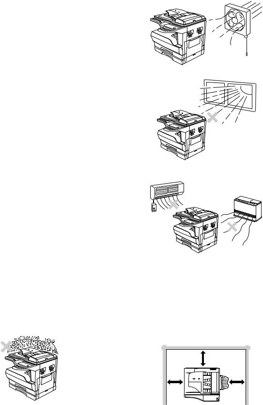
C. Note for installation place
Improper installation may damage the machine. Please note the following during initial installation and whenever the machine is moved.
Caution : If the machine is moved from a cool place to a warm place, condensation may form inside the machine. Operation in this condition will cause poor copy quality and malfunctions. Leave the machine at room temperature for at least 2 hours before use.
Do not install your machine in areas that are:
•damp, humid, or very dusty
•poorly ventilated
•exposed to direct sunlight
•subject to extreme temperature or humidity changes, e.g., near an air conditioner or heater.
The machine should be installed near an accessible power outlet for easy connection and disconnection.
Be sure to connect the power cord only to a power outlet that meets the specified voltage and current requirements. Also make certain the outlet is properly grounded.
Note : Connect the machine to a power outlet which is not used for other electric appliances. If a lighting fixture is connected to the same outlet, the light may flicker.
Be sure to allow the required space around the machine for servicing and proper ventilation.
|
8″ (20cm) |
|
|
8″ |
8″ |
|
(20cm) |
(20cm) |
AR-M205 GENERAL 1-1
[2] SPECIFICATIONS
1. Copy mode
A. Type
|
Type |
Desk-top |
|
Paper exit |
Wing less |
B. Machine composition
|
AR-M160 |
16-CPM multi function model |
|
AR-M205 |
20-CPM multi function model |
(1) Option
|
Machine |
Model |
|
|
250 sheets paper feed unit |
AR-D24 |
|
|
250 sheets x 2 paper feed unit |
AR-D25 |
|
|
SPF |
AR-SP6 |
AR-M160 only |
|
RSPF |
AR-RP6 |
AR-M205 only |
|
Original cover |
AR-VR5 |
|
|
Dual function board |
AR-EB7 |
|
|
Network expansion kit |
AR-NB2 |
Available from October |
|
PS3 expansion kit |
AR-PK1/N |
option for AR-NB2 |
|
256MB optional memory |
AR-SM5 |
|
C. Copy speed
(1) Scan One Print many
Condition: Copy speed in the normal copy from all the paper feed ports including the manual paper feed port.
(2) Continuous copy speed (Sheets/min)
a. AR-M160
|
Paper size |
Normal |
Enlargement |
Reduction |
|||
|
(200%) |
(50%) |
|||||
|
A3 |
9 |
9 |
9 |
|||
|
B4 |
10 |
10 |
10 |
|||
|
AB |
A4 |
16 |
16 |
16 |
||
|
system |
||||||
|
A4R |
12 |
12 |
12 |
|||
|
B5 |
16 |
16 |
16 |
|||
|
B5R |
14 |
14 |
14 |
|||
|
11″ X 17″ |
9 |
9 |
9 |
|||
|
8.5″ X 14″ |
10 |
10 |
10 |
|||
|
Inch |
8.5″ X 13″ |
11 |
11 |
11 |
||
|
system |
||||||
|
8.5″ X 11″ |
16 |
16 |
16 |
|||
|
8.5″ X 11″R |
12 |
12 |
12 |
|||
|
8.5″ X 5.5″ |
16 |
16 |
16 |
|||
|
b. AR-M205 |
||||||
|
Paper size |
Normal |
Enlargement |
Reduction |
|||
|
(200%) |
(50%) |
|||||
|
A3 |
11 |
11 |
11 |
|||
|
B4 |
12 |
12 |
12 |
|||
|
AB |
A4 |
20 |
20 |
20 |
||
|
system |
||||||
|
A4R |
14 |
14 |
14 |
|||
|
B5 |
20 |
20 |
20 |
|||
|
B5R |
16 |
16 |
16 |
|||
|
11″ X 17″ |
10 |
10 |
10 |
|||
|
8.5″ X 14″ |
12 |
12 |
12 |
|||
|
Inch |
8.5″ X 13″ |
12 |
12 |
12 |
||
|
system |
||||||
|
8.5″ X 11″ |
20 |
20 |
20 |
|||
|
8.5″ X 11″R |
15 |
15 |
15 |
|||
|
8.5″ X 5.5″ |
20 |
20 |
20 |
|||
D. First copy time
(1) Basic speed
|
First copy time |
7.2sec (A4, 8.5″ X 11″/1st tray/with OC) |
|
(Polygon motor ready state) |
|
E. Document
|
Max. document size |
A3, 11″ X 17″ |
|
Document reference |
Left side center |
|
position |
|
|
Detection (Platen) |
None |
|
Detection size |
A3, B4, A4, A4R, B5, B5R, A5 |
|
11″ X 17″, 8.5″ X 14″, 8.5″ X 13″, 8.5″ X 11″, |
|
|
8.5″ X 11″R, 8.5″ X 5.5″ |
|
|
(8.5″ X 13″ is detected by key input.) |
|
(1) SPF/R-SPF
|
Standard/Option |
Option |
|
SPF: AR-SP6 (AR-M160 only) |
|
|
RSPF: AR-RP6 (AR-M205 only) |
|
|
Document load |
40 sheets (Thickness 4mm or less) |
|
capacity |
|
|
Document size |
A3 ~ A5 |
|
(Max. ~ Min.) |
11″ x 17″ ~ 8.5″ x 5.5″ |
|
(8.5″ x 5.5″, duplex is inhibited.) |
|
|
Document |
AR-M205:20 sheets/min |
|
replacement speed |
AR-M160:16 sheets/min |
|
(A4 , 8.5″ x 11″ normal copy) |
|
|
Document set/Paper |
Face up, Center reference, |
|
feed direction |
Paper feed from the top |
|
Document weight |
56 ~ 90g/m², 15 ~ 24 lbs |
|
Document size |
On the document feed tray |
|
detection |
|
|
Document mixture |
Copy mode: Not Available |
F. Paper feed
|
Copy size |
A3 ~ A6 |
|
|
(Max. ~ Min.) |
11″ x 17″ ~ 8.5″ x 5.5″ |
|
|
Paper feed system |
1 cassette + Multi manual paper feed |
|
|
Paper feed capacity |
AR-M205 |
250 x 2 (Paper feed tray) |
|
+ 100 (Multi bypass feed tray) |
||
|
AR-M160 |
250 x 1 (Paper feed tray) |
|
|
+ 100 (Multi bypass feed tray) |
||
|
Remaining quantity |
Cassette |
Only empty detection available |
|
detection |
section |
|
|
Manual tray |
Only empty detection available |
|
(1) Paper feed section of the copier
|
Paper feed |
A3, B4, A4, A4R, B5, B5R, A5 |
|
size |
11″ x 17″, 8.5″ x 14″, 8.5″ x 13″, 8.5″ x 11″, |
|
8.5″ x 11″R, 8.5″ x 5.5″ |
|
|
(For A5 and 8.5″ x 5.5″, only No. 1 tray available.) |
|
|
Side front |
Front |
|
Paper feed |
250 sheets |
|
capacity |
(56 ~ 90g/m² equivalent) (15 ~ 21 lbs.) |
|
Detection |
Paper empty detection available, size detection |
|
(by key input) |
|
|
Weight |
56 ~ 90g/m² (15 lbs. ~ 21 lbs.) |
|
Special paper |
Recycled paper |
AR-M205 SPECIFICATIONS 2-1
(2) Manual paper feed section
|
Paper feed |
A3 ~ A6, 11″ x 17″ ~ 8.5″ x 5.5″ |
|
size |
|
|
Paper feed |
100 sheets(56 ~ 80g/m²) |
|
capacity |
|
|
Detection |
Size detection not available, |
|
paper empty detection available |
|
|
Weight |
56 ~ 200g/m² (15 ~ 34 lbs.) |
|
Special paper |
Recycled paper, OHP film, labels |
|
Paper feed |
Single except for recycled paper |
(3) Option paper feed unit
|
1-step paper feed unit |
2-step paper feed unit |
|
|
Model |
AR-D24 |
AR-D25 |
|
Paper feed size |
A3, B4, A4, A4R, B5, B5R |
|
|
11″ x 17″, 8.5″ x 14″, 8.5″ x 13″, |
||
|
8.5″ x 11″, 8.5″ x 11″R |
||
|
Capacity |
About 250 sheets x |
About 250 sheets x |
|
(56 ~ 80gm²) |
1 step |
2 steps |
|
Paper weight |
56 ~ 90 g/m² (15 ~ 21 |
lbs.) |
|
Moisture preserving |
None |
|
|
heater |
||
|
Paper empty detection |
Available |
|
|
Paper size setting |
User setting |
|
|
Paper size detection:None |
||
|
External dimensions |
590 x 471 x 88mm |
590 x 471 x 173.5mm |
|
(W x D x H) |
||
|
Weight |
About 4.7kg |
About 10kg |
|
Special paper |
Recycled paper |
|
|
Power |
Supplied from the machine |
|
G. Job speed
|
S-S (1st step) |
100% (document replacement rate) |
||
|
Condition:With SPF/RSPF A4/Letter Normal 1cassette |
|||
|
H. Multi copy |
|||
|
Max. number of multi copy |
999 sheets |
||
|
I. Warm-up time |
|||
|
Warm-up time |
45 sec |
||
|
Pre-heat |
Available |
||
|
Jam recovery |
Within 45 sec |
||
|
J. Copy magnification ratio |
|||
|
Fixed |
AB system: |
||
|
magnification |
50, 70, 81, 86, 100, 115, 122, 141, 200% |
||
|
ratio |
|||
|
Inch system: |
|||
|
50, 64, 77, 95, 100, 121, 129, 141, 200% |
|||
|
Zooming |
25 ~ 400% |
||
|
SPF/RSPF(50 ~ 200%) |
|||
|
Independent |
Available (25 ~ 400%) |
||
|
zooming(vertical) |
SPF/RSPF(50 ~ 200%) |
||
|
Independent zooming |
Available (25 ~ 400%) |
||
|
(horizontal) |
SPF/RSPF(50 ~ 200%) |
||
K. Print density
|
Density mode |
Auto / Text / Photo |
|
No. of manual |
5 steps (Text / Photo) |
|
adjustment |
|
|
Resolution |
Writing: 600 x 600dpi |
|
Reading: 600 (main) x 600 (sub) (PHOTO mode) |
|
|
600 (main) x 300 (sub) (AE mode) |
|
|
Gradation |
Reading: 256 gradations |
|
Writing: Binary |
|
|
Toner save mode |
Set by the user program |
L. Void width
|
Void area |
Lead edge 1 ~ 4mm, |
|
rear edge 4mm or less, |
|
|
both sides 4mm or less |
|
|
Image loss |
4mm or less |
M. Auto duplex
|
Standard/ |
Standard provision (AR-M205 only) |
|
Option |
(D → D / D → S enable only when RSPF is installed) |
|
Not available for AR-M160 |
|
N. Paper exit / finishing
|
Paper exit section |
Face down 250 sheets |
|
capacity |
|
|
Full detection |
None |
|
Finishing |
Dual function board: |
|
Option (AR-EB7) |
|
|
Electronic sort |
A4 (8.5″ x 11″) standard document 100 sheets |
|
capacity |
|
|
Offset function |
Available (by the shifter) |
|
Staple function |
None |
(1) Electronic sort board (Option)
|
Electronic sort |
Sorting |
100 sheets of A4 standard |
|
documents |
||
|
Grouping |
100 sheets of A4 standard |
|
|
documents |
||
|
Rotation copy |
If there is paper of same size as the document, |
|
|
the image is rotated to copy even though the |
||
|
paper is set in the different direction from the |
||
|
document direction. |
||
|
2 in 1, 4 in 1 |
Copies of 2 pages or 4 pages are integrated into |
|
|
one surface. Divided by solid lines, |
||
|
(Selectable by the user program.) |
||
|
Edge erase |
Images surrounding the document are erased |
|
|
when copying. (Adjustable in 5 ~ 20mm by the |
||
|
user program.) |
||
|
Center erase |
The image at the center is erased when copying. |
|
|
(Adjustable in 5 ~ 20mm by the user program.) |
||
|
Margin shift |
Binding margin is made at the left edge of the set |
|
|
documents. |
||
|
(Adjustable in 5 ~ 20mm by the user program.) |
||
|
Memory for |
16MB |
|
|
electronic sort |
||
|
* Memory loading |
A4 standard 100 pages |
|
|
capacity |
||
|
Memory expansion |
DIMM memory slot x 1, max. 256MB x 1 slot + |
|
|
16MB (Max. 272MB in total) |
||
|
USB2.0 |
Standard provision of E-sort |
|
|
SPLC (JBIG-GDI) |
Supported when E-sort is installed. |
|
|
ROPM |
Supported when E-sort is installed. |
|
AR-M205 SPECIFICATIONS 2-2

O. Additional functions
|
APS |
O |
|||||
|
AMS |
O |
|||||
|
Auto tray switching |
O |
|||||
|
Memory copy |
O |
|||||
|
Rotation copy |
||||||
|
E-sort |
O |
Option |
||||
|
Rotation sort |
X |
|||||
|
Independent |
O |
|||||
|
zooming |
||||||
|
1 set 2 copy |
O |
Enlargement invalid/SPF invalid (Patent |
||||
|
rotation) |
||||||
|
Binding margin |
Default AB series: |
|||||
|
10mm (5, 10, 15, 20mm) |
||||||
|
Inch series: 1/2 inch (1/4, 1/2, 3/4, 1 inch) |
||||||
|
Edge erase |
Default AB series: |
|||||
|
10mm (5, 10, 15, 20mm) |
||||||
|
Inch series: 1/2 inch (1/4, 1/2, 3/4, 1 inch) |
||||||
|
Center erase |
Default AB series: |
|||||
|
10mm (5, 10, 15, 20mm) |
||||||
|
Inch series: 1/2 inch (1/4, 1/2, 3/4, 1 inch) |
||||||
|
Black/white |
X |
|||||
|
reverse |
||||||
|
2in1/4in1 |
||||||
|
Sorter |
O |
Offset function (Shifter) provided |
||||
|
Preheating |
O |
The conditions are set by the user |
||||
|
program. |
||||||
|
Auto shut-off |
O |
The conditions are set by the user |
||||
|
program. |
||||||
|
User programming |
O |
|||||
|
Total counter |
O |
Supports Total counter, Scan counter, and |
||||
|
Copy counter. |
||||||
|
Coin vendor |
O |
(Supports I/F only.) |
||||
|
support |
||||||
|
Auditor support |
O |
(Supports I/F only.) |
||||
|
Duplex |
O |
(Standard provision for the model of 20- |
||||
|
sheet model only) |
||||||
|
Toner save |
O |
(Set according to the destination) |
||||
|
Department |
O |
(Copy: 20 Dept.) |
||||
|
management |
||||||
|
O |
: Available |
:Installation of the option is required. |
||||
|
X |
: Not available |
|||||
|
P. Other specifications |
||||||
|
Photoconductor type |
OPC (Organic Photo Conductor) |
|||||
|
Photoconductor drum dia. |
30mm |
|||||
|
Copy lamp |
Cold cathode fluorescent lamp (CCFL) |
|||||
|
Developing system |
Dry 2-component magnetic brush |
|||||
|
development |
||||||
|
Charging system |
Saw teeth charging |
|||||
|
Transfer system |
(+) DC corotron |
|||||
|
Separation system |
(-) DC corotron |
|||||
|
Fusing system |
Heat roller |
|||||
|
Cleaning system |
Contact blade |
|||||
|
Q. Package form |
||||||
|
Body |
Body / Accessories |
|||||
R. External view
|
External dimensions |
590 x 577 x 520 mm(AR-M205) |
|
(W x D x H) |
590 x 577 x 470 mm(AR-M160) |
|
Occupying area |
590 x 531mm |
|
(W x D) |
(When the manual tray is installed.) |
|
Weight |
About 31.3kg (AR-M160) |
|
About 35.1kg (AR-M205) |
|
S. Power source
|
Voltage |
AC120V, 220V, 230V, 240V ±15% |
|
Frequency |
50/60Hz common |
T. Power consumption
|
Max. power consumption |
1200W |
||||
|
* EnergyStar conformity |
|||||
|
Average power consumption in |
Less than 550W |
||||
|
operation |
|||||
|
Power consumption when |
5W(Not include option) |
||||
|
standby |
|||||
|
Energy consumption efficiency |
Less than 25W |
||||
|
U. Digital performance |
|||||
|
Resolution |
Reading |
600 x 600dpi (PHOTO mode) |
|||
|
600 x 300dpi (AE mode) |
|||||
|
Writing |
600 x 600dpi |
||||
|
Gradation |
Reading |
256 gradations |
|||
|
Writing |
Binary |
||||
|
Memory |
Simplex:16MB |
Duplex:32MB |
|||
|
Hard disk |
None |
||||
|
V. Printing function |
|||||
|
Print speed |
<Standard>12ppm |
||||
|
(With the AR-EB7 installed) |
|||||
|
16ppm (AR-M160) / 20ppm (AR-M205) |
|||||
|
Data resolution |
600dpi |
||||
|
Option memory |
16MB (with the AR-EB7 installed) |
||||
|
256MB (AR-SM5) can be added to the AR-EB7. |
|||||
|
Printer driver |
Two drivers for the case when the AR-EB7 is |
||||
|
installed and when it is not are automatically |
|||||
|
installed by plug & play. |
|||||
|
<Standard> SHARP GDI driver |
|||||
|
<with the AR-EB7 installed> SPLC driver |
|||||
|
W. Scanner function |
|||||
|
Type |
Flat bed color scanner |
||||
|
Scan system |
Document table/document feed unit |
||||
|
Light source |
White CCFL |
||||
|
Resolution |
Basic 600 x 1200dpi |
||||
|
Set range: 50 ~ 9600dpi |
|||||
|
Document |
Sheet/Book |
||||
|
Effective scan range |
OC/SPF: about 297(length) x 431(width) mm |
||||
|
Scan speed |
OC/SPF: 2.88msec/line (Color) |
||||
|
Input data |
1bit or 12bit |
||||
|
Output data |
1bit or 8bit |
||||
|
Scan color |
Black and white binaryGray scaleFull color |
||||
|
Protocol |
TWAIN/WIA (XP only) / STI |
||||
|
Interface |
USB1.1 |
||||
|
USB2.0 |
|||||
|
(Option support: High-speed mode/Full speed |
|||||
|
mode (Switched by the user program.)) |
|||||
|
(Supported when E-sort is installed) |
|||||
|
Scanner utility |
Sharp Desk/Button Manager |
||||
|
Drop-out color |
Provided |
||||
|
Scanner button |
Provided (6) |
||||
|
Supported OS |
Windows98/ME/2000/XP |
||||
|
Void area |
Lead edge/rear edge (2.5mm) on the driver |
||||
|
side Left/right: 3.0mm |
|||||
|
WHQL support |
Yes |
AR-M205 SPECIFICATIONS 2-3
[3] CONSUMABLE PARTS
1.Supply system table
A.USA/CANADA/Latin America
|
NO |
Name |
Content |
Life |
Product name |
Remark |
|
|
1 |
Toner cartridge(Black) |
Toner |
x10 |
160K |
AR-202MT |
Life setting by A4 6% document |
|
<With IC> |
(Toner: Net Weight 537g) |
|||||
|
Vinyl bag |
x10 |
|||||
|
2 |
Developer |
Developer |
x10 |
500K |
AR-202MD |
|
|
(Developer : Net Weight 400g) |
||||||
|
3 |
Drum kit |
Drum |
x1 |
50K |
AR-202DR |
|
|
Drum fixing plate |
x1 |
|||||
B. Middle East/Africa/Taiwan/Philippine
|
NO |
Name |
Content |
Life |
Product name |
Remark |
|
|
1 |
Toner cartridge(Black) |
Toner |
x10 |
160K |
AR-202ET |
Life setting by A4 6% document |
|
<With IC> |
(Toner: Net Weight 537g) |
|||||
|
Vinyl bag |
x10 |
|||||
|
2 |
Developer |
Developer |
x10 |
500K |
AR-202CD |
|
|
(Developer : Net Weight 400g) |
||||||
|
3 |
Drum kit |
Drum |
x1 |
50K |
AR-202DR |
|
|
Drum fixing plate |
x1 |
|||||
C. Europe/East Europe
|
NO |
Name |
Content |
Life |
Product name |
Remark |
|
|
1 |
Toner cartridge(Black) |
Toner |
x10 |
160K |
AR-202LT |
Life setting by A4 6% document |
|
<With IC> |
(Toner: Net Weight 537g) |
|||||
|
Vinyl bag |
x10 |
|||||
|
2 |
Developer |
Developer |
x10 |
500K |
AR-202LD |
|
|
(Developer : Net Weight 400g) |
||||||
|
3 |
Drum kit |
Drum |
x1 |
50K |
AR-202DM |
|
|
Drum fixing plate |
x1 |
|||||
D. Asia
|
NO |
Name |
Content |
Life |
Product name |
Remark |
|
|
1 |
Toner cartridge(Black) |
Toner |
x10 |
160K |
AR-202CT |
Life setting by A4 6% document |
|
<With IC> |
(Toner: Net Weight 537g) |
|||||
|
Vinyl bag |
x10 |
|||||
|
2 |
Developer |
Developer |
x10 |
500K |
AR-202CD |
|
|
(Developer : Net Weight 400g) |
||||||
|
3 |
Drum kit |
Drum |
x1 |
50K |
AR-202DR |
|
|
Drum fixing plate |
x1 |
|||||
E.Hong Kong/China
|
NO |
Name |
Content |
Life |
Product name |
Remark |
||
|
1 |
Toner cartridge(Black) |
Toner |
x10 |
160K |
AR-202CT-C |
Life setting by |
A4 6% document |
|
<With IC> |
(Toner: Net Weight 645g) |
||||||
|
(Hong Kong only) |
Vinyl bag |
x10 |
|||||
|
2 |
Toner cartridge(Black) |
Toner |
x1 |
19K |
AR-203ST-C |
Life setting by |
A4 6% document |
|
<With IC> |
(Toner: Net Weight 645g) |
||||||
|
(China only) |
Vinyl bag |
x1 |
|||||
|
3 |
Developer |
Developer |
x10 |
500K |
AR-202CD-C |
||
|
(Developer : Net Weight 4500) |
|||||||
|
4 |
Drum kit |
Drum |
x1 |
50K |
AR-202DR-C |
||
|
Drum fixing plate |
x1 |
||||||
AR-M205 CONSUMABLE PARTS 3-1
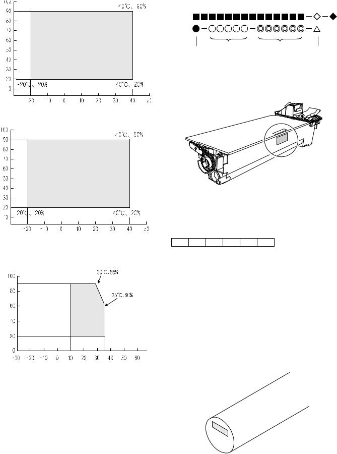
2. Environmental conditions
A. Transport conditions
(1) Transport conditions
Temperature 

(2) Storage conditions
Temperature 

3. Production number identification
<Toner cartridge>
The label on the toner cartridge shows the date of production.
|
Production |
Serial |
Year/ |
Ver.No. |
|
place |
number |
Month/ |
|
|
Day |
<Drum cartridge>
The lot number, printed on the front side flange, is composed of 6 digits, each digit showing the following content:
|
1 |
2 |
3 |
4 |
5 |
6 |
B. Use conditions
1Alphabet
Indicates the model conformity code. A for this model.
|
2 |
Number |
||
|
Indicates the end digit of the production year. |
|||
|
(%) |
3 |
Number or X, Y, Z |
|
|
Use envi- |
Indicates the month of packing. |
||
|
Humidity |
ronment |
Indicates the day of the month of packing. |
|
|
X stands for October, Y November, and Z December. |
|||
|
conditions |
4/5 |
Number |
|
|
6 |
Alphabet |
||
|
Indicates the production factory. «A» for Nara Plant, “C“ for |
|||
|
SOCC |
Temperature 

C. Life(packed conditions)
Photoconductor drum (36 months from the production month)
Developer, toner (24 months from the production month)
AR-M205 CONSUMABLE PARTS 3-2
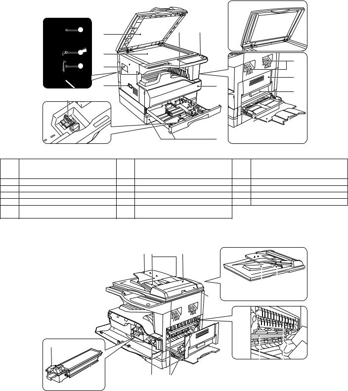
[4] EXTERNAL VIEWS AND INTERNAL STRUCTURES
1. Appearance
1
10
|
8 |
11 |
12 |
13 |
||||||
|
1 |
Document feeder cover (when the SPF/ |
2 |
Document glass |
3 |
Handles |
||||
|
RSPF is installed) /document cover |
|||||||||
|
(when the document cover is installed) |
|||||||||
|
4 |
Power switch |
5 |
Operation panel |
6 |
Paper output tray |
||||
|
7 |
Front cover |
8 |
Paper trays |
9 |
Side cover |
||||
|
10 |
Side cover handle |
11 |
Bypass tray guides |
12 |
Bypass tray |
||||
|
13 |
Bypass tray extension |
14 |
Charger cleaner |
15 |
USB 1.1 port |
||||
|
16 |
Parallel port |
17 |
USB 2.0 port (when the dual function |
||||||
|
board is installed) |
|||||||||
|
2. Internal |
|||||||||
|
18 |
19 |
20 |
25
|
18 |
Document feeder tray |
19 |
Original guides |
20 |
Feeding roller cover |
|
(when the SPF/RSPF is installed) |
(when the SPF/RSPF is installed) |
(when the SPF/RSPF is installed) |
|||
|
21 |
Right side cover |
22 |
Exit area |
23 |
Reversing tray |
|
(when the SPF/RSPF is installed) |
(when the SPF/RSPF is installed) |
(when the RSPF is installed) |
|||
|
24 |
Toner cartridge lock release lever |
25 |
Toner cartridge |
26 |
Roller rotating knob |
|
27 |
Fusing unit release levers |
28 |
Photoconductive drum |
29 |
Fusing unit paper guide |
AR-M205 EXTERNAL VIEWS AND INTERNAL STRUCTURES 4-1
![]()
3. Operation Section
|
1 |
2 |
3 |
4 |
5 |
6 |
|||||
|
SCAN |
ON LINE |
ORIGINAL TO COPY |
XY- |
|||||||
|
1 |
1 |
2 |
3 |
4 |
5 |
6 |
ZOOM |
|||
|
2 |
||||||||||
|
DUAL |
||||||||||
|
PAGE |
||||||||||
|
COPY |
The AR-M160 is shown below.
PAPER
SIZE
X17
X14
X11

X5½ 
X11
TRA
|
1 |
SCAN MENU key |
2 |
SCAN key/indicator |
3 |
ON LINE key/indicator |
||||||||||||||||
|
4 |
ORIGINAL TO COPY key/indicators |
5 |
DUAL PAGE COPY key/indicator |
6 |
XY-ZOOM key/indicator |
||||||||||||||||
|
(AR-M205 only) |
|||||||||||||||||||||
|
7 |
8 |
9 |
10 11 12 |
13 |
14 |
15 |
16 |
17 |
18 |
19 |
20 |
21 |
|
ORIGINAL DATA |
AUDIT CLEAR |
AUTO PAPER SELECT |
POWER SAVE |
|||||
|
SORT |
||||||||
|
GROUP |
2 IN 1 |
ORIGINAL |
PAPER |
200% |
||||
|
AUTO |
||||||||
|
4 IN 1 |
SIZE |
SIZE |
141 |
|||||
|
TEXT |
11X17 |
|||||||
|
PHOTO |
8½X14 |
129 |
||||||
|
EDGE |
8½X11 |
121 |
||||||
|
100% |
||||||||
|
ERASE |
8½X5½ |
|||||||
|
95 |
||||||||
|
CENTER |
8½X11 |
|||||||
|
MARGIN |
77 |
|||||||
|
EXTRA |
64 |
|||||||
|
SHIFT |
1 |
3 |
5 |
|||||
|
50% |
||||||||
|
ORIGINAL SIZE |
TRAY |
AUTO |
PRESET RATIO |
|||||
|
ENTER |
SELECT |
IMAGE |
CLEAR
CLEAR ALL
START
READ-END
|
22 |
23 |
24 25 26 27 |
28 |
29 |
30 |
31 |
32 |
33 |
34 |
35 |
36 |
||||||||||||
|
7 |
SORT/GROUP key/indicators |
8 |
ORIGINAL DATA indicator |
9 |
2 IN 1 / 4 IN 1 key/indicators |
||||||||||||||||||
|
(when the dual function board is |
(when the dual function board is |
(when the dual function board is |
|||||||||||||||||||||
|
installed) |
installed) |
installed) |
|||||||||||||||||||||
|
10 |
ERASE key/indicators |
11 |
MARGIN SHIFT key/indicator |
12 |
AUTO/TEXT/PHOTO key / indicators |
||||||||||||||||||
|
(when the dual function board is |
(when the dual function board is |
||||||||||||||||||||||
|
installed) |
installed) |
||||||||||||||||||||||
|
13 |
AUDIT CLEAR key |
14 |
AUTO PAPER SELECT indicator |
15 |
Alarm indicators |
||||||||||||||||||
|
16 |
POWER SAVE indicator |
17 |
Display |
18 |
Copy ratio display key ( |
) |
|||||||||||||||||
|
19 |
ZOOM indicator |
20 |
Zoom keys ( |
, |
) |
21 |
INTERRUPT key ( |
) / indicator |
|||||||||||||||
|
22 |
Light and Dark keys ( , ) / indicators |
23 |
ORIGINAL SIZE ENTER key / |
24 |
PAPER SIZE indicators |
||||||||||||||||||
|
ORIGINAL SIZE indicators |
|||||||||||||||||||||||
|
25 |
PAPER SIZE ENTER key |
26 |
SPR/RSPF indicator |
27 |
TRAY SELECT key ( |
) |
|||||||||||||||||
|
(when the SPF/RSPF is installed) |
|||||||||||||||||||||||
|
28 |
AUTO IMAGE key/indicator |
29 |
Paper feed location/misfeed location |
30 |
PRESET RATIO selector keys ( , ) / |
||||||||||||||||||
|
indicators |
indicators |
||||||||||||||||||||||
|
31 |
[ |
] key |
32 |
Numeric keys |
33 |
READ-END key ( |
) |
||||||||||||||||
|
34 |
START key ( |
) /indicators |
35 |
CLEAR ALL key ( |
) |
36 |
CLEAR key ( |
) |
AR-M205 EXTERNAL VIEWS AND INTERNAL STRUCTURES 4-2
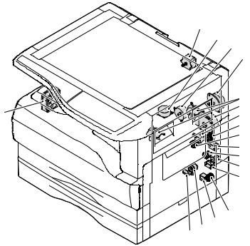
4. Motor, solenoid, clutch
|
1 |
|
|
2 |
|
|
3 |
|
|
4 |
|
|
5 |
|
|
18 |
6 |
|
7 |
|
|
8 |
|
|
9 |
|
|
10 |
|
|
11 |
|
|
12 |
|
|
13 |
|
14 |
|||
|
15 |
|||
|
17 16 |
|||
|
No. |
Name |
Code |
Function operation |
|
1 |
Mirror motor |
MRM |
Drives the optical mirror base (scanner unit). |
|
2 |
Shifter motor |
SHTM |
Shifts the paper exit tray. |
|
3 |
Toner motor |
TM |
Toner supply |
|
4 |
Duplex motor |
DPX |
Switchback operation and paper exit motor in duplex. |
|
5 |
Cooling fan motor |
CFM |
Cools the inside of the machine. |
|
6 |
Main motor |
MM |
Drives the machine. |
|
7 |
1st tray paper feed clutch |
CPFC1 |
Drive the pick up roller |
|
8 |
PS clutch |
RRC |
Drives the resist roller |
|
9 |
Paper feed solenoid |
CPSOL1 |
Solenoid for paper feed from cassette |
|
10 |
Resist roller solenoid |
RRS |
Resist roller rotation control solenoid |
|
11 |
Manual paper transport clutch |
MPTC |
Drives the manual paper transport roller. |
|
12 |
Manual paper feed clutch |
MPFC |
Drives the manual paper feed roller. |
|
13 |
Manual paper feed solenoid |
MPFS |
Manual paper feed solenoid |
|
14 |
2nd tray transport clutch |
CPFC2 |
Drives the 2nd tray transport roller. |
|
15 |
2nd tray transport solenoid |
FSOL1 |
2nd tray transport solenoid |
|
16 |
2nd tray paper feed clutch |
CPFC1 |
Drives the 2nd tray paper feed roller. |
|
17 |
2nd tray paper feed solenoid |
PSOL2 |
2nd tray transport solenoid |
|
18 |
Exhaust fan motor |
VFM |
Cools the inside of the machine. |
AR-M205 EXTERNAL VIEWS AND INTERNAL STRUCTURES 4-3
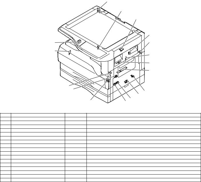
5. Sensor, switch
|
1 |
|
|
2 |
|
|
3 |
|
|
4 |
|
|
17 |
5 |
|
16 |
6 |
|
7 |
|
|
8 |
15
|
14 |
9 |
||||
|
10 |
|||||
|
13 |
12 |
11 |
|||
|
No. |
Name |
Code |
Function operation |
||
|
1 |
Mirror home position sensor |
MHPS |
Detects the mirror (scanner unit) home position. |
||
|
2 |
Side door switch |
DSWR |
Side door open detection |
||
|
3 |
Paper exit sensor (paper exit side) |
POD1 |
Detects paper exit. |
||
|
4 |
Shifter home position sensor |
SFTHP |
Shifter home position detection |
||
|
5 |
Paper exit sensor (DUP side) |
PDPX |
Paper transport detection |
||
|
6 |
Thermistor |
RTH |
Fusing section temperature detection |
||
|
7 |
Thermostat |
Fusing section abnormally high temperature detection |
|||
|
8 |
Toner density sensor |
TCS |
Toner quantity detection |
||
|
9 |
2nd tray detection switch |
2nd tray detection |
|||
|
10 |
Manual sensor |
MPED |
Manual transport detection |
||
|
11 |
2nd tray door open/close sensor |
DRS2 |
2nd tray door open/close detection |
||
|
12 |
2nd tray door paper pass sensor |
PPD2 |
2nd tray paper entry detection |
||
|
13 |
2nd tray paper empty sensor |
CSS2 |
2nd tray paper empty detection |
||
|
14 |
Paper in sensor |
PIN |
Paper transport detection |
||
|
15 |
Cassette empty |
Tray paper entry detection |
|||
|
16 |
Front cover SW |
Front cover open detection |
|||
|
17 |
Power switch |
MAIN SW |
Turns ON/OFF the main power source. |
AR-M205 EXTERNAL VIEWS AND INTERNAL STRUCTURES 4-4
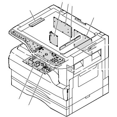
6. PWB unit
2 6 3
1
4

 5 10
5 10 
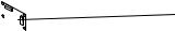 7
7
9
8
|
No. |
Name |
Function operation |
|
1 |
Copy lamp Inverter PWB |
Copy lamp control |
|
2 |
I / F PWB |
USB1.1, IEEE1284 I/F |
|
3 |
CCD sensor PWB |
Image scanning |
|
4 |
Main control PWB |
Main control PWB |
|
5 |
Tray PWB |
Shifter motor control |
|
6 |
IMC2 PWB |
Electronic sort, USB2.0 << Option:AR-EB7>> |
|
7 |
2nd cassette PWB |
2nd cassette control |
|
8 |
High voltage PWB |
High voltage control |
|
9 |
Power PWB |
AC power input/DC power control |
|
10 |
Operation main PWB |
Operation panel input/Display, operation panel section control |
AR-M205 EXTERNAL VIEWS AND INTERNAL STRUCTURES 4-5
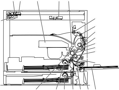
7. Cross sectional view
|
1 |
2 |
3 |
4 |
5 |
6
18
7 8
9
10
11
12


 13
13
 14 15
14 15
|
23 |
22 |
21 |
20 |
19 |
17 |
16 |
|
|
No. |
Name |
Function/Operation |
|||||
|
1 |
Copy lamp |
Image radiation lamp |
|||||
|
2 |
Copy lamp unit |
Operates in synchronization with No. 2/3 mirror unit to radiate documents |
|||||
|
sequentially. |
|||||||
|
3 |
LSU unit |
Converts image signals into laser beams to write on the drum. |
|||||
|
4 |
Lens unit |
Reads images with the lens and the CCD. |
|||||
|
5 |
MC holder unit |
Supplies negative charges evenly on the drum. |
|||||
|
6 |
Paper exit roller |
Used to discharge paper. |
|||||
|
7 |
Transport roller |
Used to transport paper. |
|||||
|
8 |
Upper heat roller |
Fuses toner on paper (with the teflon roller). |
|||||
|
9 |
Lower heat roller |
Fuses toner on paper (with the silicon rubber roller). |
|||||
|
10 |
Waste toner transport roller |
Transports waste toner to the waste toner box. |
|||||
|
11 |
Drum unit |
Forms images. |
|||||
|
12 |
Transfer charger unit |
Transfer images (on the drum) onto paper. |
|||||
|
13 |
DUP follower roller |
||||||
|
14 |
Duplex transport roller |
Transports paper for duplex . |
|||||
|
15 |
Resist roller |
Takes synchronization between the paper lead edge and the image lead edge. |
|||||
|
16 |
Manual paper feed tray |
Manual paper feed tray |
|||||
|
17 |
Manual paper pick up roller |
Picks up paper in manual paper feed. |
|||||
|
18 |
No. 2/3 mirror unit |
Reflects the images from the copy lamp unit to the lens unit. |
|||||
|
19 |
Manual transport roller |
Transports paper from the manual paper feed port. |
|||||
|
20 |
2nd tray paper transport roller |
Transports paper from the 2nd tray. |
|||||
|
21 |
2nd tray paper pick up roller |
Picks up paper from the 2nd tray. |
|||||
|
(semi-circular roller) |
|||||||
|
22 |
1st tray paper feed roller |
Picks up paper from the 1st tray. |
|||||
|
(semi-circular roller) |
|||||||
|
23 |
MG roller |
Puts toner on the OPC drum. |
AR-M205 EXTERNAL VIEWS AND INTERNAL STRUCTURES 4-6
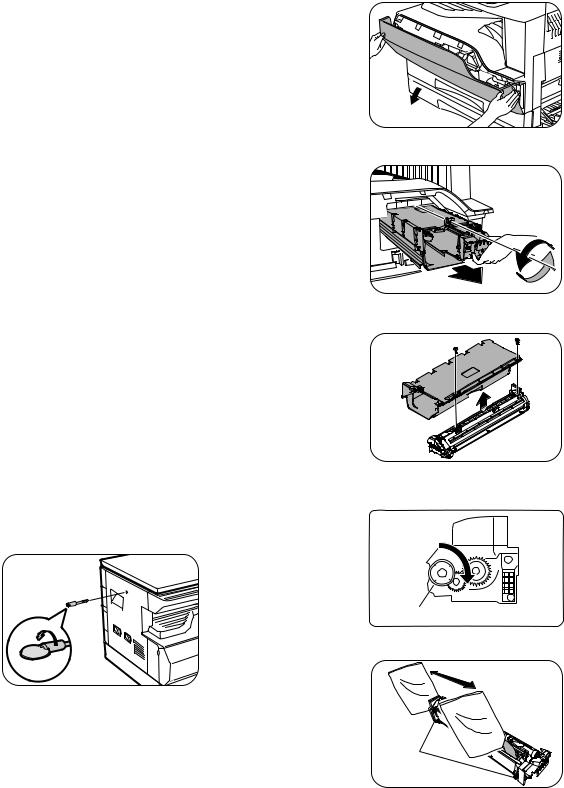
[5]UNPACKING AND INSTALLATION
1.Installing conditions
A.Copier installation
Do not install your copier in areas that are: •damp, humid, or very dusty
•exposed to direct sunlight •poorly ventilated
•subject to extreme temperature or humidity changes, e.g., near an air conditioner or heater.
•Be sure to allow the required space around the machine for servicing and proper ventilation.
2) Open the front cover.
•Hold the both sides and pull down to open.
3) Loosen the screw and remove the developer cartridge.
B.Power source
•Use an exclusive-use power outlet. If the power plug of this machine is inserted into a power outlet commonly used with other illumination units, flickers of the lamp may be result. Use a power outlet which is not used commonly with any illumination units.
•Avoid complex wiring.
C.Grounding wire connection.
•To avoid danger, be sure to connect a grounding wire. If no grounding wire is connected and a leakage occurs, a fire or an electric shock may be result.
2.Removal of protective material and fixing screw
1) Remove all tapes and protective material.
•Remove all tapes, then open the document cover and remove the protective material of sheet shape
2) Remove the fixing screw.
•Use a coin to remove the fixing screw.
•The fixing screw is required when transporting the machine. Keep it in the tray. (Refer to the later description.)
4) Remove the developer tank from the developer cartridge.
5)Supply developer into the developer tank while rotating the MG roller in the arrow direction.
MG roller
* Shake the developer bag enough before opening it.
3.Installing procedure
Hook
A.Developer cartridge installation
1) Open the manual tray, and open the side cover.
Note:Check that the DV seal is free from developing agent. If developing agent is attached to the DV seal, clean it carefully.
Check to insure that the hook is engaged in two positions.
6) Attach the developer tank to the developer cartridge.
* After supplying developer into the developer cartridge, do not tilt or shake the developer cartridge.
7) Attach the developer cartridge to the copier, and fix it with the screw.
AR-M205 UNPACKING AND INSTALLATION 5-1
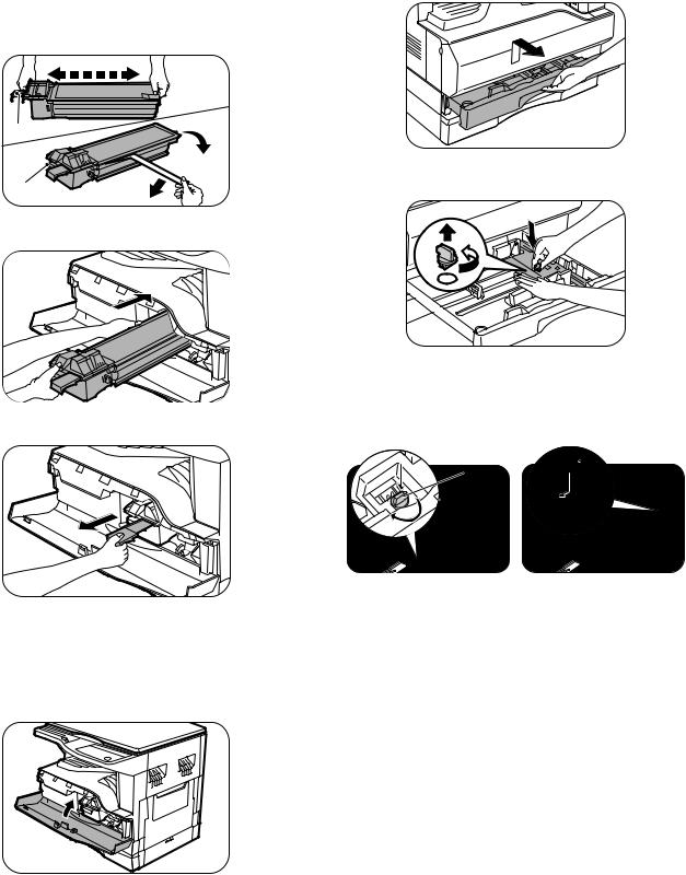
B.Toner cartridge installation
1)Shake the toner cartridge several times horizontally, and remove the tape.
*Do not hold the shutter lever when shaking.
*After removing the tape, do not tilt or shake the toner cartridge.
4 or 5 times
Shutter
 Tape
Tape
Handle 
2) Attach the toner cartridge to the copier.
3) Pull the shutter lever.
Close the front cover A, then close the side cover B. •When closing the front cover, gently press the both sides. •When closing the side cover, hold the knob.
•When closing the covers, be sure to close the front cover first, then close the side cover. If closed in a wrong sequence, the covers may be broken.
4.Removal and storage of fixing screw
1) Lift the knob and gently pull out the tray.
2)Hold the paper pressure plate and turn the fixing screw in the arrow direction.
3) Store the fixing pin and the fixing screw in the tray.
•Store the fixing screw which was removed in the above procedure 2 and the fixing screw which was removed in procedure 2 of 2.
•Removal of protective material and fixing screw in the storage place in the tray.
Pressure  Screw plate
lock
AR-M205 UNPACKING AND INSTALLATION 5-2
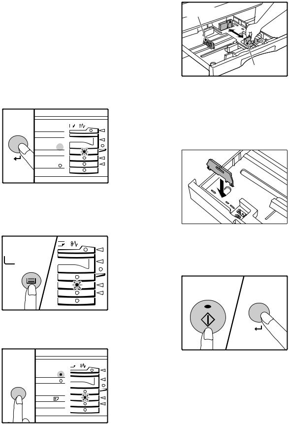
5. Changing the copy paper size in the tray
Note
•The paper size setting cannot be changed when the machine has stopped temporarily due to running out of paper or a misfeed, or during interrupt copying.
•During printing (even in copy mode), the paper size setting cannot be changed.
•5-1/2″ x 8-1/2″ size paper can only be selected in upper paper tray.
•Do not load paper that is a different size than the paper size setting. Copying will not be possible.
1)Hold down the [PAPER SIZE ENTER] key for more than 5 seconds to set the selected paper size.
The currently selected paper feed location indicator will blink and the corresponding paper size (which is currently set) indicator will light steadily.
All other indicators will go out.
INAL PAPER SIZE 11X17 
8½X14  8½X11
8½X11
 8½X5½
8½X5½  8½X11
8½X11 EXTRA
EXTRA
2)Use the [TRAY SELECT] key to select the paper tray for which you wish to change the paper size setting.
Each time the [TRAY SELECT] key is pressed, a paper tray will be indicated with a blinking paper feed location indicator.
TRAY
SELECT
4)Squeeze the lock lever of the front guide and slide the front guide to match the width of the paper, and move the left guide to the appropriate slot as marked on the tray.
Left guide
Front guide
•The front guide is a slide-type guide. Grasp the locking knob on the guide and slide the guide to the indicator line of the paper to be loaded. •The left guide is an insert-type guide. Remove it and then insert it at the indicator line of the paper to be loaded.
•When using 11″ x 17″ sized paper store the left guide in the slot at the left front of the paper tray.
6)Press the [START] key and then the [PAPER SIZE ENTER] key.
To change the paper size setting of another tray, repeat steps 2 to 3 after pressing the [START] key.
3)Use the [ORIGINAL SIZE ENTER] key to select the paper size. The indicator of the selected paper size lights up.
GINAL PAPER
SIZE
|
ORIGINAL SIZE |
11X17 |
|
8½X14 |
ENTER 8½X11
 8½X5½
8½X5½  8½X11
8½X11  EXTRA
EXTRA 
START
Note
Affix the paper size label for the paper size selected in step 3 to the label position on the right end of the tray.
AR-M205 UNPACKING AND INSTALLATION 5-3
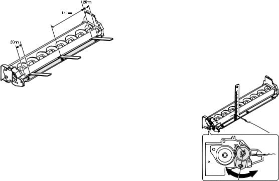
[6]ADJUSTMENTS
1.Adjustment item list
|
Section |
Adjustment item |
Adjustment procedure/SIM No. |
||
|
A |
Process |
(1) |
Developing doctor gap adjustment |
Developing doctor gap adjustment |
|
section |
||||
|
(2) |
MG roller main pole position adjustment |
MG roller main pole position adjustment |
||
|
(3) |
Developing bias voltage check |
|||
|
(4) |
Main charger voltage check |
|||
|
B |
Mechanism |
(1) |
Image position adjustment |
SIM-50 |
|
section |
||||
|
(2) |
Main scanning direction (FR direction) distortion balance |
No. 2/3 mirror base unit installing position adjustment |
||
|
adjustment |
||||
|
Copy lamp unit installing position adjustment |
||||
|
(3) |
Main scanning direction (FR direction) distortion adjustment |
Rail height adjustment |
||
|
(4) |
Sub scanning direction (scanning direction) distortion |
Winding pulley position adjustment |
||
|
adjustment |
||||
|
(5) |
Main scanning direction (FR direction) magnification ratio |
SIM 48-1 |
||
|
adjustment |
||||
|
(6) |
Sub scanning direction (scanning direction) magnification ratio |
OC mode in copying (SIM 48-1) |
||
|
adjustment |
||||
|
SPF mode in copying (SIM 48-5) |
||||
|
(7) |
Off center adjustment |
OC mode (SIM 50-12) |
||
|
SPF mode (SIM 50-12) |
||||
|
(8) |
SPF white correction pixel position adjustment |
SIM63-7 |
||
|
(required in an SPF model when replacing the lens unit) |
||||
|
C |
Image density |
(1) |
Copy mode |
SIM 46-1 |
|
adjustment |
||||
2.Copier adjustment
A.Process section
(1) Developing doctor gap adjustment
1)Loosen the developing doctor fixing screw A.
2)Insert a thickness gauge of 1.5mm to the three positions at 20mm and 130mm from the both ends of the developing doctor as shown.
3)Push the developing doctor in the arrow direction, and tighten the developing doctor fixing screw. (Perform the same procedure for the front and the rear frames.)
4)Check the clearance of the developing doctor. If it is within the specified range, then fix the doctor fixing screw with screw lock.
*When inserting a thickness gauge, be careful not to scratch the developing doctor and the MG roller.
<Adjustment specification>
Developing doctor gap
Both ends (20mm from the both ends) : 1.5 +0.1— 0.15 mm
C (Center) (150mm from the both ends) :1.55 +0.15— 0.2 mm
(2) MG roller main pole position adjustment
1)Remove and separate the waste toner box and put the developing unit on a flat surface.
2)Tie a string to a needle or a pin.
3)Hold the string and bring the needle close to the MG roller horizontally. (Do not use paper clip, which is too heavy to make a correct adjustment.) (Put the developing unit horizontally for this adjustment.)
4)Do not bring the needle into contact with the MG roller, but bring it to a position 2 or 3mm apart from the MG roller. Mark the point on the MG roller which is on the extension line from the needle tip.
5)Measure the distance from the marking position to the top of the doctor plate of the developing unit to insure that it is 18mm.
If the distance is not within the specified range, loosen the fixing screw A of the main pole adjustment plate, and move the adjustment plate in the arrow direction to adjust.
AR-M205 ADJUSTMENT 6-1
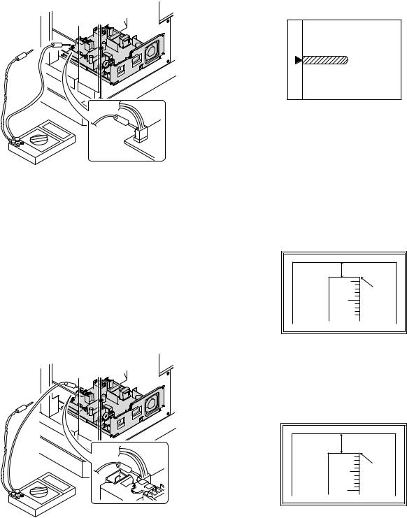
(3)Developing bias voltage check
Note:Use a digital multi-meter with an internal resistance of 10MΩ or more.
1)Set the digital multi-meter range to DC700V.
2)Put the test rod of the digital multi-meter on the developing bias voltage output check pin.
3)Turn on the power, execute SIM25-1.
<Specification>
|
Mode |
Specification |
|
Developing bias voltage |
DC — 400±8V |
(4) Grid bias voltage check
Note:Use a digital multi-meter with an internal resistance of 10MΩ or more.
1)Set the digital multi-meter range to DC700V.
2)Put the test rod of the digital multi-meter on the grid bias voltage output check pin.
3)Turn on the power.
(The voltage is outputted in the grid bias High output mode during warming up, and in the grid bias Low output mode when warming up is completed.)
<Specification>
|
Mode |
Specification |
|
Grid bias LOW |
DC — 400±8V |
|
Grid bias HIGH |
DC — 525±10V |
B.Mechanism section
Note: If a jam error or paper empty occurs during copying in the adjustment by the simulation, the image data are not saved, and therefore recopying is required.
(1)Image position adjustment
a.OC image lead edge position adjustment (SIM 50-1)
Note:In advance to this adjustment, the sub scanning magnification ratio adjustment must be performed.
1) Set a scale on the OC table as shown below.
2)Make a copy.
3)Check the copy output. If necessary, perform the following adjustment procedures.
4)Execute SIM 50-1.
5)Set the OC lead edge position set value (Exposure display <<PHOTO>> ON) to [1]
The OC image scanning start position is shifted inside the document edge.
6)Set the main cassette lead edge void adjustment value (Exposure display <<TEXT>> ON) * to [1]
The lead edge void becomes the minimum.
7)Set the main cassette print start position value (Exposure display <<AUTO+MAIN CASSETTE LAMP>> ON) to [1] and make a copy. The print start position is shifted inside the document edge.
*The dimension varies depending on the model.
 Measure the image loss R of the copied image. Enter the set value of the image scanning lead edge position (Exposure display <<PHOTO>> ON) again.
•1 step of the set value corresponds to about 0.1mm shift. •Calculate the set value from the formula below. R/0.1(mm) = Image loss set value
<R: Image loss measurement value (mm)>
*The scanning edge is set.
(A line may be printed by scanning the document edge.)
Example: 4/0.1 = 40 = about 40
Note:If the set value is not obtained from the above formula, perform the fine adjustment.
AR-M205 ADJUSTMENT 6-2
![]()
9)Measure the distance H between the paper lead edge and the image print start position. Set the image print start position set value (Exposure display <<AUTO+MAIN CASSETTE LAMP>> ON) again.
•1 step of the set value corresponds to about 0.1mm shift. •Calculate the set value from the formula below. H/0.1(mm) = Image print start position set value
<H: Print start position measurement value (mm)>
*Fit the print edge with the paper edge, and perform the lead edge adjustment.
Example: 5/0.1 = 50 = about 50
Note:If the set value is not obtained from the above formula, perform the fine adjustment.
10) Set the lead edge void adjustment value (Exposure display <<TEXT>> ON)* again.
•1 step of the set value corresponds to about 0.1mm shift. •Calculate the set value from the formula below.
B/0.05 (mm) = Lead edge void adjustment value <B: Lead edge void (mm)>
|
Example: |
When setting the lead edge void to 2.5mm |
|
:2.5 /0.05 = about 50 |
Note:If the set value is not obtained from the above formula, perform the fine adjustment.
*2nd cassette lead edge void adjustment: Exposure display <<AUTO
+ TEXT + PHOTO>>
Multi bypass tray lead edge void adjustment: Exposure display <<TEXT + PHOTO>>
<Duplex mode adjustment>
OC 2nd print surface (Auto duplex) lead edge position adjustment: SIM50-19 <<PHOTO>>
*For the adjustment procedure, set to S → D mode before execution.
Note:Before performing the 2nd print surface lead edge position adjustment and the lead edge void adjustment, be sure to perform the 1st print surface lead edge position adjustment in advance, and be sure to perform the 2nd print surface lead edge position adjustment and then the lead edge void adjustment in this sequence.
<Adjustment specification>
|
Adjustment |
SIM |
LED |
Set |
Spec |
Set |
|
mode |
value |
value |
range |
||
|
OC image lead |
SIM |
PHOTO |
R/0.1 |
Lead edge |
1 ~ 99 |
|
edge position |
50-1 |
||||
|
void: |
|||||
|
Main cassette |
AUTO |
B/0.1 |
|||
|
print start |
+ |
1 — 4mm |
|||
|
position |
MAIN |
Image loss: |
|||
|
2nd cassette |
AUTO |
||||
|
3mm or |
|||||
|
print start |
+ |
||||
|
less |
|||||
|
position |
2nd |
||||
|
CASSETTE |
|||||
|
Multi bypass |
AUTO |
||||
|
tray print start |
+ |
||||
|
position |
MULTI |
||||
|
Lead edge void |
TEXT |
B/0.05 |
|||
|
OC 2nd print |
SIM |
PHOTO |
1 step: |
||
|
surface lead |
50-19* |
0.1mm shift |
|||
|
edge position |
|||||
|
adjustment |
|||||
*(Set to S → D mode for before execution)
b.SPF image lead edge position adjustment (SIM50-6)
1) Set a scale on the OC table as shown below.
Note:Since the printed copy is used as a test chart, put the scale in paralled with the edge lines.
2)Make a copy, Then use the copy output as an original to make an SPF copy again.
3)Check the copy output. If necessary, perform the following adjustment procedures.
4)Execute SIM 50-6.
5)Set the SPF lead edge position set value (Exposure display <<AUTO>> ON) so that the same image is obtained as that obtained in the previous OC image lead edge position adjustment.
<Adjustment specification>
|
Adjustment mode |
SIM |
LED |
Set value |
Spec value |
Set |
|
range |
|||||
|
SPF image lead |
SIM |
AUTO |
1 step: |
Lead edge |
1 ~ 99 |
|
edge position |
50-6 |
0.1mm shift |
void: |
||
|
(1st print surface) |
1 — 4mm |
||||
|
(2nd print surface) |
TEXT |
Image loss: |
|||
|
3mm or |
|||||
|
less |
|||||
AR-M205 ADJUSTMENT 6-3
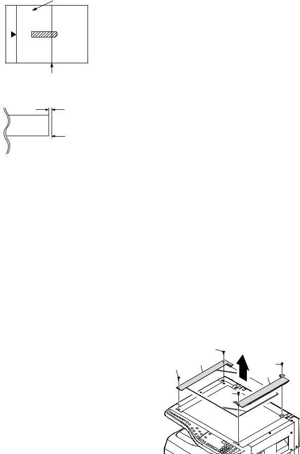
c.Rear edge void adjustment (SIM50-1, SIM50-19)
1) Set a scale as shown in the figure below.
A4(8.5″ x 11″)
Paper rear edge
2)Set the document size to A4 (8.5″ x 11″), and make a copy at 100%.
3)If necessary, perform the following adjustment procedure.
Void amount (Standard value: 4mm or less)
Scale image
Paper rear edge
4)Execute SIM 50-1 and set the density mode to AUTO + TEXT + PHOTO (Rear edge void).The currently set adjustment value is displayed.
5)Enter the set value and press the start key. The correction value is
stored and a copy is made.
<Duplex mode adjustment>
*1st print surface (auto duplex) rear edge void adjustment: SIM50-19 <<AUTO>>
*2nd print surface (auto duplex) rear edge void adjustment: SIM50-19<<TEXT>>
*Set to S → D mode before execution.
Note:Before performing the 2nd print surface rear edge void adjustment, be sure to perform the 2nd print surface lead edge position adjustment. Never reverse the sequence.
<Adjustment specification>
|
Mode |
SIM |
LED |
Set value |
Specifi- |
Set |
|
cation |
range |
||||
|
Rear edge void |
SIM |
AUTO |
1 step: |
4mm or |
1 ~ 99 |
|
50-1 |
+ |
0.1mm shift |
less |
||
|
TEXT |
|||||
|
+ |
|||||
|
PHOTO |
|||||
|
1st print |
SIM |
AUTO |
|||
|
surface rear |
50-19* |
||||
|
edge void |
|||||
|
2nd print |
SIM |
TEXT |
|||
|
surface rear |
50-19* |
||||
|
edge void |
|||||
*Set to S → D mode before execution
d. Paper off center adjustment (SIM50-10)
1)Set a test chart (UKOG-0089CSZZ) on the document table.
2)Select a paper feed port and make a copy. Compare the copy and the test chart. If necessary, perform the following adjustment procedure.
3)Execute SIM 50-10. After completion of warm-up, shading is performed and the currently set off center adjustment value of each paper feed port is displayed.
4)Enter the set value and press the start key. The correction value is stored and a copy is made.
<Duplex mode adjustment>
*2nd print surface (auto duplex) off-center adjustment: SIM50-10<<TEXT+MAIN CASSETTE>>
<Adjustment specification>
|
Mode |
SIM |
LED |
Set value |
Specifi- |
Set |
|
cation |
range |
||||
|
Paper off |
SIM |
AUTO |
Add 1: |
Single: |
1 ~ 99 |
|
center |
50-10 |
+ |
0.1mm shift |
Center |
|
|
Selected |
to R side. |
±2.0mm |
|||
|
tray ON |
|||||
|
Reduce 1: |
|||||
|
2nd print |
SIM |
TEXT |
Duplex: |
||
|
surface off- |
50-10 |
+ |
0.1mm shift |
Center |
|
|
center |
MAIN |
to L side. |
±2.5mm |
||
|
CASSETTE |
|||||
e.Side edge void area adjustment (SIM26-43)
Note:Before performing this adjustment, be sure to check that the paper off center adjustment (SIM 50-10) is completed.
1)Set a test chart (UKOG-0089CSZZ) on the document table.
2)Select a paper feed port and make two copies. Compare the 2nd copy and the test chart. If necessary, perform the following
adjustment procedure.
*The 1st copy does not show the void. Be sure to check the 2nd copy.
3)Execute SIM 26-43 and set the density mode to AUTO(right edge void) + TEXT (Left edge void).
The currently set adjustment value is displayed.
4)Enter the set value and press the start key. The correction value is stored.
<Adjustment specification>
|
ode |
SIM |
LED |
Set value |
Specifi- |
Set |
|
cation |
range |
||||
|
Left edge void |
SIM |
AUTO |
1 step: |
0.5 ~ 4mm |
1 ~ 99 |
|
26-43 |
(right |
0.5mm shift |
|||
|
edge) |
|||||
|
+ |
|||||
|
TEXT |
|||||
|
(left edge) |
|||||
*The void adjustment values on the right and the left must be the same.
(2)Main scanning direction(FR direction) distortion balance adjustment
1) Remove the OC glass and the right cabinet.
AR-M205 ADJUSTMENT 6-4
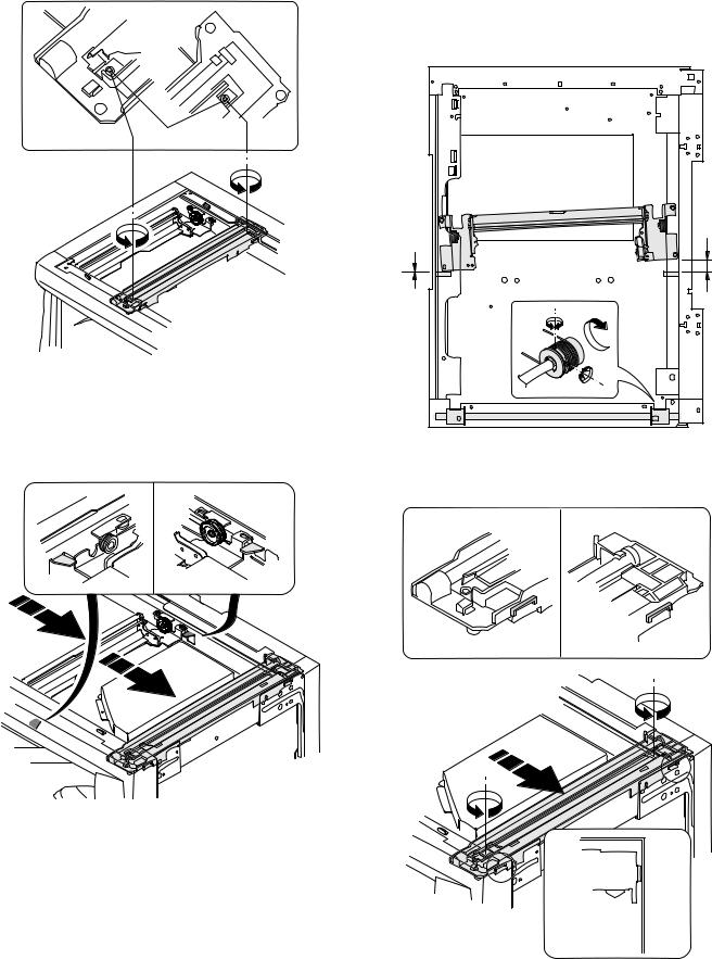
2) Loosen the copy lamp unit wire fixing screw.
4)Loosen the set screw of the scanner drive pulley which is not in contact with No. 2/3 mirror base unit positioning plate.
5)Without moving the scanner drive pulley shaft, manually turn the scanner drive pulley until the positioning plate is brought into contact with No. 2/3 mirror base unit, then fix the scanner drive pulley.
Wire fixing screw
3)Manually turn the mirror base drive pulley and bring No. 2/3 mirror base unit into contact with the positioning plate. At that time, if the front frame side and the rear frame side of No. 2/3 mirror base unit are brought into contact with the positioning plate at the same time, the mirror base unit parallelism is proper. If one of them is in contact with the positioning plate, perform the adjustment of 4).
6)Put No. 2/3 mirror base unit on the positioning plate again, push the projections on the front frame side and the rear frame side of the copy lamp unit to the corner frame, and tighten the wire fixing screw.
AR-M205 ADJUSTMENT 6-5
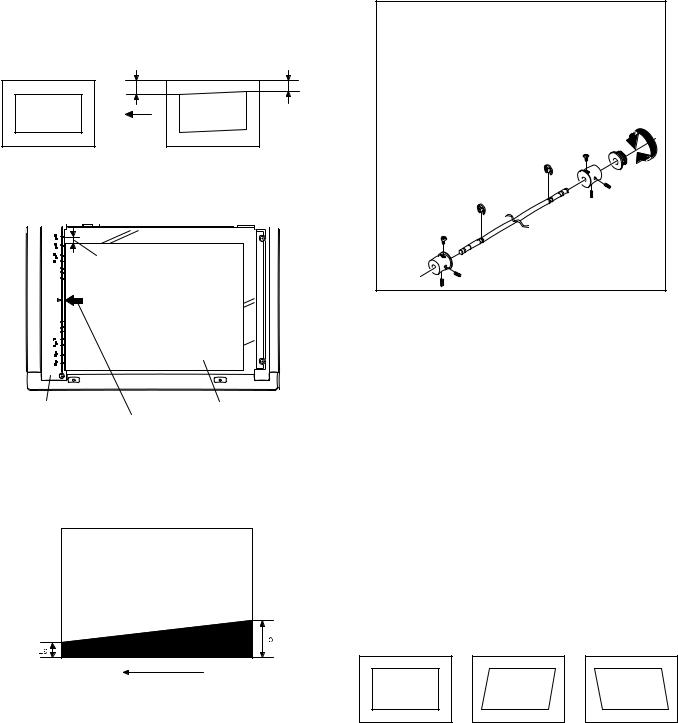
(3)Main scanning direction (FR direction) distortion adjustment
This adjustment must be performed in the following cases: •When the mirror base drive wire is replaced.
•When the lamp unit, or No. 2/3 mirror holder is replaced. •When a copy as shown is made.
Paper exit direction
1) Set A3 (11″ x 17″) white paper on the original table as shown below.
Allow a little space.
|
Glass holding plate |
A3 (11″ x 17″) white paper |
Fit the paper edge and
the glass holding plate edge.
2)Open the original cover and make a normal (100%) copy.
3)Measure the width of the black background at the lead edge and at the rear edge.
Paper exit direction
La: Lead edge black background width
Lb: Rear edge black background width
If the width (La) of the black background at the lead edge is equal that (Lb) at the rear edge, there is no need to execute the following procedures of 4) ~ 7).
4)Loosen the mirror base drive pulley fixing screw on the front frame side or on the rear frame side.
 When La < Lb
Turn the mirror base drive pulley on the front frame side in the arrow direction A.
(Do not move the mirror base drive pulley shaft.)
 When La > Lb
Turn the mirror base drive pulley on the front frame side in the arrow direction A.
(Do not move the mirror base drive pulley shaft.)
Rear side
A
B
Front side
5)Tighten the mirror base drive pulley fixing screw.
<Adjustment specification>
La = Lb
6)Execute the main scanning direction (FR) distartion balance adjustment previously described in 2) again.
(4)Sub scanning direction (scanning direction) distortion adjustment
When there is no skew copy in the mirror base scanning direction and there is no horizontal error (right angle to the scanning direction), the adjustment can be made by adjusting the No. 2/3 mirror base unit rail height.
Before performing this adjustment, be sure to perform the horizontal image distortion adjustment in the laser scanner section.
This adjustment must be performed in the following cases: •When the mirror base wire is replaced.
•When the copy lamp unit or No. 2/3 mirror unit is replaced. •When the mirror unit rail is replaced or moved.
•When a following copy is made.
AR-M205 ADJUSTMENT 6-6
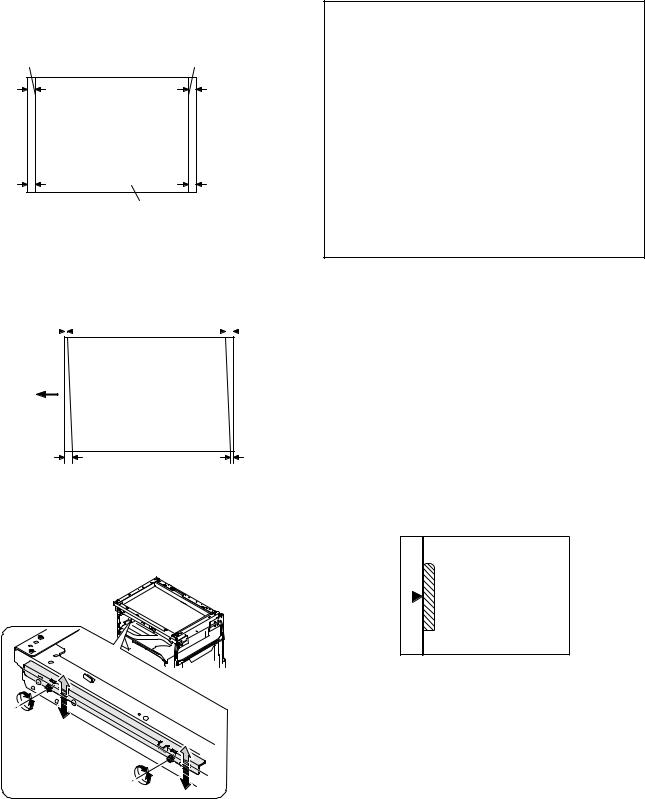
1)Making of a test sheet
Make test sheet by drawing parallel lines at 10mm from the both ends of A3 (11″ x 17″) white paper as shown below. (These lines must be correctly parallel to each other.)
|
Parallel line |
Parallel line |
|
10mm |
10mm |
White paper
2)Make a normal (100%) copy of the test sheet on A3 (11″ x 17″) paper. (Fit the paper edge with the glass holding plate edge.)
3)Measure the distances (La, Lb, Lc, Ld) at the four corners as shown below.
|
La |
Lc |
|||||
Paper exit direction
When La = Lb and Lc = Ld, no need to perform the procedures 4) and 5).
4)Move the mirror base F rail position up and down (in the arrow direction) to adjust.
Note:If the rear side rail is used for the adjustment, the scanning position of the white balance sheet is shifted and «E7-04» may occur only when scanning with the SPF. Therefore it is advisable to use the front side rail for the adjustment.
 When La > Lb
Shift the mirror base B rail upward by the half of the difference of La — Lb.
 When La < Lb
Shift the mirror base B rail downward by the half of the difference of Lb — La.
Example: When La = 12mm and Lb = 9mm, shift the mirror base B rail upward by 1.5mm.
 When Lc > Ld
Shift the mirror base B rail downward by the half of the difference of Lc — Ld.
 When Lc < Ld
Shift the mirror base B rail downward by the half of the difference of Ld — Lc.
 When moving the mirror base rail, hold the mirror base rail with your hand.
<Adjustment specification>
La = Lb, Lc = Ld
5)After completion of adjustment, manually turn the mirror base drive pulley, scan the mirror base A and mirror base B fully, and check that
the mirror bases are not in contact with each other.
*If the mirror base rail is moved extremely, the mirror base may be in contact with the frame or the original glass. Be careful to avoid this.
(5)Main scanning direction (FR direction) magnification ratio adjustment (SIM 48-1)
Note:Before performing this adjustment, be sure to check that the CCD unit is properly installed.
1) Put a scale on the original table as shown below.
2)Execute SIM 48-1.
3)After warm-up, shading is performed and the current set value of the main scanning direction magnification ratio is displayed on the display section in 2 digits.
4)Select the mode and press the start key again.
5)Manual correction mode (TEXT lamp ON) Enter the set value and press the start key. The set value is stored and a copy is made.
AR-M205 ADJUSTMENT 6-7
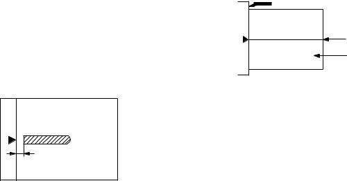
<Adjustment specification>
Note: A judgment must be made with 200mm width, and must not be made with 100mm width.
|
Mode |
Specification |
SIM |
Set value |
Set range |
|
Main scanning |
At normal: |
SIM 48-1 |
Add 1:0.1% |
1 ~ 99 |
|
direction |
±1.0% |
increase |
||
|
magnification |
Reduce 1: |
|||
|
ratio |
0.1% |
|||
|
decrease |
||||
(6)Sub scanning direction (scanning direction) magnification ratio adjustment (SIM 48-1, SIM 48-5)
a. OC mode in copying (SIM48-1)
Note:Before performing this adjustment, be sure to check that the CCD unit is properly installed.
1)Put a scale on the original table as shown below, and make a normal (100%) copy.
2)Compare the scale image and the actual image. If necessary, perform the following adjustment procedures.
3)Execute SIM 48-1.<<PHOTO>>
4)After warm-up, shading is performed and the current set value of the main scanning direction magnification ratio is displayed on the display section in 2 digits.
5)When the photo lamp is lighted by pressing the density selection key, the current magnification ratio correction value in the sub scanning direction is displayed in lower 2 digits of the display section.
6)Enter the set value and press the start key. The set value is stored and a copy is made.
<Adjustment specification>
|
Mode |
Specification |
SIM |
Set value |
Set range |
|
Sub scanning |
Normal |
SIM 48-1 |
Add 1:0.1% |
1 ~ 99 |
|
direction |
±1.0% |
(PHOTO) |
increase |
|
|
magnification |
Reduce 1: |
|||
|
ratio |
0.1% |
|||
|
(OC mode) |
decrease |
|||
b. RSPF sub scanning direction magnification ratio (SIM48-5)
Note:
•Before performing this adjustment, be sure to check that the CCD unit is properly installed.
•Before performing this adjustment, the OC mode adjustment in copying must be completed.
1)Put a scale on the original table as shown below, and make a normal (100%) copy to make a test chart.
Note:Since the printed copy is used as a test chart, put the scale in parallel with the edge lines.
2)Set the test chart on the SPF and make a normal (100%) copy.
3)Compare the scale image and the actual image. If necessary, perform the following adjustment procedures.
4)Execute SIM 48-5.
5)After warm-up, shading is performed.
The auto density lamp lights up and the current front surface sub scanning direction magnification ratio correction value is displayed in two digits on the display section.
6)Enter the set value and press the start key. The set value is stored and a copy is made.
7)Change the mode from the duplex original mode to the simplex original mode.
«MANUAL» lamp lights up and the current back surface sub scanning direction magnification ratio is displayed in two digits on the display section.
Enter the set value and press the start key. The set value is stored and a copy is made.
<Adjustment specification>
|
Mode |
Specification |
SIM |
Set value |
Set range |
|
Sub scanning |
Normal |
SIM 48-5 |
Add 1:0.1% |
1 ~ 99 |
|
direction |
±1.0% |
increase |
||
|
magnification |
Reduce 1: |
|||
|
ratio |
0.1% |
|||
|
(SPF mode) |
decrease |
|||
(7) Off center adjustment (SIM 50-12)
a. OC mode (SIM50-12)
1)Make a test chart as shown below and set it so that its center line is fit with the original guide center mark.
*To make a test chart, draw a line on A3 or 11″ x 17″ paper at the center in the paper transport direction.
Original guide
Center
Copy paper
(A3 or 17″ x 11″)
2)Make a normal copy from the manual paper feed tray, and compare the copy and the test chart.
If necessary, perform the following adjustment procedures.
3)Execute SIM 50-12.
4)After warm-up, shading is performed and the current set value of the off center adjustment is displayed on the display section in 2 digits.
5)Enter the set value and press the start key. The set value is stored and a copy is made.
<Adjustment specification>
|
Mode |
Specification |
SIM |
Set value |
Set range |
|
Original off |
Single: |
SIM 50-12 |
Add 1: |
1 ~ 99 |
|
center mode |
Center ±2.0mm |
(AE lamp |
0.1mm shift |
|
|
(OC mode) |
ON) |
to R side |
||
|
Reduce 1: |
||||
|
0.1mm shift |
||||
|
to L side |
||||
AR-M205 ADJUSTMENT 6-8
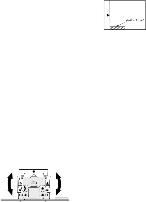
b. SPF original off-center adjustment (SIM50-12)
Note:Before performing this adjustment, be sure to check that the paper off center is properly adjusted.
1) Make a test chart for the center position adjustment and set it on the SPF.
<Adjustment specification>
Draw a line on a paper in the scanning direction.
2)Make a normal copy from the manual paper feed tray, and compare the copy and the original test chart.
If necessary, perform the following adjustment procedures.
3)Execute SIM 50-12.
4)After warm-up, shading is performed and the current set value of the off center adjustment at each paper feed port is displayed on the display section in 2 digits.
5)Enter the set value and press the start key. The set value is stored and a copy is made.
<Adjustment specification>
|
Mode |
Specification |
SIM |
Set value |
Set |
|
range |
||||
|
Original off |
Single: |
SIM |
Add 1: |
1 ~ 99 |
|
center |
Center ±3.0mm(TEXT lamp) |
50-12 |
0.1mm shift |
|
|
mode |
to R side |
|||
|
Duplex: |
||||
|
(SPF mode) |
Center ±3.5mm(PHOTO lamp) |
Reduce 1: |
||
|
0.1mm shift |
||||
|
to L side |
||||
(8)SPF white correction pixel position adjustment(SIM63-7) (required in an SPF model when replacing the lens unit)
1)Fully open the SPF.
2)Execute SIM 63-7.
3)When the operation panel displays «COMPLETE,»the adjustment is completed.
4)If the operation panel displays «ERROR,»perform the following measures.
•When the display is 0: Check that the SPF is open.
Check that the lamp is ON.(If the lamp is OFF,check the MCU connector.) Check that the CCD harness is properly inserted into the MCU connector.
•When the display is 281 or above:
1)Remove the table glass.
2)Remove the dark box.
3)Slide the lens unit toward the front side and attach it,then execute
SIM.
•When the display is 143 or below:
1)Remove the table glass.
2)Remove the dark box.
3)Slide the lens unit toward the rear side and attach it,then execute SIM.
F R
C.Image density adjustment
(1)Copy mode (SIM 46-1)
1)Set a test chart (UKOG-0162FCZZ) on the OC table as shown below.
2)Put several sheets of A3 or 11″ x 17″ white paper on the test chart.
3)Execute SIM 46-1.
4)After warm-up, shading is performed and the current set value of the density level is displayed on the display section in 2 digits.
For mode selection, use the density select key.
5)Change the set value with the 10-key to adjust the copy image density.
6)Make a copy and check that the specification below is satisfied.
<Adjustment specification>
|
Density |
Display |
Exposure |
Sharp Gray |
Set value |
Set |
|
mode |
lamp |
level |
Chart output |
range |
|
|
Auto |
Auto |
— |
«2» is slightly |
The greater the |
1 ~ 99 |
|
copied. |
set value is the |
||||
|
greater the |
|||||
|
Text |
Text |
3 |
«3» is slightly |
||
|
copied. |
density is The |
||||
|
smaller the set |
|||||
|
Photo |
Photo |
3 |
«2» is slightly |
||
|
copied. |
value is the |
||||
|
smaller the |
|||||
|
Toner |
Text/ |
3 |
«3» is slightly |
||
|
density is. |
|||||
|
save |
Photo |
copied |
|||
|
Toner |
Auto/ |
— |
«2» is slightly |
||
|
save |
Photo |
copied |
|||
*When the lens unit is moved,execute the OC main scanning magnification ratio auto adjustment,SIM 48-1-1,IM48-3 and the PF original off-center adjustment.
*This adjustment is basically O.K.with IM 63-7.
AR-M205 ADJUSTMENT 6-9
[7] SIMULATIONS
1. Entering the simulation mode
Perform the following procedure to enter the simulation mode. «#» key  Interrupt key
  «C» key
  Interrupt key
  Main code
  Start key
  Sub code
  Start key
2. Canceling the simulation mode
When the clear all key is pressed, the simulation mode is cancelled. When the interruption key is pressed, the process is interrupted and the screen returns to the sub code entering display.
*After canceling the simulation mode, be sure to turn OFF/ON the power and check the operation.
Note: If the machine is terminated by a jam error or paper empty during copying in the adjustment by the simulation, recopying is required.
3. List of simulations
|
Main |
Sub |
Contents |
|
|
code |
code |
||
|
01 |
01 |
Mirror scanning operation |
|
|
02 |
Mirror home position sensor (MHPS) status display |
||
|
06 |
Mirror scanning operation aging |
||
|
02 |
01 |
Single paper feeder (SPF) aging |
|
|
02 |
SPF sensor status display |
||
|
03 |
SPF motor operation check |
||
|
08 |
SPG paper feed solenoid operation check |
||
|
09 |
RSPF reverse solenoid operation check |
||
|
10 |
RSPF paper exit gate solenoid operation check |
||
|
11 |
SPF PS release solenoid operation check |
||
|
03 |
02 |
Shifter sensors status display |
|
|
03 |
Shifter operation check |
||
|
11 |
Shifter home position check |
||
|
05 |
01 |
Operation panel display check |
|
|
02 |
Fusing lamp and cooling fan operation check |
||
|
03 |
Copy lamp lighting check |
||
|
06 |
01 |
Paper feed solenoid operation check |
|
|
02 |
Resist roller solenoid operation check |
||
|
10 |
Main cassette semicircular roller cleaning |
||
|
07 |
01 |
Warm-up display and aging with jam |
|
|
06 |
Intermittent aging |
||
|
08 |
Shifting with warm-up display |
||
|
08 |
01 |
Developing bias output |
|
|
02 |
Main charger output (Grid = HIGH) |
||
|
03 |
Main charger output (Grid = LOW) |
||
|
06 |
Transfer charger output |
||
|
09 |
01 |
Duplex motor forward rotation check |
|
|
02 |
Duplex motor reverse rotation check |
||
|
04 |
Duplex motor RPM adjustment |
||
|
05 |
Duplex motor switchback time adjustment |
||
|
10 |
— |
Toner motor operation |
|
|
14 |
— |
Trouble cancel (except for U2) |
|
|
16 |
— |
U2 trouble cancel |
|
|
20 |
01 |
Maintenance counter clear |
|
|
21 |
01 |
Maintenance cycle setting |
|
|
02 |
Mini maintenance cycle setting |
||
|
22 |
01 |
Maintenance counter display |
|
|
02 |
Maintenance preset display |
||
|
03 |
Jam memory display |
||
|
04 |
Jam total counter display |
||
|
05 |
Total counter display |
||
|
06 |
Developing counter display |
||
|
07 |
Mini maintenance preset display |
||
|
08 |
SPF counter display |
||
|
09 |
Paper feed counter display |
||
|
12 |
Drum counter display |
||
|
13 |
CRUM type display |
||
|
14 |
P-ROM version display |
||
|
15 |
Trouble memory display |
||
|
16 |
Duplex print counter display |
||
|
17 |
Copy counter display |
||
|
18 |
Printer counter display |
||
|
19 |
Scanner mode counter display |
||
|
21 |
Scanner counter display |
||
|
22 |
SPF jam counter display |
||
AR-M205 SIMULATIONS 7-1
 Loading…