15
Errors occurring during the operation of the virtual encoder are shown as «Error 38: Error
in one technology function» (main error). The sub error code offers more information on
the cause of the error.
Suber-
ror
Problem
code
Electronic cam
3
Incorrect flow control block type.
4
Incorrect flow table block type.
5
Incorrect profile generator block type.
6
Incorrect derivative generator block type.
7
Incorrect motor management block type.
8
Flow control block version is newer than
that of the firmware.
9
Flow table block version is newer than
that of the firmware.
10
Profile generator block version is newer
than that of the firmware.
11
Derivative generator block version is
newer than that of the firmware.
12
Motor management block version is
newer than that of the firmware.
13
Start address of CAMFlow table block not
within DDB.
14
The denominator of a mathematical curve
must not be zero.
15
Invalid start curve type.
16
This curve type is not permitted.
17
–
18
The master cycle of a curve defined by
control points must be greater than zero.
19
A sequence of transition functions is not
permitted.
20
A transition function may not be con-
nected to speed control.
21
A mathematic curve may not precede
speed control.
22
Absolute position control may not precede
speed control.
23
Relative position control may not precede
speed control.
24
Start curve number is negative (not initial-
ized).
25
A negative curve number is not permitted
(not initialized).
Technology Functions Manual – MOVIAXIS® Multi-Axis Servo Inverter
Response
Stop at application limit
Stop at application limit
Stop at application limit
Stop at application limit
Stop at application limit
Stop at application limit
Stop at application limit
Stop at application limit
Stop at application limit
Stop at application limit
Stop at application limit
Stop at application limit
Stop at application limit
Stop at application limit
–
Stop at application limit
Stop at application limit
Stop at application limit
Stop at application limit
Stop at application limit
Stop at application limit
Stop at application limit
Stop at application limit
Error description
Remedy
Check structure in the DDB.
Download the project again, if necessary.
Make sure that the Output and Reverse
output are connected in all curve blocks.
Check structure in the DDB.
Download the project again, if necessary.
Check structure in the DDB.
Download the project again, if necessary.
Check structure in the DDB.
Download the project again, if necessary.
Check structure in the DDB.
Download the project again, if necessary.
Check structure in the DDB.
Download the project again, if necessary.
Update firmware.
Update firmware.
Update firmware.
Check structure in the DDB.
Download the project again, if necessary.
The parameter CFT Denominator factor is
zero for one or several mathematical
curves (control-point-based curves).
Start curves may not be transition func-
tions.
The value of the CFT Curve type parame-
ter of a curve is not permitted.
–
The parameter CFT Master cycle of a
mathematical curve (control-point-based
curve) must be set > 5.
Transition functions must not be con-
nected in sequence. You must always
connect another curve type in between.
A transition function must not follow or
precede the curve type «absolute speed
control».
The curve type «speed control» must not
follow a «mathematic curve».
The curve type «speed control» must not
follow «absolute position control».
The curve type «speed control» must not
follow «relative position control».
The «Start» output of the system block is
not connected to a start curve.
The value of the CFT Curve type parame-
ter of a curve is not permitted.
n
n
kVA
kVA
15
f
f
i
i
P
Hz
P
Hz
217
- Manuals
- Brands
- SEW-Eurodrive Manuals
- Inverter
- MOVIAXIS MXP81A 503-00 Series
Manuals and User Guides for SEW-Eurodrive MOVIAXIS MXP81A 503-00 Series. We have 1 SEW-Eurodrive MOVIAXIS MXP81A 503-00 Series manual available for free PDF download: System Manual
-
Page 1
Gearmotors Industrial Gear Units Drive Electronics Drive Automation Services ® MOVIAXIS MX Multi-Axis Servo Inverter Edition 07/2007 perating nstructions 11508213 / EN… -
Page 2
SEW-EURODRIVE – Driving the world… -
Page 3: Table Of Contents
Contents General Information ………………6 Structure of the safety notes …………..6 Right to claim under warranty …………..6 Exclusion of liability………………. 6 Safety Notes …………………. 7 General information ……………… 7 Target group ………………… 7 Designated use ………………7 Transportation, storage…………….8 Installation………………..
-
Page 4
………………70 Signal bus connection cable for several axis systems – EtherCAT-based…………. 71 Signal bus cables to other SEW units — EtherCAT-based system bus..72 Covers and touch guards……………. 73 Electrical Installation …………….74 4.10 Wiring diagrams ………………78 4.11 Terminal assignment……………. -
Page 5
Contents Service ………………….179 General information …………….179 Removing / installing a module …………. 180 Extended storage……………… 186 Waste disposal………………186 Technical Data………………..187 CE marking and approvals…………..187 General technical data …………….188 Technical data for the supply module ……….. 189 Technical data for the axis module ………… -
Page 6: General Information
MOVIAXIS multi-axis servo inverter and to achieve the spec- ified product characteristics and performance requirements. SEW-EURODRIVE as- sumes no liability for injury to persons or damage to equipment or property resulting from non-observance of these operating instructions. In such cases, any liability for defects is excluded.
-
Page 7: Safety Notes
If you are unclear about any of the information in this documentation, or if you require further information, please contact SEW-EURO- DRIVE.
-
Page 8: Transportation, Storage
Safety Notes Transportation, storage Startup (i.e. start of designated operation) is only permitted with adherence to EMC (89/336/EEC) guideline. The multi-axis servo inverters meet the requirements stipulated in the low voltage guide- line 2006/95/EC. The harmonized standards of the EN 61800-5-1 DIN VDE/T105 series in connection with EN 60439-1 VDE 0660 part 500 and EN 60146 VDE/0558 are applied to the multi-axis servo inverters.
-
Page 9: Electrical Connection
Safety Notes Electrical connection Electrical connection Observe the applicable national accident prevention guidelines when working on live multi-axis servo inverters (for example, BGV A3). Perform electrical installation according to the pertinent regulations (e.g. cable cross sections, fusing, protective conductor connection). Additional information is contained in the documentation.
-
Page 10: Unit Temperature
Safety Notes Unit temperature Unit temperature ® MOVIAXIS multi-axis servo inverters are usually operated with braking resistors. The braking resistors can also be installed in the housing of the supply modules. The braking resistors can reach surface temperatures ranging from 70 °C to 250 °C. ®…
-
Page 11: Unit Design
Unit Design Axis system with CAN-based system bus Unit Design Axis system with CAN-based system bus [10] 61523axx ® Figure 1: Sample structure of a MOVIAXIS axis system Master module Axis module size 4 Capacitor or buffer module Axis module size 3 Supply module size 3 Axis module size 2 Axis module size 6…
-
Page 12: Axis System With Ethercat-Based System Bus
Unit Design Axis system with EtherCAT-based system bus Axis system with EtherCAT-based system bus [10] [11] 62072axx ® Figure 2: Sample structure of a MOVIAXIS axis system Master module Axis module size 4 Capacitor or buffer module Axis module size 3 Supply module size 3 Axis module size 2 Option card for EtherCAT-based system…
-
Page 13: Important Notes
Unit Design Important notes Important notes Protective measures and protective equipment have to meet the respective national regulations in force. Required preventive measures: Protective grounding (protection class I) Required protection devices: The overcurrent protection devices have to be designed to protect the lines at the cus- tomer’s site.
-
Page 14: Nameplates And Unit Designations
Unit Design Nameplates and unit designations Nameplates and unit designations The nameplate is divided into up to three parts depending on the module. • Part «I»of the nameplate indicates the unit designation, production number and sta- tus. • Part «II» of the nameplate indicates the factory installed options and the version sta- tus.
-
Page 15
Unit Design Nameplates and unit designations Axis module nameplate XFA11A XIO11A XFP11A XIA11A XIA11A 10 11 10 10 11 11 11 10 61847axx ® Figure 4: Example: MOVIAXIS MX axis module nameplate Part «I» of the nameplate: Located on the Unit designation, see page 17 upper fastening plate of the module Part «II»… -
Page 16
Unit Design Nameplates and unit designations Nameplate of the 24 V switched mode power supply additional module 61849axx Figure 6: Example: Nameplate of a 24 V switched-mode power supply module Part «I» of the nameplate: Located on the Unit designation upper fastening plate of the module Part «III»… -
Page 17
Unit Design Nameplates and unit designations ® Example: Unit designation for MOVIAXIS basic units -004 — 00 00 = Standard design XX = Special design 3-phase connection type 50 = U = AC 380 — 500 V connection voltage Versions: 004 = For axis modules the rated current, such as 004 = 4 A 050 =… -
Page 18
Unit Design Nameplates and unit designations Unit designation for the supply module: MXP80A-010-503-00 10 kW supply module MXR80A-025-503-00 25 kW supply module with regeneration (in preparation) Unit designation for the 24 V switched-mode power supply module component MXS80A-060-503-00 24 V switched-mode power supply module Unit designation DC link discharge module component: DC link discharge module with a dissipatable energy quantity of MXZ80A-050-503-00… -
Page 19: Standard Accessories
Unit Design Standard accessories Standard accessories Standard accessories are included with the basic unit at delivery. [15] [16] [17] [18] [19] [10] [20] [11] [21] [22] [12] [23] [24] [25] [26] [27] [13] [28] [29] [14] [30] 61637axx Figure 8: Standard accessories The corresponding mating connectors for all connectors are installed at the factory.
-
Page 20
Unit Design Standard accessories Standard accessory assignment table MXP [kW] MXA [A] Dimen- sions Touch guard DC link connection [2] 76 mm [3] 106 mm [4] 136 mm [5] 160 mm [6] 226 mm Electronics shield clamp [7] 60 mm [8] 90 mm [9] 120 mm [10] 150 mm… -
Page 21: Optional Accessories
Figure 9: Optional accessories Optional accessory assignment table Dimension / Designation / Connector type System bus connection cable for CAN-based system bus (axis system with other SEW units) 750 mm RJ45 / open end 3,000 mm RJ45 / open end Connection cable EtherCAT –…
-
Page 22: Overview Of An Axis System
Unit Design Overview of an axis system Overview of an axis system The units are displayed without cover in the following figure. 61507axx Figure 10: Exemplary representation of the energy supply in the axis system X4: DC link connection X5a, X5b: 24 V voltage supply Master module Capacitor / buffer module Supply module BG 3…
-
Page 23: Unit Design Of Moviaxis® Mxp Power Supply Module
Unit Design Unit design of MOVIAXIS® MXP power supply module ® Unit design of MOVIAXIS MXP power supply module The following figures show the units without cover. ® MOVIAXIS MXP supply module size 1 [13] [14] [10] [12] [11] 61524axx ®…
-
Page 24
Unit Design Unit design of MOVIAXIS® MXP power supply module ® MOVIAXIS MXP supply module size 2 [13] [14] [10] [11] [12] 64525axx ® Figure 12: Unit design of MOVIAXIS MXP power supply module size 2 View from top View from front View from bottom Signaling bus Electronics shield clamps… -
Page 25
Unit Design Unit design of MOVIAXIS® MXP power supply module ® MOVIAXIS MXP supply module size 3 [10] [11] [14] [12] [13] 55468AXX ® Figure 13: Unit design of MOVIAXIS MXP power supply module size 3 View from top View from front Signaling bus Electronics shield clamps X9a: Input, green plug on cable… -
Page 26: Unit Design Of Moviaxis® Mxa Axis Modules
Unit Design Unit design of MOVIAXIS® MXA axis modules ® Unit design of MOVIAXIS MXA axis modules The following figures show the units without cover. ® MOVIAXIS MXP axis module size 1 [11] [12] [13] [10] 61544axx ® Figure 14: Unit design of MOVIAXIS MXA axis module size 1 View from top View from front…
-
Page 27
Unit Design Unit design of MOVIAXIS® MXA axis modules ® MOVIAXIS MXP axis module size 2 [11] [12] [13] [10] 61545axx ® Figure 15: Unit design of MOVIAXIS MXA axis module size 2 View from top View from front View from bottom Signaling bus Electronics shield clamps [11]… -
Page 28
Unit Design Unit design of MOVIAXIS® MXA axis modules ® MOVIAXIS MXP axis module size 3 [11] [12] [13] [10] 61546axx ® Figure 16: Unit design of MOVIAXIS MXA axis module size 3 View from top View from front View from bottom Signaling bus Electronics shield clamps [11]… -
Page 29
Unit Design Unit design of MOVIAXIS® MXA axis modules ® MOVIAXIS MXP axis module size 4 [12] [13] [10] [11] 61547axx ® Figure 17: Unit design of MOVIAXIS MXA axis module size 4 View from top View from front View from bottom Signaling bus Electronics shield clamps [12]… -
Page 30
Unit Design Unit design of MOVIAXIS® MXA axis modules ® MOVIAXIS MXP axis module size 5 [12] [13] [10] [11] 61548axx ® Figure 18: Unit design of MOVIAXIS MXA axis module size 5 View from top View from front View from bottom Signaling bus Electronics shield clamps [12]… -
Page 31
Unit Design Unit design of MOVIAXIS® MXA axis modules ® MOVIAXIS MXP axis module size 6 [12] [13] [10] [11] 61549axx ® Figure 19: Unit design of MOVIAXIS MXA axis module size 6 View from top View from front View from bottom Signaling bus Electronics shield clamps [12]… -
Page 32: System Bus In Ethercat- Or Can-Based Version
Unit Design System bus in EtherCAT- or CAN-based version 3.10 System bus in EtherCAT- or CAN-based version Axis modules can be equipped with different system bus versions: • CAN-based system bus, • EtherCAT-based system bus. The figures displayed on page 26… page 31 show the axis modules with CAN-based system bus.
-
Page 33: Unit Design Of The Moviaxis® Mxm Master Module Component
Unit Design Unit design of the MOVIAXIS® MXM master module component ® 3.11 Unit design of the MOVIAXIS MXM master module component The following figure shows the unit without cover. ® MOVIAXIS MXM master module in MOVI-PLC basic version master module shown here…
-
Page 34
Unit Design Unit design of the MOVIAXIS® MXM master module component ® MOVIAXIS MXM master module in MOVI-PLC advanced version master module shown here following designation: MXM80A-000-000-00/DHE41B. 62207axx ® Figure 22: Unit design of the master module, MOVI-PLC Advanced version View from front ®… -
Page 35: Unit Design Of The Moviaxis Mxc Capacitor Module Component
Unit Design Unit design of the MOVIAXIS® MXC capacitor module component ® 3.12 Unit design of the MOVIAXIS MXC capacitor module component The following figure shows the unit without protective cover. Capacitor module MXC 60433AXX ® Figure 23: Unit design of the MOVIAXIS MXC capacitor module View from front Standby display (Power)
-
Page 36: Unit Design Of The Moviaxis Mxb Buffer Module Component
Unit Design Unit design of the MOVIAXIS® MXB buffer module component ® 3.13 Unit design of the MOVIAXIS MXB buffer module component The following figure shows the unit without protective cover. Buffer module 60433AXX ® Figure 24: Unit design of the MOVIAXIS MXB buffer module View from front No function…
-
Page 37: Unit Design Of The Moviaxis ® Mxs 24 V Switched-Mode
Unit Design Unit design of the MOVIAXIS® MXS 24 V switched-mode power supply ® 3.14 Unit design of the MOVIAXIS MXS 24 V switched-mode power supply module component The following figure shows the unit without protective cover. 24 V switched-mode power supply module 57583axx Figure 25: Units design of the 24 V switched-mode power supply module View from top…
-
Page 38: Unit Design Of The Moviaxis Mxz Dc Link Discharge Module Component
Unit Design Unit design of the MOVIAXIS® MXZ DC link discharge module component ® 3.15 Unit design of the MOVIAXIS MXZ DC link discharge module component The following figure shows the unit without protective cover. ® DC link discharge module MOVIAXIS 54427BXX ®…
-
Page 39: Option Combinations On Delivery
Unit Design Option combinations on delivery 3.16 Option combinations on delivery The axis modules include an expansion system for up to three options. 56598axx Figure 27: Slot combinations [1 — 3] Slots 1 — 3, assignment see following table [4] Control board — Basic unit components EtherCAT- The following table shows the possible combinations and the fixed assignment of cards capable units…
-
Page 40
Unit Design Option combinations on delivery CAN version of The following tables show the possible combinations and the fixed assignment of cards the units to the slots. Fieldbus The fieldbus options can be plugged in the following combinations: combinations Combination Slot 1 Slot 2 Slot 3… -
Page 41
Unit Design Option combinations on delivery Combinations with The following option card combinations are possible: Combination Slot 1 Slot 2 Slot 3 XIA11A XIA11A Combinations with The following option card combinations are possible: XGH, XGS only Combination Slot 1 Slot 2 Slot 3 Combinations with The following option card combinations are possible:… -
Page 42: Multi-Encoder Card Option Xgh11A, Xgs11A
Unit Design Multi-encoder card option XGH11A, XGS11A 3.17 Multi-encoder card option XGH11A, XGS11A ® The multi-encoder card expands the MOVIAXIS system for evaluation of additional en- coders. Two different multi-encoder cards are available. Their selection is based on the encoder type that is to be evaluated, see table on page 44.
-
Page 43
Analog input Optional 24 V voltage supply Resolver • Please contact SEW-EURODRIVE before installing HTL encoders. • You need 15-pole SUB-D connectors for all encoders that are to be connected to the multi-encoder card. Operating Instructions – MOVIAXIS® MX Multi-Axis Servo Inverter… -
Page 44
Unit Design Multi-encoder card option XGH11A, XGS11A Suitable The encoders listed in the following tables are evaluated by the multi-encoder card. encoders SEW encoder desig- Manufacturer designation / Voltage Encoder system nation manufacturer AL1H Hiperface linear encoder L230 / SICK-Stegmann… -
Page 45
Unit Design Multi-encoder card option XGH11A, XGS11A Manufacturer designation / Encoder system Voltage manufacturer Laser encoder DME5000 / SICK-Stegmann 24 V Laser encoder DME4000 / SICK-Stegmann Hiperface single-turn absolute encoder SRS60 / SICK-Stegmann Hiperface multi-turn absolute encoder SRM60 / SICK-Stegmann 12 V Single-turn absolute encoder ECN1313 / Heidenhain… -
Page 46
Unit Design Multi-encoder card option XGH11A, XGS11A Restrictions for the evaluation of inputs for axis modules equipped with I / O and multi-encoder cards NOTE If the axis module is equipped with two I / O and one multi-encoder card or with one I / O and two multi-encoder cards (see following table), the following restrictions apply for the evaluation of inputs and outputs: Evaluation is only possible for the inputs and outputs (if applicable) of two cards. -
Page 47
Unit Design Multi-encoder card option XGH11A, XGS11A (DGND) 3 +24 V / +12 V (+24 V) 4 X63 / X64 X63 / X64 62358axx Figure 30: Wiring diagram with two multi-encoder cards Voltage source Multi-encoder card Encoders PIN assignment X62 encoder emu- Terminal Assignment Brief description Type of connector… -
Page 48
Unit Design Multi-encoder card option XGH11A, XGS11A PIN assignment X63 XGH X64 Terminal Function for TTL encoder, sin/cos encoder Type of XGS with TTL connector encoder, sin/cos X63 (XGH) encoder 1 Signal track A (cos+) 2 Signal track B (sin+) 3 Signal track C 4 n.c. -
Page 49
Unit Design Multi-encoder card option XGH11A, XGS11A PIN assignment X63 XGH Terminal Function for EnDat 2.1 Type of X64 XGS with connector EnDat 2.1 X63 (XGH) 1 Signal track A 2 Signal track B 3 Cycle + 4 DATA + 5 n.c. -
Page 50
Unit Design Multi-encoder card option XGH11A, XGS11A PIN assignment X64 XGS with SSI Terminal Function for SSI (AV1Y) Type of (AV1Y) connector X64 (XGS) 1 Signal track A (cos+) 2 Signal track B (sin+) 3 Cycle + 4 DATA + 5 n.c. -
Page 51: Profibus Xfp11A Fieldbus Interface Option
Unit Design PROFIBUS XFP11A fieldbus interface option 3.18 PROFIBUS XFP11A fieldbus interface option Terminal assignment Front view of XFP11A Description switches Function Terminal 56596AXX RUN: PROFIBUS operation Indicates that the bus electronics are operating cor- LED (green) rectly. BUS FAULT: PROFIBUS error Indicates PROFIBUS-DP error.
-
Page 52
Unit Design PROFIBUS XFP11A fieldbus interface option The PROFIBUS interface sends a TTL control signal for a repeater or fiber optic adapter (reference = pin 9) via pin 4 (CNTR-P). NOTE If long bus cables are used, the bus stations must have a «hard» common reference potential. -
Page 53: K-Net Xfa11A Fieldbus Interface Option
Unit Design K-Net XFA11A fieldbus interface option 3.19 K-Net XFA11A fieldbus interface option The XFA11A (K-Net) fieldbus interface is a slave module for connection to a serial bus system for high-speed data transfer. Install no more than one XF11A fieldbus interface per axis module.
-
Page 54: Ethercat Xfe24A Fieldbus Interface Option
Unit Design EtherCAT XFE24A fieldbus interface option 3.20 EtherCAT XFE24A fieldbus interface option The XFE24A fieldbus interface is a slave module for connection to EtherCAT networks. Only one XFE24A fieldbus interface can be installed per axis module. The XFE24A field- ®…
-
Page 55: Xse24A Ethercat-Based System Bus Option
MOVIAXIS . The XSE24A option module is no fieldbus card. It cannot be used for communication with non-SEW EtherCAT masters. Analogously to the wiring of the CAN system bus, the system is connected using the RJ- 45 plug connection on the top of the unit included in the standard scope of delivery. The CAN system bus is not available when XSE24A is used.
-
Page 56: Terminal Expansion Board Type Xio11A Option
Unit Design Terminal expansion board type XIO11A option 3.22 Terminal expansion board type XIO11A option NOTE For information on the ground designations used in the following diagrams, refer to sec. «Terminal assignment» on page 89. STOP There is electrical isolation between servo drive and analog inputs and outputs on the XIO card.
-
Page 57
Unit Design Terminal expansion board type XIO11A option +24V XIO11A +24V Load Logic GND_EXT GND_EXT 58750aen Figure 32: Block diagram for using a free-wheeling diode at the binary output Free-wheeling diode Parallel connection Connecting two binary outputs in parallel doubles the rated current. of binary outputs This module has •… -
Page 58
Unit Design Terminal expansion board type XIO11A option Connection diagram +24V XIO11A Voltage +24V supply GND_EXT Logic GND_EXT GND_EXT 56935aen Figure 33: Block diagram of a binary input +24V XIO11A +24V Load Logic GND_EXT GND_EXT 56936aen Figure 34: Block diagram of a binary output NOTE It the 24 V supply for the outputs is disconnected, the inputs will not function any longer. -
Page 59: Terminal Expansion Board Type Xia11A Option
Unit Design Terminal expansion board type XIA11A option 3.23 Terminal expansion board type XIA11A option NOTE For information on the ground designations used in the following diagrams, refer to sec. «Terminal assignment» on page 89. STOP There is no electrical isolation between servo drive and analog inputs and outputs on the XIA card.
-
Page 60
Unit Design Terminal expansion board type XIA11A option +24V XIA11A +24V Load GND_EXT Logic GND_EXT 56942aen Figure 35: Block diagram for using a free-wheeling diode at the binary output Free-wheeling diode Parallel connection Connecting two binary outputs in parallel doubles the rated current. of binary outputs This module has •… -
Page 61
Unit Design Terminal expansion board type XIA11A option Connection diagram +24V XIA11A Voltage +24V supply GND_EXT Logic GND_EXT GND_EXT 58752aen Figure 36: Block diagram of a binary input +24V XIA11A +24V Load Logic GND_EXT GND_EXT 58753aen Figure 37: Block diagram of a binary output NOTE The XIA11A analog / binary hybrid module has no internal free-wheeling diodes. -
Page 62
Unit Design Terminal expansion board type XIA11A option XIA11A Sensor -10V<U<10V Logic Ground bar 56937aen Figure 38: Block diagram of an analog input XIA11A Actuator Logic Ground bar 56940aen Figure 39: Block diagram of an analog output Operating Instructions – MOVIAXIS® MX Multi-Axis Servo Inverter… -
Page 63: Installation
Installation Mechanical installation Installation Mechanical installation CAUTION ® Do not install defective or damaged modules of the MOVIAXIS MX multi-axis servo inverter; they can possibly result in injuries or damage parts of the production system. ® • Check the MOVIAXIS MX multi-axis servo inverter modules prior to installing them for external damage and replace any damaged modules.
-
Page 64
Installation Mechanical installation ® Rear view of MOVIAXIS MX axis and supply module housing 06695AXX Figure 40: Drilling template Position of tapped hole Table with dimensions, see page 63 Operating Instructions – MOVIAXIS® MX Multi-Axis Servo Inverter… -
Page 65
Installation Mechanical installation ® Rear view of MOVIAXIS MX DC link discharge module housing 06696AXX Figure 41: Drilling template Position of tapped hole Operating Instructions – MOVIAXIS® MX Multi-Axis Servo Inverter… -
Page 66
Installation Mechanical installation Minimum clear- • Leave 100 mm (4 in) clearance at the top and bottom for optimum cooling. Make ance and mount- sure air circulation in the clearance is not impaired by cables or other installation ing position equipment. -
Page 67: Connection Cable For Can-Based System Bus With Optional Master Module
Installation Connection cable for CAN-based system bus with optional master module Connection cable for CAN-based system bus with optional master module The following describes how the signal bus cables of the CAN system bus must be con- nected in the axis system. •…
-
Page 68: System Bus Connection Cable For Several Axis Systems — Can-Based
Installation System bus connection cable for several axis systems – CAN-based System bus connection cable for several axis systems – CAN-based • The individual axis systems are connected as described on page 67. • The CAN connection cable [1] is routed from the red output (X9b) of the last axis module in one axis system to the green input (X9a) of the first axis module of the sub- sequent system.
-
Page 69: System Bus Connection Cable To Other Sew Units — Can-Based
Installation System bus connection cable to other SEW units – CAN-based System bus connection cable to other SEW units – CAN-based System bus connection cable CAN H orange-white Output plug black Terminating resistor CAN L orange Contact shield connection NOTE Establish a common ground potential, e.g.
-
Page 70: Connection Cable Ethercat-Based System Bus — Optional Master Module
Installation Connection cable EtherCAT-based system bus – optional master module Connection cable EtherCAT-based system bus – optional master module The following describes how the signal bus cables of the EtherCAT-based system bus must be connected in the axis system. • Insert the signal bus plugs [1] as described in the following (X9a, X9b): •…
-
Page 71: Signal Bus Connection Cable For Several Axis Systems — Ethercat-Based
Installation Signal bus connection cable for several axis systems – EtherCAT-based Signal bus connection cable for several axis systems – EtherCAT-based • The individual axis systems are connected as described on page 70. • The connection cable [1] is routed from the yellow output (b) of the last axis module in one axis system to the black input (a) of the first axis module of the subsequent system.
-
Page 72: Signal Bus Cables To Other Sew Units — Ethercat-Based System Bus
Installation Signal bus cables to other SEW units — EtherCAT-based system bus Signal bus cables to other SEW units — EtherCAT-based system bus System bus connection cable SEW stations with SEW EtherCAT interface Output plug yellow LAM switch • Switch setting 0: All axis modules except the last one •…
-
Page 73: Covers And Touch Guards
Installation Covers and touch guards Covers and touch guards Cover The following units come equipped with a cover: • Master module (not shown), • Capacitor module (not shown), • Buffer module (not shown), • Supply module; all sizes, • Axis module; all sizes. •…
-
Page 74: Electrical Installation
Installation Electrical Installation Electrical Installation HAZARD Dangerous voltage levels may still be present inside the unit and at the terminal strips up to 10 minutes after the complete axis system has been disconnected from the mains. Severe or fatal injuries from electric shock. To prevent electric shocks: •…
-
Page 75
Installation Electrical Installation Temperature sen- sor in the motor WARNING Dangerous contact voltages at the unit terminals when connecting the wrong temper- ature sensors. Severe or fatal injuries from electric shock. • Connect only temperature sensors with reliable isolation from the motor winding to the temperature evaluation. -
Page 76
199. • SEW-EURODRIVE recommends to connect the braking resistor as shown in figure 46. Install switch F16 close to the unit system. If an unshielded cable is used for con- necting switch F16 with the supply module, keep the length as short as possible. -
Page 77
Installation Electrical Installation ® Electrical • Connect the supply terminals of all units in the MOVIAXIS MX axis system accord- installation ing to the wiring diagrams in section «Wiring diagrams» page 78 ff. • Check to see that the assignment of multi-axis servo drive and motor is correct ac- cording to project planning specification. -
Page 78: Wiring Diagrams
Installation Wiring diagrams 4.10 Wiring diagrams General notes on the wiring diagrams • You will find more information on the connection of power electronics and control electronics in section «Technical Data», page 187. • All units within the axis group will have to be connected to each other via the DC link bus connection (PE, + U , — U ), the 24 V bus (X5a, X5b) and the signaling bus (X9a,…
-
Page 79: Wiring Of Power Terminals
Installation Wiring diagrams Connection of supply module, axis module and capacitor or buffer module Wiring of power terminals L1 L2 L3 Line filter L1´ L2´ L3´ Cable length < 600 mm L2 L3 Capacitor Supply module Axis module Axis module Axis module module PE U…
-
Page 80
** Make sure to provide separate isolation for the brake lines when controlling the brakes with 24 V. We recommend using SEW hybrid cables that offer complete shielding with shielding supports as well as separate shielding for the brake line. -
Page 81
Installation Wiring diagrams Brake control BMK brake control BMK brake control Terminal box connection variant Plug connector connection variant PE U PE U Brake Brake control control Motor Motor Brake Brake Terminal box Brake connector BME brake control Terminal box connection variant Directly controlled motor brake PE U PE U… -
Page 82
Installation Wiring diagrams Connection of supply module Wiring of control electronics X9a X9b Not assigned DGND CAN_L CAN_H DGND CAN_H CAN_L Internal bus terminating resistor 2 x 7-segment displays Supply modules size 1-3 DGND BGND DGND 24 V for 24 V supply brake supply for control electronics* 53664AEN… -
Page 83
Installation Wiring diagrams Connection of axis modules Wiring of control electronics X9a X9b Electronics Input Output signal bus signal bus shield clamps not assigned DGND CAN_L CAN_H DGND Higher-level CAN_H CAN_L not assigned controller not assigned Fixed assignment with DI∅∅ Output stage enable User programmable DI∅1… -
Page 84
Installation Wiring diagrams Connection diagram of binary inputs and outputs +24V DGND DI0 1 .. 8 Logik DCOM 60888axx Figure 50: Block diagram of a binary input +24V DGND Logik D00 1 .. 4 DGND 60889axx Figure 51: Block diagram of a binary output Operating Instructions –… -
Page 85
Installation Wiring diagrams Connection of master module component Wiring DGND BGND DGND 24 V for 24 V supply brake supply* for control electronics* PE (housing grounding point) 62224AEN ® Figure 52: Wiring diagram of MOVIAXIS MXM master module Connection via supplied pre-fabricated cables. STOP The housing grounding point of the master module must be connected to PE, e.g. -
Page 86
Installation Wiring diagrams Connection of capacitor module component Wiring of control electronics DGND BGND DGND 24 V for 24 V supply brake control* for control electronics* 60438AEN ® Figure 53: Wiring diagram control electronics MOVIAXIS MXC capacitor module Connection via supplied pre-fabricated cables. Operating Instructions –… -
Page 87
Installation Wiring diagrams Connection of buffer module component Wiring of control electronics DGND BGND DGND 24 V for 24 V supply brake control* for control electronics* 60438AEN ® Figure 54: Wiring diagram control electronics MOVIAXIS MXB buffer module Connection via supplied pre-fabricated cables. Operating Instructions –… -
Page 88
Installation Wiring diagrams Connection of 24 V switched-mode power supply module component Wiring 24 V external DGND BGND 24 V for 24 V supply 24 V supply for brake supply for control electronics* (channel 1) control electronics (2) 57165aen Figure 55: Wiring of the 24 V switched-mode power supply module Connection via supplied pre-fabricated cables. -
Page 89: Terminal Assignment
Installation Terminal assignment 4.11 Terminal assignment NOTES Reference potentials inside the unit: The designation of the reference potentials is listed in the following table: Designation Meaning DGND General reference potential of control electronics. There is a metallic connection to PE. BGND Reference potential for brake connection RGND…
-
Page 90
Installation Terminal assignment Terminal assignment of the MXP supply modules (10 kW, 25 kW, 50 kW, 75 kW) NOTES The technical data for the connections of power electronics and control electronics are listed in section 9 «Technical Data». Terminal Assignment Brief description X1:1 X1:2… -
Page 91
Installation Terminal assignment Terminal Assignment Brief description X12:1 n.c. X12:2 CAN_L CAN bus low X12:3 DGND Reference potential CAN bus X12:4 CAN_L CAN bus low X12:5 Unit internal SBus terminating resistor termination X12:6 DGND Reference potential CAN bus X12:7 CAN_H CAN bus high X12:8 CAN_H… -
Page 92
Installation Terminal assignment Terminal Assignment Brief description Unit design with one safety relay, optional Safety relay I (sizes 1-6) X7:1 +24 V X7:2 RGND Safety relay I (size 1-6), common contact X7:3 Safety relay I (sizes 1-6), NC contact X7:4 The connector comes equipped with a coding nose. -
Page 93
Installation Terminal assignment Terminal Assignment Brief description X13:1 Signal track A (COS +) X13:2 Signal track B (SIN +) X13:3 Signal track C X13:4 n.c. X13:5 n.c. X13:6 TF / TH / KTY — X13:7 n.c. X13:8 DGND Connection of motor encoders: sin/cos encoder, TTL encoder X13:9 Signal track A_N (COS -) X13:10… -
Page 94
Installation Terminal assignment Terminal assignment of the MXC capacitor module Terminal Assignment Brief description X4:PE X4:1 DC link bar X4:2 X5a:1 +24 V Voltage supply for electronics X5a:2 DGND X5a:3 +24 V Voltage supply for brake supply X5a:4 BGND X5b:1 +24 V Voltage supply for electronics X5b:2… -
Page 95: Connecting Encoders To The Basic Unit
The core colors specified in the wiring diagrams are in accordance with IEC 757 and correspond to the core colors used in the pre-fabricated cables from SEW- EURODRIVE. You will find detailed information in the «SEW encoder systems» manual. The manual is available from SEW-EURODRIVE. Example…
-
Page 96
For drives with a plug connector, connect the shield on the encoder plug. Prefabricated SEW-EURODRIVE offers prefabricated cables for connecting encoders. SEW- cables EURODRIVE recommends to use these prefabricated cables. ® You can find details on prefabricated cables in the «MOVIAXIS MX Multi-Axis Servo Inverter»… -
Page 97: Notes On Electromagnetic Compatibility
Installation Notes on electromagnetic compatibility 4.13 Notes on electromagnetic compatibility Separate cable • Route power cables and electronics leads in separate cable ducts. ducts Shielding and • Only use shielded control cables. grounding • Apply the shield by the shortest possible route and make sure it is grounded over a wide area at both ends.
-
Page 98
Installation Notes on electromagnetic compatibility Interference SEW-EURODRIVE recommends the following EMC measures to limit interference emission emission: • On the supply end: – Select line filters according to the assignment tables of braking resistors and line ® filters in the MOVIAXIS catalog. -
Page 99: Ul Compliant Installation
Installation UL compliant installation 4.14 UL compliant installation Note the following points for UL-compliant installation: • Use only copper cables with the temperature range 60 / 75 °C as connection ca- bles. ® • The permitted tightening torques for MOVIAXIS power terminals are: Tightening torque Power supply module…
-
Page 100
Installation UL compliant installation • The maximum permitted value of the input fuse is: MXP power supply module 10 kW 25 kW 50 kW 75 kW Input fuse 20 A 40 A 80 A 125 A • Only use melting fuses as input fuses. •… -
Page 101: Startup
Startup General information Startup General information HAZARD Uncovered power connections. Severe or fatal injuries from electric shock. • Install the covers at the modules, see page 73. • Install the touch guards according to the regulations, see page 73. ® •…
-
Page 102: Supply Module Settings For A Can-Based System Bus
Startup Supply module settings for a CAN-based system bus Supply module settings for a CAN-based system bus The following settings are necessary: • The CAN baud rate is set using the two DIP switches S1 and S2 on the supply mod- ule, see sec.
-
Page 103
Startup Supply module settings for a CAN-based system bus Setting the CAN baud rate The two DIP switches S1 and S2 have been installed in the supply module for setting the CAN baud rate, see figure 58. 125 kBit/s 250 kBit/s 500 kBit/s 1 MBit/s NOTES… -
Page 104
Startup Supply module settings for a CAN-based system bus The addresses within the axis system are assigned as follows: Signal bus Terminating resistor* a / b a / b a / b a / b a / b a / b a / b a / b a / b… -
Page 105
Startup Supply module settings for a CAN-based system bus Connections and PC diagnostics NOTES CAN connections should only be implemented in the control cabinet to avoid any dif- ference of potential. max. 5 m CAN1 59095axx Figure 60: CAN cable length Connection cable between PC and CAN interface on the supply module. -
Page 106
Startup Supply module settings for a CAN-based system bus Connecting CAN cables to the supply module: Connection assignment of connection and extension cables The connecting and extension cables between the CAN adapter (see page 111) and the axis system comes equipped with a 9 pin D-sub socket on both ends. The pin assign- ment of the connection cable with the 9 pin D-sub CAN connector is shown in the follow- ing figure. -
Page 107
Startup Supply module settings for a CAN-based system bus Bus terminating resistors for CAN / signal bus connection: The signal bus connection includes the CAN1 connection between supply module and axis module. The CAN bus requires a terminating resistor. The following figures show the diagram of possible combinations for CAN communica- tion and the respective position of the terminating resistor (supply module option). -
Page 108: Can2 Bus Information And Settings
The maximum permitted cable length between terminating resistor and the first axis module is 5 m. NOTES For the connection between the axis systems, please use pre-fabricated cables from SEW-EURODRIVE. ® For more information on communication between PC and the MOVIAXIS system, refer to page 111.
-
Page 109
Startup CAN2 bus information and settings Connecting CAN2 cables to the axis modules: Connection assignment of connection and extension cables The connecting and extension cables between the CAN adapter (see page 111) and the axis system comes equipped with a 9 pin D-sub socket on both ends. The pin assign- ment of the connection cable with the 9 pin D-sub CAN connector is shown in the follow- ing figure. -
Page 110
Startup CAN2 bus information and settings Bus terminating resistors for CAN2 bus connection: The signal bus connection includes the CAN2 connection between supply module and axis module. The CAN2 bus requires a terminating resistor. The following figure shows the diagram of possible combinations for CAN communica- tion and the respective position of the terminating resistor (supply module accessory). -
Page 111: Communication Via Can Adapter
For communication between a PC and a MOVIAXIS system, we recommend using the CAN adapter from SEW-EURODRIVE, which is supplied with a pre-fabricated cable and a terminating resistor. The part no. of the CAN adapter is 18210597. As an alternative, the CAN adapter «USB Port PCAN-USB ISO (IPEH 002022)» from Peak can be used.
-
Page 112: Settings For Ethercat-Based System Bus
Startup Settings for EtherCAT-based system bus Settings for EtherCAT-based system bus Please note the following when using an EtherCAT-based system bus: • Set the 4 DIP switches on the supply module to setting «E», see Figure 68. • Switches S1, S2, S3 and S4 plus X12 on the supply modules have no function in this version.
-
Page 113: Description Of The Startup Software
Description of the startup software ® The MOVITOOLS MotionStudio software package is the SEW engineering tool that ® you can use to access all SEW drive units. For the MOVIAXIS series, you can use ® MOVITOOLS MotionStudio for startup, parameter setting and diagnostics.
-
Page 114: Communication Selection
Figure 70: Communication access PC-CAN to CAN Master module with CAN- / EtherCAT-based system bus PC-CAN to CAN2 SEW-EURODRIVE recommends the following communication paths: • Unit system without master module: CAN • Unit system with master module + DHP: CAN •…
-
Page 115: Sequence In Case Of New Startup
Startup Sequence in case of new startup Sequence in case of new startup There are two different variants for new startup: • New startup without master module ® • New startup with master module and MOVI-PLC New startup without master module 1.
-
Page 116: Moviaxis ® Startup — Single-Motor Operation
Startup MOVIAXIS® startup — Single-motor operation ® MOVIAXIS startup — Single-motor operation • Start the motor startup by selecting the respective unit in the hardware tree with the right mouse button. • Double-click on the «Startup» entry. • Click on «Next» to continue with the startup sequence. 11796aen Figure 71: Commencing startup Operating Instructions –…
-
Page 117
Startup MOVIAXIS® startup — Single-motor operation NOTES There are 3 parameter records available for startup, which can be assigned to 3 differ- ent motors. The parameter record that is to be used for startup can be selected by clicking on it, see figure 72. -
Page 118
Startup MOVIAXIS® startup — Single-motor operation Current settings The figure below shows the current settings. 11798aen Figure 73: Overview of current settings The card types of option cards inserted into the card slots are shown in this figure. In this example: •… -
Page 119
11833aen Figure 74: Encoder with electronic nameplate When using encoders with a SEW nameplate (electronic nameplate), i. e. encoders which were programmed according to SEW specifications, you can select one of the fol- lowing options for data transfer: • Accept data: The motor data stored in the encoder is read out from the encoder and used for startup. -
Page 120
Startup MOVIAXIS® startup — Single-motor operation Encoder management 11799aen Figure 75: Encoder management Encoder management allows you to assign the yellow-marked encoders offered in the encoder pool to the individual parameter records or motors. If several motors are to be operated on one axis module, you need additional multi-encoder cards (option). -
Page 121
SEW designation Double-click on an encoder symbol to open the «Encoder selection» submenu. of encoders In this menu, the SEW designations of the encoders are listed. They are necessary for selecting the encoders. 11800aen Figure 76: SEW designation of the encoders •… -
Page 122
Startup MOVIAXIS® startup — Single-motor operation Encoder data You can enter encoder data in this menu. However, you cannot enter data if the encoder is defined as «motor encoder». 11801aen Figure 77: Encoder data Operating Instructions – MOVIAXIS® MX Multi-Axis Servo Inverter… -
Page 123
Startup MOVIAXIS® startup — Single-motor operation Approved You can view the list of approved encoders by selecting «Approved encoders». encoders 11802aen Figure 78: Approved encoders Operating Instructions – MOVIAXIS® MX Multi-Axis Servo Inverter… -
Page 124
Startup MOVIAXIS® startup — Single-motor operation Encoder management for non-SEW encoders 11803aen Figure 79: Encoder management / non-SEW encoder Input data Description • Rotational Mechanically • Linear • Hiperface • Resolver Electrical • • • sin/cos There are two counting directions: •… -
Page 125
Input data Description This factor determines the encoder resolution. The value that has to be entered depends on the encoder type. • Non-SEW TTL, non-SEW sin/cos, non-SEW Hiperface Factor numerator encod.1 = Encoder resolution Factor denominator encod.1 Revolution Example: sin / cos encoder:… -
Page 126
Startup MOVIAXIS® startup — Single-motor operation Selection menu 11804aen Figure 80: Startup options You have three options for startup in the selection menu: • Complete startup: This is the setting option for the initial startup. This part of the program stores the in- formation for motor, speed controller as well as machine and system data. -
Page 127
One drive is equipped with encoder feedback. The other motors are running in the same rotating field. When synchronous motors are used, the two rotors have to be aligned in addition. Please also refer to the SEW documentation «10509011 / EN Multi-Motor Drives» manual. -
Page 128
In this menu, you can set the motor to which the MOVIAXIS is connected. The motor type of SEW motors is indicated on the nameplate. If the motor is a non-SEW motor, activate the radio button «Non-SEW motor.» The next menu view will prompt you to load an XML file created by SEW-EURODRIVE. -
Page 129
You will need a file created by SEW-EURODRIVE with the motor spec- ifications to use this option. If the function «Non-SEW motor» is selected, you will see the «Load motor file» button. Select the non-SEW motor from the motor database. -
Page 130
The KTY only provides an initial value. Afterwards, the calculation model is responsible for motor protection. If the motor with KTY is a non-SEW motor and the XML file of the non-SEW motor does not contain any thermal data, then a KTY limit temperature shut- down is activated. -
Page 131
Startup MOVIAXIS® startup — Single-motor operation Monitoring 11808aen Figure 84: Menu setting for monitoring NOTES The value in the left column of the input menu is a recommendation, while the value in ® the right column is the current value of the MOVIAXIS MX multi-axis servo drive. -
Page 132
• If you increase the stiffness value, you will also increase the control rate. SEW-EURODRIVE recommends to increase the value during startup in small increments (0.05) until the control loop starts oscillating (motor noise). You will then have to lower the value. This approach ensures an optimum setting. -
Page 133
Startup MOVIAXIS® startup — Single-motor operation Block diagram speed controller 11810aen Figure 86: Block diagram speed controller Speed control parameters In addition, you can set the speed controller parameters to «Classic». 11811aen Figure 87: Parameter speed control menu Operating Instructions – MOVIAXIS® MX Multi-Axis Servo Inverter… -
Page 134
Startup MOVIAXIS® startup — Single-motor operation NOTES The value in the left column of the input menu is a recommendation, while the value in ® the right column is the current value of the MOVIAXIS MX multi-axis servo drive. Click on →… -
Page 135
Startup MOVIAXIS® startup — Single-motor operation «Basic configuration» button • Travel distance Unit: Rotations (of the motor), 4 decimal positions Example: Setpoint Traveled distance Display in MotionStudio 10000 1 motor revolution 1.0000 15000 1.5 motor revolutions 1.5000 Once motor startup has been executed, the following values are written to the axis module (conversion 16-bit increments / rotation): •… -
Page 136
Startup MOVIAXIS® startup — Single-motor operation Example Proceed as follows to set user-defined units other than the basic configuration. Specification × • Position in (mm 1E-01) • Velocity in 1/min × • Acceleration in (m/s 1E-02) The rotary motion is turned into a linear motion with a spindle (pitch = 5 mm). Spindle pitch 5 mm are traveled per reference revolution of s = 1… -
Page 137
Startup MOVIAXIS® startup — Single-motor operation Application and system limits 11813aen Figure 90: Application and system limits menu The application and machine limit values refer to the set user-specified units, see figure 89. The user-specified units selected previously are shown in the illustration and cannot be altered. -
Page 138
Startup MOVIAXIS® startup — Single-motor operation Download 11814aen Figure 91: Download menu • Press the «Finish» button to download the settings to the axis module. • Close the window to finish startup. Operating Instructions – MOVIAXIS® MX Multi-Axis Servo Inverter… -
Page 139
Startup MOVIAXIS® startup — Single-motor operation Pxxx controller parameters Pxxx speed control Speed control only parameter set 1. The setting of all parameters important for speed control is supported by the startup functions of the startup manager. Direct alterations to individual controller parameters are reserved for optimization by specialists. -
Page 140: Moviaxis ® Startup — Multi-Motor Operation
Positioning, either directly using the external encoder or with the motor encoder. • Multi-motor operation (max. 3 motors). • SSI absolute encoder evaluation. • Operation of non-SEW motors that are equipped with EnDat encoders. • Systems with slip. • Compensation of rope and belt elongation. •…
-
Page 141
Startup MOVIAXIS® startup — Multi-motor operation Current settings The figure below shows the current settings. 11815aen Figure 93: Overview of current settings The card types of option cards inserted into the card slots are shown in this menu. In this example: •… -
Page 142
Startup MOVIAXIS® startup — Multi-motor operation Encoder management 11818aen Figure 94: Encoder management Encoder management allows you to assign the yellow-marked encoders offered in the encoder pool to the individual parameter records or motors. If several motors are to be operated on one axis module, you need additional multi-encoder cards (option). -
Page 143
Startup MOVIAXIS® startup — Multi-motor operation Encoder signal processing when using encoder emulation Encoder emulation can be used to make encoder signals available to a higher-level con- troller via the emulation output terminals. Encoder emulation is independent of the connected encoder type. 11817aen Figure 95: Encoder signal processing Emulation source direct is without delay. -
Page 144: Application Examples
Startup Application examples Emulation source direct The signals of the connected encoder are looped through to emulation directly. NOTES If a resolver is connected to the encoder input of the basic unit, this cannot be used as «emulation source direct». This is possible in connection with software emulation only. With signal fan-out, increments per motor revolution This selection uses software emulation.
-
Page 145
Startup Application examples Settings: Encoder 2 must be set as «Source actual position». Selection and settings of the encoder type. Operating Instructions – MOVIAXIS® MX Multi-Axis Servo Inverter… -
Page 146
Startup Application examples Setting the ratio between encoder revolutions and motor revolutions directly, i.e. by cal- cuation or moving the system. Example 2: Linear encoder as position encoder Applications: E.g. storage and retrieval units (because of the slip of the carrying wheels), for systems with backlash. -
Page 147
Startup Application examples Settings: Selection and settings of the encoder type using the example of the linear encoder AL1H. Encoder 2 must be set as «Source actual position». Selection and settings of the used AL1H encoder. Operating Instructions – MOVIAXIS® MX Multi-Axis Servo Inverter… -
Page 148
Startup Application examples «Travel distance on encoder per motor revolution» can be entered here directly after cal- culating it manually, or be determined by moving the system. «Determined automatically» can only be selected under the menu item «Axis configura- tion», see next figure. Configuration of the axis. -
Page 149
Startup Application examples Double-click on encoder 2 «AL1H» to enter the «Travel distance on encoder per motor revolution». It is possible to enter the travel distance by clicking on the «Direct entry» but- ton after calculating it manually, or to determine it by clicking on «Move the system» or by selecting «Determined automatically». -
Page 150
Startup Application examples Example 3: Multi-motor operation Application: In applications with several axes, which have the same output torque and which are not operated at the same time. Up to 3 motors can be connected to one axis module. For this purpose, 2 additional multi-encoder cards must be inserted into the axis module, see following figure. -
Page 151
Startup Application examples Encoder 1 must be set as «Actual position source» for parameter record 1. Encoder 2 must be set as «Actual position source» for parameter record 2. Encoder 3 must be set as «Actual position source» for parameter record 3. The individual parameter records can only be started up one after another and only once the startup process has been completed. -
Page 152: Pdo Editor
Startup PDO Editor 5.12 PDO Editor Use the PDO Editor to set the process data. Structure and You can write setpoints, such as velocity or position, as 16-bit process data into the PD- ® data flow IN buffer of MOVIAXIS via a bus system, e.g.
-
Page 153
Startup PDO Editor Parameter set- This example shows how to set the parameters of a PROFIBUS connection for speed ting example control. Setting the fieldbus A mouse-click on an IN buffer opens its configuration interface. The communication op- interface parame- tion is selected as data source for a PROFIBUS connection. -
Page 154
Startup PDO Editor Setting the para- A single click on one of the control words, in the example control word 1, opens the con- meters of the con- figuration interface and selects the FCB / instance layout. The IN process data trol word and the channel 0 is assigned the system variable «velocity», and channel 1 the system variable IN process data… -
Page 155
Startup PDO Editor Assigning the input Next, the words of the IN buffer must be assigned to the control word 1 and the IN pro- buffer to the sys- cess data. tem variables In the example, the first word of the IN buffer is assigned the FCB number, the second word is assigned the speed, and the third word the ramp. -
Page 156: Parameter List
Startup Parameter list Testing the The configuration is now complete and can be tested. You can change the words in the configurations detail view using the keyboard as long as IN buffer update is disabled. 11832aen Figure 101: Testing the configuration Once buffer update is enabled, see figure 97, the words are automatically updated with the values of the bus.
-
Page 157: Operation
Operation General information Operation General information HAZARD Dangerous voltages at cables and motor terminals Severe or fatal injuries from electric shock. • When the unit switch is in the ON position, dangerous voltages are present at the output terminals as well as any connected cables and motor terminals. This also ap- plies even when the unit is inhibited and the motor is at standstill.
-
Page 158: Displays Of The Supply And Axis Modules
Operation Displays of the supply and axis modules Displays of the supply and axis modules Operating display of the 7-segment display • The two 7-segment displays indicate the operating status of the supply modules and axis modules. • All settings and functions relating to startup of the axis system are located in the axis module.
-
Page 159
Operation Displays of the supply and axis modules Error list Explanation of terms in the error lists Terms and Meaning abbreviations Programmable error response Default error response set at the factory Power supply module Axis module DC link Hardware Software User-defined unit The final error status determines which reset type will be executed in case of an error reset, see following table. -
Page 160
Operation Displays of the supply and axis modules Responses to error acknow- ledgement CPU reset A true restart of the microcontroller and the firmware will take place in case of a CPU reset. The firmware system is started as though a new axis module has been connected to the network. -
Page 161: Operating Displays And Errors Of The Mxp Supply Module
Operation Operating displays and errors of the MXP supply module Operating displays and errors of the MXP supply module Table of displays Display on Description State Comment / action the axis module Displays during standard operation Ready for operation (ready) No error/Warning.
-
Page 162: Operating Displays And Errors Of Mxa Axis Module
Operation Operating displays and errors of MXA axis module Operating displays and errors of MXA axis module Table of displays Description State Comment / action Displays during boot process Unit passes through several • Status: not ready. states when loading the firm- •…
-
Page 163
Operation Operating displays and errors of MXA axis module Description State Comment / action Displays during standard operation The drive is not actuated by the output stage. The brake is applied; without brake the motor Output stage inhibit • Output stage is blocked. coasts to a halt. -
Page 164
NOTES Errors or sub-error codes, which are not included in the following list, can be displayed within the framework of displayed error codes. In this case, contact SEW-EURO- DRIVE. A «P» in the column «Error response» indicates that the response is programmable. The factory set error response appears in the «Error response»… -
Page 165
Operation Operating displays and errors of MXA axis module Error Error message Possible reason for error Error response Final error Save Message code error (P = programma- status / binary out- code ble, Reset type History puts (valid D = default for default response) response) -
Page 166
Operation Operating displays and errors of MXA axis module Error Error message Possible reason for error Error response Final error Save Message code error (P = programma- status / binary out- code ble, Reset type History puts (valid D = default for default response) response) -
Page 167
Operation Operating displays and errors of MXA axis module Error Error message Possible reason for error Error response Final error Save Message code error (P = programma- status / binary out- code ble, Reset type History puts (valid D = default for default response) response) -
Page 168
Operation Operating displays and errors of MXA axis module Error Error message Possible reason for error Error response Final error Save Message code error (P = programma- status / binary out- code ble, Reset type History puts (valid D = default for default response) response) -
Page 169
Operation Operating displays and errors of MXA axis module Error Error message Possible reason for error Error response Final error Save Message code error (P = programma- status / binary out- code ble, Reset type History puts (valid D = default for default response) response) -
Page 170
Operation Operating displays and errors of MXA axis module Error Error message Possible reason for error Error response Final error Save Message code error (P = programma- status / binary out- code ble, Reset type History puts (valid D = default for default response) response) -
Page 171
Operation Operating displays and errors of MXA axis module Error Error message Possible reason for error Error response Final error Save Message code error (P = programma- status / binary out- code ble, Reset type History puts (valid D = default for default response) response) -
Page 172
Operation Operating displays and errors of MXA axis module Error Error message Possible reason for error Error response Final error Save Message code error (P = programma- status / binary out- code ble, Reset type History puts (valid D = default for default response) response) -
Page 173
Operation Operating displays and errors of MXA axis module Error Error message Possible reason for error Error response Final error Save Message code error (P = programma- status / binary out- code ble, Reset type History puts (valid D = default for default response) response) -
Page 174
Operation Operating displays and errors of MXA axis module Error Error message Possible reason for error Error response Final error Save Message code error (P = programma- status / binary out- code ble, Reset type History puts (valid D = default for default response) response) -
Page 175
Operation Operating displays and errors of MXA axis module Error Error message Possible reason for error Error response Final error Save Message code error (P = programma- status / binary out- code ble, Reset type History puts (valid D = default for default response) response) -
Page 176
Operation Operating displays and errors of MXA axis module Error Error message Possible reason for error Error response Final error Save Message code error (P = programma- status / binary out- code ble, Reset type History puts (valid D = default for default response) response) -
Page 177
Operation Operating displays and errors of MXA axis module Error Error message Possible reason for error Error response Final error Save Message code error (P = programma- status / binary out- code ble, Reset type History puts (valid D = default for default response) response) -
Page 178: Operating Displays Of Mxc Capacitor Module Component
Operation Operating displays of MXC capacitor module component Operating displays of MXC capacitor module component The operating statuses are indicated by a two-color LED at the front of the housing, see page 35. • LED lights up green: – Capacitor module is ready for operation. •…
-
Page 179: Service
«Customer and spare parts service»). → When contacting the SEW electronics service, please always quote the production num- ber and order number, so that our service personnel can assist you more effectively. You find the production number on the nameplate, see page 15.
-
Page 180: Removing / Installing A Module
Service Removing / installing a module Removing / installing a module This chapter describes how to replace an axis module in the axis system. The master module, capacitor module, buffer module, supply module, DC link discharge module and the 24 V switched mode power supply unit are all installed / removed in the same way. Safety notes Always adhere to the following safety instructions.
-
Page 181
Service Removing / installing a module Removing an axis module Remove an axis module in the following sequence: Disconnecting the • Disconnect the entire axis system from the power supply. Follow the safety notes on axis system from page 180. the power supply Shield clamps •… -
Page 182
Service Removing / installing a module 24 V cables • Remove 24 V cable plugs [8] (electronics and brake supply) (X5a, X5b). DC link bars • Remove DC link bars [13] of the respective units (X4). Shield plate • Remove shield plate on the power terminal [10]: •… -
Page 183
Service Removing / installing a module Removing the axis • Slightly raise the axis module, tilt it to the front and remove it in upward direction. module Operating Instructions – MOVIAXIS® MX Multi-Axis Servo Inverter… -
Page 184
Service Removing / installing a module Installing an axis module Installing an axis • Insert the axis module from top into the lower retaining screws, press the axis module module backward and then lower it. Operating Instructions – MOVIAXIS® MX Multi-Axis Servo Inverter… -
Page 185
Service Removing / installing a module Retaining screws • Tighten upper retaining screws [7]. • Tighten bottom retaining screws [9]. Brake control • Insert brake control plug [11] (X6). system Motor lines • Insert motor line plug [12] (X2). Shield plate •… -
Page 186: Extended Storage
This effect can damage the capacitors if the unit is connected using the rated voltage after a longer period of storage. If you have not performed maintenance regularly, SEW-EURODRIVE recommends that you increase the supply voltage slowly up to the maximum voltage. This can be done, for example, by using a variable transformer for which the output voltage has been set according to the following overview.
-
Page 187: Technical Data
SEW-EURODRIVE can provide detailed information on request. The CE mark on the nameplate indicates conformity with the Low Voltage Directive 2006/95/EC and the EMC Directive 89/336/EEC. SEW-EURODRIVE can provide a dec- laration of conformity on request. ®…
-
Page 188: General Technical Data
Technical Data General technical data General technical data ® The technical data in the following tables is valid for all MOVIAXIS MX multi-axis servo inverters, regardless of type, version, size and performance. ® MOVIAXIS Interference resistance Conforms to EN 61800-3 Interference emission with Category «C2″…
-
Page 189: Technical Data For The Supply Module
Technical Data Technical data for the supply module Technical data for the supply module Power component supply module Size ® MOVIAXIS supply module MXP80A-…-503-00 Type INPUT 3 × 380 V … 3 × 500 V Supply voltage AC V mains Rated supply current AC I mains…
-
Page 190
Technical Data Technical data for the supply module Size ® MOVIAXIS supply module MXP80A-…-503-00 GENERAL INFORMATION Power loss at nominal capacity No. of times power may be < 1/min switched on/off Minimum switch-off time for > 10 mains off Weight 10.2 10.7 12.1… -
Page 191: Technical Data For The Axis Module
Technical Data Technical data for the axis module Technical data for the axis module Axis module power section Size ® MOVIAXIS axis module MXA80A-…-503-00 Type INPUT (DC link) Rated DC link voltage U DC 560 Rated DC link current I Cross section and con- CU rails 3 ×…
-
Page 192
Technical Data Technical data for the axis module Size ® MOVIAXIS axis module MXA80A-…-503-00 GENERAL INFORMATION Power loss at nominal 1100 capacity Weight 15.6 15.6 Dimensions: 1) Nameplate information 2) Unit 3) With simplification: I (typical motor application) 4) Material strength [mm] × width [mm] 5) Indicated values apply to motor operation. -
Page 193
Technical Data Technical data for the axis module Control section axis module ® MOVIAXIS MX axis module General electronics data DC 24 V ± 25 % (EN 61131) COMBICON 5.08 DC 24 V voltage supply One conductor per terminal: 0.20…2.5 mm Two conductors per terminal: 0.25…1 mm X10:1 and X10:10 binary inputs Isolated (optocoupler), PLC compatible (EN 61131), sampling interval 1 ms… -
Page 194: Technical Data For Master Module Component
Technical Data Technical data for master module component Technical data for master module component ® MOVIAXIS MX master module Size 1 MXM80A-…-000-00 Type Supply voltage U DC 24 V ± 25 % to EN 61131 COMBICON 5.08 Cross section and contacts (X5a) One conductor per terminal: 0.20…2.5 mm Two conductors per terminal: 0.25…1 mm COMBICON 5.08…
-
Page 195: Technical Data For Capacitor Module Component
Technical Data Technical data for capacitor module component Technical data for capacitor module component ® MOVIAXIS capacitor module MXC80A-050-503-00 Type INPUT Rated DC link voltage DC 560 Storable energy 1000 Peak power capacity CU rails 3 × 14 mm, M6 screw fitting Cross section and contacts GENERAL INFORMATION Capacity…
-
Page 196: Technical Data For Buffer Module Component
Technical Data Technical data for buffer module component Technical data for buffer module component ® MOVIAXIS buffer module MXB80A-050-503-00 Type INPUT Rated DC link voltage DC 560 CU rails 3 × 14 mm, M6 screw fitting Cross section and contacts GENERAL INFORMATION Capacity µF…
-
Page 197: Technical Data For 24 V Switched-Mode Power Supply Module Component
Technical Data Technical data for 24 V switched-mode power supply module component Technical data for 24 V switched-mode power supply module component ® MOVIAXIS 24 V switched-mode power supply module MXS80A-…-503-00 Type INPUT via DC link Rated DC link voltage U DC 560 CU rails 3 ×…
-
Page 198: Technical Data For The Dc Link Discharge Module Component
Convertible energy E 5000 OUTPUT Ω Braking resistor R Discharge connection Specific screw fitting by SEW M6 screw bolts, max. 4 × 16 Cross section and contacts max. 4 × 16 Connection to power shield clamp GENERAL INFORMATION Ready for operation once mains ≤…
-
Page 199: Technical Data For 24 V Current Consumption
Type BW… braking resistors are UL and cUL approved in conjunction with the ® approval MOVIAXIS multi-axis servo inverter. SEW-EURODRIVE will provide a certificate upon request. ® The following braking resistors have cRUus approval independent of the MOVIAXIS multi-axis servo inverter: •…
-
Page 200
Technical Data Technical data for the braking resistors BW012-015- Braking resistor type BW012-015 BW012-025 BW012-050 BW012-100 BW915 Part number 821 679 7 1 820 010 9 821 680 0 821 681 9 821 682 7 821 260 0 Power class of the supply 25, 50, 75 module Load capacity at… -
Page 201: Technical Data For Line Filter And Line Chokes
–25 … +40 Degree of protection IP20 (EN 60529) Connections L1-L3/L1’-L3’ M5 stud M5/M6 stud NF…type line filter 1) Unit 2) SEW-EURODRIVE will provide a certificate upon request. Line choke Line choke type ND020-013 ND045-013 ND085-013 ND150-013 Part number 826 012 5…
-
Page 202: Appendix
Appendix Cable dimensions to AWG Appendix Cable dimensions to AWG AWG stands for American Wire Gauge and refers to the size of the wires. This number specifies the diameter or cross section of a wire in code. This type of cable designation is usually only used in the USA.
-
Page 203: List Of Abbreviations
Appendix List of abbreviations List of abbreviations Abbreviation Definition Meaning Controller Area Network Digital In Deutsches Institut für Normung e.V. (German institute for standardization) EN European Standard whose German version DIN EN has the status of a German standard. ISO standard that has been made a European DIN EN ISO standard and has been adopted into the German book of standards.
-
Page 204: Definition Of Terms
Appendix Definition of terms Definition of terms Serial bus system for the automotive industry and industrial control CAN bus system devices. The bus medium is a twisted conductor pair with excellent trans- mission characteristics in the short-distance range of less than 40 m. PROFIBUS (Process Field Bus) is a standard for fieldbus communication PROFIBUS used in automation engineering.
-
Page 205
Index Line filter …………97 Separate cable ducts ……..97 Accessory assignment table ……20 Shielding and grounding ……97 Axis module nameplate ……..15 Error display of the 7-segment display ….. 158 Error in the supply module ……158 Bending space note ……….66 Error message with two 7-segment Binary inputs / binary outputs ……76 displays ………… -
Page 206
Encoder management for Assigning the input buffer to the system non-SEW encoders ……..124 variables ………….155 Encoder management of SEW encoders .. 119 Parameter setting example ……153 Encoder selection ……120 Setting the FCB parameters …….155 Encoder signal processing when Setting the fieldbus interface parameters …153… -
Page 207
Index Technical data for Brake control ……….81 the DC link discharge module component Buffer module — Control section ………..198 Wiring of control electronics ……87 Power section ……….198 Capacitor module — Technical data for the supply module Wiring of control electronics ……86 Control section ………..190 General notes ………. -
Page 208
Sales Avenue Eiffel 5 Fax +32 10 231-336 Service B-1300 Wavre http://www.caron-vector.be info@caron-vector.be Italy Assembly Milano SEW-EURODRIVE di R. Blickle & Co.s.a.s. Tel. +39 02 96 9801 Sales Via Bernini,14 Fax +39 02 96 799781 Service I-20020 Solaro (Milano) sewit@sew-eurodrive.it… -
Page 209
Fax +31 10 4155-552 Service NL-3044 AS Rotterdam http://www.vector.nu Postbus 10085 info@vector.nu NL-3004 AB Rotterdam Switzerland Assembly Basel Alfred lmhof A.G. Tel. +41 61 417 1717 Sales Jurastrasse 10 Fax +41 61 417 1700 Service CH-4142 Münchenstein bei Basel http://www.imhof-sew.ch info@imhof-sew.ch… -
Page 211
SEW-EURODRIVE – Driving the world… -
Page 212
Internet, available Anywhere. today. around the clock. SEW-EURODRIVE GmbH & Co KG P.O. Box 3023 · D-76642 Bruchsal / Germany Phone +49 7251 75-0 · Fax +49 7251 75-1970 sew@sew-eurodrive.com www.sew-eurodrive.com…
File Specifications:1698/1698846-moviaxis_series.pdf file (13 Mar 2023) |
Accompanying Data:
SEW-Eurodrive MOVIAXIS Series Inverter PDF System Manual (Updated: Monday 13th of March 2023 12:19:28 AM)
Rating: 4.6 (rated by 83 users)
Compatible devices: MOVITRAC 31C005-233-4-21, Movidrive MDX61B, MOVIDRIVE B, MOVIDRIVE compact Series, MOVIAXIS, MOVIDRIVE MDX60/61B, MOVIDRIVE modular, MOVITRAC 07.
Recommended Documentation:
System Manual (Text Version):
(Ocr-Read Summary of Contents of some pages of the SEW-Eurodrive MOVIAXIS Series Document (Main Content), UPD: 13 March 2023)
-
SEW-Eurodrive MOVIAXIS Series User Manual
-
SEW-Eurodrive MOVIAXIS Series User Guide
-
SEW-Eurodrive MOVIAXIS Series PDF Manual
-
SEW-Eurodrive MOVIAXIS Series Owner’s Manuals
Recommended: TC SERIES, Pliko X-Lite, CBA750B, DC-SLIM3000
Links & Tools
-
Air-ConditionersIndoor unitPKA-RP·HALPCA-RP·KAQPCA-RP·HAQISTRUZIONI DI FUNZIONAMENTOLeggere attentamente questi istruzioni di funzionamento prima di avviare l’unità, per un uso corretto e sicuro della stessa.BEDIENUNGSHANDBUCHZum sicheren und einwandfreien Gebrauch der Klimaanlage dieses Bedienungshandbuch vor …
PKA-RP·HAL 28
-
Safety Instructions & Operator’s ManualThank you for buying a SENCI Power Product! Before operating your generator, read this manual carefully and pay particular attention to the “IMPORTANT SAFETY INSTRUCTIONS” on Pages 2 & 3. Remember that all power equipment can be dangerous if used impr …
SC13000 14
-
Fronius prints on elemental chlorine free paper (ECF) sourced from certified sustainable forests (FSC)./ Perfect Charging / Perfect Welding / Solar EnergyFronius Symo GEN243.0 / 3.0 Plus / 4.0 / 4.0 Plus5.0 / 5.0 PlusENOperating instructions42,0426,0388,EN 011-10112021 …
Symo GEN24 3.0 144
-
OPERATOR’S MANUALMANUEL D’UTILISATIONMANUAL DEL OPERADOR7,500 WATT GENERATORGÉNÉRATRICE DE 7 500 WATTS GENERADOR 7 500 WATTSAR907511PWARNING: To reduce the risk of injury, the user must read and understand the operator’s manual before using this product.TABLE OF CONTENTS Important Safety Instructions …
AR907511P 68
Operating Impressions, Questions and Answers:
![]()
Drive Technology \ Drive Automation \ System Integration \ Services
Manual
Controllers
DHE21B / DHF21B / DHR21B (standard)
DHE41B / DHF41B / DHR41B (advanced)
|
Edition 03/2010 |
16897226 / EN |

SEW-EURODRIVE—Driving the world

Contents
Contents
|
1 |
General Information ……………………………………………………………………………….. |
6 |
||
|
1.1 |
How to use the documentation …………………………………………………………. |
6 |
||
|
1.2 |
Structure of the safety notes …………………………………………………………….. |
6 |
||
|
1.2.1 |
Meaning of the signal words ……………………………………………….. |
6 |
||
|
1.2.2 |
Structure of section safety notes …………………………………………. |
6 |
||
|
1.2.3 |
Structure of embedded safety notes…………………………………….. |
6 |
||
|
1.3 |
Right to claim under warranty …………………………………………………………… |
7 |
||
|
1.4 |
Exclusion of liability…………………………………………………………………………. |
7 |
||
|
1.5 |
Copyright |
……………………………………………………………………………………….. |
7 |
|
2 |
Safety Notes ………………………………………………………………………………………….. |
8 |
|
|
2.1 |
Other applicable documentation ……………………………………………………….. |
8 |
|
|
2.2 |
Bus systems…………………………………………………………………………………… |
8 |
|
|
2.3 |
Safety functions ……………………………………………………………………………… |
8 |
|
|
2.4 |
Hoist applications……………………………………………………………………………. |
8 |
|
|
2.5 |
Disposal ………………………………………………………………………………………… |
9 |
|
3 |
Introduction |
…………………………………………………………………………………………. |
10 |
|
|
3.1 |
General ……………………………………………………………………….information |
10 |
||
|
3.1.1 ……………………………………………………… |
Content of this manual |
10 |
||
|
3.1.2 …………………………………………………. |
Additional documentation |
10 |
||
|
3.2 |
Overview …………………………………………………………………..of controllers |
11 |
||
|
3.2.1 |
Freely programmable motion and logic controller |
|||
|
………………………………………………………………….. |
(MOVI — PLC ® ) |
11 |
||
|
3.2.2 …………………………… |
Configurable application controller (CCU) |
11 |
||
|
3.3 |
Controller …………………………………………………………………..DH.21B/41B |
12 |
||
|
3.3.1 …………………………………………………………………………. |
Features |
12 |
||
|
3.3.2 …………………………………………………………………… |
Device types |
12 |
||
|
3.3.3 ……………………………….. |
Overview of communication interfaces |
12 |
||
|
3.3.4 …………………………………………………………………….. |
Engineering |
13 |
||
|
3.3.5 ……………………… |
System buses CAN 1, CAN 2 and Ethernet 1 |
14 |
||
|
3.3.6 ………………………………….. |
RS485 interfaces COM1 and COM2 |
14 |
||
|
3.3.7 ………………………………………………………………………. |
Ethernet 2 |
14 |
||
|
3.3.8 …………………………………………………. |
Binary inputs and outputs |
14 |
||
|
3.3.9 ……………………………………………………………… |
Diagnostic LEDs |
14 |
|
4 Assembly and Installation Notes…………………………………………………………… |
15 |
||
|
4.1 |
Installation options of DH.21B/41B ………………………………………………….. |
15 |
|
|
4.2 |
Installing the DH.21B/41B option in MOVIDRIVE® MDX61B……………….. |
15 |
|
|
4.2.1 |
Before you start ………………………………………………………………. |
15 |
|
|
4.2.2 |
Basic procedure for installing or removing an option card in |
||
|
MOVIDRIVE® MDX61B ……………………………………………………. |
16 |
||
|
4.3 |
Installing the DH.21B/41B option in MOVIDRIVE® MDX61B……………….. |
17 |
|
|
4.4 |
Installing the DH.21B/41B option in the MOVIAXIS® master module ……. |
17 |
|
|
4.4.1 |
Functional description of terminals X5a / X5b |
||
|
(MOVIAXIS® master module) ……………………………………………. |
17 |
Phone: 800.894.0412 — Fax: 888.723.4773 — Web: www.clrwtr.com — Email: info@clrwtr.com
|
Manual – Controllers DHE/DHF/DHR21B (standard) and DHE/DHF/DHR41B (advanced) |
3 |
||

Contents
|
4.5 Installing the DH.21B/41B option in MOVITRAC® B / stand-alone unit …. |
19 |
||
|
4.5.1 |
Description of terminals and LEDs …………………………………….. |
19 |
|
|
4.5.2 |
RS485 interface COM1 connection (connector X24)…………….. |
19 |
|
|
4.5.3 |
Connecting CAN 1 system bus/voltage supply (X26) ……………. |
20 |
|
|
4.5.4 |
LED when installing in MOVITRAC®/stand-alone unit…………… |
21 |
|
|
4.6 |
Shielding and routing bus cables …………………………………………………….. |
22 |
|
|
4.7 |
Installing the DH.21B/41B option …………………………………………………….. |
23 |
|
|
4.7.1 |
Functional description of terminals, DIP switches and LEDs….. |
23 |
|
|
4.7.2 |
Connecting binary inputs and outputs (X31 terminal)……………. |
24 |
|
|
4.7.3 |
Connnection to system bus CAN 2 (X32) / CAN 1 (X33)……….. |
25 |
|
|
4.7.4 |
RS485 interface connection (X34)……………………………………… |
26 |
|
|
4.7.5 |
System bus Ethernet 1 connection (X36) ……………………………. |
27 |
|
|
4.7.6 |
Ethernet 2 interface connection (X37) ………………………………… |
27 |
|
|
4.7.7 |
LEDs of the DH.21B/41B option ………………………………………… |
27 |
|
|
4.7.8 |
DIP switch S1 ………………………………………………………………… |
29 |
|
|
4.7.9 |
SD memory card types OMH41B-T. and OMC41B-T……………. |
30 |
|
|
4.8 |
Installing the DHF21B/41B option……………………………………………………. |
32 |
|
|
4.8.1 |
Functional description of terminals, DIP switches and LEDs….. |
32 |
|
|
4.8.2 |
Connecting PROFIBUS (X30P) …………………………………………. |
33 |
|
|
4.8.3 |
LEDs in PROFIBUS mode………………………………………………… |
34 |
|
|
4.8.4 |
Connecting DeviceNet (X30D)…………………………………………… |
35 |
|
|
4.8.5 |
LEDs in DeviceNet mode………………………………………………….. |
36 |
|
|
4.8.6 |
Connecting SEW safety bus (X38) …………………………………….. |
38 |
|
|
4.9 |
Installing the DHR21B/41B option …………………………………………………… |
39 |
|
|
4.9.1 |
Functional description of the terminals, DIP switches |
||
|
and LEDs……………………………………………………………………….. |
39 |
||
|
4.9.2 |
Connecting the DHR21B/41B controller to the |
||
|
Ethernet network……………………………………………………………… |
40 |
||
|
4.9.3 |
Setting DIP switches 20 and 21…………………………………………. |
40 |
|
|
4.9.4 |
The integrated Ethernet switch………………………………………….. |
41 |
|
|
4.9.5 |
TCP / IP addressing and subnets………………………………………. |
42 |
|
|
4.9.6 |
LEDs in PROFINET mode ………………………………………………… |
44 |
|
|
4.9.7 |
Setting IP address parameters via DCP ……………………………… |
45 |
|
|
4.9.8 |
LEDs in EtherNet/IP and Modbus/TCP mode………………………. |
46 |
|
|
4.9.9 |
Setting IP address parameters ………………………………………….. |
47 |
|
|
4.10 |
Engineering interfaces of the DH.21B/41B option ……………………………… |
49 |
|
|
5 Project Planning and Startup with MOVITOOLS® MotionStudio ……………… |
50 |
||
|
5.1 |
About MOVITOOLS® MotionStudio …………………………………………………. |
50 |
|
|
5.1.1 |
Tasks …………………………………………………………………………….. |
50 |
|
|
5.1.2 |
Establishing communication with other units ……………………….. |
50 |
|
|
5.1.3 |
Executing functions with the units………………………………………. |
50 |
|
|
5.2 |
First steps ……………………………………………………………………………………. |
50 |
|
|
5.2.1 |
Starting the software and creating a project ………………………… |
50 |
|
|
5.2.2 |
Establishing communication and scanning the network ………… |
51 |
Phone: 800.894.0412 — Fax: 888.723.4773 — Web: www.clrwtr.com — Email: info@clrwtr.com
|
4 |
Manual – Controllers DHE/DHF/DHR21B (standard) and DHE/DHF/DHR41B (advanced) |
||

Contents
|
5.3 |
Connection mode………………………………………………………………………….. |
52 |
|
|
5.3.1 |
Overview………………………………………………………………………… |
52 |
|
|
5.3.2 |
Selecting the communication mode (online or offline) …………… |
53 |
|
|
5.4 |
Communication via USB ………………………………………………………………… |
54 |
|
|
5.4.1 |
Connecting the unit with the PC via USB ……………………………. |
54 |
|
|
5.4.2 |
Installing the driver…………………………………………………………… |
55 |
|
|
5.4.3 |
Configuring USB communication……………………………………….. |
56 |
|
|
5.4.4 |
USB communication parameters ……………………………………….. |
57 |
|
|
5.5 |
Communication via Ethernet…………………………………………………………… |
58 |
|
|
5.5.1 |
Direct communication ………………………………………………………. |
58 |
|
|
5.5.2 |
Address Editor ………………………………………………………………… |
59 |
|
|
5.5.3 |
Configuring the communication channel via Ethernet …………… |
62 |
|
|
5.5.4 |
Setting communication parameters for SMLP ……………………… |
64 |
|
|
5.5.5 |
Communication parameters for SMLP………………………………… |
65 |
|
|
5.5.6 |
Communication ports used……………………………………………….. |
65 |
|
|
5.6 |
Executing functions with the units……………………………………………………. |
66 |
|
|
5.6.1 |
Parameterizing units ………………………………………………………… |
66 |
|
|
5.6.2 |
Reading or changing unit parameters…………………………………. |
66 |
|
|
5.6.3 |
Starting up units (online)…………………………………………………… |
67 |
|
|
5.7 |
Configuration and startup of the drives …………………………………………….. |
68 |
|
|
5.8 |
Configuration and startup in the PLC Editor ……………………………………… |
68 |
|
|
5.9 |
Replacing the unit …………………………………………………………………………. |
68 |
|
|
6 Error Diagnostics …………………………………………………………………………………. |
69 |
||
|
6.1 |
Diagnostic procedure CAN 1/CAN 2 system bus……………………………….. |
69 |
|
|
7 Technical Data and Dimension Drawings………………………………………………. |
70 |
||
|
7.1 |
General technical data …………………………………………………………………… |
70 |
|
|
7.2 |
DHE21B/41B option………………………………………………………………………. |
71 |
|
|
7.3 |
DHF21B/41B option ………………………………………………………………………. |
73 |
|
|
7.4 |
DHR21B/41B option………………………………………………………………………. |
74 |
|
|
7.5 |
Stand-alone unit……………………………………………………………………………. |
74 |
|
|
7.6 |
Dimension drawings for stand-alone unit DH.21B/41B/UOH..B …………… |
75 |
|
|
7.6.1 |
Dimension drawing for DHE21B/41B / UOH11B ………………….. |
75 |
|
|
7.6.2 |
Dimension drawing for DHF/DHR21B/41B / UOH21B…………… |
76 |
|
|
Index |
……………………………………………………………………………………………………. |
77 |
Phone: 800.894.0412 — Fax: 888.723.4773 — Web: www.clrwtr.com — Email: info@clrwtr.com
|
Manual – Controllers DHE/DHF/DHR21B (standard) and DHE/DHF/DHR41B (advanced) |
5 |
||
|
1 |
General Information |
|
|
How to use the documentation |
||
1 General Information
1.1How to use the documentation
The manual is part of the product and contains important information on operation and service. The manual is written for all employees who assemble, install, startup, and service the product.
The manual must be accessible and legible. Make sure that persons responsible for the system and its operation, as well as persons who work independently on the unit, have read through the manual carefully and understood it. If you are unclear about any of the information in this documentation, or if you require further information, contact SEWEURODRIVE.
1.2Structure of the safety notes
1.2.1Meaning of the signal words
The following table shows the grading and meaning of the signal words for safety notes, notes on potential risks of damage to property, and other notes.
|
Signal word |
Meaning |
Consequences if disregarded |
|
DANGER |
Imminent danger |
Severe or fatal injuries |
|
WARNING |
Possible dangerous situation |
Severe or fatal injuries |
|
CAUTION |
Possible dangerous situation |
Minor injuries |
|
NOTICE |
Possible damage to property |
Damage to the drive system or its |
|
environment |
||
|
INFORMATION |
Useful information or tip: Simplifies the |
|
|
handling of the drive system. |
||
1.2.2Structure of section safety notes
Section safety notes do not apply to a specific action, but to several actions pertaining to one subject. The used symbols indicate either a general or a specific hazard.
This is the formal structure of a section safety note:
 SIGNAL WORD
Type and source of danger.
Possible consequence(s) if disregarded.
•Measure(s) to prevent the danger.
1.2.3Structure of embedded safety notes
Embedded safety notes are directly integrated in the instructions just before the description of the dangerous action.
This is the formal structure of an embedded safety note:
• SIGNAL WORD Nature and source of hazard. Possible consequence(s) if disregarded.
– Measure(s) to prevent the danger.
Phone: 800.894.0412 — Fax: 888.723.4773 — Web: www.clrwtr.com — Email: info@clrwtr.com
|
6 |
Manual – Controllers DHE/DHF/DHR21B (standard) and DHE/DHF/DHR41B (advanced) |
||

General Information
Right to claim under warranty
1.3Right to claim under warranty
A requirement of fault-free operation and fulfillment of any rights to claim under limited warranty is that you adhere to the information in the documentation. Therefore, read the manual before you start operating the device.
Make sure that the manual is available to persons responsible for the plant and its operation as well as to persons who work independently on the device. You must also ensure that the documentation is legible.
1.4Exclusion of liability
You must observe this documentation and the documentation of the connected devices from SEW-EURODRIVE to ensure safe operation and to achieve the specified product characteristics and performance requirements. SEW-EURODRIVE assumes no liability for injury to persons or damage to equipment or property resulting from non-observance of these operating instructions. In such cases, any liability for defects is excluded.
1.5Copyright
© 2009 – SEW-EURODRIVE. All rights reserved.
Copyright law prohibits the unauthorized duplication, modification, distribution, and use of this document, in whole or in part.
Phone: 800.894.0412 — Fax: 888.723.4773 — Web: www.clrwtr.com — Email: info@clrwtr.com
Manual – Controllers DHE/DHF/DHR21B (standard) and DHE/DHF/DHR41B (advanced)

Safety Notes
Other applicable documentation
2 Safety Notes
2.1Other applicable documentation
•Read through this document carefully before you commence installation and startup of the DH.21B/41B options.
The following publications and documents apply to the connected units:
•Operating instructions for the units (such as for MOVIDRIVE® B, MOVITRAC® B, MOVIAXIS®)
•Only electrical specialists are allowed to perform installation and startup observing
the relevant accident prevention regulations and the operating instructions of the connected units (such units are, for example, MOVIDRIVE® MDX60B/61B, MOVITRAC® B, MOVIAXIS®).
•For units with functional safety, also observe the corresponding manual «Functional Safety» or «Safe Disconnection – Conditions».
•You must adhere to the information in the documentation as a prerequisite to faultfree operation and fulfillment of warranty claims.
2.2Bus systems
The DH.21B and DH.41B options support various bus systems. A bus system makes it possible to adapt frequency inverters to the particulars of the machinery within wide limits. As with all bus systems, there is a danger of invisible, external (as far as the inverter is concerned) modifications to the parameters which give rise to changes in the unit behavior. This may result in unexpected, though not uncontrolled, system behavior.
2.3Safety functions
MOVIDRIVE® MDX60B/61B and MOVITRAC® B inverters may not perform any safety functions without higher-level safety systems. Use higher-level safety systems to ensure protection of equipment and personnel. For safety applications, ensure that the information in the following publications is observed: «Safe Disconnection for MOVIDRIVE® MDX60B/61B / MOVITRAC® B».
2.4Hoist applications
MOVIDRIVE® MDX60B/61B, MOVITRAC® B and MOVIAXIS® must not be used as a safety device in hoist applications.
Use monitoring systems or mechanical protection devices as safety equipment to avoid possible damage to property or injury to people.
Phone: 800.894.0412 — Fax: 888.723.4773 — Web: www.clrwtr.com — Email: info@clrwtr.com
Manual – Controllers DHE/DHF/DHR21B (standard) and DHE/DHF/DHR41B (advanced)

2.5Disposal
Observe the applicable national regulations.
Dispose of the following materials separately in accordance with the country-specific regulations in force, as:
•Electronics scrap
•Plastic
•Sheet metal
•Copper
Phone: 800.894.0412 — Fax: 888.723.4773 — Web: www.clrwtr.com — Email: info@clrwtr.com
|
Manual – Controllers DHE/DHF/DHR21B (standard) and DHE/DHF/DHR41B (advanced) |
9 |
||

|
3 |
Introduction |
|
|
General information |
||
3 Introduction
3.1General information
3.1.1Content of this manual
This user manual describes the following:
•How to install the DH.21B/41B options in MOVIDRIVE® MDX61B
•Interfaces and LEDs of the DH.21B/41B options
•How to install the DH.21B/41B options in MOVIDRIVE® MDX61B and MOVITRAC® B inverters, in MOVIAXIS® servo inverters, and in stand-alone housings
•Engineering access to the DH.21B/41B options
•Project planning and startup of DH.21B/41B options
3.1.2Additional documentation
To be able to configure and start up the DH.21B/41B options simply and effectively, you should also order the following publications in addition to this manual:
•«DHF21B/41B Controller PROFIBUS DP-V1 and DeviceNet Fieldbus Interfaces» manual
•«DHR21B/41B Controller PROFINET IO, EtherNet/IP, Modbus TCP/IP Fieldbus Interfaces» manual
•MOVIDRIVE® MDX60/61B system manual
•MOVITRAC® B system manual
•MOVIAXIS® system folder
When used as freely programmable motion and logic controller with SD card OMH41B:
•«MOVI-PLC® Programming in the PLC Editor» system manual
The «MOVI-PLC® Programming in the PLC Editor» system manual contains instructions for IEC 61131-3 compliant programming.
•«MPLCMotion_MDX and MPLCMotion_MX Libraries for MOVI-PLC®» manual
•«MPLCMotion_MC07 and MPLCMotion_MM Libraries for MOVI-PLC®» manual
The library relevant manuals describe the motion libraries for controlling MOVIDRIVE® MDX60B/61B, MOVIAXIS®, MOVITRAC® B, and MOVIMOT® inverters.
When used as configurable application controller with SD card OMC41B:
•Manuals for the respective application modules
Phone: 800.894.0412 — Fax: 888.723.4773 — Web: www.clrwtr.com — Email: info@clrwtr.com
|
10 |
Manual – Controllers DHE/DHF/DHR21B (standard) and DHE/DHF/DHR41B (advanced) |
||
![]()
|
Introduction |
3 |
|
|
Overview of controllers |
||
3.2Overview of controllers
3.2.1Freely programmable motion and logic controller (MOVI-PLC®)
The controller can be operated as freely programmable motion and logic controller MOVI-PLC® when using SD cards of the type OMH41B. MOVI-PLC® is a series of programmable motion and logic controllers. It allows drive solutions, logic processes and sequence controls to be automated simply and efficiently using IEC 61131-3 compliant programming languages.
• MOVI-PLC® is a universal solution because it is able to control the entire portfolio of SEW inverters and offers a simple upgrade to a more powerful MOVI-PLC® version due to the fact that all possible programs can be executed.
|
• MOVI-PLC® is scalable due to several different hardware platforms (standard, |
|
|
advanced, etc.) and modular software concepts (libraries for numerous applications). |
|
|
• MOVI-PLC® is powerful due to extensive technologies (such as electronic cam, |
|
|
synchronous operation) and the control of demanding applications (such as material |
|
|
handling). |
|
|
Performance class |
• DH.21B controllers enable coordinated single axis movements and integration of |
|
MOVI-PLC® |
external inputs/outputs as well as Drive Operator Panels (DOP). The DH.21B.. option |
|
standard |
is therefore suitable for use as a module controller or stand-alone controller for |
|
machines of medium complexity. |
|
|
Performance class |
• The DH.41B controller is characterized by a great variety of interfaces and a higher |
|
MOVI-PLC® |
performance level, which allows complex calculations and interpolated movements, |
|
advanced |
for example. The DH.41B option is therefore suitable for the automation of cells and |
|
machines. The integrated Ethernet interface enables direct connection of the |
|
|
DH.41B controller to the control level. |
3.2.2Configurable application controller (CCU)
The controller can be used as configurable application controller (CCU) by using SD cards of the type OMC41B. Only standardized application modules created by SEW-EURODRIVE can be executed. The application modules can be started up quickly and conveniently by graphical configuration. A defined process data interface provides this functionality to a higher-level controller. A process data monitor with control mode is available to support the startup procedure.
|
CCU standard |
The «CCU standard» performance class is intended for application modules with single- |
|
|
performance class |
axis functionality and medium response times. A maximum of 16 axes can be connected |
|
|
to a configurable application controller. The following application modules are available |
||
|
and can be started up using the AxisConfigurator tool. |
||
|
• |
Speed specification |
|
|
• |
Cam positioning |
• Bus positioning with 6 process data
• Single-axis universal module
Phone: 800.894.0412 — Fax: 888.723.4773 — Web: www.clrwtr.com — Email: info@clrwtr.com
|
Manual – Controllers DHE/DHF/DHR21B (standard) and DHE/DHF/DHR41B (advanced) |
11 |
||

|
3 |
Introduction |
|
|
Controller DH.21B/41B |
||
Performance class The «CCU advanced» performance class is intended for application modules with single- CCU advanced axis and multi-axis functionality and fast response times. The following application
modules are available:
•Single-axis functionality:
–Speed specification
–Cam positioning
–Bus positioning 6 process data
–Single-axis universal module
•Multi-axis functionality:
–SyncCrane
–Energy-efficient SRU
3.3Controller DH.21B/41B
3.3.1Features
Two types of DH.21B/41B controllers are available:
•As option card DH.21B/41B for MOVIDRIVE® B and MOVITRAC® B inverters (only DHE21B/41B) and for MOVIAXIS® servo inverters
•In stand-alone housing DH.21B/41B UOH.1B prepared for installation on a mounting rail.
3.3.2Device types
Three types of DH.21B/41B controllers are available, which differ in the fieldbus interfaces:
|
DH.21B/41B type |
Fieldbus interfaces |
|
DHE21B/41B |
Ethernet TCP/IP, UDP |
|
DHF21B/41B |
Ethernet TCP/IP, UDP, PROFIBUS DP-V1, DeviceNet |
|
DHR21B/41B |
Ethernet TCP/IP, UDP, PROFINET, EtherNet/IP, ModbusTCP/IP |
3.3.3Overview of communication interfaces
The DH.21B/41B option is equipped with numerous communication interfaces.
The two system bus interfaces CAN 1 and CAN 2 are primarily used for connecting and controlling several inverters and for integrating decentralized I/O modules.
You can operate this machine module on a higher-level controller using the integrated fieldbus interface.
An operator terminal (e.g. DOP11B) or a MOVIMOT® gearmotor with integrated frequency inverter is connected to the RS485 interfaces.
SEW drives and SEW I/O modules with EtherCAT interface can be connected to the SBUSPLUS® system bus interface.
Phone: 800.894.0412 — Fax: 888.723.4773 — Web: www.clrwtr.com — Email: info@clrwtr.com
|
12 |
Manual – Controllers DHE/DHF/DHR21B (standard) and DHE/DHF/DHR41B (advanced) |
||
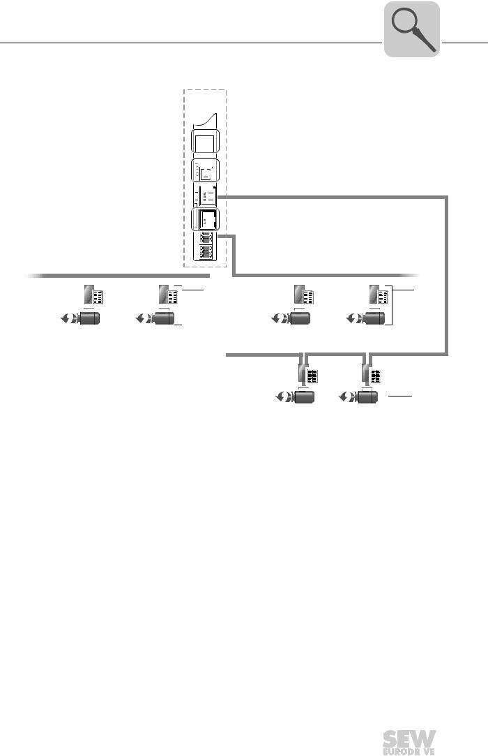
|
Introduction |
3 |
|
|
Controller DH.21B/41B |
||
X34
 [4]
[4]
 [1]
[1]
SBUSPLUS*

 [1]
[1]
|
SBUS (CAN1) |
SBUS (CAN2) |
|||||
|
[2] |
[2] |
||||||||||||||||||||||||||
EtherCAT
[3]
2384673547
[1]Engineering interface USB (X35) and Ethernet 2 (X37)
[2]SEW inverter with SBus interface (X32/X33)
[3]SEW inverter with EtherCAT interface (X36)
[4]2 × RS485 interfaces (X34)
3.3.4Engineering
Engineering of the DH.21B/41B option includes the following activities:
•Configuration
•Parameterization
•Programming (only MOVI-PLC®)
These activities are carried out using the MOVITOOLS® MotionStudio engineering software. The software has a number of useful features for startup and diagnostics of all SEW-EURODRIVE units. The DH.21B/41B option is connected with the engineering PC via
•Ethernet communication interface (X37)
•USB interface (X35)
•Engineering channels of the fieldbus system used
Phone: 800.894.0412 — Fax: 888.723.4773 — Web: www.clrwtr.com — Email: info@clrwtr.com
|
Manual – Controllers DHE/DHF/DHR21B (standard) and DHE/DHF/DHR41B (advanced) |
13 |
||

Introduction
Controller DH.21B/41B
3.3.5System buses CAN 1, CAN 2 and Ethernet 1
You can use the DH.21B/41B option to control a machine module by connecting several inverters via the system bus. The DH.21B/41B option controls all drives within the machine module and in this way takes load off the higher-level controller (e.g. machine/ system PLC). You can connect a total of maximum 16 units to the DH.21B option, and a total of maximum 64 units to the DH.41B option via system buses CAN 1, CAN 2, and Ethernet 1:
•MOVITRAC® B frequency inverter
•MOVIDRIVE® MDX60B/61B drive inverter
•MOVIAXIS® servo inverter
•Gearmotor with integrated frequency inverter MOVIMOT® (Fieldbus interface DeviceNet MFD… required)
•I/O coupler (OCC11B/OCE11B)
3.3.6RS485 interfaces COM1 and COM2
Connect one of the following devices each to the RS485 interfaces COM1 or COM2:
•DOP11B operator terminal
•MOVIMOT® gearmotor with integrated frequency inverter
3.3.7Ethernet 2
You can implement the following functions and connections using the Ethernet 2 communication interface:
•Connection of a DOP11B operator terminal
•PC visualization (e.g. OPC interface)
•Connection to master level
3.3.8Binary inputs and outputs
Binary inputs and outputs enable you to switch actuators (e.g. valves) and evaluate binary input signals (e.g. sensors).
3.3.9Diagnostic LEDs
The LEDs of the DH.21B/41B options indicate the following states:
•Voltage supply of the binary inputs and outputs
•General state of the DH.21B/41B options
•State of the control program
•State of the fieldbus interface (DHF/DHR)
•State of the Ethernet interface
•State of both CAN interfaces
You can connect operator terminals to perform diagnostics. It is recommended to connect an operator terminal to the communication interface Ethernet 2.
Phone: 800.894.0412 — Fax: 888.723.4773 — Web: www.clrwtr.com — Email: info@clrwtr.com
Manual – Controllers DHE/DHF/DHR21B (standard) and DHE/DHF/DHR41B (advanced)

|
Assembly and Installation Notes |
4 |
|
|
Installation options of DH.21B/41B |
||
4 Assembly and Installation Notes
4.1Installation options of DH.21B/41B
Observe the following installation instructions:
INFORMATION
•You can insert the DH.21B/41B option in the MOVIDRIVE® MDX61B inverter. Do not insert it in the MOVIDRIVE® MDX60B inverter.
•Option cards can only be installed or removed for MOVIDRIVE® MDX61B sizes 1 to 6.
•The installation or removal of option cards for MOVIDRIVE® MDX61B size 0 inverters must only be carried out by SEW-EURODRIVE engineers.
•The installation or removal of the DH.21B/41B option in MOVIAXIS® as well as the installation of the stand-alone housing DH.21B41B/UOH..B must only be carried out by SEW-EURODRIVE engineers.
4.2Installing the DH.21B/41B option in MOVIDRIVE® MDX61B
•You must insert the DHE21B/DHE41B option into the fieldbus slot of MOVIDRIVE® MDX61B. If the fieldbus slot is not available, you can plug the DHE21B/41B option into the expansion slot.
•You must insert the DHF21B/DHR21B and DHF41B/DHR41B options into the expansion slot of MOVIDRIVE® MDX61B. It cannot be installed in MOVIDRIVE® MDX61B size 0.
4.2.1Before you start
Read the following notes before installing or removing DH.21B/41B options:
•Disconnect the inverter from power. Switch off the DC 24 V and the line voltage.
•Before touching the DH.21B/41B option, take appropriate measures (discharge strap, conductive shoes, etc.) to protect it from electrostatic charge.
•Before installing the DH.21B/41B option, remove the keypad and the front cover.
•After installing the DH.21B/41B option, replace the front cover and the keypad.
•Keep the DH.21B/41B option in its original packaging until immediately before you are ready to install it.
•Hold the DH.21B/41B option only by its edges. Do not touch any of the components.
•Never place the DH.21B/41B option on a conductive surface.
Phone: 800.894.0412 — Fax: 888.723.4773 — Web: www.clrwtr.com — Email: info@clrwtr.com
|
Manual – Controllers DHE/DHF/DHR21B (standard) and DHE/DHF/DHR41B (advanced) |
15 |
||

|
4 |
Assembly and Installation Notes |
|
|
Installing the DH.21B/41B option in MOVIDRIVE® MDX61B |
||
4.2.2Basic procedure for installing or removing an option card in MOVIDRIVE® MDX61B
2. 
1.
3. 
4
2102036363
1.Remove the retaining screws holding the card retaining bracket. Pull the card retaining bracket out evenly from the slot (do not twist!).
2.Remove the retaining screws of the black cover plate on the card retaining bracket. Remove the black cover plate.
3.Position the option card onto the retaining bracket so that the retaining screws fit into the corresponding bores on the card retaining bracket.
4.Insert the retaining bracket with the installed option card into the slot, pressing slightly so it is seated properly. Secure the option card retaining bracket with the retaining screws.
5.Follow the instructions in reverse order when removing the option card.
Phone: 800.894.0412 — Fax: 888.723.4773 — Web: www.clrwtr.com — Email: info@clrwtr.com
|
16 |
Manual – Controllers DHE/DHF/DHR21B (standard) and DHE/DHF/DHR41B (advanced) |
||
|
Assembly and Installation Notes |
4 |
|
|
Installing the DH.21B/41B option in MOVIDRIVE® MDX61B |
||
4.3Installing the DH.21B/41B option in MOVIDRIVE® MDX61B
INFORMATION
The DH.21B/41B option is installed as described in the «Installation options of DH.21B/ 41B» chapter. The DH.21B/41B option is powered via MOVIDRIVE® MDX61B. A separate voltage supply is only required for the binary inputs and outputs (connector X31). For wiring the system bus, connect the X33 plug (CAN 1) or X32 (CAN 2) of the DH.21B/41B option with X12 of MOVIDRIVE® MDX61B.
4.4Installing the DH.21B/41B option in the MOVIAXIS® master module
INFORMATION
The DH.21B/41B option is installed as described in the «Installation options of DH.21B/ 41B» chapter. For wiring the system bus, connect connector X33 (CAN 1) or X32 (CAN 2) of the DH.21B/41B option with X9 (signal bus of the MOVIAXIS® supply module or of a MOVIAXIS® axis module), or with X12 (CAN 2 bus of a MOVIAXIS® axis module). The MOVIAXIS® master module provides additional connections that are described in the following section.
4.4.1Functional description of terminals X5a / X5b (MOVIAXIS® master module)
|
MOVIAXIS® master |
Designation |
Terminal |
Function |
|||||||
|
module MXM |
||||||||||
|
X5b connector |
X5b:1 |
DC 24 VE |
Voltage supply for control electronics |
|||||||
|
X5b |
X5b:2 |
DGND |
Reference potential for control electronics |
|||||||
|
1 |
||||||||||
|
X5b:3 |
DC 24 VB |
Voltage supply for brake |
||||||||
|
2 |
||||||||||
|
3 |
X5b:4 |
BGND |
Reference potential for brake connection |
|||||||
|
4 |
||||||||||
|
X5a |
Terminal X5a |
X5a:1 |
DC 24 VE |
Voltage supply for control electronics |
||||||
|
1 |
X5a:2 |
DGND |
Reference potential for control electronics |
|||||||
|
2 |
||||||||||
|
X5a:3 |
DC 24 VB |
Voltage supply for brake |
||||||||
|
3 |
||||||||||
|
4 |
X5a:4 |
BGND |
Reference potential for brake connection |
|||||||
|
2107418379 |
||||||||||
•The terminals X5a and X5b are connected in parallel. In this way, the voltage supply of the MOVIAXIS® master module can be provided from the right to X5b or from below to X5a. With connection to X5a, further modules can be connected via X5b
(e.g. supply module, axis module). The voltage supply for the brake (X5a/b:3,4) is fed through the MOVIAXIS® master module.
•The DH.21B/41B option can be supplied from the MOVIAXIS® switched-mode power supply (MXS) or from an external voltage source. To do so, connect X5 between the individual units.
•If the DH.21B/41B option is connected with DC 24 V from the MOVIAXIS® switchedmode power supply, the functioning of the DH.21B/41B option is maintained after
disconnection from the power supply. This is the case if the DC link voltage is maintained or an external DC 24 V supply is present from the MOVIAXIS® switchedmode power supply.
Phone: 800.894.0412 — Fax: 888.723.4773 — Web: www.clrwtr.com — Email: info@clrwtr.com
|
Manual – Controllers DHE/DHF/DHR21B (standard) and DHE/DHF/DHR41B (advanced) |
17 |
||
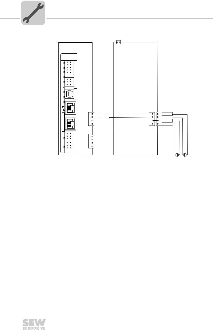
|
4 |
Assembly and Installation Notes |
|
|
Installing the DH.21B/41B option in the MOVIAXIS® master module |
||
Wiring diagram
External DC 24 V
|
MOVIAXIS® |
+ — |
MOVIAXIS® |
|||||||
|
master module MXM |
X16 |
switched-mode |
|||||||
|
DHE41B |
power supply MXS |
||||||||
|
L10 |
1 |
2 |
|||||||
|
3 |
4 |
X31 |
|||||||
|
L9 |
5 |
6 |
|||||||
|
7 |
8 |
||||||||
|
L8 |
9 |
10 |
|||||||
|
L7 |
1 |
2 |
X34 |
||||||
|
L6 |
3 |
4 |
|||||||
|
5 |
6 |
||||||||
|
L4 L5 T1 |
X35 |
Version |
|||||||
|
3 |
2 |
||||||||
|
4 |
1 |
||||||||
|
X36 |
|||||||||
|
L3 |
|||||||||
|
S1 |
X5b |
X5a |
X5b |
||||||
|
X37 |
1 |
1 |
1 DC 24VE |
||||||
|
2 |
2 |
2 DGND |
|||||||
|
3 |
3 |
3 DC 24VB |
|||||||
|
4 |
4 |
4 BGND |
|||||||
|
XM |
1 |
1 |
X32 |
X5a |
|||||
|
2 |
2 |
1 |
|||||||
|
L2 |
3 |
3 |
2 |
||||||
|
1 |
1 |
X33 |
3 |
||||||
|
L1 |
2 |
2 |
4 |
||||||
|
3 |
3 |
||||||||
|
DC 24 V for |
+ |
— |
|||||||
|
brake power supply — |
DC 24 V supply
+ for control electronics
2107421323
Phone: 800.894.0412 — Fax: 888.723.4773 — Web: www.clrwtr.com — Email: info@clrwtr.com
|
18 |
Manual – Controllers DHE/DHF/DHR21B (standard) and DHE/DHF/DHR41B (advanced) |
||
|
Assembly and Installation Notes |
4 |
|
|
Installing the DH.21B/41B option in MOVITRAC® B / stand-alone unit |
||
4.5Installing the DH.21B/41B option in MOVITRAC® B / stand-alone unit
INFORMATION
The DH.21B/41B option is installed as described in the «Installation options of DH.21B/ 41B» chapter. The option card slot MOVITRAC® B and the stand-alone unit provide additional connections for the DH.21B/41B option. These connections are described below.
4.5.1Description of terminals and LEDs
|
Front view |
LED |
||||||||||||||
|
MOVITRAC® B/ |
Designation |
Function |
|||||||||||||
|
stand-alone unit |
Terminal |
||||||||||||||
|
LED |
H1 |
Reserved |
|||||||||||||
|
H1 |
H2 |
Reserved |
|||||||||||||
|
H2 |
X24 connector: |
X24:4 |
DGND |
Reference potential COM 1 |
|||||||||||
|
RS485 COM 1 |
X24:3 |
RS– |
Signal RS485– |
||||||||||||
|
(RJ10 socket) |
X24:2 |
RS+ |
Signal RS485+ |
||||||||||||
|
X24 |
X24:1 |
5 V |
Voltage output DC +5 V |
||||||||||||
|
2108468363 |
|||||||||||||||
|
Side view |
Designation |
Terminal |
Function |
||||||||||||
|
Stand-alone unit |
|||||||||||||||
|
X26 connector: |
X26:1 |
CAN 1H |
System bus CAN 1 high |
||||||||||||
|
CAN 1 and |
X26:2 |
CAN 1L |
System bus CAN 1 low |
||||||||||||
|
X26 |
voltage supply |
X26:3 |
DGND |
Reference potential control/CAN1 |
|||||||||||
|
(plug-in |
X26:4 |
Reserved |
— |
||||||||||||
|
1 |
2 |
3 |
4 |
5 |
6 |
7 |
terminal) |
X26:5 |
Reserved |
— |
|||||
|
2108496651 |
|||||||||||||||
|
X26:6 |
DGND |
Reference potential control/CAN1 |
|||||||||||||
|
X26:7 |
DC 24 V |
Voltage supply for controller |
|||||||||||||
4.5.2RS485 interface COM1 connection (connector X24)
The connectors X24 and X34:1/3/5 are connected in parallel. You can connect a DOP11B operator terminal at X24. If X24 is unassigned, you can connect an operator terminal or a gearmotor with integrated MOVIMOT® frequency inveter to X34:1/3/5.
For more information, refer to «RS485 interface connection (X34)».
Phone: 800.894.0412 — Fax: 888.723.4773 — Web: www.clrwtr.com — Email: info@clrwtr.com
|
Manual – Controllers DHE/DHF/DHR21B (standard) and DHE/DHF/DHR41B (advanced) |
19 |
||

|
4 |
Assembly and Installation Notes |
|
|
Installing the DH.21B/41B option in MOVITRAC® B / stand-alone unit |
||
4.5.3Connecting CAN 1 system bus/voltage supply (X26)
X26:1/2/3 and connector X33 are connected in parallel. The DH.21B/41B option in the compact controller is supplied with voltage via X26:6/7.
The DHE21B/41B option can be supplied with the required voltage by MOVITRAC® B. To do so, connect X26:3 (6)/7 with X46:3 (6)/7 or with X12:9/8. If MOVITRAC® B supplies the DHE21B/41B option with DC 24 V, then the functions of the DHE21B/41B option are also ensured after disconnection from the supply system. This requires an external DC 24 V supply to X12:8/9 of MOVITRAC® B.
|
MOVITRAC® B |
DHE41B |
|||||||||
|
L10 |
1 |
2 |
||||||||
|
3 |
4 |
X31 |
||||||||
|
L9 |
7 |
8 |
||||||||
|
5 |
6 |
|||||||||
|
L8 |
9 |
10 |
||||||||
|
L7 |
1 |
2 |
X34 |
|||||||
|
L6 |
3 |
4 |
||||||||
|
5 |
6 |
|||||||||
|
T1 |
X35 |
|||||||||
|
S1 |
S2 |
L5 |
3 |
2 |
||||||
|
4 |
1 |
|||||||||
|
L4 |
||||||||||
|
ON |
X36 |
|||||||||
|
L3 |
||||||||||
|
OFF |
||||||||||
|
X44 |
||||||||||
|
S1 |
||||||||||
|
FSC11B |
X37 |
|||||||||
|
X45 |
X46 |
|||||||||
|
H L 1 |
2 3 4 5 6 |
7 |
XM |
2 |
2 |
X32 |
||||
|
1 |
1 |
|||||||||
|
L2 |
3 |
3 |
||||||||
|
L1 |
1 |
1 |
X33 |
120Ω |
||||||
|
2 |
2 |
|||||||||
|
3 |
3 |
|||||||||
|
H1 |
||||||||||
|
H2 |
||||||||||
|
X24 |
||||||||||
|
X26 |
||||||||||
|
X12 |
1 2 3 4 5 6 7 |
|||||||||
|
1 |
||||||||||
|
2 |
||||||||||
|
3 |
||||||||||
|
+ |
4 |
|||||||||
|
5 |
||||||||||
|
DC 24V = |
6 |
|||||||||
|
— |
24V IO |
7 |
||||||||
|
8 |
||||||||||
|
GND |
9 |
|||||||||
2108499339
Phone: 800.894.0412 — Fax: 888.723.4773 — Web: www.clrwtr.com — Email: info@clrwtr.com
|
20 |
Manual – Controllers DHE/DHF/DHR21B (standard) and DHE/DHF/DHR41B (advanced) |
||
![]()
|
Assembly and Installation Notes |
4 |
|
|
Installing the DH.21B/41B option in MOVITRAC® B / stand-alone unit |
||
SC11 System bus +, CAN high SC12 System bus -, CAN low
GND, CAN GND
|
Compact controller |
||||
|
DHE41B |
||||
|
L10 |
1 |
2 |
||
|
3 |
4 |
X31 |
||
|
L9 |
7 |
8 |
||
|
5 |
6 |
|||
|
L8 |
9 |
10 |
||
|
L7 |
1 |
2 |
X34 |
|
|
L6 |
3 |
4 |
||
|
5 |
6 |
|||
|
T1 |
X35 |
|||
|
L5 |
3 |
2 |
||
|
4 |
1 |
|||
|
L4 |
||||
|
X36 |
||||
|
L3 |
||||
|
S1 |
||||
|
X37 |
||||
|
XM |
2 |
2 |
X32 |
|
|
1 |
1 |
|||
|
L2 |
3 |
3 |
||
|
L1 |
1 |
1 |
X33 |
120Ω |
|
3 |
3 |
|||
|
2 |
2 |
|||
|
H1 |
||||
|
H2 |
||||
|
X24 |
||||
|
SEW drive |
X26 |
|||
|
1 2 3 4 5 6 7 |
||||
|
DC +24 V |
||||
|
GND |
2108502027
4.5.4LED when installed in MOVITRAC®/stand-alone unit
|
LED H1, H2 |
LEDs H1 and H2 are reserved. |
Phone: 800.894.0412 — Fax: 888.723.4773 — Web: www.clrwtr.com — Email: info@clrwtr.com
|
Manual – Controllers DHE/DHF/DHR21B (standard) and DHE/DHF/DHR41B (advanced) |
21 |
||
|
4 |
Assembly and Installation Notes |
|
|
Shielding and routing bus cables |
||
4.6Shielding and routing bus cables
Only use shielded cables and connection elements that also meet the requirements of category 5, class 2 in compliance with IEC 11801 edition 2.0.
Correct shielding of the bus cable attenuates electrical interference that can occur in industrial environments. The following measures ensure the best possible shielding:
•Manually tighten the mounting screws on the connectors, modules, and equipotential bonding conductors.
•Use only connectors with a metal housing or metallized housing.
•Connect the shielding in the connector over a wide surface area.
•Apply the shielding of the bus cable on both ends.
•Route signal and bus cables in separate cable ducts. Do not route them parallel to power cables (motor leads).
•Use metallic, grounded cable racks in industrial environments.
•Route the signal cable and the corresponding equipotential bonding close to each other using the shortest possible route.
•Avoid using plug connectors to extend bus cables.
•Route the bus cables closely along existing grounding surfaces.
NOTICE
In case of fluctuations in the ground potential, a compensating current may flow via the bilaterally connected shield that is also connected to the protective earth (PE). In such a case, make sure you supply adequate equipotential bonding in accordance with relevant VDE regulations.
Phone: 800.894.0412 — Fax: 888.723.4773 — Web: www.clrwtr.com — Email: info@clrwtr.com
|
22 |
Manual – Controllers DHE/DHF/DHR21B (standard) and DHE/DHF/DHR41B (advanced) |
||

|
Assembly and Installation Notes |
4 |
|
|
Installing the DH.21B/41B option |
||
4.7Installing the DH.21B/41B option
4.7.1Functional description of terminals, DIP switches and LEDs
|
Front view |
Designation |
LED |
Function |
||||||||||
|
DH.21B/41B |
DIP switch |
||||||||||||
|
option |
Terminal |
||||||||||||
|
LED |
LED 10 |
24 V / I/O OK |
State of voltage supply I/O |
||||||||||
|
LED 9 |
DIO0/1 |
State of input or output DIO 0/1 |
|||||||||||
|
LED 8 |
DIO2/3 |
State of input or output DIO 2/3 |
|||||||||||
|
LED 7 |
DIO4/5 |
State of input or output DIO 4/5 |
|||||||||||
|
L10 |
1 |
2 |
|||||||||||
|
3 |
4 |
LED 6 |
DIO6/7 |
State of input or output DIO 6/7 |
|||||||||
|
L9 |
5 |
6 |
X31 |
||||||||||
|
7 |
8 |
LED 5 |
User LED |
Freely programmable |
|||||||||
|
L8 |
9 |
10 |
|||||||||||
|
LED 4 |
PLC state |
State of control firmware |
|||||||||||
|
L7 |
|||||||||||||
|
1 |
2 |
X34 |
LED 3 |
IEC progr. state |
State of control program |
||||||||
|
L6 |
3 |
4 |
|||||||||||
|
5 |
6 |
LED 2 |
CAN 2 state |
State of CAN 2 system bus |
|||||||||
|
T1 |
X35 |
LED 1 |
CAN 1 state |
State of CAN 1 system bus |
|||||||||
|
L5 |
3 |
2 |
|||||||||||
|
4 |
1 |
Terminal X31: |
X31:1 |
+24 V input |
Voltage input DC +24 V |
||||||||
|
L4 |
|||||||||||||
|
L3 |
X36 |
Binary inputs and outputs |
X31:2 |
BZG 24 V |
Reference potential for binary signals |
||||||||
|
(plug-in terminals) |
X31:3 |
DIO 0 |
Binary input or output (DIO 0) |
||||||||||
|
X31:4 |
DIO 1 |
Binary input or output (DIO 1) |
|||||||||||
|
S1 |
|||||||||||||
|
X31:5 |
DIO 2 |
Binary input or output (DIO 2) |
|||||||||||
|
X37 |
|||||||||||||
|
X31:6 |
DIO 3 |
Binary input or output (DIO 3) |
|||||||||||
|
X31:7 |
DIO 4 |
Binary input or output (DIO 4) |
|||||||||||
|
X31:8 |
DIO 5 |
Binary input or output (DIO 5) |
|||||||||||
|
XM |
1 |
1 |
X32 |
X31:9 |
DIO 6 |
Binary input or output (DIO 6) |
|||||||
|
2 |
2 |
||||||||||||
|
L2 |
3 |
3 |
X31:10 |
DIO 7 |
Binary input or output (DIO 7) |
||||||||
|
1 |
1 |
X33 |
|||||||||||
|
L1 |
3 |
3 |
Terminal X34: |
X34:1 |
RS+ |
Signal RS485+ (COM 1) |
|||||||
|
2 |
2 |
||||||||||||
|
RS485 interfaces COM1, COM2 |
X34:2 |
RS+ insulated |
Signal RS485+ insulated (COM 2) |
||||||||||
|
2102456075 |
(plug-in terminals) |
X34:3 |
RS– |
Signal RS485– (COM 1) |
|||||||||
|
X34:4 |
RS– insulated |
Signal RS485– insulated (COM 2) |
|||||||||||
|
X34:5 |
DGND |
Reference potential (COM 1) |
|||||||||||
|
X34:6 |
GND insulated |
Reference potential (COM 2) |
|||||||||||
|
X35 terminal: |
X35:1 |
USB +5 V |
|||||||||||
|
USB connection |
X35:2 |
USB– |
Standard USB-B assignment |
||||||||||
|
X35:3 |
USB+ |
||||||||||||
|
X35:4 |
DGND |
||||||||||||
|
X36 terminal: |
X36 |
||||||||||||
|
Ethernet 1 connection |
|||||||||||||
|
System bus (RJ45 socket) |
|||||||||||||
|
Standard Ethernet assignment |
|||||||||||||
|
X37 terminal: |
X37 |
||||||||||||
|
Ethernet 2 connection |
|||||||||||||
|
(RJ45 socket) |
|||||||||||||
|
X32 terminal: |
X32:1 |
BZG_CAN 2 |
Reference potential for system bus |
||||||||||
|
CAN 2 system bus |
X32:2 |
CAN 2H |
CAN 2 |
||||||||||
|
(electrically isolated) |
X32:3 |
CAN 2L |
System bus CAN 2 high |
||||||||||
|
(plug-in terminals) |
System bus CAN 2 low |
||||||||||||
|
X33 terminals: |
X33:1 |
DGND |
Reference potential for system bus |
||||||||||
|
CAN 1 system bus |
X33:2 |
CAN 1H |
CAN 1 |
||||||||||
|
(plug-in terminals) |
X33:3 |
CAN 1L |
System bus CAN 1 high |
||||||||||
|
System bus CAN 1 low |
|||||||||||||
|
DIP switch |
S1 |
Up |
Default IP address (192.168.10.4) |
||||||||||
|
Down |
IP parameter from SD memory card |
||||||||||||
Phone: 800.894.0412 — Fax: 888.723.4773 — Web: www.clrwtr.com — Email: info@clrwtr.com
|
Manual – Controllers DHE/DHF/DHR21B (standard) and DHE/DHF/DHR41B (advanced) |
23 |
||
|
4 |
Assembly and Installation Notes |
|
|
Installing the DH.21B/41B option |
||
4.7.2Connecting binary inputs and outputs (X31 terminal)
Terminal X31 provides eight binary inputs or outputs (e.g. for controlling external actuators/sensors).
X31
1 
 2
2
3 
 4
4
5 
 6
6
7 
 8
8
9 
 10
10
2102458763
|
Binary inputs |
• The binary inputs are electrically isolated by optocouplers. |
|
• The permitted input voltages are defined according to IEC 61131. |
|
|
+13 V – +30 V = «1» = contact closed |
|
|
–3 V – +5 V = «0» = contact open |
|
|
Binary outputs |
• The binary outputs are electrically isolated by optocouplers. |
|
• The binary outputs are short-circuit proof but not interference-voltage-proof. |
|
|
• The maximum permitted output current is 150 mA per binary output. All eight binary |
|
|
outputs can be operated simultaneously with this current. |
|
|
NOTICE |
|
|
The supply voltage must be present on X31:1/2 when using binary inputs and outputs. |
|
|
The DH.21B/41B option might be damaged. In this case, the specified function of the |
|
|
binary inputs and outputs is no longer ensured. |
|
|
If the supply voltage is switched off, you must switch off all other voltages at X31:1 to |
|
|
10, e.g. DC 24 V of switches and sensors at the binary inputs. |
|
|
• To prevent dangerous voltage peaks from occurring, do not connect inductive loads |
|
|
to the supply voltage or the binary inputs or outputs without free running diodes. |
Cable specification • Only connect cables with a minimum core cross section of 0.25 mm2 (AWG23) and a maximum core cross section of 1 mm2 (AWG18). Clamping without conductor end sleeves is possible in accordance with IEC 60999.
•Choose the type and core cross section of the connected cable in dependency of the required cable length and the load expected from your application.
For more information on binary inputs or outputs, refer to the «Technical Data» chapter.
Phone: 800.894.0412 — Fax: 888.723.4773 — Web: www.clrwtr.com — Email: info@clrwtr.com
|
24 |
Manual – Controllers DHE/DHF/DHR21B (standard) and DHE/DHF/DHR41B (advanced) |
||
 Loading…