10.3 List of errors (F-00 … F-97)
No.
Designation
Response
00
No error
01
Over-current
Immediate
switch-off
with inhibit
03
Ground fault
Immediate
switch-off
with inhibit
04
Brake chopper
Immediate
switch-off
with inhibit
06
Phase failure in
Immediate
supply system
switch-off
(only applies
with inhibit
to 3-phase
inverter)
07
DC link
Immediate
overvoltage
switch-off
with inhibit
08
Speed
Immediate
monitoring
switch-off
with inhibit
10
ILLOP
Stop with
inhibit
11
Overtempera-
Stop with
ture
inhibit
System Manual – MOVITRAC
Possible cause
•
Short circuit output
•
Output switching
•
Motor too large
•
Faulty output stage
•
Ground fault in motor
•
Ground fault in inverter
•
Ground fault in the motor supply
lead
•
Overcurrent (see F-01)
•
Too much regenerative power
•
Braking resistor circuit interrupted
•
Short circuit in the braking resistor
circuit
•
Brake resistor has too high
resistance
•
Brake chopper defective
•
Ground fault
•
Phase failure
•
Supply voltage too low
•
DC link voltage too high
•
Ground fault
Current controller works at the set limit
due to:
•
Mechanical overload
•
Phase failure in supply system
•
Phase failure in motor
Maximum speed for VFC operating
modes exceeded
•
Wrong command during command
execution
•
Incorrect conditions during
command execution.
•
Function does not exist / is not
implemented in the inverter
Thermal overload of inverter
®
B
Operation and service
List of errors (F-00 … F-97)
Measure
•
Rectify the short circuit
•
Switching with inhibited output
stage only
•
Connect a smaller motor
•
Consult SEW Service if the error
still cannot be reset
•
Replace motor
•
Replace MOVITRAC
•
Eliminate ground fault
•
See F-01
•
Extend deceleration ramps
•
Check supply cable to the braking
resistor
•
Rectify the short circuit
•
Check technical data of braking
resistor
•
Replace MOVITRAC
•
Eliminate ground fault
•
Check the supply system lead
•
Check the supply voltage
•
Extend deceleration ramps
•
Check supply cable to the braking
resistor
•
Check technical data of braking
resistor
•
Eliminate ground fault
•
Reduce load
•
Increase deceleration time setting
P501
•
Check current limitation
•
Extend deceleration ramps
•
Check mains phases
•
Check motor cable and motor
•
Reduce maximum speed
•
Check the program
•
Check program run
•
Use another function
•
Reduce load and / or ensure
adequate cooling
•
If a braking resistor is integrated in
the heat sink: Install braking
resistor externally
10
®
B
®
B
159
-
Page 1
*28487486_0219* Drive Technology Drive Automation System Integration Services Product Manual Application Inverter ® MOVIDRIVE system Edition 02/2019 28487486/EN… -
Page 2
SEW-EURODRIVE—Driving the world… -
Page 3: Table Of Contents
Table of contents Table of contents Product description…………………… 6 Device availability …………………. 9 ® MOVIDRIVE system at a glance ……………. 10 ® MOVIDRIVE system product overview …………… 15 Product overview accessories ……………… 17 FCB concept ……………………. 19 Control mode …………………… 26 Energy-saving functions……………….. 33 ® MOVISUITE engineering software ……………. 34 Technical data…………………….
-
Page 4: Table Of Contents
Table of contents About this documentation ………………. 186 Structure of the safety notes ……………… 186 Decimal separator in numerical values …………… 187 Rights to claim under limited warranty ……………. 187 Content of the documentation……………… 188 Other applicable documentation …………….. 188 Product names and trademarks……………… 188 Copyright notice …………………. 188 Device availability ………………….. 189 Safety notes ……………………..
-
Page 5: Table Of Contents
Table of contents Startup procedure ………………….. 289 Connection to the engineering software ………….. 293 Operation…………………….. 294 10.1 General information ……………….. 294 10.2 7-segment display………………….. 295 10.3 Operating displays …………………. 296 10.4 Fault description on basic device……………. 298 10.5 Power section fault description ………………. 334 10.6 Responses to fault acknowledgement ……………. 339 10.7 Fault responses …………………. 341 Service ………………………
-
Page 6: Product Description
Product description Product description ® With its brand MOVI-C , SEW‑EURODRIVE is launching a new generation of drive ® and automation technology. MOVI-C is the modular automation system that enables the highest level of system and machine automation. ® MOVI-C comprises drive technology, MotionControl, control technology, and visualiz- ation.
-
Page 7
10 min ® MOVI-C CONTROLLER ® ® MOVIDRIVE modular MOVIDRIVE system 16000611083 The CiA402 device profile for controlling inverters has established itself in plants with very individual motion control functions that are calculated in the external higher-level controller. ® ®… -
Page 8
Product description ® For applications with requirements on functional safety, the MOVISAFE CS..A safety cards are available. They are controlled via the integrated inputs and outputs or via ® safe communication using Safety over EtherCAT (FSoE). 24494793995 ® ® MOVIDRIVE modular and MOVIDRIVE system are available with device profile CiA402. -
Page 9: Device Availability
Product description Device availability Device availability This documentation also lists devices that are not yet available at the time of the pub- lication of this document. The following table lists the available application inverters. Accessories required for the inverter operation such as braking resistors, chokes, and filters are available. Type designation MDX9_A-0020-5E3-4-S00/E00 MDX9_A-0025-5E3-4-S00/E00…
-
Page 10: Movidrive ® System At A Glance
Product description MOVIDRIVE® system at a glance MOVIDRIVE ® system at a glance ® MOVIDRIVE system at a glance ® MOVIDRIVE system Description: (→ 2 15) Technical data: (→ 2 41) Dimension drawings: (→ 2 49) • Nominal output current: 2 – 588 A • Voltage ranges: 3 × 380 – 500 V, 3 × 200 – 240 V, 50 – 60 Hz •…
-
Page 11
Product description MOVIDRIVE® system at a glance Cards CES11A multi-encoder card Description: (→ 2 17), (→ 2 243) Technical data: (→ 2 58) The multi-encoder card makes it possible to evaluate additional encoders. For information on this card, refer to the following document: • «Multi-encoder card CES11A» manual Safety cards CS..A Description: (→ 2 18) Technical data: (→ 2 59) -
Page 12
Product description MOVIDRIVE® system at a glance ® MOVI-C CONTROLLER ® ® MOVI-C CONTROLLER MOVI-C CONTROLLER power is characterized by: power UHX85A • Intel Core2Duo 2.2 GHz processor ® • Windows Embedded Standard 7 • Ethernet interface for engineering tasks or TCP/IP and UDP via IEC 61131‑3 •… -
Page 13
Product description MOVIDRIVE® system at a glance ® MOVI-C CONTROLLER ® ® MOVI-C CONTROLLER MOVI-C CONTROLLER advanced is characterized by: advanced UHX45A • A maximum of 8 interpolating axes that can be connected • Another 8 auxiliary axes that can be connected X 80 For further information on this device, refer to the following documents: L /A… -
Page 14
Product description MOVIDRIVE® system at a glance Accessories ® The MOVIKIT software module allows for simple, quick and fault-free startup ® of all applications. The MOVIKIT software module supports both the ® ® MOVIRUN smart software platform and the MOVIRUN flexible software platform. -
Page 15
Product description Product overview MOVIDRIVE® system Product overview MOVIDRIVE ® system ® MOVIDRIVE system product overview Properties • Coverage of a wide range of power ratings with finely graded performance classes. • Universal use due to a wide voltage range for line connection. •… -
Page 16
Product description Product overview MOVIDRIVE® system Type designation Nominal out- Recommen- Nominal line Size Technical put current at ded motor current data PWM = 4 kHz power ASM MDX91A-0910-503-4-S00/E00 MDX91A-1130-503-4-S00/E00 MDX91A-1490-503-4-S00/E00 MDX91A-1770-503-4-S00/E00 MDX91A-2200-503-4-S00/E00 (→ 2 41) MDX91A-2500-503-4-S00/E00 MDX91A-3000-503-4-S00/E00 MDX91A-3800-503-4-S00/E00 MDX91A-4700-503-4-S00/E00 MDX91A-5880-503-4-S00/E00 Device data 3 × AC 230 V Nominal line voltage 3 × 200 – 240 V In accordance with EN 50160… -
Page 17: Product Overview Accessories
Product description Product overview accessories Product overview accessories ® The functionality and flexibility of MOVI-C application inverters can be supplemented by many different cards. 1.4.1 CID21A input/output card This input/output card is used to increase the number of digital inputs and outputs of the basic device.
-
Page 18
Product description Product overview accessories 1.4.4 Safety cards CS..A ® The MOVISAFE CS..A safety cards provide further functional safety functions to ® EN IEC 61800-5-2 in addition to STO. The MOVISAFE CS..A safety cards and the CES11A multi-encoder card are intended to be used in the same card slot and thus cannot be used simultaneously. -
Page 19: Fcb Concept
Product description FCB concept FCB concept FCB = Function Control Block ® The FCB concept describes the modular firmware design of MOVI-C inverters. This feature ensures that a wide range of drive functions can be selected or deselected quickly and easily using control words. All primary functions, i.e.
-
Page 20
Product description FCB concept 1.5.1 Description of the FCBs FCB 01 Output stage inhibit Activating FCB 01 stops the connected motor via the motor brake. If no brake is in- stalled, the motor coasts to a stop. FCB 02 Default stop FCB 02 stops the drive with the preset profile value «Maximum deceleration». -
Page 21
Product description FCB concept This higher-level controller usually calculates a track profile for several drive axes. The axis is then assigned just one setpoint (torque, torque limits, precontrol values, inertia) that it has to follow. The inverter limits the setpoints using the application limits. The course of the path curve profile is controlled by the controller. -
Page 22
Product description FCB concept Upper limit = «Modulo max.» If the position setpoint is outside this range, a fault is issued. The direction of the drive is determined using the last setpoint position (= current ac- tual position after activation without an «In position» message) and the current setpoint position. -
Page 23
Product description FCB concept FCB 14 Emergency stop When FCB 14 is activated, the drive stops with the preset emergency stop decelera- tion. FCB 18 Rotor position identification For the operation of permanent magnet synchronous motors, the exact position in- formation of the rotor is required for closed-loop control. -
Page 24
Product description FCB concept FCB 25 Motor parameter measurement FCB 25 is used for determining the necessary parameters from the electric equivalent wiring diagram during startup. The nameplate data of the connected motor is required for the motor parameter meas- urement. -
Page 25
Product description FCB concept 1.5.2 Setpoints and limits in the FCBs Index 02 04 05 06 07 08 09 10 12 13 14 19 20 26 Setpoint buffer Position Rotational speed Torque 8376 Acceleration precontrol Mass moment of inertia Torque precontrol Correcting value of external position controllers Profile value buffer… -
Page 26: Control Mode
Product description Control mode Control mode ® The following control modes are available for MOVIDRIVE application inverters: • PLUS • • ® • ELSM 1.6.1 Description of the control modes The characteristics of the motor connected to the application inverter are influenced by the control modes used.
-
Page 27
Product description Control mode PLUS PLUS is a high-performance control mode that is able to operate asynchronous mo- tors with very high torque dynamics with or without rotary encoder. The control mode can be operated as speed or torque control. This control mode calculates all important state variables for controlling the motor by using a motor model. -
Page 28
Product description Control mode The CFC control mode is a current-controlled control mode. The CFC control mode al- lows the operation of asynchronous and synchronous motors with maximum torque dynamics. For this purpose, the current components for the magnetic flux and for the torque generation are controlled separately. -
Page 29
Product description Control mode Speed control ® The speed control operating mode can be activated in the ELSM control mode. The control mode has to be distinguished speed-dependent in two different operating ranges: • Open-loop control • speed-controlled operation. Open-loop control takes place when starting from standstill and below a transition speed. -
Page 30
Product description Control mode 1.6.2 Characteristics of the control modes Overview of the control modes PLUS ® ELSM Principle Voltage controlled Field-oriented, Field-oriented, cur- Field-oriented, cur- according to charac- voltage-controlled, rent controller rent controller teristic curve stator flux controller, torque controller Motor ASM/LSPM Encoder… -
Page 31
Product description Control mode PLUS ® ELSM Rotational speed 32 bits 32 bits 32 bits 32 bits 0.0001 1/min 0.0001 1/min 0.0001 1/min 0.0001 1/min Position — 16 bits 16 bits — (increment/revolution) Position — 32 bits 32 bits — (absolute increment) Characteristic values for accuracy of torque and speed PLUS PLUS ®… -
Page 32
Product description Control mode FCBs that can be activated for selected control mode PLUS ® FCB no. Designation ELSM Output stage inhibit Default stop Manual mode Speed control Interpolated speed control Torque control Interpolated torque control Reference travel Stop at application limits Emergency stop Motor parameter measurement Stop at user limits… -
Page 33: Energy-Saving Functions
Product description Energy-saving functions Energy-saving functions 1.7.1 Flux optimization Flux optimization is a function that allows for operating an asynchronous motor in con- PLUS trol mode VFC with minimal losses. The magnetic flux is lead depending on the torque setpoint, so that the motor is operated with minimum current and thus with min- imized losses.
-
Page 34: Movisuite ® Engineering Software
Product description MOVISUITE® engineering software MOVISUITE ® e ngineering software ® MOVISUITE engineering software ® MOVISUITE is the new engineering software from SEW‑EURODRIVE. The engineering software excels thanks to a new design of the user interface and user guidance. This new interface concept allows for the users to configure, parameterize, and start up their applications intuitively.
-
Page 35
Product description MOVISUITE® engineering software The scan function enables the reading of available devices, and the creation of these ® devices as projects in MOVISUITE The drive train can be built from motor to gear unit using the product catalog. Further- more, encoders, brakes, control modes, and user units can be selected and paramet- erized. -
Page 36
Product description MOVISUITE® engineering software Drive functions • FCB 01 Output stage inhibit • FCB 05 Speed control • FCB 06 Interpolated speed control • FCB 08 Interpolated torque control • FCB 09 Positioning • FCB 10 Interpolated position control • FCB 12 Reference travel • FCB 08 Rotor position identification •… -
Page 37: Technical Data
Technical data Markings Technical data ® ® The following technical data applies to MOVIDRIVE system and MOVIDRIVE tech- nology. Markings 2.1.1 Basic device The application inverter complies with the following directives and guidelines: Marking Definition The CE marking states the compliance with the following European guidelines: •…
-
Page 38
Technical data Markings 2.1.2 Accessories Braking resistors BR.. Marking Definition The CE marking states the compliance with the following European guidelines: • Low Voltage Directive 2014/35/EU • Directive 2011/65/EU for limiting the use of hazardous substances in electric and electronic equipment The China RoHS marking states compliance with directive SJ/T 11364-2014 for limiting the use of hazardous substances in electric and electronic equipment. -
Page 39
Technical data Markings Marking Definition The China RoHS marking states compliance with directive SJ/T 11364-2014 for limiting the use of hazardous substances in electric and electronic equipment. The cUR marking states the UL approval for this component. Output filter Marking Definition The China RoHS marking states compliance with directive SJ/T 11364-2014 for limiting the use of hazardous substances in electric and… -
Page 40: General Technical Data
Technical data General technical data General technical data The following table lists the technical data for all application inverters independent of • Type • Design • Size • Performance General specifications Interference immunity Meets EN 61800-3; 2. Environment Interference emission Limit value class C2 to EN 61800‑3 The interference suppression level can be improved with relevant measures.
-
Page 41: Technical Data Of Basic Device
Technical data Technical data of basic device Technical data of basic device 2.3.1 Performance data 3 × AC 400 V Unit MDX9_A-…-5_3-4-.. Type 0020 0025 0032 0040 0055 0070 0095 0125 0160 Size Nominal output current I 12.5 = 4 kHz Input Nominal line voltage (to EN 50160) 3 × 380 – 500 V AC U…
-
Page 42
Technical data Technical data of basic device Unit MDX9_A-…-5_3-4-.. Type 0240 0320 0460 0620 0750 0910 1130 1490 Input Nominal line voltage (to 3 × 380 – 500 V EN 50160) AC U line Nominal line current AC I 21.6 28.8 41.4 55.8 67.5 81.9 line Line frequency f 50 – 60 ± 5% line… -
Page 43
Technical data Technical data of basic device Unit MDX9_A-…-5_3-4-.. Type 1770 2200 2500 3000 3800 4700 5880 Nominal output current I = 4 kHz Input Nominal line voltage (to EN 50160) AC 3 × 380 – 500 V line Nominal line current AC I line Line frequency f 50 – 60 ± 5% line Controlled rectifier… -
Page 44
Technical data Technical data of basic device 2.3.2 Performance data 3 × AC 230 V Unit MDX9_A-…-2_3-4-.. Type 0070 0093 0140 Size Nominal output current I = 4 kHz Input Nominal line voltage (to EN 50160) AC U 3 × 200 – 240 V line Nominal line current AC I 8.37 12.6 line… -
Page 45
Technical data Technical data of basic device Unit MDX9_A-…-2_3-4-.. Type 0213 0290 0420 0570 0840 1080 Nominal line current AC I 19.2 26.1 37.8 51.3 75.6 97.2 line Line frequency f 50 – 60 ± 10% line Controlled rectifier Plug connector – 1 core: 0.5 – 16 mm X1 connection contacts –… -
Page 46: Technical Data Of Accessories
Technical data Technical data of accessories Technical data of accessories 2.4.1 Installation accessories Type designation Part number Plastic cover Number Scope of deliv- Description MDX9_A-0460 – 0750-5_3-.. 28243625 MDX9_A-0420 – 0570-2_3-.. Not included in (→ 2 228) scope of delivery MDX91A-0910 – 1490-5_3-.. 28244540 MDX91A-0840 –…
-
Page 47: Electronics Data – Signal Terminals
Technical data Electronics data – signal terminals Electronics data – signal terminals Terminal designation Specification General Design According to IEC 61131-2 Supply voltage Port External power supply 24 V according to IEC 61131 Plug connector Connecting contacts — 1 core: 0.25 – 2.5 mm — 2 cores: 0.5 – 1.5 mm (Twin-AEH) 1) AEH: Conductor end sleeve Digital inputs…
-
Page 48: Electronics Data – Drive Safety Functions
Technical data Electronics data – drive safety functions Electronics data – drive safety functions The table below shows the technical data of the application inverter relating to the in- tegrated safety technology. The safety-related digital inputs comply with type 3 in accordance with IEC 61131‑2. Reference potential for the F_STO_P1 and F_STO_P2 is STO_M (contact at terminal X6:2).
-
Page 49: Dimension Drawings
Technical data Dimension drawings Dimension drawings 2.7.1 MDX9_A-0020 – 0040-5_3-.. 20367245579 ® Product Manual – MOVIDRIVE system…
-
Page 50
Technical data Dimension drawings 2.7.2 MDX9_A-0020 – 0040-5_3-.. , MDX9_A-0070 – 0093-2_3-.. with braking resistor 20367243147 ® Product Manual – MOVIDRIVE system… -
Page 51
Technical data Dimension drawings 2.7.3 MDX9_A-0055 – 0095-5_3-.. , MDX9_A-0070 – 0093-2_3-.. 20367250443 ® Product Manual – MOVIDRIVE system… -
Page 52
Technical data Dimension drawings 2.7.4 MDX9_A-0125 – 0160-5_3-.. , MDX9_A-0140-2_3-.. 20367252875 ® Product Manual – MOVIDRIVE system… -
Page 53
Technical data Dimension drawings 2.7.5 MDX9_A-0240 – 0320-5_3-.. , MDX9_A-0213 – 0290-2_3-.. 20367248011 ® Product Manual – MOVIDRIVE system… -
Page 54
Technical data Dimension drawings 2.7.6 MDX9_A-0460 – 0750-5_3-.. , MDX9_A-0420 – 0570-2_3-.. 20968151179 ® Product Manual – MOVIDRIVE system… -
Page 55
Technical data Dimension drawings 2.7.7 MDX91A-0910 – 1490-5_3-.., MDX91A-0840 – 1080-2_3-.. 23543938443 ® Product Manual – MOVIDRIVE system… -
Page 56: Technical Data Of The Cards
Technical data Technical data of the cards Technical data of the cards 2.8.1 CIO21A and CID21A input/output cards The CIO21A input/output card provides digital/analog inputs and outputs; the CID21A cards provide digital inputs and outputs. Terminal designation/ Specifications specification CIO21A CID21A Part number 28229495…
-
Page 57
Technical data Technical data of the cards Terminal designation/ Specifications specification CIO21A CID21A X51:1 Analog voltage output AOV2/AOV3 X51:4 Assignment X51:2 Analog current output AOC2/AOC3 X51:5 X51: 3, 6 Voltage output Tolerance ± 5% Capacitive load ≤ 300 nF Inductive load ≤… -
Page 58
Technical data Technical data of the cards 2.8.2 CES11A multi-encoder card Voltage supply The multi-encoder card is supplied by the basic device. Technical data of encoder supply Terminal designation Specifications Part number 28229479 Power consumption Nominal power loss 24 V 0.8 W Maximum power consumption 24 V (card including 12.8 W encoder supply) -
Page 59
Technical data Technical data of the cards 2.8.3 Safety cards CS..A General technical data Value Ambient temperature for storage of the safety ≥ -25 °C – ≤ 85 °C card ® • 0 °C – 40 °C without derating Ambient temperature of MOVIDRIVE system/ technology, all sizes • 40 °C – 55 °C with derating ®… -
Page 60
Technical data Technical data of the cards F-SS0, F-SS1 Value/description Internal voltage drop < DC 1.3 V Pulsed voltage supply (if activated) • 2 ms open (LOW) • Period duration, pulsed voltage supply: 8 ms Permitted cable length 30 m (per sensor) Leakage current (F-SSx blocked) < 0.1 mA Safe digital outputs F-DO00_P/M, F-DO01_P/M… -
Page 61: Technical Data Of Encoder Interfaces
Technical data Technical data of encoder interfaces Technical data of encoder interfaces 2.9.1 Basic device Terminal designation Specification Supported encoders Resolver SIN/COS Encoder interface X15:1 – 15 TTL/HTL ® HIPERFACE Encoders with RS422 signals Connecting contacts 15-pin socket Encoder supply Nominal output voltage U according to DC 24 V…
-
Page 62: Technical Data Of Braking Resistors, Filters, And Chokes
Technical data Technical data of braking resistors, filters, and chokes 2.10 Technical data of braking resistors, filters, and chokes 2.10.1 Braking resistors type BR…/BR…-T General The BR…/BR…-T braking resistors are adapted to the technical characteristics of the application inverter. Braking resistors with different continuous and peak braking powers are available. The braking resistors can be protected against overload and overtemperature by the customer when a thermal overload relay is used.
-
Page 63
Technical data Technical data of braking resistors, filters, and chokes UL and cUL approval The listed braking resistors have a cRUus approval independent of the application in- verter. Parallel connection of braking resistors Identical braking resistors must be connected in parallel for some inverter/resistor combinations. -
Page 64
Technical data Technical data of braking resistors, filters, and chokes Technical data and assignment to an inverter Technical data Braking resistor Unit BR120-001 BR100-001 BR100-002 BR100-006-T Part number 18176011 08281718 08281653 18204198 Current-carrying capacity at 100% 0.03 Resistance value R Ω… -
Page 65
Technical data Technical data of braking resistors, filters, and chokes Braking resistor Unit BR027-016-T BR027-024-T BR027-042-T Resistance value R Ω 27 ± 10% Tripping current I 12.5 trip Design Wire resistor Frame resistor Power connections Ceramic terminal 2.5 mm Tightening torque PE connection Tightening torque PE Degree of protection IP20… -
Page 66
Technical data Technical data of braking resistors, filters, and chokes Braking resistor Unit BR010-024 BR010-050-T BR010-108-T Tightening torque PE connection M4 stud M6 stud Tightening torque PE Degree of protection IP20 Ambient temperature ϑ -20 °C to +40 °C Mass 17.5 Assignment to an The assignment considers the maximum peak braking power of the inverter. -
Page 67
Technical data Technical data of braking resistors, filters, and chokes Assignment to an The assignment considers the maximum peak braking power of the inverter. inverter Braking resistor BR005-070 BR005-170-T BR004-050-01 BR004-070-01 0910 1130 1770 (Parallel connection of 2 braking resist- ors) MDX9_A-…-5_3-.. -
Page 68
Technical data Technical data of braking resistors, filters, and chokes Braking resistor Unit BR1.0-170 Mass Assignment to an The assignment considers the maximum peak braking power of the inverter. inverter Braking resistor BR1.0-170 3000 3800 MDX9_A-…-5_3-.. 4700 5880 Technical data of BR..-T Specifications for BR..-T Design Signal contact connection cross section… -
Page 69
Technical data Technical data of braking resistors, filters, and chokes Dimension drawings and dimensions Wire resistor M../PG.. M../PG.. 18874863883 Braking resistor Main dimensions in mm Mounting dimensions in mm Cable gland BR100-006-T M25 + M12 BR47-010-T M25 + M12 BR147-T PG16 + M12 BR247-T PG16 + M12… -
Page 70
Technical data Technical data of braking resistors, filters, and chokes Grid resistor mounting position 2 18874876043 Braking resistor Main dimensions in mm Mounting dimensions in mm Cable gland BR003-420-T 10.5 — — BR1.0-170 10.5 — — ® Product Manual – MOVIDRIVE system… -
Page 71
Technical data Technical data of braking resistors, filters, and chokes Frame resistor M../PG.. M../PG.. 18874873611 Braking resistor Main dimensions in mm Mounting dimensions in mm Cable gland BR027-042-T M25 + M12 BR015-042-T M25 + M12 Flat type resistor 18874878475 Braking resistor Main dimensions in mm Mounting dimensions in mm Cable gland… -
Page 72
Technical data Technical data of braking resistors, filters, and chokes 2.10.2 TCB thermal circuit breaker option General The TCB thermal circuit breaker protects the braking resistor from constant overload and protects in case of a short circuit in the cable or the braking resistor. The setting range of the thermal circuit breaker has to be selected in such a way that it corresponds to the tripping current I of the braking resistor. -
Page 73
Technical data Technical data of braking resistors, filters, and chokes Dimension drawing 17195255435 ® Product Manual – MOVIDRIVE system… -
Page 74
Technical data Technical data of braking resistors, filters, and chokes 2.10.3 Line filter Line filters are used to suppress interference emission on the line side of inverters. INFORMATION: • Do not switch between the NF… line filter and inverter. UL and cUL approval The listed line filters have cRUus approvals independent of the application inverter. -
Page 75
Technical data Technical data of braking resistors, filters, and chokes Dimension drawings and dimensions 18891135115 Line filter Main dimensions in mm Mounting dimensions in mm Port NF0055-503 — NF0120-503 — NF0220-503 — 9007218145873675 Line filter Main dimensions in mm Mounting dimensions in mm Port NF0420-513 NF0910-523… -
Page 76
Technical data Technical data of braking resistors, filters, and chokes 2.10.4 Line choke Using line chokes is optional: • To support overvoltage protection • To smoothen the line current, to reduce harmonics • Protection in the event of distorted line voltage •… -
Page 77
Technical data Technical data of braking resistors, filters, and chokes Dimension drawings and dimensions 18891130251 Line choke Main dimensions in mm Mounting dimensions in mm Port ND0070-503 ND0160-503 ND0300-503 ND0420-503 20917778571 Line choke Main dimensions in mm Mounting dimensions in mm Port ND0910-503 ND1800-503… -
Page 78
Technical data Technical data of braking resistors, filters, and chokes 2.10.5 Output filter Description of the output filter HF.. type output filters are sine filters used to smooth the output voltages of inverters. • Discharge currents in the motor cables are suppressed. •… -
Page 79
Technical data Technical data of braking resistors, filters, and chokes Dimension drawings and dimensions 9007218523812619 Output filter Main dimensions in mm Mounting dimensions in mm Connection HF0055-503 – HF0125-503 – HF0240-503 – HF0460-503 – HF0650-503 HF1150-503 ® Product Manual – MOVIDRIVE system… -
Page 80
Technical data Technical data of braking resistors, filters, and chokes 2.10.6 Output choke Description of output choke HD.. type output chokes suppress interference emitted from unshielded motor cables. UL and cUL approval The listed output chokes have cRUus approvals independent of the application in- verter. -
Page 81
Technical data Technical data of braking resistors, filters, and chokes Dimension drawings and dimensions 9007218145873675 Line filter Main dimensions in mm Mounting dimensions in mm Connection HD0125-503 HD0240-503 HD0460-503 HD1000-503 143.5 HD2000-503 152.5 160.5 ® Product Manual – MOVIDRIVE system… -
Page 82: Configuration
Configuration SEW-Workbench Configuration SEW-Workbench The SEW-Workbench is the central configuration software for inverters from SEW‑EURODRIVE. All necessary configurations can be processed, from entering the application to gear unit, motor and inverter calculations. Other features are optimization of the various axis cycles including the selection of accessories and a fault check of the entire drive system configuration.
-
Page 83: Schematic Workflow For Project Planning
Configuration Schematic workflow for project planning Schematic workflow for project planning The following flow diagram illustrates the drive selection procedure for a positioning drive. The drive consists of a gearmotor that is supplied by an application inverter. Necessary information regarding the machine to be driven •…
-
Page 84: Drive Selection
Configuration Drive selection Drive selection For drive selection, in addition to the travel diagram that describes the exact travel cycle, a large number of additional specifications must be made about the operating and ambient conditions. It is first necessary to have data for the machine to be driven such as mass, setting range, speed, information about the mechanical design and so on in order to select the drive correctly.
-
Page 85
Configuration Drive selection Requirements for third-party motors The connected third-party motor has to be designed in inverter mode for these DC link voltages. The inverters pulse the DC voltage of the DC link U to the supply cables to the mo- tor. -
Page 86
Configuration Drive selection 3.3.2 Group drive and multi-motor drive Group drive of asynchronous motors A group drive is a group of asynchronous motors of any power rating. The motors do not have a rigid mechanical connection or only a connection that is subject to slip and are connected to an electrically parallel inverter. -
Page 87
Configuration Drive selection • Note the permitted length of all motor leads connected in parallel: ≤ l = Maximum total length of the motor leads connected in parallel = Permitted motor lead length n = Number of motors connected in parallel •… -
Page 88
Configuration Drive selection 3.3.4 General requirements for encoders Valid motor encoders from SEW‑EURODRIVE The following overview shows the motor encoders from SEW‑EURODRIVE that are ® valid for use with MOVIDRIVE . For information on the respective encoder cables, refer to the chapter «Prefabricated cables» (→ 2 154). A.7Y E.7S, E.7R, E.7C A.7W… -
Page 89: Recommendations For Motor And Inverter Selection
Configuration Recommendations for motor and inverter selection Recommendations for motor and inverter selection The basis for motor selection are the limit characteristic curves of the motors in in- verter operation. The limit characteristic curve states the torque characteristic of the motor depending on the speed.
-
Page 90
Configuration Recommendations for motor and inverter selection Typical characteristic curve of synchronous motors 500 % 400 % 300 % 200 % 100 % 1000 1500 2000 2500 3000 3500 9007217201768843 Thermal limit characteristic curve S1 operation Dynamic limit torque 3.4.3 Motor selection for asynchronous motors The mechanical resistance of the motor against the overload, which might exceed the permitted limit values, must be strictly checked. -
Page 91
Configuration Recommendations for motor and inverter selection PLUS The described restrictions do not apply in control mode VFC with encoder. In com- parison to operation without encoder, higher dynamic properties can be achieved with an encoder. When determining the maximum speed, observe that the breakdown torque M is re- duced in an quadratic relationship in the field weakening range. -
Page 92
Configuration Recommendations for motor and inverter selection Package Overload capacity in relation to the nominal torque Dynamics 2 (D2) 300% – 350% To obtain an optimal adjustment of the motor speed to the required controller output limit of the application, SEW‑EURODRIVE offers DRL.. servomotors with the following 4 rated speeds: •… -
Page 93
Configuration Recommendations for motor and inverter selection 3.4.6 Synchronous servomotors in control mode CFC In general, synchronous servomotors and the corresponding inverters are designed for a high short-time overload capacity. This allows a multiple of the nominal torque. When using the following CMP.. motors in the higher speed ranges, it is recommen- ded to only set the PWM frequencies 8 kHz or 16 kHz. -
Page 94: Motor-Inverter Assignments
Configuration Motor-inverter assignments Motor-inverter assignments ® The following motor-inverter assignments apply to MOVIDRIVE system and ® MOVIDRIVE technology. 3.5.1 Technical data DRN.. motors Rated power Rated torque Rated speed Rated current cosφ Power factor Short for «International Efficiency» (international efficiency classes IE1 – IE4) η…
-
Page 95
Configuration Motor-inverter assignments IE3 DRN.. motors, 400 V, 50 Hz, 4-pole Information on motors Motor cosφ η η η 100% DRN63MS4 0.12 0.83 1380 0.64 58.3 63.9 64.8 DRN63M4 0.18 1.25 1375 0.57 0.65 65.1 69.4 69.9 DRN71MS4 0.25 1405 0.72 0.66 70.1 73.5 73.5… -
Page 96
Configuration Motor-inverter assignments Further information on motors and brakemotors Motor BE.. BMot BMot min-1 1000 DRN63MS4 0.12 0.83 1380 2.95 BE03 3.63 1000 1000 DRN63M4 0.18 1.25 1375 3.76 BE03 4.44 1000 6200 DRN71MS4 0.25 1405 5.42 BE03 6.11 9700 5000 DRN71M4 0.37… -
Page 97
Configuration Motor-inverter assignments 3.5.2 Motor-inverter assignments DRN.. motors, f = 4 kHz Nominal output current of the inverter Maximum output current of inverter Peak torque of the motor Base speed of the motor base ® PLUS MOVIDRIVE system/technology – 400 V, 50 Hz, VFC Inverter 0020 0025… -
Page 98
Configuration Motor-inverter assignments ® PLUS MOVIDRIVE system/technology – 230 V, 50 Hz, VFC Motor 0070 0093 0140 0213 0290 0420 0570 21.3 18.6 42.3 DRN90S4 23.8 min-1 1149 base DRN90L4 32.4 min-1 1148 1152 base DRN100LS4 M 38.5 47.8 min-1 1232 1157 1105 base… -
Page 99
Configuration Motor-inverter assignments 3.5.3 Technical data of DRL.. motors Key to the technical data for asynchronous DRL.. servomotors The following table lists the short symbols used in the «Technical data» tables. Rated speed Rated torque Rated current Mass moment of inertia of the motor Maximum limit torque (dynamics package 1) Maximum limit torque (dynamics package 2) Mass of the motor… -
Page 100
Configuration Motor-inverter assignments Asynchronous DRL.. servomotors 4-pole DRL.. servomotors for 400 V, 50 Hz Motor type Nm/A 1200 DRL71S4 1.18 1.02 0.62 2.66 DRL71M4 1.36 0.80 2.93 DRL80S4 2.15 1.95 0.88 3.33 11.5 14.9 DRL80M4 2.64 1.10 3.60 15.2 21.5 DRL90L4 4.14 2.21 3.63 22.5… -
Page 101
Configuration Motor-inverter assignments Motor type Nm/A 2100 DRL71S4 1.70 1.08 1.53 DRL71M4 2.25 1.39 1.69 DRL80S4 3.59 3.22 1.52 1.92 11.5 14.9 DRL80M4 4.60 1.91 2.07 15.2 21.5 DRL90L4 7.21 3.84 2.08 22.5 43.5 DRL100L4 13.4 4.63 1.87 DRL132S4 21.4 20.3 7.07 2.02… -
Page 102
Configuration Motor-inverter assignments 4-pole DRL.. servomotors/brakemotors for 400 V, 50 Hz Motor type BE.. Mot_BE 1200 DRL71S4 1.18 BE05 DRL71M4 12.6 DRL80S4 2.15 15.2 19.4 DRL80M4 18.9 DRL90L4 28.5 49.5 DRL100L4 DRL132S4 12.6 BE11 DRL132MC4 17.6 BE11 DRL160M4 25.5 BE20 DRL160MC4 BE20 DRL180S4 34.5 BE30… -
Page 103
Configuration Motor-inverter assignments Motor type BE.. Mot_BE 3000 DRL71S4 2.68 BE05 DRL71M4 3.55 12.6 DRL80S4 4.82 15.2 19.4 DRL80M4 18.9 DRL90L4 28.5 49.5 DRL100L4 16.6 DRL132S4 25.5 BE11 DRL132MC4 34.8 BE11 DRL160M4 BE20 DRL160MC4 BE20 DRL180S4 70.1 BE30 1030 DRL180M4 BE30 1250 DRL180L4… -
Page 104
Configuration Motor-inverter assignments 3.5.4 Motor-inverter assignments DRL.. motors, f = 4 kHz Nominal output current of the inverter Maximum output current of inverter Peak torque of the motor Base speed of the motor base ® MOVIDRIVE system/technology – rated motor speed 1200 min , dynamics package 1, CFC Inverter 0020… -
Page 105
Configuration Motor-inverter assignments Inverter 0020 0025 0032 0040 0055 0070 0095 0125 0160 0240 0320 0460 0620 0750 12.5 Motor DRL180LC4 M 1101 1135 base DRL200L4 1123 1034 1211 base DRL225S4 1103 1204 base DRL225MC4 M 1212 1144 base ® MOVIDRIVE system/technology –… -
Page 106
Configuration Motor-inverter assignments Inverter 0020 0025 0032 0040 0055 0070 0095 0125 0160 0240 0320 0460 0620 0750 12.5 Motor DRL180M4 1559 1926 base DRL180L4 1594 1628 1838 base DRL180LC4 M 1612 1523 base DRL200L4 1623 1534 base DRL225S4 1610 base ®… -
Page 107
Configuration Motor-inverter assignments Inverter 0020 0025 0032 0040 0055 0070 0095 0125 0160 0240 0320 0460 0620 0750 12.5 Motor DRL180S4 1999 2323 base DRL180M4 2043 2131 2428 base DRL180L4 2025 2024 base DRL180LC4 M 2149 2034 base DRL200L4 2041 base ®… -
Page 108
Configuration Motor-inverter assignments Inverter 0020 0025 0032 0040 0055 0070 0095 0125 0160 0240 0320 0460 0620 0750 12.5 Motor DRL180S4 2827 3028 base DRL180M4 2897 2739 base DRL180L4 3091 2906 base DRL180LC4 M 3179 base ® MOVIDRIVE system/technology – rated motor speed 1200 min , dynamics package 2, CFC Inverter 0020… -
Page 109
Configuration Motor-inverter assignments Inverter 0020 0025 0032 0040 0055 0070 0095 0125 0160 0240 0320 0460 0620 0750 12.5 Motor DRL180M4 1057 base DRL180L4 1162 1013 base DRL180LC4 M 1101 1004 base DRL200L4 1123 1034 1000 base DRL225S4 1103 1048 base DRL225MC4 M 1212… -
Page 110
Configuration Motor-inverter assignments Inverter 0020 0025 0032 0040 0055 0070 0095 0125 0160 0240 0320 0460 0620 0750 12.5 Motor DRL160MC4 M 1656 1515 1365 1362 1511 base DRL180S4 1629 1435 1303 1354 base DRL180M4 1497 1400 1346 base DRL180L4 1594 1444 1374… -
Page 111
Configuration Motor-inverter assignments Inverter 0020 0025 0032 0040 0055 0070 0095 0125 0160 0240 0320 0460 0620 0750 12.5 Motor DRL160M4 2078 1876 1752 1944 base DRL160MC4 M 2272 2069 1911 1823 base DRL180S4 1999 1814 1726 base DRL180M4 2043 1858 1805 base… -
Page 112
Configuration Motor-inverter assignments Inverter 0020 0025 0032 0040 0055 0070 0095 0125 0160 0240 0320 0460 0620 0750 12.5 Motor DRL160M4 2897 2677 2571 base DRL160MC4 M 2880 2668 2554 base DRL180S4 2827 2668 base DRL180M4 2897 2739 base DRL180L4 3091 2906 base… -
Page 113
Configuration Motor-inverter assignments 3.5.5 Technical data of CMP.. motors Key to the technical data Rated speed Standstill torque (thermal continuous torque at low speeds) Standstill current Dynamic limit torque Maximum permitted motor current Standstill torque with forced cooling fan Standstill current with forced cooling fan Mass moment of inertia of the motor Mass moment of inertia of the brakemotor bmot… -
Page 114
Configuration Motor-inverter assignments CMP40 to CMP112, 400 V system voltage cold Motor Ω CMP71S 19.2 3.13 33.5 3.48 CMP71M 30.8 13.7 4.17 21.6 1.87 CMP71L 13.1 46.9 10.1 11.4 6.27 16.2 CMP80S 13.4 42.1 18.5 12.8 15.3 CMP80M 18.7 62.6 13.4 16.5 12.1 10.5… -
Page 115
Configuration Motor-inverter assignments cold Motor Ω CMP40S 11.9 27.5 CMP40M 0.95 0.15 45.9 19.9 56.3 CMP50S 1.32 0.42 37.2 11.6 62.4 CMP50M 10.3 13.1 3.35 0.67 20.7 5.29 66.3 CMP50L 3.15 15.4 19.5 0.92 14.6 3.57 CMP63S 3.05 11.1 18.3 1.15 18.3 3.35… -
Page 116
Configuration Motor-inverter assignments CMP40 – 100, 230 V system voltage cold Motor Ω CMP40S 11.9 27.5 CMP40M 0.15 18.4 7.85 35.7 CMP50S 1.64 0.42 24.3 7.39 50.4 CMP50M 2.84 10.3 17.05 0.67 13.5 3.41 53.7 CMP50L 3.84 15.4 23.1 0.92 9.79 2.34 55.7 CMP63S… -
Page 117
Configuration Motor-inverter assignments 3.5.6 Motor-inverter assignments CMP.. motors, 400 V, f = 4 kHz Nominal output current of the inverter Maximum output current of inverter Peak torque of the motor Base speed of the motor base ® MOVIDRIVE system/technology – 400 V, rated speed 2000 min-1, f = 4 kHz, non-ventilated Inverter 0020… -
Page 118
Configuration Motor-inverter assignments Inverter 0020 0025 0032 0040 0055 0070 0095 0125 0160 0240 0320 0460 0620 0750 12.5 Motor CMP112E min-1 2000 2000 2000 2000 ® MOVIDRIVE system/technology – 400 V, rated speed 3000 min-1, f = 4 kHz, non-ventilated Inverter 0020 0025 0032… -
Page 119
Configuration Motor-inverter assignments Inverter 0020 0025 0032 0040 0055 0070 0095 0125 0160 0240 0320 0460 0620 0750 12.5 Motor CMP100S 32.3 40.4 55.2 64.6 68.3 min-1 3000 3000 3000 3000 3000 CMP100M 45.4 65.8 82.7 min-1 3000 3000 3000 3000 3000 CMP100L… -
Page 120
Configuration Motor-inverter assignments Inverter 0020 0025 0032 0040 0055 0070 0095 0125 0160 0240 0320 0460 0620 0750 12.5 Motor CMP63L 8.31 11.1 13.8 17.9 22.2 26.2 30.4 min-1 4500 4500 4500 4500 4500 4500 4500 CMP112S 45.2 58.7 77.8 min-1 4500 4500… -
Page 121
Configuration Motor-inverter assignments 3.5.7 Motor-inverter assignments CMP.. motors, 400 V, f = 8 kHz Nominal output current of the inverter Maximum output current of inverter Peak torque of the motor Base speed of the motor base ® MOVIDRIVE system/technology – 400 V, rated speed 2000 min-1, f = 8 kHz, non-ventilated Inverter 0020… -
Page 122
Configuration Motor-inverter assignments Inverter 0020 0025 0032 0040 0055 0070 0095 0125 0160 0240 0320 0460 0620 0750 12.5 Motor CMP112E min-1 2000 2000 2000 2000 ® MOVIDRIVE system/technology – 400 V, rated speed 3000 min-1, f = 8 kHz, non-ventilated Inverter 0020 0025… -
Page 123
Configuration Motor-inverter assignments Inverter 0020 0025 0032 0040 0055 0070 0095 0125 0160 0240 0320 0460 0620 0750 12.5 Motor CMP100S 32.3 40.4 55.2 64.6 68.3 min-1 3000 3000 3000 3000 3000 CMP100M 45.4 65.8 82.7 min-1 3000 3000 3000 3000 3000 CMP100L… -
Page 124
Configuration Motor-inverter assignments Inverter 0020 0025 0032 0040 0055 0070 0095 0125 0160 0240 0320 0460 0620 0750 12.5 Motor CMP63L 8.31 11.1 13.8 17.9 22.2 26.2 30.4 min-1 4500 4500 4500 4500 4500 4500 4500 CMP71S 9.43 11.5 14.4 16.8 18.5 19.2… -
Page 125
Configuration Motor-inverter assignments ® MOVIDRIVE system/technology – 400 V, rated speed 6000 min-1, f = 8 kHz, non-ventilated Inverter 0020 0025 0032 0040 0055 0070 0095 0125 0160 0240 0320 0460 0620 0750 12.5 Motor CMP40S 1.46 min-1 6000 6000 6000 CMP40M 2.64 3.12 3.64… -
Page 126
Configuration Motor-inverter assignments 3.5.8 Motor-inverter assignments CMP.. motors, 230 V, f = 4 kHz ® MOVIDRIVE system/technology – 230 V, rated speed 4500 min-1, non-ventilated Motor 0070 0093 0140 0213 0290 0420 0570 21.3 18.6 42.3 CMP50S min-1 4500 CMP50M 7.43 9.11 10.3 min-1 4500… -
Page 127
Configuration Motor-inverter assignments 3.5.9 Motor-inverter assignments CMP.. motors, 230 V, f = 8 kHz ® MOVIDRIVE system/technology – 230 V, rated speed 3000 min-1, non-ventilated Motor 0070 0093 0140 0213 0290 0420 0570 21.3 18.6 42.3 CMP40S min-1 3000 CMP40M min-1 3000 CMP50S min-1 3000… -
Page 128
Configuration Motor-inverter assignments Motor 0070 0093 0140 0213 0290 0420 0570 21.3 18.6 42.3 CMP100L 67.9 min-1 3000 ® Product Manual – MOVIDRIVE system… -
Page 129
Configuration Motor-inverter assignments ® MOVIDRIVE system/technology – 230 V, rated speed 4500 min-1, non-ventilated Motor 0070 0093 0140 0213 0290 0420 0570 21.3 18.6 42.3 CMP40S min-1 4500 CMP40M min-1 4500 CMP50S 4.88 min-1 4500 4500 CMP50M 6.12 7.43 9.11 10.3 min-1 4500 4500… -
Page 130
Configuration Motor-inverter assignments ® MOVIDRIVE system/technology – 230 V, rated speed 6000 min-1, non-ventilated Motor 0070 0093 0140 0213 0290 0420 0570 21.3 18.6 42.3 CMP40S min-1 6000 CMP40M 3.62 min-1 6000 6000 CMP50S 4.01 4.72 min-1 6000 6000 6000 CMP50M 4.87 7.54 9.96… -
Page 131: Selection Of An Application Inverter
Configuration Selection of an application inverter Selection of an application inverter The selection of the application inverter is based on the course of the output current over time. The required current has to be determined from the required torque charac- teristic of the connected motor.
-
Page 132
Configuration Selection of an application inverter 3.6.1 Overload capacity Load cycle with base load current – typical for the selection of asynchronous and servomotors The characteristic load cycle consists of a load and a load relief period. In the load re- lief period, the output current must not exceed the specified value. -
Page 133
Configuration Selection of an application inverter 3.6.2 Derating Due to the following operating and ambient conditions, a reduction of the output cur- rent may be necessary. Derating due to the rotary field frequency The specified nominal output current I of the application inverter is the rms value. The increased load on the power semiconductors has to be considered especially for slow rotating fields and rotating fields at standstill. -
Page 134
Configuration Selection of an application inverter Derating due to line voltage and temperature Derating depending on the line voltage V and the ambient temperature T: line : 3 × 400 V : 3 x 500 V line line Inverter Continuous current I cont 4 kHz = 125% – (T – 40 °C) × 2.5% = 114% –… -
Page 135: Braking Resistor Selection
Configuration Braking resistor selection Braking resistor selection 3.7.1 Tables of braking resistors ® The following braking resistors are intended for use with MOVIDRIVE system. The technical data is valid in the temperature range -20 °C to +40 °C. Information on ambient temperature For ambient temperatures of more than +40°C, the continuous power must be re- duced by 4% for every 10 …
-
Page 136
Configuration Braking resistor selection Braking resistor type BR.. Unit BR010-024 BR010-050-T BR010-108-T Part number 17983266 17983274 19155298 Peak braking power 57.2 Continuous braking 100% cdf 10.8 power Current-carrying 50% cdf 18.4 capacity 25% cdf 15.0 32.4 12% cdf 14.4 22.5 48.6 6% cdf 22.8… -
Page 137
Configuration Braking resistor selection 3.7.2 Selection criteria The selection of the braking resistor takes place via the SEW-Workbench. The neces- sary selection parameters for the braking resistor are calculated during the project planning procedure. Depending on these selection parameters, a braking resistor is selected from the table. -
Page 138
Configuration Braking resistor selection Overload factor OF Flatpack resistors 10 % 100 % 20532478731 ..% ED Wire resistors, frame resistors 100% 2990447883 ..% ED 1.12 ® Product Manual – MOVIDRIVE system… -
Page 139
Configuration Braking resistor selection Grid resistors 100% 2990530187 ..% ED 1.12 ® Product Manual – MOVIDRIVE system… -
Page 140
Configuration Braking resistor selection Peak braking power The maximum permitted peak braking power is specified by the resistance value and the DC link voltage. The maximum peak braking power required by the application is calculated from the regenerative parts within a cycle. The peak braking power required by the application must be lower than the maximum permitted peak braking power of the braking resistor. -
Page 141
Configuration Braking resistor selection 3.7.3 Calculation example Given: Peak braking power: 13 kW Average braking power: 6 kW Braking time: 7 s Cycle duration: 28 s Inverter used: MDX90A-0095-5-3-4-S00 Required: Braking resistor BR… Calculation: 1) Determining the cyclic duration factor Cyclic duration factor cdf = braking time/cycle duration Cyclic duration factor cdf = (7 s/28 s) ×… -
Page 142
Configuration Braking resistor selection 3.7.5 Protection against thermal overload of the braking resistor To avoid thermal damage of the braking resistor as well as subsequent damage, the braking resistor has to be thermally monitored. SEW‑EURODRIVE suggests the fol- lowing options: •… -
Page 143: Supply System Cable And Motor Cable
Configuration Supply system cable and motor cable Supply system cable and motor cable 3.8.1 Supply system cable Dimensioning of the supply system cable generally takes place plant-specifically and depends on the design of the line connection. Line connection is shown in the chapter «Power connection» (→ 2 271).
-
Page 144
Configuration Supply system cable and motor cable 3.8.2 Motor cable Cable length ® For MOVIDRIVE system application inverters, a maximum motor cable length must not be exceeded. The following configuration guidelines must be observed: • When shielded motor cables are used, a capacitance core/shield of maximum 280 pF/m must not be exceeded. -
Page 145: Signal Lines
Configuration Signal lines Voltage drop Select the cable cross section of the motor cable so the voltage drop is as small as possible. An excessively high voltage drop means that the full motor torque is not achieved. Determine the expected voltage drop based on the following table. With shorter cables, you can convert the voltage drop proportionally.
-
Page 146: Emc-Compliant Installation According To En 61800-3
Configuration EMC-compliant installation according to EN 61800-3 3.10 EMC-compliant installation according to EN 61800-3 ® MOVIDRIVE application inverters are designed as components for installation in ma- chinery and systems. They comply with the EMC product standard EN 61800-3 «Vari- able-speed electrical drives». Provided the EMC-compliant installation is observed, the appropriate requirements for a CE marking are met on the basis of the EMC Directive 2014/30/EU.
-
Page 147: Line Components
Configuration Line components 3.11 Line components 3.11.1 Line fuses and miniature circuit breakers Line fuses and miniature circuit breakers are used for protecting the supply system cables. For fusing, use fuses and miniature circuit breakers with the following proper- ties: Type class Prerequisite Fuses in utilization categor-…
-
Page 148
Configuration Line components 3.11.3 NF line filter A line filter reduces interference emission via the supply system cable, which is gener- ated by the application inverter. The line filter mainly serves to meet interference voltage limit requirements in the frequency range from 150 kHz to 30 MHz at the line connection. -
Page 149
Configuration Line components 3.11.4 ND line choke The main reason for using line chokes is the reduction of grid disturbances that may occur due to harmonic currents. In addition, line chokes improve the overvoltage pro- tection. The line choke has to be selected according to the following table. Technical data Line choke ND0070-503… -
Page 150
Configuration Line components 3.11.5 Residual current device WARNING No protection against electric shock if an incorrect type of residual current device is used. Severe or fatal injuries. • The product can cause direct current in the PE conductor. If a residual current device (RCD) or a residual current monitoring device (RCM) is used for protec- tion in the event of a direct or indirect contact, only a type B RCD or RCM is per- mitted on the supply end of the product. -
Page 151: V Supply Voltage Selection
Configuration 24 V supply voltage selection 3.12 24 V supply voltage selection The MDX90A-… application inverter requires an external 24 V voltage supply for the electronics. The MDX91A-… application inverter has an internal 24 V voltage supply (80 W) that can also be supported externally. 3.12.1 Project planning for 24 V supply power For dimensioning the 24 V supply voltage, it is necessary to know the power and cur-…
-
Page 152
Configuration 24 V supply voltage selection Card Power consumption CSS21A 12.3 W CSB31A 24.3 W CSS31A 24.3 W ® Product Manual – MOVIDRIVE system… -
Page 153
Configuration 24 V supply voltage selection 3.12.3 Project planning example The following example illustrates project planning of the 24 V voltage supply for the ® MOVIDRIVE system application inverter MDX90B0040-5E3-4-00 with CES11A multi- encoder card and I/O expansion CID21A. The DI00 digital input (output stage enable) is supplied with voltage by the inverter. The motor brake is controlled via DB00. -
Page 154: Prefabricated Cables
Prefabricated cables Meaning of the symbols Prefabricated cables The overviews showing the assignment of the cables to the motors apply also to any motors of the respective motor type that can be used in areas subject to a risk of ex- plosion.
-
Page 155: Power Cables For Cmp.. Motors
Prefabricated cables Power cables for CMP.. motors Power cables for CMP.. motors 4.2.1 Overview CMP(Z)../SM.. —> [2] —> [2] —> [1] —> [1] RUN ERR RUN ERR —> [3] —> [5] —> [3] —> [5] —> [4] —> [4] —> [4] —>…
-
Page 156
Prefabricated cables Power cables for CMP.. motors 4.2.2 Motor cable with connector on motor end Motor cable illustration 4818831115 Types of CMP.. motor cables Plug connector Number of cores and cable cross Part number Installation type section SM11 4 × 1.5 mm 05904544 Fixed installation SM11… -
Page 157
Prefabricated cables Power cables for CMP.. motors Illustration of motor extension cable 4818839179 Types of CMP.. motor extension cables Plug connector Number of cores and cable cross Part number Installation type section SM11 4 × 1.5 mm 13332457 Cable carrier installation SM12 4 ×… -
Page 158
Prefabricated cables Power cables for CMP.. motors 4.2.3 Brakemotor cables for BP/BK brake with connector at motor end Figure of CMP.. brakemotor cables 500 ±5 24323160075 Types of CMP.. brakemotor cables Plug connector Number of cores and cable cross Part number Installation type section SB11… -
Page 159
Prefabricated cables Power cables for CMP.. motors 4.2.4 Brakemotor cables for BY brake with connector at motor end Figure of CMP.. brakemotor cables 14824163467 Types of CMP.. brakemotor cables Plug connector Number of cores and cable cross Part number Installation type section SB11 4 ×… -
Page 160
Prefabricated cables Power cables for CMP.. motors 4.2.5 Extension cables BP/BK and BY brakes Illustration of brakemotor extension cable 4818839179 Types of CMP.. brakemotor extension cables Plug connector Number of cores and cable cross Part number Installation type section SB11 4 ×… -
Page 161: Encoder Cables For Cmp.. Motors
Prefabricated cables Encoder cables for CMP.. motors Encoder cables for CMP.. motors 4.3.1 Overview CMP(Z).. /SM.. CMP(Z).. /SB.. CMP(Z).. /KKS /RH1M CMP(Z).. /KK /RH1M 01995421 /KKS 01995413 13356356 13327429 13327437 13356364 RUN ERR RUN ERR 13324535 13356291 13324551 13356305 01995391 01995405 CMP(Z)..
-
Page 162
Prefabricated cables Encoder cables for CMP.. motors 4.3.2 Resolver Illustration of RH1M resolver cable 4819185931 Types of RH1M resolver cables Number of cores and cable cross section Part number Installation type 5 × 2 × 0.25 mm 13327429 Fixed installation 5 × 2 × 0.25 mm 13327437 Cable carrier installation Illustration of RH1M extension cable… -
Page 163
Prefabricated cables Encoder cables for CMP.. motors ® 4.3.3 HIPERFACE encoders ® Illustration of HIPERFACE encoder cable 4819185931 ® Types of HIPERFACE encoder cables Number of cores and cable cross section Part number Installation type 4 × 2 × 0.25 mm + 2 ×… -
Page 164: Single-Cable Technology For Cmp.. Motors
Prefabricated cables Single-cable technology for CMP.. motors Single-cable technology for CMP.. motors 4.4.1 Overview CMP(Z)../SH.. —> [2] —> [1] RUN ERR RUN ERR —> [1] CMP../SH.. /BK.. CMP../SH.. /BP.. CMP(Z)../SH.. /BY.. —> [2] 9007215244070283 Motor/brakemotor cable Extension cable 4.4.2 Types of motor/brakemotor cable Plug connector Number of cores and cable cross section Part number…
-
Page 165
Prefabricated cables Single-cable technology for CMP.. motors 4.4.3 Types of extension cables Plug connector Number of cores and cable cross section Part number Installation type SH11 4 × 1.5 mm + 3 × 1 mm + 4 × 0.34 mm 18177069 SH12 4 × 2.5 mm + 3 ×… -
Page 166: Power Cables For Cfm.. Motors
Prefabricated cables Power cables for CFM.. motors Power cables for CFM.. motors 4.5.1 Overview CFM.. /SM.. —> [2] —> [2] —> [1] —> [1] RUN ERR RUN ERR —> [3] —> [3] —> [4] —> [4] CFM.. /SB.. /BR.. 9007214064524299 Motor cable ../SM.. (→ 2 167) Brakemotor cable ../SB..
-
Page 167
Prefabricated cables Power cables for CFM.. motors 4.5.2 Motor cable Motor cable illustration 4836649099 Motor cable types The cables are equipped with a connector for motor connection and conductor end sleeves for inverter connection. Plug connector Number of cores and cable cross Part number Installation type section… -
Page 168
Prefabricated cables Power cables for CFM.. motors 4.5.3 Motor extension cable Illustration of motor extension cable 4838345099 Types of motor extension cables The cables are equipped with a connector and adapter for extending the CFM.. motor cable. Plug connector Number of cores and cable cross Part number Installation type section… -
Page 169
Prefabricated cables Power cables for CFM.. motors 4.5.4 Brakemotor cable Illustration of brakemotor cable 4838352907 Types of brakemotor cables Plug connector Number of cores and cable cross Part number Installation type section SB51/SB61 4 × 1.5 mm + 3 × 1.0 mm 01991892 Fixed installation SB51/SB61… -
Page 170
Prefabricated cables Power cables for CFM.. motors 4.5.5 Brakemotor extension cables Illustration of brakemotor extension cable 4838345099 Types of brakemotor extension cables Plug connector Number of cores and cable cross Part number Installation type section SK51/SK61 4 × 1.5 mm + 3 ×… -
Page 171: Encoder Cables For Cfm.. Motors
Prefabricated cables Encoder cables for CFM.. motors Encoder cables for CFM.. motors 4.6.1 Overview CFM.. /SM.. CFM.. /SB.. CFM.. /KK CFM.. /KK5 /RH1M CFM.. /KK6 /RH1L /RH1M /RH1L 01995421 01995413 01995898 13327429 13327437 01995901 RUN ERR RUN ERR 13322535 13324578 13324551 13324543 01995391…
-
Page 172
Prefabricated cables Encoder cables for CFM.. motors 4.6.2 Resolver Illustration of RH1M/RH1L resolver cable 4819185931 Types of RH1M/RH1L resolver cables Number of cores and cable cross section Part number Installation type 5 × 2 × 0.25 mm 13327429 Fixed installation 5 × 2 × 0.25 mm 13327437 Cable carrier installation Illustration of RH1M/RH1L extension cable… -
Page 173
Prefabricated cables Encoder cables for CFM.. motors ® 4.6.3 HIPERFACE encoders ® Illustration of HIPERFACE encoder cable 4819185931 ® Types of HIPERFACE encoder cables Number of cores and cable cross section Part number Routing 6 × 2 × 0.25 mm 13324535 Fixed installation 6 ×… -
Page 174: Encoder Cables For Dr.. Motors
Prefabricated cables Encoder cables for DR.. motors Encoder cables for DR.. motors 4.7.1 Overview DR..315 /EH7S 13602659 13623206 RUN ERR RUN ERR 13621998 13617621 13622021 13623192 13621971 13617648 13622048 13621963 18140394 DR.. DR.. 13623184 /ES7S /EG7S /ES7S /EG7S /AH7Y /ES7R /EG7R /ES7R /EG7R…
-
Page 175
Prefabricated cables Encoder cables for DR.. motors A.7Y encoders can be connected only to the CES11A (X17) multi-encoder card. DR..71 – 315 /EK8S /EK8R 13621963 /EK8C /AK8W /AK8Y /AK8H 18139183 28111451 28111478 13617621 13621998 D-Sub —> X.. 13617648 18195393 13621963 18139183 13622021 28111451… -
Page 176
Prefabricated cables Encoder cables for DR.. motors DR..71-315 DR..71-315 /EK8S /EK8S /EK8R /EI8R /EK8R /EI8R /EK8C /EI8C /EK8C /EI8C /AK8W /AK8W /AK8Y /AK8Y /AK8H /AK8H 13623184 28111486 18140408 28111494 28111451 28111451 28111478 28111478 28111508 28111516 28111435 13621998 13622021 18195393 28111443 13622048 D-Sub —>… -
Page 177
Prefabricated cables Encoder cables for DR.. motors ® D-Sub —> X.. MOVIDRIVE modular/system/technology Basic device: X15 CES11A multi-encoder card: X17 AK8Y encoders can be connected only to the CES11A multi-encoder card. Motors with terminal strip in the terminal box for encoder signals and thermal monitoring. The signals for thermal monitoring of the motor are not located in the encoder cable. -
Page 178
Prefabricated cables Encoder cables for DR.. motors 4.7.2 Encoder cable with connection cover and D-sub Illustration of encoder cable 14818281099 Types of encoder cables and encoders Number of cores and cable cross section Part number Installation type 6 × 2 × 0.25 mm 13617621 Fixed installation 6 ×… -
Page 179
Prefabricated cables Encoder cables for DR.. motors 4.7.4 Encoder cable with M23 and D-sub Illustration of encoder cable 14818370059 Types of encoder cables Number of cores and cable cross section Part number Installation type 5 × 2 × 0.25 mm 13602659 Fixed installation 5 ×… -
Page 180
Prefabricated cables Encoder cables for DR.. motors 4.7.6 Encoder extension cable with conductor end sleeves and M23 Illustration of encoder extension cable 14818388875 Types of encoder extension cables Number of cores and cable cross section Part number Installation type 6 × 2 × 0.25 mm 13623184 Fixed installation Encoder types… -
Page 181
Prefabricated cables Encoder cables for DR.. motors 4.7.8 Encoder extension cable with M23 and D-sub Illustration of encoder extension cable 14818406795 Types of encoder extension cables Number of cores and cable cross section Part number Installation type 6 × 2 × 0.25 mm 13621998 Fixed installation Encoder types… -
Page 182: System Bus And Module Bus Cable
Prefabricated cables System bus and module bus cable System bus and module bus cable The RJ45 connectors of the system bus and module bus cables and the sockets in the application inverters have been checked for mechanical stability and contact reliability by SEW‑EURODRIVE.
-
Page 183
Prefabricated cables System bus and module bus cable 4.8.2 System bus cable Figure of the cable 9007214291596811 [1] Connector, red [2] Connector, red ® PLUS The 4-pole system bus cable [2] for EtherCAT and SBus is used between the automation components; see figure (→ 2 182). Some of these components are listed here as examples: ®… -
Page 184
Prefabricated cables System bus and module bus cable Color coding Reserved Orange Reserved Reserved ® Product Manual – MOVIDRIVE system… -
Page 185
Prefabricated cables System bus and module bus cable 4.8.3 Module bus cable Figure 18027071371 [1] Connector, black [2] Connector, red ® ® PLUS For MOVIDRIVE modular, the 8-pole module bus cable [1] for EtherCAT /SBus and internal signals connects the power supply module to the first axis module and the axis modules to each other;… -
Page 186: General Information
General information About this documentation General information About this documentation The current version of the documentation is the original. This documentation is an integral part of the product. The documentation is intended for all employees who perform work on the product. Make sure this documentation is accessible and legible.
-
Page 187: Decimal Separator In Numerical Values
General information Decimal separator in numerical values Meaning of the hazard symbols The hazard symbols in the safety notes have the following meaning: Hazard symbol Meaning General hazard Warning of dangerous electrical voltage Warning of hot surfaces Warning about suspended load Warning of automatic restart 5.2.3 Structure of embedded safety notes…
-
Page 188: Content Of The Documentation
General information Content of the documentation Content of the documentation This documentation contains additional safety-related information and conditions for operation in safety-related applications. Other applicable documentation Observe the corresponding documentation for all further components. Product names and trademarks The brands and product names in this documentation are trademarks or registered trademarks of their respective titleholders.
-
Page 189
General information Device availability Device availability This documentation also lists devices that are not yet available at the time of the pub- lication of this document. The following table lists the available application inverters. Accessories required for the inverter operation such as braking resistors, chokes, and filters are available. Type designation MDX9_A-0020-5E3-4-S00/E00 MDX9_A-0025-5E3-4-S00/E00… -
Page 190: Safety Notes
Safety notes Preliminary information Safety notes Preliminary information The following general safety notes serve the purpose of preventing injury to persons and damage to property. They primarily apply to the use of products described in this documentation. If you use additional components, also observe the relevant warning and safety notes.
-
Page 191: Designated Use
Safety notes Designated use Specialist for elec- Any electrotechnical work may only be performed by electrically skilled persons with a trotechnical work suitable education. Electrically skilled persons in the context of this documentation are persons familiar with electrical installation, startup, troubleshooting, and maintenance of the product who possess the following qualifications: •…
-
Page 192: Functional Safety Technology
Safety notes Functional safety technology Functional safety technology The product must not perform any safety functions without a higher-level safety sys- tem, unless explicitly allowed by the documentation. Transport Inspect the shipment for damage as soon as you receive the delivery. Inform the ship- ping company immediately about any damage.
-
Page 193: Installation/Assembly
Safety notes Installation/assembly Installation/assembly Ensure that the product is installed and cooled according to the regulations in this doc- umentation. Protect the product from excessive mechanical strain. Ensure that elements are not deformed or insulation spaces are maintained, particularly during transportation. Elec- tric components must not be mechanically damaged or destroyed.
-
Page 194: Electrical Installation
Safety notes Electrical installation Electrical installation Ensure that all of the required covers are correctly attached after carrying out the elec- trical installation. Make sure that preventive measures and protection devices comply with the applic- able regulations (e.g. EN 60204-1 or EN 61800-5-1). 6.8.1 Required preventive measure Make sure that the product is correctly attached to the ground connection.
-
Page 195: Startup/Operation
Safety notes Startup/operation 6.10 Startup/operation Observe the safety notes in the chapters Startup and Operation in this documentation. Make sure the connection boxes are closed and screwed before connecting the sup- ply voltage. Depending on the degree of protection, products may have live, uninsulated, and sometimes moving or rotating parts, as well as hot surfaces during operation.
-
Page 196: Device Structure
Device structure Connection variants Device structure Connection variants ® The MOVIDRIVE system application inverter can be used in the following connection variants: ® • As application inverter in connection with a MOVI-C CONTROLLER power/power eco. ® • As application inverter in connection with a MOVI-C CONTROLLER advanced ®…
-
Page 197
Device structure Connection variants ® ® MOVIDRIVE modular and MOVIDRIVE system RUN ERR RUN ERR 9007214127262859 ® [1] Line voltage [4] MOVIDRIVE modular axis system ® [2] Industrial communication [5] MOVIDRIVE system ® [3] MOVI-C CONTROLLER ® Product Manual – MOVIDRIVE system… -
Page 198
Device structure Connection variants ® 7.1.2 Application inverter with MOVI-C CONTROLLER advanced ® MOVIDRIVE system 20972835467 Line voltage 3 × AC 380 – 500 V Industrial communication ® MOVI-C CONTROLLER advanced ® MOVIDRIVE system ® Product Manual – MOVIDRIVE system… -
Page 199
Device structure Connection variants ® ® MOVIDRIVE modular and MOVIDRIVE system RUN ERR RUN ERR 20840829579 Line voltage 3 × AC 380 – 500 V Industrial communication ® MOVI-C CONTROLLER advanced ® MOVIDRIVE modular power supply module MDP.. ® MOVIDRIVE modular single-axis module MDA. ®… -
Page 200
Device structure Connection variants ® 7.1.3 Application inverter with MOVI-C CONTROLLER standard ® MOVIDRIVE system UHX25A-N 20972837899 Line voltage 3 × AC 380 – 500 V Industrial communication ® MOVI-C CONTROLLER standard ® MOVIDRIVE system ® Product Manual – MOVIDRIVE system… -
Page 201
Device structure Connection variants ® ® MOVIDRIVE modular and MOVIDRIVE system RUN ERR RUN ERR UHX25A-N 20841203211 Line voltage 3 × AC 380 – 500 V Industrial Communication ® MOVI-C CONTROLLER standard ® MOVIDRIVE modular power supply module MDP.. ® MOVIDRIVE modular single-axis module MDA. -
Page 202: Product Manual – Movidrive ® System
Device structure MOVIDRIVE® system nameplate MOVIDRIVE ® system nameplate ® MOVIDRIVE system nameplate 7.2.1 System nameplate 18014413567942667 Device status Serial number 7.2.2 Performance data nameplate 23907979019 Device status ® Product Manual – MOVIDRIVE system…
-
Page 203: Movidrive ® System Type Code
Device structure MOVIDRIVE® system type code MOVIDRIVE ® system type code ® MOVIDRIVE system type code Example: MDX90A-0125-5E3-X-S00 ® Product family MOVIDRIVE Device type • X = Single-axis inverter • 90 = without DC 24 V switched-mode power supply Series • 91 = with DC 24 V switched-mode power supply Version •…
-
Page 204: Device Structure Of The Application Inverter
Device structure Device structure of the application inverter Device structure of the application inverter 7.4.1 MDX9_A-0020 – 0040-5_3-.. [20] [10] [17] [18] [11] [19] [16] [12] [13] [14] [15] 27021612063583499 A: View from top W: View from front C: View from bottom [1] X1: Line connection 2 ×…
-
Page 205
Device structure Device structure of the application inverter 7.4.2 MDX9_A-0055 – 0095-5_3-.. MDX9_A-0070 – 0093-2_3-.. [20] [10] [17] [18] [11] [19] [16] [12] [13] [14] [15] 27021612063593227 A: View from top W: View from front C: View from bottom [1] X1: Line connection 2 ×… -
Page 206
Device structure Device structure of the application inverter 7.4.3 MDX9_A-0125 – 0160-5_3-.. MDX9_A-0140-2_3-.. [20] [10] [17] [18] [11] [19] [16] [12] [13] [14] [15] 27021612063602955 A: View from top W: View from front C: View from bottom [1] X1: Line connection 2 ×… -
Page 207
Device structure Device structure of the application inverter 7.4.4 MDX9_A-0240 – 0320-5_3-.. MDX9_A-0210 – 0290-2_3-.. [20] [10] [17] [18] [11] [19] [12] [16] [13] [14] [15] 27021612063612683 A: View from top W: View from front C: View from bottom [1] X1: Line connection [6] 2 ×… -
Page 208
Device structure Device structure of the application inverter 7.4.5 MDX9_A-0460 – 0750-5_3-.. MDX9_A-0420 – 0570-2_3-.. [20] [18] [10] [19] [11] [12] [16] [13] [14] [17] [15] 9007220618454155 A: View from top W: View from front C: View from bottom [1] X1: Line connection 2 ×… -
Page 209
Device structure Device structure of the application inverter 7.4.6 MDX91A-0910 – 1490-5_3-.. MDX91A-0840 – 1080-2_3-.. [20] [18] [10] [11] [19] [12] [13] [16] [14] [17] [15] 9007222917489675 A: View from top W: View from front C: View from bottom [1] X5: +24 V supply voltage 2 ×… -
Page 210: Card Slots
Device structure Card slots Card slots The application inverters can have up to 2 cards installed. The following section de- scribes the assignment of the slots and possible combinations of cards. Type designation Description Slot CES11A Multi-encoder card ® CS..A MOVISAFE safety card CID21A, CIO21A…
-
Page 211: Installation
Installation Permitted tightening torques Installation ® MOVIDRIVE system application inverters are exclusively suitable for control cabinet installation according to the degree of protection. Permitted tightening torques 0020 – 0055 – 0125 – 0240 – 0460 – 0910 – 1770 – 2500 –…
-
Page 212: Special Aspects When Transporting The Devices
Installation Special aspects when transporting the devices Special aspects when transporting the devices The rear wall of the housing of the following devices is designed in such a way that you can grip them securely by hand to lift and transport the inverters without damaging them.
-
Page 213: Mechanical Installation
Installation Mechanical installation Mechanical installation CAUTION Risk of injury to persons and damage to property. Never install defective or damaged products. • Before installing any products, check them for external damage. Replace any damaged products. NOTICE Risk of damage to property due to mounting surfaces with poor conductivity. Damage to the application inverter.
-
Page 214
Installation Mechanical installation 8.3.1 Bore patterns Inverter Dimensions of the device base plate in mm MDX9_A-0020 – 0040-5_3-.. MDX9_A-0055 – 0095-5_3-.. MDX9_A-0070 – 0093-2_3-.. MDX9_A-0125 – 0160-5_3-.. MDX9_A-0140-2_3-… MDX9_A-0240 – 0320-5_3-.. MDX9_A-0213 – 0290-2_3-.. MDX9_A-0460 – 0750-5_3-.. MDX9_A-0420 – 0570-2_3-.. MDX91A-0910 –… -
Page 215
Installation Mechanical installation 8.3.2 Minimum clearance and mounting position When installing the application inverters in the control cabinet, observe the following: • To ensure unobstructed cooling, leave a minimum clearance of 100 mm above and below the application inverter housings. Make sure air circulation in the clear- ance is not impaired by cables or other installation equipment. -
Page 216: Covers
Installation Covers Covers 8.4.1 Covers The application inverter is equipped with a safety cover [1]. Removing the safety cover 14299394571 1. The safety cover [1] has a latching mechanism at the bottom. Pull the lower part of the safety cover away from the application inverter to unlatch it. 2.
-
Page 217
Installation Covers 8.4.2 Touch guards With the following devices, the touch guards must be removed for the line connection and the connection of the motor and the braking resistor: • MDX9_A-0460 – 1490-5_3-.. • MDX9_A-0420 – 1080-2_3-.. Line connection 21425921035 1. -
Page 218
Installation Covers Connection motor/ braking resistor 21425950603 3. Push the plastic clips of the touch guard [1] to the inside and remove the touch guard [1] by moving it to the front. 4. Remove the 2 screws [2] and remove the touch guard [3] by moving it to the front. ®… -
Page 219: Control Cabinet Installation
Installation Control cabinet installation Control cabinet installation 8.5.1 Inverter and bottom shield plate The retaining screws [1] and [2] are screwed into the prepared tapped holes in the mounting plate in the control cabinet but not tightened. 1. Place the application inverter with the slotted holes in the device base plate onto the retaining screws [1] from the top.
-
Page 220
Installation Control cabinet installation 8.5.2 Installation with submounting resistor BR120-001 The MDX90A-0020 – 0040-.. inverters can be installed in the control cabinet together with a braking resistor. The braking resistor is located at the back wall of the inverter and therefore it has the same mounting hole pattern as the inverter. Observe that the retaining screws [1] and [2] must be 20 … -
Page 221
Installation Control cabinet installation The hole distance of the submounting braking resistor must be larger than the hole distance of the application inverter. 20363403787 ® Product Manual – MOVIDRIVE system… -
Page 222
Installation Control cabinet installation 8.5.3 Top shield plate 1. Insert the shield plate [2] so that you can fasten it to the device housing [3] with the screw [1]. 27521510667 8.5.4 Shield plate at bottom of control unit 1. Insert the shield plate [2] so that you can fasten it with the screw [1] in the position [3] shown in the figure. -
Page 223
Installation Electrical installation Electrical installation DANGER Dangerous voltage levels may still be present inside the device and at the terminal strips up to 10 minutes after the application inverter has been disconnected from the power supply. Severe or fatal injuries from electric shock. To prevent electric shocks: •… -
Page 224
Installation Electrical installation 8.6.1 General information • Take suitable measures to prevent the motor starting up inadvertently, for example by removing the electronics terminal block X20. Take additional safety measures depending on the application to prevent possible injuries to people and damage to machinery. -
Page 225
Installation Electrical installation Application inverter Position of the terminal screw MDX9_A-0125 – 0320-5_3-.. On the right side of the application inverter. MDX9_A-0140 – 0290-2_3-.. MDX91A-0910 – 1490-5_3-.. MDX91A-0840 – 1080-2_3-.. 9007214280971403 MDX9_A-0460 – 0750-5_3-.. One screw on the top, another screw on the right side of the application inverter. -
Page 226
Installation Electrical installation INFORMATION EMC limit values No EMC limits are specified for interference emission in voltage supply systems without a grounded star point (IT systems). The effectiveness of line filters is severely limited. ® Product Manual – MOVIDRIVE system… -
Page 227
Installation Electrical installation 8.6.4 Line fuses, fuse types Type class Prerequisite Fuses in utilization categor- Fusing voltage ≥ nominal line voltage ies gL, gG Miniature circuit breaker with Nominal miniature circuit breaker voltage ≥ nominal characteristics B, C, D line voltage Nominal currents of the miniature circuit breaker must be 10% higher than the nominal line current of the ap- plication inverter… -
Page 228
Installation Electrical installation Special aspects for the line connection Note that the IP20 degree of protection is achieved with the following devices only if the terminal studs are protected with special plastic covers against contact. • MDX9_A-0460 – 1490-5_3-.. • MDX9_A-0420 –… -
Page 229
Installation Electrical installation 3. The plastic covers must be removed in different ways depending on the used cross section. 21439477771 4. Attach the plastic covers at the individual connections. X 1 0 21439475339 8.6.6 Motor connection For the terminal assignment for motor connection of the various size, refer to the chapter «Terminal assignment» (→ 2 266). -
Page 230
Installation Electrical installation 8.6.7 Line contactor The following table provides an overview of when a line contactor is required and what kind of preventive measures must be taken for the used braking resistor, see also the chapter «Protection against thermal overload of the braking resistor» (→ 2 250). Inverter type Braking resistor type Protective element/preven-… -
Page 231
Installation Electrical installation 8.6.8 24 V supply voltage ® MOVIDRIVE MDX90A… must be connected to an external 24 V supply voltage. ® MOVIDRIVE MDX91A has an integrated 24 V power supply unit with a power rating of 80 W. An external power supply unit can be connected as well. The maximum cable cross section is 2.5 mm Whether an external 24 V supply is required for MDX91A depends on the load e.g. -
Page 232
Installation Electrical installation 8.6.9 Motor output NOTICE Connecting capacitive loads to the application inverter. Destruction of the application inverter. • Only connect ohmic/inductive loads (motors). • Never connect capacitive loads. Special aspects for the motor connection Note that the IP20 degree of protection is achieved with the following devices only if the terminal studs are protected with special plastic covers against contact. -
Page 233
Installation Electrical installation 8.6.12 Brake output INFORMATION • If the brake connection and the motor connection are combined in one power cable, the brake cable must be shielded separately. The shielding of the power cable and the brake cable must be connected to the motor and application inverter over a large area. -
Page 234
Installation Electrical installation ® PLUS 8.6.14 System bus EtherCAT /SBus ® PLUS For connecting the EtherCAT /SBus system bus, SEW‑EURODRIVE recommends using only prefabricated cables from SEW‑EURODRIVE. NOTICE Use of wrong cables Damage to the application inverter Only 4-pole cables are permitted to be used as system bus cables [2]. If an 8-pole cable is used, malfunctions or failures may occur at the connected devices. -
Page 235
Installation Electrical installation Correct cabling ® Module bus cable In the case of MOVIDRIVE modular, the 8-core module bus cable connects the power supply module to the first axis module and the axis modules to one another; see figure (→ 2 234). ® In the case of MOVIDRIVE modular, in addition to the system bus communication, the module bus is routed in the cable for information inside the device. -
Page 236
Installation Electrical installation 8.6.15 Encoders Installation notes for encoder connection Encoder cables • Use shielded cables with twisted pair cores. Connect the shield over a wide area at both ends: – At the encoder in the cable gland or in the encoder plug, –… -
Page 237: Installing Options And Accessories
Installation Installing options and accessories Installing options and accessories 8.7.1 Installing a card Observe the safety notes in the chapter «Electrical installation» (→ 2 223). For information on which option card can be installed in which slot, refer to the chapter «Card slots». 1.
-
Page 238
Installation Installing options and accessories INFORMATION Hold the card by its edges only. 5. Take the card [1] and insert it in the slot with slight pressure. 15160623243 6. Screw in the card with the specified tightening torque (→ 2 211). 15160625675 ® Product Manual –… -
Page 239
Installation Installing options and accessories 7. Install the safety cover [1] at the front of the application inverter. 14578455307 ® Product Manual – MOVIDRIVE system… -
Page 240
Installation Installing options and accessories 8.7.2 CIO21A and CID21A input/output card INFORMATION Technical data of the cards For technical data and a detailed description of the encoder interface, refer to the chapter «Technical data of the cards». Voltage supply The I/O cards are supplied by the basic unit via the 24 V voltage supply. Short-circuit behavior of digital outputs The digital outputs are short-circuit-proof. -
Page 241
Installation Installing options and accessories CIO21A terminal assignment Terminal Connec- Short description tion S50/1 on: Current input active for AI2x S50/2 on: Current input active for AI3x S50/1 off : Voltage input active for AI2x S50/2 off : Voltage input active for AI3x X50:1 REF1 +10 V reference voltage output… -
Page 242
Installation Installing options and accessories CID21A terminal assignment Terminal Connec- Short description tion X52:1 DI10 Digital input 1, freely programmable X52:2 DI11 Digital input 2, freely programmable X52:3 DI12 Digital input 3, freely programmable X52:4 DI13 Digital input 4, freely programmable X52:5 Reference potential for the digital inputs DI10 –… -
Page 243
Installation Installing options and accessories 8.7.3 CES11A multi-encoder card INFORMATION Technical data of the cards For technical data and a detailed description of the encoder interface, refer to the chapter «Technical data of the cards». Overview of functions The CES11A multi-encoder card expands the functionality of the application inverter in a way that an additional encoder can be evaluated. -
Page 244
Installation Installing options and accessories Terminal assignment of TTL, HTL, sin/cos encoder Card Terminal Connection Brief description X17:1 A (cos+) (K1) Signal track A (cos+) (K1) X17:2 B (sin+) (K2) Signal track B (sin+) (K2) X17:3 Signal track C (K0) X17:4 DATA+ Data cable for electronic nameplate… -
Page 245
Installation Installing options and accessories Terminal assignment EnDat encoder Card Terminal Connection Brief description X17:1 A (cos+) Signal track A (cos+) X17:2 B (sin+) Signal track B (sin+) X17:3 PULSE+ Clock signal X17:4 DATA+ Data line X17:5 Reserved – X17:6 -TEMP_M Motor temperature evaluation X17:7… -
Page 246
Installation Installing options and accessories Terminal assignment SSI and sin/cos combination encoders Card Terminal Connection Brief description X17:1 A (cos+) Signal track A (cos+) X17:2 B (sin+) Signal track B (sin+) X17:3 PULSE+ Clock signal X17:4 DATA+ Data line X17:5 Reserved –… -
Page 247: Braking Resistors
Installation Braking resistors Braking resistors The supply cables to the braking resistors carry a high pulsed DC voltage during nom- inal operation. DANGER Dangerous pulsed DC voltage of up to 970 V. Severe or fatal injuries from electric shock. To prevent electric shocks: •…
-
Page 248
Installation Braking resistors 8.8.1 Permitted installation of braking resistors The surfaces of the resistors become very hot if loaded with nominal power. Make sure that you select an installation site that will accommodate these high temperat- ures. For this reason, braking resistors are usually mounted on the control cabinet roof. -
Page 249
Installation Braking resistors • Wire resistor 18512455307 • Flat type resistor 18512457739 ® Product Manual – MOVIDRIVE system… -
Page 250
Installation Braking resistors 8.8.2 Protection against thermal overload of the braking resistor INFORMATION PTC braking resistor. A PTC braking resistor goes to high resistance in the event of overload. INFORMATION Flat-type resistor. Flat-type resistors have internal thermal protection (fuse cannot be replaced) that in- terrupts the current circuit in the event of overload. -
Page 251
Installation Braking resistors External thermal circuit breaker TCB If an external TCB thermal circuit breaker is used for this application inverter, the fol- lowing connection applies. Connection MDX9_A X20:x DI0x X20:9 GND X21:1 24 VO 23 24 1 4 3 6 18014413788389131 TCB thermal circuit breaker Braking resistor… -
Page 252
Installation Braking resistors Internal temperature switch -T Application inverter: MDX9_A-0020 – 0160-5_3-.., MDX9_A-0070 – 0140-2_3-.. If a BR…-T braking resistor with internal temperature switch is used with these appli- cation inverters, there are 3 possible connections. Connection 1 Connection 2 Connection 3 24 V OUT 24 V OUT… -
Page 253
Installation Braking resistors – With connection 2, it is possible that the PLC finishes the current travel cycle al- though the thermal circuit breaker has tripped. Only then is the power supply disconnected. In this case, the residual braking energy W ×… -
Page 254
Installation Braking resistors Application inverter: as of MDX9_A-0240-5_3-.., as of MDX9_A-0213-2_3-.. If a BR…-T braking resistor with internal temperature switch is used with these appli- cation inverters, there are 3 possible connections. Connection 1 Connection 2 Connection 3 24 V OUT DC 24 V MDX9_A MDX9_A… -
Page 255
Installation Braking resistors – If the thermal circuit breaker trips, there is no direct response in the application inverter. – With connection 2, it is possible that the PLC finishes the current travel cycle al- though the thermal circuit breaker has tripped. Only then is the power supply disconnected. -
Page 256
Installation Braking resistors External bimetallic relay Application inverter: MDX9_A-0020 – 0160-5_3-.., MDX9_A-0070 – 0140-2_3-.. If an external bimetallic relay is used with the application inverter, there are 3 possible connections. Connection 1 Connection 2 Connection 3 24 V OUT 24 V OUT MDX9_A MDX9_A MDX9_A… -
Page 257
Installation Braking resistors – With connection 2, it is possible that the PLC finishes the current travel cycle al- though the thermal circuit breaker has tripped. Only then is the power supply disconnected. In this case, the residual braking energy W ×… -
Page 258
Installation Braking resistors Application inverter: as of MDX9_A-0240-5_3-.., as of MDX9_A-0213-2_3-.. If an external bimetallic relay is used with the application inverter, there are 3 possible connections. Connection 1 Connection 2 Connection 3 24 V OUT DC 24 V MDX9_A MDX9_A MDX9_A X5:24 V… -
Page 259
Installation Braking resistors – If the thermal circuit breaker trips, there is no direct response in the application inverter. – With connection 2, it is possible that the PLC finishes the current travel cycle al- though the thermal circuit breaker has tripped. Only then is the power supply disconnected. -
Page 260: Line Filter
Installation Line filter Line filter • Install the line filter close to the application inverter but outside the minimum clear- ance for cooling. The line filter must not be heated by the exhaust air of the appli- cation inverter. • Do not wire any other consumers between the line filter and the application in- verter.
-
Page 261: Emc-Compliant Installation
Installation EMC-compliant installation 8.10 EMC-compliant installation [13] [11] [10] [12] [14] [14] [14] [12] [10] [14] [11] 19508519307 Galvanized mounting plate [8] Braking resistor Line filter [9] Braking resistor cable Inverter [10] Motor cable PE busbar [11] Brake cable HF connection of PE busbar/mounting plate [12] Grounding clamp Supply system cable [13] Electronics shield plate…
-
Page 262: Edition
Installation EMC-compliant installation The notes in this chapter are not legal regulations, but rather recommendations for im- proving the electromagnetic compatibility of your plant. For further notes on EMC-compliant installation, refer to the publication Drive Techno- logy – Practical Implementation, edition «EMC in Drive Technology – Basic Theoretical Principles –…
-
Page 263
Installation EMC-compliant installation 8.10.4 Supply system cable connection The supply system cable can be connected to the line choke and/or line filter using twisted unshielded single conductors or using unshielded cables. If necessary, shielded cables may improve EMC. 8.10.5 Line filter connection Limit the length of the connection lead between the line filter and the inverter to the absolute minimum needed. -
Page 264
Installation EMC-compliant installation 8.10.7 Motor and brake connection Use shielded motor cables only. Connect the braided shield of the motor cable at both ends over its entire circumference to the power shield plate at the inverter. Provide shielded cables for the brake supply. The shield of the brake cable can be connected to the power shield plate at the inverter. -
Page 265
Installation EMC-compliant installation 8.10.10 Shielding connection Ensure that there is an HF-compatible shield connection, e.g. by using grounding clamps or EMC cable glands, so that the braided shield has a large connection sur- face. ® Product Manual – MOVIDRIVE system… -
Page 266: Terminal Assignment
Installation Terminal assignment 8.11 Terminal assignment INFORMATION Reference potentials inside the device: The device internal reference potential is designated as GND in the following table. All reference potentials GND are internally connected to PE. INFORMATION The assignment «Reserved» means that no cable may be connected to this connec- tion.
-
Page 267
Installation Terminal assignment Representa- Terminal Connection Brief description tion X2:U Motor connection X2:V — MDX9_A-0240 – 0320-5_3-.. — MDX9_A-0213 – 0290-2_3-.. X2:W X2:+R Braking resistor connection X2:-R PE connection X1:L1 Line connection X1:L2 — MDX9_A-0460 – 1490-5_3-.. — MDX9_A-0420 – 1080-2_3-.. X1:L3 X1:-U DC link connection… -
Page 268
Installation Terminal assignment Representa- Terminal Connection Brief description tion X20:1 DI00 Digital input 1, with fixed assignment «Output stage en- able» X20:2 DI01 Digital input 2, fixed setpoints – positive direction of rota- tion X20:3 DI02 Digital input 3, fixed setpoints – negative direction of rota- tion X20:4 DI03… -
Page 269
Installation Terminal assignment Representa- Terminal Connection Brief description tion X15:1 S2 (sin+) Signal track X15:2 S1 (cos+) Signal track X15:3 Reserved – X15:4 Reserved – X15:5 R1 (REF+) Supply voltage resolver X15:6 -TEMP_M Motor temperature evaluation X15:7 Reserved – X15:8 Reserved –… -
Page 270
Installation Terminal assignment Representa- Terminal Connection Brief description tion X15:1 A (K1) Signal track A (K1) X15:2 B (K2) Signal track B (K2) X15:3 C (K0) Signal track C (K0) X15:4 Reserved – X15:5 Reserved – X15:6 -TEMP_M Motor temperature evaluation X15:7 Reserved –… -
Page 271: Wiring Diagrams
Installation Wiring diagrams 8.12 Wiring diagrams 8.12.1 General information on the wiring diagrams • For technical data of the power electronics and the control electronics, refer to chapter «Technical data» (→ 2 37). • For the terminal assignment and connections, refer to chapter «Terminal assign- ment» (→ 2 266).
-
Page 272
Installation Wiring diagrams Wiring of the power connections with line choke, line filter, output choke, without line contactor Refer to the table in the chapter «Line contactor» (→ 2 230) to find out which applica- tion inverters can be operated without a line contactor. NOTICE Operation without line contactor If the required measures are not taken, operation of an application inverter with con-… -
Page 273
Installation Wiring diagrams INFORMATION In the event of a line connection without line contactor, the temperature evaluation of the braking resistor must be ensured via a digital input on the application inverter. The connected digital input must be parameterized for monitoring the braking resistor temperature evaluation. -
Page 274
Installation Wiring diagrams 8.12.3 Brake control Legend: Cut-off in the DC and AC circuits (rapid brake application) Cut-off in the DC circuit Brake BS = Accelerator coil TS = Coil section DC brake with one brake coil Auxiliary terminal strip in terminal box Control cabinet limit White Blue… -
Page 275
Installation Wiring diagrams BMK. brake control DB00 BMKB 14324495755 BMV brake control – 2 coils DB00 DC 24 V 14373482507 ® Product Manual – MOVIDRIVE system… -
Page 276
Installation Wiring diagrams BMV brake control – 1 coil DB00 DC 24 V 14373494923 BMS, BME brake control DB00 14324554891 ® Product Manual – MOVIDRIVE system… -
Page 277
Installation Wiring diagrams BMP brake control DB00 14324544523 BG, BGE brake control DB00 14324565259 ® Product Manual – MOVIDRIVE system… -
Page 278
Installation Wiring diagrams BSG brake control DC 24 V DB00 14324597131 8.12.4 Electronics connection Wiring the control electronics For the terminal assignment and connections, refer to chapter «Terminal assign- ment» (→ 2 266). ® Product Manual – MOVIDRIVE system… -
Page 279
Installation Wiring diagrams The assignment of the digital inputs and outputs shown here is the factory setting. MASTER SLAVE «Output stage enable» permanently assigned DI00 Fixed setpoints – positive rotation direction DI01 Fixed setpoints – negative rotation direction DI02 DI03 Fixed speed setpoint bit 0 DI04 Fixed speed setpoint bit 1… -
Page 280
Installation Wiring diagrams DC 24 V 24 V X30 OUT X30 IN F_STO_P1 F_STO_M F_STO_P2 24VSTO_OUT Brake control DB0/DB00 Reference potential Motor temperature evaluation Reference potential 25606731275 +24 V supply voltage Connection for Safe Torque Off (STO). With installed CS.A card, the cable bridges are removed at the factory. If no CS.A card is installed upon delivery, the cable bridges are installed at the factory. -
Page 281
Installation Wiring diagrams 8.12.5 Connection diagram CIO21A and CID21A input/output card Digital inputs and outputs DI10 DI11 DI12 DI13 DO10 DO11 DO12 DO13 18014412829087243 Higher-level controller Voltage input REF1 AI21 AI22 AI31 AI32 REF2 9007213575393675 Connection to the terminals AI31 and AI32 is carried out analogously to the connec- tion to the terminals AI21 and AI22 shown in the wiring diagrams. -
Page 282
Installation Wiring diagrams R > 5 kΩ REF1 AI21 AI22 AI31 AI32 REF2 18014412830137099 Connection to the terminals REF2 and AI31 is carried out analogously to the connec- tion to the terminals REF1 and AI21 shown in the wiring diagrams. Current input REF1 AI21… -
Page 283
Installation Wiring diagrams Voltage output AOV2 AOC2 AOV3 AOC3 18014412830141963 Connection to the terminals AOV2 and GND is carried out analogously to the connec- tion to the terminals AOV1 and GND shown in the wiring diagram. Current output AOV2 AOC2 AOV3 AOC3 18014412830272395… -
Page 284: Information Regarding Ul
Installation Information regarding UL 8.13 Information regarding UL INFORMATION Due to UL requirements, the following chapter is always printed in English indepen- dent of the language of the documentation. INFORMATION The UL-certification does not apply to operation on voltage supply systems with a non-grounded star point (IT systems).
-
Page 285
Installation Information regarding UL AC 380 – 500 V devices MDX9_A-.. SCCR: 5 kA/ 500 V Non semiconductor fuses Inverse-time circuit breaker Type E Combination Motor (currents are maximum val- (currents are maximum val- Controller ues) ues) 0020 – 0040 50 A/600 V 50 A/500 V min. -
Page 286: Startup
Startup General Startup General 9.1.1 Lifting applications WARNING Danger of fatal injury if the hoist falls. Severe or fatal injuries. • The application inverter is not designed for use as a safety device in lifting applic- ations. Use monitoring systems or mechanical protection devices to ensure safety.
-
Page 287: Setting The Ethercat ® Id
Startup Setting the EtherCAT ID Setting the EtherCAT ® Setting the EtherCAT ® An EtherCAT ID can be permanently assigned to the application inverter using the hexadecimal switches S1 and S2. With these switches, you can set a decimal ® EtherCAT ID between 1 and 255 in hexadecimal notation.
-
Page 288: Startup Requirements
Startup Startup requirements Startup requirements The following requirements apply to startup: • You have installed the application inverter correctly, both mechanically and electri- cally. • You have configured the application inverter and connected drives correctly. • Safety measures prevent accidental drive startup. •…
-
Page 289: Startup Procedure
Startup Startup procedure Startup procedure ® The application inverters are put into operation using the MOVISUITE engineering software from SEW‑EURODRIVE. 15643252491 The startup is functionally divided into segments. The following steps illustrate in ex- emplary fashion the startup procedure for an application inverter. Drive train segment Drive train Configuring drive trains.
-
Page 290
Startup Startup procedure Drive functions • FCB 01 Output stage inhibit • FCB 05 Speed control • FCB 06 Interpolated speed control • FCB 08 Interpolated torque control • FCB 09 Positioning • FCB 10 Interpolated position control • FCB 12 Reference travel • FCB 08 Rotor position identification •… -
Page 291
Startup Startup procedure Optional Basic settings of the options • Fieldbus • I/O card • Encoder 2 ® • MOVISAFE CS.. ® Product Manual – MOVIDRIVE system… -
Page 292
Startup Startup procedure 9.4.1 Check list for startup The following checklist lists the necessary steps for complete startup. Step Startup step Done Motor installation ® Install MOVI‑C component ® Start MOVISUITE Start up the drive train Parameterize setpoints and FCBs Configure digital inputs and outputs Configure PD ®… -
Page 293: Connection To The Engineering Software
Startup Connection to the engineering software Connection to the engineering software The following figure shows the connection of the application inverter to the ® MOVISUITE engineering software using a PC. L/ A RUN ERR RUN ERR L/ A L/ A UHX45A-N 18014413831237515 [1] Ethernet…
-
Page 294: Operation
Operation General information Operation 10.1 General information DANGER Dangerous voltages present at cables and motor terminals Severe or fatal injuries from electric shock. • Dangerous voltages are present at the output terminals and the cables and motor terminals connected to them when the device is switched on. This also applies even when the device is inhibited and the motor is at standstill.
-
Page 295: Segment Display
Operation 7-segment display 10.2 7-segment display 10.2.1 Operating displays • The two 7-segment displays indicate the operating state of the application in- verter. 10.2.2 Fault display The application inverter detects any faults that occur and displays them as fault code. Each fault is clearly defined by its fault code and corresponding attributes, as shown below: •…
-
Page 296: Operating Displays
Operation Operating displays 10.3 Operating displays Display Description State Comment/action Displays during boot process Device passes through several • Status: Not ready. • Waiting for boot process to finish. states when loading the firmware • Output stage is inhibited. • Device stays in this condition: Device is de- (boot) in order to become ready for •…
-
Page 297
Operation Operating displays Display Description State Comment/action Default stop For further information, refer to the Drive function (FCB) «Default stop» active if no FCB description. other FCB is selected and the system is ready. Manual mode Manual mode active. Speed control Speed control with internal ramp generator. -
Page 298: Fault Description On Basic Device
Operation Fault description on basic device 10.4 Fault description on basic device 10.4.1 Fault 1 Output stage monitoring Subfault: 1.1 Description: Short circuit in motor output terminals Response: Output stage inhibit Cause Measure Overcurrent in output stage or faulty output stage control detec- Possible causes for overcurrent are short circuit at the output, ted, and output stage inhibited by hardware.
-
Page 299
Operation Fault description on basic device 10.4.5 Fault 7 DC link Subfault: 7.1 Description: DC link overvoltage Response: Output stage inhibit Cause Measure Maximum permitted DC link voltage limit exceeded and output – Extend deceleration ramps. stage inhibited by hardware. –… -
Page 300
Operation Fault description on basic device Subfault: 9.2 Description: Requested operating mode not possible with active control mode Response: Output stage inhibit Cause Measure The current FCB activated an operating mode. The active con- Start up control mode that supports the required operating trol mode does not support this operating mode, for example mode. -
Page 301
Operation Fault description on basic device 10.4.8 Fault 10 Data Flexibility Subfault: 10.1 Description: Initialization Response: Application stop + output stage inhibit Cause Measure Init task error. The init task has issued a return code != 0. Check the program. Subfault: 10.2 Description: Illegal operation code Response: Application stop + output stage inhibit Cause… -
Page 302
Operation Fault description on basic device Subfault: 10.10 Description: Setpoint cycle time not supported Response: Application stop + output stage inhibit Cause Measure Non-supported setpoint cycle time parameterized. Set the setpoint cycle time to the default value 1 ms. Subfault: 10.11 Description: No application program loaded Response: Output stage inhibit Cause… -
Page 303
Operation Fault description on basic device Subfault: 11.7 Description: Wire break at temperature sensor of heat sink Response: Output stage inhibit Cause Measure Wire break at temperature sensor of heat sink. Contact SEW-EURODRIVE Service. Subfault: 11.8 Description: Short circuit at temperature sensor of heat sink Response: Output stage inhibit Cause Measure… -
Page 304
Operation Fault description on basic device Subfault: 13.6 Description: Signal level too low Response: Encoder 1 – latest critical fault Cause Measure Vector below permitted limit during signal level monitoring. – Check the wiring. – Check interference sources (e.g. from EMC). –… -
Page 305
Operation Fault description on basic device Subfault: 13.12 Description: Emergency Response: Encoder 1 – latest critical fault Cause Measure Encoder signaled emergency. – Check interference sources (e.g. from EMC). – Check startup parameters. Information: In «emergency mode» manual mode, you can move the drive using the motor encoder even if the external po- sition encoder is faulty. -
Page 306
Operation Fault description on basic device Subfault: 13.18 Description: Permanent low level in data line – critical Response: Encoder 1 – latest critical fault Cause Measure Permanent low level of data signal. – Check the wiring. – Check the encoder. Information: In «emergency mode»… -
Page 307
Operation Fault description on basic device Subfault: 13.24 Description: Travel range exceeded Response: Encoder 1 – latest fault Cause Measure Current position mode (index 8381.10) does not allow for larger Check travel range. travel range. Information: In «emergency mode» manual mode, you can move the drive using the motor encoder even if the external po- sition encoder is faulty. -
Page 308
Operation Fault description on basic device Subfault: 14.5 Description: Internal warning Response: Encoder – warning Cause Measure Encoder signaled warning. – Check the wiring. – Check interference sources (light beam interrupted, reflector, data cables, etc.). – Clean sensor. Subfault: 14.6 Description: Signal level too low Response: Encoder 2 –… -
Page 309
Operation Fault description on basic device Subfault: 14.11 Description: Data timeout Response: Encoder 2 – latest critical fault Cause Measure Encoder process data timeout. – Check interference sources (e.g. from EMC). – Check startup parameters. Information: In «emergency mode» manual mode, you can move the drive using the motor encoder even if the external po- sition encoder is faulty. -
Page 310
Operation Fault description on basic device Subfault: 14.17 Description: Permanent high level in data line Response: Encoder 2 – latest fault Cause Measure Permanent high level of data signal. – Check the wiring. – Check the encoder. Information: In «emergency mode» manual mode, you can move the drive using the motor encoder even if the external po- sition encoder is faulty. -
Page 311
Operation Fault description on basic device Subfault: 14.23 Description: Internal fault Response: Encoder 2 – latest fault Cause Measure Encoder signaled internal fault. – Check the wiring. – Check interference sources (light beam interrupted, reflector, data cables, etc.). – Replace encoder. Information: In «emergency mode»… -
Page 312
Operation Fault description on basic device Subfault: 16.7 Description: PWM frequency not possible Response: Output stage inhibit Cause Measure Specified PWM frequency not allowed for this power output Select different PWM frequency. Possible PWM frequencies; stage. see device configuration data. Subfault: 16.8 Description: Temperature sensor motor 1 Response: Output stage inhibit… -
Page 313
Operation Fault description on basic device Subfault: 16.23 Description: Plausibility check failed Response: Output stage inhibit Cause Measure During startup using nameplate data: the estimated nominal Check entered nameplate data for plausibility. power does not match the entered nominal power. Subfault: 16.24 Description: Speed controller sampling cycle not possible with current PWM frequency or current control mode Response: Application stop + output stage inhibit… -
Page 314
Operation Fault description on basic device Subfault: 18.3 Description: Task system warning Response: Warning Cause Measure A fault was detected during the processing of the internal task – Acknowledge the warning. system. This may be a timeout for cyclical tasks, for example. –… -
Page 315
Operation Fault description on basic device 10.4.15 Fault 19 Process data Subfault: 19.1 Description: Torque setpoint violation Response: Application stop + output stage inhibit Cause Measure Implausible values specified as torque setpoints. Adjust torque setpoints. Subfault: 19.2 Description: Position setpoint violation Response: Application stop + output stage inhibit Cause Measure… -
Page 316
Operation Fault description on basic device 10.4.16 Fault 20 Device monitoring Subfault: 20.1 Description: Supply voltage fault Response: Output stage inhibit System state: Fault acknowledgment with CPU reset Cause Measure Internal electronics supply voltage or externally connected Check the voltage level of the external DC 24 V standby supply DC 24 V standby supply voltage outside permitted voltage voltage and check for correct port. -
Page 317
Operation Fault description on basic device 10.4.17 Fault 23 Power section Subfault: 23.1 Description: Warning Response: Warning with self-reset Cause Measure Power section fault with fault response of the type «warning». See also «Power section subcomponent» fault status. Subfault: 23.2 Description: Fault Response: Emergency stop + output stage inhibit Cause… -
Page 318
Operation Fault description on basic device 10.4.18 Error 24 Cam switch Subfault: 24.1 Description: Cam window limits interchanged Response: Warning Cause Measure Left cam window limit larger than right limit. Check cam window limits and adjust. Subfault: 24.2 Description: Cam window limit not within modulo range Response: Warning Cause Measure… -
Page 319
Operation Fault description on basic device Subfault: 25.10 Description: Power section configuration data – version conflict Response: Output stage inhibit Cause Measure Wrong version of configuration data of power section. Contact SEW-EURODRIVE Service. Subfault: 25.12 Description: Power section configuration data – CRC error Response: Output stage inhibit Cause Measure… -
Page 320
Operation Fault description on basic device Subfault: 25.30 Description: Initialization error – replaceable memory module Response: Output stage inhibit Cause Measure The formatting of the replaceable memory module does not Restore delivery state. NOTICE: All the data on the replaceable match. -
Page 321
Operation Fault description on basic device Subfault: 26.4 Description: External braking resistor fault Response: Response to external braking resistor fault Cause Measure External braking resistor’s temperature switch connected to ter- – Check the resistor mounting position. minal tripped. – Clean the resistor. –… -
Page 322
Operation Fault description on basic device Subfault: 28.7 Description: FCB 21 – Test torque greater than maximum torque at motor shaft Response: Output stage inhibit Cause Measure The required test torque for the brake test is higher than the Reduce the test torque. maximum torque. -
Page 323
Operation Fault description on basic device Subfault: 28.15 Description: FCB 25 – Timeout Response: Output stage inhibit Cause Measure Measuring rotor resistance, LSigma, or stator inductance not Contact SEW-EURODRIVE Service. completed. 10.4.22 Fault 29 HW limit switch Subfault: 29.1 Description: Positive limit switch approached Response: HW limit switch –… -
Page 324
Operation Fault description on basic device 10.4.24 Fault 31 Thermal motor protection Subfault: 31.1 Description: Temperature sensor wire break – motor 1 Response: Application stop + output stage inhibit Cause Measure Connection to temperature sensor of motor 1 interrupted. Check the temperature sensor wiring. Subfault: 31.2 Description: Temperature sensor short circuit –… -
Page 325
Operation Fault description on basic device Subfault: 31.11 Description: Temperature sensor wire break – motor 2 Response: Application stop + output stage inhibit Cause Measure Connection to temperature sensor of motor 2 interrupted. Check the temperature sensor wiring. Subfault: 31.12 Description: Temperature sensor short circuit –… -
Page 326
Operation Fault description on basic device Subfault: 32.3 Description: Faulty synchronization signal Response: External synchronization Cause Measure ® PLUS Faulty synchronization signal period. Check for correct setting of the EtherCAT /SBus configura- ® tion in the MOVI-C CONTROLLER. Subfault: 32.4 Description: No synchronization signal Response: External synchronization Cause… -
Page 327
Operation Fault description on basic device Subfault: 33.2 Description: Firmware CRC check Response: Output stage inhibit System state: Fault acknowledgment with CPU reset Cause Measure Error checking firmware. Contact SEW-EURODRIVE Service. Subfault: 33.6 Description: FPGA configuration Response: Output stage inhibit Cause Measure Error checking FPGA configuration. -
Page 328
Operation Fault description on basic device Subfault: 33.15 Description: Firmware configuration Response: Output stage inhibit System state: Fault acknowledgment with CPU reset Cause Measure The Device Update Manager detected a modified version of the Acknowledge the fault. Doing so will update the configuration application firmware. -
Page 329
Operation Fault description on basic device 10.4.29 Fault 42 Lag error Subfault: 42.1 Description: Positioning lag error Response: Positioning lag error Cause Measure A lag error occurred during positioning. Check the connection of the encoder. Incorrect encoder connection. Position encoder inverted or not installed correctly at the track. Check the installation and connection of the position encoder. Wiring faulty. -
Page 330
Operation Fault description on basic device Subfault: 46.2 Description: Invalid variant Response: Output stage inhibit Cause Measure Plugged safety card design does not match inverter type. – Remove safety card. – Use the correct safety card design. For double axes, only designs without encoder interface can be –… -
Page 331
Operation Fault description on basic device Subfault: 47.3 Description: Supply unit – critical fault Response: Output stage inhibit Cause Measure The supply unit signals a fault with response type «critical For the exact cause of the fault and for information on how to error». -
Page 332
Operation Fault description on basic device Subfault: 50.4 Description: Option card timeout error Response: Output stage inhibit Cause Measure Option card signals timeout error on SPI bus. – Check card slot and installation and correct if necessary. – Check for EMC-compliant installation. –… -
Page 333
Operation Fault description on basic device Subfault: 52.5 Description: Time duration exceeded f < 5 Hz Response: Emergency stop + output stage inhibit Cause Measure Duration of 60 s for f < 5 Hz exceeded. Check the dimensioning of the system: If speed control = FCB05, increase the speed. -
Page 334: Power Section Fault Description
Operation Power section fault description 10.5 Power section fault description 10.5.1 Fault 7 DC link Subfault: 7.1 Description: DC link overvoltage Response: Remote – critical fault Cause Measure Maximum permitted DC link voltage limit exceeded and output – Extend deceleration ramps. stage inhibited by hardware.
-
Page 335
Operation Power section fault description 10.5.5 Fault 20 Device monitoring Subfault: 20.1 Description: Supply voltage fault Response: Remote – critical fault Cause Measure Internal electronics supply voltage or externally connected Check the voltage level of the external DC 24 V standby supply DC 24 V standby supply voltage outside permitted voltage voltage and check for correct port. -
Page 336
Operation Power section fault description Subfault: 25.6 Description: Incompatible device configuration Response: Remote – standard fault Cause Measure The data set in the device was copied from another device, – Check whether the configuration is correct and repeat the which differs from the current device in the device family, startup, if necessary. -
Page 337
Operation Power section fault description 10.5.8 Fault 33 System initialization Subfault: 33.2 Description: Firmware CRC check Response: Disable rectifier Cause Measure Error checking firmware. Contact SEW-EURODRIVE Service. Subfault: 33.8 Description: SW function block configuration Response: Remote – standard fault Cause Measure Error detected while checking configuration of software function Contact SEW-EURODRIVE Service. -
Page 338
Operation Power section fault description Subfault: 44.6 Description: Faulty supply voltage in gate drivers for brake chopper Response: Remote – critical fault Cause Measure Faulty supply voltage in gate drivers for brake chopper. Switch the power off and on again/perform a reset. Brake chopper not ready for operation. -
Page 339: Responses To Fault Acknowledgement
Operation Responses to fault acknowledgement 10.6 Responses to fault acknowledgement 10.6.1 Fault acknowledgement During fault acknowledgement, the final fault status determines which reset type will be executed, see following table. Final fault status Responses to fault acknowledgement System blocked System restart System waiting Warm start: Delete fault code Only display fault…
-
Page 340
Operation Responses to fault acknowledgement Warm start A warm start only resets the fault code. Response Effect The firmware system is not rebooted. All reference positions will be maintained. Warm start Communication is not interrupted. The active «fault message» is reset (digital output = 1, system status = 0). -
Page 341: Fault Responses
Operation Fault responses 10.7 Fault responses 10.7.1 Default – fault response Fault response Description No response The inverter ignores the event. The inverter sends a warning message with self-reset. The fault is automatically reset after Warning with self-reset the cause of fault is eliminated. Warning The inverter issues a warning message.
-
Page 342
Operation Fault responses Parameterizable faults Description Index no. Possible fault response Fieldbus – timeout This parameter is used to set the device re- 8622.6 • Warning ® PLUS sponse to an EtherCAT /SBus timeout • Application stop (with output stage in- (timeout time, index 8455.3). -
Page 343
Operation Fault responses Parameterizable faults Description Index no. Possible fault response Encoder 1 – latest critical fault 8622.18 • No response • Inhibit output stage Encoder 2 – latest critical fault 8622.19 • No response • Inhibit output stage Response to external braking re- External braking resistor fault 8622.20 •… -
Page 344: Service
Service Electronics Service by SEW‑EURODRIVE Service 11.1 Electronics Service by SEW‑EURODRIVE If you are unable to rectify a fault, contact SEW‑EURODRIVE Service. For the ad- dresses, refer to www.sew‑eurodrive.com. When contacting SEW‑EURODRIVE Service, always specify the following information so that our service personnel can assist you more effectively: •…
-
Page 345: Shutdown
Service Shutdown 11.3 Shutdown To shut down the application inverter, de-energize the application inverter using ap- propriate measures. WARNING Electric shock due to incompletely discharged capacitors. Severe or fatal injuries. • Observe a minimum switch-off time of 10 minutes after disconnecting the power supply.
-
Page 346: Functional Safety
Functional safety General information Functional safety 12.1 General information 12.1.1 Underlying standards The safety assessment of the device is based on the following standards and safety classes: Underlying standards Safety class/ • Performance level (PL) in accordance with ISO 13849‑1:2015 underlying standard •…
-
Page 347
Functional safety Integrated safety technology 12.2.2 Safety concept The device is supposed to be able to perform the drive safety function «Safe Torque Off» in accordance with IEC 61800‑5‑2: • Device is characterized by the optional connection of an external safety controller/ safety relay. -
Page 348
Functional safety Integrated safety technology 12.2.3 Schematic representation of the safety concept 23543720971 STO function Drive controller Internal safety card/safety option (optional) Diagnostics and inhibiting unit External safety device (optional) Motor ® Product Manual – MOVIDRIVE system… -
Page 349
Functional safety Integrated safety technology 12.2.4 Drive safety functions The following drive-related safety functions can be used: • STO (Safe Torque Off in accordance with IEC 61800-5-2) by disconnecting the STO input. If the STO function is activated, the frequency inverter no longer supplies power to the motor for generating torque. -
Page 350
Functional safety Integrated safety technology 2463226251 Speed Time Point of time when brake ramp is initiated Point of time when STO is triggered Δt Delay time until STO is triggered Safe time delay range Disconnection range ® Product Manual – MOVIDRIVE system… -
Page 351
Functional safety Integrated safety technology 12.2.5 Restrictions • Note that if the drive does not have a mechanical brake or if the brake is defective, the drive may coast to a halt (depending on the friction and mass moment of iner- tia of the system). -
Page 352: Safety Conditions
Functional safety Safety conditions 12.3 Safety conditions The requirement for safe operation is that the drive safety functions of the application inverter are properly integrated into an application-specific, higher-level drive safety function. A system/machine-specific risk assessment must be carried out without fail by the system/machine manufacturer and taken into account for the use of the drive system with the device.
-
Page 353
Functional safety Safety conditions 12.3.2 Requirements for the installation • The components must be protected against conductive dirt, e.g. by installing them in a control cabinet with degree of protection IP54 in accordance with IEC 60529. Assuming that the presence of conductive dirt can be excluded at the installation site, a control cabinet with a correspondingly lower degree of protection is also permitted if in accordance with the applicable standards (e.g. -
Page 354
Functional safety Safety conditions 12.3.3 Requirements for external safety controllers A safety relay can be used as an alternative to a safety controller. The following re- quirements apply analogously. • The safety controller and all other safety-related subsystems must be approved for at least that safety class which is required in the overall system for the respective, application-related drive safety function. -
Page 355
Functional safety Safety conditions – The next test pulse in one sourcing channel must occur only after a 2 ms time period. – A maximum package of 3 switch-on test pulses may be generated in sequence at an interval of 2 ms. Wait for at least 500 ms after any package before you generate another switch-on test pulse or another switch-on test pulse package. -
Page 356
Functional safety Safety conditions 12.3.5 Requirements for operation • Operation is permitted only within the limits specified in the corresponding docu- mentation. This principle applies to the external safety controller as well as to the device and any approved options. •… -
Page 357: Connection Designs
Functional safety Connection designs 12.4 Connection designs 12.4.1 General information Generally, all the connection designs listed in this documentation are permitted for safety-relevant applications, insofar as the safety conditions arising from this docu- mentation are satisfied. This means that you must ensure without fail that the DC 24 V safety inputs are activated by a safety controller or an external safety relay, so that an independent restart is not possible.
-
Page 358
Functional safety Connection designs Use of safety controllers The switch-off test pulse of the used safe digital outputs (F-DO) must be ≤ 1 ms and another switch-off test pulse must only occur 2 ms later at the earliest. <1 ms >2 ms 15214338827 High INFORMATION If the safety-related control voltage at … -
Page 359
Functional safety Connection designs 12.4.3 Wiring diagrams Delivery state In the delivery state, the terminals at the port for safe disconnection X6 are jumpered. F_STO_P1 F_STO_M F_STO_P2 0V24_OUT 24 V_OUT 27743538443 STO terminal X6 2-pole sourcing F-DO_P1 F_STO_P1 F_STO_M F-DO_P2 F_STO_P2 0V24_OUT 24 V_OUT 27743543947… -
Page 360
Functional safety Connection designs STO group disconnection, 2-pole, sourcing F_STO_P1 F_STO_P1 F-DO_P1 F_STO_M F_STO_M F-DO_P2 F_STO_P2 F_STO_P2 0V24_OUT 0V24_OUT 24 V_OUT 24 V_OUT 27739017995 [1] External safety controller [2] STO terminal X6 STO group disconnection, 2-pole, sourcing/sinking F-DO_P F_STO_P1 F_STO_P1 F-DO_M F_STO_M F_STO_M… -
Page 361
Functional safety Connection designs 12.4.4 Port X6 on the device The following figure shows the X6 port on the top of the device. 17915451659 X6: Connection for Safe Torque Off (STO) ® Product Manual – MOVIDRIVE system… -
Page 362: Safety Characteristics
Functional safety Safety characteristics 12.5 Safety characteristics Characteristic values in accordance with IEC 61800-5-2 ISO 13849-1 Tested safety class/underlying stand- Safety integrity level 3 Performance level e / ards category 3 Probability of a dangerous failure per 2.5 × 10 hour (PFH value) Service life 20 years, after which the component must be replaced with a new one.
-
Page 363: Appendix
Appendix Abbreviation key Appendix 13.1 Abbreviation key The following table lists the abbreviations that are used in this document together with their unit and meaning. Abbreviation Information on Unit Meaning the nameplate Asynchronous motor μF Capacitance Maximum output frequency Line frequency line Frequency of the pulse width modulation Installation altitude…
-
Page 364
Appendix Abbreviation key Abbreviation Information on Unit Meaning the nameplate DC 24 V to supply STO_P1 and STO_P2 Supply voltage of encoders DC 12 V supply voltage of encoders S12VG DC 24 V supply voltage of encoders S24VG Voltage supply for electronics and brake ϑ °C Ambient temperature (+ES) … -
Page 365: Index
Index Index Icons Supported encoder types …… 243 Terminal assignment CANopen encoder .. 246 +24 V supply voltage ……… 231 Terminal assignment EnDat encoder … 245 ® Terminal assignment HIPERFACE and SEW encoder (RS485) ………. 244 Abbreviation key ………. 363 Terminal assignment of TTL, HTL, sin/cos en- Ambient conditions ……….
-
Page 366
Index Drive selection …………. 84 Extended storage ………. 344 External bimetallic relay …….. 256 External safety controllers ……… 354 Electrical installation …….. 194, 223 Braking resistors +24 V supply voltage …….. 231 External thermal circuit breaker TCB … 251 Brake output ………. 233 Cabling of the axis system …… -
Page 367
Index Installing options and accessories Operation, requirements…….. 356 CES11A multi-encoder card…… 243 CID21A terminal assignment…… 242 Partial magnetization ……….. 33 CIO21A and CID21A input/output card .. 240 Permitted tightening torques …… 211 CIO21A terminal assignment ……. 241 Permitted voltage systems …….. 224 Interference immunity, interference emission.. -
Page 368
Index Requirements Shutdown ………… 345 External safety controllers …… 354 Signal terminals — electronics data …… 47 Installation ………… 353 Signal words in safety notes…… 186 Operation………… 356 Single-cable technology for CMP.. motors .. 164 Startup………… 355 Standby mode …………. 33 Requirements for the brake control ….. -
Page 369
Index U/f control mode ………. 26 Waste disposal ………. 345 Use in IT systems ………. 224 Wiring diagram control electronics …. 278 Wiring diagrams ………. 271 Brake control ………. 274 Validation………… 355 Connection diagram of digital inputs …. 281 VFCPLUS control mode …….. 27 General information…….. -
Page 370: Address List
Address list Address list Argentina Assembly Buenos Aires SEW EURODRIVE ARGENTINA S.A. Tel. +54 3327 4572-84 Sales Ruta Panamericana Km 37.5, Lote 35 Fax +54 3327 4572-21 (B1619IEA) Centro Industrial Garín http://www.sew-eurodrive.com.ar Prov. de Buenos Aires sewar@sew-eurodrive.com.ar Australia Assembly Melbourne SEW-EURODRIVE PTY.
-
Page 371
Address list Cameroon Sales Douala SEW-EURODRIVE S.A.R.L. Tel. +237 233 39 02 10 Ancienne Route Bonabéri Fax +237 233 39 02 10 P.O. Box sew@sew-eurodrive-cm B.P 8674 Douala-Cameroun Canada Assembly Toronto SEW-EURODRIVE CO. OF CANADA LTD. Tel. +1 905 791-1553 Sales 210 Walker Drive Fax +1 905 791-2999… -
Page 372
Address list Colombia Assembly Bogota SEW-EURODRIVE COLOMBIA LTDA. Tel. +57 1 54750-50 Sales Calle 17 No. 132-18 Fax +57 1 54750-44 Service Interior 2 Bodega 6, Manzana B http://www.sew-eurodrive.com.co Santafé de Bogotá sew@sew-eurodrive.com.co Croatia Sales Zagreb KOMPEKS d. o. o. Tel. -
Page 373
Address list France Assembly Bordeaux SEW-USOCOME Tel. +33 5 57 26 39 00 Sales Parc d’activités de Magellan Fax +33 5 57 26 39 09 Service 62 avenue de Magellan – B. P. 182 33607 Pessac Cedex Lyon SEW-USOCOME Tel. +33 4 74 99 60 00 75 rue Antoine Condorcet Fax +33 4 74 99 60 15 38090 Vaulx-Milieu… -
Page 374
Address list Germany SEW-EURODRIVE GmbH & Co KG Tel. +49 7348 9885-0 Dieselstraße 18 Fax +49 7348 9885-90 89160 Dornstadt dc-ulm@sew-eurodrive.de Würzburg SEW-EURODRIVE GmbH & Co KG Tel. +49 931 27886-60 Nürnbergerstraße 118 Fax +49 931 27886-66 97076 Würzburg-Lengfeld dc-wuerzburg@sew-eurodrive.de Drive Service Hotline / 24 Hour Service 0 800 SEWHELP 0 800 7394357… -
Page 375
Address list Indonesia Jakarta PT. Agrindo Putra Lestari Tel. +62 21 2921-8899 JL.Pantai Indah Selatan, Komplek Sentra In- Fax +62 21 2921-8988 dustri Terpadu, Pantai indah Kapuk Tahap III, aplindo@indosat.net.id Blok E No. 27 http://www.aplindo.com Jakarta 14470 Surabaya PT. TRIAGRI JAYA ABADI Tel. -
Page 376
Address list Lebanon Sales (Lebanon) Beirut Gabriel Acar & Fils sarl Tel. +961 1 510 532 B. P. 80484 Fax +961 1 494 971 Bourj Hammoud, Beirut ssacar@inco.com.lb Sales (Jordan, Kuwait , Beirut Middle East Drives S.A.L. (offshore) Tel. +961 1 494 786 Saudi Arabia, Syria) Sin El Fil. -
Page 377
Fax +595 21 3285539 Departamento Central sewpy@sew-eurodrive.com.py Fernando de la Mora, Barrio Bernardino Peru Assembly Lima SEW EURODRIVE DEL PERU S.A.C. Tel. +51 1 3495280 Sales Los Calderos, 120-124 Fax +51 1 3493002 Service Urbanizacion Industrial Vulcano, ATE, Lima http://www.sew-eurodrive.com.pe sewperu@sew-eurodrive.com.pe… -
Page 378
Address list Senegal Sales Dakar SENEMECA Tel. +221 338 494 770 Mécanique Générale Fax +221 338 494 771 Km 8, Route de Rufisque http://www.senemeca.com B.P. 3251, Dakar senemeca@senemeca.sn Serbia Sales Belgrade DIPAR d.o.o. Tel. +381 11 347 3244 / +381 11 288 0393 Ustanicka 128a Fax +381 11 347 1337 PC Košum, IV floor office@dipar.rs 11000 Beograd… -
Page 379
Address list Spain Assembly Bilbao SEW-EURODRIVE ESPAÑA, S.L. Tel. +34 94 43184-70 Sales Parque Tecnológico, Edificio, 302 http://www.sew-eurodrive.es Service 48170 Zamudio (Vizcaya) sew.spain@sew-eurodrive.es Sri Lanka Sales Colombo SM International (Pte) Ltd Tel. +94 1 2584887 254, Galle Raod Fax +94 1 2582981 Colombo 4, Sri Lanka Swaziland Sales… -
Page 380
Address list United Arab Emirates Drive Technology Dubai SEW-EURODRIVE FZE Tel. +971 (0)4 8806461 Center PO Box 263835 Fax +971 (0)4 8806464 Jebel Ali Free Zone – South, info@sew-eurodrive.ae P.O. Box Dubai, United Arab Emirates Uruguay Assembly Montevideo SEW-EURODRIVE Uruguay, S. A. Tel. -
Page 384
SEW-EURODRIVE—Driving the world SEW-EURODRIVE GmbH & Co KG Ernst-Blickle-Str. 42 76646 BRUCHSAL GERMANY Tel. +49 7251 75-0 Fax +49 7251 75-1970 sew@sew-eurodrive.com www.sew-eurodrive.com…
|
|
Ремонт частотных преобразователей SEW-EURODRIVE
 Ремонт частотного преобразователя SEW-EURODRIVE, впрочем, как и ремонт частотников других производителей имеет ряд особенностей в силу своего конструктива. Частотные преобразователи, точнее их начинка делятся на две части:
- Аппаратная часть,
- Программная часть.
Частотники данного производителя не являются исключением из правил, именно поэтому ремонт частотного преобразователя SEW-EURODRIVE имеет точно такой же ряд особенностей, как и у других преобразователей.
Диагностировать ту или иную неисправность помогают коды ошибок частотного преобразователя, которые отображаются на небольшом дисплее, расположенном на лицевой панели привода. Коды ошибок частотного преобразователя SEW-EURODRIVE в зависимости от серии описаны в инструкции, пользователя которые можно скачать с нашего сайта.
Ремонт частотных преобразователей SEW-EURODRIVE в , как и любых других преобразователей, выпущенных под другими брендами, всегда начинается с аппаратной части, после успешного ремонта аппаратной части наступает очередь программной.
Настройка частотного преобразователя SEW-EURODRIVE также прописана в инструкции завода производителя, для каждой серии частотных преобразователей настройка будет индивидуальной, так как каждая линейка преобразователей решает свои собственные задачи, этим обусловливается широкая номенклатура данного промышленного оборудования.
Ремонт частотных преобразователей SEW-EURODRIVE в сервисном центре
 Компания «Кернел» производит ремонт частотных преобразователей SEW-EURODRIVE в с 2002 года. За время существования компании наши сотрудники накопили колоссальный опыт в ремонте преобразователей частоты такого известного производителя как SEW-EURODRIVE. Ремонт подобного промышленного оборудования ответственное и сложное занятие, требующие максимальной отдачи, профессионализма и максимально полной материальной базе.
Специалисты нашего сервисного центра максимальное внимание уделяют качеству исполнения ремонта, программирования и настройке промышленных преобразователей частоты, не зависимо от производителя данного промышленного оборудования. Именно поэтому мы смело даем гарантию на все выполненные работы шесть месяцев.
Ремонт частотных преобразователей SEW-EURODRIVE в производится исключительно с использованием оригинальных запасных частей, на компонентном уровне с применением высокотехнологичного диагностического оборудования, квалифицированным персоналом с инженерным образованием.
В случае выхода из строя преобразователя частоты на вашем производстве либо появились проблемы с приводом, которые вы не можете решить самостоятельно, мы всегда рады вам помочь. Специалисты нашего сервисного центра в минимальные сроки проведут глубокую диагностику с последующим ремонтом частотного преобразователя SEW-EURODRIVE.
Инженеры сервисного центра выполняют качественный ремонт частотных преобразователей SEW-EURODRIVE всех серий, когда-либо выпускаемых компанией.
|
Серии частотных преобразователей SEW-EURODRIVE |
Типы частотных преобразователей SEW-EURODRIVE |
|
MOVITRAC® LTE-B |
MC-LTE-B0004-101-1-00, MC-LTE-B0008-101-1-00, MC-LTE-B0011-101-4-00, MC-LTE-B0004-2B1-1-00, MC-LTE-B0008-2B1-1-00 |
|
MOVITRAC® LTE-B+ |
MC-LTE-B0015-2B1-4-00, MC-LTE-B0022-2B1-4-00, MC-LTE-B0040-2B1-4-00, MC-LTE-B0015-2A3-4-00, MC-LTE-B0015-5A3-1-00 |
|
MOVITRAC® LTP-B |
MC-LTP-B0008-2B1-4-00, LTP-B MC-LTP-B0015-2B1-4-00, LTP-B MC-LTP-B0022-2B1-4-00, LTP-B MC-LTP-B0015-2A3-4-00 |
|
MOVITRAC®B |
MC-07B-0003-2B1-4-00, MC-07B-0004-2B1-4-00, MC-07B-0005-2B1-4-00, MC-07B-0008-2B1-4-00, MC-07B-0015-2B1-4-00 |
|
MOVIDRIVE®B |
MC-07B-0005-2A3-4-00/S0, MC-07B-0008-2A3-4-00/S0, MC-07B-0011-2A3-4-00/S0, MC-07B-0015-2A3-4-00/S0, MC-07B-0022-2A3-4-00/S0 |
|
MOVIAXIS® |
MD-X60-61B-0005-5A3-4-0, MD-X60-61B-0008-5A3-4-0, MD-X60-61B-0011-5A3-4-0, MD-X61B-0015-5A3-4-0, MD-X61B-0110-5A3-4-0 |
В данной таблице присутствуют далеко не все частотные преобразователи SEW-EURODRIVE ремонт которых предлагает наш сервисный центр.
Настройка частотного преобразователя SEW-EURODRIVE, программирование
 Настройка частотных преобразователей SEW-EURODRIVE (программирование) происходит в рамках установленных производителем правил, существует общий алгоритм по программированию (настройке частотных преобразователей), относящийся ко всем производителям данного промышленного оборудования. Ниже представлена пошаговая инструкция по настройке частотных преобразователей SEW-EURODRIVE.
- Выбор режима управления приводом SEW-EURODRIVE (управление по показанию датчиков, дистанционное управление, дистанционное управление).
- В случае использования отдельного (выносного) монитора, настраивается вывод на него технической информации.
- Далее определяем конфигурацию подключения серводвигателя. На данной стадии задаются такие параметры как- возможность применения обратной связи либо без ее применения, а в память блока заносятся данные по: величине крутящего момента, мощности потребителей, номинальное значения частоты, напряжение, ток и скорости вращения ротора.

- Программируется минимально допустимая величина напряжения и частоты, а также время ускорения ротора от ноля до номинального значения.
- И в завершении, в программу управления частотным преобразователем SEW-EURODRIVE вносятся функциональные данные со значениями отдельных клемм и особенностями сигналов. Отмечаются действия оборудования, выполняющиеся автоматически при отсутствии информации поступающей в оперативном режиме с датчика.

В некоторых частотниках существует пункт наличия/отсутствия фильтра в цепи питания двигателя. Этот пункт отвечает за подключение различных видов нагрузок, в том случае, когда возможно выбрать нормальное или инверсное изменение частоты при повышении уровня сигнала обратной связи.
Все настройки частотных преобразователей SEW-EURODRIVE приведены в технической документации ниже в удобном формате (PDF) который можно скачать на свой компьютер, распечатать или просто открыть на нашем сайте.
Коды ошибок частотного преобразователя SEW-EURODRIVE
 В процессе работы выходит из строя даже самое надежное промышленное оборудование. В данной статье мы приведем ошибки частотного преобразователя SEW-EURODRIVE, а точнее SEW-EURODRIVE серии MOVITRAC LTE-B. Частотники в наше время, нашли широкое применение абсолютно во всех сферах промышленности, управляя как мини моторами в оргтехнике, так и гигантскими двигателями в горнодобывающей промышленности.
Для простоты общения со столь сложной электроникой все частотные преобразователи оснащены небольшими дисплеями с помощью которых выводятся информационные сообщения с кодами ошибок, расшифровав которые можно сразу же узнать причину ее возникновения. Если учесть распространенность данной промышленной электроники, то появляется острая нужда в расшифровке кодов ошибок частотных преобразователей. В этой статье мы рассмотрим одного из самых известных производителей промышленной электроники имеющему уважение во всем мире, SEW-EURODRIVE.
Существует несколько видов ошибок, некоторые из них можно устранить автоматически, а некоторые возможно исправить только, обратившись в специализированный сервисный центр. В таблицах ниже приведены коды ошибок частотного преобразователя SEW-EURODRIVE MOVITRAC LTE-B и их расшифровка.
Обязательно должны соблюдаться все рекомендации, изложенные в инструкции по монтажу и эксплуатации насосов, в особенности требования по технике безопасности!
Ошибки частотных преобразователей SEW-EURODRIVE серии MOVITRAC LTE-B
|
Код ошибки |
Значение |
Устранение |
|
P-dEF |
Загружены установленные на заводе-изготовителе параметры. |
Нажать клавишу <стоп>. Теперь преобразователь можно конфигурировать под желаемое применение. |
|
O-I |
Избыточный ток на выходе преобразователя к двигателю. Перегрузка в двигателе. Перегрев на радиаторе преобразователя. |
Ошибка при постоянной частоте вращения:
Ошибка при разблокировке преобразователя:
Ошибка во время эксплуатации:
|
|
I.t-trP |
Ошибка из-за перегрузки. Возникает, если преобразователь в течении определенного времени подавал более 100% номинального тока. Индикация мигает, чтобы показать перегрузку. |
|
|
OI-b |
Избыточный ток тормозного канала. Избыточный ток в цепи тормозного резистора. |
|
|
OL-br |
Тормозной резистор перегружен. |
|
|
PS-trP |
Внутренняя ошибка выходного каскада. |
Ошибка при разблокировке преобразователя:
Ошибка во время эксплуатации:
|
|
O.Uolt |
Перенапряжение звена постоянного тока. |
|
|
U.Uolt |
Пониженное напряжение в цепи постоянного тока. |
Возникает обычно при отключении преобразователя. Проверить напряжение электросети, если ошибка возникает при работающем двигателе. |
|
O-hEat |
Слишком высокая температура окружающей среды. |
|
|
O-t |
Перегрев радиатора. |
|
|
U-t |
Пониженная температура. |
|
|
Th-FIt |
Неисправный термистор на радиаторе. |
Обратитесь в сервисный центр. |
|
E-triP |
Внешняя ошибка (в сочетании с двоичным входом 3). |
|
|
SC-trP |
Ошибка: сбой обмена данными. |
|
|
P-LOSS |
Ошибка: отказ фазы входа. |
|
|
SPIn-F |
Запуск вращения не удался. |
Функция запуска вращения не может определить частоту вращения двигателя. |
|
dAtA-F |
Внутренняя ошибка памяти. |
Параметры не сохраняются, воспроизводятся заводские настройки. Попытаться еще раз. Если данная проблема появляется повторно, обратитесь в сервисный центр. |
|
EE-F |
Параметры неисправности EEPROM не сохраняются, воспроизводятся заводские настройки. |
Параметры неисправности EEPROM не сохраняются, воспроизводятся заводские настройки. При повторной появлении ошибки обратитесь в сервисный центр. |
|
4_20 F |
Ток на аналоговом входе за границами установленного диапазона. |
Убедиться, что входной ток находится в установленном P-16 диапазоне. Проверить соединительный кабель. |
|
SC-FLt |
Внутренняя ошибка преобразователя. |
Обратитесь в сервисный центр. |
|
FAULtY |
||
|
Prog__ |
 1)Для функционального испытания для преобразователей частоты мощностью свыше 0.75kw нажмите все кнопки встроенной клавишной цепи одновременно.
Преобразователь частоты разработан таким образом, что он пытается избежать аварийных отключений путем ограничения момента, перенапряжения и т.п.
Появление сбоев при вводе в эксплуатацию или вскоре после него обычно свидетельствует о неверной настройке или неправильном подключении.
Возникновение неисправностей или проблем после длительного режима бесперебойной работы обычно происходит по причине изменений в системе или ее окружении (например, в результате износа).
Дополнительную информацию по частотным преобразователям SEW-EURODRIVE можно посмотреть и скачать в файлах ниже.
Частотный преобразователь SEW-EURODRIVE, скачать инструкции по эксплуатации
Ниже вы можете скачать руководства по эксплуатации частотных преобразователей SEW-EURODRIVE для всех серий, когда-либо выпущенных данным производителем.
|
Частотный преобразователь SEW-EURODRIVE MOVITRAC® LTE-B инструкция, руководство пользователя. |
 Скачать PDF Скачать PDF |
|
Частотный преобразователь SEW-EURODRIVE MOVITRAC® LTE-B+ инструкция, руководство пользователя. |
Скачать PDF |
|
Частотный преобразователь SEW-EURODRIVE MOVITRAC® LTP-B инструкция, руководство пользователя. |
Скачать PDF |
|
Частотный преобразователь SEW-EURODRIVE MOVITRAC® B инструкция, руководство пользователя. |
Скачать PDF |
|
Частотный преобразователь SEW-EURODRIVE инструкция, руководство пользователя. |
Скачать PDF |
|
Частотный преобразователь SEW-EURODRIVE MOVIDRIVE®B инструкция, руководство пользователя. |
Скачать PDF |
|
Частотный преобразователь SEW-EURODRIVE MOVIAXIS® инструкция, руководство пользователя. |
Скачать PDF |
Схемы подключения частотных преобразователей SEW-EURODRIVE
Схемы подключений частотных преобразователей SEW-EURODRIVE могут, отличатся друг от друга даже если эти преобразователи относятся ко одной линейке. Схема подключения преобразователя зависит от многих факторов таких как потребляемая частотным преобразователем нагрузка или питающая сеть к которой подключается частотник 200V – 380V и конечно же зависит от CPU в паре, с которым предполагается работа преобразователя.
|
Схема подключения частотных преобразователей SEW-EURODRIVE MOVITRAC на 230v (0.37kw…2.2kw) 400v (0.55kw…4.0kw) |
Схема подключения частотных преобразователей SEW-EURODRIVE MOVITRAC на 230v (3.7kw…30kw) 400v (5.5kw…30kw) |
|
|
 400v (5.5kw…30kw)")
|
 400v (0.55kw…4.0kw)")
Другие схемы подключений частотных преобразователей SEW-EURODRIVE вы найдете в руководстве пользователя.
Оставьте заказ на ремонт промышленного оборудования, используя форму на сайте, либо свяжетесь с нашими менеджерами, сделать это очень просто.
Оставить заявку на ремонт частотных преобразователей SEW-EURODRIVE
У вас вышел из строя частотник? Вам необходим срочный ремонт частотных преобразователей SEW-EURODRIVE в ? Оставьте заявку на ремонт нажав на одноименную кнопку в верхней правой части экрана либо свяжитесь с нашими менеджерами. Связаться с ними можно несколькими способами:

- Заказав обратный звонок (кнопка в правом нижнем углу сайта)
- Посредством чата (кнопка расположена с левой стороны сайта)
- Позвонив по номеру телефона:
- +7(8482) 79-78-54;
- +7(8482) 55-96-39;
- +7(917) 121-53-01
- Написав на электронную почту: 89171215301@mail.ru
Далеко не полный список производителей промышленной электроники и оборудования, ремонтируемой в нашей компании.
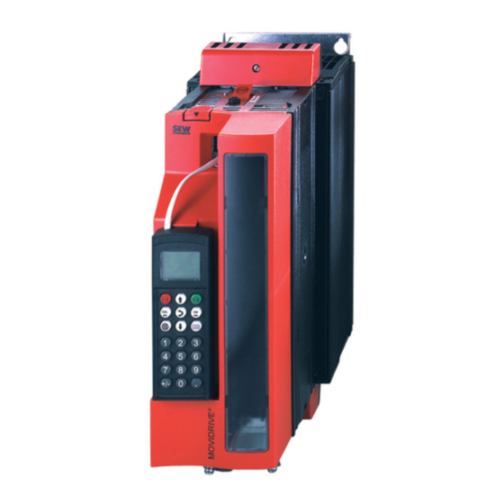
- Manuals
- Brands
- SEW-Eurodrive Manuals
- DC Drives
- Movidrive MDX61B
- System manual
-
Contents
-
Table of Contents
-
Bookmarks
Quick Links
Drive Technology \ Drive Automation \ System Integration \ Services
®
MOVIDRIVE
MDX60B / 61B
System Manual
Edition 06/2008
11697415 / EN
Related Manuals for SEW-Eurodrive MOVIDRIVE MDX61B
Summary of Contents for SEW-Eurodrive MOVIDRIVE MDX61B
-
Page 1
Drive Technology \ Drive Automation \ System Integration \ Services ® MOVIDRIVE MDX60B / 61B System Manual Edition 06/2008 11697415 / EN… -
Page 2
Color Code System Color code system for catalogs and system manuals Our catalogs and system manuals are identified by a color code system at the back to make it easier to work with these publications. The short designation of the publication is indicated as well. -
Page 3
1 System Description………………..7 2 Technical Data and Dimension Drawings …………33 3 Parameters………………….147 P6.. P60. P600 4 Project Planning ………………..251 5 Serial Communication ………………351 6 Structure of the Safety Notes…………….352 7 Safety Notes ………………….. 353 8 Unit Design …………………. -
Page 4: Table Of Contents
1 System Description………………..7 ® System Overview MOVIDRIVE MDX60B/61B …………7 Functions / features ………………..18 Additional functions of the application version …………20 ® Application modules for MOVIDRIVE MDX61B …………24 ® MOVITOOLS operating software …………….32 2 Technical Data and Dimension Sheets ………….. 33 CE-marking, UL approval and C-Tick …………….
-
Page 5
3 Parameters………………….147 Menu structure DBG60B ………………147 Overview of parameters ………………. 148 Explanation of the parameters …………….. 157 Duty types …………………… 239 4 Project Planning ………………..251 Schematic procedure ………………..251 Control characteristics………………..252 Description of applications ………………253 Basic recommendations for motor selection ………… -
Page 6
9 Installation ………………….367 Installation instructions for basic unit …………… 367 Removing/installing the keypad …………….374 Removing/installing the front cover …………….375 UL-compliant installation ………………377 Shield clamps………………….379 Touch guard for power terminals …………….382 Wiring diagrams for basic unit……………… 385 Assignment of braking resistors, chokes and filters ………. -
Page 7: System Description
System Description System Overview MOVIDRIVE® MDX60B/61B System Description ® System Overview MOVIDRIVE MDX60B/61B Power components 3 x AC 380…500 V 3 x AC 200…240 V Line filter option Line choke option Regenerative power supply unit option ® ® MOVIDRIVE MOVIDRIVE ®…
-
Page 8
System Description System Overview MOVIDRIVE® MDX60B/61B Encoder and communication options MDX60/61B application version for using plus® «Electronic cam», «Internal synchronous operation» MDX60/61B standard version with IPOS as standard or the application modules. MASTER DBG60B keypad option MOVITOOLS ® operating software System bus (SBus) Encoder options… -
Page 9
System Description System Overview MOVIDRIVE® MDX60B/61B Fieldbus options DFC 11B DFD 11B DFI 21B DFP 21B DFI 11B DFE 11B DFE 12B DFE 13B DFE 24B DFE 32B DFE 33B DFE33B MODULE STATUS NETWORK STATUS ETHERNET/IP 63227AXX System Manual – MOVIDRIVE® MDX60B/61B Inverter… -
Page 10
System Description System Overview MOVIDRIVE® MDX60B/61B Control options MOVI-PLC ® DHP 11B OST 11B DHE 41B DHF 41B 63062AXX System Manual – MOVIDRIVE® MDX60B/61B Inverter… -
Page 11
System Description System Overview MOVIDRIVE® MDX60B/61B Safety options DFS 11B DFS 12B DFS 21B DFS 22B DCS 21B DCS 31B 63061AXX System Manual – MOVIDRIVE® MDX60B/61B Inverter… -
Page 12
System Description System Overview MOVIDRIVE® MDX60B/61B ® General MOVIDRIVE MDX60/61B is the new generation of drive inverters from SEW. The new ® description MOVIDRIVE B series inverters feature a modular design, provide enhanced functions in the lower power range, more basic functions and greater overload capacity. AC drives with the latest digital inverter technology can now be used without restrictions in the 0.55 to 160 kW power range. -
Page 13
System Description System Overview MOVIDRIVE® MDX60B/61B ® Modular unit The option-capable MOVIDRIVE MDX61B units have the following option slots: concept Size 0 (0005 … 0014) → 2 option slots • – 1 option slot for encoder connection – 1 option slot for a communication option Sizes 1 … -
Page 14
System Description System Overview MOVIDRIVE® MDX60B/61B Required option Option slot Encoder option Asynchronous AC motor with encoder feedback ® (HIPERFACE , sin/cos, TTL) ® HIPERFACE encoder card DEH11B Asynchronous or synchronous ® servomotor with HIPERFACE encoder SSI encoder interface Absolute encoder card DEH21B Synchronous servomotor with Resolver card type DER11B resolver… -
Page 15
System Description System Overview MOVIDRIVE® MDX60B/61B Control mode The VFC (Voltage Flux Control) and CFC (Current Flux Control)/SERVO control modes ® are features of MOVIDRIVE MDX60B/61B inverters. The continuous calculation of the complete motor model forms the basis for both control modes. VFC (Voltage Flux Control) control mode CFC (Current Flux Control)/SERVO control mode… -
Page 16
System Description System Overview MOVIDRIVE® MDX60B/61B The units at a glance ® MDX60/61B for 3 × AC 380 … 500 V supply voltage (AC 400/500 V units): MOVIDRIVE ® Recommended motor power (VFC) Contin. output current MOVIDRIVE type Size MDX60B MDX61B (techn. -
Page 17
System Description System Overview MOVIDRIVE® MDX60B/61B Block circuit The following block circuit diagram shows the basic structure and theory of operation of ® diagram MOVIDRIVE MDX60B/61B inverters. Input protection Rectifier Inverter switch Brake link chopper Power Motor supply Control signals Supply Current X10:… -
Page 18: Functions / Features
System Description Functions / features Functions / features Unit properties • Wide voltage range – 400/500 V units for the voltage range 3 × AC 380 … 500 V – 230 V units for the voltage range 3 × AC 200 … 240 V •…
-
Page 19
System Description Functions / features • Speed monitoring and monitoring of the motor and regenerative limit power • Programmable signal range monitoring (speed, current, maximum current) • Memory for displaying x/t diagrams using SCOPE process data visualization four channels (8 channels, real-time capable) •… -
Page 20: Additional Functions Of The Application Version
System Description Additional functions of the application version ® Standards / • UL, cUL, C-Tick approval. The MOVIDRIVE MDR60A1320-503-00 unit does not certificates have UL or cUL or C-Tick approval. The GOST-R certificate (Russia) is approved for ® the MOVIDRIVE range of units.
-
Page 21
System Description Additional functions of the application version Motors and Use the following motor types: encoders ® • For operation with MOVIDRIVE MDX61B…-4-0T: – CT/CV asynchronous servomotor, high-resolution sin/cos encoder installed as ® standard or HIPERFACE encoder. – DT/DV/D series AC motors with incremental encoder option, preferably high- ®… -
Page 22
System Description Additional functions of the application version ® Internal synchro- You can always use the MOVIDRIVE range of units with «internal synchronous opera- nous operation tion» whenever a group of motors has to be operated at a synchronous angle in relation to one another or with an adjustable proportional ratio (electronic gear). -
Page 23
System Description Additional functions of the application version Example The figure below shows a typical application for the «internal synchronous operation.» Extruder material must be cut to length. The saw receives a start signal and synchronizes with the material. During the sawing process, the saw moves synchronously with the material. -
Page 24: Application Modules For Movidrive® Mdx61B
System Description Application modules for MOVIDRIVE® MDX61B ® Application modules for MOVIDRIVE MDX61B The application The drive application often involves more than just adjusting the speed of a motor. The inverter often has to control motion sequences and take on typical PLC tasks. More and more complex drive applications have to be solved, without this resulting in lengthy project planning and startup.
-
Page 25
System Description Application modules for MOVIDRIVE® MDX61B The following illustration shows an example of how the various SEW application modules are used in a block warehouse. 04008AXX Figure 4: Use in a high-bay warehouse 1. Hoist: Table positioning 2. Travel axis: Absolute value or bus positioning 3. -
Page 26
System Description Application modules for MOVIDRIVE® MDX61B Positioning The application modules for the «Positioning» application are suited to all applications where target positions are specified and movement then takes place to those positions. Movement can either be linear or rotatory. Such sequences of motions include trolleys, hoists, gantries, rotary tables, swiveling devices and storage and retrieval units for high-bay warehouses. -
Page 27
System Description Application modules for MOVIDRIVE® MDX61B • Straightforward connection to the machine control. • Guided startup and diagnostics. There are 3 operating modes for controlling the machine: • Jog mode: The machine can be moved manually. • Reference travel: The machine zero is determined automatically for incremental position measurement. -
Page 28
System Description Application modules for MOVIDRIVE® MDX61B Rotational • Modulo positioning positioning A large number of movements have to be controlled in automated conveyor and logistics applications to transport the material. Linear movements in the form of trolleys or hoists, and rotary movements via rotary tables play an important role in these applications. -
Page 29
System Description Application modules for MOVIDRIVE® MDX61B Winding • Center winder The «Central winder» application module is suitable for applications in which endless material, such as paper, plastic, fabrics, sheet metal or wire, must be wound, unwound or rewound continuously. Control takes place either via the binary inputs of the inverter or using the virtual terminals (fieldbus, system bus). -
Page 30
System Description Application modules for MOVIDRIVE® MDX61B Controlling • Flying saw The «Flying saw» application module is suited to applications in which endless material has to be cut, sawn or pressed, for example in diagonal saws or flying punches. This application module is used to control the sequence of motion according to specific values. -
Page 31
System Description Application modules for MOVIDRIVE® MDX61B Four operating modes are available for controlling the application: • Jog mode • Reference travel • Positioning mode • Synchronous operation – The electrical connection of the master/slave can be made using the X14 encoder connection or an SBus connection. -
Page 32: Movitools® Operating Software
System Description MOVITOOLS® operating software ® MOVITOOLS operating software ® plus® Description MOVITOOLS is a program package comprising SHELL, SCOPE and the IPOS ® ® Compiler. MOVITOOLS can be used for the MOVIDRIVE MDX60B/61B and ® MOVIDRIVE compact range of units. •…
-
Page 33: Technical Data And Dimension Sheets
Technical Data and Dimension Sheets CE-marking, UL approval and C-Tick Technical Data and Dimension Sheets CE-marking, UL approval and C-Tick CE marking • Low voltage directive ® MOVIDRIVE MDX60B/61B inverters comply with the regulations of the Low Voltage Directive 2006/95/EC. •…
-
Page 34: General Technical Data
Technical Data and Dimension Sheets General technical data General technical data ® The following table lists the technical data applicable to all MOVIDRIVE MDX60B/61B inverters, regardless of their type, version, size and performance. ® MOVIDRIVE MDX60B/61B All sizes Interference resistance Complies with EN 61800-3 Interference emission with Sizes 0 to 6 meet EN 61800-3…
-
Page 35
Technical Data and Dimension Sheets General technical data ® MOVIDRIVE MDX60B/61B series, size 0 51485AXX ® Figure 6: MOVIDRIVE MDX60/61B series, size 0 ® MOVIDRIVE MDX61B series, sizes 1 to 6 52159AXX ® Figure 7: MOVIDRIVE MDX61B series, sizes 1 to 6 System Manual –… -
Page 36: Movidrive® Mdx60/61B
Technical Data and Dimension Sheets MOVIDRIVE® MDX60/61B…-5_3 (AC 400/500 V units) ® MOVIDRIVE MDX60/61B…-5_3 (AC 400/500 V units) Size 0 ® MOVIDRIVE MDX60/61B 0005-5A3-4-0_ 0008-5A3-4-0_ 0011-5A3-4-0_ 0014-5A3-4-0_ Size INPUT 3 × AC 380 V -500 V Rated supply voltage (to EN 50160) supply 50 Hz …
-
Page 37
Technical Data and Dimension Sheets MOVIDRIVE® MDX60/61B…-5_3 (AC 400/500 V units) MDX61B standard version 0005-5A3-4-00 0008-5A3-4-00 0011-5A3-4-00 0014-5A3-4-00 Design with coated printed circuit boards 0005-5A3-4-00/L 0008-5A3-4-00/L 0011-5A3-4-00/L 0014-5A3-4-00/L 827 722 2 827 723 0 827 724 9 827 725 7 Part number 828 947 6 828 948 4… -
Page 38
Technical Data and Dimension Sheets MOVIDRIVE® MDX60/61B…-5_3 (AC 400/500 V units) Size 1 (AC 400/500 V units) ® MOVIDRIVE MDX61B 0015-5A3-4-0_ 0022-5A3-4-0_ 0030-5A3-4-0_ 0040-5A3-4-0_ INPUT 3 × AC 380 V — 500 V Rated supply voltage (to EN 50160) supply 50 Hz … -
Page 39
Technical Data and Dimension Sheets MOVIDRIVE® MDX60/61B…-5_3 (AC 400/500 V units) Sizes 2S, 2 (AC 400/500 V units) ® MOVIDRIVE MDX61B 0055-5A3-4-0_ 0075-5A3-4-0_ 0110-5A3-4-0_ Size INPUT 3 × AC 380 V — 500 V Rated supply voltage (to EN 50160) supply 50 Hz … -
Page 40
Technical Data and Dimension Sheets MOVIDRIVE® MDX60/61B…-5_3 (AC 400/500 V units) Size 3 (AC 400/500 V units) ® MOVIDRIVE MDX61B 0150-503-4-0_ 0220-503-4-0_ 0300-503-4-0_ INPUT 3 × AC 380 V — 500 V Rated supply voltage (to EN 50160) supply 50 Hz … 60 Hz ±5 % Supply frequency supply Rated supply current… -
Page 41
Technical Data and Dimension Sheets MOVIDRIVE® MDX60/61B…-5_3 (AC 400/500 V units) Size 4 (AC 400/500 V units) ® MOVIDRIVE MDX61B 0370-503-4-0_ 0450-503-4-0_ INPUT 3 × AC 380 V — 500 V Rated supply voltage (to EN 50160) supply 50 Hz … 60 Hz ±5 % Supply frequency supply Rated supply current… -
Page 42
Technical Data and Dimension Sheets MOVIDRIVE® MDX60/61B…-5_3 (AC 400/500 V units) Size 5 (AC 400/500 V units) ® MOVIDRIVE MDX61B 0550-503-4-0_ 0750-503-4-0_ INPUT 3 × AC 380 V — 500 V Rated supply voltage (to EN 50160) supply 50 Hz … 60 Hz ±5 % Supply frequency supply Rated supply current… -
Page 43
Technical Data and Dimension Sheets MOVIDRIVE® MDX60/61B…-5_3 (AC 400/500 V units) Size 6 (AC 400/500 V units) ® MOVIDRIVE MDX61B 0900-503-4-0_ 1100-503-4-0_ 1320-503-4-0_ INPUT 3 × AC 380 V — 500 V Rated supply voltage (to EN 50160) supply 50 Hz … 60 Hz ±5 % Supply frequency supply Rated supply current… -
Page 44: Movidrive® Mdx61B
Technical Data and Dimension Sheets MOVIDRIVE® MDX61B…-2_3 (AC 230 V units) ® MOVIDRIVE MDX61B…-2_3 (AC 230 V units) Size 1 (AC 230 V units) ® MOVIDRIVE MDX61B 0015-2A3-4-0_ 0022-2A3-4-0_ 0037-2A3-4-0_ INPUT 3 × AC 200 V — 240 V Rated supply voltage (to EN 50160) supply 50 Hz …
-
Page 45
Technical Data and Dimension Sheets MOVIDRIVE® MDX61B…-2_3 (AC 230 V units) Size 2 (AC 230 V units) ® MOVIDRIVE MDX61B 0055-2A3-4-0_ 0075-2A3-4-0_ INPUT 3 × AC 200 V — 240 V Rated supply voltage (to EN 50160) supply 50 Hz … 60 Hz ± 5 % Supply frequency supply Rated supply current… -
Page 46
Technical Data and Dimension Sheets MOVIDRIVE® MDX61B…-2_3 (AC 230 V units) Size 3 (AC 230 V units) ® MOVIDRIVE MDX61B 0110-203-4-0_ 0150-203-4-0_ INPUT 3 × AC 200 V — 240 V Rated supply voltage (to EN 50160) supply 50 Hz … 60 Hz ± 5 % Supply frequency supply Rated supply current… -
Page 47
Technical Data and Dimension Sheets MOVIDRIVE® MDX61B…-2_3 (AC 230 V units) Size 4 (AC 230 V units) ® MOVIDRIVE MDX61B 0220-203-4-0_ 0300-203-4-0_ INPUT 3 × AC 200 V — 240 V Rated supply voltage (to EN 50160)V supply 50 Hz … 60 Hz ± 5 % Supply frequency supply Rated supply current… -
Page 48: Movidrive® Mdx60/61B Electronics Data
Technical Data and Dimension Sheets MOVIDRIVE® MDX60/61B electronics data ® MOVIDRIVE MDX60/61B electronics data ® MOVIDRIVE MDX60/61B General electronics data Voltage supply X11:1 REF1: DC+10 V +5 % / –0 %, I = DC 3 mA Reference voltages for setpoint potentiometer REF2: DC–10 V +0 % / –5 %, I = DC 3 mA for setpoint input…
-
Page 49
Technical Data and Dimension Sheets MOVIDRIVE® MDX60/61B electronics data ® MOVIDRIVE MDX60/61B General electronics data Safety contact X17:1 DGND: Reference potential for X17:3 X17:2 VO24: : V = DC 24 V, only to supply X17:4 of the same unit; it cannot be used to supply other units. -
Page 50: Movidrive® Mdx60B Dimension Sheets
Technical Data and Dimension Sheets MOVIDRIVE® MDX60B dimension sheets ® MOVIDRIVE MDX60B dimension sheets Size 0S 249 (9.8) 6 (0.24) 260 (10.2) 45 (1.8) 53019CXX Figure 8: Dimensions for MDX60B size 0S, dimensions in mm (in) Size 0S with braking resistor installed 249 (9.8) 6 (0.24)
-
Page 51
Technical Data and Dimension Sheets MOVIDRIVE® MDX60B dimension sheets Size 0M 249 (9.8) 6 (0.24) 260 (10.2) 67.5 (2.66) 53022CXX Figure 10: Dimensions for MDX60B size 0M, dimensions in mm (in) Size 0M with braking resistor 6 (0.24) 249 (9.8) 260 (10.2) 67.5 (2.66) 94 (3.7) -
Page 52: Movidrive® Mdx61B Dimension Sheets
Technical Data and Dimension Sheets MOVIDRIVE® MDX61B dimension sheets ® MOVIDRIVE MDX61B dimension sheets NOTE ® For MOVIDRIVE MDX61B size 0, installing a braking resistor does not affect the ® dimensions. Therefore, MOVIDRIVE MDX61B size 0 dimensions are displayed without an installed braking resistor. Size 0S 249 (9.8) 6 (0.24)
-
Page 53
Technical Data and Dimension Sheets MOVIDRIVE® MDX61B dimension sheets Size 0M 6 (0.24) 249 (9.8) 67.5 (2.66) 260 (10.2) 95 (3.7) 51378CXX Figure 13: Dimensions for MDX61B size 0M, dimensions in mm (in) System Manual – MOVIDRIVE® MDX60B/61B Inverter… -
Page 54
Technical Data and Dimension Sheets MOVIDRIVE® MDX61B dimension sheets Size 1 234 (9.21) 105 (4.13) 6 (0.24) 85 (3.3) 6 (0.24) 52274CXX Figure 14: Dimensions for MDX61B size 1, dimensions in mm (in) System Manual – MOVIDRIVE® MDX60B/61B Inverter… -
Page 55
Technical Data and Dimension Sheets MOVIDRIVE® MDX61B dimension sheets Size 2S 105 (4.13) 294 (11.6) 70 (2.8) 7 (0.28) 52273CXX Figure 15: Dimensions for MDX61B size 2S, dimensions in mm (in) System Manual – MOVIDRIVE® MDX60B/61B Inverter… -
Page 56
Technical Data and Dimension Sheets MOVIDRIVE® MDX61B dimension sheets Size 2 285 (11.2) 130 (5.12) 105 (4.13) 6,5 (0.26) 124.5 (4.9) 52276CXX Figure 16: Dimensions for MDX61B size 2, dimensions in mm (in) System Manual – MOVIDRIVE® MDX60B/61B Inverter… -
Page 57
Technical Data and Dimension Sheets MOVIDRIVE® MDX61B dimension sheets Size 3 308 (12.1) 200 (7.87) 105 (4.13) 2 (0.08) 7 (0.3) 52315CXX Figure 17: Dimensions for MDX61B size 3, dimensions in mm (in) System Manual – MOVIDRIVE® MDX60B/61B Inverter… -
Page 58
Technical Data and Dimension Sheets MOVIDRIVE® MDX61B dimension sheets Size 4 307 (12.1) 280 (11.0) 2 (0.08) 140 (5.51) 7 (0.3) 52277CXX Figure 18: Dimensions for MDX61B size 4, dimensions in mm (in) System Manual – MOVIDRIVE® MDX60B/61B Inverter… -
Page 59
Technical Data and Dimension Sheets MOVIDRIVE® MDX61B dimension sheets Size 5 280 (11.0) 330 (13.0) 140 (5.51) 2 (0.08) 7 (0.3) 52278CXX Figure 19: Dimensions for MDX61B size 5, dimensions in mm (in) System Manual – MOVIDRIVE® MDX60B/61B Inverter… -
Page 60
Technical Data and Dimension Sheets MOVIDRIVE® MDX61B dimension sheets Size 6 382 (15.0) 2 (0.08) 140 (5.51) 11 (0.43) 9 (0.4) 294 (11.6) 318 (12.5) 58389CXX Figure 20: Dimensions for MDX61B size 6, dimensions in mm (in) System Manual – MOVIDRIVE® MDX60B/61B Inverter… -
Page 61: Movidrive® Mdr60A Regenerative Power Supply Units
Technical Data and Dimension Sheets MOVIDRIVE® MDR60A regenerative power supply units ® MOVIDRIVE MDR60A regenerative power supply units ® In MOVIDRIVE inverters operating in regenerative mode (4Q operation), the ® MOVIDRIVE MDR60A regenerative power supply unit can be used as an alternative to braking resistors.
-
Page 62
Technical Data and Dimension Sheets MOVIDRIVE® MDR60A regenerative power supply units Features of a • Energy balance: Regenerative power is fed back into the supply system instead of regenerative being converted into waste heat. power supply unit • Less installation work for several inverters (network and braking resistor connec- compared to an tions). -
Page 63
Technical Data and Dimension Sheets MOVIDRIVE® MDR60A regenerative power supply units ® Technical data for MOVIDRIVE MDR60A regenerative power supply ® MOVIDRIVE MDR60A 0370-503-00 0750-503-00 1320-503-00 (size 3) (size 4) (size 6) Part number 826 658 1 826 556 9 827 952 7 INPUT 3 ×… -
Page 64
Technical Data and Dimension Sheets MOVIDRIVE® MDR60A regenerative power supply units Dimension draw- Provide at least 100 mm clearance above and below the unit. There is no need for ings for MDR60A clearance at the sides. You can line up the units directly next to one another. With sizes 4 and 6, do not install any components that are sensitive to high temperatures within 300 mm (11.8 in) of the top of the unit, for example contactors or fuses. -
Page 65
Technical Data and Dimension Sheets MOVIDRIVE® MDR60A regenerative power supply units 85 (3.3) 350 (13.8) 395 (15.6) 380 (15.0) 54282CXX Figure 24: Dimension drawing, MDR60A size 6, dimensions in mm (in) DC link SEW-EURODRIVE recommends using the following cable sets for the DC link connec- connection tion. -
Page 66: Ipos
Technical Data and Dimension Sheets IPOSplus® plus® IPOS plus® ® Description IPOS positioning and sequence control is integrated into every MOVIDRIVE plus® inverter as standard. With IPOS , control functions and positioning tasks can be performed either simultaneously or independently of one another. plus®…
-
Page 67: Dbg60B Keypad Option
Technical Data and Dimension Sheets DBG60B keypad option 2.10 DBG60B keypad option ® Description The basic version of MOVIDRIVE does not have a DBG60B keypad and can be upgraded to include the keypad as an option. Keypad Language variants Part number DE/EN/FR/IT/ES/PT/NL DBG60B-01 (German / English / French / Italian / Spanish / Portuguese /…
-
Page 68
Technical Data and Dimension Sheets DBG60B keypad option NOTE The DBG60B keypad option and the interface adapter are plugged into the same inverter slot (XT) and therefore cannot be used at the same time. Dimension draw- Dimensions in mm (in) ing for DBG60B 45 (1.8) 18 (0.71) -
Page 69
Technical Data and Dimension Sheets DBG60B keypad option Dimension The DBM60B option can be used to mount the keypad close to the inverter (e.g. in the drawing for control cabinet door). The DBM60B option consists of housing in enclosure IP65 and a DBG60B housing 5 m DKG60B extension cable. -
Page 70: Dmp11B Mounting Panel Option
Technical Data and Dimension Sheets DMP11B mounting panel option 2.11 DMP11B mounting panel option Part number 818 398 8 Description DMP11B 54588AXX ® ® If a MOVIDRIVE MD_60A size 2 unit is to be replaced by MOVIDRIVE MDX61B size 2S, the MDX61B size 2S can be fitted on the existing mounting plate with the DMP11B mounting panel.
-
Page 71: Dlb11B Touch Guard Option
Technical Data and Dimension Sheets DLB11B touch guard option 2.12 DLB11B touch guard option Part number 823 111 7 (12 pieces included in the scope of delivery) Description 63233AXX ® Degree of protection IP20 can be achieved with touch guard DLB11B for MOVIDRIVE MDX61B sizes 4 and 5 (AC 500 V units: MDX61B0370/0450/0550/0750;…
-
Page 72: Hiperface® Encoder Card Option Type Deh11B
Technical Data and Dimension Sheets HIPERFACE® encoder card option type DEH11B ® 2.13 HIPERFACE encoder card option type DEH11B Part number 824 310 7 ® Description The option capable MOVIDRIVE MDX61B units can be equipped with the ® HIPERFACE encoder card type DEH11B. The encoder card offers one input for the motor encoder and one input for an external encoder, also referred to as synchronous encoder.
-
Page 73: Absolute Encoder Card Option Type Deh21B/Dip11B
Technical Data and Dimension Sheets Absolute encoder card option type DEH21B/DIP11B 2.14 Absolute encoder card option type DEH21B/DIP11B Part numbers • DEH21B: 1820 818 5 • DIP11B: 824 969 5 ® Description The DEH21B and DIP11B options extend the MOVIDRIVE B system to include an SSI interface for absolute encoders.
-
Page 74
Technical Data and Dimension Sheets Absolute encoder card option type DEH21B/DIP11B Electronics data for DIP11B DIP11B option Connection binary inputs X60:1 … 8 DI10 … DI17 isolated via optocoupler, PLC compatible (EN 61131), scanning time 1 ms ≈ 3 kΩ , I ≈… -
Page 75: Resolver Card Option Type Der11B
Technical Data and Dimension Sheets Resolver card option type DER11B 2.15 Resolver card option type DER11B Part number 824 307 7 ® Description Option-capable MOVIDRIVE MDX61B units can be equipped with resolver card type DER11B. The resolver card offers one input for the resolver as motor encoder and one input for an external encoder, also referred to as synchronous encoder.
-
Page 76: Connector Adapter For Unit Replacement Md_60A — Mdx60B/61B
Technical Data and Dimension Sheets Connector adapter for unit replacement MD_60A — MDX60B/61B 2.16 Connector adapter for unit replacement MD_60A — MDX60B/61B ® The following adapters are available for rapid replacement of a MOVIDRIVE A unit with ® a MOVIDRIVE B unit during system operation.
-
Page 77
Technical Data and Dimension Sheets Connector adapter for unit replacement MD_60A — MDX60B/61B Terminal of the 15-pin sub D connector Core color in Terminal of 9-pin sub ® (MOVIDRIVE MDX61B, option DEH11B, X15) prefabricated cable D socket (encoder end) Yellow (YE) Red (RD) Pink (PK) Violet (VT) -
Page 78: Interface Adapter Option Type Dwe11B/12B
Technical Data and Dimension Sheets Interface adapter option type DWE11B/12B 2.17 Interface adapter option type DWE11B/12B Part number and • DWE11B, part number 188 187 6 description The interface adapter DWE11B (HTL→TTL) in the form of an adapter cable is used to connect single-ended HTL encoders to the DEH11B/DEH21B option.
-
Page 79
Technical Data and Dimension Sheets Interface adapter option type DWE11B/12B • DWE12B, part number 188 180 9 The interface adapter DWE12B (HTL→TTL) in the form of an adapter cable is used to connect single-ended HTL encoders to the DEH11B/DEH21B option. In addition to the A, B and C track, you will also have to connect the negated tracks (A, B, C). -
Page 80: Interface Adapter Option Type Uws11A
Technical Data and Dimension Sheets Interface adapter option type UWS11A 2.18 Interface adapter option type UWS11A Part number 822 689 X Description The UWS11A option converts RS232 signals, for example from the PC, into RS485 signals. These RS485 signals can then be routed to the RS485 interface of the ®…
-
Page 81: Interface Adapter Option Type Uws21B
Technical Data and Dimension Sheets Interface adapter option type UWS21B 2.19 Interface adapter option type UWS21B Part number 1820 456 2 Description The UWS21B option converts RS232 signals, for example from the PC, into RS485 ® signals. These RS485 signals can then be routed to the XT slot of MOVIDRIVE RS232 interface The connection of UWS21B with PC is made using a standard serial interface cable (shielded).
-
Page 82: Interface Adapter Option Type Usb11A
Technical Data and Dimension Sheets Interface adapter option type USB11A 2.20 Interface adapter option type USB11A Part number 824 831 1 Description Option USB11A enables a PC or laptop with a USB interface to be connected to the XT ® slot of MOVIDRIVE B.
-
Page 83: Dc 5 V Encoder Power Supply Option Type Dwi11A
Technical Data and Dimension Sheets DC 5 V encoder power supply option type DWI11A 2.21 DC 5 V encoder power supply option type DWI11A Part number 822 759 4 Description If you are using an incremental encoder with a DC 5 V encoder power supply, install the DC 5 V encoder power supply option type DWI11A between the inverter and the incremental encoder.
-
Page 84: Input/Output Card Type Dio11B Option
Technical Data and Dimension Sheets Input/output card type DIO11B option 2.22 Input/output card type DIO11B option Part number 824 308 5 ® Description The number of inputs/outputs of the basic MOVIDRIVE B unit can be expanded with the DIO11B option. The DIO11B option is plugged into the fieldbus slot. If the fieldbus slot is not available, you can plug the DIO11B option into the expansion slot.
-
Page 85: Profibus Fieldbus Interface Option Type Dfp21B
Technical Data and Dimension Sheets PROFIBUS fieldbus interface option type DFP21B 2.23 PROFIBUS fieldbus interface option type DFP21B Part number 824 240 2 ® Description MOVIDRIVE B can be equipped with a 12 Mbaud fieldbus interface for the PROFIBUS- ® DP serial bus system.
-
Page 86: Interbus Fieldbus Interface Option Type Dfi11B
Technical Data and Dimension Sheets INTERBUS fieldbus interface option type DFI11B 2.24 INTERBUS fieldbus interface option type DFI11B Part number 824 309 3 ® Description MOVIDRIVE B can be equipped with a fieldbus interface for the non-proprietary and standardized INTERBUS sensor/actuator bus system. INTERBUS is defined in EN 50254 / DIN 19258 and, as far as its function is concerned, it consists of a process data channel and a parameter data channel.
-
Page 87: Interbus-Lwl Fieldbus Interface Option Type Dfi21B (Fo)
Technical Data and Dimension Sheets INTERBUS-LWL fieldbus interface option type DFI21B (FO) 2.25 INTERBUS-LWL fieldbus interface option type DFI21B (FO) Part number 824 311 5 ® Description MOVIDRIVE B can be equipped with a fieldbus interface for the non-proprietary and standardized INTERBUS sensor/actuator bus system INTERBUS with fiber optic cables (INTERBUS-LWL).
-
Page 88: Dfe11B Fieldbus Interface Option Modbus/Tcp
Technical Data and Dimension Sheets DFE11B fieldbus interface option Modbus/TCP 2.26 DFE11B fieldbus interface option Modbus/TCP Part number 1820 036 2 ® Description The MOVIDRIVE MDX61B inverter enables you to use the DFE11B option to connect to higher-level automation, project planning and visualization systems via Ethernet (MODUBUS/TCP protocol) thanks to its powerful, universal fieldbus interface.
-
Page 89: Profinet Io Rt Type Dfe12B Fieldbus Interface Option
Technical Data and Dimension Sheets PROFINET IO RT type DFE12B fieldbus interface option 2.27 PROFINET IO RT type DFE12B fieldbus interface option Part number 1820 563 1 ® Description The MOVIDRIVE MDX61B inverter enables you to use the DFE12B option to connect to higher-level automation, project planning and visualization systems via Ethernet (PROFINET/IO protocol) thanks to its powerful, universal fieldbus interface.
-
Page 90: Profinet Io Rt Type Dfe32B Fieldbus Interface Option
Technical Data and Dimension Sheets PROFINET IO RT type DFE32B fieldbus interface option 2.28 PROFINET IO RT type DFE32B fieldbus interface option Part number 1821 345 6 ® Description The MOVIDRIVE MDX61B inverter enables you to use the DFE32B option to connect to higher-level automation, project planning and visualization systems via Ethernet (PROFINET/IO protocol) thanks to its powerful, universal fieldbus interface.
-
Page 91: Dfe13B Ethernet/Ip Fieldbus Interface Option
Technical Data and Dimension Sheets DFE13B EtherNet/IP fieldbus interface option 2.29 DFE13B EtherNet/IP fieldbus interface option Part number 1820 565 8 ® Description The MOVIDRIVE MDX61B inverter enables you to use the DFE13B option to connect to higher-level automation, project planning and visualization systems via Ethernet (EtherNet/IP protocol) thanks to its powerful, universal fieldbus interface.
-
Page 92: Dfe33B Ethernet/Ip Fieldbus Interface Option
Technical Data and Dimension Sheets DFE33B EtherNet/IP fieldbus interface option 2.30 DFE33B EtherNet/IP fieldbus interface option Part number 1821 346 4 ® Description The MOVIDRIVE MDX61B inverter enables you to use the DFE33B option to connect to higher-level automation, project planning and visualization systems via Ethernet (EtherNet/IP protocol) thanks to its powerful, universal fieldbus interface.
-
Page 93: Ethercat Fieldbus Interface Option Type Dfe24B
Technical Data and Dimension Sheets EtherCAT fieldbus interface option type DFE24B 2.31 EtherCAT fieldbus interface option type DFE24B Part number 1821 126 7 ® Description The MOVIDRIVE MDX61B inverter enables you to use the DFE24B option to connect to higher-level automation, project planning and visualization systems via EtherCAT thanks to its powerful, universal fieldbus interface.
-
Page 94: Devicenet Fieldbus Interface Option Type Dfd11B
Technical Data and Dimension Sheets DeviceNet fieldbus interface option type DFD11B 2.32 DeviceNet fieldbus interface option type DFD11B Part number 824 972 5 ® Description The MOVIDRIVE MDX61B inverter in conjunction with the DFD11B option allows connection to higher-level automation, project planning and visualization systems via the open and standardized DeviceNet fieldbus system thanks to the option’s high- performance universal fieldbus interface.
-
Page 95: Canopen Fieldbus Interface Option Type Dfc11B
Technical Data and Dimension Sheets CANopen fieldbus interface option type DFC11B 2.33 CANopen fieldbus interface option type DFC11B Part number 824 317 4 ® Description The MOVIDRIVE MDX61B inverter in conjunction with the DFC11B option allows connection to higher-level automation, project planning and visualization systems via the open and standardized CANopen fieldbus system thanks to the option’s high- performance universal fieldbus interface.
-
Page 96: Synchronous Operation Board Option Type Drs11B
Technical Data and Dimension Sheets Synchronous operation board option type DRS11B 2.34 Synchronous operation board option type DRS11B Part number 824 672 6 Description The DRS11B option enables a group of motors to run in angular synchronous operation or in an adjustable proportional relationship. For detailed information, refer to the «Syn- chronous Operation Board Type DRS11B»…
-
Page 97: Profibus Dp-V1 With Profisafe Fieldbus Interface Option Type Dfs11B
Technical Data and Dimension Sheets PROFIBUS DP-V1 with PROFIsafe fieldbus interface option type DFS11B 2.35 PROFIBUS DP-V1 with PROFIsafe fieldbus interface option type DFS11B Part number 1820 962 9 ® Description MOVIDRIVE B can be equipped with a 12 Mbaud fieldbus interface DFS11B for the PROFIBUS-DP-V1 serial bus system with PROFIsafe.
-
Page 98
Technical Data and Dimension Sheets PROFIBUS DP-V1 with PROFIsafe fieldbus interface option type DFS11B Safety part Safety characteristics Highest possible safety category • SIL 3 according to EN 61508 • Category 4 according to EN 954-1 • Performance level e according to EN ISO 13849-1 System structure 2 channels with diagnostics (1002D) Type of operating mode… -
Page 99: Profibus Dp-V1 With Profisafe Fieldbus Interface Option Type Dfs12B
Technical Data and Dimension Sheets PROFIBUS DP-V1 with PROFIsafe fieldbus interface option type DFS12B 2.36 PROFIBUS DP-V1 with PROFIsafe fieldbus interface option type DFS12B Part number 1820 963 7 (in preparation) ® Description MOVIDRIVE B can be equipped with a 12 Mbaud fieldbus interface DFS12B for the PROFIBUS-DP-V1 serial bus system with PROFIsafe.
-
Page 100: Profinet Io With Profisafe Fieldbus Interface Option, Type Dfs21B
Technical Data and Dimension Sheets PROFINET IO with PROFIsafe fieldbus interface option, type DFS21B 2.37 PROFINET IO with PROFIsafe fieldbus interface option, type DFS21B Part number 1821 183 6 ® Description The MOVIDRIVE MDX61B inverter enables you to use the DFS21B option to connect to higher-level automation, project planning and visualization systems via Ethernet (PROFINET/IO RT protocol) thanks to its powerful, universal fieldbus interface.
-
Page 101
Technical Data and Dimension Sheets PROFINET IO with PROFIsafe fieldbus interface option, type DFS21B Safety part Safety characteristics Highest possible safety category • SIL 3 according to EN 61508 • Category 4 according to EN 954-1 • Performance level e according to EN ISO 13849-1 System structure 2 channels with diagnostics (1oo2D) Type of operating mode… -
Page 102: Profinet Io With Profisafe Fieldbus Interface Option, Type Dfs22B
Technical Data and Dimension Sheets PROFINET IO with PROFIsafe fieldbus interface option, type DFS22B 2.38 PROFINET IO with PROFIsafe fieldbus interface option, type DFS22B Part number 1821 184 4 ® Description The MOVIDRIVE MDX61B inverter enables you to use the DFS22B option to connect to higher-level automation, project planning and visualization systems via Ethernet (PROFINET/IO RT protocol) thanks to its powerful, universal fieldbus interface.
-
Page 103: Movisafe® Dcs21B/31B Safety Module Option
Technical Data and Dimension Sheets MOVISAFE® DCS21B/31B safety module option ® 2.39 MOVISAFE DCS21B/31B safety module option Part numbers • DCS21B complete with prefabricated cable DAE34B (CAN bus connection between DCS21B X86 and DFS21B X31): 1821 895 4 • DCS21B without prefabricated cable: 1820 392 2 •…
-
Page 104
Technical Data and Dimension Sheets MOVISAFE® DCS21B/31B safety module option Electronics data DCS21B/31B option LED alarm/error LED watchdog LED system B LED system A X80: Power supply connection X81: Connection binary inputs X82: Connection of binary outputs DO0, DO1 X83: Connection of binary output DO2 X84: Connection of incremental, sin/cos or absolute encoder (encoder 1) X85: Connection of incremental, sin/cos or absolute encoder (encoder 2) X86: CAN bus connection (only for DCS21B) -
Page 105: Movi-Plc® Basic Dhp11B.. Controller Option
Technical Data and Dimension Sheets MOVI-PLC® basic DHP11B.. controller option ® 2.40 MOVI-PLC basic DHP11B.. controller option ® Part numbers The MOVI-PLC basic controller DHP11B.. is available in 3 versions, which differ in the modules available from a range of libraries. ®…
-
Page 106: Ost11B Option
Technical Data and Dimension Sheets OST11B option 2.41 OST11B option Part number 1820 544 5 ® Description Option OST11B provides an additional RS485 interface (COM2) for MOVI-PLC basic DHP11B.. in terminal design or as an engineering interface. Only use option OST11B in ®…
-
Page 107: Movi-Plc® Advanced Controller Option Dh.41B
Technical Data and Dimension Sheets MOVI-PLC® advanced controller option DH.41B ® 2.42 MOVI-PLC advanced controller option DH.41B ® Part numbers The MOVI-PLC advanced DH.41B is available in 2 variants, which differ in the integrated fieldbus interfaces: ® Part number Unit design of MOVI-PLC Fieldbus interfaces advanced DH.41B 1821 160 7…
-
Page 108
Technical Data and Dimension Sheets MOVI-PLC® advanced controller option DH.41B Electronics data for DHE41B ® MOVI-PLC advanced DHE41B option Electrical supply The following applies for all units (MDX, MX, compact controller): • You will have to supply the binary inputs and outputs with DC 24 V (X31:1/2) separately. ®… -
Page 109
Technical Data and Dimension Sheets MOVI-PLC® advanced controller option DH.41B ® MOVI-PLC advanced DHE41B option System bus CAN 2 • System bus CAN 1 and CAN 2 to CAN specification 2.0, parts A and B, transmission X32:1 … X32:3 technology to ISO 11898, max. 64 stations, •… -
Page 110
Technical Data and Dimension Sheets MOVI-PLC® advanced controller option DH.41B Electronics data for DHF41B NOTE For connections identical with DHE41B, refer to the «Electronics data for DHE41B» section. ® MOVI-PLC advanced DHF41B option ® Potential levels The MOVI-PLC advanced DHF41B controller has the following potential levels: •… -
Page 111: Braking Resistor Type Bw
Technical Data and Dimension Sheets Braking resistor type BW… option / BW…-T / BW…-P 2.43 Braking resistor type BW… option / BW…-T / BW…-P General • Braking resistors BW… / BW…-T and BW…-P match the technical features of the ® information MOVIDRIVE inverters.
-
Page 112
Technical Data and Dimension Sheets Braking resistor type BW… option / BW…-T / BW…-P Parallel Two braking resistors with the same value must be connected in parallel for some connection inverter/resistor combinations. In this case, the trip current must be set on the bimetallic relay to twice the value of I entered in the table. -
Page 113
Technical Data and Dimension Sheets Braking resistor type BW… option / BW…-T / BW…-P Braking resistor type BW… BW147 BW247 BW347 BW039-012 Part number 820 713 5 820 714 3 820 798 4 821 689 4 Braking resistor type BW…-T BW147-T BW247-T BW347-T… -
Page 114
Technical Data and Dimension Sheets Braking resistor type BW… option / BW…-T / BW…-P Braking resistor type BW…- BW012-025 Part number 821 680 0 Braking resistor type BW…-T/-P BW012-025-P BW012-050T BW012-100-T BW106-T BW206-T Part number 1820 414 7 1820 140 7 1820 141 5 1820 083 4 1820 412 0… -
Page 115
Technical Data and Dimension Sheets Braking resistor type BW… option / BW…-T / BW…-P Assignment to AC 230 V units (…-2_3) Braking resistor type BW… BW039- BW039- BW039- BW027- BW027- Part number 821 687 8 821 688 6 821 689 4 822 422 6 822 423 4 Braking resistor type BW…-T BW039-… -
Page 116
Technical Data and Dimension Sheets Braking resistor type BW… option / BW…-T / BW…-P MDimension drawing braking resistors BW… / BW…-T / BW…-P BW… : • 1 = Flat design The connecting lead is 500 mm (19.7 in) long. The scope of delivery includes four M4 stud bolts each of type 1 and •… -
Page 117
Technical Data and Dimension Sheets Braking resistor type BW… option / BW…-T / BW…-P Touch guard BS… A BS.. touch guard is available for braking resistors in flat design. Touch guard BS003 BS005 Part number 813 151 1 813 152 X for braking resistor BW027-003 BW027-005… -
Page 118
Technical Data and Dimension Sheets Braking resistor type BW… option / BW…-T / BW…-P DKB11A heat sink for braking resistors in flat design Part number 814 345 5 Description The DKB11A heat sink for braking resistors in flat design provides a space-saving means for mounting the braking resistors (BW072-005, BW100-005) beneath ®… -
Page 119: Line Choke Option Type Nd
Technical Data and Dimension Sheets Line choke option type ND.. 2.44 Line choke option type ND.. • To increase overvoltage protection. • To limit the charging current when several inverters are connected together in parallel on the input end with shared mains contactors (rated current of line choke = total of inverter currents).
-
Page 120
Technical Data and Dimension Sheets Line choke option type ND.. 58315AXX Figure 29: Dimension drawing for line chokes ND150.. / ND200.. / ND300.. Hole dimension Main dimensions mm (in) Mounting dimensions mm (in) Weight Line choke mm (in) type kg (lb) ND020-013 85 (3.3) 60 (2.4) -
Page 121: Line Filter Type Nf
Technical Data and Dimension Sheets Line filter type NF…-… option 2.45 Line filter type NF…-… option • To suppress interference emission on the line side of inverters. ® • Do not switch between the NF… line filter and MOVIDRIVE ® •…
-
Page 122
Technical Data and Dimension Sheets Line filter type NF…-… option Dimension draw- ing for NF… Eingang Ausgang 55862ADE Figure 30: Dimension drawing for NF line filter Any mounting position Mounting dimensions mm Hole dimension Main dimensions mm (in) Weight Line filter (in) mm (in) type… -
Page 123: Hd… Output Choke Option
Technical Data and Dimension Sheets HD… output choke option 2.46 HD… output choke option • For suppression of interference from the unshielded motor cable. For HD001 to HD003 we recommend routing the motor cable through the output choke with 5 loops.
-
Page 124
Technical Data and Dimension Sheets HD… output choke option ® MOVIDRIVE HD004 58424AXX Mounting dimensions mm Hole dimen- Inside ∅ mm (in) Main dimensions mm (in) Weight Output (in) sion mm (in) choke type kg (lb) HD001 121 (4.76) 64 (2.5) 131 (5.16) 80 (3.1) 50 (2.0) -
Page 125: Output Filter Option Type Hf
Technical Data and Dimension Sheets Output filter option type HF… 2.47 Output filter option type HF… HF… output filters are sine filters used to smooth output voltage from inverters. HF… output filters (with the exception of HF450-503) are approved to UL/cUL in combination ®…
-
Page 126
Technical Data and Dimension Sheets Output filter option type HF… Output filter type HF075-503 HF023-403 HF033-403 HF047-403 HF450-503 Part number 826 313 2 825 784 1 825 785 X 825 786 8 826 948 3 3 × AC 230 V — 500 V, 50/60 Hz Rated voltage ΔI Earth-leakage current at U… -
Page 127
Technical Data and Dimension Sheets Output filter option type HF… Dimension drawings for HF…-503 output filters HF008 / 015 / 022 / 030-503 HF040/055/075-503 MOVIDRIVE ® MOVIDRIVE ® MOVIDRIVE ® 58418AXX Figure 31: Dimension drawings for output filters HF008…075-503 Only the mounting position shown in the dimension drawing is permitted. Mounting dimensions Hole dimen- Ventilation clearances… -
Page 128
Technical Data and Dimension Sheets Output filter option type HF… Dimension drawing for HF…-403 output filter 58996AXX Figure 33: Dimension drawing for HF…-403 output filter Mounting dimensions mm (in) Hole dimen- Ventilation clearances Horizontal Main dimensions mm (in) Standard mounting sion mm mm (in) mounting… -
Page 129: Prefabricated Cables
Technical Data and Dimension Sheets Prefabricated cables 2.48 Prefabricated cables Overview SEW offers cable sets and prefabricated cables for straightforward and error-free ® connection of various system components to MOVIDRIVE . The cables are pre- fabricated in 1 m steps to the required length. It is necessary to differentiate between whether the cables are intended for fixed routing or for cable carrier applications.
-
Page 130
Technical Data and Dimension Sheets Prefabricated cables 2. Prefabricated cables and extension cables for connecting CM motors to MDX Motor cables The cables are equipped with a connector for motor connection and conductor end sleeves for inverter connection. Number of cores and line cross section Part number Installation type for motor… -
Page 131
Technical Data and Dimension Sheets Prefabricated cables Number of cores and line cross section Part number Installation type for motor 4×1.5 mm 1 333 118 3 CM..SM51 4×1.5 mm + 3×1.0 mm 1 333 120 5 CM..BR SB51 4×2.5 mm 1 333 119 1 CM..SM52 4×2.5 mm… -
Page 132
Technical Data and Dimension Sheets Prefabricated cables 4. Prefabricated cables and extension cables for connecting VR forced cooling fans VR forced cooling fan cable: Number of cores and line cross section Part number Installation type 3×1 mm 198 634 1 Fixed installation 3×1 mm 199 560 X… -
Page 133
Technical Data and Dimension Sheets Prefabricated cables 5. Prefabricated cables for connecting options DEH11B / DEH21B / DER11B The following overviews show the possible connections for the DEH11B/DEH21B and DER11B options. Meaning of the The connection cables are assigned a part number and a symbol. The symbols have the symbols following meaning: Symbol… -
Page 134
Technical Data and Dimension Sheets Prefabricated cables Connection options at X15 X15 DEH11B/DEH21B DS, CM, CMD, CMP DT(E)/DV(E), CT/CV, DZ/DX AF1H, AK0H, AS1H, AS3H, AS4H EF1H, EK0H, ES1H, ES3H, ES4H EV1H, AV1H AS1H, ES1H AS1H, ES1H ® Hiperface 199 539 1 199 540 5 X15 DEH.1B ®… -
Page 135
Technical Data and Dimension Sheets Prefabricated cables ® • Cable to connect HIPERFACE encoders AF1H, AK0H, AS1H, AS3H, AS4H, EF1H, EK0H, ES1H, ES3H, ES4H, EV1H, AV1H with plug connector connection on the motor side to DS, CM, CMD, CMP, DT, DV, DT(E), DV(E), CT, CV, DZ or DX motors. 56135AXX Type Installation… -
Page 136
Technical Data and Dimension Sheets Prefabricated cables ® • Cable to connect HIPERFACE encoders AS1H, ES1H, AF1H, EF1H with terminal box connection on the motor side to DS motors. 56132AXX Type Installation Part number 1332 765 8 56049AXX DEH11B/21B X15 → DS motors with AS1H, ES1H, AF1H, EF1H 1332 766 6 56050AXX… -
Page 137
Technical Data and Dimension Sheets Prefabricated cables Cable (option DWE12B, interface adapter HTL → TTL) to connect push-pull HTL • encoders at X15 of option (→ chapter «Interface adapter DWE11B/12B»). 59109AXX Type Installation Part number DEH11B/21B X15 → Option DWE12B (connection 188 180 9 for push-pull HTL encoders) 56047AXX… -
Page 138
Technical Data and Dimension Sheets Prefabricated cables • Cable to connect DC 5 V TTL sensors ES1T, ES2T, EV1T, EV2T, EH1T with terminal box connection on the motor side (DT(E), DV(E), eDT, eDV, DR, DZ or DX motors) to DC 5 V encoder power supply type DWI11A. 56132AXX Type Installation… -
Page 139
Technical Data and Dimension Sheets Prefabricated cables • Y cable to connect the AV1Y absolute encoder with plug connector on the motor side to DT(E), DV(E), CT, CV, DR, DZ and DX motors. The following encoder tracks are evaluated with the Y cable: –… -
Page 140
Technical Data and Dimension Sheets Prefabricated cables Connection options at X14, DEH11B / DER11B AV1H EV1S, EV1R EV1T ® Hiperface DWI11A 199 539 1 X2 DWI11A X14 DER11B/DEH11B → TTL/5V → TTL, Sin/Cos 199 540 5 198 829 8 817 960 3 X14 DER11B/ DEH11B 198 828 X… -
Page 141
Technical Data and Dimension Sheets Prefabricated cables ® • Cable to connect external HIPERFACE encoders AV1H, AS1H, ES1H, AF1H, EF1H via plug connector. 56131AXX Type Installation Part number 199 539 1 56051AXX DEH11B / DER11B X14 → AV1H, AS1H, ES1H, AF1H, EF1H 199 540 5 56052AXX… -
Page 142
Technical Data and Dimension Sheets Prefabricated cables • Cable to connect the DC 5 V encoder power supply type DWI11A via plug connector. 56109AXX Type Installation Part number DEH11B / DER11B X14 → DWI11A X1 818 164 0 56047AXX • Cable to connect an external DC 5 V TTL sensor to the DC 5 V encoder power supply type DWI11A via encoder terminal strip. -
Page 143
Technical Data and Dimension Sheets Prefabricated cables • Cable to connect the encoder simulation (DEH11B/DER11B:X14) of the master to terminal X42 of option DRS11B. 56109AXX Type Installation Part number DEH11B/DER11B X14 → DRS11B X42 0818 166 7 (master and slave turn in the same direction) 56047AXX DEH11B/DER11B X14 →… -
Page 144
Technical Data and Dimension Sheets Prefabricated cables Connection options at X15 DER11B X15 DER11B → RH1M/L X15 DER11B → RH1M/L X15 DER11B 1332 817 4 → RH1M/L 199 589 8 X62 DIP11B → SSI DER11B 199 487 5 1332 844 1 199 590 1 198 929 4 DIP11B… -
Page 145
Technical Data and Dimension Sheets Prefabricated cables • Cable to connect resolvers RH1M / RH1L with plug connector connection on the motor side to DS, CM, CMD or CMP motors. 56138AXX Type Installation Part number 199 487 5 56047AXX DER11B X15 → DS/CM/CMD/CMP motors with RH1M/RH1L 199 319 4 56048AXX… -
Page 146
Technical Data and Dimension Sheets Prefabricated cables • Cable to connect resolvers RH1M / RH1L with terminal box connection on the motor side to CM and DS motors. 56142AXX Type Installation Part number 199 589 8 56049AXX DER11B X15 → CM motors with RH1M/RH1L 199 590 1 56050AXX 1332 817 4… -
Page 147: Parameters
P6.. Parameters Menu structure DBG60B P60. P600 Parameters Generally speaking, the parameter menu is only required for startup and in case of ® service. That is the reason why MOVIDRIVE is designed as a basic unit without key- ® pad. You can equip the MOVIDRIVE with a PC connection or a keypad.
-
Page 148: Overview Of Parameters
P6.. Parameters Overview of parameters P60. P600 Overview of parameters The following table lists all parameters together with their factory settings (underlined): Numerical values are displayed with the complete setting range. Display values Process values Speed User display Frequency Actual position Output current Active current 006 / 007…
-
Page 149
P6.. Parameters Overview of parameters P60. P600 Option / firmware expansion slot Firmware basic unit Technology function Unit type Error memory 080 … Error t-0 … t-4 Bus diagnostics PD configuration Fieldbus type Fieldbus baud rate Fieldbus address 094 … PO1 … -
Page 150
P6.. Parameters Overview of parameters P60. P600 16x / 17x Fixed setpoints 1 / 2 160 / 170 Internal setpoint n11 / n21 –6000 … 150 … 6000 rpm (% I 161 / 171 Internal setpoint n12 / n22 –6000 … 750 … 6000 rpm (% I 162 / 172 Internal setpoint n13 / n23 –6000 … -
Page 151
P6.. Parameters Overview of parameters P60. P600 Scaling setpoint –32.767 … 1 … 32.767 Actual value source Analog 1 IPOS actual value address 0 … 1023 Actual scaling factor –32.767 … 1 … 32.767 Actual offset value –32767 … 0 … 32767 Actual time constant 0 … -
Page 152
P6.. Parameters Overview of parameters P60. P600 Speed setpoint/actual value comparison Hysteresis 0 … 100 … 300 rpm Delay time 0 … 1 … 9 s n ≠ n Signal = «1» if: / n = n setpt setpt Current reference signal Current reference value 0 … -
Page 153
P6.. Parameters Overview of parameters P60. P600 Binary inputs DCS 1 … 8 Display value Binary outputs DCS DO0_P … Display value DO2_M Serial number DCS Display value CRC DCS Display value DCS error response Immediate stop/fault DCS alarm response Rapid stop / warning DCS source actual position Motor encoder (X15) -
Page 154
P6.. Parameters Overview of parameters P60. P600 720 / 723 Setpoint stop function 1 / 2 721 / 724 Stop setpoint 1 / 2 0 … 30 … 500 rpm 722 / 725 Start offset 1 / 2 0 … 30 … 500 rpm Brake function 730 / 733 Brake function 1 / 2… -
Page 155
P6.. Parameters Overview of parameters P60. P600 Response SW LIMIT SWITCH EMERG. ST/FAULT Reset behavior Manual reset Auto reset Restart time 1 … 3 … 30 s Scaling actual speed value Scaling factor numerator 1 … 65 535 Scaling factor denominator 1 … -
Page 156
P6.. Parameters Overview of parameters P60. P600 Ramp type LINEAR Ramp mode MODE 1 IPOS Monitoring SW limit switch RIGHT –(2 –1) … 0 … 2 –1 increments SW limit switch LEFT –(2 –1) … 0 … 2 –1 increments Position window 0 … -
Page 157: Explanation Of The Parameters
P6.. Parameters Explanation of the parameters P60. P600 Explanation of the parameters The parameters are explained below. The parameters are divided into 10 groups. The ® parameter names correspond to their representation in the SHELL PC program. The factory setting is indicated by underline. Symbols The following symbols explain the parameters: These parameters are switch-selectable and available in parameter sets 1 and 2.
-
Page 158
P6.. Parameters Explanation of the parameters P60. P600 P0xx display values This parameter group contains the following information: • process values and states of the basic unit • process values and states of the installed options • Error memory • Fieldbus parameters P00x process values P000 Speed… -
Page 159
P6.. Parameters Explanation of the parameters P60. P600 P011 Operating The following operating states are possible (7 segment display): state • 0: 24 V OPERATION (inverter not ready for operation) • 1: CONTROLLER INHIBIT • 2: NO ENABLE • 3: CURRENT AT STANDSTILL •… -
Page 160
P6.. Parameters Explanation of the parameters P60. P600 P03x Binary inputs basic unit P030 … P037 The display will show the current status of input terminal DI00 … DI07 and the current binary input DI00 function assignment..DI07 Please note that binary input DI00 is always assigned with controller inhibit. Menu selection see P60x binary inputs basic unit. -
Page 161
P6.. Parameters Explanation of the parameters P60. P600 • ELECTRONIC CAM: Setting for technology function «Electronic cam» to coordinate the operation of several drives. Prerequisites are: – Motor with encoder feedback – Inverter in unit design «Application version» • ISYNCH: Setting for technology function «Electronic synchronous operation» to synchronize the operation of several drives with accurate positioning. -
Page 162
P6.. Parameters Explanation of the parameters P60. P600 P08x Error memory P080 … P084 Error There are 5 error memories (t-0 … t-4). The errors are stored in a chronological t-0 … t4 sequence with the most recent error event being held in error memory t-0. If there are more than 5 errors, the error event of longest standing, stored in t-4, is deleted. -
Page 163
P6.. Parameters Explanation of the parameters P60. P600 P094 … P096 PO1 Displays the value currently transferred on the process data word in hexadecimal form..PO3 setpoint PO setpoint Description P094 PO1 setpoint P870 Setpoint description PO1 P095 PO2 setpoint P871 Setpoint description PO2 P096 PO3 setpoint P872 Setpoint description PO3… -
Page 164
P6.. Parameters Explanation of the parameters P60. P600 • FIX SETP+ANALOG1: The setpoint is defined by the total of the selected fixed setpoint and the setpoint selection at analog input AI1. The fixed setpoint is processed without sign (= according to its value) and the analog setpoint is processed as a signed setpoint. -
Page 165
P6.. Parameters Explanation of the parameters P60. P600 plus® • SBus 2: The setpoint is specified using system bus 2. (See IPOS manual.) • IPOS setpoint: The value of the IPOS variable H524 (IPOS system setpoint) is used as the setpoint. The setpoint is interpreted depending on P700 Operation mode 1. –… -
Page 166
P6.. Parameters Explanation of the parameters P60. P600 P11x Analog input AI1 P110 AI1 Scaling Setting range: –10 … 0 … 1 … 10 The slope of the setpoint characteristic is defined. Depending on P112 AI1 operation mode with AI1 scaling = 1 and an input voltage V of +/–10 V, the setpoint +/–3000 rpm or +/–n is set. -
Page 167
P6.. Parameters Explanation of the parameters P60. P600 P111 AI1 Offset Setting range: –500 … 0 … 500 mV When the setpoint is selected by an external controller, it is possible to compensate for a voltage offset present at analog input AI1 when the setpoint selection is zero. The setting of this parameter causes calibration of the coordinate basic origin of Figure 35. -
Page 168
P6.. Parameters Explanation of the parameters P60. P600 • Expert characteristic: Free choice of reference between setpoint voltage and speed. The characteristic can be adapted with P110 AI1 scaling (reference 3000 rpm), P113 AI1 voltage offset and P114 AI1 speed offset (-> Figure 41). The following structural diagram shows how a speed setpoint is created from an expert characteristics. -
Page 169
P6.. Parameters Explanation of the parameters P60. P600 P114 AI1 speed Setting range: –6000 … 0 … 6000 rpm offset The zero passage of the setpoint characteristic can be moved along the n-axis. Reference point with positive offset Reference point with negative offset -10 V -8 V… -
Page 170
P6.. Parameters Explanation of the parameters P60. P600 Sample expert characteristics (P112 AI1 operating mode = Expert charactristic curve): Free choice of reference between setpoint voltage and speed for the expert character- istics. Set parameter P100 Setpoint source = BIPOL./FIX.SETPT to make full use of the possibilities of the expert characteristic. -
Page 171
P6.. Parameters Explanation of the parameters P60. P600 The expert characteristics displayed in Figure 41 are created as follows: Char- P113 P114 P110 acter- AI1 Voltage offset V AI1 Speed offset rpm AI1 scaling (slope) istics curve 1.39 1500 3000 –1.25 The expert characteristic can also be used with P100 Setpoint source = UNIPOL/FIX.SETPT. -
Page 172
P6.. Parameters Explanation of the parameters P60. P600 Expert characteristics with current setpoints: Voltage signals are required at the AI11/AI12 analog input for the expert characteristic function. If a load-independent current 0 (4) … 20 mA is available as setpoint, switch S11 (changeover I-signal/U-signal) must be set to ON and the current signal routed to X11:2 AI11. -
Page 173
P6.. Parameters Explanation of the parameters P60. P600 P12x Analog inputs option P120 AI2 operating Analog input AI2 is only available with the optional input/output card (DIO11B). mode (optional) • NO FUNCTION: The setpoint at AI2 is not used; the external current limitation is set to 100 %. -
Page 174
P6.. Parameters Explanation of the parameters P60. P600 P135 / P145 S Setting range: 0 / 1 / 2 / 3 (0 = off, 1 = weak, 2 = medium, 3 = strong) pattern t12 / t22 The 2nd ramp (t12/ t22) of parameter sets 1 and 2 can be rounded with 3 pattern grades to achieve a smoother acceleration of the drive. -
Page 175
P6.. Parameters Explanation of the parameters P60. P600 This step also entails an increased setting of the respective ramp, if the ramp timeout definitely appears in form of a preset ramp that cannot be traveled. This parameter is an additional monitoring function for speed monitoring. This parameter only applies to the downwards ramp. -
Page 176
P6.. Parameters Explanation of the parameters P60. P600 P16x / P17x Fixed Setting range: –6000 ..+6000 rpm setpoints 1 / 2 3 internal setpoints (= fixed setpoints) can be set separately for parameter sets 1 and 2. The internal setpoints are active if P100 Setpoint source is set to one of the following functions and an input terminal programmed to n11/n21 or n12/n22 (P6xx Terminal assignment) has a “1”… -
Page 177: Filter Speed Actual Value 0
P6.. Parameters Explanation of the parameters P60. P600 P2xx Controller parameters P20x Speed Speed control only parameter set 1. control ® The speed controller of the MOVIDRIVE is a PI-controller and is active when the following operating modes are set: •…
-
Page 178: Load Precontrol Cfc
P6.. Parameters Explanation of the parameters P60. P600 P204 Actual speed Setting range: 0 … 32 ms value filter Filter time constant of the actual speed value filter. AUTO P205 Load Load precontrol CFC (only effective in CFC and SERVO operating modes). precontrol CFC Setting range: –150 …
-
Page 179
P6.. Parameters Explanation of the parameters P60. P600 P221 / P222 Setting range: 1 … 3 999 999 999 Master gear ratio These settings are only required with the slave inverter. These parameters set the factor / Slave gear position measurement ratio between the master and slave drives. The ratio is entered ratio factor as the quotient of master to slave drive to include non-integer ratios. -
Page 180
P6.. Parameters Explanation of the parameters P60. P600 • Mode 6: Temporary angular offset, new reference point – Free-running is active when a «1» signal is set at X40:1. – The input terminals and setpoints of the slave drive are effective in free-running mode. -
Page 181: Master Encoder Resolution
P6.. Parameters Explanation of the parameters P60. P600 P230 Synchro- Setting range: OFF / EQUAL-RANKING / CHAIN nous encoder • OFF: Synchronous operation control with the signals on X15: «Motor encoder». P231 and P232 have no effect. • EQUAL-RANKING: Forwarding of X42 signals: «Master encoder» at X43: «Incremental encoder output.»…
-
Page 182: Derivative Time T V
P6.. Parameters Explanation of the parameters P60. P600 P263 Factor K Setting range: 0 …1 … 32,767 Proportional factor of the proportional share of the PID controller with 3 decimal places. The proportionality factor takes the sign (+/-) of the parameter «Direction of rotation» into account.
-
Page 183
P6.. Parameters Explanation of the parameters P60. P600 P278 Offset actual Setting range: –32767 … 0 … 32767 value This parameter is used to set an integer, permanent offset of the actual value. P278 and the IPOS variable H552 are identical. P279 Time con- Setting range: 0 … -
Page 184
P6.. Parameters Explanation of the parameters P60. P600 P3xx Motor parameters This parameter group is used to adjust the inverter to the motor. The parameters can be set separately for parameter set 1 and 2. This means two different motors can be operated alternately on the same inverter without requiring a new setting. -
Page 185
P6.. Parameters Explanation of the parameters P60. P600 P304 Torque limit Setting range: 0 … 150 % (size 0: 200 %) The parameter limits the maximum torque of the motor. The entry acts on the setpoint × I of the motor torque (k ). -
Page 186
P6.. Parameters Explanation of the parameters P60. P600 P322 / P332 IxR Setting range: 0 … 100 % compensation 1/2 The I×R value of the matching motor is set as the factory setting. In VFC operating mode, this parameter acts on the parameters of the calculated motor model which establish the torque. -
Page 187
P6.. Parameters Explanation of the parameters P60. P600 The following signal and display functions are available in conjunction with motor protection: Parameters Signal and display function P006 Motor utilization 1 / P007 Display of the motor utilization for parameter set 1 / 2. Motor utilization 2 P832 Response MOTOR Error response of the inverter when reaching P006 Motor utilization 1… -
Page 188
P6.. Parameters Explanation of the parameters P60. P600 • SEW motor with KTY temperature sensor: Motor utilization is calculated using a ® motor model stored in MOVIDRIVE (P006 Motor utilization1, P018 KTY utilization 1). Once the motor dependent switch-off limit is reached, the inverter will be switched off using the response set in P832 Response motor utilization. -
Page 189
P6.. Parameters Explanation of the parameters P60. P600 P36x Startup Startup (only available in the DBG60B keypad). P360 Startup Setting range: YES / NO • YES: Begins the startup function with the DBG60B keypad. NOTE ® With P360, MOVIDRIVE B can only be started up in VFC operating modes. Startup in the CFC and SERVO operating modes must be performed using MOVITOOLS/SHELL. -
Page 190
P6.. Parameters Explanation of the parameters P60. P600 P41x Speed Signals whether the speed is within or outside the set window range. window signal n rpm P411 P410 Window P412 P413: Signal = «1» at n <> n Window P413: Signal = «1» at n = n Window 55733BEN… -
Page 191
P6.. Parameters Explanation of the parameters P60. P600 P43x Current Signal if the output current is greater or less than the reference value. reference signal I [% off I ] P431 P430 P432 P433: Signal = «1» at | I | > I P433: Signal = «1»… -
Page 192
P6.. Parameters Explanation of the parameters P60. P600 Activate the speed monitoring for hoists and set the delay time to a rather small value. Speed monitoring is not that important for safety since an incorrect movement of the hoist does not necessarily mean operation in the current limitation. P501 / P503 Delay Setting range: 0 … -
Page 193
P6.. Parameters Explanation of the parameters P60. P600 P512 Lag error Setting range: 100 … 4000 … 99,999,999 inc limit Fault message F42 ‘Lag error’ is issued if the angular misalignment exceeds the value set here. This is regardless of whether the slave drive is operating in free-running or synchronous operation mode. -
Page 194
P6.. Parameters Explanation of the parameters P60. P600 P521 Power off Setting range: CONTROL.INHIBIT / EMERGENCY STOP response If the binary input is programmed to «Power on», the response set here will be triggered ® when the binary receives a «0» signal. The 7-segment display of MOVIDRIVE indicates «0»… -
Page 195
P6.. Parameters Explanation of the parameters P60. P600 P54x Gear unit / motor monitoring These parameters are used to set the response to be triggered in the event of a motor or gear unit problem. The binary inputs have to be set accordingly for this purpose. The fault responses will also be triggered in the CONTROLLER INHIBIT inverter status. -
Page 196
P6.. Parameters Explanation of the parameters P60. P600 P545 Oil aging / Factory setting: Display error ready signal Once the oil aging sensor signals ready, the inverter will respond with the set response. P549 Response Factory setting: Display error brake wear Once the brake wear sensor signals a fault, the inverter will respond with the set response. -
Page 197
P6.. Parameters Explanation of the parameters P60. P600 P555 Error Setting range P555: No response / Display error / Immediate stop / Fault / Emergency response DCS / stop/Fault / Rapid stop/Fault / Immediate stop/Warning / Emergency stop/Warning / P556 Alarm Rapid stop/Warning response DCS Setting range P556: No response / Display error / Rapid stop / Fault / Emergency… -
Page 198
P6.. Parameters Explanation of the parameters P60. P600 P560 Current limi- Setting range: On / Off tation Ex-e motor ON: Current limitation for Ex-e motors active. On startup, the current limitation for Ex-e motors is automatically activated for motors AUTO selected and approved for the operation in potentially explosive areas. -
Page 199
P6.. Parameters Explanation of the parameters P60. P600 P6xx Terminal assignment P60x Binary inputs Binary input DIØØ with fixed assignment «/CONTROL. INHIBIT.» basic unit P600 … P606 The binary inputs of the basic unit can be set to the same functions as the binary outputs Binary inputs DIØ1 option (P61x). -
Page 200
P6.. Parameters Explanation of the parameters P60. P600 Effect in Effect at Fac- Inverter status Function tory set See also «1» signal Inhib- «0» signal Enabled ited Vibration/fault Vibration sensor reports fault Vibration sensor does not report fault Oil aging/warning Oil aging sensor signals Oil aging sensor does not warning… -
Page 201
P6.. Parameters Explanation of the parameters P60. P600 P63x Binary outputs option P630 … P637 The following functions can be assigned to the binary outputs: Binary output DO1Ø … DO17 Binary output has Factory set Function See also «0» signal «1»… -
Page 202
P6.. Parameters Explanation of the parameters P60. P600 NOTE The binary signals are only valid if the inverter has signaled «READY» after switch-on. ® Binary signals have «0» status while MOVIDRIVE is being initialized. Several terminals can be assigned the same function. P64x Analog outputs optional P640 / P643 Depending on P642 Operating mode AO1 / P645 Operating mode AO2 the signal range… -
Page 203
P6.. Parameters Explanation of the parameters P60. P600 P641 / P644 Scal- Setting range: –10 … 0 … 1 … 10 ing AO1 / AO2 The incline of the characteristic for the analog outputs is defined. The value for unit utilization, current and relative torque is 200% for each in BG0. -
Page 204
P6.. Parameters Explanation of the parameters P60. P600 P642 / P645 Here you can set the operating mode of the analog output. The following operating Operating mode modes are available: AO1 / AO2 • OFF: The value zero is always output. •… -
Page 205
P6.. Parameters Explanation of the parameters P60. P600 P7xx Control functions All settings with regard to the fundamental control properties of the inverter are defined within parameter group 7xx. These are all functions which the inverter performs auto- matically upon activation and which influence its behavior in certain operating modes. NOTE ®… -
Page 206
P6.. Parameters Explanation of the parameters P60. P600 P71 x Standstill current P710 / P711 Setting range: 0 … 50 % I Standstill current 1 The standstill current is used for injecting an adjustable current into the motor when the motor is at a standstill and the brake is applied. -
Page 207
P6.. Parameters Explanation of the parameters P60. P600 P72x Setpoint stop The setpoint stop function makes possible an enable function generated automatically function by the inverter depending on the main setpoint. It results in an enable process with all necessary functions, such as premagnetization, brake control, etc. It always requires an additional enable via terminals. -
Page 208
P6.. Parameters Explanation of the parameters P60. P600 ® P73x Brake MOVIDRIVE B inverters are capable of controlling a brake installed on the motor. The function brake function acts on the binary output DBØØ, which has the fixed assignment of the “/BRAKE”… -
Page 209
P6.. Parameters Explanation of the parameters P60. P600 P74x Speed skip The skip window center and skip width are values and automatically have an effect on positive and negative setpoints when activated. The function is deactivated by setting the skip width to 0. Output speed P741/P743 Ramps… -
Page 210
P6.. Parameters Explanation of the parameters P60. P600 P75x Master-Slave The master-slave function allows for implementing automatical functions such as speed function synchronization, shared load and torque control (slave). The RS485 interface (ST11 ST12) or the system bus interface (SC11 / SC12) can be used as the communication link. -
Page 211
P6.. Parameters Explanation of the parameters P60. P600 Connection check • System bus (SBus): P815 SBus timeout delay is in effect when there is a communi- cation link via the SBus. If P883 SBus timeout delay = 0, there is no monitoring of data transmission via the SBus. -
Page 212
P6.. Parameters Explanation of the parameters P60. P600 Synchronous Speed synchronization (SPEED (RS485) / SPEED (SBus) / SPEED (485+SBus)): speed running The actual speed of the master is transferred to the slave. The speed ratio is set for the slave inverter with P751 Scaling slave setpoint. Leave P324 Slip compensation 1 / P334 Slip compensation 2 of the slave at the value of the startup setting. -
Page 213
P6.. Parameters Explanation of the parameters P60. P600 Example: Parameters Setting on the master Setting on the slave P100 Setpoint source e.g. BIPOL./FIXED SETP MASTER RS485 P101 Control signal source e.g. TERMINALS Not in effect P324 Slip compensation 1 Do not change P700 Operating mode 1 VFC 1 VFC 1… -
Page 214
P6.. Parameters Explanation of the parameters P60. P600 P751 Scaling slave Setting range: –10 … 1 … 10 setpoint The setpoint sent from the master is multiplied by this factor which is set in the slave. P76x Manual operation P760 Lockout Setting range: YES / NO run/stop keys NO: Run/stop keys of the DBG60B keypad are active and can be used for starting and… -
Page 215
P6.. Parameters Explanation of the parameters P60. P600 P785 Ethernet / IP Setting range: DHCP / Saved IP parameters Startup Configura- Only available with DFE13B EtherNet/IP option. tion: • DHCP: The DFE13B option is assigned its IP parameters (P780 … P782) P782) by a DHCP server when the supply voltage is switched on. -
Page 216
P6.. Parameters Explanation of the parameters P60. P600 • P94x IPOS encoder (except for P944) • P95x DIP (except for P955) • Error memory • Statistical data • PROFINET device name The «Delivery state» setting also resets the data listed above. «8»… -
Page 217
P6.. Parameters Explanation of the parameters P60. P600 P806 Copy DBG -> Setting range: YES / NO ® The parameter data in the DBG60B are transferred to MOVIDRIVE P807 Copy MDX — Setting range: YES / NO > DBG ® The parameter data set in MOVIDRIVE are transferred to the DBG60B keypad. -
Page 218
P6.. Parameters Explanation of the parameters P60. P600 P82x Braking operation P820 / P821 Setting range: ON / OFF 4-quadrant This setting is only taken into account in operating modes without encoder feedback operation 1/2 (VFC, V/f); 4-quadrant operation is assumed in all other operating modes. P820 / P821 enables 4-quadrant operation to be switched on and off for parameter sets 1 / 2. -
Page 219
P6.. Parameters Explanation of the parameters P60. P600 P832 Response Factory setting: EMERG. ST/FAULT MOTOR P832 programs the fault response that is triggered in the event of motor overload. Make OVERLOAD one of the following settings to monitor motor overload: •… -
Page 220
P6.. Parameters Explanation of the parameters P60. P600 P84x Reset response P840 Manual reset Setting range: YES / NO ® • YES: The error in the MOVIDRIVE B unit is reset. In case of a fault, it is possible to press the [←… -
Page 221
P6.. Parameters Explanation of the parameters P60. P600 P850 Scaling Setting range: 1 … 65535 (can be set with SHELL only) factor numerator P851 Scaling Setting range: 1 … 65535 (can be set with SHELL only) factor denominator P852 User-defined Factory setting: rpm (can be set with SHELL only) unit Up to eight ASCII characters;… -
Page 222
P6.. Parameters Explanation of the parameters P60. P600 P87x Process data description P870 / P871 / P870 / P871 / P872 define the content of the process output data words PO1 / PO2 / ® P872 Setpoint PO3. This is necessary so MOVIDRIVE B can allocate the appropriate setpoints. -
Page 223
P6.. Parameters Explanation of the parameters P60. P600 The following PI assignments are available: Assignment Description NO FUNCTION The content of the process input data word is 0000 SPEED Current actual speed value of the drive in rpm. OUTPUT CURRENT Instantaneous output current of the system in % of I Current active current of the system in % of I ACTIVE CURRENT… -
Page 224
P6.. Parameters Explanation of the parameters P60. P600 P884 / P894 SBus Setting range: 125 / 250 / 500 / 1000 kbaud baud rate 1 / 2 P884 / P894 set the transmission speed of the system bus. The total of the baud rates in P884 / P894 must not exceed 1125 kBaud. -
Page 225
P6.. Parameters Explanation of the parameters P60. P600 P9xx IPOS parameters plus® plus® The IPOS parameters are described in detail in the IPOS manual. HAZARD! Risk of crushing if the motor starts up unintentionally. Severe or fatal injuries. • Ensure that the motor cannot start unintentionally. plus®… -
Page 226
P6.. Parameters Explanation of the parameters P60. P600 P902 Reference Setting range: 0 … 50 … 6000 rpm speed 2 Reference speed 2 determines the travel speed for the second part of the reference travel. Speed change always takes place via stop ramp t13. The search directions during reference travel are determined by the respective reference travel type. -
Page 227
P6.. Parameters Explanation of the parameters P60. P600 • Type 6: Reference cam flush with CW limit switch – First search direction is CW. – Reference position = First zero pulse or falling edge to the left of the reference –… -
Page 228
P6.. Parameters Explanation of the parameters P60. P600 plus® P91x IPOS travel parameters P910 Gain X Setting range: 0,1 … 0,5 … 32 controller plus® Setting value for the P controller of the position control loop in IPOS . The value from P210 P gain hold controller is adopted here in the default setting. -
Page 229
P6.. Parameters Explanation of the parameters P60. P600 P916 Ramp type This parameter specifies the type of the positioning ramp. This influences the speed or acceleration characteristics during positioning. NOTE The following ramp types are not supported if P702 Motor category is set to «Linear»: •… -
Page 230
P6.. Parameters Explanation of the parameters P60. P600 Ramp type Positioning characteristics POSITION INTERPOLATION The position specifications sent cyclically by the external controller are 12 BIT interpolated. Position resolution: 1 revolution corresponds to 4096 increments (12 bit). • Position specification using process data: –… -
Page 231
P6.. Parameters Explanation of the parameters P60. P600 P917 Ramp mode Setting range: MODE 1 / MODE 2 This parameter determines the use of P912 Positioning ramp 2 with ramp type set to LINEAR. • P917 = MODE 1: Deceleration for travel to target position (spot braking) takes place with P912 Positioning ramp 2. -
Page 232
P6.. Parameters Explanation of the parameters P60. P600 plus® P93x IPOS special functions P930 Override Setting range: ON / OFF The override function makes it possible to change the travel speed for positioning plus® operations which is programmed in the IPOS program. -
Page 233
P6.. Parameters Explanation of the parameters P60. P600 plus® P94x IPOS encoder P940 IPOS Setting range: ON / OFF variables edit plus® IPOS variables edit with DBG60B keypad only, not in SHELL. plus® IPOS varibles can be changed if P940 is set to ‘ON’. P941 Source Setting range: Motor encoder (X15) / Ext. -
Page 234
P6.. Parameters Explanation of the parameters P60. P600 The number of pulses detected at X14 is multiplied by P944 and then mapped to H510. The external encoder must always provide fewer pulses than the motor encoder. Please contact SEW-EURODRIVE if this is not possible. P945 Synchro- Setting range: TTL / SIN/COS / HIPERFACE nous encoder type… -
Page 235
P6.. Parameters Explanation of the parameters P60. P600 P948 Automatic Setting range: ON / OFF encoder replace- ® This parameter is only effective with Hiperface encoders. ment detection ® • ON: A replaced Hiperface encoder is detected. Reference travel is required before the «IPOS reference»… -
Page 236
P6.. Parameters Explanation of the parameters P60. P600 ® P95x Absolute The DIP parameters are described in detail in the «MOVIDRIVE MDX61B Absolute encoder (SSI) Encoder Card DIP11B/DEH21B» manual. The DIP11B option cannot be used with ® MOVIDRIVE MDX61B size 0. P950 Encoder type The absolute encoder connected to the DEH21B/DIP11B option (X62) is selected. -
Page 237
P6.. Parameters Explanation of the parameters P60. P600 P954 Zero offset Setting range: –(2 –1) … 0 … 2 –1 Zero offset is used for assigning the value you want to a specific position. The range of values can adopt positive or negative position values. The maximum valid parameter must not be exceeded. -
Page 238
P6.. Parameters Explanation of the parameters P60. P600 P962 Modulo Setting range: 0 … 1 … 2 – 1 denominator Simulation of the gear unit by entering the number of teeth of the gear unit and the additional gear. Modulo denominator = Denominator gear unit i x denominator additional gear i P963 Modulo Setting range: 0 … -
Page 239: Duty Types
P6.. Parameters Duty types P60. P600 Duty types NOTES • In operating modes with encoder feedback, toggling between parameter sets must not be performed faster than every 2 seconds. The reason is to ensure that the encoders can be initialized. •…
-
Page 240
P6.. Parameters Duty types P60. P600 NOTE • SEW-EURODRIVE recommends using P320 Automatic compensation 1 / P330 Automatic compensation 2 activated in the factory setting. This means P322 IxR compensation 1 / P332 IxR compensation 2 are set automatically during the pre- magnetization time by calibration of the motor. -
Page 241
P6.. Parameters Duty types P60. P600 VFC 1 / 2 & Hoist / VFC n-control & hoist in parameter set 1 only. Disabling 4Q operation (P820) will be VFC n-control & ignored. Hoist In the VFC&Hoist operating mode, the start/stop speed (P300/P310) is set to the slip speed of the motor;… -
Page 242
P6.. Parameters Duty types P60. P600 STOP! No guided stop. The system can be damaged. With DC braking, guided stops are not possible and certain ramp values cannot be observed. The main purpose of DC braking is to drastically reduce the time the motors need for coasting to a halt. -
Page 243
P6.. Parameters Duty types P60. P600 VFC 1 / 2 & Flying The flying start function lets you synchronize the inverter to an already running motor. start This function is used in particular with drives that are not braked actively, run on for a long time or are turned by a flowing medium, e.g. -
Page 244
P6.. Parameters Duty types P60. P600 VFC n-control VFC n-control in parameter set 1 only. Based on VFC operating mode, the VFC n-control operating mode allows for speed controlled operation with an encoder installed on the motor shaft. The following encoders can be used: ®… -
Page 245
P6.. Parameters Duty types P60. P600 Setting of P820 4-quadrant operation 1 is ignored; 4-Q operation is always active. VFC-n-control & VFC n-control & group in parameter set 1 only. group Set this mode if a group of asynchronous motors is to be operated on one inverter. All motors of the group must have the same rated voltage, rated frequency and rated power. -
Page 246
P6.. Parameters Duty types P60. P600 VFC n-control & VFC n-control & sync in parameter set 1 only. synch Set on the slave drives if a group of asynchronous motors should be operated at a synchronous angle in relation to one another or with an adjustable proportional ratio. Refer to the «MDX61B — Synchronous Operation Board DRS11B»… -
Page 247
P6.. Parameters Duty types P60. P600 CFC always requires to startup the speed controller. Settings after the startup function of the speed controller P200 P gain speed controller P201 Time constant n-controller P202 Gain acceleration precontrol Setting in accordance with specified data P204 Filter speed actual value P115 Filter setpoint P203 Filter acceleration precontrol… -
Page 248
P6.. Parameters Duty types P60. P600 Settings after the startup function P303 Current limit 1 (inverter) = 150 % I motor Depends on number of poles and rated motor frequency P302 Maximum speed 1 e. g. 2-pole / 50 Hz -> 3000 rpm e. -
Page 249
P6.. Parameters Duty types P60. P600 SERVO SERVO in parameter set 1 only. The SERVO operating mode allows for operating a permanent-field synchronous motor ® (servomotor). The motor must be equipped with a resolver or a Hiperface encoder. The SHELL startup function requires the motor type to be entered (SEW motor). Startup cannot be performed with the DBG60B keypad in SERVO mode. -
Page 250
P6.. Parameters Duty types P60. P600 SERVO & M-con- SERVO & M-control in parameter set 1 only. trol This operating mode enables the servomotor to be controlled directly with torque control. The setpoint is standardized on the following torque: 3000 rpm = 150 % output current × torque constant In P16x Fixed setpoints 1, the torques have to be entered directly in [% I ]. -
Page 251: Project Planning
Project Planning Schematic procedure Project Planning Schematic procedure Drive properties The required drive properties are the main factors determining the selection of the inverter. The following figure is to provide assistance for this. System selection Positioning accuracy of the motor Setting range (reference 3000 rpm) Control shaft…
-
Page 252: Control Characteristics
Project Planning Control characteristics Control characteristics ® Characteristic MOVIDRIVE inverters achieve excellent control characteristics thanks to their features optimally adapted control algorithms. The following characteristic features apply to operation with four-pole motors and synchronous servomotors from SEW- EURODRIVE. Transient recovery time Rotational accuracy setp Maximum…
-
Page 253: Description Of Applications
Project Planning Description of applications Description of applications Selecting the The large number of different drive applications can be divided into five categories. The inverter five categories are listed below together with the recommended SEW inverter. The assignment is based on the required setting range and the resulting control process. 1.
-
Page 254
Project Planning Description of applications Project planning The motor load in the dynamic sections determines the peak motor power to be for trolleys dimensioned. The thermal load determines the required continuous motor power. The thermal load is determined on the basis of the travel cycle, with the load from acceleration and deceleration as well as the standstill times. -
Page 255
Project Planning Description of applications ® ® Encoder MOVIDRIVE has encoder monitoring for RS422, TTL, sin/cos, and HIPERFACE monitoring encoders. NOTE For speed controlled hoist drives, SEW-EURODRIVE recommends using RS422, TTL, ® sin/cos, or HIPERFACE encoders and activating encoder monitoring. Control The control for the hoist must be designed so that the direction of rotation of the drive can only be changed when it is at a standstill. -
Page 256: Basic Recommendations For Motor Selection
Project Planning Basic recommendations for motor selection Basic recommendations for motor selection • Only use motors with at least thermal class F. • Use TF thermistors or TH winding thermostats. TH should be preferred in the case of group drives on one inverter. The series connection of the TH contacts (normally closed) is not subject to limitation when both monitoring functions are used.
-
Page 257
Project Planning Motor selection for asynchronous AC motors (VFC) The inverter output voltage V is limited by the connected supply voltage. The «rated supply voltage» input value in the startup function limits the effective value of the maximum output voltage. This restriction is used whenever the connected motor has a lower rated voltage than the power supply of the inverter. -
Page 258
Project Planning Motor selection for asynchronous AC motors (VFC) Typical is determined by the motor. M and n depend on the motor/inverter trans speed/torque combination. You can refer to the motor selection tables for CFC mode for the values of characteristic and M trans… -
Page 259
Project Planning Motor selection for asynchronous AC motors (VFC) Motor selection with delta/star connection type (AC 230/400 V / 50 Hz) Motors for AC 380 V / 60 Hz can also be allocated on the basis of this selection table. ®… -
Page 260
Project Planning Motor selection for asynchronous AC motors (VFC) Examples for motor selection delta/star AC 230/400 V Trolley drive Constant load with overload (acceleration) and low load during travel: • = 1.3 kW travel • = 13 kW • = 270 rpm, setting range 1:10 •… -
Page 261
Project Planning Motor selection for asynchronous AC motors (VFC) Motor selection in double-star/star circuit type (AC 230/460 V / 60 Hz) ® in kW (HP) for operation on MOVIDRIVE MDX60/61B…-5_3 (AC 400/500 V units) Connection / AC 460 V / AC 230 V Cooling Forced Forced… -
Page 262
Project Planning Motor selection for asynchronous AC motors (VFC) Motor selection in delta connection type (AC 230 V / 50 Hz) ® kW (HP) for operation on MOVIDRIVE MDX61B…-2_3 (AC 230 V units) Δ / AC 230 V Connection Cooling Forced 10 — 50 ≤… -
Page 263
Project Planning Motor selection for asynchronous AC motors (VFC) Motor selection in double-star connection type (AC 230 V / 60 Hz) ® kW (HP) for operation on MOVIDRIVE MDX61B…-2_3 (AC 230 V units) Connection / AC 230 V Cooling Forced 6 — 90 10 — 60 0 — 60… -
Page 264: Motor Selection For Asynchronous Servomotors (Cfc)
Project Planning Motor selection for asynchronous servomotors (CFC) Motor selection for asynchronous servomotors (CFC) NOTE The torque limit (M limit) is set automatically by the startup function of the ® MOVITOOLS operating software. Do not increase this automatically set value! ®…
-
Page 265
Project Planning Motor selection for asynchronous servomotors (CFC) CFC mode with There is no need to differentiate between the load types quadratic, dynamic and static speed control when performing project planning for the CFC operating mode. Project planning for an asynchronous motor in CFC mode is carried out in accordance with the following requirements: 1. -
Page 266
Project Planning Motor selection for asynchronous servomotors (CFC) CFC mode with This operating mode permits direct torque control of the asynchronous motor in the basic speed range (n ≤ n torque control ). The setpoint sources of the speed-controlled CFC mode trans (CFC &… -
Page 267
Project Planning Motor selection for asynchronous servomotors (CFC) CT/CV SEW offers CT/CV asynchronous servomotors especially for operating with ® asynchronous MOVIDRIVE in the CFC operating modes. These motors have the following servomotors characteristics: High power yield The optimum winding of CT/CV motors permits a high power yield. Classification into CT/CV motors are available in four speed classes. -
Page 268
Project Planning Motor selection for asynchronous servomotors (CFC) Motor table CT/CV Motor BMot Nm (lb in) Nm/A (lb in(A) CT71D4 3 (27) 1.21 0.69 2.48 (21.9) CT80N4 5 (44) 1.65 1.30 3.0 (27) CT90L4 10 (88.5) 3.65 3.13 1.89 3.2 (28) 39.5 CV100M4 15 (133) -
Page 269
Project Planning Motor selection for asynchronous servomotors (CFC) CT/CV motor selection 1. Rated speed n = 1200 rpm: ® Assignment of MOVIDRIVE MDX61B0005-5A3 … MDX61B0040-503 (sizes 0 and 1): ® MOVIDRIVE MDX61B…-5_3 (AC 400/500 V units) in CFC operating modes (P700) Motor 0005 0008… -
Page 270
Project Planning Motor selection for asynchronous servomotors (CFC) 2. Rated speed n = 1700 rpm: ® Assignment of MOVIDRIVE MDX61B0005-5A3 … MDX61B0110-503 (sizes 0 … 2): ® MOVIDRIVE MDV60A…-5_3 (AC 400/500 V units) in CFC operating modes (P700) Motor 0005 0008 0011 0014… -
Page 271
Project Planning Motor selection for asynchronous servomotors (CFC) 3. Rated speed n = 2100 rpm: ® Assignment of MOVIDRIVE MDX61B0008-5A3 … MDX61B0110-503 (sizes 0 … 2): ® MOVIDRIVE MDX61B…-5_3 (AC 400/500 V units) in CFC operating modes (P700) Motor 0008 0011 0014 0015… -
Page 272
Project Planning Motor selection for asynchronous servomotors (CFC) 4. Rated speed n = 3000 rpm: ® Assignment of MOVIDRIVE MDX61B0011-5A3 … MDX61B0110-503 (sizes 0 … 2): ® MOVIDRIVE MDX61B…-5_3 (AC 400/500 V units) in CFC operating modes (P700) Motor 0011 0014 0015 0022… -
Page 273
Project Planning Motor selection for asynchronous servomotors (CFC) DT/DV/D motor tables Characteristic values for delta/star AC 230/400 V / 50 Hz Delta Δ (AC 230 V) Mass moment of inertia J Star (AC 400 V) Without brake With brake Motor Nm/A Nm/A Nm (lb in) -
Page 274
Project Planning Motor selection for asynchronous servomotors (CFC) Characteristic values for double-star/star AC 230/460 V / 60 Hz (according to MG1, NEMA Design B to DT80K4, NEMA Design C from DT80N4) Mass moment of inertia J Star (AC 460 V) Double-star (AC 230 V) Without brake… -
Page 275
Project Planning Motor selection for asynchronous servomotors (CFC) DT/DV/D motor selection in delta/star connection type (AC 230/400 V / 50 Hz) 1. Motors AC 230/400 V / 50 Hz in connection or motors AC 400/690 V / 50 Hz in connection ®… -
Page 276
Project Planning Motor selection for asynchronous servomotors (CFC) ® Assignment of MOVIDRIVE MDX61B0150-503 … MDX61B1320-503 (sizes 3 … 6): ® Motor MOVIDRIVE MDX61B…-5_3 (AC 400/500 V units) in CFC operating modes (P700) AC 400 V / 50 Hz 0150 0220 0300 0370 0450… -
Page 277
Project Planning Motor selection for asynchronous servomotors (CFC) 2. Motors AC 230/400 V / 50 Hz in delta connection: ® Assignment of MOVIDRIVE MDX61B0008-5A3 … MDX61B0110-503 (sizes 0 … 2): ® Motor MOVIDRIVE MDX61B…-5_3 (AC 400/500 V units) in CFC operating modes (P700) Δ… -
Page 278
Project Planning Motor selection for asynchronous servomotors (CFC) ® Assignment of MOVIDRIVE MDX61B0150-503 … MDX61B1320-503 (sizes 3 … 6): ® Motor MOVIDRIVE MDX61B…-5_3 (AC 400/500 V units) in CFC operating modes (P700) Δ AC 230 V / 50 Hz 0150 0220 0300 0370… -
Page 279
Project Planning Motor selection for asynchronous servomotors (CFC) DT/DV/D motor selection in double-star/star connection type (AC 230/460 V / 60 Hz) 1. Motors AC 230460 V / 60 Hz in star connection: ® Assignment of MOVIDRIVE MDX61B0005-5A3 … MDX61A0110-503 (size 0 … 2): ®… -
Page 280
Project Planning Motor selection for asynchronous servomotors (CFC) ® Assignment of MOVIDRIVE MDX61B0150-503 … MDX61B1320-503 (sizes 3 … 6): ® Motor MOVIDRIVE MDX61B…-5_3 (AC 400/500 V units) in CFC operating modes (P700) AC 460 V / 60 Hz 0150 0220 0300 0370 0450… -
Page 281
Project Planning Motor selection for asynchronous servomotors (CFC) 2. Motors AC 230/460 V / 60 Hz in double star connection: ® Assignment of MOVIDRIVE MDX61B0008-5A3 … MDX61B0110-503 (sizes 0 … 2): ® Motor MOVIDRIVE MDX61B…-5_3 (AC 400/500 V units) in CFC operating modes (P700) AC 230 V / 60 Hz 0008 0011… -
Page 282
Project Planning Motor selection for asynchronous servomotors (CFC) ® Assignment of MOVIDRIVE MDX61B0150-503 … MDX61B1320-503 (sizes 3 … 6): ® Motor MOVIDRIVE MDX61B…-5_3 (AC 400/500 V units) in CFC operating modes (P700) AC 230 V / 60 Hz 0150 0220 0300 0370 0450… -
Page 283
Project Planning Motor selection for asynchronous servomotors (CFC) DT/DV motor selection with delta connection type (AC 230 V / 50 Hz) Motors AC 230/400 V / 50 Hz in delta connection: ® Motor MOVIDRIVE MDX61B…-2_3 (AC 230 V units) in CFC operating modes (P700) Δ… -
Page 284
Project Planning Motor selection for asynchronous servomotors (CFC) DT/DV motor selection with double-star connection type (AC 230 V / 60 Hz) Motors AC 230/460 V / 60 Hz in double star connection: ® Motor MOVIDRIVE MDX61B…-2_3 (AC 230 V units) in CFC operating modes (P700) AC 230 V / 60 Hz 0015 0022… -
Page 285: Motor Selection For Synchronous Servomotors (Servo)
Project Planning Motor selection for synchronous servomotors (SERVO) Motor selection for synchronous servomotors (SERVO) NOTE The torque limit (M limit) is set automatically by the startup function of the ® MOVITOOLS operating software. Do not increase this automatically set value! ®…
-
Page 286
Project Planning Motor selection for synchronous servomotors (SERVO) ® Basic recommen- The necessary motor data for the SERVO operating modes are stored in MOVIDRIVE dations for the SEW motors. Speed is the correcting variable in the SERVO operating modes with speed control. Torque is the correcting variable in the SERVO operating modes with torque control (SERVO &… -
Page 287
Project Planning Motor selection for synchronous servomotors (SERVO) Motor table DS/CM Characteristic values at V = AC 230 V / AC 400 V Without forced cool- With forced cooling Mass moment of inertia J ing fan fan VR Motor Without brake With brake 0_VR 0_VR… -
Page 288
Project Planning Motor selection for synchronous servomotors (SERVO) NOTE Additional project planning instructions and information on the DS/CM synchronous servomotors can be found in the «Servo Gearmotors» catalog, which can be ordered from SEW-EURODRIVE. DS/CM motor selection (AC 400 V system voltage) 1. -
Page 289
Project Planning Motor selection for synchronous servomotors (SERVO) 2. Rated speed n = 3000 rpm: ® MOVIDRIVE MDX61B…-5_3 (AC 400/500 V units) in the SERVO operating modes (P700) Motor 0005 0008 0011 0014 0015 0022 0030 0040 0055 DS56M (lb in) (21) (25) (32) -
Page 290
Project Planning Motor selection for synchronous servomotors (SERVO) 3. Rated speed n = 4500 rpm: ® MOVIDRIVE MDX61B…-5_3 (AC 400/500 V units) in the SERVO operating modes (P700) Motor 0005 0008 0011 0014 0015 0022 0030 0040 DS56M (lb in) (21) (25) (32) -
Page 291
Project Planning Motor selection for synchronous servomotors (SERVO) 4. Rated speed n = 6000 rpm: ® MOVIDRIVE MDX61B…-5_3 (AC 400/500 V units) in the SERVO operating modes (P700) Motor 0005 0008 0011 0014 0015 0022 0030 0040 0055 0075 0110 0150 0220 0300 0370 0450 DS56M (lb in) (21) -
Page 292
Project Planning Motor selection for synchronous servomotors (SERVO) DS/CM motor selection (AC 230 V system voltage) 1. Rated speed n = 2000 rpm: ® MOVIDRIVE MDX61B…-2_3 (AC 230 V units) in SERVO operating modes (P700) Motor 0015 0022 0037 0055 0075 0110 0150… -
Page 293
Project Planning Motor selection for synchronous servomotors (SERVO) 3. Rated speed n = 4500 rpm: ® MOVIDRIVE MDX61B…-2_3 (AC 230 V units) in SERVO operating modes (P700) Motor 0015 0022 0037 0055 0075 0110 0150 0220 0300 DS56M (lb in) (34) 12.1 16.3… -
Page 294
Project Planning Motor selection for synchronous servomotors (SERVO) Motor table CMD Characteristic values at V = AC 400 V Motor Mass moment of inertia J Nm (lb in) CMD93S 2.4 (21) 1.55 1.23 CMD93M 4.2 (37) 16.2 2.31 CMD93L 6.0 (50) 22.9 3.38 1200… -
Page 295
Project Planning Motor selection for synchronous servomotors (SERVO) 3. Rated speed n = 3000 rpm: ® MOVIDRIVE MDX61B…-5_3 (AC 400 V units) in SERVO operating modes (P700) Motor 0005 0008 0011 0014 0015 0022 0030 0040 0055 0075 0110 0150 CMD70S (lb in) (19) -
Page 296
Project Planning Motor selection for synchronous servomotors (SERVO) Motor table CMP Characteristic values at V = AC 400 V Without forced cooling fan With forced cooling fan Mass moment of inertia J Motor Without brake With brake 0_VR 0_VR –4 Nm (lb in) Nm (lb in) CMP40S… -
Page 297: Sl2 Synchronous Linear Motors
Project Planning SL2 synchronous linear motors 2. Rated speed n = 4500 rpm: ® MOVIDRIVE MDX61B…-5_3 (AC 400 V units) in SERVO operating modes (P700) Motor 0005 0008 0011 0014 0015 0022 0030 0040 0055 0075 0110 0150 CMP40S (lb in) (13) (15) (17)
-
Page 298: Overload Capacity Of The Inverter
Project Planning Overload capacity of the inverter Overload capacity of the inverter ® MOVIDRIVE inverters permanently calculate the load on the inverter output stage (unit utilization). Consequently, they enable the maximum possible power to be produced in each operating status. The heat sink constant T of the inverter is used as the time unit. The heat sink time constant T is different for every size (→…
-
Page 299
Project Planning Overload capacity of the inverter Example Sample load cycle: • Overload current I = 120 % I out 1 • Low-load current I = 40 % I out 2 = 0.75 × T • Overload time t = 1.5 × T •… -
Page 300
Project Planning Overload capacity of the inverter MDX60B / 61B size 0: Guaranteed continuous output currents I depending on the output frequency f = 3 x AC 400 V, ϑ ϑ = 25 °C = 3 x AC 400 V = 40 °C 8 kHz 4 kHz… -
Page 301
Project Planning Overload capacity of the inverter MDX61B sizes 1 — 6: Guaranteed continuous output currents I depending on the output frequency f 4 kHz V = 3 AC 230 V V = 3 AC 230 V 4 kHz V = 3 AC 400 V V = 3 AC 400 V ϑ… -
Page 302
Project Planning Overload capacity of the inverter Overload This is the overload capacity that corresponds to at least a quarter of the heat sink time capacity in the constant (0.25 T). The overload usually lasts a few minutes. The overload capacity can minute range be determined as follows: ≥… -
Page 303
Project Planning Overload capacity of the inverter MDX60B/61B, Cycle frequency f = 4 kHz: BG0 overload capacity at = 3 x AC 400 V 400 V / 25 °C ϑ = 25 °C out 1 (P860 / P861) = 4 kHz 80 % I 60 % I out 2… -
Page 304
Project Planning Overload capacity of the inverter Cycle frequency f = 16 kHz: = 3 x AC 400 V ϑ = 25 °C out 1 (P860 / P861) = 16 kHz 60 % I out 2 40 % I 20 % I 0 % I 63454AXX Figure 76: Overload capacity at f… -
Page 305
Project Planning Overload capacity of the inverter Cycle frequency f = 8 kHz: 80 % I out 1 60 % I out 2 40 % I 20 % I V = 3 x AC 400 V ϑ 25 °C am b (P860 / P861) = 8 kHz 0 % I… -
Page 306
Project Planning Overload capacity of the inverter MDX60B/61B, Cycle frequency f = 4 kHz: BG0 overload capacity at 400 V / 40 °C = 3 x AC 400 V ϑ out 1 = 40 °C (P860 / P861) = 4 kHz 60 % I out 2 40 % I… -
Page 307
Project Planning Overload capacity of the inverter Cycle frequency f = 16 kHz: = 3 x AC 400 V ϑ = 40 °C out 1 (P860 / P861) = 16 kHz 60 % I out 2 40 % I 20 % I 0 % I 63462AXX Figure 82: Overload capacity at f… -
Page 308
Project Planning Overload capacity of the inverter Cycle frequency f = 8 kHz: V = 3 x AC 400 V ϑ 40 °C (P860 / P861) = 8 kHz out 1 60 % I out 2 40 % I 20 % I 0 % I 63464AXX Figure 84: Overload capacity at f… -
Page 309
Project Planning Overload capacity of the inverter MDX60B/61B, Cycle frequency f = 4 kHz: BG0 overload capacity at = 3 x AC 500 V ϑ 500 V / 25 °C = 25 °C out 1 (P860 / P861) = 4 kHz 80 % I 60 % I out 2… -
Page 310
Project Planning Overload capacity of the inverter Cycle frequency f = 16 kHz: = 3 x AC 500 V ϑ = 25 °C out 1 (P860 / P861) = 16 kHz 60 % I out 2 40 % I 20 % I 0 % I 63472AXX Figure 88: Overload capacity at f… -
Page 311
Project Planning Overload capacity of the inverter Cycle frequency f = 8 kHz: 80 % I out 1 60 % I out 2 40 % I 20 % I V = 3 x AC 500 V ϑ 25 °C (P860 / P861) = 8 kHz 0 % I 63474AXX… -
Page 312
Project Planning Overload capacity of the inverter MDX60B/61B, Cycle frequency f = 4 kHz: BG0 overload capacity at = 3 x AC 500 V 500 V / 40 °C ϑ = 40 °C out 1 (P860 / P861) = 4 kHz 60 % I out 2 40 % I… -
Page 313
Project Planning Overload capacity of the inverter Cycle frequency f = 16 kHz: = 3 x AC 500 V ϑ = 40 °C out 1 (P860 / P861) = 16 kHz 60 % I out 2 40 % I 20 % I 0 % I 63478AXX Figure 94: Overload capacity at f… -
Page 314
Project Planning Overload capacity of the inverter Cycle frequency f = 8 kHz: V = 3 x AC 500 V ϑ 40 °C (P860 / P861) = 8 kHz out 1 60 % I out 2 40 % I 20 % I 0 % I 63480AXX Figure 96: Overload capacity at f… -
Page 315
Project Planning Overload capacity of the inverter Overload This is the overload capacity that corresponds at the most to a quarter of the heat sink capacity in the time constant (0.25 T). The overload usually lasts a few seconds. In this time range, the second range curve is almost linear and the overload capacity can be determined as follows: <… -
Page 316
Project Planning Overload capacity of the inverter MDX60B/61B, BG0 overload Contin. output Overload factor k at low-load current I out 2 capacity at Clock rate Overload current current I (at f > 2 Hz) 0.2 × I 0.4 × I 0.6 ×… -
Page 317
Project Planning Overload capacity of the inverter Overload capac- In dynamic applications (CFC and SERVO operating modes) with a short overload time ity for an over- , the inverter can output overload currents up to 150 % I even at PWM frequencies of load time <… -
Page 318
Project Planning Overload capacity of the inverter → t • Move vertically downwards and then read the minimum low-load time t = 0.13 s All times t to the right of the point of intersection with I are permissible (√); all times out2 to the left are not (!). -
Page 319
Project Planning Overload capacity of the inverter Cycle frequency f = 16 kHz: ≤ 81 % I The permitted mean inverter output current is I out RMS = 3 x AC 400 V ϑ = 25 °C (P860 / P861) = 16 kHz ≤… -
Page 320
Project Planning Overload capacity of the inverter Cycle frequency f = 16 kHz: ≤ 69 % I The permitted mean inverter output current is I out RMS = 3 x AC 400 V ϑ = 40 °C (P860 / P861) = 16 kHz ≤… -
Page 321
Project Planning Overload capacity of the inverter Cycle frequency f = 16 kHz: ≤ 82 % I The permitted mean inverter output current is I out RMS = 3 x AC 500 V ϑ = 25 °C (P860 / P861) = 16 kHz ≤… -
Page 322
Project Planning Overload capacity of the inverter Cycle frequency f = 16 kHz: ≤ 69 % I The permitted mean inverter output current is I out RMS = 3 x AC 500 V ϑ = 40 °C (P860 / P861) = 16 kHz ≤… -
Page 323: Selecting The Braking Resistor
Project Planning Selecting the braking resistor 4.10 Selecting the braking resistor HAZARD! The supply cables to the braking resistor carry a high DC voltage (ca. DC 900 V). Severe or fatal injuries from electric shock. • The braking resistor cables must be suitable for this high DC voltage. •…
-
Page 324
Project Planning Selecting the braking resistor The following table lists the peak braking power levels that are possible for the different resistance values. Peak braking power Resistance value MDX60/61B…-5_3 MDX61B…-2_3 (AC 400/500 V units) (AC 230 V units) 100 Ω 9.4 kW 2.3 kW 72 Ω… -
Page 325
Project Planning Selecting the braking resistor Braking resistor type BW… BW147 BW247 BW347 BW039-012 Part number 820 713 5 820 714 3 820 798 4 821 689 4 Braking resistor type BW…-T BW147-T BW247-T BW347-T BW039-012-T BW039-026-T BW039-050-T Part number 1820 134 2 1820 084 2 1820 135 0… -
Page 326
Project Planning Selecting the braking resistor Braking resistor type BW…- BW012-025 Part number 821 680 0 Braking resistor type BW…-T/-P BW012-025-P BW012-050T BW012-100-T BW106-T BW206-T Part number 1820 414 7 1820 140 7 1820 141 5 1820 083 4 1820 412 0 Continuous braking power (= 2.5 kW 5.0 kW… -
Page 327
Project Planning Selecting the braking resistor Assignment to AC 230 V units (…-2_3) Braking resistor type BW… BW039- BW039- BW039- BW027- BW027- Part number 821 687 8 821 688 6 821 689 4 822 422 6 822 423 4 Braking resistor type BW…-T BW039- BW039- BW018-… -
Page 328
Project Planning Selecting the braking resistor ≤ 120 s), the resulting Overload factor In braking operations within the cycle duration T (standard: T for braking cdf braking power can be determined using the overload factor (→ following diagrams). resistors Observe the conditional peak braking power due to the DC link voltage when determining the load capacity. -
Page 329
Project Planning Selecting the braking resistor Overload factor for wire resistors on ceramic core ÜF 100% 58875AXX Figure 108: Overload factor depending on the cyclic duration factor for wire resistors Cyclic duration factor 15 % 25 % 40 % 60 % 80 % 100 % (cdf) -
Page 330
Project Planning Selecting the braking resistor Calculation Given: example • Peak braking power 13 kW • Average braking power during the braking time 6.5 kW • Cyclic duration factor cdf 6 % Required: • BW.. braking resistor Procedure 1. Determine the overload capacity. First, determine the overload factor for a cyclic duration factor cdf of 6% from the respective diagrams. -
Page 331: Connecting Ac Brakemotors
Project Planning Connecting AC brakemotors 4.11 Connecting AC brakemotors For detailed information about the SEW brake system, refer to the «Gearmotors» catalog, which you can order from SEW-EURODRIVE. SEW brake systems are disc brakes with a DC coil that release electrically and brake using spring force.
-
Page 332: Permitted Voltage Systems For Movidrive ® B
Project Planning Permitted voltage systems for MOVIDRIVE® B ® 4.12 Permitted voltage systems for MOVIDRIVE NOTE ® MOVIDRIVE B is intended to be operated on TN and TT voltage supply systems with a directly grounded star point. Operation on voltage supply systems with a non- grounded star point (for example IT power systems) is also permitted.
-
Page 333: Supply System Cables And Motor Cables
Project Planning Supply system cables and motor cables 4.14 Supply system cables and motor cables Special Comply with the regulations issued by specific countries and for specific machines regulations regarding fusing and selecting the supply and motor cables. If required, also adhere to the notes on UL compliant installation (→…
-
Page 334
Project Planning Supply system cables and motor cables = 3 × AC 230 V: AC 230 V units metric, V supply MDX61B…-2_3 0015 0022 0037 0055 0075 Size Fuses F11/F12/F13 16 A 25 A 25 A 35 A Supply system cable 1.5 mm 4 mm 4 mm… -
Page 335
Project Planning Supply system cables and motor cables = 3 × AC 460 V: AC 400/500 V units according to USA NEC, U supply MDX61B…-5A3 0005 0008 0011 0014 0015 0022 0030 0040 Size Fuses F11/F12/F13 15 A Mains L1/L2/L3 AWG14 AWG14 PE conductor… -
Page 336
Project Planning Supply system cables and motor cables Permitted motor The maximum motor line length depends on: line lengths • Cable type • Voltage drop in the cable • Set PWM frequency P860/P861. • An HF… output filter can only be connected for VFC operating mode. If an HF… out- put filter is connected, the cable length is not restricted by these limiting values, but exclusively by the voltage drop along the motor feeder. -
Page 337
Project Planning Supply system cables and motor cables Voltage drop The line cross section of the motor lead should be selected so the voltage drop is as small as possible. An excessively large voltage drop means that the full motor torque is not achieved. -
Page 338: Group Drive In Vfc Mode
Project Planning Group drive in VFC mode 4.15 Group drive in VFC mode In VFC & GROUP operating mode, a group of asynchronous motors can be operated on one inverter. In this operating mode, the inverter operates without slip compensation and with a constant V/f ratio.
-
Page 339: Connecting Explosion-Proof Ac Motors
Project Planning Connecting explosion-proof AC motors 4.16 Connecting explosion-proof AC motors Observe the following instructions when connecting explosion-proof AC motors to ® MOVIDRIVE B inverters: • The inverter must be installed outside the potentially explosive area. • Comply with regulations specific to the industry and country. •…
-
Page 340: Emc-Compliant Installation According To En 61800-3
Project Planning EMC-compliant installation according to EN 61800-3 4.17 EMC-compliant installation according to EN 61800-3 ® The designated use of drive systems with MOVIDRIVE is as components for installation in machinery and systems. They comply with the EMC product standard EN 61800-3 «Variable-speed electrical drives.»…
-
Page 341
Project Planning EMC-compliant installation according to EN 61800-3 Block diagram of class C1 limit MOVIDRIVE ® F11 F12 F13 NF…-… L1′ L2′ L3′ MOVIDRIVE ® MOVIDRIVE ® HF…-403 HF…-503 U1 V1 W1 V5 HD… HF.. HF…-403 HF…-503 V2 W2 63520AXX Figure 110: EMC-compliant installation according to class C1 limit (1) = 1. -
Page 342: Hf Output Filter Type
Project Planning HF output filter type 4.18 HF output filter type Important Notes Observe the following instructions when using output filters: • Operate output filters in V/f and VFC operating modes only. Output filters may not be used in CFC and SERVO operating modes. •…
-
Page 343
Project Planning HF output filter type connection Operation without V connection: DC link DC link • Approved only for PWM frequency 4 kHz or 8 kHz. HF… ® MOVIDRIVE U V W PE HF…-403 = 4/8 kHz HF…-503 U V W U V W L1 L2 L3 U1 V1 W1… -
Page 344
Project Planning HF output filter type The procedure for selecting the PWM frequency and checking the inverter is summarized in the following figure. Selecting PWM frequency Noise-sensitive and V DC link connection environment where HF is used (not motor!) Shielded Motor cable Unschielded Motor cable length… -
Page 345: Electronics Cables And Signal Generation
Project Planning Electronics cables and signal generation 4.19 Electronics cables and signal generation • The electronics terminals of the basic unit are suitable for the following cross sections: – Single core 0.20…2.5 mm (AWG24…12) – Double core 0.20…1 mm (AWG24…17) Route electronics cables separately from power cables, contactor control cables or braking resistor cables.
-
Page 346: External Dc 24 V Voltage Supply
Project Planning External DC 24 V voltage supply 4.20 External DC 24 V voltage supply ® General The internal switched-mode power supply of MOVIDRIVE B has a maximum power of information 29 W. An external DC 24 V power supply unit must be connected if a higher power is needed due to installed options.
-
Page 347
Project Planning External DC 24 V voltage supply ® • Additional DC 24 V power demand of MOVIDRIVE MDX60/61B with option (size 0: only available with option-capable MDX61B units): Additional DC 24 V power demand with installed option DEH11B Fieldbus DRS11B DER11B DIO11B… -
Page 348: Parameter Set Switchover
Project Planning Parameter set switchover 4.21 Parameter set switchover This function serves for operating two motors on one inverter using two different parameter sets. The parameter set is switched over via binary input or fieldbus. A binary input must be programmed to the ‘PARAM.
-
Page 349: Priority Of The Operating States And Interrelation Between Control Signals
Project Planning Priority of the operating states and interrelation between control signals 4.22 Priority of the operating states and interrelation between control signals Priority of the operating states Priority high Controller inhibit Rapid stop Hold control Stop Enable 05306AEN Figure 114: Priority of the operating states Interrelation The following table shows the interrelation between control signals.
-
Page 350: Limit Switches
Project Planning Limit switches 4.23 Limit switches Limit switch Limit switch processing makes sure that the travel range of a drive is observed. To do processing this, it is possible to program the binary inputs to the functions «/LS CW» (limit switch CW) and «/LS CCW»…
-
Page 351: Serial Communication
Serial Communication MOVILINK® protocol Serial Communication ® MOVILINK protocol ® The MOVILINK profile enables the uniform transmission of user data between SEW inverters as well as via various communications interfaces to higher-level automation ® equipment. Consequently, MOVILINK guarantees a control and parameterization concept which can be used disregarding the fieldbus for all current bus systems, such •…
-
Page 352: General Information
General Information Structure of the safety notes General Information Structure of the safety notes The safety notes in these operating instructions are structured as follows: Symbol SIGNAL WORD! Nature and source of hazard. Possible consequence(s) if disregarded. • Measure(s) to avoid the hazard. Symbol Signal word Meaning…
-
Page 353: Safety Notes
Safety Notes General information Safety Notes The following basic safety notes are intended to prevent injury to persons and damage to property. The operator must ensure that the basic safety notes are read and observed. Make sure that persons responsible for the system and its operation, as well as persons who work independently on the unit, have read through the operating instruc- tions carefully and understood them.
-
Page 354: Transportation, Storage
Safety Notes Transportation, storage ® Safety functions MOVIDRIVE MDX60/61B inverters may not perform safety functions without higher- level safety systems. Use higher-level safety systems to ensure protection of equipment and personnel. For safety applications, refer to the information in the following publications: ®…
-
Page 355: Safe Disconnection
Safety Notes Safe disconnection Safe disconnection The unit meets all requirements for safe disconnection of power and electronic connections in accordance with EN 61800-5-1. All connected circuits must also satisfy the requirements for safe disconnection. Operation Systems with integrated drive inverters must be equipped with additional monitoring and protection devices, if necessary, according to the applicable safety guidelines, such as legislation governing technical equipment, accident prevention regulations, etc.
-
Page 356: Unit Design
Unit Design Unit designation, nameplates and scope of delivery Unit Design Unit designation, nameplates and scope of delivery Example: Unit designation MDX60 B 0011 — 5 A 3 — 4 00 00 = Standard Variant 0T = Application XX = Special unit Quadrants 4 = 4Q (with brake chopper) Connection type…
-
Page 357
Unit Design Unit designation, nameplates and scope of delivery Example: The braking resistor BW090-P52B is only available for MDX60B/61B size 0. Nameplate for BW090-P52B braking resistor 54522AXX Example: System For MDX61B.. sizes 1 — 6, the system nameplate is attached to the side of the unit. nameplate for sizes 1 — 6 56493AXX… -
Page 358
Unit Design Unit designation, nameplates and scope of delivery Scope of delivery • Connector housing for all signal terminals (X10 … X17), connected • Connector housing for the power terminals (X1 … X4), connected • Pluggable memory card, connected Size 0 •… -
Page 359: Size 0
Unit Design Size 0 Size 0 MDX60/61B-5A3 (AC 400/500 V units): 0005 … 0014 [15] [14] [13] [12] [11] [10] [16] [17] [20] [18] [19] 62710AXX * View of the bottom of the unit [1] Power shield clamp for mains connection and connection for DC link connection [2] X4: Connection for DC link connection U –…
-
Page 360: Size 1
Unit Design Size 1 Size 1 MDX61B-5A3 (AC 400/500 V units): 0015 … 0040 MDX61B-2A3 (AC 230 V units): 0015 … 0037 [19] [18] [17] [16] [15] [14] [13] [12] [11] [10] 62711AXX [1] X1: Power supply connection 1/L1, 2/L2, 3/L3, separable [2] X4: Connection for DC link connection –U , separable [3] Fieldbus slot…
-
Page 361: Size 2S
Unit Design Size 2S Size 2S MDX61B-5A3 (AC 400/500 V units): 0055 / 0075 [19] [18] [17] [16] [15] [14] [13] [12] [11] [10] 62712AXX [1] X1: Power supply connection 1/L1, 2/L2, 3/L3 [2] X4: Connection for DC link connection –U and PE connection [3] Memory card [4] Fieldbus slot…
-
Page 362: Size 2
Unit Design Size 2 Size 2 MDX61B-5A3 (AC 400/500 V units): 0110 MDX61B-2A3 (AC 230 V units): 0055 / 0075 [19] [18] [17] [16] [15] [14] [13] [12] [11] [10] 62713AXX [1] X1: Power supply connection 1/L1, 2/L2, 3/L3 [2] X4: Connection for DC link connection –U and PE connection [3] Fieldbus slot [4] Expansion slot…
-
Page 363: Size 3
Unit Design Size 3 Size 3 MDX61B-503 (AC 400/500 V units): 0150 … 0300 MDX61B-203 (AC 230 V units): 0110 / 0150 [20] [19] [18] [17] [16] [15] [14] [13] [12] [11] [10] 62714AXX [1] PE connections [2] X1: Power supply connection 1/L1, 2/L2, 3/L3 [3] X4: Connection for DC link connection –U [4] Fieldbus slot [5] Expansion slot…
-
Page 364: Size 4
Unit Design Size 4 Size 4 MDX61B-503 (AC 400/500 V units): 0370 / 0450 MDX61B-203 (AC 230 V units): 0220 / 0300 [21] [20] [19] [18] [17] [16] [15] [14] [13] [12] [11] [10] 62715AXX [1] PE connection [2] X1: Power supply connection 1/L1, 2/L2, 3/L3 [3] X4: Connection for DC link connection –U and PE connection [4] Fieldbus slot…
-
Page 365: Size 5
Unit Design Size 5 Size 5 MDX61B-503 (AC 400/500 V units): 0550 / 0750 [21] [20] [19] [18] [17] [16] [15] [14] [13] [12] [11] [10] 62716AXX [1] PE connection [2] X1: Power supply connection 1/L1, 2/L2, 3/L3 [3] X4: Connection for DC link connection –U and PE connection [4] Fieldbus slot [5] Expansion slot…
-
Page 366: Size 6
Unit Design Size 6 Size 6 MDX61B-503 (AC 400/500 V units): 0900 … 1320 [20] [19] [18] [17] [16] [15] [14] [13] [12] [11] [10] 62717AXX [1] PE connection [2] X1: Power supply connection 1/L1, 2/L2, 3/L3 [3] X4: Connection for DC link connection –U [4] Fieldbus slot [5] Expansion slot [6] Encoder slot…
-
Page 367: Installation
Installation Installation instructions for basic unit Installation Installation instructions for basic unit ® Installation notes The MOVIDRIVE units of size 6 (0900 … 1320) are equipped with a factory mounted for size 6 lifting lug [1]. Use a crane and lifting eye [1] to install the unit. HAZARD! Suspended load.
-
Page 368
Installation Installation instructions for basic unit Tightening • Only use original connection elements. Note the permitted tightening torques of ® torques MOVIDRIVE power terminals. → – Sizes 0, 1 and 2S 0.6 Nm (5 lb in) → – Size 2 1.5 Nm (13 lb in) →… -
Page 369
Installation Installation instructions for basic unit Fuses and earth- • Install the input fuses at the beginning of the supply system lead after the supply leakage circuit bus junction (→ Wiring diagram for basic unit, power section and brake). breakers •… -
Page 370
Installation Installation instructions for basic unit Cable cross • Supply cable: Cable cross section according to rated input current I at rated mains sections load. • Motor cable: Cable cross section according to rated output current I rated • Signal cables of basic unit (terminals X10, X11, X12, X13, X16): –… -
Page 371
Installation Installation instructions for basic unit • For braking resistors of the BW…-T / BW…-P series, the integrated temperature switch/overcurrent relay can be connected using a 2-core shielded cable as an alternative to a bimetallic relay. • Flat-type braking resistors have internal thermal overload protection (fuse which cannot be replaced). -
Page 372
Installation Installation instructions for basic unit • You can also use earthed sheet-metal ducts or metal pipes to shield the cables. Route the power and signal cables separately. • Ground the inverter and all additional units to ensure high-frequency compati- bility (wide area, metal-on-metal contact between the unit housing and ground, e.g. -
Page 373
Installation Installation instructions for basic unit HD… output choke • Install the output choke close to the inverter but outside the minimum clearance for cooling. • For HD001 … HD003: Route all three phases (U, V, W) of the motor cable [1] through the output choke. -
Page 374: Removing/Installing The Keypad
Installation Removing/installing the keypad Removing/installing the keypad Removing the Proceed as follows: keypad STOP 60032AXX Figure 122: Removing the keypad 1. Unplug the connection cable from the XT slot. 2. Carefully push the keypad downward until it comes off the upper fixture on the front cover.
-
Page 375: Removing/Installing The Front Cover
Installation Removing/installing the front cover Removing/installing the front cover Removing the Proceed as follows to remove the front cover: front cover 60034AXX Figure 124: Removing the front cover 1. If a keypad is installed, remove it first (→ page 374). 2.
-
Page 376
Installation Removing/installing the front cover Installing the Proceed as follows to install the front cover: front cover BG1 -6 60035AXX Figure 125: Installing the front cover 1. Insert the underside of the front cover into the support. 2. Keep the grooved clip on top of the front cover pressed down. 3. -
Page 377: Ul-Compliant Installation
Installation UL-compliant installation UL-compliant installation Observe the following notes for UL-compliant installation: • Only use copper cables with the following rated thermal values as connection cables: ® • MOVIDRIVE MDX60B/61B0005 … 0300: Rated thermal valuee 60 °C / 75 °C ®…
-
Page 378
Installation UL-compliant installation AC 230 V units ® MOVIDRIVE Max. supply current Max. supply voltage Fuses MDX61B…2_3 0015/0022/0037 AC 5000 A AC 240 V AC 30 A / 250 V 0055/0075 AC 5000 A AC 240 V AC 110 A / 250 V 0110 AC 5000 A AC 240 V… -
Page 379: Shield Clamps
Installation Shield clamps Shield clamps ® Shield clamp for A set of shield clamps is supplied as standard for the power section of MOVIDRIVE power section, MDX60B/61B size 0. The shield clamps are not yet installed. size 0 Install the shield clamps for the power section as follows: •…
-
Page 380
Installation Shield clamps ® Shield clamp for A shield clamp is supplied as standard for the power section with MOVIDRIVE power section, MDX61B size 1. Install this shield clamp on the power section together with the unit’s size 1 retaining screws. 60019AXX Figure 127: Securing the shield clamp on the power section (size 1) [1] Power section shield clamp… -
Page 381
Installation Shield clamps Shield clamp for Install the shield clamp for the signal cable as follows: signal cables • If installed, remove the keypad and the front cover. • Size 0: Attach the shield clamp on the bottom of the control unit. •… -
Page 382: Touch Guard For Power Terminals
Installation Touch guard for power terminals Touch guard for power terminals HAZARD! Uncovered power connections. Severe or fatal injuries from electric shock. • Install the touch guard according to the regulations. • Never start the unit if the touch guard is not installed. ®…
-
Page 383
Installation Touch guard for power terminals ® Sizes 4 and 5 IP20 is achieved for MOVIDRIVE MDX61B sizes 4 and 5 (AC 500 V units: MDX61B0370/0450/0550/0750; AC 230 V units: MDX61B0220/0300), as soon as one of the following conditions is fulfilled: Cables with shrink tubing and a cable cross section of ≥… -
Page 384
Installation Touch guard for power terminals ® Sizes 4 -6 For MOVIDRIVE size 4 (AC 500 V units: MDX61B0370/0450; AC 230 V units: MDX61B0220/0300), size (MDX61B0550/0750) size (MDX61B0900/1100/1320), two (2) touch guards with eight (8) retaining screws are supplied as standard. Install the touch guard on both covers of the power terminals. 06624AXX ®… -
Page 385: Wiring Diagrams For Basic Unit
Installation Wiring diagrams for basic unit Wiring diagrams for basic unit Power section and brake F11/F12/F13 Grounding conductor (shield) (AC-3) L1 L2 NF… line filter option DC link L1′ L2′ L3′ connection* F14/F15 F14/F15 F14/F15 L1 L2 L3 Power section (AC-3) (AC-3) (AC-3)
-
Page 386
Installation Wiring diagrams for basic unit Brake rectifier in Install the connection cables between the brake rectifier and the brake separately from control cabinet other power cables when installing the brake rectifier in the control cabinet. Joint installation is only permitted with shielded power cables. Braking resistor BW… -
Page 387
Installation Wiring diagrams for basic unit Signal terminals Control unit Switchover I signal <-> U signal * S 11 Option Option System bus terminating resistor S 12 keypad serial interface XT: 9.6 kBaud <-> 57.6 kBaud S 13 DBG60B e. g. UWS21B Frequency input active S 14 ON OFF*… -
Page 388
Installation Wiring diagrams for basic unit Description of terminal functions on the basic unit (power section and control unit) Terminal Function X1:1/2/3 L1/L2/L3 (PE) Power supply connection X2:4/5/6 U/V/W (PE) Motor connection X3:8/9 +R/-R (PE) Braking resistor connection (PE) DC link connection Change I-signal DC(0(4)…20 mA) ↔… -
Page 389: Assignment Of Braking Resistors, Chokes And Filters
Installation Assignment of braking resistors, chokes and filters Assignment of braking resistors, chokes and filters AC 400/500 V units, size 0 ® MOVIDRIVE MDX60/61B…-5A3 0005 0008 0011 0014 Size Braking resistors Trip current Part number Part number BW… / BW… BW…-…-T BW..-..-T BW090-P52B…
-
Page 390
Installation Assignment of braking resistors, chokes and filters AC 400/500 V units, sizes 1, 2S, and 2 ® MOVIDRIVE MDX61B…-5A3 0015 0022 0030 0040 0055 0075 0110 Size Braking resistors Trip current Part number Part number BW… / BW..-..-T BW… BW…-…-T BW100-005 = 0.8 A… -
Page 391
Installation Assignment of braking resistors, chokes and filters AC 400/500 V units, sizes 3 and 4 ® MOVIDRIVE MDX61B…-503 0150 0220 0300 0370 0450 Size Braking resistors Trip current Part number Part number Part number BW… / BW… BW…-…-T BW…-…-P BW…-…-T BW…-…-P BW018-015/… -
Page 392
Installation Assignment of braking resistors, chokes and filters AC 400/500 V units, sizes 5 and 6 ® MOVIDRIVE MDX61B…-503 0550 0750 0900 1100 1320 Size Braking Trip current Part number Part number Part number resistors BW… BW…-…-T BW…-…-P BW… / BW…-…-T BW…-…-P BW018-015/… -
Page 393
Installation Assignment of braking resistors, chokes and filters AC 400/500 V units, sizes 3 to 6 ® MOVIDRIVE MDX61B…-503 0150 0220 0300 0370 0450 0550 0750 0900 1100 1320 Size Line filter Part number NF035-503 827 128 3 NF048-503 827 117 8 NF063-503 827 414 2 NF085-503… -
Page 394
Installation Assignment of braking resistors, chokes and filters AC 230 V units, sizes 1 to 4 ® MOVIDRIVE MDX61B…-2_3 0015 0022 0037 0055 0075 0110 0150 0220 0300 Size Braking resis- tors Part num- Part num- BW…-…/ Trip current ber BW…- ber BW… -
Page 395: System Bus Connection (Sbus 1)
Installation System bus connection (SBus 1) System bus connection (SBus 1) NOTE Only if P884 «SBus baud rate» = 1000 kbaud: ® MOVIDRIVE compact MCH4_A units are not allowed to be combined with other ® MOVIDRIVE units in the same system bus combination. The units may be combined at baud rates ≠…
-
Page 396: Connection Of Rs485 Interface
Installation Connection of RS485 interface Terminating • Switch on the system bus terminating resistor (S12 = ON) at the start and end of the resistor system bus connection. Switch off the terminating resistor on the other units (S12 = OFF). STOP! There must not be any potential displacement between the units connected with the SBus.
-
Page 397: Connection Interface Adapter Option Type Dwe11B/12B
Installation Connection interface adapter option type DWE11B/12B 9.11 Connection interface adapter option type DWE11B/12B Part number and • DWE11B, part number 188 187 6 description The interface adapter DWE11B (HTL→TTL) in the form of an adapter cable is used to connect single-ended HTL encoders to theDEH11B/DEH21B option. Only the A, B and C tracks are connected.
-
Page 398
Installation Connection interface adapter option type DWE11B/12B • DWE12B, part number 188 180 9 The interface adapter DWE12B (HTL→TTL) in the form of an adapter cable is used to connect single-ended HTL encoders to theDEH11B/DEH21B option. In addi- tion to the A, B and C track, you will also have to connect the negated tracks (A, B, C). -
Page 399: Connection Of Interface Adapter Option Uws21B (Rs232)
Installation Connection of interface adapter option UWS21B (RS232) 9.12 Connection of interface adapter option UWS21B (RS232) Part number Interface adapter UWS21B: 1 820 456 2 Scope of delivery The scope of delivery for the UWS21B option includes: • UWS21B unit ®…
-
Page 400: Connection Of The Interface Adapter Option Usb11A
Installation Connection of the interface adapter option USB11A 9.13 Connection of the interface adapter option USB11A Part number Interface adapter USB11A: 824 831 1 Scope of delivery • The scope of delivery for the USB11A includes: – USB11A interface adapter –…
-
Page 401: Option Combinations For Mdx61B
Installation Option combinations for MDX61B 9.14 Option combinations for MDX61B Configuration of Size 0 (0005 … 0014) Sizes 1 … 6 (0015 … 1320) option slots 62725AXX [1] Encoder slot for encoder options [2] Fieldbus slot for communication options [3] Expansion slot for communication options (only sizes 1 to 6) System Manual –…
-
Page 402
Installation Option combinations for MDX61B Option card The option cards are different sizes and can only be installed in the matching option combinations for slots. The following list shows the possible combinations of option cards for ® MDX61B MOVIDRIVE MDX61B. ®… -
Page 403: Installing And Removing Option Cards
Installation Installing and removing option cards 9.15 Installing and removing option cards NOTES ® • For MOVIDRIVE MDX61B size 0, only SEW-EURODRIVE is authorized to install or remove option cards. ® • For MOVIDRIVE MDX61B sizes 1 to 6, you can install or remove the option cards yourself.
-
Page 404
Installation Installing and removing option cards Basic procedure for installing/removing an option card (MDX61B, sizes 1 — 6) 60039AXX 1. Remove the retaining screws holding the card retaining bracket. Pull the card retaining bracket out evenly from the slot (do not twist!). 2. -
Page 405: Connection Of Encoder And Resolver
Installation Connection of encoder and resolver 9.16 Connection of encoder and resolver NOTES • The wiring diagrams do now show the view onto the cable end. They show the ® connection to the motor or MOVIDRIVE • The conductor colors specified in the wiring diagrams are in accordance with IEC 757 and correspond to the conductor colors used in the pre-fabricated cables from SEW.
-
Page 406
Installation Connection of encoder and resolver On the Connect the shield on the encoder/resolver side at the respective grounding clamps (→ encoder/resolver following figure). When using an EMC screw fitting, apply the shield over a wide area in the cable gland. For drives with a plug connector, connect the shield on the encoder plug. -
Page 407: Connection And Terminal Description Of The Deh11B (Hiperface ® ) Option
Installation Connection and terminal description of the DEH11B (HIPERFACE®) option ® 9.17 Connection and terminal description of the DEH11B (HIPERFACE ) option ® Part number DEH11B HIPERFACE encoder card option: 824 310 7 NOTES ® • The «HIPERFACE encoder card type DEH11B» option is only possible in ®…
-
Page 408
Installation Connection and terminal description of the DEH11B (HIPERFACE®) option STOP! Do not connect HTL encoders E..C to X15 of option DEH11B. Doing so can destroy the X15 (motor encoder input) on the DEH11B option. Only connect HTL encoders E..C to option DEH11B/12B using the interface adapter DWE11B/12B (→… -
Page 409
Installation Connection and terminal description of the DEH11B (HIPERFACE®) option Part numbers of the prefabricated extension cables: • For fixed routing: 199 539 1 • For cable carrier routing: 199 540 5 ® CM71…112 with Connect the HIPERFACE encoder to the option DEH11B as follows: terminal box max. -
Page 410
Installation Connection and terminal description of the DEH11B (HIPERFACE®) option Connecting TTL TTL encoders from SEW-EURODRIVE are available with DC 24 V and DC 5 V voltage encoders to supply. DT../DV.. motors DC -24 V voltage Connect TTL encoders with DC 24 V voltage supply EH1R, ES1R, ES2R or EV1R in the supply same way as the high-resolution sin/cos encoders (→… -
Page 411: Connection And Terminal Description Of The Deh21B Option
Installation Connection and terminal description of the DEH21B option 9.18 Connection and terminal description of the DEH21B option Part number Encoder card option DEH21B: 1820 818 5 NOTES ® • For detailed information on the DEH21B option, refer to the «MOVIDRIVE MDX61B DIP11B/DEH21B absolute encoder cards».
-
Page 412
Installation Connection and terminal description of the DEH21B option NOTE The DC 12 V supply voltage from X15 is sufficient to operate SEW encoders (except HTL encoders) with a DC 24 V supply voltage. With all other encoders, check whether they can be connected to the DC 12 V supply voltage. -
Page 413: Connection Of Der11B (Resolver) Option
Installation Connection of DER11B (resolver) option 9.19 Connection of DER11B (resolver) option Part number Resolver card option type DER11B: 824 307 7 NOTES • The «resolver card type DER11B» option is only possible in conjunction with ® MOVIDRIVE MDX61B, not with MDX60B. •…
-
Page 414
Installation Connection of DER11B (resolver) option Permitted The following encoders can be connected at X14 (external encoder inputs): encoders ® • HIPERFACE encoder type AS1H, ES1H or AV1H • sin/cos encoder type ES1S, ES2S, EV1S or EH1S • DC 5 V TTL encoder with DC 24 V voltage supply type ES1R, ES2R, EV1R or EH1R •… -
Page 415
Installation Connection of DER11B (resolver) option Connection Connect the resolver as follows: max. 100 m DER11B, X15: CM71…112 Ref.+ DS56 Ref.- cos+ cos- sin+ sin- N.C. N.C. TF/TH/KTY+ TF/TH/KTY- 54331BXX [1] Plug connectors [2] Terminal strip System Manual – MOVIDRIVE® MDX60B/61B Inverter… -
Page 416: Connecting An External Encoder
Installation Connecting an external encoder 9.20 Connecting an external encoder External The following external encoders can be connected to connector X14 of the DEH11B encoders option and the DER11B option. ® • HIPERFACE encoder AV1H • High-resolution sin/cos encoders with signal voltage 1 V •…
-
Page 417
Installation Connecting an external encoder ® You can still connect HIPERFACE encoders via a prefabricated cable with conductor end sleeves DEH11B/DER11B, max. 100 m (330 ft) X14: REFCOS REFSIN DA TA+ DA TA- RDBU GYPK 54332BXX ® Figure 138: Connecting the HIPERFACE encoder to DEH11B/DER11B as external encoder Part numbers of the prefabricated cables: •… -
Page 418
Installation Connecting an external encoder TTL encoder TTL encoders from SEW-EURODRIVE are available with DC 24 V and DC 5 V voltage connection supply. DC -24 V voltage Connect TTL encoders with DC 24 V voltage supply EV1R in the same way as the high- supply resolution sin/cos encoders (→… -
Page 419: Connection Of Incremental Encoder Simulation
Installation Connection of incremental encoder simulation 9.21 Connection of incremental encoder simulation Incremental Connector X14 of the DEH11B or DER11B option can also be used as the incremental encoder encoder simulation output. For this purpose, you must jumper «switch-over» (X14:7) with emulation DGND (X14:8).
-
Page 420: Master/Slave Connection
Installation Master/slave connection 9.22 Master/slave connection Master/slave Connector X14 of the DEH11B or DER11B option can also be used for the «internal syn- ® connection chronous operation» application (master/slave connection of several MOVIDRIVE units). For this purpose, you must jumper «switch-over» (X14:7) with DGND (X14:8) on the master end.
-
Page 421: Connection And Terminal Description Of The Dio11B Option
Installation Connection and terminal description of the DIO11B option 9.23 Connection and terminal description of the DIO11B option Part number Input/output card type DIO11B: 824 308 5 NOTES • The «input/output card type DIO11B» option is only possible in conjunction with ®…
-
Page 422
Installation Connection and terminal description of the DIO11B option Voltage input 24 The 24VIN (X23:9) voltage input serves as DC+24 V supply voltage for the binary outputs DO1Ø … DO17. Reference potential is DGND (X22:10). The binary outputs do not give a level if the DC+24 V supply voltage is not connected. The supply voltage DC+24 V can also be jumpered from the X10:8 connection of the basic unit if the load does not exceed DC 400 mA (current limitation in X10:8). -
Page 423
Installation Connection and terminal description of the DIO11B option Voltage outputs Assign the analog voltage outputs AOV1 and AOV2 in accordance with the following AOV1 and AOV2 figure: DIO11B DIO11B AI21 AI21 AI22 AI22 AGND AGND AOV1 AOV1 AOC1 AOC1 AGND AGND AOV2… -
Page 424: Connection And Terminal Description Of Option Dfc11B
Installation Connection and terminal description of option DFC11B 9.24 Connection and terminal description of option DFC11B Part number CAN-Bus interface type DFC11B: 824 317 4 NOTES • The «CAN-Bus interface type DFC11B» option is only possible in conjunction with ® MOVIDRIVE MDX61B, not with MDX60B.
-
Page 425: Startup
Startup General startup instructions Startup 10.1 General startup instructions HAZARD! Uncovered power connections. Severe or fatal injuries from electric shock. • Install the touch guard according to the regulations. • Never start the unit if the touch guard is not installed. Prerequisite The drive must be configured correctly to ensure that startup is successful.
-
Page 426
Startup General startup instructions Inverter/motor The following tables indicate which inverter/motor combinations this applies to. combinations 400 / 500 V units ® MOVIDRIVE MDX60/61B in VFC mode SEW motor 0005-5A3-4 DT80K4 0008-5A3-4 DT80N4 0011-5A3-4 DT90S4 0014-5A3-4 DT90L4 0015-5A3-4 DT90L4 0022-5A3-4 DV100M4 0030-5A3-4 DV100L4… -
Page 427: Preliminary Work And Resources
Startup Preliminary work and resources 10.2 Preliminary work and resources • Check the installation. HAZARD! Risk of crushing if the motor starts up unintentionally. Severe or fatal injuries. • Ensure that the motor cannot start inadvertently, for example, by removing the electronics terminal block X13.
-
Page 428: Startup Using The Dbg60B Keypad
Startup Startup using the DBG60B keypad 10.3 Startup using the DBG60B keypad General Startup with the DBG60B keypad is only possible in VFC operating modes. Startup ® information of CFC and SERVO operating modes is only possible using the MOVITOOLS operating software.
-
Page 429
Startup Startup using the DBG60B keypad Selecting the The figure below shows the keys for selecting the language. required language 60008AXX Move up to the next menu item Confirm entry Move down to the next menu item A list of languages is displayed The following text appears on the display when the keypad is switched on for the first time or after activating the start mode: EURODRIVE… -
Page 430
Startup Startup using the DBG60B keypad Startup The figure below shows the keys required for startup. 60010AXX Move up to the next menu item Confirm entry Activate the context menu Move down to the next menu item Change the menu, display mode ↔ edit mode Cancel or abort startup Startup procedure… -
Page 431
Startup Startup using the DBG60B keypad 4. Press the key to begin the startup procedure. The first STARTUP parameter appears. The flashing cursor under the parameter PREPARE FOR STARTUP number indicates that the keypad is in display mode. • Use the key to change to edit mode. -
Page 432
Startup Startup using the DBG60B keypad 10. Enter the rated power supply voltage (C05* for SEW motor, C05* RAT. MAINS VOLT. 1 C14* for non-SEW motor). +400.000 11. If no TF/TH is connected to X10:1/2 or X15 → Set «NO 835* RESP. -
Page 433
Startup Startup using the DBG60B keypad Startup of speed Startup is performed without the speed controller first (→ Section «Startup procedure, controller steps 1 through 17»). Caution: Set the VFC-n-CONTROL mode. C01*OPER. MODE 1 VFC1&FLYSTART VFC1-n-CONTROL VFC-n-CTRL.GRP 1. Commence startup for the speed controller by choosing «YES». C09*STARTUPn-CTRL. -
Page 434
Startup Startup using the DBG60B keypad 8. Enter the mass moment of inertia of the load (gear unit + driven C20* 10e–4kgm LOAD MOMENT OF INER- machine) extrapolated for the motor shaft. +0.200 9. Enter the time for the shortest ramp you want. C21* SHORTEST RAMP +0.100… -
Page 435
Startup Startup using the DBG60B keypad HAZARD! Parameter settings incorrect due to unsuitable data sets. Severe or fatal injury. Make sure that the data set you copy is suitable for the application. • Enter parameter settings that differ from the factory setting in the parameter list (→ page 442). -
Page 436: Startup With A Pc And Movitools
Startup Startup with a PC and MOVITOOLS® ® 10.4 Startup with a PC and MOVITOOLS ® General MOVITOOLS software version 4.20 or higher is required for startup with a PC. information • Terminal X13:1 (DIØØ «/CONTROL.INHIBIT») must receive a «0» signal! ®…
-
Page 437
Startup Startup with a PC and MOVITOOLS® Startup for HTL Observe the following safety notes when starting up an HTL motor encoder to ® motor encoders MOVIDRIVE MDX61B: 60101AEN Figure 148: Settings for startup of a motor with HTL motor encoder Dropdown menu «SEW encoder type»… -
Page 438: Starting The Motor
Startup Starting the motor 10.5 Starting the motor Analog setpoint The following table shows the signals that must be present on terminals X11:2 (AI1) and specification X13:1 to X13:6 (DIØØ to DIØ5) when the «UNIPOL/FIX.SETPT» setpoint is selected (P100) to operate the drive with an analog setpoint entry. X11:2 (AI11) X13:1 (DIØØ) X13:2 (DIØ1)
-
Page 439
Startup Starting the motor Fixed setpoints The following table shows the signals that must be present on terminals X13:1 to X13:6 (DIØØ to DIØ5) when the «UNIPOL/FIX.SETPT» setpoint is selected (P100) to operate the drive with the fixed setpoints. X13:1 (DIØØ) X13:2 (DIØ1) X13:3 (DIØ2) X13:4 (DIØ3) -
Page 440
Startup Starting the motor Manual operation The inverter can be controlled using the DBG60B keypad in manual operation (Context menu → Manual operation). The 7-segment display on the unit shows «H» during manual mode. The binary inputs are then without any functions for the duration of manual operation, with the exception of X13:1 (DIØØ… -
Page 441
Startup Starting the motor Startup in «VFC & The parameter P320 Automatic adjustment is deactivated in the «VFC & Flying start» Flying start» mode. It is important that the stator resistance (P322 IxR compensation 1) is set operating mode correctly to ensure that the flying start function is performed properly. NOTE Due to exact motor data, the proper function of the flying start function has only been tested with SEW motors. -
Page 442: Complete Parameter List
Startup Complete parameter list 10.6 Complete parameter list General notes • The parameters in the quick menu are marked by a «\» (= display on the DBG60B keypad). • The factory setting for the parameter is highlighted in bold. Par. Name Value range Par.
-
Page 443
Startup Complete parameter list Name Setting range Par. Comment Selectable par. Factory setting Parameter set 1/2 SETPOINTS / RAMP GENERATORS Setpoint selection UNIPOL./FIX.SETPT. BIPOL./FIX.SETPT UNIPOL./FIX.SETPT. RS485 Fieldbus Motor potentiometer Motor pot.+analog 1 \100 Setpoint source Fix.setpt.+analog 1 Master-SBus1 Master-RS485 SBus 1 Frequency input SBus 2 IPOS setpoint… -
Page 444
Startup Complete parameter list Name Setting range Par. Comment Selectable par. Factory setting Parameter set 1/2 Emergency stop ramp t24 0 … 2 … 20 s Ramp monitoring 2 Motor potentiometer (parameter sets 1 and 2) Ramp t3 up 0.2 … 20 … 50 s Ramp t3 down 0.2 … -
Page 445
Startup Complete parameter list Name Setting range Par. Comment Selectable par. Factory setting Parameter set 1/2 Synchronous operation with catch up Synchronous speed -6000 … 1500 … 6000 rpm Synchronous ramp 0 … 2 … 50 s Process controller parameters Operating mode Controller off / Control / Step response Cycle time… -
Page 446
Startup Complete parameter list Name Setting range Par. Comment Selectable par. Factory setting Parameter set 1/2 Startup (only available in DBG60B) Only available in DBG60B, not in MOVI- Startup Yes / No ® TOOLS /SHELL! REFERENCE SIGNALS Speed reference signal Speed reference value 0 … -
Page 447
Startup Complete parameter list Name Setting range Par. Comment Selectable par. Factory setting Parameter set 1/2 Mains-off check Mains OFF response time 0 … 5 s Controller inhibit Mains OFF response Emergency stop Phase failure monitoring Motor temperature protection No sensor Sensor type 1 TF/TH/KTY (KTY: only for DS/CM motors) No sensor… -
Page 448
Startup Complete parameter list Name Setting range Par. Comment Selectable par. Factory setting Parameter set 1/2 TERMINAL ASSIGNMENT Binary inputs basic unit Binary input DIØØ Fixed assignment with: /CONTR. INHIBIT Binary input DIØ1 CW/stop The following functions can be programmed: Binary input DIØ2 CCW/stop No function •… -
Page 449
Startup Complete parameter list Name Setting range Par. Comment Selectable par. Factory setting Parameter set 1/2 CONTROL FUNCTIONS Operating modes VFC 1 VFC 1 & GROUP VFC 1 & HOIST VFC 1 & DC BRAKE VFC 1 & FLYING START VFC-n CONTROL VFC-n-CTRL&GRP. -
Page 450
Startup Complete parameter list Name Setting range Par. Comment Selectable par. Factory setting Parameter set 1/2 Baud rate Display value that cannot be changed (0 … 100 … 1000 Mbaud) MAC address Display value that cannot be changed (00-0F-69-XX-XX-XX) DHCP EtherNet / IP startup configuration Saved IP parameters UNIT FUNCTIONS… -
Page 451
Startup Complete parameter list Name Setting range Par. Comment Selectable par. Factory setting Parameter set 1/2 Process data description Setpoint description PO1 Control word 1 The following PO assignment can be set: Setpoint description PO2 Speed No function • speed • current • position LO •… -
Page 452
Startup Complete parameter list Name Setting range Par. Comment Selectable par. Factory setting Parameter set 1/2 IPOS Monitoring SW limit switch RIGHT – (2 – 1) … 0 … 2 – 1 Inc SW limit switch LEFT – (2 – 1)…0…2 –… -
Page 453: Operation
Operation Operating display Operation 11.1 Operating display ® 7-segment The 7-segment display shows the operating condition of MOVIDRIVE and, in the event display of an error, an error or warning code. 7-segment display Unit status Meaning (high byte in status word 1) 24 V operation (inverter not ready) Controller inhibit active No enable…
-
Page 454: Information Messages
Operation Information messages DBG60B keypad Basic displays: 0.00rpm Display when X13:1 (DIØØ «/CONTROLLER INHIBIT») = «0». 0.000Amp CONTROLLER INHIBIT 0.00rpm Display when X13:1(DIØØ «/CONTROLLER INHIBIT») = «1» and 0.000Amp inverter is disabled («ENABLE/STOP» = «0»). NO ENABLE 950.00rpm Display for enabled inverter. 0.990Amp ENABLE (VFC) Information message…
-
Page 455: Functions Of The Dbg60B Keypad
Operation Functions of the DBG60B keypad 11.3 Functions of the DBG60B keypad Key assignments for DBG60B [12] [11] [10] 60017AXX Stop STOP Up arrow, moves up to the next menu item Start OK, confirms the entry Activate the context menu Down arrow, moves down to the next menu item Decimal point Sign reversal…
-
Page 456
Operation Functions of the DBG60B keypad Parameter mode Proceed as follows to set the parameters in parameter mode: 1. Activate the context menu by pressing the key. The first PARAMETER MODE menu item is «PARAMETER MODE». VARIABLE MODE BASIC VIEW 2. -
Page 457
Operation Functions of the DBG60B keypad Variable mode H… variables are displayed in the variable mode. To call up the variable mode, proceed as follows: • Use the key to call up the context menu. Select the «VARIABLE MODE» menu item and use the key. -
Page 458: Memory Card
Operation Memory card Proceed as follows to save a wake-up parameter: • First select the required parameter in parameter mode. • In the context menu, select the «XXXX WAKE-UP PARAM.» menu item. «XXXX» is the selected wake-up parameter. Use the key.
-
Page 459
Operation Memory card • The counter status of the DRS11B option and the data of the DH..1B and DCS..B options are not stored on the memory card. When you replace the memory card, you have to install the DRS11B, DH..1B and DCS..B option cards from the original unit in the new inverter. -
Page 460: Service
Service Fault information Service 12.1 Fault information Error memory The error memory (P080) stores the last five error messages (errors t-0 to t-4). The error message of longest standing is deleted whenever more than five error messages have occurred. The following information is stored when the error occurs: Fault which occurred •…
-
Page 461: Error Messages And List Of Errors
Service Error messages and list of errors 12.2 Error messages and list of errors Error message on The error code is shown in a 7-segment display. The following display sequence is used 7-segment (e.g. error code 100): display Flashes, ca. 1 s Display off, ca.
-
Page 462
Service Error messages and list of errors Error list The factory set error response appears in the «Response (P)» column. (P) indicates that plus® the response is programmable (via P83_error response or with IPOS ). In the event of error 108, (P) indicates that the response can be programmed via P555 DCS error response In the event of error 109, (P) indicates that the response can be programmed via P556 DCS alarm response Error… -
Page 463
Service Error messages and list of errors Error Suberror Response Code Designation Code Designation Possible cause Measure Heat sink temperature too high or temperature sensor defective Overtempera- Emergency Reduce load and/or provide for Thermal overload of inverter ture stop (P) adequate cooling. -
Page 464
Service Error messages and list of errors Error Suberror Response Code Designation Code Designation Possible cause Measure Read or write error on EEPROM power section NV memory read error • Activate factory settings, NV-RAM inside the unit perform reset and reset NV memory chip card Access to the EEPROM of the parameters. -
Page 465
Service Error messages and list of errors Error Suberror Response Code Designation Code Designation Possible cause Measure Hardware is missing or not • Use correct option card • Type of option card not permitted. • Set correct setpoint source allowed (P100) Encoder slot error. -
Page 466
Service Error messages and list of errors Error Suberror Response Code Designation Code Designation Possible cause Measure General error during initialization Data bus error during RAM check CPU clock error. • No parameters set for Error in the current • Restore factory settings EEPROM in power section, evaluation. -
Page 467
Service Error messages and list of errors Error Suberror Response Code Designation Code Designation Possible cause Measure «Motor temperature simu- lation» error • Reduce load. • Extend ramps. Short circuit or open circuit • Motor utilization too high. Motor Emergency •… -
Page 468
Service Error messages and list of errors Error Suberror Response Code Designation Code Designation Possible cause Measure Vibration sensor warns (→ Determine cause of vibrations. Vibration Display error Vibrations diagnostics «DUV10A» operating instruc- Continue operation until F101 warning warning tions). occurs. -
Page 469
Service Error messages and list of errors Error Suberror Response Code Designation Code Designation Possible cause Measure DCS error Error during transfer of Interruption in connection during Send the configuration files configuration data to the program download again monitoring unit. Configuration data for soft- Subassembly configured with Configure subassembly with… -
Page 470
Service Error messages and list of errors Error Suberror Response Code Designation Code Designation Possible cause Measure DCS alarm Communication error The DCS21B/31B option does • Check hardware connec- between CAN interface not receive any valid data from tion to the inverter inverter the inverter. -
Page 471
Service Error messages and list of errors Error Suberror Response Code Designation Code Designation Possible cause Measure Pulse 2 plausibility error at • Check configuration of the binary input DI1 DI1 binary input according to configuration and wiring diagram • Check wiring Pulse 2 plausibility error at •… -
Page 472
Service Error messages and list of errors Error Suberror Response Code Designation Code Designation Possible cause Measure DCS alarm Rapid Plausibility error incorrect The current position is outside • Check track with the con- stop/warning position range. the configured range. figured data of the encoder setting •… -
Page 473
Service Error messages and list of errors Error Suberror Response Code Designation Code Designation Possible cause Measure Plausibility error SIN/COS Incorrect encoder type con- • Check the encoder encoder connection. nected. connection • Check the encoder connection (jumper between pin 1 and pin 2) Plausibility error SSI Phase error of the incremental •… -
Page 474: Sew Electronics Service
Service SEW electronics service 12.3 SEW electronics service Sending in for Please contact the SEW-EURODRIVE electronics service if an error cannot be repair rectified (→ «Customer and spare parts service»). When contacting SEW electronics service, always quote the digits on the status label so that our service personnel can assist you more effectively.
-
Page 475: Disposal
Service Disposal 12.5 Disposal Dispose of materials separately in accordance with the current regulations in force, for example: • Electronics scrap (circuit boards) • Plastic (housing) • Sheet metal • Copper System Manual – MOVIDRIVE® MDX60B/61B Inverter…
-
Page 476: Abbreviation Key And Index
Index Abbreviation Key and Index 13.1 Abbreviation key Quantity Meaning Unit cosϕ Power factor of motor Mains frequency [Hz] mains Installation altitude [m above sea level] η Effeciency Magnetization current Input current, mains current mains Trip current Rated current Continuous output current Torque-forming current Total current IP..
-
Page 477: Index
Index 13.2 Index Numerics Assignment of braking resistors, chokes, and filters 4-quadrant operation 1 ……..218 AC 230 V units, sizes 1 to 4 …… 394 Auto reset …………220 4-quadrant operation 2 ……..218 5 V encoder power supply DWI11A ….83 Automatic adjustment 1 ……..
-
Page 478
Index Binary outputs option ……. 160 DFC11B option ………. 424 Block circuit diagram for MOVIDRIVE® ….17 Encoder and resolver, general notes ..405 Boost 1 …………..185 Incremental encoder simulation ….419 Boost 2 …………..185 Option DIO11B ………. 421 Brake application time 1 ……..208 Resolver ………… -
Page 479
Index Functions of the keys ………455 DBG60B keypad ………. 68 Information messages ……..454 DKB11A heat sink for braking resistors in flat design ……….. 118 Parameter mode ………456 HF.. output filter ……… 127 Startup functions ……..430 Housing for DBG60B ……..69 User menu ……….457 MDX60B, size 0M …….. -
Page 480
Index Interference immunity ………340 Filter acceleration feedforward ……177 Emergency ramp t14 ………174 Filter setpoint ……….. 169 Emergency ramp t24 ………174 Filter speed actual value ……..178 Enable time …………159 Firmware basic unit ………. 160 Encoder monitoring distance ……192 Fixed setpoints 1 / 2 ……… 176 Encoder monitoring motor ………192 Frequency ………… -
Page 481
Index USB11A ……….82 Manual operation ……….214 UWS11A …………80 Manual reset ………… 220 UWS21B ………….399 Master gear ratio factor ……..179 Master-Slave function ……..210 Interference emission ……..340 Interference immunity ……..340 Master/slave connection ……..420 Maximum offset + actual value ……183 Internal setpoint n11 / n12 / n13 / n21 / n22 / n23 …………176 Maximum speed 1 / 2 …….. -
Page 482
Index rated speed 2100 rpm ….271 Motor table CMP ……..296 CT/CV motor selection Motor table DS/CM ……..287 rated speed 3000 rpm ….272 Torque control ……….. 286 DT/DV motor selection delta Motor selection SL2 synchronous AC 230 V / 50 Hz ……283 linear motors ………… -
Page 483
Index VFC 1/2 & Flying Start ……..243 P001 User display ……….158 VFC 1/2 & group ………240 P002 Frequency ……….158 P003 Actual position ……..158 VFC 1/2 & Hoist ……….241 P004 Output current ……… 158 VFC n-control ……….244 P005 Active current ………. 158 VFC n-control &… -
Page 484
Index P101 Control signal source …….165 coder …………..180 P102 Frequency scaling ……..165 P240 Synchronization speed ……181 P105 Error response wire breakage AI1 …165 P241 Synchronization ramp ……181 P10x Setpoint preselection …….163 P24x Synchronous operation with catch up ..181 P110 AI1 Scaling ……….166 P280 Minimum offset + actual value …. -
Page 485
Index P422 Signal = «1» when ……..190 P557 Actual position source DCS ….197 P42x Speed setpoint/actual value comparison .190 P55x Safety monitor DCS …….. 196 P430 Current reference value ……191 P560 Current limitation Ex-e motor ….198 P561 frequency A ……….198 P431 Hysteresis ……….191 P432 Delay time ……….191 P562 Current limit A ……… -
Page 486
Index P700 Operating mode 1 ……..205 P821 4-quadrant operation 2 ……218 P701 Operating mode 2 ……..205 P82x Braking operation ……..218 P702 Motor category ………205 P830 Response EXT. ERROR ……218 P70x Operating modes ……..205 P831 FIELDBUS TIMEOUT response ….. 218 P71x Standstill current ……..206 P832 Response MOTOR OVERLOAD …. -
Page 487
Index P894 SBus baud rate 2 ……..224 P95x Absolute encoder (SSI) ……236 P895 Synchronization ID SBus 2 ……224 P960 Modulo function ……..237 P896 CANopen address 2 ……..224 P961 Modulo numerator ……..237 P8xx Unit functions ………..215 P962 Modulo denominator ……. 238 P900 Reference offset ……..225 P963 Modulo encoder resolution ….. -
Page 488
Index Cable sets for connecting options DEH11B/ Rated output current ……..160 DEH21B/DER11B ……133 Reference messages ……..189 Cable sets for connecting the Reference offset ……….225 VR forced cooling fan ….132 Reference signals ……….189 Cable sets for DC link connection Reference speed 1 ……….. -
Page 489
Index SBus baud rate 1 ……….224 Speed control ……….. 177 SBus baud rate 2 ……….224 Speed feedforward ……….. 228 SBus group address 1 ……..223 Speed monitoring ……….191 SBus group address 2 ……..223 Speed monitoring 1 ………. 191 SBus timeout delay 1 ……..223 Speed monitoring 2 ………. -
Page 490
Index Synchronous encoder type (X14) …..234 DFE12B ………. 89 Synchronous operation board DRS11B ….96 Fieldbus interface PROFINET IO RT DFE32B ………. 90 Synchronous operation control ……178 Fildbus interface EtherCAT DFE24B … 93 Synchronous operation monitoring ….192 General technical data ……… 34 Synchronous operation with catch up ….181 HD… -
Page 491
Index Sizes 4 and 5 (DLB11B) ……383 Travel speed CW/CCW ……..228 V/f characteristic curve ……..239 Variable mode ……….457 VFC 1/2 …………239 UL approval …………33 VFC 1/2 & DC BRAKING ……… 241 UL-compliant installation ……..377 VFC 1/2 & Flying Start ……..243 Unit concept …………13 VFC 1/2 &… -
Page 492: Address Directory
Address Directory Address Directory Germany Headquarters Bruchsal SEW-EURODRIVE GmbH & Co KG Tel. +49 7251 75-0 Production Ernst-Blickle-Straße 42 Fax +49 7251 75-1970 Sales D-76646 Bruchsal http://www.sew-eurodrive.de P.O. Box sew@sew-eurodrive.de Postfach 3023 • D-76642 Bruchsal Production Graben SEW-EURODRIVE GmbH & Co KG Tel.
-
Page 493
Address Directory Germany Erfurt SEW-EURODRIVE GmbH & Co KG Tel. +49 361 21709-70 Blumenstraße 70 Fax +49 361 21709-79 D-99092 Erfurt tb-erfurt@sew-eurodrive.de Güstrow SEW-EURODRIVE GmbH & Co KG Tel. +49 3843 8557-80 Am Gewerbegrund 3 Fax +49 3843 8557-88 D-18273 Güstrow tb-guestrow@sew-eurodrive.de P.O. -
Page 494
Address Directory Germany Nürnberg SEW-EURODRIVE GmbH & Co KG Tel. +49 911 98884-50 Plattenäckerweg 6 Fax +49 911 98884-60 D-90455 Nürnberg tb-nuernberg@sew-eurodrive.de Regensburg SEW-EURODRIVE GmbH & Co KG Tel. +49 941 46668-68 Im Gewerbepark A15 Fax +49 941 46668-66 D-93059 Regensburg tb-regensburg@sew-eurodrive.de Rhein-Main SEW-EURODRIVE GmbH &… -
Page 495
Address Directory France Ardennes SEW-USOCOME Tel. +33 3 83 96 28 04 Lorraine 1, rue de la Forêt Fax +33 3 83 96 28 07 F-54250 Champigneulles Bourgogne SEW-USOCOME Tel. +33 3 85 49 92 18 10, rue de la Poste Fax +33 3 85 49 92 19 F-71350 Saint Loup Géanges Bretagne Ouest… -
Page 496
16, rue des Frères Zaghnoun Fax +213 21 8222-84 Bellevue El-Harrach reducom_sew@yahoo.fr 16200 Alger Argentina Assembly Buenos Aires SEW EURODRIVE ARGENTINA S.A. Tel. +54 3327 4572-84 Sales Centro Industrial Garin, Lote 35 Fax +54 3327 4572-21 Service Ruta Panamericana Km 37,5 sewar@sew-eurodrive.com.ar 1619 Garin http://www.sew-eurodrive.com.ar… -
Page 497
Address Directory Belarus Sales Minsk SEW-EURODRIVE BY Tel.+375 (17) 298 38 50 RybalkoStr. 26 Fax +375 (17) 29838 50 BY-220033 Minsk sales@sew.by Belgium Assembly Brüssel SEW Caron-Vector S.A. Tel. +32 10 231-311 Sales Avenue Eiffel 5 Fax +32 10 231-336 Service B-1300 Wavre http://www.sew-eurodrive.be… -
Page 498
Address Directory China Production Tianjin SEW-EURODRIVE (Tianjin) Co., Ltd. Tel. +86 22 25322612 Assembly No. 46, 7th Avenue, TEDA Fax +86 22 25322611 Sales Tianjin 300457 info@sew-eurodrive.cn Service http://www.sew-eurodrive.cn Assembly Suzhou SEW-EURODRIVE (Suzhou) Co., Ltd. Tel. +86 512 62581781 Sales 333, Suhong Middle Road Fax +86 512 62581783 Service… -
Page 499
Address Directory Egypt Sales Cairo Copam Egypt Tel. +20 2 22566-299 + 1 23143088 Service for Engineering & Agencies Fax +20 2 22594-757 33 EI Hegaz ST, Heliopolis, Cairo http://www.copam-egypt.com/ copam@datum.com.eg Estonia Sales Tallin ALAS-KUUL AS Tel. +372 6593230 Reti tee 4 Fax +372 6593231 EE-75301 Peetri küla, Rae vald, Harjumaa veiko.soots@alas-kuul.ee… -
Page 500
308, Prestige Centre Point Fax +91 80 22266569 7, Edward Road salesbang@seweurodriveindia.com Bangalore — 560052 — Karnataka ganesh@seweurodriveindia.com Kolkata SEW EURODRIVE India Private Limited Tel. +91 33 22827457 2nd floor, Room No. 35 Fax +91 33 22894204 Chowringhee Court saleskal@seweurodriveindia.com 55, Chowringhee Road a.j.biswas@seweurodriveindia.com… -
Page 501
Address Directory India Hyderabad SEW-EURODRIVE India Private Limited Tel. +91 40 23414698 408, 4th Floor, Meridian Place Fax +91 40 23413884 Green Park Road saleshyd@seweurodriveindia.com Amerpeet ma.choudary@seweurodriveindia.com Hyderabad — 500016 — Andhra Pradesh Jamshedpur SEW-EURODRIVE India Private Limited Tel. +91 9934123671 Flat No.: B/2, B.S. -
Page 502
Address Directory Italy Firenze RIMA Tel. +39 055 898 58-21 Via Einstein, 14 Fax +39 055 898 58-30 I-50013 Campi Bisenzio (Firenze) Pescara SEW-EURODRIVE di R. Blickle & Co.s.a.s. Tel. +39 085 41-59-427 Viale Europa,132 Fax +39 085 41-59-643 I-65010 Villa Raspa di Spoltore (PE) Torino SEW-EURODRIVE di R. -
Page 503
Address Directory Korea Kwangju SEW-EURODRIVE KOREA Co., Ltd. Tel. +82 62 511-9172 4fl., Dae-Myeong B/D Fax +82 62 511-9174 96-16 Unam-dong, Buk-ku Kwangju 500-170 Seoul SEW-EURODRIVE KOREA Co., Ltd. Tel. +82 2 862-8051 No.504 Sunkyung officetel Fax +82 2 862-8199 106-4 Kuro 6-dong, Kuro-ku Seoul 152-054 Latvia… -
Page 504
Address Directory Malaysia Penang SEW-EURODRIVE Sdn. Bhd. Tel. +60 4 3999349 No. 38, Jalan Bawal Fax +60 4 3999348 Kimsar Garden seweurodrive@po.jaring.my 13700 Prai, Penang Mauritania Sales Zouérate AFRICOM — SARL Tel. +222 54 40134 En Face Marché Dumez Fax +222 54 40538 P.B. -
Page 505
Address Directory Philippines Technical Office Manila SEW-EURODRIVE Pte Ltd Tel. +63 2 894275254 Manila Liaison Office Fax +63 2 8942744 Suite 110, Ground Floor sewmla@i-next.net Comfoods Building Senator Gil Puyat Avenue 1200 Makati City Poland Assembly Lodz SEW-EURODRIVE Polska Sp.z.o.o. Tel. -
Page 506
Address Directory Russia Irkutsk ZAO SEW-EURODRIVE Tel. +7 3952 25 5880 5-Armii Str., 31 Fax +7 3952 25 5881 RUS-664011 Irkutsk iso@sew-eurodrive.ru Moskau ZAO SEW-EURODRIVE Tel. +7 495 9337090 RUS-107023 Moskau Fax +7 495 9337094 mso@sew-eurodrive.ru Novosibirsk ZAO SEW-EURODRIVE Tel. +7 383 3350200 pr. -
Page 507
Address Directory South Africa Assembly Johannesburg SEW-EURODRIVE (PROPRIETARY) LIMITED Tel. +27 11 248-7000 Sales Eurodrive House Fax +27 11 494-3104 Service Cnr. Adcock Ingram and Aerodrome Roads http://www.sew.co.za Aeroton Ext. 2 dross@sew.co.za Johannesburg 2013 P.O.Box 90004 Bertsham 2013 Capetown SEW-EURODRIVE (PROPRIETARY) LIMITED Tel. -
Page 508
Address Directory Sri Lanka Sales Colombo SM International (Pte) Ltd Tel. +94 1 2584887 254, Galle Raod Fax +94 1 2582981 Colombo 4, Sri Lanka Sweden Assembly Jönköping SEW-EURODRIVE AB Tel. +46 36 3442 00 Sales Gnejsvägen 6-8 Fax +46 36 3442 80 Service S-55303 Jönköping http://www.sew-eurodrive.se… -
Page 509
Address Directory Thailand Assembly Chonburi SEW-EURODRIVE (Thailand) Ltd. Tel. +66 38 454281 Sales 700/456, Moo.7, Donhuaroh Fax +66 38 454288 Service Muang sewthailand@sew-eurodrive.com Chonburi 20000 Technical Offices Bangkok SEW-EURODRIVE (Thailand) Ltd. Tel. +66 2 7178149 6th floor, TPS Building Fax +66 2 7178152 1023, Phattanakarn Road sewthailand@sew-eurodrive.com Suanluang… -
Page 510
Address Directory Ukraine Sales Kiev SEW-EURODRIVE GmbH Tel. +380 44 503 95 77 S. Oleynika str. 21 Fax +380 44 503 95 78 02068 Kiev kso@sew-eurodrive.ua Donetsk SEW-EURODRIVE GmbH Tel. +380 62 38 80 545 25th anniversary of RKKA av. 1-B, of. 805 Fax +380 62 38 80 533 Donetsk 83000 dso@sew-eurodrive.ua… -
Page 511
Connection of signal terminals Control unit Switchover I signal <-> U signal * S 11 Option Option System bus terminating resistor S 12 keypad serial interface XT: 9.6 kBaud <-> 57.6 kBaud S 13 DBG60B e. g. UWS21B S 14 Frequency input active ON OFF* X12:… -
Page 512
Functional description of the terminals in the basic unit (power section and control unit) Terminal Function X1:1/2/3 L1/L2/L3 (PE) Mains connection X2:4/5/6 U/V/W (PE) Motor connection X3:8/9 +R/-R (PE) Braking resistor connection (PE) DC link connection Switching I-signal DC(0(4)…20 mA) ↔ V-signal DC(-10 V…0…10 V, 0…10 V), factory set to V-signal. S11: S12: System bus terminating resistor on/off, factory set to off. -
Page 513
Connection to the power section and brake F11/F12/F13 Grounding conductor (shield) (AC-3) L1 L2 NF… line filter option DC link L1′ L2′ L3′ connection* F14/F15 F14/F15 F14/F15 L1 L2 L3 Power section (AC-3) (AC-3) (AC-3) +R -R DBØØ DBØØ DBØØ DGND (AC-3) (AC-3) -
Page 514
Drive Technology \ Drive Automation \ System Integration \ Services How we’re driving the world With people who With comprehensive With uncompromising think fast and With a worldwide With drives and controls knowledge in virtually quality that reduces the develop the service network that is that automatically every branch of…