Commissioning
IV.3
Error messages
Errors which occur are shown in coded form by an error number in the LED display on the front
panel.All error messages result in the BTB/RTO contact being opened, and the output stage of the
amplifier being switched off (motor looses all torque). If a motor-holding brake is installed, it will
be activated.
Number
F20-F31
IV.4
Warning messages
Faults which occur, but which do not cause a switch-off of the amplifier output stage (BTB/RTO
contact remains closed) , are indicated in the LED display on the front panel by a coded warning
number.
Number
n14-n32
56
Designation
F01
heat sink temperature
F02
overvoltage
F03
following error
F04
feedback
F05
undervoltage
F06
motor temperature
F07
aux. voltage
F08
overspeed
F09
EEPROM
F10
Flash-EPROM
F11
brake
F12
motor phase
F13
internal temperature
F14
output stage
F15
I²t max
F16
supply — BTB/RTO
F17
A/D converter
F18
regen
F19
supply phase
reserved
F32
system error
Designation
n01
I²t
n02
regen power
n03
S_fault
n04
response monitoring
n05
supply phase
n06
Sw limit-switch 1
n07
Sw limit-switch 2
n08
motion task error
n09
no reference point
n10
PSTOP
n11
NSTOP
n12
default values
n13
expansion card
reserved
0 2 . 9 9
Explanation
heat sink temperature too high
limit is set by manufacturer to 80°C
overvoltage in DC-link
limit depends on the mains supply voltage
message from the position controller
cable break, short circuit, short to ground
undervoltage in DC-link
limit is set by manufacturer to 100V
motor temperature too high
limit is set by manufacturer to145°C
internal aux. voltage not OK
motor running away, speed is too high
checksum error
checksum error
cable break, short circuit, short to ground
motor phase missing (cable break or similar)
internal temperature too high
fault in the output stage
I²t max. value exceeded
2 or 3 phases missing in the supply feed
error in the analog-digital conversion
regen circuit faulty or incorrect setting
a supply phase is missing
(can be switched off for 2-phase operation)
reserved
system software not responding correctly
Explanation
I²t threshold exceeded
preset regen power reached
exceeded preset contouring error
response monitoring (fieldbus) is active
supply phase missing
passed software limit-switch 1
passed software limit-switch 2
a faulty motion task was started
not reference point set at start of motion task
PSTOP limit-switch activated
NSTOP limit-switch activated
only HIPERFACE® : motor default values were loaded
expansion card not functioning correctly
reserved
SERVOSTAR™ 600 Installation-manual
Kollmorgen
-
Contents
-
Table of Contents
-
Bookmarks
Quick Links
Digital servo amplifier
SERVOSTAR™ 600
Assembly, Installation and Commissioning Instructions
Edition 02/99
Related Manuals for Kollmorgen Seidel SERVOSTAR 600 Series
Summary of Contents for Kollmorgen Seidel SERVOSTAR 600 Series
-
Page 1
Digital servo amplifier SERVOSTAR™ 600 Assembly, Installation and Commissioning Instructions Edition 02/99… -
Page 2
Previous versions : Edition Remarks 05/98 First edition 08/98 a few corrections various minor corrections, parameter description removed, parameter setting for multi-axis systems and on/off swit- 09/98 ching behaviour added, Installation/Commissioning divided into two chapters 01/99 614 added, various minor corrections 02/99 Interface relay for digital outputs (pages 26, 43) VGA is a registered trademark of International Business Machines Corp. -
Page 3: Table Of Contents
Kollmorgen Contents 0 2 . 9 9 Contents Drawing Page Contents ……….3 Safety instructions .
-
Page 4
Contents Kollmorgen 0 2 . 9 9 D r a w i n g P a g e Contents Interfaces III.1 Power supply ………………37 III.1.1 Mains supply connection (X0) . -
Page 5
Kollmorgen 0 2 . 9 9 This page has been deliberately left blank SERVOSTAR™ 600 Installation-manual… -
Page 6: Safety Instructions
Safety instructions Kollmorgen 0 2 . 9 9 Safety Instructions Only properly qualified personnel are permitted to perform activities such as transport, installation, commissioning and maintenance. Properly qualified persons are those who are familiar with the transport, assembly, installation, commissioning and operation of the product, and who have the appropriate qualifications for their job.
-
Page 7: European Directives And Standards
Kollmorgen Directives and standards 0 2 . 9 9 European directives and standards Servo amplifiers are components which are intended to be incorporated into electrical plant and machines for industrial use. When the servo amplifiers are built into machines or plant, the intended operation of the amplifier is forbidden until it has been established that the machine or plant fulfills the requirements of the EC Directive on Machines 89/392/EEC and the EC Directive on EMC (89/336/EEC).
-
Page 8: Abbreviations And Symbols
Abbreviations / symbols Kollmorgen 0 2 . 9 9 Abbreviations used in this manual The abbreviations used in this manual are explained in the table below. Abbrev. Meaning Abbrev. Meaning AGND Analog ground NSTOP Limit-switch input, rot. dir. CCW (left) BTB/RTO Ready to operate PC-AT…
-
Page 9: I General
Kollmorgen General 0 2 . 9 9 General About this manual This manual describes the digital servo amplifiers of the SERVOSTAR™ 600 series (standard version). You can find information about: Technical data of the servo amplifier Chapter I Assembly / installation Chapter II Interfaces Chapter III…
-
Page 10: Nameplate
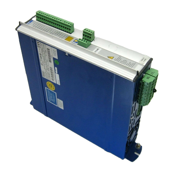
General Kollmorgen 0 2 . 9 9 — A . 4 . 0 2 8 . 6 / 1 0 Nameplate The nameplate depicted below is attached to the side of the servo amplifer. The information described below is printed in the individual fields. CONNECT-module Servo amplifier type Serial number…
-
Page 11: The Digital Servo Amplifiers Of The Servostar™ 600 Family
Kollmorgen General 0 2 . 9 9 I.4.2 The digital servo amplifiers of the SERVOSTAR™ 600 family Standard version 5 current ratings (1.5 A , 3 A , 6 A , 10 A , 14 A, 20 A) two instrument widths : 70 mm up to 10A rated current 100 mm for 14 up to 20A rated current wide range of rated voltage (3x230V –10% to 3x480V +10%)
-
Page 12: Digital Servo Amplifier Concept
General Kollmorgen 0 2 . 9 9 I.4.4 Digital servo amplifier concept Operation and parameter setting With the comfortable Seidel operator-software through the serial interface of a PC Direct operation by means of two keys on the servo amplifier and a 3-character LED display for status display in case of no PC available Fully programmable via RS232 interface Power section…
-
Page 13: Block Diagram
Kollmorgen General 0 2 . 9 9 — A . 4 . 0 3 1 . 1 / 2 8 Block diagram — A.4.031.1/28 SERVOSTAR™ 600 Installation-manual…
-
Page 14: Components Of A Servo System
General Kollmorgen 0 2 . 9 9 Components of a servo system Control / PLC 24V supply SERVOSTAR™ 600 fuses drive contactor terminals motor SERVOSTAR™ 600 Installation-manual…
-
Page 15: Technical Data Of The Servostar™ 600 Series
Kollmorgen General 0 2 . 9 9 Technical data of the SERVOSTAR™ 600 series SERVOSTAR™ Rated data -10% +10% Rated supply voltage 3 x 230V … 480V , 50 … 60 Hz Rated installed load for S1 operation Rated DC-link voltage 310 — 675 Rated output current (rms value, ±…
-
Page 16: Permissible Ambient Conditions, Ventilation, Mounting Position
General Kollmorgen 0 2 . 9 9 I.7.2 Permissible ambient conditions, ventilation, mounting position Storage temperature/humidity, ð VI.1 storage duration ð VI.1 Transport temperature / humidity Supply voltage tolerances -10% +10% Input power min 3x230V AC / max 3x 480V , 50 …
-
Page 17: Grounding System
Kollmorgen General 0 2 . 9 9 — A . 4 . 0 3 1 . 3 / 0 1 , 1 / 3 5 Grounding system AGND — ground for analog inputs/outputs, internal analog ground DGND — ground for digital inputs/outputs, optically isolated XGND —…
-
Page 18: Regen Circuit
General Kollmorgen 0 2 . 9 9 I.10 Regen circuit During braking with the aid of the motor, energy is fed back to the servo amplifier. This energy is converted into heat in the regen resistor. The regen resistor is switched into circuit by the regen circuit.
-
Page 19: Switch-On And Switch-Off Behaviour
Kollmorgen General 0 2 . 9 9 — A . 4 . 0 3 1 . 3 / 6 I.11 Switch-on and switch-off behaviour The diagram below illustrates the correct functional sequence for switching the servo amplifier on and off. If you are using the digital output function MAINS-BTB/RTO, you can find a diagram which is valid for this case in the “Operator Software”…
-
Page 20: Emergency Stop Strategies
General Kollmorgen 0 2 . 9 9 I.11.2 Emergency Stop strategies The Emergency Stop function is defined in EN 60204 (VDE 0113), Para. 9.2.5.4. Implementation of the Emergency Stop function : You can find wiring recommendations in our application note (available from february 1999) “Stop and Emergency Stop functions with SERVOSTAR™…
-
Page 21: Installation
Kollmorgen Installation 0 2 . 9 9 Installation II.1 Important instructions Protect the servo amplifier from impermissible stresses. In particular, do not let any components become bent or any insulation distances altered during transport and handling. Avoid contact with electronic components and contacts. Check the combination of servo amplifier and motor.
-
Page 22: Ii.2 Assembly
Installation Kollmorgen 0 2 . 9 9 — A . 4 . 0 3 1 . 4 / 1 5 II.2 Assembly Material : 2 or 4 hexagon socket screws to DIN 912, M5 Tool required : 4 mm Allen key — A.4.031.4/15 SERVOSTAR™…
-
Page 23: Ii.2.1 Dimensions Of Servostar™ 600
Kollmorgen Installation 0 2 . 9 9 — A . 4 . 0 3 1 . 4 / 1 4 II.2.1 Dimensions of SERVOSTAR™ 600 — A.4.031.4/14 SERVOSTAR™ 601/603/606/610 SERVOSTAR™ 614/620 SERVOSTAR™ 600 Installation-manual…
-
Page 24: Ii.3 Wiring
Installation Kollmorgen 0 2 . 9 9 II.3 Wiring Only professional staff who are qualified in electrical engineering are allowed to install the servo amplifier. The installation procedure is described as an example. A different procedure may be sensible or necessary, depending on the application of the equipment.
-
Page 25
Kollmorgen Installation 0 2 . 9 9 The following notes should assist you to carry out the installation in a sensible sequence, without overlooking anything important. In a closed switchgear cabinet. Observe Chapter I.7.2 . Site The site must be free from conductive or corrosive materials. For the mounting position in the cabinet ð… -
Page 26: Connection Diagram For Servostar™ 600
Installation Kollmorgen 0 2 . 9 9 — A . 4 . 0 3 1 . 1 / 2 II.3.1 Connection diagram for SERVOSTAR™ 600 — A.4.031.1/2 ð III.5.1 ð III.4.2 ð III.5.4 ð III.4.1 ð III.5.2 ð III.2 ð III.5.3 ð…
-
Page 27: Ii.3.2 Example Of Connections For Multi-Axis System
Kollmorgen Installation 0 2 . 9 9 — A . 4 . 0 3 1 . 1 / 1 9 II.3.2 Example of connections for multi-axis system — A.4.031.1/19 SERVOSTAR™ 600 Installation-manual…
-
Page 28: Ii.3.3 Pin Assignments For Servostar™ 600
Installation Kollmorgen 0 2 . 9 9 — A . 4 . 0 3 1 . 4 / 2 1 II.3.3 Pin assignments for SERVOSTAR™ 600 — A.4.031.4/21 SERVOSTAR™ 600 Installation-manual…
-
Page 29: Notes On Connection Techniques
Kollmorgen Installation 0 2 . 9 9 — A . 4 . 0 2 9 . 4 / 2 5 II.3.4 Notes on connection techniques II.3.4.1 Tool list Connector (Interconnectron), unit Tool Mat.NoS. hand crimp tool 69227 positioner 88173 RES-connector 12-pole, 6SM27…107 assembly spanner 85511 open-jaw spanner 22 a/f…
-
Page 30: Wiring Up A Subd-Connector With Shielding
Installation Kollmorgen 0 2 . 9 9 — A . 4 . 0 2 9 . 4 / 2 II.3.4.3 Wiring up a SubD-connector with shielding Example : resolver connector X2 — A.4.029.4/2 Strip off the outer covering over a length of about 25mm, taking care not to damage the shielding braid.
-
Page 31: Ii.3.4.4 Assembling The Resolver Connector (Motor End)
Kollmorgen Installation 0 2 . 9 9 — A . 4 . 0 2 9 . 4 / 6 II.3.4.4 Assembling the resolver connector (motor end) — A.4.029.4/6 Strip off the outer covering over a length of 22mm. Take care not to da- mage the shielding braid.
-
Page 32: Wiring Up The Motor Power Connector (Amplifier End)
Installation Kollmorgen 0 2 . 9 9 — A . 4 . 0 2 9 . 4 / 2 4 II.3.4.5 Wiring up the motor power connector (amplifier end) — A.4.029.4/24 Strip off the outer covering over a length of 70mm, without damaging the shielding braid.
-
Page 33: Wiring Up The Motor Power Connector (Motor End)
Kollmorgen Installation 0 2 . 9 9 — A . 4 0 2 9 . 4 / 9 II.3.4.6 Wiring up the motor power connector (motor end) — A.4029.4/9 Strip off the outer covering over a length of 40mm. Do not damage the shielding braid.
-
Page 34: Technical Data For Connecting Cables
Installation Kollmorgen 0 2 . 9 9 II.3.5 Technical data for connecting cables All the cables which we supply are shown in the table below. Further information on the chemical, mechanical and electrical characteristics of the cables can be obtained from out applications department. Insulation material Sheathing PUR (polyurethane, code 11Y)
-
Page 35: Ii.4 Operator Software
Kollmorgen Installation 0 2 . 9 9 II.4 Operator software II.4.1 General This chapter describes the installation of the operator software for the SERVOSTAR™ 600 digital servo amplifiers. We offer training and familiarisation courses on request. II.4.1.1 Use as directed The operator software is intended to be used for setting up and storing the operating parameters for the SERVOSTAR™…
-
Page 36: Hardware Requirements
Installation Kollmorgen 0 2 . 9 9 II.4.1.3 Hardware requirements The PC interface (X6, RS232) of the servo amplifier is connected to the serial interface of the PC by a null-modem cable (not a null-modem link cable !) (ð III.7). Connect / disconnect the interface cable only when the supply is switched off for both the PC and the servo amplifier.
-
Page 37: Interfaces
Kollmorgen Interfaces 0 2 . 9 9 — A . 4 . 0 3 1 . 1 / 2 1 , 2 5 Interfaces All important interfaces are shown in this Chapter. The precise location of the connectors and terminals can be seen in Chapter II.3.3. III.1 Power supply III.1.1…
-
Page 38: Iii.2
Interfaces Kollmorgen 0 2 . 9 9 — A . 4 . 0 3 1 . 1 / 1 7 , 1 8 III.2 Motor connection with brake (X9) Lead length £ 25m Lead length >25m For lead lengths above 25m the choke box 3YL-xx must be wired into the motor lead, close to the amplifier (please consult our applications department).
-
Page 39: Iii.4
Kollmorgen Interfaces 0 2 . 9 9 — A . 4 . 0 3 1 . 1 / 2 6 III.4 Feedback III.4.1 Resolver connection (X2) The motors of the 6SM series have 2-pole hollow-shaft resolvers built in as a standard. It is possible to connect 2, 4 or 6-pole resolvers to the SERVOSTAR™…
-
Page 40: Iii.4.2
Interfaces Kollmorgen 0 2 . 9 9 — A . 4 . 0 3 1 . 1 / 2 7 III.4.2 Encoder (X1) As an option, the 6SM series of motors can be fitted with a single-turn or multiturn sine-cosine encoder. This encoder is used by the SERVOSTAR™…
-
Page 41: Iii.5
Kollmorgen Interfaces 0 2 . 9 9 — A . 4 . 0 3 1 . 1 / 2 3 III.5 Control signals, monitor signals III.5.1 Analog setpoint inputs (X3) The servo amplifier is equipped with two differential inputs for analog setpoints which are freely programmable (with the aid of the macro-language, consult our applications department).
-
Page 42: Iii.5.2
Interfaces Kollmorgen 0 2 . 9 9 — A . 4 . 0 3 1 . 1 / 2 4 III.5.2 Digital setpoint inputs (X3) All digital inputs are electrically isolated through optocouplers. Technical characteristics — Reference ground is digital-GND (DGND, terminal X3/18) —…
-
Page 43: Iii.5.3
Kollmorgen Interfaces 0 2 . 9 9 — A . 4 . 0 3 1 . 1 / 2 0 III.5.3 Digital control outputs (X3) Technical characteristics — Reference ground is digital-GND (DGND, terminal X3/18) — All digital outputs are floating —…
-
Page 44: Iii.5.4
Interfaces Kollmorgen 0 2 . 9 9 — A . 4 . 0 3 1 . 1 / 2 2 III.5.4 Monitor outputs (X3) Technical characteristics — Reference ground is analog-GND (AGND, terminal X3/1 and X3/10) — Output resistance : 2.2kΩ Output voltage ±10V —…
-
Page 45: Iii.6
Kollmorgen Interfaces 0 2 . 9 9 — A . 4 . 0 3 1 . 1 / 1 1 III.6 Encoder emulations III.6.1 Incremental-encoder interface (X5) The incremental-encoder interface is part of the package supplied. Select the encoder function ROD (screen page “Encoder”). In the servo amplifier, the position of the motor shaft is calculated from the cylic-absolute signals of the resolver or encoder.
-
Page 46: Iii.6.2
Interfaces Kollmorgen 0 2 . 9 9 — A . 4 . 0 3 1 . 1 / 1 2 III.6.2 SSI-Interface (X5) The SSI interface (synchronous serial absolut-encoder emulation) is part of the package delivered. Select the encoder function SSI (screeen page “Encoder”). In the servo amplifier, the position of the motor shaft is calculated from the cyclic-absolute signals of the resolver or encoder.
-
Page 47: Iii.7
Kollmorgen Interfaces 0 2 . 9 9 — A . 4 . 0 3 1 . 1 / 1 3 , 1 4 III.7 RS232 interface, PC connection (X6) The setting of the operating, position control, and motion-block parameters, can be carried out on an ordinary commercial PC.
-
Page 48: Iii.8
Interfaces Kollmorgen 0 2 . 9 9 — A . 4 . 0 3 1 . 1 / 1 5 , 1 / 3 6 III.8 CANopen Interface (X6) The interface for connection to the CAN bus (default 500 kBaud). The integrated profile is based on the communication profile CANopen DS301 and the drive profile DSP402.
-
Page 49: Iii.9
Kollmorgen Interfaces 0 2 . 9 9 — A . 4 . 0 3 1 . 1 / 1 0 , 3 / 2 III.9 Interface for stepper-motor controls (X5) This interface can be used to connect the servo amplifier to a third-party stepper-motor controller. The parameters for the servo amplifier are set up with the aid of the operator software.
-
Page 50: Iii.10 Interface For Master-Slave Operation, Encoder Input (X5)
Interfaces Kollmorgen 0 2 . 9 9 — A . 4 . 0 3 1 . 1 / 1 6 , 3 / 2 III.10 Interface for master-slave operation, encoder input (X5) This interface can be used to link several SERVOSTAR™ 600 amplifiers together in master-slave operation.
-
Page 51: Commissioning
Kollmorgen Commissioning 0 2 . 9 9 Commissioning IV.1 Important notes Only professional personnel with extensive knowledge in the fields of electrical/ drive technology are allowed to commission the servo amplifier. The procedure for commissioning is described as an example. Depending on the application, a different procedure may be sensible or necessary.
-
Page 52
Commissioning Kollmorgen 0 2 . 9 9 The following instructions should help you to carry out the commissioning in a sensible order, without any hazards to people or machinery. ð II. Disconnect the servo amplifier from the supply. Check installation Inhibit 0V on terminal X3/15 (Enable) Enable signal… -
Page 53: Iv.2 Parameter Setting
Kollmorgen Commissioning 0 2 . 9 9 — A . 4 . 0 3 1 . 4 / 3 7 IV.2 Parameter setting A default parameter set is loaded into your servo amplifier at the factory. This contains valid and safe parameters for the current and speed controllers.
-
Page 54: Key Operation / Led Display
Commissioning Kollmorgen 0 2 . 9 9 — A . 4 . 0 3 1 . 3 / 4 IV.2.2 Key operation / LED display The structure of the operating menus is shown at the right of the picture, and the operation of the keypad on the front panel is shown below.
-
Page 55: Structure
Kollmorgen Commissioning 0 2 . 9 9 — A . 4 . 0 3 1 . 3 / 3 IV.2.2.2 Structure — A.4.031.3/3 IV.2.1 SERVOSTAR™ 600 Installation-manual…
-
Page 56: Iv.3 Error Messages
Commissioning Kollmorgen 0 2 . 9 9 IV.3 Error messages Errors which occur are shown in coded form by an error number in the LED display on the front panel.All error messages result in the BTB/RTO contact being opened, and the output stage of the amplifier being switched off (motor looses all torque).
-
Page 57: Accessories
Kollmorgen Accessories 0 2 . 9 9 — A . 4 . 0 1 2 . 4 / 3 2 Accessories External 24V DC supply for one servo amplifier — A.4.012.4/32 SERVOSTAR™ 600 Installation-manual…
-
Page 58: External 24V Dc Supply For Up To 7 Servo Amplifiers
Accessories Kollmorgen 0 2 . 9 9 — A . 4 . 0 1 2 . 4 / 3 3 External 24V DC supply for up to 7 servo amplifiers — A.4.012.4/33 SERVOSTAR™ 600 Installation-manual…
-
Page 59: External Regen Resistor Barxxx
Kollmorgen Accessories 0 2 . 9 9 — A . 4 . 9 4 7 . 4 / 2 2 External regen resistor BARxxx — A.4.947.4/22 SERVOSTAR™ 600 Installation-manual…
-
Page 60
Accessories Kollmorgen 0 2 . 9 9 This page has been deliberately left blank SERVOSTAR™ 600 Installation-manual… -
Page 61: Appendix
Kollmorgen Appendix 0 2 . 9 9 Appendix VI.1 Transport, storage, maintenance, disposal Transport : — only by qualified personnel — only in the manufacturer’s original recyclable packaging — avoid shocks — temperature –25 to +70°C, max. 20°C / hour rate of change —…
-
Page 62: Vi.2 Removing Faults
Appendix Kollmorgen 0 2 . 9 9 VI.2 Removing faults The table below should be regarded as a “First-aid” box. Depending on the conditions in your installation, there may be a wide variety of reasons for the fault. In multi-axis systems there may be further hidden causes of a fault. Our applications department can give you further assistance with problems.
-
Page 63
Kollmorgen Appendix 0 2 . 9 9 Fault possible causes measures to remove the cause of the fault — feedback connector not properly inserted — check connector message: — feedback cable is broken, crushed or — check cable feedback unit otherwise damaged message: —… -
Page 64: Vi.3 Glossary
Appendix Kollmorgen 0 2 . 9 9 VI.3 Glossary Clock Clock signal Common-mode voltage The maximum amplitude of a disturbance (on both inputs) which a differential input can eliminate CONNECT- modules Modules built into the servo amplifier, with integrated position control, which provide special versions of the interface for the connection to the higher-level control Continuous power of regen circuit Mean power which can be dissipated in the regen circuit…
-
Page 65
Kollmorgen Appendix 0 2 . 9 9 P-controller Control loop with purely proportional behaviour Phase shift Compensation for the lag between the electromagnetic and magnetic fields in the motor PID-controller Control loop with proportional, integral and differential behaviour PID-T2 Filter time constant for the speed controller output Position controller Regulates the difference between the position setpoint and the actual position to 0… -
Page 66
Appendix Kollmorgen 0 2 . 9 9 This page has been deliberately left blank. SERVOSTAR™ 600 Installation-manual… -
Page 67: Vi.4 Index
Kollmorgen Appendix 0 2 . 9 9 VI.4 Index Text Seite Text Seite 24V supply motor choke 20A ….58 connection example … . 27 5A .
-
Page 68
Vertri eb u n d Se rv i c e / Sa le s a nd Se rvi ce / Ag en ce e t S er vi ce s B u n d e s r e p u b l i k D e u t s c h l a n d / D ä…
- 17 Июн 2010
Подскажите , может кто сталкивался с сервоприводами и сервомоторами. Проблема такого плана, сервопривод включается и держится тормозам, как только пытаюсь дать обороты , срабатывает ошибка «фаза мотора». Пока мотор находится на тормозе смотрю все три фазы на выходе с сервопривода, две фазы относительно земли примерно 250 вольт, а одна 380. И это не зависимо как с фазированы провода от мотора. Разбираю привод , в нем стоит IGBT сборка BSM35GD120DN2E3224. Выпаиваю её, и проверяю ее на низких напряжениях, как проверяют обычный тиристор. Все вроде нормально. Но как она себя ведет при питании мотора? Может повесить на выход привода лампы вольт по 380? Или менять её не задумываясь?
- 17 Июн 2010
IGBT если нет явных замыканий.скорее всего целая.С лампочками врядли заработает .Фазы правильно надо подключать и проверить энкодер.Относительно какой земли меряешь?
- 17 Июн 2010
Измеряю на выходе привода. Фазы переберал, все тоже самое.
Добавлено 17-06-2010 12:14
Еще что интересно. Использую программу Drive. Когда не выбираю свой мотор, он становится в тормоз, а когда выбираю свой мотор AKM64K?, то срабатывает ошибка тормоз.
- 17 Июн 2010
zuenko сказал(а):
Фазы переберал, все тоже самое
А на двигателе нормальной маркировки нет?Сам драйвер вскрывал?Энкодер подключен правильно ?Может управление модулем стоит проверить?
- 17 Июн 2010
gnu,правильно писал,-проверь энкодер!Если энкодер,или резольвер,не в порядке,то привод ухoдит в разнос и срабатывает защита.С английским у тебя как?Если нормально,то давай свое «мыло»,закачаю хорошую книжку!
- 17 Июн 2010
Для начала озвуч ошибку которая выскакивает в оригинале и ее номер а не в переводе.В интернете есть много информации на них.Ну а дальше можно подумать.
- 17 Июн 2010
вега, О!Умная мысль
- 18 Июн 2010
Ваще,когда проблема с тормозами,он вешает ошибку «F18»,а когда пробой в кабеле,или коротыш в движке,то «F12″(Motor phase missing) Вaще,это хорошая шаробайка!Наверняка,на выходе кoза,или энкодер дуркует.
- 18 Июн 2010
Давайте попытаюсь сначала объяснить. Он сейчас снят с оборудования и лежит у меня на столе вместе с двигателем. Подключил к нему двигатель AKM64K, к разъему X6 ноут , X5 и X1 не используется, X2 — обратная связь от мотора. 24 вольта на X4. Запускаю программу Drive, в ней ни чего не меняю и не выбираю свой мотор. На приводе на X3 на 15 подаю 24 вольта. В программе нажимаю Enable. В приводе слышен тихий писк. Мотор стоит на тормозе. Напряжение замеряю на выходе привода относительно земли , на двух фазах одинаково 120 вольт, а на одной 350. Открываю осцилоскоп, ставлю скорость 100 rpm , нажимаю старт. Мотор дернулся на 40 градусов и сработала ошибка F12 Motor Fhase.
Сейчас в программе пробую выбрать свой мотор AKM64K. Срабатывает сразу ошибка F11 Brake.
Вот и пойми тут , мотор или привод. Другого сервомотора нет. А как можно еще проверить этот мотор или привод?
Мыло zyenko@gmail.com
- 18 Июн 2010
Ты можеш узнать с чего все началось?Меняли двигатель, кабель двигателя, кабель резольвера или просто по среди работы?В машине Х6 используется?Кстати F11(Cable break, short-circuit, short to ground) говорит про электромеханический тормоз. Он у тебя в двигателе есть?

|
Technical |
SERVOSTAR® 600 |
|
Systems |
|
Publication |
with Kollmorgen GOLDLINE™ |
|||
|
BH/MH Motors |
||||

SERVOSTAR® 600
INTRODUCTION
Kollmorgen SERVOSTAR® 600 Amplifier
•400 to 480 Volt Three Phase AC Input Power
•Resolver Feedback
•Integrated Power Supply
•Fully Digital Control
•CE, UL, cUL
The SERVOSTAR 600 amplifier is a compact, fully digital drive-amplifier designed to simplify installation, system setup, and system reliability.
FEATURES:
Servo Control
•Easy to tune servo loops
•Advanced sinewave commutation technology provides smooth, precise low-speed control and high speed performance
•Velocity loop bandwidths to 400 Hz
•DQ Current control increases high speed peak torque performance for faster cycle rates
•Space Vector Modulation reduces normal power stage switching loses
•Torque angle control enhances motor performance
•Fully digital control loops
•Compact and attractive rugged metal package for spacesaving, modern appearance — metal package minimizes electrical noise emmision & suceptability
•Command modes: Torque, Velocity, Position, Electronic Gearing Pulse Following, and Motion Task
•Five current ratings: 3, 6, 10, 14, and 20 amp RMS/phase continuous
•2 to 1 peak/continuous current rating (5 second at peak)
•Run time counter
Easy Connectivity
•Built in encoder equivalent output can eliminate the need for an additional position feedback device
•RS-232 Communication
•Unique multi-drop configuration allows a PC or PLC to communicate to multiple SERVOSTAR 600 amplifiers via single RS-232 connection
•SERVOSTAR 600’s versatile communication capabilities make it easy to integrate machine control data directly from the factory floor to your information system
•Analog ±10V, pulse/direction, master encoder, and serial port, I/O command options
Robust Design
•ESD rugged circuit design and fully metallic enclosure
•Full protection against short circuit, overvoltage, undervoltage, heatsink overtemperature, motor overtemperature, overspeed, overcurrent, and feedback loss
•UL , cUL listed, and CE
•Built-in line filter for CE
•Flash memory
Windows Start-up Environment
•Graphical environment simplifies set up
•PC “Oscilloscope” for measuring real-time motion performance
•Interactive MOTIONTASK Programming
Configurable I/O
•2 separate analog inputs (14 and 12 bit resolution) configurable to 6 different command modes
•2 analog outputs
•4 digital inputs
•2 digital outputs
•I/O can be configured to a variety of functions to customize the SERVOSTAR 600 to individual machines
I/O Option Card (see page 5)
•Adds 14 additional digital inputs and 8 digital outputs
•All I/O are optically isolated
•Simple plug in to top face of Amplifier
Regenerative Power Sharing
• Patented circuitry allows the DC bus from two or more amplifiers to be connected together allowing regen power to be shared among multiple drives
Built in Parameter Unit
•Perform basic drive set up without the need for a PC
•Provides diagnostic information
•Allows motor selection from parameters store in memory
Built in Safety Relay
•Switches off the power stage to ensure personnel safety and prevents an unintended restart of the drive, even in the event of a fault
•Allows DC bus to remain on

SERVOSTAR 600
INTRODUCTION
Motion Capabilities
The SERVOSTAR 600 can be configured to perform motion control that normally requires a fully programmable drive with a motion language. With the SERVOSTAR 600 there is no programming language to learn; the user only “fill in the blanks” to create common motion tasks
•Up to 180 motion task can be stored in permanent memory
•Motion Tasked can be linked together.
•10 types of homing
•Speed profile/registration control
•Adjustable S curve acceleration
•Absolute and relative (index) moves
•Linking of motion task (sequencing)
•Adjustable Following-Error window
•Adjustable window for the In Position signal
Linked motion tasks are started:
•Immediately upon reaching a targeted position
•Digital Input upon reaching the targeted position
•A PresetTime Delay after the targeted position is reached
Motion Examples
INCREMENTAL MOVE
Velocity
Time
ABSOLUTE MOVE
Velocity
Position
ELECTRONIC GEARING 5:1 (MASTER/SLAVE)
Velocity
Time
MACRO MOVE
Velocity
Application Examples
•material handling
•bottle making
•packaging
•soft positioning
•robot
•conveyor belt controlling
•fast positioning
•special cleaning process
•part selection
•glass processing
•robot
•wirepuller
•textile industry
•printing
•electronics
•web converting
•cut to length
Time

SERVOSTAR 600
CONNECTOR INFORMATION
X5 Encoder Equivalent Output
1
PGND
6
B+ (DATA)
2
Motor +
7
B- (/DATA)
3
Motor —
8
+5V
4
A- (CLK)
X6 PC 9 N.C.
5
A+ (/CLK)
1
+8V
6
CANL
2
RxD
7
3
TxD
8
4
N.C.
9
CANH
5
PGND
X4 24V INPUT
1+24V 1
2+24V 2
X10 MOTOR
DISCONNECT
RELAY
1KSO1 1
2KSO2 2
3KSI- 3
4KSI+ 4
Connectors underneath:
|
XOB |
X8 RREGEN |
Brake- |
X9 motor/brake |
W2 |
|||||||||
|
L1 |
L2 |
L3 |
PE |
R- |
+R |
R |
n.c. |
Brake+ |
PE |
U2 |
V2 |
||
|
B |
Bint |
BEXT |
|||||||||||
|
1 |
2 |
3 |
4 |
1 |
2 |
3 |
4 |
1 |
2 |
3 |
4 |
5 |
6 |
|
XOA |
X7 DC-circuit |
||||||||||||
|
L1 |
L2 |
L3 |
PE |
+DC |
-DC |
+DC |
-DC |
||||||
|
1 |
2 |
3 |
4 |
1 |
2 |
3 |
4 |
X2 RESOLVER
5
R2
9
R1
4
S3
8
S1
3
S4
7
S2
2
THERMOSTAT
6
THERMOSTAT
1
SHIELD
X3 I/O
1AGND
2BTB/RTO
3BTB/RTO
4SW/SETP.1+
5SW/SETP.1-
6SW/SETP.2+
7SW/SETP.2-
8MONITOR1
9MONITOR2
10AGND
11DIGITAL-IN1
12DIGITAL-IN2
13PSTOP
14NSTOP
15ENABLE
16DIGITAL-OUT1
17DIGITAL-OUT2
18DGND

SERVOSTAR 600
I/O OPTION CARD
CONNECTOR POSITION
X11
The I/O option card is an extremely economical way of operating servo controllers under position control for simple automation tasks.
14 additional digital inputs permit the selection and start of the motion tasks that are stored in the motion-task memory of the SERVOSTAR® 600. All the important functions for the position controller that is integrated into the servo controller can thus be operated from a small, independent control system.
8 digital outputs report the status of the drive to the higher-level control.
CONNECTOR ASSIGNMENTS
|
Connector |
Connector |
||||||
|
X11A |
X11B |
||||||
|
Terminal |
Fn. |
Description |
Terminal |
Fn. |
Description |
||
|
1 |
In |
A0 |
1 |
In |
MT_Restart |
||
|
2 |
In |
A1 |
2 |
In |
Start_MT |
||
|
3 |
In |
A2 |
3 |
Out |
InPos |
||
|
4 |
In |
A3 |
4 |
Out |
Next-InPos |
||
|
5 |
In |
A4 |
5 |
Out |
Sfault |
||
|
6 |
In |
A5 |
6 |
Out |
PosReg1 |
||
|
7 |
In |
A6 |
7 |
Out |
PosReg2 |
||
|
8 |
In |
A7 |
8 |
Out |
PosReg3 |
||
|
9 |
In |
Reference |
9 |
Out |
PosReg4 |
||
|
10 |
In |
Sfault_clear |
10 |
Out |
Reserve |
||
|
11 |
In |
Start_MT Next |
11 |
Sup. |
24V DC |
||
|
12 |
In |
Start_Jog v=x |
12 |
Sup. |
I/O-GND |
||

SERVOSTAR 600
AMPLIFIER SPECIFICATIONS
Electrical characteristics
•Closed loop velocity bandwidth up to 400 Hz
•Motor current ripple frequency 16 kHz
•Switching frequency: 8 kHz
•Long term speed regulation (0.01%)
•Position loop update rate 250 µs (4 kHz)
•Velocity loop update rate 250 µs (4 kHz)
•Commutation update rate 62.5 µs (16 kHz)
•SVM Current loop update rate 62.5 µs (16 kHz)
Fault protection
•Output phase to phase and phase to ground short circuit protection
•Overvoltage
•Undervoltage
•Overtemperature (motor and amplifier)
•Overspeed
•Overcurrent
•Feedback loss
•Foldback
•Supply loss
•Excessive position error
Environmental
•Operation range
—Ambient 0 to 45°C (derated above ambient up to 55˚C)
—Storage -25°C to 55°C
•Humidity (non-condensing) max 85%
Velocity Loop Compensation
•PI Plus controller (PDFF Format) or PI controller
•Field tunable and digital repeatability
Position Feedback For User (Encoder Equivalent Output Port)
•Configurable to Encoder Equivalent (ROD) or SSI format
•Encoder Equivalent (ROD): A Quad B with Marker (zero) pulse, RS-485 driver
•SSI (serial synchronous interface): max clock frequency is 1.5 Mhz, RS-485 driver
•Programmable resolution
I/O Extension Card (Option)
•Field Installable
•14 Digital Inputs 24V, PLC-compatible
•8 Digital Outputs 24V, PLC-compatible
•24V PLC Interface
Communications
• RS-232 Interface
Operational modes
•Torque control — from analog or digital command
•Velocity control — from analog or digital command
•Pulse following
•Gearing from quad encoder input
•Motion Task
•Serial Commands
Diagnostics
•3 digit Seven segment LED display
•Error history log
•Internal variable monitoring
•PC scope
Motor Feedback
|
Position Loop Compensation |
• Resolver |
|
• Proportional loop with Feed Forward |
|
|
Motor Brake Control |
|
|
Analog I/O |
• 24V optional holding brake in the motor can be controlled directly by |
|
• 2 Configurable Inputs: ±10V, 12 and 14 bit resolution |
the SERVOSTAR 600 |
|
• 2 Configurable Outputs: ±10V, 10 bit resolution |
|
|
Power Inputs |
|
|
Digital I/O |
• 400 to 480VAC 3phase, 50 or 60 Hz, built in line filter for |
|
• 4 Configurable Inputs: 24 volts, PLC-compatible |
CE requirements |
|
• 2 Configurable Outputs: 24 volts (open collector), PLC-compatible |
• 24 VDC @ 1 amp (3 amps with brake) For Logic |
|
• Remote enable Input: 24V, PLC-compatible |
|
|
Power Regeneration Options |
|
|
Drive Status Relay (BTB/RTO) |
• Internal |
|
• Contact closure rated for 0.5 amps, 24 Volt |
• External — using BAR housed resistors |
|
• Bus Sharing — Distributes regen power among multiple amplifiers |
|
|
Pulse or Master/Slave Input |
|
|
• Pulse command: pulse/direction or quadrature encoder format |
Built in Parameter Unit |
|
• RS-485 receivers |
• Displays drive status information |
|
• Up to 16 slave amplifiers can be connected together |
• Parameters: Drive Address, baud rate, Velocity loop tuning, Motor |
|
• Input ratio is configurable |
type, Position output information format, brake, regen type |
Amplifier Ratings
|
Model |
Output Continuous |
Output Peak |
Internal Power |
AC Input |
Rated |
Continuous |
Continuous |
|
Current Per Phase |
Current Per |
Dissipation |
Line |
Input |
Internal |
External |
|
|
(RMS/phase) |
Phase |
(Watts) |
Voltage |
Power (KVA) |
Regen Power |
Regen Power |
|
|
(5 sec) |
(3 phase) |
@480 V |
(Watts) |
(Watts) |
|||
|
S603 |
3 |
6 |
40 |
400-480 |
2.3 |
80 |
500 |
|
S606 |
6 |
12 |
60 |
400-480 |
4.6 |
200 |
1,500 |
|
S610 |
10 |
20 |
90 |
400-480 |
8.1 |
200 |
1,500 |
|
S614 |
14 |
28 |
160 |
400-480 |
11.6 |
200 |
1,500 |
|
S620 |
20 |
40 |
200 |
400-480 |
16.6 |
200 |
1,500 |
|
6 |
KOLLMORGEN • keyfaith • 0755-83288220 |

SERVOSTAR 600
DIMENSIONS/ORDERING INFORMATION
Resistive Regeneration Sizing
Shunt regeneration is required to dissipate energy that is pumped back into the DC bus during load deceleration. The amount of shunt regeneration required is a function of the sum of simultaneously decelerating loads. The loads need to be defined in terms of system inertia, maximum speed, and deceleration time. In addition, the duty cycle must be known. Application Note AS6000H details a calculation method to determine proper regeneration sizing.
G
|
Model |
Watts |
Ohms |
Amplifiers |
A |
B |
C |
D |
E1 |
E2 |
F |
G |
|
BAR-250 |
250 |
33 |
S603, S606, S610 |
330(12.99) |
390(15.35) |
412(16.22) |
66(2.60) |
44(1.73) |
35(1.38) |
4,5×9(.20x.35) |
77(3.03) |
|
BAR-500 |
500 |
33 |
S603, S606, S610 |
400(15.75) |
426(16.77) |
486(19.13) |
92(3.62) |
64(2.52) |
64(2.52) |
6,5×9(.20x.35) |
120(4.72) |
|
BAR-1500 |
1500 |
33 |
S606, S610 |
500(19.69) |
526(20.71) |
586(23.07) |
185(7.28) |
150(5.91) |
150(5.91) |
6,5×9(.20x.35) |
120(4.72) |
SERVOSTAR 600 DIMENSIONS
S603/06/10
265 (10.4) with connector: 273 (10.7)
325
(12.8)
275
(10.8)
|
DIM. “ A” |
|
|
3 AMP |
70 (2.8) |
|
6 AMP |
70 (2.8) |
|
10 AMP |
70 (2.8) |
|
14 AMP |
100 (3.9) |
|
20 AMP |
120 (4.7) |
«A»
Dimensions in mm (inches)
|
KOLLMORGEN • keyfaith • 0755-83288220 |
7 |

|
MOTIONLINK |
SERVOSTAR 600 |
||
|
ADDITIONAL FUNCTIONS |
|||
MOTIONLINK® for Windows takes the fear out of setting up a servo system. Designed for the novice as well as the advanced user, MOTIONLINK lets users quickly set-up and fine tune system performance.
PC Oscilloscope:
For closely evaluating system performance MOTIONLINK includes the functionality of an oscilloscope. You can very easily excite the load then review performance graphically on your computer screen.
Tuning:
Velocity and position loop tuning is straight forward, allowing the novice user to achieve the best machine performance.
Direct Terminal Mode:
This mode turns your computer into a “dumb terminal.” Variables or parame ters can be monitored and changed using the SERVOSTAR 600’s command language. This mode is ideal for advanced users who want to get directly in the “heart” of the SERVO STAR 600.
Monitor Mode:
Allows you to monitor key operation variables. Speed, torque, and other variables can be viewed in real PSEUDO time in linear gauge format.
Auto Set-up:
MOTIONLINK auto set-up environment walks even the first time user through line voltage, motor, operation mode and load tuning to make system configuration friendly and fast.
Configuring I/O:
Inputs & Outputs are configurable to a wide variety of functions to configure the SERVOSTAR 600 to individual machine needs.
|
MOTIONLINK has many other features including: |
• |
Saving drive configuration to disk |
• |
Setting acceleration amps |
|
• |
Activating position limits |
• |
Limiting max speed or torque |
|
|
• |
Displaying amplifier status |
|||
|
8 |
KOLLMORGEN • keyfaith • 0755-83288220 |

|
MOTIONLINK |
|||||
|
CONFIGURABLE AND READABLE FUNCTIONS |
|||||
|
Basic Set Up |
Velocity Control |
Motion Homing/Jogging |
|||
|
• |
Input Power |
• Speed Command Scaling |
• Direction |
||
|
• |
Main Phase Missing |
• Speed Command Ramp (Accel) |
• Homing Type |
||
|
• |
Max Regen Power |
• Speed Command Ramp (Decel) |
• Reference Offset |
||
|
• Internal or External Regen Resistor |
• Maximum Speed |
• Start Command |
|||
|
• Drive Name and Serial No * |
• Proportional Gain |
• Jog Command |
|||
|
• |
Run Time * |
• Integral Time Constant |
• Homing Velocity |
||
|
• |
Firmware Version * |
• Feedback Filter |
• Jog Velocity |
||
|
• |
Hardware Version * |
• Motion direction |
|||
|
Drive Operation Modes |
Current Control |
Communications |
|||
|
• |
Digital Speed |
• Current Command Scaling |
• |
RS-232 from PC |
|
|
• |
Analog Speed |
• Current Foldback |
• |
Drive Address |
|
|
• |
Digital Torque |
• Cont Drive Current |
• Message Types from Drive |
||
|
• |
Analog Torque |
• Peak Drive Current |
• |
Prompt Configuration |
|
|
• |
Electronic Gearing |
• Proportional Gain |
• |
Scan |
|
|
• |
External Position Control |
• Integral Time Constant |
|||
|
• |
Internal Position — MotionTasks |
||||
|
Digital Scope Tool |
Motor Configuration |
Position Output (Motor) |
|||
|
• Record real time data |
• |
Motor Name and Number * |
• Format: Off, Encoder equivalent |
||
|
• Display on PC Oscilloscope |
• |
Motor Continuous Current |
output or SSI format |
||
|
• Start Current Move |
• |
Motor Peak Current |
Encoder Equivalent Output |
||
|
• Start Jog Move |
• |
Motor Inductance |
• Resolution of Encoder Equiv Output |
||
|
• Start Position Move |
• |
Motor Poles |
• Marker Pulse Offset |
||
|
• Record Start |
• |
Motor Max Speed |
SSI |
||
|
• Adjust Trigger |
• Motor Brake (with or without) |
• Baud rate of SSI Output |
|||
|
• Recording in Process * |
• |
Motor Adaptive Gain |
• Format type (binary or gray code) |
||
|
• Cancel Recording |
• |
Motor Speed Angle Advance |
• Standard or Inverted Clock |
||
|
• Recording Done * |
• |
Motor Torque Angle Advance |
• Input Edge Positive or Negative |
||
|
• Transmit Data to PC Oscilloscope |
|||||
|
Feedback Configuration |
Drive Status |
Position Control |
|||
|
Resolvers: |
• Actual Error * |
• Proportional Gain |
|||
|
• Number of Poles |
• Actual Warning * |
• Integral Action Time |
|||
|
• Resolver-zero offsetting |
• Last 10 Errors * |
• Feed Forward |
|||
|
• Resolver Bandwidth |
• Rate of Occurrence * |
• Following Error * |
|||
|
• Feedback Gain |
• Drive Reset Command |
||||
|
Drive Monitoring |
Others |
Motion-Gear Mode |
|||
|
• Regen Wattage * |
• Stop Drive |
• GearMode Type: |
|||
|
• Actual Position (within one rev) * |
• Drive Enable |
• Encoder Follower |
|||
|
• Actual Position * |
• Drive Disable |
• Pulse Follower |
•Actual Speed *
•Command Speed *
•Current Foldback Level *
•Drive Temperature *
•Heatsink Temperature *
•Effective Current *
•D Current Component *
•Q Current Component *
•Analog Commands *
•DC Bus voltage *
*READ ONLY
|
KOLLMORGEN • keyfaith • 0755-83288220 |
9 |
 Loading…
You can only view or download manuals with
Sign Up and get 5 for free
Upload your files to the site. You get 1 for each file you add
Get 1 for every time someone downloads your manual
Buy as many as you need
Table of Contents for Danaher Motion SERVOSTAR S600:
-
www.DanaherMotion.com SERVOSTAR ® S600 Electronic Gearing and Software User Interface This Product Note describes how gearing works on the SERVOSTAR ® S600. It begins with a general discussion of gearing and continues with details on hardware and software set up. This document only describes the software setup for gearing using the Software User Interface for the SERVOSTAR S600. How Electronic Gearing Works Electronic gearing provides a position command to a drive that depend
-
Document Number: P-SS-004-09 Rev 5 Old Numbers (AS6007H, A-SS-004-20208) Revised 11/20/2003 www.DanaherMotion.com Page 8 Multiple Slaves One master signal can drive many slaves. The limitations are that the master must have the current available to drive all inputs. Refer to the manufacturer’s information on the encoder to ensure that sufficient current is available to supply multiple electronically geared drives. If a SERVOSTAR S600 is being used as the master, it can drive up to 16 slave axes. SER
-
Document Number: P-SS-004-09 Rev 5 Old Numbers (AS6007H, A-SS-004-20208) Revised 11/20/2003 www.DanaherMotion.com Page 9 Software Setup The following section describes the software setup for gearing using the Software User Interface for the SERVOSTAR S600. The Software User Interface provides a user-friendly graphical interface and terminal for the setup, monitoring, and troubleshooting of the SERVOSTAR S600. When setup is complete, save your settings to the EEPROM. Otherwise, all settings are
-
Document Number: P-SS-004-09 Rev 5 Old Numbers (AS6007H, A-SS-004-20208) Revised 11/20/2003 www.DanaherMotion.com Page 11 To access the Gearing dialog box, click Position in the Amplifier dialog box (Figure 11). Click Gearing, located near the bottom-right of the displayed Position dialog box (Figure 12). From the Gearing dialog box, select the appropriate value of GEARMODE from the Gearing Mode drop- down box at the
-
Document Number: P-SS-004-09 Rev 5 Old Numbers (AS6007H, A-SS-004-20208) Revised 11/20/2003 www.DanaherMotion.com Page 16 Set the Offset of Analog Input 2 (ANOFF2) By using the analog offset (ANOFF2), you can shift the range across which the gear ratio is modified. For example, setting ANOFF2 = 5000 mV, an input of –5V generates the nominal gear ratio, +10 V generates 1.5 * GEARI/GEARO, and –10 V produces a ratio of 0.5 * GEARI/GEARO. By setting the offset to a negative value, cause the g
-
Document Number: P-SS-004-09 Rev 5 Old Numbers (AS6007H, A-SS-004-20208) Revised 11/20/2003 www.DanaherMotion.com Page 7 Figure 8: Step/Direction Encoder Format Some encoders provide a single channel output. If you are using such an encoder, use the step/direction format. Connect the output channel to the step input and tie the direction channel either high or low, as is appropriate for the application requirements. • Sine Encoder Format Sine encoders provide two channels in quadrature. This is
-
Document Number: P-SS-004-09 Rev 5 Old Numbers (AS6007H, A-SS-004-20208) Revised 11/20/2003 www.DanaherMotion.com Page 3 Multi-pulse generator/ Handwheel input SERVOSTAR S600 Encoder input Resolver/ sine encoder feedback Electronically- geared drive Electronically- geared motor Operator control panel Figure 3: Following a Potentiometer Following a Pulse/Direction Signal For some applications, it is useful for a servomotor to follow a pulse or direction input. For example, pulse and direction inputs are
-
Document Number: P-SS-004-09 Rev 5 Old Numbers (AS6007H, A-SS-004-20208) Revised 11/20/2003 www.DanaherMotion.com Page 15 Select the Analog Configuration (ANCNFG = 6) To use analog gearing, set the analog configuration to 6. To do this, click Analog I/O on the Amplifier dialog box (Figure 11). From the displayed Analog I/O dialog box (Figure 16), select 6. Analog Gearing from the Setp. Function drop-down box. Alternatively, set ANCFG to 6 in the terminal window.
-
Document Number: P-SS-004-09 Rev 5 Old Numbers (AS6007H, A-SS-004-20208) Revised 11/20/2003 www.DanaherMotion.com Page 12 Selecting Velocity or Position Control (EXTPOS) Select whether you want the encoder input to represent a position command or a velocity command. For most applications, the setting is a position command. In some applications, the encoder input may represent a velocity command. The most common example of this is when a multi-pulse ge
-
Document Number: P-SS-004-09 Rev 5 Old Numbers (AS6007H, A-SS-004-20208) Revised 11/20/2003 www.DanaherMotion.com Page 14 This example assumes that the input encoder resolution (ENCIN) accurately represents the input encoder resolution. If not, the formula must be modified: VELOCITY SLAVE = VELOCITY MASTER * (GEARI/GEARO) * (Encoder resolution/ENCIN) For example, suppose you have a 500-line encoder w
-
Document Number: P-SS-004-09 Rev 5 Old Numbers (AS6007H, A-SS-004-20208) Revised 11/20/2003 www.DanaherMotion.com Page 6 Most optical encoders provide 0 to 5 VDC signals. The encoder emulation output from another (master) SERVOSTAR S600 are also 0 to 5 VDC signals and should be brought into Connector X5. A SERVOSTAR S600 cannot simultaneously take 0 to 5 VDC connections into Connector X5 and provide encod
-
Document Number: P-SS-004-09 Rev 5 Old Numbers (AS6007H, A-SS-004-20208) Revised 11/20/2003 www.DanaherMotion.com Page 4 SERVOSTAR S600 Encoder input Resolver/ sine encoder feedback Electronically- geared drive Electronically- geared motor SERVOSTAR S600 Resolver/ sine encoder feedback Master drive Master motor Encoder emulation output Slave analog input (to adjust gear ratio in real time) Analog input 2 Master analog input (for command speed) Analog
-
Document Number: P-SS-004-09 Rev 5 Old Numbers (AS6007H, A-SS-004-20208) Revised 11/20/2003 www.DanaherMotion.com Page 10 Selecting the Gearing Mode (GEARMODE) Select the gearing mode (GEARMODE) based on the hardware used for the encoder input. Currently, there are six choices: GEARMODE Encoder Input Voltage Levels and Format 0 Digital quadrature format with 0 to 24 VDC Inputs (Connector X3). 1 Step/direction format with 0 to 24 VDC
Questions, Opinions and Exploitation Impressions:
You can ask a question, express your opinion or share our experience of Danaher Motion SERVOSTAR S600 device using right now.