– Printer model: Mutoh RJ900C DraftStation
– Mutoh RJ900C DraftStation Error Code List and description errors:
- Code:
- Display: Cover open
- Description: Front cover is open.
- Troubleshooting Guides: 1. Is cover sensor assembly loose? Tighten cover sensor assembly screws.
- Code: E001
- Display: E001 error DRAM
- Description: Standard DRAM error: Abnormal condition in standard memory mounted on main board assembly
- Troubleshooting Guides: Main board assembly may be defective. Replace main board assembly.
- Code: E016-00
- Display: E016 error CPU Err [00]
- Description: Interruption exception error: Abnormal condition in interruption process.
- Troubleshooting Guides: 1. Check AC power supply and plotter surrounding equipment. 2. Check reappearance by turning ON/OFF the machine power several times. Make sure to perform this check repeatedly even if no problems seem to be present. (Make the same condition as user’s.) Contact our customer support center. 3. Check serial number of the plotter. 4. Main board assembly may be defective. • Contact our customer support center. • Replace main board assembly.
- Code: E016-02
- Display: E016 error CPU Err [02]
- Description: Command border exception/TLB exception (load or command fetch) error: Abnormal condition in command border. Or TLB exception in data load or command fetch.
- Troubleshooting Guides: 1. Check AC power supply and plotter surrounding equipment. 2. Check reappearance by turning ON/OFF the machine power several times. Make sure to perform this check repeatedly even if no problems seem to be present. (Make the same condition as user’s.) Contact our customer support center. 3. Check serial number of the plotter. 4. Main board assembly may be defective. • Contact our customer support center. • Replace main board assembly.
- Code: E016-03
- Display: E 016 error CPU Err [03]
- Description: Data border exception/TLB exception (store) error: Abnormal condition in data border. Or TLB exception in data storing.
- Troubleshooting Guides: 1. Check AC power supply and plotter surrounding equipment. 2. Check reappearance by turning ON/OFF the machine power several times. Make sure to perform this check repeatedly even if no problems seem to be present. (Make the same condition as user’s.) Contact our customer support center. 3. Check serial number of the plotter. 4. Main board assembly may be defective. • Contact our customer support center. • Replace main board assembly.
- Code: E016-04
- Display: E 016 error CPU Err [04]
- Description: Address exception error (load or command fetch): Address error in command load or fetch.
- Troubleshooting Guides: 1. Check AC power supply and plotter surrounding equipment. 2. Check reappearance by turning ON/OFF the machine power several times. Make sure to perform this check repeatedly even if no problems seem to be present. (Make the same condition as user’s.) Contact our customer support center. 3. Check serial number of the plotter. 4. Main board assembly may be defective. • Contact our customer support center. • Replace main board assembly.
- Code: E016-05
- Display: E 016 error CPU Err [05]
- Description: Address exception error (store): Address error in saving process.
- Troubleshooting Guides: 1. Check AC power supply and plotter surrounding equipment. 2. Check reappearance by turning ON/OFF the machine power several times. Make sure to perform this check repeatedly even if no problems seem to be present. (Make the same condition as user’s.) Contact our customer support center. 3. Check serial number of the plotter. 4. Main board assembly may be defective. • Contact our customer support center. • Replace main board assembly.
- Code: E016-06
- Display: E 016 error CPU Err [06]
- Description: Address exception error (command fetch): Address error in command loading or storing
- Troubleshooting Guides: 1. Check AC power supply and plotter surrounding equipment. 2. Check reappearance by turning ON/OFF the machine power several times. Make sure to perform this check repeatedly even if no problems seem to be present. (Make the same condition as user’s.) Contact our customer support center. 3. Check serial number of the plotter. 4. Main board assembly may be defective. • Contact our customer support center. • Replace main board assembly.
- Code: E016-07
- Display: E 016 error CPU Err [07]
- Description: Bus exception error (load or store): Bus error in command loading or storing
- Troubleshooting Guides: 1. Check serial number of the plotter. 2. Main board assembly may be defective. • Contact our customer support center. • Replace main board assembly.
- Code: E016-08
- Display: E 016 error CPU Err [08]
- Description: System call exception error: Abnormal condition in system call
- Troubleshooting Guides: 1. Check serial number of the plotter. 2. Main board assembly may be defective. • Contact our customer support center. • Replace main board assembly.
- Code: E016-09
- Display: E 016 error CPU Err [09]
- Description: Break point exception error: Abnormal condition in break point
- Troubleshooting Guides: 1. Check serial number of the plotter. 2. Main board assembly may be defective. • Contact our customer support center. • Replace main board assembly.
- Code: E016-10
- Display: E 016 error CPU Err [10]
- Description: Reserved command exception error: Abnormal condition in reserved command
- Troubleshooting Guides: 1. Check serial number of the plotter. 2. Main board assembly may be defective. • Contact our customer support center. • Replace main board assembly.

- Code: E016-11
- Display: E 016 error CPU Err [11]
- Description: Coprocessor disabled exception error: Abnormal condition in coprocessor
- Troubleshooting Guides: 1. Check serial number of the plotter. 2. Main board assembly may be defective. • Contact our customer support center. • Replace main board assembly.
- Code: E016-12
- Display: E 016 error CPU Err [12]
- Description: Arithmetic overflow exception error: Overflow occurs
- Troubleshooting Guides: 1. Check AC power supply and plotter surrounding equipment. 2. Check reappearance by turning ON/OFF the machine power several times. Make sure to perform this check repeatedly even if no problems seem to be present. (Make the same condition as user’s.) 3. Check serial number of the plotter. • Contact our customer support center. 4. Main board assembly may be defective. • Replace main board assembly.
- Code: E016-32
- Display: E 016 error CPU Err [32]
- Description: Watchdog time-out exception error: Time-out in watchdog
- Troubleshooting Guides: 1. Check AC power supply and plotter surrounding equipment. 2. Check reappearance by turning ON/OFF the machine power several times. Make sure to perform this check repeatedly even if no problems seem to be present. (Make the same condition as user’s.) 3. Check serial number of the plotter. • Contact our customer support center. 4. Main board assembly may be defective. • Replace main board assembly.
- Code: E016-33
- Display: E 016 error CPU Err [33]
- Description: Abort error: Process aborted
- Troubleshooting Guides: 1. Check AC power supply and plotter surrounding equipment. 2. Check reappearance by turning ON/OFF the machine power several times. Make sure to perform this check repeatedly even if no problems seem to be present. (Make the same condition as user’s.) 3. Check serial number of the plotter. • Contact our customer support center. 4. Main board assembly may be defective. • Replace main board assembly.
- Code: E065
- Display: E065 error X motor
- Description: Abnormal condition in PF motor (X-axis) during plotter operation. Displayed if the difference between motor command value and feedback from encoder is large.
- Troubleshooting Guides: 1. Check error history from ‘Test: Elec.’ of self-diagnosis function. 2. Set the number of endurance running cycles to 50 or more from ‘Life: PF motor’ of selfdiagnosis function, and check if ‘X motor error’ occurs. 3. Check ‘Encoder: PF’ from ‘Test: Encoder’ of selfdiagnosis function. 4. Check if Main Power Board normally supplies DC24V. 5. PF motor assembly may be defective. 6. Main board assembly may be defective. – Check connection of following main board assembly connectors. • PF motor cable assembly connector: J107 • PF_ENC assembly connector: J129 • If NG, check connection of main board assembly connector: J129. • Replace PF motor assembly. • Replace main board assembly.
- Code: E066
- Display: E066 error Y motor
- Description: Abnormal condition in CR motor (Yaxis) during plotter operation. Displayed if the difference between motor command value and feedback from encoder is large.
- Troubleshooting Guides: 1. Check error history from ‘Test: Elec.’ of self-diagnosis function. 2. Move carriage in both directions while the plotter is turned off, and check if there is any position where carriage does not move smoothly. 3. Set the number of endurance running cycles to 50 or more from ‘Life: CR motor’ of selfdiagnosis function, and check if ‘Y motor error’ occurs. – • Clean and lubricate CR rail roller guide. • Check connection of following connectors. Main board: • CR motor assembly connector: J106 • CR cable connector: J110 – J114 CR board: • CR cable connector: J201 – J205 • TF_ENC assembly connector: J210 4. Check if T fence is contaminated or worn out. • If grease or dust collect: Wipe fence with a dry cloth. • If ink deposit presents: Wipe it off with cloth dampened with neutral detergent. • If contamination or deposit is too heavy: Replace T fence. 5. Check ‘Y Encoder’ from ‘Test: Encoder’ of selfdiagnosis function. a) If NG: Check following cable connection. • CR board assembly connector J210 b) Replace following parts. • T fence • CR motor assembly • CR board assembly • CR cable • Replace main board assembly. 6. Main board assembly may be damaged.
- Code: E067
- Display: E067 error X encoder
- Description: Abnormal condition in media feed amount (Xaxis) during plotter operation. Displayed if there is no feedback from encoder.
- Troubleshooting Guides: 1. Check error history from ‘Test: Elec.’ of self-diagnosis function. 2. Set the number of endurance running cycles to 50 or more from ‘Life: PF motor’ of selfdiagnosis function, and check if ‘X motor error’ occurs. 3. Check ‘Encoder: PF’ from ‘Test: Encoder’ of selfdiagnosis function. 4. Check if Main Power Board normally supplies DC24V. 5. PF motor assembly may be defective. 6. Main board assembly may be defective. – Check connection of following main board assembly connectors. • PF motor cable assembly connector: J107 • PF_ENC assembly connector: J129 • If NG, check connection of main board assembly connector: J129. • Replace PF motor assembly. • Replace main board assembly.
- Code: E068
- Display: E068 error Y encoder
- Description: Abnormal condition in head travel distance (Yaxis) during plotter operation. Displayed if there is no feedback from encoder.
- Troubleshooting Guides: 1. Check error history from ‘Test: Elec.’ of self-diagnosis function. 2. Move carriage in both directions while the plotter is turned off, and check if there is any position where carriage does not move smoothly. 3. Set the number of endurance running cycles to 50 or more from ‘Life: CR motor’ of selfdiagnosis function, and check if ‘Y motor error’ occurs. – • Clean and lubricate CR rail roller guide. • Check connection of following connectors. Main board: • CR motor assembly connector: J106 • CR cable connector: J110 – J114 CR board: • CR cable connector: J201 – J205 • TF_ENC assembly connector: J210 4. Check if T fence is contaminated or worn out. • If grease or dust collect: Wipe fence with a dry cloth. • If ink deposit presents: Wipe it off with cloth dampened with neutral detergent. • If contamination or deposit is too heavy: Replace T fence. 5. Check ‘Y Encoder’ from ‘Test: Encoder’ of selfdiagnosis function. a) If NG: Check following cable connection. • CR board assembly connector J210 b) Replace following parts. • T fence • CR motor assembly • CR board assembly • CR cable • Replace main board assembly. 6. Main board assembly may be damaged.
- Code: E069
- Display: E069 error X time-out
- Description: Time-out condition in media feed amount (Xaxis) during plotter operation. Displayed if pressure roller does not reach the defined position.
- Troubleshooting Guides: 1. Check error history from ‘Test: Elec.’ of self-diagnosis function. 2. Set the number of endurance running cycles to 50 or more from ‘Life: PF motor’ of selfdiagnosis function, and check if ‘X motor error’ occurs. 3. Check ‘Encoder: PF’ from ‘Test: Encoder’ of selfdiagnosis function. 4. Check if Main Power Board normally supplies DC24V. 5. PF motor assembly may be defective. 6. Main board assembly may be defective. – Check connection of following main board assembly connectors. • PF motor cable assembly connector: J107 • PF_ENC assembly connector: J129 • If NG, check connection of main board assembly connector: J129. • Replace PF motor assembly. • Replace main board assembly.
- Code: E070
- Display: E070 error Y time-out
- Description: Time-out condition in head travel distance (Yaxis) during plotter operation. Displayed if carriage does not reach the defined position.
- Troubleshooting Guides: 1. Check error history from ‘Test: Elec.’ of self-diagnosis function. 2. Move carriage in both directions while the plotter is turned off, and check if there is any position where carriage does not move smoothly. 3. Set the number of endurance running cycles to 50 or more from ‘Life: CR motor’ of selfdiagnosis function, and check if ‘Y motor error’ occurs. – • Clean and lubricate CR rail roller guide. • Check connection of following connectors. Main board: • CR motor assembly connector: J106 • CR cable connector: J110 – J114 CR board: • CR cable connector: J201 – J205 • TF_ENC assembly connector: J210 4. Check if T fence is contaminated or worn out. • If grease or dust collect: Wipe fence with a dry cloth. • If ink deposit presents: Wipe it off with cloth dampened with neutral detergent. • If contamination or deposit is too heavy: Replace T fence. 5. Check ‘Y Encoder’ from ‘Test: Encoder’ of selfdiagnosis function. a) If NG: Check following cable connection. • CR board assembly connector J210 b) Replace following parts. • T fence • CR motor assembly • CR board assembly • CR cable • Replace main board assembly. 6. Main board assembly may be damaged.
- Code: E071
- Display: E071 error X overcurrent
- Description: Overload condition in PF motor (X-axis) during plotter operation.
- Troubleshooting Guides: 1. Check error history from ‘Test: Elec.’ of self-diagnosis function. 2. Set the number of endurance running cycles to 50 or more from ‘Life: PF motor’ of selfdiagnosis function, and check if ‘X motor error’ occurs. 3. Check ‘Encoder: PF’ from ‘Test: Encoder’ of selfdiagnosis function. 4. Check if Main Power Board normally supplies DC24V. 5. PF motor assembly may be defective. 6. Main board assembly may be defective. – Check connection of following main board assembly connectors. • PF motor cable assembly connector: J107 • PF_ENC assembly connector: J129 • If NG, check connection of main board assembly connector: J129. • Replace PF motor assembly. • Replace main board assembly.
- Code: E072
- Display: E072 error Y overcurrent
- Description: Overload condition in CR motor (Yaxis) during plotter operation.
- Troubleshooting Guides: 1. Check error history from ‘Test: Elec.’ of self-diagnosis function. 2. Move carriage in both directions while the plotter is turned off, and check if there is any position where carriage does not move smoothly. 3. Set the number of endurance running cycles to 50 or more from ‘Life: CR motor’ of selfdiagnosis function, and check if ‘Y motor error’ occurs. – • Clean and lubricate CR rail roller guide. • Check connection of following connectors. Main board: • CR motor assembly connector: J106 • CR cable connector: J110 – J114 CR board: • CR cable connector: J201 – J205 • TF_ENC assembly connector: J210 4. Check if T fence is contaminated or worn out. • If grease or dust collect: Wipe fence with a dry cloth. • If ink deposit presents: Wipe it off with cloth dampened with neutral detergent. • If contamination or deposit is too heavy: Replace T fence. 5. Check ‘Y Encoder’ from ‘Test: Encoder’ of selfdiagnosis function. a) If NG: Check following cable connection. • CR board assembly connector J210 b) Replace following parts. • T fence • CR motor assembly • CR board assembly • CR cable • Replace main board assembly. 6. Main board assembly may be damaged.
– Mutoh RJ900C DraftStation Error codes and solution steps to fix:
- Code: E073
- Display: E073 error Y origin
- Description: CR_HP detection is not possible.
- Troubleshooting Guides: 1. Check CR_HP sensor from ‘Sen: CR Origin’ of selfdiagnosis function. • Check connection of CR_HP sensor cable assembly connector. 2. CR_HP sensor may be damaged. • Replace CR_HP sensor. 3. Main board assembly may be damaged. • Replace main board assembly
- Code: E074
- Display: E074 error cover
- Description: Abnormal condition in cover sensor.
- Troubleshooting Guides: 1. Check cover sensor from ‘Sen: Cover’ of self-diagnosis function. • Check connection of cover sensor assembly connector. 2. Cover sensor assembly may be damaged. • Replace cover sensor assembly. 3. Main board assembly may be damaged. • Replace main board assembly.
- Code: E075
- Display: E075 error H overcurrent
- Description: Abnormal condition in print head during plotter operation due to overload.
- Troubleshooting Guides: 1. Check connection of head cable connectors on CR board assembly side and head side. • Is head cable inserted obliquely? • Is it locked securely? Reconnect head cable. 2. CR board assembly may be damaged. • Replace CR board assembly. • Cancel head error. 3. Main board assembly may be damaged. • Replace main board assembly. Cancel head error. 4. Print head assembly may be damaged. • Replace Print head assembly. • Cancel head error.
- Code: E077
- Display: E077 error H overheat
- Description: Abnormal condition in head driver.
- Troubleshooting Guides: 1. Main board assembly may be damaged. Replace main board assembly.
- Code: E078
- Display: E078 error H cable
- Description: Abnormal condition in head cable or head thermistor.
- Troubleshooting Guides: 1. Check connection of head cable connectors on CR board assembly side and head side. • Is head cable inserted obliquely? • Is it locked securely? Reconnect head cable. 2. Is head cable broken? Replace head cable. 3. Head thermistor may be faulty. Replace Print head assembly.
- Code: E079
- Display: E079 error X2 overcurrent
- Description: Overload condition in PF motor (X-axis) during plotter operation.
- Troubleshooting Guides: 1. Check error history from ‘Test: Elec.’ of self-diagnosis function. 2. Set the number of endurance running cycles to 50 or more from ‘Life: PF motor’ of selfdiagnosis function, and check if ‘X motor error’ occurs. 3. Check ‘Encoder: PF’ from ‘Test: Encoder’ of selfdiagnosis function. 4. Check if Main Power Board normally supplies DC24V. 5. PF motor assembly may be defective. 6. Main board assembly may be defective. – Check connection of following main board assembly connectors. • PF motor cable assembly connector: J107 • PF_ENC assembly connector: J129 • If NG, check connection of main board assembly connector: J129. • Replace PF motor assembly. • Replace main board assembly.
- Code: E080
- Display: E080 error Y2 overcurrent
- Description: Overload condition in CR motor (Yaxis) during plotter operation.
- Troubleshooting Guides: 1. Check error history from ‘Test: Elec.’ of self-diagnosis function. 2. Move carriage in both directions while the plotter is turned off, and check if there is any position where carriage does not move smoothly. 3. Set the number of endurance running cycles to 50 or more from ‘Life: CR motor’ of selfdiagnosis function, and check if ‘Y motor error’ occurs. – • Clean and lubricate CR rail roller guide. • Check connection of following connectors. Main board: • CR motor assembly connector: J106 • CR cable connector: J110 – J114 CR board: • CR cable connector: J201 – J205 • TF_ENC assembly connector: J210 4. Check if T fence is contaminated or worn out. • If grease or dust collect: Wipe fence with a dry cloth. • If ink deposit presents: Wipe it off with cloth dampened with neutral detergent. • If contamination or deposit is too heavy: Replace T fence. 5. Check ‘Y Encoder’ from ‘Test: Encoder’ of selfdiagnosis function. a) If NG: Check following cable connection. • CR board assembly connector J210 b) Replace following parts. • T fence • CR motor assembly • CR board assembly • CR cable • Replace main board assembly. 6. Main board assembly may be damaged.
- Code: E097
- Display: E097 error NVRAM
- Description: Abnormal condition in NVRAM.
- Troubleshooting Guides: Replace main board assembly.
- Code: E129
- Display: E129 error NVRAM
- Description: Abnormal condition in NVRAM in main board assembly that memorizes product settings.
- Troubleshooting Guides: Main board assembly may be defective. Replace main board assembly.
- Code: E161
- Display: E161 error Y life
- Description: Carriage motor has reached the end of life.
- Troubleshooting Guides: 1. Turn machine OFF. Turn it ON again and check if the same message appears. If message appears: Refer to action in check item No. 2. 2. The number of endurance running cycles of carriage motor has reached the specified value. Replace Carriage motor 3. Main board assembly may be damaged. Replace main board assembly.
- Code: E237
- Display: E237 error Transfer memory
- Description: Transfer memory error: Abnormal condition in transfer of analyzed plotter data.
- Troubleshooting Guides: 1. Check AC power supply and plotter surrounding equipment. 2. Check reappearance by turning ON/OFF the machine power several times. Make sure to perform this check repeatedly even if no problems seem to be present. (Make the same condition as user’s.) 3. Check serial number of the plotter. • Contact our customer support center. 4. Main board assembly may be defective. • Replace main board assembly.
- Code: I05
- Display: I 05 error command [ ]
- Description: Sum check error
- Troubleshooting Guides: 1. Attempt communication using PC and cable on hand. 2. Is there any error statement in printing data? 3. Does the symptom remain the same even if application driver is replaced? 4. Main board assembly may be defective. • Contact our customer support center. • Replace application driver. • Obtain printing data. • Contact our customer support center. • Replace main board assembly.
- Code: I07
- Display: I 07 error command [ ]
- Description: ECS parameter
- Troubleshooting Guides: 1. Attempt communication using PC and cable on hand. 2. Is there any error statement in printing data? 3. Does the symptom remain the same even if application driver is replaced? 4. Main board assembly may be defective. • Contact our customer support center. • Replace application driver. • Obtain printing data. • Contact our customer support center. • Replace main board assembly.
- Code: I11
- Display: I 11 error command [ ]
- Description: Undefined ESC
- Troubleshooting Guides: 1. Attempt communication using PC and cable on hand. 2. Is there any error statement in printing data? 3. Does the symptom remain the same even if application driver is replaced? 4. Main board assembly may be defective. • Contact our customer support center. • Replace application driver. • Obtain printing data. • Contact our customer support center. • Replace main board assembly.
- Code: I12
- Display: I 12 error command [ ]
- Description: Unauthorized character ESC
- Troubleshooting Guides: 1. Attempt communication using PC and cable on hand. 2. Is there any error statement in printing data? 3. Does the symptom remain the same even if application driver is replaced? 4. Main board assembly may be defective. • Contact our customer support center. • Replace application driver. • Obtain printing data. • Contact our customer support center. • Replace main board assembly.
- Code: I13
- Display: I 13 error command [ ]
- Description: Numeral character ESC
- Troubleshooting Guides: 1. Attempt communication using PC and cable on hand. 2. Is there any error statement in printing data? 3. Does the symptom remain the same even if application driver is replaced? 4. Main board assembly may be defective. • Contact our customer support center. • Replace application driver. • Obtain printing data. • Contact our customer support center. • Replace main board assembly.
- Code: I14
- Display: I 14 error command [ ]
- Description: Parameter error ESC
- Troubleshooting Guides: 1. Attempt communication using PC and cable on hand. 2. Is there any error statement in printing data? 3. Does the symptom remain the same even if application driver is replaced? 4. Main board assembly may be defective. • Contact our customer support center. • Replace application driver. • Obtain printing data. • Contact our customer support center. • Replace main board assembly.
- Code: I15-1
- Display: I 15-1 error command [ ]
- Description: Online frame error
- Troubleshooting Guides: 1. Attempt communication using PC and cable on hand. 2. Is there any error statement in printing data? 3. Does the symptom remain the same even if application driver is replaced? 4. Main board assembly may be defective. • Contact our customer support center. • Replace application driver. • Obtain printing data. • Contact our customer support center. • Replace main board assembly.
- Code: I15-2
- Display: I 15-2 error command [ ]
- Description: Overrun error
- Troubleshooting Guides: 1. Attempt communication using PC and cable on hand. 2. Is there any error statement in printing data? 3. Does the symptom remain the same even if application driver is replaced? 4. Main board assembly may be defective. • Contact our customer support center. • Replace application driver. • Obtain printing data. • Contact our customer support center. • Replace main board assembly.
- Code: I15-3
- Display: I 15-3 error command [ ]
- Description: Online parity error
- Troubleshooting Guides: 1. Attempt communication using PC and cable on hand. 2. Is there any error statement in printing data? 3. Does the symptom remain the same even if application driver is replaced? 4. Main board assembly may be defective. • Contact our customer support center. • Replace application driver. • Obtain printing data. • Contact our customer support center. • Replace main board assembly.
- Code: I16
- Display: I 16 error command [ ]
- Description: Buffer overflow
- Troubleshooting Guides: 1. Attempt communication using PC and cable on hand. 2. Is there any error statement in printing data? 3. Does the symptom remain the same even if application driver is replaced? 4. Main board assembly may be defective. • Contact our customer support center. • Replace application driver. • Obtain printing data. • Contact our customer support center. • Replace main board assembly.
- Code: MH01
- Display: MH 01 Error Command [ ]
- Description: Undefined command: Command being analyzed is not defined in applicable command mode.
- Troubleshooting Guides: 1. Attempt communication using PC and cable on hand. 2. Is there any error statement in printing data? 3. Does the symptom remain the same even if application driver is replaced? 4. Main board assembly may be defective. • Contact our customer support center. • Replace application driver • Obtain printing data. • Contact our customer support center. • Replace main board assembly.
- Code: MH02
- Display: MH 02 Error Command [ ]
- Description: Parameter error: Number of parameters following command is inappropriate.
- Troubleshooting Guides: 1. Attempt communication using PC and cable on hand. 2. Is there any error statement in printing data? 3. Does the symptom remain the same even if application driver is replaced? 4. Main board assembly may be defective. • Contact our customer support center. • Replace application driver • Obtain printing data. • Contact our customer support center. • Replace main board assembly.
- Code: MH03
- Display: MH 03 Error Command [ ]
- Description: Numeral value error: Number of parameters following command is inappropriate.
- Troubleshooting Guides: 1. Attempt communication using PC and cable on hand. 2. Is there any error statement in printing data? 3. Does the symptom remain the same even if application driver is replaced? 4. Main board assembly may be defective. • Contact our customer support center. • Replace application driver • Obtain printing data. • Contact our customer support center. • Replace main board assembly.
- Code: MH04
- Display: MH 04 Error Command [ ]
- Description: Undefined character set: Unknown character set is present.
- Troubleshooting Guides: 1. Attempt communication using PC and cable on hand. 2. Is there any error statement in printing data? 3. Does the symptom remain the same even if application driver is replaced? 4. Main board assembly may be defective. • Contact our customer support center. • Replace application driver • Obtain printing data. • Contact our customer support center. • Replace main board assembly.
- Code: MH07
- Display: MH 07 Error Command [ ]
- Description: Buffer overflow: Polygon buffer or downloadable character buffer overflows.
- Troubleshooting Guides: 1. Attempt communication using PC and cable on hand. 2. Is there any error statement in printing data? 3. Does the symptom remain the same even if application driver is replaced? 4. Main board assembly may be defective. • Contact our customer support center. • Replace application driver • Obtain printing data. • Contact our customer support center. • Replace main board assembly.
- Code: n01
- Display: Set media
- Description: Media holding lever is turned backward.
- Troubleshooting Guides: 1. Does cover sensor assembly turns ON/ OFF correctly as front cover opens and closes? Adjust cover sensor assembly height. 2. Is cover sensor assembly cable connected securely? Correctly connect cover sensor assembly cables to main board assembly connector J117. 3. Does pressure lever move smoothly? Lubricate pressure cam. 4. Is lever sensor assembly fitted correctly? Adjust lever sensor assembly position. 5. Is sensor of lever sensor assembly contaminated? Clean sensor face using a swab. 6. Is lever sensor cable connected securely? Correctly connect lever sensor assembly cables to main board assembly connector J132. 7. Panel unit assembly may be damaged. Replace panel unit assembly. 8. Panel cable may be damaged. Replace panel cable. 9. Check cover sensor assembly operation from ‘Sen: Cover’ of self-diagnosis function. Replace cover sensor assembly. 10. Check lever sensor operation from ‘Sen: Lever’ of selfdiagnosis function. Replace lever sensor assembly. 11. Main board assembly may be damaged. Replace main board assembly.
- Code: n02
- Display: No media
- Description: Displayed in the following cases: • When media is not set • When printing finishes in cut media mode
- Troubleshooting Guides: 1. Is P_EDGE sensor assembly cable at the head section connected correctly? Securely connect it to CR board assembly connector J211. 2. Is P_REAR sensor assembly under media guide R connected correctly? Securely connect it to main board assembly connector J114. 3. Check sensor sensitivity from ‘Sen: PaperEdge AD’ of selfdiagnosis function. Adjust with main board assembly volume (R117, R119). Replace P_EDGE sensor assembly. 4. CR board assembly may be damaged. Replace CR board assembly. 5. Check presence of media from ‘Sen: PaperRear AD’ of self-diagnosis function. When ‘No media’ is displayed even if media is set, replace P_REAR sensor assembly. 6. CR cable may be broken. Replace CR cable. 7. Main board assembly may be damaged. Replace main board assembly.
- Code: n03
- Display: Media detection error
- Description: Media detection failed
- Troubleshooting Guides: 1. Is P_EDGE sensor assembly cable at head connected correctly? Securely connect it to CR board assembly connector J211. 2. Is P_REAR sensor under media guide R connected correctly? Securely connect it to main board assembly connector J130, J131. 3. Check sensor sensitivity from ‘Sen: PaperEdge AD’ of selfdiagnosis function. • Adjust with main board assembly volume (R117, R119). • Replace P_EDGE sensor assembly. 4. Is CR cable inserted obliquely? Reconnect following connectors. • Main board assembly: J110 – J114 • CR board: J201 – J205 5. CR cable may be broken. Replace CR cable. 6. CR board assembly may be damaged. Replace CR board assembly. 7. Check presence of media from ‘Sen: PaperRear AD’ of self-diagnosis function. When ‘No media’ is displayed even if media is set, replace P_REAR sensor. 8. Main board assembly may be damaged. Replace main board assembly.
- Code: n04
- Display: Media skew error
- Description: Media is running obliquely.
- Troubleshooting Guides: 1. Set media again and check reappearance. If this error is caused by user’s inappropriate media setting, instruct correct media setting procedure. 2. Is suction fan judged as normal when checked through ‘Test: Fan’ of self-diagnosis function? – Check connection of following main board assembly connectors. • Suction fan 1 cable: J128 • Suction fan 2 cable: J127 • Suction fan L cable: J126 • Replace suction fan assembly. • Replace cable of suction fan that does not operate normally. 3. Is shielding material secured at specified position? Remount it at specified position. 4. Check pressure lever operation. Apply grease (G501) to pressure cam and make adjustment.
- Code: n05
- Display: Remove media
- Description: Displayed if lever is raised during printing or cutting media and then lowered without removing media.
- Troubleshooting Guides: 1. Does the same message appear if turning machine OFF and turn it ON again? If the message appears, refer to the action in check item No. 2. 2. Is pressure lever detected as normal when checked through ‘Sen: Lever’ of selfdiagnosis function? Check that LCD monitor does not display up/down as chattering when slowly raising/lowering pressure lever. 3. Check contact of lever sensor assembly. • Reconnect main board assembly connector J132. • If LCD displays as chattering, sensor may be damaged. Replace lever sensor assembly. 4. Is P_REAR sensor assembly under media guide R connected correctly? Securely connect it to main board assembly connector J130, J131. 5. Check presence of media from ‘Sen: PaperRear AD’ of self-diagnosis function. When ‘No media’ is displayed even if media is set, replace P_REAR sensor assembly. 6. Main board assembly may be damaged. Replace main board assembly.
- Code: n06
- Display: Media cut error
- Description: Even though cutting operation is performed, media is not cut off.
- Troubleshooting Guides: 1. Does media dust accumulate in cutter groove? Remove accumulated media dust along groove. 2. Is cutter cap securely installed? Reinstall cutter cap securely. 3. Check cutter sliding up/down operation. When setting cutter, lower cutter with finger and check that cutter rises to upper end only by spring force. • When it does not rise: Refer to action in check item No. 4. • When it rises: Refer to action in check item No. 5. 4. When setting cutter after removing cutter spring, does cutter lower to lower end by its own weight? • When it lowers: Cutter spring may be defective. Replace cutter spring referring to exploded views. • When it does not lower: Cutter may be defective. Replace cutter. 5. Check if solenoid goes up/down from ‘Life: Cutter’ of self-diagnosis function. a) Goes up/down: Check the position where cutter goes down to cutter groove. • OK: Cutter has reached the end of life or be damaged. Replace cutter with new one. • NG: Adjust cutter holder position. b) Does not go up/ down: Connector may be poorly connected. Check connection of following connectors. • CR board assembly: J212 • CR board assembly: J201 – J205 • Main board assembly: J110 – J114 6. CR cable may be broken, solenoid assembly may be defective, or each board assembly may be defective. a) Replace CR cable with new one. If solenoid goes up/ down, replace CR cable. b) Replace solenoid assembly with new one. (Check by connecting connectors directly) If solenoid goes up/ down, replace solenoid assembly. c) Replace CR board assembly. After replacement, adjust sensor reflection amount from ‘Sen: PaperEdge AD’ of ‘Test: Sensor’ of selfdiagnosis function. d) Replace main board assembly. Before replacing main board, back up parameters and recover to new main board assembly. Then start operation check.
- Code: n07
- Display: [KCMY] Ink Near End [KCMY] Ink End
- Description: Ink is running short. Printing is possible. Ink has run out. Any printing operation stops immediately.
- Troubleshooting Guides: 1. Check which cartridge has no ink from ‘Sen: Ink NOT’ of selfdiagnosis function. Remove all cartridges and lightly push the black resin lever of ink sensor assembly (K1, K2, C, M, Y) to check that the display of ‘Sen: Ink NOT’ changes. 2. Check contact of the ink sensor assembly. Reconnect following connectors. • Connector J115(K1) • Connector J116(K2) • Connector J120(C) • Connector J121(M) • Connector J122(Y) 3. For the ink color that is displayed as ‘Ink Near End’ or ‘Ink End’, switch ink sensor assembly connector with that of normally displayed ink color. • If ink color display changes after replacing connector: Ink sensor assembly is damaged. Replace ink sensor assembly. • If ink color display does not change after replacing connector: Main board assembly may be damaged.Replace main board assembly.
- Code: n08
- Display: [KCMY] No Cartridge
- Description: Cartridge is not installed.
- Troubleshooting Guides: 1. Turn machine OFF. Turn it ON again and check if the same message appears. If message appears: Refer to action in check item No. 2. 2. Check presence of ink cartridge from ‘Sen: Ink NOT’ of self-diagnosis function. Remove all cartridges and lightly push the switch of ink NOT sensor assembly (K1, K2, C, M, Y) with something with a flat tip such as ballpoint pen to check that the display of ‘Sen: Ink NOT’ changes. 3. Check contact of ink NOT sensor assembly connector. Reconnect following connectors. • Connector J115(K1) • Connector J116(K2) • Connector J120(C) • Connector J121(M) • Connector J122(Y) 4. For the ink color that is displayed as ‘Little ink’ or ‘No ink’, switch ink NOT sensor assembly connector with that of normally displayed ink color. If ink color displayed as ‘No ink’ changes after replacing connector: Ink sensor assembly is damaged. Replace ink sensor assembly. If ink color displayed as ‘No ink’ does not change after replacing connector: Main board assembly may be damaged. Replace main board assembly.
- Code: n09
- Display: Insert specified cartridge
- Description: Specified ink cartridge is not installed.
- Troubleshooting Guides: 1. Check if the same message appear if turning machine OFF and turn it ON again. If the message appears: Refer to the action in check item No. 2. 2. Check if specified ink cartridge is used. Replace ink cartridge with specified one. 3. Check if ink cartridge status detection operates normally from ‘Ink Not’ of selfdiagnosis function. If detection does not operate normally, replace following parts. • Ink sensor assembly • Main board assembly • Ink ID sensor assembly 4. Check contact of ink ID sensor assembly connector. – Reconnect following main board assembly connectors. • J117(K1) • J118(K2) • J119(C) • J123(M) • J124(Y) If no change occurs, proceed to step (5). 5. For cartridge that is displayed as NG in ‘Sen: Ink NOT’ of self-diagnosis function, switch ink ID sensor assembly connector with that of normally displayed cartridge. • If cartridge displayed as NG changes: Ink ID sensor assembly displayed as NG is damaged. Replace defective ink ID sensor assembly. • If cartridge displayed as NG does not change, or all units are displayed as NG: Main board assembly may be damaged. Replace main board assembly.
- Code: n10
- Display: Warning: Waste fluid box full
- Description: Waste fluid box is almost full.
- Troubleshooting Guides: 1. Turn machine OFF. Turn it ON again and check if the same message appears. If the message appears: Refer to the action in check item No. 2. 2. Waste ink in waste fluid box reaches full level. Replace waste fluid box. 3. Main board assembly may be damaged. Replace main board assembly.
- Code: n11
- Display: Warning: Ink tube life
- Description: Ink tube life has almost expired.
- Troubleshooting Guides: 1. Turn machine OFF. Turn it ON again and check if the same message appears. If the message appears: Refer to the action in check item No. 2. 2. Use of ink tube has exceeded specified level. Replace ink tube. 3. Main board assembly may be damaged. Replace main board assembly.
- Code: n12
- Display: Out of memory DIMM 64MB
- Description: Memory is insufficient for data analysis/ printing. Required memory size is displayed.
- Troubleshooting Guides: 1. Check RAM size from ‘Test: Ram Capacity’ of selfdiagnosis function. Memory size is as follows. 901C: 128MB 900C: 256MB If the displayed value is less than the memory size of the model, the SODIMM may be damaged. Replace the SODIMM. 2. Main board assembly may be damaged. Replace main board assembly.
About Canon Servie Tool V5610
– Canon Service Tool V5610 is a tool used to perform maintenance on Canon printers and reset Canon printers after replacement of parts such as replacing ink absorbents, print heads, printer mainboard, and others. Based on the many cases we have encountered, the Service Tool is most often used to reset ink absorber counter value when the waste ink absorber is full.
– The ink absorber is going to be full of box, it has to be replaced or cleaned the waste ink absorber. Also, replaceing or cleaning the waste ink absorber, you need to repair or reset the waste ink counter value, cause those parts are concerned to each others.
– So using Canon Service Tool V5610 to reset the waste ink counter value becomes effective when the ink absorber is replaced or cleaned.

– Canon Service Tool V5610 can use to fix error code 5B00, 5B02, 5B04, 5B14, 1701, 1702, 1700 on your printer. You must enter Service Mode on your printer to use this Canon Service Tool.
– If the printer can not enter Service Mode, you can not reset it by Canon ST V5610. In this case, change EEPROM on the logic board.
Canon Service Tool V5610 Functions
– Fix Canon printer 7 times/ 8 times red light blinking:

– Fix Canon printer error code: 5B00, 5B01, 1700, 1701

Enter Service Mode on Canon Printer
1. Turn off a printer
2. Press and hold the Resume/Cancel/Stop button
3. Press and hold the ON button (do not release both buttons)
4. Release the Resume/Cancel/Stop button (do not release the ON button)
5. While holding the ON button, press the Resume/Cancel/Stop button 5 times, then release both the ON and Resume/Cancel/Stop buttons together.
– Canon printer in service mode: computer detects new hardware, led on printer goes green light.
For more information about Canon Serice Tool V5610
Contact us to get support with Mutoh RJ900C DraftStation Error case
Telegram: https://t.me/hyperaktiv
Facebook: https://www.facebook.com/dngnm/
If any service call error has occurred, Stylus Pro 7600/9600 inhibits interruption, restores the actuators to their respective initial positions, writes the NVRAM values as a rule, and makes all the LEDs on the panel flash.
□ Description:
■ Occurrence of any error from which the user can not recover the printer.
■ Life expiration of a long-life part which can cause secondary problems if the part is further used.
■ The printer has been brought into malfunction by unexpected operation or by receiving an unexpected command.
Turn the power off once and turn it on again. If the error display is cleared, try to continue using the printer.
If the error of the same code has occurred again, the service technician must replace the relevant part with a new one. Then the error display will be cleared.
NOTE: See «3.2.1.3 Service Call (Fatal) Errors (p.125)».
3.2.4.1 CR motor life (00000101)
The number of carriage round trips has reached the specified value.
□ Specified value:
Stylus Pro 9600: 2,500,000 passes (B0/Speed) Stylus Pro 7600: 3,250,000 passes (A1/Speed) NOTE: 1 Pass = 1 round trip
1. Replace the CR Motor and Driven Pulley.
2. Check the Head FFC for breakage, scratches on the surface or damage.
3. Check the ink supply tube for cracks, breakage or ink leakage.
4. Check the CR motor life by «SelecType» (p.35). ([SelecType] key ^ «PRINTER STATUS MENU» ^ «SERVICE LIFE»)
■ When the life of the CR motor has been almost expired:
■ When the CR motor has still an adequate life remaining.:
• Replace the MAIN Board (C472 MAIN) (p.207).
^RJfR^B ■ After replacing the CR Motor, execute » Initialize CR motor life» (p83) in «Maintenance Mode 2». ■ Do not initialize the CR Motor cumulative counter value («CR TOTAL»).
3.2.4.2 PF motor encoder check error (00010000)
□ Explanation:
During initial operation at power on or during PF Motor operation, there may be a case where the encoder pulse signal can not be recognized at specified intervals. In such a case, this message is displayed and the printer stops operating.
Broken wire for the PF motor encoder, inverted wiring for A and B pulses, disconnected connector for the encoder or motor, or inverted wiring for the motor.
□ Points to be checked:
1. The PF Encoder and the PF Loop Scale must be free from dust and dirt or any other foreign matters.
2. The PF Timing Belt must be free from any defects and the belt must be in proper tension.
3. The grid roller must rotate smoothly, free from undue load.
4. Measure the resistance value of the PF Motor (5.8 Q).
If the PF Motor is found in short mode, replace the C472MAIN Board at the same time.
5. Execute encoder checking by «5.2.2.4 Encoder «(p225) in the self-diagnostics menu.
6. All the harness must be connected properly and free from short circuit or broken wire.
• Replace the PF Encoder Sensor ASSY (p.186).
(Refer to PF Encoder Sensor Installation Position Adjustment (p.272))
(Refer to PF Timing Belt Tension Adjustment (p.264))
• Replace the MAIN Board (C472 MAIN) (p.207).
3.2.4.3 PF Motor out of step (00010001)
□ Explanation:
During PF Motor operation, there may be a case where the encoder pulse signal within the specified range is not input within a specified period of time or the pulse width is extremely long. In such a case, the PF Motor is judged to be out-of-step, so that this message is displayed and the printer stops operating.
• During paper feed operation, the error counter has reached the out-of-step pulse count.
• Defective motor.
□ Points to be checked:
1. The PF Encoder and the PF Loop Scale must be free from dust and dirt or any other foreign matters.
2. The PF Timing Belt must be free from any defects and the belt must be in proper tension.
3. The grid roller must rotate smoothly, free from undue load.
4. Measure the resistance value of the PF Motor (5.8 Q)
If the PF Motor is found in short mode, replace the C472MAIN Board at the same time.
5. Execute encoder checking by «5.2.2.4 Encoder «(p225) in the self-diagnostics menu.
6. All the harness must be connected properly and free from short circuit or broken wire.
• PF Timing Belt Tension Adjustment (p.264)
• Replace the PF motor extension cable
• Replace the MAIN Board (C472 MAIN) (p.207).
3.2.4.4 PF motor overcurrent (00010002)
□ Explanation:
During PF Motor operation, there may be a case where an abnormal current out of the specified limits is detected in the PF Motor drive circuit on the C472MAIN Board or a current exceeding the specified value is required. In such a case, this message is displayed and the printer stops operating.
Hardware has detected overcurrent in the PF motor circuit.
□ Points to be checked:
1. Measure the resistance value of the PF Motor (5.8 Q)
If the PF Motor is found in short mode, replace the C472MAIN Board at the same time.
2. By visual inspection, check the PF Loop Scale for any defect, such as damage or soiling, which can cause faulty reading by the sensor.
3. By visual inspection, check the harness of the PF Motor for any problem causing a short circuit to the frame.
• Replace the PF motor extension cable
• Replace the MAIN Board (C472 MAIN) (p.207).
3.2.4.5 PF motor in-position time out (00010003)
□ Explanation:
At PF stop processing in PF Motor control, there may be a case where the paper can not move to the final target position within a specified period of time. In such a case, this message is displayed and the printer stops operating.
There are pulses smaller than out-of-step pulse remaining without completing paper feed.
□ Points to be checked:
1. The PF Encoder and the PF Loop Scale must be free from dust and dirt or any other foreign matters.
2. The PF Timing Belt must be free from any defects and the belt must be in proper tension.
3. The grid roller must rotate smoothly, free from undue load.
4. Measure the resistance value of the PF Motor (5.8 Q)
If the PF Motor is found in short mode, replace the C472MAIN Board at the same time.
5. Execute encoder checking by «5.2.2.4 Encoder «(p225) in the self-diagnostics menu.
6. All the harness must be connected properly and free from short circuit or broken wire.
• Replace the PF Encoder Sensor ASSY (p.186).
(Refer to PF Encoder Sensor Installation Position Adjustment (p.272))
(Refer to PF Timing Belt Tension Adjustment (p.264))
• Replace the MAIN Board (C472 MAIN) (p.207).
• Replace the PF motor extension cable
3.2.4.6 CR motor encoder check error (00010004)
□ Explanation:
During initial operation at power on or during CR Motor operation, there may be a case where the encoder pulse signal is not input at specified intervals. In such a case, this message is displayed and the printer stops operating.
Broken wire for the CR motor encoder, inverted wiring for A and B pulses, disconnected connector for the encoder or motor, or inverted wiring for the motor.
□ Points to be checked:
1. The CR Encoder and the T Fence must be free from dust and dirt or any other foreign matters.
2. The CR Timing Belt must be free from any defects and the belt must be in proper tension.
3. The carriage must slide smoothly, free from undue load.
4. Measure the resistance value of the CR Motor. (5.8 Q)
5. Execute encoder checking by «5.2.2.4 Encoder «(p225) in the self-diagnostics menu.
6. All the harness must be connected properly and free from short circuit or broken wire.
• Replace the CR Encoder Sensor ASSY (p.178).
(Refer to «CR Encoder Sensor Mounting Position Adjustment» (p.268))
(Refer to «CR Timing Belt Tension Adjustment» (p.263))
• Replace the MAIN Board (C472 MAIN) (p.207).
• Check to see if the timing fence for detection of the encoder pulse is removed
• Check for dirt, paper dust or damage to the timing fence
3.2.4.7 CR motor out of step (00010005)
□ Explanation:
During CR Motor operation, there may be a case where the encoder pulse signal within the specified range is not input within a specified period of time or the pulse width is extremely long. In such a case, the CR Motor is judged to be out-of-step, so that this message is displayed and the printer stops operating.
• The error counter has reached the out-of-step pulse count because of impossible movement of the carriage, bumping of the carriage or dirty timing fence.
• Defective motor.
□ Points to be checked:
1. The CR Encoder and the T Fence must be free from dust and dirt or any other foreign matters.
2. The CR Timing Belt must be free from any defects and the belt must be in proper tension.
3. The carriage must slide smoothly, free from undue load.
4. Measure the resistance value of the CR Motor. (5.8 Q)
5. Execute encoder checking by «5.2.2.4 Encoder «(p225) in the self-diagnostics menu.
6. All the harness must be connected properly and free from short circuit or broken wire.
7. Check the carriage home position sensor.
(Refer to «CR Timing Belt Tension Adjustment» (p.263))
• Replace the MAIN Board (C472 MAIN) (p.207).
• Replace the CR Encoder Sensor ASSY (p. 178).
(Refer to «CR Encoder Sensor Mounting Position Adjustment» (p.268))
• Replace the CR Encoder Scale (Timing Fence) (p. 184).
• Check to see if the timing fence for detection of the encoder pulse is not installed correctly.
• Check for dirt, paper dust or damage to the timing fence
3.2.4.8 CR motor overcurrent (00010006)
□ Explanation:
During CR Motor operation, there may be a case where an abnormal current out of the specified limits is detected in the CR Motor drive circuit on the C472MAIN Board or a current exceeding the specified value is required. In such a case, this message is displayed and the printer stops operating.
Hardware has detected overcurrent in the CR motor circuit.
□ Points to be checked:
1. Measure the resistance value of the CR Motor. (5.8 Q)
If the CR Motor is found in short mode, replace the C472MAIN Board at the same time.
2. By visual inspection, check the T Fence for any defect, such as damage or soiling, which can cause faulty reading by the sensor.
3. By visual inspection, check the harness of the CR Motor for any problem causing a short circuit to the frame.
• Replace the MAIN Board (C472 MAIN) (p.207).
(Refer to «CR Timing Belt Tension Adjustment» (p.263))
• Correct the carriage home position.
• Remove the foreign matters. Clean the timing fence.
3.2.4.9 CR motor in-position time-out (00010007)
□ Explanation:
At carriage stop processing in CR Motor control, there may be a case where the carriage can not move to the final target position within a specified period of time (as per pulse detection). In such a case, this message is displayed and the printer stops operating.
There are pulses smaller than out-of-step pulse remaining without completing paper feed.
□ Points to be checked:
1. The CR Encoder and the T Fence must be free from dust and dirt or any other foreign matters.
2. The CR Timing Belt must be free from any defects and the belt must be in proper tension.
3. The carriage must slide smoothly, free from undue load.
4. Measure the resistance value of the CR Motor. (5.8 Q)
5. Execute encoder checking by «5.2.2.4 Encoder «(p225) in the self-diagnostics menu.
6. All the harness must be connected properly and free from short circuit or broken wire.
• Replace the CR Encoder Sensor ASSY (p. 178).
(Refer to «CR Encoder Sensor Mounting Position Adjustment» (p.268))
(Refer to «CR Timing Belt Tension Adjustment» (p.263))
• Replace the MAIN Board (C472 MAIN) (p.207).
3.2.4.10 Servo interrupt watchdog time-out (00010008)
□ Explanation:
During the CR Motor or PF Motor operation, there may be a case where watch dog time-out is detected in the DC motor control circuit or on the ASIC. In such a case, this message is displayed and the printer stops operating.
□ Cause of trouble: System trouble.
Since the cause is deemed to be a defective CPU or ASIC, replace the MAIN Board (C472 MAIN) (p.207).
3.2.4.11 System interrupt watchdog time-out (00010009)
□ Explanation:
In the data processing stage on the C472MAIN Board, there may be a case where runaway or defective cash occurs on CPU or ASIC. In such a case, this message is displayed and the printer stops operating.
□ Cause of trouble: System trouble.
Since the CPU or ASIC is deemed defective, take the following action:
If this error is not cleared even when the power is turned off once and on again, replace the MAIN Board (C472 MAIN) (p.207).
3.2.4.12 CR home position sensor error (0001000A)
□ Explanation:
During initial operation at power on or during printing operation, there may be a case where the home position can not be detected at the home position detection timing or within a specified period of time. In such a case, this message is displayed and the printer stops operating.
Shield plate detection error due to no change in the signal from the CR home position sensor.
□ Points to be checked:
1. Check that the sensor functions properly.
(Refer to «5.2.2.3 Sensors «(p224) in the self-diagnostics menu.)
2. Check that the sensor is free from adhesion of any foreign matters.
• Replace the MAIN Board (C472 MAIN) (p.207).
3.2.4.13 PF home position sensor error (0001000B)
Does not occur (there is no function to detect PF home position).
3.2.4.14 Head slide (PG) home position sensor error (0001000C)
□ Explanation:
During initial operation at power on or during head platen gap fluctuation (change) operation after paper setting, there may be a case where the head slide home position can not be detected. In such a case, this message is displayed and the printer stops operating.
• Home position detection error due to head slide out-of-step
• Defective head slide home position sensor
• Defective head slide motor, disconnected connector or broken cable
• Gears not engaged properly
□ Points to be checked: ■ Head Slide Detection Sensor
• Check that the sensor functions
3.2.4.15 CR motor PWM output faulty (0001000F)
□ Explanation:
There may be a case where a current exceeding the specified value flows during CR Motor operation. In such a case, this message is displayed and the printer stops operating.
This error can be displayed in the following case: an abnormal load which does not reach the level causing an out-of-step phenomenon 00010005 in the carriage drive system has occurred and the running speed of the motor has been detected to be too low, so that the current is increased to raise the running speed of the motor. Thus, this message appears to prevent the CR Motor from being overheated.
• A small PWM output is kept on for a certain period of time (load is kept applied).
• Carriage related mechanism out of step or carriage bumped.
• Check that the sensor and the head platen gap drive gear are free from obstruction by adhesion of foreign matters or soiling.
If the motor is found in short mode, replace the C472MAIN Board at the same time.
• Check that the motor operates properly.
(Refer to «5.2.2.4 Encoder «(p225) in the self-diagnostics menu.)
• Check that the gear train including the head platen gap drive gear is free from any obstruction.
• Replace the HEAD_SLIDE Sensor ASSY (p.182).
U Remedy/Points to be checked:
1. Check the load on the CR Motor.
• Running load of CR Motor (check by manual operation)
• Measure the resistance value of the CR Motor.(5.8 Q)
• Damage to or wear in the CR Driven Pulley
• Damaged or worn bearing of the CR Unit
• Flaws in the CR Rail caused by roller running
• Tension of the steel belt
2. Replace the CR Motor ASSY (p.180).
If the CR Motor is found in short mode, replace the C472MAIN Board at the same time.
3. Replace the MAIN Board (C472 MAIN) (p.207).
NOTE: Refer to «Head Slide (PG Change) Initialization Sequence» (p.107).
3.2.4.16 PF motor PWM output faulty (00010010)
□ Explanation:
There may be a case where a current exceeding the specified value flows during PF Motor operation. In such a case, this message is displayed and the printer stops operating.
This error can be displayed in the following case: an abnormal load which does not reach the level causing an out-of-step phenomenon 00010001 in the paper feed drive system has occurred and the running speed of the motor has been detected to be too low, so that the current is increased to raise the running speed of the motor. Thus, this message appears to prevent the PF Motor from being overheated.
• A small PWM output is kept on for a certain period of time (load is kept applied).
• Paper feed related mechanism out of step.
□ Remedy/Points to be checked:
1. Check the load on the PF Motor.
• Measure the resistance value of the PF Motor (5.8 Q)
If the PF Motor is found in short mode, replace the C472MAIN Board at the same time.
• Running load of PF Motor (check by manual operation)
• Rotation load of PF Roller
3. Replace the MAIN Board (C472 MAIN) (p. 207).
3.2.4.17 Head driver (TG) temperature error (0001001B)
□ Explanation:
During printing operation, there may be a case where the temperature inside the print head has risen above the specified value and the thermistor in the print head detects it as abnormal temperature. In such a case, this message is displayed and the printer stops operating.
• Faulty contact of tape electric wire, broken wire or wire out of position.
1. Turn off the power to the printer once and turn it on again and check for recovery.
2. If the same error occurs immediately or in a short time, replace the print head with a new one.
3.2.4.18 CR servo parameter error (0001001D)
□ Explanation:
There may be a case where a voltage exceeding the specified value is about to be applied to the CR Motor. In such a case, this message is displayed and the printer stops operating.
• A small PWM output is kept on for a certain period of time (load is kept applied).
• Carriage related mechanism out of step or carriage bumped.
□ Points to be checked:
1. The CR Encoder and the T Fence must be free from dust and dirt or any other foreign matters.
2. The CR Timing Belt must be free from any defects and the belt must be in proper tension.
3. The carriage must slide smoothly, free from undue load.
4. Measure the resistance value of the CR Motor. (5.8 Q)
If the CR Motor is found in short mode, replace the C472MAIN Board at the same time.
5. Execute encoder checking by «5.2.2.4 Encoder «(p225) in the self-diagnostics menu.
6. All the harness must be connected properly and free from short circuit or broken wire.
• Replace the MAIN Board (C472 MAIN) (p.207).
• Replace the CR Encoder Sensor ASSY (p.178).
(Refer to «CR Encoder Sensor Mounting Position Adjustment» (p.268))
(Refer to «CR Timing Belt Tension Adjustment» (p.263))
• Make the mechanism adjustment for the carriage-related mechanism.
• Remove the foreign matters.
3.2.4.19 PF servo parameter error (0001001E)
□ Explanation:
There may be a case where a voltage exceeding the specified value is about to be applied to the PF Motor. In such a case, this message is displayed and the printer stops operating.
• A small PWM output is kept on for a certain period of time (load is kept applied).
• Paper feed related mechanism out of step.
□ Points to be checked:
1. The PF Encoder and the PF Loop Scale must be free from dust and dirt or any other foreign matters.
2. The PF Timing Belt must be free from any defects and the belt must be in proper tension.
3. The grid roller must rotate smoothly, free from undue load.
4. Measure the resistance value of the CR Motor.(5.8 Q)
If the CR Motor is found in short mode, replace the C472MAIN Board at the same time.
5. Execute encoder checking by «5.2.2.4 Encoder «(p225) in the self-diagnostics menu.
6. All the harness must be connected properly and free from short circuit or broken wire.
• Replace the MAIN Board (C472 MAIN) (p.207).
• Replace the PF Encoder Sensor ASSY (p.186).
(Refer to PF Encoder Sensor Installation Position Adjustment (p.272))
(Refer to PF Timing Belt Tension Adjustment (p.264))
• Clear the cause of paper feed related mechanism out-of-step.
3.2.4.20 CSIC reed/right error (00010020)
□ Explanation:
At turning on or off the power, at opening or closing the I/C Cover or at completion of one-page printing, there may be a case where it is impossible to read the data from the CSIC of the ink cartridge or write the latest ink information in the CSIC. In such a case, this message is displayed and the printer stops operating.
Read/write for CSIC (ink cartridge) is impossible.
• Faulty contact with the CSIC
(Deformation of the CSIC contact connector / Replace the Holder Assembly IC.)
• Defective CSIC Board (Replace the ink cartridge.)
• Replace the CSIC Board (ink cartridge).
• Tape electric wire out of position
• Replace the supply valve unit. (Faulty contact with the CSIC)
• Replace the MAIN Board (C472 MAIN) (p.207).
3.2.4.21 Ink type error (setting on printer body side) (00010022)
• An ink type other than dye/pigment has been set.
• «Ink type: neutral» setting with «CSIC detection: OFF» setting.
• Install the correct cartridge.
• With the ink lever released, set «ink type» in «Maintenance Mode 2» (p.70). NOTE: If setting is performed with the ink lever in the set position, initialization will start again and the service call error will occur again.
3.2.4.22 RTC analysis error (00010023)
□ Explanation:
There may be a case where the absolute time data stored on NVRAM indicates an impossible date or hour. In such a case, this message is displayed and the printer stops operating.
Various values of the absolute time data stored in NVRAM are abnormal.
1. With the paper set lever in the up position, start «Maintenance Mode 2»
(Power OFF^ [Paper Source] + [Cut/Eject] + [Paper Feed V ] ^ Power ON)
2. Input a date and hour in «Initialize RTC» in the counter initialize menu and turn off the power.
(«CLEAR COUNTERS»^ «RTC»)
■ Remove the lithium battery once and install it again.
■ Replace the lithium battery with a new one.
■ Replace the MAIN Board (C472 MAIN) (p.207).
3.2.4.23 CSIC ROM communication error (00010025)
□ Explanation:
Only when the starter cartridge is used, there may be a case where an error occurs in communication with the CSIC and Main Board. In such a case, this message is displayed and the printer stops operating.
Faulty contact of ink cartridge
(Only with the starter cartridge or with individual cartridges for which writing has been performed by the factory setting command.)
Make sure that the ink cartridge is connected properly.
3.2.4.24 RTC communication error (00010026)
□ Explanation:
There may be a case where the RTC circuit on the Main Board operates incorrectly. In such a case, this message is displayed and the printer stops operating.
The RTC on the circuit board is operating abnormally (operating in test mode).
1. Remove the battery once with the power turned off and after waiting for a while, install the battery again and turn the power on.
2. Repeat step 1 above until this error does not occur at power-on.
3. After making certain that the error does not occur, set the date and hour for the RTC by Initialize RTC (p.83) in «Maintenance Mode 2» (p. 70) or by booting the printer in the normal mode and sending the timer IC value change command of the factory setting commands.
3.2.4.25 Head error (00010028)
□ Cause of trouble: The head is damaged.
3.2.4.26 Unidentified NMI (00010029)
CPU has detected undefined NMI.
If this error is not cleared even when the power is turned off once and on again, replace the MAIN Board (C472 MAIN) (p.207).
3.2.4.27 CR ASIC ECU error (0001002A)
Faulty firmware or damaged drive circuit board
• Firmware Reinstallation (p.219)
• Replace the MAIN Board (C472 MAIN) (p.207).
3.2.4.28 PF ASIC ECU error (0001002B)
Faulty firmware or damaged drive circuit board
• Firmware Reinstallation (p.219)
• Replace the MAIN Board (C472 MAIN) (p.207).
3.2.4.29 NVRAM error (00020000)
□ Explanation:
There may be a case where the parameter data in NVRAM is broken. In such a case, this message is displayed and the printer stops operating.
NVRAM erase error or write error (Check in 2 bytes)
• Download the parameter data from another model. (However, make the necessary adjustments.)
• Replace the MAIN Board (C472 MAIN) (p.207).
3.2.4.30 SDRAM error (00020002)
□ Explanation:
In memory check of SDRAM executed at power on, there may be a case where a bit error is detected. In such a case, this message is displayed and the printer stops operating.
SDRAM check error at power-on.
• Replace the MAIN Board (C472 MAIN) (p.207).
3.2.4.31 BOOT program SUM error (00020003)
□ Explanation:
There may be a case where the boot program of firmware is broken. In such a case, this message is displayed and the printer stops operating. (Only at power on)
SUM check error for BOOT program area.
• Firmware Reinstallation (p.219)
• Replace the MAIN Board (C472 MAIN) (p.207).
3.2.4.32 Flash memory SUM error (00020009)
□ Explanation:
This error is displayed when the firmware has not been installed in flash memory or when the firmware has not been installed successfully.
SUM check error for program area.
• Firmware Reinstallation (p.219)
• Replace the MAIN Board (C472 MAIN) (p.207).
3.2.4.33 Program load error (0002000A)
SUM check error for program area on RAM.
• Firmware Reinstallation (p.219)
• Replace the MAIN Board (C472 MAIN) (p.207).
3.2.4.34 Internal memory shortage error (0002000B)
□ Explanation:
This error appears when the cash area is insufficient. There may be a case where the assigned work area varies with the I/F mode and I/F mode setting does not agree or decoding of a command is impossible. Then the work area is consumed up, thus memory runs short. In such a case, this message is displayed and the printer stops operating.
□ Cause of trouble: Faulty program.
• Firmware Reinstallation (p.219)
• Replace the MAIN Board (C472 MAIN) (p.207).
3.2.4.35 Review error (0002000C)
□ Explanation:
There may be a case where the combination of the DIP Switch setting positions on the Main Board is not supported by the firmware. In such a case, this message is displayed and the printer stops operating.
Driver circuit board review and the state of the DIP switch are not consistent with the program version.
■ Check driver circuit board review and state of DIP switch.
■ Check the DIP Switch setting. (See p.209)
3.2.4.36 CPU address error (load misalignment) (100000E0)
Defective circuit board or faulty CPU soldering. Program trouble or generation error.
• Firmware Reinstallation (p.219)
• Replace the MAIN Board (C472 MAIN) (p.207).
3.2.4.37 CPU address error (storage misalignment) (10000100)
Defective circuit board or faulty CPU soldering. Program trouble or generation error.
• Firmware Reinstallation (p.219)
• Replace the MAIN Board (C472 MAIN) (p.207).
3.2.4.38 CPU reserve command code exception error (10000180)
Defective circuit board or faulty CPU soldering. Program trouble or generation error.
• Firmware Reinstallation (p.219)
• Replace the MAIN Board (C472 MAIN) (p.207).
3.2.4.39 CPU slot illegal command exception error (100001A0)
Faulty CPU soldering. Program trouble or generation error.
• Firmware Reinstallation (p.219)
• Replace the MAIN Board (C472 MAIN) (p.207).
3.2.4.40 CPU DMA address error (100005C0)
Defective circuit board or faulty CPU soldering. Program trouble or generation error.
• Firmware Reinstallation (p.219)
• Replace the MAIN Board (C472 MAIN) (p.207).
3.2.4.41 CPU error (10000xxx)
Defective circuit board or faulty CPU soldering. Program trouble or generation error.
• Firmware Reinstallation (p.219)
• Replace the MAIN Board (C472 MAIN) (p.207).
Continue reading here: PF Encoder Sensor ASSY
Was this article helpful?
Посмотри сдесь. Перевод не очень, но разоброться можно.
Код ошибки
00000101
00010000
00010001
00010002
00010003
00010004
00010005
00010006
00010007
00010008
00010009
0001000A
0001000C
0001000F
00010010
00010012
00010013
0001001B
0001001D
0001001E
00010020
00010022
00010023
00010025
00010026
00010028
00010029
0001002A
0001002B
0001002D
0001002F
00010030
00010031
00010032
00010033
00010034
00010035
00010036
00010037
00010038
00010039
0001003A
0001003B
0001003C
0001003D
00020000
00020002
00020003
00020009
0002000A
0002000B
0003xxxx
0Dxxxxxx
0Exxxxxx
100000E0
10000100
10000180
100001A0
100001C0
100005C0
10000xxx
Источник, Руководство по обслуживанию SP4400_4450_4800_4880_4880C_C
Код ошибки; 00000101
Описание; CR срок службы двигателя
Объяснение
Указывает, что число проходов CR Motor достигла заданного значения. Принтер будет развивать следующие проблемы и остановить работу, если печать продолжается в таком состоянии.
? утечки чернил через трещины в чернильных сопел.
? Плохое движение каретки из-за CR Двигатель внутреннего WEA
Средство
1. Проверьте количество раз, что CR Мотор курсировал на «VIEWCOUNTER» режиме обслуживания 2, обратите внимание на измеренное число на графике, и замените соответствующие компоненты. (См. Руководство по обслуживанию «1.4.6 Режим обслуживания 2» (с.90).)
2. Продукт-жизненный цикл такой же, как CR Мотор-жизненный цикл, так что проверить и поддерживать во всем механизме принтера. Специально контрольно-пропускные пункты, показаны ниже.
? Проверьте изгиба или повреждения глава ФФК.
? Проверить на наличие повреждений на пояс CR сроки и временные пояса PF.
? Проверьте ненормальные шумы при ходе каретки (подшипники изношены).
? Проверьте накопления бумажной пыли или пыли на бумагу маршруту корм.
Если есть бумажная пыль или грязь, см. Руководство по техническому обслуживанию 6.1.2 важных пунктов обслуживания в течение Операции службы (p.450) и провести очистку.
? См. Глава 6 «Техническое обслуживание» (p.448), проверьте точки смазки и смажьте их, если они сухие.
3. Очистить Жизнь CR Motor счетчика. (См. Руководство по обслуживанию «5.6.4 сброс При CR изменение блока» (p.442).)
ТОП
Код ошибки; 00010000
Описание; PF датчика двигателя проверить ошибки
Объяснение
Во время ввода в эксплуатацию при включении питания или во время работы двигателя PF, может быть случай, когда Импульсный сигнал не может быть признана с заданной периодичностью. В таком случае, это сообщение и принтер прекращает работу.
Причина неисправности
? Розетку разъема для датчика PF Encoder.
? розетку разъема для двигателя PF.
? Обрыв провода для датчика двигателя PF.
? Перевернутый проводка для А и В импульсами.
& # 1048708 ; Перевернутый проводку для двигателя PF.
? PF Motor короткие
? PF мотор непрерывного возбуждения (напряжение непрерывно, обороты двигателя необычно)
? Разбитые предохранителя питания для водителя PF двигателя (на основной плате )
Вопросы, которые необходимо
1. PF Датчик кодера и PF Масштаб петли должны быть очищены от пыли и грязи или любые другие посторонние вещества.
2. Выполните проверку датчика службой Manual «1.4.6.1 само тестирование меню (само тестирование)» (стр.91) в «Обслуживание Mode 2».
3. PF Ремень ГРМ должен быть свободен от любых дефектов и пояса должны находиться в исправном напряженности.
4. Роликовые PF должны вращаться плавно, без чрезмерной нагрузки от.
5. Измерьте величину сопротивления PF мотор (17,9 ± 15% [?]). Если двигатель PF находится в режиме короткого, заменить плату ASSY. MAIN в то же время.
6. Все жгут должен быть подключен правильно и свободны от короткого замыкания или обрыва провода.
Средство
1. Проверьте наличие грязи, пыли бумаги или повреждение Loop Шкала
2. Подключите PF Разъем датчика или датчика PF Разъем двигателя.
3. PF ремня Регулировка натяжения (Service Manual p.378)
4. Замените датчик PF энкодер (p.357)
5. Замена двигателя в сборе., PF (с.349)
6. Заменить C593 основной плате (с.226)
ТОП
Код ошибки; 00010001
Описание; PF мотор не в ногу
Объяснение
Во время работы двигателя PF, может быть случай, когда Импульсный сигнал в указанный диапазон не вход в течение определенного периода времени или длительности импульса очень длинными или короткими. В таком случае двигатель PF оценивается как из собственного шага, так что это сообщение и принтер прекращает работу.
Вопросы, которые необходимо
1. PF Датчик кодера и PF Масштаб петли должны быть очищены от пыли и грязи или любые другие посторонние вещества.
2. Выполните проверку датчика службой Manual «1.4.6.1 само тестирование меню (само тестирование)» (стр.91) в «Обслуживание Mode 2».
3. PF Ремень ГРМ должен быть свободен от любых дефектов и пояса должны находиться в исправном напряженности.
4. Роликовые PF должны вращаться плавно, без чрезмерной нагрузки от.
5. Измерьте величину сопротивления PF мотор (17,9 ± 15% [?]). Если двигатель PF находится в режиме короткого, заменить плату ASSY. MAIN в то же время.
6. Все жгут должен быть подключен правильно и свободны от короткого замыкания или обрыва провода.
Средство
1. Проверьте наличие грязи, пыли бумаги или повреждение Loop Scale.
2. Выполните Пояс Ремень PF Регулировка натяжения (Service Manual p.378)
3. Замените датчик PF энкодер (p.357)
4. Замена двигателя в сборе., PF (с.349)
5. Заменить C593 основной плате (с.226)
ТОП
Код ошибки; 00010002
Описание; PF двигателя по току
Объяснение
Во время работы двигателя PF, может быть случай, когда аномального тока из указанных пределов обнаружения в схеме привода PF двигателя на плате сборе., MAIN или ток, превышающий заданное значение не требуется. В таком случае, это сообщение и принтер прекращает работу.
Вопросы, которые необходимо
1. PF Масштаб петли должны быть очищены от пыли и грязи или любые другие посторонние вещества.
2. Измерьте величину сопротивления PF мотор (17,9 ± 15% [?]). Если двигатель PF находится в режиме короткого, заменить плату ASSY. ГЛАВНОЕ В то же время
3. Путем визуального осмотра, проверьте жгут проводов двигателя PF для любой проблемы возникновения короткого замыкания на раме.
Средство
1. Проверьте наличие грязи, пыли бумаги или повреждение Loop Scale.
2. Замена двигателя в сборе., PF (Service Manual с.349)
3. Заменить C593 основной плате (с.226)
ТОП
Код ошибки; 00010003
Описание; PF Motor в позиции тайм-аут
Объяснение
На PF остановить обработку в управлении PF мотор, может быть случай, когда бумага могла двигаться в конечное положение цели в пределах определенного периода времени. В таком случае, это сообщение и принтер прекращает работу.
Вопросы, которые необходимо
1. PF Датчик кодера и PF Масштаб петли должны быть очищены от пыли и грязи или любые другие посторонние вещества.
2. Выполните проверку датчика службой Manual «1.4.6.1 само тестирование меню (само тестирование)» (стр.91) в «Обслуживание Mode 2».
3. PF Ремень ГРМ должен быть свободен от любых дефектов и пояса должны находиться в исправном напряженности.
4. Роликовые PF должны вращаться плавно, без чрезмерной нагрузки от.
5. Измерьте величину сопротивления PF мотор (17,9 ± 15% [?]). Если двигатель PF находится в режиме короткого, заменить плату ASSY. MAIN в то же время.
6. Все жгут должен быть подключен правильно и свободны от короткого замыкания или обрыва провода.
Средство
1. Проверьте наличие грязи, пыли бумаги или повреждение Loop Scale.
2. Выполните Пояс Ремень PF Регулировка натяжения (Service Manual p.378)
3. Замените датчик PF энкодер (p.357)
4. Замена двигателя в сборе., PF (с.349)
5. Заменить C593 основной плате (с.226)
ТОП
Код ошибки; 00010004
Описание; CR датчика двигателя проверки ошибке
Объяснение
Во время ввода в эксплуатацию при включении питания или во время работы двигателя CR, может быть случай, когда Импульсный сигнал не поступает с заданной периодичностью. В таком случае, это сообщение и принтер прекращает работу.
Причина неисправности
? Отключен FFC для датчика Датчик CR.
? Отключен разъем для CR Motor.
? Обрыв провода для кодового датчика CR Motor.
? Перевернутый проводка для А и В импульсами.
& # 1048708;. Перевернутый проводка для CR Motor
? CR Motor короткие
? Разбитые предохранитель электроснабжению PF приводным двигателем (на основной плате)
Вопросы, которые необходимо
1. CR Масштаб отключен от датчика Датчик CR.
2. Датчик CR кодера и CR Шкала должна быть свободна от пыли и грязи или любые другие посторонние вещества.
3. Выполните проверку датчика службой Manual «1.4.6.1 само тестирование меню (само тестирование)» (стр.91) в «Обслуживание Mode 2».
4. Пояс CR Сроки должны быть свободны от любых дефектов и пояса должны находиться в исправном напряженности.
5. Каретки должен свободно скользить свободными от неоправданного нагрузки.
6. Измерьте величину сопротивления CR Motor. (17,9 ± 10% [?])
7. Все жгут должен быть подключен правильно и свободны от короткого замыкания или обрыва провода.
Средство
1. Проверьте, если масштаб CR для обнаружения импульсного датчика удаляется.
2. Проверьте наличие грязи, пыли бумаги или повреждение шкале CR.
3. Проверьте подключение датчика CR Разъем датчика или двигателя в сборе., CR разъем.
4. Выполните пояса CR Сроки Регулировка натяжения (Service Manual p.376)
5. Замените датчик CR энкодер (p.280)
6. Замена двигателя в сборе., CR (с.270)
7. Заменить C593 основной плате (с.226)
ТОП
Код ошибки; 00010005
Описание; CR Motor не в ногу
Объяснение
Во время работы двигателя CR, может быть случай, когда Импульсный сигнал в указанный диапазон не вход в течение определенного периода времени или длительности импульса очень длинными или короткими. В таком случае, CR Motor оценивается как из собственного шага, так что это сообщение и принтер прекращает работу.
Причина неисправности
Дефектные ? CR Motor.
? CR Водитель мотора повреждений (42V Система коротких)
? Разбитые предохранитель температуры для резака соленоида.
Вопросы, которые необходимо
1. CR Масштаб отключен от датчика Датчик CR.
2. Датчик CR и CR масштабе должны быть очищены от пыли и грязи или любые другие посторонние вещества.
3. Выполните проверку датчика службой Manual «1.4.6.1 само тестирование меню (само тестирование)» (стр.91) в «Обслуживание Mode 2».
4. Пояс CR Сроки должны быть свободны от любых дефектов и пояса должны находиться в исправном напряженности.
5. Выполните проверку датчика CR_HP на «1.4.6.1 Самостоятельная TestingMenu (самотестирования)» (стр.91) в «Обслуживание Mode 2».
6. Каретки должен свободно скользить свободными от неоправданного нагрузки.
7. Измерьте величину сопротивления CR Motor. (17,9 ± 10% [?])
8. Все жгут должен быть подключен правильно и свободны от короткого замыкания или обрыва провода.
Средство
1. Проверьте, если масштаб CR для обнаружения импульсного датчика удаляется
2. Проверьте наличие грязи, пыли бумаги или повреждение шкале CR.
3. Выполните пояса CR Сроки Регулировка натяжения (Service Manual p.376)
4. Замените датчик CR энкодер (p.280)
5. Замените датчик CR_HP (p.276)
6. Замена двигателя в сборе., CR (с.270)
7. Заменить C593 основной плате (с.226)
8. Замена резака соленоида.
ТОП
Код ошибки; 00010006
Описание; CR двигателя по току
Объяснение
Во время работы двигателя CR, может быть случай, когда аномального тока из указанных пределов обнаружения в схеме привода CR Motor на доске ASSY. MAIN или ток, превышающий указанное значение не требуется. В таком случае, это сообщение и принтер прекращает работу.
Вопросы, которые необходимо
1. Масштаб CR должна быть свободна от пыли и грязи или любых других посторонних веществ.
2. Выполните проверку датчика CR_HP службой Manual «1.4.6.1 само тестирование меню (само тестирование)» (стр.91) в «Обслуживание Mode 2».
3. Измерьте величину сопротивления CR Motor. (19,3 ± 10% [?]), если CR Motor находится в режиме короткого, заменить плату ASSY. MAIN в то же время.
4. Путем визуального осмотра, проверьте жгут CR двигатель для любой проблемы возникновения короткого замыкания на раме.
Средство
1. Проверьте наличие грязи, пыли бумаги или повреждение шкале CR.
2. Выполните пояса CR Сроки Регулировка натяжения (Service Manual p.376)
3. Замените датчик CR_HP (p.276)
4. Замена двигателя в сборе., CR (с.270)
5. Заменить C593 основной плате (с.226)
ТОП
Код ошибки; 00010007
Описание; CR-Motor в позиции тайм-аут
Объяснение
На каретке остановить обработку в управлении CR Motor, может быть случай, когда каретки не может двигаться в конечное положение цели в пределах определенного периода времени (в соответствии с импульса обнаружения). В таком случае, это сообщение и принтер прекращает работу.
Причина неисправности
Есть импульсов меньше, чем вне шаг импульса оставшихся без завершения подачи бумаги.
Вопросы, которые необходимо
1. CR Масштаб не удаляется от датчика Датчик CR.
2. Датчик CR кодера и CR Шкала должна быть свободна от пыли и грязи или любые другие посторонние вещества.
3. Выполните проверку датчика службой Manual «1.4.6.1 само тестирование меню (само тестирование)» (стр.91) в «Обслуживание Mode 2».
4. Пояс CR Сроки должны быть свободны от любых дефектов и пояса должны находиться в исправном напряженности.
5. Каретки должен свободно скользить свободными от неоправданного нагрузки.
6. Измерьте величину сопротивления CR Motor. (19,3 ± 10% [?])
7. Все жгут должен быть подключен правильно и свободны от короткого замыкания или обрыва провода.
Средство
1. Проверьте, если масштаб CR для обнаружения импульсного датчика удаляется.
2. Проверьте наличие грязи, пыли бумаги или повреждение шкале CR.
3. Выполните пояса CR Сроки Регулировка натяжения (Service Manual p.376)
4. Замените датчик CR энкодер (p.280)
5. Замените датчик CR_HP (p.276)
6. Замена двигателя в сборе., CR (с.270)
7. Заменить C593 основной плате (с.226)
ТОП
Код ошибки; 00010008
Описание; Servo циклического прерывания тайм-аут
Объяснение
Во время CR двигатель или PF Работа двигателя, может быть случай, когда сторожевой тайм-аут обнаружен в цепи управления двигателем постоянного тока или на ASIC. В таком случае, это сообщение и принтер прекращает работу.
Средство
Поскольку причина считается дефектным процессор или ASIC, заменить C593 основной плате (Service Manual с.226).
ТОП
Код ошибки; 00010009
Описание; система циклического прерывания тайм-аут
Объяснение
На этапе обработки данных на доске ASSY. MAIN, может быть случай, когда беглые или дефектные взнос приходится на процессор или ASIC. В таком случае, это сообщение и принтер прекращает работу.
Средство
Если не очищается при выключении питания выключить и снова включить, процессор или ASIC считается неполноценным, поэтому рекомендуется заменить C593 основной плате (Service Manual с.226).
ТОП
Код ошибки; 0001000A
Описание; CR исходное положение ошибке датчика
Объяснение
В начале работы при включении питания или во время операции печати, может быть случай, когда исходное положение не может быть обнаружен на обнаружение распределения временных интервалов положение дома или в течение определенного периода времени. В таком случае, это сообщение и принтер прекращает работу.
Вопросы, которые необходимо
1. Убедитесь, что датчик CR_HP свободный от адгезии посторонних вопросов.
2. Выполнить CR_HP Датчик проверки Службой Manual «1.4.6.1 само тестирование меню (само тестирование)» (стр.91) в «Обслуживание Mode 2».
Средство
1. Проверьте наличие грязи, пыли бумаги или повреждение CR_HP датчика.
2. Замените датчик CR_HP (Service Manual p.276)
3. Заменить C593 основной плате (с.226)
Внимание
Если перечисленные выше меры не приводят к восстановлению, это сообщение будет отображаться из-за сбоя в работе системы CR (CR кодовый датчик / CR двигателя и т.д.), так что проверить счет расширения спектра исследований.
ТОП
Код ошибки; 0001000C
Описание; PG датчика фазы ошибке
Объяснение
Во время ввода в эксплуатацию при включении питания или во время разрыва валика колебания (изменить) работы после настройки бумаги, может быть случай, когда PG исходное положение не может быть обнаружено. В таком случае, это сообщение и принтер прекращает работу.
Причина неисправности
? Розетку разъема для датчика фазы PG.
? розетку разъема для двигателя PG.
? Обрыв провода для двигателя PG.
? неисправного датчика PG фазы.
? Дефектные PG Motor .
? повреждения колесных связь PG зубчатые колеса
? питания предохранитель для PG / PO водителем Автотранспорт разбита на основной плате.
Вопросы, которые необходимо
1. Убедитесь, что PG датчика фазы и PG шестерни привода не должны быть загорожены путем адгезии посторонних веществ или загрязнения.
2. Измерьте величину сопротивления двигателя PG. (7,0 ± 10% [?]), если PG Motor находится в режиме короткого, заменить плату ASSY. MAIN в то же время.
3. Все жгут должен быть подключен правильно и свободны от короткого замыкания или обрыва провода.
4. Там не должно быть никаких повреждений колеса, такие как связь между PG Мотор шестерни и шестерни привода PG.
Средство
1. Подключите PG датчика фазы или PG Разъем двигателя правильно.
2. Замените PG датчика фазы (Service Manual p.278)
3. Замена двигателя в сборе., PG (p.274)
4. Заменить C593 основной плате (с.226)
ТОП
Код ошибки; 0001000F
Описание; CR Motor ШИМ выход неисправного
Объяснение
Там может быть случай, когда ток, превышающий указанное значение потоков во время работы CR Motor. В таком случае, это сообщение и принтер прекращает работу.
Эта ошибка может быть отображен в следующем случае: ненормальная нагрузка, которая не достигает уровня вызывая вне шаг феномен «00010005» в системе привод заднего моста произошла, и скорость движения двигатель был обнаружен быть слишком низкой (кодером), так что ток увеличивается повышение рабочей скорости вращения двигателя.
Таким образом, это сообщение появляется, чтобы предотвратить двигатель CR от перегрева .
Способы устранения / вопросы, которые необходимо
1. Проверьте нагрузку на двигатель CR.
• Запуск нагрузки CR двигателя (проверка в ручном режиме)
• Измерение величины сопротивления CR Motor. (19,3 ± 10% [?])
Если CR Motor находится в режиме короткого, заменить плату ASSY. MAIN в то же время.
• Повреждение или износ в ЧР ведомого шкива
• Поврежденные или изношенные подшипники каретки
• Недостатки в CR распределителе, вызванного ролик работает
• Напряжение сроков CR пояса
2. Замена двигателя в сборе., CR (Service Manual с.270)
Если CR Motor находится в режиме короткого, заменить C593 основной плате в то же время.
3. Заменить C593 основной плате (с.226)
ТОП
Код ошибки; 00010010
Описание; PF Motor ШИМ выход неисправного
Объяснение
Там может быть случай, когда ток превышает заданное значение течет во время работы двигателя PF. В таком случае, это сообщение и принтер прекращает работу.
Эта ошибка может быть отображен в следующем случае: ненормальная нагрузка, которая не достигает уровня вызывая вне шаг феномен «00010001» в приводе подачи бумаги системы произошла, и скорость движения двигатель был обнаружен быть слишком низкой (кодером), так что currentis увеличилось до повышения скорости движения двигателя.
Таким образом, это сообщение появляется, чтобы предотвратить PF мотора от перегрева .
Способы устранения / вопросы, которые необходимо
1. Проверьте нагрузку на двигатель PF.
• Измерение величины сопротивления двигателя PF. (17,9 ± 15% [?]) Если двигатель PF находится в режиме короткого, заменить плату справочной., Основная плата в то же время.
• Запуск нагрузки PF двигателя (проверка в ручном режиме)
• Вращение нагрузки PF роликовые
2. Замена двигателя в сборе., PF (Service Manual с.349)
3. Заменить C593 основной плате (с.226)
ТОП
Код ошибки; 00010012
Описание; CR перегрузки (высокая чувствительность) ошибки
Объяснение
ШИМ была выводится в течение определенного периода времени. Это может быть сделано, когда нагрузка на двигатель CR слегка увеличивается.
Способы устранения / вопросы, которые необходимо
1. Проверьте нагрузку на двигатель CR.
• Запуск нагрузки CR двигателя (проверка в ручном режиме)
• Измерение величины сопротивления PF Motor.
Если CR Motor находится в режиме короткого, заменить плату ASSY. MAIN в то же времени.
• Повреждение или износ в ЧР ведомого шкива
• Поврежденные или изношенные подшипники каретки
• Недостатки в CR распределителе, вызванного ролик работает
• Напряжение сроков CR пояса
2. Замена двигателя в сборе., CR (Service Manual с.270)
3. Заменить C593 основной плате (с.226)
ТОП
Код ошибки; 00010013
Описание; PF перегрузки (высокая чувствительность) ошибки
Объяснение
ШИМ была выводится в течение определенного периода времени. Это может быть сделано, когда нагрузка на двигатель PF слегка увеличивается.
Способы устранения / вопросы, которые необходимо
1. Проверьте нагрузку на двигатель PF.
• Измерение величины сопротивления двигателя PF. Если двигатель PF находится в режиме короткого, заменить плату ASSY. MAIN в то же время.
• Запуск нагрузки PF двигателя (проверьте руководство по эксплуатации)
• Вращение нагрузки PF двигателя
2. Замена двигателя в сборе., PF (Service Manual с.349)
3. Заменить C593 основной плате (с.226)
ТОП
Код ошибки; 0001001B
Описание, начальник драйвера (ТГ) Температурная погрешность
Объяснение
Во время операции печати (пусто струйное чернил), может быть случай, когда температура внутри печатающей головки поднялись выше указанного значения, а термистор в печатающей головке определяет его как ненормальное температуры. В таком случае, это сообщение и принтер прекращает работу.
Причина неисправности
? Печати Тепло увеличиваться за счет пустой струйное чернил
? Плохой контакт главы FFC, разбитой головой FFC или отключен глава ФФК.
? печатающей головки из строя.
Средство
1. Выключите питание принтера один раз и снова включите его и проверьте для восстановления.
2. Если ошибка возникает сразу, замените печатающую головку (Service Manual с.285)
ТОП
Код ошибки; 0001001D
Описание; CR сервопривода ошибка параметра
Объяснение
Там может быть случай, когда напряжение, превышающее указанное значение вот-вот будет, подаваемое на двигатель CR. В таком случае, это сообщение и принтер прекращает работу.
Вопросы, которые необходимо
1. Датчик CR кодера и CR Шкала должна быть свободна от пыли и грязи или любые другие посторонние вещества.
2. Выполните проверку датчика службой Manual «1.4.6.1 само тестирование меню (само тестирование)» (стр.91) в «Обслуживание Mode 2».
3. Пояс CR Сроки должны быть свободны от любых дефектов и пояса должны находиться в исправном напряженности.
4. Каретки должен свободно скользить свободными от неоправданного нагрузки.
5. Измерьте величину сопротивления CR Motor. (19,3 ± 10% [?]), если CR Motor находится в режиме короткого, заменить плату ASSY. MAIN в то же время.
6. Все жгут должен быть подключен правильно и свободны от короткого замыкания или обрыва провода.
Средство
1. Проверьте наличие грязи, пыли бумаги или повреждение Масштаб CR
2. Выполните пояса CR Сроки Регулировка натяжения (Service Manual p.376)
3. Замените датчик CR энкодер (p.280)
4. Замена двигателя в сборе., CR (с.270)
5. Заменить C593 основной плате (с.226)
ТОП
Код ошибки; 0001001E
Описание; PF сервопривода ошибка параметра
Объяснение
Там может быть случай, когда напряжение, превышающее указанное значение собирается быть применены к PF Motor. В таком случае, это сообщение и принтер прекращает работу.
Вопросы, которые необходимо
1. PF Датчик кодера и PF Масштаб петли должны быть очищены от пыли и грязи или любые другие посторонние вещества.
2. Выполните проверку датчика службой Manual «1.4.6.1 само тестирование меню (само тестирование)» (стр.91) в «Обслуживание Mode 2».
3. PF Ремень ГРМ должен быть свободен от любых дефектов и пояса должны находиться в исправном напряженности.
4. Роликовые PF должны вращаться плавно, без чрезмерной нагрузки от.
5. Измерьте величину сопротивления PF мотор (17,9 ± 10% [?]). Если двигатель PF находится в режиме короткого, заменить плату ASSY. MAIN в то же время.
6. Все жгут должен быть подключен правильно и свободны от короткого замыкания или обрыва провода.
Средство
1. Проверьте наличие грязи, пыли бумаги или повреждение Loop Scale.
2. Выполните пояса CR Сроки Регулировка натяжения. (Руководство по обслуживанию p.304)
3. Замените датчик PF Encoder. (P.290)
4. Замена двигателя в сборе., PF (с.349)
5. Заменить C593 основной плате (с.226)
ТОП
Код ошибки; 00010020
Описание; CSIC Рид / Ошибка записи
Объяснение
Это сообщение появляется, и принтер и остановлен, когда информация с Картридж CSIC не могут быть получены или последней информации о чернилах для CSIC не может быть записана при включении питания ON / OFF, открытие / закрытие I / C крышки или при завершении печати 1 страницы.
Средство
1. Подключите CR_FFC
2. Дефектные CSIC совета (замените картридж.)
3. Плохой контакт с CSIC Замените «I / H левый узел» или «I / H Правый модуль». (См. I / H левый узел / I / H Датчик балансира (левый) (Руководство по обслуживанию p.296), или я / H Правый модуль / I / H Датчик балансира (справа) (p.305))
4. Замените C511_SUB-B совета (с.236), замените C593_SUB-C совета (стр. 238)
5. Заменить C593 основной плате (с.226)
ТОП
Код ошибки; 00010022
Описание; ошибке Тип чернил (установка на принтере стороны тела)
Объяснение
«Тип чернил: нейтральный» установлен хотя тип чернил, кроме красителя / пигмента или «CSIC обнаружения: OFF» была установлена.
Средство
1. Установите чернильный картридж.
2. Поднимите рычаг чернильного картриджа и установите Тип чернил (NPD) в сервисном CONFIG режима обслуживания 2 (Service Manual с.90).
ПРИМЕЧАНИЕ
Если установка выполняется с чернилами рычаг в заданном положении, начнет инициализацию и ошибка запроса на обслуживание будет происходить снова.
ТОП
Код ошибки; 00010023
Описание, анализ ошибок RTC
Объяснение
Там может быть случай, когда абсолютные данные хранятся на время NVRAM указывает дату или невозможно час. В таком случае, это сообщение и принтер прекращает работу.
Средство
? Выполните одно из следующих действий:
• Включите принтер в режиме обслуживания 2 (Service Manual стр.90), и выполнить «РТК ID & USB & IEEE1394 ID», чтобы установить дату, используя базовую настройку в настройке программы.
? Удалить литиевую батарею один раз и установить его снова.
? Замените литиевую батарею на новую. (После замены обязательно выполните настройку RTC в одном из методов выше.)
? Заменить C593 основной плате ( с.226)
ТОП
Код ошибки; 00010025
Описание; CSIC ROM ошибка связи
Объяснение
Там может быть случай, когда ошибка возникает в связи с CSIC и Совету ASSY. MAIN. В таком случае, это сообщение и принтер прекращает работу.
Причина неисправности
? Плохой контакт патрона чернил
Средство
1. Установите чернильный картридж.
2. Дефектные CSIC совета (замените картридж.)
3. Плохой контакт с CSIC
Замените «I / H левый узел» или «I / H Правый модуль». (см. I / H левый узел / I / H Датчик балансира (левый) (Руководство по обслуживанию p.296), или я / H Правый модуль
/ I / H Датчик балансира (справа) (p.305))
4. Замените C511_SUB-B совета (с.236) и C593_SUB-C совета (стр. 238)
5. Заменить C593 основной плате (с.226)
ТОП
Код ошибки; 00010026
Описание; RTC ошибка связи
Объяснение
Там может быть случай, когда схема RTC на доске ASSY. ГЛАВНАЯ работает неправильно (работает как тестовом режиме). В таком случае, это сообщение и принтер прекращает работу.
Средство
1. Выньте аккумулятор с выключенным и после ожидания в течение некоторого времени, установить батарею и снова включите питание.
2. Повторите Шаг 1 выше, пока эта ошибка не происходит при включении питания.
? запуску принтера в режиме обслуживания 2 (Service Manual с.90), выполнить «РТК и USBID & IEEE1394ID», чтобы установить дату, используя основные корректировки в настройки программы .
ТОП
Код ошибки; 00010028
Описание, начальник ошибке
Объяснение
Печатающая головка была повреждена или неопределенному НМИ был обнаружен на CPU.
Средство
Замените печатающую головку (Service Manual с.285)
ТОП
Код ошибки; 00010029
Описание; Неопознанные НМИ
Объяснение
CPU обнаружил неопределенное НМИ.
Средство
Если эта ошибка не теряются даже при выключении питания раз и снова, замените основную плату C593 (Руководство по обслуживанию с.226)
ТОП
Код ошибки; 0001002A
Описание; CR ASIC ECU ошибке
Причина неисправности
Неисправный ? прошивки (нерегулярной перезапись регистра и т.д.)
? Поврежденные плате привода (перерыв в шаблоне и т.д.)
Средство
1. Установка прошивки (Service Manual p.444)
2. Заменить C593 основной плате (с.226)
ТОП
Код ошибки; 0001002B
Описание; PF ASIC ECU ошибке
Причина неисправности
Неисправный ? прошивки (нерегулярной перезапись регистра и т.д.)
? Поврежденные плате привода (перерыв в шаблоне и т.д.)
Средство
1. Установка прошивки (Service Manual p.444)
2. Заменить C593 основной плате (с.226)
ТОП
Код ошибки; 0001002D
Описание, блок очистки трудовую жизнь ошибке
Объяснение
Насос счетчик (8P х 1000 = 8000 Р) достигла своей регулируемой величины.
Средство
Замените блок очистки и сброса работы блока очистки жизнь счетчика. (Сброс при чистке единицу изменения (Service Manual p.443).)
ПРИМЕЧАНИЕ
Обратитесь к таблице 3-4 «Корректирующие действия для отображаемые предупреждения (стр.162)» об очистке Блоки к аппаратуре.
ТОП
Код ошибки; 0001002F
Описание; 360 DPI письменной Ошибка времени ожидания
Объяснение
При перезапуске ASIC, не может восстановить должность до сброса или перевозки помех и т.д.
Средство
Соберите при помощи включения питания выключить и снова включить.
ТОП
Код ошибки; 00010030
Описание; Мульти неисправности датчика
Объяснение
Мультисенсором поврежден
Средство
1. Проверьте правильность соединения между мультисенсором и Совету ASSY. MAIN, и исправить ее, если ненормально.
2. Замените мультисенсором (Service Manual p.277)
ТОП
Код ошибки; 00010031
Описание, ASF фазе обнаружения ошибок
Объяснение
? ASF исходное положение не может быть обнаружена, хотя двигатель насоса превращается в обозначенную сумму.
? ASF датчика фазы повреждены.
? питания предохранитель для ASF / драйвера двигателя насоса нарушается на основной плате.
Средство
1. Убедитесь в том, ASF обнаружения фазы колесо вращается плавно, и исправить ее, если ненормально.
2. Замените датчик фаз ASF (Service Manual с.263)
3. Заменить C593 основной плате (с.226)
ТОП
Код ошибки; 00010032
—
Объяснение
Эта ошибка, для разъяснения и только на самом деле не происходит.
ТОП
Код ошибки; 00010033
Описание; брос бумаги обнаружения ошибок фазы
Причина неисправности
Исходное положение для извлечения бумаги переключения не может быть обнаружена, хотя PG двигатель вращается на обозначенную сумму, или бумагу извлечения датчика фазы damaged.Or питания предохранитель для PG / PO драйвер двигателя разбивается на основной плате.
Средство
1. Убедитесь, что бумага Eject Единица вращается правильно и исправить ее, если ненормально.
2. Замените бумагу Извлечь датчик фаз (Service Manual с.356)
3. Заменить C593 основной плате (с.226)
ТОП
Код ошибки; 00010034
Описание; брос бумаги ошибку движения
Причина неисправности
Плавающие бумаги извлечения ролика (Paper Eject Unit) из-за замятия бумаги или посторонние предметы.
Средство
Восстановление поворотом питание и снова после снятия бумаги или посторонние предметы.
ТОП
Код ошибки; 00010035
Описание; фазы накачки обнаружения ошибок
Причина неисправности
Насос позиции не могут быть обнаружены, хотя двигатель насоса превращается в обозначенную сумму, или датчика фазы накачки является damaged.Or питания предохранитель для ASF / двигателя насоса драйвера разрывается на основной плате.
Средство
Проверьте, поддерживает ли восстановление может быть сделано путем включения питания выключить и снова включить. Если ошибка повторяется, замените датчик фазы накачки (Service Manual с.323). Или заменить C593 основной плате (с.226).
ТОП
Код ошибки; 00010036
Описание, Тип-B Установка платы ошибке
Причина неисправности
Type-B совет ниже, чем уровень 2 установлен.
Средство
Удалить установленные Type-B совета.
ТОП
Код ошибки; 00010037
Описание; ошибки руководителя термистора
Причина неисправности
? Голову термистора не удается.
? Термистор температуры при -20 ° С или менее, или при 100 ° С и более.
? Глава FFC отключен или имеет плохой контакт.
Средство
1. Убедитесь, что «Жгут проводов, глава» подключен правильно, и исправить ее, если ненормально.
2. Замените печатающую головку (Service Manual с.285)
ТОП
Код ошибки; 00010038
Описание; ошибке Транзистор термистора
Причина неисправности
? * Транзистора термистора не удается.
? Термистор температуры при -20 ° С или менее, или при 100 ° С и более.
Средство
Заменить C593 основной плате (Service Manual с.226)
Внимание
Части определения температуры, который присоединен к радиатору (номера адресов: Q12, Q13, Q14, Q15), который управляет ON / OFF статус главы управляющего напряжения, с помощью винтов. Эта часть расположена по адресу «TH1» на главной плате.
ТОП
Код ошибки; 00010039
Описание; PG значение коррекции неправильно переписать ошибке
Объяснение
Запись в значение PG регулировки площади NVRAM было сделано неправильно, или неправильное значение было читать.
Причина неисправности
? Дефектные платы
? Неисправность CPU пайки
? Программа неприятности.
Средство
1. Установка прошивки (Service Manual p.444)
2. Заменить C593 основной плате (с.226)
ТОП
Код ошибки; 0001003A
Описание; PG регулировки значение, выходящее за пределы диапазона
Объяснение
Значение вне диапазона коррекции была написана, чтобы значение PG регулировки площади NVRAM, или неправильное значение было читать.
Причина неисправности
? Дефектные платы
? Неисправность CPU пайки
? Программа беда
? непригодными F / W установлен
Средство
1. Установка прошивки (Service Manual p.444)
2. Заменить C593 основной плате (с.226)
ТОП
Код ошибки; 0001003B
Описание; резака ошибка 1
Причина неисправности
CR блокировка не может быть выпущен PG2.6 после замены ножа. Резак резак или толкатель установлен неправильно.
Средство
1. Выключите питание принтера.
2. Проверьте состояние резака и исправить ее, если ненормально.
ТОП
Код ошибки; 0001003C
Описание; резака ошибки 2
Причина неисправности
CR блокировка не может быть выпущен PG1.2 даже после 3 попытки с проблемой обнаружения движения резака замены. Резак резак или толкатель установлен неправильно.
Средство
1. Выключите питание принтера.
2. Проверьте состояние резака и исправить ее, если ненормально.
ТОП
Код ошибки; 0001003D
Описание; резака ошибка 3
Причина неисправности
CR блокировка не может быть выпущен PG1.2 следующий раз, когда питание включено, если было выключено питание во время замены ножа. Резак резак или толкатель установлен неправильно.
Средство
1. Выключите питание принтера.
2. Проверьте состояние резака и исправить ее, если ненормально.
ТОП
Код ошибки; 00020000
Описание; NVRAM ошибке
Объяснение
Там может быть случай, когда параметр данные в энергонезависимой памяти повреждена. В таком случае, это сообщение и принтер прекращает работу.
Причина неисправности
? NVRAM стирания ошибки
? ошибка записи (Заезд 2 байта)
Средство
Заменить C593 основной плате (Service Manual с.226)
ТОП
Код ошибки; 00020002
Описание; SDRAM ошибке
Объяснение
В памяти SDRAM проверка выполняется при включении питания, может быть случай, когда бит обнаружения ошибки. В таком случае, это сообщение и принтер прекращает работу.
Причина неисправности
SDRAM ошибки чтения / записи
Средство
Заменить C593 основной плате (Service Manual с.226)
ТОП
Код ошибки; 00020003
Описание; загрузочная программа SUM ошибке
Объяснение
Там может быть случай, когда программа загрузки прошивки не работает. В таком случае, это сообщение и принтер прекращает работу. (Только при включении питания)
Причина неисправности
Нарушение правил установки ?
? неисправная флэш-памяти
Средство
1. Установка прошивки (Service Manual p.444)
2. Заменить C593 основной плате (с.226)
ТОП
Код ошибки; 00020009
Описание, флэш-память SUM ошибке
Причина неисправности
? Прошивки не была установлена ??во флэш-памяти.
? Флэш-память неисправна.
Средство
1. Установка прошивки (Service Manual p.444)
2. Заменить C593 основной плате (с.226)
ТОП
Код ошибки; 0002000A
Описание; ошибке загрузки программы
Объяснение
Ошибка контрольной суммы для программной области памяти.
Причина неисправности
Программа ? проблемы
? SDRAM недостаточности
Средство
1. Установка прошивки (Service Manual p.444)
2. Заменить C593 основной плате (с.226)
ТОП
Код ошибки; 0002000B
Описание; Внутренняя ошибка нехватки памяти
Объяснение
Эта ошибка появляется, когда наличные области является недостаточным. Там может быть случай, когда назначенный рабочей области изменяется в зависимости от I / F режим и I / F режима не согласен или декодирование команд невозможно. Тогда рабочая зона потребляется вверх, таким образом, память работает короткими. В таком случае, это сообщение и принтер прекращает работу.
Причина неисправности
Программа ? проблемы
Средство
1. Проверка I / F режиме.
2. Установка прошивки (Service Manual p.444)
3. Заменить C593 основной плате (с.226)
ТОП
Код ошибки; 0003xxxx
Описание; код ошибки для отладки
Причина неисправности
Дефектные ? печатной плате.
? Дефектные SDRAM.
? неисправная флэш-памяти.
? Неисправный ASIC пайки.
? Неисправность CPU пайки.
? Программа беда
? поколения ошибки.
Средство
1. Установка прошивки (Service Manual p.444)
2. Заменить C593 основной плате (с.226)
ТОП
Код ошибки; 0Dxxxxxx
Описание; код ошибки для отладки
Причина неисправности
Дефектные ? печатной плате.
? Дефектные SDRAM.
? неисправная флэш-памяти.
? Неисправный ASIC пайки.
? Неисправность CPU пайки.
? Программа беда
? поколения ошибки.
Средство
1. Установка прошивки (Service Manual p.444)
2. Заменить C593 основной плате (с.226)
ТОП
Код ошибки; 0Exxxxxx
Описание; RTC таймера выключения ошибке
Объяснение
Эта ошибка возникает при попытке безуспешно общаться с RTC чип на материнской плате.
0Exxyyzz:
XX: Ошибка сравнения: расположение
(00 = LTMR1, 01 = LTMR0, 02 = MIN счетчик)
YY: заданное значение (написание значение)
ZZ: настройка результат ( Значение читается во сравнении)
Способы устранения / вопросы, которые необходимо
1. Выключите принтер и снова включите его.
2. Включите принтер в режиме обслуживания 2 (стр.90), и выполнить «РТК ID & USB & IEEE1394 ID», чтобы установить дату, используя базовую настройку в настройке программы.
ТОП
Код ошибки; 100000E0
Описание; ошибки CPU адрес (смещение нагрузки)
Причина неисправности
? Дефектные платы
? Неисправность CPU пайки
? Программа беда
? поколения ошибке
Средство
1. Установка прошивки (Service Manual p.444)
2. Заменить C593 основной плате (с.226)
ТОП
Код ошибки; 10000100
Описание; ошибки адреса процессора (хранение смещение)
Причина неисправности
? Дефектные платы
? Неисправность CPU пайки
? Программа беда
? поколения ошибке
Средство
1. Установка прошивки (Service Manual p.444)
2. Заменить C593 основной плате (с.226)
ТОП
Код ошибки; 10000180
Описание; CPU резерва код команды ошибке исключения
Причина неисправности
? Дефектные платы
? Неисправность CPU пайки
? Программа беда
? поколения ошибке
Средство
1. Установка прошивки (Service Manual p.444)
2. Заменить C593 основной плате (с.226)
ТОП
Код ошибки; 100001A0
Описание; CPU слот незаконных об исключении команды
Причина неисправности
? Неисправный CPU пайки
? Программа беда
? поколения ошибке
Средство
1. Установка прошивки (Service Manual p.444)
2. Заменить C593 основной плате (с.226)
ТОП
Код ошибки; 100001C0
Описание; AC нарушения
Причина неисправности
? Отключение электроэнергии (= Мгновенное затемнение)
? отключен от электрической розетки
? питания неисправность платы
? отказа основного совета.
Средство
1. Выключите питание, извлеките и вставьте заземленной розетке твердо, и включите питание снова.
2. Замените плату питания (Руководство по обслуживанию P233)
3. Заменить C593 основной плате (с.226)
ТОП
Код ошибки; 100005C0
Описание; CPU DMA адрес ошибке
Причина неисправности
? Дефектные платы
? Неисправность CPU пайки
? Программа беда
? поколения ошибке
Средство
1. Установка прошивки (p.444)
2. Заменить C593 основной плате (с.226)
ТОП
Код ошибки; 10000xxx
Описание; CPU ошибке
Причина неисправности
? Дефектные платы
? Неисправность CPU пайки
? Программа беда
? поколения ошибке
Средство
1. Установка прошивки (Service Manual p.444)
2. Заменить C593 основной плате (с.226)
Just observations that do not fit on the comments:
I made a little research, and here are what I found + some of my observations:
1) You can use exhaustive search to find whether a solution exist. [so it is decidable]
2) In case $\delta$ is not restricted, all you need to check is the sum of all ranges and compare it to the distance between the farthest two points. If greater or equal, then there exist a solution.
3) In case $\delta$ is restricted, then you are trying to restrict the distance traveled by sensors to at most $n \delta$. In case the sensing ranges are not equal, then this problem is still open [1].
I would suggest you look in the same reference for a solution for the case of equal sensing ranges. So I think a greedy solution exist.
[1] On Minimizing the Maximum Sensor Movement for Barrier Coverage of a Line Segment. J. Czyzowicz , E. Kranakis , D. Krizanc , I. Lambadaris , L. Narayanan , J. Opatrny , L. Stacho , J. Urrutia, and M. Yazdani.
Chapter 6
Remove foreign substances from multi sensor if any.
4) Multi sensor
Select [SERVICE MODE] > [DISPLAY] > [SYSTEM] > [SIZE CR] to check the value read by the multi sensor. If the value is wrong, replace the multi sensor.
5) Replace the head relay PCB.
6) Cable continuity check
If continuity of the cable between the head relay PCB and the carriage relay PCB is abnormal, replace the cable.
7) Replace the carriage relay PCB.
 Cable continuity check
If continuity of the cable between the carriage relay PCB and the main controller PCB is abnormal, replace the cable.
9) Replace the main controller PCB.
iPF9000
<Cause>
The upper cover lock switch detected that the upper cover was open with the upper cover locked.
<Probable fault location>
upper cover, upper cover lock switch, upper cover lock, or main controller PCB
<Countermeasure>
1) Visual check
If the upper cover sensor flag or upper cover lock switch is damaged or deformed, replace it.
Remove foreign substances from the upper cover lock if any.
2) Upper cover lock switch
Check the upper cover lock switch for normal operation. If the operation is abnormal, replace the upper cover lock switch.
3) Upper cover lock unit
Check the upper cover lock for normal operation. If the operation is abnormal, replace the upper cover lock unit.
4) Replace the main controller PCB.
6.1.3.4 03031101-2E10 Ink tank cover switch error
iPF9000
<Cause>
During printing, ink tank cover switch has detected the open state of the ink tank.
<Probable fault location>
Operation method, ink tank cover, ink tank cover switch, main controller PCB
<Countermeasure>
1) Operation check
Close the ink tank cover surely.
2) Replace the ink tank cover unit.
3) Replace the main controller unit.
6.1.3.5 03031000-2E11 Carriage cover sensor error
iPF9000
<Cause>
The carriage cover sensor detected that the carriage cover was opened with the upper cover locked.
<Probable fault location>
Operation method, carriage cover sensor, carriage relay PCB, or main controller PCB
<Countermeasure>
1) Operation check
Close the carriage cover tightly.
2) Visual check
If the carriage cover is damaged or deformed, replace it.
3) Carriage cover sensor
check the carriage cover sensor for normal operation. If the operation is abnormal, replace the carriage cover sensor.
4) Replace the carriage relay PCB.
5) Cable continuity check
If continuity of the cable between the carriage relay PCB and the main controller PCB is abnormal, replace the cable.
6) Replace the main controller PCB.
6.1.3.6 03031000-2E12 Defective paper release lever
iPF9000
<Cause>
The pressure release switch detected that the paper release lever was opened with the upper cover locked.
<Probable fault location>
Operation method, pressure release switch, or main controller PCB
<Countermeasure>
1) Operation check
Close the paper release lever fully.
2) Visual check
If the paper release lever is damaged or deformed, replace it.
3) Pressure release switch
check the pressure release switch for normal operation. If the operation is abnormal, replace the pressure release switch.
4) Replace the main controller PCB.
6-4
0012-6642
0014-9218
0012-6644
0012-6645
Did your Galaxy Watch’s Sensor Cover just fall off? Samsung has been getting a lot of complaints about the sensor cover falling off on its own. Several users are posting complaints and comments on forums regularly.
Samsung has no explanation of what causing or how to fix it. People are assuming that this is a manufacturing defect and it is negatively affecting Samsung’s reputation.
By looking at some customer’s feedback and my own experience, here is a possible cause of Galaxy Watch’s Sensor Cover falling off:
Your Galaxy Watch’s Sensor Cover attaches to the watch using adhesive, so any time the watch goes through rigorous activity it might start to peel off.
Here’s a scenario: Heat generated while charging your watch can melt the adhesive glue from inside. It weakens the bonding between the sensor cover and the bracket, causing the sensor cover to fall off on its own.
Whatever the reason is; Now, your main objective is to restore the sensor cover to its original state. In this guide, you’ll get a step by step instructions on fixing your Galaxy Watch Sensor Cover Falling Off on its own.
The process explained below applies to any of these Galaxy Watch Models:
- Galaxy Watch
- Galaxy Watch Active
- Galaxy Watch Active 2
- Galaxy Watch 3
- Galaxy Watch 4
- Gear S2
- Gear S3 Frontier
Table of Contents
Repacing Your Galaxy Watch’s Sensor Cover is the only way to solve the Galaxy Watch Sensor Cover Falling Off issue. Here’s how to do it:
Step 1: Prepare Your Replacement Parts
Every Galaxy Watch Model has a compatible sensor cover replacement part. To avoid purchasing the wrong replacement part, you should know the compatible part for your Galaxy Watch.
Here’s a list according to the Galaxy Watch Models:
| Models | Sensor Cover Replacement Part |
| Galaxy Watch Active 2, Galaxy Watch 3, and Galaxy Watch 4 | Check Eaglewireless |
| Galaxy Watch Active | Check Eaglewireless |
| Samsung Galaxy Watch 46mm SM-R800 R805, Galaxy Watch 42mm SM-R810 R815 | Check Ubrokeifixit |
| Gear S2 SM-R720 SM-R730 SM-R732 | Check Ubrokeifixit |
| Gear S3 Frontier | Check Eaglewireless |
Ensure that the replacement part includes a red circular sticker, which is the adhesive. You’ll use it to attach the new sensor cover to the Watch.
Step 2: Power Off Your Galaxy Watch

Once you got your replacement part delivered, you can proceed with the second step.
In this step, you’ll need to Turn Off your Galaxy Watch. Turning it off is as simple as dragging the notification panel and tapping on the “Power Off” symbol.
Also, Holding the home button for three seconds works too. The watch slightly vibrates when it initiates the “Power off” process.
Step 3: Remove Old Adhesive
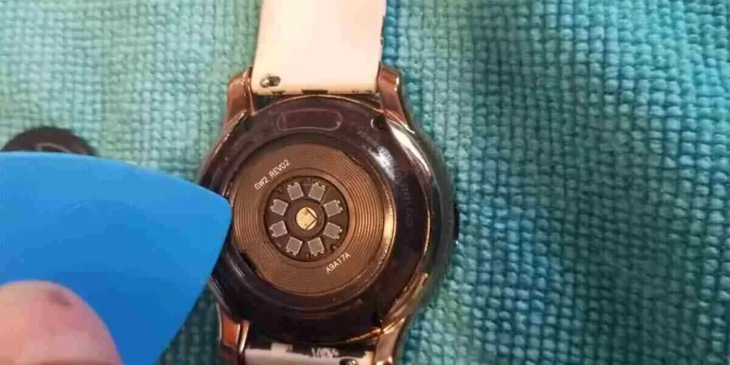
Since the sensor cover is off, you’ll notice old sticky adhesive on the surface. Dampen the cloth with water and add a few drops of 90-percent isopropyl alcohol. Gently wipe away any sticky residue from the surface.
Step 4: Apply Adhesive to New Sensor Cover
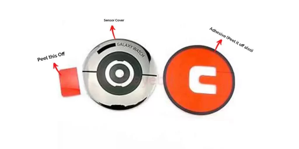
As discussed earlier, there is no adhesive on the sensor cover’s backing. A red circular sticker is included in the replacement part, which serves as the adhesive. You must apply the adhesive to the new sensor cover to make it attachable to the watch.
Start by peeling away the red outer layer of the adhesive part. Then, hold the back cover and pull the red part outwards to peel off the backside layer.
Stick the cover and adhesive together after the opening is free. Tap it multiple times so that it bonds properly. Then, remove the transparent layer to reveal the underlying adhesive. Your sensor cover is ready to be attached to the watch.
Step 5: Attach New Sensor Cover to Watch
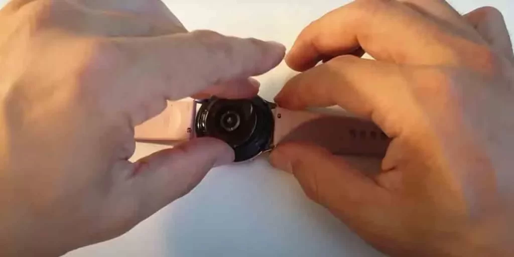
Once your sensor cover is ready, attach it to the back housing of your watch. For effective bonding, I recommend you wrap your watch with a synthetic fiber cloth and add some weight (like books) to it.
Leave for an hour or two without touching it. Within a few hours, your smartwatch looks brand new, just as if it came from the manufacturer.
A Similar Issue | Fossil Watch Back Cover Came Off – Here’s How to Fix?
Tips to Avoid Galaxy Watch Sensor Cover from Falling Off
- Charge Your Watch In Cool Environment – Heat from charging can cause the adhesive on your watch back cover to meltdown. Placing your Watch in an air-conditioned room is the best way to prevent your watch from overheating.
- Avoid Wearing Watch Under Water – Keep your watch away from water. At longer immersion times, water can affect adhesion joints. The study says adhesive bond decreases by 30% after one month in water.
- Look for Moisturizer on Wrist – Watches should not be worn while moisturizer is applied to the wrist. Moisturizer breaks the concentration of adhesive because the adhesive is composed of water-soluble components.
Read More On Galaxy Watch
- Can You Install Wear OS on Galaxy Watch? (Explained)
- 9 Best Apps For Galaxy Watch 4 (Must-Install!)