Events specification
BOC Gen Lx <V
(where x=1,2,3)
BOC Gen V Unbal
BOC Gen >, <Freq
Gen CCW Rot
BOC Amps Unbal
BOC Amps IDMT
BOC Overload
BOC Short Crct
Sd Earth Fault
Sd Overspeed
Sd Underspeed
Mains Lx >V
Mains Lx <V
(where x=1,2,3)
Mains V Unbal
Mains >, <Freq
Mains CCW Rot
Wrn MainsV Det
EmergencyStop
Sd Override
GCB Fail
MCB Fail
Sd RPMMeasFail
NT
– AMF20/25, SW version 2.2, ©ComAp – September 2014
InteliLite
IL-NT-AMF-2.2-Reference Guide.pdf
Information on binary
Protection
output available (See
type
list of
Binary
BOC
BOC
YES
BOC
YES
WRN
NO
BOC
NO
BOC
NO
BOC
YES
BOC
YES
SD
YES
SD
YES
SD
YES
MF
YES
MF
YES
MF
YES
WRN
NO
NONE
NO
SD
NO
WRN
NO
SD
NO
MF
NO
SD
NO
Description
outputs)
given by Gen <V BOC and Gen >V Sd
setpoints.
The generator voltage is unbalanced
more than the value of Volt Unbal
BOC setpoint.
The generator frequency is out of
limits given by Gen >Freq BOC and
Gen <Freq BOC setpoints.
Genset voltage phases are not wired
correctly. MCB closing is prohibited by
controller.
The generator current is unbalanced.
Generator current exceeds the limit
for IDMT protection given by Nominal
current and Amps IDMT Del setpoints.
The load is greater than the value
given by Overload BOC setpoint.
Generator current is higher than the
value given by Short Crct BOC
setpoint.
This alarm is activated when Earth
Fault value exceeds Earth Fault Sd
limit for at least Earth Fault Del period.
The protection comes active if the
speed is greater than Overspeed
setpoint.
During starting of the engine when the
RPM reach the value of Starting RPM
setpoint the starter is switched off and
the speed of the engine can drop
under Starting RPM again. Then the
Underspeed protection becomes
active. Protection evaluation starts 5
seconds after reaching StartingRPM.
The mains voltage is out of limits
given by Mains <V and Mains >V
setpoints.
The mains voltage is unbalanced
more than the value of Mains VUnbal
setpoint.
The mains frequency is out of limits
given by Mains >Freq and Mains
<Freq setpoints.
Mains voltage phases are not wired
correctly. MCB closing is prohibited by
controller.
AMF controller in MRS mode detects
a voltage on mains connector.
If the input Emergency Stop is opened
shutdown is immediately activated.
The protection is active if the output
Sd Override is closed.
Failure of generator circuit breaker.
Failure of mains circuit breaker.
Failure of magnetic pick-up sensor for
111
 Доброго времени!
Совсем не редко с SD-картами и USB-флешками происходят всякие неприятности: то не читаются, то копирование идет слишком долго, то появляются разного рода ошибки (что диск защищен от записи, что требуется форматирование, отображается неправильный объем памяти и пр.). Причем, происходит это порой ни с того ни с сего… 👀
В этой статье, хочу порекомендовать десяток утилит, которые не раз и не два меня выручали. С их помощью можно работать с флешками и накопителями разных производителей (Silicon Power, Kingston, Transcend и пр.), т.е. это универсальное ПО! 👌
Думаю, материал придется весьма кстати всем, кто периодически сталкивается с подобными проблемами.
Итак…
*
📌Также в помощь!
1) Почему компьютер не видит флешку: 10 основных причин!
2) Как проверить SD-карту или USB-флешку: на работоспособность, на ошибки, реальный объем, скорость работы.
3) Как проверить флешку на вирусы и очистить ее — см. инструкцию
*
Содержание статьи
- 1 Программы и утилиты для ремонта флешек и SD-карт
- 1.1 Для тестирования и диагностики
- 1.2 Для восстановления удаленных файлов с флешки
- 1.3 Для форматирования и ремонта

→ Задать вопрос | дополнить
Для тестирования и диагностики
CrystalDiskMark
Сайт разработчика: https://crystalmark.info/en/download/
Расшифровка параметров + как пользоваться: см. инструкцию
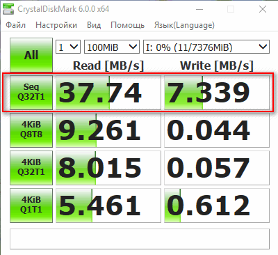
Скорость чтения — 37MB/s, записи — 7MB/s (скриншот окна DiskMark)
Очень полезная небольшая утилита. Позволяет быстро получить данные по скорости чтения/записи. Поддерживает не только USB флешки, но и классические HDD, SSD, внешние жесткие диски и пр. накопители (которые видит «Windows»).
Примечание: в большинстве случаев ориентируются по первой строчке «Sec» (последовательная скорость чтения записи). Read — чтение, Write — запись.
*
H2testw
Сайт разработчика: https://www.heise.de
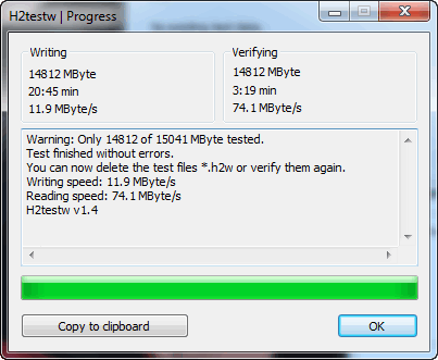
Тест пройден нормально, ошибок не найдено
Небольшая утилита от немецких программистов. Предназначена для сканирования USB накопителей на их реальных объем (прим.: некоторые флешки, например, китайских производителей — идут с «липовым» завышенным объемом). В этих случаях, достаточно прогнать флешку с помощью H2testw, а затем правильно отформатировать ее.
📌 В помощь!
Как узнать реальный объем флешки и восстановить ее работоспособность (с помощью H2testw).
*
Flash Memory Toolkit
Сайт разработчика: http://www.flashmemorytoolkit.com/
Мой пример, как ей пользоваться: см. инструкцию
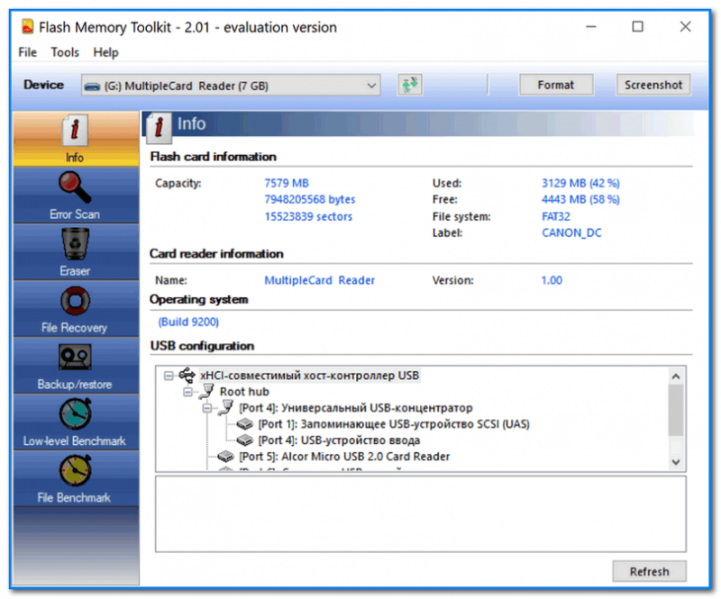
Flash Memory Toolkit — главное окно утилиты
Flash Memory Toolkit — хороший комплекс для обслуживания USB устройств. Позволяет выполнить целый спектр самых необходимых действий:
- тестирования накопители на ошибки при чтении и записи;
- восстановление данных с флеш-накопителей;
- просмотр свойств и характеристик;
- возможность создания бэкапа флешки;
- низкоуровневый тест скорости работы накопителя.
*
Flashnul
Сайт разработчика: http://shounen.ru/
Загрузить можно с SoftPortal
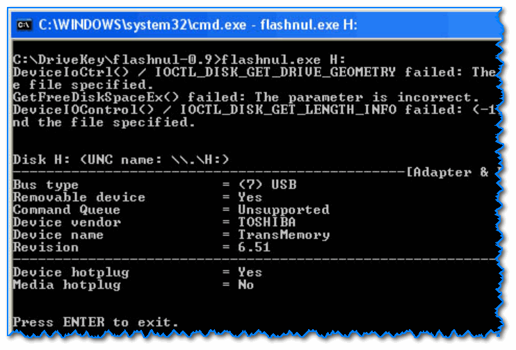
Окно работы Flashnul
Эта программа можно диагностировать и исправлять многие программные ошибки (особенно, когда неясно, что вообще происходит с флешкой: т.е. не высвечивается никаких ошибок). К тому же она поддерживает практически все носители на flash-памяти: USB flash drives, CompactFlash, SD, MMC, MS, XD, и пр.
Возможности:
- тестирование чтения и записи: будет проверена доступность каждого сектора носителя;
- проверка целостности файлов, находящихся на USB-накопителе;
- возможность сделать образ содержимого на флешке (может пригодится для восстановления данных);
- возможность посекторной записи образа на устройство USB;
- часть операций можно выполнить и для других типов носителей: HDD, CD, Floppy disk и пр.
*
ChipEasy
Англоязычная версия (Софтпедия): https://www.softpedia.com/
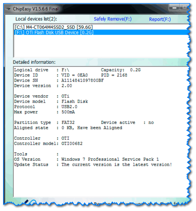
ChipEasy — предоставление информации о носителе
Бесплатная и очень простая утилита для получения полной информации о флешке. Очень пригодится в тех случаях, когда на самой флешке маркировка стерлась (или ее вообще не было).
Какие данные предоставляет ChipEasy:
- VID&PID;
- производитель;
- модель контроллера;
- серийный номер;
- информация о прошивке;
- модель памяти;
- макс. потребление тока и др.
*
Flash Drive Information
Англоязычная версия: https://www.softpedia.com/
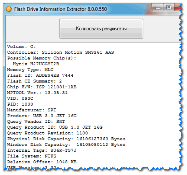
Flash Drive Information — скрин работы приложения
Утилита аналогична предыдущей. Позволяет за 2 клика мышкой узнать всю информацию о накопителе (флешке, карте памяти): модель, контроллер, память и т.д.
*
USB Flash Benchmark
Сайт разработчика: http://usbflashspeed.com/
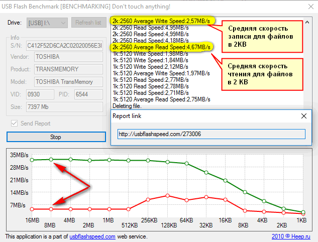
Результаты тестирования накопителя в USB Flash Benchmark
Еще одна утилита для тестирования скорости работы флешек. Позволяет получить не только какие-то цифры, но и сравнить их с другими накопителями (т.е. оценить свою флешку с другими моделями устройств). Сделать это можно благодаря тому, что результаты тестов сохраняются на одноименном сайте (вместе с моделями флешек).
Кстати! Если вы надумали купить быструю флешку — просто зайдите на сайт http://usbflashspeed.com/ и посмотрите топ 10. Таким образом сможете приобрести то, что уже другие люди испытали на практике!
*
Для восстановления удаленных файлов с флешки
Нижеперечисленные утилиты могут пригодится и в тех случаях, когда флешка была отформатирована (или возникли какие-либо ошибки).
Data Recovery Wizard
Сайт разработчика: https://www.easeus.com/datarecoverywizard/
Инструкция по работе с программой — см. мой пример
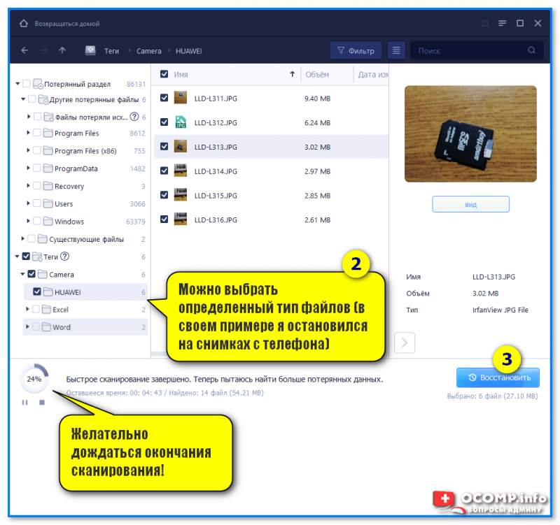
Выбираем файлы для восстановления
Достаточно мощная программа для восстановления случайно-удаленных файлов (например, после форматирования диска, или после каких-то ошибок файловой системы). Data Recovery Wizard поддерживает разные типы накопителей: HDD, SSD, SD-карты, USB-флешки.
Примечание: программа подкупает тем, что часто помогает восстановить данные, когда другое ПО бессильно (еще один плюс: структура каталогов при восстановлении тоже будет сохранена).
Обратите внимание, что бесплатная версия программы поддерживает восстановление не более 2 ГБ информации. Совместима с Windows 10/11.
*
R.Saver
Сайт разработчика: https://rlab.ru/tools/rsaver.html
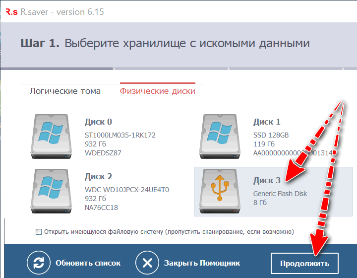
Выбор накопителя, с которого пропали файлы (процесс восстановления в R.Saver)
Простая в использовании программа для восстановления удаленных файлов с различных типов носителей: жестких дисков, карт памяти, флешек и т.д. Можно использовать при различных ошибках, сбоях файловой системы, после форматирования, вирусного заражения и пр.
Поддерживает файловые системы NTFS, FAT и ExFAT. Для жителей России (при использовании в не коммерческих целях) программа бесплатна.
📌 В помощь!
Вы можете подробно ознакомиться по работе с R.Saver в статье о том, как восстановить фото с MicroSD карты памяти или USB-флешки.

*
Recuva
Сайт разработчика: https://www.ccleaner.com/recuva
Инструкция: пример восстановления Word-документов
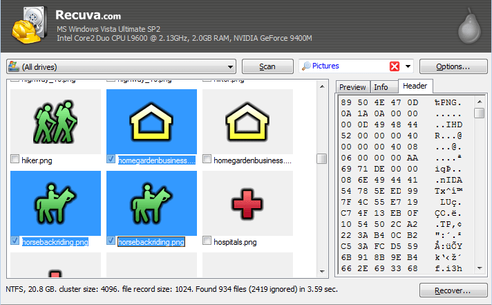
Поиск удаленных картинок на диске — Recuva
Программа для восстановления файлов от разработчиков CCleaner (знаменитой утилите для очистки Windows от мусорных файлов).
Recuva позволяет работать не только с HDD, но и с USB флешками, внешними дискам, SSD, картами памяти. Программа ориентирована на начинающего пользователя, поэтому ее использование очень простое.
Особенности:
- все действия в программе выполняются по шагам;
- 2 режима для сканирования накопителей;
- сортировка файлов по их имени, размеру, состоянию и пр.;
- утилита бесплатная;
- поддерживается русский;
- совместима с Windows XP, 7, 8, 10, 11 (32/64 bits).
*
MiniTool Power Data Recovery
Сайт разработчика: https://www.minitool.com/

MiniTool Power Data Recovery — главное окно
Очень мощная программа (с уникальными алгоритмами сканирования), которая позволит восстановить данные с битых флешек, карт памяти, внешних дисков, CD-дисков и др. накопителей. Поддерживаются популярные файловые системы: FAT 12/16/32, NTFS.
От себя отмечу, что на мой скромный взгляд, алгоритмы программы на самом деле отличны от других программ подобного толка, т.к. несколько раз с ее помощью удавалось восстановить информацию, когда другое ПО просто ничего не находило…
Примечание: в бесплатной версии программы MiniTool Power Data Recovery можно восстановить только 1 ГБ информации.
*
📌 Дополнение!
Вообще подобных программ достаточно много (прим.: которые могут просканировать накопитель и восстановить часть удаленных файлов).
В одной из своих прошлых статей я уже приводил десяток наиболее удачных бесплатных продуктов (большая часть из них работает не только с классическими HDD, но и с флешками). Ссылку на статью публикую ниже.

10 бесплатных программ для восстановления удаленных данных: файлов, документов, фото — [см. мою подборку софта]
*
Для форматирования и ремонта
HDD Low Level Format Tool
Сайт разработчика: http://hddguru.com/
Как ей пользоваться: см. пример форматирования
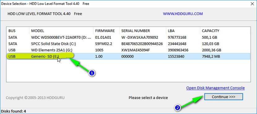
Выбор накопителя || Continue || HDD Low Level Format Tool
Программа для низкоуровневого* форматирования жестких дисков, SD карт, флешек и др. накопителей. Отметил бы ее «неприхотливость»: даже если другие утилиты зависают при попытке обратится к флешке (или ее не видят), HDD Low Level Format Tool способна в большинстве случаев помочь…
Особенности:
- поддерживается большинство производителей (Hitachi, Seagate, Samsung, Toshiba и др.) и интерфейсов (SATA, IDE, USB, SCSI, Firewire);
- при форматировании очищается абсолютно вся информация с диска (таблица разделов, MBR);
- восстановить информацию с диска после форматирования с помощью HDD Low Level Format Tool — почти невозможно!
*
MyDiskFix
Англоязычная версия: https://www.usbdev.ru/files/mydiskfix/
Примечание: утилита разработана китайскими программистами. В китайской версии разобраться достаточно сложно, поэтому ссылку даю на англ. версию (русской в сети не встречал).
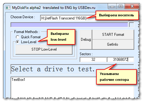
Скриншот работы MyDiskFix
Бесплатная небольшая утилита, предназначенная для низкоуровневого форматирования сбойных флешек. Пригодится в тех случаях, когда вашу флешку не удается отформатировать стандартными средствами Windows, когда у флешки показывается ошибочный объем, или происходит ошибка записи.
Примечание: перед форматированием в MyDiskFix, необходимо узнать, сколько на вашей флешке реально-рабочих секторов. Сделать это можно, например, с помощью утилиты H2Test (которую приводил выше).
*
USB Disk Storage Format Tool
Разработчик: Hewlett-Packard Company
Англоязычная версия: http://www.authorsoft.com/
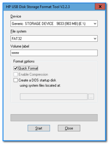
USB Disk Storage Format Tool — окно работы
Небольшая утилита для форматирования HDD/USB Flash drive (поддерживаются файловые системы: NTFS, FAT, FAT32).
Кстати, USB Disk Storage Format Tool не требует установки, не зависает, если работает со сбойными флешками, от которых необходимо минутами ждать ответа (как, например, стандартная утилита форматирования в Windows).
Особенности:
- быстрое и безопасное форматирование накопителя;
- при полном форматировании через утилиту происходит удаление всех данных с флешки (в последствии, ни один файл с нее невозможно будет восстановить);
- сканирование накопителя на ошибки;
- создание разделов с файловой системой FAT 32 больше, чем 32 GB;
- протестирована с 1000 самых различных флешек (Compact Flash, CF Card II, Memory Stick Duo Pro, SDHC, SDXC, Thumb Drive и др.), и различных производителей (HP, Sony, Lexar, Imation, Toshiba, PNY, ADATA и др.).
*
Format USB Or Flash Drive Software
Англоязычная версия (сайт разработчика): https://www.sobolsoft.com/formatusbflash/

Скриншот главного окна утилиты Format USB Or Flash Drive Software
Специализированная утилита для работы со сбойными USB накопителям. Позволяет произвести форматирование и восстановление работы флешки. Отметил бы еще ее очень простой интерфейс (см. скрин выше), и возможность работы без установки.
Особенности:
- поддержка файловых систем: FAT, FAT32, eXFAT, NTFS;
- простой и удобный интерфейс;
- возможность полного и быстрого форматирования;
- возможность «видеть» накопители, которые отказывается «показывать» проводник;
- возможность интеграции в меню Windows;
- совместима с Windows 7, 8, 10, 11.
*
Transcend RecoveRx
Сайт разработчика: https://ru.transcend-info.com/recoverx
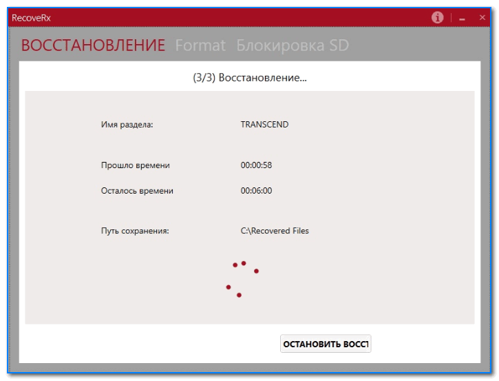
Скрин работы приложения Transcend RecoveRx
Многофункциональная программа: позволяет восстанавливать файлы с флешек, производить их форматирование, и защищать паролем.
Вообще, эта программа предназначена для флешек от производителя Transcend, но не могу не отметить, что возможность форматирования работает и для флешек другого производства.
RecoveRx достаточно «всеядная» программа: поддерживает USB флешки, карты памяти, MP3-плееры, внешние жесткие диски (HDD)и твердотельные накопители (SSD).
*
JetFlash Recovery Tool
Сайт разработчика: https://ru.transcend-info.com/Support/Software-3

JetFlash Recovery Tool — скрин главного окна
Эта утилита поможет в тех случаях, когда стандартные средства Windows просто не видят флешку. Официально поддерживаются USB флешки только от Transcend, JetFlash и A-DATA (неофициально — гораздо больше).
Важно! Имейте ввиду, что программа в процессе ремонта (восстановления) флешки производит полное удаление всех данных с нее! Если у вас есть возможность сохранить что-то с неисправной флешки — сделайте это.
Особенности:
- простая и бесплатная утилита (всего 2 кнопки!);
- совместима с Windows 7, 8, 10 (также работает и с более старыми ОС Windows XP, 2000 (остальные ОС — работа не гарантируется));
- официально поддерживаются только 3 производителя: Transcend, A-DATA и JetFlash;
- автоматическое восстановление накопителя (от пользователя нужно нажать только 1 кнопку);
- низкие системные требования;
- не требуется установка утилиты.
*
SD Formatter
Сайт разработчика: https://www.sdcard.org/downloads/formatter/
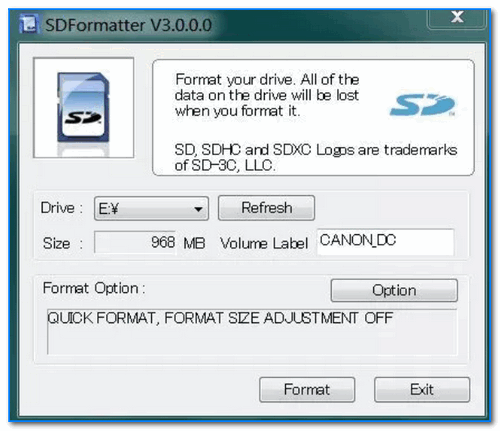
Форматирование SD карты Canon в SD Formatter
Эта утилита предназначена для ремонта и восстановления карт памяти: SD, SDHC, SDXC, microSD. Разработчики специально ориентировали свой продукт для нужд фотографов, видео-операторов, и специалистов по обслуживанию подобной техники.
Восстановление накопителя происходит в авто-режиме. Подойдет в самых разных случаях: при ошибках в ПО, заражении вирусами, сбоях, из-за неправильного использования и пр.
Примечание: в процессе работы с флешкой — SD Formatter удалит с нее все данные!
*
D-Soft Flash Doctor
Разработчик: Казанцев Владимир
Русскоязычная версия: https://www.usbdev.ru/files/dsoftflashdoctor/
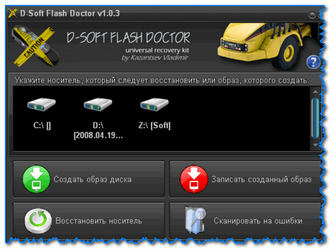
D-Soft Flash Doctor — главное окно программы
Небольшая портативная программа для диагностики и ремонта битых флешек (низкоуровневое форматирование, программный сброс). Кроме этого, умеет создавать образы с флешек/карт памяти и записывать их на др. носители информации.
Программа поддерживает русский язык (т.к. разработчик из Казахстана), и совместима со всеми современными ОС Windows 7, 8, 10, 11.
*
На этом пока все…
Дополнения по полезным и интересным утилитам — всегда приветствуются.
Удачи!
👋
Первая публикация: 02.12.2018
Корректировка: 12.10.2021


Полезный софт:
-

- Видео-Монтаж

Отличное ПО для создания своих первых видеороликов (все действия идут по шагам!).
Видео сделает даже новичок!
-
- Ускоритель компьютера

Программа для очистки Windows от «мусора» (удаляет временные файлы, ускоряет систему, оптимизирует реестр).
-
Page 1
Emotron TSA Softstarter Instruction manual English Valid from Software version 1.27… -
Page 3
Date of release: 28-01-2017 © Copyright CG Drives & Automation Sweden AB 2013-2017 CG Drives & Automation Sweden AB retains the right to change specifications and illustrations in the text, without prior notification. The contents of this document may not be copied without the explicit… -
Page 5: Safety Instructions
Safety instructions Phase compensation capacitor Congratulations for choosing a product from CG Drives & Automation! If a phase compensation capacitor is to be used, it must be Before you begin with the installation, commissioning or connected at the inlet of the softstarter, not between the powering up the unit for the first time it is very important motor and the softstarter.
-
Page 6
CG Drives & Automation 01-5980-01r2… -
Page 7: Table Of Contents
4.4.13 Other control voltage ……….37 8.1.1 1st Line [110]…………69 8.1.2 2nd Line [120] …………69 Getting started……….39 Main Setup [200]………… 69 Check list …………..39 8.2.1 Operation setup [210] ……….69 Mains and motor connection ……… 39 CG Drives & Automation 01-5980-01r2…
-
Page 8
Process value …………140 Description of the EInt formats ……141 Softstarter theory ……..143 10.1 Background theory……….143 10.2 Reduced voltage starting……..145 10.3 Other starting methods……… 147 10.4 Use of softstarters with torque control ….148 CG Drives & Automation 01-5980-01r2… -
Page 9: Introduction
The Quick Start Guide can be put in a cabinet so that it is always easy to access in case of an emergency. — =Standard (Grounded Supply type net) I=IT-net (EMC not fulfilled) Brand label A=Standard Software A=Standard software — =CE approved Standard U=UL/cUL approved CG Drives & Automation 01-5980-01r2 Introduction…
-
Page 10: Standards
The recycling of materials will help to conserve natural resources. For more detailed information about recycling this product, please contact the local distributor of the product. Introduction CG Drives & Automation 01-5980-01r2…
-
Page 11: Glossary
——————————————— — lb ft UInt Communication format (Unsigned Integer) n mot Communication format (Integer) Long Communication format (Integer Long) SELV Safety Extra Low Voltage The function cannot be changed in run mode CG Drives & Automation 01-5980-01r2 Introduction…
-
Page 12
Introduction CG Drives & Automation 01-5980-01r2… -
Page 13: Mounting
Minimum free space WARNING! Never operate the softstarter with the front Minimum free space cover removed. mm (in) Frame size above* below at side (3.9) (3.9) *) Above: Cabinet roof to softstarter or softstarter to softstarter CG Drives & Automation 01-5980-01r2 Mounting…
-
Page 14: Mechanical Specifications And Drawings
H3 = Total height including Cable covers. Emotron TSA frame size 1 — 2 Fig. 3 Dimensions for Emotron TSA frame size 1 and 2, bottom view. Fig. 2 Dimensions for Emotron TSA frame size 1 and 2. Mounting CG Drives & Automation 01-5980-01r2…
-
Page 15
Emotron TSA frame size 3 196 (7.7) 235 (9.3) Fig. 4 Dimensions for Emotron TSA frame size 3. Fig. 5 Dimensions for Emotron TSA frame size 3, bottom view. CG Drives & Automation 01-5980-01r2 Mounting… -
Page 16
Emotron TSA frame size 4 254 (10) 260 (10.3) Fig. 6 Dimensions for Emotron TSA frame size 4 . Fig. 7 Dimensions for Emotron TSA frame size 4, bottom view. Mounting CG Drives & Automation 01-5980-01r2… -
Page 17: Mounting Schemes
On our websites www.cgglobal.com and www.emotron.com Ø 13 it is possible to download a full-size template for positioning of the fixing holes. Ø 7 (x 4) Fig. 9 Hole pattern for Emotron TSA frame size 3. CG Drives & Automation 01-5980-01r2 Mounting…
-
Page 18
Mounting CG Drives & Automation 01-5980-01r2… -
Page 19: Connections
Fig. 11 Mains, motor and control supply voltage connection NOTE: The Emotron TSA control-board is equipped with a ground plane to which shielded cables can be connected (see Fig. 17 on page 21). NOTE: For UL-approval use 75°C copper wire only. CG Drives & Automation 01-5980-01r2 Connections…
-
Page 20
Full voltage can be detected if no motor is connected. Table 7 Tightening torque for bolts [Nm (Lb-in)]. Tightening torque for bolts [Nm (Lb-in)] Frame size Motor or mains PE cable cables 8 (70) 5 (44) 8 (70) 5(44) Connections CG Drives & Automation 01-5980-01r2… -
Page 21
Full voltage can be detected if no motor is connected. Table 8 Tightening torque for bolts [Nm (Lb-in)]. Tightening torque for bolts [Nm (Lb-in)] Frame size Motor or mains PE cable cables 20 (177) 12 (106) CG Drives & Automation 01-5980-01r2 Connections… -
Page 22
Full voltage can be detected if no motor is connected. Table 9 Tightening torque for bolts [[Nm (Lb-in)]. Tightening torque for bolts [Nm (Lb-in)] Frame size Motor or mains PE cable cables 50 (442) 12 (106) Connections CG Drives & Automation 01-5980-01r2… -
Page 23: Busbar Distances On Emotron Tsa Softatarter
44 (0.9) 83 (3.27) 83 (3.27) 3.1.2 Cable covers When the Mains and motor cables are connected, mount the cable covers according to Fig. 16. Fig. 16 How to mount the cable covers general drawing. CG Drives & Automation 01-5980-01r2 Connections…
-
Page 24: Board Layout And Connectors
WARNING! For softstarters rated higher than 525 VAC, it is mandatory to have at least basic insulation from the temperature sensor towards live voltage. Connections CG Drives & Automation 01-5980-01r2…
-
Page 25
Solid: 2.5 (27) 8. Terminals for DigIn/AnIn/AnOut signals (control board) * When using Ferrules, suitable Ferrule length is 10-12 mm/ 0.39 — 0.47 in. 9. Terminals for relay output signals and PTC connection (power board) CG Drives & Automation 01-5980-01r2 Connections… -
Page 26: Control Signal Connections
Analogue output. Factory setting is “Current”. 0-20 mA and 4-20 mA; max load impedance 500 Ω +24 VDC ±5%. Max. current from +24 VDC = 50 mA. Control signal supply 2, voltage to digital input. Short circuit-proof and overload-proof. Connections CG Drives & Automation 01-5980-01r2…
-
Page 27: Wiring Examples
• If required, connect relay R1 (terminals 21 and 22) to the contactor – the softstarter then controls the mains contactor (for factory configuration of R1 see menu [551]). Always ensure the installation complies with the appropriate local regulations. CG Drives & Automation 01-5980-01r2 Connections…
-
Page 28
Relay 2 Relay 3 Run FWD Stop DigIn 1 DigIn 2 +10 V AnIn DigIn 3 DigIn 4 +24 V AnOut +24 V Fig. 20 Separate Start- Stop-signals ( 3-wire connection) wir- ing example. Connections CG Drives & Automation 01-5980-01r2… -
Page 29
Relay 2 Relay 3 Stop Run FWD DigIn 1 DigIn 2 +10 V AnIn DigIn 3 DigIn 4 +24 V AnOut +24 V Fig. 21 Common Start- Stop-signals ( 2-wire connection) wir- ing example. CG Drives & Automation 01-5980-01r2 Connections… -
Page 30
Relay 2 Relay 3 Run FWD DigIn 1 DigIn 2 +10 V AnIn DigIn 3 DigIn 4 +24 V AnOut +24 V Fig. 22 Common Start- Stop-signals ( 2-wire connection) wir- ing example, Level control. Connections CG Drives & Automation 01-5980-01r2… -
Page 31
+24 V Reset Run FWD Pressure 0 — 10 bar Current 0 — I 4 — 20 mA 4 — 20 mA Fig. 23 Extended wiring example, using digital and analogue inputs and outputs. CG Drives & Automation 01-5980-01r2 Connections… -
Page 32
Relay 1 Relay 2 Relay 3 DigIn 1 DigIn 2 +10 V AnIn DigIn 3 DigIn 4 +24 V AnOut +24 V Run FWD Stop Fig. 24 Reverse current brake wiring example. Connections CG Drives & Automation 01-5980-01r2… -
Page 33
Relay 2 OperationREV avoided. Relay 1 Relay 2 DigIn 1 DigIn 2 +10 V AnIn DigIn 3 DigIn 4 +24 V AnOut +24 V Run FWD Stop Run REV Fig. 25 Connection for start forward/reverse. CG Drives & Automation 01-5980-01r2 Connections… -
Page 34
If both DigIn 1 “RunFWD” and DigIn 3 “RunREV” are closed at the same time, a stop is performed according to the stop settings in menu group [340]. In this case no start will be allowed. Connections CG Drives & Automation 01-5980-01r2… -
Page 35: Application Guidelines
70 A with a start current ratio of 3.0 x FLC (210 A) for 30 seconds, and with a 330 seconds (5.5 minutes) interval between starts (current via bypass contactors). CG Drives & Automation 01-5980-01r2 Application guidelines…
-
Page 36
Bandsaw Chipper Circular saw Lumber & Wood Debarker Planer Sander Ball mill Centrifuge Petrochemical Extruder Screw conveyor Ball mill Grinder Material conveyor Palletiser Transport & Machine Press Roller mill Rotary table Trolley Escalator Application guidelines CG Drives & Automation 01-5980-01r2… -
Page 37: The Application Functions List
This column guides you to the menu, menu group, or manual section where you find a description of the settings for the function. For instance «331=Sqr Torq Ctr», means: set menu [331] to “Sqr Torq Ctr.” CG Drives & Automation 01-5980-01r2 Application guidelines…
-
Page 38
344=Rev Curr Brk Conveyor speed set from planer shaft High speed lines power analogue output. Worn out tool Use load monitor maximum alarm Broken coupling Use load monitor minimum alarm Application guidelines CG Drives & Automation 01-5980-01r2… -
Page 39
Torque boost in beginning of ramp. Jamming Use load monitor maximum alarm HAMMER MILL Reverse current brake with reversing 341=Brake Fast stop contactor for heavy loads. 344=Rev Curr Brk Motor blocked Locked rotor function CG Drives & Automation 01-5980-01r2 Application guidelines… -
Page 40: Special Conditions
For instance, the start ramp can only be set for an average starting ramp for all the connected motors. This means that the start time may differ from motor to motor. Similarly, the load monitor alarm levels/margins are applied for the Application guidelines CG Drives & Automation 01-5980-01r2…
-
Page 41: Earthing System
Emotron TSA should be configured for IT-net supply type. The unit will then not fulfil the EMC requirements. If you have a softstarter without IT net supply type, the softstarter can be rebuilt. Contact your local CG Drives & Automation service partner. 4.4.12 Earth fault relay It is possible to use an earth fault relay to protect motor and cables.
-
Page 42
Application guidelines CG Drives & Automation 01-5980-01r2… -
Page 43: Getting Started
73). • Check / Set real time clock (menu [740], section 8.7.4, page 134) • Select keyboard control (menu [2151], section 7.1.1, page 49). • Perform a test run from the control panel. CG Drives & Automation 01-5980-01r2 Getting started…
-
Page 44: Default Toggle Loop
Chapter 6. page 43. Menu [100], “Preferred View” is displayed at start. 1. Press to display menu [211] “Language”. NQE1 Select Language using the keys. Confirm with Getting started CG Drives & Automation 01-5980-01r2…
-
Page 45: Control Panel Operation
To stop the motor, press the key on the control panel. NOTE: For selection of other stop method than the default “Coast”, see section 7.1.2, page 35 and menu [341]. CG Drives & Automation 01-5980-01r2 Getting started…
-
Page 46
Getting started CG Drives & Automation 01-5980-01r2… -
Page 47: Operation Via The Control Panel
Shows the setting or selection in the active Area F: menu (empty at 1st level and 2nd level menus). Shows warnings and alarm messages. CG Drives & Automation, 01-5980-01r2 Operation via the control panel…
-
Page 48: Led Indicators
Table 18 Control key commands. Start with reversed (left) rotation. START REVERSE RUN (Requires reversing contactor). Stop motor. STOP/RESET Reset softstarter (after a trip). Start with forward START FORWARD RUN (right) rotation. Operation via the control panel CG Drives & Automation, 01-5980-01r2…
-
Page 49: Function Keys
To activate the jog key function, see instructions in “Jog functions” on page 50. To deactivate the jog key function, unlock the keyboard in menu [218]. CG Drives & Automation, 01-5980-01r2 Operation via the control panel…
-
Page 50: Toggle And Loc/Rem Key
1. Press the Toggle key and keep it pressed while pressing the ESC key. 2. The message “Clear Loop?” is shown. 3. Confirm with ENTER to delete the menus in the loop. Operation via the control panel CG Drives & Automation, 01-5980-01r2…
-
Page 51: Loc/Rem Function
Relays [550]. When the softstarter is set to “LOCAL”, the signal on the relay will be active/high. In “REMOTE” the signal will be inactive/low. 3rd level 4th level Fig. 33 Menu structure CG Drives & Automation, 01-5980-01r2 Operation via the control panel…
-
Page 52: The Main Menu
View Trip Log Here you can see the last 9 trips in the trip memory. System Data This menu contains information on softstarter model and software version. Operation via the control panel CG Drives & Automation, 01-5980-01r2…
-
Page 53: Main Features
[520], see section 8.5.2, page 108. Spinbrake can only be activated when the TSA is non-operational, i.e that Stp is shown in the display. Fig. 35 Run/Stop decision tree CG Drives & Automation, 01-5980-01r2 Main features…
-
Page 54: Jog Functions
Jog speed level in menu “[353] Jog Ramp Rate” to achieve smooth Jog start. There are also a couple of examples on how to apply time settings for jog by using logic functions, see page 63. Main features CG Drives & Automation, 01-5980-01r2…
-
Page 55: Working With Parameter Sets
DigIn running in automatic control mode (i.e. control signals from 3 [523] is set to “Set Ctrl 1” and DigIn 4 [524] is set to “Set PLC, e.g. via fieldbus). Ctrl 2”. CG Drives & Automation, 01-5980-01r2 Main features…
-
Page 56: Configuration Of Parameter Sets
2. Select motor M1 in menu [212]. 3. Enter motor data and settings for other parameters. 4. Select parameter set B in menu [241]. 5. Select M2 in menu [212]. 6. Enter motor data and settings for other parameters. Main features CG Drives & Automation, 01-5980-01r2…
-
Page 57
1 to the internal control board of TSA unit 2, using menu [245]. Fig. 38 Copy and load parameters between two Emotron TSA units via the control panel. WARNING! Switch off all power connections before opening the front cover. CG Drives & Automation, 01-5980-01r2 Main features… -
Page 58
Fig. 39 Copy and load parameters between two Emotron TSA units using an external control panel (optional). NOTE: Another solution for copying settings and data between different softstarter units is via PC, using the EmoSoftCom PC tool (option). See section 12.2, page 155. Main features CG Drives & Automation, 01-5980-01r2… -
Page 59: Applying Limitations, Alarms And Autoreset
• The Trip LED indicator (red triangle) is lit. • The “TRP” status indication is displayed (area D of the display). • The Trip relay or output is active (if selected function in menu [551], [552] or [553]). CG Drives & Automation, 01-5980-01r2 Main features…
-
Page 60: Load Monitor Function
[223] (being 100%). However, the way to set the levels differs between the two methods: NOTE: When using the load monitor, check that the nominal motor power is set properly in menu [223]. Main features CG Drives & Automation, 01-5980-01r2…
-
Page 61
(menu [223]). The actual shaft 4112 MaxAlarmLev power is displayed in brackets together with the Alarm Level (104%) 116% value to facilitate setting. See example on the right. Fig. 40 Manually set load monitor alarm levels. CG Drives & Automation, 01-5980-01r2 Main features… -
Page 62
Every time a new “Autoset Alarm” command is executed, the actual shaft power value will be updated as the “Normal Load” value, with the alarm levels following this. Fig. 41 Autoset load monitor alarm margins. Main features CG Drives & Automation, 01-5980-01r2… -
Page 63
C. The maximum alarm level is exceeded. D. When the set maximum alarm delay time (3 seconds) has passed, the set maximum alarm action is executed, in this case a Hard trip, as set in menu [4111]. CG Drives & Automation, 01-5980-01r2 Main features… -
Page 64: Reset And Autoreset
“Autoreset Attempts [251]” on page 83. activated by selecting one of the keyboard alternatives (enabled as default). If controlled by digital input [520], or by virtual I/O [560], this is set by selecting “Reset” signal. Main features CG Drives & Automation, 01-5980-01r2…
-
Page 65: Programmable I/O
• No digital outputs are available. • 3 relays [550], with the possibility for up to 6 extra relays if extended I/O option boards (max 2) are fitted. • There are also 8 virtual I/Os [560] CG Drives & Automation, 01-5980-01r2 Main features…
-
Page 66: Enable And Stop Functions
Fig. 44, page 61. Fig. 45 gives an example of a possible RunFWD and RunREV inputs are active, then the sequence. softstarter stops according to the selected stop method in menu [341]. Fig. 46 gives an example of a possible sequence. Main features CG Drives & Automation, 01-5980-01r2…
-
Page 67: Logical Functions
WARNING! Fig. 46 Input and output status for level control Motor may start instantly! Please verify that parameter settings and I/O connections are according to desired function before switching on mains supply. CG Drives & Automation, 01-5980-01r2 Main features…
-
Page 68
Number of pulses with Jog speed before run 6521 C2 trig DigIn 2 Pulse input 6522 C2 Reset Counter 2 is blocked until end of deceleration. 6523 C2 Trip Val Number of pulses with Jog speed after run Main features CG Drives & Automation, 01-5980-01r2… -
Page 69
Reset Flip Flop 1 and stop the motor 6323 Timer2 Dly 5,0 s Jog time before stop 6411 F1 mode Edge 6412 F1 set Negative flank of “Dec” 6413 F1 reset Reset when “Jog speed after run” has ended CG Drives & Automation, 01-5980-01r2 Main features… -
Page 70
Main features CG Drives & Automation, 01-5980-01r2… -
Page 71: Functionality
Emotron TSA model, software and hardware version. Service System data 8.9, page 136 information. WARNING! Motor may start instantly! Please verify that parameter settings and I/O connections are according to desired function before switching on mains supply. CG Drives & Automation, 01-5980-01r2 Functionality…
-
Page 72
For bus communication, the integer value 0 is used to select “Off ” in the example. Integer 1 represents “REV”. To change selection by bus communication refer to the description in Chapter 9. page 139. Functionality CG Drives & Automation, 01-5980-01r2… -
Page 73: Preferred View [100]
Sets the content of the lower row in the menu [100] “Preferred View”. Same selection as in menu [110]. Default: 120 2nd Line Motor Data [220] is connected to Current selected motor. Default: Current CG Drives & Automation, 01-5980-01r2 Functionality…
-
Page 74
Jog command via digital input or Virtual I/O. Int+Ext Jog command via internal or external keyb control panel. Jog command via serial communication. Int keyb Jog command via internal control panel. Ext keyb Jog command via external control panel. Functionality CG Drives & Automation, 01-5980-01r2… -
Page 75
Local start/stop command via serial keyboard and the keys are activated. (it is possible to select communication. e.g. Start REV to be Off or REV in menu [2175] above). 218 Lock Code? Default: Range: 0–9999 CG Drives & Automation, 01-5980-01r2 Functionality… -
Page 76: Remote Signal Level/Edge [21A]
NOTE: Edge controlled inputs can comply with the Machine Directive (see Chapter 1.5.1 page 6) if the inputs are directly used to start and stop the machine. Functionality CG Drives & Automation, 01-5980-01r2…
-
Page 77: Motor Data [220]
For explanation of the different abbreviations used in this 1 US-units chapter, see Chapter 1.7.2 page 7 WARNING! When the “Units” setting is changed, this will also affect the factory settings of the motor. CG Drives & Automation, 01-5980-01r2 Functionality…
-
Page 78
. It must be set within the range 25 — 400% of n_soft the softstarter power Pn_soft. If parallel motors, set the sum 221 Motor Volts of the motor power. See nominal data for CG motors in Ta- 400V ble 27. 400 V for SI-units… -
Page 79
226 Motor Poles Default: Range: 2-144 Nominal Motor Cos φ [227] Set the nominal Motor cosphi (power factor). 227 Motor Cosφ 0.86 0.86 Default: (see Note 2, page 73) Range: 0.50 — 1.00 CG Drives & Automation, 01-5980-01r2 Functionality… -
Page 80: Motor Protection [230]
[2311] is performed. The alarm remains active until the I²t value is below 95% before allowing a reset or an autoreset (see more detailed description in menu [2521]). Functionality CG Drives & Automation, 01-5980-01r2…
-
Page 81
Using motor overload trip class 10 Current: 5 x In_mot Overload trip time (max start time): 20 sec 60 s 20 s Current (x I n_mot 500% x I 300% x I n_mot n_mot Fig. 50 The thermal curve CG Drives & Automation, 01-5980-01r2 Functionality… -
Page 82
PTC Alarm Action [2331] B 120 ° F 140 F Nema 2331 PTC AA ° No action H 165°C Default: No action No action Hard Trip For a definition, see Table 23, page 55. Soft Trip Warning Functionality CG Drives & Automation, 01-5980-01r2… -
Page 83
Counts down from set value in menu [2343]. 2341 StartLim AA No action 2344 TimTNxtStrt Read only Default: No action No action Unit minutes Hard Trip For a definition, see Table 23, page 55 Resolution: 1 min Warning CG Drives & Automation, 01-5980-01r2 Functionality… -
Page 84: Parameter Set Handling [240]
NOTE: The parameter set cannot be changed No action during run if the parameter set includes change of the motor set (M1-M4). Hard Trip For a definition, see Table 23, page 55. Soft Trip Warning Functionality CG Drives & Automation, 01-5980-01r2…
-
Page 85
NOTE: The control panel will be temporarily locked while copying or loading data to the internal control panel. If the on-board RS-232 port is connected to a PC or to an external control panel this will also be temporarily locked. CG Drives & Automation, 01-5980-01r2 Functionality… -
Page 86
Data from motor 4 is loaded. M1M2M3 Data from motor 1, 2, 3 and 4 are loaded. All data is loaded from the control panel. NOTE: Loading or copying will not affect the value in menus for viewing. Functionality CG Drives & Automation, 01-5980-01r2… -
Page 87: Autoreset [250]
• Number of allowed autoreset attempts [2511]= 5. • Within 10 minutes 6 trips occur. 1–3600 1–3600 1–3,600 s • At the 6th trip there is no autoreset, because the autoreset counter allows only 5 attempts to autoreset a trip. CG Drives & Automation, 01-5980-01r2 Functionality…
-
Page 88
When the delay time has [2541] elapsed, the alarm will be reset. The delay counter starts counting immediately. 2524 LockedRotor 2541 MaxAlarm Default: Default: 1–3600 1–3600 1–3,600 s 1–3600 1–3600 1–3,600 s Functionality CG Drives & Automation, 01-5980-01r2… -
Page 89
External Alarm 1 autoreset [2549] Default: The delay counter starts counting as soon as the relevant external alarm input is inactive. 1–3600 1–3600 1–3,600 s 2549 Ext Alarm 1 Default: 1–3600 1–3600 1–3,600 s CG Drives & Automation, 01-5980-01r2 Functionality… -
Page 90: Serial Communication [260]
In this menu the delay time for an autoreset of an Fieldbus module. undervoltage alarm [433] is set. The delay time starts counting when the fault is removed. The undervoltage *) EtherCAT and Bluetooth are future options. Functionality CG Drives & Automation, 01-5980-01r2…
-
Page 91
Select “RW” in normal Set up the parameters for fieldbus communication. cases to control inverter. 263 Fieldbus Additional Process Values [2634] Define the number of additional process values sent in cyclic messages. 2634 AddPrValues Default: Range: CG Drives & Automation, 01-5980-01r2 Functionality… -
Page 92
Communication Fault Time [2642] Gateway [2654] Defines the delay time for the trip/warning. 2654 Gateway 2642 ComFlt Time 0.000.000.000 0.5s Default: 0.0.0.0 Default: 0.5 s Range: 0.1-15 s DHCP [2655] 2655 DHCP Default: Selection: On/Off Functionality CG Drives & Automation, 01-5980-01r2… -
Page 93: Process [300]
321 Proc Source Default: No process source selected. F(AnIn) Function of analogue input. F(Bus) Function of communication value. NOTE: If F (Bus) is chosen in menu [321], see section 9.5 Process value, page 140. CG Drives & Automation, 01-5980-01r2 Functionality…
-
Page 94
Confirm the character by moving the cursor to the next position by pressing the NEXT key. No. for serial No. for serial Character Character comm. comm. ° í Space 0–9 1–10 ñ ó ô ü Functionality CG Drives & Automation, 01-5980-01r2… -
Page 95: Start Setting [330]
Voltage control is selected when a linear voltage ramp is desired. The thyristor switch on time will be ramped up linearly, from “Initial Voltage”, menu [334], up to full mains voltage. See Fig. 52. CG Drives & Automation, 01-5980-01r2 Functionality…
-
Page 96
The motor voltage is controlled according torque ramp reactivated. The ramp slope will increase above Voltage Ctr to a linear voltage ramp, menu [334]. Direct online Functionality CG Drives & Automation, 01-5980-01r2… -
Page 97
As “Voltage ramp with Current limit” but with fixed ramp 336 Start Time time of 6 seconds. Default: 10 s Range: 1 — 60 s Current limit Ramp time (6 seconds) Fig. 55 Direct on-line start in combination with current limit at start. CG Drives & Automation, 01-5980-01r2 Functionality… -
Page 98: Stop Setting [340]
Braking may be used in applications where the motor needs to be stopped quickly. When this selection is made, the braking method (“Dynamic Vector Brake” or “Reverse Current Brake”) can be activated in menu [344]. Functionality CG Drives & Automation, 01-5980-01r2…
-
Page 99
The DC brake will automatically be deactivated when the Stop time motor has stopped or when the stop time has expired. Time Optionally an external rotation sensor can be connected via Fig. 58 Step down voltage at stop. CG Drives & Automation, 01-5980-01r2 Functionality… -
Page 100
The strength of the DC brake is set here, the value expressed Range: 0 – 120s as a percentage of the maximum available DC braking power. 348 DCB Strength Default: 30 % Range: 20 – 80% Functionality CG Drives & Automation, 01-5980-01r2… -
Page 101: Jog [350]
[rpm] Jog speed t [s] t [s] Jog command Fig. 59 Jog command Jog Speed Forward [351] 351 JogSpd FWD Default: Range: 1- 30% of nominal motor speed [225] CG Drives & Automation, 01-5980-01r2 Functionality…
-
Page 102: Load Monitor And Process Protection [400]
Setting of the wanted alarm behaviour when a “Maximum Alarm” has been detected. 4111 MaxAlarmAct No Action Default: No Action No Action Hard Trip For a definition, see Table 23, page 55. Soft Trip Warning Functionality CG Drives & Automation, 01-5980-01r2…
-
Page 103
0.5 s period longer than the set “Max Pre-Alarm Delay” time, the Range: 0.1 — 90 s selected “Maximum Pre-Alarm Action” in menu [4121] is activated. 4123 MaxPreAlDel 0.5s Default: 0.5 s Range: 0.1–90 s CG Drives & Automation, 01-5980-01r2 Functionality… -
Page 104
“Autoset”. See nominal motor power, the alarm delay timer starts counting further information in Fig. 40, page 57. down. 4142 MinAlarmLev shaft Default: Range: 0 — 200% of nominal motor power [223] Functionality CG Drives & Automation, 01-5980-01r2… -
Page 105
[4142] MinAlarmLev [4174] MinAlarmMar nominal motor power [223]. NOTE: Changing any alarm margin without performing 4172 MaxPreAlMar Autoset will NOT affect the alarm levels. Default: Range: 0 — of nominal motor power [223] CG Drives & Automation, 01-5980-01r2 Functionality… -
Page 106
[417] Autoset. A new autoset command will overwrite previously used alarm levels. Autoset can also be triggered by a remote signal, setting the function of any digital input to “Autoset”. Note that this signal is edge-triggered. Functionality CG Drives & Automation, 01-5980-01r2… -
Page 107: Process Protection [420]
Hard Trip 4223 LockRotCurr For a definition, see Table 23, page 55. 480% Soft Trip Warning Default: 480% (4.8 x I n_mot Range: 100% — 1000% (1.0 x I — 10.0 x I n_mot n_mot CG Drives & Automation, 01-5980-01r2 Functionality…
-
Page 108: Mains Protection [430]
Voltage Unbalance Alarm Delay [4313] Default: In this menu the response delay for the voltage unbalance Range: 1 — 90 s alarm, as set in [4311] and [4312], is selected. 4313 VoltUnbDel Default: Range: 1 — 90 s Functionality CG Drives & Automation, 01-5980-01r2…
-
Page 109
L123 and L321 Under-Voltage Alarm Delay [4333] In this menu the response delay for the voltage unbalance alarm, as set in [4431] and [4432], is selected 4333 UnderV Del Default: Range: 1 — 90 s CG Drives & Automation, 01-5980-01r2 Functionality… -
Page 110: I/O [500]
S1. When the jumper is in voltage mode only the voltage menu items are selectable. With the jumper in Default: Min (0 V/4.00 mA) current mode only the current menu items are 0.00–20.00 mA selectable. Range: 0–10.00 V Functionality CG Drives & Automation, 01-5980-01r2…
-
Page 111
With “AnIn Function Max” the physical maximum value is scaled to selected process unit. The default scaling is dependent of the selected function of AnIn [511]. 5136 AnIn FcMax Default: Min value Max value User-defined 2 Define user value in menu [5137] CG Drives & Automation, 01-5980-01r2 Functionality… -
Page 112: Digital Inputs [520]
Activates other parameter set. See Table Set Ctrl 1 29 for selection possibilities. Activates other parameter set. See Table Set Ctrl 2 29 for selection possibilities. Loc/Rem 10 Activates local mode defined in [2173]. Functionality CG Drives & Automation, 01-5980-01r2…
-
Page 113: Analogue Output [530]
AnIn Mirror of received signal value on AnIn. Line Voltage 14 Mains supply NOTE: To activate the parameter set selection, menu 241 must be set to DigIn. Used Th Cap 15 Used thermal capacity CG Drives & Automation, 01-5980-01r2 Functionality…
-
Page 114
[531]. Table 30 AnOut Min Value Max Value Function Process Value Process Min [324] Process Max [325] Shaft Power Motor Power [223] Current Motor Current [224] Functionality CG Drives & Automation, 01-5980-01r2… -
Page 115
Min value Max value User defined 2 Define user value in menu [5337 ] NOTE: It is possible to set AnOut up as an inverted output signal by setting “AnOut Min” > “AnOut Max”. CG Drives & Automation, 01-5980-01r2 Functionality… -
Page 116: Relays [550]
Max pre-alarm condition active (trip or Flip-flop output 4. Max PreAlarm warning). Flip-flop output 4 inverted. Min alarm condition active (trip or Min Alarm CTR1 Counter output 1. warning). !CTR1 Counter output 1 inverted. Functionality CG Drives & Automation, 01-5980-01r2…
-
Page 117
Fig. 63 Relay function example for start and braking cycle. is active (trip) PTC Alarm 103 PTC alarm active (trip or warning) PT100 Alarm 104 PT100 alarm active (trip or warning) 105 I t alarm active (trip or warning) CG Drives & Automation, 01-5980-01r2 Functionality… -
Page 118
I/O option board on the option mounting plate. The functions and selections are the same as for “Relay 1” [551]. Default settings are “Off ”. NOTE: Visible only if optional board is detected or if any input/output is activated. Functionality CG Drives & Automation, 01-5980-01r2… -
Page 119: Virtual I/Os [560]
“OR logic”. See section 8.5.2, page 108 (Digital Input) for descriptions of the different selections. 561 VIO 1 Dest Default: Same selections as in menu Digital Input 1 Selection: [521], page 108. CG Drives & Automation, 01-5980-01r2 Functionality…
-
Page 120: Logical Functions And Timers [600]
CA1 Level LO [6113] Digital Comparator Setup [615] — [618] There are also 4 digital comparators that compare any Fig. 65 Analogue comparator type “Window” available digital signals. Functionality CG Drives & Automation, 01-5980-01r2…
-
Page 121
CA1 Value AnIn 6112 CA1 Level HI 60% (12 mA/20 mA x 100%) 6113 CA1 Level LO 40% (8 mA/20 mA x 100%) 6114 CA1 Type Hysteresis VIO 1 Dest Run FWD VIO 1 Source CG Drives & Automation, 01-5980-01r2 Functionality… -
Page 122
The reference signal passes the Level LO Hysteresis/ value from above (negative edge), the window band 40°C comparator CA1 is reset, output is set low. CA1 Level LO CA1 output Hysteresis High Window High Functionality CG Drives & Automation, 01-5980-01r2… -
Page 123
The reference signal passes the Level LO value from above (signal outside Window band), the comparator CA1 is reset, output is set low. Set delay Reset delay Fig. 68 Set/reset delay of output signal. CG Drives & Automation, 01-5980-01r2 Functionality… -
Page 124
“Trip”, and for CD4 [6181] the default is “Ready”. Operation Default: Operation Same selection as in menu Relay 1 Selection: [551], page 112. Input signal for CD1 [6151] Digital comparator 1 Fig. 69 Digital comparator. Functionality CG Drives & Automation, 01-5980-01r2… -
Page 125: Logic Outputs [620]
Default: ((1.2).3).4 ((1&1)+1)&0 Default execution order, see which is equal to 0. ((1.2).3).4 explanation below. With the alternative execution order for the L1 Expression Alternative execution order, see (1.2).(3.4) explanation below. this is representing: CG Drives & Automation, 01-5980-01r2 Functionality…
-
Page 126
Logic output 1 inverted. +=OR Not used for Logic 1. ^=EXOR Logic output 2. Not used for Logic 2. Logic output 2 inverted. Not used for Logic 2. Logic output 3. Not used for Logic 3. Functionality CG Drives & Automation, 01-5980-01r2… -
Page 127
The reset of the output signal for the Logic 1 function is delayed with the set value in this menu. Compare to Fig. 68, page 119. 621A L1 Res Dly 0:00:00.0 Default: 0:00:00.0 (hours:minutes:seconds) Range: 0:00:00.0–9:59:59.9 CG Drives & Automation, 01-5980-01r2 Functionality… -
Page 128: Timers [630]
The function of the “On-time” mode is to extend an Prolongs the activation of the output On-time activated (high) timer output signal in comparison to the signal according to menu [6314]. trigger signal. See Fig. 72. Functionality CG Drives & Automation, 01-5980-01r2…
-
Page 129: Sr Flip-Flops [640]
RESET This menu shows the actual value of the timer. 6316 Timer1 Val Read-only 0:00:00.0 Fig. 73 Programmable flip-flop modes. Timer 2 — 4 [632] — [634] Refer to the descriptions for Timer 1. CG Drives & Automation, 01-5980-01r2 Functionality…
-
Page 130
Table 35 Truth table for Edge control without priority 6414 F1 Set Dly 0:00:00.0 RESET Default: 0:00:00.0 (hours:minutes:seconds) — (no change) Range: 0:00:00.0–9:59:59.9 1 (set) 0 (reset) No change Functionality CG Drives & Automation, 01-5980-01r2… -
Page 131: Counters [650]
Counter 1 is incremented by 1 on every positive edge of the trigger signal. NOTE: Maximum counting frequency is 8 Hz. 6511 C1 Trig Default: Same selections as in menu Relay 1 [551], Selection: page 112. CG Drives & Automation, 01-5980-01r2 Functionality…
-
Page 132: Clock Logic [660]
Date when the clock output signal (CLK1) is deactivated. Note that if “Clk1DateOff ” is set to an earlier date than “Clk1DateOn”, the result will be that the clock is not deactivated at the set date. Functionality CG Drives & Automation, 01-5980-01r2…
-
Page 133: Operation/Status [700]
6615 Clk1Weekday — — — — — SS VIO 1 Dest Run FWD 716 Shaft Power Read-only VIO 1 Source Clk1 Clock 2 [662] Unit: Resolution: Refer to the description for Clock 1 [661]. CG Drives & Automation, 01-5980-01r2 Functionality…
-
Page 134
3. See menu PT100 Inputs [2323], page 78. Used Thermal Capacity [71K] 71B PT100B1 123 This menu displays the used thermal capacity. Read-only Unit: °C 71K Used Th Cap Read-only Resolution: 1°C Unit: Resolution: Functionality CG Drives & Automation, 01-5980-01r2… -
Page 135: Status [720]
4 — 2 1=Thyristor driven motor 2=Bypass driven motor Source of Run/Stop command, where: 0=Rem, 1=Keyboard (internal + external), 2=Com, 7 — 5 3=Spare, 4=VIO, 5=Internal keyboard, 6=External keyboard. 15 — 8 Reserved for future use. CG Drives & Automation, 01-5980-01r2 Functionality…
-
Page 136
Fig. 78 indicates that AnIn is active and has a 65% input Volt Unbal (voltage unbalance) value. NOTE: The shown percentage is an absolute value based on the maximum value of the in- or output; so related to either to 10 V or 20 mA. Functionality CG Drives & Automation, 01-5980-01r2… -
Page 137
This menu indicates the active digital comparators (CD1 — CD4). 72B CD1-4 Read-only 0000 Logic function status 1 — 4 [72C] This menu indicates the active logic outputs (L1 — L4). 72C Logic 1-4 Read-only 0000 CG Drives & Automation, 01-5980-01r2 Functionality… -
Page 138: Stored Values [730]
00: 00: 00–262143: 59: 59 Energy [733] This menu displays the total energy consumption since the last energy reset [7331] took place. 733 Energy Read-only Unit: Wh (shows Wh, kWh, MWh or GWh) Range: 0 Wh–999,999 GWh Functionality CG Drives & Automation, 01-5980-01r2…
-
Page 139: View Trip Log [800]
Analogue comparator 1 — 4 132 (menu [722]). 812A Digital comparator 1 — 4 812B Logic function status 1-4 812C Timer status 1-4 812D Flip-flop status 1-4 812E Counter status 1-2 812F Time to next start CG Drives & Automation, 01-5980-01r2 Functionality…
-
Page 140: Trip Messages [820] — [890]
0: V, release version 15–14 1: P, pre-release version β , Beta version α , Alpha version Table 39 Information for Modbus and Profibus number, option version Example Description 7–0 Minor option version 15–8 Major option version Functionality CG Drives & Automation, 01-5980-01r2…
-
Page 141
12 characters. Press the + / — keys to enter graphic symbols from the same list as for User-defined Unit [323], page 90. See also «Editing parameter values», page 45. 923 Unit Name Default: No characters shown CG Drives & Automation, 01-5980-01r2 Functionality… -
Page 142
Functionality CG Drives & Automation, 01-5980-01r2… -
Page 143: Serial Communication
The on-board RS232 connection is not galvanically option boards. isolated. Modbus RTU The RS485 and USB option boards from CG Drives & Automation are galvanically isolated. There is an asynchronous unisolated RS232 serial communication interface on top of the Emotron TSA unit.
-
Page 144: Motor Data
Requires that menu [2151] Run/Stop Control is set to “Com”. Modbus/DeviceNet Function Instance number 42901 Reset Run, active together with either 42902 Run FWD or Run REV to perform start. (1=Run, 0=Stop) 42903 Run FWD (1=Active) 42904 Run REV (1=Active) Serial communication CG Drives & Automation 0-5980-01r2…
-
Page 145: Description Of The Eint Formats
4-bit signed exponent. Gives a value range: -8..+7 (binary 1000 .. 0111) Where bit 15 indicates that we are using the fixed point m10-m0 11-bit signed mantissa. Gives a format (F=0). value range: -1024..+1023 (binary 10000000000..01111111111) CG Drives & Automation 01-5980-01r2 Serial communication…
-
Page 146
// make signed Rreturn (*(unsigned short int *)&etmp); //————————————————————————— float eint16_to_float(unsigned short int value) float f; eint16 evalue; evalue=*(eint16 *)&value; if (evalue.f) if (evalue.e>=0) f=(int)evalue.m*pow10(evalue.e); else f=(int)evalue.m/pow10(abs(evalue.e)); else f=value; return f; //————————————————————————— Serial communication CG Drives & Automation 0-5980-01r2… -
Page 147: Softstarter Theory
The dashed line indicates the nominal motors’ torque characteristic is added to the diagram. values. Torque Torque Fig. 85 Typical load torque characteristics Fig. 83 Typical torque characteristics for the DOL start CG Drives & Automation 01-5980-01r2 Softstarter theory…
-
Page 148
This means when the motor current is decreased by a factor of two by means of reducing the supply voltage, the torque delivered by the motor will be decreased by a factor of four (approximately). Softstarter theory CG Drives & Automation 01-5980-01r2… -
Page 149: Reduced Voltage Starting
On the other hand for low load applications further savings of starting current are impossible even though a big torque reserve is available. Moreover, the resulting abrupt rise of torque first at start and CG Drives & Automation 01-5980-01r2 Softstarter theory…
-
Page 150
This means, the lowest possible starting current is determined by the combination of motor and load characteristics. Softstarter theory CG Drives & Automation 01-5980-01r2… -
Page 151: Other Starting Methods
However, it is always possible to use a frequency inverter instead. The following illustration shows how the torque and current characteristics are affected when the stator frequency is changed. CG Drives & Automation 01-5980-01r2 Softstarter theory…
-
Page 152: Use Of Softstarters With Torque Control
(linear, square or constant load, need of initial release torque) must be known. In this case a proper torque control method (linear or square) can be chosen and torque boost can be enabled if needed. Softstarter theory CG Drives & Automation 01-5980-01r2…
-
Page 153: Troubleshooting, Diagnoses And Maintenance
For more information on maintenance, please contact your this instruction manual, it is absolutely necessary to CG Drives & Automation service partner. read and follow the safety instructions in the manual. Precautions to take with a connected motor…
-
Page 154: Troubleshooting List
Change the Motor I t Current setting in menu [2312]. (Area D: I Soft trip to the prog-rammed I t settings. Check setting of menu [228] Motor Vent, which affects I Warning behaviour. Troubleshooting, Diagnoses and Maintenance CG Drives & Automation 01-5980-01r2…
-
Page 155
Mains voltage dip due to starting Soft trip limits set in menu group [433]. other major power consuming Warning Use other mains supply lines if dip is caused by other machines on the same line. machinery. CG Drives & Automation 01-5980-01r2 Troubleshooting, Diagnoses and Maintenance… -
Page 156
Possible cause Remedy /Menu (and indicator) No action Hard trip Check 3-phase mains supply. Volt unbalance 4311 Mains supply voltage unbalance. Soft trip Check settings in menu [4312] and [4313]. Warning Troubleshooting, Diagnoses and Maintenance CG Drives & Automation 01-5980-01r2… -
Page 157
The alarm can only be reset if the The alarm can not alarm condition is removed. be reset. E.g. PTC, PT100 or over temperature alarm can only be reset after the temperature is decreased. CG Drives & Automation 01-5980-01r2 Troubleshooting, Diagnoses and Maintenance… -
Page 158
Troubleshooting, Diagnoses and Maintenance CG Drives & Automation 01-5980-01r2… -
Page 159: Options
PC for backup and printing. options are described in a separate manual. Recording can be made in oscilloscope mode. Please contact CG Drives & Automation sales for further information. CG Drives & Automation 01-5980-01r2 Options…
-
Page 160
Options CG Drives & Automation 01-5980-01r2… -
Page 161: Technical Data
Heavy duty: Start current = 5 x I , Start time = 15 s (Size 1) or 30 s (Size 2- 4), 10 starts/hour. n_soft Fuse data for Semi-conductor fuses, see Table 48. H1=Height of enclosure, H2= Total height. CG Drives & Automation 01-5980-01r2 Technical data…
-
Page 162
Heavy duty: Start current = 5 x I , Start time = 15 s (Size 1) or 30 s (Size 2-4), 10 starts/hour. n_soft Fuse data for Semi-conductor fuses, see Table 48. H1=Height of enclosure, H2= Total height. Technical data CG Drives & Automation 01-5980-01r2… -
Page 163
Heavy duty: Start current = 5 x I , Start time = 15 s (Size 1) or 30 s (Size 2-4), 10 starts/hour. n_soft Fuse data for Semi-conductor fuses, see Table 48. H1=Height of enclosure, H2= Total height. CG Drives & Automation 01-5980-01r2 Technical data… -
Page 164: General Electrical Specifications
42 000 -085 55 000 -100 99 000 -140 160 000 -170 222 000 -200 332 000 -240 433 000 -300 1000 950 000 -360 1200 1 470 000 -450 1400 1 890 000 Technical data CG Drives & Automation 01-5980-01r2…
-
Page 165: Environmental Conditions
85 A nominal current: 85 A — (20% x 85 A) = 68 A, which is lower than the required 70 A. An even higher rated model is checked, TSA52-100, rated for 100 A nominal current: CG Drives & Automation 01-5980-01r2 Technical data…
-
Page 166: Derating At High Altitude
56 A — (11% x 56 A) = 49.8 A, which is well above the required 42 A, and therefore TSA52-056 could be selected in this case. Technical data CG Drives & Automation 01-5980-01r2…
-
Page 167: Control Power- And I/O Signal Connectors
24 VDC or max 250 VAC) must be used for all three output relays (terminals 21-33). Do not mix AC and DC voltage. Make sure to use the same voltage level within this terminal section, otherwise the softstarter may be damaged. CG Drives & Automation 01-5980-01r2 Technical data…
-
Page 168
Technical data CG Drives & Automation 01-5980-01r2… -
Page 169: Index
LOC/REM key ……. 46 Emergency ………1 Clock settings ……..134 Local control ……..71 EN60204-1 ……..6 Coast ……….94 Logic ……..116, 121 EN61800-3 ……..6 Com Type ……..86 Status ……..133 EN61800-5-1 ……..6 Comparator Low Voltage Directive ……. 6 CG Drives & Automation 01-5980-01r2…
-
Page 170
Phase compensation capacitor ….1 Status ……….131 Phase loss ………79 Status indications ……43 Phase reversal ………105 Step-up transformer for high Phase sequence …….105, 130 voltage motor ……..36 Planer ……….34 Stop command …….108 Power- and signal connectors ..163 CG Drives & Automation 01-5980-01r2… -
Page 171: Appendix 1: Menu List
Appendix 1: Menu List This is a list of the Emotron TSA menu parameters and their factory settings, along with communication settings for the most important bus formats. Complete lists with communication data and parameter set information could be downloaded from www. cgglobal.com or www.emotron.com. Customer settings Modbus Inst.
-
Page 172
Customer settings Modbus Inst. Fieldbus Modbus Menu Parameters Default settings Notes DeviceNet no. format format Motor Power [Motor] W 43043 Long, 1=1W EInt Motor Curr [Motor] A 43044 Long, 1=0.1A EInt Motor Speed [Motor] rpm 43045 UInt, 1=1rpm UInt Motor Poles [Motor] 43046 Long, 1=1… -
Page 173
Customer settings Modbus Inst. Fieldbus Modbus Menu Parameters Default settings Notes DeviceNet no. format format Copy Set A>B 43021 UInt UInt Default>Set 43023 UInt UInt Copy to CP No Copy 43024 UInt UInt Load from CP No Copy 43025 UInt UInt Autoreset page 83… -
Page 174
Customer settings Modbus Inst. Fieldbus Modbus Menu Parameters Default settings Notes DeviceNet no. format format 2563 OverVolt 43077 Long, 1=1s EInt 2564 Undervolt 43088 Long, 1=1s EInt Serial Com page 86 Com Type RS232 43031 UInt UInt Modbus RTU 2621 Baudrate 9600 43032 UInt… -
Page 175
Customer settings Modbus Inst. Fieldbus Modbus Menu Parameters Default settings Notes DeviceNet no. format format 2653 Subnet Mask 0.0.0.0 42711 UInt, 1=1 UInt 0.0.0.0 42712 UInt, 1=1 UInt 0.0.0.0 42713 UInt, 1=1 UInt 0.0.0.0 42714 UInt, 1=1 UInt 2654 Gateway 0.0.0.0 42715 UInt, 1=1… -
Page 176
Customer settings Modbus Inst. Fieldbus Modbus Menu Parameters Default settings Notes DeviceNet no. format format FB Status page 89 2691 Board Type 31081 UInt, 1=1 UInt 2692 SUP-bit 31082 UInt, 1=1 UInt 2693 State FB 31083 UInt, 1=1 UInt 2694 Serial Nbr 31084 UInt, 1=1 UInt… -
Page 177
Customer settings Modbus Inst. Fieldbus Modbus Menu Parameters Default settings Notes DeviceNet no. format format StartSetting page 91 Start Method Lin Torq Ctr 43701 UInt, 1=1 UInt Init Torque 43702 UInt, 1=1% UInt EndTorqueSt 150% 43703 UInt, 1=1% UInt Init Volt 43704 UInt, 1=1% UInt… -
Page 178
Customer settings Modbus Inst. Fieldbus Modbus Menu Parameters Default settings Notes DeviceNet no. format format 4111 MaxAlarmAct No action 43775 UInt UInt 4112 MaxAlarmLev 116% 43776 Long, 1=1% EInt 4113 MaxAlarmDel 0,5s 43330 Long, 1=0.1s EInt MaxPreAlarm page 99 4121 MaxPreAlAct No action 43777 UInt… -
Page 179
Customer settings Modbus Inst. Fieldbus Modbus Menu Parameters Default settings Notes DeviceNet no. format format 4221 LockRot AA No action 43362 UInt UInt 4222 LockRotTime 5,0s 43757 UInt, 1=0.1s UInt 4223 LockRotCurr 480% 43759 UInt, 1=1% UInt Mains Prot page 104 Volt Unbal 4311 VoltUnbalAA No action… -
Page 180
Customer settings Modbus Inst. Fieldbus Modbus Menu Parameters Default settings Notes DeviceNet no. format format AnIn Advan 5131 AnIn Min 43203 Long, 1=0.01 EInt 5132 AnIn Max 20mA 43204 Long, 1=0.01 EInt 5134 AnIn FcMin 43206 UInt UInt Long, 1= see 1=0.001, 1rpm, 1%, 1°C, 0.001 5135 AnIn VaMin 43541… -
Page 181
Customer settings Modbus Inst. Fieldbus Modbus Menu Parameters Default settings Notes DeviceNet no. format format 5334 AnOutFcMin 43256 UInt UInt Long, 1= see 1W, 0.1Hz, 0.1A, 0.1V, 1rpm, 1% 5335 AnOutVaMin 43545 EInt Notes or 0.001 as set in [322] 5336 AnOutFcMax 43257 UInt… -
Page 182
Customer settings Modbus Inst. Fieldbus Modbus Menu Parameters Default settings Notes DeviceNet no. format format VIO 2 Dest 43283 UInt UInt VIO 2 Source 43284 UInt UInt VIO 3 Dest 43285 UInt UInt VIO 3 Source 43286 UInt UInt VIO 4 Dest 43287 UInt UInt… -
Page 183
Customer settings Modbus Inst. Fieldbus Modbus Menu Parameters Default settings Notes DeviceNet no. format format 6117 CA1 Res Dly 00:00:00 43408 UInt, 1=1h UInt 43409 UInt, 1=1m UInt 43410 UInt, 1=0.1s UInt 6118 CA1 Tmr Val 00:00:00 42600 UInt, 1=1h UInt 42601 UInt, 1=1m… -
Page 184
Customer settings Modbus Inst. Fieldbus Modbus Menu Parameters Default settings Notes DeviceNet no. format format 1W, 0.1Hz, 0.1A, 0.1V, 1rpm, 1%, Long, 1= see 6133 CA3 LevelLO 43424 EInt 0.1°C, 1kWh, 1h or 0.001 as set Notes in [322] 6134 CA3 Type Hysteresis 43425 UInt… -
Page 185
Customer settings Modbus Inst. Fieldbus Modbus Menu Parameters Default settings Notes DeviceNet no. format format 42611 UInt, 1=0.1s UInt CD1 Setup page 120 6151 CD1 Operation 43444 UInt UInt 6152 CD1 Set Dly 00:00:00 43445 UInt, 1=1h UInt 43446 UInt, 1=1m UInt 43447 UInt, 1=0.1s… -
Page 186
Customer settings Modbus Inst. Fieldbus Modbus Menu Parameters Default settings Notes DeviceNet no. format format 6173 CD3 Res Dly 00:00:00 43462 UInt, 1=1h UInt 43463 UInt, 1=1m UInt 43464 UInt, 1=0.1s UInt 6174 CD3 Tmr Val 00:00:00 42618 UInt, 1=1h UInt 42619 UInt, 1=1m… -
Page 187
Customer settings Modbus Inst. Fieldbus Modbus Menu Parameters Default settings Notes DeviceNet no. format format 6219 L1 Set Dly 00:00:00 43480 UInt, 1=1h UInt 00:00:00 43481 UInt, 1=1m UInt 00:00:00 43482 UInt, 1=0.1s UInt 621A L1 Res Dly 43483 UInt, 1=1h UInt 43484 UInt, 1=1m… -
Page 188
Customer settings Modbus Inst. Fieldbus Modbus Menu Parameters Default settings Notes DeviceNet no. format format Logic 3 page 124 6231 L3 Expr ((1.2).3).4 43780 UInt UInt 6232 L3 Input 1 43781 UInt UInt 6233 L3 Op 1 & 43782 UInt UInt 6234 L3 Input 2 43783… -
Page 189
Customer settings Modbus Inst. Fieldbus Modbus Menu Parameters Default settings Notes DeviceNet no. format format 6249 L4 Set Dly 00:00:00 43802 UInt, 1=1h UInt 43803 UInt, 1=1m UInt 43804 UInt, 1=0.1s UInt 624A L4 Res Dly 00:00:00 43805 UInt, 1=1h UInt 43806 UInt, 1=1m… -
Page 190
Customer settings Modbus Inst. Fieldbus Modbus Menu Parameters Default settings Notes DeviceNet no. format format 6323 Timer2 Dly 00:00:00 43821 UInt, 1=1h UInt 43822 UInt, 1=1m UInt 43823 UInt, 1=0.1s UInt 6324 Timer2 T1 00:00:00 43824 UInt, 1=1h UInt 43825 UInt, 1=1m UInt 43826… -
Page 191
Customer settings Modbus Inst. Fieldbus Modbus Menu Parameters Default settings Notes DeviceNet no. format format Timer4 page 125 6341 Timer4 Trig 43841 UInt UInt 6342 Timer4 Mode Delay 43842 UInt UInt 6343 Timer4 Dly 00:00:00 43843 UInt, 1=1h UInt 43844 UInt, 1=1m UInt 43845… -
Page 192
Customer settings Modbus Inst. Fieldbus Modbus Menu Parameters Default settings Notes DeviceNet no. format format 6416 F1 Tmr Val 00:00:00 42648 UInt, 1=1h UInt 42649 UInt, 1=1m UInt 42650 UInt, 1=0.1s UInt Flip flop 2 page 127 6421 F2 mode Reset 43861 UInt… -
Page 193
Customer settings Modbus Inst. Fieldbus Modbus Menu Parameters Default settings Notes DeviceNet no. format format 6436 F3 Tmr Val 00:00:00 42654 UInt, 1=1h UInt 42655 UInt, 1=1m UInt 42656 UInt, 1=0.1s UInt Flip flop 4 page 127 6441 F4 mode Edge 43879 UInt… -
Page 194
Customer settings Modbus Inst. Fieldbus Modbus Menu Parameters Default settings Notes DeviceNet no. format format Clock logic page 128 Clock 1 6611 Clk1TimeON 00:00:00 43600 Long, 1=1h EInt 43601 Long, 1=1m EInt 43602 Long, 1=1s EInt 6612 Clk1TimeOff 00:00:00 43603 Long, 1=1h EInt 43604… -
Page 195
Customer settings Modbus Inst. Fieldbus Modbus Menu Parameters Default settings Notes DeviceNet no. format format Shaft Power 31006 UInt, 1=1% UInt El Power 31007 Long, 1=1W EInt RMS Current 31008 Long, 1=0.1A EInt L main volt 31009 Long, 1=0.1V EInt Heatsnk Tmp 31010 Long, 1=0.1°C EInt… -
Page 196
Customer settings Modbus Inst. Fieldbus Modbus Menu Parameters Default settings Notes DeviceNet no. format format CA1-4 31050 UInt, 1=1 UInt CD1-4 31051 UInt, 1=1 UInt Logic 1-4 31052 UInt, 1=1 UInt Timer 1-4 31053 UInt, 1=1 UInt FlipFlop1-4 31072 UInt, 1=1 UInt Counter 1-2 31073… -
Page 197
Customer settings Modbus Inst. Fieldbus Modbus Menu Parameters Default settings Notes DeviceNet no. format format Long, 1= see 1rpm, 1%, 1°C, 0.001 as set in 8111 Process Val 31102 EInt Notes [322] 8113 Torque 31104 Long, 1=0.1Nm EInt 8114 Torque 31105 Long, 1=1% EInt… -
Page 198
Customer settings Modbus Inst. Fieldbus Modbus Menu Parameters Default settings Notes DeviceNet no. format format 8124 AnalogueIn 31129 Long, 1=1% EInt 8125 AnalogueOut 31130 Long, 1=1% EInt 8126 IO StatusB1 31131 UInt, 1=1 UInt 8127 IO StatusB2 31132 UInt, 1=1 UInt 8129 CA1-4 31134… -
Page 199
Customer settings Modbus Inst. Fieldbus Modbus Menu Parameters Default settings Notes DeviceNet no. format format (Trip log list 2) page 136 (Trip log list 3) (Trip log list 4) Same parameters as for menu group 810 (Trip (Trip log list 5) log list 1). -
Page 200
Customer settings Modbus Inst. Fieldbus Modbus Menu Parameters Default settings Notes DeviceNet no. format format 42307 UInt UInt 42308 UInt UInt 42309 UInt UInt 42310 UInt UInt 42311 UInt UInt 42312 UInt UInt… -
Page 201: Appendix 2: Trip Message Communication Data
Appendix 2: Trip message communication data Trip log list 31101-31154 31201-31254 31301-31354 Modbus Instance no/ 31401-31454 DeviceNet no: 31501-31554 31601-31654 31701-31754 31801-31854 31901-31954 Trip log list 121/245-122/43 122/90-122/143 122/190-122/243 123/35-123/88 Profibus slot/index 123/135—123/188 123/235-124/33 124/80-124/133 124/180-124/233 125/25-125/78 Trip log list 1101-1154 1201-1254 1301-1354…
-
Page 204
CG Drives & Automation Sweden AB Mörsaregatan 12 Box 222 25 SE-250 24 Helsingborg Sweden T +46 42 16 99 00 F +46 42 16 99 49 www.emotron.com/www.cgglobal.com…
10
EURORACK UB1222FX-PRO Руководство пользователя
2-TRACK OUTPUT
Данные соединительные элементы выведены перед графической EQ и
XPQ Surround-функцией. Они поставляют стереосумму в асимметричной
форме в распоряжение эффект-микширования. Подключите сюда входы
Вашего записывающего устройства. Если Вы используете микшерный
пульт исключительно в целях записи, тогда, конечно, альтернативой могут
послужить Main-выходы.
2.3.5 Main mix, main out-втулки и
подключение наушников
10
10
15
20
25
30
40
60
0
PHONES
MAIN MIX
MAIN MIX
LEFT
RIGHT
MA X
Рис. 2.11: Фейдеры main mix
MAIN MIX
При помощи высокоточных качественных фейдеров Вы регулируете
выходной уровень Main микшера.
LEFT
RIGHT
BAL OR UNBAL
MAIN OUT
Рис. 2.12: Main out-втулки
MAIN OUT
MAIN OUT-выходы проводят MAIN MIX-сигнал и сконструированы как
симметричные XLR-втулки с номинальным уровнем в +4 дБ. В зависимости
от того, как Вы хотите использовать микшерный пульт и каким
оборудованием Вы владеете, Вы можете подключать следующие приборы:
Live-озвучивание:
Динамический стереопроцессор (по заказу), стереоэквалайзер (по заказу)
и затем выходная ступень стереоусилителя для широкодиапазонных
динамиков с пассивными частотными разделительными фильтрами.
Если Вы хотите использовать многоканальные системы динамиков без
встроенных частотных разделительных фильтров, Вы должны использовать
один активный разделительный частотный фильтр и несколько выходных
ступеней усилителя. Часто там уже встроен динамический ограничитель
(Limiter) (например, в BEHRINGER SUPER-X PRO CX2310 и ULTRADRIVE PRO
DCX2496). Активные разделительные частотные фильтры устанавливаются
непосредственно перед выходными ступенями и разделяют полосу частот
на несколько частей, которые затем через выходные ступени подводятся к
соответствующим системам динамиков.
Запись:
Для Mastering рекомендуется использовать стереокомпрессор,
как например COMPOSER PRO-XL MDX2600, при помощи которого Вы можете
собственноручно проектировать динамику Ваших музыкальных сигналов
в динамическом объеме используемого Вами записывающего устройства.
От компрессора сигнал поступает в записывающее устройство.
PHONES
PHONES-потенциометр регулирует уровень громкости подключенных
к PHONS/CTRL-втулке наушников. Если здесь Вы подключили активные
динамики монитора или же выходные ступени усилителя, тогда при
помощи данного регулятора Вы можете регулировать выходной уровень.
ВНИМАНИЕ!
◊
Мы хотим обратить Ваше внимание на то, что высокий уровень
громкости может причинить вред органам слуха и/или вывести
из строя наушники и динамики. Поэтому, прежде чем включить
прибор, установите фейдер MAIN MIX в Main-Sektion в самое
нижнее положение и поверните PHONES-регулятор влево до
упора. Постоянно следите за тем, чтобы уровень громкости
был умеренным.
PHONS
/
CTRL
Рис. 2.13: PHONS/CTRL-втулка
PHONS/CTRL-втулка
К этой 6,3-мм-стереохраповой втулке вы можете подключить Ваши
наушники. Данная втулка может также использоваться в качестве
соединительного элемента для активных динамиков монитора
(или выходной ступени усилителя) в радиоаппаратной. Для данной цели
сигнал отводится непосредственно перед фейдерами Main Mix.
2.3.6 Индикатор уровня и модуляция
POWER
POWER-светодиод сообщает о том, что прибор включен.
Events specification
BOC Gen Lx <V
(where x=1,2,3)
BOC Gen V Unbal
BOC Gen >, <Freq
Gen CCW Rot
BOC Amps Unbal
BOC Amps IDMT
BOC Overload
BOC Short Crct
Sd Earth Fault
Sd Overspeed
Sd Underspeed
Mains Lx >V
Mains Lx <V
(where x=1,2,3)
Mains V Unbal
Mains >, <Freq
Mains CCW Rot
Wrn MainsV Det
EmergencyStop
Sd Override
GCB Fail
MCB Fail
Sd RPMMeasFail
NT
– AMF20/25, SW version 2.2, ©ComAp – September 2014
InteliLite
IL-NT-AMF-2.2-Reference Guide.pdf
Information on binary
Protection
output available (See
type
list of
Binary
BOC
BOC
YES
BOC
YES
WRN
NO
BOC
NO
BOC
NO
BOC
YES
BOC
YES
SD
YES
SD
YES
SD
YES
MF
YES
MF
YES
MF
YES
WRN
NO
NONE
NO
SD
NO
WRN
NO
SD
NO
MF
NO
SD
NO
Description
outputs)
given by Gen <V BOC and Gen >V Sd
setpoints.
The generator voltage is unbalanced
more than the value of Volt Unbal
BOC setpoint.
The generator frequency is out of
limits given by Gen >Freq BOC and
Gen <Freq BOC setpoints.
Genset voltage phases are not wired
correctly. MCB closing is prohibited by
controller.
The generator current is unbalanced.
Generator current exceeds the limit
for IDMT protection given by Nominal
current and Amps IDMT Del setpoints.
The load is greater than the value
given by Overload BOC setpoint.
Generator current is higher than the
value given by Short Crct BOC
setpoint.
This alarm is activated when Earth
Fault value exceeds Earth Fault Sd
limit for at least Earth Fault Del period.
The protection comes active if the
speed is greater than Overspeed
setpoint.
During starting of the engine when the
RPM reach the value of Starting RPM
setpoint the starter is switched off and
the speed of the engine can drop
under Starting RPM again. Then the
Underspeed protection becomes
active. Protection evaluation starts 5
seconds after reaching StartingRPM.
The mains voltage is out of limits
given by Mains <V and Mains >V
setpoints.
The mains voltage is unbalanced
more than the value of Mains VUnbal
setpoint.
The mains frequency is out of limits
given by Mains >Freq and Mains
<Freq setpoints.
Mains voltage phases are not wired
correctly. MCB closing is prohibited by
controller.
AMF controller in MRS mode detects
a voltage on mains connector.
If the input Emergency Stop is opened
shutdown is immediately activated.
The protection is active if the output
Sd Override is closed.
Failure of generator circuit breaker.
Failure of mains circuit breaker.
Failure of magnetic pick-up sensor for
111
Updated: May 11, 2022
Note: The below content, originally published September 30, 2021, has been updated to reflect the revised stance on USB/SD cards as a boot device for ESXi outlined in KB Article 85685. For full details regarding the use of USB/SD cards as a boot device for ESXi, refer to KB Article 85685.
Historically, SD cards or USB devices have been chosen to free up device bays and lower the cost of installing ESXi hosts. Such devices, however, have lower endurance and exhibit reliability and issues over time. SD cards and USB drives may also exhibit performance issues and may not tolerate high-frequency read-write operations. We are now witnessing boot-related problems more frequently with ESXi 7.x with the hosts using SD cards or USB drives as boot media. This blog post will outline such issues in detail and provide the technical guidance to mitigate the same.
Before getting into the details, it is crucial to understand the new system layout. Before vSphere 7, partition management was limited in that partition sizes were fixed and the partition numbers were static. There were constraints on using multiple solutions with the 6.x partition sizes, for example, if you started to combine NSX-T, vSAN, Tanzu, vGPU etc. This restricted the support for installing large modules, debugging functionality, and possible third-party components.
Looking forward, the need for ESXi hosts to support other VMware or 3rd party solutions is ever-increasing. Therefore, the need for a more reliable, flexible, and high-performing storage device for ESXi 7.x system storage is a necessity.
With the new partition schema in vSphere 7.x, only the system boot partition is fixed at 100 MB. The rest of the partitions are dynamic, meaning partition size will be determined based on the boot media size.

Another significant change in the context of SD cards and USB devices is the ESX-OSData partition. All the non-boot partitions such as core dump, locker, and scratch partitions are now consolidated under the new partition called ESX-OSData (VMFS-L) partition.
ESX-OSData partition must be created on a high endurance persistent storage device as there is an increase in IO requests sent to the ESX-OSData partition. The increased IO request is a result of multiple factors that have been introduced with ESXi 7.x such as:
- Increased number of probe requests sent to check the device state, making sure they continue to service IO requests.
- Scheduled scripts to backup system state, timestamp slightly contribute to the increased IO requests.
- Also, more features and solutions store their configuration state on ESX-OSData, thus requiring it to be installed on a high-endurance, locally attached persistent storage device.

Potential issues with ESXi 7 and SD card and USB drives
-
Potential VMFS-L locker partition corruption
Low endurance devices such as SD cards or USB drives wear out quickly due to the frequent read operations. The most common reasons for frequent read operations are VMTools files accessed by virtual machines. One way to mitigate this is to offload the VMTools read IO operations to RAM Disk, significantly reducing the IO operations sent to SD cards or USB drives.
The current workaround is to move VMTools to RAMDisk by enabling the ToolsRAMDisk Option manually. The issue is resolved in vSphere 7 Update 2c. Please refer to KB Article 83376 for more details.
-
‘/bootbank’ missing
SD cards or USB devices usually have a small queue depth resulting in outstanding IO requests at the storage stack, ultimately getting timed out. The issue is resolved in vSphere 7 Update 2c. Please refer to KB Article 83963 for more details.
Remediation plan on the usage of SD cards or USB drives as a boot media
The use of SD cards or USB devices come with some limitations:
- The use of standalone SD cards or USB Drives (No additional device available for ESX-OSData partition) as boot media to store the ESX-OSData partition is not recommended.
- A configuration involving the usage of SD card or USB drives as boot media is a minimum of 8 GB SD card or USB drive + Locally attached persistent storage device for ESX-OSData partition may be used but is also not recommended. Recommended list of locally attached storage devices are listed below.
- In any case, if an SD or USB device is used for boot media (only SD/USB or SD/USB + local HDD/SSD disk), follow the below instructions to reduce the amount of IO sent to the SD or USB boot media:
- Enable the ToolsRamDisk option to offload VMTools install/upgrade IO requests on the RAM disk.
- Ensure the /scratch partition is configured on persistent storage like a local HDD/SSD or boot from the SAN device. The ESXi 7.0 installer will not create the /scratch partition on an SD card or USB drive. It tries to find persistent storage and attempts to create /scratch on the persistent storage device.
A 250 MB /tmp partition is created on a RAM disk if no persistent storage is available. Please note that the performance of ESXi hosts gets affected if /tmp partition runs out of space.
VMware does not support the /scratch partition on the SD or USB boot media. Always configure /scratch on locally attached disk (HDD or SSD). If the local disk is not available, then configure it on a SAN. Please follow the steps mentioned in KB Article 1033696.
Note: Please be wary that RAMDisk is volatile and subject to data loss, and hence storing portions of the boot partitions on RAM Disk results in an unrecommended mode of operation.
-
- It is always a good practice to configure ESXi Dump Collector to offload core dumps.
- Please ensure that customers also upgrade to vSphere 7 Update 2c or higher to overcome the missing /bootbank issue. Please refer to the release notes at https://docs.vmware.com/en/VMware-vSphere/7.0/rn/vsphere-esxi-702-release-notes.html
- The dual SD card: This is not a solution customers should rely on. Read disturbance/performance issues can be caused in the dual SD card setup as well. It is also important to note that even a single SD card degradation in a mirrored setup can also cause degradation on other SD cards.
- If your ESXi host is already upgraded to 7.x, you can add a locally attached storage device and set autoPartition=True. It will partition the first locally attached storage to be used for ESX-OSData partition upon the next reboot. Please see VMware KB Article 77009
As of today, the best practice is that customers should have, and in the future, must have a locally attached persistent storage device. Please check the details below for more information.


Booting ESXi host from a locally attached storage in a vSAN environment
Booting the ESXi host from the same storage controllers shared by the vSAN disks is not recommended. Customers may consider getting an additional controller to support the boot device, or use an M.2 flash, PCIe NVMe, or SATA SSD device.
Boot from SAN
Boot from SAN is fully supported and in this case, customers can use a minimum of 32 GB LUN (FC/FCoE/iSCSI). All the partitions including the ESXOSData partition will be entirely stored on SAN LUN.
vSphere Auto Deploy Stateless Installations
vSphere Auto Deploy Stateless installation is supported in vSphere 7. Stateless deployments, while supported in vSphere 7, are not compatible with vSphere Lifecycle Manager.
Conclusion
VMware is moving away from the support of SD cards and USB drives as boot media. ESXi Boot configuration with only SD card or USB drive, without any persistent device, is not recommended with vSphere 7 Update 3. Customers are advised to move away from SD cards or USB drives completely. If that is not currently a feasible situation, please ensure a minimum of 8GB SD cards or USB drive is present and an additional minimum of 32 GB locally attached high endurance device available for ESX-OSData Partition.
As explained earlier, customers should take all the actions that reduce IO requests sent to the SD card or a USB device, such as configuring /scratch partition on a persistent device, configuring network core dump, and enabling the toolsRamDisk option. In addition, customers should upgrade to the vSphere 7 Update 2c release or higher that contains fixes to USB and storage stack issues.
Important Links
[POST_VERSION] #DO NOT MOVE OR ALTER THIS LINE# V17.00 P0 E1 W17.00 T1391635708 M17.00 I0 O0
# Post Name : MPFAN.pst
# Product : Mill
# Machine Name : Generic
# Control Name : Fanuc
# Description : Generic 4 Axis Mill Post
# 4-axis/Axis subs. : Yes
# 5-axis : No
# Subprograms : Yes
# Executable : MP 17.0
#
# WARNING: THIS POST IS GENERIC AND IS INTENDED FOR MODIFICATION TO
# THE MACHINE TOOL REQUIREMENTS AND PERSONAL PREFERENCE.
#
# THIS POST REQUIRES A VALID 3 OR 4 AXIS MACHINE DEFINITION.
# YOU WILL RECEIVE AN ERROR MESSAGE IF MORE THAN ONE ROTARY AXIS IS DETECTED IN
# THE ACTIVE AXIS COMBINATION WITH READ_MD SET TO YES.
#
# Associated File List$
#
# Associated File List$
#
#region Revision log
# —————————————————————————
# Revision log:
# —————————————————————————
# CNC 06/09/05 — Initial post setup for Mastercam X
# CNC 10/06/05 — Changed parameter read for min_speed, modified pspindle, pprep$ and pset_mach
# — Modified pset_rot_label to use srot_y for horizontal machines
# — Added call to pset_mach in pq$ to set rotaxtyp$
# CNC 11/18/05 — Added psynclath with call to pset_mach to set rotaxtyp$, removed call from pq$
# CNC 02/03/06 — Added logic for high-speed toolpath tool inspection (see prapidout & plinout)
# CNC 06/26/06 — Initial post setup for Mastercam X2
# CNC 12/15/06 — Modified pset_mach for horizontal rotation when rotating about world Z axis.
# CNC 02/26/07 — Modified pwcs
# CNC 11/02/07 — Added prv_shftdrl$ = zero
# CNC 04/08/08 — X3 release — Removed check for write_ops
# CNC 01/26/09 — Initial post update for Mastercam X4
# CNC 04/15/09 — Added read_md switch to enable or disable setting rotary axis from Machine Definition
# CNC 05/06/09 — Modified pindxcalc to omit ctable check when rotary is not indexer
# CNC 06/09/09 — Updated MD parameters
# CNC 08/31/09 — Added check for read_md in pset_mach
# CNC 02/03/10 — Initial post update for Mastercam X5
# CNC 04/21/10 — Added Toolpath Transform Enhancements
# CNC 08/17/10 — Added fix for canned drill cycle incremental mode code output and Z output in incremental mode
# — Added fix for X coolant output
# — Added fix for MP line break pattern
# — Added fix for stock to leave output in tool table
# — Removed CD_VAR variables
# — Added axis sub direction logic
# CNC 08/23/10 — Added logic to handle axis sub with signed or shortest direction and rotation >= 360 degrees
# CNC 02/17/11 — Added three arctype$ initialization variables that are used for
# full arc and helix arc output, when CD is set to R or signed R
# CNC 05/20/11 — Initial post update for Mastercam X6
# CNC 05/23/11 — Modified pcoutrev to fix potential endless loop when processing axis sub
# CNC 09/01/11 — Modified pcoutrev to fix potential endless loop when processing axis sub for null tool change operation
# CNC 11/21/11 — Modified ptap$ and pmisc2$ logic. Post now uses switch (tap_feedtype) to control
# Feed per Unit (Inch/MM), or Feed per Revolution
# CNC 12/28/11 — Minor spacing change
# CNC 02/21/12 — Added support for CD option ‘Subprograms before / after main program’
# CNC 07/24/12 — X coolant ‘With’ — separated coolant ‘with’ logic from cantext ‘with’ logic to give
# more control over output location of X coolant ‘With’. See pcan1 and pcan1_cool
# CNC 10/16/12 — Initial post update for Mastercam X7
# CNC 04/23/13 — Revised logic for rotary lock / unlock (See use_rot_lock)
# CNC 02/06/14 — Initial post update for Mastercam X8
# CNC 05/09/14 — Added «Convert Rapid To Feed» code
#
#endregion
#region Features, notes
# —————————————————————————
# Features:
# —————————————————————————
# This post supports Generic Fanuc code for 3 and 4 axis milling.
# It is designed to support the features of Mastercam X Mill.
#
# NEW FEATURES FOR X:
# — Sub-program support
# Choose the location of subprogram output using the Control Definition options
# ‘Subprograms after main program’ or ‘Subprograms before main program’
# — Machine definition, control definition and toolpath group parameter read sections added.
# — Post sets rotary «switches» from MD and CD settings. Also sets min/max spindle speed,
# max feed rates and type of feed for rotary motion from MD and CD. Includes option for
# units/min and units/sec for inverse time feed rate.
# — Variable initialization with SET_BY_MD or SET_BY_CD are overwritten in this post by parameter or
# variable settings from MD or CD.
# — Support for rotary axis lock/unlock codes when in index mode (see use_rot_lock)
# — Support for signed rotary axis direction and M-code specified axis direction (see use_rotmcode)
# — Switch to force rotary output to index mode when tool plane positioning with a full rotary (see force_index)
# — Enhanced tool information — Added switch for tool comments only, tooltable in header with no tool
# comments at tool change or tooltable in header with tool comments at tool change (see tool_info)
# Tooltable output includes cutter compensation type and stock to leave information
# — Enhanced tool staging options — enable or disable in CD. Set stagetltype in post for output type:
# Do not stage 1st tool, stage 1st tool at last tool change or stage 1st tool at end of file (peof)
# — Supports X comments including machine name, group name and group comment output (see pcomment2)
# — Additional date, time and data path output options (see pheader)
# — Additional rigid tapping cycle (separate from original tapping cycle) and initial custom drill
# cycle support (see pmisc2$ and pdrlcst$)
# — Support for 10 additional canned text options for X
# — Decimal support for sequence number output (set «Increment sequence number» in CD to a decimal value
# for output. I.E. «Increment sequence number» = .5, «Start sequence number» = 10 : N10, N10.5, N11, N11.5, etc…)
# — Switch for output of M00 or M01 at tool change (3 position switch, off, M00, M01 — see prog_stop)
# — Support for seperate XY, XZ and YZ plane/arc variables (see Arc page in CD)
# — Support for X style coolant. Allows up to 10 different coolants to be turned on/off before, with, or after like
# canned text. Coolant output is handled by «coolant» variable and string selector for V9 style coolant,
# «coolantx» variable and string selector for X style coolant.
#
# —————————————————————————
# Misc. Values:
# —————————————————————————
# Integers:
#
# mi1 — Work coordinate system
# 0 = Reference return is generated and G92 with the
# X, Y and Z home positions at file head.
# 1 = Reference return is generated and G92 with the
# X, Y and Z home positions at each tool.
# 2 = WCS of G54, G55…. based on Mastercam settings.
#
# mi2 — Absolute or Incremental positioning at top level
# 0 = absolute
# 1 = incremental
#
# mi3 — Select G28 or G30 reference point return.
# 0 = G28, 1 = G30
#
# mi4 — mi10 (NOT USED)
#
# Reals:
#
# mr1 — mr10 (NOT USED)
#
# —————————————————————————
#Canned text:
# Entering cantext on a contour point from within Mastercam allows the
# following functions to enable/disable.
# Cantext value:
# 1 = Program Stop = output the «M00» stop code
# 2 = Optional Stop = output the «M01» optional stop code
# 3 = Block Delete on = turn on block delete codes in NC lines
# 4 = Block Delete off = turn off block delete codes in NC lines
#
# —————————————————————————
#Milling toolpaths (4 axis)
#Layout:
# The term «Reference View» refers to the coordinate system associated
# with the Top view (Alt-F9, the upper gnomon of the three displayed).
# Create the part drawing with the axis of rotation about the axis
# of the «Reference View» according to the setting you entered for
# ‘vmc’ (vertical or horizontal) and ‘rot_on_x’ (machine relative
# axis of rotation).
# vmc = 1 (vertical machine) uses the top toolplane as the base machine
# view.
# vmc = 0 (horizontal machine) uses the front toolplane as the base machine
# view.
# Relative to the machine matrix —
# Rotation zero position is on the Z axis for rotation on X axis.
# Rotation zero position is on the Z axis for rotation on Y axis.
# Rotation zero position is on the X axis for rotation on Z axis.
# The machine view rotated about the selected axis as a «single axis
# rotation» are the only legal views for 4 axis milling. Rotation
# direction around the part is positive in the CCW direction when
# viewed from the plus direction of the rotating axis. Set the variable
# ‘rot_ccw_pos’ to indicate the signed direction. Always set the work
# origin at the center of rotation.
#
#Toolplane Positioning:
# Create the Cplane and Tplane as the rotation of the machine view about
# the selected axis of rotation. The toolplane is used to calculate
# the position of the rotary axis. This is the default setting.
#
#3 Axis Rotary (Polar)
# Polar positioning is offered in Mastercam 3 axis toolpaths through the
# rotary axis options dialog. The selected toolpath is converted to angle
# and radius position. The axis of rotation is forced to zero.
#
#Axis substitution:
# Use the Rotary axis substitution by drawing the geometry flattened
# from the cylinder. The rotary axis button must be active for axis
# substitution information to be output to the NCI file. The radius of
# the rotary diameter is added to all the Z positions at output.
#
#Simultaneous 4 Axis (11 gcode):
# Full 4 axis toolpaths can be generated from various toolpaths under the
# ‘multi-axis’ selection (i.e. Rotary 4 axis). All 5 axis paths are
# converted to 4 axis paths where only the angle about the rotation axis
# is resolved.
#
#Drill:
# All drill methods are supported in the post. See Simultaneous 4 Axis.
#
# —————————————————————————
#Additional Notes:
# 1) G54 calls are generated where the work offset entry of 0 = G54,
# 1 = G55, etc.
# 2) Metric is applied from the NCI met_tool variable.
# 3) Incremental mode calculates motion from home position at toolchanges.
# The home position is used to define the last position of the tool
# for all toolchanges.
# 4) The variable ‘absinc’ is now pre-defined, set mi2 (Misc. Integer) for
# the ‘top level’ absolute/incremental program output. Subprograms are
# updated through the Mastercam dialog settings for sub-programs.
# 5) Always avoid machining to the center of rotation with rotary axis!
# 6) Transform subprograms are intended for use with G54.. workshifts.
#
# END_HEADER$
#
#endregion
#region Debugging and factory set program switches
# —————————————————————————
# Debugging and Factory Set Program Switches
# —————————————————————————
#Define Constants
m_one := -1
zero := 0
one := 1
two := 2
three := 3
four := 4
five := 5
c9k := 9999
bug4$ : 1 #Debug output with the tilde ‘~’.
#A value greater the zero applies the variable formatting with
#debug output (default is typically FS 1 but not a guarantee).
#A value of zero gets the value directly with NO formatting.
linktolvar$ : 0 #Associate X tolerance variables to V9- variable?
linkplnvar$ : 0 #Associate X plane specific variables to V9- variable?
skp_lead_flgs$ : 0 #Do NOT use v9 style contour flags
get_1004$ : 1 #Find gcode 1004 with getnextop?
rpd_typ_v7$ : 0 #Use Version 7 style contour flags/processing?
strtool_v7$ : 2 #Use Version 7+ toolname?
tlchng_aft$ : 2 #Delay call to toolchange until move line
cant_tlchng$ : 1 #Ignore cantext entry on move with tlchng_aft
newglobal$ : 1 #Error checking for global variables
getnextop$ : 1 #Build the next variable table
tooltable$ : 3 #Pre-read, call the pwrtt postblock
#endregion
#region General output settings
# —————————————————————————
# General Output Settings
# —————————————————————————
maxfeedpm : 500 #SET_BY_MD Limit for feed in inch/min
ltol_m : 0.05 #Length tolerance for arccheck, metric
vtol_m : 0.0025#System tolerance, metric
maxfeedpm_m : 10000 #SET_BY_MD Limit for feed in mm/min
force_wcs : yes$ #Force WCS output at every toolchange?
stagetool : 0 #SET_BY_CD 0 = Do not pre-stage tools, 1 = Stage tools
stagetltype : 1 #0 = Do not stage 1st tool
#1 = Stage 1st tool at last tool change
#2 = Stage 1st tool at end of file (peof)
use_gear : 0 #Output gear selection code, 0=no, 1=yes
min_speed : 50 #SET_BY_MD Minimum spindle speed
progname$ : 1 #Use uppercase for program name (sprogname)
prog_stop : 1 #Program stop at toolchange: 0=None, 1=M01, 2 = M00
tool_info : 2 #Output tooltable information?
#0 = Off — Do not output any tool comments or tooltable
#1 = Tool comments only
#2 = Tooltable in header — no tool comments at T/C
#3 = Tooltable in header — with tool comments at T/C
tlchg_home : no$ #Zero return X and Y axis prior to tool change?
# The following three initializations are used for full arc and helix arc output when the CD
# is set to output R or signed R for arcs
arctype$ : 2 #Arc center type XY plane 1=abs, 2=St-Ctr, 3=Ctr-St, 4=unsigned inc.
arctypexz$ : 2 #Arc center type XZ plane 1=abs, 2=St-Ctr, 3=Ctr-St, 4=unsigned inc.
arctypeyz$ : 2 #Arc center type YZ plane 1=abs, 2=St-Ctr, 3=Ctr-St, 4=unsigned inc.
#endregion
#region Rotary axis settings
# —————————————————————————
# Rotary Axis Settings
# —————————————————————————
read_md : no$ #Set rotary axis switches by reading Machine Definition?
vmc : 1 #SET_BY_MD 0 = Horizontal Machine, 1 = Vertical Mill
rot_on_x : 1 #SET_BY_MD Default Rotary Axis Orientation
#0 = Off, 1 = About X, 2 = About Y, 3 = About Z
rot_ccw_pos : 0 #SET_BY_MD Axis signed dir, 0 = CW positive, 1 = CCW positive
index : 0 #SET_BY_MD Use index positioning, 0 = Full Rotary, 1 = Index only
ctable : 5 #SET_BY_MD Degrees for each index step with indexing spindle
use_frinv : no$ #SET_BY_CD Use Inverse Time Feedrates in 4 Axis, (0 = no, 1 = yes)
maxfrdeg : 2000 #SET_BY_MD Limit for feed in deg/min
maxfrinv : 999.99#SET_BY_MD Limit for feed inverse time
maxfrinv_m : 99.99 #SET_BY_MD Maximum feedrate — inverse time
frc_cinit : yes$ #Force C axis reset at toolchange
ctol : 225 #Tolerance in deg. before rev flag changes
ixtol : 0.01 #Tolerance in deg. for index error
frdegstp : 10 #Step limit for rotary feed in deg/min
rot_type : 1 #SET_BY_MD Rotary type — 0=signed continuous, 1=signed absolute, 2=shortest direction
force_index : no$ #Force rotary output to index mode when tool plane positioning with a full rotary
use_rotmcode : 0 #Output M-Code for Axis direction (sindx_mc)
#0 = Signed direction (only valid when rot_type = 1)
#1 = M-Code for direction
toolismetric : 0 #flag that tool is metric
tap_feedtype : 1 #0 = Units Per Minute (G94)
#1 = Units Per Revolution (G95)
#Rotary Axis Label options
use_md_rot_label : no$ #Use rotary axis label from machine def? — Leave set to ‘no’ until available
srot_x : «A» #Label applied to rotary axis movement — rotating about X axis — used when use_md_rot_label = no
srot_y : «B» #Label applied to rotary axis movement — rotating about Y axis — used when use_md_rot_label = no
srot_z : «C» #Label applied to rotary axis movement — rotating about Z axis — used when use_md_rot_label = no
sminus : «-» #Address for the rotary axis (signed motion)
#Axis locking
use_rot_lock : no$ #Use rotary axis lock/unlock codes
#endregion
#region Common user-defined variable initializations (not switches!)
# —————————————————————————
# Common User-defined Variable Initializations (not switches!)
# —————————————————————————
xia : 0 #Formatted absolute value for X incremental calculations
yia : 0 #Formatted absolute value for Y incremental calculations
zia : 0 #Formatted absolute value for Z incremental calculations
cia : 0 #Formatted absolute value for C incremental calculations
cuttype : 0 #Cut type flag
#0 = Tool Plane, 1 = Axis Subs, 2 = Polar, 3 = 4/5 axis
bld : 0 #Block delete active
result : 0 #Return value for functions
sav_spc : 0 #Save spaces
sav_gcode : 0 #Gcode saved
sav_absinc : 0 #Absolute/Incremental Saved Value
sav_coolant : 0 #Coolant saved
sav_frc_wcs : 0 #Force work offset flag saved
toolchng : 1 #On a toolchange flag
toolchng0 : 0 #On a null toolchange flag
spdir2 : 1 #Copy for safe spindle direction calculation
#Drill variables
drlgsel : -1 #Drill Select Initialize
drillref : 0 #Select drill reference
drlgcode : 0 #Save Gcode in drill
sav_dgcode : 0 #Drill gcode saved
#Subprogram variables
mr_rt_actv : 0 #Flag to indicate if G51/G68 is active
#0=Off, 1=Rotate initial, 2=G68 Subprogram call/start, 3=Mirror, Neg. enable restore
mr_rt_rst : 0 #Flag to restore abs/inc when G51/G68 is active
rt_csav : 0 #C saved value
end_sub_mny : 0 #Many tool setting captured at transform sub end
#Rotary/Index variables
csav : 0 #C saved value
prvcabs : 0 #Saved cabs from pe_inc_calc,
#Used for rotary feed and direction calculations
cdelta : 0 #Calculation for angle change
cdelta_calc : 0 #Rotation calculation
rev : 0 #Calculation for deg/min
sav_rev : 0 #Saved revolution counter
indx_out : c9k #Rotation direction calculation
fmt 16 indx_mc #Rotation direction calculation
rev_brkflag : 0 #Revolution break flag. 0 = No break, 1 = Break every 90 or 360 degrees (see pmotion_su)
rot_locked : 1 #Flag to track status of rotary lock (0=unlocked, 1=locked), (Not a switch — initialized to 1 to force unlock with first rotary move)
#Vector Constants for Rotatary Calculations
aaxisx : 1 #A axis rotation vector constant
aaxisy : 0 #A axis rotation vector constant
aaxisz : 0 #A axis rotation vector constant
baxisx : 0 #B axis rotation vector constant
baxisy : 1 #B axis rotation vector constant
baxisz : 0 #B axis rotation vector constant
caxisx : 0 #C axis rotation vector constant
caxisy : 0 #C axis rotation vector constant
caxisz : 1 #C axis rotation vector constant
#Feedrate calculation variables
frdelta : 0 #Calculation for deg/min
frinv : 0 #Feedrate inverse time
frdeg : 0 #Feedrate deg/min actual
prvfrdeg : 0 #Feedrate deg/min actual
ldelta : 0 #Calculation for deg/min, linear
cldelta : 0 #Calculation for deg/min, linear and rotary
circum : 0 #Calculation for deg/min
ipr_type : 0 #Feedrate for Rotary, 0 = UPM, 1 = DPM, 2 = Inverse
comp_type : 0 #Cutter compensation type — 0=computer, 1=control, 2=wear, 3=reverse wear, 4=off
subs_before : 0 #Flag to indicate whether subprograms are to be output before or after main program
first_sub : 1 #Flag used to suppress blank line before first sub that gets output with subs before main
#rotary_axis2 values are not consistent with rot_on_x values. Need to add 1 to rotary_axis2 to compare them.
rotary_axis2 : c9k #Rotary axis selected in Multiaxis Drill and Curve 5 Axis, 0=X, 1=Y, 2=Z
#Coolant variables for X style coolant
cant_pos : 0 #Read from current canned text (cant_pos1 — cant_pos20)
coolant_bin : 0 #Binary value for current coolant command
coolant_on : 0 #Binary value holding the sum of all coolants currently on
coolantx : 0 #Selector variable for coolant string selector
local_int : 0 #Local variable for output of coolant off commands
result2 : 0 #Return value for functions
suppress : 0 #Flag used to suppress redundant coolant on commands
all_cool_off : 0 #First coolant off command shuts off ALL coolant options
#Variables to capture parameter values — use to set post switches in pset_mach
rotaxerror : 0 #Error flag
rot_axis : 0 #Axis of rotation — 1=X, 2=Y, 3=Z
rot_dir : 0 #Rotary direction — CW is positive, 0 = false, 1 = true
rot_index : 0 #Index or continuous — 0 = continuous, 1 = index
rot_angle : 0 #Degrees for each index step with indexing spindle
rot_zero : 0 #Rotary zero degree position (NOT CURRENTLY IMPLEMENTED)
rot_ax_cnt : 0 #Rotary axis counter
component_type : 0 #Component type: (See documentation for complete list — )
#0 = MACHINE
#1 = STOCK_COMPONENT
#2 = MISC_COMPONENT
#3 = MACHINE_BASE_COMPONENT
#4 = LINEAR_AXIS_COMPONENT
#5 = ROTARY_AXIS_COMPONENT
#6 = RECT_TABLE_COMPONENT
#12 = CHUCK_COMPONENT
#24 = TOOL_SPINDLE_COMPONENT
#23 = ATC_COMPONENT
z_dir : 0 #Z Axis direction flag
axis_label : 0 #Axis label — 1=X,2=Y,3=Z
srot_label : «» #Rotary Axis label (Generally A, B or C)
sav_srot_label : «» #Store original rotary axis label (required for signed rotation output rot_type = 1)
sav_index : 0 #Store original index value
#endregion
#region String definitions for NC output
# —————————————————————————
#String and string selector definitions for NC output
# —————————————————————————
#Address string definitions
strm : «M»
strn : «N»
stro : «O»
strp : «P»
srad : «R»
srminus : «R-«
sblank : «»
#Cantext string definitions (spaces must be padded here)
sm00 : «M00»
sm01 : «M01»
strtextno : «»
strcantext : «»
#Transform mirror and rotate codes
strns_mir_on : «G51.1» #Programmable mirror image code
strns_mir_off : «G50.1» #Programmable mirror image cancel code
strns_rot_on : «G68» #Coordinate System Rotation
strns_rot_off : «G69» #Coordinate System Rotation Cancel
#Misc. string definitions
sopen_prn : «(» #String for open parenthesis «(»
sclose_prn : «)» #String for close parenthesis «)»
sdelimiter : «|» #String for delimiter
sg95 : «G95» #Feed per rotation
sm29 : «M29» #Rigid tapping preperation support function
sg80 : «G80» #Cancel canned drilling cycle
sg43 : «G43» #Tool length compensation
sg49 : «G49» #Tool length compensation cancel
sg92 : «G92» #Set work piece coordinate system
sm06 : «M6» #Toolchange
#endregion
#region Error messages
# —————————————————————————
# Error messages
# —————————————————————————
saxiserror : «WARNING — DEFINED AXIS OF ROTATION DOES NOT MATCH OPERATION’S AXIS OF ROTATION — OUTPUT MAY BE INVALID»
sindxerror : «WARNING — INDEX ANGLE DOES NOT MATCH POST SETTING (‘ctable’)»
stlorgerr : «ERROR — TOOL ORIGIN DOES NOT MATCH CENTER OF ROTATION IN POLAR MILLING»
shomeserror : «ERROR — WORK OFFSET USAGE DOES NOT SUPPORT TRANSFORM SUBPROGRAM»
sprgnerror : «ERROR — SUBPROGRAM NUMBER MATCHES THE MAIN PROGRAM NUMBER»
srotaxerror : «ERROR — MORE THAN 1 ROTARY AXIS DETECTED IN SELECTED AXIS COMBINATION — OUTPUT MAY BE INVALID»
#endregion
#region String select, lookup tables for NC output
# —————————————————————————
# General G and M Code String select tables
# —————————————————————————
# Motion G code selection
sg00 : «G0» #Rapid
sg01 : «G1» #Linear feed
sg02 : «G2» #Circular interpolation CW
sg03 : «G3» #Circular interpolation CCW
sg04 : «G4» #Dwell
sgcode : «» #Target string
fstrsel sg00 gcode$ sgcode 5 -1
# —————————————————————————
# Select work plane G code
sg17 : «G17» #XY plane code
sg19 : «G19» #YZ plane code
sg18 : «G18» #XZ plane code
sgplane : «» #Target string
fstrsel sg17 plane$ sgplane 3 -1
# —————————————————————————
#Select english/metric code
sg20 : «G20» #Inch code
sg21 : «G21» #Metric code
smetric : «» #Target string
fstrsel sg20 met_tool$ smetric 2 -1
# —————————————————————————
#Select reference return code
sg28 : «G28» #First reference point return
sg30 : «G30» #Second reference point return
sg28ref : «» #Target string
fstrsel sg28 mi3$ sg28ref 2 -1
# —————————————————————————
# Cutter compensation G code selection
scc0 : «G40» #Cancel cutter compensation
scc1 : «G41» #Cutter compensation left
scc2 : «G42» #Cutter compensation right
sccomp : «» #Target string
fstrsel scc0 cc_pos$ sccomp 3 -1
# —————————————————————————
# Canned drill cycle string select
sg81 : «G81» #drill — no dwell
sg81d : «G82» #drill — with dwell
sg83 : «G83» #peck drill — no dwell
sg83d : «G83» #peck drill — with dwell
sg73 : «G73» #chip break — no dwell
sg73d : «G73» #chip break — with dwell
sg84 : «G84» #tap — right hand
sg84d : «G74» #tap — left hand
sg85 : «G85» #bore #1 — no dwell
sg85d : «G89» #bore #1 — with dwell
sg86 : «G86» #bore #2 — no dwell
sg86d : «G86» #bore #2 — with dwell
sgm1 : «G76» #fine bore — no dwell
sgm1d : «G76» #fine bore — with dwell
sgm2 : «G84» #rigid tap — right hand
sgm2d : «G74» #rigid tap — left hand
sgdrill : «» #Target string
fstrsel sg81 drlgsel sgdrill 16 -1
# —————————————————————————
# Select incremental or absolute G code
sg90 : «G90» #Absolute code
sg91 : «G91» #Incremental code
sgabsinc : «» #Target string
fstrsel sg90 absinc$ sgabsinc 2 -1
# —————————————————————————
# Feed mode G code selection
sg94 : «G94» #UPM
sg94d : «G94» #DPM, See pfcalc_deg if you use another gcode
sg93 : «G93» #Inverse
sgfeed : «» #Target string
fstrsel sg94 ipr_type sgfeed 3 -1
# —————————————————————————
#Canned drill cycle reference height
sg98 : «G98» #Reference at initht
sg99 : «G99» #Reference at refht
sgdrlref : «» #Target string
fstrsel sg98 drillref sgdrlref 2 -1
# —————————————————————————
# Generate string for spindle
sm04 : «M4» #Spindle reverse
sm05 : «M5» #Spindle off
sm03 : «M3» #Spindle forward
spindle : «» #Target string
fstrsel sm04 spdir2 spindle 3 -1
# —————————————————————————
# Coolant M code selection for V9 style coolant
# Note: To enable V9 style coolant, click on the General Machine Parameters icon
# in the Machine Definition Manager, Coolant tab, enable first check box
# Output of V9 style coolant commands in this post is controlled by scoolant
sm09 : «M9» #Coolant Off
sm08 : «M8» #Coolant Flood
sm08_1 : «M8» #Coolant Mist
sm08_2 : «M8» #Coolant Tool
scoolant : «» #Target string
fstrsel sm09 coolant$ scoolant 4 -1
# —————————————————————————
# Coolant output code selection for X style coolant
# Note: To enable X style coolant, click on the General Machine Parameters icon
# in the Machine Definition Manager, Coolant tab, disable first check box
# Output of X style coolant commands in this post is controlled by pcan, pcan1, & pcan2
scool50 : «M8» #Coolant 1 on value
scool51 : «M9» #Coolant 1 off value
scool52 : «M7» #Coolant 2 on value
scool53 : «M9» #Coolant 2 off value
scool54 : «M88» #Coolant 3 on value
scool55 : «M89» #Coolant 3 off value
scool56 : «M8(Coolant4=ON)» #Coolant 4 on value
scool57 : «M9(Coolant4=OFF)» #Coolant 4 off value
scool58 : «M8(Coolant5=ON)» #Coolant 5 on value
scool59 : «M9(Coolant5=OFF)» #Coolant 5 off value
scool60 : «M8(Coolant6=ON)» #Coolant 6 on value
scool61 : «M9(Coolant6=OFF)» #Coolant 6 off value
scool62 : «M8(Coolant7=ON)» #Coolant 7 on value
scool63 : «M9(Coolant7=OFF)» #Coolant 7 off value
scool64 : «M8(Coolant8=ON)» #Coolant 8 on value
scool65 : «M9(Coolant8=OFF)» #Coolant 8 off value
scool66 : «M8(Coolant9=ON)» #Coolant 9 on value
scool67 : «M9(Coolant9=OFF)» #Coolant 9 off value
scool68 : «M8(Coolant10=ON)» #Coolant 10 on value
scool69 : «M9(Coolant10=OFF)» #Coolant 10 off value
scoolantx : «» #Target string
fstrsel scool50 coolantx scoolantx 20 -1
# —————————————————————————
#X coolant has the option — First coolant off command shuts off ALL coolant options
sall_cool_off : «M09» #Coolant off command output with all_cool_off
# —————————————————————————
# Table rotation direction, index
sindx_cw : «M22» #Rotate CW code
sindx_ccw : «M21» #Rotate CCW code
sindx_mc : «» #Target string
fstrsel sindx_cw indx_mc sindx_mc 2 -1
# —————————————————————————
# Define the gear selection code
flktbl 1 3 #Lookup table definition — table no. — no. entries
40 0 #Low gear range
41 400 #Med gear range
42 2250 #Hi gear range
# —————————————————————————
# Define coolant binary value for X style coolant
flktbl 2 20 #Lookup table definition — table no. — no. entries
1 50 #Coolant 1 on value
2 51 #Coolant 1 off value
4 52 #Coolant 2 on value
8 53 #Coolant 2 off value
16 54 #Coolant 3 on value
32 55 #Coolant 3 off value
64 56 #Coolant 4 on value
128 57 #Coolant 4 off value
256 58 #Coolant 5 on value
512 59 #Coolant 5 off value
1024 60 #Coolant 6 on value
2048 61 #Coolant 6 off value
4096 62 #Coolant 7 on value
8192 63 #Coolant 7 off value
16384 64 #Coolant 8 on value
32768 65 #Coolant 8 off value
65536 66 #Coolant 9 on value
131072 67 #Coolant 9 off value
262144 68 #Coolant 10 on value
524288 69 #Coolant 10 off value
# —————————————————————————
# Month selector
smon0 : «»
smon1 : «JAN.»
smon2 : «FEB.»
smon3 : «MAR.»
smon4 : «APR.»
smon5 : «MAY.»
smon6 : «JUN.»
smon7 : «JUL.»
smon8 : «AUG.»
smon9 : «SEP.»
smon10 : «OCT.»
smon11 : «NOV.»
smon12 : «DEC.»
smonth : «» #Target string
fstrsel smon0 month$ smonth 13 -1
# —————————————————————————
# Cutter Compensation Type
scomp : «COMPUTER»
scomp1 : «CONTROL COMP»
scomp2 : «WEAR COMP»
scomp3 : «REVERSE WEAR COMP»
scomp4 : «OFF»
scomp_type : «» #Target string
fstrsel scomp comp_type scomp_type 5 -1
# —————————————————————————
# Rotary axis lock/unlock
sunlock : «M11» #Unlock Rotary Axis
slock : «M10» #Lock Rotary Axis
srot_lock : «» #Target string
fstrsel sunlock rot_locked srot_lock 2 -1
#endregion
#region Format statements
# —————————————————————————
# Format statements — n=nonmodal, l=leading, t=trailing, i=inc, d=delta
# —————————————————————————
#Default english/metric position format statements
fs2 1 0.7 0.6 #Decimal, absolute, 7 place, default for initialize (:)
fs2 2 0.4 0.3 #Decimal, absolute, 4/3 place
fs2 3 0.4 0.3d #Decimal, delta, 4/3 place
#Common format statements
fs2 4 1 0 1 0 #Integer, not leading
fs2 5 2 0 2 0l #Integer, force two leading
fs2 6 3 0 3 0l #Integer, force three leading
fs2 7 4 0 4 0l #Integer, force four leading
fs2 9 0.1 0.1 #Decimal, absolute, 1 place
fs2 10 0.2 0.2 #Decimal, absolute, 2 place
fs2 11 0.3 0.3 #Decimal, absolute, 3 place
fs2 12 0.4 0.4 #Decimal, absolute, 4 place
fs2 13 0.5 0.5 #Decimal, absolute, 5 place
fs2 14 0.3 0.3d #Decimal, delta, 3 place
fs2 15 0.2 0.1 #Decimal, absolute, 2/1 place (feedrate)
fs2 16 1 0 1 0n #Integer, forced output
fs2 17 0.2 0.3 #Decimal, absolute, 2/3 place (tapping feedrate)
# These formats used for ‘Date’ & ‘Time’
fs2 18 2.2 2.2lt #Decimal, force two leading & two trailing (time2)
fs2 19 2 0 2 0t #Integer, force trailing (hour)
fs2 20 0 2 0 2lt #Integer, force leading & trailing (min)
# This format statement is used for sequence number output
# Number of places output is determined by value for «Increment Sequence Number» in CD
# Max depth to the right of the decimal point is set in the fs statement below
fs2 21 0^7 0^7 #Decimal, 7 place, omit decimal if integer value
fs2 22 0^3 0^3 #Decimal, 3 place, omit decimal if integer value
#endregion
#region Format assignments
# —————————————————————————
# Toolchange / NC output Variable Formats
# —————————————————————————
fmt «T» 4 t$ #Tool number
fmt «T» 4 first_tool$ #First tool used
fmt «T» 4 next_tool$ #Next tool used
fmt «D» 4 tloffno$ #Diameter offset number
fmt «H» 4 tlngno$ #Length offset number
fmt «G» 4 g_wcs #WCS G address
fmt «P» 4 p_wcs #WCS P address
fmt «S» 4 speed #Spindle Speed
fmt «M» 4 gear #Gear range
# —————————————————————————
fmt «N» 21 n$ #Sequence number
fmt «X» 2 xabs #X position output
fmt «Y» 2 yabs #Y position output
fmt «Z» 2 zabs #Z position output
fmt «X» 3 xinc #X position output
fmt «Y» 3 yinc #Y position output
fmt «Z» 3 zinc #Z position output
fmt «A» 11 cabs #C axis position
fmt «A» 14 cinc #C axis position
fmt «A» 22 indx_out #Index position
fmt «R» 14 rt_cinc #C axis position, G68
fmt «I» 3 iout #Arc center description in X
fmt «J» 3 jout #Arc center description in Y
fmt «K» 3 kout #Arc center description in Z
fmt «R» 2 arcrad$ #Arc Radius
fmt «F» 15 feed #Feedrate
fmt «P» 11 dwell$ #Dwell
fmt «M» 5 cantext$ #Canned text
fmt «F» 2 pitch #Tap pitch (units per thread)
# —————————————————————————
#Move comment (pound) to output colon with program numbers
fmt «O» 7 progno$ #Program number
#fmt «:» 7 progno$ #Program number
fmt «O» 7 main_prg_no$ #Program number
#fmt «:» 7 main_prg_no$ #Program number
fmt «O» 7 sub_prg_no$ #Program number
#fmt «:» 7 sub_prg_no$ #Program number
fmt «X» 2 sub_trnsx$ #Rotation point
fmt «Y» 2 sub_trnsy$ #Rotation point
fmt «Z» 2 sub_trnsz$ #Rotation point
# —————————————————————————
fmt «Q» 2 peck1$ #First peck increment (positive)
fmt «Q» 2 shftdrl$ #Fine bore tool shift
fmt «R» 2 refht_a #Reference height
fmt «R» 2 refht_i #Reference height
# —————————————————————————
fmt «TOOL — » 4 tnote #Note format
fmt «DIA. OFF. — » 4 toffnote #Note format
fmt «LEN. — » 4 tlngnote #Note format
fmt «TOOL DIA. — » 1 tldia$ #Note format
fmt «XY STOCK TO LEAVE — » 2 xy_stock #Note format
fmt «Z STOCK TO LEAVE — » 2 z_stock #Note format
# —————————————————————————
fmt 4 year2 #Calculated year value
fmt 18 time2 #Capture 24-hour time value into ‘time2’ variable
fmt 19 hour #Hour
fmt 20 min #Minutes
year2 = year$ + 2000
#endregion
#region Tool comment, tool table, manual entry output
# —————————————————————————
# Tool Comment / Manual Entry Section
# —————————————————————————
ptoolcomment #Comment for tool
tnote = t$, toffnote = tloffno$, tlngnote = tlngno$
if tool_info = 1 | tool_info = 3,
sopen_prn, pstrtool, sdelimiter, *tnote, sdelimiter, *toffnote, sdelimiter, *tlngnote, sdelimiter, *tldia$, sclose_prn, e$
ptooltable #Tooltable output
sopen_prn, *t$, sdelimiter, pstrtool, sdelimiter, *tlngno$,
[if comp_type > 0 & comp_type < 4, sdelimiter, *tloffno$, sdelimiter, *scomp_type, sdelimiter, *tldia$],
[if xy_stock <> 0 | z_stock <> 0, sdelimiter, *xy_stock, sdelimiter, *z_stock],
sclose_prn, e$
xy_stock = 0 #Reset stock to leave values
z_stock = 0 #Reset stock to leave values
pstrtool #Comment for tool
if strtool$ <> sblank,
[
strtool$ = ucase(strtool$)
*strtool$
]
pcomment$ #Comment from manual entry (must call pcomment2)
pcomment2 #Required if doing boolean ‘if’ logic testing!
pcomment2 #Output Comment from manual entry
scomm$ = ucase (scomm$)
if gcode$ = 1005, sopen_prn, scomm$, sclose_prn, e$ #Manual entry — as comment
if gcode$ = 1006, scomm$, e$ #Manual entry — as code
if gcode$ = 1007, sopen_prn, scomm$, sclose_prn #Manual entry — as comment with move NO e$
if gcode$ = 1026, scomm$ #Manual entry — as code with move NO e$
if gcode$ = 1008, sopen_prn, scomm$, sclose_prn, e$ #Operation comment
if gcode$ = 1051, sopen_prn, scomm$, sclose_prn, e$ #Machine name
if gcode$ = 1052, sopen_prn, scomm$, sclose_prn, e$ #Group comment
if gcode$ = 1053, sopen_prn, scomm$, sclose_prn, e$ #Group name
if gcode$ = 1054, sopen_prn, scomm$, sclose_prn, e$ #File Descriptor
#endregion
#region Header, date/time
# —————————————————————————
# Start of File and Toolchange Setup
# —————————————————————————
ptime #Convert 24-hour time format into 12-hour AM/PM format
if time$ >= 13, time2 = (time$ — 12)
else, time2 = time$
hour = int(time2), min = frac(time2)
*hour, «:», *min,
if time$ > 12, » PM»
else, » AM»
pheader$ #Call before start of file
if subs_before, » «, e$ #header character is output from peof when subs are output before main
else, «%», e$
sav_spc = spaces$
spaces$ = 0
*progno$, sopen_prn, sprogname$, sclose_prn, e$
#sopen_prn, «PROGRAM NAME — «, sprogname$, sclose_prn, e$
sopen_prn, «DATE=DD-MM-YY — «, date$, » TIME=HH:MM — «, time$, sclose_prn, e$ #Date and time output Ex. 12-02-05 15:52
#sopen_prn, «DATE — «, month$, «-«, day$, «-«, year$, sclose_prn, e$ #Date output as month,day,year — Ex. 02-12-05
#sopen_prn, «DATE — «, *smonth, » «, day$, » «, *year2, sclose_prn, e$ #Date output as month,day,year — Ex. Feb. 12 2005
#sopen_prn, «TIME — «, time$, sclose_prn, e$ #24 hour time output — Ex. 15:52
#sopen_prn, «TIME — «, ptime sclose_prn, e$ #12 hour time output 3:52 PM
spathnc$ = ucase(spathnc$)
smcname$ = ucase(smcname$)
stck_matl$ = ucase(stck_matl$)
snamenc$ = ucase(snamenc$)
sopen_prn, «MCX FILE — «, *smcpath$, *smcname$, *smcext$, sclose_prn, e$
sopen_prn, «NC FILE — «, *spathnc$, *snamenc$, *sextnc$, sclose_prn, e$
sopen_prn, «MATERIAL — «, *stck_matl$, sclose_prn, e$
spaces$ = sav_spc
#endregion
#region Start of file
psof0$ #Start of file for tool zero
psof$
psof$ #Start of file for non-zero tool number
pcuttype
toolchng = one
if ntools$ = one,
[
#skip single tool outputs, stagetool must be on
stagetool = m_one
!next_tool$
]
pbld, n$, *smetric, e$
if convert_rpd$, pconvert_rpd
pbld, n$, [if gcode$, *sgfeed], *sgcode, *sgplane, scc0, sg49, sg80, *sgabsinc, [if gcode$, *feed], e$
sav_absinc = absinc$
if mi1$ <= one, #Work coordinate system
[
absinc$ = one
pfbld, n$, sgabsinc, *sg28ref, «Z0.», e$
pfbld, n$, *sg28ref, «X0.», «Y0.», e$
pfbld, n$, sg92, *xh$, *yh$, *zh$, e$
absinc$ = sav_absinc
]
pcom_moveb
pcheckaxis
c_mmlt$ #Multiple tool subprogram call
ptoolcomment
comment$
pcan
pbld, n$, *t$, sm06, e$
pindex
if mi1$ > one, absinc$ = zero
if use_rot_lock & (cuttype <> zero | (index = zero & prv_cabs <> fmtrnd(cabs))), prot_unlock
if convert_rpd$, pconvert_rpd
pcan1, pbld, n$, [if gcode$, *sgfeed], *sgcode, *sgabsinc, pwcs, pfxout, pfyout, pfcout,
[if nextdc$ <> 7, *speed, *spindle], pgear, [if gcode$, *feed], strcantext, e$
if use_rot_lock & cuttype = zero, prot_lock
pbld, n$, sg43, *tlngno$, pfzout, pscool, pstagetool, e$
absinc$ = sav_absinc
pbld, n$, sgabsinc, e$
pcom_movea
toolchng = zero
c_msng$ #Single tool subprogram call
#endregion
#region Tool change
#region Null tool change
ptlchg0$ #Call from NCI null tool change (tool number repeats)
pcuttype
toolchng0 = one
pcom_moveb
pcheckaxis
c_mmlt$ #Multiple tool subprogram call
comment$
pcan
result = newfs(15, feed) #Reset the output format for ‘feed’
pbld, n$, sgplane, e$
pspindchng
pbld, n$, pscool, e$
if use_rot_lock & (cuttype <> zero | (index = zero & prv_cabs <> fmtrnd(cabs))), prot_unlock
if mi1$ > one & workofs$ <> prv_workofs$,
[
sav_absinc = absinc$
absinc$ = zero
pbld, n$, sgabsinc, pwcs, pfxout, pfyout, pfzout, pfcout, e$
pe_inc_calc
ps_inc_calc
absinc$ = sav_absinc
]
if cuttype = zero, ppos_cax_lin
if gcode$ = one, plinout
else, prapidout
if use_rot_lock & cuttype = zero, prot_lock
pcom_movea
toolchng0 = zero
c_msng$ #Single tool subprogram call
!xnci$, !ynci$, !znci$
#endregion
#region Tool change / stage tool
ptlchg$ #Tool change
pcuttype
toolchng = one
if mi1$ = one, #Work coordinate system
[
pfbld, n$, *sg28ref, «X0.», «Y0.», e$
pfbld, n$, sg92, *xh$, *yh$, *zh$, e$
]
if prog_stop = 1, pbld, n$, *sm01, e$
if prog_stop = 2, pbld, n$, *sm00, e$
pcom_moveb
pcheckaxis
c_mmlt$ #Multiple tool subprogram call
ptoolcomment
comment$
pcan
result = newfs(15, feed) #Reset the output format for ‘feed’
pbld, n$, *t$, sm06, e$
pindex
sav_absinc = absinc$
if mi1$ > one, absinc$ = zero
if use_rot_lock & (cuttype <> zero | (index = zero & prv_cabs <> fmtrnd(cabs))), prot_unlock
if convert_rpd$, pconvert_rpd
pcan1, pbld, n$, [if gcode$, *sgfeed], *sgcode, *sgabsinc, pwcs, pfxout, pfyout, pfcout,
[if nextdc$ <> 7, *speed, *spindle], pgear, [if gcode$, *feed], strcantext, e$
if use_rot_lock & cuttype = zero, prot_lock
pbld, n$, sg43, *tlngno$, pfzout, pscool, pstagetool, e$
absinc$ = sav_absinc
pbld, n$, sgabsinc, e$
pcom_movea
toolchng = zero
c_msng$ #Single tool subprogram call
!xnci$, !ynci$, !znci$
pstagetool #Pre-stage tools
if stagetool = 1,
[
if ttblend$, #Check for last toolchange
[
if stagetltype = 1, *next_tool$ #stage first tool at last toolchange
]
else, *next_tool$ #stage tool at every toolchange
]
#endregion
#End of Tool change region
#endregion
#region Retract at end of tool path, reference return
pretract #End of tool path, toolchange
sav_absinc = absinc$
absinc$ = one
sav_coolant = coolant$
coolant$ = zero
# if nextop$ = 1003, #Uncomment this line to leave coolant on until eof unless
[ # explicitely turned off through a canned text edit
if all_cool_off,
[
#all coolant off with a single off code here
if coolant_on, pbld, n$, sall_cool_off, e$
coolant_on = zero
]
else,
[
local_int = zero
coolantx = zero
while local_int < 20 & coolant_on > 0,
[
coolantx = and(2^local_int, coolant_on)
local_int = local_int + one
if coolantx > zero,
[
coolantx = local_int
pbld, n$, scoolantx, e$
]
coolantx = zero
]
coolant_on = zero
]
]
#cc_pos is reset in the toolchange here
cc_pos$ = zero
gcode$ = zero
if use_rot_lock & rot_on_x,
[
if (index = one & (prv_indx_out <> fmtrnd(indx_out)) | (prv_cabs <> fmtrnd(cabs)))
| nextop$ = 1003 | frc_cinit, prot_unlock
]
pbld, n$, sccomp, *sm05, psub_end_mny, e$
if convert_rpd$, pconvert_rpd
pbld, n$, [if gcode$, sgfeed], sgabsinc, sgcode, *sg28ref, «Z0.», [if gcode$, feed], scoolant, e$
if nextop$ = 1003 | tlchg_home, pbld, n$, *sg28ref, «X0.», «Y0.», protretinc, e$
else, pbld, n$, protretinc, e$
absinc$ = sav_absinc
coolant$ = sav_coolant
protretinc #Reset the C axis revolution counter
if frc_cinit & rot_on_x,
[
rev = zero
sav_rev = zero
cabs = zero
csav = zero
indx_out = zero
if index, e$, pindxcalc, pindex
else, *cabs
prvcabs = zero
!csav, !cabs
]
#endregion
#region End-of-file
peof0$ #End of file for tool zero
peof$
peof$ #End of file for non-zero tool
pretract
comment$
if stagetool = 1 & stagetltype = 2, pbld, n$, *first_tool$, e$
n$, «M30», e$
if subs_before, #Merge subs before main program
[ #At this point, the NC / Main program level is blank (Main prg was written to ext with subs before)
subout$ = zero
«%», e$
mergesub$ #Merge transform subs
clearsub$
mergeaux$ #Merge non-transform subs
clearaux$
mergeext$ #Merge NC / Main program
clearext$
]
else, #Merge subs after main program
[ #At this point, the NC / Main program is written (Main prg was written to NC level with subs after)
mergesub$
clearsub$
mergeaux$
clearaux$
]
subout$ = zero
«%», e$
#endregion
#region Work offsets, gear selection
pwcs #G54+ coordinate setting at toolchange
if mi1$ > one,
[
sav_frc_wcs = force_wcs
if sub_level$ > 0, force_wcs = zero
if workofs$ <> prv_workofs$ | (force_wcs & toolchng),
[
if workofs$ < 6,
[
g_wcs = workofs$ + 54
*g_wcs
]
else,
[
p_wcs = workofs$ — five
«G54.1», *p_wcs
]
]
force_wcs = sav_frc_wcs
!workofs$
]
pgear #Find spindle gear from lookup table
if use_gear = one,
[
gear = frange (one, speed)
*gear
]
#endregion
#region Tool change setup, spindle speed, tool end
#Toolchange setup
pspindchng #Spindle speed change
if prv_spdir2 <> spdir2 & prv_speed <> zero, pbld, n$, *sm05, e$
if prv_speed <> speed | prv_spdir2 <> spdir2,
[
if speed, pbld, n$, *speed, *spindle, pgear, e$
]
!speed, !spdir2
pspindle #Spindle speed calculations for RPM
speed = abs(ss$)
if speed,
[
if speed > maxss$, speed = maxss$
if speed < min_speed, speed = min_speed
]
spdir2 = fsg3(spdir$)
pq$ #Setup post based on switch settings
stagetool = bldnxtool$ #Set stagetool from CD setting
result = newfs(11, cdelta_calc) #Format for 3 place precision
ptoolend$ #End of tool path, before reading new tool data
!speed, !spdir2
ptlchg1002$ #Call at actual toolchange, end last path here
if op_id$ <> prv_op_id$, pset_mach #Set rotary switches by reading machine def parameters
if cuttype <> one, sav_rev = rev #Axis Sub does not update to rev
pspindle
whatline$ = four #Required for vector toolpaths
if gcode$ = 1000,
[
#Null toolchange
]
else,
[
#Toolchange and Start of file
if gcode$ = 1002,
[
#Actual toolchange
pretract
]
if stagetool = one, prv_next_tool$ = m_one
prv_xia = vequ(xh$)
prv_feed = c9k
]
!op_id$
#endregion
#region Motion output
# —————————————————————————
# Motion NC output
# —————————————————————————
#region NC output postblocks
# —————————————————————————
#The variables for absolute output are xabs, yabs, zabs.
#The variables for incremental output are xinc, yinc, zinc.
# —————————————————————————
prapidout #Output to NC of linear movement — rapid
if convert_rpd$, pconvert_rpd
pcan1, pbld, n$, [if gcode$, `sgfeed], sgplane, `sgcode, sgabsinc, pccdia,
pxout, pyout, pzout, pcout, [if gcode$, `feed], strcantext, pscool, e$
#Modify following line to customize output for high-speed toolpath
#tool inspection/change points
if rpd_typ$ = 7, pbld, n$, «M00», «(TOOL INSPECTION POINT — POST CUSTOMIZATION REQUIRED)», e$
plinout #Output to NC of linear movement — feed
pcan1, pbld, n$, sgfeed, sgplane, `sgcode, sgabsinc, pccdia,
pxout, pyout, pzout, pcout, feed, strcantext, pscool, e$
#Modify following line to customize output for high-speed toolpath
#tool inspection/change points
if rpd_typ$ = 7, pbld, n$, «M00», «(TOOL INSPECTION POINT — POST CUSTOMIZATION REQUIRED)», e$
pcirout #Output to NC of circular interpolation
pcan1, pbld, n$, `sgfeed, sgplane, sgcode, sgabsinc, pccdia,
pxout, pyout, pzout, pcout, parc, feed, strcantext, pscool, e$
#endregion
#region Motion preparation routines
pcom_moveb #Common motion preparation routines, before
pxyzcout
ps_inc_calc
pncoutput #Movement output
pcom_moveb
comment$
pcan
if mr_rt_actv,
[
!cabs, !cinc #No rotary in sub
]
else,
[
if cuttype = zero, ppos_cax_lin #Toolplane rotary positioning
]
if gcode$ = zero, prapidout
if gcode$ = one, plinout
if gcode$ > one & gcode$ < four, pcirout
if mr_rt_rst, #Restore absolute/incremental for G51/G68
[
absinc$ = sav_absinc
mr_rt_rst = zero
]
pcom_movea
pcom_movea #Common motion preparation routines, after
pcan2
pe_inc_calc
pdwl_spd$ #Call from NCI gcode 4
pspindle
comment$
pspindchng
pcan
if fmtrnd(dwell$), pcan1, pbld, n$, *sgcode, *dwell$, strcantext, e$
else, pcan1, pbld, n$, strcantext, e$
pcan2
prapid$ #Output to NC of linear movement — rapid
pncoutput
pzrapid$ #Output to NC of linear movement — rapid Z only
pncoutput
plin$ #Output to NC of linear movement — feed
pncoutput
pz$ #Output to NC of linear movement — feed Z only
pncoutput
pmx$ #Output to NC of vector NCI
pncoutput
pcir$ #Output to NC of circular interpolation
pncoutput
#Pre-process rotary motion control flags
pmx0$ #5 axis gcode setup
if drillcur$ = zero,
[
if fr$ = -2, gcode$ = zero
else, gcode$ = one
]
plin0$ #Linear movement, mill motion test
pmotion_su
pcir0$ #Circular interpolation, mill arc motion test
pmotion_su
#endregion
#region Motion output components
# —————————————————————————
# Motion output components
# —————————————————————————
pbld #Canned text — block delete
if bld, ‘/’
pfbld #Force — block delete
«/»
pccdia #Cutter Compensation
#Force Dxx#
if prv_cc_pos$ <> cc_pos$ & cc_pos$, prv_tloffno$ = c9k
sccomp
if cc_pos$, tloffno$
pscool #Coolant output
scoolant #Old style coolant — based on NCI variable «coolant$»
pcan1_cool #X style coolant — based on Canned Text coolant
pfxout #Force X axis output
if absinc$ = zero, *xabs, !xinc
else, *xinc, !xabs
pxout #X output
if absinc$ = zero, xabs, !xinc
else, xinc, !xabs
pfyout #Force Y axis output
if absinc$ = zero, *yabs, !yinc
else, *yinc, !yabs
pyout #Y output
if absinc$ = zero, yabs, !yinc
else, yinc, !yabs
pfzout #Force Z axis output
if absinc$ = zero, *zabs, !zinc
else, *zinc, !zabs
pzout #Z output
if absinc$ = zero, zabs, !zinc
else, zinc, !zabs
pfcout #Force C axis output
if index = zero & rot_on_x,
[
if use_rotmcode & cabs <> prv_cabs, *sindx_mc
if absinc$ = zero, *cabs, !cinc
else, *cinc, !cabs
]
pcout #C axis output
if index = zero & rot_on_x,
[
if use_rotmcode & cabs <> prv_cabs, *sindx_mc
if absinc$ = zero, cabs, !cinc
else, cinc, !cabs
]
pindex #Index output
if index & rot_on_x,
[
if (prv_indx_out <> fmtrnd(indx_out)) | (prv_cabs <> fmtrnd(cabs)),
[
if use_rot_lock, prot_unlock
pbld, n$, [if use_rotmcode, `sindx_mc], *indx_out, e$
!cabs, !cinc
]
if use_rot_lock, prot_lock
]
prot_unlock #Unlock Rotary axis
rot_locked = zero
pbld, n$, srot_lock, e$
prot_lock #Lock Rotary axis
if nextop$ <> 1003,
[
rot_locked = one
pbld, n$, srot_lock, e$
]
parc #Select the arc output
if (plane$ = zero & (arctype$ = one | arctype$ = four)) | #XY Plane
(plane$ = one & (arctypeyz$ = one | arctypeyz$ = four)) | #YZ Plane
(plane$ = two & (arctypexz$ = one | arctypexz$ = four)), #XZ Plane
[
result = newfs(two, iout)
result = newfs(two, jout)
result = newfs(two, kout)
]
else,
[
result = newfs(three, iout)
result = newfs(three, jout)
result = newfs(three, kout)
]
if (plane$ = 0 & arctype$ < five) | (plane$ = 1 & arctypeyz$ < five) |
(plane$ = 2 & arctypexz$ < five) | full_arc_flg$ | arc_pitch$,
[
#Arc output for IJK
# If you do NOT want to force out the I,J,K values,
# remove the «*» asterisks on the *i, *j, *k ‘s below…
if plane$ = zero, *iout, *jout, kout #XY plane code — G17
if plane$ = one, iout, *jout, *kout #YZ plane code — G19
if plane$ = two, *iout, jout, *kout #XZ plane code — G18
!i$, !j$, !k$
]
else,
[
#Arc output for R
if abs(sweep$)<=180 | (plane$ = 0 & arctype$ = five) | (plane$ = 1 & arctypeyz$ = five) |
(plane$ = 2 & arctypexz$ = five), result = nwadrs(srad, arcrad$)
else, result = nwadrs(srminus, arcrad$)
*arcrad$
]
ppos_cax_lin #Position the rotary axis before move — rapid
if index, pindex
else,
[
if fmtrnd(prv_cabs) <> fmtrnd(cabs) & rot_on_x,
[
sav_gcode = gcode$
gcode$ = zero
if convert_rpd$, pconvert_rpd
pbld, n$, [if gcode$, sgfeed], sgcode, pcout, [if gcode$, feed], e$
!cia
ps_cinc_calc
gcode$ = sav_gcode
]
]
#endregion
#End of Motion output region
#endregion
#region Drilling
#region Canned drill cycles, pre-process, first hole
# —————————————————————————
# Drilling
# —————————————————————————
pdrill0$ #Pre-process before drill call
sav_dgcode = gcode$ #Capture gcode for 5 axis drill
pdrlcommonb #Canned Drill Cycle common call, before
if initht$ <> refht$, drillref = zero
else, drillref = one
if sav_dgcode = 81,
[
result = newfs(two, zinc)
if drillcyc$ = three | drillcyc$ = 7, drlgsel = fsg1(-ss$) + drillcyc$ * two
else, drlgsel = fsg2(dwell$) + drillcyc$ * two
prv_refht_a = c9k
prv_refht_i = c9k
prv_dwell$ = zero
prv_shftdrl$ = zero
]
if cuttype = three, sav_dgcode = gcode$
else, z$ = depth$
if cuttype = one, prv_zia = refht$ + (rotdia$/two)
else, prv_zia = refht$
pcom_moveb
feed = fr_pos$
comment$
pcan
#5 axis must map the true Z, correct Z calculation here
if cuttype = three,
[
prv_zia = zabs + (-depth$) + refht$
zia = fmtrnd(zabs)
zinc = zia — prv_zia
]
prdrlout #R drill position
if cuttype = one, refht_a = refht$ + (rotdia$ / two)
else, refht_a = refht$
refht_i = refht$ — initht$
if cuttype = three, refht_a = w$
if absinc$ = zero, refht_a, !refht_i
else, refht_i, !refht_a
pdrill$ #Canned Drill Cycle
pdrlcommonb
pcan1, pbld, n$, *sgdrlref, *sgdrill, pxout, pyout, pfzout, pcout,
prdrlout, dwell$, *feed, strcantext, e$
pcom_movea
ppeck$ #Canned Peck Drill Cycle
pdrlcommonb
pcan1, pbld, n$, *sgdrlref, *sgdrill, pxout, pyout, pfzout, pcout,
prdrlout, *peck1$, *feed, strcantext, e$
pcom_movea
pchpbrk$ #Canned Chip Break Cycle
pdrlcommonb
pcan1, pbld, n$, *sgdrlref, *sgdrill, pxout, pyout, pfzout, pcout,
prdrlout, *peck1$, *feed, strcantext, e$
pcom_movea
ptap$ #Canned Tap Cycle
pdrlcommonb
result = newfs(17, feed) # Set for tapping Feedrate format
if met_tool$,
[
if toolismetric, pitch = n_tap_thds$ #Metric NC Code — Metric Tap
else, pitch = (1/n_tap_thds$) * 25.4 #Metric NC Code — English Tap
]
else,
[
if toolismetric, pitch = n_tap_thds$ * (1/25.4) #English NC Code — Metric Tap
else, pitch = 1/n_tap_thds$ #English NC Code — English Tap
]
pitch = pitch * speed #Force Units Per Minute for regular Tap cycle
pbld, n$, sg94, e$
pcan1, pbld, n$, *sgdrlref, *sgdrill, pxout, pyout, pfzout, pcout,
prdrlout, *pitch, !feed, strcantext, e$
pcom_movea
pbore1$ #Canned Bore #1 Cycle
pdrlcommonb
pcan1, pbld, n$, *sgdrlref, *sgdrill, pxout, pyout, pfzout, pcout,
prdrlout, dwell$, *feed, strcantext, e$
pcom_movea
pbore2$ #Canned Bore #2 Cycle
pdrlcommonb
pcan1, pbld, n$, *sgdrlref, *sgdrill, pxout, pyout, pfzout, pcout,
prdrlout, *feed, strcantext, e$
pcom_movea
pmisc1$ #Canned Fine Bore (shift) Cycle
pdrlcommonb
pcan1, pbld, n$, *sgdrlref, *sgdrill, pxout, pyout, pfzout, pcout,
prdrlout, shftdrl$, dwell$, *feed, strcantext, e$
pcom_movea
pmisc2$ #Canned Rigid Tapping Cycle
pdrlcommonb
#RH/LH based on spindle direction
if met_tool$,
[
if toolismetric, pitch = n_tap_thds$ #Metric NC Code — Metric Tap
else, pitch = (1/n_tap_thds$) * 25.4 #Metric NC Code — English Tap
]
else,
[
if toolismetric, pitch = n_tap_thds$ * (1/25.4) #English NC Code — Metric Tap
else, pitch = 1/n_tap_thds$ #English NC Code — English Tap
]
if tap_feedtype = 0,
[
pitch = pitch * speed
pbld, n$, sg94, e$
]
else, pbld, n$, sg95, e$
pbld, n$, sm29, *speed, e$
pcan1, pbld, n$, *sgdrlref, *sgdrill, pxout, pyout, pfzout,
prdrlout, *pitch, !feed, strcantext, e$
pcom_movea
#endregion
#region Custom drill cycles (cycles 8-19), first hole
pdrlcst$ #Custom drill cycles 8 — 19 (user option)
#Use this postblock to customize drilling cycles 8 — 19
if drillcyc$ = 8, pdrlcst8
else,
[
pdrlcommonb
sopen_prn, «CUSTOMIZABLE DRILL CYCLE — NOT CONFIGURED — FIRST HOLE», sclose_prn, e$
pcom_movea
]
pdrlcst8 #Custom drill cycle 8 — example custom cycle
pdrlcommonb
sopen_prn, «CUSTOMIZABLE DRILL CYCLE EXAMPLE — FIRST HOLE», sclose_prn, e$
pcan1, pbld, n$, *sgdrlref, *sgdrill, pxout, pyout, pfzout, pcout,
prdrlout, shftdrl$, dwell$, *feed, strcantext, e$
pcom_movea
#endregion
#region Canned drill cycles (additional holes)
# Additional Holes
pdrill_2$ #Canned Drill Cycle, additional points
pdrlcommonb
pcan1, pbld, n$, pxout, pyout, pzout, pcout, prdrlout, feed, strcantext, e$
pcom_movea
ppeck_2$ #Canned Peck Drill Cycle
pdrill_2$
pchpbrk_2$ #Canned Chip Break Cycle
pdrill_2$
ptap_2$ #Canned Tap Cycle
pdrill_2$
pbore1_2$ #Canned Bore #1 Cycle
pdrill_2$
pbore2_2$ #Canned Bore #2 Cycle
pdrill_2$
pmisc1_2$ #Canned Fine Bore (shift) Cycle
pdrill_2$
pmisc2_2$ #Canned Rigid Tapping Cycle
pdrlcommonb
pcan1, pbld, n$, pxout, pyout, pzout, pcout, prdrlout, strcantext, e$
pcom_movea
#endregion
#region Custom drill cycles (cycles 8-19), additional holes
pdrlcst_2$ #Custom drill cycles 8 — 19, additional points (user option)
#Use this postblock to customize drilling cycles 8 — 19
if drillcyc$ = 8, pdrlcst8_2
else,
[
sopen_prn, «CUSTOMIZABLE DRILL CYCLE — NOT CONFIGURED — NEXT HOLE», sclose_prn, e$
pdrill_2$
]
pdrlcst8_2 #Custom drill cycle 8 — example custom cycle
sopen_prn, «CUSTOMIZABLE DRILL CYCLE EXAMPLE — NEXT HOLE», sclose_prn, e$
pdrill_2$
#endregion
#region Cancel canned drill cycle
pcanceldc$ #Cancel canned drill cycle
result = newfs(three, zinc)
z$ = initht$
if cuttype = one, prv_zia = initht$ + (rotdia$/two)
else, prv_zia = initht$
pxyzcout
!zabs, !zinc
prv_gcode$ = zero
pcan
pcan1, pbld, n$, sg80, strcantext, e$
if (drillcyc$ = 3 | drillcyc$ = 7) & tap_feedtype, pbld, n$, sg94, e$
result = newfs(15, feed) #Reset the output format for ‘feed’
pcan2
#endregion
#end of Drilling region
#endregion
#region Subprograms
# —————————————————————————
#Subprogram postblocks
#sub_trnstyp — 0=mirror, 1=rotate, 2=scale, 3=translate
#sub_trnmthd (mirror) — 0=X axis, 1=Y axis, 2=line
#sub_trnmthd (rotate) — 0=tplane, 1=tplane origin only, 2=coordinates
# —————————————————————————
psub_call_m$ #Call to main level, single tool
psub_call_trans
psub_call_mm$ #Call to main level, multiple tools
psub_call_trans
psub_call_trans #Translate level calls from toolchange, user
if mi1$ <= one, result = mprint(shomeserror)
sav_absinc = absinc$
pindex
#Mirror or Rotate Coord’s
if sub_trnstyp$ = zero, mr_rt_actv = three #Mirror
if mr_rt_actv,
[
if sub_trnstyp$ = zero,
[
#The original pattern is not mirrored
if sub_chn_no$ <> one,
[
absinc$ = zero
psub_mirror
]
]
else,
[
#The original pattern is not rotated, calculate the rotation incremental angle for G68
rt_csav = atan2(sub_m2$, sub_m1$)
if sub_sec_no$,
[
rt_cinc = prv_rt_csav — rt_csav
while rt_cinc > 180, rt_cinc = rt_cinc — 360
while rt_cinc < -180, rt_cinc = rt_cinc + 360
if rot_ccw_pos = one, rt_cinc = -rt_cinc
!rt_csav
absinc$ = zero
psub_rotate
]
else,
[
!rt_csav
]
]
#Set restore flag and sign mr_rt_actv to indicate active
mr_rt_rst = one
mr_rt_actv = -abs(mr_rt_actv)
]
else, #Translate all, Rotate toolplane
[
if sub_mny_t$,
[
if mi1$ > one, absinc$ = zero
if convert_rpd$, pconvert_rpd
pbld, n$, [if gcode$, *sgfeed], *sgcode, *sgabsinc, pwcs, pfxout, pfyout, pfzout, pfcout, [if gcode$, *feed], e$
pe_inc_calc
ps_inc_calc
]
]
absinc$ = sav_absinc
result = nwadrs(strp, main_prg_no$)
if progno$ = main_prg_no$, result = mprint(sprgnerror)
pbld, n$, «M98», *main_prg_no$, e$
prv_feed = c9k #Force feed in sub
psub_mirror #Mirror start code, user
#Mirror Y axis
if sub_trnmthd$, pbld, n$, *sgabsinc, strns_mir_on, *sub_trnsx$, e$
#Mirror X axis
else, pbld, n$, *sgabsinc, strns_mir_on, *sub_trnsy$, e$
psub_rotate #Rotate start code, user
if convert_rpd$, pconvert_rpd
pbld, n$, [if gcode$, *sgfeed], *sgcode, *sgabsinc, strns_rot_on, *sub_trnsx$, *sub_trnsy$,
[absinc$ = one], *sgabsinc, *rt_cinc, [if gcode$, *feed], e$
psub_st_m$ #Header in main level
result = nwadrs(stro, main_prg_no$)
if first_sub & subs_before, first_sub = zero #suppress blank line before first sub with subs before main
else, » «, e$
*main_prg_no$, e$
#G51/G68 requires absolute position on first move
if mr_rt_rst,
[
sav_absinc = absinc$
if absinc$ = one,
[
absinc$ = zero
prv_absinc$ = m_one
prv_xabs = m_one
prv_yabs = m_one
]
]
else, pbld, n$, sgabsinc, e$
psub_end_m$ #End in main level
n$, «M99», e$
prv_absinc$ = m_one
#Reset update variables for subs at main level
#Mirror or Rotate cancel, flagged cleared on return
if mr_rt_actv,
[
subout$ = zero
no_nc_out$ = m_one
sav_absinc = absinc$
if sub_trnstyp$ = zero,
[
#The original pattern is not cancelled
if sub_chn_no$ <> one,
[
absinc$ = zero
pbld, n$, *sgabsinc, strns_mir_off, *sub_trnsx$, *sub_trnsy$, e$
]
]
else, #Rotate
[
#The original pattern is not cancelled
if sub_trnstyp$ = one & sub_trnmthd$ = two & esub_sec_no$,
[
absinc$ = zero
pbld, n$, strns_rot_off, e$
]
]
absinc$ = sav_absinc
no_nc_out$ = zero
mr_rt_rst = zero
mr_rt_actv = zero
]
end_sub_mny = sub_mny_t$
psub_end_mny #End in main level for many tools sub, user
#Check for coming out of xform with stage tool.
if end_sub_mny & stagetool = one,
[
*t$
end_sub_mny = zero
]
psub_call_s$ #Call to sub level
result = nwadrs(strp, sub_prg_no$)
sub_prg_no$ = sub_prg_no$ + 1000 #Add sub number offset
if progno$ = sub_prg_no$, result = mprint(sprgnerror)
pbld, n$, «M98», *sub_prg_no$, e$
psub_st_s$ #Header in sub leveln
result = nwadrs(stro, sub_prg_no$)
if first_sub & subs_before, first_sub = zero #suppress blank line before first sub with subs before main
else, » «, e$
*sub_prg_no$, e$
pbld, n$, sgabsinc, e$
psub_end_s$ #End in sub level
n$, «M99», e$
prv_absinc$ = -1
#endregion
#region Canned text
# —————————————————————————
# Canned Text
# —————————————————————————
pcan #Canned text — before output call
strcantext = sblank
if cant_no$ > zero,
[
if cant_pos1$ = zero | cant_pos1$ = three, pcant_1
if cant_pos2$ = zero | cant_pos2$ = three, pcant_2
if cant_pos3$ = zero | cant_pos3$ = three, pcant_3
if cant_pos4$ = zero | cant_pos4$ = three, pcant_4
if cant_pos5$ = zero | cant_pos5$ = three, pcant_5
if cant_pos6$ = zero | cant_pos6$ = three, pcant_6
if cant_pos7$ = zero | cant_pos7$ = three, pcant_7
if cant_pos8$ = zero | cant_pos8$ = three, pcant_8
if cant_pos9$ = zero | cant_pos9$ = three, pcant_9
if cant_pos10$ = zero | cant_pos10$ = three, pcant_10
if cant_pos11$ = zero | cant_pos11$ = three, pcant_11
if cant_pos12$ = zero | cant_pos12$ = three, pcant_12
if cant_pos13$ = zero | cant_pos13$ = three, pcant_13
if cant_pos14$ = zero | cant_pos14$ = three, pcant_14
if cant_pos15$ = zero | cant_pos15$ = three, pcant_15
if cant_pos16$ = zero | cant_pos16$ = three, pcant_16
if cant_pos17$ = zero | cant_pos17$ = three, pcant_17
if cant_pos18$ = zero | cant_pos18$ = three, pcant_18
if cant_pos19$ = zero | cant_pos19$ = three, pcant_19
if cant_pos20$ = zero | cant_pos20$ = three, pcant_20
pbld, n$, strcantext, e$
strcantext = sblank
]
pcan1 #Canned text — with move
strcantext = sblank
if cant_no$ > zero,
[
if cant_pos1$ = one, pcant_1
if cant_pos2$ = one, pcant_2
if cant_pos3$ = one, pcant_3
if cant_pos4$ = one, pcant_4
if cant_pos5$ = one, pcant_5
if cant_pos6$ = one, pcant_6
if cant_pos7$ = one, pcant_7
if cant_pos8$ = one, pcant_8
if cant_pos9$ = one, pcant_9
if cant_pos10$ = one, pcant_10
if cant_pos11$ = one, pcant_11
if cant_pos12$ = one, pcant_12
if cant_pos13$ = one, pcant_13
if cant_pos14$ = one, pcant_14
if cant_pos15$ = one, pcant_15
if cant_pos16$ = one, pcant_16
if cant_pos17$ = one, pcant_17
if cant_pos18$ = one, pcant_18
if cant_pos19$ = one, pcant_19
if cant_pos20$ = one, pcant_20
]
if cstop$, strcantext = strcantext + sm00
if cgstop$, strcantext = strcantext + sm01
#Output of strcantext occurs at the end of the output line
pcan1_cool #Canned text Coolant — with move
if cant_no$ > zero,
[
if cant_pos1$ = four, pcant_1
if cant_pos2$ = four, pcant_2
if cant_pos3$ = four, pcant_3
if cant_pos4$ = four, pcant_4
if cant_pos5$ = four, pcant_5
if cant_pos6$ = four, pcant_6
if cant_pos7$ = four, pcant_7
if cant_pos8$ = four, pcant_8
if cant_pos9$ = four, pcant_9
if cant_pos10$ = four, pcant_10
if cant_pos11$ = four, pcant_11
if cant_pos12$ = four, pcant_12
if cant_pos13$ = four, pcant_13
if cant_pos14$ = four, pcant_14
if cant_pos15$ = four, pcant_15
if cant_pos16$ = four, pcant_16
if cant_pos17$ = four, pcant_17
if cant_pos18$ = four, pcant_18
if cant_pos19$ = four, pcant_19
if cant_pos20$ = four, pcant_20
]
pcan2 #Canned text — after output call
strcantext = sblank
if cant_no$ > zero,
[
if cant_pos1$ = two | cant_pos1$ = five, pcant_1
if cant_pos2$ = two | cant_pos2$ = five, pcant_2
if cant_pos3$ = two | cant_pos3$ = five, pcant_3
if cant_pos4$ = two | cant_pos4$ = five, pcant_4
if cant_pos5$ = two | cant_pos5$ = five, pcant_5
if cant_pos6$ = two | cant_pos6$ = five, pcant_6
if cant_pos7$ = two | cant_pos7$ = five, pcant_7
if cant_pos8$ = two | cant_pos8$ = five, pcant_8
if cant_pos9$ = two | cant_pos9$ = five, pcant_9
if cant_pos10$ = two | cant_pos10$ = five, pcant_10
if cant_pos11$ = two | cant_pos11$ = five, pcant_11
if cant_pos12$ = two | cant_pos12$ = five, pcant_12
if cant_pos13$ = two | cant_pos13$ = five, pcant_13
if cant_pos14$ = two | cant_pos14$ = five, pcant_14
if cant_pos15$ = two | cant_pos15$ = five, pcant_15
if cant_pos16$ = two | cant_pos16$ = five, pcant_16
if cant_pos17$ = two | cant_pos17$ = five, pcant_17
if cant_pos18$ = two | cant_pos18$ = five, pcant_18
if cant_pos19$ = two | cant_pos19$ = five, pcant_19
if cant_pos20$ = two | cant_pos20$ = five, pcant_20
pbld, n$, strcantext, e$
strcantext = sblank
]
pcant_1 #Canned text — output call
cant_pos = cant_pos1$
cantext$ = cant_val1$
pcant_out
pcant_2 #Canned text — output call
cant_pos = cant_pos2$
cantext$ = cant_val2$
pcant_out
pcant_3 #Canned text — output call
cant_pos = cant_pos3$
cantext$ = cant_val3$
pcant_out
pcant_4 #Canned text — output call
cant_pos = cant_pos4$
cantext$ = cant_val4$
pcant_out
pcant_5 #Canned text — output call
cant_pos = cant_pos5$
cantext$ = cant_val5$
pcant_out
pcant_6 #Canned text — output call
cant_pos = cant_pos6$
cantext$ = cant_val6$
pcant_out
pcant_7 #Canned text — output call
cant_pos = cant_pos7$
cantext$ = cant_val7$
pcant_out
pcant_8 #Canned text — output call
cant_pos = cant_pos8$
cantext$ = cant_val8$
pcant_out
pcant_9 #Canned text — output call
cant_pos = cant_pos9$
cantext$ = cant_val9$
pcant_out
pcant_10 #Canned text — output call
cant_pos = cant_pos10$
cantext$ = cant_val10$
pcant_out
pcant_11 #Canned text — output call
cant_pos = cant_pos11$
cantext$ = cant_val11$
pcant_out
pcant_12 #Canned text — output call
cant_pos = cant_pos12$
cantext$ = cant_val12$
pcant_out
pcant_13 #Canned text — output call
cant_pos = cant_pos13$
cantext$ = cant_val13$
pcant_out
pcant_14 #Canned text — output call
cant_pos = cant_pos14$
cantext$ = cant_val14$
pcant_out
pcant_15 #Canned text — output call
cant_pos = cant_pos15$
cantext$ = cant_val15$
pcant_out
pcant_16 #Canned text — output call
cant_pos = cant_pos16$
cantext$ = cant_val16$
pcant_out
pcant_17 #Canned text — output call
cant_pos = cant_pos17$
cantext$ = cant_val17$
pcant_out
pcant_18 #Canned text — output call
cant_pos = cant_pos18$
cantext$ = cant_val18$
pcant_out
pcant_19 #Canned text — output call
cant_pos = cant_pos19$
cantext$ = cant_val19$
pcant_out
pcant_20 #Canned text — output call
cant_pos = cant_pos20$
cantext$ = cant_val20$
pcant_out
pcant_out #Canned text — build the string for output
#Assign string select type outputs
if cant_pos < three, #cant_pos indicates canned text output
[
if cantext$ = three, bld = one
if cantext$ = four, bld = zero
#Build the cantext string
if cantext$ = one, strcantext = strcantext + sm00
if cantext$ = two, strcantext = strcantext + sm01
if cantext$ > four,
[
strtextno = no2str(cantext$)
strcantext = strcantext + strm + strtextno
]
]
else, #cant_pos indicates coolant output
[
coolant_bin = flook (two, cantext$) #Create binary value for each coolant using lookup table
if frac(cantext$/two), # coolant off
[
if all_cool_off,
[
if coolant_on, pbld, n$, sall_cool_off, e$
coolant_on = zero
]
else,
[
if coolant_on > 0,
[
coolant_on = coolant_on — coolant_bin/2 #Odd = off command, subtract appropriate binary value.
coolantx = cantext$ — 50 #Create a coolantx value for string select
pbld, n$, *scoolantx, e$
]
]
]
else, #Even = on command
[ #Determine if this coolant is already on
local_int = zero
coolantx = zero
suppress = zero
while local_int < 20 & coolant_on > 0,
[
result2 = and(2^local_int, coolant_on)
local_int = local_int + one
if result2 = coolant_bin, suppress = one
]
if suppress <> 1, #Don’t output an on code for a coolant that is already on
[
coolant_on = coolant_on + coolant_bin #Maintain binary sum of all coolants currently on
coolantx = cantext$ — 50 #Create a coolantx value for string select
if cant_pos = four, *scoolantx #Coolant «With»
else, pbld, n$, *scoolantx, e$ #Coolant «Before» or «After»
]
]
]
#endregion
#region Calculations
#region Position calculations
# —————————————————————————
# Position calculations, generally these do not need to be modified
# —————————————————————————
pmiscint$ #Capture the top level absinc for subprograms
if sub_level$ <= zero, absinc$ = mi2$
#Disable cutpos2 if not 4 axis, saves time
if rot_on_x = zero, cutpos2$ = m_one
pmotion_su #Motion Setup (Set brklinestype & linarc)
brklinestype$ = zero
linarc$ = zero
if rot_on_x,
[
if cuttype = one, #Axis Substitution
[
linarc$ = one #Linearize all arcs
if rev_brkflag, #Break rotation flag (set in pcoutrev)
[
brklinestype$ = 11 #Break all lines, use brklineslen$ for segment length
#brklineslen$ = pi$ * rotdia$ #Break every 360 degrees
brklineslen$ = pi$ * rotdia$ / four #Break every 90 degrees
rev_brkflag = zero #Reset flag
]
]
if cuttype = two, #Polar
[
brklinestype$ = rotary_axis$ + three
linarc$ = one
]
]
pcuttype #Determine the cut type
#cuttype (0 = Tool Plane, 1 = Axis Subs, 2 = Polar, 3 = 4/5 axis)
cuttype = rotary_type$
if cuttype = three, cuttype = zero
if mill5$, cuttype = three
if cuttype = zero & force_index, index = 1 #If tool plane positioning & force index mode
else, index = rot_index #otherwise use machine def. rotary axis setting
#Check for Tool Origin in Polar Milling
if cuttype = two & (tox$ | toy$ | toz$), result = mprint(stlorgerr)
#Avoid calling G51/G68 with additional toolchanges
if mr_rt_actv = zero,
[
#Transform Rotate, set mr_rt_actv if user selected ‘coordinates’
#Mirror is set on sub call
if sub_trnstyp$ = one & sub_trnmthd$ = two,
[
if sub_sec_no$, mr_rt_actv = two
else, mr_rt_actv = one
]
]
pfcalc_u_min
pmotion_su
pcheckaxis #Check for valid rotary axis
#If selected axis combination has more than 1 rotary axis and toolpath has rotation
if (cabs | cdelta | cuttype) & rotaxerror = 1, [if mprint(srotaxerror, 2) = 2, exitpost$]
#If machine’s defined axis of rotation does not match operations axis of rotation
# if (rotary_axis$ & (rotary_axis$ <> rot_on_x)) | (rotary_axis2 <> c9k &
# ((rotary_axis2 + 1) <> rot_on_x)), [if mprint(saxiserror, 2) = 2, exitpost$]
# rotary_axis2 = c9k
pxyzcout #Map coordinates
if rot_on_x,
[
if cuttype = zero, pxyzcout0 #Toolplane Positioning
if cuttype = one, pxyzcout1 #Axis Substitution
if cuttype = two, pxyzcout2 #Polar Conversion
if cuttype = three, pxyzcout3 #Simulatneous 4 axis (Multi-axis)
if rot_ccw_pos = one, csav = -csav
if mr_rt_actv <> two,
[
pcoutrev
if index, pindxcalc
pfcalc
]
else, feed = fr_pos$
]
else,
[
xabs = vequ(x$)
iout = vequ(i$)
feed = fr_pos$
]
pxyzcout0 #Toolplane Positioning
xabs = vequ(x$)
iout = vequ(i$)
if rot_on_x = two, csav = -c$
else, csav = c$
pxyzcout1 #Axis substitution
if rot_on_x = one, #X axis substitution
[
xabs = x$
yabs = zero
zabs = z$ + (rotdia$ / two)
csav = y$ * (360 / (pi$ * rotdia$))
]
else, #Y axis substitution
[
xabs = zero
yabs = y$
zabs = z$ + (rotdia$ / two)
csav = x$ * (360 / (pi$ * rotdia$))
]
#Reverse direction if needed
if (rot_ccw_pos = 0 & rotaxis_dir$ = 1) | (rot_ccw_pos = 1 & rotaxis_dir$ = 0), csav = -csav
pxyzcout2 #polar interpolation
#Drill polar is toolplane drilling toward center
#if not a coincident axis
#Also, Capture initial index position for Polar Milling
if (opcode$ = three & rot_on_x <> three), pxyzcout0
else,
[
if rot_on_x = one, #X axis rotation
[
csav = atan2(y$, z$) #Z+ zero
axisx$ = vequ(aaxisx)
xabs = rotp(csav, x$)
]
if rot_on_x = two, #Y axis rotation
[
csav = atan2(-x$, z$) #Z+ zero
axisx$ = vequ(baxisx)
xabs = rotp(csav, x$)
]
if rot_on_x = three, #Z axis rotation
[
csav = atan2(-y$, x$) #X+ zero
axisx$ = vequ(caxisx)
xabs = rotp(csav, x$)
]
csav = csav + c$
]
pxyzcout3 #Multisurf rotary axis motion
if rot_on_x = one, #Multisurf Rotary about X
[
csav = atan2 (vtooly$, vtoolz$)
axisx$ = vequ (aaxisx)
]
if rot_on_x = two, #Multisurf Rotary about Y
[
csav = atan2 (-vtoolx$, vtoolz$)
axisx$ = vequ (baxisx)
]
xabs = rotp (csav, x$)
u$ = rotp (csav, u$)
csav = csav + c$
#endregion
#region Rotary axis revolution / index calculations
pcoutrev #Rotary axis revolution calculation (Modify for wind-up)
cdelta = csav — prv_csav
if cuttype = one & rot_type > zero & not(index) & toolchng = zero & toolchng0 = zero, #Axis sub and signed direction or shortesat direction
[
cdelta_calc = abs(cdelta)
cdelta_calc = fmtrnd(cdelta_calc)
if cdelta_calc > 360, #Break rotary motion
[
rev_brkflag = one #Break every 90 or 360 degrees (see plin0$)
redo_proc$ #Reprocess NCI line
]
]
while abs(cdelta) > ctol, #If motion exceeds ctol, add wind-up
[
if cdelta > zero,
[
rev = rev — one
cdelta = cdelta — 360
]
else,
[
rev = rev + one
cdelta = cdelta + 360
]
]
if cuttype <> one, cabs = rev * 360 + csav
else, cabs = sav_rev * 360 + csav
!csav
if index <> 1 & rot_type > 0, #Signed absolute output or shortest direction
[
#Keep tablebetween 0 — 360
while cabs < 0 & absinc$ <> 1, cabs = cabs + 360
while cabs > 360 & absinc$ <> 1, cabs = cabs — 360
# Calc signed direction. Not sure why I need to flop indx_mc
#Phase shift delta 10 revolutions, check odd/even
if frac(int((cdelta + 3600)/180)/two), indx_mc = zero #indx_mc = one
else, indx_mc = one #indx_mc = zero
if cdelta < 0, indx_mc = zero
else, indx_mc = one
]
if rot_type = 1, pset_rot_label_sign #Set rotary axis label with sign
else, pset_rot_label #Set rotary axis label
pindxcalc #Index move calculations, direction is shortest
#Check if in tolerance when not full rotary
#ie. rotary has been defined as an indexer or force_index is yes$
if rot_index = one,
[
cdelta = frac(abs(csav)/ctable)
if cdelta > ixtol & cdelta < 1-ixtol, result = mprint(sindxerror)
]
cdelta = prvcabs — cabs
#Phase shift delta 10 revolutions, check odd/even
if frac(int((cdelta + 3600)/180)/two), indx_mc = one
else, indx_mc = zero
#Set range 0-360
indx_out = csav
while indx_out < 0, indx_out = indx_out + 360
while indx_out > 360, indx_out = indx_out — 360
if rot_type = 1, pset_rot_label_sign #Set rotary axis label
else, pset_rot_label
#endregion
#region Set rotary axis label and sign
pset_rot_label #Set rotary axis label
if not(use_md_rot_label),
[
if rot_on_x = 1, srot_label = srot_x #Rotating about X axis
if rot_on_x = 2, srot_label = srot_y #Rotating about Y axis
if rot_on_x = 3,
[
if vmc, srot_label = srot_z #Rotating about Z axis — vertical machine
else, srot_label = srot_y #Rotating about Y axis — horizontal machine
]
]
result = nwadrs(srot_label, cabs)
result = nwadrs(srot_label, cinc)
result = nwadrs(srot_label, indx_out)
pset_rot_label_sign #Set rotary axis label for signed output direction
if use_md_rot_label,
[
if not(use_rotmcode),
[
if indx_mc = zero, srot_label = srot_label + sminus
else, srot_label = sav_srot_label
]
]
else,
[
if not(use_rotmcode),
[
if rot_on_x = 1, srot_label = srot_x #Rotating about X axis
if rot_on_x = 2, srot_label = srot_y #Rotating about Y axis
if rot_on_x = 3, srot_label = srot_z #Rotating about Z axis
if indx_mc = zero, srot_label = srot_label + sminus
]
]
result = nwadrs(srot_label, cabs)
result = nwadrs(srot_label, cinc)
result = nwadrs(srot_label, indx_out)
#endregion
#region Feedrate calculations
#Feedrate calculations
pconvert_rpd #Convert rapid motion to linear motion at maximum feedrate when selected in CD
gcode$ = one
feed = pst_rpd_fr$
ipr_type = zero
pfcalc #Feedrate calculations, gcode 0 does not evaluate
if gcode$ <> zero,
[
if fmtrnd(cabs) = prvcabs | index, pfcalc_u_min
else,
[
if (cuttype = one & (cutpos2$ <= one | cutpos2$ = four)) | rotfeed4$ = 0,
pfcalc_u_min
else, pfclc_deg_inv
]
if ipr_type <> prv_ipr_type, prv_feed = c9k
]
pfcalc_u_min #Feedrate unit/min
ipr_type = zero
feed = fr_pos$
if feed > maxfeedpm, feed = maxfeedpm
prvfrdeg = feed
pfclc_deg_inv #Feedrate deg/min
circum = zabs * two * pi$
if circum = zero, circum = c9k #Don’t allow Zero
ldelta = sqrt((xabs-prv_xabs)^2+(yabs-prv_yabs)^2+(zabs-prv_zabs)^2)
cdelta = ((abs(cabs — prvcabs))/360)*circum
if ldelta = zero, cldelta = cdelta
else, cldelta = sqrt(cdelta^two + ldelta^two)
if cldelta = zero, cldelta = c9k
#Set rotary feedrate type from CD variable
if rotfeed4$ = 2, use_frinv = yes$ #Use inverse time feedrate is set in CD
else, use_frinv = no$ #Or not…
if use_frinv,
[
#Feedrate inverse calculation
ipr_type = two
prv_feed = c9k #Always force feed
if cuttype = three, cldelta = sqrt((x$-prv_x$)^2+(y$-prv_y$)^2+(z$-prv_z$)^2)
if inversefeed$, #Feedrate in seconds
[
frinv = (fr_pos$*(1/60))/cldelta
if frinv > (maxfrinv/60), frinv = (maxfrinv/60)
]
else, #Feedrate in minutes
[
frinv = fr_pos$/cldelta
if frinv > maxfrinv, frinv = maxfrinv
]
feed = frinv
]
else,
[
#Feedrate deg/min control and calculation
ipr_type = zero #Change to ipr_type = one to force new DPM
frdeg = abs(cdelta/cldelta) * abs(fr_pos$ * (360/circum))
if abs(frdeg — prvfrdeg) > frdegstp | ipr_type <> prv_ipr_type,
[
#Control output of frdeg
prvfrdeg = frdeg
feed = frdeg
]
if frdeg > maxfrdeg, feed = maxfrdeg
]
#endregion
#region Incremental calculations
#Incremental calculations
ps_inc_calc #Incremental calculations, start
xia = fmtrnd(xabs)
yia = fmtrnd(yabs)
zia = fmtrnd(zabs)
xinc = vsub (xia, prv_xia)
ps_cinc_calc
ps_cinc_calc #Incremental calculations, start rotary
cia = fmtrnd(cabs)
cinc = cia — prv_cia
pe_inc_calc #Incremental calculations, end
prvcabs = fmtrnd(cabs) #Avoid updating until called explicitly
!xia, !yia, !zia, !cia
!x$, !y$, !z$, !cc_pos$, !cutpos2$
#endregion
#end of Calculations region
#endregion
#region Parameter read postblocks, parameter tables
# —————————————————————————
# Parameter read postblocks:
# —————————————————————————
pprep$ #Pre-process postblock — Allows post instructions after the post is parsed but before the NC and NCI file are opened.
#DO NOT ATTEMPT TO OUTPUT TO THE NC FILE IN THIS POSTBLOCK (OR ANY POSTBLOCKS YOU MAY CALL FROM HERE) BECAUSE THE NC OUTPUT FILE IS NOT YET OPENED!
sav_index = index #Save original index value
rd_cd$ #Read CD Parameters
rd_mch_ent_no$ = 0 #Read only the machine base parameters (use to collect common parameters from CNC_MACHINE_TYPE)
rd_md$ #Read machine definition parameters
psynclath$ #Read NCI Axis-Combination (950) line
pset_mach #Set rotary switches by reading machine def parameters
#Rotaxtyp = 1 sets initial matrix to top
#Rotaxtyp = -2 sets initial matrix to front
if vmc, rotaxtyp$ = one
else, rotaxtyp$ = -2
pwrtt$ #Pre-read NCI file
if tool_info > 1 & t$ > 0 & gcode$ <> 1003, ptooltable
pwrttparam$ #Pre-read parameter data
#»pwrttparam», ~prmcode$, ~sparameter$, e$
if prmcode$ = 15346, comp_type = rpar(sparameter$, 1) #Cutter compensation type — 0=computer, 1=control, 2=wear, 3=reverse wear, 4=off
if prmcode$ = 10010, xy_stock = rpar(sparameter$, 1) #Capture stock to leave (XY)
if prmcode$ = 10068, z_stock = rpar(sparameter$, 1) #Capture stock to leave (Z)
pparameter$ #Read operation parameters
#rd_params is used to call pparameter postblock and read the parameters of the operation specified in rd_param_op_no
#»pparameter», ~prmcode$, ~sparameter$, e$
if prmcode$ = 12025, rotary_axis2 = rpar(sparameter$, 1) #Capture the axis of rotation in Multiaxis Drill and Curve 5 Axis
# Check To See if tool is metric
if prmcode$ = 20007, toolismetric = rparsngl(sparameter$, 11)
# —————————————————————————
# Parameter lookup tables — You must adjust the size value if you add any parameters to these tables!
# —————————————————————————
# Machine Definition Parameters
fprmtbl 17000 14 #Table Number, Size
# Param Variable to load value into
17391 axis_label #Axis label — 1=X,2=Y,3=Z
17397 srot_label #Rotary Axis label (Generally A, B or C) — Not yet available.
17401 rot_zero #Rotary zero degree position
17402 rot_dir #Rotary direction
17408 rot_index #Index or continuous
17409 rot_angle #Index step
17410 rot_type #Rotary type
17605 min_speed #Minimum spindle speed
17058 maxfrinv #Maximum feedrate — inverse time — inch — Minimum value from MD as this is inverse time
17066 maxfrinv_m #Maximum feedrate — inverse time — metric — Minimum value from MD as this is inverse time
17992 maxfrdeg #Maximum feedrate deg/min
17055 maxfeedpm #Limit for feed in inch/min
17063 maxfeedpm_m #Limit for feed in mm/min
17101 all_cool_off #First coolant off command shuts off ALL coolant options
# Control Definition Parameters
fprmtbl 18000 1 #Table Number, Size
# Param Variable to load value into
18713 subs_before #Subprograms output before or after main program
# Toolpath Group Parameters
fprmtbl 19000 0 #Table Number, Size
# Param Variable to load value into
# —————————————————————————
pset_mach #Set post switches by reading machine def parameters
rot_ax_cnt = 0
rotaxerror = 0
rot_axis = 0 #Turn off rotary axis unless it is detected in machine read — supresses rotary output in 3 axis machines
#maxfeedpm = 999999 #Uncomment these variables to force use of machine def values as initial lowest max feedrate value
#maxfeedpm_m = 9999999 #Otherwise the default (post) initialization setting is used as initial value
!maxfeedpm, !maxfeedpm_m
rd_mch_ent_no$ = syncaxis$ #Retrieve machine parameters based on current axis combination — read from .nci G950 line
if read_md = yes$, rd_md$ #Read machine definition parameters — calls pmachineinfo$
#We only need these set at toolchange (and start of file). No need to set them each time a user may call rd_md
if read_md = yes$, #Override initial post values if reading Machine Definition
[
rot_on_x = rot_axis
rot_ccw_pos = rot_dir
index = rot_index
if rot_angle = zero, ctable = one #ctable zero will produce a divide by zero error, so force to one if zero in MD
else, ctable = rot_angle
if not(vmc) & rot_on_x = 3, rot_on_x = 2 #If HMC and rotating about world Z axis (machine Y axis)
]
else, rot_index = sav_index
if met_tool$ = 1,
[
maxfrinv = maxfrinv_m #Set limit for feed inverse time
maxfeedpm = maxfeedpm_m #Set limit for feed in mm/min
]
sav_srot_label = srot_label #Backup the original rotary axis label
# —————————————————————————
# Machine definition and control definition parameter capture:
# —————————————————————————
pmachineinfo$ #Machine information parameters postblock
#rd_md is used to call pmachineinfo postblock and read the parameters of the selected axis
#combination machine entity set in rd_mch_ent_no
#rd_cd is used to call pmachineinfo postblock and read the active control definition parameters
#rd_tlpathgrp is used to call pmachineinfo postblock and read the active toolpath group parameters
#»—>pmachineinfo», ~prmcode$, » «, ~sparameter$, e$ #Do not uncomment if being called from pprep$ — see pprep comment
#Read parameter lookup tables —
if prmcode$ >= 17000 & prmcode$ < 18000, result = fprm(17000) #Run the parameter table for Machine Definition Parameters
if prmcode$ >= 18000 & prmcode$ < 19000, result = fprm(18000) #Run the parameter table for Control Definition Parameters
#Leave line below commented until you enter values in related lookup tables
#if prmcode$ >= 19000 & prmcode$ < 19900, result = fprm(19000) #Run the parameter table for Toolpath Group Parameters
#Count rotary axis and output error message if more than one is found in the active axis combination and read_md = yes$
if prmcode$ = 19958,
[
component_type = rpar(sparameter$, 1) #Component type
if component_type = 5 & read_md = yes$,
[
rot_ax_cnt = rot_ax_cnt + 1 #Rotary component
if rot_ax_cnt = 2, rotaxerror = rotaxerror + 1 #Post only supports 1 rotary per axis combination
]
]
#Determine Z direction — set vmc
if prmcode$ = 17392 & axis_label = 3,
[
z_dir = rpar(sparameter$, 1) #Z axis direction — +X=1,+Y=2,+Z=3,-X=7,-Y=8,-Z=9
if z_dir <> 3 & z_dir <> 9, vmc = 0 #0 = Horizontal Machine, 1 = Vertical Mill
else, vmc = 1
]
#Set axis of rotation for rotary component
if prmcode$ = 17399,
[
rot_axis = rpar(sparameter$, 1) #Axis of rotation — +X=1,+Y=2,+Z=3,-X=7,-Y=8,-Z=9
if rot_axis > 3, rot_axis = rot_axis — 6 #Keep value positive (+X,+Y,+Z) for use in rot_on_x
]
#Read Linear Axis parameters — capture lowest feedrate value of all linear axis
if maxfeedpm > prv_maxfeedpm, maxfeedpm = prv_maxfeedpm
if maxfeedpm_m > prv_maxfeedpm_m, maxfeedpm_m = prv_maxfeedpm_m
!maxfeedpm, !maxfeedpm_m
#endregion
#region Post text
# Do not add an #endregion tag — or any other #region tags — below this line.
# —————————————————————————
# POST TEXT
# —————————————————————————
[CTRL_MILL|MPFAN]
[misc integers]
1. «Work Coordinates [0-1=G92, 2=G54’s]»//2
2. «Absolute/Incremental, top level [0=ABS, 1=INC]»
3. «Reference Return [0=G28, 1=G30]»
[simple drill]
1. «Drill/Counterbore»
7. «»
8. «»
9. «»
10. «»
11. «»
[peck drill]
3. «»
7. «Peck»
8. «»
9. «»
10. «»
11. «»
[chip break]
3. «»
7. «Peck»
8. «»
9. «»
10. «»
11. «»
[tap]
3. «»
7. «»
8. «»
9. «»
10. «»
11. «»
[bore1]
1. «Bore #1 (feed-out)»
7. «»
8. «»
9. «»
10. «»
11. «»
[bore2]
1. «Bore #2 (stop spindle, rapid out)»
3. «»
7. «»
8. «»
9. «»
10. «»
11. «»
[misc1]
1. «Fine Bore (shift)»
7. «»
8. «»
9. «»
10. «»
[misc2]
1. «Rigid Tapping Cycle»
3. «»
7. «»
8. «»
9. «»
10. «»
11. «»
[drill cycle descriptions]
7. «Fine bore (shift)»
8. «Rigid Tapping Cycle»
[canned text]
1. «Stop»
2. «Ostop»
3. «Bld on»
4. «bLd off»
5. «M5»
6. «M6»
7. «M7»
8. «M8»
9. «M9»
10. «M10»
[CTRL_MILL|DEFAULT]
[misc integers]
1. «Work Coordinates [0-1=G92, 2=G54’s]»//2
2. «Absolute/Incremental, top level [0=ABS, 1=INC]»
3. «Reference Return [0=G28, 1=G30]»
[simple drill]
1. «Drill/Counterbore»
7. «»
8. «»
9. «»
10. «»
11. «»
[peck drill]
3. «»
7. «Peck»
8. «»
9. «»
10. «»
11. «»
[chip break]
3. «»
7. «Peck»
8. «»
9. «»
10. «»
11. «»
[tap]
3. «»
7. «»
8. «»
9. «»
10. «»
11. «»
[bore1]
1. «Bore #1 (feed-out)»
7. «»
8. «»
9. «»
10. «»
11. «»
[bore2]
1. «Bore #2 (stop spindle, rapid out)»
3. «»
7. «»
8. «»
9. «»
10. «»
11. «»
[misc1]
1. «Fine Bore (shift)»
7. «»
8. «»
9. «»
10. «»
[misc2]
1. «Rigid Tapping Cycle»
3. «»
7. «»
8. «»
9. «»
10. «»
11. «»
[drill cycle descriptions]
7. «Fine bore (shift)»
8. «Rigid Tapping Cycle»
[canned text]
1. «Stop»
2. «Ostop»
3. «Bld on»
4. «bLd off»
5. «M5»
6. «M6»
7. «M7»
8. «M8»
9. «M9»
10. «M10»
[CTRL_TEXT_END]