


 Пришло сие…
При запуске пишет с7901 и все, Сенсорная клавиатура работает в сервисный режим выходит, сбрасывал по умолчанию, не помогает…
Пролил прошивки с оффсайта, как посоветовали на других ресурсах, не помогло.
viewtopic.php?f=27&t=13436&p=144849&hilit=c7901#p144849
проблему так и не решили…
Может кто тоже сталкивался с сей проблеиой…
Заранее благодарю..
ПыСы Буду благодпарен за сервисник по данной машине, в сети нет нигде…
На куосеровском саете тоже…
-

manik.76
- Over 9000 заправок
-

- Сайт
- ICQ
- Персональный альбом

![]()
![]() manik.76 » Пт апр 17, 2020 8:44 am
manik.76 » Пт апр 17, 2020 8:44 am
Победил… С7901…
Снял плату с драма…
Прозвонил все преды, сдул s24c02/// Кинул на 866, снял дамп, залил 24 FFками, верифицировал, все ок…
Залил дамп обратно…
Запаял 24 обратно, поставил на сместо, с7901 исчезла…
Кому интересно в подвале дамп с платки драма.
Всем спасибо всем пока…
- За это сообщение автора manik.76 поблагодарил:
- dviz
-
manik.76
- Over 9000 заправок
-
- Сайт
- ICQ
- Персональный альбом
![]()
-
-
«ошибка принтера HSYNC»
Sunat в форуме Xerox 3100 и иже с ним…
- 10
- 29501
Sunat

Сб май 10, 2014 6:19 am
-
«ошибка принтера HSYNC»
-
-
brother DCP 7030R «ошибка барабана»
vg2804 в форуме Принтеры, МФУ, факсы, копиры формата A4
- 14
- 20102
Rexvil
Пт окт 09, 2020 8:01 am
-
brother DCP 7030R «ошибка барабана»
-
-
Samsung SCX 4300 V 1.15. Ошибка «Нет картриджа»
PrintFree в форуме Картриджи, их заправка и дефекты.
- 9
- 10526
С.Н.Н.
Пт авг 19, 2011 7:16 pm
-
Samsung SCX 4300 V 1.15. Ошибка «Нет картриджа»
-
-
Canon mf635cx ошибка «замятие»
belocarsk в форуме Принтеры, МФУ, факсы, копиры формата A4
- 8
- 5383
belocarsk
Пн мар 04, 2019 12:23 pm
-
Canon mf635cx ошибка «замятие»
-
-
BROTHER DCP-1512R ошибка «Фотобарабан !»
VIRT в форуме Принтеры, МФУ, факсы, копиры формата A4
- 1
- 4031
kvg
Чт сен 05, 2019 1:35 pm
-
BROTHER DCP-1512R ошибка «Фотобарабан !»
Вернуться в Принтеры, МФУ, копиры формата A3
Кто сейчас на форуме
Сейчас этот форум просматривают: нет зарегистрированных пользователей и гости: 16
Регистрация Вход
|
||||
| Текущее время: 23 сен 2023, 05:44 |
|
|
|
|


Сообщения без ответов | Активные темы
Список форумов » Ремонт прочей электронной техники » Ремонт принтеров и факсов
Часовой пояс: UTC + 4 часа
Модератор: kod.begemot
| Страница 1 из 1 [ Сообщений: 7 ] |
| Версия для печати | Пред. тема | След. тема |
Показать сообщения за: Поле сортировки
|
|||||||||||||||||||||||||||||||||||||||||||||||||||||||||||||||||||||||||||||


| Страница 1 из 1 [ Сообщений: 7 ] |
|
||||||||||||||||||||||||||||||||||||||
Список форумов » Ремонт прочей электронной техники » Ремонт принтеров и факсов
Часовой пояс: UTC + 4 часа
|
||||
|
||||

| Вы не можете начинать темы Вы не можете отвечать на сообщения Вы не можете редактировать свои сообщения Вы не можете удалять свои сообщения Вы не можете добавлять вложения |
| Найти: |
Перейти: |
Language:
Powered by
phpBB
© 2000, 2002, 2005, 2007, 2008 phpBB Group
- Code: C0030
- Description: FAX PWB system error
- Causes: The FAX processing cannot be continued due to the FAX firmware error.
- Remedy: 1 Resetting the main power The FAX PWB does not operate properly. Turn off the power switch and the main power switch. After 5 seconds, turn on the main power switch and the power switch.
2 Firmware upgrade The firmware is faulty. Reinstall the FAX firmware.
3 Replacing the FAX PWB The FAX PWB is faulty. Replace the FAX PWB.
- Code: C0060
- Description: Engine PWB communication error
- Causes: Error was detected at the initial communication of the engine PWB
- Remedy: 1 Resetting the main power The engine PWB does not operate properly. Turn off the power switch and the main power switch. After 5 seconds, turn on the main power switch and the power switch.
2 Checking the connection The connector is not properly connected. Clean the engine PWB connector (YC17) and reconnect it.
3 Firmware upgrade The firmware is not the latest version. Upgrade the firmware to the latest version.
4 Replacing the engine PWB The engine PWB is faulty. Replace the engine PWB and then execute U411 [Table(ChartA)].
- Code: C0070
- Description: FAX PWB incompatible detection error
- Causes: Abnormal detection of FAX control PWB incompatibility in the initial communication with the FAX control PWB, any normal communication command is not transmitted.
- Remedy: 1 Checking the FAX PWB The incompatible FAX PWB is installed. Install the FAX PWB for the applicable model.
2 Firmware upgrade The FAX firmware is faulty. Reinstall the FAX firmware.
3 Replacing the main PWB The main PWB is faulty. Replace the main PWB.
- Code: C0100
- Description: Backup memory device error
- Causes: An abnormal status is output from the flash memory.
- Remedy: 1 Resetting the main power The flash memory does not operate properly. Turn off the power switch and the main power switch. After 5 seconds, turn on the main power switch and the power switch.
2 Checking the main PWB The connector or the FFC is not connected properly. Or, the wire, FFC, the PWB is faulty. Clean the terminal of the connectors on the main PWB, reconnect the connector of the wire, and reconnect the FFC terminal. If the wire or the FFC is faulty, repair or replace them. If not resolved, replace the main PWB.
- Code: C0120
- Description: MAC address data error
- Causes: The MAC address data is incorrect.
- Remedy: 1 Resetting the main power The flash memory does not operate properly. Turn off the power switch and the main power switch. After 5 seconds, turn on the main power switch and the power switch.
2 Checking the MAC address The MAC address is incorrect. Replace the main PWB when the MAC address is not indicated on the network status page.
- Code: C0130
- Description: Backup memory reading/writing error
- Causes: The reading or writing into the flash memory is unavailable.
- Remedy: 1 Resetting the main power The flash memory does not operate properly. Turn off the power switch and the main power switch. After 5 seconds, turn on the main power switch and the power switch.
2 Checking the main PWB The connector or the FFC is not connected properly. Or, the wire, FFC, the PWB is faulty. Clean the terminal of the connectors on the main PWB, reconnect the connector of the wire, and reconnect the FFC terminal. If the wire or the FFC is faulty, repair or replace them. If not resolved, replace the main PWB.
- Code: C0150
- Description: Engine EEPROM reading / writing error
- Causes: 1. No response from the device is detected for 5ms or more 5 times continuously when reading / writing the data.
2. The reading data of 2 points mismatches 8 times continuously.
3. The reading data and the writing data mismatch 8 times continuously. - Remedy: 1 Resetting the main power The EEPROM on the engine PWB does not operate properly. Turn off the power switch and the main power switch. After 5 seconds, turn on the main power switch and the power switch.
2 Reinstalling the EEPROM The EEPROM is not properly attached. Reattach the EEPROM on the engine PWB.
3 Replacing the EEPROM The EEPROM is faulty. 1. Print Maintenance Report at U000 beforehand. 2. Replace the EEPROM on the engine PWB. C0180 appears when turning the power on. Execute U004 at that state. 3. Then, print Maintenance Report at U000. Compare the setting values with Maintenance Report printed before and change the different values. (Target maintenance mode: U051, U065, U067, U100, U101, U161, etc.) 4. Check the output image and adjust the image at U410, etc. if necessary.
4 Replacing the engine PWB The engine PWB is faulty. Replace the engine PWB and then execute U411 [Table(ChartA)].
- Code: C0160
- Description: EEPROM data error
- Causes: The data read from the EEPROM is judged as abnormal.
- Remedy: 1 Resetting the main power The EEPROM on the engine PWB does not operate properly. Turn off the power switch and the main power switch. After 5 seconds, turn on the main power switch and the power switch.
2 Executing U021 The storage data in the EEPROM on the engine PWB is faulty. Execute U021. 3 Replacing the EEPROM The EEPROM is faulty. 1. Print Maintenance Report at U000 beforehand. 2. Replace the EEPROM on the engine PWB. C0180 appears when turning the power on. Execute U004 at that state.
3. Then, print Maintenance Report at U000. Compare the setting values with Maintenance Report printed before and change the different values. (Target maintenance mode: U051, U065, U067, U100, U101, U161, etc.)
4. Check the output image and adjust the image at U410, etc. if necessary. 4 Replacing the engine PWB The engine PWB is faulty. Replace the engine PWB and then execute U411 [Table(ChartA)].
- Code: C0170
- Description: Charger count error
- Causes: 1. Errors are detected in both backup memory of the engine PWB charge counter and main PWB charge counter.
2. Main PWB counter data and engine PWB counter date are faulty - Remedy: 1 Replacing the main PWB The main PWB is faulty. Replace the main PWB and execute U004.
2 Replacing the EEPROM The EEPROM is faulty. 1. Print Maintenance Report at U000 beforehand. 2. Replace the EEPROM on the engine PWB. C0180 appears when turning the power on. Execute U004 at that state. 3. Then, print Maintenance Report at U000. Compare the setting values with Maintenance Report printed before and change the different values. (Target maintenance mode: U051, U065, U067, U100, U101, U161, etc.) 4. Check the output image and adjust the image at U410, etc. if necessary.
3 Replacing the engine PWB The engine PWB is faulty. Replace the engine PWB and then execute U411 [Table(ChartA)].
- Code: C0180
- Description: Machine serial number mismatch
- Causes: The machine serial Nos. in the main PWB and the EEPROM on the engine PWB mismatch when turning the power on.
- Remedy: 1 Checking the machine serial No. of the main PWB The main PWB for the different main unit is installed. Check the machine serial Nos of MAIN and ENGINE at U004, and install the correct main PWB if the MAIN No. differs.
2 Checking the machine serial No. in the EEPROM on the engine PWB The EEPROM for the different main unit is installed. Check the machine serial Nos of MAIN and ENGINE at U004, and install the correct EEPROM on the engine PWB if the ENGINE machine serial No. differs.
3 Replacing the main PWB The main PWB is faulty. When the MAIN machine serial No. differs at U004, replace the main PWB and execute U004.
4 Replacing the EEPROM The EEPROM is faulty. If the machine serial number on the engine PWB is different at U004, reattach the EEPROM. If not repaired, replace the EEPROM on the engine PWB. 1. Print Maintenance Report at U000 beforehand. 2. Replace the EEPROM on the engine PWB. C0180 appears when turning the power on. Execute U004 at that state. 3. Then, print Maintenance Report at U000. Compare the setting values with Maintenance Report printed before and change the different values. (Target maintenance mode: U051, U065, U066, U067, U100, U101, U161, etc.) 4. Check the output image and adjust the image at U410, etc. if necessary.
5 Replacing the engine PWB The engine PWB is faulty. Replace the engine PWB and then execute U411 [Table(ChartA)].
- Code: C0350
- Description: Operation panel PWB communication error (Electronic volume I2C communication error)
- Causes: Since NACK was received during the I2C communication, the retry was repeated 5 times and the initial command was transmitted, and then the retry was repeated 5 times again. After that, NACK was also received.
- Remedy: 1 Resetting the main power The firmware installed in the engine PWB does not operate correctly. Turn off the power switch and the main power switch. After 5 seconds, turn on the main power switch and the power switch.
2 Checking the connection The connector is not connected properly, or the wire is faulty. Clean the terminal of the following wire connectors and reconnect the connectors. If there is no continuity, replace the wire. • Operation panel 1 — Main PWB
3 Replacing operation panel PWB 1 Operation panel PWB 1 is faulty. Replace operation panel PWB 1.
4 Replacing the main PWB The main PWB is faulty. Replace the main PWB.
- Code: C0500
- Description: Engine firmware drive lock
Remarks: excluding the case of maintenance mode in process - Causes: The main motor drive continued 60 minutes or more during the engine steady control.
- Remedy: 1 Resetting the main power The firmware installed in the engine PWB does not operate correctly. Turn off the power switch and the main power switch. After 5 seconds, turn on the main power switch and the power switch.
2 Replacing the engine PWB The engine PWB is faulty. Replace the engine PWB and then execute U411 [Table(ChartA)].
- Code: C0510
- Description: High voltage remote control error
- Causes: Only the high voltage remote signal is on when the drum is stopped.
- Remedy: 1 Resetting the main power The firmware installed in the engine PWB does not operate correctly. Turn off the power switch and the main power switch. After 5 seconds, turn on the main power switch and the power switch.
2 Replacing the engine PWB The engine PWB is faulty. Replace the engine PWB and then execute U411 [Table(ChartA)].
- Code: C0520
- Description: Developer control error
- Causes: The developer bias on is detected when the main charger bias is off.
- Remedy: 1 Resetting the main power The firmware installed in the engine PWB does not operate correctly. Turn off the power switch and the main power switch. After 5 seconds, turn on the main power switch and the power switch.
2 Replacing the engine PWB The engine PWB is faulty. Replace the engine PWB and then execute U411 [Table(ChartA)].
- Code: C0530
- Description: Backup task error
- Causes: No operation 30s or more when monitoring the backup task operation
- Remedy: 1 Resetting the main power The firmware installed in the engine PWB does not operate correctly. Turn off the power switch and the main power switch. After 5 seconds, turn on the main power switch and the power switch.
2 Replacing the engine PWB The engine PWB is faulty. Replace the engine PWB and then execute U411 [Table(ChartA)].
- Code: C0540
- Description: Engine firmware unanticipated control detection 1
- Causes: The feed-shift solenoid turns on for the specified time
- Remedy: 1 Resetting the main power The firmware installed in the engine PWB does not operate correctly. Turn off the power switch and the main power switch. After 5 seconds, turn on the main power switch and the power switch.
2 Replacing the engine PWB The engine PWB is faulty. Replace the engine PWB and then execute U411 [Table(ChartA)].
- Code: C0550
- Description: Engine firmware unanticipated control detection 2
- Causes: Detecting the main charge control failure when the drum is stopped
- Remedy: 1 Resetting the main power The firmware installed in the engine PWB does not operate correctly. Turn off the power switch and the main power switch. After 5 seconds, turn on the main power switch and the power switch.
2 Replacing the engine PWB The engine PWB is faulty. Replace the engine PWB and then execute U411 [Table(ChartA)].
- Code: C0560
- Description: Engine firmware unanticipated control detection 3
- Causes: Event watch process is come to time-out at start-up.
- Remedy: 1 Resetting the main power The firmware installed in the engine PWB does not operate correctly. Turn off the power switch and the main power switch. After 5 seconds, turn on the main power switch and the power switch.
2 Replacing the engine PWB The engine PWB is faulty. Replace the engine PWB and then execute U411 [Table(ChartA)].
- Code: C0570
- Description: Engine firmware unanticipated control detection 4
- Causes: Time-out of each function control is detected during warm-up.
- Remedy: 1 Resetting the main power The firmware installed in the engine PWB does not operate correctly. Turn off the power switch and the main power switch. After 5 seconds, turn on the main power switch and the power switch.
2 Replacing the engine PWB The engine PWB is faulty. Replace the engine PWB and then execute U411 [Table(ChartA)]. [CONFIDENTIAL
- Code: C0640
- Description: Hard Disk error
- Causes: Hard disk (HDD) cannot be accessed normally.
- Remedy: 1 Releasing the partial operation The partial operation is executed. Reset the partial operation at U906.
2 (In case of HDD non-standard machine) replacing the SSD When installing the 8GB HDD mistakenly, it tries to access the HDD. At that time, the error appears if the HDD is not installed in the main units . Replace with the correct 32GB SSD.
3 (When abnormal sounds occur) Replacing the HDD The HDD is faulty. Replace the HDD when the abnormal sounds are from the HDD.
4 Checking the connection The connector is not connected properly. The SATA cable or the wire is faulty. Reconnect the below SATA cable and connector of the wire. If there is no continuity, replace SATA cable or the wire. • HDD — main PWB
5 Initializing the HDD The HDD storage data is faulty. Execute U024 [FULL] (HDD Format).
6 Replacing the HDD The HDD is faulty. Replace the HDD.
7 Replacing the main PWB The main PWB is faulty. Replace the main PWB. Step
- Code: C0650
- Description: FAX image storage pair-check error
- Causes: The SSD (FAX image storage) used in other main unit is installed.
- Remedy: 1 Checking the SSD The SSD (FAX image storage) already used in other unit is installed. When installing the SSD used once, replace with the correct SSD.
2 Executing U671 The SSD (FAX image storage) already used in other unit is reused without executing U671. When installing the SSD used once, execute U671 [FAX Data CLEAR].
3 Reinstalling the SSD The SSD (FAX image storage) is not properly installed. Be sure to install the SSD to the connector on the main PWB.
4 Replacing the SSD The SSD (FAX image storage) is faulty. Replace with the new SSD.
5 Replacing the main PWB The main PWB is faulty. Replace the main PWB.
- Code: C0660
- Description: Hard Disk encryption key error
- Causes: 1. The encrypted password entered when replacing the main PWB is not correct.
2. Install SSD which is used in the other machine. - Remedy: 1 (When the issue occurs after replacing the main PWB) Executing U004 The encryption key after replacing the main PWB is faulty. Execute U004 when this issue occurs after replacing the main PWB.
2 Replacing the HDD (abnormal sounds) The HDD is faulty. Replace the HDD when the abnormal sounds are from the HDD.
3 Checking the connection The connector is not connected properly. The SATA cable or the wire is faulty. Reconnect the below SATA cable and connector of the wire. If there is no continuity, replace SATA cable or the wire. • HDD — main PWB
4 Initializing the HDD The HDD storage data is faulty. Execute U024 [FULL] (HDD Format).
5 Replacing the HDD The HDD is faulty. Replace the HDD.
6 Replacing the main PWB The main PWB is faulty. Replace the main PWB.
- Code: C0670
- Description: Hard Disk overwriting error
- Causes: The SSD (FAX image storage) used in other main unit is installed.
- Remedy: 1 Replacing the HDD (abnormal sounds) The HDD is faulty. Replace the HDD when the abnormal sounds are from the HDD.
2 Checking the connection The connector is not connected properly. The SATA cable or the wire is faulty. Reconnect the below SATA cable and connector of the wire. If there is no continuity, replace SATA cable or the wire. • HDD — main PWB
3 Initializing the HDD The HDD storage data is faulty. Execute U024 [FULL] (HDD Format).
4 Replacing the HDD The HDD is faulty. Replace the HDD.
5 Replacing the main PWB The main PWB is faulty. Replace the main PWB.
- Code: C0680
- Description: SSD error
- Causes: SSD cannot be accessed or an error occurs when accessing SSD.
- Remedy: 1 Checking the SSD (if lit after replacing the SSD) An SSD out of specification is installed. Install the SSD matching the memory capacity specification.
2 Resetting the main power The SSD is faulty. Turn off the power switch and the main power switch. After 5 seconds, turn on the main power switch and the power switch.
3 Reinstalling the SSD The connection with the main PWB is faulty. Reinstall the SSD on the main PWB.
4 Initializing the SSD The data stored in the SSD is faulty. Retrieve data stored in the SSD at U026 and initialize the SSD at U024.
5 Replacing the SSD The SSD is faulty. Retrieve data stored in the SSD at U026 and replace the SSD .
6 Replacing the main PWB The main PWB is faulty. Replace the main PWB.
- Code: C0800
- Description: Image processing error
- Causes: The print sequence jam (J010x) is detected 2 times continuously.
- Remedy: 1 Checking the image data The image data is faulty. When this issue occurs only when handling the certain image data, check if the image data is faulty.
2 Checking the situation The printing operation of the certain file is faulty. Acquire the job’s log if the phenomenon can be reproduced by specifying the job when the error was detected.
3 Checking the main PWB The connector or the FFC is not connected properly. Or, the wire, FFC, the PWB is faulty. Clean the terminal of the connectors on the main PWB, reconnect the connector of the wire, and reconnect the FFC terminal. If the wire or the FFC is faulty, repair or replace them. If not resolved, replace the main PWB.
- Code: C0830
- Description: FAX PWB flash program area checksum error
- Causes: The program stored in the flash memory on the FAX PWB is broken so it cannot perform.
- Remedy: 1 Resetting the main power The FAX PWB is not connected properly. Turn off the power switch and the main power switch. After 5s passes, reinstall the FAX PWB, and then turn on the main power switch and the power switch.
2 Firmware upgrade The firmware is faulty. Reinstall the FAX firmware.
3 Initializing the fax The data in the FAX PWB is faulty. Execute U600 to initialize the FAX.
4 Replacing the FAX PWB The FAX PWB is faulty. Replace the FAX PWB.
- Code: C0840
- Description: RTC error
- Causes: <Check at the start up>
• Setting value of RTC has returned to the past.
• The power has not turned on more than 5 years.
• Setting value of RTC is older than 00:01 January 1st, 2000.
<Check regularly (each 5 minutes) after start up>
• Setting value of RTC has returned to the past which is older than the time previously checked. After detecting C0840, reset the main power to go into disable function and [Time for Maintenance] is displayed. - Remedy: 1 Executing U906 The backup battery on the main PWB is faulty, and so, the RTC settings are erased after unplugging the power cord. Execute U906 and reset the display [Maintenance T]. After that, set the date and time (RTC) through System menu. (It is necessary to perform this process every time when unplug/plug the power cord.)
2 Replacing the main PWB The main PWB is faulty, or the backup battery runs out. The user call regarding C0840 is frequent even if performing the previous treatment, replace the main PWB.
- Code: C0870
- Description: Image data transmission error
- Causes: Data was not properly transmitted even if the specified times of retry were made when the large volume data is transmitted between the FAX PWB and the main PWB.
- Remedy: 1 Resetting the main power The FAX PWB does not operate properly. Turn off the power switch and the main power switch. After 5s passes, reinstall the FAX PWB, and then turn on the main power switch and the power switch.
2 Initializing the fax The data in the FAX PWB is faulty. Execute U600 to initialize the FAX.
3 Firmware upgrade The FAX firmware is faulty. Upgrade the firmware to the latest version.
4 Replacing the FAX PWB The FAX PWB is faulty. Replace the FAX PWB.
5 Replacing the main PWB The main PWB is faulty. Replace the main PWB.
6 Executing U024 The data stored in the SSD is faulty. Execute U024 [SSD Format].
- Code: C0920
- Description: FAX file system error
- Causes: The backup data could not be stored since the file system of the flash memory is faulty.
- Remedy: 1 Resetting the main power The FAX PWB does not operate properly. Turn off the power switch and the main power switch. After 5s passes, reinstall the FAX PWB, and then turn on the main power switch and the power switch.
2 Initializing the fax FAX control values are incorrect. Execute U600 to initialize the FAX.
3 Firmware upgrade The firmware is faulty. Reinstall the FAX firmware.
4 Replacing the FAX PWB The FAX PWB is faulty. Replace the FAX PWB.
- Code: C0950
- Description: FAX job stay error
- Causes: Print processing of the received FAX could not be executed and the job continues staying.
- Remedy: 1 Resetting the main power The printing process is not properly executed. Turn off the power switch and the main power switch. After 5s passes, reinstall the FAX PWB, and then turn on the main power switch and the power switch.
2 Firmware upgrade The firmware does not properly activate. Upgrade the firmware to the latest version.
- Code: C0980
- Description: 24V power interruption detection
- Causes: 24V power off signal is detected for 1s continuously.
- Remedy: 1 Resetting the main power The firmware installed in the engine PWB does not operate correctly. Turn off the power switch and the main power switch. After 5 seconds, turn on the main power switch and the power switch.
2 Checking the connection The connector is not connected properly, or the wire is faulty. Clean the terminal of the following wire connectors and reconnect the connectors. If there is no continuity, replace the wire. • Low voltage PWB — Engine PWB
3 Replacing the low voltage PWB The low voltage PWB is faulty. When the +24V generation from the low voltage PWB is not stable, and it lowers, replace the low voltage PWB.
4 Firmware upgrade The firmware is not the latest version. Upgrade the firmware to the latest version.
5 Replacing the engine PWB The engine PWB is faulty. Replace the engine PWB and then execute U411 [Table(ChartA)].
- Code: C1010
- Description: Lift motor 1 error
- Causes: Cassette 1 lift motor 1 over-current is detected 5 times continuously. The lift sensor not turning on 5 times continuously when passing 15s after loading cassette 1.
- Remedy: 1 Checking the lift plate The lift plate does not operate properly. Repair or replace the lift plate when it does not move vertically.
2 Checking the connection The connector is not connected properly, or the wire is faulty. Clean the terminal of the following wire connectors and reconnect the connectors. If there is no continuity, replace the wire. • Lift motor 1 — Engine PWB • Lift sensor 1 — Engine PWB
3 Checking lift motor 1 Lift motor 1 is not attached properly, or it is faulty. Reattach lift motor 1. If it does not operate correctly, replace it.
4 Checking lift sensor 1 Lift sensor 1 is not attached properly, or it is faulty. Reattach lift sensor 1. If it does not operate correctly, replace it.
5 Firmware upgrade The firmware is not the latest version. Upgrade the firmware to the latest version.
6 Replacing the engine PWB The engine PWB is faulty. Replace the engine PWB and then execute U411 [Table(ChartA)].
- Code: C1020
- Description: Lift motor 2 error
- Causes: Cassette 2 lift motor 2 over-current is detected 5 times continuously. The lift sensor not turning on 5 times continuously when passing 15s after loading cassette 2.
- Remedy: 1 Checking the lift plate The lift plate does not operate properly. Repair or replace the lift plate when it does not move vertically.
2 Checking the connection The connector is not connected properly, or the wire is faulty. Clean the terminal of the following wire connectors and reconnect the connectors. If there is no continuity, replace the wire. • Lift motor 2 — Engine PWB • Lift sensor 2 — Engine PWB
3 Checking lift motor 2 Lift motor 2 is not attached properly, or it is faulty. Reattach lift motor 2. If it does not operate correctly, replace it.
4 Checking lift sensor 2 Lift sensor 2 is not attached properly, or it is faulty. Reattach lift sensor 2. If it does not operate correctly, replace it.
5 Firmware upgrade The firmware is not the latest version. Upgrade the firmware to the latest version.
6 Replacing the engine PWB The engine PWB is faulty. Replace the engine PWB and then execute U411 [Table(ChartA)].
- Code: C1030
- Description: PF lift motor 1 error
Target: Paper feeder (500-sheet x 2) - Causes: The PF lift sensor 1 on is not detected 5 times continuously when passing 15s after loading cassette 3.
- Remedy: 1 Checking the lift plate The lift plate does not operate properly. Repair or replace the lift plate when it does not move vertically.
2 Checking the connection The connector is not connected properly, or the wire is faulty. Clean the terminal of the following wire connectors and reconnect the connectors. If there is no continuity, replace the wire. • PF lift motor 1 — PF PWB • PF lift sensor 1 — PF PWB
3 Checking PF lift motor 1 PF lift motor 1 is not attached properly, or it is faulty. Reattach PF lift motor 1. If it does not operate correctly, replace it.
4 Checking PF lift sensor 1 PF lift sensor 1 is not attached properly, or it is faulty. Reattach PF lift sensor 1. If it does not operate correctly, replace it.
5 PF firmware upgrade The PF firmware is not the latest version. Upgrade the firmware to the latest version.
6 Replacing the PF PWB The PF PWB is faulty. Replace the PF PWB.
- Code: C1040
- Description: PF lift motor 2 error
Target: Paper feeder (500-sheet x 2) - Causes: The PF lift sensor 1 on is not detected 5 times continuously when passing 15s after loading cassette 4.
- Remedy: 1 Checking the lift plate The lift plate does not operate properly. Repair or replace the lift plate when it does not move vertically.
2 Checking the connection The connector is not connected properly, or the wire is faulty. Clean the terminal of the following wire connectors and reconnect the connectors. If there is no continuity, replace the wire. • PF lift motor 2 — PF PWB • PF lift sensor 2 — PF PWB
3 Checking PF lift motor 2 PF lift motor 2 is not attached properly, or it is faulty. Reattach PF lift motor 2. If it does not operate correctly, replace it.
4 Checking PF lift sensor 2 PF lift sensor 2 is not properly attached, or it is faulty. Reattach PF lift sensor 2. If it does not operate correctly, replace it.
5 PF firmware upgrade The PF firmware is not the latest version. Upgrade the firmware to the latest version.
6 Replacing the PF PWB The PF PWB is faulty. Replace the PF PWB.
- Code: C1100
- Description: PF lift motor 1 error
Target: Large capacity paper feeder (1,500-sheet x 2) - Causes: • The PF lift sensor 1 not turning on is detected 5 times continuously when passing 23s after loading cassette 3. (detection time at the 2nd time and later: 2s)
• The lift over-current protection monitor signal is detected for 1s or more 5 times continuously during the motor operation. (however, this is not detected for 1s when starting up PF lift motor 1) - Remedy: 1 Checking the lift plate The lift plate does not operate properly. Repair or replace the lift plate when it does not move vertically.
2 Checking the connection The connector is not connected properly, or the wire is faulty. Clean the terminal of the following wire connectors and reconnect the connectors. If there is no continuity, replace the wire. • PF lift motor 1 — PF PWB • PF lift sensor 1 — PF PWB
3 Checking PF lift motor 1 PF lift motor 1 is not attached properly, or it is faulty. Reattach PF lift motor 1. If it does not operate correctly, replace it.
4 Checking PF lift sensor 1 PF lift sensor 1 is not attached properly, or it is faulty. Reattach PF lift sensor 1. If it does not operate correctly, replace it.
5 PF firmware upgrade The PF firmware is not the latest version. Upgrade the firmware to the latest version.
6 Replacing the PF PWB The PF PWB is faulty. Replace the PF PWB.
- Code: C1110
- Description: PF lift motor 2 error
Target: Large capacity paper feeder (1,500-sheet x 2) - Causes: • The PF lift sensor 2 not turning on is detected 5 times continuously when passing 23s after loading cassette 3. (detection time at the 2nd time and later: 2s)
• The lift over-current protection monitor signal is detected for 1s or more 5 times continuously during the motor operation. (however, this is not detected for 1s when starting up PF lift motor 2) - Remedy: 1 Checking the lift plate The lift plate does not operate properly. Repair or replace the lift plate when it does not move vertically.
2 Checking the connection The connector is not connected properly, or the wire is faulty. Clean the terminal of the following wire connectors and reconnect the connectors. If there is no continuity, replace the wire. • PF lift motor 2 — PF PWB • PF lift sensor 2 — PF PWB
3 Checking PF lift motor 2 PF lift motor 2 is not attached properly, or it is faulty. Reattach PF lift motor 2. If it does not operate correctly, replace it.
4 Checking PF lift sensor 2 PF lift sensor 2 is not attached properly, or it is faulty. Reattach PF lift sensor 2. If it does not operate correctly, replace it.
5 PF firmware upgrade The PF firmware is not the latest version. Upgrade the firmware to the latest version.
6 Replacing the PF PWB The PF PWB is faulty. Replace the PF PWB.
- Code: C1800
- Description: Paper Feeder communication error
Target: Paper feeder (500-sheet x 2) - Causes: The communication error was detected 10 times continuously.
- Remedy: 1 Reinstalling the paper feeder The paper feeder is not properly installed. Clean the drawer connector terminal of the paper feeder and main unit and reinstall the paper feeder.
2 Checking the connection The connector is not connected properly or, the wire or drawer connector is faulty. Check the connection. Repair and clean the terminal. Insert the connector all the way. If there is no continuity or the drawer connector is faulty, replace it.
3 Firmware upgrade The firmware is not the latest version. Upgrade the firmware to the latest version.
4 Replacing the PF PWB The PF PWB is faulty. Replace the PF PWB.
5 Replacing the engine PWB The engine PWB is faulty. Replace the engine PWB and then execute U411 [Table(ChartA)].
- Code: C1800
- Description: Paper Feeder communication error
Target: Large capacity paper feeder (1,500-sheet x 2) - Causes: The communication error was detected 10 times continuously.
- Remedy: 1 Reinstalling the paper feeder The paper feeder is not properly installed. Clean the drawer connector terminal of the paper feeder and main unit and reinstall the paper feeder.
2 Checking the connection The connector is not connected properly or, the wire or drawer connector is faulty. Check the connection. Repair and clean the terminal. Insert the connector all the way. If there is no continuity or the drawer connector is faulty, replace it.
3 Firmware upgrade The firmware is not the latest version. Upgrade the firmware to the latest version.
4 Replacing the PF PWB The PF PWB is faulty. Replace the PF PWB.
5 Replacing the engine PWB The engine PWB is faulty. Replace the engine PWB and then execute U411 [Table(ChartA)].
- Code: C1900
- Description: Paper Feeder EEPROM error
Target: Paper feeder (500-sheet x 2) For internal count - Causes: The writing data and the reading data mismatch 4 times continuously when writing.
- Remedy: 1 Checking the connection The connector is not connected properly or, the wire or drawer connector is faulty. Check the connection. Repair and clean the terminal. Insert the connector all the way. If there is no continuity or the drawer connector is faulty, replace it.
2 Firmware upgrade The firmware is not the latest version. Upgrade the firmware to the latest version.
3 Replacing the PF PWB The PF PWB is faulty. Replace the PF PWB.
4 Replacing the engine PWB The engine PWB is faulty. Replace the engine PWB and then execute U411 [Table(ChartA)].
- Code: C1900
- Description: Paper Feeder EEPROM error
Target: Large capacity paper feeder (1,500-sheet x 2) For internal count - Causes: The writing data and the reading data mismatch 4 times continuously when writing.
- Remedy: 1 Checking the connection The connector is not connected properly or, the wire or drawer connector is faulty. Check the connection. Repair and clean the terminal. Insert the connector all the way. If there is no continuity or the drawer connector is faulty, replace it.
2 Firmware upgrade The firmware is not the latest version. Upgrade the firmware to the latest version.
3 Replacing the PF PWB The PF PWB is faulty. Replace the PF PWB.
4 Replacing the engine PWB The engine PWB is faulty. Replace the engine PWB and then execute U411 [Table(ChartA)].
- Code: C2000
- Description: Main motor steady state error
- Causes: The main motor steady state off is detected 1s continuously after becoming the steady state.
- Remedy: 1 Firmware upgrade The firmware is not the latest version. Upgrade the firmware to the latest version.
2 Checking the connection The connector is not connected properly, or the wire is faulty. Clean the terminal of the following wire connectors and reconnect the connectors. If there is no continuity, replace the wire. • Main motor — Engine PWB
3 Checking drive unit 1 Drive unit 1 is faulty. Execute U030[Main] and check if the gear in drive unit 1 rotates normally. If there is a load in rotation, clean the gear and bushing and apply grease. If not repaired, replace drive unit 1.
4 Checking the main motor The main motor is not attached properly, or it is faulty. Reattach the main motor and execute U030[Main]. If not operating normally, replace it.
5 Replacing the engine PWB The engine PWB is faulty. Replace the engine PWB and then execute U411 [Table(ChartA)].
- Code: C2010
- Description: Main motor startup error
- Causes: The main motor is not in the steady state within 3s after start-up.
- Remedy: 1 Firmware upgrade The firmware is not the latest version. Upgrade the firmware to the latest version.
2 Checking the connection The connector is not connected properly, or the wire is faulty. Clean the terminal of the following wire connectors and reconnect the connectors. If there is no continuity, replace the wire. • Main motor — Engine PWB
3 Checking drive unit 1 Drive unit 1 is faulty. Execute U030[Main] and check if the gear in drive unit 1 rotates normally. If there is a load in rotation, clean the gear and bushing and apply grease. If not repaired, replace drive unit 1.
4 Checking the main motor The main motor is not attached properly, or it is faulty. Reattach the main motor and execute U030[Main]. If not operating normally, replace it.
5 Replacing the engine PWB The engine PWB is faulty. Replace the engine PWB and then execute U411 [Table(ChartA)].
- Code: C2101
- Description: Developer motor steady state error
- Causes: Developer motor steady state off is detected 1s continuously after becoming the steady state.
- Remedy: 1 Firmware upgrade The firmware is not the latest version. Upgrade the firmware to the latest version.
2 Checking the connection The connector is not connected properly, or the wire is faulty. Clean the terminal of the following wire connectors and reconnect the connectors. If there is no continuity, replace the wire. • Developer motor — Engine PWB
3 Checking drive unit 1 Drive unit 1 is not attached properly, or it is faulty. Execute U030[DLP] and check if the gear in drive unit 1 rotates normally. If there is a load in rotation, clean the gear and bushing and apply grease. If not repaired, replace drive unit 1.
4 Checking the developer motor The developer motor is not properly attached, or it is faulty. Reattach the developer motor and execute U030[DLP]. If not operating normally, replace it.
5 Replacing the engine PWB The engine PWB is faulty. Replace the engine PWB and then execute U411 [Table(ChartA)].
- Code: C2111
- Description: Developer motor start-up error
- Causes: The developer motor is not in the steady state within 3s after start-up
- Remedy: 1 Firmware upgrade The firmware is not the latest version. Upgrade the firmware to the latest version.
2 Checking the connection The connector is not connected properly, or the wire is faulty. Clean the terminal of the following wire connectors and reconnect the connectors. If there is no continuity, replace the wire. • Developer motor — Engine PWB
3 Checking drive unit 1 Drive unit 1 is not attached properly, or it is faulty. Execute U030[DLP] and check if the gear in drive unit 1 rotates normally. If there is a load in rotation, clean the gear and bushing and apply grease. If not repaired, replace drive unit 1
4 Checking the developer motor The developer motor is not properly attached, or it is faulty. Reattach the developer motor and execute U030[DLP]. If not operating normally, replace it.
5 Replacing the engine PWB The engine PWB is faulty. Replace the engine PWB and then execute U411 [Table(ChartA)].
- Code: C2300
- Description: Fuser motor steady state error
- Causes: The fuser motor steady state off is detected 1s continuously after becoming steady state.
- Remedy: 1 Firmware upgrade The firmware is not the latest version. Upgrade the firmware to the latest version.
2 Checking the connection The connector is not connected properly, or the wire is faulty. Clean the terminal of the following wire connectors and reconnect the connectors. If there is no continuity, replace the wire. • Fuser motor — Engine PWB
3 Checking drive unit 1 Drive unit 1 is not attached properly, or it is faulty. Execute U030[Fuser] and check if the gear in the drive unit 1 rotates normally. If there is a load in rotation, clean the gear and bushing and apply grease. If not repaired, replace drive unit 1.
4 Checking the fuser motor The fuser motor is not properly attached, or it is faulty. Reattach the fuser motor ad execute U030[Fuser]. If not operating properly, replace the fuser motor.
5 Replacing the engine PWB The engine PWB is faulty. Replace the engine PWB and then execute U411 [Table(ChartA)].
- Code: C2310
- Description: Fuser motor start-up error
- Causes: The fuser motor is not in the steady state within 3s after start-up.
- Remedy: 1 Firmware upgrade The firmware is not the latest version. Upgrade the firmware to the latest version.
2 Checking the connection The connector is not connected properly, or the wire is faulty. Clean the terminal of the following wire connectors and reconnect the connectors. If there is no continuity, replace the wire. • Fuser motor — Engine PWB
3 Checking drive unit 1 Drive unit 1 is not attached properly, or it is faulty. Execute U030[Fuser] and check if the gear in the drive unit 1 rotates normally. If there is a load in rotation, clean the gear and bushing and apply grease. If not repaired, replace drive unit 1.
4 Checking the fuser motor The fuser motor is not properly attached, or it is faulty. Reattach the fuser motor ad execute U030[Fuser]. If not operating properly, replace the fuser motor.
5 Replacing the engine PWB The engine PWB is faulty. Replace the engine PWB and then execute U411 [Table(ChartA)].
- Code: C2600
- Description: PF drive motor error
Target: Paper feeder (500-sheet x 2) - Causes: An error signal was received for 2s continuously when the PF drive motor is driven.
- Remedy: 1 Checking the connection The connector is not connected properly, or the wire is faulty. Clean the terminal of the following wire connectors and reconnect the connectors. If there is no continuity, replace the wire. • PF drive motor — PF PWB
2 Firmware upgrade The firmware is not the latest version. Upgrade the firmware to the latest version.
3 Checking the PF drive motor The PF drive motor is faulty. Replace the PF drive motor.
4 Replacing the PF PWB The PF PWB is faulty. Replace the PF PWB.
- Code: C2610
- Description: PF feed motor error
Target: Large capacity paper feeder (1,500-sheet x 2) - Causes: An error signal was received for 2s continuously when the PF feed motor is driven.
- Remedy: 1 Checking the connection The connector is not connected properly, or the wire is faulty. Clean the terminal of the following wire connectors and reconnect the connectors. If there is no continuity, replace the wire. • PF feed motor — PF PWB
2 Firmware upgrade The firmware is not the latest version. Upgrade the firmware to the latest version.
3 Checking the PF feed motor The PF feed motor is not attached properly, or it is faulty. Reattach the PF feed motor and execute U247 [LCF] > [Motor] > {On]. If not operating properly, replace the PF feed motor.
4 Replacing the PF PWB The PF PWB is faulty. Replace the PF PWB.
- Code: C3100
- Description: Carriage error
- Causes: The home position sensor is off and does not turn on when passing the specified time at initialization and it does not turn on at retry once.
- Remedy: 1 Unlocking the primary mirror unit The primary mirror unit is not unlocked. Unlock the primary mirror unit.
2 Checking the lamp unit operation There is a load at the lamp unit slide motion. Execute U073[Scanner Motor] and check the lamp unit operation. If there is an excess load applied, clean the scanner wire, scanner wire drum, scanner rail, etc.
3 Checking the scanner wires The scanner wire is dirty or comes off. Clean the scanner wires. If the wires come off, reattach the scanner wires.
4 Checking the connection The connector is not connected properly, or the wire is faulty. Clean the terminal of the following wire connectors and reconnect the connectors. If there is no continuity, replace the wire. • Scanner motor — Engine PWB • Home position sensor — Engine PWB
5 Checking the scanner motor The scanner motor is not attached properly, or it is faulty. The belt tension is not enough. Reattach the scanner motor and adjust the belt tension properly. Execute U073[Scanner Motor] and if it does not operate normally, replace the scanner motor.
6 Checking the home position sensor The home position sensor is not attached properly or faulty. Reattach the home position sensor. If it does not operate correctly, replace it.
7 Firmware upgrade The firmware is not the latest version. Upgrade the firmware to the latest version.
8 Replacing the engine PWB The engine PWB is faulty. Replace the engine PWB and then execute U411 [Table(ChartA)].
- Code: C3200
- Description: LED error
- Causes: The white reference data obtained by turning on the LED lamp is lower than the specified value.
- Remedy: 1 Checking the LED lamp The LED lamp does not light. Execute U061 [CCD] and check if the LED lamp turns on. If it does not turn on, replace the LED unit and execute U411[Table(ChartA)].
2 Checking the connection FFC is not connected properly. Or it is faulty. Clean the FFC terminal and reconnect it. If the FFC terminal is deformed or FFC wire is broken, replace the FFC. • LED drive PWB — CCD PWB • CCD PWB — Main PWB
3 Replacing the LED unit The LED drive PWB is faulty. Replace the LED unit.
4 Replacing the lens unit The CCD PWB is faulty. Replace the lens unit and execute U411.
5 Firmware upgrade The firmware is not the latest version. Upgrade the firmware to the latest version.
6 Replacing the engine PWB The engine PWB is faulty. Replace the engine PWB and then execute U411 [Table(ChartA)].
- Code: C3210
- Description: CIS lamp error
Target: Dual scan DP - Causes: The input data did not exceed threshold for 5s when lighting the CIS lamp.
- Remedy: 1 Releasing the partial operation The partial operation is executed. Reset the partial operation at U906.
2 Checking the DPCIS The CIS lamp does not light. Execute U061 [CIS] and check if the CIS lamp turns on. If the CIS lamp does not turn on, replace the DPCIS and execute U091, U411.
3 Cleaning the CIS glass and the CIS roller The CIS glass or the CIS roller is dirty. Clean the CIS glass and the CIS roller.
4 Reconnecting the DPSHD PWB The DPSHD PWB is not properly connected. Reconnect the DPSHD PWB to the DPCIS.
5 Checking the connection The connector is not connected properly, or the wire is faulty. Clean the terminal of the following wire connectors and reconnect the connectors. If there is no continuity, replace the wire. • DPSHD PWB — DP PWB • DP PWB — Engine PWB
6 Firmware upgrade The firmware is faulty. Upgrade the firmware to the latest version.
7 Replacing the DPSHD PWB The DPSHD PWB is faulty. Replace the DPSHD PWB.
8 Replacing the DP PWB The DP PWB is faulty. Replace the DP PWB.
9 Replacing the engine PWB The engine PWB is faulty. Replace the engine PWB and then execute U411 [Table(ChartA)].
- Code: C3300
- Description: CCD AGC error
- Causes: The white reference data after adjustment is not within the target range
- Remedy: 1 Cleaning the backside of the contact glass The white reference sheet is dirty. Clean the white reference sheet at the backside of the contact glass.
2 Checking the LED lamp The LED lamp is broken. Execute U061 [CCD] and check if the LED lamp turns on. If it does not turn on, replace the LED unit and execute U411[Table(ChartA)].
3 Checking the connection FFC is not connected properly. Or it is faulty. Clean the FFC terminal and reconnect it. If the FFC terminal is deformed or FFC wire is broken, replace the FFC. • LED drive PWB — CCD PWB • CCD PWB — Main PWB
4 Replacing the LED unit The LED drive PWB is faulty. Replace the LED unit.
5 Replacing the lens unit The CCD PWB is faulty. Replace the lens unit and execute U411.
6 Firmware upgrade The firmware is not the latest version. Upgrade the firmware to the latest version.
7 Replacing the engine PWB The engine PWB is faulty. Replace the engine PWB and then execute U411 [Table(ChartA)].
- Code: C3310
- Description: CIS AGC error
Target: Dual scan DP For internal count - Causes: The DPCIS could not acquire the correct white reference value while AGC process was executed.
- Remedy: 1 Releasing the partial operation The partial operation is executed. Execute resetting the partial operation at U906.
2 Cleaning the CIS glass and the CIS roller The CIS glass or the CIS roller is dirty. Clean the CIS glass and the CIS roller.
3 Firmware upgrade The firmware is faulty. Upgrade the firmware to the latest version.
4 Reconnecting the DPSHD PWB The DPSHD PWB is not properly connected. Reconnect the DPSHD PWB to the DPCIS.
5 Checking the connection The connector is not connected properly, or the wire is faulty. Clean the terminal of the following wire connectors and reconnect the connectors. If there is no continuity, replace the wire. • DPSHD PWB — DP PWB • DP PWB — Engine PWB
6 Replacing the DPSHD PWB The DPSHD PWB is faulty. Replace the DPSHD PWB.
7 Replacing the DPCIS The DPCIS is faulty. Replace the DPCIS then execute U091 and U411.
8 Replacing the DP PWB The DP PWB is faulty. Replace the DP PWB.
9 Replacing the engine PWB The engine PWB is faulty. Replace the engine PWB and then execute U411 [Table(ChartA)].
- Code: C3500
- Description: Scanner AISC communication error
- Causes: Readback values are different 4 times continuously during communication between the scanner and ASIC
- Remedy: 1 Checking the connection FFC is not connected properly. Or it is faulty. Clean the terminals of the FFC and reconnect if. If the FFC terminal is deformed or FFC wire is broken, replace the FFC. • Main PWB — Engine PWB
2 Firmware upgrade The firmware is not the latest version. Upgrade the firmware to the latest version.
3 Replacing the engine PWB The engine PWB is faulty. Replace the engine PWB and then execute U411 [Table(ChartA)].
4 Replacing the main PWB The main PWB is faulty. Replace the main PWB.
- Code: C3600
- Description: Scanner sequence error
- Causes: • The mail box buffer overflow is detected.
• The software sequence error is detected. - Remedy: 1 Checking the connection FFC is not connected properly. Or it is faulty. Clean the terminals of the FFC and reconnect if. If the FFC terminal is deformed or FFC wire is broken, replace the FFC. • Main PWB — Engine PWB
2 Firmware upgrade The firmware is not the latest version. Upgrade the firmware to the latest version.
3 Replacing the engine PWB The engine PWB is faulty. Replace the engine PWB and then execute U411 [Table(ChartA)].
4 Replacing the main PWB The main PWB is faulty. Replace the main PWB.
- Code: C3800
- Description: AFE error
- Causes: When writing, writing data and reading data does not match 3 times continuously. There is no response from AFE for 100ms.
- Remedy: 1 Checking the connection FFC is not connected properly. Or it is faulty. Clean the FFC terminals of the following FFC and reconnect them. If the FFC terminal is deformed or broken, replace the FFC. • CCD PWB — Engine PWB
2 Replacing the lens unit The CCD PWB is faulty. Replace the lens unit and execute U411.
3 Replacing the engine PWB The engine PWB is faulty. Replace the engine PWB and then execute U411 [Table(ChartA)].
- Code: C3900
- Description: Backup memory reading/writing error (Engine PWB)
- Causes: Read value and write value are different
- Remedy: 1 Resetting the main power The engine PWB does not operate properly. Turn off the power switch and the main power switch. After 5 seconds, turn on the main power switch and the power switch.
2 Replacing the engine PWB The engine PWB is faulty. Replace the engine PWB and then execute U411 [Table(ChartA)].
- Code: C4001
- Description: Polygon motor synchronization error
- Causes: The polygon motor does not become steady state when passing 10s after starting the drive
- Remedy: 1 Checking the connection The connector is not connected properly, or the wire is faulty. Clean the terminal of the following wire connectors and reconnect the connectors. If there is no continuity, replace the wire. • Polygon motor — Engine PWB
2 Checking the polygon motor The polygon motor does not rotate properly. Check the rotation sound of the polygon motor, and reattach or replace the LSU if it does not rotate properly.
3 Firmware upgrade The firmware is not the latest version. Upgrade the firmware to the latest version.
4 Replacing the engine PWB The engine PWB is faulty. Replace the engine PWB and then execute U411 [Table(ChartA)].
- Code: C4011
- Description: Polygon motor steady-state error
- Causes: Steady state off is detected 1s continuously after the polygon motor is in the steady state
- Remedy: 1 Checking the connection The connector is not connected properly, or the wire is faulty. Clean the terminal of the following wire connectors and reconnect the connectors. If there is no continuity, replace the wire. • Polygon motor — Engine PWB
2 Checking the polygon motor The polygon motor does not rotate properly. Check the rotation sound of the polygon motor, and reattach or replace the LSU if it does not rotate properly.
3 Firmware upgrade The firmware is not the latest version. Upgrade the firmware to the latest version.
4 Replacing the engine PWB The engine PWB is faulty. Replace the engine PWB and then execute U411 [Table(ChartA)].
- Code: C4101
- Description: BD initialization error
- Causes: BD is not detected within 1s after the polygon motor is in the steady state
- Remedy: 1 Checking the connection The connector is not connected properly, or the wire is faulty. Clean the terminal of the following wire connectors and reconnect the connectors. If there is no continuity, replace the wire. • LSU (APC PWB) — Engine PWB
2 Checking the LSU The APC PWB does not operate normally. Reattach or replace the LSU.
3 Firmware upgrade The firmware is not the latest version. Upgrade the firmware to the latest version.
4 Replacing the engine PWB The engine PWB is faulty. Replace the engine PWB and then execute U411 [Table(ChartA)].
- Code: C4201
- Description: BD initialization error
- Causes: The BD signal is not detected during the laser lighting.
- Remedy: 1 Checking the connection The connector is not connected properly, or the wire is faulty. Clean the terminal of the following wire connectors and reconnect the connectors. If there is no continuity, replace the wire. • LSU (APC PWB) — Engine PWB
2 Checking the LSU The APC PWB does not operate normally. Reattach or replace the LSU.
3 Firmware upgrade The firmware is not the latest version. Upgrade the firmware to the latest version.
4 Replacing the engine PWB The engine PWB is faulty. Replace the engine PWB and then execute U411 [Table(ChartA)].
- Code: C4701
- Description: VIDEO ASIC device error 1
- Causes: Communication with VIDEO ASIC has fails 10 times continuously. (After writing to VIDEO ASIC, read from same address and the error occurred that the value does not match)
- Remedy: 1 Resetting the main power The ASIC operation on the engine is faulty. Turn off the power switch and the main power switch. After 5 seconds, turn on the main power switch and the power switch.
2 Firmware upgrade The firmware is not the latest version. Upgrade the firmware to the latest version.
3 Replacing the engine PWB The engine PWB is faulty. Replace the engine PWB and then execute U411 [Table(ChartA)].
- Code: C5101
- Description: Main high voltage error
- Causes: When measuring the rush-in current by changing the Vpp in 3 steps at the Vpp adjustment, the difference between zero current value and the third step current value is 5 or less.
- Remedy: 1 Checking the drum unit and the developer unit The drum does not rotate normally with a excess load. Check if the drum is rotated manually. If not, replace the drum unit.
2 Checking the main charger unit Since foreign objects adhere to the main charger high voltage contact, it is deformed or damaged, proper current does not flow. Check the high voltage contact of the main charger unit and clean it if foreign objects adhere. If deformed or damaged, replace the main charger unit and execute U930.
3 Checking the connection FFC is not connected properly. Or it is faulty. Clean the terminals of the FFC and reconnect if. If the FFC terminal is deformed or FFC wire is broken, replace the FFC. • High voltage PWB — Engine PWB
4 Replacing the high voltage PWB The high voltage PWB is faulty. Replace the high voltage PWB.
5 Checking the main motor The main motor is not attached properly, or it is faulty. Reattach the main motor and execute U030[Main]. If not operating normally, replace it.
6 Firmware upgrade The firmware is not the latest version. Upgrade the firmware to the latest version.
7 Replacing the engine PWB The engine PWB is faulty. Replace the engine PWB and then execute U411 [Table(ChartA)].
- Code: C6000
- Description: Broken fuser heater 1 error
- Causes: 1. The fuser thermopile does not detect 100°C/212°F within 20s after starting warm-up
2. During warm-up, the temperature detected by the fuser thermopile does reach the edge ready temperature within 60s after detecting 100°C/212°F. - Remedy: 1 Reinstalling the fuser unit There are foreign objects in the drawer contact terminal of the fuser unit. Clean the drawer connector terminal of the fuser unit. Check if the pin of the drawer connector is not bent, and replace the fuser unit if it is bent. If it is normal, reinstall the fuser unit so that the drawer connector is securely connected.
2 Checking the connection The connector is not connected properly, or the wire is faulty. Clean the terminal of the following wire connectors and reconnect the connectors. If there is no continuity, replace the wire. • Fuser heater 1 — Low voltage PWB • Fuser thermostat — Fuser unit (Drawer connector) — Engine PWB • Fuser thermopile — Engine PWB
3 Replacing the fuser thermopile The fuser thermopile does not detect temperature correctly. Replace the fuser thermopile.
4 Replacing the fuser unit The fuser heater, fuser thermistor or other is faulty. Replace the fuser unit.
5 Replacing the low voltage PWB The low voltage PWB is faulty. Replace the low voltage PWB.
6 Firmware upgrade The firmware is not the latest version. Upgrade the firmware to the latest version.
7 Replacing the engine PWB The engine PWB is faulty. Replace the engine PWB and then execute U411 [Table(ChartA)].
- Code: C6020
- Description: Fuser thermopile error
- Causes: The fuser thermopile detects high temperature 1s continuously
- Remedy: 1 Checking the connection The connector is not connected properly, or the wire is faulty. Clean the terminal of the following wire connectors and reconnect the connectors. If there is no continuity, replace the wire. • Fuser thermopile — Engine PWB
2 Replacing the fuser thermopile The fuser thermopile does not detect temperature correctly. Replace the fuser thermopile.
3 Replacing the low voltage PWB The low voltage PWB is faulty. Replace the low voltage PWB.
4 Firmware upgrade The firmware is not the latest version. Upgrade the firmware to the latest version.
5 Replacing the engine PWB The engine PWB is faulty. Replace the engine PWB and then execute U411 [Table(ChartA)].
- Code: C6030
- Description: Broken fuser thermopile error
- Causes: 1. During warm-up, the fuser thermopile detected the abnormal outer temperature output value for 1s.
2. During warm-up, the fuser thermopile detected the abnormal target output value for 1s. - Remedy: 1 Checking the connection The connector is not connected properly, or the wire is faulty. Clean the terminal of the following wire connectors and reconnect the connectors. If there is no continuity, replace the wire. • Fuser thermopile — Engine PWB
2 Replacing the fuser thermopile The fuser thermopile is faulty. Replace the fuser thermopile.
3 Firmware upgrade The firmware is not the latest version. Upgrade the firmware to the latest version. 4 Replacing the engine PWB The engine PWB is faulty. Replace the engine PWB and then execute U411 [Table(ChartA)].
- Code: C6050
- Description: Fuser thermopile low temperature error
- Causes: The fuser thermopile detected 100°C/212°F or less 1s continuously during printing
- Remedy: 1 Checking the connection The connector is not connected properly, or the wire is faulty. Clean the terminal of the following wire connectors and reconnect the connectors. If there is no continuity, replace the wire. • Fuser heaters — Low voltage PWB • Fuser thermostat — Fuser unit (Drawer connector) — Engine PWB • Fuser thermopile — Engine PWB
2 Replacing the fuser thermopile The fuser thermopile does not detect temperature correctly. Replace the fuser thermopile.
3 Replacing the fuser unit The fuser heater, fuser thermistor or other is faulty. Replace the fuser unit.
4 Replacing the low voltage PWB The low voltage PWB is faulty. Replace the low voltage PWB.
5 Firmware upgrade The firmware is not the latest version. Upgrade the firmware to the latest version.
6 Replacing the engine PWB The engine PWB is faulty. Replace the engine PWB and then execute U411 [Table(ChartA)].
- Code: C6200
- Description: Broken fuser heater 2 error
- Causes: 1. The fuser thermistor does not detect 35°C/95°F within 30s after starting warm-up
2. During warm-up, the temperature detected by the fuser thermistor does reach the edge ready temperature within 60s after detecting 100°C/212°F. - Remedy: 1 Reinstalling the fuser unit There are foreign objects in the drawer contact terminal of the fuser unit. Clean the drawer connector terminal of the fuser unit. Check if the pin of the drawer connector is not bent, and replace the fuser unit if it is bent. If it is normal, reinstall the fuser unit so that the drawer connector is securely connected.
2 Checking the connection The connector is not connected properly, or the wire is faulty. Clean the terminal of the following wire connectors and reconnect the connectors. If there is no continuity, replace the wire. • Fuser heater 2 — Low voltage PWB • Fuser thermostat — Fuser unit (Drawer connector) — Engine PWB • Fuser thermopile — Engine PWB
3 Replacing the fuser unit The fuser heater 2, fuser thermistor or other is faulty. Replace the fuser unit.
4 Replacing the low voltage PWB The low voltage PWB is faulty. Replace the low voltage PWB.
5 Firmware upgrade The firmware is not the latest version. Upgrade the firmware to the latest version.
6 Replacing the engine PWB The engine PWB is faulty. Replace the engine PWB and then execute U411 [Table(ChartA)].
- Code: C6220
- Description: Fuser thermistor high temperature error
- Causes: The fuser thermistor detected high temperature 1s continuously
- Remedy: 1 Reinstalling the fuser unit There are foreign objects in the drawer contact terminal of the fuser unit. Clean the drawer connector terminal of the fuser unit. Check if the pin of the drawer connector is not bent, and replace the fuser unit if it is bent. If it is normal, reinstall the fuser unit so that the drawer connector is securely connected.
2 Checking the connection The connector is not connected properly, or the wire is faulty. Clean the terminal of the following wire connectors and reconnect the connectors. If there is no continuity, replace the wire. • Fuser heaters — Low voltage PWB • Fuser thermostat — Fuser unit (Drawer connector) — Engine PWB • Fuser thermopile — Engine PWB
3 Replacing the fuser unit The fuser thermistor does not detect normal temperature. Replace the fuser unit.
4 Replacing the low voltage PWB The low voltage PWB is faulty. Replace the low voltage PWB.
5 Firmware upgrade The firmware is not the latest version. Upgrade the firmware to the latest version.
6 Replacing the engine PWB The engine PWB is faulty. Replace the engine PWB and then execute U411 [Table(ChartA)].
- Code: C6230
- Description: Broken fuser thermistor error
- Causes: The fuser thermistor detects 10°C/50°F or more while the fuser thermopile detects 100°C/212°F or more during war-up.
- Remedy: 1 Reinstalling the fuser unit There are foreign objects in the drawer contact terminal of the fuser unit. Clean the drawer connector terminal of the fuser unit. Check if the pin of the drawer connector is not bent, and replace the fuser unit if it is bent. If it is normal, reinstall the fuser unit so that the drawer connector is securely connected.
2 Checking the connection The connector is not connected properly, or the wire is faulty. Clean the terminal of the following wire connectors and reconnect the connectors. If there is no continuity, replace the wire. • Fuser heaters — Low voltage PWB • Fuser thermostat — Fuser unit (Drawer connector) — Engine PWB • Fuser thermopile — Engine PWB
3 Replacing the fuser unit The fuser thermistor is faulty. Replace the fuser unit. 4 Replacing the low voltage PWB The low voltage PWB is faulty. Replace the low voltage PWB.
5 Firmware upgrade The firmware is not the latest version. Upgrade the firmware to the latest version.
6 Replacing the engine PWB The engine PWB is faulty. Replace the engine PWB and then execute U411 [Table(ChartA)]. [CONFIDENTIAL
- Code: C6250
- Description: Fuser thermistor low temperature error
- Causes: The fuser thermistor detected 60 degree C or less 1s continuously during printing
- Remedy: 1 Reinstalling the fuser unit There are foreign objects in the drawer contact terminal of the fuser unit. Clean the drawer connector terminal of the fuser unit. Check if the pin of the drawer connector is not bent, and replace the fuser unit if it is bent. If it is normal, reinstall the fuser unit so that the drawer connector is securely connected.
2 Checking the connection The connector is not connected properly, or the wire is faulty. Clean the terminal of the following wire connectors and reconnect the connectors. If there is no continuity, replace the wire. • Fuser heaters — Low voltage PWB • Fuser thermostat — Fuser unit (Drawer connector) — Engine PWB • Fuser thermopile — Engine PWB
3 Replacing the fuser unit The fuser thermistor is faulty. Replace the fuser unit.
4 Replacing the low voltage PWB The low voltage PWB is faulty. Replace the low voltage PWB.
5 Firmware upgrade The firmware is not the latest version. Upgrade the firmware to the latest version.
6 Replacing the engine PWB The engine PWB is faulty. Replace the engine PWB and then execute U411 [Table(ChartA)].
- Code: C6400
- Description: Zero-cross signal error
- Causes: The zero-cross signal did not enter 3s continuously during the fuser heater control.
- Remedy: 1 Checking the connection The connector is not connected properly, or the wire is faulty. Clean the terminal of the following wire connectors and reconnect the connectors. If there is no continuity, replace the wire. • Low voltage PWB — Engine PWB
2 Replacing the low voltage PWB The low voltage PWB is faulty. Replace the low voltage PWB.
3 Firmware upgrade The firmware is not the latest version. Upgrade the firmware to the latest version.
4 Replacing the engine PWB The engine PWB is faulty. Replace the engine PWB and then execute U411 [Table(ChartA)].
- Code: C6410
- Description: Uninstalled fuser unit
- Causes: The fuser pressure release sensor signal was not detected and the fuser thermistor AD value was 252 or more for 3s continuously.
- Remedy: 1 Reinstalling the fuser unit There are foreign objects in the drawer contact terminal of the fuser unit. Clean the drawer connector terminal of the fuser unit. Check if the pin of the drawer connector is not bent, and replace the fuser unit if it is bent. If it is normal, reinstall the fuser unit so that the drawer connector is securely connected.
2 Checking the connection The connector is not connected properly, or the wire is faulty. Clean the terminal of the following wire connectors and reconnect the connectors. If there is no continuity, replace the wire. • Fuser heaters — Low voltage PWB • Fuser thermistor — Fuser unit (Drawer connector) — Engine PWB • Fuser press-release motor — Engine PWB
3 Replacing the fuser unit The fuser thermistor is faulty. Replace the fuser unit.
4 Replacing the low voltage PWB The low voltage PWB is faulty. Replace the low voltage PWB.
5 Firmware upgrade The firmware is not the latest version. Upgrade the firmware to the latest version.
6 Replacing the engine PWB The engine PWB is faulty. Replace the engine PWB and then execute U411 [Table(ChartA)].
- Code: C6610
- Description: Pressure release error
- Causes: 1. The fuser pressure release sensor changing from on to off is not detected when passing 10s after starting the fuser pressure decrease.
2. The fuser pressure release sensor changing from off to on is not detected when passing 10s after starting the fuser pressure increase. - Remedy: 1 Reinstalling the fuser unit There are foreign objects in the drawer contact terminal of the fuser unit. Clean the drawer connector terminal of the fuser unit. Check if the pin of the drawer connector is not bent, and replace the fuser unit if it is bent. If it is normal, reinstall the fuser unit so that the drawer connector is securely connected.
2 Checking the connection The connector is not connected properly, or the wire is faulty. Clean the terminal of the following wire connectors and reconnect the connectors. If there is no continuity, replace the wire. • Fuser heaters — Low voltage PWB • Fuser press-release motor — Engine PWB • Fuser press-release sensor — Fuser unit (Drawer connector) — Engine PWB
3 Replacing the fuser unit The fuser unit is faulty at the fuser pressure release mechanism or the fuser pressure release sensor . Replace the fuser unit. Step
- Code: C6650
- Description: Fuser thermopile EEPROM error
- Causes: 1. Access to the thermopile EEPROM is not available.
2. Data in the thermopile EEPROM is abnormal. - Remedy: 1 Checking the connection The connector is not connected properly, or the wire is faulty. Clean the terminal of the following wire connectors and reconnect the connectors. If there is no continuity, replace the wire. • Fuser thermopile — Engine PWB
2 Replacing the fuser thermopile The fuser thermopile does not detect normal temperature. Replace the fuser thermopile.
3 Firmware upgrade The firmware is not the latest version. Upgrade the firmware to the latest version.
4 Replacing the engine PWB The engine PWB is faulty. Replace the engine PWB and then execute U411 [Table(ChartA)].
- Code: C7200
- Description: Broken inner thermistor error
- Causes: The input sampling value of the sensor is at the reference value or more.
- Remedy: 1 Reinstalling the developer unit The developer unit is not properly installed. Reinstall developer unit so that the connector connects securely.
2 Checking the connection The connector is not connected properly, or the wire is faulty. Clean the terminal of the following wire connectors and reconnect the connectors. If there is no continuity, replace the wire. • Developer relay PWB — Engine PWB
3 Replacing the developer unit The sensor on the developer PWB is faulty. Replace the developer unit.
4 Firmware upgrade The firmware is not the latest version. Upgrade the firmware to the latest version.
5 Replacing the developer relay PWB The developer relay PWB is faulty. Replace the developer relay PWB.
6 Replacing the engine PWB The engine PWB is faulty. Replace the engine PWB and then execute U411 [Table(ChartA)].
- Code: C7210
- Description: Inner thermistor short-circuited
- Causes: The sensor input sampling value is at the reference value or less
- Remedy: 1 Reinstalling the developer unit The developer unit is not properly installed. Reinstall developer unit so that the connector connects securely.
2 Checking the connection The connector is not connected properly, or the wire is faulty. Clean the terminal of the following wire connectors and reconnect the connectors. If there is no continuity, replace the wire. • Developer relay PWB — Engine PWB
3 Replacing the developer unit The sensor on the developer PWB is faulty. Replace the developer unit.
4 Firmware upgrade The firmware is not the latest version. Upgrade the firmware to the latest version.
5 Replacing the developer relay PWB The developer relay PWB is faulty. Replace the developer relay PWB.
6 Replacing the engine PWB The engine PWB is faulty. Replace the engine PWB and then execute U411 [Table(ChartA)].
- Code: C7401
- Description: Developer unit type mismatch error
- Causes: There is mismatch between the main unit and developer unit.
- Remedy: 1 Checking the developer unit The different type of the developer unit is installed. Install the correct developer unit.
2 Reinstalling the developer unit The developer unit is not properly installed. Reinstall developer unit so that the connector connects securely.
3 Checking the connection The connector is not connected properly, or the wire is faulty. Clean the terminal of the following wire connectors and reconnect the connectors. If there is no continuity, replace the wire. • Developer relay PWB — Engine PWB
4 Firmware upgrade The firmware is not the latest version. Upgrade the firmware to the latest version.
5 Replacing the developer relay PWB The developer relay PWB is faulty. Replace the developer relay PWB.
6 Replacing the engine PWB The engine PWB is faulty. Replace the engine PWB and then execute U411 [Table(ChartA)].
- Code: C7411
- Description: Drum unit type mismatch error
- Causes: There is mismatch between the main unit and drum unit.
- Remedy: 1 Checking the drum unit and the developer unit The different drum unit is installed. Install the proper drum unit.
2 Reinstalling the drum unit The drum unit is not properly installed. Reinsert the drum unit connector for secure connection.
3 Checking the connection The connector is not connected properly, or the wire is faulty. Clean the terminal of the following wire connectors and reconnect the connectors. If there is no continuity, replace the wire. • Drum relay PWB — Engine PWB
4 Firmware upgrade The firmware is not the latest version. Upgrade the firmware to the latest version.
5 Replacing the drum relay PWB The drum relay PWB is faulty. Replace the drum relay PWB.
6 Replacing the engine PWB The engine PWB is faulty. Replace the engine PWB and then execute U411 [Table(ChartA)].
- Code: C7800
- Description: Broken outer thermistor error
- Causes: The input sampling value of the sensor is at the reference value or more.
- Remedy: 1 Checking the connection The connector is not connected properly, or the wire is faulty. Clean the terminal of the following wire connectors and reconnect the connectors. If there is no continuity, replace the wire. • Temperature/humidity sensor — Engine PWB
2 Replacing the temperature/ humidity sensor The temperature/humidity sensor is faulty. Replace the temperature/humidity sensor.
3 Firmware upgrade The firmware is not the latest version. Upgrade the firmware to the latest version.
4 Replacing the engine PWB The engine PWB is faulty. Replace the engine PWB and then execute U411 [Table(ChartA)].
- Code: C7810
- Description: Outer thermistor short-circuited
- Causes: The sensor input sampling value is at the reference value or less
- Remedy: 1 Checking the connection The connector is not connected properly, or the wire is faulty. Clean the terminal of the following wire connectors and reconnect the connectors. If there is no continuity, replace the wire. • Temperature/humidity sensor — Engine PWB
2 Replacing the temperature/ humidity sensor The temperature/humidity sensor is faulty. Replace the temperature/humidity sensor.
3 Firmware upgrade The firmware is not the latest version. Upgrade the firmware to the latest version.
4 Replacing the engine PWB The engine PWB is faulty. Replace the engine PWB and then execute U411 [Table(ChartA)].
- Code: C7901
- Description: Drum unit EEPROM error
- Causes: 1. Five times consecutive detection of no response from the device for more than 5ms on reading / writing.
2. Data read in 2 places does not match 8 consecutive times.
3. Writing data and reading data does not match 8 consecutive times. - Remedy: 1 Resetting the main power The data stored in the EEPROM in the drum unit is faulty. Turn off the power switch and the main power switch. After 5 seconds, turn on the main power switch and the power switch.
2 Reinstalling the drum unit The drum unit is not properly installed. Reinsert the drum unit connector for secure connection.
3 Checking the connection The connector is not connected properly, or the wire is faulty. Clean the terminal of the following wire connectors and reconnect the connectors. If there is no continuity, replace the wire. • Drum relay PWB — Engine PWB
4 Replacing the drum unit The EEPROM in the drum unit is faulty. Replace the drum unit.
5 Firmware upgrade The firmware is not the latest version. Upgrade the firmware to the latest version.
6 Replacing the drum relay PWB The drum relay PWB is faulty. Replace the drum relay PWB.
7 Replacing the engine PWB The engine PWB is faulty. Replace the engine PWB and then execute U411 [Table(ChartA)].
- Code: C7911
- Description: Developer unit EEPROM error
- Causes: 1. Five times consecutive detection of no response from the device for more than 5ms on reading / writing.
2. Data read in 2 places does not match 8 consecutive times.
3. Writing data and reading data does not match 8 consecutive times. - Remedy: 1 Resetting the main power The data stored in the EEPROM in the developer unit is faulty. Turn off the power switch and the main power switch. After 5 seconds, turn on the main power switch and the power switch.
2 Reinstalling the developer unit The developer unit is not properly installed. Reinstall developer unit so that the connector connects securely.
3 Checking the connection The connector is not connected properly, or the wire is faulty. Clean the terminal of the following wire connectors and reconnect the connectors. If there is no continuity, replace the wire. • Developer relay PWB — Engine PWB
4 Replacing the developer unit The EEPROM in the developer unit is faulty. Replace the developer unit.
5 Firmware upgrade The firmware is not the latest version. Upgrade the firmware to the latest version.
6 Replacing the developer relay PWB The developer relay PWB is faulty. Replace the developer relay PWB.
7 Replacing the engine PWB The engine PWB is faulty. Replace the engine PWB and then execute U411 [Table(ChartA)].
- Code: C8010
- Description: PH motor error 1
Target: 3,000-sheet finisher + Punch unit, 1,000-sheet finisher + Punch unit - Causes: 1. The PH home position sensor does not turn on even 200ms passed when the PH motor drives.
2. The pulse plate does not count the specified pulse even if passing 300ms after the punch operation is started. - Remedy: 1 Checking the punch unit The punch unit is not assembled properly. If the punch unit does not move manually, repair the position where restricts the operation.
2 Checking the PH cam drive parts The PH cam drive parts are not attached properly, or faulty. Reattach the PH cam drive parts. If not repaired, replace them.
3 Checking the connection The connector is not connected properly, or the wire is faulty. Clean the terminal of the following wire connectors and reconnect the connectors. If there is no continuity, replace the wire. • PH motor — PH PWB • PH home position sensor — PH PWB • PH PWB — DF PW
4 Checking the PH motor The PH motor is not attached properly, or it is faulty. Reattach the PH motor and execute U240 [Motor] > [Punch]. If it does not operate correctly, replace it.
5 Checking the PH home position sensor The PH home position sensor is not attached properly, or it is faulty. Reattach the PH home position sensor and execute U241 [Punch] > [Punch HP]. If it does not operate correctly, replace it.
6 Firmware upgrade The firmware is not the latest version. Upgrade the PH firmware to the latest version.
7 Replacing the PH PWB The PH PWB is faulty. Replace the PH PWB.
8 Replacing the DF PWB The DF PWB is faulty. Replace the DF PWB.
- Code: C8020
- Description: PH motor error 2
Target: 3,000-sheet finisher + Punch unit, 1,000-sheet finisher + Punch unit - Causes: The positioning alignment of the home position is not completed within 3s when initializing or waiting the home position.
- Remedy: 1 Checking the punch unit The punch unit is not assembled properly. If the punch unit does not move manually, repair the position where restricts the operation.
2 Checking the PH cam drive parts The PH cam drive parts are not attached properly, or faulty. Reattach the PH cam drive parts. If not repaired, replace them.
3 Checking the connection The connector is not connected properly, or the wire is faulty. Clean the terminal of the following wire connectors and reconnect the connectors. If there is no continuity, replace the wire. • PH motor — PH PWB • PH PWB — DF PWB
4 Checking the PH motor The PH motor is not attached properly, or it is faulty. Reattach the PH motor and execute U240 [Motor] > [Punch]. If it does not operate correctly, replace it.
5 Firmware upgrade The firmware is not the latest version. Upgrade the PH firmware to the latest version.
6 Replacing the PH PWB The PH PWB is faulty. Replace the PH PWB.
7 Replacing the DF PWB The DF PWB is faulty. Replace the DF PWB.
- Code: C8030
- Description: PH motor error 3
Target: 3,000-sheet finisher + Punch unit, 1,000-sheet finisher + Punch unit - Causes: The home position detection does not turn off within 50ms when initializing the home position.
- Remedy: 1 Checking the punch unit The punch unit is not assembled properly. If the punch unit does not move manually, repair the position where restricts the operation.
2 Checking the PH cam drive parts The PH cam drive parts are not attached properly, or faulty. Reattach the PH cam drive parts. If not repaired, replace them.
3 Checking the connection The connector is not connected properly, or the wire is faulty. Clean the terminal of the following wire connectors and reconnect the connectors. If there is no continuity, replace the wire. • PH motor — PH PWB • PH PWB — DF PWB
4 Checking the PH motor The PH motor is not attached properly, or it is faulty. Reattach the PH motor and execute U240 [Motor] > [Punch]. If it does not operate correctly, replace it.
5 Firmware upgrade The firmware is not the latest version. Upgrade the PH firmware to the latest version.
6 Replacing the PH PWB The PH PWB is faulty. Replace the PH PWB.
7 Replacing the DF PWB The DF PWB is faulty. Replace the DF PWB.
- Code: C8090
- Description: DF paddle motor error
Target: 3,000-sheet finisher, 1,000-sheet finisher - Causes: 1. The DF paddle sensor does not turn on when passing 1s while the DF paddle motor drives.
2. The DF paddle sensor does not turn off when passing 1s from the on condition. - Remedy: 1 Checking the DF paddle drive parts The DF paddle drive parts are not properly attached, or it is faulty. Reattach the DF paddle drive parts. If not repaired, replace them.
2 Checking the connection The connector is not connected properly, or the wire is faulty. Clean the terminal of the following wire connectors and reconnect the connectors. If there is no continuity, replace the wire. • DF paddle motor — DF PWB • DF paddle sensor — DF PWB
3 Checking the DF paddle motor The DF paddle motor is not attached properly, or it is faulty. Reattach the DF paddle motor and execute U240 [Motor] > [Beat]. If it does not operate correctly, replace it.
4 Checking the DF paddle sensor The DF paddle sensor is not attached properly, or it is faulty. Reattach the DF paddle sensor and execute U241 [Finisher] > [Lead Paddle]. If it does not operate correctly, replace it.
5 Replacing the DF PWB The DF PWB is faulty. Replace the DF PWB.
- Code: C8100
- Description: DF exit release motor error
Target: 1,000-sheet finisher - Causes: 1. The DF paper bundle eject switch does not turn on after passing 1s when the DF eject release motor drives.
2. The DF paper bundle eject switch does not turn off when driving for 1s from the on condition. - Remedy: 1 Checking the DF bundle exit unit The exit guide in the DF bundle exit unit is deformed. If the eject guide, etc., of the DF bundle eject unit is deformed, repair or replace it.
2 Checking the DF bundle exit unit drive parts The DF bundle exit unit drive parts are not properly attached, or they are faulty. Reattach the DF bundle exit unit drive parts. If not repaired, replace them.
3 Checking the connection The connector is not connected properly, or the wire is faulty. Clean the terminal of the following wire connectors and reconnect the connectors. If there is no continuity, replace the wire. • DF exit release motor — DF PWB • DF bundle exit switch — DF PWB
4 Checking the DF exit release motor The DF exit release motor is not attached properly, or it is faulty. Reattach the DF exit release motor and execute U240 [Motor] > [Eject Unlock(HP)]. If it does not operate correctly, replace it.
5 Checking the DF bundle exit switch The DF bundle exit switch is not attached properly, or it is faulty. Reattach the DF bundle exit switch and execute U241 [Finisher] > [Bundle Eject HP]. If it does not operate correctly, replace it.
6 Replacing the DF PWB The DF PWB is faulty. Replace the DF PWB.
- Code: C8100
- Description: DF exit release motor error
Target: 3,000-sheet finisher - Causes: 1. The DF paper bundle eject sensor does not turn on after passing 1s when the DF eject release motor drives.
2. The DF paper bundle eject sensor does not turn off when driving for 1s from the on condition. - Remedy: 1 Checking the DF bundle exit unit The exit guide in the DF bundle exit unit is deformed. If the eject guide, etc., of the DF bundle eject unit is deformed, repair or replace it.
2 Checking the DF bundle exit unit drive parts The DF bundle exit unit drive parts are not properly attached, or they are faulty. Reattach the DF bundle exit unit drive parts. If not repaired, replace them.
3 Checking the connection The connector is not connected properly, or the wire is faulty. Clean the terminal of the following wire connectors and reconnect the connectors. If there is no continuity, replace the wire. • DF exit release motor — DF PWB • DF bundle exit sensor — DF PWB
4 Checking the DF exit release motor The DF exit release motor is not attached properly, or it is faulty. Reattach the DF exit release motor and execute U240 [Motor] > [Eject Unlock(HP)]. If it does not operate correctly, replace it.
5 Checking the DF bundle exit sensor The DF bundle exit sensor is not attached properly, or it is faulty. Reattach the DF bundle exit sensor and execute U241 [Finisher] > [Bundle Eject HP]. If it does not operate correctly, replace it.
6 Replacing the DF PWB The DF PWB is faulty. Replace the DF PWB.
- Code: C8110
- Description: DF shift motor 1 error
Target: 3,000-sheet finisher - Causes: 1. DF shift sensor 1 does not turn on when passing 3s while DF shift motor 1 drives.
2. DF shift sensor 1 does not turn off when passing 3s while DF shift motor 1 drives. - Remedy: 1 Checking the front shift guide The front shift guide is not assembled properly. If the front shift guide does not move manually, repair the position where restricts the operation.
2 Checking the front shift guide drive parts The front shift guide drive parts are not properly attached, or they are faulty. Reattach the front shift guide drive parts. If not repaired, replace them.
3 Checking the connection The connector is not connected properly, or the wire is faulty. Clean the terminal of the following wire connectors and reconnect the connectors. If there is no continuity, replace the wire. • DF shift motor 1 — DF PWB • DF shift sensor 1 — DF PWB
4 Checking DF shift motor 1 DF shift motor 1 is not attached properly, or it is faulty. Reattach DF shift motor 1 and execute U240 [Motor] > [Sort Test]. If it does not operate correctly, replace it.
5 Checking DF shift sensor 1 DF shift sensor 1 is not attached properly, or it is faulty. Reattach DF shift sensor 1 and execute U241 [Finisher] > [Shift Front HP]. If it does not operate correctly, replace it.
6 Replacing the DF PWB The DF PWB is faulty. Replace the DF PWB.
- Code: C8120
- Description: DF shift motor 2 error
Target: 3,000-sheet finisher - Causes: 1. DF shift sensor 2 does not turn on when passing 3s while DF shift motor 2 drives.
2. DF shift sensor 2 does not turn off when passing 3s while DF shift motor 2 drives. - Remedy: 1 Checking the rear shift guide The rear shift guide is not assembled properly. If the rear shift guide does not move manually, repair the position where restricts the operation.
2 Checking the rear shift guide drive parts The rear shift guide drive parts are not properly attached, or they are faulty. Reattach the rear shift guide drive parts. If not repaired, replace them.
3 Checking the connection The connector is not connected properly, or the wire is faulty. Clean the terminal of the following wire connectors and reconnect the connectors. If there is no continuity, replace the wire. • DF shift motor 2 — DF PWB • DF shift sensor 2 — DF PWB
4 Checking DF shift motor 2 DF shift motor 2 is not attached properly, or it is faulty. Reattach DF shift motor 2 and execute U240 [Motor] > [Sort Test]. If it does not operate correctly, replace it.
5 Checking DF shift sensor 2 DF shift sensor 2 is not attached properly, or it is faulty. Reattach DF shift sensor 2 and execute U241 [Finisher] > [Shift Tail HP]. If it does not operate correctly, replace it.
6 Replacing the DF PWB The DF PWB is faulty. Replace the DF PWB.
- Code: C8130
- Description: DF shift release motor error
Target: 3,000-sheet finisher - Causes: 1. The DF shift release sensor does not turn on when driving the DF shift release motor for 3s in the direction of HP detection.
2. The DF shift release sensor does not turn off when driving the DF shift release motor for 3s in the direction of HP detection off. - Remedy: 1 Checking the rear shift guide The rear shift guide is not assembled properly. If the rear shift guide does not move manually, repair the position where restricts the operation.
2 Checking the rear shift guide drive parts The rear shift guide drive parts are not properly attached, or they are faulty. Reattach the rear shift guide drive parts. If not repaired, replace them.
3 Checking the connection The connector is not connected properly, or the wire is faulty. Clean the terminal of the following wire connectors and reconnect the connectors. If there is no continuity, replace the wire. • DF shift release motor — DF PWB • DF shift release sensor — DF PWB
4 Checking the DF shift release motor The DF shift release motor is not attached properly, or it is faulty. Reattach the DF shift release motor and execute U240 [Motor] > [Sort Test]. If it does not operate correctly, replace it.
5 Checking the DF shift release sensor The DF shift release sensor is not attached properly, or it is faulty. Reattach the DF shift release sensor and execute U241 [Finisher] > [Shift Unlock HP]. If it does not operate correctly, replace it.
6 Replacing the DF PWB The DF PWB is faulty. Replace the DF PWB.
- Code: C8140
- Description: DF tray motor error 1
Target: 1,000-sheet finisher - Causes: The DF tray sensor or DF tray upper level sensor turning on is not detected when passing 30s while the DF tray is ascending.
- Remedy: 1 Checking the DF tray The DF tray is not assembled properly. If the DF tray does not move up and down manually, repair the position where restricts the operation.
2 Checking the DF tray drive parts The DF tray drive parts are not properly attached, or they are faulty. Reattach the DF tray drive parts. If not repaired, replace them.
3 Checking the connection The connector is not connected properly, or the wire is faulty. Clean the terminal of the following wire connectors and reconnect the connectors. If there is no continuity, replace the wire. • DF tray motor — DF PWB • DF tray sensor 1 — DF PWB • DF tray upper surface sensor 1 — DF PWB • DF tray upper surface sensor 2 — DF PWB
4 Checking the DF tray motor The DF tray motor is not attached properly, or it is faulty. Reattach the DF tray motor and execute U240 [Motor] > [Tray]. If it does not operate correctly, replace it.
5 Checking DF tray sensor 1 DF tray sensor 1 is not attached properly, or it is faulty. Reattach DF tray sensor 1 and execute U241 [Finisher] > [Tray U-Limit]. If it does not operate correctly, replace it.
6 Checking DF tray upper side sensors 1, 2 DF tray upper surface sensor 1, 2 is not attached properly, or it is faulty. Reattach DF tray upper surface sensor 1, 2 and execute U241 [Finisher] > [Tray Top]. If it does not operate correctly, replace it.
7 Replacing the DF PWB The DF PWB is faulty. Replace the DF PWB.
- Code: C8140
- Description: DF tray motor error 1
Target: 3,000-sheet finisher - Causes: The DF tray sensor or DF tray upper level sensor turning on is not detected when passing 30s while the DF main tray is ascending.
- Remedy: 1 Checking the DF main tray The DF main tray is not assembled properly. If the DF main tray does not move up and down manually, repair the position where restricts the operation.
2 Checking the DF main tray drive parts The DF main tray drive parts are not properly attached, or they are faulty. Reattach the DF main tray drive parts. If not repaired, replace them.
3 Checking the connection The connector is not connected properly, or the wire is faulty. Clean the terminal of the following wire connectors and reconnect the connectors. If there is no continuity, replace the wire. • DF tray motor — DF PWB • DF tray sensor 1 — DF PWB • DF tray sensor 2 — DF PWB • DF tray upper surface sensor 1 — DF PWB • DF tray upper surface sensor 2 — DF PWB
4 Checking the DF tray motor The DF tray motor is not attached properly, or it is faulty. Reattach the DF tray motor and execute U240 [Motor] > [Tray]. If it does not operate correctly, replace it.
5 Checking DF tray sensors 1, 2 DF tray sensor 1, 2 is not attached properly, or it is faulty. Reattach DF tray sensor 1, 2 and execute U241 [Finisher] > [Tray U-Limit]. If it does not operate correctly, replace it.
6 Checking DF tray upper side sensors 1, 2 DF tray upper surface sensor 1, 2 is not attached properly, or it is faulty. Reattach DF tray upper surface sensor 1, 2 and execute U241 [Finisher] > [Tray Top]. If it does not operate correctly, replace it.
7 Replacing the DF PWB The DF PWB is faulty. Replace the DF PWB.
- Code: C8150
- Description: DF tray motor error 2
Target: 1,000-sheet finisher - Causes: The DF tray sensor or DF tray upper level sensor turning on to off is not detected when passing 30s while the DF main tray is descending.
- Remedy: 1 Checking the DF tray The DF tray is not assembled properly. If the DF tray does not move up and down manually, repair the position where restricts the operation.
2 Checking the DF tray drive parts The DF tray drive parts are not properly attached, or they are faulty. Reattach the DF tray drive parts. If not repaired, replace them.
3 Checking the connection The connector is not connected properly, or the wire is faulty. Clean the terminal of the following wire connectors and reconnect the connectors. If there is no continuity, replace the wire. • DF tray motor — DF PWB • DF tray sensor 1 — DF PWB • DF tray upper surface sensor 1 — DF PWB • DF tray upper surface sensor 2 — DF PWB
4 Checking the DF tray motor The DF tray motor is not attached properly, or it is faulty. Reattach the DF tray motor and execute U240 [Motor] > [Tray]. If it does not operate correctly, replace it.
5 Checking DF tray sensor 1 DF tray sensor 1 is not attached properly, or it is faulty. Reattach DF tray sensor 1 and execute U241 [Finisher] > [Tray U-Limit]. If it does not operate correctly, replace it.
6 Checking DF tray upper side sensors 1, 2 DF tray upper surface sensor 1, 2 is not attached properly, or it is faulty. Reattach DF tray upper surface sensor 1, 2 and execute U241 [Finisher] > [Tray Top]. If it does not operate correctly, replace it.
7 Replacing the DF PWB The DF PWB is faulty. Replace the DF PWB.
- Code: C8150
- Description: DF tray motor error 2
Target: 3,000-sheet finisher - Causes: The DF tray sensor or DF tray upper level sensor turning on to off is not detected when passing 30s while the DF tray is descending.
- Remedy: 1 Checking the DF main tray The DF main tray is not assembled properly. If the DF main tray does not move up and down manually, repair the position where restricts the operation.
2 Checking the DF main tray drive parts The DF main tray drive parts are not properly attached, or they are faulty. Reattach the DF main tray drive parts. If not repaired, replace them.
3 Checking the connection The connector is not connected properly, or the wire is faulty. Clean the terminal of the following wire connectors and reconnect the connectors. If there is no continuity, replace the wire. • DF tray motor — DF PWB • DF tray sensor 1 — DF PWB • DF tray sensor 2 — DF PWB • DF tray upper surface sensor 1 — DF PWB • DF tray upper surface sensor 2 — DF PWB
4 Checking the DF tray motor The DF tray motor is not attached properly, or it is faulty. Reattach the DF tray motor and execute U240 [Motor] > [Tray]. If it does not operate correctly, replace it.
5 Checking DF tray sensors 1, 2 DF tray sensor 1, 2 is not attached properly, or it is faulty. Reattach DF tray sensor 1, 2 and execute U241 [Finisher] > [Tray U-Limit]. If it does not operate correctly, replace it.
6 Checking DF tray upper side sensors 1, 2 DF tray upper surface sensor 1, 2 is not attached properly, or it is faulty. Reattach DF tray upper surface sensor 1, 2 and execute U241 [Finisher] > [Tray Top]. If it does not operate correctly, replace it.
7 Replacing the DF PWB The DF PWB is faulty. Replace the DF PWB.
- Code: C8160
- Description: DF tray motor error 3
Target: 1,000-sheet finisher - Causes: The DF tray sensor 3 on is not detected when passing 30s at the DF tray descending.
- Remedy: 1 Checking the DF tray The DF tray is not assembled properly. If the DF tray does not move up and down manually, repair the position where restricts the operation.
2 Checking the DF tray drive parts The DF tray drive parts are not properly attached, or they are faulty. Reattach the DF tray drive parts. If not repaired, replace them.
3 Checking the connection The connector is not connected properly, or the wire is faulty. Clean the terminal of the following wire connectors and reconnect the connectors. If there is no continuity, replace the wire. • DF tray motor — DF PWB • DF tray sensor 3 -DF PWB
4 Checking the DF tray motor The DF tray motor is not attached properly, or it is faulty. Reattach the DF tray motor and execute U240 [Motor] > [Tray]. If it does not operate correctly, replace it.
5 Checking DF tray sensor 3 DF tray sensor 3 is not attached properly, or it is faulty. Reattach DF tray sensor 3 and execute U241 [Finisher] > [Tray L-Limit]. If it does not operate correctly, replace it.
6 Replacing the DF PWB The DF PWB is faulty. Replace the DF PWB.
- Code: C8160
- Description: DF tray motor error 3
Target: 3,000-sheet finisher - Causes: The DF tray sensor 4 on is not detected when passing 60s at the DF main tray descending.
- Remedy: 1 Checking the DF main tray The DF main tray is not assembled properly. If the DF main tray does not move up and down manually, repair the position where restricts the operation.
2 Checking the DF main tray drive parts The DF main tray drive parts are not properly attached, or they are faulty. Reattach the DF main tray drive parts. If not repaired, replace them.
3 Checking the connection The connector is not connected properly, or the wire is faulty. Clean the terminal of the following wire connectors and reconnect the connectors. If there is no continuity, replace the wire. • DF tray motor — DF PWB • DF tray sensor 4 -DF PWB
4 Checking the DF tray motor The DF tray motor is not attached properly, or it is faulty. Reattach the DF tray motor and execute U240 [Motor] > [Tray]. If it does not operate correctly, replace it.
5 Checking DF tray sensor 4 DF tray sensor 4 is not attached properly, or it is faulty. Reattach DF tray sensor 4 and execute U241 [Finisher] > [Tray L-Limit]. If it does not operate correctly, replace it.
6 Replacing the DF PWB The DF PWB is faulty. Replace the DF PWB.
- Code: C8170
- Description: DF side registration motor 1 error 1
Target: 1,000-sheet finisher - Causes: The home position cannot be detected after passing 3s when relocating to the home position.
- Remedy: 1 Checking the front DF adjusting plate The DF front adjusting plate is not assembled correctly. If the front DF adjusting plate does not move manually, repair the position where there is stuck.
2 Checking the DF front adjusting plate drive units The DF front adjusting plate drive parts are not attached properly, or they are faulty. Reattach the DF front adjusting plate drive parts. If not resolved, replace the parts.
3 Checking the connection The connector is not connected properly, or the wire is faulty. Clean the terminal of the following wire connectors and reconnect the connectors. If there is no continuity, replace the wire. • DF side registration motor 1 — DF PWB • DF side registration sensor 1 — DF PWB
4 Checking DF side registration motor 1 DF side registration motor 1 is not attached properly, or it is faulty. Reattach DF side registration motor 1 and execute U240 [Motor] > [Width Test(A3)] or [Width Test(LD)]. If it does not operate correctly, replace it.
5 Checking DF side registration sensor 1 DF side registration sensor 1 is not properly attached, or it is faulty. Reattach DF side registration sensor 1, then execute U241 [Finisher] > [Width Front HP]. If DF side registration sensor 1 does not operate properly, replace it.
6 Replacing the DF PWB The DF PWB is faulty. Replace the DF PWB.
- Code: C8170
- Description: DF side registration motor 1 error 1
Target: 3,000-sheet finisher - Causes: The home position cannot be detected after passing 3s when relocating to the home position.
- Remedy: 1 Checking the front DF adjusting plate The DF front adjusting plate is not assembled correctly. If the front DF adjusting plate does not move manually, repair the position where there is stuck.
2 Checking the DF front adjusting plate drive units The DF front adjusting plate drive parts are not attached properly, or they are faulty. Reattach the DF front adjusting plate drive parts. If not resolved, replace the parts.
3 Checking the connection The connector is not connected properly, or the wire is faulty. Clean the terminal of the following wire connectors and reconnect the connectors. If there is no continuity, replace the wire. • DF side registration motor 1 — DF PWB • DF side registration sensor 1 — DF PWB
4 Checking DF side registration motor 1 DF side registration motor 1 is not attached properly, or it is faulty. Reattach DF side registration motor 1 and execute U240 [Motor] > [Width Test(A3)] or [Width Test(LD)]. If it does not operate correctly, replace it.
5 Checking DF side registration sensor 1 DF side registration sensor 1 is not properly attached, or it is faulty. Reattach DF side registration sensor 1, then execute U241 [Finisher] > [Width Front HP]. If DF side registration sensor 1 does not operate properly, replace it.
6 Replacing the DF PWB The DF PWB is faulty. Replace the DF PWB.
- Code: C8180
- Description: DF side registration motor 1 error 2
Target: 1,000-sheet finisher - Causes: J6810/J6811/J6812 (Front DF side registration jam) was detected 2 times continuously.
- Remedy: 1 Checking the front DF adjusting plate The DF front adjusting plate is not assembled correctly. If the front DF adjusting plate does not move manually, repair the position where there is stuck.
2 Checking the DF front adjusting plate drive units The DF front adjusting plate drive parts are not attached properly, or they are faulty. Reattach the DF front adjusting plate drive parts. If not resolved, replace the parts.
3 Replacing the front DF side registration guide drive parts The front DF side registration guide drive parts are faulty. Replace the front DF side registration guide drive parts.
4 Checking the connection The connector is not connected properly, or the wire is faulty. Clean the terminal of the following wire connectors and reconnect the connectors. If there is no continuity, replace the wire. • DF side registration motor 1 — DF PWB • DF side registration sensor 1 — DF PWB
5 Checking DF side registration motor 1 DF side registration motor 1 is not attached properly, or it is faulty. Reattach DF side registration motor 1 and execute U240 [Motor] > [Width Test(A3)] or [Width Test(LD)]. If it does not operate correctly, replace it.
6 Checking DF side registration sensor 1 DF side registration sensor 1 is not properly attached, or it is faulty. Reattach DF side registration sensor 1, then execute U241 [Finisher] > [Width Front HP]. If DF side registration sensor 1 does not operate properly, replace it.
7 Replacing the DF PWB The DF PWB is faulty. Replace the DF PWB.
- Code: C8180
- Description: DF side registration motor 1 error 2
Target: 3,000-sheet finisher - Causes: J6810/J6811/J6812 (Front DF side registration jam) was detected 2 times continuously.
- Remedy: 1 Checking the front DF adjusting plate The DF front adjusting plate is not assembled correctly. If the front DF adjusting plate does not move manually, repair the position where there is stuck.
2 Checking the DF front adjusting plate drive units The DF front adjusting plate drive parts are not attached properly, or they are faulty. Reattach the DF front adjusting plate drive parts. If not resolved, replace the parts.
3 Replacing the front DF side registration guide drive parts The front DF side registration guide drive parts are faulty. Replace the front DF side registration guide drive parts.
4 Checking the connection The connector is not connected properly, or the wire is faulty. Clean the terminal of the following wire connectors and reconnect the connectors. If there is no continuity, replace the wire. • DF side registration motor 1 — DF PWB • DF side registration sensor 1 — DF PWB
5 Checking DF side registration motor 1 DF side registration motor 1 is not attached properly, or it is faulty. Reattach DF side registration motor 1 and execute U240 [Motor] > [Width Test(A3)] or [Width Test(LD)]. If it does not operate correctly, replace it.
6 Checking DF side registration sensor 1 DF side registration sensor 1 is not properly attached, or it is faulty. Reattach DF side registration sensor 1, then execute U241 [Finisher] > [Width Front HP]. If DF side registration sensor 1 does not operate properly, replace it.
7 Replacing the DF PWB The DF PWB is faulty. Replace the DF PWB.
- Code: C8190
- Description: DF side registration motor 2 error 1
Target: 1,000-sheet finisher - Causes: The home position cannot be detected after passing 3s when relocating to the home position.
- Remedy: 1 Checking the rear DF adjusting plate The DF rear adjusting plate is not assembled correctly. If the rear DF adjusting plate does not move manually, repair the position where there is stuck.
2 Checking the DF rear adjusting plate drive units The DF rear adjusting plate drive parts are not attached properly, or they are faulty. Reattach the DF rear adjusting plate drive parts. If not resolved, replace the parts.
3 Checking the connection The connector is not connected properly, or the wire is faulty. Clean the terminal of the following wire connectors and reconnect the connectors. If there is no continuity, replace the wire. • DF side registration motor 2 — DF PWB • DF side registration sensor 2 — DF PWB
4 Checking DF side registration motor 2 DF side registration motor 2 is not attached properly, or it is faulty. Reattach DF side registration motor 2 and execute U240 [Motor] > [Width Test(A3)] or [Width Test(LD)]. If it does not operate correctly, replace it.
5 Checking DF side registration sensor 2 DF side registration sensor 2 is not properly attached, or it is faulty. Reattach DF side registration sensor 2, then execute U241 [Finisher] > [Width Tail HP]. If DF side registration sensor 2 does not operate properly, replace it.
6 Replacing the DF PWB The DF PWB is faulty. Replace the DF PWB.
- Code: C8190
- Description: DF side registration motor 2 error 1
Target: 3,000-sheet finisher - Causes: The home position cannot be detected after passing 3s when relocating to the home position.
- Remedy: 1 Checking the rear DF adjusting plate The DF rear adjusting plate is not assembled correctly. If the rear DF adjusting plate does not move manually, repair the position where there is stuck.
2 Checking the DF rear adjusting plate drive units The DF rear adjusting plate drive parts are not attached properly, or they are faulty. Reattach the DF rear adjusting plate drive parts. If not resolved, replace the parts.
3 Checking the connection The connector is not connected properly, or the wire is faulty. Clean the terminal of the following wire connectors and reconnect the connectors. If there is no continuity, replace the wire. • DF side registration motor 2 — DF PWB • DF side registration sensor 2 — DF PWB
4 Checking DF side registration motor 2 DF side registration motor 2 is not attached properly, or it is faulty. Reattach DF side registration motor 2 and execute U240 [Motor] > [Width Test(A3)] or [Width Test(LD)]. If it does not operate correctly, replace it.
5 Checking DF side registration sensor 2 DF side registration sensor 2 is not properly attached, or it is faulty. Reattach DF side registration sensor 2, then execute U241 [Finisher] > [Width Tail HP]. If DF side registration sensor 2 does not operate properly, replace it.
6 Replacing the DF PWB The DF PWB is faulty. Replace the DF PWB.
- Code: C8200
- Description: DF side registration motor 2 error 2
Target: 1,000-sheet finisher - Causes: J6910/J6911/J6912 (Rear DF side registration jam) was detected 2 times continuously.
- Remedy: 1 Checking the rear DF adjusting plate The DF rear adjusting plate is not assembled correctly. If the rear DF adjusting plate does not move manually, repair the position where there is stuck.
2 Checking the DF rear adjusting plate drive units The DF rear adjusting plate drive parts are not attached properly, or they are faulty. Reattach the DF rear adjusting plate drive parts. If not resolved, replace the parts.
3 Checking the connection The connector is not connected properly, or the wire is faulty. Clean the terminal of the following wire connectors and reconnect the connectors. If there is no continuity, replace the wire. • DF side registration motor 2 — DF PWB • DF side registration sensor 2 — DF PWB
4 Checking DF side registration motor 2 DF side registration motor 2 is not attached properly, or it is faulty. Reattach DF side registration motor 2 and execute U240 [Motor] > [Width Test(A3)] or [Width Test(LD)]. If it does not operate correctly, replace it.
5 Checking DF side registration sensor 2 DF width adjustment sensor 2 is not installed properly. Or, it is faulty. Reattach DF side registration sensor 2, then execute U241 [Finisher] > [Width Tail HP]. If DF side registration sensor 2 does not operate properly, replace it.
6 Replacing the DF PWB The DF PWB is faulty. Replace the DF PWB.
- Code: C8200
- Description: DF side registration motor 2 error 2
Target: 3,000-sheet finisher - Causes: J6910/J6911/J6912 (Rear DF side registration jam) was detected 2 times continuously.
- Remedy: 1 Checking the rear DF adjusting plate The DF rear adjusting plate is not assembled correctly. If the rear DF adjusting plate does not move manually, repair the position where there is stuck.
2 Checking the DF rear adjusting plate drive units The DF rear adjusting plate drive parts are not attached properly, or they are faulty. Reattach the DF rear adjusting plate drive parts. If not resolved, replace the parts.
3 Checking the connection The connector is not connected properly, or the wire is faulty. Clean the terminal of the following wire connectors and reconnect the connectors. If there is no continuity, replace the wire. • DF side registration motor 2 — DF PWB • DF side registration sensor 2 — DF PWB
4 Checking DF side registration motor 2 DF side registration motor 2 is not attached properly, or it is faulty. Reattach DF side registration motor 2 and execute U240 [Motor] > [Width Test(A3)] or [Width Test(LD)]. If it does not operate correctly, replace it.
5 Checking DF side registration sensor 2 DF width adjustment sensor 2 is not installed properly. Or, it is faulty. Reattach DF side registration sensor 2, then execute U241 [Finisher] > [Width Tail HP]. If DF side registration sensor 2 does not operate properly, replace it.
6 Replacing the DF PWB The DF PWB is faulty. Replace the DF PWB.
- Code: C8210
- Description: DF slide motor error
Target: 1,000-sheet finisher - Causes: The home position is not be detected after passing 3s when replacing to the home position at the initial operation.
- Remedy: 1 Checking the DF staple unit The DF staple unit is not assembled properly. If the DF staple unit does not move front and back manually, repair the position where restricts the operation.
2 Checking the DF staple unit drive parts The DF staple unit drive parts are not properly attached, or they are faulty. Reattach the DF staple unit drive parts. If not repaired, replace them.
3 Checking the connection The connector is not connected properly, or the wire is faulty. Clean the terminal of the following wire connectors and reconnect the connectors. If there is no continuity, replace the wire. • DF slide motor — DF PWB • DF slide sensor — DF PWB
4 Checking the DF slide motor The DF slide motor is not attached properly, or it is faulty. Reattach the DF slide motor and execute U240 [Motor] > [Staple Move]. If it does not operate correctly, replace it.
5 Checking the DF slide sensor The DF slide sensor is not attached properly, or it is faulty. Reattach the DF slide sensor and execute U241 [Finisher] > [Staple HP]. If it does not operate correctly, replace it.
6 Replacing the DF PWB The DF PWB is faulty. Replace the DF PWB.
- Code: C8210
- Description: DF slide motor error
Target: 3,000-sheet finisher - Causes: The home position is not be detected after passing 3s when replacing to the home position at the initial operation.
- Remedy: 1 Checking the DF staple unit The DF staple unit is not assembled properly. If the DF staple unit does not move front and back manually, repair the position where restricts the operation.
2 Checking the DF staple unit drive parts The DF staple unit drive parts are not properly attached, or they are faulty. Reattach the DF staple unit drive parts. If not repaired, replace them.
3 Checking the connection The connector is not connected properly, or the wire is faulty. Clean the terminal of the following wire connectors and reconnect the connectors. If there is no continuity, replace the wire. • DF slide motor — DF PWB • DF slide sensor — DF PWB
4 Checking the DF slide motor The DF slide motor is not attached properly, or it is faulty. Reattach the DF slide motor and execute U240 [Motor] > [Staple Move]. If it does not operate correctly, replace it.
5 Checking the DF slide sensor The DF slide sensor is not attached properly, or it is faulty. Reattach the DF slide sensor and execute U241 [Finisher] > [Staple HP]. If it does not operate correctly, replace it.
6 Replacing the DF PWB The DF PWB is faulty. Replace the DF PWB.
- Code: C8230
- Description: DF staple motor error 1
Target: 1,000-sheet finisher - Causes: DF staple jam is detected twice continuously.
- Remedy: 1 Checking the DF staple unit The DF staple unit is not assembled properly. If the DF staple can’t be done without paper jam, repair the position where restricts the operation.
2 Checking the connection The connector is not connected properly, or the wire is faulty. Clean the terminal of the following wire connectors and reconnect the connectors. If there is no continuity, replace the wire. • DF staple unit — DF PWB
3 Replacing the DF staple unit The DF staple motor is faulty. Execute U240 [Motor] > [Staple]. If the DF staple motor does not operate properly, replace the DF staple unit.
4 Replacing the DF PWB The DF PWB is faulty. Replace the DF PWB.
- Code: C8230
- Description: DF staple motor error 1
Target: 3,000-sheet finisher - Causes: DF staple jam is detected 2 times continuously. (The condition of jam detection for the second time: after the DF staple motor (staple unit) is started, home position can’t be detected even 600ms passed.)
- Remedy: 1 Checking the DF staple unit The DF staple unit is not assembled properly. If the DF staple can’t be done without paper jam, repair the position where restricts the operation.
2 Checking the connection The connector is not connected properly, or the wire is faulty. Clean the terminal of the following wire connectors and reconnect the connectors. If there is no continuity, replace the wire. • DF staple unit — DF PWB
3 Replacing the DF staple unit The DF staple motor is faulty. Execute U240 [Motor] > [Staple]. If the DF staple motor does not operate properly, replace the DF staple unit.
4 Replacing the DF PWB The DF PWB is faulty. Replace the DF PWB.
- Code: C8240
- Description: DF staple motor error 2
Target: 3,000-sheet finisher - Causes: DF staple jam is detected 2 times continuously. (The condition of jam detection for the second time: during the DF staple motor (staple unit) operation, the lock detection signal level is 1V or more for 500ms continuously.)
- Remedy: 1 Checking the DF staple unit The DF staple unit is not assembled properly. If the DF staple can’t be done without paper jam, repair the position where restricts the operation.
2 Checking the connection The connector is not connected properly, or the wire is faulty. Clean the terminal of the following wire connectors and reconnect the connectors. If there is no continuity, replace the wire. • DF staple unit — DF PWB
3 Replacing the DF staple unit The DF staple motor is faulty. Execute U240 [Motor] > [Staple]. If the DF staple motor does not operate properly, replace the DF staple unit.
4 Replacing the DF PWB The DF PWB is faulty. Replace the DF PWB.
- Code: C8250
- Description: DF main tray error 4
Target: 1,000-sheet finisher - Causes: The lock detection signal level is 0.7V or less for 10s continuously during the DF tray motor motion.
- Remedy: 1 Checking the DF tray The DF tray is not assembled properly. If the DF tray does not move up and down manually, repair the position where restricts the operation.
2 Checking the DF tray drive parts The DF tray drive parts are not properly attached, or they are faulty. Reattach the DF tray drive parts. If not repaired, replace them.
3 Checking the connection The connector is not connected properly, or the wire is faulty. Clean the terminal of the following wire connectors and reconnect the connectors. If there is no continuity, replace the wire. • DF tray motor — DF PWB
4 Checking the DF tray motor The DF tray motor is not attached properly, or it is faulty. Reattach the DF tray motor and execute U240 [Motor] > [Tray]. If it does not operate correctly, replace it.
5 Replacing the DF PWB The DF PWB is faulty. Replace the DF PWB.
- Code: C8260
- Description: DF middle motor HP detection error
Target: 1,000-sheet finisher - Causes: Home position is not detected when passing 1s or more after driving the DF middle motor.
- Remedy: 1 Checking the DF paddle drive parts The DF paddle drive parts are not properly attached, or it is faulty. Reattach or replace the DF paddle drive parts.
2 Checking the connection The connector is not connected properly, or the wire is faulty. Clean the terminal of the following wire connectors and reconnect the connectors. If there is no continuity, replace the wire. • DF middle motor — DF PWB • DF paddle sensor — DF PWB
3 Checking the DF middle motor The DF middle motor is not attached properly, or it is faulty. Reattach the DF middle motor and execute U240 [Motor] > [Middle(H)]. If it does not operate correctly, replace it.
4 Checking the DF paddle sensor The DF paddle sensor is not attached properly, or it is faulty. Reattach the DF paddle sensor and execute U241 [Finisher] > [Lead Paddle]. If it does not operate correctly, replace it.
5 Replacing the DF PWB The DF PWB is faulty. Replace the DF PWB.
- Code: C8260
- Description: DF middle motor HP detection error
Target: 3,000-sheet finisher - Causes: Home position is not detected when passing 1s or more after driving the DF middle motor.
- Remedy: 1 Checking the DF paddle drive parts The DF paddle drive parts are not properly attached, or it is faulty. Reattach or replace the DF paddle drive parts.
2 Checking the connection The connector is not connected properly, or the wire is faulty. Clean the terminal of the following wire connectors and reconnect the connectors. If there is no continuity, replace the wire. • DF middle motor — DF PWB • DF paddle sensor — DF PWB
3 Checking the DF middle motor The DF middle motor is not attached properly, or it is faulty. Reattach the DF middle motor and execute U240 [Motor] > [Middle(H)]. If it does not operate correctly, replace it.
4 Checking the DF paddle sensor The DF paddle sensor is not attached properly, or it is faulty. Reattach the DF paddle sensor and execute U241 [Finisher] > [Lead Paddle]. If it does not operate correctly, replace it.
5 Replacing the DF PWB The DF PWB is faulty. Replace the DF PWB.
- Code: C8410
- Description: PH slide motor error 1
Target: 1,000-sheet finisher + Punch unit - Causes: The PH slide sensor does not turn on after shifting 30mm when relocating to the home position.
- Remedy: 1 Checking the punch unit The punch unit is not assembled properly. If the punch slide section does not move front and back manually, repair the position where restricts the operation.
2 Checking the PH drive parts The PH drive parts are not attached properly, or faulty. Reattach the PH drive parts. If not repaired, replace them.
3 Checking the connection The connector is not connected properly, or the wire is faulty. Clean the terminal of the following wire connectors and reconnect the connectors. If there is no continuity, replace the wire. • PH slide motor — PH PWB • PH slide sensor — PH PWB • PH PWB — DF PWB
4 Checking the PH slide motor The PH slide motor is not attached properly, or it is faulty. Reattach the PH slide motor and execute U240 [Motor] > [Punch Move]. If it does not operate correctly, replace it.
5 Checking the PH slide sensor The PH slide sensor is not attached properly, or it is faulty. Reattach the PH slide sensor. If it does not operate correctly, replace it.
6 Replacing the PH PWB The PH PWB is faulty. Replace the PH PWB.
7 Replacing the DF PWB The DF PWB is faulty. Replace the DF PWB.
- Code: C8410
- Description: PH slide motor error 1
Target: 3,000-sheet finisher + Punch unit - Causes: The PH slide sensor does not turn on after shifting 30mm when relocating to the home position.
- Remedy: 1 Checking the punch unit The punch unit is not assembled properly. If the punch slide section does not move front and back manually, repair the position where restricts the operation.
2 Checking the PH drive parts The PH drive parts are not attached properly, or faulty. Reattach the PH drive parts. If not repaired, replace them.
3 Checking the connection The connector is not connected properly, or the wire is faulty. Clean the terminal of the following wire connectors and reconnect the connectors. If there is no continuity, replace the wire. • PH slide motor — PH PWB • PH slide sensor — PH PWB • PH PWB — DF PWB
4 Checking the PH slide motor The PH slide motor is not attached properly, or it is faulty. Reattach the PH slide motor and execute U240 [Motor] > [Punch Move]. If it does not operate correctly, replace it.
5 Checking the PH slide sensor The PH slide sensor is not attached properly, or it is faulty. Reattach the PH slide sensor. If it does not operate correctly, replace it.
6 Replacing the PH PWB The PH PWB is faulty. Replace the PH PWB.
7 Replacing the DF PWB The DF PWB is faulty. Replace the DF PWB. Step
- Code: C8420
- Description: PH slide motor error 2
Target: 1,000-sheet finisher + Punch unit - Causes: The paper edge cannot be detected even if shifting 30mm when detecting the paper edge.
- Remedy: 1 Checking the punch unit The punch unit is not assembled properly. If the punch slide section does not move front and back manually, repair the position where restricts the operation.
2 Checking the PH drive parts The PH drive parts are not attached properly, or faulty. Reattach the PH drive parts. If not repaired, replace them.
3 Checking the connection The connector is not connected properly, or the wire is faulty. Clean the terminal of the following wire connectors and reconnect the connectors. If there is no continuity, replace the wire. • PH slide motor — PH PWB • PH paper edge sensor 1 — PH PWB • PH paper edge sensor 2 — PH PWB • PH PWB — DF PWB
4 Checking the PH slide motor The PH slide motor is not attached properly, or it is faulty. Reattach the PH slide motor and execute U240 [Motor] > [Punch Move]. If it does not operate correctly, replace it.
5 Checking the PH paper edge sensors 1, 2 PH paper edge sensor 1 or 2 is not attached properly, or it is faulty. Reattach the sensor and execute U241 [] > []. If it does not operate correctly, replace it.
6 Replacing the PH PWB The PH PWB is faulty. Replace the PH PWB.
7 Replacing the DF PWB The DF PWB is faulty. Replace the DF PWB.
- Code: C8420
- Description: PH slide motor error 2
Target: 3,000-sheet finisher + Punch unit - Causes: The paper edge cannot be detected even if shifting 30mm when detecting the paper edge.
- Remedy: 1 Checking the punch unit The punch unit is not assembled properly. If the punch slide section does not move front and back manually, repair the position where restricts the operation.
2 Checking the PH drive parts The PH drive parts are not attached properly, or faulty. Reattach the PH drive parts. If not repaired, replace them.
3 Checking the connection The connector is not connected properly, or the wire is faulty. Clean the terminal of the following wire connectors and reconnect the connectors. If there is no continuity, replace the wire. • PH slide motor — PH PWB • PH paper edge sensor 1 — PH PWB • PH paper edge sensor 2 — PH PWB • PH PWB — DF PWB
4 Checking the PH slide motor The PH slide motor is not attached properly, or it is faulty. Reattach the PH slide motor and execute U240 [Motor] > [Punch Move]. If it does not operate correctly, replace it.
5 Checking the PH paper edge sensors 1, 2 PH paper edge sensor 1 or 2 is not attached properly, or it is faulty. Reattach the sensor and execute U241 [] > []. If it does not operate correctly, replace it.
6 Replacing the PH PWB The PH PWB is faulty. Replace the PH PWB.
7 Replacing the DF PWB The DF PWB is faulty. Replace the DF PWB.
- Code: C8430
- Description: Main program error / Punch unit communication error
Target: 1,000-sheet finisher + Punch unit - Causes: 1. The punch unit main program is faulty at power-up.
2. Communication is unavailable after establishing the connection with the punch unit. - Remedy: 1 Resetting the main power The PWB malfunctions. Turn off the power switch and the main power switch. After 5 seconds, turn on the main power switch and the power switch.
2 Checking the connection The connector is not connected properly, or the wire is faulty. Clean the terminal of the following wire connectors and reconnect the connectors. If there is no continuity, replace the wire. • PH PWB — DF PWB
3 Replacing the PH PWB The PH PWB is faulty. Replace the PH PWB.
4 Replacing the DF PWB The DF PWB is faulty. Replace the DF PWB.
- Code: C8430
- Description: Main program error / Punch unit communication error
Target: 3,000-sheet finisher + Punch unit - Causes: 1. The punch unit main program is faulty at power-up.
2. Communication is unavailable after establishing the connection with the punch unit. - Remedy: 1 Resetting the main power The PWB malfunctions. Turn off the power switch and the main power switch. After 5 seconds, turn on the main power switch and the power switch.
2 Checking the connection The connector is not connected properly, or the wire is faulty. Clean the terminal of the following wire connectors and reconnect the connectors. If there is no continuity, replace the wire. • PH PWB — DF PWB
3 Replacing the PH PWB The PH PWB is faulty. Replace the PH PWB.
4 Replacing the DF PWB The DF PWB is faulty. Replace the DF PWB.
- Code: C8500
- Description: Main program error / Mail Box communication error
Target: 3,000-sheet finisher + Mail box - Causes: 1. The mail box main program is faulty at power-up.
2. Communication is unavailable after establishing the connection with the mail box. - Remedy: 1 Resetting the main power The PWB malfunctions. Turn off the power switch and the main power switch. After 5 seconds, turn on the main power switch and the power switch.
2 Checking the connection The connector is not connected properly, or the wire is faulty. Clean the terminal of the following wire connectors and reconnect the connectors. If there is no continuity, replace the wire. • MT PWB — DF PWB
3 Replacing the MT PWB The MT PWB is faulty. Replace the MT PWB.
4 Replacing the DF PWB The DF PWB is faulty. Replace the DF PWB.
- Code: C8510
- Description: MB conveying motor error 1
Target: 3,000-sheet finisher + Mail box - Causes: MT home position sensor on is not detected for 5s continuously at the initial operation.
- Remedy: 1 Checking the MT conveying roller The MT conveying roller is not assembled properly. If the MT conveying roller is not rotated manually, repair the part that restricts the operation.
2 Checking the connection The connector is not connected properly, or the wire is faulty. Clean the terminal of the following wire connectors and reconnect the connectors. If there is no continuity, replace the wire. • MT conveying motor — MT PWB • MT home position sensor — MT PWB
3 Checking the MT conveying motor The MT conveying motor is not attached properly, or it is faulty. Reattach the MT conveying motor and execute U240 [Mail Box] > [Conv]. If it does not operate correctly, replace it.
4 Checking the MT home position sensor The MT home position sensor is not attached properly, or it is faulty. Reattach the sensor and execute U241 [] > []. If it does not operate correctly, replace it.
5 Replacing the MT PWB The MT PWB is faulty. Replace the MT PWB.
- Code: C8520
- Description: MB conveying motor error 2
Target: 3,000-sheet finisher + Mail box - Causes: MT home position sensor on is not detected for 1s continuously at the standby operation.
- Remedy: 1 Checking the MT conveying roller The MT conveying roller is not assembled properly. If the MT conveying roller is not rotated manually, repair the part that restricts the operation.
2 Checking the MT conveying roller drive parts The MT conveying roller drive parts are not properly attached, or they are faulty. Reattach the MT conveying roller drive parts.
3 Replacing the MT conveying roller drive parts The MT conveying roller drive parts are faulty. Replace the MT conveying roller drive parts.
4 Checking the connection The connector is not connected properly, or the wire is faulty. Clean the terminal of the following wire connectors and reconnect the connectors. If there is no continuity, replace the wire. • MT conveying motor — MT PWB • MT home position sensor — MT PWB
5 Checking the MT conveying motor The MT conveying motor is not attached properly, or it is faulty. Reattach the MT conveying motor and execute U240 [Mail Box] > [Conv]. If it does not operate correctly, replace it.
6 Checking the MT home position sensor The MT home position sensor is not attached properly, or it is faulty. Reattach the sensor and execute U241 [] > []. If it does not operate correctly, replace it.
7 Replacing the MT PWB The MT PWB is faulty. Replace the MT PWB.
- Code: C8800
- Description: Main program error / communication error between the engine and DF.
Target: 1,000-sheet finisher - Causes: 1. The main program is faulty at power-up.
2. Communication is unavailable after establishing the connection with the finisher. - Remedy: 1 Resetting the main power The program does not start up properly. Turn off the power switch and the main power switch. After 5 seconds, turn on the main power switch and the power switch.
2 Firmware upgrade The firmware is not the latest version. Upgrade the DF firmware to the latest version.
3 Checking the connection The connector is not connected properly, or the wire is faulty. Clean the terminal of the following wire connectors and reconnect the connectors. If there is no continuity, replace the wire. • DF PWB — Engine PWB
4 Replacing the DF PWB The DF PWB is faulty. Replace the DF PWB.
5 Firmware upgrade The firmware is not the latest version. Upgrade the firmware to the latest version.
6 Replacing the engine PWB The engine PWB is faulty. Replace the engine PWB and then execute U411 [Table(ChartA)].
- Code: C8800
- Description: Main program error / communication error between the engine and DF.
Target: 3,000-sheet finisher - Causes: 1. The main program is faulty at power-up.
2. Communication is unavailable after establishing the connection with the finisher. - Remedy: 1 Resetting the main power The program does not start up properly. Turn off the power switch and the main power switch. After 5 seconds, turn on the main power switch and the power switch.
2 Firmware upgrade The firmware is not the latest version. Upgrade the DF firmware to the latest version.
3 Checking the connection The connector is not connected properly, or the wire is faulty. Clean the terminal of the following wire connectors and reconnect the connectors. If there is no continuity, replace the wire. • DF PWB — Engine PWB
4 Replacing the DF PWB The DF PWB is faulty. Replace the DF PWB.
5 Firmware upgrade The firmware is not the latest version. Upgrade the firmware to the latest version.
6 Replacing the engine PWB The engine PWB is faulty. Replace the engine PWB and then execute U411 [Table(ChartA)].
- Code: C8990
- Description: Finisher setup error
Target: 3,000-sheet finisher + Bridge unit, 1,000-sheet finisher + Bridge unit - Causes: 1. The relay conveying unit is not installed while the finisher is connected.
2. The relay conveying unit is installed while the finisher is not connected. - Remedy: 1 Reinstalling the bridge unit The bridge unit is not connected properly. Clean the connecting terminal of the bridge unit and reconnect it to the main unit.
2 Checking the connection The connector is not connected properly, or the wire is faulty. Clean the terminal of the following wire connectors and reconnect the connectors. If there is no continuity, replace the wire. • BR PWB — Engine PWB • DF PWB — Engine PWB
3 Replacing the BR PWB The BR PWB is faulty. Replace the BR PWB.
4 Firmware upgrade The firmware is not the latest version. Upgrade the firmware to the latest version.
5 Replacing the engine PWB The engine PWB is faulty. Replace the engine PWB and then execute U411 [Table(ChartA)].
- Code: C9000
- Description: DP communication error
Target: Document processor - Causes: The communication error was detected 10 times continuously.
- Remedy: 1 Firmware upgrade The main unit firmware and the document processor firmware mismatch. Upgrade the firmware to the latest version.
2 Checking the connection The connector is not connected properly, or the wire is faulty. Clean the terminal of the following wire connectors and reconnect the connectors. If there is no continuity, replace the wire. • DP PWB — Engine PWB
3 Replacing the DP PWB The DP PWB is faulty. Replace the DP PWB.
4 Replacing the engine PWB The engine PWB is faulty. Replace the engine PWB and then execute U411 [Table(ChartA)].
- Code: C9040
- Description: DP lift motor ascend error
Target: Document processor - Causes: Unable to detect turning on the DP lift upper limit sensor continues specified times or more when passing 500 pulses while the DP lift motor is ascending.
- Remedy: 1 Checking the original lift plate The original lift plate is not attached properly. Or, the fulcrum located at the back side of the machine for the original lift plate is broken. If the original lift plate does not move up and down manually, repair the position where there is stuck. If damaged, replace it.
2 Checking the connection The connector is not connected properly, or the wire is faulty. Clean the terminal of the following wire connectors and reconnect the connectors. If there is no continuity, replace the wire. • DP lift motor — DP PWB • DP lift upper limit sensor — DP PWB
3 Checking the DP lift motor The DP lift motor is not attached properly, or it is faulty. Reattach the DP lift motor and execute U243 [Lift Motor]. If it does not operate correctly, replace it.
4 Checking the DP lift upper limit sensor The DP lift upper limit sensor is not attached properly, or it is faulty. Reattach the DP lift upper limit sensor and execute U244 [Lift U-Limit]. If it does not operate correctly, replace it.
5 Replacing the DP PWB The DP PWB is faulty. Replace the DP PWB.
- Code: C9050
- Description: DP lift motor descend error
Target: Document processor - Causes: Unable to detect turning on the DP lift lower limit sensor continues specified times or more when passing 500 pulses while the DP lift motor is descending.
- Remedy: 1 Checking the original lift plate The DP original lift plate is not properly attached. If the original lift plate does not move up and down manually, repair the position where restricts the operation.
2 Checking the connection The connector is not connected properly, or the wire is faulty. Clean the terminal of the following wire connectors and reconnect the connectors. If there is no continuity, replace the wire. • DP lift motor — DP PWB • DP lift lower limit sensor — DP PWB
3 Checking the DP lift motor The DP lift motor is not attached properly, or it is faulty. Reattach the DP lift motor and execute U243 [Lift Motor]. If it does not operate correctly, replace it.
4 Checking the DP lift lower limit sensor The DP lift lower limit sensor is not attached properly, or it is faulty. Reattach the DP lift lower limit sensor and execute U244 [Lift L-Limit]. If it does not operate correctly, replace it.
5 Replacing the DP PWB The DP PWB is faulty. Replace the DP PWB.
- Code: C9060
- Description: DP EEPROM error
Target: Document processor - Causes: The writing data and the reading data into the EEPROM mismatch.
- Remedy: 1 Checking the EEPROM The EEPROM is not properly installed. Reattach the EEPROM on the DP PWB.
2 Replacing the DP PWB The DP PWB is faulty. Replace the DP PWB.
3 Replacing the EEPROM The EEPROM is faulty. Replace the EEPROM on the DP PWB, then execute U411.
- Code: C9070
- Description: DP — SHD communication error
Target: Dual scan DP - Causes: The communication error between the DP PWB and the DP SHD PWB is detected during the communication.
- Remedy: 1 Checking the connection The connector is not connected properly, or the wire is faulty. Clean the terminal of the following wire connectors and reconnect the connectors. If there is no continuity, replace the wire. • DPSHD PWB — DP PWB
2 Replacing the DPSHD PWB The DPSHD PWB is faulty. Replace the DPSHD PWB.
3 Replacing the DP PWB The DP PWB is faulty. Replace the DP PWB.
- Code: C9080
- Description: LED failure detection
Target: Dual scan DP For internal count - Causes: After 4 blocks of the LED lamps of the DPCIS are lit when turning on the power, the acquired peak value of some blocks is the reference value or less.
- Remedy: 1 Checking the LED lamp The LED lamp of the DPCIS does not light. Execute U061 [CIS] and confirm the LED lamp of the DPCIS does not turn on. Then, go to the next step.
2 Reconnecting the DPSHD PWB The DPSHD PWB is not properly connected. Reconnect the DPSHD PWB to the DPCIS.
3 Checking the connection The connector is not connected properly, or the wire is faulty. Clean the terminal of the following wire connectors and reconnect the connectors. If there is no continuity, replace the wire. • DPSHD PWB — DP PWB
4 Executing U411 DP scanning is not properly adjusted. Execute U411 [DP FD(ChartB)] and [DP FD(ChartA)].
5 Replacing the DPCIS The DPCIS is faulty. Replace the DPCIS then execute U091 and U411.
6 Replacing the DPSHD PWB The DPSHD PWB is faulty. Replace the DPSHD PWB.
- Code: C9180
- Description: DP feed-shift motor error
Target: Mechanically reversed DP with the DP feed belt
Remarks: When detecting the DP feed-shift motor error (C9180) (up to 2 times), display J9002. - Causes: HP can’t be detected even after the retrying process for the HP detection of the DP feed-shift guide for 3 times continuously.
* HP detection of the DP feed-shift guide: When the DP feed-shift motor moves to HP, if HP can’t be detected even driving the DP feed-shift motor for 1 round, the retry is done. - Remedy: 1 Removing the original The original accordion jam in the guide between the DP reversing tray and the DP registration roller. (The position is not visible when the DP upper cover is opened.) Remove the original which is stuck in the guide between the DP reversing tray and DP registration roller.
2 Cleaning the DP conveying guide. Sticky foreign objects adhere to the DP conveying guide. Clean the DP conveying guide.
3 Resetting the main power The DP feed-shift motor is not controlled correctly. Turn off the power switch and the main power switch. After 5 seconds, turn on the main power switch and the power switch.
4 Checking the DP feed-shift motor The DP feed-shift motor is not rotated correctly. Or, there is an excess load. After removing the DP feed-shift motor and repair it by rotating the drive section manually, reattach it.
5 Checking the connection The connector is not connected properly, or the wire is faulty. Clean the connector terminal of the wire and reconnect. If there is no continuity, replace the wire. • DP feed-shift motor — DP PWB • DP feed-shift sensor — DP PWB
6 Firmware upgrade The firmware is not the latest version. Upgrade the firmware to the latest version.
7 Replacing the DP feed-shift motor The DP feed-shift motor is faulty. Replace the DP feed-shift motor.
8 Checking the DP feed-shift sensor The DP feed-shift sensor is not attached properly or faulty. Reattach the DP feed-shift sensor. If not repaired, replace it.
9 Replacing the DP PWB The DP PWB is faulty. Replace the DP PWB.
- Code: C9500
- Description: Image processing circuit error (Scanner)
- Causes:
- Remedy: 1 Checking the connection FFC is not connected properly. Or it is faulty. Clean the terminals of the FFC and reconnect if. If the FFC terminal is deformed or FFC wire is broken, replace the FFC. • Main PWB (YC64, YC65)- Engine PWB (YC37, YC3)
2 Replacing the main PWB The main PWB is faulty. Replace the main PWB.
3 Replacing the engine PWB The engine PWB is faulty. Replace the engine PWB and then execute U411 [Table(ChartA)].
- Code: C9510
- Description: Image processing circuit error (DP)
Target: Dual scan DP - Causes:
- Remedy: 1 Reattaching the DP relay PWB The DP relay PWB is not properly attached. Reattach the DP relay PWB.
2 Checking the connection The SATA cable is not properly connected, or it is faulty. Reconnect the connector of the following SATA cable. If there is no continuity, replace the SATA cable. • DP SHD PWB — DP relay PWB
3 Replacing the DPSHD PWB The DPSHD PWB is faulty. Replace the DPSHD PWB.
4 Replacing the DP relay PWB The DP relay PWB is faulty. Replace the DP relay PWB.
5 Replacing the main PWB The main PWB is faulty. Replace the main PWB.
- Code: F000
- Description: Main unit CPU communication error (Controller — Panel)
- Causes: The panel cannot be detected since the CPU communication between the main PWB and operation panel PWB 1 is unavailable.
- Remedy: 1 Resetting the main power The communication between the main PWB and the operation panel PWB 1 is faulty. Turn off the power switch and the main power switch. After 5 seconds, turn on the main power switch and the power switch.
2 Checking the connection The connector is not connected properly. Or, the wire or the SATA cable is faulty. Clean the terminal of the wire and SATA cable connector and reconnect them. If there is no continuity, replace the wire. • Main PWB — Operation panel main PWB 1
3 Executing U021 The backup RAM data is faulty. Execute U021 to initialize the backup RAM data.
4 Replacing the main PWB The main PWB is faulty. Replace the main PWB.
5 Replacing operation panel PWB 1 Operation panel PWB 1 is faulty. Replace operation panel PWB 1.
- Code: F010
- Description: Program read error (SSD)
- Causes: Data corruption is detected at the program read
- Remedy: 1 Resetting the main power The communication between the main PWB and the operation panel PWB 1 is faulty. Turn off the power switch and the main power switch. After 5 seconds, turn on the main power switch and the power switch.
2 Checking the SSD The SSD is not installed properly. Clean the SSD terminals and reinstall the SSD. If the SSD terminals are faulty, correct or replace it.
3 Checking the SSD (if lit after replacing the SSD) An SSD out of specification is installed. Install the SSD matching the memory capacity specification.
4 (When the service call error appears after replacing the SSD) Replacing the SSD along the correct procedures SSD was replaced without installing the USB memory storing the release firmware set in the main unit. Install the USB memory storing the release firmware set in the main unit and turn the power off and on to upgrade the firmware. (For regular procedures, refer to Service Manual Chapter 4 [SSD replacement procedures when SSD replacement message appears])
5 Checking the connection The connector is not connected properly. Or, the wire or the SATA cable is faulty. Clean the terminal of the wire and SATA cable connector and reconnect them. If there is no continuity, replace the wire. • Main PWB — Operation panel main PWB 1
6 Executing U021 The backup RAM data is faulty. Execute U021 to initialize the backup RAM data.
7 Replacing the SSD The SSD is faulty. Replace the SSD. (For regular procedures, refer to Service Manual Chapter 4 [SSD replacement procedures when SSD replacement message appears])
8 Replacing the main PWB The main PWB is faulty. Replace the main PWB.
- Code: F020
- Description: System memory error (RAM read/write error, CPU memory error)
- Causes: The error appears during the reading/writing check of the RAM for the CPU when the main unit starts up.
- Remedy: Resetting the main power The communication between the main PWB and the operation panel main PWB is faulty. Turn off the power switch and the main power switch. After 5 seconds, turn on the main power switch and the power switch.
2 Executing U021 The backup RAM data is faulty. Execute U021 to initialize the backup RAM data.
3 Checking the main PWB The connector or the FFC is not connected properly. Or, the wire, FFC, the PWB is faulty. Clean the terminal of the connectors on the main PWB, reconnect the connector of the wire, and reconnect the FFC terminal. If the wire or the FFC is faulty, repair or replace them. If not resolved, replace the main PWB.
- Code: F021
- Description: System memory error (RAM read/write error, ASIC memory error)
- Causes: Error occurred when checking read/write of RAM for main PWB ASIC at start up.
- Remedy: 1 Resetting the main power The main PWB does not properly start up. Turn off the power switch and the main power switch. After 5 seconds, turn on the main power switch and the power switch.
2 Executing U021 The backup RAM data is faulty. Execute U021 to initialize the backup RAM data.
3 Checking the main PWB The connector or the FFC is not connected properly. Or, the wire, FFC, the PWB is faulty. Clean the terminal of the connectors on the main PWB, reconnect the connector of the wire, and reconnect the FFC terminal. If the wire or the FFC is faulty, repair or replace them. If not resolved, replace the main PWB.
- Code: F022
- Description: System memory error (RAM read/write error, ASIC memory error)
- Causes: Error occurred when checking read/write of RAM for DP relay PWB ASIC at start up.
- Remedy: 1 Resetting the main power The main PWB does not properly start up. Turn off the power switch and the main power switch. After 5 seconds, turn on the main power switch and the power switch.
2 Executing U021 The backup RAM data is faulty. Execute U021 to initialize the backup RAM data.
3 Checking the DP relay PWB The DP relay PWB is not properly connected or attached. Or, it is faulty. Reattach the DP relay PWB and tighten the screw. If not repaired, replace the DP relay PWB.
- Code: F040
- Description: Communication error between the main unit CPU (Communication error between the controller and engine)
- Causes: There is an error in the communication between the main PWB and the engine PWB.
- Remedy: 1 Resetting the main power There is an error in the communication between the main PWB and the engine PWB. Turn off the power switch and the main power switch. After 5 seconds, turn on the main power switch and the power switch.
2 Checking the connection The connector or FFC is not connected properly. Or, the wire or FFC is faulty. Reconnect the following wire connectors and reconnect the FFC. If there is no continuity, replace the wire. If the FFC terminal section is deformed or FFC is broken, replace the FFC. • Main PWB — Engine PWB
3 Firmware upgrade The firmware is not the latest version. Upgrade the firmware to the latest version.
4 Replacing the main PWB The main PWB is faulty. Replace the main PWB.
5 Replacing the engine PWB The engine PWB is faulty. Replace the engine PWB and then execute U411 [Table(ChartA)].
- Code: F041
- Description: Communication error between the main PWB and the scanner engine
- Causes: There is an error in the communication between the main PWB and the engine PWB (Scanner).
- Remedy: 1 Resetting the main power The communication between the controller and the scanner is faulty. Turn off the power switch and the main power switch. After 5 seconds, turn on the main power switch and the power switch.
2 Checking the connection The connector or FFC is not connected properly. Or, the wire or FFC is faulty. Reconnect the following wire connectors and reconnect the FFC. If there is no continuity, replace the wire. If the FFC terminal section is deformed or FFC is broken, replace the FFC. • Main PWB — Engine PWB
3 Firmware upgrade The firmware is not the latest version. Upgrade the firmware to the latest version.
4 Replacing the main PWB The main PWB is faulty. Replace the main PWB.
5 Replacing the engine PWB The engine PWB is faulty. Replace the engine PWB and then execute U411 [Table(ChartA)].
- Code: F050
- Description: Engine program error
- Causes: The engine program cannot start up.
- Remedy: 1 Firmware upgrade The firmware is not the latest version. Upgrade the engine firmware to the latest version.
2 Resetting the main power The engine firmware checksum is faulty. Turn off the power switch and the main power switch. After 5 seconds, turn on the main power switch and the power switch.
3 Reinstalling the EEPROM The EEPROM is not properly attached. Reattach the EEPROM.
4 Checking the engine PWB The connector or the FFC is not connected properly. Or, the wire, FFC, the PWB is faulty. Clean the terminal of the connectors on the engine PWB, reconnect the connector of the wire, and reconnect the FFC terminal. If the wire or the FFC is faulty, repair or replace it. If not resolved, replace the engine PWB and execute U411 [Table(ChartA)].
- Code: F051
- Description: Scanner engine program error
- Causes: The scanner program cannot start up
- Remedy: 1 Firmware upgrade The firmware is not the latest version. Upgrade the engine firmware to the latest version.
2 Resetting the main power The scanner engine RAM checksum is faulty. Turn off the power switch and the main power switch. After 5 seconds, turn on the main power switch and the power switch.
3 Reattaching the SSD The SSD is not installed properly. Reinstall SSD.
4 Checking the engine PWB The connector or the FFC is not connected properly. Or, the wire, FFC, the PWB is faulty. Clean the terminal of the connectors on the engine PWB, reconnect the connector of the wire, and reconnect the FFC terminal. If the wire or the FFC is faulty, repair or replace it. If not resolved, replace the engine PWB and execute U411 [Table(ChartA)].
- Code: F052
- Description: Panel engine program error
- Causes: The panel program cannot start up.
- Remedy: 1 Firmware upgrade The firmware is not the latest version. Upgrade the panel firmware to the latest version.
2 Resetting the main power The panel RAM checksum is faulty. Turn off the power switch and the main power switch. After 5 seconds, turn on the main power switch and the power switch.
3 Checking the connection The connector is not connected properly, or the wire is faulty. Clean the terminals of the operation panel PWB 1 connector and reinsert the wire connector. If there is no continuity, replace the wire.
4 Replacing operation panel PWB 1 Operation panel PWB 1 is faulty. Replace operation panel PWB 1.
Home » Misc » Kyocera c7901 ошибка
Последние новости туризма на сегодня 2022
Отдых и Туризм — Новости туризма 2022
Февраль 12, 2022 8 комментариев
С чем у любого туриста ассоциируется Хорватия? В первую очередь — отличная экология, чистейшее лазурного цвета Адриатическое море и невероятно живописные берега…
Февраль 1, 2022
Февраль 1, 2022
Февраль 1, 2022
Февраль 2, 2022
Правильное питание
Ноябрь 19, 2021 5 комментариев
Хотя общая идея заключается в том, что замороженные фрукты не несут никакой пользы для здоровья, многочисленные доказательства противоречат. ..
Ноябрь 19, 2021 17 комментариев
Ноябрь 19, 2021 10 комментариев
Ноябрь 19, 2021 20 комментариев
Общество
Ноябрь 19, 2021 7 комментариев
Найти идеальный подарок на Новый год для близких и друзей — непростая задача.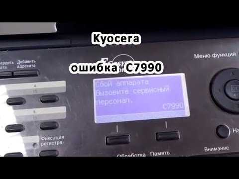 Если нет уверенности в правильности своего решения, то может…
Ноябрь 19, 2021 20 комментариев
Ноябрь 19, 2021 4 комментария
Ноябрь 19, 2021 5 комментариев
Cпорт отдых туризм
Ноябрь 20, 2021 16 комментариев
Занять всю семью непросто.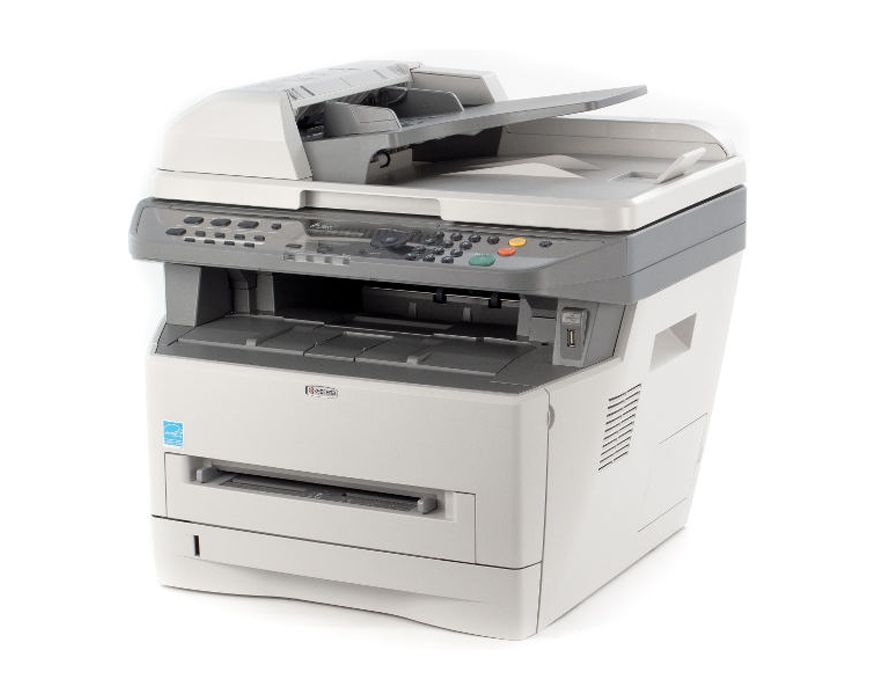 И что ж, нужно время, чтобы постоянно придумывать новые…
Бизнес
Ноябрь 20, 2021 2 комментария
Во французском языке существительное menu имеет два совершенно разных…
Спорт
Ноябрь 21, 2021 8 комментариев
Если вы все-таки решились на покупку первого сноуборда, при выборе однозначно не стоит…
Сброс, обнуление информации, ошибки об установленном неоригинальном тонер-картридже Kyocera
Модели принтеров и МФУ Kyocera, выпущенные после 2013 года, при использовании неоригинальных картриджей без чипа или заправке картриджей блокируются:
- — блокируется функция печати
- — появляется уведомление на дисплее об ошибке и/или красная световая индикация
Тем не менее производитель, компания Kyocera, допускает работу с устройством и информация о сбросе ошибки указана в инструкции по эксплуатации.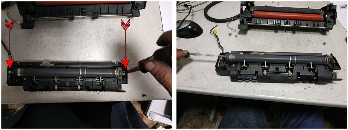
Существует 3 варианта сброса данной ошибки в зависимости от модели
Необходимо выполнить одновременное нажатие на две кнопки и удержание в течение 3-4 секунд — до момента исчезновения надписи предупреждающей надписи на устройствах с экраном и/или появления зеленой индикации предупреждающих диодов.
1. В большинстве случаев для сброса информации об ошибке необходимо нажать кнопки [Сброс] (оранжевая) и [Ок] за исключением моделей серии Aquarius:
2. В моделях после 2020 года для сброса ошибки о неоригинальном тонере, например, P3145DN. P3150DN, P3155DN, P3260DN при появлении информации об установленном неоригинальном тонере, нажать клавишу [Далее]. Появится цифра от 0 до 9 (в данном случае 4). Нужно нажать клавишу [4] и [ОК]
3. Модели МФУ с сенсорным экраном, например
M2640idw/M2735dw, M3040idn, M3145idn, M3540idn, M3550idn, M3645idn, M3655idn/M3660idn, M3860din, M6230cidn/ M6035cidn/M6630cidn, M6235cidn/ M6535cidn/M6635cidn, M4125idn/M4132idn/M8124cidn/M8130cidn, FS-C8520MFP/FS-C8525MFP/ FS-6525mfp/ FS-6530mfp; TASKalfa 2552ci/ TASKalfa 3011i/ TASKalfa 3212i/ TASKalfa 3511i/ TASKalfa 4002i/ TASKalfa 5002i/ TASKalfa 6002i/ TASKalfa 7002i/ TASKalfa 8002i/ TASKalfa 9002i/ TASKalfa 5052ci/TASKalfa 6052ci/TASKalfa 7052ci/TASKalfa 8052ci, TASKalfa 306ci/ TASKalfa 307ci/ TASKalfa 356ci/ TASKalfa 406ci и принтеры P8060cdn
при появлении информации о неустановленном картридже выбрать «Продолжить».
4. В остальных устройствах, выпускавшихся ранее, информация носит предупреждающий характер, работа принтера или МФУ не блокируются.
Расположение клавиш сброса в наиболее популярных моделях Kyocera
Сброс информации в МФУ Kyocera FS-1020mfp — кнопка [Стоп/Сброс] и кнопка выбора
Сброс информации в МФУ Kyocera FS-1025mfp, Kyocera FS-1120mfp — кнопки [Стоп/Сброс] и [OK]
Сброс информации в принтерах Kyocera FS-1040, Kyocera FS-1060DN — кнопки [GO] и [Отмена]
Сброс информации в принтерах Kyocera FS-2100DN, FS-4100DN, FS-4200DN
Сброс информации в FS-9130DN/FS-9530DN
Сброс информации в МФУ Kyocera M2030DN, M2035DN, M2535DN
Сброс информации в M2040dn/M2135dn/M2635dn/M2540dn
Сброс информации в МФУ Kyocera M3040DN, M3540DN
Сброс информации в M3145dn/M3645dn
Сброс информации в МФУ Kyocera M5521cdn/ M5521cdw
Сброс информации в МФУ Kyocera M6030cdn/M6530cdn
Сброс информации в Ecosys P2035d, FS-1120D, FS-1320dn, FS-1110
Сброс информации в FS-1370dn, P2135dn
Сброс информации в P2235dn/P2235dw
Сброс информации в P2040dn/P2040dw
Сброс информации в P3045dn/P3050dn/P3055dn/P3060dn/ P4040DN
Сброс информации в P5021cdn/P5021cdw, P5026cdn/P5026cdw
Сброс информации в P6130cdn/P6230cdn
Сброс информации в P6235cdn/P6035cdn/P7040cdn/P7240cdn
Сброс информации в TASKalfa 1800, TASKalfa1801/ TASKalfa 2201
管理とサポート | TASKalfa 4012i/3212i 特長
管理とサポート | TASKalfa 4012i/3212i версия |京セラドキュメントソリューションズ
- ГЛАВНАЯ>
- 品情報>
- モノクロA3/A4複合機・コピー機>
- ЗАДАЧАльфа 4012i/3212i>
- 特長>
- 管理とサポート
常に の ソフトウェア で 利用 できる できる
新しい サービス で ソフトウェア や ファームウェア の アップデート が です。 常に 最新 ソフト に 更新 こと で 、 万一 事態 に 備え。。 更新 する で 、 万一 事態 に ます。。 更新 する で 万一 の に ます。。 ソフト 更新 する 、0019
※ 契約 へ の ご 加入 が 必要 です。。
リモート サポート で 未然
複合 の トラブル を 防止
複合 機 リモート リモート する。。。。。。。。。。。。。。。。。。。 、 、届ける こと 、 急 な トナー 切れ を 未然 に 防ぎ ます また 、 複合機 の 状態 を リモート で 監視 し 安定 し た を サポート し ます。。 で で し 、 し た 使用 サポート し。。
※ 保守 へ の 加入 必要。。。。。。。。。。。。。。。。。。。。。。。。。。。。。。。。。。。。。。 です です です です です です です です です です です です です です です です です です です です です です です です です です です です です です です です です です です です です 必要 必要 必要 必要 必要 必要 必要 必要 必要 必要 が ご
オフィス ある 複合 機 の 管理 を 簡単 に
管理 が オフィス オフィス の ネットワーク 内 に ある の 状態 を 元 できる 、 、 各 プリンター の 通 通 は 、 発注 や 把握 把握 把握 把握 把握 把握 把握 把握 把握 把握 把握 把握 把握 把握管理のトータルな効率化を図れます。
購入 ご 検討 の お 客 様 様
お 積り ・ 資料 請求 ・ 購入 購入 の 相談 など 、 気軽 に お 請求 ・ 購入 購入 の ご 相談 など お 気軽 お 問い 合わせ。。
- 購入 関する 電話0041
- (ナビダイヤル)
受付時間 9:00〜12:00 / 13:00〜17:00
(土曜、日曜、祝日および当社指定休日は除く)
- メールでのご相談
-
-
ご購入の流れ
購入時のよくあるご質問
- 機器の選び方がわかりません。
- 保守契約は選べますか?
他の質問を見る
-
カタログダウンロード
-
ショールームのご案内
-
販売パートナーを探す
製品をご利用中のお客様
-
消耗品
-
取扱説明書ダウンロード
-
ドライバーダウンロード
-
サポート
-
保守のご案内
モノクロ複合機の一覧
ECOSYS M2640idwシリーズ
| 希望小売価格(税別) | オープン価格 |
|---|---|
| 最大用紙サイズ | A4 |
| モノクロ印刷速度 | 40枚/分 |
スマートフォン連携も簡単なビジネスエントリーモデルコンパクトモノクロA4複合機。
ECOSYS M3645idn
| 希望小売価格(税別) | オープン価格 |
|---|---|
| 最大用紙サイズ | A4 |
| モノクロ 印刷 速度 | 45 枚/分 |
7 パネル 搭載 で 快適 ・ 簡単 操作。 ニーズ に すばやく 応える モノクロ A4 複合機
TASKalfa 2520iシリーズ
| 希望小売価格(税別) | 580 000 円 〜690,000円 |
|---|---|
| 最大用紙サイズ | A3 |
| モノクロ印刷速度 | 25枚/分 |
お客様の「欲しい」と「コスト」のバランスが取れた複合機。
TASKalfa 4012iシリーズ
| 希望小売価格(税別) | 920 000 円 ~1 330 000 фунтов стерлингов |
|---|---|
| 最大用紙サイズ | А3 |
| モノクロ印刷速度 | 32~40°C/°C |
様々な利用シーンをサポートする高性能と耐久性
TASKalfa 6003i シリーズ
| 希望小売価格(税別) | 1,340,000円〜 1,620,000円 |
|---|---|
| 最大用紙サイズ | SRA3、A3 |
| モノクロ印刷速度 | 40〜60枚/分 |
長寿命技術とHyPASで、創造的な働き方を実現する複合機。
Taskalfa 9003i シリーズ
9 1122222220 000 円 12222220 000 円 ~ ~ ~ .
| 希望 小売 価格 (税別 税別) | 2 930 000 円 ~ 3 560 000 円 |
|---|---|
| 2220 000 円 | |
| モノクロ 印刷 速度 | 70 ~ 90 枚/分 |
0121
オフィスワーク 支える 、 ハイエンド モノクロ 複合機
Kyocera Alle Fehlercode Liste Deutsch – Wie Repariert Man
Маркус 10 января 2021 г.
Kyocera Fehlercode Liste Deutsche , Im Folgenden finden Sie eine lange Liste von Kyocera-Fehlercodes. Einige Kyocera-Drucker können zurückgesetzt werden, indem der Netzschalter des Geräts aus- und wieder eingeschaltet wird, während einige andere eine «Teilbetriebskontrolle» aktivieren, die den defecten Teil/Bereich des Geräts (Papiereinzugskassette, Hefter, Vorlageneinz. Wenn eine bestimmte Einheit nicht funktioniert, führen Sie U906 durch, nachdem Sie Maßnahmen gegen die Störungsursache ergriffen haben, um die Einheit wieder zu aktivieren.
Inhaltsverzeichnis
C0030 Fax PWB Проблема. Die Verarbeitung mit der Faxsoftware ist aufgrund von Software- oder Hardwareproblemen deaktiviert.
C0060 Ошибка несоответствия типа главной платы.
C0070 Fax PWB Проблема несовместимости. Программное обеспечение для факсов несовместимо с Haupt-PWB-Software.
C0130 Haupt-PWB EEPROM-Backup-Speichergerät Проблема. EEPROM kann nicht geschrieben oder gelesen werden.
C0140 Haupt-PWB EEPROM-Backup-Speicherdatenproblem. Abnormales Lesen von Daten aus dem EEPROM.
C0150 Motor-PWB EEPROM-Backup-Speichergerät Проблема. EEPROM kann nicht geschrieben oder gelesen werden.
C0160 Двигатель PWB EEPROM Проблема, связанная с датой. Abnormales Lesen von Daten в EEPROM. Lese- und Schreibdaten stimmen fünfmalhintereinander nicht überein.
C0170 Проблема с копировальным аппаратом. Ein Prüfsummenfehler wird in den Haupt- und Motor-Backup-Speichern für Kopierzähler erkannt.
C0180 Maschinennummer stimmt nicht überein Fehler. Die Maschinennummer stimmt auf den Haupt- und Motor-PWBs nicht überein.
C0600 Неправильная установка Haupt-PWB-DIMM.
C0610 Haupt-PWB-DIMM-Fehler
C0630 DMA-Übertragung komprimierten, dekomprimierten, gedrehten, verschobenen oder ausgeblendeten Bilddaten wird nicht innerhalb einer bestimmten Zeitspanne abgeschlossen.
C0640 Festplattenlaufwerk kann nicht angesprochen werden
C0700 Options CF-Backup не используется.
C0800 Bildverarbeitungsproblem. JAM05 wird zweimal erkannt.
C0830 Fax-Flash-ROM-Programmbereich-Prüfsummenfehler
C0870 Проблема с датой передачи факса-PWB zur Haupt-PWB mit hoher Kapazität.
C0880 Fax-PWB-Programchivierungsproblem.
C0920 Fax-Sicherungsdaten werden nicht beibehalten.
C1010 Fehler im Hubmotor der Kassette 1. Überschreitet 12 Sekunden Betrieb oder 500ms Überstrom.
C1020 Fehler im Hubmotor der Kassette 2. Überschreitet 12 Sekunden Betriebszeit или 500 мс Überstrom.
C1030 PF-700 дополнительная кассета №3 Liftmotorfehler.
C1040 PF-700 дополнительная кассета #4 Hubmotorfehler.
C1100 PF-750 (ссылки) Мотор-втулка 1 Fehler. Überschreitung фон 1 Sekunde Überstrom.
C1110 PF-750 (Rechts) Fehler Hebemotor 2. Überschreitet 1 Sekunde Überstrom.
C1120 PF-750 (Ссылки) Hebemotor 1 Positionsproblem. PF-Schalter 2 bleibt nach 30 Sekunden Motorbetrieb ausgeschaltet.
C1130 PF-750 (Rechts) Positionsproblem Liftmotor 2. PF-Schalter 1 bleibt nach 30 Sekunden Motorbetrieb ausgeschaltet.
C1800 PF-700/PF-750 Проблемы связи.
C1900 PF-700 ЭСППЗУ-Фелер. Schreibdaten & Lesedaten sind dreimalhintereinander nicht in Übereinstimmung.
C2000 Антрибмоторпроблема. Stable Off wird длиннее 1 сек. nach Motorstabilisierung erkannt. Stabilisierung wird nicht mit 6 Sek. nach Aktivierung erkannt.
C2250 Hauptladungsreiniger Motorfehler. Verriegelungsfehler wird dreimal hintereinander während des Betriebs des Reinigermotors erkannt.
C2500 Papiervorschubmotor-Fehler. Stabiles Aus wird Länger als 1 Sek. nach Motorstabilisierung erkannt. Stabilisierung wird nicht innerhalb von 6 Sekunden nach Aktivierung erkannt.
C2600 PF-700 Антрибмотор-Фелер. Verriegelungssignal überschreitet 500 мс.
C2600 PF-750 Fehler des Papiertransportmotors. Verriegelungssignal überschreitet 450 мс.
C3100 Проблема сканера-Шлиттена. Scanner-Ausgangsposition wird bei der Initialisierung oder beim Start des Kopierens vom Kontaktglas nicht erkannt.
C3200 Проблема со световой лампой. Belichtungslampe erreicht nicht innerhalb von 5 Sek. nach Beginn der Lesung den Schwellenwert des Eingangswertes.
C3210 Проблема с белой лампой. Berichtungslampe überschreitet den Eingangsschwellenwert nicht innerhalb von 5 Sek. nach Beginn der Lesung.
C3300 CCD-AGC-Проблема. Nach AGC wird kein correkter Eingang am CCD erreicht.
C3310 CIS AGC Проблема. Nach der AGC wird kein correkter Eingang am CIS erreicht.
C3500 Kommunikationsfehler Zwischen Scanner und SHD.
C3900 Scanner PWB Backup-Speicher Lese-/Schreibproblem. Lese- und Schreibdaten stimmen nicht überein.
C3910 Scanner-PWB-Backup-Speicher-Datenпроблема. Daten in einem bestimmten Bereich des Sicherungsspeichers stimmen nicht mit den angegebenen Werten überein.
C4000 Polygonmotor-Проблема синхронизации. Der Polygonmotor stabilisiert seine Geschwindigkeit nicht innerhalb von 20 Sekunden nach der Aktivierung.
C4010 Проблема стационарного двигателя многоугольника.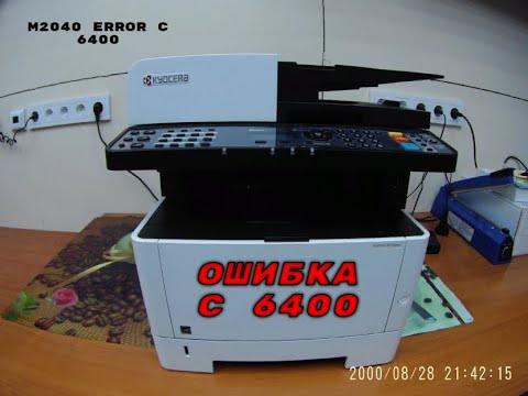 Nach der Stabilisierung des Polygonmotors wird 20 Sek. lang kein stabiler Zustand erkannt.
C4200 BD Проблема установившегося состояния. ASIC erkennt einen Beam-Detect-Fehler A für 2 Sek. nach der Polygonmotor-Stabilisierung.
C5300 Reinigungslampe Drahtbruch. Während die Reinigungslampe eingeschaltet ist, wird das Signal zur Erkennung eines Drahtbruchs für 2 Sekunden kontinuierlich erkannt.
C6000 Heizungsbruch der Fixiereinheit. Thermistor1 hat während der Aufwärm- und Bereitschaftsphase 10 Sekunden lang eine Temperatur von Weniger als 70C/158F festgestellt. Thermistor2 hat während der Aufwärm- und Bereitschaftsphase 10 Sekunden lang weniger als 40C/104F erkannt. Die Temperatur an Thermistor 1 или 2 steigt innerhalb von 5 Sek. nicht um mindestens 1C/1.8F.
C6020 Ungewöhnlich hohe Thermistortemperatur. Термистор 1 или 2 провода 250C/482F для 40 мс или дольше.
C6030 Fehler bei Thermistorbruch beheben. Термисторбрухсигнал для 1-й проверки.
C6050 Ungewöhnlich niedrige Thermistortemperatur.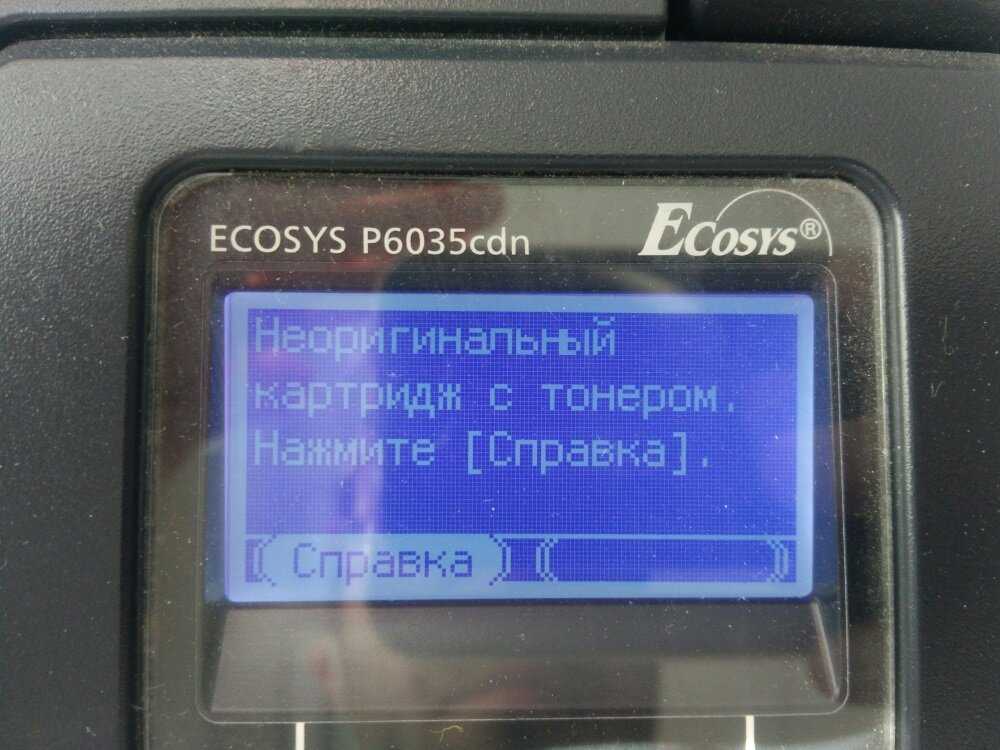 Термистор 1 wird während des Kopierens 1 Sekunde lang kontinuierlich 80C/176F oder weniger erkannt.
C6400 Nulldurchgangssignalfehler. Während der Ein/Aus-Steuerung der Fixiereinheit wird das Nulldurchgangssignal nicht innerhalb von 3 s eingegeben.
C6410 Проблема beim Einsetzen der Fixiereinheit. Das Fehlen дер Fixiereinheit Wird erkannt.
C6420 Проблема beim Durchtrennen der Sicherung der Fixiereinheit. Die Sicherung wurde 33 Sek. nach Einschalten des Signals zum Abschalten der Sicherung abgeschaltet.
C7300 Проблема с тонером. Tonerstand wird nicht erkannt, wenn Toner leer erkannt wird.
C7400 Проблема с Einstecken der Entwicklungseinheit. Das Fehlen дер Entwicklungseinheit wird erkannt.
C7410 Проблема с Einstecken der Trommeleinheit. Das Fehlen дер Trommeleinheit wird erkannt.
C7800 Gebrochener externer Thermistordraht. Термистор с Umgebungssensor gibt 4,5 V oder mehr aus.
C7810 Внешний термистор Kurzgeschlossener. Термоаккумулятор ist 0,5v или weniger.
C7900 Trommel-EEPROM-Фелер. Lesen oder Schreiben in das EEPROM kann nicht durchgeführt werden.
C7910 Fehler beim Entwickeln des EEPROMs. Das Lesen oder Schreiben in das EEPROM kann nicht durchgeführt werden.
C8020 DF-710 Станцмоторпроблема. Das Signal zur Verriegelung des Stanzmotors wird während der Aktivierung für 500ms oder länger erkannt.
C8030 DF-730 Проблема определения верхнего предела лотка. Wenn der Motor zum Anheben eines Fachs ein Fach anhebt, erkennt der obere Endschalter den Zustand Ein.
C8050 DF-710 Papiertransportbandmotor 1 Fehler. Der Sensor 1 für die Grundstellung des Papiertransportbandes schaltet sich nicht innerhalb von 1,5 Sekunden aus. Der Sensor für die Grundstellung des Papiertransportbandes 1 schaltet nicht innerhalb von 2,5 Sekunden ein. Stau 88.
C8060 DF-710 Papiertransportbandmotor 2 Fehler. Der Sensor für die Grundstellung des Papiertransportbandes 2 schaltet sich nicht innerhalb von 1,5 Sekunden aus. Der Sensor 2 für die Grundstellung des Papiertransportbandes schaltet nicht innerhalb von 2,5 Sekunden ein.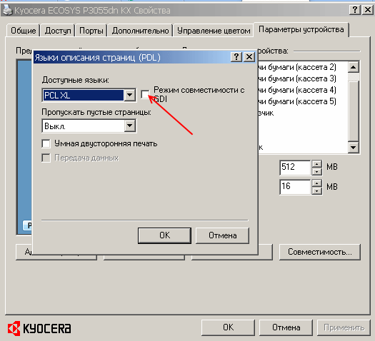
C8070 DF-710 Ошибка связи с внутренним лотком. Die Verbindung wird erkannt, aber die Kommunikation mit dem internen Fach ist nicht möglich.
C8140 DF-710 Hauptfach Проблема. Hauptfach wird nicht vom Hauptfach-Obergrenzen-Erkennungssensor oder vom Hauptfach-Kapazitätserkennungssensor innerhalb von 20 Sek. nach dem Aufsteigen erkannt. Hauptfach-Obergrenzen-Erkennungssensor oder Hauptfach-Kapazitätserkennungssensor wird innerhalb von 20 Sek. nach dem Abwärtsfahren des Hauptfachs nicht als Aus erkannt. Der Sensor zur Erkennung der Unteren Grenze des Hauptfachs wird nicht innerhalb von 20 Sekunden nach dem Absenken des Hauptfachs als Ein erkannt. Der Sensor für die Erkennung der Obergrenze des Haupttabletts oder der Sensor für die Erkennung der Haupttablettlast bleibt während des Ansteigens des Haupttabletts für 2 Sekunden oder länger eingeschaltet.
C8140 DF-730 Проблема двигателя подъема лотка. Tray-Untergrenzensensor или Oberflächensicht-Sensor kann nicht innerhalb von 10 Sek. Эркант Верден.
C8170 DF-710 Seitenregistrierungsmotor 1 Проблема. Während der ersten Umdrehungen wird die Ausgangsposition nicht innerhalb von 3 Sek. эрканнт. Stau 88.
C8170 DF-720 Проблема двигателя передней боковой регистрации. Während der ersten Umdrehungen wird die Grundstellung nicht innerhalb von 106 Impulsen erkannt. Wenn der Sensor für die Home-Position der Vorderseite während der Initialisierung ausgeschaltet wird, schaltet sich der Sensor nicht innerhalb von 3 Sekunden ein.
C8170 DF-730 Проблема с двигателем Justier. Der Motor für die Grundstellung des Justiermotors wird während der Aktivierung nicht innerhalb einer bestimmten Zeit erkannt.
C8180 DF-710 Seitenregistrierungsmotor 2 Проблема. Während der ersten Umdrehungen wird die Grundstellung nicht innerhalb von 3 Sek. эрканнт. Stau 88.
C8180 DF-720 Hinterer Seitenregistrierungsmotor Проблема. Während der ersten Umdrehungen wird die Grundstellung nicht innerhalb von 106 Impulsen erkannt. Wenn der Sensor für diehintere Grundstellung während der Initialisierung ausgeschaltet wird, schaltet sich der Sensor nicht innerhalb von 3 Sek. Эйн.
Эйн.
C8190 DF-720 Проблема двигателя регистрации заднего фронта. Während der ersten Umdrehungen wird die Grundstellung nicht innerhalb von 106 Impulsen erkannt. Wenn der Sensor für die Ausgangsposition der Hinteren Kante während der Initialisierung ausgeschaltet wird, schaltet sich der Sensor nicht innerhalb von 3 Sekunden ein.
C8210 DF-710 Hefter Bewegungsmotor 1 Fehler. Während der ersten Umdrehungen wird die Grundstellung nicht innerhalb von 1,5 Sek. эрканнт.
C8210 DF-720 Проблема с финишером. Der Sensor für die Ausgangsposition des Hefters ändert seinen Zusstand nicht innerhalb von 200 ms nach der Vorwärtsdrehung (CCW) von «nicht erkannt» zu «erkannt». Während der ersten Umdrehungen wechselt die Grundstellungserkennung des Hefters innerhalb von 600 ms nach einer Rückwärtsdrehung (CW) nicht von Nicht-Erkennung zu Erkennung.
C8210 Проблема с DF-730 Hefter. Die Grundstellung wird nicht innerhalb einer bestimmten Zeit nach der Aktivierung erkannt.
C8220 DF-710 Hefter Bewegungsmotor 2 Fehler. Während der ersten Umdrehungen wird die Grundstellung nicht innerhalb von 3,5 Sek. эрканнт.
C8230 DF-710 Проблема с подъемным двигателем. Stau 82 wird angezigt.
C8300 BF-710 Разворотный модуль Kommunikationsfehler. Obwohl die Verbindung erkannt wird, ist eine Kommunikation mit der Centerfold-Einheit nicht möglich.
C8310 BF-710 Двигатель 1 боковой регистрации центральной фальцовки Проблема. Während der ersten Umdrehungen wird die Grundstellung nicht innerhalb von 1000ms erkannt.
C8320 BF-710 Проблема с двигателем разворота бумаги. Während der ersten Umdrehungen wird die Ausgangsposition nicht innerhalb von 2500 ms erkannt.
C8330 BF-710 Проблема двигателя Klingen. Während der ersten Umdrehungen wird die Grundstellung nicht innerhalb von 1500 ms erkannt.
C8340 BF-710 Кламмермотор центрального сгиба Проблема. Stau 89.
C8350 BF-710 Разворот Seitenregist
C8460 DF-730 Проблема EEPROM. Lesen in Oder Schreiben aus EEPROM kann nicht durchgeführt werden.
C8500 MT-710 Связь. Die Verbindung wird erkannt, aber die Kommunikation mit der Mailbox ist nicht möglich.
C8510 MT-710 Антрибмоторпроблема. Das Motorverriegelungssignal wird während der Aktivierung für mehr als 500ms erkannt.
C8800 DF-710 Проблема связи. Keine Kommunikation: Es erfolgt keine Antwort nach (5) Versuchen. Abnormale Communikation: Ein Paritätsoder Prüfsummenfehler wird (5) Mal in Folge erkannt.
C8900 DF-710 Datensicherungsspeicherпроблема. Lese- und Schreibdaten stimmen nicht überein.
C8910 PH-5A Проблема с Sicherungsspeicherdaten. Lese- und Schreibdaten stimmen nicht überein.
C8920 MT-710 Проблема с Sicherungsspeicherdaten. Lese- und Schreibdaten stimmen nicht überein.
C8930 BF-710 Проблема с Sicherungsspeicherdaten. Lese- und Schreibdaten stimmen nicht überein.
C9000 DP-700 Проблема связи. Es wurde ein Kommunikationsfehler festgestellt.
C9040 DP-700 Liftmotor-Aufstiegsfehler. Der obere Endschalter des DP-Aufzugs wird innerhalb von 10000 Impulsen nicht erkannt. Nach einem einmaligen Wiederholungsversuch konnte der obere Endschalter des DP-Aufzugs nicht eingeschaltet werden.
C9050 Ошибка спуска двигателя подъема DP-700. Der Untere Endschalter des DP-Aufzugs wird innerhalb von 10000 Impulsen nicht erkannt. Nach einem einmaligen Wiederholungsversuch konnte der untere Endschalter des DP-Hubs nicht eingeschaltet werden.
C9060 DP-700 EEPROM-Фелер. Lese- und Schreibdaten stimmen nicht überein. Die Daten im angegebenen Bereich des Sicherungsspeichers stimmen nicht mit den angegebenen Werten überein.
C9070 DP-700 Kommunikationsfehler zwischen dem DP und dem SHD. Es wurde ein Kommunikationsfehler festgestellt.
C9080 DP-700 Kommunikationsfehler zwischen dem DP und dem CIS. Das Lesen kann nicht korrekt durchgeführt werden.
CF000 Bedienfeld-PWB Kommunikationsfehler/Systemfehler. Унбекантер Фелер. Kommunikationsfehler zwischen Bedienfeld und Hauptcontroller. (Wenn CF620 aufgetreten ist und verlassen wird, ist CF000 auch wegen der Timeout-Kontrolle aufgetreten.
CF010 Haupt-PWB Prüfsummenfehler/Systemfehler.0025 CF030 Haupt-PWB-Systemfehler.
CF040 Motor-PWB Kommunikationsfehler.
CF041 Scanner-PWB-Communikationsfehler.
CF050 Motor-ROM-Prüfsummenfehler.
CF060 Motor-RAM-Fehler.
CF070 Flash-ROM-Fehler. Дефекты Flash-ROM (валчи?).
CF080 Flash-ROM-Fehler (доступен для загрузки). Дефекты Flash-ROM (валчи?).
CF090 Fax System M Kommunikationsfehler.
CF14F Fehler auf der Sekundärseite der Stromquelle/Betriebssystemfehler. Der Betrieb wird nach dem Wiederherstellen des Stromversorgungsfehlers (Stromausfall oder Spannungsabfall) instabil. Die Wandspannung ist instabil oder der Hauptschalter der Stromversorgung wurde innerhalb von 1 Sekunde AUS/EIN geschaltet.
CF256 Faxsystem M IOBL-Fehler или KUIOLIB-Fehler. Schlechter Kontakt an der Faxkarte aufgrund eines falschen Einbaus.
CF257 Faxsystem M IOBL-Fehler или KUIOLIB-Fehler. Schlechter Kontakt an der Faxkarte durch Fehlinstallation.
CF26F Drucksystem Sonstige Fehler. Fehler von v.2.03B wurde mit v.2.04A behoben (Буклет > Печать буклета).
CF3xx Неопределенный.
CF423 Факс M Fehler. Falsche Daten oder falscher Wert erkannt, wenn die folgende Funktion verwendet wird. Oder schlechter Kontakt an der Faxkarte aufgrund einer falschen Installation.
CF423 Факсимильная система М Fehler. Der IF-Fehler wird während der Systemauthentifizierung von ACT_Account_Manager erkannt. Oder schlechter Kontakt an der Faxkarte aufgrund einer Fehlinstallation.
CF433 CF434 CF437 CF43F CF441 CF444 CF445 CF451 Ошибка обработки образа жесткого диска. Zerstörung von gespeicherten Aufträgen auf der Festplatte. Kann auftreten, wenn die Tasten für den Aufruf gespeicherter Копировальный аппарат Scanneraufträge aus einer Custom Box gewählt werden.
CF45F CF453 CF454 CF45F CF460 CF463 CF46F CF470 Ошибка обработки образа жесткого диска. Zerstörung von gespeicherten Aufträgen auf der Festplatte. Kann auftreten, wenn die Tasten für den Aufruf von gespeicherten Kopier-oder Scanneraufträgen aus einer Anwenderbox gewählt werden.
CF473 CF47F CF484 CF487 CF48F CF490 CF493 CF494 Ошибка обработки образа жесткого диска. Zerstörung von gespeicherten Aufträgen auf der Festplatte. Kann auftreten, wenn die Tasten für den Aufruf eines gespeicherten Kopier-oder Scannerauftrags aus einer Anwenderbox gewählt werden.
CF5xx Неопределенный.
CF610 Systemstartfehler.
CF620 Системфелер. Fehler beim Erfassen der Ereignisdaten. Das Panel erkennt CF000 als gleichen Fehler.
CF620 Системфелер. Fehler beim Erfassen der Ereignisdaten. Сделанная панель CF000 также плотно закрыта Fehler. Невозможно загрузить файлы на CF-карту.
CF7D7 Auslesefehler von SSL (Authentifizierungsdaten).
CFAxx Festplattenfehler.
CFB2C CFB30 CFB31 Панель-Фелер. NetFont-Фелер. Kommunikationsfehler zwischen Panel und Hauptcontroller während der Initialisierung oder Ablehnung der Kommunikation durch den Controller während der Initialisierung. Blauer Bildschirm des Todes.
CFB30 Incompatibler Level der Firmware auf dem Haupt-EEPROM.
CFB31 Повреждена прошивка в Haupt-EEPROM.
CFB32 Панель-Фелер. Тайм-аут-Anforderung für Start-Befehl. Startbefehl ist nicht empfangen worden. Mögliche Zerstörung der Systemdatei auf der Festplatte. Kann nicht in den Wartungsmodus gehen. Blauer Bildschirm des Todes.
CFB33 Панель-Фелер. Erkennt eine Unterbrechung der Verbindung mit der Steuerung. Mögliche Übersteuerung der Steuerplatine oder Zerstörung der Systemdatei auf der Festplatte. Kann nicht in den Wartungsmodus wechseln. Blauer Bildschirm des Todes.
F000 Bedienfeld-PWB-Kommunikationsfehler.
F010 Prüfsummenfehler der Haupt-PWB.
F020 Speicher-Prüfsummenfehler.
F030 Systemfehler der Haupt-PWB.
F040 Motor-PWB-Communikationsfehler.
F041 Сканер-PWB-Kommunikationsfehler.
F050 Motor-ROM-Prüfsummen-Fehler.
F060 Motor-RAM-Fehler.
F070 Flash-ROM-Fehler.
F080 Flash-ROM-Fehler (ссылка для загрузки).
F090 Fax-Steuerungs-PWB-Kommunikationsfehler.
F14F Ошибка второй стороны PWB источника питания.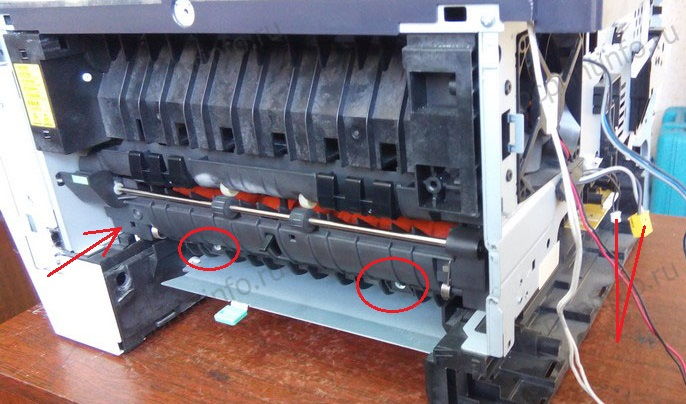
E00000 или U00000 Faxkommunikationsfehler: Keine Antwort или Leitung besetzt nach der eingestellten Anzahl von Wahlwiederholungen.
E00100 или U00100 Fehler bei der Faxkommunikation: Die Übertragung wurde durch Drücken der Taste Stopp/Löschen unterbrochen.
E00200 или U00200 Fehler bei der Faxkommunikation: Der Empfang wurde durch einen Druck auf die Taste Stopp/Löschen unterbrochen.
E00300 или U00300 Fehler bei der Faxkommunikation: Das Registrierpapier in der Zieleinheit ist während des Empfangs ausgegangen.
E00420 или U00420 Fehler bei der Faxkommunikation: Eine Weiterleitungsanforderung wurde von der Hostzentrale empfangen, aber aufgrund einer Nichtübereinstimmung der Genehmigungs-ID oder der Telefonnummer unterbrochen.
E00421 oder U00421 Fehler bei der Faxkommunikation: Der Empfang eines subaddressenbasierten Relais wurde aufgrund einer Nichtübereinstimmung in der angegebenen Subadressen-Relaisboxnummer unterbrochen.
E00430 или U00430 Fehler bei der Faxkommunikation: Der Empfang einer Abrufanforderung (vertraulicher oder umgekehrter Abruf) wurde unterbrochen, weil die Nummer der Genehmigung nicht übereinstimmt.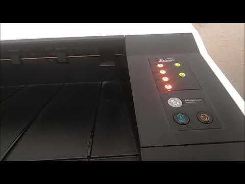
E00430 или U00430 Fax-Kommunikationsfehler: Die Bulletin-Board-Übertragung über Subaddresse wurde aufgrund einer Nichtübereinstimmung in der Genehmigungsnummer der übertragenden Einheit unterbrochen.
E00431 или U00431 Fax-Kommunikationsfehler: Die vertrauliche Abrufübertragung wurde unterbrochen, weil die angegebene vertrauliche Boxnummer nicht registriert wurde.
E00431 или U00431 Fehler bei der Faxkommunikation: Eine Bulletin-Board-Übertragung mit Subaddresse wurde unterbrochen, weil die angegebene vertrauliche Box nicht registriert wurde.
E00432 или U00432 Fehler bei der Faxkommunikation: Die vertrauliche Abrufübertragung wurde unterbrochen, weil die ID-Nummer der vertraulichen Box nicht übereinstimmt.
E00432 или U00432 Fehler bei der Faxkommunikation: Eine Bulletin-Board-Übertragung über Subaddresse wurde aufgrund einer Fehlanpassung in der vertraulichen Boxnummer unterbrochen.
E00433 или U00433 Fax-Kommunikationsfehler: Eine vertrauliche Abrufanforderung wurde empfangen, aber es waren keine Daten in der vertraulichen Box vorhanden.
E00433 или U00433 Fax-Communikationsfehler: Subadressenbasierte Bulletin-Board-Übertragungsanforderung wurde empfangen, aber es waren keine Daten in der vertraulichen Box for Subaddressen vorhanden.
E00434 или U00434 Fax-Communikationsfehler: Vertrauliche Abrufanforderung wurde empfangen, aber unterbrochen, weil die angegebene vertrauliche Boxnummer zur Verschlüsselung vorgesehen war.
E00435 или U00435 Fehler bei der Faxkommunikation: Die vertrauliche Abrufanforderung wurde empfangen, aber unterbrochen, weil auf die angegebene vertrauliche Box zugegriffen wurde.
E00435 или U00435 Fehler bei der Faxkommunikation: Subadressenbasierte Bulletin-Board-Übertragungsanforderung wurde empfangen, aber unterbrochen, weil auf die angegebene vertrauliche Box zugegriffen wurde.
E00440 или U00440 Fax-Communikationsfehler: Der vertrauliche Empfang wurde unterbrochen, weil die angegebene vertrauliche Boxnummer nicht registriert war.
E00440 или U00440 Fehler bei der Faxkommunikation: Der vertrauliche Empfang über Subaddresse oder der Relaisempfang über Subaddresse wurde unterbrochen, weil die angegebene Subadressenbox nicht registriert wurde.
E00440 или U00440 Fehler bei der Faxkommunikation: Der vertrauliche Empfang über Subaddresse oder der Empfang von Relay-Befehlen über Subaddresse wurde unterbrochen, weil auf die spezifische Subaddressenboxnummer zugegriffen wurde.
E00441 или U00441 Faxkommunikationsfehler: Der vertrauliche Empfang wurde unterbrochen, weil die angegebene vertrauliche Boxnummer zur Verschlüsselung vorgesehen war.
E00450 или U00450 Fax-Communikationsfehler: Die Verbindung zum Zielsender wurde unterbrochen, weil die Genehmigungs-IDs nicht übereinstimmten, während sich der Zielsender in der passwortgeschützten oder eingeschränkten Übertragung befindet.
E00460 или U00460 Fehler bei der Faxkommunikation: Der verschlüsselte Empfang wurde unterbrochen, weil die angegebene Verschlüsselungsboxnummer nicht registriert wurde.
E00460 или U00460 Fehler bei der Faxkommunikation: Die Anforderung für den verschlüsselten Empfang wurde empfangen, aber unterbrochen, weil auf die angegebene Verschlüsselungsbox zugegriffen wurde.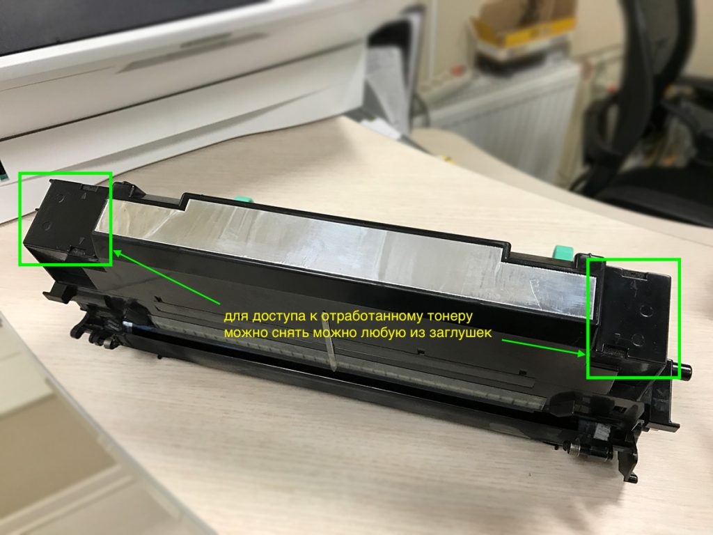
E00462 или U00462 Факс-коммуникатор: Der Verschlüsselungsempfang wurde unterbrochen, weil der Verschlüsselungscode für die angegebene Verschlüsselungsbox nicht registriert wurde.
E00500 или U00500 Fehler bei der Faxkommunikation: Die Mehrfachkommunikation wurde unterbrochen und der Anruf wurde nach der Unterbrechung auf den Zielgeräten nicht ausgeführt.
E00600 или U00600 Fehler bei der Faxkommunikation: Die Abdeckung des Vorlageneinzugs ist geöffnet.
E00601 или U00601 Fehler bei der Faxkommunikation: Dokumentenstau oder die Dokumentenlänge überschreitet das Maximum.
E00602 или U00602 Связь по факсу: Проблема в Bildeinzugsbereich
E00603 или U00603 Связь по факсу: Kein Dokumenteneinzug.
E00604 oder U00604 Fehler bei der Faxkommunikation: Die Dokumentlänge hat die Grenze der Bitmap-Speicherkapazität überschritten.
E00610 или U00610 Fax-Kommunikationsfehler: Abdeckung des Aufnahmebereichs offen.
E00611 или U00611 Fax-Kommunikationsfehler: Aufzeichnungspapierstau.
E00613 или U00613 Fax-Kommunikationsfehler: Проблема в Bildschreibbereich.
E00614 oder U00614 Fehler bei der Faxkommunikation: Aufzeichnungspapier fast leer.
E00615 или U00615 Fehler bei der Faxkommunikation: Aufzeichnungspapier ist leer.
E00620 или U00620 Fehler bei der Faxkommunikation: Problem mit der Fixiereinheit des Kopierers.
E00622 или U00622 Fax-Kommunikationsfehler: Проблема с Antriebsmotor des Kopierers.
E00655 или U00655 Fehler bei der Faxkommunikation: CTS wurde aufgrund eines Modemfehlers nach RTS nicht aktiviert.
E00656 или U00656 Fehler bei der Faxkommunikation: Daten wurden aufgrund eines Modemfehlers nach der Aktivierung von CTS nicht übertragen.
E00670 или U00670 Faxkommunikationsfehler: Die Stromversorgung wurde während der Communikation unterbrochen.
E00677 или U00677 Fehler bei der Faxübertragung: Es konnte keine Datei im Speicherübertragungsmodus übertragen werden.
E00690 или U00690 Fehler bei der Faxübertragung: Systemfehler.
E00700 или U00700 Fax-Kommunikationsfehler: Die Kommunikation wurde aufgrund eines Problems in der Zieleinheit unterbrochen.
E00800 или U00800 Fax-Communikationsfehler: Im G3-Modus ist ein Seitenübertragungsfehler aufgetreten, weil ein RTN- или PIN-Signal empfangen wurde.
E00810 или U00810 Fehler bei der Faxübertragung: Ein Seitenübertragungsfehler ist im G3-Modus nach einem erneuten Übertragungsversuch im ECM-Modus aufgetreten.
E00900 или U00900 Fax-Kommunikationsfehler: Ein Seitenempfangsfehler ist im G3-Modus aufgetreten. Ein RTN- oder PIN-Signal wurde aufgrund eines Seitenempfangsfehlers übertragen.
E00910 или U00910 Fax-Kommunikationsfehler: Im G3-Modus ist ein Seitenempfangsfehler aufgetreten. Ein Seitenempfangsfehler blieb nach der Wiederholung der Übertragung im ECM-Modus bestehen.
E01000 или U01000 Fax-Communikationsfehler: Die Übertragung im G3-Modus wurde durch einen Signalfehler unterbrochen. Ein FTT-Signal wurde für eine bestimmte Anzahl von Malen nach TCF-Signalübertragungen bei 2400bps empfangen.
E01000 или U01000 Fax-Kommunikationsfehler: Die Übertragung im G3-Modus wurde durch einen Signalfehler unterbrochen. Ein RTN-Signal передаёт ответ на Q-Signal (außer EOP) с пропускной способностью 2400 бит/с.
E01001 или U01001 Fax-Communikationsfehler: Die Übertragung im G3-Modus wurde durch einen Signalfehler unterbrochen. Die Funktion des Geräts weicht von der durch ein DIS-Signal angezeigten Funktion ab.
E01010 или U01010 Fax-Communikationsfehler: Die Übertragung im G3-Modus wurde durch einen Signalfehler unterbrochen. Nach der Übertragung eines DNL-Signals (MPS oder EOM) wurde kein entsprechendes Signal empfangen, und die voreingestellte Anzahl der Befehlsübertragungen wurde überschritten (zwischen Geräten unserer Marke).
E01011 или U01011 Fax-Kommunikationsfehler: Die Übertragung im G3-Modus wurde durch einen Signalfehler unterbrochen. Nach der Übertragung eines DCS-, TCF-Signals wurde kein relayes Signal empfangen und die voreingestellte Anzahl der Befehlsübertragungen wurde überschritten.
E01012 или U01012 Faxkommunikationsfehler: Die Übertragung im G3-Modus wurde durch einen Signalfehler unterbrochen. Nach der Übertragung eines NSS1-, NSS2- (TCF-) Signals wurde kein entsprechendes Signal empfangen, und die voreingestellte Anzahl der Befehlsübertragungen wurde überschritten (zwischen Geräten unserer Marke).
E01013 или U01013 Fax-Communikationsfehler: Die Übertragung im G3-Modus wurde durch einen Signalfehler unterbrochen. Nach der Übertragung eines NSS3-, TCF-Signals wurde kein entsprechendes Signal empfangen, und die voreingestellte Anzahl der Befehlsübertragungen wurde überschritten (zwischen Geräten unserer Marke).
E01014 или U01014 Faxkommunikationsfehler: Die Übertragung im G3-Modus wurde durch einen Signalfehler unterbrochen. Nach der Übertragung eines MPS-Signals wurde kein relayes Signal empfangen, und die voreingestellte Anzahl der Befehlsübertragungen wurde überschritten.
E01015 или U01015 Fax-Communikationsfehler: Die Übertragung im G3-Modus wurde durch einen Signalfehler unterbrochen.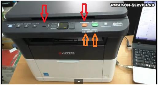 Nach der Übertragung eines EOM-Signals wurde kein relayes Signal empfangen, und die voreingestellte Anzahl der Befehlsübertragungen wurde überschritten.
E01016 или U01016 Fax-Communikationsfehler: Die Übertragung im G3-Modus wurde durch einen Signalfehler unterbrochen. Es wurde ein MCF-Signal empfangen, aber kein DIS-Signal nach der Übertragung eines EOM-Signals, und es wurde eine T1-Zeitüberschreitung festgestellt.
E01017 или U01017 Faxkommunikationsfehler: Die Übertragung im G3-Modus wurde durch einen Signalfehler unterbrochen. Nach der Übertragung eines EOP-Signals wurde kein relayes Signal empfangen, und die voreingestellte Anzahl der Befehlsübertragungen wurde überschritten.
E01018 или U01018 Fax-Communikationsfehler: Die Übertragung im G3-Modus wurde durch einen Signalfehler unterbrochen. Nach der Übertragung eines PRI-EOP-Signals wurde kein relayes Signal empfangen, und die voreingestellte Anzahl der Befehlsübertragungen wurde überschritten.
E01019 или U01019 Faxkommunikationsfehler: Die Übertragung im G3-Modus wurde durch einen Signalfehler unterbrochen.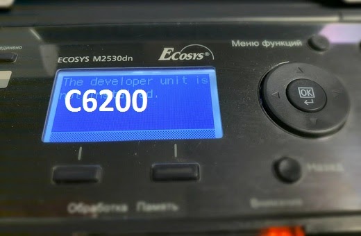 Nach der Übertragung eines CNC-Signals wurde kein entsprechendes Signal empfangen, und die voreingestellte Anzahl der Befehlsübertragungen wurde überschritten (zwischen Geräten unseres Fabrikats).
E01020 или U01020 Fax-Communikationsfehler: Die Übertragung im G3-Modus wurde durch einen Signalfehler unterbrochen. Nach der Übertragung eines CTC-Signals wurde kein релевантные Signal empfangen, und die voreingestellte Anzahl der Befehlsübertragungen wurde überschritten (ECM).
E01021 или U01021 Fax-Communikationsfehler: Die Übertragung im G3-Modus wurde durch einen Signalfehler unterbrochen. Nach der Übertragung eines EOR.Q-Signals wurde kein релевантные Signal empfangen, und die voreingestellte Anzahl der Befehlsübertragungen wurde überschritten (ECM).
E01022 или U01022 Faxkommunikationsfehler: Die Übertragung im G3-Modus wurde durch einen Signalfehler unterbrochen. Nach der Übertragung eines RR-Signals wurde kein релевантные Signal empfangen, und die voreingestellte Anzahl der Befehlsübertragungen wurde überschritten (ECM).
E01023 или U01023 Faxkommunikationsfehler: Die Übertragung im G3-Modus wurde durch einen Signalfehler unterbrochen. Nach der Übertragung eines PS.NULL-Signals wurde kein entsprechendes Signal empfangen, und die voreingestellte Anzahl der Befehlsübertragungen wurde überschritten (ECM).
E01024 или U01024 Fax-Communikationsfehler: Die Übertragung im G3-Modus wurde durch einen Signalfehler unterbrochen. Nach der Übertragung eines PPS.MPS-Signals wurde kein релевантные Signal empfangen, und die voreingestellte Anzahl der Befehlsübertragungen wurde überschritten (ECM).
E01025 или U01025 Faxkommunikationsfehler: Die Übertragung im G3-Modus wurde durch einen Signalfehler unterbrochen. Nach der Übertragung eines PPS.EOM-Signals wurde kein relayes Signal empfangen, und die voreingestellte Anzahl der Befehlsübertragungen wurde überschritten (ECM).
E01026 или U01026 Faxkommunikationsfehler: Die Übertragung im G3-Modus wurde durch einen Signalfehler unterbrochen. Nach der Übertragung eines PPS. EOP-Signals wurde kein релевантные Signal empfangen, und die voreingestellte Anzahl der Befehlsübertragungen wurde überschritten (ECM).
E01027 или U01027 Fax-Communikationsfehler: Die Übertragung im G3-Modus wurde durch einen Signalfehler unterbrochen. Nach der Übertragung eines PPS.PRI-EOP-Signals wurde kein entsprechendes Signal empfangen, und die voreingestellte Anzahl der Befehlsübertragungen wurde überschritten (ECM).
E01028 или U01028 Fax-Communikationsfehler: Die Übertragung im G3-Modus wurde durch einen Signalfehler unterbrochen. T5-Timeout während während der ECM-Übertragung erkannt (ECM).
E01040 или U01040 Fax-Kommunikationsfehler: Die Übertragung im G3-Modus wurde durch einen Signalfehler unterbrochen. Ein DCN oder ein anderes ungeeignetes Signal während der Bereitschaft für den DIS-Signalempfang empfangen.
E01041 или U01041 Fehler bei der Faxkommunikation: Die Übertragung im G3-Modus wurde durch einen Signalfehler unterbrochen. Ein DCN-Signal wurde nach der Übertragung eines DNL-Signals (MPS oder EOM) empfangen (zwischen Geräten unserer Marke).
E01042 или U01042 Fax-Communikationsfehler: Die Übertragung im G3-Modus wurde durch einen Signalfehler unterbrochen. Ein DCN-Signal wurde nach der Übertragung eines DCS-, TCF-Signals empfangen.
E01043 или U01043 Fax-Communikationsfehler: Die Übertragung im G3-Modus wurde durch einen Signalfehler unterbrochen. Ein DCN-Signal wurde nach der Übertragung eines NSS1, NSS2 (TCF)-Signals empfangen (zwischen Geräten unserer Marke).
E01044 или U01044 Fax-Kommunikationsfehler: Die Übertragung im G3-Modus wurde durch einen Signalfehler unterbrochen. Ein DCN-Signal wurde nach der Übertragung eines NSS3-, TCF-Signals empfangen (zwischen Geräten unserer Marke).
E01045 или U01045 Fax-Communikationsfehler: Die Übertragung im G3-Modus wurde durch einen Signalfehler unterbrochen. Nach der Übertragung eines MPS-Signals wurde eine DCN oder ein anderes ungeeignetes Signal empfangen.
E01046 или U01046 Fax-Communikationsfehler: Die Übertragung im G3-Modus wurde durch einen Signalfehler unterbrochen.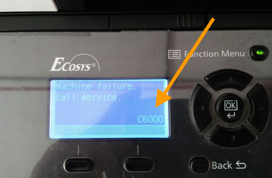 Eine DCN oder ein anderes ungeeignetes Signal wurde nach der Übertragung eines EOM-Signals empfangen.
E01047 или U01047 Faxkommunikationsfehler: Die Übertragung im G3-Modus wurde durch einen Signalfehler unterbrochen. Nach der Übertragung eines EOP-Signals wurde eine DCN oder ein anderes ungeeignetes Signal empfangen.
E01048 или U01048 Fax-Communikationsfehler: Die Übertragung im G3-Modus wurde durch einen Signalfehler unterbrochen. Es wurde ein DCN-Signal nach der Übertragung eines PRI-EOP-Signals empfangen.
E01049 или U01049 Fehler bei der Faxkommunikation: Die Übertragung im G3-Modus wurde durch einen Signalfehler unterbrochen. Ein DCN-Signal wurde nach der Übertragung eines CNC-Signals (zwischen Geräten unserer Marke) empfangen.
E01050 или U01050 Fax-Communikationsfehler: Die Übertragung im G3-Modus wurde durch einen Signalfehler unterbrochen. Ein DCN-Signal wurde nach der Übertragung eines CTC-Signals (ECM) empfangen.
E01051 или U01051 Fax-Communikationsfehler: Die Übertragung im G3-Modus wurde durch einen Signalfehler unterbrochen. Es wurde ein DCN-Signal nach der Übertragung eines EOR.Q-Signals (ECM) empfangen.
E01052 или U01052 Fehler bei der Faxkommunikation: Die Übertragung im G3-Modus wurde durch einen Signalfehler unterbrochen. Ein DCN-Signal wurde nach der Übertragung eines RR-Signals (ECM) empfangen.
E01053 или U01053 Fax-Kommunikationsfehler: Die Übertragung im G3-Modus wurde durch einen Signalfehler unterbrochen. Nach der Übertragung eines PPS.NULL-Signals (ECM) wurde ein DCN-Signal empfangen.
E01054 или U01054 Fehler bei der Faxkommunikation: Die Übertragung im G3-Modus wurde durch einen Signalfehler unterbrochen. Es wurde ein DCN-Signal nach der Übertragung eines PPS.MPS-Signals (ECM) empfangen.
E01055 или U01055 Fax-Communikationsfehler: Die Übertragung im G3-Modus wurde durch einen Signalfehler unterbrochen. Ein DCN-Signal wurde nach der Übertragung eines PPS.EOM-Signals (ECM) empfangen.
E01056 или U01056 Fax-Kommunikationsfehler: Die Übertragung im G3-Modus wurde durch einen Signalfehler unterbrochen. Ein DCN-Signal wurde nach der Übertragung eines PPS.EOP-Signals (ECM) empfangen.
E01057 или U01057 Fehler bei der Faxkommunikation: Die Übertragung im G3-Modus wurde durch einen Signalfehler unterbrochen. Ein DCN-Signal wurde nach der Übertragung eines PPS.PRI-EOP-Signals (ECM) empfangen.
E01070 или U01070 Fax-Kommunikationsfehler: Die Übertragung im G3-Modus wurde durch einen Signalfehler unterbrochen. Beim Handshake wurde eine Verpolung erkannt.
E01071 или U01071 Fax-Communikationsfehler: Die Übertragung im G3-Modus wurde durch einen Signalfehler unterbrochen. Während der Nachrichtenübertragung wurde eine Verpolung festgestellt.
E01072 или U01072 Fax-Communikationsfehler: Die Übertragung im G3-Modus wurde durch einen Signalfehler unterbrochen. Während der Übertragung wurde eine Unterbrechung des Schleifenstroms erkannt.
E01073 или U01073 Fax-Kommunikationsfehler: Die Übertragung im G3-Modus wurde durch einen Signalfehler unterbrochen. Beim Reverse Polling im V.
Learn more
-
Catalog
-
Sign In
-
Contacts
-
Forum
-
Eng
- Error Codes
- Kyocera
- KMC3225
- Code C7901
- Code: C7901
- Description: Drum BK EEPROM error Reading from or writing to EEPROM cannot be performed.
- Causes: Poor contact in the connector terminals. Defective drum PWB BK.
- Remedy: Poor contact in the connector terminals. Check the connection of connector YC18 on the engine PWB and the continuity across the connector terminals. Repair or replace if necessary. Defective drum PWB BK. Replace the drum unit BK.