-
Page 1
ROTOPLAT 507 — 707 Serial number INSTRUCTIONS MANUAL ROTATING PLATFORM MACHINE FOR PLASTIC STRETCH FILM WRAPPING 3710305994 Instructions manual code __________________ 0/0308 English Edition __________________________… -
Page 3
Dichiarazione “CE” di conformità EG-Verklaring van overeenstemming (Direttiva 98/37 CE allegato II tipo A) (Richtlijn 98/37 EG bijlage II type A) ROBOPAC s.a. dichiara che la macchina per uso artigianale e ROBOPAC s.a. verklaart dat de machine die bedoeld is voor industriale, identificabile dai riferimenti in calce, è… -
Page 4
“CE” atbilstības apliecinājums ES vyhlásenie o zhode (Eiropas Savienības direktīvas 98/37 CE pielikums II tips A) (Smernica 98/37 ES príloha II. typ A) Uzņēmums ROBOPAC s.a. apliecina, ka amatnieciskai un Akciová spoločnost’ ROBOPAC s.a., identifikovateľná podľa rūpnieciskai izmantošanai paredzēta mašīna, kuras identifikācijas vyššie uvedených údajov v záhlaví, prehlasuje, že strojné… -
Page 5
Warranty conditions Robopac S.A. pledges, within the limits described herein, The warranty does not cover to replace or repair, at no charge, the parts that become – damage caused by transport; – damage due to incorrect installation; defective during the 12 (twelve) months following the date indicated on the company’s shipping documents. -
Page 7
ITALIANO NEDERLANDS La realizzazione di questo manuale intende essere una guida pratica per De voor U liggende handleiding is bedoeld als een praktische gids voor l’utilizzo corretto e sicuro della macchina nonché per una sua razionale het correcte en veilige gebruik van de machine, alsook voor een manutenzione. -
Page 8
La riproduzione, la divulgazione e l’utilizzazione parziale o totale di questo documento, con qualsiasi mezzo, non sono consentite senza http ://www.aetnagroup.com il preventivo consenso scritto della titolare dei diritti. Eventuali infrazioni saranno perseguite nei modi e nei tempi previsti dalla legge — Con riserva di modifiche. -
Page 9: Table Of Contents
INDEX GENERAL INFORMATION INFORMATION ON USE 1.1. AIM OF THE MANUAL ……… 2 6.1. RECOMMENDATIONS FOR USE AND FUNCTIONING ………. 24 1.2. MANUFACTURER AND MACHINE IDENTIFICATION ……….2 6.2. CONTROL DESCRIPTION ……… 24 1.3. ATTACHED DOCUMENTATION……3 6.3. ELECTROMECHANICAL CONTROL DESCRIPTION ………..
-
Page 10: General Information
Chapter GENERAL INFORMATION 1.1. AIM OF THE MANUAL This manual is an integral part of the machine and has The manufacturer reserves the right to carry out mod- been produced by the manufacturer in order to furnish ifications without obligation of prior notice. necessary information to those that are authorised to To better stress the importance of some passages or interact with it.
-
Page 11: Attached Documentation
Chapter 1 GENERAL INFORMATION 1.3. ATTACHED DOCUMENTATION The indicated documentation is given to the customer – Spare parts catalogue. along with this manual. – Manuals of installed commercial devices (if neces- – Wiring diagram and list of components. sary for machine use). –…
-
Page 12: Technical Information
Chapter TECHNICAL INFORMATION 2.1. MACHINE GENERAL DESCRIPTION This is a semi-automatic wrapping machine for wrap- Machine models ping and blocking palletised loads using stretchable – Rotoplat 507 with «PSF» type reel carriage plastic film. – Rotoplat 507 with «PGS» type reel carriage –…
-
Page 13: Accessories (Optional)
Chapter 2 TECHNICAL INFORMATION 2.2. ACCESSORIES (OPTIONAL) The following accessories, which are intended to enhance the machine performance and versatility, are available from the Manufacturer. – Pneumatic presser (A): pneumatically controlled device to stabilise load. It can be furnished with a rod (max.
-
Page 14: Operational Cycle
Chapter 2 TECHNICAL INFORMATION – Remote control (D): to start and stop the wrapping cycle. – Template: adequately shaped grounding frame. – Rotating table (ø1800, ø2200, ø2400 e ø1800 «extended»): to wrap larger than standard loads. – Sliding guide mast (2400 — 2800 — 3100 mm): to wrap taller than stand- ard loads.
-
Page 15: Safety Devices
Chapter 2 TECHNICAL INFORMATION 2.4. SAFETY DEVICES The figure shows the positioning of the devices on board of the machine. A) Spool carriage base micro switch: stops the descent when there are obstacles under the carriage. B) Mechanical device for blocking the spool carriage: it stops the spool carriage falling in the event that the lifting rope breaks.
-
Page 16: Signal Position
Chapter 2 TECHNICAL INFORMATION 2.5. SIGNAL POSITION The figure illustrates the position of the safety signals. Their meaning explained in § 3.6. Information Check that the plates are clearly readable, and, if necessary, replace them with new ones that shall be positioned in the same places as previously.
-
Page 17
Chapter 2 TECHNICAL INFORMATION Presser (optional) Operating pressure ….6±1 bar (0.6÷0.1 MPa) Rod cylinder stroke ……..800 mm. Air consumption ……….5 Nl/min. No rod cylinder stroke (H2200) …..2000 mm Air consumption ……..11,5 Nl/min. No rod cylinder stroke (H2400) …..2000 mm Air consumption ………. -
Page 18: Surrounding Areas
Chapter 2 TECHNICAL INFORMATION Machine dimensions Slide shaft Overall size Ref. H=2200 H=2400 H=2800 H=3100 2350 2550 2950 3250 2580 2780 3180 3480 Rotating table Overall size Ref. ø1650 ø1800 «elongated» ø1800 ø2200 ø2400 1650 1800 1800 2200 2400 2755 2830 3030 3030…
-
Page 19: Noise Level
Chapter 2 TECHNICAL INFORMATION 2.9. NOISE LEVEL Acoustic power measured during working according to ISO 3746-79 — ISO/CD 11202-1997 standards. dB (A) dBw (A) dB (A) Functioning in 62.8 80.6 69.2 working conditions Lm — Average level of pressure on the measurement surface Lw — Acoustic power output Lop — Level at the operator’s place…
-
Page 20: Safety Information
Chapter SAFETY INFORMATION 3.1. GENERAL NORMS During design and construction, the manufacturer has Pay attention to the meanings of the symbols on the carefully considered the possible hazards and person- applied stickers; their shape and colour are significant al risks that may result from interaction with the ma- to safety ends.
-
Page 21: Adjustments And Maintenance Norms
Chapter 3 SAFETY INFORMATION 3.4. ADJUSTMENTS AND MAINTENANCE NORMS Keep the machine in maximum working conditions and nical competence or specific skills must be exclusively perform the programmed maintenance operations ad- performed by qualified personnel with acquired certi- vised by the manufacturer. Good maintenance fied experience in the specific field.
-
Page 22: Information And Safety Signals
Chapter 3 SAFETY INFORMATION Body crushing hazard: do not linger in the machine operating area. IDM-24118301300.tif IDM-24118301400.tif 3.6. INFORMATION AND SAFETY SIGNALS Some among these signals are affixed to the machine; their locations are detailed in § 1.5. together with the relative explanations.
-
Page 23: Load And Transport Instructions
Chapter LOAD AND TRANSPORT INSTRUCTIONS 4.1. RECOMMENDATIONS FOR HANDLING AND LOADING Information Accomplish handling and loading according to these operations must, if necessary, organise a the instructions supplied by the manufacturer to «safety plan» to guarantee safety to the persons be found on the machine and in the operating in- directly involved.
-
Page 24: Installation Environment Characteristics
Chapter 4 LOAD AND TRANSPORT INSTRUCTIONS 4.4. INSTALLATION ENVIRONMENT CHARACTERISTICS Careful consideration must be given to the place where the machine is to be in- stalled, in order to ensure that it may be easily operated, without creating any unnecessary risks for personnel. Therefore we suggest the following pre- requisites: –…
-
Page 25
Chapter 4 LOAD AND TRANSPORT INSTRUCTIONS Slide guide mast assembly 1 -Lift and position the slide guide mast (H) over the rotating table in corre- spondence with the hinge. 2 -Insert the screws (L) in the hinge without tightening them. IDM-24145900400.tif 3 -Secure the hook of the lifting equip- ment to the bracket (M) of the sliding… -
Page 26
Chapter 4 LOAD AND TRANSPORT INSTRUCTIONS Pneumatic presser assembly (optional) 1 -Fasten the guide (P) to the slide guide mast with Information the screws (Q). If the presser is delivered with the machine, the pneumatic connections have already been per- 2 -Assemble the arm (R) to the guide and fasten with formed by the manufacturer. -
Page 27: Fastening The Machine
Chapter 4 LOAD AND TRANSPORT INSTRUCTIONS 4.6. FASTENING THE MACHINE Upon completion of the assembly of the units, and having checked that the vari- ous parts are level, square, parallel and at right angles, as required, fasten the body of the machine to the floor. Depending on the characteristics of the flooring, it may be necessary, before po- sitioning the machine, to create founda-…
-
Page 28: Pneumatic Connections
Chapter 4 LOAD AND TRANSPORT INSTRUCTIONS 4.9. PNEUMATIC CONNECTIONS For this operation, proceed in the follow- ing way. 1 -Insert a flexible tube on the end of the rubber fitting and fasten it with a metallic screw clamp (A). 2 -Check that the valve (B) is in the «OPEN»…
-
Page 29: Adjustment Information
Chapter ADJUSTMENT INFORMATION 5.1. ADJUSTMENT RECOMMENDATIONS Information Before performing and type of adjustment, acti- the surrounding areas and prevent access to all vate all foreseen safety devices and evaluate the devices that could, if activated, cause unexpect- need to warn operating personnel and those in ed personal safety hazards.
-
Page 30: Pluriball» Reel Brake Adjustment
Chapter 5 ADJUSTMENT INFORMATION 5.4. «PLURIBALL» REEL BRAKE ADJUSTMENT To create correct film tensioning, use the hand wheel (A) that adjusts reel braking. IDM-24123301400.tif IDM — 2412330140.tif 5.5. PRESSER HEIGHT ADJUSTMENT Rod pneumatic cylinder 3 -Tighten the screw (A). For this operation, proceed in the following way. For loads less than 1400 mm high, the presser arm 1 -Loosen the screw (A).
-
Page 31
Chapter 5 ADJUSTMENT INFORMATION No rod pneumatic cylinder This cylinder does not require adjustments for wrap- ping heights over 860 mm. The presser arm must be overturned for lower heights (see § 4.5.). IDM-24145900200.tif * Pneumatic presser H=2400 ** Pneumatic presser H=2800 *** Pneumatic presser H=3100 — 23 — English… -
Page 32: Information On Use
Chapter INFORMATION ON USE 6.1. RECOMMENDATIONS FOR USE AND FUNCTIONING Information Accident frequency derived from machine use the operations foreseen by the manufacturer and depends upon many factors that cannot always do not tamper with any device to obtain perform- be foreseen and controlled.
-
Page 33: Electromechanical Control Description
Chapter 6 INFORMATION ON USE 6.3. ELECTROMECHANICAL CONTROL DESCRIPTION 1) «Cycle start» button: to start the automatic wrapping cycle. 2) «Stop cycle» button: to stop the au- tomatic wrapping cycle. 3) «Reset» button: either to reset the machine before re-starting it after an emergency stop, or to re-start the machine after a stop caused by a power supply interruption.
-
Page 34: Description Of (Grey) Buttons For Programme Setting
Chapter 6 INFORMATION ON USE 6.5. DESCRIPTION OF (GREY) BUTTONS FOR PROGRAMME SETTING 1) «Increase values» key: to increase the value of the selected parameter. The value is increased by one unit each time the key is pressed. 2) «Decrease values» key: to de- crease the value of the selected pa- rameter.
-
Page 35: Description Of (Green) Buttons For Cycle Selection
Chapter 6 INFORMATION ON USE 5) «Bottom wrap/Top wrap» button: this button has two functions, press the button and check which LED is Left LED on: indicates that the number of wraps at the top of the pallet has been set. Right LED on: indicates that the number of wraps at the bottom of the pallet has been set.
-
Page 36: Switching The Machine On And Off
Chapter 6 INFORMATION ON USE 6.8. SWITCHING THE MACHINE ON AND OFF For this operation, proceed in the following way. 3 -Set the cycle parameters (see § 6.9.). 1 -Turn the main switch (A) to 1 (ON) to power the 4 -Perform the cycle start operations (see §…
-
Page 37: 6.10. Wrapping Cycles Description
Chapter 6 INFORMATION ON USE 6.10. WRAPPING CYCLES DESCRIPTION Simple wrapping cycle To select the «simple wrapping cycle», press button (N) and check that the cor- responding LED comes on. The reel carriage moves off from the bottom of the pallet and stops when it gets to the top, after having performed the set number of bottom and top wrap- pings of the pallet.
-
Page 38: 6.11. Starting And Stopping The Cycle
Chapter 6 INFORMATION ON USE 6.11. STARTING AND STOPPING THE CYCLE For this operation, proceed in the follow- ing way. 1 -Position the load on the rotating ta- ble and remove the loading device. 2 -Block the edge of the film in the clasping disk on the rotating table.
-
Page 39: 6.13. Reel Carriage Manual Rise
Chapter 6 INFORMATION ON USE 6.13. REEL CARRIAGE MANUAL RISE For this operation, proceed in the follow- ing way. 1 -Simultaneously press «Stop cycle» and «Carriage speed» to lift the car- riage. 2 -When one of the two buttons is re- leased the carriage stops.
-
Page 40: 6.15. «Pluriball» Reel Loading
Chapter 6 INFORMATION ON USE The roller rotation button (B) on the reel carriage must be pressed to permit film unwinding on «PVS» type carriages. IDM-24128800700.tif 6.15. «PLURIBALL» REEL LOADING For this operation, proceed in the following way. 3 -Adjust reel brake (see § 5.4.). 1 -Position the reel with the film in its housing provid- 4 -Block the edge of the film in the clasping disk (A) ed on the reel carriage.
-
Page 41: Maintenance Information
Chapter MAINTENANCE INFORMATION 7.1. MAINTENANCE INSTRUCTIONS Danger — Warning Before performing maintenance mark the surrounding areas and prevent access to adjustment, activate all foreseen safety devices and devices that could, activated, cause evaluate the need to warn operating personnel and unexpected personal safety hazards.
-
Page 42: Lubrication Point Diagram
Chapter 7 MAINTENANCE INFORMATION 7.3. LUBRICATION POINT DIAGRAM Lubricate the illustrated parts at the time and with the methods indicated. IDM-24128603401.tif Key: Smear with grease Check lubricant level (1) The reduction gears and gear motors can be lubricated with grease, oil or with permanent lubrication. Refilling and/or change shall not be performed in case of permanently lubricated reduction gears and gear motors.
-
Page 43: Lubricant Table
Chapter 7 MAINTENANCE INFORMATION 7.4. LUBRICANT TABLE Lubricant type Code Parts to be lubricated 23°E a 50°C — 320 CST a 40°C MELLANA OIL 320 IP SPARTAN EP 320 ESSO BLASIA 320 AGIP Gear motor MOBILGEAR 632 MOBIL OMALA EP 320 SHELL ENERGOL GR-XP 320 BP Mineral oil 32°E a 50°C — 460 CST a 40°C…
-
Page 44: Condensate Drainage
Chapter 7 MAINTENANCE INFORMATION 7.5. CONDENSATE DRAINAGE For this operation, proceed in the fol- lowing way. 1 -Close the tap (A) and control the level of condensation in the con- tainer (B). 2 -Unscrew, if necessary, the valve (C) to empty condensation. 3 -Push the valve (C) up until all con- densation is removed.
-
Page 45: Breakdown Information
Chapter BREAKDOWN INFORMATION 8.1. ALARM MESSAGES In the event of a breakdown during operations the ma- chine stops automatically and alarm messages appear Information on the display. For these operations a precise technical skill or The table lists the displayed messages, the type of ability is required and must therefore be exclu- problem, the cause and possible solutions.
-
Page 46: Led Control
Chapter 8 BREAKDOWN INFORMATION 8.2. LED CONTROL The illustration represents signal LED positions on the electrical board. IDM-24126303801.tif Reference Description Clamp Not available Not used Presser rise outfeed status signal LED Presser descent outfeed status signal LED Friction outfeed status signal LED Voltage on signal LED 24Vdc End product photocell status signal LED Table in phase status signal LED…
-
Page 47: Replacement Information
Chapter REPLACEMENT INFORMATION 9.1. REPLACEMENT INSTRUCTIONS Before performing any replacement operation, activate event deteriorated parts need replacement, only use all of the security devices provided and evaluate the original spare parts. The manufacturer is not liable for necessity to adequately inform personnel operating in damages to persons or parts caused by the use of non- the near vicinity.
-
Page 48: Machine Disposal
Chapter 9 REPLACEMENT INFORMATION 9.4. MACHINE DISPOSAL Information This operation must be performed by skilled te- degradable products, lubricants and non-ferrous chnicians according to the work safety laws in parts (rubber, PVC, resin, etc.). Perform disposal force. Do not litter the environment with non-bio- according to the pertinent laws in force.
-
Page 49: Enclosures
ENCLOSURES PNEUMATIC DIAGRAM (ROD PNEUMATIC CYLINDER) IDM-24145900700.tif Legend Filter/regulator unit Solenoid valve Flow regulator Muffler Drain regulator Presser drive pneumatic cylinder — 41 — English…
-
Page 50: Pneumatic Circuit Diagram (No Rod Pneumatic Cylinder)
ENCLOSURES PNEUMATIC CIRCUIT DIAGRAM (NO ROD PNEUMATIC CYLINDER) IDM-24145900800.tif Legend Filter/regulator unit Solenoid valve Quick release valve Muffler Drain regulator Presser drive pneumatic cylinder — 42 — English…
В случае возникновения неисправностей во время работы,произойдет автоматическая остановка машины и дисплей отобразит об аварии.
В таблице ниже приводится перечень отображаемых сигналов, вид неисправности, их причины и возможные методы устранения.

Проведение этих работ требует наличия точной технической копметенции или опыта в определенной области,
поэтому они должны выполняться квалифицированным персоналом с опытом работы в соответствующем специфическом секторе.
| Аварийный сигнал | Неисправность | Причина | Устранение |
| E11 | Аварийный сигнал опускания каретки | Зафиксированно препятствие на пути каретки с рулоном | Удалить препятствие и нажать кнопку «Сброс». |
| E30 | Аварийный сигнал главного инвертора | Перегрузка инвертора | Устранить причину перегрузки и нажать кнопку «Сброс» |
| E31 | Аварийный сигнал инвертора каретки | Перегрузка инвертора | Устранить причину перегрузки и нажать кнопку «Сброс» |
| E32 | Аварийный сигнал предварительного натяжения | Перегрузка инвертора | Устранить причину перегрузки и нажать кнопку «Сброс» |
| E33 | Аварийный сигнал натяжения пленки | Перегрузка инвертора | Устранить причину перегрузки и нажать кнопку «Сброс» |
| E41 | Аварийный сигнал ошибки последовательной связи | Сбой в электронике | Обратиться в ремонтную службу |
| E42 | Аварийный сигнал инициализации параметров цикла | Сбой в электронике | Обратиться в ремонтную службу |
| E43 | Аварийный сигнал инициализации параметров конфигурации машины | Сбой в электронике | Обратиться в ремонтную службу |
| E44 | Аварийный сигнал СБРОС PLC | Сбой в электронике | Обратиться в ремонтную службу |
| E46 | Аварийный сигнал ошибки последовательной связи (плата предварительного натяжения) | Сбой в электронике | Обратиться в ремонтную службу |
| E47 | Аварийный сигнал ошибки последовательной связи (плата расширения/вывода) | Сбой в электронике | Обратиться в ремонтную службу |
| E60 | Аварийный сигнал разрыва/завершения пленки | Порвалась пленка или закончился рулон | Обратиться в ремонтную службу |
| E61 | Аварийный сигнал блокировки стола | Неисправность или загромождение блокируют вращение стола | Устранить неисправность или удалить загромождение и нажать кнопку «Сброс» |
| E79 | Аварийный сигнал не задействованной функции | С пульта управления выбрана функция, которая не активизирована для машины данного типа или заблокирована | Выбрать на пульте управления другую функцию или разблокировать клавиатуру |
| E90 | Аварийный сигнал низкого напряжения | Напряжение ниже минимально допустимого значения | Восстановить значение напряжения |
| E91 | Аварийный сигнал высокого напряжения | Напряжение выше максимально допустимого значение | Восстановить значение напряжения |
Дата публикации: 04.05.2016 20:15
Проблема:
На паллетоупаковщике Rotoplat появилась ошибка «61».
Диагностика:
Из-за износа роликов платформы увеличилась нагрузка мотор-редуктора привода, что привело к этой ошибке.
Выполненная работа:
Замена роликов поворотного стола
Стоимость работ по замене комплекта (8шт) 4500р

![]()
![]()
Гарантия на запчасти и оборудование
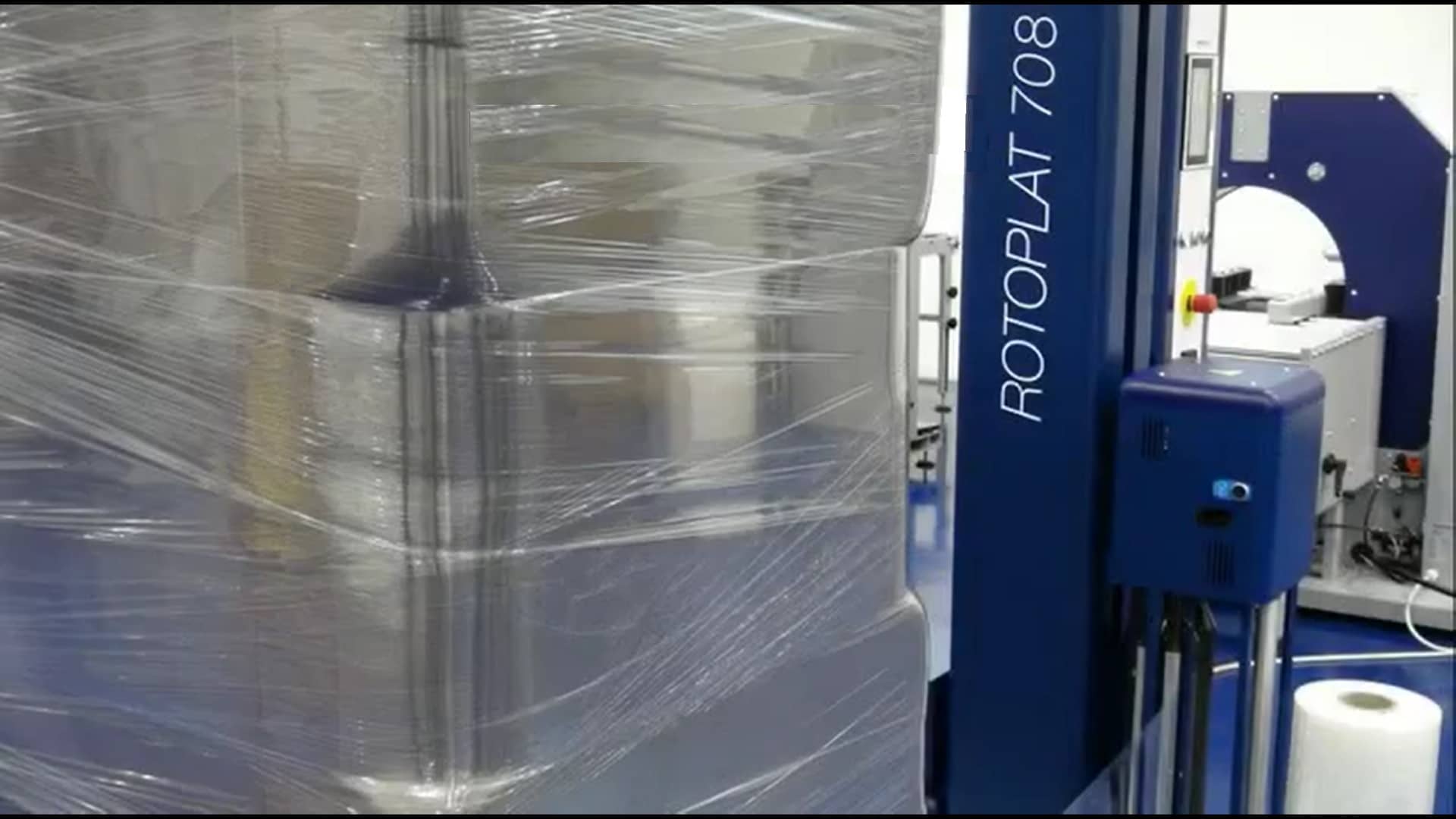
Автоматический или полуавтоматический паллетообмотчик
Автоматические паллетообмотчики встраиваются в конвейерную линию и не требуют ручного запуска. Продукция на паллетах подаётся в зону обмотки автоматически.
Простейшая линия состоит из паллетообмотчика и конвейера на входе и выходе. Оператор устанавливает поддон с грузом на роликовый конвейер. Далее конвейер автоматически подаёт поддон в зону обмотки. Паллетообмотчик фиксирует продукт стрейч-плёнкой и подаёт по второму конвейру в зону отгрузки. Оператор забирает готовый поддон и отвозит на склад.
Автоматическая линия упаковывает 30-190 паллет в час.
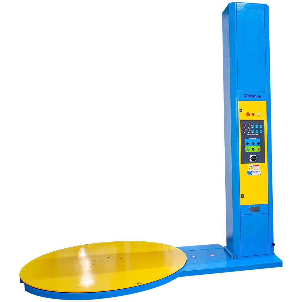
Полуавтоматические паллетообмотчики ещё называют отдельностоящими или стационарными. Им не нужны конвейеры, чтобы упаковать продукт. Работают они так: оператор при помощи погрузчика или рохли подвозит паллет с грузом, привязывает конец плёнки и нажимает кнопку «Старт».
Производительность полуавтоматов 15-20 паллет в час.
Условия поставки
Если выбираете прямой контракт с Италией на условиях EXW, FCA или DAP, то мы подготовим двухсторонний договор на русском языке.
Условия DDP предоставляем от ООО «АЕТНА ГРУПП ВОСТОК» в России.
Сервисная служба в России
Да. Наши сотрудники технической поддержки:
- проведут диагностику и сервис оборудования;
- помогут правильно подобрать и заказать запчасти;
- установят и запустят новую линию упаковки ROBOPAC.
Ребята работают по России, странам СНГ и привлекаются на установку оборудования в страны Африки и Азии.

Гарантия на оборудование
Гарантия 14 месяцев после отгрузки со склада в Италии.
Что такое предварительное растяжение плёнки
Чтобы снизить стоимость упаковки, паллетообмотчики ROBOPAC предварительно растягивают стрейч-плёнку от 0 до 400%.
Полотно плёнки проходит между двумя оранжевыми роликами в каретке паллетоупаковщика. Чтобы плёнка растягивалась, ролики вращаются с разной скоростью. Чем больше разница скоростей, тем растяжение плёнки сильнее.
Предрастяжение 150% означает, что с 1 метра плёнки мы получим 1 + 1,5 = 2,5 метра.
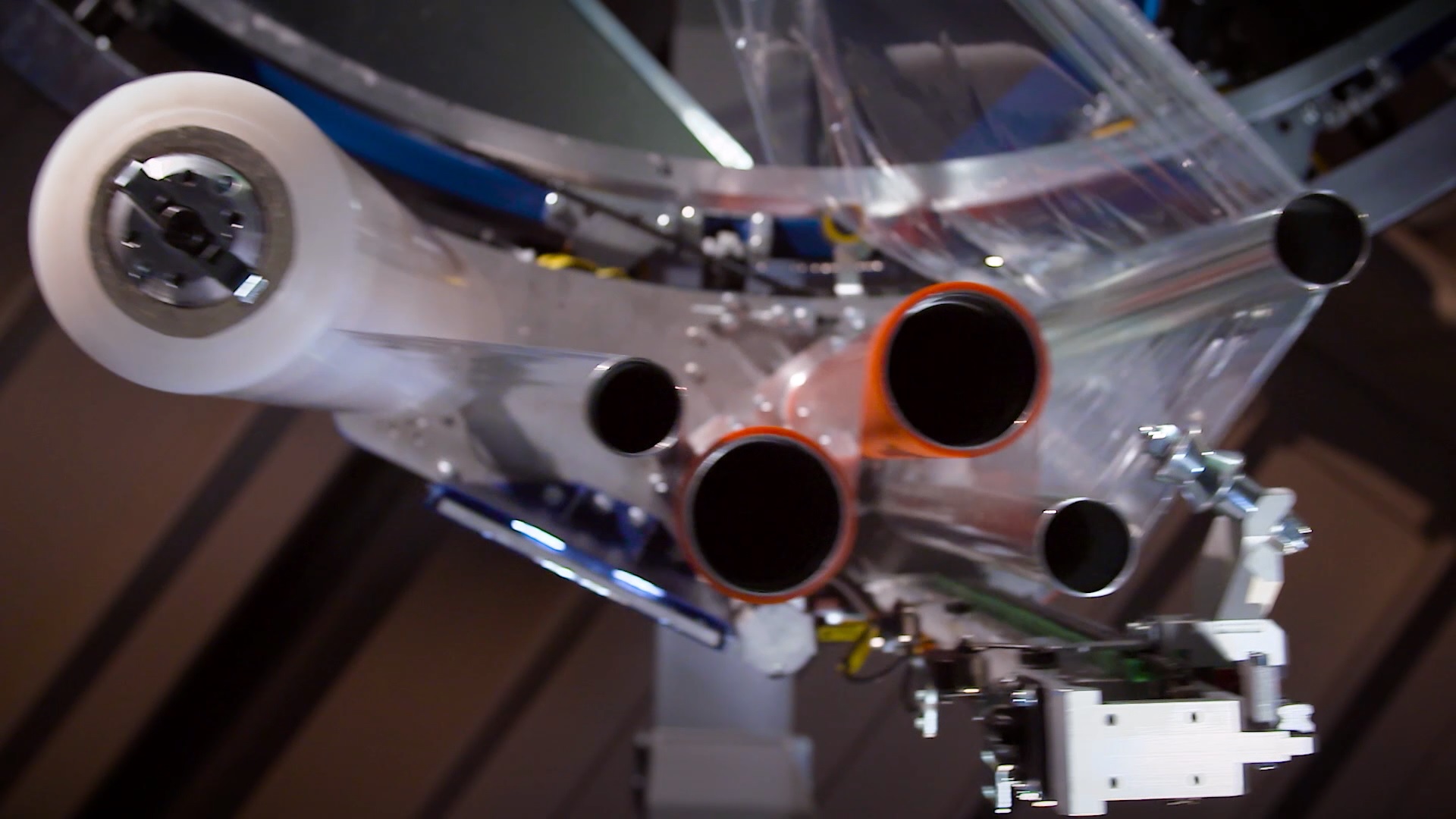
Чтобы закрепить продукт на паллете, нижние слои обматываем плёнкой с растяжением 0-200%. Наверху растягиваем и экономим плёнку до 400%.

Что такое натяжение плёнки
Натяжение плёнки — это усилие, с которым плёнка сдавливает продукт.
Плёнка может пережать или недожать продукцию на поддоне. В первом случае мы деформируем упаковку, во втором паллета развалится при транспортировке.
Чтобы груз целым доехал до места назначения, паллетообмотчики ROBOPAC регулируют натяжение плёнки по высоте поддона.
Нижние слои стягиваются сильнее, а на верхних усилие уменьшается, чтобы не деформировать продукт. Это важно, когда на поддоне хрупкий или сборный груз — внизу картонные короба, на них пачки с бутылками, а сверху туалетная бумага.
Паллетоупаковщики — один из самых распространенных видов упаковочного оборудования, активно используемых в складской сфере. Они предназначены для обмотки и фиксации грузов на поддонах при помощи стретч-пленки. Со временем оборудование может выйти из строя. В этом случае стоит обратиться за помощью в нашу компанию: мы занимаемся ремонтом паллетоупаковщиков уже много лет. Каковы же их распространенные неисправности?
Что в паллетоупаковщиках ломается чаще всего?
Если оборудование не реагирует на кнопку включения, следует для начала убедиться в исправности шнура питания. Также нужно проверить стабильность электросети. Если с ними все в порядке, следует осмотреть плавкий предохранитель. Возможно, он просто перегорел, если оборудование эксплуатировалось в интенсивном режиме в течение длительного времени.
 Иногда паллетоупаковщик обматывает груз стретч-пленкой неравномерно. Такое может произойти вследствие установки неверного значения натяжения. В этом случае нужно проверить этот параметр при помощи потенциометра и при необходимости отрегулировать его.
Если каретка не останавливается над поддоном, а поднимается до самого верха платформы, следует проверить состояние фотоэлемента прижимного устройства. Возможно, нужно просто отрегулировать чувствительность сенсора. Иногда такое случается вследствие загрязнения фотоэлемента или его выхода из строя. В первом случае его нужно очистить, во втором — заменить на новый.
Достаточно распространенной проблемой и заклинивание прижимного устройства. Оно не опускается на поддон даже при нажатии соответствующей кнопки. Как правило, причина заключается в выходе из строя электрического вентиля либо пневматического цилиндра. Нужно осмотреть элементы и при необходимости заменить их на новые.
Наша компания занимается не только ремонтом упаковочной техники, но и продажей запчастей для паллетообмотчиков. У нас представлен широкий ассортимент деталей для различных устройств от проверенных производителей.
8.1. ALARM MESSAGES
In the event of a breakdown during operation the machine stops automatically and alarm messages appear on the
display.
The table lists the displayed messages, the type of problem, the causes and possible solutions.
Important
For these operations a precise technical expertise or ability is required; therefore, these operations must
be exclusively performed by qualified personnel with certified experience acquired in the specific field of
intervention.
Alarms list Ecoplat Plus
In Ecoplat Plus, the alarms are shown with a «Reset» button flash code. (e.g.: film breakage alarm, the button will flash
5 times consecutively, followed by a short pause).
The sequence of flashes will be repeated until the alarm is reset (by pressing the «Reset» button).
No. of flashes
Problem
1 flash
Inverter communication
alarm
2 flashes
Plate alarm
3 flashes
Motor alarm
4 flashes
Table alarm
5 flashes
Film breakage alarm
6 flashes
Carriage alarm
7 flashes
Pallet start alarm
67
Cause
Electronic fault
Emergency plate pressed
Inverter overload
A fault or an obstacle is
preventing the table from moving
Film breakage detected during a
wrapping cycle
A fault or an obstacle is
preventing the film carriage from
moving
If the pallet is not present on the
machine, the machine will
remain stationary when the
CYCLE START button is
pressed
FAULT INFORMATION
Solution
Contact technical support
Release the emergency plate and
reset the machine
Remove the overload cause.
Switch the machine off and then
on again
Remove the fault cause. Switch
the machine off and then on again
Re-join the film to the product and
reset the machine) (Only available
with R-Connect with film
monitoring device)
Remove the fault cause. Switch
the machine off and then on again
Position the product on the table
and start a new cycle
ENG

Диагностические коды системы управления электродвигателем
313155U
15
3.
Проверьте установленные соединения. Оранжевый
провод датчика щеток, идущий от щеток, может
переплетаться с толстым красным проводом
коллектора, что ведет к подаче ложных аварийных
сигналов. Измените положение оранжевого провода,
идущего от щеток, так, чтобы он не находился рядом
с проводом коллектора.
4.
Проверьте плату управления электродвигателем,
выполнив следующие действия.
•
Отстыкуйте вилочную часть разъема J7 (E-20 èëè
E-XP1) èëè J6 (E-30 èëè E-XP2). (Это приведет
к подаче аварийного сигнала E27).
•
Для отмены подачи аварийного сигнала E27
воспользуйтесь проволочной перемычкой на плате
управления электродвигателем между двумя
контактами, к которым подсоединены два желтых
провода. Затем включите дозатор.
•
Аварийные сигналы E27 è E29 должны исчезнуть.
Если аварийный сигнал E27 не исчезает, проверьте
перемычку.
•
Если перемычка установлена должным образом,
но аварийный сигнал E29 по-прежнему не исчезает,
замените плату управления электродвигателем
(см. стр. 34).
E31: сбой системы
управления
электродвигателем
(только для E-30 è E-XP2)
Ошибка E31 относится к приводу двигателя. Появление
этой ошибки свидетельствует о неисправности платы
управления электродвигателем 24G881 и необходимости
ее заменить. Помимо этого, о неисправности платы
управления электродвигателем может говорить запуск
двигателя непосредственно после включения питания
(без нажатия кнопки
). Это означает, что
задающие устройства выходной цепи системы
управления двигателем замкнуты накоротко
и непрерывно подают питание на двигатель
в полном объеме.
Данный сбой может возникнуть по одной из следующих
причин: неисправность двигателя, неисправность
конденсатора, закорачивание или потертость проводов,
непригодность источника питания. Перед заменой платы
управления электродвигателем необходимо выполнить
следующую процедуру.
1.
Переведите главный выключатель питания в
положение OFF («Выкл.»)
. Отключите
источник питания.
2.
Сбросьте давление (см. стр. 23).
3.
Выполните следующие действия.
a.
Неисправность двигателя. Осмотрите
коллектор двигателя, сняв верхнюю щетку (см.
раздел «Снятие щеток» на стр. 30). Поверните
двигатель и осмотрите коллектор на предмет
следов огня, отметин или перемычек между
полюсами. Продолжайте вращать двигатель
на протяжении полного цикла работы насоса:
следует убедиться в отсутствии механических
помех и препятствий в основании насоса
и системе зубчатых передач.
b.
Неисправность конденсатора. Осмотрите
и испытайте пусковой конденсатор. Для этого
необходимо выполнить инструкции по проверке
конденсатора на стр. 32.
c.
Закорачивание или потертость проводов.
Осмотрите все провода, соединенные с платой
управления двигателем и собственно
двигателем, на предмет перемычек
и потертостей. Замените поврежденные
провода проводами того же диаметра,
цвета и температурного номинала.
d.
Непригодность источника питания. Убедитесь
в том, что характеристики напряжения и тока
применяемого источника питания соответствуют
системе, и что все провода подключены
правильно. Убедитесь в том, что во время
эксплуатации системы отсутствуют сбои
в подаче электроэнергии.
Перед выключением генератора следует
удостовериться в том, что двигатель
остановился, а главный выключатель разомкнут.
Если генератор останавливается во время
работы (даже в случае нехватки топлива),
падение напряжения питания может привести
к отказу привода электродвигателя.
Подождите, пока сохраняющееся напряжение не
исчезнет; это должно занять около 5 минут. (Данное
действие следует выполнить при наличии модели
E-30 èëè E-XP2).
File Specifications:1819/1819492-robopac_rotoplat_507.pdf file (12 Jul 2023) |
Accompanying Data:
AETNAGROUP Robopac Rotoplat 507 Stretch Wrapping Systems PDF Instruction Manual (Updated: Wednesday 12th of July 2023 07:32:37 AM)
Rating: 4.6 (rated by 13 users)
Compatible devices: AUTO WRAP 1510, ROBOPAC COMPACTA 400, FS3 Series, FLEX RTA, HWS-4-C, Orion SENTRY, ROBOPAC TECHNOPLAT CS/CW, H-1619.
Recommended Documentation:
Instruction Manual (Text Version):
(Ocr-Read Summary of Contents of some pages of the AETNAGROUP Robopac Rotoplat 507 Document (Main Content), UPD: 12 July 2023)
-
AETNAGROUP Robopac Rotoplat 507 User Manual
-
AETNAGROUP Robopac Rotoplat 507 User Guide
-
AETNAGROUP Robopac Rotoplat 507 PDF Manual
-
AETNAGROUP Robopac Rotoplat 507 Owner’s Manuals
Recommended: DAC-80, B4-M500, WNF 5421 AE, XJ-S33 — XGA DLP Projector
Links & Tools
-
Table of Contents Rev. 9/19/2018 SWA, MANUAL SWA-50, SWA-70, & SWA-51-AR Semi-Automatic Stretch Wrap Machines Instruction Manual Receiving instructions: After delivery, remove the packaging from the product. Inspect the product closely to determine whether it sustained damage during transport. If dama …
SWA-50 19
-
USE AND MAINTENANCE MANUALENGRotating ring band wrapping machineORBIT 16Translation of the original instructionsInstructions manual code:3709301866.0English Edition: 0616Serial number|_|_|_|_|_|_|_|_|_|_|AttentionRead and understand these instructions before using the machine.Keep this handbook for further consultat …
ORBIT 16 95
-
TRACTOR CONNECTION (ARC)1. HydraulicsRed pipe > Supply (50 lpm)Blue pipe > Return (Free flow return!!)2. ElectricsA. Connect 12V supply to 3pin plugB. Connect wrapper harness to controllerC. Connect receiver to controllerENTERING THE WORKING POSITION1. Lower the rear of the machine to the ground …
1814 S 4
-
Revised 2017 READ ALL INSTRUCTIONS CAREFULLY BEFORE OPERATING EQUIPMENT OPERATING & SERVICE PARTS MANUAL SM20ES ENERGY SMART® WRAPPER Series B SM20ES – C6B2WWBPXLB 6” x 15: Seal Plate with Optional Left & Right Wings, Label Dispenser and Printer Shelf *Scale and printer pictured are not included SM20ES � …
SM20ES 11
Operating Impressions, Questions and Answers:
AETNAGROUP Robopac Rotoplat 507 Instruction manual
- AETNAGROUP
- Stretch Wrapping Systems
- Instruction manual for AETNAGROUP Robopac Rotoplat 507
- aetnagroup-robopac-rotoplat-507-instruction-manual-50_manual.pdf
- 50 |
Pages Preview:


Document Transcription:
See Details
Download