
81
TROUBLESHOOTING
ALARM CODES
Using a sophisticated self check system, the UPS can verify and indicate on the display panel any faults
and/or malfunctions that may occur during the normal operation of the device. In the event of a problem, the
UPS indicates this by displaying the code and the type of alarm (FAULT and/or LOCK).
FAULT
FAULT signals can be subdivided into three categories.
Faults: these are “minor” problems that do not stop the UPS but reduce performance or prevent the
use of some of its functions.
CODE
DESCRIPTION
A06
Sensor1 temperature less than 0°C
A08
Sensor2 temperature less than 0°C
A11
Input relay locked (does not open)
A54
Load > preset user threshhold
A61
Batteries to be replaced
A62
No Battery box or not connected
A63
Waiting to recharge batteries
Alarms: these are more critical problems than faults since if they persist, even for a very short time,
they may cause the UPS to stop.
CODE
DESCRIPTION
F03
Auxiliary power supply not correct
F04
Dissipators overtemperature
F05
Temperature sensor1 faulty
F07
Temperature sensor2 faulty
F10
Input fuse broken or input relay locked (does not close)
F13
Condenser precharge failed
F21
Condenser bank overvoltage
F40
Inverter overvoltage
F41
Direct voltage in output
F42
Inverter voltage not correct
F43
Inverter undervoltage
F50
Overload: load > 103%
F51
Overload: load > 125%
F52
Overload: load > 150%
F53
Short circuit
F55
Waiting for reduction of load to return onto inverter
F60
Batteries overvoltage
На чтение 14 мин Просмотров 14.4к. Опубликовано 26.11.2021 Обновлено 10.07.2022
Содержание
- Таблица неисправностей и возможных причин поломки
- Основные виды схем применяемых в ИБП
- Алгоритм ремонта источника бесперебойного питания
Внезапные отключения электроэнергии — не такое уж частое явление, но случаются они, обычно, в тот момент, когда долго вводимые перед этим данные не успели сохранить. Исключить такие ситуации призвано использование UPS (Uninterruptible Power Supply, он же ИБП – Источник Бесперебойного Питания), оберегающего компьютер от потери данных при исчезновении внешнего электроснабжения. Эти в целом надежные приборы иногда выходят из строя, а отремонтировать во многих случаях их можно самостоятельно.
Таблица неисправностей и возможных причин поломки
Самые простые ситуации можно разрешить, не обладая специальными знаниями и навыками и не разбирая ИБП. Эти случаи сведены в таблицу.
| Видимое проявление проблемы | Возможная причина | Способ устранения |
|---|---|---|
| UPS не включается или работает только от аккумулятора | Неисправен сетевой шнур | Заменить сетевой шнур |
| Перегорел плавкий предохранитель или сработало устройство защиты. | Заменить предохранитель или взвести защитное устройство. | |
| Отсутствует или неисправна батарея | Установить исправную АКБ | |
| При исправной батарее горит сигнал низкого уровня заряда | Сбилась калибровка зарядного контроллера | Восстановить калибровку с помощью ПО от производителя |
| Нет питания нагрузки при исчезновении напряжения сети (аккумулятор исправен) | Сбой программного обеспечения | Сбросить контроллер кнопкой «Сброс» (если есть) или перепрошить программу |
| Не заряжается АКБ | Сбой программного обеспечения | Сбросить контроллер кнопкой «Сброс» или перепрошить программу |
| ИБП отключается, горит значок перегрузки | Излишняя нагрузка | Уменьшить мощность нагрузки или количество потребителей |
Не все УПС управляются программно. Недорогие модели собраны на дискретных элементах и микросхемах небольшой степени интеграции. Советы по перезагрузке, перепрошивке или настройке ПО к ним не относятся. Также надо учитывать, что одни и те же неисправности могут быть как при сбое работы ПО, так и при проблемах с «железом», поэтому сброс или перепрошивка – сродни первой медицинской помощи. Может помочь, а может не помочь. В этом случае понадобится глубокая диагностика и ремонт аппаратной части.

Основные виды схем применяемых в ИБП
Если предварительное тестирование проведено, то можно попытаться провести более глубокую диагностику. Даже обладая специальными знаниями, полезным будет изучить общие принципы работы ИБП и принципиальные схемы конкретных приборов.
Для резервирования питания офисной техники применяются несколько типов бесперебойников, различающихся своей схемотехникой. Первый тип – Offline.
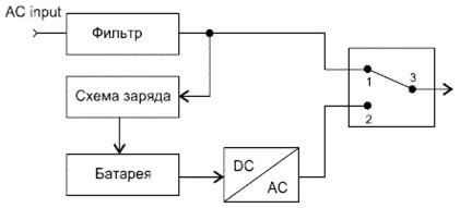
Как и у всех УПС, в схеме имеется сетевой фильтр, зарядное устройство и батарея, которая питает преобразователь (инвертор) постоянного напряжения в переменное. В нормальном режиме выход преобразователя к нагрузке не подключен. При исчезновении питающей сети происходит переключение потребителей на питание от инвертора. Основной минус такого подхода – на переключение требуется время. Оно минимально для человеческого восприятия, но для техники может быть слишком большим. Некоторые устройства могут за это время отключиться или потерять данные. Зато эти бесперебойники простые, дешевые, надежные и ремонтопригодные.
ИБП, построенные по схеме Line interactive, работают по сходному принципу, но у них на входе установлен стабилизатор сетевого напряжения. Он построен по принципу переключения отводов первичной обмотки трансформатора. Поэтому при изменениях параметров сети потребители питаются стабильным напряжением, и переключение в автономный режим происходит только тогда, когда входной стабилизатор не может справиться. То есть, гораздо реже.
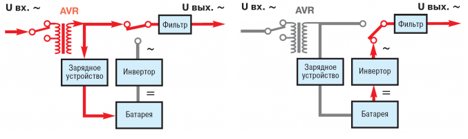
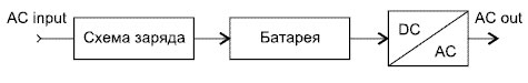
Самым дорогим, но и оптимальным способом построения резервного источника считается On-line. В этом случае батарея постоянно подзаряжается сетевым напряжением (буферный режим), а потребители постоянно питаются от инвертора стабилизированным напряжением. При исчезновении питания от сети не происходит переключения, бестоковая пауза отсутствует. Такие приборы эффективны, но дороговаты.
Алгоритм ремонта источника бесперебойного питания
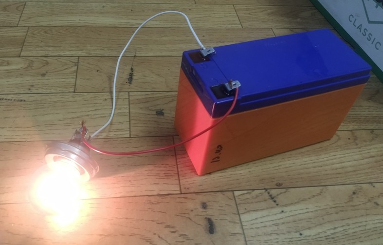
Если есть подозрения на выход из строя (потерю емкости) аккумулятора, проверить его можно без разборки прибора. Для этого надо подержать UPS включенным в сеть 220 вольт до заведомо полной зарядки АКБ. Потом к разъему для нагрузки надо подключить лампы накаливания соответствующей мощности (для источника с выходной мощностью 600 ватт потребуется 10 стоваттных ламп) и дождаться появления сигнализации разряда батареи (Low battery level).
Если время полного разряда существенно меньше заявленного в технической документации, значит, пришло время задуматься о скорой замене батареи. Если емкость снизилась до уровня, при котором время резервирования стало неприемлемым, менять аккумулятор придется срочно.
Если предварительные методы диагностики и ремонта результата не дали, можно разобрать UPS и попытаться протестировать более глубоко. Прежде надо здраво оценить свою квалификацию – если она недостаточна, возможно, поход в сервисный центр обойдется дешевле и быстрее.
Если решение починить прибор самостоятельно принято, надо изучить конструкцию корпуса бесперебойника. Некоторые приборы помещены в пластиковый кейс, скрепленный винтами.
Чтобы снять крышку, надо перевернуть УПС и снизу отвернуть четыре винта (самореза). В некоторых устройствах крышка крепится на защелках, которые надо аккуратно оттянуть.

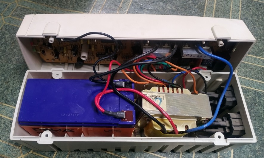
Компоновка обычна для большинства недорогих UPS:
- в верхнем отсеке находится плата с электроникой, на стенку выведены разъемы для слаботочных цепей;
- в нижнем – аккумулятор, силовой трансформатор, на стенку выведены силовые разъемы.
Если тест аккумулятора не проведен до разборки, его можно произвести сейчас, но понадобится набор лампочек на 12 вольт. Надо полностью зарядить АКБ и подключить к нему нагрузку из ламп. Контролируя напряжение на выходе, надо зафиксировать время разряда до 10,5 вольт. Емкость при этом вычисляется по формуле:
С=(P/12)*t, где:
- С – фактическая емкость в ампер-часах;
- P — мощность лампы, Вт;
- 12 – напряжение АКБ, вольт;
- t – время разряда, часов.
Еще лучше замерить ток разряда и подставить его в формулу вместо множителя P/12 в амперах. Решение о замене батареи принимается по тем же критериям, что и при тестировании без разборки.
Надо помнить, что некоторые ИБП вообще не включаются при отсутствии или серьезной неисправности аккумулятора. Поэтому поиск проблемы рекомендуется начать с тестирования АКБ.
Компоновка аппарата APC Back Up 500 выполнена по-другому. Для аккумулятора предусмотрен отдельный отсек, добраться до него можно без разборки, просто отжав защелку крышки.

Входная силовая часть (фильтр и силовой трансформатор) расположены в другом отсеке.
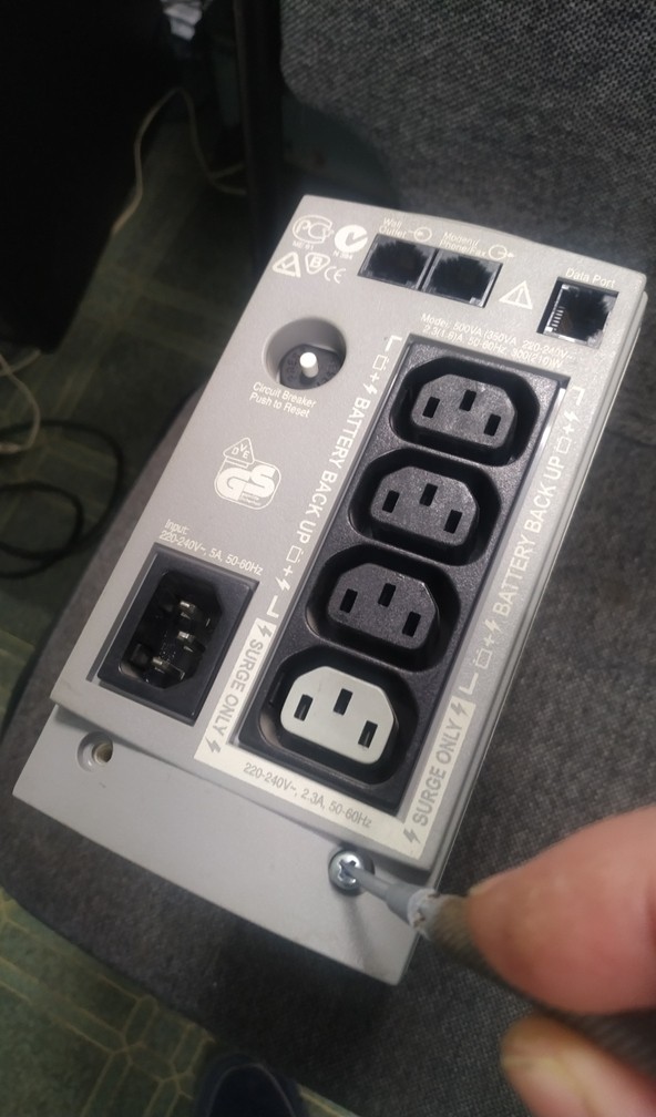
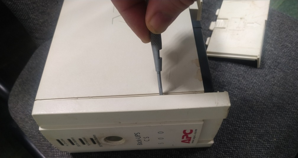
Чтобы до него добраться, надо вывинтить два самореза. Откроется ниша с элементами силовой цепи.

Чтобы добраться до платы с электроникой, надо отжать защелки передней панели.
В приборах других производителей порядок разборки и расположение основных элементов может отличаться. На основании приведенных примеров разобраться не составит труда.
Диагностику прибора начинают с визуального осмотра. Так можно обнаружить:
- отпаявшиеся провода;
- вздувшиеся оксидные конденсаторы;
- отгоревшие дорожки;
- трещины;
- обгоревшие компоненты.
Читайте также
![]()
Схема бестрансформаторного источника питания
Если элемент обгорел, это не говорит однозначно о нем, как о виновнике неисправности. Проблема может быть в другом компоненте. Но уже так можно локализовать неисправность на участке схемы.
Если невооруженным глазом обнаружить проблему не удалось, надо анализировать схему. Пошаговую инструкцию в этом случае дать невозможно – схемы разнообразны, а потенциальные неисправности еще разнообразнее. Но общий принцип поиска проблемы разобрать вполне реально. Это будет сделано на примере UPS N-Power SVP-625 – в ней применены стандартизированные решения без особенностей. Схема ИБП построена под управлением микроконтроллера MDT10P73.
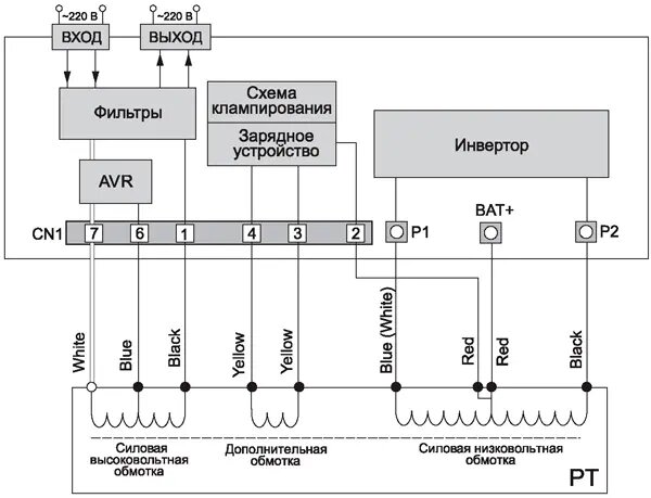
Рассматривая структурную схему, легко понять, что этот прибор относится к классу Line active. Сетевое напряжение, пройдя через фильтр, поступает на силовую высоковольтную обмотку, которая служит для входа и для выхода – в зависимости от режима. Схема AVR (автоматическая регулировка напряжения) в зависимости от уровня на входе, может подключить дополнительно к основной обмотке (синий и черный провода) регулировочную – провода белый и синий. В зависимости от входного уровня, дополнительная секция подключается к основной то в фазе, то в противофазе, добавляя или уменьшая напряжение на выходе. Коммутация осуществляется с помощью реле RY2 и RY3 (обозначения по принципиальной схеме). Реле RY1 замыкает вход и выход в нормальном режиме работы, при его размыкании потребители запитываются от аккумулятора через инвертор.
Зарядное устройство, построенное по принципу линейного стабилизатора, питается от дополнительной обмотки, от нее же питается схема формирования dead time (клампирование) – она нужна, чтобы исключить сквозной ток через транзисторы инвертора.

Инвертор построен по пушпульной схеме. Ключами служат полевые транзисторы.

Диагностику надо начать с проверки предохранителей FUSE1 и FUSE2. Чаще всего они перегорают из-за выхода из строя транзисторов инвертора Q4..Q7. Обнаружив неисправность плавких вставок надо сразу протестировать и полевые транзисторы.
Дальнейшую диагностику лучше проводить исходя из внешних признаков неисправности. Если при включении ИБП не подает признаков работы (не слышен легкий гул трансформатора, не горят индикаторы) и предохранители исправны, проверяется:
- наличие переменного напряжения на входе (контакты 3 и 4 клеммника CN1);
- при его отсутствии проверяется сетевой шнур и его соединения;
- если напряжение присутствует, проверяется наличие выходного напряжения на клеvмнике CN2 (контакты 1,2);
- если его нет, проверяется исправность контактных групп реле RY1, RY2, RY3 и элементов входного фильтра CX1, MOV1, CY1, Cy2 и выходного фильтра CX2 и R100.
Если не заряжается заведомо исправная батарея и отсутствует индикация VBAT, проверяется:
- наличие переменного напряжения на клеммнике CN1 контакты 3 и 4;
- при его наличии – исправность диодного моста D5..D8;
- если там все в порядке – наличие постоянного напряжения на входе и выходе микросхемы LM317 (U5);
- при отсутствии напряжения на входе проверяется транзистор Q8 схемы CLAMP;
- при отсутствии напряжения на выходе с большой вероятностью неисправна LM317.

Если не происходит стабилизации напряжение при изменениях в сети, надо проверить исправность реле RY2, RY3 и транзисторных ключей Q11, Q12. Если все в порядке, надо проверить исправность датчика входного напряжения (сигнал HOT, операционный усилитель U2 формирует постоянное напряжение, пропорциональное сетевому). Если все в порядке, есть основания думать, что неисправен микроконтроллер.
Если при исчезновении питающей сети напряжение к потребителям не поступает, АКБ и датчик напряжения (тракт HOT-VIN) в порядке, проверяется исправность реле RY1, транзистора Q10 и наличие на затворе ключа сигнала на переключение. Если все в порядке, надо проверять, в порядке ли контроллер. Если переключение происходит, а переключения нет, проверяется:
- Наличие импульсов на затворах пар Q4Q5 и Q6Q7 (линии PSHPL2 и PSPHL1).
- Если их нет, проверяется исправность ключей микросхемы U3.
- Если все в порядке – снова проверяется контроллер.
Также могут быть и другие неисправности — проблемы с датчиком тока, с формированием управляющих сигналов, с питающими напряжениями и многое другое. Все перечислить и предугадать невозможно. Процесс поиска неисправности весьма творческий, и для успеха надо хорошо разобраться в работе схемы.
Найденные компоненты, вышедшие из строя, заменяют. Если это мощные транзисторы, эксплуатирующиеся на радиаторах, их сначала надо установить на теплоотвод на теплопроводящую пасту или упругую подложку, привинтить – а потом припаивать.

Самая сложная проблема – намоточные детали (дроссели, трансформаторы). Перемотка «на коленке» в большинстве случаев не дает надлежащего качества, и срок службы будет недолгим. Здесь поможет наличие прибора-«донора», из которого можно взять недостающие детали. Если неисправен микроконтроллер, новый чип придется запрограммировать. Для этого понадобится собственно программа прошивки, а также программатор с соответствующим ПО.
Для наглядности рекомендуем к просмотру тематические видео.
Если неисправен ИБП другого типа, ремонт начинается с поиска принципиальной схемы и ее изучения до полного понимания принципа действия. А данное руководство в этом поможет.
S
/
TATUS
ALARM CODES
By using a sophisticated self-diagnostic system, this UPS can check and indicate on the display panel its status and any error
and/or fault occurred during operation. Whenever a problem arises, the UPS signals the event by showing the code and the
corresponding alarm on the display.
Commands: these codes indicate that a command has been activated.
CODE
C01
C02
C03
C04
C05
C06
C08
User messages: these messages refer to a specific configuration or operation of the UPS.
CODE
U01
U02
U03
U04
U05
U06
U07
U08
Anomalies: these are «minor» problems, which do not bring the UPS to a halt, but can reduce its performance or
inhibit the use of some of its functions.
CODE
A03
A05
A08
A11
A13
A16
A18
A22
A25
A26
A29
A30
A31
A32
A37
A38
A39
DESCRIPTION
Remote switch-off command
Remote load on bypass command
Remote start-up command
Battery test running
Manual bypass command
Emergency switch-off command
Load on bypass command
DESCRIPTION
Low battery warning
Programmed switch-off enabled
Programmed switch-off imminent
Bypass disabled
Synchronisation disabled (UPS in Free running mode)
Waiting for battery charging
Service UPS
Service Batteries
DESCRIPTION
Inverter not synchronised
Overvoltage on input line of Phase1
Undervoltage on input line of Phase1
Input frequency outside tolerance limits
Voltage on bypass line of Phase1 out of tolerance limits
Bypass frequency out of tolerance limits
Voltage on bypass line out of tolerance limits
Load on Phase1 > user-defined threshold
Output isolator open
Positive branch batteries missing or battery fuses open
System temperature probe damaged
System temperature < 0°C
System temperature too high
Temperature of heat sink Phase1 < 0°C
External battery temperature probe damaged
External battery overtemperature
Positive branch batteries must be replaced
— 40 —
-
Contents
-
Table of Contents
-
Bookmarks
Quick Links
U
N
I
N
T
E
R
R
U
P
T
I
B
L
E
P
O
W
E
R
S
U
P
P
L
Y
U
N
I
N
T
E
R
R
U
P
T
I
B
L
E
P
O
W
E
R
S
U
P
P
L
Y
300 to 500 kVA Three-Phase Output
MASTER HP-UL
USER MANUAL
Related Manuals for Riello UPS Master HP-UL Series
Summary of Contents for Riello UPS Master HP-UL Series
-
Page 1
300 to 500 kVA Three-Phase Output MASTER HP-UL USER MANUAL… -
Page 2
RPS SpA Viale Europa 7 37045 Legnago (VR) Italy www.riello-ups.com page 2 / 84 0MLMHTM30RUENUA… -
Page 3
Thank you for choosing our product. RPS S.p.A. is highly specialized in the development and production of uninterruptible power systems (UPS). The UPS’s of this series are high quality products, carefully designed and manufactured to ensure optimum performance. Applicability This manual applies to the following models: Master-HP 300 300 kVA, 480 V input, 480 V output, 60 Hz, configured as wye-wye or delta-delta (see below);… -
Page 4
DANGER This UPS contains LETHAL VOLTAGES. All repairs and service should be performed by AUTHORIZED SERVICE PERSONNEL ONLY. There are NO USER SERVICEABLE PARTS inside the UPS. WARNING To reduce the risk of fire or electric shock, install this UPS in a temperature and humidity controlled, indoor environment, free of conductive contaminants. -
Page 5
3. Must have a background of technical training, or specific training relating to the procedures for the safe use and maintenance of the equipment. Emergency interventions The following information is of a general nature. First aid interventions Company regulations and traditional procedures should be followed for any first aid intervention that may be required. -
Page 6
Protective equipment to be worn No maintenance operations must be carried out on the device without wearing the Personal Protective Equipment (PPE) described below. Personnel involved in the installation or maintenance of the equipment must not wear clothes with wide sleeves or laces, belts, bracelets or other items that may be dangerous, especially if they are metallic. -
Page 7: Table Of Contents
CONTENTS ………………….9 ODELS ………………….10 AYOUT …………….12 RELIMINARY OPERATIONS Removing the packaging and positioning the unit …………. 12 Storage ……………………12 Handling ……………………12 …………..13 NSTALLATION ENVIRONMENT Ambient conditions: ………………..13 Dimensions of the premises ………………13 Cooling of the premises ………………..
-
Page 8
6.1.2 Measurements menus (key 2) …………………..49 6.1.3 Times Measurement……………………49 6.1.4 Full page Measurements and output waveforms (key 2, 7)…………50 6.1.5 Controls Menu (key 3), ……………………51 6.1.5.1 Keys menu 3, 2: battery test ………………..51 6.1.5.2 CUSTOMIZING ……………………52 6.1.5.3 Keys menu 3, 5: CODE 436215 ………………52 6.1.5.4 RATED OUTPUT VOLTAGE. -
Page 9: Models
Models Based on the models ordered, they are configured in factory before shipping. The followings are the configuration codes for any size of UPS: Power rating (kVA) Models 00= UPS 300 KVA 480 V — 60 Hz Single, bottom cable entry 01= UPS 300 KVA 480 V — 60 Hz Single, bottom cable entry, MBY 02= UPS 300 KVA 480 V — 60 Hz Single, TCE 03= UPS 300 KVA 480 V — 60 Hz Single, TCE, MBY…
-
Page 10: Layout
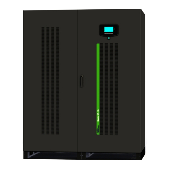
Layout MASTER – HP – UL – Front View A Control panel with graphic display Door handle Ventilation grilles D Communication area Front Cover panel with ventilation grilles Switch cover panel G Door SWIN: Input power switch SWBY: Static switch bypass input SWMB: Maintenance bypass switch (optional) SWOUT: Static switch output page 10 / 84…
-
Page 11
MASTER – HP – UL (with TCE) – Front View Control panel with graphic display Door handle Ventilation grilles Communication area Front Cover panel with ventilation grilles Switch cover panel Doors TCE — Top Cable Entry cabinets (Optional) SWIN: Input power switch SWBY: Static switch bypass input SWMB: Maintenance bypass switch (optional) SWOUT: Static switch output… -
Page 12: Preliminary Operations
Preliminary operations Removing the packaging and positioning the unit On delivery, the packaging must be inspected to ensure that it is whole and that it has not been crushed or dented. Check in particular that neither of the two impact resistant devices on the packaging is red; if one of them is red;…
-
Page 13: Installation Environment
2. Slide away the carton from above. 3. Remove the screws securing the cabinet to the wooden base. Installation environment The UPS and the battery cabinet have been designed for indoor installation. The choice of premises for installation should comply with the points set out below. Ambient conditions: …
-
Page 14: Cooling Of The Premises
Cooling of the premises The recommended operating temperature for the lifetime of the UPS and of the batteries is between 20 and 25°C. The lifespan of the battery depends on the operating temperature; with an operating temperature increase from 20°C to 30°C, the lifespan of the batteries is halved.
-
Page 15: Electrical Connections
Electrical Connections CCESSING THE TERMINALS The following operations must be performed while the UPS is disconnected from the utility mains power, switched off and all the input and output power switches on the equipment are open. Before performing connection, open all the input and output power switches and check that the UPS is completely isolated from all power sources: battery and AC power line.
-
Page 16: Ups In Single Configuration
UPS in single configuration The UPS is designed to work either as Single input Unit or as Dual input Unit. Schematic diagram: Single input Unit (*) OPTION Schematic diagram: Dual input Unit (*) OPTION page 16 / 84 0MLMHTM30RUENUA…
-
Page 17: Cable Entry
5.1.1 Cable Entry The cables can enter in the UPS from the bottom or the top in the MASTER HP – UL it depends on the configuration of the unit. Proceed as follows in order to open the UPS Open the door …
-
Page 18
MASTER HP — UL, top cable entry version -Top view: cable entry in the UPS from the top- page 18 / 84 0MLMHTM30RUENUA… -
Page 19: Connection Of Power Cables For Single Input Unit
5.1.2 Connection of Power Cables for Single input Unit Connect the input, output and battery cables to the terminals as shown in the figure below: MASTER HP – UL 300 kVA Power connection Terminals MASTER HP – UL 400 kVA and 500 kVA Power connection Terminals Note: Maintenance Bypass Switch optional.
-
Page 20
MASTER HP — UL 300 kVA with TCE Power connection Terminals MASTER HP — UL 400 kVA and 500 kVA with TCE Power connection Terminals Note: When cables entering from the top, respect the following order: connecting cables to the Input terminals first and Battery terminals then, and in the same way, connecting cables to the Bypass terminals first and Output terminals then. -
Page 21: Connection Of Power Cables For Dual Input Unit
5.1.3 Connection of Power Cables for Dual input Unit Connect the input, output and battery cables to the terminals as shown in the figure below: MASTER HP — UL 300 kVA Power connection Terminals MASTER HP — UL 400 kVA and 500 kVA Power connection Terminals Remove the jumpers present between the SWIN and SWBY.
-
Page 22
MASTER HP — UL 300 kVA TCE Power connection Terminals MASTER HP — UL 400 kVA and 500 kVA TCE Power connection Terminals Remove the jumpers present between the BYPASS and INPUT bars. Note: When cables entering from the top, respect the following order: connecting cables to the Input terminals first and Battery terminals then, and in the same way, connecting cables to the Bypass terminals first and Output terminals then. -
Page 23: Minimum Wire Size Requirements
Minimum Wire Size Requirements Input (for single input unit) Phase and Neutral Conductor models 300 kVA 2 x 250 kcmil / (2 x 127 mm 400 kVA 3 x 250 kcmil / (3 x 127 mm 500 kVA 4 x 250 kcmil / (4 x 127 mm Rectifier Input (for dual input unit only) Phase Conductor models…
-
Page 24
CAUTION: Use at least 75 C rated copper wire. Minimum wire size is based on full load ratings applied to NEC Code Table 310-16. Code may require a larger AWG size than shown in this table because of temperature, number of conductors in the conduit, or long service runs. Follow local requirements. -
Page 25: External Overcurrent Protection Unit And Terminals
External OverCurrent Protection unit and terminals CAUTION to reduce the risk of fire, connect only to a circuit provided with branch circuit protection with maximum current rating per the table, below, in accordance with the National Electrical Code, ANSI/NFPA 70. Input (for single input unit) Nominal Maximum…
-
Page 26: Ground Fault Circuit Interrupter (Gfci)
Battery Bolt Size Nominal Current Maximum Current OCP Device rating models (in. — ISO) 300 kVA 641A@480Vdc 769A@400.8Vdc 800A 1/2 — M12 400 kVA 855A@480Vdc 1025A@400.8Vdc 1000A 1/2 — M12 500 kVA 962A@480Vdc 1154A@400.8Vdc 1200A 1/2 — M12 CAUTION: Input and output circuit protection devices must be provided by others as part of the UPS installation.
-
Page 27: Backfeed Protection
When operating in the presence of mains supply, a GFCI installed on the input will trip as the output circuit is not isolated from the input circuit. When operating without mains supply (from battery) the input GFCI will trip only if it is able to switch as a result of leakage current without any voltage at its poles (for example a GFCI with an auxiliary relay is not suitable).
-
Page 28: Mains, Load And Battery Connections
Mains, load and battery connections Input line without neutral A transformer must be inserted either on the mains supply line or on the bypass line (as shown in the drawings) if the load requires a neutral. Schematic diagram: Single power line without neutral from the source SWMB SWBY 3P+G…
-
Page 29: Connection Of Signals And Remote Commands
Battery connections This UPS has been designed to be supplied by a battery consist on 240 Lead Acid Battery cells (40 12Vdc battery blocks). See “General Characteristics” for voltages and current of charge If “RIELLO BBX 1900 489V UL 3U” battery cabinets are used, the connection have to be made in accordance with the manual for the battery cabinet.
-
Page 30
NOTE: Aux signals isolation board allows receiving external auxiliary contacts and keeping them isolated from the UPS internal circuits making easier connections in case of paralleling of the units. Jumpers AUX (SWBATT, SWMB, SWOUT) must be connected to the terminal of the board if no external auxiliary contacts are presents. -
Page 31: Remote Commands, Alarms And Epo
5.5.1 REMOTE COMMANDS, ALARMS AND EPO -C- The card is equipped with a terminal board with 14 positions. SELV CIRCUIT PROVIDED. THE FOLLOWING SIGNALS MUST BE CONNECTED TO SELV CIRCUIT ONLY. POWER SUPPLY 1 power supply 12Vdc 80mA (max.) [pins 10 and 11]; ALARMS 3 FORM C dry contacts for alarms (they are capable of switching up to 30 V AC or DC and UP to 1 A);…
-
Page 32: Rs232
Please refer to APPENDIX A for the list of alarms and commands that can be programmed. The change of function should be made by authorized technical support personnel. 5.5.2 RS232 SELV CIRCUIT PROVIDED. CONNECT TO SELV CIRCUIT ONLY. 2 DB9 connectors are available for RS232 connection. The factory-set transmission protocol is the following: 9600 baud, -no parity, -8 bits, -1 stop bit.
-
Page 33: Slots 2-1, The Following Cards May Be Inserted (Optional)
Modem male female female male DB9 male RS232-1 maschio femmina femmina maschio — E — For connection with a modem use a cable RS232-2 standard. See the diagram for connection with a computer. Computer male female female male maschio femmina femmina maschio RS232-2…
-
Page 34: Swout And Swmb Externals
5.5.6 SWOUT and SWMB EXTERNALS See section “Parallel”. Start-up procedure mains power supply The mains power supply has to be present in order to start up the UPS The UPS output terminals will be powered in this phase and all loads connected will receive voltages. All users must therefore be warned before carrying out the start-up procedure.
-
Page 35: Battery Operation Check
SWMB (optional) The Maintenance bypass switch SWMB must not be closed during normal operation of the UPS. SWMB should only be closed during UPS maintenance operations in order to keep the load powered (see the instructions on page 37). When the UPS is first started up, it is in on-line mode (see page 36 ). See pages 36 and 59 to set Standby-on / Smart active operating mode.
-
Page 36: On — Line — Factory Setting
5.7.1 On — line — factory setting — Load is always powered by the inverter, in the event of an input mains failure the load continues to be powered from the inverter using the energy stored in the batteries. On – line: The load is always powered by the inverter, with very stable voltage and frequency, using the energy from the mains power supply (INPUT).
-
Page 37: Stabilizer Mode (Operation In On-Line Mode Without Battery)
acceptable range. When the mains power supply is restored, the UPS is automatically reset to Standby-Off mode. When operating in this mode the letter F will be displayed on the second line of the BASIC MENU, near the UPS model. 5.7.4 Stabilizer mode (operation in on-line mode without battery) Load is powered from the inverter, if there is a mains failure the load is not powered, the…
-
Page 38: Ups And Load Shutdown
Backfeed protection is provided to assure that the inverter output can never be connected to a de-energized bypass input, even if there is a failed component in the UPS. This is to protect service personnel servicing circuits that connect to the bypass input. Static switch is an automatic electronically switched bypass path.
-
Page 39: Block Diagram
5.11 Block diagram page 39 / 84 0MLMHTM30RUENUA…
-
Page 40: Components Of The Block Diagrams
5.12 Components of the block diagrams The UPS is made up the following sub-assemblies: IGBT RECTIFIER This represents the input stage and its function is to convert the AC voltage of the power supply line into DC voltage. Rectifier start-up can be programmed from the display panel.
-
Page 41
INVERTER This is the output stage, the function of which is to convert the DC voltage from the RECTIFIER or from the BATTERY into stabilized sinusoidal AC voltage. The inverter output is isolated from the input and from the batteries by a galvanic isolation transformer. -
Page 42: Maintenance Bypass (Optional)
5.13 Maintenance Bypass (optional) following the precautions when operating SWMB SWMB must not be closed on a UPS that is off and that is connected in parallel with other units operating normally. This operation may cause a fault on the UPS’s which may create a dangerous voltage at the output.
-
Page 43: Signal Panel Functions
Signal panel functions Control Panel View 250kVA LED Bypass line indicator LED Mains line indicator LED Battery powering the load LED Load on bypass LED Normal output LED Alarm for internal fault Graphic display F1, F2, F3, F4, F5, F6, F7, F8 = FUNCTION KEYS. The function of each key is shown at the bottom of the display and it varies according to the menu.
-
Page 44
EPO = Emergency Power Off button. Led status indicators Indicat Symb Function State Meaning Color Input Bypass line is present and correct Bypass Flashin Green line Input Bypass line is present but not correct indicator Input Bypass line is not present Mains is present and correct Mains Flashin… -
Page 45
RAPHIC DISPLAY A wide graphic display is present on the UPS door, which allows the user to have a close-up, detailed overview in real time of the status of the UPS. The user can switch the UPS on and off, consult electrical mains, output, battery measurements etc. -
Page 46
Picture of the UPS display having all items OFF, 250kVA Table of diagram items Shapes Active Inactive Meaning Input converter Output inverter Bypass line switch Battery Manual bypass line switch Bypass line input switch Battery switch Output switch Main line input switch Output load (40%VA or 0%VA) Battery(70%Ah or 0%Ah) Table with keys numbers and Icons… -
Page 47
Basic menu (text lines area) If no commands have been inserted, the first text line shows messages to inform about status of operation. First text line NORMAL OPERATION U200A OUT=100%VA, BATT=100%Ah, 5=ON Second text line In each operating condition, the display returns to the «basic menu» after two minutes from the last command inserted with the keys. -
Page 48: Language Setting Menu (Keys 1, 1)
The message OUT changes to BY when the load is not powered from the inverter (normal operation) but from the mains through the bypass line. The message OUT=100%VA changes to OUT= SWMB when the load is powered through the maintenance bypass switch, and the output current cannot be provided.
-
Page 49: Measurements Menus (Key 2)
6.1.2 Measurements menus (key 2) The measurements with two line displayed, are selected from the basic menu by pressing key 2 IN=100,100,100%V, 60.2Hz OUT=277,277,277Vln Measurement of the three voltages, neutral phase and input Measurement of the three output phase voltages of frequency.
-
Page 50: Full Page Measurements And Output Waveforms (Key 2, 7)
6.1.4 Full page Measurements and output waveforms (key 2, 7) The full page measurements and output voltage and current waveform are selected by pressing key 7 from the two line measurement menu. Basic Menu IN=100,100,100%V; 101,101,101%A; 60.1Hz BY=277,277,277Vln (480V); 60.1Hz; 250kVA 125kVA 277V 3L 60Hz [15:35:55]…
-
Page 51: Controls Menu (Key 3)
6.1.5 Controls Menu (key 3), BATTERY TEST Menu 3, 2 Keys 8 and 7 to increase and DISPLAY CONTRAST: 6 ADJUSTMENT: 7=-, 8=+ decrease the contrast. Code ? ………………. 2=BATTERY TEST 4=DISPLAY CONTRAST Menu 3, 5 5=PERSONALIZ. 6=BYPASS 7=TOTAL BLOCK Menu 3, 6 INVERTER OFF/BYPASS Menu 3, 7…
-
Page 52: Customizing
6.1.5.2 CUSTOMIZING The «CUSTOMIZING» menu is accessed by means of key 5 from the COMMANDS menu; an intermediate menu will then be displayed in which a CODE has to be entered. Access by CODE ensures that unauthorized persons cannot modify the operating parameters of the equipment.
-
Page 53: Rated Output Voltage
6.1.5.4 RATED OUTPUT VOLTAGE. Press the following sequence of keys to access the menu: 3, 5, 436215, 2 Keys 7 and 8 can be used to decrease or increase the rated output voltage. The value displayed is the voltage between phase and neutral «Vln». The value set modifies the operation of the inverter, during normal operation.
-
Page 54: Pre-Alarm
NOTE: this type of recharging may be configured on site and is mainly used for special type batteries such as open vase and NiCd. For batteries of type 1, 2 or 3, press key 2 from menu a to change from cyclical charge to charging at two levels float voltage Ac= xxx, Vbat.: min=xxx, ch xxx, max=xxx Bat.type(1) 2=Cycl.->ON ,…
-
Page 55
Type “0” Battery With the battery set to type 0, the following menu is displayed: (420Vmin,480Vp,540Vs) Prealarm : 5min Adjustment: (4=setV), 7=-,8=+ When key 4 is pressed, the program proposes the setting of the three voltage values. Vbat.test: Vmin., Vp, Vs: 420, 480, 540V Adjustment: 3-4+, 5-6+, 7-8+ Preset value… -
Page 56: Auto-Off «Va
6.1.5.7 AUTO-OFF «VA» Press the following sequence of keys to access the menu: 3, 5, 436215, 6: Automatic Switch-OFF when Output < 0%VA Adjustment: (5=Toff,Ton) 7=-,8=+ Press key 1 to exit the menu. Keys 7 and 8 can be used to decrease or increase the percentage threshold of the output load for the AUTO-OFF function and switching the system to the bypass line;…
-
Page 57: Bypass Voltage Range Adjustment
The «end of discharge pre-alarm» contact for remote alarms is also switched. In this case the system remains active for the next 4 minutes, after which the system switches onto the bypass line and then deactivates. There is no output voltage after deactivation. The interval between the start of the alarm and deactivation is equal to the interval selected as PRE-ALARM.
-
Page 58: Dial /Send» Modem
NOTE: for correct operation, use a modem that has already been configured to recognize «HAYES» type commands and that is able to dial the telephone number using pulses or tones as required by the telephone line that is to be used. Example of messages sent to the modem in the event of an «INTERNAL FAULT 5″…
-
Page 59: Ident
6.1.5.15 IDENT. Press the following sequence of keys to access the menu: 3, 5, 436215, 7, 7: Press key 1 to exit the menu. Keys 7 and 8 can be used to decrease or increase the number used for the identification of a single unit in systems with several UPS connected to a single RS232 serial line.
-
Page 60: Total Block
6.1.5.19 TOTAL BLOCK Press the following sequence of keys to access the menu: 3, 7 : Total System Shut-OFF Command = 47263 WARNING, the Output Voltage will be OFF Exit the menu by pressing key 8 or any other key with a sequence other than the one described here. Pressing keys 4, 7, 2, 6, 3 in succession as shown on the display activates the command for TOTAL BLOCK of the system.
-
Page 61: Recorded Value On Full Page
The «RECORDED CODES» menu is accessed with key 6 from menu 4 «RECORDED EVENTS» and menus 4, 2; 4, 2, 2; 4,2,2,2 that is, the recorded measurement menus. Return to the basic menu by means of key 1. Apart from key 6, the other keys have the same functions as those described for menu 4, and the messages on the lower line also remain the same.
-
Page 62: Disabling The Audible Alarm (Key 5)
6.1.7 DISABLING THE AUDIBLE ALARM (key 5) Press the following sequence of keys to access the menu: 5 During operation from the basic menu, the operator can permanently disable or re-enable the audible alarm (buzzer) by pressing key 5. «5=ON» is shown in the basic menu when the audible alarm is enabled and «5=OFF» when the audible alarm is disabled.
-
Page 63: Parallel (Optional)
Parallel (OPTIONAL) UPS in parallel configuration 7.1.1 Introduction UPS’s with parallel option fitted may be connected in a parallel configuration to increase both the reliability of the power supply to the load and the available output power. Up to 8 UPS’s can be parallel-connected. It is recommended to connect units of the same power.
-
Page 64: Electrical System Set-Up
Electrical system set-up If the UPS’s are required to be configured as “parallel” units in field, the operation requires to install and connect one parallel card and one parallel signal card inside the unit. Read the instructions carefully before carrying out installation. All maintenance operations inside the UPS must be carried out only by trained personnel.
-
Page 65: Emergency Power Off Device (Epo)
UPS in parallel, as depicted in the diagram below. Note: MASTER HP-UL series have input terminals (for acquiring the status of aux contacts) galvanically isolated from the internal circuits of the UPS. This will result in to be sufficient a single aux contact electrical connection of the External switch brought to each UPS of the parallel system.
-
Page 66: Mains, And Load Connections
The auxiliary contacts of SWOUT EXT and SWMB EXT must be connected to terminal J1 on the board 9AB2145 (aux signals insulation). The purpose of this board is to galvanically isolate the internal circuits of UPS, so that, in case of parallel of UPS, one auxiliary contact of the external switch is sufficient to be acquired by all the UPS in parallel.
-
Page 67: Connection Of Signals
The length of cables rule of thumb must also be followed with separate mains power lines: the lengths of the cables of the bypass line + output line must be the same between all the UPS connected in parallel. Lack of compliance with this rule of thumb may cause a current imbalance between the UPS’s when the load is powered through the bypass line.
-
Page 68
Insertion and removal with UPS’s operating (hot swap) The hot insertion and removal of the UPS can only take place if the system is configured with the RJ45 female/RJ45 female shielded adaptor cable (as shown in the figures below). The hot insertion and removal of the UPS makes technical support easier and improves the reliability of the system. With this procedure it is not necessary to shut down all the UPS’s in order to add or remove a unit. -
Page 69
Example of hot removal With hot removal, it is not necessary to shut down all the UPSs of the system in order to remove one. A) UPS parallel cable type RJ45 UPS 1 UPS 3 UPS 2 B) RJ45 female/RJ45 female shielded adaptor cable UPS BYPASS CABLE NOTE: if the UPS to be removed… -
Page 70
Firmware update All the parallel-connected UPS’s must have the same firmware version. Press key 7 from the basic menu on the display panel to display the firmware version installed. For the expansion of an existing system, check that the system has the same firmware version as the new UPS. -
Page 71
Three UPS in parallel D UPS1 LED on, UPS2 LED off, UPS3 LED off SW1 in start position on UPS1, SW1 in cont position on UPS2 and UPS3 Note: 3 RJ45 cables are required despite redundancy. System will not start up unless 3 cables are installed. UPS 2 UPS 2 UPS 1… -
Page 72: Start-Up Procedure
Start-up procedure Before starting up the whole system for the first time, some tests have to be performed to check that the UPS’s are connected to each other correctly. A) Open all the switches and disconnects on the UPS’s (SWIN, SWOUT and SWMB if fitted) and on the battery cabinets.
-
Page 73: Maintenance Bypass On The Whole System
Maintenance bypass on the whole system The sequences of operations to place the system in maintenance bypass are described below. The procedures shall depend on the initial state: — All the UPS are in NORMAL OPERATION procedure a) the power supplied to the load is not interrupted in any way; — All the UPS are in BAD BYPASS VOLTAGE or SWBY OFF with the bypass line procedure b) the power supplied to the load is interrupted…
-
Page 74: Operating Modes
Operating modes UPS units connected in parallel share the load current. In a system with several UPS’s connected in parallel, there is a single MASTER unit and the remaining units are SLAVES. The UPS’s are all exactly the same and the MASTER is chosen on start-up. The MASTER unit is shown on the display panel by the capital letter “P”…
-
Page 75
Example of parallel operation The instructions shown below refer to a system with three UPS’s, but are valid for more complex systems. Let us assume the UPS’s are in the following state: UPS STATUS 1) Normal operation, Master unit 2) Normal operation, Slave unit 3) Normal operation, Slave unit A — UPS PARALLEL CABLE type RJ45 1, 2, 3 — Parallel-connected UPS’s… -
Page 76: Maintenance
Maintenance The uninterruptible power system is designed and produced to last a long time, even in the most severe service conditions. It should be remembered however that this is electronic power equipment, which requires routine maintenance. Moreover, some components have a limited lifespan and as such must be periodically checked and replaced should conditions so dictate: in particular the batteries, the fans and in some cases the electrolytic capacitors.
-
Page 77: General Characteristics
General characteristics 300kVA UPS models 400kVA 500kVA MECHANICAL DATA Width (inches [mm]) 59 [1500] Width (inches [mm]) TCE version * 74,80 [1900] Height (inches [mm]) 74,80 [1900] Depth / height (inches [mm]) 39.70 [1000] Ventilation Air Forced Noise at 1m from front (0÷100% load)(dBA) UL Standard 1778 5 edition…
-
Page 78
UPS models 300kVA 400kVA 500kVA INTERMEDIATE D.C. CIRCUIT N. cells (Lead acid batteries) 240 (40 x 12Vdc battery) Rated battery voltage 9.1.1.1.1.1.1.1 Float charge (20°C) with cyclical charge not active Battery type 1 or 2 542 (2,26V/cells-default) 528 (2,2 V/cells-default) 2÷2,5 V/cells programmable 9.1.1.1.1.1.1.2 Boost charge 562 (2,34 V/cells — default) -
Page 79
UPS models 300kVA 400kVA 500kVA INVERTER Rated power Pf 0.9 (kVA) inductive Active power Pf 1 (kW) Rated power reduction factor (kVA/kW) 0,95/1 0,85/0,89 for Pf =0.8/0.9 capacitive Rated voltage 480Vac 3-phase + N Rated frequency 60Hz Rated voltage adjustment field +5% -10% Static variation ±… -
Page 80
UPS models 300kVA 400kVA 500kVA BYPASS Rated voltage 480Vac 3-phase + N Rated voltage tolerance ± 15% (adjustable from ± 10% to ± 25% from control panel) Rated frequency 60Hz Frequency tolerance ± 2% (adjustable up to ± 6% from control panel) Switching onto bypass with synchronized Inverter (UPS in “Normal Approx 0ms… -
Page 81: Appendixa Alarm Messages
10 Appendix A Alarm messages Below is a list of the alarm messages that are shown on the first line of the display panel, the “A=” column shows the number that is also displayed on the right in the lower row . ALARMS EVENT MESSAGE DESCRIPTION…
-
Page 82
Alarm present when the system has been deactivated and switched onto the BYPASS COMMAND bypass, by means of a specific command inserted via the keyboard. The command ACTIVE; 8=COMMAND remains stored also during shutdown due to a mains power supply failure. The system does not return to normal operation when the mains power supply is restored if the block has been set intentionally and not deactivated. -
Page 83
Parallel Redund. lost: Redund. In a parallel system, the redundancy is has been lost because the operating units unit OFF are less than the set number of units. Brake circuit fail The optional brake circuit has a failure Brake circuit Overload The optional brake circuit has an overload Rectifier switched OFF by The input converter stage is switched off by a remote command. -
Page 84: Appendixb — Optional Remote Commands
11 Appendix B — Optional remote commands Technical support personnel may modify the COMMAND that can executed from the standard “INV.OFF” remote input or from the optional remote input/output card. COMMAND Name Description Typical application Disables the recharging of the battery, keeping the When there is a generator, this allows Battery charge recharge current to a minimum, independently of the…