Still Workshop FM-X Error list Download
FM-X-10 FM-X-14 FM-X-17 FM-X-20 FM-X-25
Error List FM-X, FM-X N, FM-X W, FM-X EW, FM-X SE
Diagnostics
Error list
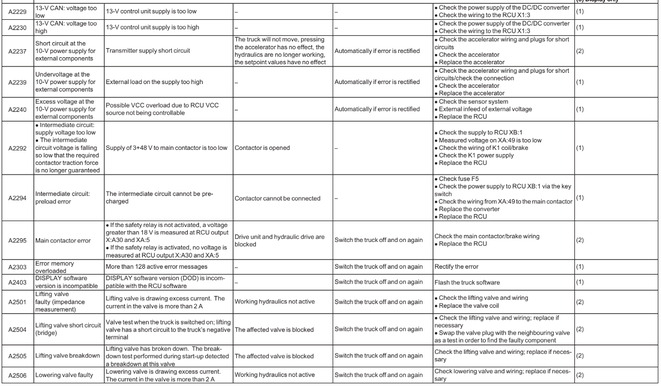
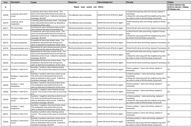
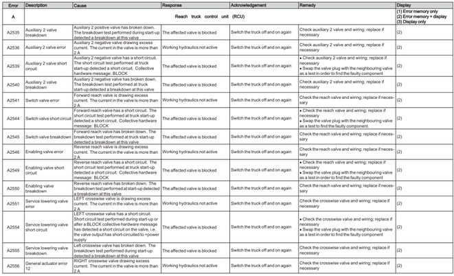
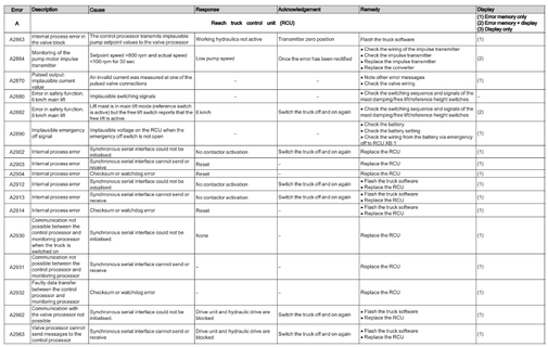
Reach truck Control Unit RCU (A)
Converter(D,F)
Card reader (G)
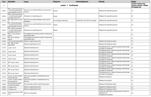
Joystick 4Plus/fingertips
Display and operating unit (J)
Battery controller (S)
Electric steering (z)
Additional Error numbers
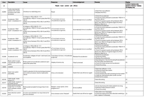
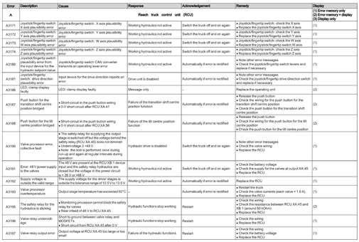
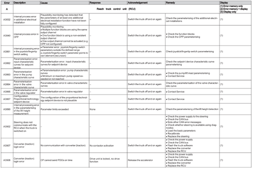
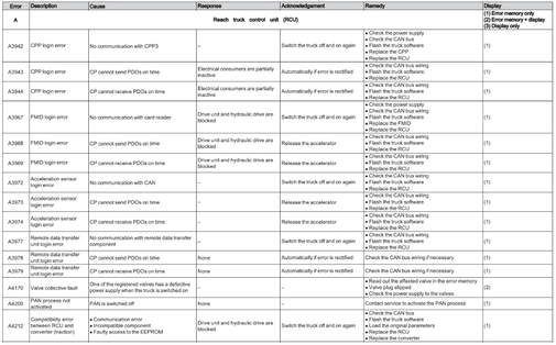
Reach Truck Control RCU (A)
Error A1201-A3902


Converter (D,F)
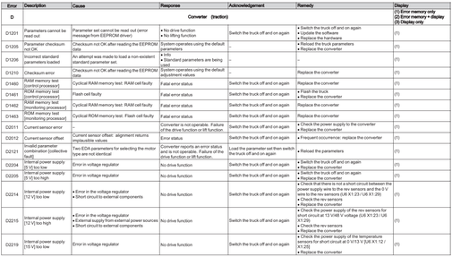
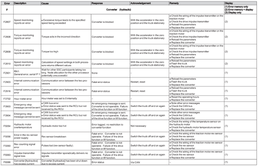
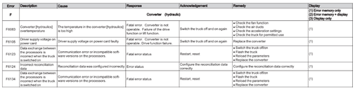
The converter is a dual converter. The two areas Traction and Hydraulics are covered by two error list (D,F)
Error D1201-D6134


Hydraulic converter (F)
Error F1201-F6134


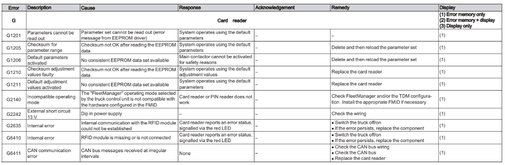
Card reader (G)
Error G1201-G6411
Joystick 4Plus/fingertips (I)
Error I1201-4491


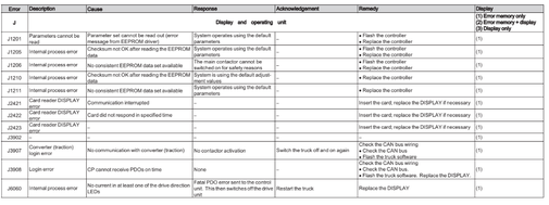
Display and operating unit (J)
Error J1201-J6060
Battary controller (S)
Error S3601-S3632

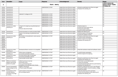
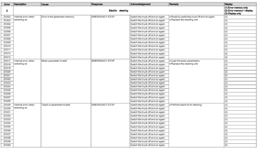
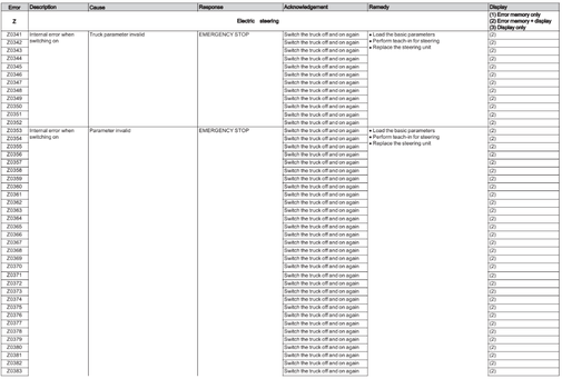
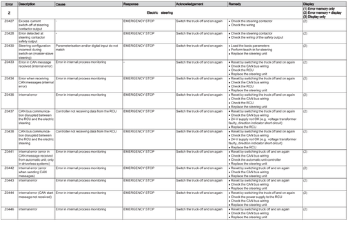
Electric steering (Z)
Error Z0200-Z0498


Additional error numbers
Error numbers without prefixed code letters appear in the display together with the symbol «i» for information.

- Manuals
- Brands
- Still Manuals
- Forklifts
- FM-X-17
Manuals and User Guides for Still FM-X-17. We have 4 Still FM-X-17 manuals available for free PDF download: Original Instructions Manual, Instructions Manual
Still FM-X-17 Original Instructions Manual (380 pages)
Brand: Still
|
Category: Forklifts
|
Size: 14.74 MB
Table of Contents
-
Table of Contents
5
-
Foreword
13
-
Your Truck
14
-
General
14
-
Conformity Marking
14
-
Declaration that Reflects the Content of the Declaration of Conformity
15
-
Accessories
16
-
Labelling Points
17
-
Nameplate
18
-
Production Number
19
-
Nameplate for a 48-V Lithium-Ion Battery
20
-
Declarations of Conformity in Accordance with Directive RED 2014/53/EU
21
-
Using the Truck
22
-
Commissioning
22
-
Proper Usage
22
-
Intended Use of the Lithium-Ion Battery (Variant)
22
-
Improper Use
23
-
Place of Use
23
-
Parking in Temperatures below -10 °C
24
-
Using Working Platforms
24
-
Information about the Documentation
25
-
Documentation Scope
25
-
Supplementary Documentation
26
-
Issue Date and Topicality of the Operating Instructions
27
-
Copyright and Trademark Rights
27
-
Explanation of Information Symbols Used
27
-
List of Abbreviations
28
-
Defining Directions
30
-
Schematic Views
31
-
Environmental Considerations
32
-
Packaging
32
-
Disposal of Components and Batteries
32
-
Safety
33
-
Definition of Responsible Persons
34
-
Operating Company
34
-
Specialist
34
-
Drivers
35
-
Basic Principles for Safe Operation
37
-
Insurance Cover on Company Premises
37
-
Special Notes When Using Lithium-Ion Batteries (Variant)
37
-
Changes and Retrofitting
41
-
Modifications to the Overhead Guard and Cabs
42
-
Seat Belt
43
-
Safety Information for FM-X Wide, Extra Wide (W, EW)
43
-
Warning Regarding Non-Original Parts
44
-
Damage, Defects and Misuse of Safety Systems
44
-
Wheels and Tyres
45
-
Medical Equipment
46
-
Exercise Caution When Handling Gas Springs and Accumulators
46
-
Length of the Fork Arms
47
-
Residual Risk
48
-
Residual Dangers, Residual Risks
48
-
Special Risks Associated with Using the Truck and Attachments
49
-
Overview of Hazards and Countermeasures
52
-
Danger to Employees
54
-
Safety Tests
56
-
Carrying out Regular Inspections on the Truck
56
-
Insulation Testing
56
-
Safety Regulations for Handling Consumables
58
-
Permissible Consumables
58
-
Oils
58
-
Hydraulic Fluid
59
-
Battery Acid
60
-
Brake Fluid
61
-
Disposal of Consumables
63
-
Commissioning Fleetmanager™ (Variant)
64
-
Activating the Access Control after Delivery of the Truck
64
-
Emissions
64
-
Overviews
67
-
Overview
68
-
Overview of the Driver’s Compartment
69
-
Shelves and Cup Holders
70
-
Operating Devices and Display Elements
71
-
Display and Operating Unit
71
-
Operating Status Displays on the Display and Operating Unit
72
-
Display Messages
73
-
Entering Truck Operating Data Via the Display and Operating Unit
77
-
Lithium-Ion Battery Display
81
-
Operating Devices for Hydraulic and Traction Functions
81
-
Joystick 4Plus
82
-
Fingertip
83
-
Operating
85
-
Checks and Tasks before Daily Use
86
-
Visual Inspections and Function Checking
86
-
Climbing into and out of the Truck
89
-
Adjusting the MSG 65/MSG 75 Driver’s Seat
91
-
Adjusting the Steering Column
95
-
Filling the Washer System (Variant)
96
-
Unlocking the Emergency off Switch
97
-
Access Authorisation with PIN Code (Variant)
97
-
Operating the Signal Horn
98
-
Checking the Brake System for Correct Function
98
-
Checking the Steering System for Correct Function
100
-
Checking the Emergency off Function
100
-
Checking the «Automatic Tilting Centre Position» (Variant) for Correct Function
101
-
Switching on
102
-
Switching on the Key Switch
102
-
Lighting
105
-
STILL Safetylight (Variant)
105
-
Switching the Working Spotlights (Variant) on and off
106
-
Daytime Running Lights / Footwell Lighting (Variant)
107
-
Efficiency and Drive Modes
108
-
Blue-Q Efficiency Mode
108
-
OPTISPEED — Continuously Variable Reduction in Driving Speed or Hydraulic Functions (Variant)
108
-
Driving
111
-
Safety Regulations When Driving
111
-
Roadways
113
-
Side Chassis Supports
115
-
Enabling Truck Functions Using the Foot Switch and Seat Switch
116
-
Setting the Drive Programme
118
-
Selecting the Drive Direction
119
-
Actuating the Drive Direction Switch, Joystick 4Plus
120
-
Actuating the Drive Direction Switch, Fingertip
120
-
Starting Drive Mode, Single-Pedal Version
121
-
Starting Drive Mode, Dual-Pedal Version (Variant)
123
-
Operating the Service Brake
125
-
Applying the Electromagnetic Parking Brake
126
-
Steering
128
-
Switching between 360°/180° Steering (Variant)
130
-
Emergency Operation of the Reach Measurement System
132
-
Parking
134
-
Parking the Truck Securely
134
-
Lifting
136
-
Lifting System Variants
136
-
Lift Mast Versions
136
-
Lifting System Operating Devices
137
-
Joystick 4Plus Lifting System
138
-
Fingertip Lifting System
141
-
Electronic Lowering Stop Function
143
-
Automatic Lift Cut out (Variant)
144
-
Reach-Lower Lock (Variant)
145
-
Automatic Centre Position (Variant)
146
-
Fork Wear Protection (Variant)
147
-
Changing the Fork Arms
147
-
Speed Limitation Safety Function
149
-
Fork Extension (Variant)
151
-
Load Backrest (Variant)
153
-
Working Platforms
153
-
Malfunctions in Lifting Mode
153
-
Handling Loads
155
-
Safety Regulations When Handing Loads
155
-
Before Picking up a Load
155
-
Picking up Loads
157
-
Danger Area
159
-
Transporting Pallets
160
-
Transporting Suspended Loads
160
-
Picking up a Load
161
-
Transporting Loads
165
-
Setting down Loads
167
-
Driving on Upward and Downward Gradients
169
-
Driving Onto Lifts
169
-
Attachments
171
-
Fitting Attachments
171
-
Releasing the Pressure from the Auxiliary Hydraulics
174
-
General Instructions for Controlling Attachments
175
-
Controlling Attachments (Variant) Using the Joystick 4Plus (5Th/6Th Hydraulic Function)
177
-
Controlling Attachments (Variant) with the Fingertip (5Th/6Th Hydraulic Function)
179
-
Operating the Clamp Locking Mechanism (Variant) with a Joystick 4Plus
181
-
Operating the Clamp Locking Mechanism (Variant) with the Fingertip Switch
183
-
Picking up a Load Using Attachments
184
-
Assistance Systems
186
-
Automatic Fork Centre Position During Lowering (Variant)
186
-
Lowering Protection Assistant (Variant)
188
-
Auxiliary Equipment
190
-
Fleetmanager (Variant)
190
-
Shock Recognition (Variant)
190
-
Active Load Stabilisation als (Variant)
190
-
Optical Height Measuring System (Variant)
192
-
Load Measurement (Variant)
196
-
Speed Limitation Based on Lift Height
198
-
Button for Speed Limitation, Creep Speed (Variant)
199
-
Camera/Monitor System (Variant)
200
-
Electrical Adjustment Mechanism for the Driver’s Compartment (Variant)
200
-
Overhead Guard with Optimised Visibility (Variant)
201
-
Clipboard (Variant)
202
-
Battery Change Frame (Variant)
203
-
General
203
-
Safe Handling
203
-
Load Capacity
203
-
Area of Application
204
-
Adjusting the Transfer Height
204
-
Locking the Battery Change Frame
205
-
Battery Replacement Area
205
-
Lift Height Preselector / Easy Target (Variant)
207
-
General
207
-
Definition of Terms
208
-
AUTO MODE Function
209
-
Operating the Lift Height Preselector
212
-
Teach-In, General
215
-
Performing a Teach-In
216
-
Easy Target/Easy Target Plus (Variants)
219
-
Approaching Target Heights Using «Easy Target
221
-
Positioning the Fork Horizontally Using «Easy Target Plus
222
-
Cab (Variant)
224
-
General Information about the Cab
224
-
Opening the Cab Door
224
-
Closing the Cab Door
226
-
Cab Operating Devices
226
-
Cab Interior Lighting (Variant)
227
-
Heating System in the Cab (Variant)
228
-
Emergency Exit Window in the Cab
230
-
Cold Store Application
232
-
General
232
-
Areas of Application
232
-
Description of the Cold Store Equipment
233
-
Battery in the Cold Store
234
-
Impermissible Use of the Lithium-Ion Battery in the Shock Cold Store (-45°C)
235
-
Before Entering the Cold Store
235
-
Procedure in Emergencies
237
-
Emergency Shutdown
237
-
Procedure if Truck Tips over
238
-
Emergency Lowering
239
-
Towing
240
-
Connecting and Disconnecting the Battery Male Connector
243
-
Connecting the Battery Male Connector
243
-
Disconnecting the Battery Male Connector
243
-
Handling the Lead-Acid Battery
245
-
Safety Regulations When Handling the Battery
245
-
Maintaining the Battery
248
-
Checking the Battery Condition, Acid Level and Acid Density
249
-
Checking the Battery Charge Status
251
-
Charging the Battery
251
-
Equalising Charging to Preserve the Battery Capacity
254
-
Handling the Lithium-Ion Battery (Variant)
256
-
Safety Regulations for Handling the Lithium-Ion Battery
256
-
Approved Lithium-Ion Batteries
259
-
Lithium-Ion Batteries «GGS Li-Ion 48 V (BG4)» 9.8 Kwh and 39.2 Kwh
259
-
Regulations for Storing Lithium-Ion Batteries
260
-
Checking the Battery Charge Status (Lithium-Ion Battery)
261
-
Charging the Lithium-Ion Battery Upon Delivery
263
-
Charging the Lithium-Ion Battery
264
-
Recommissioning the Lithium-Ion Battery Following Deep Discharge
266
-
Replacing and Transporting the Battery
268
-
Commissioning Batteries that Are Delivered Separately
268
-
Alternating between a Lead-Acid Battery and a Lithium-Ion Battery
268
-
General Information on Replacing the Battery
268
Advertisement
Still FM-X-17 Instructions Manual (360 pages)
Reach truck
Brand: Still
|
Category: Forklifts
|
Size: 20.9 MB
Table of Contents
-
Table of Contents
5
-
Foreword
13
-
Your Truck
14
-
General
14
-
Conformity Marking
14
-
Declaration that Reflects the Content of the Declaration of Conformity
15
-
Accessories
16
-
Labelling Points
17
-
Nameplate
18
-
Serial Number
19
-
Nameplate for a 48-V Lithium-Ion Battery
20
-
Declarations of Conformity in Accordance with Directive RED 2014/53/EU
21
-
Using the Truck
22
-
Commissioning
22
-
Intended Use
22
-
Intended Use of the Lithium-Ion Battery (Variant)
22
-
Improper Use
23
-
Place of Use
23
-
Parking in Temperatures below -10 °C
24
-
Using Working Platforms
25
-
Information about the Documentation
26
-
Scope of the Documentation
26
-
Supplementary Documentation
27
-
Issue Date and Topicality of the Operating Instructions
27
-
Copyright and Trademark Rights
28
-
Explanation of Signal Terms Used
29
-
List of Abbreviations
29
-
Defining Directions
31
-
Schematic Views
32
-
Environmental Considerations
33
-
Packaging
33
-
Disposal of Components and Batteries
33
-
Safety
35
-
Definition of Responsible Persons
36
-
Operating Company
36
-
Specialist
36
-
Drivers
37
-
Basic Principles for Safe Operation
39
-
Insurance Cover on Company Premises
39
-
Special Notes for Using Lithium-Ion Batteries
39
-
Product-Specific Dangers Posed by the Lithium-Ion Battery
41
-
Changes and Retrofitting
42
-
Modifications to the Overhead Guard and Cabs
44
-
Seat Belt
45
-
Safety Information for FM-X Wide, Extra Wide (W, EW)
45
-
Warning Regarding Non-Original Parts
45
-
Damage, Defects and Misuse of Safety Systems
46
-
Wheels and Tyres
46
-
Medical Equipment
47
-
Exercise Caution When Handling Gas Springs and Accumulators
48
-
Length of the Fork Arms
48
-
Residual Risk
50
-
Residual Dangers, Residual Risks
50
-
Special Risks Associated with Using the Truck and Attachments
51
-
Overview of Hazards and Countermeasures
54
-
Danger to Employees
56
-
Safety Tests
58
-
Carrying out Regular Inspections on the Truck
58
-
Insulation Testing
58
-
Safety Regulations for Handling Consumables
60
-
Permissible Consumables
60
-
Oils
60
-
Hydraulic Fluid
61
-
Battery Acid
62
-
Brake Fluid
63
-
Disposal of Consumables
65
-
Commissioning Fleetmanager™ (Variant)
66
-
Activating the Access Control after Delivery of the Truck
66
-
Emissions
66
-
Overviews
69
-
Overview
70
-
Overview of the Driver’s Compartment
71
-
Shelves and Cup Holders
72
-
Operating Devices and Display Elements
73
-
Display and Operating Unit
73
-
Operating Status Displays on the Display and Operating Unit
74
-
Display Messages
75
-
Entering Truck Operating Data Via the Display and Operating Unit
79
-
Lithium-Ion Battery Display
83
-
Operating Devices for Hydraulic and Traction Functions
83
-
Joystick 4Plus
84
-
Fingertip
85
-
Operating
87
-
Checks and Tasks before Daily Use
88
-
Visual Inspections and Function Checking
88
-
Climbing into and out of the Truck
91
-
Adjusting the MSG 65/MSG 75 Driver’s Seat
93
-
Adjusting the Steering Column
97
-
Filling the Washer System (Variant)
98
-
Unlocking the Emergency off Switch
98
-
Access Authorisation with PIN Code (Variant)
99
-
Operating the Signal Horn
99
-
Checking the Brake System for Correct Function
99
-
Checking the Steering System for Correct Function
101
-
Checking the Emergency off Function
101
-
Checking the «Automatic Tilting Centre Position» (Variant) for Correct Function
102
-
Switching on
103
-
Switching on the Key Switch
103
-
Lighting
106
-
Retrofitting Lighting Equipment
106
-
STILL Safetylight® and STILL Safetylight 4Plus® (Variants)
106
-
Switching the Working Spotlights (Variant) on and off
107
-
Daytime Running Lights / Footwell Lighting (Variant)
108
-
Efficiency and Drive Modes
109
-
Blue-Q Efficiency Mode
109
-
OPTISPEED — Continuously Variable Reduction in Driving Speed or Hydraulic Functions (Variant)
109
-
Driving
112
-
Safety Regulations When Driving
112
-
Roadways
114
-
Side Chassis Supports
116
-
Enabling Truck Functions Using the Foot Switch and Seat Switch
116
-
Setting the Drive Programme
119
-
Selecting the Drive Direction
120
-
Actuating the Drive Direction Switch, Joystick 4Plus
121
-
Actuating the Drive Direction Switch, Fingertip
121
-
Starting Drive Mode, Single-Pedal Version
122
-
Starting Drive Mode, Dual-Pedal Version (Variant)
124
-
Operating the Service Brake
126
-
Applying the Electromagnetic Parking Brake
127
-
Steering
129
-
Switching between 360°/180° Steering (Variant)
131
-
Emergency Operation of the Reach Measurement System
133
-
Parking
135
-
Parking the Truck Securely
135
-
Lifting
137
-
Lifting System Variants
137
-
Lift Mast Versions
137
-
Lifting System Operating Devices
138
-
Joystick 4Plus Lifting System
139
-
Fingertip Lifting System
142
-
Electronic Lowering Stop Function
144
-
Automatic Lift Cut out (Variant)
145
-
Reach-Lower Lock (Variant)
146
-
Automatic Centre Position (Variant)
147
-
Fork Wear Protection (Variant)
148
-
Changing the Fork Arms
148
-
Speed Limitation Safety Function
150
-
Fork Extension (Variant)
152
-
Load Backrest (Variant)
154
-
Working Platforms
154
-
Malfunctions in Lifting Mode
154
-
Handling Loads
156
-
Safety Regulations When Handing Loads
156
-
Capacity Rating Plate
157
-
Picking up Loads
160
-
Danger Area
161
-
Transporting Pallets
162
-
Transporting Suspended Loads
163
-
Picking up a Load
164
-
Transporting Loads
167
-
Setting down Loads
169
-
Driving on Upward and Downward Gradients
171
-
Driving Onto Lifts
171
-
Attachments
173
-
Fitting Attachments
173
-
Releasing the Pressure from the Auxiliary Hydraulics
176
-
General Instructions for Controlling Attachments
177
-
Controlling Attachments (Variant) Using the Joystick 4Plus (5Th/6Th Hydraulic Function)
179
-
Controlling Attachments (Variant) with the Fingertip (5Th/6Th Hydraulic Function)
181
-
Operating the Clamp Locking Mechanism (Variant) with a Joystick 4Plus
183
-
Operating the Clamp Locking Mechanism (Variant) with the Fingertip Switch
185
-
Picking up a Load Using Attachments
186
-
Assistance Systems
188
-
Automatic Fork Centre Position During Lowering (Variant)
188
-
Lowering Protection Assistant (Variant)
190
-
Auxiliary Equipment
192
-
Fleetmanager (Variant)
192
-
Shock Recognition (Variant)
192
-
Active Load Stabilisation als (Variant)
192
-
Optical Height Measuring System (Variant)
194
-
Load Measurement (Variant)
198
-
Speed Limitation Based on Lift Height
200
-
Button for Speed Limitation, Creep Speed (Variant)
201
-
Camera/Monitor System (Variant)
202
-
Electrical Adjustment Mechanism for the Driver’s Compartment (Variant)
202
-
Overhead Guard with Optimised Visibility (Variant)
203
-
Clipboard (Variant)
204
-
Battery Change Frame (Variant)
205
-
General
205
-
Safe Handling
205
-
Load Capacity
205
-
Area of Application
206
-
Adjusting the Transfer Height
206
-
Locking the Battery Change Frame
207
-
Battery Replacement Area
207
-
Lift Height Preselector/Easy Target (Variant)
209
-
General
209
-
Definition of Terms
210
-
AUTO MODE Function
211
-
Operating the Lift Height Preselector
214
-
Teach-In, General
217
-
Performing a Teach-In
218
-
Easy Target/Easy Target Plus (Variants)
221
-
Approaching Target Heights Using «Easy Target
223
-
Positioning the Fork Horizontally Using «Easy Target Plus
224
-
Cab (Variant)
226
-
General Information about the Cab
226
-
Opening the Cab Door
226
-
Closing the Cab Door
228
-
Cab Operating Devices
228
-
Cab Interior Lighting (Variant)
229
-
Heating System in the Cab (Variant)
230
-
Emergency Exit Window in the Cab
232
-
Cold Store Application
234
-
General
234
-
Areas of Application
234
-
Description of the Cold Store Equipment
235
-
Battery in the Cold Store
236
-
Impermissible Use of the Lithium-Ion Battery in the Shock Cold Store (-45°C)
237
-
Before Entering the Cold Store
237
-
Procedure in Emergencies
239
-
Emergency Shutdown
239
-
Procedure if Truck Tips over
240
-
Emergency Lowering
241
-
Towing
242
-
Connecting and Disconnecting the Battery Male Connector
245
-
Connecting the Battery Male Connector
245
-
Disconnecting the Battery Male Connector
245
-
Handling the Lead-Acid Battery
247
-
Safety Regulations for Handling the Battery
247
-
Safety Regulations for Handling the Lithium-Ion Battery
247
-
Maintaining the Battery
250
-
Checking the Battery Condition, Acid Level and Acid Density
251
-
Checking the Battery Charge Status
253
-
Charging the Lead-Acid Battery
253
-
Equalising Charging to Preserve the Battery Capacity
256
-
Handling the Lithium-Ion Battery
259
-
Approved Lithium-Ion Batteries
261
-
Illustration of a Lithium-Ion Battery
262
-
Special Instructions and Course of Action for C-Line Lithium-Ion Batteries
262
-
Regulations for Storing Lithium-Ion Batteries
264
-
Checking the Battery Charge Status (Lithium-Ion Battery)
266
-
Charging the Lithium-Ion Battery Upon Delivery
268
-
Charging the Lithium-Ion Battery
268
-
Recommissioning the Lithium-Ion Battery Following Deep Discharge
270
Still FM-X-17 Original Instructions Manual (360 pages)
Reach trucks
Brand: Still
|
Category: Forklifts
|
Size: 17.54 MB
Table of Contents
-
Table of Contents
5
-
1 Foreword
13
-
Your Truck
14
-
General
14
-
CE Labelling
14
-
EC Declaration of Conformity in Accordance with Machinery Directive
15
-
Accessories
16
-
Labelling Points
17
-
Nameplate
18
-
Production Number
19
-
Nameplate of a Lithium-Ion Battery
19
-
Using the Truck
20
-
Commissioning
20
-
Proper Usage
20
-
Intended Use of the Lithium-Ion Battery (Variant)
20
-
Impermissible Use
21
-
Place of Use
21
-
Parking in Temperatures below -10°C
22
-
Fm-X
22
-
Using Working Platforms
23
-
Information about the Documentation
24
-
Documentation Scope
24
-
Fm-X
24
-
Supplementary Documentation
25
-
Issue Date and Topicality of the Operating Instructions
26
-
Copyright and Trademark Rights
26
-
Explanation of Information Symbols Used
26
-
Fm-X
26
-
List of Abbreviations
27
-
Defining Directions
29
-
Fm-X
29
-
Schematic Views
30
-
Environmental Considerations
31
-
Packaging
31
-
Disposal of Components and Batteries
31
-
Fm-X
32
-
-
2 Safety
33
-
Definition of Responsible Persons
34
-
Operating Company
34
-
Specialist
34
-
Drivers
35
-
Basic Principles for Safe Operation
37
-
Insurance Cover on Company Premises
37
-
Special Notes When Using Lithium-Ion Batteries (Variant)
37
-
Changes and Retrofitting
41
-
Modifications to the Overhead Guard and Cabs
43
-
Seat Belt
43
-
Safety Information for FM-X Wide, Extra Wide (W, EW)
44
-
Warning Regarding Non-Original Parts
44
-
Damage, Defects and Misuse of Safety Systems
45
-
Wheels and Tyres
45
-
Medical Equipment
46
-
Exercise Caution When Handling Gas Springs and Accumulators
47
-
Length of the Fork Arms
47
-
Residual Risk
49
-
Residual Dangers, Residual Risks
49
-
Special Risks Associated with Using the Truck and Attachments
50
-
Overview of Hazards and Countermeasures
52
-
Danger to Employees
55
-
Safety Tests
56
-
Carrying out Regular Inspections on the Truck
56
-
Insulation Testing
56
-
Safety Regulations for Handling Consumables
57
-
Permissible Consumables
57
-
Oils
58
-
Hydraulic Fluid
59
-
Battery Acid
60
-
Brake Fluid
61
-
Disposal of Consumables
62
-
Commissioning the Fleetmanager™ (Variant)
63
-
Activating the Access Control after Delivery of the Truck
63
-
Emissions
63
-
-
3 Overviews
67
-
Overview
68
-
Overview of the Driver’s Compartment
69
-
Shelves and Cup Holders
70
-
Operating Devices and Display Elements
71
-
Display and Operating Unit
71
-
Operating Status Displays on the Display and Operating Unit
72
-
Display Messages
73
-
Entering Truck Operating Data Via the Display and Operating Unit
77
-
Lithium-Ion Battery Display
82
-
Operating Devices for Hydraulic and Traction Functions
82
-
Joystick 4Plus
83
-
Fingertip
84
-
-
4 Operation
85
-
Testing and Activities before Daily Use
86
-
Visual Inspections and Function Checking
86
-
Climbing into and out of the Truck
89
-
Adjusting the MSG 65/MSG 75 Driver’s Seat
91
-
Adjusting the Steering Column
95
-
Filling the Washer System (Variant)
96
-
Unlocking the Emergency off Switch
96
-
Switching on the Key Switch
97
-
Access Authorisation with PIN Code (Variant)
99
-
Operating the Signal Horn
100
-
Checking the Brake System for Correct Function
100
-
Checking the Steering System for Correct Function
102
-
Checking the Emergency off Function
102
-
Checking the «Automatic Tilting Centre Position» (Variant) for Correct Function
103
-
Lighting
104
-
STILL Safetylight (Variant)
104
-
Switching the Working Spotlights (Variant) on and off
105
-
Efficiency and Drive Modes
106
-
Blue-Q Efficiency Mode
106
-
OPTISPEED — Continuously Variable Reduction in Driving Speed or Hydraulic Functions (Variant)
106
-
Driving
108
-
Safety Regulations When Driving
108
-
Roadways
110
-
Side Chassis Supports
113
-
Enabling Truck Functions Using the Foot Switch and Seat Switch
113
-
Setting the Drive Programme
116
-
Selecting the Drive Direction
117
-
Actuating the Drive Direction Switch, Joystick 4Plus
118
-
Actuating the Drive Direction Switch, Fingertip
118
-
Starting Drive Mode, Single-Pedal Version
119
-
Starting Drive Mode, Dual-Pedal Version (Variant)
121
-
Operating the Service Brake
123
-
Applying the Electromagnetic Parking Brake
124
-
Steering
126
-
Emergency Operation of the Reach Measurement System
127
-
Parking
130
-
Parking the Truck Securely
130
-
Lifting
131
-
Lifting System Variants
131
-
Lift Mast Versions
131
-
Lifting System Operating Devices
132
-
Joystick 4Plus Lifting System
133
-
Fingertip Lifting System
136
-
Automatic Lift Cut out (Variant)
138
-
Reach-Lower Lock (Variant)
140
-
Automatic Centre Position (Variant)
141
-
Speed Limitation Safety Function
143
-
Changing the Fork Arms
143
-
Fork Extension (Variant)
146
-
Load Backrest (Variant)
147
-
Working Platforms
148
-
Malfunctions in Lifting Mode
148
-
Handling Loads
150
-
Safety Regulations When Handing Loads
150
-
Before Picking up a Load
150
-
Picking up Loads
152
-
Danger Area
154
-
Transporting Pallets
155
-
Transporting Suspended Loads
155
-
Picking up a Load
156
-
Transporting Loads
159
-
Setting down Loads
161
-
Driving on Upward and Downward Gradients
163
-
Driving Onto Lifts
163
-
Attachments
165
-
Fitting Attachments
165
-
Releasing the Pressure from the Auxiliary Hydraulics
167
-
General Instructions for Controlling Attachments
168
-
Controlling Attachments (Variant) Using the Joystick 4Plus (5Th/6Th Hydraulic Function
169
-
Controlling Attachments (Variant) with the Fingertip (5Th/6Th Hydraulic Function)
172
-
Operating the Clamp Locking Mechanism (Variant) with a Joystick 4Plus
174
-
Operating the Clamp Locking Mechanism (Variant) with the Fingertip Switch
176
-
Picking up a Load Using Attachments
177
-
Auxiliary Equipment
178
-
Fleetmanager (Variant)
178
-
Shock Recognition (Variant)
178
-
Active Load Stabilisation als (Variant)
178
-
Optical Height Measuring System (Variant)
180
-
Load Measurement (Variant)
185
-
Speed Limitation Based on Lift Height
187
-
Button for Speed Limitation, Creep Speed (Variant)
188
-
Camera/Monitor System (Variant)
188
-
Electrical Adjustment Mechanism for the Driver’s Compartment (Variant)
189
-
Overhead Guard with Optimised Visibility (Variant)
190
-
Clipboard (Variant)
191
-
Battery Change Frame (Variant)
191
-
General
191
-
Safe Handling
192
-
Load Capacity
192
-
Area of Application
192
-
Adjusting the Transfer Height
193
-
Locking the Battery Change Frame
193
-
Battery Replacement Area
194
-
Lift Height Preselector/Easy Target (Variant)
196
-
General
196
-
Definition of Terms
197
-
AUTO MODE Function
198
-
Operating the Lift Height Preselector
201
-
Teach-In, General
204
-
Performing a Teach-In
205
-
Easy Target/Easy Target Plus (Variants)
208
-
Approaching Target Heights Using «Easy Target
210
-
Positioning the Fork Horizontally Using «Easy Target Plus
211
-
Cab (Variant)
212
-
General Information about the Cab
212
-
Opening the Cab Door
213
-
Closing the Cab Door
214
-
Cab Operating Devices
215
-
Cab Interior Lighting (Variant)
216
-
Heating System in the Cab (Variant)
216
-
Emergency Exit Window in the Cab
219
-
Cold Store Application
219
-
General
219
-
Areas of Application
220
-
Description of the Cold Store Equipment
221
-
Battery in the Cold Store
222
-
-
Impermissible Use of the Lithium-Ion Battery in the Shock Cold Store (-45°C)
222
-
Before Entering the Cold Store
223
-
Procedure in Emergencies
224
-
Emergency Shutdown
224
-
Procedure if Truck Tips over
225
-
Emergency Lowering
226
-
Towing
227
-
Connecting and Disconnecting the Battery Male Connector
229
-
Connecting the Battery Male Connector
229
-
Disconnecting the Battery Male Connector
230
-
Handling the Lead-Acid Battery
231
-
Safety Regulations When Handling the Battery
231
-
Maintaining the Battery
234
-
Checking the Battery Condition, Acid Level and Acid Density
235
-
Checking the Battery Charge Status
237
-
Charging the Battery
237
-
Equalising Charging to Preserve the Battery Capacity
240
-
Handling the Lithium-Ion Battery (Variant)
242
-
Safety Regulations for Handling the Lithium-Ion Battery
242
-
Approved Lithium-Ion Batteries
245
-
Lithium-Ion Batteries «GGS Li-Ion 48 V (BG4)» 9.8 Kwh and 39.2 Kwh
246
-
Regulations for Storing Lithium-Ion Batteries
247
-
Checking the Battery Charge Status (Lithium-Ion Battery)
248
-
Charging the Lithium-Ion Battery Upon Delivery
250
-
Charging the Lithium-Ion Battery
251
-
Recommissioning the Lithium-Ion Battery Following Deep Discharge
253
-
Replacing and Transporting the Battery
254
-
Commissioning Batteries that Are Delivered Separately
254
-
Alternating between a Lead-Acid Battery and a Lithium-Ion Battery
255
-
General Information on Battery Replacement
256
-
Actuating the Battery Lock
258
-
Adjusting the Battery Lock
259
-
Special Notes for Installing the Lithium-Ion Battery
261
-
Replacing the Battery Using a Lifting Device
261
-
Changing the Battery Using the Internal Roller Channel (Variant)
266
-
Setting the Battery Data (Lead Acid Batteries)
271
-
Transporting the Battery Using a Lifting Device (Lead Acid Batteries)
273
-
Transporting the Battery Using a Lifting Device (Lithium-Ion Batteries)
275
-
Cleaning the Truck
276
-
Cleaning the Electrical System
279
-
Cleaning Load Chains
280
-
Cleaning Panes of Glass and Mirrors
280
-
After Cleaning
281
-
Transporting the Truck
281
-
Transportation
281
-
Crane Loading (Standard Truck with Overhead Guard)
284
-
Crane Loading (Trucks with a Cab)
288
-
Decommissioning
294
-
Shutting down and Storing the Truck
294
-
Re-Commissioning after Shutdown
295
-
-
Advertisement
Still FM-X-17 Original Instructions Manual (292 pages)
Reach trucks
Brand: Still
|
Category: Forklifts
|
Size: 6.02 MB
Table of Contents
-
Table of Contents
3
-
1 Foreword
11
-
Your Truck
12
-
General
12
-
CE Labelling
12
-
EC Declaration of Conformity in Accordance with Machinery Directive
13
-
Information about the Documentation
14
-
Documentation Scope
14
-
Issue Date and Topicality of the Operating Instructions
15
-
Copyright and Trademark Rights
15
-
Explanation of Information Symbols Used
15
-
List of Abbreviations
16
-
Defining Directions
19
-
Schematic Views
20
-
Environmental Considerations
21
-
Packaging
21
-
Disposal of Components and Batteries
21
-
-
2 Introduction
23
-
Using the Truck
24
-
Proper Usage
24
-
Impermissible Use
24
-
Place of Use
25
-
Parking in Temperatures below -10°C
25
-
Using Working Platforms
26
-
Residual Risk
27
-
Residual Dangers, Residual Risks
27
-
Special Risks Associated with Using the Truck and Attachments
28
-
Overview of Hazards and Countermeasures
30
-
Danger to Employees
32
-
-
3 Safety
35
-
Definition of Terms Used for Responsible Persons
36
-
Operating Company
36
-
Specialist
36
-
Drivers
37
-
Basic Principles for Safe Operation
39
-
Insurance Cover on Company Premises
39
-
Changes and Retrofitting
39
-
Modifications to the Overhead Guard and Cabs
41
-
Safety Information for FM-X Wide, Extra Wide (W, EW)
42
-
Warning Regarding Non-Original Parts
42
-
Damage, Defects and Misuse of Safety Systems
43
-
Tyres
43
-
Medical Equipment
44
-
Exercise Caution When Handling Gas Springs and Accumulators
44
-
Safety Tests
45
-
Regular Safety Inspection of the Truck
45
-
Insulation Testing
45
-
Safety Regulations for Handling Consumables
46
-
Permissible Consumables
46
-
Oils
47
-
Hydraulic Fluid
48
-
Battery Acid
49
-
Brake Fluid
50
-
Disposal of Consumables
51
-
Emissions
51
-
-
4 Overviews
55
-
Overview
56
-
Overview of the Driver’s Compartment
57
-
Operating Devices and Display Elements
58
-
Display and Operating Unit
58
-
Operating Devices for Hydraulic and Traction Functions
58
-
Joystick 4Plus
59
-
Reserved
59
-
Fingertip
60
-
Identification Points
61
-
Overview
61
-
Nameplate
62
-
Production Number
63
-
-
5 Operation
65
-
Checks and Tasks to be Carried out Prior to Commissioning
66
-
Visual Inspections
66
-
Filling the Washer System (Variant)
68
-
Checking the Condition of the Wheels and Tyres
69
-
Adjusting the MSG 65/MSG 75 Driver’s Seat
70
-
(Variant)
73
-
Electrical Driver’s Compartment Adjustment (Variant)
74
-
Compartment
74
-
Adjusting the Steering Column
75
-
Commissioning
75
-
Climbing into and out of the Truck
75
-
Shelves and Cup Holders
77
-
Connecting the Battery Male Connector
77
-
Enabling Truck Functions Using the Foot Switch and Seat Switch
78
-
Display and Operating Unit
78
-
Foot Switch
78
-
Driver’s Seat
78
-
Unlocking the Emergency off Switch
80
-
Switching on the Key Switch
80
-
Access Authorisation with PIN Code (Variant)
83
-
Entering Truck Operating Data Via the Display and Operating Unit
84
-
Operating the Signal Horn
89
-
Checking the Brake System for Correct Function
89
-
Checking the Steering System for Correct Function
91
-
Checking the Emergency off Function
91
-
Checking the «Automatic Tilting Centre Position» (Variant) for Correct Function
92
-
Setting the Drive Programme
93
-
OPTISPEED — Continuously Variable Reduction in Driving Speed or Hydraulic Functions (Variant)
94
-
Driving
95
-
Safety Regulations When Driving
95
-
Roadways
98
-
Side Chassis Supports
100
-
Selecting the Drive Direction
101
-
Actuating the Drive Direction Switch, Joystick 4Plus
102
-
Actuating the Drive Direction Switch, Fingertip
102
-
Starting Drive Mode, Single-Pedal Version
102
-
Starting Drive Mode, Dual-Pedal Version (Variant)
104
-
Operating the Service Brake
106
-
Applying the Electromagnetic Parking Brake
107
-
Steering
110
-
Lifting
112
-
Lifting System Variants
112
-
Automatic Lift Cut out (Variant)
113
-
Reach-Lower Lock (Variant)
114
-
Automatic Centre Position (Variant)
115
-
Lift Mast Versions
116
-
Malfunctions in Lifting Mode
117
-
Lifting System Operating Devices
118
-
Joystick 4Plus Lifting System
119
-
Fingertip Lifting System
122
-
Load Backrest (Variant)
124
-
Changing the Fork Arms
124
-
Fork Extension (Variant)
127
-
Working Platforms
128
-
Handling Loads
129
-
Safety Regulations When Handing Loads
129
-
Before Picking up a Load
129
-
Picking up Loads
131
-
Danger Area
132
-
Transporting Pallets
133
-
Transporting Swinging Loads
134
-
Picking up a Load
135
-
Transporting Loads
138
-
Setting down Loads
140
-
Driving on Upward and Downward Gradients
142
-
Driving Onto Lifts
142
-
Working with Attachments
144
-
Fitting Attachments
144
-
Releasing the Pressure from the Auxiliary Hydraulics
146
-
General Instructions for Controlling Attachments
147
-
Controlling Attachments (Variant) with the Fingertip (5Th/6Th Hydraulic Function)
151
-
Operating the Clamp Locking Mechanism (Variant) with a Joystick 4Plus
153
-
Operating the Clamp Locking Mechanism (Variant) with the Fingertip Switch
155
-
Picking up a Load Using Attachments
156
-
Operating Auxiliary Equipment
157
-
Switching the Working Spotlights (Variant) on and off
157
-
Clipboard (Variant)
158
-
Fleetmanager (Variant)
158
-
Accident Recorder (Variant)
158
-
Active Load Stabilisation als (Variant)
159
-
Camera/Monitor System (Variant)
160
-
Load Measurement
160
-
Battery Change Frame (Variant)
162
-
General
162
-
Safe Handling
163
-
Load Capacity
163
-
Area of Application
163
-
Adjusting the Transfer Height
164
-
Locking the Battery Change Frame
164
-
Battery Replacement Area
165
-
Lift Height Preselector (Variant)
166
-
General
166
-
Definition of Terms
167
-
AUTO MODE Function
168
-
Operating the Lift Height Preselector
171
-
Teach-In, General
175
-
Performing a Teach-In
176
-
Cab Operation (Variant)
179
-
General Information about the Cab
179
-
Opening the Cab Door
180
-
Closing the Cab Door
181
-
Emergency Exit Window in the Cab
181
-
Cab Operating Devices
182
-
Cab Interior Lighting (Variant)
183
-
Heating System in the Cab (Variant)
184
-
Cold Store Application
185
-
General
185
-
Areas of Application
186
-
Battery in the Cold Store
187
-
Description of the Cold Store Equipment
187
-
Warming up the Truck
188
-
Operating the Display and Operating Unit
188
-
Operating Status Displays on the Display and Operating Unit
188
-
Blue-Q Efficiency Mode
190
-
Functional Description
190
-
Switching the Blue-Q Efficiency Mode on and off
190
-
Fault Displays
191
-
View on the Display and Operating Unit
191
-
Operating in Special Operating Situations
191
-
Transportation
191
-
Towing
194
-
Crane Loading
196
-
Procedure in Emergencies
199
-
Emergency Shutdown
200
-
Procedure if Truck Tips over
201
-
Emergency Lowering
202
-
Handling the Battery
202
-
Safety Regulations When Handling the Battery
202
-
General Information on Battery Replacement
206
-
Actuating the Battery Lock
207
-
Disconnecting the Battery Male Connector
209
-
Battery Replacement Using a Crane
210
-
Changing the Battery Using the Internal Roller Channel (Variant)
215
-
Battery Commissioning
221
-
Adjusting the Battery Lock
221
-
Setting the Battery Data
223
-
Battery Transport with Crane
225
-
Maintaining the Battery
226
-
Decommissioning
230
-
Parking the Truck Securely
230
-
Shutting down and Storing the Truck
232
-
Re-Commissioning after Shutdown
233
-
Cleaning
234
-
Cleaning the Truck
234
-
Cleaning Load Chains
235
-
After Cleaning
236
-
-
Advertisement
Related Products
-
Still FM-X-12
-
Still FM-X-14
-
Still FM-X-10
-
Still FM-X 10 N
-
Still FMX 12 N
-
Still FM-X
-
Still FM-X-20
-
Still FM-X-25
-
Still FM-X SE
-
Still FM-X W Series
Still Categories
Forklifts
Trucks
Tractor
Industrial Equipment
Camera Accessories
More Still Manuals
Overviews
Item no. Display
Function assistant, centre position for
10
transition shift
Function assistant, centre position for tilting —
11
Operating hours, error messages, drive
12
profile, information text
Acknowledge button
13
14
Information
Maintenance expired
15
16
Caution
Creep speed activated
17
Blue-Q activated
18
Overtemperature
19
Driver’s seat not occupied during operation
20
of the truck (seat switch)
Parking brake activated
21
Seat belt on driver’s seat not fastened (not
22
series production truck)
Foot switch required
23
Symbol for FleetManager variant or PIN
24
code access variant
Battery water level display too low (variant) —
25
Battery not locked
26
.
Event-related operating information and
malfunctions are shown in the display field
(2). In addition, the «Caution»symbol (1) lights
up if there is a malfunction.
Messages are always shown periodically and
for a certain period of time, according to the
event.
In the case of successive events, the respec-
tive messages are displayed one after another
on the display.
After a few seconds, the display will alternate
between the last shown operating display and
the message.
Operating devices and display elements
Comment
—
The meter displays up to 99,999.9 operat-
ing hours.
Actuation required for further functioning
—
—
Displayed together with an error message
(FE)
—
—
—
—
—
—
—
—
—
50988078001 EN — 10/2018
3
61
![]()
![]()
STILL Forklift Fault Codes
STILL Forklift Fault Codes
STILL Forklift Fault Codes.pdf
Adobe Acrobat Document
2.3 MB
![]()
STILL RX 50 Operator Manual
STILL RX 50 Operator Manual
STILL RX 50 Operator Manual.pdf
Adobe Acrobat Document
7.8 MB
![]()
STILL FM X Operator Manual
STILL FM X Operator Manual
STILL FM X Operator Manual.pdf
Adobe Acrobat Document
5.7 MB
![]()
STILL RX 60 16 18 20 Operator Manual
STILL RX 60 16 18 20 Operator Manual
STEEL RX 60 16 18 20 Operator Manual.pdf
Adobe Acrobat Document
1.2 MB
![]()
STILL RX 20-E3 Operator Manual
SILL RX 20-E3 Operator Manual
STEEL RX 20-E3 Operator Manual.pdf
Adobe Acrobat Document
5.7 MB
![]()
STILL RX 70 16 20 Diesel Operator Manual
STILL RX 70 16 20 Diesel Operator Manual
STEEL RX 70 16 20 Diesel Operator Manual
Adobe Acrobat Document
5.3 MB
![]()
STILL RX 70 20 35 Operator Manual
STILL RX 70 20 35 Operator Manual
STEEL RX 70 20 35 Operator Manual.pdf
Adobe Acrobat Document
5.0 MB
![]()
STILL RX 60 60 80 Operator Manual
STILL RX 60 60 80 Operator Manual
STILL RX 60 60 80 Operator Manual.pdf
Adobe Acrobat Document
4.8 MB
![]()
STILL RX 70 40 50 Operator Manual
STILL RX 70 40 50 Operator Manual
STILL RX 70 40 50 Operator Manual.pdf
Adobe Acrobat Document
6.0 MB
![]()
STILL RX 60 25 35 Operator Manual
STILL RX 60 25 35 Operator Manual
STILL RX 60 25 35 Operator Manual.pdf
Adobe Acrobat Document
6.2 MB
![]()
STILL RX 70 60 80 Operator Manual
STILL RX 70 60 80 Operator Manual
STILL RX 70 60 80 Operator Manual.pdf
Adobe Acrobat Document
5.2 MB
Some STILL Forklift Truck Operator Manuals PDF, Fault Codes DTC are above this page — FM, RX.
STILL GmbH was founded in 1920 in Hamburg and is named after its founder Hans Still. It all started with a small electrical workshop where the electric motors
were repaired and semi-automatic emergency power supply units were manufactured.
After a considerable period of time, including the WW2, in 1949, Still presented his first loader. From that moment a new history of the company began — already under the sign of
the manufacturer of forklifts.
Today there are several enterprises in STILL.
The expansion began in 1989, when SAXBY was acquired in 1997 Wagner purchased.
In 2001, the production site in South America began operating. Since 2006, STILL belongs to Kion Group.
In addition to 4 factories, Still has 14 branches in Germany, 20 subsidiaries and an extensive dealer network around the world. The
geography of deliveries of loaders STILL — more than 200 countries of the world.
The company produces forklift electric, diesel and gas forklifts and warehouse stackers. Among the products — forklifts, pickers, lifting carts, tractors, cars and other storage equipment.
STILL not only offers equipment for sale, but also leases it (including used ones). Specialists of the company are engaged in maintenance,
repair and maintenance of leased equipment (forklifts, stackers, etc.), conduct training for the personnel of the client enterprise.
Another innovation from STILL is the development and implementation of software solutions that establish control over internal material
and information flows, combining them into a single chain «Receiving goods — Distribution — Warehousing — Shipping».
FLTA Fork Lift Truck Association, a world association of manufacturers of forklifts, has repeatedly awarded diplomas and prizes to the company’s
products.
![]()
![]()
Still RX 60 16 18 20 Operator’s Manual
Still RX 60 16 18 20 Operator’s Manual
Still RX 60 16 18 20 Operator’s Manual.p
Adobe Acrobat Document
1.2 MB
![]()
Still FM X Operator’s Manual
Still FM X Operator’s Manual
Still FM X Operator’s Manual.pdf
Adobe Acrobat Document
5.5 MB
![]()
Still RX70 Diesel Operator’s Manual
Still RX70 Diesel Operator’s Manual
Still RX70 Diesel Operator’s Manual.pdf
Adobe Acrobat Document
5.3 MB
![]()
Still EXD18 Pallet Truck Operator’s Manual PDF
Still EXD18 Pallet Truck Operator’s Manual PDF
Still EXD18 Pallet Truck Operator’s Manu
Adobe Acrobat Document
1.8 MB
![]()
Still ECV10C Order Picker Operator’s Manual PDF
Still ECV10C Order Picker Operator’s Manual PDF
Still ECV10C rde Picker Operator’s Manua
Adobe Acrobat Document
1.8 MB
![]()
Still RX 60 80 Operator’s Manual
Still RX 60 80 Operator’s Manual
Still RX 60 80 Operator’s Manual.pdf
Adobe Acrobat Document
4.7 MB
Some STILL Forklift Truck Manuals PDF are above the page.
The story of Still began on February 1, 1920, when Hans Still opened his first workshop in Hamburg.
The first workshop was founded by Still in 22 years, the energy of a young specialist and faith in their work laid down the principles on which the company has been holding for
more than 90 years and continues to grow.
Hans Still offered his customers high quality products, reliability and speed of service, which won fame for the electric motor repair company and in the same year Hans
Still began its own production of electric motors.
In 1924, the production of generators began, and the number of employees grew to 20 people from three enthusiasts who were passionate about their work.
In 1937, the company’s staff already numbered 500 people, and in our time at Still there are more than 6,000 employees worldwide.
The company’s headquarters in Berzeliusstraße, Hamburg, was opened by Hans Still in 1932 and, despite the wartime and crises of all subsequent years, Still never
moved its head office.
After the war, Still introduces a new product to the market that allowed the company to stay afloat and grow significantly in the
future — the EK 2000 electric forklift, capable of lifting weights up to 2 tons.
From this moment Still begins to grow as a manufacturer of warehouse and material handling equipment. Soon, the company introduced its
first forklift truck EGS 1000.
Still establishes a network of new service stations and in the 60s at Still they
decide to modernize production and create new assembly shops, which the company has been able to do in a record five years.
Still products are in great demand, both in Germany and in other European countries.
In 1979, the company registers the trademark STILL GmbH. Still one of the first
to start using IBM equipment to upgrade production processes.
By 1990, Still grew into a giant of the industry, having representative offices in almost all countries of the Eurozone.
Today Still produces warehouse and construction equipment, conducts service throughout Europe, being one of the leading manufacturers of warehouse equipment and forklifts.
Still produces forklift trucks with engines for liquefied gas, diesel and electric, with a lifting capacity of up to 8 tons and a special
system of economical fuel consumption.
Still FM-X20:
Code A6612 on screen
When you turn on FMX20 Still, hydraulic system does not work and code A6612 appears on the screen. Travel system works well, operator has to walk 15 minutes with elevator FMX20 and code A6612 disappears from the screen allowing normal operation of elevator FMX20.
Showing items 1 — 2 of 2 results.
Sort messages by:
Hello!
please tell me, did you fix the reactruck? I have a similar breakdown, but sometimes the movement and error a6610 are turned off.
ERROR — A6612
Description:
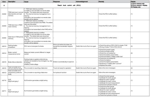
Fatal error in converter hydraulics.
Cause:
The converter is reporting a fatal error.
Response:
No hydraulic function
Acknowledgement:
Switch lock
Remendy:
Check the converter: replace if necessary.
Having trouble using the Discussion Forums? Contact us for help.
Forkliftaction.com accepts no responsibility for forum content and requires forum participants to adhere to the rules. Click here for more information.

Forklift
Super Moderator
- Joined
- Mar 27, 2015
- Messages
-
2,504
- Likes
- 152
-
Download this document, you need
0
Gallons
Download Now
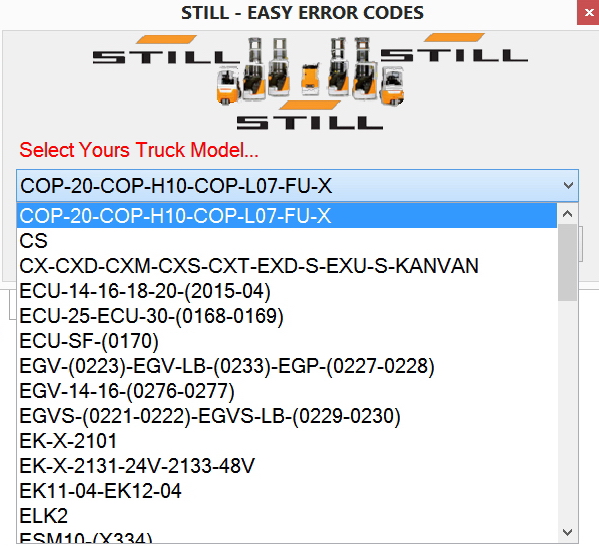
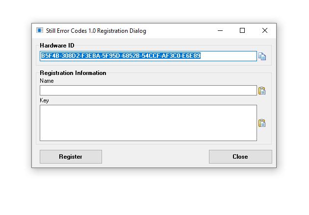
1/ Still Forklift Easy Error Codes
2/ This PC Lock Send Me Yours Name + HWID
3/ One Key for one PC
4/ After install Comment on below «Yours Name + HWID» or sent to email: «autorepairmanuals.ws@gmail.com»
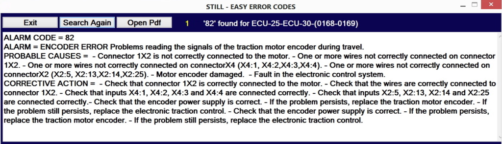
COP-20-COP-H10-COP-L07-FU-X.txt
CS.txt
CX-CXD-CXM-CXS-CXT-EXD-S-EXU-S-KANVAN.txt
ECU-14-16-18-20-(2015-04).txt
ECU-25-ECU-30-(0168-0169).txt
ECU-SF-(0170).txt
EGV-(0223)-EGV-LB-(0233)-EGP-(0227-0228).txt
EGV-14-16-(0276-0277).txt
EGVS-(0221-0222)-EGVS-LB-(0229-0230).txt
EK-X-2101.txt
EK-X-2101_INFO.txt
EK-X-2131-24V-2133-48V.txt
EK-X-2131-24V-2133-48V_INFO.txt
EK11-04-EK12-04.txt
ELK2.txt
ESM10-(X334).txt
EXD20-EXD-SF20-EXU-SF20-(0283-0284-0179).txt
EXU22.txt
EXV-10-10Basic-12-12i-14-14i.txt
EXV-10-10Basic-12-12i-14-14i_INFO.txt
EXV14-16-20-(i)-EXV-SF14-16-20-(i)-(0323-0334)-EXP-(0301-0303-0305).txt
EXV14-16-20-(i)-EXV-SF14-16-20-(i)-(0323-0334)-EXP-(0301-0303-0305)_INFO.txt
FM-X-(1900-1922).txt
FM-X-(1900-1922)_INFO.txt
FM-X-(1900-1922)_OLD.txt
FM-X-1801.txt
FM-X-1801_INFO.txt
FMI-Typ-429.txt
FMI-Typ-447.txt
FMI-Typ-451.txt
FS-X33.txt
FV-X-12-12i-16-16i.txt
GX-X-GX-Q.txt
GX-X-GX-Q_INFO.txt
iGo-neo-CX-20-(1063).txt
Lithium-ion-technology.txt
MX-X-2332-2334.txt
MX-X-2332-2334_INFO.txt
MX-X-2332-2334_old.txt
MX-X-MX-Q-Generation-1-2-80V.txt
MX-X-MX-Q-Generation-1-2-80V_OLD.txt
MX-X-MX-Q-Generation-3-48V.txt
MX-X-MX-Q-Generation-3-48V_OLD.txt
MX-X-MX-Q-Generation-3-80V.txt
MX-X-MX-Q-Generation-3-80V_OLD.txt
MX-X-MX-Q-Generation-4-48V.txt
MX-X-MX-Q-Generation-4-48V_OLD.txt
MX-X-MX-Q-Generation-4-80V.txt
MX13-3-MX15-3-MX13-3i-MX15-3i.txt
OPX-LTX50.txt
OPX-LTX50_INFO.txt
R07—25-R08-20-2017.txt
R07-25-R08-20.txt
R07-25-R08-20_INFO.txt
R20-2008-2014-2017-2024-2037-2044.txt
R20i-2015-2045-2049.txt
R60-(S60).txt
R60-6022-6029-6042-6052.txt
R60i-6033-6035-6053-6055.txt
R60i-6036-6039.txt
R70.txt
RX20-RX60_INFO.txt
RX20.txt
RX50-5051-5055.txt
RX50-5051-5055_INFO.txt
RX50-5060-5066.txt
RX50-5060-5066_INFO.txt
RX60.txt
RX70.txt
RX70_INFO.txt
SU-SD-SV.txt
X_Not_Sorted_Model_List.txt
X_Sorted_Model_List.txt
Last edited by a moderator: Feb 20, 2020
More the random threads same category:
- STILL STEDS Forklifts 8.17 R2 [02.2017] Full Instruction + Activation
- STILL STEDS 8.16.R2 Plus [05.2016] Full Instruction + Activation
- Still Steds 8.14 FULL
- Still Steds Navigator Forklifts 8.19 R2 [02.2019]
- STILL STEDS Forklifts 8.15 R2 [08.2015] Full VM
- STILL Some Error Code PDF
- Prosecco Multi KG V4 + ProSecCo Activator
- STILL STEDS Forklifts 8.18 R3 [03.2018] Full Instruction
- Forklift ProSecCo KG 2015 v2 (Clark,Linde,Lidos,Liebherr,Valtra,Widos,Jeti,Still)
- Still Steds Navigator Forklifts 8.18 R8 [09.2018] Full Instruction
- STETI EPC (Steinbock) Forklifts v3.6 2003 Spare Parts Catalog
- Still Steds Navigator Forklifts 8.20 R2 [02.2020] Full Instruction
- Forklift ProSecCo KG 2016 v1
- Still Forklift ProSecCo KG 2016v2
- Still Steds Navigator Forklifts 8.19 R8 2020 [08.2019] Full Instruction

Master
Administrator
- Joined
- Sep 3, 2012
- Messages
-
17,165
- Likes
- 701
1/ Still Forklift Easy Error Codes
2/ This PC Lock Send Me Yours Name + HWID
3/ One Key for one PC
4/ After install Comment on below «Yours Name + HWID» or sent to email: «autorepairmanuals.ws@gmail.com»
empilhomat
New Member
- Joined
- Feb 16, 2021
- Messages
-
1
- Likes
- 0
Варианты оснащения
Мы предлагаем широкий выбор интеллектуального оборудования для складской техники, которое значительно облегчит выполнение ваших повседневных задач и обеспечит эффективную, безопасную, эргономичную работу без утомления в любой ситуации.
- Безопасность
- Эргономика
- Системы помощи оператору
- Другое оборудование
Highlights
Световые индикаторы безопасности STILL SafetyLight 4plus →
Визуальная предупредительная система, снижающая количество несчастных случаев
Предупредительный сигнал синего цвета STILL SafetyLight 4plus значительно повышает производственную безопасность в зонах со сложной навигацией и большим количеством поворотов. Синие световые пятна проецируются на пол приблизительно в пяти метрах впереди и позади погрузчика, что предупреждает сотрудников о его приближении и помогает предотвратить несчастные случаи.
Читать далее
Звуковой сигнал при движении задним ходом →
Повышение безопасности на складе за счет звукового сигнала: он предупреждает сотрудников о приближении погрузчика задним ходом, таким образом, они могут своевременно среагировать, даже если находятся спиной к машине.
Читать далее
Широкополосный звуковой сигнал →

Широкополосный сигнал – это звуковой сигнал, издаваемый в широкополосном диапазоне. Такой звуковой сигнал заглушается окружающим шумом на больших расстояниях, при этом в непосредственной близости можно с легкостью определить расположение источника звука, а значит и опасности. Таким образом, машина становится более заметной для окружающих, что снижает вероятность аварий.
Системы защитных ограждений →
Системы защитных ограждений обеспечивают защиту оператора благодаря надежности конструкции, смонтированной внутри контуров машины. Мы также предлагаем комплекты таких систем для установки на машины с задним стеклом. Они не ограничивают свободу движения и оператора и обзор, а также не затрудняют посадку и высадку из машины. Имеются системы с ручным открыванием / закрыванием, а также с автоматическим, которые связаны с ручным тормозом или педалью акселератора, а закрытие ограждения происходит в момент начала движения машины.
Защитная сетка на крышу →
Защитная сетка на крышу, предназначенная для защиты оператора в случае падения грузов, доступна в низкой и высокой версиях в зависимости от высоты проездов.
Защитная решетка для грузов →
Защитная решетка каретки вил повышает устойчивость грузов в районе каретки, обеспечивая их сохранность во время перевозки.
Читать далее
Распознавание ударов (в сочетании с ПО FleetManager 4.x или без) →

При использовании системы распознавания ударов без ПО FleetManager акселерометр распознает механические удары, что может указывать на неправильное обращение с машиной. После регистрации удара погрузчик переключается в режим малого хода. Руководитель может отключить ограничение скорости, введя «PIN-код менеджера парка техники» через дисплей Easy Control.
Такое решение для предотвращения повреждения машин и грузов является экономичным, т.к. не требует установки дополнительного оборудования. Если система распознавания ударов используется вместе с ПО FleetManager, то в этом случае при превышении определенного уровня вибраций информация об этом направляется менеджеру парка техники.
Кроме непосредственно ударов также может регистрироваться скорость движения, время происшествия, номер машины и данные оператора.
Дополнительная информация
Проблесковый маячок →
Желтый проблесковый маячок повышает безопасность работы на складе, предупреждая других сотрудников о приближении погрузчика.
Читать далее
Контроль доступа (с использованием ПО FleetManager 4.x) →

Система контроля доступа может интегрироваться с различными другими типами контроля доступа для одной или нескольких машин. Использование ПО FleetManager 4.x дает возможность выбора систем контроля доступа: чип-карты, карты FleetManager, заводские пропуска или PIN-коды. Благодаря интеллектуальной функции автоматического выхода из системы, доступ к машинам деактивируется по истечении периода времени, который указывается в настройках системы, что также способствует повышению безопасности.
Контроль доступа →
При желании, доступ к управлению транспортным средством можно ограничить. Функция контроля доступа позволяет разрешить управление только отдельным сотрудниками или группам сотрудников. Доступ может осуществляться как посредством ключа, так и введением цифрового кода (доступно десять настраиваемых кодов доступа).
Читать далее
Контроль доступа посредством введения PIN-кода (без использования ПО FleetManager 4.x) →

Использование кодовых замков является простым способом предотвращения несанкционированного использования машины. Для запуска двигателя необходимо лишь ввести PIN-код. Это позволяет эксплуатирующей организации разрешить доступ к машине только отдельным лицам или группам лиц. Имеется возможность использования десяти настраиваемых PIN-кодов.
Дополнительная информация
Сиденье с регулируемым наклоном спинки →

Устраивайтесь поудобнее:
Сиденье с регулируемым наклоном спинки (опция) для ричтраков FM-X значительно повышает эргономику рабочего места оператора. Оно защищает его спину и шею во время работы, а также улучшает обзор окружающего пространства при посадке в машину и высадки из нее. Наклон спинки имеет удобную регулировку.
Читать далее
Панорамная стеклянная крыша →
Оптимальный обзор: для улучшения обзора во время постановки и забора груза на машину может быть установлена защитная крыша из армированного стекла (опция).
Читать далее
Регулировка положения сиденья и педалей →

Всегда на нужной высоте:
Высота сиденья и педалей регулируется пропорционально. Операторы могут настраивать их положение в соответствии со своими предпочтениями, что обеспечивает работу без утомляемости. Амортизация рабочего места оператора позволяет защитить мышцы спины при движении по неровным покрытиям и через пороги.
Читать далее
Highlights
Система ALS (активная стабилизация грузов) →

Отсутствие вибраций
Ричтрак FM-X не просто опережает своих конкурентов. Благодаря системе ALS (активной стабилизации грузов) оператор ричтрака FM-X может заниматься обработкой следующего груза, в то время, когда остальные будут ждать, пока прекратятся вибрации мачты. Система ALS быстро и эффективно гасит колебания мачты на больших высотах подъема за счет контрдвижений, осуществляемых в автоматическом режиме, что на 80% сокращает время ожидания при постановке груза на полку. В результате скорость выполнения цикла значительно возрастает.
Читать далее
Система Curve Speed Control →
Автоматическое снижение скорости в поворотax
Автоматическое снижение скорости при выполнении поворотов позволяет снизить риск повреждения груза за счет выбора оптимальной скорости в поворотах. Данная вспомогательная функция доступна для различных вилочных погрузчиков и складской погрузочной техники. Она позволяет автоматически устанавливать скорость движения в зависимости от угла поворота. Иными словами, оператору не нужно думать о скорости во время выполнения поворотов. Скорость движения машины снизится автоматически именно настолько, насколько это необходимо для безопасного, но при этом быстрого прохождения поворота.
Читать далее
Система Easy Target Plus →

Попасть в яблочко по нажатию кнопки
Система Easy Target Plus позволяет быстро и точно разместить груз на нужном уровне стеллажей – для этого достаточно лишь нажать кнопку. Оператору при этом не требуется корректировать высоту подъема вил вручную.
Ваши преимущества:
- Высокая степень безопасности оператора и груза
- Во время выполнении операции на дисплее отображаются подсказки, таким образом, с ней легко сможет справиться даже неопытный оператор
- Быстрый выбор необходимого уровня полок
- Настройка высоты уровней для конкретного склада
Читать далее
Отображение высоты подъема →
Устанавливаемый в стандартной комплектации датчик высоты подъема с ЖК-дисплеем обеспечивает высочайшую точность – до миллиметра. Система стабильно работает с точностью до +/- 5 мм. Оператор видит высоту подъема на дисплее. Таким образом, он всегда знает точную высоту, на которой находятся концы вил, и может быть уверен, что не заденет полку при подъеме палеты.
Читать далее
Датчик высоты потолка →
Датчик высоты потолка распознает зоны с низкой высотой потолка и предлагает оператору снизить скорость движения для повышения общей безопасности на складе. Ультраакустический датчик устанавливается на крыше машины и распознает наличие потолков на высоте до 20м. В зависимости от сигнала, поступаемого с датчика, может меняться максимально допустимая скорость движения машины (стандартное ограничение – 6 км/ч).
Профиль оператора в системе FleetManager →
Кому разрешено использовать определенный погрузчик и для каких задач? С какой скоростью разрешено движение погрузчика определенному оператору?
Решение: наши интеллектуальные профили операторов в системе FleetManager 4.x. С помощью этого веб-приложения характеристики транспортного средства могут быть определены в соответствии с квалификацией оператора, например, индивидуальное снижение скорости движения, подъема или наклона, автоматическое включение освещения.
Дополнительная информация
Читать далее
Программы движения →
Подходящая программа движения для любой ситуации: оператор может выбирать одну из трех предустановленных и двух настраиваемых программ в трех режимах управления: Blue-Q, стандарт, спринт. Программы движения выбираются исходя из ситуации для достижения максимальной производительности и энергоэффективности.
Интеллектуальный автопилот: эффективный режим Blue-Q включается одним нажатием кнопки (синей кнопки на погрузчике). Интеллектуальная оптимизация рабочих характеристик привода позволяет экономить энергию в тех случаях, когда это не оказывает влияния на рабочий процесс.
Это обеспечивает до 10% экономии энергопотребления в зависимости от режима эксплуатации и установленного оборудования.
Читать далее
Предварительный выбор высоты подъема →
При постановке и заборе грузов, при подъеме и опускании мачты: необходимую высоту подъема можно выбрать заранее, используя кнопку выбора на многофункциональной панели управления. Можно запрограммировать до 20 уровней стеллажных полок. После достижения желаемой высоты подъем вил останавливается автоматически. Индикатор высоты подъема на ЖК-дисплее также указывает оператору на то, что заданная высота подъема вил достигнута.
Преимущества: повышение безопасности и эффективности работы, осторожности при обращении с грузом, комфорта оператора.
Читать далее
Установка нулевого угла наклона вил и мачты →
По нажатию кнопки угол наклона палеты (относительно мачты) устанавливается на 90°. Это значительно облегчает ввод вил в палету (как и вывод) даже на уровне верхних ярусов стеллажей.
Читать далее
OptiSpeed 3.0, 3.1, 3.3 для ричтраков →
Максимальная производительность работы с грузом: STILL OptiSpeed
В данный пакет входят как программные, так и аппаратные системы помощи оператору, оптимизирующие движение машины вне зависимости от массы перемещаемого груза, что значительно повышает производительность работы с грузом.
Используя программное обеспечение, система OptiSpeed определяет оптимальную траекторию движения машины и вил в зависимости от высоты подъема. Данная система непрерывно корректирует скорость движения машины в проходе вне зависимости от высоты подъема. Это обеспечивает повышение производительности, комфорта и безопасности.
В версии 3.3 система OptiSpeed имеет все преимущества предыдущих версий, а также датчик веса: в дополнение к подаче звуковых и визуальных сигналов при достижении установленных пороговых значений также автоматически блокируются функции движения и подъема при превышении допустимого веса груза. Система также рассчитывает идеальную траекторию движения при работе с грузом и оптимизирует ее на основании данных о высоте подъема и весе груза. Это позволяет повысить скорость при холостых пробегах, погрузке и разгрузке.
Читать далее
OptiSpeed для ричтраков →
Безопасность операций на любой высоте подъема
Система помощи оператору OptiSpeed снижает вибрации мачты на средних высотах подъема до минимума, что значительно ускоряет обработку грузов.
Система помощи оператору OptiSpeed не может сочетаться с системой стабилизации груза ALS (Active Load Stabilisation).
Читать далее
Режим малого хода →

При заданной высоте подъема вил активируется режим малого хода (5 км/ч). Это значительно снижает риск несчастных случаев, т.к. в случае возникновения опасной ситуации у оператора будет достаточно времени на реагирование.
Читать далее
Блокировка сдвига и опускания каретки →
Данная система устанавливается на ричтрак FM-X и практически исключает риск повреждения грузов при подъеме палет. Преимуществом системы блокировки сдвига и опускания каретки является то, что палеты, поднятые неровно или диагонально, при опускании ложатся на опорные лапы и при выдвижении вил повернутся или сдвинутся. Для обеспечения безопасности оператор обязан удостовериться в этом, а также при подборе грузов проверять правильность их положения.
Читать далее
Автоматический стояночный тормоз →

Автоматический стояночный тормоз включается автоматически или при нажатии кнопки, предотвращая откат машины. Электрогидравлический пружинный тормоз блокирует движение колес при каждой остановке машины.
Видеокамеры на вилах →

Установка видеокамер на вилах предотвращает повреждение грузов, получение телесных повреждений в результате падения грузов, а также столкновения со стеллажами. Изображение с видеокамер, устанавливаемых на внутреннюю сторону концов вил, выводится на дисплей оператора, что улучшает обзор груза, в особенности на больших высотах подъема.
Ограничение скорости при поднятии вил →
Для безопасности перевозки грузов: при движении с поднятыми вилами имеется риск опрокидывания палет, что может привести к повреждению груза. Для предотвращения такой ситуации, скорость движения автоматически снижается в зависимости от высоты подъема вил.
Читать далее
Видеокамеры →

Ричтрак FM-X может быть укомплектован системой видеокамер (опция), которая значительно улучшает обзор, что упрощает работу оператора.
Читать далее
Видеокамеры на каретке вил, внешней мачте и в задней части машины →

Установка видеокамер на каретке вил, внешней мачте и в задней части машины улучшает обзор оператора и, таким образом, помогает предотвратить столкновения с инфраструктурой склада, а также получение телесных повреждений. Изображение с установленной в соответствующем месте машины камеры выводится на дисплей. Таким образом, оператор может видеть все, что происходит как спереди, так и сзади машины.
Панорамное зеркало →

Панорамное зеркало, устанавливаемое с левой или правой стороны машины, повышает обзор, расширяет видимую зону и, таким образом, снижает размер слепого пятна. Оператор может оперативно увидеть, что находится позади машины, что позволяет повысить безопасность работы.
Дневные ходовые огни →
Безопасность прежде всего: светодиодные дневные ходовые огни гарантируют, что вилочный погрузчик не останется незамеченным даже в зонах с недостаточной освещенностью.
Читать далее
-
Page 1
Original instructions Reach trucks FM-X, FM-X N, FM-X W, FM-X EW FM-X-10 FM-X-12 FM-X-14 FM-X-17 FM-X-20 FM-X-22 FM-X-25 1900 1901 1902 1903 1904 1905 1906 1907 1908 1909 1910 1914 1915 1916 1917 1918 1919 1920 1921 1922 50988078001 EN — 04/2015… -
Page 3: Table Of Contents
Table of contents Foreword Your truck …………2 General .
-
Page 4
Table of contents Safety information for FM-X Wide, Extra Wide (W, EW) ……32 Warning regarding non-original parts ……..32 Damage, defects and misuse of safety systems . -
Page 5
Table of contents Commissioning ……….. . . 65 Climbing into and out of the truck . -
Page 6
Table of contents Fork extension (variant) ……….117 Working platforms . -
Page 7
Table of contents Lift height preselector (variant) ……… . 156 General . -
Page 8
Table of contents Disconnecting the battery male connector ……..199 Battery replacement using a crane . -
Page 9
VDI datasheet FM-X 10 (N), FM-X 12 (N)* ……. . . -
Page 11: Foreword
Foreword…
-
Page 12: Your Truck
Foreword Your truck Your truck General The truck described in these operating instruc- These operating instructions provide the tions corresponds to the applicable standards necessary information to do this. Read and and safety regulations. observe the information provided before commissioning the truck. This will prevent The trucks have been fitted with state-of-the- accidents and ensure that the warranty art technology.
-
Page 13: Ec Declaration Of Conformity In Accordance With Machinery Directive
Foreword Your truck EC declaration of conformity in accordance with Machinery Directive Declaration STILL GmbH Berzeliusstraße 10 D-22113 Hamburg Germany We declare that the according to these operating instructions Industrial truck according to these operating instructions Model conforms to the latest version of the Machinery Directive 2006/42/EC.
-
Page 14: Information About The Documentation
Foreword Information about the documentation Information about the documentation Documentation scope • Operating instructions • Operating instructions for attachments (variant) • Spare parts list • VDMA rules for the proper use of industrial trucks These operating instructions describe all mea- sures necessary for the safe operation and proper maintenance of your truck in all pos- sible variants available at the time of printing.
-
Page 15: Issue Date And Topicality Of The Operating Instructions
The issue date of these operating instructions can be found on the title page. STILL is constantly engaged in the further development of trucks. These operating instructions are subject to change, and any claims based on the information and/or illustrations contained in them cannot be asserted.
-
Page 16: List Of Abbreviations
Foreword Information about the documentation CAUTION Indicates procedures that must be strictly adhered to in order to prevent material damage and/or destruction. NOTE For technical requirements that require special attention. ENVIRONMENT NOTE To prevent environmental damage. List of abbreviations NOTE This list of abbreviations applies to all types of operating instructions.
-
Page 17
Foreword Information about the documentation Meaning Abbreviation Decibels Remote data transmission DFÜ German standard European Community European standard Fédération Européene de la Manutention Maximum power Grams Industrial inspectorate If applicable If applicable GPRS General Packet Radio Service Hours per day (time driven each day in hours) ID no. -
Page 18
Foreword Information about the documentation Meaning Abbreviation Metres per second squared Maximum workplace concentration Max. Maximum Min. Minimum Minutes Revolution(s) per minute Millimetres Newtons Newton metres Personal identification number Superelastic Snap-in tyre for simplified assembly German Road Traffic Licensing Regulations StVZO Tonnes Technical Regulations for Hazardous Substances… -
Page 19: Defining Directions
Foreword Information about the documentation Defining directions General: • left (1) • right (2) Drive directions: • Travelling in the load direction (backwards) • Travelling in the drive direction (forwards) Movements of the reach carriage: • Extending the reach carriage (in the load direction) (5) •…
-
Page 20: Schematic Views
Foreword Information about the documentation Schematic views View of functions and operating proce- dures At many points in this documentation, the (mostly sequential) operation of certain func- tions or operating procedures is explained. To illustrate these operations, schematic views of a reach truck are used.
-
Page 21: Environmental Considerations
Foreword Environmental considerations Environmental considerations Packaging During delivery of the truck, certain parts are packaged to provide protection during transport. This packaging must be removed completely prior to initial start-up. ENVIRONMENT NOTE The packaging material must be disposed of properly after delivery of the truck. Disposal of components and batteries The truck is composed of different materials.
-
Page 22
Foreword Environmental considerations 50988078001 [EN]… -
Page 23: Introduction
Introduction…
-
Page 24: Using The Truck
Introduction Using the truck Using the truck Proper usage The truck described in these operating in- structions is suitable for lifting, transporting and stacking loads. The truck may only be used for its proper purpose as set out and described in these operating instructions.
-
Page 25: Place Of Use
Introduction Using the truck Place of use The truck is only approved for indoor use. The ground must have an adequate load capacity (concrete, asphalt) and a rough surface. Roadways, working areas and aisle widths must conform to the specifications in these operating instructions;…
-
Page 26: Using Working Platforms
Introduction Using the truck Using working platforms WARNING The use of working platforms is regulated by na- tional law. The use of working platforms is only permitted by virtue of the jurisdiction in the country of use. – Observe national legislation. –…
-
Page 27: Residual Risk
Introduction Residual risk Residual risk Residual dangers, residual risks Despite careful working and compliance with standards and regulations, the occurrence of other risks when using the truck cannot be entirely excluded. The truck and all other system components comply with current safety requirements. Nevertheless, even when the truck is used for its proper purpose and all instructions are followed, some residual risk cannot be…
-
Page 28: Special Risks Associated With Using The Truck And Attachments
Introduction Residual risk The manufacturer is not held responsible for accidents involving the truck caused by the failure of the operating company to comply with these regulations either intentionally or carelessly. Stability The stability of the truck has been tested to the latest technological standards and is guaranteed if the truck is used properly and according to its intended purpose.
-
Page 29
Introduction Residual risk 50988078001 [EN]… -
Page 30: Overview Of Hazards And Countermeasures
Introduction Residual risk Overview of hazards and counter- measures NOTE This table is intended to help evaluate the hazards in your facility and applies to all drive types. It does not claim to be complete. NOTE Observe the national regulations for your country! Hazard Measure…
-
Page 31
Introduction Residual risk Hazard Measure Check note Notes √ actioned — not applicable Impermissible usage Issuing of operating BetrSichVO (improper usage) instructions (Workplace Safety Ordinance) and ArbSchG (Health and Safety at Work Act) Written notice of BetrSichVO instruction to driver (Workplace Safety Ordinance) and ArbSchG (Health and… -
Page 32: Danger To Employees
Introduction Residual risk Hazard Measure Check note Notes √ actioned — not applicable With driverless transport systems Roadway quality Clean/clear driveways BetrSichVO inadequate (Workplace Safety Ordinance) Load carrier Reattach load to pallet BetrSichVO incorrect/slipped (Workplace Safety Ordinance) Drive behaviour Employee training BetrSichVO unpredictable (Workplace Safety…
-
Page 33
Introduction Residual risk tachments possess their own CE labelling and likewise are not included for that reason. The operating company must, however, select the type and equipment of the trucks so as to com- ply with the local provisions for deployment. The result must be documented (§… -
Page 34
Introduction Residual risk 50988078001 [EN]… -
Page 35: Safety
Safety…
-
Page 36: Definition Of Terms Used For Responsible Persons
Safety Definition of terms used for responsible persons Definition of terms used for responsible persons Operating company The operating company is the natural or legal person or group who operates the truck or on whose authority the truck is used. The operating company must ensure that the truck is only used for its proper purpose and in compliance with the safety regulations set out…
-
Page 37: Drivers
Safety Definition of terms used for responsible persons regarding the industrial truck to be tested and the risk being assessed Drivers This truck may only be driven by suitable per- sons who are at least 18 years of age, have been trained in driving, have demonstrated their skills in driving and handling loads to the operating company or an authorised rep-…
-
Page 38
Safety Definition of terms used for responsible persons DANGER The use of drugs, alcohol or medications that affect reactions impair the ability to drive the truck! Individuals under the influence of the aforementio- ned substances are not permitted to perform work of any kind on or with the truck. -
Page 39: Basic Principles For Safe Operation
There is a risk of accident due to restricted visibility. Additional attachments (e.g. terminals, printers, mirrors) in the driver’s compartment area can restrict the driver’s field of vision. – Only install attachments (variants) that have been specifically approved by STILL in accor- dance with the safety regulations. 50988078001 [EN]…
-
Page 40
Safety Basic principles for safe operation Only restraint systems (variants) that have been specifically approved by STILL may be installed and used. DANGER Risk of injury if truck tips over! Even if the driver has fastened the seat belt (variant), there is still a residual risk of injury if the truck tips over. -
Page 41: Modifications To The Overhead Guard And Cabs
Safety Basic principles for safe operation – Name and address of the company imple- menting the modification. Modifications to the overhead guard and cabs DANGER The overhead guard or the weather protection cab/cold store cab may fail. A falling load or the truck tipping over could result in fatal consequences for the driver.
-
Page 42: Safety Information For Fm-X Wide, Extra Wide (W, Ew)
– Do not mount any additional roof loads on the truck. Safety information for FM-X Wide, Extra Wide (W, EW) The W (Wide) and EW (Extra Wide) versions differ from the standard truck by having additional cover sheets (1) between the overhead guard and the widened chassis.
-
Page 43: Damage, Defects And Misuse Of Safety Systems
Safety Basic principles for safe operation Damage, defects and misuse of safety systems Damage or other defects on the truck or attachment must be reported to the supervisor or responsible fleet manager immediately so that they can have the defect rectified. Trucks and attachments that are not functional or safe to drive may not be used until they have been properly repaired.
-
Page 44: Medical Equipment
Safety Basic principles for safe operation Medical equipment WARNING Electromagnetic interference may occur on medical devices! Only use equipment that is sufficiently protected against electromagnetic interference. Medical equipment, such as pacemakers or hearing aids, may not work properly when the truck is in operation.
-
Page 45: Safety Tests
Safety Safety tests Safety tests Regular safety inspection of the truck Safety inspection based on time and extraordinary incidents The operating company must ensure that the truck is checked by a specialist at least once a year or after particular incidents. As part of this inspection, a complete check of the technical condition of the truck must be performed with regard to accident safety.
-
Page 46: Safety Regulations For Handling Consumables
Safety Safety regulations for handling consumables Measuring the battery’s insulation resistance NOTE Nominal battery voltage < test voltage < 500 – Measure the insulation resistance with a suitable measuring device. The insulation resistance can be considered sufficient if it measures at least 500 /V for the nominal battery voltage against ground.
-
Page 47: Oils
Safety Safety regulations for handling consumables Oils DANGER Oils are flammable! – Follow the statutory regulations. – Do not allow oils to come into contact with hot engine parts. – No smoking, fires or naked flames! DANGER Oils are toxic! –…
-
Page 48: Hydraulic Fluid
Safety Safety regulations for handling consumables ENVIRONMENT NOTE Oil is a water-polluting substance! Always store oil in containers that comply • with the applicable regulations. Avoid spilling oils. • Spilt oil should be removed immediately • with oil-binding agents and disposed of according to the regulations.
-
Page 49: Battery Acid
Safety Safety regulations for handling consumables ENVIRONMENT NOTE Hydraulic fluid is a water-polluting substance. Always store hydraulic fluid in containers • that comply with regulations Avoid spills • Spilt hydraulic fluid should be removed • immediately with oil-binding agents and disposed of according to the regulations Dispose of old hydraulic fluid according to •…
-
Page 50: Brake Fluid
Safety Safety regulations for handling consumables Brake fluid WARNING Brake fluid is poisonous! – Avoid swallowing. In the event of swallowing, do not induce vomiting. Rinse out your mouth thoroughly with water and ask a doctor for advice. – Avoid aerosolisation and inha- lation.
-
Page 51: Disposal Of Consumables
Safety Emissions ENVIRONMENT NOTE Brake fluid is a water pollutant! Always store brake fluid in containers • complying with the regulations.. Do not spill brake fluid. • Spilt brake fluid must be removed immedia- • tely using an oil binding agent and disposed of in accordance with regulations Dispose of old brake fluid according to the •…
-
Page 52
Safety Emissions dard (noise measurement for industrial trucks based on EN 12001 and EN ISO 3744 and the requirements of EN ISO 4871). This machine emits the following sound pressure level: Continuous sound pressure level in the driver’s compartment < 69.5 dB(A) The values were determined in the test cycle on an identical machine from the weighted values for operating statuses and idling. -
Page 53
Safety Emissions The personal vibration load on the driver over a working day must be determined in accordance with Directive 2002/44/EC by the operating company at the actual place of use, in order to consider all additional influences, such as driving route, intensity of use etc. Battery DANGER Risk of explosion due to flammable… -
Page 54
Safety Emissions 50988078001 [EN]… -
Page 55: Overviews
Overviews…
-
Page 56: Overview
Overviews Overview Overview Overhead guard Battery Driver’s compartment Side support (tilt protection) Lift mast Control compartment Fork arms Drive wheel Load wheel Step Battery frame 50988078001 [EN]…
-
Page 57: Overview Of The Driver’s Compartment
Overviews Overview of the driver’s compartment Overview of the driver’s compartment 2 3 4 5 Steering wheel Operating devices for hydraulic and traction Working spotlight push button (variant) functions Key switch or push button (variant) Emergency off switch Reserved Push button for additional hydraulic func- Electrical seat adjustment push button tions (variant)
-
Page 58: Operating Devices And Display Elements
Overviews Operating devices and display elements Operating devices and display elements Display and operating unit Display of the operating statuses Keypad for lift height preselection (variant) or PIN code access (variant) Keypad for onboard diagnostics, parame- terising Drive programme button (P1-P4) Blue-Q button Parking brake button Operating devices for hydraulic and…
-
Page 59: Joystick 4Plus
Overviews Operating devices and display elements Joystick 4Plus «Transition shift» slider «Transition shift/tilt centre position» push Shift button «F» (auxiliary hydraulics con- button (variant) troller) Reserve Drive direction switch Pictograms for operation of the 5th and 6th Joystick, «lifting/lowering» function hydraulic function (variant) Joystick, «shifting»…
-
Page 60: Fingertip
Overviews Operating devices and display elements Fingertip «Lift/lower» operating lever «Transition shift/tilt centre position» push «Shift» operating lever button (variant) «Tilt» operating lever Reserve «Transition shift» operating lever «Auxiliary hydraulics» push button (variant) Emergency off switch Drive direction switch «Enable» push button (variant) Signal horn button «Load measurement»…
-
Page 61: Identification Points
Overviews Identification points Identification points Overview 400-600 1000 10200 1150 9800 1110 1300 9500 1050 1200 1400 9300 1080 1240 1450 9000 1160 1320 1500 8750 1200 1600 1600 8300 1270 1700 1700 7100 X<= 15mm 50988078001 [EN]…
-
Page 62: Nameplate
Overviews Identification points Warning sign: Do not stand underneath the Decal information: Electrical seat adjust- fork/Do not stand on the fork/Danger due to ment (variant) shearing/Danger due to high fluid pressure Decal information: FEM test Decal information: Caution/read the operat- Decal information: FEM test (inspection ing instructions sticker)
-
Page 63: Production Number
Overviews Identification points Production number xx xxxx x xxxxx NOTE The production number is used to identify the truck. It can be found on the nameplate and must be referred to in all technical questions. The production number contains the following coded information: (1) Production location (2) Model…
-
Page 64
Overviews Identification points 50988078001 [EN]… -
Page 65: Operation
Operation…
-
Page 66: Checks And Tasks To Be Carried Out Prior To Commissioning
Operation Checks and tasks to be carried out prior to commissioning Checks and tasks to be carried out prior to commissioning Visual inspections WARNING Risk of accident due to damage or other defects on the truck or on the attachment (variant)! Damage to the truck or the attachment (variant) can lead to unpredictable and dangerous situations.
-
Page 67
Operation Checks and tasks to be carried out prior to commissioning cab (variant) must be undamaged and securely mounted • Attachments (variant) must be properly attached and function according to their operating instructions • All decal information signs must be in place and legible. -
Page 68: Filling The Washer System (Variant)
Operation Checks and tasks to be carried out prior to commissioning WARNING Risk of component damage! A deformed or damaged battery male connector can cause overheating and related consequential damage. – Check the battery male connector for damage. – If necessary, have the battery male connector replaced by the authorised service centre.
-
Page 69: Checking The Condition Of The Wheels And Tyres
Operation Checks and tasks to be carried out prior to commissioning Checking the condition of the wheels and tyres WARNING Risk of accident! Uneven wear reduces the stability of the truck and increases the braking distance. – If the tyres are worn or damaged, inform the authorised service centre immediately NOTE Only approved tyre types may be used;…
-
Page 70: Adjusting The Msg 65/Msg 75 Driver’s Seat
Operation Checks and tasks to be carried out prior to commissioning Adjusting the MSG 65/MSG 75 driver’s seat DANGER There is a risk of accident if the seat or seat backrest shifts suddenly, which could cause the driver to move in an uncontrolled manner. This can result in unintentional actuation of the steering or the operating devices and thus cause uncontrolled movements of the truck or load.
-
Page 71
Operation Checks and tasks to be carried out prior to commissioning Adjusting the seat backrest Do not put pressure on the seat backrest while disengaging it. – Lift the lever (2) and hold. – Push the seat backrest into the desired position. -
Page 72
Operation Checks and tasks to be carried out prior to commissioning Adjusting the lumbar support (variant) NOTE The lumbar support can be adjusted to suit the contours of the individual driver’s spine. Adjusting the lumbar support moves a convex support cushion into the upper or lower part of the backrest. -
Page 73: (Variant)
Operation Checks and tasks to be carried out prior to commissioning Switching the seat heater (variant) on and off NOTE The seat heater only functions if the seat contact switch is active, i.e. when the driver is sitting on the driver’s seat. –…
-
Page 74: Electrical Driver’s Compartment Adjustment (Variant)
Operation Checks and tasks to be carried out prior to commissioning Electrical driver’s compartment adjustment (variant) WARNING Risk of accident, risk of crushing The pedal plate and seat console move during adjustment. – Change settings only when the truck is at a standstill.
-
Page 75: Adjusting The Steering Column
Operation Commissioning Adjusting the steering column DANGER Risk of accident! – Ensure that the steering column is securely attached. Never adjust the steering column while driving. – Push the steering column adjustment lever (1) forwards to release the steering column lock.
-
Page 76
Operation Commissioning WARNING Risk of injury when jumping out of the truck! If the driver jumps out the truck while it is moving, he or she could fall under the truck or be crushed by an obstacle. If the driver’s clothing or jewellery (watch, ring etc.) become stuck on components, this can lead to serious injuries, e.g. -
Page 77: Shelves And Cup Holders
Operation Commissioning Shelves and cup holders WARNING Objects may fall into the footwell and obstruct the pedals, which poses a risk of accident! Objects to be stored must be of the correct size so that they do not fall from the shelves (1, 4) or out of the cup holder (2).
-
Page 78: Enabling Truck Functions Using The Foot Switch And Seat Switch
Operation Commissioning Enabling truck functions using the foot switch and seat switch The foot switch and seat switch are there for safety purposes during operation of the truck. The complete range of truck functions is available only when the driver is sitting on the driver’s seat and then actuates the foot switch.
-
Page 79
Operation Commissioning The hydraulic functions are only enabled if: • The seat switch has been actuated • The switch is functioning correctly The drive function is only enabled if: • The parking brake has been released • The seat switch has been actuated but the accelerator pedals have not •… -
Page 80: Unlocking The Emergency Off Switch
Operation Commissioning Unlocking the emergency off switch Unlocking the emergency off switch – Pull the emergency off switch (1) upwards until it is unlocked. Switching on the key switch WARNING Before switching on the key switch, all tests prior to commissioning must be performed without any defects being detected.
-
Page 81
Operation Commissioning – Insert switch key (1) into the key switch and turn to position «I». This initiates a self-test. All symbols on the display and operating unit are displayed briefly until the truck controllers have started up completely. When the truck is switched on, the fork carriage and the reach carriage must initially be in the basic position. -
Page 82
Operation Commissioning Displays after the switch-on process (for trucks with default options) NOTE Depending on the truck equipment, further information may be visible on the display and operating unit. Battery charge(1) The usable battery charge is shown in the display field. NOTE After connecting a «partially»… -
Page 83: Access Authorisation With Pin Code (Variant)
Operation Commissioning direction is only selected when the drive direction switch has been actuated once. Operating hours(3) The current value of the hour meter is shown in the display field. Drive programme(4) The current drive programme (1-4) is shown in the display field.
-
Page 84: Entering Truck Operating Data Via The Display And Operating Unit
Operation Commissioning Entering truck operating data via the display and operating unit Authorisation levels The authorisation levels determine which operating data and functions the user can access. The higher the authorisation level, the more comprehensive the access to truck operating data. The display and operating unit is used to access operating data at three authorisation levels:…
-
Page 85
Operation Commissioning Level 3 (authorised service centre) Access: Press OK and ESC for 4 seconds and enter the password for level 3 Authorisations: Maintenance interval PIN for remote data transfer via SIM card Delete error list Accessing the main menu without a password (authorisation level 1) First of all, press the OK button to open the main menu at authorisation level 1. -
Page 86
Operation Commissioning If the password is invalid, a corresponding message appears on the display and operat- ing unit. PASSWORD NOT VALID The message appears for three seconds and then the display and operating unit shows the input screen for the password again. The password can be entered again. -
Page 87
Operation Commissioning Entering operating data in the main menu The menus on the display and operating unit are controlled using the OK button (1), ESC button (3) and arrow buttons (2). – Press the arrow buttons to navigate through the menus –… -
Page 88
Operation Commissioning Authori- sation Main menu Submenu (level) Edit/select Comment CONFIGU- RATION VX.XX UNITS DISTANCE miles LOAD ERROR CUSTOMER MODE LIST SERVICE A–Z, *: all DEVICE devices current error TYPE since reset since deletion Error e.g. X XX XX 12 12 Teach-in ADJUST Lift heights… -
Page 89: Operating The Signal Horn
Operation Commissioning Operating the signal horn NOTE The signal horn is used to warn people against imminent danger or to announce your intention to overtake. – Push the signal horn button (1). The signal horn sounds. Checking the brake system for correct function DANGER If the brake system fails, the truck will be braked…
-
Page 90
Operation Commissioning Checking the reverse brake – Accelerate the truck without a load in a clear area; see «Driving» chapter. – Change the drive direction in inching mode; see the chapter entitled «Selecting the drive direction». The braking and subsequent acceleration processes in the opposite direction must be gentle and not subject to jerking movements. -
Page 91: Checking The Steering System For Correct Function
Operation Commissioning Checking the steering system for correct function – Operate the steering wheel (1). The steer- ing must be continuous and move freely. NOTE In the «180° steering» variant, the drive’s maximum steering angle is ±90°. 5060_003-031 Checking the emergency off function –…
-
Page 92: Checking The «Automatic Tilting Centre Position» (Variant) For Correct Function
Operation Commissioning Checking the «automatic tilting centre position» (variant) for correct function NOTE The «automatic tilting centre position» lift mast function (variant) must be executed whenever the truck is commissioned. The driver can use the «automatic tilting centre position» function to position the tilt of the fork arms to 0°…
-
Page 93: Setting The Drive Programme
Operation Commissioning Setting the drive programme Setting The driving and braking characteristics of the drive can be set on the display and operating unit. Four different drive programmes can be set. Depending on the drive programme selected, different driving characteristics are applied in relation to the maximum speed, acceleration behaviour* and deceleration behaviour**.
-
Page 94: Optispeed — Continuously Variable Reduction In Driving Speed Or Hydraulic Functions (Variant)
DANGER The stability limits defined by the laws of physics are still in effect even when the «reduction of speed when turning» function is active. There is a risk of tipping! – Before using this function, familiarise yourself with the change to the truck’s driving and steering…
-
Page 95: Driving
Operation Driving • Cornering with an inadequately secured load. • Cornering too fast on a smooth or wet roadway. Reduction in speed of hydraulic functions This variant optimises the speed of the hy- draulic functions, taking the lift height and load weight into account.
-
Page 96
There is a risk of accident! – Do not use devices during travel or when hand- ling loads. – Set the volume so that warning signals can still be heard. WARNING In areas where the use of mobile phones is prohi- bited, it is absolutely not permitted to use a mobile phone or radio telephone. -
Page 97
Operation Driving Visibility when driving The driver must look in the drive direction and have a sufficient view of the driving lane. In a reach truck, the driver’s visibility may be restricted by the lift mast or the load in particular. -
Page 98: Roadways
Max. permissible gradient in With load Without load FM-X 10, FM-X 12, FM-X 14, FM-X 17, FM-X 20, FM-X 25 FM-X 10N, FM-X 12N, FM-X 14N, FM-X 17N, FM-X 20N Picking up a load, putting down a load, stack- ing or unstacking is only permitted on a hori- zontal, level surface.
-
Page 99
Operation Driving designed for this purpose. However, movable parts may project beyond the truck contour and be damaged or torn off. Examples of such components include: • Extended lift mast • Additional attachments (mirrors, monitors etc. ) • Cab doors Condition of the roadways Roadways must be sufficiently firm, smooth and even. -
Page 100: Side Chassis Supports
Operation Driving Side chassis supports Side chassis supports (1) on the rear left and right of the truck support the truck if it tips to the side. The permissible distance «X» for the ground clearance of the chassis supports (2) is noted on the load capacity diagram on the truck.
-
Page 101: Selecting The Drive Direction
Operation Driving • Fingertip; see the chapter entitled Actuating the drive direction switch, fingertip. NOTE The drive direction can also be changed during travel. Your foot can remain on the accelerator pedal. The truck decelerates and is then accelerated again in the opposite direction (reversing).
-
Page 102: Actuating The Drive Direction Switch, Joystick 4Plus
Operation Driving Actuating the drive direction switch, joystick 4Plus – For «travelling in the load direction», press the drive direction switch (1)up. – For «travelling in the drive direction», press the drive direction switch (1)down. Actuating the drive direction switch, fingertip –…
-
Page 103
Operation Driving Observe the information in the chapter entitled «Safety regulations when driving». The driver’s seat is equipped with a seat switch. In the event of an operating error or malfunction, see the chapter entitled «Enabling truck functions using the foot switch and seat switch». -
Page 104: Starting Drive Mode, Dual-Pedal Version (Variant)
The truck cannot be driven again until the accelerator pedal has been released and then actuated again. If the truck still cannot be operated, park it securely and contact your authorised service centre. Starting drive mode, dual-pedal…
-
Page 105
Operation Driving – To «travel in the load direction», press the right-hand accelerator pedal (1). – To «travel in the drive direction», press the left-hand accelerator pedal (2). NOTE In the dual pedal version, any drive direction switches on the operating devices will not function. -
Page 106: Operating The Service Brake
The truck cannot be driven again until the accelerator pedal has been released and then actuated again, provided that the electrical fault has been corrected. If the truck still cannot be operated, park it securely and contact your authorised service centre.
-
Page 107: Applying The Electromagnetic Parking Brake
Operation Driving DANGER At speeds that are too high, there is a danger that the truck could slip or overturn! The braking distance of the truck depends on the weather conditions and the level of contamination on the roadway. – Adapt your driving and braking style to suit the weather conditions and the level of contamina- tion on the roadway.
-
Page 108
Operation Driving Functions of the parking brake when the truck is at a standstill Actuation by the driver – Push the push button (1) to apply the parking brake. The parking brake is applied audibly and the symbol (2) is shown on the display and operating unit. -
Page 109
Operation Driving Releasing the parking brake by pushing the button When the truck is ready for operation, the driver can release the parking brake at any time by pushing the button. – Sit down on the driver’s seat. – Push the push button (1) to release the parking brake. -
Page 110: Steering
Operation Driving – Push the push button (1) to apply the parking brake. The parking brake is applied immediately and audibly, and brings the truck to a standstill. The symbol (2) is shown in the display and operating unit. Actuation triggered automatically Cause Effect The parking brake is…
-
Page 111
Operation Driving 360° steering (standard) The steering wheel has no mechanical stops and can be continuously turned. Starting in the straight-ahead position, the steered wheel reaches the 90° position after 2, 2½ or 3 revolutions (can be configured) of the steering wheel. This position corresponds to the truck’s smallest turning radius. -
Page 112: Lifting
Operation Lifting Reverse steering (variant) If the steering wheel is turned clockwise when travelling in the load direction, the truck will move to the right. If the steering wheel is turned anticlockwise when travelling in the load direction, the truck will move to the left. Trucks with reverse steering are marked with an adhesive label (1) next to the steering wheel adjustment mechanism.
-
Page 113: Automatic Lift Cut Out (Variant)
Operation Lifting Automatic lift cut out (variant) The automatic lift cut out (variant) means that the load cannot be lifted above a certain height. This height is predefined by a sensor on the lift mast and cannot be changed at a later date.
-
Page 114: Reach-Lower Lock (Variant)
Operation Lifting Reach-lower lock (variant) The reach-lower lock prevents the load forks from being lowered between the load wheel posts whenever the reach carriage is in the retracted position. As a result, wide loads cannot accidentally come to rest on the load wheel posts during lowering and become unstable.
-
Page 115: Automatic Centre Position (Variant)
Operation Lifting Automatic centre position (variant) Automatic transition shift centre position (variant) The driver can use the «automatic transition shift centre position» function to position the transition shift in the centre automatically. In order to do this, the push button must be pushed until the function switches off auto- matically.
-
Page 116: Lift Mast Versions
Operation Lifting Lift mast versions One of the following lift masts may be installed in the truck: Telescopic lift mast During lifting, the lift mast rises above the outer lift cylinders, bringing the fork carriage with it via the chains (fork carriage rises twice as fast as the inner lift mast).
-
Page 117: Malfunctions In Lifting Mode
Operation Lifting Malfunctions in lifting mode Incorrect extension sequence DANGER Risk of accident! With triple lift masts (variant), an incorrect extension sequence may occur, i.e. the inner lift mast may extend before the free lift has finished. As a result, the overall height is exceeded and damage can be caused when passing through entrances or in areas with low ceilings.
-
Page 118: Lifting System Operating Devices
Operation Lifting – If the fork carriage rollers are blocked in the lift mast due to contamination, lift the fork carriage until the chains are under tension again. Remove the contamination before resuming work. WARNING Risk of injury! – Observe the safety regulations for working on the lift mast, see the chapter entitled «Working at the front of the truck».
-
Page 119: Joystick 4Plus Lifting System
Operation Lifting Joystick 4Plus lifting system A / B Lowering/lifting the fork carriage E / F Transition shift (variant) C / D Tilting the lift mast (variant) G / H Shifting DANGER Reaching or climbing between moving parts of the truck (e.g.
-
Page 120
Operation Lifting In this version, the hydraulic functions are controlled using the joystick 4Plus. The pictogram (1) shows the basic hydraulic functions and how they are controlled using the joystick. The pictogram (2) shows the 3rd and 4th function and their operation. Lifting/lowering the fork carriage To lift the fork carriage: –… -
Page 121
Operation Lifting Tilting the lift mast or fork carriage (variant) Depending on the truck equipment, either the entire lift mast is tilted or just the fork carriage (fork tilt device). To tilt the lift mast backwards: – Push the rocker button (2) towards » «. -
Page 122: Fingertip Lifting System
Operation Lifting Shifting To extend the reach carriage: – Push the joystick (4) in the direction of » «. To retract the reach carriage: – Push the joystick (4) in the direction of » «. NOTE The pictograms on the base of the joystick show the direction of movement for the corresponding hydraulic function.
-
Page 123
Operation Lifting DANGER Reaching or climbing between moving parts of the truck (e.g. lift mast, sideshifts, working equipment, load carrying devices etc.) can lead to serious injury or death and is therefore prohibited. – Always observe the safety regulations for hand- ling loads;… -
Page 124: Load Backrest (Variant)
Operation Lifting – Push the «transition shift» operating lever (4) forwards. Transition shift to the right: – Pull the «transition shift» operating lever (4) backwards. NOTE The pictograms on the operating levers show the direction of movement for the corresponding hydraulic function. Load backrest (variant) The load backrest (1) prevents individual packages from falling backwards when…
-
Page 125
Operation Lifting WARNING There is a risk of injury when changing the fork arms; the fork arms’ weight could cause them to fall on your legs, feet or knees. The space to the left and right of the fork is a danger area. –… -
Page 126
Operation Lifting Removal – Extend the reach carriage fully. – Select a pallet corresponding to the fork arm size. – Position the pallet to the left or right of the fork carriage. – Raise the fork carriage until the lower edges of the fork arms are approx. -
Page 127: Fork Extension (Variant)
Operation Lifting Fork extension (variant) DANGER There is a risk of being run over if the truck rolls away, and therefore a danger to life. – Do not park the truck on a gradient. – Apply the parking brake. – Change the fork extension in a separate, safe location on a level surface.
-
Page 128: Working Platforms
Operation Lifting – Remove the securing bolt from the fork extension (1). – Push the fork extension onto the fork arms until it is flush with the fork back. – Insert the securing bolts located behind the fork back fully into the fork extension. –…
-
Page 129: Handling Loads
Operation Handling loads Handling loads Safety regulations when handing loads The safety regulations for handling loads are shown in the following sections. DANGER There is a risk to life caused by falling loads or if parts of the truck are being lowered. –…
-
Page 130
Operation Handling loads WARNING The figures show examples. Only the capacity rating plates on the truck are valid! The attachment of additional weights to increase load capacity is prohibited. DANGER Risk to life from the truck losing stability! Never exceed the maximum loads shown! These values apply to compact and homogeneous loads. -
Page 131: Picking Up Loads
Operation Handling loads mation shown on the truck and the attachment. 88 0 kg 5230 Picking up loads To make sure that the load is securely sup- ported, it must be ensured that the fork arms are sufficiently far apart and are positioned as far as possible under the load.
-
Page 132: Danger Area
Operation Handling loads of dynamic forces such as braking. A load which is otherwise resting safely on the fork arms may move forward and fall. However, If the fork arms are too long they can catch on loading units behind the load, which then fall over when the load is raised.
-
Page 133: Transporting Pallets
Operation Handling loads DANGER Risk of injury! – Do not step on the fork. DANGER Risk of injury! – Do not step under the raised forks. DANGER People may be injured in the danger area of the truck! The danger area of the truck must be completely clear of all personnel, except the driver in his normal operating position.
-
Page 134: Transporting Swinging Loads
Operation Handling loads Transporting swinging loads Before transporting swinging loads, consult the national regulatory authorities (in Ger- many, the employer’s liability insurance asso- ciations). National regulations may place restrictions on these operations. Contact the relevant authorities. DANGER Swinging loads can result in the following risks: •…
-
Page 135: Picking Up A Load
Operation Handling loads DANGER Risk of accident! When transporting hanging loads, never abruptly perform or end driving and load movements. Never drive on upward or downward gradients with a hanging load! It is not permissible to transport containers holding fluids as hanging loads. Picking up a load NOTE Loads may only be picked up and set down on…
-
Page 136
Operation Handling loads – Tilt the fork arms or lift mast until the fork arms are horizontal. – Raise the fork carriage to a position for clear entry into the pallet or load. – Release the brake. – Drive up to the racking until the truck chassis is as close as possible. -
Page 137
Operation Handling loads – Retract the reach carriage fully. – Release the brake. DANGER Risk of accident! – Beware of any people in the danger area. – Ensure that the roadway on the drive side is clear. Move backwards carefully and slowly until the load is clear of the racking. -
Page 138: Transporting Loads
Operation Handling loads – Lower the load carefully while maintaining ground clearance. Lower wider loads that do not fit between the load wheel posts only until they are not resting on the posts. – Tilt the fork tips or lift mast fully to the drive side into the driving position.
-
Page 139
Operation Handling loads DANGER The higher a load is lifted, the less stable it beco- mes. The truck can tip over or the load can fall, increasing the risk of accident! Driving with a raised load and the lift mast tilted forward is not permitted. -
Page 140: Setting Down Loads
Operation Handling loads – Never drive with a load protruding on one side or with a load shifted to the side (sideshift). The centre of gravity of the load must always be positioned on the longitudinal axis of the truck. Setting down loads DANGER Risk of accident due to changed moment of tilt!
-
Page 141
Operation Handling loads load capacity diagram must be created as the stability will be affected. Contact the authorised service centre on • this matter. – With the load lowered in accordance with regulations, approach the racking and align the load as accurately as possible. –… -
Page 142: Driving On Upward And Downward Gradients
Operation Handling loads Driving on upward and downward gradients DANGER Danger to life! On upward and downward gradients, the load must be carried facing uphill. It is only permitted to drive on upward and down- ward gradients if they are marked as traffic routes and can be used safely.
-
Page 143
Operation Handling loads Determining the total actual weight – Park the truck securely. – Determine the unit weights by reading the truck nameplate and, if necessary, the attachment (variant) nameplate and, if Type-Modèle-Typ / Serial no.-No. de série-Serien-Nr. / year-année-Baujahr necessary, by weighing the load to be lifted. -
Page 144: Working With Attachments
Fitting attachments If the truck is equipped with an integrated attachment (variant) at the factory, the specifi- cations in the STILL operating instructions for integrated attachments must be observed. If attachments are fitted at the place of use, the specifications in the operating instructions of the attachment manufacturer must be observed.
-
Page 145
Operation Working with attachments DANGER There is risk to life caused by a falling load! During installation of a clamp with integral sideshift, ensure that the clamp does not open when the sideshift is actuated. – Notify your authorised service centre before installation. -
Page 146: Releasing The Pressure From The Auxiliary Hydraulics
Operation Working with attachments Releasing the pressure from the auxiliary hydraulics Attachments must only be fitted by competent persons in accordance with the information provided by the manufacturer and supplier of the attachments. After each installation, the attachment must be checked for correct function prior to initial commissioning.
-
Page 147: General Instructions For Controlling Attachments
Operation Working with attachments DANGER When activating the valves for the purpose of depressurising the hydraulic lines, unexpected hydraulic movements may occur. The «release the pressure from the hydraulics» truck function can be used to depressurise the entire hydraulic system. For example, this means that the fork may lower faster than expected when the «lowering»…
-
Page 148
Operation Working with attachments WARNING Use of attachments can give rise to additional hazards such as a change in the centre of gravity, additional danger areas etc. Attachments must only be used for their intended purpose as described in the relevant operating instructions. -
Page 149
Operation Working with attachments – Actuate the shift button «F»(1). – Move the joystick in the direction of the arrow «4» or «5». Or: – Move the vertical rocker button (6) to the left or right. NOTE The movement/action of these additional functions can be found in the operating instructions of the fitted attachment. -
Page 150
Operation Working with attachments Operating device Function of the attachment Joystick + shift Fork prong positioner: close/open button «F» Vertical rocker Fork positioner: forwards/backwards button + shift button «F» Vertical rocker Rotator: left/right button + shift button «F» Vertical rocker Clamp: close/open button + shift button «F»… -
Page 151: Controlling Attachments (Variant) With The Fingertip (5Th/6Th Hydraulic Function)
Operation Working with attachments Controlling attachments (variant) with the fingertip (5th/6th hydraulic function) The designation «5th/6th function» refers to the fact that the four operating levers control four functions, while additional functions can be controlled by switching functions. In this version, the attachments are controlled using the operating levers (1).
-
Page 152
Operation Working with attachments changed if necessary. Please contact the authorised service centre if necessary. Overview of the pictograms – Note the following attachment functions and pictograms! Function of the attachment Fork prong positioner: close/open Fork positioner: forwards/backwards Rotator: left/right Clamp: close/open Load retainer: close/open Additional fork carriage: lift/lower… -
Page 153: Operating The Clamp Locking Mechanism (Variant) With A Joystick 4Plus
Operation Working with attachments Operating the clamp locking mecha- nism (variant) with a joystick 4Plus This truck can be fitted with a clamp locking mechanism as a variant. This prevents the clamp from opening unintentionally if the operating function is inadvertently triggered. DANGER There is a risk of fatal injury from falling loads if the correct function of the clamp locking mechanism is…
-
Page 154
Operation Working with attachments The LED (4) indicating the clamp locking mechanism has been unlocked lights up and the clamp can now be opened. If the clamp locking mechanism is locked again, the LED will go out. – To open the clamp, press and hold shift button «F»… -
Page 155: Operating The Clamp Locking Mechanism (Variant) With The Fingertip Switch
Operation Working with attachments Operating the clamp locking mech- anism (variant) with the fingertip switch This truck can be fitted with a clamp locking mechanism as a variant. This prevents the clamp from opening unintentionally if the operating function is inadvertently triggered. DANGER There is a risk of fatal injury from falling loads if the correct function of the clamp locking mechanism is…
-
Page 156: Picking Up A Load Using Attachments
Operation Working with attachments The LED (4) indicating the clamp locking mechanism has been unlocked lights up and the clamp can now be opened. If the clamp locking mechanism is locked again, the LED will go out. – To open the clamp, press and hold shift button «F»…
-
Page 157: Operating Auxiliary Equipment
Operation Operating auxiliary equipment Operating auxiliary equipment Switching the working spotlights (variant) on and off There is an option to have the truck fitted with one or several working spotlights (1) to improve illumination of the working area. – Switch on the truck. –…
-
Page 158: Clipboard (Variant)
FleetManager (variant), which is in- stalled in the truck’s acceleration sensor. The acceleration sensor records data in the event of an accident. This data can be electronically read out and evaluated. For further informa- tion, contact your STILL service centre. 50988078001 [EN]…
-
Page 159: Active Load Stabilisation Als (Variant)
Even if vibration damping of the lift mast is inactive, the driver can still operate all of the truck’s hydraulic functions. – If active vibration damping fails, take the change in vibration characteristics into consideration.
-
Page 160: Camera/Monitor System (Variant)
Operation Operating auxiliary equipment Camera/monitor system (variant) CAUTION Risk of accident due to collision of the lift mast or load with the racking or low ceilings. – Also, when using the system, always consider the vibration characteristics of the lift mast and the load.
-
Page 161
Operation Operating auxiliary equipment For this reason, load measurement is disabled during the following truck activities: • Driving • Lifting • Lowering Once the fork has been in the inactive posi- tion for two seconds, load measurement is enabled. Load measurement is now possible. The measured weight of the load is shown on the display and operating unit. -
Page 162: Battery Change Frame (Variant)
Operation Battery change frame (variant) After releasing the button, the display switches back to the speed indicator after 2.5 seconds. If the button is pressed for more than two minutes, the display switches back to the speed indicator but message «A3440» also appears.
-
Page 163: Safe Handling
Operation Battery change frame (variant) Safe handling WARNING Risk of physical injury Battery racks are used for moving heavy weights. Especially for versions with manual drive, there is always the risk of being trapped or crushing hands or fingers. The greatest possible care must therefore be taken to ensure that the battery is against its stop and that when the battery moves along the guides your fingers or hands are not in the…
-
Page 164: Adjusting The Transfer Height
Operation Battery change frame (variant) a double battery rack is available, a freshly charged battery can also be carried on the second roller channel. Adjusting the transfer height – Use an external spirit level or straight-edge to check the height of the battery rack and that it is level.
-
Page 165: Battery Replacement Area
Operation Battery change frame (variant) Battery replacement area Requirements for the battery replace- ment area There must be sufficient space to allow the change frames to be positioned and for the truck to be driven through the area. The battery replacement area must be hori- zontal, level and have a sufficient load capac- ity.
-
Page 166: Lift Height Preselector (Variant)
Operation Lift height preselector (variant) CAUTION Risk of damage to property It depends on conditions on site whether or not an extension cable for connecting the battery to the truck is required during battery replacement. If an extension cable is required, only a cable with an appropriate cross-section and approved plugs must be used.
-
Page 167: Definition Of Terms
Operation Lift height preselector (variant) Definition of terms Level 1-20 Level Area A-H One target height can be assigned to each level. Valid levels can be reached semi- automatically. Area A warehouse can be divided into eight areas and each area can contain up to 20 levels. Placing into stock Placing into stock (3) is the insertion of a pallet into the rack.
-
Page 168: Auto Mode Function
Operation Lift height preselector (variant) Pallet free lift The pallet free lift (10) is the difference in height by which the load support is raised or lowered after shifting in order to place a load into stock or remove a load from stock. This value can be individually adjusted for placing into and removing from stock at each level by using the service software.
-
Page 169
Operation Lift height preselector (variant) • AUTO MODE height preselection «Without fork cycle» • AUTO MODE height preselection «Start only with fork below target height» AUTO MODE height preselection «Basic position» In the «Basic position» configuration, the assistant also specifies, in addition to the height preselection, the respective position of the reach carriage. -
Page 170
Operation Lift height preselector (variant) Once the area and level have been entered, the place into/remove from stock function must be selected to activate height preselection. • Regardless of the position of the reach car- riage, only lifting or lowering is enabled and is specified by the assistant accordingly. -
Page 171: Operating The Lift Height Preselector
NOTE If height preselection is active, only the arrow symbols for movements that are still possible will light up on the function symbols in the assistant (1). The required movement is identified in each case by a corresponding flashing arrow symbol.
-
Page 172
Operation Lift height preselector (variant) When the truck has been switched ON, area «A» (2) is automatically selected. The area can be changed by pressing the button (3). If «H» is reached, «A» is repeated. This enables area preselection. A level can be selected (1-20) by entering a digit using the alphanumeric keypad (4). -
Page 173
Operation Lift height preselector (variant) – After entering the target level (e.g. A1), press the button for placing into stock (1). The symbol for placing into stock (3) and «auto» for automatic operation (4) appear in the assistant (2). The display (5) changes from the target height to the distance to the target (target difference). -
Page 174
Operation Lift height preselector (variant) Example: Removing from stock in fully automatic mode NOTE Removing from stock can only be selected if valid heights were assigned to the levels during the teach-in process. Levels that are invalid or that have not had a height assigned to them are not activated in automatic mode. -
Page 175: Teach-In, General
Operation Lift height preselector (variant) – Activate the lift function (displayed by the assistant). The exact selected height is reached and the automatic stop is per- formed (6). The display (5) shows a dis- tance to the target ≤ 6 mm. –…
-
Page 176: Performing A Teach-In
Operation Lift height preselector (variant) This can only be done using the service software. The following parameters, among others, can be changed using the service software: • Pallet free lift height • Pallet free lowering height • Accuracy and speed of pallet free lift and pallet free lowering •…
-
Page 177
Operation Lift height preselector (variant) level, see the chapter entitled «Onboard truck configuration/General». – Press the «ESC» (4) and «OK» (6) buttons for three seconds. The following appears on the display field (1): PASSWORD _ _ _ _ – Using the enter keys (3), enter a password for authorisation level «2»… -
Page 178
Operation Lift height preselector (variant) Entering and saving lift heights for height preselection The programmable lift heights are entered using the enter keys on the control panel. The result of each entry is displayed in the display field (1). To ensure saved lift heights can be selected at a later stage, three items of information must be entered for each lift height: •… -
Page 179: Cab Operation (Variant)
Operation Cab operation (variant) Programming the lift height (example: area A, level 07, lift height 5500 mm) Display Button Action A07 05 (X flashes) XX Press, the flashing digit is —> the cursor advances one replaced place A07 055 (X flashes) X Press, the flashing digit is —>…
-
Page 180: Opening The Cab Door
Operation Cab operation (variant) Opening the cab door DANGER Risk of fatal injury as a result of driving with the cab door open! The driver can be injured if he does not keep his entire body within the protective cab, or if he falls off the truck.
-
Page 181: Closing The Cab Door
Operation Cab operation (variant) Closing the cab door DANGER Risk of fatal injury as a result of driving with the cab door open! The driver can be injured if he does not keep his entire body within the protective cab, or if he falls off the truck.
-
Page 182: Cab Operating Devices
Operation Cab operation (variant) – Pull both locking knobs (1) upwards until the window (2) can be opened outwards. – Ensure that the surrounding area is safe, push the window outwards and climb out of the truck to the side. –…
-
Page 183: Cab Interior Lighting (Variant)
Operation Cab operation (variant) Operating device Function Heating system rocker Selection of two heating levels for the warm air heating system switch (door), 2-stage in the door Ventilation fan rocker Selection of two blower speeds switch, 2-stage Heating system rocker Selection of two heating levels for the warm air heating system switch (footwell), 2-stage under the steering wheel…
-
Page 184: Heating System In The Cab (Variant)
Operation Cab operation (variant) Heating system in the cab (variant) Switching on the blower and heating system DANGER There is a risk of poisoning if heavily polluted surrounding air is aspirated into the closed cab! The heater must not be operated in the vicinity of storage areas or the like, in which fuel vapours or fine dust (e.g.
-
Page 185: Cold Store Application
Operation Cold store application – Switch on the desired heating function by actuating the relevant rocker switch; see the chapter entitled «Cab operating devices». Switching off the heating system and blower DANGER The heating system overheats if the hot air cannot escape from it. There is a risk of fire! The blower may only be turned off if the heating system is turned off.
-
Page 186: Areas Of Application
Operation Cold store application Areas of application Distinction is drawn between 4 different areas of application, and between various different modes of operation within these areas: Area of Cold store Temperature Operating time Comment application equipment range up to Not required Typical -10°C Brief…
-
Page 187: Battery In The Cold Store
Operation Cold store application Battery in the cold store The drive batteries of the industrial trucks may under no circumstances reach the temperature of the cold store (-30°C) or shock cold store (-42°C). This means that they must either be in operation or charging. The batteries must not remain in the cold store overnight without power drain or charging.
-
Page 188: Warming Up The Truck
Operation Operating the display and operating unit order to keep the most important compo- nents at operating temperature. • Precautions are taken to allow any conden- sation water to drain off without it getting into the electrics. • The lift cylinders and other hydraulic parts are fitted with special seals where required.
-
Page 189
Operation Operating the display and operating unit Item no. Display Comment Battery charging state Steering angle display combined with drive direction Time display (digital) Joystick 4Plus (operating error) Display is dependent on truck parameters (e.g. driving speed, reach position, lift Multifunction indicator height) Display field for the selected default setting… -
Page 190: Blue-Q Efficiency Mode
Operation Blue-Q efficiency mode Item no. Display Comment Battery water level display too low (variant) — Battery not locked Blue-Q efficiency mode Functional description The Blue-Q efficiency mode affects both the drive unit and the activation of the additional consumers, and reduces the truck’s energy consumption.
-
Page 191: Fault Displays
Operation Fault displays Fault displays View on the display and operating unit Error messages Malfunctions are indicated by error numbers on the display (2). In addition to the error message, symbol (1) lights up. NOTE If the error cannot be rectified by switching on and off or by operating the truck correctly, please call the authorised service centre.
-
Page 192
Operation Operating in special operating situations Determining the total actual weight – Park the truck securely; see the chapter entitled «Parking the truck securely». – Determine the unit weights by reading the truck nameplate and, if necessary, the Type-Modèle-Typ / Serial no.-No. de série-Serien-Nr. / year-année-Baujahr attachment (variant) nameplate. -
Page 193
Operation Operating in special operating situations Lashing down the truck CAUTION Abrasive lashing straps can rub against the surface of the truck and cause damage. – Position slip-resistant pads underneath the lifting points (3) (e.g. rubber mats or foam). DANGER The load may slip if the lashing straps slide off! The truck must be lashed securely so that it cannot move during transportation. -
Page 194: Towing
Operation Operating in special operating situations Towing DANGER The brake system on the towing vehicle may fail. There is a risk of accident! If the brake system of the towing vehicle is not adequately sized, the vehicle may not brake safely or the brakes may fail.
-
Page 195
– Only manoeuvre with a guide. If the truck’s steering still functions and the brake is released, the truck can be towed with ropes. – Select a towing speed that allows the truck and towing vehicle to be braked and controlled effectively at all times. -
Page 196: Crane Loading
Operation Operating in special operating situations the heavy-duty rollers must be placed under- neath the drive wheel or underneath the posts on the side of the truck. As the drive wheel does not come into contact with the ground when using this towing method, the brakes can also no longer operate.
-
Page 197
Operation Operating in special operating situations Hooking on the lifting straps CAUTION Harnesses may damage the truck’s paintwork! Harnesses may damage paintwork by rubbing and pressing on the surface of the truck. Particularly hard or sharp-edged harnesses, such as wires or chains, can quickly damage the surface. -
Page 198
Operation Operating in special operating situations Hooking on the lifting straps to a truck without a lift mast • Attach two suitable shackles (4) in the upper mast bearings of the truck • Guide the lifting strap upwards through the two shackles and through the struts of the overhead guard. -
Page 199: Procedure In Emergencies
Operation Procedure in emergencies Loading the truck DANGER If the raised truck swings in an uncontrolled manner, it may crush people. There is a risk of fatal injury! – Never walk or stand underneath suspended loads. – Do not allow the truck to bump into anything whilst it is being lifted, or allow it to move in an uncontrolled manner.
-
Page 200: Emergency Shutdown
Operation Procedure in emergencies connector is disconnected. – Do not disconnect the battery male connector while the truck is switched on except in the case of an emergency. CAUTION Risk of accident in the event of an emergency shutdown of the truck whilst the load is raised. In the event of an emergency shutdown of the truck whilst the load is raised, the fork carriage must be fully lowered once and the reach carriage fully…
-
Page 201: Procedure If Truck Tips Over
Operation Procedure in emergencies Procedure if truck tips over DANGER If the truck tips over, the driver could fall out and slide under the truck with potentially fatal conse- quences. There is a risk to life. Failure to comply with the limits specified in these operating instructions, e.g.
-
Page 202: Emergency Lowering
Operation Handling the battery In the event of a power failure, the forks can be lowered manually so that the truck can be moved to a safe position. The emergency lowering valve is operated remotely by means of a flexible drive. The handle for operation is located on the reach carriage near the mast fixture.
-
Page 203
Operation Handling the battery DANGER Risk of accident! The battery could fall from the lifting accessory, or the lifting accessory could tip over or become damaged. If this happens, there is a risk to life. The battery must be removed only when the truck is on level, smooth ground with sufficient load capacity. -
Page 204
Operation Handling the battery WARNING DANGER The battery is very heavy. There is a risk of serious injury if any parts of the body remain under the battery. There is a risk of crushing/shearing! – Always wear safety footwear during battery replacement. Fire protection measures DANGER No flammable materials or spark-… -
Page 205
Operation Handling the battery Maintaining the battery The cell covers of the battery must be kept dry and clean. Any spilt battery acid must be neutralised immediately. Observe the safety regulations for handling battery acid; see the chapter entitled «Battery acid». Terminals and cable shoes must be clean, lightly coated with battery grease and screwed on tightly. -
Page 206: General Information On Battery Replacement
Operation Handling the battery Damage to cables CAUTION There is a risk of short circuit if the cables are damaged. – Check the connecting cable for damage. – When removing and reinstalling the battery, ensure that the battery cables are not damaged. General information on battery replacement CAUTION…
-
Page 207: Actuating The Battery Lock
Operation Handling the battery The battery can be removed using the follo- wing lifting accessories: • Crane (with standard equipment) • Change frame (with roller channel variant for side battery replacement) The load capacity of the lifting accessory used must at least match the battery weight (see battery identification plate).
-
Page 208
Operation Handling the battery – Move the actuating lever into the zero position once – Actuate the actuating lever again and retract the reach carriage to the drive side into the end position – Pull the release lever (3) for the battery lock upwards The battery is unlocked and can be extended to the load side together with the reach… -
Page 209: Disconnecting The Battery Male Connector
Operation Handling the battery NOTE If the acoustic warning signal sounds again and the «creep speed» symbol reappears, the battery was not extended to the load side by at least one third of the reach travel once it was unlocked. Extend and retract the battery again to lock the battery.
-
Page 210: Battery Replacement Using A Crane
Operation Handling the battery – Disconnect the battery male connector (1) from the plug connection by pulling in the direction of the arrow. – Place the battery male connector on the battery. CAUTION There is a risk of short circuit if the cables are damaged.
-
Page 211
Operation Handling the battery The battery sits in a frame. To replace the battery, this frame is extended in the load direction together with the reach carriage. Before the reach carriage is extended, the battery lock lever must be actuated. When the reach carriage is fully retracted, the battery frame is mechanically locked again. -
Page 212
Operation Handling the battery – Extend the reach carriage fully together with the battery (2). – Switch off the truck. – Push the emergency off switch. CAUTION Risk of component damage! If you remove the battery male connector while the truck is switched on (under load), an arc will be produced. -
Page 213
Operation Handling the battery Installing the battery WARNING Risk of corrosion The electrolyte (battery acid) is toxic and corrosive on contact. When handling battery acid, the speci- fied safety measures must be observed without fail. For newly charged batteries in particular, be aware of the risk of explosion in the gassing area. -
Page 214
Operation Handling the battery – Return the hexagon key for the emergency lowering mechanism to its position in the driver’s compartment underneath the steering wheel. Activities after installation of the battery DANGER If the battery is not locked correctly, the battery can slide out of the truck, with potentially fatal consequences! –… -
Page 215: Changing The Battery Using The Internal Roller Channel (Variant)
Operation Handling the battery – Make sure that the battery cable cannot become trapped when the reach carriage is retracted with the battery. – Unlock the emergency off switch. – Switch on the truck. – Press the foot switch. – Retract the reach carriage with the battery fully until the battery lock engages.
-
Page 216
Operation Handling the battery WARNING Risk of crushing if the battery falls out. Releasing the battery lock, as described below, must only be carried out on horizontal, level ground using a suitable battery change frame. The battery lock lever may be actuated only when the truck is stationary and the reach carriage is fully retracted. -
Page 217
Operation Handling the battery – Position the truck and battery rack parallel to each other. – Position the truck and the battery rack so that the roller channels of the truck and battery rack are exactly aligned with each other. Extending the battery The battery sits in a frame. -
Page 218
Operation Handling the battery – Disconnect the battery male connector (3). CAUTION There is a risk of short circuit if the cables are damaged! Position the battery cable on the battery in such a way that it cannot be crushed when removing or inserting the battery. -
Page 219
Operation Handling the battery – Swing the swing bolt (2) up to the stop (3). DANGER The battery can now move freely and may roll away unimpeded, creating a risk of crushing! People must not stand directly in the battery’s direction of travel. -
Page 220
Operation Handling the battery CAUTION Risk of component damage! If you connect the battery male connector when the truck is switched on (under load), an arc will be produced. This can cause the contacts to erode, which considerably shortens their service life. –… -
Page 221: Battery Commissioning
Operation Handling the battery Battery commissioning CAUTION battery, as it has had to be transported over a long distance (e.g. from overseas). Please Risk of accident, risk of injury from crushing and follow the information and guidelines from the shear points battery manufacturer precisely.
-
Page 222
This is achieved by placing suitable washers beneath rubber buffers (2) on the load side. If the lock still does not function properly despite all of these adjustment options, check whether the correct reach cylinder has been… -
Page 223: Setting The Battery Data
Operation Handling the battery Setting the battery data Adjustment instructions To enable the truck controller to determine the residual capacity of the battery correctly, the technical data for the installed battery must be entered using the following buttons on the display: –…
-
Page 224
Operation Handling the battery – Push the arrow buttons on the keypad (2) to select. Once the correct value is set, confirm by pushing the «OK» button on the keypad (2). – The capacity is read from the nameplate on the battery and is input as a column of numbers. -
Page 225: Battery Transport With Crane
Operation Handling the battery Battery transport with crane DANGER If the load is dropped, the conse- quences could potentially be fatal! Type-Modèle-Typ / Serial no.-No. de série-Serien-Nr. / year-année-Baujahr – Never walk or stand underneath Rated capacity Unladen mass suspended loads. Capacité…
-
Page 226: Maintaining The Battery
Operation Handling the battery Maintaining the battery DANGER Risk of explosion! – Observe the safety regulations when handling the battery; see the chapter entitled «Safety regulations when handling the battery». DANGER Risk of accident! If the battery has to be removed for maintenance, this must only be carried out using the specified de- vices;…
-
Page 227
Operation Handling the battery after another. If the permissible discharge depth of 20% residual capacity is reached, only the last segment will still flash. This indicates that the lift cut out has been reached. After connecting a partially charged battery: •… -
Page 228
Operation Handling the battery – Fully extend the battery together with the reach carriage to the load side before charging the battery in the truck (see the chapter entitled «Changing the battery») CAUTION Risk of component damage! If you remove the battery male connector while the truck is switched on (under load), an arc will be produced. -
Page 229
Operation Handling the battery – Before the charging process, inspect the battery cable and charging cable for damage and change if necessary. CAUTION Risk of component damage! If you connect the battery male connector while the battery charger is switched on (under load), an arc will be produced. -
Page 230: Decommissioning
Operation Decommissioning – Reconnect the battery male connector to the truck; see the chapter entitled «Con- necting the battery male connector». – Fully retract the battery together with the reach carriage to the drive side (see the chapter entitled «Changing the battery») Decommissioning Parking the truck securely DANGER…
-
Page 231
Operation Decommissioning – Lower the fork to the ground. – Tilt the lift mast forwards until the tips of the fork arms rest on the ground. – If attachments (variant) are fitted, retract the working cylinders. – Turn the switch key (variant) to the left and pull it out. -
Page 232: Shutting Down And Storing The Truck
Operation Decommissioning Shutting down and storing the truck CAUTION Component damage due to incorrect storage! If the truck is stored or shut down in an improper manner for more than two months, it may suffer cor- rosion damage. If the truck is parked in an ambient temperature of below -10°C for an extended period, the batteries will cool down.
-
Page 233: Re-Commissioning After Shutdown
Operation Decommissioning NOTE Only store batteries that are fully charged. – Spray all exposed electrical contacts with a suitable contact spray. CAUTION Danger of tyre deformation by continuously loading on one side! Jack up the truck so that all wheels are off the ground.
-
Page 234: Cleaning
Operation Cleaning – Carry out checks and operations before the first commissioning. – Change the brake fluid. – Put the truck into operation. During commissioning, the following must be checked in particular: • Drive, controller, steering • Brakes (service brake, parking brake) •…
-
Page 235: Cleaning Load Chains
Operation Cleaning – Use equipment such as stepladders or platforms to reach inaccessible areas Cleaning the truck exterior – Clean the truck exterior using water-soluble cleaning materials and water (sponge, cloth) – Clean all accessible areas, the oil filling openings and their surroundings, and clean the lubricating nipples before lubricating NOTE The more often the truck is cleaned, the more…
-
Page 236: After Cleaning
Operation Cleaning After cleaning – Carefully dry the truck (e.g. with com- pressed air). – Sit in the driver’s seat and start up the truck in accordance with the regulations. CAUTION Risk of short circuit! – If any moisture has penetrated the motors despite the precautionary measures taken, first dry them using compressed air.
-
Page 237: Maintenance
Maintenance…
-
Page 238: General Maintenance Information
Maintenance General maintenance information General maintenance information Personnel qualifications Only qualified and authorised personnel are allowed to perform maintenance work. The annual testing must be carried out by a qualified person. The examination and assessment by the qualified person must not be affected by operational and economic conditions and must be conducted solely from a safety perspective.
-
Page 239
Maintenance General maintenance information vides optimal performance and service life. It is also a precondition for any warranty claims. Maintenance timeframe – The maintenance check lists indicate the maintenance work that is due. – Carry out maintenance work on the truck based on the hour meter. -
Page 240
Maintenance General maintenance information 50988078001 [EN]… -
Page 241: Maintenance — 1000 Hours/Year
Maintenance General maintenance information Maintenance — 1000 hours/year At operating hours Carried 1000 2000 4000 5000 7000 8000 10000 11000 13000 14000 Chassis, bodywork and fittings Examine the chassis, covers, support elements and mast mounting for cracks or damage (visual inspection) Check the overhead guard/cab and panes of glass for damage;…
-
Page 242
Maintenance General maintenance information At operating hours Carried 1000 2000 4000 5000 7000 8000 10000 11000 13000 14000 Check the steering turntable bearing for ease of movement and wear Check the steering gears for play, and lubricate Hydraulic brake system Check the condition of all mechanical and hydraulic brake parts, check for correct function and clean Check the brake linings and replace if necessary… -
Page 243
Maintenance General maintenance information At operating hours Carried 1000 2000 4000 5000 7000 8000 10000 11000 13000 14000 Measure the battery voltage under load Perform insulation testing Measure the tray for short circuits Hydraulic system Check the condition of the hydraulic system and check for damage, correct function and leak tightness Check the hydraulic pump for leak tightness Check the hydraulic oil level… -
Page 244
Maintenance General maintenance information At operating hours Carried 1000 2000 4000 5000 7000 8000 10000 11000 13000 14000 Check the attachments for wear and damage; observe the manufacturer’s mainten- ance instructions Clean excessive dirt from the battery change frame and check it for deformation/da- mage Check the freedom of movement of the rollers and keep the surface of the rollers free of corrosion using a film of oil Lubricating… -
Page 245: Maintenance — 3000 Hours/Every Two Years
Maintenance General maintenance information Maintenance — 3000 hours/every two years Carried At operating hours 3000 6000 9000 12000 15000 Chassis, bodywork and fittings Examine the chassis, covers, support elements and mast mounting for cracks or damage (visual inspection) Check the overhead guard/cab and panes of glass for damage;…
-
Page 246
Maintenance General maintenance information Carried At operating hours 3000 6000 9000 12000 15000 Check that the steering wheel is securely attached and check the turning handle for damage Check the function of the steering system Check the steering turntable bearing for ease of movement and wear Check the steering gears for play, and lubricate Hydraulic brake system Check the condition of all mechanical and hydraulic brake parts, check for correct… -
Page 247
Maintenance General maintenance information Carried At operating hours 3000 6000 9000 12000 15000 Check the battery for damage and acid density; observe the manufacturer’s mai- ntenance instructions Check the battery male connector and cables for damage Measure the battery voltage under load Perform insulation testing Measure the tray for short circuits Hydraulic system… -
Page 248: Additional Maintenance Guidelines For Using The Truck In A Cold Store — 500 Hours Or Every 12 Weeks
Maintenance General maintenance information Carried At operating hours 3000 6000 9000 12000 15000 Special equipment Check the heating system for damage; observe the manufacturer’s maintenance instructions Check the attachments for wear and damage; observe the manufacturer’s mainten- ance instructions Clean excessive dirt from the battery change frame and check it for deformation/da- mage Check the freedom of movement of the rollers and keep the surface of the rollers free of corrosion using a film of oil…
-
Page 249: Ordering Spare Parts And Wearing Parts
Maintenance General maintenance information At operating hours Carried 1000 1500 2000 2500 3000 3500 4000 4500 Perform a visual inspection of the fork arms Check the ease of movement of the limit switches Lubricating Lubricate using approved lubricants in accordance with the lubrication plan In addition, lubricate the lubricating nipple for the door hinges and the door closing mechanism every six weeks Ordering spare parts and wearing…
-
Page 250: Maintenance Data Table
Maintenance General maintenance information When topping up working materials, use only clean containers! Maintenance data table CAUTION Risk of damage to property Trucks for cold store operation must be lubricated using different lubricants; see the chapter entitled «Cold store application». Additive/consum- Specifications Unit…
-
Page 251
Maintenance General maintenance information Additive/consum- Specifications Unit Measurement able As required Lift mast Super-pressure SKD 3400 adhesive lubricant ID no. 0147873 Load chains Chain lubrication Stabylan 2100 As required ID no. 8010100 — Setting Distance to support 35 mm under the top roller edge of the inner mast Brake system… -
Page 252: Safety Regulations For Maintenance
Maintenance Safety regulations for maintenance Safety regulations for maintenance General information To prevent accidents during maintenance and repair work, all necessary safety measures must be taken, e.g.: • Ensuring that unintentional movement or undesired start-up of the truck is prevented (by applying the parking brake, having the truck jacked up by the authorised service centre).
-
Page 253: Safety Devices
Maintenance Safety regulations for maintenance Safety devices After maintenance and repair work, all safety devices must be reinstalled and tested for operational reliability. Set values The device-dependent set values must be observed when making repairs and when changing hydraulic and electrical compo- nents.
-
Page 254
Maintenance Safety regulations for maintenance DANGER Risk of accident! – Use only chains with adequate lifting capacity to secure the particular lift mast. CAUTION Potential damage to the ceiling! – Note the maximum lift height of the lift mast. Removing the lift mast DANGER Risk of accident! –… -
Page 255: Servicing
Maintenance Servicing Securing the triple mast – Extend the lift mast. – Route the chain over the cross beam of the outer mast (1) and under the cross beam of the middle mast (2). – Lower the lift mast until it strikes the chain. –…
-
Page 256: Maintaining Wheels And Tyres
Maintenance Servicing – Open filler cap (1) and check the acid level. For batteries with «caged cell plugs», the acid must reach the bottom of the cage; for batteries without «caged cell plugs», it must cover the lead plates by about 10–15 mm. –…
-
Page 257
Maintenance Servicing Checking the condition and wear of the tyres WARNING Tyre quality affects the stability and handling of the truck. Changes must only be made following consultation with the manufacturer. When changing wheels or tyres, ensure that this does not cause the truck to tilt to one side (e.g. always replace right-hand and left-hand wheels at the same time). -
Page 258: Checking The Hydraulic System For Leaks
Maintenance Servicing Checking the hydraulic system for leaks WARNING Hydraulic oil under pressure can escape from leaking lines and cause injuries to the skin. Wear suitable protective gloves, industrial goggles etc. WARNING Hydraulic hoses become brittle over time! Hydraulic hoses must not be used for a period longer than six years.
-
Page 259: Greasing The Lift Mast And Roller Tracks
Maintenance Servicing Greasing the lift mast and roller tracks – Remove dirt and lubricant residue from the roller tracks – Lubricate the roller tracks (1) of the outer mast, middle mast and inner mast with a super-pressure adhesive lubricant to reduce wear;…
-
Page 260
Maintenance Servicing 50988078001 [EN]… -
Page 261: Technical Data
Technical data…
-
Page 262: Dimensions
Technical data Dimensions Dimensions Measurements h and b customised and can be taken from the order confirmation. 50988078001 [EN]…
-
Page 263: Vdi Datasheet Fm-X 10 (N), Fm-X 12 (N)
Technical data VDI datasheet FM-X 10 (N), FM-X 12 (N)* VDI datasheet FM-X 10 (N), FM-X 12 (N)* *Subject to change DS = drive side LS = load side All dimensions include sideshift/fork tilt; mast sideshift not possible. Decreases for larger batteries by 90 mm in each case depending on battery size…
-
Page 264
Technical data VDI datasheet FM-X 10 (N), FM-X 12 (N)* Wheels, chassis frame FM-X 12 FM-X 10 FM-X 10 N FM-X 12 3.1 Tyres Polyureth. Polyureth. Polyureth. Polyureth. Ø 360 x Ø 360 x Ø 360 x 3.2 Front tyre size mm Ø… -
Page 265
Technical data VDI datasheet FM-X 10 (N), FM-X 12 (N)* FM-X 12 FM-X 10 FM-X 10 N FM-X 12 Ground clearance with 4.31 load under lift mast Ground clearance at 4.32 centre of wheelbase Working width when handling pallets 4.34.1… -
Page 266
Technical data VDI datasheet FM-X 10 (N), FM-X 12 (N)* Electric motor FM-X 12 FM-X 10 FM-X 10 N FM-X 12 Traction motor, power rating, S2=60 min. Lift motor, power rating, S3=15% Battery in accordance with DIN 43531/35/36 A, 43531C /… -
Page 267: Vdi Datasheet Fm-X 14 (N), Fm-X 17 (N)
Technical data VDI datasheet FM-X 14 (N), FM-X 17 (N)* VDI datasheet FM-X 14 (N), FM-X 17 (N)* *Subject to change DS = drive side LS = load side All dimensions include sideshift/fork tilt; mast sideshift not possible. Decreases for larger batteries by 90 mm in each case depending on battery size…
-
Page 268
Technical data VDI datasheet FM-X 14 (N), FM-X 17 (N)* Wheels, chassis frame FM-X 17 FM-X 14 FM-X 14 N FM-X 17 3.1 Tyres Polyureth. Polyureth. Polyureth. Polyureth. Ø 360 x Ø 360 x Ø 360 x 3.2 Front tyre size mm Ø… -
Page 269
Technical data VDI datasheet FM-X 14 (N), FM-X 17 (N)* FM-X 17 FM-X 14 FM-X 14 N FM-X 17 Ground clearance with 4.31 load under lift mast Ground clearance at 4.32 centre of wheelbase Working width when handling pallets 4.34.1… -
Page 270
Technical data VDI datasheet FM-X 14 (N), FM-X 17 (N)* Electric motor FM-X 17 FM-X 14 FM-X 14 N FM-X 17 Traction motor, power rating, S2=60 min. Lift motor, power rating, S3=15% Battery in accordance with DIN 43531/35/36 A, 43531C /… -
Page 271: Vdi Datasheet Fm-X 20 (N, W, Ew)
Technical data VDI datasheet FM-X 20 (N, W, EW)* VDI datasheet FM-X 20 (N, W, EW)* *Subject to change DS = drive side LS = load side All dimensions include sideshift/fork tilt; mast sideshift not possible. Decreases for larger batteries by 90 mm in each case depending on battery size…
-
Page 272
Technical data VDI datasheet FM-X 20 (N, W, EW)* Wheels, chassis frame FM-X 20 FM-X 20 FM-X 20 FM-X 20 N 3.1 Tyres Polyureth. Polyureth. Polyureth. Polyureth. Ø 360 x Ø 360 x Ø 360 x 3.2 Front tyre size mm Ø… -
Page 273
Technical data VDI datasheet FM-X 20 (N, W, EW)* FM-X 20 FM-X 20 FM-X 20 FM-X 20 N Ground clearance with 4.31 load under lift mast Ground clearance at 4.32 centre of wheelbase Working width when handling pallets 4.34.1 measuring 1000×1200… -
Page 274: Vdi Datasheet Fm-X 22
Technical data VDI datasheet FM-X 22* Electric motor FM-X 20 FM-X 20 FM-X 20 FM-X 20 N Traction motor, power rating, S2=60 min. Lift motor, power rating, S3=15% Battery in accordance with DIN 43531/35/36 A, 43531C / 43531B / 43531C /…
-
Page 275
Technical data VDI datasheet FM-X 22* All dimensions include sideshift/fork tilt; mast sideshift not possible. Decreases for larger batteries by 90 mm in each case depending on battery size Calculation in accordance with VDI 3597; extended for larger batteries by 90 mm in each case depending on battery size Dependent on the lift mast;… -
Page 276
Technical data VDI datasheet FM-X 22* Basic dimensions FM-X 22 Lift mast/fork carriage tilt, forwards/back- a/b (°) ° wards Height with lift mast retracted 5200 Free lift 4578 Lift 12,500 Height with lift mast extended 13,122 Height of overhead guard (cab) -
Page 277
Technical data VDI datasheet FM-X 22* Performance data FM-X 22 Driving speed with/without load km/h 14/14 Driving speed with/without load when 5.11 km/h reversing 14/14 Lifting speed with/without load 0.34/0.50 Lowering speed with/without load 0.52/0.50 Reach speed with/without load 0.18… -
Page 278
Technical data VDI datasheet FM-X 22* FM-X 22 Distributed load in accordance with VDI kg/m2 2199 50988078001 [EN]… -
Page 279: Vdi Datasheet Fm-X 25
Technical data VDI datasheet FM-X 25* VDI datasheet FM-X 25* *Subject to change DS = drive side LS = load side All dimensions include sideshift/fork tilt; mast sideshift not possible. Decreases for larger batteries by 90 mm in each case depending on battery size…
-
Page 280
Technical data VDI datasheet FM-X 25* Wheels, chassis frame FM-X 25 Tyres Polyureth. Front tyre size Ø 360 x 140 Rear tyre size Ø 350 x 100 Number of wheels at front/rear (× = driven) 1x/2 Rear track width 1167… -
Page 281
Technical data VDI datasheet FM-X 25* FM-X 25 Turning radius 4.35 1915 Length across the load wheel supports 4.37 2066 Step height 4.43 Performance data FM-X 25 Driving speed with/without load km/h 14/14 Driving speed with/without load when km/h 5.11… -
Page 282: Wheels And Tyres
FM-X 14 (N) (standard versions) ∅ 360 x 130 FM-X 17 (N) (standard versions) ∅ 360 x 130 FM-X 20 (N, W, EW) (standard versions) ∅ 360 x 130 FM-X 22 (standard versions) ∅ 360 x 140 FM-X 25 (standard versions) ∅…
-
Page 283
FM-X 14 (N) (standard versions) ∅ 285 x 100 FM-X 17 (N) (standard versions) ∅ 285 x 100 FM-X 20 (N, W, EW) (standard versions) ∅ 350 x 100 FM-X 22 (standard versions) ∅ 350 x 100 FM-X 25 (standard versions) ∅… -
Page 284
Technical data Wheels and tyres 50988078001 [EN]… -
Page 285
Index NUMBERS AND SYMBOLS Battery change frame Adjusting the transfer height ..154 180° steering ….101 Area of application . -
Page 286
Index Changing the battery Display and operating unit … 48 Battery change frame … 205 Accessing the main menu with a password . -
Page 287
Index Emissions ….. . . 41 Insulation testing ….35 Battery . -
Page 288
Index Overview ……46 Identification points ….51 Maintenance data table . -
Page 289
Index Safety regulations for maintenance Steering ……100 General information … . 242 Steering column Safety devices . -
Page 290
Index Working at the front of the truck ..243 Working on the electrical equipment . . . 242 Warning regarding non-original parts . . . 32 Working on the hydraulic equipment . . . 242 Wheels and tyres Checking the condition . -
Page 292
STILL GmbH Berzeliusstrasse 10 D-22113 Hamburg Ident no. 50988078001 EN…
![]()
STILL Forklift Fault Codes
STILL Forklift Fault Codes
STILL Forklift Fault Codes.pdf
Adobe Acrobat Document
2.3 MB
![]()
STILL RX 50 Operator Manual
STILL RX 50 Operator Manual
STILL RX 50 Operator Manual.pdf
Adobe Acrobat Document
7.8 MB
![]()
STILL FM X Operator Manual
STILL FM X Operator Manual
STILL FM X Operator Manual.pdf
Adobe Acrobat Document
5.7 MB
![]()
STILL RX 60 16 18 20 Operator Manual
STILL RX 60 16 18 20 Operator Manual
STEEL RX 60 16 18 20 Operator Manual.pdf
Adobe Acrobat Document
1.2 MB
![]()
STILL RX 20-E3 Operator Manual
SILL RX 20-E3 Operator Manual
STEEL RX 20-E3 Operator Manual.pdf
Adobe Acrobat Document
5.7 MB
![]()
STILL RX 70 16 20 Diesel Operator Manual
STILL RX 70 16 20 Diesel Operator Manual
STEEL RX 70 16 20 Diesel Operator Manual
Adobe Acrobat Document
5.3 MB
![]()
STILL RX 70 20 35 Operator Manual
STILL RX 70 20 35 Operator Manual
STEEL RX 70 20 35 Operator Manual.pdf
Adobe Acrobat Document
5.0 MB
![]()
STILL RX 60 60 80 Operator Manual
STILL RX 60 60 80 Operator Manual
STILL RX 60 60 80 Operator Manual.pdf
Adobe Acrobat Document
4.8 MB
![]()
STILL RX 70 40 50 Operator Manual
STILL RX 70 40 50 Operator Manual
STILL RX 70 40 50 Operator Manual.pdf
Adobe Acrobat Document
6.0 MB
![]()
STILL RX 60 25 35 Operator Manual
STILL RX 60 25 35 Operator Manual
STILL RX 60 25 35 Operator Manual.pdf
Adobe Acrobat Document
6.2 MB
![]()
STILL RX 70 60 80 Operator Manual
STILL RX 70 60 80 Operator Manual
STILL RX 70 60 80 Operator Manual.pdf
Adobe Acrobat Document
5.2 MB
Some STILL Forklift Truck Operator Manuals PDF, Fault Codes DTC are above this page — FM, RX.
STILL GmbH was founded in 1920 in Hamburg and is named after its founder Hans Still. It all started with a small electrical workshop where the electric motors
were repaired and semi-automatic emergency power supply units were manufactured.
After a considerable period of time, including the WW2, in 1949, Still presented his first loader. From that moment a new history of the company began — already under the sign of
the manufacturer of forklifts.
Today there are several enterprises in STILL.
The expansion began in 1989, when SAXBY was acquired in 1997 Wagner purchased.
In 2001, the production site in South America began operating. Since 2006, STILL belongs to Kion Group.
In addition to 4 factories, Still has 14 branches in Germany, 20 subsidiaries and an extensive dealer network around the world. The
geography of deliveries of loaders STILL — more than 200 countries of the world.
The company produces forklift electric, diesel and gas forklifts and warehouse stackers. Among the products — forklifts, pickers, lifting carts, tractors, cars and other storage equipment.
STILL not only offers equipment for sale, but also leases it (including used ones). Specialists of the company are engaged in maintenance,
repair and maintenance of leased equipment (forklifts, stackers, etc.), conduct training for the personnel of the client enterprise.
Another innovation from STILL is the development and implementation of software solutions that establish control over internal material
and information flows, combining them into a single chain «Receiving goods — Distribution — Warehousing — Shipping».
FLTA Fork Lift Truck Association, a world association of manufacturers of forklifts, has repeatedly awarded diplomas and prizes to the company’s
products.