Unplug the mains plug before performing troubleshooting!
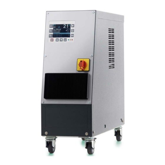
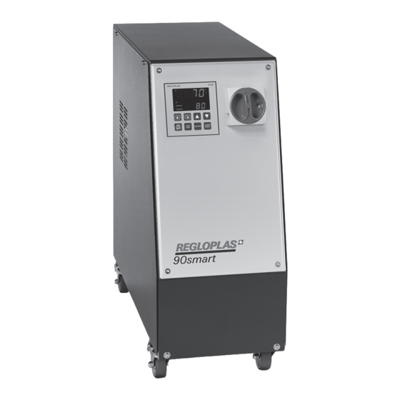
Temperature Control Unit 90smart/150smart
V 11/2014
WARNING
Error messages on the device
Display
Remark
The light is on if there is insufficient heat carrier — possible
causes:
This light is on if the thermal relay has been triggered — possi-
ble causes:
Device malfunctions
Malfunc-
Remark
tion
Safety thermostat (F5) triggered:
Device
does not
heat up
Water flow in cooler too low — possible causes:
Device
does not
cool
down
Automatic water filling does not switch off. Possible causes:
Device
overfilled
Device is refilled
Cooling water supply not connected or shut off (shut-
off valve)
Filter dirty
Solenoid valve water filling (Y2) dirty
Level switch defective
Pump overheated (lines blocked)
Incorrect value set on thermal relay (see information
on electrical wiring diagram and rating plate on the
pump)
Switch thermal relay on again using the reset button
(S5) on the back of the control unit
Check level control (water level in the device) and
switch safety thermostat (F5) on again using reset
button on the heating
Heating contactor defective
Solenoid valve cooling defective or dirty
Filter dirty
Cooler coated with lime
Replace cooler or clean using descaling unit
Float switch defective
Solenoid valve water filling (Y2) defective or dirty
Leak in cooler
Clean or replace defective parts
Operating Instructions 11
- Manuals
- Brands
- REGLOPLAS Manuals
- Control Unit
- 90smart
- Operating instructions manual
-
Contents
-
Table of Contents
-
Bookmarks
Quick Links
En
90smart/150smart
Operating Instructions
Summary of Contents for REGLOPLAS 90smart
-
Page 1
90smart/150smart Operating Instructions… -
Page 2
The contents, however, do not constitute a binding obligation on the part of Regloplas AG and are subject to change without notice. © Copyright 2013 Regloplas AG… -
Page 3: Table Of Contents
Setting the Set-point values …………..13 Parameter Menu ………………14 RT70 Control System — Functions …………….. 14 Powering Up………………… 14 Shutdown ………………..14 Leak-stop operation …………….. 14 Emptying (option) ………………15 Contents i Temperature Control Unit 90smart/150smart…
-
Page 4
Block diagram 90smart ………………25 Block diagram 150smart ………………26 Graph (pump capacity) ………………27 Graph (Cooling capacity 90smart) ……………. 28 Graph (Cooling capacity 150smart) …………..28 Components/Spare parts 90smart …………… 29 Components/Spare parts 150smart …………..32 … -
Page 5: General Safety Information
Failure to heed the information can result in property damage as well as minor or moderate personal injury! NOTE Denotes general information, useful advice to users and work recommenda- tions, which, however, do not have any influence on the safety and health of personnel. General Safety Information 1 Temperature Control Unit 90smart/150smart…
-
Page 6: Range Of Application
Safety Information General information The Regloplas temperature control unit is safe to operate but can cause danger if it is used incorrectly or for a purpose other than its intended use. It should be noted that any such incorrect use or non-compliance…
-
Page 7: Information For Operators And Personnel
If the temperature control unit is damaged, it must not remain in use; the defective part must be replaced or repaired immediately. Only original Regloplas replacement parts may be used. Damage due to the use of third-party parts renders any and all warranty claims null and void.
-
Page 8: Using This Documentation
The corresponding additional documents are included with special versions of devices. Any additional documents sup- plement and/or replace the descriptions contained in this documentation, which are then either invalid or only conditionally valid. 4 General Safety Information Temperature Control Unit 90smart/150smart…
-
Page 9: Operating Instructions
Operating Range The operating range and heat transfer fluid of the Temperature Control Unit 90smart/150smart are shown in the following table (in this regard, see also the chapter «Technical Data» in the Maintenance section). Temperature Control 90smart…
-
Page 10: Start-Up
The Operating Instructions for the temperature control unit must be kept at all times close at hand for the personnel responsible for start-up and operation. Please ensure that the operating instructions are read. By do- 6 Operating Instructions Temperature Control Unit 90smart/150smart…
-
Page 11: Inspection Of Consumers
Descaling can be carried out using the Regloplas REG de- scaling unit (see the «Regloplas Temperature Control Technolo- gy» brochure, REG data sheet)
-
Page 12: Electrical Connections
The vent valves on the consumer and the shut-off valves (if present) must be open. RT34 Control System RT34 Control System — front panel 8 Operating Instructions Temperature Control Unit 90smart/150smart…
-
Page 13: Powering Up
A. Cool down device and switch off, turn switch to position — and switch device on again. Turn switch to position A and hold down until fully drained (observe maximum expansion volume!) Operating Instructions 9 Temperature Control Unit 90smart/150smart…
-
Page 14: Displays
Before detaching connecting lines from the temperature control circuit, first al- low the temperature control unit to cool down, as a function of the outlet tem- perature, and then switch it off! Check that the pump is no longer running! 10 Operating Instructions Temperature Control Unit 90smart/150smart…
-
Page 15: Malfunctions
Automatic water filling does not switch off. Possible causes: Float switch defective Device Solenoid valve water filling (Y2) defective or dirty overfilled Leak in cooler Clean or replace defective parts Operating Instructions 11 Temperature Control Unit 90smart/150smart…
-
Page 16: Rt70 Control System
Scrolling through pages Setting the additional display Setting the parameters Selection of the device functions (toggling Alarm reset and alarm history SP1/SP2, drainage by suction, leak-stop) Button ON/OFF Enter key Navigation upward Navigation downward 12 Operating Instructions Temperature Control Unit 90smart/150smart…
-
Page 17: Status Leds
Setting the Set-point values The set-point values SP1 and SP2 are set by pressing the key F1. The set-point value is then coloured light blue and can be set with the RCD Operating Instructions 13 Temperature Control Unit 90smart/150smart…
-
Page 18: Parameter Menu
OFF appears on the display. Leak-stop operation The leak-stop operation is activated by pressing the F3 key and selecting the leak-stop symbol and is only possible if it is supported by the device type. 14 Operating Instructions Temperature Control Unit 90smart/150smart…
-
Page 19: Emptying (Option)
The suction or blowing out program can be aborted by pressing the ON/OFF button. When the ON/OFF button is pressed again (wait until the display reads OFF), the unit switches back to normal operation. Operating Instructions 15 Temperature Control Unit 90smart/150smart…
-
Page 20: Operation With Code/Password
User password — Default 0000 (switched off) Technician password — Default 0070 Service password — only for personnel trained by Regloplas NOTE It is strongly recommended that an operator password should be set up when commissioning the temperature control unit.
-
Page 21: Alarm Messages
Attention — temperature control cabinet too high ambient temperature Check the outlet pressure (min. 0.7 bar must be pre- Flow switch act sent) Max. temperature exceeded Max. temperature of the heat transfer medium may Operating Instructions 17 Temperature Control Unit 90smart/150smart…
-
Page 22: System Errors/System Notes
(e.g., 2000 hours, see the RT70 control system programming instructions). Please note that the instructions below are based on a daily operating time of 8 hours. In multi-shift operation, the inspections and maintenance 18 Operating Instructions Temperature Control Unit 90smart/150smart…
-
Page 23
Descale cooler — exercise caution when tightening the screwed connections on the heat exchanger (max. 170 Nm). Check pump capacity (the flow rate and final pressure must comply with the pump characteristic) Operating Instructions 19 Temperature Control Unit 90smart/150smart… -
Page 24: Cleaning
Allow the temperature control unit to cool down and, if necessary, drain it be- fore any repair! Switch off the temperature control unit: press the main switch and unplug from the mains! Disconnect all hose couplings from the temperature control unit! 20 Operating Instructions Temperature Control Unit 90smart/150smart…
-
Page 25: Transport
Disposal The temperature control unit must be drained completely and disposed of in accordance with local regulations. The temperature control unit can also be returned to Regloplas AG, Swit- zerland, for disposal. Operating Instructions 21 Temperature Control Unit 90smart/150smart…
-
Page 26
V 11/2014 22 Operating Instructions Temperature Control Unit 90smart/150smart… -
Page 27: Maintenance
Important — twisting of the When attach- hoses can also be ing/detaching a hose, al- caused during installa- ways hold it in place with tion. a second wrench Maintenance 23 Temperature Control Unit 90smart/150smart…
-
Page 28: Technical Data 90Smart/150Smart
Dimensions W/H/D 202/560/661 mm 202/560/661 mm Weight approx. 44 kg approx. 50 kg Colour RAL 9006/7016 RAL 9006/7016 Ambient temperature max. 40°C max. 40°C Continuous sound pressure level < 70 dB(A) < 70 dB(A) 24 Maintenance Temperature Control Unit 90smart/150smart…
-
Page 29: Block Diagram 90Smart
Vessel, reservoir, tank Safety thermostat Cooler Pump Bypass Level control Filter — cooling circuit Solenoid valve — auto. water refill Consumer Solenoid valve — cooling Temperature probe — internal Solenoid valve — suction (optional) Heating Maintenance 25 Temperature Control Unit 90smart/150smart…
-
Page 30: Block Diagram 150Smart
Vessel, reservoir, tank Safety thermostat Cooler Pump Filter — cooling circuit Level control Consumer Solenoid valve — auto. water refill Temperature probe — internal Solenoid valve — cooling Heating Solenoid valve — suction (optional) 26 Maintenance Temperature Control Unit 90smart/150smart…
-
Page 31: Graph (Pump Capacity)
V 11/2014 Graph (pump capacity) 1 — Pump curve TP20 2 — Pump curve TS22, TS22H Pump capacity — Delivery rate V as a function of pressure (p), bypass not tak- en into account Maintenance 27 Temperature Control Unit 90smart/150smart…
-
Page 32: Graph (Cooling Capacity 90Smart)
V 11/2014 Graph (Cooling capacity 90smart) 1 — Cooling curve 90smart (1K) 2 — Cooling curve 90smart (2K) Cooling capacity (P) as a function of out- let temperature ( ) Cooling water temperature 20 °C Flow rate 20 l/min Graph (Cooling capacity 150smart)
-
Page 33: Components/Spare Parts 90Smart
V 11/2014 Components/Spare parts 90smart V21a Maintenance 29 Temperature Control Unit 90smart/150smart…
-
Page 34
V 11/2014 S3/B1 30 Maintenance Temperature Control Unit 90smart/150smart… -
Page 35
See electrical wiring diagram of the temperature control unit for additional elec- trical components! CAUTION Only authentic (OEM) Regloplas spare parts may be used! In case of damage from the use of non-OEM parts, the warranty will be rendered null and void! Maintenance … -
Page 36: Components/Spare Parts 150Smart
V 11/2014 Components/Spare parts 150smart V21a 32 Maintenance Temperature Control Unit 90smart/150smart…
-
Page 37
V 11/2014 S3/B1 Maintenance 33 Temperature Control Unit 90smart/150smart… -
Page 38
See electrical wiring diagram of the temperature control unit for additional elec- trical components! CAUTION Only authentic (OEM) Regloplas spare parts may be used! In case of damage from the use of non-OEM parts, the warranty will be rendered null and void! 34 … -
Page 39: Dimension Sheet 90Smart
V 11/2014 Dimension sheet 90smart Item Designation Item Designation RT70 Control System Inlet Main switch Cooling water IN Cooling water OUT Outlet Maintenance 35 Temperature Control Unit 90smart/150smart…
-
Page 40: Dimension Sheet 150Smart
V 11/2014 Dimension sheet 150smart Item Designation Item Designation RT70 Control System Inlet Main switch Cooling water IN Cooling water OUT Outlet 36 Maintenance Temperature Control Unit 90smart/150smart…
-
Page 41
V 11/2014 Maintenance 37 Temperature Control Unit 90smart/150smart…
This manual is also suitable for:
150smart
We have compiled a selection of solutions for frequently asked questions for you under FAQ. If you require further information, our temperature control specialists will be happy to answer your questions about temperature control using liquid media. Please use the contact form for this purpose.
Watch the videos also on our YouTube channel
We show you in this Video how to request and load the option codes.
In this video we show you the whole process, that is necessary to replace a broken RT100 mainboard with a new one.
We therefore suggest to do it according to a circuit diagram, which you can request at service@regloplas.com.
At this e-mail address you can also request the software. The option code you can request at rt100@regloplas.com.
In this Video we show you how to load the parameter files. You can request the files at service@regloplas.com.
In this video we show you how to inspect the filter and the valves on a P160M.
We therefore recommend that you also check the principle diagram, which you can request at service@regloplas.com.
If you choose the individual valve in the IO Test menu and put it on “active”, it should get energized and open.
Now you can check the coil with a solenoid tester. If it doesn’t open, there is probably something wrong with the coil, the cable or the output of the controller.
Before getting rid of the error message, the mechanical reset of the safety thermostat is necessary. If the software version is higher than V1168, also an electrical reset is necessary. In this video we show you how to do the mechanical and the electrical reset on an example of a pressurized unit with RT100 controller. The reset process is the same on every unit (RT100 and RT70). The only difference is the location of the thermostat.
You can request the service password, which is necessary to access the service menu for the electrical reset at service@regloplas.com.
Be aware that if you keep getting the “heating thermostat triggered” error message, there must be something wrong. We therefore strongly recommend looking for the cause instead of repeating the reset process. Otherwise serious problems may occur.
You can find the software version in Parameter->actual values->software version:
Temperature control units can be used in any application in which the consumer (mould, die, roller, container, etc.) to be connected to the temperature control unit is heated to production temperature by means of corresponding holes/channels through which circulating water of thermal oil flows. During production that temperature is held by means of heating and/or cooling. The number of potentials fields of application/possibilities is extensive.
Heating the consumers (mould, die, roller, container, etc.) to their operating temperature. Keeping the consumer at its operating temperature (regardless of production conditions, such as changes in cycle time, production interruptions, etc.)
These tasks result in:
- Optimal cycle time
- Consistent high-quality products
- Maximum outlet temperature
- Heat transfer fluid
- Heating capacity
- Cooling capacity
- Pump capacity (flow rate/pressure)
- Operating voltage
Units are differentiated by whether they operate on water, oil (or glycol). Units using water usually have a maximum outlet temperature of 90 °C or approximately 160 °C for pressurised water units. Units using oil usually have a maximum outlet temperature of approximately 350 °C.
Other criteria differentiating the units include:
- Units with direct or indirect cooling (separation of cooling and temperature control circuits by cooler).
- Units with bath heating or forced circulation system.
- Single or multiple-circuit units.
- Temperature control circuits differ in terms of main technical specifications, such as maximum outlet temperature, heat transfer fluid (water or oil), heating capacity, cooling capacity, pump capacity (flow rate and pressure).
There are 3 basic cases of heating and cooling:
- Heating to production temperature: The unit heats only.
- Production: Due to changes in the ambient temperature, cycle time, etc., the temperature of the consumer also changes. If it rises, the unit will cool; if it drops, the unit will heat.
- Production interruption: Generally, the consumer must be heated to prevent its temperature from dropping.
Method: Heating and cooling take place in on/off mode, i.e. either completely on or completely off. Due to its PD behaviour, the controller cycles, with heating or cooling pulses becoming shorter as the temperature nears its set point. Cycling prevents under and overshooting.
Because of the inertia of the control loop, on/off mode (cycling) provides the same control accuracy as control valves, for example, which are significantly more technically demanding and much more likely to break down. The controller is a three-step controller with the positions «heating — neutral — cooling».
The minimum required accessories consist of the following:
- A temperature and pressure-resistant hose for the outlet and for the inlet.
- Two hoses for the cooling water circuit.
- Power cable.
Additional accessories depend on the application involved.
Via a data interface. The digital interface (e.g. RS485) is preferable both technically and in terms of reliability.
Regloplas units provide about 38 different data transfer protocols for the transfer of data from the unit to the production machine. The choice of interface depends on the production machine in use. The machine’s hardware and interface protocol of the machine must be compatible with the unit.
The set-up depends on production and space conditions. If, due to production conditions, the temperature control unit settings must be changed frequently, it makes sense to place the unit where it is easily accessible.
With regard to the distance of the temperature control unit from the production machine or consumer: Due to temperature and pressure losses in the connection lines between the unit and the consumer, the temperature control unit should be placed as close to the machine or consumer as possible. Due to pressure losses, the inner Ø of the feed hoses should not be reduced before the consumer.
Recommended value for the connection lines: inner Ø not less than the inner Ø of the inlet/outlet of the temperature control unit.
Distances greater than approximately 5 m should be avoided. If this is not possible, temperature drops and pressure losses in the feed hoses must be considered when setting up the temperature control unit. If the unit is used primarily for heating, the hoses should be thermally insulated.
Bringing a temperature control unit on line is very simple:
- Connect the hoses between the temperature control unit and the consumer.
- Connect the unit to the cooling water circuit.
- Connect the unit to the power supply.
- Turn the unit on at the main switch.
- Fill the heat transfer fluid (manually for thermal oil, manually or automatically for water, depending on model and version).
- Enter the outlet temperature/set-point value at the controller (corresponds roughly to the production temperature of the consumer).
- Turn on the unit (pump, heater, etc.).
- For manual filling, continue to fill the heat transfer fluid until the pump runs without interruption, i.e. sufficient heat transfer fluid is circulating in the temperature control circuit.
The steps listed above are described in detail in the Operating Instructions.
The theoretically lowest possible outlet temperature of a temperature control unit is the inlet temperature of the cooling water (for direct cooling). Practically speaking, however, the minimal outlet temperature must be at least 5 °C higher.
The reason for this is that a minimal temperature drop is necessary in order for heat exchange to occur between the cooling water and the circulating heat transfer fluid in the temperature control circuit (consumer circuit).
Yes. A temperature control unit’s cooling capacity is strongly temperature dependent. The lower the set-point temperature selected, the lower the cooling capacity. See the unit-specific cooling-capacity graphs in the “Regloplas Temperature Control Engineering” brochure.
At operating temperatures above approximately 180 °C. The reasons for this are:
- Safety risks associated with systems not using fixed pipes. At 180 °C, the system pressure has already reached 12 bar, which does not include the pump pressure that depends on the consumer connected to the temperature control unit.
- The seals in the consumer can leak at these high pressures.
- Depending on the acceptable pressure of the consumer, the pressure in the temperature control circuit must be kept to a minimum.
- If no limits are present, water is to be preferred over oil as a heat transfer fluid due to water’s significantly better heat transfer properties.
Basically, only oils specifically labelled as thermal oils may be used (e.g. hydraulic oils are not acceptable). The main criterion for the use of a thermal oil for a given temperature control unit is the maximum acceptable outlet and film temperatures provided by the manufacturer of the oil. Synthetic thermal oil should be used whenever possible.
No. Energy consumption depends upon the application. A few criteria include:
- Duration and number of heat-up phases (depends on: consumer weight, e.g. injection mould, number of consumer changes due to small series, production interruptions, etc.).
- Layout of the consumer (heating, cooling, or thermal equilibrium, i.e. practically neither heating nor cooling during production).
- Unit-specific criteria: Heat-insulation (“good” for heating, “poor” for cooling), pump efficiency (heat generation).
The only thing that can be said about the minimum energy consumption of a temperature control unit is that it is the sum of the power consumed by the pump motor and the control system.
As applications conditions have such a large influence (operating temperature, dusty environment, quality of the heat transfer fluid, dirt in the temperature control circuit (consumer, connection lines)), absolute answers aren’t possible.
The customer must use his experience to find the optimal cleaning interval himself. The Operating Instructions serve as a basis. In the “Maintenance/Service” section, you’ll find tips for necessary cleaning procedures/checks to be made on the temperature control unit.
Application conditions such as operating temperature, characteristics of the heat transfer fluid (quality of the water or oil), dirt in the temperature control circuit (consumer, connection lines), etc. play a very important role in this question. An absolute answer is therefore not possible.
Guidelines for water: Replace after about 2000 hours of operation, including additive. Guidelines for oil: Check after about 1000 hours and replace after about 2000 hours, including additive (= 1 year in 1-shift operation).
One factor in judging whether a temperature control unit is functioning properly is the temperature. Set-point and actual temperatures must correspond (±1 to ±2 °C). If this is not the case, the unit is not operating properly.
If cooling remains on continuously and the actual temperature nevertheless remains too high, either the unit is too small for the application, or one of the following problems may exist: the cooling water connection is closed; the cooler is coated with scale; or the filter in the cooling water network is dirty.
Possible causes of insufficient temperatures: heater, heat contactor, or solid-state relay is defective; or the solenoid valve for the cooler does not close properly, causing water to flow through the cooler continuously. If the actual temperature oscillates about the set-point value due to incorrect setting of the control parameters (alternating heating and cooling), energy is wasted and stress on the unit increased.
As the temperature is usually measured in the medium (water or oil), agreement between the set-point and actual temperatures displayed does not necessarily mean that the consumer temperature is being controlled properly. If the flow rate is insufficient, the temperature will not be transferred to the consumer fully. Therefore, the flow rate must also be checked which can be done using a built-in or external flow meter.
As a rule, yes.
However, this depends greatly on the repair skills of the company in question; i.e. does it have a maintenance department with qualified employees?
Yes. Regloplas has compiled a number of checklists to determine the correct temperature control unit. Send a request for more information.
Yes. Regloplas has compiled checklists for the purchase of temperature control units. For more information send a request.
File Specifications:2358/2358788-90smart.pdf file (30 May 2023) |
Accompanying Data:
REGLOPLAS 90smart Control Unit PDF Operating Instructions Manual (Updated: Tuesday 30th of May 2023 05:56:08 PM)
Rating: 4.6 (rated by 30 users)
Compatible devices: bq35100, ME70-169, SCU 800/16, JANUS, FAE900, CEP7-ERID, QN9090, ACS580-04.
Recommended Documentation:
Operating Instructions Manual (Text Version):
(Ocr-Read Summary of Contents of some pages of the REGLOPLAS 90smart Document (Main Content), UPD: 30 May 2023)
-
40, V 11/2014 36 Maintenance Temperature Control Unit 90smart/150smart Dimension sheet 150smart Item Designation Item Designation 1 RT70 Control System 5 Inlet 2 Main switch 6 Cooling water IN 3 — 7 Cooling water OUT 4 Outlet
… -
25, V 11/2014 Temperature Control Unit 90smart/150smart Operating Instructions 21 For fast, error-free supply of spares, we need the following data without fail: Device type Device number Voltage and frequency This information is given on the rating plate on the temperature control unit. The item numbers of the components can be found in the corresponding drawings in these operating instructions and the electrical circuit dia- grams of the …
-
20, V 11/2014 16 Operating Instructions Temperature Control Unit 90smart/150smart NOTE In the case of pressurised water units, the pressure release valve (Y8) closes at 5 °C above the coastdown temperature (max. 85 °C) and opens at the pro- grammed coastdown temperature during the cooling process (only devices with 1K/2K). Operation with Code/Password In order to prevent the values that have already been set or programmed from being unintentionally reset/…
-
9, REGLOPLAS 90smart V 11/2014 Temperature Control Unit 90smart/150smart Operating Instructions 5 Operating Instructions General Introduction These Operating Instructions contain a detailed description of the Tem- perature Control Unit 90smart/150smart as well as important information for safe operation and optimal maintenance. The Operating Instructions must be kept near the temperature control unit and must alwa…
-
30, V 11/2014 26 Maintenance Temperature Control Unit 90smart/150smart Block diagram 150smart Block diagram 150smart Item Designation Item Designation 38 Vessel, reservoir, tank F5 Safety thermostat 41 Cooler M10 Pump 60 Filter — cooling circuit S1 Level control 99 Consumer Y2 Solenoid valve — auto. water refill B1 Temperature probe — internal Y6 Solenoid valve — cooling E21 Heating Y13 Solenoid valve — suction (optional)
… -
22, REGLOPLAS 90smart V 11/2014 18 Operating Instructions Temperature Control Unit 90smart/150smart Error message Rectification not exceed the maximum device temperature (if re- quired, check the tool temperature) Motor current underrun Check the pump/pump motor (with Ohmmeter) and if required, replace them Phase sequence failure Correct the phase sequence (interchange 2 phases) Phase sequence unidentified Switch…
-
2, V 11/2014 Documentation Temperature Control Unit 90smart/150smart This documentation is copyrighted. Unauthorised duplication is prohibited by law. To the best of our knowledge and belief, the information con- tained in this documentation is true and correct as of the date of publica- tion. The contents, however, do not constitute a binding obligation on the part of Regloplas AG and are subject to change without notice. © Copyright 2…
-
10, V 11/2014 6 Operating Instructions Temperature Control Unit 90smart/150smart Start-up Setting up the temperature control unit The temperature control unit is designed for an ambient temperature range of 10-40 °C. Sufficient ventilation must be provided during setup. The distance between the devices and/or between the temperature con- trol unit and a wall must be at least 10 cm. The ventilation slits must not be covered. C…
-
33, V 11/2014 Temperature Control Unit 90smart/150smart Maintenance 29 Components/Spare parts 90smart P1 V21 V21a 9 30 63 66 Q1 67 73 72 70 68 75 M10 35 E21 54 9 41 60 46 38 75
… -
5, V 11/2014 Temperature Control Unit 90smart/150smart General Safety Information 1 General Safety Information Safety Symbols DANGER Denotes imminent danger. Failure to heed the information can result in death or grave personal injury (dis- ability)! WARNING Denotes a dangerous situation. Failure to heed the information can result in death or grave personal injury (dis- ability)! CAUTION Denotes a potentially dangerous situation. Failure to heed the …
-
6, V 11/2014 2 General Safety Information Temperature Control Unit 90smart/150smart Range of Application This general safety information is generally valid for all temperature con- trollers and control systems from Regloplas. Intended Use The Regloplas temperature control unit is built according to the current state of the art and the generally accepted principles of safety engineer- ing. The temperature control unit is intended solely for normal use in the he…
-
31, V 11/2014 Temperature Control Unit 90smart/150smart Maintenance 27 Graph (pump capacity) 1 — Pump curve TP20 2 — Pump curve TS22, TS22H Pump capacity — Delivery rate V as a function of pressure (p), bypass not tak- en into account
… -
16, REGLOPLAS 90smart V 11/2014 12 Operating Instructions Temperature Control Unit 90smart/150smart Pt100 Malfunction This indication means that the internal temperature sensor Pt100 is de- fective. In this case, the float switch has to be replaced. RT70 Control System RT700 Control System — front panel Buttons Setting the set-point value Scrolling through pages Setting the additional display Setting the parameters Selection of the device functions (togg…
-
37, V 11/2014 Temperature Control Unit 90smart/150smart Maintenance 33 Y2 Y13 69 41 68 T5 V21 F5 M10 Y6 Y13 S3/B1
… -
4, V 11/2014 ii Contents Temperature Control Unit 90smart/150smart Operation with Code/Password ……………………………………………………… 16 Alarm Reset and Alarm History ……………………………………………………… 16 Save/Reset of the Setting Values …………………………………………………… 16 Changing Consumer/Decommissioning …………….…
-
REGLOPLAS 90smart User Manual
-
REGLOPLAS 90smart User Guide
-
REGLOPLAS 90smart PDF Manual
-
REGLOPLAS 90smart Owner’s Manuals
Recommended: LRS 400, PA-32-301 Saratoga, 685000, Carrier MMC-AP0181H2UL
Links & Tools
Operating Impressions, Questions and Answers:
- Anleitungen
- Marken
- REGLOPLAS Anleitungen
- Thermostate
- 90smart
- Betriebsanleitung
-
Inhalt
-
Inhaltsverzeichnis
-
Fehlerbehebung
-
Lesezeichen
Quicklinks
90smart
Betriebsanleitung
Instructions de service
Operating Instructions
Verwandte Anleitungen für REGLOPLAS 90smart
Inhaltszusammenfassung für REGLOPLAS 90smart
-
Seite 1
90smart Betriebsanleitung Instructions de service Operating Instructions… -
Seite 3
Betriebsanleitung Seiten 2–10 Instructions de service Pages 11–19 Operating Instructions Pages 20–30 Deutsch Français English Service Seiten/Pages 31–33 Änderungen vorbehalten Sous réserve de modifications Subject to change without notice BA 90smart 0705/dfe… -
Seite 4: Inhaltsverzeichnis
Das Temperiergerät dient ausschliesslich zum Heizen oder Kühlen von Spritzgiess- und Druckgiessformen, Extrudern, Kalandern, Mischern und weiteren Verbrauchern in nicht explosionsgefährdeten Bereichen. Andere Anwendungen müssen zuerst mit Regloplas oder deren Vertreter abgestimmt werden. Der Hersteller haftet nicht bei unsachgemässer Verwendung.
-
Seite 5: Kontrollen Am Verbraucher
Gesamthärte 4–18 °d ph-Wert 7–9 KKG* Leitwert max. 1000 µS/cm *KKG = Kalk-Kohlensäure-Gleichgewicht Die Beigabe des Korrosionsschutzes RK93 ist dringend zu empfehlen (siehe Broschüre «Regloplas-Temperierge- räte», Datenblatt «RK93»). 2.4 Verbindungsleitungen Siehe auch «Richtlinien für das Anschliessen von Schläuchen», Seite 29.
-
Seite 6: Einschalten
Weitere mögliche Anzeigen siehe Abschnitt 2.8 und Programmieranleitung RT60. Gewünschten Sollwert mit den Tasten einstellen. Für die Einstellung weiterer Einstellwerte siehe se- parate Programmieranleitung RT60. Temperierkreislauf auf Dichtigkeit prüfen. Entlüftungsventil am Verbraucher erst schliessen, wenn aus diesem regelmässig Wasser fliesst. BA 90smart 0705/dfe…
-
Seite 7: Betriebsarten
Der Sollwert kann mit eingeschaltet. den Tasten abgerufen Beispiel: Istwert 148.8 °C, werden. Sollwert 150.0 °C. Anzeige bei Schnittstellen- betrieb. Im unteren Anzeigefeld wird die Adresse des Gerätes angezeigt. Beispiel: A.13. Der Sollwert kann mit den Tasten abgerufen werden. BA 90smart 0705/dfe…
-
Seite 8: Störungen
Pumpe auf Korrosion überprüfen. Motor kontrollieren. Minimaler Pumpenstrom kleiner als 0,2 A. Phase Netzzuleitung ausgefallen. Motor läuft nur an zwei Phasen. Netzzuleitung, Vorsicherung und Motor kontrollieren. Phase am Netzeingang fehlt. Erscheint nach Betätigung der Taste «ON/OFF» (Einschalten). Netzzuleitung, Vorsicherung kontrollieren. BA 90smart 0705/dfe…
-
Seite 9
Service fällig (blinkt nicht). Werkseinstellung 2000 h. Die Anzeige verschwindet, wenn das Gerät mit der Taste «ON/OFF» eingeschaltet wird, erscheint aber wieder, sobald das Gerät ausgeschal- tet wird. Siehe Abschnitt 4.1. Eingabe eines falschen Codes. Richtigen Code eingeben (siehe Programmieranleitung RT60, Abschnitt 7.14). BA 90smart 0705/dfe… -
Seite 10: Störungen Am Gerät
4.1 Periodische Kontrollen und Servicearbeiten Um Ihnen die Servicearbeiten zu erleichtern, ist das Regelsystem RT60 mit einer Serviceintervall-Anzeige ausge- rüstet. Wir empfehlen Ihnen, das entsprechende Serviceintervall einzugeben (z.B. 2000 Stunden). Programmie- rung siehe Programmieranleitung RT60, Anzeige SerU. duE. BA 90smart 0705/dfe…
-
Seite 11: Jährliche Kontrollen/Servicearbeiten
9 Pumpe auf Korrosion kontrollieren und allenfalls ersetzen. 10 Wir empfehlen, auch den Verbraucher bei jeder Gerätereinigung auf Verunreinigungen zu kontrollieren und die Reinigung ebenfalls mit dem Entkalkungsgerät REG vorzunehmen. Rost und Kalkablagerungen führen zu einer starken Verschlechterung des Wärmeaus- Abb. 6: Niveauschalter BA 90smart 0705/dfe…
-
Seite 12: Reparaturen
Hinweise auf der Verpackung beachten. 7. Sonderausrüstung 7.1 Durchflussmessung Taste drücken: die Anzeige Actu. erscheint. Dieselbe Taste nochmals drücken: die Anzeige FL.C. mit der gemessenen Durchflussmenge in l/min oder GPM erscheint. Zurück in die Betriebsebene durch nochmaliges Drücken derselben Taste. BA 90smart 0705/dfe…
-
Seite 13: Généralités
Le régulateur de température sert uniquement à chauffer ou refroidir les moules d’injection ou de coulée sous pression, les extrudeuses, les calandres, les mélangeurs et autres consommateurs dans des zones non explosi- ves. Pour toute autre application, Regloplas ou sa représentation doit donner son accord préalable. Le fabricant ne peut être tenu responsable d’une utilisation incorrecte.
-
Seite 14: Branchements Électriques
Le détartrage peut se faire au moyen de l’appareil de détartrage REG (voir brochure «Régulateurs de tempé- rature Regloplas», Fiche technique «REG»). 2.3 Qualité de l’eau Pour éviter des dommages dans le refroidisseur du régulateur de température et dans le consommateur raccor- dé, l’eau utilisée doit répondre aux exigences suivantes:…
-
Seite 15: Mise En Marche
«S1» de la sonde interne S1. Autres affichages possibles, voir paragraphe 2.8 et Instructions de programmation RT60. Ajuster la consigne à l’aide des touches . Pour le réglage d’autres paramètres, se référer aux instructions de programmation RT60. BA 90smart 0705/dfe…
-
Seite 16: Modes D’utilisation
«ON». appeler la consigne, utiliser les Exemple: valeur réelle touches 148.8 °C, consigne 150.0 °C. Affichage en service interface. L’adresse de l’appareil apparaît dans le champ d’affichage inférieur. Exemple: A.13. Pour appeler la consigne, utiliser les touches BA 90smart 0705/dfe…
-
Seite 17: Perturbations
Contrôler les conducteurs du réseau et le fusible préliminaire. Tension de réseau inférieure à 340 V. Contrôler le conducteur du réseau. L’ordre des phases à l’entrée du réseau est incorrect. Apparaît après avoir actionné la touche «ON/OFF». Intervertir les deux phases à l’entrée du réseau. BA 90smart 0705/dfe…
-
Seite 18
Circulation d’eau insuffisante dans le refroidisseur. Causes possibles: ne refroidit – L’électro-vanne du refroidissement (Fig. 4, pos. 3) est défectueuse ou encrassée. – Le filtre est encrassé. – Le refroidisseur est entartré. → Nettoyer avec l’appareil de détartrage ou changer. BA 90smart 0705/dfe… -
Seite 19: Entretien
4.3 Contrôles et travaux d’entretien mensuels Contrôler l’ouverture d’admission d’air du refroidissement du moteur de la pompe qui doit être libre d’accès. Nettoyer à l’air comprimé de l’intérieur vers l’extérieur. Nettoyer le filtre. BA 90smart 0705/dfe…
-
Seite 20: Réparations
Attention: libérer auparavant tous les connecteurs. Démonter le filtre. Séparer le châssis du bas à l’aide des 4 vis et le faire passer au-dessus des raccords hydrauliques pour libé- rer le réservoir. Démonter la pompe et le chauffage. BA 90smart 0705/dfe…
-
Seite 21: Transport
Appuyer sur la touche : Actu. apparaît. Appuyer encore une fois sur cette même touche: FL.C. et le débit en l/min on GPM apparaît. Appuyer encore une fois sur cette touche pour revenir au niveau de service. BA 90smart 0705/dfe…
-
Seite 22: General
The temperature control unit is intended exclusively for heating and cooling injection moulds, diecasting dies, extruders, calenders, mixers and other consumers in areas not subject to explosion. Other applications must be approved in advance by Regloplas or its representatives. The manufacturer bears no responsibility for unintended use.
-
Seite 23: Water Quality
Remove rust, scaling and oil residue, as these strongly restrict heat transfer between the consumer and the heat transfer fluid and increase the pressure drop in the consumer. Regloplas’s de-scaling agent, REG, can be used to descale (see “Regloplas Temperature Control Units” brochure, “REG” data sheet).
-
Seite 24
Enter the desired set-point value using the keys. To set other values, please refer to the RT60 Programming Instructions. Check the temperature control circuit for leakage. Once water flows out of it regularly, close the consumer vent valve. BA 90smart 0705/dfe… -
Seite 25: Operating Modes
E.g.: Actual value 148.8 °C, Set- keys. point value 150.0 °C. Display during interface oper- ation. The unit’s address is shown in the lower display field. E.g.: A.13. The set point can be retrieved using the keys. BA 90smart 0705/dfe…
-
Seite 26: Troubleshooting
Minimum pump current less than 0.2 A. Mains input phase failed. Motor running only on two phases. Check incoming mains cable, back-up fuse and motor. Missing phase at mains connection. Appears after switching unit on. Check incoming mains cable and back-up fuse. BA 90smart 0705/dfe…
-
Seite 27
Maintenance due. (Does not blink.) Factory setting 2000 h. Message disappears when the unit is switched on via the “ON/OFF” key, but reappears as soon as the unit is switched off again. See 4.1. Incorrect code entered. Enter correct code (see Programming Instructions RT60, section 7.14). BA 90smart 0705/dfe… -
Seite 28: Switching The Unit Off
4.1 Periodic checks and maintenance To simplify maintenance procedures, the RT60 control system is equipped with a service-interval display. We recommend entering the appropriate service interval (e.g. 2000 hours). For programming, see RT60 Programming Instructions, messages SerU. and duE. BA 90smart 0705/dfe…
-
Seite 29
10 We also recommend checking the consumer for lime deposits every time the unit is cleaned as well as cleaning it with the aid of the descaling unit REG. As previously mentioned, rust and lime deposits drastically reduce the exchange of heat between the consumer and circulating fluid. Lime deposits also increase the BA 90smart 0705/dfe… -
Seite 30: Repairs
Follow any instructions on the packing material. 7. Optional equipment 7.1 Flow rate measurement Press key: Actu. appears. Press key again: FL.C. and the flow rate in l/min or GPM appear. To return to the operating level, press the same key again. BA 90smart 0705/dfe…
-
Seite 31: Richtlinien Für Das Anschliessen Von Schläuchen
• Schlauch mit einem zweiten Schraubenschlüssel festhal- • Une torsion peut se produire au montage. ten. • Torsion can be caused during installation. • Immobiliser le flexible avec une deuxième clé. • Hold the hose with a second spanner. BA 90smart 0705/dfe…
-
Seite 32: Technische Daten
Weight Farbe Couleur RAL9006/7016 Colour Bemerkungen/Remarques/Notes Motor für 60Hz/Moteur pour 60Hz/Motor for 60Hz TP20 TP20V Kühlleistung/Capacité de refroidissement Pumpenleistung/Capacité de pompe Cooling capacity Pump capacitiy Kühlwassertemperatur/Température d’eau de refroidissement Cooling water temperature 15 °C, Durchfluss/Débit/Flow rate 20l/min BA 90smart 0705/dfe…
-
Seite 33: Service
Service Ersatzteile / Pièces de rechange / Spare parts F1-4 BA 90smart 0705/dfe…
-
Seite 34
440-480V 143-100038 Sicherung T 1.6 A L Fusible T 1.6 A L Fuse T 1.6 A L 143-100010 Sicherheitsthermostat Thermostat de sécurité Safety thermostat 150-100002 Motor (siehe Pos. 35) Moteur (voir pos. 35) Motor (see item 35) BA 90smart 0705/dfe… -
Seite 35
Viton O-ring Set mit 3 Spulen 24V DC; Kit avec 3 bobines 24V DC; Assembly with 3 coils 24 VDC: Y2 7W und Y6+Y13 3W Y2 7W et Y6+Y13 3W Y2 7W and Y6+Y13 3W 350-100023 Y13c BA 90smart 0705/dfe… -
Seite 36
Prinzip/Principe/Principle BA 90smart 0705/dfe… -
Seite 37
BA 90smart 0705/dfe… -
Seite 38: Ce-Konformitätserklärung
Regloplas, aux exigences fondamentales et spécifiques de sécurité et de santé requises par la directive CEE.
-
Seite 40
Regloplas Flurhofstrasse 158 CH-9006 St.Gallen Telefon +41-71-282 58 00 Fax +41-71-282 58 40 E-mail info@regloplas.com Internet www.regloplas.com BA 90smart 0705/dfe…