-
Contents
-
Table of Contents
-
Troubleshooting
-
Bookmarks
Quick Links
2 8 0 — F
Frozen Fry Dispenser
Equipment Manual
English (Rev H)
P/N 293511
Manufactured By
Automated Equipment LLC
5140 Moundview Drive
Red Wing, MN 55066 U.S.A.
For Warranty Service & Technical Support
:
US & Canada call: 1 (800) 248-2724
International call: 1 (651) 385-2273
Sales Fax: 1 (651) 385-2166
Service Fax: 1 (651) 385-2172
http://www.autoequipllc.com
Business Hours:
Monday — Friday: 8:00 AM to 5:00 PM CST
(excluding. holidays)
After hours, your call will be handled by a voice mail
paging service. The on-call technician will be paged and
will return your call.
Table of Contents
Introduction ……………………………………………………………………………………………………………………………1
Unpacking & Installation …………………………………………………………………………………………………………1
Intended Use ………………………………………………………………………………………………………………………….1
Specifications…………………………………………………………………………………………………………………………1
Warranty ………………………………………………………………………………………………………………………………..2
Service Information ………………………………………………………………………………………………………………..3
Equipment Safety……………………………………………………………………………………………………………………4
Disassembly, Defrost & Cleaning…………………………………………………………………………………………..12
Dispenser Startup …………………………………………………………………………………………………………………13
Operation ……………………………………………………………………………………………………………………………..14
Daily Opening and Closing ……………………………………………………………………………………………………15
User Function Menu Structure ………………………………………………………………………………………………18
Manager Function Menu Structure…………………………………………………………………………………………19
Error Detection……………………………………………………………………………………………………………………..23
Troubleshooting……………………………………………………………………………………………………………………24
Calibrations and Adjustments ……………………………………………………………………………………………….27
Part Identification………………………………………………………………………………………………………………….30
Refrigeration System…………………………………………………………………………………………………………….40
Copyright © 2011
Automated Equipment LLC
All rights reserved.
Summary of Contents for AUTOMATED EQUIPMENT RAM 280-F
-
Contents
-
Table of Contents
-
Troubleshooting
-
Bookmarks
Quick Links
2 8 0 — F
Frozen Fry Dispenser
Equipment Manual
English (Rev H)
P/N 293511
Manufactured By
Automated Equipment LLC
5140 Moundview Drive
Red Wing, MN 55066 U.S.A.
For Warranty Service & Technical Support
:
US & Canada call: 1 (800) 248-2724
International call: 1 (651) 385-2273
Sales Fax: 1 (651) 385-2166
Service Fax: 1 (651) 385-2172
http://www.autoequipllc.com
Business Hours:
Monday — Friday: 8:00 AM to 5:00 PM CST
(excluding. holidays)
After hours, your call will be handled by a voice mail
paging service. The on-call technician will be paged and
will return your call.
Table of Contents
Introduction ……………………………………………………………………………………………………………………………1
Unpacking & Installation …………………………………………………………………………………………………………1
Intended Use ………………………………………………………………………………………………………………………….1
Specifications…………………………………………………………………………………………………………………………1
Warranty ………………………………………………………………………………………………………………………………..2
Service Information ………………………………………………………………………………………………………………..3
Equipment Safety……………………………………………………………………………………………………………………4
Disassembly, Defrost & Cleaning…………………………………………………………………………………………..12
Dispenser Startup …………………………………………………………………………………………………………………13
Operation ……………………………………………………………………………………………………………………………..14
Daily Opening and Closing ……………………………………………………………………………………………………15
User Function Menu Structure ………………………………………………………………………………………………18
Manager Function Menu Structure…………………………………………………………………………………………19
Error Detection……………………………………………………………………………………………………………………..23
Troubleshooting……………………………………………………………………………………………………………………24
Calibrations and Adjustments ……………………………………………………………………………………………….27
Part Identification………………………………………………………………………………………………………………….30
Refrigeration System…………………………………………………………………………………………………………….40
Copyright © 2011
Automated Equipment LLC
All rights reserved.
Summary of Contents for AUTOMATED EQUIPMENT RAM 280-F
Все ошибки RAM 1000, 1200, 1500, 2500, 3500, C/V, Dakota, Promaster, Promaster City, RAM
Ошибки RAM по протоколу OBDI. Самодиагностика.
Ошибки RAM по протоколу OBDII
Топливная система и воздухоподача
P0000-P0099, P0100-P0199, P0200-P0299
Система зажигания
P0300-P0399
Контроль выбросов
P0400-P0499
Контроль скорости и холостого хода
P0500-P0599
Электронный блок управления (ЭБУ) и его подсистемы
P0600-P0699
Трансмиссия
P0700-P0799, P0800-P0899, P0900-P0999
Не нашли нужную ошибку? Воспользуйтесь нашим поиском или оставьте комментарий и мы вам поможем!
 Loading…
![]()
200-Fx
Frozen Fry Dispenser
Equipment Manual
English
Manufactured By
Automated Equipment LLC
5140 Moundview Drive
Red Wing, MN 55066 U.S.A.
For Warranty Service & Technical Support, call:
|
US & Canada support call: |
1 (800) 248-2724 |
|
|
International support call: |
1 (651) 385-2273 |
|
|
Sales Fax: |
1 (651) 385-2166 |
|
|
Service Fax: |
1 (651) 385-2172 |
|
|
http://www.autoequipllc.com |
||
|
Business Hours: |
||
|
Monday – Friday: 8:00 AM to 5:00 PM CST |
||
|
(excluding. holidays) |
||
|
After hours, your call will be handled by a voice mail |
||
|
paging service. The on call technician will be paged and |
||
|
will return your call |
||
|
Introduction |
Table of Contents |
1 |
|
Unpacking & Installation ………………………………………………………………………………………………………… |
1 |
|
|
Intended Use …………………………………………………………………………………………………………………………. |
1 |
|
|
Specifications………………………………………………………………………………………………………………………… |
1 |
|
|
Warranty ……………………………………………………………………………………………………………………………….. |
2 |
|
|
Service Information ……………………………………………………………………………………………………………….. |
3 |
|
|
Equipment Safety…………………………………………………………………………………………………………………… |
4 |
|
|
Dispenser Assembly………………………………………………………………………………………………………………. |
6 |
|
|
Disassembly, Defrost & Cleaning……………………………………………………………………………………………. |
9 |
|
|
Dispenser Startup ………………………………………………………………………………………………………………… |
10 |
|
|
Operation …………………………………………………………………………………………………………………………….. |
11 |
|
|
Daily Opening and Closing …………………………………………………………………………………………………… |
12 |
|
|
User Functions Menu Structure ……………………………………………………………………………………………. |
15 |
|
|
Configuration (Config) Functions Menu Structure …………………………………………………………………. |
16 |
|
|
Service Functions Menu Structure………………………………………………………………………………………… |
17 |
|
|
Error Detection…………………………………………………………………………………………………………………….. |
21 |
|
|
Troubleshooting…………………………………………………………………………………………………………………… |
22 |
|
|
Calibrations and Adjustments ………………………………………………………………………………………………. |
24 |
|
|
Part Identification…………………………………………………………………………………………………………………. |
27 |
|
|
Refrigeration System……………………………………………………………………………………………………………. |
35 |
|
|
Disposal of Equipment …………………………………………………………………………………………………………. |
39 |
|
|
Electrical Diagram………………………………………………………………………………………………………………… |
40 |
|
|
Copyright © 2013 Automated Equipment LLC All rights reserved. |
Published 8/13 |
The information in this manual is subject to change without notice.
IN NO EVENT WILL AUTOMATED EQUIPMENT LLC BE LIABLE FOR TECHNICAL OR EDITORIAL OMISSIONS MADE HEREIN, NOR FOR DIRECT, SPECIAL, INCIDENTAL, OR CONSEQUENTIAL DAMAGES RESULTING FROM THE FURNISHING, PERFORMANCE,
OR USE OF THIS MATERIAL.
This manual is copyrighted with all rights reserved. Under the copyright laws, this manual may not be copied, in whole or part, without the written consent of Automated Equipment LLC.
Product names mentioned herein are for identification purposes only, and may be trademarks and/or registered trademarks of their respective companies.
Copyright © 2013 Automated Equipment LLC All rights reserved. Published 8/13

RAM™ 200-Fx Frozen Fry Dispenser
Introduction
This manual contains important information on the proper installation, operation, and care of the RAM 200-Fx Frozen Fry Dispenser. Following the instructions and procedures in this document will ensure that your dispenser provides years of reliable service. If any problems with the dispenser arise, this manual will also provide troubleshooting tips and service information.
Unpacking & Installation
Remove all packing material from Dispenser. Open Cabinet Door. Disassemble, clean, sanitize and dry the Hopper and Accumulator assemblies. Clean, sanitize and dry Fry Baskets. (see pages 6-9 for assembly, disassembly & cleaning). Reassemble all components (see pages 10-12 for startup and operation).
The equipment must be installed by qualified personnel, in accordance with the manufacturer’s instructions. Local electrical installation and safety regulations must be observed. Before installing check that voltage and frequency on the data plate match the electrical supply.
Intended Use
The Frozen Fry Dispenser must only be used for the temporary frozen storage and dispensing of non-meat based food products at commercial restaurants and similar locations. Any other use would be deemed as inappropriate. The dispenser is designed for installation and use indoors, in a restaurant environment protected from weather, excessive heat, excessive humidity and salt air.
HAZARD COMMUNICATION STANDARD:
Hazard Communication Standard (HCS) Procedures in this manual may include the use of chemical products. These chemical products will be highlighted with boldface letters followed by the abbreviation (HCS) in the text of the procedure. See the HCS Manual for the appropriate Material Safety Data Sheets (MSDS).
FCC STATEMENT
WARNING: This equipment generates, uses, and can radiate radio frequency energy and, if not installed and used in accordance with the instruction manual, may cause interference to radio communications.
EMC STATEMENT
This equipment meets EMC directives: — EN 55014-1:2006 + A1:2009
— EN55014-2:1997 + A1:2001 +
A2:2008-Category II
Specifications
Electrical Requirements:
Domestic:
•120 Volts AC., 60 Hertz, 8 Amps, 1Φ International
•220 — 240 Volts AC., 50 Hertz, 4.6 Amps, 1Φ
Internal Circuit Breaker: 15 Amps
Dimensions:
•22″ wide, 32.5″ deep, 76.8″ high (580mm x 686mm x 1511mm)
Minimum Operating Clearance Shall be:
•1” (2.6 cm) clearance on each side
•2” (5 cm) clearance at the back
•Open to ceiling, minimum 24” (60 cm)
Weight: 300 lbs (136 kg)
Hopper Capacity:
•42 lbs (19.1 kg), weight may vary with product.
Operating Temperature:
•5°F to 0°F (-15°C to -18°C) (Recommended Ambient Operating Temperature of 75°F (24°C))
•Climate Class= N
Refrigeration:
•R-404A: (12.5 oz) (354 g)
Maximum Operating Altitude & Safe Tilt:
•Maximum Altitude: 7000 ft (2,134 meters), Maximum Tilt = 10 degrees
Insulation Blowing Gas:
•Methyl formate
Noise Emissions: < 70 dB (A)
Serial Number: The information on the serial number identification label is as follows:
Example: s/n 20FR1303B00103
|
20F = Model |
03 = Month |
|
R = Manu. Facility |
B = Revision Level |
|
13 = Year |
00103 = Sequence # |
|
Copyright © 2013 Automated Equipment LLC All rights reserved. Published 8/13 |
1 |

RAM™ 200-Fx Frozen Fry Dispenser
Warranty
The terms «we», “us”, “our” or “factory” hereinafter refer to Automated Equipment LLC. We warrant the purchased product to be free from manufacturing defects in material and workmanship under normal use and conditions for the period and component specified below. Warranty is part only unless otherwise specified.
|
Components Covered |
Term |
|
Electronic Circuit Board Assemblies |
See Serial # / Warranty Label |
|
Electrical and Mechanical Moving Parts |
See Serial # / Warranty Label |
|
Structural frame work or enclosures |
See Serial # / Warranty Label |
|
Refrigeration Compressor Extended Warranty |
See Serial # / Warranty Label |
|
Crew removable components: |
(no labor, part only) |
|
Baskets |
90 days |
|
Basket Rack and Guide |
90 days |
|
Drip Tray |
90 days |
|
Power Cord |
90 days |
|
Hopper, Fry Diverter & Drum |
90 days |
|
Flap Door |
90 days |
|
Accumulator Housing |
90 days |
The Warranty period commences on the date of shipment of the RAM 200-Fx Frozen Fry Dispenser (hereinafter “Product”) from our manufacturing facility.
EXCEPT AS OTHERWISE PROVIDED HEREIN WE MAKE NO OTHER WARRANTIES, EXPRESSED OR IMPLIED AND SPECIFICALLY DISCLAIM ANY WARRANTY OF MERCHANTABILITY OR FITNESS FOR A PARTICULAR PURPOSE.
We shall not be liable for any direct, indirect, consequential damages (including damages for loss of business profits, business interruption, loss of business information and the like) arising out of the use of or inability to use the Product.
THIS WARRANTY IS VOID IF THE PRODUCT IS NOT FUNCTIONING CORRECTLY DUE TO ABUSE OR NEGLECT BY THE PURCHASER, ITS EMPLOYEES, AGENTS, OR OTHER REPRESENTATIVES EITHER BY BREAKING, BENDING, MISUSE, ABUSE, DROPPING, ALTERATION, IMPROPER MAINTENANCE OR ANY OTHER FORM OF NEGLECT OR IMPROPER USAGE. THIS WARRANTY DOES NOT COVER DAMAGE TO THE PRODUCT CAUSED BY NATURAL CAUSES SUCH AS LIGHTNING, ELECTRICAL CURRENT FLUCTUATIONS, FLOOD, FIRE, TORNADOES, OR OTHER ACTS OF GOD. WE WILL INVOICE PURCHASER FOR REPAIRS MADE NECESSARY BY THE HEREIN LISTED CAUSES.
This warranty is governed by the substantive laws of Minnesota, U.S.A., without giving effect to the conflict of law provisions.
This warranty is non-transferable and applies only to the original Purchaser.
|
2 |
Copyright © 2013 Automated Equipment LLC All rights reserved. Published 8/13 |

RAM™ 200-Fx Frozen Fry Dispenser
Service Information
Warranty Service
Warranty service must be initiated by calling our Technical Support Hotline at 1-800-248-2724 (U.S./Canada) or 651-385-2273 to establish all warranty requests.
Our Technical Support personnel will determine the cause of failure and provide appropriate resolution. Any required replacement parts will be provided by us or by an authorized Service Support Center/Parts Distributor.
Our Technical Support personnel will make all reasonable efforts to perform such repairs during normal business hours, and will not be responsible for any after-hours or holiday charges.
Non-Warranty Service
Service is normally conducted by customer appointed personnel, or by contracting a local service agent. The service person must be licensed in refrigeration to troubleshoot, open, or repair refrigeration and related systems.
Service fees are in accordance with industry standards.
Replacement parts are available through local Service Support Center/Parts Distributors or direct from us by calling 1-800-248-2724 (U.S./Canada) or 651-385-2273 in the event a local distributor is not available.
Our Technical Support Hot Line is available for telephone assistance providing product technical support, parts and parts information, and service agent referral.
Contact our Technical Support Hotline at 1-800-248-2724 (U.S./Canada) or 651-385-2273.
Record the following information for your records:
Date of Installation
Service Agency Telephone
Serial Number
When repairing this unit, use only replacement parts supplied by us, or supplied by our Factory Authorized Parts Distributor. Use of replacement parts other than those supplied by us or by our Factory Authorized Parts Distributor will void the warranty.
All shipping charges are F.O.B. factory, and are subject to change without notice. Prices will be those in effect at the time of shipment.
Automated Equipment LLC. reserves the right to make suitable substitutions in materials, depending upon their availability.
Warning!
Only personnel qualified, trained and licensed in refrigeration, may diagnose or repair the refrigeration systems on this equipment.
Service functions described in this manual could cause irreversible damage to the equipment and/or injury to personnel if performed improperly.
If the power cord is damaged, it must be replaced by the manufacturer, or its service agent, or a similarly qualified person in order to avoid a hazard
|
Copyright © 2013 Automated Equipment LLC All rights reserved. Published 8/13 |
3 |

RAM™ 200-Fx Frozen Fry Dispenser
Equipment Safety
•Turn the Power Switch off and disconnect the Dispenser Power Cord from the wall outlet before cleaning, moving or servicing the Dispenser.
•Inspect the Dispenser on a regular basis to identify potential problems before they occur.
•Keep the Dispenser clean.
•Keep hands away from the Accumulator Doors and Dispenser Drum while the Dispenser is operating. Disconnect power before clearing blocked Accumulator Doors or Dispenser Drum.
•Fry Baskets may be hot. Pick them up by the handles only.
•Do NOT roll the Dispenser to the back sink for cleaning, this will cause unnecessary wear on the Dispenser.
•If the Power Cord is damaged it must be replaced by the manufacturer or its service agent or a similarly qualified person in order to avoid a hazard.
•Use only the Power Cord that came with the Dispenser. Do NOT use an extension cord.
•Do NOT modify the Power Cord
•In a safety emergency, immediately disconnect the Dispenser Power Cord from the wall outlet.
•Do NOT obstruct access to the wall outlet or place pressure on the Power Cord.
•Only trained and/or qualified personnel should service the electrical system.
•DO NOT SPRAY THE DISPENSER WITH LIQUID OR SOLVENTS.
It is not sealed against jetting fluids and contamination may get into sensitive components. Spraying the dispenser may void the warranty.
•Use caution when handling heavy parts such as back and top panels.
•Always reinstall service panels when maintenance is complete.
•Do NOT drill or otherwise puncture cabinet walls or top.
•Keep unit upright at all times.
•Keep ventilation openings in the appliance enclosure, particularly in the bottom back panel, clear of obstruction.
•Do NOT use mechanical devices or other means to accelerate the defrosting process, other than those recommended by the manufacturer. Do NOT drill or otherwise puncture cabinet walls or top.
•Do NOT damage the refrigerant circuit.
•Do NOT use electrical appliances inside the food storage compartments of the appliance, unless they are of the type recommended by the manufacturer.
•Do NOT store explosive substances such as aerosol cans with a flammable propellant in this appliance.
•This appliance is not intended for use by persons (including children) with reduced physical, sensory or mental capabilities, or lack of experience and knowledge, unless they have been given supervision or instruction concerning use of the appliance by a person responsible for their safety. Children should be supervised to ensure that they do not play with the appliance.
|
4 |
Copyright © 2013 Automated Equipment LLC All rights reserved. Published 8/13 |

RAM™ 200-Fx Frozen Fry Dispenser
Equipment Safety Cont.
Label is located on the rear access panel and applies to the drum motor and accumulator assemblies within the enclosure. (A different label may be present on US models.)
CAUTION, MOVING PARTS.
DO NOT OPERATE WITH PANEL REMOVED
Label is located on Rear Access Panel and near Power Cord inlet.
CAUTION, RISK OF ELECTRIC SHOCK.
INDICATES HAZARDOUS VOLTAGE WITHIN
DISCONNECT POWER BEFORE SERVICING UNIT.
Label is located on the Rear Access Panel and applies to the cabinet insulation.
CAUTION, RISK OF FIRE
KEEP OPEN FLAME FROM EXPOSED INSULATION WHEN SERVICING
|
Copyright © 2013 Automated Equipment LLC All rights reserved. Published 8/13 |
5 |
RAM™ 200-Fx Frozen Fry Dispenser
Dispenser Assembly
Note: Before assembling the Dispenser it is recommended that all parts be cleaned, sanitized, dry, and handled in a sanitary manner. Refer to the Cleaning Procedures (page 9) for more Information.
Fry Guide
Install the Fry Guide under the cabinet outlet, sliding it onto the mounting rails.
|
Flap Door |
Pivot Block |
Accumulator Housing |
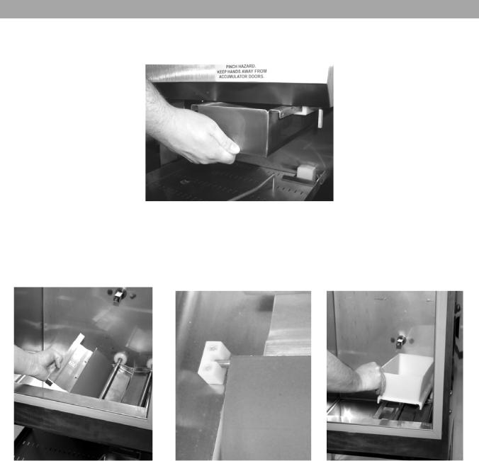
Open the cabinet door. Install the Flap Door by slipping it under the Accumulator Doors so the green arrows are visible from inside the cabinet. Seat the Flap Door Pivot Pin into the plastic Pivot Blocks, as shown above. Install the Accumulator Housing on the Accumulator Doors
|
6 |
Copyright © 2013 Automated Equipment LLC All rights reserved. Published 8/13 |

RAM™ 200-Fx Frozen Fry Dispenser
Dispenser Assembly Cont.
|
Drum |
Fry Diverter |
Hopper Assembly |
Install the Drum into the Hopper making sure the square opening in the drum is pointed toward the rear of the Hopper. Install the Fry Diverter in the Hopper by sliding the Fry Diverter tabs into the slots located on the inside Hopper wall. Install the hopper assembly into the cabinet by sliding them onto the hopper supports. DO NOT force the drum on to the shaft. Rotate the drum in the hopper until the square opening meshes with the drum motor shaft, then slide the hopper assembly backward until it drops into place.
|
Storage Guide |
Basket Rack |
Drip Tray |
Once the Accumulator Housing and Hopper Assembly are in place, place the Storage Guide alongside the Hopper Assembly and close the Cabinet Door. Assemble Basket Rack and Drip Tray in the dispensing area.
|
Copyright © 2013 Automated Equipment LLC All rights reserved. Published 8/13 |
7 |
RAM™ 200-Fx Frozen Fry Dispenser
Using the Hash-brown Rack
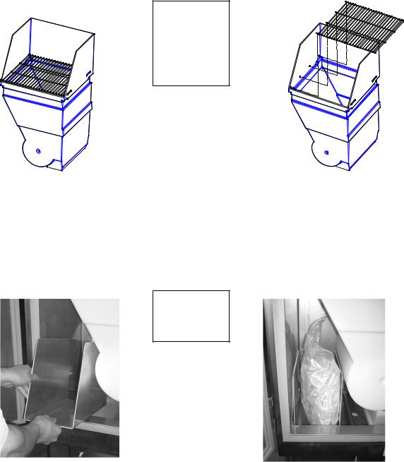
The RAM 200-Fx cabinet can be used to store frozen hash-browns while serving breakfast. To use the cabinet for hash-brown storage, properly assemble the dispenser (pages 6-7), then install the hashbrown rack accessory as shown in the diagram below. The rack will serve as a shelf inside the refrigerated cabinet for hash-brown storage.
Note: The hash-brown rack should be removed during fry dispensing.
Caution: Do not store hash-browns on the drum below the rack, this can damage the dispenser.
Insert the four rods of the hash-brown rack into the holes in the side of the hopper then lower the rack onto the fry diverter.
Hash-brown rack
PN: 295846 (shown with Hopper p/n 295696)
Using the Storage Guide
The RAM 200-Fx comes with a storage guide which can be used to aid storage inside the cabinet. To use the Storage Guide, properly assemble the dispenser (pages 6-7), then install the Storage Guide as shown below. An extra bag of fries or other frozen products may be placed in the storage guide. This allows for extra storage inside the cabinet while not interfering with the operation of the dispenser.
Caution: Do not store items inside the cabinet without using the Storage Guide.
Storage
Guide
PN: 295942
|
8 |
Copyright © 2013 Automated Equipment LLC All rights reserved. Published 8/13 |
![]()
RAM™ 200-Fx Frozen Fry Dispenser
Disassembly, Defrost & Cleaning
IMPORTANT! These cleaning instructions are intended as a guide. Refer to your local, state, and federal regulations for any additional instructions and for cleaning frequency requirements.
Remove all Baskets from the dispense area. Open the Cabinet Door and remove the Hopper Assembly by lifting the front of the Hopper up slightly and pulling forward on assembly.
Remove any unused product from the Hopper and Accumulator Housing by emptying the product into an approved storage container. Place the storage container immediately into a freezer to maintain frozen product.
Defrost
Because the dispenser employs a cold wall design, it will be necessary to manually defrost the cabinet daily. After removing the product, using the On/Off Switch turn the power OFF and unplug the dispenser power cord. Open the Cabinet Door and allow 1 hour to defrost.
Caution: Never use a sharp object to remove frost build-up. Never drill or otherwise puncture cabinet walls or top.
Lift and remove the Storage Guide
Lift and remove the Hopper Assembly and Accumulator Housing.
Take the removable components from the Dispenser to the washing area. Wash them with a hot solution of detergent and water. Rinse each component with clear water and sanitize (wash/rinse/sanitize) (HCS). Allow components to air dry,.
NOTE: The removable components are NOT dishwasher safe.
Move the Dispenser out from the wall to clean behind and underneath it.
Do NOT roll the dispenser to the back sink for cleaning, this will cause unnecessary wear on the dispenser.
Once the cabinet is free of frost, wipe down the internal and external cabinet with a hot solution of detergent and water. Rinse with clear water and repeat wipe down with sanitizing solution (HCS) and allow to air dry.
Warning: Do not spray the Dispenser with Liquid or Solvents. The Dispenser does not provide a water tight seal. Contaminants and moisture may get into sensitive components.
Dry all components and reassemble the Dispenser (page 6-7). Move Dispenser back into place.
Lift and remove Flap door assembly.
Lift the front of the Fry Guide and pull out to remove.
Remove Basket Guide assembly from the Dispenser by lifting up on the front of the guide then tilt and pull outward. Remove Drip Tray by lifting, tilting and sliding outward.
Notice: The dispenser must be accessible from all sides for routine cleaning and maintenance. A minimum of 1” (26 mm) clearance on both sides and 2” (50 mm) behind the dispenser is recommended.
|
Copyright © 2013 Automated Equipment LLC All rights reserved. Published 8/13 |
9 |
RAM™ 200-Fx Frozen Fry Dispenser
Dispenser Startup
When the dispenser is in place, lock both front casters. Make sure Power Switch, located on the right side of the dispenser is turned off. Assemble the Dispenser (Pages 6-7). Plug the Power Cord into an approved outlet and turn the Dispenser on.
Note: Turn Dispenser on a minimum of 90 minutes (depending on ambient temperature conditions) before loading frozen product into the Dispenser. Once the temperature display has dropped to 10°F (-12°C) load frozen product into Dispenser and use the Dispenser.
|
Menu Button |
||
|
Refrigeration |
Cabinet |
|
|
Temperature |
||
|
Status |
||
|
Load Size |
Weighing |
|
|
System Status |
||
|
Selection |
||
|
Display |
Up and Down |
|
|
Buttons |
||
|
OK Button |
Load Size |
|
|
Indicator Lights |
||
|
Basket Loads Size |
||
|
Buttons |
Small load
Medium load
Large load
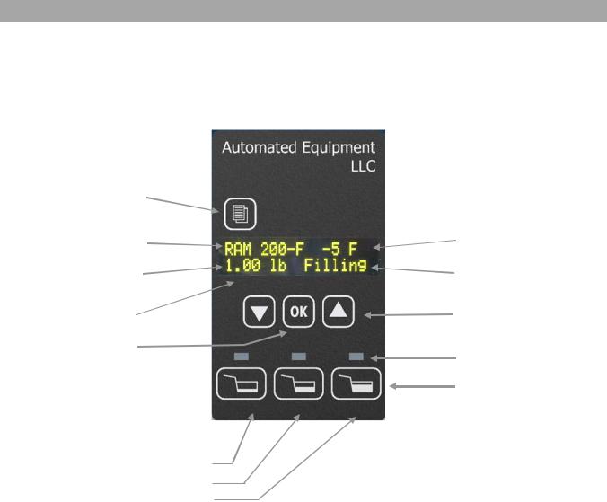
The Operator Panel consists of two groups of controls: the Hopper controls and System controls with Data Display. It is used to make basket load size selections and to access controller functions. On power up, the display will very briefly show the Software Name, Software Version, Copyright Notice, and then the Main Screen.
The Main Screen will appear as shown above. The display shows:
•Current refrigeration status
Waiting – Refrigeration system in short cycle delay
Cooling – In initial cool down stage
RAM 200-F – in normal refrigeration cycle
Open – Cabinet door is not closed
•Current cabinet temperature ( after temperature indicates compressor is on in normal cycle)
•Current basket load size selection (Select Size — if no selection has been made)
•Current weighing system status
Filling – Drum is turning to place fries on the accumulator doors
Empty – Insufficient weight on accumulator doors after filling cycle, hopper is empty. Ready – Fries are waiting to be dispensed, place basket in fill position to dispense.
|
10 |
Copyright © 2013 Automated Equipment LLC All rights reserved. Published 8/13 |

RAM™ 200-Fx Frozen Fry Dispenser
Operation
Note: This machine is to be used only for dispensing frozen fries or other approved product. Any other use may cause injury to personnel or damage to the machine.
The Frozen Fry Dispenser is intended to maintain and dispense frozen fries on demand eliminating the need for staging full baskets of fries. Dispensing and cooking fries direct from the freezer results in improved fry quality, consistency and yield.
Do not stage full baskets of fries on the bottom tray. The lower tray area should be used for empty fry basket storage only.
|
Loading the Hopper |
|||
|
Note: To achieve optimum fry yield and the |
For each bag or box of fries: |
||
|
most consistent basket loads, it is important |
1. |
Remove the bag of fries from the case. Be |
|
|
to use the following technique for loading |
|||
|
frozen fries into the Hopper. |
careful not to crush the fries. |
||
|
The dispenser hopper holds 42 lbs (19.1 kg) |
2. |
Open the top of the bag or box completely. |
|
|
Hopper capacity may vary depending on the |
(A partially open bag may retain fries.) |
||
|
product. |
3. |
Hold the opened end of the bag closed with |
|
|
your hand and lay it in the Hopper with the |
|||
|
Warning: Pinch Hazard. |
Personnel should |
opening toward the side opposite of the |
|
|
Diverter. |
|||
|
take care not to place hands or fingers near |
4. |
Release the opened end of the bag or box. |
|
|
the Drum inside the Hopper while this |
|||
|
machine is in operation. |
Hands or fingers |
5. |
Empty the bag into the Hopper by pulling it |
|
could be pinched between the Drum and the |
evenly toward the diverter. When adding |
||
|
Hopper as the Drum turns. |
multiple bags of fries, alternate the |
||
|
placement of the bag in the Hopper |
|||
|
Note: Do NOT shake or drop fries from the |
opposite of the previous bag. The second |
||
|
bag of fries should be emptied into the |
|||
|
bag or box into the Hopper, this will result in |
|||
|
Hopper with the opening toward the |
|||
|
unnecessary fry breakage. |
|||
|
Diverter, and pulling it evenly toward the |
|||
|
Hopper wall opposite the Diverter. |
|||
|
6. |
This crisscross loading method assures an |
||
|
even distribution of fry lengths in the Hopper |
|||
|
and the Baskets. |
|
Copyright © 2013 Automated Equipment LLC All rights reserved. Published 8/13 |
11 |
- Обязательно представиться на русском языке кириллицей (заполнить поле «Имя»).
- Фиктивные имена мы не приветствуем. Ивановых и Пупкиных здесь уже достаточно.
- Не писать свой вопрос в первую попавшуюся тему — вместо этого создать новую тему.
- За поиск, предложение и обсуждение пиратского ПО и средств взлома — бан без предупреждения.
- Рекламу и частные объявления «куплю/продам/есть халтура» мы не размещаем ни на каких условиях.
- Перед тем как что-то написать — читать здесь и здесь.
-
RuslanL
- здесь недавно

- Сообщения: 6
- Зарегистрирован: 29 мар 2021, 09:08
- Имя: Руслан
- Страна: Украина
- город/регион: Черкассы

FX2N некорректная работа программы
Сообщение
RuslanL » 29 мар 2021, 09:37
Добрый день. Имеем следующую проблему.
Станок китайского производства 2003г.р. Оборудован ПЛК FX2N-48 с панелью оператора HITECH.
После поломки механической части простоял без напряжения около трех месяцев. Починили механику, попробовали запустить — не получилось. Система управления зашла в ошибку и не возвращается никакими сбросами. Приходили умельцы, поменяли батарейки на ПЛК и ПО. Не помогло…
В таком виде он нам и достался. Удалось считать программу с ПЛК, с ПО — безнадега, нет исходного кода.
В памяти контроллера — полный бардак, куча левых цифр в регистрах. После очистки памяти все ожило, работают все функции станка кроме одной, связанной с подсчетом импульсов по энкодеру. Не могу понять. Дело в том, что в симуляторе GX Works2 программа абсолютно корректно работает, а на ПЛК не хочет.
Энкодер живой, от него измеряется скорость движения механизма каждые 6 сек., она адекватна и отображается на ПО. Она же является исходником для неработающей части программы.
Что может быть?
-

Jackson
- администратор
- Сообщения: 15770
- Зарегистрирован: 17 июн 2008, 16:01
- Имя: Евгений свет Брониславович
- Страна: Россия
- город/регион: Санкт-Петербург
- Благодарил (а): 555 раз
- Поблагодарили: 982 раза


FX2N некорректная работа программы
Сообщение
Jackson » 29 мар 2021, 10:10
RuslanL писал(а): ↑29 мар 2021, 09:37
Что может быть?
ПЛК сдох. Ему 20 лет уже.
RuslanL писал(а): ↑29 мар 2021, 09:37
нет исходного кода
А как тогда поняли в какой части проблема?
По вопросам работы Форума можно обратиться по этим контактам.
-
RuslanL
- здесь недавно
- Сообщения: 6
- Зарегистрирован: 29 мар 2021, 09:08
- Имя: Руслан
- Страна: Украина
- город/регион: Черкассы
FX2N некорректная работа программы
Сообщение
RuslanL » 29 мар 2021, 11:27
Jackson писал(а): ↑29 мар 2021, 10:10
А как тогда поняли в какой части проблема?
Программа ПЛК есть. Нет программы панели оператора.
Отправлено спустя 2 минуты 17 секунд:
Думал, что полетели выходы Y1,Y2,Y3. Переадресовал на заведомо рабочие. Тоже самое. Получается ошибка в работе программы.
-
Jackson
- администратор
- Сообщения: 15770
- Зарегистрирован: 17 июн 2008, 16:01
- Имя: Евгений свет Брониславович
- Страна: Россия
- город/регион: Санкт-Петербург
- Благодарил (а): 555 раз
- Поблагодарили: 982 раза
FX2N некорректная работа программы
Сообщение
Jackson » 29 мар 2021, 13:11
RuslanL писал(а): ↑29 мар 2021, 11:29
Получается ошибка в работе программы.
Когда дохнет электроника — проявления могут быть самые разнообразные. ПО может и работает. А может и нет в результате опять аппаратного сбоя.
Загрузите в него тупую программу которая будет просто транслировать сигналы с дискретного входа на дискретные выходы и проверьте в принципе работоспособность входов и выходов.
Но учитывая что контроллеру 20 лет без малого, ему помереть совсем не стыдно. Тратить время на его диагностику — мне кажется, это впустую. Всё равно придёте к замене с большой вероятностью. А если окажется что он целый то всё равно в любой момент может помереть. Сегодня вы успокоились, а завтра он умер. В итоге время потрачено зря.
По вопросам работы Форума можно обратиться по этим контактам.
-
RuslanL
- здесь недавно
- Сообщения: 6
- Зарегистрирован: 29 мар 2021, 09:08
- Имя: Руслан
- Страна: Украина
- город/регион: Черкассы
FX2N некорректная работа программы
Сообщение
RuslanL » 29 мар 2021, 14:22
Простите, конечно, за настойчивость, но т.к. я начинаю только разбираться с ПЛК, все же допускаю, что дело тут простое. Базовые настройки ПЛК, например. Вот, вычитал из памяти ПЛК данные. Три счетчика, которые в одной цепи должны считать импульсы по М8012. Два считают, а один нет.
счетчики.png
Это уже фиаско?
У вас нет необходимых прав для просмотра вложений в этом сообщении.
-
Sergy6661
- частый гость
- Сообщения: 415
- Зарегистрирован: 19 фев 2019, 22:38
- Имя: Сергей
- Страна: Россия
- город/регион: Краснодар
- Благодарил (а): 9 раз
- Поблагодарили: 39 раз

FX2N некорректная работа программы
Сообщение
Sergy6661 » 29 мар 2021, 15:30
RuslanL писал(а): ↑29 мар 2021, 14:22
Это уже фиаско?
Если три счетчика от одного контакта работают и 2 считают, а один нет, то что???
Это значит, что тот, кто не считает далее в программе сбрасывается.
Конкретно с этим ЦПУ не знаю как устроено, но сигналы от энкодера подключаются к высокоскоростным аппаратным счетчикам, они не могут работать от контакта М, т.к считают быстрее цикла программы. Для ПЛК Мицубиши полно документации, проект, как я понял вытащили из ПЛК…
-
RuslanL
- здесь недавно
- Сообщения: 6
- Зарегистрирован: 29 мар 2021, 09:08
- Имя: Руслан
- Страна: Украина
- город/регион: Черкассы
FX2N некорректная работа программы
Сообщение
RuslanL » 29 мар 2021, 16:01
Sergy6661 писал(а): ↑29 мар 2021, 15:30
Если три счетчика от одного контакта работают и 2 считают, а один нет, то что???
Это значит, что тот, кто не считает далее в программе сбрасывается.
Есть только эти общие
счетчики2.png
счетчики3.png
Sergy6661 писал(а): ↑29 мар 2021, 15:30
Конкретно с этим ЦПУ не знаю как устроено, но сигналы от энкодера подключаются к высокоскоростным аппаратным счетчикам, они не могут работать от контакта М, т.к считают быстрее цикла программы. Для ПЛК Мицубиши полно документации, проект, как я понял вытащили из ПЛК…
Проект из ПЛК. Был рабочий. Я ничего не менял. А энкодер, конечно, подключен на вход Х4 по которому работает измерение скорости транспортера. В зависимости от скорости устанавливаются D80, D76, D84.
счетчики4.png
У вас нет необходимых прав для просмотра вложений в этом сообщении.
-
Sergy6661
- частый гость
- Сообщения: 415
- Зарегистрирован: 19 фев 2019, 22:38
- Имя: Сергей
- Страна: Россия
- город/регион: Краснодар
- Благодарил (а): 9 раз
- Поблагодарили: 39 раз
FX2N некорректная работа программы
Сообщение
Sergy6661 » 29 мар 2021, 16:44
RuslanL писал(а): ↑29 мар 2021, 16:01
Проект из ПЛК. Был рабочий. Я ничего не менял. А энкодер, конечно, подключен на вход Х4 по которому работает измерение скорости транспортера. В зависимости от скорости устанавливаются D80, D76, D84.
Энкодер работает минимум по 2м входам, а это просто счетчик.
Оператор SPD — считает кол-во импульсов за 6 сек и помещает в D78, а далее умножает D78 на 559 и делит на 1000.
Ну и что?
И еще в описаловке к инструкции SPD смотрим : После отсчета времени содержание ((D+)+1) передается в (D+), а само ((D+)+1) отключается. (Это типа перевод такой )
-
RuslanL
- здесь недавно
- Сообщения: 6
- Зарегистрирован: 29 мар 2021, 09:08
- Имя: Руслан
- Страна: Украина
- город/регион: Черкассы
FX2N некорректная работа программы
Сообщение
RuslanL » 31 мар 2021, 10:47
Всем крепкого здоровья! Отчитываюсь о проделанной работе и ее результатах.
После долгих размышлений было принято волевое решение перенести память счетчиков из энергонезависмой в энергозависимую часть памяти. И… станок выздоровел. Понятно, что не совсем, возраст все-таки. Видимо, сбоит какая-то часть памяти ПЛК. Так что уважаемый Jackson был не далек от истины.
Надеюсь, что наш подопечный агрегат прослужит еще несколько лет и отработает вложенные в него время и усилия.
Всем спасибо!
-
Jackson
- администратор
- Сообщения: 15770
- Зарегистрирован: 17 июн 2008, 16:01
- Имя: Евгений свет Брониславович
- Страна: Россия
- город/регион: Санкт-Петербург
- Благодарил (а): 555 раз
- Поблагодарили: 982 раза
FX2N некорректная работа программы
Сообщение
Jackson » 31 мар 2021, 11:39
RuslanL писал(а): ↑31 мар 2021, 10:47
Видимо, сбоит какая-то часть памяти ПЛК.
Он сыплется уже. Тут не на несколько лет надеяться надо, а каждый вечер можно молиться чтобы он завтрашним утром ещё работал.
- [+] специальный бубен для ритуальных танцев
Отправлено спустя 4 минуты 4 секунды:
Физика и химия — это объективные процессы, на которые не повлиять, приводящие к тому что нормально любая (исключая военную специальную) электроника в нормальных условиях живёт лет 10, а потом может сдохнуть в любой момент.
Раза три на форуме я это уже объяснял. Здесь прожило 18 лет — ну, можно считать что повезло, хотя это и не редкость. Но чаще всё-таки техника дохнет, не доживая и до 10 лет.
У вас нет необходимых прав для просмотра вложений в этом сообщении.
По вопросам работы Форума можно обратиться по этим контактам.
-

petr2off
- эксперт
- Сообщения: 1348
- Зарегистрирован: 06 янв 2016, 19:45
- Имя: Петров В.Л.
- Страна: Россия
- город/регион: Красноярск
- Благодарил (а): 56 раз
- Поблагодарили: 136 раз


FX2N некорректная работа программы
Сообщение
petr2off » 12 апр 2021, 11:04
Jackson писал(а): ↑31 мар 2021, 11:43
Физика и химия — это объективные процессы, на которые не повлиять, приводящие к тому что нормально любая (исключая военную специальную) электроника в нормальных условиях живёт лет 10, а потом может сдохнуть в любой момент.
Почему то в ментальность Российского менеджмента, идея замены оборудования не по отказу, а по истечении определенного периода времени приживается с большим трудом. В прошлом году, я отказался ехать на объект, где на сервере «нонаме» диски отпахали 5 лет. В результате диски заменили — служба эксплуатации была мне весьма благодарна, им почему то не верили. А там % сбойных блоков уже был в районе 16%.
18 лет — это много. Не факт конечно, что прямо завтра откажет. Но откажет точно, и как правило (закон Паркинсона) в самый не подходящий момент.
-
tonyk
- здесь недавно
- Сообщения: 89
- Зарегистрирован: 16 дек 2018, 16:35
- Имя: Антон
- Благодарил (а): 3 раза
- Поблагодарили: 3 раза
FX2N некорректная работа программы
Сообщение
tonyk » 12 апр 2021, 14:11
RuslanL писал(а): ↑31 мар 2021, 10:47
было принято волевое решение перенести память счетчиков из энергонезависмой в энергозависимую часть памяти. И… станок выздоровел
Могли просто измениться параметры ПЛК (GX Works2->PLC->PLC Parameters). Там как раз указывается, какие значения в конце цикла будут сохраняться в памяти с батарейной поддержкой. Я не знаю, в какой памяти хранятся параметры ПЛК, во флэш или ОЗУ с батарейной поддержкой.
-
Sergy6661
- частый гость
- Сообщения: 415
- Зарегистрирован: 19 фев 2019, 22:38
- Имя: Сергей
- Страна: Россия
- город/регион: Краснодар
- Благодарил (а): 9 раз
- Поблагодарили: 39 раз
FX2N некорректная работа программы
Сообщение
Sergy6661 » 13 апр 2021, 13:36
Jackson писал(а): ↑31 мар 2021, 11:43
Физика и химия — это объективные процессы, на которые не повлиять, приводящие к тому что нормально любая (исключая военную специальную) электроника в нормальных условиях живёт лет 10, а потом может сдохнуть в любой момент.
Во вложении файлик от Сименса с MTBF… оборудование Сименс, судя по этому документу ![]() вечно, как ебипетские пирамиды
вечно, как ебипетские пирамиды
У вас нет необходимых прав для просмотра вложений в этом сообщении.
-

Valerich
- шаман
- Сообщения: 951
- Зарегистрирован: 27 июн 2013, 12:20
- Имя: Валерич
- Страна: СССР
- Благодарил (а): 33 раза
- Поблагодарили: 68 раз


FX2N некорректная работа программы
Сообщение
Valerich » 13 апр 2021, 14:24
У нас 2 станка на Митсубиси FX (еще без цифр) 96года, соответственно 25 лет работают практически 24/7. Из проблем, как я выше писал — если садится батарейка — мусор в памяти. Батарейку меняешь, чистишь через полное стирание, перезаливаешь и дальше поехали.
-
Jackson
- администратор
- Сообщения: 15770
- Зарегистрирован: 17 июн 2008, 16:01
- Имя: Евгений свет Брониславович
- Страна: Россия
- город/регион: Санкт-Петербург
- Благодарил (а): 555 раз
- Поблагодарили: 982 раза
FX2N некорректная работа программы
Сообщение
Jackson » 13 апр 2021, 14:57
Sergy6661 писал(а): ↑13 апр 2021, 13:36
оборудование Сименс, судя по этому документу вечно, как ебипетские пирамиды
Ага, и божественно.
MTBF никак не учитывает процессы естественного старения. Бесполезная цифра, показывающая разве что процент неконтролируемого заводского брака. У нашего оборудования MTBF такой, что египетские пирамиды рухнут раньше чем оно сдохнет. И тем не менее, почему-то приходится менять по старости.
Отправлено спустя 2 минуты 26 секунд:
and909 писал(а): ↑13 апр 2021, 14:24
У нас 2 станка на Митсубиси FX (еще без цифр) 96года, соответственно 25 лет работают практически 24/7. Из проблем, как я выше писал — если садится батарейка — мусор в памяти. Батарейку меняешь, чистишь через полное стирание, перезаливаешь и дальше поехали.
Старая электроника, как ни странно, была надёжнее по моим ощущениям. У меня есть некоторое количество техники примерно моего же возраста — с ней всё в порядке.
По вопросам работы Форума можно обратиться по этим контактам.
-
Sergy6661
- частый гость
- Сообщения: 415
- Зарегистрирован: 19 фев 2019, 22:38
- Имя: Сергей
- Страна: Россия
- город/регион: Краснодар
- Благодарил (а): 9 раз
- Поблагодарили: 39 раз
FX2N некорректная работа программы
Сообщение
Sergy6661 » 13 апр 2021, 15:20
Jackson писал(а): ↑13 апр 2021, 15:00
Бесполезная цифра, показывающая разве что процент неконтролируемого заводского брака
Однако цифра сия лежит в основе расчета надежности системы…мне только не понятно как эти получили значения по некоторым позициям в сотни тысячелетий ![]()
Отправлено спустя 1 минуту 49 секунд:
Jackson писал(а): ↑13 апр 2021, 15:00
Старая электроника, как ни странно, была надёжнее по моим ощущениям. У меня есть некоторое количество техники примерно моего же возраста — с ней всё в порядке.
Ну, пока Китай компоненты не производил, все было надежнее ![]()
-
Jackson
- администратор
- Сообщения: 15770
- Зарегистрирован: 17 июн 2008, 16:01
- Имя: Евгений свет Брониславович
- Страна: Россия
- город/регион: Санкт-Петербург
- Благодарил (а): 555 раз
- Поблагодарили: 982 раза
FX2N некорректная работа программы
Сообщение
Jackson » 13 апр 2021, 15:43
Sergy6661 писал(а): ↑13 апр 2021, 15:22
Однако цифра сия лежит в основе расчета надежности системы
Потому что это расчёт надёжности на момент выпуска системы с завода изготовителя, или на момент сдачи в эксплуатацию. Эксплуатационные факторы в этом расчёте никак не учтены.
Sergy6661 писал(а): ↑13 апр 2021, 15:22
мне только не понятно как эти получили значения по некоторым позициям в сотни тысячелетий
Легко. А ещё это означает, что если MTBF = 1000 лет, то одно из 1000 таких устройств точно откажет в течение года.
Sergy6661 писал(а): ↑13 апр 2021, 15:22
Ну, пока Китай компоненты не производил, все было надежнее
Не в Китае дело — они научились делать всё, даже джинсы и кроссовки. Дело в том что плотность монтажа растёт, количество элементов в схеме тоже, а отказ одного элемента = отказ всего устройства.
По вопросам работы Форума можно обратиться по этим контактам.
-
Sergy6661
- частый гость
- Сообщения: 415
- Зарегистрирован: 19 фев 2019, 22:38
- Имя: Сергей
- Страна: Россия
- город/регион: Краснодар
- Благодарил (а): 9 раз
- Поблагодарили: 39 раз
FX2N некорректная работа программы
Сообщение
Sergy6661 » 13 апр 2021, 16:34
Jackson писал(а): ↑13 апр 2021, 15:43
Эксплуатационные факторы в этом расчёте никак не учтены.
Расчет делается для неких «нормальных» условий эксплуатации.
Jackson писал(а): ↑13 апр 2021, 15:43
они научились делать всё, даже джинсы и кроссовки
Ох! едрит-мадрит жинсы, красовки млин…и вкусные конфетки из козьих какашек и пальмового масла и прочего «условно съедобного»
У вас нет необходимых прав для просмотра вложений в этом сообщении.
-
petr2off
- эксперт
- Сообщения: 1348
- Зарегистрирован: 06 янв 2016, 19:45
- Имя: Петров В.Л.
- Страна: Россия
- город/регион: Красноярск
- Благодарил (а): 56 раз
- Поблагодарили: 136 раз
FX2N некорректная работа программы
Сообщение
petr2off » 29 апр 2021, 04:29
Sergy6661 писал(а): ↑13 апр 2021, 13:36
Во вложении файлик от Сименса с MTBF… оборудование Сименс, судя по этому документу вечно, как ебипетские пирамиды
Надежно, но не вечно. У меня в стойке сименовский сервер — контроллер стоит. 10 лет отпахал, первым сдох блок питания (фуджицу кстати),
4 часа болтики на корпусе отворачивал (они там со звездочкой внутри), часть высверливать пришлось. Внутри все круто. Платы специальным девайсом к разъемам прижимаются. Сетевая плата хитрая- много поточная, в документации называется сетевым процессором. Ценник посмотрел больше 1000$, убрал нафиг.
Потом сдох 1 винт. Так что срок эксплуатации сименосовского железа на платформе Intel — 10 лет. До египетских пирамид тыщи 3 лет недотягивает.
Вернуться в «Средний уровень автоматизации (управляющий)»
Перейти
- Работа форума
- База знаний (Knowledge Exchange)
- ↳ Eplan Electric P8
- ↳ Общий F.A.Q.
- ↳ Общие вопросы
- ↳ Новости
- ↳ Ошибки
- ↳ Проект
- ↳ Изделия
- ↳ Устройства
- ↳ Соединения
- ↳ Кабели
- ↳ Клеммы
- ↳ ПЛК
- ↳ Компоновка 2D
- ↳ Макросы
- ↳ Eplan API
- ↳ Сценарии (Только готовые решения)
- ↳ Внешняя обработка
- ↳ ProPanel
- ↳ Инструкции ProPanel (Только готовые решения)
- ↳ Прочие направления Eplan
- ↳ FieldSys (Топология)
- ↳ Preplanning
- ↳ Harness proD
- ↳ EEC One
- ↳ Advantech
- ↳ F.A.Q., Инструкции
- ↳ Allen Bradley
- ↳ Общие вопросы
- ↳ ПЛК
- ↳ Операторские панели
- ↳ B&R Automation
- ↳ F.A.Q.
- ↳ Danfoss
- ↳ DEIF A/S
- ↳ Общие вопросы
- ↳ UNI-LINE
- ↳ MULTI-LINE
- ↳ MULTI-LINE 300
- ↳ Emerson
- ↳ Общие вопросы
- ↳ КИП и регуляторы
- ↳ DeltaV
- ↳ ОВЕН
- ↳ Прософт-Системы
- ↳ Общие вопросы
- ↳ ПЛК REGUL
- ↳ Schneider Electric
- ↳ Общие вопросы
- ↳ ПЛК
- ↳ Панели оператора
- ↳ SCADA
- ↳ Электротехника
- ↳ Приводная техника
- ↳ SIEMENS
- ↳ Общие вопросы
- ↳ LOGO!
- ↳ ПЛК SIMATIC (S7-200, S7-1200, S7-300, S7-400, S7-1500, ET200)
- ↳ Simatic Step7
- ↳ Simatic TIA Portal
- ↳ Simatic PCS 7
- ↳ Операторские панели
- ↳ WinCC
- ↳ Приводная техника (Sinamics, Micromaster, Masterdrive, Simoreg, Simotics)
- ↳ SmartGen
- ↳ Общие вопросы
- ↳ Промышленные (береговые) контроллеры
- ↳ Морские контроллеры и устройства
- ↳ WEINTEK (операторские панели)
- ↳ F.A.Q., Инструкции
- ↳ Архив
- ↳ Микроконтроллеры и электроника
- ↳ Arduino
- ↳ Raspberry
- ↳ Другие микроконтроллеры
- ↳ Электроника
- Общие вопросы АСУТП
- ↳ Общие вопросы
- ↳ Вопросы от студентов
- ↳ Литература
- ↳ Новости и отчётность
- ↳ Нормативы, ГОСТы, стандарты
- ↳ Информационная безопасность
- ↳ Проектирование и САПР
- ↳ Системная интеграция
- ↳ Разбор полетов
- ↳ Работа
- ↳ Заготовки для базы знаний
- ↳ Производство и технология
- ↳ MES — Системы автоматизации управления производством
- ↳ Метрология, КИП и датчики
- ↳ Исполнительные устройства, регуляторы
- ↳ Средний уровень автоматизации (управляющий)
- ↳ Алгоритмы
- ↳ Операторские панели
- ↳ Верхний уровень автоматизации (отображение)
- ↳ GE iFix
- ↳ Wonderware Intouch
- ↳ MasterScada
- ↳ SCADA+
- ↳ Альфа платформа
- ↳ Интерфейсы, протоколы, связь
- ↳ Радиосвязь
- ↳ Полезное ПО
- ↳ Электротехника, энергетика и электропривод
- ↳ Генераторы, электростанции и силовые агрегаты
- ↳ Теплотехника
- ↳ Подбор аналогов
- F.A.Q. (краткая выжимка из некоторых сообщений форума)
- ↳ Документация (вариант 1)
- ↳ Документация (вариант 2)
- ↳ Электротехника и электроэнергетика
- ↳ F.A.Q. по программируемым логическим контроллерам (PLC)
- ↳ Обсуждение F.A.Q. по PLC
- ↳ F.A.Q. по выбору PLC
- ↳ F.A.Q. по аппаратной части PLC
- ↳ F.A.Q. по языкам программирования
- ↳ F.A.Q. по структуре программ
- ↳ F.A.Q. по взаимодействию PLC с HMI
- О жизни
- ↳ Для дома, для семьи
- ↳ Комната смеха
- ↳ Электродвижение
Представлено значение индикаторов (состояние светодиодов, коды ошибок, сообщения на дисплеях) ПЛК ABB Group:
— серия программируемых реле AC010
— серия SattCon
— серия Procontic
— серия Advant Controller 31
— серия AC500
— серия AC800M
================================== Logic relays ======================================
ABB AC010 Logic relays: LM001, LM002, LM003, LM011, LM012, LM021, LM022, LM023, LM024, LM025, LM026, LM041, LM042, LM043, LM044;
ABB CL Logic relays: CL-LSR, CL-LST, CL-LMT, CL-LMR
| Сообщение на дисплее | Описание |
|---|---|
| TEST: AC | Самодиагностика прервана. Аппаратный сбой. |
| TEST: EEPROM | Самодиагностика прервана. Ошибка памяти. |
| TEST: DISPLAY | Самодиагностика прервана. Ошибка дисплея. |
| TEST: CLOCK | Самодиагностика прервана. Ошибка модуля часов. |
| ERROR: I2C | Ошибка карты памяти. |
| ERROR: EEPROM | Ошибка внутренней памяти. |
| ERROR: CLOCK | Ошибка модуля часов. |
| ERROR: LCD | Ошибка дисплея. |
| ERROR: ACLOW | Некорректное питание АС. Аппаратный сбой. |
| пустой дисплей | Нет питания или неисправен дисплей |
{banner_rca-news-1-1}
(Программируемые реле ABB являются полными аналогами программируемых реле Moeller EASY)
====================================== SattCon ==========================================
SattControl (ABB) SattCon SlimLine Central unit CU05: CU05-25, CU05-45, OP-45
| Состояние светодиода | Описание |
|---|---|
| PWR горит | Корректное питание подано. |
| PWR мигает | Батарейка разряжена! |
| STOP горит | Устройство в режиме STOP |
| RD, TD | Индикация передачи данных. |
===================================== Procontic =========================================
ABB Procontic K200: 07KR220, 07KR228, 07KR240, 07KR264
| Состояние светодиода | Описание |
|---|---|
| Mains горит | Корректное питание подано. |
| STA мигает | Подана команда «Пуск» |
| RUN горит | Система в режиме RUN. |
| HZ | Работа высокоскоростного счётчика. |
| HR | Сброс высокоскоростного счётчика. |
ABB Procontic T200: Central unit 07ZE60, 07ZE61, 07ZE62, 07ZE63
| Состояние светодиода | Описание |
|---|---|
| RUN горит | ПЛК в режиме RUN. |
| HLT горит | ПЛК в режиме STOP. |
| SIM горит | Работа без выходов (симуляция) |
| FRC горит | ПЛК в режиме FORCE. |
| ERR горит | Ошибка, расшифровка на семисегментном дисплее. |
| BAT.E горит | Батарейка разряжена! |
|
Номер ошибки на дисплее |
Описание |
|---|---|
|
11 |
Ошибка суммы системной ROM. |
|
12 |
Ошибка суммы системной RAM. |
|
13 |
Нераспознанный код во время исполнения программы. |
|
15 |
Ошибка связи — таймаут цикла системной шины. |
|
21 |
Ошибка чтения системной ROM массивов. |
|
22 |
Ошибка суммы процессора SP системной ROM массивов. |
|
23 |
Программы содержит инструкцию, которую модуль управления не может выполнить. |
|
24 |
Нет ответа на запрос к внешним модулям входов/выходов. |
|
25 |
Ошибка памяти программы. |
|
26 |
Ошибка памяти с высокоскоростным доступом. |
|
27 |
Ошибка памяти данных. |
|
28 |
Ошибка шины — нет ответа на запрос к внешним модулям входов/выходов. |
|
29 |
Ошибка входов/выходов — таймаут цикла шины массивов. |
|
2A |
Ошибка системной памяти RAM 2. |
|
2C |
Ошибка массивов. |
|
31 |
Ошибка памяти программы пользователя. |
|
33 |
Размер программы пользователя превышает размер памяти программы пользователя, либо неверная системная конфигурация. |
|
34 |
Синтаксическая ошибка или ошибка архитектуры программы. |
|
41 |
Несоответствие назначенных входов/выходов физическим. |
|
43 |
Несоответствие назначенных удалённых входов/выходов физическим. |
|
44 |
Таймаут цикла программы. |
|
45 |
Превышение установленного времени для модулей, управляемых по времени. |
|
46 |
Ошибка прерывания. |
|
47 |
Количество точек входов/выходов, указанных в программе, превысило максимально возможное (4096). |
|
51 |
Ошибка модуля входов/выходов (например, перегорел предохранитель). |
|
52 |
Ошибка во время передачи данных к/от модулям входов/выходов. |
|
53 |
Недопустимое прерывание получено от незарегистрированного модуля входов/выходов. |
|
54 |
Аппаратный сбой в модуле коммуникаций. |
|
55 |
Ошибка передачи данных к/от модулю коммуникаций. |
|
56 |
Ошибка связи в шине в комплексном модуле. |
|
57 |
Ошибка конфигурации — количество заданных модулей превысило максимально допустимое. |
|
58 |
Ошибка конфигурации — заданный модуль связи не соотвествует фактическому. |
|
59 |
Аппаратный сбой в модуле 07ZB69. |
|
61 |
Ошибка чётности во время связи с программатором. |
|
62 |
Ошибка кадров во время связи с программатором. |
|
63 |
Таймаут цикла во время связи с программатором. |
|
64 |
Ошибка протокола во время связи с программатором. |
|
65 |
Ошибка блока проверки символов (BCC) во время связи с программатором. |
|
71 |
Батарейка разряжена или отсутствует! |
|
72 |
Зафиксирован кратковременный перебой в питании. |
|
88 |
Сработал сторожевой таймер. |
{banner_rca-news-1-2}
ABB Procontic b: Central control module 07ZE84
| Состояние светодиода | Описание |
|---|---|
| горит | Модуль в режиме RUN. |
| не горит | Модуль в режиме STOP. |
ABB Procontic b: Central control module 07ZE86, 07ZE88
| Состояние светодиода | Описание |
|---|---|
| Netz Ein зелёный горит | Корректное питание подано. |
| ACK жёлтый горит | Индикация передачи данных по последовательному интерфейсу. |
| BSY зелёный мигает | Модуль в режиме RUN. |
| M1 красный горит | Ошибка памяти. |
| M2 красный горит | Ошибка программы или конфигурации. |
| M1 и M2 красные горят | Аппаратный сбой. |
ABB Procontic T300: PLC central processor unit 35ZE93, processor card 35ZP93
| Состояние светодиода | Описание |
|---|---|
| 1 горит | Модуль в режиме RUN. |
| 2 горит | Сбой питания. |
| 3 горит | Ошибка. |
| 1, 2, 3 мигают последовательно | Ошибка памяти. |
| RDY красный горит | Питание подано, процессор готов. |
{banner_rca-news-1-3}
ABB Procontic CS 31: 07KR31, 07KT31, PCZB, CS20
| Состояние светодиода | Описание |
|---|---|
| SUPPLY зелёный горит | Корректное питание подано. |
| RUN зелёный горит | ПЛК в режиме RUN. |
| красный горит | Ошибка. |
================================= Advant Controller 31 ======================================
ABB Advant Controller 31 Series 90 Basic unit: 07KR91, 07KT92, 07KT93, 07KT94, 07KT95, 07KT96, 07KT97, 07KT98
ABB Procontic CS 31: 07KR91, 07KT92, 07KT93
| Состояние светодиода | Описание |
|---|---|
| RUN зелёный горит | ПЛК в режиме RUN. |
| FK1 красный горит | Критичная ошибка. Сбой питания, ошибка памяти. Если после перезагрузки не исчезает, то аппаратный сбой. |
| FK2 красный горит | Значительная ошибка. Ошибки в программе. Переход в режим STOP. |
| FK3 красный горит | Незначительная ошибка. Ошибки шины, адресации, связи. |
| Ovl. красный горит | Перегрузка или короткое замыкание на одном или нескольких дискретных выходах. |
| K красный горит | Перегрузка или короткое замыкание на одном или нескольких дискретных выходах. |
| Sup. зелёный горит | Питание подано. |
| Batt. красный горит | Батарейка разряжена! |
| Batt. красный мигает | Производится запись программы пользователя в Flash память. |
| BA зелёный горит | CS31BUS: Шина активна. |
| BE красный горит | CS31BUS: Ошибка шины. |
| RE красный горит | CS31BUS: Ошибка удалённого устройства. |
| SE красный горит | CS31BUS: Ошибка последовательного устройства. |
ABB Advant Controller 31: Series 40 Basic unit 07CR41, 07CT41, 07CR42, 07CT42; Series 50 Basic unit 07KR51, 07KT51
| Состояние светодиода | Описание |
|---|---|
| POWER горит | Питание подано |
| RUN горит | ПЛК в режиме RUN |
| ERR горит | Ошибка в программе, перебой в питании, ошибка памяти, ошибки шины, связи, адресации. |
==================================== AC500 =========================================
ABB AC500 PLC: CPU PM554, PM564, PM571, PM571-ETH, PM581, PM581-ETH, PM591, PM591-ETH
| Состояние светодиода | Описание |
|---|---|
| PWR зелёный горит | Питание 24В в норме. |
| RUN зелёный горит | CPU в режиме RUN. |
| RUN зелёный мигает | Если мигание частое (4 Гц): CPU читает/пишет на карту SD, вместе с мигающим светодиодом ошибки показывает, что CPU пишет во внутреннюю флэш-память EEPROM. Если мигание редкое (1 Гц): Обновление микропрограммы с карты SD прошло без ошибок. |
| ERR красный горит | Ошибка. Тип и код ошибки отображаются на дисплее. |
| ERR красный мигает | Идет процесс обновления микропрограммы или запись во внутреннюю флэш-память EEPROM. |
| SYS на дисплее |
— нет информации — |
| BATT на дисплее не горит | Батарейка разряжена или отсутствует! |
| I/O bus на дисплее мигает | Индикация передачи данных по шине входов/выходов. |
| ETH на дисплее мигает | Индикация передачи данных по Ethernet. |
| FPB на дисплее мигает | Индикация передачи данных по FPB. |
| COM1 на дисплее мигает | Индикация передачи данных по последовательному интерфейсу COM1. |
| COM2 на дисплее мигает | Индикация передачи данных по последовательному интерфейсу COM2. |
=================================== AC800M ========================================
ABB AC800M controller: CPU PM851, PM856, PM860, PM861, PM861A, PM864A, PM865, PM866
| Состояние светодиода | Описание |
|---|---|
| F (Fault) красный горит | Кратковременно при перезапуске CPU, либо состояние задаётся в программе пользователя. |
| R (Run) зелёный горит | CPU в режиме RUN. Мигает при перезапуске CPU, либо состояние задаётся в программе пользователя. |
| P (Power) зелёный горит | Питание 5В и 3,3В в норме. |
| B (Battery) зелёный негорит | Напряжение на батарейках (внешняя и внутренняя включены параллельно) ниже 3,1В. |
| PRIM (Primary) жёлтый горит | Индикация первичного CPU в системах с резервированием. |
| DUAL жёлтый горит | Индикация работы с резервированием и выполненной синхронизацией. |
Источник: /engine/api/go.php?go=https://promservis-rostov.ru/
Обсудить на форуме
На чтение 5 мин Просмотров 14к.
Рассмотрим подробнее
- Техническое описание и расшифровка ошибки P2A00
- Симптомы неисправности
- Причины возникновения ошибки
- Как устранить или сбросить код неисправности P2A00
- Диагностика и решение проблем
- Проверка проводки
- Проверка датчика
- На каких автомобилях чаще встречается данная проблема
- Видео
Код ошибки P2A00 звучит как «несоответствие диапазона рабочих характеристик цепи датчика кислорода O2 (Банк 1, Датчик 1)». Часто, в программах, работающих со сканером OBD-2, название может иметь английское написание «O2 Sensor Circuit Range/Performance (Bank 1, Sensor 1)».
Код P2A00 относится к датчику перед каталитическим нейтрализатором Банк 1, который находится на стороне двигателя с цилиндром №1. Ошибка означает, что модуль управления трансмиссией (PCM) обнаружил неисправность в датчике кислорода O₂ или его цепи.

В автомобилях для определения содержания кислорода, в выхлопной системе, до и после каталитических нейтрализаторов используются кислородные датчики O₂. Они используют обратную связь для регулировки топливной системы. Чтобы поддерживать оптимальное соотношение воздушно-топливной смеси 14,7:1.
В некоторых кислородных датчиках используется цепь нагрева для более быстрой работы обратной связи с модулем управления. Датчик кислорода может использовать три или четыре провода в зависимости от автомобиля.
Два обычно используются для обратной связи с модулем управления трансмиссией (PCM). А другие провода предназначены для нагревателя и питания нагретой цепи. Трехпроводные датчики обычно заземляются через выхлопную систему. А четырехпроводные имеют отдельный провод заземления.
Если цепь датчика O₂ не работает должным образом в течение заданного периода времени и при определенных запрограммированных обстоятельствах. То код P2A00 будет сохранен, и может загореться индикаторная лампа неисправности.
Некоторым автомобилям может потребоваться несколько циклов отказа для включения контрольной лампы MIL.
Симптомы неисправности
Основным симптомом появления ошибки P2A00 для водителя является подсветка MIL (индикатор неисправности). Также его называют Check engine или просто «горит чек».
Также они могут проявляться как:
- Загорится контрольная лампа «Check engine» на панели управления (код будет записан в память как неисправность).
- Повышенный расход топлива.
- Снижение мощности двигателя.
- Возможны пропуски зажигания в цилиндрах двигателя. Также двигатель автомобиля может работать неустойчиво.
- Другие связанные диагностические коды неисправностей также могут быть сохранены.
При появлении кода неисправности P2A00, автомобиль может продолжить движение, но проблему необходимо устранить как можно скорее. При долгом игнорировании проблемы, возможна неустойчивая работа двигателя, а также повреждение других компонентов.
Причины возникновения ошибки
Код P2A00 может означать, что произошла одна или несколько следующих проблем:
- Неисправный датчик O₂.
- Обрыв провода питания, заземления или цепи нагревателя датчика O₂.
- Повреждение или износ разъемов, идущих к датчику.
- Перегоревший предохранитель или плавкая вставка.
- Слишком низкое или слишком высокое давление топлива.
- Утечка вакуума.
- Сильная утечка выхлопных газов.
- Плохой датчик массового расхода воздуха или абсолютного давления в коллекторе.
- Иногда причиной является неисправный модуль PCM.
Как устранить или сбросить код неисправности P2A00
Некоторые предлагаемые шаги для устранения неполадок и исправления кода ошибки P2A00:
- Очистите коды ошибок с памяти компьютера автомобиля.
- Проведите тест-драйва автомобиля, чтобы выяснить, появляется ли код P2A00 снова.
- Выполните визуальный осмотр и при необходимости отремонтируйте или замените поврежденные электрические провода.
- Проверьте заземление, при необходимости устраните проблему.
- Протестируйте датчик кислорода тестером, обычно сопротивление должно быть 7-9 Ом, при необходимости замените.
- В случае проблемы с PCM, перепрограммируйте или замените модуль управления двигателем.
Диагностика и решение проблем
Неисправность P2A00 обычно вызвана проблемой с цепью кислородного датчика или самим датчиком, поэтому диагностику начинают с проверки проводки датчика. Если установлен датчик кислорода с подогревом на него обычно приходит четыре провода.
Два провода идут прямо к цепи нагревателя, а два других для питания и заземления датчика. Вам может понадобиться электрическая схема вашего автомобиля. Чтобы быть уверенным, что вы проверяете правильный набор проводов.
Проверка проводки
Проверьте цепь с помощью цифрового мультиметра или вольтомметра. Сверьтесь со схемой проводки автомобиля, чтобы определить точные контакты разъема, на котором установлено заземление.
Показания должны быть близки к напряжению батареи. Если это не так, то скорее всего существует проблема с питанием датчика.
Также необходимо проверить заземление. Для этого необходимо положительную клемму аккумулятора соединить с красным проводом мультиметра. А черный провод приложить к заземлению, чтобы проверить заземление цепи. Результат должен быть 12 В, если нет, то это указывает на проблему заземления на датчике.
Проверка датчика
Если питание и заземление в порядке, то следующий вариант с исправлением ошибки P2A00, проверить сам датчик. Чтобы определить, есть ли у него обрыв цепи или высокое сопротивление. Установите вольтомметр на шкале Ом, проверьте сопротивление цепи, используя электрическую схему в качестве справки.
Цепь внутри датчика должна иметь небольшое сопротивление, точные данные нужно смотреть в руководстве к конкретному автомобилю. Превышение предельного значения указывает на обрыв, поэтому датчик кислорода придется заменить.
На каких автомобилях чаще встречается данная проблема
Проблема с кодом P2A00 может встречаться на различных машинах, но всегда есть статистика, на каких марках эта ошибка присутствует чаще. Вот список некоторых из них:
- Acura (Акура RDX)
- Buick (Бьюик Люцерн)
- Chevrolet (Шевроле Каптива, Круз)
- Citroen (Ситроен Джампи)
- Dodge (Додж Рам)
- Ford (Форд Фокус)
- Honda (Хонда Аккорд, СРВ, Цивик)
- Infiniti (Инфинити ex35, fx35, fx37, g25, g37, qx56)
- Jeep (Джип Гранд Чероки)
- Lexus
- Mercedes (Мерседес Спринтер)
- Nissan (Ниссан Мурано, Сентра, Теана, Х-Трейл)
- Opel (Опель Антара)
- Peugeot
- Renault (Рено Мастер)
- Toyota (Тойота Приус)
- Volvo
С кодом неисправности Р2А00 иногда можно встретить и другие ошибки. Наиболее часто встречаются следующие: P0171, P0300, P0412, P2195, P2A01, P2A02, P2A03, P2A04, P2A05.
Видео
Если FF загорается сразу и не меняется, то это не посткод, а его отсутствие. Т.е. она не стартует вообще. Как уже сказали, то это скорее всего слетел BIOS. Это самый вероятный вариант, но не единственный.
Кое-где пишут, что это слетел биос.
Такое может случаться, если какая-нибудь утилита от интела решит вместе с драйверами ещё обновить микрокод ядра — в результате она ещё и в биос лазит, и ломает его.
Проще всего отнести в сервис, где тебе его прошьют заново.
Если хочешь сам — тебе нужен программатор, работающий компьютер, и оригинальный образ bios.
Можно написать в Алик продавцу. Думаю у них есть типовые решения для подобных ситуаций. Вы наверняка не первый
Ребят если кому поможет, у кого такая проблема сделайте следующее, снимите кулер с процессора, откройте крепления возьмите отвёртку и ослабте болты которые крепления держут, потом аккуратно закройте крепление только придерживайте процессор, и закручивайте болты не сильно до лёгкого затяга, вот прям двумя пальцами крутит почувствуете напрягу больше не крутит, поставьте кулер и попробуйте запустит мне помогло благодаря одному человеку который так же решил свою проьлему
-
Repair manuals
1

Ram 200-FX service manual
(43 pages)
- Languages:English
-
Type:
PDF -
Size:
1.67 MB
Preview
Ram 200-FX (Cooking) service manuals in PDF format will help to find failures and errors and repair Ram 200-FX and restore the device’s functionality.
![]()
200-Fx
Frozen Fry Dispenser
Equipment Manual
English
Manufactured By
Automated Equipment LLC
5140 Moundview Drive
Red Wing, MN 55066 U.S.A.
For Warranty Service & Technical Support, call:
|
US & Canada support call: |
1 (800) 248-2724 |
|
|
International support call: |
1 (651) 385-2273 |
|
|
Sales Fax: |
1 (651) 385-2166 |
|
|
Service Fax: |
1 (651) 385-2172 |
|
|
http://www.autoequipllc.com |
||
|
Business Hours: |
||
|
Monday – Friday: 8:00 AM to 5:00 PM CST |
||
|
(excluding. holidays) |
||
|
After hours, your call will be handled by a voice mail |
||
|
paging service. The on call technician will be paged and |
||
|
will return your call |
||
|
Introduction |
Table of Contents |
1 |
|
Unpacking & Installation ………………………………………………………………………………………………………… |
1 |
|
|
Intended Use …………………………………………………………………………………………………………………………. |
1 |
|
|
Specifications………………………………………………………………………………………………………………………… |
1 |
|
|
Warranty ……………………………………………………………………………………………………………………………….. |
2 |
|
|
Service Information ……………………………………………………………………………………………………………….. |
3 |
|
|
Equipment Safety…………………………………………………………………………………………………………………… |
4 |
|
|
Dispenser Assembly………………………………………………………………………………………………………………. |
6 |
|
|
Disassembly, Defrost & Cleaning……………………………………………………………………………………………. |
9 |
|
|
Dispenser Startup ………………………………………………………………………………………………………………… |
10 |
|
|
Operation …………………………………………………………………………………………………………………………….. |
11 |
|
|
Daily Opening and Closing …………………………………………………………………………………………………… |
12 |
|
|
User Functions Menu Structure ……………………………………………………………………………………………. |
15 |
|
|
Configuration (Config) Functions Menu Structure …………………………………………………………………. |
16 |
|
|
Service Functions Menu Structure………………………………………………………………………………………… |
17 |
|
|
Error Detection…………………………………………………………………………………………………………………….. |
21 |
|
|
Troubleshooting…………………………………………………………………………………………………………………… |
22 |
|
|
Calibrations and Adjustments ………………………………………………………………………………………………. |
24 |
|
|
Part Identification…………………………………………………………………………………………………………………. |
27 |
|
|
Refrigeration System……………………………………………………………………………………………………………. |
35 |
|
|
Disposal of Equipment …………………………………………………………………………………………………………. |
39 |
|
|
Electrical Diagram………………………………………………………………………………………………………………… |
40 |
|
|
Copyright © 2013 Automated Equipment LLC All rights reserved. |
Published 8/13 |
The information in this manual is subject to change without notice.
IN NO EVENT WILL AUTOMATED EQUIPMENT LLC BE LIABLE FOR TECHNICAL OR EDITORIAL OMISSIONS MADE HEREIN, NOR FOR DIRECT, SPECIAL, INCIDENTAL, OR CONSEQUENTIAL DAMAGES RESULTING FROM THE FURNISHING, PERFORMANCE,
OR USE OF THIS MATERIAL.
This manual is copyrighted with all rights reserved. Under the copyright laws, this manual may not be copied, in whole or part, without the written consent of Automated Equipment LLC.
Product names mentioned herein are for identification purposes only, and may be trademarks and/or registered trademarks of their respective companies.
Copyright © 2013 Automated Equipment LLC All rights reserved. Published 8/13
RAM™ 200-Fx Frozen Fry Dispenser
Introduction
This manual contains important information on the proper installation, operation, and care of the RAM 200-Fx Frozen Fry Dispenser. Following the instructions and procedures in this document will ensure that your dispenser provides years of reliable service. If any problems with the dispenser arise, this manual will also provide troubleshooting tips and service information.
Unpacking & Installation
Remove all packing material from Dispenser. Open Cabinet Door. Disassemble, clean, sanitize and dry the Hopper and Accumulator assemblies. Clean, sanitize and dry Fry Baskets. (see pages 6-9 for assembly, disassembly & cleaning). Reassemble all components (see pages 10-12 for startup and operation).
The equipment must be installed by qualified personnel, in accordance with the manufacturer’s instructions. Local electrical installation and safety regulations must be observed. Before installing check that voltage and frequency on the data plate match the electrical supply.
Intended Use
The Frozen Fry Dispenser must only be used for the temporary frozen storage and dispensing of non-meat based food products at commercial restaurants and similar locations. Any other use would be deemed as inappropriate. The dispenser is designed for installation and use indoors, in a restaurant environment protected from weather, excessive heat, excessive humidity and salt air.
HAZARD COMMUNICATION STANDARD:
Hazard Communication Standard (HCS) Procedures in this manual may include the use of chemical products. These chemical products will be highlighted with boldface letters followed by the abbreviation (HCS) in the text of the procedure. See the HCS Manual for the appropriate Material Safety Data Sheets (MSDS).
FCC STATEMENT
WARNING: This equipment generates, uses, and can radiate radio frequency energy and, if not installed and used in accordance with the instruction manual, may cause interference to radio communications.
EMC STATEMENT
This equipment meets EMC directives: — EN 55014-1:2006 + A1:2009
— EN55014-2:1997 + A1:2001 +
A2:2008-Category II
Specifications
Electrical Requirements:
Domestic:
•120 Volts AC., 60 Hertz, 8 Amps, 1Φ International
•220 — 240 Volts AC., 50 Hertz, 4.6 Amps, 1Φ
Internal Circuit Breaker: 15 Amps
Dimensions:
•22″ wide, 32.5″ deep, 76.8″ high (580mm x 686mm x 1511mm)
Minimum Operating Clearance Shall be:
•1” (2.6 cm) clearance on each side
•2” (5 cm) clearance at the back
•Open to ceiling, minimum 24” (60 cm)
Weight: 300 lbs (136 kg)
Hopper Capacity:
•42 lbs (19.1 kg), weight may vary with product.
Operating Temperature:
•5°F to 0°F (-15°C to -18°C) (Recommended Ambient Operating Temperature of 75°F (24°C))
•Climate Class= N
Refrigeration:
•R-404A: (12.5 oz) (354 g)
Maximum Operating Altitude & Safe Tilt:
•Maximum Altitude: 7000 ft (2,134 meters), Maximum Tilt = 10 degrees
Insulation Blowing Gas:
•Methyl formate
Noise Emissions: < 70 dB (A)
Serial Number: The information on the serial number identification label is as follows:
Example: s/n 20FR1303B00103
|
20F = Model |
03 = Month |
|
R = Manu. Facility |
B = Revision Level |
|
13 = Year |
00103 = Sequence # |
|
Copyright © 2013 Automated Equipment LLC All rights reserved. Published 8/13 |
1 |
RAM™ 200-Fx Frozen Fry Dispenser
Warranty
The terms «we», “us”, “our” or “factory” hereinafter refer to Automated Equipment LLC. We warrant the purchased product to be free from manufacturing defects in material and workmanship under normal use and conditions for the period and component specified below. Warranty is part only unless otherwise specified.
|
Components Covered |
Term |
|
Electronic Circuit Board Assemblies |
See Serial # / Warranty Label |
|
Electrical and Mechanical Moving Parts |
See Serial # / Warranty Label |
|
Structural frame work or enclosures |
See Serial # / Warranty Label |
|
Refrigeration Compressor Extended Warranty |
See Serial # / Warranty Label |
|
Crew removable components: |
(no labor, part only) |
|
Baskets |
90 days |
|
Basket Rack and Guide |
90 days |
|
Drip Tray |
90 days |
|
Power Cord |
90 days |
|
Hopper, Fry Diverter & Drum |
90 days |
|
Flap Door |
90 days |
|
Accumulator Housing |
90 days |
The Warranty period commences on the date of shipment of the RAM 200-Fx Frozen Fry Dispenser (hereinafter “Product”) from our manufacturing facility.
EXCEPT AS OTHERWISE PROVIDED HEREIN WE MAKE NO OTHER WARRANTIES, EXPRESSED OR IMPLIED AND SPECIFICALLY DISCLAIM ANY WARRANTY OF MERCHANTABILITY OR FITNESS FOR A PARTICULAR PURPOSE.
We shall not be liable for any direct, indirect, consequential damages (including damages for loss of business profits, business interruption, loss of business information and the like) arising out of the use of or inability to use the Product.
THIS WARRANTY IS VOID IF THE PRODUCT IS NOT FUNCTIONING CORRECTLY DUE TO ABUSE OR NEGLECT BY THE PURCHASER, ITS EMPLOYEES, AGENTS, OR OTHER REPRESENTATIVES EITHER BY BREAKING, BENDING, MISUSE, ABUSE, DROPPING, ALTERATION, IMPROPER MAINTENANCE OR ANY OTHER FORM OF NEGLECT OR IMPROPER USAGE. THIS WARRANTY DOES NOT COVER DAMAGE TO THE PRODUCT CAUSED BY NATURAL CAUSES SUCH AS LIGHTNING, ELECTRICAL CURRENT FLUCTUATIONS, FLOOD, FIRE, TORNADOES, OR OTHER ACTS OF GOD. WE WILL INVOICE PURCHASER FOR REPAIRS MADE NECESSARY BY THE HEREIN LISTED CAUSES.
This warranty is governed by the substantive laws of Minnesota, U.S.A., without giving effect to the conflict of law provisions.
This warranty is non-transferable and applies only to the original Purchaser.
|
2 |
Copyright © 2013 Automated Equipment LLC All rights reserved. Published 8/13 |
RAM™ 200-Fx Frozen Fry Dispenser
Service Information
Warranty Service
Warranty service must be initiated by calling our Technical Support Hotline at 1-800-248-2724 (U.S./Canada) or 651-385-2273 to establish all warranty requests.
Our Technical Support personnel will determine the cause of failure and provide appropriate resolution. Any required replacement parts will be provided by us or by an authorized Service Support Center/Parts Distributor.
Our Technical Support personnel will make all reasonable efforts to perform such repairs during normal business hours, and will not be responsible for any after-hours or holiday charges.
Non-Warranty Service
Service is normally conducted by customer appointed personnel, or by contracting a local service agent. The service person must be licensed in refrigeration to troubleshoot, open, or repair refrigeration and related systems.
Service fees are in accordance with industry standards.
Replacement parts are available through local Service Support Center/Parts Distributors or direct from us by calling 1-800-248-2724 (U.S./Canada) or 651-385-2273 in the event a local distributor is not available.
Our Technical Support Hot Line is available for telephone assistance providing product technical support, parts and parts information, and service agent referral.
Contact our Technical Support Hotline at 1-800-248-2724 (U.S./Canada) or 651-385-2273.
Record the following information for your records:
Date of Installation
Service Agency Telephone
Serial Number
When repairing this unit, use only replacement parts supplied by us, or supplied by our Factory Authorized Parts Distributor. Use of replacement parts other than those supplied by us or by our Factory Authorized Parts Distributor will void the warranty.
All shipping charges are F.O.B. factory, and are subject to change without notice. Prices will be those in effect at the time of shipment.
Automated Equipment LLC. reserves the right to make suitable substitutions in materials, depending upon their availability.
Warning!
Only personnel qualified, trained and licensed in refrigeration, may diagnose or repair the refrigeration systems on this equipment.
Service functions described in this manual could cause irreversible damage to the equipment and/or injury to personnel if performed improperly.
If the power cord is damaged, it must be replaced by the manufacturer, or its service agent, or a similarly qualified person in order to avoid a hazard
|
Copyright © 2013 Automated Equipment LLC All rights reserved. Published 8/13 |
3 |
RAM™ 200-Fx Frozen Fry Dispenser
Equipment Safety
•Turn the Power Switch off and disconnect the Dispenser Power Cord from the wall outlet before cleaning, moving or servicing the Dispenser.
•Inspect the Dispenser on a regular basis to identify potential problems before they occur.
•Keep the Dispenser clean.
•Keep hands away from the Accumulator Doors and Dispenser Drum while the Dispenser is operating. Disconnect power before clearing blocked Accumulator Doors or Dispenser Drum.
•Fry Baskets may be hot. Pick them up by the handles only.
•Do NOT roll the Dispenser to the back sink for cleaning, this will cause unnecessary wear on the Dispenser.
•If the Power Cord is damaged it must be replaced by the manufacturer or its service agent or a similarly qualified person in order to avoid a hazard.
•Use only the Power Cord that came with the Dispenser. Do NOT use an extension cord.
•Do NOT modify the Power Cord
•In a safety emergency, immediately disconnect the Dispenser Power Cord from the wall outlet.
•Do NOT obstruct access to the wall outlet or place pressure on the Power Cord.
•Only trained and/or qualified personnel should service the electrical system.
•DO NOT SPRAY THE DISPENSER WITH LIQUID OR SOLVENTS.
It is not sealed against jetting fluids and contamination may get into sensitive components. Spraying the dispenser may void the warranty.
•Use caution when handling heavy parts such as back and top panels.
•Always reinstall service panels when maintenance is complete.
•Do NOT drill or otherwise puncture cabinet walls or top.
•Keep unit upright at all times.
•Keep ventilation openings in the appliance enclosure, particularly in the bottom back panel, clear of obstruction.
•Do NOT use mechanical devices or other means to accelerate the defrosting process, other than those recommended by the manufacturer. Do NOT drill or otherwise puncture cabinet walls or top.
•Do NOT damage the refrigerant circuit.
•Do NOT use electrical appliances inside the food storage compartments of the appliance, unless they are of the type recommended by the manufacturer.
•Do NOT store explosive substances such as aerosol cans with a flammable propellant in this appliance.
•This appliance is not intended for use by persons (including children) with reduced physical, sensory or mental capabilities, or lack of experience and knowledge, unless they have been given supervision or instruction concerning use of the appliance by a person responsible for their safety. Children should be supervised to ensure that they do not play with the appliance.
|
4 |
Copyright © 2013 Automated Equipment LLC All rights reserved. Published 8/13 |
RAM™ 200-Fx Frozen Fry Dispenser
Equipment Safety Cont.
Label is located on the rear access panel and applies to the drum motor and accumulator assemblies within the enclosure. (A different label may be present on US models.)
CAUTION, MOVING PARTS.
DO NOT OPERATE WITH PANEL REMOVED
Label is located on Rear Access Panel and near Power Cord inlet.
CAUTION, RISK OF ELECTRIC SHOCK.
INDICATES HAZARDOUS VOLTAGE WITHIN
DISCONNECT POWER BEFORE SERVICING UNIT.
Label is located on the Rear Access Panel and applies to the cabinet insulation.
CAUTION, RISK OF FIRE
KEEP OPEN FLAME FROM EXPOSED INSULATION WHEN SERVICING
|
Copyright © 2013 Automated Equipment LLC All rights reserved. Published 8/13 |
5 |
RAM™ 200-Fx Frozen Fry Dispenser
Dispenser Assembly
Note: Before assembling the Dispenser it is recommended that all parts be cleaned, sanitized, dry, and handled in a sanitary manner. Refer to the Cleaning Procedures (page 9) for more Information.
Fry Guide
Install the Fry Guide under the cabinet outlet, sliding it onto the mounting rails.
|
Flap Door |
Pivot Block |
Accumulator Housing |
Open the cabinet door. Install the Flap Door by slipping it under the Accumulator Doors so the green arrows are visible from inside the cabinet. Seat the Flap Door Pivot Pin into the plastic Pivot Blocks, as shown above. Install the Accumulator Housing on the Accumulator Doors
|
6 |
Copyright © 2013 Automated Equipment LLC All rights reserved. Published 8/13 |
RAM™ 200-Fx Frozen Fry Dispenser
Dispenser Assembly Cont.
|
Drum |
Fry Diverter |
Hopper Assembly |
Install the Drum into the Hopper making sure the square opening in the drum is pointed toward the rear of the Hopper. Install the Fry Diverter in the Hopper by sliding the Fry Diverter tabs into the slots located on the inside Hopper wall. Install the hopper assembly into the cabinet by sliding them onto the hopper supports. DO NOT force the drum on to the shaft. Rotate the drum in the hopper until the square opening meshes with the drum motor shaft, then slide the hopper assembly backward until it drops into place.
|
Storage Guide |
Basket Rack |
Drip Tray |
Once the Accumulator Housing and Hopper Assembly are in place, place the Storage Guide alongside the Hopper Assembly and close the Cabinet Door. Assemble Basket Rack and Drip Tray in the dispensing area.
|
Copyright © 2013 Automated Equipment LLC All rights reserved. Published 8/13 |
7 |
RAM™ 200-Fx Frozen Fry Dispenser
Using the Hash-brown Rack
The RAM 200-Fx cabinet can be used to store frozen hash-browns while serving breakfast. To use the cabinet for hash-brown storage, properly assemble the dispenser (pages 6-7), then install the hashbrown rack accessory as shown in the diagram below. The rack will serve as a shelf inside the refrigerated cabinet for hash-brown storage.
Note: The hash-brown rack should be removed during fry dispensing.
Caution: Do not store hash-browns on the drum below the rack, this can damage the dispenser.
Insert the four rods of the hash-brown rack into the holes in the side of the hopper then lower the rack onto the fry diverter.
Hash-brown rack
PN: 295846 (shown with Hopper p/n 295696)
Using the Storage Guide
The RAM 200-Fx comes with a storage guide which can be used to aid storage inside the cabinet. To use the Storage Guide, properly assemble the dispenser (pages 6-7), then install the Storage Guide as shown below. An extra bag of fries or other frozen products may be placed in the storage guide. This allows for extra storage inside the cabinet while not interfering with the operation of the dispenser.
Caution: Do not store items inside the cabinet without using the Storage Guide.
Storage
Guide
PN: 295942
|
8 |
Copyright © 2013 Automated Equipment LLC All rights reserved. Published 8/13 |
![]()
RAM™ 200-Fx Frozen Fry Dispenser
Disassembly, Defrost & Cleaning
IMPORTANT! These cleaning instructions are intended as a guide. Refer to your local, state, and federal regulations for any additional instructions and for cleaning frequency requirements.
Remove all Baskets from the dispense area. Open the Cabinet Door and remove the Hopper Assembly by lifting the front of the Hopper up slightly and pulling forward on assembly.
Remove any unused product from the Hopper and Accumulator Housing by emptying the product into an approved storage container. Place the storage container immediately into a freezer to maintain frozen product.
Defrost
Because the dispenser employs a cold wall design, it will be necessary to manually defrost the cabinet daily. After removing the product, using the On/Off Switch turn the power OFF and unplug the dispenser power cord. Open the Cabinet Door and allow 1 hour to defrost.
Caution: Never use a sharp object to remove frost build-up. Never drill or otherwise puncture cabinet walls or top.
Lift and remove the Storage Guide
Lift and remove the Hopper Assembly and Accumulator Housing.
Take the removable components from the Dispenser to the washing area. Wash them with a hot solution of detergent and water. Rinse each component with clear water and sanitize (wash/rinse/sanitize) (HCS). Allow components to air dry,.
NOTE: The removable components are NOT dishwasher safe.
Move the Dispenser out from the wall to clean behind and underneath it.
Do NOT roll the dispenser to the back sink for cleaning, this will cause unnecessary wear on the dispenser.
Once the cabinet is free of frost, wipe down the internal and external cabinet with a hot solution of detergent and water. Rinse with clear water and repeat wipe down with sanitizing solution (HCS) and allow to air dry.
Warning: Do not spray the Dispenser with Liquid or Solvents. The Dispenser does not provide a water tight seal. Contaminants and moisture may get into sensitive components.
Dry all components and reassemble the Dispenser (page 6-7). Move Dispenser back into place.
Lift and remove Flap door assembly.
Lift the front of the Fry Guide and pull out to remove.
Remove Basket Guide assembly from the Dispenser by lifting up on the front of the guide then tilt and pull outward. Remove Drip Tray by lifting, tilting and sliding outward.
Notice: The dispenser must be accessible from all sides for routine cleaning and maintenance. A minimum of 1” (26 mm) clearance on both sides and 2” (50 mm) behind the dispenser is recommended.
|
Copyright © 2013 Automated Equipment LLC All rights reserved. Published 8/13 |
9 |
RAM™ 200-Fx Frozen Fry Dispenser
Dispenser Startup
When the dispenser is in place, lock both front casters. Make sure Power Switch, located on the right side of the dispenser is turned off. Assemble the Dispenser (Pages 6-7). Plug the Power Cord into an approved outlet and turn the Dispenser on.
Note: Turn Dispenser on a minimum of 90 minutes (depending on ambient temperature conditions) before loading frozen product into the Dispenser. Once the temperature display has dropped to 10°F (-12°C) load frozen product into Dispenser and use the Dispenser.
|
Menu Button |
||
|
Refrigeration |
Cabinet |
|
|
Temperature |
||
|
Status |
||
|
Load Size |
Weighing |
|
|
System Status |
||
|
Selection |
||
|
Display |
Up and Down |
|
|
Buttons |
||
|
OK Button |
Load Size |
|
|
Indicator Lights |
||
|
Basket Loads Size |
||
|
Buttons |
Small load
Medium load
Large load
The Operator Panel consists of two groups of controls: the Hopper controls and System controls with Data Display. It is used to make basket load size selections and to access controller functions. On power up, the display will very briefly show the Software Name, Software Version, Copyright Notice, and then the Main Screen.
The Main Screen will appear as shown above. The display shows:
•Current refrigeration status
Waiting – Refrigeration system in short cycle delay
Cooling – In initial cool down stage
RAM 200-F – in normal refrigeration cycle
Open – Cabinet door is not closed
•Current cabinet temperature ( after temperature indicates compressor is on in normal cycle)
•Current basket load size selection (Select Size — if no selection has been made)
•Current weighing system status
Filling – Drum is turning to place fries on the accumulator doors
Empty – Insufficient weight on accumulator doors after filling cycle, hopper is empty. Ready – Fries are waiting to be dispensed, place basket in fill position to dispense.
|
10 |
Copyright © 2013 Automated Equipment LLC All rights reserved. Published 8/13 |
RAM™ 200-Fx Frozen Fry Dispenser
Operation
Note: This machine is to be used only for dispensing frozen fries or other approved product. Any other use may cause injury to personnel or damage to the machine.
The Frozen Fry Dispenser is intended to maintain and dispense frozen fries on demand eliminating the need for staging full baskets of fries. Dispensing and cooking fries direct from the freezer results in improved fry quality, consistency and yield.
Do not stage full baskets of fries on the bottom tray. The lower tray area should be used for empty fry basket storage only.
|
Loading the Hopper |
|||
|
Note: To achieve optimum fry yield and the |
For each bag or box of fries: |
||
|
most consistent basket loads, it is important |
1. |
Remove the bag of fries from the case. Be |
|
|
to use the following technique for loading |
|||
|
frozen fries into the Hopper. |
careful not to crush the fries. |
||
|
The dispenser hopper holds 42 lbs (19.1 kg) |
2. |
Open the top of the bag or box completely. |
|
|
Hopper capacity may vary depending on the |
(A partially open bag may retain fries.) |
||
|
product. |
3. |
Hold the opened end of the bag closed with |
|
|
your hand and lay it in the Hopper with the |
|||
|
Warning: Pinch Hazard. |
Personnel should |
opening toward the side opposite of the |
|
|
Diverter. |
|||
|
take care not to place hands or fingers near |
4. |
Release the opened end of the bag or box. |
|
|
the Drum inside the Hopper while this |
|||
|
machine is in operation. |
Hands or fingers |
5. |
Empty the bag into the Hopper by pulling it |
|
could be pinched between the Drum and the |
evenly toward the diverter. When adding |
||
|
Hopper as the Drum turns. |
multiple bags of fries, alternate the |
||
|
placement of the bag in the Hopper |
|||
|
Note: Do NOT shake or drop fries from the |
opposite of the previous bag. The second |
||
|
bag of fries should be emptied into the |
|||
|
bag or box into the Hopper, this will result in |
|||
|
Hopper with the opening toward the |
|||
|
unnecessary fry breakage. |
|||
|
Diverter, and pulling it evenly toward the |
|||
|
Hopper wall opposite the Diverter. |
|||
|
6. |
This crisscross loading method assures an |
||
|
even distribution of fry lengths in the Hopper |
|||
|
and the Baskets. |
|
Copyright © 2013 Automated Equipment LLC All rights reserved. Published 8/13 |
11 |
Loading…
Code
Distinction
Indoor Unit Activation of Protection Device(Float
01
Indoor Unit
Switch)
02
Outdoor Unit
Outdoor Unit Activation of Protection Device
Transmission Abnormality between Indoor and
03
Wiring
Outdoor
Transmission Abnormality between Inverter PCB
04
Inverter
and Outdoor PCB
05
Wiring
Abnormality Power Source Phases
06
Voltage
Abnormality Inverter Voltage
07
Decrease in Discharge Gas Superheat
Refrigerant
Cycle System
08
Increase in Discharge Gas Temperature
11
Abnormality Inlet Air Thermistor (Indoor)
12
Abnormality Outlet Air Thermistor (Indoor)
Abnormality Freeze Protection Thermistor
Indoor Unit
13
(Indoor)
Thermistor
14
Abnormality Gas Piping Thermistor (Indoor)
19
Activation of Protection for Indoor Fan Motor
21
Abnormality High Pressure Thermistor(Outdoor)
22
Abnormality Outdoor Air Thermistor
Abnormality Discharge Pipe
Outdoor Unit
23
Thermistor(Outdoor)
Thermistor
Abnormality Heat Exchanger Liquid Pipe
24
Thermistor(Outdoor)
29
Abnormality Low Pressure Thermistor (Outdoor)
Incorrect Capacity Setting of Outdoor and Indoor
31
Unit
System
35
Incorrect Setting of Indoor Unit No.
Abnormality of Picking Up Circuit for
38
Outdoor Unit
Protection(Outdoor)
Activation of Low Pressure Decrease Protection
43
Device
Activation of Low Pressure Increase Protection
44
Device
Pressure
Activation of High Pressure Increase Protection
45
Device
Activation of Low Pressure Decrease Protection
47
Device(Vacuum Operation Protection)
Activation of Inverter Overcurrent Protection
48
Outdoor Unit
Device
51
Abnormality Inverter Current Sensor
53
IPM Protection Activation
Inverter
54
Activation of Inverter Fin Thermistor Protection
55
Inverter Failure
57
Outdoor Unit
Activation of Outdoor Fan Controller Protection
EE
Compressor
Compressor Protection Alarm
Incorrect Outdoor Unit Address Number or Unit
b1
Number Setting
Wiring
b5
Number of Indoor Units Connected Error.
PS:
Remote control operation indicator flashes once every 2 seconds, the symbol of between the indoor unit and remote control for the
transmission abnormally (connector loss, loose, incorrect wiring, and disconnection).
4) Finally, please deliver the guarantee, operation manual, and installation manual, etc. to the customer to keep it.
Danger: Before the preparation of test running, please do not start running, be sure implementation to confirm the electrical wiring, etc.
Content of Abnormality
Activation of Float Switch (High water Level Drain Pan, Abnormality
of Drain Pipe, Float Switch or Drain Pan)
Activation of High Pressure Switch (4.15MPa); Air Conditioner
Outdoor Unit Fan Motor Lock.
Incorrect Wiring, Loose Terminals, Disconnect Wire, Blowout of
Fuse, Outdoor Unit Power OFF.
Inverter PCB — Outdoor PCB Transmission Failure (Loose
Connector, Wire Breaking, Blowout of Fuse), Abnormal fan motor
controller transmitted, «04» the lower right will be » . «Signal flashing.
Incorrect Power Source Phases, Connection to Reversed Phases,
Open-Phases.
Outdoor Voltage Drop, Insufficient Power Capacity.
Excessive Refrigerant Charge, Failure of Thermistor, Incorrect
Wiring, Incorrect Piping Connection, Expansion Valve Locking at
Opened Position (Disconnect Connector).
Insufficient Refrigerant Charge, Pipe Clogging, Failure of Thermistor,
Incorrect Wiring, Incorrect Piping Connection, Expansion Valve
Locking at Closed Position (Disconnect Connector).
Incorrect Wiring, Disconnecting Wiring, Breaking Wire, Short Circuit.
Incorrect Wiring, Disconnecting Wiring, Breaking Wire, Short Circuit.
Incorrect Wiring, Disconnecting Wiring, Breaking Wire, Short Circuit.
Incorrect Wiring, Disconnecting Wiring, Breaking Wire, Short Circuit.
Fan Motor Overheat, Locking.
Thermistor Incorrect Wiring, Disconnecting Wiring, Breaking Wire,
Short Circuit.
Incorrect Capacity Code Setting of Combination; Excessive or
Insufficient Indoor Unit Total Capacity Code (outside of 80~120%)
Duplication of Indoor Unit No. In Same Ref. Gr., or The Connection
Unit Number Exceeds The Maximum Number of Combination.
Failure of Protection Detecting Device(Incorrect Wiring of Outdoor
PCB)
Defective Compressor(Failure of Compressor of Inverter, Loose
Power Supply Connection)
Overload at Cooling, High Temperature at Expansion Valve
Locking(Loose Connector)
Overload Operation (Clogging, Short-Pass), Pipe Clogging,
Excessive Refrigerant, Inert Gas Mixing.
Insufficient Refrigerant, Pipe Clogging, Expansion Valve Locking at
Open Position (Loose Connector).
Overload Operation, Compressor Failure.
Current Sensor Failure.
Driver IC Error Signal Detection(Protection for Overcurrent, Low
Voltage)
Abnormality Fin Thermistor, Heat Exchanger Clogging, Fan Motor
Failure.
Inverter PCB Failure
Abnormality Fan Controller Protection (Overcurrent),Fin Overheat
Compressor Occurred Three Times of Abnormality within 6 Hour.
Over 64 Number Is Set for Address or Refrigerant Cycle.
Connection of Non-H-LINK-Ⅱ Indoor Unit More Than 17 Units.
22
Leading Cause