Пробег 115000км, проблем не было вообще, но тут появилась.
Дело было так, приехал, заглушил машину, через 15 минут завёл, хотел ехать, но не смог, машина не тянула и глохла. Добрался до своего сервиса, с горем пополам, на типтронике, на высоких оборотах. Двигатель работал на 3000 и выше. Сразу сделали компьютерную диагностику, ошибки естественно есть, скинули, завели мотор, потом он заглох и опять диагностика. В описании основной ошибки написано «Переобеднённая смесь». За ней появлялись P0174, Р0300, Р0302, Р0304, Р0304, Р0306, Р0308, что говорит об отказе цилиндров 2, 4, 6, 8. После сброса ошибок и повторного запуска, двигатель работал от 5 секунд до 10 минут, мотор глох и всё повторялось.
Первое о чем я подумал, это не докачивает бензонасос, думал поменять сразу, но решил проверить, насос то дороговатый. Проверили на утечки, подсосы и воздуха и топлива, всё в норме, подсосов и утечек нет. Оставался, как я думал насос, но из за его цены жаба поддавливала. Созвонился с одними, другими советчиками, кто то говорил бензонасос, кто то электрика, ЭБУ сдох, готовь 150т рублей, другие говорили ищи утечки и подсосы. Мне не одна подсказка не помогла. Машина нужна была, да и нет времени изучать устройство двухсотого. Решил обратиться к официалам. Позвонил, привезли меня в Кунцево. По мастеру было видно, что он знает в чем проблема. Поломка лечится в течении 5 минут, но я должен поверить, что всё сложно и чтоб расстался с честно заработанными денежками с удовольствием. Померяли сопротивление датчика воздуха, в норме, установили прибор для замера давления топлива в системе, проверили, насос качает, но давление очень слабое 0,7, проверили обратку, в норме. Я уж расстроился, типа зря эвакуатор, зря официалы, надо было сразу менять бензонасос. Мастер молчит, но вижу какой то он подозрительный, я же не знал, что он понты колотит. Давления нет, а он ходит вокруг машины. Далее залез под машину, посмотрел, потом притащил проводок и что то замкнул. На манометре мгновенно давление поднялось до 4, а может и больше, я смотрел со стороны. Насос жив!
В общем, укорочу рассказ, я же не пытаюсь заработать, я хочу поделиться информацией, чтоб вам не пришлось тратить лишние денежки, или наоборот, могли заработать по быстрому.
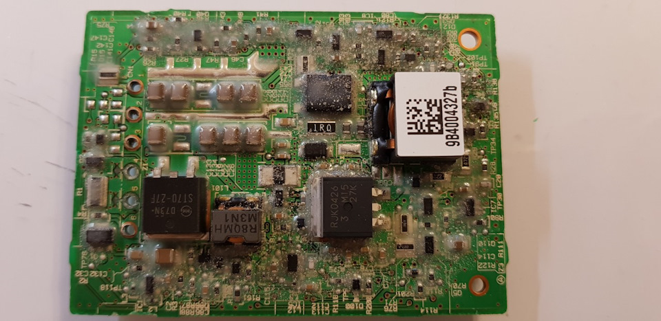
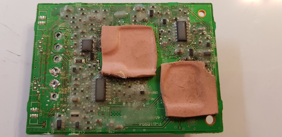
Вылез он из под машины и сказал всё норм, скоро поедете домой на машине, реле бензонасоса вышло из строя. Реле называется, «болк управления бензонасосом», они как я видел в инете бывают разные, моё 8957160060, отдал за него 14000р + 1000р на бензин и кофе в дороге, у официалов не оказалось и у них подороже. Привез из Балашихи, установили, двигатель заработал. Проблема решена!
Ремонт обошелся в 17320р работа + 15000 реле + 3000 эвакуатор, итого 35320р. Бензонасос подороже будет.
Забрал я блок домой, очень уж хотелось посмотреть, из за чего я все нервы вытрепал, разобрал и увидел, что отремонтировать, типа пропаять дорожку перегоревшую, не реально, реле по любому на выброс.
Благодарить не надо  Пользуйтесь Кстати, этот блок установлен на раме, весь в земле и влаге, можно сказать в говне. Так что советую первым делом, если у вас такая проблема, смотреть там.
35 821
Ошибка P0171 Toyota- cлишком бедная смесь (bank 1)
Что означает код P0171
Код ошибки P0171 означает, что топливная система первой головы (bank 1 ) автомобиля Тойота плохо работает или на этой стороне двигателя имеется потеря герметичности впускного тракта. Происходит обеднение топливной смеси — двигатель получает слишком мало топлива и много воздуха.
Каковы причины кода P0171?
Причинами ошибки могут быть:
- Неисправный регулятор давления топлива автомобиля Toyota
- Топливный насос не создает нужного давления
- Забитый топливный фильтр автомобиля Toyota
- Неисправный блок управления двигателем
- Подсос воздуха
- Неисправный инжектор(ы)
- Неисправный кислородный датчик автомобиля Тойота
- Неисправный датчик массового расхода воздуха
Каковы симптомы кода P0171?
- Потеря мощности
- Горит индикатор «Check Engine»
- Не ровная работа двигателя автомобиля Toyota. Плавают обороты
- Двигатель с трудом заводится
- Двигатель не заводится
Если эта ошибка в течении длительного времени не устраняется и автомобиль Тойота эксплуатируется на обедненной топливно-воздушной смеси это приведет к повреждению каталитического нейтрализатора (катализатора).
Как диагностируется ошибка P0171?
Предполагая, что никаких других кодов неисправностей не существует, можно диагностировать код P0171, проверяя двигатель на наличие утечек вакуума с помощью вакуумметра и проверив давление в топливной системе с помощью манометра.
Вероятнее всего причина ошибки будет найдена во время этих двух тестов. Если причина находится не в топливной системе и не в лишнем воздухе, то на следующем шаге нужно проверить MAF-сенсор автомобиля Toyota (датчик массового расхода воздуха) и датчики кислорода (лямбда-зонд).
Если все эти тесты были выполнены, и никаких проблем не найдено, то вероятнее всего неисправность находится в блоке управления двигателем Тойота.
Если блок управления зафиксировал два кода DTC — P0171 и P0174, то очень вероятно, что проблема в лишнем воздухе, подсос воздуха во впускном тракте. Если нет подсоса нет, то следующий этап — замена воздушного фильтра и очистка расходомера. Если проблема остается, то возможно, потребуется заменить первый (передний) датчик кислорода.
Распространенные ошибки при диагностике кода ошибки
Самая распространенная ошибка, которая может быть допущена при диагностике кода P0171 ошибка — отсутствие бюллетеней технического обслуживания для конкретной модели автомобиля. И хотя не каждая модель имеет TBS для этой ошибки, всегда разумнее это проверить и сэкономить время и усилия.
Насколько серьезен код P0171?
Ошибка P0171 является серьезной проблемой. Если в блоке управления двигателем хранится эта ошибка, то двигатель автомобиля не будет поддерживать правильное соотношение воздуха и топлива. Во время движения будет потеря мощности и повышенный расход топлива. Для того что бы автомобиль работал нормально, неисправность нужно устранить как можно скорее. Не правильная работа двигателя в течении длительного времени может привести к более серьезным неисправностям для устранения которых понадобится куда больше средств.
Что возможно потребуется ремонтировать для устранения ошибки Р0171 в автомобиле Toyota?
- Замена топливного насоса
- Замена топливного фильтра
- Замена регулятора давления топлива Тойота
- Замена блока управления двигателем
- Замена одной или нескольких форсунок
- Замена одного или нескольких датчиков кислорода Toyota
- Замена датчика массового расхода воздуха
- Ремонт подсоса воздуха
Код ошибки P0171 — “Слишком бедная смесь” появляется при сбоях в работе топливной системы двигателя в автомобиле “Тойота”. Одной из причин может стать повреждение впускного коллектора. Из-за этого получается бедная топливная смесь: мотор получает слишком много кислорода, но мало горючего.
Причины появления ошибки p0171
Если возникла данная ошибка в системе самодиагностики авто, обычно это означает, что либо двигатель засасывает слишком много воздуха из атмосферы, либо в цилиндры впрыскивается недостаточно топлива. Из этого можно сделать следующие выводы:
- В автомобиле может быть неисправен регулятор давления топлива;
- Возможно, вышел из строя топливный насос;
- Произошло засорение топливного фильтра;
- Возник подсос воздуха в топливной системе;
- Неисправен топливный инжектор;
- Вышел из строя датчик массового расхода воздуха.
В ходе диагностики проблем при ошибке по коду P0171 проверяются:
- двигатель на утечки вакуума;
- датчики массового расхода воздуха и давления топлива;
- работа датчиков кислорода;
- выполняется диагностика модуля управления PCM.
Устранение ошибки p0171 и сопутствующих неполадок
Ошибка P0171 мешает двигателю поддерживать оптимальный баланс топливовоздушной смеси, а значит о нормальной работе мотора можно забыть до её устранения. Простой сброс ошибки ничего не решит. Нужно либо искать перечисленные выше неисправности, либо воспользоваться другими методами.
В данной ситуации возможны:
- Замена топливного насоса.
- Замена топливного фильтра.
- Замена регулятора давления топлива.
- Замена блока управления двигателем.
- Замена одной или нескольких топливных форсунок.
- Замена одного или нескольких датчиков кислорода.
- Замена датчика массового расхода воздуха.
- Устранение подсоса воздуха в системе циркуляции топлива.
Наиболее часто код ошибки P0171 появляется на таких моделях Toyota как Camry, RAV4, Corolla, Avensis, внедорожниках семейства Land Cruiser. Довольно распространённой причиной этого на данных авто является простое загрязнение и окисление датчика массового расхода воздуха. В силу этих причин датчик не может правильно оценить объём воздуха на впуске в цилиндры, и ЭБУ двигателя выводит ошибку с упомянутым выше кодом.
В автотехцентре Тойота Мотор Клуб на Рязанском проспекте, д 10, стр 19 вам могут устранить любые неисправности Toyota в крайтчайшие сроки.
DESCRIPTION
MONITOR DESCRIPTION
WIRING DIAGRAM
INSPECTION PROCEDURE
CHECK ANY OTHER DTCS OUTPUT (IN ADDITION TO DTC P0171, P0172, P0174 OR P0175)
CHECK PCV HOSE CONNECTIONS
CHECK AIR INDUCTION SYSTEM
PERFORM ACTIVE TEST USING INTELLIGENT TESTER (A/F CONTROL)
READ VALUE USING INTELLIGENT TESTER (COOLANT TEMP)
INSPECT MASS AIR FLOW METER
CHECK FUEL PRESSURE
CHECK FOR EXHAUST GAS LEAK
CHECK SPARK AND IGNITION
INSPECT FUEL INJECTOR ASSEMBLY (INJECTION AND VOLUME)
INSPECT AIR FUEL RATIO SENSOR (HEATER RESISTANCE)
INSPECT INTEGRATION RELAY (A/F RELAY)
CHECK HARNESS AND CONNECTOR (A/F SENSOR — ECM)
REPLACE AIR FUEL RATIO SENSOR
PERFORM CONFIRMATION DRIVING PATTERN
CHECK WHETHER DTC OUTPUT RECURS (DTC P0171, P0172, P0174 OR P0175)
DTC P0171 System Too Lean (Bank 1)
DTC P0172 System Too Rich (Bank 1)
DTC P0174 System Too Lean (Bank 2)
DTC P0175 System Too Rich (Bank 2)
Description DTC P0171 P0172 P0174 P0175
The fuel trim is related to the feedback compensation value, not to the basic injection time. The fuel trim consists of both the short-term and long-term fuel trim.
The short-term fuel trim is fuel compensation that is used to constantly maintain the air fuel ratio at stoichiometric levels. The signal from the Air Fuel Ratio (A/F) sensor indicates whether the air fuel ratio is rich or lean compared to the stoichiometric ratio. This triggers a reduction in the fuel injection volume if the air fuel ratio is rich and an increase in the fuel injection volume if it is lean.
Factors such as individual engine differences, wear over time and changes in operating environment cause short-term fuel trim to vary from the central value. The long-term fuel trim, which controls overall fuel compensation, compensates for long-term deviations in the fuel trim from the central value caused by the short-term fuel trim compensation.
If both the short-term and long-term fuel trim are lean or rich beyond predetermined values, it is interpreted as a malfunction, and the ECM illuminates the MIL and sets a DTC.
| DTC Code | DTC Detection Condition | Trouble Area |
| P0171 P0174 | With a warm engine and stable air fuel ratio feedback, the fuel trim is considerably in error to the lean side (2 trip detection logic). |
|
| P0172 P0175 | With a warm engine and stable air fuel ratio feedback, the fuel trim is considerably in error to the rich side (2 trip detection logic). |
|
HINT:
- When DTC P0171 or P0174 is stored, the actual air fuel ratio is on the lean side. When DTC P0172 or P0175 is stored, the actual air fuel ratio is on the rich side.
- If the vehicle runs out of fuel, the air fuel ratio becomes lean and DTC P0171 or P0174 may be stored. The MIL is then illuminated.
- When the total of the short-term and long-term fuel trim values is within the malfunction threshold (and the engine coolant temperature is more than 75°C [167°F]), the system is functioning normally.
Monitor description
Under closed-loop fuel control, fuel injection volumes that deviate from those estimated by the ECM cause changes in the long-term fuel trim compensation value. The long-term fuel trim is adjusted when there are persistent deviations in the short-term fuel trim values. Deviations from the ECM’s estimated fuel injection volumes also affect the average fuel trim learned value, which is a combination of the average short-term fuel trim (fuel feedback compensation value) and the average long-term fuel trim (learned value of the air fuel ratio). If the average fuel trim learned value exceeds the malfunction thresholds, the ECM interprets this as a fault in the fuel system and stores a DTC.
Example:
If the average fuel trim learned value is more than +35% or less than -35%, the ECM interprets this as a fuel system malfunction.

Wiring diagram
Refer to DTC P2195.
Inspection procedure
HINT:
Malfunctioning areas can be identified by performing the Control the Injection Volume for A/F sensor function provided in the Active Test. The Control the Injection Volume for A/F sensor function can help to determine whether the Air Fuel Ratio (A/F) sensor, Heated Oxygen (HO2) sensor and other potential trouble areas are malfunctioning.
The following instructions describe how to conduct the Control the Injection Volume for A/F sensor operation using the intelligent tester.
- Connect the intelligent tester to the DLC3.
- Start the engine and turn the intelligent tester on.
- Warm up the engine at an engine speed of 2500 rpm for approximately 90 seconds.
- Enter the following menus: Powertrain / Engine and ECT / Active Test / Control the Injection Volume for A/F sensor.
- Perform the Active Test operation with the engine idling (press the RIGHT or LEFT button to change the fuel injection volume.)
- Monitor the output voltages of the A/F and HO2 sensors (AFS Voltage B1S1 and O2S B1S2, or AFS Voltage B2S1 and O2S B2S2) displayed on the intelligent tester.
HINT:
- The Control the Injection Volume for A/F sensor operation lowers the fuel injection volume by 12.5% or increases the injection volume by 25%.
- Each sensor reacts in accordance with increases and decreases in the fuel injection volume.
| Tester Display (Sensor) | Injection Volume | Status | Voltage |
| AFS Voltage B1S1 or AFS Voltage B2S1 (A/F) | +25% | Rich | Less than 3.1 V |
| AFS Voltage B1S1 or AFS Voltage B2S1 (A/F) | -12.5% | Lean | More than 3.4 V |
| O2S B1S2 or O2S B2S2 (HO2) | +25% | Rich | More than 0.55 V |
| O2S B1S2 or O2S B2S2 (HO2) | -12.5% | Lean | Less than 0.4 V |
NOTICE:
The Air Fuel Ratio (A/F) sensor has an output delay of a few seconds and the Heated Oxygen (HO2) sensor has a maximum output delay of approximately 20 seconds.
| Case | A/F Sensor (Sensor 1) Output Voltage | HO2 Sensor (Sensor 2) Output Voltage | Main Suspected Trouble Area |
| 1 | 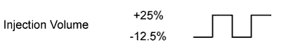 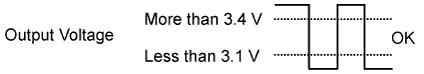 |
 |
— |
| 2 | 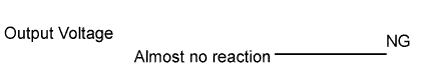 |
|
|
| 3 | |
|
|
| 4 | |
|
|
- Following the Control the Injection Volume for A/F sensor procedure enables technicians to check and graph the voltage outputs of both the A/F and HO2 sensors.
- To display the graph, enter the following menus: Powertrain / Engine and ECT / Active Test / Control the Injection Volume for A/F Sensor / A/F Control System / AFS Voltage B1S1 and O2S B1S2 or AFS Voltage B2S1 and O2S B2S2.
HINT:
- Read freeze frame data using the intelligent tester. Freeze frame data records the engine condition when malfunctions are detected. When troubleshooting, freeze frame data can help determine if the vehicle was moving or stationary, if the engine was warmed up or not, if the air fuel ratio was lean or rich, and other data from the time the malfunction occurred.
- A low A/F sensor voltage could be caused by a rich air-fuel mixture. Check for conditions that would cause the engine to run rich.
- A high A/F sensor voltage could be caused by a lean air-fuel mixture. Check for conditions that would cause the engine to run lean.
1.CHECK ANY OTHER DTCS OUTPUT (IN ADDITION TO DTC P0171, P0172, P0174 OR P0175)
-
Connect the intelligent tester to the DLC3.
-
Turn the ignition switch to ON and turn the intelligent tester on.
-
Enter the following menus: Powertrain / Engine and ECT / Trouble Codes.
-
Read the DTCs.
Result
Display (DTC Output) Proceed to P0171, P0172, P0174 or P0175 A P0171, P0172, P0174 or P0175 and other DTCs B HINT:
If any DTCs other than P0171, P0172, P0174 or P0175 are output, troubleshoot those DTCs first.
2.CHECK PCV HOSE CONNECTIONS
-
Check the PCV hose connections.
OK:
PCV hose is connected correctly and is not damaged.
|
REPAIR OR REPLACE PCV HOSE |
|
3.CHECK AIR INDUCTION SYSTEM
-
Check the air induction system for vacuum leakage.
OK:
No leakage from air induction system.
|
REPAIR OR REPLACE AIR INDUCTION SYSTEM |
|
4.PERFORM ACTIVE TEST USING INTELLIGENT TESTER (A/F CONTROL)
-
Connect the intelligent tester to the DLC3.
-
Start the engine and turn the intelligent tester on.
-
Warm up the engine at an engine speed of 2500 rpm for approximately 90 seconds.
-
Enter the following menus: Powertrain / Engine and ECT / Active Test / Control the Injection Volume for A/F Sensor.
-
Perform the Control the Injection Volume for A/F Sensor operation with the engine idling (press the RIGHT or LEFT button to change the fuel injection volume).
-
Monitor the voltage outputs of the A/F and HO2 sensors (AFS Voltage B1S1 and O2S B1S2, or AFS Voltage B2S1 and O2S B2S2) displayed on the intelligent tester.
HINT:
- The Control the Injection Volume for A/F Sensor operation lowers the fuel injection volume by 12.5% or increases the injection volume by 25%.
- Each sensor reacts in accordance with increases and decreases in the fuel injection volume.
Standard:
Tester Display (Sensor) Injection Volume Status Voltage AFS Voltage B1S1 or AFS Voltage B2S1 (A/F) +25% Rich Less than 3.1 AFS Voltage B1S1 or AFS Voltage B2S1 (A/F) -12.5% Lean More than 3.4 O2S B1S2 or O2S B2S2 (HO2) +25% Rich More than 0.55 O2S B1S2 or O2S B2S2 (HO2) -12.5% Lean Less than 0.4 Result:
Status AFS Voltage B1S1 or AFS Voltage B2S1 Status O2S B1S2 or O2S B2S2 A/F Condition and A/F Sensor Condition Misfire Suspected Trouble Area Proceed to Lean/Rich Lean/Rich Normal — — C Lean Lean Actual air fuel ratio lean May occur - PCV valve and hose
- PCV hose connections
- Injector blockage
- Gas leakage from exhaust system
- Air induction system
- Fuel pressure
- Mass Air Flow (MAF) meter
- Engine Coolant Temperature (ECT) sensor
A Rich Rich Actual air fuel ratio rich — - Injector blockage or blockage
- Gas leakage from exhaust system
- Ignition system
- Fuel pressure
- MAF meter
- ECT sensor
Lean Lean/Rich A/F sensor malfunction — - A/F sensor
B Rich Lean/Rich A/F sensor malfunction — - A/F sensor
Lean: During Control the Injection Volume for A/F Sensor, the A/F sensor output voltage (AFS) is consistently more than 3.4 V, and the HO2 sensor output voltage (O2S) is consistently less than 0.4 V.
Rich: During Control the Injection Volume for A/F Sensor, the AFS is consistently less than 3.1 V, and the O2S is consistently more than 0.55 V.
Lean/Rich: During Control the Injection Volume for A/F Sensor of the Active Test, the output voltage of the heated oxygen sensor alternates correctly.
5.READ VALUE USING INTELLIGENT TESTER (COOLANT TEMP)
-
Connect the intelligent tester to the DLC3.
-
Turn the ignition switch to ON and turn the intelligent tester on.
-
Enter the following menus: Powertrain / Engine and ECT / Data List / All Data / Coolant Temp.
-
Read the Data List twice, when the engine is cold and when it is warmed up.
Standard:
With cold engine: Same as ambient air temperature. With warm engine: 80 to 100°C (176 to 212°F).
|
REPLACE ENGINE COOLANT TEMPERATURE SENSOR |
|
6.INSPECT MASS AIR FLOW METER
-
Inspect the mass air flow meter.
|
REPLACE MASS AIR FLOW METER |
|
7.CHECK FUEL PRESSURE
-
Check the fuel pressure.
|
REPAIR OR REPLACE FUEL SYSTEM |
|
8.CHECK FOR EXHAUST GAS LEAK
-
Inspect for exhaust gas leakage from the exhaust manifold sub-assembly and exhaust pipes.
OK:
No gas leakage.
|
REPAIR OR REPLACE EXHAUST SYSTEM |
|
9.CHECK SPARK AND IGNITION
-
Check the ignition system.
HINT:
If the spark plugs or ignition system malfunctions, engine misfires may occur. The misfire count can be read using the intelligent tester. Enter the following menus: Powertrain / Engine and ECT / Data List / All Data / Cylinder #1 Misfire Rate (to Cylinder #6 Misfire Rate).
|
REPAIR OR REPLACE IGNITION SYSTEM |
|
10.INSPECT FUEL INJECTOR ASSEMBLY (INJECTION AND VOLUME)
-
Inspect the fuel injector assembly.
HINT:
If the injectors malfunction, engine misfires may occur. The misfire count can be read using the intelligent tester. Enter the following menus: Powertrain / Engine and ECT / Data List / All Data / Cylinder #1 Misfire Rate (to Cylinder #6 Misfire Rate).
|
REPLACE FUEL INJECTOR ASSEMBLY |
|
11.INSPECT AIR FUEL RATIO SENSOR (HEATER RESISTANCE)

-
Disconnect the A/F sensor connector.
-
Measure the resistance according to the value(s) in the table below.
Standard Resistance (for Bank 1 Sensor 1):
Tester Connection Condition Specified Condition 1 (HA1A) — 2 (+B) 20°C (68°F) 1.8 to 3.4 ? 1 (HA1A) — 4 (A1A-) Always 10 k? or higher Standard Resistance (for Bank 2 Sensor 1):
Tester Connection Condition Specified Condition 1 (HA2A) — 2 (+B) 20°C (68°F) 1.8 to 3.4 ? 1 (HA2A) — 4 (A2A-) Always 10 k? or higher
|
REPLACE AIR FUEL RATIO SENSOR |
|
12.INSPECT INTEGRATION RELAY (A/F RELAY)

-
Remove the integration relay from the engine room junction block.
-
Inspect the A/F fuse.
-
Remove the A/F fuse from the integration relay.
-
Measure the resistance according to the value(s) in the table below.
Standard Resistance:
Tester Connection Condition Specified Condition A/F fuse Always Below 1 ? -
Reinstall the A/F fuse.
-
-
Inspect the A/F relay.
-
Measure the resistance according to the value(s) in the table below.
Standard Resistance:
Tester Connection Condition Specified Condition 1A-4 — 1C-1 No battery voltage applied to terminals 1A-2 and 1A-3 10 k? or higher Battery voltage applied to terminals 1A- 2 and 1A-3 Below 1 ?
-
|
REPLACE INTEGRATION RELAY |
|
13.CHECK HARNESS AND CONNECTOR (A/F SENSOR — ECM)
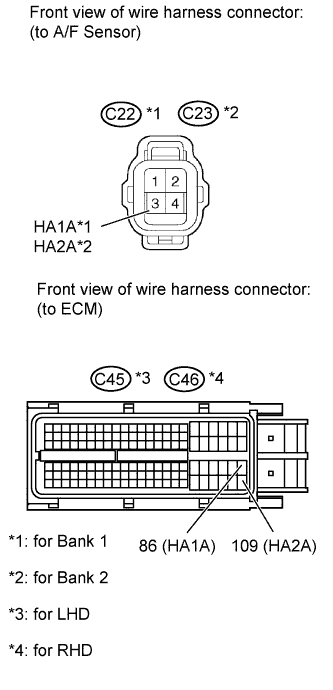
-
Disconnect the A/F sensor connector.
-
Disconnect the ECM connector.
-
Measure the resistance according to the value(s) in the table below.
Standard Resistance (Check for Open):
for LHD
Tester Connection Condition Specified Condition C22-1 (HA1A) — C45-86 (HA1A) Always Below 1 ? C23-1 (HA2A) — C45-109 (HA2A) Always Below 1 ? for RHD
Tester Connection Condition Specified Condition C22-1 (HA1A) — C46-86 (HA1A) Always Below 1 ? C23-1 (HA2A) — C46-109 (HA2A) Always Below 1 ? Standard Resistance (Check for Short):
for LHD
Tester Connection Condition Specified Condition C22-1 (HA1A) or C45-86 (HA1A) — Body ground Always 10 k? or higher C23-1 (HA2A) or C45-109 (HA2A) — Body ground Always 10 k? or higher for RHD
Tester Connection Condition Specified Condition C22-1 (HA1A) or C46-86 (HA1A) — Body ground Always 10 k? or higher C23-1 (HA2A) or C46-109 (HA2A) — Body ground Always 10 k? or higher
|
REPAIR OR REPLACE HARNESS OR CONNECTOR |
|
14.REPLACE AIR FUEL RATIO SENSOR
-
Replace the A/F sensor.
15.PERFORM CONFIRMATION DRIVING PATTERN
-

- (a) Connect the intelligent tester to the DLC3.
- (b) Turn the ignition switch to ON and turn the intelligent tester on.
- (c) Clear DTCs.
- (d) Switch the ECM from normal mode to check mode using the intelligent tester.
- (e) Start the engine and warm it up with all the accessories switched OFF.
- (f) Drive the vehicle at between 60 km/h and 120 km/h (38 mph and 75 mph) and at an engine speed of between 1400 rpm and 3200 rpm for 3 to 5 minutes.
HINT:
If the system is still malfunctioning, the MIL is illuminated during step (f).
NOTICE:
If the conditions in this test are not strictly followed, no malfunction will be detected.

16.CHECK WHETHER DTC OUTPUT RECURS (DTC P0171, P0172, P0174 OR P0175)
-
Connect the intelligent tester to the DLC3.
-
Turn the ignition switch to ON and turn the intelligent tester on.
-
Enter the following menus: Powertrain / Engine and ECT / Trouble Codes.
-
Read the DTCs.
Result
Display (DTC Output) Proceed to No output A P0171, P0172, P0174 or P0175 B
Автомобиль 2008 Toyota 4runner (1GR-FE). Двигатель разогрет до рабочей температуры.
Останавливаюсь на светофоре, удерживаю автомобиль педалью тормоза, рычаг АКПП в положении D — обороты двигателя 500-600
(если перевести селектор АКПП в положение N или P — обороты возрастают).
Так вот, именно на малых оборотах иногда замечаю нестабильную работу двигателя и после этого загорается Check Engine.
Соответственно, загораются и другие сопутствующие пиктограммы.
Диагностический сканер выдает ошибку P0171 System too Lean (Fuel Trim) — бедная топливная смесь.
Учитывая нестабильную работу мотора (на слух) заменил все свечи.
Поменял фильтры тонкой и грубой очистки топлива (снимал бак).
Вычистил с помощью Carb Cleaner MAF sensor — и не только утолщение на проволочке, но и все каналы на этом датчике.
Насколько мог осмотрел все соединения во впускном тракте.
Вроде все целое…
Иногда Check Engine сам по себе гаснет. Через некоторое время вот так же во время остановки и работы мотора на малых оборотах зажигается снова.
Я понимаю, что причину искать придется самому, но на всякий случай спрошу — может кто сталкивался с этой ситуацией?
ВАЖНО: какие обороты на Вашем автомобиле во время остановки и удерживании автомобиля тормозом в положении АКПП — D?
Всем спасибо.
http://www.testroete.com/car/Toyota/celica/repair%20information/repair%20manual/05%20-%20Diagnostics/20.pdf
Из этого документа следует, что причин может быть несколько:
— Air induction system
— Injector blockage
— Mass air flow meter
— Engine coolant temp. sensor
— Fuel pressure
— Gas leakage on exhaust system
— Open or short in A/F sensor (bank 1 sensor 1) circuit
— A/F sensor (bank 1 sensor 1)
Изменено пользователем Boris4Runner