9 Trouble-shooting
«
!
50
9.2
Serious system errors are always recognised by the instrument as «Fault messages»,
and are shown on the display. Fault messages immediately affect the inputs and out-
puts.
Caution!
In the event of a serious fault, a flowmeter might have to be returned to the manufacturer
for repair. The procedures on Page 8 must be carried out before you return a flowmeter
to Endress+Hauser. Always enclose a fully completed «Declaration of Contamination»
form. You will find a copy of the form at the back of these Operating Instructions.
Note!
Also observe the information on Page 39 and 52.
Error message
Error description
Communication
No data transfer between internal
modules or faulty internal data
transfer.
Amplifier Fault
Amplifier board defective.
Amplifier Data
Amplifier data invalid.
Received Signal
The strength of received signals
is changing.
Init. Run
Initialisation running.
Signal Low
Attenuation of acoustic measure-
ment section too high.
Signal High
Received signal is too high.
Error Current Output
Range current out exceeded.
Backup Battery Fail.
The backup battery for setup and
log data failed and needs to be
exchanged.
Prosonic Flow 92
Remedy / spare part
→
Spare parts see Page 53
contact E+H
Replace the amplifier board.
→
Spare parts see Page 53
contact E+H
Verify Site Setup data.
Restart device.
– Check whether the application
causes interference of the
signal.
– Check for air in the fluid.
– Check for solid content.
– Check for stable flow
conditions.
Wait until the procedure is com-
pleted.
– Check to see if coupling fluid
must be renewed.
– It is possible that the fluid
indicates too much attenuation.
– Check the sensor distance
(installation dimensions).
– Reduce the number of traverses
if possible.
Reduce burst voltage.
Modify the range.
→
Spare parts see Page 53
contact E+H
Endress+Hauser

Operating Instructions
Proline Prosonic Flow 92F
HART
Ultrasonic Flow Measuring System
6
 Esc
Esc
 Esc
Esc 
BA00121D/06/EN/13.10
71124139
Valid as of version V1.01.XX (device software)

|
Proline Prosonic Flow 92F |
Table of contents |
Table of contents
|
1 |
Safety instructions . . . . . . . . . . . . . . . . |
5 |
|
1.1 |
Designated use . . . . . . . . . . . . . . . . . . . . . . . . . . . . |
5 |
|
1.2 |
Installation, commissioning and operation . . . . . . . . |
5 |
|
1.3 |
Operational safety . . . . . . . . . . . . . . . . . . . . . . . . . . |
5 |
|
1.4 |
Return . . . . . . . . . . . . . . . . . . . . . . . . . . . . . . . . . . . |
6 |
|
1.5 |
Notes on safety conventions and icons . . . . . . . . . . . |
6 |
|
2 |
Identification . . . . . . . . . . . . . . . . . . . . |
7 |
|
2.1 |
Device designation . . . . . . . . . . . . . . . . . . . . . . . . . |
7 |
|
2.1.1 Nameplate of the transmitter . . . . . . . . . . . . |
7 |
|
|
2.1.2 Nameplate of the sensor . . . . . . . . . . . . . . . |
8 |
|
|
2.1.3 Nameplate for connections . . . . . . . . . . . . . |
8 |
|
|
2.2 |
Certificates and approvals . . . . . . . . . . . . . . . . . . . . |
9 |
|
2.3 |
Registered trademarks . . . . . . . . . . . . . . . . . . . . . . . |
9 |
|
3 |
Installation . . . . . . . . . . . . . . . . . . . . . |
10 |
|
|
3.1 |
Incoming acceptance, transport, storage . . . . . . . . . |
10 |
|
|
3.1.1 |
Incoming acceptance . . . . . . . . . . . . . . . . . |
10 |
|
|
3.1.2 |
Transport . . . . . . . . . . . . . . . . . . . . . . . . . |
10 |
|
|
3.1.3 |
Storage . . . . . . . . . . . . . . . . . . . . . . . . . . . |
10 |
|
|
3.2 |
Installation conditions . . . . . . . . . . . . . . . . . . . . . . |
11 |
|
|
3.2.1 |
Dimensions . . . . . . . . . . . . . . . . . . . . . . . . |
11 |
|
|
3.2.2 |
Mounting location . . . . . . . . . . . . . . . . . . . |
11 |
|
|
3.2.3 |
Orientation . . . . . . . . . . . . . . . . . . . . . . . . |
12 |
|
|
3.2.4 |
Heating . . . . . . . . . . . . . . . . . . . . . . . . . . . |
12 |
|
|
3.2.5 |
Thermal insulation . . . . . . . . . . . . . . . . . . |
13 |
|
|
3.2.6 Inlet and outlet run . . . . . . . . . . . . . . . . . . |
13 |
||
|
3.2.7 |
Limiting flow . . . . . . . . . . . . . . . . . . . . . . . |
13 |
|
|
3.3 |
Installation instructions . . . . . . . . . . . . . . . . . . . . . |
14 |
|
|
3.3.1 |
Mounting the sensor . . . . . . . . . . . . . . . . . |
14 |
|
|
3.3.2 Turning the transmitter housing . . . . . . . . |
14 |
||
|
3.3.3 Turning the local display . . . . . . . . . . . . . . |
14 |
||
|
3.3.4 Mounting the remote version . . . . . . . . . . |
15 |
||
|
3.4 |
Post-installation check . . . . . . . . . . . . . . . . . . . . . . |
15 |
|
4 |
Wiring . . . . . . . . . . . . . . . . . . . . . . . . |
16 |
|
4.1 Connecting the remote version . . . . . . . . . . . . . . . |
16 |
4.1.1Connecting cable for sensor/transmitter . . 16
4.1.2 Cable specification for connecting cable . . . 16 4.2 Connecting the measuring unit . . . . . . . . . . . . . . . 17 4.2.1 Connecting the transmitter . . . . . . . . . . . . 17 4.2.2 Terminal assignment . . . . . . . . . . . . . . . . . 19 4.2.3 HART connection . . . . . . . . . . . . . . . . . . . 20
4.3 Degree of protection . . . . . . . . . . . . . . . . . . . . . . . 21 4.4 Post-connection check . . . . . . . . . . . . . . . . . . . . . . 22
|
5 |
Operation . . . . . . . . . . . . . . . . . . . . . . |
23 |
|
5.1 |
Display and operating elements . . . . . . . . . . . . . . . |
23 |
|
5.2 |
Operation via the function matrix . . . . . . . . . . . . . |
24 |
|
5.2.1 General notes . . . . . . . . . . . . . . . . . . . . . . |
25 |
|
|
5.2.2 Enabling the programming mode . . . . . . . . |
25 |
|
|
5.2.3 Disabling the programming mode . . . . . . . |
25 |
|
|
5.3 |
Communication . . . . . . . . . . . . . . . . . . . . . . . . . . |
26 |
Endress+Hauser
5.3.1 Operating options . . . . . . . . . . . . . . . . . . . 27 5.3.2 Current device description files . . . . . . . . . 28
5.3.3Device variables and process variables . . . . 29
5.3.4 Universal/common practice HART commands . . 30 5.3.5 Device status/diagnosis code messages . . . . 35
5.3.6Switching HART write protection on/off . . 37
6 Commissioning . . . . . . . . . . . . . . . . . . 38
6.1 Function check . . . . . . . . . . . . . . . . . . . . . . . . . . . 38 6.2 Switching on the measuring device . . . . . . . . . . . . 38 6.3 Quick Setup . . . . . . . . . . . . . . . . . . . . . . . . . . . . . . 39 6.3.1 «Commissioning» Quick Setup . . . . . . . . . . 39
6.3.2Data backup with the T–DAT SAVE/LOAD
|
function . . . . . . . . . . . . . . . . . . . . . . . |
. . . . 41 |
||
|
6.4 |
Adjust |
. . . . . . . . . . . . . . . . . . . . . . . . . . . . . . |
. . . . 42 |
|
6.4.1 |
Zero point adjustment . . . . . . . . . . . . |
. . . . 42 |
|
|
6.5 |
Data storage device (HistoROM) . . . . . . . . . . |
. . . . 43 |
|
|
6.5.1 |
HistoROM/T-DAT (transmitter–DAT) |
. . . . 43 |
|
7 |
Maintenance . . . . . . . . . . . . . . . . |
. . . . 44 |
|
|
7.1 |
Exterior cleaning . . . . . . . . . . . . . . . . . . . . . |
. . . . . 44 |
|
|
7.2 |
Cleaning with pigs . . . . . . . . . . . . . . . . . . . . . |
. . . . 44 |
|
|
8 |
Accessories . . . . . . . . . . . . . . . . . . |
. . . 45 |
|
|
8.1 |
Device-specific accessories . . . . . . . . . . . . . . . |
. . . . 45 |
|
|
8.2 |
Measuring principle-specific accessories . . . . . |
. . . . 45 |
|
|
8.3 |
Communication-specific accessories . . . . . . . . |
. . . . 45 |
|
|
8.4 |
Service-specific accessories . . . . . . . . . . . . . . . |
. . . . 46 |
|
|
9 |
Troubleshooting . . . . . . . . . . . . . . |
. . . 47 |
|
|
9.1 |
Troubleshooting instructions . . . . . . . . . . . . . |
. . . . 47 |
|
|
9.2 |
Diagnosis code messages . . . . . . . . . . . . . . . . |
. . . . 48 |
|
|
9.2.1 |
Category F diagnosis code messages . . |
. . . . 48 |
|
|
9.2.2 |
Category C diagnosis code messages |
. . . . . 49 |
|
|
9.2.3 |
Category S diagnosis code messages . . |
. . . . 50 |
|
|
9.3 |
Process errors without messages . . . . . . . . . . |
. . . . 51 |
|
|
9.4 |
Response of outputs to errors . . . . . . . . . . . . . |
. . . . 52 |
|
|
9.5 |
Spare parts . . . . . . . . . . . . . . . . . . . . . . . . . . . |
. . . . 53 |
|
|
9.5.1 |
Installing and removing electronics boards . 54 |
||
|
9.6 |
Return |
. . . . . . . . . . . . . . . . . . . . . . . . . . . . . . |
. . . . 58 |
|
9.7 |
Disposal . . . . . . . . . . . . . . . . . . . . . . . . . . . . . |
. . . . 58 |
|
|
9.8 |
Software history . . . . . . . . . . . . . . . . . . . . . . . |
. . . . 58 |
|
|
10 |
Technical data . . . . . . . . . . . . . . . . |
. . . 59 |
|
|
10.1 |
Technical data at a glance . . . . . . . . . . . . . . . |
. . . . 59 |
|
|
10.1.1 |
Application . . . . . . . . . . . . . . . . . . . . |
. . . . 59 |
|
|
10.1.2 |
Function and system design . . . . . . . . |
. . . . 59 |
|
|
10.1.3 |
Input . . . . . . . . . . . . . . . . . . . . . . . . . |
. . . . 59 |
|
|
10.1.4 |
Output . . . . . . . . . . . . . . . . . . . . . . . |
. . . . 60 |
|
|
10.1.5 |
Power supply . . . . . . . . . . . . . . . . . . . |
. . . . 62 |
|
|
10.1.6 |
Performance characteristics . . . . . . . . |
. . . . 62 |
|
|
10.1.7 |
Operating conditions: Installation . . . . |
. . . . 62 |
|
|
10.1.8 |
Operating conditions: Environment . . |
. . . . 63 |
|
|
3 |
|
Proline Prosonic Flow 92F |
Table of contents |
||||
|
10.1.9 |
Operating conditions: Process |
64 |
|||
|
10.1.10 Mechanical construction . . . . . . . . . . . . |
. . 64 |
||||
|
10.1.11 Human interface . . . . . . . . . . . . . . . . . . |
. . 66 |
||||
|
10.1.12 Certificates and approvals . . . . . . . . . . . |
. . 66 |
||||
|
10.1.13 Ordering information . . . . . . . . . . . . . . |
. . 67 |
||||
|
10.1.14 Accessories . . . . . . . . . . . . . . . . . . . . . . . |
. 67 |
||||
|
10.1.15 Documentation . . . . . . . . . . . . . . . . . . |
. . 67 |
||||
|
11 Description of device functions . . . . . |
. 68 |
||||
|
11.1 |
Illustration of the function matrix . . . . . . . . . . . . . |
. 68 |
|||
|
11.2 |
Group MEASURING VALUES . . . . . . . . . . . . . . |
. . 70 |
|||
|
11.3 |
Group |
. . . . . . . . . . . . . . . . . . . . . SYSTEM UNITS 71 |
|||
|
11.4 |
Group QUICK SETUP . . . . . . . . . . . . . . . . . . . . |
. . 75 |
|||
|
11.5 |
Group OPERATION . . . . . . . . . . . . . . . . . . . . . |
. . 76 |
|||
|
11.6 |
Group USER INTERFACE . . . . . . . . . . . . . . . . . |
. . 77 |
|||
|
11.7 |
Group TOTALIZER . . . . . . . . . . . . . . . . . . . . . . |
. . 79 |
|||
|
11.7.1 Function group TOTALIZER 1 (TOTALIZER 2) |
. 79 |
||||
|
11.7.2 Group HANDLING TOTALIZER . . . . . . |
. . 81 |
||||
|
11.8 |
Group CURRENT OUTPUT . . . . . . . . . . . . . . . . |
. . 82 |
|||
|
11.9 |
Group PULSE, FREQUENCY, STATUS . . . . . . . . |
. . 85 |
|||
|
11.10 |
Information on the response of the status output |
. . 98 |
|||
|
11.11 |
Group COMMUNICATION . . . . . . . . . . . . . . . . |
. 100 |
|||
|
11.12 |
Group PROCESS PARAMETER . . . . . . . . . . . . . |
. 101 |
|||
|
11.13 |
Group SYSTEM PARAMETER . . . . . . . . . . . . . . |
. 103 |
|||
|
11.14 |
Group SENSOR DATA . . . . . . . . . . . . . . . . . . . . |
. 104 |
|||
|
11.15 |
Group SUPERVISION . . . . . . . . . . . . . . . . . . . . |
. 106 |
|||
|
11.16 |
Group SIMULATION SYSTEM . . . . . . . . . . . . . |
. 108 |
|||
|
11.17 |
Group SENSOR VERSION . . . . . . . . . . . . . . . . . |
. 108 |
|||
|
11.18 |
Group AMPLIFIER VERSION . . . . . . . . . . . . . . . |
. 108 |
|||
|
12 |
Factory settings . . . . . . . . . . . . . . . . . |
109 |
|||
|
12.1 |
Metric system units (not for USA and Canada) . . |
. 109 |
|||
|
12.1.1 |
Low flow cut off, fullscale value, pulse value, |
||||
|
totalizer → Page 71 . . . . . . . . . . . . . . . |
. 109 |
||||
|
12.1.2 |
Language → Page 76 . . . . . . . . . . . . . . |
. 109 |
|||
|
12.1.3 |
Unit totalizer 1 + 2 → ä 79 . . . . . . . . . . |
109 |
|||
|
12.2 |
US units (only for USA and Canada) . . . . . . . . . . |
. 110 |
|||
|
12.2.1 |
low flow cut off, full scale value, pulse value, |
||||
|
totalizer → ä 71 . . . . . . . . . . . . . . . . . |
. 110 |
||||
|
Index . . . . |
. . . . . . . . . . . . . . . . . . . . . . . . . |
111 |
|||
|
Proline Prosonic Flow 92F |
Safety instructions |
1 Safety instructions
1.1Designated use
The measuring device described in these Operating Instructions is to be used only for measuring the flow rate of liquids in closed pipes, e.g.:
•Acids, alkalis, paints, oils
•Liquefied gas
•Ultrapure water with a low conductivity, water, wastewater
In addition to measuring the volume flow, the measuring device also always measures the sound velocity of the fluid. In this way, different fluids can be distinguished or the fluid quality can be monitored.
Resulting from incorrect use or from use other than that designated the operational safety of the measuring devices can be suspended. The manufacturer accepts no liability for damages being produced from this.
1.2Installation, commissioning and operation
Note the following points:
•Installation, connection to the electricity supply, commissioning and maintenance of the device must be carried out by trained, qualified specialists authorized to perform such work by the facility’s owner operator. The specialist must have read and understood these Operating Instructions and must follow the instructions they contain.
•The device must be operated by persons authorized and trained by the facility’s owner-operator. Strict compliance with the instructions in these Operating Instructions is mandatory.
•In the case of special fluids (incl. fluids for cleaning), Endress+Hauser will be happy to assist in clarifying the corrosion resistance properties of wetted materials. Slight changes to the temperature, concentration or degree of contamination in the process can, however, alter the corrosion resistance. Consequently, Endress+Hauser does not accept any guarantee or liability with regard to the corrosion resistance of wetted materials in a specific application. The user is responsible for the choice of suitable wetted materials in the process.
•If carrying out welding work on the piping, the welding unit may not be grounded by means of the measuring device.
•The installer must ensure that the measuring system is correctly wired in accordance with the wiring diagrams. The transmitter must be grounded, unless the power supply is galvanically isolated.
•Invariably, local regulations governing the opening and repair of electrical devices apply.
1.3Operational safety
•Measuring systems for use in hazardous environments are accompanied by separate «Ex documentation», which is an integral part of these Operating Instructions. Strict compliance with the installation instructions and ratings as listed in this supplementary documentation is mandatory. The symbol on the front of this supplementary Ex documentation indicates the approval and the inspection authority (0 Europe, 2 USA, 1 Canada).
•The measuring device complies with the general safety requirements in accordance with EN 61010, the EMC requirements of IEC/EN 61326 and NAMUR recommendations NE 21 and NE 43.
•The manufacturer reserves the right to modify technical data without prior notice. Your Endress+Hauser distributor will supply you with current information and updates to these Operating Instructions.
|
Safety instructions |
Proline Prosonic Flow 92F |
1.4Return
•Do not return a measuring device if you are not absolutely certain that all traces of hazardous substances have been removed, e.g. substances which have penetrated crevices or diffused through plastic.
•Costs incurred for waste disposal and injury (burns, etc.) due to inadequate cleaning will be charged to the owner-operator.
•Please note the measures on → ä 58
1.5Notes on safety conventions and icons
The devices are designed to meet state-of-the-art safety requirements, have been tested, and left the factory in a condition in which they are safe to operate. The devices comply with the applicable standards and regulations in accordance with EN 61010 «Protection Measures for Electrical Equipment for Measurement, Control, Regulation and Laboratory Procedures». The devices can, however, be a source of danger if used incorrectly or for anything other than the designated use. Consequently, always pay particular attention to the safety instructions indicated in these Operating Instructions by the following symbols:
#Warning!«Warning» indicates an action or procedure which, if not performed correctly, can result in injury or a safety hazard. Comply strictly with the instructions and proceed with care.
«Caution!«Caution» indicates an action or procedure which, if not performed correctly, can result in incorrect operation or destruction of the device. Comply strictly with the instructions.
!Note!«Note» indicates an action or procedure which, if not performed correctly, can have an indirect effect on operation or trigger an unexpected response on the part of the device.

|
Proline Prosonic Flow 92F |
Identification |
2 Identification
2.1Device designation
The «Prosonic Flow 92» flowmeter system consists of the following components:
•Prosonic Flow 92 transmitter
•Prosonic Flow F Inline sensor
Two versions are available:
•Compact version: transmitter and sensor form a single mechanical unit.
•Remote version: transmitter and sensor are installed separately.
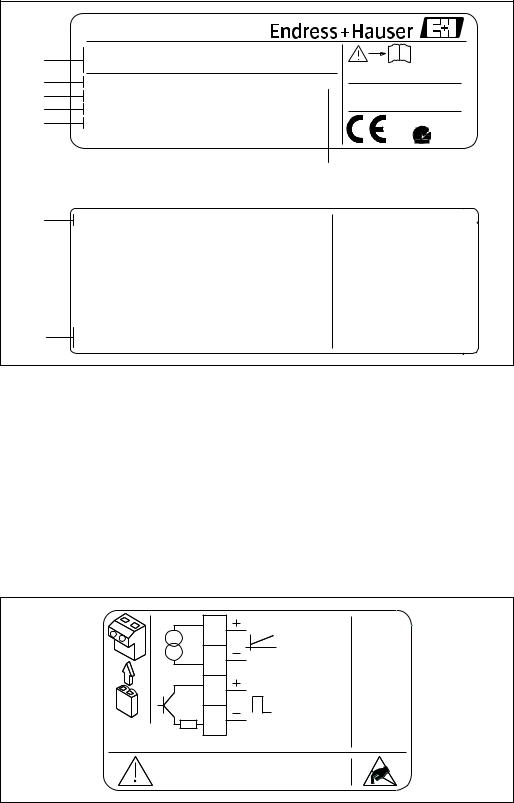
2.1.1Nameplate of the transmitter
|
Prosonic Flow 92 |
||||
|
Order Code: |
92FXX-XXXXXXXXXXX |
IP67 / NEMA/Type4X |
||
|
1 |
Ser.No.: |
12345678901 |
||
|
TAG No.: |
ABCDEFGHJKLMNPQRST |
|||
|
2 |
12-35VDC |
1.2W |
||
|
3 |
4…20mA, HART |
|||
|
i |
||||
|
-40°C<Ta<+60°C |
Ta+10°C/18°F |
|||
|
-40°F<Ta<+140°F |
||||
|
N12895 |
||||
|
4 |
5 |
|||
|
a0006111 |
Fig. 1: Nameplate specifications for the «Prosonic Flow» transmitter (example)
1Order code / serial number: See the specifications on the order confirmation for the meanings of the individual letters and digits
2Power supply: 12 to 35 V DC Power consumption: 1.2 W
3Available outputs
4Permitted ambient temperature range
5Degree of protection
|
Identification |
Proline Prosonic Flow 92F |
2.1.2Nameplate of the sensor
|
Prosonic Flow F |
||||
|
1 |
Order Code: |
92FXX-XXXXXXXXXXXXX |
i |
|
|
Ser.No.: |
XXXXXXXXXXX |
|||
|
2 |
K-factor: |
1.000/0000 |
5P-CAL |
|
|
3 |
DN100/4″ DIN/EN PN16 |
|||
|
4 |
Materials: |
CF3M / 1.4404 / F316L / F316 |
||
|
5 |
TM: |
-40°C(-40°F)…+150°C(+302°F) |
||
|
N12895 |
||||
|
8 |
||||
|
6 |
IP67 / NEMA/Type4X |
|||
|
7 |
-40°C <Tamb< +80°C |
4153 Reinach |
||
|
-40°F <Tamb< +176°F |
Switzerland |
|||
|
a0006107 |
Fig. 2: Nameplate specifications for the Prosonic Flow F sensor (example)
1Order code/serial number: See the specifications on the order confirmation for the meanings of the individual letters and digits
2Calibration factor with zero point
3Device nominal diameter/nominal pressure
4Measuring tube material
5Medium temperature range
6Degree of protection
7Permitted ambient temperature range
8Additional information (examples):
– 5P-CAL: with 5-point calibration
2.1.3Nameplate for connections
|
1 |
4..20mA |
||
|
max. 36VDC |
|||
|
2 |
|||
|
3 |
|||
|
max. 36VDC |
|||
|
4 |
max. 15mA |
||
|
Plug |
Optional |
||
|
Connector |
|||
|
ATEX II3G / Zone 2: |
|||
|
Do not separate when energized! |
|
Seeoperatingmanual. |
Betriebsanleitungbeachten. |
Observermanueld’Instruction. |
a0006110
Fig. 3: Nameplate specifications for Proline transmitter (example)
|
Proline Prosonic Flow 92F |
Identification |
2.2Certificates and approvals
The devices are designed in accordance with good engineering practice to meet state-of-the-art safety requirements, have been tested, and left the factory in a condition in which they are safe to operate.
The measuring device complies with the general safety requirements in accordance with EN 61010, the EMC requirements of IEC/EN 61326 and NAMUR recommendations NE 21 and NE 43. The measuring system described in these Operating Instructions thus complies with the statutory requirements of the EC Directives. Endress+Hauser confirms successful testing of the device by affixing to it the CE mark.
The measuring system complies with the EMC requirements of the Australian Communications and Media Authority (ACMA).
!Note!A detailed list of all the certificates and approvals is provided in the technical data on Page 66.
2.3Registered trademarks
HART®
Registered trademark of the HART Communication Foundation, Austin, USA
HistoROM™ T-DAT ®, FieldCare ®, Fieldcheck®, FieldXpert™, Applicator®
Registered or registration-pending trademarks of Endress+Hauser Flowtec AG, Reinach, CH

|
Installation |
Proline Prosonic Flow 92F |
3 Installation
3.1Incoming acceptance, transport, storage
3.1.1Incoming acceptance
On receipt of the goods, check the following points:
•Check the packaging and the contents for damage.
•Check the shipment, make sure nothing is missing and that the scope of supply matches your order.
3.1.2Transport
Please note the following when unpacking or transporting to the measuring point:
•The devices must be transported in the container supplied.
•The covers or caps fitted to the process connections prevent mechanical damage to the sealing faces and the ingress of foreign matter to the measuring tube during transportation and storage. Consequently, do not remove these covers or caps until immediately before installation.
•Devices with nominal diameters > DN 40 (> 1½») may not be lifted at the transmitter housing or at the connection housing of the remote version when transporting. Use carrier slings when transporting and put the slings around both process connections. Avoid chains as these could damage the housing.
#Warning!Risk of injury if the measuring device slips. The center of gravity of the entire measuring device might be higher than the points around which the slings are slung.
Therefore, when transporting, make sure that the device does not unintentionally turn or slip.
a0005765
Fig. 4: Instructions for transporting sensors with a nominal diameter > DN 40 (> 1½»)
3.1.3Storage
Note the following points:
•Pack the measuring device in such a way as to protect it reliably against impact for storage (and transportation). The original packaging provides optimum protection.
•The permissible storage temperature is –40 to +80 °C (–40 °F to 176 °F), preferably +20 °C (68 °F).
•Do not remove the protective covers or caps on the process connections until you are ready to install the device.
•The measuring device must be protected against direct sunlight during storage in order to avoid unacceptably high surface temperatures.
![]()
|
Proline Prosonic Flow 92F |
Installation |
3.2Installation conditions
Note the following points:
•No special measures such as supports are necessary. External forces are absorbed by the construction of the instrument.
•The flowmeter flanges must be coplanar with connecting flanges and free from tension.
•The maximum permitted ambient temperatures (→ ä 63) and fluid temperatures (→ ä 63) must be observed.
•Pay particular attention to the notes on orientation and piping insulation on the following pages.
•The correct operation of the measuring system is not influenced by pipe vibrations.
3.2.1Dimensions
All the dimensions and lengths of the sensor and transmitter are provided in the separate documentation «Technical Information». → ä 67
3.2.2Mounting location
Accumulated gas bubbles in the measuring tube can result in measuring errors.
Avoid the following locations:
•Highest point of a pipeline. Risk of gas accumulating.
•Directly upstream of a free pipe outlet in a vertical pipeline.
a0006081
Fig. 5: Mounting location
The proposed configuration in the following diagram, however, permits installation in a vertical pipeline. Pipe restrictors or the use of an orifice plate with a smaller cross section than the nominal diameter prevent the sensor from running empty during measurement.
1
2
3
4
5
a0006082
Fig. 6: Installation in a vertical pipe (e.g. for batching applications)
1 = Supply tank , 2 = Sensor, 3 = Orifice plate, pipe restriction , 4 = Valve, 5 = Batching tank

|
Installation |
Proline Prosonic Flow 92F |
System pressure
No additional pressure loss results from installing the device. It is important to ensure that cavitation or degassing does not occur at fittings upstream from the measuring device as this can affect sound transmission in the fluid.
No special measures need to be taken for fluids which have properties similar to water under normal conditions.
In the case of liquids with a low boiling point (hydrocarbons, solvents, liquefied gases) or in suction lines, it is important to ensure that pressure does not drop below the vapor pressure and that the liquid does not start to boil. It is also important to ensure that the gases that occur naturally in many liquids do not outgas. Such effects can be prevented when system pressure is sufficiently high.
For this reason, preference should be given to the following mounting locations:
•Downstream from pumps (no danger of vacuum)
•At the lowest point in a vertical pipe
3.2.3Orientation
Make sure that the direction of the arrow on the nameplate of the sensor matches the direction of flow (direction in which the fluid flows through the pipe).
A  B C
B C  D
D
a0005971
Fig. 7: Orientations A, B and C recommended, orientation D only recommended under certain circumstances
3.2.4Heating
Some fluids require heat to be transfered at the sensor. Heating can be electric, e.g. with heated elements, or by hot water or steam.
«Caution!• Danger of electronics overheating!
Make sure that the adapter between the sensor and transmitter and the connection housing of the remote version always remain free of insulating material.
•When using electrical heat tracing whose heat is regulated using phase control or by pulse packs, it cannot be ruled out that the measured values are influenced by magnetic fields which may occur, (i.e. at values greater than those permitted by the EC standard (Sinus 30 A/m)). In such cases, the sensor must be magnetically shielded.

|
Proline Prosonic Flow 92F |
Installation |
3.2.5Thermal insulation
Some fluids require suitable measures to avoid loss of heat at the sensor. A wide range of materials can be used to provide the required thermal insulation.
a0005763-ae
Fig. 8: A maximum insulation thickness of 20 mm (0.8 inch) must be observed in the area of the electronics/neck.
If the device is installed horizontally (with transmitter head pointing upwards), an insulation thickness of min. 10 mm (0.4″) is recommended to reduce convection. The maximum insulation thickness of 20 mm (0.8″) must not be exceeded.
3.2.6Inlet and outlet run
If possible, install the sensor well clear of fittings such as valves, T-pieces, elbows, etc. As a minimum, the inlet and outlet runs shown below must be observed to achieve the specified accuracy of the device. The longest inlet run shown must be observed if two or more flow disturbances are present.
|
5 × DN |
3 × DN |
15 × DN |
3 × DN |
||
|
1 |
A |
B |
2 |
A |
B |
|
5 × DN |
3 × DN |
4 |
10 × DN |
3 × DN |
|
|
A |
B |
A |
B |
||
|
3 |
|||||
|
A0006267 |
Fig. 9: Minimum inlet and outlet runs with various flow obstructions (values given for 3 and 4 path versions)
A = Inlet run, B = Outlet run, 1 = 90° elbow or T-piece, 2 = Pump, 3 = 2 × 90° elbow, 3-dimensional, 4 = Control valve
3.2.7Limiting flow
Information on limiting flow is provided under «Measuring range» in the technical data section.

|
Installation |
Proline Prosonic Flow 92F |
3.3Installation instructions
3.3.1Mounting the sensor
•Prior to installing the measuring device in the piping, remove all traces of transport packaging and any protective covers from the sensor.
•Make sure that the internal diameters of seals are the same as, or greater than, those of the measuring device and piping. If seals with a smaller internal diameter are used, this affects the flow and results in inaccurate measurement.
•Ensure that the arrow on the measuring tube matches the direction of flow in the piping.
•For Carbon steel option remove transport protection coating using mineral spirit (optional).
3.3.2Turning the transmitter housing
1.Loosen the safety screw.
2.Turn the transmitter housing to the desired position (max. 180° in each direction to the stop).
! Note!
There are recesses in the rotating groove at 90° stages (only compact version). These help you align the transmitter easier.
3.Retighten the securing screw.
180°
180°
a0005766
Fig. 10: Turning the transmitter housing
3.3.3Turning the local display
1.Unscrew the cover of the electronics compartment from the transmitter housing.
2.Remove the display module from the transmitter retainer rails.
3.Turn the display to the desired position (max. 4 x 45° in each direction) and reset it onto the retaining rails.
4.Screw the cover of the electronics compartment firmly back onto the transmitter housing.

|
Proline Prosonic Flow 92F |
Installation |
3.3.4Mounting the remote version
The transmitter can be mounted in the following ways:
•Wall mounting
•Pipe mounting (with separate mounting kit, accessories) → ä 45
«Caution!When mounting on a pipe, the ambient temperature range may not be exceeded. → ä 63
The transmitter and the sensor must be mounted separate in the following circumstances:
•Poor accessibility
•Lack of space
•Extreme ambient temperatures
Mount the transmitter as illustrated in the diagram.
|
232 |
(9.13) |
227 |
(8.94) |
|
|
*226 |
(*8.90) |
*221 |
(*8.70) |
|
ANSCHLUSSKLEMMEN |
— |
FIELD TERMINALS |
||
|
ANSCHLUSSKLEMMEN |
— |
FIELD TERMINALS |
mm (inch)
a0005947-ae
Fig. 11: Mounting the transmitter (remote version)
ADirect wall mounting
BPipe mounting
* Dimensions for version without local display
3.4Post-installation check
Perform the following checks after installing the measuring device:
|
Device condition and specifications |
Notes |
|
Is the device damaged (visual inspection)? |
— |
|
Do the process temperature/pressure, ambient temperature, measuring range etc. correspond to the |
→ ä 5 |
|
specifications of the device? |
|
|
Installation |
Notes |
|
Does the arrow on the sensor or sensor neck match the direction of flow through the pipe? |
— |
|
Are the measuring point number and labeling correct (visual inspection)? |
– |
|
Process environment / process conditions |
Notes |
|
Is the measuring device protected against direct sunlight? |
-→ ä 63 |
|
Wiring |
Proline Prosonic Flow 92F |
4 Wiring
4.1Connecting the remote version
4.1.1 Connecting cable for sensor/transmitter
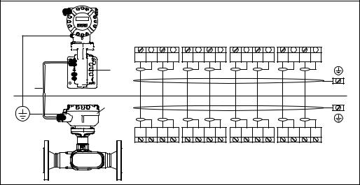
!Note!• The remote version must be grounded. In doing so, the sensor and transmitter must be connected
to the same potential matching (see Fig. 12, d).
•You may only connect the sensor to the transmitter with the same serial number (see nameplate). Communication errors can occur if this is not observed when connecting the devices.
Procedure
1.Remove the covers of the connection compartments (a/b).
2.Feed the connecting cable (c) through the appropriate cable entries.
3.Wire the sensor and transmitter in accordance with the electrical connection diagram: see Fig. 12 or the wiring diagram in the cover of the connection compartment.
4.Connect the appropriate cable shield (e/f).
5.Firmly tighten the glands of the cable entries.
6.Screw the covers of the connection compartments (a/b) back on.
|
1 |
GROUND |
2 |
GROUND |
3 |
GROUND |
4 |
GROUND |
5 |
GROUND |
6 |
GROUND |
7 |
GROUND |
8 |
GROUND |
|
|
1 G 2 G 3 G 4 G 5 G 6 G 7 G 8 G |
||||||||||||||||
|
a |
||||||||||||||||
|
e |
||||||||||||||||
|
c |
1 |
2 |
3 |
4 |
5 |
6 |
7 |
8 |
||||||||
|
d |
b |
f |
||||||||||||||
|
1 G 2 G 3 G 4 G 5 G 6 G 7 G 8 G |
||||||||||||||||
|
1 |
GROUND |
2 |
GROUND |
3 |
GROUND |
4 |
GROUND |
5 |
GROUND |
6 |
GROUND |
7 |
GROUND |
8 |
GROUND |
|
|
a0005764 |
Fig. 12: Connecting the remote version
aCover of the connection compartment (transmitter)
bCover of the connection compartment (sensor)
cConnecting cable (signal cable)
dIdentical potential matching for sensor and transmitter
eConnect the shielding to the ground terminal in the transmitter
fConnect the shielding to the ground terminal in the connection
housing and keep it as short as possible housing
4.1.2Cable specification for connecting cable
Only use the cables supplied by Endress+Hauser and pre-terminated at the factory. The cables are available with a fixed length of 10 m (30 feet) and 30 m (90 feet) and optionally available with variable lengths ranging from 1 m (3 feet) to max. 50 m (150 feet). The cable sheathing is made of PVC.
|
Proline Prosonic Flow 92F |
Wiring |
4.2Connecting the measuring unit
4.2.1 Connecting the transmitter
#Warning!When connecting Ex-certified devices, see the notes and diagrams in the Ex-specific supplement to these Operating Instructions. Please do not hesitate to contact your Endress+Hauser representative if you have any questions.
!Note!• Observe national regulations governing the installation of electrical equipment.
•The remote version must be grounded. In doing so, the sensor and transmitter must be connected to the same potential matching.
•When connecting the transmitter, use a connecting cable with a continuous service temperature range between –40 °C (–40 °F) and the permitted max. ambient temperature plus 10 °C (plus 18 °F)
Connecting the transmitter, non-Ex/Ex-i version (→ å 13)
1.Unscrew the cover (a) of the electronics compartment from the transmitter housing.
2.Remove the display module (b) from the retaining rails (c) and refit onto the right retaining rail with the left side of the display (this secures the display module).
3.Loosen screw (d) of the cover of the connection compartment and fold the cover down.
4.Push the cable for the power supply current output through the cable gland (e).
Optional: push the cable for the pulse output/frequency output through the cable gland (f).
5.Pull the terminal connector (g) out of the transmitter housing and connect the cable for the power supply/current output. (→ Fig. 14, A)
Optional: pull terminal connector (h) out of the transmitter housing and connect the cable for the pulse output/frequency output. (→ Fig. 14, B)
! Note!
The terminal connectors (g / h) are pluggable, i.e. they can be plugged out of the transmitter housing to connect the cables.
6.Plug the terminal connectors (g / h) into the transmitter housing.
! Note!
The connectors are coded so you cannot mix them up.
7.Only remote version:
secure the ground cable to the ground terminal (→ Fig. 14, C).
8.Tighten the cable glands (e / f) (see alsoPage 21).
9.Fold up the cover of the connection compartment and tighten the screws (d).
10.Remove the display module (b) and fit on the retaining rails (c).
11.Screw the cover of the electronics compartment (a) onto the transmitter housing.

|
Wiring |
Proline Prosonic Flow 92F |
|
d |
h |
g |
e |
|
|
c |
f |
|||
|
a |
d |
|||
|
b |
a0001895
Fig. 13: Connecting the transmitter, non-Ex/Ex i version
aCover of electronics compartment
bDisplay module
cRetaining rail for display module
dConnection compartment cover
eCable gland for power supply/current output cable
fCable gland for pulse output/frequency output cable (optional)
gTerminal connector for power supply/current output
hTerminal connector for pulse output/frequency output (optional)
Connecting the transmitter, Ex-d → å 14
1.Open the clamp (a) securing the cover of the connection compartment.
2.Unscrew the cover (b) of the connection compartment from the transmitter housing.
3.Push the cable for the power supply/current output through the cable gland (c).
Optional: push the cable for the pulse output/frequency output through the cable gland (d).
4.Pull the terminal connector (e) out of the transmitter housing and connect the cable for the power supply/current output. (→ Fig. 14, A)
Optional: pull terminal connector (f) out of the transmitter housing and connect the cable for the pulse output/frequency output. (→ Fig. 14, B)
! Note!
The terminal connectors (e/f) are pluggable, i.e. they can be plugged out of the transmitter housing to connect the cables.
5.Plug the terminal connectors (e / f) into the transmitter housing.
! Note!
The connectors are coded so you cannot mix them up.
6.Only remote version:
secure the ground cable to the ground terminal (→ Fig. 14, C).
7.Tighten the cable glands (c / d) (see alsoPage 21).
8.Secure the ground cable to the ground terminal (only remote version)
9.Screw the cover (b) of the connection compartment onto the transmitter housing.
10.Tighten the clamp (a) securing the cover of the connection compartment.

|
Proline Prosonic Flow 92F |
Wiring |
d
c
f
e
a
b
a0001896
Fig. 14: Connecting the transmitter, Ex d version
aClamp securing cover of connection compartment
bCover of connection compartment
cCable gland for power supply/current output cable
dCable gland for pulse output/frequency output cable (optional)
eTerminal connector for power supply/current output
fTerminal connector for pulse output/frequency output (optional)
Wiring diagram
C
A0014635
Fig. 15: Assignment of terminals
APower supply/current output
BOptional pulse output/status output
CGround terminal (only relevant for remote version)
4.2.2Terminal assignment
|
Terminal No. (inputs/outputs) |
|||
|
Order version |
1 – 2 |
3 – 4 |
|
|
92***-***********W |
HART current output |
– |
|
|
92***-***********A |
HART current output |
Pulse/status output/ |
|
|
frequency output |
|||
HART current output
Galvanically isolated, 4 to 20 mA with HART
Pulse/status output
Open collector, passive, galvanically isolated, Umax = 30 V, with 15 mA current limiting, Ri = 500 Ω, can be configured as pulse output or status output

|
Wiring |
Proline Prosonic Flow 92F |
4.2.3HART connection
Users have the following connection options at their disposal:
•Direct connection to transmitter by means of terminals 1 (+) / 2 (−)
•Connection by means of the 4 to 20 mA circuit
!Note!• The measuring circuit’s minimum load must be at least 250 Ω .
•After commissioning, make the following setting:
Switch HART write protection on or off (see Page 38)→ Page 37
•For connecting, please refer also to the documentation issued by the HART Communication Foundation, in particular HCF LIT 20: «HART, a technical summary».
Connecting the HART handheld terminal
For the connection, also refer to the documentation issued by the HART Communication
Foundation, and in particular HCF LIT 20: «HART, a technical summary».
|
9 |
6 |
|
|
1 |
2 |
3 |
|
4 |
5 |
6 |
|
7 |
8 |
9 |
|
. |
0 |
— |
|
375 |
FIELD COMMUNICATOR
250
A0014632
Fig. 16: Electrical connection to the HART operating terminal
1HART operating terminal
2Power supply
3Shielding
4Additional switching units or PLC with passive input
Connecting a PC with operating software
A HART modem (e.g. «Commubox FXA195») is required for connecting a PC with operating software (e.g. «FieldCare»).
For the connection, also refer to the documentation issued by the HART Communication Foundation, and in particular HCF LIT 20: «HART, a technical summary».
A0014633
Fig. 17: Electrical connection of a PC with operating software
1PC with operating software
2Power supply
3Shielding
4Additional switching units or PLC with passive input
5HART modem e.g. Commubox FXA195
![]()
|
Proline Prosonic Flow 92F |
Wiring |
4.3Degree of protection
The devices fulfill all the requirements for IP 67 (optional IP 68) degree of protection. Compliance with the following points is mandatory following installation in the field or servicing in order to ensure that IP 67 protection is maintained:
•The housing seals must be clean and undamaged when inserted into their grooves. The seals must be dried, cleaned or replaced if necessary.
•All housing screws and screw caps must be firmly tightened.
•The cables used for connection must be of the specified outside diameter.
•Firmly tighten the cable entries.
•The cables must loop down before they enter the cable entries («water trap»).
This arrangement prevents moisture penetrating the entry. Always install the measuring device in such a way that the cable entries do not point up.
•Replace all unused cable entries with dummy plugs.
•Do not remove the grommet from the cable entry.
a0001914
Fig. 18: Installation instructions for cable entries
«Caution!The cable glands of the sensor housing must not be released as the degree of protection guaranteed by Endress+Hauser would no longer apply.
!Note!The Prosonic Flow 92F can be supplied with IP 68 rating (permanent immersion in water to a depth ot 3 meters /10 ft). In this case the transmitter must be installed remote from the sensor.
|
Wiring |
Proline Prosonic Flow 92F |
4.4Post-connection check
Perform the following checks after completing electrical installation of the measuring device:
|
Device condition and specifications |
Notes |
|
Are cables or the device damaged (visual inspection)? |
− |
|
Electrical connection |
Notes |
|
Does the supply voltage match the specifications on the nameplate? |
− |
|
• Non-Ex: 12 to 35 V DC (with HART: 18 to 35 V DC) |
|
|
• Ex i and Ex n: 12 to 30 V DC (with HART 18 to 30 V DC) |
|
|
• Ex d: 15 to 35 V DC (with HART 21 to 35 V DC) |
|
|
Do the cables used comply with the specifications? |
→ ä 16, → ä 62 |
|
Do the cables have adequate strain relief? |
− |
|
Are the cables for power supply/current output, frequency output (optional) and |
→ ä 17 |
|
grounding connected correctly? |
|
|
Remote version only: |
→ ä 16 |
|
Is the connecting cable between the sensor and transmitter connected correctly? |
|
|
Remote version only: |
→ ä 16 |
|
Are the sensor and transmitter connected to the same potential matching? |
|
|
Are all screw terminals firmly tightened? |
− |
|
Are all the cable entries installed, tightened and sealed? |
→ ä 21 |
|
Cable run with «water trap»? |
|
|
Are all the housing covers installed and tightened? |
− |

|
Proline Prosonic Flow 92F |
Operation |
5 Operation
5.1Display and operating elements
The local display enables you to read important parameters directly at the measuring point and configure the device using the «Quick Setup» or the function matrix.
The display consists of two lines; this is where measured values and/or status variables (e.g. bar graph) are displayed.
By means of local operation, you can change the assignment of the display lines to different variables to suit your needs and preferences. See Device Functions in the Appendix → ä 68
+48.25 xx/yy
1
+3702.6 x
Esc
— + E
a0001141
Fig. 19: Display and operating elements
1Liquid crystal display
The two-line liquid-crystal display shows measured values and diagnosis messages.
–Top line: shows main measured values, e.g. volume flow in [dm/h] or in [%].
–Bottom line: shows additional measured variables and status variables, e.g. totalizer reading in [dm], bar graph, tag name.
–During commissioning or in the event of a fault in normal measuring operation, a diagnosis message flashes on the screen.
The first line shows the diagnosis code beginning with the letters F, C, S or M and a short text containing the diagnosis message appears on the second line.
2Plus/minus keys
–Enter numerical values, select parameters
–Select different function groups within the function matrix
Press the +/- keys simultaneously to trigger the following functions:
–Exit the function matrix step by step → HOME position
–Press and hold down +/- keys for longer than 3 seconds → return directly to the HOME position
–Cancel data entry
3Enter key
–HOME position → enter the function matrix
–Save the numerical values you input or settings you changed

|
Operation |
Proline Prosonic Flow 92F |
5.2 Operation via the function matrix
!Note!• Please refer to the general notes → ä 25
• Function descriptions → see the «Description of Device Functions» manual
1. HOME position → F → enter the function matrix
2.Select a function group e.g. CURRENT OUTPUT
3.Select a function (e.g. TIME CONSTANT) Change parameter/enter numerical values:
P → select or enter enable code, parameters, numerical values F → save your entries
4.Exit the function matrix:
–Press and hold down the Esc key (X) for more than 3 seconds → HOME position
–Repeatedly press Esc key (X) → return step by step to HOME position
 Esc
Esc
— + E
|
p |
|||
|
Esc |
Esc |
> 3 s |
|
|
m E |
– + |
– + |
|
o |
||||
|
E |
E |
E |
E |
E |
|
Esc |
||||
|
– |
+ |
n +–
E
E
E
E
a0001142
Fig. 20: Selecting and configuring functions (function matrix)
|
Proline Prosonic Flow 92F |
Operation |
5.2.1General notes
The Quick Setup menu is adequate for commissioning with the necessary standard settings. Complex measuring operations on the other hand necessitate additional functions that you can configure as necessary and customize to suit your process conditions. The function matrix, therefore, comprises a multiplicity of additional functions which, for the sake of clarity, are arranged in a number of function groups.
Comply with the following instructions when configuring functions:
•You select functions as described already.
•You can switch off certain functions (OFF). If you do so, related functions in other function groups will no longer be displayed.
•Certain functions prompt you to confirm your data entries. Press P to select «SURE [ YES ]» and press F to confirm. This saves your setting or starts a function, as applicable.
•Return to the HOME position is automatic if no key is pressed for 5 minutes.
•Programming mode is automatically disabled if you do not press a key within 60 seconds following return to the HOME position.
!Note!A detailed description of all the functions required for commissioning is provided in Section 11.1 «Description of device functions».
!Note!• The transmitter continues to measure while data entry is in progress, i.e. the current measured
values are output via the signal outputs in the normal way.
• If the power supply fails, all preset and configured values remain safely stored in the EEPROM.
5.2.2Enabling the programming mode
The function matrix can be disabled. Disabling the function matrix rules out the possibility of inadvertent changes to device functions, numerical values or factory settings. A numerical code (factory setting = 92) has to be entered before settings can be changed.
If you use a code number of your choice, you exclude the possibility of unauthorized persons accessing data ( → see «Description of Device Functions» manual).
Comply with the following instructions when entering codes:
•If programming is disabled and the P operating elements are pressed in any function, a prompt for the code automatically appears on the display.
•If «0» is entered as the private code, programming is always enabled.
•Your Endress+Hauser service organization can be of assistance if you are locked out of the device.
«Caution!Changing certain parameters influences numerous functions of the entire measuring device, and may effect measuring accuracy!
There is no need to change these parameters under normal circumstances and consequently, they are protected by a special service code known only to the Endress+Hauser service organization. Please contact Endress+Hauser if you have any questions.
5.2.3Disabling the programming mode
Programming mode is disabled if you do not press an operating element within 60 seconds following automatic return to the HOME position.
You can also disable programming by entering any number (other than the private code) in the ACCESS CODE function.
|
Operation |
Proline Prosonic Flow 92F |
5.3Communication
In addition to via local operation, the measuring device can also be configured and measured values obtained by means of the HART protocol. Digital communication takes place using the 4–20 mA current output HART.
The HART protocol allows the transfer of measuring and device data between the HART master and the field devices for configuration and diagnostics purposes. HART masters, such as a handheld terminal or PC-based operating programs (such as FieldCare), require device description (DD) files. They are used to access all the information in a HART device. Such information is transferred solely via «commands». There are three different command classes:
There are three different command classes:
•Universal commands
All HART devices support and use universal commands. The following functionalities are linked to them:
–Recognizing HART devices
–Reading off digital measured values (volume flow, totalizer, etc.)
•Common practice commands:
Common practice commands offer functions which are supported and can be executed by many but not all field devices.
•Device-specific commands:
These commands allow access to device-specific functions which are not HART standard. Such commands access individual field device information, (among other things), such as empty-pipe/ full-pipe adjustment values, low flow cutoff settings etc.
!Note!The measuring device has all three command classes.
List of all «Universal Commands» and «Common Practice Commands»: → ä 30
|
Proline Prosonic Flow 92F |
Operation |
5.3.1Operating options
For the complete operation of the measuring device, including device-specific commands, there are device description (DD) files available to the user to provide the following operating aids and programs:
!Note!• The HART protocol requires the «4 to 20 mA HART» setting (individual options see device
function) in the CURRENT SPAN function (current output 1).
HART Field Communicator Field Xpert
Selecting device functions with a HART Communicator is a process involving a number of menu levels and a special HART function matrix.
The HART operating instructions in the carrying case of the HART handheld terminal contain more detailed information on the device.
Operating program «FieldCare»
FieldCare is Endress+Hauser’s FDT-based plant asset management tool and allows the configuration and diagnosis of intelligent field devices. By using status information, you also have a simple but effective tool for monitoring devices.
Operating program «SIMATIC PDM» (Siemens)
SIMATIC PDM is a standardized, manufacturer independent tool for the operation, configuration, maintenance and diagnosis of intelligent field devices.
Operating program «AMS» (Emerson Process Management)
AMS (Asset Management Solutions): program for operating and configuring devices.
|
Operation |
Proline Prosonic Flow 92F |
5.3.2Current device description files
The following table illustrates the suitable device description file for the operating tool in question and then indicates where these can be obtained.
HART protocol:
|
Valid for software: |
1.01.XX |
→ Function «Device software» |
|
|
Device data HART |
→ Function «Manufact ID» |
||
|
Manufacturer ID: |
11hex (ENDRESS+HAUSER) |
||
|
Device ID: |
61hex |
→ Function «Device ID» |
|
|
HART version data: |
Device Revision 6/ DD Revision 1 |
||
|
Software release: |
12.2010 |
||
|
Operating program: |
Sources for obtaining device descriptions: |
||
|
Handheld terminal Field Xpert |
• Use update function of handheld terminal |
||
|
FieldCare / DTM |
• www.endress.com → Download |
||
|
• CD-ROM (Endress+Hauser order number 56004088) |
|||
|
• DVD (Endress+Hauser order number 70100690) |
|||
|
AMS |
• www.endress.com → Download |
||
|
SIMATIC PDM |
• www.endress.com → Download |
||
|
Tester/simulator: |
Sources for obtaining device descriptions: |
||
|
Fieldcheck |
• Update by means of FieldCare via the Flow Device FXA193/291 DTM |
||
|
in the Fieldflash module |
|||
!Note!The «Fieldcheck» tester/simulator is used for testing flowmeters in the field. When used in conjunction with the «FieldCare» software package, test results can be imported into a database, printed out and used for official certification. Contact your Endress+Hauser representative for more information.
|
Proline Prosonic Flow 92F |
Operation |
5.3.3Device variables and process variables
Device variables:
The following device variables are available via the HART protocol:
|
ID (decimal) |
Device variable |
|
30 |
Volume flow |
|
40 |
Sound velocity |
|
43 |
Signal strength |
|
49 |
Flow velocity |
|
240 |
Totalizer 1 |
|
241 |
Totalizer 2 |
Process variables:
At the factory, the process variables are assigned to the following device variables:
•Primary process variable (PV) → volume flow
•Secondary process variable (SV) → totalizer
•Third process variable (TV) → sound velocity
•Fourth process variable (FV) → flow velocity
!Note!You can set or change the assignment of device variables to process variables using Command 51 → ä 33.
|
Operation |
Proline Prosonic Flow 92F |
5.3.4Universal/common practice HART commands
The following table contains all the universal commands supported by the device.
|
Command No. |
Command data |
Response data |
|||
|
HART command/access type |
(numeric data in decimal form) |
(numeric data in decimal form) |
|||
|
Universal commands |
|||||
|
0 |
Read the unique device identifier |
None |
The device identifier provides information on the device |
||
|
Access type = Read |
and manufacturer; it cannot be altered. |
||||
|
The response consists of a 12-byte device ID: |
|||||
|
– |
Byte 0: fixed value 254 |
||||
|
– |
Byte 1: manufacturer ID, 17 = E+H |
||||
|
– |
Byte 2: device type ID, e.g. 0x61 = Prosonic 92 |
||||
|
– |
Byte 3: number of preambles |
||||
|
– |
Byte 4: rev. no. universal commands |
||||
|
– |
Byte 5: rev. no. device-spec. Commands |
||||
|
– |
Byte 6: software revision |
||||
|
– |
Byte 7: hardware revision |
||||
|
– |
Byte 8: additional device information |
||||
|
– |
Byte 9-11: device identification |
||||
|
1 |
Read the primary process variable |
None |
– |
Byte 0: HART unit ID of the primary process variable |
|
|
Access type = Read |
– |
Byte 1-4: primary process variable |
|||
|
Factory setting: |
|||||
|
Primary process variable = volume flow |
|||||
|
! |
Note! |
||||
|
• |
You can set the assignment of device variables to |
||||
|
process variables using Command 51. |
|||||
|
• |
Manufacturer-specific units are represented using the |
||||
|
HART unit ID «240». |
|||||
|
2 |
Read the primary process variable as |
None |
– |
Byte 0-3: current current of the primary process |
|
|
current in mA and percentage of the |
variable in mA |
||||
|
set measuring range |
– |
Byte 4-7: percentage of the set measuring range |
|||
|
Access type = Read |
Factory setting: |
||||
|
Primary process variable = volume flow |
|||||
|
! |
Note! |
||||
|
You can set the assignment of device variables to process |
|||||
|
variables using Command 51. |
|||||
|
3 |
Read the primary process variable as |
None |
24 bytes are sent as a response: |
||
|
current in mA and four (preset |
– |
Byte 0-3: current of the primary process variable in |
|||
|
using command 51) dynamic |
mA |
||||
|
process variables |
– |
Byte 4: HART unit ID of the primary process variable |
|||
|
Access type = Read |
– |
Byte 5-8: primary process variable |
|||
|
– |
Byte 9: HART unit ID of the secondary process |
||||
|
variable |
|||||
|
– |
Byte 10-13: secondary process variable |
||||
|
– |
Byte 14: HART unit ID of the third process variable |
||||
|
– |
Byte 15-18: third process variable |
||||
|
– |
Byte 19: HART unit ID of the fourth process variable |
||||
|
– |
Byte 20-23: fourth process variable |
||||
|
Factory setting: |
|||||
|
• |
Primary process variable = volume flow |
||||
|
• |
Secondary process variable = totalizer 1 |
||||
|
• |
Third process variable = sound velocity |
||||
|
• |
Fourth process variable = flow velocity |
||||
|
! |
Note! |
||||
|
• |
You can set the assignment of device variables to |
||||
|
process variables using Command 51. |
|||||
|
• |
Manufacturer-specific units are represented using the |
||||
|
HART unit ID «240». |
|||||
|
Proline Prosonic Flow 92F |
Operation |
|||||
|
Command No. |
Command data |
Response data |
||||
|
HART command/access type |
(numeric data in decimal form) |
(numeric data in decimal form) |
||||
|
6 |
Set HART short-form address |
Byte 0: desired address (0 to 15) |
Byte 0: active address |
|||
|
Access type = Write |
Factory setting: |
|||||
|
0 |
||||||
|
! |
Note! |
|||||
|
With an address >0 (multidrop mode), the current |
||||||
|
output of the primary process variable is fixed to 4 mA. |
||||||
|
11 |
Read the unique device identifier |
Byte 0-5: TAG |
The device identifier provides information on the device |
|||
|
using the TAG |
and manufacturer; it cannot be altered. |
|||||
|
Access type = Read |
The response consists of a 12-byte device ID if the given |
|||||
|
TAG matches the one saved in the device: |
||||||
|
– |
Byte 0: fixed value 254 |
|||||
|
– |
Byte 1: manufacturer ID, 17 = E+H |
|||||
|
– |
Byte 2: device type ID, 0x61 = Prosonic 92 |
|||||
|
– |
Byte 3: number of preambles |
|||||
|
– |
Byte 4: rev. no. universal commands |
|||||
|
– |
Byte 5: rev. no. device-spec. Commands |
|||||
|
– |
Byte 6: software revision |
|||||
|
– |
Byte 7: hardware revision |
|||||
|
– |
Byte 8: additional device information |
|||||
|
– |
Byte 9-11: device identification |
|||||
|
12 |
Read user message |
None |
Byte 0-24: user message |
|||
|
Access type = Read |
! |
Note! |
||||
|
You can write the user message using command 17. |
||||||
|
13 |
Read TAG, TAG description and |
None |
– |
Byte 0-5: TAG |
||
|
date |
– |
Byte 6-17: TAG description |
||||
|
Access type = Read |
– |
Byte 18-20: date |
||||
|
! |
Note! |
|||||
|
You can write the TAG, TAG description and date using |
||||||
|
command 18. |
||||||
|
14 |
Read sensor information on the |
None |
– |
Byte 0-2: serial number of the sensor |
||
|
primary process variable |
– |
Byte 3: HART unit ID of the sensor limits and |
||||
|
measuring range of the primary process variable |
||||||
|
– |
Byte 4-7: upper sensor limit |
|||||
|
– |
Byte 8-11: lower sensor limit |
|||||
|
– |
Byte 12-15: minimum span |
|||||
|
! |
Note! |
|||||
|
• |
The data relate to the primary process variable (= |
|||||
|
volume flow). |
||||||
|
• |
Manufacturer-specific units are represented using the |
|||||
|
HART unit ID «240». |
||||||
|
15 |
Read output information of the |
None |
– |
Byte 0: alarm selection ID |
||
|
primary process variable |
– |
Byte 1: ID for transfer function |
||||
|
Access type = Read |
– |
Byte 2: HART unit ID for the set measuring range of |
||||
|
the primary process variable |
||||||
|
– |
Byte 3-6: end of measuring range, value for 20 mA |
|||||
|
– |
Byte 7-10: start of measuring range, value for 4 mA |
|||||
|
– |
Byte 11-14: attenuation constant in [s] |
|||||
|
– |
Byte 15: ID for write protection |
|||||
|
– |
Byte 16: ID for OEM dealer, 17 = E+H |
|||||
|
Factory setting: |
||||||
|
Primary process variable = volume flow |
||||||
|
! |
Note! |
|||||
|
• |
You can set the assignment of device variables to |
|||||
|
process variables using Command 51. |
||||||
|
• |
Manufacturer-specific units are represented using the |
|||||
|
HART unit ID «240». |
||||||
|
16 |
Read the device production number |
None |
Byte 0-2: production number |
|||
|
Access type = Read |
||||||
|
Operation |
Proline Prosonic Flow 92F |
||||
|
Command No. |
Command data |
Response data |
|||
|
HART command/access type |
(numeric data in decimal form) |
(numeric data in decimal form) |
|||
|
17 |
Write user message |
You can save any 32-character long text in the device |
Displays the current user message in the device: |
||
|
Access = Write |
with this parameter: |
Byte 0-23: current user message in the device |
|||
|
Byte 0-23: desired user message |
|||||
|
18 |
Write TAG, TAG description and |
You can save an 8-character TAG, a 16-character TAG |
Displays the current information in the device: |
||
|
date |
description and a date with this parameter: |
– |
Byte 0-5: TAG |
||
|
Access = Write |
– |
Byte 0-5: TAG |
– |
Byte 6-17: TAG description |
|
|
– |
Byte 6-17: TAG description |
– |
Byte 18-20: date |
||
|
– |
Byte 18-20: date |
||||
The following table contains all the common practice commands supported by the device.
|
Command No. |
Command data |
Response data |
|||||
|
HART command/access type |
(numeric data in decimal form) |
(numeric data in decimal form) |
|||||
|
Common practice commands |
|||||||
|
33 |
Read measured values |
Byte 0: device variable ID for channel 0 |
Byte 0: device variable ID for channel 0 |
||||
|
Byte 1: device variable ID for channel 1 |
Byte 1: unit ID for channel 0 |
||||||
|
Byte 2: device variable ID for channel 2 |
Byte 2-5: value of channel 0 |
||||||
|
Byte 3: device variable ID for channel 3 |
Byte 6: device variable ID for channel 1 |
||||||
|
Byte 7: unit ID for channel 1 |
|||||||
|
Byte 8-11: value of channel 1 |
|||||||
|
Byte 12: device variable ID for channel 2 |
|||||||
|
Byte 13: unit ID for channel 2 |
|||||||
|
Byte 14-17: value of channel 2 |
|||||||
|
Byte 18: device variable ID for channel 3 |
|||||||
|
Byte 19: unit ID for channel 3 |
|||||||
|
Byte 20-23: value of channel 3 |
|||||||
|
34 |
Write attenuation constant for |
Byte 0-3: attenuation constant of the primary process |
Displays the current attenuation constant in the device: |
||||
|
primary process variable |
variable in seconds |
Byte 0-3: attenuation constant in seconds |
|||||
|
Access = Write |
Factory setting: |
||||||
|
Primary process variable = flow |
|||||||
|
35 |
Write measuring range of the |
Write the desired measuring range: |
The measuring range currently set is shown as the |
||||
|
primary process variable |
– |
Byte 0: HART unit ID for the primary process variable |
response: |
||||
|
Access = Write |
– Byte 1-4: end of measuring range, value for 20 mA |
– Byte 0: HART unit ID for the set measuring range of |
|||||
|
– |
Byte 5-8: start of measuring range, value for 4 mA |
the primary process variable |
|||||
|
Factory setting: |
– |
Byte 1-4: end of measuring range, value for 20 mA |
|||||
|
– |
Byte 5-8: start of measuring range, value for 4 mA |
||||||
|
Primary process variable = flow |
|||||||
|
(is always at «0») |
|||||||
|
! |
Note! |
||||||
|
! |
Note! |
||||||
|
• |
You can set the assignment of device variables to |
||||||
|
process variables using Command 51. |
Manufacturer-specific units are represented using the |
||||||
|
HART unit ID «240». |
|||||||
|
• |
If the HART unit ID does not suit the process variable, |
||||||
|
the device will continue with the last valid unit. |
|||||||
|
36 |
Set full scale value |
None |
None |
||||
|
37 |
Set lower range value |
None |
None |
||||
|
38 |
Device status reset «configuration |
None |
None |
||||
|
changed» |
|||||||
|
Access = Write |
|||||||
|
40 |
Simulate output current of the |
Simulation of the desired output current of the primary |
The current output current of the primary process |
||||
|
primary process variable |
process variable. |
variable is displayed as a response: |
|||||
|
Access = Write |
An entry value of 0 exits the simulation mode: |
Byte 0-3: output current in mA |
|||||
|
Byte 0-3: output current in mA |
|||||||
|
Factory setting: |
|||||||
|
Primary process variable = flow |
|||||||
|
! |
Note! |
||||||
|
You can set the assignment of device variables to process |
|||||||
|
variables with Command 51. |
|||||||
|
42 |
Perform device reset |
None |
None |
||||
|
Access = Write |
|||||||
|
Proline Prosonic Flow 92F |
Operation |
||||||
|
Command No. |
Command data |
Response data |
|||||
|
HART command/access type |
(numeric data in decimal form) |
(numeric data in decimal form) |
|||||
|
44 |
Write unit of the primary process |
Specify the unit of the primary process variable. |
The current unit code of the primary process variable is |
||||
|
variable |
Only units which are suitable for the process variable are |
displayed as a response: |
|||||
|
Access = Write |
Byte 0: HART unit ID |
||||||
|
accepted by the device: |
|||||||
|
! |
|||||||
|
Byte 0: HART unit ID |
Note! |
||||||
|
Factory setting: |
Manufacturer-specific units are represented using the |
||||||
|
HART unit ID «240». |
|||||||
|
Primary process variable = flow |
|||||||
|
! |
Note! |
||||||
|
• |
If the written HART unit ID does not suit the process |
||||||
|
variable, the device will continue with the last valid |
|||||||
|
unit. |
|||||||
|
• |
If you change the unit of the primary process variable, |
||||||
|
this does not affect the system units. |
|||||||
|
45 |
Zero point adjustment at the |
Byte 0-3: measured current in mA |
The current output current of the primary process |
||||
|
current output |
variable is displayed as a response: |
||||||
|
Byte 0-3: output current in mA |
|||||||
|
46 |
Span adjustment (adjustment of the |
Byte 0-3: measured current in mA |
The current output current of the primary process |
||||
|
measuring range) at the current |
variable is displayed as a response: |
||||||
|
output |
Byte 0-3: output current in mA |
||||||
|
48 |
Read extended device status |
None |
The current device status is displayed in extended form |
||||
|
Access = Read |
as the response: |
||||||
|
Coding: see Table → Page 35 |
|||||||
|
50 |
Read assignment of the device |
None |
Display of the current variable assignment of the process |
||||
|
variables to the four process |
variables: |
||||||
|
variables |
– |
Byte 0: device variable ID to the primary process |
|||||
|
Access = Read |
variable |
||||||
|
– |
Byte 1: device variable ID to the secondary process |
||||||
|
variable |
|||||||
|
– |
Byte 2: device variable ID to the third process variable |
||||||
|
– |
Byte 3: device variable ID to the fourth process |
||||||
|
variable |
|||||||
|
Factory setting: |
|||||||
|
• |
Primary process variable: ID 1 for flow |
||||||
|
• |
Second process variable: code 250 for totalizer 1 |
||||||
|
• |
Third process variable: code 7 for sound velocity |
||||||
|
• |
Fourth process variable: code 9 for flow velocity |
||||||
|
! |
Note! |
||||||
|
You can set the assignment of device variables to process |
|||||||
|
variables with Command 51. |
|||||||
|
51 |
Write assignments of the device |
Specify device variables for the four process variables: |
The variable assignment of the process variables is |
||||
|
variables to the four process |
– Byte 0: device variable ID to the primary process |
displayed as a response: |
|||||
|
variables |
variable |
– |
Byte 0: device variable ID to the primary process |
||||
|
Access = Write |
– Byte 1: device variable ID to the secondary process |
variable |
|||||
|
variable |
– |
Byte 1: device variable ID to the secondary process |
|||||
|
– Byte 2: device variable ID to the third process variable |
variable |
||||||
|
– Byte 3: device variable ID to the fourth process |
– Byte 2: device variable ID to the third process variable |
||||||
|
variable |
– |
Byte 3: device variable ID to the fourth process |
|||||
|
ID of the supported device variables: |
variable |
||||||
|
See data → ä 29 |
|||||||
|
Factory setting: |
|||||||
|
• |
Primary process variable = flow |
||||||
|
• |
Secondary process variable = totalizer 1 |
||||||
|
• |
Third process variable = sound velocity |
||||||
|
• |
Fourth process variable = flow velocity |
||||||
|
Operation |
Proline Prosonic Flow 92F |
|||||
|
Command No. |
Command data |
Response data |
||||
|
HART command/access type |
(numeric data in decimal form) |
(numeric data in decimal form) |
||||
|
53 |
Write device variable unit |
This command sets the unit of the given device variables. |
The current unit of the device variables is displayed in |
|||
|
Access = Write |
Only those units which suit the device variable are |
the device as a response: |
||||
|
transferred: |
– Byte 0: device variable ID |
|||||
|
– Byte 0: device variable ID |
– Byte 1: HART unit ID |
|||||
|
– |
Byte 1: HART unit ID |
! |
Note! |
|||
|
ID of the supported device variables: |
||||||
|
Manufacturer-specific units are represented using the |
||||||
|
See data → ä 29 |
HART unit ID «240». |
|||||
|
! |
Note! |
|||||
|
• |
If the written unit does not suit the device variable, |
|||||
|
the device will continue with the last valid unit. |
||||||
|
• |
If you change the unit of the device variable, this does |
|||||
|
not affect the system units. |
||||||
|
54 |
Read information on the device |
Byte 0: device variable ID |
Byte 0: device variable ID |
|||
|
variables |
Byte 1-3: serial number of the associated sensor |
|||||
|
Access = Read |
Byte 4: unit ID for device variable |
|||||
|
Byte 5-8: upper limit of the device variable |
||||||
|
Byte 9-12: lower limit of the device variable |
||||||
|
Byte 13-16: time constant of device variable (unit: s) |
||||||
|
59 |
Specify number of preambles in |
This parameter specifies the number of preambles which |
As a response, the current number of the preambles is |
|||
|
message responses |
are inserted in the message responses: |
displayed in the response message: |
||||
|
Access = Write |
Byte 0: number of preambles (2 to 20) |
Byte 0: number of preambles |
||||
|
Proline Prosonic Flow 92F |
Operation |
5.3.5Device status/diagnosis code messages
You can read the extended device status, in this case, current diagnosis code messages, via command «48». The command delivers bit-encoded information (see table below).
!Note!Detailed information on the device status messages and diagnosis code messages, and how they are rectified, can be found in the Troubleshooting section on → ä 47
|
Byte |
Bit |
Diagnosis |
Brief description of the message → ä 48 |
|
|
code |
||||
|
0 |
0 |
284 |
Software update |
Loading new amplifier software version. No other commands |
|
possible at this point. |
||||
|
1 |
481 |
Diagnostic active |
||
|
2 |
281 |
Initialization |
Initialization in progress. All outputs are set to 0. |
|
|
3 |
411 |
Upload/download |
Uploading and downloading device files. No other commands |
|
|
possible at this point. |
||||
|
4 |
1 |
Device fault |
Serious device error |
|
|
5 |
282-1 |
Data storage |
Error when accessing the amplifier EEPROM |
|
|
6 |
282-2 |
Data storage |
Error when accessing the I/O module EEPROM |
|
|
7 |
282-3 |
Data storage |
Error when accessing the T-DAT |
|
|
1 |
0 |
283-1 |
Checksum error |
Data in the amplifier EEPROM faulty |
|
1 |
283-2 |
Checksum error |
Data in the I/O module EEPROM faulty |
|
|
2 |
283-3 |
Checksum error |
Data in the T-DAT EEPROM faulty |
|
|
3 |
242 |
Incompatible SW |
The I/O board and the amplifier board are not compatible |
|
|
4 |
62-1 |
Sensor connection |
Connection (down) sensor K1 / transmitter interrupted |
|
|
5 |
62-2 |
Sensor connection |
Connection (up) sensor K1 / transmitter interrupted |
|
|
6 |
62-3 |
Sensor connection |
Connection (down) sensor K2 / transmitter interrupted |
|
|
7 |
62-5 |
Sensor connection |
Connection (up) sensor K2 / transmitter interrupted |
|
|
2 |
0 |
62-5 |
Sensor connection |
Connection (down) sensor K3 / transmitter interrupted |
|
1 |
62-6 |
Sensor connection |
Connection (up) sensor K3 / transmitter interrupted |
|
|
2 |
62-7 |
Sensor connection |
Connection (down) sensor K4 / transmitter interrupted |
|
|
3 |
62-8 |
Sensor connection |
Connection (up) sensor K4 / transmitter interrupted |
|
|
4 |
283-4 |
Checksum error |
Totalizer checksum error |
|
|
5 |
262 |
Module connection |
Internal communication error on the amplifier board |
|
|
6 |
823-1 |
Ambient temp. |
The lower medium temperature limit for the thermosensor was |
|
|
undershot |
||||
|
7 |
823-2 |
Ambient temp. |
The upper medium temperature limit for the thermosensor was |
|
|
overshot |
||||
|
3 |
0 |
881-1 |
Sensor signal |
Channel 1: signal strength of the sensor too low |
|
1 |
881-2 |
Sensor signal |
Channel 2: signal strength of the sensor too low |
|
|
2 |
881-3 |
Sensor signal |
Channel 3: signal strength of the sensor too low |
|
|
3 |
881-4 |
Sensor signal |
Channel 4: signal strength of the sensor too low |
|
|
4 |
431-1 |
Adjust |
Zero point adjustment faulty |
|
|
5 |
431-2 |
Adjust |
Channel 1: zero point adjustment faulty |
|
|
6 |
431-3 |
Adjust |
Channel 2: zero point adjustment faulty |
|
|
7 |
431-4 |
Adjust |
Channel 3: zero point adjustment faulty |
|
Operating Instructions
Proline Prosonic Flow 92F
HART
Ultrasonic Flow Measuring System
6
Esc
Esc
BA00121D/06/EN/13.10
71124139
Valid as of version V1.01.XX (device software)
|
Proline Prosonic Flow 92F |
Table of contents |
Table of contents
|
1 |
Safety instructions . . . . . . . . . . . . . . . . |
5 |
|
1.1 |
Designated use . . . . . . . . . . . . . . . . . . . . . . . . . . . . |
5 |
|
1.2 |
Installation, commissioning and operation . . . . . . . . |
5 |
|
1.3 |
Operational safety . . . . . . . . . . . . . . . . . . . . . . . . . . |
5 |
|
1.4 |
Return . . . . . . . . . . . . . . . . . . . . . . . . . . . . . . . . . . . |
6 |
|
1.5 |
Notes on safety conventions and icons . . . . . . . . . . . |
6 |
|
2 |
Identification . . . . . . . . . . . . . . . . . . . . |
7 |
|
2.1 |
Device designation . . . . . . . . . . . . . . . . . . . . . . . . . |
7 |
|
2.1.1 Nameplate of the transmitter . . . . . . . . . . . . |
7 |
|
|
2.1.2 Nameplate of the sensor . . . . . . . . . . . . . . . |
8 |
|
|
2.1.3 Nameplate for connections . . . . . . . . . . . . . |
8 |
|
|
2.2 |
Certificates and approvals . . . . . . . . . . . . . . . . . . . . |
9 |
|
2.3 |
Registered trademarks . . . . . . . . . . . . . . . . . . . . . . . |
9 |
|
3 |
Installation . . . . . . . . . . . . . . . . . . . . . |
10 |
|
|
3.1 |
Incoming acceptance, transport, storage . . . . . . . . . |
10 |
|
|
3.1.1 |
Incoming acceptance . . . . . . . . . . . . . . . . . |
10 |
|
|
3.1.2 |
Transport . . . . . . . . . . . . . . . . . . . . . . . . . |
10 |
|
|
3.1.3 |
Storage . . . . . . . . . . . . . . . . . . . . . . . . . . . |
10 |
|
|
3.2 |
Installation conditions . . . . . . . . . . . . . . . . . . . . . . |
11 |
|
|
3.2.1 |
Dimensions . . . . . . . . . . . . . . . . . . . . . . . . |
11 |
|
|
3.2.2 |
Mounting location . . . . . . . . . . . . . . . . . . . |
11 |
|
|
3.2.3 |
Orientation . . . . . . . . . . . . . . . . . . . . . . . . |
12 |
|
|
3.2.4 |
Heating . . . . . . . . . . . . . . . . . . . . . . . . . . . |
12 |
|
|
3.2.5 |
Thermal insulation . . . . . . . . . . . . . . . . . . |
13 |
|
|
3.2.6 Inlet and outlet run . . . . . . . . . . . . . . . . . . |
13 |
||
|
3.2.7 |
Limiting flow . . . . . . . . . . . . . . . . . . . . . . . |
13 |
|
|
3.3 |
Installation instructions . . . . . . . . . . . . . . . . . . . . . |
14 |
|
|
3.3.1 |
Mounting the sensor . . . . . . . . . . . . . . . . . |
14 |
|
|
3.3.2 Turning the transmitter housing . . . . . . . . |
14 |
||
|
3.3.3 Turning the local display . . . . . . . . . . . . . . |
14 |
||
|
3.3.4 Mounting the remote version . . . . . . . . . . |
15 |
||
|
3.4 |
Post-installation check . . . . . . . . . . . . . . . . . . . . . . |
15 |
|
4 |
Wiring . . . . . . . . . . . . . . . . . . . . . . . . |
16 |
|
4.1 Connecting the remote version . . . . . . . . . . . . . . . |
16 |
4.1.1Connecting cable for sensor/transmitter . . 16
4.1.2 Cable specification for connecting cable . . . 16 4.2 Connecting the measuring unit . . . . . . . . . . . . . . . 17 4.2.1 Connecting the transmitter . . . . . . . . . . . . 17 4.2.2 Terminal assignment . . . . . . . . . . . . . . . . . 19 4.2.3 HART connection . . . . . . . . . . . . . . . . . . . 20
4.3 Degree of protection . . . . . . . . . . . . . . . . . . . . . . . 21 4.4 Post-connection check . . . . . . . . . . . . . . . . . . . . . . 22
|
5 |
Operation . . . . . . . . . . . . . . . . . . . . . . |
23 |
|
5.1 |
Display and operating elements . . . . . . . . . . . . . . . |
23 |
|
5.2 |
Operation via the function matrix . . . . . . . . . . . . . |
24 |
|
5.2.1 General notes . . . . . . . . . . . . . . . . . . . . . . |
25 |
|
|
5.2.2 Enabling the programming mode . . . . . . . . |
25 |
|
|
5.2.3 Disabling the programming mode . . . . . . . |
25 |
|
|
5.3 |
Communication . . . . . . . . . . . . . . . . . . . . . . . . . . |
26 |
Endress+Hauser
5.3.1 Operating options . . . . . . . . . . . . . . . . . . . 27 5.3.2 Current device description files . . . . . . . . . 28
5.3.3Device variables and process variables . . . . 29
5.3.4 Universal/common practice HART commands . . 30 5.3.5 Device status/diagnosis code messages . . . . 35
5.3.6Switching HART write protection on/off . . 37
6 Commissioning . . . . . . . . . . . . . . . . . . 38
6.1 Function check . . . . . . . . . . . . . . . . . . . . . . . . . . . 38 6.2 Switching on the measuring device . . . . . . . . . . . . 38 6.3 Quick Setup . . . . . . . . . . . . . . . . . . . . . . . . . . . . . . 39 6.3.1 «Commissioning» Quick Setup . . . . . . . . . . 39
6.3.2Data backup with the T–DAT SAVE/LOAD
|
function . . . . . . . . . . . . . . . . . . . . . . . |
. . . . 41 |
||
|
6.4 |
Adjust |
. . . . . . . . . . . . . . . . . . . . . . . . . . . . . . |
. . . . 42 |
|
6.4.1 |
Zero point adjustment . . . . . . . . . . . . |
. . . . 42 |
|
|
6.5 |
Data storage device (HistoROM) . . . . . . . . . . |
. . . . 43 |
|
|
6.5.1 |
HistoROM/T-DAT (transmitter–DAT) |
. . . . 43 |
|
7 |
Maintenance . . . . . . . . . . . . . . . . |
. . . . 44 |
|
|
7.1 |
Exterior cleaning . . . . . . . . . . . . . . . . . . . . . |
. . . . . 44 |
|
|
7.2 |
Cleaning with pigs . . . . . . . . . . . . . . . . . . . . . |
. . . . 44 |
|
|
8 |
Accessories . . . . . . . . . . . . . . . . . . |
. . . 45 |
|
|
8.1 |
Device-specific accessories . . . . . . . . . . . . . . . |
. . . . 45 |
|
|
8.2 |
Measuring principle-specific accessories . . . . . |
. . . . 45 |
|
|
8.3 |
Communication-specific accessories . . . . . . . . |
. . . . 45 |
|
|
8.4 |
Service-specific accessories . . . . . . . . . . . . . . . |
. . . . 46 |
|
|
9 |
Troubleshooting . . . . . . . . . . . . . . |
. . . 47 |
|
|
9.1 |
Troubleshooting instructions . . . . . . . . . . . . . |
. . . . 47 |
|
|
9.2 |
Diagnosis code messages . . . . . . . . . . . . . . . . |
. . . . 48 |
|
|
9.2.1 |
Category F diagnosis code messages . . |
. . . . 48 |
|
|
9.2.2 |
Category C diagnosis code messages |
. . . . . 49 |
|
|
9.2.3 |
Category S diagnosis code messages . . |
. . . . 50 |
|
|
9.3 |
Process errors without messages . . . . . . . . . . |
. . . . 51 |
|
|
9.4 |
Response of outputs to errors . . . . . . . . . . . . . |
. . . . 52 |
|
|
9.5 |
Spare parts . . . . . . . . . . . . . . . . . . . . . . . . . . . |
. . . . 53 |
|
|
9.5.1 |
Installing and removing electronics boards . 54 |
||
|
9.6 |
Return |
. . . . . . . . . . . . . . . . . . . . . . . . . . . . . . |
. . . . 58 |
|
9.7 |
Disposal . . . . . . . . . . . . . . . . . . . . . . . . . . . . . |
. . . . 58 |
|
|
9.8 |
Software history . . . . . . . . . . . . . . . . . . . . . . . |
. . . . 58 |
|
|
10 |
Technical data . . . . . . . . . . . . . . . . |
. . . 59 |
|
|
10.1 |
Technical data at a glance . . . . . . . . . . . . . . . |
. . . . 59 |
|
|
10.1.1 |
Application . . . . . . . . . . . . . . . . . . . . |
. . . . 59 |
|
|
10.1.2 |
Function and system design . . . . . . . . |
. . . . 59 |
|
|
10.1.3 |
Input . . . . . . . . . . . . . . . . . . . . . . . . . |
. . . . 59 |
|
|
10.1.4 |
Output . . . . . . . . . . . . . . . . . . . . . . . |
. . . . 60 |
|
|
10.1.5 |
Power supply . . . . . . . . . . . . . . . . . . . |
. . . . 62 |
|
|
10.1.6 |
Performance characteristics . . . . . . . . |
. . . . 62 |
|
|
10.1.7 |
Operating conditions: Installation . . . . |
. . . . 62 |
|
|
10.1.8 |
Operating conditions: Environment . . |
. . . . 63 |
|
|
3 |
|
Proline Prosonic Flow 92F |
Table of contents |
||||
|
10.1.9 |
Operating conditions: Process |
64 |
|||
|
10.1.10 Mechanical construction . . . . . . . . . . . . |
. . 64 |
||||
|
10.1.11 Human interface . . . . . . . . . . . . . . . . . . |
. . 66 |
||||
|
10.1.12 Certificates and approvals . . . . . . . . . . . |
. . 66 |
||||
|
10.1.13 Ordering information . . . . . . . . . . . . . . |
. . 67 |
||||
|
10.1.14 Accessories . . . . . . . . . . . . . . . . . . . . . . . |
. 67 |
||||
|
10.1.15 Documentation . . . . . . . . . . . . . . . . . . |
. . 67 |
||||
|
11 Description of device functions . . . . . |
. 68 |
||||
|
11.1 |
Illustration of the function matrix . . . . . . . . . . . . . |
. 68 |
|||
|
11.2 |
Group MEASURING VALUES . . . . . . . . . . . . . . |
. . 70 |
|||
|
11.3 |
Group |
. . . . . . . . . . . . . . . . . . . . . SYSTEM UNITS 71 |
|||
|
11.4 |
Group QUICK SETUP . . . . . . . . . . . . . . . . . . . . |
. . 75 |
|||
|
11.5 |
Group OPERATION . . . . . . . . . . . . . . . . . . . . . |
. . 76 |
|||
|
11.6 |
Group USER INTERFACE . . . . . . . . . . . . . . . . . |
. . 77 |
|||
|
11.7 |
Group TOTALIZER . . . . . . . . . . . . . . . . . . . . . . |
. . 79 |
|||
|
11.7.1 Function group TOTALIZER 1 (TOTALIZER 2) |
. 79 |
||||
|
11.7.2 Group HANDLING TOTALIZER . . . . . . |
. . 81 |
||||
|
11.8 |
Group CURRENT OUTPUT . . . . . . . . . . . . . . . . |
. . 82 |
|||
|
11.9 |
Group PULSE, FREQUENCY, STATUS . . . . . . . . |
. . 85 |
|||
|
11.10 |
Information on the response of the status output |
. . 98 |
|||
|
11.11 |
Group COMMUNICATION . . . . . . . . . . . . . . . . |
. 100 |
|||
|
11.12 |
Group PROCESS PARAMETER . . . . . . . . . . . . . |
. 101 |
|||
|
11.13 |
Group SYSTEM PARAMETER . . . . . . . . . . . . . . |
. 103 |
|||
|
11.14 |
Group SENSOR DATA . . . . . . . . . . . . . . . . . . . . |
. 104 |
|||
|
11.15 |
Group SUPERVISION . . . . . . . . . . . . . . . . . . . . |
. 106 |
|||
|
11.16 |
Group SIMULATION SYSTEM . . . . . . . . . . . . . |
. 108 |
|||
|
11.17 |
Group SENSOR VERSION . . . . . . . . . . . . . . . . . |
. 108 |
|||
|
11.18 |
Group AMPLIFIER VERSION . . . . . . . . . . . . . . . |
. 108 |
|||
|
12 |
Factory settings . . . . . . . . . . . . . . . . . |
109 |
|||
|
12.1 |
Metric system units (not for USA and Canada) . . |
. 109 |
|||
|
12.1.1 |
Low flow cut off, fullscale value, pulse value, |
||||
|
totalizer → Page 71 . . . . . . . . . . . . . . . |
. 109 |
||||
|
12.1.2 |
Language → Page 76 . . . . . . . . . . . . . . |
. 109 |
|||
|
12.1.3 |
Unit totalizer 1 + 2 → ä 79 . . . . . . . . . . |
109 |
|||
|
12.2 |
US units (only for USA and Canada) . . . . . . . . . . |
. 110 |
|||
|
12.2.1 |
low flow cut off, full scale value, pulse value, |
||||
|
totalizer → ä 71 . . . . . . . . . . . . . . . . . |
. 110 |
||||
|
Index . . . . |
. . . . . . . . . . . . . . . . . . . . . . . . . |
111 |
|||
|
Proline Prosonic Flow 92F |
Safety instructions |
1 Safety instructions
1.1Designated use
The measuring device described in these Operating Instructions is to be used only for measuring the flow rate of liquids in closed pipes, e.g.:
•Acids, alkalis, paints, oils
•Liquefied gas
•Ultrapure water with a low conductivity, water, wastewater
In addition to measuring the volume flow, the measuring device also always measures the sound velocity of the fluid. In this way, different fluids can be distinguished or the fluid quality can be monitored.
Resulting from incorrect use or from use other than that designated the operational safety of the measuring devices can be suspended. The manufacturer accepts no liability for damages being produced from this.
1.2Installation, commissioning and operation
Note the following points:
•Installation, connection to the electricity supply, commissioning and maintenance of the device must be carried out by trained, qualified specialists authorized to perform such work by the facility’s owner operator. The specialist must have read and understood these Operating Instructions and must follow the instructions they contain.
•The device must be operated by persons authorized and trained by the facility’s owner-operator. Strict compliance with the instructions in these Operating Instructions is mandatory.
•In the case of special fluids (incl. fluids for cleaning), Endress+Hauser will be happy to assist in clarifying the corrosion resistance properties of wetted materials. Slight changes to the temperature, concentration or degree of contamination in the process can, however, alter the corrosion resistance. Consequently, Endress+Hauser does not accept any guarantee or liability with regard to the corrosion resistance of wetted materials in a specific application. The user is responsible for the choice of suitable wetted materials in the process.
•If carrying out welding work on the piping, the welding unit may not be grounded by means of the measuring device.
•The installer must ensure that the measuring system is correctly wired in accordance with the wiring diagrams. The transmitter must be grounded, unless the power supply is galvanically isolated.
•Invariably, local regulations governing the opening and repair of electrical devices apply.
1.3Operational safety
•Measuring systems for use in hazardous environments are accompanied by separate «Ex documentation», which is an integral part of these Operating Instructions. Strict compliance with the installation instructions and ratings as listed in this supplementary documentation is mandatory. The symbol on the front of this supplementary Ex documentation indicates the approval and the inspection authority (0 Europe, 2 USA, 1 Canada).
•The measuring device complies with the general safety requirements in accordance with EN 61010, the EMC requirements of IEC/EN 61326 and NAMUR recommendations NE 21 and NE 43.
•The manufacturer reserves the right to modify technical data without prior notice. Your Endress+Hauser distributor will supply you with current information and updates to these Operating Instructions.
|
Safety instructions |
Proline Prosonic Flow 92F |
1.4Return
•Do not return a measuring device if you are not absolutely certain that all traces of hazardous substances have been removed, e.g. substances which have penetrated crevices or diffused through plastic.
•Costs incurred for waste disposal and injury (burns, etc.) due to inadequate cleaning will be charged to the owner-operator.
•Please note the measures on → ä 58
1.5Notes on safety conventions and icons
The devices are designed to meet state-of-the-art safety requirements, have been tested, and left the factory in a condition in which they are safe to operate. The devices comply with the applicable standards and regulations in accordance with EN 61010 «Protection Measures for Electrical Equipment for Measurement, Control, Regulation and Laboratory Procedures». The devices can, however, be a source of danger if used incorrectly or for anything other than the designated use. Consequently, always pay particular attention to the safety instructions indicated in these Operating Instructions by the following symbols:
#Warning!«Warning» indicates an action or procedure which, if not performed correctly, can result in injury or a safety hazard. Comply strictly with the instructions and proceed with care.
«Caution!«Caution» indicates an action or procedure which, if not performed correctly, can result in incorrect operation or destruction of the device. Comply strictly with the instructions.
!Note!«Note» indicates an action or procedure which, if not performed correctly, can have an indirect effect on operation or trigger an unexpected response on the part of the device.
|
Proline Prosonic Flow 92F |
Identification |
2 Identification
2.1Device designation
The «Prosonic Flow 92» flowmeter system consists of the following components:
•Prosonic Flow 92 transmitter
•Prosonic Flow F Inline sensor
Two versions are available:
•Compact version: transmitter and sensor form a single mechanical unit.
•Remote version: transmitter and sensor are installed separately.
2.1.1Nameplate of the transmitter
|
Prosonic Flow 92 |
||||
|
Order Code: |
92FXX-XXXXXXXXXXX |
IP67 / NEMA/Type4X |
||
|
1 |
Ser.No.: |
12345678901 |
||
|
TAG No.: |
ABCDEFGHJKLMNPQRST |
|||
|
2 |
12-35VDC |
1.2W |
||
|
3 |
4…20mA, HART |
|||
|
i |
||||
|
-40°C<Ta<+60°C |
Ta+10°C/18°F |
|||
|
-40°F<Ta<+140°F |
||||
|
N12895 |
||||
|
4 |
5 |
|||
|
a0006111 |
Fig. 1: Nameplate specifications for the «Prosonic Flow» transmitter (example)
1Order code / serial number: See the specifications on the order confirmation for the meanings of the individual letters and digits
2Power supply: 12 to 35 V DC Power consumption: 1.2 W
3Available outputs
4Permitted ambient temperature range
5Degree of protection
|
Identification |
Proline Prosonic Flow 92F |
2.1.2Nameplate of the sensor
|
Prosonic Flow F |
||||
|
1 |
Order Code: |
92FXX-XXXXXXXXXXXXX |
i |
|
|
Ser.No.: |
XXXXXXXXXXX |
|||
|
2 |
K-factor: |
1.000/0000 |
5P-CAL |
|
|
3 |
DN100/4″ DIN/EN PN16 |
|||
|
4 |
Materials: |
CF3M / 1.4404 / F316L / F316 |
||
|
5 |
TM: |
-40°C(-40°F)…+150°C(+302°F) |
||
|
N12895 |
||||
|
8 |
||||
|
6 |
IP67 / NEMA/Type4X |
|||
|
7 |
-40°C <Tamb< +80°C |
4153 Reinach |
||
|
-40°F <Tamb< +176°F |
Switzerland |
|||
|
a0006107 |
Fig. 2: Nameplate specifications for the Prosonic Flow F sensor (example)
1Order code/serial number: See the specifications on the order confirmation for the meanings of the individual letters and digits
2Calibration factor with zero point
3Device nominal diameter/nominal pressure
4Measuring tube material
5Medium temperature range
6Degree of protection
7Permitted ambient temperature range
8Additional information (examples):
– 5P-CAL: with 5-point calibration
2.1.3Nameplate for connections
|
1 |
4..20mA |
||
|
max. 36VDC |
|||
|
2 |
|||
|
3 |
|||
|
max. 36VDC |
|||
|
4 |
max. 15mA |
||
|
Plug |
Optional |
||
|
Connector |
|||
|
ATEX II3G / Zone 2: |
|||
|
Do not separate when energized! |
|
Seeoperatingmanual. |
Betriebsanleitungbeachten. |
Observermanueld’Instruction. |
a0006110
Fig. 3: Nameplate specifications for Proline transmitter (example)
|
Proline Prosonic Flow 92F |
Identification |
2.2Certificates and approvals
The devices are designed in accordance with good engineering practice to meet state-of-the-art safety requirements, have been tested, and left the factory in a condition in which they are safe to operate.
The measuring device complies with the general safety requirements in accordance with EN 61010, the EMC requirements of IEC/EN 61326 and NAMUR recommendations NE 21 and NE 43. The measuring system described in these Operating Instructions thus complies with the statutory requirements of the EC Directives. Endress+Hauser confirms successful testing of the device by affixing to it the CE mark.
The measuring system complies with the EMC requirements of the Australian Communications and Media Authority (ACMA).
!Note!A detailed list of all the certificates and approvals is provided in the technical data on Page 66.
2.3Registered trademarks
HART®
Registered trademark of the HART Communication Foundation, Austin, USA
HistoROM™ T-DAT ®, FieldCare ®, Fieldcheck®, FieldXpert™, Applicator®
Registered or registration-pending trademarks of Endress+Hauser Flowtec AG, Reinach, CH
|
Installation |
Proline Prosonic Flow 92F |
3 Installation
3.1Incoming acceptance, transport, storage
3.1.1Incoming acceptance
On receipt of the goods, check the following points:
•Check the packaging and the contents for damage.
•Check the shipment, make sure nothing is missing and that the scope of supply matches your order.
3.1.2Transport
Please note the following when unpacking or transporting to the measuring point:
•The devices must be transported in the container supplied.
•The covers or caps fitted to the process connections prevent mechanical damage to the sealing faces and the ingress of foreign matter to the measuring tube during transportation and storage. Consequently, do not remove these covers or caps until immediately before installation.
•Devices with nominal diameters > DN 40 (> 1½») may not be lifted at the transmitter housing or at the connection housing of the remote version when transporting. Use carrier slings when transporting and put the slings around both process connections. Avoid chains as these could damage the housing.
#Warning!Risk of injury if the measuring device slips. The center of gravity of the entire measuring device might be higher than the points around which the slings are slung.
Therefore, when transporting, make sure that the device does not unintentionally turn or slip.
a0005765
Fig. 4: Instructions for transporting sensors with a nominal diameter > DN 40 (> 1½»)
3.1.3Storage
Note the following points:
•Pack the measuring device in such a way as to protect it reliably against impact for storage (and transportation). The original packaging provides optimum protection.
•The permissible storage temperature is –40 to +80 °C (–40 °F to 176 °F), preferably +20 °C (68 °F).
•Do not remove the protective covers or caps on the process connections until you are ready to install the device.
•The measuring device must be protected against direct sunlight during storage in order to avoid unacceptably high surface temperatures.
![]()
|
Proline Prosonic Flow 92F |
Installation |
3.2Installation conditions
Note the following points:
•No special measures such as supports are necessary. External forces are absorbed by the construction of the instrument.
•The flowmeter flanges must be coplanar with connecting flanges and free from tension.
•The maximum permitted ambient temperatures (→ ä 63) and fluid temperatures (→ ä 63) must be observed.
•Pay particular attention to the notes on orientation and piping insulation on the following pages.
•The correct operation of the measuring system is not influenced by pipe vibrations.
3.2.1Dimensions
All the dimensions and lengths of the sensor and transmitter are provided in the separate documentation «Technical Information». → ä 67
3.2.2Mounting location
Accumulated gas bubbles in the measuring tube can result in measuring errors.
Avoid the following locations:
•Highest point of a pipeline. Risk of gas accumulating.
•Directly upstream of a free pipe outlet in a vertical pipeline.
a0006081
Fig. 5: Mounting location
The proposed configuration in the following diagram, however, permits installation in a vertical pipeline. Pipe restrictors or the use of an orifice plate with a smaller cross section than the nominal diameter prevent the sensor from running empty during measurement.
1
2
3
4
5
a0006082
Fig. 6: Installation in a vertical pipe (e.g. for batching applications)
1 = Supply tank , 2 = Sensor, 3 = Orifice plate, pipe restriction , 4 = Valve, 5 = Batching tank
|
Installation |
Proline Prosonic Flow 92F |
System pressure
No additional pressure loss results from installing the device. It is important to ensure that cavitation or degassing does not occur at fittings upstream from the measuring device as this can affect sound transmission in the fluid.
No special measures need to be taken for fluids which have properties similar to water under normal conditions.
In the case of liquids with a low boiling point (hydrocarbons, solvents, liquefied gases) or in suction lines, it is important to ensure that pressure does not drop below the vapor pressure and that the liquid does not start to boil. It is also important to ensure that the gases that occur naturally in many liquids do not outgas. Such effects can be prevented when system pressure is sufficiently high.
For this reason, preference should be given to the following mounting locations:
•Downstream from pumps (no danger of vacuum)
•At the lowest point in a vertical pipe
3.2.3Orientation
Make sure that the direction of the arrow on the nameplate of the sensor matches the direction of flow (direction in which the fluid flows through the pipe).
A B C D
a0005971
Fig. 7: Orientations A, B and C recommended, orientation D only recommended under certain circumstances
3.2.4Heating
Some fluids require heat to be transfered at the sensor. Heating can be electric, e.g. with heated elements, or by hot water or steam.
«Caution!• Danger of electronics overheating!
Make sure that the adapter between the sensor and transmitter and the connection housing of the remote version always remain free of insulating material.
•When using electrical heat tracing whose heat is regulated using phase control or by pulse packs, it cannot be ruled out that the measured values are influenced by magnetic fields which may occur, (i.e. at values greater than those permitted by the EC standard (Sinus 30 A/m)). In such cases, the sensor must be magnetically shielded.
|
Proline Prosonic Flow 92F |
Installation |
3.2.5Thermal insulation
Some fluids require suitable measures to avoid loss of heat at the sensor. A wide range of materials can be used to provide the required thermal insulation.
a0005763-ae
Fig. 8: A maximum insulation thickness of 20 mm (0.8 inch) must be observed in the area of the electronics/neck.
If the device is installed horizontally (with transmitter head pointing upwards), an insulation thickness of min. 10 mm (0.4″) is recommended to reduce convection. The maximum insulation thickness of 20 mm (0.8″) must not be exceeded.
3.2.6Inlet and outlet run
If possible, install the sensor well clear of fittings such as valves, T-pieces, elbows, etc. As a minimum, the inlet and outlet runs shown below must be observed to achieve the specified accuracy of the device. The longest inlet run shown must be observed if two or more flow disturbances are present.
|
5 × DN |
3 × DN |
15 × DN |
3 × DN |
||
|
1 |
A |
B |
2 |
A |
B |
|
5 × DN |
3 × DN |
4 |
10 × DN |
3 × DN |
|
|
A |
B |
A |
B |
||
|
3 |
|||||
|
A0006267 |
Fig. 9: Minimum inlet and outlet runs with various flow obstructions (values given for 3 and 4 path versions)
A = Inlet run, B = Outlet run, 1 = 90° elbow or T-piece, 2 = Pump, 3 = 2 × 90° elbow, 3-dimensional, 4 = Control valve
3.2.7Limiting flow
Information on limiting flow is provided under «Measuring range» in the technical data section.
|
Installation |
Proline Prosonic Flow 92F |
3.3Installation instructions
3.3.1Mounting the sensor
•Prior to installing the measuring device in the piping, remove all traces of transport packaging and any protective covers from the sensor.
•Make sure that the internal diameters of seals are the same as, or greater than, those of the measuring device and piping. If seals with a smaller internal diameter are used, this affects the flow and results in inaccurate measurement.
•Ensure that the arrow on the measuring tube matches the direction of flow in the piping.
•For Carbon steel option remove transport protection coating using mineral spirit (optional).
3.3.2Turning the transmitter housing
1.Loosen the safety screw.
2.Turn the transmitter housing to the desired position (max. 180° in each direction to the stop).
! Note!
There are recesses in the rotating groove at 90° stages (only compact version). These help you align the transmitter easier.
3.Retighten the securing screw.
180°
180°
a0005766
Fig. 10: Turning the transmitter housing
3.3.3Turning the local display
1.Unscrew the cover of the electronics compartment from the transmitter housing.
2.Remove the display module from the transmitter retainer rails.
3.Turn the display to the desired position (max. 4 x 45° in each direction) and reset it onto the retaining rails.
4.Screw the cover of the electronics compartment firmly back onto the transmitter housing.
|
Proline Prosonic Flow 92F |
Installation |
3.3.4Mounting the remote version
The transmitter can be mounted in the following ways:
•Wall mounting
•Pipe mounting (with separate mounting kit, accessories) → ä 45
«Caution!When mounting on a pipe, the ambient temperature range may not be exceeded. → ä 63
The transmitter and the sensor must be mounted separate in the following circumstances:
•Poor accessibility
•Lack of space
•Extreme ambient temperatures
Mount the transmitter as illustrated in the diagram.
|
232 |
(9.13) |
227 |
(8.94) |
|
|
*226 |
(*8.90) |
*221 |
(*8.70) |
|
ANSCHLUSSKLEMMEN |
— |
FIELD TERMINALS |
||
|
ANSCHLUSSKLEMMEN |
— |
FIELD TERMINALS |
mm (inch)
a0005947-ae
Fig. 11: Mounting the transmitter (remote version)
ADirect wall mounting
BPipe mounting
* Dimensions for version without local display
3.4Post-installation check
Perform the following checks after installing the measuring device:
|
Device condition and specifications |
Notes |
|
Is the device damaged (visual inspection)? |
— |
|
Do the process temperature/pressure, ambient temperature, measuring range etc. correspond to the |
→ ä 5 |
|
specifications of the device? |
|
|
Installation |
Notes |
|
Does the arrow on the sensor or sensor neck match the direction of flow through the pipe? |
— |
|
Are the measuring point number and labeling correct (visual inspection)? |
– |
|
Process environment / process conditions |
Notes |
|
Is the measuring device protected against direct sunlight? |
-→ ä 63 |
|
Wiring |
Proline Prosonic Flow 92F |
4 Wiring
4.1Connecting the remote version
4.1.1 Connecting cable for sensor/transmitter
!Note!• The remote version must be grounded. In doing so, the sensor and transmitter must be connected
to the same potential matching (see Fig. 12, d).
•You may only connect the sensor to the transmitter with the same serial number (see nameplate). Communication errors can occur if this is not observed when connecting the devices.
Procedure
1.Remove the covers of the connection compartments (a/b).
2.Feed the connecting cable (c) through the appropriate cable entries.
3.Wire the sensor and transmitter in accordance with the electrical connection diagram: see Fig. 12 or the wiring diagram in the cover of the connection compartment.
4.Connect the appropriate cable shield (e/f).
5.Firmly tighten the glands of the cable entries.
6.Screw the covers of the connection compartments (a/b) back on.
|
1 |
GROUND |
2 |
GROUND |
3 |
GROUND |
4 |
GROUND |
5 |
GROUND |
6 |
GROUND |
7 |
GROUND |
8 |
GROUND |
|
|
1 G 2 G 3 G 4 G 5 G 6 G 7 G 8 G |
||||||||||||||||
|
a |
||||||||||||||||
|
e |
||||||||||||||||
|
c |
1 |
2 |
3 |
4 |
5 |
6 |
7 |
8 |
||||||||
|
d |
b |
f |
||||||||||||||
|
1 G 2 G 3 G 4 G 5 G 6 G 7 G 8 G |
||||||||||||||||
|
1 |
GROUND |
2 |
GROUND |
3 |
GROUND |
4 |
GROUND |
5 |
GROUND |
6 |
GROUND |
7 |
GROUND |
8 |
GROUND |
|
|
a0005764 |
Fig. 12: Connecting the remote version
aCover of the connection compartment (transmitter)
bCover of the connection compartment (sensor)
cConnecting cable (signal cable)
dIdentical potential matching for sensor and transmitter
eConnect the shielding to the ground terminal in the transmitter
fConnect the shielding to the ground terminal in the connection
housing and keep it as short as possible housing
4.1.2Cable specification for connecting cable
Only use the cables supplied by Endress+Hauser and pre-terminated at the factory. The cables are available with a fixed length of 10 m (30 feet) and 30 m (90 feet) and optionally available with variable lengths ranging from 1 m (3 feet) to max. 50 m (150 feet). The cable sheathing is made of PVC.
|
Proline Prosonic Flow 92F |
Wiring |
4.2Connecting the measuring unit
4.2.1 Connecting the transmitter
#Warning!When connecting Ex-certified devices, see the notes and diagrams in the Ex-specific supplement to these Operating Instructions. Please do not hesitate to contact your Endress+Hauser representative if you have any questions.
!Note!• Observe national regulations governing the installation of electrical equipment.
•The remote version must be grounded. In doing so, the sensor and transmitter must be connected to the same potential matching.
•When connecting the transmitter, use a connecting cable with a continuous service temperature range between –40 °C (–40 °F) and the permitted max. ambient temperature plus 10 °C (plus 18 °F)
Connecting the transmitter, non-Ex/Ex-i version (→ å 13)
1.Unscrew the cover (a) of the electronics compartment from the transmitter housing.
2.Remove the display module (b) from the retaining rails (c) and refit onto the right retaining rail with the left side of the display (this secures the display module).
3.Loosen screw (d) of the cover of the connection compartment and fold the cover down.
4.Push the cable for the power supply current output through the cable gland (e).
Optional: push the cable for the pulse output/frequency output through the cable gland (f).
5.Pull the terminal connector (g) out of the transmitter housing and connect the cable for the power supply/current output. (→ Fig. 14, A)
Optional: pull terminal connector (h) out of the transmitter housing and connect the cable for the pulse output/frequency output. (→ Fig. 14, B)
! Note!
The terminal connectors (g / h) are pluggable, i.e. they can be plugged out of the transmitter housing to connect the cables.
6.Plug the terminal connectors (g / h) into the transmitter housing.
! Note!
The connectors are coded so you cannot mix them up.
7.Only remote version:
secure the ground cable to the ground terminal (→ Fig. 14, C).
8.Tighten the cable glands (e / f) (see alsoPage 21).
9.Fold up the cover of the connection compartment and tighten the screws (d).
10.Remove the display module (b) and fit on the retaining rails (c).
11.Screw the cover of the electronics compartment (a) onto the transmitter housing.
|
Wiring |
Proline Prosonic Flow 92F |
|
d |
h |
g |
e |
|
|
c |
f |
|||
|
a |
d |
|||
|
b |
a0001895
Fig. 13: Connecting the transmitter, non-Ex/Ex i version
aCover of electronics compartment
bDisplay module
cRetaining rail for display module
dConnection compartment cover
eCable gland for power supply/current output cable
fCable gland for pulse output/frequency output cable (optional)
gTerminal connector for power supply/current output
hTerminal connector for pulse output/frequency output (optional)
Connecting the transmitter, Ex-d → å 14
1.Open the clamp (a) securing the cover of the connection compartment.
2.Unscrew the cover (b) of the connection compartment from the transmitter housing.
3.Push the cable for the power supply/current output through the cable gland (c).
Optional: push the cable for the pulse output/frequency output through the cable gland (d).
4.Pull the terminal connector (e) out of the transmitter housing and connect the cable for the power supply/current output. (→ Fig. 14, A)
Optional: pull terminal connector (f) out of the transmitter housing and connect the cable for the pulse output/frequency output. (→ Fig. 14, B)
! Note!
The terminal connectors (e/f) are pluggable, i.e. they can be plugged out of the transmitter housing to connect the cables.
5.Plug the terminal connectors (e / f) into the transmitter housing.
! Note!
The connectors are coded so you cannot mix them up.
6.Only remote version:
secure the ground cable to the ground terminal (→ Fig. 14, C).
7.Tighten the cable glands (c / d) (see alsoPage 21).
8.Secure the ground cable to the ground terminal (only remote version)
9.Screw the cover (b) of the connection compartment onto the transmitter housing.
10.Tighten the clamp (a) securing the cover of the connection compartment.
|
Proline Prosonic Flow 92F |
Wiring |
d
c
f
e
a
b
a0001896
Fig. 14: Connecting the transmitter, Ex d version
aClamp securing cover of connection compartment
bCover of connection compartment
cCable gland for power supply/current output cable
dCable gland for pulse output/frequency output cable (optional)
eTerminal connector for power supply/current output
fTerminal connector for pulse output/frequency output (optional)
Wiring diagram
C
A0014635
Fig. 15: Assignment of terminals
APower supply/current output
BOptional pulse output/status output
CGround terminal (only relevant for remote version)
4.2.2Terminal assignment
|
Terminal No. (inputs/outputs) |
|||
|
Order version |
1 – 2 |
3 – 4 |
|
|
92***-***********W |
HART current output |
– |
|
|
92***-***********A |
HART current output |
Pulse/status output/ |
|
|
frequency output |
|||
HART current output
Galvanically isolated, 4 to 20 mA with HART
Pulse/status output
Open collector, passive, galvanically isolated, Umax = 30 V, with 15 mA current limiting, Ri = 500 Ω, can be configured as pulse output or status output
|
Wiring |
Proline Prosonic Flow 92F |
4.2.3HART connection
Users have the following connection options at their disposal:
•Direct connection to transmitter by means of terminals 1 (+) / 2 (−)
•Connection by means of the 4 to 20 mA circuit
!Note!• The measuring circuit’s minimum load must be at least 250 Ω .
•After commissioning, make the following setting:
Switch HART write protection on or off (see Page 38)→ Page 37
•For connecting, please refer also to the documentation issued by the HART Communication Foundation, in particular HCF LIT 20: «HART, a technical summary».
Connecting the HART handheld terminal
For the connection, also refer to the documentation issued by the HART Communication
Foundation, and in particular HCF LIT 20: «HART, a technical summary».
|
9 |
6 |
|
|
1 |
2 |
3 |
|
4 |
5 |
6 |
|
7 |
8 |
9 |
|
. |
0 |
— |
|
375 |
FIELD COMMUNICATOR
250
A0014632
Fig. 16: Electrical connection to the HART operating terminal
1HART operating terminal
2Power supply
3Shielding
4Additional switching units or PLC with passive input
Connecting a PC with operating software
A HART modem (e.g. «Commubox FXA195») is required for connecting a PC with operating software (e.g. «FieldCare»).
For the connection, also refer to the documentation issued by the HART Communication Foundation, and in particular HCF LIT 20: «HART, a technical summary».
A0014633
Fig. 17: Electrical connection of a PC with operating software
1PC with operating software
2Power supply
3Shielding
4Additional switching units or PLC with passive input
5HART modem e.g. Commubox FXA195
![]()
|
Proline Prosonic Flow 92F |
Wiring |
4.3Degree of protection
The devices fulfill all the requirements for IP 67 (optional IP 68) degree of protection. Compliance with the following points is mandatory following installation in the field or servicing in order to ensure that IP 67 protection is maintained:
•The housing seals must be clean and undamaged when inserted into their grooves. The seals must be dried, cleaned or replaced if necessary.
•All housing screws and screw caps must be firmly tightened.
•The cables used for connection must be of the specified outside diameter.
•Firmly tighten the cable entries.
•The cables must loop down before they enter the cable entries («water trap»).
This arrangement prevents moisture penetrating the entry. Always install the measuring device in such a way that the cable entries do not point up.
•Replace all unused cable entries with dummy plugs.
•Do not remove the grommet from the cable entry.
a0001914
Fig. 18: Installation instructions for cable entries
«Caution!The cable glands of the sensor housing must not be released as the degree of protection guaranteed by Endress+Hauser would no longer apply.
!Note!The Prosonic Flow 92F can be supplied with IP 68 rating (permanent immersion in water to a depth ot 3 meters /10 ft). In this case the transmitter must be installed remote from the sensor.
|
Wiring |
Proline Prosonic Flow 92F |
4.4Post-connection check
Perform the following checks after completing electrical installation of the measuring device:
|
Device condition and specifications |
Notes |
|
Are cables or the device damaged (visual inspection)? |
− |
|
Electrical connection |
Notes |
|
Does the supply voltage match the specifications on the nameplate? |
− |
|
• Non-Ex: 12 to 35 V DC (with HART: 18 to 35 V DC) |
|
|
• Ex i and Ex n: 12 to 30 V DC (with HART 18 to 30 V DC) |
|
|
• Ex d: 15 to 35 V DC (with HART 21 to 35 V DC) |
|
|
Do the cables used comply with the specifications? |
→ ä 16, → ä 62 |
|
Do the cables have adequate strain relief? |
− |
|
Are the cables for power supply/current output, frequency output (optional) and |
→ ä 17 |
|
grounding connected correctly? |
|
|
Remote version only: |
→ ä 16 |
|
Is the connecting cable between the sensor and transmitter connected correctly? |
|
|
Remote version only: |
→ ä 16 |
|
Are the sensor and transmitter connected to the same potential matching? |
|
|
Are all screw terminals firmly tightened? |
− |
|
Are all the cable entries installed, tightened and sealed? |
→ ä 21 |
|
Cable run with «water trap»? |
|
|
Are all the housing covers installed and tightened? |
− |
|
Proline Prosonic Flow 92F |
Operation |
5 Operation
5.1Display and operating elements
The local display enables you to read important parameters directly at the measuring point and configure the device using the «Quick Setup» or the function matrix.
The display consists of two lines; this is where measured values and/or status variables (e.g. bar graph) are displayed.
By means of local operation, you can change the assignment of the display lines to different variables to suit your needs and preferences. See Device Functions in the Appendix → ä 68
+48.25 xx/yy
1
+3702.6 x
Esc
— + E
a0001141
Fig. 19: Display and operating elements
1Liquid crystal display
The two-line liquid-crystal display shows measured values and diagnosis messages.
–Top line: shows main measured values, e.g. volume flow in [dm/h] or in [%].
–Bottom line: shows additional measured variables and status variables, e.g. totalizer reading in [dm], bar graph, tag name.
–During commissioning or in the event of a fault in normal measuring operation, a diagnosis message flashes on the screen.
The first line shows the diagnosis code beginning with the letters F, C, S or M and a short text containing the diagnosis message appears on the second line.
2Plus/minus keys
–Enter numerical values, select parameters
–Select different function groups within the function matrix
Press the +/- keys simultaneously to trigger the following functions:
–Exit the function matrix step by step → HOME position
–Press and hold down +/- keys for longer than 3 seconds → return directly to the HOME position
–Cancel data entry
3Enter key
–HOME position → enter the function matrix
–Save the numerical values you input or settings you changed
|
Operation |
Proline Prosonic Flow 92F |
5.2 Operation via the function matrix
!Note!• Please refer to the general notes → ä 25
• Function descriptions → see the «Description of Device Functions» manual
1. HOME position → F → enter the function matrix
2.Select a function group e.g. CURRENT OUTPUT
3.Select a function (e.g. TIME CONSTANT) Change parameter/enter numerical values:
P → select or enter enable code, parameters, numerical values F → save your entries
4.Exit the function matrix:
–Press and hold down the Esc key (X) for more than 3 seconds → HOME position
–Repeatedly press Esc key (X) → return step by step to HOME position
Esc
— + E
|
p |
|||
|
Esc |
Esc |
> 3 s |
|
|
m E |
– + |
– + |
|
o |
||||
|
E |
E |
E |
E |
E |
|
Esc |
||||
|
– |
+ |
n +–
E
E
E
E
a0001142
Fig. 20: Selecting and configuring functions (function matrix)
|
Proline Prosonic Flow 92F |
Operation |
5.2.1General notes
The Quick Setup menu is adequate for commissioning with the necessary standard settings. Complex measuring operations on the other hand necessitate additional functions that you can configure as necessary and customize to suit your process conditions. The function matrix, therefore, comprises a multiplicity of additional functions which, for the sake of clarity, are arranged in a number of function groups.
Comply with the following instructions when configuring functions:
•You select functions as described already.
•You can switch off certain functions (OFF). If you do so, related functions in other function groups will no longer be displayed.
•Certain functions prompt you to confirm your data entries. Press P to select «SURE [ YES ]» and press F to confirm. This saves your setting or starts a function, as applicable.
•Return to the HOME position is automatic if no key is pressed for 5 minutes.
•Programming mode is automatically disabled if you do not press a key within 60 seconds following return to the HOME position.
!Note!A detailed description of all the functions required for commissioning is provided in Section 11.1 «Description of device functions».
!Note!• The transmitter continues to measure while data entry is in progress, i.e. the current measured
values are output via the signal outputs in the normal way.
• If the power supply fails, all preset and configured values remain safely stored in the EEPROM.
5.2.2Enabling the programming mode
The function matrix can be disabled. Disabling the function matrix rules out the possibility of inadvertent changes to device functions, numerical values or factory settings. A numerical code (factory setting = 92) has to be entered before settings can be changed.
If you use a code number of your choice, you exclude the possibility of unauthorized persons accessing data ( → see «Description of Device Functions» manual).
Comply with the following instructions when entering codes:
•If programming is disabled and the P operating elements are pressed in any function, a prompt for the code automatically appears on the display.
•If «0» is entered as the private code, programming is always enabled.
•Your Endress+Hauser service organization can be of assistance if you are locked out of the device.
«Caution!Changing certain parameters influences numerous functions of the entire measuring device, and may effect measuring accuracy!
There is no need to change these parameters under normal circumstances and consequently, they are protected by a special service code known only to the Endress+Hauser service organization. Please contact Endress+Hauser if you have any questions.
5.2.3Disabling the programming mode
Programming mode is disabled if you do not press an operating element within 60 seconds following automatic return to the HOME position.
You can also disable programming by entering any number (other than the private code) in the ACCESS CODE function.
|
Operation |
Proline Prosonic Flow 92F |
5.3Communication
In addition to via local operation, the measuring device can also be configured and measured values obtained by means of the HART protocol. Digital communication takes place using the 4–20 mA current output HART.
The HART protocol allows the transfer of measuring and device data between the HART master and the field devices for configuration and diagnostics purposes. HART masters, such as a handheld terminal or PC-based operating programs (such as FieldCare), require device description (DD) files. They are used to access all the information in a HART device. Such information is transferred solely via «commands». There are three different command classes:
There are three different command classes:
•Universal commands
All HART devices support and use universal commands. The following functionalities are linked to them:
–Recognizing HART devices
–Reading off digital measured values (volume flow, totalizer, etc.)
•Common practice commands:
Common practice commands offer functions which are supported and can be executed by many but not all field devices.
•Device-specific commands:
These commands allow access to device-specific functions which are not HART standard. Such commands access individual field device information, (among other things), such as empty-pipe/ full-pipe adjustment values, low flow cutoff settings etc.
!Note!The measuring device has all three command classes.
List of all «Universal Commands» and «Common Practice Commands»: → ä 30
|
Proline Prosonic Flow 92F |
Operation |
5.3.1Operating options
For the complete operation of the measuring device, including device-specific commands, there are device description (DD) files available to the user to provide the following operating aids and programs:
!Note!• The HART protocol requires the «4 to 20 mA HART» setting (individual options see device
function) in the CURRENT SPAN function (current output 1).
HART Field Communicator Field Xpert
Selecting device functions with a HART Communicator is a process involving a number of menu levels and a special HART function matrix.
The HART operating instructions in the carrying case of the HART handheld terminal contain more detailed information on the device.
Operating program «FieldCare»
FieldCare is Endress+Hauser’s FDT-based plant asset management tool and allows the configuration and diagnosis of intelligent field devices. By using status information, you also have a simple but effective tool for monitoring devices.
Operating program «SIMATIC PDM» (Siemens)
SIMATIC PDM is a standardized, manufacturer independent tool for the operation, configuration, maintenance and diagnosis of intelligent field devices.
Operating program «AMS» (Emerson Process Management)
AMS (Asset Management Solutions): program for operating and configuring devices.
|
Operation |
Proline Prosonic Flow 92F |
5.3.2Current device description files
The following table illustrates the suitable device description file for the operating tool in question and then indicates where these can be obtained.
HART protocol:
|
Valid for software: |
1.01.XX |
→ Function «Device software» |
|
|
Device data HART |
→ Function «Manufact ID» |
||
|
Manufacturer ID: |
11hex (ENDRESS+HAUSER) |
||
|
Device ID: |
61hex |
→ Function «Device ID» |
|
|
HART version data: |
Device Revision 6/ DD Revision 1 |
||
|
Software release: |
12.2010 |
||
|
Operating program: |
Sources for obtaining device descriptions: |
||
|
Handheld terminal Field Xpert |
• Use update function of handheld terminal |
||
|
FieldCare / DTM |
• www.endress.com → Download |
||
|
• CD-ROM (Endress+Hauser order number 56004088) |
|||
|
• DVD (Endress+Hauser order number 70100690) |
|||
|
AMS |
• www.endress.com → Download |
||
|
SIMATIC PDM |
• www.endress.com → Download |
||
|
Tester/simulator: |
Sources for obtaining device descriptions: |
||
|
Fieldcheck |
• Update by means of FieldCare via the Flow Device FXA193/291 DTM |
||
|
in the Fieldflash module |
|||
!Note!The «Fieldcheck» tester/simulator is used for testing flowmeters in the field. When used in conjunction with the «FieldCare» software package, test results can be imported into a database, printed out and used for official certification. Contact your Endress+Hauser representative for more information.
|
Proline Prosonic Flow 92F |
Operation |
5.3.3Device variables and process variables
Device variables:
The following device variables are available via the HART protocol:
|
ID (decimal) |
Device variable |
|
30 |
Volume flow |
|
40 |
Sound velocity |
|
43 |
Signal strength |
|
49 |
Flow velocity |
|
240 |
Totalizer 1 |
|
241 |
Totalizer 2 |
Process variables:
At the factory, the process variables are assigned to the following device variables:
•Primary process variable (PV) → volume flow
•Secondary process variable (SV) → totalizer
•Third process variable (TV) → sound velocity
•Fourth process variable (FV) → flow velocity
!Note!You can set or change the assignment of device variables to process variables using Command 51 → ä 33.
|
Operation |
Proline Prosonic Flow 92F |
5.3.4Universal/common practice HART commands
The following table contains all the universal commands supported by the device.
|
Command No. |
Command data |
Response data |
|||
|
HART command/access type |
(numeric data in decimal form) |
(numeric data in decimal form) |
|||
|
Universal commands |
|||||
|
0 |
Read the unique device identifier |
None |
The device identifier provides information on the device |
||
|
Access type = Read |
and manufacturer; it cannot be altered. |
||||
|
The response consists of a 12-byte device ID: |
|||||
|
– |
Byte 0: fixed value 254 |
||||
|
– |
Byte 1: manufacturer ID, 17 = E+H |
||||
|
– |
Byte 2: device type ID, e.g. 0x61 = Prosonic 92 |
||||
|
– |
Byte 3: number of preambles |
||||
|
– |
Byte 4: rev. no. universal commands |
||||
|
– |
Byte 5: rev. no. device-spec. Commands |
||||
|
– |
Byte 6: software revision |
||||
|
– |
Byte 7: hardware revision |
||||
|
– |
Byte 8: additional device information |
||||
|
– |
Byte 9-11: device identification |
||||
|
1 |
Read the primary process variable |
None |
– |
Byte 0: HART unit ID of the primary process variable |
|
|
Access type = Read |
– |
Byte 1-4: primary process variable |
|||
|
Factory setting: |
|||||
|
Primary process variable = volume flow |
|||||
|
! |
Note! |
||||
|
• |
You can set the assignment of device variables to |
||||
|
process variables using Command 51. |
|||||
|
• |
Manufacturer-specific units are represented using the |
||||
|
HART unit ID «240». |
|||||
|
2 |
Read the primary process variable as |
None |
– |
Byte 0-3: current current of the primary process |
|
|
current in mA and percentage of the |
variable in mA |
||||
|
set measuring range |
– |
Byte 4-7: percentage of the set measuring range |
|||
|
Access type = Read |
Factory setting: |
||||
|
Primary process variable = volume flow |
|||||
|
! |
Note! |
||||
|
You can set the assignment of device variables to process |
|||||
|
variables using Command 51. |
|||||
|
3 |
Read the primary process variable as |
None |
24 bytes are sent as a response: |
||
|
current in mA and four (preset |
– |
Byte 0-3: current of the primary process variable in |
|||
|
using command 51) dynamic |
mA |
||||
|
process variables |
– |
Byte 4: HART unit ID of the primary process variable |
|||
|
Access type = Read |
– |
Byte 5-8: primary process variable |
|||
|
– |
Byte 9: HART unit ID of the secondary process |
||||
|
variable |
|||||
|
– |
Byte 10-13: secondary process variable |
||||
|
– |
Byte 14: HART unit ID of the third process variable |
||||
|
– |
Byte 15-18: third process variable |
||||
|
– |
Byte 19: HART unit ID of the fourth process variable |
||||
|
– |
Byte 20-23: fourth process variable |
||||
|
Factory setting: |
|||||
|
• |
Primary process variable = volume flow |
||||
|
• |
Secondary process variable = totalizer 1 |
||||
|
• |
Third process variable = sound velocity |
||||
|
• |
Fourth process variable = flow velocity |
||||
|
! |
Note! |
||||
|
• |
You can set the assignment of device variables to |
||||
|
process variables using Command 51. |
|||||
|
• |
Manufacturer-specific units are represented using the |
||||
|
HART unit ID «240». |
|||||
|
Proline Prosonic Flow 92F |
Operation |
|||||
|
Command No. |
Command data |
Response data |
||||
|
HART command/access type |
(numeric data in decimal form) |
(numeric data in decimal form) |
||||
|
6 |
Set HART short-form address |
Byte 0: desired address (0 to 15) |
Byte 0: active address |
|||
|
Access type = Write |
Factory setting: |
|||||
|
0 |
||||||
|
! |
Note! |
|||||
|
With an address >0 (multidrop mode), the current |
||||||
|
output of the primary process variable is fixed to 4 mA. |
||||||
|
11 |
Read the unique device identifier |
Byte 0-5: TAG |
The device identifier provides information on the device |
|||
|
using the TAG |
and manufacturer; it cannot be altered. |
|||||
|
Access type = Read |
The response consists of a 12-byte device ID if the given |
|||||
|
TAG matches the one saved in the device: |
||||||
|
– |
Byte 0: fixed value 254 |
|||||
|
– |
Byte 1: manufacturer ID, 17 = E+H |
|||||
|
– |
Byte 2: device type ID, 0x61 = Prosonic 92 |
|||||
|
– |
Byte 3: number of preambles |
|||||
|
– |
Byte 4: rev. no. universal commands |
|||||
|
– |
Byte 5: rev. no. device-spec. Commands |
|||||
|
– |
Byte 6: software revision |
|||||
|
– |
Byte 7: hardware revision |
|||||
|
– |
Byte 8: additional device information |
|||||
|
– |
Byte 9-11: device identification |
|||||
|
12 |
Read user message |
None |
Byte 0-24: user message |
|||
|
Access type = Read |
! |
Note! |
||||
|
You can write the user message using command 17. |
||||||
|
13 |
Read TAG, TAG description and |
None |
– |
Byte 0-5: TAG |
||
|
date |
– |
Byte 6-17: TAG description |
||||
|
Access type = Read |
– |
Byte 18-20: date |
||||
|
! |
Note! |
|||||
|
You can write the TAG, TAG description and date using |
||||||
|
command 18. |
||||||
|
14 |
Read sensor information on the |
None |
– |
Byte 0-2: serial number of the sensor |
||
|
primary process variable |
– |
Byte 3: HART unit ID of the sensor limits and |
||||
|
measuring range of the primary process variable |
||||||
|
– |
Byte 4-7: upper sensor limit |
|||||
|
– |
Byte 8-11: lower sensor limit |
|||||
|
– |
Byte 12-15: minimum span |
|||||
|
! |
Note! |
|||||
|
• |
The data relate to the primary process variable (= |
|||||
|
volume flow). |
||||||
|
• |
Manufacturer-specific units are represented using the |
|||||
|
HART unit ID «240». |
||||||
|
15 |
Read output information of the |
None |
– |
Byte 0: alarm selection ID |
||
|
primary process variable |
– |
Byte 1: ID for transfer function |
||||
|
Access type = Read |
– |
Byte 2: HART unit ID for the set measuring range of |
||||
|
the primary process variable |
||||||
|
– |
Byte 3-6: end of measuring range, value for 20 mA |
|||||
|
– |
Byte 7-10: start of measuring range, value for 4 mA |
|||||
|
– |
Byte 11-14: attenuation constant in [s] |
|||||
|
– |
Byte 15: ID for write protection |
|||||
|
– |
Byte 16: ID for OEM dealer, 17 = E+H |
|||||
|
Factory setting: |
||||||
|
Primary process variable = volume flow |
||||||
|
! |
Note! |
|||||
|
• |
You can set the assignment of device variables to |
|||||
|
process variables using Command 51. |
||||||
|
• |
Manufacturer-specific units are represented using the |
|||||
|
HART unit ID «240». |
||||||
|
16 |
Read the device production number |
None |
Byte 0-2: production number |
|||
|
Access type = Read |
||||||
|
Operation |
Proline Prosonic Flow 92F |
||||
|
Command No. |
Command data |
Response data |
|||
|
HART command/access type |
(numeric data in decimal form) |
(numeric data in decimal form) |
|||
|
17 |
Write user message |
You can save any 32-character long text in the device |
Displays the current user message in the device: |
||
|
Access = Write |
with this parameter: |
Byte 0-23: current user message in the device |
|||
|
Byte 0-23: desired user message |
|||||
|
18 |
Write TAG, TAG description and |
You can save an 8-character TAG, a 16-character TAG |
Displays the current information in the device: |
||
|
date |
description and a date with this parameter: |
– |
Byte 0-5: TAG |
||
|
Access = Write |
– |
Byte 0-5: TAG |
– |
Byte 6-17: TAG description |
|
|
– |
Byte 6-17: TAG description |
– |
Byte 18-20: date |
||
|
– |
Byte 18-20: date |
||||
The following table contains all the common practice commands supported by the device.
|
Command No. |
Command data |
Response data |
|||||
|
HART command/access type |
(numeric data in decimal form) |
(numeric data in decimal form) |
|||||
|
Common practice commands |
|||||||
|
33 |
Read measured values |
Byte 0: device variable ID for channel 0 |
Byte 0: device variable ID for channel 0 |
||||
|
Byte 1: device variable ID for channel 1 |
Byte 1: unit ID for channel 0 |
||||||
|
Byte 2: device variable ID for channel 2 |
Byte 2-5: value of channel 0 |
||||||
|
Byte 3: device variable ID for channel 3 |
Byte 6: device variable ID for channel 1 |
||||||
|
Byte 7: unit ID for channel 1 |
|||||||
|
Byte 8-11: value of channel 1 |
|||||||
|
Byte 12: device variable ID for channel 2 |
|||||||
|
Byte 13: unit ID for channel 2 |
|||||||
|
Byte 14-17: value of channel 2 |
|||||||
|
Byte 18: device variable ID for channel 3 |
|||||||
|
Byte 19: unit ID for channel 3 |
|||||||
|
Byte 20-23: value of channel 3 |
|||||||
|
34 |
Write attenuation constant for |
Byte 0-3: attenuation constant of the primary process |
Displays the current attenuation constant in the device: |
||||
|
primary process variable |
variable in seconds |
Byte 0-3: attenuation constant in seconds |
|||||
|
Access = Write |
Factory setting: |
||||||
|
Primary process variable = flow |
|||||||
|
35 |
Write measuring range of the |
Write the desired measuring range: |
The measuring range currently set is shown as the |
||||
|
primary process variable |
– |
Byte 0: HART unit ID for the primary process variable |
response: |
||||
|
Access = Write |
– Byte 1-4: end of measuring range, value for 20 mA |
– Byte 0: HART unit ID for the set measuring range of |
|||||
|
– |
Byte 5-8: start of measuring range, value for 4 mA |
the primary process variable |
|||||
|
Factory setting: |
– |
Byte 1-4: end of measuring range, value for 20 mA |
|||||
|
– |
Byte 5-8: start of measuring range, value for 4 mA |
||||||
|
Primary process variable = flow |
|||||||
|
(is always at «0») |
|||||||
|
! |
Note! |
||||||
|
! |
Note! |
||||||
|
• |
You can set the assignment of device variables to |
||||||
|
process variables using Command 51. |
Manufacturer-specific units are represented using the |
||||||
|
HART unit ID «240». |
|||||||
|
• |
If the HART unit ID does not suit the process variable, |
||||||
|
the device will continue with the last valid unit. |
|||||||
|
36 |
Set full scale value |
None |
None |
||||
|
37 |
Set lower range value |
None |
None |
||||
|
38 |
Device status reset «configuration |
None |
None |
||||
|
changed» |
|||||||
|
Access = Write |
|||||||
|
40 |
Simulate output current of the |
Simulation of the desired output current of the primary |
The current output current of the primary process |
||||
|
primary process variable |
process variable. |
variable is displayed as a response: |
|||||
|
Access = Write |
An entry value of 0 exits the simulation mode: |
Byte 0-3: output current in mA |
|||||
|
Byte 0-3: output current in mA |
|||||||
|
Factory setting: |
|||||||
|
Primary process variable = flow |
|||||||
|
! |
Note! |
||||||
|
You can set the assignment of device variables to process |
|||||||
|
variables with Command 51. |
|||||||
|
42 |
Perform device reset |
None |
None |
||||
|
Access = Write |
|||||||
|
Proline Prosonic Flow 92F |
Operation |
||||||
|
Command No. |
Command data |
Response data |
|||||
|
HART command/access type |
(numeric data in decimal form) |
(numeric data in decimal form) |
|||||
|
44 |
Write unit of the primary process |
Specify the unit of the primary process variable. |
The current unit code of the primary process variable is |
||||
|
variable |
Only units which are suitable for the process variable are |
displayed as a response: |
|||||
|
Access = Write |
Byte 0: HART unit ID |
||||||
|
accepted by the device: |
|||||||
|
! |
|||||||
|
Byte 0: HART unit ID |
Note! |
||||||
|
Factory setting: |
Manufacturer-specific units are represented using the |
||||||
|
HART unit ID «240». |
|||||||
|
Primary process variable = flow |
|||||||
|
! |
Note! |
||||||
|
• |
If the written HART unit ID does not suit the process |
||||||
|
variable, the device will continue with the last valid |
|||||||
|
unit. |
|||||||
|
• |
If you change the unit of the primary process variable, |
||||||
|
this does not affect the system units. |
|||||||
|
45 |
Zero point adjustment at the |
Byte 0-3: measured current in mA |
The current output current of the primary process |
||||
|
current output |
variable is displayed as a response: |
||||||
|
Byte 0-3: output current in mA |
|||||||
|
46 |
Span adjustment (adjustment of the |
Byte 0-3: measured current in mA |
The current output current of the primary process |
||||
|
measuring range) at the current |
variable is displayed as a response: |
||||||
|
output |
Byte 0-3: output current in mA |
||||||
|
48 |
Read extended device status |
None |
The current device status is displayed in extended form |
||||
|
Access = Read |
as the response: |
||||||
|
Coding: see Table → Page 35 |
|||||||
|
50 |
Read assignment of the device |
None |
Display of the current variable assignment of the process |
||||
|
variables to the four process |
variables: |
||||||
|
variables |
– |
Byte 0: device variable ID to the primary process |
|||||
|
Access = Read |
variable |
||||||
|
– |
Byte 1: device variable ID to the secondary process |
||||||
|
variable |
|||||||
|
– |
Byte 2: device variable ID to the third process variable |
||||||
|
– |
Byte 3: device variable ID to the fourth process |
||||||
|
variable |
|||||||
|
Factory setting: |
|||||||
|
• |
Primary process variable: ID 1 for flow |
||||||
|
• |
Second process variable: code 250 for totalizer 1 |
||||||
|
• |
Third process variable: code 7 for sound velocity |
||||||
|
• |
Fourth process variable: code 9 for flow velocity |
||||||
|
! |
Note! |
||||||
|
You can set the assignment of device variables to process |
|||||||
|
variables with Command 51. |
|||||||
|
51 |
Write assignments of the device |
Specify device variables for the four process variables: |
The variable assignment of the process variables is |
||||
|
variables to the four process |
– Byte 0: device variable ID to the primary process |
displayed as a response: |
|||||
|
variables |
variable |
– |
Byte 0: device variable ID to the primary process |
||||
|
Access = Write |
– Byte 1: device variable ID to the secondary process |
variable |
|||||
|
variable |
– |
Byte 1: device variable ID to the secondary process |
|||||
|
– Byte 2: device variable ID to the third process variable |
variable |
||||||
|
– Byte 3: device variable ID to the fourth process |
– Byte 2: device variable ID to the third process variable |
||||||
|
variable |
– |
Byte 3: device variable ID to the fourth process |
|||||
|
ID of the supported device variables: |
variable |
||||||
|
See data → ä 29 |
|||||||
|
Factory setting: |
|||||||
|
• |
Primary process variable = flow |
||||||
|
• |
Secondary process variable = totalizer 1 |
||||||
|
• |
Third process variable = sound velocity |
||||||
|
• |
Fourth process variable = flow velocity |
||||||
|
Operation |
Proline Prosonic Flow 92F |
|||||
|
Command No. |
Command data |
Response data |
||||
|
HART command/access type |
(numeric data in decimal form) |
(numeric data in decimal form) |
||||
|
53 |
Write device variable unit |
This command sets the unit of the given device variables. |
The current unit of the device variables is displayed in |
|||
|
Access = Write |
Only those units which suit the device variable are |
the device as a response: |
||||
|
transferred: |
– Byte 0: device variable ID |
|||||
|
– Byte 0: device variable ID |
– Byte 1: HART unit ID |
|||||
|
– |
Byte 1: HART unit ID |
! |
Note! |
|||
|
ID of the supported device variables: |
||||||
|
Manufacturer-specific units are represented using the |
||||||
|
See data → ä 29 |
HART unit ID «240». |
|||||
|
! |
Note! |
|||||
|
• |
If the written unit does not suit the device variable, |
|||||
|
the device will continue with the last valid unit. |
||||||
|
• |
If you change the unit of the device variable, this does |
|||||
|
not affect the system units. |
||||||
|
54 |
Read information on the device |
Byte 0: device variable ID |
Byte 0: device variable ID |
|||
|
variables |
Byte 1-3: serial number of the associated sensor |
|||||
|
Access = Read |
Byte 4: unit ID for device variable |
|||||
|
Byte 5-8: upper limit of the device variable |
||||||
|
Byte 9-12: lower limit of the device variable |
||||||
|
Byte 13-16: time constant of device variable (unit: s) |
||||||
|
59 |
Specify number of preambles in |
This parameter specifies the number of preambles which |
As a response, the current number of the preambles is |
|||
|
message responses |
are inserted in the message responses: |
displayed in the response message: |
||||
|
Access = Write |
Byte 0: number of preambles (2 to 20) |
Byte 0: number of preambles |
||||
|
Proline Prosonic Flow 92F |
Operation |
5.3.5Device status/diagnosis code messages
You can read the extended device status, in this case, current diagnosis code messages, via command «48». The command delivers bit-encoded information (see table below).
!Note!Detailed information on the device status messages and diagnosis code messages, and how they are rectified, can be found in the Troubleshooting section on → ä 47
|
Byte |
Bit |
Diagnosis |
Brief description of the message → ä 48 |
|
|
code |
||||
|
0 |
0 |
284 |
Software update |
Loading new amplifier software version. No other commands |
|
possible at this point. |
||||
|
1 |
481 |
Diagnostic active |
||
|
2 |
281 |
Initialization |
Initialization in progress. All outputs are set to 0. |
|
|
3 |
411 |
Upload/download |
Uploading and downloading device files. No other commands |
|
|
possible at this point. |
||||
|
4 |
1 |
Device fault |
Serious device error |
|
|
5 |
282-1 |
Data storage |
Error when accessing the amplifier EEPROM |
|
|
6 |
282-2 |
Data storage |
Error when accessing the I/O module EEPROM |
|
|
7 |
282-3 |
Data storage |
Error when accessing the T-DAT |
|
|
1 |
0 |
283-1 |
Checksum error |
Data in the amplifier EEPROM faulty |
|
1 |
283-2 |
Checksum error |
Data in the I/O module EEPROM faulty |
|
|
2 |
283-3 |
Checksum error |
Data in the T-DAT EEPROM faulty |
|
|
3 |
242 |
Incompatible SW |
The I/O board and the amplifier board are not compatible |
|
|
4 |
62-1 |
Sensor connection |
Connection (down) sensor K1 / transmitter interrupted |
|
|
5 |
62-2 |
Sensor connection |
Connection (up) sensor K1 / transmitter interrupted |
|
|
6 |
62-3 |
Sensor connection |
Connection (down) sensor K2 / transmitter interrupted |
|
|
7 |
62-5 |
Sensor connection |
Connection (up) sensor K2 / transmitter interrupted |
|
|
2 |
0 |
62-5 |
Sensor connection |
Connection (down) sensor K3 / transmitter interrupted |
|
1 |
62-6 |
Sensor connection |
Connection (up) sensor K3 / transmitter interrupted |
|
|
2 |
62-7 |
Sensor connection |
Connection (down) sensor K4 / transmitter interrupted |
|
|
3 |
62-8 |
Sensor connection |
Connection (up) sensor K4 / transmitter interrupted |
|
|
4 |
283-4 |
Checksum error |
Totalizer checksum error |
|
|
5 |
262 |
Module connection |
Internal communication error on the amplifier board |
|
|
6 |
823-1 |
Ambient temp. |
The lower medium temperature limit for the thermosensor was |
|
|
undershot |
||||
|
7 |
823-2 |
Ambient temp. |
The upper medium temperature limit for the thermosensor was |
|
|
overshot |
||||
|
3 |
0 |
881-1 |
Sensor signal |
Channel 1: signal strength of the sensor too low |
|
1 |
881-2 |
Sensor signal |
Channel 2: signal strength of the sensor too low |
|
|
2 |
881-3 |
Sensor signal |
Channel 3: signal strength of the sensor too low |
|
|
3 |
881-4 |
Sensor signal |
Channel 4: signal strength of the sensor too low |
|
|
4 |
431-1 |
Adjust |
Zero point adjustment faulty |
|
|
5 |
431-2 |
Adjust |
Channel 1: zero point adjustment faulty |
|
|
6 |
431-3 |
Adjust |
Channel 2: zero point adjustment faulty |
|
|
7 |
431-4 |
Adjust |
Channel 3: zero point adjustment faulty |
|
(Ocr-Read Summary of Contents of some pages of the Endress+Hauser prosonic flow 92 Document (Main Content), UPD: 26 June 2023)
-
23, Prosonic Flow 92 3 Installation Endress+Hauser 23 3.3.3 Installing the measuring sensors Prosonic Flow U Intermediate step: Preparation of tensioning band lock for initial mounting. 1. Guide the tensioning band with the Velcro side face up through the lowest opening in the tensioning band fastener (a). 2. Loop the tensioning band back through the top opening (b). 3. Twist the tensioning band in such a way t…
-
41, Prosonic Flow 92 6 Commissioning Endress+Hauser 41 6 Commissioning 6.1 Function check Make sure that all final checks have been completed before you start up your measuring point: • “Post-installation check” checklist → Page 25 • “Post-connection check” checklist → Page 33 6.2 Commissioning 6.2.1 Switching on the measuring device Switch on the device by pressing the ON key. 1. The start-up screen (A) appears on the local display. 2. The language sel…
-
85, Endress+Hauser prosonic flow 92 Prosonic Flow 92 11 Description of device functions Endress+Hauser 85 Unit (Output) Use this function to assign a measured value and its unit to the current out- put. Metric options volume flow: L/s – L/min – L/h – ML/d – m3/s – m3/min – m3/h – Mm3/d – BBL/s – BBL/min – BBL/h – MBBL/d US options volume flow: gal/s – gal/min – gal/h – Mgal/d – ft3/s – ft3/min – ft3/h – Mft3/d – BBL/s – BBL/min – BBL/h – MBBL/d Options flow velocity: m/…
-
48, 8 Accessories Prosonic Flow 92 48 Endress +Hauser Installation set for Prosonic Flow W, P, U sensors Sensor fastening (5) Installation set for Prosonic Flow W, P sensors Mounting support tool (6) • Without sensor fastening • Tensioning bands for U sensors DN 15…100 (0.6″…4″) • Tensioning bands for W sensors DN 50…1500 (2″…59″) • Tensioning bands for W sensors DN 1000…4000 (40″…160″) • Tensioning…
-
1, BA083D/06/en/11.03 50102533 Valid from software version: V 1.01.XX (measuring amplifier) prosonic flow 92 Portable Ultrasonic Flow Measuring System Operating Instructions
… -
53, Prosonic Flow 92 9 Trouble-shooting Endress+Hauser 53 9.5 Spare parts Section 9.1 contains a detailed trouble-shooting guide. The measuring device, moreo- ver, provides additional support in the form of continuous self-diagnosis and error mes- sages. Trouble-shooting can entail replacing defective components with tested spare parts. The illustrations below show the available scope of spare parts. ! Note! You can order spare parts …
-
28, Endress+Hauser prosonic flow 92 4 Wiring Prosonic Flow 92 28 Endress+Hauser 4.2 Connecting the measuring unit 4.2.1 Connecting the transmitter # Warning! • Don’t use other power supply adapters as this may result in an accident or in damage to the device. • Compare the specifications on the nameplate of the power adapter with the local supply voltage and frequency. The national regulations governing the installation of electrical equipment also apply. Power supply via power adapter Fig. 23: Connection of …
-
64, 11 Description of device functions Prosonic Flow 92 64 Endress+Hauser 11.1 Function matrix Prosonic Flow 92 Groups Function groups Measurement (see Page 65) Site Setup (see Page 67) → Parameter Memory → Page 68 Site Data → Page 69 Zeropoint Adjust → Page 72 Time Constant → Page 72 Adjustment → Page 72 Low Flow Cut-Off → Page 73 Totalizer → Page 73 Data Logger (see Page 74) Oper. Mode → Page 75 Log Name → Page 75 System Se…
-
30, 4 Wiring Prosonic Flow 92 30 Endress+Hauser 4.2.3 Data logging connection The following logging parameters for up to 20 measuring points can be transmitted to a personal computer: • On line data • A maximum of 40000 data points (time, velocity, flow rate, totals, analog input, status) can be stored in the data logger’s memory When using a personal computer for data logging, use an RS-232C cable for serial transmission between the RS232C connector of …
-
93, Prosonic Flow 92 Index Endress+Hauser 93 Index A Accessories . . . . . . . . . . . . . . . . . . . . . . . . . . . . . . . 47 Ambient temperature range . . . . . . . . . . . . . . . . . . . 57 Application . . . . . . . . . . . . . . . . . . . . . . . . . . . . . . . . 55 B Brief operating instructions . . . . . . . . . . . . . . . . . . . . 2 Built-in battery replacement . . . . . . . . . . . . . . . . . . . 54 C Cable entry Technical data . . . . . …
-
56, 10 Technical data Prosonic Flow 92 56 Endress+Hauser 10.1.5 Power supply Electrical connection see Page 27 ff. Potential equalisation see Page 33 Cable entry see Page 32 Power supply connection: • Standard power supply cable connection Signal cable connection: • Circular connector, 4 pin Sensor cable connection: • BNC connector Cable specification see Page 27 Supply voltage Transmitter: • Built-in battery Special type Ni-Cd battery Continu…
-
72, 11 Description of device functions Prosonic Flow 92 72 Endress+Hauser Site Setup Zeropoint Adjust This function enables a zero point adjustment to be carried out manually. Options: START – MANUAL Before carrying this out, please refer to the chapter ZERO POINT ADJUSTMENT on Page 43 for a detailed description of the procedure for zero point adjustment. START Use this calibration function to perform an automatic zero poin…
-
81, Endress+Hauser prosonic flow 92 Prosonic Flow 92 11 Description of device functions Endress+Hauser 81 Measurement Mode Use this function to change between two measurement modes. Option: 1 – 2 Caution! The optimum measurement mode is automatically initialised during power on and the Site Setup procedure. It is normally not required to manually change the setting. See also the note below. Factory setting: 1 Note: Measurement mo…
-
59, Prosonic Flow 92 10 Technical data Endress+Hauser 59 Material Transmitter housing Prosonic Flow 92: • Handheld housing: plastic case Standard designations of the materials (measuring sensors P / W / U / DDU 18 / DDU 19): Sensor cables • PVC / PTFE 10.1.9 Human interface Display elements • Liquid crystal graphic display 240 x 320 dot (with backlight) • Custom configurations for presenting …
-
55, Prosonic Flow 92 10 Technical data Endress+Hauser 55 10 Technical data 10.1 Brief technical data guide 10.1.1 Application • Measuring the flow rate of fluids in closed piping systems. • Applications in measuring, control and regulation technology for temporary process surveying. 10.1.2 Function and system design Measuring principle Prosonic Flow 92 operates on the principle of transit time difference. Measuring system The flow measurin…
-
54, 9 Trouble-shooting Prosonic Flow 92 54 Endress+Hauser 9.7 Replacement of built-in battery The built-in battery is a special Ni-Cd type of battery. This battery can be charged approx. 500 times in its service life. Proceed as follows to replace a used battery: 1. Remove the two Phillips screws (1) in the lower housing cover. 2. Remove the housing cover (2). 3. Disconnect the battery plug (3). 4. Carefully r…
-
22, 3 Installation Prosonic Flow 92 22 Endress+Hauser 2 or 4 traverses version 1. Fix a tensioning band as described on Page 17. Do not fasten the second tensioning band. You must still be able to move the sec- ond tensioning band along the pipe. 2. Use the “Site Setup” menu (see Page 42, 68) to obtain the appropriate distancing holes (sensor distance) on the mounting rail for your application (i.e. a letter between A…K for sensor 1 and a …
-
51, Prosonic Flow 92 9 Trouble-shooting Endress+Hauser 51 9.3 Process errors without messages Symptoms Remedial measures Note! You may have to change or correct certain settings in functions in the matrix in order to rectify faults. The functions outlined below, such as TIME CONSTANT, for example, are described in detail in the “Descrip- tion of device functions” appendix. Flow values are negative, even …
 |
[Page 1] Endress+Hauser prosonic flow 92 BA083D/06/en/11.03 50102533 Valid from software version: V 1.01.XX (measuring amplifier) prosonic flow 92 Portable Ultrasonic Flow Measuring System Operating Instructions |
 |
[Page 2] Endress+Hauser prosonic flow 92 Brief operating instructions Prosonic Flow 92 2 Endress+Hauser Brief operating instructions These brief operating instructions explain how to configure your measuring device quickly and easily. Safety instructions Page 7 Please read the safety inst… |
 |
[Page 3] Endress+Hauser prosonic flow 92 Prosonic Flow 92 Brief operating instructions Endress+Hauser 3 ! Note! Always start trouble-shooting with the checklist on Page 49, if faults occur after startup. “SENSOR INSTALLATION” with the Site Setup Page 67 Use the “Site Setup” to deter… |
 |
[Page 4] Endress+Hauser prosonic flow 92 Brief operating instructions Prosonic Flow 92 4 Endress+Hauser |
 |
[Page 5] Endress+Hauser prosonic flow 92 Prosonic Flow 92 Contents Endress+Hauser 5 Contents 1 Safety instructions . . . . . . . . . . . . . . . . . 7 1.1 Designated use . . . . . . . . . . . . . . . . . . . . . . . . 7 1.2 Installation, commissioning and operation . . . 7 1.3 Operat… |
 |
[Page 6] Endress+Hauser prosonic flow 92 Contents Prosonic Flow 92 6 Endress+Hauser 11 Description of device functions . . . 63 11.0.1 Using the table of contents to locate a group of the device functions . . . . . . . 63 11.0.2 Using the graphic of the function matrix to locate a func… |
 |
[Page 7] Endress+Hauser prosonic flow 92 Prosonic Flow 92 1 Safety instructions Endress+Hauser 7 1 Safety instructions 1.1 Designated use The measuring device described in these Operating Instructions is to be used only for measuring the flow of fluids in closed pipes, e.g.: • Water, was… |
 |
[Page 8] Endress+Hauser prosonic flow 92 1 Safety instructions Prosonic Flow 92 8 Endress+Hauser 1.4 Return The following procedures must be carried out before a flowmeter requiring repair or cal- ibration, for example, is returned to Endress+Hauser: • Always, enclose a fully completed �… |
 |
[Page 9] Endress+Hauser prosonic flow 92 Prosonic Flow 92 2 Identification Endress+Hauser 9 2 Identification 2.1 Device designation The “Prosonic Flow 92” flow measuring system consists of the following components: • Prosonic Flow 92 transmitter • Prosonic Flow W, P and Prosonic Flo… |
 |
[Page 10] Endress+Hauser prosonic flow 92 2 Identification Prosonic Flow 92 10 Endress+Hauser 2.1.2 Nameplate of the Prosonic Flow W/P sensors Fig. 2: Nameplate specifications for the “Prosonic Flow W/P” sensors (example) 1 Order code/serial number: see the specifications on the order co… |
 |
[Page 11] Endress+Hauser prosonic flow 92 Prosonic Flow 92 2 Identification Endress+Hauser 11 2.2 CE approval, Declaration of Conformity The devices are designed to meet state-of-the-art safety requirements in accordance with sound engineering practice. They have been tested and left the fa… |
 |
[Page 12] Endress+Hauser prosonic flow 92 2 Identification Prosonic Flow 92 12 Endress+Hauser |
 |
[Page 13] Endress+Hauser prosonic flow 92 Prosonic Flow 92 3 Installation Endress+Hauser 13 3 Installation 3.1 Incoming acceptance, transport and storage 3.1.1 Incoming acceptance • Check the packaging and the contents for damage. • Check the shipment, make sure nothing is missing and th… |
 |
[Page 14] Endress+Hauser prosonic flow 92 3 Installation Prosonic Flow 92 14 Endress+Hauser 3.2 Installation conditions 3.2.1 Dimensions The dimensions and the fitting lengths of the sensors and the transmitter are on Page 61 ff. 3.2.2 Installation location Correct measuring is possible onl… |
 |
[Page 15] Endress+Hauser prosonic flow 92 Prosonic Flow 92 3 Installation Endress+Hauser 15 3.2.3 Orientation Vertical orientation Recommended orientation with upward direction of flow (View A). Entrained solids sink down. Gases rise away from the measuring sensor when fluid is not flowing…. |
 |
[Page 16] Endress+Hauser prosonic flow 92 3 Installation Prosonic Flow 92 16 Endress+Hauser 3.2.6 Sensor arrangement (Clamp On) The transmitter offers a number of options between 1 and 4 traverses for the type of installation. Please note that the signal strength is reduced with each additi… |
 |
[Page 17] Endress+Hauser prosonic flow 92 Prosonic Flow 92 3 Installation Endress+Hauser 17 3.3 Installation instructions 3.3.1 Installing tensioning bands For W sensor DN 50…4000 » Caution! Before use, check that the ratchet and springs are functioning correctly. Check tension- ing … |
 |
[Page 18] Endress+Hauser prosonic flow 92 3 Installation Prosonic Flow 92 18 Endress+Hauser For W sensor DN 250…4000 for permanent installation Accessories for permanent installation of tensioning bands on big diameter pipes. For the purpose of repeated measurements it is useful to maintai… |
 |
[Page 19] Endress+Hauser prosonic flow 92 Prosonic Flow 92 3 Installation Endress+Hauser 19 For sensors P — DN 50…300 1. Push one of the supplied threaded bolts on the tensioning band (or both bolts in the case of sound velocity measurement). 2. Run the tensioning band around the pipe wit… |
 |
[Page 20] Endress+Hauser prosonic flow 92 3 Installation Prosonic Flow 92 20 Endress+Hauser 3.3.2 Installing the measuring sensors Prosonic Flow W, P 1 traverse version 1. Fix a tensioning band for small or large nominal diameters as described on Page 17 and Page 18. Install the second tens… |
 |
[Page 21] Endress+Hauser prosonic flow 92 Prosonic Flow 92 3 Installation Endress+Hauser 21 4. Push both of the sensor holders onto the pipe over the threaded bolts and tighten the fixing nuts using a spanner (AF 13). Fig. 14: Installing the sensor holders 5. Coat the contact surface of the… |
 |
[Page 22] Endress+Hauser prosonic flow 92 3 Installation Prosonic Flow 92 22 Endress+Hauser 2 or 4 traverses version 1. Fix a tensioning band as described on Page 17. Do not fasten the second tensioning band. You must still be able to move the sec- ond tensioning band along the pipe. 2. Use … |
 |
[Page 23] Endress+Hauser prosonic flow 92 Prosonic Flow 92 3 Installation Endress+Hauser 23 3.3.3 Installing the measuring sensors Prosonic Flow U Intermediate step: Preparation of tensioning band lock for initial mounting. 1. Guide the tensioning band with the Velcro side face up through th… |
 |
[Page 24] Endress+Hauser prosonic flow 92 3 Installation Prosonic Flow 92 24 Endress+Hauser 3. Adjust the sensor distance by moving the sensors (a) along the assembly frame and tighten the sensor fixing nuts (b). You may freely choose the sensor’s position within the adjustment range. Ro… |
 |
[Page 25] Endress+Hauser prosonic flow 92 Prosonic Flow 92 3 Installation Endress+Hauser 25 3.4 Post-installation check Perform the following checks after installing the measuring device on the pipe: Device condition and specifications Notes Is the device damaged? visual inspection Does the… |
 |
[Page 26] Endress+Hauser prosonic flow 92 3 Installation Prosonic Flow 92 26 Endress+Hauser |
 |
[Page 27] Endress+Hauser prosonic flow 92 Prosonic Flow 92 4 Wiring Endress+Hauser 27 4Wiring 4.1 Connecting the sensor connecting cable 4.1.1 Connecting Prosonic Flow W, P, U sensors Fig. 22: Connection of the flow sensors of the measuring system A = View A 1 = Upstream sensor cable 2 = Dow… |
 |
[Page 28] Endress+Hauser prosonic flow 92 4 Wiring Prosonic Flow 92 28 Endress+Hauser 4.2 Connecting the measuring unit 4.2.1 Connecting the transmitter # Warning! • Don’t use other power supply adapters as this may result in an accident or in damage to the device. • Compare the speci… |
 |
[Page 29] Endress+Hauser prosonic flow 92 Prosonic Flow 92 4 Wiring Endress+Hauser 29 Power supply via built-in battery To charge the battery, turn off the instrument power and connect the AC power adapter to the device as shown below. The “FAST CHARGE” LED is lit red, and the “DC IN�… |
 |
[Page 30] Endress+Hauser prosonic flow 92 4 Wiring Prosonic Flow 92 30 Endress+Hauser 4.2.3 Data logging connection The following logging parameters for up to 20 measuring points can be transmitted to a personal computer: • On line data • A maximum of 40000 data points (time, velocity, … |
 |
[Page 31] Endress+Hauser prosonic flow 92 Prosonic Flow 92 4 Wiring Endress+Hauser 31 Data logging specifications Communication system: Half-duplex Synchronising system: Start-stop synchronising Transmission speed: 300 / 600 / 1200 / 2400 / 4800 / 9600 bps (selectable) Parity: Even/odd numbe… |
 |
[Page 32] Endress+Hauser prosonic flow 92 4 Wiring Prosonic Flow 92 32 Endress+Hauser 4.2.4 Cable connection Power supply connection: • Standard power supply cable connection (1) Signal cable connection (input/output) • Circular connector, 4 pin (2) Sensor cable connection (upstream/down… |
 |
[Page 33] Endress+Hauser prosonic flow 92 Prosonic Flow 92 4 Wiring Endress+Hauser 33 4.3 Potential equalisation Special measures for potential equalisation are not necessary. 4.4 Degree of protection The measuring system fulfills all the requirements for IP 50 degree of protection. • Flo… |
 |
[Page 34] Endress+Hauser prosonic flow 92 4 Wiring Prosonic Flow 92 34 Endress+Hauser |
 |
[Page 35] Endress+Hauser prosonic flow 92 Prosonic Flow 92 5Operation Endress+Hauser 35 5 Operation 5.1 Display The local display enables you to read all important parameters directly at the measuring point and configure the device using the “Site Setup” or the function matrix. The dis… |
 |
[Page 36] Endress+Hauser prosonic flow 92 5 Operation Prosonic Flow 92 36 Endress+Hauser 6 Unit of indication To change the units of flow rate and flow velocity on the MEASURE screen: Move the cursor to UNIT by pressing the V or the W key. Press the ENT key and select any unit by pressing … |
 |
[Page 37] Endress+Hauser prosonic flow 92 Prosonic Flow 92 5Operation Endress+Hauser 37 5.2 Operating elements The operating elements illustrated below allow you to operate the Prosonic Flow 92 transmitter quickly and safely. Fig. 30: Operating elements 1 ON/OFF switch To turn the power sup… |
 |
[Page 38] Endress+Hauser prosonic flow 92 5 Operation Prosonic Flow 92 38 Endress+Hauser 5.3 Brief operating instructions for the function matrix ! Note! • See the general notes on Page 39. • Descriptions of device functions → see Page 63 1. Power on → start-up approx. 10 sec. →… |
 |
[Page 39] Endress+Hauser prosonic flow 92 Prosonic Flow 92 5Operation Endress+Hauser 39 5.3.1 General notes The Site Setup menu (see Page 42) is adequate for commissioning with the necessary standard settings. Complex measurement tasks on the other hand necessitate addi- tional functions th… |
 |
[Page 40] Endress+Hauser prosonic flow 92 5 Operation Prosonic Flow 92 40 Endress+Hauser |
 |
[Page 41] Endress+Hauser prosonic flow 92 Prosonic Flow 92 6 Commissioning Endress+Hauser 41 6 Commissioning 6.1 Function check Make sure that all final checks have been completed before you start up your measuring point: • “Post-installation check” checklist → Page 25 • “Pos… |
 |
[Page 42] Endress+Hauser prosonic flow 92 6 Commissioning Prosonic Flow 92 42 Endress+Hauser 6.2.2 “Commissioning” Site Setup menu This Site Setup menu guides you systematically through the setup procedure for all the major device functions that have to be configured for standard measur… |
 |
[Page 43] Endress+Hauser prosonic flow 92 Prosonic Flow 92 6 Commissioning Endress+Hauser 43 6.2.4 Zero point adjustment Zero point adjustment is generally not necessary. Experience shows that zero point adjustment is advisable only in special cases: • To achieve highest measuring accuracy… |
 |
[Page 44] Endress+Hauser prosonic flow 92 6 Commissioning Prosonic Flow 92 44 Endress+Hauser Performing a zero point adjustment 1. Operate the system until normal operating conditions resume. 2. Stop the flow (v = 0 m/s). 3. Check the shut-off valves for leaks. 4. Check that operating press… |
 |
[Page 45] Endress+Hauser prosonic flow 92 Prosonic Flow 92 7 Maintenance Endress+Hauser 45 7 Maintenance The Prosonic Flow 92 flow measuring system requires no special maintenance. Exterior cleaning When cleaning the exterior of measuring devices, always use cleaning agents that do not atta… |
 |
[Page 46] Endress+Hauser prosonic flow 92 7 Maintenance Prosonic Flow 92 46 Endress+Hauser |
 |
[Page 47] Endress+Hauser prosonic flow 92 Prosonic Flow 92 8 Accessories Endress+Hauser 47 8 Accessories Various accessories, which can be ordered separately from Endress+Hauser, are avail- able for the transmitter and the sensor. The E+H service organisation can provide detailed informatio… |
 |
[Page 48] Endress+Hauser prosonic flow 92 8 Accessories Prosonic Flow 92 48 Endress +Hauser Installation set for Prosonic Flow W, P, U sensors Sensor fastening (5) Installation set for Prosonic Flow W, P sensors Mounting support tool (6) • Without sensor fastening • Tensioning bands fo… |
 |
[Page 49] Endress+Hauser prosonic flow 92 Prosonic Flow 92 9 Trouble-shooting Endress+Hauser 49 9 Trouble-shooting 9.1 Trouble-shooting instructions Always start trouble-shooting with the checklist below if faults occur after start-up or dur- ing operation. This takes you directly (via vario… |
 |
[Page 50] Endress+Hauser prosonic flow 92 9 Trouble-shooting Prosonic Flow 92 50 Endress+Hauser 9.2 Error messages Serious system errors are always recognised by the instrument as “Fault messages”, and are shown on the display. Fault messages immediately affect the inputs and out- puts…. |
 |
[Page 51] Endress+Hauser prosonic flow 92 Prosonic Flow 92 9 Trouble-shooting Endress+Hauser 51 9.3 Process errors without messages Symptoms Remedial measures Note! You may have to change or correct certain settings in functions in the matrix in order to rectify faults. The functions outli… |
 |
[Page 52] Endress+Hauser prosonic flow 92 9 Trouble-shooting Prosonic Flow 92 52 Endress+Hauser 9.4 Response of outputs to errors ! Note! The failsafe mode of current outputs can be customised by means of various functions in the function matrix. You will find detailed information on these … |
 |
[Page 53] Endress+Hauser prosonic flow 92 Prosonic Flow 92 9 Trouble-shooting Endress+Hauser 53 9.5 Spare parts Section 9.1 contains a detailed trouble-shooting guide. The measuring device, moreo- ver, provides additional support in the form of continuous self-diagnosis and error mes- sages…. |
 |
[Page 54] Endress+Hauser prosonic flow 92 9 Trouble-shooting Prosonic Flow 92 54 Endress+Hauser 9.7 Replacement of built-in battery The built-in battery is a special Ni-Cd type of battery. This battery can be charged approx. 500 times in its service life. Proceed as follows to replace a use… |
 |
[Page 55] Endress+Hauser prosonic flow 92 Prosonic Flow 92 10 Technical data Endress+Hauser 55 10 Technical data 10.1 Brief technical data guide 10.1.1 Application • Measuring the flow rate of fluids in closed piping systems. • Applications in measuring, control and regulation technology… |
 |
[Page 56] Endress+Hauser prosonic flow 92 10 Technical data Prosonic Flow 92 56 Endress+Hauser 10.1.5 Power supply Electrical connection see Page 27 ff. Potential equalisation see Page 33 Cable entry see Page 32 Power supply connection: • Standard power supply cable connection Signal cable… |
 |
[Page 57] Endress+Hauser prosonic flow 92 Prosonic Flow 92 10 Technical data Endress+Hauser 57 Maximum measured error For flow velocities between 0.5 m/s and 7 m/s and a Reynolds number of >10000, the system accuracy is: ± 0.5 % o.r. (of current reading) The system is dry calibrated. Th… |
 |
[Page 58] Endress+Hauser prosonic flow 92 10 Technical data Prosonic Flow 92 58 Endress+Hauser Degree of protection • Transmitter Prosonic Flow 92: IP 50 • Flow measuring sensors Prosonic Flow W, P: – Sensor in IP 54, if BNC adapter and BNC cable fully engaged. – Sensor in IP 67/68 (… |
 |
[Page 59] Endress+Hauser prosonic flow 92 Prosonic Flow 92 10 Technical data Endress+Hauser 59 Material Transmitter housing Prosonic Flow 92: • Handheld housing: plastic case Standard designations of the materials (measuring sensors P / W / U / DDU 18 / DDU 19): Sensor cables • PVC / PT… |
 |
[Page 60] Endress+Hauser prosonic flow 92 10 Technical data Prosonic Flow 92 60 Endress+Hauser 10.1.10 Certificates and approvals CE approval The measuring system is in conformity with the statutory requirements of the EC Directives. Endress+Hauser confirms successful testing of the devi… |
 |
[Page 61] Endress+Hauser prosonic flow 92 Prosonic Flow 92 10 Technical data Endress+Hauser 61 10.2 Dimensions of portable transmitter Fig. 39: Dimensions of handheld transmitter housing F06-92xxxxxx-06-06-xx-xx-000 |
 |
[Page 62] Endress+Hauser prosonic flow 92 10 Technical data Prosonic Flow 92 62 Endress+Hauser 10.3 Dimensions of W, P sensors Fig. 40: Dimensions of W, P sensors a = Sensor distance can be determined using Site Setup b = Pipe outer diameter (defined by the application) 10.4 Dimensions of … |
 |
[Page 63] Endress+Hauser prosonic flow 92 Prosonic Flow 92 11 Description of device functions Endress+Hauser 63 11 Description of device functions There are various ways of locating the description of a function of your choice in the manual: 11.0.1 Using the table of contents to locate a gr… |
 |
[Page 64] Endress+Hauser prosonic flow 92 11 Description of device functions Prosonic Flow 92 64 Endress+Hauser 11.1 Function matrix Prosonic Flow 92 Groups Function groups Measurement (see Page 65) Site Setup (see Page 67) → Parameter Memory → Page 68 Site Data → Page 69 Zeropoint Adj… |
 |
[Page 65] Endress+Hauser prosonic flow 92 Prosonic Flow 92 11 Description of device functions Endress+Hauser 65 11.2 Group matrix MEASUREMENT Functions Reset (-Totalizer) see Page 66 Reset (+Totalizer) see Page 66 Þ Unit (Volume Flow) see Page 66 Function groups Þ Groups Measurement … |
 |
[Page 66] Endress+Hauser prosonic flow 92 11 Description of device functions Prosonic Flow 92 66 Endress+Hauser 11.2.1 Group MEASUREMENT Measurement Þ Function Measurement Note! When the cursor points to the MEASUREMENT group tab (a), the measurement screen is not active. Move the cursor o… |
 |
[Page 67] Endress+Hauser prosonic flow 92 Prosonic Flow 92 11 Description of device functions Endress+Hauser 67 11.3 Group matrix SITE SETUP Functions Burst Voltage see Page 71 Sensor Type see Page 71 Sensor Config. see Page 71 Liquid see Page 70 Liner Thickness see Page 70 Liner Material se… |
 |
[Page 68] Endress+Hauser prosonic flow 92 11 Description of device functions Prosonic Flow 92 68 Endress+Hauser 11.3.1 Group SITE SETUP Site Setup Þ Parameter Memory Þ Function Þ Site Data Þ Function Þ Zeropoint Adjust Þ Function Þ Time Constant Þ Function Þ Adjustment Þ Function �… |
 |
[Page 69] Endress+Hauser prosonic flow 92 Prosonic Flow 92 11 Description of device functions Endress+Hauser 69 Site Name An empty line in column “SITE NAME” indicates that there is no data set available at the respective number. Start defining a new measurement site in the function gr… |
 |
[Page 70] Endress+Hauser prosonic flow 92 11 Description of device functions Prosonic Flow 92 70 Endress+Hauser Wall Thickness Use this function to enter the thickness of the pipe wall. User input (Metric): Fixed-point number 0.01…100.00 mm. User input (US): Fixed-point number 0.0004…4.0… |
 |
[Page 71] Endress+Hauser prosonic flow 92 Prosonic Flow 92 11 Description of device functions Endress+Hauser 71 Sensor Config. Use this function to select the configuration for the ultrasonic sensors, e.g. the number of traverses. Options: 1 traverse 2 traverse 4 traverse Factory setting: 2… |
 |
[Page 72] Endress+Hauser prosonic flow 92 11 Description of device functions Prosonic Flow 92 72 Endress+Hauser Site Setup Zeropoint Adjust This function enables a zero point adjustment to be carried out manually. Options: START – MANUAL Before carrying this out, please refer to the chapte… |
 |
[Page 73] Endress+Hauser prosonic flow 92 Prosonic Flow 92 11 Description of device functions Endress+Hauser 73 Site Setup Low Flow Cut-Off Use this function to assign a value to the switch-on point for low flow cut-off. Low flow cut-off is active if the value entered is not equal to 0. Use… |
 |
[Page 74] Endress+Hauser prosonic flow 92 11 Description of device functions Prosonic Flow 92 74 Endress+Hauser 11.4 Group matrix DATA LOGGER Functions Interval see Page 76 End Date/Time see Page 76 Start Date/Time seePage76 Current Inp. see Page 76 Curs. Pos see Page 77 -Totalizer see Page … |
 |
[Page 75] Endress+Hauser prosonic flow 92 Prosonic Flow 92 11 Description of device functions Endress+Hauser 75 11.4.1 Group DATA LOGGER Data Logger Þ Function Data Logger Data Logger Oper. Mode Use this function group to select the operating mode for the data logger. The selection of opera… |
 |
[Page 76] Endress+Hauser prosonic flow 92 11 Description of device functions Prosonic Flow 92 76 Endress+Hauser Flow Velocity Use this function to enable recording of flow velocity. Confirm your selection in the sub-menu “FLOW VELOCITY” by pressing the “ENT” key. The following units… |
 |
[Page 77] Endress+Hauser prosonic flow 92 Prosonic Flow 92 11 Description of device functions Endress+Hauser 77 Graphic Screen In addition to the graphic display of data, the graphic screen display in the centre of the screen also indicates the actual time and actual measured value at the … |
 |
[Page 78] Endress+Hauser prosonic flow 92 11 Description of device functions Prosonic Flow 92 78 Endress+Hauser The functions described below are available in the operating mode “START LOG”. Data logging is started by selecting the appropriate set of data with the log’s definition i… |
 |
[Page 79] Endress+Hauser prosonic flow 92 Prosonic Flow 92 11 Description of device functions Endress+Hauser 79 11.5 Group matrix SYSTEM SETUP Functions System Reset seePage82 Measurement Mode see Page 81 System Units see Page 80 Stop Bits (Communication) see Page 80 Parity (Communication… |
 |
[Page 80] Endress+Hauser prosonic flow 92 11 Description of device functions Prosonic Flow 92 80 Endress+Hauser 11.5.1 Group SYSTEM SETUP System Setup Þ Function System Setup Set Date/Time Use this function to set the actual date and the actual local time. Remember to change the time if you… |
 |
[Page 81] Endress+Hauser prosonic flow 92 Prosonic Flow 92 11 Description of device functions Endress+Hauser 81 Measurement Mode Use this function to change between two measurement modes. Option: 1 – 2 Caution! The optimum measurement mode is automatically initialised during power on and … |
 |
[Page 82] Endress+Hauser prosonic flow 92 11 Description of device functions Prosonic Flow 92 82 Endress+Hauser System Reset Use this function to re-initialise the memory and reset all current settings to the factory settings. Options: NO – YES Caution! During memory initialisation, all d… |
 |
[Page 83] Endress+Hauser prosonic flow 92 Prosonic Flow 92 11 Description of device functions Endress+Hauser 83 11.6 Group matrix INPUTS AND OUTPUTS Functions Current Range (Output) see Page 88 Failsafe Mode (Output) see Page 87 Current Range (Output) seePage86 Output Range see Page 85 Un… |
 |
[Page 84] Endress+Hauser prosonic flow 92 11 Description of device functions Prosonic Flow 92 84 Endress+Hauser 11.6.1 Group INPUTS AND OUTPUTS Inputs and Outputs Þ Function Inputs and Outputs Actual Value (Input) This function is used to display a scaled measured value which is propor- tio… |
 |
[Page 85] Endress+Hauser prosonic flow 92 Prosonic Flow 92 11 Description of device functions Endress+Hauser 85 Unit (Output) Use this function to assign a measured value and its unit to the current out- put. Metric options volume flow: L/s – L/min – L/h – ML/d – m3/s – m3/min – … |
 |
[Page 86] Endress+Hauser prosonic flow 92 11 Description of device functions Prosonic Flow 92 86 Endress+Hauser Current Range (Output) Use this function to define the current range. You can configure the current output for either standard or symmetry mode. Options: 0.8-4-20 mA – 4-20 mA … |
 |
[Page 87] Endress+Hauser prosonic flow 92 Prosonic Flow 92 11 Description of device functions Endress+Hauser 87 Further information on the “CURRENT SPAN (OUTPUT)” function How the current output responds under the following conditions: 1. Defined measuring range (➀-➁): and the fo… |
 |
[Page 88] Endress+Hauser prosonic flow 92 11 Description of device functions Prosonic Flow 92 88 Endress+Hauser Current Adjust (Output) This function is intended for manual adjustment of the zero point (4 mA) and full scale value (20 mA) of the current output. Note! To perform this functio… |
 |
[Page 89] Endress+Hauser prosonic flow 92 Prosonic Flow 92 11 Description of device functions Endress+Hauser 89 11.7 Group matrix SYSTEM Functions Backup Battery Fail see Page 90 Error Current Output see Page 90 Signal High seePage90 Signal Low see Page 90 Init. Run see Page 90 Received Si… |
 |
[Page 90] Endress+Hauser prosonic flow 92 11 Description of device functions Prosonic Flow 92 90 Endress+Hauser 11.7.1 Group SYSTEM System Þ Fault Message Þ Function Þ Signal Check Þ Function Þ Simulation Current Þ Function Þ SW-Rev. Amplifier Þ Function System System Fault Message P… |
 |
[Page 91] Endress+Hauser prosonic flow 92 Prosonic Flow 92 11 Description of device functions Endress+Hauser 91 System Signal Check The function group “SIGNAL CHECK” provides additional information to support the diagnostic of appli- cation and measurement units in the event of error. Th… |
 |
[Page 92] Endress+Hauser prosonic flow 92 11 Description of device functions Prosonic Flow 92 92 Endress+Hauser System Simulation Current Use this function to define a freely selectable value (e.g. xx % of full scale) to be output at the current out- put. This value can be used to test downs… |
 |
[Page 93] Endress+Hauser prosonic flow 92 Prosonic Flow 92 Index Endress+Hauser 93 Index A Accessories . . . . . . . . . . . . . . . . . . . . . . . . . . . . . . . 47 Ambient temperature range . . . . . . . . . . . . . . . . . . . 57 Application . . . . . . . . . . . . . . . . . . . . …. |
 |
[Page 94] Endress+Hauser prosonic flow 92 Index Prosonic Flow 92 94 Endress+Hauser Graph. Display . . . . . . . . . . . . . . . . . . . . . . . . . . 75 Graphic Screen . . . . . . . . . . . . . . . . . . . . . . . . . . 77 Information Field . . . . . . . . . . . . . . . . . . . . . 76… |
 |
[Page 95] Endress+Hauser prosonic flow 92 Prosonic Flow 92 Index Endress+Hauser 95 Measured variable . . . . . . . . . . . . . . . . . . . . . . . . . . 55 Measuring accuracy Reference operating conditions . . . . . . . . . . . . . 56 Measuring principle . . . . . . . . . . . . . . . . … |
 |
[Page 96] Endress+Hauser prosonic flow 92 Index Prosonic Flow 92 96 Endress+Hauser |
 |
[Page 97] Endress+Hauser prosonic flow 92 More information about services and repairs: www.services.endress.com ‘HFODUDWLRQRIFRQWDPLQDWLRQ Dear customer, Because of legal determinations and for the safety of our employees and operating equipment we need this “Declaration of cont… |
 |
[Page 98] Endress+Hauser prosonic flow 92 BA083D/06/en/11.03 50102533 FM+SGML 6.0 ❑ Members of the Endress+Hauser Group http://www.endress.com 05.03 Europe Austria – Wien ❑ Endress+Hauser Ges.m.b.H. Tel. (01) 88 05 60, Fax (01) 88 05 63 35 Belarus – Minsk Belorgsintez Tel. (017) 2 50… |