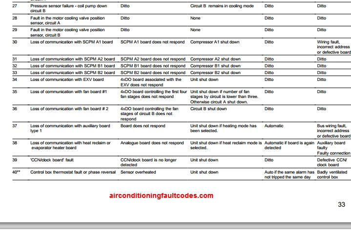
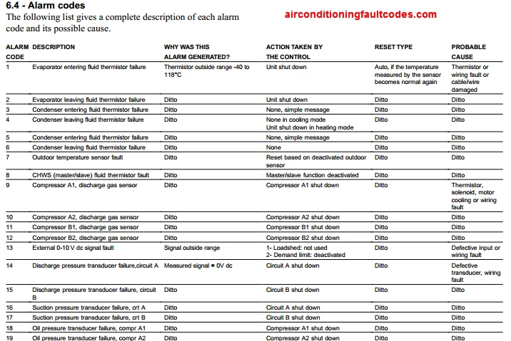
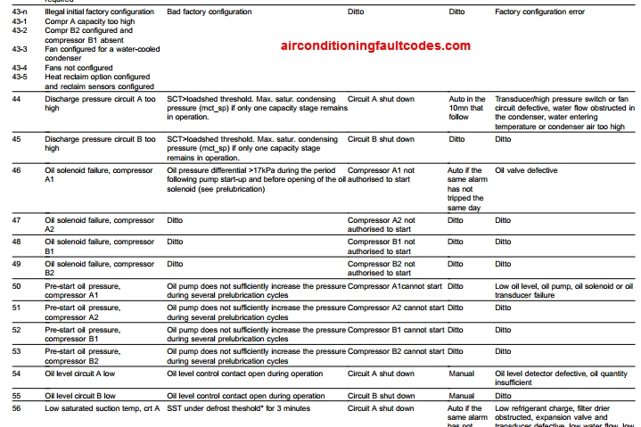
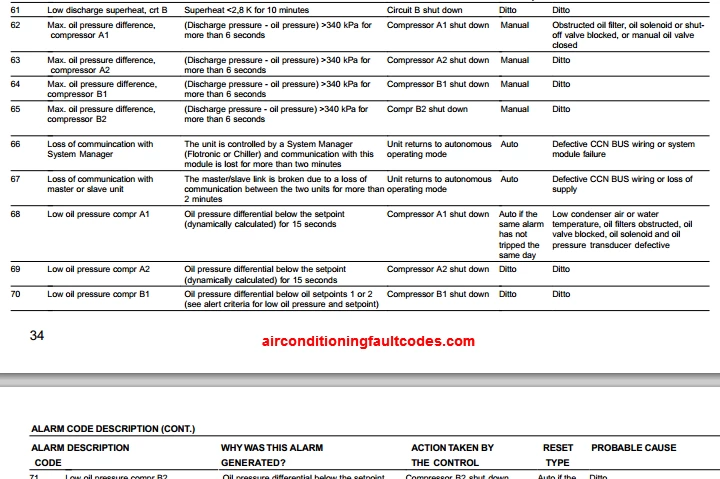
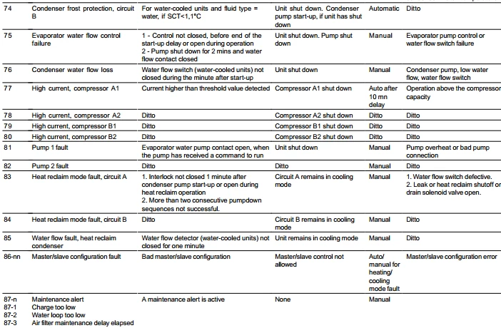
The following list gives a complete description of each alarm code and its possible cause.
ALARM CODE DESCRIPTIONS
ALARM NAME
ALARM
CODE
1
Compressor A1 failure
2
Compressor A2 failure
5
Compressor B1 failure
6
Compressor B2 failure
9
Evaporator leaving water
thermistor failure
10
Evaporator entering water
thermistor failure
11
CHWS thermistor failure
(master/slave)
12
Condenser leaving water
thermistor failure
13
Condenser entering water
thermistor failure
14
OAT sensor failure
15
Drycooler leaving water
thermistor failure
16
Discharge pressure transducer
failure, Circuit A
17
Discharge pressure transducer
failure, Circuit B
18
Suction pressure transducer
failure, Circuit A
19
Suction pressure transducer
failure, Circuit B
21
CCN/clock board failure
22
Loss of communication with
slave board
23
Loss of communication with
PD_AUX1 board
24
Loss of communication with
variable-speed drive 1
25
Loss of communication with
variable-speed drive 2
30
Low refrigerant pressure failure,
circuit A
31
Low refrigerant pressure failure,
circuit B
32
High pressure failure, circuit A
33
High pressure failure, circuit B
34
High pressure switch not reset
or compressor reverse rotation,
circuit A
35
High pressure switch not reset
or compressor reverse rotation,
circuit B
36
Water heat exchanger frost
protection
37
Repeated low evaporator
suction temperature unloading,
circuit A
38
Repeated low evaporator suction
temperature unloading, circuit B
39
Repeated high pressure
unloading, circuit A
40
Repeated high pressure
unloading, circuit B
41
Repeated high discharge
temperature unloading, circuit A
42
Repeated high discharge
temperature unloading, circuit B
ALARM DESCRIPTION
Motor safety input has opened due to
compressor overtemperature protection.
As above
As above
As above
Thermistor outside range
As above
As above
As above
As above
As above
Thermistor outside range
Voltage delivered by the sensor is incorrect
Value read by the sensor is outside range
Voltage delivered by the sensor is incorrect
Value read by the sensor is outside range
The clock board is no longer detected
Communication has been lost with the slave
board (circuit B control)
Communication has been lost with the
drycooler or remote condenser control
Communication has been lost with the
condenser pump 1 control
Communication has been lost with the
condenser pump 2 control
Circuit running and the suction pressure
below threshold
As above
Circuit running and the discharge pressure
exceeds the high pressure trip point
As above
The high pressure switch has not been reset
following a high pressure trip or one circuit
compressor runs in reverse rotation
As above
The heat exchanger entering or leaving
water sensor is below the frost trip point
More than 6 successive circuit capacity
unloads because of low suction temperature
override.
As above
More than 6 successive circuit capacity
unloads because of high pressure override.
As above
More than 8 successive circuit capacity
unloads because of high discharge
temperature
As above
ACTION TAKEN BY
RESET TYPE
THE CONTROL
Compressor is shut
Manual
down
As above
As above
As above
As above
As above
As above
Unit shut down
Automatic, if temp. measured by sensor
returns to permitted range of values
As above
As above
As above
As above
Unit shut down for heat
As above
pumps, otherwise no
action
As above
As above
Unit shut down
As above
Unit shut down if it is in
As above
cooling mode
Circuit A shut down
Automatic if the voltage delivered by the
sensor returns to normal
Circuit B shut down
As above
Circuit A shut down
As above
Circuit B shut down
As above
Unit shut down
Automatic if board is detected again
Circuit B shut down
Automatic if communication is re-
established
Unit shut down
As above
Change-over to second
As above
condenser pump, if
available, otherwise unit
shut down
Change-over to first
As above
condenser pump, if
available, otherwise unit
shut down
Circuit shut down
Automatic when pressure returns to
normal and if the same fault has not
occurred the same day (machine
equipped with CCN/clock board, If not,
manual)
As above
As above
Circuit shut down
Automatic when pressure returns to
normal and if the same fault has not
occurred the same day (machine
equipped with CCN/clock board, If not,
manual). The high pressure switch may
have to be reset.
As above
As above
As above
Manual. The high pressure switch may
have to be reset.
As above
As above
Unit shut down
Automatic if the same alarm has not
tripped the same day (machine equipped
with CCN/clock board, If not, manual)
Circuit shut down
Manual
As above
As above
None
Automatic
As above
As above
As above
As above
As above
As above
PROBABLE CAUSE
Compressor overheat
As above
As above
As above
Faulty thermistor, wiring error or
disconnection
As above
As above
As above
As above
As above
As above
Defective transducer, wiring fault
As above
As above
As above
Defective CCN/clock board
Bus wiring fault, wrong software in slave
board or defective slave board
As above
As above
As above
Shortage of refrigerant, filter blocked or
faulty pressure sensor
As above
Fan circuit fault, high condenser
entering air temperature
As above
The high pressure switch has not been
reset since the high pressure alarm was
reset, incorrect compressor wiring
As above
Low water flow or defective thermistor
Faulty pressure sensor, clogged filter or
low refrigerant charge
As above
Faulty transducer, high condenser
entering air temperature, high entering
water temperature, condenser fouled fan
flow rate too low.
As above
Pressure sensor faulty or heat
exchanger fouled
As above
33
- Manuals
- Brands
- Carrier Manuals
- Chiller
- PRO-DIALOG PLUS 30RW
- Manual
-
Contents
-
Table of Contents
-
Troubleshooting
-
Bookmarks
Quick Links
30RW — 30RWA
PRO-DIALOG
Control
AQUASNAP
Operation and maintenance instructions
Related Manuals for Carrier PRO-DIALOG PLUS 30RW
Summary of Contents for Carrier PRO-DIALOG PLUS 30RW
-
Page 1
30RW — 30RWA PRO-DIALOG Control AQUASNAP Operation and maintenance instructions… -
Page 2
The cover graphics are solely for illustration and forms no part of any offer for sale or any sale contract. The manufacturer reserves the right to change the design at any time without notice. -
Page 3: Table Of Contents
TABLE OF CONTENTS 1 — SAFETY CONSIDERATIONS …………………………4 1.1 — General ………………………………4 1.2 — Avoid electrocution …………………………..4 2 — GENERAL DESCRIPTION …………………………4 2.1 — General ………………………………4 2.2 — Abbreviations used …………………………..4 3 — HARDWARE DESCRIPTION …………………………5 3.1 — General ………………………………
-
Page 4: Safety Considerations
• CCN mode: the machine is controlled by commands from carefully and set them down gently. the Carrier Comfort Network (CCN). In this case, a data communication cable is used to connect the unit to the 1.2 — Avoid electrocution CCN communication bus.
-
Page 5: Hardware Description
3 — HARDWARE DESCRIPTION 3.2 — Electrical supply to boards 3.1 — General All boards are supplied from a common 24 V a.c. supply referred to earth. Figure 1 — Control board CAUTION: Maintain the correct polarity when connecting the power supply to the boards, otherwise the boards may be damaged.
-
Page 6: The Controls
3.5 — The controls 3.6 — Connections at the user’s terminal block Evaporator pump 3.6.1 — General description The controller can regulate one or two evaporator pumps and The contacts below are available at the user’s terminal block on takes care of the automatic change-over between pumps. the NRCP-BASE board (see figure 1).
-
Page 7
DUAL-CIRCUIT UNITS Description Connector/channel Terminal Board Remarks Remarks Alarm relay output J3 / CH24 30A — 31A Master NRCP- Indicates alarms, circuit A Volt-free contact 24 V a.c. circuit A BASE 48 V d.c. max, 20 V a.c. or min. 20 V d.c., 3 A max, 80 Alarm relay output J3 / CH24 30B — 31B… -
Page 8: Setting Up Pro-Dialog Plus Control
4 — SETTING UP PRO-DIALOG PLUS CONTROL 4.1 — Local interface general features MAIN INTERFACE SUMMARY INTERFACE MAIN INTERFACE SUMMARY INTERFACE MENU BLOCK DUAL-CIRCUIT 30RWA INTERFACE MENU BLOCK DUAL-CIRCUIT 30RW INTERFACE The local interface enables a number of operating parameters to Main interface be displayed and modified.
-
Page 9: Unit Start/Stop Control
The summary interface (right hand section) includes a mimic The following operating types can be selected using the diagram of the unit, together with push-buttons and LEDs. It Start/Stop button: gives quick access to the main operating parameters of the unit. OPERATING TYPES 4 DIGIT DISPLAY DESCRIPTION…
-
Page 10: Menus
4.3 — Menus 4.3.3 — Modifying the value of a parameter/access to a sub- menu 4.3.1 — Selecting a menu Press the Enter button for more than 2 seconds to enter the The MENU button authorises you to select a menu from the 10 modification mode or to select a sub-menu.
-
Page 11
MODIFYING THE VALUE OF A PARAMETER OPERATION PRESS BUTTON MENU LED ITEM NUMBER ITEM VALUE 2-DIGIT DISPLAY 4-DIGIT DISPLAY Hold on the MENU button until the LED for SETPOINT lights. Press one of the Arrow buttons until the two-digit display shows 1 (item number 1- cooling setpoint 2). -
Page 12
MAIN MENUS STATUS TEMPERATURES PRESSURES SETPOINTS INPUTS OUTPUTS CONFIGURATION ALARMS ALARMS HISTORY ALARMS SUB-MENUS SERVICE FACTORY RUNTIME 1 RUNTIME 2 MAINTENANCE USER [SErviCE] [FACtorY] [RuntiME 1] [RuntiME 2] [MAintEnAnCE] [USEr] SUB-SUB-MENUS USER 1 USER 2 SCHEDULE 1 SCHEDULE 2 HOLIDAYS HOUR + DATE BROADCAST SERVICE 1… -
Page 13
SETPOINTS OUTPUTS ITEM STATUS TEMP PRESSURES INPUTS CONFIG ALARMS ALARMS HIST RUNTIMES Default display Evaporator water Discharge pressure Cooling setpoint 1 Contact 1: on/off Compressor status SUB-MENU: User Number of active Historic alarm code SUB-MENU: entering temp. circuit A circuit A Configuration (USEr) alarms/resets** Runtimes 1… -
Page 14
4.3.5 — Description of the Information menu INFORMATION MENU (3) ITEM FORMAT UNITS DESCRIPTION Automatic display mode. It cycles through the following displays: ±nn.n °C Controlled water temperature: temperature of the water that the unit tries to maintain at the control point. Unit operating type LOFF Local Off… -
Page 15
INFORMATION MENU (3) continued ITEM FORMAT UNITS DESCRIPTION ±nn.n °C Active setpoint. This is the current cooling/heating setpoint: it refers to cooling setpoint 1 or cooling/heating setpoint 2. See section 5.6.1. ±nn.n Control point. This is the setpoint used by the controller to adjust the temperature of the leaving or entering water (according to Forc °C configuration). -
Page 16
4.3.6 — Description of the Temperatures menu 4.3.7 — Description of the Pressures menu TEMPERATURES MENU [2] PRESSURES MENU [2] ITEM FORMAT UNITS COMMENTS ITEM FORMAT UNITS COMMENTS ±nn.n °C Evaporator entering water temperature nnnn Discharge pressure, circuit A. Relative pressure. ±nn.n °C Evaporator leaving water temperature… -
Page 17
LEAVING WATER TEMPERATURE CONTROL RESET THRESHOLDS IN COOLING OR HEATING MODE SETPOINT — °C R-407C Reset threshold Zero Full Minimum cooling value Reset based on outdoor -10 to 51 °C -10 to 51 °C Water air temperature Medium brine Reset based on 0 to 11.1 °C 0 to 11.1 °C Brine… -
Page 18
4.3.10 — Description of the Outputs/Tests menu 4.3.10.1 — General This menu displays the status of the controller outputs. More- over, when the machine is fully stopped (LOFF) the outputs can be activated for manual tests (the access to the tests is password controlled). -
Page 19
4.3.10.3 — Tests CONFIGURATION This function allows the user to test the outputs individually, if the machine is completely shut down (LOFF). To carry out a USER [USEr] manual test use the arrow keys to access the output to be tested and press the Enter key (longer than 2 seconds) to activate the USER1 USER2… -
Page 20
SUB-MENU USER CONFIGURATION ITEM USER 1 USER 2 DATE SCHEDULE 1 SCHEDULE 2 HOLIDAYS BROADCAST [USER1] [USER2]* [dAtE]* [ScHEduLE 1MEnu]* [ScHEduLE 2 MEnu]* [HOLidAy MEnu]* [BrodCASt]* Return to previous menu Return to previous Return to previous Return to previous menu Return to previous Return to previous menu Return to previous menu… -
Page 21
4.3.11.3 — Description of the User 1 Configuration sub-menu USER 1 CONFIGURATION SUB-MENU [2] ITEM FORMAT UNITS DEFAULT COMMENTS USEr MEnu When selected this item authorises return to the previous menu. 1 [1] 0/1/2 Circuit sequence selection (two-circuit units). 0 = Balanced circuit loading 1 = Circuit A first 2 = Circuit B first 2 [1]… -
Page 22
4.3.11.4 — Description of the User 2 Configuration sub-menu This menu is only accessible if the unit is equipped with an optional CCN/clock board USER 1 CONFIGURATION SUB-MENU ITEM FORMAT UNITS DEFAULT COMMENTS USEr 2 Menu When selected this item authorises return to the previous menu. 1[1] YES/no Periodic pump quick-start of the water pump(s) -
Page 23
Program is in unoccupied mode unless a schedule time period 4.3.11.7 — Description of the Holidays sub-menus is in effect. If two periods overlap and are both active on the This function is used to define 16 public holiday periods. Each same day, the occupied mode takes priority over the period is defined with the aid of three parameters: the month, unoccupied period. -
Page 24
HOLIDAY PERIOD X CONFIGURATION SUB-MENUS (X = 1 TO 16) 4.3.11.8 — Description of the Broadcast sub-menu ITEM # FORMAT COMMENTS The controller provides a broadcast configuration menu which HoLidAy X Sub-menu When selected this item authorises a return you can use to configure the unit to be the CCN’s broadcaster, to the configuration menu. -
Page 25
4.3.12 — Description of the Alarms menu 4.3.14.1 — Description of the Runtimes 1 menu This menu is used to display and reset up to 5 active alarms. It also permits alarm reset. If no alarm is active this menu is not RUNTIMES MENU [2] accessible. -
Page 26: Pro-Dialog Plus Control Operation
5 — PRO-DIALOG PLUS CONTROL OPERATION 4.3.14.3 — Maintenance menu description To be active, the maintenance function must be preset in the 5.1 — Start/stop control Service configuration ITEM # FORMAT DESCRIPTION The table below summarises the unit control type and stop or MAintEnAnCE MEnu When selected this item authorises return to go status with regard to the following parameters.
-
Page 27
ACTIVE OPERATING TYPE PARAMETER STATUS CONTROL UNIT TYPE STATUS REMOTE MASTER UNIT START/STOP CCN GENERAL START/STOP CONTROL SCHEDULE EMERGENCY ALARM LOFF L-C L-SC MASt CHIL_S_S CONTACT TYPE MODE SHUTDOWN Enable Active — Local Active — Unoccupied Local Active — Remote Active — Unoccupied Remote… -
Page 28: Heating/Cooling Operation
5.2 — Heating/cooling operation 5.4 — Condenser water pump control 5.2.1 — General The unit can control one or two condenser water pumps. These The heating/cooling selection applies to 30RW (liquid chillers) pumps can be fixed-speed or variable-speed pumps. Depending units, controlling a boiler or equipped with a heat pump option.
-
Page 29
The following table summarises the possible selections REMOTE OPERATING MODE — DUAL-CIRCUIT UNITS depending on the control types (local, remote or CCN) and the PARAMETER STATUS following parameters: HEATING/COOLING CONTROL SCHEDULE 2 ACTIVE SETPOINT OPERATING MODE CONTACTS STATUS Setpoint select in local control: item #13 of the Infor- Cooling sp 1 Cooling setpoint 1… -
Page 30: Demand Limit
5.6.2 — Reset 5.8 — Night mode Reset means that the active setpoint is modified so that less machine capacity is required (in cooling mode, the setpoint is The night period is defined (see User configuration) by a start increased, in heating mode it is decreased). This modifica-tion is time and an end time that are the same for each day of the in general a reaction to a drop in the load.
-
Page 31: Control Of A Boiler
5.10.2 — 30RWA units One of the functions of the master unit (depending on its configuration) may be the designation, whether the master or The control offers two control modes (fan stages with or slave is to be the lead machine or the follower. The roles of without Varifan) lead machine and follower will be reversed when the differ- Automatic mode.
-
Page 32: Diagnostics — Troubleshooting
6 — DIAGNOSTICS — TROUBLESHOOTING A manual reset must be run from the main interface using the following procedure: 6.1 — General RESET OF ACTIVE ALARMS OPERATION ITEM NUMBER ITEM VALUE PRESS MENU The PRO-DIALOG Plus control system has many fault tracing 2-DIGIT DISPLAY 4-DIGIT DISPLAY BUTTON LED aid functions.
-
Page 33: Alarm Codes
6.4 — Alarm codes The following list gives a complete description of each alarm code and its possible cause. ALARM CODE DESCRIPTIONS ALARM NAME ALARM DESCRIPTION ACTION TAKEN BY RESET TYPE PROBABLE CAUSE ALARM THE CONTROL CODE Compressor A1 failure Motor safety input has opened due to Compressor is shut Manual…
-
Page 34
ALARM CODE DESCRIPTIONS (continued) ALARM NAME ALARM DESCRIPTION ACTION TAKEN BY RESET TYPE PROBABLE CAUSE ALARM THE CONTROL CODE Safety interlock open Safety interlock not closed before end of the Unit prevented to start or Manual Evaporator pump control or water flow start-up delay or opens during operation shut down switch failure… -
Page 36
Order No. R3432-76, 06.2004. Supersedes order No.: 13432-76, 03.2002 Manufactured by: Carrier s.a., Montluel, France. Manufacturer reserves the right to change any product specification without notice. Printed in the Netherlands on chlorine-free paper.
(Ocr-Read Summary of Contents of some pages of the Carrier PRO-DIALOG PLUS 30RW Document (Main Content), UPD: 17 May 2023)
-
4, 4 1 — SAFETY CONSIDERATIONS 1.1 — General Installation, start-up and servicing of equipment can be hazardous if certain factors particular to the installation are not considered: operating pressures, presence of electrical components and voltages and the installation site (elevated plinths and built-up up structures). Only properly qualified installation engineers and highly qualified installers and technicians, fully trained for the product, are authorised to install and start-…
-
13, 13 MENU Menu tree structure Legend * Displayed if the configuration requires it ** Displayed if the alarm exists — Not in use ITEM 0 1 2 3 4 5 6 7 8 9 10 11 12 13 14 15 16 17 STATUS Default display Mode Chiller occupied/ unoccupied mode* Minutes left Cooling/heating selection* Cooling/heating status* Heat reclaim selection* Heat reclaim status Unit capacity in % Capacity circuit A in %* Capacity circuit B in %* Present demand limit in % Present lag limit in %* Setpoint in local control* Setpoin…
-
14, 14 INFORMATION MENU (3) ITEM FORMAT UNITS 0 ±nn.n °C LOFF — L-On — L-Sc — CCn — rEM — MASt — OFF — rEADY — dELAY — StOPPing — running — triPout — OvErridE — OCCUPIEd — UNOCCUPIEd — COOL — HEAT — BotH — ALArM — ALErt — MAStEr — SLAvE — 1 [1] nn — 2 [2] — occu unoc Forc 3 nn.n minutes 4 [2] — HEAt — COOL — 5 [2] HEAt — COOL — both — Forc — 6 [2] rECL — nO — 7 [2] rECL — nO Forc — 8 nnn % 9 nnn % 10 [2] nnn % 11 nnn Forc % 12 [2] nnn % 13 [2] — SP-1 SP-2…
-
15, 15 DESCRIPTION The delay at start-up operates after the unit has been switched on. If the delay has not expired, the mode is active. The delay is configured in the User Configuration 1 menu. The second cooling/heating setpoint is active. See section 5.6.1 The third heating setpoint is active. See section 5.6.1 In this mode, the unit uses the reset function to adjust the leaving water temperature setpoint. See section 5.6. In this mode, the demand at which the unit is authorised to opera…
-
17, 17 INPUTS MENU [2] ITEM FORMAT UNITS 0 oPEn/CLoS — 1 [1] oPEn/CLoS — 2 oPEn/CLoS — 3 oPEn/CLoS — 4 [1] oPEn/CLoS — 5 [1] oPEn/CLoS — 6 [1] oPEn/CLoS — 7 [1] oPEn/CLoS — 8 [1] oPEn/CLoS — 9b 1 b 2 b 3 — 10 [1] b 1 b 2 b 3 — LEAVING WATER TEMPERATURE CONTROL SETPOINT — °C R-407C Minimum cooling value Water 5.0 Medium brine 0.0 Brine -10.0 Maximum cooling value 20.0 Feedback setpoint, cooling 6.0 Minimum heating va…
-
6, Carrier PRO-DIALOG PLUS 30RW 6 3.6 — Connections at the user’s terminal block 3.6.1 — General description The contacts below are available at the user’s terminal block on the NRCP-BASE board (see figure 1). Some of them can only be used if the unit operates in remote operating type (rEM). The following table summarises the connections at the user’s terminal block. Description Alarm relay output Boiler relay output Contact 1: start/stop Contact 2: heat/cool or heat reclaim selection Contact 3: demand limit sel…
-
7, 7 Description Alarm relay output circuit A Alarm relay output circuit B Boiler relay output Contact 1: start/stop Contact 2: heat/cool or heat reclaim selection Contact 3: demand limit selection Contact 4: demand limit selection Contact 5: setpoint selection Control contact 6: setpoint selection User safety loop input Connection to CCN Connector/channel J3 / CH24 J3 / CH24 J3 / CH25 J4 / CH8 J4 / CH9 J4 / CH10 J4 / CH10 J4 / CH8 J4 / CH9 J4 / CH11a J12…
-
27, 27 ACTIVE OPERATING TYPE PARAMETER STATUS CONTROL UNIT TYPE STATUS REMOTE MASTER UNIT START/STOP CCN GENERAL START/STOP CONTROL SCHEDULE EMERGENCY ALARM LOFF L-C L-SC rEM CCN MASt CHIL_S_S CONTACT TYPE MODE SHUTDOWN — — — — — — — — — — Enable — — Off ——- — -. -. — Yes — Off Active — — — — — — — — — — — Local Off — — Active — — — — — — Unoccupied — — Local Off — — — Active — — — Off — — — — Remote Off — — — Active — — — — — Unoccupied — — Remo…
-
34, 34 A LARM C ODE 43 44 45 46 46-1 46-2 46-3 46-4 46-5 48-8 46-9 46-10 46-74 46-105 47 50 51 52 53 54 55 56-2 56-3 56-4 56-5 56-6 56-7 56-7 ALARM NAME Safety interlock open Pump #1 fault Pump #2 fault Fault, condenser pump 1 Voltage too high Overcurrent Motor overload Motor overheated Transformer overheated USS communication Voltage too low Incorrect initialisation Motor overheated, calculation l 2 l Internal overheating, Combim…
-
31, 31 5.10.2 — 30RWA units The control offers two control modes (fan stages with or without Varifan) — Automatic mode. The fan stages are controlled in order to permit start-ups at low outside temperatures and perma- nent optimisation of the unit performances (no parameter setting required). — Manual mode. The fan stages are controlled based on a fixed condensing point. 5.11 — Control of a boiler NOTE: The control of a boiler is not authorised for slave units. The unit …
-
8, 8 MAIN INTERFACE BUTTON NAME DESCRIPTION Menu Permits the selection of a main menu. Each main menu is represented by an icon. The icon is lit if active. Up arrow Permits scrolling through the menu items (in the two-digit display). If the modification mode is active this button authorises increase of the value of any parameter. Down arrow Permits scrolling through the menu items (in the two-digit displ…
-
33, 33 A LARM C ODE 1 2 5 6 9 10 11 12 13 14 15 16 17 18 19 21 22 23 24 25 30 31 32 33 34 35 36 37 38 39 40 41 42 ALARM NAME Compressor A1 failure Compressor A2 failure Compressor B1 failure Compressor B2 failure Evaporator leaving water thermistor failure Evaporator entering water thermistor failure CHWS thermistor failure (master/slave) Condenser leaving water thermistor failure Condenser entering water thermistor failure OAT sensor failure…
-
3, 3 GENERAL LEGEND Each of the following drawings is replaced in the whole document by the corresponding explanation: Up arrow Down arrow Return key Start/stop button DELTA T. Example: temperature difference between entering and leaving heat exchanger temperatures means character is flashing TABLE OF CONTENTS 1 — SAFETY CONSIDERATIONS………………………………………………………………………………………………………………………………..4…
-
18, Carrier PRO-DIALOG PLUS 30RW 18 4.3.10 — Description of the Outputs/Tests menu 4.3.10.1 — General This menu displays the status of the controller outputs. More- over, when the machine is fully stopped (LOFF) the outputs can be activated for manual tests (the access to the tests is password controlled). 4.3.10.2 — Menu description OUTPUTS STATUS & TESTS MENU [2] [3] ITEM FORMAT UNITS 0b 1 b 2 tESt FAIL Good — 1 [1] b 1 b 2 tESt FAIL Good — 2 [1] n tESt 3 [1] n tESt 4 [1] n 5 [1] On OFF tES…
-
12, Carrier PRO-DIALOG PLUS 30RW 12 STATUS TEMPERATURES PRESSURES SETPOINTS INPUTS OUTPUTS CONFIGURATION ALARMS ALARMS HISTORY ALARMS USER [USEr] SERVICE [SErviCE] FACTORY [FACtorY] RUNTIME 1 [RuntiME 1] RUNTIME 2 [RuntiME 2] MAINTENANCE [MAintEnAnCE] PERIOD 3 [PEriod 3] PERIOD 4 [PEriod 4] PERIOD 5 [PEriod 5] PERIOD 6 [PEriod 6] PERIOD 7 [PEriod 7] PERIOD 8 [PEriod 8] PERIOD 1 [PEriod 1] PERIOD 2 [PEriod 2] USER 1 [USEr 1] USER 2 [USEr 2] SCHEDULE 1 [SCHEduLE 1] SCHEDULE 2 [SCHEduLE 2] HOLIDAYS [HoLidAy] HO…
-
36, Order No. R3432-76, 06.2004. Supersedes order No.: 13432-76, 03.2002 Manufactured by: Carrier s.a., Montluel, France. Manufacturer reserves the right to change any product specification without notice. Printed in the Netherlands on chlorine-free paper.
… -
23, 23 PERIOD X CONFIGURATION SUB-MENUS (X = 1 TO
ITEM # FORMAT COMMENTS 0 Period X Menu Indicates the period (X) you are going to configure. When selected this item authorises a return to the main menu. 1n 1 n 2 n 3 n 4 Occupied period — Start time*. 00:00 to 24:00 Authorises entering the time of day at which the occupied period starts. 2n 1 n 2 n 3 n 4 Occupied period — End time*. 00:00 to 24:00 Authorises entering the time of d…
Carrier is one of the oldest multinational corporations in the world, established in 1915 the company was one of the few that manufactured every single appliance part on its own. Building systems that lasted decades the company was solely focused on putting out appliances that make a name for themselves. Over the past decades, the company has gained a lot of achievements making them one of the few that have created a solid standing around the world.
Settled in more than 106 countries, Carrier is now available in six continents. Offering a wide range of appliances while keeping its main focus on its original air conditioning and heating system. These include air conditioning and heating solutions for residential and commercial buildings. One of the most promising appliances the company offers is its chillers which ensure smooth workings in various conditions.
When facing an error code we suggest you grab a pen and paper to note down the code rather than pressing various buttons on your Carrier Chiller. This way you will not risk damaging your appliance any further and will be able to find out the exact issue using the common error code list for Carrier Chiller error codes listed below. Once you nail down the issue you can easily call in a professional, or fix the issue yourself.
Alarm Codes
The following list gives a complete description of each alarm code and its possible cause.
| Alarm Codes | Description |
|---|---|
| 1 | Evaporator entering fluid thermistor failure |
| 2 | Evaporator leaving fluid thermistor failure |
| 3 | Condenser entering fluid thermistor failure |
| 4 | Condenser leaving fluid thermistor failure |
| 5 | Condenser entering fluid thermistor failure |
| 6 | Condenser leaving fluid thermistor failure |
| 7 | Outdoor temperature sensor fault |
| 8 | CHWS (master/slave) fluid thermistor fault |
| 9 | Compressor A1, discharge gas sensor |
| 10 | Compressor A2, discharge gas sensor |
| 11 | Compressor B1, discharge gas sensor |
| 12 | Compressor B2, discharge gas sensor |
| 13 | External 0-10 V dc signal fault |
| 14 | Discharge pressure transducer failure,circuit A |
| 15 | Discharge pressure transducer failure, circuit B |
| 16 | Suction pressure transducer failure, crt A |
| 17 | Suction pressure transducer failure, crt B |
| 18 | Oil pressure transducer failure, compr A1 |
| 19 | Oil pressure transducer failure, compr A2 |
| 20 | Oil pressure transducer failure, compr B1 |
| 21 | Oil pressure transducer failure, compr B2 |
| 22 | Economizer A1 transducer failure |
| 23 | Economizer A2 transducer failure |
| 24 | Economizer B1 transducer failure |
| 25 | Economizer B2 transducer failure |
| 26 | Pressure sensor failure — coil pump down circuit A |
| 27 | Pressure sensor failure — coil pump down circuit B |
| 28 | Fault in the motor cooling valve position sensor, circuit A |
| 29 | Fault in the motor cooling valve position sensor, circuit B |
| 30 | Loss of communication with SCPM A1 board |
| 31 | Loss of communication with SCPM A2 board |
| 32 | Loss of communication with SCPM B1 board |
| 33 | Loss of communication with SCPM B2 board |
| 34 | Loss of communication with EXV board |
| 35 | Loss of communication with fan board #1 |
| 36 | Loss of communication with fan board # 2 |
| 37 | Loss of communication with auxiliary board type 1 |
| 38 | Loss of communication with heat reclaim or evaporator heater board |
| 39 | ‘CCN/clock board’ fault |
| 40 | Control box thermostat fault or phase reversal |
| 41 | Unit emergency stop |
| 42 | Initial factory configuration required |
| 43-n | Illegal initial factory configuration |
| 43-1 | Compr A capacity too high |
| 43-2 | Compr B2 configured and compressor B1 absent |
| 43-3 | Fan configured for a water-cooled condenser |
| 43-4 | Fans not configured |
| 43-5 | Heat reclaim option configured and reclaim sensors configured |
| 44 | Discharge pressure circuit A too high |
| 45 | Discharge pressure circuit B too high |
| 46 | Oil solenoid failure, compressor A1 |
| 47 | Oil solenoid failure, compressor A2 |
| 48 | Oil solenoid failure, compressor B1 |
| 49 | Oil solenoid failure, compressor B2 |
| 50 | Pre-start oil pressure, compressor A1 |
| 51 | Pre-start oil pressure, compressor A2 |
| 52 | Pre-start oil pressure, compressor B1 |
| 53 | Pre-start oil pressure, compressor B2 |
| 54 | Oil level circuit A low |
| 55 | Oil level circuit B low |
| 56 | Low saturated suction temp, crt A |
| 57 | Low saturated suction temp, circuit B |
| 58 | High saturated suction temp, circuit A |
| 59 | High saturated suction temp, crt B |
| 60 | Low discharge superheat, circuit A |
| 61 | Low discharge superheat, crt B |
| 62 | Max. oil pressure difference, compressor A1 |
| 63 | Max. oil pressure difference, compressor A2 |
| 64 | Max. oil pressure difference, compressor B1 |
| 65 | Max. oil pressure difference, compressor B2 |
| 66 | Loss of commuincation with System Manager |
| 67 | Loss of communication with master or slave unit |
| 68 | Low oil pressure compr A1 |
| 69 | Low oil pressure compr A2 |
| 70 | Low oil pressure compr B1 |
| 71 | Low oil pressure compr B2 |
| 72 | Evaporator frost protection |
| 73 | Condenser frost protection, circuit A |
| 74 | Condenser frost protection, circuit B |
| 75 | Evaporator water flow control failure |
| 76 | Condenser water flow loss |
| 77 | High current, compressor A1 |
| 78 | High current, compressor A2 |
| 79 | High current, compressor B1 |
| 80 | High current, compressor B2 |
| 81 | Pump 1 fault |
| 82 | Pump 2 fault |
| 83 | Heat reclaim mode fault, circuit A |
| 84 | Heat reclaim mode fault, circuit B |
| 85 | Water flow fault, heat reclaim condenser |
| 86-nn | Master/slave configuration fault |
| 87-n | Maintenance alert |
| 87-1 | Charge too low |
| 87-2 | Water loop too low |
| 87-3 | Air filter maintenance delay elapsed |
| 87-4 | Pump 1 maintenance delay elapsed |
| 87-5 | Pump 2 maintenance delay elapsed |
| 87-6 | Water filter maintenance delay elapsed |
- 30GX and 30HXC series
- PRO-DIALOG Control
- Screw-Compressor Air- and
- Water-Cooled Liquid Chillers
- 50 Hz
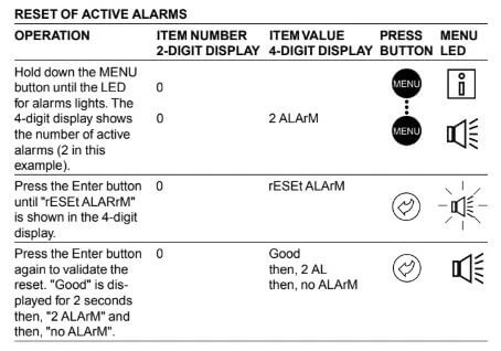
The PRO-DIALOG Plus control system has many fault tracing aid functions. The local interface and its various menus give access to all unit operating conditions. The test function makes it possible to run a quick test of all devices on the unit. If an operating fault is detected, an alarm is activated and an alarm code is stored in the Alarm menu.
Diagnostics and Troubleshooting
Resetting Alarm Codes
When the cause of the alarm has been corrected the alarm can be reset, depending on the type, either automatically on return to normal, or manually when action has been taken on the unit. Alarms can be reset even if the unit is running. This means that an alarm can be reset without stopping the machine. In the event of a power supply interrupt, the unit restarts automatically without the need for an external com- mand. However, any faults active when the supply is inter- rupted are saved and may in certain cases prevent a circuit or a unit from restarting. A manual reset must be run from the main interface using the following procedure:
Reset of Active Alarms
Manuals Pdf
Carrier Chiller Manual Pdf
Carrier Chiller Alarm Codes Pdf
Air-cooled screw chillers 30xa installation, operation and maintenance manual pdf
Carrier AC Error Codes
- Author
- Recent Posts
Regarding error and fault codes, we believe sharing knowledge is the best way to help everyone. That is why we established ACErrorCode.com, to give you every bit of info you need as a customer. HVAC Expert Contact: dannyreese@acerrorcode.com Call: 916-954-2677
*If you can’t find the code you’re looking for on our site, please let us know, and we’ll update our database as soon as possible.
-
30 gh pro dialog plus chiller (Carrier)
Hi;
30 GH chiller showing fault code 40,41,47,46,103,203.
Replaced the exv motor ,pressure transaduser,sensor of both circute.
still the chilller is tripping . somebody can help please?
-
Re: 30 gh pro dialog plus chiller (Carrier)
Hi vinod
Are you still getting the same fault codes after changing all the listed parts.
103 and 203 are HP trips on circuit 1 and 2. Have you checked the driers and are all the condenser fans running.
Blocked driers can bring up 46 & 47.
Paul
-
Re: 30 gh pro dialog plus chiller (Carrier)
Not sure if they are right for the 30GH but for the 30GX the codes are as follows.
103 — Compressor A1 current imbalance >10%
203 — Compressor A2 current imbalance >10%
46 — Oil solenoid failure compressor A1. oil pd > 17kPa
47 — Oil solenoid failure compressor A1. oil pd > 17kPa
41 — loss of communications with analogue card
40 — loss of communications with fan cardBrit
-
Re: 30 gh pro dialog plus chiller (Carrier)
Hello,
30GH’s codes are not the same with 30 GX because the softs are different.
For help me, Your display PRO DIALOG is Black or Grey?
-
Re: 30 gh pro dialog plus chiller (Carrier)
Hi Vinod, alarm # 46 & 47 indicate a need to check the oil solanoid valves. Sometimes they remain partly open due to some dirt.
-
Re: 30 gh pro dialog plus chiller (Carrier)
hi did you try change the exv board ,
-
Re: 30 gh pro dialog plus chiller (Carrier)
is it possible to take some note’s of the temps and pressure wile its working???
mabey couse of an unbalance in current the comps are not functioning like they should, and therefore give an unbalanced refrig isue, whitch cause an constand tripping on security’s.just some loud thingking.
Ice
-
Re: 30 gh pro dialog plus chiller (Carrier)
Can I have the wiring diagram of Prodiolog chiller 30GH 245?
Thank You
Similar Threads
-
Replies: 12
Last Post: 27-03-2011, 04:12 AM
-
Replies: 25
Last Post: 17-06-2010, 06:55 AM
-
Replies: 5
Last Post: 11-11-2007, 06:47 PM
-
Replies: 7
Last Post: 18-01-2007, 10:06 PM
-
Replies: 5
Last Post: 30-04-2006, 04:11 PM

Posting Permissions
- You may not post new threads
- You may not post replies
- You may not post attachments
- You may not edit your posts
- BB code is On
- Smilies are On
- [IMG] code is On
- [VIDEO] code is On
- HTML code is Off
Forum Rules


 ITEM # FORMAT COMMENTS 0 Period X Menu Indicates the period (X) you are going to configure. When selected this item authorises a return to the main menu. 1n 1 n 2 n 3 n 4 Occupied period — Start time*. 00:00 to 24:00 Authorises entering the time of day at which the occupied period starts. 2n 1 n 2 n 3 n 4 Occupied period — End time*. 00:00 to 24:00 Authorises entering the time of d…