NHTSA ID Number: 10150950
Manufacturer Communication Number: 16-94-15R
Summary
This bulletin provides a diagnosis and repair procedure for DTC P172A and / or P0B0B. When either of these DTCs is stored, a leaking o-ring which seals the electric oil pump relief valve may allow CVT fluid to enter the pump’s electric motor. Although current Service Manual diagnostic procedures instruct replacement of multiple components, this information will help isolate the actual failed component for a more cost-effective repair. NOTE: The relief valve is now available as an individual part. If there is no damage to the drive motor case assembly, refer to TSB 16-108-17R for the parts needed and Service Procedure for replacing just the relief valve.
NUMBER: 16-94-15R
DATE: 07/30/15
REVISED: 07/09/18
INTRODUCTION
This bulletin provides a diagnosis and repair procedure for DTC P172A and / or P0B0B. When either of these DTCs is stored, a leaking o-ring which seals the electric oil pump relief valve may allow CVT fluid to enter the pump’s electric motor. Although current Service Manual diagnostic procedures instruct replacement of multiple components, this information will help isolate the actual failed component for a more cost-effective repair. NOTE: The relief valve is now available as an individual part. If there is no damage to the drive motor case assembly, refer to TSB 16-108-17R for the parts needed and Service Procedure for replacing just the relief valve.
PRODUCTION CHANGE INFORMATION
A change to the drive motor relief valve o-ring was incorporated into production on June 16, 2015 starting with VIN F*298545.
ADDITIONAL TOOLS REQUIRED:
- Digital Voltage / Ohm Meter (DVOM) with test leads (1000v, CAT III)
- ¼” drive T-25 or T-30 TORX bit for battery cover screws
- Electrical tape to insulate power cable terminal ends (3- 2” long pieces of tape)
- Personal Protective Equipment (Hybrid Safety Kit J-51311, ALWAYS check the Expiration Date on Gloves)
DIAGNOSIS PROCEDURE / INFORMATION:
VERY IMPORTANT SAFETY WARNING: The HEV system includes a high-voltage circuit. Mishandling of HEV-related components may cause electric shock and serious personal injury. Technicians who have not received Subaru Hybrid training should NOT perform testing or repairs related to the HEV system. **See Subaru Technician Reference Booklet, Module 702 (MSA5P1702C) for more HEV information.
NOTE:
- Before starting the diagnosis procedure, use the SSMIII to confirm CVT fluid temperature is below 104 degrees F (40 C).
- Turn the ignition OFF.
IMPORTANT: The next steps require Personal Protective Equipment be worn.
- Remove the rear cargo area floor mat and the sub-trunk (storage tray).
- Remove the orange HEV Service Disconnect plug and put it in your
- Remove the TORX screws and necessary trim clips securing the aluminum battery
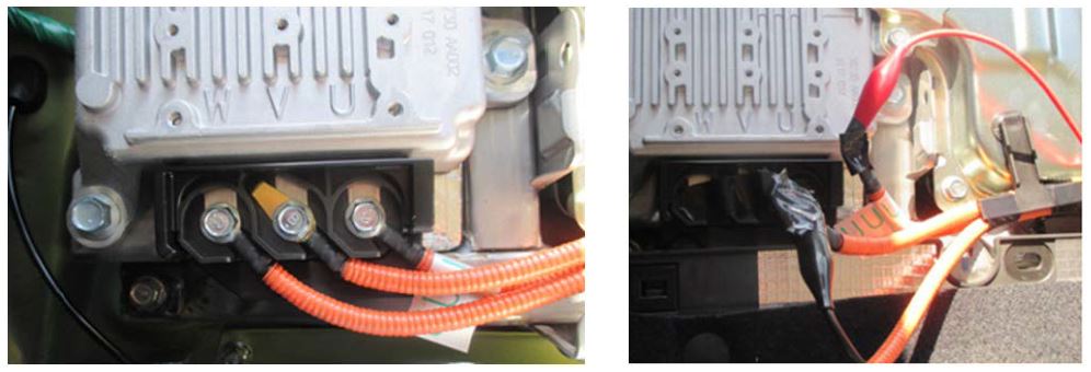
- ONE AT A TIME, remove the 3 bolts securing the orange “W”, “V”, and “U” cables to the electric oil pump inverter. As each cable is removed, cover each terminal end with one piece of electrical tape to insulate it. Connect the RED (+) test lead from the DVOM to the “U” cable end and BLACK (-) lead to the “V” cable end as shown. Confirm the “W” cable end is wrapped with insulating tape.
- Reinstall the orange HEV Service Disconnect
- Turn on the DVOM and set it to measure AC
- Start the engine and with the transmission in PARK, hold the engine at 1800
- Read the AC voltage on the DVOM display and record your
NOTES:
- The AT TEMP lamp will stay on because at this point, the power cables to the inverter are
- Confirm the DVOM is properly set so it can measure and display the correct AC voltage (e.g. select 1000 VAC or “Auto Range” depending on the DVOM being used).
IF THE DVOM SHOWS 0.5V OR MORE: the o-ring and drive motor are damaged. The drive motor / case assembly must be replaced. Remove the CVT assembly following the procedure in the applicable Service Manual.
IF THE DVOM SHOWS LESS THAN 0.5V: the root cause of the DTC is elsewhere. Continue with the DTC diagnostic procedure in the applicable Service Manual.
NOTES:
If the DTC display history shows DTC P0C79: “DRIVE MOTOR “A” INVERTER VOLTAGE TOO HIGH”, check and record the freeze frame data of both the DMCM and TCM. If P172A or P0B0B are also indicated during the same drive cycle, note that P0C79 is only indicated along with P172A and P0B0B. Therefore, the Drive Motor Inverter has no problem and is operating normally.
IMPORTANT: The next steps also require Personal Protective Equipment be worn.
REMINDER: Remove the (orange) Hybrid Service Disconnect plug again and put it in your pocket BEFORE reconnecting the Oil Pump Inverter power cables.
- Re-connect the inverter power cables ONE AT A TIME and torque the 10mm bolts to 5.5 ft.
- Replace the battery cover and torque the TORX screws to 5.5 ft.
- Reinstall the sub-trunk and rear cargo area floor mat.
- Reinstall the orange HEV Service Disconnect plug.
Required Parts List for Drive Motor Case Assembly Replacement:
| DESCRIPTION | QTY. | PART NUMBER |
| CVTFII Fluid | 13 | SOA635304* |
| ThreeBond 1217B (Pink) | 1 | SOA635068 |
| ThreeBond 1215 (Gray) | 1 | SOA635019 |
| O Ring | 1 | 806911080 |
| Case Assembly-Motor | 1 | 29019AA001 |
| Bolt Assembly-Seal | 2 | 31325KA151 |
| Clip-Transmission Harness | 1 | 31759AA060 |
| Ring-Seal | 2 | 31377AA600 |
| Gasket | 1 | 33295AA000 |
| O Ring | 5 | 806912200 |
| O Ring | 1 | 806912210 |
| O Ring | 2 | 806917100 |
| O Ring | 1 | 806929070 |
| Hose-ATF | 1 | 99079AA100 |
| Hose-ATF | 1 | 99079AA110 |
| Circlip-CVJ | 2 | 28333AG010 |
| Oil Seal | 1 | 806735300 |
| Oil Seal | 1 | 806735290 |
| Ring Seal | 1 | 31377AA490 |
| Ring Seal | 2 | 31377AA590 |
| O Ring | 1 | 806913250 |
*Warranty Claim Part Number (Not Orderable)
REPAIR PROCEDURE:
- Remove the CVT assembly following the procedure outlined in the applicable Service Manual.
- STOP HERE.
- If only the Oil Pump Relief Valve is being replaced, order the parts as listed in TSB 16-108-17R. (Always order the most up to date part numbers.) Proceed with the relief valve replacement Service Procedure as outlined in TSB 16-108-17R.
- If the drive motor case assembly is damaged and requires replacement, order the parts listed above (Always order the most up to date part numbers.) and proceed with the remainder of the Service Procedure outlined in this bulletin, 16-94-15R. • Remove the electric oil pump assembly,
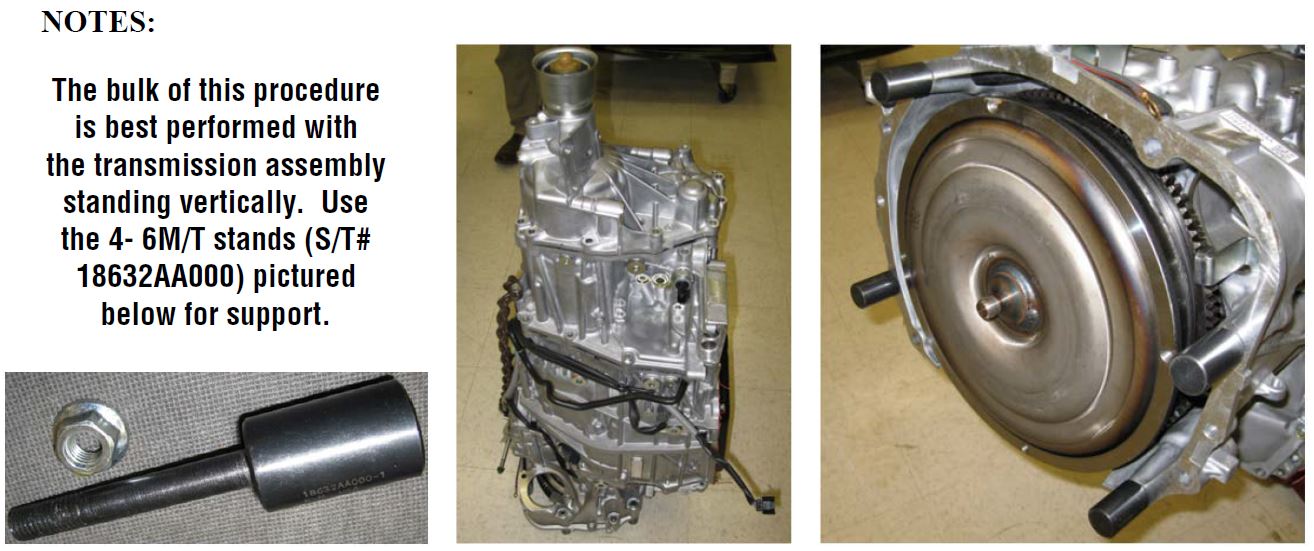
NOTES:
The bulk of this procedure is best performed with the transmission assembly standing vertically. Use the 4- 6M/T stands (S/T# 18632AA000) pictured below for support.
- The torque converter can also be left in place. Either support it from the underside after standing the unit up with a block of wood or use a retainer strap / bracket included with remanufactured and replacement transmission assemblies to keep the torque converter in place.
- It is NOT necessary to remove the internal parking pawl control rod or the inhibiter switch assembly to perform this
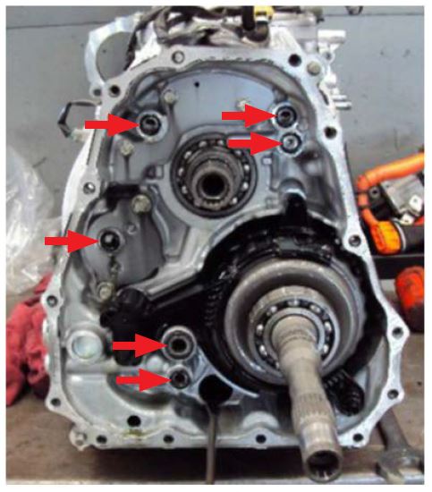
- There are 14 bolts securing the drive motor case assembly to the CVT main
- Use extra caution during removal and installation of the electric oil pump wiring harness to avoid damaging
- Always utilize a helper when removing and installing the drive motor case
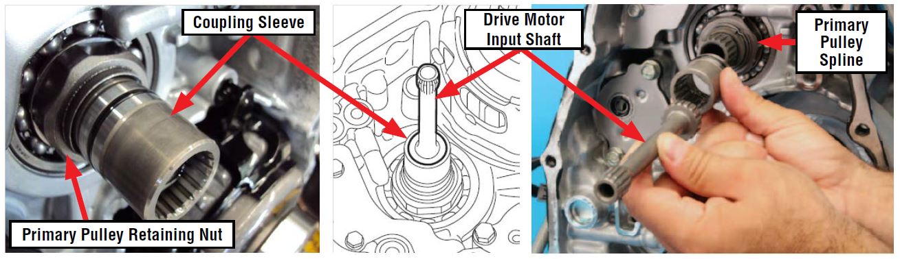
- The drive motor input shaft and coupling sleeve must be swapped over to the new Drive Motor Case assembly.
IMPORTANT: Before reassembling the cases, the following 3 measurements must be performed to determine the required thicknesses for:
- Output clutch roller bearing shim (Note measurement of removed shim(s) here)
- Transfer drive gear shim (Note measurement of removed shim(s) here)
- Transfer driven gear shim (Note measurement of removed shim(s) here)
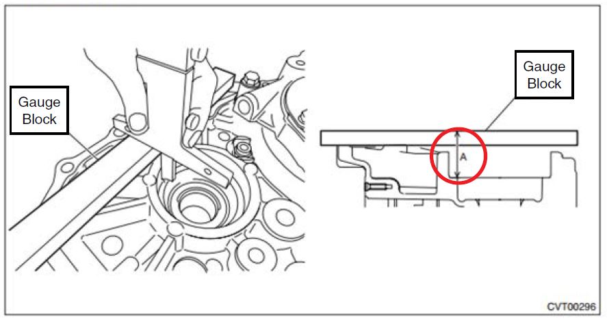
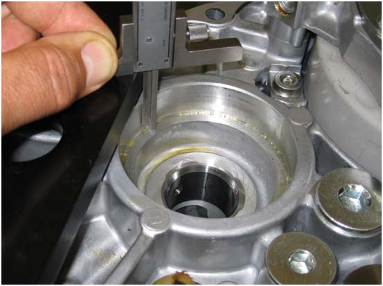
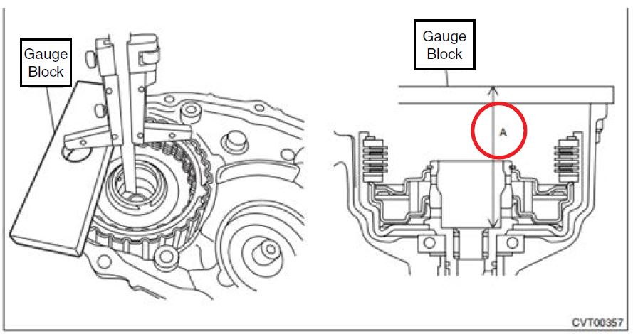
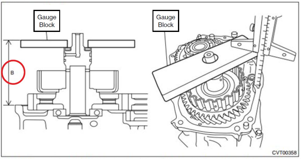
1. Output clutch roller bearing shim:
Steps 1 & 2:
- Remove the output clutch assembly.
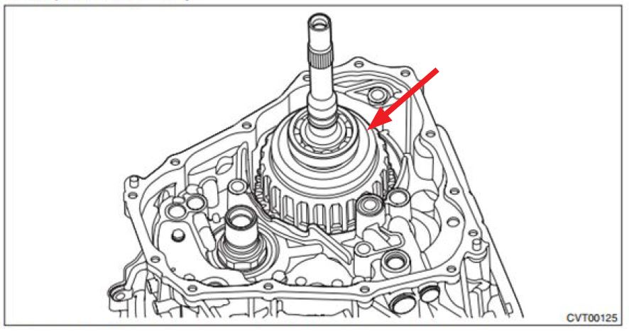
2) Measure the height “A” from the Gauge Block upper face to the ball bearing catch surface.
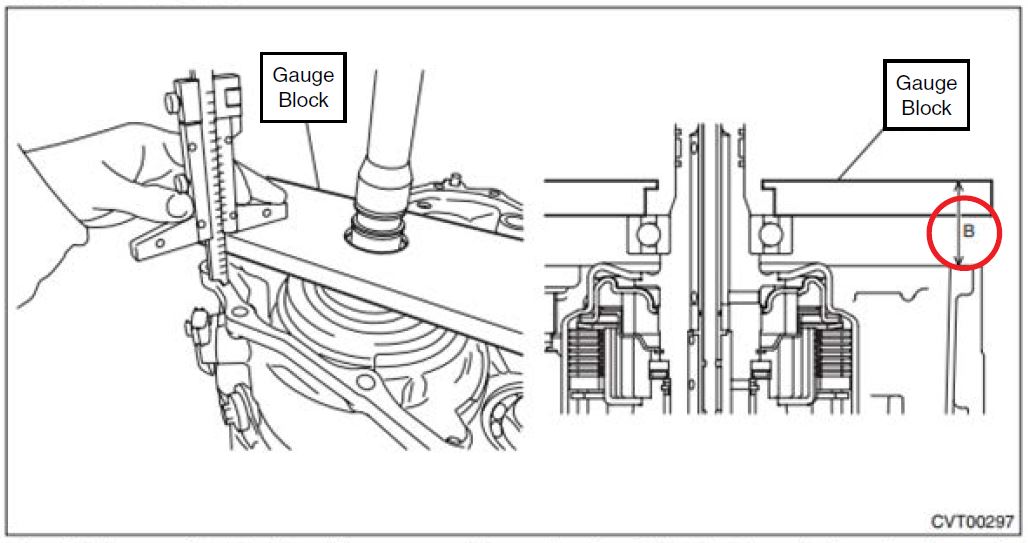
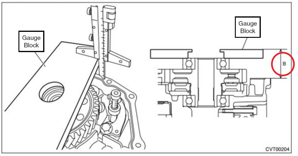
Steps 3:
3) Reinstall the output clutch assembly then measure the height “B” from the Gauge Block to the mating surface of the transmission case.
4) Obtain the thickness of reduction driven gear shim using the following formula to select zero to three reduction driven gear shims.
T (mm) = A – B – (0.05 — 0.25)
[T (in) = A – B – (0.002 — 0.01)
T: Shim thickness
A: Height from the Gauge Block upper face to the ball bearing catch surface
B: Height from Gauge Block to transmission case mating surface
0.05 — 0.25 mm (0.002 — 0.01 in): Clearance
| Reduction driven gear shim | |
| Part No. | Thickness mm (in) |
| 33279AA090 | 0.3 (0.012) |
| 33279AA100 | 0.4 (0.016) |
| 33279AA110 | 0.5 (0.020) |
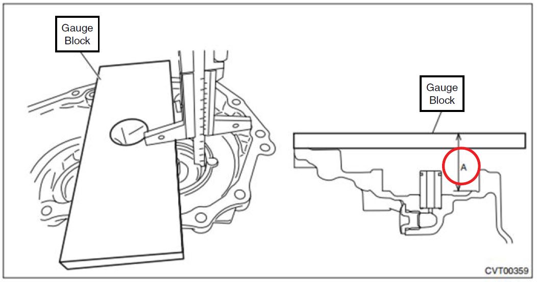
- Transfer drive gear shim:
Step 1:
1) Measure the height “A” from the Gauge Block upper face to the ball bearing catch surface.
Steps 2 and 3:
2) Measure the height “B” from the Gauge Block to the mating surface of the transmission case.
3) Obtain the thickness of transfer driven gear shim using the following formula to select zero to three transfer driven gear shims.
T (mm) = A – B – (0.05 — 0.25)
[T (in) = A – B – (0.002 — 0.01)
T: Shim thickness
A: Height from the Gauge Block upper face to the ball bearing catch surface
B: Height from Gauge Block to transmission case mating surface
0.05 — 0.25 mm (0.002 — 0.01 in): Clearance
| Reduction driven gear shim | |
| Part No. | Thickness mm (in) |
| 33279AA090 | 0.3 (0.012) |
| 33279AA100 | 0.4 (0.016) |
| 33279AA110 | 0.5 (0.020) |
- Transfer driven gear shim:
Step 1:
1) Install the transfer clutch assembly to the extension case with the transfer driven gear shims and thrust bearings removed.
Steps 2, 3, 4, and 5:
2) Install the thrust bearing to the transfer driven gear.
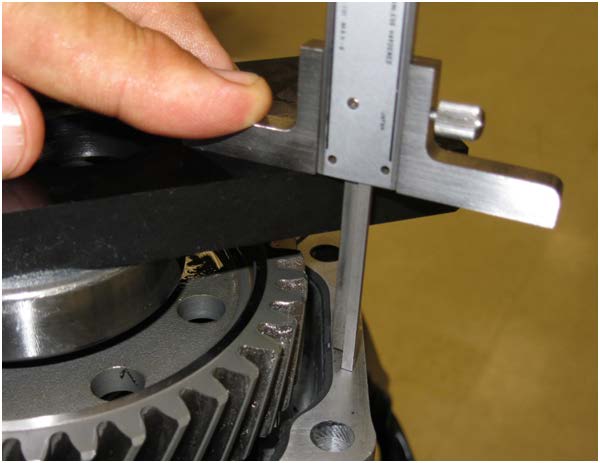
3) Using the Gauge Block, measure the height “A” from the ST end face to the thrust bearing catch surface of the transfer clutch assembly.
4) Using the Gauge Block, measure the height “B” from the transmission case mating surface to the end of the Gauge Block
5) Obtain the thickness of transfer driven gear shim using the following formula to select zero to three transfer driven gear shims.
T (mm) = A – B – (0.05 — 0.25)
[T (in) = A – B – (0.002 — 0.01)
T: Shim thickness
A: Height from the Gauge Block end face to the transfer clutch assembly thrust bearing catch surface
B: Height from mating surface of the transmission case to the end of the Gauge Block
0.05 — 0.25 mm (0.002 — 0.01 in): Clearance
| Reduction driven gear shim | |
| Part No. | Thickness mm (in) |
| 33279AA090 | 0.3 (0.012) |
| 33279AA100 | 0.4 (0.016) |
| 33279AA110 | 0.5 (0.020) |
Once all of the proper shim thicknesses have been determined, proceed with reassembly following the procedure outlined in the applicable Service Manual.
REASSEMBLY NOTES:
- When installing the secondary pressure sensor and inspection plugs, ALWAYS install a new o-ring (with some CVT fluid applied to it) and follow the proper torque specifications as they do
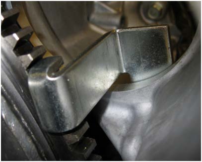
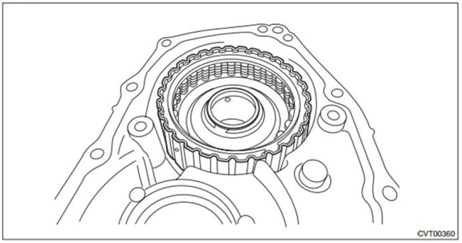
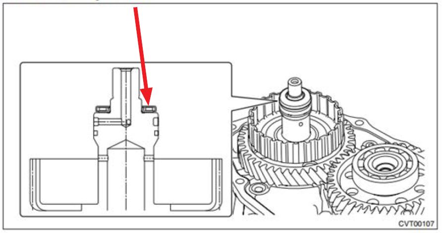
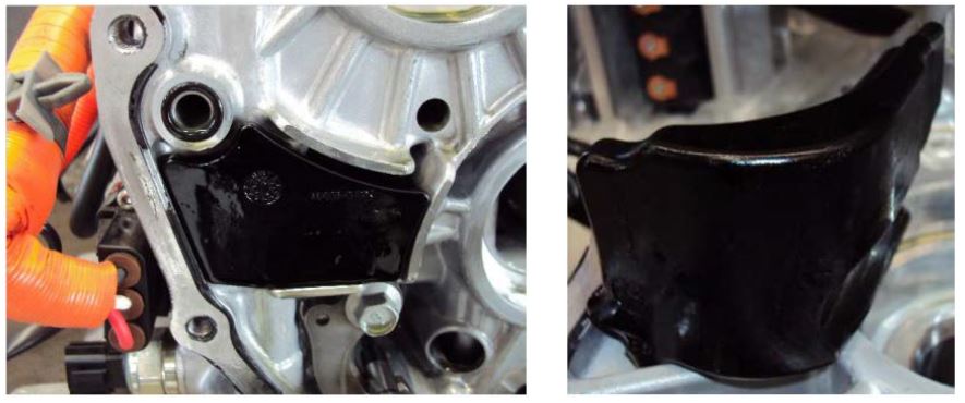
- Remember to transfer both of the oil baffles shown below over to the new assembly.
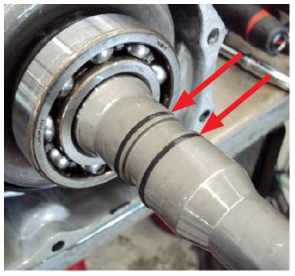
- Never expand the output clutch output shaft interlocked split sealing rings any more than necessary to get them onto the shaft. Use caution and patience as they can be tricky to install. NOTE: If these sealing rings become deformed during installation, they MUST be replaced.
IMPORTANT: BEFORE applying any sealer to the cases, always trial fit them together to confirm proper spline alignment between the coupling sleeve, the drive motor input shaft and the primary pulley. The cases are too close together to facilitate turning the primary pulley retaining nut to get the splines aligned properly, especially when there is fresh sealer applied.
- Once proper spline alignment is confirmed, use some CVT fluid to hold the 6 o-rings in place between the cases during reassembly.
- Use the GRAY ThreeBond sealer (004403007) to seal the case assemblies and the PINK (K0877YA020) sealer for the small output clutch control valve body fluid pan.
- Torque the 14 case bolts to 18.4 ft.
- Never twist the electric oil pump harness more than 360 degrees to avoid damaging it.
2 Affected Products
Vehicle
1 Associated Document
Manufacturer Communications
NUMBER: 16-94-15R
DATE: 07/30/15
REVISED: 07/09/18
https://www.nhtsa.gov/recalls?nhtsaId=10150925
MC-10150925-9999.pdf 2300.968KB
MC-10150925-9999
NHTSA ID Number: 10182591
Manufacturer Communication Number: 169415R
Summary
This bulletin provides a diagnosis and repair procedure for DTC P172A and/or P0B0B. When either of these DTCs is stored, a leaking o-ring which seals the electric oil pump relief valve may allow CVT fluid to enter the pump?s electric motor. Although current Service Manual diagnostic procedures instruct replacement of multiple components, this information will help isolate the actual failed component for a more cost-effective repair.
PRODUCTION CHANGE INFORMATION
A change to the drive motor relief valve o-ring was incorporated into production on June 16, 2015 starting with VIN F*298545.
1 Associated Document
Manufacturer Communications
NUMBER: 16-94-15R
DATE: 07/30/15
REVISED: 08/12/16
https://www.nhtsa.gov/recalls?nhtsaId=10182591
MC-10182591-9999.pdf 1260.281KB
MC-10182591-9999
NHTSA ID Number: 10150950
Manufacturer Communication Number: 16-94-15R
Summary
This bulletin provides a diagnosis and repair procedure for DTC P172A and / or P0B0B. When either of these DTCs is stored, a leaking o-ring which seals the electric oil pump relief valve may allow CVT fluid to enter the pump?s electric motor. Although current Service Manual diagnostic procedures instruct replacement of multiple components, this information will help isolate the actual failed component for a more cost-effective repair. NOTE: The relief valve is now available as an individual part. If there is no damage to the drive motor case assembly, refer to TSB 16-108-17R for the parts needed and Service Procedure for replacing just the relief valve.
1 Associated Document
Manufacturer Communications
NUMBER: 16-94-15R
DATE: 07/30/15
REVISED: 07/09/18
https://www.nhtsa.gov/recalls?nhtsaId=10150950
MC-10150950-9999.pdf 2300.968KB
MC-10150950-9999
SaleBestseller No. 3

Idemitsu ATF Type HP Automatic Transmission Fluid for Subaru — 5QT
- Engineered for and meets requirements of Subaru Automatic Transmission with HP specifications
- Precisely engineered frictional characteristics guarantee smooth shifting and outstanding anti-shudder performance
- Excellent resistance to oxidation and thermal breakdown provide long fluid life and extended protection
- Provides superior cleanliness, maintaining the transmission free of sludge and varnish deposits
- Advanced anti-wear technology provides maximum protection to gears and bearings
SaleBestseller No. 4
Bestseller No. 6
SaleBestseller No. 8

Valvoline CVT Full Synthetic Continuously Variable Transmission Fluid 1 QT
- Formulated with full-synthetic base stocks and advanced additive technology to meet the challenging demands of automatic transmissions.
- Enhanced anti-shudder protection for maximum power transfer
- Developed with anti-wear technology to help improve transmission durability
- Engineered with a proprietary blend of base oils and advanced additives to provide better oil flow at low temperatures and greater film protection at higher temperatures
Bestseller No. 10

Subaru 75W90 High Performance Gear/Transmission Fluid-1 Quart
- The extra S 5 gallon pail is no longer available and is now superseded by these quarts.
- The picture does show 5 quarts but this is for 1 quart if you need more order more
- This OEM Subaru 75w90 GL5 fluid will work in any Subaru that requires 75w90 fluid in their transmissions and differentials.
- SOA427V1700
Last update on 2023-09-20 / Affiliate links / Images from Amazon Product Advertising API
This product was presentation was made with AAWP plugin.

Степень важности ремонта : 3
Степень сложности ремонта : 3
- Неисправный насос жидкости вспомогательной трансмиссии
- Обрыв или замыкание жгута проводов насоса вспомогательной трансмиссионной жидкости
- Некачественное электрическое соединение цепи насоса вспомогательной трансмиссионной жидкости.
Как исправить код p172a subaru?
Начните с проверки ‘Возможных причин’, перечисленных выше. Визуально осмотрите жгут проводов и разъемы. Проверьте наличие поврежденных компонентов и поищите сломанные, погнутые, вытолкнутые или корродированные контакты разъема
Код p172a subaru tech notes
Существует заводской сервисный бюллетень для кода P172a. Завод рекомендует заменить негерметичное уплотнительное кольцо, герметизирующее предохранительный клапан электрического масляного насоса, может позволить жидкости CVT попасть в электродвигатель насоса
Сколько стоит диагностика кода p172a subaru?
Трудозатраты: 1. 0
Стоимость диагностики кода P172A Subaru составляет 1,0 час труда. Время диагностики и трудозатраты автосервиса зависят от местоположения, марки и модели автомобиля и даже типа двигателя. Большинство авторемонтных мастерских взимают плату от 75 до 150 долларов США в час
Каковы возможные симптомы кода p172a subaru?
- Горит лампа двигателя (или предупреждающая лампа Service Engine Soon).
Что означает код p172a subaru?
Модуль управления двигателем (ECM) контролирует работу насоса вспомогательной трансмиссионной жидкости.ECM устанавливает код OBDII, когда насос вспомогательной трансмиссионной жидкости не соответствует заводским спецификациям

P172A SUBARU — Вспомогательная трансмиссионная помпа обратного вращения
P172A SUBARU Возможные причины
- Неисправный насос жидкости вспомогательной трансмиссии
- Жгут проводов насоса вспомогательной трансмиссии открыт или замкнут
- Недостаточное электрическое соединение в цепи насоса вспомогательной трансмиссии
Как мне исправить код P172A SUBARU
Проверьте «Возможные причины», перечисленные выше. Визуально осмотрите соответствующий жгут проводов и разъемы. Проверьте, не повреждены ли компоненты, и проверьте, не сломаны ли, изогнуты ли, вытолкнуты или разъедены контакты разъема.
P172A SUBARU Возможные симптомы
P172a Subaru Описание
Модуль управления двигателем () контролирует насос жидкости вспомогательной трансмиссии. Устанавливает код OBDII, когда насос жидкости вспомогательной трансмиссии не соответствует заводским спецификациям.
Описание P172A ошибки автомобиля Subaru. В нашем справочнике имеется следующая информация:
На русском языке:
Это не часто встречающаяся неисправность в электрической цепи двигателя или автоматической коробки передач, вероятнее всего специфическая для Вашей марки автомобиля.
На английском языке:
OBD2 not find in catalog.
Выберите модель для возможности более детального просмотра информации по этой ошибке:
Найти причину >>>
Принимая во внимание тот факт, что OBD2 ошибки работы электронных систем автомобиля не всегда на прямую указывают на неработающий элемент, а чаще дают всего лишь общую информацию о неисправности, мы пришли к следующему выводу:
В разных марках и моделях автомобилей одна и также ошибка может возникать как следствие неисправности абсолютно разных элементов.
Стало понятно, что просто необходим ресурс в котором можно найти не только общую информацию об OBD2 ошибке, а практические данные по конкретному автомобилю.
Опыт автоэлектриков показал, что если рассматривать определенную марка-модель автомобиля, то в подавляющем большинстве случаев причина возникновения какой либо ошибки одна и также.
Мы создаем, не без вашей помощи, справочник причинно-следственной связи возникновения той или иной OBD2 ошибки у конкретного автомобиля (марка и модель). Если на Ваш автомобиль не найдено описание (причинно-следственной связи) ошибки, то не стесняйтесь задавайте вопрос.
Если у вас есть опыт в устранении той или иной ошибки — делитесь опытом с другими пользователями. Так мы сможем сформировать полезный ресурс. По капле от каждого и всем будет полезно.
Возможно будет интересно:
Если ошибка указывает на неверные параметры (высокие или низкие значения) какого нибудь из датчиков или анализаторов, то вероятней всего этот элемент исправен, а проблему надо искать так сказать «выше по течению», в элементах работу которых анализирует датчик или зонд.
Если ошибка указывает на постоянно открытый или закрытый клапан, то тут надо подойти к решению вопроса с умом, а не менять бездумно этот элемент. Причин может быть несколько: клапан засорен, клапан заклинил, на клапан приходит неверный сигнал от других неисправных узлов.
Автомобили с каждым днем становятся все более сложными, но и более диагностируемыми. Наш форум создан для всех, от простых автолюбителей до профессиональных автоэлектриков.
Как жить дальше?
UPDATE:
Изложу хронологию событий может кому то поможет. Итак в один прекрасный день вылез чек, движение продолжил так как был на трассе, ехал на дачу. Сканера при себе не было, на ночь сбросил клеммы, утром подключил все ок. Погрешил на 92й бенз которым заправил 2 последних раза. Проехал 150 км и чек вылез опять. По возвращению в город проверил сканером и вылезла ошибка богатая смесь Р0172. Опять стёр заправил 95й, вылезла снова. Машина при этом работала с перебоями и повысился расход до 16ти литров. Приплюсовались еще ошибки, типа пропуски зажигания в первом цилиндре, абс, дверь багажника, кондёр… короче *уева туча всего. Причем ошибки не стирались никак только чек гас на недолгий период. На обеденном перерыве заскочил к мастеру, он прошёлся сканером и как обычно достав базуку начал палить по воробьям: 1) надо промыть катализатор спец смесью, заодно и лямбду, 2) Промыть форсунуи и рейку 3) сменить свечи… но порывшись еще сделал прицельный выстрел «ПОХОЖЕ НА ОКИСЛЕНИЕ КАКОГО ТО ШТЕККЕРА» выдал он » и походу ЭБУ этот узел не видит надо по одному все проверять» добавив вслед. Сославшись на нехватку времени предложил заехать завтра. Я с грустным фейсом поехал обратно в офис. По дороге отказал кондей! Дул только горячим воздухом! Короче шарики за ролики заехали у ЭБУ. Тут я вспомнил как недавно промывал радиаторы и заодно помыл мотор. Воды не жалел, облил всё и хорошенько. Короче приехал на стоянке офиса поднял капот. На работающем движке подёргал штеккер воздухомера, и заметил изменение в работе двигателя. Снял его вообще и мотор заглох естественно. Продул штеккер, поставил обратно, завел. Гирлянда чеков пропала! Сама КАРЛ! Кондей заработал! Вечером сканером стёр ошибки и они не появились при повторном считывании. Мотор заработал ровно, расход упал! Езжу наслаждаюсь! Для профилактики все штеккеры отсоединил и промыл контакт клинером. Пока полёт отличный! Всем добра!
Пробег: 162 000 км