DESCRIPTION
MONITOR DESCRIPTION
WIRING DIAGRAM
INSPECTION PROCEDURE
CHECK ANY OTHER DTCS OUTPUT (IN ADDITION TO DTC P0171, P0172, P0174 OR P0175)
CHECK PCV HOSE CONNECTIONS
CHECK AIR INDUCTION SYSTEM
PERFORM ACTIVE TEST USING INTELLIGENT TESTER (A/F CONTROL)
READ VALUE USING INTELLIGENT TESTER (COOLANT TEMP)
INSPECT MASS AIR FLOW METER
CHECK FUEL PRESSURE
CHECK FOR EXHAUST GAS LEAK
CHECK SPARK AND IGNITION
INSPECT FUEL INJECTOR ASSEMBLY (INJECTION AND VOLUME)
INSPECT AIR FUEL RATIO SENSOR (HEATER RESISTANCE)
INSPECT INTEGRATION RELAY (A/F RELAY)
CHECK HARNESS AND CONNECTOR (A/F SENSOR — ECM)
REPLACE AIR FUEL RATIO SENSOR
PERFORM CONFIRMATION DRIVING PATTERN
CHECK WHETHER DTC OUTPUT RECURS (DTC P0171, P0172, P0174 OR P0175)
DTC P0171 System Too Lean (Bank 1)
DTC P0172 System Too Rich (Bank 1)
DTC P0174 System Too Lean (Bank 2)
DTC P0175 System Too Rich (Bank 2)
Description DTC P0171 P0172 P0174 P0175
The fuel trim is related to the feedback compensation value, not to the basic injection time. The fuel trim consists of both the short-term and long-term fuel trim.
The short-term fuel trim is fuel compensation that is used to constantly maintain the air fuel ratio at stoichiometric levels. The signal from the Air Fuel Ratio (A/F) sensor indicates whether the air fuel ratio is rich or lean compared to the stoichiometric ratio. This triggers a reduction in the fuel injection volume if the air fuel ratio is rich and an increase in the fuel injection volume if it is lean.
Factors such as individual engine differences, wear over time and changes in operating environment cause short-term fuel trim to vary from the central value. The long-term fuel trim, which controls overall fuel compensation, compensates for long-term deviations in the fuel trim from the central value caused by the short-term fuel trim compensation.
If both the short-term and long-term fuel trim are lean or rich beyond predetermined values, it is interpreted as a malfunction, and the ECM illuminates the MIL and sets a DTC.
| DTC Code | DTC Detection Condition | Trouble Area |
| P0171 P0174 | With a warm engine and stable air fuel ratio feedback, the fuel trim is considerably in error to the lean side (2 trip detection logic). |
|
| P0172 P0175 | With a warm engine and stable air fuel ratio feedback, the fuel trim is considerably in error to the rich side (2 trip detection logic). |
|
HINT:
- When DTC P0171 or P0174 is stored, the actual air fuel ratio is on the lean side. When DTC P0172 or P0175 is stored, the actual air fuel ratio is on the rich side.
- If the vehicle runs out of fuel, the air fuel ratio becomes lean and DTC P0171 or P0174 may be stored. The MIL is then illuminated.
- When the total of the short-term and long-term fuel trim values is within the malfunction threshold (and the engine coolant temperature is more than 75°C [167°F]), the system is functioning normally.
Monitor description
Under closed-loop fuel control, fuel injection volumes that deviate from those estimated by the ECM cause changes in the long-term fuel trim compensation value. The long-term fuel trim is adjusted when there are persistent deviations in the short-term fuel trim values. Deviations from the ECM’s estimated fuel injection volumes also affect the average fuel trim learned value, which is a combination of the average short-term fuel trim (fuel feedback compensation value) and the average long-term fuel trim (learned value of the air fuel ratio). If the average fuel trim learned value exceeds the malfunction thresholds, the ECM interprets this as a fault in the fuel system and stores a DTC.
Example:
If the average fuel trim learned value is more than +35% or less than -35%, the ECM interprets this as a fuel system malfunction.

Wiring diagram
Refer to DTC P2195.
Inspection procedure
HINT:
Malfunctioning areas can be identified by performing the Control the Injection Volume for A/F sensor function provided in the Active Test. The Control the Injection Volume for A/F sensor function can help to determine whether the Air Fuel Ratio (A/F) sensor, Heated Oxygen (HO2) sensor and other potential trouble areas are malfunctioning.
The following instructions describe how to conduct the Control the Injection Volume for A/F sensor operation using the intelligent tester.
- Connect the intelligent tester to the DLC3.
- Start the engine and turn the intelligent tester on.
- Warm up the engine at an engine speed of 2500 rpm for approximately 90 seconds.
- Enter the following menus: Powertrain / Engine and ECT / Active Test / Control the Injection Volume for A/F sensor.
- Perform the Active Test operation with the engine idling (press the RIGHT or LEFT button to change the fuel injection volume.)
- Monitor the output voltages of the A/F and HO2 sensors (AFS Voltage B1S1 and O2S B1S2, or AFS Voltage B2S1 and O2S B2S2) displayed on the intelligent tester.
HINT:
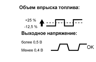
- The Control the Injection Volume for A/F sensor operation lowers the fuel injection volume by 12.5% or increases the injection volume by 25%.
- Each sensor reacts in accordance with increases and decreases in the fuel injection volume.
| Tester Display (Sensor) | Injection Volume | Status | Voltage |
| AFS Voltage B1S1 or AFS Voltage B2S1 (A/F) | +25% | Rich | Less than 3.1 V |
| AFS Voltage B1S1 or AFS Voltage B2S1 (A/F) | -12.5% | Lean | More than 3.4 V |
| O2S B1S2 or O2S B2S2 (HO2) | +25% | Rich | More than 0.55 V |
| O2S B1S2 or O2S B2S2 (HO2) | -12.5% | Lean | Less than 0.4 V |
NOTICE:
The Air Fuel Ratio (A/F) sensor has an output delay of a few seconds and the Heated Oxygen (HO2) sensor has a maximum output delay of approximately 20 seconds.
| Case | A/F Sensor (Sensor 1) Output Voltage | HO2 Sensor (Sensor 2) Output Voltage | Main Suspected Trouble Area |
| 1 | 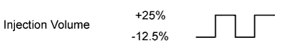 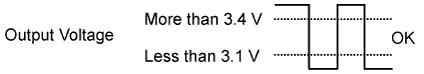 |
 |
— |
| 2 | 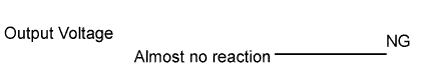 |
|
|
| 3 | |
|
|
| 4 | |
|
|
- Following the Control the Injection Volume for A/F sensor procedure enables technicians to check and graph the voltage outputs of both the A/F and HO2 sensors.
- To display the graph, enter the following menus: Powertrain / Engine and ECT / Active Test / Control the Injection Volume for A/F Sensor / A/F Control System / AFS Voltage B1S1 and O2S B1S2 or AFS Voltage B2S1 and O2S B2S2.
HINT:
- Read freeze frame data using the intelligent tester. Freeze frame data records the engine condition when malfunctions are detected. When troubleshooting, freeze frame data can help determine if the vehicle was moving or stationary, if the engine was warmed up or not, if the air fuel ratio was lean or rich, and other data from the time the malfunction occurred.
- A low A/F sensor voltage could be caused by a rich air-fuel mixture. Check for conditions that would cause the engine to run rich.
- A high A/F sensor voltage could be caused by a lean air-fuel mixture. Check for conditions that would cause the engine to run lean.
1.CHECK ANY OTHER DTCS OUTPUT (IN ADDITION TO DTC P0171, P0172, P0174 OR P0175)
-
Connect the intelligent tester to the DLC3.
-
Turn the ignition switch to ON and turn the intelligent tester on.
-
Enter the following menus: Powertrain / Engine and ECT / Trouble Codes.
-
Read the DTCs.
Result
Display (DTC Output) Proceed to P0171, P0172, P0174 or P0175 A P0171, P0172, P0174 or P0175 and other DTCs B HINT:
If any DTCs other than P0171, P0172, P0174 or P0175 are output, troubleshoot those DTCs first.
2.CHECK PCV HOSE CONNECTIONS
-
Check the PCV hose connections.
OK:
PCV hose is connected correctly and is not damaged.
|
REPAIR OR REPLACE PCV HOSE |
|
3.CHECK AIR INDUCTION SYSTEM
-
Check the air induction system for vacuum leakage.
OK:
No leakage from air induction system.
|
REPAIR OR REPLACE AIR INDUCTION SYSTEM |
|
4.PERFORM ACTIVE TEST USING INTELLIGENT TESTER (A/F CONTROL)
-
Connect the intelligent tester to the DLC3.
-
Start the engine and turn the intelligent tester on.
-
Warm up the engine at an engine speed of 2500 rpm for approximately 90 seconds.
-
Enter the following menus: Powertrain / Engine and ECT / Active Test / Control the Injection Volume for A/F Sensor.
-
Perform the Control the Injection Volume for A/F Sensor operation with the engine idling (press the RIGHT or LEFT button to change the fuel injection volume).
-
Monitor the voltage outputs of the A/F and HO2 sensors (AFS Voltage B1S1 and O2S B1S2, or AFS Voltage B2S1 and O2S B2S2) displayed on the intelligent tester.
HINT:
- The Control the Injection Volume for A/F Sensor operation lowers the fuel injection volume by 12.5% or increases the injection volume by 25%.
- Each sensor reacts in accordance with increases and decreases in the fuel injection volume.
Standard:
Tester Display (Sensor) Injection Volume Status Voltage AFS Voltage B1S1 or AFS Voltage B2S1 (A/F) +25% Rich Less than 3.1 AFS Voltage B1S1 or AFS Voltage B2S1 (A/F) -12.5% Lean More than 3.4 O2S B1S2 or O2S B2S2 (HO2) +25% Rich More than 0.55 O2S B1S2 or O2S B2S2 (HO2) -12.5% Lean Less than 0.4 Result:
Status AFS Voltage B1S1 or AFS Voltage B2S1 Status O2S B1S2 or O2S B2S2 A/F Condition and A/F Sensor Condition Misfire Suspected Trouble Area Proceed to Lean/Rich Lean/Rich Normal — — C Lean Lean Actual air fuel ratio lean May occur - PCV valve and hose
- PCV hose connections
- Injector blockage
- Gas leakage from exhaust system
- Air induction system
- Fuel pressure
- Mass Air Flow (MAF) meter
- Engine Coolant Temperature (ECT) sensor
A Rich Rich Actual air fuel ratio rich — - Injector blockage or blockage
- Gas leakage from exhaust system
- Ignition system
- Fuel pressure
- MAF meter
- ECT sensor
Lean Lean/Rich A/F sensor malfunction — - A/F sensor
B Rich Lean/Rich A/F sensor malfunction — - A/F sensor
Lean: During Control the Injection Volume for A/F Sensor, the A/F sensor output voltage (AFS) is consistently more than 3.4 V, and the HO2 sensor output voltage (O2S) is consistently less than 0.4 V.
Rich: During Control the Injection Volume for A/F Sensor, the AFS is consistently less than 3.1 V, and the O2S is consistently more than 0.55 V.
Lean/Rich: During Control the Injection Volume for A/F Sensor of the Active Test, the output voltage of the heated oxygen sensor alternates correctly.
5.READ VALUE USING INTELLIGENT TESTER (COOLANT TEMP)
-
Connect the intelligent tester to the DLC3.
-
Turn the ignition switch to ON and turn the intelligent tester on.
-
Enter the following menus: Powertrain / Engine and ECT / Data List / All Data / Coolant Temp.
-
Read the Data List twice, when the engine is cold and when it is warmed up.
Standard:
With cold engine: Same as ambient air temperature. With warm engine: 80 to 100°C (176 to 212°F).
|
REPLACE ENGINE COOLANT TEMPERATURE SENSOR |
|
6.INSPECT MASS AIR FLOW METER
-
Inspect the mass air flow meter.
|
REPLACE MASS AIR FLOW METER |
|
7.CHECK FUEL PRESSURE
-
Check the fuel pressure.
|
REPAIR OR REPLACE FUEL SYSTEM |
|
8.CHECK FOR EXHAUST GAS LEAK
-
Inspect for exhaust gas leakage from the exhaust manifold sub-assembly and exhaust pipes.
OK:
No gas leakage.
|
REPAIR OR REPLACE EXHAUST SYSTEM |
|
9.CHECK SPARK AND IGNITION
-
Check the ignition system.
HINT:
If the spark plugs or ignition system malfunctions, engine misfires may occur. The misfire count can be read using the intelligent tester. Enter the following menus: Powertrain / Engine and ECT / Data List / All Data / Cylinder #1 Misfire Rate (to Cylinder #6 Misfire Rate).
|
REPAIR OR REPLACE IGNITION SYSTEM |
|
10.INSPECT FUEL INJECTOR ASSEMBLY (INJECTION AND VOLUME)
-
Inspect the fuel injector assembly.
HINT:
If the injectors malfunction, engine misfires may occur. The misfire count can be read using the intelligent tester. Enter the following menus: Powertrain / Engine and ECT / Data List / All Data / Cylinder #1 Misfire Rate (to Cylinder #6 Misfire Rate).
|
REPLACE FUEL INJECTOR ASSEMBLY |
|
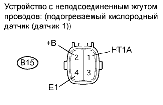
11.INSPECT AIR FUEL RATIO SENSOR (HEATER RESISTANCE)

-
Disconnect the A/F sensor connector.
-
Measure the resistance according to the value(s) in the table below.
Standard Resistance (for Bank 1 Sensor 1):
Tester Connection Condition Specified Condition 1 (HA1A) — 2 (+B) 20°C (68°F) 1.8 to 3.4 ? 1 (HA1A) — 4 (A1A-) Always 10 k? or higher Standard Resistance (for Bank 2 Sensor 1):
Tester Connection Condition Specified Condition 1 (HA2A) — 2 (+B) 20°C (68°F) 1.8 to 3.4 ? 1 (HA2A) — 4 (A2A-) Always 10 k? or higher
|
REPLACE AIR FUEL RATIO SENSOR |
|
12.INSPECT INTEGRATION RELAY (A/F RELAY)

-
Remove the integration relay from the engine room junction block.
-
Inspect the A/F fuse.
-
Remove the A/F fuse from the integration relay.
-
Measure the resistance according to the value(s) in the table below.
Standard Resistance:
Tester Connection Condition Specified Condition A/F fuse Always Below 1 ? -
Reinstall the A/F fuse.
-
-
Inspect the A/F relay.
-
Measure the resistance according to the value(s) in the table below.
Standard Resistance:
Tester Connection Condition Specified Condition 1A-4 — 1C-1 No battery voltage applied to terminals 1A-2 and 1A-3 10 k? or higher Battery voltage applied to terminals 1A- 2 and 1A-3 Below 1 ?
-
|
REPLACE INTEGRATION RELAY |
|
13.CHECK HARNESS AND CONNECTOR (A/F SENSOR — ECM)
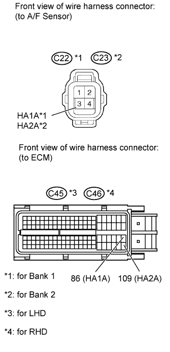
-
Disconnect the A/F sensor connector.
-
Disconnect the ECM connector.
-
Measure the resistance according to the value(s) in the table below.
Standard Resistance (Check for Open):
for LHD
Tester Connection Condition Specified Condition C22-1 (HA1A) — C45-86 (HA1A) Always Below 1 ? C23-1 (HA2A) — C45-109 (HA2A) Always Below 1 ? for RHD
Tester Connection Condition Specified Condition C22-1 (HA1A) — C46-86 (HA1A) Always Below 1 ? C23-1 (HA2A) — C46-109 (HA2A) Always Below 1 ? Standard Resistance (Check for Short):
for LHD
Tester Connection Condition Specified Condition C22-1 (HA1A) or C45-86 (HA1A) — Body ground Always 10 k? or higher C23-1 (HA2A) or C45-109 (HA2A) — Body ground Always 10 k? or higher for RHD
Tester Connection Condition Specified Condition C22-1 (HA1A) or C46-86 (HA1A) — Body ground Always 10 k? or higher C23-1 (HA2A) or C46-109 (HA2A) — Body ground Always 10 k? or higher
|
REPAIR OR REPLACE HARNESS OR CONNECTOR |
|
14.REPLACE AIR FUEL RATIO SENSOR
-
Replace the A/F sensor.
15.PERFORM CONFIRMATION DRIVING PATTERN
-

- (a) Connect the intelligent tester to the DLC3.
- (b) Turn the ignition switch to ON and turn the intelligent tester on.
- (c) Clear DTCs.
- (d) Switch the ECM from normal mode to check mode using the intelligent tester.
- (e) Start the engine and warm it up with all the accessories switched OFF.
- (f) Drive the vehicle at between 60 km/h and 120 km/h (38 mph and 75 mph) and at an engine speed of between 1400 rpm and 3200 rpm for 3 to 5 minutes.
HINT:
If the system is still malfunctioning, the MIL is illuminated during step (f).
NOTICE:
If the conditions in this test are not strictly followed, no malfunction will be detected.

16.CHECK WHETHER DTC OUTPUT RECURS (DTC P0171, P0172, P0174 OR P0175)
-
Connect the intelligent tester to the DLC3.
-
Turn the ignition switch to ON and turn the intelligent tester on.
-
Enter the following menus: Powertrain / Engine and ECT / Trouble Codes.
-
Read the DTCs.
Result
Display (DTC Output) Proceed to No output A P0171, P0172, P0174 or P0175 B
Добрый вечер всем.И с наступающим!!! Не пинайте сильно за создание клона. Хотел в другой теме отписаться, но она закрыта.
Ткните носом. Первый раз столкнулся с данным авто (точнее с америкосом)
Вообщем суть проблемы такова. Приехал данный автомобиль с просьбой заменить свечи (инициатива клиента)
Много мата и ругани, свечи не снимая коллектора заменил. Старые были в полне неплохом состоянии, спросил зачем он решился их менять , говорит машина троит. Замена свечей не помогла)))
Итог диагностика. При подключении вагон ошибок. Пропуски 2,4,6 цилиндр ошибка по датчику детонации 0330, и по топливной смеси (P0171
Переобеднение воздушно-топливной смеси (отсечка топлива))и(P0174
Переобеднение воздушно-топливной смеси (датчик A/F)). Троение было вызвано отказом VVT клапана на 2 блоке. И был лопнут коллектор выпускной на 2 блоке. Предложил клиенту начать устранять поэтапно — заменить клапан VVT и заварить коллектор, затем продолжить диагнозу…. потому как пока не решив данные проблемы вердикт точный выносить не буду.
Заменили клапан, заварили коллектор. Стало лучше , при проверке на холостом ходе всё в норме, отправил покатать авто несколько дней.
Приехал снова с горящим чеком. Проверяю, и тут малость офигел вылетела ещё и к 0171 — P0172
Переобогащение воздушно-топливной смеси (отсечка топлива)…., а так же 0174 и по ДД (P0330
Неисправен датчик детонации №2 (левый ряд цилиндров). Вопрос откуда 0172 в скопе с 0171?
Ок. Продымил на подсос, не обнаружено. Ошибка вылетает только в движении. На хх и стоя на месте во всех режимах условий возникновения ошибки не возникает. Свечи в нормальном рабочем состоянии.
Немного фото по диагностике.Заранее большое спасибо за помощь и советы!
Да, после манипуляций клиент доволен и динамикой и расходом. Говорит как было раньше, но раньше ошибок не было…. Но проблема то есть….


Изменено пользователем Одинокий Лис
Хотел прошить ECU . позвонил в тойота рус
ответ
Позвольте поблагодарить Вас за Ваше обращение в службу клиентской поддержки Toyota, а также за Ваш выбор в пользу продукции марки Toyota.
Мы внимательно ознакомились с Вашим обращением от 05.09.2016 года.
Прежде всего, позвольте обратить Ваше внимание на то, что ООО «Тойота Мотор» (далее также – Общество) является уполномоченным импортером автомобилей марки TOYOTA и LEXUS (за исключением автомобилей Toyota Camry российской сборки), основная деятельность которого заключается в ввозе и распространении на территории Российской Федерации автомобилей, запасных частей и аксессуаров марки TOYOTA и LEXUS через дилерскую сеть.
Позвольте обратить Ваше особое внимание на то обстоятельство, что принадлежащий Вам Автомобиль не предназначен для реализации на территории Российской Федерации и не импортировался Обществом в Российскую Федерацию, а также сообщить, что Изготовителем не объявлялась Специальная сервисная кампания в отношении Вашего Автомобиля на территории Российской Федерации.
Общество также не располагает информацией о Специальных сервисных кампаниях, действие которых распространяется на указанные автомобили.
Позвольте также разъяснить Вам смысл понятия Специальная сервисная кампания.
После выпуска автомобилей Изготовитель постоянно оценивает то, как автомобили ведут себя в эксплуатации. Время от времени, сталкиваясь с ситуацией, когда отдельные составляющие или характеристики произведенных автомобилей не вполне соответствуют установленным Toyota высоким стандартам качества, Изготовитель, принимает решение о проведении Специальной сервисной кампании по проверке и, при необходимости, замене отдельных составляющих. Целью проведения Специальных сервисных кампаний является улучшение потребительских свойств автомобиля. Меры, предпринимаемые Изготовителем в рамках сервисных кампаний, являются превентивными, и попадание VIN-номера автомобиля в список по Специальной сервисной кампании не является подтверждением наличия на нем неисправности.
Также необходимо отметить, что сервисная кампания объявляется Изготовителем в отношении ограниченного определенного перечня автомобилей Toyota на строго определенной территории и не является отзывом продукции по смыслу законодательства о техническом регулировании.
Тем не менее, ставя превыше всего удовлетворенность клиентов Toyota, Обществом будет запрошена интересующая Вас информация у Изготовителя – компании «Тойота Мотор Корпорэйшн».
Как только Изготовитель предоставит по данному запросу интересующую Вас информацию, мы незамедлительно уведомим Вас об этом.
Позвольте Вас предупредить, что срок ответа на подобные запросы может быть достаточно длительным. Как правило, ориентировочный срок получения ответа составляет от 2 (двух) до 5 (пяти) месяцев и более.
Надеемся, что предоставленная информация окажется для Вас полезной.
Позвольте еще раз поблагодарить Вас за Ваше обращение.
С уважением,
Наталия Гуськова
Служба Клиентской Поддержки Toyota.
DTC
|
DTC
|
для подготовки Нажмите здесь
ОПИСАНИЕ
Коррекция подачи топлива имеет отношение к значению компенсации, а не к регулированию базовой продолжительности впрыска. Общая коррекция подачи топлива включает краткосрочную и длительную коррекции подачи топлива.
Краткосрочная коррекция представляет собой непродолжительную коррекцию соотношения воздух-топливо, используемую для поддержания соотношения воздух-топливо, близкого к стехиометрическому. Сигнал подогреваемого кислородного датчика указывает, обеднено или обогащено соотношение воздух-топливо по сравнению со стехиометрическим соотношением. Указанное расхождение вызывает снижение объема впрыска топлива, если смесь обогащена, или увеличение объема впрыска топлива, если смесь обеднена.
Такие факторы, как индивидуальные различия двигателей, износ с течением времени и изменение рабочих условий приводят к отклонению краткосрочной коррекции подачи топлива от центрального значения. Длительная коррекция подачи топлива, управляющая общей компенсацией подачи топлива, компенсирует длительные отклонения коррекции подачи топлива от центрального значения, возникающие вследствие краткосрочной коррекции подачи топлива.
Если ни краткосрочная, ни длительная коррекции не приводят к достижению центрального значения и смесь по-прежнему остается обогащенной или обедненной, ЕСМ определяет это как неисправность, включает контрольную лампу MIL и регистрирует код DTC.
| № DTC | Условие обнаружения DTC | Неисправный участок |
| P0171 | При прогретом двигателе и стабильных сигналах обратной связи о соотношении воздух-топливо коррекция подачи топлива приводит к значительной ошибке в сторону обеднения (логика диагностирования за 3 поездки) |
|
| P0172 | При прогретом двигателе и стабильных сигналах обратной связи о соотношении воздух-топливо коррекция подачи топлива приводит к значительной ошибке в сторону обогащения (логика диагностирования за 3 поездки) |
|
- УКАЗАНИЕ:
- Данные коды DTC обнаруживаются, если двигатель работает на холостом ходу в течение 15 с.
- В случае регистрации DTC P0171 фактическое соотношение воздух-топливо смещается в сторону обеднения. В случае регистрации DTC P0172 фактическое соотношение воздух-топливо смещается в сторону обогащения.
- Если автомобиль выработал топливо, соотношение воздух-топливо становится обедненным, в результате чего регистрируется DTC P0171. Загорается контрольная лампа MIL.
- Если суммарная величина краткосрочной и длительной коррекции находится в пределах 20% (а температура охлаждающей жидкости превышает 75°C (167°F)), система функционирует нормально.
- Если значение параметра настройки соотношения воздух-топливо составляет 1,23 или более, регистрируется код DTC P0171.
- Если значение параметра настройки соотношения воздух-топливо составляет 0,77 или менее, регистрируется код DTC P0172.
ОПИСАНИЕ РАБОТЫ СИСТЕМЫ КОНТРОЛЯ
В случае управления подачей топлива по замкнутому контуру значения объема впрыска топлива, отклоняющиеся от рассчитанных блоком ECM, приводят к изменениям величины длительной коррекции подачи топлива. Регулирование длительной коррекции подачи топлива выполняется при наличии постоянных отклонений величины краткосрочной коррекции подачи топлива. Отклонения от вычисленного блоком ECM объема впрыска топлива также влияют на среднее значение параметра настройки коррекции подачи топлива, которое является суммой средней краткосрочной коррекции подачи топлива (значение обратной связи компенсации подачи топлива) и средней длительной коррекции подачи топлива (значение параметра настройки соотношения воздух-топливо). Если среднее значение параметра настройки коррекции подачи топлива превышает пороговое значение, ECM определяет это как неисправность топливной системы и регистрирует код DTC.
Пример:
Если среднее значение параметра настройки коррекции подачи топлива составляет более +23% или менее -23%, ECM определяет это как неисправность толпивной системы.

СХЕМА СОЕДИНЕНИЙ
См. DTC P0130 (Нажмите здесь).
ПОСЛЕДОВАТЕЛЬНОСТЬ ПРОВЕРКИ
- УКАЗАНИЕ:
- С помощью портативного диагностического прибора считайте данные фиксированного набора параметров. Одновременно с записью в память кода DTC ECM сохраняет параметры состояния автомобиля и условий движения в виде данных фиксированного набора параметров. При поиске неисправностей фиксированные параметры позволяют определить, двигался ли автомобиль в момент возникновения неисправности или нет, был ли прогрет двигатель, каким было соотношение воздух-топливо (обедненным или обогащенным) и пр.
- Причиной низкого напряжения на выходе подогреваемого кислородного датчика может быть обогащение топливовоздушной смеси. Проверьте, нет ли условий, приведших к работе двигателя на обогащенной смеси.
- Причиной высокого напряжения на выходе подогреваемого кислородного датчика может быть обеднение топливовоздушной смеси. Проверьте, нет ли условий, приведших к работе двигателя на обедненной смеси.
1.ПРОВЕРЬТЕ, НЕ ОТОБРАЖАЮТСЯ ЛИ ДРУГИЕ DTC (ПОМИМО DTC P0171 ИЛИ P0172)
-
Подсоедините портативный диагностический прибор к DLC3.
-
Включите зажигание и включите портативный диагностический прибор.
-
Выберите следующие элементы меню: Powertrain / Engine and ECT / DTC.
-
Считайте коды DTC.
- Результат:
-
Результат Следующий шаг DTC P0171 или P0172 выводится А DTC P0171 или P0172 и другие DTC выводятся B
- УКАЗАНИЕ:
- Если отображаются какие-либо другие коды, помимо P0171 или P0172, сначала выполните поиск неисправностей для данных DTC.
|
||||
| А | |
2.ВЫПОЛНИТЕ ДИАГНОСТИКУ В РЕЖИМЕ ACTIVE TEST С ПОМОЩЬЮ ПОРТАТИВНОГО ДИАГНОСТИЧЕСКОГО ПРИБОРА (УПРАВЛЕНИЕ СООТНОШЕНИЕМ ВОЗДУХ-ТОПЛИВО)
-
Подсоедините портативный диагностический прибор к DLC3.
-
Запустите двигатель и включите портативный диагностический прибор.
-
Прогрейте двигатель на 2500 об/мин в течение приблизительно 90 секунд.
-
На портативном диагностическом приборе войдите в следующие меню: Powertrain / Engine and ECT / Active Test / Control the Injection Volume for A/F Sensor.
-
Выполните испытание «Control the Injection Volume for HO2 Sensor» при работе двигателя на холостом ходу (нажмите правую или левую кнопку для изменения объема впрыска топлива).
-
Считайте значения выходного напряжения подогреваемых кислородных датчиков (OS2 B1 S1 и O2S B1 S2), отображаемые на дисплее диагностического прибора.
- Результат:
- Подогреваемый кислородный датчик должен реагировать на увеличение и уменьшение объема впрыска топлива следующим образом:
- +25% = сигнал обогащенного состояния:
- более 0,5 В
- -12,5% = сигнал обедненного состояния:
- менее 0,4 В
- ПРИМЕЧАНИЕ:
- Задержка на выходе датчика 1 (передний датчик) составляет несколько секунд, а задержка на выходе датчика 2 (задний датчик) – приблизительно 20 с.
| Корпус | Подогреваемый кислородный датчик (датчик 1) Выходное напряжение |
Подогреваемый кислородный датчик (датчик 2) Выходное напряжение |
Наиболее вероятное место нахождения неисправности |
| 1 | 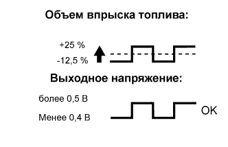 |
 |
— |
| 2 | 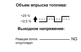 |
|
|
| 3 | |
|
|
- Рассмотренное испытание «Control the Injection Volume for HO2 Sensor» дает возможность механикам выполнить измерения и построить графики выходных напряжений обоих подогреваемых кислородных датчиков.
- Для отображения графика на портативном диагностическом приборе войдите в следующие меню: Powertrain / Engine and ECT / Active Test / Control the Injection Volume for A/F Sensor / Enter / View / O2S B1 S1 и O2S B1 S2.
- Результат:
-
Результат Следующий шаг Случай 1 C Случай 2 B Случай 3 А
| А | |
3.ПРОВЕРЬТЕ РАБОТУ ДАТЧИКА МАССОВОГО РАСХОДА ВОЗДУХА
-
Проверьте датчик массового расхода воздуха (Нажмите здесь).
|
||||
| OK | |
4.СНИМИТЕ ПОКАЗАНИЯ ПОРТАТИВНОГО ДИАГНОСТИЧЕСКОГО ПРИБОРА (COOLANT TEMP)
-
Подсоедините портативный диагностический прибор к DLC3.
-
Включите зажигание и включите портативный диагностический прибор.
-
Выберите следующие элементы меню: Powertrain / Engine and ECT / Data List / Primary / Coolant Temp.
-
Снимите показание параметра «Coolant Temp» дважды – при холодном и прогретом двигателе.
- Номинальное значение / Номинальный режим:
- При холодном двигателе: совпадает с температурой окружающего воздуха
При прогретом двигателе: От 75°C до 100°C (167-212°F)
|
||||
| OK | |
5.ПРОВЕРЬТЕ МЕСТА СОЕДИНЕНИЙ ШЛАНГА СИСТЕМЫ ПРИНУДИТЕЛЬНОЙ ВЕНТИЛЯЦИИ КАРТЕРА
-
Проверьте соединение шланга системы принудительной вентиляции картера (Нажмите здесь).
- OK:
- Шланг системы принудительной вентиляции картера подсоединен правильно и не поврежден.
|
(Нажмите здесь)ОТРЕМОНТИРУЙТЕ ИЛИ ЗАМЕНИТЕ ШЛАНГ СИСТЕМЫ ПРИНУДИТЕЛЬНОЙ ВЕНТИЛЯЦИИ КАРТЕРА |
|||
| OK | |
6.ПРОВЕРЬТЕ СИСТЕМУ ВПУСКА
-
Убедитесь в отсутствии утечки вакуума в системе забора воздуха (Нажмите здесь).
- OK:
- В системе впуска нет утечки вакуума.
|
ОТРЕМОНТИРУЙТЕ ИЛИ ЗАМЕНИТЕ СИСТЕМУ ЗАБОРА ВОЗДУХА (Нажмите здесь) |
|||
| OK | |
-
Проверьте наличие искры (Нажмите здесь).
|
||||
| OK | |
8.ПРОВЕРЬТЕ, НЕТ ЛИ УТЕЧЕК ОТРАБОТАВШИХ ГАЗОВ
-
Проверьте, нет ли утечек отработавших газов (Нажмите здесь).
- OK:
- Нет утечки газа.
|
ОТРЕМОНТИРУЙТЕ ИЛИ ЗАМЕНИТЕ СИСТЕМУ ВЫПУСКА ОТРАБОТАВШИХ ГАЗОВ (Нажмите здесь) |
|||
| OK | |
9.ПРОВЕРЬТЕ ДАВЛЕНИЕ В ТОПЛИВНОЙ СИСТЕМЕ
-
Проверьте давление в топливной системе (Нажмите здесь).
|
||||
| OK | |
10.ПРОВЕРЬТЕ ТОПЛИВНУЮ ФОРСУНКУ В СБОРЕ (ОБЪЕМ ВПРЫСКА ТОПЛИВА)
-
Проверьте объем впрыска (Нажмите здесь).
|
||||
| OK | |
11.ПРОВЕРЬТЕ ПОДОГРЕВАЕМЫЙ КИСЛОРОДНЫЙ ДАТЧИК (СОПРОТИВЛЕНИЕ ПОДОГРЕВАТЕЛЯ)
-
Отсоедините разъем подогреваемого кислородного датчика.
-
Измерьте сопротивление в соответствии со значениями, приведенными в таблице ниже.
- Номинальное сопротивление:
-
Контакты для подключения диагностического прибора Режим Заданные условия B15-1 (HT1A) — B15-2 (+B) 20°C (68°F) 6-14 Ом B15-1 (HT1A) — B15-4 (E1) Всегда 10 кОм или более
-
Подсоедините разъем подогреваемого кислородного датчика.
|
ЗАМЕНИТЕ ПОДОГРЕВАЕМЫЙ КИСЛОРОДНЫЙ ДАТЧИК (ДАТЧИК 1) (Нажмите здесь) |
|||
| OK | |
12.ПРОВЕРЬТЕ ПРЕДОХРАНИТЕЛЬ (EFI № 2)
-
Извлеките предохранитель EFI № 2 из блока реле моторного отсека.
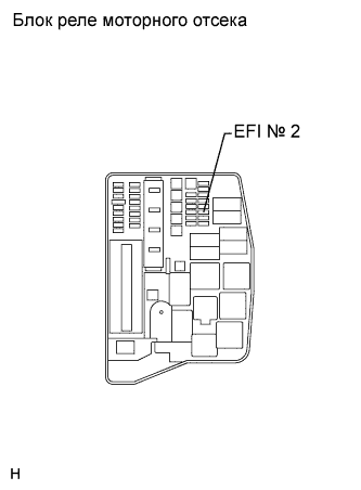
-
Измерьте сопротивление предохранителя EFI № 2.
- Номинальное сопротивление:
-
Контакты для подключения диагностического прибора Режим Заданные условия Предохранитель EFI № 2 Всегда Менее 1 Ом
-
Установите на место предохранитель EFI № 2.
|
ЗАМЕНИТЕ ПРЕДОХРАНИТЕЛЬ (EFI № 2) |
|||
| OK | |
13.ПРОВЕРЬТЕ ЖГУТ ПРОВОДОВ И РАЗЪЕМ (ПОДОГРЕВАЕМЫЙ КИСЛОРОДНЫЙ ДАТЧИК — ИНТЕГРИРОВАННОЕ РЕЛЕ)
-
Отсоедините разъем подогреваемого кислородного датчика.

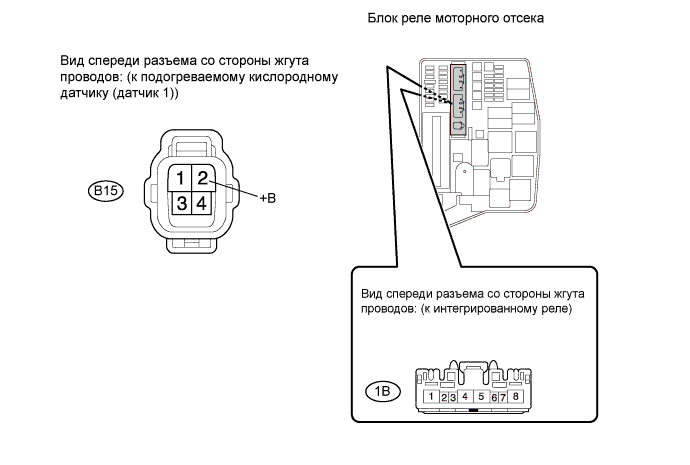
-
Извлеките интегрированное реле из блока реле моторного отсека.
-
Отсоедините разъем интегрированного реле.
-
Измерьте сопротивление в соответствии со значениями, приведенными в таблице ниже.
- Номинальное сопротивление (при проверке на обрыв):
-
Контакты для подключения диагностического прибора Режим Заданные условия B15-2 (+B) — интегрированное реле (1B-4) Всегда Менее 1 Ом
- Номинальное сопротивление (при проверке на короткое замыкание):
-
Контакты для подключения диагностического прибора Режим Заданные условия B15-2 (+B) или интегрированное реле (1B-4) — масса Всегда 10 кОм или более
-
Подсоедините разъем подогреваемого кислородного датчика.
-
Подсоедините разъем интегрированного реле.
-
Установите интегрированное реле на место.
|
ОТРЕМОНТИРУЙТЕ ИЛИ ЗАМЕНИТЕ ЖГУТ ПРОВОДОВ ИЛИ РАЗЪЕМ (ПОДОГРЕВАЕМЫЙ КИСЛОРОДНЫЙ ДАТЧИК — ИНТЕГРИРОВАННОЕ РЕЛЕ) |
|||
| OK | |
14.ПРОВЕРЬТЕ ЖГУТ ПРОВОДОВ И РАЗЪЕМ (ПОДОГРЕВАЕМЫЙ КИСЛОРОДНЫЙ ДАТЧИК — ECM)
-
Отсоедините разъем подогреваемого кислородного датчика.
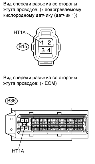
-
Отсоедините разъем ЭБУ.
-
Измерьте сопротивление в соответствии со значениями, приведенными в таблице ниже.
- Номинальное сопротивление (при проверке на обрыв):
-
Контакты для подключения диагностического прибора Режим Заданные условия B15-1 (HT1A) — B36-2 (HT1A) Всегда Менее 1 Ом
- Номинальное сопротивление (при проверке на короткое замыкание):
-
Контакты для подключения диагностического прибора Режим Заданные условия B15-1 (HT1A) или B36-2 (HT1A) — масса Всегда 10 кОм или более
-
Подсоедините разъем подогреваемого кислородного датчика.
-
Подсоедините разъем ECM.
|
ОТРЕМОНТИРУЙТЕ ИЛИ ЗАМЕНИТЕ ЖГУТ ПРОВОДОВ ИЛИ РАЗЪЕМ (ПОДОГРЕВАЕМЫЙ КИСЛОРОДНЫЙ ДАТЧИК — ECM) |
|||
| OK | |
15.ЗАМЕНИТЕ ПОДОГРЕВАЕМЫЙ КИСЛОРОДНЫЙ ДАТЧИК (ДАТЧИК 1)
- УКАЗАНИЕ:
- Замените подогреваемый кислородный датчик (Нажмите здесь).
| ДАЛЕЕ | |
16.ВЫПОЛНИТЕ ПОЕЗДКУ В ПРОВЕРОЧНОМ РЕЖИМЕ
-
Запустите двигатель и дайте ему поработать на холостом ходу в течение примерно 20 мин.
-
Совершите поездку на автомобиле в течение 20 минут со скоростью 70-100 км/час (43-62 мили в час) на 5-й передаче.
| ДАЛЕЕ | |
17.ПРОВЕРЬТЕ, ВОЗОБНОВЛЯЕТСЯ ЛИ ВЫВОД DTC (DTC P0171 ИЛИ P0172)
-
На портативном диагностическом приборе войдите в следующие меню: Powertrain / Engine and ECT / DTC.
-
Считайте коды DTC.
- Результат:
-
Результат Следующий шаг DTC не выводится А DTC P0171 или P0172 выводится B
|
||||
| А | |
© TOYOTA-COROLLA.RU, 2009-2023

P0171 and P0174 both indicate that there is a lean condition present in your Toyota Venza. By themselves, these are some of the most common OBD2 codes. When they appear together, it indicates that the entire engine is running lean.
Definition
Both of these codes are generic, which means they have the same meaning (Venza or not).
- P0171– Fuel Trim System Lean → Bank 1: P0171 indicates that the side of the engine with the first cylinder (Bank 1) is running lean.
- P0174- Fuel Trim System Lean → Bank 2: P0174 indicates that the side of the engine with the first cylinder (Bank 2) is running lean. On inline engines, this code is not available, since there is only one “bank” of cylinders.
- Lean Condition Meaning: The engine is bringing in too much air to the amount of fuel present. There are a few reasons that a vehicle will get a lean condition. It could be getting too much air (think vacuum leak, EGR problem, or mass airflow sensor) or it is not getting enough fuel (bad injectors, weak fuel pump, dirty fuel filter, bad fuel pressure regulator). Here’s more
P0171 and P0174 occur when the air/fuel mixture on the vehicle gets too lean. They are both thrown when the oxygen sensors detect that there is not enough oxygen in the exhaust. The engine then makes adjustments to compensate and throws these codes, which trigger the service engine soon light.
When these codes both appear at the same time, it is more often than not the intake manifold gasket that is the cause of the problem. It can be other things as well, but the intake manifold gasket is a great place to start.
There aren’t always drivability issues associated with these codes. For most people the first sign that anything is wrong at all is the service engine soon light coming on.
Here are the typical symptoms that something is wrong when your Venza has codes P0174 and P0171.
- Fuel Mileage- may or may not suffer depending on how much the air fuel mixture has changed.
- Misfire– If the air fuel mixture has gotten too far from factory specs, this can cause the vehicle to misfire or run rough. This will often be accompanied by P0300. If you have this code along with P0171 and P0174, ignore the P0300. It should resolve when you get the air/fuel mixture issue fixed.
- Idle Issues– With the air/fuel mixture altered, the vehicle can idle erratically as the computer compensates to keep the engine running. The engine may sputter as well.
Causes
Here are the most common causes of P0171 + P0174. Vacuum leaks (particularly at the intake manifold) and the MAF sensor are the most common culprits.
Vacuum Leaks
With most vehicles, the most common cause for the P0174 or P0171 code to show is a vacuum leak. Take a look around and see if you can find the vacuum leak. Here’s a great YouTube video on how to go about finding one. If the engine is letting in unmetered air, the intake manifold leaking is a very high likelihood. But, the leak can be anywhere.
A good scan tool can help you determine if there is a vacuum leak as well. Fuel trim at idle will be greatly affected by a vacuum leak. But, as you rev the engine, the fuel trim should dip down to around 0 (give or take a few points).
Mass Air Flow Sensor
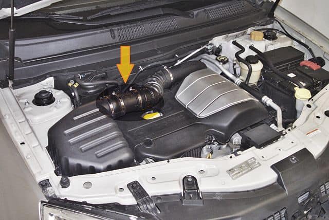
The mass air flow sensor calculates the volume of air entering the engine. If it has gone bad, the air fuel mixture will be off and the P0174 and/or P0171 codes will show. It’ll be located between the air filter and the throttle body. It’s easy to find. It will have a wiring harness plugged into it.
The number one culprit when it comes to the MAF sensor going bad is dirty air. This typically happens when the air filter has a bad seal. It’ll let unfiltered air in and it can quickly get the MAF sensor dirty enough that it will no longer work properly. Another way they can stop working properly is if they get dirty from fuel vapor.
Either way, the mover here is to clean it with a MAF sensor cleaner. Don’t use anything else. It’s very sensitive. If it’s still not working, you may need to get a new one. Toyota Venza: Bad MAF Sensor
EGR
The EGR system is designed to recycle exhaust gasses for cleaner emissions. If it has gone bad, you may get these codes as it throws off your Venza’s vacuum level.
Bad Fuel Injectors
If you have one or more fuel injectors that have gone bad that can certainly cause the air/fuel mixture to go bad. But, P0174 and P0171 indicate that BOTH sides of the engine are running lean. One bad fuel injector would cause one of those codes to show up. Multiple fuel injectors going bad on both sides of the engine could cause both codes to show, but it’s unlikely.
If you have more than one cylinder related misfire codes (such as P030X, where X is the misfiring cylinder) then it may be possible that you have more than one bad injector. Bad Fuel Injector Diagnosis
Fuel Pump/Fuel Filter
Today’s modern fuel injected motors need a lot of fuel pressure to atomize the gas properly. If the fuel pressure is not as high as it needs to be this atomization doesn’t happen properly and the optimal air/fuel mixture isn’t achieved. This is common when the fuel pump is bad, or the fuel filter is clogged. The fuel pressure regulator can also be the culprit. There’s more than likely a port you can use to check the fuel pressure. Do that before anything else.
Here’s a great YouTube video on the subject. This guy really gets into the problem, and can really help you find the cause of the code.
Conclusion
Good luck figuring out what is causing the P0171 and P0174 trouble codes with your Toyota Venza. If you feel like you could improve this article in any way, please feel free to leave a comment below.