|
|
Ремонт двигателей BOSCH REXROTH INDRAMAT
 Ремонт двигателей BOSCH REXROTH INDRAMAT в Дяневе является одним из основных направлений сервисного центра «Кернел».
Электродвигатели данного производителя имеют высокие параметры по перегрузкам, а также динамике и широким диапазоном крутящего момента.
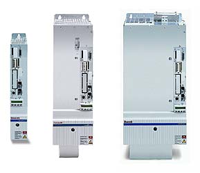
Двигатели BOSCH REXROTH INDRAMAT отличаются классом защиты, встроенным стояночного тормозом и т. п. Двигатели BOSCH REXROTH INDRAMAT, часто встречаются автоматизированных производственных площадках на больших и малых производствах.
В процессе работы рано или поздно (зависит то эксплуатационных режимов) промышленное оборудование выходит из строя, в этой ситуации ремонт двигателя BOSCH REXROTH INDRAMAT единственное экономически выгодное решение.
Самыми распространенными сериями электродвигателей BOSCH REXROTH INDRAMAT ремонт которых предлагает наша компания являются:
|
|
|
Специалисты сервисного центра «Кернел» более 20 лет проводят качественный ремонт электродвигателей BOSCH REXROTH INDRAMAT. Для максимально быстрого, а главное качественного ремонта, перемотки электродвигателей потребуется специализированное помещение, оборудованное необходимым оборудованием расходные материалы и компоненты для восстановления подобного промышленного оборудования и конечно же квалифицированный персонал.
Благодаря вышеперечисленному ремонт двигателей BOSCH REXROTH INDRAMAT в Дяневе проводится согласно всем техническим требованиям, в сжатые сроки. Каждый ремонт электродвигателей BOSCH REXROTH INDRAMAT завершается проверкой на специализированном стенде с блоками управления в условиях максимально приближенных к реальным.
Что входит в ремонт электродвигателей BOSCH REXROTH INDRAMAT
 Для восстановления работоспособности дорогостоящего промышленного оборудования инженеры компании выполняют последовательно все технологические шаги. В ремонт электродвигателей BOSCH REXROTH INDRAMAT в Дяневе входит:
- Внутренняя и внешняя очистка двигателя
- Изоляция обмоток электродвигателя
- Перемотка силовых обмоток электродвигателя
- Пролачивание и сушка обмоток электродвигателя
- Токарные работы (восстановление посадочного места подшипника)
- Замена подшипника электродвигателя
- Замена клеммников, силовых и сигнальных разъёмов
- Ремонт датчиков обратной связи (энкодера, резольвера)
- Изготовление и замена муфты энкодера
- Юстировка положения датчиков обратной связи (энкодера / резольвера)
И в тоже время каждый отдельно взятый ремонт электродвигателей BOSCH REXROTH INDRAMAT уникален. Они отличаются схемами силовых обмоток количеством витков, сечением провода и т.д.
Ошибки и неисправности двигателей BOSCH REXROTH INDRAMAT
Неисправности электродвигателей BOSCH REXROTH INDRAMAT
 Самые распространенные неисправности электродвигателей BOSCH REXROTH INDRAMAT:
- Неисправность датчиков обратной связи (энкодер, резольвер, тахогенератор);
- Сбито юстировочное положение энкодера двигателя;
- Неисправность обмоток статора. (межвитковое замыкание, пробой изоляции на корпус и обрыв);
- Износ подшипников их заклинивание;
- Износ посадочных мест подшипников на фланцах серводвигателя;
- Износ сальников;
- Износ тормозной системы;
- Размагничивание магнитов на роторе, потеря магнитных свойств;
- Разрушение корпуса двигателя (механические повреждения или из-за работы в агрессивной среде) разъёмов;
- Выход из строя термодатчика.
Ошибки двигателей BOSCH REXROTH INDRAMAT зависят от привода (частотного преобразователя) в связке с которым работают.
Ошибки привода электродвигателя BOSCH REXROTH INDRAMAT EFC x610
- Ошибка 1 (OC-1): Сверхток при постоянной скорости;
- Ошибка 2 (OC-2): Сверхток в ходе ускорения;
- Ошибка 3 (OC-3): Сверхток в ходе замедления;
- Ошибка 4 (OE-1): Перегрузка по напряжению при постоянной скорости;
- Ошибка 5 (OE-2): Скачок напряжения при ускорении;
- Ошибка 6 (OE-3): Скачок напряжения при замедлении;
- Ошибка 9 (SC): Сверхток или ток короткого замыкания;
- Ошибка 30 (OL-2): Перегрузка двигателя;
- Ошибка 31 (Ot): Перегрев двигателя;
- Ошибка 32 (t-Er): Ошибка настройки параметров двигателя;
- Ошибка 33 (AdE-): Ошибка обнаружения угла синхронного двигателя.
Ошибки BOSCH REXROTH серии EFC x610 – расшифровка, скачать руководство пользователя PDF
Перемотка электродвигателей BOSCH REXROTH INDRAMAT
 Перемотка электродвигателей BOSCH REXROTH INDRAMAT сложная и кропотливая работа под силу только настоящим профессионалам своего дела и конечно же обязательно наличие специализированных помещений и расходных материалов. Залог любого успешного ремонта — это квалифицированный специально обученный персонал и конечно же материальное оснащение обладая всем вышеперечисленным мы гарантируем качество выполненных работ по перемотке двигателей BOSCH REXROTH INDRAMAT в Дяневе.
Нет смысла перечислять все возможные сферы промышленности где работает данное промышленное оборудование, мы просто не найдем ни чего подобного. Электродвигатели BOSCH REXROTH INDRAMAT работают как в нормальных условиях, так и в крайне агрессивных средах, что приводит к частому выходу из строя оборудования, это может быть короткое межвитковое замыкание в результате попадания скажем охлаждающей жидкости на обмотки электродвигателя либо это может быть вызвано механическим износом, когда подшипник вырабатывает свой ресурс.
 Специалисты нашей компании в максимально кратчайшие сроки выполнят перемотку двигателей BOSCH REXROTH INDRAMAT, мы делаем все возможные виды ремонта электромоторов такие как:
- Чистка внешнего корпуса электродвигателя;
- Ремонт смазочной системы, замена смазки;
- Ремонт протяжка и замена рефлекторных крепежных соединений;
- Проверка крепления вентилятора;
- Перемотка статора электродвигателя;
- Перемотка ротора электродвигателя;
- Покрытие лаком лобовых обмоточных частей
- Ремонт якоря электродвигателя;
- Ремонт статора электродвигателя;
- Восстановление вала и посадочных мест;
- Замена подшипников и сальников;
- Токарные и фрезерные работы;
- Проверка электродвигателя без нагрузки и с нагрузкой.
Ремонт и настройка энкодера и резольвера BOSCH REXROTH INDRAMAT
 Ремонт энкодера необходим при износе подшипников, так как это влечет за собой потерю точности датчика и в самом плохом развитии событий из-за разбитых подшипников может пострадать самая важная часть энкодера, кодирующие стекло. Помимо данной неисправности датчика угла поворота:
- Грязное кодирующие стекло или диск;
- Поломка, неисправность сигнального разъема;
- Не правильная форма сигналов или их отсутствие;
- Наличие внутренней ошибки (для абсолютных энкодеров);
- Замыкание в электросхеме энкодера.
Также влечет за собой ремонт энкодера.
Ремонт резольвера необходим в следующих случаях:
- Обрыв одной из статорных (неподвижная часть) обмоток резольвера;
- Обрыв одной из обмоток ротора (вращающаяся часть) резольвера;
- Межвитковое замыкание одной из обмоток. Обычно происходит в части обмоток;
- Сбита позиция резольвера на двигателе.
Мы предлагаем не просто квалифицированный ремонт энкодера и резольвера в сжатые сроки, а также дополнительную экономию бюджета 60%-80% от стоимости нового датчика обратной связи. На все виды ремонта мы даем 6-и месячную гарантию
Ремонтом энкодера, на данный момент занимаются далеко не все организации предлагающие услуги по ремонту промышленного оборудования, в связи с крайне сложным процессом ремонта и последующей настройки энкодера.
Сервисный центр «Кернел» предоставляет услуги по ремонту подобного сложного промышленного оборудования как энкодеры и резольверы.
Ремонт распространенных двигателей BOSCH REXROTH INDRAMAT
Ремонт двигателей BOSCH REXROTH INDRAMAT MKD
|
mkd025a, mkd025a-144-kp0-kn |
mkd025b, mkd025b-144-gg0-un |
|
mkd041b, mkd041b-058-gg1-kn, mkd041b-144-gp0-kn |
mkd071b, mkd071b-024-gg1-kn, mkd071b-035-gg0-kn |
|
mkd090b, mkd090b-035-gp0-kn, mkd090b-035-gp0-kn |
mkd112a, mkd112a-024-gg0-bn, mkd112a-058-gg1-b1 |
|
mkd112b, mkd112b-024-gg0-an, mkd112b-048-gg0-an |
mkd112c, mkd112c-024-gg3-an, mkd112c-058-gg0-an |
Ремонт электродвигателей BOSCH REXROTH INDRAMAT MDD
|
mdd025a, mdd025a-n-100-n2g-040ga0 |
mdd025a, mdd025a-n-100-n2g-040ga0 |
|
mdd025b, mdd025b-n-100-n2g-040pb0 |
mdd025b, mdd025b-n-100-n2g-040pb0 |
|
mdd025c, mdd025c-n-100-n2g-040mb1 |
mdd025c, mdd025c-n-100-n2g-040mb1 |
|
mdd041c, mdd041c-n-100-n2g-050pb0 |
mdd041c, mdd041c-n-100-n2g-050pb0 |
|
mdd065a, mdd065a-n-040-n2l-095ga0 |
mdd065a, mdd065a-n-040-n2l-095ga0 |
|
mdd065b, mdd065b-n-040-n2l-095ga0 |
mdd065b, mdd065b-n-040-n2l-095ga0 |
|
mdd065c, mdd065c-n-040-n2l-095pb0 |
mdd065c, mdd065c-n-040-n2l-095pb0 |
|
mdd065d, mdd065d-n-040-n2l-095pa1 |
mdd065d, mdd065d-n-040-n2l-095pa1 |
Ремонт двигателей BOSCH REXROTH INDRAMAT MHD
|
mhd041b, mhd041b-144-ng0-un |
mhd071b, mhd071b-035-ng1-un, mhd071b-061-np0-un |
|
mhd071a, mhd071a-061-np0-un |
mhd090b, mhd090b-058-pp1-un, mhd090b-035-np1-un, mhd090b-047-pp1-un |
|
mhd093c, mhd093c-035-ng0-an |
mhd093b, mhd093b-035-pg0-an, mhd093b-058-pg0-an, mhd093b-024-np0-la |
|
mhd093c, mhd093c-058-pg1-an, mhd093c-035-ng0-bn, mhd093a-024-pp0-ba |
mhd093a, mhd093a-024-np0-aa, mhd093a-035-pg1-ba, mhd093a-058-ng0-ba |
|
mhd112d, mhd112d-024-np0-0n, mhd112d-027-pp0-bn, mhd112b-048-np0-bn |
mhd112c, mhd112c-024-pg0-an, mhd112c-058-pp3-bn, mhd112c-035-ng0-bn |
|
mhd112b, mhd112b-058-pg0-рн, mhd112b-024-pg0-рн, mhd112b-048-pg1-bn |
mhd112a, mhd112a-024-pg1-an, mhd112a-058-pp0-bn, mhd112a-035-pg0-bn |
|
mhd115c, mhd115c-024-pp0-bn, mhd115c-058-pp0-bn, mhd115c-035-pg1-aa |
mhd115b, mhd115b-024-ng0-bn, mhd115b-058-ng0-an, mhd115b-035-pg1-ba |
|
mhd115a, mhd115a-024-np0-aa, mhd115a-058-pp1-bn, mhd115a-035-pg1-aa |
mhd131d, mhd131d-024-pg2-an |
|
mhd131b, mhd131b-024-np0-an |
Ремонт электродвигателей BOSCH REXROTH INDRAMAT MSK
|
msk030b, msk030b-0900-nn-m1-ug1-nsnn |
msk030c, msk030c-0900-nn-s3-up1-nnnn |
|
msk040b, msk040b-0450-nn-m1-up0-nnnn |
msk040c, msk040c-0450-nn-s1-ug0-nsnn |
|
msk050b, msk050b-0300-nn-m1-up1-nnnn |
msk050c, msk050c-0450-nn-s1-ug1-nnnn |
|
msk060b, msk060b-0300-nn-s1-up0-nnnn |
msk060c, msk060c-0300-nn-s2-up1-rnnn |
|
msk061c, msk061c-0600-nn-m1-up1-nsnn |
msk070c, msk070c-0150-nn-s1-ug1-nnnn |
|
msk070d, msk070d-0300-nn-s1-ug1-nnnn |
msk070e, msk070e-0300-nn-s2-ug1-rnnn |
|
msk071c, msk071c-0200-nn-m1-up0-nnnn |
msk071d, msk071d-0450-nn-s1-bg0-nnan |
|
msk071e, msk071e-0202-nn-s3-ug0-nnnn |
msk100b, msk100b-0300-nn-s1-bg0-nnnn |
|
msk100c, msk100c-0450-nn-s1-bg0-nnnn |
msk100d, msk100d-0300-nn-s1-bg0-nnnn |
|
msk101c, msk101c-0200-nn-m1-ag2-nnnn |
msk101d, msk101d-0200-nn-m1-ag2-nnnn |
|
msk101e, msk101e-0300-nn-s3-ag0-nnnn |
Ремонт двигателей BOSCH REXROTH INDRAMAT MAC
|
mac025a, mac025a-0-ws-2-e, mac025a-0-ws-3-e, mac025a-0-ws-4-e |
mac025a, mac025a-0-ws-2-e, mac025a-0-ws-3-e, mac025a-0-ws-4-e |
|
mac025b, mac025b-0-zs-2-e, mac025b-0-zs-3-e, mac025b-0-zs-4-e |
mac025b, mac025b-0-zs-2-e, mac025b-0-zs-3-e, mac025b-0-zs-4-e |
|
mac025c, mac025c-0-qs-3-e, mac025c-0-qs-2-e, mac025c-0-qs-4-e |
mac025c, mac025c-0-qs-3-e, mac025c-0-qs-2-e, mac025c-0-qs-4-e |
|
mac041a, mac041a-0-fs-4-e, mac041a-0-fs-3-e, mac041a-0-fs-4-e |
mac041a, mac041a-0-fs-4-e, mac041a-0-fs-3-e, mac041a-0-fs-4-e |
|
mac041b, mac041b-0-bs-2-e, mac041b-0-bs-3-e, mac041b-0-bs-4-e |
mac041b, mac041b-0-bs-2-e, mac041b-0-bs-3-e, mac041b-0-bs-4-e |
|
mac041c, mac041c-0-ls-2-e, mac041c-0-ts-2-e, mac041c-0-ts-3-e |
mac041c, mac041c-0-ls-2-e, mac041c-0-ts-2-e, mac041c-0-ts-3-e |
|
mac063a, mac063a-0-es-2-f, mac063a-0-es-4-c, mac063a-0-es-2-c |
mac063a, mac063a-0-es-2-f, mac063a-0-es-4-c, mac063a-0-es-2-c |
|
MAC063B, MAC063B-0-GS-2-C, mac063b-0-gs-4-c, mac063b-0-js-1-c |
mac063b, mac063b-0-gs-2-c, mac063b-0-gs-4-c, mac063b-0-js-1-c |
|
mac063c, mac063c-0-gs-2-c, mac063c-0-h5-4-c, mac063c-0-hs-4-c |
mac063c, mac063c-0-gs-2-c, mac063c-0-h5-4-c, mac063c-0-hs-4-c |
Ремонт электродвигателей BOSCH REXROTH INDRAMAT IndraDyn S MKE
|
mke037b, mke037b-144, mke037b-144-ap0-benn |
MKE037B, MKE037B-144, mke037b-144-ap0-benn |
|
mke047b, mke047b-144, mke047b-144-kg1-bunn |
MKE047B, MKE047B-144, mke047b-144-kg1-bunn |
|
mke098b, mke098b-047, mke098b-058, mke098b-058-bg0-benn |
Ремонт двигателей BOSCH REXROTH INDRAMAT IndraDrive Cs MSM
|
msm019, msm019b, msm019a-0300, msm019b-0300, msm019b-r300 |
msm019, msm019b, msm019a-0300, msm019b-0300, msm019b-r300 |
|
msm020b-0300, msm020b-0300-nn-m0-cc0 |
msm020b-0300, msm020b-0300-nn-m0-cc0 |
|
msm030b, msm030b-0300, msm030b-0300-nn-m0-cg0 |
msm030b, msm030b-0300, msm030b-0300-nn-m0-cg0 |
|
msm030c, msm030c-0300, msm030c-0300-nn-m0-cc0 |
Ремонт электродвигателей BOSCH REXROTH INDRAMAT MAD
|
mad100b, mad100b-0150-sa-s2-hh0-05-n1 |
mad100c, mad100c-0150-sa-s2-ap0-05-n3 |
|
mad100d, mad100d-0100-sa-s2-bp0-05-a1 |
mad130b, mad130b-0100-sa-s2-fh0-05-n1 |
|
mad130c, mad130c-0200-sa-m2-ap0-05-n1 |
mad130d, mad130d-0100-sa-m2-bq0-05-v1 |
|
mad160b,mad160b-0200-sa-s2-rg0-35-v3 |
mad160c, mad160c-0200-sa-m2-ah0-05-h1 |
|
mad180c, mad180c-0100-sa-m2-ep2-35-n1 |
mad180d, mad180d-0150-sa-c0-kp0-35-a1 |
|
mad225c, mad225c-0100-sa-s2-dh0-35-n1 |
Ремонт двигателей BOSCH REXROTH INDRAMAT MAF
|
maf100, maf100c, maf100c-0150, maf100c-0250 |
maf100d, maf100d-0150, maf100d-0200, maf100d-0250 |
|
maf100b, maf100b-0200, maf100b-0250 |
maf130b, maf130b-0050, maf130b-0200, maf130b-0250 |
|
maf130d, maf130d-0100, maf130d-0150, maf130d-0200, maf130d-0250 |
maf130c, maf130c-0150, maf130c-0250, maf130c-0200 |
|
maf160b, maf160b-0100, maf160b-0200 |
maf160c, maf160c-0100, maf160c-0150, maf160c-0200 |
|
maf180d, maf180d-0100, maf180d-0150, maf180d-0200 |
maf180c, maf180c-0150 |
|
maf225c, maf225c-0100 |
Ремонт электродвигателей BOSCH REXROTH INDRAMAT 2AD и ADF
|
BOSCH REXROTH INDRAMAT 2AD |
BOSCH REXROTH INDRAMAT ADF |
|
|
Выше представлены далеко не все типы электродвигателей BOSCH REXROTH INDRAMAT ремонт которых предлагает сервисный центр «Кернел»
Оставить заявку на ремонт двигателей BOSCH REXROTH INDRAMAT
Оставить заявку на ремонт или перемотку двигателей BOSCH REXROTH INDRAMAT в Дяневе можно с помощью специальной формы, которая вызывается нажатием одноименной кнопки в верхней части страницы. Все вопросы, связанные с ремонтом электродвигателей BOSCH REXROTH INDRAMAT в Дяневе вы можете задать нашим менеджерам. Связаться с ними можно несколькими способами:

- Заказав обратный звонок (кнопка в правом нижнем углу сайта)
- Посредством чата (кнопка расположена с левой стороны сайта)
- Позвонив по номеру телефона:
- +7(8482) 79-78-54;
- +7(8482) 55-96-39;
- +7(917) 121-53-01
- Написав на электронную почту: 89171215301@mail.ru
Вот далеко не полный список производителей промышленной электроники и оборудования, ремонтируемой в нашей компании.
IndraDrive C Error Codes fall into eight classes:
- F2xxx: non-fatal error
- F3xxx: non-fatal safety technology error
- F4xxx: interface error
- F6xxx: travel range error
- F7xxx: safety technology error
- F8xxx: fatal error
- F9xxx: fatal system error
- E-xxxx: fatal system error “processor exception”
You can tell which kind of error you’re looking at by the first two characters in the 5-character error code.
When an error flashes on the control panel, you can clear the error message by resetting or using the Esc button. However, if the error state still exists, the error message will immediately begin flashing again. If, for example, you see error code F2190, Incorrect Ethernet configuration, you will have to correct the ethernet configuration before you can continue using your IndraDrive C.
You can check the most recent 50 error messages for your unit with the IndraWorks D software.
Thr IndraDrive C is a current model.
IndraDrive C uses Ethernet-based communications with multi-protocol support: Sercos III, Profi Net IO, EtherNet/IP and EtherCa.t. The intelligent operating panel has a programming function which supports device swap without a PC. Digital inputs and outputs as well as analog input on board.
In line with newer Rexroth lines, the IndraDrive C is energy efficient and features drive-integrated safety technology.
We can provide a manual for IndraDrive C. Just use our Manual Request form.
Need more than a manual? We offer phone and field support, factory repair, and factory reman. We also have the nation’s largest inventory of emergency repair units, with charter planes standing by for the fastest possible delivery. Our goal is always to get you up and running with minimal downtime. Call 479-422-0390 for immediate assistance.
|
|
Ремонт сервоприводов REXROTH INDRAMAT indradrive в Тольятти
 Ремонт сервоприводов REXROTH INDRAMAT indradrive в Тольятти, одна из многих услуг предлагаемых сервисным центром «РемПромЭл». Сервопривод относится к сложной промышленной электронике и состоит из двух взаимосвязанных составляющих- это электронная и силовая часть. Подобное конструктивное исполнение значительно усложняет ремонт сервоприводов REXROTH.
Сервопривода достаточно распространенное промышленное оборудование, и как все подвержены износу. В зависимости от интенсивности использования, нагрузки, среды в которой работает оборудования сервопривода выходят из строя останавливая рабочий процесс.
В целях сомнительной «экономии» некоторые пытаются провести ремонт сервоусилителя BOSCH REXROTH INDRAMAT indradrive самостоятельно на территории производства. Зачастую данные действия приводят к значительному удорожанию ремонта а при самом неблагоприятном исходе могут привести к не ремонтопригодности сервопривода.
В виду вышесказанного, настоятельно рекомендуем, не пытайтесь проводить ремонт сервоприводов BOSCH REXROTH своими силами, обратитесь за помощью к специалистам. Современный специализированный сервисный центр имеет в наличии весь необходимый инструмент, включая специальное диагностическое оборудование, а компетентный персонал проведет качественный ремонт сервоприводов BOSCH REXROTH INDRAMAT indradrive в Тольятти, дополнительно сервисные центры дают гарантию на проведенные ремонтные работы.
Ремонт сервоприводов BOSCH REXROTH в СЦ «РемПромЭл»
 Ремонт сервоприводов BOSCH REXROTH в сервисном центре самое разумное и экономически выгодное решение. Грамотные специалисты со знанием дела проведут глубокую диагностику неисправного блока и последующий ремонт сервопривода BOSCH REXROTH в кратчайшие сроки. К написанному можно добавить то, что каждый без исключения ремонт сервопривода INDRAMAT indradrive в СЦ «РемПромЭл» проводится с применением оригинальных запасных частей.
В 2013-ом году специалистами компании был проведен первый ремонт сервопривода BOSCH REXROTH положивший начало дальнейшему развитию в данном направлении. За прошедшее время были отремонтированы сотни единиц промышленного оборудования и накоплен колоссальный, бесценный опыт в ремонте сервоприводов различных производителей.
Сервисный центр «РемПромЭл» оснащен самым современным диагностическим и ремонтным оборудованием, имеются в наличии расходные материалы, а так же на складе компании богатый выбор оригинальных запасных частей, что дает возможность провести качественный ремонт сервоприводов BOSCH REXROTH INDRAMAT indradrive.
Обратившись в СЦ за ремонтом сервоприводов вы получите:
- Глубокую диагностику с выявлением неисправного компонента;
- Чистку неисправного блока;
- Ремонт сервопривода BOSCH REXROTH в кратчайшие сроки;
- Настройка сервоусилителя;
- Проверку отремонтированного блока на специальном стенде в условиях максимально приближенных к реальным;
- Видео проверки отремонтированного сервопривода.
Отдельное внимание мы уделяем качеству проведения ремонта и даем гарантию на ремонт сервоприводов BOSCH REXROTH INDRAMAT indradrive, а так же на замененные в процессе ремонта запасные части и расходные материалы 6 месяцев.
Настройка сервоусилителей BOSCH REXROTH INDRAMAT indradrive в Тольятти
 Настройка сервоприводов (сервоусилителей) — это заключительный этап ремонта и в тоже время очень важный. Для правильной работы восстановленного блока просто необходимо провести грамотное программирование сервоусилителя. Ремонт и дальнейшую настройку сервоприводов выполняют разные специалисты, так как подобная работа довольно сложная и имеет свою специфику.
Настройка сервоусилителей или как еще называют программирование сервоприводов, неотъемлемая часть процесса реанимирования, ввиду того, что ремонт силовой части это только половина мероприятий направленных на восстановление работоспособности сервоприводов.
В некоторых случаях возникает необходимость провести программирование сервоусилителя без его ремонта. Причин по которым может возникнуть подобная необходимость масса.
Настройка сервоуслилтелей в Тольятти может быть и отдельной услугой предоставляемой сервисным центром «РемПромЭл». Инженеры компании проведут необходимую настройку сервоприводов как на территории сервисного центра так и с выездом на территорию заказчика (по предварительной договоренности).
От качественной настройки сервоусилителя зависит правильная и безаварийная работа связки сервопривода и серводвигателя, а для этого требуется не много, просто программирование сервопривода должен проводить компетентный персонал с богатым опытом по настройке сервоуслилтелей.
Подключение сервопривода BOSCH REXROTH
 Подключение сервопривода BOSCH REXROTH к оборудованию заказчика это еще одна услуга предоставляемая нашей компанией.
При необходимости специалист центра выполнит подключение сервоприводаBOSCH REXROTH INDRAMAT indradrive с выездом на территорию заказчика.
В некоторых случаях на производстве может быть дефицит квалифицированны кадров которые могли бы произвести качественное подключение сервопривода, именно по этому мы предлагаем услуги нашего сервисного центра.
Свяжитесь с нашими менеджерами, закажите выезд специалиста, и подключением сервопривода BOSCH REXROTH займется инженер сервисного центра. В случае заказа на подключение сервопривода BOSCH REXROTH INDRAMAT indradrive силами наших специалистов вы получаете гарантию качества и работоспособности вашего оборудования.
Доверяя работу по подключению сервопривода BOSCH REXROTH профессионалам, вы избавляетесь от головной боли и гарантированно получаете работающее оборудование в кратчайшие сроки и за разумную цену.
Ошибки сервопривода Bosch Rexroth
 Каждый сервопривод, за редким исключением оснащен информационной панелью с помощью которой проходит процесс программирования сервоприводов, а так же на ней в случае нештатной ситуации отображается код ошибки которая привела к остановке оборудования.
У каждого производителя разные коды ошибок у кого то это могут быть цифровые обозначения у кого то буквенные, но вся прелесть заключается в том, что открыв документацию и расшифровав код ошибки сервопривода мы с большой долей вероятности можем исправить эту ошибку на месте, сбросить ее на сервоприводе и запустить оборудование заново.
К сожалению не все ошибки сервоприводов можно исправить и сбросить самостоятельно, в некоторых случаях придется обращаться к специалистам сервисного центра.
Самые распространенные ошибки сервоприводов:
- Превышение тока;
- Перенапряжение или недостаточное напряжение;
- Перегрузка;
- Ошибка сигнала энкодера;
- Превышение температуры IGBT-модуля ;
- Ошибка связи;
- Обрыв фазы питания;
- Короткое замыкание.
Это не полный список распространенных ошибок сервоприводов которые можно сбросить самостоятельно без обращения к специалистам.
Коды ошибок сервопривода Bosch Rexroth IndraDrive MPx-02 to MPx-08
Дисплеи F8030 и F8135
|
Дисплей |
E-код канал 1 (P3219 [0]) |
E-код канал 2 (P3219 [1]) |
Описание ошибки |
|---|---|---|---|
| F8030 | 113 | Разрешение привода установлено в состоянии внутренней ошибки. Ошибка «Безопасный останов 1». | |
| 114 | 637, 642 | Разрешение привода настраивается в функции техники безопасности «Безопасный останов 1». | |
| 115 | 638, 641 | Разрешение привода задается в функции техники безопасности «Безопасный останов 1 (Аварийный останов)». | |
| 303 | 639 | Разрешение движения устанавливается с помощью «парковочной оси». | |
| 669 | Разрешение привода все еще установлено при переходе к «Безопасный останов 1 (SS1)». | ||
| 670 | Разрешение привода все еще установлено при переходе к «Безопасный останов 1 (Аварийный останов) (SS1ES)». | ||
| F8134 | 273 | При переходе к ошибке «Безопасная остановка 1» рампа замедления упала ниже установленного значения в P-0-3282. |
|
| 405 | Безопасная система торможения и удержания: отсутствие обратной связи или тормоз управляемый приводом, включить отсутствующий. | ||
| 406 | Безопасная система торможения и удержания: Отсутствует управление резервным удерживающим тормозом без разрешения привода в состоянии покоя. | ||
| 408 | Безопасная система торможения и удержания: Отсутствует управление стояночным тормозом двигателя («P-0-3307, Техника безопасности — время задержки выключения «работает). | ||
| 235, 542 | Тормоз двигателя или резервный стояночный тормоз отпущен, хотя выходной каскад не активен. Устранение: Проверить управление тормозом. |
||
| F8135 | 205 | В функции техники безопасности «Безопасный останов 1» рампа замедления упала ниже установленного значения, для надежно контролируемого замедления (P-0-3282). |
|
| 207 | В функции техники безопасности «Безопасный останов 1 (Аварийный останов)» замедление рампа упала ниже значения, установленного для надежно контролируемого замедления (P-0-3282). |
||
| 272 | 566, 567, 586 |
При переходе к ошибке «Безопасная остановка 1» рампа замедления упала ниже установленного значения в P-0-3282. |
|
| 273 | Реакция на ошибку F7: При переходе к ошибке «Безопасный останов 1» рампа замедления упало ниже значения, установленного в P-0-3282. |
||
| 407 | Безопасная система торможения и удержания: Отсутствует управление резервным удерживающим тормозом. Причина: задержки из-за стояночного тормоза двигателя. |
||
| 410 | Превышено время безопасного останова, в результате реакции на ошибку, не удалось удалить привод, включить в течение времени P-0-3220 / P-0-3225 Устранение: Проверить параметрирование в P ‑ 0‑3220 / P ‑ 0‑3225 и S ‑ 0‑0207. |
||
| 412, 413 | 546, 623 | Безопасная система торможения и удержания: при замедлении с «значением команды скорости. сброс », темп замедления упал ниже значения, установленного в P-0-3282. |
|
| 619, 620 | В случае ошибки привод не может во время остановки, управляемой приводом, остановится в параметризованных пределах контроля. Ошибка генерируется до P-0-3226 закончился. |
Диагностический дисплей от MPB-07V12 / MPx-08VRS
|
Светодиод |
Значение | Устранение |
|---|---|---|
|
Off
|
|
|
|
Мигает зеленый
|
|
|
|
Горит зеленый
|
|
|
|
Мигает зеленый-желтый
|
|
|
|
Мигает желтый
|
|
|
|
Горит желтый
|
|
|
|
Мигает красный-желтый
|
|
|
|
Мигает красный-зеленый
|
|
|
|
Мигает красный
|
Ошибка (F2xxx, F3xxx, F6xxx, F7xxx, F8xxx). | Прочтите точный статус через «S ‑ 0‑0095», (диагностическое сообщение). Обратитесь в сервисный центр. |
|
Горит красный
|
|
|
Все возможные ошибки сервопривода Bosch Rexroth IndraDrive MPx-02 to MPx-08 — Скачать в формате DDF
Типы сервоприводов Bosch Rexroth
| Сервопривод | Тип сервопривода |
|---|---|
|
BOSCH REXROTH INDRAMAT indradrive |
HCS02.1E-W0070-A-03-NNNN; HMD01.1N-W0036; HCS01.1E-W0008-A-03; DKC02.3-018-3-MGP-01VRS; DKCXX.3-100-7; HCS01.1E-W0028-A-03; HMS01.1N-W0020; HMD01.1N-W0020 |
Указанные в таблице типы сервоприводов BOSCH REXROTH INDRAMAT это далеко не все, мы предлагаем качественный ремонт сервоприводов в Тольятти абсолютно любых производителей и года выпуска.
Оставить заявку на ремонт сервопривода BOSCH REXROTH INDRAMAT indradrive
У вас есть проблемы с сервоприводом? Вам нужен срочный ремонт сервопривода BOSCH REXROTH INDRAMAT indradrive или его настройка? Оставьте заявку на ремонт сервопривода BOSCH REXROTH в Тольятти воспользовавшись одноименной кнопкой на сайте либо обратитесь к нашим менеджерам. Связаться с ними можно несколькими способами:

- Заказав обратный звонок (кнопка в правом верхнем углу сайта)
- Посредством чата (кнопка расположена с левой стороны сайта)
- Позвонив по номеру телефона: +7(927)610-78-70; +7(848)255-80-30
- Написав на электронную почту: Адрес электронной почты защищен от спам-ботов. Для просмотра адреса в вашем браузере должен быть включен Javascript.
- Перейти в начало статьи
Rexroth IndraDrive
7.8
Error code
0x1001
0x1009
0x2001
0x2002
0x2003
0x2004
0x2005
0x3002
0x3003
0x3004
0x3005
0x4001
0x4002
0x4003
0x4004
0x4005
0x5001
0x5002
0x5003
0x5004
0x5005
0x6001
0x6002
0x6003
0x6004
DOK-INDRV*-GEN-**VRS**-WA01-EN-P
LSA Control S.L. www.lsa-control.com comercial@lsa-control.com (+34) 960 62 43 01
The error codes defined in the SERCOS interface specification are used.
(See SERCOS Interface specification, sec. 4.3.2.3 «Error messages in
service channel»). These codes are also used with faulty accessing of
control and systems parameters.
Explanation
IDN not available
element 1 incorrectly accessed
name not available
name transmission too short
name transmission too long
name cannot be changed
name presently write protected
attribute transmission too short
attribute transmission too long
attribute cannot be changed
attribute presently write protected
unit not available
unit transmission too short
unit transmission too long
unit cannot be changed
unit presently write protected
minimum input value not available
minimum input value transmission too short
minimum input value transmission too long
minimum input value cannot be changed
minimum input value presently write protected
maximum input value not available
maximum input value transmission too short
maximum input value transmission too long
maximum input value cannot be changed
-> continuation…
7-129
Error Messages

Rexroth error messages are made up of a diagnostic code and a diagnostic text. For error F2028, “F2” and “28” alternate on the H1 display. In the diagnostic message, it shows as F2028. F2028 is one of the “excessive” — error codes that tell you there’s too much of something. In this case, it’s too much deviation.
There are lots of error codes for various conditions and various components.
One group of error codes includes the word “excessive.” Sometimes too much of a good thing is just too much.
Excessives error codes
- F2027 Excessive oscillation in DC bus
The DC bus voltage fluctuates too much. The oscillation might not be visible in the machine, so be sure to check the command torque. Check the settings on the velocity control loop and the position control loop.
- F2028 Excessive deviation
When the actual position exceeds the expected parameters, this error is generated. This can be caused by errors in the parameters, if the axis is blocked, or when the power supply was turned off while the controller enable signal was applied. Check both the mechanical system to correct axis jamming, and the parameters to make sure they’re correct.
- F2036 Excessive position feedback difference
This error code means that the difference between actual position value 1 and position value 2 is greater than the monitoring window.
- F2037 Excessive position command difference
F2037 is the error shown when the position difference between two successive position command values is the same as the value in the bipolar velocity limit value — or larger.
Can we help?
Error codes can be caused by too much, too little, or just the wrong things. But any error code is more error codes than you really want to deal with.
Call us at 479-422-0390 for any Rexroth electric motion control issues. We specialize in Rexroth electric industrial motion control. We offer phone support, field support, and factory repair and reman. We also maintain the nation’s largest inventory of Rexroth electric drive and control components.
- Page 1
ECODRIVE03/DURADRIVE Drive for General Automation with SERCOS and Parallel Interface Troubleshooting Guide: SGP 03VRS SYSTEM200 DOK-ECODR3-SGP-03VRS**-WA01-EN-P… - Page 2
Date DOK-ECODR3-SGP-03VRS**-WA01-EN-P 08.2002 First edition 2002 Rexroth Indramat GmbH Copyright Copying this document, giving it to others and the use or communication of the contents thereof without express authority, are forbidden. Offenders are liable for the payment of damages. All rights are reserved in the event of the grant of a patent or the registration of a utility model or design (DIN 34-1). - Page 3
ECODR3-SGP-03VRS About this Documentation Summary of Documentation – Overview Functional Description: Description of all implemented Function based on SERCOS-Parameters Order designation: DOK-ECODR3-SGP-03VRS**-FK01-EN-P 2 8 2 8 0 1 Parameter Description: A description of all parameters used in the firmware Order designation: DOK- ECODR3—SGP-03VRS**-PA01-EN-P 2 8 2 8 0 1 Troubleshooting Guide:… - Page 4
About this Documentation ECODR3-SGP-03VRS Notes DOK-ECODR3-SGP-03VRS**-WA01-EN-P… -
Page 5: Table Of Contents
ECODRIVE03-SGP-03VRS Contents Contents Diagnostic Message Descriptions Overview of the Diagnostic Message Descriptions……………. 1-1 Diagnostic Message Types…………………. 1-1 Construction of a Diagnostic Message ………………1-1 H1-Display……………………..1-2 Important directions for use Appropriate use……………………..2-1 Introduction ……………………..2-1 Areas of use and application………………..2-2 Inappropriate use ………………………
- Page 6
Contents ECODRIVE03-SGP-03VRS F224 Maximum braking time exceeded………………. 4-6 F226 Undervoltage in power section ………………4-6 F228 Excessive deviation ………………….4-6 F229 Encoder 1 failure: quadrant error………………4-7 F230 Max. signal frequency of encoder 1 exceeded…………… 4-7 F236 Excessive position feedback difference…………….4-8 F237 Excessive position command difference ……………. - Page 7
ECODRIVE03-SGP-03VRS Contents F878 Velocity loop error………………….4-25 F879 Velocity limit S-0-0091 exceeded …………….. 4-26 Warning Diagnostic Messages E… ………………… 4-27 E217 Cooling fan too slow ………………… 4-28 E221 Warning Motor temp. surveillance defective …………..4-28 E225 Motor overload………………….4-28 E226 Undervoltage in power section ………………4-29 E247 Interpolation velocity = 0……………….. - Page 8
Contents ECODRIVE03-SGP-03VRS Description of Diagnostic Messages B…; C…, D… and A Command Diagnostic Messages B…, C… and D……………..5-1 B100 Command Release motor holding brake……………. 5-2 B101 Command not enabled ………………..5-2 B200 Brake check command………………..5-2 B201 Brake check only with drive enable …………….5-2 B202 Error during abrasion of the brake……………… - Page 9
ECODRIVE03-SGP-03VRS Contents C236 Feedback 1 required (P-0-0074) ……………… 5-16 C238 Wrong function of encoder 2 (->S-0-0022) …………..5-16 C241 Binary encoder resolution necessary …………….5-16 C300 Command Set absolute measuring…………….5-16 C302 Absolute measuring system not installed…………..5-16 C400 Switching to parameter mode ………………5-17 C401 Drive active, switching not allowed ……………. - Page 10
Contents ECODRIVE03-SGP-03VRS D903 Inertia detection failed ………………..5-27 D904 Gain adjustment failed………………..5-27 D905 Travel range invalid, P-0-0166 & P-0-0167…………..5-28 D906 Travel range exceeded………………..5-28 Status diagnostic messages ………………….5-29 A000 Communication phase 0………………..5-29 A001 Communication phase 1………………..5-29 A002 Communication phase 2……………….. - Page 11
ECODRIVE03-SGP-03VRS Contents A210 Process block mode, encoder 2 ………………. 5-39 A211 Process block mode lagless, encoder 2…………… 5-39 A218 JOG mode negative…………………. 5-40 A400 Automatic drive check and adjustment…………….. 5-40 A401 Drive deceleration to standstill ………………5-40 A800 Unknown operating mode ……………….. 5-40 Diagnostic Messages for Basic Initialization and After Fatal System Errors ……. - Page 12
VIII Contents ECODRIVE03-SGP-03VRS Index Service & Support Helpdesk ……………………….7-1 Service-Hotline……………………..7-1 Internet ……………………….7-1 Vor der Kontaktaufnahme… — Before contacting us…………… 7-1 Kundenbetreuungsstellen — Sales & Service Facilities …………..7-2 DOK-ECODR3-SGP-03VRS**-WA01-EN-P… -
Page 13: Diagnostic Message Descriptions
ECODRIVE03-SGP-03VRS Diagnostic Message Descriptions Diagnostic Message Descriptions Overview of the Diagnostic Message Descriptions Diagnostic Message Types Each operational state of the drive will be characterized with a diagnostic message. Differentiations will be made between: • Error diagnostic messages • Warning diagnostic messages •…
-
Page 14: H1-Display
Diagnostic Message Descriptions ECODRIVE03-SGP-03VRS H1-Display The H1-Display serves as an optical display of the diagnostic message on the drive. H1-Display FA5047f1.fh7 Fig. 1-2: H1-Display The diagnostic number appears on this two-positional seven-segment display. The image can be seen on the figure «Priority-dependent diagnostic message display»…
- Page 15
ECODRIVE03-SGP-03VRS Diagnostic Message Descriptions If more than one diagnostic message is waiting, then the message with Diagnostic Message Output the highest priority will be displayed. Priority The following graphic classifies operation status in order of importance. error warning command error… - Page 16
Diagnostic Message Descriptions ECODRIVE03-SGP-03VRS Clear Coded Diagnostic Message The clear coded diagnostic message contains the diagnostic message number followed by the diagnostic text, as shown in the example «Excessive deviation» (Fig. 1-1). It can be read out with parameter S-0-0095, Diagnostic message and directly displays the operation status on an operator surface. -
Page 17: Important Directions For Use
The user alone carries all responsibility of the risks. Before using Rexroth Indramat products, make sure that all the pre- requisites for appropriate use of the products are satisfied: • Personnel that in any way, shape or form uses our products must first read and understand the relevant safety instructions and be familiar with appropriate use.
-
Page 18: Areas Of Use And Application
The BTV30.2 is a PC-based user and visualization terminal into which one or several NC controls with PLC or one or more stand-alone PLCs can be mounted. The BTV30.2 terminal made by Rexroth Indramat is designed for use in the following cases: •…
-
Page 19: Safety Instructions For Electric Drives And Controls
If you do not have the user documentation for your equipment, contact your local Rexroth Indramat representative to send this documentation immediately to the person or persons responsible for the safe operation of this equipment.
-
Page 20: Hazards By Improper Use
Safety Instructions for Electric Drives and Controls ECODRIVE03-SGP-03VRS Hazards by Improper Use High voltage and high discharge current! Danger to life or severe bodily harm by electric shock! DANGER Dangerous movements! Danger to life, severe bodily harm or material damage by…
-
Page 21: General Information
ECODRIVE03-SGP-03VRS Safety Instructions for Electric Drives and Controls General Information Rexroth Indramat GmbH is not liable for damages resulting from failure to observe the warnings provided in this documentation. Read the operating, maintenance and safety instructions in your language before starting up the machine. If you find that you cannot completely understand the documentation for your product, please ask your supplier to clarify.
- Page 22
Safety Instructions for Electric Drives and Controls ECODRIVE03-SGP-03VRS Operation is only permitted if the national EMC regulations for the application are met. The instructions for installation in accordance with EMC requirements can be found in the documentation «EMC in Drive and Control Systems». -
Page 23: Protection Against Contact With Electrical Parts
ECODRIVE03-SGP-03VRS Safety Instructions for Electric Drives and Controls Protection Against Contact with Electrical Parts Note: This section refers to equipment and drive components with voltages above 50 Volts. Touching live parts with voltages of 50 Volts and more with bare hands or conductive tools or touching ungrounded housings can be dangerous and cause electric shock.
-
Page 24: Protection Against Electric Shock By Protective Low Voltage (Pelv)
Protection Against Electric Shock by Protective Low Voltage (PELV) All connections and terminals with voltages between 0 and 50 Volts on Rexroth Indramat products are protective low voltages designed in accordance with international standards on electrical safety. High electrical voltage due to wrong…
-
Page 25: Protection Against Dangerous Movements
ECODRIVE03-SGP-03VRS Safety Instructions for Electric Drives and Controls Protection Against Dangerous Movements Dangerous movements can be caused by faulty control of the connected motors. Some common examples are: improper or wrong wiring of cable connections incorrect operation of the equipment components…
- Page 26
Safety Instructions for Electric Drives and Controls ECODRIVE03-SGP-03VRS Dangerous movements! Danger to life, risk of injury, severe bodily harm or material damage! Ensure personal safety by means of qualified and tested higher-level monitoring devices measures DANGER integrated in the installation. Unintended machine motion is possible if monitoring devices are disabled, bypassed or not activated. -
Page 27: Protection Against Magnetic And Electromagnetic Fields During Operation And Mounting
ECODRIVE03-SGP-03VRS Safety Instructions for Electric Drives and Controls Protection Against Magnetic and Electromagnetic Fields During Operation and Mounting Magnetic and electromagnetic fields generated near current-carrying conductors and permanent magnets in motors represent a serious health hazard to persons with heart pacemakers, metal implants and hearing aids.
-
Page 28: Protection Against Contact With Hot Parts
3-10 Safety Instructions for Electric Drives and Controls ECODRIVE03-SGP-03VRS Protection Against Contact with Hot Parts Housing surfaces could be extremely hot! Danger of injury! Danger of burns! Do not touch housing surfaces near sources of heat! Danger of burns! CAUTION After switching the equipment off, wait at least ten (10) minutes to allow it to cool down before touching it.
-
Page 29: 3.11 Battery Safety
3-11 ECODRIVE03-SGP-03VRS Safety Instructions for Electric Drives and Controls 3.11 Battery Safety Batteries contain reactive chemicals in a solid housing. Inappropriate handling may result in injuries or material damage. Risk of injury by incorrect handling! Do not attempt to reactivate discharged batteries by heating or other methods (danger of explosion and cauterization).
- Page 30
3-12 Safety Instructions for Electric Drives and Controls ECODRIVE03-SGP-03VRS Notes DOK-ECODR3-SGP-03VRS**-WA01-EN-P… -
Page 31: Description Of Diagnostic Messages F
ECODRIVE03-SGP-03VRS Description of Diagnostic Messages F… and E… Description of Diagnostic Messages F… and E… Error Diagnostic Messages F… Many functions are monitored subject to operating modes and parameter settings. An error message is generated if a condition is discovered which no longer allows proper operation.
-
Page 32: F205 Cam Shaft Invalid
Description of Diagnostic Messages F… and E… ECODRIVE03-SGP-03VRS F205 Cam shaft invalid Cause: If one of the two cam shafts becomes invalid, e.g. error when loading, the acknowledgeable error F205 is generated when switching to phase 4. If you change to an invalid cam shaft during operation, the drive is shut down and the error F205 is generated, too.
-
Page 33: F209 Pl Load Parameter Default Values
ECODRIVE03-SGP-03VRS Description of Diagnostic Messages F… and E… Remedy: Command C700 Basic Load or press the S1 button. See also the functional description: «Automatic execution of the load default feature». F209 PL Load parameter default values After replacing the firmware version, the drive displays “PL”, if the parameters have been changed in regards to the old product.
-
Page 34: F219 Motor Overtemperature Shutdown
Description of Diagnostic Messages F… and E… ECODRIVE03-SGP-03VRS For Remedy: 1. Reduce the ambient temperature, e.g. through cooling of the control cabinet. 2. Remove obstructions or dirt from the heatsink. 3. Install the device vertically and clear a large enough area for proper heatsink ventilation.
-
Page 35: F221 Motor Temp. Surveillance Defective
ECODRIVE03-SGP-03VRS Description of Diagnostic Messages F… and E… Check the drive installation. May require installation of an additional bleeder module. 2. The bleeder resistor is used as a charging resistor to load the DC bus capacitors. Cause: If a power failure has been programmed as a warning, then the softstart of the mains section can be started (controller turned on via the bleeder resistor on the mains).
-
Page 36: F224 Maximum Braking Time Exceeded
Description of Diagnostic Messages F… and E… ECODRIVE03-SGP-03VRS Recovery: 1. bring drive into parametrization mode 2. the switching command phase 3 to 4 must be started 3. and the switching command error must be cleared See also the functional description: «Command Parking Axis»…
-
Page 37: F229 Encoder 1 Failure: Quadrant Error
ECODRIVE03-SGP-03VRS Description of Diagnostic Messages F… and E… Cause: 1. The drive’s acceleration capacity has been exceeded. 2. The axis is blocked. 3. Incorrect parameter values set in the drive parameters. 4. Incorrect parameter values in S-0-0159, Monitoring window. Remedy: Ref.
-
Page 38: F236 Excessive Position Feedback Difference
Description of Diagnostic Messages F… and E… ECODRIVE03-SGP-03VRS F236 Excessive position feedback difference Cause: In the communication phase 4 transition check command, position feedback value 1 and position feedback value 2 are set to the same value, and the cyclic evaluation of both encoders is started. In cyclic operation (phase 4), the position feedback difference of both encoders is compared with S-0-0391, Monitoring window feedback 2.
-
Page 39: F237 Excessive Position Command Difference
ECODRIVE03-SGP-03VRS Description of Diagnostic Messages F… and E… F237 Excessive position command difference Cause: When the drive is operating in position control, incoming position command values are monitored. If the velocity required of the drive by two successive position command values is greater than or equal to the value in S-0-0091, Bipolar velocity limit value, position command value monitoring is initiated.
-
Page 40: F245 Encoder 2 Failure: Quadrant Error
4-10 Description of Diagnostic Messages F… and E… ECODRIVE03-SGP-03VRS Permissible signal amplitudes for sine and cosine signals maximum pointer length > 11.8 V minimum pointer length > 5.0 or 1.0 V nominal pointer length (9.2 V) sine signal amplitude =non-permissible range Dg5004a1.fh7…
-
Page 41: F246 Max Signal Frequency Of Encoder 2 Exceeded
4-11 ECODRIVE03-SGP-03VRS Description of Diagnostic Messages F… and E… Remedy for: Exchange the encoder cable. Keep the encoder cable well away from power cables. Exchange the drive. F246 Max signal frequency of encoder 2 exceeded The signal frequency of the encoder 2 (optional encoder) is checked whether the allowed max.
-
Page 42: F249 Master Drive Encoder Failure: Signal Too Small
4-12 Description of Diagnostic Messages F… and E… ECODRIVE03-SGP-03VRS Removing the Battery • Unscrew torx screws with size 10 screwdriver. • Pull out the resolver feedback (RSF) lid by hand. • Pull off the battery connector. • Loosen battery clamp and remove the battery.
-
Page 43: F252 Master Drive Encoder Failure: Quadrant Error
4-13 ECODRIVE03-SGP-03VRS Description of Diagnostic Messages F… and E… F252 Master drive encoder failure: quadrant error A hardware error was discovered in the high resolution position interface for «DLF» sine signals of the external measurement system. Cause: Defective encoder cable…
-
Page 44: F267 Erroneous Internal Hardware Synchronization
4-14 Description of Diagnostic Messages F… and E… ECODRIVE03-SGP-03VRS • With thermal overload, the error is set and the output(s) shut off. After the driver has cooled off, the outputs are switched back on and so on. The error, however, remains until it is cleared. Thermal overload can occur if several outputs are overloaded in excess of 80 mA.
-
Page 45: F276 Absolute Encoder Out Of Allowed Window
An accident may occur by accidental axis movement. Check absolute position information. The feedback is defective if the absolute position information is wrong. The motor should be exchanged and sent to the Rexroth Indramat Customer Service. WARNING Note:…
-
Page 46: F281 Mains Fault
4-16 Description of Diagnostic Messages F… and E… ECODRIVE03-SGP-03VRS F281 Mains fault Cause: The power supply voltage was not present during operation for at least 3 power periods. As a result, the drive controller was brought to a standstill according to the set error response.
-
Page 47: F403 Invalid Communication Phase Shutdown
4-17 ECODRIVE03-SGP-03VRS Description of Diagnostic Messages F… and E… 3. SERCOS: problem in SERCOS interface (general) 4. Fieldbus: bus connection terminated/blocked longer than watchdog duration 5. The bus master is no longer sending cyclic telegrams to the drive, although they are expected in phase 4.
-
Page 48: F406 Phase Switching Without Ready Signal
4-18 Description of Diagnostic Messages F… and E… ECODRIVE03-SGP-03VRS F406 Phase switching without ready signal The SERCOS master attempted a phase switch without waiting for the drive controller’s ready signal. Cause: Error in the SERCOS master module of the control system.
-
Page 49: F629 Positive Travel Limit Exceeded
4-19 ECODRIVE03-SGP-03VRS Description of Diagnostic Messages F… and E… Cause: The emergency stop switch has been pressed. Remedy: Eliminate the malfunction that has caused the emergency switch to be actuated, and clear the error. See also the functional description: «Emergency stop feature».
-
Page 50: F634 Emergency-Stop
4-20 Description of Diagnostic Messages F… and E… ECODRIVE03-SGP-03VRS Cause: S-0-0050, Negative travel limit value exceeded. Remedy: 1. Check S-0-0050, Negative travel limit value. 2. Check the software limits of the control system. 3. Activate the axis after the error response.
-
Page 51: F644 Negative Travel Limit Switch Detected
4-21 ECODRIVE03-SGP-03VRS Description of Diagnostic Messages F… and E… Note: The drive will not accept command values which lead out of the permissible travel range. Entering these command values in the drive controller will result in this error. See also the functional description: «Travel Range Limits».
-
Page 52: F812 Motion Range Exceeded During Commutation
4-22 Description of Diagnostic Messages F… and E… ECODRIVE03-SGP-03VRS F812 Motion range exceeded during commutation A range of +/- 1 pole pair distance is defined, within which the axis may move during the Automatic Commutation adjustment. If this range is exceeded, this error message appears.
- Page 53
4-23 ECODRIVE03-SGP-03VRS Description of Diagnostic Messages F… and E… Permissible signal amplitudes for sine and cosine signals maximum pointer length > 11.8 V minimum pointer length > 5.0 or 1.0 V nominal pointer length (9.2 V) sine signal amplitude =non-permissible range Dg5004a1.fh7… -
Page 54: F828 Safe Halt While Drive Activated
4-24 Description of Diagnostic Messages F… and E… ECODRIVE03-SGP-03VRS F828 Safe Halt while drive activated When the digital input is selected while the drive is activated, the «F828 Safe Halt while drive activated» error message is output. The drive is currentless in any case.
-
Page 55: F873 Power Supply Driver Stages Fault
4-25 ECODRIVE03-SGP-03VRS Description of Diagnostic Messages F… and E… Remedy: Ref. 1. Check and, if necessary, replace the cable and connections of the control voltages. Ref. 2. Check the 24V power at the power supply unit. Ref. 3. Check the power supply unit.
-
Page 56: F879 Velocity Limit S-0-0091 Exceeded
4-26 Description of Diagnostic Messages F… and E… ECODRIVE03-SGP-03VRS F879 Velocity limit S-0-0091 exceeded In torque control, the actual velocity is monitored. This error is generated if the programmed velocity in the S-0-0091, Bipolar velocity limit value parameter is exceeded by the 1.125-fold value or a minimum of 100 rpm (rotary motor) or by 100 mm/min (linear motor).
-
Page 57: Warning Diagnostic Messages E
4-27 ECODRIVE03-SGP-03VRS Description of Diagnostic Messages F… and E… Warning Diagnostic Messages E… Many areas are monitored in connection with operating modes and Warnings do not lead to an parameter settings. As a result, if a state is discovered which is still automatic shutdown.
-
Page 58: E217 Cooling Fan Too Slow
4-28 Description of Diagnostic Messages F… and E… ECODRIVE03-SGP-03VRS E217 Cooling fan too slow Owing to dirt particles accumulated at the cooling fan, the minimum speed of the cooling fan cannot be reached. Cause: — Cooling fan is dirty Remedy: — Clean or replace cooling fan E221 Warning Motor temp.
-
Page 59: E226 Undervoltage In Power Section
4-29 ECODRIVE03-SGP-03VRS Description of Diagnostic Messages F… and E… E226 Undervoltage in power section If bit 5 of the P-0-0118, Power off on error parameter has been set, an undervoltage condition will be handled as a nonfatal warning. The drive issues this warning if the drive enabling signal is present and the DC bus voltage message disappears.
-
Page 60: E249 Positioning Velocity >= S-0-0091
4-30 Description of Diagnostic Messages F… and E… ECODRIVE03-SGP-03VRS Note: Input parameter values are converted into a drive internal format, so an input acceleration word > 0 can, when converted, result in an acceleration = 0. The parameter values which, internaly, result in an acceleration > 0,…
-
Page 61: E250 Drive Overtemp. Prewarning
4-31 ECODRIVE03-SGP-03VRS Description of Diagnostic Messages F… and E… E250 Drive overtemp. prewarning The temperature of the heatsink in the drive controller has reached the maximum permissible temperature. The drive controller follows the command value input for a period of 30 seconds. This makes it possible…
-
Page 62: E253 Target Position Out Of Travel Range
4-32 Description of Diagnostic Messages F… and E… ECODRIVE03-SGP-03VRS E253 Target position out of travel range In operation modes with drive controlled interpolation, the drive checks before the move whether the specified S-0-0258, Target position, is within the possible travel range of the drive. This range is defined by the parameters S-0-0049, Positive position limit value and S-0-0050, Negative position limit value.
-
Page 63: E255 Feedrate-Override S-0-0108 = 0
4-33 ECODRIVE03-SGP-03VRS Description of Diagnostic Messages F… and E… E255 Feedrate-override S-0-0108 = 0 With the parameter S-0-0108, Feedrate override, the travel velocity of all drive-controlled travel commands can be changed proportionally (in %). If the value of this parameter is 0, the travel velocity is also 0. With velocity = 0, the motor remains stationary despite having a commanded value.
-
Page 64: E258 Selected Process Block Is Not Programmed
4-34 Description of Diagnostic Messages F… and E… ECODRIVE03-SGP-03VRS Cause: The drive controller has been overloaded. Remedy: 1. Check the amplifier dimensioning. 2. Reduce the acceleration. 3. Check the sense of rotation of the motor encoder. In the case of installations that have been operated for a long time, check whether the drive conditions have changed with regard to: •…
-
Page 65: E261 Continuous Current Limit Pre-Warning
4-35 ECODRIVE03-SGP-03VRS Description of Diagnostic Messages F… and E… Remedy: • In position control, reduce parametrized accel value or speed value so that the drive can follow the position command value. • Increase torque limit value, if necessary. Note: The warning can be deactivated via parameter P-0-0538, Motor function parameter 1 (bit 11 = 0).
-
Page 66: E264 Target Position Out Of Num. Range
4-36 Description of Diagnostic Messages F… and E… ECODRIVE03-SGP-03VRS E264 Target position out of num. range Cause: In modes • drive-internal interpolation, • relative interpolation and • positioning block mode the previous target position in the internal position format cannot be reached.
-
Page 67: E386 No Ready Signal From Supply Module
4-37 ECODRIVE03-SGP-03VRS Description of Diagnostic Messages F… and E… Remedy: Check the mains connections to ensure that they are as illustrated in the project planning manual. See also the functional description: «Current Limit». E386 No ready signal from supply module Cause: The input BbN «mains section «ready»…
-
Page 68: E408 Invalid Addressing Of Mdt-Data Container A
4-38 Description of Diagnostic Messages F… and E… ECODRIVE03-SGP-03VRS E408 Invalid addressing of MDT-data container A This warning indicates an error during the index check in the multiplex channel. During the cyclical data exchange, the index for the access to the parameter S-0-0370, Configuration list for MDT data container is monitored as to whether it points to a non- initialized field in the list.
-
Page 69: E826 Undervoltage In Power Section
4-39 ECODRIVE03-SGP-03VRS Description of Diagnostic Messages F… and E… Result: In case of overvoltage, the motor is switched to torque-free operation. As soon as the DC Bus voltage falls again below the maximum allowable value, the controller will be turned on again.
-
Page 70: E830 Negative Position Limit Exceeded
4-40 Description of Diagnostic Messages F… and E… ECODRIVE03-SGP-03VRS E830 Negative position limit exceeded The drive has received a command value which resulted in an axis position outside the negative travel range. The axis has been brought to a standstill by setting the velocity command to zero. A class 1 diagnostic error is not generated.
-
Page 71: E835 Quick Stop With Probe Detection Is Active
4-41 ECODRIVE03-SGP-03VRS Description of Diagnostic Messages F… and E… E835 Quick stop with probe detection is active Probe 1 was parameterized with quick stop. The quick stop was activated by a positive edge at the probe input 1, i.e. the drive was immediately decelerated to velocity 0.
-
Page 72: E881 Mains Fault
4-42 Description of Diagnostic Messages F… and E… ECODRIVE03-SGP-03VRS E881 Mains fault Cause: The mains voltage has failed for at least three mains cycles during operation. Mains errors and undervoltage errors were set as fatal warnings in parameter P-0-0118, Power off on error.
-
Page 73: Description Of Diagnostic Messages B
ECODRIVE03-SGP-03VRS Description of Diagnostic Messages B…; C…, D… and A Description of Diagnostic Messages B…; C…, D… and A Command Diagnostic Messages B…, C… and D… The commands are used for control of complex features in the drive. For example, features «drive…
-
Page 74: B100 Command Release Motor Holding Brake
Description of Diagnostic Messages B…; C…, D… and A ECODRIVE03-SGP-03VRS B100 Command Release motor holding brake wurde das Kommando P-0-0542, Kommando Öffnen Motorhaltebremse aktiviert. siehe auch Funktionsbeschreibung: «Motorhaltebremse» B101 Command not enabled The command P-0-0542, Command Release motor holding brake has been activated without prior enabling via the parameter P-0-0538, Bit 9.
-
Page 75: B203 Brake Torque Too Low
ECODRIVE03-SGP-03VRS Description of Diagnostic Messages B…; C…, D… and A B203 Brake torque too low The motor moved when checking the brake torque during the command monitor brake. The motor holding brake thus does not supply the nominal torque. Possible causes for the low holding torque: 1.
-
Page 76: C104 Config. Idn For Mdt Not Configurable
Description of Diagnostic Messages B…; C…, D… and A ECODRIVE03-SGP-03VRS Remedy: A list of the invalid parameters can be seen in parameter S-0-0021, List of invalid op. data for comm. ph. 2. The invalid parameters must be rewritten with values between the respective min. and the max. value to be correct.
-
Page 77: C107 Configurated Length > Max. Length For At
ECODRIVE03-SGP-03VRS Description of Diagnostic Messages B…; C…, D… and A Remedy: • set preferred telegram (telegram type = 0..6 ) • S-0-0016, Configuration list of drive telegrams must have parameters that are also in S-0-0187, List of configurable data in the AT.
-
Page 78: C110 Length Of Mdt (S-0-0010) Odd
Description of Diagnostic Messages B…; C…, D… and A ECODRIVE03-SGP-03VRS Remedy: Parameter S-0-0009, Beginning address in master data telegram must be set to an odd value. These parameters are determined by the manufacturer of the control system, and are specified by the SERCOS interface.
-
Page 79: C113 Relation Tncyc (S-0-0001) To Tscyc (S-0-0002) Error
ECODRIVE03-SGP-03VRS Description of Diagnostic Messages B…; C…, D… and A C113 Relation TNcyc (S-0-0001) to TScyc (S-0-0002) error Cause: The value of S-0-0001, NC Cycle time (TNcyc) can only be equal to or be a multiple of S-0-0002, SERCOS Cycle time (Tscyc). Here this is not the case.
-
Page 80: C200 Communication Phase 4 Transition Check
Description of Diagnostic Messages B…; C…, D… and A ECODRIVE03-SGP-03VRS The chronological order of processing the cyclical MDT data in the drive is the same order in which the configurated ident numbers (IDN) are placed in the parameter S-0-0024, Config. list of the master-data-telegram.
-
Page 81: C203 Parameter Calculation Error (->S-0-0022)
ECODRIVE03-SGP-03VRS Description of Diagnostic Messages B…; C…, D… and A C203 Parameter calculation error (->S-0-0022) Cause: Parameters that are required for phase-4 operation (operating mode) cannot be processed in that way. The incorrect parameters are listed in S- 0-0022, IDN List of Invalid Op. Data for Comm. Ph. 3.
-
Page 82: C211 Invalid Feedback Data (->S-0-0022)
5-10 Description of Diagnostic Messages B…; C…, D… and A ECODRIVE03-SGP-03VRS C211 Invalid feedback data (->S-0-0022) Invalid data has been encountered when the parameters stored in the motor feedback were read, or an error has occurred when the data was read.
-
Page 83: C214 Velocity Data Scaling Error
5-11 ECODRIVE03-SGP-03VRS Description of Diagnostic Messages B…; C…, D… and A • S-0-0078, Linear position data scaling exponent • S-0-0079, Rotational position resolution • S-0-0116, Resolution of motor feedback • S-0-0121, Input revolutions of load gear • S-0-0122, Output revolutions of load gear •…
-
Page 84: C216 Torque/Force Data Scaling Error
5-12 Description of Diagnostic Messages B…; C…, D… and A ECODRIVE03-SGP-03VRS Remedy: Check and set the relevant parameters correctly as follows: • S-0-0160, Acceleration data scaling type • S-0-0161, Acceleration data scaling factor • S-0-0162, Acceleration data scaling exponent • S-0-0116, Resolution of motor feedback •…
-
Page 85: C218 Feedback 2 Data Reading Error
5-13 ECODRIVE03-SGP-03VRS Description of Diagnostic Messages B…; C…, D… and A C218 Feedback 2 data reading error The initialization of the measuring systems is done in the command S-0-0128, C200 Communication phase 4 transition check. If the measuring system to initialize has an intrinsic data memory, this memory is read.
-
Page 86: C221 Feedback 2 Initializing Error
5-14 Description of Diagnostic Messages B…; C…, D… and A ECODRIVE03-SGP-03VRS C221 Feedback 2 initializing error Several checks are performed during the initialization of an optional encoder. An error has been detected during this process. This error may • Error while reading the angle rectification data •…
-
Page 87: C228 Controller Type S-0-0140 Wrong
5-15 ECODRIVE03-SGP-03VRS Description of Diagnostic Messages B…; C…, D… and A C228 Controller type S-0-0140 wrong During the S-0-0128, C200 Communication phase 4 transition check command the data for the heat sink temperature model stored in the non- volatile memory of the amplifier are checked for validity. If an error is detected during this check the drive reacts with the C228 Controller type S-0-0140 wrong error message.
-
Page 88: Ecodrive03-Sgp-03Vrs Contents
5-16 Description of Diagnostic Messages B…; C…, D… and A ECODRIVE03-SGP-03VRS C236 Feedback 1 required (P-0-0074) Cause: A motor encoder is not required (P-0-0074 = 0) if a load-sided motor encoder has been selected via the P-0-0185, Function of opt. encoder parameter.
-
Page 89: C400 Switching To Parameter Mode
5-17 ECODRIVE03-SGP-03VRS Description of Diagnostic Messages B…; C…, D… and A Cause: 1. The command should not have been activated. 2. The contacted motor or the external measurement system was not executed as an absolute encoder. Remedy for: 1. Stop execution of the command.
-
Page 90: C600 Drive Controlled Homing Procedure Command
5-18 Description of Diagnostic Messages B…; C…, D… and A ECODRIVE03-SGP-03VRS C600 Drive controlled homing procedure command Command S-0-0148, C600 Drive controlled homing procedure command has been activated by the control system in use. see also the functional description: «Drive-controlled homing»…
-
Page 91: C606 Reference Mark Not Detected
5-19 ECODRIVE03-SGP-03VRS Description of Diagnostic Messages B…; C…, D… and A C606 Reference mark not detected Cause: • a distance-coded or • an incremental measuring system with zero switch are referenced, then the maximum travel distance during the referencing procedure is known. If no reference mark is detected over the course of this path, then error message C606, Reference mark not detected is generated and referencing is aborted with the generation of an error.
-
Page 92: C703 Default Parameters Invalid
The default parameters in use are not compatible with this software version. Remedy: Please contact Rexroth Indramat. Explain, which software version, which device and which motor type you have. See also the functional description: «Error Conditions of the Load Default Settings Procedure»…
-
Page 93: C801 Parameter Default Value Erroneous (-> S-0-0021)
5-21 ECODRIVE03-SGP-03VRS Description of Diagnostic Messages B…; C…, D… and A C801 Parameter default value erroneous (-> S-0-0021) Cause: During the execution of P-0-4094, C800 Command Base-parameter load, a default value that has been stored in the drive was recognized as incorrect.
-
Page 94: D303 Drive In Control At Start Of Command
5-22 Description of Diagnostic Messages B…; C…, D… and A ECODRIVE03-SGP-03VRS Remedy: 1. Increase the S-0-0092, Torque/Force limit bipolar so that the motor overcomes the mechanical resistances and can turn. Check also P-0-0109, Torque/Force peak limit; this parameter value should be at least as great as S-0-0092.
-
Page 95: D309 Proceed To Phase 4
5-23 ECODRIVE03-SGP-03VRS Description of Diagnostic Messages B…; C…, D… and A D309 Proceed to phase 4 If the drive controller is not in phase 4 (bb), then it is not possible to executed command P-0-0524, D300 Commutation adjustment command. D310 Input master password No master password was input.
-
Page 96: D400 Positive Stop Drive Procedure Command
5-24 Description of Diagnostic Messages B…; C…, D… and A ECODRIVE03-SGP-03VRS Remedy: 1. Wait until the axis stands still and set the drive enable once again. 2. Inhibit the influence of the mechanical force. 3. Reduce the parameter values for P-0-0560 Commutation adjustment current and P-0-0562 Commutation adjustment cycle time.
-
Page 97: D501 Incremental Encoder Required
5-25 ECODRIVE03-SGP-03VRS Description of Diagnostic Messages B…; C…, D… and A D501 Incremental encoder required Cause: The command has been started for a measuring system that does not possess real reference markers. These include measuring systems such as DSF, EnDat, SSI or resolver measuring systems.
-
Page 98: D801 Measuring Wheel Operation Not Possible
5-26 Description of Diagnostic Messages B…; C…, D… and A ECODRIVE03-SGP-03VRS Control loop monitoring is de-activated. Cause: The P-0-0220, D800 Command measuring wheel operation mode command has been activated. D801 Measuring wheel operation not possible Definition: The measuring wheel mode command cannot be conducted.
-
Page 99: D902 Motor Feedback Data Not Valid
5-27 ECODRIVE03-SGP-03VRS Description of Diagnostic Messages B…; C…, D… and A D902 Motor feedback data not valid Description: At the start of the automatic control loop setting (P-0-0162), the motor parameters • torque constant • rated current of unit are read out of the feedback.
-
Page 100: D905 Travel Range Invalid, P-0-0166 & P-0-0167
5-28 Description of Diagnostic Messages B…; C…, D… and A ECODRIVE03-SGP-03VRS Remedy: Satisfactory results can sometimes be achieved by starting the command P-0-0162, D9 automatic control loop setting with a large P-0-0163, damping factor for automatic control loop setting, i.e., low dynamics.
-
Page 101: Status Diagnostic Messages
5-29 ECODRIVE03-SGP-03VRS Description of Diagnostic Messages B…; C…, D… and A Status diagnostic messages A000 Communication phase 0 The communication process is divided into four communication phases: Phases 0 and 1 are used to recognize the participants. Phase 2 is used to prepare the time and data protocols for communication phases 3 and 4.
-
Page 102: A003 Communication Phase 3
5-30 Description of Diagnostic Messages B…; C…, D… and A ECODRIVE03-SGP-03VRS In this phase, usually • for field bus and SERCOS devices, the communication parameters are transferred from the control to the drive and • the functions Load and Save parameters («file services“) are performed when needed.
-
Page 103: A012 Control And Power Sections Ready For Operation
5-31 ECODRIVE03-SGP-03VRS Description of Diagnostic Messages B…; C…, D… and A A012 Control and power sections ready for operation The drive is supplied with control voltage, and the power is switched on. The drive is ready to deliver power. A013 Ready for power on The drive is supplied with a control voltage, and there are no errors in the drive controller.
-
Page 104: A103 Position Mode With Encoder 2
5-32 Description of Diagnostic Messages B…; C…, D… and A ECODRIVE03-SGP-03VRS A103 Position mode with encoder 2 The drive is in position control mode. The position loop is closed in the drive by a position encoder. The control system only sets the position command value sequence;…
-
Page 105: A108 Drive Controlled Interpolation, Lagless, Encoder 1
5-33 ECODRIVE03-SGP-03VRS Description of Diagnostic Messages B…; C…, D… and A velocity and acceleration sequences. The drive moves with a systematical lag (following error) to the target position. Encoder 2 indicates that the position encoder is installed on the machine axis (direct axis position measurement).
-
Page 106: A112 Phase Synchronization, Encoder 1, Virtual Master Drive
5-34 Description of Diagnostic Messages B…; C…, D… and A ECODRIVE03-SGP-03VRS A112 Phase synchronization, encoder 1, virtual master drive The drive is in position control. The position control loop is closed in the drive via a position encoder. The position command value is fixed in the drive taking ratio and master axis position into account.
-
Page 107: A117 Phase Synchr. Lagless, Encoder 2, Virtual Master Drive
5-35 ECODRIVE03-SGP-03VRS Description of Diagnostic Messages B…; C…, D… and A A117 Phase synchr. lagless, encoder 2, virtual master drive The drive is in position control. The position control loop is closed in the drive via a position encoder. The position command value is fixed in the drive taking ratio and master axis position into account.
-
Page 108: A132 Cam Shaft, Lagless, Encoder 1, Virt. Master Drive
5-36 Description of Diagnostic Messages B…; C…, D… and A ECODRIVE03-SGP-03VRS command value with lag distance. Encoder 1 means that the position encoder is mounted to the motor shaft (indirect measurement of axis position). Real master axis means that the master axis position is derived from incremental encoder signals.
-
Page 109: A150 Drive Controlled Positioning, Encoder 1
5-37 ECODRIVE03-SGP-03VRS Description of Diagnostic Messages B…; C…, D… and A A150 Drive controlled positioning, encoder 1 In the S-0-0282, Positioning command parameter, the drive receives a distance specification from the controller. When bit 0 of the S-0-0346, Positioning command latch parameter is toggled, this distance is summed up to the value in S-0-0258, Target position.
-
Page 110: A153 Drive Controlled Positioning, Encoder 2, Lagless
5-38 Description of Diagnostic Messages B…; C…, D… and A ECODRIVE03-SGP-03VRS This is done taking the limit values of velocity, acceleration, and jerk in the parameters • S-0-0259, Positioning Velocity • S-0-0260, Positioning Acceleration • S-0-0193, Positioning Jerk into account.
-
Page 111: A206 Process Block Mode, Encoder 1
5-39 ECODRIVE03-SGP-03VRS Description of Diagnostic Messages B…; C…, D… and A A206 Process block mode, encoder 1 The drive performs a closed loop position control with systematical lag. The actual value comes from the encoder 1 (motor encoder). The command value profile is generated in the drive. Target position, velocity, acceleration and jerk are determined by a pre-programmed process block.
-
Page 112: A218 Jog Mode Negative
5-40 Description of Diagnostic Messages B…; C…, D… and A ECODRIVE03-SGP-03VRS A218 JOG mode negative The drive moves with a jogging velocity (P-0-4030) in the negative direction. The motor is turning counter clockwise, when viewing the motor shaft. see also the functional description: «Operating Mode: Jogging»…
-
Page 113: Diagnostic Messages For Basic Initialization And After Fatal System Errors
5-41 ECODRIVE03-SGP-03VRS Description of Diagnostic Messages B…; C…, D… and A Diagnostic Messages for Basic Initialization and After Fatal System Errors Diagnostic Message Display: -0 The writable data storage of the drive controller is tested for its functional capability. If an error is detected, this display will remain.
-
Page 114: Diagnostic Message Display: E1
5-42 Description of Diagnostic Messages B…; C…, D… and A ECODRIVE03-SGP-03VRS Diagnostic Message Display: E1 Cause: Processor fault, caused by static discharge, program error or hardware fault. More information is available via a terminal connected to the RS-232 interface. Remedy: Switch the amplifier off and on again;…
-
Page 115: Operation Status
5-43 ECODRIVE03-SGP-03VRS Description of Diagnostic Messages B…; C…, D… and A Operation Status Hereafter, the possible states of operation are listed alphabetically. These are shown with the display H1 on the device. «Ready for Operation» Refer to description A013 Ready for power on.
- Page 116
5-44 Description of Diagnostic Messages B…; C…, D… and A ECODRIVE03-SGP-03VRS «Jog Forward» Refer to description A208 Jog positive. «Phase 0» (only with SERCOS communication) Refer to description A000 Communication phase 0. «Phase 1» (only with SERCOS communication) Refer to description A001 Communication phase 1. -
Page 117: Index
ECODRIVE03-SGP-03VRS Index Index +24Volt DC error 4-24 Ab 5-43 Absolute encoder out of allowed window 4-15 Absolute measuring system not installed 5-16 AC 5-43 Acceleration data scaling error 5-11 AE 5-43 AF 5-43 AH 5-43 Amplifier overtemperature shutdown 4-3 Appropriate use…
- Page 118
Index ECODRIVE03-SGP-03VRS Configurated length > max. length for AT 5-5 Configurated length > max. length for MDT 5-4 construction of a diagnostic message 1-1 Continuous current limit active 4-33 Continuous current limit pre-warning 4-35 Control and power sections ready for operation 5-31… - Page 119
ECODRIVE03-SGP-03VRS Index Error during abrasion of the brake 5-2 Error during initialisation of the parking axis 4-5 Error during initialization of master communication 4-18 Error during phase progression 4-17 Error during phase regression 4-17 Error during release of the motor holding brake 4-14… - Page 120
Index ECODRIVE03-SGP-03VRS Low battery voltage 4-11 Mains fault 4-16, 4-36, 4-42 Master drive encoder failure quadrant error 4-13 signal too small 4-12 Max signal frequency of encoder 2 exceeded 4-11 Max. signal frequency of encoder 1 exceeded 4-7 Maximum braking time exceeded 4-6… - Page 121
ECODRIVE03-SGP-03VRS Index Positioning velocity >= S-0-0091 4-30 Positive limit switch activated 4-41 Positive position limit exceeded 4-39 Positive stop drive procedure command 5-24 Positive travel limit exceeded 4-19 Positive travel limit switch detected 4-20 Power is off 5-22 Power supply driver stages fault 4-25… - Page 122
Index ECODRIVE03-SGP-03VRS warning classes 4-27 warning diagnostic messages 4-27 Warning Motor temp. surveillance defective 4-28 Wrong function of encoder 2 (->S-0-0022) 5-16 ZKL1-Error at command start 5-24 DOK-ECODR3-SGP-03VRS**-WA01-EN-P… -
Page 123: Service & Support
ECODRIVE03-SGP-03VRS Service & Support Service & Support Helpdesk Unser Kundendienst-Helpdesk im Hauptwerk Lohr Our service helpdesk at our headquarters in Lohr am am Main steht Ihnen mit Rat und Tat zur Seite. Main, Germany can assist you in all kinds of inquiries.
-
Page 124: Kundenbetreuungsstellen — Sales & Service Facilities
S E R V I C E C A L L E N T R Y C E N T E R H O T L I N E ERSATZTEILE / SPARES Rexroth Indramat GmbH MO – FR MO – FR verlängerte Ansprechzeit Bgm.-Dr.-Nebel-Str.
- Page 125
Italy — Italien Italy — Italien Netherlands – Niederlande/Holland Netherlands — Niederlande/Holland Bosch Rexroth S.p.A. Bosch Rexroth S.p.A. Bosch Rexroth B.V. Bosch Rexroth Services B.V. Via Mascia, 1 Viale Oriani, 38/A Kruisbroeksestraat 1 Kruisbroeksestraat 1 (P.O. Box 32) (P.O. Box 32) - Page 126
(0) after country code Czech Republic — Tschechien Czech Republic — Tschechien Hungary — Ungarn Poland – Polen DEL a.s. Bosch -Rexroth, spol.s.r.o. Bosch Rexroth Kft. Bosch Rexroth Sp.zo.o. Strojírenská 38 Hviezdoslavova 5 Angol utca 34 ul. Staszica 1 591 01 Zdar nad Sázavou… - Page 127
Africa, Asia, Australia – incl. Pacific Rim Australia — Australien Australia — Australien China China AIMS — Australian Industrial Bosch Rexroth Pty. Ltd. Shanghai Bosch Rexroth Bosch Rexroth (China) Ltd. Machinery Services Pty. Ltd. No. 7, Endeavour Way Hydraulics & Automation Ltd. - Page 128
Canada East — Kanada Ost Canada West — Kanada West Mexico Mexico Bosch Rexroth Canada Corporation Bosch Rexroth Canada Corporation Bosch Rexroth Mexico S.A. de C.V. Bosch Rexroth S.A. de C.V. Burlington Division 5345 Goring St. Calle Neptuno 72 Calle Argentina No 3913… - Page 130
295675…
5-8
Description of Diagnostic Messages B…; C…, D… and A
C201 Invalid parameter(s) (->S-0-0022)
C202 Parameter limit error (->S-0-0022)
The chronological order of processing the cyclical MDT data in the drive is
the same order in which the configurated ident numbers (IDN) are placed
in the parameter S-0-0024, Config. list of the master-data-telegram.
For the usage of the multiplex mode in the MDT, there are the parameters
•
S-0-0360, MDT Data container A
•
S-0-0368, Addressing for data container A
•
S-0-0362, List index, MDT data container A
If more than one of these parameters is configured in the MDT, their
correct
order
is
checked
Communication phase 3 transition check. The following rules must be
obeyed:
•
S-0-0368, Addressing for data container A must be configured as
the first of the 3 parameters above.
•
S-0-0360, MDT Data container A must be configured as the last of
the 3 parameters above.
If this is not the case, the drive generates the command error C118 Order
of MDT configuration wrong.
Meaning:
The command S-0-0128, C200 Communication phase 4 transition
check has been activated.
See also the functional description «S-0-0128, C200 Communication
phase 4 transition check».
Cause:
Parameters
which will be necessary to operate the
communications phase 4 are invalid. The invalid parameters can be seen
in S-0-0022, IDN list of invalid op. data for comm. ph. 3.
Remedy:
The parameters of S-0-0022, IDN list of invalid op. data for comm. ph.
3 must be rewritten so they are correct.
See also the functional description «S-0-0128, C200 Communication
phase 4 transition check».
Cause:
Parameters which are necessary to operate the drive in communications
phase 4 are outside of their minimum or maximum input values, or the
entered value can’t be processed (for bit bars). The incorrect parameters
are listed in S-0-0022, IDN list of invalid op. data for comm. ph. 3.
Remedy:
The parameters of S-0-0022, IDN list of invalid op. data for comm. ph.
3 must be rewritten with correct values.
See also the functional description «S-0-0128, C200 Communication
phase 4 transition check».
ECODRIVE03-SGP-03VRS
in
the
command
S-0-0127,
DOK-ECODR3-SGP-03VRS**-WA01-EN-P
C100
drive
in
-
Contents
-
Table of Contents
-
Bookmarks
Quick Links
Catálogos
Levante Sistemas de
Automatización y Control S.L.
LSA Control S.L. — Bosch Rexroth Sales Partner
Ronda Narciso Monturiol y Estarriol, 7-9
Edificio TecnoParQ Planta 1ª Derecha, Oficina 14
(Parque Tecnológico de Paterna)
46980 Paterna (Valencia)
Telf. (+34) 960 62 43 01
comercial@lsa-control.com
www.lsa-control.com
www.boschrexroth.es
Distribuidor oficial Bosch Rexroth, Indramat, Bosch y Aventics.
www.lsa-control.com
Summary of Contents for Bosch Rexroth IndraDrive

ECODRIVEDKC01.1/DKC11.1 Drive Controllers
DOK-ECODRV-ASE-04VRS**-WAR1-EN-P
Trouble Shooting Guide: ASE 04VRS
mannesmannRexroth
engineering
Indramat275271

ECODRIVE DKC01.1/DKC11.1 Drive Controllers
About this documentation
ECODRIVE Drive Controllers DKC01.1/DKC 11.1
Trouble Shooting Guide
DOK-ECODRV-ASE-04VRS**-WAR1-DE-P
• Map 56-04V/ Register 9
• 209-0073-4333-01
• Based on: 04V10
This document is design to assists maintenance personnel in identifingerrors with the machinery
It should:
• help in understanding error messages
• help in finding the causes of errors
• describe the procedure for trouble shooting
• simplify the process of establishing contact with the INDRAMATCustomer service department
This documentation is meant as a switch board panel supplement for themachine manufacturer.
Docu-identification of released up tothis point
Enable date Remarks
DOK-ECODRV-ASE-04VRS**-WAR1-EN-P 07.97 First release
INDRAMAT GmbH, 1997
Transmission as well as reproduction of this documentation, exploitationor communication of its contents is not permitted without expressedwritten permission. Violation of these stipulations will requirecompensation. All rights for the issuance of the patent or registereddesign reserved. (DIN 34-1)
INDRAMAT GmbH • Bgm.-Dr.-Nebel-Str. 2 • D-97816 Lohr a. Main
Telephone 09352/40-0 • Tx 689421 • Fax 09352/40-4885
Abt. .END (JR)
Changes in the contents of the documentation and the delivery rights forthe products are reserved.
Title
Type of documentation
Docum. type
Internal filing index
What is the purpose of thisdocument?
help you use thisdocumentation
Procedure for change
Copyright notice
Publisher
Liability

ECODRIVE DKC01.1/DKC11.1 Drive Controllers
DOK-ECODRV-ASE-04VRS**-WAR1-EN-P • 07.97 Contents I
Contents
1 Diagnostic Message Description 1-11.1 Overview of the Diagnostic Message Descriptions ……………………………………………………………………1-1
Diagnostic Message Types ……………………………………………………………………………………………..1-1
Construction of a diagnostic message ………………………………………………………………………………1-1
2 Error Diagnostic Messages 2-1UL Motor Type not Reported ……………………………………………………………………………………………2-1
PL Load Parameter Default Value…………………………………………………………………………………….2-1
F207 Switching to an Uninitialized Operating Mode…………………………………………………………….2-2
F218 Heatsink Overtemperature Shutdown ……………………………………………………………………….2-2
F219 Motor Overtemperature Shutdown……………………………………………………………………………2-2
F220 Bleeder Overtemperature Shutdown…………………………………………………………………………2-3
F226 Undervoltage Error …………………………………………………………………………………………………2-3
F228 Excessive Deviation ……………………………………………………………………………………………….2-4
F229 Motor Encoder Error: Quadrant Error………………………………………………………………………..2-4
F248 Low Battery Voltage ……………………………………………………………………………………………….2-5
F262 External Short at Status Outputs………………………………………………………………………………2-5
F276 Absolute Encoder Error …………………………………………………………………………………………..2-6
F629 Positive Travel Limit Value is Exceeded ……………………………………………………………………2-6
F630 Negative Travel Limit Value is Exceeded…………………………………………………………………..2-7
F643 Positive Travel Limit Switch Detected ……………………………………………………………………….2-7
F644 Negative Travel Limit Switch Detected………………………………………………………………………2-8
F822 Motor Encoder Failure: Signal too Small……………………………………………………………………2-8
F860 Overcurrent: Short in Powerstage…………………………………………………………………………….2-9
F870 +24 V Error……………………………………………………………………………………………………………2-9
F873 Power Supply Driver Stage Fault ……………………………………………………………………………2-10
F878 Velocity Loop Error……………………………………………………………………………………………….2-10
F879 Velocity Limit Value Exceeded (S-0-0092)……………………………………………………………….2-11
F895 4 kHz Signal Error ………………………………………………………………………………………………..2-11
3 Warning Diagnostic Messages 3-1E209 Parameter storage activ………………………………………………………………………………………….3-1
E248 Interpolation acceleration equals 0 …………………………………………………………………………..3-1
E249 Positioning vel. (S-0-0259) greater S-0-0091……………………………………………………………..3-1
E250 Heatsink Overtemperature Warning …………………………………………………………………………3-2
E251 Motor Overtemperature Warning ……………………………………………………………………………..3-2
E252 Bleeder Overtemperature Warning…………………………………………………………………………..3-3
E253 Target Position Out of Range ………………………………………………………………………………….3-3
E254 Not Homed……………………………………………………………………………………………………………3-4

ECODRIVE DKC01.1/DKC11.1 Drive Controllers
II Contents DOK-ECODRV-ASE-04VRS**-WAR1-EN-P • 07.97
E255 Feedrate-Override(S-0-0108) = 0 …………………………………………………………………………….3-4
E256 Torque Limit = 0 …………………………………………………………………………………………………….3-4
E257 Continuous Current Limiting Active…………………………………………………………………………..3-5
E258 Selected Process Block is not Programmed………………………………………………………………3-5
E259 Command Velocity Limit Active………………………………………………………………………………..3-5
E260 Current limitation active! …………………………………………………………………………………………3-6
E264 Target Position Out of Range …………………………………………………………………………………. 3-6
E825 Overvoltage Error…………………………………………………………………………………………………..3-6
E829 Positive Position Limit Value Exceeded …………………………………………………………………….3-7
E830 Negative Position Limit Value Exceeded …………………………………………………………………..3-7
E831 Jog Position Limit Value Exceeded…………………………………………………………………………..3-8
E843 Positive Travel Zone Limit Switch Activated ………………………………………………………………3-8
E844 Negative Travel Zone Limit Switch Activated……………………………………………………………..3-8
4 Command Diagnostic Messages 4-1C100 Communication Phase 3 Transition Check ……………………………………………………………….4-1
C101 Invalid Communication Parameters (S-0-0021) …………………………………………………………4-1
C102 Limit Error Communication Parameter (S-0-0021) ……………………………………………………..4-1
C200 Communication Phase 4 Transition Check ……………………………………………………………….4-2
C201 Invalid Parameter Block (-> S-0-0022) ……………………………………………………………………..4-2
C202 Limit Error Parameter (-> S-0-0022)…………………………………………………………………………4-2
C203 Parameter Calculation Error (-> S-0-0022)………………………………………………………………..4-2
C207 Load Error LCA……………………………………………………………………………………………………..4-2
C208 Invalid SSI Parameter (-> S-0-0022) ………………………………………………………………………..4-3
C211 Invalid Feedback Data (-> S-0-0022)………………………………………………………………………..4-3
C212 Invalid Amplifier Data (-> S-0-0022) …………………………………………………………………………4-3
C213 Position Data Scaling Error……………………………………………………………………………………..4-4
C214 Velocity Data Scaling Error ……………………………………………………………………………………..4-4
C215 Acceleration Data Scaling Error………………………………………………………………………………. 4-5
C216 Torque/Force Data Scaling Error……………………………………………………………………………..4-5
C217 Motor Feedback Data Reading Error………………………………………………………………………..4-6
C220 Motor Feedback Initializing Error ……………………………………………………………………………..4-6
C227 Modulo Range Error……………………………………………………………………………………………….4-6
C300 Command: Set Emulation — Absolute Value ………………………………………………………………4-7
C300 Set Absolute Measuring………………………………………………………………………………………….4-7
C301 Setting Absolute Measuring not Allowed, Drive Enabled……………………………………………..4-7
C302 Absolute Measuring System not Installed………………………………………………………………….4-7
C400 Command: Switch To Parameter Mode ……………………………………………………………………4-8
C401 Drive Active, Switch Not Allowed ……………………………………………………………………………..4-8
C500 Reset Class 1 Diagnostic………………………………………………………………………………………..4-8
C600 Drive Controlled Homing Procedure Command …………………………………………………………4-8
C601 Homing Not Possible If Drive Is Not Enable ………………………………………………………………4-8
C602 Distance Homing Switch Reference Mark Erroneous …………………………………………………4-9
C603 Homing Not Permitted in this Operating Mode …………………………………………………………..4-9
C604 Homing of Absolute Encoder Not Possible………………………………………………………………..4-9
C605, Homing velocity too great ………………………………………………………………………………………4-9
C700 Basic Load ………………………………………………………………………………………………………….4-10

ECODRIVE DKC01.1/DKC11.1 Drive Controllers
DOK-ECODRV-ASE-04VRS**-WAR1-EN-P • 07.97 Contents III
C800 Load Basic Parameters ……………………………………………………………………………………….. 4-10
D900 D9 Command Automatic Loop Control ……………………………………………………………………4-10
D901 Sart Only With RF………………………………………………………………………………………………..4-11
D902 Motor Feedback Not Valid …………………………………………………………………………………….4-11
D903 Inertia Detection Failed …………………………………………………………………………………………4-11
D904 Gain Adjustment Failed ………………………………………………………………………………………..4-12
D905 Wrong Position Range………………………………………………………………………………………….4-12
D906 Position Range Exceeded……………………………………………………………………………………..4-13
5 State diagnostic message 5-1A002 Communication Phase 2…………………………………………………………………………………………5-1
A003 Communication Phase 3…………………………………………………………………………………………5-1
A010 Drive Halt ……………………………………………………………………………………………………………..5-1
A012 Control and Power Sections Ready for Operation ………………………………………………………5-1
A013 Ready for Power ON ………………………………………………………………………………………………5-1
A100 Drive in Torque Mode……………………………………………………………………………………………..5-1
A101 Drive in Velocity Mode…………………………………………………………………………………………….5-2
A111 Velosity Synchronisation, Real Lead Drive ………………………………………………………………..5-2
A118 Phase Synchr., Lagless, Encoder 1, Real Lead Drive …………………………………………………5-2
A203 Position Mode ……………………………………………………………………………………………………….5-2
A204 Position Mode / Lagless Positioning …………………………………………………………………………5-2
A206 Position Mode / POSITION Encoder 1………………………………………………………………………5-2
A207 Position Mode/POSITION Lagless Positioning Encoder 1……………………………………………5-3
AF Control Drive Enable………………………………………………………………………………………………….5-3
JF Jogging in the Positive Direction ………………………………………………………………………………….5-3
JB Jogging in the Negative Direction…………………………………………………………………………………5-3
6 Exchanging Drive Components 4-16.1 Procedure for Exchanging Devices…………………………………………………………………………………………4-3
Exchange the DKC: ………………………………………………………………………………………………………..4-3
Motor exchange:…………………………………………………………………………………………………………….4-4
Cable exchange:…………………………………………………………………………………………………………….4-5

ECODRIVE DKC01.1/DKC11.1 Drive Controllers
IV Contents DOK-ECODRV-ASE-04VRS**-WAR1-EN-P • 07.97
Notes

ECODRIVE DKC01.1/DKC11.1 Drive Controllers
DOK-ECODRV-ASE-04VRS**-WAR1-EN-P • 07.97 Diagnostic Message Description 1-1
1 Diagnostic Message Description
1.1 Overview of the Diagnostic Message Descriptions
Diagnostic Message TypesEach operational state of the drive controller will be characterized with adiagnostic message.
Therein, it will be differentiated between:
• Error diagnostic message
• Warning diagnostic message
• Command diagnostic message
• State diagnostic message
• Process states
Construction of a diagnostic messageA diagnostic message consists of:
• Diagnostic number and a
• Diagnostic text
F2/28 excessive output error
diagnostic number
diagnostic text
Fig. 1-1: Construction of a diagnostic message from a diagnostic number anda diagnostic text.
In the example shown, the “F2” and “28” alternate on the H1 display.
The parameter S-0-0390, diagnostic message number ; appears inhexadecimal form.
Also, the drive controller stores the diagnostic number and diagnostic textas the string «F2/28, excessive output error» in the parameterS-0-0095, diagnostic message .

ECODRIVE DKC01.1/DKC11.1 Drive Controllers
1-2 Diagnostic Message Description DOK-ECODRV-ASE-04VRS**-WAR1-EN-P • 07.97
H1-Display
The H1 condition display on the front side of the DKC gives informationabout:
• Operating condition of the drive controller
• Drive controller or cable malfunctions
• Motor malfunctions
• Malfunctions caused by invalid parameter input
• Application errors
H1 DISPLAY
EK0003d1.ds4
Fig. 1-2: H1-Display
The symoblized diagnostic number appears on this two positional-sevensegment display.The form of the display is seen on the diagram «Prioritydependent diagnostic message diagram.»
In addition to the display, it is possible to use the communication interfaceto quickly monitor the actual process state.
The operating mode is not evident from the H1-Display.If the drive isenabled and no command was activated, the symbol «AF» appears on thedisplay.

ECODRIVE DKC01.1/DKC11.1 Drive Controllers
DOK-ECODRV-ASE-04VRS**-WAR1-EN-P • 07.97 Diagnostic Message Description 1-3
If more than one diagnostic message is generated at the same pointwithin the string, the diagnostic with the highest priority will be displayedfirst.
The following graphic shows the order of priority.
Error
Warning
Commanderror
PRIORITY
Commandactive
Ready to operate ?noyes
Communication phase
Drive lockactive
Ready tooperate
Driveready
DriveHalt
Driveenable
Fig. 1-3: Priority dependent diagnostic message diagram
Clear Coded Text-Diagnostic MessageThe clear coded text-diagnostic message contains the diagnositic numberfollowed by the diagnostic text; for example, «excessive output error» (Fig1-1). It can be read from parameter “S-0-0095, diagnostic message”and serves the direct display of the process state on a operator surface.
The clear coded text-diagnostic message will be changed over from thelanguage selection to the current language.
Priority of the diagnosticmessage output

ECODRIVE DKC01.1/DKC11.1 Drive Controllers
1-4 Diagnostic Message Description DOK-ECODRV-ASE-04VRS**-WAR1-EN-P • 07.97
Notes

ECODRIVE DKC01.1/DKC11.1 Drive Controllers
DOK-ECODRV-ASE-04VRS**-WAR1-EN-P •07.97 Error Diagnostic Messages 2-1
2 Error Diagnostic Messages
UL Motor Type not ReportedDescription:
The settings for current regulation, velocity command, and position loopare stored in the feedback of the motor. After powering up, the drivecompares the motor type stored in the parameters with the connectedmotor type. If the two do not match, then the drive remains in this state.
By pressing the S1 key, the drive overwrites its stored parameters withthe control loop parameters from the motor feedback.
Cause:
Motor was exchanged.Parameter file was loaded, but parameter “P-0-4036, motor typeconnected” contained a different motor type.
Remedy:
Command ”C700 Basic Load” or press the S1 button.
PL Load Parameter Default ValueDescription:
After the firmware is replaced (EPROMs), if the parameters have beenchanged in regards to the old product, the drive displays “PL”. Bypressing the S1 button on the drive or by starting the command “loadbasic parameters”, all the parameters will be erased and restored with thedefault values.
Cause:
Product was replaced. The number of parameters in comparison to thenew products has changed.
Remedy:
Press S1 button on the drive controller and all the paramters will beerased and restored with default values
WARNING
⇒ This overwrites all parameters and positioning blocks.

ECODRIVE DKC01.1/DKC11.1 Drive Controllers
2-2 Error Diagnostic Messages DOK-ECODRV-ASE-04VRS**-WAR1-EN-P •07.97
F207 Switching to an Uninitialized Operating ModeDescription:
A valid operating mode has not been defined.
This error cannot occur in the DKC01 because the input of the operatingmode will be tested at input.
Remedy:
Input correct operating mode
F218 Heatsink Overtemperature ShutdownDescription:
The temperature of the DKC heatsink will be monitored. If thetemperature of the heatsink is too high, the drive will power down in orderto protect against damage.
Cause:
1. Ambient temperature is too high. The specifiedoperational data is valid up to an ambient temperatureof 45°C.
2. The DKC’s heatsink is dirty.
3. Air flow is prevented by other assembly parts or a control cabinet panel assembly.
4. Heatsink blower may be defective
Remedy:
For 1. Reduce the ambient temperature; for example, through cooling of the control cabinet
For 2. Remove any obstruction or dirt from the heatsink.
For 3. Install the device vertically and clear a large enough area for proper heatsink ventilation.
For 4. Exchange drive.
F219 Motor Overtemperature ShutdownDescription:
Motor temperature has risen to an unacceptable level. As soon astemperature threshold (155°C) is exceeded, the drive will immediately bebrought to a standstill as set in the error reaction (P-0-0119, best possiblestandstill).
It applies:
temperature warning threshold < temperture error threshold

ECODRIVE DKC01.1/DKC11.1 Drive Controllers
DOK-ECODRV-ASE-04VRS**-WAR1-EN-P •07.97 Error Diagnostic Messages 2-3
Cause:
1. The motor was overloaded. The effective torque demanded from the motor was above its allowable continuous torque level
for too long.
2. Break in line, ground short or short circuit in the motor temperature monitor line
3. Instability in the velocity loop.
Remedy:
For 1. Check the installation of the motor. If the systemhas been in operation for a long time, check to see if thethe operating conditions have changed. (in regards topollution, friction, moved components, etc.)
For 2. Check wires and cables to the motor temperature monitor for wire breaks, earth short and short circuits.
For 3. Check velocity loop parameters.
F220 Bleeder Overtemperature ShutdownDescription:
The regenerated energy from the mechanism of the machine via themotor has exceeded the power capability of the bleeder resistor. Byexceeding the maximum resistance energy, the drive will shutdownaccording to the set error reaction. Thereby protecting the bleeder fromtemperature damage.
Cause:
The reflected energy from the machine’s mechanism over the motor istoo large.
Remedy:
With too much power —> reduce the acceleration value
With too much energy —> reduce the velocity
Check the drive installation.
May require installation of an additional bleeder module.
F226 Undervoltage ErrorDescription:
The level of the DC bus voltage will be monitored by the drive controller. Ifthe DC bus voltage falls below a minimal threshold, the driveindependently shuts down according to the set error reaction.
Cause:
1. The power source has been interrupted without first switching off the drive enable (RF).
2. Disturbance in the power supply

ECODRIVE DKC01.1/DKC11.1 Drive Controllers
2-4 Error Diagnostic Messages DOK-ECODRV-ASE-04VRS**-WAR1-EN-P •07.97
Remedy:
For 1 Check the logic regarding the activation of the drive withinthe connected control.
For 2 Check the power supply.
The error can be cleared by removing the control enable signal.
F228 Excessive DeviationDescription:
The drive could not process the given command value and reactedaccording to the set error reaction.
Cause:
1. The acceleration ability of the drive was exceeded.
2. The motor shaft was blocked.
3. Parameterization error in the drive parameters.
4. «S-0-0159, Monitoring Window» was parameterized incorrectly
Remedy:
For 1. Check the Bipolar Torque Limit, S-0-0092 parameterand set it equal to the maximum allowable value forthe application.
For 2. Check the mechanical system and eliminate any jamming of the motor shaft
For 3. Check the drive parameters (control loop settings)
For 4. Parameterize «S-0-0159, Monitoring Window»
F229 Motor Encoder Error: Quadrant ErrorDescription:
An encoder signal error was found during the encoder evaluation.
Cause:
1. Defective encoder cable
2. Insulation disturbance on the encoder or the encoder cable
3. Defective drive controller
Remedy:
For 1. Check the encoder cable and change if necessary.
For 2. Use only insulated motor cable and power cables
Separate encoder cable from power cables
For 3. Exchange drive controller

ECODRIVE DKC01.1/DKC11.1 Drive Controllers
DOK-ECODRV-ASE-04VRS**-WAR1-EN-P •07.97 Error Diagnostic Messages 2-5
F248 Low Battery VoltageCause:
The connected motor has an absolute encoder. The absolute positioninformation is stored in the motor feedback. This memory has a batterypowered backup for the electronic circuit. The battery is designed for aoperating life of 10 years. If the battery voltage drops below 2.8 V, thismessage appears. The absolute encoder function is preserved for about2 weeks.
Instructions for Exchanging Batteries
Have the following tools and accessories ready:
• Torx screwdriver, size 10
• Needle nose pliers, torque wrench
• New packaged battery (Part No.: 257101)
If the control voltage of the installed battery is turned off, the absoluteposition is lost.
The absolute position must be re-established through the process of thecommand Set Absolute Measurement .
F262 External Short at Status OutputsDescription:
Status outputs are monitored for short circuits and thermal overload.
• If output current exceeds 350mA for about 1µs, then this isacknowledged as a short circuit and the pertinent channel is shut off.The output remains off unti the error is cleared.
• With thermal overload, the error is set and the output(s) shut off. Afterthe driver has cooled off, the outputs are switched back on and so on.The error, however, remains until it is cleared. Thermal overload canoccur if several outputs are overloaded in excess of 80 mA.
Note : Light bulbs, for example, cannot be controlled as their inrushcurrent causes a short-circuit.
Cause:
1. Short circuited outputs (X2/6, X2/7, X2/8, X2/9, X2/10, X2/20,X2/21, X2/22)
2. One or more outputs are overloaded.
Remedy:
For 1. Eliminate short circuit or limit switching current (< 350 mA)
For 2. Drop current, depending on output, to < 80 mA.

ECODRIVE DKC01.1/DKC11.1 Drive Controllers
2-6 Error Diagnostic Messages DOK-ECODRV-ASE-04VRS**-WAR1-EN-P •07.97
F276 Absolute Encoder ErrorDescription:
When turning off the drive controller with a absolute encoder (multiturn),the actual feedback position will be stored. When powered up, theabsolute position given by the encoder is compared to the storedposition. If the deviation is larger than the paramaterized «P-0-0097,AbsoluteEncoderMonitoring Window» , the error «F276, AbsoluteEncoder Error» will appear and be given to the control system.
Cause:
1. Turning on for the first time (invalid stored position).
2. The motor was moved further than allowed by the parameter inthe absolute encoder monitoring window, P-0-0097, while it wasturned off.
3. Incorrect position initialization
Remedy:
For 1. Press S1 to reset the error and set the absolute position.
For 2. The motor was moved while turned off and sits outside of itspermissible position. Check to see if the displayed position iscorrect in relation to the machine zero point. Reset subsequenterrors.
For 3. An accident may occur by accidental shaft movement.
Check absolute position informartion. A feedback defect ispresent if the absolute position information is false. The motorshould be exchanged and sent to the INDRAMAT CustomerService .
F629 Positive Travel Limit Value is ExceededThe drive has been provided with a command value that leads to an axisposition outside the positive travel range. The axis has been stopped andthe error reaction «set velocity command value to zero» issued. Bit 2 of P-0-0090, Travel limit parameter has been set to «Exceeding the travellimit is an error», or a drive control command has been started while theaxis limit value is exceeded (e.g. drive-controlled homing).
Cause:
S-0-0049, Positive position limit value is exceeded.
Remedial action:
1. Check S-0-0049, Positive position limit value
2. Check the controller software limits
3. Activate the axis after the error reaction
Procedure:
• Clear the error
• Activate power if it has been de-activated
• Move the axis to the permissible working range

ECODRIVE DKC01.1/DKC11.1 Drive Controllers
DOK-ECODRV-ASE-04VRS**-WAR1-EN-P •07.97 Error Diagnostic Messages 2-7
Note: Only command values that lead back into the permissibleworking range will be accepted. Any other command value willstop the drive again.
F630 Negative Travel Limit Value is ExceededThe drive has been provided with a command value that leads to an axisposition outside the negative travel range. The axis has been stopped andthe error reaction «set velocity command value to zero» issued. Bit 2 of P-0-0090, Travel limit parameter has been set to «Exceeding the travellimit is an error», or a drive control command has been started while theaxis limit value is exceeded (e.g. drive-controlled homing).
Cause:
S-0-0050, Negative position limit value is exceeded.
Remedial action:
1. Check S-0-0050, Negative position limit value
2. Check the controller software limits
3. Activate the axis after the error reaction
Procedure:
• Clear the error
• Activate power if it has been de-activated
• Move the axis to the permissible working range
Note: Only command values that lead back into the permissibleworking range will be accepted. Any other command value willstop the drive again.
F643 Positive Travel Limit Switch DetectedThe positive travel limit switch has been actuated. The axis has beenstopped with the error reaction «set velocity command value to zero». Bit 2of P-0-0090, Travel limit parameter has been set to «Exceeding thetravel limit is an error», or a drive control command has been started whilethe axis limit value is exceeded (e.g. drive-controlled homing).
Cause:
The positive travel limit switch has been actuated.
Remedial action:
1. Reset the error
2. Activate the power supply
3. Move the axis into the permissible working range

ECODRIVE DKC01.1/DKC11.1 Drive Controllers
2-8 Error Diagnostic Messages DOK-ECODRV-ASE-04VRS**-WAR1-EN-P •07.97
Note: The drive will not accept any command values that lead furtheraway from the permissible range. Specifying such a commandwill again generate this error.
F644 Negative Travel Limit Switch DetectedThe negative travel limit switch has been actuated. The axis has beenstopped with the error reaction «set velocity command value to zero». Bit 2of P-0-0090, Travel limit parameter has been set to «Exceeding thetravel limit is considered as an error», or a drive control command hasbeen started while the axis limit value is exceeded (e.g. drive-controlledhoming).
Cause:
The negative travel limit switch has been actuated.
Remedial action:
1. Reset the error
2. Activate the power supply
3. Move the axis into the permissible working range
Note: The drive will not accept any command values that lead furtheraway from the permissible range. Specifying such a commandwill again result in this error.
F822 Motor Encoder Failure: Signal too SmallDescription:
The motor encoder signals are monitored. If the signal amplitudes asmeasured via AK1 and AK2 are outside of the allowable region betweenUss = 12.0V and Uss = 18.0 V, then the error message appears. Thedrive becomes torque-free and an optional brake is immediately activated.
Cause:
1. Defective feedback cable.
2. Defective feedback.
Remedy:
For 1. Check the feedback cable.
Lay the power cables separate from the feedback cable.
The cable shield must be connected to the drive controller.
(See also project reference of the drive control).
For 2. Exchange motor.
Note : This error can only be cleared in parametrization mode (phase2). As a result of this error, the encoder emulation is switchedoff.

ECODRIVE DKC01.1/DKC11.1 Drive Controllers
DOK-ECODRV-ASE-04VRS**-WAR1-EN-P •07.97 Error Diagnostic Messages 2-9
12 — 18 V
Figure 2-1: Methodically measured signal amplitude over AK: X31/1-2
F860 Overcurrent: Short in PowerstageDescription:
The current in the power transistor bridge has exceeded twice the peakcurrent of the drive. As a result, the drive will be immediately turned off.The drive has switched to a torque-free condition. An optional brake isimmediately activated.
Cause:
1. Short circuit in the motor cable.
2. Defective power section of the drive controller.
3. The current regulator was incorrectly parameterized.
Remedy:
For 1. Check the motor cable for a short.
For 2. Exchange drive controller.
For 3. The current regulator parameters should not deviate from the default values of the feedback.
F870 +24 V ErrorDescription:
The DKC requires a 24V control voltage. If the maximum allowabletolerance of +- 20% is exceeded, then the drive is immediately switchedto torque free operation. An optional brake is activated.
Cause:
Disturbance or overload of the 24 V supply voltage. Measure controlvoltages.

ECODRIVE DKC01.1/DKC11.1 Drive Controllers
2-10 Error Diagnostic Messages DOK-ECODRV-ASE-04VRS**-WAR1-EN-P •07.97
Remedy:
Check wiring and/or replace power supply module.
Note : This error can only be cleared in parametrization mode (phase2). As a result of this error, the encoder emulation is switchedoff.
F873 Power Supply Driver Stage FaultDescription:
The voltage supply of the driver stage is monitored and if the voltage istoo low then the drive is turned off.
Cause:
Voltage supply of the driver stage is too low
Remedy:
Exchange drive controller
F878 Velocity Loop ErrorDescription:
The velocity loop monitor will appear when the following conditions occursimultaneously:
• The current command value is at the peak current limit
• The difference between the actual velocity and the command velocityis larger than 10% of the maximum motor velocity.
• actual speed > 1.25% of maximum speed
• command and actual acceleration have different qualifying signs
Cause:
1. Motor cable is connected incorrectly.
2. Defective controller section of the drive.
3. Defective feedback.
4. Velocity loop paramaterized incorrectly.
5. Incorrect commutation offset
Remedy:
For 1. Check motor cable connection.
For 2. Exchange drive controller.
For 3. Exchange motor.
For 4. Check velocity controller to see if it is within operationalparameters.
For 5. Exchange motor.

ECODRIVE DKC01.1/DKC11.1 Drive Controllers
DOK-ECODRV-ASE-04VRS**-WAR1-EN-P •07.97 Error Diagnostic Messages 2-11
F879 Velocity Limit Value Exceeded (S-0-0092)Description:
The actual velocity is monitored in torque regulation mode. This error isgenerated if the programmed velocity in the «S-0-0091, bipolar velocitylimit value» parameter is exceeded by 1.25 times or a maximum of 100Rpm.
Cause:
The load torque was smaller or larger than the torque command value fortoo long a time. This leads to an increase in the actual velocity up to themaximum possible motor velocity.
Remedy:
Check the primary control loop.
F895 4 kHz Signal ErrorDescription:
The 4kHz signal is synchronized with the software processing for creationof the resolver signal. This error message is created whensynchronization occurs improperly.
Cause:
1. The synchronization of the resolver controller voltage is invalidin regards to the software.
2. The error can be produced through an electrical discharge.
Remedy:
For 1. Exchange drive controller and return for testing.
For 2. Power down and then on. If this in not successful; exchange drive controller.

ECODRIVE DKC01.1/DKC11.1 Drive Controllers
2-12 Error Diagnostic Messages DOK-ECODRV-ASE-04VRS**-WAR1-EN-P •07.97
Notes

ECODRIVE DKC01.1/DKC11.1 Drive Controllers
DOK-ECODRV-ASE-04VRS**-WAR1-EN-P •07.97 Warning Diagnostic Messages 3-1
3 Warning Diagnostic Messages
E209 Parameter storage activDescription:
A storage procedure is running in the drive as long as this warning isdisplayed. This means that the drive may not yet be switched off.
Note : Wait until warning E209 fades before switching power off. Ifpower is switched off while the warning stands, then theparameters could be lost or some parameters could becomeinvalid.
E248 Interpolation acceleration equals 0Description:
Note that the currently effective acceleration in the position commandvalue is equal to zero.
This is possible, for example, if the selected positioning block has aparametrized acceleration of a=0.
Remedy:
Enter a sensible accel value >0.
E249 Positioning vel. (S-0-0259) greater S-0-0091Cause:
For modes «drive-internal interpolation» and the «block-controlled mode», aspeed must be entered in parameter S-0-0259, Positioning speed mustbe entered with which the target position can be reached.
If this exceeds permissible maximum value S-0-0091, bipolar speedlimit value, then message E249 is generated.
Remedy:
S-0-0259, Positioning speed or S-0-4007, process block speed mustbe reduced.

ECODRIVE DKC01.1/DKC11.1 Drive Controllers
3-2 Warning Diagnostic Messages DOK-ECODRV-ASE-04VRS**-WAR1-EN-P •07.97
E250 Heatsink Overtemperature WarningDescription:
The temperature of the heatsink in the drive controller has reached themaximum allowable temperature. Within a time frame of 30 seconds, thedrive follows the command value input. Consequently, there exists thepossibility to shut down the motor with the control so that it remains true tothe process. (For example close the operation, leave the collision area,etc.) After 30 seconds, the parameter «Best Possible Deceleration, P-0-0119» set reaction appears during operation.
Cause:
1. Deficiency of the drive’s internal blower.
2. Deficiency of the control cabinet’s climate control.
3. Incorrect control cabinet dimensioning regarding the
head ventilation.
Remedy:
For 1. If the blower fails exchange the drive controller.
For 2. Install climitization feature to the cabinet.
For 3. Check the dimensions of the control cabinet.
E251 Motor Overtemperature WarningDescription:
As soon as the temperwature warning threshold (145°C) is exceeded,warnig E251 is generated and the drive complies with the commandvalue.
This state can last infinitely without a powering down occurring. Not untilthe temperature error threshold is exceeded will an immediate poweringdown take place.
See also F219 Motor Overtemperature Shutdown
Cause:
The motor became overloaded. The effective torque required of the motorwas above the allowable standstill continuous torque for too long.
Remedy:
Check the installation of the motor. For systems which have been in usefor a long time, check to see if the drive conditions have changed (inregards to pollution, friction, components which have been moved, etc).

ECODRIVE DKC01.1/DKC11.1 Drive Controllers
DOK-ECODRV-ASE-04VRS**-WAR1-EN-P •07.97 Warning Diagnostic Messages 3-3
E252 Bleeder Overtemperature WarningCause:
The dampening resistance in the DKC is balanced through the energythat is reflected from the motor (about 90%). The bleederovertemperature warning shows that an overload of the bleeder isexpected with continued increasing feedback energy.
Remedy:
Reduce acceleration value or velocity. Check the drive installation.
E253 Target Position Out of RangeDescription:
If a position is entered which would exceed the target position, it will notbe accepted. With “command controlled operation», the drive will notmove.
Cause:
1. Position limit value monitor was activated
2. In the «Drive Internal Interpolation» operating mode, theS-0-0258, Target Position will be checked to determine if it’sin the possible travel range of the drive.
3. In the «Command Controlled Operation» operating mode, thetarget position of the selected process block will be checked to
see if it lies within the travel range.
The possible travel range is defined through the two parameters S-0-0049Position Limit Positive and S-0-0050, Position Limit Nega-tive.
Remedy:
For 1. Deactivate the position limit monitor
For 2. Check the entered S-0-0258, target position and correct ifnecessary.
For 3. Check the target position of the process block. Add the relativepath of travel to the actual position.
Additionally, check the position limit value.

ECODRIVE DKC01.1/DKC11.1 Drive Controllers
3-4 Warning Diagnostic Messages DOK-ECODRV-ASE-04VRS**-WAR1-EN-P •07.97
E254 Not HomedDescription:
If «Absolute Positioning Commands» are selected while in «CommandControlled Operation» the control drive must be homed. If this is not thecase, an absolute position cannot be reached. The drive rejects thispositioning command and stops. The warning E254 will be given.
Cause:
Absolute positioning command was selected without the drive beingreferenced.
Remedy:
1. Reference the drive
2. Select «Relative Positioning Command»
E255 Feedrate-Override(S-0-0108) = 0Description:
The transversing velocity can be changed while jogging, homing andwhile in positioning operation with the «S-0-0108, Feedrate Override»parameter. Since the drive controller cannot follow command valueswhich do not move, the warning will be given if the value of this parameteris 0.
Cause:
1. Feedrate override is set at zero.
2. The «Feedrate Override Via Analog Output» field is activatedand the voltage there is 0V.
3. Positioning speed = 0
Remedy:
For 1. Set the S-0-0108 parameter to the correct value for the application.
For 2. Deactivate the field or establish a voltage larger than 0V.
For 3. Positioning speed greater than 0 must be selected.
E256 Torque Limit = 0Cause:
1. For protection against mechanical overload, the maximum torque can be limited by the «S-0-0092, Bipolar Torque Limit» parameter. If the actual value of this parameter is equal to 0, the motor does not develop torque and does not follow the
command value which has been entered.
2. Torque reduction is set through an analog channel and theestablished current amounts to 10 V.
Remedy:
For 1. Set the torque limit to a value larger than 0.
For 2. Establish the analog voltage so that it is smaller than 10 V.

ECODRIVE DKC01.1/DKC11.1 Drive Controllers
DOK-ECODRV-ASE-04VRS**-WAR1-EN-P •07.97 Warning Diagnostic Messages 3-5
E257 Continuous Current Limiting ActiveDescription:
The drive controller sets the peak current available for 400ms. Thereafter,the continuous current limit becomes active and dynamically limits thepeak current to the continuous current.
Cause:
More continuous torque was required than was available.
Remedy:
1. Check the drive installation.
2. Check the installation of the motor. For systems which havebeen in use for a long time, check to see if the drive conditionshave changed (in regards to pollution, friction, components whichhave been moved, etc).
E258 Selected Process Block is not ProgrammedCause:
A positioning block was selected for which there is no set target positionor positioning velocity, etc.
Remedy:
Select another positioning block or enter the required data.
E259 Command Velocity Limit ActiveDescription:
The velocity command value is limited to the value set in the S-0-0091,Bipolar Velocity Limit parameter when in the position and velocitycontrol operating modes. This warning is given if the value in the S-0-0036, Velocity Command Value parameter reaches this limit.
Cause:
S-0-0091, Bipolar Velocity Limit parameter was set too low.
Remedy:
In normal operation, set the S-0-0091, Bipolar Velocity Limit parameterto a value 10% higher than the NC operation velocity.

ECODRIVE DKC01.1/DKC11.1 Drive Controllers
3-6 Warning Diagnostic Messages DOK-ECODRV-ASE-04VRS**-WAR1-EN-P •07.97
E260 Current limitation active!Description:
The warning shows that the speed controller is entering its limit. Thismeans that the acceleration capacity of the drive has been exceeded. Inposition control mode this means that there is an ever-increasingdeviation between command and actual values (lag error).
Remedy:
• In position control, reduce parametrized accel value or speed value sothat the drive can follow the position command value.
• Increase torque limit value, if necessary.
E264 Target Position Out of RangeCause:
When using the operating mode «command controlled operation, thetarget position of the selected additive process block will be verified to seeif it lies within the represented range.
Remedy:
1. Check the target position and correct if necessary.
2. Select the position data display channel in modulo format.
E825 Overvoltage ErrorCause:
1. The mechanical system energy reflected via the motor was solarge for a moment that it could not be completely converted toheat by the bleeder. As a result, the DC Bus voltage rose abovethe maximum allowable value. The motor is then switched totorque free operation. If the DC Bus voltage falls below themaximum allowable value, the controller will be turned on again.
2. DC Bus voltage is too high
Remedy:
For 1. Reduce the acceleration value and check the drive controller layout if necessary.
Install an auxiliary bleeder, if necessary.
For 2. Check the supply voltage, if necessary.
WARNING
⇒ Danger of high-voltage shock!

ECODRIVE DKC01.1/DKC11.1 Drive Controllers
DOK-ECODRV-ASE-04VRS**-WAR1-EN-P •07.97 Warning Diagnostic Messages 3-7
E829 Positive Position Limit Value ExceededThe drive has received a command value that has led to an axis positionoutside the positive travel range. The axis is stopped by setting thevelocity command value to zero. A class 1 diagnostics error is notgenerated. The drive automatically follows command values that leadback to the valid range. Bit 2 of S-0-0090, Command Value TransmitTime (TMTSG) has been set to «Exceeding the travel limit is consideredas a warning».
Cause:
S-0-0049, Positive position limit value exceeded.
Remedial action:
Specify command values that lead back to the valid range.
E830 Negative Position Limit Value ExceededThe drive has received a command value that has led to an axis positionoutside the negative travel range. The axis is stopped by setting thevelocity command value to zero. A class 1 diagnostics error is notgenerated. The drive automatically follows command values that leadback to the valid range. Bit 2 of S-0-0090, Command Value TransmitTime (TMTSG) has been set to «Exceeding the travel limit is consideredas a warning».
Cause:
S-0-0050, Negative position limit value exceeded.
Remedial action:
Specify command values that lead back to the valid range.

ECODRIVE DKC01.1/DKC11.1 Drive Controllers
3-8 Warning Diagnostic Messages DOK-ECODRV-ASE-04VRS**-WAR1-EN-P •07.97
E831 Jog Position Limit Value ExceededDescription:
If the position limit value monitor is activated and the drive is “INREFERENCE», then it will be positioned during movement in the joggingoperation on the position limit value. If the drive is positioned on theposition limit value or on the other side of the position limit value, then thedrive stays still and signals „»position limit value reached during jogging.»
Remedy:
1. Move the motor back within the allowable travel area with the jog function.
2. Turn off the position limit value monitor.
E843 Positive Travel Zone Limit Switch ActivatedThe drive has received a command value that has led to an axis positionoutside the positive travel range. The axis is stopped by setting thevelocity command value to zero. A class 1 diagnostics error is notgenerated. The drive automatically follows command values that leadback to the valid range. Bit 2 of S-0-0090, Command Value TransmitTime (TMTSG) has been set to «Exceeding the travel limit is consideredas a warning».
Cause:
The positive travel zone limit switch has been actuated.
Remedial action:
Specify command values that lead back to the valid range.
E844 Negative Travel Zone Limit Switch ActivatedThe drive has received a command value that has led to an axis positionoutside the negative travel range. The axis is stopped by setting thevelocity command value to zero. A class 1 diagnostics error is notgenerated. The drive automatically follows command values that leadback to the valid range. Bit 2 of S-0-0090, Command Value TransmitTime (TMTSG) has been set to «Exceeding the travel limit is consideredas a warning».
Cause:
The negative travel zone limit switch has been actuated.
Remedial action:
Specify command values that lead back to the valid range.

ECODRIVE DKC01.1/DKC11.1 Drive Controllers
DOK-ECODRV-ASE-04VRS**-WAR1-EN-P • 07.97 Command Diagnostic Messages 4-1
4 Command Diagnostic MessagesThe commands serve the control of complex features in the drive.
For example, the features «drive controlled homing procedure» or»communication phase 3 transition check» are defined as commands.
Commands can start, interrupt or erase a primary control.
A parameter belongs to each command whereby the command can becontrolled by the parameter.
During the command operation, the diagnostic message «Cx» appears inthe H1 display where the x stands for the number of the command.
The drive can distinguish between 3 types of commands.
• Drive Control Commands- Lead to an eventual automatic drive movement- Can be started only through an inputted control enable- Deactivates the active operating mode during its operation
• Monitor CommandsActivation or deactivation of monitors or features
• Management Commands- Lead management tasks that are not interruptable
C100 Communication Phase 3 Transition CheckDescription:
The command «S-0-0127, C1 Communication Phase 3 TransitionCheck» is activated. The drive switches from parameter mode intooperating mode.
C101 Invalid Communication Parameters (S-0-0021)Cause:
Invalid parameters were found during the switch from parameter mode tooperating mode.
Remedy:
Connect the control drive to a PC and activate DriveTop. Select the»Parameter List of Invalid Parameters» menu and set valid parameters.
C102 Limit Error Communication Parameter (S-0-0021)Cause:
Parameters which exceed their limits were found during the switch fromthe parameter mode to operating mode.
Remedy:
Connect the control drive to a PC and activate DriveTop. Select the»Parameter List of Invalid Parameters» menu and set valid parameters.
Command Types

ECODRIVE DKC01.1/DKC11.1 Drive Controllers
4-2 Command Diagnostic Messages DOK-ECODRV-ASE-04VRS**-WAR1-EN-P • 07.97
C200 Communication Phase 4 Transition CheckDescription:
The command C2 performs the last steps of the switch from parametermode to operational mode. Thereby, numerous parameter checks will beconducted.
C201 Invalid Parameter Block (-> S-0-0022)Cause:
Parameters which are necessary for the operation of the drive inoperating mode are invalid.
Remedy:
Connect the control drive to a PC and activate DriveTop. Select the»Parameter List of Invalid Parameters» menu and set valid parameters.
C202 Limit Error Parameter (-> S-0-0022)Cause:
Parameters which are necessary for the operation of the drive inoperating mode are outside of its minimum or maximum input values.
Remedy:
Connect the control drive to a PC and activate DriveTop. Select the»Parameter List of Invalid Parameters» menu and set valid parameters.
C203 Parameter Calculation Error (-> S-0-0022)Cause:
Parameters which are required for operation of the drive in the operationmode, found errors in the conversion that do not permit an orderlyoperation.
Remedy:
Connect the control drive to a PC and activate DriveTop. Select the»Parameter List of Invalid Parameters» menu and set valid parameters.
C207 Load Error LCACause:
Defective drive.
Remedy:
Power down and then on again. If this in not successfull, exchange drive.

ECODRIVE DKC01.1/DKC11.1 Drive Controllers
DOK-ECODRV-ASE-04VRS**-WAR1-EN-P • 07.97 Command Diagnostic Messages 4-3
C208 Invalid SSI Parameter (-> S-0-0022)Description:
When the motors are first distributed, the parameter for absolute controlemulation is purposely invalid to ensure that the «Set AbsoluteMeasurement Emulator Command» will be executed after a motor isexchanged.
Cause:
The SSI emulation was selected. The parameters required for emulationare invalid.
Remedy:
Connect the control drive to a PC and activate DriveTop.
«Actual Position Output» menu with controller emulation type «AbsoluteController Emulation (SSI)»:
• Describe «Homing Position/Offset»
• Select «Absolute Control Directional Counter»
C211 Invalid Feedback Data (-> S-0-0022)Description:
Invalid data was found while processing the parameters stored in themotor feedback.
Causes:
1. Motor feedback cable not connected or it is defective
2. Defective motor feedback
3. Drive controller defective
Remedy:
For 1. Check motor feedback cable, connect at both ends
For 2. Exchange the motor
For 3. Exchange drive controller
C212 Invalid Amplifier Data (-> S-0-0022)Description:
During the installation of the drive, data from the drive controller will beprocessed for drive identification. If invalid data is detected, this errormessage will be displayed.
Cause:
Defective hardware in the drive controller
Remedy:
Exchange drive controller.

ECODRIVE DKC01.1/DKC11.1 Drive Controllers
4-4 Command Diagnostic Messages DOK-ECODRV-ASE-04VRS**-WAR1-EN-P • 07.97
C213 Position Data Scaling ErrorCause:
The display format of the position data can be set with the help of thescaling parameter. The internal drive format of the position data isdependent on the applied feedback and the controller resolution. Thefactor for the conversion of the position data from the internal drive formatinto the display format or the reverse conversion is outside of theworkable area because either:
• Rotary motor and linear positional scaling are not representable or
• the average factor for conversion of the position data from the displayformat into the internal format (or reverse process) is notrepresentable.
Remedy:
Connect the drive with a PC and start DriveTop. In the dialog box„Scaling/Mechanical system» select a scaling setting.
Should another scaling installation other than one from DriveTop be used,then the following parameters must be checked.
• S-0-0076, Position Data Scaling Type
• S-0-0077, Linear Position Data Scaling Factor
• S-0-0078, Linear Position Data Scaling Exponent
• S-0-0121, Input Revolutions of Load Gear
• S-0-0122, Output Revolutions of Load Gear
• S-0-0123, Feed Constant
C214 Velocity Data Scaling ErrorCause:
The display format of the velocity data can be set with the help of thescaling parameter. The internal drive format of the velocity data isdependent on the applied feedback and the controller resolution. Thefactor for the conversion of the velocity data from the internal drive formatinto the display format (or the reverse process) is outside of the workablearea.
Remedy:
Connect the drive with a PC and start DriveTop. In the dialog box„Scaling/Mechanical system» select a scaling setting.
Should another scaling installation other than one from DriveTop be used,then the following parameters must be checked.
• S-0-0044, Velocity Data Scaling Type
• S-0-0045, Velocity Data Scaling Factor
• S-0-0046, Velocity Data Scaling Exponent
• S-0-0121, Input Revolutions of Load Gear
• S-0-0122, Output Revolutions of Load Gear
• S-0-0123, Feed Constant

ECODRIVE DKC01.1/DKC11.1 Drive Controllers
DOK-ECODRV-ASE-04VRS**-WAR1-EN-P • 07.97 Command Diagnostic Messages 4-5
C215 Acceleration Data Scaling ErrorCause:
The display format of the acceleration data can be set with the help of thescaling parameter. The internal drive format of the acceleration data isdependent on the applied feedback and the controller resolution. Thefactor for the conversion of the acceleration data from the internal driveformat into the display format (or the reverse process) is outside of theworkable area.
Remedy:
Connect the drive with a PC and start DriveTop. In the dialog box„Scaling/Mechanical system» select a scaling setting.
Should another scaling installation other than one from DriveTop be used,then the following parameters must be checked.
• S-0-0160, Acceleration Data Scaling Type
• S-0-0161, Acceleration Data Scaling Factor
• S-0-0162, Acceleration Data Scaling Exponent
• S-0-0121, Input Revolutions of Load Gear
• S-0-0122, Output Revolutions of Load Gear
• S-0-0123, Feed Constant
C216 Torque/Force Data Scaling ErrorCause:
The display format of the torque data can be set with the help of thescaling parameter. The factor for the conversion of the torque data fromthe internal drive format into the display format (or the reverse process) isoutside of the workable area.
Remedy:
Connect the drive with a PC and start DriveTop. Select a scaling setting inthe «Scaling/Mechanical system» dialog box.
Should a scaling installation other than one from DriveTop be used, thenthe following parameters must be checked.
• S-0-0086, Torque/Force Data Scaling Type
• S-0-0093, Torque/Force Data Scaling Factor
• S-0-0094, Torque/Force Data Scaling Exponent

ECODRIVE DKC01.1/DKC11.1 Drive Controllers
4-6 Command Diagnostic Messages DOK-ECODRV-ASE-04VRS**-WAR1-EN-P • 07.97
C217 Motor Feedback Data Reading ErrorCause:
All MKD and MDD motors contain feedback data memory. From this, thesettings for the controller will be read. By processing these values, anerror is detected.
Remedy:
Check the feedback cable
Exchange the motor
C220 Motor Feedback Initializing ErrorDescription:
A number of tests are performed when the motor feedback is initialized.An error was detected while doing this. This error can be:
1. Disturbance in the communication with the controller
2. Invalid offset between the high and low dissipating path
3. Error in the micro-controller of the measuring system
Cause:
1. Defective motor feedback cable
2. Defective motor feedback
3. Defective measurement system interface
Remedy:
For 1. Check the motor feedback cable
For 2. Exchange the motor
For 3. Exchange the measuring system interface (module)
C227 Modulo Range ErrorCause:
The given modulo value is larger than half of the represented positioningarea of the drive. (Half of the represented positioning area for the DKC is2048 rotations.)
Remedy:
Select a smaller modulo value.

ECODRIVE DKC01.1/DKC11.1 Drive Controllers
DOK-ECODRV-ASE-04VRS**-WAR1-EN-P • 07.97 Command Diagnostic Messages 4-7
C300 Command: Set Emulation — Absolute ValueDescription:
The actual position of the motor can be given by means of an SSIemulation. The zero point of a given position can be fixed with the «C3Command set emulation-absolute value» command.
C300 Set Absolute MeasuringDescription:
The command «P-0-0012, Set Absolute Measurement was activated viathe control system.
C301 Setting Absolute Measuring not Allowed, Drive EnabledCause:
The command «C300 Command Setting of Absolute MeasurementEmulator» was started with the given drive enable.
Remedy:
End the command and deactivate the control enable.
C302 Absolute Measuring System not InstalledDescription:
The command «P-0-0012, command set absolute measurement» wouldbe started without an existing absolute measurement system.
The command can not be processed because there is no existingabsolute measurement system.
Cause:
1. The command was falsely activated.
2. The connected motor does not contain an absolute encoder.(Option)
Remedy:
For 1. Stop the command process.
For 2. Equip the motor or external measurement system with anabsolute encoder function.

ECODRIVE DKC01.1/DKC11.1 Drive Controllers
4-8 Command Diagnostic Messages DOK-ECODRV-ASE-04VRS**-WAR1-EN-P • 07.97
C400 Command: Switch To Parameter ModeDescription:
The command for transition is in parameter mode. While editing theparameters that can be edited only in parameter mode, this commandmust be processed.
C401 Drive Active, Switch Not AllowedCause:
The command C400 “switch from operational to parameter mode» wouldbe started without the control enable being activated.
Remedy:
End the command and turn off the drive enable, then the command canbe started from the beginning.
C500 Reset Class 1 DiagnosticDescription:
The command for erasing errors, «S-0-0099, Reset Class 1Diagnostics» was activated via the connected control system. All internaldrive errors are erased. However, the errors must have been previouslycorrected.
C600 Drive Controlled Homing Procedure CommandDescription:
The command «S-0-0148, Drive Controlled Homing Procedure» wasactivated via the connected control system. The control driveautomatically performs the internal drive homing procedure. Give thedrive a start command to do this. Prior to this the drive must be enabledand in motion.
C601 Homing Not Possible If Drive Is Not EnableCause:
The command would be started without drive enable being turned on.
Remedy:
1. Enable Drive
2. Restart the command.

ECODRIVE DKC01.1/DKC11.1 Drive Controllers
DOK-ECODRV-ASE-04VRS**-WAR1-EN-P • 07.97 Command Diagnostic Messages 4-9
C602 Distance Homing Switch Reference Mark ErroneousCause:
During the drive controlled homing procedure, an ambiguous position forthe home reference of the feedback and the switch flank of the homeswitch was determined.
Remedy:
The cam of the home switch must be shifted in such a manner such thatan accurate homing procedure is possible.
• Read the contents of parameter S-0-0298, reference cam shifting
• Mechanically shift the homing cam by the amount in the parameter.
• Re-perform the drive controlled homing procedure.
C603 Homing Not Permitted in this Operating ModeCause:
During operation of the drive in torque control or velocity control, thehoming command can not be processed.
Remedy:
Clear the homing command.
Set another operating mode.
C604 Homing of Absolute Encoder Not PossibleCause:
If the homing command is called up by the absolute value encoderwithout previously processing the command P-0-0012, setting theabsolute measurement, the reference command will be discontinuedwith this error.
If the encoder was able to be homed through the «set absolutemeasurement» , a position on the home value will be erased with thehoming command.
Remedy:
Home the absolute encoder with the command «Set AbsoluteMeasurement»
C605, Homing velocity too greatCause:
Unequivocal allocation of a reference marker to a zero switch is notpossible at a high velocity since the zero switch is only evaluated every2 ms.
Remedial action:
Reduce the value of S-0-0041, Homing velocity .

ECODRIVE DKC01.1/DKC11.1 Drive Controllers
4-10 Command Diagnostic Messages DOK-ECODRV-ASE-04VRS**-WAR1-EN-P • 07.97
C700 Basic LoadDescription:
When using MDD and MKD motors, the technical control adaptation ofthe mechanical system on the digital drive relates to the activation of thestored velocity control parameter in the motor feedback. The drivecontroller signals with the message C7 that the command C7 basic loadwas activated with the command «S-0-0262, command basic load.»
C800 Load Basic ParametersDescription:
By pressing the S1 button on the controller with display PL or by startingthe P-0-4094, Command Parameter Default Set , all parameters will beerased and set with the default value.
The process blocks are lost also.
D900 D9 Command Automatic Loop ControlDescription:
The start of this command means that an automatic control loop setting isexecuted in the drive if the drive is in the loop at command start, i.e., thedrive enable signal is applied.
WARNING
⇒ The start of this command can trigger a movement ifdrive enable and drive start are at the drive.
⇒ The drive conducts autonomous movements withinthe range defined by both limits.
⇒ The E-stop sequence function and the travel rangelimit switch must be guaranteed and checked.
See also Function description:»Safety Instructions»
⇒ During command D9, the drive autonomouslyconducts motions, i.e., without external commandvalue.
Note : Under some circumstances, errors can also occur while thecommand is being executed. These are then signalled withpertinent messages.D901 start only with RFD902 motor feedback not validD903 inertia detection failedD904 gain adjustment failedD905 wrong position rangeD906 position range exceeded

ECODRIVE DKC01.1/DKC11.1 Drive Controllers
DOK-ECODRV-ASE-04VRS**-WAR1-EN-P • 07.97 Command Diagnostic Messages 4-11
D901 Sart Only With RFDescription:
To ensure that the drive is in the loop when starting the command P-0-0162, D9 automatic control loop setting, such is queried at commandstart.
Cause:
Drive enable not set at command start (NO-RF)
Remedy:
Set drive enable and restart command.
D902 Motor Feedback Not ValidDescription:
At the start of the automatic control loop setting (P-0-0162), the motorparameters
• torque constant
• rated current of unit are read out of the feedback.
Cause:
One of the above feedback data has a value smaller than or equal to zero(<=0). This means that the controller parameter is incorrectly calculated.
Remedy:
If known, write the correct values back into the parameter or contactIndramat Customer Service to obtain the feedback data valid for yourmotor.
In the worst case, it may be necessary to replace the motor.
D903 Inertia Detection FailedDescription:
At the start of the automatic control loop setting, the load moment ofinertia is determined with an «oscillation attempt».
This means that the speed change and the motor current must exceed aminimum value during acceleration or deceleration to guarantee asensible and sufficiently precise calculation of the moment of inertia.
Cause:
• drive acceleration too low
• number of measured value too small for automatic control loop setting
• motor speed too low
• load moment of inertia too big

ECODRIVE DKC01.1/DKC11.1 Drive Controllers
4-12 Command Diagnostic Messages DOK-ECODRV-ASE-04VRS**-WAR1-EN-P • 07.97
Remedy:
• increase bipolar torque/force value S-0-0092
• increase pos. accel S-0-0260
• increase pos. speed S-0-0259
• increase feedrate override S-0-0108
D904 Gain Adjustment FailedDescription:
In exceptional cases, difficulties in the automatic control loop setting mayarise. This means that an automatic setting is not possible. Standard ordefault values must therefore be loaded into the drive.
Cause:
• oscillating mechanical systems (resonance)
• high level of interference in the encoder signal
Remedy:
Satisfactory results can sometimes be achieved by starting the commandP-0-0162, D9 automatic control loop setting with a large P-0-0163,damping factor for automatic control loop setting , i.e., low dynamics.
This value can be reduced until the control loop behaves as needed.
If even then control loop settings remain unsuccessful, then the settingmust be manual.
Note : A manual setting should only be necessary in exceptionalcases!
D905 Wrong Position RangeDescription:
Before starting an automatic control loop setting, both travel range limits,i.e., upper and lower, must be defined.
When starting command P-0-0162, D9 automatic control loop settingthe number values are automatically checked for validity. It is checked ifthe traversing path is large enough and if sensible values have beenentered.
Possible fault causes:
• P-0-0167, upper traversing range smaller than P-0-0166, lowertraversing range
• Maximum traversing path (= upper — lower limits) is less than 6 motorrotations and thus too small to start the automatic control loop setting.

ECODRIVE DKC01.1/DKC11.1 Drive Controllers
DOK-ECODRV-ASE-04VRS**-WAR1-EN-P • 07.97 Command Diagnostic Messages 4-13
Remedy:
• clear command error by ending the command
• a) input new limits whereby:upper > lower limitsb) redefine limits to define a larger traversing range
• restart command with sensible traversing range
D906 Position Range ExceededDescription:
During automatic control loop setting, there is a constant monitoring of thevalid traversing range P-0-0166 and P-0-0167.
Cause:
If only one of these limits is exceeded, then command error D906 isgenerated and the drive brought to standstill speed controlled.
Possible causes:
• actual position outside of defined traversing range
• limits redefined after command start
Remedy:
• clear command error and end command
• redefine limits so that the actual position is within defined traversingrange
• retart command using sensible traversing range

ECODRIVE DKC01.1/DKC11.1 Drive Controllers
4-14 Command Diagnostic Messages DOK-ECODRV-ASE-04VRS**-WAR1-EN-P • 07.97
Notes

ECODRIVE DKC01.1/DKC11.1 Drive Controllers
DOK-ECODRV-ASE-04VRS**-WAR1-EN-P • 07.97 State diagnostic message 5-1
5 State diagnostic message
A002 Communication Phase 2Parameter Mode
A003 Communication Phase 3Parameter Mode
A010 Drive HaltDescription:
With the set control, the function drive halt would be activated. The drive-stop-function serves to stop the motor with a defined acceleration anddefined jerk.
The acceleration or the jerk limit of the inputted position block functionsduring «linked block operation.»
The acceleration limit and bipolar jerk value function during joggingoperation and stepper motor interface.
The drive will be brought to stand still by the velocity command zeroswitch during torque regulation and velocity regulation.
A012 Control and Power Sections Ready for OperationDescription:
The drive is supplied with control voltage and the power is switched on.The drive is ready for power delivery.
A013 Ready for Power ONDescription:
The drive is supplied with a control voltage; there are no errors in thecontrol drive. The drive is ready to be turned on.
A100 Drive in Torque ModeDescription:
The drive is functioning in torque mode. The drive follows the given torquecommand value received over the analog channels E1 and E2.

ECODRIVE DKC01.1/DKC11.1 Drive Controllers
5-2 State diagnostic message DOK-ECODRV-ASE-04VRS**-WAR1-EN-P • 07.97
A101 Drive in Velocity ModeDescription:
The drive is functioning in velocity mode. The drive follows the givenvelocity command value received over the analog channels E1 and E2.
A111 Velosity Synchronisation, Real Lead DriveDescription:
The drive is in speed control. The speed command value is derived fromthe master axis position. The master axis position is generated from theincremental encoder signals of the master axis encoder inputs.
A118 Phase Synchr., Lagless, Encoder 1, Real Lead DriveDescription:
The drive is in lag-free position control. The position command value iscalculated based on the master axis position which is derived from theincremental encoder signals.
A203 Position ModeDescription:
The drive is functioning in position control with Stepper interface. Thedevice follows the position command which will be developed out of thestepper motor signals.
A204 Position Mode / Lagless PositioningDescription:
The drive is functioning in position regulation without lag/Stepper Driveinterface. The device follows the position command which will bedeveloped out of the stepper motor signals.
A206 Position Mode / POSITION Encoder 1Description:
The drive is functioning in position regulation/Positioning drive. The driveis positioned on the selected target position with the given acceleration,velocity and jerk.

ECODRIVE DKC01.1/DKC11.1 Drive Controllers
DOK-ECODRV-ASE-04VRS**-WAR1-EN-P • 07.97 State diagnostic message 5-3
A207 Position Mode/POSITION Lagless Positioning Encoder 1Description:
The drive is functioning in position regulation without lag/PositioningInterface. The drive is positioned on the selected target position with thegiven acceleration, velocity and jerk.
AF Control Drive EnableThe drive enable signal has been applied. The drive will follow thevelocity command (normal operation)
JF Jogging in the Positive DirectionThe drive moves with a jogging velocity (P-0-4030) in the positivedirection. The motor is turning clockwise, when viewing the motor shaft.
JB Jogging in the Negative DirectionThe drive moves with a jogging velocity (P-0-4030) in the negativedirection. The motor is turning counter clockwise, when viewing the motorshaft.

ECODRIVE DKC01.1/DKC11.1 Drive Controllers
5-4 State diagnostic message DOK-ECODRV-ASE-04VRS**-WAR1-EN-P • 07.97
Notes

ECODRIVE DKC01.1/DKC11.1 Drive Controllers
DOK-ECODRV-ASE-04VRS**-WAR1-EN-P • 07.97 Procedure for Exchanging Devices 4-1
6 Exchanging Dri ve Components
Lengthy error searches in individual devices and the repair devices in themachine should be avoided because of the loss of production that wouldresult.
As a result the diagnostic message displays from ECODRIVE makes itpossible to search for the error effectively.
Defective drive components can be exchanged without any difficultywhich guarantees the quickest possible resolution of the defect and returnto operation without the lengthy assembly and adjustment work.
When you return a defective device to Indramat please include acompleted copy of the defect report found at the conclusion of thischapter. When you do this, you will get the repaired drive componentback as soon as possible and/or you can receive further assistance fromINDRAMAT.
Note : The replacement component must have exactly the sametypecode description as the component that was removed! Toinsure that this is the case, let INDRAMAT know the typcodedescription for the replacement component.

ECODRIVE DKC01.1/DKC11.1 Drive Controllers
4-2 Procedure for Exchanging Devices DOK-ECODRV-ASE-04VRS**-WAR1-EN-P • 07.97
Position of the identification plates:
The identification plate for the DKC drive controller is found on the frontside of the casing. It contains all data related to this drive.
The identification plate for MKD motors is on the right side of the motor(when looking at the motor shaft with the motor connection box on top).
Assembled cables are supplied with a label (cable mark) that carries thecable number and the length of the assembled cable.
Specifications for Model Label — Base Equipment
DKC _._ — _ _ _ _ — _
S.No.: _ _ _ _ _ _ —
_ _ _ _ _ A _ _ S _ _
INDRAMAT — CableIKS _ _ _
No.Length: m
Pre-Formed Engine Performance Cable
1)
2)
2)
INDRAMAT — CableIKG _ _ _
No.Length: m
Pre-Formed Engine Feedback Cable
1)
MKD _ _ _ _ — _ _ _ — _ _ _ _ _ _ / _ _ _ _
1. Pre-formed cables made by INDRAMAT (with connector) are identified with amodel label. The label provides the ordering information (IKS 103 for the Feedback cable, for instance).
2. If cables are ordered without the connector, refer to the stamp on the cable sheathing (Engine Feedback Cable IN 488, for instance).
AP5001F1.DRW
Figure 4-1: Type Description of the Drive Components

ECODRIVE DKC01.1/DKC11.1 Drive Controllers
DOK-ECODRV-ASE-04VRS**-WAR1-EN-P • 07.97 Procedure for Exchanging Devices 4-3
6.1 Procedure for Exchanging De vices
Danger of an accident with life-threatenin g voltagelevels!
⇒ 1. Before working with electrical equipment, turn offthe main switch and take steps to insure that it will notbe switched on again.The drives must be at a stand still because motorrotations cause voltage to be generated back throughthe motor power cables.2. Do not separate live connections
Exchange the DKC:
• Turn off the main switch
• protect against the drive being turned back on prematurely
⇒ Before making contact with the connecting lines andclamps, wait for the capacitor to discharge for at least1 minute! Only then should you begin work with theconnecting cables!
• Separate the connecting lines from the DKC
• Remove the screws from the upper and lower portions of the casing.Remove the DKC from the drive package.
• Insert the new DKC and tighten the screws.
• Attach the new DKC according to the machine control plans.
• Load the parameter file from Drive Top which was saved during theinstallation into the DKC.
• Power up the machine.

ECODRIVE DKC01.1/DKC11.1 Drive Controllers
4-4 Procedure for Exchanging Devices DOK-ECODRV-ASE-04VRS**-WAR1-EN-P • 07.97
Motor exchange:
• Turn off the main switch
• protect against the drive being turned back on prematurely
Note: When the motor is exchanged, open connectors from powerconnections should be covered with protection caps to protectagainst the spread of coolant, lubricating fluid or dirt (adm.protection level V2).
• when exchanging mechanisms from the AC servo motor, pleaseobserve the directions from the machine manufacturer
⇒ Danger of accident due to undesired axismovements. For servo axes with indirect pathmeasuring systems through the motor, the absoluteposition will be lost when the motor is exchanged!This is why it is necessary to reconstruct the absoluteposition to the machine coordinate system after theexchange.
• Reconstruct the absolute position for servo axes. Acquire the positionfeedback value indirectly through the motor’s own measurementsystem.
• Reconstruct the absolute position for the position feedback valueoutput when the feature «Indirect absolute position feedback valueoutput» is used.

ECODRIVE DKC01.1/DKC11.1 Drive Controllers
DOK-ECODRV-ASE-04VRS**-WAR1-EN-P • 07.97 Procedure for Exchanging Devices 4-5
Cable exchange:
• Turn off the main switch
• protect against the drive being turned back on prematurely
⇒ Danger of accident with life-threatening voltage levels.Connect or disconnect the power connectorconnections for the cables only if power has beenturned off for the machine!
Note: When the cables are exchanged, open connectors from powerconnections should be closed with protection covers to protectagainst the spread of coolant, lubricating fluid or dirt (adm.protection level V2).
Switchboard wallMachine housing
V2 V2 V2 V2 V2
MKD DKC
V2
Immediate environment requirements
Conductive contamination cannot occur when operating the control drive (at least not with the IP 65); when installing or exchanging drive components, non-conductive contamination or light condensation may momentarily occur.
AP5002F1.DRW
Figure 4-2: Contamination level according to DIN VDE 0160
• when exchanging cables, observe the directions given by the machinemanufacturer.
⇒ Only connect the power connectors if they are dry andclean.
Note: If no assmebled cables from INDRAMAT are used. Check tosee if the new cables comply with the connection plan from themachine manufacturer!

ECODRIVE DKC01.1/DKC11.1 Drive Controllers
4-6 Procedure for Exchanging Devices DOK-ECODRV-ASE-04VRS**-WAR1-EN-P • 07.97
Operating mode used:
Error Reportfor DKC and MKD digital AC servodrives
Error report Company: Date:
Error condition: Causes: Accompanying phenomenon:
is continually presentduring installation
occurs sporadicallyoccurs after approx. hours
occurs during vibration
unknown
connection error
external causemechanical damage
loose power connection
condensation in device
mechanical system problems
power supply failure (24 Vext.)
control system failuremotor failure
cable breakdefective ventilator
is the switch box
air-conditioned? Y / N
Have there been similar
errors in the same shaft before?
How often:
Did the errors always occur on
specific days or at specific times?
additional information:
Supplementary information:
Details of the machine on which the error occurred:
How was the error detected:
Machine manufacturer:
Machine number:
Type: Hours of operation:
Installation date:
Machine control system manufacturer and type:
Designation of the machine shaft in which the error occurred:
Location:
Department: Telephone:Name:
Details of the faulty drive
PI0001d1.drw
H1
Enter thedisplay atthe time ofthe error
Serial number:
Motor type:
Motor specifics:
Power supply:single-phasethree-phase
Model specificsBasic device
INDRAMA T GmbHBgm.-Dr .Nebel-Straße 2Abt. QSPD-97816 Lohr am Main
DKC _._ — _ _ _ _ — _
S.No.: _ _ _ _ _ _ —
Firmware details: FWA-ECODRV- — —
This error report helps clarify errors and their causes. It is imperative to also find hidden, sporadic, or application induced problem and eliminate them.- Always send error reports with repairs.- In other cases send error reports to the appropriate INDRAMAT location or to the INDRAMAT Quality Assurance address printed in the address field.INDRAMAT would like to thank you for by providing you with a quick and thorough turnaround.
Figure 4-3: Defect report

ECODRIVE DKC01.1/DKC11.1 Drive Controllers
DOK-ECODRV-ASE-04VRS**-WAR1-EN-P • 07.97 Customer Service Locations
Customer Service LocationsGermany
Sales area Center
INDRAMAT GmbHD-97816 Lohr am MainBgm.-Dr.-Nebel-Str. 2
Telefon: 09352/40-4817Telefax: 09352/40-4989
Sales area East
INDRAMAT GmbHD-09120 ChemnitzBeckerstraße 31
Telefon: 0371/3555-0Telefax: 0371/3555-230
Sales area West
INDRAMAT GmbHD-40880 RatingenHarkortstraße 25
Telefon: 02102/4318-0Telefax: 02102/41315
Sales area North
INDRAMAT GmbHD-22525 HamburgKieler Str.212
Telefon: 040/853157-0Telefax: 040/853157-15
Sales area South
INDRAMAT GmbHD-80339 MünchenRidlerstraße 75
Telefon: 089/540138-30Telefax: 089/540138-10
Sales area South-West
INDRAMAT GmbHD-71229 LeonbergBöblinger Straße 25
Telefon: 07152/972-6Telefax: 07152/972-727
INDRAMAT Service-Hotline
INDRAMAT GmbHTelefon: D-0172/660 040 6
-oder-
Telefon: D-0171/333 882 6
Customer service locations in Germany
EuropeAustria
G.L.Rexroth Ges.m.b.H.Geschäftsbereich INDRAMATHägelingasse 3A-1140 Wien
Telefon: +43 1/985 25 40-400Telefax:+43 1/985 25 40-93
Austria
G.L.Rexroth Ges.m.b.H.Geschäftsbereich INDRAMATRandlstraße 14A-4061 Pasching
Telefon: +43 7229/644 01-36Telefax: +43 7229/644 01-80
Belgium
Mannesmann Rexroth N.V.-S.A.Geschäftsbereich INDRAMATIndustrielaan 8B-1740 Ternat
Telefon: +32 2/582 31 80Telefax: +32 2/582 43 10
Denmark
BEC ASZinkvej 6DK-8900 Randers
Telefon: +45 87/11 90 60Telefax: +45 87/11 90 61
England
Mannesmann Rexroth Ltd.INDRAMAT DivisionBroadway Lane, South CerneyCirencester, Glos GL7 5UH
Telefon: +44 1285/86 30 00Telefax: +44 1285/86 30 03
Finnland
Rexroth Mecman OYRiihimiehentie 3SF-01720 Vantaa
Telefon: +358 9/84 91 11Telefax: +358 9/84 63 87
France
Rexroth — Sigma S.A.Division INDRAMATParc des Barbanniers 4,Place du VillageF-92632 Gennevilliers Cedex
Telefon: +33 1/41 47 54 30Telefax: +33 1/47 94 69 41
France
Rexroth — Sigma S.A.Division INDRAMAT17, Loree du GolfF-69380 Dommartin
Telefon: +33 4/78 43 56 58Telefax: +33 4/78 43 59 05
France
Rexroth — Sigma S.A.Division INDRAMAT270, Avenue de lardenneF-31100 Toulouse
Telefon: +33 5/61 49 95 19Telefax: +33 5/61 31 00 41
Italy
Rexroth S.p.A.Divisione INDRAMATVia G. Di Vittoria, 1I-20063 Cernusco S/N.MI
Telefon: +39 2/923 65-270Telex: 331695Telefax: +39 2/92 36 55 12
Italy
Rexroth S.p.A. DivisioneINDRAMATVia Borgomanero, 11I-10145 Torino
Telefon: +39 11/771 22 30Telefax: +39 11/771 01 90
Netherlands
Hydraudyne Hydrauliek B.V.Kruisbroeksestraat 1aP.O. Box 32NL-5280 AA Boxtel
Telefon: +31 41 16/519 51Telefax: +31 41 16/514 83
Spain
Rexroth S.A.Centro Industrial SantiagoObradors s/nE-08130 Santa Perpetua deMogoda (Barcelona)
Telefon: +34 3/7 47 94 00Telefax: +34 3/7 47 94 01
Spain
Goimendi S.A.División IndramatJolastokieta (Herrera)Apartado 11 37San Sebastion, 20017
Telefon: +34 43/40 01 63Telex: 361 72Telefax: +34 43/39 93 95
Sweden
AB Rexroth MecmanINDRAMAT DivisionVaruvägen 7S-125 81 Stockholm
Telefon: +46 8/727 92 00Telefax: +46 8/64 73 277
Switzerland
Rexroth SADépartement INDRAMATChemin de l`Ecole 6CH-1036 Sullens
Telefon:+41 21/731 43 77Telefax: +41 21/731 46 78
Switzerland
Rexroth AGGeschäftsbereich INDRAMATGewerbestraße 3CH-8500 Frauenfeld
Telefon: +41 52/720 21 00Telefax: +41 52/720 21 11
Russia
Tschudnenko E.B.Arsenia 22153000 IvanovoRußland
Telefon: +7 93/22 39 633
European Customer service locations without Germany

ECODRIVE DKC01.1/DKC11.1 Drive Controllers
Customer Service Locations DOK-ECODRV-ASE-04VRS**-WAR1-EN-P • 07.97
Outside EuropeArgentina
Mannesmann Rexroth S.A.I.C.Division INDRAMATAcassusso 48 41/71605 Munro (Buenos Aires)Argentina
Telefon: +54 1/756 01 40 +54 1/756 02 40Telex: 262 66 rexro arTelefax: +54 1/756 01 36
Argentina
NakaseAsesoramiento TecnicoDiaz Velez 29291636 Olivos(Provincia de Buenos Aires)ArgentinaArgentina
Telefon +54 1/790 52 30
Australia
Australian Industrial MachineryServices Pty. Ltd.Unit ¾5 Horne STCampbellfield VIC 2061Australia
Telefon: +61 3/93 59 0228Telefax: +61 3/93 59 02886
Brazil
Mannesmann RexrothAutomação Ltda.Divisão INDRAMATRua Georg Rexroth, 609Vila Padre AnchietaBR-09.951-250 Diadema-SPCaixa Postal 377BR-09.901-970 Diadema-SP
Telefon: +55 11/745 90 65 +55 11/745 90 70Telefax: +55 11/745 90 50
Canada
Basic Technologies CorporationBurlington Division3426 Mainway DriveBurlington, OntarioCanada L7M 1A8
Telefon: +1 905/335-55 11Telefax: +1 905/335-41 84
China
Rexroth (China) Ltd.Shanghai OfficeRoom 206Shanghai Intern. Trade Centre2200 Yanan Xi LuShanghai 200335P.R. China
Telefon: +86 21/627 55 333Telefax: +86 21/627 55 666
China
Rexroth (China) Ltd.Shanghai Parts & Service Centre199 Wu Cao Road, Hua CaoMinhang DistrictShanghai 201 103P.R. China
Telefon: +86 21/622 00 058Telefax: +86 21/622 00 068
China
Rexroth (China) Ltd.1430 China World Trade Centre1, Jianguomenwai AvenueBeijing 100004P.R. China
Telefon: +86 10/50 50 380Telefax: +86 10/50 50 379
China
Rexroth (China) Ltd.A-5F., 123 Lian Shan StreetSha He Kou DistrictDalian 116 023P.R. China
Telefon: +86 411/46 78 930Telefax: +86 411/46 78 932
Hongkong
Rexroth (China) Ltd.19 Cheung Shun Street1st Floor, Cheung Sha Wan,Kowloon, Honkong
Telefon: +852 2741 13 51/-54und +852 741 14 30Telex: 3346 17 GL REX HXTelefax: +852 786 40 19 +852 786 07 33
India
Mannesmann Rexroth (India) Ltd.INDRAMAT DivisionPlot. 96, Phase IIIPeenya Industrial AreaBangalore — 560058
Telefon: +91 80/839 21 01 +91 80/839 73 74Telex: 845 5028 RexBTelefax: +91 80/839 43 45
Japan
Rexroth Co., Ltd.INDRAMAT DivisionI.R. BuildingNakamachidai 4-26-44Tsuzuki-ku, Yokohama 226Japan
Telefon: +81 45/942-72 10Telefax: +81 45/942-03 41
Korea
Rexroth-Seki Co Ltd.1500-12 Da-Dae-DongSaha-Gu, Pusan, 604-050
Telefon: +82 51/264 90 01Telefax: +82 51/264 90 10
Korea
Seo Chang Corporation Ltd.Room 903, Jeail Building44-35 Yoido-DongYoungdeungpo-KuSeoul, Korea
Telefon: +82 2/780-82 07 ~9Telefax: +82 2/784-54 08
Mexico
Motorización yDiseño de Controles, S.A. deC.V.Av. Dr. Gustavo Baz No. 288Col. Parque Industrial la IomaApartado Postal No. 31854060 TlalnepantlaEstado de Mexico
Telefon: +52 /397 86 44Telefax: +52 /398 98 88
USA
Rexroth CorporationINDRAMAT Division5150 Prairie Stone ParkwayHoffman Estates, Illinois 60192
Telefon: +1 847/645-36 00Telefax: +1 847/645-62 01
USA
Rexroth CorporationINDRAMAT Division2110 Austin AvenueRochester Hills, Michigan 48309
Telefon: +1 810/853-82 90Telefax: +1 810/853-82 90
USA
Rexroth CorporationINDRAMAT DivisionNortheastern Sales Office7 Columbia Blvd.Peabody, MA 019660
Telefon: +1 508/531-25 74Telefax: +1 508/531-2574
USA
Rexroth CorporationINDRAMAT DivisionSoutheastern Sales Office3625 Swiftwater Park DriveSuwanee, GA 30174
Telefon: +1 770/932 3200Telefax: +1 770/932-1903
Customer service locations outside Europe

ECODRIVE DKC01.1/DKC11.1 Drive Controllers
DOK-ECODRV-ASE-04VRS**-WAR1-EN-P • 07.97 Customer Service Locations
Notes

ECODRIVE DKC01.1/DKC11.1 Drive Controllers
Customer Service Locations DOK-ECODRV-ASE-04VRS**-WAR1-EN-P • 07.97
Notes


Indramat
|
|
Ремонт сервоприводов REXROTH INDRAMAT indradrive в Тольятти
Ремонт сервоприводов REXROTH INDRAMAT indradrive в Тольятти, одна из многих услуг предлагаемых сервисным центром «РемПромЭл». Сервопривод относится к сложной промышленной электронике и состоит из двух взаимосвязанных составляющих- это электронная и силовая часть. Подобное конструктивное исполнение значительно усложняет ремонт сервоприводов REXROTH.
Сервопривода достаточно распространенное промышленное оборудование, и как все подвержены износу. В зависимости от интенсивности использования, нагрузки, среды в которой работает оборудования сервопривода выходят из строя останавливая рабочий процесс.
В целях сомнительной «экономии» некоторые пытаются провести ремонт сервоусилителя BOSCH REXROTH INDRAMAT indradrive самостоятельно на территории производства. Зачастую данные действия приводят к значительному удорожанию ремонта а при самом неблагоприятном исходе могут привести к не ремонтопригодности сервопривода.
В виду вышесказанного, настоятельно рекомендуем, не пытайтесь проводить ремонт сервоприводов BOSCH REXROTH своими силами, обратитесь за помощью к специалистам. Современный специализированный сервисный центр имеет в наличии весь необходимый инструмент, включая специальное диагностическое оборудование, а компетентный персонал проведет качественный ремонт сервоприводов BOSCH REXROTH INDRAMAT indradrive в Тольятти, дополнительно сервисные центры дают гарантию на проведенные ремонтные работы.
Ремонт сервоприводов BOSCH REXROTH в СЦ «РемПромЭл»
Ремонт сервоприводов BOSCH REXROTH в сервисном центре самое разумное и экономически выгодное решение. Грамотные специалисты со знанием дела проведут глубокую диагностику неисправного блока и последующий ремонт сервопривода BOSCH REXROTH в кратчайшие сроки. К написанному можно добавить то, что каждый без исключения ремонт сервопривода INDRAMAT indradrive в СЦ «РемПромЭл» проводится с применением оригинальных запасных частей.
В 2013-ом году специалистами компании был проведен первый ремонт сервопривода BOSCH REXROTH положивший начало дальнейшему развитию в данном направлении. За прошедшее время были отремонтированы сотни единиц промышленного оборудования и накоплен колоссальный, бесценный опыт в ремонте сервоприводов различных производителей.
Сервисный центр «РемПромЭл» оснащен самым современным диагностическим и ремонтным оборудованием, имеются в наличии расходные материалы, а так же на складе компании богатый выбор оригинальных запасных частей, что дает возможность провести качественный ремонт сервоприводов BOSCH REXROTH INDRAMAT indradrive.
Обратившись в СЦ за ремонтом сервоприводов вы получите:
- Глубокую диагностику с выявлением неисправного компонента;
- Чистку неисправного блока;
- Ремонт сервопривода BOSCH REXROTH в кратчайшие сроки;
- Настройка сервоусилителя;
- Проверку отремонтированного блока на специальном стенде в условиях максимально приближенных к реальным;
- Видео проверки отремонтированного сервопривода.
Отдельное внимание мы уделяем качеству проведения ремонта и даем гарантию на ремонт сервоприводов BOSCH REXROTH INDRAMAT indradrive, а так же на замененные в процессе ремонта запасные части и расходные материалы 6 месяцев.
Настройка сервоусилителей BOSCH REXROTH INDRAMAT indradrive в Тольятти
Настройка сервоприводов (сервоусилителей) — это заключительный этап ремонта и в тоже время очень важный. Для правильной работы восстановленного блока просто необходимо провести грамотное программирование сервоусилителя. Ремонт и дальнейшую настройку сервоприводов выполняют разные специалисты, так как подобная работа довольно сложная и имеет свою специфику.
Настройка сервоусилителей или как еще называют программирование сервоприводов, неотъемлемая часть процесса реанимирования, ввиду того, что ремонт силовой части это только половина мероприятий направленных на восстановление работоспособности сервоприводов.
В некоторых случаях возникает необходимость провести программирование сервоусилителя без его ремонта. Причин по которым может возникнуть подобная необходимость масса.
Настройка сервоуслилтелей в Тольятти может быть и отдельной услугой предоставляемой сервисным центром «РемПромЭл». Инженеры компании проведут необходимую настройку сервоприводов как на территории сервисного центра так и с выездом на территорию заказчика (по предварительной договоренности).
От качественной настройки сервоусилителя зависит правильная и безаварийная работа связки сервопривода и серводвигателя, а для этого требуется не много, просто программирование сервопривода должен проводить компетентный персонал с богатым опытом по настройке сервоуслилтелей.
Подключение сервопривода BOSCH REXROTH
Подключение сервопривода BOSCH REXROTH к оборудованию заказчика это еще одна услуга предоставляемая нашей компанией.
При необходимости специалист центра выполнит подключение сервоприводаBOSCH REXROTH INDRAMAT indradrive с выездом на территорию заказчика.
В некоторых случаях на производстве может быть дефицит квалифицированны кадров которые могли бы произвести качественное подключение сервопривода, именно по этому мы предлагаем услуги нашего сервисного центра.
Свяжитесь с нашими менеджерами, закажите выезд специалиста, и подключением сервопривода BOSCH REXROTH займется инженер сервисного центра. В случае заказа на подключение сервопривода BOSCH REXROTH INDRAMAT indradrive силами наших специалистов вы получаете гарантию качества и работоспособности вашего оборудования.
Доверяя работу по подключению сервопривода BOSCH REXROTH профессионалам, вы избавляетесь от головной боли и гарантированно получаете работающее оборудование в кратчайшие сроки и за разумную цену.
Ошибки сервопривода Bosch Rexroth
Каждый сервопривод, за редким исключением оснащен информационной панелью с помощью которой проходит процесс программирования сервоприводов, а так же на ней в случае нештатной ситуации отображается код ошибки которая привела к остановке оборудования.
У каждого производителя разные коды ошибок у кого то это могут быть цифровые обозначения у кого то буквенные, но вся прелесть заключается в том, что открыв документацию и расшифровав код ошибки сервопривода мы с большой долей вероятности можем исправить эту ошибку на месте, сбросить ее на сервоприводе и запустить оборудование заново.
К сожалению не все ошибки сервоприводов можно исправить и сбросить самостоятельно, в некоторых случаях придется обращаться к специалистам сервисного центра.
Самые распространенные ошибки сервоприводов:
- Превышение тока;
- Перенапряжение или недостаточное напряжение;
- Перегрузка;
- Ошибка сигнала энкодера;
- Превышение температуры IGBT-модуля ;
- Ошибка связи;
- Обрыв фазы питания;
- Короткое замыкание.
Это не полный список распространенных ошибок сервоприводов которые можно сбросить самостоятельно без обращения к специалистам.
Коды ошибок сервопривода Bosch Rexroth IndraDrive MPx-02 to MPx-08
Дисплеи F8030 и F8135
|
Дисплей |
E-код канал 1 (P3219 [0]) |
E-код канал 2 (P3219 [1]) |
Описание ошибки |
|---|---|---|---|
| F8030 | 113 | Разрешение привода установлено в состоянии внутренней ошибки. Ошибка «Безопасный останов 1». | |
| 114 | 637, 642 | Разрешение привода настраивается в функции техники безопасности «Безопасный останов 1». | |
| 115 | 638, 641 | Разрешение привода задается в функции техники безопасности «Безопасный останов 1 (Аварийный останов)». | |
| 303 | 639 | Разрешение движения устанавливается с помощью «парковочной оси». | |
| 669 | Разрешение привода все еще установлено при переходе к «Безопасный останов 1 (SS1)». | ||
| 670 | Разрешение привода все еще установлено при переходе к «Безопасный останов 1 (Аварийный останов) (SS1ES)». | ||
| F8134 | 273 | При переходе к ошибке «Безопасная остановка 1» рампа замедления упала ниже установленного значения в P-0-3282. |
|
| 405 | Безопасная система торможения и удержания: отсутствие обратной связи или тормоз управляемый приводом, включить отсутствующий. | ||
| 406 | Безопасная система торможения и удержания: Отсутствует управление резервным удерживающим тормозом без разрешения привода в состоянии покоя. | ||
| 408 | Безопасная система торможения и удержания: Отсутствует управление стояночным тормозом двигателя («P-0-3307, Техника безопасности — время задержки выключения «работает). | ||
| 235, 542 | Тормоз двигателя или резервный стояночный тормоз отпущен, хотя выходной каскад не активен. Устранение: Проверить управление тормозом. |
||
| F8135 | 205 | В функции техники безопасности «Безопасный останов 1» рампа замедления упала ниже установленного значения, для надежно контролируемого замедления (P-0-3282). |
|
| 207 | В функции техники безопасности «Безопасный останов 1 (Аварийный останов)» замедление рампа упала ниже значения, установленного для надежно контролируемого замедления (P-0-3282). |
||
| 272 | 566, 567, 586 |
При переходе к ошибке «Безопасная остановка 1» рампа замедления упала ниже установленного значения в P-0-3282. |
|
| 273 | Реакция на ошибку F7: При переходе к ошибке «Безопасный останов 1» рампа замедления упало ниже значения, установленного в P-0-3282. |
||
| 407 | Безопасная система торможения и удержания: Отсутствует управление резервным удерживающим тормозом. Причина: задержки из-за стояночного тормоза двигателя. |
||
| 410 | Превышено время безопасного останова, в результате реакции на ошибку, не удалось удалить привод, включить в течение времени P-0-3220 / P-0-3225 Устранение: Проверить параметрирование в P ‑ 0‑3220 / P ‑ 0‑3225 и S ‑ 0‑0207. |
||
| 412, 413 | 546, 623 | Безопасная система торможения и удержания: при замедлении с «значением команды скорости. сброс », темп замедления упал ниже значения, установленного в P-0-3282. |
|
| 619, 620 | В случае ошибки привод не может во время остановки, управляемой приводом, остановится в параметризованных пределах контроля. Ошибка генерируется до P-0-3226 закончился. |
Диагностический дисплей от MPB-07V12 / MPx-08VRS
|
Светодиод |
Значение | Устранение |
|---|---|---|
|
Off
|
|
|
|
Мигает зеленый
|
|
|
|
Горит зеленый
|
|
|
|
Мигает зеленый-желтый
|
|
|
|
Мигает желтый
|
|
|
|
Горит желтый
|
|
|
|
Мигает красный-желтый
|
|
|
|
Мигает красный-зеленый
|
|
|
|
Мигает красный
|
Ошибка (F2xxx, F3xxx, F6xxx, F7xxx, F8xxx). | Прочтите точный статус через «S ‑ 0‑0095», (диагностическое сообщение). Обратитесь в сервисный центр. |
|
Горит красный
|
|
|
Все возможные ошибки сервопривода Bosch Rexroth IndraDrive MPx-02 to MPx-08 — Скачать в формате DDF
Типы сервоприводов Bosch Rexroth
| Сервопривод | Тип сервопривода |
|---|---|
|
BOSCH REXROTH INDRAMAT indradrive |
HCS02.1E-W0070-A-03-NNNN; HMD01.1N-W0036; HCS01.1E-W0008-A-03; DKC02.3-018-3-MGP-01VRS; DKCXX.3-100-7; HCS01.1E-W0028-A-03; HMS01.1N-W0020; HMD01.1N-W0020 |
Указанные в таблице типы сервоприводов BOSCH REXROTH INDRAMAT это далеко не все, мы предлагаем качественный ремонт сервоприводов в Тольятти абсолютно любых производителей и года выпуска.
Оставить заявку на ремонт сервопривода BOSCH REXROTH INDRAMAT indradrive
У вас есть проблемы с сервоприводом? Вам нужен срочный ремонт сервопривода BOSCH REXROTH INDRAMAT indradrive или его настройка? Оставьте заявку на ремонт сервопривода BOSCH REXROTH в Тольятти воспользовавшись одноименной кнопкой на сайте либо обратитесь к нашим менеджерам. Связаться с ними можно несколькими способами:
- Заказав обратный звонок (кнопка в правом верхнем углу сайта)
- Посредством чата (кнопка расположена с левой стороны сайта)
- Позвонив по номеру телефона: +7(927)610-78-70; +7(848)255-80-30
- Написав на электронную почту: Адрес электронной почты защищен от спам-ботов. Для просмотра адреса в вашем браузере должен быть включен Javascript.
- Перейти в начало статьи
|
|
 Ремонт двигателей BOSCH REXROTH INDRAMAT в Рыбинске является одним из основных направлений сервисного центра «Кернел».
Электродвигатели данного производителя имеют высокие параметры по перегрузкам, а также динамике и широким диапазоном крутящего момента.
Двигатели BOSCH REXROTH INDRAMAT отличаются классом защиты, встроенным стояночного тормозом и т. п. Двигатели BOSCH REXROTH INDRAMAT, часто встречаются автоматизированных производственных площадках на больших и малых производствах.
В процессе работы рано или поздно (зависит то эксплуатационных режимов) промышленное оборудование выходит из строя, в этой ситуации ремонт двигателя BOSCH REXROTH INDRAMAT единственное экономически выгодное решение.
Самыми распространенными сериями электродвигателей BOSCH REXROTH INDRAMAT ремонт которых предлагает наша компания являются:
|
|
|
Специалисты сервисного центра «Кернел» более 20 лет проводят качественный ремонт электродвигателей BOSCH REXROTH INDRAMAT. Для максимально быстрого, а главное качественного ремонта, перемотки электродвигателей потребуется специализированное помещение, оборудованное необходимым оборудованием расходные материалы и компоненты для восстановления подобного промышленного оборудования и конечно же квалифицированный персонал.
Благодаря вышеперечисленному ремонт двигателей BOSCH REXROTH INDRAMAT в Рыбинске проводится согласно всем техническим требованиям, в сжатые сроки. Каждый ремонт электродвигателей BOSCH REXROTH INDRAMAT завершается проверкой на специализированном стенде с блоками управления в условиях максимально приближенных к реальным.
Что входит в ремонт электродвигателей BOSCH REXROTH INDRAMAT
 Для восстановления работоспособности дорогостоящего промышленного оборудования инженеры компании выполняют последовательно все технологические шаги. В ремонт электродвигателей BOSCH REXROTH INDRAMAT в Рыбинске входит:
- Внутренняя и внешняя очистка двигателя
- Изоляция обмоток электродвигателя
- Перемотка силовых обмоток электродвигателя
- Пролачивание и сушка обмоток электродвигателя
- Токарные работы (восстановление посадочного места подшипника)
- Замена подшипника электродвигателя
- Замена клеммников, силовых и сигнальных разъёмов
- Ремонт датчиков обратной связи (энкодера, резольвера)
- Изготовление и замена муфты энкодера
- Юстировка положения датчиков обратной связи (энкодера / резольвера)
И в тоже время каждый отдельно взятый ремонт электродвигателей BOSCH REXROTH INDRAMAT уникален. Они отличаются схемами силовых обмоток количеством витков, сечением провода и т.д.
Ошибки и неисправности двигателей BOSCH REXROTH INDRAMAT
Неисправности электродвигателей BOSCH REXROTH INDRAMAT
 Самые распространенные неисправности электродвигателей BOSCH REXROTH INDRAMAT:
- Неисправность датчиков обратной связи (энкодер, резольвер, тахогенератор);
- Сбито юстировочное положение энкодера двигателя;
- Неисправность обмоток статора. (межвитковое замыкание, пробой изоляции на корпус и обрыв);
- Износ подшипников их заклинивание;
- Износ посадочных мест подшипников на фланцах серводвигателя;
- Износ сальников;
- Износ тормозной системы;
- Размагничивание магнитов на роторе, потеря магнитных свойств;
- Разрушение корпуса двигателя (механические повреждения или из-за работы в агрессивной среде) разъёмов;
- Выход из строя термодатчика.
Ошибки двигателей BOSCH REXROTH INDRAMAT зависят от привода (частотного преобразователя) в связке с которым работают.
Ошибки привода электродвигателя BOSCH REXROTH INDRAMAT EFC x610
- Ошибка 1 (OC-1): Сверхток при постоянной скорости;
- Ошибка 2 (OC-2): Сверхток в ходе ускорения;
- Ошибка 3 (OC-3): Сверхток в ходе замедления;
- Ошибка 4 (OE-1): Перегрузка по напряжению при постоянной скорости;
- Ошибка 5 (OE-2): Скачок напряжения при ускорении;
- Ошибка 6 (OE-3): Скачок напряжения при замедлении;
- Ошибка 9 (SC): Сверхток или ток короткого замыкания;
- Ошибка 30 (OL-2): Перегрузка двигателя;
- Ошибка 31 (Ot): Перегрев двигателя;
- Ошибка 32 (t-Er): Ошибка настройки параметров двигателя;
- Ошибка 33 (AdE-): Ошибка обнаружения угла синхронного двигателя.
Ошибки BOSCH REXROTH серии EFC x610 – расшифровка, скачать руководство пользователя PDF
Перемотка электродвигателей BOSCH REXROTH INDRAMAT
 Перемотка электродвигателей BOSCH REXROTH INDRAMAT сложная и кропотливая работа под силу только настоящим профессионалам своего дела и конечно же обязательно наличие специализированных помещений и расходных материалов. Залог любого успешного ремонта — это квалифицированный специально обученный персонал и конечно же материальное оснащение обладая всем вышеперечисленным мы гарантируем качество выполненных работ по перемотке двигателей BOSCH REXROTH INDRAMAT в Рыбинске.
Нет смысла перечислять все возможные сферы промышленности где работает данное промышленное оборудование, мы просто не найдем ни чего подобного. Электродвигатели BOSCH REXROTH INDRAMAT работают как в нормальных условиях, так и в крайне агрессивных средах, что приводит к частому выходу из строя оборудования, это может быть короткое межвитковое замыкание в результате попадания скажем охлаждающей жидкости на обмотки электродвигателя либо это может быть вызвано механическим износом, когда подшипник вырабатывает свой ресурс.
 Специалисты нашей компании в максимально кратчайшие сроки выполнят перемотку двигателей BOSCH REXROTH INDRAMAT, мы делаем все возможные виды ремонта электромоторов такие как:
- Чистка внешнего корпуса электродвигателя;
- Ремонт смазочной системы, замена смазки;
- Ремонт протяжка и замена рефлекторных крепежных соединений;
- Проверка крепления вентилятора;
- Перемотка статора электродвигателя;
- Перемотка ротора электродвигателя;
- Покрытие лаком лобовых обмоточных частей
- Ремонт якоря электродвигателя;
- Ремонт статора электродвигателя;
- Восстановление вала и посадочных мест;
- Замена подшипников и сальников;
- Токарные и фрезерные работы;
- Проверка электродвигателя без нагрузки и с нагрузкой.
Ремонт и настройка энкодера и резольвера BOSCH REXROTH INDRAMAT
 Ремонт энкодера необходим при износе подшипников, так как это влечет за собой потерю точности датчика и в самом плохом развитии событий из-за разбитых подшипников может пострадать самая важная часть энкодера, кодирующие стекло. Помимо данной неисправности датчика угла поворота:
- Грязное кодирующие стекло или диск;
- Поломка, неисправность сигнального разъема;
- Не правильная форма сигналов или их отсутствие;
- Наличие внутренней ошибки (для абсолютных энкодеров);
- Замыкание в электросхеме энкодера.
Также влечет за собой ремонт энкодера.
Ремонт резольвера необходим в следующих случаях:
- Обрыв одной из статорных (неподвижная часть) обмоток резольвера;
- Обрыв одной из обмоток ротора (вращающаяся часть) резольвера;
- Межвитковое замыкание одной из обмоток. Обычно происходит в части обмоток;
- Сбита позиция резольвера на двигателе.
Мы предлагаем не просто квалифицированный ремонт энкодера и резольвера в сжатые сроки, а также дополнительную экономию бюджета 60%-80% от стоимости нового датчика обратной связи. На все виды ремонта мы даем 6-и месячную гарантию
Ремонтом энкодера, на данный момент занимаются далеко не все организации предлагающие услуги по ремонту промышленного оборудования, в связи с крайне сложным процессом ремонта и последующей настройки энкодера.
Сервисный центр «Кернел» предоставляет услуги по ремонту подобного сложного промышленного оборудования как энкодеры и резольверы.
Ремонт распространенных двигателей BOSCH REXROTH INDRAMAT
Ремонт двигателей BOSCH REXROTH INDRAMAT MKD
|
mkd025a, mkd025a-144-kp0-kn |
mkd025b, mkd025b-144-gg0-un |
|
mkd041b, mkd041b-058-gg1-kn, mkd041b-144-gp0-kn |
mkd071b, mkd071b-024-gg1-kn, mkd071b-035-gg0-kn |
|
mkd090b, mkd090b-035-gp0-kn, mkd090b-035-gp0-kn |
mkd112a, mkd112a-024-gg0-bn, mkd112a-058-gg1-b1 |
|
mkd112b, mkd112b-024-gg0-an, mkd112b-048-gg0-an |
mkd112c, mkd112c-024-gg3-an, mkd112c-058-gg0-an |
Ремонт электродвигателей BOSCH REXROTH INDRAMAT MDD
|
mdd025a, mdd025a-n-100-n2g-040ga0 |
mdd025a, mdd025a-n-100-n2g-040ga0 |
|
mdd025b, mdd025b-n-100-n2g-040pb0 |
mdd025b, mdd025b-n-100-n2g-040pb0 |
|
mdd025c, mdd025c-n-100-n2g-040mb1 |
mdd025c, mdd025c-n-100-n2g-040mb1 |
|
mdd041c, mdd041c-n-100-n2g-050pb0 |
mdd041c, mdd041c-n-100-n2g-050pb0 |
|
mdd065a, mdd065a-n-040-n2l-095ga0 |
mdd065a, mdd065a-n-040-n2l-095ga0 |
|
mdd065b, mdd065b-n-040-n2l-095ga0 |
mdd065b, mdd065b-n-040-n2l-095ga0 |
|
mdd065c, mdd065c-n-040-n2l-095pb0 |
mdd065c, mdd065c-n-040-n2l-095pb0 |
|
mdd065d, mdd065d-n-040-n2l-095pa1 |
mdd065d, mdd065d-n-040-n2l-095pa1 |
Ремонт двигателей BOSCH REXROTH INDRAMAT MHD
|
mhd041b, mhd041b-144-ng0-un |
mhd071b, mhd071b-035-ng1-un, mhd071b-061-np0-un |
|
mhd071a, mhd071a-061-np0-un |
mhd090b, mhd090b-058-pp1-un, mhd090b-035-np1-un, mhd090b-047-pp1-un |
|
mhd093c, mhd093c-035-ng0-an |
mhd093b, mhd093b-035-pg0-an, mhd093b-058-pg0-an, mhd093b-024-np0-la |
|
mhd093c, mhd093c-058-pg1-an, mhd093c-035-ng0-bn, mhd093a-024-pp0-ba |
mhd093a, mhd093a-024-np0-aa, mhd093a-035-pg1-ba, mhd093a-058-ng0-ba |
|
mhd112d, mhd112d-024-np0-0n, mhd112d-027-pp0-bn, mhd112b-048-np0-bn |
mhd112c, mhd112c-024-pg0-an, mhd112c-058-pp3-bn, mhd112c-035-ng0-bn |
|
mhd112b, mhd112b-058-pg0-рн, mhd112b-024-pg0-рн, mhd112b-048-pg1-bn |
mhd112a, mhd112a-024-pg1-an, mhd112a-058-pp0-bn, mhd112a-035-pg0-bn |
|
mhd115c, mhd115c-024-pp0-bn, mhd115c-058-pp0-bn, mhd115c-035-pg1-aa |
mhd115b, mhd115b-024-ng0-bn, mhd115b-058-ng0-an, mhd115b-035-pg1-ba |
|
mhd115a, mhd115a-024-np0-aa, mhd115a-058-pp1-bn, mhd115a-035-pg1-aa |
mhd131d, mhd131d-024-pg2-an |
|
mhd131b, mhd131b-024-np0-an |
Ремонт электродвигателей BOSCH REXROTH INDRAMAT MSK
|
msk030b, msk030b-0900-nn-m1-ug1-nsnn |
msk030c, msk030c-0900-nn-s3-up1-nnnn |
|
msk040b, msk040b-0450-nn-m1-up0-nnnn |
msk040c, msk040c-0450-nn-s1-ug0-nsnn |
|
msk050b, msk050b-0300-nn-m1-up1-nnnn |
msk050c, msk050c-0450-nn-s1-ug1-nnnn |
|
msk060b, msk060b-0300-nn-s1-up0-nnnn |
msk060c, msk060c-0300-nn-s2-up1-rnnn |
|
msk061c, msk061c-0600-nn-m1-up1-nsnn |
msk070c, msk070c-0150-nn-s1-ug1-nnnn |
|
msk070d, msk070d-0300-nn-s1-ug1-nnnn |
msk070e, msk070e-0300-nn-s2-ug1-rnnn |
|
msk071c, msk071c-0200-nn-m1-up0-nnnn |
msk071d, msk071d-0450-nn-s1-bg0-nnan |
|
msk071e, msk071e-0202-nn-s3-ug0-nnnn |
msk100b, msk100b-0300-nn-s1-bg0-nnnn |
|
msk100c, msk100c-0450-nn-s1-bg0-nnnn |
msk100d, msk100d-0300-nn-s1-bg0-nnnn |
|
msk101c, msk101c-0200-nn-m1-ag2-nnnn |
msk101d, msk101d-0200-nn-m1-ag2-nnnn |
|
msk101e, msk101e-0300-nn-s3-ag0-nnnn |
Ремонт двигателей BOSCH REXROTH INDRAMAT MAC
|
mac025a, mac025a-0-ws-2-e, mac025a-0-ws-3-e, mac025a-0-ws-4-e |
mac025a, mac025a-0-ws-2-e, mac025a-0-ws-3-e, mac025a-0-ws-4-e |
|
mac025b, mac025b-0-zs-2-e, mac025b-0-zs-3-e, mac025b-0-zs-4-e |
mac025b, mac025b-0-zs-2-e, mac025b-0-zs-3-e, mac025b-0-zs-4-e |
|
mac025c, mac025c-0-qs-3-e, mac025c-0-qs-2-e, mac025c-0-qs-4-e |
mac025c, mac025c-0-qs-3-e, mac025c-0-qs-2-e, mac025c-0-qs-4-e |
|
mac041a, mac041a-0-fs-4-e, mac041a-0-fs-3-e, mac041a-0-fs-4-e |
mac041a, mac041a-0-fs-4-e, mac041a-0-fs-3-e, mac041a-0-fs-4-e |
|
mac041b, mac041b-0-bs-2-e, mac041b-0-bs-3-e, mac041b-0-bs-4-e |
mac041b, mac041b-0-bs-2-e, mac041b-0-bs-3-e, mac041b-0-bs-4-e |
|
mac041c, mac041c-0-ls-2-e, mac041c-0-ts-2-e, mac041c-0-ts-3-e |
mac041c, mac041c-0-ls-2-e, mac041c-0-ts-2-e, mac041c-0-ts-3-e |
|
mac063a, mac063a-0-es-2-f, mac063a-0-es-4-c, mac063a-0-es-2-c |
mac063a, mac063a-0-es-2-f, mac063a-0-es-4-c, mac063a-0-es-2-c |
|
MAC063B, MAC063B-0-GS-2-C, mac063b-0-gs-4-c, mac063b-0-js-1-c |
mac063b, mac063b-0-gs-2-c, mac063b-0-gs-4-c, mac063b-0-js-1-c |
|
mac063c, mac063c-0-gs-2-c, mac063c-0-h5-4-c, mac063c-0-hs-4-c |
mac063c, mac063c-0-gs-2-c, mac063c-0-h5-4-c, mac063c-0-hs-4-c |
Ремонт электродвигателей BOSCH REXROTH INDRAMAT IndraDyn S MKE
|
mke037b, mke037b-144, mke037b-144-ap0-benn |
MKE037B, MKE037B-144, mke037b-144-ap0-benn |
|
mke047b, mke047b-144, mke047b-144-kg1-bunn |
MKE047B, MKE047B-144, mke047b-144-kg1-bunn |
|
mke098b, mke098b-047, mke098b-058, mke098b-058-bg0-benn |
Ремонт двигателей BOSCH REXROTH INDRAMAT IndraDrive Cs MSM
|
msm019, msm019b, msm019a-0300, msm019b-0300, msm019b-r300 |
msm019, msm019b, msm019a-0300, msm019b-0300, msm019b-r300 |
|
msm020b-0300, msm020b-0300-nn-m0-cc0 |
msm020b-0300, msm020b-0300-nn-m0-cc0 |
|
msm030b, msm030b-0300, msm030b-0300-nn-m0-cg0 |
msm030b, msm030b-0300, msm030b-0300-nn-m0-cg0 |
|
msm030c, msm030c-0300, msm030c-0300-nn-m0-cc0 |
Ремонт электродвигателей BOSCH REXROTH INDRAMAT MAD
|
mad100b, mad100b-0150-sa-s2-hh0-05-n1 |
mad100c, mad100c-0150-sa-s2-ap0-05-n3 |
|
mad100d, mad100d-0100-sa-s2-bp0-05-a1 |
mad130b, mad130b-0100-sa-s2-fh0-05-n1 |
|
mad130c, mad130c-0200-sa-m2-ap0-05-n1 |
mad130d, mad130d-0100-sa-m2-bq0-05-v1 |
|
mad160b,mad160b-0200-sa-s2-rg0-35-v3 |
mad160c, mad160c-0200-sa-m2-ah0-05-h1 |
|
mad180c, mad180c-0100-sa-m2-ep2-35-n1 |
mad180d, mad180d-0150-sa-c0-kp0-35-a1 |
|
mad225c, mad225c-0100-sa-s2-dh0-35-n1 |
Ремонт двигателей BOSCH REXROTH INDRAMAT MAF
|
maf100, maf100c, maf100c-0150, maf100c-0250 |
maf100d, maf100d-0150, maf100d-0200, maf100d-0250 |
|
maf100b, maf100b-0200, maf100b-0250 |
maf130b, maf130b-0050, maf130b-0200, maf130b-0250 |
|
maf130d, maf130d-0100, maf130d-0150, maf130d-0200, maf130d-0250 |
maf130c, maf130c-0150, maf130c-0250, maf130c-0200 |
|
maf160b, maf160b-0100, maf160b-0200 |
maf160c, maf160c-0100, maf160c-0150, maf160c-0200 |
|
maf180d, maf180d-0100, maf180d-0150, maf180d-0200 |
maf180c, maf180c-0150 |
|
maf225c, maf225c-0100 |
Ремонт электродвигателей BOSCH REXROTH INDRAMAT 2AD и ADF
|
BOSCH REXROTH INDRAMAT 2AD |
BOSCH REXROTH INDRAMAT ADF |
|
|
Выше представлены далеко не все типы электродвигателей BOSCH REXROTH INDRAMAT ремонт которых предлагает сервисный центр «Кернел»
Оставить заявку на ремонт двигателей BOSCH REXROTH INDRAMAT
Оставить заявку на ремонт или перемотку двигателей BOSCH REXROTH INDRAMAT в Рыбинске можно с помощью специальной формы, которая вызывается нажатием одноименной кнопки в верхней части страницы. Все вопросы, связанные с ремонтом электродвигателей BOSCH REXROTH INDRAMAT в Рыбинске вы можете задать нашим менеджерам. Связаться с ними можно несколькими способами:

- Заказав обратный звонок (кнопка в правом нижнем углу сайта)
- Посредством чата (кнопка расположена с левой стороны сайта)
- Позвонив по номеру телефона: +7(8482) 79-78-54; +7(917) 121-53-01
- Написав на электронную почту: 89171215301@mail.ru
Вот далеко не полный список производителей промышленной электроники и оборудования, ремонтируемой в нашей компании.
Indramat Error Codes: What Do E and F Mean?
Error codes or fault codes in an Indramat or Rexroth drive start with different sets of letters. For instance, there’s F218, F219, and F220. But there’s also E250, E251, and E252. What’s the difference between the E and F groups?
Think of the error codes that start with the letter F as standing for failure. These are the types of codes that occur when your Indramat or Rexroth drive has shut down and stopped operating.
E codes, on the other hand, are Indramat Warning Codes, meaning a failure is about to occur unless something is fixed.
All of the codes we listed above have to do with overheating. F218 and E250 are for the heatsink, F219 and E251 are for the motor, and F220 and E252 are for the bleeder. Each one of these sets of warnings is caused by temperature gauges being tripped or nearly tripped. They all tell the operator that unless the drive shuts down and gets fixed, it can cause serious damage.
Shutting down
For all of the F codes listed here, the drive automatically shuts down to protect itself. However, if you catch the E error code quickly enough, you can resolve the problem before the Indramat or Rexroth drive has to escalate to an F code and shut itself down automatically.
How do you prevent these codes? Routine maintenance and climate control. Check the position of the motor to make sure it hasn’t been moved over time and clean out any dust or debris from your Rexroth drives and motors.
What if you need help with one of those error codes? Call us immediately for immediate assistance. Factory repair or reman will bring your Rexroth components back to you in like-new condition — or even better. Factory reman replaces all wearing parts in your unit, reseals it, and gives it a new coating.
When there has been a technical improvement in your component since you bought it, the newest parts will be used. This makes your unit better than when it was new.
Hello,
Does someone have a general Indradrive fault and alarm list? I have a servo motor system that has pumped out a few different alarms in the past few weeks which has me a bit confused, since the faults seem to alternate. The machine is still up and running but it looks like it going to give up on me soon.
Thanks!
How about your Indramat manual? You should have a chapter on troubleshooting with a detailed list of fault codes.
I was just looking for a list of fault codes. I have to track down the manual. I believe I got a hard copy when we did the installation but I’m not positive.
Rexroth Indradrive Fatal Errors (Fault Codes)
Here is a simple list of fatal errors that I have from one of the older Rexroth Indramat drives. These are the fatal errors, the way I always understood it, F means «failure» or «fatal» when it comes to the Rexroth Fault Codes. I broke the list into sections per thousands (ie F2000’s, F3000’s, F4000’s, etc) and I broke this list into two posts since it might be too big to put into one.
The F2000’s:
- F2003 Motion step skipped
- F2004 Error in motion profile
- F2005 Cam shaft invalid
- F2006 MMC was removed
- F2007 Switching to non-initialized operating mode
- F2008 RL The motor type has changed
- F2009 PL Load parameter default values
- F2010 Error when initializing digital I/O
- F2011 PLC-Error nr. 1
- F2012 PLC-Error nr. 2
- F2013 PLC — Error nr. 3
- F2014 PLC — Error nr. 4
- F2018 Device overtemperature shutdown
- F2019 Motor overtemperature shutdown
- F2021 Motor temperature monitor defective
- F2022 Device temperature monitor defective
- F2025 Drive not ready for Control
- F2026 Undervoltage in power section
- F2027 Excessive oscillation in DC bus
- F2028 Excessive deviation
- F2031 Encoder 1 error: signal amplitude incorrect
- F2032 Validation error during commutation fine adjust
- F2033 External power supply X10 error
- F2036 Excessive position feedback difference
- F2037 Excessive position command difference
- F2039 Maximum acceleration exceeded
- F2040 Device overtemperature 2 shutdown
- F2042 Encoder 2: encoder signals incorrect
- F2043 Measuring encoder: encoder signals incorrect
- F2044 External power supply X15 error
- F2048 Low battery voltage
- F2050 Overflow of target position preset memory
- F2051 No sequential block in target position preset memory
- F2053 Incr. encoder emulator: pulse frequency too high
- F2054 Incr. encoder emulator: hardware fault
- F2055 External power supply X31/X32 error
- F2057 Target position out of travel range
- F2058 Internal overflow by positioning input
- F2059 Incorrect command value direction when positioning
- F2063 Internal overflow master axis generator
- F2064 Incorrect cmd value direction master axis generator
- F2067 Synchronization to master communication incorrect
- F2069 Error when releasing the motor holding brake
- F2074 Actual pos. value 1 outside absolute encoder window
- F2075 Actual pos. value 2 outside absolute encoder window
- F2076 Actual pos. value 3 outside absolute encoder window
- F2077 Current measurement trim wrong
- F2086 Error supply module
- F2087 Module group communication error
- F2100 Incorrect access to command value memory
- F2101 It was impossible to address MMC
- F2102 It was impossible to address I2C memory
- F2103 It was impossible to address EnDat memory
- F2104 Commutation offset invalid
- F2105 It was impossible to address Hiperface memory
- F2110 Error in non-cyclical data communic. of power section
- F2120 MMC: defective or missing, replace
- F2121 MMC: incorrect data or file, create correctly
- F2122 MMC: incorrect IBF file, correct it
- F2123 Retain data backup impossible
- F2124 MMC: saving too slowly, replace
- F2130 Error comfort control panel
- F2140 CCD slave error
- F2150 MLD motion function block error
- F2174 Loss of motor encoder reference
- F2175 Loss of optional encoder reference
- F2176 Loss of measuring encoder reference
- F2177 Modulo limitation error of motor encoder
- F2178 Modulo limitation error of optional encoder
- F2179 Modulo limitation error of measuring encoder
- F2190 Incorrect Ethernet configuration
- F2260 Command current limit shutoff
- F2270 Analog input 1 or 2, wire break
- F2802 PLL is not synchronized
- F2814 Undervoltage in mains
- F2815 Overvoltage in mains
- F2816 Softstart fault power supply unit
- F2817 Overvoltage in power section
- F2818 Phase failure
- F2819 Mains failure
- F2820 Braking resistor overload
- F2821 Error in control of braking resistor
- F2825 Switch-on threshold braking resistor too low
- F2833 Ground fault in motor line
- F2834 Contactor control error
- F2835 Mains contactor wiring error
- F2836 DC bus balancing monitor error
- F2837 Contactor monitoring error
- F2840 Error supply shutdown
- F2860 Overcurrent in mains-side power section
- F2890 Invalid device code
- F2891 Incorrect interrupt timing
- F2892 Hardware variant not supported
The F3000’s:
- F3111 Refer, missing when selecting safety related end pos
- F3112 Safety related reference missing
- F3115 Error, brake check time interval exceeded
- F3117 Actual position values validation error
- F3122 Safety related holding system: system error
- F3123 Safety related holding system: brake check missing
- F3130 Error when checking input signals
- F3131 Error when checking acknowledgment signal
- F3132 Error when checking diagnostic output signal
- F3133 Error when checking interrupting circuits
- F3134 Dynamization time interval incorrect
- F3135 Dynamization pulse width incorrect
- F3140 Safety parameters validation error
- F3141 Selection validation error
- F3142 Activation time of enabling control exceeded
- F3143 Safety command for clearing errors incorrect
- F3144 Incorrect safety configuration
- F3145 Error when unlocking the safety door
- F3146 System error channel 2
- F3147 System error channel 1
- F3150 Safety command for system start incorrect
- F3151 Safety command for system halt incorrect
- F3152 Incorrect backup of safety technology data
- F3160 Safety bus communication error
The F4000’s:
- F4001 Sync telegram failure
- F4002 RTD telegram failure
- F4003 Invalid communication phase shutdown
- F4004 Error during phase progression
- F4005 Error during phase regression
- F4006 Phase switching without ready signal
- F4009 Bus failure
- F4012 Incorrect I/O length
- F4016 PLC double real-time channel failure
- F4017 S-lll: incorrect sequence during phase switch
- F4034 Emergency-Stop
- F4140 CCD communication error
The F6000’s:
- F6010 PLC Runtime Error
- F6024 Maximum braking time exceeded
- F6028 Position limit value exceeded (overflow)
- F6029 Positive travel limit exceeded
- F6030 Negative travel limit exceeded
- F6034 Emergency-Stop
- F6042 Both travel range limit switches activated
- F6043 Positive travel range limit switch activated
- F6044 Negative travel range limit switch activated
- F6140 CCD slave error (emergency halt)
Here’s the F7000’s, F8000’s, and F9000’s:
The F7000’s:
- F7010 Safety related limited increment exceeded
- F7011 Safety rel. position limit val., exc. in pos. dir
- F7012 Safety rel. position limit val., exc. in neg. dir
- F7013 Velocity threshold exceeded
- F7014 Acceleration threshold exceeded
- F7020 Safety related maximum speed exceeded
- F7021 Safety related end position exceeded
- F7030 Pos. window for safety rel. operational stop exceeded
- F7031 Incorrect direction of motion
- F7040 Validation error parameterized — effective threshold
- F7041 Actual position value validation error
- F7042 Validation error of safety related operating mode
- F7043 Error of output stage interlock
- F7050 Time for stopping process exceeded
- F7051 Safety related deceleration exceeded
The F8000’s:
- F8000 Fatal hardware error
- F8010 Autom. commutation: max. motion range when moving back
- F8011 Commutation offset could not be determined
- F8012 Autom. commutation: max. motion range
- F8013 Automatic commutation: current too low
- F8014 Automatic commutation: overcurrent
- F8015 Automatic commutation: timeout
- F8016 Automatic commutation: iteration without result
- F8017 Automatic commutation: incorrect commutation adjust
- F8022 Enc. 1: enc. signals incorr. (can be cleared in ph. 2)
- F8023 Error mechanical link of encoder or motor connection
- F8025 Overvoltage in power section
- F8027 Safety related standstill while drive enabled
- F8028 Overcurrent in power section
- F8042 Encoder 2 error: signal amplitude incorrect
- F8057 Device overload shutdown
- F8060 Overcurrent in power section
- F8064 Interruption of motor phase
- F8067 Synchronization PWM-Timer wrong
- F8069 +/-15Volt DC error
- F8070 +24Volt DC error
- F8076 Error in error angle loop
- F8078 Speed loop error
- F8079 Velocity limit value exceeded
- F8091 Power section defective
- F8100 Error when initializing the parameter handling
- F8102 Error when initializing power section
- F8118 Invalid power section/firmware combination
- F8120 Invalid control section/firmware combination
- F8122 Control section defective
- F8129 Incorrect optional module firmware
- F8130 Firmware of option 2 of safety technology defective
- F8133 Error when checking interrupting circuits
- F8134 Safety related holding system: fatal error
- F8135 Velocity exceeded with trend monitoring
- F8140 Fatal CCD error
- F8201 Safety command for basic initialization incorrect
- F8203 Safety technology configuration parameter invalid
- F8813 Connection error mains choke
- F8838 Overcurrent external braking resistor
The F9000’s:
- F9001 Error internal function call
- F9002 Error internal RTOS function call
- F9003 Watchdog
- F9004 Hardware trap
Good Luck!!
Wow, that’s a big list! Does that mean there’s a lot that can go wrong with an Indradrive? 
- OI Roundtable
-
►
Got Questions Get Answers -
►
Troubleshooting 101 (Moderator: Cheller) -
►
Indradrive Fault and Alarm List