-
Contents
-
Table of Contents
-
Bookmarks
Quick Links
Catálogos
Levante Sistemas de
Automatización y Control S.L.
LSA Control S.L. — Bosch Rexroth Sales Partner
Ronda Narciso Monturiol y Estarriol, 7-9
Edificio TecnoParQ Planta 1ª Derecha, Oficina 14
(Parque Tecnológico de Paterna)
46980 Paterna (Valencia)
Telf. (+34) 960 62 43 01
comercial@lsa-control.com
www.lsa-control.com
www.boschrexroth.es
Distribuidor oficial Bosch Rexroth, Indramat, Bosch y Aventics.
www.lsa-control.com
Summary of Contents for Bosch Rexroth IndraDrive
|
|
Ремонт двигателей BOSCH REXROTH INDRAMAT
 Ремонт двигателей BOSCH REXROTH INDRAMAT в Дяневе является одним из основных направлений сервисного центра «Кернел».
Электродвигатели данного производителя имеют высокие параметры по перегрузкам, а также динамике и широким диапазоном крутящего момента.
Двигатели BOSCH REXROTH INDRAMAT отличаются классом защиты, встроенным стояночного тормозом и т. п. Двигатели BOSCH REXROTH INDRAMAT, часто встречаются автоматизированных производственных площадках на больших и малых производствах.
В процессе работы рано или поздно (зависит то эксплуатационных режимов) промышленное оборудование выходит из строя, в этой ситуации ремонт двигателя BOSCH REXROTH INDRAMAT единственное экономически выгодное решение.
Самыми распространенными сериями электродвигателей BOSCH REXROTH INDRAMAT ремонт которых предлагает наша компания являются:
|
|
|
Специалисты сервисного центра «Кернел» более 20 лет проводят качественный ремонт электродвигателей BOSCH REXROTH INDRAMAT. Для максимально быстрого, а главное качественного ремонта, перемотки электродвигателей потребуется специализированное помещение, оборудованное необходимым оборудованием расходные материалы и компоненты для восстановления подобного промышленного оборудования и конечно же квалифицированный персонал.
Благодаря вышеперечисленному ремонт двигателей BOSCH REXROTH INDRAMAT в Дяневе проводится согласно всем техническим требованиям, в сжатые сроки. Каждый ремонт электродвигателей BOSCH REXROTH INDRAMAT завершается проверкой на специализированном стенде с блоками управления в условиях максимально приближенных к реальным.
Что входит в ремонт электродвигателей BOSCH REXROTH INDRAMAT
 Для восстановления работоспособности дорогостоящего промышленного оборудования инженеры компании выполняют последовательно все технологические шаги. В ремонт электродвигателей BOSCH REXROTH INDRAMAT в Дяневе входит:
- Внутренняя и внешняя очистка двигателя
- Изоляция обмоток электродвигателя
- Перемотка силовых обмоток электродвигателя
- Пролачивание и сушка обмоток электродвигателя
- Токарные работы (восстановление посадочного места подшипника)
- Замена подшипника электродвигателя
- Замена клеммников, силовых и сигнальных разъёмов
- Ремонт датчиков обратной связи (энкодера, резольвера)
- Изготовление и замена муфты энкодера
- Юстировка положения датчиков обратной связи (энкодера / резольвера)
И в тоже время каждый отдельно взятый ремонт электродвигателей BOSCH REXROTH INDRAMAT уникален. Они отличаются схемами силовых обмоток количеством витков, сечением провода и т.д.
Ошибки и неисправности двигателей BOSCH REXROTH INDRAMAT
Неисправности электродвигателей BOSCH REXROTH INDRAMAT
 Самые распространенные неисправности электродвигателей BOSCH REXROTH INDRAMAT:
- Неисправность датчиков обратной связи (энкодер, резольвер, тахогенератор);
- Сбито юстировочное положение энкодера двигателя;
- Неисправность обмоток статора. (межвитковое замыкание, пробой изоляции на корпус и обрыв);
- Износ подшипников их заклинивание;
- Износ посадочных мест подшипников на фланцах серводвигателя;
- Износ сальников;
- Износ тормозной системы;
- Размагничивание магнитов на роторе, потеря магнитных свойств;
- Разрушение корпуса двигателя (механические повреждения или из-за работы в агрессивной среде) разъёмов;
- Выход из строя термодатчика.
Ошибки двигателей BOSCH REXROTH INDRAMAT зависят от привода (частотного преобразователя) в связке с которым работают.
Ошибки привода электродвигателя BOSCH REXROTH INDRAMAT EFC x610
- Ошибка 1 (OC-1): Сверхток при постоянной скорости;
- Ошибка 2 (OC-2): Сверхток в ходе ускорения;
- Ошибка 3 (OC-3): Сверхток в ходе замедления;
- Ошибка 4 (OE-1): Перегрузка по напряжению при постоянной скорости;
- Ошибка 5 (OE-2): Скачок напряжения при ускорении;
- Ошибка 6 (OE-3): Скачок напряжения при замедлении;
- Ошибка 9 (SC): Сверхток или ток короткого замыкания;
- Ошибка 30 (OL-2): Перегрузка двигателя;
- Ошибка 31 (Ot): Перегрев двигателя;
- Ошибка 32 (t-Er): Ошибка настройки параметров двигателя;
- Ошибка 33 (AdE-): Ошибка обнаружения угла синхронного двигателя.
Ошибки BOSCH REXROTH серии EFC x610 – расшифровка, скачать руководство пользователя PDF
Перемотка электродвигателей BOSCH REXROTH INDRAMAT
 Перемотка электродвигателей BOSCH REXROTH INDRAMAT сложная и кропотливая работа под силу только настоящим профессионалам своего дела и конечно же обязательно наличие специализированных помещений и расходных материалов. Залог любого успешного ремонта — это квалифицированный специально обученный персонал и конечно же материальное оснащение обладая всем вышеперечисленным мы гарантируем качество выполненных работ по перемотке двигателей BOSCH REXROTH INDRAMAT в Дяневе.
Нет смысла перечислять все возможные сферы промышленности где работает данное промышленное оборудование, мы просто не найдем ни чего подобного. Электродвигатели BOSCH REXROTH INDRAMAT работают как в нормальных условиях, так и в крайне агрессивных средах, что приводит к частому выходу из строя оборудования, это может быть короткое межвитковое замыкание в результате попадания скажем охлаждающей жидкости на обмотки электродвигателя либо это может быть вызвано механическим износом, когда подшипник вырабатывает свой ресурс.
 Специалисты нашей компании в максимально кратчайшие сроки выполнят перемотку двигателей BOSCH REXROTH INDRAMAT, мы делаем все возможные виды ремонта электромоторов такие как:
- Чистка внешнего корпуса электродвигателя;
- Ремонт смазочной системы, замена смазки;
- Ремонт протяжка и замена рефлекторных крепежных соединений;
- Проверка крепления вентилятора;
- Перемотка статора электродвигателя;
- Перемотка ротора электродвигателя;
- Покрытие лаком лобовых обмоточных частей
- Ремонт якоря электродвигателя;
- Ремонт статора электродвигателя;
- Восстановление вала и посадочных мест;
- Замена подшипников и сальников;
- Токарные и фрезерные работы;
- Проверка электродвигателя без нагрузки и с нагрузкой.
Ремонт и настройка энкодера и резольвера BOSCH REXROTH INDRAMAT
 Ремонт энкодера необходим при износе подшипников, так как это влечет за собой потерю точности датчика и в самом плохом развитии событий из-за разбитых подшипников может пострадать самая важная часть энкодера, кодирующие стекло. Помимо данной неисправности датчика угла поворота:
- Грязное кодирующие стекло или диск;
- Поломка, неисправность сигнального разъема;
- Не правильная форма сигналов или их отсутствие;
- Наличие внутренней ошибки (для абсолютных энкодеров);
- Замыкание в электросхеме энкодера.
Также влечет за собой ремонт энкодера.
Ремонт резольвера необходим в следующих случаях:
- Обрыв одной из статорных (неподвижная часть) обмоток резольвера;
- Обрыв одной из обмоток ротора (вращающаяся часть) резольвера;
- Межвитковое замыкание одной из обмоток. Обычно происходит в части обмоток;
- Сбита позиция резольвера на двигателе.
Мы предлагаем не просто квалифицированный ремонт энкодера и резольвера в сжатые сроки, а также дополнительную экономию бюджета 60%-80% от стоимости нового датчика обратной связи. На все виды ремонта мы даем 6-и месячную гарантию
Ремонтом энкодера, на данный момент занимаются далеко не все организации предлагающие услуги по ремонту промышленного оборудования, в связи с крайне сложным процессом ремонта и последующей настройки энкодера.
Сервисный центр «Кернел» предоставляет услуги по ремонту подобного сложного промышленного оборудования как энкодеры и резольверы.
Ремонт распространенных двигателей BOSCH REXROTH INDRAMAT
Ремонт двигателей BOSCH REXROTH INDRAMAT MKD
|
mkd025a, mkd025a-144-kp0-kn |
mkd025b, mkd025b-144-gg0-un |
|
mkd041b, mkd041b-058-gg1-kn, mkd041b-144-gp0-kn |
mkd071b, mkd071b-024-gg1-kn, mkd071b-035-gg0-kn |
|
mkd090b, mkd090b-035-gp0-kn, mkd090b-035-gp0-kn |
mkd112a, mkd112a-024-gg0-bn, mkd112a-058-gg1-b1 |
|
mkd112b, mkd112b-024-gg0-an, mkd112b-048-gg0-an |
mkd112c, mkd112c-024-gg3-an, mkd112c-058-gg0-an |
Ремонт электродвигателей BOSCH REXROTH INDRAMAT MDD
|
mdd025a, mdd025a-n-100-n2g-040ga0 |
mdd025a, mdd025a-n-100-n2g-040ga0 |
|
mdd025b, mdd025b-n-100-n2g-040pb0 |
mdd025b, mdd025b-n-100-n2g-040pb0 |
|
mdd025c, mdd025c-n-100-n2g-040mb1 |
mdd025c, mdd025c-n-100-n2g-040mb1 |
|
mdd041c, mdd041c-n-100-n2g-050pb0 |
mdd041c, mdd041c-n-100-n2g-050pb0 |
|
mdd065a, mdd065a-n-040-n2l-095ga0 |
mdd065a, mdd065a-n-040-n2l-095ga0 |
|
mdd065b, mdd065b-n-040-n2l-095ga0 |
mdd065b, mdd065b-n-040-n2l-095ga0 |
|
mdd065c, mdd065c-n-040-n2l-095pb0 |
mdd065c, mdd065c-n-040-n2l-095pb0 |
|
mdd065d, mdd065d-n-040-n2l-095pa1 |
mdd065d, mdd065d-n-040-n2l-095pa1 |
Ремонт двигателей BOSCH REXROTH INDRAMAT MHD
|
mhd041b, mhd041b-144-ng0-un |
mhd071b, mhd071b-035-ng1-un, mhd071b-061-np0-un |
|
mhd071a, mhd071a-061-np0-un |
mhd090b, mhd090b-058-pp1-un, mhd090b-035-np1-un, mhd090b-047-pp1-un |
|
mhd093c, mhd093c-035-ng0-an |
mhd093b, mhd093b-035-pg0-an, mhd093b-058-pg0-an, mhd093b-024-np0-la |
|
mhd093c, mhd093c-058-pg1-an, mhd093c-035-ng0-bn, mhd093a-024-pp0-ba |
mhd093a, mhd093a-024-np0-aa, mhd093a-035-pg1-ba, mhd093a-058-ng0-ba |
|
mhd112d, mhd112d-024-np0-0n, mhd112d-027-pp0-bn, mhd112b-048-np0-bn |
mhd112c, mhd112c-024-pg0-an, mhd112c-058-pp3-bn, mhd112c-035-ng0-bn |
|
mhd112b, mhd112b-058-pg0-рн, mhd112b-024-pg0-рн, mhd112b-048-pg1-bn |
mhd112a, mhd112a-024-pg1-an, mhd112a-058-pp0-bn, mhd112a-035-pg0-bn |
|
mhd115c, mhd115c-024-pp0-bn, mhd115c-058-pp0-bn, mhd115c-035-pg1-aa |
mhd115b, mhd115b-024-ng0-bn, mhd115b-058-ng0-an, mhd115b-035-pg1-ba |
|
mhd115a, mhd115a-024-np0-aa, mhd115a-058-pp1-bn, mhd115a-035-pg1-aa |
mhd131d, mhd131d-024-pg2-an |
|
mhd131b, mhd131b-024-np0-an |
Ремонт электродвигателей BOSCH REXROTH INDRAMAT MSK
|
msk030b, msk030b-0900-nn-m1-ug1-nsnn |
msk030c, msk030c-0900-nn-s3-up1-nnnn |
|
msk040b, msk040b-0450-nn-m1-up0-nnnn |
msk040c, msk040c-0450-nn-s1-ug0-nsnn |
|
msk050b, msk050b-0300-nn-m1-up1-nnnn |
msk050c, msk050c-0450-nn-s1-ug1-nnnn |
|
msk060b, msk060b-0300-nn-s1-up0-nnnn |
msk060c, msk060c-0300-nn-s2-up1-rnnn |
|
msk061c, msk061c-0600-nn-m1-up1-nsnn |
msk070c, msk070c-0150-nn-s1-ug1-nnnn |
|
msk070d, msk070d-0300-nn-s1-ug1-nnnn |
msk070e, msk070e-0300-nn-s2-ug1-rnnn |
|
msk071c, msk071c-0200-nn-m1-up0-nnnn |
msk071d, msk071d-0450-nn-s1-bg0-nnan |
|
msk071e, msk071e-0202-nn-s3-ug0-nnnn |
msk100b, msk100b-0300-nn-s1-bg0-nnnn |
|
msk100c, msk100c-0450-nn-s1-bg0-nnnn |
msk100d, msk100d-0300-nn-s1-bg0-nnnn |
|
msk101c, msk101c-0200-nn-m1-ag2-nnnn |
msk101d, msk101d-0200-nn-m1-ag2-nnnn |
|
msk101e, msk101e-0300-nn-s3-ag0-nnnn |
Ремонт двигателей BOSCH REXROTH INDRAMAT MAC
|
mac025a, mac025a-0-ws-2-e, mac025a-0-ws-3-e, mac025a-0-ws-4-e |
mac025a, mac025a-0-ws-2-e, mac025a-0-ws-3-e, mac025a-0-ws-4-e |
|
mac025b, mac025b-0-zs-2-e, mac025b-0-zs-3-e, mac025b-0-zs-4-e |
mac025b, mac025b-0-zs-2-e, mac025b-0-zs-3-e, mac025b-0-zs-4-e |
|
mac025c, mac025c-0-qs-3-e, mac025c-0-qs-2-e, mac025c-0-qs-4-e |
mac025c, mac025c-0-qs-3-e, mac025c-0-qs-2-e, mac025c-0-qs-4-e |
|
mac041a, mac041a-0-fs-4-e, mac041a-0-fs-3-e, mac041a-0-fs-4-e |
mac041a, mac041a-0-fs-4-e, mac041a-0-fs-3-e, mac041a-0-fs-4-e |
|
mac041b, mac041b-0-bs-2-e, mac041b-0-bs-3-e, mac041b-0-bs-4-e |
mac041b, mac041b-0-bs-2-e, mac041b-0-bs-3-e, mac041b-0-bs-4-e |
|
mac041c, mac041c-0-ls-2-e, mac041c-0-ts-2-e, mac041c-0-ts-3-e |
mac041c, mac041c-0-ls-2-e, mac041c-0-ts-2-e, mac041c-0-ts-3-e |
|
mac063a, mac063a-0-es-2-f, mac063a-0-es-4-c, mac063a-0-es-2-c |
mac063a, mac063a-0-es-2-f, mac063a-0-es-4-c, mac063a-0-es-2-c |
|
MAC063B, MAC063B-0-GS-2-C, mac063b-0-gs-4-c, mac063b-0-js-1-c |
mac063b, mac063b-0-gs-2-c, mac063b-0-gs-4-c, mac063b-0-js-1-c |
|
mac063c, mac063c-0-gs-2-c, mac063c-0-h5-4-c, mac063c-0-hs-4-c |
mac063c, mac063c-0-gs-2-c, mac063c-0-h5-4-c, mac063c-0-hs-4-c |
Ремонт электродвигателей BOSCH REXROTH INDRAMAT IndraDyn S MKE
|
mke037b, mke037b-144, mke037b-144-ap0-benn |
MKE037B, MKE037B-144, mke037b-144-ap0-benn |
|
mke047b, mke047b-144, mke047b-144-kg1-bunn |
MKE047B, MKE047B-144, mke047b-144-kg1-bunn |
|
mke098b, mke098b-047, mke098b-058, mke098b-058-bg0-benn |
Ремонт двигателей BOSCH REXROTH INDRAMAT IndraDrive Cs MSM
|
msm019, msm019b, msm019a-0300, msm019b-0300, msm019b-r300 |
msm019, msm019b, msm019a-0300, msm019b-0300, msm019b-r300 |
|
msm020b-0300, msm020b-0300-nn-m0-cc0 |
msm020b-0300, msm020b-0300-nn-m0-cc0 |
|
msm030b, msm030b-0300, msm030b-0300-nn-m0-cg0 |
msm030b, msm030b-0300, msm030b-0300-nn-m0-cg0 |
|
msm030c, msm030c-0300, msm030c-0300-nn-m0-cc0 |
Ремонт электродвигателей BOSCH REXROTH INDRAMAT MAD
|
mad100b, mad100b-0150-sa-s2-hh0-05-n1 |
mad100c, mad100c-0150-sa-s2-ap0-05-n3 |
|
mad100d, mad100d-0100-sa-s2-bp0-05-a1 |
mad130b, mad130b-0100-sa-s2-fh0-05-n1 |
|
mad130c, mad130c-0200-sa-m2-ap0-05-n1 |
mad130d, mad130d-0100-sa-m2-bq0-05-v1 |
|
mad160b,mad160b-0200-sa-s2-rg0-35-v3 |
mad160c, mad160c-0200-sa-m2-ah0-05-h1 |
|
mad180c, mad180c-0100-sa-m2-ep2-35-n1 |
mad180d, mad180d-0150-sa-c0-kp0-35-a1 |
|
mad225c, mad225c-0100-sa-s2-dh0-35-n1 |
Ремонт двигателей BOSCH REXROTH INDRAMAT MAF
|
maf100, maf100c, maf100c-0150, maf100c-0250 |
maf100d, maf100d-0150, maf100d-0200, maf100d-0250 |
|
maf100b, maf100b-0200, maf100b-0250 |
maf130b, maf130b-0050, maf130b-0200, maf130b-0250 |
|
maf130d, maf130d-0100, maf130d-0150, maf130d-0200, maf130d-0250 |
maf130c, maf130c-0150, maf130c-0250, maf130c-0200 |
|
maf160b, maf160b-0100, maf160b-0200 |
maf160c, maf160c-0100, maf160c-0150, maf160c-0200 |
|
maf180d, maf180d-0100, maf180d-0150, maf180d-0200 |
maf180c, maf180c-0150 |
|
maf225c, maf225c-0100 |
Ремонт электродвигателей BOSCH REXROTH INDRAMAT 2AD и ADF
|
BOSCH REXROTH INDRAMAT 2AD |
BOSCH REXROTH INDRAMAT ADF |
|
|
Выше представлены далеко не все типы электродвигателей BOSCH REXROTH INDRAMAT ремонт которых предлагает сервисный центр «Кернел»
Оставить заявку на ремонт двигателей BOSCH REXROTH INDRAMAT
Оставить заявку на ремонт или перемотку двигателей BOSCH REXROTH INDRAMAT в Дяневе можно с помощью специальной формы, которая вызывается нажатием одноименной кнопки в верхней части страницы. Все вопросы, связанные с ремонтом электродвигателей BOSCH REXROTH INDRAMAT в Дяневе вы можете задать нашим менеджерам. Связаться с ними можно несколькими способами:

- Заказав обратный звонок (кнопка в правом нижнем углу сайта)
- Посредством чата (кнопка расположена с левой стороны сайта)
- Позвонив по номеру телефона:
- +7(8482) 79-78-54;
- +7(8482) 55-96-39;
- +7(917) 121-53-01
- Написав на электронную почту: 89171215301@mail.ru
Вот далеко не полный список производителей промышленной электроники и оборудования, ремонтируемой в нашей компании.
IndraDrive C Error Codes fall into eight classes:
- F2xxx: non-fatal error
- F3xxx: non-fatal safety technology error
- F4xxx: interface error
- F6xxx: travel range error
- F7xxx: safety technology error
- F8xxx: fatal error
- F9xxx: fatal system error
- E-xxxx: fatal system error “processor exception”
You can tell which kind of error you’re looking at by the first two characters in the 5-character error code.
When an error flashes on the control panel, you can clear the error message by resetting or using the Esc button. However, if the error state still exists, the error message will immediately begin flashing again. If, for example, you see error code F2190, Incorrect Ethernet configuration, you will have to correct the ethernet configuration before you can continue using your IndraDrive C.
You can check the most recent 50 error messages for your unit with the IndraWorks D software.
Thr IndraDrive C is a current model.
IndraDrive C uses Ethernet-based communications with multi-protocol support: Sercos III, Profi Net IO, EtherNet/IP and EtherCa.t. The intelligent operating panel has a programming function which supports device swap without a PC. Digital inputs and outputs as well as analog input on board.
In line with newer Rexroth lines, the IndraDrive C is energy efficient and features drive-integrated safety technology.
We can provide a manual for IndraDrive C. Just use our Manual Request form.
Need more than a manual? We offer phone and field support, factory repair, and factory reman. We also have the nation’s largest inventory of emergency repair units, with charter planes standing by for the fastest possible delivery. Our goal is always to get you up and running with minimal downtime. Call 479-422-0390 for immediate assistance.
|
|
Ремонт сервоприводов REXROTH INDRAMAT indradrive в Тольятти
 Ремонт сервоприводов REXROTH INDRAMAT indradrive в Тольятти, одна из многих услуг предлагаемых сервисным центром «РемПромЭл». Сервопривод относится к сложной промышленной электронике и состоит из двух взаимосвязанных составляющих- это электронная и силовая часть. Подобное конструктивное исполнение значительно усложняет ремонт сервоприводов REXROTH.
Сервопривода достаточно распространенное промышленное оборудование, и как все подвержены износу. В зависимости от интенсивности использования, нагрузки, среды в которой работает оборудования сервопривода выходят из строя останавливая рабочий процесс.
В целях сомнительной «экономии» некоторые пытаются провести ремонт сервоусилителя BOSCH REXROTH INDRAMAT indradrive самостоятельно на территории производства. Зачастую данные действия приводят к значительному удорожанию ремонта а при самом неблагоприятном исходе могут привести к не ремонтопригодности сервопривода.
В виду вышесказанного, настоятельно рекомендуем, не пытайтесь проводить ремонт сервоприводов BOSCH REXROTH своими силами, обратитесь за помощью к специалистам. Современный специализированный сервисный центр имеет в наличии весь необходимый инструмент, включая специальное диагностическое оборудование, а компетентный персонал проведет качественный ремонт сервоприводов BOSCH REXROTH INDRAMAT indradrive в Тольятти, дополнительно сервисные центры дают гарантию на проведенные ремонтные работы.
Ремонт сервоприводов BOSCH REXROTH в СЦ «РемПромЭл»
 Ремонт сервоприводов BOSCH REXROTH в сервисном центре самое разумное и экономически выгодное решение. Грамотные специалисты со знанием дела проведут глубокую диагностику неисправного блока и последующий ремонт сервопривода BOSCH REXROTH в кратчайшие сроки. К написанному можно добавить то, что каждый без исключения ремонт сервопривода INDRAMAT indradrive в СЦ «РемПромЭл» проводится с применением оригинальных запасных частей.
В 2013-ом году специалистами компании был проведен первый ремонт сервопривода BOSCH REXROTH положивший начало дальнейшему развитию в данном направлении. За прошедшее время были отремонтированы сотни единиц промышленного оборудования и накоплен колоссальный, бесценный опыт в ремонте сервоприводов различных производителей.
Сервисный центр «РемПромЭл» оснащен самым современным диагностическим и ремонтным оборудованием, имеются в наличии расходные материалы, а так же на складе компании богатый выбор оригинальных запасных частей, что дает возможность провести качественный ремонт сервоприводов BOSCH REXROTH INDRAMAT indradrive.
Обратившись в СЦ за ремонтом сервоприводов вы получите:
- Глубокую диагностику с выявлением неисправного компонента;
- Чистку неисправного блока;
- Ремонт сервопривода BOSCH REXROTH в кратчайшие сроки;
- Настройка сервоусилителя;
- Проверку отремонтированного блока на специальном стенде в условиях максимально приближенных к реальным;
- Видео проверки отремонтированного сервопривода.
Отдельное внимание мы уделяем качеству проведения ремонта и даем гарантию на ремонт сервоприводов BOSCH REXROTH INDRAMAT indradrive, а так же на замененные в процессе ремонта запасные части и расходные материалы 6 месяцев.
Настройка сервоусилителей BOSCH REXROTH INDRAMAT indradrive в Тольятти
 Настройка сервоприводов (сервоусилителей) — это заключительный этап ремонта и в тоже время очень важный. Для правильной работы восстановленного блока просто необходимо провести грамотное программирование сервоусилителя. Ремонт и дальнейшую настройку сервоприводов выполняют разные специалисты, так как подобная работа довольно сложная и имеет свою специфику.
Настройка сервоусилителей или как еще называют программирование сервоприводов, неотъемлемая часть процесса реанимирования, ввиду того, что ремонт силовой части это только половина мероприятий направленных на восстановление работоспособности сервоприводов.
В некоторых случаях возникает необходимость провести программирование сервоусилителя без его ремонта. Причин по которым может возникнуть подобная необходимость масса.
Настройка сервоуслилтелей в Тольятти может быть и отдельной услугой предоставляемой сервисным центром «РемПромЭл». Инженеры компании проведут необходимую настройку сервоприводов как на территории сервисного центра так и с выездом на территорию заказчика (по предварительной договоренности).
От качественной настройки сервоусилителя зависит правильная и безаварийная работа связки сервопривода и серводвигателя, а для этого требуется не много, просто программирование сервопривода должен проводить компетентный персонал с богатым опытом по настройке сервоуслилтелей.
Подключение сервопривода BOSCH REXROTH
 Подключение сервопривода BOSCH REXROTH к оборудованию заказчика это еще одна услуга предоставляемая нашей компанией.
При необходимости специалист центра выполнит подключение сервоприводаBOSCH REXROTH INDRAMAT indradrive с выездом на территорию заказчика.
В некоторых случаях на производстве может быть дефицит квалифицированны кадров которые могли бы произвести качественное подключение сервопривода, именно по этому мы предлагаем услуги нашего сервисного центра.
Свяжитесь с нашими менеджерами, закажите выезд специалиста, и подключением сервопривода BOSCH REXROTH займется инженер сервисного центра. В случае заказа на подключение сервопривода BOSCH REXROTH INDRAMAT indradrive силами наших специалистов вы получаете гарантию качества и работоспособности вашего оборудования.
Доверяя работу по подключению сервопривода BOSCH REXROTH профессионалам, вы избавляетесь от головной боли и гарантированно получаете работающее оборудование в кратчайшие сроки и за разумную цену.
Ошибки сервопривода Bosch Rexroth
 Каждый сервопривод, за редким исключением оснащен информационной панелью с помощью которой проходит процесс программирования сервоприводов, а так же на ней в случае нештатной ситуации отображается код ошибки которая привела к остановке оборудования.
У каждого производителя разные коды ошибок у кого то это могут быть цифровые обозначения у кого то буквенные, но вся прелесть заключается в том, что открыв документацию и расшифровав код ошибки сервопривода мы с большой долей вероятности можем исправить эту ошибку на месте, сбросить ее на сервоприводе и запустить оборудование заново.
К сожалению не все ошибки сервоприводов можно исправить и сбросить самостоятельно, в некоторых случаях придется обращаться к специалистам сервисного центра.
Самые распространенные ошибки сервоприводов:
- Превышение тока;
- Перенапряжение или недостаточное напряжение;
- Перегрузка;
- Ошибка сигнала энкодера;
- Превышение температуры IGBT-модуля ;
- Ошибка связи;
- Обрыв фазы питания;
- Короткое замыкание.
Это не полный список распространенных ошибок сервоприводов которые можно сбросить самостоятельно без обращения к специалистам.
Коды ошибок сервопривода Bosch Rexroth IndraDrive MPx-02 to MPx-08
Дисплеи F8030 и F8135
|
Дисплей |
E-код канал 1 (P3219 [0]) |
E-код канал 2 (P3219 [1]) |
Описание ошибки |
|---|---|---|---|
| F8030 | 113 | Разрешение привода установлено в состоянии внутренней ошибки. Ошибка «Безопасный останов 1». | |
| 114 | 637, 642 | Разрешение привода настраивается в функции техники безопасности «Безопасный останов 1». | |
| 115 | 638, 641 | Разрешение привода задается в функции техники безопасности «Безопасный останов 1 (Аварийный останов)». | |
| 303 | 639 | Разрешение движения устанавливается с помощью «парковочной оси». | |
| 669 | Разрешение привода все еще установлено при переходе к «Безопасный останов 1 (SS1)». | ||
| 670 | Разрешение привода все еще установлено при переходе к «Безопасный останов 1 (Аварийный останов) (SS1ES)». | ||
| F8134 | 273 | При переходе к ошибке «Безопасная остановка 1» рампа замедления упала ниже установленного значения в P-0-3282. |
|
| 405 | Безопасная система торможения и удержания: отсутствие обратной связи или тормоз управляемый приводом, включить отсутствующий. | ||
| 406 | Безопасная система торможения и удержания: Отсутствует управление резервным удерживающим тормозом без разрешения привода в состоянии покоя. | ||
| 408 | Безопасная система торможения и удержания: Отсутствует управление стояночным тормозом двигателя («P-0-3307, Техника безопасности — время задержки выключения «работает). | ||
| 235, 542 | Тормоз двигателя или резервный стояночный тормоз отпущен, хотя выходной каскад не активен. Устранение: Проверить управление тормозом. |
||
| F8135 | 205 | В функции техники безопасности «Безопасный останов 1» рампа замедления упала ниже установленного значения, для надежно контролируемого замедления (P-0-3282). |
|
| 207 | В функции техники безопасности «Безопасный останов 1 (Аварийный останов)» замедление рампа упала ниже значения, установленного для надежно контролируемого замедления (P-0-3282). |
||
| 272 | 566, 567, 586 |
При переходе к ошибке «Безопасная остановка 1» рампа замедления упала ниже установленного значения в P-0-3282. |
|
| 273 | Реакция на ошибку F7: При переходе к ошибке «Безопасный останов 1» рампа замедления упало ниже значения, установленного в P-0-3282. |
||
| 407 | Безопасная система торможения и удержания: Отсутствует управление резервным удерживающим тормозом. Причина: задержки из-за стояночного тормоза двигателя. |
||
| 410 | Превышено время безопасного останова, в результате реакции на ошибку, не удалось удалить привод, включить в течение времени P-0-3220 / P-0-3225 Устранение: Проверить параметрирование в P ‑ 0‑3220 / P ‑ 0‑3225 и S ‑ 0‑0207. |
||
| 412, 413 | 546, 623 | Безопасная система торможения и удержания: при замедлении с «значением команды скорости. сброс », темп замедления упал ниже значения, установленного в P-0-3282. |
|
| 619, 620 | В случае ошибки привод не может во время остановки, управляемой приводом, остановится в параметризованных пределах контроля. Ошибка генерируется до P-0-3226 закончился. |
Диагностический дисплей от MPB-07V12 / MPx-08VRS
|
Светодиод |
Значение | Устранение |
|---|---|---|
|
Off
|
|
|
|
Мигает зеленый
|
|
|
|
Горит зеленый
|
|
|
|
Мигает зеленый-желтый
|
|
|
|
Мигает желтый
|
|
|
|
Горит желтый
|
|
|
|
Мигает красный-желтый
|
|
|
|
Мигает красный-зеленый
|
|
|
|
Мигает красный
|
Ошибка (F2xxx, F3xxx, F6xxx, F7xxx, F8xxx). | Прочтите точный статус через «S ‑ 0‑0095», (диагностическое сообщение). Обратитесь в сервисный центр. |
|
Горит красный
|
|
|
Все возможные ошибки сервопривода Bosch Rexroth IndraDrive MPx-02 to MPx-08 — Скачать в формате DDF
Типы сервоприводов Bosch Rexroth
| Сервопривод | Тип сервопривода |
|---|---|
|
BOSCH REXROTH INDRAMAT indradrive |
HCS02.1E-W0070-A-03-NNNN; HMD01.1N-W0036; HCS01.1E-W0008-A-03; DKC02.3-018-3-MGP-01VRS; DKCXX.3-100-7; HCS01.1E-W0028-A-03; HMS01.1N-W0020; HMD01.1N-W0020 |
Указанные в таблице типы сервоприводов BOSCH REXROTH INDRAMAT это далеко не все, мы предлагаем качественный ремонт сервоприводов в Тольятти абсолютно любых производителей и года выпуска.
Оставить заявку на ремонт сервопривода BOSCH REXROTH INDRAMAT indradrive
У вас есть проблемы с сервоприводом? Вам нужен срочный ремонт сервопривода BOSCH REXROTH INDRAMAT indradrive или его настройка? Оставьте заявку на ремонт сервопривода BOSCH REXROTH в Тольятти воспользовавшись одноименной кнопкой на сайте либо обратитесь к нашим менеджерам. Связаться с ними можно несколькими способами:

- Заказав обратный звонок (кнопка в правом верхнем углу сайта)
- Посредством чата (кнопка расположена с левой стороны сайта)
- Позвонив по номеру телефона: +7(927)610-78-70; +7(848)255-80-30
- Написав на электронную почту: Адрес электронной почты защищен от спам-ботов. Для просмотра адреса в вашем браузере должен быть включен Javascript.
- Перейти в начало статьи
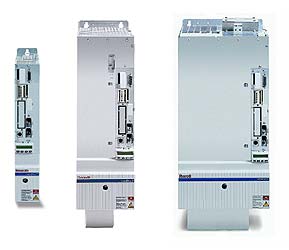
Rexroth IndraDrive
7.8
Error code
0x1001
0x1009
0x2001
0x2002
0x2003
0x2004
0x2005
0x3002
0x3003
0x3004
0x3005
0x4001
0x4002
0x4003
0x4004
0x4005
0x5001
0x5002
0x5003
0x5004
0x5005
0x6001
0x6002
0x6003
0x6004
DOK-INDRV*-GEN-**VRS**-WA01-EN-P
LSA Control S.L. www.lsa-control.com comercial@lsa-control.com (+34) 960 62 43 01
The error codes defined in the SERCOS interface specification are used.
(See SERCOS Interface specification, sec. 4.3.2.3 «Error messages in
service channel»). These codes are also used with faulty accessing of
control and systems parameters.
Explanation
IDN not available
element 1 incorrectly accessed
name not available
name transmission too short
name transmission too long
name cannot be changed
name presently write protected
attribute transmission too short
attribute transmission too long
attribute cannot be changed
attribute presently write protected
unit not available
unit transmission too short
unit transmission too long
unit cannot be changed
unit presently write protected
minimum input value not available
minimum input value transmission too short
minimum input value transmission too long
minimum input value cannot be changed
minimum input value presently write protected
maximum input value not available
maximum input value transmission too short
maximum input value transmission too long
maximum input value cannot be changed
-> continuation…
7-129
Error Messages

Rexroth error messages are made up of a diagnostic code and a diagnostic text. For error F2028, “F2” and “28” alternate on the H1 display. In the diagnostic message, it shows as F2028. F2028 is one of the “excessive” — error codes that tell you there’s too much of something. In this case, it’s too much deviation.
There are lots of error codes for various conditions and various components.
One group of error codes includes the word “excessive.” Sometimes too much of a good thing is just too much.
Excessives error codes
- F2027 Excessive oscillation in DC bus
The DC bus voltage fluctuates too much. The oscillation might not be visible in the machine, so be sure to check the command torque. Check the settings on the velocity control loop and the position control loop.
- F2028 Excessive deviation
When the actual position exceeds the expected parameters, this error is generated. This can be caused by errors in the parameters, if the axis is blocked, or when the power supply was turned off while the controller enable signal was applied. Check both the mechanical system to correct axis jamming, and the parameters to make sure they’re correct.
- F2036 Excessive position feedback difference
This error code means that the difference between actual position value 1 and position value 2 is greater than the monitoring window.
- F2037 Excessive position command difference
F2037 is the error shown when the position difference between two successive position command values is the same as the value in the bipolar velocity limit value — or larger.
Can we help?
Error codes can be caused by too much, too little, or just the wrong things. But any error code is more error codes than you really want to deal with.
Call us at 479-422-0390 for any Rexroth electric motion control issues. We specialize in Rexroth electric industrial motion control. We offer phone support, field support, and factory repair and reman. We also maintain the nation’s largest inventory of Rexroth electric drive and control components.
Bosch Rexroth IndraDrive Troubleshooting Manual

Title: Rexroth IndraDrive
Type of Documentation: Troubleshooting Guide
Document Type code: DOK-INDRV*-GEN-**VRS**-WA01-EN-P
Internal File Reference: Document Number 120-2400-B307-01/EN
Purpose of Documentation: This document is designed to assist maintanenance personnel in
identifying errors with the machinery.
It serves to:
• help in understanding error messages
• help in finding the cause of errors
• describe the procedure for trouble shooting
Record of Revisions:
Description Release Date Notes
DOK-INDRV*-GEN-**VRS**-WA01-EN-P 03.2004 First edition
Copyright: 2004 Bosch Rexroth AG
Copying this document, giving it to others and the use or communication of the contents thereof without express authority, are forbidden. Offenders are liable for the payment of damages. All rights are reserved in the event of the grant of a patent or the registration of a utility model or design (DIN 34-1).
Validity: The specified data is for product description purposes only and may not be deemed to be guaranteed unless expressly confirmed in the contract. All rights are reserved with respect to the content of this documentation and the availability of the product.
Published by:
Bosch Rexroth AG
Bgm.-Dr.-Nebel-Str. 2 • D-97816 Lohr a. Main
Telephone +49 (0)93 52/40-0
• Tx 68 94 21
• Fax +49 (0)93 52/40-48 85
http://www.boschrexroth.com/ Dept. ED
NOTE: This document has been printed on chlorine-free bleached paper.
Basics on Device Diagnosis
Diagnostic System
Coded Diagnostic Drive Messages:
Brief Description
The drive provides a diagnostic system including different possibilities that are basically divided into two groups:
• recognizing and displaying the current drive status by means of drive internal, priority-dependent generation of diagnostic messages
• collective messages for diverse status messages
Additionally, there are parameters for all important operating data the values of which can be transmitted both via master communication (e.g. SERCOS) and a parameterization interface (RS-232/485 in the ASCII protocol or SIS protocol; see “Serial Communication”). Pertinent Parameters
• S-0-0030, Manufacturer version
• S-0-0095, Diagnostic message
• S-0-0140, Controller type
• S-0-0142, Application type
• S-0-0375, List of diagnostic numbers
• S-0-0390, Diagnostic message number
• P-0-0009, Error number
• P-0-0478, Logbook event
• P-0-0479, Logbook time stamp
Drive-Internal Generation of Diagnostic Messages
Operating states, activities and reactions of the drive controller are detected by drive-internal generation of diagnostic messages and appear in coded form on the display of the control panel. In addition, these diagnostic messages can be transmitted to the master (control unit or commissioning software, e.g. Drive Top).
The following categories of diagnostic messages are differentiated (kinds of diagnostic messages):
• errors
• warnings
• commands/command errors
• status displays/operating states
Generally, the current diagnostic message with the highest priority is displayed or stored at the following locations in the drive:
• Display of the control panel
The diagnostic message number appears on the 8-digit display of the standard control panel.
• S-0-0095, Diagnostic message
This parameter contains the operating status of the drive at present relevant in the form of a plain text. Preceding the text is the respective content of parameter S-0-0390.
• S-0-0390, Diagnostic message number
The diagnostic message number shown on the display is stored in this parameter.
When a diagnostic message of the “error” category occurs, the corresponding diagnostic message number is stored in the P-0-0009,
Error number parameter. When there isn’t any error present, the value of parameter P-0-0009 equals zero.
In the S-0-0375, List of diagnostic numbers parameter the last 50 diagnostic message numbers of parameter S-0-0390 are recorded in
chronological order. When reading this list, the number of the diagnostic message that last occurred is displayed as parameter element 1.
Priorities of Display
The following priorities apply for displaying the current diagnostic message:  An overview of all diagnostic messages and their meanings is included in the documentation “Troubleshooting Guide” (description of diagnostic messages).
Structure of a Diagnostic Message
Every diagnostic message consists of
• diagnostic message number and
• diagnostic text.
The diagnostic message for the non-fatal error “Excessive deviation”, for example, has the following structure: 
“F2028” flashes on the display of the control panel. The diagnostic message number is contained in the S-0-0390, Diagnostic message
number parameter in hexadecimal form (for this example: 0x00F2028).
The diagnostic message number and the diagnostic text are contained as string F2028 Excessive deviation in the S-0-0095, Diagnostic message parameter. “2028” (dec) is written to the P-0-0009, Error number parameter because it is an error diagnosis.
Diagnostic Message on the Control Panel Display
The diagnostic message number appears on the 8-digit display of the standard control panel. This allows recognizing the current operating status of the drive quickly and without using a communication interface.
As a matter of principle, the following applies:
• status displays (P0, Ab, AF …) are displayed in right-aligned form
• warnings, command errors and other error messages are flashing  The current operating mode is not shown on the display. When the drive follows the preset operating mode and no command was activated, the display reads “AF”.
Diagnostic Messages in Plain Text
The diagnostic message in plain text contains the diagnostic message number followed by the diagnostic text. It can be read via the S-0-0095,
Diagnostic message parameter and directly displayed on an operator interface as a language-dependent description of the drive status.
The diagnostic message in plain text is switched to the selected language via the S-0-0265, Language selection parameter.
Diagnostic Message Number
The diagnostic message number contains only the diagnostic number without the diagnostic text. It can be read with the S-0-0390, Diagnostic message number parameter and is a language-independent possibility of determining and displaying the drive status on an operator interface.
Error Number
The error number contains only the error number without the diagnostic text. It can be read with the P-0-0009, Error number parameter and is a language-independent possibility of determining and displaying an error condition on an operator interface. This parameter only contains a value unequal zero when an error is present in the drive.
The error number is generated from the lowest 4 digits of the diagnostic message number. For example, the F2028 Excessive deviation error with the diagnostic message number “(0x)F2028” would produce the error number “2028.”
List of Diagnostic Numbers
The last 50 diagnostic message numbers displayed are stored in chronological order in the S-0-0375, List of diagnostic numbers parameter. Every change in the content of S-0-0390, Diagnostic message number means that the old content is transferred to S-0-0375.
When reading S-0-0375 the last transferred diagnostic message number appears in the first element of the parameter, the diagnostic message number transferred before from S-0-0390 in the second element etc.
Language Selection
Via parameter S-0-0265, Language selection it is possible to define or switch the language of diagnostic message texts.
Status Classes, Status Displays, Control Parameters:
In the drive there are many parameters with important status information
(bit lists). Some of the bits contained in these lists can be used for
configuring real-time status bits and additionally can be assigned to digital
outputs or to the configurable signal status word.
See “Digital Inputs/Outputs” in chapter “Extended Drive Functions” and
“Configurable Signal Status Word” in chapter “Master Communication”
Status Classes:
Brief Description
The drive differentiates between 3 states (error, warning and message) for which there is status information. To make the status information available there are so-called status class parameters (S-0-0011, S-0-0012, S-0-0013) that contain the respective status bits.
In addition to these status class parameters there are change bits contained in the status word of the field bus (e.g. S-0-0135 in the case of SERCOS) that display changes in one of the above-mentioned status class parameters (collective information).
Features:
• status class parameter for errors (cf. S-0-0011)
• status class parameter for warnings (cf. S-0-0012)
• status class parameter for messages (cf. S-0-0013)
• change bits in status word of master communication (e.g. S-0-0135 in the case of SERCOS)
• change bits of class 2 and 3 diagnostics (S-0-0097 and S-0-0098) can be masked in status word of master communication (e.g.
S-0-0135 in the case of SERCOS) to suppress individual bits or status messages
Pertinent Parameters:
• S-0-0011, Class 1 diagnostics
• S-0-0012, Class 2 diagnostics
• S-0-0013, Class 3 diagnostics
• S-0-0097, Mask class 2 diagnostics
• S-0-0098, Mask class 3 diagnostics
• S-0-0135, Drive status word
Functional Description:
Status Class Parameters
– S-0-0011, Class 1 diagnostics (status parameter for drive errors)
• In case a drive error occurs, the bit assigned to the error is set in parameter S-0-0011. A separate bit is assigned in S-0-0011 to errors defined according to SERCOS.
Manufacturer-specific errors cause bit 15 to be set in S-0-0011.
• In case a drive error occurs, bit 13 (drive interlock; error in class 1 diagnostics) is simultaneously set in the status word of the field bus (S-0-0135 in the case of SERCOS).
Note: All bits in class 1 diagnostics are cleared by executing the command C0500 (reset class 1 diagnostics).
See also Parameter Description “S-0-0099, C0500 Reset class 1 diagnostics”
– S-0-0012, Class 2 diagnostics (status parameter for drive warnings)
• In case a drive warning occurs, the bit assigned to the warning is set in parameter S-0-0012. A separate bit is assigned in S-0-0012 to warnings defined according to SERCOS.
Manufacturer-specific warnings cause bit 15 to be set in S-0-0012.
• In case a drive warning occurs, bit 12 (change bit class 2 diagnostics) is simultaneously set in the status word of the field bus (S-0-0135 in the case of SERCOS) when the content of S-0-0012 changes (i.e. at least one bit toggles).
• The bits in parameter S-0-0012 are automatically cleared when the warning disappears. The change bit in the status word of the master communication (S-0-0135 in the case of SERCOS) remains set, however, until parameter S-0-0012 has been read once.
Note: Via parameter S-0-0097, Mask class 2 diagnostics warnings can be masked in terms of their effect on the change bit.
– S-0-0013, Class 3 diagnostics (status parameter for drive messages)
• Messages of the drive are listed in parameter S-0-0013. A separate bit is assigned in S-0-0013 to messages defined according to SERCOS.
• In the case of a drive message, bit 11 (change bit class 3 diagnostics) is simultaneously set in the status word of the field bus (S-0-0135 in the case of SERCOS).
Note: Each of these messages is stored in a separate parameter (S-0-0330 to S-0-0342).
• The bits in parameter S-0-0013 are automatically cleared when the message disappears. The change bit in the status word of the master communication (S-0-0135 in the case of SERCOS) remains set, however, until parameter S-0-0013 has at least been read once.
Change Bits in Drive Status Word:
If the status of a bit in S-0-0012, Class 2 diagnostics or S-0-0013, Class 3 diagnostics changes, the change bit for class 2 or 3 diagnostics is set in the field bus status word (e.g. S-0-0135 in the case of SERCOS).
A change bit in the status word (bit 11 or 12) is always set due to a change of the parameter content of S-0-0012 or S-0-0013. This enables the master to recognize very quickly whether a change occurred in S-0-0012 or S-0-0013.
A read access to one of the two parameters clears the respective change bit again.
Masking the Change Bit:
By means of the parameters S-0-0097, Mask class 2 diagnostics and S-0-0098, Mask class 3 diagnostics it is possible to mask out certain bits in terms of their effect on the change bit of the status word (bit 12 or bit 11).
The figure below illustrates the principle of masking by means of an example: 
The figure below illustrates the handling of the change bits in the status word and of the status class parameters: 
Fixed Status Displays:
Function-Related Status Parameters
In the drive there are parameters the content of which has a direct relation to the status of the sequence of different drive functions. These parameters are used to display the current status information of the assigned function.
The following parameters are available for function-related status display:
• S-0-0014, Interface status
This parameter displays the status of the communication phase
transition and the cyclic communication.
• S-0-0135, Drive status word
This is the status word of the master communication (SERCOS) and
contains all essential status information for the master.
• S-0-0403, Position feedback value status
This parameter contains status bits for the position data reference of
the individual measuring systems.
• S-0-0419, Positioning command acknowledge
This status information is used for acknowledgment in the “drivecontrolled
positioning” mode.
• P-0-0046, Status word of current controller
This parameter contains status bits of the internal motor control (e.g.
overvoltage in DC bus).
• P-0-0115, Status word of system control
This parameter contains status bits of device control (see also “Device
Control”).
• P-0-0188, Status word positioning generator
This parameter contains status bits for the positioning behavior of the
drive (e.g. “In target position”).
• P-0-0222, Travel range limit inputs
This parameter displays the status of the travel range limit switch
inputs (see also “Travel Range Limit Switches”).
• P-0-0223, E-Stop input
This parameter displays the status of the E-Stop input (see also “EStop Function”).
• P-0-0445, Status word torque/current limit
This parameter contains status bits to display the activation of
torque/current limitation (see also “Torque/Current Limit”).
• P-0-0539, Holding brake status word
This parameter contains status bits for the status of the motor holding brake (see also “Motor Holding Brake”).
• P-0-0555, Controller status word
This parameter displays messages with regard to velocity and limits that have been reached.
• P-0-4029, SCSB diagnostics
Parameter for reading master communication settings and states (with SERCOS interface).
• P-0-4086, Master communication status
This parameter displays control information of the master communication for handling phase switch, drive enable etc., defined during initialization.
Status Parameters for Real-Time Status Bits
The following list contains status parameters that only contain one bit and can therefore be used for configuring real-time status bits (see “Master Communication: SERCOS interface”):
• S-0-0330, Message ’n_actual = n_command’
• S-0-0331, Status ’n_feedback = 0’
• S-0-0332, Message ’nactual < nx’
• S-0-0333, Message ’T >= Tx’
• S-0-0334, Message ’T >= Tlimit’
• S-0-0335, Message ’n command > n limit’
• S-0-0336, Message In position
• S-0-0337, Message ’P >= Px’
• S-0-0341, In-Position coarse message
• S-0-0342, Target position reached
• S-0-0343, Status “Interpolator halted”
• S-0-0409, Probe 1 positive latched
• S-0-0410, Probe 1 negative latched
• S-0-0411, Probe 2 positive latched
• S-0-0412, Probe 2 negative latched
Control Parameters
Apart from the parameters for status display, there are parameters available in the drive that are used to control the drive functions (see also
corresponding parameter description):
• P-0-0045, Control word of current controller
• P-0-0427, Control parameter of analog output
• P-0-0522, Commutation setting control word
• P-0-0556, Control word of axis controller
• P-0-0612, Control word for setting absolute measuring
• P-0-4028, Device control word
Control Panel of the IndraDrive Controllers
Brief Description:
The standard design of IndraDrive controllers includes a control panel with an 8-digit display and four buttons located underneath it.
The display shows operating states, command and error diagnoses, as well as present warnings.
Using the four buttons, the commissioning engineer or service technician can opt to display extended diagnostic messages at the drive controller and to activate simple commands (in addition to master communication using the commissioning tool or NC control unit). 
Functional Description:
Standard Displays:
The display of the IndraDrive controller automatically shows:
• status of the master communication
• operating status
• activated commands and command diagnoses
• warnings and error diagnoses
The displays have priorities because it is impossible to have various displays at the same time. 


Priorities of Display:
The current drive status is displayed with highest priority. 
Activating Extended Display and Command Input:
By simultaneously pressing the “Enter” and “Esc” buttons (for 8 s!) you can call up extended displays; subsequently pressing the “Up” button activates the command input.
Extended Displays:
By means of the extended displays it is possible to additionally call up the contents of certain parameters:
• error memory
• diagnostic message memory
• operating hours counter control section
• operating hours counter power section
• type designation of the firmware active in the device
• safety technology code, if safety technology option available 
 For more details on diagnostic messages, error messages and operating hours counters see the respective chapters of the present documentation.
Command Inputs:
Starting from the extended display it is possible to activate commands and make settings:
• set the drive address (drive number in the bus system of the master communication)
• set the length of the fiber optic cable
• activate the “analog mode” master communication
• C07_x load defaults procedure command (loading controller parameters resp. base parameters)
• other commands like
• C2200 Backup working memory procedure command
• C2300 Load working memory command
• C2500 Copy IDN from optional memory to internal memory
• C2600 Copy IDN from internal memory to optional memory
• C2900 Firmware update from MMC 

Notes on Commissioning:
Extended Diagnostic Possibilities
The firmware provides further possibilities of diagnosis. For the description please see the Functional Description of the Firmware.
Kinds of Diagnostic Messages
Error:
Depending on the operating mode that is used and some parameter settings, the drive controller carries out monitoring functions. An error
message is generated by the drive controller, if a status is detected that no longer allows correct operation.
Error Classes:
Errors can be divided into several error classes. The error class is represented by the first two digits of the diagnostic message number.
Drive Error Reaction:
If the drive controller is in control (drive enable was set) and an error occurs, the drive controller automatically starts a drive error reaction.
The reaction to errors of certain classes can be influenced by the P-0-0119, Best possible deceleration parameter.
At the end of each error reaction, the drive is torque-free. 
Clearing Errors:
Errors are not automatically cleared; they have to be cleared by:
• the control unit by activating the S-0-0099, C0500 Reset class 1 diagnostics command or
• by the user via the control panel
Note: Some errors can only be cleared in communication phase 2. If the error status persists the drive controller generates the error message again.
Booting and Firmware Download Errors:
Note: Apart from the mentioned error classes that can occur during operation, errors can occur when the devices are booted and during firmware download. These errors are not displayed at the control panel with a diagnostic message number of the “Fxxxx” pattern, but with a short text. Booting and firmware download errors are described separately.
Warnings:
While in operation the drive controller carries out monitoring functions. Some monitoring functions depend on the operating mode that is used and/or parameter settings. If a status is detected that still allows correct operation but persists, which would then cause an error to be generated, a warning is generated.
Note: Some warnings won’t result in an error if they are ignored.
Warning Classes:
Warnings can be divided into two classes:
• without drive reaction (E1xxx ..E7xxx)
• with drive reaction (E8xxx)
Warnings cannot be cleared externally.
Commands:
Commands are used to control complex functions in the drive. The command execution is displayed in a diagnostic message.
By means of the respective parameter that is assigned to the command, a higher-level control unit can start, interrupt and clear commands. In addition, some selected commands can be directly started via the control panel of the drive controller.
There are 3 command types:
Drive Control Commands: Drive control commands can only be started when drive enable was set. They might possibly cause automatic drive motion and deactivate the active operating mode during its execution.
Monitoring Commands: Executing monitoring commands activates or deactivates monitors and functions.
Administration Commands: Administration commands execute administration tasks. They cannot be interrupted.
Note: Command errors are displayed with a diagnostic message, too. By means of the first three digits (Cxx) of the diagnostic message number it is possible to recognize which command caused the command error.
States/Operating States:
The diagnostic status messages display the phases of communication build-up and initialization (boot phase), operating states or the currently active operating mode.
Note: In the case of some diagnostic status messages the diagnostic message number contained in parameter S-0-0390, Diagnostic message number differs from the display at the drive controller (see also “Operating States”).
Important directions for use
Appropriate use
Introduction:
Rexroth products represent state-of-the-art developments and manufacturing. They are tested prior to delivery to ensure operating safety
and reliability.
The products may only be used in the manner that is defined as appropriate. If they are used in an inappropriate manner, then situations
can develop that may lead to property damage or injury to personnel.
Note: Bosch Rexroth, as manufacturer, is not liable for any damages resulting from inappropriate use. In such cases, the guarantee and the right to payment of damages resulting from inappropriate use are forfeited. The user alone carries all responsibility of the risks.
Before using Rexroth products, make sure that all the pre-requisites for an appropriate use of the products are satisfied:
• Personnel that in any way, shape or form uses our products must first read and understand the relevant safety instructions and be familiar with appropriate use.
• If the product takes the form of hardware, then they must remain in their original state, in other words, no structural changes are permitted.
It is not permitted to decompile software products or alter source codes.
• Do not mount damaged or faulty products or use them in operation.
• Make sure that the products have been installed in the manner described in the relevant documentation.
Areas of use and application:
Drive controllers made by Bosch Rexroth are designed to control electrical motors and monitor their operation. Control and monitoring of the motors may require additional sensors and actors.
Note: The drive controllers may only be used with the accessories and parts specified in this document. If a component has not been specifically named, then it may not be either mounted or connected. The same applies to cables and lines.
Operation is only permitted in the specified configurations and combinations of components using the software and firmware as specified in the relevant function descriptions.
Every drive controller has to be programmed before starting it up, making it possible for the motor to execute the specific functions of an application. The drive controllers of the IndraDrive family are designed for use in single or multiple-axis drive and control applications.
To ensure an application-specific use, the drive controllers are available with differing drive power and different interfaces.
Typical applications of drive controllers belonging to the IndraDrive family are:
• handling and mounting systems,
• packaging and foodstuff machines,
• printing and paper processing machines and
• machine tools.
The drive controllers may only be operated under the assembly, installation and ambient conditions as described here (temperature, system of protection, humidity, EMC requirements, etc.) and in the position specified.
Inappropriate use
Using the drive controllers outside of the above-referenced areas of application or under operating conditions other than described in the document and the technical data specified is defined as “inappropriate use”.
Drive controllers may not be used if
• they are subject to operating conditions that do not meet the above specified ambient conditions. This includes, for example, operation under water, in the case of extreme temperature fluctuations or extremely high maximum temperatures or if
• Rexroth has not specifically released them for that intended purpose.
Please note the specifications outlined in the general safety instructions!
Safety Instructions for Electric Drives and Controls
Introduction
Read these instructions before the initial startup of the equipment in order to eliminate the risk of bodily harm or material damage. Follow these safety instructions at all times.
Do not attempt to install or start up this equipment without first reading all documentation provided with the product. Read and understand these safety instructions and all user documentation of the equipment prior to working with the equipment at any time. If you do not have the user documentation for your equipment, contact your local Bosch Rexroth representative to send this documentation immediately to the person or persons responsible for the safe operation of this equipment.
If the equipment is resold, rented or transferred or passed on to others, then these safety instructions must be delivered with the equipment.
Improper use of this equipment, failure to follow the safety instructions in this document or tampering with the product, including disabling of safety devices, may result in material damage, bodily harm, electric shock or even death!
Explanations
The safety instructions describe the following degrees of hazard seriousness in compliance with ANSI Z535. The degree of hazard seriousness informs about the consequences resulting from noncompliance with the safety instructions. 
Hazards by Improper Use 


General Information
• Bosch Rexroth AG is not liable for damages resulting from failure to observe the warnings provided in this documentation.
• Read the operating, maintenance and safety instructions in your language before starting up the machine. If you find that you cannot completely understand the documentation for your product, please ask your supplier to clarify.
• Proper and correct transport, storage, assembly and installation as well as care in operation and maintenance are prerequisites for optimal and safe operation of this equipment.
• Only persons who are trained and qualified for the use and operation of the equipment may work on this equipment or within its proximity.
• The persons are qualified if they have sufficient knowledge of the assembly, installation and operation of the equipment as well as an understanding of all warnings and precautionary measures noted in these instructions.
• Furthermore, they must be trained, instructed and qualified to switch electrical circuits and equipment on and off in accordance with technical safety regulations, to ground them and to mark them according to the requirements of safe work practices. They must
have adequate safety equipment and be trained in first aid.
• Only use spare parts and accessories approved by the manufacturer.
• Follow all safety regulations and requirements for the specific application as practiced in the country of use.
• The equipment is designed for installation in industrial machinery.
• The ambient conditions given in the product documentation must be observed.
• Use only safety features and applications that are clearly and explicitly approved in the Project Planning Manual.
For example, the following areas of use are not permitted: construction cranes, elevators used for people or freight, devices and vehicles to transport people, medical applications, refinery plants, transport of hazardous goods, nuclear applications, applications sensitive to high frequency, mining, food processing, control of protection equipment (also in a machine).
• The information given in the documentation of the product with regard to the use of the delivered components contains only examples of
applications and suggestions.
The machine and installation manufacturer must
• make sure that the delivered components are suited for his individual application and check the information given in this documentation with regard to the use of the components,
• make sure that his application complies with the applicable safety regulations and standards and carry out the required measures, modifications and complements.
• Startup of the delivered components is only permitted once it is sure that the machine or installation in which they are installed complies with the national regulations, safety specifications and standards of the application.
• Operation is only permitted if the national EMC regulations for the application are met.
The instructions for installation in accordance with EMC requirements can be found in the documentation “EMC in Drive and Control Systems”.
The machine or installation manufacturer is responsible for compliance with the limiting values as prescribed in the national regulations.
• Technical data, connections and operational conditions are specified in the product documentation and must be followed at all times.
Protection Against Contact with Electrical Parts
Note: This section refers to equipment and drive components with voltages above 50 Volts.
Touching live parts with voltages of 50 Volts and more with bare hands or conductive tools or touching ungrounded housings can be dangerous and cause electric shock. In order to operate electrical equipment, certain parts must unavoidably have dangerous voltages applied to them.
High electrical voltage! Danger to life, severe bodily harm by electric shock!
⇒ Only those trained and qualified to work with or on electrical equipment are permitted to operate, maintain or repair this equipment.
⇒ Follow general construction and safety regulations when working on high voltage installations.
⇒ Before switching on power the ground wire must be permanently connected to all electrical units according to the connection diagram.
⇒ Do not operate electrical equipment at any time, even for brief measurements or tests, if the ground wire is not permanently connected to the points of the components provided for this purpose.
⇒ Before working with electrical parts with voltage higher than 50 V, the equipment must be disconnected from the mains voltage or power supply. Make sure the equipment cannot be switched on again unintended.
⇒ The following should be observed with electrical drive and filter components:
⇒ Wait five (5) minutes after switching off power to allow capacitors to discharge before beginning to work.
Measure the voltage on the capacitors before beginning to work to make sure that the equipment is safe to touch.
⇒ Never touch the electrical connection points of a component while power is turned on.
⇒ Install the covers and guards provided with the equipment properly before switching the equipment on.
Prevent contact with live parts at any time.
⇒ A residual-current-operated protective device (RCD) must not be used on electric drives! Indirect contact must be prevented by other means, for example, by an overcurrent protective device.
⇒ Electrical components with exposed live parts and uncovered high voltage terminals must be installed in a protective housing, for example, in a control cabinet.
To be observed with electrical drive and filter components:
High electrical voltage on the housing! High leakage current! Danger to life, danger of injury by electric shock!
⇒ Connect the electrical equipment, the housings of all electrical units and motors permanently with the safety conductor at the ground points before power is switched on. Look at the connection diagram. This is even necessary for brief tests.
⇒ Connect the safety conductor of the electrical equipment always permanently and firmly to the supply mains. Leakage current exceeds 3.5 mA in normal operation.
⇒ Use a copper conductor with at least 10 mm² cross section over its entire course for this safety conductor connection!
⇒ Prior to startups, even for brief tests, always connect the protective conductor or connect with ground wire.
Otherwise, high voltages can occur on the housing that lead to electric shock.
Protection Against Electric Shock by Protective Low Voltage (PELV)
All connections and terminals with voltages between 0 and 50 Volts on Rexroth products are protective low voltages designed in accordance with international standards on electrical safety.
High electrical voltage due to wrong connections! Danger to life, bodily harm by electric shock!
⇒ Only connect equipment, electrical components and cables of the protective low voltage type (PELV = Protective Extra Low Voltage) to all terminals and clamps with voltages of 0 to 50 Volts.
⇒ Only electrical circuits may be connected which are safely isolated against high voltage circuits. Safe isolation is achieved, for example, with an isolating transformer, an opto-electronic coupler or when battery-operated.
Protection Against Dangerous Movements
Dangerous movements can be caused by faulty control of the connected motors. Some common examples are:
• improper or wrong wiring of cable connections
• incorrect operation of the equipment components
• wrong input of parameters before operation
• malfunction of sensors, encoders and monitoring devices
• defective components
• software or firmware errors
Dangerous movements can occur immediately after equipment is switched on or even after an unspecified time of trouble-free operation.
The monitoring in the drive components will normally be sufficient to avoid faulty operation in the connected drives. Regarding personal safety, especially the danger of bodily injury and material damage, this alone cannot be relied upon to ensure complete safety. Until the integrated monitoring functions become effective, it must be assumed in any case that faulty drive movements will occur. The extent of faulty drive movements depends upon the type of control and the state of operation.
Dangerous movements! Danger to life, risk of injury, severe bodily harm or material damage!
⇒ Ensure personal safety by means of qualified and tested higher-level monitoring devices or measures integrated in the installation. Unintended machine motion is possible if monitoring devices are disabled, bypassed or not activated.
⇒ Pay attention to unintended machine motion or other malfunction in any mode of operation.
⇒ Keep free and clear of the machine’s range of motion and moving parts. Possible measures to prevent people from accidentally entering the machine’s range of motion:
– use safety fences
– use safety guards
– use protective coverings
– install light curtains or light barriers
⇒ Fences and coverings must be strong enough to resist maximum possible momentum, especially if there is a possibility of loose parts flying off.
⇒ Mount the emergency stop switch in the immediate reach of the operator. Verify that the emergency stop works before startup. Don’t operate the machine if the emergency stop is not working.
⇒ Isolate the drive power connection by means of an emergency stop circuit or use a starting lockout to prevent unintentional start.
⇒ Make sure that the drives are brought to a safe standstill before accessing or entering the danger zone. Safe standstill can be achieved by switching off the power supply contactor or by safe mechanical locking of moving parts.
⇒ Secure vertical axes against falling or dropping after switching off the motor power by, for example:
– mechanically securing the vertical axes
– adding an external braking/ arrester/ clamping mechanism
– ensuring sufficient equilibration of the vertical axes
The standard equipment motor brake or an external brake controlled directly by the drive controller are not sufficient to guarantee personal safety!
⇒ Disconnect electrical power to the equipment using a master switch and secure the switch against reconnection for:
– maintenance and repair work
– cleaning of equipment
– long periods of discontinued equipment use
⇒ Prevent the operation of high-frequency, remote control and radio equipment near electronics circuits and supply leads. If the use of such equipment cannot be avoided, verify the system and the installation for possible malfunctions in all possible positions of normal use before initial startup. If necessary, perform a special electromagnetic compatibility (EMC) test on the installation.
Protection Against Magnetic and Electromagnetic Fields During Operation and Mounting
Magnetic and electromagnetic fields generated near current-carrying conductors and permanent magnets in motors represent a serious health hazard to persons with heart pacemakers, metal implants and hearing aids.
Health hazard for persons with heart pacemakers, metal implants and hearing aids in proximity to electrical equipment!
⇒ Persons with heart pacemakers, hearing aids and metal implants are not permitted to enter the following areas:
– Areas in which electrical equipment and parts are mounted, being operated or started up.
– Areas in which parts of motors with permanent magnets are being stored, operated, repaired or mounted.
⇒ If it is necessary for a person with a heart pacemaker to enter such an area, then a doctor must be consulted prior to doing so. Heart pacemakers that are already implanted or will be implanted in the future, have a considerable variation in their electrical noise immunity. Therefore there are no rules with general validity.
⇒ Persons with hearing aids, metal implants or metal pieces must consult a doctor before they enter the areas described above. Otherwise, health hazards will occur.
Protection Against Contact with Hot Parts
Housing surfaces could be extremely hot!
Danger of injury! Danger of burns!
⇒ Do not touch housing surfaces near sources of heat!
Danger of burns!
⇒ After switching the equipment off, wait at least ten (10) minutes to allow it to cool down before touching it.
⇒ Do not touch hot parts of the equipment, such as housings with integrated heat sinks and resistors.
Danger of burns!
Protection During Handling and Mounting
Under certain conditions, incorrect handling and mounting of parts and components may cause injuries.
Risk of injury by incorrect handling! Bodily harm caused by crushing, shearing, cutting and mechanical shock!
⇒ Observe general installation and safety instructions with regard to handling and mounting.
⇒ Use appropriate mounting and transport equipment.
⇒ Take precautions to avoid pinching and crushing.
⇒ Use only appropriate tools. If specified by the product documentation, special tools must be used.
⇒ Use lifting devices and tools correctly and safely.
⇒ For safe protection wear appropriate protective clothing, e.g. safety glasses, safety shoes and safety gloves.
⇒ Never stand under suspended loads.
⇒ Clean up liquids from the floor immediately to prevent slipping.
Battery Safety
Batteries contain reactive chemicals in a solid housing. Inappropriate handling may result in injuries or material damage.
Risk of injury by incorrect handling!
⇒ Do not attempt to reactivate discharged batteries by heating or other methods (danger of explosion and cauterization).
⇒ Never charge non-chargeable batteries (danger of leakage and explosion).
⇒ Never throw batteries into a fire.
⇒ Do not dismantle batteries.
⇒ Do not damage electrical components installed in the equipment.
Note: Be aware of environmental protection and disposal! The batteries contained in the product should be considered as hazardous material for land, air and sea transport in the sense of the legal requirements (danger of explosion). Dispose batteries separately from other waste. Observe the legal requirements in the country of installation.
Protection Against Pressurized Systems
Certain motors and drive controllers, corresponding to the information in the respective Project Planning Manual, must be provided with pressurized media, such as compressed air, hydraulic oil, cooling fluid and cooling lubricant supplied by external systems. Incorrect handling of the supply and connections of pressurized systems can lead to injuries or accidents. In these cases, improper handling of external supply systems, supply lines or connections can cause injuries or material damage.
Danger of injury by incorrect handling of pressurized systems !
⇒ Do not attempt to disassemble, to open or to cut a pressurized system (danger of explosion).
⇒ Observe the operation instructions of the respective manufacturer.
⇒ Before disassembling pressurized systems, release pressure and drain off the fluid or gas.
⇒ Use suitable protective clothing (for example safety glasses, safety shoes and safety gloves)
⇒ Remove any fluid that has leaked out onto the floor immediately.
Note: Environmental protection and disposal! The media used in the operation of the pressurized system equipment may not be environmentally compatible. Media that are damaging the environment must be disposed separately from normal waste.
Observe the legal requirements in the country of installation.
Diagnostic Messages when Booting the Devices
Devices with Valid Firmware
When a valid firmware is available in the control section, the texts
800T1.1
800T1.2
800T1.3
are displayed on the control section display after the control voltage is
switched on (“booting”). The controller first goes through the boot phases
in which the basic initialization of the processor takes place.
In the following boot phases the basic initialization of the hardware
configuration, the peripherals, the parameters, the master communication
etc. takes place:
800T2.2
….
800T2.9
Finally, the initialization results are controlled. If initialization errors
occurred they are output via the display. After initialization without errors
the controller goes through the communication phases and, where
required, switches to “ready for operation” (“bb”):
800T3.0
800T3.1
Devices without Valid Firmware
In case the device does not detect valid firmware, neither in the nonvolatile memory (flash) nor in the MultiMediaCard (MMC), the so-called
“loader” is started. The “loader” is an auxiliary program used to load firmware to the flash memory. When the “loader” is activated the controller goes through several initialization phases:
LOAD1
LOAD2
LOAD3
LOAD4
The LOADER display signals that the auxiliary program for loading (“download”) firmware is ready for operation.
Error Messages when Booting the Devices
PLC ?
Brief Description: PLC start dialog
Before “Boot 2.9” was displayed on the control panel the buttons “ESC” and “ENTER” had been simultaneously pressed and kept pressed on the control panel.
As the functional package “Motion Logic” (drive PLC and technology functions) has been enabled, the display reads “PLC ?”. The automatic start of a PLC boot project was prevented.
By pressing the arrow buttons (arrow down or arrow up) the display changes between “Run PLC” and “Stop PLC”.
Stop PLC
Brief Description: Do not start PLC after booting
Pressing the “ENTER” button on the control panel prevents the start of a PLC boot project.
Run PLC
Brief Description: Start PLC after booting
When the “ENTER” button is pressed on the control panel, the drive PLC and a possibly available boot project are started after the booting process.
No IDN on MMC !
Brief Description: MMC was not formatted correctly 
Load new Param. ?
Brief Description: MMC plugged, changed or removed => different parameter file 
End C29
Brief Description: Command C29 successfully completed
The command C2900 Command Firmware update from MMC was successfully completed. The firmware was copied from the MultiMediaCard (MMC) to the drive-internal memory.
MMC not correct!
Brief Description: MMC incorrectly formatted. 
IBF not correct!
Brief Description: Content of IBF file not correct 
Firmware update ?
Brief Description: Different firmware in device and on MMC During the booting process with the MMC plugged in, a check is run by means of the release version to find out whether the firmware (FW) on the flash is identical to the one on the MMC. 
Update Error !
Brief Description: Firmware update error during booting process 
Operating States
In the following, the possible operating states are listed in alphabetical order. The operating states are displayed on the control panel of the device:
Ab
“drive ready” (Antrieb bereit)
see also: A0012 Control and power sections ready for operation
AC
see also: A0400 Automatic drive check and adjustment
AE
see also: A0401 Drive deceleration to standstill
AF
“drive enable” (Antrieb Freigabe)
Depending on the operating mode used you can find a detailed description of the “AF” display under the respective diagnostic status message.
AH
“Drive Halt” (Antrieb Halt)
see also: A0010 Drive HALT
AS
see also: A0011 Starting lockout active
ASP
see also: A0014 Drive interlock active
AU
see also: A0402 Drive in automatic mode
bb
“ready for operation” (betriebsbereit)
see also: A0013 Ready for power on
charg
see also: A0503 DC bus charging active
LB
see also: A0500 Supply module in voltage control resp. A0503 Supply module in operation
P0
“Phase 0” (only with SERCOS master communication)
see also: A0000 Communication phase 0
P-1
“Phase -1”
see also: A0009 Automatic baud rate detection for SERCOS Interface
P1
“Phase 1”
see also: A0001 Communication phase 1
P2
“Phase 2”
see also: A0002 Communication phase 2
P3
“Phase 3”
see also: A0003 Communication phase 3
PL
“parameter load with basic values”
see also: F2009 PL Load parameter default values
RL
see also: F2008 RL The motor type has changed
SBB
see also: A0017 Special mode motion active
SBH
see also: A0016 Safety related operational stop active
SH
see also: A0015 Safety related standstill active
ZKS
see also: A0520 DC bus quick discharge active
Status Diagnostic Messages
A0000 Communication phase 0:
Supported by Firmware Variant:
FWA-INDRV*-MPH02VRS-MS
FWA-INDRV*-MPB02VRS-MS
FWA-INDRV*-MPD02VRS-MS
Supported by Supply Unit:
HMV01
The communication between master and slaves via SERCOS interface is established in four communication phases:
The communication phases 0 and 1 are used to recognize the bus nodes.
In the communication phase 2 the time and data build-up of the protocols are prepared for the communication phases 3 and 4. The phase progression takes place in ascending order. The communication phase is set by the master. Switching to communication phase 4 completes the initialization and allows power input. If the phase progression is interrupted, the status display remains in the communication phase that has been reached.
When the A0000 Communication phase 0 diagnostic message is active the drive is in phase 0 and waits for the master’s phase switch from
communication phase 0 to 1. During the communication phase 0 the control panel of the drive reads “P0”.
A0000 – Attributes
Display: P0
Mess. no.: A0000 (hex)
A0001 Communication phase 1:
Supported by Firmware Variant:
FWA-INDRV*-MPH02VRS-MS
FWA-INDRV*-MPB02VRS-MS
FWA-INDRV*-MPD02VRS-MS
Supported by Supply Unit:
HMV01
The communication between master and slaves via SERCOS interface is established in four communication phases:
The communication phases 0 and 1 are used to recognize the bus nodes.
In the communication phase 2 the time and data build-up of the protocols are prepared for the communication phases 3 and 4.
The phase progression takes place in ascending order. The communication phase is set by the master. Switching to communication
phase 4 completes the initialization and allows power input. If the phase progression is interrupted, the status display remains in the
communication phase that has been reached.
When the A0001 Communication phase 1 diagnostic message is active the drive is in phase 1, the master has not yet activated the phase switch form phase 1 to 2. During the communication phase 1 the control panel of the drive reads “P1”.
A0001 – Attributes
Display: P1
Mess. no.: A0001 (hex)
A0002 Communication phase 2:
Supported by Firmware Variant:
FWA-INDRV*-MPH02VRS-MS
FWA-INDRV*-MPB02VRS-MS
FWA-INDRV*-MPD02VRS-MS
Supported by Supply Unit:
HMV01
Communication phase 2 means that the drive is in the parameterization mode. In this mode many parameters can be written that cannot be written any more in communication phase 4 (operating mode).
In communication phase 2
• the communication parameters are usually transmitted from the master to the drive (in the case of field bus and SERCOS devices) and
• the “Load drive parameters” and “Save drive parameters” (“file service”) functions are carried out, if required.
During the communication phase 2 the control panel of the drive reads “P2”.
In order to get to communication phase 2 the master, in the case of drives with field bus and SERCOS interfaces, sets “communication phase 2” via the master communication interface. Another possibility to switch to communication phase 2 is to execute the P-0-4023, C0400 Communication phase 2 transition command.
Communication Phase 3
Before it is possible to switch to communication phase 3 it is necessary to execute the S-0-0127, C0100 Communication phase 3 transition
check command. Among other things the drive, during the transition check, checks the parameters required for communication phase 3 for validity.
After successful execution of the transition check command the master switches the drive to communication phase 3 (in the case of field bus and SERCOS devices) or the drive automatically switches to phase 3 at the end of the transition check command.
A0002 – Attributes
Display: P2
Mess. no.: A0002 (hex)
A0003 Communication phase 3\
Supported by Firmware Variant:
FWA-INDRV*-MPH02VRS-MS
FWA-INDRV*-MPB02VRS-MS
FWA-INDRV*-MPD02VRS-MS
Supported by Supply Unit:
HMV01
Communication phase 3 means that the drive is in the restricted parameterization mode. In this mode, as in the parameterization mode (phase 2), many parameters can still be written that cannot be written any more in communication phase 4 (operating mode). Communication parameters cannot be written in phase 3.
During the communication phase 3 the control panel of the drive reads “P3”.
In order to get to communication phase 3 the master, in the case of drives with field bus and SERCOS interfaces, sets “communication phase 3” via the master communication interface. Another possibility to switch to communication phase 3 is to execute the S-0-0127, C0100 Communication phase 3 transition check command.
Communication Phase 4
Before it is possible to switch to communication phase 4 it is necessary to execute the S-0-0128, C0200 Communication phase 4 transition
check command. Among other things the drive, during the transition check, checks the parameters required for communication phase 4 for validity.
After successful execution of the transition check command the master switches the drive to communication phase 4 (in the case of field bus and SERCOS devices) or the drive automatically switches to phase 4 at the end of the transition check command.
A0003 – Attributes
Display: P3
Mess. no.: A0003 (hex)
A0009 Automatic baud rate detection for SERCOS interface
Supported by Firmware Variant:
FWA-INDRV*-MPH02VRS-MS
FWA-INDRV*-MPB02VRS-MS
FWA-INDRV*-MPD02VRS-MS
The communication between master and slaves via SERCOS interface is established in four communication phases:
The communication phases 0 and 1 are used to recognize the bus nodes.
In the communication phase 2 the time and data build-up of the protocols are prepared for the communication phases 3 and 4.
The phase progression takes place in ascending order. The communication phase is set by the master. Switching to communication
phase 4 completes the initialization and allows power input.
If the phase progression is interrupted, the status display remains in the communication phase that has been reached.
If the A0009 Automatic baud rate detection for SERCOS interface diagnostic message is active, the drive is in phase 0 – 1, the progression to phase 0 is carried out at the moment when the correct baud rate is detected.
During the A0009 Automatic baud rate detection for SERCOS interface diagnostic message the control panel of the drive reads “P-1”.
A0009 – Attributes
Display: P -1
Mess. no.: A0009 (hex)
A0010 Drive HALT
Supported by Firmware Variant:
FWA-INDRV*-MPH02VRS-MS
FWA-INDRV*-MPB02VRS-MS
FWA-INDRV*-MPD02VRS-MS
The Drive HALT function is activated by the master via the master communication interface by clearing the Drive HALT bit in the S-0-0134, Master control word parameter or by interrupting a drive control command (e.g. Drive controlled homing procedure).
When the Drive HALT function is active the control panel of the drive reads “AH”.
The Drive HALT function is used to shut down an axis with defined acceleration and defined jerk.
In the case of speed control and torque control the drive is shut down by means of velocity command value reset with maximum torque.
See also Functional Description “The Functional Principle of Drive Halt”
A0010 – Attributes
Display: AH
Mess. no.: A0010 (hex)
A0011 Starting lockout active
Supported by Firmware Variant:
FWA-INDRV*-MPH02VRS-MS
FWA-INDRV*-MPB02VRS-MS
FWA-INDRV*-MPD02VRS-MS
As an option, certain digital drive controllers can be equipped with a drive interlock. The drive interlock prevents the unintended start of a servo axis.
This is realized by separating the electronic control system of the power output stage from the power output stage by means of a relay contact.
When the drive interlock is active the control panel of the drive reads “AS”.
See also Project Planning Manual Control Section, keyword “Drive interlock”
A0011 – Attributes
Display: AS
Mess. no.: A0011 (hex)
A0012 Control and power sections ready for operation
Supported by Firmware Variant:
FWA-INDRV*-MPH02VRS-MS
FWA-INDRV*-MPB02VRS-MS
FWA-INDRV*-MPD02VRS-MS
Supported by Supply Unit:
HMV01
For HMS, HMD, HCS:
The A0012 Control and power sections ready for operation diagnostic message signals that the drive is provided with control voltage and the power has been switched on. The drive is ready for power output.
Note: This status is displayed on the control panel of the drive with “Ab” (“Antrieb bereit” = Drive ready).
For HMV:
The diagnostic message A0012 Control and power sections ready for operation signals that the supply unit is ready for switching in the mains contactor.
Note: This status is displayed on the control panel of the device with “Bb” (“betriebsbereit” = ready for operation).
A0012 – Attributes
Display: Ab
Mess. no.: A0012 (hex)
A0013 Ready for power on
Supported by Firmware Variant:
FWA-INDRV*-MPH02VRS-MS
FWA-INDRV*-MPB02VRS-MS
FWA-INDRV*-MPD02VRS-MS
Supported by Supply Unit: HMV01
The A0013 Ready for power on diagnostic message signals that the drive is provided with control voltage and that there isn’t any error present
in the drive.
The drive is ready for power on.
Note: This status is displayed on the control panel of the drive with “bb” (“betriebsbereit” = ready for operation).
A0013 – Attributes
Display: bb
Mess. no.: A0013 (hex)
A0014 Drive interlock active
Supported by Firmware Variant:
FWA-INDRV*-MPH02VRS-MS
FWA-INDRV*-MPB02VRS-MS
FWA-INDRV*-MPD02VRS-MS
The drive is in the “special mode standstill”. The active safety function is “safety related drive interlock”.
Note: If the safety function “safety related drive interlock” is active, this is displayed on the control panel of the drive with “ASP”
(Antriebssperre = drive interlock).
Bit 1 is set in parameter P-0-3213, Safety technology status.
The drive has come to standstill, the power supply has been interrupted via two channels (output stage locked).
DANGER:
Dangerous movements! Danger to life, danger of injury, severe bodily injury or property damage!
⇒ After the output stage has been locked, standstill monitoring is not active. If external force influences are to be expected, e.g. in the case of a vertical axis, this motion has to be safely prevented by additional measures, e.g. a mechanical brake or weight compensation.
The safety function “safety related drive interlock” cannot be deselected by the enabling control but only by resetting the selection.
A0014 – Attributes
Display: ASP
Mess. no.: A0014 (hex)
A0015 Safety related standstill active
Supported by Firmware Variant:
FWA-INDRV*-MPH02VRS-MS
FWA-INDRV*-MPB02VRS-MS
FWA-INDRV*-MPD02VRS-MS
The drive is in the “special mode standstill”. The active safety function is “safety related standstill”.
Note: If the safety function “safety related standstill” is active, this is displayed on the control panel of the drive with “SH” (Sicherer Halt = safety related standstill).
Bit 2 is set in parameter P-0-3213, Safety technology status.
The drive has come to standstill, the power supply has been interrupted via two channels (output stage locked). If the drive is still in motion when “safety related standstill” is selected, there first is a stopping process, then the power supply is interrupted via two channels (output stage locked).
DANGER
Dangerous movements! Danger to life, danger of injury, severe bodily injury or property damage!
⇒ After the output stage has been locked, standstill monitoring is not active. If external force influences are to be expected, e.g. in the case of a vertical axis, this motion has to be safely prevented by additional measures, e.g. a mechanical brake or weight compensation.
A0015 – Attributes
Display: SH
Mess. no.: A0015 (hex)
A0016 Safety related operational stop active
Supported by Firmware Variant:
FWA-INDRV*-MPH02VRS-MS
FWA-INDRV*-MPB02VRS-MS
FWA-INDRV*-MPD02VRS-MS
The drive is in the “special mode standstill”. The active safety function is “safety related operational stop”.
Note: If the safety function “safety related operational stop” is active, this is displayed on the control panel of the drive with “SBH”
(Sicherer Betriebshalt = safety related operational stop).
Bit 2 is set in parameter P-0-3213, Safety technology status. The drive has come to standstill, the power supply has not been
interrupted, all control loops are active, the standstill monitors are active.
If the drive is still in motion when “safety related operational stop” is selected, there first is a stopping process, then the standstill monitors become active (axis/spindle cannot be moved). When the drive leaves the standstill position, the output stage is locked via two channels.
DANGER
Dangerous movements! Danger to life, danger of injury, severe bodily injury or property damage!
⇒ After the output stage has been locked, standstill monitoring is not active. If external force influences are to be expected, e.g. in the case of a vertical axis, this motion has to be safely prevented by additional measures, e.g. a mechanical brake or weight compensation.
A0016 – Attributes
Display: SBH
Mess. no.: A0016 (hex)
A0017 Special mode motion active
Supported by Firmware Variant:
FWA-INDRV*-MPH02VRS-MS
FWA-INDRV*-MPB02VRS-MS
FWA-INDRV*-MPD02VRS-MS
The drive is in one of up to four operating states “special mode motion” that can be differently configured and selected.
By means of the parameters
• P-0-3240, Control word for safety related motion 1
• P-0-3250, Control word for safety related motion 2
• P-0-3260, Control word for safety related motion 3
• P-0-3270, Control word for safety related motion 4
It is possible to configure different characteristics of the special mode motion.
When a limit value of the configured and selected safety functions has been exceeded, the drive system is brought to standstill in a safety related way, then the power supply is interrupted via two channels (output stage locked).
DANGER
Dangerous movements! Danger to life, danger of injury, severe bodily injury or property damage!
⇒ After the output stage has been locked, standstill monitoring is not active. If external force influences are to be expected, e.g. in the case of a vertical axis, this motion has to be safely prevented by additional measures, e.g. a mechanical brake or weight compensation.
Note: The “special mode motion” can only be selected for the time limited by P-0-3222, Max. activation time of enabling control.
According to selection, bit 3, 4, 5 or 6 is set in parameter P-0-3213, Safety technology status.
Safety Functions and their Limit Value Monitors
Safety Related Reduced Speed:
With the safety function “safety related reduced speed” selected, the drive moves at reduces speed. The speed monitors are active
Safety Related Direction of Rotation:
With the safety function “safety related direction of rotation” selected, the drive can only move in a determined direction with reduced speed. The speed monitors are active.
Safety Related Limited Increment:
With the safety function “safety related limited increment” selected, the drive may only travel a maximum of one fixed increment after a travel command was executed. The drive moves at reduced speed. The speed and position monitors are active.
Safety Related Limited Absolute Position:
With the safety function “safety related limited absolute position” selected, the drive is under control loop control. The absolute position monitors are active. The drive may only move within the range limits.
Note: Before the safety function “safety related limited absolute position” selected, the “safety related homing procedure” has to be carried out.
Safety Related Homing Procedure:
Even if an absolute measuring system is used, it is necessary to carry out the homing procedure for safely determining the “reference position channel 2”. The “reference position channel 2” is determined via cam/switch at a separate input on channel 2.
A0017 – Attributes
Display: SBB
Mess. no.: A0017 (hex)
A0100 Drive in TORQUE control
Supported by Firmware Variant:
FWA-INDRV*-MPH02VRS-MS
FWA-INDRV*-MPB02VRS-MS
FWA-INDRV*-MPD02VRS-MS
The drive is in the “Torque control” mode. It follows the torque command value characteristic set by the master.
See also Functional Description “Torque/Force Control”
A0100 – Attributes
Display: AF
Mess. no.: A0100 (hex)
A0101 Drive in VELOCITY control
Supported by Firmware Variant:
FWA-INDRV*-MPH02VRS-MS
FWA-INDRV*-MPB02VRS-MS
FWA-INDRV*-MPD02VRS-MS
The drive is in the “Velocity control” mode. It follows the speed command value characteristic set by the master. The speed control loop is closed in the drive.
See also Functional Description “Velocity Control”
A0101 – Attributes
Display: AF
Mess. no.: A0101 (hex)
A0102 Position mode with encoder 1
Supported by Firmware Variant:
FWA-INDRV*-MPH02VRS-MS
FWA-INDRV*-MPB02VRS-MS
FWA-INDRV*-MPD02VRS-MS
The drive is in position control. The position control loop is closed by means of a position encoder in the drive. The master only specifies the position command value characteristic, the drive follows the command value with a lag error.
“Encoder 1” means that the encoder assigned by means of P-0-0077, Assignment motor encoder->optional slot is used as a control encoder.
See also Functional Description “Position Control with Cyclic Command Value Input”
A0102 – Attributes
Display: AF
Mess. no.: A0102 (hex)
A0103 Position mode with encoder 2
Supported by Firmware Variant:
FWA-INDRV*-MPH02VRS-MS
FWA-INDRV*-MPB02VRS-MS
FWA-INDRV*-MPD02VRS-MS
The drive is in position control. The position control loop is closed by means of a position encoder in the drive. The master only specifies the position command value characteristic, the drive follows the command value with a lag error.
“Encoder 2” means that the encoder assigned by means of P-0-0078, Assignment optional encoder->optional slot is used as a control encoder.
See also Functional Description “Position Control with Cyclic Command Value Input”
A0103 – Attributes
Display: AF
Mess. no.: A0103 (hex)
A0104 Position mode lagless, encoder 1
Supported by Firmware Variant:
FWA-INDRV*-MPH02VRS-MS
FWA-INDRV*-MPB02VRS-MS
FWA-INDRV*-MPD02VRS-MS
The drive is in position control. The position control loop is closed by means of a position encoder in the drive. The master only specifies the
position command value characteristic, the drive follows the command value laglessly (prerequisite: P-0-0040, Velocity feedforward
evaluation=100%).
“Encoder 1” means that the encoder assigned by means of P-0-0077, Assignment motor encoder->optional slot is used as a control
encoder.
See also Functional Description “Position Control with Cyclic Command Value Input”
A0104 – Attributes
Display: AF
Mess. no.: A0104 (hex)
A0105 Position control lagless, encoder 2
Supported by Firmware Variant:
FWA-INDRV*-MPH02VRS-MS
FWA-INDRV*-MPB02VRS-MS
FWA-INDRV*-MPD02VRS-MS
The drive is in position control. The position control loop is closed by means of a position encoder in the drive. The master only specifies the
position command value characteristic, the drive follows the command value laglessly (prerequisite: P-0-0040, Velocity feedforward
evaluation=100%).
“Encoder 2” means that the encoder assigned by means of P-0-0078, Assignment optional encoder->optional slot is used as a control
encoder.
See also Functional Description “Position Control with Cyclic Command Value Input”
A0105 – Attributes
Display: AF
Mess. no.: A0105 (hex)
A0106 Drive controlled interpolation, encoder 1
Supported by Firmware Variant:
FWA-INDRV*-MPH02VRS-MS
FWA-INDRV*-MPB02VRS-MS
FWA-INDRV*-MPD02VRS-MS
From the control unit the drive receives a position command value identical to the target position of the distance to be traveled. The drive
then generates (interpolates) an internal position command value characteristic that complies with the maximum values for the jerk,
acceleration and velocity characteristic determined by the master.
With a lag error the drive moves to the target position.
“Encoder 1” means that the encoder assigned by means of P-0-0077, Assignment motor encoder->optional slot is used as a control encoder.
See also Functional Description “Drive Internal Interpolation
A0106 – Attributes
Display: AF
Mess. no.: A0106 (hex)
A0107 Drive controlled interpolation, encoder 2
Supported by Firmware Variant:
FWA-INDRV*-MPH02VRS-MS
FWA-INDRV*-MPB02VRS-MS
FWA-INDRV*-MPD02VRS-MS
From the master the drive receives a position command value identical to the target position of the distance to be traveled. The drive then generates (interpolates) an internal position command value characteristic that
complies with the maximum values for the jerk, acceleration and velocity characteristic determined by the master.
With a lag error the drive moves to the target position.
“Encoder 2” means that the encoder assigned by means of P-0-0078, Assignment optional encoder->optional slot is used as a control encoder.
See also Functional Description “Drive Internal Interpolation”
A0107 – Attributes
Display: AF
Mess. no.: A0107 (hex)
A0108 Drive controlled interpolation, lagless, encoder 1
Supported by Firmware Variant:
FWA-INDRV*-MPH02VRS-MS
FWA-INDRV*-MPB02VRS-MS
FWA-INDRV*-MPD02VRS-MS
From the master the drive receives a position command value identical to the target position of the distance to be traveled. The drive then generates (interpolates) an internal position command value characteristic that complies with the maximum values for the jerk, acceleration and velocity characteristic determined by the master.
The drive laglessly moves to the target position (prerequisite: P-0-0040, Velocity feedforward evaluation=100%).
“Encoder 1” means that the encoder assigned by means of P-0-0077, Assignment motor encoder->optional slot is used as a control encoder.
See also Functional Description “Drive Internal Interpolation”
A0108 – Attributes
Display: AF
Mess. no.: A0108 (hex)
A0109 Drive controlled interpolation, lagless, encoder 2
Supported by Firmware Variant:
FWA-INDRV*-MPH02VRS-MS
FWA-INDRV*-MPB02VRS-MS
FWA-INDRV*-MPD02VRS-MS
From the master the drive receives a position command value identical to the target position of the distance to be traveled. The drive then generates (interpolates) an internal position command value characteristic that complies with the maximum values for the jerk, acceleration and velocity characteristic determined by the master.
The drive laglessly moves to the target position (prerequisite: P-0-0040, Velocity feedforward evaluation=100%).
“Encoder 2” means that the encoder assigned by means of P-0-0078, Assignment optional encoder->optional slot is used as a control encoder.
See also Functional Description “Drive Internal Interpolation”
A0109 – Attributes
Display: AF
Mess. no.: A0109 (hex)
A0110 Velocity synchronization, virtual master axis
Supported by Firmware Variant:
FWA-INDRV*-MPH02VRS-MS
FWA-INDRV*-MPB02VRS-MS
FWA-INDRV*-MPD02VRS-MS
The drive is in velocity control. Taking the gear ratio and the master axis position into account, the command speed is determined in the drive.
Virtual master axis means that the master axis position is calculated by the control unit.
See also Functional Description “Velocity Synchronization with Real/Virtual Master Axis”
A0110 – Attributes
Display: AF
Mess. no.: A0110 (hex)
A0111 Velocity synchronization, real master axis
Supported by Firmware Variant:
FWA-INDRV*-MPH02VRS-MS
FWA-INDRV*-MPB02VRS-MS
FWA-INDRV*-MPD02VRS-MS
The drive is in velocity control. The speed command value is derived from the master axis position. The master axis position is generated by the measuring encoder.
See also Functional Description “Velocity Synchronization with Real/Virtual Master Axis”
A0111 – Attributes
Display: AF
Mess. no.: A0111 (hex)
A0112 Phase synchronization, encoder 1, virtual master axis
Supported by Firmware Variant:
FWA-INDRV*-MPH02VRS-MS
FWA-INDRV*-MPB02VRS-MS
FWA-INDRV*-MPD02VRS-MS
The drive is in position control. The position control loop is closed by means of a position encoder in the drive. Taking the gear ratio and the master axis position into account, the position command value is determined in the drive.
The drive follows the command value with a lag distance.
Encoder 1 means that the position encoder is mounted to the motor shaft (indirect measuring of the axis position). Virtual master axis means that the master axis position is calculated by the control unit.
See also Functional Description “Phase Synchronization with Real/Virtual Master Axis”
A0112 – Attributes
Display: AF
Mess. no.: A0112 (hex)
A0113 Phase synchronization, encoder 2, virtual master axis
Supported by Firmware Variant:
FWA-INDRV*-MPH02VRS-MS
FWA-INDRV*-MPB02VRS-MS
FWA-INDRV*-MPD02VRS-MS
The drive is in position control. The position control loop is closed by means of a position encoder in the drive. Taking the gear ratio and the
master axis position into account, the position command value is determined in the drive.
The drive follows the command value with a lag distance.
Encoder 2 means that the position encoder is mounted to the machine axis (direct measuring of the axis position). Virtual master axis means that the master axis position is calculated by the control unit.
See also Functional Description “Phase Synchronization with Real/Virtual Master Axis”
A0113 – Attributes
Display: AF
Mess. no.: A0113 (hex)
A0114 Phase synchronization, encoder 1, real master axis
Supported by Firmware Variant:
FWA-INDRV*-MPH02VRS-MS
FWA-INDRV*-MPB02VRS-MS
FWA-INDRV*-MPD02VRS-MS
The drive is in position control. The position control loop is closed by means of a position encoder in the drive. Taking the gear ratio and the
master axis position into account, the position command value is determined in the drive. The drive follows the command value with a lag distance.
Encoder 1 means that the position encoder is mounted to the motor shaft (indirect measuring of the axis position). Real master axis means that the master axis position is derived from the incremental encoder signals.
See also Functional Description “Phase Synchronization with Real/Virtual Master Axis”
A0114 – Attributes
Display: AF
Mess. no.: A0114 (hex)
A0115 Phase synchronization, encoder 2, real master axis
Supported by Firmware Variant:
FWA-INDRV*-MPH02VRS-MS
FWA-INDRV*-MPB02VRS-MS
FWA-INDRV*-MPD02VRS-MS
The drive is in position control. The position control loop is closed by means of a position encoder in the drive. Taking the gear ratio and the
master axis position into account, the position command value is determined in the drive. The drive follows the command value with a lag
distance.
Encoder 2 means that the position encoder is mounted to the machine axis (direct measuring of the axis position). Real master axis means that the master axis position is derived from the measuring encoder.
See also Functional Description “Phase Synchronization with Real/Virtual Master Axis”
A0115 – Attributes
Display: AF
Mess. no.: A0115 (hex)
A0116 Phase synchr. lagless, encoder 1, virtual master axis
Supported by Firmware Variant:
FWA-INDRV*-MPH02VRS-MS
FWA-INDRV*-MPB02VRS-MS
FWA-INDRV*-MPD02VRS-MS
The drive is in position control. The position control loop is closed by means of a position encoder in the drive. Taking the gear ratio and the
master axis position into account, the position command value is determined in the drive.
The drive follows the command value without any lag error.
Encoder 1 means that the position encoder is mounted to the motor shaft (indirect measuring of the axis position). Virtual master axis means that the master axis position is calculated by the control unit.
See also Functional Description “Phase Synchronization with Real/Virtual Master Axis”
A0116 – Attributes
Display: AF
Mess. no.: A0116 (hex)
A0117 Phase synchr. lagless, encoder 2, virtual master axis
Supported by Firmware Variant:
FWA-INDRV*-MPH02VRS-MS
FWA-INDRV*-MPB02VRS-MS
FWA-INDRV*-MPD02VRS-MS
The drive is in position control. The position control loop is closed by means of a position encoder in the drive. Taking the gear ratio and the
master axis position into account, the position command value is determined in the drive.
The drive follows the command value without any lag error.
Encoder 2 means that the position encoder is mounted to the machine axis (direct measuring of the axis position). Virtual master axis means that the master axis position is calculated by the control unit.
See also Functional Description “Phase Synchronization with Real/Virtual Master Axis”
A0117 – Attributes
Display: AF
Mess. no.: A0117 (hex)
A0118 Phase synchr. lagless, encoder 1, real master axis
Supported by Firmware Variant:
FWA-INDRV*-MPH02VRS-MS
FWA-INDRV*-MPB02VRS-MS
FWA-INDRV*-MPD02VRS-MS
The drive is in lagless position control. The position command value is calculated by the master axis position. The master axis position is derived from the measuring encoder.
See also Functional Description “Phase Synchronization with Real/Virtual Master Axis”
A0118 – Attributes
Display: AF
Mess. no.: A0118 (hex)
A0119 Phase synchr. lagless, encoder 2, real master axis
Supported by Firmware Variant:
FWA-INDRV*-MPH02VRS-MS
FWA-INDRV*-MPB02VRS-MS
FWA-INDRV*-MPD02VRS-MS
The drive is in lagless position control. The position command value is calculated by the master axis position. The master axis position is derived from the measuring encoder.
See also Functional Description “Phase Synchronization with Real/Virtual Master Axis”
A0119 – Attributes
Display: AF
Mess. no.: A0119 (hex)
A0128 Cam shaft, encoder 1, virtual master axis
Supported by Firmware Variant:
FWA-INDRV*-MPH02VRS-MS
FWA-INDRV*-MPB02VRS-MS
FWA-INDRV*-MPD02VRS-MS
The drive is in the cam shaft mode. The function has been derived from the principle of the mechanical cam shaft. There is a fixed position
relation between master axis and slave axis. The position command values are taken from a table that is accessed by means of the master axis position.
The drive follows the command value with a lag distance.
Encoder 1 means that the position encoder is mounted to the motor shaft (indirect measuring of the axis position). Virtual master axis means that the master axis position is calculated by the control unit.
See also Functional Description “Electronic Cam Shaft with Real/Virtual Master Axis”
A0128 – Attributes
Display: AF
Mess. no.: A0128 (hex)
A0129 Cam shaft, encoder 2, virtual master axis
Supported by Firmware Variant:
FWA-INDRV*-MPH02VRS-MS
FWA-INDRV*-MPB02VRS-MS
FWA-INDRV*-MPD02VRS-MS
The drive is in the cam shaft mode. The function has been derived from the principle of the mechanical cam shaft. There is a fixed position
relation between master axis and slave axis. The position command values are taken from a table that is accessed by means of the master axis position.
The drive follows the command value with a lag distance.
Encoder 2 means that the position encoder is mounted to the machine axis (direct measuring of the axis position). Virtual master axis means that the master axis position is calculated by the control unit.
See also Functional Description “Electronic Cam Shaft with Real/Virtual Master Axis”
A0129 – Attributes
Display: AF
Mess. no.: A0129 (hex)
A0130 Cam shaft, encoder 1, real master axis
Supported by Firmware Variant:
FWA-INDRV*-MPH02VRS-MS
FWA-INDRV*-MPB02VRS-MS
FWA-INDRV*-MPD02VRS-MS
The drive is in the cam shaft mode. The function has been derived from the principle of the mechanical cam shaft. There is a fixed position
relation between master axis and slave axis. The position command values are taken from a table that is accessed by means of the master axis position.
The drive follows the command value with a lag distance.
Encoder 1 means that the position encoder is mounted to the motor shaft (indirect measuring of the axis position). Real master axis means that the master axis position is derived from the measuring encoder.
See also Functional Description “Electronic Cam Shaft with Real/Virtual Master Axis”
A0130 – Attributes
Display: AF
Mess. no.: A0130 (hex)
A0131 Cam shaft, encoder 2, real master axis
Supported by Firmware Variant:
FWA-INDRV*-MPH02VRS-MS
FWA-INDRV*-MPB02VRS-MS
FWA-INDRV*-MPD02VRS-MS
The drive is in the cam shaft mode. The function has been derived from the principle of the mechanical cam shaft. There is a fixed position
relation between master axis and slave axis. The position command values are taken from a table that is accessed by means of the master
axis position.
The drive follows the command value with a lag distance.
Encoder 2 means that the position encoder is mounted to the machineaxis (direct measuring of the axis position). Real master axis means that
the master axis position is derived from the measuring encoder.
See also Functional Description “Electronic Cam Shaft with Real/Virtual Master Axis”
0131 – Attributes
Display: AF
Mess. no.: A0131 (hex)
A0132 Cam shaft, lagless, encoder 1, virt. master axis
Supported by Firmware Variant:
FWA-INDRV*-MPH02VRS-MS
FWA-INDRV*-MPB02VRS-MS
FWA-INDRV*-MPD02VRS-MS
The drive is in the cam shaft mode. The function has been derived from the principle of the mechanical cam shaft. There is a fixed position
relation between master axis and slave axis. The position command values are taken from a table that is accessed by means of the master axis position.
The drive follows the command value without any lag error.
Encoder 1 means that the position encoder is mounted to the motor shaft (indirect measuring of the axis position). Virtual master axis means that the master axis position is calculated by the control unit.
See also Functional Description “Electronic Cam Shaft with Real/Virtual Master Axis”
A0132 – Attributes
Display: AF
Mess. no.: A0132 (hex)
A0133 Cam shaft, lagless, encoder 2, virt. master axis
Supported by Firmware Variant:
FWA-INDRV*-MPH02VRS-MS
FWA-INDRV*-MPB02VRS-MS
FWA-INDRV*-MPD02VRS-MS
The drive is in the cam shaft mode. The function has been derived from the principle of the mechanical cam shaft. There is a fixed position
relation between master axis and slave axis. The position command values are taken from a table that is accessed by means of the master
axis position.
The drive follows the command value without any lag error.
Encoder 2 means that the position encoder is mounted to the machine axis (direct measuring of the axis position). Virtual master axis means that the master axis position is calculated by the control unit.
See also Functional Description “Electronic Cam Shaft with Real/Virtual Master Axis”
A0133 – Attributes
Display: AF
Mess. no.: A0133 (hex)
A0134 Cam shaft, lagless, encoder 1, real master axis
Supported by Firmware Variant:
FWA-INDRV*-MPH02VRS-MS
FWA-INDRV*-MPB02VRS-MS
FWA-INDRV*-MPD02VRS-MS
The drive is in the cam shaft mode. The function has been derived from the principle of the mechanical cam shaft. There is a fixed position
relation between master axis and slave axis. The position command values are taken from a table that is accessed by means of the master
axis position.
The drive follows the command value without any lag error.
Encoder 1 means that the position encoder is mounted to the motor shaft (indirect measuring of the axis position). Real master axis means that the master axis position is derived from the incremental encoder signals.
See also Functional Description “Electronic Cam Shaft with Real/Virtual Master Axis”
A0134 – Attributes
Display: AF
Mess. no.: A0134 (hex)
A0135 Cam shaft, lagless, encoder 2, real master axis
Supported by Firmware Variant:
FWA-INDRV*-MPH02VRS-MS
FWA-INDRV*-MPB02VRS-MS
FWA-INDRV*-MPD02VRS-MS
The drive is in the cam shaft mode. The function has been derived from the principle of the mechanical cam shaft. There is a fixed position
relation between master axis and slave axis. The position command values are taken from a table that is accessed by means of the master
axis position.
The drive follows the command value without any lag error.
Encoder 2 means that the position encoder is mounted to the machine axis (direct measuring of the axis position). Real master axis means that the master axis position is derived from the measuring encoder.
See also Functional Description “Electronic Cam Shaft with Real/Virtual Master Axis”
A0135 – Attributes
Display: AF
Mess. no.: A0135 (hex)
A0150 Drive-controlled positioning, encoder 1
Supported by Firmware Variant:
FWA-INDRV*-MPH02VRS-MS
FWA-INDRV*-MPB02VRS-MS
FWA-INDRV*-MPD02VRS-MS
From the master the drive receives a position command value in the S-0-0282, Positioning command value parameter. This
position/distance, when the status of bit 0 of parameter S-0-0346, Positioning command strobe changes, is copied to S-0-0258, Target
position or, in the case of a relative input, added to the value in S-0-0430, Effective target position. The drive then generates (interpolates) an internal position command value characteristic in order to get from the current position to this target position. This is done considering the limit values for velocity, acceleration and jerk in the following parameters:
• S-0-0193, Positioning Jerk,
• S-0-0259, Positioning Velocity,
• S-0-0260, Positioning Acceleration and
• S-0-0359, Positioning Deceleration.
With a lag error proportional to the velocity the drive moves to the target position.
“Encoder 1” means that the encoder assigned by means of P-0-0077, Assignment motor encoder->optional slot is used as a control encoder.
See also Functional Description “Drive Controlled Positioning”
A0150 – Attributes
Display: AF
Mess. no.: A0150 (hex)
A0151 Drive-controlled positioning, encoder 1, lagless
Supported by Firmware Variant:
FWA-INDRV*-MPH02VRS-MS
FWA-INDRV*-MPB02VRS-MS
FWA-INDRV*-MPD02VRS-MS
From the master the drive receives a position command value in the S-0-0282, Positioning command value parameter. This distance, when
the status of bit 0 of parameter S-0-0346, Positioning command strobe changes, is copied to S-0-0430, Effective target position or, in the case
of a relative input, added to the value in S-0-0430, Effective target position. The drive then generates (interpolates) an internal position
command value characteristic in order to get from the current position to this target position. This is done considering the limit values for velocity, acceleration and jerk in the following parameters:
• S-0-0259, Positioning Velocity,
• S-0-0260, Positioning Acceleration,
• S-0-0359, Positioning Deceleration and
• S-0-0193, Positioning Jerk.
The drive laglessly moves to the target position (prerequisite: P-0-0040, Velocity feedforward evaluation=100%).
“Encoder 1” means that the encoder assigned by means of P-0-0077, Assignment motor encoder->optional slot is used as a control encoder.
See also Functional Description “Drive Controlled Positioning”
A0151 – Attributes
Display: AF
Mess. no.: A0151 (hex)
A0152 Drive-controlled positioning, encoder 2
Supported by Firmware Variant:
FWA-INDRV*-MPH02VRS-MS
FWA-INDRV*-MPB02VRS-MS
FWA-INDRV*-MPD02VRS-MS
From the master the drive receives a position command value in the S-0-0282, Positioning command value parameter. This distance, when
the status of bit 0 of parameter S-0-0346, Positioning command strobe changes, is copied to S-0-0430, Effective target position or, in the case
of a relative input, added to the value in S-0-0430, Effective target position. The drive then generates (interpolates) an internal position
command value characteristic in order to get from the current position to this target position. This is done considering the limit values for velocity, acceleration and jerk in the following parameters:
• S-0-0259, Positioning Velocity,
• S-0-0260, Positioning Acceleration,
• S-0-0359, Positioning Deceleration and
• S-0-0193, Positioning Jerk.
With a lag error proportional to the velocity the drive moves to the target position.
“Encoder 2” means that the encoder assigned by means of P-0-0078, Assignment optional encoder->optional slot is used as a control encoder.
See also Functional Description “Drive Controlled Positioning”
A0152 – Attributes
Display: AF
Mess. no.: A0152 (hex)
A0153 Drive-controlled positioning, encoder 2, lagless
Supported by Firmware Variant:
FWA-INDRV*-MPH02VRS-MS
FWA-INDRV*-MPB02VRS-MS
FWA-INDRV*-MPD02VRS-MS
From the master the drive receives a position command value in the S-0-0282, Positioning command value parameter. This distance, when
the status of bit 0 of parameter S-0-0346, Positioning command strobe changes, is copied to S-0-0430, Effective target position or, in the case
of a relative input, added to the value in S-0-0430, Effective target position. The drive then generates (interpolates) an internal position
command value characteristic in order to get from the current position to this target position. This is done considering the limit values for velocity, acceleration and jerk in the following parameters:
• S-0-0259, Positioning Velocity,
• S-0-0260, Positioning Acceleration,
• S-0-0359, Positioning Deceleration and
• S-0-0193, Positioning Jerk.
The drive laglessly moves to the target position (prerequisite: P-0-0040, Velocity feedforward evaluation=100%).
“Encoder 2” means that the encoder assigned by means of P-0-0078, Assignment optional encoder->optional slot is used as a control encoder.
See also Functional Description “Drive Controlled Positioning”
A0153 – Attributes
Display: AF
Mess. no.: A0153 (hex)
A0154 Position mode with encoder 1 drive controlled
Supported by Firmware Variant:
FWA-INDRV*-MPH02VRS-MS
FWA-INDRV*-MPB02VRS-MS
FWA-INDRV*-MPD02VRS-MS
The drive is in position control. The position control loop is closed by means of a position encoder in the drive. The drive presets the position
command value characteristic internally and follows the command value with a lag distance.
“Encoder 1” means that the encoder assigned by means of P-0-0077, Assignment motor encoder->optional slot is used as a control encoder.
See also Functional Descriptions “Drive-Internal Interpolation” and “Drive- Controlled Positioning”
A0154 – Attributes
Display: AF
Mess. no.: A0154 (hex)
A0155 Position mode with encoder 2 drive controlled
Supported by Firmware Variant:
FWA-INDRV*-MPH02VRS-MS
FWA-INDRV*-MPB02VRS-MS
FWA-INDRV*-MPD02VRS-MS
The drive is in position control. The position control loop is closed by means of a position encoder in the drive. The drive presets the position
command value characteristic internally and follows the command value with a lag distance.
“Encoder 2” means that the encoder assigned by means of P-0-0078, Assignment optional encoder->optional slot is used as a control encoder.
See also Functional Descriptions “Drive-Internal Interpolation” and “Drive- Controlled Positioning”
A0155 – Attributes
Display: AF
Mess. no.: A0155 (hex)
A0156 Position mode lagless, encoder 1 drive controlled
Supported by Firmware Variant:
FWA-INDRV*-MPH02VRS-MS
FWA-INDRV*-MPB02VRS-MS
FWA-INDRV*-MPD02VRS-MS
The drive is in position control. The position control loop is closed by means of a position encoder in the drive. The drive presets the position
command value characteristic internally and follows the command value without any lag error. (Prerequisite: P-0-0040, Velocity feedforward evaluation= 100%).
“Encoder 1” means that the encoder assigned by means of P-0-0077, Assignment motor encoder->optional slot is used as a control
encoder.
See also Functional Descriptions “Drive-Internal Interpolation” and “Drive- Controlled Positioning”
A0156 – Attributes
Display: AF
Mess. no.: A0156 (hex)
A0157 Position control lagless, encoder 2 drive controlled
Supported by Firmware Variant:
FWA-INDRV*-MPH02VRS-MS
FWA-INDRV*-MPB02VRS-MS
FWA-INDRV*-MPD02VRS-MS
The drive is in position control. The position control loop is closed by means of a position encoder in the drive. The drive presets the position
command value characteristic internally and follows the command value without any lag error. (Prerequisite: P-0-0040, Velocity feedforward
evaluation= 100%).
“Encoder 2” means that the encoder assigned by means of P-0-0078, Assignment motor encoder->optional slot is used as a control encoder.
See also Functional Descriptions “Drive-Internal Interpolation” and “Drive- Controlled Positioning”
A0157 – Attributes
Display: AF
Mess. no.: A0157 (hex)
A0206 Positioning block mode, encoder 1
Supported by Firmware Variant:
FWA-INDRV*-MPH02VRS-MS
FWA-INDRV*-MPB02VRS-MS
FWA-INDRV*-MPD02VRS-MS
The drive is in position control with systematic lag distance. Encoder 1 (motor encoder) provides the actual value. The command value profile is generated in the drive. Target position, velocity, acceleration and jerk are determined by a previously programmed positioning block According to the parameterization of P-0-4019, Positioning block mode, the target
position shall be understood as being absolute or as relative distance.
See also Functional Description “Positioning Block Mode”
A0206 – Attributes
Display: AF
Mess. no.: A0206 (hex)
A0207 Positioning block mode lagless, encoder 1
Supported by Firmware Variant:
FWA-INDRV*-MPH02VRS-MS
FWA-INDRV*-MPB02VRS-MS
FWA-INDRV*-MPD02VRS-MS
The drive is in position control without lag distance. Encoder 1 (motor encoder) provides the actual value. The command value profile is
generated in the drive. Target position, velocity, acceleration and jerk are determined by a previously programmed positioning block According to the parameterization of P-0-4019, Positioning block mode, the target
position shall be understood as being absolute or as relative distance.
See also Functional Description “Positioning Block Mode”
A0207 – Attributes
Display: AF
Mess. no.: A0207 (hex)
A0210 Positioning block mode, encoder 2
Supported by Firmware Variant:
FWA-INDRV*-MPH02VRS-MS
FWA-INDRV*-MPB02VRS-MS
FWA-INDRV*-MPD02VRS-MS
The drive is in position control with systematic lag distance. Encoder 2 provides the actual value. The command value profile is generated in the drive. Target position, velocity, acceleration and jerk are determined by a previously programmed positioning block According to the
parameterization of P-0-4019, Positioning block mode, the target position shall be understood as being absolute or as relative distance.
See also Functional Description “Positioning Block Mode”
A0210 – Attributes
Display: AF
Mess. no.: A0210 (hex)
A0211 Positioning block mode lagless, encoder 2
Supported by Firmware Variant:
FWA-INDRV*-MPH02VRS-MS
FWA-INDRV*-MPB02VRS-MS
FWA-INDRV*-MPD02VRS-MS
The drive is in position control without lag distance. Encoder 2 provides the actual value. The command value profile is generated in the drive.
Target position, velocity, acceleration and jerk are determined by a previously programmed positioning block According to the
parameterization of P-0-4019, Positioning block mode, the target position shall be understood as being absolute or as relative distance.
See also Functional Description “Positioning Block Mode”
A0211 – Attributes
Display: AF
Mess. no.: A0211 (hex)
A0500 Supply module in voltage control
Supported by Supply Unit: HMV01
The mains contactor has been switched in, the DC bus has been
charged, the DC bus voltage is regulated to 750 V direct voltage.
A0500 – Attributes
Display: Lb
Mess. no.: A0500 (hex)
A0501 Supply module in current control
Supported by Supply Unit: HMV01
The mains contactor has been switched in, the DC bus has been charged, the DC bus current is regulated with regard to a preset command value.
Note: This operating status is only available for manufacturer-side testing and developing purposes!
A0501 – Attributes
Display: I Lb
Mess. no.: A0501 (hex)
A0502 Supply module in operation
Supported by Supply Unit: HMV01
The mains contactor has been switched in, the DC bus has been charged and is ready for power output.
A0502 – Attributes
Display: Lb
Mess. no.: A0502 (hex)
A0503 DC bus charging active
Supported by Supply Unit: HMV01
The DC bus is presently charged to the crest value of the mains voltage (“soft start”). When the voltage in the DC bus has reached the crest value of the mains voltage, the mains contactor is switched in.
A0503 – Attributes
Display: charg
Mess. no.: A0503 (hex)
A0510 Test run for voltage control
Supported by Supply Unit: HMV01
The mains contactor has been switched in, the DC bus is regulated to 65 V. All monitoring thresholds have been adjusted for a test run at 43 V
mains voltage.
Note: This operating status is only available for manufacturer-side testing and developing purposes!
A0510 – Attributes
Display: lb
Mess. no.: A0510 (hex)
A0511 Test run for current control
Supported by Supply Unit: HMV01
The mains contactor has been switched in, the DC bus current is regulated with regard to a preset command value. All monitoring
thresholds have been adjusted for a test run at 43 V mains voltage.
Note: This operating status is only available for manufacturer-side testing and developing purposes!
A0511 – Attributes
Display: i lb
Mess. no.: A0511 (hex)
A0512 Test run active
Supported by Supply Unit: HMV01
The mains contactor has been switched in. DC bus voltage is available.
All monitoring thresholds have been adjusted for a test run at 43 V mains voltage.
Note: This operating status is only available for manufacturer-side testing and developing purposes!
A0512 – Attributes
Display: lb
Mess. no.: A0512 (hex)
A0520 DC bus quick discharge active
Supported by Supply Unit: HMV01
The braking resistor is presently short-circuiting the DC bus in order to reduce the DC bus voltage as quickly as possible.
Note: The “DC bus short circuit” function (ZKS) was activated via the terminal strip X32 at the HMV.
A0520 – Attributes
Display: ZKS
Mess. no.: A0520 (hex)
A0800 Unknown operating mode
Supported by Supply Unit: HMV01
There isn’t any diagnostic message existing for the activated operating mode.
A0800 – Attributes
Display: AF
Mess. no.: A0800 (hex)
A4000 Automatic drive check and adjustment
Supported by Firmware Variant:
FWA-INDRV*-MPH02VRS-MS
FWA-INDRV*-MPB02VRS-MS
FWA-INDRV*-MPD02VRS-MS
The A4000 diagnostic message is a collective diagnostic message for different system states. It is used for drive check and adjustment. When
enabling and disabling the drive enable this diagnosis is automatically activated. The following system states that are processed independent of the parameterization are counted among the drive checks and adjustments:
• the holding brake delay times (S-0-0206, Drive on delay time, S-0-0207, Drive off delay time)
• build-up of the air-gap field (in the case of asynchronous motors)
• automatic determination of the commutation offset (in the case of synchronous motors with incremental measuring system)
Depending on the parameterization the automatic brake check is displayed with the A4000 diagnostic message, too (see P-0-0525, Holding brake control word).
A4000 – Attributes
Display: AC
Mess. no.: A4000 (hex)
A4001 Drive deceleration to standstill
Supported by Firmware Variant:
FWA-INDRV*-MPH02VRS-MS
FWA-INDRV*-MPB02VRS-MS
FWA-INDRV*-MPD02VRS-MS
The drive
• is decelerated to standstill as set in the P-0-0119, Best possible deceleration parameter
– or –
• conducts a speed command value reset.
Note: This status is displayed on the control panel of the drive with “AE”.
See also Functional Description “Error”
4001 – Attributes
Display: AE
Mess. no.: A4001 (hex)
A4002 Drive in automatic mode
Supported by Firmware Variant: FWA-INDRV*-MPH02VRS-MS
The drive-internal PLC moves the drive in the automatic mode.
See also Application Manual “Rexroth IndraMotion MLD”
A4002 – Attributes
Display: AU
Mess. no.: A4002 (hex)
Error Messages
Fatal System Errors (F9xxx and E-xxxx)
Behavior in the Case of Fatal System Error:
In the case of fatal system errors there is a grave problem in the drive system (e.g. watchdog error, processor crash, …) which does no longer
allow regular operation of the drive. Due to a hardware or firmware error, the drive firmware is no longer operable; clearing an error is no longer possible.
In this case the drive reacts automatically as follows:
Drive Behavior:
• All digital outputs are set to “0”.
Safety technology: safety related feedback is deactivated!
• The “ready for operation” relay opens, this also switches power off in case the wiring is correct.
• The output stage is locked, this disables the drive torque.
• The brake output is deactivated; if a self-holding brake is used, it is applied!
• One of the following diagnostic messages is output at the display:
• F9xxx (fatal system errors),
• E8xxx (exceptions),
• or E-0800 (watchdog)
• An English diagnostic message text is output via the serial interface.
Steps of Commissioning:
After a fatal system error has occurred, the drive can only be commissioned again when:
1. the 24 V supply is completely switched off and on so that a restart of the drive is carried out (incl. booting process and initialization).
2. the drive is run up to the operating mode again.
3. power is switched on again (as the “ready for operation” relay has opened before and power was switched off in case the wiring is correct).
Note: In case fatal system errors are occurring repeatedly, contact our service department as operating the drive then is no longer possible.
E-0000 Processor exception error:
Supported by Firmware Variant:
FWA-INDRV*-MPH02VRS-MS
FWA-INDRV*-MPB02VRS-MS
FWA-INDRV*-MPD02VRS-MS
Cause:
An error occurred in the firmware (general software error). The drive was switched off by the firmware.
Note: The display varies according to the interrupt or processor exception that occurred.
Remedy: Please contact our service department.
E0000 – Attributes
Display: E-XXXX
Mess. no.: E0000 (hex)
F9001 Error internal function call
Supported by Firmware Variant:
FWA-INDRV*-MPH02VRS-MS
FWA-INDRV*-MPB02VRS-MS
FWA-INDRV*-MPD02VRS-MS
Supported by Supply Unit: HMV01
The device was switched off by the firmware. 
F9001 – Attributes
Display: F9001
Mess. no.: F9001 (hex)
F9002 Error internal RTOS function call
Supported by Firmware Variant:
FWA-INDRV*-MPH02VRS-MS
FWA-INDRV*-MPB02VRS-MS
FWA-INDRV*-MPD02VRS-MS
Cause:
An error occurred in the firmware (general software error). The drive was switched off by the firmware.
Remedy:
Please contact our service department.
F9002 – Attributes
Display: F9002
Mess. no.: F9002 (hex)
F9003 Watchdog
Supported by Firmware Variant:
FWA-INDRV*-MPH02VRS-MS
FWA-INDRV*-MPB02VRS-MS
FWA-INDRV*-MPD02VRS-MS
Supported by Supply Unit: HMV01
Cause : Firmware-side watchdog timer was triggered (general firmware error). Drive was switched off by firmware.
Remedy: Replace device, contact our service department.
F9003 – Attributes
Display: F9003
Mess. no.: F9003 (hex)
F9004 Hardware trap
Supported by Supply Unit: HMV01
An internal firmware error has occurred. The device was switched off by the firmware.
Cause: An error occurred in firmware.
Remedy: Please contact our service department
F9004 – Attributes
Display: F9004
Mess. no.: F9004 (hex)
Fatal Errors (F8xxx)
Behavior in the Case of Fatal Error:
Basically there are 2 kinds of fatal errors (F8-errors):
• fatal errors during initialization (initialization errors) (e.g. F8201 and F8203, F8118, F8120, …)
• fatal errors during operation (e.g. F8060, F8022, …)
Note: Fatal initialization errors cannot be cleared, they require the drive to be switched off completely.
In addition to completely switching off the drive, fatal errors associated with the safety technology (e.g. F8201 and F8203) require safety technology to be completely recommissioned.
Drive Behavior:
In the case of fatal errors, closed-loop control (or open-loop U/f control) of the drive is no longer ensured; with these errors the drive, independent of the setting in P-0-0119, Best possible deceleration and P-0-0117, Activation of NC reaction on error, therefore is immediately switched off, i.e. it goes torque-free (see also Functional Description “Error Reaction”).
Note: In the case of fatal errors, the settings in P-0-0118, Power supply, configuration still are taken into account.
Steps of Commissioning:
After a fatal error has occurred, the drive can only be commissioned again when:
1. the error message was cleared by the error clearing command (cf. S-0-0099, C0500 Reset class 1 diagnostics) [to do this it might possibly be necessary to switch to the parameter mode or switch the drive off completely].
2. the actual cause of the error was recognized and removed. This might possibly imply the replacement of an entire component (e.g. motor or drive controller).
3. the drive is in the operating mode again and power was switched on again (“Ab”).
4. drive enable was switched on again (0-1 edge).
Note: In case fatal errors are occurring repeatedly, contact our service department as operating the drive then is no longer possible.
F8010 Autom. commutation: max. motion range when moving back
Supported by Firmware Variant:
FWA-INDRV*-MPH02VRS-MS
FWA-INDRV*-MPB02VRS-MS
FWA-INDRV*-MPD02VRS-MS
When moving back to the initial position at which it was before commutation setting (only in the case of sine-wave method with motion), the axis left the allowed actual position value range. 
F8010 – Attributes
Display: F8010
Mess. no.: F8010 (hex)
F8011 Commutation offset could not be determined
Supported by Firmware Variant:
FWA-INDRV*-MPH02VRS-MS
FWA-INDRV*-MPB02VRS-MS
FWA-INDRV*-MPD02VRS-MS
The sine-wave method for commutation setting could not determine any value for the commutation offset. 
F8011 – Attributes
Display: F8011
Mess. no.: F8011 (hex)
F8012 Autom. commutation: max. motion range
Supported by Firmware Variant:
FWA-INDRV*-MPH02VRS-MS
FWA-INDRV*-MPB02VRS-MS
FWA-INDRV*-MPD02VRS-MS
During commutation setting (sine-wave method) the axis left the allowed actual position value range. 
F8012 – Attributes
Display: F8012
Mess. no.: F8012 (hex)
F8013 Automatic commutation: current too low
Supported by Firmware Variant:
FWA-INDRV*-MPH02VRS-MS
FWA-INDRV*-MPB02VRS-MS
FWA-INDRV*-MPD02VRS-MS
The actual current value amplitude resulting from commutation setting with the saturation method is monitored. When it does not exceed a minimum threshold, the error F8013 is generated. 
Note: If error occurs repeatedly, please contact our service department.
F8013 – Attributes
Display: F8013
Mess. no.: F8013 (hex)
F8014 Automatic commutation: overcurrent
Supported by Firmware Variant:
FWA-INDRV*-MPH02VRS-MS
FWA-INDRV*-MPB02VRS-MS
FWA-INDRV*-MPD02VRS-MS
The actual current value amplitude resulting from automatic commutation offset determination is monitored. When a maximum value is exceeded, the error F8014 is generated.

Note: If error occurs repeatedly, please contact our service department.
F8014 – Attributes
Display: F8014
Mess. no.: F8014 (hex)
F8015 Automatic commutation: timeout
Supported by Firmware Variant:
FWA-INDRV*-MPH02VRS-MS
FWA-INDRV*-MPB02VRS-MS
FWA-INDRV*-MPD02VRS-MS
Saturation Method:
During the execution of the automatic commutation offset determination (after drive enable) an error was detected. 
F8015 – Attributes
Display: F8015
Mess. no.: F8015 (hex)
F8016 Automatic commutation: iteration without result
Supported by Firmware Variant:
FWA-INDRV*-MPH02VRS-MS
FWA-INDRV*-MPB02VRS-MS
FWA-INDRV*-MPD02VRS-MS
During the automatic commutation offset determination (after drive enable) it has been impossible to find appropriate values for P-0-0506, Voltage amplitude for angle acquisition and P-0-0507, Test frequency for angle acquisition with which it would be possible to determine a useful commutation offset of the connected motor. 
See also Functional Description “Commutation Setting”
F8016 – Attributes
Display: F8016
Mess. no.: F8016 (hex)
F8022 Enc. 1: enc. signals incorr. (can be cleared in ph. 2)
Supported by Firmware Variant:
FWA-INDRV*-MPH02VRS-MS
FWA-INDRV*-MPB02VRS-MS
FWA-INDRV*-MPD02VRS-MS
The signals of the measuring system (encoder 1) are monitored with regard to their amplitudes and signal shape. If a signal (e.g. sin or cos)
leaves the thresholds monitored by the hardware or if the signals are disturbed in such a way that a position error occurs, the error F8022 is
generated.
Note: As the position of the measuring system is no longer generated correctly when the error F8022 is detected, it is necessary to initialize the encoder again.
The error can only be cleared in communication phase 2 (parameter mode). 
Note: Only Rexroth service engineers or especially trained users are allowed to replace the control section. The replacement of the entire drive controller is described in the Project Planning Manual for the power section.
See also E2074 Encoder 1: encoder signals disturbed
F8022 – Attributes
Display: F8022
Mess. no.: F8022 (hex)
F8023 Error mechanical link of encoder or motor connection
Supported by Firmware Variant:
FWA-INDRV*-MPH02VRS-MS
FWA-INDRV*-MPB02VRS-MS
FWA-INDRV*-MPD02VRS-MS
The controller is monitoring the motor, among other things, by means of a model calculation. The input values required for the model calculation are checked for plausibility. If the check is negative, this error message is generated. 
F8023 – Attributes
Display: F8023
Mess. no.: F8023 (hex)
F8027 Starting lockout while drive enabled
Supported by Firmware Variant:
FWA-INDRV*-MPH02VRS-MS
FWA-INDRV*-MPB02VRS-MS
FWA-INDRV*-MPD02VRS-MS
In the drive a monitoring function ensures that the starting lockout cannot be set with control being active.
Note: When the error occurs, the drive immediately becomes torque free! 
F8027 – Attributes
Display: F8027
Mess. no.: F8027 (hex)
F8057 Device overload shutdown
Supported by Supply Unit: HMV01
The device was switched off due to overload. 
F8057 – Attributes
Display: F8057
Mess. no.: F8057 (hex)
F8060 Overcurrent in power section
Supported by Firmware Variant:
FWA-INDRV*-MPH02VRS-MS
FWA-INDRV*-MPB02VRS-MS
FWA-INDRV*-MPD02VRS-MS
The current in the power transistors has exceeded the maximum allowed device peak current (cf. S-0-0110, Amplifier peak current).
Note: In the case of an internal signal voltage error in the power section, this error message is directly generated when the device is switched on, before power was demanded from the power section. 
F8060 – Attributes
Display: F8060
Mess. no.: F8060 (hex)
F8069 +/-15Volt DC error
Supported by Supply Unit: HMV01
An error has occurred in the internal ±15 V supply of the supply unit.
Cause: Supply unit defective
Remedy: Replace supply unit
F8069 – Attributes
Display: F8069
Mess. no.: F8069 (hex)
F8070 +24Volt DC error
Supported by Firmware Variant:
FWA-INDRV*-MPH02VRS-MS
FWA-INDRV*-MPB02VRS-MS
FWA-INDRV*-MPD02VRS-MS
Supported by Supply Unit: HMV01
The operation of IndraDrive devices requires an external 24 V control voltage supply. This voltage is monitored with regard to the allowed tolerance.
Note: When the error F8070 occurs, the motors within the drive system are immediately go torque-free. Apply possibly existing self-holding motor holding brakes. 
F8070 – Attributes
Display: F8070
Mess. no.: F8070 (hex)
F8078 Speed loop error
Supported by Firmware Variant:
FWA-INDRV*-MPH02VRS-MS
FWA-INDRV*-MPB02VRS-MS
FWA-INDRV*-MPD02VRS-MS
The speed loop monitor is activated if the following conditions occur simultaneously:
• Parameter S-0-0080, Torque/force command value is at the torque/force limit.
• S-0-0080, Torque/force command value and actual velocity have different signs.
• The actual velocity is higher than 20 rpm or 20 mm/min.
• Actual acceleration and control deviation have different signs. 
F8078 – Attributes
Display: F8078
Mess. no.: F8078 (hex)
F8079 Velocity limit S-0-0091 exceeded
Supported by Firmware Variant:
FWA-INDRV*-MPH02VRS-MS
FWA-INDRV*-MPB02VRS-MS
FWA-INDRV*-MPD02VRS-MS 
See also Functional Description “Control Loop Structure”
F8079 – Attributes
Display: F8079
Mess. no.: F8079 (hex)
F8091 Power section defective
Supported by Firmware Variant:
FWA-INDRV*-MPH02VRS-MS
FWA-INDRV*-MPB02VRS-MS
FWA-INDRV*-MPD02VRS-MS
Cause: After control voltage had been switched on, an error was detected in power section of drive controller
Remedy: Replace power section or entire drive controller
Note: Only Rexroth service engineers or especially trained users are allowed to replace the power section. The replacement of the entire drive controller is described in the Project Planning Manual for the power section.
F8091 – Attributes
Display: F8091
Mess. no.: F8091 (hex)
F8100 Error during initialization of control section
Supported by Firmware Variant:
FWA-INDRV*-MPH02VRS-MS
FWA-INDRV*-MPB02VRS-MS
FWA-INDRV*-MPD02VRS-MS
During the initialization of the drive the control section is checked for correct function. An error was detected during this check. 
Note: Only Rexroth service engineers or especially trained users are allowed to replace the control section. The replacement of the entire drive controller is described in the Project Planning Manual for the power section.
See also Functional Description “System Overview”
See also Project Planning Manual for control section, keyword “Type Code”
F8100 – Attributes
Display: F8100
Mess. no.: F8100 (hex)
F8102 Error when initializing power section
Supported by Firmware Variant:
FWA-INDRV*-MPH02VRS-MS
FWA-INDRV*-MPB02VRS-MS
FWA-INDRV*-MPD02VRS-MS
During the initialization of the drive the power section is checked for correct function. An error was detected during this check. 
Note: Only Rexroth service engineers or especially trained users are allowed to replace the control section. The replacement of the
entire drive controller is described in the Project Planning Manual for the power section.
F8102 – Attributes
Display: F8102
Mess. no.: F8102 (hex)
F8118 Invalid power section/firmware combination
Supported by Firmware Variant:
FWA-INDRV*-MPH02VRS-MS
FWA-INDRV*-MPB02VRS-MS
FWA-INDRV*-MPD02VRS-MS
The power section is incompatible with the firmware used. 
F8118 – Attributes
Display: F8118
Mess. no.: F8118 (hex)
F8120 Invalid control section/firmware combination
Supported by Firmware Variant:
FWA-INDRV*-MPH02VRS-MS
FWA-INDRV*-MPB02VRS-MS
FWA-INDRV*-MPD02VRS-MS
The control section is incompatible with the firmware used. 
F8120 – Attributes
Display: F8120
Mess. no.: F8120 (hex)
F8122 Control section defective
Supported by Firmware Variant:
FWA-INDRV*-MPH02VRS-MS
FWA-INDRV*-MPB02VRS-MS
FWA-INDRV*-MPD02VRS-MS
During the initialization of the control section an error occurred.
Cause: Hardware of control section is defective
Remedy: Replace control section or entire drive controller; use hardware configuration of same type
Note: Only Rexroth service engineers or especially trained users are allowed to replace the control section. The replacement of the
entire drive controller is described in the Project Planning Manual for the power section.
F8122 – Attributes
Display: F8122
Mess. no.: F8122 (hex)
F8129 Firmware of option 1 of safety technology defective
Supported by Firmware Variant:
FWA-INDRV*-MPH02VRS-MS
FWA-INDRV*-MPB02VRS-MS
FWA-INDRV*-MPD02VRS-MS
The firmware of the optional safety technology module is defective. 
Note: Only Rexroth service engineers or especially trained users are allowed to replace the control section. The replacement of the
entire drive controller is described in the Project Planning Manual for the power section.\
F8129 – Attributes
Display: F8129
Mess. no.: F8129 (hex)
F8130 Firmware of option 2 of safety technology defective
Supported by Firmware Variant:
FWA-INDRV*-MPH02VRS-MS
FWA-INDRV*-MPB02VRS-MS
FWA-INDRV*-MPD02VRS-MS
The firmware of the optional safety technology module is defective. 
Note: Only Rexroth service engineers or especially trained users are allowed to replace the control section. The replacement of the
entire drive controller is described in the Project Planning Manual for the power section.
F8130 – Attributes
Display: F8130
Mess. no.: F8130 (hex)
F8133 Error when checking interrupting circuits
Supported by Firmware Variant:
FWA-INDRV*-MPH02VRS-MS
FWA-INDRV*-MPB02VRS-MS
FWA-INDRV*-MPD02VRS-MS
In order to lock the output stage in a safety related way when the safety technology has detected an error, the correct functioning of the
interrupting circuit is cyclically checked. This is done on the one hand during the actions “release output stage” and “lock output stage”, on the
other hand statically while the output stage is being released or locked.
The corresponding hardware realization ensures that this is possible without repercussion on the PWM control signals.
The drive torque is immediately disabled. The drive automatically switches to “safety related standstill” and the output stage is switched off
via one channel. All poles of the mains contactor are switched off.
Note: Safety is not acknowledged; i.e. “safety technology status output controller” was cleared/reset in P-0-3214, Safety technology signal status word, channel 1 or the diagnosis input/output I/O10n (channel 2) was set depending on the parameterization in P-0-3210, Safety technology control word. 
Note: Only Rexroth service engineers or especially trained users are allowed to replace the control section. The replacement of the
entire drive controller is described in the Project Planning Manual for the power section.
F8133 – Attributes
Display: F8133
Mess. no.: F8133 (hex)
F8201 Safety command for basic initialization incorrect
Supported by Firmware Variant:
FWA-INDRV*-MPH02VRS-MS
FWA-INDRV*-MPB02VRS-MS
FWA-INDRV*-MPD02VRS-MS
In the booting phase of the drive a basic initialization is carried out on both safety technology channels. The initialization sequence on channel 2 is started via an internal command. 
If the error occurs repeatedly, the hardware has to be replaced.
Note: Only Rexroth service engineers or especially trained users are allowed to replace the control section or the safety technology
module. The replacement of the entire drive controller is described in the Project Planning Manual for the power section.
F8201 – Attributes
Display: F8201
Mess. no.: F8201 (hex)
F8203 Safety technology configuration parameter invalid
Supported by Firmware Variant:
FWA-INDRV*-MPH02VRS-MS
FWA-INDRV*-MPB02VRS-MS
FWA-INDRV*-MPD02VRS-MS
All safety technology parameters are protected against incorrect input – which is similar to the use of a password – because they have to be input twice.
The time and control word parameters required for initialization are read from their parameter memory after the drive has been switched on and the two double elements are compared.
• P-0-3210, Safety technology control word
• P-0-3211, Safety technology I/O control word, channel 2
• P-0-3220, Tolerance time transition from normal operation
• P-0-3221, Max. tolerance time for different channel states
• P-0-3222, Max. activation time of enabling control
• P-0-3223, Time interval for dynamization of safety function selection
• P-0-3224, Duration of dynamization pulse of safety function selection
• P-0-3225, Tolerance time transition from safety rel. oper.
• P-0-3240, Control word for safety related motion 1
• P-0-3250, Control word for safety related motion 2
• P-0-3260, Control word for safety related motion 3
• P-0-3270, Control word for safety related motion 4
The comparison showed that not all of the double elements are identical.
Note: Switching to the operating mode is impossible. 
Note: The command C07_2 Load def. proc. com. (load def. pr. for safety techn.) is started by parameter S-0-0262, C07_x Load defaults procedure command with the respective setting in P-0-4090, Index for C07 Load defaults procedure.
F8203 – Attributes
Display: F8203
Mess. no.: F8203 (hex)
F8806 Timeout during loading process
Supported by Supply Unit: HMV01
During the loading of the DC bus before switching on the power supply (“soft start”) the expected DC bus voltage could not be reached within a time window. 
F8806 – Attributes
Display: F8806
Mess. no.: F8806 (hex)
F8813 Connection error mains choke
Supported by Supply Unit: HMV01
After the power supply had been switched on a wiring error of the mains choke (e.g. incorrect phase sequence of the mains phases) was detected.
Cause: Mains choke was incorrectly connected
Remedy: Check and correct connection of mains choke
F8813 – Attributes
Display: F8813
Mess. no.: F8813 (hex)
F8838 Overcurrent external braking resistor
Supported by Firmware Variant:
FWA-INDRV*-MPH02VRS-MS
FWA-INDRV*-MPB02VRS-MS
FWA-INDRV*-MPD02VRS-MS
The error F8838 is generated when the current in the braking resistor circuit is rising in an inadmissible way. 
See also Functional Description “Power Supply”
F8838 – Attributes
Display: F8838
Mess. no.: F8838 (hex)
Safety Technology Errors (F7xxx)
Behavior in the Case of Safety Technology Error:
In the case of safety technology errors (F7xxx), the drive, independent of the setting in P-0-0119, Best possible deceleration and P-0-0117,
Activation of NC reaction on error, is shut down as fast as can; the drive is stopped by a velocity command value reset (see also Functional
Description “Error Reaction{“).
Note: NC-controlled deceleration is no longer possible in the case of safety technology errors (F7xxx).
At the end of the error reaction the drive goes torque-free and the output stage is locked via two channels after the time entered in P-0-3220,
Tolerance time transition from normal operation or P-0-3225, Tolerance time transition from safety rel. oper. is over.
Then the power is switched off depending on the setting in P-0-0118, Power supply, configuration.
The drive can only be commissioned again when:
Steps of Commissioning:
1. the error message was cleared by the error clearing command (cf. S-0-0099, C0500 Reset class 1 diagnostics).
2. the actual cause of the error was recognized and removed (e.g. incorrect parameterization of velocity thresholds or time windows).
3. the drive is in the operating mode again and power was switched on again (“Ab”).
4. drive enable was switched on again (0-1 edge).
Note: In case safety technology errors are occurring repeatedly, contact our service department as operating the drive then is no longer allowed.
F7010 Safety related limited increment exceeded
Supported by Firmware Variant:
FWA-INDRV*-MPH02VRS-MS
FWA-INDRV*-MPB02VRS-MS
FWA-INDRV*-MPD02VRS-MS
The drive is shut down with velocity command value reset. The drive automatically switches to safety related standstill and the output stage is switched off via two channels.
As soon as the axis has stopped the safety door can be opened.
Cause: In safety function “special mode motion”, position range defined in parameter
• P-0-3243, Safety related limited increment 1 or
• P-0-3253, Safety related limited increment 2 or
• P-0-3263, Safety related limited increment 3 or
• P-0-3273, Safety related limited increment 4
has been exceeded.
Remedy:
Start command S-0-0099, C0500 Reset class 1 diagnostics in order to clear error and then set drive enable again.
F7010 – Attributes
Display: F7010
Mess. no.: F7010 (hex)
F7011 Safety rel. position limit val., exc. in pos. dir.
Supported by Firmware Variant:
FWA-INDRV*-MPH02VRS-MS
FWA-INDRV*-MPB02VRS-MS
FWA-INDRV*-MPD02VRS-MS
The drive is shut down with velocity command value reset. The drive automatically switches to safety related standstill and the output
stage is switched off via two channels.
As soon as the axis has stopped the safety door can be opened.
Cause:
In safety function “special mode motion”, value in parameter
• P-0-3241, Safety related limited absolute position 1, positive or
• P-0-3251, Safety related limited absolute position 2, positive
has been exceeded.
Remedy:
Start command S-0-0099, C0500 Reset class 1 diagnostics in order to clear error and then set drive enable again.
F7011 – Attributes
Display: F7011
Mess. no.: F7011 (hex)
F7012 Safety rel. position limit val., exc. in neg. dir.
Supported by Firmware Variant:
FWA-INDRV*-MPH02VRS-MS
FWA-INDRV*-MPB02VRS-MS
FWA-INDRV*-MPD02VRS-MS
The drive is shut down with velocity command value reset. The drive automatically switches to safety related standstill and the output
stage is switched off via two channels.
As soon as the axis has stopped the safety door can be opened.
Cause:
In safety function “special mode motion”, value in parameter
• P-0-3242, Safety related limited absolute position 1, negative or
• P-0-3252, Safety related limited absolute position 2, negative
has been exceeded.
Remedy:
Start command S-0-0099, C0500 Reset class 1 diagnostics in order to clear error and then set drive enable again.
F7012 – Attributes
Display: F7012
Mess. no.: F7012 (hex)
F7013 Velocity threshold exceeded
Supported by Firmware Variant:
FWA-INDRV*-MPH02VRS-MS
FWA-INDRV*-MPB02VRS-MS
FWA-INDRV*-MPD02VRS-MS
The drive is shut down with velocity command value reset. The drive automatically switches to safety related standstill and the output
stage is switched off via two channels.
As soon as the axis has stopped the safety door can be opened.
Cause:
In safety function “special mode motion”, velocity threshold parameterized in parameter
• P-0-3244, Safety related reduced speed 1 or
• P-0-3254, Safety related reduced speed 2 or
• P-0-3264, Safety related reduced speed 3 or
• P-0-3274, Safety related reduced speed 4
has been exceeded.
Remedy:
Start command S-0-0099, C0500 Reset class 1 diagnostics in order to clear error and then set drive enable again.
F7013 – Attributes
Display: F7013
Mess. no.: F7013 (hex)
F7014 Acceleration threshold exceeded
Supported by Firmware Variant:
FWA-INDRV*-MPH02VRS-MS
FWA-INDRV*-MPB02VRS-MS
FWA-INDRV*-MPD02VRS-MS
The drive is shut down with velocity command value reset. The drive automatically switches to safety related standstill and the output
stage is switched off via two channels.
As soon as the axis has stopped the safety door can be opened.
Cause:
In safety function “special mode motion”, threshold parameterized in parameter
• P-0-3245, Safety related deceleration/acceleration ramp 1 or
• P-0-3255, Safety related deceleration/acceleration ramp 2 or
• P-0-3265, Safety related deceleration/acceleration ramp 3 or
• P-0-3275, Safety related deceleration/acceleration ramp 4
has been exceeded.
Remedy:
Start command S-0-0099, C0500 Reset class 1 diagnostics in order to clear error and then set drive enable again.
F7014 – Attributes
Display: F7014
Mess. no.: F7014 (hex)
F7020 Safety related maximum velocity exceeded
Supported by Firmware Variant:
FWA-INDRV*-MPH02VRS-MS
FWA-INDRV*-MPB02VRS-MS
FWA-INDRV*-MPD02VRS-MS
The drive is shut down with velocity command value reset. When the drive is in a safety function, it is automatically switched to safety
related standstill and the output stage is switched off via two channels.
As soon as the axis has stopped the safety door can be opened. 
F7020 – Attributes
Display: F7020
Mess. no.: F7020 (hex)
F7021 Safety related end position exceeded
Supported by Firmware Variant:
FWA-INDRV*-MPH02VRS-MS
FWA-INDRV*-MPB02VRS-MS
FWA-INDRV*-MPD02VRS-MS
The drive is shut down with velocity command value reset. The drive automatically switches to safety related standstill and the output
stage is switched off via two channels.
As soon as the axis has stopped the safety door can be opened. 
F7021 – Attributes
Display: F7021
Mess. no.: F7021 (hex)
F7030 Pos. window for safety rel. operational stop exceeded
Supported by Firmware Variant:
FWA-INDRV*-MPH02VRS-MS
FWA-INDRV*-MPB02VRS-MS
FWA-INDRV*-MPD02VRS-MS
The drive is shut down with velocity command value reset. The drive automatically switches to safety related standstill and the output
stage is switched off via two channels.
As soon as the axis has stopped the safety door can be opened. 
F7030 – Attributes
Display: F7030
Mess. no.: F7030 (hex)
F7031 Incorrect direction of motion
Supported by Firmware Variant:
FWA-INDRV*-MPH02VRS-MS
FWA-INDRV*-MPB02VRS-MS
FWA-INDRV*-MPD02VRS-MS
The drive is shut down with velocity command value reset. The drive automatically switches to safety related standstill and the output
stage is switched off via two channels.
As soon as the axis has stopped the safety door can be opened.
Cause:
In safety function “special mode motion”, axis was moved in different direction than the one parameterized in
• P-0-3240, Control word for safety related motion 1 or
• P-0-3250, Control word for safety related motion 2 or
• P-0-3260, Control word for safety related motion 3 or
• P-0-3270, Control word for safety related motion 4
Motion in incorrect direction was carried out with velocity greater than parameterized velocity threshold P-0-3232, Monitoring window for safety related direction of motion.
Parameterization of P-0-3232, Monitoring window for safety related direction of motion possibly not useful.
Remedy:
If necessary, change parameterization of P-0-3232, Monitoring window for safety related direction of motion in useful way.
Start command S-0-0099, C0500 Reset class 1 diagnostics in order to clear error and then set drive enable again.
F7031 – Attributes
Display: F7031
Mess. no.: F7031 (hex)
F7040 Plausibility error parameterized – effective threshold
Supported by Firmware Variant:
FWA-INDRV*-MPH02VRS-MS
FWA-INDRV*-MPB02VRS-MS
FWA-INDRV*-MPD02VRS-MS
The drive is shut down with velocity command value reset. The drive automatically switches to safety related standstill and the output
stage is switched off via two channels.
As soon as the axis has stopped the safety door can be opened. 
F7040 – Attributes
Display: F7040
Mess. no.: F7040 (hex)
F7041 Plausibility error actual position value
Supported by Firmware Variant:
FWA-INDRV*-MPH02VRS-MS
FWA-INDRV*-MPB02VRS-MS
FWA-INDRV*-MPD02VRS-MS
The drive is shut down with velocity command value reset. The drive automatically switches to safety related standstill and the output
stage is switched off via two channels.
As soon as the axis has stopped the safety door can be opened. 
Note: Only Rexroth service engineers or especially trained users are allowed to replace the control section. The replacement of the entire drive controller is described in the Project Planning Manual for the power section.
F7041 – Attributes
Display: F7041
Mess. no.: F7041 (hex)
F7042 Plausibility error safety related operating mode
Supported by Firmware Variant:
FWA-INDRV*-MPH02VRS-MS
FWA-INDRV*-MPB02VRS-MS
FWA-INDRV*-MPD02VRS-MS
The drive is shut down with velocity command value reset. The drive automatically switches to safety related standstill and the output
stage is switched off via two channels.
As soon as the axis has stopped the safety door can be opened. 
F7042 – Attributes
Display: F7042
Mess. no.: F7042 (hex)
F7043 Error of output stage interlock
Supported by Firmware Variant:
FWA-INDRV*-MPH02VRS-MS
FWA-INDRV*-MPB02VRS-MS
FWA-INDRV*-MPD02VRS-MS
The axis was already shut down before in order to then lock the output stage or has been shut down in order to then activate the output stage.
After selecting “safety related drive interlock” or “safety related standstill” the output stage cannot be switched off. The output stage is only switched off via one channel.
If the drive already is in “safety related drive interlock” or “safety related standstill”, the output stage cannot be switched on via channel 2. 
Note: Only Rexroth service engineers or especially trained users are allowed to replace the control section. The replacement of the
entire drive controller is described in the Project Planning Manual for the power section.
F7043 – Attributes
Display: F7043
Mess. no.: F7043 (hex)
F7050 Time for stopping process exceeded
Supported by Firmware Variant:
FWA-INDRV*-MPH02VRS-MS
FWA-INDRV*-MPB02VRS-MS
FWA-INDRV*-MPD02VRS-MS
The drive is shut down with velocity command value reset. The drive automatically switches to safety related standstill and the output
stage is switched off via two channels.
As soon as the axis has stopped the safety door can be opened. 
F7050 – Attributes
Display: F7050
Mess. no.: F7050 (hex)
Travel Range Errors (F6xxx)
Behavior in the Case of Travel Range Error
Travel range errors are errors associated with exceeding a travel range previously defined via hardware or software switches; independent of the settings in P-0-0119, Best possible deceleration and P-0-0117, Activation of NC reaction on error the drive therefore is stopped as fast
as can.
The kind of deceleration depends on the control mode:
• closed Loop: velocity command value reset
• open Loop: under compliance with P-0-0569, Maximum stator frequency change
See also Functional Description “Error Reaction”
Note: In the case of travel range errors, the settings in P-0-0118, Power supply, configuration still are taken into account.
At the end of each error reaction, the drive goes torque-free.
Steps of Commissioning:
The drive can only be commissioned again when:
1. the error reaction has been completed, i.e. the drive has stopped (v=0!).
2. the error message was cleared by the error clearing command (cf. S-0-0099, C0500 Reset class 1 diagnostics).
3. the cause of the error was removed.
4. the drive is in the operating mode again and power was switched on (“Ab”).
5. drive enable was switched on again (0-1 edge).
F6024 Maximum braking time exceeded
Supported by Firmware Variant:
FWA-INDRV*-MPH02VRS-MS
FWA-INDRV*-MPB02VRS-MS
FWA-INDRV*-MPD02VRS-MS
The drive checks automatically whether the motor, after drive enable has been switched off or when an error occurs, was shut down within the
delay time parameterized in S-0-0273, Maximum drive off delay time. If not, the error F6024 is generated. 
Note: Only Rexroth service engineers or especially trained users are allowed to replace the control section. The replacement of the
entire drive controller is described in the Project Planning Manual for the power section.
See also Functional Description “Motor Holding Brake”
F6024 – Attributes
Display: F6024
Mess. no.: F6024 (hex)
F6029 Positive travel limit exceeded
Supported by Firmware Variant:
FWA-INDRV*-MPH02VRS-MS
FWA-INDRV*-MPB02VRS-MS
FWA-INDRV*-MPD02VRS-MS
The drive provides a function for monitoring an allowed travel range by means of software limit switches that can be parameterized.
Note: The travel range monitor has to be activated and parameterized via S-0-0049, Positive position limit value,
S-0-0050, Negative position limit value and S-0-0055, Position polarities.
The drive reaction (fatal warning or error) in case the travel range is exceeded has to be parameterized in P-0-0090, Travel range limit parameter. 
Note: The S-0-0057, Position window parameter is used to realize a hysteresis function for evaluating the position limit values.
See also Functional Description “Position Limitation/Travel Range Limit Switch”
F6029 – Attributes
Display: F6029
Mess. no.: F6029 (hex)
F6030 Negative travel limit exceeded
Supported by Firmware Variant:
FWA-INDRV*-MPH02VRS-MS
FWA-INDRV*-MPB02VRS-MS
FWA-INDRV*-MPD02VRS-MS
The drive provides a function for monitoring an allowed travel range by means of software limit switches that can be parameterized.
Note: The travel range monitor has to be activated and parameterized via S-0-0049, Positive position limit value, S-0-0050, Negative position limit value and S-0-0055, Position polarities.
The drive reaction (fatal warning or error) in case the travel range is exceeded has to be parameterized in P-0-0090, Travel range limit parameter. 
Note: The S-0-0057, Position window parameter is used to realize a hysteresis function for evaluating the position limit values.
See also Functional Description “Position Limitation/Travel Range Limit Switch”
F6030 – Attributes
Display: F6030
Mess. no.: F6030 (hex)
F6034 Emergency-Stop activated
Supported by Firmware Variant:
FWA-INDRV*-MPH02VRS-MS
FWA-INDRV*-MPB02VRS-MS
FWA-INDRV*-MPD02VRS-MS
The drive provides a function for monitoring an E-Stop input (connection of an external hardware switch).
Note: This monitor has to be activated and parameterized via P-0-0008, Activation E-Stop function.
When the error F6034 occurs, the axis is shut down as fast as can with velocity command value reset. 
Note: Only Rexroth service engineers or especially trained users are allowed to replace the control section. The replacement of the entire drive controller is described in the Project Planning Manual for the power section.
See also Functional Descriptions:
• “E-Stop Function”
• “Digital Inputs/Outputs”
• “Velocity Command Value Reset”
F6034 – Attributes
Display: F6034
Mess. no.: F6034 (hex)
F6042 Both travel range limit switches activated
Supported by Firmware Variant:
FWA-INDRV*-MPH02VRS-MS
FWA-INDRV*-MPB02VRS-MS
FWA-INDRV*-MPD02VRS-MS
The compliance with the allowed travel range of linear axes is monitored on the hardware side via two travel range limit switches. When the travel range has been exceeded, one of the two limit switches is activated, if the limit switches were correctly mounted.
The error F6042 is generated, if
• the controller detects that both travel range limit switches have been simultaneously activated and
• exceeding the travel range is handled as an error (setting in P-0-0090, Travel range limit parameter). 
F6042 – Attributes
Display: F6042
Mess. no.: F6042 (hex)
F6043 Positive travel range limit switch activated
Supported by Firmware Variant:
FWA-INDRV*-MPH02VRS-MS
FWA-INDRV*-MPB02VRS-MS
FWA-INDRV*-MPD02VRS-MS
The drive provides a function for monitoring travel range limit switches (external hardware limit switches).
Note: This monitor has to be activated and parameterized via P-0-0090, Travel range limit parameter.
When the error F6043 occurs, the axis is shut down with velocity command value reset. 
Note: Only Rexroth service engineers or especially trained users are allowed to replace the control section. The replacement of the
entire drive controller is described in the Project Planning Manual for the power section.
See also Functional Descriptions:
• “Position Limitation/Travel Range Limit Switch”
• “Digital Inputs/Outputs”
F6043 – Attributes
Display: F6043
Mess. no.: F6043 (hex)
F6044 Negative travel range limit switch activated
Supported by Firmware Variant:
FWA-INDRV*-MPH02VRS-MS
FWA-INDRV*-MPB02VRS-MS
FWA-INDRV*-MPD02VRS-MS
The drive provides a function for monitoring travel range limit switches (external hardware limit switches).
Note: This monitor has to be activated and parameterized via P-0-0090, Travel range limit parameter.
When the error F6044 occurs, the axis is shut down with velocity command value reset. 
Note: Only Rexroth service engineers or especially trained users are allowed to replace the control section. The replacement of the
entire drive controller is described in the Project Planning Manual for the power section.
See also Functional Descriptions:
• “Position Limitation/Travel Range Limit Switch”
• “Digital Inputs/Outputs”
F6044 – Attributes
Display: F6044
Mess. no.: F6044 (hex)
Interface Errors (F4xxx)
Behavior in the Case of Interface Error
The user can influence the drive behavior in the case of interface errors by means of the parameterization of P-0-0118, Power supply,
configuration and P-0-0119, Best possible deceleration (see also Functional Description “Error Reaction”).
Note: In the case of an interface error, activating the NC reaction via P-0-0117, Activation of NC reaction on error is no longer possible!
At the end of each error reaction, the drive goes torque-free.
Steps of Commissioning:
The drive can only be commissioned again when:
1. the error reaction has been completed, i.e. the drive has stopped (v=0!).
2. the error message was cleared by the error clearing command (cf. S-0-0099, C0500 Reset class 1 diagnostics).
3. the cause of the error was removed.
4. the drive is in the operating mode again and power was switched on (“Ab”).
5. drive enable was switched on again (0-1 edge).
F4001 Double MST failure shutdown
Supported by Firmware Variant:
FWA-INDRV*-MPH02VRS-MS
FWA-INDRV*-MPB02VRS-MS
FWA-INDRV*-MPD02VRS-MS
The master synchronization telegram (MST) was not received in the drive in two successive SERCOS cycles. 
Note: Only Rexroth service engineers or especially trained users are allowed to replace the control section. The replacement of the
entire drive controller is described in the Project Planning Manual for the power section.
See also Functional Description “Interface Errors and Diagnostic Possibilities”
F4001 – Attributes
Display: F4001
Mess. no.: F4001 (hex)
F4002 Double MDT failure shutdown
Supported by Firmware Variant:
FWA-INDRV*-MPH02VRS-MS
FWA-INDRV*-MPB02VRS-MS
FWA-INDRV*-MPD02VRS-MS
The master data telegram (MDT) was not received in the drive in two successive SERCOS or field bus cycles. The drive goes back to communication phase 0. 
Note: Only Rexroth service engineers or especially trained users are allowed to replace the control section. The replacement of the
entire drive controller is described in the Project Planning Manual for the power section.
See also Functional Description “Interface Errors and Diagnostic Possibilities”
F4002 – Attributes
Display: F4002
Mess. no.: F4002 (hex)
F4003 Invalid communication phase shutdown
Supported by Firmware Variant:
FWA-INDRV*-MPH02VRS-MS
FWA-INDRV*-MPB02VRS-MS
FWA-INDRV*-MPD02VRS-MS
An invalid communication phase (phase > 4) was set by the SERCOS master module. 
See also Functional Description “Interface Errors and Diagnostic Possibilities”
F4003 – Attributes
Display: F4003
Mess. no.: F4003 (hex)
F4004 Error during phase progression
Supported by Firmware Variant:
FWA-INDRV*-MPH02VRS-MS
FWA-INDRV*-MPB02VRS-MS
FWA-INDRV*-MPD02VRS-MS
The compulsory order was not followed during the phase progression. 
See also Functional Description “Interface Errors and Diagnostic Possibilities”
F4004 – Attributes
Display: F4004
Mess. no.: F4004 (hex)
F4005 Error during phase regression
Supported by Firmware Variant:
FWA-INDRV*-MPH02VRS-MS
FWA-INDRV*-MPB02VRS-MS
FWA-INDRV*-MPD02VRS-MS
When regressing from a communication phase the drive wasn’t switched to communication phase 0.
See also Functional Description “Interface Errors and Diagnostic Possibilities”
F4005 – Attributes
Display: F4005
Mess. no.: F4005 (hex)
F4006 Phase switching without ready signal
Supported by Firmware Variant:
FWA-INDRV*-MPH02VRS-MS
FWA-INDRV*-MPB02VRS-MS
FWA-INDRV*-MPD02VRS-MS
The SERCOS master tried to carry out a phase switch without waiting for the ready signal from the drive.
See also Functional Description “Interface Errors and Diagnostic
Possibilities”
F4006 – Attributes
Display: F4006
Mess. no.: F4006 (hex)
F4009 Bus failure
Supported by Firmware Variant:
FWA-INDRV*-MPH02VRS-MS
FWA-INDRV*-MPB02VRS-MS
FWA-INDRV*-MPD02VRS-MS
Communication via the field bus has failed. After the field bus had been initialized and put into operation, the field bus watchdog reacted, i.e. not telegram was received within the monitoring time stored in P-0-4075,
Field bus: watchdog. 
F4009 – Attributes
Display: F4009
Mess. no.: F4009 (hex)
F4012 Incorrect I/O length
Supported by Firmware Variant:
FWA-INDRV*-MPH02VRS-MS
FWA-INDRV*-MPB02VRS-MS
FWA-INDRV*-MPD02VRS-MS
The master tries to establish communication with an I/O length that does not correspond to the I/O length parameterized in the drive. 
F4012 – Attributes
Display: F4012
Mess. no.: F4012 (hex)
F4014 PLC watchdog
Supported by Firmware Variant:
FWA-INDRV*-MPH02VRS-MS
The controller is monitoring the runtime of the PLC tasks. 
F4014 – Attributes
Display: F4014
Mess. no.: F4014 (hex)
F4034 Emergency-Stop
Supported by Firmware Variant:
FWA-INDRV*-MPH02VRS-MS
FWA-INDRV*-MPB02VRS-MS
FWA-INDRV*-MPD02VRS-MS
The drive provides a function for monitoring an E-Stop input (connection of an external hardware switch).
Note: This monitor has to be activated and parameterized via P-0-0008, Activation E-Stop function.
The axis is shut down as parameterized in P-0-0119, Best possible deceleration. 
Note: Only Rexroth service engineers or especially trained users are allowed to replace the control section. The replacement of the
entire drive controller is described in the Project Planning Manual for the power section.
See also Functional Descriptions:
• “E-Stop Function”
• “Digital Inputs/Outputs”
• “Best Possible Deceleration”
F4034 – Attributes
Display: F4034
Mess. no.: F4034 (hex)
Non-Fatal Safety Technology Errors (F3xxx)
Behavior in the Case of Non-Fatal Safety Technology Error
Non-fatal safety technology errors are errors that are still allowing a freely definable, variable error reaction. The user can define the drive behavior for the case of non-fatal safety technology errors occurring via the setting in P-0-0119, Best possible deceleration.
Note: NC-controlled deceleration activated via P-0-0117, Activation of NC reaction on error or en error reaction set via P-0-0119, Best possible deceleration is only possible for the duration entered in P-0-3220, Tolerance time transition from normal operation or P-0-3225, Tolerance time transition from safety rel. oper.! In case the time is exceeded the error F7050 Time for stopping process exceeded is generated.
At the end of the error reaction the drive goes torque-free and power is switched off depending on the setting in P-0-0118, Power supply,
configuration.
Steps of Commissioning:
The drive therefore can only be commissioned again when:
1. the error reaction has been completed, i.e. the drive has stopped (v=0!).
2. the error message was cleared by the error clearing command (cf. S-0-0099, C0500 Reset class 1 diagnostics).
3. the cause of the error was removed.
4. the drive is in the operating mode again and power was switched on (“Ab”).
5. drive enable was switched on again (0-1 edge).
Note: In case non-fatal safety technology errors are occurring repeatedly, contact our service department as operating the drive then is no longer allowed.
F3111 Refer. missing when selecting safety related end pos.
Supported by Firmware Variant:
FWA-INDRV*-MPH02VRS-MS
FWA-INDRV*-MPB02VRS-MS
FWA-INDRV*-MPD02VRS-MS
The drive is shut down according to the setting in P-0-0119, Best possible deceleration.
The drive automatically switches to safety related standstill and the output stage is switched off via two channels.
As soon as the axis has stopped the safety door can be opened. 
F3111 – Attributes
Display: F3111
Mess. no.: F3111 (hex)
F3112 Reference missing when selecting safety related pos.
Supported by Firmware Variant:
FWA-INDRV*-MPH02VRS-MS
FWA-INDRV*-MPB02VRS-MS
FWA-INDRV*-MPD02VRS-MS
When a “safety related motion” safety function with configured safety related absolute position monitor is selected, a check is run to find out
whether “safety related reference” has been established.
The drive is decelerated according to the setting in P-0-0119, Best possible deceleration.
The drive automatically switches to safety related standstill and the output stage is switched off via two channels.
As soon as the axis has stopped, the axis signals safety; i.e. “safety technology status output controller” was set in P-0-3214, Safety
technology signal status word, channel 1 or the diagnosis input/output I/O10n (channel 2) was set depending on the parameterization in
P-0-3210, Safety technology control word. 
F3112 – Attributes
Display: F3112
Mess. no.: F3112 (hex)
F3117 Plausibility error of actual position values
Supported by Firmware Variant:
FWA-INDRV*-MPH02VRS-MS
FWA-INDRV*-MPB02VRS-MS
FWA-INDRV*-MPD02VRS-MS
When both safety technology channels have been homed (confer S-0-0403, Position feedback value status for channel 1 and P-0-3213, Safety technology status for channel 2), their actual position values are cyclically checked for plausibility.
The drive is shut down according to the setting in P-0-0119, Best possible deceleration.
The drive automatically switches to “safety related standstill” and the output stage is switched off via two channels.
As soon as the axis has stopped, the axis signals safety; i.e. “safety technology status output controller” was set in P-0-3214, Safety technology signal status word, channel 1 or the diagnosis input/output I/O10n (channel 2) was set depending on the parameterization in P-0-3210, Safety technology control word. 
F3117 – Attributes
Display: F3117
Mess. no.: F3117 (hex)
F3130 Error when checking input signals
Supported by Firmware Variant:
FWA-INDRV*-MPH02VRS-MS
FWA-INDRV*-MPB02VRS-MS
FWA-INDRV*-MPD02VRS-MS
The drive is shut down according to the setting in P-0-0119, Best possible deceleration.
The drive automatically switches to safety related standstill and the output stage is switched off via two channels.
As soon as the axis has stopped the safety door can be opened. 
F3130 – Attributes
Display: F3130
Mess. no.: F3130 (hex)
F3131 Error when checking acknowledgment signal
Supported by Firmware Variant:
FWA-INDRV*-MPH02VRS-MS
FWA-INDRV*-MPB02VRS-MS
FWA-INDRV*-MPD02VRS-MS
The drive is shut down according to the setting in P-0-0119, Best possible deceleration.
The drive automatically switches to safety related standstill and the output stage is switched off via two channels.
As soon as the axis has stopped the safety door can be opened. 
F3131 – Attributes
Display: F3131
Mess. no.: F3131 (hex)
F3132 Error when checking diagnostic output signal
Supported by Firmware Variant:
FWA-INDRV*-MPH02VRS-MS
FWA-INDRV*-MPB02VRS-MS
FWA-INDRV*-MPD02VRS-MS
The drive is shut down according to the setting in P-0-0119, Best possible deceleration.
The drive automatically switches to safety related standstill and the output stage is switched off via two channels.
As soon as the axis has stopped the safety door can be opened. 
After trouble shooting start command S-0-0099, C0500 Reset class 1 diagnostics in order to clear error an then set drive enable again.
F3132 – Attributes
Display: F3132
Mess. no.: F3132 (hex)
F3133 Error when checking interrupting circuits
Supported by Firmware Variant:
FWA-INDRV*-MPH02VRS-MS
FWA-INDRV*-MPB02VRS-MS
FWA-INDRV*-MPD02VRS-MS
In order to lock the output stage in a safety related way when the safety technology has detected an error, the correct functioning of the
interrupting circuit is cyclically checked. This is done on the one hand during the actions “release output stage” and “lock output stage”, on the
other hand statically while the output stage is being released or locked.
The corresponding hardware realization ensures that this is possible without repercussion on the PWM control signals.
Note: When the safety technology has been activated, the error F3133 only occurs in normal operation. When a safety function
is selected, the cause of the error causes the error F8133 Error when checking interrupting circuit to be triggered.
The drive is decelerated according to the setting in P-0-0119, Best possible deceleration.
The drive automatically switches to “safety related standstill” and the output stage is switched off via one channel.
Note: Safety is not acknowledged; i.e. “safety technology status output controller” was cleared/reset in P-0-3214, Safety technology signal status word, channel 1 or the diagnosis input/output I/O10n (channel 2) was set depending on the parameterization in P-0-3210, Safety technology control word. 
Note: Only Rexroth service engineers or especially trained users are allowed to replace the control section. The replacement of the
entire drive controller is described in the Project Planning Manual for the power section.
F3133 – Attributes
Display: F3133
Mess. no.: F3133 (hex)
F3134 Dynamization time interval incorrect
Supported by Firmware Variant:
FWA-INDRV*-MPH02VRS-MS
FWA-INDRV*-MPB02VRS-MS
FWA-INDRV*-MPD02VRS-MS
The drive is shut down according to the setting in P-0-0119, Best possible deceleration.
The drive automatically switches to safety related standstill and the output stage is switched off via two channels.
As soon as the axis has stopped the safety door can be opened. 
After having removed the cause start command S-0-0099, C0500 Reset class 1 diagnostics in order to clear error and then set drive enable
again.
Note: If error message occurs repeatedly, safety technology firmware has to be replaced.
– or –
Control section (only by Rexroth service engineers or especially trained users) or entire drive controller has to be replaced. The replacement of the entire drive controller is described in the Project Planning Manual for the power section.
F3134 – Attributes
Display: F3134
Mess. no.: F3134 (hex)
F3135 Dynamization pulse width incorrect
Supported by Firmware Variant:
FWA-INDRV*-MPH02VRS-MS
FWA-INDRV*-MPB02VRS-MS
FWA-INDRV*-MPD02VRS-MS
The drive is shut down according to the setting in P-0-0119, Best possible deceleration.
The drive automatically switches to safety related standstill and the output stage is switched off via two channels.
As soon as the axis has stopped the safety door can be opened. 
After having removed the cause start command S-0-0099, C0500 Reset class 1 diagnostics in order to clear error and then set drive enable
again.
Note: If error message occurs repeatedly, safety technology firmware has to be replaced.
– or –
Control section (only by Rexroth service engineers or especially trained users) or entire drive controller has to be replaced. The replacement of the entire drive controller is described in the Project Planning Manual for the power section.
F3135 – Attributes
Display: F3135
Mess. no.: F3135 (hex)
F3140 Plausibility error of safety parameters
Supported by Firmware Variant:
FWA-INDRV*-MPH02VRS-MS
FWA-INDRV*-MPB02VRS-MS
FWA-INDRV*-MPD02VRS-MS
The drive is shut down according to the setting in P-0-0119, Best possible deceleration.
The drive automatically switches to safety related standstill and the output stage is switched off via two channels.
As soon as the axis has stopped the safety door can be opened. 
F3140 – Attributes
Display: F3140
Mess. no.: F3140 (hex)
F3141 Plausibility error of selection
Supported by Firmware Variant:
FWA-INDRV*-MPH02VRS-MS
FWA-INDRV*-MPB02VRS-MS
FWA-INDRV*-MPD02VRS-MS
During the monitoring process the input signals of channel 1 and channel 2 were detected not to be identical.
The drive is shut down according to the setting in P-0-0119, Best possible deceleration.
The drive automatically switches to safety related standstill and the output stage is switched off via two channels.
As soon as the axis has stopped the safety door can be opened. 
After having removed the cause start command S-0-0099, C0500 Reset class 1 diagnostics in order to clear error and then set drive enable again.
F3141 – Attributes
Display: F3141
Mess. no.: F3141 (hex)
F3142 Activation time of enabling control exceeded
Supported by Firmware Variant:
FWA-INDRV*-MPH02VRS-MS
FWA-INDRV*-MPB02VRS-MS
FWA-INDRV*-MPD02VRS-MS
The parameterized maximum time for the activation of the enabling control (P-0-3222, Max. activation time of enabling control) has been
exceeded. The drive is shut down according to the setting in P-0-0119, Best possible deceleration.
The drive automatically switches to safety related standstill and the output stage is switched off via two channels.
As soon as the axis has stopped the safety door can be opened. 
After having removed the cause start command S-0-0099, C0500 Reset class 1 diagnostics in order to clear error and then set drive enable
again.
F3142 – Attributes
Display: F3142
Mess. no.: F3142 (hex)
F3143 Safety command for clearing errors incorrect
Supported by Firmware Variant:
FWA-INDRV*-MPH02VRS-MS
FWA-INDRV*-MPB02VRS-MS
FWA-INDRV*-MPD02VRS-MS
Axis is in “safety related standstill”. The output stage has been switched off via two channels.
As soon as the axis has stopped the safety door can be opened. 
Note: Only Rexroth service engineers or especially trained users are allowed to replace the control section. The replacement of the
entire drive controller is described in the Project Planning Manual for the power section.
F3143 – Attributes
Display: F3143
Mess. no.: F3143 (hex)
F3145 Error when unlocking the safety door
Supported by Firmware Variant:
FWA-INDRV*-MPH02VRS-MS
FWA-INDRV*-MPB02VRS-MS
FWA-INDRV*-MPD02VRS-MS
The drive is decelerated according to the setting in P-0-0119, Best possible deceleration
– or –
the axis already is in “safety related standstill”. The output stage is switched off via two channels. 
Then start command S-0-0099, C0500 Reset class 1 diagnostics in order to clear error and then set drive enable again.
F3145 – Attributes
Display: F3145
Mess. no.: F3145 (hex)
F3146 System error channel 2
Supported by Firmware Variant:
FWA-INDRV*-MPH02VRS-MS
FWA-INDRV*-MPB02VRS-MS
FWA-INDRV*-MPD02VRS-MS
The drive is shut down according to the setting in P-0-0119, Best possible deceleration.
The drive automatically switches to safety related standstill and the output stage is switched off via two channels.
As soon as the axis has stopped the safety door can be opened. 
Note: Only Rexroth service engineers or especially trained users are allowed to replace the control section. The replacement of the entire drive controller is described in the Project Planning Manual for the power section.
F3146 – Attributes
Display: F3146
Mess. no.: F3146 (hex)
F3147 System error channel 1
Supported by Firmware Variant:
FWA-INDRV*-MPH02VRS-MS
FWA-INDRV*-MPB02VRS-MS
FWA-INDRV*-MPD02VRS-MS
The operatability of safety monitoring functions is cyclically checked in normal operation.
A system error occurred in channel 1. The drive is decelerated according to the setting in P-0-0119, Best possible deceleration.
The drive automatically switches to safety related standstill and the output stage is switched off via two channels.
As soon as the axis has stopped the safety door can be opened. 
Note: Only Rexroth service engineers are allowed to replace optional modules of the control section.
Only Rexroth service engineers or especially trained users are allowed to replace the control section. The replacement of the
entire drive controller is described in the Project Planning Manual for the power section.
F3147 – Attributes
Display: F3147
Mess. no.: F3147 (hex)
F3150 Safety command for system start incorrect
Supported by Firmware Variant:
FWA-INDRV*-MPH02VRS-MS
FWA-INDRV*-MPB02VRS-MS
FWA-INDRV*-MPD02VRS-MS
The drive is shut down according to the setting in P-0-0119, Best possible deceleration.
The drive automatically switches to safety related standstill and the output stage is switched off via two channels.
As soon as the axis has stopped the safety door can be opened. 
F3150 – Attributes
Display: F3150
Mess. no.: F3150 (hex)
F3151 Safety command for system halt incorrect
Supported by Firmware Variant:
FWA-INDRV*-MPH02VRS-MS
FWA-INDRV*-MPB02VRS-MS
FWA-INDRV*-MPD02VRS-MS
The drive is shut down according to the setting in P-0-0119, Best possible deceleration.
The drive automatically switches to safety related standstill and the output stage is switched off via two channels.
As soon as the axis has stopped the safety door can be opened. 
F3151 – Attributes
Display: F3151
Mess. no.: F3151 (hex)
F3152 Incorrect backup of safety technology data
Supported by Firmware Variant:
FWA-INDRV*-MPH02VRS-MS
FWA-INDRV*-MPB02VRS-MS
FWA-INDRV*-MPD02VRS-MS 
F3152 – Attributes
Display: F3152
Mess. no.: F3152 (hex)
Non-Fatal Errors (F2xxx)
Behavior in the Case of Non-Fatal Error
Non-fatal errors are errors that are still allowing a freely definable, variable error reaction.
The user can define the drive behavior for the case of non-fatal errors occurring via the setting of the parameters P-0-0117, Activation of NC reaction on error and P-0-0119, Best possible deceleration.
The drive can only be commissioned again when:
1. the error reaction has been completed, i.e. the drive has stopped (v=0!).
2. the error message was cleared by the error clearing command (cf. S-0-0099, C0500 Reset class 1 diagnostics).
3. the cause of the error was removed.
4. drive enable was switched on again (0-1 edge).
F2005 Cam shaft invalid
Supported by Firmware Variant:
FWA-INDRV*-MPH02VRS-MS
FWA-INDRV*-MPB02VRS-MS
FWA-INDRV*-MPD02VRS-MS
When the cam shaft mode is active, the drive monitors whether one of the cam shaft profiles contains invalid elements or is incomplete. 
See also Functional Description “Electronic Cam Shaft with Real/Virtual Master Axis”
F2005 – Attributes
Display: F2005
Mess. no.: F2005 (hex)
F2006 MMC was removed
Supported by Firmware Variant:
FWA-INDRV*-MPH02VRS-MS
FWA-INDRV*-MPB02VRS-MS
FWA-INDRV*-MPD02VRS-MS
The drive monitors whether the MMC is available when it is used as an active memory, i.e. when the parameters are stored in the MMC. 
Note: Only Rexroth service engineers or especially trained users are allowed to replace the control section. The replacement of the entire drive controller is described in the Project Planning Manual for the power section.
F2006 – Attributes
Display: F2006
Mess. no.: F2006 (hex)
F2007 Switching to non-initialized operating mode
Supported by Firmware Variant:
FWA-INDRV*-MPH02VRS-MS
FWA-INDRV*-MPB02VRS-MS
FWA-INDRV*-MPD02VRS-MS
When switching the active operating mode the drive was switched to a non-initialized operating mode.
For the operating modes that can be selected please see Parameter Description for the operating mode parameters:
• S-0-0032, Primary mode of operation
• S-0-0033, Secondary operating mode 1
• S-0-0034, Secondary operating mode 2
• S-0-0035, Secondary operating mode 3 
See also Functional Description “Operating Mode Selection”
F2007 – Attributes
Display: F2007
Mess. no.: F2007 (hex)
F2008 RL The motor type has changed.
Supported by Firmware Variant:
FWA-INDRV*-MPH02VRS-MS
FWA-INDRV*-MPB02VRS-MS
FWA-INDRV*-MPD02VRS-MS
In the initialization phase (after the drive has been switched on) the controller checks whether the connected motor type corresponds to the
type designation in S-0-0141, Motor type. If this is not the case, the error F2008 is generated and the controller demands loading the motor-specific control loop parameter values from the encoder memory of the motor (the display of the control panel reads “RL”). 
See also Functional Description “Control Panel”
F2008 – Attributes
Display: RL
Mess. no.: F2008 (hex)
F2009 PL Load parameter default values
Supported by Firmware Variant:
FWA-INDRV*-MPH02VRS-MS
FWA-INDRV*-MPB02VRS-MS
FWA-INDRV*-MPD02VRS-MS
Supported by Supply Unit: HMV01
When the firmware is replaced (firmware update) the non-volatile memory (internal memory or MMC) is automatically analyzed; during the analysis an error was detected.
Note: When the S-0-0262, C07_x Load defaults procedure command is started directly with the “Load basic parameters”
option the F2009 error is automatically cleared.
During the transition checks for the communication phases 3 and 4 the operating data (parameter values) are verified; parameters with invalid operating data (normally only all new parameters) are output in the S-0-0021, IDN list of invalid operating data for communication
phase 2 or S-0-0022, IDN list of invalid operating data for communication phase 3 parameters.
Material damage caused by unintended overwriting of parameters and positioning blocks!
⇒ Before executing the command for loading the parameter default values by “clear errors” you should save the current parameter set. 
Note: Only Rexroth service engineers or especially trained users are allowed to replace the control section. The replacement of the entire drive controller is described in the Project Planning Manual for the power section.
See also Functional Description “Control Panel”
F2009 – Attributes
Display: PL
Mess. no.: F2009 (hex)
F2010 Error when initializing digital inputs/outputs
Supported by Firmware Variant:
FWA-INDRV*-MPH02VRS-MS
FWA-INDRV*-MPB02VRS-MS
FWA-INDRV*-MPD02VRS-MS
An error occurred during the first initialization of the drive (initialization of digital inputs/outputs). 
F2010 – Attributes
Display: F2010
Mess. no.: F2010 (hex)
F2011 PLC – Error nr. 1
Supported by Firmware Variant:
FWA-INDRV*-MPH02VRS-MS
In conjunction with technology functions the PLC integrated in the drive (optional expansion package “drive PLC”) allows the user generating error messages (F2011…F2014) within the PLC program.
The causes of the error are depending on the respective PLC project (or the active technology function). If the error message is generated by a
technology function made available by Bosch Rexroth, the causes and remedies are contained in the description of the technology function.
See also documentation “Rexroth IndraMotion MLD-S”
F2011 – Attributes
Display: F2011
Mess. no.: F2011 (hex)
F2012 PLC – Error nr. 2
Supported by Firmware Variant:
FWA-INDRV*-MPH02VRS-MS
In conjunction with technology functions the PLC integrated in the drive (optional expansion package “drive PLC”) allows the user generating error messages (F2011…F2014) within the PLC program.
The causes of the error are depending on the respective PLC project (or the active technology function). If the error message is generated by a
technology function made available by Bosch Rexroth, the causes and remedies are contained in the description of the technology function.
See also documentation “Rexroth IndraMotion MLD-S”
F2012 – Attributes
Display: F2012
Mess. no.: F2012 (hex)
F2013 PLC – Error nr. 3
Supported by Firmware Variant:
FWA-INDRV*-MPH02VRS-MS
In conjunction with technology functions the PLC integrated in the drive (optional expansion package “drive PLC”) allows the user generating error messages (F2011…F2014) within the PLC program.
The causes of the error are depending on the respective PLC project (or the active technology function). If the error message is generated by a
technology function made available by Bosch Rexroth, the causes and remedies are contained in the description of the technology function.
See also documentation “Rexroth IndraMotion MLD-S”
F2013 – Attributes
Display: F2013
Mess. no.: F2013 (hex)
F2014 PLC – Error nr. 4
Supported by Firmware Variant:
FWA-INDRV*-MPH02VRS-MS
In conjunction with technology functions the PLC integrated in the drive (optional expansion package “drive PLC”) allows the user generating error messages (F2011…F2014) within the PLC program.
The causes of the error are depending on the respective PLC project (or the active technology function). If the error message is generated by a
technology function made available by Bosch Rexroth, the causes and remedies are contained in the description of the technology function.
See also documentation “Rexroth IndraMotion MLD-S”
F2014 – Attributes
Display: F2014
Mess. no.: F2014 (hex)
F2018 Device overtemperature shutdown
Supported by Firmware Variant:
FWA-INDRV*-MPH02VRS-MS
FWA-INDRV*-MPB02VRS-MS
FWA-INDRV*-MPD02VRS-MS
Supported by Supply Unit: HMV01
The heat sink temperature of the device is monitored by a temperature sensor and a temperature model. When the heat sink temperature has
reached the maximum value, the device is switched off in order to protect it against destruction.
Note: Before the error F2018 is triggered, the warning E2050 Device over-temp. prewarning is output for 30 s. 
See also Functional Description “Current Limitation”
F2018 – Attributes
Display: F2018
Mess. no.: F2018 (hex)
F2019 Motor overtemperature shutdown
Supported by Firmware Variant:
FWA-INDRV*-MPH02VRS-MS
FWA-INDRV*-MPB02VRS-MS
FWA-INDRV*-MPD02VRS-MS
The motor temperature is monitored by a temperature sensor and a temperature model. As soon as the maximum allowed motor temperature
(S-0-0204, Motor shutdown temperature) has been reached, the drive is shut down immediately according to the selected error reaction
(P-0-0119, Best possible deceleration) and then switched off.
Note: Before the error F2019 is triggered, the warning E2050 Motor over-temp. prewarning is output for 30 s.
Note: In the case of MHD, MKD, MKE and LSF motors, the motor overtemperature prewarning cannot be used due to the
temperature sensor characteristic.
For MSK and MLF motors the prewarning function can be used because an appropriate temperature sensor is used for these motors. 
See also Functional Description “Motor Temperature Monitoring”
F2019 – Attributes
Display: F2019
Mess. no.: F2019 (hex)
F2021 Motor temperature monitor defective
Supported by Firmware Variant:
FWA-INDRV*-MPH02VRS-MS
FWA-INDRV*-MPB02VRS-MS
FWA-INDRV*-MPD02VRS-MS
The function of the temperature sensor used for motor temperature monitoring is cyclically monitored by the drive.
When a temperature equal to or less than -20 °C has been measured for 30 seconds, a defect is supposed to have occurred and the F2021 error is output. 
See also Functional Description “Motor Temperature Monitoring”
F2021 – Attributes
Display: F2021
Mess. no.: F2021 (hex)
F2022 Device temperature monitor defective
Supported by Firmware Variant:
FWA-INDRV*-MPH02VRS-MS
FWA-INDRV*-MPB02VRS-MS
FWA-INDRV*-MPD02VRS-MS
Supported by Supply Unit: HMV01
The function of the temperature sensor used for device temperature monitoring is cyclically monitored.
When a temperature equal to or less than -20 °C has been measured for 30 seconds, a defect is supposed to have occurred and the F2022 error is output. 
F2022 – Attributes
Display: F2022
Mess. no.: F2022 (hex)
F2026 Undervoltage in power section
Supported by Firmware Variant:
FWA-INDRV*-MPH02VRS-MS
FWA-INDRV*-MPB02VRS-MS
FWA-INDRV*-MPD02VRS-MS
Supported by Supply Unit: HMV01
The DC bus voltage value is monitored by the drive controller and the supply unit.
Drive Controllers HMS, HMD, HCS:
If the DC bus voltage falls below the minimum value determined for the drive (see value of P-0-0114, Under voltage threshold) or it reacts to
“DC bus not ok” of the module bus, the device generates the error message F2026 if “non-fatal warning” has been set with regard to the
reaction to under voltage in P-0-0118, Power supply, configuration.
Supply Unit HMV01.1:
If the DC bus voltage falls below 75% of the mains voltage crest value that was detected when the mains contactor had been switched on, the
error F2026 is displayed at the device. Power is switched off! 
See also Functional Description “Power Supply”
F2026 – Attributes
Display: F2026
Mess. no.: F2026 (hex)
F2028 Excessive deviation
Supported by Firmware Variant:
FWA-INDRV*-MPH02VRS-MS
FWA-INDRV*-MPB02VRS-MS
FWA-INDRV*-MPD02VRS-MS
When the position control loop is closed the drive monitors whether it can follow the preset position command value. To do this a actual model position value is calculated in the drive and compared with the real actual position value. If the difference of calculated and real actual position value exceeds the value entered in parameter S-0-0159, Monitoring window it is obvious that the drive cannot follow the preset command value and the error F2028 is generated.
Note: The maximum deviation between calculated and real actual position value can be read from P-0-0098, Max. model deviation. 
F2028 – Attributes
Display: F2028
Mess. no.: F2028 (hex)
F2032 Plausibility error during commutation fine adjust
Supported by Firmware Variant:
FWA-INDRV*-MPH02VRS-MS
FWA-INDRV*-MPB02VRS-MS
FWA-INDRV*-MPD02VRS-MS
When a synchronous motor with incremental measuring system is homed, the value of P-0-0521, Effective commutation offset is
converted to the home point reference and compared to the optimized commutation offset in P-0-0508, Commutation offset. If the deviation
determined due to this comparison is too great, the error F2032 is generated and the drive is shut down.
Note: If the deviation is too great, the operational safety of the motor is no longer guaranteed because a “runaway effect” of the motor can occur. 
See also Functional Description “Establishing the Position Data Reference (Drive-Controlled Homing)”
F2032 – Attributes
Display: F2032
Mess. no.: F2032 (hex)
F2033 External power supply X10 error
Supported by Firmware Variant:
FWA-INDRV*-MPH02VRS-MS
FWA-INDRV*-MPB02VRS-MS
FWA-INDRV*-MPD02VRS-MS
If the X10 interface at the IndraDrive M controller has been equipped with a digital I/O extension, this requires an external 24 V power supply. 
F2033 – Attributes
Display: F2033
Mess. no.: F2033 (hex)
F2036 Excessive position feedback difference
Supported by Firmware Variant:
FWA-INDRV*-MPH02VRS-MS
FWA-INDRV*-MPB02VRS-MS
FWA-INDRV*-MPD02VRS-MS
In cyclic operation the difference between actual position value 1 and position value 2 (see also P-0-0391, Actual position value difference
encoder1 – encoder2) is compared to S-0-0391, Monitoring window feedback 2. If the absolute value of the difference is greater than the
monitoring window and both encoders have been homed, the error F2036 is generated.
The drive carries out the error reaction parameterized in P-0-0119, Best possible deceleration and the reference bits of both encoders are
cleared (S-0-0403, Position feedback value status).
Note: The monitoring function is inactive if the value “0” was entered in the S-0-0391, Monitoring window feedback 2 parameter. 
See also Functional Description “Velocity Control with Cyclic Command Value Input”
F2036 – Attributes
Display: F2036
Mess. no.: F2036 (hex)
F2037 Excessive position command difference
Supported by Firmware Variant:
FWA-INDRV*-MPH02VRS-MS
FWA-INDRV*-MPB02VRS-MS
FWA-INDRV*-MPD02VRS-MS
When the drive is running in the operating mode “position control with cyclic command value input”, the incoming position command values (cf. S-0-0047, Position command value) are monitored. If the position difference between two successive position command values is greater
than or equal to the value in S-0-0091, Bipolar velocity limit value, the position command value monitor is activated and the error F2037 is
generated. The excessive position command value is stored in parameter P-0-0010, Excessive position command value.
The last valid position command value is stored in parameter P-0-0011, Last valid position command value. 
See also Functional Description “Velocity Control with Cyclic Command Value Input”
F2037 – Attributes
Display: F2037
Mess. no.: F2037 (hex)
F2039 Maximum acceleration exceeded
Supported by Firmware Variant:
FWA-INDRV*-MPH02VRS-MS
FWA-INDRV*-MPB02VRS-MS
FWA-INDRV*-MPD02VRS-MS
In cyclic position control the allowed acceleration limit value was exceeded.
Note: The acceleration monitor can be switched off by means of P-0-0556, Control word of axis controller. 
F2039 – Attributes
Display: F2039
Mess. no.: F2039 (hex)
F2040 Device overtemperature 2 shutdown
Supported by Firmware Variant:
FWA-INDRV*-MPH02VRS-MS
FWA-INDRV*-MPB02VRS-MS
FWA-INDRV*-MPD02VRS-MS
A switch-off value for the second temperature sensor is stored in element 3 of parameter P-0-4059, Electric type data of power section.
If parameter P-0-0816, Amplifier temperature 2 exceeds the switch-off value, the error F2040 is generated and the device is switched off. 
F2040 – Attributes
Display: F2040
Mess. no.: F2040 (hex)
F2042 Encoder 2: encoder signals incorrect
Supported by Firmware Variant:
FWA-INDRV*-MPH02VRS-MS
FWA-INDRV*-MPB02VRS-MS
FWA-INDRV*-MPD02VRS-MS
The signals of the measuring system (encoder 2) are monitored with regard to their amplitudes and signal shape. If a signal (sin or cos) leaves
the allowed range or if the signals are disturbed in such a way that a position error occurs, this error is generated.
Note: As the position is no longer generated correctly when this error is detected, it is necessary to initialize the encoder again. 
Note: Only Rexroth service engineers or especially trained users are allowed to replace the control section. The replacement of the
entire drive controller is described in the Project Planning Manual for the power section.
Note: When using an incremental encoder with square-wave signals, monitoring is carried out with regard to an un-allowed edge.
With regard to the software the signals of a resolver are monitored for their level.
See also E2075 Encoder 2: encoder signals disturbed
F2042 – Attributes
Display: F2042
Mess. no.: F2042 (hex)
F2043 Measuring encoder: encoder signals incorrect
Supported by Firmware Variant:
FWA-INDRV*-MPH02VRS-MS
FWA-INDRV*-MPB02VRS-MS
FWA-INDRV*-MPD02VRS-MS
The signals of the measuring system (measuring encoder) are monitored with regard to their amplitudes and signal shape. If a signal (e.g. sin or cos) leaves the allowed range or if the signals are disturbed in such a way that a position error occurs, this error is generated.
Note: As the position is no longer generated correctly when this error is detected, it is necessary to initialize the encoder again. 
Note: Only Rexroth service engineers or especially trained users are allowed to replace the control section. The replacement of the
entire drive controller is described in the Project Planning Manual for the power section.
Note: When using an incremental encoder with square-wave signals, monitoring is carried out with regard to an un-allowed edge.
See also E2076 Measuring encoder: encoder signals disturbed F2043 – Attributes
Display: F2043
Mess. no.: F2043 (hex)
F2044 External power supply X15 error
Supported by Firmware Variant:
FWA-INDRV*-MPH02VRS-MS
FWA-INDRV*-MPB02VRS-MS
FWA-INDRV*-MPD02VRS-MS
The external 24 V power supply for the digital I/Os at the optional module (HCC01) is monitored by the drive.
If the 24 V power supply is outside of the range of 19 V to 30 V, the error F2044 is generated. 
F2044 – Attributes
Display: F2044
Mess. no.: F2044 (hex)
F2048 Low battery voltage
Supported by Firmware Variant:
FWA-INDRV*-MPH02VRS-MS
FWA-INDRV*-MPB02VRS-MS
FWA-INDRV*-MPD02VRS-MS
Note: The battery was designed for a service life of 10 years in its installed state.
In the case of Rexroth motors of the MKD/MKE line, the absolute position information is maintained, by means of battery-buffered electronics in the motor feedback, even when the drive controller has been switched off.
The battery voltage is checked in the transition command from parameter to operating mode during the initialization of the drive.
Note: As long as the drive is locked with a customer password, the error F2048 cannot be cleared!
Error when controlling motors and moving parts!
⇒ When the error occurs for the first time, the absolute encoder function is only guaranteed for approx. another 2 weeks!
⇒ Replace battery immediately! 
Lethal electric shock caused by live parts with more than 50 V!
⇒ The battery must be replaced with the control voltage switched on. The replacement of the battery may only be carried out by a qualified electrician.
Note: If the control voltage is switched off after the battery was removed, the absolute position data reference gets lost. The position data reference then has to be reestablished.
See also Functional Description “Establishing the Position Data Reference”
F2048 – Attributes
Display: F2048
Mess. no.: F2048 (hex)
F2050 Overflow of target position preset memory
Supported by Firmware Variant:
FWA-INDRV*-MPH02VRS-MS
FWA-INDRV*-MPB02VRS-MS
FWA-INDRV*-MPD02VRS-MS
In the case of drive-controlled positioning it is possible to preset a new positioning command value x(k+1) while the drive is moving to the target position of the last positioning command value x(k). The new positioning command value is stored in an input buffer (target position preset memory) and is not cleared until it has been accepted. 
See also Functional Description “Drive-Controlled Positioning”
F2050 – Attributes
Display: F2050
Mess. no.: F2050 (hex)
F2051 No sequential block in target position preset memory
Supported by Firmware Variant:
FWA-INDRV*-MPH02VRS-MS
FWA-INDRV*-MPB02VRS-MS
FWA-INDRV*-MPD02VRS-MS
In the case of the positioning block mode “sequential block without intermediate stop” the drive is monitoring whether a new positioning block is available in the target position preset memory when the target position has been reached. 
See also Functional Description “Drive-Controlled Positioning”
See also Functional Description “Positioning Block Mode”
F2051 – Attributes
Display: F2051
Mess. no.: F2051 (hex)
F2053 Incr. encoder emulator: pulse frequency too high
Supported by Firmware Variant:
FWA-INDRV*-MPH02VRS-MS
FWA-INDRV*-MPB02VRS-MS
FWA-INDRV*-MPD02VRS-MS
The number of increments or lines output within the position loop cycle (basic: TA = 500 μs, advanced: TA = 250 μs) is monitored in the drive in order to make sure that the maximum allowed frequency of the incremental encoder signals of 1024 kHz is not exceeded; otherwise a
position offset would be produced due to “lost increments”.
Note: The maximum allowed frequency of the incremental encoder signals also has to be taken into account for dimensioning the subsequent evaluation electronics in the control unit! 
See also Functional Description “Incremental Encoder Emulation”
F2053 – Attributes
Display: F2053
Mess. no.: F2053 (hex)
F2054 Incr. encoder emulator: hardware fault
Supported by Firmware Variant:
FWA-INDRV*-MPH02VRS-MS
FWA-INDRV*-MPB02VRS-MS
FWA-INDRV*-MPD02VRS-MS
In the case of incremental encoder emulation, a check is run at the end of each output interval (= position loop clock) to find out whether all
increments to be output have been output before the next increment output is started. Exceeding the run time or hardware errors can cause overlapping that is detected during the check and signaled by the error message F2054. 
Note: Only Rexroth service engineers or especially trained users are allowed to replace the control section. The replacement of the
entire drive controller is described in the Project Planning Manual for the power section.
See also Functional Description “Incremental Encoder Emulation”
F2054 – Attributes
Display: F2054
Mess. no.: F2054 (hex)
F2067 Synchronization to master communication incorrect
Supported by Firmware Variant:
FWA-INDRV*-MPH02VRS-MS
FWA-INDRV*-MPB02VRS-MS
FWA-INDRV*-MPD02VRS-MS
The drive control is synchronized to the bus interface (SERCOS, Profibus, Interbus, …) via two phase control loops (Phase Locked Loop – PLL). The correct function of the synchronization is monitored by monitoring the respective control deviation of the two PLLs for an allowed threshold. When the threshold is exceeded this error message is generated. 
Note: Only Rexroth service engineers or especially trained users are allowed to replace the control section. The replacement of the entire drive controller is described in the Project Planning Manual for the power section.
See also Functional Description “Master Communication”
F2067 – Attributes
Display: F2067
Mess. no.: F2067 (hex)
F2069 Error when releasing the motor holding brake
Supported by Firmware Variant:
FWA-INDRV*-MPH02VRS-MS
FWA-INDRV*-MPB02VRS-MS
FWA-INDRV*-MPD02VRS-MS
During the automatic check of the holding brake (P-0-0525, Holding brake control word), after drive enable or after the start of the P-0-0541,
C2100 Brake check command the motor did not move, although half the holding torque was produced.
Note: The result of the brake check is displayed in P-0-0539, Holding brake status word. 
F2069 – Attributes
Display: F2069
Mess. no.: F2069 (hex)
F2074 Actual pos. value 1 outside absolute encoder window
Supported by Firmware Variant:
FWA-INDRV*-MPH02VRS-MS
FWA-INDRV*-MPB02VRS-MS
FWA-INDRV*-MPD02VRS-MS
When turning off a drive with an encoder that can be evaluated in absolute form, the current actual position will be stored in the drive. When
switching the drive on again the current position is compared with the position stored when the drive was switched off the last time. If the
deviation is greater than the value in P-0-0095, Absolute encoder monitoring window for motor encoder the F2074 error message is
generated.
Note: The monitoring function can be switched off by P-0-0095, Absolute encoder monitoring window for motor encoder = “0”. 
Danger of accident by unintended axis motion!
⇒ Check position data reference. The encoder is defective if the position data reference is incorrect!
Replace the motor and send it to the manufacturer’s service department for inspection.
F2074 – Attributes
Display: F2074
Mess. no.: F2074 (hex)
F2075 Actual pos. value 2 outside absolute encoder window
Supported by Firmware Variant:
FWA-INDRV*-MPH02VRS-MS
FWA-INDRV*-MPB02VRS-MS
FWA-INDRV*-MPD02VRS-MS
When turning off a drive with an external encoder that can be evaluated in absolute form, the current actual position will be stored in the drive. When switching the drive on again the current position is compared with the position stored when the drive was switched off the last time. If the deviation is greater than the value in P-0-0096, Absolute encoder monitoring window for opt. encoder the F2075 error message is generated.
Note: The monitoring function can be switched off by P-0-0096, Absolute encoder monitoring window for opt. encoder. 
Danger of accident by unintended axis motion!
⇒ Check position data reference. The encoder is defective if the position data reference is incorrect!
Replace the encoder and send it to the manufacturer’s service department for inspection.
F2075 – Attributes
Display: F2075
Mess. no.: F2075 (hex)
F2076 Actual pos. value 3 outside absolute encoder window
Supported by Firmware Variant:
FWA-INDRV*-MPH02VRS-MS
FWA-INDRV*-MPB02VRS-MS
FWA-INDRV*-MPD02VRS-MS
When turning off a drive with a measuring encoder that can be evaluated in absolute form, the current actual position will be stored in the drive. When switching the drive on again the current position is compared with the position stored when the drive was switched off the last time. If the deviation is greater than the value in P-0-0097, Absolute encoder monitoring window for measuring encoder the F2076 error message is generated.
Note: The monitoring function can be switched off by P-0-0097, Absolute encoder monitoring window for measuring encoder = “0”. 
Danger of accident by unintended axis motion!
⇒ Check position data reference. The encoder is defective if the position data reference is incorrect!
Replace the encoder and send it to the manufacturer’s service department for inspection.
F2076 – Attributes
Display: F2076
Mess. no.: F2076 (hex)
F2077 Current measurement trim wrong
Supported by Firmware Variant:
FWA-INDRV*-MPH02VRS-MS
FWA-INDRV*-MPB02VRS-MS
FWA-INDRV*-MPD02VRS-MS
Supported by Supply Unit: HMV01
The current measurement in the drive controller is adjusted in operation. The adjust values are checked for compliance with the allowed tolerance. If the values are higher the error message F2077 is generated. 
Note: Only Rexroth service engineers or especially trained users are allowed to replace the control section or the power section.
The replacement of the entire drive controller is described in the Project Planning Manual for the power section.
F2077 – Attributes
Display: F2077
Mess. no.: F2077 (hex)
F2086 Error supply module
Supported by Firmware Variant:
FWA-INDRV*-MPH02VRS-MS
FWA-INDRV*-MPB02VRS-MS
FWA-INDRV*-MPD02VRS-MS
This error is signaled by the supply to the drives via the module bus. It has high priority and…
• causes error reaction in the drives in operation. The error message is displayed at these drives.
• causes power of the supply unit to be switched off or the Bb contact of converters to open (requires assignment of respective bit P-0-0861, Status word of power section to digital output!) and possibly causes DC bus short circuit (requires corresponding wiring!).
This error can also have been caused by a fatal drive error that was signaled to the supply via the module bus. The respective settings must be made in P-0-0118, Power supply, configuration. 
See also Functional Description “Power Supply”
F2086 – Attributes
Display: F2086
Mess. no.: F2086 (hex)
F2087 Module group communication error
Supported by Firmware Variant:
FWA-INDRV*-MPH02VRS-MS
FWA-INDRV*-MPB02VRS-MS
FWA-INDRV*-MPD02VRS-MS
Supported by Supply Unit: HMV01 
See also Functional Description “Power Supply”
F2087 – Attributes
Display: F2087
Mess. no.: F2087 (hex)
F2100 Incorrect access to command value memory
Supported by Firmware Variant:
FWA-INDRV*-MPH02VRS-MS
FWA-INDRV*-MPB02VRS-MS
FWA-INDRV*-MPD02VRS-MS
An error occurred when accessing the flash/internal memory. 
Note: Only Rexroth service engineers or especially trained users are allowed to replace the control section. The replacement of the
entire drive controller is described in the Project Planning Manual for the power section.
F2100 – Attributes
Display: F2100
Mess. no.: F2100 (hex)
F2101 It was impossible to address MMC
Supported by Firmware Variant:
FWA-INDRV*-MPH02VRS-MS
FWA-INDRV*-MPB02VRS-MS
FWA-INDRV*-MPD02VRS-MS
When accessing the Multi Media Card (MMC) an error occurred. 
See also Functional Description “MultiMediaCard (MMC)”
F2101 – Attributes
Display: F2101
Mess. no.: F2101 (hex)
F2102 It was impossible to address I2C memory
Supported by Firmware Variant:
FWA-INDRV*-MPH02VRS-MS
FWA-INDRV*-MPB02VRS-MS
FWA-INDRV*-MPD02VRS-MS
When addressing a memory via the I2C bus an error occurred. 
Note: Only Rexroth service engineers or especially trained users are allowed to replace the control section. The replacement of the
entire drive controller is described in the Project Planning Manual for the power section.
See also Functional Description “Measuring Systems”
F2102 – Attributes
Display: F2102
Mess. no.: F2102 (hex)
F2103 It was impossible to address EnDat memory
Supported by Firmware Variant:
FWA-INDRV*-MPH02VRS-MS
FWA-INDRV*-MPB02VRS-MS
FWA-INDRV*-MPD02VRS-MS
When addressing a memory via the EnDat bus an error occurred. 
Note: Only Rexroth service engineers or especially trained users are allowed to replace the control section. The replacement of the
entire drive controller is described in the Project Planning Manual for the power section.
See also Functional Description “Measuring Systems”
F2103 – Attributes
Display: F2103
Mess. no.: F2103 (hex)
F2104 Commutation offset invalid
Supported by Firmware Variant:
FWA-INDRV*-MPH02VRS-MS
FWA-INDRV*-MPB02VRS-MS
FWA-INDRV*-MPD02VRS-MS
The commutation offset value stored in the motor encoder memory was detected to be invalid.
Note: The motor mustn’t be operated without valid commutation offset! 
See also Functional Description “Commutation Setting”
F2104 – Attributes
Display: F2104
Mess. no.: F2104 (hex)
F2110 Error in non-cyclical data communic. of power section
Supported by Firmware Variant:
FWA-INDRV*-MPH02VRS-MS
FWA-INDRV*-MPB02VRS-MS
FWA-INDRV*-MPD02VRS-MS
Supported by Supply Unit: HMV01
An error occurred in the communication between control section and power section. 
Note: Only Rexroth service engineers or especially trained users are allowed to replace the control section. The replacement of the
entire drive controller is described in the Project Planning Manual for the power section.
F2110 – Attributes
Display: F2110
Mess. no.: F2110 (hex)
F2174 Loss of motor encoder reference
Supported by Firmware Variant:
FWA-INDRV*-MPH02VRS-MS
FWA-INDRV*-MPB02VRS-MS
FWA-INDRV*-MPD02VRS-MS
In the case of absolute encoder evaluation, the plausibility of the initialize absolute position is checked during position initialization. If the controller detects that the position data reference of the encoder cannot be established any more due to changes of the mechanical system
parameters or due to replacement of encoder or device, the actual position value status (S-0-0403, Position feedback value status) goes to “relative” and the error F2174 is generated. 
F2174 – Attributes
Display: F2174
Mess. no.: F2174 (hex)
F2175 Loss of optional encoder reference
Supported by Firmware Variant:
FWA-INDRV*-MPH02VRS-MS
FWA-INDRV*-MPB02VRS-MS
FWA-INDRV*-MPD02VRS-MS
In the case of absolute encoder evaluation, the plausibility of the initialized absolute position is checked during position initialization. If the controller detects that the position data reference of the encoder cannot be established any more due to changes of the mechanical system
parameters or due to replacement of encoder or device, the actual position value status (S-0-0403, Position feedback value status) goes
to “relative” and the error F2175 is generated. 
F2175 – Attributes
Display: F2175
Mess. no.: F2175 (hex)
F2176 Loss of measuring encoder reference
Supported by Firmware Variant:
FWA-INDRV*-MPH02VRS-MS
FWA-INDRV*-MPB02VRS-MS
FWA-INDRV*-MPD02VRS-MS
When the controller is switched on, it determines, in the case of absolute encoder evaluation, the initial position of the measuring system (position initialization) and checks its plausibility. If the controller detects that the position data reference of the encoder cannot be established any more due to changes of the mechanical system parameters or due to replacement of encoder or device, the actual position value status (S-0-0403, Position feedback value status) goes to “relative” and this diagnostic message is generated. 
F2176 – Attributes
Display: F2176
Mess. no.: F2176 (hex)
F2177 Modulo limitation error of motor encoder
Supported by Firmware Variant:
FWA-INDRV*-MPH02VRS-MS
FWA-INDRV*-MPB02VRS-MS
FWA-INDRV*-MPD02VRS-MS
With active modulo scaling the drive limits its actual position values to the values parameterized in S-0-0103, Modulo value, otherwise to the value parameterized in S-0-0278, Maximum travel range. As these values possibly cannot be exactly displayed, the corresponding recalculation of the systematic errors in the case of position overflow takes place in the drive.
Note: In the ideal case S-0-0278, Maximum travel range is set in such a way that the drive always is within the defined travel range and there is no overflow. 
F2177 – Attributes
Display: F2177
Mess. no.: F2177 (hex)
F2178 Modulo limitation error of optional encoder
Supported by Firmware Variant:
FWA-INDRV*-MPH02VRS-MS
FWA-INDRV*-MPB02VRS-MS
FWA-INDRV*-MPD02VRS-MS
According to scaling, the drive limits the actual position values to the maximum travel range or to the modulo value. As these values possibly cannot be exactly displayed the corresponding recalculation of the errors takes place in the drive. 
F2178 – Attributes
Display: F2178
Mess. no.: F2178 (hex)
F2179 Modulo limitation error of measuring encoder
Supported by Firmware Variant:
FWA-INDRV*-MPH02VRS-MS
FWA-INDRV*-MPB02VRS-MS
FWA-INDRV*-MPD02VRS-MS
With active modulo scaling the drive limits its actual position values to the values parameterized in S-0-0103, Modulo value, otherwise to the value parameterized in S-0-0278, Maximum travel range. As these values possibly cannot be exactly displayed, the corresponding recalculation of the systematic errors in the case of position overflow takes place in the drive.
Note: In the ideal case S-0-0278, Maximum travel range is set in such a way that the drive always is within the defined travel range and there is no overflow. 
F2179 – Attributes
Display: F2179
Mess. no.: F2179 (hex)
F2802 PLL is not synchronized
Supported by Supply Unit: HMV01
Synchronization to the mains voltage is impossible. 
F2802 – Attributes
Display: F2802
Mess. no.: F2802 (hex)
F2814 Under-voltage in mains
Supported by Supply Unit: HMV01
The crest value of the mains voltage has fallen below the allowed minimum value (connection voltage range see documentation for HMV01.1).
Cause: Mains voltage below minimum value
Remedy: Use matching transformer
See also Functional Description “Power Supply”
F2814 – Attributes
Display: F2814
Mess. no.: F2814 (hex)
F2815 Overvoltage in mains
Supported by Supply Unit: HMV01 
F2815 – Attributes
Display: F2815
Mess. no.: F2815 (hex)
F2816 Softstart fault power supply unit
Supported by Firmware Variant:
FWA-INDRV*-MPH02VRS-MS
FWA-INDRV*-MPB02VRS-MS
FWA-INDRV*-MPD02VRS-MS
Supported by Supply Unit: HMV01
During the soft start process (loading of DC bus capacitance) the DC bus voltage curve is monitored. Great deviations suggest a defect in the power section and are diagnosed with the error F2816. 
F2816 – Attributes
Display: F2816
Mess. no.: F2816 (hex)
F2817 Overvoltage in power section
Supported by Supply Unit: HMV01
If the warning E8025 Overvoltage in power section persists for more than 2 seconds, the error F2817 is generated and power is switched off. 
F2817 – Attributes
Display: F2817
Mess. no.: F2817 (hex)
F2818 Phase failure
Supported by Supply Unit: HMV01
A single-phase mains failure of more than 2 seconds was detected. The device was switched off. 
F2818 – Attributes
Display: F2818
Mess. no.: F2818 (hex)
F2819 Mains failure
Supported by Firmware Variant:
FWA-INDRV*-MPH02VRS-MS
FWA-INDRV*-MPB02VRS-MS
FWA-INDRV*-MPD02VRS-MS
Supported by Supply Unit: HMV01
The mains has failed. The DC bus voltage has fallen below a threshold value so that a new soft start process is required. 
See also Functional Description “Power Supply”
F2819 – Attributes
Display: F2819
Mess. no.: F2819 (hex)
F2820 Braking resistor overload
Supported by Firmware Variant:
FWA-INDRV*-MPH02VRS-MS
FWA-INDRV*-MPB02VRS-MS
FWA-INDRV*-MPD02VRS-MS
Supported by Supply Unit: HMV01
Power was switched off due to overload of the braking resistor.
Note: After having eliminated the cause of the error check the braking resistor for operatability! 
See also Functional Description “Power Supply”
F2820 – Attributes
Display: F2820
Mess. no.: F2820 (hex)
F2821 Error in control of braking resistor
Supported by Firmware Variant:
FWA-INDRV*-MPH02VRS-MS
FWA-INDRV*-MPB02VRS-MS
FWA-INDRV*-MPD02VRS-MS
Supported by Supply Unit: HMV01
Note: The error can occur for devices of both the HCS and the HMV type. There are different causes and remedies for both device types!
Devices of the HCS type:
An error has occurred in the control of the external braking resistor. 
Devices of the HMV type:
An error has occurred in the control of the internal braking resistor. 
F2821 – Attributes
Display: F2821
Mess. no.: F2821 (hex)
F2825 Switch-on threshold braking resistor too low
Supported by Firmware Variant:
FWA-INDRV*-MPH02VRS-MS
FWA-INDRV*-MPB02VRS-MS
FWA-INDRV*-MPD02VRS-MS
For devices of the HCS type this error message is generated when the parameterized braking resistor reference switch-on voltage is too low. The braking resistor would already be active with correct DC bus voltage. 
F2825 – Attributes
Display: F2825
Mess. no.: F2825 (hex)
F2833 Ground fault in motor line
Supported by Supply Unit: HMV01
During the loading process of the DC bus a ground fault was detected in the motor line of one of the connected converters/inverters. 
F2833 – Attributes
Display: F2833
Mess. no.: F2833 (hex)
F2834 Contactor control error
Supported by Supply Unit: HMV01
The mains contactor could not be switched on or dropped out during operation. 
F2834 – Attributes
Display: F2834
Mess. no.: F2834 (hex)
F2836 Error balancing monitor/ground fault
Supported by Firmware Variant:
FWA-INDRV*-MPH02VRS-MS
FWA-INDRV*-MPB02VRS-MS
FWA-INDRV*-MPD02VRS-MS
Supported by Supply Unit: HMV01
Unbalance was detected for supply unit HMV01.1 / converter HCS03 during the loading of the DC bus capacitances. 
F2836 – Attributes
Display: F2836
Mess. no.: F2836 (hex)
F2840 Error supply shutdown
Supported by Supply Unit: HMV01 
F2840 – Attributes
Display: F2840
Mess. no.: F2840 (hex)
F2860 Overcurrent in mains-side power section
Supported by Supply Unit: HMV01
For HCS, HMS, HMD:
The current in the power transistor bridge has exceeded the maximum allowed device peak current. The drive is immediately de-energized, the motor coasts to stop.
For HMV01.1R:
The current in the mains-side power bridge has exceeded the maximum allowed value. The power supply is switched off. 
F2860 – Attributes
Display: F2860
Mess. no.: F2860 (hex)
F2890 Invalid device code
Supported by Supply Unit: HMV01 
F2890 – Attributes
Display: F2890
Mess. no.: F2890 (hex)
F2891 Incorrect interrupt timing
Supported by Supply Unit: HMV01
F2891 – Attributes
Display: F2891
Mess. no.: F2891 (hex)
F2892 Hardware variant not supported
Supported by Supply Unit: HMV01
F2892 – Attributes
Display: F2892
Mess. no.: F2892 (hex)
SERCOS error codes / Error messages in service channel
The error codes defined in the SERCOS interface specification are used. (See SERCOS Interface specification, sec. 4.3.2.3 “Error messages in service channel”). These codes are also used with faulty accessing of control and systems parameters. 

Warning Diagnostic Messages (Exxxx)
Fatal Warning Diagnostic Messages (E8xxx)
E8025 Overvoltage in power section
Supported by Firmware Variant:
FWA-INDRV*-MPH02VRS-MS
FWA-INDRV*-MPB02VRS-MS
FWA-INDRV*-MPD02VRS-MS
Supported by Supply Unit: HMV01
The DC bus voltage is monitored. When the allowed maximum value is exceeded, the fatal warning E8025 is generated.
Note: The controller switches the motor to torque-free state in the case of overvoltage. If the DC bus voltage falls below the
allowed maximum value again, the motor is switched on again.
Note: Only for HMV: If the warning E8025 persists for more than 2 seconds, the error F2817 Overvoltage in power section is generated. 
E8025 – Attributes
Display: E8025
Mess. no.: E8025 (hex)
E8028 Overcurrent in power section
Supported by Firmware Variant:
FWA-INDRV*-MPH02VRS-MS
FWA-INDRV*-MPB02VRS-MS
FWA-INDRV*-MPD02VRS-MS
The controller monitors the motor current (= controller output current) supplied by the power section.
• If the controller output current is higher than the 1.2-fold of S-0-0110, Amplifier peak current
– or –
• if the controller output current is higher than the product of P-0-4013, Current limit value of demagnetization and S-0-0109, Motor peak current, the output stage of the power section is locked until the controller output current has fallen to allowed values again; during this time the warning E8028 is output. 
E8028 – Attributes
Display: E8028
Mess. no.: E8028 (hex)
E8029 Positive position limit exceeded
Supported by Firmware Variant:
FWA-INDRV*-MPH02VRS-MS
FWA-INDRV*-MPB02VRS-MS
FWA-INDRV*-MPD02VRS-MS
The drive provides a function for monitoring an allowed travel range by means of software limit switches that can be parameterized.
Note: The travel range monitor has to be activated and parameterized via S-0-0049, Positive position limit value, S-0-0050, Negative position limit value and S-0-0055, Position polarities.
The drive reaction (fatal warning or error) in case the travel range is exceeded has to be parameterized in P-0-0090, Travel range limit parameter. 
Note: The S-0-0057, Position window parameter is used to realize a hysteresis function for evaluating the position limit values.
See also Functional Description “Position Limitation/Travel Range Limit Switch”
E8029 – Attributes
Display: E8029
Mess. no.: E8029 (hex)
E8030 Negative position limit exceeded
Supported by Firmware Variant:
FWA-INDRV*-MPH02VRS-MS
FWA-INDRV*-MPB02VRS-MS
FWA-INDRV*-MPD02VRS-MS
The drive provides a function for monitoring an allowed travel range by means of software limit switches that can be parameterized.
Note: The travel range monitor has to be activated and parameterized via S-0-0049, Positive position limit value, S-0-0050, Negative position limit value and S-0-0055, Position polarities.
The drive reaction (fatal warning or error) in case the travel range is exceeded has to be parameterized in P-0-0090, Travel range limit parameter. 
Note: The S-0-0057, Position window parameter is used to realize a hysteresis function for evaluating the position limit values.
See also Functional Description “Position Limitation/Travel Range Limit Switch”
E8030 – Attributes
Display: E8030
Mess. no.: E8030 (hex)
E8034 Emergency-Stop
Supported by Firmware Variant:
FWA-INDRV*-MPH02VRS-MS
FWA-INDRV*-MPB02VRS-MS
FWA-INDRV*-MPD02VRS-MS
The drive provides a function for monitoring an E-Stop input (connection of an external hardware switch). This monitor has to be activated and parameterized via P-0-0008, Activation E-Stop function.
Note: When the warning E8034 occurs, the axis is shut down as fast as can with velocity command value reset.
There isn’t any message transmitted to the control unit. 
Note: Only Rexroth service engineers or especially trained users are allowed to replace the control section. The replacement of the
entire drive controller is described in the Project Planning Manual for the power section.
See also Functional Description “E-Stop Function”
See also Functional Description “Digital Inputs/Outputs”
See also Functional Description “Velocity Command Value Reset”
E8034 – Attributes
Display: E8034
Mess. no.: E8034 (hex)
E8040 Torque/force actual value limit active
Supported by Firmware Variant:
FWA-INDRV*-MPH02VRS-MS
FWA-INDRV*-MPB02VRS-MS
FWA-INDRV*-MPD02VRS-MS
The warning E8040 is generated when the “stall protection loop” takes effect and changes the working point of the machine for its relief.
Note: The axis is shut down as fast as can with velocity command value reset. There isn’t any message transmitted to the control unit. 
See also Functional Description “Voltage-Controlled Operation”
E8040 – Attributes
Display: E8040
Mess. no.: E8040 (hex)
E8041 Current limit active
Supported by Firmware Variant:
FWA-INDRV*-MPH02VRS-MS
FWA-INDRV*-MPB02VRS-MS
FWA-INDRV*-MPD02VRS-MS
The warning E8041 is generated when the current limitation loop takes effect and reduces the output voltage due to overvoltage.
Note: The axis is shut down as fast as can with velocity command value reset. There isn’t any message transmitted to the control unit. 
Note: The replacement of the drive controller is described in the Project Planning Manual for the power section.
See also Functional Description “Voltage-Controlled Operation”
E8041 – Attributes
Display: E8041
Mess. no.: E8041 (hex)
E8042 Both travel range limit switches activated
Supported by Firmware Variant:
FWA-INDRV*-MPH02VRS-MS
FWA-INDRV*-MPB02VRS-MS
FWA-INDRV*-MPD02VRS-MS
The compliance with the allowed travel range of linear axes is monitored on the hardware side via two travel range limit switches. When the travel range has been exceeded, one of the two limit switches is activated, if the limit switches were correctly mounted.
The warning E8042 is generated, if
• the controller detects that both travel range limit switches have been simultaneously activated and
• exceeding the travel range is handled as a fatal warning (setting in P-0-0090, Travel range limit parameter).
Note: Unless the cause of E8042 has not been removed the controller does not accept any command value! 
E8042 – Attributes
Display: E8042
Mess. no.: E8042 (hex)
E8043 Positive travel range limit switch activated
Supported by Firmware Variant:
FWA-INDRV*-MPH02VRS-MS
FWA-INDRV*-MPB02VRS-MS
FWA-INDRV*-MPD02VRS-MS
The drive provides a function for monitoring travel range limit switches (external hardware limit switches). This monitor has to be activated and parameterized via P-0-0090, Travel range limit parameter.
Note: When the warning E8043 occurs, the axis is shut down with velocity command value reset. 
Note: Only Rexroth service engineers or especially trained users are allowed to replace the control section. The replacement of the entire drive controller is described in the Project Planning Manual for the power section.
See also Functional Description “Travel Range Limits”
See also Functional Description “Digital Inputs/Outputs”
E8043 – Attributes
Display: E8043
Mess. no.: E8043 (hex)
E8044 Negative travel range limit switch activated
Supported by Firmware Variant:
FWA-INDRV*-MPH02VRS-MS
FWA-INDRV*-MPB02VRS-MS
FWA-INDRV*-MPD02VRS-MS
The drive provides a function for monitoring travel range limit switches (external hardware limit switches). This monitor has to be activated and parameterized via P-0-0090, Travel range limit parameter.
Note: When the warning E8044 occurs, the axis is shut down with velocity command value reset. 
Note: Only Rexroth service engineers or especially trained users are allowed to replace the control section. The replacement of the
entire drive controller is described in the Project Planning Manual for the power section.
See also Functional Description “Travel Range Limits”
See also Functional Description “Digital Inputs/Outputs”
E8044 – Attributes
Display: E8044
Mess. no.: E8044 (hex)
E8055 Motor overload, current limit active
Supported by Firmware Variant:
FWA-INDRV*-MPH02VRS-MS
FWA-INDRV*-MPB02VRS-MS
FWA-INDRV*-MPD02VRS-MS
In order to protect the motors against thermal destruction in the case of peak loads occurring for a very short time, the thermal work load of the motor is continuously calculated in the controller by means of a motor temperature model.
If the maximum possible motor current is reduced, due to the current thermal motor load, compared to the content of S-0-0109, Motor peak
current, the drive generated the warning E8055. As a consequence thereof the drive can no longer follow the command values preset by a
control unit.
Note: When the E8055 warning is active, bit 0 (overload warning) is additionally set in S-0-0012, Class 2 diagnostics. 
See also Functional Description “Current Limitation”
E8055 – Attributes
Display: E8055
Mess. no.: E8055 (hex)
E8057 Device overload, current limit active
Supported by Firmware Variant:
FWA-INDRV*-MPH02VRS-MS
FWA-INDRV*-MPB02VRS-MS
FWA-INDRV*-MPD02VRS-MS
Supported by Supply Unit: HMV01
In order to protect the devices against thermal destruction, the thermal load of the output stage in devices with digital current control is continuously calculated by a temperature model, depending on the measured current.
For HCS, HMS, HMD;
If the thermal load exceeds 97% (displayed in P-0-0141, Thermal drive load), the continuous current limitation is activated and the warning E8057 is generated. As a consequence thereof the drive can no longer follow the command values preset by a control unit.
Note: When the E8057 warning is active, bit 0 (overload warning) is additionally set in S-0-0012, Class 2 diagnostics.
For HMV01.1R:
When the thermal load has reached 100%, the continuous current limitation is activated and the warning E8057 is generated. As a
consequence thereof the available DC bus power is reduced and especially drives that require high power can no longer follow the preset command values. 
See also Functional Description “Current Limitation”
E8057 – Attributes
Display: E8057
Mess. no.: E8057 (hex)
E8058 Drive system not ready for operation
Supported by Firmware Variant:
FWA-INDRV*-MPH02VRS-MS
FWA-INDRV*-MPB02VRS-MS
FWA-INDRV*-MPD02VRS-MS
This fatal warning can occur for drive controllers in operation that are interconnected via the module bus. If one of these drive controllers in
operation signals an error via the module bus, the drives that are to react to signaled errors (“package reaction”) react with shutdown. The reacting drives display the warning E8058, the supply unit displays E2810 Drive system not ready for operation.
The settings for error messages and error reactions for devices that are interconnected via the DC bus and module bus are made in P-0-0118, Power supply, configuration. 
See also Functional Description “Power Supply”
E8058 – Attributes
Display: E8058
Mess. no.: E8058 (hex)
E8260 Torque/force command value limit active
Supported by Firmware Variant:
FWA-INDRV*-MPH02VRS-MS
FWA-INDRV*-MPB02VRS-MS
FWA-INDRV*-MPD02VRS-MS
Apart from the dynamic actual torque/force value limitation by means of a motor or amplifier temperature model there also are parameterizable limitations of the torque/force command value. One or several limit values have been reached.
Note: For the occurrence of warning E8260 there are different causes and remedies for “closed-loop operation” and “open loop operation”! 
E8260 – Attributes
Display: E8260
Mess. no.: E8260 (hex)
Non-Fatal Safety Technology Warning Diagnostic Messages (E31xx)
E3100 Error when checking input signals
Supported by Firmware Variant:
FWA-INDRV*-MPH02VRS-MS
FWA-INDRV*-MPB02VRS-MS
FWA-INDRV*-MPD02VRS-MS
When the safety technology has been activated, this warning only occurs in normal operation. When a safety related operation is selected, the cause of the error causes the error F3130 Error when checking input signals or F3141 Plausibility error of selection to be triggered. 
E3100 – Attributes
Display: E3100
Mess. no.: E3100 (hex)
E3101 Error when checking acknowledgment signal
Supported by Firmware Variant:
FWA-INDRV*-MPH02VRS-MS
FWA-INDRV*-MPB02VRS-MS
FWA-INDRV*-MPD02VRS-MS
When the safety technology has been activated, this warning only occurs in normal operation. When a safety related operation is selected, the
cause of the error causes the error F3131 Error when checking acknowledgment signal to be triggered. 
E3101 – Attributes
Display: E3101
Mess. no.: E3101 (hex)
E3102 Plausibility error of actual position values
Supported by Firmware Variant:
FWA-INDRV*-MPH02VRS-MS
FWA-INDRV*-MPB02VRS-MS
FWA-INDRV*-MPD02VRS-MS
When both safety technology channels have been homed, their actual position values are cyclically checked for plausibility.
When the safety technology has been activated, this warning only occurs in normal operation. When a safety function is selected, the cause of the error causes the error F3117 Plausibility error of actual position values to be triggered. 
E3102 – Attributes
Display: E3102
Mess. no.: E3102 (hex)
E3103 Dynamization failed
Supported by Firmware Variant:
FWA-INDRV*-MPH02VRS-MS
FWA-INDRV*-MPB02VRS-MS
FWA-INDRV*-MPD02VRS-MS
When the safety technology has been activated, this warning only occurs in normal operation. When a safety function is selected, the cause of the error causes the error F3134 Dynamization time interval incorrect or F3135 Dynamization pulse width incorrect to be triggered. 
E3103 – Attributes
Display: E3103
Mess. no.: E3103 (hex)
E3104 Plausibility error of safety parameters
Supported by Firmware Variant:
FWA-INDRV*-MPH02VRS-MS
FWA-INDRV*-MPB02VRS-MS
FWA-INDRV*-MPD02VRS-MS
When the safety technology has been activated, this warning only occurs in normal operation. When a safety function is selected, the cause of the error causes the error F3140 Plausibility error of safety parameters to be triggered. 
E3104 – Attributes
Display: E3104
Mess. no.: E3104 (hex)
E3105 Plausibility error of safety related operating mode
Supported by Firmware Variant:
FWA-INDRV*-MPH02VRS-MS
FWA-INDRV*-MPB02VRS-MS
FWA-INDRV*-MPD02VRS-MS
When the safety technology has been activated, this warning only occurs in normal operation. When a safety function is selected, the cause of the error causes the error F7042 Plausibility error safety related operating mode to be triggered. 
E3105 – Attributes
Display: E3105
Mess. no.: E3105 (hex)
E3106 System error channel 2
Supported by Firmware Variant:
FWA-INDRV*-MPH02VRS-MS
FWA-INDRV*-MPB02VRS-MS
FWA-INDRV*-MPD02VRS-MS
When the safety technology has been activated, this warning only occurs in normal operation. When a safety function is selected, the cause of the error causes the error F3146 System error channel 2 to be triggered.
E3106 – Attributes
Display: E3106
Mess. no.: E3106 (hex)
E3107 Error when unlocking the safety door
Supported by Firmware Variant:
FWA-INDRV*-MPH02VRS-MS
FWA-INDRV*-MPB02VRS-MS
FWA-INDRV*-MPD02VRS-MS
When the safety technology has been activated, this warning only occurs in normal operation. When a safety function is selected, the cause of the error causes the error F3145 Error when unlocking the safety door to be triggered. 
E3107 – Attributes
Display: E3107
Mess. no.: E3107 (hex)
E3110 Time interval of forced dynamization exceeded
Supported by Firmware Variant:
FWA-INDRV*-MPH02VRS-MS
FWA-INDRV*-MPB02VRS-MS
FWA-INDRV*-MPD02VRS-MS
In parameter P-0-0103, Time interval of forced dynamization it is possible to set a time interval within which the starting lockout has to be activated. This time interval has been exceeded. 
E3110 – Attributes
Display: E3110
Mess. no.: E3110 (hex)
Non-Fatal Warning Diagnostic Messages (E2xxx)
E2011 PLC – Warning no. 1
Supported by Firmware Variant:
FWA-INDRV*-MPH02VRS-MS
In conjunction with technology functions the drive-integrated PLC allows the user generating warnings (E2011 .. E2014) within the PLC program. Cause and remedy of a PLC warning depend on the respective PLC project (or the active Rexroth technology function) and are contained in the respective description of the technology function.
E2011 – Attributes
Display: E2011
Mess. no.: E2011 (hex)
E2012 PLC – Warning no. 2
Supported by Firmware Variant:
FWA-INDRV*-MPH02VRS-MS
In conjunction with technology functions the drive-integrated PLC allows the user generating warnings (E2011 .. E2014) within the PLC program. Cause and remedy of a PLC warning depend on the respective PLC project (or the active Rexroth technology function) and are contained in the respective description of the technology function.
E2012 – Attributes
Display: E2012
Mess. no.: E2012 (hex)
E2013 PLC – Warning no. 3
Supported by Firmware Variant:
FWA-INDRV*-MPH02VRS-MS
In conjunction with technology functions the drive-integrated PLC allows the user generating warnings (E2011 .. E2014) within the PLC program. Cause and remedy of a PLC warning depend on the respective PLC project (or the active Rexroth technology function) and are contained in the respective description of the technology function.
E2013 – Attributes
Display: E2013
Mess. no.: E2013 (hex)
E2014 PLC – Warning no. 4
Supported by Firmware Variant: FWA-INDRV*-MPH02VRS-MS In conjunction with technology functions the drive-integrated PLC allows
the user generating warnings (E2011 .. E2014) within the PLC program. Cause and remedy of a PLC warning depend on the respective PLC
project (or the active Rexroth technology function) and are contained in the respective description of the technology function.
E2014 – Attributes
Display: E2014
Mess. no.: E2014 (hex)
E2026 Undervoltage in power section
Supported by Firmware Variant:
FWA-INDRV*-MPH02VRS-MS
FWA-INDRV*-MPB02VRS-MS
FWA-INDRV*-MPD02VRS-MS
Supported by Supply Unit: HMV01
The DC bus voltage value is monitored by the drive controller and the supply unit.
Drive Controllers HMS, HMD, HCS:
If the DC bus voltage falls below the minimum value determined for the drive or it reacts to “DC bus not ok” of the module bus (see value of
P-0-0114, Under-voltage threshold), the device generates the warning E2026 if “non-fatal warning” has been set with regard to the reaction to
under-voltage in P-0-0118, Power supply, configuration.
Supply Unit HMV01.1:
If the DC bus voltage falls by 80 V below the command value of 750 V direct voltage, the warning E2026 is displayed at the device. The circuit is not interrupted yet! 
See also Functional Description “Power Supply”
E2026 – Attributes
Display: E2026
Mess. no.: E2026 (hex)
E2040 Device overtemperature 2 prewarning
Supported by Firmware Variant:
FWA-INDRV*-MPH02VRS-MS
FWA-INDRV*-MPB02VRS-MS
FWA-INDRV*-MPD02VRS-MS
A switch-off value for the second temperature sensor is stored in element 3 of parameter P-0-4059, Electric type data of power section.
If the parameter P-0-0816, Amplifier temperature 2 exceeds a value that is 5 °C below this switch-off threshold, the warning E2040 is generated. Before the switch-off threshold has been reached and the device is switched off (F2040) it is possible to shut down the axis via the control unit in accordance with the process (e.g. terminate processing, leave collision area etc.) or to reduce the load of the drive controller. 
E2040 – Attributes
Display: E2040
Mess. no.: E2040 (hex)
E2047 Interpolation velocity = 0
Supported by Firmware Variant:
FWA-INDRV*-MPH02VRS-MS
FWA-INDRV*-MPB02VRS-MS
FWA-INDRV*-MPD02VRS-MS
In operating states/ operating modes in which the drive-internal position command value interpolator is active, the preset velocity effective in the drive is monitored with regard to the value “0”; i.e. the monitor is active in the following operating modes or operating states:
Operating Modes:
• drive-internal interpolation
• drive-controlled positioning
• positioning block mode
• Drive Halt
Commands:
• position spindle
• drive-controlled homing
• automatic control loop setting
• … 
Note: Only Rexroth service engineers or especially trained users are allowed to replace the control section. The replacement of the entire drive controller is described in the Project Planning Manual for the power section.
E2047 – Attributes
Display: E2047
Mess. no.: E2047 (hex)
E2048 Interpolation acceleration = 0
Supported by Firmware Variant:
FWA-INDRV*-MPH02VRS-MS
FWA-INDRV*-MPB02VRS-MS
FWA-INDRV*-MPD02VRS-MS
In operating states/ operating modes in which the drive-internal position command value interpolator is active, the preset acceleration effective in the drive is monitored with regard to the value “0” [without acceleration (deceleration) a preset velocity can never be reached; slowing down with a deceleration “0” isn’t possible either].
Note: The input values of the parameters are converted to a drive internal format. This is why input values > “0” can, internally,
also cause an acceleration = “0”. The parameter values which drive-internally still cause an acceleration > “0” can be
calculated.
See also Functional Description “Drive-Internal Display of Position Data”.
The monitor is active in the following operating modes or operating states:
Operating Modes:
• drive-internal interpolation
• drive-controlled positioning
• positioning block mode
• Drive Halt
Commands:
• position spindle
• drive-controlled homing
• automatic control loop setting
• … 
E2048 – Attributes
Display: E2048
Mess. no.: E2048 (hex)
E2049 Positioning velocity >= S-0-0091
Supported by Firmware Variant:
FWA-INDRV*-MPH02VRS-MS
FWA-INDRV*-MPB02VRS-MS
FWA-INDRV*-MPD02VRS-MS
In the operating modes in which the drive-internal command value interpolator is active, the velocity command value (positioning velocity)
effective in the drive is limited to the value parameterized in S-0-0091, Bipolar velocity limit value.
This means that the monitor is active in the following operating modes or operating states:
Operating Modes:
• drive-internal interpolation
• drive-controlled positioning
• positioning block mode
• Drive Halt
Commands:
• position spindle
• drive-controlled homing
• automatic control loop setting
• …

Note: Only Rexroth service engineers or especially trained users are allowed to replace the control section. The replacement of the
entire drive controller is described in the Project Planning Manual for the power section.
E2049 – Attributes
Display: E2049
Mess. no.: E2049 (hex)
E2050 Device overtemp. Prewarning
Supported by Firmware Variant:
FWA-INDRV*-MPH02VRS-MS
FWA-INDRV*-MPB02VRS-MS
FWA-INDRV*-MPD02VRS-MS
Supported by Supply Unit: HMV01
The heat sink temperature of the device is monitored by a temperature sensor and a temperature model. When the heat sink has become too
hot, the device is switched off in order to protect it against destruction. Before the error F2018 Device overtemperature shutdown is triggered,
the warning E2050 Device over-temp. Prewarning is output.
Note: When the warning E2050 appears, it is possible to stop the axis via the control unit in accordance with the process (e.g. terminate processing, leave collision area etc.) or to reduce the load of the drive controller. 
See also Functional Description “Current Limitation”
E2050 – Attributes
Display: E2050
Mess. no.: E2050 (hex)
E2051 Motor over-temp. prewarning
Supported by Firmware Variant:
FWA-INDRV*-MPH02VRS-MS
FWA-INDRV*-MPB02VRS-MS
FWA-INDRV*-MPD02VRS-MS
The motor temperature is monitored by a temperature sensor and a temperature model. As soon as the maximum allowed motor temperature
(S-0-0201, Motor warning temperature) has been reached, the warning E2051 Motor over-temp. prewarning is output for 30 s. The drive is then switched off by the error F2019 Motor overtemperature shutdown being triggered.
Note: In the case of MHD, MKD, MKE and LSF motors, the motor overtemperature prewarning cannot be used due to the
temperature sensor characteristic!
For MSK and MLF motors the prewarning function can be used because an appropriate temperature sensor is used for these motors. 
See also Functional Description “Motor Temperature Monitoring”
E2051 – Attributes
Display: E2051
Mess. no.: E2051 (hex)
E2053 Target position out of travel range
Supported by Firmware Variant:
FWA-INDRV*-MPH02VRS-MS
FWA-INDRV*-MPB02VRS-MS
FWA-INDRV*-MPD02VRS-MS
In operating modes with internal position command value generation a check is run, before a movement is carried out, in order to find out
whether the preset target position (S-0-0258, Target position, S-0-0282, Positioning command value or P-0-4006, Positioning block target
position[i]) is within the allowed travel range of the drive. The allowed travel range of the drive is defined by
• S-0-0049, Positive position limit value
• S-0-0050, Negative position limit value
The position limit value monitor and thus the monitoring of the allowed travel range is activated in S-0-0055, Position polarities.
Note: When the position limit value monitor has been activated and the target position is outside the allowed travel range, the drive
stops or it does not accept the target position or positioning block. In parameter S-0-0012, Class 2 diagnostics a warning bit is set. 
See also functional description “Position Limitation/Travel Range Limit Switch”
For “relative interpolation” see functional description “drive-controlled positioning”
For “absolute interpolation” see functional description “drive-internal interpolation”
E2053 – Attributes
Display: E2053
Mess. no.: E2053 (hex)
E2054 Not homed
Supported by Firmware Variant:
FWA-INDRV*-MPH02VRS-MS
FWA-INDRV*-MPB02VRS-MS
FWA-INDRV*-MPD02VRS-MS
Before a motion is carried out a check is run in the case of operating modes with drive-internal position command value generation (drive internal interpolation, drive-controlled positioning and positioning block mode) to find out whether, with absolute target position preset (S-0-0258, Target position or S-0-0282, Positioning command value, or P-0-4006, Positioning block target position), the measuring system
used for positioning (cf. operating mode selection) has been homed.
Note: When the warning E2054 appears, the drive stops or does not accept the target position or the positioning block. In parameter S-0-0012, Class 2 diagnostics a warning bit is set. 
See also Functional Description “Establishing the Position Data Reference”
E2054 – Attributes
Display: E2054
Mess. no.: E2054 (hex)
E2055 Feedrate override S-0-0108 = 0
Supported by Firmware Variant:
FWA-INDRV*-MPH02VRS-MS
FWA-INDRV*-MPB02VRS-MS
FWA-INDRV*-MPD02VRS-MS
By means of the S-0-0108, Feed rate override it is possible to make a proportional scaling for the travel velocity of drive-controlled travel
commands (0..100 %). A feed rate override of 0 % causes the effective travel velocity to become “0”. In spite of velocity command value being present (e. g. S-0-0259, Positioning velocity), the drive remains stopped at the current position or brakes down until reaching standstill.
Note: The function of the feed rate override can be switched off by setting S-0-0108 = 100 %.
If S-0-0108 has been cyclically configured or assigned to an analog input, this configuration has to be changed. 
Note: Only Rexroth service engineers or especially trained users are allowed to replace the control section. The replacement of the
entire drive controller is described in the Project Planning Manual for the power section.
E2055 – Attributes
Display: E2055
Mess. no.: E2055 (hex)
E2056 Torque limit = 0
Supported by Firmware Variant:
FWA-INDRV*-MPH02VRS-MS
FWA-INDRV*-MPB02VRS-MS
FWA-INDRV*-MPD02VRS-MS
To protect the drive or the connected mechanical system against mechanical overload the maximum torque or the maximum force can be limited to allowed values. 
Note: Only Rexroth service engineers or especially trained users are allowed to replace the control section. The replacement of the
entire drive controller is described in the Project Planning Manual for the power section.
See also Functional Description “Torque/Force Control”
E2056 – Attributes
Display: E2056
Mess. no.: E2056 (hex)
E2058 Selected process block is not programmed.
Supported by Firmware Variant:
FWA-INDRV*-MPH02VRS-MS
FWA-INDRV*-MPB02VRS-MS
FWA-INDRV*-MPD02VRS-MS
In the “positioning block mode” the selected positioning block is checked so that only complete positioning blocks can be started.
Note: When the warning E2058 appears, the drive stops or does not accept the selected positioning block. In parameter S-0-0012, Class 2 diagnostics a warning bit is set. 
See also Functional Description “Digital Inputs/Outputs”
See also Functional Description “Positioning Block Mode”
E2058 – Attributes
Display: E2058
Mess. no.: E2058 (hex)
E2059 Velocity command value limit active
Supported by Firmware Variant:
FWA-INDRV*-MPH02VRS-MS
FWA-INDRV*-MPB02VRS-MS
FWA-INDRV*-MPD02VRS-MS
The drive is constantly monitoring the effective velocity command value (sum of velocity command values at controller input) and is limiting it. If the effective velocity command value exceeds S-0-0091, Bipolar velocity limit value, the warning E2059 is output because for positioning tasks the lag error can be increased. 
See also Functional Description “Velocity Control”
E2059 – Attributes
Display: E2059
Mess. no.: E2059 (hex)
E2061 Device overload prewarning
Supported by Firmware Variant:
FWA-INDRV*-MPH02VRS-MS
FWA-INDRV*-MPB02VRS-MS
FWA-INDRV*-MPD02VRS-MS
Supported by Supply Unit: HMV01
The work load of the device has exceeded a threshold and a message is generated that warns against overload which will occur if the load is not reduced.
Devices with digital control are monitored by means of a permanently processed temperature model. If the thermal work load approaches
100 % the continuous current limit is activated shortly after and the warning E8057 Device overload, current limit active appears.
When the current is limited the torque/force is reduced which is not wanted for machines and installations and can cause problems. A warning is therefore output before this situation occurs.
For HCS, HMS, HMD:
The threshold value for the overload prewarning can be set in P-0-0441, Overload warning. If the thermal work load exceeds this value the
E2061 warning is output. Useful values for P-0-0441, Overload warning are at 80-90% so that there still is a little reserve capacity until the actual thermal work load is reached (100%).
Note: The warning can be deactivated by the value “100%” in P-0-0441, Overload warning because in this case the fatal warning E8057 Device overload, current limit active warning is immediately generated!
For HMV01.1R:
The threshold value for the overload prewarning is fixed to 90%. If the thermal work load exceeds this value the E2061 warning is output. This threshold cannot be set and therefore the warning cannot be deactivated! 
See also Functional Description “Current Limitation”
E2061 – Attributes
Display: E2061
Mess. no.: E2061 (hex)
E2063 Velocity command value > limit S-0-0091
Supported by Firmware Variant:
FWA-INDRV*-MPH02VRS-MS
FWA-INDRV*-MPB02VRS-MS
FWA-INDRV*-MPD02VRS-MS
The drive continuously monitors the effective velocity command value (S-0-0036, Velocity command value).
If the effective velocity command value exceeds the S-0-0091, Bipolar velocity limit value, the warning E2063 is output because for positioning tasks the lag error can be increased. 
See also Functional Description “Velocity Control”
E2063 – Attributes
Display: E2063
Mess. no.: E2063 (hex)
E2064 Target position out of num. range
Supported by Firmware Variant:
FWA-INDRV*-MPH02VRS-MS
FWA-INDRV*-MPB02VRS-MS
FWA-INDRV*-MPD02VRS-MS
The operating mode “drive-internal interpolation” or “drive-controlled positioning” was selected and the preset target position cannot be displayed in the internal position format. 
See also Functional Description “Drive-Controlled Positioning”
See also Functional Description “Drive-Internal Interpolation”
E2064 – Attributes
Display: E2064
Mess. no.: E2064 (hex)
E2069 Brake torque too low
Supported by Firmware Variant:
FWA-INDRV*-MPH02VRS-MS
FWA-INDRV*-MPB02VRS-MS
FWA-INDRV*-MPD02VRS-MS
When the drive enable was switched off the motor moved during the automatic brake torque check (can be activated via P-0-0525, Holding
brake control word). The motor holding brake therefore no longer provides the required holding torque (see also P-0-0547, Test torque
with holding brake applied).
Note: The result of the brake check is displayed in P-0-0539, Holding brake status word. 
See also Functional Description “Motor Holding Brake”
E2069 – Attributes
Display: E2069
Mess. no.: E2069 (hex)
E2074 Encoder 1: encoder signals disturbed
Supported by Firmware Variant:
FWA-INDRV*-MPH02VRS-MS
FWA-INDRV*-MPB02VRS-MS
FWA-INDRV*-MPD02VRS-MS
The hardware checks the signals of the measuring system (encoder 1) for inadmissible signal dips. If a signal (e.g. sin or cos) leaves the thresholds monitored by the hardware, the warning E2074 is generated. In the case of major failures or several signal dips in series, the error
F8022 Enc. 1: enc. signals incorr. is generated and the drive is shut down. The warning E2074 therefore points at disturbed encoder signals
before a breakdown occurs.
Note: The warning E2074 is only cleared by reinitialization of the encoder position; i. e. it is necessary to switch to communication phase 2. 
Note: Only Rexroth service engineers or especially trained users are allowed to replace the control section. The replacement of the
entire drive controller is described in the Project Planning Manual for the power section.
E2074 – Attributes
Display: E2074
Mess. no.: E2074 (hex)
E2075 Encoder 2: encoder signals disturbed
Supported by Firmware Variant:
FWA-INDRV*-MPH02VRS-MS
FWA-INDRV*-MPB02VRS-MS
FWA-INDRV*-MPD02VRS-MS
The hardware checks the signals of the measuring system (encoder 2) for inadmissible signal dips. If a signal (e.g. sin or cos) leaves the thresholds monitored by the hardware, the warning E2075 is generated. In the case of major failures or several signal dips in series, the error
F2042 Encoder 2: encoder signals incorrect is generated and the drive is shut down. The warning E2075 therefore points at disturbed encoder
signals before a breakdown occurs.
Note: The warning E2075 is only cleared by reinitialization of the encoder position; i. e. it is necessary to switch to communication phase 2. 
Note: Only Rexroth service engineers or especially trained users are allowed to replace the control section. The replacement of the
entire drive controller is described in the Project Planning Manual for the power section.
E2075 – Attributes
Display: E2075
Mess. no.: E2075 (hex)
E2076 Measuring encoder: encoder signals disturbed
Supported by Firmware Variant:
FWA-INDRV*-MPH02VRS-MS
FWA-INDRV*-MPB02VRS-MS
FWA-INDRV*-MPD02VRS-MS
The hardware checks the signals of the measuring encoder for inadmissible signal dips. If a signal (e. g. sin or cos) leaves the thresholds
monitored by the hardware, the warning E2076 is generated. In the case of major failures or several signal dips in series, the error
F2043 Measuring encoder: encoder signals incorrect is generated and the drive is shut down. The warning E2076 therefore points at
disturbed encoder signals before a breakdown occurs.
Note: The warning E2076 is only cleared by reinitialization of the encoder position; i. e. it is necessary to switch to communication phase 2. 
Note: Only Rexroth service engineers or especially trained users are allowed to replace the control section. The replacement of the
entire drive controller is described in the Project Planning Manual for the power section.
E2076 – Attributes
Display: E2076
Mess. no.: E2076 (hex)
E2086 Prewarning supply module overload
Supported by Firmware Variant:
FWA-INDRV*-MPH02VRS-MS
FWA-INDRV*-MPB02VRS-MS
FWA-INDRV*-MPD02VRS-MS
The supply signals a warning regarding imminent overload via the module bus. The warning is displayed at the drive controllers and can be
evaluated by the control master via the master communication. If there is no relief, the module bus message “error supply module” and power off (F2086) can occur. 
See also Functional Description “Power Supply”
E2086 – Attributes
Display: E2086
Mess. no.: E2086 (hex)
E2800 DC bus timeout
Supported by Supply Unit: HMV01
After a DC bus short circuit was triggered the DC bus voltage has not fallen below 25 Volt within 10 seconds. 
E2800 – Attributes
Display: E2800
Mess. no.: E2800 (hex)
E2802 HW control braking resistor
Supported by Firmware Variant:
FWA-INDRV*-MPH02VRS-MS
FWA-INDRV*-MPB02VRS-MS
FWA-INDRV*-MPD02VRS-MS
During the braking process the increasing DC bus voltage is reduced by switching on the braking resistor. But when the regenerated braking
power is too high the DC bus voltage keeps increasing. The warning E2802 is generated when the protective hardware circuit switches on the braking resistor in the case of high voltages (>900 V). 
Note: Only Rexroth service engineers or especially trained users are allowed to replace the power section. The replacement of the entire drive controller is described in the Project Planning Manual for the power section. See also Functional Description “Power Supply”
E2802 – Attributes
Display: E2802
Mess. no.: E2802 (hex)
E2810 Drive system not ready for operation
Supported by Firmware Variant:
FWA-INDRV*-MPH02VRS-MS
FWA-INDRV*-MPB02VRS-MS
FWA-INDRV*-MPD02VRS-MS
Supported by Supply Unit: HMV01
One or several drives of a “drive system” (devices interconnected via DC bus and module bus) are signaling a drive error via the module bus and the supply is not yet ready for power output. As long as the error keeps being signaled, it is impossible to switch power on.
The supply unit or converter is signaling E2810 Drive system not ready for operation on the display. 
See also Functional Description “Power Supply”
E2810 – Attributes
Display: E2810
Mess. no.: E2810 (hex)
E2814 Undervoltage in mains
Supported by Firmware Variant:
FWA-INDRV*-MPH02VRS-MS
FWA-INDRV*-MPB02VRS-MS
FWA-INDRV*-MPD02VRS-MS
Supported by Supply Unit: HMV01
Note: This warning only occurs for drive controllers of the HCS03 type!
The crest value of the mains voltage during operation has fallen below the parameterized threshold value. The threshold value can be individually set by the user via P-0-0810, Minimum mains crest value. 
See also Functional Description “Power Supply”
E2814 – Attributes
Display: E2814
Mess. no.: E2814 (hex)
E2815 Overvoltage in mains
Supported by Supply Unit: HMV01 
See also Functional Description “Power Supply”
E2815 – Attributes
Display: E2815
Mess. no.: E2815 (hex)
E2816 Undervoltage in power section
Supported by Firmware Variant:
FWA-INDRV*-MPH02VRS-MS
FWA-INDRV*-MPB02VRS-MS
FWA-INDRV*-MPD02VRS-MS
The warning E2816 is generated with the respective setting in P-0-0118, Power supply, configuration when the DC bus voltage in operation falls below the values parameterized in P-0-0114, Under-voltage threshold.
Note: The parameter P-0-0114, Under-voltage threshold is preset with a default value and, if required, can be changed by the user. 
See also Functional Description “Power Supply”
E2816 – Attributes
Display: E2816
Mess. no.: E2816 (hex)
E2818 Phase failure
Supported by Supply Unit: HMV01
A single-phase mains failure was detected. Power is not switched off unless under-voltage occurs in the DC bus (F2026). 
E2818 – Attributes
Display: E2818
Mess. no.: E2818 (hex)
E2819 Mains failure
Supported by Firmware Variant:
FWA-INDRV*-MPH02VRS-MS
FWA-INDRV*-MPB02VRS-MS
FWA-INDRV*-MPD02VRS-MS
Supported by Supply Unit: HMV01
A two-phase or three-phase mains failure was detected. Power is not switched off unless under-voltage occurs in the DC bus (F2026). 
E2819 – Attributes
Display: E2819
Mess. no.: E2819 (hex)
E2820 Braking resistor overload prewarning
Supported by Firmware Variant:
FWA-INDRV*-MPH02VRS-MS
FWA-INDRV*-MPB02VRS-MS
FWA-INDRV*-MPD02VRS-MS
Supported by Supply Unit: HMV01
90% of the energy absorption capacity of the braking resistor have been reached. 
E2820 – Attributes
Display: E2820
Mess. no.: E2820 (hex)
E2829 Not ready for power on
Supported by Firmware Variant:
FWA-INDRV*-MPH02VRS-MS
FWA-INDRV*-MPB02VRS-MS
FWA-INDRV*-MPD02VRS-MS
The mains voltage for power supply cannot yet be switched on for the HCS03 converter; the device is not yet ready for loading the DC bus capacitances. 
E2829 – Attributes
Display: E2829
Mess. no.: E2829 (hex)
Command Diagnostic Messages
Commands
Note: Each command that was started by a control unit must be actively cleared again.
See also “Basic Functions of Master Communication, Command Processing”
C0100 Communication phase 3 transition check
Supported by Firmware Variant:
FWA-INDRV*-MPH02VRS-MS
FWA-INDRV*-MPB02VRS-MS
FWA-INDRV*-MPD02VRS-MS
Supported by Supply Unit: HMV01
The S-0-0127, C0100 Communication phase 3 transition check command was activated.
Note: This status is displayed on the control panel of the drive with “C01”.
C0100 – Attributes
Display: C01
Mess. no.: C0100 (hex)
C0200 Communication phase 4 transition check
Supported by Firmware Variant:
FWA-INDRV*-MPH02VRS-MS
FWA-INDRV*-MPB02VRS-MS
FWA-INDRV*-MPD02VRS-MS
Supported by Supply Unit: HMV01
The S-0-0128, C0200 Communication phase 4 transition check command was activated.
Note: This status is displayed on the control panel of the drive with “C02”.
C0200 – Attributes
Display: C02
Mess. no.: C0200 (hex)
C0300 Command Set absolute measuring
Supported by Firmware Variant:
FWA-INDRV*-MPH02VRS-MS
FWA-INDRV*-MPB02VRS-MS
FWA-INDRV*-MPD02VRS-MS
The command for setting the absolute measuring P-0-0012, C0300 Command Set absolute measuring was activated.
See also Functional Description “Set Absolute Measuring”
C0300 – Attributes
Display: C03
Mess. no.: C0300 (hex)
C0400 Switching to parameter mode
Supported by Firmware Variant:
FWA-INDRV*-MPH02VRS-MS
FWA-INDRV*-MPB02VRS-MS
FWA-INDRV*-MPD02VRS-MS
Supported by Supply Unit: HMV01
The command for switching to the parameter mode was started by means of the P-0-4023, C0400 Communication phase 2 transition parameter.
Note: This command has to be carried out before editing parameters that can only be written in the parameter mode.
C0400 – Attributes
Display: C04
Mess. no.: C0400 (hex)
C0500 Reset class 1 diagnostics, error reset
Supported by Firmware Variant:
FWA-INDRV*-MPH02VRS-MS
FWA-INDRV*-MPB02VRS-MS
FWA-INDRV*-MPD02VRS-MS
Supported by Supply Unit: HMV01
The command for clearing errors, S-0-0099, C0500 Reset class 1 diagnostics, was activated. All drive-internal errors are cleared.
Note: Only those errors can be cleared that were removed! Errors that are still present after clearing will cause the error message to be generated again.
C0500 – Attributes
Display: C05
Mess. no.: C0500 (hex)
C0600 Drive-controlled homing procedure command
Supported by Firmware Variant:
FWA-INDRV*-MPH02VRS-MS
FWA-INDRV*-MPB02VRS-MS
FWA-INDRV*-MPD02VRS-MS
The command for drive-controlled homing, S-0-0148, C0600 Drive controlled homing procedure command, was activated.
See also Functional Description “Drive-Controlled Homing”
C0600 – Attributes
Display: C06
Mess. no.: C0600 (hex)
C07_0 Load defaults procedure com. (load controller param.)
Supported by Firmware Variant:
FWA-INDRV*-MPH02VRS-MS
FWA-INDRV*-MPB02VRS-MS
FWA-INDRV*-MPD02VRS-MS
The C07_0 message on the display of the drive controller shows that the C07_0 Load defaults procedure command (load controller parameters) command was activated.
The command can be started as follows:
• by means of the S-0-0262, C07_x Load defaults procedure command parameter or
• by means of the control panel of the drive controller or
• by starting the S-0-0099, C0500 Reset class 1 diagnostics command if the drive controller displays “RL” (occurs if the S-0-0141, Motor type and P-0-2141, Motor type, encoder memory parameters are different).
Note: With parameter S-0-0262 it is possible to start another command, the C07_1 Load defaults procedure command (load base parameters) command. In parameter P-0-4090, Index for C07 Load defaults procedure it is possible to set which of both commands is started.
The C07_0 Load defaults procedure command (load controller parameters) can only be carried out in the case of motors of the MHD,
MKD and MKE series. In the case of these motors, the controller parameters are loaded from the motor encoder data memory to the drive
controller and some controller parameters are set to their default values.
With the C07_0 Load defaults procedure command (load controller parameters) command user-defined controller settings are overwritten!
⇒ Only use this command if you want to load standard controller parameter values. For saving and then loading user-defined parameter values specific commands are available.
See also Functional Description “Loading, Storing and Saving Parameters”
See also Functional Description “Control Panel of the IndraDrive Controllers”
C0700 – Attributes
Display: C07_0
Mess. no.: C0700 (hex)
C07_2 Load def. proc. com. (load def. pr. for safety techn.)
Supported by Firmware Variant:
FWA-INDRV*-MPH02VRS-MS
FWA-INDRV*-MPB02VRS-MS
FWA-INDRV*-MPD02VRS-MS
The C07_2 message on the display of the drive controller shows that the C07_2 Load def. proc. com. (load def. pr. for safety techn.) command was activated.
The command can be started as follows:
1. Enter value 165 for “load defaults procedure for safety technology” in parameter P-0-4090, Index for C07 Load defaults procedure
2. Start S-0-0262, C07_x Load defaults procedure command
Note: It is possible to start further commands with parameter S-0-0262. In parameter P-0-4090, Index for C07 Load defaults procedure it is possible to set which commands is started.
The command C07_2 Load def. proc. com. (load def. pr. for safety techn.) deactivates the safety technology and sets all safety technology parameters to their default value.
The command C07_2 Load def. proc. com. (load def. pr. for safety techn.) overwrites user defined safety technology settings!
⇒ Only use this command if you want to commission safety technology again.
C0720 – Attributes
Display: C07_2
Mess. no.: C0720 (hex)
C07_1 Load defaults procedure com. (load basic parameters)
Supported by Firmware Variant:
FWA-INDRV*-MPH02VRS-MS
FWA-INDRV*-MPB02VRS-MS
FWA-INDRV*-MPD02VRS-MS
The basic parameter set (firmware-specific default values for all parameters) stored in the firmware is loaded. All previous parameters are overwritten.
C0750 – Attributes
Display: C07_1
Mess. no.: C0750 (hex)
C0800 Load basic parameters command
Supported by Supply Unit: HMV01
Note: This command is only available for manufacturer-side testing and developing purposes!
C0800 – Attributes
Display: C08
Mess. no.: C0800 (hex)
C0900 Position spindle command
Supported by Firmware Variant:
FWA-INDRV*-MPH02VRS-MS
FWA-INDRV*-MPB02VRS-MS
Via the control unit the S-0-0152, C0900 Position spindle command parameter was activated.
See also Functional Description “Spindle Positioning”
C0900 – Attributes
Display: C09
Mess. no.: C0900 (hex)
C1200 Commutation offset setting command
Supported by Firmware Variant:
FWA-INDRV*-MPH02VRS-MS
FWA-INDRV*-MPB02VRS-MS
FWA-INDRV*-MPD02VRS-MS
The command for setting the commutation offset, P-0-0524, C1200 Commutation offset setting command, was activated.
Which one of the two methods with current (saturation or sine-wave method) is to be active has to be set in P-0-0522, Control word for
commutation setting before.
Note: Correctly set commutation offset is obligatory for operating synchronous kit motors and synchronous third-party motors!
See also Functional Description “Commutation Setting”
C1200 – Attributes
Display: C12
Mess. no.: C1200 (hex)
C1300 Positive stop drive procedure command
Supported by Firmware Variant:
FWA-INDRV*-MPH02VRS-MS
FWA-INDRV*-MPB02VRS-MS
FWA-INDRV*-MPD02VRS-MS
The command S-0-0149, C1300 Positive stop drive procedure command was activated.
See also Functional Description “Positive Stop Drive Procedure”
C1300 – Attributes
Display: C13
Mess. no.: C1300 (hex)
C1400 Command Get marker position
Supported by Firmware Variant:
FWA-INDRV*-MPH02VRS-MS
FWA-INDRV*-MPB02VRS-MS
FWA-INDRV*-MPD02VRS-MS
The P-0-0014, C1400 Command Get marker position command was started.
The “C14” display signals that the command is executed.
In the case of incremental measuring systems, the reference mark is checked for correct detection.
See also Functional Description “Detect marker position”
C1400 – Attributes
Display: C14
Mess. no.: C1400 (hex)
C1700 Command measuring wheel mode
Supported by Firmware Variant:
FWA-INDRV*-MPH02VRS-MS
FWA-INDRV*-MPB02VRS-MS
FWA-INDRV*-MPD02VRS-MS
The P-0-0240, C1700 Command measuring wheel mode was started.
C1700 – Attributes
Display: C17
Mess. no.: C1700 (hex)
C1800 Command automatic control loop setting
Supported by Firmware Variant:
FWA-INDRV*-MPH02VRS-MS
FWA-INDRV*-MPB02VRS-MS
FWA-INDRV*-MPD02VRS-MS
By starting the command P-0-0162, C1800 Command Automatic control loop adjust automatic control loop setting is carried out in the drive, if the drive is in control at the start of the command (i.e. drive enable must have been set).
⇒ Starting the command C1800 can immediately trigger a motion, if drive enable and drive start are set at the drive.
⇒ The drive automatically (i.e. without external command value input) carries out motions within the travel range defined before with the two limits (P-0-0166, Lower limit for autom. control loop adjust and P-0-0167, Upper limit for autom. control loop adjust).
⇒ Check and make sure that the E-Stop circuit and the travel range limit switches are working.
See also Functional Description “Safety Instructions”
See also Functional Description “Automatic Setting of Axis Control”
C1800 – Attributes
Display: C18
Mess. no.: C1800 (hex)
C2000 Command Release motor holding brake
Supported by Firmware Variant:
FWA-INDRV*-MPH02VRS-MS
FWA-INDRV*-MPB02VRS-MS
FWA-INDRV*-MPD02VRS-MS
The P-0-0542, C2000 Command Release motor holding brake command was started.
While the command is executed the motor holding brake is released.
The “C2” display signals that the command is executed.
See also Functional Description “Motor Holding Brake”
C2000 – Attributes
Display: C20
Mess. no.: C2000 (hex)
C2100 Brake check command
Supported by Firmware Variant:
FWA-INDRV*-MPH02VRS-MS
FWA-INDRV*-MPB02VRS-MS
FWA-INDRV*-MPD02VRS-MS
The P-0-0541, C2100 Brake check command was activated.
See also Functional Description “Motor Holding Brake”
C2100 – Attributes
Display: C21
Mess. no.: C2100 (hex)
C2200 Backup working memory procedure command
Supported by Firmware Variant:
FWA-INDRV*-MPH02VRS-MS
FWA-INDRV*-MPB02VRS-MS
FWA-INDRV*-MPD02VRS-MS
The S-0-0264, C2200 Backup working memory procedure command was activated.
C2200 – Attributes
Display: C22
Mess. no.: C2200 (hex)
C2300 Load working memory command
Supported by Firmware Variant:
FWA-INDRV*-MPH02VRS-MS
FWA-INDRV*-MPB02VRS-MS
FWA-INDRV*-MPD02VRS-MS
The S-0-0263, C2300 Load working memory procedure command was activated.
C2300 – Attributes
Display: C23
Mess. no.: C2300 (hex)
C2400 Selectively backup working memory procedure command
Supported by Firmware Variant:
FWA-INDRV*-MPH02VRS-MS
FWA-INDRV*-MPB02VRS-MS
FWA-INDRV*-MPD02VRS-MS
The S-0-0293, C2400 Selectively backup working memory procedure command was activated.
C2400 – Attributes
Display: C24
Mess. no.: C2400 (hex)
C2500 Copy IDN from optional memory to internal memory
Supported by Firmware Variant:
FWA-INDRV*-MPH02VRS-MS
FWA-INDRV*-MPB02VRS-MS
FWA-INDRV*-MPD02VRS-MS
The command P-0-4091, C2500 Copy IDN from optional memory to internal memory was started.
All parameters are copied from the optional memory (MMC) to the internal memory (flash).
The display “C25” signals that the command is executed and the parameters are loaded from the MMC to the drive.
Note: The MMC can only be used as an optional memory for control sections with MMC slot.
See also Functional Description “Loading, Storing and Saving Parameters”
C2500 – Attributes
Display: C25
Mess. no.: C2500 (hex)
C2600 Copy IDN from internal memory to optional memory
Supported by Firmware Variant:
FWA-INDRV*-MPH02VRS-MS
FWA-INDRV*-MPB02VRS-MS
FWA-INDRV*-MPD02VRS-MS
The command P-0-4092, C2600 Copy IDN from internal memory to optional memory was started.
All parameters are copied from the internal memory (flash) to the optional memory (MMC).
The display “C26” signals that the command is executed and the parameters are written from the drive to the MMC.
Note: The MMC can only be used as an optional memory for control sections with MMC slot.
See also Functional Description “Loading, Storing and Saving
Parameters”
C2600 – Attributes
Display: C26
Mess. no.: C2600 (hex)
C2800 Analog input adjust command
Supported by Firmware Variant:
FWA-INDRV*-MPH02VRS-MS
FWA-INDRV*-MPB02VRS-MS
FWA-INDRV*-MPD02VRS-MS
By executing the command P-0-0220, C2800 Analog input adjust command it is possible to carry out an automatic adjust (zero point and gain) of the analog input.
Note: The command is controlled by the settings in P-0-0218, Analog input, control parameter.
See also Functional Description “Analog Inputs”
C2800 – Attributes
Display: C28
Mess. no.: C2800 (hex)
C2900 Command Firmware update from MMC
Supported by Firmware Variant:
FWA-INDRV*-MPH02VRS-MS
FWA-INDRV*-MPB02VRS-MS
FWA-INDRV*-MPD02VRS-MS
The command P-0-4072, C2900 Command Firmware update from MMC was started.
The firmware is copied from the MultiMediaCard (MMC) to the driveinternal memory.
Note: The MMC can only be used as an optional memory for control sections with MMC slot.
Note: Upon successful firmware update the drive has to be rebooted by switching it off and on again so that the firmware copied before becomes active. If you try to switch to the operating mode without the drive having been rebooted, there will either occur a switching command error or a system error (F8xxx) entered before the firmware update will be displayed again.
See also Functional Description “Firmware Update”
C2900 – Attributes
Display: C29
Mess. no.: C2900 (hex)
C3000 Synchronize and store safety technology IDN
Supported by Firmware Variant:
FWA-INDRV*-MPH02VRS-MS
FWA-INDRV*-MPB02VRS-MS
FWA-INDRV*-MPD02VRS-MS
By execution of the command P-0-3204, C3000 Synchronize and store safety technology IDN command channel 2 accepts the safety parameters of channel 1 and stores them in the safety memory.
C3000 – Attributes
Display: C30
Mess. no.: C3000 (hex)
C3100 Recalculate actual value cycle
Supported by Firmware Variant:
FWA-INDRV*-MPH02VRS-MS
FWA-INDRV*-MPB02VRS-MS
FWA-INDRV*-MPD02VRS-MS
When the command P-0-0071, C3100 Recalculate actual value cycle is executed, the modulo value for the actual value cycle is recalculated.
C3100 – Attributes
Display: C31
Mess. no.: C3100 (hex)
C3200 Command Calculate data for asynchronous motor
Supported by Firmware Variant:
FWA-INDRV*-MPH02VRS-MS
FWA-INDRV*-MPB02VRS-MS
FWA-INDRV*-MPD02VRS-MS
The command is started via the command parameter P-0-4033, C3200 Command Calculate data for asynchronous motor.
While the command is executed, the values in P-0-4032, Type plate list asynchronous motor are checked for plausibility and completeness.
Then the motor parameters are calculated according to type plate data.
Note: To calculate the controller parameters the current settings is P-0-0001, Switching frequency of the power output stage and P-0-0556, Control word of axis controller (with regard to controller performance) are taken as basis. If one of these parameters is changed after the command has been started, the controller settings may not be correct any more.
C3200 – Attributes
Display: C32
Mess. no.: C3200 (hex)
C3300 Set coordinate system procedure command
Supported by Firmware Variant:
FWA-INDRV*-MPH02VRS-MS
FWA-INDRV*-MPB02VRS-MS
FWA-INDRV*-MPD02VRS-MS
The command for setting the coordinate system (S-0-0197, C3300 Set coordinate system procedure command) was activated.
See also Functional Description “Shifting the Position Data Reference for Relative and Absolute Measuring Systems”
C3300 – Attributes
Display: C33
Mess. no.: C3300 (hex)
C3400 Shift coordinate system procedure command
Supported by Firmware Variant:
FWA-INDRV*-MPH02VRS-MS
FWA-INDRV*-MPB02VRS-MS
FWA-INDRV*-MPD02VRS-MS
The command for shifting the coordinate system (S-0-0199, C3400 Shift coordinate system procedure command) was activated.
See also Functional Description “Shifting the Position Data Reference for Relative and Absolute Measuring Systems”
C3400 – Attributes
Display: C34
Mess. no.: C3400 (hex)
C3500 Command Determine encoder correction
Supported by Firmware Variant:
FWA-INDRV*-MPH02VRS-MS
FWA-INDRV*-MPB02VRS-MS
FWA-INDRV*-MPD02VRS-MS
By executing the command P-0-0340, C3500 Command Determine encoder correction values signal shape errors of a measuring system with sinusoidal signals are determined and correction values are stored in P-0-0342, Correction value table for encoder correction.
The encoder the signal shape error of which is to be compensated has to be selected in P-0-0341, Control word for encoder correction.
C3500 – Attributes
Display: C35
Mess. no.: C3500 (hex)
C3700 Manually unlocking the safety door
Supported by Firmware Variant:
FWA-INDRV*-MPH02VRS-MS
FWA-INDRV*-MPB02VRS-MS
FWA-INDRV*-MPD02VRS-MS
When an encoder error has occurred with the safety function active, the drive goes to “safety related standstill” and switches the motor control off via two channels. The unlocking of the safety door, however, in this case is blocked. After previous visual check of the situation at the axis the safety door can be manually unlocked by the command C3700 (P-0-3218, Manually unlocking the safety door).
The command can be executed in the operating mode and is effective in a selected safety function.
C3700 – Attributes
Display: C37
Mess. no.: C3700 (hex)
C3800 Command Apply motor holding brake
Supported by Firmware Variant:
FWA-INDRV*-MPH02VRS-MS
FWA-INDRV*-MPB02VRS-MS
FWA-INDRV*-MPD02VRS-MS
The command P-0-0543, C3800 Command Apply motor holding brake was started.
While the command is executed the motor holding brake is applied.
See also Functional Description “Motor Holding Brake”
C3800 – Attributes
Display: C38
Mess. no.: C3800 (hex)
C3900 Command Abrasion of brake
Supported by Firmware Variant:
FWA-INDRV*-MPH02VRS-MS
FWA-INDRV*-MPB02VRS-MS
FWA-INDRV*-MPD02VRS-MS
The command P-0-0544, C3900 Command Abrasion of brake was activated.
See also Functional Description “Motor Holding Brake”
C3900 – Attributes
Display: C39
Mess. no.: C3900 (hex)
C4000 Homing procedure command channel 2
Supported by Firmware Variant:
FWA-INDRV*-MPH02VRS-MS
FWA-INDRV*-MPB02VRS-MS
FWA-INDRV*-MPD02VRS-MS
The command P-0-3228, C4000 Homing procedure command Channel 2 was started.
See also documentation “Integrated Safety Technology”, keyword “Safety
Related Homing Procedure”
C4000 – Attributes
Display: C40
Mess. no.: C4000 (hex)
Command errors
A command error can not be eliminated via “clear error”, but only by terminating the associated command.
C0101 Invalid parameters (-> S-0-0021)
Supported by Firmware Variant:
FWA-INDRV*-MPH02VRS-MS
FWA-INDRV*-MPB02VRS-MS
FWA-INDRV*-MPD02VRS-MS
Supported by Supply Unit: HMV01
While the command S-0-0127, C0100 Communication phase 3 transition check is executed, internal variables are initialized and the
available parameters are checked (e. g. for validity). An error was detected during the execution of the command. 
For removing command errors see “Command Errors”
C0101 – Attributes
Display: C0101
Mess. no.: C0101 (hex)
C0102 Limit error in parameter (-> S-0-0021)
Supported by Firmware Variant:
FWA-INDRV*-MPH02VRS-MS
FWA-INDRV*-MPB02VRS-MS
FWA-INDRV*-MPD02VRS-MS
Supported by Supply Unit: HMV01
While the command S-0-0127, C0100 Communication phase 3 transition check is executed, the limit values (minimum/maximum value) are checked for some parameters. An error was detected during the execution of the command. 
For removing command errors see “Command Errors”
C0102 – Attributes
Display: C0102
Mess. no.: C0102 (hex)
C0103 Parameter conversion error (->S-0-0021)
Supported by Firmware Variant:
FWA-INDRV*-MPH02VRS-MS
FWA-INDRV*-MPB02VRS-MS
FWA-INDRV*-MPD02VRS-MS
While the command S-0-0127, C0100 Communication phase 3 transition check is executed, the internal parameter formats are checked in order to ensure the internal processing. An error was detected during the execution of the command. 
For removing command errors see “Command Errors”
C0103 – Attributes
Display: C0103
Mess. no.: C0103 (hex)
C0104 Config. IDN for MDT not configurable
Supported by Firmware Variant:
FWA-INDRV*-MPH02VRS-MS
FWA-INDRV*-MPB02VRS-MS
FWA-INDRV*-MPD02VRS-MS
During the transition check from communication phase 2 to communication phase 3 (C0100) an error with regard to the telegram configuration of the master communication was detected. 
Note: List parameters are only allowed in the multiplex channel.
C0104 – Attributes
Display: C0104
Mess. no.: C0104 (hex)
C0105 Maximum length for MDT exceeded
Supported by Firmware Variant:
FWA-INDRV*-MPH02VRS-MS
FWA-INDRV*-MPB02VRS-MS
FWA-INDRV*-MPD02VRS-MS
During the execution of the command S-0-0127, C0100 Communication phase 3 transition check an error with regard to the telegram configuration of the master communication was detected. 
Note: List parameters are only allowed in the multiplex channel.
For removing command errors see “Command Errors”
C0105 – Attributes
Display: C0105
Mess. no.: C0105 (hex)
C0106 Config. IDNs for AT not configurable
Supported by Firmware Variant:
FWA-INDRV*-MPH02VRS-MS
FWA-INDRV*-MPB02VRS-MS
FWA-INDRV*-MPD02VRS-MS
During the transition check from communication phase 2 to communication phase 3 (C0100) an error with regard to the telegram configuration of the master communication was detected. 
Note: List parameters are only allowed in the multiplex channel.
C0106 – Attributes
Display: C0106
Mess. no.: C0106 (hex)
C0107 Maximum length for AT exceeded
Supported by Firmware Variant:
FWA-INDRV*-MPH02VRS-MS
FWA-INDRV*-MPB02VRS-MS
FWA-INDRV*-MPD02VRS-MS
During the transition check from communication phase 2 to communication phase 3 (C0100) an error with regard to the telegram configuration of the master communication was detected. 
C0107 – Attributes
Display: C0107
Mess. no.: C0107 (hex)
C0108 Time slot parameter > Sercos cycle time
Supported by Firmware Variant:
FWA-INDRV*-MPH02VRS-MS
FWA-INDRV*-MPB02VRS-MS
FWA-INDRV*-MPD02VRS-MS
While the command S-0-0127, C0100 Communication phase 3 transition check is executed, the timing setting for SERCOS communication are checked. An error was detected during the execution of the command. 
Note: The definition of the times for the time slot parameters is the responsibility of the control unit manufacturer and is specified by SERCOS interface.
For removing command errors see “Command Errors”
C0108 – Attributes
Display: C0108
Mess. no.: C0108 (hex)
C0109 Position of data record in MDT (S-0-0009) even
Supported by Firmware Variant:
FWA-INDRV*-MPH02VRS-MS
FWA-INDRV*-MPB02VRS-MS
FWA-INDRV*-MPD02VRS-MS
During the execution of the command S-0-0127, C0100 Communication phase 3 transition check an error was detected. 
Note: The definition of the S-0-0009 parameter is the responsibility of the control unit manufacturer and is specified by SERCOS.
For removing command errors see “Command Errors”
C0109 – Attributes
Display: C0109
Mess. no.: C0109 (hex)
C0110 Length of MDT (S-0-0010) odd
Supported by Firmware Variant:
FWA-INDRV*-MPH02VRS-MS
FWA-INDRV*-MPB02VRS-MS
FWA-INDRV*-MPD02VRS-MS
During the execution of the command S-0-0127, C0100 Communication phase 3 transition check an error was detected. 
Note: The definition of the S-0-0010 parameter is the responsibility of the control unit manufacturer and is specified by SERCOS.
For removing command errors see “Command Errors”
C0110 – Attributes
Display: C0110
Mess. no.: C0110 (hex)
C0111 ID9 + Record length – 1 > length MDT (S-0-0010)
Supported by Firmware Variant:
FWA-INDRV*-MPH02VRS-MS
FWA-INDRV*-MPB02VRS-MS
FWA-INDRV*-MPD02VRS-MS
During the execution of the command S-0-0127, C0100 Communication phase 3 transition check an error was detected.
The position of the data record in the master data telegram (MDT) (S-0-0009) plus the length of the data record in the MDT for the drive is
greater than the total length of the MDT (S-0-0010). 
Note: The definition of the S-0-0009 and S-0-0010 parameters is the responsibility of the control unit manufacturer and is specified by SERCOS.
C0111 – Attributes
Display: C0111
Mess. no.: C0111 (hex)
C0112 TNcyc (S-0-0001) or TScyc (S-0-0002) error
Supported by Firmware Variant:
FWA-INDRV*-MPH02VRS-MS
FWA-INDRV*-MPB02VRS-MS
FWA-INDRV*-MPD02VRS-MS
During the execution of the command S-0-0127, C0100 Communication phase 3 transition check an error with regard to the SERCOS timing settings was detected. 
Note: The definition of the S-0-0001 and S-0-0002 parameters is the responsibility of the control unit manufacturer and is specified by SERCOS.
For removing command errors see “Command Errors”
C0112 – Attributes
Display: C0112
Mess. no.: C0112 (hex)
C0113 Relation TNcyc (S-0-0001) to TScyc (S-0-0002) error
Supported by Firmware Variant:
FWA-INDRV*-MPH02VRS-MS
FWA-INDRV*-MPB02VRS-MS
FWA-INDRV*-MPD02VRS-MS
During the execution of the command S-0-0127, C0100 Communication phase 3 transition check an error with regard to the SERCOS timing settings was detected. 
Note: The definition of the S-0-0001 and S-0-0002 parameters is the responsibility of the control unit manufacturer and is specified
by SERCOS.
For removing command errors see “Command Errors”
C0113 – Attributes
Display: C0113
Mess. no.: C0113 (hex)
C0114 T4 > TScyc (S-0-0002) – T4min (S-0-0005)
Supported by Firmware Variant:
FWA-INDRV*-MPH02VRS-MS
FWA-INDRV*-MPB02VRS-MS
FWA-INDRV*-MPD02VRS-MS
During the execution of the command S-0-0127, C0100 Communication phase 3 transition check an error with regard to the SERCOS timing settings was detected. 
Note: The definition of the S-0-0007 parameter is the responsibility of the control unit manufacturer and is specified by SERCOS.
For removing command errors see “Command Errors”
C0114 – Attributes
Display: C0114
Mess. no.: C0114 (hex)
C0115 T2 too small
Supported by Firmware Variant:
FWA-INDRV*-MPH02VRS-MS
FWA-INDRV*-MPB02VRS-MS
FWA-INDRV*-MPD02VRS-MS
During the execution of the command S-0-0127, C0100 Communication phase 3 transition check an error with regard to the SERCOS timing
settings was detected. 
Note: The definition of the S-0-0089 parameter is the responsibility of the control unit manufacturer and is specified by SERCOS.
For removing command errors see “Command Errors”
C0115 – Attributes
Display: C0115
Mess. no.: C0115 (hex)
C0116 T3 (S-0-0008) within MDT (S-0-0089 + S-0-0010)
Supported by Firmware Variant:
FWA-INDRV*-MPH02VRS-MS
FWA-INDRV*-MPB02VRS-MS
FWA-INDRV*-MPD02VRS-MS
During the execution of the command S-0-0127, C0100 Communication phase 3 transition check an error with regard to the SERCOS timing settings was detected. 
Note: The definition of the SERCOS parameters is the responsibility of the control unit manufacturer and is specified by SERCOS.
For removing command errors see “Command Errors”
C0116 – Attributes
Display: C0116
Mess. no.: C0116 (hex)
C0119 Max. travel range too large
Supported by Firmware Variant:
FWA-INDRV*-MPH02VRS-MS
FWA-INDRV*-MPB02VRS-MS
FWA-INDRV*-MPD02VRS-MS
During the transition check from communication phase 2 to communication phase 3 (C0100) an error with regard to the scaling of the drive was detected. 
For removing command errors see “Command Errors”
See also Functional Description “Scaling of Physical Data”
C0119 – Attributes
Display: C0119
Mess. no.: C0119 (hex)
C0120 Error when reading encoder data => motor encoder
Supported by Firmware Variant:
FWA-INDRV*-MPH02VRS-MS
FWA-INDRV*-MPB02VRS-MS
FWA-INDRV*-MPD02VRS-MS
During the transition check from communication phase 2 to communication phase 3 (C0100) an error during the reading of the
encoder data from the data memory of the motor encoder was detected.
Note: Measuring systems with their own data memory are DSF/HSF and resolvers, as well as measuring systems with EnDat interface (Heidenhain company) and HIPERFACE interface (Stegmann company). 
C0120 – Attributes
Display: C0120
Mess. no.: C0120 (hex)
C0121 Incorrect parameterization of motor encoder (hardware)
Supported by Firmware Variant:
FWA-INDRV*-MPH02VRS-MS
FWA-INDRV*-MPB02VRS-MS
FWA-INDRV*-MPD02VRS-MS
During the transition check from communication phase 2 to communication phase 3 (C0100) an error with regard to the parameterization of the motor encoder hardware was detected. 
C0121 – Attributes
Display: C0121
Mess. no.: C0121 (hex)
C0122 Incorr. parameteriz. of motor enc. (mechanical system)
Supported by Firmware Variant:
FWA-INDRV*-MPH02VRS-MS
FWA-INDRV*-MPB02VRS-MS
FWA-INDRV*-MPD02VRS-MS
During the transition check from communication phase 2 to communication phase 3 (C0100) an error was detected with regard to scaling that was set and the selected motor encoder type (e.g. rotary scaling with linear motor). 
For removing command errors see “Command Errors”
C0122 – Attributes
Display: C0122
Mess. no.: C0122 (hex)
C0123 Modulo value for motor encoder cannot be displayed
Supported by Firmware Variant:
FWA-INDRV*-MPH02VRS-MS
FWA-INDRV*-MPB02VRS-MS
FWA-INDRV*-MPD02VRS-MS
During the transition check from communication phase 2 to communication phase 3 (C0100) an error with regard to the modulo value for the motor encoder was detected. 
For removing command errors see “Command Errors”
C0123 – Attributes
Display: C0123
Mess. no.: C0123 (hex)
C0124 Motor encoder unknown
Supported by Firmware Variant:
FWA-INDRV*-MPH02VRS-MS
FWA-INDRV*-MPB02VRS-MS
FWA-INDRV*-MPD02VRS-MS
During the transition check from communication phase 2 to communication phase 3 (C0100) an error with regard to the motor encoder was detected. The content of P-0-1000, Kind of encoder 1, encoder memory is invalid and therefore the parameterized motor encoder is not allowed (e.g. rotary scaling with linear encoder). 
Note: Only Rexroth service engineers or especially trained users are allowed to replace the control section. The replacement of the
entire drive controller is described in the Project Planning Manual for the power section.
For removing command errors see “Command Errors”
C0124 – Attributes
Display: C0124
Mess. no.: C0124 (hex)
C0125 Error when reading encoder data => optional encoder
Supported by Firmware Variant:
FWA-INDRV*-MPH02VRS-MS
FWA-INDRV*-MPB02VRS-MS
FWA-INDRV*-MPD02VRS-MS
During the transition check from communication phase 2 to communication phase 3 (C0100) an error during the reading of the encoder data from the data memory of the optional encoder was detected.
Note: Measuring systems with their own data memory are DSF/HSF and resolvers, as well as measuring systems with EnDat interface (Heidenhain company) and HIPERFACE interface (Stegmann company).

C0125 – Attributes
Display: C0125
Mess. no.: C0125 (hex)
C0126 Incorrect parameterization of optional enc. (hardware)
Supported by Firmware Variant:
FWA-INDRV*-MPH02VRS-MS
FWA-INDRV*-MPB02VRS-MS
FWA-INDRV*-MPD02VRS-MS
During the transition check from communication phase 2 to communication phase 3 (C0100) an error with regard to the parameterization of the hardware of the optional encoder was detected. 
C0126 – Attributes
Display: C0126
Mess. no.: C0126 (hex)
C0127 Incorr. parameteriz. of opt. enc. (mechanical system)
Supported by Firmware Variant:
FWA-INDRV*-MPH02VRS-MS
FWA-INDRV*-MPB02VRS-MS
FWA-INDRV*-MPD02VRS-MS
During the transition check from communication phase 2 to communication phase 3 (C0100) an error was detected with regard to scaling that was set and the selected motor encoder type (e.g. rotary scaling with linear optional encoder). 
For removing command errors see “Command Errors”
C0127 – Attributes
Display: C0127
Mess. no.: C0127 (hex)
C0128 Modulo value for optional encoder cannot be displayed
Supported by Firmware Variant:
FWA-INDRV*-MPH02VRS-MS
FWA-INDRV*-MPB02VRS-MS
FWA-INDRV*-MPD02VRS-MS
During the transition check from communication phase 2 to communication phase 3 (C0100) an error with regard to the modulo value for the optional encoder was detected. 
For removing command errors see “Command Errors”
See also Functional Description “Scaling of Physical Data”
C0128 – Attributes
Display: C0128
Mess. no.: C0128 (hex)
C0129 Optional encoder unknown
Supported by Firmware Variant:
FWA-INDRV*-MPH02VRS-MS
FWA-INDRV*-MPB02VRS-MS
FWA-INDRV*-MPD02VRS-MS
During the transition check from communication phase 2 to communication phase 3 (C0100) an error with regard to the optional
encoder was detected. The content of P-0-1010, Kind of encoder 2, encoder memory is invalid and therefore the parameterized optional encoder is not allowed (e.g. rotary scaling with linear encoder). 
Note: Only Rexroth service engineers or especially trained users are allowed to replace the control section. The replacement of the
entire drive controller is described in the Project Planning Manual for the power section.
For removing command errors see “Command Errors”
C0129 – Attributes
Display: C0129
Mess. no.: C0129 (hex)
C0130 Maximum travel range cannot be displayed internally
Supported by Firmware Variant:
FWA-INDRV*-MPH02VRS-MS
FWA-INDRV*-MPB02VRS-MS
FWA-INDRV*-MPD02VRS-MS
In the case of absolute scaling, the maximum travel range represents the overflow limit of the actual position values. If this travel range cannot be displayed correctly internally so that position generation without error is impossible, this error is generated. 
See also Functional Description “Scaling of Physical Data”
For removing command errors see “Command Errors”
C0130 – Attributes
Display: C0130
Mess. no.: C0130 (hex)
C0131 Switching to phase 3 impossible
Supported by Firmware Variant:
FWA-INDRV*-MPH02VRS-MS
FWA-INDRV*-MPB02VRS-MS
FWA-INDRV*-MPD02VRS-MS
During the transition check from communication phase 2 to communication phase 3 (C0100) a forbidden attempt to switch to phase 3 was detected. 
C0131 – Attributes
Display: C0131
Mess. no.: C0131 (hex)
C0132 Invalid settings for controller cycle times
Supported by Firmware Variant:
FWA-INDRV*-MPH02VRS-MS
FWA-INDRV*-MPB02VRS-MS
FWA-INDRV*-MPD02VRS-MS
During the execution of the command S-0-0127, C0100 Communication phase 3 transition check an error in the parameterization of controller cycle times or PWM switching frequencies was detected.

See also Functional Description “Features of the Control Loops”
For removing command errors see “Command Errors”
C0132 – Attributes
Display: C0132
Mess. no.: C0132 (hex)
C0134 Invalid motor data in encoder memory (->S-0-0021)
Supported by Firmware Variant:
FWA-INDRV*-MPH02VRS-MS
FWA-INDRV*-MPB02VRS-MS
FWA-INDRV*-MPD02VRS-MS
During the transition check from communication phase 2 to communication phase 3 (C0100) an error during the reading of the motor
data from the data memory of the motor encoder was detected.
The respective parameters are entered in the S-0-0021, IDN list of invalid operating data for communication phase 2 parameter. 
Note: Only Rexroth service engineers or especially trained users are allowed to replace the control section. The replacement of the entire drive controller is described in the Project Planning
Manual for the power section.
For removing command errors see “Command Errors”
C0134 – Attributes
Display: C0134
Mess. no.: C0134 (hex)
C0135 Type of construction of motor P-0-4014 incorrect
Supported by Firmware Variant:
FWA-INDRV*-MPH02VRS-MS
FWA-INDRV*-MPB02VRS-MS
FWA-INDRV*-MPD02VRS-MS
During the execution of the command S-0-0127, C0100 Communication phase 3 transition check an error in the parameterization of the kind of motor was detected.
In P-0-4014, Kind of motor a motor with encoder data memory was parameterized but there wasn’t any known motor type designation recognized in the encoder. 
For removing command errors see “Command Errors”
C0135 – Attributes
Display: C0135
Mess. no.: C0135 (hex)
C0136 Several motor encoders connected
Supported by Firmware Variant:
FWA-INDRV*-MPH02VRS-MS
FWA-INDRV*-MPB02VRS-MS
FWA-INDRV*-MPD02VRS-MS
During the execution of the command S-0-0127, C0100 Communication phase 3 transition check two motor encoders were detected during the encoder configuration check.
For removing command errors see “Command Errors”
C0136 – Attributes
Display: C0136
Mess. no.: C0136 (hex)
C0137 Error during initialization of motor data (->S-0-0021)
Supported by Firmware Variant:
FWA-INDRV*-MPH02VRS-MS
FWA-INDRV*-MPB02VRS-MS
FWA-INDRV*-MPD02VRS-MS
During the execution of the command S-0-0127, C0100 Communication phase 3 transition check an error during the initialization of motor data was detected. The respective parameters are entered in the list S-0-0021, IDN list of invalid operating data for communication phase 2. 
Note: Only Rexroth service engineers or especially trained users are allowed to replace the control section. The replacement of the
entire drive controller is described in the Project Planning Manual for the power section.
For removing command errors see “Command Errors”
C0137 – Attributes
Display: C0137
Mess. no.: C0137 (hex)
C0138 Invalid control section data (->S-0-0021)
Supported by Firmware Variant:
FWA-INDRV*-MPH02VRS-MS
FWA-INDRV*-MPB02VRS-MS
FWA-INDRV*-MPD02VRS-MS
During the transition check from communication phase 2 to communication phase 3 (C0100) an error during the initialization of the control section data was detected. The respective parameters are entered in the list S-0-0021, IDN list of invalid operating data for communication phase 2.

For removing command errors see “Command Errors”
C0138 – Attributes
Display: C0138
Mess. no.: C0138 (hex)
C0139 T2 (S-0-089) + length MDT (S-0-010) > TScyc (S-0-002)
Supported by Firmware Variant:
FWA-INDRV*-MPH02VRS-MS
FWA-INDRV*-MPB02VRS-MS
FWA-INDRV*-MPD02VRS-MS
During the execution of the command S-0-0127, C0100 Communication phase 3 transition check an error with regard to the timing setting of the SERCOS interface was detected. The phase switch to communication phase 3 is prevented. 
For removing command errors see “Command Errors”
C0139 – Attributes
Display: C0139
Mess. no.: C0139 (hex)
C0140 Rotary scaling not allowed
Supported by Firmware Variant:
FWA-INDRV*-MPH02VRS-MS
FWA-INDRV*-MPB02VRS-MS
FWA-INDRV*-MPD02VRS-MS
During the transition check from communication phase 2 to communication phase 3 (C0100) an error was detected with regard to scaling that was set and the selected motor type (e.g. rotary scaling although a linear motor is used). The phase switch to communication phase 3 is prevented. 
For removing command errors see “Command Errors”
C0140 – Attributes
Display: C0140
Mess. no.: C0140 (hex)
C0153 Error at init. of synchr. motor with reluctance torque
Supported by Firmware Variant:
FWA-INDRV*-MPH02VRS-MS
FWA-INDRV*-MPB02VRS-MS
FWA-INDRV*-MPD02VRS-MS
During the execution of the command S-0-0127, C0100 Communication phase 3 transition check a plausibility error was detected during the
initialization of a synchronous motor with reluctance torque.
Note: The initialization of a synchronous motor with reluctance torque is only run when this has been set in parameter P-0-4014, Kind of motor.
The initialization of a synchronous motor implies the following parameters:
• S-0-0109, Motor peak current
• S-0-0110, Amplifier peak current
• S-0-0111, Motor current at standstill
• P-0-0018, Number of pole pairs/pole pair distance
• P-0-0051, Torque/force constant
• P-0-4002, Charact. of quadrature-axis induct. of motor, inductances
• P-0-4003, Charact. of quadrature-axis inductance of motor, currents
• P-0-4016, Direct-axis inductance of motor
• P-0-4017, Quadrature-axis inductance of motor 
See also Functional Description “Third-Party Motors at IndraDrive Controllers”
For removing command errors see “Command Errors”
C0153 – Attributes
Display: C0153
Mess. no.: C0153 (hex)
C0154 Field bus: IDN for cycl. command val. not configurable
Supported by Firmware Variant:
FWA-INDRV*-MPH02VRS-MS
FWA-INDRV*-MPB02VRS-MS
FWA-INDRV*-MPD02VRS-MS
During the execution of the command S-0-0127, C0100 Communication phase 3 transition check an error with regard to the telegram configuration of the master communication was detected. 
For removing command errors see “Command Errors”
C0154 – Attributes
Display: C0154
Mess. no.: C0154 (hex)
C0155 Field bus: max. length for cycl. command val. exceeded
Supported by Firmware Variant:
FWA-INDRV*-MPH02VRS-MS
FWA-INDRV*-MPB02VRS-MS
FWA-INDRV*-MPD02VRS-MS
During the transition check from communication phase 2 to communication phase 3 (C0100) an error with regard to the telegram configuration of the master communication was detected. 
C0155 – Attributes
Display: C0155
Mess. no.: C0155 (hex)
C0156 Field bus: IDN for cycl. actual val. not configurable
Supported by Firmware Variant:
FWA-INDRV*-MPH02VRS-MS
FWA-INDRV*-MPB02VRS-MS
FWA-INDRV*-MPD02VRS-MS
During the execution of the command S-0-0127, C0100 Communication phase 3 transition check an error with regard to the telegram
configuration of the master communication was detected.
Note: List parameters are only allowed in the multiplex channel.
For removing command errors see “Command Errors”
C0156 – Attributes
Display: C0156
Mess. no.: C0156 (hex)
C0157 Field bus: length for cycl. actual values exceeded
Supported by Firmware Variant:
FWA-INDRV*-MPH02VRS-MS
FWA-INDRV*-MPB02VRS-MS
FWA-INDRV*-MPD02VRS-MS
During the transition check from communication phase 2 to communication phase 3 (C0100) an error with regard to the telegram
configuration of the master communication was detected. 
C0157 – Attributes
Display: C0157
Mess. no.: C0157 (hex)
C0158 Field bus: Tcyc (P-0-4076) incorrect
Supported by Firmware Variant:
FWA-INDRV*-MPH02VRS-MS
FWA-INDRV*-MPB02VRS-MS
FWA-INDRV*-MPD02VRS-MS
During the execution of the command S-0-0127, C0100 Communication phase 3 transition check an error with regard to the timing settings of the master communication was detected. 
Note: The minimum field bus cycle time [P-0-4076, Field bus: cycle time (Tcyc)] is 500 μs for control section ADVANCED and 1000 μs for control section BASIC.
For removing command errors see “Command Errors”
C0158 – Attributes
Display: C0158
Mess. no.: C0158 (hex)
C0159 Field bus: P-0-4077 missing for cycl. command values
Supported by Firmware Variant:
FWA-INDRV*-MPH02VRS-MS
FWA-INDRV*-MPB02VRS-MS
FWA-INDRV*-MPD02VRS-MS
During the execution of the command S-0-0127, C0100 Communication phase 3 transition check an error with regard to the telegram configuration of the master communication was detected. 
For removing command errors see “Command Errors”
C0159 – Attributes
Display: C0159
Mess. no.: C0159 (hex)
C0160 Error when reading encoder data => measuring encoder
Supported by Firmware Variant:
FWA-INDRV*-MPH02VRS-MS
FWA-INDRV*-MPB02VRS-MS
FWA-INDRV*-MPD02VRS-MS
It was impossible to read the encoder data (P-0-1020, Kind of encoder 3, encoder memory, P-0-1021, Encoder 3 resolution, encoder memory, P-0-1022, Absolute encoder offset 3, encoder memory) correctly from the encoder memory during the initialization of
the control section. 
Note: Only Rexroth service engineers or especially trained users are allowed to replace the control section. The replacement of the
entire drive controller is described in the Project Planning Manual for the power section.
See also Functional Description “Measuring Systems”
C0160 – Attributes
Display: C0160
Mess. no.: C0160 (hex)
C0161 Incorr. prarmeterization of measuring enc. (hardware)
Supported by Firmware Variant:
FWA-INDRV*-MPH02VRS-MS
FWA-INDRV*-MPB02VRS-MS
FWA-INDRV*-MPD02VRS-MS
During the transition check from communication phase 2 to communication phase 3 (C0100) an error with regard to the parameterization of the hardware of the measuring encoder was detected. 
Note: Only Rexroth service engineers or especially trained users are allowed to replace the control section. The replacement of the
entire drive controller is described in the Project Planning Manual for the power section.
See also Functional Description “Measuring Systems”
C0161 – Attributes
Display: C0161
Mess. no.: C0161 (hex)
C0162 Measuring encoder unknown
Supported by Firmware Variant:
FWA-INDRV*-MPH02VRS-MS
FWA-INDRV*-MPB02VRS-MS
FWA-INDRV*-MPD02VRS-MS
During the transition check from communication phase 2 to communication phase 3 (C0100) an error with regard to the measuring
encoder was detected. The content of P-0-1020, Kind of encoder 3, encoder memory is invalid and the measuring encoder therefore is not
allowed. 
Note: Only Rexroth service engineers or especially trained users are allowed to replace the control section. The replacement of the
entire drive controller is described in the Project Planning Manual for the power section.
C0162 – Attributes
Display: C0162
Mess. no.: C0162 (hex)
C0163 Modulo value for measuring encoder cannot be displayed
Supported by Firmware Variant:
FWA-INDRV*-MPH02VRS-MS
FWA-INDRV*-MPB02VRS-MS
FWA-INDRV*-MPD02VRS-MS
During the transition check from communication phase 2 to communication phase 3 (C0100) an error was detected. 
See also Functional Description “Scaling of Physical Data”
C0163 – Attributes
Display: C0163
Mess. no.: C0163 (hex)
C0164 Incorrect measuring encoder configuration
Supported by Firmware Variant:
FWA-INDRV*-MPH02VRS-MS
FWA-INDRV*-MPB02VRS-MS
FWA-INDRV*-MPD02VRS-MS
During the execution of the command S-0-0127, C0100 Communication phase 3 transition check an error with regard to the measuring encoder configuration was detected.
For removing command errors see “Command Errors”
C0164 – Attributes
Display: C0164
Mess. no.: C0164 (hex)
C0199 Functional package selection changed. Restart
Supported by Firmware Variant:
FWA-INDRV*-MPH02VRS-MS
FWA-INDRV*-MPB02VRS-MS
FWA-INDRV*-MPD02VRS-MS
During the execution of the command S-0-0127, C0100 Communication phase 3 transition check, the drive detected that the functional package selection was changed in communication phase 2 but the drive was not rebooted. 
See also Functional Description “Enabling of Functional Packages”
For removing command errors see “Command Errors”
C0199 – Attributes
Display: C0199
Mess. no.: C0199 (hex)
C0201 Invalid parameters (->S-0-0022)
Supported by Firmware Variant:
FWA-INDRV*-MPH02VRS-MS
FWA-INDRV*-MPB02VRS-MS
FWA-INDRV*-MPD02VRS-MS
Supported by Supply Unit: HMV01
While the command S-0-0128, C0200 Communication phase 4 transition check is executed, internal variables are initialized and the
available parameters are checked (e. g. for validity). An error was detected during the execution of the command.

For removing command errors see “Command Errors”
C0201 – Attributes
Display: C0201
Mess. no.: C0201 (hex)
C0202 Parameter limit error (->S-0-0022)
Supported by Firmware Variant:
FWA-INDRV*-MPH02VRS-MS
FWA-INDRV*-MPB02VRS-MS
FWA-INDRV*-MPD02VRS-MS
Supported by Supply Unit: HMV01
While the command S-0-0128, C0200 Communication phase 4 transition check is executed, the limit values (minimum/maximum value) are checked for some parameters. An error was detected during the execution of the command. 
For removing command errors see “Command Errors”
C0202 – Attributes
Display: C0202
Mess. no.: C0202 (hex)
C0203 Parameter calculation error (->S-0-0022)
Supported by Firmware Variant:
FWA-INDRV*-MPH02VRS-MS
FWA-INDRV*-MPB02VRS-MS
FWA-INDRV*-MPD02VRS-MS
Supported by Supply Unit: HMV01
While the command S-0-0128, C0200 Communication phase 4 transition check is executed, the internal parameter formats are checked in order to ensure the internal processing. An error was detected during the execution of the command. 
For removing command errors see “Command Errors”
C0203 – Attributes
Display: C0203
Mess. no.: C0203 (hex)
C0212 Invalid control section data (->S-0-0022)
Supported by Firmware Variant:
FWA-INDRV*-MPH02VRS-MS
FWA-INDRV*-MPB02VRS-MS
FWA-INDRV*-MPD02VRS-MS
Supported by Supply Unit: HMV01
For HMS, HMD, HCS:
During the execution of the command S-0-0128, C0200 Communication phase 4 transition check an error during the initialization of amplifier data was detected. The respective parameters are entered in the list S-0-0022, IDN list of invalid operating data for communication
phase 3.
For HMV:
During the initialization of the device data error was detected. 
For removing command errors see “Command Errors”
C0212 – Attributes
Display: C0212
Mess. no.: C0212 (hex)
C0220 Error when initializing position of encoder 1
Supported by Firmware Variant:
FWA-INDRV*-MPH02VRS-MS
FWA-INDRV*-MPB02VRS-MS
FWA-INDRV*-MPD02VRS-MS
While the command S-0-0128, C0200 Communication phase 4 transition check is executed, the following checks are carried out for initializing encoder 1 (motor encoder).
• offset between high-resolution and low-resolution track
• communication with encoder
• generation of position of an initialization track
• reading of analog signals of an initialization track
If the motor encoder is an HSF encoder, the following checks are additionally carried out
• access of angle correction data
• pointer length of analog signals of an initialization track
If one of the above checks fails, the transition command error C0220 is generated. 
For removing command errors see “Command Errors”
C0220 – Attributes
Display: C0220
Mess. no.: C0220 (hex)
C0221 Initialization velocity encoder 1 too high
Supported by Firmware Variant:
FWA-INDRV*-MPH02VRS-MS
FWA-INDRV*-MPB02VRS-MS
FWA-INDRV*-MPD02VRS-MS
During the execution of the command S-0-0128, C0200 Communication phase 4 transition check an error in the initialization velocity of
encoder 1 (motor encoder) was detected.

For removing command errors see “Command Errors”
C0221 – Attributes
Display: C0221
Mess. no.: C0221 (hex)
C0224 Error when initializing position of encoder 2
Supported by Firmware Variant:
FWA-INDRV*-MPH02VRS-MS
FWA-INDRV*-MPB02VRS-MS
FWA-INDRV*-MPD02VRS-MS
While the command S-0-0128, C0200 Communication phase 4 transition check is executed, the following checks are carried out for initializing encoder 2 (optional encoder).
• offset between high-resolution and low-resolution track
• communication with encoder
• generation of position of an initialization track
• reading of analog signals of an initialization track
If the optional encoder is an HSF encoder, the following checks are additionally carried out
• access of angle correction data
• pointer length of analog signals of an initialization track
If one of the above checks fails, the transition command error C0224 is generated. 
For removing command errors see “Command Errors”
C0224 – Attributes
Display: C0224
Mess. no.: C0224 (hex)
C0225 Initialization velocity encoder 2 too high
Supported by Firmware Variant:
FWA-INDRV*-MPH02VRS-MS
FWA-INDRV*-MPB02VRS-MS
FWA-INDRV*-MPD02VRS-MS
During the execution of the command S-0-0128, C0200 Communication phase 4 transition check an error in the initialization velocity of encoder 2 (optional encoder) was detected. 
For removing command errors see “Command Errors”
C0225 – Attributes
Display: C0225
Mess. no.: C0225 (hex)
C0227 Error when initializing position of measuring encoder
Supported by Firmware Variant:
FWA-INDRV*-MPH02VRS-MS
FWA-INDRV*-MPB02VRS-MS
FWA-INDRV*-MPD02VRS-MS
While the command S-0-0128, C0200 Communication phase 4 transition check is executed, the following checks are carried out for initializing the measuring encoder.
• offset between high-resolution and low-resolution track
• communication with encoder
• generation of position of an initialization track
• reading of analog signals of an initialization track
If the measuring encoder is an HSF encoder, the following checks are additionally carried out:
• access of angle correction data
• pointer length of analog signals of an initialization track
If one of the above checks fails, the transition command error C0227 is generated. 
For removing command errors see “Command Errors”
C0227 – Attributes
Display: C0227
Mess. no.: C0227 (hex)
C0228 Initialization velocity measuring encoder too high
Supported by Firmware Variant:
FWA-INDRV*-MPH02VRS-MS
FWA-INDRV*-MPB02VRS-MS
FWA-INDRV*-MPD02VRS-MS
During the execution of the command S-0-0128, C0200 Communication phase 4 transition check an error in the initialization velocity of the measuring encoder was detected.
For removing command errors see “Command Errors”
C0228 – Attributes
Display: C0228
Mess. no.: C0228 (hex)
C0242 Multiple configuration of a parameter (->S-0-0022)
Supported by Firmware Variant:
FWA-INDRV*-MPH02VRS-MS
FWA-INDRV*-MPB02VRS-MS
FWA-INDRV*-MPD02VRS-MS
During the execution of the command S-0-0128, C0200 Communication phase 4 transition check an error was detected.
Cause:
For cyclic parameter write, a parameter was simultaneously configured in different interfaces. It is impossible, however, to simultaneously write data to the same parameter from different interfaces.
Note: “Interfaces” means as well analog and digital inputs as complete bus systems.
Remedy:
All multiple configurations are listed in parameter S-0-0022, IDN list of invalid operating data for communication phase 3.
Each multiple configuration/each conflict is displayed in the following form:
The 1st entry contains the IDN of the parameter that was configured in a multiple way. The subsequent entries contain the IDNs of the parameters in which the multiple-configuration parameter was configured for cyclic parameter write. Up to 5 entries are displayed. In the IDN list, each conflict is concluded by the IDN S-0-0000. If several conflicts occur at the same time, they are represented one after the other in S-0-0022, IDN list of invalid operating data for communication phase 3, being separated by the IDN S-0-0000.
For each conflict, the configurations of the involved interfaces have to be modified in such a way that only one interface writes data to a parameter.
For removing command errors see “Command Errors”
C0242 – Attributes
Display: C0242
Mess. no.: C0242 (hex)
C0243 Brake check function not possible
Supported by Firmware Variant:
FWA-INDRV*-MPH02VRS-MS
FWA-INDRV*-MPB02VRS-MS
FWA-INDRV*-MPD02VRS-MS
In the P-0-0525, Holding brake control word parameter the automatic brake check was selected/activated. When initializing the function an error occurred. 
For removing command errors see “Command Errors”
C0243 – Attributes
Display: C0243
Mess. no.: C0243 (hex)
C0244 Act. modulo value cycle greater than max. travel range
Supported by Firmware Variant:
FWA-INDRV*-MPH02VRS-MS
FWA-INDRV*-MPB02VRS-MS
FWA-INDRV*-MPD02VRS-MS
During the execution of the command S-0-0128, C0200 Communication phase 4 transition check an error was detected. 
For removing command errors see “Command Errors”
C0244 – Attributes
Display: C0244
Mess. no.: C0244 (hex)
C0245 Operating mode configuration (->S-0-0022) not allowed
Supported by Firmware Variant:
FWA-INDRV*-MPH02VRS-MS
FWA-INDRV*-MPB02VRS-MS
FWA-INDRV*-MPD02VRS-MS
During the execution of the command S-0-0128, C0200 Communication phase 4 transition check an invalid operating mode configuration was detected.
In the operating mode parameters it is not allowed to parameterize synchronization modes with outer position control loop (phase synchronization or electronic cam shaft) with different control encoders.
Operating Mode Parameters:
• S-0-0032, Primary mode of operation
• S-0-0033, Secondary operating mode 1
• S-0-0034, Secondary operating mode 2
• S-0-0035, Secondary operating mode 3
• etc. 
For removing command errors see “Command Errors”
C0245 – Attributes
Display: C0245
Mess. no.: C0245 (hex)
C0246 Trav. range lim. switch not ass. to dig. input
Supported by Firmware Variant:
FWA-INDRV*-MPH02VRS-MS
FWA-INDRV*-MPB02VRS-MS
FWA-INDRV*-MPD02VRS-MS
During the transition check from communication phase 3 to communication phase 4 (C0200) the configuration of the digital inputs
with activated travel range limit switches is checked in order to ensure the function of the travel range limit switches that are relevant for machine safety. 
For removing command errors see “Command Errors”
See also Functional Description “Digital Inputs/Outputs”
See also Functional Description “Position Limitation/Travel Range Limit Switch”
C0246 – Attributes
Display: C0246
Mess. no.: C0246 (hex)
C0247 Dig. output already assigned to other axis
Supported by Firmware Variant:
FWA-INDRV*-MPH02VRS-MS
FWA-INDRV*-MPB02VRS-MS
FWA-INDRV*-MPD02VRS-MS
During the transition check from communication phase 3 to communication phase 4 (C0200) digital outputs were detected to have been configured more than once. 
For removing command errors see “Command Errors”
See also Functional Description “Digital Inputs/Outputs”
C0247 – Attributes
Display: C0247
Mess. no.: C0247 (hex)
C0248 Dig. input assigned differently to axes
Supported by Firmware Variant:
FWA-INDRV*-MPH02VRS-MS
FWA-INDRV*-MPB02VRS-MS
FWA-INDRV*-MPD02VRS-MS
During the transition check from communication phase 3 to communication phase 4 (C0200) the configuration of the available digital inputs is checked with regard to inconsistent double assignment. 
For removing command errors see “Command Errors”
See also Functional Description “Digital Inputs/Outputs”
C0248 – Attributes
Display: C0248
Mess. no.: C0248 (hex)
C0249 Dig. I/Os: bit number too large
Supported by Firmware Variant:
FWA-INDRV*-MPH02VRS-MS
FWA-INDRV*-MPB02VRS-MS
FWA-INDRV*-MPD02VRS-MS
During the transition check from communication phase 3 to communication phase 4 (C0200) the configuration of the digital I/Os is checked with regard to the configured bit numbers. 
For removing command errors see “Command Errors”
C0249 – Attributes
Display: C0249
Mess. no.: C0249 (hex)
C0250 Probe inputs incorrectly configured
Supported by Firmware Variant:
FWA-INDRV*-MPH02VRS-MS
FWA-INDRV*-MPB02VRS-MS
FWA-INDRV*-MPD02VRS-MS
During the transition check from communication phase 3 to communication phase 4 (C0200) an error was detected. 
See also Functional Description “Digital Inputs/Outputs”
See also Functional Description “Probe Function”
C0250 – Attributes
Display: C0250
Mess. no.: C0250 (hex)
C0251 Error during synchronization to master communication
Supported by Firmware Variant:
FWA-INDRV*-MPH02VRS-MS
FWA-INDRV*-MPB02VRS-MS
FWA-INDRV*-MPD02VRS-MS
During the transition check from communication phase 3 to communication phase 4 (C0200) the drive checks whether the drive control is synchronized to the bus interface (SERCOS, Profibus, Interbus,…) via two phase control loops. The synchronization process must have been completed until the end of the communication phase 4 transition check (C0200). If not, this error message is generated. 
Note: Only Rexroth service engineers or especially trained users are allowed to replace the control section. The replacement of the
entire drive controller is described in the Project Planning Manual for the power section.
For removing command errors see “Command Errors”
See also Functional Description “Master Communication”
C0251 – Attributes
Display: C0251
Mess. no.: C0251 (hex)
C0255 Safety command for system init. incorrect
Supported by Firmware Variant:
FWA-INDRV*-MPH02VRS-MS
FWA-INDRV*-MPB02VRS-MS
FWA-INDRV*-MPD02VRS-MS
During the transition check from communication phase 3 to communication phase 4 (C0200) the optional safety technology module is initialized and a timeout check is run for the module. 
Note: Only Rexroth service engineers are allowed to replace optional modules of the control section.
For removing command errors see “Command Errors”
See also documentation “Integrated Safety Technology”, keyword “Firmware Update”
C0255 – Attributes
Display: C0255
Mess. no.: C0255 (hex)
C0257 No encoder assigned to slot 1
Supported by Firmware Variant:
FWA-INDRV*-MPH02VRS-MS
FWA-INDRV*-MPB02VRS-MS
FWA-INDRV*-MPD02VRS-MS
During the transition check from communication phase 3 to communication phase 4 (C0200) a check is run in closed-loop operation in order to find out whether an optional encoder module is available in optional slot 1. 
Note: Only Rexroth service engineers or especially trained users are allowed to replace the control section. The replacement of the entire drive controller is described in the Project Planning Manual for the power section.
Only Rexroth service engineers are allowed to replace the optional encoder module.
For removing command errors see “Command Errors”
C0257 – Attributes
Display: C0257
Mess. no.: C0257 (hex)
C0258 Error in relation TNcyc (S-0-0001) to fine interpol.
Supported by Firmware Variant:
FWA-INDRV*-MPH02VRS-MS
FWA-INDRV*-MPB02VRS-MS
FWA-INDRV*-MPD02VRS-MS
During the transition check from communication phase 3 to communication phase 4 (C0200) a check is run, when the cubic fine interpolator or the interpolator according to contour (P-0-0187, Position command processing mode = 1 or 2) is used, to find out whether the selected NC cycle time is supported by the respective fine interpolator. 
For removing command errors see “Command Errors”
C0258 – Attributes
Display: C0258
Mess. no.: C0258 (hex)
C0260 Incremental enc. emulator resol. cannot be displayed
Supported by Firmware Variant:
FWA-INDRV*-MPH02VRS-MS
FWA-INDRV*-MPB02VRS-MS
FWA-INDRV*-MPD02VRS-MS
In the case of incremental encoder emulation, inadmissible overflow can occur for increment output. In order to avoid this overflow, P-0-0903, Encoder emulation resolution has to be parameterized accordingly.
In the case of modulo processing, the overflow takes place at the modulo value entered in S-0-0103, Modulo value: 
See also Functional Description “Incremental Encoder Emulation”
C0260 – Attributes
Display: C0260
Mess. no.: C0260 (hex)
C0301 Measuring system unavailable
Supported by Firmware Variant:
FWA-INDRV*-MPH02VRS-MS
FWA-INDRV*-MPB02VRS-MS
FWA-INDRV*-MPD02VRS-MS
During the execution of the “Set absolute measuring” command (C0300) the measuring system selected by parameter P-0-0612, Control word for setting absolute measuring was detected to be unavailable. 
See also Functional Description “Set Absolute Measuring”
C0301 – Attributes
Display: C0301
Mess. no.: C0301 (hex)
C0302 Absolute evaluation of measuring system impossible
Supported by Firmware Variant:
FWA-INDRV*-MPH02VRS-MS
FWA-INDRV*-MPB02VRS-MS
FWA-INDRV*-MPD02VRS-MS
During the execution of the “Set absolute measuring” command (C0300) it was detected that absolute evaluation of the selected measuring system is impossible.
Note: The “Set absolute measuring” command can only be executed if there is an absolute measuring system available (see S-0-0277, Position feedback 1 type respectively S-0-0115, Position feedback 2 type). 
See also Functional Description “Set Absolute Measuring”
C0302 – Attributes
Display: C0302
Mess. no.: C0302 (hex)
C0303 Absolute encoder offset cannot be saved
Supported by Firmware Variant:
FWA-INDRV*-MPH02VRS-MS
FWA-INDRV*-MPB02VRS-MS
FWA-INDRV*-MPD02VRS-MS
When executing the command for setting absolute measuring (C0300) the offset of the encoder zero point with regard to the machine zero point is determined and stored in the data memory of the encoder. It was impossible to store the offset correctly.
Cause:
The communication between encoder and drive is disturbed.
Remedy:
• check encoder cable and repair it, if necessary
– or –
• replace encoder
C0303 – Attributes
Display: C0303
Mess. no.: C0303 (hex)
C0401 Drive active, switching not allowed
Supported by Firmware Variant:
FWA-INDRV*-MPH02VRS-MS
FWA-INDRV*-MPB02VRS-MS
FWA-INDRV*-MPD02VRS-MS
Supported by Supply Unit: HMV01
When switching to communication phase 2 (C0400) an error was recognized. 
C0401 – Attributes
Display: C0401
Mess. no.: C0401 (hex)
C0501 Error clearing only in parameter mode
Supported by Firmware Variant:
FWA-INDRV*-MPH02VRS-MS
FWA-INDRV*-MPB02VRS-MS
FWA-INDRV*-MPD02VRS-MS
During the execution of the error clearing command (C0500) an error was detected.
Cause:
There was an attempt to clear the F8022 Enc. 1 error: sign. amplitude (can be cleared in ph.2) error in communication phase 4 (operating
mode). This is only possible in communication phase 2 (parameterization mode).
Remedy:
Switch the drive in communication phase 2 by means of the P-0-4023, C400 Communication phase 2 transition command and start the error clearing command again.
C0501 – Attributes
Display: C0501
Mess. no.: C0501 (hex)
C0601 Homing only possible with drive enable
Supported by Firmware Variant:
FWA-INDRV*-MPH02VRS-MS
FWA-INDRV*-MPB02VRS-MS
FWA-INDRV*-MPD02VRS-MS
During the execution of the “Drive-controlled homing procedure” command (C0600) an error was detected.
Cause:
The command was started without drive enable. This is not allowed.
Remedy:
Enable the drive and start the command again.
See also Functional Description “Drive-Controlled Homing”
C0601 – Attributes
Display: C0601
Mess. no.: C0601 (hex)
C0602 Distance home switch – reference mark erroneous
Supported by Firmware Variant:
FWA-INDRV*-MPH02VRS-MS
FWA-INDRV*-MPB02VRS-MS
FWA-INDRV*-MPD02VRS-MS
During the execution of the command for drive-controlled homing (C0600) an error was detected.
Cause:
The evaluation of the home switch has been switched on (S-0-0147, Homing parameter). The distance between selected home switch edge and reference mark to be evaluated is outside the allowed range.
Remedy:
Read the value from parameter S-0-0298, Reference cam shift and take it over to parameter S-0-0299, Home switch offset
– or –
shift the reference cam.
See also Functional Description “Establishing Position Data Reference for
Relative Measuring Systems”
C0602 – Attributes
Display: C0602
Mess. no.: C0602 (hex)
C0604 Homing of absolute encoder not possible
Supported by Firmware Variant:
FWA-INDRV*-MPH02VRS-MS
FWA-INDRV*-MPB02VRS-MS
FWA-INDRV*-MPD02VRS-MS
During the execution of the command for drive-controlled homing (C0600) an error was detected.
Cause:
By the encoder selection in S-0-0147, Homing parameter an absolute measuring system was selected. The command for drive-controlled
homing can only be executed if the P-0-0012, C0300 Command Set absolute measuring command had been activated before.
Remedy:
First activate the P-0-0012, C0300 Command Set absolute measuring command and then start the S-0-0148, C0600 Drive-controlled homing
procedure command. Doing this the absolute reference point is established.
C0604 – Attributes
Display: C0604
Mess. no.: C0604 (hex)
C0606 Reference mark not detected
Supported by Firmware Variant:
FWA-INDRV*-MPH02VRS-MS
FWA-INDRV*-MPB02VRS-MS
FWA-INDRV*-MPD02VRS-MS
During the execution of the command for drive-controlled homing (C0600) an error was detected.
Cause:
If a
• distance-coded measuring system or
• an incremental measuring system
are homed, the maximum travel distance during the homing procedure is known. If there isn’t any reference mark detected within this distance, the C0606 Reference mark not detected error message is generated and the homing procedure is aborted with error.
Note: In the case of linear non-distance-coded measuring systems, the travel distance is unknown if “0” was entered in parameter
P-0-0153, Optimum distance home switch-reference mark.
This normally is the case if the linear scale does not have any reference marks in equal, known distances. In this case
monitoring for faulty reference mark detection cannot be carried out.
Remedy:
• check the measuring system to be homed and its cabling
• check the parameterization
• in the case of incremental measuring systems, check the reference ark detection by executing the P-0-0014, C1400 Command Get marker position command
C0606 – Attributes
Display: C0606
Mess. no.: C0606 (hex)
C0607 Reference cam input not assigned
Supported by Firmware Variant:
FWA-INDRV*-MPH02VRS-MS
FWA-INDRV*-MPB02VRS-MS
FWA-INDRV*-MPD02VRS-MS
During the execution of the “Drive-controlled homing procedure” command (C0600) an error was detected. 
C0607 – Attributes
Display: C0607
Mess. no.: C0607 (hex)
C0702 Default parameters not available
Supported by Firmware Variant:
FWA-INDRV*-MPH02VRS-MS
FWA-INDRV*-MPB02VRS-MS
FWA-INDRV*-MPD02VRS-MS
During the execution of the C07_0 Load defaults procedure com. (load controller param.) command an error occurred.
Cause:
The control loops, in the case of motors of the MHD, MKD and MKE series, are adjusted to the connected digital drive by activating the controller parameters stored in the motor encoder data memory. The C0702 message on the display of the drive controller signals that there isn’t any data memory available at the connected motor.
Remedy:
Data sheets of Rexroth Indramat motors are made available by the service department. Enter the controller parameters.
See also Functional Description “Loading, Storing and Saving Parameters”
See also Functional Description “Rexroth Housing Motors with Encoder Data Memory”
C0702 – Attributes
Display: C0702
Mess. no.: C0702 (hex)
C0703 Default parameters invalid
Supported by Firmware Variant:
FWA-INDRV*-MPH02VRS-MS
FWA-INDRV*-MPB02VRS-MS
FWA-INDRV*-MPD02VRS-MS
During the execution of the C07_0 Load defaults procedure com. (load controller param.) command an error occurred.
Cause:
The default parameters are read from the motor encoder data memory. At least one of these parameters is invalid.
Remedy:
Check the connection to the motor encoder. Replace the motor, if necessary.
See also Functional Description “Loading, Storing and Saving Parameters”
See also Functional Description “Rexroth Housing Motors with Encoder Data Memory”
C0703 – Attributes
Display: C0703
Mess. no.: C0703 (hex)
C0704 Parameters not copyable
Supported by Firmware Variant:
FWA-INDRV*-MPH02VRS-MS
FWA-INDRV*-MPB02VRS-MS
FWA-INDRV*-MPD02VRS-MS
An error occurred during the execution of the command S-0-0262, C07_x Load defaults procedure command (load controller parameters; see also P-0-4090, Index for C07 Load defaults procedure). 
See also Functional Description “Loading, Storing and Saving Parameters”)
C0704 – Attributes
Display: C0704
Mess. no.: C0704 (hex)
C0706 Error when reading the controller parameters
Supported by Firmware Variant:
FWA-INDRV*-MPH02VRS-MS
FWA-INDRV*-MPB02VRS-MS
FWA-INDRV*-MPD02VRS-MS
During the execution of the C07_0 Load defaults procedure com. (load controller param.) command an error occurred when reading the
controller parameters from the feedback.
Cause:
Feedback defective
Remedy:
Replace feedback
C0706 – Attributes
Display: C0706
Mess. no.: C0706 (hex)
C0722 Parameter default value incorrect (-> S-0-0021)
Supported by Firmware Variant:
FWA-INDRV*-MPH02VRS-MS
FWA-INDRV*-MPB02VRS-MS
FWA-INDRV*-MPD02VRS-MS
The S-0-0262, C07_x Load defaults procedure command with the “load defaults procedure for safety technology” option was started. An
error occurred when writing a default value.
Note: The faulty parameter is recorded in parameter S-0-0021, IDN list of invalid operating data for communication phase 2.
C0722 – Attributes
Display: C0722
Mess. no.: C0722 (hex)
C0723 Safety command for load defaults procedure incorrect
Supported by Firmware Variant:
FWA-INDRV*-MPH02VRS-MS
FWA-INDRV*-MPB02VRS-MS
FWA-INDRV*-MPD02VRS-MS
With the command C07_2 Load def. proc. com. (load def. pr. for safety techn.) the safety parameters of channel 1 are set to default values and an internal command is started so that channel 2 accepts the default values. The safety technology is deactivated by the command because valid safety parameters are no longer available. The safety technology is in its condition as supplied. 
Note: Only Rexroth service engineers or especially trained users are allowed to replace the control section. The replacement of the
entire drive controller is described in the Project Planning Manual for the power section.
C0723 – Attributes
Display: C0723
Mess. no.: C0723 (hex)
C0724 Timeout of safety command for load defaults procedure
Supported by Firmware Variant:
FWA-INDRV*-MPH02VRS-MS
FWA-INDRV*-MPB02VRS-MS
FWA-INDRV*-MPD02VRS-MS
Within the command C07_2 Load def. proc. com. (load def. pr. for safety techn.) an internal command for the safety technology channel 2
was started. The internal command was aborted with timeout.
Note: The command C07_2 Load def. proc. com. (load def. pr. for safety techn.) is started by parameter S-0-0262, C07_x Load defaults procedure command with the respective setting in P-0-4090, Index for C07 Load defaults procedure. 
Note: Only Rexroth service engineers are allowed to replace optional modules of the control section.
Only Rexroth service engineers or especially trained users are allowed to replace the control section. The replacement of the entire drive controller is described in the Project Planning Manual for the power section.
C0724 – Attributes
Display: C0724
Mess. no.: C0724 (hex)
C0751 Parameter default value incorrect (-> S-0-0021)
Supported by Firmware Variant:
FWA-INDRV*-MPH02VRS-MS
FWA-INDRV*-MPB02VRS-MS
FWA-INDRV*-MPD02VRS-MS
The S-0-0262, C07_x Load defaults procedure command with the “load basic parameters” option was started. An error occurred when
writing a default value. The faulty parameter is displayed in S-0-0021.
Note: The faulty parameter is recorded in the S-0-0021, IDN list of invalid operating data for communication phase 2 parameter.
C0751 – Attributes
Display: C0751
Mess. no.: C0751 (hex)
C0752 Locked with password
Supported by Firmware Variant:
FWA-INDRV*-MPH02VRS-MS
FWA-INDRV*-MPB02VRS-MS
FWA-INDRV*-MPD02VRS-MS
During the execution of the C07_1 Load defaults procedure com. (load basic parameters) command an error occurred.
Cause:
The drive parameters were write-protected by means of the S-0-0267, Password parameter. The C0752 diagnostic message signals that the
C07_1 Load defaults procedure com. (load basic parameters) command was started without first deactivating the customer password.
Remedy:
Deactivate the write protection by entering the password. Start the command again.
See also Functional Description “Using a Password”
C0752 – Attributes
Display: C0752
Mess. no.: C0752 (hex)
C0799 An invalid index was set
Supported by Firmware Variant:
FWA-INDRV*-MPH02VRS-MS
FWA-INDRV*-MPB02VRS-MS
FWA-INDRV*-MPD02VRS-MS
At the time the command S-0-0262, C07_x Load defaults procedure command was started no valid value had been entered in P-0-4090,
Index for C07 Load defaults procedure.
Note: The function of the command S-0-0262, C07_x Load defaults procedure command can be set via P-0-4090, Index for C07
Load defaults procedure.
After the command was cleared the value in P-0-4090, Index for C07 Load defaults procedure is automatically set to “0” again.
C0799 – Attributes
Display: C0799
Mess. no.: C0799 (hex)
C0851 Parameter default value incorrect (-> S-0-0021)
Supported by Supply Unit: HMV01
Note: This command error can only occur as a result of the C0800 Load basic parameters command that can only be used by the manufacturer!
C0851 – Attributes
Display: C0851
Mess. no.: C0851 (hex)
C0852 Locked with password
Supported by Supply Unit: HMV01
Note: This command error can only occur as a result of the C0800 Load basic parameters command that can only be used by the manufacturer!
C0852 – Attributes
Display: C0852
Mess. no.: C0852 (hex)
C0902 Spindle positioning requires drive enable
Supported by Firmware Variant:
FWA-INDRV*-MPH02VRS-MS
FWA-INDRV*-MPB02VRS-MS
During the execution of the command for spindle positioning (C0900) an error was detected.
Cause:
At the start of the S-0-0152, C0900 Position spindle command the drive was not yet in drive enable.
Remedy:
Set drive enable before starting the command.
C0902 – Attributes
Display: C0902
Mess. no.: C0902 (hex)
C0903 Error during initialization
Supported by Firmware Variant:
FWA-INDRV*-MPH02VRS-MS
FWA-INDRV*-MPB02VRS-MS
During the execution of the command for spindle positioning (C0900) an error was detected. 
C0903 – Attributes
Display: C0903
Mess. no.: C0903 (hex)
C0906 Error during search for zero pulse
Supported by Firmware Variant:
FWA-INDRV*-MPH02VRS-MS
FWA-INDRV*-MPB02VRS-MS
During the execution of the command for spindle positioning (C0900) an error was detected.
Cause:
Homing procedure integrated in spindle positioning was not executed successfully. Encoder zero mark was not found or it was impossible to assign it correctly.
Remedy:
• Check parameterization of spindle positioning and of drive-controlled homing procedure, especially encoder and home switch combination used.
• Check encoder parameterization.
• Check distance zero pulse – home switch.
• Carry out drive-controlled homing in order to check homing procedure.
C0906 – Attributes
Display: C0906
Mess. no.: C0906 (hex)
C1204 Error in offset calculation
Supported by Firmware Variant:
FWA-INDRV*-MPH02VRS-MS
FWA-INDRV*-MPB02VRS-MS
FWA-INDRV*-MPD02VRS-MS
During the execution of the command for commutation offset determination (C1200) an error was detected.
Cause:
Due to incorrect measured values it was impossible to determine the commutation offset correctly.
C1204 – Attributes
Display: C1204
Mess. no.: C1204 (hex)
C1208 No adjustment with asynchronous motor
Supported by Firmware Variant:
FWA-INDRV*-MPH02VRS-MS
FWA-INDRV*-MPB02VRS-MS
FWA-INDRV*-MPD02VRS-MS
During the execution of the command for commutation offset determination (C1200) an error was detected.
Cause:
There was an attempt to carry out a commutation offset determination with an asynchronous motor. For asynchronous motors it is impossible to carry out a commutation offset determination.
C1208 – Attributes
Display: C1208
Mess. no.: C1208 (hex)
C1209 Proceed to phase 4
Supported by Firmware Variant:
FWA-INDRV*-MPH02VRS-MS
FWA-INDRV*-MPB02VRS-MS
FWA-INDRV*-MPD02VRS-MS
During the execution of the command for commutation offset determination (C1200) an error was detected.
Cause:
The drive controller is not in phase 4 (ready for operation, display: bb); the P-0-0524, C1200 Commutation offset setting command can only
be executed in phase 4.
Remedy:
Switch the drive controller to phase 4 and execute the command P-0-0524, C1200 Commutation offset setting command again.
C1209 – Attributes
Display: C1209
Mess. no.: C1209 (hex)
C1211 Commutation offset could not be determined.
Supported by Firmware Variant:
FWA-INDRV*-MPH02VRS-MS
FWA-INDRV*-MPB02VRS-MS
FWA-INDRV*-MPD02VRS-MS
An error has occurred during the execution of the command P-0-0524, C1200 Commutation offset setting command (in this case: sine-wave
method).
Note: Simultaneously output Fxxxx error messages allow more precise diagnosis.
See also Functional Description “Commutation Setting”
C1211 – Attributes
Display: C1211
Mess. no.: C1211 (hex)
C1214 Command only possible with linear synchronous motor
Supported by Firmware Variant:
FWA-INDRV*-MPH02VRS-MS
FWA-INDRV*-MPB02VRS-MS
FWA-INDRV*-MPD02VRS-MS
When executing the command for determining the commutation offset (C1200) with the current-less procedure (see P-0-0522,Control word for commutation setting) the condition for the motor type was detected not to have been fulfilled. 
C1214 – Attributes
Display: C1214
Mess. no.: C1214 (hex)
C1215 Command only possible in ’bb’
Supported by Firmware Variant:
FWA-INDRV*-MPH02VRS-MS
FWA-INDRV*-MPB02VRS-MS
FWA-INDRV*-MPD02VRS-MS
When executing the command for determining the commutation offset (C1200) with the current-less procedure (see P-0-0522,Control word for commutation setting) the drive was detected not to be ready for operation (“bb”).
Cause:
The drive isn’t yet ready for operation (“bb”)
– or –
the drive is already in drive enable (“AF”)
Remedy:
Bring the drive to the ready for operation status (“bb”)
C1215 – Attributes
Display: C1215
Mess. no.: C1215 (hex)
C1216 Commutation determination not selected
Supported by Firmware Variant:
FWA-INDRV*-MPH02VRS-MS
FWA-INDRV*-MPB02VRS-MS
FWA-INDRV*-MPD02VRS-MS
During the execution of the command for commutation offset determination (C1200) an error was detected.
Cause:
There wasn’t any mode for commutation determination selected.
Remedy:
Set a mode for commutation determination in the P-0-0522,
Commutation setting control word parameter.
C1216 – Attributes
Display: C1216
Mess. no.: C1216 (hex)
C1217 Setting only possible in ’Ab’
Supported by Firmware Variant:
FWA-INDRV*-MPH02VRS-MS
FWA-INDRV*-MPB02VRS-MS
FWA-INDRV*-MPD02VRS-MS
During the execution of the command for commutation offset determination (C1200) an error was detected. 
C1217 – Attributes
Display: C1217
Mess. no.: C1217 (hex)
C1218 Automatic commutation: current too low
Supported by Firmware Variant:
FWA-INDRV*-MPH02VRS-MS
FWA-INDRV*-MPB02VRS-MS
FWA-INDRV*-MPD02VRS-MS
The actual current value amplitude resulting from commutation setting with the saturation method is monitored. If it does not exceed a minimum threshold when the command P-0-0524, C1200 Commutation offset setting command is executed, the command error C1218 is generated. 
Note: If error occurs repeatedly, please contact our service department.
See also Functional Description “Commutation Setting”
C1218 – Attributes
Display: C1218
Mess. no.: C1218 (hex)
C1219 Automatic commutation: overcurrent
Supported by Firmware Variant:
FWA-INDRV*-MPH02VRS-MS
FWA-INDRV*-MPB02VRS-MS
FWA-INDRV*-MPD02VRS-MS
During the execution of the command for commutation offset determination (C1200) an error was detected.
Cause:
The actual current is higher than the allowed maximum current.
Remedy:
Reduce the signal voltage (P-0-0506, Voltage amplitude for angle acquisition) or increase the signal frequency (P-0-0507, Test frequency for angle acquisition).
– or –
With P-0-0506 = 0 start the automatic determination of appropriate values.
C1219 – Attributes
Display: C1219
Mess. no.: C1219 (hex)
C1220 Automatic commutation: timeout
Supported by Firmware Variant:
FWA-INDRV*-MPH02VRS-MS
FWA-INDRV*-MPB02VRS-MS
FWA-INDRV*-MPD02VRS-MS
During the execution of the command for commutation offset determination (C1200) an error was detected.
Cause:
An error occurred in the signal generator.
Remedy:
Switch the drive off and on again. If the error continues to be signaled, contact the service department.
C1220 – Attributes
Display: C1220
Mess. no.: C1220 (hex)
C1221 Automatic commutation: iteration without result
Supported by Firmware Variant:
FWA-INDRV*-MPH02VRS-MS
FWA-INDRV*-MPB02VRS-MS
FWA-INDRV*-MPD02VRS-MS
The commutation offset determination (P-0-0524, C1200 Commutation offset setting command) was unsuccessful. It was impossible to find
appropriate values for P-0-0506, Amplitude for angle acquisition and P-0-0507, Test frequency for angle acquisition with which it would
have been possible to obtain sufficient magnetic saturation effects in the motor. It was therefore impossible to determine a functioning value for the commutation offset. 
See also Functional Description “Commutation Setting”
C1221 – Attributes
Display: C1221
Mess. no.: C1221 (hex)
C1222 Error when writing offset parameters
Supported by Firmware Variant:
FWA-INDRV*-MPH02VRS-MS
FWA-INDRV*-MPB02VRS-MS
FWA-INDRV*-MPD02VRS-MS
When executing the command for determining the commutation offset (C1200) with the current-less procedure (see P-0-0522, Commutation
setting control word) the determined commutation offset value is written to the P-0-0508, P-0-0521 and P-0-3008 parameters. When writing data to these parameters an error or a disorder occurred.
Cause:
For at least one of the parameters P-0-0508, P-0-0521 or P-0-3008 it was impossible to write the determined commutation offset value to it.
Remedy:
• execute the C1200 command again
• check wiring for noise immunity
• replace sensor of the encoder
• contact our service department, if necessary
C1222 – Attributes
Display: C1222
Mess. no.: C1222 (hex)
C1301 Class 1 diagnostics error at command start
Supported by Firmware Variant:
FWA-INDRV*-MPH02VRS-MS
FWA-INDRV*-MPB02VRS-MS
FWA-INDRV*-MPD02VRS-MS
The command S-0-0149, C1300 Positive stop drive procedure command cannot be carried out as a class 1 diagnostics error has occurred.
See also Functional Description “Positive Stop Drive Procedure”
C1301 – Attributes
Display: C1301
Mess. no.: C1301 (hex)
C1701 Measuring wheel operation not possible
Supported by Firmware Variant:
FWA-INDRV*-MPH02VRS-MS
FWA-INDRV*-MPB02VRS-MS
FWA-INDRV*-MPD02VRS-MS
The P-0-0240, C1700 Command measuring wheel mode cannot be executed.
Cause: There aren’t two encoders available
Remedy: Connect measuring wheel encoder
C1701 – Attributes
Display: C1701
Mess. no.: C1701 (hex)
C1801 Start requires drive enable
Supported by Firmware Variant:
FWA-INDRV*-MPH02VRS-MS
FWA-INDRV*-MPB02VRS-MS
FWA-INDRV*-MPD02VRS-MS
In order to make sure that the drive is in control when the command P-0-0162, C1800 Command Automatic control loop adjust is started, this is queried at the start of the command. 
See also Functional Description “Automatic Setting of Axis Control”
C1801 – Attributes
Display: C1801
Mess. no.: C1801 (hex)
C1802 Motor feedback data not valid
Supported by Firmware Variant:
FWA-INDRV*-MPH02VRS-MS
FWA-INDRV*-MPB02VRS-MS
FWA-INDRV*-MPD02VRS-MS
At the beginning of the automatic control loop setting (P-0-0162, C1800 Command Automatic control loop adjust) the motor parameters
• torque constant and
• device type current
are read from the encoder data memory.
Cause:
• One of above-mentioned data stored in encoder has a value equal to or less than zero (<= 0) which would cause incorrect calculation of controller parameters.
• Motor without encoder data memory
Remedy:
If known, write correct values back to encoder data memory or contact Rexroth service department in order to get data valid for respective motor. If it is impossible to correct parameter values in encoder data memory, motor must be replaced!
See also Functional Description “Automatic Setting of Axis Control”
C1802 – Attributes
Display: C1802
Mess. no.: C1802 (hex)
C1803 Inertia detection failed
Supported by Firmware Variant:
FWA-INDRV*-MPH02VRS-MS
FWA-INDRV*-MPB02VRS-MS
FWA-INDRV*-MPD02VRS-MS
At the beginning of the automatic control loop setting the mass inertia is determined by a “pendulum test”.
This means that the speed change and motor current during acceleration or deceleration have to exceed certain minimum values in order to guarantee useful and sufficiently exact calculation of the inertia.
Causes:
• drive acceleration too low
• load inertia too high
• motor speed too low
• not enough measured values for automatic control loop setting
Remedies:
• increase S-0-0260, Positioning acceleration
• increase S-0-0092, Bipolar torque/force limit value
• increase S-0-0259, Positioning Velocity
• increase S-0-0108, Feed rate override
See also Functional Description “Prerequisites for Starting the Automatic Control Loop Setting”
C1803 – Attributes
Display: C1803
Mess. no.: C1803 (hex)
C1804 Automatic controller setting failed
Supported by Firmware Variant:
FWA-INDRV*-MPH02VRS-MS
FWA-INDRV*-MPB02VRS-MS
FWA-INDRV*-MPD02VRS-MS
In exceptional cases difficulties can occur during automatic control loop setting. This means that automatic setting is impossible and the default or standard values are loaded to the drive again.
Causes:
• oscillating mechanical systems (resonances)
• highly noisy encoder signals
Remedy:
It is sometimes possible to achieve a satisfactory result by restarting the command P-0-0162, C1800 Command Automatic control loop adjust
with a high P-0-0163, Damping factor for autom. controller adjust, i.e. a low degree of dynamic response.
This value then can still be reduced until the desired control loop behavior occurs.
See also Functional Description “Automatic Setting of Axis Control”
C1804 – Attributes
Display: C1804
Mess. no.: C1804 (hex)
C1805 Travel range invalid
Supported by Firmware Variant:
FWA-INDRV*-MPH02VRS-MS
FWA-INDRV*-MPB02VRS-MS
FWA-INDRV*-MPD02VRS-MS
Before beginning the automatic control loop setting it is necessary to define both travel range limits (upper and lower).
When the command P-0-0162, C1800 Command Automatic control loop adjust is started, the numeric values are checked for validity. A check is run to find out whether the travel distance is big enough. 
See also Functional Description “Prerequisites for Starting the Automatic Control Loop Setting”
C1805 – Attributes
Display: C1805
Mess. no.: C1805 (hex)
C1806 Travel range exceeded
Supported by Firmware Variant:
FWA-INDRV*-MPH02VRS-MS
FWA-INDRV*-MPB02VRS-MS
FWA-INDRV*-MPD02VRS-MS
During the automatic control loop setting the travel range limits P-0-0166, Lower limit for autom. control loop adjust and P-0-0167, Upper limit for autom. control loop adjust are permanently monitored.
If one of these limits is exceeded, the command error C1806 is output and the drive is shut down in a speed-controlled way. 
See also Functional Description “Prerequisites for Starting the Automatic Control Loop Setting”
C1806 – Attributes
Display: C1806
Mess. no.: C1806 (hex)
C1807 Determining travel range only via travel distance
Supported by Firmware Variant:
FWA-INDRV*-MPH02VRS-MS
FWA-INDRV*-MPB02VRS-MS
FWA-INDRV*-MPD02VRS-MS 
C1807 – Attributes
Display: C1807
Mess. no.: C1807 (hex)
C2001 Command not enabled
Supported by Firmware Variant:
FWA-INDRV*-MPH02VRS-MS
FWA-INDRV*-MPB02VRS-MS
FWA-INDRV*-MPD02VRS-MS
The execution of the “Release motor holding brake” command (C2000) was aborted by an error.
Cause:
The command can only be executed if it is allowed by bit 5 in the P-0-0525, Holding brake control word parameter.
Remedy:
Set bit 5 in parameter P-0-0525 to “allowed”.
See also Functional Description “Motor Holding Brake”
C2001 – Attributes
Display: C2001
Mess. no.: C2001 (hex)
C2101 Brake check only possible with drive enable
Supported by Firmware Variant:
FWA-INDRV*-MPH02VRS-MS
FWA-INDRV*-MPB02VRS-MS
FWA-INDRV*-MPD02VRS-MS
It is impossible to execute the “Brake check” command (C2100).
Cause:
The P-0-0541, C2100 Brake check command was activated but drive enable (“AF”) had not been set.
Remedy:
Switch drive to “AF” (“Antriebsfreigabe” = drive enable), then start the C2100 command.
See also Functional Description “Motor Holding Brake”
C2101 – Attributes
Display: C2101
Mess. no.: C2101 (hex)
C2103 Brake torque too low
Supported by Firmware Variant:
FWA-INDRV*-MPH02VRS-MS
FWA-INDRV*-MPB02VRS-MS
FWA-INDRV*-MPD02VRS-MS
When executing the “brake check” command (C2100) the holding torque of the brake was detected to be too low.
The command C2100 is aborted if the “abrasion” of the brake was deactivated via bit 4 in P-0-0525, Holding brake control word.
Otherwise the drive tries to reestablish the brake torque by automatically starting the abrasion cleaning process and then checks the holding torque again.
Cause:
Due to storage brake is covered with an oxide layer.
– or –
Brake is wetted with oil or grease.
– or –
Brake is worn.
Remedy:
Start “Brake check” command again in order to reestablish full brake torque by repeated abrasion.
If brake torque is still too low after several attempts to reestablish it, brake or motor must be replaced.
See also Functional Description “Motor Holding Brake”
C2103 – Attributes
Display: C2103
Mess. no.: C2103 (hex)
C2104 Command execution not possible
Supported by Firmware Variant:
FWA-INDRV*-MPH02VRS-MS
FWA-INDRV*-MPB02VRS-MS
FWA-INDRV*-MPD02VRS-MS
It was impossible to start the “Brake check” command (C2100). 
See also Functional Description “Motor Holding Brake”
C2104 – Attributes
Display: C2104
Mess. no.: C2104 (hex)
C2202 Error when writing data to non-volatile memory
Supported by Firmware Variant:
FWA-INDRV*-MPH02VRS-MS
FWA-INDRV*-MPB02VRS-MS
FWA-INDRV*-MPD02VRS-MS
During the execution of the S-0-0264, C2200 Backup working memory procedure command an error occurred.
Cause:
It was impossible to address the active, non-volatile memory (internal flash memory or MMC, if plugged in) without error.
Remedy:
• First start the command S-0-0264, C2200 Backup working memory procedure command again. If the error occurs again, then
• replace MMC (if plugged in) if necessary, then start the command again. If the error occurs again,
• contact the service department.
C2202 – Attributes
Display: C2202
Mess. no.: C2202 (hex)
C2301 Error when reading non-volatile memory
Supported by Firmware Variant:
FWA-INDRV*-MPH02VRS-MS
FWA-INDRV*-MPB02VRS-MS
FWA-INDRV*-MPD02VRS-MS
During the execution of the S-0-0263, C2300 Load working memory procedure command an error occurred.
Cause:
It was impossible to read the active, non-volatile memory [internal flash memory or MMC (if plugged in)] without error.
Remedy:
Restart the command. If the error occurs again contact the service department. Have the control section checked for functional safety.
C2301 – Attributes
Display: C2301
Mess. no.: C2301 (hex)
C2302 Error when converting parameters
Supported by Firmware Variant:
FWA-INDRV*-MPH02VRS-MS
FWA-INDRV*-MPB02VRS-MS
FWA-INDRV*-MPD02VRS-MS
During the execution of the S-0-0263, C2300 Load working memory procedure command an error occurred.
Cause:
When reading the parameters from the active, non-volatile memory an error occurred.
Remedy:
Enter the faulty parameter values correctly by hand and save them again in the non-volatile memory.
C2302 – Attributes
Display: C2302
Mess. no.: C2302 (hex)
C2402 Error when saving parameters
Supported by Firmware Variant:
FWA-INDRV*-MPH02VRS-MS
FWA-INDRV*-MPB02VRS-MS
FWA-INDRV*-MPD02VRS-MS
During the execution of the S-0-0293, C2400 Selectively backup working memory procedure command an error occurred.
Cause:
It was impossible to address the active, non-volatile memory (internal flash memory or MMC, if plugged in) without error.
Remedy:
• Start the S-0-0293, C2400 Selectively backup working memory procedure command again. If the error occurs again, then
• replace MMC (if plugged in) if necessary, then start the command again. If the error occurs again,
• contact the service department.
C2402 – Attributes
Display: C2402
Mess. no.: C2402 (hex)
C2502 Error when accessing the MMC
Supported by Firmware Variant:
FWA-INDRV*-MPH02VRS-MS
FWA-INDRV*-MPB02VRS-MS
FWA-INDRV*-MPD02VRS-MS
During the execution of P-0-4091, C2500 Copy IDN from optional memory to internal memory an error occurred.
Note: The MMC can only be used as an optional memory for control sections with MMC slot. 
Note: If the MMC must be replaced, the values stored on it are lost.
Note: Only Rexroth service engineers or especially trained users are allowed to replace the control section. The replacement of the
entire drive controller is described in the Project Planning Manual for the power section.
For removing command errors see “Command Errors”
See also Functional Description “MultiMediaCard (MMC)”
C2502 – Attributes
Display: C2502
Mess. no.: C2502 (hex)
C2504 Error when writing data to internal memory
Supported by Firmware Variant:
FWA-INDRV*-MPH02VRS-MS
FWA-INDRV*-MPB02VRS-MS
FWA-INDRV*-MPD02VRS-MS
During the execution of the P-0-4091, C2500 Copy IDN from optional memory to internal memory an error occurred. 
C2504 – Attributes
Display: C2504
Mess. no.: C2504 (hex)
C2602 Error when accessing the MMC
Supported by Firmware Variant:
FWA-INDRV*-MPH02VRS-MS
FWA-INDRV*-MPB02VRS-MS
FWA-INDRV*-MPD02VRS-MS
During the execution of the command P-0-4092, C2600 Copy IDN from internal memory to optional memory a check is run in order to find out whether a functioning MMC (MultiMediaCard) is available.
Note: The MMC can only be used as an optional memory for control sections with MMC slot. 
Note: Only Rexroth service engineers or especially trained users are allowed to replace the control section. The replacement of the
entire drive controller is described in the Project Planning Manual for the power section.
Note: If the MMC must be replaced, the values stored on it are lost.
See also Functional Description “MultiMediaCard (MMC)”
C2602 – Attributes
Display: C2602
Mess. no.: C2602 (hex)
C2604 Error when reading the internal memory
Supported by Firmware Variant:
FWA-INDRV*-MPH02VRS-MS
FWA-INDRV*-MPB02VRS-MS
FWA-INDRV*-MPD02VRS-MS
During the execution of the P-0-4092, C2600 Copy IDN from internal memory to optional memory an error occurred. 
C2604 – Attributes
Display: C2604
Mess. no.: C2604 (hex)
C2802 Oscillations of input signal outside tolerance range
Supported by Firmware Variant:
FWA-INDRV*-MPH02VRS-MS
FWA-INDRV*-MPB02VRS-MS
FWA-INDRV*-MPD02VRS-MS
When the command P-0-0220, C2800 Analog input adjust command is executed, the quality of the reference signal used is checked. 
See also Functional Description “Analog Inputs”
C2802 – Attributes
Display: C2802
Mess. no.: C2802 (hex)
C2803 Measured values at zero point and max. value identical
Supported by Firmware Variant:
FWA-INDRV*-MPH02VRS-MS
FWA-INDRV*-MPB02VRS-MS
FWA-INDRV*-MPD02VRS-MS
During the execution of the command P-0-0220, C2800 Analog input adjust command an error was detected. The execution of the command was aborted. 
See also Functional Description “Analog Inputs”
C2803 – Attributes
Display: C2803
Mess. no.: C2803 (hex)
C2804 Automatic adjust failed
Supported by Firmware Variant:
FWA-INDRV*-MPH02VRS-MS
FWA-INDRV*-MPB02VRS-MS
FWA-INDRV*-MPD02VRS-MS
The command P-0-0220, C2800 Analog input adjust command was aborted due to an unspecified error. Please contact our service department.
C2804 – Attributes
Display: C2804
Mess. no.: C2804 (hex)
C2903 Error when accessing the MMC
Supported by Firmware Variant:
FWA-INDRV*-MPH02VRS-MS
FWA-INDRV*-MPB02VRS-MS
FWA-INDRV*-MPD02VRS-MS
During the execution of P-0-4072, C2900 Command Firmware update from MMC a check is run to find out whether the firmware was correctly loaded. 
Note: If the command error occurs during the transmission of the firmware to an optional module, the respective system error
(F8xxx) is displayed in addition to the command error C2903.
C2903 – Attributes
Display: C2903
Mess. no.: C2903 (hex)
C2904 Error when accessing the flash
Supported by Firmware Variant:
FWA-INDRV*-MPH02VRS-MS
FWA-INDRV*-MPB02VRS-MS
FWA-INDRV*-MPD02VRS-MS
During the execution of the P-0-4072, C2900 Command Firmware update from MMC an error occurred. 
Note: Only Rexroth service engineers or especially trained users are allowed to replace the control section. The replacement of the
entire drive controller is described in the Project Planning Manual for the power section.
Note: If the command error occurs during the transmission of the firmware to an optional module, the respective system error (F8xxx) is displayed in addition to the command error C2904.
C2904 – Attributes
Display: C2904
Mess. no.: C2904 (hex)
C2905 Programmed firmware defective
Supported by Firmware Variant:
FWA-INDRV*-MPH02VRS-MS
FWA-INDRV*-MPB02VRS-MS
FWA-INDRV*-MPD02VRS-MS
During the execution of the P-0-4072, C2900 Command Firmware update from MMC an error occurred. 
Note: Only Rexroth service engineers or especially trained users are allowed to replace the control section. The replacement of the
entire drive controller is described in the Project Planning Manual for the power section.
Note: If the command error occurs during the transmission of the firmware to an optional module, the respective system error (F8xxx) is displayed in addition to the command error C2905.
C2905 – Attributes
Display: C2905
Mess. no.: C2905 (hex)
C3001 Synchronization and storage failed
Supported by Firmware Variant:
FWA-INDRV*-MPH02VRS-MS
FWA-INDRV*-MPB02VRS-MS
FWA-INDRV*-MPD02VRS-MS
The command P-0-3204, C3000 Synchronize and store safety technology IDN command was not or incorrectly executed. 
C3001 – Attributes
Display: C3001
Mess. no.: C3001 (hex)
C3101 Act. modulo value cycle greater than max. travel range
Supported by Firmware Variant:
FWA-INDRV*-MPH02VRS-MS
FWA-INDRV*-MPB02VRS-MS
FWA-INDRV*-MPD02VRS-MS
The command error C3101 is generated when the calculated modulo value for the actual value cycle is greater than the maximum travel range
(S-0-0278, Maximum travel range).
C3101 – Attributes
Display: C3101
Mess. no.: C3101 (hex)
C3102 Drive is still in drive enable
Supported by Firmware Variant:
FWA-INDRV*-MPH02VRS-MS
FWA-INDRV*-MPB02VRS-MS
FWA-INDRV*-MPD02VRS-MS 
C3102 – Attributes
Display: C3102
Mess. no.: C3102 (hex)
C3201 Incorrect input for current
Supported by Firmware Variant:
FWA-INDRV*-MPH02VRS-MS
FWA-INDRV*-MPB02VRS-MS
FWA-INDRV*-MPD02VRS-MS
During the execution of the command P-0-4033, C3200 Command Calculate data for asynchronous motor an error was detected. 
C3201 – Attributes
Display: C3201
Mess. no.: C3201 (hex)
C3203 Incorrect input for voltage
Supported by Firmware Variant:
FWA-INDRV*-MPH02VRS-MS
FWA-INDRV*-MPB02VRS-MS
FWA-INDRV*-MPD02VRS-MS
During the execution of the command P-0-4033, C3200 Command Calculate data for asynchronous motor an error was detected. 
C3202 – Attributes
Display: C3202
Mess. no.: C3202 (hex)
C3202 Incorrect input for frequency
Supported by Firmware Variant:
FWA-INDRV*-MPH02VRS-MS
FWA-INDRV*-MPB02VRS-MS
FWA-INDRV*-MPD02VRS-MS
During the execution of the command P-0-4033, C3200 Command Calculate data for asynchronous motor an error was detected. 
C3203 – Attributes
Display: C3203
Mess. no.: C3203 (hex)
C3204 Incorrect input for speed
Supported by Firmware Variant:
FWA-INDRV*-MPH02VRS-MS
FWA-INDRV*-MPB02VRS-MS
FWA-INDRV*-MPD02VRS-MS
During the execution of the command P-0-4033, C3200 Command Calculate data for asynchronous motor an error was detected. 
C3204 – Attributes
Display: C3204
Mess. no.: C3204 (hex)
C3205 Incorrect input for power factor
Supported by Firmware Variant:
FWA-INDRV*-MPH02VRS-MS
FWA-INDRV*-MPB02VRS-MS
FWA-INDRV*-MPD02VRS-MS
During the execution of the command P-0-4033, C3200 Command Calculate data for asynchronous motor an error was detected. 
C3205 – Attributes
Display: C3205
Mess. no.: C3205 (hex)
C3206 Incorrect input for power
Supported by Firmware Variant:
FWA-INDRV*-MPH02VRS-MS
FWA-INDRV*-MPB02VRS-MS
FWA-INDRV*-MPD02VRS-MS
During the execution of the command P-0-4033, C3200 Command Calculate data for asynchronous motor an error was detected.
Cause:
There is no useful relation between list element 6 (rated power) in P-0-4032, Type plate list asynchronous motor and electric power that results from the other rated data.
Effective electric power of an asynchronous motor results from 
Mechanical power output has to be smaller than above value because an efficiency of less than 1 is assumed. Furthermore a mechanical power
output smaller than 40% of effective electric power is not plausible.
Remedy:
Correct values in P-0-4032, Type plate list asynchronous motor and restart command P-0-4033, C3200 Command Calculate data for asynchronous motor.
C3206 – Attributes
Display: C3206
Mess. no.: C3206 (hex)
C3207 Type plate list incomplete
Supported by Firmware Variant:
FWA-INDRV*-MPH02VRS-MS
FWA-INDRV*-MPB02VRS-MS
FWA-INDRV*-MPD02VRS-MS
During the execution of the command P-0-4033, C3200 Command Calculate data for asynchronous motor an error was detected. 
C3207 – Attributes
Display: C3207
Mess. no.: C3207 (hex)
C3208 Error when writing parameters
Supported by Firmware Variant:
FWA-INDRV*-MPH02VRS-MS
FWA-INDRV*-MPB02VRS-MS
FWA-INDRV*-MPD02VRS-MS
During the execution of the command P-0-4033, C3200 Command Calculate data for asynchronous motor an error occurred (e.g. violation of limit values) when a parameter for motor control was written. 
C3208 – Attributes
Display: C3208
Mess. no.: C3208 (hex)
C3501 Acquisition velocity not allowed
Supported by Firmware Variant:
FWA-INDRV*-MPH02VRS-MS
FWA-INDRV*-MPB02VRS-MS
FWA-INDRV*-MPD02VRS-MS
During the execution of the command P-0-0340, C3500 Command Determine encoder correction values an error was detected.
To acquire the signal shape the axis has to be moved at constant velocity; the velocity command value has to be within an allowed range of values.
The controller monitors the velocity command value and, if necessary, signals inadmissible acquisition velocity. 
“Acquisition velocity” see Functional Description “Encoder Correction”
C3501 – Attributes
Display: C3501
Mess. no.: C3501 (hex)
C3502 Motor encoder not available
Supported by Firmware Variant:
FWA-INDRV*-MPH02VRS-MS
FWA-INDRV*-MPB02VRS-MS
FWA-INDRV*-MPD02VRS-MS
During the execution of the command P-0-0340, C3500 Command Determine encoder correction values an error was detected. 
C3502 – Attributes
Display: C3502
Mess. no.: C3502 (hex)
C3503 Optional encoder not available
Supported by Firmware Variant:
FWA-INDRV*-MPH02VRS-MS
FWA-INDRV*-MPB02VRS-MS
FWA-INDRV*-MPD02VRS-MS
During the execution of the command P-0-0340, C3500 Command Determine encoder correction values an error was detected. 
C3503 – Attributes
Display: C3503
Mess. no.: C3503 (hex)
C3504 Measuring encoder not available
Supported by Firmware Variant:
FWA-INDRV*-MPH02VRS-MS
FWA-INDRV*-MPB02VRS-MS
FWA-INDRV*-MPD02VRS-MS
During the execution of the command P-0-0340, C3500 Command Determine encoder correction values an error was detected. 
C3504 – Attributes
Display: C3504
Mess. no.: C3504 (hex)
C3505 No encoder selected
Supported by Firmware Variant:
FWA-INDRV*-MPH02VRS-MS
FWA-INDRV*-MPB02VRS-MS
FWA-INDRV*-MPD02VRS-MS
During the execution of the command P-0-0340, C3500 Command Determine encoder correction values an error was detected. 
C3505 – Attributes
Display: C3505
Mess. no.: C3505 (hex)
C3506 Correction value table cannot be stored
Supported by Firmware Variant:
FWA-INDRV*-MPH02VRS-MS
FWA-INDRV*-MPB02VRS-MS
FWA-INDRV*-MPD02VRS-MS
During the execution of the command P-0-0340, C3500 Command Determine encoder correction values an error was detected. 
C3506 – Attributes
Display: C3506
Mess. no.: C3506 (hex)
C3701 Error when manually unlocking the safety door
Supported by Firmware Variant:
FWA-INDRV*-MPH02VRS-MS
FWA-INDRV*-MPB02VRS-MS
FWA-INDRV*-MPD02VRS-MS
The command C3700 Manually unlocking the safety door was not or incorrectly executed. 
C3701 – Attributes
Display: C3701
Mess. no.: C3701 (hex)
C3901 Abrasion of brake only possible with drive enable
Supported by Firmware Variant:
FWA-INDRV*-MPH02VRS-MS
FWA-INDRV*-MPB02VRS-MS
FWA-INDRV*-MPD02VRS-MS
It is impossible to execute the command P-0-0544, C3900 Command Abrasion of brake.
See also Functional Description “Motor Holding Brake”
C3901 – Attributes
Display: C3901
Mess. no.: C3901 (hex)
C3902 Error during abrasion of brake
Supported by Firmware Variant:
FWA-INDRV*-MPH02VRS-MS
FWA-INDRV*-MPB02VRS-MS
FWA-INDRV*-MPD02VRS-MS
The execution of the command “abrasion of brake” (P-0-0544, C3900 Command Abrasion of brake) was aborted by an error. 
See also Functional Description “Motor Holding Brake”
C3902 – Attributes
Display: C3902
Mess. no.: C3902 (hex)
C3903 Command execution impossibl
Supported by Firmware Variant:
FWA-INDRV*-MPH02VRS-MS
FWA-INDRV*-MPB02VRS-MS
FWA-INDRV*-MPD02VRS-MS
It was impossible to start the command “abrasion of brake” (P-0-0544, C3900 Command Abrasion of brake). 
See also Functional Description “Motor Holding Brake”
C3903 – Attributes
Display: C3903
Mess. no.: C3903 (hex)
C4001 Error during safety related homing procedure
Supported by Firmware Variant:
FWA-INDRV*-MPH02VRS-MS
FWA-INDRV*-MPB02VRS-MS
FWA-INDRV*-MPD02VRS-MS
The command P-0-3228, C4000 Homing procedure command channel 2 was not or incorrectly executed. 
Note: If necessary, reset the module (switch control voltage off and then on again) in addition to trouble shooting.
C4001 – Attributes
Display: C4001
Mess. no.: C4001 (hex)
Handling, Diagnostic and Service Functions
Firmware Update
See Functional Description “Firmware Update”
Firmware Download
The firmware download is carried out with the auxiliary “loader” program.
The loader is either
• activated directly via the control section if there isn’t any valid firmware available in the device
– or –
• activated via the valid firmware available in the device if a firmware update is to be carried out.
Messages During the Firmware Download
The active loader appears on the display. It precedes the download status display:
• LD: ?????: the loader of the control section is active
• FL: ?????: the loader of the firmware is active
Note: Explanation of the messages displayed during firmware download:
XX: ????? = active loader : download status
During error-free firmware download the following diagnostic messages are displayed:
- XX: DL
- XX: ERASE
- XX: PROG
- XX: CKS
- XX: DL
XX: DL
Brief Description: Download -> Shutdown carried out successfully A shutdown was carried out.
FL: DL: The firmware loader is active.
LD: DL: The loader in the control section is active.
Note: You can only exit the shutdown mode by rebooting (requested via the master communication or by switching the drive off).
XX:ERASE
Brief Description: Clearing active
The loader (FL:ERASE = firmware loader, LD:ERASE = loader in control section) is in the clearing mode. The requested memory range / module is being cleared.
XX: PROG
Brief Description: Programming active
The loader (FL:PROG = firmware loader, LD:PROG = loader in control section) is in the programming mode. The transmitted data are written to the requested address in the memory range / module.
XX: CKS
Brief Description: Checksum calculation active The checksum calculation is active. Subsequent to the calculation a comparison with the stored checksums is run.
Note: “FL: CKS” means firmware loader and “LD: CKS” means loader in control section.
XX:E ADR
Brief Description: Warning: address error
Cause : Address read from IBF file is outside of allowed range
Remedy: Please contact our service department
Note: “FL:E ADR” means firmware loader and “LD:E ADR” means loader in control section.
XX:E SEC
Brief Description: Warning: range error
Cause: Data in IBF concerning memory range (firmware, loader, boot kernel) are incorrect
Remedy: Please contact our service department
Note: “FL: SEC” means firmware loader and “LD: SEC” means loader in control section.
XX:E FW
Brief Description: Warning: no valid firmware available
Cause: Firmware module contained in internal memory is defective, therefore clearing of loader is impossible
Remedy: Carry out firmware update (by means of “Dolfi” program or by starting command P-0-4072, C2900 Command Firmware update from MMC)
Note: “FL:E FW” means firmware loader and “LD:E FW” means loader in control section.
XX:E LD
Brief Description: Warning: no valid loader available
Cause
Firmware module contained in internal memory is defective, therefore clearing of loader is impossible
Remedy: Carry out firmware update (by means of “Dolfi” program or by starting command P-0-4072, C2900 Command Firmware update from MMC)
ATTENTION: If “Dolfi” is used for carrying out firmware update, it is first necessary to program loader before firmware module can be programmed
Note: “FL:E LD” means firmware loader and “LD:E LD” means loader in control section.
XX:E SEQ
Brief Description: Warning: sequence error
Cause: Command order was not complied with when drive firmware was programmed
Remedy: Use auxiliary program “Dolfi” or command P-0-4072, C2900 Command Firmware update from MMC for
firmware update
– or –
Carry out shutdown before clearing or programming drive firmware
You tried to write to a range with valid checksum Before writing, clear range to which data are to be written
Note: “FL:E SEQ” means firmware loader and “LD:E SEQ” means loader in control section.
XX:F9002
Brief Description: Error: operating system error
See F9002 Error internal RTOS function call
XX:F2100
Brief Description: Error: internal memory defective
See F2100 Incorrect access to command value memory
XX:F CKS
Brief Description: Error: checksum error 
Note: “FL:F CKS” means firmware loader and “LD:F CKS” means loader in control section.
XX:F ACC
Brief Description: Error: access error 
Note: “FL:F ACC” means firmware loader and “LD:F ACC” means loader in control section.
XX:F2101
Brief Description: Error: MMC defective
See F2101 It was impossible to address MMC
XX:F8122
Brief Description: Error: control section defective
An error occurred during firmware update. 
Note: Only Rexroth service engineers or especially trained users are allowed to replace the control section. The replacement of the entire drive controller is described in the Project Planning Manual for the power section.
Identical cause / remedy: F8122 Control section defective
XX:F8129
Brief Description: Error: optional safety module 1 incorrectly programmed
See F8129 Firmware of option 1 of safety technology defective
XX:F8130
Brief Description: Error: optional safety module 2 incorrectly programmed
See F8130 Firmware of option 2 of safety technology defective
XX:F8120
Brief Description: Error: firmware does not support hardware
See F8120 Invalid control section/firmware combination
Replacing Devices, Cables and Motors
Supply Units
The concept of Rexroth supply units includes safe, quick and uncomplicated replacement of devices. This allows reducing production
downtimes, caused by failures of these devices, to a minimum.
Failures in the supply unit are displayed by means of diagnostic messages. According to the diagnostic error message, the measure
“replacing the supply unit” can be indicated.
Note: The sequence of the replacement of devices is described in the supply unit documentation.
Immediately after having replaced the device the drive is operational again because it is not required to repeat the adjustment of the drive to the machine.
How to Replace Supply Units
Procure Replacement Device:
Identify device to be replaced by means of type plate; procure supply unit of same type from Bosch Rexroth!
See also documentation of the respective supply unit
Fill Out Fault Report:
A fault report form to be copied can be found in the documentation of the respective supply unit. Please copy this fault report, fill it out carefully and completely and enclose it to the defective device! The fault report filled out completely supports quick handling of repair and helps recognizing application-related failure causes.
Replace Supply Unit: De-energize drive system; wait for DC bus to discharge!
Live conductor bars (higher than 50 V), even if mains voltage switched off!
Electric shock when touching!
⇒ Wait for the DC bus (L+/L-) to discharge; before touching the conductor bar check whether below 50 V!
Note: Notes on how to mount and dismount the supply unit see documentation of the respective supply unit.
Put Drive System into Operation Again: Put machine into operation again according to machine manufacturer’s instructions!
Drive Controllers
The concept of Rexroth controllers includes safe, quick and uncomplicated replacement of devices. This allows reducing production
downtimes, caused by failures of these devices, to a minimum.
Failures in the drive controller are displayed by means of diagnostic messages. According to the diagnostic error message, the measure
“replacing the controller” can be indicated. The sequence of the replacement of devices is described in the documentation “Project Planning Manual for Power Section”.
Note: IndraDrive controllers are delivered completely with the control section and should be replaced completely, too. Only Bosch Rexroth service engineers or especially trained users are allowed to replace the control section separately. Only service engineers are allowed to replace optional modules of the control section.
Immediately after the device has been replaced and
• the operating data saved before have been loaded
– or –
• the MultiMediaCard (MMC) possibly plugged in the defective device has been plugged in the replacement device he drive is operational again because it is not required to repeat the adjustment of the drive to the machine.
Note: When using the drive-internal safety technology, particular instructions have to be observed for replacing a device!
See documentation “Integrated Safety Technology”
How to Replace Controllers
Procure Replacement Device:
Identify defective controller by means of type plates; procure controller of same type from Bosch Rexroth!
The following type designations have to match:
• type designation of power section
• type designation of control section
Note: Ideally the firmware type designation of the replacement device should also comply with that of the defective device.
If the available replacement device has a different firmware type designation (differences in version and release), the same firmware as the one active in the defective device has to be loaded to the replacement controller!
The type designations can be seen on the adhesive labels at the power section and control section (see also documentation for the respective device component).
The firmware type active in the device can be shown on the display of the control panel.
Fill Out Fault Report: A fault report form to be copied can be found in the documentation “Project Planning Manual for Power Section or Control Section”. Please copy this fault report, fill it out carefully and completely and enclose it to the defective device! The fault report filled out completely supports quick handling of repair and helps recognizing application-related failure causes.
Replacing a Device with Stationarily Plugged MMC
Saving Parameter Values: When the device having a stationarily plugged MMC is switched off (MMC used as “programming module”), the current parameter values are automatically saved on the MMC.
Replace Controller: Replace the controller in the following steps:
1. De-energize drive; wait for DC bus to discharge!
2. Take MMC out of device to be replaced and plug it in new device!
Live conductor bars (higher than 50 V), even if mains voltage switched off!
Electric shock when touching!
⇒ Wait for the DC bus (L+/L-) to discharge; before touching the conductor bar check whether below 50 V!
Note: Notes on how to mount and dismount the controller see documentation “Project Planning Manual for Power Section”.
Put Controller Into Ready-For- Operation Status Again: Put machine into ready-for-operation status again according to machine manufacturer’s instructions; then switch on control voltage!
Depending on the previous configuration of the replacement device, the following messages can appear during the booting phase:
Firmware Download: • “Firmware update?”
Acknowledge this message by pressing the “Enter” button of the control panel. The firmware download is then running, the respective messages are appearing.
The drive then is in the booting phase again and the display reads:
Loading Parameter Values: • “Load new Param.?”
Acknowledge the message by pressing the “Enter” button of the control panel. The drive then completes the booting phase and in communication phase “P1” waits for further actions of the control master.
Note: The drive is now running again with the same firmware and the same parameter values as before the device was replaced. The absolute position data reference of measuring systems is maintained!
When the MMC was not plugged in the controller before the control voltage is switched on, the following message is displayed:
• “Load new Param.?”.
In this case switch the control voltage off, plug the MMC of the defective device in the replacement device and then switch the control voltage on again.
Note: The message “Load new Param.?” does not always appear when the MMC hasn’t been plugged (depending on the previous configuration of the replacement device)!
Replacing a Device without Stationarily Plugged MMC
An MMC temporarily plugged in the controller can be used as update medium for firmware and as update and backup medium for parameter
values.
Save Parameter Values: Before dismounting defective device save drive parameter values, if possible. To do this, switch drive off and on again, then save parameter values in communication phase “P2”.
Parameter values of defective device can be saved via:
• Control panel of the controller with temporarily plugged MMC (“hot plug”)
By pressing the buttons on the control panel in a certain order C2600 Copy data from flash to MMC command (P-0-4092) can be started.
By doing this the active parameter values [according to S-0-0192, IDN list of backup operation data and P-0-0195, IDN list of retain data
(replacement of devices)] are copied from the controller-internal memory to an MMC temporarily plugged in the controller.
Note: If the MMC does not remain stationarily (permanently) plugged in the device, it may be temporarily plugged in the switched on
device after the booting phase and removed again (“hot plug” or “hot unplug”).
• “DriveTop” commissioning tool
By selecting the respective menu item, the parameter values according to the list parameters S-0-0192 and P-0-0195 are stored on an external data carrier (hard disk, floppy disk or the like) [serial communication with the controller or via SYSDA/SERCOS interface].
• Control master
The parameter values according to the list parameters S-0-0192 and P-0-0195 are stored on a master-side data carrier by the control master.
Replace Controller: De-energize drive; wait for DC bus to discharge!
Live conductor bars (higher than 50 V), even if mains voltage switched off!
Electric shock when touching!
⇒ Wait for the DC bus (L+/L-) to discharge; before touching the conductor bar check whether below 50 V!
Note: Notes on how to mount and dismount the controller see documentation “Project Planning Manual for Power Section”.
Put Controller Into Ready-For- Operation Status Again: Put machine into ready-for-operation status again according to machine manufacturer’s instructions; then switch on control voltage!
Depending on the previous configuration of the replacement device, the following message can appear during the booting phase:
• “Load new Param.?”
Acknowledge this message by pressing the “Enter” button of the control panel. The drive then completes the booting phase and in communication phase “P1” waits for further actions of the control master.
Load Firmware: First load the same firmware as installed before replacing the device to the replacement device (if it is not already available there). The firmware can be loaded via:
• Control panel of the controller with temporarily plugged MMC (“hot plug”)
Note: The MMC may only be plugged in its slot at the device when the booting process has been completed (communication phase > “P1”). Otherwise it is possible that axis-specific drive parameters are overwritten with incorrect values!
By pressing the buttons on the control panel in a certain order the command C2900 Firmware update from MMC (P-0-4072) can be
started. By doing this the firmware is loaded from the plugged MMC to the controller. At the end of the loading process the display reads
“End C29”. Now switch the drive off and, after the MMC has been removed, switch it on again (without plugged MMC, see note)!
• Service program “Dolfi”
By selecting the respective menu item, the firmware stored on an external data carrier (hard disk, floppy disk or the like) is loaded to the controller (serial communication with the controller).
Load Parameter Values (Saved Before Replacing Device): The axis-specific parameter values saved before replacing the device can
be loaded via:
• Control panel of the controller with temporarily plugged MMC (“hot plug”)
By pressing the buttons on the control panel in a certain order the command C2500 Copy IDN from optional memory to internal
memory (P-0-4091) can be started. By doing this the parameter values stored on the MMC [according to S-0-0192, IDN-list of backup
operation data and P-0-0195, IDN list of retain data (replacement of devices)] are loaded to the internal flash memory.
• “DriveTop” commissioning tool
By selecting the respective menu item, the parameter values stored on an external data carrier (hard disk, floppy disk or the like), immediately
before the device was replaced, according to lists S-0-0192 and P-0-0195 are loaded to the controller (serial communication with the controller or via SYSDA/SERCOS interface).
• Control master
The parameter values saved immediately before the replacement of the device on a master-side data carrier (according to list parameters
S-0-0192 and P-0-0195) are loaded to the controller by the control master.
Load Parameter Values in Case of Total Breakdown of Device: If it should have been impossible to save the parameter values according to the list parameters S-0-0192 and P-0-0195 immediately before replacing the device (total breakdown of device), the parameter values saved after initial commissioning have to be loaded.
Note: In the case of drives with absolute value encoder and modulo format, the position data reference has to be established again after having loaded the parameter values saved after initial commissioning, even if the actual position values are signaled to be valid via S-0-0403, Position feedback value status!
The parameter values saved after initial commissioning are not generally suited for re-establishing the operatability of the drive after replacement of devices!
⇒ Check actual position values and active target position before drive enable!
Put Machine Into Ready-For- Operation Status: Reestablish ready-for-operation status of the machine:
• put machine into ready-for-operation status again according to machine manufacturer’s instructions
• check functions of drive
Control Section
IndraDrive controllers are delivered completely with the control section and should be replaced completely, too. Only Bosch Rexroth service
engineers or especially trained users are allowed to replace the control section separately.
Optional Modules
Only service engineers are allowed to replace optional modules of the control section.
Replacing the Motor
• Switch main switch off.
• Make sure main switch cannot be switched on again.
• Disconnect plug-in connectors.
Note: When replacing the motor, cap open connector ends particularly if there might be the chance that they get in contact with coolant/lubricant or dirt (allowed level of contamination is 2 according to EN50178).
• Replace motor.
Note: To mechanically replace the AC servo motor, note the instructions of the machine manufacturer.
• Connect plug-in connectors.
Danger caused by unwanted axis motion!
⇒ Servo axes with indirect path measuring system via the motor encoder will loose the reference dimension when the motor is replaced!
This reference to the machine coordinate system must therefore be reestablished after replacement.
• Servo axes with absolute motor encoder: reestablish the reference dimension.
Replacing Cables
Lethal electric shock caused by live parts with more than 50 V!
⇒ Power connectors of the cables may only be separated or connected if the installation has been de-energized!
Note: When replacing cables, note the instructions of the machine manufacturer.
If you do not use standard cables from Rexroth, then check to ensure that the cables agree with the terminal diagram of the machine manufacturer!
• Switch main switch off.
• Make sure main switch cannot be switched on again.
• Disconnect plug-in connectors.
Note: When replacing cables, cap open connector ends particularly if there might be the chance that they get in contact with coolant/lubricant or dirt (allowed level of contamination is 2 according to EN50178).
• Replace cables.
Material damage caused by bad power connectors!
⇒ Connect power connectors only when they are dry and clean.
• Connect plug-in connectors.
Fault Report 


Notes for Machine Operators
General Information
Time-consuming debugging attempts and repair of drive components at the machine cannot be accepted due to the production downtimes this implicates.
The modularity of the Rexroth AC drives allows replacing individual drive components. In case servicing becomes necessary, you can confine
yourself to locating errors at the motor, at the drive controller or at the supply unit and to replacing the respective component.
Note: Repeated adjustments are not required
Diagnosing Failures and Removing Errors
Diagnosing Failures:
The supply unit signals operating states, warnings or errors via the display at the front of the device.
Prerequisites for diagnosing failures are that the control voltage +24 V is within tolerance and the processors in the supply unit and the drive controllers are working without error.
Resetting an Error:
Stored error messages have to be reset before the device is ready for operation again. An error can be reset by pressing the “ESC” button at the control panel for starting the RESET command (cf. S-0-0099, C0500 Reset class 1 diagnostics) or switching off the control voltage supply
RESET command via the module bus (by drive)
Destruction of the supply unit when power is switched on and a drive controller is defective!
⇒ After having reset an overcurrent error and after having replaced a defective supply unit, the error memories of the drive controllers have to be read before the supply unit is switched on again.
Replacing Defective Drive Components:
If a defective components has to be replaced, the following aspects have to be observed:
Only Rexroth service engineers or especially trained users are allowed to replace the control section. The replacement of the entire drive controller is described in the Project Planning Manual for the power section.
Only Rexroth service engineers are allowed to replace optional modules of the control section.
The replacement of the supply unit is described in the Project Planning Manual for the supply unit.
In case devices fail within the warranty period, the defective components have to be returned to Bosch Rexroth; for addresses and telephone numbers please see the printed documentation (chapter “Service & Support”) or the Internet (http://www.boschrexroth.com).
Testing and Repairs:
If tests or repairs are required, the following applies:
Tests and repairs may only be carried out by the Rexroth service department or by especially trained staff.
For tests at the installation the corresponding safety regulations have to be complied with.
Repair of drive components at the machine can be very time-consuming.
For this reason, replace defective drive components completely.
Danger to persons and damage to machines can arise from the removal of failures!
⇒ Only have failures removed by especially trained staff.
⇒ Do not put protective devices out of operation.
⇒ Observe the Safety Instructions for Electric Drives and Controls in the homonymous chapter.
Contacting the Service Department
If you would like to contact our service department, we ask you to have the following information ready in order to facilitate quick and purposeful handling:
type data and serial numbers of devices and motors, failure condition, diagnostic display, if available, and software versions, if necessary.
For addresses and telephone numbers please see the printed documentation (chapter “Service & Support”) or the Internet
(http://www.boschrexroth.com).
Notes for Installation Programmers
How to Handle Command Errors
If an error occurs during the execution of a command, the respective command error is generated by the drive.
There are several possibilities of diagnosing a command error:
• evaluating the command change bit in P-0-0115, Device control: status word
• evaluating S-0-0390, Diagnostic message number which contains the error message as a number (e.g. C0201)
• evaluating S-0-0095, Diagnostic message which contains the error message as ASCII text (e.g. C0201 Invalid parameters (->S-0-0022))
• evaluating the command status (see Functional Description “Command Processing”)
Note: A command error cannot be removed by “clearing errors”, but only by completing the corresponding command. 
How to Handle Errors
If an error occurs while the drive is in operation, the corresponding error reaction is carried out.
There are several possibilities of diagnosing a drive error:
• evaluating the collective error bit (class 1 diagnostics bit) in the respective master communication status word (e.g. S-0-0135, Drive status word; P-0-4078, Field bus: status word; P-0-4028, Device control word)
• evaluating S-0-0011, Class 1 diagnostics in order to obtain the detailed information with regard to the cause of the error
• evaluating S-0-0390, Diagnostic message number which contains the error message as a number (e.g. F6034)
• evaluating S-0-0095, Diagnostic message which contains the error message as ASCII text (e.g. F6034 Emergency-Stop activated)
Note: Before a drive error is cleared, the cause for the occurrence of the error should be investigated and permanently removed. 
How to Handle Warnings
If a warning occurs while the drive is in operation, this diagnostic warning message is maintained as long as the condition for the warning has been fulfilled.
There are several possibilities of diagnosing a drive warning:
• evaluating the collective warning bit (class 2 diagnostics bit) in the respective master communication status word (e.g. S-0-0135, Drive status word; P-0-4078, Field bus: status word; P-0-4028, Device control word)
• evaluating S-0-0012, Class 2 diagnostics in order to obtain the detailed information with regard to the cause of the warning
• evaluating S-0-0390, Diagnostic message number which contains the warning message as a number (e.g. E2054)
• evaluating S-0-0095, Diagnostic message which contains the warning message as ASCII text (e.g. E2054 Not homed)
Note: Warnings cannot be cleared. They persist until the condition that activated the warning is no longer fulfilled. In order to remove the cause of the triggering of the warning, carry out the remedy specified in the description of the respective warning. 
Note: In the case of drives with SERCOS master communication, it is only possible to reset the collective warning bit (change bit of class 2 diagnostics) by read-accessing parameter S-0-0012, Class 2 diagnostics.
Service & Support
Helpdesk
Our service helpdesk at our headquarters in Lohr am Main, Germany can assist you in all kinds of inquiries.
Contact us:
499352405060
Uber Service Call Entry Center: Mo-Fr (07:00-18:00)
Via Service Call Entry Center: Mo-Fr (7:00 am – 6:00 pm)
E-mail: [email protected]
Service-Hotline
After helpdesk hours, contact our service department directly at:
+491713338826
+491726600406
Internet
At www.boschrexroth.com you may find additional notes about service, repairs and training in the Internet, as well as the actual addresses * of our sales- and service facilities figuring on the following pages.
Please contact our sales / service office in your area first.
* Data in the present documentation may have become obsolete since printing.
Before contacting us…
For quick and efficient help, please have the following information ready:
- Detailed description of the failure and circumstances.
- Information on the type plate of the affected products, especially type codes and serial numbers.
- Your phone/fax numbers and e-mail address, so we can contact you in case of questions.
Sales & Service Facilities
Germany:
Europe (West): 

Europe (East): 
Africa, Asia, Australia – incl. Pacific Rim: 

North America:  South America:
![]() Bosch Rexroth AG
Bosch Rexroth AG
Electric Drives and Controls
P.O. Box 13 57 97803 Lohr, Germany Bgm.-Dr.-Nebel-Str. 2 97816 Lohr, Germany
Phone +499352-40-5060
Fax +49 93 52-40-49 41
[email protected]
www.boschrexroth.com