Существует множество причин появления ошибок кофемашин Franke, зачастую не связанных с серьезными поломками. Кофемашина — это технически сложный прибор, обладающий функцией самодиагностики. Если какой-то из узлов выходит из строя, электронный модуль сигнализирует о неполадках и на дисплей выводятся код ошибки. В некоторых случаях причиной может стать технический сбой, связанный со скачками электроэнергии или иными факторами. Однако не стоит оставлять без внимания сигналы, подаваемые вашим прибором. Рассмотрим основные коды и связанные с ними причины неполадок.

Часто встречающиеся коды ошибок кофемашин Franke
В случае неисправности дисплей загорается и выводит буквенный и цифровой пароль, который в зашифрованном виде говорит нам о том, какие части и узлы стоит проверить, где необходим ремонт или дополнительная диагностика. Если вы увидели такой пароль, расшифруйте его с помощью сервисной книжки или инструкции по эксплуатации и определите необходимость вызова специалиста. В нашей статье мы разберем самые распространенные коды, которые смогут вам помочь при отсутствии под рукой мануала.
- Error 1. При появлении этого кода ошибки кофемашины Франке, стоит обратиться специалистам сервисного центра, так как код говорит о сбое в работе парового блока. Скорее всего, вам потребуется полная замена элемента, так как ремонт парового блока нецелесообразен (ремонт достаточно дорогостоящий и через некоторое непродолжительное время блок сломается вновь).
- Error 2. Это ошибка появляется на экране при неисправности температурного датчика нагрева кофе. Если аппарат снизил температуру до минимума (+5), например, при перемещении в другое помещение через улицу, термодатчик сообщит о наличии проблемы. После нагрева до допустимой температуры (комнатной) код ошибки исчезнет. Если через некоторое время этого не произошло, или код появился без причин, стоит обратиться к специалистам для полной диагностики кофемашины.
- Некоторые модели кофемашин Франке выводят код ошибки Error 2 при блокировке кофемолки. Разблокировать данную функцию могут только специалисты сервисной службы.
- Error 5 — ошибка системы терморегулирования. Возможен выход из строя термодатчика или термоблока.
- Error 8 говорит о неисправности редуктора кофемашины. Точную причину поломки невозможно определить без внутренней диагностики. Чаще всего, при возникновении данного кода вам понадобится замена редуктора. Однако этот же код может говорить об ошибке заварочного блока или поршня заварочного блока. Такая неисправность может возникнуть из-за неправильной эксплуатации, настройки или очистки кофемашины. Вы можете попытаться самостоятельно произвести первичный ремонт. Отключите прибор от электросети, хорошо промойте заварочный узел, производить настройку в соответствии с сервисной книжкой. Если вышеуказанные действия не привели к исчезновению кода ошибки, обратитесь за помощью в сервисный центр.
- При появлении ошибочного кода Fill up pipe system, необходимо прочистить гидравлическую систему и заполнить ее водой, подключив режим подачи воды(пара). Ошибка говорит о попадании воздуха в гидросистему.
- Empty trays говорит о том что поддон с остатками кофе существенно загрязнен. Произведите очистку от переработанного кофе. Вызов специалиста не требуется.
- Trays missing чаще всего сигнализирует о плохой фиксации поддона или его отсутствии. Если поддон установлен, попробуйте вытащить его и установить обратно. Если вы уверены в хорошей фиксации поддона, но ошибка не пропадает, возможно необходима очистка электрических контактов.
- Brewing unit missing — проверьте, установлен ли заварочный блок. Для устранения, вытащите его и установите заново.
- Add beans. В контейнере закончились зерна кофе. Добавьте необходимое количество (до отметки «минимум»).

Другие неисправности
Помимо самодиагностируемых ошибок кофемашин Franke, вам может понадобиться помощь специалиста при появлении таких неисправностей как:
- Отсутствие подачи воды при запуске цикла варки. При наличии воды в кувшине и полностью подключенной системе, кофе не течет в кружку.
- Протечка в любом из узлов или патрубков.
- •Проблема со включением. Прибор подключен к исправной розетке (проверьте исправность, подключив к розетке любой другой исправный электрический прибор), но ни одна из лампочек не загорается, аппарат не реагирует на касания.
- Индикаторы загораются, но не реагируют на касания.
- Проблемы с перемолкой кофе. Сигнал может быть отсутствие характерного шума при перемалывании зерен.
- Отсутствие нагрева воды. В кружку течет вода комнатной температуры, подходя цикл без варки кофе.
- Другие неопознанные неисправности, которые приводят к тому, что аппарат не делает кофе.
- Не работает капучинатор.
- Кофемашина издает нехарактерный свист, треск, шум или гудение.
- По окончанию цикла варки, аппарат не производит самоочистку.
- Плохой отжим кофе.
- Кофе сварен, но он слишком холодный или слишком горячий.
- Прибор самопроизвольно выключается.
Все эти неисправности могут потребовать тщательной диагностики. Даже незначительная поломка, при отсутствии своевременного ремонта, может в последующем привести к более серьезным проблемам.

Вывод
Несмотря на высокое качество, каждый пользователь может столкнуться с необходимостью знания расшифровки ошибок кофемашин Franke. Благодаря умной системе самодиагностики и появлению на дисплее буквенных и цифровых кодов, сигнализирующих о неисправностях, вы можете узнать о необходимости чистки, промыва и о выходе из строя тех или иных узлов. Поскольку кофемашина является сложным техническим прибором, не стоит пытаться самостоятельно произвести ремонтные работы, связанные с разбором аппарата. Доверьте эту работу специалисту сервисной службы, который имеет достаточный опыт и знания для быстрого и качественного ремонта. Своевременное и качественное обслуживание способна продлить срок эксплуатации прибора на несколько лет.
6.7.
6.7.1. Error code list
Error code
Code
Description
group
Grinder
000 Left grinder blocked
0
001 Left grinder faulty
0
002 Left grinder foreign parts
0
003 Left grinding too coarse
0
004 Left grinding too fine
0
010 Right grinder blocked
0
011 Right grinder faulty
0
012 Right grinder foreign
0
parts
013 Right grinding too coarse
0
014 Right grinding too fine
0
Sensors
101 Sensor – coffee-/tea
1
heating faulty
111 Sensor – steam heating
1
faulty
121 Flowmeter coffee / tea
1
faulty
131 Flowmeter steam faulty
1
141 Reedcontact floater faulty
1
151 Encor brewing group
1
faulty
Brewing
201 brewing group faulty /
2
broken
206 brewing group clamp
2
207 brewing group leaking
2
208 Sieve plugged
2
211 Gear motor faulty
2
227 Upper tupe leaking
2
231 Drainage valve faulty
2
237 Drainage valve leaking /
2
not switching
241 Drainage valve plunger
2
faulty
Pump
301 Pump coffee / tea faulty
3
311 Pump steam faulty
3
Heaters
401 coffee / tea heating faulty
4
409 coffee / tea heating
4
scaled
411 steam heating faulty
4
TD-100345.doc
Error code
Code
Description
group
Heaters
419 steam heating scaled
4
421 Temp. fuse coffee / tea
4
heating faulty
431 Temp. fuse steam heating
4
faulty
Control
501 Logic print faulty
5
511 Power print faulty
5
521 Interface print faulty
5
531 Button faulty
5
551 Connections/wiring/cable
5
faulty
541 Transformer drive faulty
5
Pipes
601 Steam valve faulty
6
611 Cappuccino valve faulty
6
621 Relief valve faulty
6
631 Tea valve faulty
6
637 Tupe and connections
6
leaking
639 Tupe and connections
6
scaled
641 Milk valve faulty
6
651 Rinse valve
6
Housing
701 Housing part faulty
7
711 Trip tray faulty
7
721 Drip tray faulty
7
731 Housing account system
7
faulty
Accessories
801 Water tank faulty
8
811 Floater faulty
8
825 Sieve in tank base needs
8
to be replaced
Misc.
900 No error found
9
910 Operating error
9
920 Service performed
9
930 Installation
9
77
Войти или зарегистрироваться
-
Файл недоступен
Получить доступ12,6 КБ .pdf
![]()
Ошибки Franke Flaire 2019-12-27
Расшифровка ошибок кофемашины ranke Flaire ENG
- Обзoр
- История версий
-

Расшифровка ошибок кофемашины ranke Flaire ENG

- Войти через Facebook
- Войти через Twitter
- Войти через Google
- Ваше имя или e-mail:
- У Вас уже есть учётная запись?
-
- Нет, зарегистрироваться сейчас.
- Да, мой пароль:
-
Забыли пароль?
-
Запомнить меня
Поиск
-
- Искать только в заголовках
- Сообщения пользователя:
-
Имена участников (разделяйте запятой).
- Новее чем:
-
-
Искать только в этой категории
- Искать только в описаниях ресурсов
-
Искать только в этой категории
-
Быстрый поиск
- Последние сообщения
Больше…
-
Этот сайт использует файлы cookie. Продолжая пользоваться данным сайтом, Вы соглашаетесь на использование нами Ваших файлов cookie.
Accept
Узнать больше.Скрыть объявление
Стоимость ремонта ~ 600 р.
Если у Вашей кофемашины Franke неисправность — «Выдает ошибку» не расстраивайтесь. Смело звоните нам или закажите звонок. Наши специалисты сделают бесплатную диагностику, установят причину поломки кофемашины Franke и произведут ремонт по самым низким ценам Санкт-Петербурга. В ремонте кофемашины Franke будут использованы фирменные комплектующие. Наш мастер может выехать на дом для ремонта Вашей кофемашины Franke.
Все бренды

Не молет кофе
Узнать еще больше…
Чистка кофемолки с последующей настройкой помола.
Замена жерновов.
Ремонт или замена кофемолки.
Ремонт силовой платы кофемашины.
Смена программного обеспечения кофемашины
стоимость
ремонта
~ 1100 р.
Не наливает кофе
Узнать еще больше…
Необходимо провести комплексную чистку кофемашины.
Техническое обслуживание блока заваривания.
Настройка кофемолки.
Замена клапанов и уплотнений.
Чистка датчика расхода воды.
стоимость
ремонта
~ 1100 р.
Не делает кофе
Узнать еще больше…
Ремонт электроники. Ремонт блока заваривания.
Чистка контактов датчика поддона.
Удаление накипи. удаление кофейных отложений.
Чистка с разбором корпуса.
Замена микропереключателей.
стоимость
ремонта
~ 950 р.
Выдает ошибку
Узнать еще больше…
Замена термо предохранителей, термодатчиков.
Замена бойлера. Ремонт кофемолки. Чистка кофемолки.
Замена датчика наличия воды. Замена датчика движения воды.
Техническое обслуживание блока заваривания.
Ремонт привода блока заваривания.
стоимость
ремонта
~ 1200 р.
Не подает воду
Узнать еще больше…
Чистка системы подачи воды
Ремонт насоса, Ремонт гидросистемы.
Замена термо предохранителей,термодатчиков.
Замена бойлера.
стоимость
ремонта
~ 1600 р.
Не делает пену
Узнать еще больше…
Настройка кофемолки.
Замена капучинатора
Ремонт гидросистемы с заменой армированных или тефлоновых
трубок высокого давления.
Замена микропереключателей.
Чистка системы подачи воды
стоимость
ремонта
~ 1650 р.
Кофемашина протекает
Узнать еще больше…
Ремонт гидросистемы с заменой уплотнителей.
Ремонт бойлера с заменой уплотнителей.
Чистка с разбором корпуса.
Замена соединителей гидросистемы.
стоимость
ремонта
~ 1050 р.
Кофе невкусный
Узнать еще больше…
Автоматическая чистка кофемашины с помощью профессиональных средств.
Комплексная чистка с разбором корпуса при необходимости.
Возможен сбой программного обеспечения кофемашины.
Замена кофемолки.
Замена или установка фильтра
стоимость
ремонта
~ 890 р.
-
Page 1
Franke Coffee machine Flair Service manual Coffee fully automatic machine Franke Coffee Systems Franke Kaffeemaschinen AG – CH-4663 Aarburg – Hotline:+41 62 787 37 37 – Fax:+41 62 787 30 10 Downloaded from www.Manualslib.com manuals search engine… -
Page 2
Downloaded from www.Manualslib.com manuals search engine… -
Page 3
1 Security advice / Table of contents 2 Technical data / Dimensions 3 General installation and operating instructions 4 Subassembly units 5 Assembly units controller / Wiring electrical diagram / Fluid systems diagram 6 Menu instructions / Service menu 7 Settings for a better coffee 8 Troubleshooting / Service 9 Service information 10 Miscellaneous… -
Page 4
Downloaded from www.Manualslib.com manuals search engine… -
Page 5: Safety Warnings
These service instructions are intended for authorized Franke service technicians only! The installation, setting, repair and maintenance work featured in these Service Instructions is to be carried out by a trained Franke Service Technician only, using original Franke spare parts.
-
Page 6
Downloaded from www.Manualslib.com manuals search engine… -
Page 7: Table Of Contents
Table of Contents Security advice, table of contents Technical data, dimensions 2.1. Technical data 2.2. Dimensions General installation and operating instructions 3.1. Installation instructions for permanent water mains connection 3.1.1. Security advice 3.1.2. Permanent water mains connection in the water tank 3.1.3.
-
Page 8
4.4.3. Setting the amount of ground coffee 4.4.4. Grinding correction 4.4.5. Replacing a grinder 4.4.6. Installing a grinder 4.4.7. Technical data 4.5. Brewing assembly 4.5.1. Mode of operation 4.5.2. Dismantling the brewing assembly 4.5.3. Replacing piston upper o-rings 4.5.4. Further dismantling 4.5.5. -
Page 9
4.12. Thermal link 4.12.1. Mode of operation 4.12.2 Replacing the thermal link for coffee/hot water and steam 4.12.3. Technical data 4.14. Coffee/hot water and steam temperature sensors 4.14.1. Mode of operation 4.14.2. Replacing the temperature sensor for coffee/hot water and steam 4.15. -
Page 10
5.4.3. Technical data Menu instructions – Service menu 6.1. Overview of key assignments 6.1.1. Function of keys 1 – 18 6.1.2. Products code 6.1.3. Key combinations 6.2. Service menu 6.2.1. Operating Terminal3000 6.2.2. Compatibility of Terminal3000 6.2.3. Installing Terminal3000 6.2.4. Deinstalling Terminal3000 6.2.5. -
Page 11
Explanation of symbols and conventions • Designates instructions /information Designates actions to be taken Designates considerations and reference to other chapters United States of America Japan Underwriter Laboratories TD-100340.doc Downloaded from www.Manualslib.com manuals search engine… -
Page 12: Technical Data Dimensions
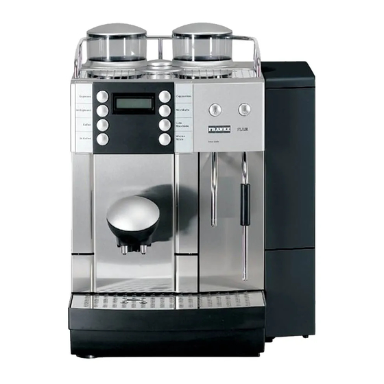
2. Technical data, Dimensions 2.1. Technical data Franke Coffee machine Flair Type: F 2M HD CE2 Performance 2 grinders, hot water, steam dispenser and integrated milk froth / Cappuccinatore (CE2) Bean container: 2 containers each 250g Grounds container: 40 cakes; option: grounds chute…
-
Page 13
2.2. Dimensions Dimensions Dimensions (WxDxH): 423 x 542 x 523mm (17 x 21 x 21 inches) Weight: approx. 20kg (45 lbs) net TD-100341.doc Downloaded from www.Manualslib.com manuals search engine… -
Page 14: Installation Instructions For Permanent Water Mains Connection
3. Installation and operating instructions 3.1. Installation instructions for permanent water mains connection* 3.1.1. Security advice • The permanent water mains connection is to be installed and connected by a specialist! • To avoid short-circuits, make sure the water supply lines and power cables are not in contact with or routed past a heat source;…
-
Page 15: Assembly Instructions
3.1.3. Assembly instructions • Make sure the control unit (3) is installed with the housing at the top! • Make sure the hose is installed without tensile load! • To protect the machine against scaling, use a de-scaling filter if the water hardness is above 10°…
-
Page 16: Commissioning
Connecting the internal power supply Connect connecting cable (2) to electronic unit (1) Plug connector of connecting cable (2) on rear panel of machine, as illustrated 3.1.5. Commissioning • Caution! If the red LED is lit, check the following: — Is the electronic unit correctly in place in the water tank? — Water level (water level must not exceed half the water tank.) — Scale build-up of the electronic unit;…
-
Page 17: Cleaning The Control Unit
3.1.6. Cleaning the control unit (valve block) Cleaning the water connection filter Turn off water supply at water valve(b) Remove cover and take filter out Clean filter under running water Insert filter and close cover Turn water valve (b) back on TD-100342.doc Downloaded from www.Manualslib.com…
-
Page 18: De-Scaling The Electronic Unit Manually
3.1.7. De-scaling the electronic unit (clip) manually • The coffee machine can be de-scaled directly using the machine de-scaling programme, as described in the Operating instructions under <<Machine care/cleaning/de-scaling>>. Before you can start the de-scaling programme, you need to disconnect the electrical connection on the rear panel and remove the electronic unit.
-
Page 19: Installation Instructions For Drainage Connection
3.2. Installation instructions for drainage connection* 3.2.1. Assembling the drainage The drainage kit comprises: — 1 tank valve pressure spring (Art. No. 1P 315 019) — 1 valve body, black (Art. No. 1P 315 020) — 1 O-ring 6.02 x 2.62 mm (Art. No. 1P 315 018) — 1 drainage hose, black (Art.
-
Page 20
Remove plastic cover from base of grounds container housing Tilt machine back and secure in that position Connect drainage hose to connecting piece as far as the stop Place machine upright again Enabling the drip tray • The trip tray can be enabled using a PC and the Customer Card or via the menu on the Terminal3000. -
Page 21: Operating Instructions
3.3. Operating instructions • Here you will find the Operating instructions for the Flair (BA Flair). • If the Operating instructions are not to be found here, order a set from your supplier using the article references below. BA Flair Deutsch Art.
-
Page 22
Downloaded from www.Manualslib.com manuals search engine… -
Page 23
Franke Kaffeemaschinen AG Festwasseranschluss Saphira / Flair Installationsvorschrift Installation instructions Instructions d’installation TD-100444.doc 1 / 4 Downloaded from www.Manualslib.com manuals search engine… -
Page 24
Ihrem örtlichen Kundendienstpartner oder direkt von Franke Kaffeemaschinen AG, in Aarburg an. Dear Customer! We congratulate you on your purchase of a Franke Coffee Machine. You have decided upon a high quality appliance for the preparation of coffee, developed and manufactured according to the state of the art. -
Page 25
Franke Kaffeemaschinen AG Wasseranschluss 1. Bei einer Neuinstallation muss vor dem Anschluss der Kaffeemaschine der Druckschlauch und die Wasserleitung gut durchgespült werden. 2. Die Kaffeemaschine muss an eine Trinkwasserleitung mit einem Absperrhahn angeschlossen werden. 3. Der Wasserdruck muss zwischen 0.8 und 8.0 bar liegen. -
Page 26
10. Do not pour liquids on to the cup support. 11. When heating beverages with steam, the noise emission level can exceed 70dB (A). 12. Franke Kaffeemaschinen AG accept no responsibility for damage or injury resulting from non- compliance with the Installation and Operating Instructions. -
Page 27
Downloaded from www.Manualslib.com manuals search engine… -
Page 28
Downloaded from www.Manualslib.com manuals search engine… -
Page 29
Downloaded from www.Manualslib.com manuals search engine… -
Page 30
Downloaded from www.Manualslib.com manuals search engine… -
Page 31
Downloaded from www.Manualslib.com manuals search engine… -
Page 32
Downloaded from www.Manualslib.com manuals search engine… -
Page 33
Downloaded from www.Manualslib.com manuals search engine… -
Page 34
Downloaded from www.Manualslib.com manuals search engine… -
Page 35
Downloaded from www.Manualslib.com manuals search engine… -
Page 36
Downloaded from www.Manualslib.com manuals search engine… -
Page 37
Downloaded from www.Manualslib.com manuals search engine… -
Page 38
Downloaded from www.Manualslib.com manuals search engine… -
Page 39: Subassembly Units
Subassembly units 4.1. Drip tray and grounds container 4.1.1. Drip tray Removing the drip tray Carefully pull out the full drip tray, holding it at a slight angle Empty and clean Clean both tray contacts • To achieve an even better contact, detach contacts and clean on reverse side too (or replace contacts if necessary) 4.1.2.
-
Page 40: Coffee Dispenser With Frother Head
4.2. Coffee dispenser with frother head 4.2.1. Coffee dispenser Removing the coffee dispenser Gently press dispenser at the 2 markings and pull out frontwards Pull out dispensers complete with hoses • White connecting pipe is for milk and is fitted on the left Unscrew the 4 marked screws from frame and remove Remove frame and front plate…
-
Page 41: Housing
4.3. Housing 4.3.1. Removing the rear panel Removing the rear panel Access to: — Power print board — Grinders — Voltage components — Right-hand and left-hand side panels Release cover locks on rear panel Fold outwards from rear panel and remove Unscrew the 3 screws from rear panel Lift rear panel from underneath and remove outwards as illustrated…
-
Page 42: Removing The Side Panels
4.3.2. Removing the side panels Removing the right hand side panel Access to: — Geared motor — Valves — Unit heater — Pumps Dismantle rear panel as described in Chap. 4.3.1 before removing side panels Slide side panel by hand out of guide, sideways to the rear •…
-
Page 43: Removing The Housing Cover
4.3.4. Removing the housing cover Removing the coffee-bean container Release cover locks on rear panel Fold outwards from rear panel and remove Close both coffee-bean container locks as far as the stop The sides of the coffee-bean container (R and L) are defined as viewed from the front. The coffee-bean containers are marked (see circle) R = Right and L = Left to define each of the sides.
-
Page 44
Take out setting rings Unscrew the 4 screws from cover and open Disconnect the 2 contact connectors for the sensors for the bean monitoring system TD-100343.doc Downloaded from www.Manualslib.com manuals search engine… -
Page 45: Opening The Housing Front Panel
4.3.5. Opening the housing front panel Opening the front panel Access to: — Front panel control system — Dispenser hoses Remove drip tray and grounds container as described in Chap. 4.1. Remove housing cover as described in Chap. 4.3.4. Remove coffee dispenser as described in Chap.
-
Page 46: Coffee Grinder
4.4. Coffee grinder 4.4.1. Mode of operation The coffee grinder (grinding unit) comprises: 1 screw 2 Socket 3 Rubber buffer 4 Grinding mechanism adjusting disc 5 Retaining ring for top grinding mechanism 6 Upper grinding ring 7 Grinder motor with bottom grinding mechanism The grinding mechanism consists of two parts: the grinding ring and the grinding cone.
-
Page 47: Setting The Grinding Degree Of The Grinding Mechanisms
4.4.2. Setting the grinding degree of the grinding mechanisms The coffee machine is shipped with the grinding mechanisms ideally set for <<medium>> grinding. The grinding mechanisms are set manually using the setting ring and only when the coffee grinder is running. A single notch setting for finer or coarser can have a big impact on the amount of ground coffee, so always adjust one notch at a time only.
-
Page 48: Replacing A Grinder
4.4.5. Replacing a grinder Removing the grinder • The grinding mechanism of the grinding unit cannot be replaced as the grinding ring and grinding cone are adapted to each other. The entire grinding unit must therefore be replaced. • Replace the grinding unit if the grinding mechanism has become blunt.
-
Page 49: Installing A Grinder
4.4.6. Installing a grinder • To avoid damaging the grinding mechanism, do not interchange the upper grinding rings. • When inserting the new grinding unit make sure it is correctly seated so that the grinder dispenser leads into the ground coffee chute.
-
Page 50: Brewing Assembly
4.5. Brewing assembly 4.5.1. Mode of operation The brewing assembly comprises: 1) brewing unit and 1a) drainage valve; 2) Lower o-ring; 3) Upper o-ring; 4) grounds scoop; 5) guide complete Simple description. The (brewing) piston travels from the set grinding position to the ground coffee in the brewing cylinder and compresses the powder.
-
Page 51: Dismantling The Brewing Assembly
4.5.2. Dismantling the brewing assembly Dismantling the brewing assembly — e.g.: to replace the piston upper o-ring • CAUTION! If the inspected brewing assembly cannot be serviced and fitted according to instructions, always replace it with a new brewing assembly! Open the coffee machine as described in Chap.
-
Page 52: Further Dismantling
4.5.4. Further dismantling (e.g. for an inspection) Remove hose protection and outlet pipe Unclip both from holder • CAUTION! Small hose o-rings might fall out! Removing the cap Use a screwdriver to loosen the 4 marked spring loaded catches Remove cap Removing left + right covers Use a screwdriver to loosen all 4 marked spring loaded catches on the inside…
-
Page 53
Removing left + right dynamic bend • CAUTION! Guide rollers are loosely fitted! Remove bend Removing outer guide rollers Detach guide rollers Removing toothed wheel and piston Unscrew toothed wheel from cylinder Remove piston from cylinder Remove old piston upper o-ring (arrow) Clean groove of piston upper o-ring Smear new piston upper o-ring with Klübersynth grease (Art. -
Page 54
Removing axle and piston Use a screwdriver to loosen the 2 retaining rings from axle Use a screwdriver to press axle out Use screwdriver to press down on toothed rack and remove piston Removing the brewing chamber and toothed wheel clamp Pull out both parts one after the other TD-100343.doc Downloaded from… -
Page 55: Assembling The Brewing Assembly
4.5.5. Assembling the brewing assembly Installing the brewing chamber and toothed wheel clamp • CAUTION! Take note of the installation direction for the toothed wheel clamp! Insert toothed wheel clamp from the side Insert brewing chamber into toothed wheel clamp Installing the piston and axle Insert into toothed wheel clamp as far as the stop…
-
Page 56
Installing the feed pipe Fit spring with sealing pin into piston Next screw into guide Installing the upper piston Smear piston lower o-ring with Klübersynth grease (Art. No. 1L 296 804) Fit with feed pipe in opposite direction to ground coffee intake Installing the toothed wheel Screw onto cylinder •… -
Page 57
Fit guide, making sure the piston positioning peg is not tilted Drainage valve Fit drainage valve into guide and press into place Fitting the left + right covers Place cover parallel with housing and snap spring-loaded catch into place Fitting the pipe bend and cap Position longitudinal guide in slot Press retaining pegs towards hole centre and snap into place… -
Page 58
Fitting the outlet pipe and hose protection Fit outlet pipe onto pipe bend as far as the stop Fit the hose protection parallel to the housing Grounds scoop Fit into place • Next check the serviced brewing assembly for function and tightness inside the coffee machine. -
Page 59: Encoder
4.6. Encoder 4.6.1. Mode of operation Mechanically, the encoder is directly connected with the geared motor of the brewing unit. When the geared motor is running, the encoder signals each recorded pulse to the control system. The control system uses the pulse signals to calculate the current position of the brewing unit piston.
-
Page 60: Flowmeter
4.7. Flowmeter 4.7.1. Mode of operation Flowing water turns the impeller (rotor) running on the middle axle of the white plastic flowmeter. The flowmeter are located on the right side of machine, under the tank base. The two magnets fitted to the rotor send signals which allow a reed contact to count the number of revolutions.
-
Page 61: Pumps
4.8. Pumps 4.8.1. Mode of operation The module comprises: 2 pumps (coffee/hot water and steam) with thermal overload protection 1 membrane controller (coffee/hot water) The pumps pump the water into the two unit heaters and provide the operating pressure for the entire water system. 4.8.2.
-
Page 62: Membrane Controller And Bimetallic Thermostat
4.9. Membrane controller and bimetallic thermostat 4.9.1. Mode of operation The membrane controller smoothes the pulses of the coffee/hot water pump and reduces the pump’s vibration noise. 4.9.2. Replacing the membrane controller Removing the membrane controller • Replace defective membrane controller Detach hose from pump inlet Use pliers to pull off clamp type clip Take pump out of rubber holder…
-
Page 63: Coffee/Hot Water Thermoblock
4.10. Coffee/hot water thermoblock 4.10.1. Mode of operation The unit heater comprises: Thermoblock (TB-K/HW) Temperature sensor Thermal link The water flowing through this block is heated to the set temperature inside the thermoblock, and provides the water used for coffee brewing and hot water production. 4.10.2.
-
Page 64: Steam Thermoblock
4.11. Steam thermoblock 4.11.1. Mode of operation The steam thermoblock comprises: Thermoblock (TB-D) Temperature sensor Thermal link This block provides the water used for steaming and is heated to the set steam temperature inside the thermoblock. 4.11.2. Replacing the thermoblock Removing the thermoblock •…
-
Page 65: Thermal Link
4.12. Thermal link 4.12.1. Mode of operation The thermal link protects the thermoblock from overheating and switches the heating off. 4.12.2. Replacing the thermal link for coffee/hot water and steam Removing the thermal link • CAUTION! The thermal links are not interchangeable! Unscrew screw from retaining clamp Remove link and replace…
-
Page 66: Coffee/Hot Water And Steam Temperature Sensors
4.14. Coffee/hot water and steam temperature sensors 4.14.1. Mode of operation The temperature sensors measure the temperatures of the thermoblocks so that the temperatures can be regulated by the software. 4.14.2. Replacing the temperature sensor for coffee/hot water and steam Removing the temperature sensor Unscrew screw from thermoblock base holder…
-
Page 67: Pressure Control Valve
4.15. Pressure control valve 4.15.1. Mode of operation The pressure control valve prevents a return of water from the brewing unit if the pump is not running and prevents hot water from flowing into the brewing unit when <<hot water>> is dispensed.
-
Page 68: Replacing The Overpressure Valve For Steam Circuit
4.15.4. Replacing the overpressure valve for steam circuit (pressure relief valve No. 1) 4.15.5. Mode of operation The overpressure valve diverts the residual steam to the expansion container after steam is dispensed. The valve is briefly activated each time after steam is dispensed. If the valve has an electrical defect, it will open if the pressure exceeds 6 bar (87 PSI).
-
Page 69: Solenoid Valves (No. 2-6)
4.16. Solenoid valves (No. 2-6) 4.16.2. Replacing solenoid valves (For coffee/hot water and steam circuit/cappuccino and milk systems) Removing the valves • CAUTION! Make a note of the installation direction of valve 2! Use pliers to pull off all the clamp-type clips •…
-
Page 70: Coffee Dispenser Micro Switch
4.17. Coffee dispenser micro switch 4.17.2. Replacing the micro switch Removing the micro switch Remove front panel as described in Chapter 4.2.1. Take out dispenser chute • CAUTION! Disconnect cable connectors beforehand! Unscrew screw Remove cover Replace micro switch TD-100343.doc Downloaded from www.Manualslib.com manuals search engine…
-
Page 71: Front Panel Control System
Control system subassembly /diagram 5.1. Front panel control system (Flair electronics, complete) 5.1.1. Mode of operation The front panel control system controls the programmed product dispensers via input on the operating keypad. 5.1.2. Replacing the front panel control system Dismantling the front panel control system Remove housing cover (top) as described in Chap.
-
Page 72
Connect new front panel control system to existing cables, close cover or if necessary replace front panel control system complete with cables see Instructions for replacing control system on Franke Animation/Terminal3000 TD-100344.doc Downloaded from www.Manualslib.com manuals search engine… -
Page 73: Power Print Board
5.2. Power print board 5.2.1. Mode of operation The power print board supplies electrical power to all the machine electrical components. 5.2.2. Replacing fuses Removing fuses Remove rear panel as described in Chap. 4.3.2. Remove white flap Check fuses (arrow) 5.2.3.
-
Page 74: Transformer
5.3. Transformer 5.3.2. Replacing the transformer Removing the transformer Remove rear panel as described in Chap. 4.3.2. Remove power cable carrier Disconnect the 2 cable connectors from power print board Unscrew the 2 screws (arrow) on transformer 5.3.3. Technical data Supply voltage: Primary 230V / 50-60 Hz / 0.16A Secondary 20, 15, 10.7, 8.3V AC…
-
Page 75: Interference Eliminator
5.4. Interference eliminator 5.4.1. Mode of operation The interference eliminator reduces electrical interference (interference frequencies). 5.4.2. Replacing the Interference eliminator Removing the Interference eliminator (arrow) Remove power cable carrier as described in Chap. 5.3. Disconnect all cable connectors Press the 2 holders down on base element Lift up Interference eliminator and remove…
-
Page 76
Downloaded from www.Manualslib.com manuals search engine… -
Page 77
TD-100350.doc Downloaded from www.Manualslib.com manuals search engine… -
Page 78
Downloaded from www.Manualslib.com manuals search engine… -
Page 79
TD-100351.doc Downloaded from www.Manualslib.com manuals search engine… -
Page 80
Downloaded from www.Manualslib.com manuals search engine… -
Page 81
TD-100352.doc Downloaded from www.Manualslib.com manuals search engine… -
Page 82
Downloaded from www.Manualslib.com manuals search engine… -
Page 83
Downloaded from www.Manualslib.com manuals search engine… -
Page 84
Downloaded from www.Manualslib.com manuals search engine… -
Page 85
Downloaded from www.Manualslib.com manuals search engine… -
Page 86
Downloaded from www.Manualslib.com manuals search engine… -
Page 87
Downloaded from www.Manualslib.com manuals search engine… -
Page 88
Downloaded from www.Manualslib.com manuals search engine… -
Page 89: Function Of Keys 1 –
Menu instructions – Service menu 6.1. Overview key assignment 6.1.1. Function of keys 1 – 18 14 13 12 11 18 17 16 15 Function Request Pre adjustments Flair assignment Inkasso Key1 Product key 1 *TA1 Key2 Product key 2…
-
Page 90: Products Code
6.1.2. Products Code • Notice: Only the screen display of the product can be changed with the buttons, as described in the Operating instructions. • In addition to the product codes 1 to 24, there is also product <<0>> which corresponds to a power On/Off button.
-
Page 91
Display of production data Key combination Function Screen example 6 & 2 Display production date 1. Software version logic 2. Production date & machine number logic 3. Production date & serial number logic 4. Software version screen 5. Production date & machine number screen 6. -
Page 92: Service Menu
<<ESC>> and automatically reach the main program. • Start up: • The front panel of the Flair must be switch OFF. (press power button 14) • Please confirm the current date. • Please use numerical keyboard to enter the date.
-
Page 93: Deinstalling Terminal3000
6.2.4. De-installing Terminal3000 You can leave the current program with <<ESC>>. Press the ON/OFF button to switch off the Terminal3000. Remove the serial cable between the coffee machine and the Terminal3000. Disconnect the plug from the socket and replace all parts in the Terminal3000 service suitcase.
-
Page 94: Operating Elements
6.3. Operating elements write card/ 5 config key’s/ 6 write coffee/ 2 Serial 2 Serial 1 config coffee/ 3 coffee machine or printer read coffee/1 print data é / max. read card / 4 single functions/ 7 ê / min. ON/OFF config Terminal/ 9 history bit’s / 0…
-
Page 95: Card Type 3 Applications
— Basic settings and product settings can be saved by the software program <<Customer card>> on the <<Customer parameter card>> — A number of machines of the Flair with the same software settings, before provided configurations can be programmed • Notice: Please use the current software version! 6.5.
-
Page 96
Read coffee (read data from the coffee machine) The data from the Flair are read into the Terminal3000 memory. These data can be edited and written afterwards again into the Flair (as described in chapter <<write parameter to coffee machine>>). -
Page 97
Write card Used for saving the data from the Flair on a data card. Read in data can not be saved on <<Customer parameter card>>. User Terminal Screen Terminal Carry out read card procedure TERMINAL READY DATA LOADED write card key… -
Page 98
Configuration keys All coffee product configuration data are read out and written back to the Flair (as described in chapter <<write parameter to coffee machine>>). CAUTION! If the ESC button is pressed before writing to the coffee machine, the settings read in are lost and the whole section must be repeated. -
Page 99
Some of the data of the coffee machine are read out. You can adapt the respective positions and write again in the Flair (as described in chapter <<write parameter to coffee machine>>). The menu option <<write coffee>> writes the changes into the Flair. CAUTION! If the ESC button pressed before writing to the coffee machine, the settings read in are lost and the whole section must be repeated. -
Page 100
User Terminal Screen Terminal Next function Coded or Enabled 5.3 filter reset Cursor keys Enter Next function Coded or Enabled 7 counter Cursor keys Enter Next function Coded or Enabled 8 counter reset Cursor keys Enter Next function Coded or Enabled cleaning Cursor keys Enter Next function… -
Page 101
User Terminal Screen Terminal Start up bit Set or not set START UP BIT Entry with Enter Setting the language, time and date Not set Change with cursor keys when next activating the machine Commissioning date Commissioning date writing into the OPERATION DATE Entry with Enter machine. -
Page 102
Configuration of the terminal (Config. terminal) This button enables you to enter the configuration menu for the Terminal3000. You have the possibility for changing the language and date. The identification number is fixed by the service and cannot be changed. User Terminal Screen Terminal… -
Page 103
User Terminal Screen Terminal Determine next function. Start with FUNCTION Enter. F17 STEAM v. ON Determine next function. Start with FUNCTION Enter. F18 STEAM v. OFF Determine next function. Start with FUNCTION Enter. F19 CAPPU v. ON Determine next function. Start with FUNCTION Enter. -
Page 104
History bits The <<history bits>> gives you a history of the errors the machine has had. The history bits are cleared with the next writing of a service stamp. User Terminal Screen Terminal Press history bits key Read data for machine configuration. PLEASE WAIT COFFEE è… -
Page 105
WORK 2 0-999 SERVICE STAMP Entry with Enter line 1 blinks 000 WORK 2 Change with numerical keyboard WORK 3 0-999 SERVICE STAMP Entry with Enter line 1 blinks 000 WORK 3 Change with numerical keyboard WORK 4 0-999 SERVICE STAMP Entry with Enter line 1 blinks 000 WORK 4 Change with numerical keyboard… -
Page 106: Working With The Terminal3000
Diagnostics with Terminal3000 The diagnosis is split into 2 areas, in <<history bits>> (input diagnosis) and in <<service stamp>> (output diagnosis), the same as in the Franke Animations application. Performing input and output 1. Switch the terminal on using the «ON/OFF» button.
-
Page 107
8. Use the cursor keys to switch to the service stamp entries. The error and work codes are listed in the appendix. 9. After entering the entries information, switch into the menu. <<Write coffee>> 10. Press <<Write coffee>>. The service stamp is now saved to the Flair and all previous history bits are reset to zero. <<Please wait>> <<Terminal->Coffee>>… -
Page 108
Factory parameter of the Flair The <<factory parameter settings>> of the Flair can now be updated with the generated factory parameter card (please see chapter <<generate Factory parameter card>> in the operating manual of the <<Franke Animation>> application. 1 Switch on the terminal with <<ON/OFF>>. -
Page 109
The configuration that has been created with the help of the customer card software (set- up and product adjustments) can be transferred into the Flair as described below. Please read carefully the instructions in the operating manual of the <<Customer card Software>>… -
Page 110: Appendix
6.7. Appendix 6.7.1. Error code list Error code Code Description Error code Code Description group group Heaters Grinder 419 steam heating scaled 000 Left grinder blocked 421 Temp. fuse coffee / tea 001 Left grinder faulty heating faulty 002 Left grinder foreign parts 431 Temp.
-
Page 111: Work Code List
Example: A defective output print has Type (2) been determined as the The composite of the type yield and code cause for a Flair error. yield defined the work code. Error code: 511 (Error code list 6.7.1.- group 5- control) The type(2) determines the executed task.
-
Page 112
Technical data External dimensions of the suitcase: 44 x 35 x 14 cm Dimensions of the Terminal3000: 17.5 x 10 x 4.4 cm Power supply: 9 V AC / 300mA Service handbook Flair (R6) TD1305B Downloaded from www.Manualslib.com manuals search engine… -
Page 113
TD-100665.xls Downloaded from www.Manualslib.com manuals search engine… -
Page 114
Downloaded from www.Manualslib.com manuals search engine… -
Page 115
TD-100665.xls Downloaded from www.Manualslib.com manuals search engine… -
Page 116
Downloaded from www.Manualslib.com manuals search engine… -
Page 117: Settings For A Better Coffee
Setting the quality of the coffee • using the operating keypad on the installed machine • using the customer menu, <<Product Definition>> menu • using the Operating instructions Basic setup for the Franke Coffee machine Flair Cappuc left short normal…
-
Page 118
Customer Notes A, Franke Coffee machine Flair Cappuc cino White coffee Latte macchi Milk Espres espres Coffee coffee water Steam Customer Notes B, Franke Coffee machine Flair TD-100346.doc Downloaded from www.Manualslib.com manuals search engine… -
Page 119
Downloaded from www.Manualslib.com manuals search engine… -
Page 120
Downloaded from www.Manualslib.com manuals search engine… -
Page 121: Troubleshooting / Service
Troubleshooting / Service 8.1. Display messages and measures Display reading / Effect Measures message No drip tray Interrupts any process (process resumes Clean and dry drip-tray contacts normally once drip tray is inserted) Insert cleaned drip tray into machine as far as stop (see Chap. 4.1) Unit heaters for coffee and steam are switched off Switches discharge valve off…
-
Page 122: Fault Messages On The Display
History bits The Terminal3000 is capable of recognising the “History Bits” recorded by the Flair coffee machine. The digit 0 or 1 in front of the text indicates whether or not there is a fault.
-
Page 123: Service
• Replace drain valve, by not current version of the drain valve or by out of order. • Allways replace piston o-ring. Service periode We recommend the following service intervals for the Flair brewing unit when it is used under regular conditions: > 15,000 cycles replace brewing unit >…
-
Page 124
Preventative service Diagnostic findings only TD-100347.doc Downloaded from www.Manualslib.com manuals search engine… -
Page 125: Preventive Maintenance
1 = Replace 2 = Clean 3 = Adjust 4 = Control (Replace when needed) Thermoblock 1P 315 172 Sensor thermoblock complete (S 1P 315 518 Temp. Sensor steam Flair 0035584 Brew Unit 1P 315 174 Brew unit assembled 1T 310 382…
-
Page 126
Downloaded from www.Manualslib.com manuals search engine… -
Page 127
Franke Kaffeemaschinen AG Order Form / Faxbestellung Franke-Strasse 9 CH-4663 Aarburg Switzerland FAX: +41 62 787 30 10 Tel: +41 62 787 37 37 Fax: +41 62 787 30 10 km@franke.com Delivery address / Lieferadresse www.franke-cs.com Firma / Company: ………. -
Page 128
Downloaded from www.Manualslib.com manuals search engine… -
Page 129
FLAIR Section 9 – Service Infor mation Read the safety information chapter before working on the machines. Downloaded from www.Manualslib.com manuals search engine… -
Page 130
The present instructions reflect the state of the technology as of the date of issue. © 2011 by Franke Coffee Systems FRANKE and the logo are registered trademarks of Franke Technology and Trademark Ltd., Hergiswil, Switzerland, a subsidiary of Franke Artemis Holding AG, 4663 Aarburg. Downloaded from www.Manualslib.com… -
Page 131
Franke Kaffeemaschinen AG Saphira & Flair Inkasso3 PCB installation instructions Position of the Inkasso3 PCB:………………2 Undo the power distributor carrier: …………….2 Cutting the transformer cable (green) …………….3 Wiring up the green cables and the supplied cable tree……….4 Cable glands …………………….5 Connection of the cable tree to the Inkasso3 PCB…………5… -
Page 132: Position Of The Inkasso3 Pcb
Franke Kaffeemaschinen AG Position of the Inkasso3 PCB: Optional: Key-operated switch to switch off the accounting Fig. 1: The Inkasso3 PCB is fastened with the supplied self-adhesive feet in the enclosure cut-out. Undo the power distributor carrier: Fig. 2: Remove both screws on the power distributor carrier.
-
Page 133: Cutting The Transformer Cable (Green)
Franke Kaffeemaschinen AG Fig. 3: Open the power distributor carrier Cutting the transformer cable (green) Fig. 4: Pull the two green cables up to the plastic rise on the enclosure. Cut them. TD-100441.doc 3 / 7 Downloaded from www.Manualslib.com manuals search engine…
-
Page 134: Wiring Up The Green Cables And The Supplied Cable Tree
Franke Kaffeemaschinen AG Wiring up the green cables and the supplied cable tree Fig. 5: Pass both green cables coming directly from the transformer through the opening of the power distributor carrier. Pos 1 Pos4 Pos 2, 3 Fig. 6: Remount the power distributor carrier and fasten the terminal strip of the cable tree to the prepared fixing position (Pos.
-
Page 135: Cable Glands
Franke Kaffeemaschinen AG Cable glands Pos. 5 Pos. 5 Fig. 7: To prevent the cables from hindering the installation of the rear and side walls, two gaps must be made at the Positions 5 shown here. Connection of the cable tree to the Inkasso3 PCB Fig.
-
Page 136: Optional: Connection Of The Cci Cable To The Inkasso3 Pcb
Franke Kaffeemaschinen AG Optional: Connection of the CCI cable to the Inkasso3 PCB You must first ensure that the cable glands at Positions 5 in Figure 7 are sufficiently large enough for the three cables. Fig. 9: In addition to Point 6, connect the CCI-RS232 cable and the CCI power cable, as shown in Figure 8.
-
Page 137: Components: Components For The Converter
Franke Kaffeemaschinen AG Components: Components for the converter Franke Art. No. Designation Quantity 1P 315 233 Inkasso3 with display and keyboard 1 Software vers. 1.0 or higher 1P 315 214 Panel holder 10 296 472 Spacer bolts 02 211 820…
-
Page 138
Downloaded from www.Manualslib.com manuals search engine… -
Page 139
Franke Kaffeemaschinen AG Operating Instructions for Inkasso3 1 / 32 TD-100470.doc Downloaded from www.Manualslib.com manuals search engine… -
Page 140
Franke Kaffeemaschinen AG Contents Install menu …………………….4 1.1 Setup …………………………4 1.2 Coin validator ……………………….9 1.3 MDB Changer……………………….10 1.4 Cash CARD……………………….10 1.5 Diagnostics……………………….12 1.6 CC-Simulation ……………………….12 1.7 Card service ……………………….13 1.8 Exit menu ……………………….. 13 Customer menu ………………….14… -
Page 141
The most commonly used settlement devices can be connected to the collection system and include the chip card system from Franke (CASH and FREE), coin checker CF330, MDB coin changer (CF690) and MDB card reader (CASH terminal , U-key, EVIS, and similar). -
Page 142: Install Menu
Franke Saphira >> Default (page 36) Franke Flair 1.1.5 Converter This enables Franke Saphira / Flair CCI / CSI compatibility. When the protocol converter is switched on, the MDB protocol is automatically deactivated. 4 / 32 TD-100470.doc Downloaded from www.Manualslib.com…
-
Page 143
Franke Kaffeemaschinen AG Saphira article numbers The article numbers are fixed for each product. They cannot be changed. Product name: Article number: Cappuccino Milky coffee Macchiato Crème coffee 2 x crème coffee Pot of coffee (under prog. flap) Milk foam (under prog. flap) -
Page 144
Franke Kaffeemaschinen AG FLAIR article numbers The article numbers are not fixed for each product. They can be changed at any time. The following are the preset default settings. Product name: Article number: Cappuccino Milky coffee Macchiato Milk foam Crème coffee 2 x crème coffee… -
Page 145
We make a distinction between two different types: F700 protocol (Saphira/Flair) If the coffee machine is set to Saphira or Flair (F700), it is the Saphira/Flair timeout. The user can set the same timeout as on the Saphira/Flair; the collection system automatically uses 300 [ms] less to understand the signal just to be on the safe side. -
Page 146
Franke Kaffeemaschinen AG 1.1.11 Key Beep This function actives the key beep. 0 = OFF The duration of the key beep can also be set. Default = 0 [10 ms] Key beep: 0 .. 30 x [10 ms] = 0 .. 300 [ms]; 0 = deactivated 1.1.12… -
Page 147: Coin Validator
Franke Kaffeemaschinen AG 1.2 Coin validator 1.2.1 Debit limit This defines the maximum amount of money the system can accept. For example if a coin checker is set for SFr. 7 and this amount is reached or exceeded, the coin input is blocked and no further coins are accepted (i.e.
-
Page 148: Mdb Changer
Franke Free Card MultiVend-capable MDB devices (multiple sale) 1.4.2 Load limit Here a limit can be set so that a Franke Cash Card does not have too high of an amount. Default = SFr. 010.00 Cash card load limit 0 .. 99999 10 / 32 TD-100470.doc…
-
Page 149
Franke Kaffeemaschinen AG 1.4.3 Cash Card A A maximum of three price levels can be set under this menu items (discount system). Cashcard A,B,C 0 .. 255% Default >> CASH-A = 100% Default >> CASH-B = 100% Default >> CASH-C = 100% 1.4.4… -
Page 150: Diagnostics
Franke Kaffeemaschinen AG 1.5 Diagnostics 1.5.1 Coffee machine This function allows you to conduct diagnostic tests on the coffee machine 1.5.2 This function allows you to view the MDB information. Status: à connection > MDB device not present or not found Inactive Identified à…
-
Page 151: Card Service
Franke Kaffeemaschinen AG 1.7 Card service 1.7.1 clear This function makes it possible to delete all cards and reinitialize. Proceed as follows: 1. Select this menu item with the ENTER key 2. The message “target card” appears in the display 3.
-
Page 152: Customer Menu
Franke Kaffeemaschinen AG 2 CUSTOMER MENU 2.1 Free Vend 2.1.1 Free Vend This function makes it possible to toggle settlement no and yes and permit free procurement. 2.1.2 Counter on/off This function toggles the counter functions of the free procurement ON and OFF.
-
Page 153
Franke Kaffeemaschinen AG 2.3.4 FREE Card With «Free-Card» the procured products are sequentially totalled across all cards and each card is individually totalled as well. The credit of the card, however, is here in the Inkasso3. The overall sales are not totalled. Briefly pressing ENTER resets the counter to zero. Pressing and holding EXIT a moment lets you leave the item without making changes. -
Page 154: Load Counter
Franke Kaffeemaschinen AG 2.4 Load Counter Here the amounts of the products which were credited through the load menu are totalled. 2.5 Free table Free cards must first be logged on before they can be used. The instructions for doing this are described below step by step.
-
Page 155: Addimat Table
Franke Kaffeemaschinen AG 2.6 Addimat table 2.6.1 Log on Here you can log on Addimat waiter keys. When this menu item is selected, you are prompted to insert a waiter key. 1. A not yet logged on waiter key must first be inserted.
-
Page 156: Change Pin
Franke Kaffeemaschinen AG Display view of an entry: Nr.: Pr00.015 Num: Place: 07 The individual meanings Nr.: >> PLU no. 000.15 >> Price = SFr. 0.15 Num: >> Number Place: 07 >> Place no. 2.7.2 Copy price With this you can copy an entry.
-
Page 157: Load Menu
Franke Kaffeemaschinen AG 3 LOAD MENU 3.1 Load cards This function loads cash cards. Warning: It is not possible to load a cash card from a simulated Load Menu. 3.2 Load amount You can define an amount with this function. You can insert the card more than once and load money to the card each time.
-
Page 158: Download Menu
Franke Kaffeemaschinen AG 4 DOWNLOAD MENU 4.1 Inka >> Card This function allows you to save the Inkasso3 settings to a Download card. To do this the card must be empty or the same serial number must be saved on the card as is on Inkasso3. Using the submenu items, you can also perform a full backup or only a partial backup.
-
Page 159: Error Codes
Franke Kaffeemaschinen AG 5 ERROR CODES 5.1 Error categories Chip card errors ……..These are displayed as long as the card with the error is inserted the reader. EEPROM errors ……… These errors mean that operation is no longer possible à…
-
Page 160
Franke Kaffeemaschinen AG E046 chipcard read CRC error main ID block. E047 chipcard read CRC error only shadow ID block. E048 chipcard read CRC error in two data blocks (main block + mirrored). E049 chipcard read CRC error in a data block (mirrored). -
Page 161
Franke Kaffeemaschinen AG E060 chipcard write A verification error occurred while writing to the card. Either the contacts of the chip or of the reader are soiled or the card is defective. It may be necessary to re-initialise. E061 chipcard ident Chip is invalid or unknown. -
Page 162
Franke Kaffeemaschinen AG EEPROM ERROR Writing error. There was an inconsistency while reading back. Can be deleted by restarting. UART 0 (X11) Interface 0: Initialisation error, restart machine. UART 0 (X11) Interface 0: Send memory overflow, restart machine. UART 0 (X11) Interface 0: Framing error, restart machine. -
Page 163
Franke Kaffeemaschinen AG E105 MDB Error Coin changer: two coins have been inserted too quickly in sequence. E106 MDB Error Coin changer: the coin insertion unit may be lacking or defective. E107 MDB Error Coin changer: a coin has jammed during coin return. -
Page 164: Inkasso3 Drawing
Franke Kaffeemaschinen AG 6 INKASSO3 DRAWING Warning: not protected against incorrect polarity! closed = switched off) Protocol converter (Saphira+Flair on bar panel) Inkasso3: Normal operation Protocol converter Inkasso3: normal operation Software update 26 / 32 TD-100470.doc Downloaded from www.Manualslib.com manuals search engine…
-
Page 165: Menu Structure
Franke Kaffeemaschinen AG 7 MENU STRUCTURE 7.1 General The following menus are integrated in Inkasso3: • Install Menu • Customer Menu • Download Menu • Load Menu • Boot Menu Inkasso3 navigation is the same in all menus: • Use + / — to navigate in the main and submenu •…
-
Page 166: Install Menu Programming Tree
Franke Kaffeemaschinen AG 7.2 INSTALL menu programming tree (Chip card reader Art. no. 10 300 939 is necessary in order to enter the install menu. (no function with protocol converter) (appears only if chip card reader is connected and a card is…
-
Page 167: Customer Menu Programming Tree
Franke Kaffeemaschinen AG 7.3 CUSTOMER menu programming tree CUSTOMER MENU 1 Free Vend 1 Free Vend 2 Counter on/off 2 Productcounter 3 Turnover coun. 1 Turnover total 2 Cashcard 3 Free Vend 4 Free Card 5 Change giver 6 Coin validator…
-
Page 168: Load Menu Programming Tree
Franke Kaffeemaschinen AG 7.4 LOAD menu programming tree 7.5 DOWNLOAD menu programming tree Download Menu 1 Inka >> Card 1 All >> Card 2 Config >> Card 3 PLU >> Card 4 FREE >> Card 2 Card >> Inka 1 All >> Inka 2 Config >>…
-
Page 169: Default Values
Franke Kaffeemaschinen AG 8 DEFAULT VALUES The software has a default value for each menu item. List of all Inkasso3 default values: Language German Serial number 00000000 Install number 00000000 Coffee machine Franke Saphira Protocol converter WITHOUT (NO) Waiter lock…
-
Page 170: Software Update
Franke Kaffeemaschinen AG 9 SOFTWARE UPDATE You can carry out a software update for every Inkasso3 using Service Tool version 2.0.0 and above. To do so proceed as described below. Remove any connected Service Tool cables. Disconnect the 10-pin connector at X10 on the Inkasso3 printed board.
-
Page 171
Diagnosis with Terminal 3000 ………………… 25 Perform Entry and Exit diagnoses ……………… 25 Save diagnosis data to the chip card …………….26 Load the diagnosis data to Franke Service Animation ………… 27 Flair appendix …………………..29 Error code list……………………29 Work code list ……………………31 1 / 32 TD-100356.doc… -
Page 172: Installation
Flair Tool Customer card for Flair / Saphira (is installed without prompting) Framework 1.1 (install only if the print output of the Flair Tool does not work) Place the supplied CD ROM into your CD ROM drive. The AutoPlay menu appears after a moment.
-
Page 173
Now follow the installation instructions (not every single step is mentioned). Choose the installation language. Select the desired programs: Full installation: installs Franke Animation and Flair Tool Franke Animation: service software for Saphira and Flair Flair Tool: printing software for product labelling… -
Page 174: Structure Of Franke Service Animation
Franke Service Animation is used exclusively with the coffee machine types Saphira and Flair. It makes it possible to read data (device number, device configurations, service history and more) from the Saphira and Flair and to copy data to the Saphira or Flair. Diagnosis documents are then generated from this data.
-
Page 175: Icons
Before you begin working with Franke Service Animation, check the settings below. Device type Prior to performing a diagnosis on a Saphira or Flair, you must first select the relevant coffee machine design. Warning: When selecting a Saphira machine, the Top 2000 software is started up automatically.
-
Page 176: Language
Franke Kaffeemaschinen AG Language Here you can select one of the displayed languages in Franke Service Animation. Diagnosis port Select the port to which the Terminal 3000 is connected to your computer. If the wrong port is selected, the following error message appears: 6 / 32 TD-100356.doc…
-
Page 177: Internet Download
Franke Kaffeemaschinen AG Internet download Before you perform the first download, it is necessary to fill out the user information in the following masks. The “User name” and associated “Password” are assigned by Franke. They are as follows: User name: frankeservice Password: gkbjrzur In the “E-mail address”…
-
Page 178: Settings
Franke Kaffeemaschinen AG Settings If you use a proxy server, the addresses have to be entered under “Proxy settings”. If the mail server requires special settings, you can enter these under “SMTP settings”. 00.000.0.00 0000 muster@franke.com ******** ******** As soon as OK is clicked in the User Information window, the FTP download starts and the following window appears.
-
Page 179: Individual Test
Statistics When “Statistics” is selected, all data (product, service, statistics data and more) is read directly from the Flair. This data can be printed out on a system printer or printed as a file and saved on your computer. 9 / 32 TD-100356.doc…
-
Page 180: Statistics From Card (Data)
When “Statistics from Card” is selected, the data on the chip card inserted in the chip card reader of Terminal 3000 is read. This data can be printed out on a system printer or printed as a file and saved on your computer. No connection between the terminal and Flair is required for this test.
-
Page 181: Terminal Download
Initiate the command “Statistics from card (data)”. The Flair data is read into Franke Service Animation. Terminal download Terminal 3000 has a Flash EPROM that can be updated with Franke Animation software. The terminal software is available in two versions. German / English German / French Follow the software instructions during installation.
-
Page 182: Generate Factory Settings Card (Factory Parameters)
These cards can be given to authorised employees who then copy over the parameters to the Flair by means of a Terminal 3000. For this you need two parameter cards. One for 654 DI and one for 654 MA.
-
Page 183
Insert the “Factory parameters” chip card into the chip card reader of Terminal 3000. Open the “Individual test” menu. Initiate the command “Generate factory settings card (factory parameters)”. Select the required Flair design. Generate the two parameter cards for the selected machine. — 654 MA — 654 DI Warning: The machine may be listed more than once under the same KS article number. -
Page 184
Franke Kaffeemaschinen AG Example: KS 100101 Flair 654 DI SW 03 230 V / 50 Hz Select the command Generate card. If the chip card already contains data, the message below is displayed. Make sure that the card does not contain any important data. -
Page 185
The machine may be listed more than once under the same KS article number. Once for each software version! SW 0x Examples: — KS100116 Flair NSF 654 DI SW 03 230 V / 60 Hz — KS100116 Flair NSF 654 MA SW 04 230 V / 60 Hz 15 / 32 TD-100356.doc… -
Page 186
Franke Kaffeemaschinen AG The factory settings of the Flair can now be updated with the generated factory parameters card. Switch on the terminal using the “ON/OFF” button. Enter date D:02 M:02 Y:2005 Confirm each entry of the date with the ENTER key or enter a new date with the numerical keypad. -
Page 187: Delete Card
Franke Kaffeemaschinen AG Delete card Data on a chip card that is no longer used can be deleted. Switch on the terminal using the “ON/OFF” button. Enter date D:02 M:02 Y:2005 Confirm each entry of the date with the ENTER key or enter a new date with the numerical keypad.
-
Page 188
KS 100103 Flair EU black / KS 100104 Flair EU silver These cannot be differentiated. KS100104 appears for these machines! Configuration of the Entry diagnosis This menu is described in detail in the section “Diagnosis with Franke Service Animation”. 18 / 32 TD-100356.doc Downloaded from www.Manualslib.com… -
Page 189: Diagnostic
During diagnosis, data such as production data, product data, and service data is read from the Flair. There are two ways to get the data from the Flair in order to import it into the coffee machine service system as diagnostic documents: 1.
-
Page 190: Entry Diagnosis
Franke Kaffeemaschinen AG Entry diagnosis Before carrying out service work or commissioning the Flair, an Entry diagnosis first has to be performed. The Entry diagnosis is a defined procedure as outlined below. Read out data (production, statistical, service and customer data).
-
Page 191: Long Diagnosis
Once you have started the Entry diagnosis, follow the instructions below. You will be prompted to do certain things on the Flair. Should an error message appear, repeat the test. To ensure that the test has been properly carried out. If an error message appears again, stop the test.
-
Page 192: Exit Diagnosis
Once you have started the Exit diagnosis, follow the instructions below. You will be prompted to do certain things on the Flair. Should an error message appear, repeat the test to ensure that the test has been properly carried out. If you continue with the test despite an error message, the service stamp entry cannot be made and thus no diagnosis document can be created.
-
Page 193: Replace Logical Print Board
The service stamp is created in the entry mask shown below. A maximum of two service stamps are saved in the Flair. If service has been performed more than twice on the Flair, the older service stamp is always overwritten.
-
Page 194
Franke Kaffeemaschinen AG The appliance code is required so that the Entry diagnosis data can be copied to the new electronics. To create the definitive diagnosis document, follow the instructions in section “Create diagnosis document for KSS”. 24 / 32 TD-100356.doc… -
Page 195: Diagnosis With Terminal 3000
Franke Kaffeemaschinen AG Diagnosis with Terminal 3000 As with the diagnosis using Franke Service Animation, the diagnosis here is also divided into two parts: the “History bits” (Entry diagnosis) and the “Service stamp” (Exit diagnosis). Important: Both diagnoses must be performed; otherwise the diagnosis document cannot be created.
-
Page 196: Save Diagnosis Data To The Chip Card
After you have made the entries, change to the menu “Write coffee”. Press the “Write coffee” key. The service stamp is now entered in the Flair and any history bits entries are set to zero. Please wait Terminal à…
-
Page 197: Load The Diagnosis Data To Franke Service Animation
Franke Kaffeemaschinen AG Load the diagnosis data to Franke Service Animation To integrate the diagnosis data on the chip card into Franke Service Animation, proceed as described below. Switch on the terminal using the “ON/OFF” button. Enter date D:02 M:02 Y:2005 Confirm each entry of the date with the ENTER key or enter a new date with the numerical keypad.
-
Page 198
Franke Kaffeemaschinen AG The data is now imported from the chip card. As described in the section “Statistics”, you can print out the data. The diagnosis data has been loaded into Franke Service Animation. 28 / 32 TD-100356.doc Downloaded from www.Manualslib.com… -
Page 199: Flair Appendix
Franke Kaffeemaschinen AG Flair appendix Error code list Error code Code Description group Grinder Left, grinder blocked Left, grinder defective Left, foreign body in the grinder Left, grinding too coarse Left, grinding too fine Right, grinder blocked Right, grinder defective…
-
Page 200
Franke Kaffeemaschinen AG Control system Logical print board defective Power print board defective Collection print board defective Keys defective Cable/strand/plug defective Transformer of drive defective Lines Steam valve defective Cappuccino valve defective Relief valve defective Tea valve defective Lines and connections not sealed… -
Page 201: Work Code List
Franke Kaffeemaschinen AG Work code list Error code / Type Code Description group replaced replaced cleaned found decalci- fied Grinder left Grinder right Flow meter for coffee/tea Flow meter for steam Brewing unit Drive motor BE Drainage magnet Pump for coffee/tea…
-
Page 202
The error code group refers to the error code list. Example: A defective power print board was found on the Flair. Error code: 511 (from error code group 5 control system)
- Manuals
- Brands
- Franke Manuals
- Coffee Maker
- Flair
- Service manual
-
Contents
-
Table of Contents
-
Troubleshooting
-
Bookmarks
Related Manuals for Franke FLAIR
Summary of Contents for Franke FLAIR
-
Page 1
Franke Coffee machine Flair Service manual Coffee fully automatic machine Franke Coffee Systems Franke Kaffeemaschinen AG – CH-4663 Aarburg – Hotline:+41 62 787 37 37 – Fax:+41 62 787 30 10 Downloaded from www.Manualslib.com manuals search engine… -
Page 2
Downloaded from www.Manualslib.com manuals search engine… -
Page 3
1 Security advice / Table of contents 2 Technical data / Dimensions 3 General installation and operating instructions 4 Subassembly units 5 Assembly units controller / Wiring electrical diagram / Fluid systems diagram 6 Menu instructions / Service menu 7 Settings for a better coffee 8 Troubleshooting / Service 9 Service information 10 Miscellaneous… -
Page 4
Downloaded from www.Manualslib.com manuals search engine… -
Page 5: Safety Warnings
These service instructions are intended for authorized Franke service technicians only! The installation, setting, repair and maintenance work featured in these Service Instructions is to be carried out by a trained Franke Service Technician only, using original Franke spare parts.
-
Page 6
Downloaded from www.Manualslib.com manuals search engine… -
Page 7: Table Of Contents
Table of Contents Security advice, table of contents Technical data, dimensions 2.1. Technical data 2.2. Dimensions General installation and operating instructions 3.1. Installation instructions for permanent water mains connection 3.1.1. Security advice 3.1.2. Permanent water mains connection in the water tank 3.1.3.
-
Page 8
4.4.3. Setting the amount of ground coffee 4.4.4. Grinding correction 4.4.5. Replacing a grinder 4.4.6. Installing a grinder 4.4.7. Technical data 4.5. Brewing assembly 4.5.1. Mode of operation 4.5.2. Dismantling the brewing assembly 4.5.3. Replacing piston upper o-rings 4.5.4. Further dismantling 4.5.5. -
Page 9
4.12. Thermal link 4.12.1. Mode of operation 4.12.2 Replacing the thermal link for coffee/hot water and steam 4.12.3. Technical data 4.14. Coffee/hot water and steam temperature sensors 4.14.1. Mode of operation 4.14.2. Replacing the temperature sensor for coffee/hot water and steam 4.15. -
Page 10
5.4.3. Technical data Menu instructions – Service menu 6.1. Overview of key assignments 6.1.1. Function of keys 1 – 18 6.1.2. Products code 6.1.3. Key combinations 6.2. Service menu 6.2.1. Operating Terminal3000 6.2.2. Compatibility of Terminal3000 6.2.3. Installing Terminal3000 6.2.4. Deinstalling Terminal3000 6.2.5. -
Page 11
Explanation of symbols and conventions • Designates instructions /information Designates actions to be taken Designates considerations and reference to other chapters United States of America Japan Underwriter Laboratories TD-100340.doc Downloaded from www.Manualslib.com manuals search engine… -
Page 12: Technical Data Dimensions
2. Technical data, Dimensions 2.1. Technical data Franke Coffee machine Flair Type: F 2M HD CE2 Performance 2 grinders, hot water, steam dispenser and integrated milk froth / Cappuccinatore (CE2) Bean container: 2 containers each 250g Grounds container: 40 cakes; option: grounds chute…
-
Page 13
2.2. Dimensions Dimensions Dimensions (WxDxH): 423 x 542 x 523mm (17 x 21 x 21 inches) Weight: approx. 20kg (45 lbs) net TD-100341.doc Downloaded from www.Manualslib.com manuals search engine… -
Page 14: Installation Instructions For Permanent Water Mains Connection
3. Installation and operating instructions 3.1. Installation instructions for permanent water mains connection* 3.1.1. Security advice • The permanent water mains connection is to be installed and connected by a specialist! • To avoid short-circuits, make sure the water supply lines and power cables are not in contact with or routed past a heat source;…
-
Page 15: Assembly Instructions
3.1.3. Assembly instructions • Make sure the control unit (3) is installed with the housing at the top! • Make sure the hose is installed without tensile load! • To protect the machine against scaling, use a de-scaling filter if the water hardness is above 10°…
-
Page 16: Commissioning
Connecting the internal power supply Connect connecting cable (2) to electronic unit (1) Plug connector of connecting cable (2) on rear panel of machine, as illustrated 3.1.5. Commissioning • Caution! If the red LED is lit, check the following: — Is the electronic unit correctly in place in the water tank? — Water level (water level must not exceed half the water tank.) — Scale build-up of the electronic unit;…
-
Page 17: Cleaning The Control Unit
3.1.6. Cleaning the control unit (valve block) Cleaning the water connection filter Turn off water supply at water valve(b) Remove cover and take filter out Clean filter under running water Insert filter and close cover Turn water valve (b) back on TD-100342.doc Downloaded from www.Manualslib.com…
-
Page 18: De-Scaling The Electronic Unit Manually
3.1.7. De-scaling the electronic unit (clip) manually • The coffee machine can be de-scaled directly using the machine de-scaling programme, as described in the Operating instructions under <<Machine care/cleaning/de-scaling>>. Before you can start the de-scaling programme, you need to disconnect the electrical connection on the rear panel and remove the electronic unit.
-
Page 19: Installation Instructions For Drainage Connection
3.2. Installation instructions for drainage connection* 3.2.1. Assembling the drainage The drainage kit comprises: — 1 tank valve pressure spring (Art. No. 1P 315 019) — 1 valve body, black (Art. No. 1P 315 020) — 1 O-ring 6.02 x 2.62 mm (Art. No. 1P 315 018) — 1 drainage hose, black (Art.
-
Page 20
Remove plastic cover from base of grounds container housing Tilt machine back and secure in that position Connect drainage hose to connecting piece as far as the stop Place machine upright again Enabling the drip tray • The trip tray can be enabled using a PC and the Customer Card or via the menu on the Terminal3000. -
Page 21: Operating Instructions
3.3. Operating instructions • Here you will find the Operating instructions for the Flair (BA Flair). • If the Operating instructions are not to be found here, order a set from your supplier using the article references below. BA Flair Deutsch Art.
-
Page 22
Downloaded from www.Manualslib.com manuals search engine… -
Page 23
Franke Kaffeemaschinen AG Festwasseranschluss Saphira / Flair Installationsvorschrift Installation instructions Instructions d’installation TD-100444.doc 1 / 4 Downloaded from www.Manualslib.com manuals search engine… -
Page 24
Ihrem örtlichen Kundendienstpartner oder direkt von Franke Kaffeemaschinen AG, in Aarburg an. Dear Customer! We congratulate you on your purchase of a Franke Coffee Machine. You have decided upon a high quality appliance for the preparation of coffee, developed and manufactured according to the state of the art. -
Page 25
Franke Kaffeemaschinen AG Wasseranschluss 1. Bei einer Neuinstallation muss vor dem Anschluss der Kaffeemaschine der Druckschlauch und die Wasserleitung gut durchgespült werden. 2. Die Kaffeemaschine muss an eine Trinkwasserleitung mit einem Absperrhahn angeschlossen werden. 3. Der Wasserdruck muss zwischen 0.8 und 8.0 bar liegen. -
Page 26
10. Do not pour liquids on to the cup support. 11. When heating beverages with steam, the noise emission level can exceed 70dB (A). 12. Franke Kaffeemaschinen AG accept no responsibility for damage or injury resulting from non- compliance with the Installation and Operating Instructions. -
Page 27
Downloaded from www.Manualslib.com manuals search engine… -
Page 28
Downloaded from www.Manualslib.com manuals search engine… -
Page 29
Downloaded from www.Manualslib.com manuals search engine… -
Page 30
Downloaded from www.Manualslib.com manuals search engine… -
Page 31
Downloaded from www.Manualslib.com manuals search engine… -
Page 32
Downloaded from www.Manualslib.com manuals search engine… -
Page 33
Downloaded from www.Manualslib.com manuals search engine… -
Page 34
Downloaded from www.Manualslib.com manuals search engine… -
Page 35
Downloaded from www.Manualslib.com manuals search engine… -
Page 36
Downloaded from www.Manualslib.com manuals search engine… -
Page 37
Downloaded from www.Manualslib.com manuals search engine… -
Page 38
Downloaded from www.Manualslib.com manuals search engine… -
Page 39: Subassembly Units
Subassembly units 4.1. Drip tray and grounds container 4.1.1. Drip tray Removing the drip tray Carefully pull out the full drip tray, holding it at a slight angle Empty and clean Clean both tray contacts • To achieve an even better contact, detach contacts and clean on reverse side too (or replace contacts if necessary) 4.1.2.
-
Page 40: Coffee Dispenser With Frother Head
4.2. Coffee dispenser with frother head 4.2.1. Coffee dispenser Removing the coffee dispenser Gently press dispenser at the 2 markings and pull out frontwards Pull out dispensers complete with hoses • White connecting pipe is for milk and is fitted on the left Unscrew the 4 marked screws from frame and remove Remove frame and front plate…
-
Page 41: Housing
4.3. Housing 4.3.1. Removing the rear panel Removing the rear panel Access to: — Power print board — Grinders — Voltage components — Right-hand and left-hand side panels Release cover locks on rear panel Fold outwards from rear panel and remove Unscrew the 3 screws from rear panel Lift rear panel from underneath and remove outwards as illustrated…
-
Page 42: Removing The Side Panels
4.3.2. Removing the side panels Removing the right hand side panel Access to: — Geared motor — Valves — Unit heater — Pumps Dismantle rear panel as described in Chap. 4.3.1 before removing side panels Slide side panel by hand out of guide, sideways to the rear •…
-
Page 43: Removing The Housing Cover
4.3.4. Removing the housing cover Removing the coffee-bean container Release cover locks on rear panel Fold outwards from rear panel and remove Close both coffee-bean container locks as far as the stop The sides of the coffee-bean container (R and L) are defined as viewed from the front. The coffee-bean containers are marked (see circle) R = Right and L = Left to define each of the sides.
-
Page 44
Take out setting rings Unscrew the 4 screws from cover and open Disconnect the 2 contact connectors for the sensors for the bean monitoring system TD-100343.doc Downloaded from www.Manualslib.com manuals search engine… -
Page 45: Opening The Housing Front Panel
4.3.5. Opening the housing front panel Opening the front panel Access to: — Front panel control system — Dispenser hoses Remove drip tray and grounds container as described in Chap. 4.1. Remove housing cover as described in Chap. 4.3.4. Remove coffee dispenser as described in Chap.
-
Page 46: Coffee Grinder
4.4. Coffee grinder 4.4.1. Mode of operation The coffee grinder (grinding unit) comprises: 1 screw 2 Socket 3 Rubber buffer 4 Grinding mechanism adjusting disc 5 Retaining ring for top grinding mechanism 6 Upper grinding ring 7 Grinder motor with bottom grinding mechanism The grinding mechanism consists of two parts: the grinding ring and the grinding cone.
-
Page 47: Setting The Grinding Degree Of The Grinding Mechanisms
4.4.2. Setting the grinding degree of the grinding mechanisms The coffee machine is shipped with the grinding mechanisms ideally set for <<medium>> grinding. The grinding mechanisms are set manually using the setting ring and only when the coffee grinder is running. A single notch setting for finer or coarser can have a big impact on the amount of ground coffee, so always adjust one notch at a time only.
-
Page 48: Replacing A Grinder
4.4.5. Replacing a grinder Removing the grinder • The grinding mechanism of the grinding unit cannot be replaced as the grinding ring and grinding cone are adapted to each other. The entire grinding unit must therefore be replaced. • Replace the grinding unit if the grinding mechanism has become blunt.
-
Page 49: Installing A Grinder
4.4.6. Installing a grinder • To avoid damaging the grinding mechanism, do not interchange the upper grinding rings. • When inserting the new grinding unit make sure it is correctly seated so that the grinder dispenser leads into the ground coffee chute.
-
Page 50: Brewing Assembly
4.5. Brewing assembly 4.5.1. Mode of operation The brewing assembly comprises: 1) brewing unit and 1a) drainage valve; 2) Lower o-ring; 3) Upper o-ring; 4) grounds scoop; 5) guide complete Simple description. The (brewing) piston travels from the set grinding position to the ground coffee in the brewing cylinder and compresses the powder.
-
Page 51: Dismantling The Brewing Assembly
4.5.2. Dismantling the brewing assembly Dismantling the brewing assembly — e.g.: to replace the piston upper o-ring • CAUTION! If the inspected brewing assembly cannot be serviced and fitted according to instructions, always replace it with a new brewing assembly! Open the coffee machine as described in Chap.
-
Page 52: Further Dismantling
4.5.4. Further dismantling (e.g. for an inspection) Remove hose protection and outlet pipe Unclip both from holder • CAUTION! Small hose o-rings might fall out! Removing the cap Use a screwdriver to loosen the 4 marked spring loaded catches Remove cap Removing left + right covers Use a screwdriver to loosen all 4 marked spring loaded catches on the inside…
-
Page 53
Removing left + right dynamic bend • CAUTION! Guide rollers are loosely fitted! Remove bend Removing outer guide rollers Detach guide rollers Removing toothed wheel and piston Unscrew toothed wheel from cylinder Remove piston from cylinder Remove old piston upper o-ring (arrow) Clean groove of piston upper o-ring Smear new piston upper o-ring with Klübersynth grease (Art. -
Page 54
Removing axle and piston Use a screwdriver to loosen the 2 retaining rings from axle Use a screwdriver to press axle out Use screwdriver to press down on toothed rack and remove piston Removing the brewing chamber and toothed wheel clamp Pull out both parts one after the other TD-100343.doc Downloaded from… -
Page 55: Assembling The Brewing Assembly
4.5.5. Assembling the brewing assembly Installing the brewing chamber and toothed wheel clamp • CAUTION! Take note of the installation direction for the toothed wheel clamp! Insert toothed wheel clamp from the side Insert brewing chamber into toothed wheel clamp Installing the piston and axle Insert into toothed wheel clamp as far as the stop…
-
Page 56
Installing the feed pipe Fit spring with sealing pin into piston Next screw into guide Installing the upper piston Smear piston lower o-ring with Klübersynth grease (Art. No. 1L 296 804) Fit with feed pipe in opposite direction to ground coffee intake Installing the toothed wheel Screw onto cylinder •… -
Page 57
Fit guide, making sure the piston positioning peg is not tilted Drainage valve Fit drainage valve into guide and press into place Fitting the left + right covers Place cover parallel with housing and snap spring-loaded catch into place Fitting the pipe bend and cap Position longitudinal guide in slot Press retaining pegs towards hole centre and snap into place… -
Page 58
Fitting the outlet pipe and hose protection Fit outlet pipe onto pipe bend as far as the stop Fit the hose protection parallel to the housing Grounds scoop Fit into place • Next check the serviced brewing assembly for function and tightness inside the coffee machine. -
Page 59: Encoder
4.6. Encoder 4.6.1. Mode of operation Mechanically, the encoder is directly connected with the geared motor of the brewing unit. When the geared motor is running, the encoder signals each recorded pulse to the control system. The control system uses the pulse signals to calculate the current position of the brewing unit piston.
-
Page 60: Flowmeter
4.7. Flowmeter 4.7.1. Mode of operation Flowing water turns the impeller (rotor) running on the middle axle of the white plastic flowmeter. The flowmeter are located on the right side of machine, under the tank base. The two magnets fitted to the rotor send signals which allow a reed contact to count the number of revolutions.
-
Page 61: Pumps
4.8. Pumps 4.8.1. Mode of operation The module comprises: 2 pumps (coffee/hot water and steam) with thermal overload protection 1 membrane controller (coffee/hot water) The pumps pump the water into the two unit heaters and provide the operating pressure for the entire water system. 4.8.2.
-
Page 62: Membrane Controller And Bimetallic Thermostat
4.9. Membrane controller and bimetallic thermostat 4.9.1. Mode of operation The membrane controller smoothes the pulses of the coffee/hot water pump and reduces the pump’s vibration noise. 4.9.2. Replacing the membrane controller Removing the membrane controller • Replace defective membrane controller Detach hose from pump inlet Use pliers to pull off clamp type clip Take pump out of rubber holder…
-
Page 63: Coffee/Hot Water Thermoblock
4.10. Coffee/hot water thermoblock 4.10.1. Mode of operation The unit heater comprises: Thermoblock (TB-K/HW) Temperature sensor Thermal link The water flowing through this block is heated to the set temperature inside the thermoblock, and provides the water used for coffee brewing and hot water production. 4.10.2.
-
Page 64: Steam Thermoblock
4.11. Steam thermoblock 4.11.1. Mode of operation The steam thermoblock comprises: Thermoblock (TB-D) Temperature sensor Thermal link This block provides the water used for steaming and is heated to the set steam temperature inside the thermoblock. 4.11.2. Replacing the thermoblock Removing the thermoblock •…
-
Page 65: Thermal Link
4.12. Thermal link 4.12.1. Mode of operation The thermal link protects the thermoblock from overheating and switches the heating off. 4.12.2. Replacing the thermal link for coffee/hot water and steam Removing the thermal link • CAUTION! The thermal links are not interchangeable! Unscrew screw from retaining clamp Remove link and replace…
-
Page 66: Coffee/Hot Water And Steam Temperature Sensors
4.14. Coffee/hot water and steam temperature sensors 4.14.1. Mode of operation The temperature sensors measure the temperatures of the thermoblocks so that the temperatures can be regulated by the software. 4.14.2. Replacing the temperature sensor for coffee/hot water and steam Removing the temperature sensor Unscrew screw from thermoblock base holder…
-
Page 67: Pressure Control Valve
4.15. Pressure control valve 4.15.1. Mode of operation The pressure control valve prevents a return of water from the brewing unit if the pump is not running and prevents hot water from flowing into the brewing unit when <<hot water>> is dispensed.
-
Page 68: Replacing The Overpressure Valve For Steam Circuit
4.15.4. Replacing the overpressure valve for steam circuit (pressure relief valve No. 1) 4.15.5. Mode of operation The overpressure valve diverts the residual steam to the expansion container after steam is dispensed. The valve is briefly activated each time after steam is dispensed. If the valve has an electrical defect, it will open if the pressure exceeds 6 bar (87 PSI).
-
Page 69: Solenoid Valves (No. 2-6)
4.16. Solenoid valves (No. 2-6) 4.16.2. Replacing solenoid valves (For coffee/hot water and steam circuit/cappuccino and milk systems) Removing the valves • CAUTION! Make a note of the installation direction of valve 2! Use pliers to pull off all the clamp-type clips •…
-
Page 70: Coffee Dispenser Micro Switch
4.17. Coffee dispenser micro switch 4.17.2. Replacing the micro switch Removing the micro switch Remove front panel as described in Chapter 4.2.1. Take out dispenser chute • CAUTION! Disconnect cable connectors beforehand! Unscrew screw Remove cover Replace micro switch TD-100343.doc Downloaded from www.Manualslib.com manuals search engine…
-
Page 71: Front Panel Control System
Control system subassembly /diagram 5.1. Front panel control system (Flair electronics, complete) 5.1.1. Mode of operation The front panel control system controls the programmed product dispensers via input on the operating keypad. 5.1.2. Replacing the front panel control system Dismantling the front panel control system Remove housing cover (top) as described in Chap.
-
Page 72
Connect new front panel control system to existing cables, close cover or if necessary replace front panel control system complete with cables see Instructions for replacing control system on Franke Animation/Terminal3000 TD-100344.doc Downloaded from www.Manualslib.com manuals search engine… -
Page 73: Power Print Board
5.2. Power print board 5.2.1. Mode of operation The power print board supplies electrical power to all the machine electrical components. 5.2.2. Replacing fuses Removing fuses Remove rear panel as described in Chap. 4.3.2. Remove white flap Check fuses (arrow) 5.2.3.
-
Page 74: Transformer
5.3. Transformer 5.3.2. Replacing the transformer Removing the transformer Remove rear panel as described in Chap. 4.3.2. Remove power cable carrier Disconnect the 2 cable connectors from power print board Unscrew the 2 screws (arrow) on transformer 5.3.3. Technical data Supply voltage: Primary 230V / 50-60 Hz / 0.16A Secondary 20, 15, 10.7, 8.3V AC…
-
Page 75: Interference Eliminator
5.4. Interference eliminator 5.4.1. Mode of operation The interference eliminator reduces electrical interference (interference frequencies). 5.4.2. Replacing the Interference eliminator Removing the Interference eliminator (arrow) Remove power cable carrier as described in Chap. 5.3. Disconnect all cable connectors Press the 2 holders down on base element Lift up Interference eliminator and remove…
-
Page 76
Downloaded from www.Manualslib.com manuals search engine… -
Page 77
TD-100350.doc Downloaded from www.Manualslib.com manuals search engine… -
Page 78
Downloaded from www.Manualslib.com manuals search engine… -
Page 79
TD-100351.doc Downloaded from www.Manualslib.com manuals search engine… -
Page 80
Downloaded from www.Manualslib.com manuals search engine… -
Page 81
TD-100352.doc Downloaded from www.Manualslib.com manuals search engine… -
Page 82
Downloaded from www.Manualslib.com manuals search engine… -
Page 83
Downloaded from www.Manualslib.com manuals search engine… -
Page 84
Downloaded from www.Manualslib.com manuals search engine… -
Page 85
Downloaded from www.Manualslib.com manuals search engine… -
Page 86
Downloaded from www.Manualslib.com manuals search engine… -
Page 87
Downloaded from www.Manualslib.com manuals search engine… -
Page 88
Downloaded from www.Manualslib.com manuals search engine… -
Page 89: Function Of Keys 1 –
Menu instructions – Service menu 6.1. Overview key assignment 6.1.1. Function of keys 1 – 18 14 13 12 11 18 17 16 15 Function Request Pre adjustments Flair assignment Inkasso Key1 Product key 1 *TA1 Key2 Product key 2…
-
Page 90: Products Code
6.1.2. Products Code • Notice: Only the screen display of the product can be changed with the buttons, as described in the Operating instructions. • In addition to the product codes 1 to 24, there is also product <<0>> which corresponds to a power On/Off button.
-
Page 91
Display of production data Key combination Function Screen example 6 & 2 Display production date 1. Software version logic 2. Production date & machine number logic 3. Production date & serial number logic 4. Software version screen 5. Production date & machine number screen 6. -
Page 92: Service Menu
<<ESC>> and automatically reach the main program. • Start up: • The front panel of the Flair must be switch OFF. (press power button 14) • Please confirm the current date. • Please use numerical keyboard to enter the date.
-
Page 93: Deinstalling Terminal3000
6.2.4. De-installing Terminal3000 You can leave the current program with <<ESC>>. Press the ON/OFF button to switch off the Terminal3000. Remove the serial cable between the coffee machine and the Terminal3000. Disconnect the plug from the socket and replace all parts in the Terminal3000 service suitcase.
-
Page 94: Operating Elements
6.3. Operating elements write card/ 5 config key’s/ 6 write coffee/ 2 Serial 2 Serial 1 config coffee/ 3 coffee machine or printer read coffee/1 print data é / max. read card / 4 single functions/ 7 ê / min. ON/OFF config Terminal/ 9 history bit’s / 0…
-
Page 95: Card Type 3 Applications
— Basic settings and product settings can be saved by the software program <<Customer card>> on the <<Customer parameter card>> — A number of machines of the Flair with the same software settings, before provided configurations can be programmed • Notice: Please use the current software version! 6.5.
-
Page 96
Read coffee (read data from the coffee machine) The data from the Flair are read into the Terminal3000 memory. These data can be edited and written afterwards again into the Flair (as described in chapter <<write parameter to coffee machine>>). -
Page 97
Write card Used for saving the data from the Flair on a data card. Read in data can not be saved on <<Customer parameter card>>. User Terminal Screen Terminal Carry out read card procedure TERMINAL READY DATA LOADED write card key… -
Page 98
Configuration keys All coffee product configuration data are read out and written back to the Flair (as described in chapter <<write parameter to coffee machine>>). CAUTION! If the ESC button is pressed before writing to the coffee machine, the settings read in are lost and the whole section must be repeated. -
Page 99
Some of the data of the coffee machine are read out. You can adapt the respective positions and write again in the Flair (as described in chapter <<write parameter to coffee machine>>). The menu option <<write coffee>> writes the changes into the Flair. CAUTION! If the ESC button pressed before writing to the coffee machine, the settings read in are lost and the whole section must be repeated. -
Page 100
User Terminal Screen Terminal Next function Coded or Enabled 5.3 filter reset Cursor keys Enter Next function Coded or Enabled 7 counter Cursor keys Enter Next function Coded or Enabled 8 counter reset Cursor keys Enter Next function Coded or Enabled cleaning Cursor keys Enter Next function… -
Page 101
User Terminal Screen Terminal Start up bit Set or not set START UP BIT Entry with Enter Setting the language, time and date Not set Change with cursor keys when next activating the machine Commissioning date Commissioning date writing into the OPERATION DATE Entry with Enter machine. -
Page 102
Configuration of the terminal (Config. terminal) This button enables you to enter the configuration menu for the Terminal3000. You have the possibility for changing the language and date. The identification number is fixed by the service and cannot be changed. User Terminal Screen Terminal… -
Page 103
User Terminal Screen Terminal Determine next function. Start with FUNCTION Enter. F17 STEAM v. ON Determine next function. Start with FUNCTION Enter. F18 STEAM v. OFF Determine next function. Start with FUNCTION Enter. F19 CAPPU v. ON Determine next function. Start with FUNCTION Enter. -
Page 104
History bits The <<history bits>> gives you a history of the errors the machine has had. The history bits are cleared with the next writing of a service stamp. User Terminal Screen Terminal Press history bits key Read data for machine configuration. PLEASE WAIT COFFEE è… -
Page 105
WORK 2 0-999 SERVICE STAMP Entry with Enter line 1 blinks 000 WORK 2 Change with numerical keyboard WORK 3 0-999 SERVICE STAMP Entry with Enter line 1 blinks 000 WORK 3 Change with numerical keyboard WORK 4 0-999 SERVICE STAMP Entry with Enter line 1 blinks 000 WORK 4 Change with numerical keyboard… -
Page 106: Working With The Terminal3000
Diagnostics with Terminal3000 The diagnosis is split into 2 areas, in <<history bits>> (input diagnosis) and in <<service stamp>> (output diagnosis), the same as in the Franke Animations application. Performing input and output 1. Switch the terminal on using the «ON/OFF» button.
-
Page 107
8. Use the cursor keys to switch to the service stamp entries. The error and work codes are listed in the appendix. 9. After entering the entries information, switch into the menu. <<Write coffee>> 10. Press <<Write coffee>>. The service stamp is now saved to the Flair and all previous history bits are reset to zero. <<Please wait>> <<Terminal->Coffee>>… -
Page 108
Factory parameter of the Flair The <<factory parameter settings>> of the Flair can now be updated with the generated factory parameter card (please see chapter <<generate Factory parameter card>> in the operating manual of the <<Franke Animation>> application. 1 Switch on the terminal with <<ON/OFF>>. -
Page 109
The configuration that has been created with the help of the customer card software (set- up and product adjustments) can be transferred into the Flair as described below. Please read carefully the instructions in the operating manual of the <<Customer card Software>>… -
Page 110: Appendix
6.7. Appendix 6.7.1. Error code list Error code Code Description Error code Code Description group group Heaters Grinder 419 steam heating scaled 000 Left grinder blocked 421 Temp. fuse coffee / tea 001 Left grinder faulty heating faulty 002 Left grinder foreign parts 431 Temp.
-
Page 111: Work Code List
Example: A defective output print has Type (2) been determined as the The composite of the type yield and code cause for a Flair error. yield defined the work code. Error code: 511 (Error code list 6.7.1.- group 5- control) The type(2) determines the executed task.
-
Page 112
Technical data External dimensions of the suitcase: 44 x 35 x 14 cm Dimensions of the Terminal3000: 17.5 x 10 x 4.4 cm Power supply: 9 V AC / 300mA Service handbook Flair (R6) TD1305B Downloaded from www.Manualslib.com manuals search engine… -
Page 113
TD-100665.xls Downloaded from www.Manualslib.com manuals search engine… -
Page 114
Downloaded from www.Manualslib.com manuals search engine… -
Page 115
TD-100665.xls Downloaded from www.Manualslib.com manuals search engine… -
Page 116
Downloaded from www.Manualslib.com manuals search engine… -
Page 117: Settings For A Better Coffee
Setting the quality of the coffee • using the operating keypad on the installed machine • using the customer menu, <<Product Definition>> menu • using the Operating instructions Basic setup for the Franke Coffee machine Flair Cappuc left short normal…
-
Page 118
Customer Notes A, Franke Coffee machine Flair Cappuc cino White coffee Latte macchi Milk Espres espres Coffee coffee water Steam Customer Notes B, Franke Coffee machine Flair TD-100346.doc Downloaded from www.Manualslib.com manuals search engine… -
Page 119
Downloaded from www.Manualslib.com manuals search engine… -
Page 120
Downloaded from www.Manualslib.com manuals search engine… -
Page 121: Troubleshooting / Service
Troubleshooting / Service 8.1. Display messages and measures Display reading / Effect Measures message No drip tray Interrupts any process (process resumes Clean and dry drip-tray contacts normally once drip tray is inserted) Insert cleaned drip tray into machine as far as stop (see Chap. 4.1) Unit heaters for coffee and steam are switched off Switches discharge valve off…
-
Page 122: Fault Messages On The Display
History bits The Terminal3000 is capable of recognising the “History Bits” recorded by the Flair coffee machine. The digit 0 or 1 in front of the text indicates whether or not there is a fault.
-
Page 123: Service
• Replace drain valve, by not current version of the drain valve or by out of order. • Allways replace piston o-ring. Service periode We recommend the following service intervals for the Flair brewing unit when it is used under regular conditions: > 15,000 cycles replace brewing unit >…
-
Page 124
Preventative service Diagnostic findings only TD-100347.doc Downloaded from www.Manualslib.com manuals search engine… -
Page 125: Preventive Maintenance
1 = Replace 2 = Clean 3 = Adjust 4 = Control (Replace when needed) Thermoblock 1P 315 172 Sensor thermoblock complete (S 1P 315 518 Temp. Sensor steam Flair 0035584 Brew Unit 1P 315 174 Brew unit assembled 1T 310 382…
-
Page 126
Downloaded from www.Manualslib.com manuals search engine… -
Page 127
Franke Kaffeemaschinen AG Order Form / Faxbestellung Franke-Strasse 9 CH-4663 Aarburg Switzerland FAX: +41 62 787 30 10 Tel: +41 62 787 37 37 Fax: +41 62 787 30 10 km@franke.com Delivery address / Lieferadresse www.franke-cs.com Firma / Company: ………. -
Page 128
Downloaded from www.Manualslib.com manuals search engine… -
Page 129
FLAIR Section 9 – Service Infor mation Read the safety information chapter before working on the machines. Downloaded from www.Manualslib.com manuals search engine… -
Page 130
The present instructions reflect the state of the technology as of the date of issue. © 2011 by Franke Coffee Systems FRANKE and the logo are registered trademarks of Franke Technology and Trademark Ltd., Hergiswil, Switzerland, a subsidiary of Franke Artemis Holding AG, 4663 Aarburg. Downloaded from www.Manualslib.com… -
Page 131
Franke Kaffeemaschinen AG Saphira & Flair Inkasso3 PCB installation instructions Position of the Inkasso3 PCB:………………2 Undo the power distributor carrier: …………….2 Cutting the transformer cable (green) …………….3 Wiring up the green cables and the supplied cable tree……….4 Cable glands …………………….5 Connection of the cable tree to the Inkasso3 PCB…………5… -
Page 132: Position Of The Inkasso3 Pcb
Franke Kaffeemaschinen AG Position of the Inkasso3 PCB: Optional: Key-operated switch to switch off the accounting Fig. 1: The Inkasso3 PCB is fastened with the supplied self-adhesive feet in the enclosure cut-out. Undo the power distributor carrier: Fig. 2: Remove both screws on the power distributor carrier.
-
Page 133: Cutting The Transformer Cable (Green)
Franke Kaffeemaschinen AG Fig. 3: Open the power distributor carrier Cutting the transformer cable (green) Fig. 4: Pull the two green cables up to the plastic rise on the enclosure. Cut them. TD-100441.doc 3 / 7 Downloaded from www.Manualslib.com manuals search engine…
-
Page 134: Wiring Up The Green Cables And The Supplied Cable Tree
Franke Kaffeemaschinen AG Wiring up the green cables and the supplied cable tree Fig. 5: Pass both green cables coming directly from the transformer through the opening of the power distributor carrier. Pos 1 Pos4 Pos 2, 3 Fig. 6: Remount the power distributor carrier and fasten the terminal strip of the cable tree to the prepared fixing position (Pos.
-
Page 135: Cable Glands
Franke Kaffeemaschinen AG Cable glands Pos. 5 Pos. 5 Fig. 7: To prevent the cables from hindering the installation of the rear and side walls, two gaps must be made at the Positions 5 shown here. Connection of the cable tree to the Inkasso3 PCB Fig.
-
Page 136: Optional: Connection Of The Cci Cable To The Inkasso3 Pcb
Franke Kaffeemaschinen AG Optional: Connection of the CCI cable to the Inkasso3 PCB You must first ensure that the cable glands at Positions 5 in Figure 7 are sufficiently large enough for the three cables. Fig. 9: In addition to Point 6, connect the CCI-RS232 cable and the CCI power cable, as shown in Figure 8.
-
Page 137: Components: Components For The Converter
Franke Kaffeemaschinen AG Components: Components for the converter Franke Art. No. Designation Quantity 1P 315 233 Inkasso3 with display and keyboard 1 Software vers. 1.0 or higher 1P 315 214 Panel holder 10 296 472 Spacer bolts 02 211 820…
-
Page 138
Downloaded from www.Manualslib.com manuals search engine… -
Page 139
Franke Kaffeemaschinen AG Operating Instructions for Inkasso3 1 / 32 TD-100470.doc Downloaded from www.Manualslib.com manuals search engine… -
Page 140
Franke Kaffeemaschinen AG Contents Install menu …………………….4 1.1 Setup …………………………4 1.2 Coin validator ……………………….9 1.3 MDB Changer……………………….10 1.4 Cash CARD……………………….10 1.5 Diagnostics……………………….12 1.6 CC-Simulation ……………………….12 1.7 Card service ……………………….13 1.8 Exit menu ……………………….. 13 Customer menu ………………….14… -
Page 141
The most commonly used settlement devices can be connected to the collection system and include the chip card system from Franke (CASH and FREE), coin checker CF330, MDB coin changer (CF690) and MDB card reader (CASH terminal , U-key, EVIS, and similar). -
Page 142: Install Menu
Franke Saphira >> Default (page 36) Franke Flair 1.1.5 Converter This enables Franke Saphira / Flair CCI / CSI compatibility. When the protocol converter is switched on, the MDB protocol is automatically deactivated. 4 / 32 TD-100470.doc Downloaded from www.Manualslib.com…
-
Page 143
Franke Kaffeemaschinen AG Saphira article numbers The article numbers are fixed for each product. They cannot be changed. Product name: Article number: Cappuccino Milky coffee Macchiato Crème coffee 2 x crème coffee Pot of coffee (under prog. flap) Milk foam (under prog. flap) -
Page 144
Franke Kaffeemaschinen AG FLAIR article numbers The article numbers are not fixed for each product. They can be changed at any time. The following are the preset default settings. Product name: Article number: Cappuccino Milky coffee Macchiato Milk foam Crème coffee 2 x crème coffee… -
Page 145
We make a distinction between two different types: F700 protocol (Saphira/Flair) If the coffee machine is set to Saphira or Flair (F700), it is the Saphira/Flair timeout. The user can set the same timeout as on the Saphira/Flair; the collection system automatically uses 300 [ms] less to understand the signal just to be on the safe side. -
Page 146
Franke Kaffeemaschinen AG 1.1.11 Key Beep This function actives the key beep. 0 = OFF The duration of the key beep can also be set. Default = 0 [10 ms] Key beep: 0 .. 30 x [10 ms] = 0 .. 300 [ms]; 0 = deactivated 1.1.12… -
Page 147: Coin Validator
Franke Kaffeemaschinen AG 1.2 Coin validator 1.2.1 Debit limit This defines the maximum amount of money the system can accept. For example if a coin checker is set for SFr. 7 and this amount is reached or exceeded, the coin input is blocked and no further coins are accepted (i.e.
-
Page 148: Mdb Changer
Franke Free Card MultiVend-capable MDB devices (multiple sale) 1.4.2 Load limit Here a limit can be set so that a Franke Cash Card does not have too high of an amount. Default = SFr. 010.00 Cash card load limit 0 .. 99999 10 / 32 TD-100470.doc…
-
Page 149
Franke Kaffeemaschinen AG 1.4.3 Cash Card A A maximum of three price levels can be set under this menu items (discount system). Cashcard A,B,C 0 .. 255% Default >> CASH-A = 100% Default >> CASH-B = 100% Default >> CASH-C = 100% 1.4.4… -
Page 150: Diagnostics
Franke Kaffeemaschinen AG 1.5 Diagnostics 1.5.1 Coffee machine This function allows you to conduct diagnostic tests on the coffee machine 1.5.2 This function allows you to view the MDB information. Status: à connection > MDB device not present or not found Inactive Identified à…
-
Page 151: Card Service
Franke Kaffeemaschinen AG 1.7 Card service 1.7.1 clear This function makes it possible to delete all cards and reinitialize. Proceed as follows: 1. Select this menu item with the ENTER key 2. The message “target card” appears in the display 3.
-
Page 152: Customer Menu
Franke Kaffeemaschinen AG 2 CUSTOMER MENU 2.1 Free Vend 2.1.1 Free Vend This function makes it possible to toggle settlement no and yes and permit free procurement. 2.1.2 Counter on/off This function toggles the counter functions of the free procurement ON and OFF.
-
Page 153
Franke Kaffeemaschinen AG 2.3.4 FREE Card With «Free-Card» the procured products are sequentially totalled across all cards and each card is individually totalled as well. The credit of the card, however, is here in the Inkasso3. The overall sales are not totalled. Briefly pressing ENTER resets the counter to zero. Pressing and holding EXIT a moment lets you leave the item without making changes. -
Page 154: Load Counter
Franke Kaffeemaschinen AG 2.4 Load Counter Here the amounts of the products which were credited through the load menu are totalled. 2.5 Free table Free cards must first be logged on before they can be used. The instructions for doing this are described below step by step.
-
Page 155: Addimat Table
Franke Kaffeemaschinen AG 2.6 Addimat table 2.6.1 Log on Here you can log on Addimat waiter keys. When this menu item is selected, you are prompted to insert a waiter key. 1. A not yet logged on waiter key must first be inserted.
-
Page 156: Change Pin
Franke Kaffeemaschinen AG Display view of an entry: Nr.: Pr00.015 Num: Place: 07 The individual meanings Nr.: >> PLU no. 000.15 >> Price = SFr. 0.15 Num: >> Number Place: 07 >> Place no. 2.7.2 Copy price With this you can copy an entry.
-
Page 157: Load Menu
Franke Kaffeemaschinen AG 3 LOAD MENU 3.1 Load cards This function loads cash cards. Warning: It is not possible to load a cash card from a simulated Load Menu. 3.2 Load amount You can define an amount with this function. You can insert the card more than once and load money to the card each time.
-
Page 158: Download Menu
Franke Kaffeemaschinen AG 4 DOWNLOAD MENU 4.1 Inka >> Card This function allows you to save the Inkasso3 settings to a Download card. To do this the card must be empty or the same serial number must be saved on the card as is on Inkasso3. Using the submenu items, you can also perform a full backup or only a partial backup.
-
Page 159: Error Codes
Franke Kaffeemaschinen AG 5 ERROR CODES 5.1 Error categories Chip card errors ……..These are displayed as long as the card with the error is inserted the reader. EEPROM errors ……… These errors mean that operation is no longer possible à…
-
Page 160
Franke Kaffeemaschinen AG E046 chipcard read CRC error main ID block. E047 chipcard read CRC error only shadow ID block. E048 chipcard read CRC error in two data blocks (main block + mirrored). E049 chipcard read CRC error in a data block (mirrored). -
Page 161
Franke Kaffeemaschinen AG E060 chipcard write A verification error occurred while writing to the card. Either the contacts of the chip or of the reader are soiled or the card is defective. It may be necessary to re-initialise. E061 chipcard ident Chip is invalid or unknown. -
Page 162
Franke Kaffeemaschinen AG EEPROM ERROR Writing error. There was an inconsistency while reading back. Can be deleted by restarting. UART 0 (X11) Interface 0: Initialisation error, restart machine. UART 0 (X11) Interface 0: Send memory overflow, restart machine. UART 0 (X11) Interface 0: Framing error, restart machine. -
Page 163
Franke Kaffeemaschinen AG E105 MDB Error Coin changer: two coins have been inserted too quickly in sequence. E106 MDB Error Coin changer: the coin insertion unit may be lacking or defective. E107 MDB Error Coin changer: a coin has jammed during coin return. -
Page 164: Inkasso3 Drawing
Franke Kaffeemaschinen AG 6 INKASSO3 DRAWING Warning: not protected against incorrect polarity! closed = switched off) Protocol converter (Saphira+Flair on bar panel) Inkasso3: Normal operation Protocol converter Inkasso3: normal operation Software update 26 / 32 TD-100470.doc Downloaded from www.Manualslib.com manuals search engine…
-
Page 165: Menu Structure
Franke Kaffeemaschinen AG 7 MENU STRUCTURE 7.1 General The following menus are integrated in Inkasso3: • Install Menu • Customer Menu • Download Menu • Load Menu • Boot Menu Inkasso3 navigation is the same in all menus: • Use + / — to navigate in the main and submenu •…
-
Page 166: Install Menu Programming Tree
Franke Kaffeemaschinen AG 7.2 INSTALL menu programming tree (Chip card reader Art. no. 10 300 939 is necessary in order to enter the install menu. (no function with protocol converter) (appears only if chip card reader is connected and a card is…
-
Page 167: Customer Menu Programming Tree
Franke Kaffeemaschinen AG 7.3 CUSTOMER menu programming tree CUSTOMER MENU 1 Free Vend 1 Free Vend 2 Counter on/off 2 Productcounter 3 Turnover coun. 1 Turnover total 2 Cashcard 3 Free Vend 4 Free Card 5 Change giver 6 Coin validator…
-
Page 168: Load Menu Programming Tree
Franke Kaffeemaschinen AG 7.4 LOAD menu programming tree 7.5 DOWNLOAD menu programming tree Download Menu 1 Inka >> Card 1 All >> Card 2 Config >> Card 3 PLU >> Card 4 FREE >> Card 2 Card >> Inka 1 All >> Inka 2 Config >>…
-
Page 169: Default Values
Franke Kaffeemaschinen AG 8 DEFAULT VALUES The software has a default value for each menu item. List of all Inkasso3 default values: Language German Serial number 00000000 Install number 00000000 Coffee machine Franke Saphira Protocol converter WITHOUT (NO) Waiter lock…
-
Page 170: Software Update
Franke Kaffeemaschinen AG 9 SOFTWARE UPDATE You can carry out a software update for every Inkasso3 using Service Tool version 2.0.0 and above. To do so proceed as described below. Remove any connected Service Tool cables. Disconnect the 10-pin connector at X10 on the Inkasso3 printed board.
-
Page 171
Diagnosis with Terminal 3000 ………………… 25 Perform Entry and Exit diagnoses ……………… 25 Save diagnosis data to the chip card …………….26 Load the diagnosis data to Franke Service Animation ………… 27 Flair appendix …………………..29 Error code list……………………29 Work code list ……………………31 1 / 32 TD-100356.doc… -
Page 172: Installation
Flair Tool Customer card for Flair / Saphira (is installed without prompting) Framework 1.1 (install only if the print output of the Flair Tool does not work) Place the supplied CD ROM into your CD ROM drive. The AutoPlay menu appears after a moment.
-
Page 173
Now follow the installation instructions (not every single step is mentioned). Choose the installation language. Select the desired programs: Full installation: installs Franke Animation and Flair Tool Franke Animation: service software for Saphira and Flair Flair Tool: printing software for product labelling… -
Page 174: Structure Of Franke Service Animation
Franke Service Animation is used exclusively with the coffee machine types Saphira and Flair. It makes it possible to read data (device number, device configurations, service history and more) from the Saphira and Flair and to copy data to the Saphira or Flair. Diagnosis documents are then generated from this data.
-
Page 175: Icons
Before you begin working with Franke Service Animation, check the settings below. Device type Prior to performing a diagnosis on a Saphira or Flair, you must first select the relevant coffee machine design. Warning: When selecting a Saphira machine, the Top 2000 software is started up automatically.
-
Page 176: Language
Franke Kaffeemaschinen AG Language Here you can select one of the displayed languages in Franke Service Animation. Diagnosis port Select the port to which the Terminal 3000 is connected to your computer. If the wrong port is selected, the following error message appears: 6 / 32 TD-100356.doc…
-
Page 177: Internet Download
Franke Kaffeemaschinen AG Internet download Before you perform the first download, it is necessary to fill out the user information in the following masks. The “User name” and associated “Password” are assigned by Franke. They are as follows: User name: frankeservice Password: gkbjrzur In the “E-mail address”…
-
Page 178: Settings
Franke Kaffeemaschinen AG Settings If you use a proxy server, the addresses have to be entered under “Proxy settings”. If the mail server requires special settings, you can enter these under “SMTP settings”. 00.000.0.00 0000 muster@franke.com ******** ******** As soon as OK is clicked in the User Information window, the FTP download starts and the following window appears.
-
Page 179: Individual Test
Statistics When “Statistics” is selected, all data (product, service, statistics data and more) is read directly from the Flair. This data can be printed out on a system printer or printed as a file and saved on your computer. 9 / 32 TD-100356.doc…
-
Page 180: Statistics From Card (Data)
When “Statistics from Card” is selected, the data on the chip card inserted in the chip card reader of Terminal 3000 is read. This data can be printed out on a system printer or printed as a file and saved on your computer. No connection between the terminal and Flair is required for this test.
-
Page 181: Terminal Download
Initiate the command “Statistics from card (data)”. The Flair data is read into Franke Service Animation. Terminal download Terminal 3000 has a Flash EPROM that can be updated with Franke Animation software. The terminal software is available in two versions. German / English German / French Follow the software instructions during installation.
-
Page 182: Generate Factory Settings Card (Factory Parameters)
These cards can be given to authorised employees who then copy over the parameters to the Flair by means of a Terminal 3000. For this you need two parameter cards. One for 654 DI and one for 654 MA.
-
Page 183
Insert the “Factory parameters” chip card into the chip card reader of Terminal 3000. Open the “Individual test” menu. Initiate the command “Generate factory settings card (factory parameters)”. Select the required Flair design. Generate the two parameter cards for the selected machine. — 654 MA — 654 DI Warning: The machine may be listed more than once under the same KS article number. -
Page 184
Franke Kaffeemaschinen AG Example: KS 100101 Flair 654 DI SW 03 230 V / 50 Hz Select the command Generate card. If the chip card already contains data, the message below is displayed. Make sure that the card does not contain any important data. -
Page 185
The machine may be listed more than once under the same KS article number. Once for each software version! SW 0x Examples: — KS100116 Flair NSF 654 DI SW 03 230 V / 60 Hz — KS100116 Flair NSF 654 MA SW 04 230 V / 60 Hz 15 / 32 TD-100356.doc… -
Page 186
Franke Kaffeemaschinen AG The factory settings of the Flair can now be updated with the generated factory parameters card. Switch on the terminal using the “ON/OFF” button. Enter date D:02 M:02 Y:2005 Confirm each entry of the date with the ENTER key or enter a new date with the numerical keypad. -
Page 187: Delete Card
Franke Kaffeemaschinen AG Delete card Data on a chip card that is no longer used can be deleted. Switch on the terminal using the “ON/OFF” button. Enter date D:02 M:02 Y:2005 Confirm each entry of the date with the ENTER key or enter a new date with the numerical keypad.
-
Page 188
KS 100103 Flair EU black / KS 100104 Flair EU silver These cannot be differentiated. KS100104 appears for these machines! Configuration of the Entry diagnosis This menu is described in detail in the section “Diagnosis with Franke Service Animation”. 18 / 32 TD-100356.doc Downloaded from www.Manualslib.com… -
Page 189: Diagnostic
During diagnosis, data such as production data, product data, and service data is read from the Flair. There are two ways to get the data from the Flair in order to import it into the coffee machine service system as diagnostic documents: 1.
-
Page 190: Entry Diagnosis
Franke Kaffeemaschinen AG Entry diagnosis Before carrying out service work or commissioning the Flair, an Entry diagnosis first has to be performed. The Entry diagnosis is a defined procedure as outlined below. Read out data (production, statistical, service and customer data).
-
Page 191: Long Diagnosis
Once you have started the Entry diagnosis, follow the instructions below. You will be prompted to do certain things on the Flair. Should an error message appear, repeat the test. To ensure that the test has been properly carried out. If an error message appears again, stop the test.
-
Page 192: Exit Diagnosis
Once you have started the Exit diagnosis, follow the instructions below. You will be prompted to do certain things on the Flair. Should an error message appear, repeat the test to ensure that the test has been properly carried out. If you continue with the test despite an error message, the service stamp entry cannot be made and thus no diagnosis document can be created.
-
Page 193: Replace Logical Print Board
The service stamp is created in the entry mask shown below. A maximum of two service stamps are saved in the Flair. If service has been performed more than twice on the Flair, the older service stamp is always overwritten.
-
Page 194
Franke Kaffeemaschinen AG The appliance code is required so that the Entry diagnosis data can be copied to the new electronics. To create the definitive diagnosis document, follow the instructions in section “Create diagnosis document for KSS”. 24 / 32 TD-100356.doc… -
Page 195: Diagnosis With Terminal 3000
Franke Kaffeemaschinen AG Diagnosis with Terminal 3000 As with the diagnosis using Franke Service Animation, the diagnosis here is also divided into two parts: the “History bits” (Entry diagnosis) and the “Service stamp” (Exit diagnosis). Important: Both diagnoses must be performed; otherwise the diagnosis document cannot be created.
-
Page 196: Save Diagnosis Data To The Chip Card
After you have made the entries, change to the menu “Write coffee”. Press the “Write coffee” key. The service stamp is now entered in the Flair and any history bits entries are set to zero. Please wait Terminal à…
-
Page 197: Load The Diagnosis Data To Franke Service Animation
Franke Kaffeemaschinen AG Load the diagnosis data to Franke Service Animation To integrate the diagnosis data on the chip card into Franke Service Animation, proceed as described below. Switch on the terminal using the “ON/OFF” button. Enter date D:02 M:02 Y:2005 Confirm each entry of the date with the ENTER key or enter a new date with the numerical keypad.
-
Page 198
Franke Kaffeemaschinen AG The data is now imported from the chip card. As described in the section “Statistics”, you can print out the data. The diagnosis data has been loaded into Franke Service Animation. 28 / 32 TD-100356.doc Downloaded from www.Manualslib.com… -
Page 199: Flair Appendix
Franke Kaffeemaschinen AG Flair appendix Error code list Error code Code Description group Grinder Left, grinder blocked Left, grinder defective Left, foreign body in the grinder Left, grinding too coarse Left, grinding too fine Right, grinder blocked Right, grinder defective…
-
Page 200
Franke Kaffeemaschinen AG Control system Logical print board defective Power print board defective Collection print board defective Keys defective Cable/strand/plug defective Transformer of drive defective Lines Steam valve defective Cappuccino valve defective Relief valve defective Tea valve defective Lines and connections not sealed… -
Page 201: Work Code List
Franke Kaffeemaschinen AG Work code list Error code / Type Code Description group replaced replaced cleaned found decalci- fied Grinder left Grinder right Flow meter for coffee/tea Flow meter for steam Brewing unit Drive motor BE Drainage magnet Pump for coffee/tea…
-
Page 202
The error code group refers to the error code list. Example: A defective power print board was found on the Flair. Error code: 511 (from error code group 5 control system)
Кофемашины Franke являются популярным выбором для тех, кто ищет высококачественное оборудование для своего кофейного бизнеса. Однако, как и у любой другой техники, у кофемашин Franke могут возникать проблемы, включая ошибки, которые могут затруднить работу машины или снизить качество приготовления кофе.
Ошибки в работе кофемашины Franke обычно сопровождаются специальными кодами, которые отображаются на дисплее машины. Зная значения этих кодов, вы сможете быстро определить причину возникновения ошибки и принять необходимые меры для ее устранения.
Содержание
- Диагностика ошибок кофемашины Franke
- Решение проблем с помощью кодов ошибок
- Ошибки во время приготовления напитков
- Ошибки связанные с обслуживанием кофемашины
- 1. Ошибка «Неисправность уровня воды»
- 2. Ошибка «Необходима очистка кофемашины»
- 3. Ошибка «Замена фильтра»
Диагностика ошибок кофемашины Franke
Для диагностирования ошибок на кофемашине Franke можно использовать специальные таблицы, которые перечисляют все возможные коды ошибок и предоставляют информацию о причинах и способах устранения каждой проблемы.
Ошибки кофемашин Franke могут включать такие проблемы, как низкое давление воды, сбои в работе электронной системы, неправильная температура воды или кофе, проблемы с молочным сопло и другие.
Решение проблем с помощью кодов ошибок
Коды ошибок кофемашины Franke позволяют не только определить причину возникновения проблемы, но и принять необходимые меры для ее устранения. Например, для ошибки, связанной с низким давлением воды, можно проверить подачу воды, очистить фильтр или обратиться к специалисту для проведения ремонта.
Важно помнить, что в некоторых случаях для устранения проблемы требуется обращение к сервисному центру или профессионалу. Если вы не уверены в своих навыках или опыте, лучше всего обратиться за помощью к специалисту, чтобы избежать дополнительных повреждений или проблем с оборудованием.
Ошибки во время приготовления напитков
Кофемашина Franke обладает функцией автоматического приготовления различных напитков, таких как эспрессо, латте, каппуччино и других. Однако, в процессе работы иногда могут возникать ошибки, которые не позволяют корректно приготовить напиток. Ниже приведены наиболее распространенные ошибки при приготовлении напитков и возможные способы их устранения:
-
Ошибка E001: данная ошибка возникает в случае, если водонагреватель не нагревается или нагревается недостаточно. Проверьте подключение кофемашины к источнику питания и убедитесь, что температура в помещении не ниже определенной границы. Также, возможно, требуется проверка или замена нагревательного элемента.
-
Ошибка E002: данная ошибка указывает на проблемы с системой подачи воды. Проверьте наличие воды в резервуаре, а также правильность подключения водопровода. Возможно, требуется очистка или замена водонагревательного элемента.
-
Ошибка E003: данная ошибка возникает, когда слишком мало или слишком много кофейной молотой смеси в подаче. Проверьте правильность установки кофейной молотой смеси и наличие или отсутствие засорений в системе.
-
Ошибка E004: данная ошибка указывает на превышение времени приготовления напитка. Машина может остановиться, чтобы предотвратить перегрев или избыток давления. Проверьте состояние экспресс-группы и отверстий для пара, возможно, требуется их очистка или замена.
Если описанные выше рекомендации не помогли решить проблему или вы столкнулись с другой ошибкой, рекомендуется обратиться к технической поддержке Franke для получения квалифицированной помощи.
Ошибки связанные с обслуживанием кофемашины
Кофемашины Franke имеют специальные функции обслуживания и поддержания чистоты, которые помогают гарантировать надлежащую работу и долговечность оборудования. Однако, иногда в процессе обслуживания или использования могут возникать ошибки и проблемы, связанные с этими функциями. Ниже перечислены некоторые из наиболее распространенных ошибок, связанных с обслуживанием кофемашины Franke, и способы их решения.
1. Ошибка «Неисправность уровня воды»
Если на дисплее отображается ошибка «Неисправность уровня воды», это означает, что кофемашина не распознает уровень воды в емкости. В таком случае, следует проверить следующие аспекты:
- Убедитесь, что внешний резервуар с водой полностью заполнен.
- Проверьте, нет ли засоров или препятствий в системе подачи воды.
- Проверьте, нет ли утечек или повреждений водопроводной системы.
- Проверьте, правильно ли установлен фильтр для воды во внешний резервуар.
- Перезагрузите кофемашину, чтобы сбросить ошибку.
2. Ошибка «Необходима очистка кофемашины»
Если на дисплее отображается ошибка «Необходима очистка кофемашины», это означает, что кофемашина требует очистки и удаления накипи. Чтобы решить эту проблему, выполните следующие действия:
- Подготовьте и запустите программу очистки, используя специальные средства от накипи.
- Проверьте, что водопроводные фильтры соответствуют регламенту замены и необходимое обслуживание проведено вовремя.
- Убедитесь, что система подачи воды и контакты для удаления накипи чисты и функционируют нормально.
- После очистки, сбросьте ошибку на дисплее путем перезагрузки кофемашины.
3. Ошибка «Замена фильтра»
Ошибка «Замена фильтра» указывает на необходимость замены одного или нескольких фильтров в кофемашине. Чтобы решить эту проблему, выполните следующие шаги:
- Определите, какой именно фильтр требуется заменить и приобретите новый.
- Подготовьте кофемашину к кратковременному прекращению работы и безопасно отсоедините старый фильтр.
- Очистите и проверьте область установки фильтра, чтобы убедиться, что нет засоров или проблемной области.
- Установите новый фильтр в соответствии с инструкциями производителя и проверьте, что он надежно закреплен.
- Сбросьте ошибку на дисплее путем перезагрузки кофемашины.
Важно помнить, что устранение ошибок связанных с обслуживанием кофемашины требует грамотного и осторожного подхода. Если у вас возникла проблема, которую вы не можете решить самостоятельно, рекомендуется обратиться к специалистам по обслуживанию кофемашин Franke для получения квалифицированной помощи.