Here is the procedure for displaying the diagnostic service codes on the dash, and then a listing of what those codes mean. This will hopefully help those who are attempting to figure out what is causing any error signals on their bike’s dash.
Make sure your bike’s battery is fully charged when conducting self-diagnosis. Poor battery charge will affect the signals that the ECU uses to determine faults.
To display error codes:
Turn ignition off, then back on. Push the Mode button to display the odometer. Then push the mode button and hold it for more than two seconds. The service error code will consist of two digits displayed in the upper right corner of the LCD display (if the fault is in the ABS or KIBS, a «b» will appear to the left of the two digits). If there is more than one fault, the error codes will be displayed in numerical order beginning with the lowest number first.
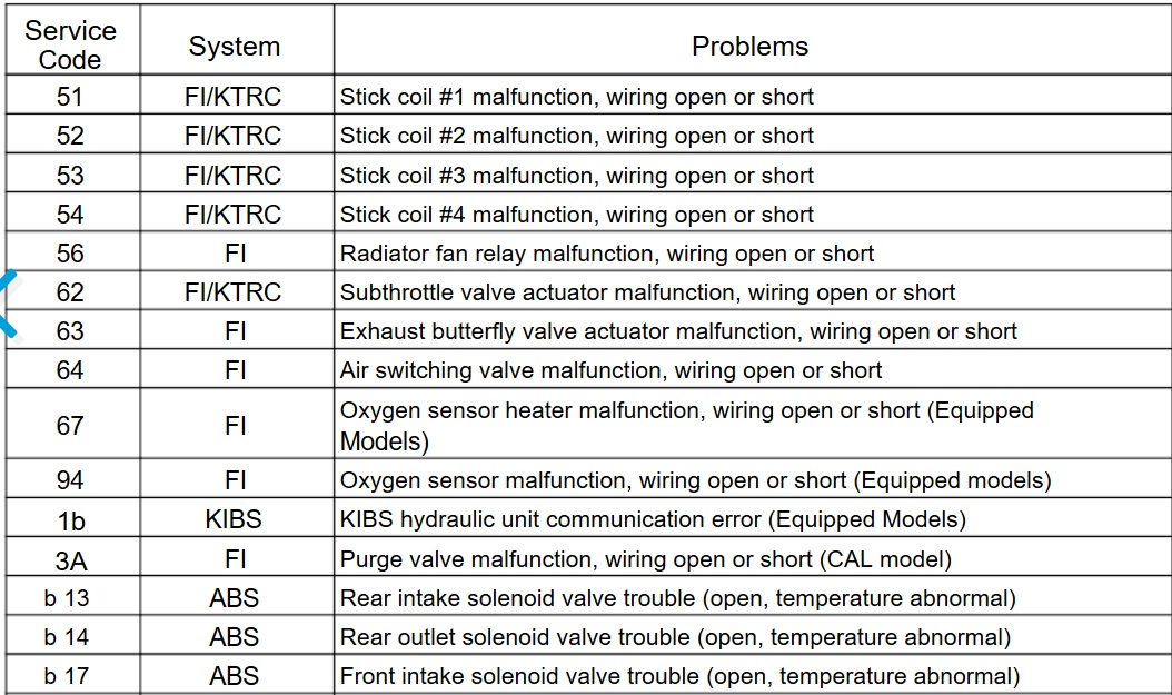
b18 ABS Front outlet solenoid valve trouble (open, temperature abnormal)
b19 ABS KIBS solenoid valve relay trouble (wiring shorted or open, stuck relay [ON or
OFF], or dropout)

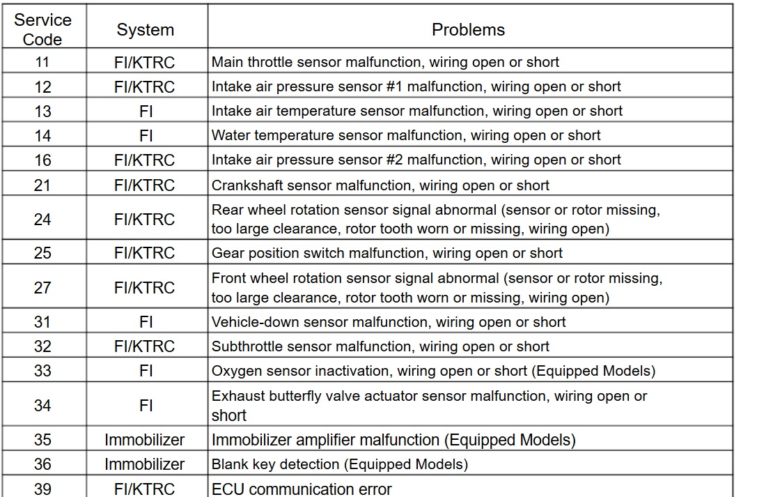
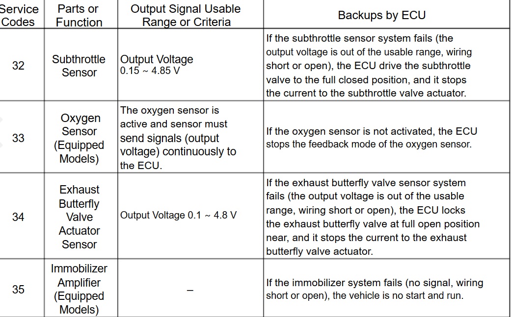
13 Intake Air Temp sensor — Intake Air Temperature Ta= -47~+178° C — If the intake air temperature sensor system fails (the signal is out of the usable range (wiring short or open), the ECU sets Ta at 30°C.
14 Water Temp — Water Temperature Sensor Tw= -30~+120° C — If the water temperature sensor system fails (the signal is out of the usable range, wiring short or open), the ECU sets Tw at 80°C and the radiator fan operates.
36 Ignition key — Ignition key must use register key. — If a blank or broken key is used, the
vehicle will not start or run.


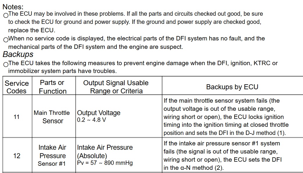
1b — KIBS — The KIBS hydraulic unit sends the data (for status of KIBS hydraulic unit) to the meter unit and ECU through the CAN communication line. — If the communication data is not sent, the ECU stops the KTRC control.
#1
![]()
Stef495
-

- Читатели
- 4 сообщений

- Пол:Мужчина
- Страна:Россия
- Город:Москва
- Мото:Kawasaki ZX6R 2005
Отправлено 25 Июль 2015 — 12:11
мотоцикл Kawasaki zx6r 2005 года снимали глушитель теперь горит ошибка считали сканером показывает 3 коротких и 3 быстрых мигания !!! может кто сталкивался подскажите как это исправить!! заранее благодарен!!!
- Наверх
#2
![]()
Indiana
Indiana
- Пол:Мужчина
- Страна:РФ
- Город:Нижний Новгород
- Мото:Zx6r 2011
Отправлено 03 Август 2015 — 13:30
F1 — ошибка топливной системы и смежных датчиков. Скорее всего если трогал глушитель, то на нем стоит лямбда зонд. Переткни полярность проводов.
Далее, если не пройдет, EX-UP. Может тросики перепутал или перетянул.
Если не оно, то смотри воздушку. Далее мерь насос.
В целом, попробуй скинуть аккумулятор на 10 минут.
- Наверх
#3
![]()
Anton33
Anton33
- Пол:Мужчина
- Страна:Россия
- Город:Ковров
- Мото:ninja zx-6r
Отправлено 05 Август 2015 — 18:16
Да, там заморочки что бы потом нормально тросики экзапа обратно запилить
- Наверх
#4
![]()
Stef495
Stef495
-
- Читатели
- 4 сообщений
- Пол:Мужчина
- Страна:Россия
- Город:Москва
- Мото:Kawasaki ZX6R 2005
Отправлено 06 Август 2015 — 09:01
Да, там заморочки что бы потом нормально тросики экзапа обратно запилить
спасибо ребят попробую!!
- Наверх
#5
![]()
point4you
point4you
-
- Members
-
- 16 сообщений
Прохожий


- Пол:Мужчина
- Страна:Россия
- Город:Санкт-Петербург
- Мото:kawasaki zx-6r
Отправлено 06 Август 2015 — 10:45
ничего серьезного в этом нет, у меня глушитель стоит неродной, из-за него тоже горит эта ошибка… 3-й сезон, никаких проблем) Но для успокоения души заморочиться можно конечно))
- Наверх
#6
![]()
Dimacus
Dimacus
- Пол:Мужчина
- Страна:РФ
- Город:Питер, Москва и Нижний Новгород
- Мото:ZX14+KLR650
Отправлено 06 Август 2015 — 12:06
3 коротких и 3 быстрых мигания
3 + 3 такого нету. есть 3 +4 и это будет клапан экзапа. поставь обманку либо отключи програмно
ничего серьезного в этом нет
да если только не напрягает тот факт, что мот переходит в аварийный режим
то на нем стоит лямбда зонд.
на 5 году небыло лямбды помойму. даже ошибки такой нету в DFI
- Наверх
#7
![]()
Monster2005
Monster2005
-
- Members
-
- 27 сообщений
Прохожий
- Пол:Мужчина
- Страна:Россия
- Город:Улан-Удэ
- Мото:ZX6RR
Отправлено 15 Август 2015 — 05:55
F1 — ошибка топливной системы и смежных датчиков. Скорее всего если трогал глушитель, то на нем стоит лямбда зонд. Переткни полярность проводов.
Далее, если не пройдет, EX-UP. Может тросики перепутал или перетянул.
Если не оно, то смотри воздушку. Далее мерь насос.
В целом, попробуй скинуть аккумулятор на 10 минут.
братья как узнать какая ошибка? горит FI мот 2005г ZX6RR
- Наверх
#8
![]()
Monster2005
Monster2005
-
- Members
-
- 27 сообщений
Прохожий
- Пол:Мужчина
- Страна:Россия
- Город:Улан-Удэ
- Мото:ZX6RR
Отправлено 15 Август 2015 — 15:29
люди помогите расскажите! как узнать какая ошибка!!!! горит FI мотак zx6r 2005!
- Наверх
#9
![]()
sherhan6
sherhan6
-
Вконтакте:
- Пол:Мужчина
- Страна:Россия
- Город:Белогорск
- Мото:kawassaki zx-6r 2006
Отправлено 16 Август 2015 — 01:12
люди помогите расскажите! как узнать какая ошибка!!!! горит FI мотак zx6r 2005!
Под седлом оранжевый провод, он как аппендицит из проводки торчит, его замкни на массу и включи зажигание, потом считай длинные и короткие мигания лампочки Fi, длинные это десятки, короткие это еденицы ( длинный+длинный+длинный=30)+(короткий+короткий+короткий+короткий=4) итого 34, номер ошибки. Потом сюда загляни http://www.ninjaclub…rosy-po-636-6r/
- Наверх
#10
![]()
Monster2005
Monster2005
-
- Members
-
- 27 сообщений
Прохожий
- Пол:Мужчина
- Страна:Россия
- Город:Улан-Удэ
- Мото:ZX6RR
Отправлено 16 Август 2015 — 16:04
Под седлом оранжевый провод, он как аппендицит из проводки торчит, его замкни на массу и включи зажигание, потом считай длинные и короткие мигания лампочки Fi, длинные это десятки, короткие это еденицы ( длинный+длинный+длинный=30)+(короткий+короткий+короткий+короткий=4) итого 34, номер ошибки. Потом сюда загляни http://www.ninjaclub…rosy-po-636-6r/
Спасибо попробую!
- Наверх
#11
![]()
Monster2005
Monster2005
-
- Members
-
- 27 сообщений
Прохожий
- Пол:Мужчина
- Страна:Россия
- Город:Улан-Удэ
- Мото:ZX6RR
Отправлено 18 Август 2015 — 18:47
попробывал! и видио посмотрел где чувак рассказал что у когото в клубе есть ехема как спаять обманку!!!!! у кого есть дайте пожалуйста!!!!!!
- Наверх
#12
![]()
xarj
xarj
- Пол:Мужчина
- Страна:Россия
- Город:Псковская обл….
- Мото:Kawasaki Ninja ZX-6R
Отправлено 22 Август 2015 — 09:10
Привет!!! Вот обратись… Мне недавно делал…. http://www.ninjaclub…raznye-kavasak/
- Наверх
#13
![]()
zloi_rastafarian
zloi_rastafarian
-
- Members
-
- 25 сообщений
Прохожий

- Пол:Мужчина
- Страна:Россия
- Город:Великий новгород
- Мото:kawasaki zx6r 2005
Отправлено 27 Август 2015 — 14:07
мотоцикл Kawasaki zx6r 2005 года снимали глушитель теперь горит ошибка считали сканером показывает 3 коротких и 3 быстрых мигания !!! может кто сталкивался подскажите как это исправить!! заранее благодарен!!!
была точно такая же проблема,посмотрел по ошибке — выдало что что то с выпуском,в итоге заказал с ебея или алика,точно не помню, обманку,около 1,5 ка вышла тогда,пришла,подключил и все,ошибка FI пропала сразу)
хотел спаять кто-то схему где-то выкидывал,но что то пошло не так и она не заработала)мб руки крюки)
- Наверх
#14
![]()
TURB0
TURB0
-
- Members
-
- 14 сообщений
Прохожий

- Пол:Мужчина
- Страна:Россия
- Город:Ставрополь
- Мото:ZX-6R
Отправлено 22 Февраль 2016 — 12:23
Всем здорово! Горит F1, как проверить что сломалось?
Спасибо!!!
- Наверх
#15
![]()
xarj
xarj
- Пол:Мужчина
- Страна:Россия
- Город:Псковская обл….
- Мото:Kawasaki Ninja ZX-6R
Отправлено 22 Февраль 2016 — 13:54
Всем здорово! Горит F1, как проверить что сломалось?
Спасибо!!!
Год какой мота…?
Если 2005, проводок под седушкой есть, замкни его на массу и считай короткие мигания и длинные и получишь код ошибки… Код смотри в мануале… Так вроде…
- Наверх
#16
![]()
TURB0
TURB0
-
- Members
-
- 14 сообщений
Прохожий
- Пол:Мужчина
- Страна:Россия
- Город:Ставрополь
- Мото:ZX-6R
Отправлено 22 Февраль 2016 — 14:49
Двигатель должен быть заглушен? или не важно? Во время теста?
- Наверх
#17
![]()
xarj
xarj
- Пол:Мужчина
- Страна:Россия
- Город:Псковская обл….
- Мото:Kawasaki Ninja ZX-6R
Отправлено 22 Февраль 2016 — 14:59
Двигатель должен быть заглушен? или не важно? Во время теста?
Прижал провод, зажигание включил… Заводить не надо…
- Наверх
#18
![]()
TURB0
TURB0
-
- Members
-
- 14 сообщений
Прохожий
- Пол:Мужчина
- Страна:Россия
- Город:Ставрополь
- Мото:ZX-6R
Отправлено 22 Февраль 2016 — 16:02
6 длинных 3 коротких, #63 по мануалу.
Мот 2005 год, стоит полный выхлоп и пауер коммандер, ставили давно, мот взял недавно, сначала не горела, проехал км 300 теперь горит. Что это может быть?
- Наверх
#19
![]()
Dimacus
Dimacus
- Пол:Мужчина
- Страна:РФ
- Город:Питер, Москва и Нижний Новгород
- Мото:ZX14+KLR650
Отправлено 23 Февраль 2016 — 01:56
Стандарт. как всегда. ПРИВОД ЭКЗАПА.
остальное в поиск. здесь по этой теме куча инфы по всем годам и моделям уже сто раз перетерли
- Наверх
#20
![]()
kazama
kazama
- Пол:Мужчина
- Страна:Россия
- Город:Питер
- Мото:zx10r 13 abs
Отправлено 31 Май 2016 — 19:30
Ехал ехал и без причины загорелось FI на приборке. Считал коды, показало 62 и 32. Все разобрал, все разъемы на месте. Подскажите куда копать?
мот zx6r 08
- Наверх
Kawasaki Ninja ZX-6R motorcycles have engines, which are made up of many different parts.
These parts must work together in order for the engine to function. A problem with one of the
parts can make the engine not run. There are many different parts that make up an engine.
The following kawasaki ninja zx-6r faults are the list of some of the parts of a motorcycle engine.
To fix the issue of fault codes, you’ll need to disconnect the battery cable. This will ensure that you don’t get shocked while handling the terminals. Next, you will want to clean them with a soft brush and water to get rid of the corrosion. Once Kawasaki Ninja ZX-6R is cleaned properly, you can put them back on the terminal and reattach the cable.
Kawasaki Ninja ZX-6R Faults :
Your bike engine consists of a great deal of elements like the casting, cylinder heads and pistons. it’s necessary to form certain these area unit all clean and lubricated to avoid engine issues. Conjointly keep in mind that Kawasaki Ninja ZX-6R motorbike engine could be a terribly delicate piece of machinery therefore it is best to handle it with care.
Kawasaki Diagnosis
Under the seat, along the right subframe rail is a short orange/black wire with a bullet connector
sticking out of the thick loom. This is the self-diagnosis terminal. There is another bullet connector
protruding nearby — make sure it’s the orange and black which can take some tugging.
In order to read out the Service Codes below, ground that connector with a bit of wire with the motor
running.
The red FI light will begin to flash codes. There will be a 5 second delay and then the codes begin.
The first flash is always a LONG (1 sec) followed by either LONG or SHORT (0.5 sec) flashes. LONG
flashes indicate TENS and short flashes ONES.
One LONG followed by two SHORT = 12.
Two LONG, one SHORT = 21.
Three LONG, two short = 32, etc.
There is an interval of 1.5 seconds between TENS and ONES.
There is a 3 second
interval between codes.
To recover codes set in memory ground the self-diagnosis terminal rapidly more than 5 times within
2 seconds. The lead must remain grounded after 5 groundings for the remainder of the diagnostic
session. You can then clear codes from the ECU by pulling the clutch lever in for more than 5
seconds.
KAWASAKI Motorcycles Fault Codes DTC List
| Trouble Code | Problem Description |
|---|---|
| 11 | Main throttle sensor malfunction, wiring open or short |
| 12 | Inlet air pressure sensor malfunction, wiring open or short |
| 13 | Inlet air temperature sensor malfunction, wiring open or short |
| 14 | Water temperature sensor malfunction, wiring open or short |
| 15 | Atmospheric pressure sensor malfunction, wiring open or short |
| 21 | Crankshaft sensor malfunction, wiring open or short |
| 23 | Camshaft position sensor malfunction, wiring open or short |
| 24 | Speed sensor malfunction, wiring open or short |
| 25 | Gear position switch malfunction, wiring open or short |
| 31 | Vehicle-down sensor malfunction, wiring open or short |
| 32 | Subthrottle sensor malfunction, wiring open or short |
| 33 | Oxygen sensor #1 inactivation, wiring open or short (Equipped Models) |
| 34 | Exhaust butterfly valve actuator sensor malfunction, wiring open or short |
| 35 | Immobilizer amplifier malfunction |
| 36 | Blank Key detection |
| 39 | ECU communication error |
| 51 | Stick coil #1 malfunction, wiring open or short |
| 52 | Stick coil #2 malfunction, wiring open or short |
| 53 | Stick coil #3 malfunction, wiring open or short |
| 54 | Stick coil #4 malfunction, wiring open or short |
| 56 | Radiator fan relay malfunction, wiring open or short |
| 62 | Subthrottle valve actuator malfunction, wiring open or short |
| 63 | Exhaust butterfly valve actuator malfunction, wiring open or short |
| 64 | Air switching valve malfunction, wiring open or short |
| 67 | Oxygen sensor heater malfunction, wiring open or short (Equipped Models) |
| 83 | Oxygen Sensor #2 inactivation, wiring open or shout (Equipped Models) |
| 94 | Oxygen sensor #1 malfunction, wiring open or short (Equipped Models) |
| 95 | Oxygen sensor #2 malfunction, wiring open or short (Equipped Models) |
Kawasaki Ninja ZX-6R Motorcycle Problems :
- Kawasaki ninja zx-6r after fire
- Kawasaki ninja zx-6r air cleaner clogged, poorly sealed, or missing
- Kawasaki ninja zx-6r air cleaner element clogged
- Kawasaki ninja zx-6r air duct loose
- Kawasaki ninja zx-6r air suction valve trouble
- Kawasaki ninja zx-6r air switching valve trouble
- Kawasaki ninja zx-6r backfiring when deceleration
- Kawasaki ninja zx-6r cracked or obstructed intake air pressure sensor
- Kawasaki ninja zx-6r crankshaft sensor trouble
- Kawasaki ninja zx-6r eCU ground and power supply trouble
- Kawasaki ninja zx-6r eCU trouble
- Kawasaki ninja zx-6r engine overheating — Water temperature sensor or crankshaft sensor trouble
- Kawasaki ninja zx-6r engine stalls easily
- Kawasaki ninja zx-6r engine vacuum not synchronizing
- Kawasaki ninja zx-6r exhaust Smokes Excessively
- Kawasaki ninja zx-6r firing incorrect
- Kawasaki ninja zx-6r fuel filter clogged
- Kawasaki ninja zx-6r fuel injector clogged
- Kawasaki ninja zx-6r fuel injector O-ring damage
- Kawasaki ninja zx-6r fuel injector trouble
- Kawasaki ninja zx-6r fuel line clogged
- Kawasaki ninja zx-6r fuel poor quality or incorrect
- Kawasaki ninja zx-6r fuel pressure regulator trouble
- Kawasaki ninja zx-6r fuel pressure too low or too high
- Kawasaki ninja zx-6r fuel pump bearings may wear. Replace the fuel pump
- Kawasaki ninja zx-6r fuel pump not operating
- Kawasaki ninja zx-6r fuel pump operates intermittently and often DFI fuse blows
- Kawasaki ninja zx-6r fuel pump relay trouble
- Kawasaki ninja zx-6r fuel pump trouble
- Kawasaki ninja zx-6r fuel/air mixture incorrect
- Kawasaki ninja zx-6r fuel/air mixture incorrect
- Kawasaki ninja zx-6r gear position sensor, starter lockout or side stand switch trouble
- Kawasaki ninja zx-6r inspect and repair or replace
- Kawasaki ninja zx-6r intake air pressure sensor trouble
- Kawasaki ninja zx-6r intake air temperature sensor trouble
- Kawasaki ninja zx-6r intake air temperature sensor trouble
- Kawasaki ninja zx-6r intermittent any DFI fault and its recovery
- Kawasaki ninja zx-6r little fuel in tank
- Kawasaki ninja zx-6r main throttle sensor trouble
- Kawasaki ninja zx-6r no or little fuel in tank
- Kawasaki ninja zx-6r poor acceleration
- Kawasaki ninja zx-6r spark plug burned or gap maladjusted
- Kawasaki ninja zx-6r spark plug dirty, broken or gap maladjusted
- Kawasaki ninja zx-6r spark plug incorrect
- Kawasaki ninja zx-6r spark weak
- Kawasaki ninja zx-6r stick coil shorted or not in good contact
- Kawasaki ninja zx-6r stick coil trouble
- Kawasaki ninja zx-6r subthrottle sensor trouble
- Kawasaki ninja zx-6r subthrottle valve actuator trouble
- Kawasaki ninja zx-6r throttle body assy dust seal damage
- Kawasaki ninja zx-6r throttle body assy holder loose
- Kawasaki ninja zx-6r throttle valves will not fully open
- Kawasaki ninja zx-6r unstable (rough) idling
- Kawasaki ninja zx-6r unstable fuel pressure
- Kawasaki ninja zx-6r vacuum hose
- Kawasaki ninja zx-6r vehicle-down sensor trouble
- Kawasaki ninja zx-6r water or foreign matter in fuel Change fuel
- Kawasaki ninja zx-6r water temperature sensor trouble
Issues with the engine are typically caused by issues with the engine parts. Whether it is a fuel issue or an ignition problem, the engine parts should be inspected to determine the cause. Another issue that can occur is when the Kawasaki Ninja ZX-6R motorcycle engine is not working is a failure of the electrical system. This can cause the motorcycle to stall and not work correctly. The electrical system is typically the most complex system on a motorcycle.
Possible Failure Types :
- Strange Kawasaki Ninja ZX-6R engine noise.
- Kawasaki Ninja ZX-6R fog from engine.
- Strange Kawasaki Ninja ZX-6R engine noise.
- Kawasaki Ninja ZX-6R Vibrations and Rattling
- Kawasaki Ninja ZX-6R Loud Acceleration
- Kawasaki Ninja ZX-6R rusty exhaust
- Kawasaki Ninja ZX-6R blockages in exhaust pipe
- Kawasaki Ninja ZX-6R wear and tear exhaust

Kawasaki Heavy Industries was started in 1878, as a producer of maritime equipment and vessels. Kawasaki began motorcycle manufacturing in the late 1960’s and today, their bikes are famous for being nearly bulletproof, and many of their models being friendly for new riders.
Check other Kawasaki fault codes.
Common abbreviations and their meanings below:
ABS: Anti-Lock Braking System
ACR: Automatic Compression Release
AFR: Air Fuel Ratio
AIS: Active Intake Solenoid
ATS: Air Temperature Sensor
BAS: Bank Angle Sensor
BCM: Body Control Module
CAN: Controller Area Network
CCM: Cruise Control Module
CKP: Crank Position Sensor
DLC: Datalink Connector
DTC: Diagnostic Trouble Codes
ECM: Electronic Control Module
ECT: Engine Coolant Temperature
ECU: Electronic Control Unit
EFI: Electronic Fuel Injection
EFP: Electronic Fuel Pump
ET: Engine Temperature sensor
FI: Fuel Injectors
FPR: Fuel Pressure Regulator
H-DSSS: Harley-Davidson® Smart Security System
HCU: Hydraulic Control Unit, ABS
HFSM: Hands Free Security Module
HO2S: Heated Oxygen Sensor
IAC: Idle Air Control actuator
IAT: Intake Air Temperature sensor
ICM: Ignition Control Module
IMAP: MAP + IAT in one unit
ISS: Ion Sensing System
JSS: Jiffy Stand Sensor
LHCM: Left Hand Control Module
MAP: Manifold Absolute Pressure sensor
MHR: Right Hand Control Module
RCM: Reverse Control Module
TCA: Throttle Control Actuator
TGS: Twist Grip Sensor
TMAP: Intake Air Temperature / Manifold Absolute Pressure equipment
TPS: Throttle Position Sensor
TSM / TSSM: (Turn Signal / Turn Signal Security Module)
VE: Volume Efficiency
VIN: Vehicle Identification Number
VSS: Vehicle Speed Sensor
WSS: Wheel Speed Sensor
These abbreviations, and the accompanying list of trouble codes, can be a
great start when your Kawasaki check engine light comes on. As mentioned
above, if you are not comfortable with electrical diagnostic work, a dealership or qualified
technician can offer assistance. Please keep in mind that even though you have the ability to
clear a DTC using the onboard diagnostic feature, you shouldn’t clear the code prior to your
service appointment. Let the technician view and clear the codes as they troubleshoot the issue.
Kawasaki and logo are registered trademarks of Kawasaki. We are fan of MOTORCYCLES ! We love them.
Motorcycle electrical systems are very complex to fix it, check with your motorcycle diagnosis tool for the fault code and start motorcycle troubleshooting process.Some bike problems require professional troubleshooting and repair. However, there are many issues that you can easily fix on your own.
About Us | Contact | Privacy
Copyright 2022 — © MotorcycleTroubleshooting.com
![]()
Ninja ZX-6R
Motorcycle
Service Manual

Quick Reference Guide
This quick reference guide will assist you in locating a desired topic or procedure.
•Bend the pages back to match the black tab of the desired chapter number with the black tab on the edge at each table of contents page.
•Refer to the sectional table of contents for the exact pages to locate the specific topic required.
|
General Information |
1 |
j |
|
Periodic Maintenance |
2 |
j |
|
Fuel System (DFI) |
3 |
j |
|
Cooling System |
4 |
j |
|
Engine Top End |
5 |
j |
|
Clutch |
6 |
j |
|
Engine Lubrication System |
7 |
j |
|
Engine Removal/Installation |
8 |
j |
|
Crankshaft/Transmission |
9 |
j |
|
Wheels/Tires |
10 |
j |
|
Final Drive |
11 |
j |
|
Brakes |
12 |
j |
|
Suspension |
13 |
j |
|
Steering |
14 |
j |
|
Frame |
15 |
j |
|
Electrical System |
16 |
j |
|
Appendix |
17 |
j |

Ninja ZX-6R
Motorcycle
Service Manual
All rights reserved. No parts of this publication may be reproduced, stored in a retrieval system, or transmitted in any form or by any means, electronic mechanical photocopying, recording or otherwise, without the prior written permission of Quality Assurance Department/Consumer Products & Machinery Company/Kawasaki Heavy Industries, Ltd., Japan.
No liability can be accepted for any inaccuracies or omissions in this publication, although every possible care has been taken to make it as complete and accurate as possible.
The right is reserved to make changes at any time without prior notice and without incurring an obligation to make such changes to products manufactured previously. See your Motorcycle dealer for the latest information on product improvements incorporated after this publication.
All information contained in this publication is based on the latest product information available at the time of publication. Illustrations and photographs in this publication are intended for reference use only and may not depict actual model component parts.
|
© 2004 Kawasaki Heavy Industries, Ltd. |
First Edition (1): Sep. 30, 2004 (M) |
LIST OF ABBREVIATIONS
|
A |
ampere(s) |
lb |
pound(s) |
|
ABDC |
after bottom dead center |
m |
meter(s) |
|
AC |
alternating current |
min |
minute(s) |
|
ATDC |
after top dead center |
N |
newton(s) |
|
BBDC |
before bottom dead center |
Pa |
pascal(s) |
|
BDC |
bottom dead center |
PS |
horsepower |
|
BTDC |
before top dead center |
psi |
pound(s) per square inch |
|
°C |
degree(s) Celsius |
r |
revolution |
|
DC |
direct current |
rpm |
revolution(s) per minute |
|
F |
farad(s) |
TDC |
top dead center |
|
°F |
degree(s) Fahrenheit |
TIR |
total indicator reading |
|
ft |
foot, feet |
V |
volt(s) |
|
g |
gram(s) |
W |
watt(s) |
|
h |
hour(s) |
Ω |
ohm(s) |
|
L |
liter(s) |
Read OWNER’S MANUAL before operating.

EMISSION CONTROL INFORMATION
To protect the environment in which we all live, Kawasaki has incorporated crankcase emission (1) and exhaust emission (2) control systems in compliance with applicable regulations of the United States Environmental Protection Agency and California Air Resources Board. Additionally, Kawasaki has incorporated an evaporative emission control system (3) in compliance with applicable regulations of the California Air Resources Board on vehicles sold in California only.
1. Crankcase Emission Control System
This system eliminates the release of crankcase vapors into the atmosphere. Instead, the vapors are routed through an oil separator to the inlet side of the engine. While the engine is operating, the vapors are drawn into combustion chamber, where they are burned along with the fuel and air supplied by the fuel injection system.
2. Exhaust Emission Control System
This system reduces the amount of pollutants discharged into the atmosphere by the exhaust of this motorcycle. The fuel, ignition, and exhaust systems of this motorcycle have been carefully designed and constructed to ensure an efficient engine with low exhaust pollutant levels.
The exhaust system of this model motorcycle manufactured primarily for sale in California includes a catalytic converter system.
3. Evaporative Emission Control System
Vapors caused by fuel evaporation in the fuel system are not vented into the atmosphere. Instead, fuel vapors are routed into the running engine to be burned, or stored in a canister when the engine is stopped. Liquid fuel is caught by a vapor separator and returned to the fuel tank.
The Clean Air Act, which is the Federal law covering motor vehicle pollution, contains what is commonly referred to as the Act’s “tampering provisions”.
“Sec. 203(a) The following acts and the causing thereof are prohibited…
(3)(A) for any person to remove or render inoperative any device or element of design installed on or in a motor vehicle or motor vehicle engine in compliance with regulations under this title prior to its sale and delivery to the ultimate purchaser, or for any manufacturer or dealer knowingly to remove or render inoperative any such device or element of design after such sale and delivery to the ultimate purchaser.
(3)(B) for any person engaged in the business of repairing, servicing, selling, leasing, or trading motor vehicles or motor vehicle engines, or who operates a fleet of motor vehicles knowingly to remove or render inoperative any device or element of design installed on or in a motor vehicle or motor vehicle engine in compliance with regulations under this title following its sale and delivery to the ultimate purchaser…”
NOTE
○The phrase “remove or render inoperative any device or element of design” has been generally interpreted as follows.
1.Tampering does not include the temporary removal or rendering inoperative of devices or elements of design in order to perform maintenance.
2.Tampering could include.
a.Maladjustment of vehicle components such that the emission standards are exceeded.
b.Use of replacement parts or accessories which adversely affect the performance or durability of the motorcycle.
c.Addition of components or accessories that result in the vehicle exceeding the standards.
d.Permanently removing, disconnecting, or rendering inoperative any component or element of design of the emission control systems.
WE RECOMMEND THAT ALL DEALERS OBSERVE THESE PROVISIONS OF FEDERAL LAW, THE VIOLATION OF WHICH IS PUNISHABLE BY CIVIL PENALTIES NOT EXCEEDING $10 000 PER VIOLATION.

TAMPERING WITH NOISE CONTROL SYSTEM PROHIBITED
Federal law prohibits the following acts or the causing thereof. (1) The removal or rendering inoperative by any person other than for purposes of maintenance, repair, or replacement, of any device or element of design incorporated into any new vehicle for the purpose of noise control prior to its sale or delivery to the ultimate purchaser or while it is in use, or (2) the use of the vehicle after such device or element of design has been removed or rendered inoperative by any person.
Among those acts presumed to constitute tampering are the acts listed below.
•Replacement of the original exhaust system or muffler with a component not in compliance with Federal regulations.
•Removal of the muffler(s) or any internal portion of the muffler(s).
•Removal of the air box or air box cover.
•Modifications to the muffler(s) or air inlet system by cutting, drilling, or other means if such modifications result in increased noise levels.
Foreword
This manual is designed primarily for use by trained mechanics in a properly equipped shop. However, it contains enough detail and basic information to make it useful to the owner who desires to perform his own basic maintenance and repair work. A basic knowledge of mechanics, the proper use of tools, and workshop procedures must be understood in order to carry out maintenance and repair satisfactorily. Whenever the owner has insufficient experience or doubts his ability to do the work, all adjustments, maintenance, and repair should be carried out only by qualified mechanics.
In order to perform the work efficiently and to avoid costly mistakes, read the text, thoroughly familiarize yourself with the procedures before starting work, and then do the work carefully in a clean area. Whenever special tools or equipment are specified, do not use makeshift tools or equipment. Precision measurements can only be made if the proper instruments are used, and the use of substitute tools may adversely affect safe operation.
For the duration of the warranty period, we recommend that all repairs and scheduled maintenance be performed in accordance with this service manual. Any owner maintenance or repair procedure not performed in accordance with this manual may void the warranty.
To get the longest life out of your vehicle.
•Follow the Periodic Maintenance Chart in the Service Manual.
•Be alert for problems and non-scheduled maintenance.
•Use proper tools and genuine Kawasaki Motorcycle parts. Special tools, gauges, and testers that are necessary when servicing Kawasaki motorcycles are introduced by the Special Tool Catalog or Manual. Genuine parts provided as spare parts are listed in the Parts Catalog.
•Follow the procedures in this manual carefully. Don’t take shortcuts.
•Remember to keep complete records of maintenance and repair with dates and any new parts installed.
How to Use This Manual
In preparing this manual, we divided the product into its major systems. These systems became the manual’s chapters. All information for a particular system from adjustment through disassembly and inspection is located in a single chapter.
The Quick Reference Guide shows you all of the product’s system and assists in locating their chapters. Each chapter in turn has its own comprehensive Table of Contents.
The Periodic Maintenance Chart is located in the Periodic Maintenance chapter. The chart gives a time schedule for required maintenance operations.
If you want spark plug information, for example, go to the Periodic Maintenance Chart first. The chart tells you how frequently to clean and gap the plug. Next, use the Quick Reference Guide to locate the Periodic Maintenance chapter. Then, use the Table of Contents on the first page of the chapter to find the Spark Plug section.
Whenever you see these WARNING and CAUTION symbols, heed their instructions! Always follow safe operating and maintenance practices.

 WARNING
This warning symbol identifies special instructions or procedures which, if not correctly followed, could result in personal injury, or loss of life.
CAUTION
This caution symbol identifies special instructions or procedures which, if not strictly observed, could result in damage to or destruction of equipment.
This manual contains four more symbols (in addition to WARNING and CAUTION) which will help you distinguish different types of information.
NOTE
○This note symbol indicates points of particular interest for more efficient and convenient operation.
•Indicatesdone. a procedural step or work to be ○Indicates a procedural sub-step or how to do the work of the procedural step it follows. It
also precedes the text of a NOTE.
 Indicates a conditional step or what action to take based on the results of the test or inspection in the procedural step or sub-step it follows.
In most chapters an exploded view illustration of the system components follows the Table of Contents. In these illustrations you will find the instructions indicating which parts require specified tightening torque, oil, grease or a locking agent during assembly.
![]()
GENERAL INFORMATION 1-1
General Information |
1 |
|
Table of Contents |
|
|
Before Servicing ……………………………………………………………………………………………………… |
1-2 |
|
Model Identification………………………………………………………………………………………………….. |
1-7 |
|
General Specifications……………………………………………………………………………………………… |
1-9 |
|
Unit Conversion Table ……………………………………………………………………………………………… |
1-12 |
1-2 GENERAL INFORMATION
Before Servicing
Before starting to perform an inspection service or carry out a disassembly and reassembly operation on a motorcycle, read the precautions given below. To facilitate actual operations, notes, illustrations, photographs, cautions, and detailed descriptions have been included in each chapter wherever necessary. This section explains the items that require particular attention during the removal and reinstallation or disassembly and reassembly of general parts.
Especially note the following.
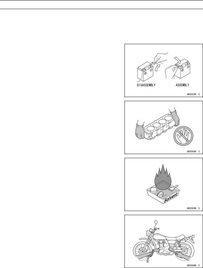
Battery Ground
Before completing any service on the motorcycle, disconnect the battery cables from the battery to prevent the engine from accidentally turning over. Disconnect the ground cable (–) first and then the positive (+). When completed with the service, first connect the positive (+) cable to the positive (+) terminal of the battery then the negative (–) cable to the negative terminal.
Edges of Parts
Lift large or heavy parts wearing gloves to prevent injury from possible sharp edges on the parts.
Solvent
Use a high-flush point solvent when cleaning parts. High -flush point solvent should be used according to directions of the solvent manufacturer.
Cleaning vehicle before disassembly
Clean the vehicle thoroughly before disassembly. Dirt or other foreign materials entering into sealed areas during vehicle disassembly can cause excessive wear and decrease performance of the vehicle.
GENERAL INFORMATION 1-3
Before Servicing
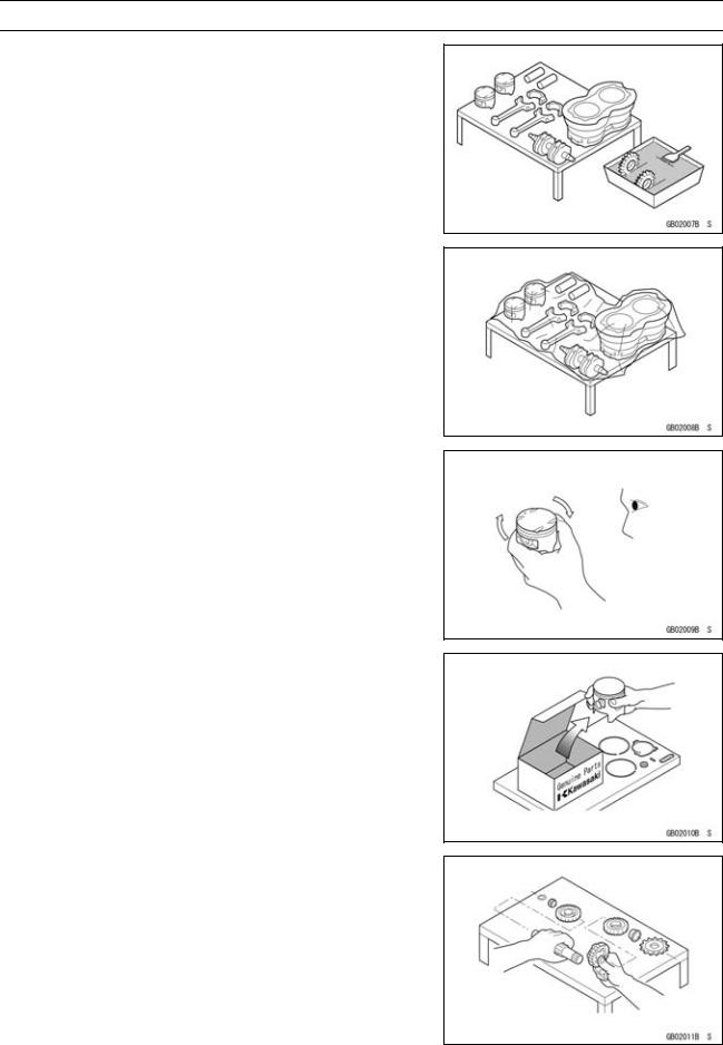
Arrangement and Cleaning of Removed Parts
Disassembled parts are easy to confuse. Arrange the parts according to the order the parts were disassembled and clean the parts in order prior to assembly.
Storage of Removed Parts
After all the parts including subassembly parts have been cleaned, store the parts in a clean area. Put a clean cloth or plastic sheet over the parts to protect from any foreign materials that may collect before re-assembly.
Inspection
Reuse of worn or damaged parts may lead to serious accident. Visually inspect removed parts for corrosion, discoloration, or other damage. Refer to the appropriate sections of this manual for service limits on individual parts. Replace the parts if any damage has been found or if the part is beyond its service limit.
Replacement Parts
Replacement Parts must be KAWASAKI genuine or recommended by KAWASAKI. Gaskets, O-rings, oil seals, grease seals, circlips or cotter pins must be replaced with new ones whenever disassembled.
Assembly Order
In most cases assembly order is the reverse of disassembly, however, if assembly order is provided in this Service Manual, follow the procedures given.
1-4 GENERAL INFORMATION
Before Servicing
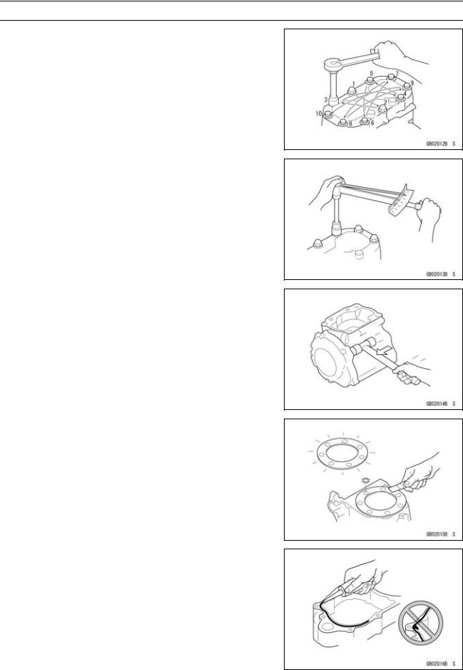
Tightening Sequence
Generally, when installing a part with several bolts, nuts, or screws, start them all in their holes and tighten them to a snug fit. Then tighten them according to the specified sequence to prevent case warpage or deformation which can lead to malfunction. Conversely when loosening the bolts, nuts, or screws, first loosen all of them by about a quarter turn and then remove them. If the specified tightening sequence is not indicated, tighten the fasteners alternating diagonally.
Tightening Torque
Incorrect torque applied to a bolt, nut, or screw may lead to serious damage. Tighten fasteners to the specified torque using a good quality torque wrench.
Force
Use common sense during disassembly and assembly, excessive force can cause expensive or hard to repair damage. When necessary, remove screws that have a non -permanent locking agent applied using an impact driver. Use a plastic-faced mallet whenever tapping is necessary.
Gasket, O-ring
Hardening, shrinkage, or damage of both gaskets and O-rings after disassembly can reduce sealing performance. Remove the old gaskets and clean the sealing surfaces thoroughly so that no gasket material or other material remains. Install the new gaskets and replace the used O-rings when re-assembling
Liquid Gasket, Non-permanent Locking Agent
For applications that require Liquid Gasket or a Non-permanent Locking Agent, clean the surfaces so that no oil residue remains before applying liquid gasket or non-permanent locking agent. Do not apply them excessively. Excessive application can clog oil passages and cause serious damage.
GENERAL INFORMATION 1-5
Before Servicing
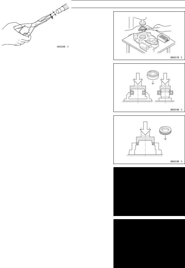
Press
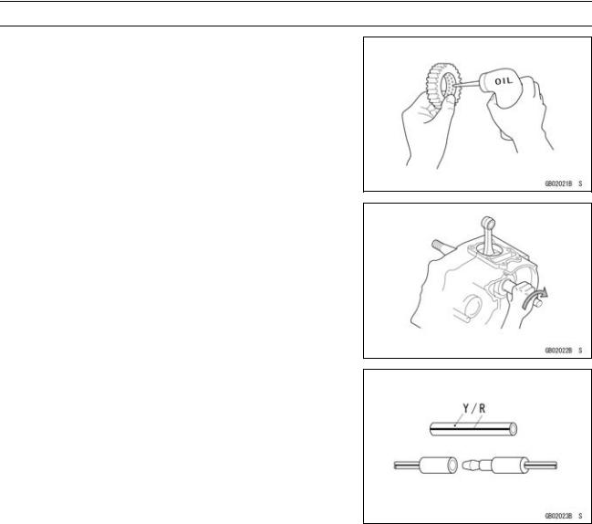
For items such as bearings or oil seals that must be pressed into place, apply small amount of oil to the contact area. Be sure to maintain proper alignment and use smooth movements when installing.
Ball Bearing and Needle Bearing
Do not remove pressed ball or needle unless removal is absolutely necessary. Replace with new ones whenever removed. Press bearings with the manufacturer and size marks facing out. Press the bearing into place by putting pressure on the correct bearing race as shown.
Pressing the incorrect race can cause pressure between the inner and outer race and result in bearing damage.
Oil Seal, Grease Seal
Do not remove pressed oil or grease seals unless removal is necessary. Replace with new ones whenever removed. Press new oil seals with manufacture and size marks facing out. Make sure the seal is aligned properly when installing.
Apply specified grease to the lip of seal before installing the seal.
Circlips, Cotter Pins
Replace the circlips or cotter pins that were removed with new ones. Take care not to open the clip excessively when installing to prevent deformation.
1-6 GENERAL INFORMATION
Before Servicing
Lubrication
It is important to lubricate rotating or sliding parts during assembly to minimize wear during initial operation. Lubrication points are called out throughout this manual, apply the specific oil or grease as specified.
Direction of Engine Rotation
When rotating the crankshaft by hand, the free play amount of rotating direction will affect the adjustment. Rotate the crankshaft to positive direction (clockwise viewed from output side).
Electrical Wires
A two-color wire is identified first by the primary color and then the stripe color. Unless instructed otherwise, electrical wires must be connected to those of the same color.
GENERAL INFORMATION 1-7
Model Identification
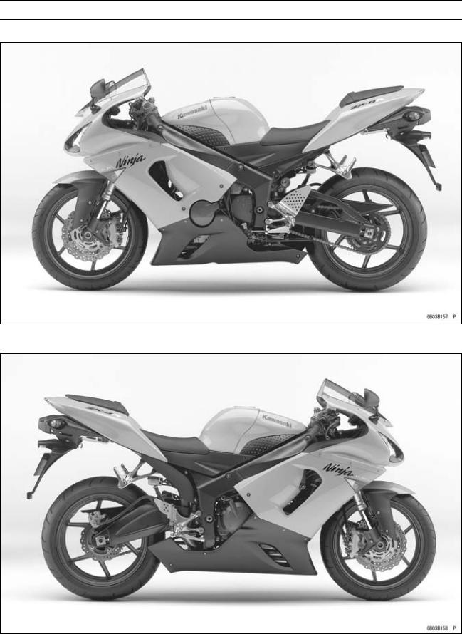
ZX636-C1 (Europe) Left Side View
ZX636-C1 (Europe) Right Side View
1-8 GENERAL INFORMATION
Model Identification
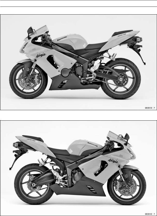
ZX636-C1 (US and Canada) Left Side View
ZX636-C1 (US and Canada) Right Side View
|
GENERAL INFORMATION 1-9 |
|
|
General Specifications |
|
|
Items |
ZX636-C1 (Ninja ZX-6R) |
|
Dimensions |
|
|
Overall Length |
2 065 mm (81.3 in.) |
|
Overall Width |
715 mm (28.1 in.) |
|
Overall Height |
1 110 mm (43.7 in.) |
|
Wheelbase |
1 390 mm (54.7 in.) |
|
Road Clearance |
120 mm (4.7 in.) |
|
Seat Height |
820 mm (32.3 in.) |
|
Dry Mass |
164 kg (362 lb) |
|
Curb Mass: |
|
|
Front |
95 kg (209 lb) |
|
Rear |
97 kg (214 lb) |
|
Fuel Tank Capacity |
17 L (4.5 US gal) |
|
Performance |
|
|
Minimum Turning Radius |
3.3 m (10.8 ft) |
|
Engine |
|
|
Type |
4-stroke, DOHC, 4-cylinder |
|
Cooling System |
Liquid-cooled |
|
Bore and Stroke |
68.0 × 43.8 mm (2.7 × 1.7 in.) |
|
Displacement |
636 mL (38.8 cu in.) |
|
Compression Ratio |
12.9 : 1 |
|
Maximum Horsepower |
95.5 kW (130 PS) @14 000 r/min (rpm), |
|
(FR) 78.2 kW (106 PS) @13 000 r/min (rpm), |
|
|
(MY) 90.8 kW (123 PS) @12 500 r/min (rpm), |
|
|
(CA), (CAL), (US) – – – |
|
|
Maximum Torque |
70.5 N·m (7.1 kgf·m, 52 ft·lb) @11 500 r/min (rpm), |
|
(FR) 63 N·m (6.4 kgf·m, 46 ft·lb) @11 500 r/min (rpm), |
|
|
(CA), (CAL), (US) – – – |
|
|
Carburetion System |
FI (Fuel injection) |
|
Primary: KEIHIN TTK 38 × 4 |
|
|
Secondary: KEIHIN Multihole (3 holes) × 4 |
|
|
Starting System |
Electric starter |
|
Ignition System |
Battery and coil (transistorized) |
|
Timing Advance |
Electronically advanced (digital igniter in ECU) |
|
Ignition Timing |
From 12.5° BTDC @1 300 r/min (rpm) to 35° BTDC @4 600 r/min |
|
(rpm) |
|
|
Spark Plug |
NGK CR9E |
|
Cylinder Numbering Method |
Left to right, 1-2-3-4 |
|
Firing Order |
1-2-4-3 |
|
Valve Timing: |
|
|
Inlet: |
|
|
Open |
59° BTDC |
|
Close |
81° ABDC |
|
Duration |
320° |
|
Exhaust: |
|
|
Open |
61° BBDC |
|
Close |
31° ATDC |

1-10 GENERAL INFORMATION
General Specifications
|
Items |
ZX636-C1 (Ninja ZX-6R) |
|
Duration |
272° |
|
Lubrication System |
Forced lubrication (wet sump with cooler) |
|
Engine Oil: |
|
|
Type |
API SE, SF or SG |
|
API SH or SJ with JASO MA |
|
|
Viscosity |
SAE10W-40 |
|
Capacity |
4.0 L (4.2 US qt) |
|
Drive Train |
|
|
Primary Reduction System: |
|
|
Type |
Gear |
|
Reduction Ratio |
1.891 (87/46) |
|
Clutch Type |
Wet multi disc |
|
Transmission: |
|
|
Type |
6-speed, constant mesh, return shift |
|
Gear Ratios: |
|
|
1st |
2.923 (38/13) |
|
2nd |
2.055 (37/18) |
|
3rd |
1.666 (35/21) |
|
4th |
1.450 (29/20) |
|
5th |
1.272 (28/22) |
|
6th |
1.153 (30/26) |
|
Final Drive System: |
|
|
Type |
Chain drive |
|
Reduction Ratio |
2.866 (43/15) |
|
Overall Drive Ratio |
6.255 @Top gear |
|
Frame |
|
|
Type |
Tubular, diamond |
|
Caster (Rake Angle) |
25° |
|
Trail |
106 mm (4.2 in.) |
|
Front Tire: |
|
|
Type |
Tubeless |
|
Size |
120/65 ZR17 M/C (56 W) |
|
Rear Tire: |
|
|
Type |
Tubeless |
|
Size |
180/55 ZR17 M/C (73 W) |
|
Front Suspension: |
|
|
Type |
Telescopic fork (upside-down) |
|
Wheel Travel |
120 mm (4.7 in.) |
|
Rear Suspension: |
|
|
Type |
Swingarm (uni-trak) |
|
Wheel Travel |
135 mm (5.3 in.) |
|
Brake Type: |
|
|
Front |
Dual discs |
|
Rear |
Single disc |
|
GENERAL INFORMATION 1-11 |
||
|
General Specifications |
||
|
Items |
ZX636-C1 (Ninja ZX-6R) |
|
|
Electrical Equipment |
||
|
Battery |
12 V 8 Ah |
|
|
Headlight: |
||
|
Type |
Semi-sealed beam |
|
|
Bulb: |
||
|
High |
12 |
V 55 W (quartz-halogen) × 2 |
|
Low |
12 |
V 55 W (quartz-halogen) |
|
Tail/Brake Light |
12 |
V 0.5/4.1 W (LED) |
|
Alternator: |
||
|
Type |
Three-phase AC |
|
|
Rated Output |
22.5 A/14 V @5 000 r/min (rpm) |
Specifications subject to change without notice, and may not apply to every country. CA: Canada Model
CAL: California Model
FR: France Model
MY: Malaysia Model US: United States Model
1-12 GENERAL INFORMATION
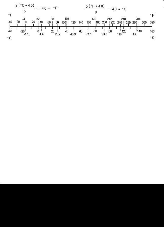
Unit Conversion Table
Prefixes for Units |
Units of Length |
|
Prefix |
Symbol |
Power |
||
|
mega |
M |
× 1 000 |
000 |
|
|
kilo |
k |
× |
1 000 |
|
|
centi |
c |
× |
0.01 |
|
|
milli |
m |
0.001 |
||
|
× |
||||
|
micro |
µ |
× 0.000001 |
Units of Mass
|
kg |
× |
2.205 |
= |
lb |
|
g |
× |
0.03527 |
= |
oz |
|
km |
× |
0.6214 |
= |
mile |
|
m |
× |
3.281 |
= |
ft |
|
mm |
× |
0.03937 |
= |
in |
Units of Torque
|
N·m |
× |
0.1020 |
= |
kgf·m |
|
N·m |
× |
0.7376 |
= |
ft·lb |
|
N·m |
× |
8.851 |
= |
in·lb |
|
kgf·m |
× |
9.807 |
= |
N·m |
|
kgf·m |
× |
7.233 |
= |
ft·lb |
|
kgf·m |
× |
86.80 |
= |
in·lb |
Units of Volume
|
L |
× |
0.2642 |
= |
gal (US) |
|
L |
× |
0.2200 |
= |
gal (imp) |
|
L |
× |
1.057 |
= |
qt (US) |
|
L |
× |
0.8799 |
= |
qt (imp) |
|
L |
× |
2.113 |
= |
pint (US) |
|
L |
× |
1.816 |
= |
pint (imp) |
|
mL |
× |
0.03381 |
= |
oz (US) |
|
mL |
× |
0.02816 |
= |
oz (imp) |
|
mL |
× |
0.06102 |
= |
cu in |
Units of Force
|
N |
× |
0.1020 |
= |
kg |
|
N |
× |
0.2248 |
= |
lb |
|
kg |
× |
9.807 |
= |
N |
|
kg |
× |
2.205 |
= |
lb |
Units of Temperature
Units of Pressure
|
kPa |
× |
0.01020 |
= |
kgf/cm² |
|
kPa |
× |
0.1450 |
= |
psi |
|
kPa |
× |
0.7501 |
= |
cmHg |
|
kgf/cm² |
× |
98.07 |
= |
kPa |
|
kgf/cm² |
× |
14.22 |
= |
psi |
|
cmHg |
× |
1.333 |
= |
kPa |
Units of Speed
km/h × 0.6214 = mph
Units of Power
|
kW |
× |
1.360 |
= |
PS |
|
kW |
× |
1.341 |
= |
HP |
|
PS |
× |
0.7355 |
= |
kW |
|
PS |
× |
0.9863 |
= |
HP |

PERIODIC MAINTENANCE 2-1
Periodic Maintenance
|
Periodic Maintenance Chart (United States, Canada Model)…………………………………………. |
2-3 |
|
Periodic Maintenance Chart (Other than United States, Canada Model)…………………………. |
2-6 |
|
Torque and Locking Agent………………………………………………………………………………………… |
2-9 |
|
Specifications …………………………………………………………………………………………………………. |
2-15 |
|
Special Tools ………………………………………………………………………………………………………….. |
2-17 |
|
Maintenance Procedure …………………………………………………………………………………………… |
2-18 |
|
Fuel System (DFI)…………………………………………………………………………………………………. |
2-18 |
|
Throttle Control System Inspection……………………………………………………………………….. |
2-18 |
|
Engine Vacuum Synchronization Inspection…………………………………………………………… |
2-18 |
|
Idle Speed Inspection …………………………………………………………………………………………. |
2-22 |
|
Idle Speed Adjustment………………………………………………………………………………………… |
2-22 |
|
Fuel Hose Damage and Installation Condition Inspection ………………………………………… |
2-22 |
|
Evaporative Emission Control System (California Model) …………………………………………… |
2-23 |
|
Evaporative Emission Control System Inspection …………………………………………………… |
2-23 |
|
Cooling System…………………………………………………………………………………………………….. |
2-24 |
|
Coolant Level Inspection……………………………………………………………………………………… |
2-24 |
|
Radiator Hose Damage and Installation Condition Inspection…………………………………… |
2-24 |
|
Engine Top End ……………………………………………………………………………………………………. |
2-25 |
|
Valve Clearance Inspection …………………………………………………………………………………. |
2-25 |
|
Valve Clearance Adjustment………………………………………………………………………………… |
2-26 |
|
Air Suction System ……………………………………………………………………………………………….. |
2-29 |
|
Air Suction System Damage Inspection…………………………………………………………………. |
2-29 |
|
Clutch………………………………………………………………………………………………………………….. |
2-29 |
|
Clutch Operation Inspection ………………………………………………………………………………… |
2-29 |
|
Wheels/Tires………………………………………………………………………………………………………… |
2-30 |
|
Air Pressure Inspection……………………………………………………………………………………….. |
2-30 |
|
Wheel/Tire Damage Inspection…………………………………………………………………………….. |
2-30 |
|
Tire Tread Wear Inspection …………………………………………………………………………………. |
2-30 |
|
Wheel Bearing Damage Inspection ………………………………………………………………………. |
2-31 |
|
Drive Train …………………………………………………………………………………………………………… |
2-32 |
|
Drive Chain Lubrication Condition Inspection …………………………………………………………. |
2-32 |
|
Drive Chain Slack Inspection ……………………………………………………………………………….. |
2-32 |
|
Drive Chain Slack Adjustment ……………………………………………………………………………… |
2-33 |
|
Wheel Alignment Inspection ………………………………………………………………………………… |
2-34 |
|
Drive Chain Wear Inspection ……………………………………………………………………………….. |
2-34 |
|
Chain Guide Wear Inspection ………………………………………………………………………………. |
2-35 |
|
Brake System ………………………………………………………………………………………………………. |
2-35 |
|
Brake Fluid Leak (Brake Hose and Pipe) Inspection ……………………………………………….. |
2-35 |
|
Brake Hose Damage and Installation Condition Inspection………………………………………. |
2-35 |
|
Brake Operation Inspection …………………………………………………………………………………. |
2-35 |
|
Brake Fluid Level Inspection………………………………………………………………………………… |
2-36 |
|
Brake Pad Wear Inspection …………………………………………………………………………………. |
2-36 |
|
Brake Light Switch Operation Inspection ……………………………………………………………….. |
2-36 |
|
Suspensions ………………………………………………………………………………………………………… |
2-37 |
|
Front Forks/Rear Shock Absorber Operation Inspection ………………………………………….. |
2-37 |
|
Front Fork Oil Leak Inspection……………………………………………………………………………… |
2-38 |

2-2 PERIODIC MAINTENANCE
|
Rear Shock Absorber Oil Leak Inspection ……………………………………………………………… |
2-38 |
|
Rocker Arm Operation Inspection…………………………………………………………………………. |
2-38 |
|
Tie-Rod Operation Inspection ………………………………………………………………………………. |
2-38 |
|
Steering System …………………………………………………………………………………………………… |
2-39 |
|
Steering Play Inspection ……………………………………………………………………………………… |
2-39 |
|
Steering Play Adjustment…………………………………………………………………………………….. |
2-39 |
|
Steering Stem Bearing Lubrication ……………………………………………………………………….. |
2-40 |
|
Electrical System ………………………………………………………………………………………………….. |
2-40 |
|
Spark Plug Clean and Gap Inspection…………………………………………………………………… |
2-40 |
|
Lights and Switches Operation Inspection……………………………………………………………… |
2-42 |
|
Headlight Aiming Inspection ………………………………………………………………………………… |
2-44 |
|
Side Stand Switch Operation Inspection………………………………………………………………… |
2-45 |
|
Engine Stop Switch Operation Inspection………………………………………………………………. |
2-46 |
|
Others…………………………………………………………………………………………………………………. |
2-47 |
|
Chassis Parts Lubrication …………………………………………………………………………………… |
2-47 |
|
Bolts, Nuts and Fasteners Tightness Inspection……………………………………………………… |
2-48 |
|
Replacement Parts ……………………………………………………………………………………………….. |
2-50 |
|
Air Cleaner Element Replacement………………………………………………………………………… |
2-50 |
|
Fuel Hose Replacement ……………………………………………………………………………………… |
2-50 |
|
Coolant Change …………………………………………………………………………………………………. |
2-52 |
|
Radiator Hose and O-ring Replacement………………………………………………………………… |
2-54 |
|
Engine Oil Change……………………………………………………………………………………………… |
2-55 |
|
Oil Filter Replacement ………………………………………………………………………………………… |
2-55 |
|
Brake Hose and Pipe Replacement………………………………………………………………………. |
2-56 |
|
Brake Fluid Change ……………………………………………………………………………………………. |
2-56 |
|
Master Cylinder Rubber Parts Replacement ………………………………………………………….. |
2-58 |
|
Caliper Rubber Parts Replacement ………………………………………………………………………. |
2-59 |
|
Spark Plug Replacement …………………………………………………………………………………….. |
2-62 |
PERIODIC MAINTENANCE 2-3
Periodic Maintenance Chart (United States, Canada Model)
The scheduled maintenance must be done in accordance with this chart to keep the motorcycle in good running condition.The initial maintenance is vitally important and must not be neglected.
Periodic Inspection
|
FREQUENCY |
Whichever |
* ODOMETER READING |
||||||||||||
|
comes |
× 1 000 km |
See |
||||||||||||
|
first |
(× 1 000 mile) |
|||||||||||||
|
Page |
||||||||||||||
|
1 |
6 |
12 |
18 |
24 |
30 |
36 |
||||||||
|
INSPECTION |
Every |
(0.6) |
(4) |
(7.5) |
(12) |
(15) |
(20) |
(24) |
||||||
|
Fuel System |
||||||||||||||
|
Throttle control system (play, smooth |
year |
• |
• |
• |
• |
2-18 |
||||||||
|
return, no drag)-inspect |
||||||||||||||
|
Engine vacuum synchronization-inspect |
• |
• |
• |
2-18 |
||||||||||
|
Idle speed-inspect |
• |
• |
• |
• |
2-22 |
|||||||||
|
Fuel leak (fuel hose and pipe)-inspect |
year |
• |
• |
• |
• |
2-22 |
||||||||
|
Fuel hose and pipe damage-inspect |
year |
• |
• |
• |
• |
2-22 |
||||||||
|
Fuel hose and pipe installation |
year |
• |
• |
• |
• |
2-22 |
||||||||
|
condition-inspect |
||||||||||||||
|
Evaporative Emission Control System |
||||||||||||||
|
(CAL) |
||||||||||||||
|
Evaporative emission control system |
• |
• |
• |
• |
• |
• |
• |
2-23 |
||||||
|
function-inspect |
||||||||||||||
|
Cooling System |
||||||||||||||
|
Coolant level-inspect |
• |
• |
• |
• |
2-24 |
|||||||||
|
Coolant leak (radiator hose and |
year |
• |
• |
• |
• |
2-24 |
||||||||
|
pipe)-inspect |
||||||||||||||
|
Radiator hose damage-inspect |
year |
• |
• |
• |
• |
2-24 |
||||||||
|
Radiator hose installation condition |
year |
• |
• |
• |
• |
2-24 |
||||||||
|
-inspect |
||||||||||||||
|
Engine Top End |
||||||||||||||
|
Valve clearance-inspect |
• |
2-25 |
||||||||||||
|
Air Suction System |
||||||||||||||
|
Air suction system damage-inspect |
• |
• |
• |
2-29 |
||||||||||
|
Clutch |
||||||||||||||
|
Clutch operation (play, disengagement, |
• |
• |
• |
• |
2-29 |
|||||||||
|
engagement)-inspect |
||||||||||||||
|
Wheels and Tires |
||||||||||||||
|
Tire air pressure-inspect |
year |
• |
• |
• |
2-30 |
|||||||||
|
Wheel/tire damage-inspect |
• |
• |
• |
2-30 |
||||||||||
|
Tire tread wear, abnormal wear-inspect |
• |
• |
• |
2-30 |
||||||||||
|
Wheel bearing damage-inspect |
year |
• |
• |
• |
2-31 |
|||||||||
|
Drive Train |
||||||||||||||
|
Drive chain lubrication condition-inspect # |
Every 600 km (400 mile) |
2-32 |
||||||||||||
|
Drive chain slack-inspect # |
Every 1 000 km (600 mile) |
2-32 |
||||||||||||
|
Drive chain wear-inspect # |
• |
• |
• |
2-34 |
||||||||||
|
Drive chain guide wear-inspect |
• |
• |
• |
2-35 |
2-4 PERIODIC MAINTENANCE
Periodic Maintenance Chart (United States, Canada Model)
|
FREQUENCY |
Whichever |
* ODOMETER READING |
|||||||||||
|
comes |
× 1 000 km |
See |
|||||||||||
|
first |
(× 1 000 mile) |
||||||||||||
|
Page |
|||||||||||||
|
1 |
6 |
12 |
18 |
24 |
30 |
36 |
|||||||
|
INSPECTION |
Every |
(0.6) |
(4) |
(7.5) |
(12) |
(15) |
(20) |
(24) |
|||||
|
Brake System |
|||||||||||||
|
Brake fluid leak (brake hose and |
year |
• |
• |
• |
• |
• |
• |
• |
2-35 |
||||
|
pipe)-inspect |
|||||||||||||
|
Brake hose and pipe damage-inspect |
year |
• |
• |
• |
• |
• |
• |
• |
2-35 |
||||
|
Brake pad wear-inspect # |
• |
• |
• |
• |
• |
• |
2-36 |
||||||
|
Brake hose installation condition-inspect |
year |
• |
• |
• |
• |
• |
• |
• |
2-35 |
||||
|
Brake fluid level-inspect |
6 months |
• |
• |
• |
• |
• |
• |
• |
2-36 |
||||
|
Brake operation (effectiveness, play, no |
year |
• |
• |
• |
• |
• |
• |
• |
2-35 |
||||
|
drag)-inspect |
|||||||||||||
|
Brake light switch operation-inspect |
• |
• |
• |
• |
• |
• |
• |
2-36 |
|||||
|
Suspensions |
|||||||||||||
|
Front forks/rear shock absorber operation |
• |
• |
• |
2-37 |
|||||||||
|
(damping and smooth stroke)-inspect |
|||||||||||||
|
Front forks/rear shock absorber oil |
year |
• |
• |
• |
2-38 |
||||||||
|
leak-inspect |
|||||||||||||
|
Rocker arm operation-inspect |
• |
• |
• |
2-38 |
|||||||||
|
Tie-Rods operation-inspect |
• |
• |
• |
2-38 |
|||||||||
|
Steering System |
|||||||||||||
|
Steering play-inspect |
year |
• |
• |
• |
• |
2-39 |
|||||||
|
Steering stem bearings-lubricate |
2 years |
• |
2-40 |
||||||||||
|
Electrical System |
|||||||||||||
|
Spark plug condition – inspect |
• |
• |
• |
2-40 |
|||||||||
|
Lights and switches operation-inspect |
year |
• |
• |
• |
2-42 |
||||||||
|
Headlight aiming-inspect |
year |
• |
• |
• |
2-44 |
||||||||
|
Side stand switch operation-inspect |
year |
• |
• |
• |
2-45 |
||||||||
|
Engine stop switch operation-inspect |
year |
• |
• |
• |
2-46 |
||||||||
|
Others |
|||||||||||||
|
Chassis parts-lubricate |
year |
• |
• |
• |
2-47 |
||||||||
|
Bolts and nuts tightness-inspect |
• |
• |
• |
• |
2-48 |
*: For higher odometer readings, repeat at the frequency interval established here.
#: Service more frequently when operating in severe conditions; dusty, wet, muddy, high speed or frequent starting/stopping.
CAL: California Model

PERIODIC MAINTENANCE 2-5
Periodic Maintenance Chart (United States, Canada Model)
Periodic Replacement Parts
|
FREQUENCY |
Whichever |
* ODOMETER READING |
||||||||||
|
come |
× 1 000 km |
See |
||||||||||
|
first |
(× 1 000 mile) |
|||||||||||
|
Page |
||||||||||||
|
1 |
12 |
24 |
36 |
48 |
||||||||
|
CHANGE/REPLACE ITEM |
Every |
(0.6) |
(7.5) |
(15) |
(24) |
(30) |
||||||
|
Air cleaner element # |
Every 18 000 km (12 000 mile) |
2-50 |
||||||||||
|
Fuel hose |
4 years |
• |
2-50 |
|||||||||
|
Coolant |
3 years |
• |
2-52 |
|||||||||
|
Radiator hose and O-ring |
3 years |
• |
2-54 |
|||||||||
|
Engine oil # |
year |
• |
• |
• |
• |
• |
2-55 |
|||||
|
Oil filter |
year |
• |
• |
• |
• |
• |
2-55 |
|||||
|
Brake hose and pipe |
4 years |
• |
2-56 |
|||||||||
|
Brake fluid |
2 years |
• |
• |
2-56 |
||||||||
|
Rubber parts of master cylinder and caliper |
4 years |
• |
2-58, |
|||||||||
|
2-59 |
||||||||||||
|
Spark plug |
• |
• |
• |
• |
2-62 |
*: For higher odometer readings, repeat at the frequency interval established here.
#: Service more frequently when operating in severe conditions; dusty, wet, muddy, high speed or frequent starting/stopping.

2-6 PERIODIC MAINTENANCE
Periodic Maintenance Chart (Other than United States, Canada Model)
The scheduled maintenance must be done in accordance with this chart to keep the motorcycle in good running condition.The initial maintenance is vitally important and must not be neglected.
Periodic Inspection
|
FREQUENCY |
Whichever |
* ODOMETER READING |
||||||||||||
|
comes |
× 1 000 km |
See |
||||||||||||
|
first |
(× 1 000 mile) |
|||||||||||||
|
Page |
||||||||||||||
|
1 |
6 |
12 |
18 |
24 |
30 |
36 |
||||||||
|
INSPECTION |
Every |
(0.6) |
(4) |
(7.5) |
(12) |
(15) |
(20) |
(24) |
||||||
|
Fuel System |
||||||||||||||
|
Throttle control system (play, smooth |
year |
• |
• |
• |
• |
2-18 |
||||||||
|
return, no drag)-inspect |
||||||||||||||
|
Engine vacuum synchronization-inspect |
• |
• |
• |
2-18 |
||||||||||
|
Idle speed-inspect |
• |
• |
• |
• |
2-22 |
|||||||||
|
Fuel leak (fuel hose and pipe)-inspect |
year |
• |
• |
• |
• |
2-22 |
||||||||
|
Fuel hose and pipe damage-inspect |
year |
• |
• |
• |
• |
2-22 |
||||||||
|
Fuel hose and pipe installation |
year |
• |
• |
• |
• |
2-22 |
||||||||
|
condition-inspect |
||||||||||||||
|
Cooling System |
||||||||||||||
|
Coolant level-inspect |
• |
• |
• |
• |
2-23 |
|||||||||
|
Coolant leak (radiator hose and |
year |
• |
• |
• |
• |
2-24 |
||||||||
|
pipe)-inspect |
||||||||||||||
|
Radiator hose damage-inspect |
year |
• |
• |
• |
• |
2-24 |
||||||||
|
Radiator hose installation condition |
year |
• |
• |
• |
• |
2-24 |
||||||||
|
-inspect |
||||||||||||||
|
Engine Top End |
||||||||||||||
|
Valve clearance-inspect |
Every 42 000 km (26 000 mile) |
2-25 |
||||||||||||
|
Air Suction System |
||||||||||||||
|
Air suction system damage-inspect |
• |
• |
• |
2-29 |
||||||||||
|
Clutch |
||||||||||||||
|
Clutch operation (play, disengagement, |
• |
• |
• |
• |
2-29 |
|||||||||
|
engagement)-inspect |
||||||||||||||
|
Wheels and Tires |
||||||||||||||
|
Tire air pressure-inspect |
year |
• |
• |
• |
2-30 |
|||||||||
|
Wheel/tire damage-inspect |
• |
• |
• |
2-30 |
||||||||||
|
Tire tread wear, abnormal wear-inspect |
• |
• |
• |
2-30 |
||||||||||
|
Wheel bearing damage-inspect |
year |
• |
• |
• |
2-31 |
|||||||||
|
Drive Train |
||||||||||||||
|
Drive chain lubrication condition-inspect |
Every 600 km (400 mile) |
2-32 |
||||||||||||
|
# |
||||||||||||||
|
Drive chain slack-inspect # |
Every 1 000 km (600 mile) |
2-32 |
||||||||||||
|
Drive chain wear-inspect # |
• |
• |
• |
2-34 |
||||||||||
|
Drive chain guide wear-inspect |
• |
• |
• |
2-35 |
||||||||||
|
Brake System |
||||||||||||||
|
Brake fluid leak (brake hose and |
year |
• |
• |
• |
• |
• |
• |
• |
2-35 |
|||||
|
pipe)-inspect |

PERIODIC MAINTENANCE 2-7
Periodic Maintenance Chart (Other than United States, Canada Model)
|
FREQUENCY |
Whichever |
* ODOMETER READING |
|||||||||||
|
comes |
× 1 000 km |
See |
|||||||||||
|
first |
(× 1 000 mile) |
||||||||||||
|
Page |
|||||||||||||
|
1 |
6 |
12 |
18 |
24 |
30 |
36 |
|||||||
|
INSPECTION |
Every |
(0.6) |
(4) |
(7.5) |
(12) |
(15) |
(20) |
(24) |
|||||
|
Brake hose and pipe damage-inspect |
year |
• |
• |
• |
• |
• |
• |
• |
2-35 |
||||
|
Brake pad wear-inspect # |
• |
• |
• |
• |
• |
• |
2-36 |
||||||
|
Brake hose installation condition-inspect |
year |
• |
• |
• |
• |
• |
• |
• |
2-35 |
||||
|
Brake fluid level-inspect |
6 months |
• |
• |
• |
• |
• |
• |
• |
2-36 |
||||
|
Brake operation (effectiveness, play, no |
year |
• |
• |
• |
• |
• |
• |
• |
2-35 |
||||
|
drag)-inspect |
|||||||||||||
|
Brake light switch operation-inspect |
• |
• |
• |
• |
• |
• |
• |
2-36 |
|||||
|
Suspensions |
|||||||||||||
|
Front forks/rear shock absorber |
• |
• |
• |
2-37 |
|||||||||
|
operation (damping and smooth |
|||||||||||||
|
stroke)-inspect |
|||||||||||||
|
Front forks/rear shock absorber oil |
year |
• |
• |
• |
2-38 |
||||||||
|
leak-inspect |
|||||||||||||
|
Rocker arm operation-inspect |
• |
• |
• |
2-38 |
|||||||||
|
Tie-Rods operation-inspect |
• |
• |
• |
2-38 |
|||||||||
|
Steering System |
|||||||||||||
|
Steering play-inspect |
year |
• |
• |
• |
• |
2-39 |
|||||||
|
Steering stem bearings-lubricate |
2 years |
• |
2-40 |
||||||||||
|
Electrical System |
|||||||||||||
|
Spark plug condition – inspect |
• |
• |
• |
2-40 |
|||||||||
|
Lights and switches operation-inspect |
year |
• |
• |
• |
2-42 |
||||||||
|
Headlight aiming-inspect |
year |
• |
• |
• |
2-44 |
||||||||
|
Side stand switch operation-inspect |
year |
• |
• |
• |
2-45 |
||||||||
|
Engine stop switch operation-inspect |
year |
• |
• |
• |
2-46 |
||||||||
|
Others |
|||||||||||||
|
Chassis parts-lubricate |
year |
• |
• |
• |
2-47 |
||||||||
|
Bolts and nuts tightness-inspect |
• |
• |
• |
• |
2-48 |
*: For higher odometer readings, repeat at the frequency interval established here.
#: Service more frequently when operating in severe conditions; dusty, wet, muddy, high speed or frequent starting/stopping.
2-8 PERIODIC MAINTENANCE
Periodic Maintenance Chart (Other than United States, Canada Model)
Periodic Replacement Parts
|
FREQUENCY |
Whichever |
* ODOMETER READING |
||||||||||
|
come |
× 1 000 km |
See |
||||||||||
|
first |
(× 1 000 mile) |
|||||||||||
|
Page |
||||||||||||
|
1 |
12 |
24 |
36 |
48 |
||||||||
|
CHANGE/REPLACE ITEM |
Every |
(0.6) |
(7.5) |
(15) |
(24) |
(30) |
||||||
|
Air cleaner element # |
Every 18 000 km (12 000 mile) |
2-50 |
||||||||||
|
Fuel hose |
4 years |
• |
2-50 |
|||||||||
|
Coolant |
3 years |
• |
2-52 |
|||||||||
|
Radiator hose and O-ring |
3 years |
• |
2-54 |
|||||||||
|
Engine oil # |
year |
• |
• |
• |
• |
• |
2-55 |
|||||
|
Oil filter |
year |
• |
• |
• |
• |
• |
2-55 |
|||||
|
Brake hose and pipe |
4 years |
• |
2-56 |
|||||||||
|
Brake fluid |
2 years |
• |
• |
2-56 |
||||||||
|
Rubber parts of master cylinder and caliper |
4 years |
• |
2-58, |
|||||||||
|
2-59 |
||||||||||||
|
Spark plug |
• |
• |
• |
• |
2-62 |
*: For higher odometer readings, repeat at the frequency interval established here.
#: Service more frequently when operating in severe conditions; dusty, wet, muddy, high speed or frequent starting/stopping.
![]()
PERIODIC MAINTENANCE 2-9
Torque and Locking Agent
The following tables list the tightening torque for the major fasteners requiring use of a non-permanent locking agent or silicone sealant etc.
Letters used in the “Remarks” column mean:
AL: Tighten the two clamp bolts alternately two times to ensure even tightening torque.
G:Apply grease to the threads.
L:Apply a non-permanent locking agent to the threads. MO: Apply molybdenum disulfide grease oil solution.
R:Replacement Parts
S:Tighten the fasteners following the specified sequence. SI: Apply silicone grease.
SS:Apply silicone sealant.
|
Fastener |
Torque |
Remarks |
|||
|
N·m |
kgf·m |
ft·lb |
|||
|
Fuel System |
|||||
|
Air Cleaner Housing Clamp Bolts |
2.0 |
0.20 |
17 in·lb |
||
|
Air Cleaner Housing Mounting Bolt |
6.9 |
0.70 |
61 in·lb |
||
|
Air Inlet Duct Mounting Bolts |
6.9 |
0.70 |
61 in·lb |
L |
|
|
Canister Bracket Mounting Bolt (M6) |
6.9 |
0.70 |
61 in·lb |
||
|
Canister Bracket Mounting Bolt (M5) |
0.4 |
0.04 |
4 in·lb |
||
|
Camshaft Position Sensor Bolt |
12 |
1.2 |
104 in·lb |
||
|
Crankshaft Sensor Bolts |
5.9 |
0.60 |
52 in·lb |
||
|
Delivery Pipe Mounting Screws (Nozzle Assy) |
3.4 |
0.35 |
30 in·lb |
||
|
Delivery Pipe Mounting Screws (Throttle Body) |
3.4 |
0.35 |
30 in·lb |
||
|
Exhaust Butterfly Valve Actuator Mounting Bolts |
6.9 |
0.70 |
61 in·lb |
||
|
Exhaust Butterfly Valve Actuator Pulley Bolt |
4.9 |
0.50 |
43 in·lb |
||
|
Fuel Hose Mounting Screw |
4.9 |
0.50 |
43 in·lb |
||
|
Fuel Pump Bolts |
9.8 |
1.0 |
87 in·lb |
L, S |
|
|
Nozzle Assy Mounting Bolts |
6.9 |
0.70 |
61 in·lb |
||
|
Separator Bracket Mounting Bolt |
0.8 |
0.08 |
7 in·lb |
||
|
Throttle Body Assembly Holder Clamp Bolts |
3.0 |
0.30 |
27 in·lb |
||
|
Throttle Body Holder Bolts |
12 |
1.2 |
104 in·lb |
L |
|
|
Throttle Cable Holder Bolt |
3.9 |
0.40 |
35 in·lb |
||
|
Vehicle-down Sensor Bolts |
5.9 |
0.60 |
52 in·lb |
||
|
Water Temperature Sensor |
25 |
2.5 |
18 |
SS |
|
|
Cooling System |
|||||
|
Coolant By-pass Fitting Bolt |
8.8 |
0.90 |
78 in·lb |
L |
|
|
Coolant Drain Bolt (Cylinder) |
9.8 |
1.0 |
87 in·lb |
||
|
Coolant Drain Bolt (Water Pump) |
8.8 |
0.90 |
78 in·lb |
||
|
Coolant Reserve Tank Mounting Bolts |
6.9 |
0.70 |
61 in·lb |
||
|
Impeller Bolt |
9.8 |
1.0 |
87 in·lb |
||
|
Oil Cooler Mounting Bolts |
12 |
1.2 |
104 in·lb |
S |
|
|
Radiator Bracket Mounting Bolt |
6.9 |
0.70 |
61 in·lb |
||
|
Radiator Lower Bolt |
6.9 |
61 in·lb |
|||
|
0.70 |
|||||
|
Radiator Upper Bolt |
12 |
1.2 |
104 in·lb |
||
|
Thermostat Housing Cover Bolts |
5.9 |
0.60 |
52 in·lb |
||
|
Water Hose Clamp Screws |
2.0 |
0.20 |
17 in·lb |

2-10 PERIODIC MAINTENANCE
Torque and Locking Agent
|
Fastener |
Torque |
Remarks |
|||
|
N·m |
kgf·m |
ft·lb |
|||
|
Water Hose Fitting Bolts |
12 |
1.2 |
104 in·lb |
||
|
Water Pump Cover Bolts |
12 |
1.2 |
104 in·lb |
L |
|
|
Water Temperature Sensor |
25 |
2.5 |
18 |
SS |
|
|
Engine Top End |
|||||
|
Air Suction Valve Cover Bolts |
12 |
1.2 |
104 in·lb |
L |
|
|
Camshaft Cap Bolts |
12 |
1.2 |
104 in·lb |
S |
|
|
Camshaft Chain Tensioner Cap Bolt |
20 |
2.0 |
15 |
||
|
Camshaft Chain Tensioner Mounting Bolts |
11 |
1.1 |
97 in·lb |
||
|
Cam Sprocket Mounting Bolts |
15 |
1.5 |
11 |
L |
|
|
Coolant Drain Bolt (Cylinder) |
9.8 |
1.0 |
87 in·lb |
||
|
Crankshaft Sensor Cover Bolts |
9.8 |
1.0 |
87 in·lb |
L (1) |
|
|
Cylinder Head Bolts (M9) |
39 |
4.0 |
29 |
MO, S |
|
|
Cylinder Head Bolts (M6) |
12 |
1.2 |
104 in·lb |
S |
|
|
Cylinder Head Cover Bolts |
9.8 |
1.0 |
87 in·lb |
||
|
Exhaust Butterfly Valve Actuator Mounting Bolts |
6.9 |
0.70 |
61 in·lb |
||
|
Exhaust Butterfly Valve Actuator Pulley Bolt |
4.9 |
0.50 |
43 in·lb |
||
|
Exhaust Butterfly Valve Cable Adjuster Locknuts |
6.9 |
0.70 |
61 in·lb |
||
|
Exhaust Butterfly Valve Cable Locknuts |
6.9 |
0.70 |
61 in·lb |
||
|
Exhaust Butterfly Valve Cover Bolt |
6.9 |
0.70 |
61 in·lb |
||
|
Exhaust Pipe Clamp Bolt |
17 |
1.7 |
12 |
||
|
Exhaust Pipe Manifold Holder Nuts |
17 |
1.7 |
12 |
||
|
Exhaust Pipe Mounting Bolt |
25 |
2.5 |
18 |
||
|
Front Camshaft Chain Guide Bolt (Lower) |
12 |
1.2 |
104 in·lb |
||
|
Front Camshaft Chain Guide Bolt (Upper) |
25 |
2.5 |
18 |
||
|
Muffler Body Clamp Bolt |
17 |
1.7 |
12 |
||
|
Muffler Body Mounting Bolts |
25 |
2.5 |
18 |
||
|
Muffler Rear Cover Bolts |
6.9 |
0.70 |
61 in·lb |
||
|
Muffler Upper Cover Bolts |
6.9 |
0.70 |
61 in·lb |
||
|
Rear Camshaft Chain Guide Bolt |
25 |
2.5 |
18 |
||
|
Spark Plugs |
13 |
1.3 |
113 in·lb |
||
|
Throttle Body Assy Holder Clamp Bolts |
2.9 |
0.30 |
26 in·lb |
||
|
Throttle Body Holder Bolts |
12 |
1.2 |
104 in·lb |
L |
|
|
Water Passage Plug (Left) |
20 |
2.0 |
15 |
L |
|
|
Water Passage Plugs (Upper) |
20 |
2.0 |
15 |
L |
|
|
Clutch |
|||||
|
Clutch Cover Bolt (M6, L = 50 mm) |
12 |
1.2 |
104 in·lb |
||
|
Clutch Cover Bolt (M6, L = 40 mm) |
12 |
1.2 |
104 in·lb |
L (1) |
|
|
Clutch Cover Bolts (M6, L = 30 mm) |
12 |
1.2 |
104 in·lb |
L (1) |
|
|
Clutch Hub Nut |
135 |
14 |
100 |
R |
|
|
Clutch Lever Clamp Bolts |
7.8 |
0.80 |
69 in·lb |
S |
|
|
Clutch Spring Bolts |
8.8 |
0.90 |
78 in·lb |
||
|
Oil Filler Plug |
1.5 |
0.15 |
13 in·lb |
||
|
Sub Clutch Hub Bolts |
25 |
2.5 |
18 |
L |

PERIODIC MAINTENANCE 2-11
Torque and Locking Agent
|
Fastener |
Torque |
Remarks |
|||
|
N·m |
kgf·m |
ft·lb |
|||
|
Engine Lubrication System |
|||||
|
Coolant Drain Bolt (Water Pump) |
8.8 |
0.90 |
78 in·lb |
||
|
Engine Oil Drain Bolt |
29 |
3.0 |
22 |
||
|
Impeller Bolt |
9.8 |
1.0 |
87 in·lb |
||
|
Oil Cooler Mounting Bolts |
12 |
1.2 |
104 in·lb |
S |
|
|
Oil Filter |
31 |
3.2 |
23 |
EO, R |
|
|
Oil Filter Mounting Bolt |
25 |
2.5 |
18 |
L |
|
|
Oil Jet Nozzle Bolts |
6.9 |
0.70 |
61 in·lb |
L |
|
|
Oil Pan Bolts |
9.8 |
1.0 |
87 in·lb |
||
|
Oil Pan Clamp Bolt |
9.8 |
1.0 |
87 in·lb |
||
|
Oil Passage Plug (Left Side) |
20 |
2.0 |
15 |
L |
|
|
Oil Passage Plug (Right Side) |
15 |
1.5 |
11 |
||
|
Oil Pipe Bolts |
12 |
1.2 |
104 in·lb |
||
|
Oil Pressure Relief Valve |
15 |
1.5 |
11 |
L |
|
|
Oil Pressure Switch |
15 |
1.5 |
11 |
SS |
|
|
Oil Pressure Switch Terminal Bolt |
1.5 |
0.15 |
13 in·lb |
||
|
Water Hose Clamp Screws |
2.0 |
0.20 |
17 in·lb |
||
|
Water Pump Cover Bolts |
12 |
1.2 |
104 in·lb |
L |
|
|
Engine Removal/Installation |
|||||
|
Adjusting Collar Locknut |
49 |
5.0 |
36 |
S |
|
|
Lower Engine Mounting Bolt |
10 |
1.0 |
87 in·lb |
S |
|
|
Lower Engine Mounting Nut |
44 |
4.5 |
33 |
S |
|
|
Middle Engine Mounting Bolt |
10 |
1.0 |
87 in·lb |
S |
|
|
Middle Engine Mounting Nut |
44 |
4.5 |
33 |
S |
|
|
Upper Engine Mounting Bolts |
44 |
4.5 |
33 |
S |
|
|
Crankshaft/Transmission |
|||||
|
Breather Plate Bolts |
5.9 |
0.60 |
52 in·lb |
L |
|
|
Connecting Rod Big End Nuts |
see the text |
← |
← |
← |
|
|
Crankcase Bolts (M8) |
31 |
3.2 |
23 |
MO, S |
|
|
Crankcase Bolts (M7, L = 38 mm) |
27 |
2.8 |
20 |
S |
|
|
Crankcase Bolt (M7, L = 70 mm) |
20 |
2.0 |
14 |
S |
|
|
Crankcase Bolts (M6, L = 65 mm) |
12 |
1.2 |
104 in·lb |
S |
|
|
Crankcase Bolts (M6, L = 50 mm) |
12 |
1.2 |
104 in·lb |
S |
|
|
Crankcase Bolts (M6, L = 38 mm) |
12 |
1.2 |
104 in·lb |
S |
|
|
Crankcase Bolt (M6, L = 95 mm) |
12 |
1.2 |
104 in·lb |
S |
|
|
Crankcase Bolt (M6, L = 85 mm) |
12 |
1.2 |
104 in·lb |
S |
|
|
Crankcase Bolt (M6, L = 35 mm) |
12 |
1.2 |
104 in·lb |
S |
|
|
Neutral Switch |
15 |
1.5 |
11 |
L |
|
|
Gear Positioning Lever Bolt |
12 |
1.2 |
104 in·lb |
||
|
Harness Clamp Bolt |
8.8 |
0.90 |
78 in·lb |
L |
|
|
Oil Passage Plug (Left Side) |
20 |
2.0 |
15 |
L |
|
|
Oil Passage Plug (Right Side) |
15 |
1.5 |
11 |
||
|
Oil Pressure Switch |
15 |
1.5 |
11 |
SS |

2-12 PERIODIC MAINTENANCE
Torque and Locking Agent
|
Fastener |
Torque |
Remarks |
|||
|
N·m |
kgf·m |
ft·lb |
|||
|
Oil Pressure Switch Terminal Bolt |
1.5 |
0.15 |
13 in·lb |
||
|
Plate Screws |
5.9 |
0.60 |
52 in·lb |
L |
|
|
Shift Drum Bearing Holder Bolts |
12 |
1.2 |
104 in·lb |
L |
|
|
Shift Drum Cam Holder Bolt |
12 |
1.2 |
104 in·lb |
L |
|
|
Shift Lever Bolt |
6.9 |
0.70 |
61 in·lb |
||
|
Shift Pedal Mounting Bolt |
25 |
2.5 |
18 |
||
|
Shift Shaft Return Spring Pin |
28 |
2.9 |
21 |
L |
|
|
Tie-Rod Locknuts |
6.9 |
0.70 |
61 in·lb |
||
|
Wheels/Tires |
|||||
|
Front Axle Clamp Bolts |
20 |
2.0 |
15 |
AL |
|
|
Front Axle Nut |
127 |
13 |
94 |
||
|
Rear Axle Nut |
127 |
13 |
94 |
||
|
Final Drive |
|||||
|
Engine Sprocket Cover Bolts |
6.9 |
0.70 |
61 in·lb |
||
|
Engine Sprocket Nut |
125 |
13 |
92 |
MO |
|
|
Rear Axle Nut |
127 |
13 |
94 |
||
|
Rear Sprocket Nuts |
59 |
6.0 |
43 |
||
|
Brakes |
|||||
|
Bleed Valves |
7.8 |
0.80 |
69 in·lb |
||
|
Brake Hose Banjo Bolts |
34 |
||||
|
3.5 |
25 |
||||
|
Brake Lever Pivot Bolt |
1.0 |
0.10 |
9 in·lb |
SI |
|
|
Brake Lever Pivot Bolt Locknut |
5.9 |
0.60 |
52 in·lb |
||
|
Brake Pedal Bolt |
8.8 |
0.90 |
78 |
||
|
Front Brake Light Switch Screw |
1.2 |
0.12 |
10 in·lb |
||
|
Front Brake Reservoir Cap Stopper Screw |
1.2 |
0.12 |
10 in·lb |
||
|
Front Brake Disc Mounting Bolts |
27 |
2.8 |
20 |
L |
|
|
Front Brake Pad Pins |
15 |
1.5 |
11 |
||
|
Front Caliper Assembly Bolts |
22 |
2.2 |
16 |
||
|
Front Caliper Mounting Bolts |
34 |
3.5 |
25 |
||
|
Front Master Cylinder Bleed Valve |
5.9 |
0.60 |
52 in·lb |
||
|
Front Master Cylinder Clamp Bolts |
8.8 |
0.90 |
78 in·lb |
S |
|
|
Rear Brake Disc Mounting Bolts |
27 |
2.8 |
20 |
L |
|
|
Rear Caliper Mounting Bolts |
25 |
2.5 |
18 |
||
|
Rear Master Cylinder Mounting Bolts |
25 |
2.5 |
18 |
||
|
Rear Master Cylinder Push Rod Locknut |
18 |
1.8 |
13 |
||
|
Suspension |
|||||
|
Front Axle Clamp Bolts |
20 |
2.0 |
15 |
AL |
|
|
Front Fork Bottom Allen Bolts |
35 |
3.5 |
26 |
L |
|
|
Front Fork Clamp Bolts (Lower) |
25 |
2.5 |
18 |
AL |
|
|
Front Fork Clamp Bolts (Upper) |
20 |
2.0 |
15 |
||
|
Front Fork Top Plugs |
35 |
3.5 |
26 |
||
|
Piston Rod Nuts |
|||||
|
20 |
2.0 |
15 |
|||
|
Rear Shock Absorber Bracket Nut |
59 |
6.0 |
43 |

PERIODIC MAINTENANCE 2-13
Torque and Locking Agent
|
Fastener |
Torque |
Remarks |
|||
|
N·m |
kgf·m |
ft·lb |
|||
|
Rear Shock Absorber Nut (Lower) |
34 |
3.5 |
25 |
||
|
Rear Shock Absorber Nut (Upper) |
34 |
3.5 |
25 |
||
|
Swingarm Pivot Adjusting Collar |
20 |
2.0 |
15 |
||
|
Swingarm Pivot Adjusting Collar Locknut |
98 |
10 |
72 |
||
|
Swingarm Pivot Shaft Nut |
108 |
11 |
81 |
||
|
Tie-Rod Nuts |
59 |
6.0 |
43 |
||
|
Uni-Trak Rocker Arm Nut |
34 |
3.5 |
25 |
||
|
Steering |
|||||
|
Front Fork Clamp Bolts (Lower) |
25 |
2.5 |
18 |
AL |
|
|
Front Fork Clamp Bolts (Upper) |
20 |
2.0 |
15 |
||
|
Handlebar Bolts |
25 |
2.5 |
18 |
||
|
Handlebar Position Bolts |
9.8 |
1.0 |
87 in·lb |
L |
|
|
Steering Stem Head Nut |
78 |
8.0 |
58 |
||
|
Steering Stem Nut |
20 |
2.0 |
15 |
||
|
Switch Housing Screws |
3.5 |
0.36 |
31 in·lb |
||
|
Frame |
|||||
|
Air Inlet Duct Mounting Bolts |
6.9 |
0.70 |
61 |
L |
|
|
Front Fender Mounting Bolts |
3.9 |
35 in·lb |
|||
|
0.40 |
|||||
|
Front Footpeg Bracket Bolts |
25 |
2.5 |
18 |
||
|
Rear Footpeg Bracket Bolts |
25 |
2.5 |
18 |
||
|
Rear Frame Bolts |
59 |
6.0 |
44 |
L (2) |
|
|
Side Stand Bolt |
44 |
4.5 |
32 |
G |
|
|
Side Stand Bracket Bolts |
49 |
5.0 |
36 |
L |
|
|
Side Stand Switch Bolt |
8.8 |
0.90 |
78 in·lb |
L |
|
|
Side Stand Switch Bracket Bolt |
3.9 |
0.40 |
35 in·lb |
L |
|
|
Windshield Mounting Bolts |
4 in·lb |
||||
|
0.4 |
0.04 |
||||
|
Electrical System |
|||||
|
Alternator Cover Bolts |
12 |
1.2 |
104 in·lb |
||
|
Alternator Lead Holding Plate Bolts |
6.9 |
0.70 |
61 in·lb |
L |
|
|
Alternator Rotor Bolt |
110 |
11 |
81 |
||
|
Camshaft Position Sensor Bolt |
12 |
1.2 |
104 in·lb |
||
|
Crankshaft Sensor Bolts |
5.9 |
0.60 |
52 in·lb |
||
|
Crankshaft Sensor Cover Bolts |
9.8 |
1.0 |
87 in·lb |
L (1) |
|
|
Engine Ground Lead Terminal Bolt |
9.8 |
1.0 |
87 in·lb |
||
|
Front Brake Light Switch Screw |
1.2 |
0.12 |
10 in·lb |
||
|
Front Turn Signal Light Lens Screws |
1.0 |
0.10 |
9 in·lb |
||
|
Front Turn Signal Light Mounting Screws |
1.2 |
0.12 |
10 in·lb |
||
|
Headlight Mounting Screws |
1.2 |
0.12 |
10 in·lb |
||
|
Licence Light Assembly Screws |
0.9 |
0.09 |
8 in·lb |
||
|
Licence Light Mounting Screws |
1.2 |
0.12 |
10 in·lb |
||
|
Meter Mounting Screws |
1.2 |
0.12 |
10 in·lb |
||
|
Neutral Switch |
15 |
1.5 |
11 |
L |
|
|
Rear Turn Signal Light Lens Screws |
1.0 |
0.10 |
9 in·lb |

2-14 PERIODIC MAINTENANCE
Torque and Locking Agent
|
Fastener |
Torque |
Remarks |
||||
|
N·m |
kgf·m |
ft·lb |
||||
|
Rear Turn Signal Light Mounting Screws |
1.2 |
0.12 |
10 in·lb |
|||
|
Regulator/Rectifier Bolts |
6.9 |
0.70 |
61 |
in·lb |
||
|
Side Stand Switch Bolt |
8.8 |
0.90 |
78 in·lb |
L |
||
|
Side Stand Switch Bracket Bolt |
3.9 |
0.40 |
35 in·lb |
L |
||
|
Spark Plugs |
13 |
1.3 |
115 in·lb |
|||
|
Speed Sensor Bolt |
12 |
1.2 |
104 in·lb |
|||
|
Stator Coil Bolts |
12 |
1.2 |
104 in·lb |
L |
||
|
Starter Motor Cable Terminal Bolt |
2.7 |
0.28 |
24 |
in·lb |
||
|
Starter Motor Clutch Bolts |
34 |
3.5 |
25 |
L |
||
|
Starter Motor Mounting Bolts |
11 |
1.1 |
97 |
in·lb |
||
|
Starter Relay Cable Terminal Bolts |
3.9 |
0.40 |
35 |
in·lb |
||
|
Switch Housing Screws |
3.5 |
0.36 |
31 in·lb |
|||
|
Tail/Brake Light Mounting Screws |
4.0 |
0.40 |
35 in·lb |
|||
|
Timing Rotor Bolt |
45 |
|||||
|
4.5 |
33 |
|||||
|
Vehicle-down Sensor Bolts |
5.9 |
0.60 |
52 in·lb |
|||
|
Water Temperature Sensor |
25 |
2.5 |
18 |
SS |
The table below, relating tightening torque to thread diameter, lists the basic torque for the bolts and nuts. Use this table for only the bolts and nuts which do not require a specific torque value. All of the values are for use with dry solvent-cleaned threads.
Basic Torque for General Fasteners
|
Threads |
Torque |
||||||||
|
Diameter (mm) |
N·m |
kgf·m |
ft·lb |
||||||
|
5 |
3.4 |
4.9 |
0.35 |
0.50 |
30 |
43 in·lb |
|||
|
6 |
5.9 |
7.8 |
0.60 |
0.80 |
52 |
69 in·lb |
|||
|
14 19 |
1.4 1.9 |
10 |
13.5 |
||||||
|
8 |
|||||||||
|
10 |
25 |
34 |
2.6 |
3.5 |
19 |
25 |
|||
|
12 |
44 |
61 |
4.5 |
6.2 |
33 |
45 |
|||
|
14 |
73 |
98 |
7.4 |
10.0 |
54 |
72 |
|||
|
16 |
115 |
155 |
11.5 |
16.0 |
83 |
115 |
|||
|
18 |
165 |
225 |
17.0 |
23.0 |
125 |
165 |
|||
|
20 |
225 |
325 |
23.0 |
33.0 |
165 |
240 |

PERIODIC MAINTENANCE 2-15
Specifications
|
Item |
Standard |
Service Limit |
||
|
Fuel System |
||||
|
Throttle Grip Free Play |
2 3 mm (0.08 0.12 in.) |
– – – |
||
|
Idle Speed |
1 300 ±50 r/min (rpm) |
– – – |
||
|
Throttle Body Vacuum |
27.3 ±1.3 kPa (205 ±10 mmHg) at idle speed |
– – – |
||
|
Air Cleaner Element |
Viscous paper element |
– – – |
||
|
Cooling System |
||||
|
Coolant: |
||||
|
Type (Recommended) |
Permanent type antifreeze |
– – – |
||
|
Color |
Green |
– – – |
||
|
Mixed Ratio |
Soft water 50%, coolant 50% |
– – – |
||
|
Freezing Point |
–35°C (–31°F) |
– – – |
||
|
Total Amount |
2.6 L (2.7 US qt) |
– – – |
||
|
Engine Top End |
||||
|
Valve Clearance: |
||||
|
Exhaust |
0.22 |
0.31 mm (0.0087 |
0.0122 in.) |
– – – |
|
Inlet |
0.11 |
0.19 mm (0.0043 |
0.0075 in.) |
– – – |
|
Clutch |
||||
|
Clutch Lever Free Play |
2 3 mm (0.08 0.12 in.) |
– – – |
||
|
Engine Lubrication System |
||||
|
Engine Oil: |
||||
|
Type |
API SE, SF or SG |
– – – |
||
|
API SH or SJ with JASO MA |
||||
|
Viscosity |
SAE 10W-40 |
– – – |
||
|
Capacity |
3.4 L (3.6 US qt) (when filter is not removed) |
– – – |
||
|
3.6 L (3.8 US qt) (when filter is removed) |
– – – |
|||
|
4.0 L (4.2 US qt) (when engine is completely dry) |
– – – |
|||
|
Level |
Between upper and lower level lines (Wait 2 3 |
– – – |
||
|
minutes after idling or running) |
||||
|
Tires |
||||
|
Tread Depth: |
||||
|
Front |
BRIDGESTONE: 3.6 mm (0.14 in.) |
1 mm (0.04 in.), |
||
|
(AT, CH, DE) 1.6 |
||||
|
mm (0.06 in.) |
||||
|
Rear |
BRIDGESTONE: 5.8 mm (0.23 in.) |
Up to 130 km/h |
||
|
(80 mph): 2 mm |
||||
|
(0.08 in.), Over |
||||
|
130 km/h (80 |
||||
|
mph): 3 mm (0.12 |
||||
|
in.) |
||||
|
Air Pressure (when Cold): |
||||
|
Front |
Up to 180 kg (397 lb) load: 250 kPa (2.5 kgf/cm², |
– – – |
||
|
36 psi) |
||||
|
Rear |
Up to 180 kg (397 lb) load: 290 kPa (2.9 kgf/cm², |
– – – |
||
|
42 psi) |
||||

2-16 PERIODIC MAINTENANCE
Specifications
|
Item |
Standard |
Service Limit |
|
Final Drive |
||
|
Drive Chain Slack |
30 35 mm (1.2 1.4 in.) |
– – – |
|
Drive Chain Wear (20-link |
317.5 318.2 mm (12.50 12.53 in.) |
323 mm (12.7 in.) |
|
Length) |
||
|
Standard Chain: |
||
|
Make |
ENUMA |
– – – |
|
Type |
EK520MVXL |
– – – |
|
Link |
110 links |
– – – |
|
Brakes |
||
|
Brake Fluid: |
||
|
Grade |
DOT4 |
– – – |
|
Brake Pad Lining |
||
|
Thickness: |
||
|
Front |
4.0 mm (0.16 in.) |
1 mm (0.04 in.) |
|
Rear |
5.0 mm (0.20 in.) |
1 mm (0.04 in.) |
|
Brake Light Timing: |
||
|
Front |
Pulled ON |
– – – |
|
Rear |
On after about 10 mm (0.39 in.) of pedal travel |
– – – |
|
Electrical System |
||
|
Spark Plug Gap |
0.7 0.8 mm (0.028 0.031 in.) |
– – – |
|
AT: Austria |
||
|
CH: Switzerland |
||
|
DE: Germany |
||
|
US: United States |

PERIODIC MAINTENANCE 2-17
Special Tools
Inside Circlip Pliers: 57001-143
Pilot Screw Adjuster, C: 57001-1292
Steering Stem Nut Wrench: 57001-1100
Extension Tube: 57001-1578
|
Jack: |
Jack Attachment: |
|
|
57001-1238 |
57001-1608 |
|
Oil Filter Wrench: 57001-1249

2-18 PERIODIC MAINTENANCE
Maintenance Procedure
Fuel System (DFI)
Throttle Control System Inspection
•Check the throttle grip free play [A].
 If the free play is incorrect, adjust the throttle cables.
Throttle Grip Free Play
Standard: 2 3 mm (0.08 0.12 in.)
•Check that the throttle grip [B] moves smoothly from full open to close, and the throttle closes quickly and completely by the return spring in all steering positions.
 If the throttle grip does not return properly, check the throttle cables routing, grip free play, and cable damage. Then lubricate the throttle cable.
•Run the engine at the idle speed, and turn the handlebar all the way to the right and left to ensure that the idle speed does not change.
 If the idle speed increases, check the throttle cable free play and the cable routing.
 If necessary, adjust the throttle cable as follows.
•Loosen the locknuts [A] [B].
•Screw both throttle cable adjusters [C] [D] to give the throttle grip plenty of play.
•Turn the decelerator cable adjuster [C] until 2 3 mm (0.08 0.12 in.) of throttle grip play is obtained.
•Tighten the locknut [A].
•Turn the accelerator cable adjuster [D] until 2 3 mm (0.08 0.12 in.) of throttle grip play is obtained.
•Tighten the locknut [B].
 If the free play cannot be adjusted with the adjusters, replace the cable.
Engine Vacuum Synchronization Inspection
NOTE
○These procedures are explained on the assumption that the inlet and exhaust systems of the engine are in good condition.
•Situate the motorcycle so that it is vertical.
•Remove the fuel tank (see Fuel Tank Removal in the Fuel System (DFI) chapter).
•Pull off the vacuum hoses and the rubber cap(s) from the right fitting of each throttle body.
•Pull off the vacuum switch valve hose (thick) [A] from the air cleaner housing [B].
CAUTION
Do not remove the inlet air pressure sensor hoses on the left fitting of each throttle body.
![]()
PERIODIC MAINTENANCE 2-19
Maintenance Procedure
•Connect a commercially available vacuum gauge [A] to these right fittings of the throttle body as shown.
Front [B]
•Connect a highly accurate tachometer to one of the stick coil primary leads.
•Plug:Vacuum Switch Valve Hose (Thick) and its Air Cleaner Housing Hole
Vacuum Switch Valve Vacuum Hose Ends [C]
•Install:
Air Cleaner Housing [A] (see Air Cleaner Housing Removal in the Fuel System (DFI) chapter)
Tachometer [B] Vacuum Gauge [C]
•Connect:Extension Tube [D]
Special Tool — Extension Tube: 57001-1578
•Start the engine and warm it up thoroughly.
•Check the idle speed.
•Open and close the throttle.
 If the idle speed is out of the specified range, adjust it.
CAUTION
Do not measure the idle speed by the tachometer of the meter unit.
•While idling the engine, inspect the engine vacuum, using the vacuum gauge [B].
Engine Vacuum
Standard: 27.3 ±1.333 kPa (205 ±10 mmHg) at Idle Speed 1 300 ±50 r/min (rpm)

2-20 PERIODIC MAINTENANCE
Maintenance Procedure
 If any vacuum is not within the specifications, first synchronize the balance of the left (#1, #2) and right (#3, #4) assemblies.
Example:
#1: 165 mmHg #2: 190 mmHg #3: 170 mmHg #4: 200 mmHg
•With the engine at the correct idle speed, equalize the lower vacuum of #3 and #4 (example 170 mmHg) to the lower vacuum of #1 and #2 (example 165 mmHg) by turning the center adjusting screw [A].
Special Tool — Pilot Screw Adjuster, C: 57001-1292
Front [B]
NOTE
○After adjustment, the final vacuum measurement between the lowest throttle valves may not be 165 mmHg (in this example). The goal is to have the lower two vacuums between the left (#1 and #2) and right (#3 and #4) banks be the same.
•Open and close the throttle after each measurement and adjust the idle speed as necessary.
•Once the throttle valves have been synchronized, inspect the main throttle sensor’s output voltage to ensure proper operation (procedure is at the end of this section).
 If any one vacuum measurement is out of the standard measurement after left and right synchronization, turn in the bypass screws [A] until it seats fully but not tightly.
Front [B]
CAUTION
Do not over tighten them. They could be damaged, requiring replacement.
•Turn out the bypass screw of the higher vacuum between #1 and #2 to the lower vacuum.
•Turn out the bypass screw of the higher vacuum between #3 and #4 to the lower vacuum.
•Open and close the throttle valves after each measurement and adjust the idle speed as necessary.
•Inspect the vacuums as before.
 If all vacuums are within the specification, finish the engine vacuum synchronization.
 If any vacuum can not be adjusted within the specification, remove the bypass screws #1 #4 and clean them.

PERIODIC MAINTENANCE 2-21
Maintenance Procedure
•Remove the bypass screw [A], spring [B], washer [C] and O-ring [D].
○Check the bypass screw and its hole for carbon deposits.  If any carbon accumulates, wipe the carbon off the bypass screw and the hole, using a cotton pad penetrated with a high-flash point solvent.
○Replace the O-ring with a new one.
○Check the tapered portion [E] of the bypass screw for wear or damage.
 If the bypass screw is worn or damaged, replace it.
•Turn in the bypass screw until it seats fully but not tightly.
•Repeat the same procedure for other bypass screws.
•Repeat the synchronization.
 If the vacuums are correct, check the output voltage of the main throttle sensor (see Output Voltage Inspection of the Main Throttle Sensor in the Fuel System (DFI) chapter).
Main Throttle Sensor Output Voltage
Connections to ECU
Meter (+) → Y/W lead (terminal 7)
Meter (–) → BR/BK lead (terminal 28)
Standard: 1.02 1.06 V DC (at idle throttle opening)
 If the output voltage is out of the range, check the throttle input voltage (see Input Voltage Inspection of the Main Throttle Sensor in the Fuel System (DFI) chapter).
•Remove the vacuum gauge hoses and install the vacuum hoses [A] and rubber caps [B] on the original position as shown.
Front [C]
Except California Model [D] California Model [E] Separator [F]
Canister [G]

2-22 PERIODIC MAINTENANCE
Maintenance Procedure
Idle Speed Inspection
•Start the engine and warm it up thoroughly.
•With[A]. the engine idling, turn the handlebar to both sides
 If handlebar movement changes the idle speed, the throttle cables may be improperly adjusted or incorrectly routed, or damaged. Be sure to correct any of these conditions before riding (see Cable, Wire, and Hose Routing section in the Appendix chapter).

 WARNING
Operation with improperly adjusted, incorrectly routed, or damaged cables could result in an unsafe riding condition.
•Check the idle speed.
 If the idle speed is out of specified range, adjust it.
Idle Speed
Standard: 1 300 ±50 r/min (rpm)
Idle Speed Adjustment
•Start the engine and warm it up thoroughly.
•Turn the adjusting screw [A] until the idle speed is correct. ○Open and close the throttle a few times to make sure that the idle speed is within the specified range. Readjust if
necessary.
Fuel Hose Damage and Installation Condition Inspection
○The motorcycle is not properly handled, the high pressure inside the fuel line can cause fuel to leak or the hose to burst. Remove the fuel tank (see Fuel Tank Removal in the Fuel System (DFI) chapter) and check the fuel hose [A].
 Replace the fuel hose if any fraying, cracks [B] or bulges
[C] are noticed.
•Check that the hose joints are securely connected.
•When installing the fuel hose, avoid sharp bending, kinking, flattening or twisting.
 Replace the hose if it has been sharply bent or kinked.

PERIODIC MAINTENANCE 2-23
Maintenance Procedure
Evaporative Emission Control System (California Model)
Evaporative Emission Control System Inspection
•Inspect the canister as follows. ○Remove:
Left Upper Inner Fairing (see Upper Inner Fairing Removal in the Frame chapter)
○Remove the canister [A], and disconnect the hoses from the canister.
○Visually inspect the canister for cracks or other damage.
 If the canister has any cracks or bad damage, replace it with a new one.
NOTE
○The canister is designed to work well through the motorcycle’s life without any maintenance if it is used under normal conditions.
•Check the liquid/vapor separator as follows. ○Remove:
Left Center Fairing (see Center Fairing Removal in the Frame chapter)
○Disconnect the hoses from the separator, and remove the separator [A] from the motorcycle left side.
○Visually inspect the separator for cracks and other damage.
 If the separator has any cracks or damage, replace it with a new one.
○To prevent the gasoline from flowing into or out of the canister, hold the separator perpendicular to the ground.
•Check the hoses of the evaporative emission control system as follows.
○Check that the hoses are securely connected and clips are in position.
○Replace any kinked, deteriorated or damaged hoses. ○Route the hoses according to Cable, Wire, and Hose
Routing section in the Appendix chapter.
○When installing the hoses, avoid sharp bending, kinking, flattening or twisting, and route the hoses with a minimum of bending so that the emission flow will not be obstructed.

2-24 PERIODIC MAINTENANCE
Maintenance Procedure
Cooling System
Coolant Level Inspection
NOTE
○Check the level when the engine is cold (room or ambient temperature).
•Check the coolant level in the reserve tank [A] with the motorcycle held perpendicular (Do not use the side stand).
 If the coolant level is lower than the “L” level line [B], unscrew the reserve tank cap and add coolant to the “F” level line [C].
“L”: low “F”: full
CAUTION
For refilling, add the specified mixture of coolant and soft water. Adding water alone dilutes the coolant and degrades its anticorrosion properties. The diluted coolant can attack the aluminum engine parts. In an emergency, soft water alone can be added. But the diluted coolant must be returned to the correct mixture ratio within a few days.
If coolant must be added often or the reservoir tank has run completely dry, there is probably leakage in the cooling system. Check the system for leaks.
Coolant ruins painted surfaces. Immediately wash away any coolant that spills on the frame, engine, wheels or other painted parts.
Radiator Hose Damage and Installation Condition Inspection
○The high pressure inside the radiator hose can cause coolant to leak [A] or the hose to burst if the line is not properly maintained. Visually inspect the hoses for signs of deterioration. Squeeze the hoses. A hose should not be hard and brittle, nor should it be soft or swollen.
 Replace the hose if any fraying, cracks [B] or bulges [C] are noticed.
•Check that the hoses are securely connected and clamps are tightened correctly.
Torque — Radiator Hose Clamp Screws: 2.0 N·m (0.20 kgf·m, 17 in·lb)

PERIODIC MAINTENANCE 2-25
Maintenance Procedure
Engine Top End
Valve Clearance Inspection
NOTE
○Valve clearance must be checked and adjusted when the engine is cold (at room temperature).
•Remove:
Lower Fairings (see Lower Fairing Removal in the Frame chapter)
Crankshaft Sensor Cover (see Crankshaft Sensor Removal in the Electrical System chapter)
Cylinder Head Cover (see Cylinder Head Cover Removal in the Engine Top End chapter)
•Position the crankshaft at #1, 4 piston TDC. TDC Mark [A] for #1, 4 Pistons
Timing Mark [B] (Crankcase Halves Mating Surface)
•Using a thickness gauge [A], measure the valve clearance between the cam and the valve lifter.
Valve Clearance
Standard:
Exhaust 0.22 0.31 mm (0.0087 0.0122 in.)
|
Inlet |
0.11 0.19 mm (0.0043 0.0075 in.) |
NOTE
○Thickness gauge is horizontally inserted on the valve lifter.
Appropriateness [A] Inadequacy [B] Thickness Gauge [C] Horizontally Inserts [D] Cam [E]
Valve Lifter [F]
Hits the Valve Lifter Ahead [G]

2-26 PERIODIC MAINTENANCE
Maintenance Procedure
○When positioning #1 piston TDC at the end of the compression stroke.
Inlet Valve Clearance of #1 and #3 Cylinders Exhaust Valve Clearance of #1 and #2 Cylinders Measuring Valve [A]
○When positioning #4 piston TDC at the end of the compression stroke.
Inlet Valve Clearance of #2 and #4 Cylinders Exhaust Valve Clearance of #3 and #4 Cylinders Measuring Valve [A]
 If the valve clearance is not within the specified range, first record the clearance, and then adjust it.
Valve Clearance Adjustment
•To change the valve clearance, remove the camshaft chain tensioner, camshafts and valve lifters (see appropriate chapters). Replace the shim with one of a different thickness.
NOTE
○Mark and record the valve lifter and shim locations so they can be reinstalled in their original positions.
○If there is no clearance, select a shim which is several sizes smaller and then measure the clearance.
•To select a new shim which brings the valve clearance within the specified range, refer to the Valve Clearance Adjustment Charts.
•Apply a thin coat of engine oil to the valve lifter surface and install the lifter.
•Install the camshafts. Be sure to time the camshafts properly (see Camshaft Installation in the Engine Top End chapter).
•Remeasure any valve clearance that was adjusted. Readjust if necessary.
CAUTION
Do not put shim stock under the shim. This may cause the shim to pop out at high rpm, causing extensive engine damage. Do not grind the shim. This may cause it to fracture, causing extensive engine damage.

PERIODIC MAINTENANCE 2-27
Maintenance Procedure
VALVE CLEARANCE ADJUSTMENT CHART INLET VALVE
1.Measure the clearance (when engine is cold).
2.Check present shim size.
3.Match clearance in vertical column with present shim size in horizontal column.
4.Install the shim specified where the lines intersect. This shim will give the proper clearance.
Example:
Present shim is 3.05 mm.
Measured clearance is 0.35 mm.
Replace 3.05 mm shim with 3.25 mm shim.
5.Remeasure the valve clearance and readjust if necessary.

2-28 PERIODIC MAINTENANCE
Maintenance Procedure
VALVE CLEARANCE ADJUSTMENT CHART EXHAUST VALVE
1.Measure the clearance (when engine is cold).
2.Check present shim size.
3.Match clearance in vertical column with present shim size in horizontal column.
4.Install the shim specified where the lines intersect. This shim will give the proper clearance.
Example:
Present shim is 3.10 mm.
Measured clearance is 0.40 mm.
Replace 3.10 mm shim with 3.20 mm shim.
5.Remeasure the valve clearance and readjust if necessary.
Here is the procedure for displaying the diagnostic service codes on the dash, and then a listing of what those codes mean. This will hopefully help those who are attempting to figure out what is causing any error signals on their bike’s dash.
Make sure your bike’s battery is fully charged when conducting self-diagnosis. Poor battery charge will affect the signals that the ECU uses to determine faults.
To display error codes:
Turn ignition off, then back on. Push the Mode button to display the odometer. Then push the mode button and hold it for more than two seconds. The service error code will consist of two digits displayed in the upper right corner of the LCD display (if the fault is in the ABS or KIBS, a «b» will appear to the left of the two digits). If there is more than one fault, the error codes will be displayed in numerical order beginning with the lowest number first.
b18 ABS Front outlet solenoid valve trouble (open, temperature abnormal)
b19 ABS KIBS solenoid valve relay trouble (wiring shorted or open, stuck relay [ON or
OFF], or dropout)
13 Intake Air Temp sensor — Intake Air Temperature Ta= -47~+178° C — If the intake air temperature sensor system fails (the signal is out of the usable range (wiring short or open), the ECU sets Ta at 30°C.
14 Water Temp — Water Temperature Sensor Tw= -30~+120° C — If the water temperature sensor system fails (the signal is out of the usable range, wiring short or open), the ECU sets Tw at 80°C and the radiator fan operates.
36 Ignition key — Ignition key must use register key. — If a blank or broken key is used, the
vehicle will not start or run.
1b — KIBS — The KIBS hydraulic unit sends the data (for status of KIBS hydraulic unit) to the meter unit and ECU through the CAN communication line. — If the communication data is not sent, the ECU stops the KTRC control.
Для моделей 2007-2009 гг.:
11 — Main throttle sensor malfunction, wiring open or short
12 — Inlet air pressure sensor malfunction, wiring open or short
13 — Inlet air temperature sensor malfunction, wiring open or short
14 — Water temperature sensor malfunction, wiring open or short
15 — Atmospheric pressure sensor malfunction, wiring open or short
21 — Crankshaft sensor malfunction, wiring open or short
23 — Camshaft position sensor (EX) malfunction, wiring open or short
24 — Speed sensor malfunction
25 — Gear position switch malfunction, wiring open or short
26 — Camshaft position sensor (IN) malfunction, wiring open or short
31 — Vehicle-down sensor malfunction, wiring open or short
32 — Subthrottle sensor malfunction, wiring open or short
33 — Oxygen sensor #1 inactivation, wiring open or short (Equipped Models)
37 — Steering lock unit communication error
38 — FI ECU communication error
39 — The 2010 manual lists error code 39 — as a KIPASS ECU communication error.
46 — Fuel pump relay malfunction, relay is stuck
51 — Stick coil #1 malfunction, wiring open or short
52 — Stick coil #2 malfunction, wiring open or short
53 — Stick coil #3 malfunction, wiring open or short
54 — Stick coil #4 malfunction, wiring open or short
56 — Radiator fan relay malfunction, wiring open or short
59 — Valve timing abnormal
62 — Subthrottle valve actuator malfunction, wiring open or short
64 — Air switching valve malfunction, wiring open or short
65 — Oil control valve solenoid malfunction, wiring open or short
67 — Oxygen sensor heater malfunction, wiring open or short (Equipped Models)
68 — Steering lock unit malfunction, wiring open
83 — Oxygen sensor #2 inactivation, wiring open or short (Equipped Models)
87 — Steering lock unit identify authentication Error
88 — FI ECU identify authentication Error