
HP Designjet Entry-Level Printers Service
Manual
Version: September 2010

For HP Internal Use Only
©Copyright Hewlett-Packard Company 2010
This document contains proprietary
information that is protected by copyright. All
rights are reserved. No part of this document
may be photocopied, reproduced, or
translated to another language without the
prior written consent of Hewlett-Packard
Company.
Edition,
September 2010.

Notices
Warranty
The information contained in this
document is subject to change without
notice.
Hewlett-Packard makes no
warranty of any kind with regard to
this material, including, but not
limited to, the implied warranties of
merchantability and fitness for a
particular purpose.
Hewlett-Packard shall not be liable for
errors contained herein or for
incidental or consequential damages
in connection with the furnishing,
performance, or use of this material.
WARNING
The procedures described in this manual are
to be performed by HP-qualified service
personnel only.
Electrical Shock Hazard
Serious shock hazard leading to death or
injury may result if you do not take the
following precautions:
●
Ensure that the ac power outlet (mains)
has a protective earth (ground)
terminal.
●
Disconnect the Printer from the power
source prior to performing any
maintenance.
●
Prevent water or any other liquids from
running onto electrical components or
circuits, or through openings in the
enclosure.
Electrostatic Discharge
Refer to the beginning of Chapter 4
Utilities on page 53 of this manual, for
precautions you should take to prevent
damage to the Printer circuits from
electrostatic discharge.
Safety Symbols
General definitions of safety symbols are
given immediately after the table of contents.
WARNING
The Warning symbol calls attention to a
procedure, practice, or the like, which,
if not correctly performed or adhered to,
could result in personal injury. Do not
proceed beyond a Warning symbol until
the indicated conditions are fully
understood and met.
CAUTION
The Caution symbol calls attention to
an operating procedure, practice, or the
like, which, if not correctly performed or
adhered to, could result in damage to or
destruction of part or all of the product.
Do not proceed beyond a Caution
symbol until the indicated conditions
are fully understood and met.
Content Management Department,
Barcelona Division,
Hewlett-Packard Espanola, S.A.
Avda. Graells, 501
08190 Sant Cugat del Valles
Spain
ENWW iii

iv Notices ENWW

Using this Manual
Purpose
This Service Manual contains information necessary to test, calibrate and service:
●
HP Designjet 30 Printer (Model C7790D)
●
HP Designjet 30n Printer (Model C7790E)
●
HP Designjet 70 Printer (Model Q6655A)
●
HP Designjet 90 Printer (Model Q6656A)
●
HP Designjet 90r Printer (Model Q6656B)
●
HP Designjet 100+ Printer (Model C7796C)
●
HP Designjet 110+ Printer (Model C7796D)
●
HP Designjet 110+nr Printer (Model C7796E)
●
HP Designjet 130 Printer (Model C7791C)
●
HP Designjet 130nr Printer (Model C7791D)
●
HP Designjet 110+r Printer (Model C7796H)
●
HP Designjet 130r Printer (Model C7791H)
●
HP Designjet 111 Printer with Roll (Model CQ532A)
●
HP Designjet 111 Printer with tray (Model CQ533A)
For information about using these printers, refer to the corresponding User and Quick Reference Guides.
Readership
The procedures described in this Service Manual are to be performed by HP Certified service personnel
only.
Part Numbers
Part Numbers for Printer options, accessories and service parts are located in Chapter 7
Removal
and Installation on page 95.
Conventions
A small arrow
is used to indicate other parts of the Service Manual where you can find information
related to the topic you are consulting.
ENWW v

vi Using this Manual ENWW

Table of contents
1 Test Prints
Usage Report Page ………………………..……………………………………………………………………..……….……. 2
Information Page ……………………..…………………..…………………………………………..………..……………….. 3
NVM Contents Page ………………………………..…………………………………………………………..………………. 5
2 System Error Codes
Introduction ……………………………..…………………………….……………………………………………………………. 8
Errors and Warnings ………………………………………..………………………………………………………………….. 9
System Error Codes ………………………………………..…………………..………………………………..…………… 10
Warnings ……………………………..…………………….………………………………………..………..…………………. 17
Startup track mode …………………….………………………………………….…………………………….…………….. 25
Emergency Firmware Upgrade ……………………………………………….……………………………..……….…… 33
System Error Codes — Explanation ………………………….…………………..………………….……………………. 34
3 System Maintenance Utility
Introduction ……………………………..…………………………….………………………………………………………….. 38
Launching the System Maintenance Utility …………………….……………………………………………………... 38
System Maintenance Utility (Designjet 30, 30n, 70, 90, 90r, 110plus, 111, 130, 130nr) ……………….. 40
Main Menu — Printer Front Panel Replication ………………………………………..…………………. 40
Color Calibration .…………………….…………………..………………….…………………….………….… 40
Align Printheads ……………………………………………………………….…………………………..…..… 45
Clean Printheads …………………………….………………………………………………………………….. 46
Check Image Quality …………………………………..…………………………………..………………….. 47
Calibrate Paper Feed ……………………………..………………………………………………………..….. 48
Get Printer Information ………………………….…………………………………….………………………. 50
Update Firmware ……………………………………………………………………………….……………….. 51
Reset Jetdirect Network Card …………………………..……………..……………………..…………….. 52
4 Utilities
Utilities ………………………………………………..………………………………………………….………………………… 53
How to Access Restricted Access Utilities …………..…………………………..……………………… 54
Enable/Disable Buzzer ………………………..………………………………………………………………. 54
Transport Position ………………………………….……………………………..…………………………..... 54
Printhead Recovery …………………….………………………..………………………….…………………. 55
Network Card Reset ……………………………..………………………………..…………………………… 56
Set to Factory Defaults ……………..………………………..………………………..……………………… 56
Hard EEPROM reset …………………………..……………………………..…………….…………..…….. 57
ENWW vii

Set Flag to Prime Tubes ……………….…………………………………………..…………………..…….. 57
5 Calibrations
PRS Adjustment ………………….………………………………………….…………………..…………………………..… 60
When Required …………………………..…………………….……………………..…………………………. 60
Manual PRS Adjustment …………………………….……………………..……………………….……………..……….. 60
Factory Accuracy Calibration ……….……………………………….…………………………………………………….. 70
Parts replacement and associated calibrations …………………….……………………………………………..…. 72
6 Parts and Diagrams
Cover Assemblies .………………………..…………………………..………………………..……………….……………. 75
Cover Assemblies .………………………..…………………………..………………………..……………….……………. 76
Printer Labels …………………..…………………..…………………..……………………..……………..………………… 78
Right Hand Assemblies ……………………………………….…………………..…………………..………….…………. 79
Left Hand Assemblies ….………………………..……………………………………………………….………………….. 81
Scan-Axis Assemblies ………………………….……………………………………………..………………….………….. 82
Top Paper Path Assemblies (1 of 2) ……..……………………………….………………………………..…………… 84
Top Paper Path Assemblies (2 of 2) ……..……………………………….………………………………..…………… 85
Rear Paper Path Assemblies …………….………………………………………………..……………………....……… 87
Paper Feed Assemblies .…………………….……………………….…………………….……………………..………… 88
Cable Harnesses ………………………..……………………….………………………………………………………….…. 90
Ink Supplies and Accessories (1 of 2) ..…………………..…………………..…………………….…………….……. 91
Ink Supplies & Accessories (2 of 2) ……………..…………..…………………………………………………………… 92
Rollfeed Components …………………………..………………………..……………………………………….………….. 93
Printer Stand and Basket ……………………………………………….…………………………….………….…………. 94
7 Removal and Installation
Introduction ………………………..…………………………….……………………………….…………..………………….. 96
Top Cover ……………………………..……………………………..…………………………….………….…………………. 98
Front Cover (Applicability: 30, 30n, 50ps) ……………………….…………..…………………..……….…………… 98
Center Cover ………………………..…………………….…………………..……………………………….……………….. 99
Right End Cover ………………….……………………..………………………………………………………………….… 101
Left End Cover ..………………………….………………………..……………………….………………….…………….. 103
Ink Supply Station Cover (Applicability: 70, 100, 100plus, 110plus, 111) …………………………………. 105
Ink Supply Station …………………….…………………………………………………..…………………………………. 106
Electronics Module ……………………….…………………..…………………..…………………….…………………… 109
Power Supply Unit ……………………….……………………………………………………………………………..……. 112
Service Station ..……………………………………………………………………………………..………..……………… 114
Front Panel ……………………….………………………………………………….……………………….………………… 117
Encoder Strip …………………………………..…………………………….……………………………..…………………. 118
Carriage Motor ………………………………….………………………..………………………..…………..…………….. 119
Cleanout Assembly …………………………..…………………………………………………………………..…………. 120
Ink Supply Tubes ………………………..…………………………………………………………….………..……………. 121
Carriage Assembly (Applicability: 70, 100+, 110+, 111) ………………………………………………………… 123
Carriage Assembly (Applicability: 30, 30nr, 90, 90r, 130, 130nr) …………………………………………..… 125
Carriage Belt …………………………………..……………………….……………………………………..……….……… 128
viii ENWW

Starwheel Assembly (Applicability: 30, 30n) ……………………………………………………..…………………. 129
Starwheel Assembly …………………..……………………..…………………….……………………..……..…………. 130
Print Platen Assembly ……………………………………….……………………….…………………….………………. 131
Output Separator (Applicability: 30, 30n) ..…………….………………..………………………………………..…. 133
Ramp Motor Assembly .………………………………………………………..………………………….……….………. 134
Output Mechanism Assembly (Applicability: 30, 30n) ……………………………………..…………………….. 135
Spittoon (If Installed in the Printer) …………………………………..………………………………………..……….. 137
Pivot Assembly …..…………………….…………………………………………..…………………….…….……….……. 138
Feed Roller Assembly (Applicability: 30, 30n) …..………………………………………………………………….. 13 9
Feed Roller Assembly …………………..……………………..……………………………………………..….………… 141
Pick Assembly (Applicability: 30, 30n) ..……………………..……………………..…………………………….…… 145
Pick Assembly ..………………………..……………………….…………………………..………………….…………….. 146
Pinch Assembly (Applicability: 30, 30n) …….……………………………..…………….………………………..…. 152
Lower Paper Guide (Applicability: 30, 30n) ……………………………..……………………………..………….... 153
Inner Paper Guide (Applicability: 30, 30n) .…………………………..………………………………………………. 154
Inner Paper Guide .………………………..…………………………..………………………………………..……….….. 155
OOPS Sensor ……………………….…………………..………………………………………….…………………………. 156
Paper-Axis Motor Drive Assembly (Applicable only to 30, 30n) ………………………………………………. 158
Paper-Axis Motor Assembly (Applicability: 90, 90r, 130, 130nr) ……………………………………………… 159
Bypass Platen (Applicability: 90, 90r, 130, 130nr) ……………..………………………….………………………. 160
Bypass Platen Actuator (Applicability: 90, 90r, 130, 130nr) ………..…………………………………….……. 163
Output Platen (HP Designjet 111 with Roll) ……………………………….………………………………………... 165
8 Maintenance
Maintenance ………………………………………………………..…………………..……………………………………… 168
Cleaning Information ..………………………………………….…………………..………………………… 168
Lubrication Information …………..………………………..………………………………………………… 170
About this Edition ………………………….………………………………………………….……………….. 17 0
What’s in this Service Manual ……………….…………………….…………………….………………… 170
ENWW ix

x ENWW

1Test Prints
●
Usage Report Page
●
Information Page
●
NVM Contents Page
ENWW 1
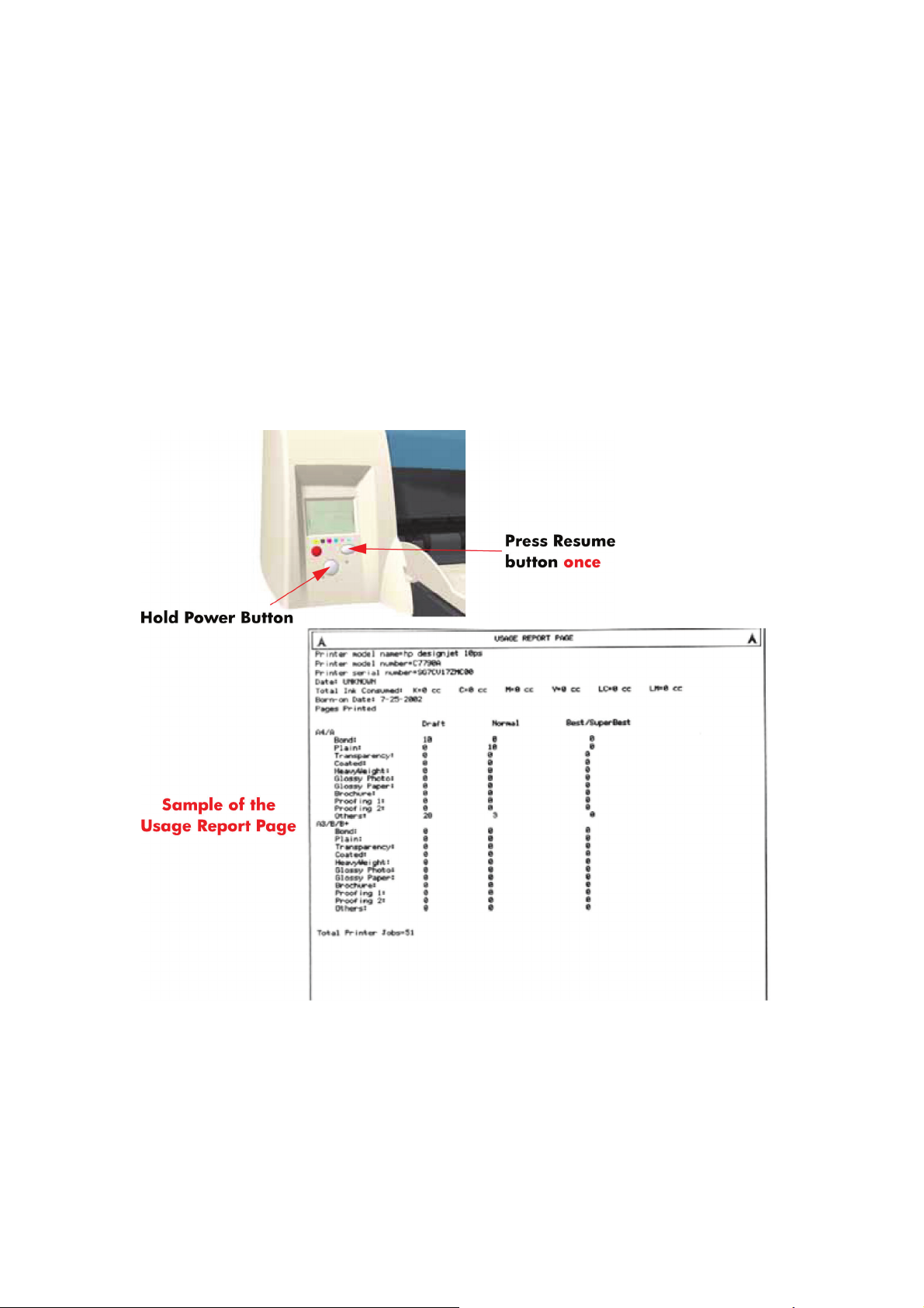
Usage Report Page
The Usage Report Page contains the following information:
●
Printer Model Name.
●
Printer Model Number.
●
Printer Serial Number.
●
Date of last print job received.
●
Total ink consumed.
●
Date of first print job received.
●
Number of pages printer (media size/media type/print quality setting).
To print the Usage Report Page, hold the power button down and press the resume button once.
2 Chapter 1 Test Prints ENWW
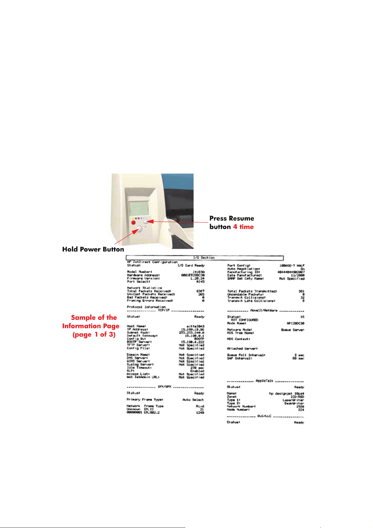
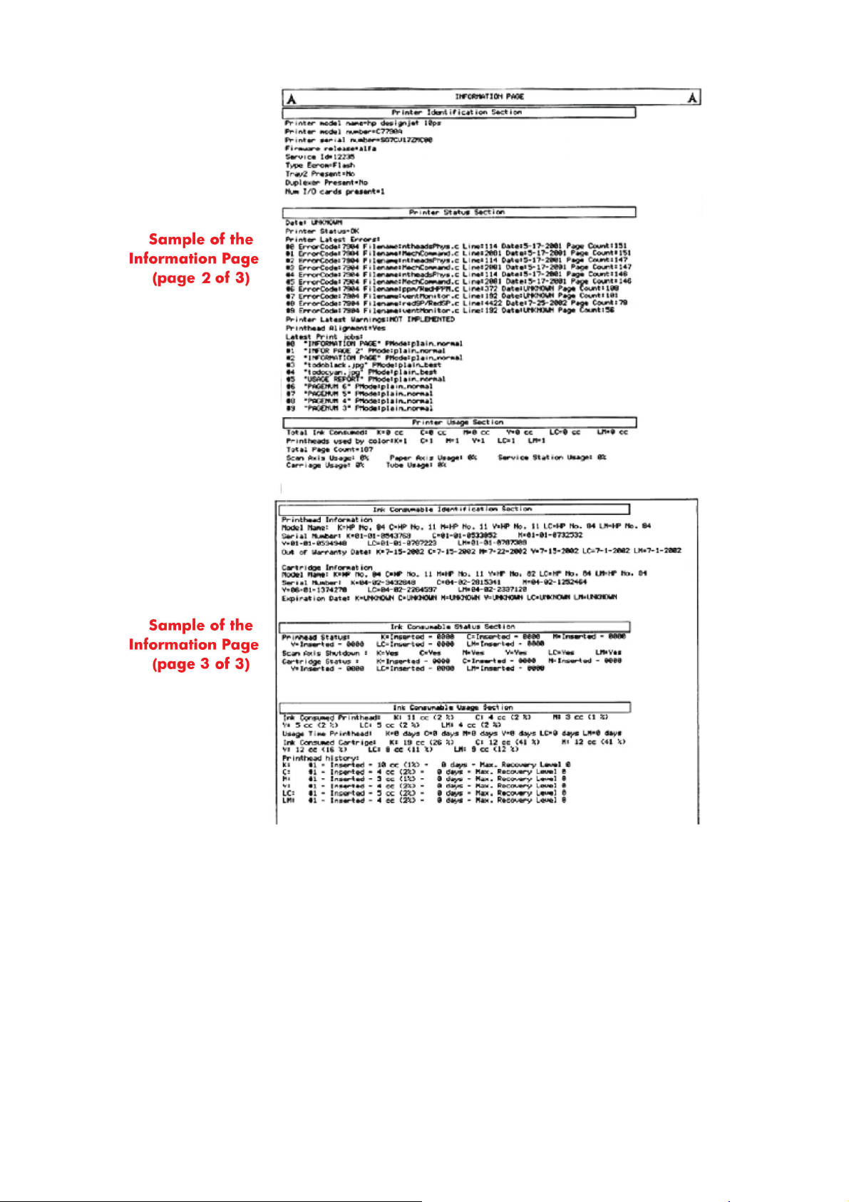
Information Page
The Information Page contains the following information:
●
Printer Identification.
●
Printer Status.
●
Printer Usage.
●
Ink Consumable Identification.
●
Ink Consumable Status.
●
Ink Consumable Usage.
●
Network Card Information.
To print the Information Page, hold the power button down and press the resume button four times.
ENWW Information Page 3
4 Chapter 1 Test Prints ENWW
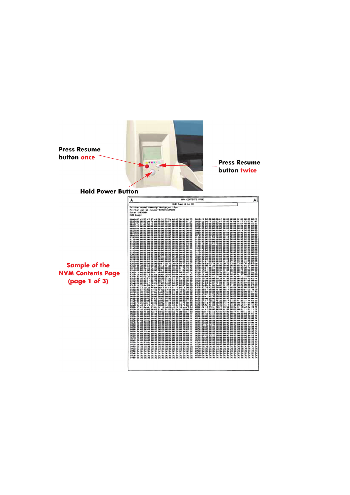
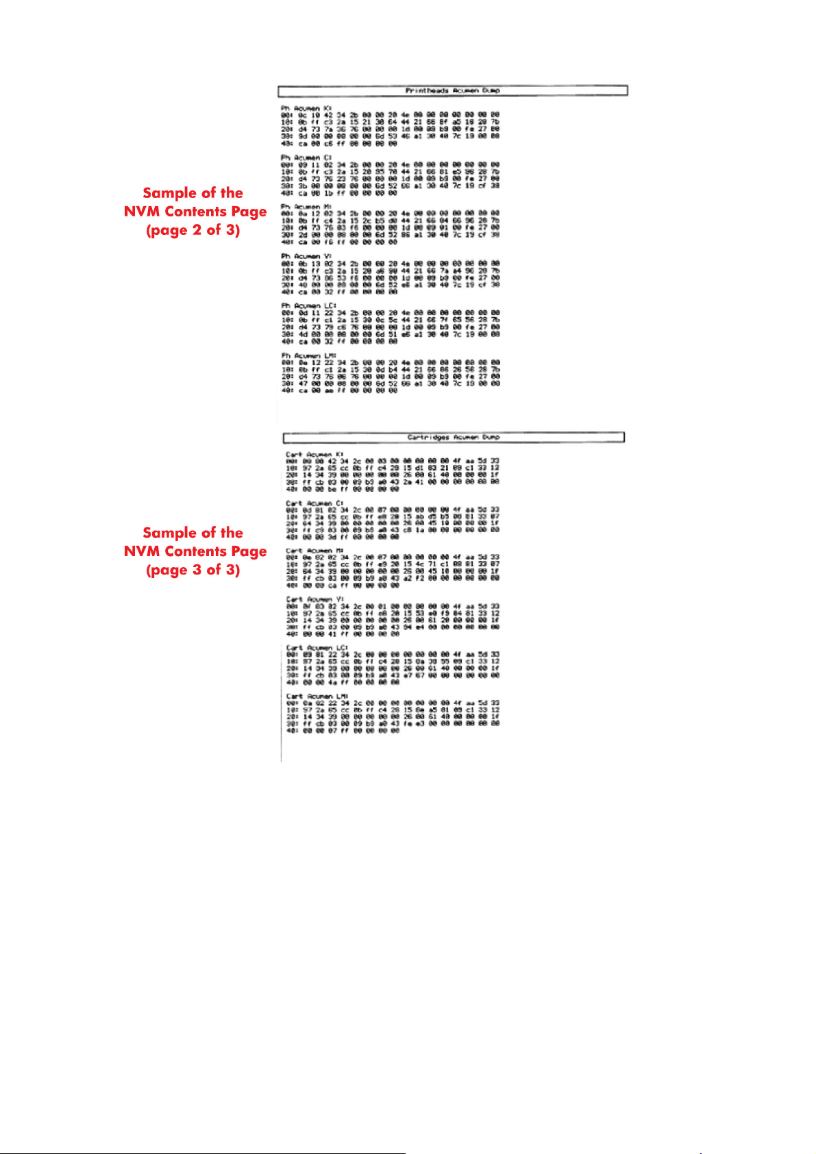
NVM Contents Page
The NVM Contents Page contains the following information:
●
EEROM values dump containing all the values stored in the EEROM (Calibration, etc.)
●
Printheads Acumen dump
●
Cartridges Acumen dump.
To print the NVM Contents Page, hold the power button down and press the cancel button once and
the resume button twice.
ENWW NVM Contents Page 5
6 Chapter 1 Test Prints ENWW

2 System Error Codes
●
Introduction
●
Errors and Warnings
●
System Error Codes
●
Warnings
●
Startup track mode
●
Emergency Firmware Upgrade
●
System Error Codes — Explanation
ENWW 7

Introduction
The following pages contain a list of system error codes and their respective descriptions and
recommended corrective actions. Only try one recommended action at a time and check if the error
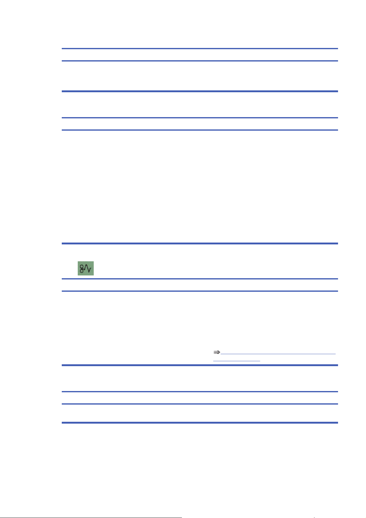
code has disappeared. Since the front panel can only display graphics, the error code needs to be
determined by counting the bars on the front panel (as shown below).
NOTE: Refer to System Error Codes — Explanation on page 34 for an explanation on the construction
of the Error Codes and Warnings.
8 Chapter 2 System Error Codes ENWW
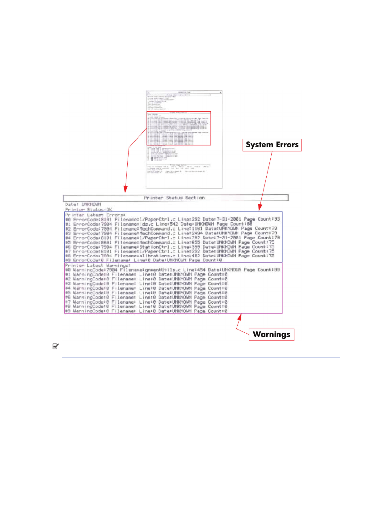
Errors and Warnings
Error Codes will normally be displayed directly on the front panel (but can also be seen on the
Information Page) and will require some kind of intervention to resolve the problem. Warnings will
not be displayed on the front panel, but will instead only appear on the Information Page, therefore
allowing the user to continue operating the printer without the need of an intervention.
NOTE: You can also obtain report of the System Error and Warnings through the DesignJet System
Maintenance Tool.
ENWW Errors and Warnings 9
System Error Codes
NOTE: Applicable for 111 only: The printer has a MROM module and it is not possible to perform a
firmware upgrade, and in fact not required as the printer already has the latest version.
01:10
Cause
Solution
Electronics Module failure.
Replace the Electronics Module
Electronics Module
on page 109.
01:12
Cause
Solution
Electronics Module failed during the firmware upgrade OR the
Electronics Module failed during initialization.
Try the following:
●
If the Electronics Module failed during the firmware
upgrade, first perform an emergency firmware upgrade
(
Emergency Firmware Upgrade on page 33).
●
If an emergency firmware upgrade is NOT possible or it
didn’t work, replace the Electronics Module
Electronics Module on page 109.
02:10
Cause
Solution
Carriage failure.
Replace the Carriage Assembly
Carriage Assembly
(Applicability: 70, 100+, 110+, 111) on page 123.
04:13
Cause
Solution
Generic Firmware Error (Network Card). Unplug the power cable from the printer and wait a few
seconds. Plug in the power cable again and check if the Error
Code has disappeared. If the error code continues, refer to the
Jetdirect Card Service Manual and Service Notes.
08:11
Cause
Solution
Front Panel cannot be detected. Try the following:
●
Check the connections and cables of the Font Panel,
check they have not been damaged and are correctly
connected, disconnect and reconnect the front panel.
●
Replace the Front Panel if the problem persists
Front
Panel on page 117.
10 Chapter 2 System Error Codes ENWW
11:10
Cause
Solution
Trailing Cable Failure. Try the following:
●
Replace the Carriage Assembly
Carriage Assembly
(Applicability: 70, 100+, 110+, 111) on page 123.
●
If the Error Code continues, replace the Electronics
Module
Electronics Module on page 109.
NOTE: Only replace one component at a time and check if
the error has gone before replacing another component. Using
this procedure you will be able to determine exactly which
component failed.
11:11
Cause
Solution
Trailing Cable is badly connected. Try the following:
●
Reconnect the Trailing Cable correctly to the Electronics
Module.
●
If the Error Code continues, replace the Carriage
Assembly
Carriage Assembly (Applicability: 70, 100
+, 110+, 111) on page 123.
21:10
Cause
Solution
Service Station failure.
Replace the Service Station Assembly
Service Station
on page 114.
22:10
Cause
Solution
Ink Supply Station failure.
Replace the Ink Supply Station
Ink Supply Station
on page 106.
ENWW System Error Codes 11
35:01
Cause
Solution
No Cleanout Assembly detected while loading media. Try the following:
●
Remove the Cleanout Assembly and install it again
correctly.
●
Replace the Cleanout Interconnect PCA.
●
If the Error Code continues, replace the Cleanout
Assembly.
NOTE: Only replace one component at a time and check if
the error has gone before replacing another component. Using
this procedure you will be able to determine exactly which
component failed.
37:01
Cause
Solution
Automatic roll motor shutdown. Try the following:
●
If this error code was caused by a paper jam, unplug the
power cable from the printer and clear the blockage. Plug
in the power cable again and check if the Error Code has
disappeared.
●
If there is no paper jam or if recovering the paper jam does
not resolve the problem, then replace the Automatic Roll
System (the error could be caused by anything that stalls
the motor).
37:10
Cause
Solution
Automatic roll home position error. Replace the Automatic Roll System (the error could be caused
by anything that causes the home position not to be detected
or not to be the correct one — electrical sensors, internal
mechanical problems, etc.).
42:10
Cause
Solution
Carriage Motor failure (short-circuit).
Replace the Carriage Motor Assembly
Carriage Motor
on page 119.
12 Chapter 2 System Error Codes ENWW
56:10
Cause
Solution
Error during the calibration of the motor encoder system or a
problem finding the zero position on the Encoder Disc.
Try the following:
●
Replace the Paper-Axis Motor Drive Assembly
Paper-
Axis Motor Drive Assembly (Applicable only to 30, 30n)
on page 158.
●
Replace the Encoder Disc.
NOTE: Make sure you recalibrate the Paper-Axis after
replacing the Paper-Axis Motor Drive Assembly or the Encoder
Disc.
Only replace one component at a time and check if the error
has gone before replacing another component. Using this
procedure you will be able to determine exactly which
component failed.
56:13
Cause
Solution
Error during the calibration of the Line-feed Motor/Encoder
system.
Unplug the power cable from the printer and wait a few
seconds. Plug in the power cable again.
61:05
Cause
Solution
Firmware Upgrade or Color Calibration was rejected because
the file was sent in the wrong format.
Upgrade the RIP software or the Designjet System
Maintenance Tool.
62:04, 63:04, 64:04 and 65:04
Cause
Solution
I/O module error (62 = parallel; 63 = Network; 64 = USB). Try the following:
●
Unplug the power cable from the printer and wait a few
seconds. Plug in the power cable again and check if the
Error Code has disappeared.
●
If the Error Code reappears, upgrade the firmware.
71:03
Cause
Solution
Generic Firmware Error (Out of memory). Try the following:
●
Unplug the power cable from the printer and wait a few
seconds. Plug in the power cable again and check if the
Error Code has disappeared.
●
If the Error Code reappears, check for a new Firmware
release.
ENWW System Error Codes 13
71:14
Cause
Solution
Memory Management Error (Out of memory during firmware
upgrade).
Try the following:
●
Unplug the power cable from the printer and wait a few
seconds. Plug in the power cable again and check if the
Error Code has disappeared.
●
If the Error Code reappears, perform an emergency
firmware upgrade (
Emergency Firmware Upgrade
on page 33).
72:04
Cause
Solution
Generic Firmware Error (expected). Try the following:
●
Unplug the power cable from the printer and wait a few
seconds. Plug in the power cable again and check if the
Error Code has disappeared.
●
If the Error Code reappears, check for a new Firmware
release.
●
If possible, request the user to provide the following
information which can be found on the information
page:
◦
Firmware Release.
◦
Filename.
◦
Line.
74:12
Cause
Solution
Firmware Upgrade Error (Memory size check failed during
firmware upgrade).
Try the following:
●
Perform the automatic troubleshooting procedure
(requires a special firmware upgrade file that must be
provided by the manufacturing division).
74:14
Cause
Solution
The printer is unavailable to upgrade the firmware.. Try the following:
●
Turn off and on the printer.
●
Print the Service Page
●
Check that the firmware is the latest available.:
◦
Applicable for 110+,110+r,130,130r: If the
firmware version is D.05.04, this would indicate that
the printer has a MROM module and it is not possible
to perform a firmware upgrade, and in fact not
required as the printer already has the latest version.
14 Chapter 2 System Error Codes ENWW
74:14
Cause
Solution
◦
Applicable for 111 only: The printer has a MROM
module and it is not possible to perform a firmware
upgrade, and in fact not required as the printer
already has the latest version.
79:04
Cause
Solution
Generic Firmware Error (unexpected). Try the following:
●
Unplug the power cable from the printer and wait a few
seconds. Plug in the power cable again and check if the
Error Code has disappeared.
●
If the Error Code reappears, check for a new Firmware
release.
●
If possible, request the user to provide the following
information which can be found on the information
page:
◦
Firmware Release.
◦
Filename.
◦
Line.
81:01
Cause Solution
Paper-Axis shutdown — usually a paper-jam caused by a
blockage of the Paper-axis System.
Try the following:
●
If this error code was caused by a paper-jam, unplug the
power cable from the printer and clear the blockage. Plug
in the power cable again and check if the Error Code has
disappeared
●
If this error code appeared but was NOT caused by a
paper jam, replace the Paper-Axis Motor Drive Assembly
Paper-Axis Motor Drive Assembly (Applicable only to
30, 30n) on page 158.
81:12
Cause
Solution
Media Advance error. This error usually appears during the paper-advance
calibration — Retry the paper-advance calibration.
ENWW System Error Codes 15
83:10
Cause
Solution
Sheet feeding failure. Try the following:
●
Replace the Out-Of-paper Sensor.
●
Replace the Electronics Module
Electronics Module
on page 109.
85:10
Cause
Solution
Paper-Axis Encoder error. Try the following:
●
Make sure that the Encoder Sensor cable is connected
correctly.
●
Replace the Paper-Axis Motor Drive Assembly
Paper-
Axis Motor Drive Assembly (Applicable only to 30, 30n)
on page 158.
●
Replace the Electronics Module
Electronics Module
on page 109.
86:01
Cause Solution
Scan-axis shutdown — usually a paper-jam caused by a
blockage of the Scan-axis System.
Try the following:
●
Check that there are no obstacles in the Scan-Axis which
stops the Carriage from moving freely.
●
Too much friction in the Slider Rod, try lubricating the
Slider Rod.
●
The Carriage is bumping into the Service Station. If the
Carriage is stuck at the right hand side of the Printer and
cannot be moved out to the center of the Print Platen it is
because the Service Station cannot uncap the
printheads. In this case replace the Service Station
Assembly
Service Station on page 114.
●
Check that the belt is correctly installed and not damaged.
●
Check that the Turnaround Pulley is correctly installed.
●
Replace the Carriage Motor Assembly
Carriage
Motor on page 119.
16 Chapter 2 System Error Codes ENWW
86:11
Cause
Solution
Scan-axis shutdown during initialization. Typically, this error
occurs when the printer detects an incorrect length.
Try the following:
●
Unplug the power cable from the printer and wait a few
seconds. Plug in the power cable again and check if the
Error Code has disappeared.
●
Check that the Paper-Axis Drive Motor Assembly is
correctly installed and that the bushing is correctly locked
into position.
●
Check that the Carriage moves freely and DOES NOT
bump into the Service Station.
●
If the Printheads are not installed, maybe the carriage
cover is not closed completely.
●
If the Error Code continues, replace the Carriage
Assembly
Carriage Assembly (Applicability: 70, 100+,
110+, 111) on page 123.
Warnings
01:11
Cause
Solution
The Electronics Module is incorrectly positioned. Reseat the Electronics Module by Removing it from the Printer
Electronics Module on page 109 and installing it again in
the correct position.
01:12
Cause
Solution
Electronics Module Error. The Electronics Module EEPROM is flagged as empty and
must be upgraded with the contents of the Carriage EEPROM,
but the Carriage is also flagged as empty. The backup is not
performed. This is the result of an error during the
manufacturing or the repair process. Therefore the Electronics
Module must be reconfigured.
02:10
Cause
Solution
Carriage failure.
Replace the Carriage Assembly
Carriage Assembly
(Applicability: 70, 100+, 110+, 111) on page 123.
ENWW Warnings 17
270:00
Cause
Solution
Black Color Calibration Failure — Black Color Calibration
cancelled.
Try the following:
●
Clean the electrical contacts on the black printhead.
●
If the error code continues, replace the black printhead.
271:00
Cause
Solution
Cyan Color Calibration Failure — Cyan Color Calibration
cancelled.
Try the following:
●
Clean the electrical contacts on the cyan printhead.
●
If the error code continues, replace the cyan printhead.
272:00
Cause
Solution
Magenta Color Calibration Failure — Magenta Color Calibration
cancelled.
Try the following:
●
Clean the electrical contacts on the magenta printhead.
●
If the error code continues, replace the magenta
printhead.
273:00
Cause
Solution
Yellow Color Calibration Failure — Yellow Color Calibration
cancelled.
Try the following:
●
Clean the electrical contacts on the yellow printhead.
●
If the error code continues, replace the yellow printhead.
274:00 (Not applicable to HP DesignJet 70, 100, 100+, 110+)
Cause
Solution
Light Cyan Color Calibration Failure — Light Cayan Color
Calibration cancelled.
Try the following:
●
Clean the electrical contacts on the light cyan printhead.
●
If the error code continues, replace the light cyan
printhead.
18 Chapter 2 System Error Codes ENWW
275:00 (Not applicable to HP DesignJet 70, 100, 100+, 110+)
Cause
Solution
Light Magenta Color Calibration Failure — Light Magenta Color
Calibration cancelled.
Try the following:
●
Clean the electrical contacts on the light magenta
printhead.
●
If the error code continues, replace the light magenta
printhead.
35:01
Cause
Solution
No Cleanout Assembly (or Duplexer, if installed) detected
while loading media.
Try the following:
●
Remove the Cleanout Assembly (
Cleanout
Assembly on page 120) (or Duplexer, if installed) and
install it again correctly.
●
Replace the Duplexer Interconnect PCA.
●
If the Error Code continues, replace the Cleanout
Assembly
Cleanout Assembly on page 120.
58:10
Cause
Solution
Problem detected in the color sensor system.
Replace the Carriage Assembly
Carriage Assembly
(Applicability: 70, 100+, 110+, 111) on page 123.
61:05
Cause
Solution
Language interpreting error. This is usually and error produced
while parsing a file. There is probably an incompatibility
between the driver and the firmware.
Upgrade the RIP software or the Designjet System
Maintenance Tool.
65:01
Cause
Solution
Communication Failure. Try the following:
●
Unplug the power cable from the printer and check the
cable connections (Parallel, USB and Network cables).
Plug in the power cable again and check if the Error Code
has disappeared.
ENWW Warnings 19
66:02:1 (Only applicable to HP DesignJet 30, 30n, 90, 90r, 130, 130nr)
Cause
Solution
Horizontal clipping. May happen when the roll ends in the
middle of printing an image. Could also happen when multi-
pick occurs and two sheets are loaded together and they do
not completely overlap.
Make sure the image size is within the selected WIDTH of the
sheet.
66:02:2 (Only applicable to HP DesignJet 30, 30n, 90, 90r, 130, 130nr)
Cause
Solution
Vertical clipping. May happen when the roll ends in the middle
of printing an image. Could also happen when multi-pick
occurs and two sheets are loaded together and they do not
completely overlap.
Make sure the image size is within the selected LENGTH of
the sheet.
71:14
Cause
Solution
Out-of-memory while trying to process the firmware upgrade
file. Probably this is a firmware bug, because the firmware
should free up enough memory to perform the firmware
upgrade process correctly.
Perform an emergency firmware upgrade (
Emergency
Firmware Upgrade on page 33) .
74:12
Cause
Solution
Firmware bug in the firmware upgrade process Try the following:
●
Download the special file in order to update the bootlog.
●
If possible, request the user to provide the following
information which can be found on the information
page:
◦
Firmware Release.
◦
Printer Serial Number.
74:14
Cause
Solution
The printer is unavailable to upgrade the firmware.. Try the following:
●
Turn off and on the printer.
●
Print the Service Page
●
Check that the firmware is the latest available.:
◦
Applicable for 110+,110+r,130,130r: If the
firmware version is D.05.04, this would indicate that
the printer has a MROM module and it is not possible
20 Chapter 2 System Error Codes ENWW
74:14
Cause
Solution
to perform a firmware upgrade, and in fact not
required as the printer already has the latest version.
◦
Applicable for 111 only: The printer has a MROM
module and it is not possible to perform a firmware
upgrade, and in fact not required as the printer
already has the latest version.
81:01
Cause Solution
Paper-Axis shutdown — usually a paper-jam caused by a
blockage of the Paper-axis System.
Try the following:
●
If this error code was caused by a paper-jam, unplug the
power cable from the printer and clear the blockage. Plug
in the power cable again and check if the Error Code has
disappeared.
●
If this error code appeared but was NOT caused by a
paper jam, replace the Paper-Axis Motor Drive Assembly
Paper-Axis Motor Drive Assembly (Applicable only to
30, 30n) on page 158.
83:01:1 (Only applicable to HP DesignJet 30, 30n, 70, 100+, 110+, 111, 90, 90r,, 130, 130nr)
Cause
Solution
The paper is rejected from the Bypass due to skew. When manually loading paper from the front of the paper, make
sure that it is loaded straight.
83:01:3 (Only applicable to HP DesignJet 70/100plus/110plus, 111 with Roll)
Cause
Solution
The paper is rejected from the roll due to skew. When loading paper from the roll, make sure that it is loaded
straight.
94:02:1 (Only applicable to HP DesignJet 30, 30n, 90, 90r, 130, 130nr, 111)
Cause
Solution
User selected Coated Paper and Best mode, but the Color
Calibration profile was obsolete or missing for Coated Paper
and the selected print quality setting.
Using the System Maintenance Tool, perform Color Calibration
for Coated Paper and the selected print quality setting.
94:02:3 (Only applicable to HP DesignJet 30, 30n, 90, 90r, 130, 130nr, 111)
Cause
Solution
User selected Photo Paper and Best mode, but the Color
Calibration profile was obsolete or missing for Photo Paper and
the selected print quality setting.
Using the System Maintenance Tool, perform Color Calibration
for Photo Paper and the selected print quality setting.
ENWW Warnings 21
94:02:4 (Only applicable to HP DesignJet 30, 30n, 90, 90r, 130, 130nr)
Cause
Solution
User selected Heavy-Weight Coated Paper and Best mode,
but the Color Calibration profile was obsolete or missing for
Heavy-Weight Coated Paper and the selected print quality
setting.
Using the System Maintenance Tool, perform Color Calibration
for Heavy- Weight Coated Paper and the selected print quality
setting.
94:02:5 (Only applicable to HP DesignJet 30, 30n, 90, 90r, 130, 130nr)
Cause
Solution
User selected Proofing Semi-Gloss Paper and Best mode, but
the Color Calibration profile was obsolete or missing for
Proofing Semi-Gloss Paper and the selected print quality
setting
Using the System Maintenance Tool, perform Color Calibration
for Proofing Semi-Gloss Paper and the selected print quality
setting.
94:02:6 (Only applicable to HP DesignJet 30, 30n, 90, 90r, 130, 130nr)
Cause
Solution
User selected Photo Matte Paper and Best mode, but the Color
Calibration profile was obsolete or missing for Photo Matte
Paper and the selected print quality setting.
Using the System Maintenance Tool, perform Color Calibration
for Photo Matte Paper and the selected print quality setting.
94:02:7 (Only applicable to HP DesignJet 30, 30n, 90, 90r, 130, 130nr)
Cause
Solution
User selected Photo Satin Paper and Best mode, but the Color
Calibration profile was obsolete or missing for Photo Satin
Paper and the selected print quality setting.
Using the System Maintenance Tool, perform Color Calibration
for Photo Satin Paper and the selected print quality setting.
94:02:8 (Only applicable to HP DesignJet 30, 30n, 90, 90r, 130, 130nr)
Cause
Solution
User selected Coated Paper and Max dpi, but the Color
Calibration profile was obsolete or missing for Coated Paper
and the selected print quality setting.
Using the System Maintenance Tool, perform Color Calibration
for Coated Paper and the selected print quality setting.
941:02:1 (Only applicable to HP DesignJet 30, 30n, 90, 90r, 130, 130nr)
Cause
Solution
User selected Photo Paper and Max dpi, but the Color
Calibration profile was obsolete or missing for Photo Paper and
the selected print quality setting.
Using the System Maintenance Tool, perform Color Calibration
for Photo Paper and the selected print quality setting.
22 Chapter 2 System Error Codes ENWW
941:02:2 (Only applicable to HP DesignJet 30, 30n, 90, 90r, 130, 130nr)
Cause
Solution
User selected Heavy-Weight Coated Paper and Max dpi, but
the Color Calibration profile was obsolete or missing for Heavy-
Weight Coated Paper and the selected print quality setting.
Using the System Maintenance Tool, perform Color Calibration
for Heavy- Weight Coated Paper and the selected print quality
setting.
941:02:3 (Only applicable to HP DesignJet 30, 30n, 90, 90r, 130, 130nr)
Cause
Solution
User selected Proofing Semi-Gloss Paper and Max dpi mode,
but the Color Calibration profile was obsolete or missing for
Proofing Semi-Gloss Paper and the selected print quality
setting.
Using the System Maintenance Tool, perform Color Calibration
for Proofing Semi-Gloss Paper and the selected print quality
setting.
941:02:4 (Only applicable to HP DesignJet 30, 30n, 90, 90r, 130, 130nr)
Cause
Solution
User selected Photo Matte Paper and Max dpi mode, but the
Color Calibration profile was obsolete or missing for Photo
Matte Paper and the selected print quality setting.
Using the System Maintenance Tool, perform Color Calibration
for Photo Matte Paper and the selected print quality setting.
941:02:5 (Only applicable to HP DesignJet 30, 30n, 90, 90r, 130, 130nr)
Cause
Solution
User selected Photo Satin Paper and Max dpi mode, but the
Color Calibration profile was obsolete or missing for Photo
Satin Paper and the selected print quality setting.
Using the System Maintenance Tool, perform Color Calibration
for Photo Satin Paper and the selected print quality setting.
94:04
Cause
Solution
Firmware Error (during color calibration). Try the following:
●
Unplug the power cable from the printer and wait a few
seconds. Plug in the power cable again and check if the
Error Code has disappeared.
●
If the Error Code reappears, check for a new Firmware
release.
94:08
Cause
Solution
Color Calibration Warning — Color Calibration not cancelled but
Color Calibration values are likely to be incorrect.
Try the Color Calibration again, but this time using a different
type of media (preferably HP media).
ENWW Warnings 23
94:10
Cause
Solution
Color Calibration Failure — Color Calibration cancelled. Try the following:
●
Unplug the power cable from the printer and wait a few
seconds. Plug in the power cable again and try the Color
Calibration again.
●
If this error code appears again, check the Color
Calibration print:
◦
If the Color Calibration was printed correctly without
any print defects, then check that the media is
moving freely (backwards and forwards) while the
printer is scanning it.
◦
If the Color Calibration was printed incorrectly, with
some print defects, replace the faulty Printhead of
the color where the defects were noticeable.
◦
If the Error Code continues, replace the Carriage
Assembly
Carriage Assembly (Applicability: 70,
100+, 110+, 111) on page 123.
95:00
Cause
Solution
Printhead Alignment Failure — Printhead Alignment cancelled. Try the following:
●
Clean the printhead indicated by the printer.
●
If the error code continues, replace the faulty printhead.
95:02
Cause
Solution
Printhead Alignment Failure — Printhead Alignment cancelled. Try the following:
●
Unplug the power cable from the printer and wait a few
seconds. Plug in the power cable again and try the
Printhead Alignment again.
●
If this error code appears again, check the Printhead
Alignment print:
◦
If the Printhead Alignment was printed correctly
without any print defects, then check that the media
is moving freely (backwards and forwards) while the
printer is scanning it.
◦
If the Printhead Alignment was printed incorrectly,
with some print defects, replace the faulty Printhead
of the color where the defects were noticeable.
95:04
Cause
Solution
Firmware Error (during Printhead Alignment). Upgrade the printer to the latest firmware release.
24 Chapter 2 System Error Codes ENWW
Startup track mode
Introduction
The startup track mode is designed to enable you to identify a failing subsystems while the printer is
initializing. Startup track mode provides a specific indication of which particular subsystem is failing.
This mode is not intended for use by end-users.
Initializing the printer in Startup track mode
To initialize the printer in Startup track mode:
1. Hold the ’Continue’ button while connecting the printer to the power supply.
2. During the initialization of the printer, the front panel will display a range of code numbers in the
form of squares, these code numbers added together represent the various subsystems about to
be initialized.
3. Once the printer comes to initializing the failing subsystem, the front panel will hang, and all that
will be displayed is the failing subsystem.
Interpreting the numbered code system
While the printer is initializing, the front panel will display a sequence of squares in the last two columns.
Each position in the last two columns represents a number, all the numbers represented are shown
below. To find the failing subsystem, add the numbers together that have a square and refer to the list
of numbers with their associated subsystems on
Subsystem Code Description on page 25.
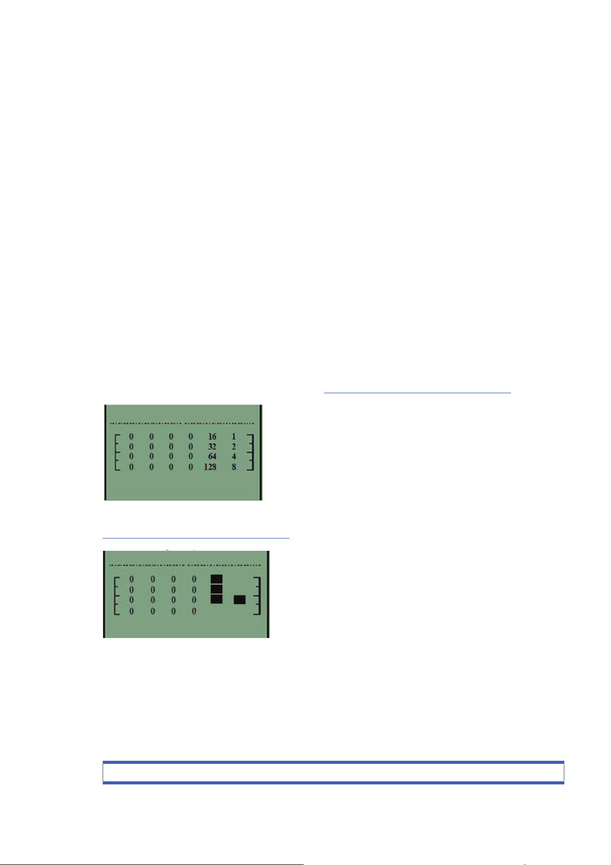
In the example below the printer is initializing and the front panel has stopped and is displaying squares
in positions 16, 32, 64, and 4. Add these four values together and you get 116, refer to the list on
Subsystem Code Description on page 25, and we can see the failing subsystem is the Trailing Cable.
If the display reaches 191, you will need to turn On the printer from the power button. If all the subsystems
pass the initialization, the printer will initialize normally and go to the ready status.
Subsystem Code Description
This is the list of the subsystems and their associated Startup Track Numbers. Many of the descriptions
of the Subsystems will not be immediately obvious, when this is the case contact the lfp help desk and
they can assist you.
Table 2-1 Subsystem code description
Startup track number: Associated Subsystem
ENWW Startup track mode 25

Startup Track 004: Calling EiffelMain
Startup Track 005: Initializing Classes
Startup Track 006: Initializing SM
Startup Track 007: Initializing Memory
Startup Track 008: Initializing MemoryVolatile
Startup Track 009: Initializing MemoryEndian
Startup Track 010: Initializing MemoryVolatileEndian
Startup Track 011: Initializing Impala
Startup Track 012: Initializing ColdFire
Startup Track 013: Initializing ImpalaInterruptController
Startup Track 014: Initializing MechProcTaskHiIntA
Startup Track 015: Initializing IsardInterruptA
Startup Track 016: Initializing Watchdog
Startup Track 017: Initializing Chronometer
Startup Track 018: Initializing EddTimer
Startup Track 019: Initializing IsardInterruptB
Startup Track 020: Initializing PciSlot2Interrupt
Startup Track 021: Initializing PciSlot3Interrupt
Startup Track 022: Initializing PciSlot4Interrupt
Startup Track 023: Initializing PciSlot5Interrupt
Startup Track 024: Initializing MagentaFireLow
Startup Track 025: Initializing BongoGpio
Startup Track 026: Initializing SecondTraySensor
Startup Track 027: Initializing CleanoutSensor
Startup Track 028: Initializing RearPathPaperSensor
Startup Track 029: Initializing BlackCartridgeSensor
Startup Track 030: Initializing CyanCartridgeSensor
Startup Track 031: Initializing MagentaCartridgeSensor
Startup Track 032: Initializing YellowCartridgeSensor
Startup Track 033: Initializing LightMagentaCartridgeSensor
Startup Track 034: Initializing LightCyanCartridgeSensor
Startup Track 035: Initializing SynergyReset
Startup Track 036: Initializing FrontPanelReset
Startup Track 037: Initializing PowerFan
Startup Track 038: Initializing FrontPanelInterrupt
Startup Track 039: Initializing CoverWindowSensor
Startup Track 040: Initializing nUSB_ENABLE
Startup Track 041: Initializing USB_CONNECT
Table 2-1 Subsystem code description (continued)
26 Chapter 2 System Error Codes ENWW

Startup Track 042: Initializing TrailingCable3Sensor
Startup Track 043: Initializing TrailingCable12Sensor
Startup Track 044: Initializing PrintheadSensor
Startup Track 045: Initializing BongoBrake
Startup Track 046: Initializing Dma
Startup Track 047: Initializing BongoEncoder
Startup Track 048: Initializing ServiceStationEncoder
Startup Track 049: Initializing SSPwm
Startup Track 050: Initializing PaperPwm
Startup Track 051: Initializing RampPwm
Startup Track 052: Initializing CarriagePwmForward
Startup Track 052: Initializing CarriagePwmForward
Startup Track 054: Initializing BomboPwm
Startup Track 055: Initializing EddPwm
Startup Track 056: Initializing ImpalaCarriagePosition
Startup Track 057: Initializing I2c0
Startup Track 058: Initializing I2c1
Startup Track 059: Initializing I2c2
Startup Track 060: Initializing I2c3
Startup Track 061: Initializing Darwin
Startup Track 062: Initializing PciCtrl
Startup Track 063: Initializing PciDma
Startup Track 064: Initializing MBandToPixel
Startup Track 065: Initializing PixelData
Startup Track 066: Initializing BlackCSData
Startup Track 067: Initializing CyanCSData
Startup Track 068: Initializing MagentaCSData
Startup Track 069: Initializing YellowCSData
Startup Track 070: Initializing LightCyanCSData
Startup Track 071: Initializing LightMagentaCSData
Startup Track 072: Initializing BlackPrintHead
Startup Track 073: Initializing CyanPrintHead
Startup Track 074: Initializing MagentaPrintHead
Startup Track 075: Initializing YellowPrintHead
Startup Track 076: Initializing LightCyanPrintHead
Startup Track 077: Initializing LightMagentaPrintHead
Startup Track 078: Initializing BlockBlack
Startup Track 079: Initializing BlockColor
Table 2-1 Subsystem code description (continued)
ENWW Startup track mode 27

Startup Track 080: Initializing ContoneToRaster
Startup Track 081: Initializing Enhancer
Startup Track 082: Initializing RasterToMband
Startup Track 083: Initializing MechProcA
Startup Track 084: Initializing MemoryUncached
Startup Track 085: Initializing Isard
Startup Track 086: Initializing IsardInterruptController
Startup Track 087: Initializing PaperInterrupt
Startup Track 088: Initializing IsardPMTimer
Startup Track 089: Initializing IsardKFort
Startup Track 090: Initializing IsardCarriagePosition
Startup Track 091: Initializing IsardPaperPosition
Startup Track 092: Initializing MediaPosition
Startup Track 093: Initializing PaperEncoderPosition
Startup Track 094: Initializing IsardMotorShortcut
Startup Track 095: Initializing Eridani
Startup Track 096: Initializing EddOn
Startup Track 097: Initializing ServiceStationLed
Startup Track 098: Initializing FetRegulator
Startup Track 099: Initializing EddOut
Startup Track 100: Initializing DuplexerConversor
Startup Track 101: Initializing EridaniConversorAuto
Startup Track 102: Initializing EridaniConversorAB
Startup Track 103: Initializing EridaniConversorAnA
Startup Track 104: Initializing EridaniConversorBnB
Startup Track 105: Initializing PaperDriver
Startup Track 106: Initializing ServiceStationDriver
Startup Track 107: Initializing RampDriver
Startup Track 108: Initializing DuplexerSensor
Startup Track 109: Initializing PaperMotorHw
Startup Track 110: Initializing CarriageMotorHw
Startup Track 111: Initializing ServiceStationMotorHw
Startup Track 112: Initializing BongoEncoderWindowHw
Startup Track 113: Initializing BongoMotorHw
Startup Track 114: Initializing RampMotorHw
Startup Track 115: Initializing FrontPanelHw
Startup Track 116: Initializing TrailingCable
Startup Track 117: Initializing CarriageBoardHw
Table 2-1 Subsystem code description (continued)
28 Chapter 2 System Error Codes ENWW
Startup Track 118: Initializing SynergyA
Startup Track 119: Initializing VPPA
Startup Track 120: Initializing VPPB
Startup Track 121: Initializing SynergyInternalRegulatorA
Startup Track 122: Initializing Led1Voltage
Startup Track 123: Initializing EndeavourA
Startup Track 124: Initializing EndeavourAcumenA
Startup Track 125: Initializing CLC_Channel0
Startup Track 126: Initializing CLC_Channel1
Startup Track 127: Initializing CLC_Channel2
Startup Track 128: Initializing EndeavourVRefConversor
Startup Track 129: Initializing CLC_ChannelDACConversor
Startup Track 130: Initializing IS_Channel3Conversor_A
Startup Track 131: Initializing CLC_Channel0Conversor
Startup Track 132: Initializing CLC_Channel1Conversor
Startup Track 133: Initializing CLC_Channel2Conversor
Startup Track 134: Initializing Led2Voltage
Startup Track 135: Initializing Black5V
Startup Track 136: Initializing Yellow5V
Startup Track 137: Initializing Magenta5V
Startup Track 138: Initializing Cyan5V
Startup Track 139: Initializing Black12V
Startup Track 140: Initializing Yellow12V
Startup Track 141: Initializing Magenta12V
Startup Track 142: Initializing Cyan12V
Startup Track 143: Initializing VPen_Current_Sense_A
Startup Track 144: Initializing VPen_OV_Latch_A
Startup Track 145: Initializing VPen_OV_Clear_Latch_A
Startup Track 146: Initializing VPen_UV_Latch_A
Startup Track 147: Initializing VPen_UV_Clear_Latch_A
Startup Track 148: Initializing VPen_OV_Present_A
Startup Track 149: Initializing VPen_UV_Present_A
Startup Track 150: Initializing EndeavourB
Startup Track 151: Initializing EndeavourAcumenB
Startup Track 152: Initializing IS_Channel3Conversor_B
Startup Track 153: Initializing Led3Voltage
Startup Track 154: Initializing LightMagenta5V
Startup Track 155: Initializing LightCyan5V
Table 2-1 Subsystem code description (continued)
ENWW Startup track mode 29

Startup Track 156: Initializing LightMagenta12V
Startup Track 157: Initializing LightCyan12V
Startup Track 158: Initializing VPen_Current_Sense_B
Startup Track 159: Initializing VPen_OV_Latch_B
Startup Track 160: Initializing VPen_OV_Clear_Latch_B
Startup Track 161: Initializing VPen_UV_Latch_B
Startup Track 162: Initializing VPen_UV_Clear_Latch_B
Startup Track 163: Initializing VPen_OV_Present_B
Startup Track 164: Initializing VPen_UV_Present_B
Startup Track 165: Initializing Eerom
Startup Track 166: Initializing EeromCarriage
Startup Track 167: Initializing PrintheadControl
Startup Track 168: Initializing BlackPrintheadAcumen
Startup Track 169: Initializing CyanPrintheadAcumen
Startup Track 170: Initializing MagentaPrintheadAcumen
Startup Track 171: Initializing YellowPrintheadAcumen
Startup Track 172: Initializing LightCyanPrintheadAcumen
Startup Track 173: Initializing LightMagentaPrintheadAcumen
Startup Track 174: Initializing BlackCartridgeAcumen
Startup Track 175: Initializing CyanCartridgeAcumen
Startup Track 176: Initializing MagentaCartridgeAcumen
Startup Track 177: Initializing YellowCartridgeAcumen
Startup Track 178: Initializing LightCyanCartridgeAcumen
Startup Track 179: Initializing LightMagentaCartridgeAcumen
Startup Track 180: Initializing ColorSensor
Startup Track 181: Initializing ColorSensorLed1
Startup Track 182: Initializing ColorSensorLed2
Startup Track 183: Initializing ColorSensorLed3
Startup Track 184: Initializing ColorSensorConverso
Startup Track 185: Initializing ColorSensorConversorB
Startup Track 186: Initializing ColorSensorConversorC
Startup Track 187: Initializing V5_V12_ISDetection
Startup Track 188: Initializing VPP_ISDetection
Startup Track 189: Initializing InterruptController
Startup Track 190: SM Initialized
Startup Track 191: Back from EiffelMain!!!
PRESS POWER BUTTON HERE!!
Startup Track 192: Initializing VPPA
Table 2-1 Subsystem code description (continued)
30 Chapter 2 System Error Codes ENWW

Startup Track 193: Initializing VPPB
Startup Track 194: Initializing SynergyInternalRegulatorA
Startup Track 195: Initializing Led1Voltage
Startup Track 196: Initializing EndeavourAcumenA
Startup Track 197: Initializing CLC_Channel0
Startup Track 198: Initializing CLC_Channel1
Startup Track 199: Initializing CLC_Channel2
Startup Track 200: Initializing EndeavourVRefConversor
Startup Track 201: Initializing CLC_ChannelDACConversor
Startup Track 202: Initializing IS_Channel3Conversor_A
Startup Track 203: Initializing CLC_Channel0Conversor
Startup Track 204: Initializing CLC_Channel1Conversor
Startup Track 205: Initializing CLC_Channel2Conversor
Startup Track 206: Initializing Led2Voltage
Startup Track 207: Initializing Black5V
Startup Track 208: Initializing Yellow5V
Startup Track 209: Initializing Magenta5V
Startup Track 210: Initializing Cyan5V
Startup Track 211: Initializing Black12V
Startup Track 212: Initializing Yellow12V
Startup Track 213: Initializing Magenta12V
Startup Track 214: Initializing Cyan12V
Startup Track 215: Initializing VPen_Current_Sense_A
Startup Track 216: Initializing VPen_OV_Latch_A
Startup Track 217: Initializing VPen_OV_Clear_Latch_A
Startup Track 218: Initializing VPen_UV_Latch_A
Startup Track 219: Initializing VPen_UV_Clear_Latch_A
Startup Track 220: Initializing VPen_OV_Present_A
Startup Track 221: Initializing VPen_UV_Present_A
Startup Track 222: Initializing EndeavourAcumenB
Startup Track 223: Initializing IS_Channel3Conversor_B
Startup Track 224: Initializing Led3Voltage
Startup Track 225: Initializing LightMagenta5V
Startup Track 226: Initializing LightCyan5V
Startup Track 227: Initializing LightMagenta12V
Startup Track 228: Initializing LightCyan12V
Startup Track 229: Initializing VPen_Current_Sense_B
Startup Track 230: Initializing VPen_OV_Latch_B
Table 2-1 Subsystem code description (continued)
ENWW Startup track mode 31

Startup Track 231: Initializing VPen_OV_Clear_Latch_B
Startup Track 232: Initializing VPen_UV_Latch_B
Startup Track 233: Initializing VPen_UV_Clear_Latch_B
Startup Track 234: Initializing VPen_OV_Present_B
Startup Track 235: Initializing VPen_UV_Present_B
Table 2-1 Subsystem code description (continued)
32 Chapter 2 System Error Codes ENWW
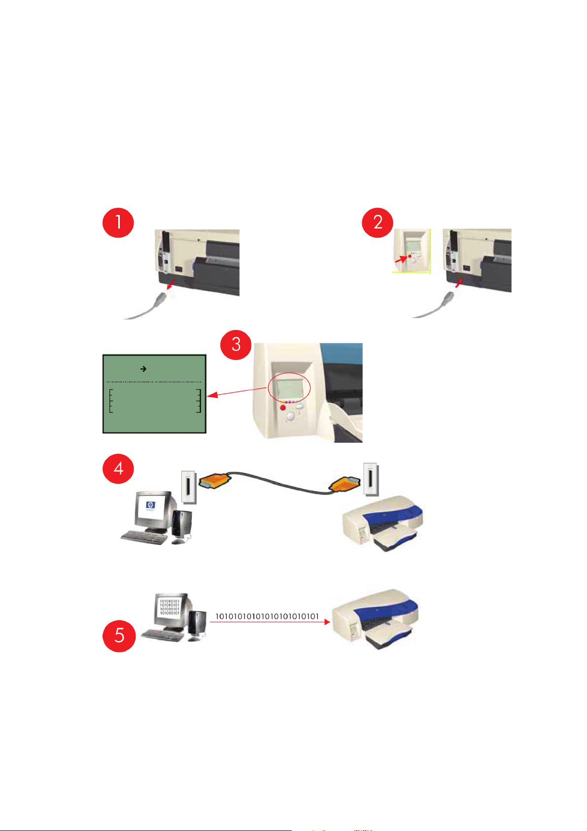
Emergency Firmware Upgrade
1. Unplug the power cord from the printer and wait a few seconds.
2. Press and hold the Cancel (red) button while plugging in the power cord.
3. The printer will initialize in emergency mode (the front panel will display just the arrow icon).
4. Connect the printer to the computer with a parallel cable.
5. Send the firmware file through the parallel port from the DOS command prompt. Type: copy /b
firmware_file lpt1: and then press ENTER.
ENWW Emergency Firmware Upgrade 33
System Error Codes — Explanation
System Error Codes explain which component/system is failing and what action should be taken to
resolve the problem.
System Error Codes are displayed directly on the front panel (but can also be seen on the Information
Page) and have been defined in the format XX.YZ.
Warnings will not be displayed on the front panel, but will instead only appear on the Information Page
and have been defined in the format XXn.YZ.m.
●
XX: Service Part (2 digits).
●
n: Service Part Index (if more than one used in the product) — Optional.
◦
e.g. Identify the Ink Supply (color and number).
●
Y: Who should perform the action (1 digit) — (User or Service Engineer).
●
Z: Action to perform (1 digit).
●
m: additional actions/information to consider (1 digit) — Optional.
◦
e.g. Non-authorized ink was detected, PM was triggered or Printhead in/out of Warranty.
The following table explains the XX part of the System Error Code or Warning:
NOTE: Items denoting * (Asterisk) are not applicable to the printers.
Table 2-2 System error codes
Code Component/System
01 Main PCA/Electronics Module
02 Carriage/Carriage PCA
03 Power Supply Unit
04 Network Card
05 Formatter *
06 Hard Disk Drive *
07 Interconnect PCA
08 Front Panel
11 Trailing Cable
12 Carriage Flex Circuit
17 Interconnect Cable
21 Service Station
22 Ink Supply Station
23 Pressure System (APS) *
24 Ink Delivery Tubes
25 Spittoon *
26n Ink Cartridge (color n)
26n Printhead (color n)
31 Cutter
34 Chapter 2 System Error Codes ENWW

32 Take-up Reel *
33 Sheet Feeder
34 Dryer/Blower *
35 Cleanout Assembly
36 Duplexer
37 ARSS/Rollfeed
38 Output Tray
41 Paper-Axis Motor
42 Scan-Axis Motor
43 Vacuum Fan *
44 Aerosol fan *
51 Window Sensor
52 Drop Detector *
53 Media Sensor
54 Pinch-Arm Sensor
55 Line Sensor
56 Drive Roller Encoder Sensor
57 Ink Leak Detector *
58 Color Sensor *
59 Media Type Sensor *
61 Language Interpreting
62 Input/Output through Parallel Port
63 Input/Output through Network Card
64 Input/Output through USB Port
65 Input/Output (not know what port)
66 Print Job Configuration
71 Print Job Configuration
72 Generic Firmware
73 Motor Control Functions
74 Motor Control Functions 74 Firmware Upgrade
79 Firmware Crash
81 Media Advance
82 Media Cut *
83 Single-Sheet Feeding
84 Roll Feeding *
85 Media-Axis Encoder Reading
86 Carriage Movement
87 Scan-Axis Encoder Reading
Table 2-2 System error codes (continued)
ENWW System Error Codes — Explanation 35
91 Printhead Firing
92 Servicing
93 Ink Pumping
94 Ink Pumping
95 Printhead Alignment
96 Image Quality Troubleshooting
The following table explains the YZ part of the System Error Code or Warning:
Table 2-3 System error codes
Code Response Response
00 Replace
Possible for customer
to perform action
01 Reseat/Reconnect/Clean/Adjust (manually)
02 Calibrate/Adjust (using Automatic Process)
03 Power OFF
04 Upgrade System Firmware
05 Upgrade Driver
06 Add Accessory
07 Escalate
08 Send Plot Again
09 Wrong Part Installed
10 Replace
HP qualified
personnel assistance
required
11
Reseat/Reconnect/Clean/Adjust (manually)
12 Calibrate/Adjust (using Automatic Process)
13 Power OFF
14 Upgrade System Firmware
15 Upgrade Driver
16 Add Accessory
17 Escalate
18 Send Plot Again
19 Wrong Part Installed
Table 2-2 System error codes (continued)
36 Chapter 2 System Error Codes ENWW

3 System Maintenance Utility
●
Introduction
●
Launching the System Maintenance Utility
●
System Maintenance Utility (Designjet 30, 30n, 70, 90, 90r, 110plus, 111, 130, 130nr)
ENWW 37
Introduction
The System Maintenance Utility is designed to assist the customer with common maintenance tasks for
the printer and also to resolve common problems that they may encounter.
NOTE: Print jobs must not be sent to the printer while the system maintenance utility is in use.
Since the design of the System Maintenance Tool is different between the Designjet 120/120nr and
Designjet 130/130, this chapter will explain how to use the tool for each product separately:
Launching the System Maintenance Utility
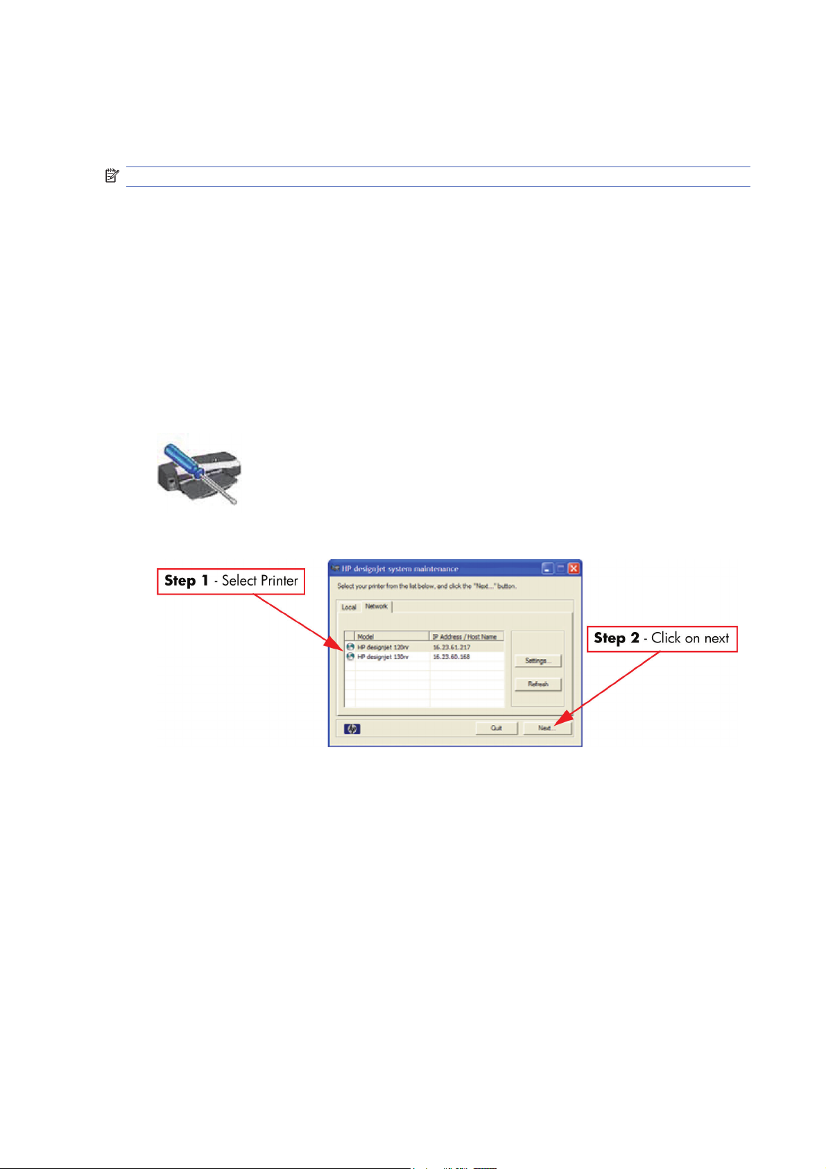
The procedures described here are applicable to the following printers: HP Designjet 30, 30n, 70, 90,
90r, 100+, 110+r, 110+nr, 111 with roll, 111 with tray, 130, 130r, 130nr:
There are two ways of launching the System Maintenance Utility.
From your computer’s desktop (Windows, Mac OS 9 and X)
1. Double click the hp designjet system maintenance icon on the desktop.
2. A printer selector window opens — select your printer from the list.
3. Click Next (in Windows) or Configure (in Mac OS).
From the Printer Driver (Windows, Mac OS X)
●
In the Windows driver click the hp designjet system maintenance icon in the Services tab.
38 Chapter 3 System Maintenance Utility ENWW
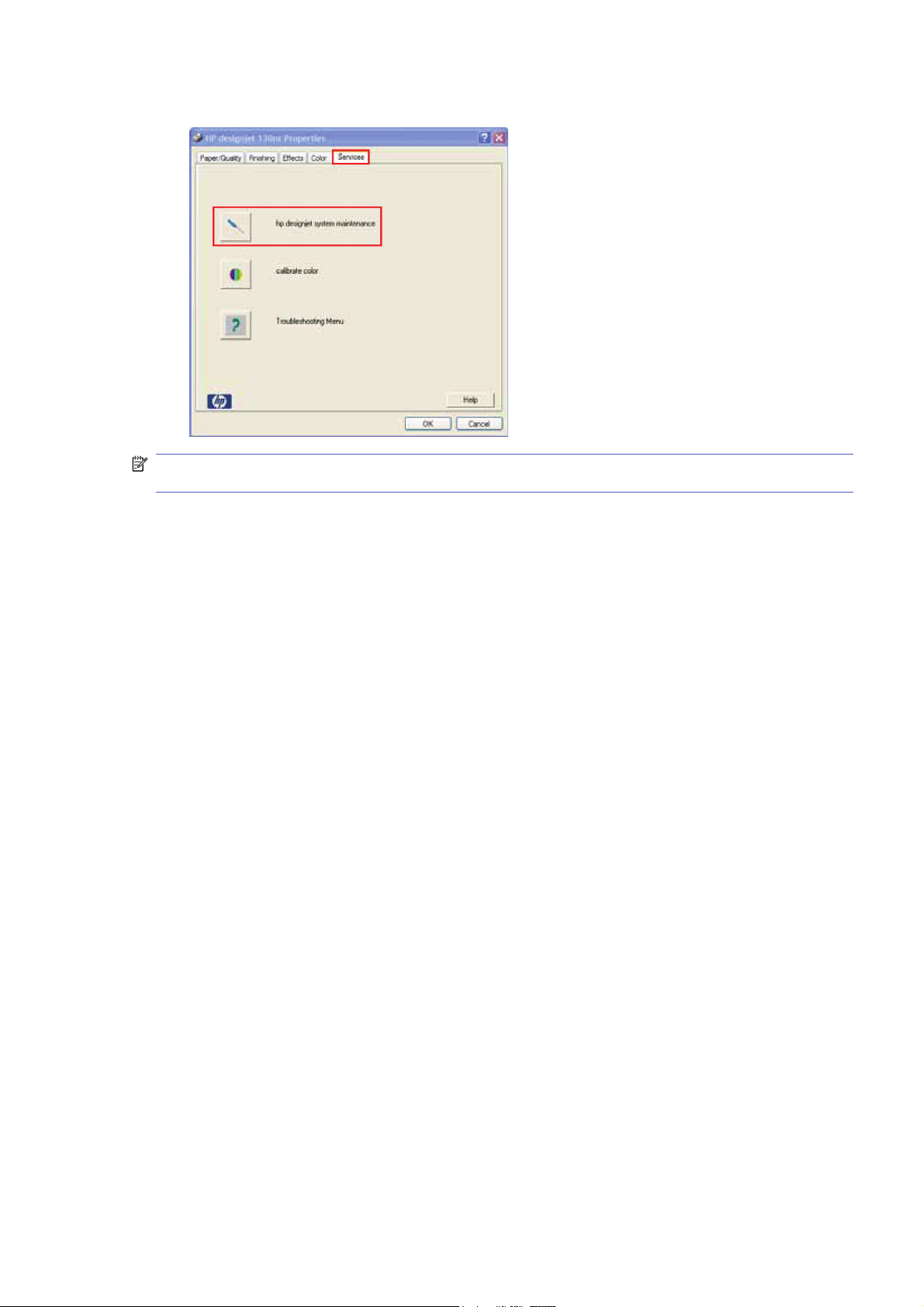
●
In Mac OS X, select the Printer in the Print Center or Print Setup Utility and click configure.
NOTE: When you finish using the System Maintenance Utility, you must click on exit on the left hand
column before closing the browser.
ENWW Launching the System Maintenance Utility 39
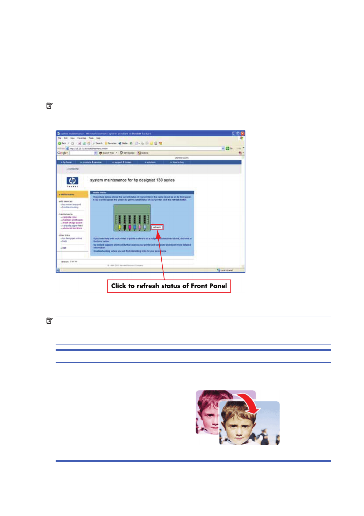
System Maintenance Utility (Designjet 30, 30n, 70, 90, 90r,
110plus, 111, 130, 130nr)
Main Menu — Printer Front Panel Replication
The main page of the System Maintenance Utility includes a replica of the Printer’s Front Panel showing
the status of the Printer.
NOTE: The replica Front Panel does not show the real-time status. It is a snapshot which can be
refreshed by pressing the refresh button either on the web browser toolbar or in the actual replica
window.
Color Calibration
NOTE: The Color Calibration is only available for the following printers: HP Designjets 30, 30n, 90,
90r, 130, 130nr. It is not available for the HP Designjets 70, 110plus, 111.
NOTE: The Color Calibration should ONLY be performed by the user when required.
Question Answer
Why calibrate color? Calibrate color performs a maintenance function to ensure
color consistency. If you calibrate correctly, the colors printed
on printers with different printheads will look very similar.
This picture shows an exaggerated example of how a printout
could look like before and after color calibration.
40 Chapter 3 System Maintenance Utility ENWW
 Loading…
* 01:10
Electronics Module failure.
Requires Service Engineer
* 01:12 Warning/Error Code
Electronics Module Error. Warning information indicates:- Electronics Module failed during the firmware upgrade OR the Electronics Module failed during initialization.
The Electronics Module EEPROM is flagged as empty and must be upgraded with the contents of the Carriage EEPROM, but the Carriage is also flagged as empty. The backup is not performed. This is the result of an error during the manufacturing or the repair process. Therefore the Electronics Module must be reconfigured. Call service engineer
* 02:10
Carriage failure.
Call service engineer
* 04:13
Generic Firmware Error (Network Card).
Unplug the power cable from the printer and wait a few seconds. Plug in the power cable again and check if the Error Code has disappeared.
If the error code continues Requires a Service Engineer
* 08:11
Problem with the Front Panel/Front Panel cannot be detected.
• Switch the Power OFF from the back of the Printer and disconnect the Power cord. Reconnect the power cord and power ON the Printer.
• If the System Error continues requires a Service Engineer.
* 11:10
Trailing Cable does not seem to be detected.
Try the following:
- Switch the Power OFF from the back of the Printer and disconnect the Power cord.
- Check that the Trailing Cable is not damaged.
- Reconnect the power cord and power ON the Printer.
If problem continues — requires Service Engineer.
* 11:11
Trailing Cable is badly connected.
Requires Service Engineer.
* 1:11 Warning
The Electronics Module is incorrectly positioned
Call service engineer to reseat module
* 21:10
Service Station failure.
Requires a Service Engineer.
* 22:10
Ink Supply Station failure.
Requires Service Engineer
* 270:00 Warning
Black Color Calibration Failure — Black Color Calibration cancelled.
Try the following: Clean the electrical contacts on the black printhead. If the error code continues, replace the black printhead.
* 271:00 Warning
Cyan Color Calibration Failure — Cyan Color Calibration cancelled.
Try the following: Clean the electrical contacts on the cyan printhead. If the error code continues, replace the cyan printhead
* 272:00 Warning
Magenta Color Calibration Failure — Magenta Color Calibration cancelled.
Try the following: Clean the electrical contacts on the magenta printhead. If the error code continues, replace the magenta printhead.
* 273:00 Warning
Yellow Color Calibration Failure — Yellow Color Calibration cancelled.
Try the following: Clean the electrical contacts on the yellow printhead. If the error code continues, replace the yellow printhead.
* 274:00 Warning
Light Cyan Color Calibration Failure — Light Cayan Color Calibration cancelled.
Try the following: Clean the electrical contacts on the light cyan printhead. If the error code continues, replace the light cyan printhead.
(Not applicable to HP DesignJet 70, 100, 100+, 110+)
* 275:00 Warning
Light Magenta Color Calibration Failure — Light Magenta Color Calibration cancelled.
Try the following:Clean the electrical contacts on the light magenta printhead. If the error code continues, replace the light magenta printhead.
(Not applicable to HP DesignJet 70, 100, 100+, 110+)
* 35:01 Warning/Error Code
No Cleanout Assembly (or Duplexer, if installed) detected while loading media.
Call service engineer
* 37:01
Automatic roll motor shutdown.
If this error code was caused by a paper jam, unplug the power cable from the printer and clear the blockage. Plug in the power cable again and check if the Error Code has disappeared.
If there is no paper jam or if recovering the paper jam does not resolve the problem, Requires Sevice Engineer.
* 37:10
Automatic roll home position error.
Requires Service Engineer.
* 42:10
Carriage Motor failure (short-circuit).
Requires Service Engineer.
* 56:10
Error during the calibration of the motor encoder system or a problem finding the zero position on the Encoder Disc.
Requires Service Engineer.
* 56:13
Error during the calibration of the Line-feed Motor/Encoder system.
Unplug the power cable from the printer and wait a few seconds. Plug in the power cable again and check if the Error Code has disappeared.
If Error Code remains,Requires Sevice Engineer.
* 58:10
Problem detected in the colour sensor system.
Call service engineer
* 61:05 Warning/Error Code
Language interpreting error. This is usually an error produced while parsing a file.
There is probably an incompatibility between the driver and the firmware.
Warning info indicates:- Firmware Upgrade or Colour Calibration was rejected because the file was sent in the wrong format. Upgrade the RIP software or the Designjet System Maintenance Tool. Requires Service Engineer
* 62:04
I/O module error (62 = parallel).
Unplug the power cable from the printer and wait a few seconds. Plug in the power cable again and check if the Error Code has disappeared.
If the Error Code reappears, the firmware requires an upgrade. Requires Service Engineer
* 63:04
I/O module error (63 = Network).
Try the following: Unplug the power cable from the printer and wait a few seconds. Plug in the power cable again and check if the Error Code has disappeared. If the Error Code reappears, upgrade the firmware.
Requires a Service Engineer.
* 64:04
I/O module error (64 = USB).
Try the following: Unplug the power cable from the printer and wait a few seconds. Plug in the power cable again and check if the Error Code has disappeared. If the Error Code reappears, upgrade the firmware.
Requires a Service Engineer.
* 65:01 Warning
Communication Failure.
Try the following: Unplug the power cable from the printer and check the cable connections (Parallel, USB and Network cables). Plug in the power cable again and check if the Error Code has disappeared.
* 65:04
I/O module error (62 = parallel; 63 = Network; 64 = USB = Unknown Port; 65).
Try the following: Unplug the power cable from the printer and wait a few seconds. Plug in the power cable again and check if the Error Code has disappeared.
If the Error Code reappears, upgrade the firmware. Call service engineer
* 71:03
Generic Firmware Error (Out of memory).
Unplug the power cable from the printer and wait a few seconds. Plug in the power cable again and check if the Error Code has disappeared.
If the Error Code reappears, check for a new Firmware release. Requires a Service Engineer.
* 71:14 Warning/Error Code
Out-of-memory while trying to process the firmware upgrade file.
Probably this is a firmware bug, because the firmware should free up enough memory to perform the firmware upgrade process correctly. Requires a Service Engineer.
* 72:04
Generic Firmware error.
• Switch the Power OFF from the back of the Printer and disconnect the Power cord. Reconnect the power cord and power ON the Printer.
• Check that the Printer has the latest Firmware version. If not requires a Service Engineer to update the Firmware to the latest version.
* 74:12 Warning/Error Code
Firmware Upgrade Error (Memory size check failed during firmware upgrade).
Call service engineer to Perform the automatic troubleshooting procedure — If possible, provide the following information which can be found on the information page:– Firmware Release.– Printer Serial Number.
* 79:04
Generic Firmware error.
• Switch the Power OFF from the back of the Printer and disconnect the Power cord. Reconnect the power cord and power ON the Printer.
• Check that the Printer has the latest Firmware version.
If error persists, requires a Service Engineer
* 81:01
Paper-Axis shutdown/ Paper Servo shutdown — usually a paper-jam caused by a blockage of the Paper-axis System.
If this error code was caused by a paper-jam, unplug the power cable from the printer and clear the blockage. Plug in the power cable again and check if the Error Code has disappeared.
If this error code appeared but was NOT caused by a paper jam — requires a Service Engineer.
* 81:12
Media Advance error.
This error usually appears during the paper-advance calibration — Retry the paper-advance calibration.
* 83:10
Sheet feeding failure.
Call service engineer
* 85:10
Paper-Axis Encoder error. The Drive Roller Encoder Sensor cannot find the zero position of the Encoder Disk.
Requires Service Engineer
* 86:01
Scan-axis shutdown/Carriage Servo shutdown — caused by problem moving the carriage, most likely due to a paper jam.
Try the following:
- Switch the Power OFF from the back of the Printer and disconnect the Power cord.
- Open the Window and check for any visible obstacles restricting the movement of the carriage. If there is a wrinkled mass of media inside the paper path, lift the Pinch wheels (using the Media Lever) and clear the obstruction.
- Reconnect the power cord and power ON the Printer.
If problem persists — Requires Service Engineer
* 86:11
Scan-axis shutdown during initialization. Typically, this error occurs when the printer detects an incorrect length.
- Unplug the power cable from the printer and wait a few seconds.
- Plug in the power cable again and check if the Error Code has disappeared.
- Check that the Carriage moves freely and DOES NOT bump into the Service Station.
- If the Printheads are not installed, maybe the carriage cover is not closed completely.
If the Error Code continues, Requires a Service Engineer
* 94:08 Warning
Color Calibration Warning — Color Calibration not cancelled but Color Calibration values are likely to be incorrect.
Try the Color Calibration again, but this time using a different type of media (preferably HP media).
* 94:10 Warning
Color Calibration Failure — Color Calibration cancelled.
Try the following: Unplug the power cable from the printer and wait a few seconds. Plug in the power cable again and try the Color Calibration again. If this error code appears again, check the Color Calibration print:– If the Color Calibration was printed correctly without any print defects, then check that the media is moving freely (backwards and forwards) while the printer is scanning it.– If the Color Calibration was printed incorrectly,with some print defects replace the faulty Printhead of the color where the defects were noticeable. If the Error Code continues, call service engineer
* 95:00 Warning
Printhead Alignment Failure — Printhead Alignment cancelled.
Try the following: Clean the printhead indicated by the printer. If the error code continues, replace the faulty printhead.
* 95:02 Warning
Printhead Alignment Failure — Printhead Alignment cancelled.
Try the following: Unplug the power cable from the printer and wait a few seconds. Plug in the power cable again and try the Printhead Alignment again. If this error code appears again, check the Printhead Alignment print:– If the Printhead Alignment was printed correctly without any print defects, then check that the media is moving freely (backwards and forwards) while the printer is scanning it. – If the Printhead Alignment was printed incorrectly, with some print defects, replace the faulty Printhead of the color where the defects were noticeable.
* 95:04 Warning
Firmware Error (during Printhead Alignment)
Upgrade the printer to the latest firmware release. — Call service engineer
HP Designjet Entry-Level Printers Service
Manual
Version: September 2010
For HP Internal Use Only
©Copyright Hewlett-Packard Company 2010
This document contains proprietary
information that is protected by copyright. All
rights are reserved. No part of this document
may be photocopied, reproduced, or
translated to another language without the
prior written consent of Hewlett-Packard
Company.
Edition,
September 2010.
Notices
Warranty
The information contained in this
document is subject to change without
notice.
Hewlett-Packard makes no
warranty of any kind with regard to
this material, including, but not
limited to, the implied warranties of
merchantability and fitness for a
particular purpose.
Hewlett-Packard shall not be liable for
errors contained herein or for
incidental or consequential damages
in connection with the furnishing,
performance, or use of this material.
WARNING
The procedures described in this manual are
to be performed by HP-qualified service
personnel only.
Electrical Shock Hazard
Serious shock hazard leading to death or
injury may result if you do not take the
following precautions:
●
Ensure that the ac power outlet (mains)
has a protective earth (ground)
terminal.
●
Disconnect the Printer from the power
source prior to performing any
maintenance.
●
Prevent water or any other liquids from
running onto electrical components or
circuits, or through openings in the
enclosure.
Electrostatic Discharge
Refer to the beginning of Chapter 4
Utilities on page 53 of this manual, for
precautions you should take to prevent
damage to the Printer circuits from
electrostatic discharge.
Safety Symbols
General definitions of safety symbols are
given immediately after the table of contents.
WARNING
The Warning symbol calls attention to a
procedure, practice, or the like, which,
if not correctly performed or adhered to,
could result in personal injury. Do not
proceed beyond a Warning symbol until
the indicated conditions are fully
understood and met.
CAUTION
The Caution symbol calls attention to
an operating procedure, practice, or the
like, which, if not correctly performed or
adhered to, could result in damage to or
destruction of part or all of the product.
Do not proceed beyond a Caution
symbol until the indicated conditions
are fully understood and met.
Content Management Department,
Barcelona Division,
Hewlett-Packard Espanola, S.A.
Avda. Graells, 501
08190 Sant Cugat del Valles
Spain
ENWW iii
iv Notices ENWW
Using this Manual
Purpose
This Service Manual contains information necessary to test, calibrate and service:
●
HP Designjet 30 Printer (Model C7790D)
●
HP Designjet 30n Printer (Model C7790E)
●
HP Designjet 70 Printer (Model Q6655A)
●
HP Designjet 90 Printer (Model Q6656A)
●
HP Designjet 90r Printer (Model Q6656B)
●
HP Designjet 100+ Printer (Model C7796C)
●
HP Designjet 110+ Printer (Model C7796D)
●
HP Designjet 110+nr Printer (Model C7796E)
●
HP Designjet 130 Printer (Model C7791C)
●
HP Designjet 130nr Printer (Model C7791D)
●
HP Designjet 110+r Printer (Model C7796H)
●
HP Designjet 130r Printer (Model C7791H)
●
HP Designjet 111 Printer with Roll (Model CQ532A)
●
HP Designjet 111 Printer with tray (Model CQ533A)
For information about using these printers, refer to the corresponding User and Quick Reference Guides.
Readership
The procedures described in this Service Manual are to be performed by HP Certified service personnel
only.
Part Numbers
Part Numbers for Printer options, accessories and service parts are located in Chapter 7
Removal
and Installation on page 95.
Conventions
A small arrow
is used to indicate other parts of the Service Manual where you can find information
related to the topic you are consulting.
ENWW v
vi Using this Manual ENWW
Table of contents
1 Test Prints
Usage Report Page ………………………..……………………………………………………………………..……….……. 2
Information Page ……………………..…………………..…………………………………………..………..……………….. 3
NVM Contents Page ………………………………..…………………………………………………………..………………. 5
2 System Error Codes
Introduction ……………………………..…………………………….……………………………………………………………. 8
Errors and Warnings ………………………………………..………………………………………………………………….. 9
System Error Codes ………………………………………..…………………..………………………………..…………… 10
Warnings ……………………………..…………………….………………………………………..………..…………………. 17
Startup track mode …………………….………………………………………….…………………………….…………….. 25
Emergency Firmware Upgrade ……………………………………………….……………………………..……….…… 33
System Error Codes — Explanation ………………………….…………………..………………….……………………. 34
3 System Maintenance Utility
Introduction ……………………………..…………………………….………………………………………………………….. 38
Launching the System Maintenance Utility …………………….……………………………………………………... 38
System Maintenance Utility (Designjet 30, 30n, 70, 90, 90r, 110plus, 111, 130, 130nr) ……………….. 40
Main Menu — Printer Front Panel Replication ………………………………………..…………………. 40
Color Calibration .…………………….…………………..………………….…………………….………….… 40
Align Printheads ……………………………………………………………….…………………………..…..… 45
Clean Printheads …………………………….………………………………………………………………….. 46
Check Image Quality …………………………………..…………………………………..………………….. 47
Calibrate Paper Feed ……………………………..………………………………………………………..….. 48
Get Printer Information ………………………….…………………………………….………………………. 50
Update Firmware ……………………………………………………………………………….……………….. 51
Reset Jetdirect Network Card …………………………..……………..……………………..…………….. 52
4 Utilities
Utilities ………………………………………………..………………………………………………….………………………… 53
How to Access Restricted Access Utilities …………..…………………………..……………………… 54
Enable/Disable Buzzer ………………………..………………………………………………………………. 54
Transport Position ………………………………….……………………………..…………………………..... 54
Printhead Recovery …………………….………………………..………………………….…………………. 55
Network Card Reset ……………………………..………………………………..…………………………… 56
Set to Factory Defaults ……………..………………………..………………………..……………………… 56
Hard EEPROM reset …………………………..……………………………..…………….…………..…….. 57
ENWW vii
Set Flag to Prime Tubes ……………….…………………………………………..…………………..…….. 57
5 Calibrations
PRS Adjustment ………………….………………………………………….…………………..…………………………..… 60
When Required …………………………..…………………….……………………..…………………………. 60
Manual PRS Adjustment …………………………….……………………..……………………….……………..……….. 60
Factory Accuracy Calibration ……….……………………………….…………………………………………………….. 70
Parts replacement and associated calibrations …………………….……………………………………………..…. 72
6 Parts and Diagrams
Cover Assemblies .………………………..…………………………..………………………..……………….……………. 75
Cover Assemblies .………………………..…………………………..………………………..……………….……………. 76
Printer Labels …………………..…………………..…………………..……………………..……………..………………… 78
Right Hand Assemblies ……………………………………….…………………..…………………..………….…………. 79
Left Hand Assemblies ….………………………..……………………………………………………….………………….. 81
Scan-Axis Assemblies ………………………….……………………………………………..………………….………….. 82
Top Paper Path Assemblies (1 of 2) ……..……………………………….………………………………..…………… 84
Top Paper Path Assemblies (2 of 2) ……..……………………………….………………………………..…………… 85
Rear Paper Path Assemblies …………….………………………………………………..……………………....……… 87
Paper Feed Assemblies .…………………….……………………….…………………….……………………..………… 88
Cable Harnesses ………………………..……………………….………………………………………………………….…. 90
Ink Supplies and Accessories (1 of 2) ..…………………..…………………..…………………….…………….……. 91
Ink Supplies & Accessories (2 of 2) ……………..…………..…………………………………………………………… 92
Rollfeed Components …………………………..………………………..……………………………………….………….. 93
Printer Stand and Basket ……………………………………………….…………………………….………….…………. 94
7 Removal and Installation
Introduction ………………………..…………………………….……………………………….…………..………………….. 96
Top Cover ……………………………..……………………………..…………………………….………….…………………. 98
Front Cover (Applicability: 30, 30n, 50ps) ……………………….…………..…………………..……….…………… 98
Center Cover ………………………..…………………….…………………..……………………………….……………….. 99
Right End Cover ………………….……………………..………………………………………………………………….… 101
Left End Cover ..………………………….………………………..……………………….………………….…………….. 103
Ink Supply Station Cover (Applicability: 70, 100, 100plus, 110plus, 111) …………………………………. 105
Ink Supply Station …………………….…………………………………………………..…………………………………. 106
Electronics Module ……………………….…………………..…………………..…………………….…………………… 109
Power Supply Unit ……………………….……………………………………………………………………………..……. 112
Service Station ..……………………………………………………………………………………..………..……………… 114
Front Panel ……………………….………………………………………………….……………………….………………… 117
Encoder Strip …………………………………..…………………………….……………………………..…………………. 118
Carriage Motor ………………………………….………………………..………………………..…………..…………….. 119
Cleanout Assembly …………………………..…………………………………………………………………..…………. 120
Ink Supply Tubes ………………………..…………………………………………………………….………..……………. 121
Carriage Assembly (Applicability: 70, 100+, 110+, 111) ………………………………………………………… 123
Carriage Assembly (Applicability: 30, 30nr, 90, 90r, 130, 130nr) …………………………………………..… 125
Carriage Belt …………………………………..……………………….……………………………………..……….……… 128
viii ENWW
Starwheel Assembly (Applicability: 30, 30n) ……………………………………………………..…………………. 129
Starwheel Assembly …………………..……………………..…………………….……………………..……..…………. 130
Print Platen Assembly ……………………………………….……………………….…………………….………………. 131
Output Separator (Applicability: 30, 30n) ..…………….………………..………………………………………..…. 133
Ramp Motor Assembly .………………………………………………………..………………………….……….………. 134
Output Mechanism Assembly (Applicability: 30, 30n) ……………………………………..…………………….. 135
Spittoon (If Installed in the Printer) …………………………………..………………………………………..……….. 137
Pivot Assembly …..…………………….…………………………………………..…………………….…….……….……. 138
Feed Roller Assembly (Applicability: 30, 30n) …..………………………………………………………………….. 13 9
Feed Roller Assembly …………………..……………………..……………………………………………..….………… 141
Pick Assembly (Applicability: 30, 30n) ..……………………..……………………..…………………………….…… 145
Pick Assembly ..………………………..……………………….…………………………..………………….…………….. 146
Pinch Assembly (Applicability: 30, 30n) …….……………………………..…………….………………………..…. 152
Lower Paper Guide (Applicability: 30, 30n) ……………………………..……………………………..………….... 153
Inner Paper Guide (Applicability: 30, 30n) .…………………………..………………………………………………. 154
Inner Paper Guide .………………………..…………………………..………………………………………..……….….. 155
OOPS Sensor ……………………….…………………..………………………………………….…………………………. 156
Paper-Axis Motor Drive Assembly (Applicable only to 30, 30n) ………………………………………………. 158
Paper-Axis Motor Assembly (Applicability: 90, 90r, 130, 130nr) ……………………………………………… 159
Bypass Platen (Applicability: 90, 90r, 130, 130nr) ……………..………………………….………………………. 160
Bypass Platen Actuator (Applicability: 90, 90r, 130, 130nr) ………..…………………………………….……. 163
Output Platen (HP Designjet 111 with Roll) ……………………………….………………………………………... 165
8 Maintenance
Maintenance ………………………………………………………..…………………..……………………………………… 168
Cleaning Information ..………………………………………….…………………..………………………… 168
Lubrication Information …………..………………………..………………………………………………… 170
About this Edition ………………………….………………………………………………….……………….. 17 0
What’s in this Service Manual ……………….…………………….…………………….………………… 170
ENWW ix
x ENWW
1Test Prints
●
Usage Report Page
●
Information Page
●
NVM Contents Page
ENWW 1
Usage Report Page
The Usage Report Page contains the following information:
●
Printer Model Name.
●
Printer Model Number.
●
Printer Serial Number.
●
Date of last print job received.
●
Total ink consumed.
●
Date of first print job received.
●
Number of pages printer (media size/media type/print quality setting).
To print the Usage Report Page, hold the power button down and press the resume button once.
2 Chapter 1 Test Prints ENWW
Information Page
The Information Page contains the following information:
●
Printer Identification.
●
Printer Status.
●
Printer Usage.
●
Ink Consumable Identification.
●
Ink Consumable Status.
●
Ink Consumable Usage.
●
Network Card Information.
To print the Information Page, hold the power button down and press the resume button four times.
ENWW Information Page 3
4 Chapter 1 Test Prints ENWW
NVM Contents Page
The NVM Contents Page contains the following information:
●
EEROM values dump containing all the values stored in the EEROM (Calibration, etc.)
●
Printheads Acumen dump
●
Cartridges Acumen dump.
To print the NVM Contents Page, hold the power button down and press the cancel button once and
the resume button twice.
ENWW NVM Contents Page 5
6 Chapter 1 Test Prints ENWW
2 System Error Codes
●
Introduction
●
Errors and Warnings
●
System Error Codes
●
Warnings
●
Startup track mode
●
Emergency Firmware Upgrade
●
System Error Codes — Explanation
ENWW 7
Introduction
The following pages contain a list of system error codes and their respective descriptions and
recommended corrective actions. Only try one recommended action at a time and check if the error
code has disappeared. Since the front panel can only display graphics, the error code needs to be
determined by counting the bars on the front panel (as shown below).
NOTE: Refer to System Error Codes — Explanation on page 34 for an explanation on the construction
of the Error Codes and Warnings.
8 Chapter 2 System Error Codes ENWW
Errors and Warnings
Error Codes will normally be displayed directly on the front panel (but can also be seen on the
Information Page) and will require some kind of intervention to resolve the problem. Warnings will
not be displayed on the front panel, but will instead only appear on the Information Page, therefore
allowing the user to continue operating the printer without the need of an intervention.
NOTE: You can also obtain report of the System Error and Warnings through the DesignJet System
Maintenance Tool.
ENWW Errors and Warnings 9
System Error Codes
NOTE: Applicable for 111 only: The printer has a MROM module and it is not possible to perform a
firmware upgrade, and in fact not required as the printer already has the latest version.
01:10
Cause
Solution
Electronics Module failure.
Replace the Electronics Module
Electronics Module
on page 109.
01:12
Cause
Solution
Electronics Module failed during the firmware upgrade OR the
Electronics Module failed during initialization.
Try the following:
●
If the Electronics Module failed during the firmware
upgrade, first perform an emergency firmware upgrade
(
Emergency Firmware Upgrade on page 33).
●
If an emergency firmware upgrade is NOT possible or it
didn’t work, replace the Electronics Module
Electronics Module on page 109.
02:10
Cause
Solution
Carriage failure.
Replace the Carriage Assembly
Carriage Assembly
(Applicability: 70, 100+, 110+, 111) on page 123.
04:13
Cause
Solution
Generic Firmware Error (Network Card). Unplug the power cable from the printer and wait a few
seconds. Plug in the power cable again and check if the Error
Code has disappeared. If the error code continues, refer to the
Jetdirect Card Service Manual and Service Notes.
08:11
Cause
Solution
Front Panel cannot be detected. Try the following:
●
Check the connections and cables of the Font Panel,
check they have not been damaged and are correctly
connected, disconnect and reconnect the front panel.
●
Replace the Front Panel if the problem persists
Front
Panel on page 117.
10 Chapter 2 System Error Codes ENWW
11:10
Cause
Solution
Trailing Cable Failure. Try the following:
●
Replace the Carriage Assembly
Carriage Assembly
(Applicability: 70, 100+, 110+, 111) on page 123.
●
If the Error Code continues, replace the Electronics
Module
Electronics Module on page 109.
NOTE: Only replace one component at a time and check if
the error has gone before replacing another component. Using
this procedure you will be able to determine exactly which
component failed.
11:11
Cause
Solution
Trailing Cable is badly connected. Try the following:
●
Reconnect the Trailing Cable correctly to the Electronics
Module.
●
If the Error Code continues, replace the Carriage
Assembly
Carriage Assembly (Applicability: 70, 100
+, 110+, 111) on page 123.
21:10
Cause
Solution
Service Station failure.
Replace the Service Station Assembly
Service Station
on page 114.
22:10
Cause
Solution
Ink Supply Station failure.
Replace the Ink Supply Station
Ink Supply Station
on page 106.
ENWW System Error Codes 11
35:01
Cause
Solution
No Cleanout Assembly detected while loading media. Try the following:
●
Remove the Cleanout Assembly and install it again
correctly.
●
Replace the Cleanout Interconnect PCA.
●
If the Error Code continues, replace the Cleanout
Assembly.
NOTE: Only replace one component at a time and check if
the error has gone before replacing another component. Using
this procedure you will be able to determine exactly which
component failed.
37:01
Cause
Solution
Automatic roll motor shutdown. Try the following:
●
If this error code was caused by a paper jam, unplug the
power cable from the printer and clear the blockage. Plug
in the power cable again and check if the Error Code has
disappeared.
●
If there is no paper jam or if recovering the paper jam does
not resolve the problem, then replace the Automatic Roll
System (the error could be caused by anything that stalls
the motor).
37:10
Cause
Solution
Automatic roll home position error. Replace the Automatic Roll System (the error could be caused
by anything that causes the home position not to be detected
or not to be the correct one — electrical sensors, internal
mechanical problems, etc.).
42:10
Cause
Solution
Carriage Motor failure (short-circuit).
Replace the Carriage Motor Assembly
Carriage Motor
on page 119.
12 Chapter 2 System Error Codes ENWW
56:10
Cause
Solution
Error during the calibration of the motor encoder system or a
problem finding the zero position on the Encoder Disc.
Try the following:
●
Replace the Paper-Axis Motor Drive Assembly
Paper-
Axis Motor Drive Assembly (Applicable only to 30, 30n)
on page 158.
●
Replace the Encoder Disc.
NOTE: Make sure you recalibrate the Paper-Axis after
replacing the Paper-Axis Motor Drive Assembly or the Encoder
Disc.
Only replace one component at a time and check if the error
has gone before replacing another component. Using this
procedure you will be able to determine exactly which
component failed.
56:13
Cause
Solution
Error during the calibration of the Line-feed Motor/Encoder
system.
Unplug the power cable from the printer and wait a few
seconds. Plug in the power cable again.
61:05
Cause
Solution
Firmware Upgrade or Color Calibration was rejected because
the file was sent in the wrong format.
Upgrade the RIP software or the Designjet System
Maintenance Tool.
62:04, 63:04, 64:04 and 65:04
Cause
Solution
I/O module error (62 = parallel; 63 = Network; 64 = USB). Try the following:
●
Unplug the power cable from the printer and wait a few
seconds. Plug in the power cable again and check if the
Error Code has disappeared.
●
If the Error Code reappears, upgrade the firmware.
71:03
Cause
Solution
Generic Firmware Error (Out of memory). Try the following:
●
Unplug the power cable from the printer and wait a few
seconds. Plug in the power cable again and check if the
Error Code has disappeared.
●
If the Error Code reappears, check for a new Firmware
release.
ENWW System Error Codes 13
71:14
Cause
Solution
Memory Management Error (Out of memory during firmware
upgrade).
Try the following:
●
Unplug the power cable from the printer and wait a few
seconds. Plug in the power cable again and check if the
Error Code has disappeared.
●
If the Error Code reappears, perform an emergency
firmware upgrade (
Emergency Firmware Upgrade
on page 33).
72:04
Cause
Solution
Generic Firmware Error (expected). Try the following:
●
Unplug the power cable from the printer and wait a few
seconds. Plug in the power cable again and check if the
Error Code has disappeared.
●
If the Error Code reappears, check for a new Firmware
release.
●
If possible, request the user to provide the following
information which can be found on the information
page:
◦
Firmware Release.
◦
Filename.
◦
Line.
74:12
Cause
Solution
Firmware Upgrade Error (Memory size check failed during
firmware upgrade).
Try the following:
●
Perform the automatic troubleshooting procedure
(requires a special firmware upgrade file that must be
provided by the manufacturing division).
74:14
Cause
Solution
The printer is unavailable to upgrade the firmware.. Try the following:
●
Turn off and on the printer.
●
Print the Service Page
●
Check that the firmware is the latest available.:
◦
Applicable for 110+,110+r,130,130r: If the
firmware version is D.05.04, this would indicate that
the printer has a MROM module and it is not possible
to perform a firmware upgrade, and in fact not
required as the printer already has the latest version.
14 Chapter 2 System Error Codes ENWW
74:14
Cause
Solution
◦
Applicable for 111 only: The printer has a MROM
module and it is not possible to perform a firmware
upgrade, and in fact not required as the printer
already has the latest version.
79:04
Cause
Solution
Generic Firmware Error (unexpected). Try the following:
●
Unplug the power cable from the printer and wait a few
seconds. Plug in the power cable again and check if the
Error Code has disappeared.
●
If the Error Code reappears, check for a new Firmware
release.
●
If possible, request the user to provide the following
information which can be found on the information
page:
◦
Firmware Release.
◦
Filename.
◦
Line.
81:01
Cause Solution
Paper-Axis shutdown — usually a paper-jam caused by a
blockage of the Paper-axis System.
Try the following:
●
If this error code was caused by a paper-jam, unplug the
power cable from the printer and clear the blockage. Plug
in the power cable again and check if the Error Code has
disappeared
●
If this error code appeared but was NOT caused by a
paper jam, replace the Paper-Axis Motor Drive Assembly
Paper-Axis Motor Drive Assembly (Applicable only to
30, 30n) on page 158.
81:12
Cause
Solution
Media Advance error. This error usually appears during the paper-advance
calibration — Retry the paper-advance calibration.
ENWW System Error Codes 15
83:10
Cause
Solution
Sheet feeding failure. Try the following:
●
Replace the Out-Of-paper Sensor.
●
Replace the Electronics Module
Electronics Module
on page 109.
85:10
Cause
Solution
Paper-Axis Encoder error. Try the following:
●
Make sure that the Encoder Sensor cable is connected
correctly.
●
Replace the Paper-Axis Motor Drive Assembly
Paper-
Axis Motor Drive Assembly (Applicable only to 30, 30n)
on page 158.
●
Replace the Electronics Module
Electronics Module
on page 109.
86:01
Cause Solution
Scan-axis shutdown — usually a paper-jam caused by a
blockage of the Scan-axis System.
Try the following:
●
Check that there are no obstacles in the Scan-Axis which
stops the Carriage from moving freely.
●
Too much friction in the Slider Rod, try lubricating the
Slider Rod.
●
The Carriage is bumping into the Service Station. If the
Carriage is stuck at the right hand side of the Printer and
cannot be moved out to the center of the Print Platen it is
because the Service Station cannot uncap the
printheads. In this case replace the Service Station
Assembly
Service Station on page 114.
●
Check that the belt is correctly installed and not damaged.
●
Check that the Turnaround Pulley is correctly installed.
●
Replace the Carriage Motor Assembly
Carriage
Motor on page 119.
16 Chapter 2 System Error Codes ENWW
86:11
Cause
Solution
Scan-axis shutdown during initialization. Typically, this error
occurs when the printer detects an incorrect length.
Try the following:
●
Unplug the power cable from the printer and wait a few
seconds. Plug in the power cable again and check if the
Error Code has disappeared.
●
Check that the Paper-Axis Drive Motor Assembly is
correctly installed and that the bushing is correctly locked
into position.
●
Check that the Carriage moves freely and DOES NOT
bump into the Service Station.
●
If the Printheads are not installed, maybe the carriage
cover is not closed completely.
●
If the Error Code continues, replace the Carriage
Assembly
Carriage Assembly (Applicability: 70, 100+,
110+, 111) on page 123.
Warnings
01:11
Cause
Solution
The Electronics Module is incorrectly positioned. Reseat the Electronics Module by Removing it from the Printer
Electronics Module on page 109 and installing it again in
the correct position.
01:12
Cause
Solution
Electronics Module Error. The Electronics Module EEPROM is flagged as empty and
must be upgraded with the contents of the Carriage EEPROM,
but the Carriage is also flagged as empty. The backup is not
performed. This is the result of an error during the
manufacturing or the repair process. Therefore the Electronics
Module must be reconfigured.
02:10
Cause
Solution
Carriage failure.
Replace the Carriage Assembly
Carriage Assembly
(Applicability: 70, 100+, 110+, 111) on page 123.
ENWW Warnings 17
270:00
Cause
Solution
Black Color Calibration Failure — Black Color Calibration
cancelled.
Try the following:
●
Clean the electrical contacts on the black printhead.
●
If the error code continues, replace the black printhead.
271:00
Cause
Solution
Cyan Color Calibration Failure — Cyan Color Calibration
cancelled.
Try the following:
●
Clean the electrical contacts on the cyan printhead.
●
If the error code continues, replace the cyan printhead.
272:00
Cause
Solution
Magenta Color Calibration Failure — Magenta Color Calibration
cancelled.
Try the following:
●
Clean the electrical contacts on the magenta printhead.
●
If the error code continues, replace the magenta
printhead.
273:00
Cause
Solution
Yellow Color Calibration Failure — Yellow Color Calibration
cancelled.
Try the following:
●
Clean the electrical contacts on the yellow printhead.
●
If the error code continues, replace the yellow printhead.
274:00 (Not applicable to HP DesignJet 70, 100, 100+, 110+)
Cause
Solution
Light Cyan Color Calibration Failure — Light Cayan Color
Calibration cancelled.
Try the following:
●
Clean the electrical contacts on the light cyan printhead.
●
If the error code continues, replace the light cyan
printhead.
18 Chapter 2 System Error Codes ENWW
275:00 (Not applicable to HP DesignJet 70, 100, 100+, 110+)
Cause
Solution
Light Magenta Color Calibration Failure — Light Magenta Color
Calibration cancelled.
Try the following:
●
Clean the electrical contacts on the light magenta
printhead.
●
If the error code continues, replace the light magenta
printhead.
35:01
Cause
Solution
No Cleanout Assembly (or Duplexer, if installed) detected
while loading media.
Try the following:
●
Remove the Cleanout Assembly (
Cleanout
Assembly on page 120) (or Duplexer, if installed) and
install it again correctly.
●
Replace the Duplexer Interconnect PCA.
●
If the Error Code continues, replace the Cleanout
Assembly
Cleanout Assembly on page 120.
58:10
Cause
Solution
Problem detected in the color sensor system.
Replace the Carriage Assembly
Carriage Assembly
(Applicability: 70, 100+, 110+, 111) on page 123.
61:05
Cause
Solution
Language interpreting error. This is usually and error produced
while parsing a file. There is probably an incompatibility
between the driver and the firmware.
Upgrade the RIP software or the Designjet System
Maintenance Tool.
65:01
Cause
Solution
Communication Failure. Try the following:
●
Unplug the power cable from the printer and check the
cable connections (Parallel, USB and Network cables).
Plug in the power cable again and check if the Error Code
has disappeared.
ENWW Warnings 19
66:02:1 (Only applicable to HP DesignJet 30, 30n, 90, 90r, 130, 130nr)
Cause
Solution
Horizontal clipping. May happen when the roll ends in the
middle of printing an image. Could also happen when multi-
pick occurs and two sheets are loaded together and they do
not completely overlap.
Make sure the image size is within the selected WIDTH of the
sheet.
66:02:2 (Only applicable to HP DesignJet 30, 30n, 90, 90r, 130, 130nr)
Cause
Solution
Vertical clipping. May happen when the roll ends in the middle
of printing an image. Could also happen when multi-pick
occurs and two sheets are loaded together and they do not
completely overlap.
Make sure the image size is within the selected LENGTH of
the sheet.
71:14
Cause
Solution
Out-of-memory while trying to process the firmware upgrade
file. Probably this is a firmware bug, because the firmware
should free up enough memory to perform the firmware
upgrade process correctly.
Perform an emergency firmware upgrade (
Emergency
Firmware Upgrade on page 33) .
74:12
Cause
Solution
Firmware bug in the firmware upgrade process Try the following:
●
Download the special file in order to update the bootlog.
●
If possible, request the user to provide the following
information which can be found on the information
page:
◦
Firmware Release.
◦
Printer Serial Number.
74:14
Cause
Solution
The printer is unavailable to upgrade the firmware.. Try the following:
●
Turn off and on the printer.
●
Print the Service Page
●
Check that the firmware is the latest available.:
◦
Applicable for 110+,110+r,130,130r: If the
firmware version is D.05.04, this would indicate that
the printer has a MROM module and it is not possible
20 Chapter 2 System Error Codes ENWW
74:14
Cause
Solution
to perform a firmware upgrade, and in fact not
required as the printer already has the latest version.
◦
Applicable for 111 only: The printer has a MROM
module and it is not possible to perform a firmware
upgrade, and in fact not required as the printer
already has the latest version.
81:01
Cause Solution
Paper-Axis shutdown — usually a paper-jam caused by a
blockage of the Paper-axis System.
Try the following:
●
If this error code was caused by a paper-jam, unplug the
power cable from the printer and clear the blockage. Plug
in the power cable again and check if the Error Code has
disappeared.
●
If this error code appeared but was NOT caused by a
paper jam, replace the Paper-Axis Motor Drive Assembly
Paper-Axis Motor Drive Assembly (Applicable only to
30, 30n) on page 158.
83:01:1 (Only applicable to HP DesignJet 30, 30n, 70, 100+, 110+, 111, 90, 90r,, 130, 130nr)
Cause
Solution
The paper is rejected from the Bypass due to skew. When manually loading paper from the front of the paper, make
sure that it is loaded straight.
83:01:3 (Only applicable to HP DesignJet 70/100plus/110plus, 111 with Roll)
Cause
Solution
The paper is rejected from the roll due to skew. When loading paper from the roll, make sure that it is loaded
straight.
94:02:1 (Only applicable to HP DesignJet 30, 30n, 90, 90r, 130, 130nr, 111)
Cause
Solution
User selected Coated Paper and Best mode, but the Color
Calibration profile was obsolete or missing for Coated Paper
and the selected print quality setting.
Using the System Maintenance Tool, perform Color Calibration
for Coated Paper and the selected print quality setting.
94:02:3 (Only applicable to HP DesignJet 30, 30n, 90, 90r, 130, 130nr, 111)
Cause
Solution
User selected Photo Paper and Best mode, but the Color
Calibration profile was obsolete or missing for Photo Paper and
the selected print quality setting.
Using the System Maintenance Tool, perform Color Calibration
for Photo Paper and the selected print quality setting.
ENWW Warnings 21
94:02:4 (Only applicable to HP DesignJet 30, 30n, 90, 90r, 130, 130nr)
Cause
Solution
User selected Heavy-Weight Coated Paper and Best mode,
but the Color Calibration profile was obsolete or missing for
Heavy-Weight Coated Paper and the selected print quality
setting.
Using the System Maintenance Tool, perform Color Calibration
for Heavy- Weight Coated Paper and the selected print quality
setting.
94:02:5 (Only applicable to HP DesignJet 30, 30n, 90, 90r, 130, 130nr)
Cause
Solution
User selected Proofing Semi-Gloss Paper and Best mode, but
the Color Calibration profile was obsolete or missing for
Proofing Semi-Gloss Paper and the selected print quality
setting
Using the System Maintenance Tool, perform Color Calibration
for Proofing Semi-Gloss Paper and the selected print quality
setting.
94:02:6 (Only applicable to HP DesignJet 30, 30n, 90, 90r, 130, 130nr)
Cause
Solution
User selected Photo Matte Paper and Best mode, but the Color
Calibration profile was obsolete or missing for Photo Matte
Paper and the selected print quality setting.
Using the System Maintenance Tool, perform Color Calibration
for Photo Matte Paper and the selected print quality setting.
94:02:7 (Only applicable to HP DesignJet 30, 30n, 90, 90r, 130, 130nr)
Cause
Solution
User selected Photo Satin Paper and Best mode, but the Color
Calibration profile was obsolete or missing for Photo Satin
Paper and the selected print quality setting.
Using the System Maintenance Tool, perform Color Calibration
for Photo Satin Paper and the selected print quality setting.
94:02:8 (Only applicable to HP DesignJet 30, 30n, 90, 90r, 130, 130nr)
Cause
Solution
User selected Coated Paper and Max dpi, but the Color
Calibration profile was obsolete or missing for Coated Paper
and the selected print quality setting.
Using the System Maintenance Tool, perform Color Calibration
for Coated Paper and the selected print quality setting.
941:02:1 (Only applicable to HP DesignJet 30, 30n, 90, 90r, 130, 130nr)
Cause
Solution
User selected Photo Paper and Max dpi, but the Color
Calibration profile was obsolete or missing for Photo Paper and
the selected print quality setting.
Using the System Maintenance Tool, perform Color Calibration
for Photo Paper and the selected print quality setting.
22 Chapter 2 System Error Codes ENWW
941:02:2 (Only applicable to HP DesignJet 30, 30n, 90, 90r, 130, 130nr)
Cause
Solution
User selected Heavy-Weight Coated Paper and Max dpi, but
the Color Calibration profile was obsolete or missing for Heavy-
Weight Coated Paper and the selected print quality setting.
Using the System Maintenance Tool, perform Color Calibration
for Heavy- Weight Coated Paper and the selected print quality
setting.
941:02:3 (Only applicable to HP DesignJet 30, 30n, 90, 90r, 130, 130nr)
Cause
Solution
User selected Proofing Semi-Gloss Paper and Max dpi mode,
but the Color Calibration profile was obsolete or missing for
Proofing Semi-Gloss Paper and the selected print quality
setting.
Using the System Maintenance Tool, perform Color Calibration
for Proofing Semi-Gloss Paper and the selected print quality
setting.
941:02:4 (Only applicable to HP DesignJet 30, 30n, 90, 90r, 130, 130nr)
Cause
Solution
User selected Photo Matte Paper and Max dpi mode, but the
Color Calibration profile was obsolete or missing for Photo
Matte Paper and the selected print quality setting.
Using the System Maintenance Tool, perform Color Calibration
for Photo Matte Paper and the selected print quality setting.
941:02:5 (Only applicable to HP DesignJet 30, 30n, 90, 90r, 130, 130nr)
Cause
Solution
User selected Photo Satin Paper and Max dpi mode, but the
Color Calibration profile was obsolete or missing for Photo
Satin Paper and the selected print quality setting.
Using the System Maintenance Tool, perform Color Calibration
for Photo Satin Paper and the selected print quality setting.
94:04
Cause
Solution
Firmware Error (during color calibration). Try the following:
●
Unplug the power cable from the printer and wait a few
seconds. Plug in the power cable again and check if the
Error Code has disappeared.
●
If the Error Code reappears, check for a new Firmware
release.
94:08
Cause
Solution
Color Calibration Warning — Color Calibration not cancelled but
Color Calibration values are likely to be incorrect.
Try the Color Calibration again, but this time using a different
type of media (preferably HP media).
ENWW Warnings 23
94:10
Cause
Solution
Color Calibration Failure — Color Calibration cancelled. Try the following:
●
Unplug the power cable from the printer and wait a few
seconds. Plug in the power cable again and try the Color
Calibration again.
●
If this error code appears again, check the Color
Calibration print:
◦
If the Color Calibration was printed correctly without
any print defects, then check that the media is
moving freely (backwards and forwards) while the
printer is scanning it.
◦
If the Color Calibration was printed incorrectly, with
some print defects, replace the faulty Printhead of
the color where the defects were noticeable.
◦
If the Error Code continues, replace the Carriage
Assembly
Carriage Assembly (Applicability: 70,
100+, 110+, 111) on page 123.
95:00
Cause
Solution
Printhead Alignment Failure — Printhead Alignment cancelled. Try the following:
●
Clean the printhead indicated by the printer.
●
If the error code continues, replace the faulty printhead.
95:02
Cause
Solution
Printhead Alignment Failure — Printhead Alignment cancelled. Try the following:
●
Unplug the power cable from the printer and wait a few
seconds. Plug in the power cable again and try the
Printhead Alignment again.
●
If this error code appears again, check the Printhead
Alignment print:
◦
If the Printhead Alignment was printed correctly
without any print defects, then check that the media
is moving freely (backwards and forwards) while the
printer is scanning it.
◦
If the Printhead Alignment was printed incorrectly,
with some print defects, replace the faulty Printhead
of the color where the defects were noticeable.
95:04
Cause
Solution
Firmware Error (during Printhead Alignment). Upgrade the printer to the latest firmware release.
24 Chapter 2 System Error Codes ENWW
Startup track mode
Introduction
The startup track mode is designed to enable you to identify a failing subsystems while the printer is
initializing. Startup track mode provides a specific indication of which particular subsystem is failing.
This mode is not intended for use by end-users.
Initializing the printer in Startup track mode
To initialize the printer in Startup track mode:
1. Hold the ’Continue’ button while connecting the printer to the power supply.
2. During the initialization of the printer, the front panel will display a range of code numbers in the
form of squares, these code numbers added together represent the various subsystems about to
be initialized.
3. Once the printer comes to initializing the failing subsystem, the front panel will hang, and all that
will be displayed is the failing subsystem.
Interpreting the numbered code system
While the printer is initializing, the front panel will display a sequence of squares in the last two columns.
Each position in the last two columns represents a number, all the numbers represented are shown
below. To find the failing subsystem, add the numbers together that have a square and refer to the list
of numbers with their associated subsystems on
Subsystem Code Description on page 25.
In the example below the printer is initializing and the front panel has stopped and is displaying squares
in positions 16, 32, 64, and 4. Add these four values together and you get 116, refer to the list on
Subsystem Code Description on page 25, and we can see the failing subsystem is the Trailing Cable.
If the display reaches 191, you will need to turn On the printer from the power button. If all the subsystems
pass the initialization, the printer will initialize normally and go to the ready status.
Subsystem Code Description
This is the list of the subsystems and their associated Startup Track Numbers. Many of the descriptions
of the Subsystems will not be immediately obvious, when this is the case contact the lfp help desk and
they can assist you.
Table 2-1 Subsystem code description
Startup track number: Associated Subsystem
ENWW Startup track mode 25
Startup Track 004: Calling EiffelMain
Startup Track 005: Initializing Classes
Startup Track 006: Initializing SM
Startup Track 007: Initializing Memory
Startup Track 008: Initializing MemoryVolatile
Startup Track 009: Initializing MemoryEndian
Startup Track 010: Initializing MemoryVolatileEndian
Startup Track 011: Initializing Impala
Startup Track 012: Initializing ColdFire
Startup Track 013: Initializing ImpalaInterruptController
Startup Track 014: Initializing MechProcTaskHiIntA
Startup Track 015: Initializing IsardInterruptA
Startup Track 016: Initializing Watchdog
Startup Track 017: Initializing Chronometer
Startup Track 018: Initializing EddTimer
Startup Track 019: Initializing IsardInterruptB
Startup Track 020: Initializing PciSlot2Interrupt
Startup Track 021: Initializing PciSlot3Interrupt
Startup Track 022: Initializing PciSlot4Interrupt
Startup Track 023: Initializing PciSlot5Interrupt
Startup Track 024: Initializing MagentaFireLow
Startup Track 025: Initializing BongoGpio
Startup Track 026: Initializing SecondTraySensor
Startup Track 027: Initializing CleanoutSensor
Startup Track 028: Initializing RearPathPaperSensor
Startup Track 029: Initializing BlackCartridgeSensor
Startup Track 030: Initializing CyanCartridgeSensor
Startup Track 031: Initializing MagentaCartridgeSensor
Startup Track 032: Initializing YellowCartridgeSensor
Startup Track 033: Initializing LightMagentaCartridgeSensor
Startup Track 034: Initializing LightCyanCartridgeSensor
Startup Track 035: Initializing SynergyReset
Startup Track 036: Initializing FrontPanelReset
Startup Track 037: Initializing PowerFan
Startup Track 038: Initializing FrontPanelInterrupt
Startup Track 039: Initializing CoverWindowSensor
Startup Track 040: Initializing nUSB_ENABLE
Startup Track 041: Initializing USB_CONNECT
Table 2-1 Subsystem code description (continued)
26 Chapter 2 System Error Codes ENWW
Startup Track 042: Initializing TrailingCable3Sensor
Startup Track 043: Initializing TrailingCable12Sensor
Startup Track 044: Initializing PrintheadSensor
Startup Track 045: Initializing BongoBrake
Startup Track 046: Initializing Dma
Startup Track 047: Initializing BongoEncoder
Startup Track 048: Initializing ServiceStationEncoder
Startup Track 049: Initializing SSPwm
Startup Track 050: Initializing PaperPwm
Startup Track 051: Initializing RampPwm
Startup Track 052: Initializing CarriagePwmForward
Startup Track 052: Initializing CarriagePwmForward
Startup Track 054: Initializing BomboPwm
Startup Track 055: Initializing EddPwm
Startup Track 056: Initializing ImpalaCarriagePosition
Startup Track 057: Initializing I2c0
Startup Track 058: Initializing I2c1
Startup Track 059: Initializing I2c2
Startup Track 060: Initializing I2c3
Startup Track 061: Initializing Darwin
Startup Track 062: Initializing PciCtrl
Startup Track 063: Initializing PciDma
Startup Track 064: Initializing MBandToPixel
Startup Track 065: Initializing PixelData
Startup Track 066: Initializing BlackCSData
Startup Track 067: Initializing CyanCSData
Startup Track 068: Initializing MagentaCSData
Startup Track 069: Initializing YellowCSData
Startup Track 070: Initializing LightCyanCSData
Startup Track 071: Initializing LightMagentaCSData
Startup Track 072: Initializing BlackPrintHead
Startup Track 073: Initializing CyanPrintHead
Startup Track 074: Initializing MagentaPrintHead
Startup Track 075: Initializing YellowPrintHead
Startup Track 076: Initializing LightCyanPrintHead
Startup Track 077: Initializing LightMagentaPrintHead
Startup Track 078: Initializing BlockBlack
Startup Track 079: Initializing BlockColor
Table 2-1 Subsystem code description (continued)
ENWW Startup track mode 27
Startup Track 080: Initializing ContoneToRaster
Startup Track 081: Initializing Enhancer
Startup Track 082: Initializing RasterToMband
Startup Track 083: Initializing MechProcA
Startup Track 084: Initializing MemoryUncached
Startup Track 085: Initializing Isard
Startup Track 086: Initializing IsardInterruptController
Startup Track 087: Initializing PaperInterrupt
Startup Track 088: Initializing IsardPMTimer
Startup Track 089: Initializing IsardKFort
Startup Track 090: Initializing IsardCarriagePosition
Startup Track 091: Initializing IsardPaperPosition
Startup Track 092: Initializing MediaPosition
Startup Track 093: Initializing PaperEncoderPosition
Startup Track 094: Initializing IsardMotorShortcut
Startup Track 095: Initializing Eridani
Startup Track 096: Initializing EddOn
Startup Track 097: Initializing ServiceStationLed
Startup Track 098: Initializing FetRegulator
Startup Track 099: Initializing EddOut
Startup Track 100: Initializing DuplexerConversor
Startup Track 101: Initializing EridaniConversorAuto
Startup Track 102: Initializing EridaniConversorAB
Startup Track 103: Initializing EridaniConversorAnA
Startup Track 104: Initializing EridaniConversorBnB
Startup Track 105: Initializing PaperDriver
Startup Track 106: Initializing ServiceStationDriver
Startup Track 107: Initializing RampDriver
Startup Track 108: Initializing DuplexerSensor
Startup Track 109: Initializing PaperMotorHw
Startup Track 110: Initializing CarriageMotorHw
Startup Track 111: Initializing ServiceStationMotorHw
Startup Track 112: Initializing BongoEncoderWindowHw
Startup Track 113: Initializing BongoMotorHw
Startup Track 114: Initializing RampMotorHw
Startup Track 115: Initializing FrontPanelHw
Startup Track 116: Initializing TrailingCable
Startup Track 117: Initializing CarriageBoardHw
Table 2-1 Subsystem code description (continued)
28 Chapter 2 System Error Codes ENWW
Startup Track 118: Initializing SynergyA
Startup Track 119: Initializing VPPA
Startup Track 120: Initializing VPPB
Startup Track 121: Initializing SynergyInternalRegulatorA
Startup Track 122: Initializing Led1Voltage
Startup Track 123: Initializing EndeavourA
Startup Track 124: Initializing EndeavourAcumenA
Startup Track 125: Initializing CLC_Channel0
Startup Track 126: Initializing CLC_Channel1
Startup Track 127: Initializing CLC_Channel2
Startup Track 128: Initializing EndeavourVRefConversor
Startup Track 129: Initializing CLC_ChannelDACConversor
Startup Track 130: Initializing IS_Channel3Conversor_A
Startup Track 131: Initializing CLC_Channel0Conversor
Startup Track 132: Initializing CLC_Channel1Conversor
Startup Track 133: Initializing CLC_Channel2Conversor
Startup Track 134: Initializing Led2Voltage
Startup Track 135: Initializing Black5V
Startup Track 136: Initializing Yellow5V
Startup Track 137: Initializing Magenta5V
Startup Track 138: Initializing Cyan5V
Startup Track 139: Initializing Black12V
Startup Track 140: Initializing Yellow12V
Startup Track 141: Initializing Magenta12V
Startup Track 142: Initializing Cyan12V
Startup Track 143: Initializing VPen_Current_Sense_A
Startup Track 144: Initializing VPen_OV_Latch_A
Startup Track 145: Initializing VPen_OV_Clear_Latch_A
Startup Track 146: Initializing VPen_UV_Latch_A
Startup Track 147: Initializing VPen_UV_Clear_Latch_A
Startup Track 148: Initializing VPen_OV_Present_A
Startup Track 149: Initializing VPen_UV_Present_A
Startup Track 150: Initializing EndeavourB
Startup Track 151: Initializing EndeavourAcumenB
Startup Track 152: Initializing IS_Channel3Conversor_B
Startup Track 153: Initializing Led3Voltage
Startup Track 154: Initializing LightMagenta5V
Startup Track 155: Initializing LightCyan5V
Table 2-1 Subsystem code description (continued)
ENWW Startup track mode 29
Startup Track 156: Initializing LightMagenta12V
Startup Track 157: Initializing LightCyan12V
Startup Track 158: Initializing VPen_Current_Sense_B
Startup Track 159: Initializing VPen_OV_Latch_B
Startup Track 160: Initializing VPen_OV_Clear_Latch_B
Startup Track 161: Initializing VPen_UV_Latch_B
Startup Track 162: Initializing VPen_UV_Clear_Latch_B
Startup Track 163: Initializing VPen_OV_Present_B
Startup Track 164: Initializing VPen_UV_Present_B
Startup Track 165: Initializing Eerom
Startup Track 166: Initializing EeromCarriage
Startup Track 167: Initializing PrintheadControl
Startup Track 168: Initializing BlackPrintheadAcumen
Startup Track 169: Initializing CyanPrintheadAcumen
Startup Track 170: Initializing MagentaPrintheadAcumen
Startup Track 171: Initializing YellowPrintheadAcumen
Startup Track 172: Initializing LightCyanPrintheadAcumen
Startup Track 173: Initializing LightMagentaPrintheadAcumen
Startup Track 174: Initializing BlackCartridgeAcumen
Startup Track 175: Initializing CyanCartridgeAcumen
Startup Track 176: Initializing MagentaCartridgeAcumen
Startup Track 177: Initializing YellowCartridgeAcumen
Startup Track 178: Initializing LightCyanCartridgeAcumen
Startup Track 179: Initializing LightMagentaCartridgeAcumen
Startup Track 180: Initializing ColorSensor
Startup Track 181: Initializing ColorSensorLed1
Startup Track 182: Initializing ColorSensorLed2
Startup Track 183: Initializing ColorSensorLed3
Startup Track 184: Initializing ColorSensorConverso
Startup Track 185: Initializing ColorSensorConversorB
Startup Track 186: Initializing ColorSensorConversorC
Startup Track 187: Initializing V5_V12_ISDetection
Startup Track 188: Initializing VPP_ISDetection
Startup Track 189: Initializing InterruptController
Startup Track 190: SM Initialized
Startup Track 191: Back from EiffelMain!!!
PRESS POWER BUTTON HERE!!
Startup Track 192: Initializing VPPA
Table 2-1 Subsystem code description (continued)
30 Chapter 2 System Error Codes ENWW
Startup Track 193: Initializing VPPB
Startup Track 194: Initializing SynergyInternalRegulatorA
Startup Track 195: Initializing Led1Voltage
Startup Track 196: Initializing EndeavourAcumenA
Startup Track 197: Initializing CLC_Channel0
Startup Track 198: Initializing CLC_Channel1
Startup Track 199: Initializing CLC_Channel2
Startup Track 200: Initializing EndeavourVRefConversor
Startup Track 201: Initializing CLC_ChannelDACConversor
Startup Track 202: Initializing IS_Channel3Conversor_A
Startup Track 203: Initializing CLC_Channel0Conversor
Startup Track 204: Initializing CLC_Channel1Conversor
Startup Track 205: Initializing CLC_Channel2Conversor
Startup Track 206: Initializing Led2Voltage
Startup Track 207: Initializing Black5V
Startup Track 208: Initializing Yellow5V
Startup Track 209: Initializing Magenta5V
Startup Track 210: Initializing Cyan5V
Startup Track 211: Initializing Black12V
Startup Track 212: Initializing Yellow12V
Startup Track 213: Initializing Magenta12V
Startup Track 214: Initializing Cyan12V
Startup Track 215: Initializing VPen_Current_Sense_A
Startup Track 216: Initializing VPen_OV_Latch_A
Startup Track 217: Initializing VPen_OV_Clear_Latch_A
Startup Track 218: Initializing VPen_UV_Latch_A
Startup Track 219: Initializing VPen_UV_Clear_Latch_A
Startup Track 220: Initializing VPen_OV_Present_A
Startup Track 221: Initializing VPen_UV_Present_A
Startup Track 222: Initializing EndeavourAcumenB
Startup Track 223: Initializing IS_Channel3Conversor_B
Startup Track 224: Initializing Led3Voltage
Startup Track 225: Initializing LightMagenta5V
Startup Track 226: Initializing LightCyan5V
Startup Track 227: Initializing LightMagenta12V
Startup Track 228: Initializing LightCyan12V
Startup Track 229: Initializing VPen_Current_Sense_B
Startup Track 230: Initializing VPen_OV_Latch_B
Table 2-1 Subsystem code description (continued)
ENWW Startup track mode 31
Startup Track 231: Initializing VPen_OV_Clear_Latch_B
Startup Track 232: Initializing VPen_UV_Latch_B
Startup Track 233: Initializing VPen_UV_Clear_Latch_B
Startup Track 234: Initializing VPen_OV_Present_B
Startup Track 235: Initializing VPen_UV_Present_B
Table 2-1 Subsystem code description (continued)
32 Chapter 2 System Error Codes ENWW
Emergency Firmware Upgrade
1. Unplug the power cord from the printer and wait a few seconds.
2. Press and hold the Cancel (red) button while plugging in the power cord.
3. The printer will initialize in emergency mode (the front panel will display just the arrow icon).
4. Connect the printer to the computer with a parallel cable.
5. Send the firmware file through the parallel port from the DOS command prompt. Type: copy /b
firmware_file lpt1: and then press ENTER.
ENWW Emergency Firmware Upgrade 33
System Error Codes — Explanation
System Error Codes explain which component/system is failing and what action should be taken to
resolve the problem.
System Error Codes are displayed directly on the front panel (but can also be seen on the Information
Page) and have been defined in the format XX.YZ.
Warnings will not be displayed on the front panel, but will instead only appear on the Information Page
and have been defined in the format XXn.YZ.m.
●
XX: Service Part (2 digits).
●
n: Service Part Index (if more than one used in the product) — Optional.
◦
e.g. Identify the Ink Supply (color and number).
●
Y: Who should perform the action (1 digit) — (User or Service Engineer).
●
Z: Action to perform (1 digit).
●
m: additional actions/information to consider (1 digit) — Optional.
◦
e.g. Non-authorized ink was detected, PM was triggered or Printhead in/out of Warranty.
The following table explains the XX part of the System Error Code or Warning:
NOTE: Items denoting * (Asterisk) are not applicable to the printers.
Table 2-2 System error codes
Code Component/System
01 Main PCA/Electronics Module
02 Carriage/Carriage PCA
03 Power Supply Unit
04 Network Card
05 Formatter *
06 Hard Disk Drive *
07 Interconnect PCA
08 Front Panel
11 Trailing Cable
12 Carriage Flex Circuit
17 Interconnect Cable
21 Service Station
22 Ink Supply Station
23 Pressure System (APS) *
24 Ink Delivery Tubes
25 Spittoon *
26n Ink Cartridge (color n)
26n Printhead (color n)
31 Cutter
34 Chapter 2 System Error Codes ENWW
32 Take-up Reel *
33 Sheet Feeder
34 Dryer/Blower *
35 Cleanout Assembly
36 Duplexer
37 ARSS/Rollfeed
38 Output Tray
41 Paper-Axis Motor
42 Scan-Axis Motor
43 Vacuum Fan *
44 Aerosol fan *
51 Window Sensor
52 Drop Detector *
53 Media Sensor
54 Pinch-Arm Sensor
55 Line Sensor
56 Drive Roller Encoder Sensor
57 Ink Leak Detector *
58 Color Sensor *
59 Media Type Sensor *
61 Language Interpreting
62 Input/Output through Parallel Port
63 Input/Output through Network Card
64 Input/Output through USB Port
65 Input/Output (not know what port)
66 Print Job Configuration
71 Print Job Configuration
72 Generic Firmware
73 Motor Control Functions
74 Motor Control Functions 74 Firmware Upgrade
79 Firmware Crash
81 Media Advance
82 Media Cut *
83 Single-Sheet Feeding
84 Roll Feeding *
85 Media-Axis Encoder Reading
86 Carriage Movement
87 Scan-Axis Encoder Reading
Table 2-2 System error codes (continued)
ENWW System Error Codes — Explanation 35
91 Printhead Firing
92 Servicing
93 Ink Pumping
94 Ink Pumping
95 Printhead Alignment
96 Image Quality Troubleshooting
The following table explains the YZ part of the System Error Code or Warning:
Table 2-3 System error codes
Code Response Response
00 Replace
Possible for customer
to perform action
01 Reseat/Reconnect/Clean/Adjust (manually)
02 Calibrate/Adjust (using Automatic Process)
03 Power OFF
04 Upgrade System Firmware
05 Upgrade Driver
06 Add Accessory
07 Escalate
08 Send Plot Again
09 Wrong Part Installed
10 Replace
HP qualified
personnel assistance
required
11
Reseat/Reconnect/Clean/Adjust (manually)
12 Calibrate/Adjust (using Automatic Process)
13 Power OFF
14 Upgrade System Firmware
15 Upgrade Driver
16 Add Accessory
17 Escalate
18 Send Plot Again
19 Wrong Part Installed
Table 2-2 System error codes (continued)
36 Chapter 2 System Error Codes ENWW
3 System Maintenance Utility
●
Introduction
●
Launching the System Maintenance Utility
●
System Maintenance Utility (Designjet 30, 30n, 70, 90, 90r, 110plus, 111, 130, 130nr)
ENWW 37
Introduction
The System Maintenance Utility is designed to assist the customer with common maintenance tasks for
the printer and also to resolve common problems that they may encounter.
NOTE: Print jobs must not be sent to the printer while the system maintenance utility is in use.
Since the design of the System Maintenance Tool is different between the Designjet 120/120nr and
Designjet 130/130, this chapter will explain how to use the tool for each product separately:
Launching the System Maintenance Utility
The procedures described here are applicable to the following printers: HP Designjet 30, 30n, 70, 90,
90r, 100+, 110+r, 110+nr, 111 with roll, 111 with tray, 130, 130r, 130nr:
There are two ways of launching the System Maintenance Utility.
From your computer’s desktop (Windows, Mac OS 9 and X)
1. Double click the hp designjet system maintenance icon on the desktop.
2. A printer selector window opens — select your printer from the list.
3. Click Next (in Windows) or Configure (in Mac OS).
From the Printer Driver (Windows, Mac OS X)
●
In the Windows driver click the hp designjet system maintenance icon in the Services tab.
38 Chapter 3 System Maintenance Utility ENWW
●
In Mac OS X, select the Printer in the Print Center or Print Setup Utility and click configure.
NOTE: When you finish using the System Maintenance Utility, you must click on exit on the left hand
column before closing the browser.
ENWW Launching the System Maintenance Utility 39
System Maintenance Utility (Designjet 30, 30n, 70, 90, 90r,
110plus, 111, 130, 130nr)
Main Menu — Printer Front Panel Replication
The main page of the System Maintenance Utility includes a replica of the Printer’s Front Panel showing
the status of the Printer.
NOTE: The replica Front Panel does not show the real-time status. It is a snapshot which can be
refreshed by pressing the refresh button either on the web browser toolbar or in the actual replica
window.
Color Calibration
NOTE: The Color Calibration is only available for the following printers: HP Designjets 30, 30n, 90,
90r, 130, 130nr. It is not available for the HP Designjets 70, 110plus, 111.
NOTE: The Color Calibration should ONLY be performed by the user when required.
Question Answer
Why calibrate color? Calibrate color performs a maintenance function to ensure
color consistency. If you calibrate correctly, the colors printed
on printers with different printheads will look very similar.
This picture shows an exaggerated example of how a printout
could look like before and after color calibration.
40 Chapter 3 System Maintenance Utility ENWW
I could not find this error for your printer but found information for the 110 plus. Maybe?
Issue
The HP Designjet 110plus Printer displays the following message: error 01:13. This error is not included in the Service Manual.
Solution
Apply the Hard EEPROM Reset using the following instructions:
Apply the Hard EEPROM Reset, and upgrade the firmware to the latest version.
The Hard EEPROM Reset must be done through the Restricted Access Utilities.
WARNING: Some of the Service Utilities are restricted to HP-qualified personnel only.
To access these restricted service utilities, while the printer is switched OFF, press both the Resume and Power buttons together, until the Tool icon appears on the front panel.
If the error persists, replaces the carriage and electronic module at the same time in the following sequence:
-
Panel+Module+Power: Error 01:13
-
Panel+Module+Power+Carriage: Error 22:10
-
Panel+Module+Power+Carriage+Motor Carriage: Error 22:10
-
Panel+Module+Power+Carriage+Motor Paper Axis: Error 22:10
-
Panel+Module+Power+Ink Supply: Error 01:13
-
Panel+Module+Power+Carriage+Ink Supply: Error 21:10
-
Panel+Module+Power+Carriage+Ink Supply+Motor Carriage: Error all the icons displayed on panel.
-
Panel+Module+Power+Carriage+InkSupply+Motor Carriage+Motor Paper Axis: Initialized without problems, requests supplies.
-
Panel+Module+Power+Carriage+InkSupply+Motor Carriage+Motor Paper Axis+Ramp drive motor: Initialized without problems, requests supplies.
-
Set complete with inks and heads: initialized without problems.
See the attached on how to perform the reset on your plotter.
В данной статье мы поговорим об общем положении ошибок. Все системные ошибки можно посмотреть в сервисном мануале вашего плоттера. Опытные мастера без проблем определяют причину возникновения той или иной ошибки и устраняют их в большинстве случаев на территории заказчика. Большинство ошибок плоттера не имеют прямую связь с кодом ошибки и не могут быть исправлены описанными действиями, но тем не менее существуют и не критические ошибки, которые устраняются действиями рядового пользователя. В таких случаях компания HP рекомендует вызывать квалифицированных инженеров.
При некоторых ошибках можно продолжать работу, нажав кнопку Enter на передней панели; при других ошибках продолжать работу нельзя — попробуйте выключить и включить принтер, если ошибка не исчезла, то требуется квалифицированное вмешательство.
Код ошибки состоит из четырех цифр; в таблице 1 приведены расшифровки первых двух цифр, в таблице 2 — последних двух. Чтоб открыть таблицу нажмите на кнопку Показать/Скрыть
Таблица 1: первые две цифры кода ошибки
Таблица 2: последние две цифры кода ошибки
Утилита просмотра лог-файла ошибок
Подробное описание кодов ошибок плоттеров HP
Если Вы умный, смелый, ловкий и умелый, желаете работать в дружном коллективе и зарабатывать достойную заработную плату, то просто позвоните нам,…
Для юридических лиц мы рекомендуем заключить договор на сервисное техническое обслуживание. В случае, если Вы заключите договор во время покупки…
Loading…
![]()
HP Designjet Entry-Level Printers Service
Manual
Version: September 2010
For HP Internal Use Only
©Copyright Hewlett-Packard Company 2010
This document contains proprietary information that is protected by copyright. All rights are reserved. No part of this document may be photocopied, reproduced, or translated to another language without the prior written consent of Hewlett-Packard Company.
Edition, September 2010.

|
The information contained in this |
The procedures described in this manual are |
|
document is subject to change without |
to be performed by HP-qualified service |
|
notice. |
personnel only. |
Hewlett-Packard makes no warranty of any kind with regard to this material, including, but not limited to, the implied warranties of merchantability and fitness for a particular purpose.
Hewlett-Packard shall not be liable for errors contained herein or for incidental or consequential damages in connection with the furnishing, performance, or use of this material.
Electrical Shock Hazard
Serious shock hazard leading to death or injury may result if you do not take the following precautions:
●Ensure that the ac power outlet (mains) has a protective earth (ground) terminal.
●Disconnect the Printer from the power source prior to performing any maintenance.
●Prevent water or any other liquids from running onto electrical components or circuits, or through openings in the enclosure.
Electrostatic Discharge
Refer to the beginning of Chapter 4 
Utilities on page 53 of this manual, for precautions you should take to prevent damage to the Printer circuits from electrostatic discharge.
Safety Symbols
General definitions of safety symbols are given immediately after the table of contents.
The Warning symbol calls attention to a procedure, practice, or the like, which, if not correctly performed or adhered to, could result in personal injury. Do not proceed beyond a Warning symbol until the indicated conditions are fully understood and met.
CAUTION
The Caution symbol calls attention to an operating procedure, practice, or the like, which, if not correctly performed or adhered to, could result in damage to or destruction of part or all of the product. Do not proceed beyond a Caution symbol until the indicated conditions are fully understood and met.
Content Management Department,
Barcelona Division,
Hewlett-Packard Espanola, S.A.
Avda. Graells, 501
08190 Sant Cugat del Valles
Spain
Using this Manual
Purpose
This Service Manual contains information necessary to test, calibrate and service:
●HP Designjet 30 Printer (Model C7790D)
●HP Designjet 30n Printer (Model C7790E)
●HP Designjet 70 Printer (Model Q6655A)
●HP Designjet 90 Printer (Model Q6656A)
●HP Designjet 90r Printer (Model Q6656B)
●HP Designjet 100+ Printer (Model C7796C)
●HP Designjet 110+ Printer (Model C7796D)
●HP Designjet 110+nr Printer (Model C7796E)
●HP Designjet 130 Printer (Model C7791C)
●HP Designjet 130nr Printer (Model C7791D)
●HP Designjet 110+r Printer (Model C7796H)
●HP Designjet 130r Printer (Model C7791H)
●HP Designjet 111 Printer with Roll (Model CQ532A)
●HP Designjet 111 Printer with tray (Model CQ533A)
For information about using these printers, refer to the corresponding User and Quick Reference Guides.
Readership
The procedures described in this Service Manual are to be performed by HP Certified service personnel only.
Part Numbers
Part Numbers for Printer options, accessories and service parts are located in Chapter 7  Removal and Installation on page 95.
Conventions
A small arrow  is used to indicate other parts of the Service Manual where you can find information related to the topic you are consulting.

Table of contents
|
1 |
Test Prints |
|
|
Usage Report Page ……………………………………………………………………………………………………………… |
2 |
|
|
Information Page …………………………………………………………………………………………………………………. |
3 |
|
|
NVM Contents Page …………………………………………………………………………………………………………….. |
5 |
|
|
2 System Error Codes |
||
|
Introduction …………………………………………………………………………………………………………………………. |
8 |
|
|
Errors and Warnings ……………………………………………………………………………………………………………. |
9 |
|
|
System Error Codes …………………………………………………………………………………………………………… |
10 |
|
|
Warnings ………………………………………………………………………………………………………………………….. |
17 |
|
|
Startup track mode …………………………………………………………………………………………………………….. |
25 |
|
|
Emergency Firmware Upgrade ……………………………………………………………………………………………. |
33 |
|
|
System Error Codes — Explanation ……………………………………………………………………………………….. |
34 |
|
|
3 System Maintenance Utility |
||
|
Introduction ……………………………………………………………………………………………………………………….. |
38 |
|
|
Launching the System Maintenance Utility ……………………………………………………………………………. |
38 |
|
|
System Maintenance Utility (Designjet 30, 30n, 70, 90, 90r, 110plus, 111, 130, 130nr) ……………….. |
40 |
|
|
Main Menu — Printer Front Panel Replication …………………………………………………………… |
40 |
|
|
Color Calibration …………………………………………………………………………………………………. |
40 |
|
|
Align Printheads ………………………………………………………………………………………………….. |
45 |
|
|
Clean Printheads ………………………………………………………………………………………………… |
46 |
|
|
Check Image Quality …………………………………………………………………………………………… |
47 |
|
|
Calibrate Paper Feed …………………………………………………………………………………………… |
48 |
|
|
Get Printer Information ………………………………………………………………………………………… |
50 |
|
|
Update Firmware ………………………………………………………………………………………………… |
51 |
|
|
Reset Jetdirect Network Card ……………………………………………………………………………….. |
52 |
|
|
4 |
Utilities |
|
|
Utilities ……………………………………………………………………………………………………………………………… |
53 |
|
|
How to Access Restricted Access Utilities ………………………………………………………………. |
54 |
|
|
Enable/Disable Buzzer ………………………………………………………………………………………… |
54 |
|
|
Transport Position ……………………………………………………………………………………………….. |
54 |
|
|
Printhead Recovery …………………………………………………………………………………………….. |
55 |
|
|
Network Card Reset ……………………………………………………………………………………………. |
56 |
|
|
Set to Factory Defaults ………………………………………………………………………………………… |
56 |
|
|
Hard EEPROM reset …………………………………………………………………………………………… |
57 |
|
Set Flag to Prime Tubes ………………………………………………………………………………………. |
57 |
|
5 Calibrations |
|
|
PRS Adjustment ………………………………………………………………………………………………………………… |
60 |
|
When Required …………………………………………………………………………………………………… |
60 |
|
Manual PRS Adjustment …………………………………………………………………………………………………….. |
60 |
|
Factory Accuracy Calibration ………………………………………………………………………………………………. |
70 |
|
Parts replacement and associated calibrations ………………………………………………………………………. |
72 |
|
6 Parts and Diagrams |
|
|
Cover Assemblies ……………………………………………………………………………………………………………… |
75 |
|
Cover Assemblies ……………………………………………………………………………………………………………… |
76 |
|
Printer Labels ……………………………………………………………………………………………………………………. |
78 |
|
Right Hand Assemblies ………………………………………………………………………………………………………. |
79 |
|
Left Hand Assemblies ………………………………………………………………………………………………………… |
81 |
|
Scan-Axis Assemblies ………………………………………………………………………………………………………… |
82 |
|
Top Paper Path Assemblies (1 of 2) …………………………………………………………………………………….. |
84 |
|
Top Paper Path Assemblies (2 of 2) …………………………………………………………………………………….. |
85 |
|
Rear Paper Path Assemblies ………………………………………………………………………………………………. |
87 |
|
Paper Feed Assemblies ……………………………………………………………………………………………………… |
88 |
|
Cable Harnesses ……………………………………………………………………………………………………………….. |
90 |
|
Ink Supplies and Accessories (1 of 2) …………………………………………………………………………………… |
91 |
|
Ink Supplies & Accessories (2 of 2) ………………………………………………………………………………………. |
92 |
|
Rollfeed Components …………………………………………………………………………………………………………. |
93 |
|
Printer Stand and Basket ……………………………………………………………………………………………………. |
94 |
|
7 Removal and Installation |
|
|
Introduction ……………………………………………………………………………………………………………………….. |
96 |
|
Top Cover …………………………………………………………………………………………………………………………. |
98 |
|
Front Cover (Applicability: 30, 30n, 50ps) ……………………………………………………………………………… |
98 |
|
Center Cover …………………………………………………………………………………………………………………….. |
99 |
|
Right End Cover ………………………………………………………………………………………………………………. |
101 |
|
Left End Cover ………………………………………………………………………………………………………………… |
103 |
|
Ink Supply Station Cover (Applicability: 70, 100, 100plus, 110plus, 111) …………………………………. |
105 |
|
Ink Supply Station ……………………………………………………………………………………………………………. |
106 |
|
Electronics Module …………………………………………………………………………………………………………… |
109 |
|
Power Supply Unit ……………………………………………………………………………………………………………. |
112 |
|
Service Station ………………………………………………………………………………………………………………… |
114 |
|
Front Panel ……………………………………………………………………………………………………………………… |
117 |
|
Encoder Strip …………………………………………………………………………………………………………………… |
118 |
|
Carriage Motor ………………………………………………………………………………………………………………… |
119 |
|
Cleanout Assembly ………………………………………………………………………………………………………….. |
120 |
|
Ink Supply Tubes ……………………………………………………………………………………………………………… |
121 |
|
Carriage Assembly (Applicability: 70, 100+, 110+, 111) ………………………………………………………… |
123 |
|
Carriage Assembly (Applicability: 30, 30nr, 90, 90r, 130, 130nr) …………………………………………….. |
125 |
|
Carriage Belt …………………………………………………………………………………………………………………… |
128 |
|
Starwheel Assembly (Applicability: 30, 30n) ………………………………………………………………………… |
129 |
|
Starwheel Assembly …………………………………………………………………………………………………………. |
130 |
|
Print Platen Assembly ………………………………………………………………………………………………………. |
131 |
|
Output Separator (Applicability: 30, 30n) …………………………………………………………………………….. |
133 |
|
Ramp Motor Assembly ……………………………………………………………………………………………………… |
134 |
|
Output Mechanism Assembly (Applicability: 30, 30n) ……………………………………………………………. |
135 |
|
Spittoon (If Installed in the Printer) ……………………………………………………………………………………… |
137 |
|
Pivot Assembly ………………………………………………………………………………………………………………… |
138 |
|
Feed Roller Assembly (Applicability: 30, 30n) ………………………………………………………………………. |
139 |
|
Feed Roller Assembly ………………………………………………………………………………………………………. |
141 |
|
Pick Assembly (Applicability: 30, 30n) …………………………………………………………………………………. |
145 |
|
Pick Assembly …………………………………………………………………………………………………………………. |
146 |
|
Pinch Assembly (Applicability: 30, 30n) ………………………………………………………………………………. |
152 |
|
Lower Paper Guide (Applicability: 30, 30n) ………………………………………………………………………….. |
153 |
|
Inner Paper Guide (Applicability: 30, 30n) ……………………………………………………………………………. |
154 |
|
Inner Paper Guide ……………………………………………………………………………………………………………. |
155 |
|
OOPS Sensor ………………………………………………………………………………………………………………….. |
156 |
|
Paper-Axis Motor Drive Assembly (Applicable only to 30, 30n) ………………………………………………. |
158 |
|
Paper-Axis Motor Assembly (Applicability: 90, 90r, 130, 130nr) ……………………………………………… |
159 |
|
Bypass Platen (Applicability: 90, 90r, 130, 130nr) …………………………………………………………………. |
160 |
|
Bypass Platen Actuator (Applicability: 90, 90r, 130, 130nr) ……………………………………………………. |
163 |
|
Output Platen (HP Designjet 111 with Roll) …………………………………………………………………………. |
165 |
|
8 Maintenance |
|
|
Maintenance ……………………………………………………………………………………………………………………. |
168 |
|
Cleaning Information ………………………………………………………………………………………….. |
168 |
|
Lubrication Information ………………………………………………………………………………………. |
170 |
|
About this Edition ………………………………………………………………………………………………. |
170 |
|
What’s in this Service Manual ……………………………………………………………………………… |
170 |

1 Test Prints
●Usage Report Page
●Information Page
●NVM Contents Page
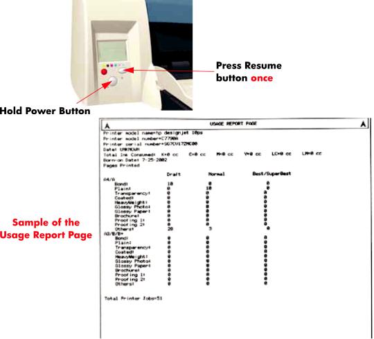
Usage Report Page
The Usage Report Page contains the following information:
●Printer Model Name.
●Printer Model Number.
●Printer Serial Number.
●Date of last print job received.
●Total ink consumed.
●Date of first print job received.
●Number of pages printer (media size/media type/print quality setting).
To print the Usage Report Page, hold the power button down and press the resume button once.
|
2 Chapter 1 Test Prints |
ENWW |
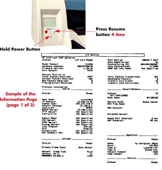
Information Page
The Information Page contains the following information:
●Printer Identification.
●Printer Status.
●Printer Usage.
●Ink Consumable Identification.
●Ink Consumable Status.
●Ink Consumable Usage.
●Network Card Information.
To print the Information Page, hold the power button down and press the resume button four times.
![]()
|
4 Chapter 1 Test Prints |
ENWW |
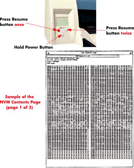
NVM Contents Page
The NVM Contents Page contains the following information:
●EEROM values dump containing all the values stored in the EEROM (Calibration, etc.)
●Printheads Acumen dump
●Cartridges Acumen dump.
To print the NVM Contents Page, hold the power button down and press the cancel button once and the resume button twice.
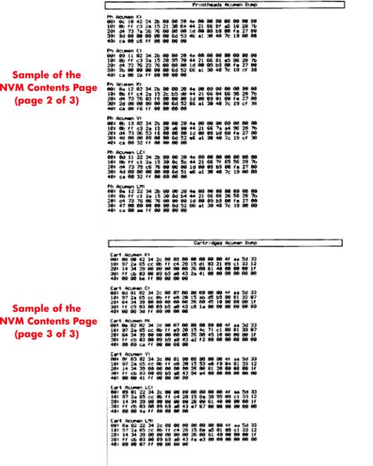
|
6 Chapter 1 Test Prints |
ENWW |

2 System Error Codes
●Introduction
●Errors and Warnings
●System Error Codes
●Warnings
●Startup track mode
●Emergency Firmware Upgrade
●System Error Codes — Explanation

Introduction
The following pages contain a list of system error codes and their respective descriptions and recommended corrective actions. Only try one recommended action at a time and check if the error code has disappeared. Since the front panel can only display graphics, the error code needs to be determined by counting the bars on the front panel (as shown below).
 NOTE: Refer to System Error Codes — Explanation on page 34 for an explanation on the construction of the Error Codes and Warnings.
|
8 Chapter 2 System Error Codes |
ENWW |
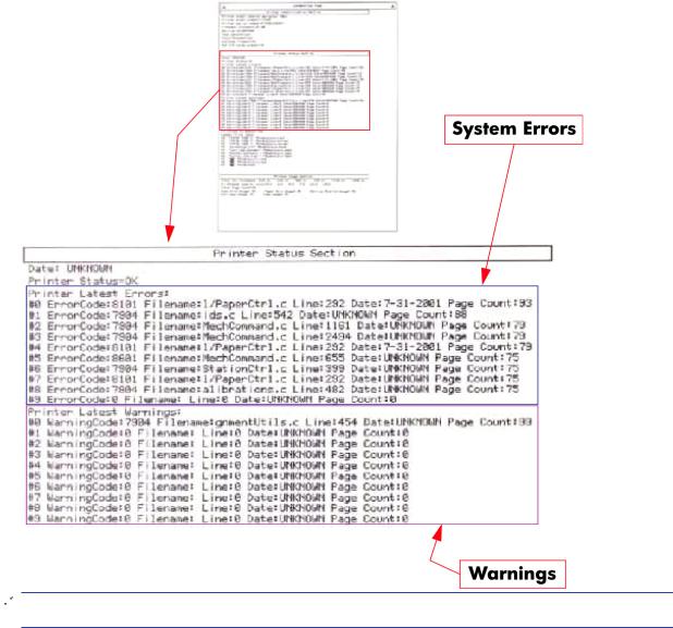
Errors and Warnings
Error Codes will normally be displayed directly on the front panel (but can also be seen on the Information Page) and will require some kind of intervention to resolve the problem. Warnings will not be displayed on the front panel, but will instead only appear on the Information Page, therefore allowing the user to continue operating the printer without the need of an intervention.
 NOTE: You can also obtain report of the System Error and Warnings through the DesignJet System Maintenance Tool.
|
ENWW |
Errors and Warnings 9 |

System Error Codes
 NOTE: Applicable for 111 only: The printer has a MROM module and it is not possible to perform a firmware upgrade, and in fact not required as the printer already has the latest version.
01:10
|
Cause |
Solution |
|
|
Electronics Module failure. |
Replace the Electronics Module |
Electronics Module |
|
on page 109. |
||
|
01:12 |
||
|
Cause |
Solution |
Electronics Module failed during the firmware upgrade OR the Electronics Module failed during initialization.
Try the following:
●If the Electronics Module failed during the firmware upgrade, first perform an emergency firmware upgrade ( Emergency Firmware Upgrade on page 33).
●If an emergency firmware upgrade is NOT possible or it
didn’t work, replace the Electronics Module  Electronics Module on page 109.
02:10
|
Cause |
Solution |
||
|
Carriage failure. |
Replace the Carriage Assembly |
Carriage Assembly |
|
|
(Applicability: 70, 100+, 110+, 111) on page 123. |
|||
|
04:13 |
|||
|
Cause |
Solution |
||
|
Generic Firmware Error (Network Card). |
Unplug the power cable from the printer and wait a few |
||
|
seconds. Plug in the power cable again and check if the Error |
|||
|
Code has disappeared. If the error code continues, refer to the |
|||
|
Jetdirect Card Service Manual and Service Notes. |
|||
|
08:11 |
|||
|
Cause |
Solution |
||
|
Front Panel cannot be detected. |
Try the following: |
||
|
● Check the connections and cables of the Font Panel, |
|||
|
check they have not been damaged and are correctly |
|||
|
connected, disconnect and reconnect the front panel. |
|||
|
● Replace the Front Panel if the problem persists |
Front |
||
|
Panel on page 117. |
|||
|
10 Chapter 2 System Error Codes |
ENWW |
11:10
|
Cause |
Solution |
||
|
Trailing Cable Failure. |
Try the following: |
||
|
● |
Replace the Carriage Assembly |
Carriage Assembly |
(Applicability: 70, 100+, 110+, 111) on page 123.
● If the Error Code continues, replace the Electronics Module  Electronics Module on page 109.
NOTE: Only replace one component at a time and check if the error has gone before replacing another component. Using this procedure you will be able to determine exactly which component failed.
11:11
Trailing Cable is badly connected.
Try the following:
●Reconnect the Trailing Cable correctly to the Electronics Module.
●If the Error Code continues, replace the Carriage
Assembly  Carriage Assembly (Applicability: 70, 100 +, 110+, 111) on page 123.
21:10
|
Cause |
Solution |
||
|
Service Station failure. |
Replace the Service Station Assembly |
Service Station |
|
|
on page 114. |
|||
|
22:10 |
|||
|
Cause |
Solution |
||
|
Ink Supply Station failure. |
Replace the Ink Supply Station |
Ink Supply Station |
|
|
on page 106. |
|||
|
ENWW |
System Error Codes 11 |
No Cleanout Assembly detected while loading media.
Try the following:
●Remove the Cleanout Assembly and install it again correctly.
●Replace the Cleanout Interconnect PCA.
●If the Error Code continues, replace the Cleanout Assembly.
NOTE: Only replace one component at a time and check if the error has gone before replacing another component. Using this procedure you will be able to determine exactly which component failed.
37:01
|
Cause |
Solution |
|
|
Automatic roll motor shutdown. |
Try the following: |
|
|
● |
If this error code was caused by a paper jam, unplug the |
|
|
power cable from the printer and clear the blockage. Plug |
||
|
in the power cable again and check if the Error Code has |
||
|
disappeared. |
||
|
● |
If there is no paper jam or if recovering the paper jam does |
|
|
not resolve the problem, then replace the Automatic Roll |
System (the error could be caused by anything that stalls the motor).
37:10
Automatic roll home position error.
Replace the Automatic Roll System (the error could be caused by anything that causes the home position not to be detected or not to be the correct one — electrical sensors, internal mechanical problems, etc.).
42:10
|
Cause |
Solution |
|
|
Carriage Motor failure (short-circuit). |
Replace the Carriage Motor Assembly |
Carriage Motor |
|
on page 119. |
||
|
12 Chapter 2 System Error Codes |
ENWW |
Error during the calibration of the motor encoder system or a problem finding the zero position on the Encoder Disc.
Try the following:
●Replace the Paper-Axis Motor Drive Assembly  PaperAxis Motor Drive Assembly (Applicable only to 30, 30n) on page 158.
●Replace the Encoder Disc.
NOTE: Make sure you recalibrate the Paper-Axis after replacing the Paper-Axis Motor Drive Assembly or the Encoder Disc.
Only replace one component at a time and check if the error has gone before replacing another component. Using this procedure you will be able to determine exactly which component failed.
Error during the calibration of the Line-feed Motor/Encoder system.
Unplug the power cable from the printer and wait a few seconds. Plug in the power cable again.
Firmware Upgrade or Color Calibration was rejected because the file was sent in the wrong format.
Upgrade the RIP software or the Designjet System Maintenance Tool.
62:04, 63:04, 64:04 and 65:04
|
Cause |
Solution |
|
I/O module error (62 = parallel; 63 = Network; 64 = USB). |
Try the following: |
|
● Unplug the power cable from the printer and wait a few |
|
|
seconds. Plug in the power cable again and check if the |
|
|
Error Code has disappeared. |
|
|
● If the Error Code reappears, upgrade the firmware. |
|
71:03
Generic Firmware Error (Out of memory).
Try the following:
●Unplug the power cable from the printer and wait a few seconds. Plug in the power cable again and check if the Error Code has disappeared.
●If the Error Code reappears, check for a new Firmware release.
|
ENWW |
System Error Codes 13 |
![]()
Memory Management Error (Out of memory during firmware upgrade).
Try the following:
●Unplug the power cable from the printer and wait a few seconds. Plug in the power cable again and check if the Error Code has disappeared.
●If the Error Code reappears, perform an emergency
firmware upgrade ( Emergency Firmware Upgrade on page 33).
72:04
|
Cause |
Solution |
||
|
Generic Firmware Error (expected). |
Try the following: |
||
|
● |
Unplug the power cable from the printer and wait a few |
||
|
seconds. Plug in the power cable again and check if the |
|||
|
Error Code has disappeared. |
|||
|
● |
If the Error Code reappears, check for a new Firmware |
||
|
release. |
|||
|
● |
If possible, request the user to provide the following |
||
|
information which can be found on the information |
|||
|
page: |
|||
|
◦ |
Firmware Release. |
||
|
◦ |
Filename. |
||
|
◦ |
Line. |
||
74:12
Firmware Upgrade Error (Memory size check failed during firmware upgrade).
Try the following:
●Perform the automatic troubleshooting procedure (requires a special firmware upgrade file that must be provided by the manufacturing division).
74:14
|
Cause |
Solution |
|
|
The printer is unavailable to upgrade the firmware.. |
Try the following: |
|
|
● Turn off and on the printer. |
||
|
● Print the Service Page |
||
|
● Check that the firmware is the latest available.: |
||
|
◦ |
Applicable for 110+,110+r,130,130r: If the |
|
|
firmware version is D.05.04, this would indicate that |
||
|
the printer has a MROM module and it is not possible |
to perform a firmware upgrade, and in fact not required as the printer already has the latest version.
|
14 Chapter 2 System Error Codes |
ENWW |

74:14
◦ Applicable for 111 only: The printer has a MROM module and it is not possible to perform a firmware upgrade, and in fact not required as the printer already has the latest version.
79:04
|
Cause |
Solution |
|
|
Generic Firmware Error (unexpected). |
Try the following: |
|
|
● Unplug the power cable from the printer and wait a few |
||
|
seconds. Plug in the power cable again and check if the |
||
|
Error Code has disappeared. |
||
|
● If the Error Code reappears, check for a new Firmware |
||
|
release. |
||
|
● If possible, request the user to provide the following |
||
|
information which can be found on the information |
||
|
page: |
||
|
◦ |
Firmware Release. |
|
|
◦ |
Filename. |
|
|
◦ |
Line. |
|
81:01 
Paper-Axis shutdown — usually a paper-jam caused by a blockage of the Paper-axis System.
Try the following:
●If this error code was caused by a paper-jam, unplug the power cable from the printer and clear the blockage. Plug in the power cable again and check if the Error Code has disappeared
●If this error code appeared but was NOT caused by a paper jam, replace the Paper-Axis Motor Drive Assembly
 Paper-Axis Motor Drive Assembly (Applicable only to 30, 30n) on page 158.
81:12
|
Cause |
Solution |
|
Media Advance error. |
This error usually appears during the paper-advance |
|
calibration — Retry the paper-advance calibration. |
|
|
ENWW |
System Error Codes 15 |
83:10
|
Cause |
Solution |
|||
|
Sheet feeding failure. |
Try the following: |
|||
|
● Replace the Out-Of-paper Sensor. |
||||
|
● |
Replace the Electronics Module |
Electronics Module |
||
|
on page 109. |
||||
|
85:10 |
||||
|
Cause |
Solution |
|||
|
Paper-Axis Encoder error. |
Try the following: |
|||
|
● Make sure that the Encoder Sensor cable is connected |
||||
|
correctly. |
||||
|
● |
Replace the Paper-Axis Motor Drive Assembly |
Paper- |
||
|
Axis Motor Drive Assembly (Applicable only to 30, 30n) |
||||
|
on page 158. |
||||
|
● |
Replace the Electronics Module |
Electronics Module |
||
|
on page 109. |
||||
86:01 
Scan-axis shutdown — usually a paper-jam caused by a blockage of the Scan-axis System.
Try the following:
●Check that there are no obstacles in the Scan-Axis which stops the Carriage from moving freely.
●Too much friction in the Slider Rod, try lubricating the Slider Rod.
●The Carriage is bumping into the Service Station. If the Carriage is stuck at the right hand side of the Printer and cannot be moved out to the center of the Print Platen it is because the Service Station cannot uncap the printheads. In this case replace the Service Station Assembly  Service Station on page 114.
●Check that the belt is correctly installed and not damaged.
●Check that the Turnaround Pulley is correctly installed.
●Replace the Carriage Motor Assembly  Carriage Motor on page 119.
|
16 Chapter 2 System Error Codes |
ENWW |
Scan-axis shutdown during initialization. Typically, this error occurs when the printer detects an incorrect length.
Try the following:
●Unplug the power cable from the printer and wait a few seconds. Plug in the power cable again and check if the Error Code has disappeared.
●Check that the Paper-Axis Drive Motor Assembly is correctly installed and that the bushing is correctly locked into position.
●Check that the Carriage moves freely and DOES NOT bump into the Service Station.
●If the Printheads are not installed, maybe the carriage cover is not closed completely.
●If the Error Code continues, replace the Carriage
Assembly  Carriage Assembly (Applicability: 70, 100+, 110+, 111) on page 123.
Warnings
01:11
|
Cause |
Solution |
|
|
The Electronics Module is incorrectly positioned. |
Reseat the Electronics Module by Removing it from the Printer |
|
|
Electronics Module on page 109 and installing it again in |
||
|
the correct position. |
||
|
01:12 |
||
|
Cause |
Solution |
|
|
Electronics Module Error. |
The Electronics Module EEPROM is flagged as empty and |
|
|
must be upgraded with the contents of the Carriage EEPROM, |
||
|
but the Carriage is also flagged as empty. The backup is not |
||
|
performed. This is the result of an error during the |
||
|
manufacturing or the repair process. Therefore the Electronics |
||
|
Module must be reconfigured. |
||
|
02:10 |
||
|
Cause |
Solution |
|
|
Carriage failure. |
Replace the Carriage Assembly |
Carriage Assembly |
|
(Applicability: 70, 100+, 110+, 111) on page 123. |
||

Black Color Calibration Failure — Black Color Calibration cancelled.
Try the following:
●Clean the electrical contacts on the black printhead.
●If the error code continues, replace the black printhead.
Cyan Color Calibration Failure — Cyan Color Calibration cancelled.
Try the following:
●Clean the electrical contacts on the cyan printhead.
●If the error code continues, replace the cyan printhead.
272:00
|
Cause |
Solution |
|
Magenta Color Calibration Failure — Magenta Color Calibration |
Try the following: |
|
cancelled. |
● Clean the electrical contacts on the magenta printhead. |
|
● If the error code continues, replace the magenta |
|
|
printhead. |
|
273:00
Yellow Color Calibration Failure — Yellow Color Calibration cancelled.
Try the following:
●Clean the electrical contacts on the yellow printhead.
●If the error code continues, replace the yellow printhead.
274:00 (Not applicable to HP DesignJet 70, 100, 100+, 110+)
Light Cyan Color Calibration Failure — Light Cayan Color Calibration cancelled.
Try the following:
●Clean the electrical contacts on the light cyan printhead.
●If the error code continues, replace the light cyan printhead.
|
18 Chapter 2 System Error Codes |
ENWW |
275:00 (Not applicable to HP DesignJet 70, 100, 100+, 110+)
Light Magenta Color Calibration Failure — Light Magenta Color Calibration cancelled.
Try the following:
●Clean the electrical contacts on the light magenta printhead.
●If the error code continues, replace the light magenta printhead.
35:01
|
Cause |
Solution |
||
|
No Cleanout Assembly (or Duplexer, if installed) detected |
Try the following: |
||
|
while loading media. |
● Remove the Cleanout Assembly ( Cleanout |
||
|
Assembly on page 120) (or Duplexer, if installed) and |
|||
|
install it again correctly. |
|||
|
● Replace the Duplexer Interconnect PCA. |
|||
|
● If the Error Code continues, replace the Cleanout |
|||
|
Assembly |
Cleanout Assembly on page 120. |
||
|
58:10 |
|||
|
Cause |
Solution |
||
|
Problem detected in the color sensor system. |
Replace the Carriage Assembly |
Carriage Assembly |
|
|
(Applicability: 70, 100+, 110+, 111) on page 123. |
|||
|
61:05 |
|||
|
Cause |
Solution |
Language interpreting error. This is usually and error produced while parsing a file. There is probably an incompatibility between the driver and the firmware.
Upgrade the RIP software or the Designjet System Maintenance Tool.
65:01
|
Cause |
Solution |
|
Communication Failure. |
Try the following: |
|
● Unplug the power cable from the printer and check the |
|
|
cable connections (Parallel, USB and Network cables). |
|
|
Plug in the power cable again and check if the Error Code |
|
|
has disappeared. |
|

66:02:1 (Only applicable to HP DesignJet 30, 30n, 90, 90r, 130, 130nr)
Horizontal clipping. May happen when the roll ends in the middle of printing an image. Could also happen when multipick occurs and two sheets are loaded together and they do not completely overlap.
Make sure the image size is within the selected WIDTH of the sheet.
66:02:2 (Only applicable to HP DesignJet 30, 30n, 90, 90r, 130, 130nr)
Vertical clipping. May happen when the roll ends in the middle of printing an image. Could also happen when multi-pick occurs and two sheets are loaded together and they do not completely overlap.
Make sure the image size is within the selected LENGTH of the sheet.
Out-of-memory while trying to process the firmware upgrade file. Probably this is a firmware bug, because the firmware should free up enough memory to perform the firmware upgrade process correctly.
Perform an emergency firmware upgrade ( Emergency Firmware Upgrade on page 33) .
74:12
|
Cause |
Solution |
|
|
Firmware bug in the firmware upgrade process |
Try the following: |
|
|
● Download the special file in order to update the bootlog. |
||
|
● If possible, request the user to provide the following |
||
|
information which can be found on the information |
||
|
page: |
||
|
◦ |
Firmware Release. |
|
|
◦ |
Printer Serial Number. |
|
|
74:14 |
||
|
Cause |
Solution |
|
|
The printer is unavailable to upgrade the firmware.. |
Try the following: |
|
|
● Turn off and on the printer. |
||
|
● Print the Service Page |
||
|
● Check that the firmware is the latest available.: |
||
|
◦ |
Applicable for 110+,110+r,130,130r: If the |
|
|
firmware version is D.05.04, this would indicate that |
||
|
the printer has a MROM module and it is not possible |
||
|
20 Chapter 2 System Error Codes |
ENWW |

74:14
to perform a firmware upgrade, and in fact not required as the printer already has the latest version.
◦ Applicable for 111 only: The printer has a MROM module and it is not possible to perform a firmware upgrade, and in fact not required as the printer already has the latest version.
81:01 
Paper-Axis shutdown — usually a paper-jam caused by a blockage of the Paper-axis System.
Try the following:
●If this error code was caused by a paper-jam, unplug the power cable from the printer and clear the blockage. Plug in the power cable again and check if the Error Code has disappeared.
●If this error code appeared but was NOT caused by a paper jam, replace the Paper-Axis Motor Drive Assembly
 Paper-Axis Motor Drive Assembly (Applicable only to 30, 30n) on page 158.
83:01:1 (Only applicable to HP DesignJet 30, 30n, 70, 100+, 110+, 111, 90, 90r,, 130, 130nr)
The paper is rejected from the Bypass due to skew.
When manually loading paper from the front of the paper, make sure that it is loaded straight.
83:01:3 (Only applicable to HP DesignJet 70/100plus/110plus, 111 with Roll)
The paper is rejected from the roll due to skew.
When loading paper from the roll, make sure that it is loaded straight.
94:02:1 (Only applicable to HP DesignJet 30, 30n, 90, 90r, 130, 130nr, 111)
User selected Coated Paper and Best mode, but the Color Calibration profile was obsolete or missing for Coated Paper and the selected print quality setting.
Using the System Maintenance Tool, perform Color Calibration for Coated Paper and the selected print quality setting.
94:02:3 (Only applicable to HP DesignJet 30, 30n, 90, 90r, 130, 130nr, 111)
User selected Photo Paper and Best mode, but the Color Calibration profile was obsolete or missing for Photo Paper and the selected print quality setting.
Using the System Maintenance Tool, perform Color Calibration for Photo Paper and the selected print quality setting.

94:02:4 (Only applicable to HP DesignJet 30, 30n, 90, 90r, 130, 130nr)
User selected Heavy-Weight Coated Paper and Best mode, but the Color Calibration profile was obsolete or missing for Heavy-Weight Coated Paper and the selected print quality setting.
Using the System Maintenance Tool, perform Color Calibration for HeavyWeight Coated Paper and the selected print quality setting.
94:02:5 (Only applicable to HP DesignJet 30, 30n, 90, 90r, 130, 130nr)
User selected Proofing Semi-Gloss Paper and Best mode, but the Color Calibration profile was obsolete or missing for Proofing Semi-Gloss Paper and the selected print quality setting
Using the System Maintenance Tool, perform Color Calibration for Proofing Semi-Gloss Paper and the selected print quality setting.
94:02:6 (Only applicable to HP DesignJet 30, 30n, 90, 90r, 130, 130nr)
User selected Photo Matte Paper and Best mode, but the Color Calibration profile was obsolete or missing for Photo Matte Paper and the selected print quality setting.
Using the System Maintenance Tool, perform Color Calibration for Photo Matte Paper and the selected print quality setting.
94:02:7 (Only applicable to HP DesignJet 30, 30n, 90, 90r, 130, 130nr)
User selected Photo Satin Paper and Best mode, but the Color Calibration profile was obsolete or missing for Photo Satin Paper and the selected print quality setting.
Using the System Maintenance Tool, perform Color Calibration for Photo Satin Paper and the selected print quality setting.
94:02:8 (Only applicable to HP DesignJet 30, 30n, 90, 90r, 130, 130nr)
User selected Coated Paper and Max dpi, but the Color Calibration profile was obsolete or missing for Coated Paper and the selected print quality setting.
Using the System Maintenance Tool, perform Color Calibration for Coated Paper and the selected print quality setting.
941:02:1 (Only applicable to HP DesignJet 30, 30n, 90, 90r, 130, 130nr)
User selected Photo Paper and Max dpi, but the Color Calibration profile was obsolete or missing for Photo Paper and the selected print quality setting.
Using the System Maintenance Tool, perform Color Calibration for Photo Paper and the selected print quality setting.
|
22 Chapter 2 System Error Codes |
ENWW |

941:02:2 (Only applicable to HP DesignJet 30, 30n, 90, 90r, 130, 130nr)
User selected Heavy-Weight Coated Paper and Max dpi, but the Color Calibration profile was obsolete or missing for HeavyWeight Coated Paper and the selected print quality setting.
Using the System Maintenance Tool, perform Color Calibration for HeavyWeight Coated Paper and the selected print quality setting.
941:02:3 (Only applicable to HP DesignJet 30, 30n, 90, 90r, 130, 130nr)
User selected Proofing Semi-Gloss Paper and Max dpi mode, but the Color Calibration profile was obsolete or missing for Proofing Semi-Gloss Paper and the selected print quality setting.
Using the System Maintenance Tool, perform Color Calibration for Proofing Semi-Gloss Paper and the selected print quality setting.
941:02:4 (Only applicable to HP DesignJet 30, 30n, 90, 90r, 130, 130nr)
User selected Photo Matte Paper and Max dpi mode, but the Color Calibration profile was obsolete or missing for Photo Matte Paper and the selected print quality setting.
Using the System Maintenance Tool, perform Color Calibration for Photo Matte Paper and the selected print quality setting.
941:02:5 (Only applicable to HP DesignJet 30, 30n, 90, 90r, 130, 130nr)
User selected Photo Satin Paper and Max dpi mode, but the Color Calibration profile was obsolete or missing for Photo Satin Paper and the selected print quality setting.
Using the System Maintenance Tool, perform Color Calibration for Photo Satin Paper and the selected print quality setting.
Firmware Error (during color calibration).
Try the following:
●Unplug the power cable from the printer and wait a few seconds. Plug in the power cable again and check if the Error Code has disappeared.
●If the Error Code reappears, check for a new Firmware release.
Color Calibration Warning — Color Calibration not cancelled but Color Calibration values are likely to be incorrect.
Try the Color Calibration again, but this time using a different type of media (preferably HP media).
![]()
Color Calibration Failure — Color Calibration cancelled.
Try the following:
●Unplug the power cable from the printer and wait a few seconds. Plug in the power cable again and try the Color Calibration again.
●If this error code appears again, check the Color Calibration print:
|
◦ |
If the Color Calibration was printed correctly without |
|||
|
any print defects, then check that the media is |
||||
|
moving freely (backwards and forwards) while the |
||||
|
printer is scanning it. |
||||
|
◦ |
If the Color Calibration was printed incorrectly, with |
|||
|
some print defects, replace the faulty Printhead of |
||||
|
the color where the defects were noticeable. |
||||
|
◦ |
If the Error Code continues, replace the Carriage |
|||
|
Assembly |
Carriage Assembly (Applicability: 70, |
|||
|
100+, 110+, 111) on page 123. |
||||
|
95:00 |
||||
|
Cause |
Solution |
|||
|
Printhead Alignment Failure — Printhead Alignment cancelled. Try the following: |
||||
|
● |
Clean the printhead indicated by the printer. |
|||
|
● |
If the error code continues, replace the faulty printhead. |
|||
|
95:02 |
||||
|
Cause |
Solution |
|||
|
Printhead Alignment Failure — Printhead Alignment cancelled. Try the following: |
||||
|
● |
Unplug the power cable from the printer and wait a few |
|||
|
seconds. Plug in the power cable again and try the |
||||
|
Printhead Alignment again. |
||||
|
● |
If this error code appears again, check the Printhead |
|||
|
Alignment print: |
||||
|
◦ |
If the Printhead Alignment was printed correctly |
|||
|
without any print defects, then check that the media |
||||
|
is moving freely (backwards and forwards) while the |
||||
|
printer is scanning it. |
||||
|
◦ |
If the Printhead Alignment was printed incorrectly, |
|||
|
with some print defects, replace the faulty Printhead |
||||
|
of the color where the defects were noticeable. |
||||
|
95:04 |
||||
|
Cause |
Solution |
|||
|
Firmware Error (during Printhead Alignment). |
Upgrade the printer to the latest firmware release. |
|||
|
24 Chapter 2 System Error Codes |
ENWW |

Startup track mode
Introduction
The startup track mode is designed to enable you to identify a failing subsystems while the printer is initializing. Startup track mode provides a specific indication of which particular subsystem is failing. This mode is not intended for use by end-users.
Initializing the printer in Startup track mode
To initialize the printer in Startup track mode:
1.Hold the ’Continue’ button while connecting the printer to the power supply.
2.During the initialization of the printer, the front panel will display a range of code numbers in the form of squares, these code numbers added together represent the various subsystems about to be initialized.
3.Once the printer comes to initializing the failing subsystem, the front panel will hang, and all that will be displayed is the failing subsystem.
Interpreting the numbered code system
While the printer is initializing, the front panel will display a sequence of squares in the last two columns. Each position in the last two columns represents a number, all the numbers represented are shown below. To find the failing subsystem, add the numbers together that have a square and refer to the list of numbers with their associated subsystems on Subsystem Code Description on page 25.
In the example below the printer is initializing and the front panel has stopped and is displaying squares in positions 16, 32, 64, and 4. Add these four values together and you get 116, refer to the list on Subsystem Code Description on page 25, and we can see the failing subsystem is the Trailing Cable.
If the display reaches 191, you will need to turn On the printer from the power button. If all the subsystems pass the initialization, the printer will initialize normally and go to the ready status.
Subsystem Code Description
This is the list of the subsystems and their associated Startup Track Numbers. Many of the descriptions of the Subsystems will not be immediately obvious, when this is the case contact the lfp help desk and they can assist you.
Table 2-1 Subsystem code description
Startup track number: Associated Subsystem
|
ENWW |
Startup track mode 25 |

Table 2-1 Subsystem code description (continued)
Startup Track 004: Calling EiffelMain
Startup Track 005: Initializing Classes
Startup Track 006: Initializing SM
Startup Track 007: Initializing Memory
Startup Track 008: Initializing MemoryVolatile
Startup Track 009: Initializing MemoryEndian
Startup Track 010: Initializing MemoryVolatileEndian
Startup Track 011: Initializing Impala
Startup Track 012: Initializing ColdFire
Startup Track 013: Initializing ImpalaInterruptController
Startup Track 014: Initializing MechProcTaskHiIntA
Startup Track 015: Initializing IsardInterruptA
Startup Track 016: Initializing Watchdog
Startup Track 017: Initializing Chronometer
Startup Track 018: Initializing EddTimer
Startup Track 019: Initializing IsardInterruptB
Startup Track 020: Initializing PciSlot2Interrupt
Startup Track 021: Initializing PciSlot3Interrupt
Startup Track 022: Initializing PciSlot4Interrupt
Startup Track 023: Initializing PciSlot5Interrupt
Startup Track 024: Initializing MagentaFireLow
Startup Track 025: Initializing BongoGpio
Startup Track 026: Initializing SecondTraySensor
Startup Track 027: Initializing CleanoutSensor
Startup Track 028: Initializing RearPathPaperSensor
Startup Track 029: Initializing BlackCartridgeSensor
Startup Track 030: Initializing CyanCartridgeSensor
Startup Track 031: Initializing MagentaCartridgeSensor
Startup Track 032: Initializing YellowCartridgeSensor
Startup Track 033: Initializing LightMagentaCartridgeSensor
Startup Track 034: Initializing LightCyanCartridgeSensor
Startup Track 035: Initializing SynergyReset
Startup Track 036: Initializing FrontPanelReset
Startup Track 037: Initializing PowerFan
Startup Track 038: Initializing FrontPanelInterrupt
Startup Track 039: Initializing CoverWindowSensor
Startup Track 040: Initializing nUSB_ENABLE
Startup Track 041: Initializing USB_CONNECT
|
26 Chapter 2 System Error Codes |
ENWW |

Table 2-1 Subsystem code description (continued)
Startup Track 042: Initializing TrailingCable3Sensor
Startup Track 043: Initializing TrailingCable12Sensor
Startup Track 044: Initializing PrintheadSensor
Startup Track 045: Initializing BongoBrake
Startup Track 046: Initializing Dma
Startup Track 047: Initializing BongoEncoder
Startup Track 048: Initializing ServiceStationEncoder
Startup Track 049: Initializing SSPwm
Startup Track 050: Initializing PaperPwm
Startup Track 051: Initializing RampPwm
Startup Track 052: Initializing CarriagePwmForward
Startup Track 052: Initializing CarriagePwmForward
Startup Track 054: Initializing BomboPwm
Startup Track 055: Initializing EddPwm
Startup Track 056: Initializing ImpalaCarriagePosition
Startup Track 057: Initializing I2c0
Startup Track 058: Initializing I2c1
Startup Track 059: Initializing I2c2
Startup Track 060: Initializing I2c3
Startup Track 061: Initializing Darwin
Startup Track 062: Initializing PciCtrl
Startup Track 063: Initializing PciDma
Startup Track 064: Initializing MBandToPixel
Startup Track 065: Initializing PixelData
Startup Track 066: Initializing BlackCSData
Startup Track 067: Initializing CyanCSData
Startup Track 068: Initializing MagentaCSData
Startup Track 069: Initializing YellowCSData
Startup Track 070: Initializing LightCyanCSData
Startup Track 071: Initializing LightMagentaCSData
Startup Track 072: Initializing BlackPrintHead
Startup Track 073: Initializing CyanPrintHead
Startup Track 074: Initializing MagentaPrintHead
Startup Track 075: Initializing YellowPrintHead
Startup Track 076: Initializing LightCyanPrintHead
Startup Track 077: Initializing LightMagentaPrintHead
Startup Track 078: Initializing BlockBlack
Startup Track 079: Initializing BlockColor
|
ENWW |
Startup track mode 27 |

Table 2-1 Subsystem code description (continued)
Startup Track 080: Initializing ContoneToRaster
Startup Track 081: Initializing Enhancer
Startup Track 082: Initializing RasterToMband
Startup Track 083: Initializing MechProcA
Startup Track 084: Initializing MemoryUncached
Startup Track 085: Initializing Isard
Startup Track 086: Initializing IsardInterruptController
Startup Track 087: Initializing PaperInterrupt
Startup Track 088: Initializing IsardPMTimer
Startup Track 089: Initializing IsardKFort
Startup Track 090: Initializing IsardCarriagePosition
Startup Track 091: Initializing IsardPaperPosition
Startup Track 092: Initializing MediaPosition
Startup Track 093: Initializing PaperEncoderPosition
Startup Track 094: Initializing IsardMotorShortcut
Startup Track 095: Initializing Eridani
Startup Track 096: Initializing EddOn
Startup Track 097: Initializing ServiceStationLed
Startup Track 098: Initializing FetRegulator
Startup Track 099: Initializing EddOut
Startup Track 100: Initializing DuplexerConversor
Startup Track 101: Initializing EridaniConversorAuto
Startup Track 102: Initializing EridaniConversorAB
Startup Track 103: Initializing EridaniConversorAnA
Startup Track 104: Initializing EridaniConversorBnB
Startup Track 105: Initializing PaperDriver
Startup Track 106: Initializing ServiceStationDriver
Startup Track 107: Initializing RampDriver
Startup Track 108: Initializing DuplexerSensor
Startup Track 109: Initializing PaperMotorHw
Startup Track 110: Initializing CarriageMotorHw
Startup Track 111: Initializing ServiceStationMotorHw
Startup Track 112: Initializing BongoEncoderWindowHw
Startup Track 113: Initializing BongoMotorHw
Startup Track 114: Initializing RampMotorHw
Startup Track 115: Initializing FrontPanelHw
Startup Track 116: Initializing TrailingCable
Startup Track 117: Initializing CarriageBoardHw
|
28 Chapter 2 System Error Codes |
ENWW |

Table 2-1 Subsystem code description (continued)
Startup Track 118: Initializing SynergyA
Startup Track 119: Initializing VPPA
Startup Track 120: Initializing VPPB
Startup Track 121: Initializing SynergyInternalRegulatorA
Startup Track 122: Initializing Led1Voltage
Startup Track 123: Initializing EndeavourA
Startup Track 124: Initializing EndeavourAcumenA
Startup Track 125: Initializing CLC_Channel0
Startup Track 126: Initializing CLC_Channel1
Startup Track 127: Initializing CLC_Channel2
Startup Track 128: Initializing EndeavourVRefConversor
Startup Track 129: Initializing CLC_ChannelDACConversor
Startup Track 130: Initializing IS_Channel3Conversor_A
Startup Track 131: Initializing CLC_Channel0Conversor
Startup Track 132: Initializing CLC_Channel1Conversor
Startup Track 133: Initializing CLC_Channel2Conversor
Startup Track 134: Initializing Led2Voltage
Startup Track 135: Initializing Black5V
Startup Track 136: Initializing Yellow5V
Startup Track 137: Initializing Magenta5V
Startup Track 138: Initializing Cyan5V
Startup Track 139: Initializing Black12V
Startup Track 140: Initializing Yellow12V
Startup Track 141: Initializing Magenta12V
Startup Track 142: Initializing Cyan12V
Startup Track 143: Initializing VPen_Current_Sense_A
Startup Track 144: Initializing VPen_OV_Latch_A
Startup Track 145: Initializing VPen_OV_Clear_Latch_A
Startup Track 146: Initializing VPen_UV_Latch_A
Startup Track 147: Initializing VPen_UV_Clear_Latch_A
Startup Track 148: Initializing VPen_OV_Present_A
Startup Track 149: Initializing VPen_UV_Present_A
Startup Track 150: Initializing EndeavourB
Startup Track 151: Initializing EndeavourAcumenB
Startup Track 152: Initializing IS_Channel3Conversor_B
Startup Track 153: Initializing Led3Voltage
Startup Track 154: Initializing LightMagenta5V
Startup Track 155: Initializing LightCyan5V
|
ENWW |
Startup track mode 29 |

Table 2-1 Subsystem code description (continued)
Startup Track 156: Initializing LightMagenta12V
Startup Track 157: Initializing LightCyan12V
Startup Track 158: Initializing VPen_Current_Sense_B
Startup Track 159: Initializing VPen_OV_Latch_B
Startup Track 160: Initializing VPen_OV_Clear_Latch_B
Startup Track 161: Initializing VPen_UV_Latch_B
Startup Track 162: Initializing VPen_UV_Clear_Latch_B
Startup Track 163: Initializing VPen_OV_Present_B
Startup Track 164: Initializing VPen_UV_Present_B
Startup Track 165: Initializing Eerom
Startup Track 166: Initializing EeromCarriage
Startup Track 167: Initializing PrintheadControl
Startup Track 168: Initializing BlackPrintheadAcumen
Startup Track 169: Initializing CyanPrintheadAcumen
Startup Track 170: Initializing MagentaPrintheadAcumen
Startup Track 171: Initializing YellowPrintheadAcumen
Startup Track 172: Initializing LightCyanPrintheadAcumen
Startup Track 173: Initializing LightMagentaPrintheadAcumen
Startup Track 174: Initializing BlackCartridgeAcumen
Startup Track 175: Initializing CyanCartridgeAcumen
Startup Track 176: Initializing MagentaCartridgeAcumen
Startup Track 177: Initializing YellowCartridgeAcumen
Startup Track 178: Initializing LightCyanCartridgeAcumen
Startup Track 179: Initializing LightMagentaCartridgeAcumen
Startup Track 180: Initializing ColorSensor
Startup Track 181: Initializing ColorSensorLed1
Startup Track 182: Initializing ColorSensorLed2
Startup Track 183: Initializing ColorSensorLed3
Startup Track 184: Initializing ColorSensorConverso
Startup Track 185: Initializing ColorSensorConversorB
Startup Track 186: Initializing ColorSensorConversorC
Startup Track 187: Initializing V5_V12_ISDetection
Startup Track 188: Initializing VPP_ISDetection
Startup Track 189: Initializing InterruptController
Startup Track 190: SM Initialized
Startup Track 191: Back from EiffelMain!!!
PRESS POWER BUTTON HERE!!
Startup Track 192: Initializing VPPA
|
30 Chapter 2 System Error Codes |
ENWW |

Table 2-1 Subsystem code description (continued)
Startup Track 193: Initializing VPPB
Startup Track 194: Initializing SynergyInternalRegulatorA
Startup Track 195: Initializing Led1Voltage
Startup Track 196: Initializing EndeavourAcumenA
Startup Track 197: Initializing CLC_Channel0
Startup Track 198: Initializing CLC_Channel1
Startup Track 199: Initializing CLC_Channel2
Startup Track 200: Initializing EndeavourVRefConversor
Startup Track 201: Initializing CLC_ChannelDACConversor
Startup Track 202: Initializing IS_Channel3Conversor_A
Startup Track 203: Initializing CLC_Channel0Conversor
Startup Track 204: Initializing CLC_Channel1Conversor
Startup Track 205: Initializing CLC_Channel2Conversor
Startup Track 206: Initializing Led2Voltage
Startup Track 207: Initializing Black5V
Startup Track 208: Initializing Yellow5V
Startup Track 209: Initializing Magenta5V
Startup Track 210: Initializing Cyan5V
Startup Track 211: Initializing Black12V
Startup Track 212: Initializing Yellow12V
Startup Track 213: Initializing Magenta12V
Startup Track 214: Initializing Cyan12V
Startup Track 215: Initializing VPen_Current_Sense_A
Startup Track 216: Initializing VPen_OV_Latch_A
Startup Track 217: Initializing VPen_OV_Clear_Latch_A
Startup Track 218: Initializing VPen_UV_Latch_A
Startup Track 219: Initializing VPen_UV_Clear_Latch_A
Startup Track 220: Initializing VPen_OV_Present_A
Startup Track 221: Initializing VPen_UV_Present_A
Startup Track 222: Initializing EndeavourAcumenB
Startup Track 223: Initializing IS_Channel3Conversor_B
Startup Track 224: Initializing Led3Voltage
Startup Track 225: Initializing LightMagenta5V
Startup Track 226: Initializing LightCyan5V
Startup Track 227: Initializing LightMagenta12V
Startup Track 228: Initializing LightCyan12V
Startup Track 229: Initializing VPen_Current_Sense_B
Startup Track 230: Initializing VPen_OV_Latch_B
|
ENWW |
Startup track mode 31 |

Table 2-1 Subsystem code description (continued)
Startup Track 231: Initializing VPen_OV_Clear_Latch_B
Startup Track 232: Initializing VPen_UV_Latch_B
Startup Track 233: Initializing VPen_UV_Clear_Latch_B
Startup Track 234: Initializing VPen_OV_Present_B
Startup Track 235: Initializing VPen_UV_Present_B
|
32 Chapter 2 System Error Codes |
ENWW |

Emergency Firmware Upgrade
1.Unplug the power cord from the printer and wait a few seconds.
2.Press and hold the Cancel (red) button while plugging in the power cord.
3.The printer will initialize in emergency mode (the front panel will display just the arrow icon).
4.Connect the printer to the computer with a parallel cable.
5.Send the firmware file through the parallel port from the DOS command prompt. Type: copy /b firmware_file lpt1: and then press ENTER.
|
ENWW |
Emergency Firmware Upgrade 33 |
![]()
System Error Codes — Explanation
System Error Codes explain which component/system is failing and what action should be taken to resolve the problem.
System Error Codes are displayed directly on the front panel (but can also be seen on the Information Page) and have been defined in the format XX.YZ.
Warnings will not be displayed on the front panel, but will instead only appear on the Information Page and have been defined in the format XXn.YZ.m.
●XX: Service Part (2 digits).
●n: Service Part Index (if more than one used in the product) — Optional.
◦e.g. Identify the Ink Supply (color and number).
●Y: Who should perform the action (1 digit) — (User or Service Engineer).
●Z: Action to perform (1 digit).
●m: additional actions/information to consider (1 digit) — Optional.
◦e.g. Non-authorized ink was detected, PM was triggered or Printhead in/out of Warranty. The following table explains the XX part of the System Error Code or Warning:
 NOTE: Items denoting * (Asterisk) are not applicable to the printers.
Table 2-2 System error codes
|
Code |
Component/System |
|
01 |
Main PCA/Electronics Module |
|
02 |
Carriage/Carriage PCA |
|
03 |
Power Supply Unit |
|
04 |
Network Card |
|
05 |
Formatter * |
|
06 |
Hard Disk Drive * |
|
07 |
Interconnect PCA |
|
08 |
Front Panel |
|
11 |
Trailing Cable |
|
12 |
Carriage Flex Circuit |
|
17 |
Interconnect Cable |
|
21 |
Service Station |
|
22 |
Ink Supply Station |
|
23 |
Pressure System (APS) * |
|
24 |
Ink Delivery Tubes |
|
25 |
Spittoon * |
|
26n |
Ink Cartridge (color n) |
|
26n |
Printhead (color n) |
|
31 |
Cutter |
|
34 Chapter 2 System Error Codes |
ENWW |
Table 2-2 System error codes (continued)
|
32 |
Take-up Reel * |
|
33 |
Sheet Feeder |
|
34 |
Dryer/Blower * |
|
35 |
Cleanout Assembly |
|
36 |
Duplexer |
|
37 |
ARSS/Rollfeed |
|
38 |
Output Tray |
|
41 |
Paper-Axis Motor |
|
42 |
Scan-Axis Motor |
|
43 |
Vacuum Fan * |
|
44 |
Aerosol fan * |
|
51 |
Window Sensor |
|
52 |
Drop Detector * |
|
53 |
Media Sensor |
|
54 |
Pinch-Arm Sensor |
|
55 |
Line Sensor |
|
56 |
Drive Roller Encoder Sensor |
|
57 |
Ink Leak Detector * |
|
58 |
Color Sensor * |
|
59 |
Media Type Sensor * |
|
61 |
Language Interpreting |
|
62 |
Input/Output through Parallel Port |
|
63 |
Input/Output through Network Card |
|
64 |
Input/Output through USB Port |
|
65 |
Input/Output (not know what port) |
|
66 |
Print Job Configuration |
|
71 |
Print Job Configuration |
|
72 |
Generic Firmware |
|
73 |
Motor Control Functions |
|
74 |
Motor Control Functions 74 Firmware Upgrade |
|
79 |
Firmware Crash |
|
81 |
Media Advance |
|
82 |
Media Cut * |
|
83 |
Single-Sheet Feeding |
|
84 |
Roll Feeding * |
|
85 |
Media-Axis Encoder Reading |
|
86 |
Carriage Movement |
|
87 |
Scan-Axis Encoder Reading |
|
ENWW |
System Error Codes — Explanation 35 |
Table 2-2 System error codes (continued)
|
91 |
Printhead Firing |
|
92 |
Servicing |
|
93 |
Ink Pumping |
|
94 |
Ink Pumping |
|
95 |
Printhead Alignment |
|
96 |
Image Quality Troubleshooting |
The following table explains the YZ part of the System Error Code or Warning:
Table 2-3 System error codes
|
Code |
Response |
Response |
|
|
00 |
Replace |
||
|
01 |
Reseat/Reconnect/Clean/Adjust (manually) |
||
|
02 |
Calibrate/Adjust (using Automatic Process) |
||
|
03 |
Power OFF |
||
|
04 |
Upgrade System Firmware |
Possible for customer |
|
|
05 |
Upgrade Driver |
to perform action |
|
|
06 |
Add Accessory |
||
|
07 |
Escalate |
||
|
08 |
Send Plot Again |
||
|
09 |
Wrong Part Installed |
||
|
10 |
Replace |
||
|
11 |
Reseat/Reconnect/Clean/Adjust (manually) |
||
|
12 |
Calibrate/Adjust (using Automatic Process) |
||
|
13 |
Power OFF |
||
|
HP qualified |
|||
|
14 |
Upgrade System Firmware |
||
|
personnel assistance |
|||
|
15 |
Upgrade Driver |
||
|
required |
|||
|
16 |
Add Accessory |
||
|
17 |
Escalate |
||
|
18 |
Send Plot Again |
||
|
19 |
Wrong Part Installed |
||
|
36 Chapter 2 System Error Codes |
ENWW |

3 System Maintenance Utility
●Introduction
●Launching the System Maintenance Utility
●System Maintenance Utility (Designjet 30, 30n, 70, 90, 90r, 110plus, 111, 130, 130nr)

Introduction
The System Maintenance Utility is designed to assist the customer with common maintenance tasks for the printer and also to resolve common problems that they may encounter.
 NOTE: Print jobs must not be sent to the printer while the system maintenance utility is in use.
Since the design of the System Maintenance Tool is different between the Designjet 120/120nr and Designjet 130/130, this chapter will explain how to use the tool for each product separately:
Launching the System Maintenance Utility
The procedures described here are applicable to the following printers: HP Designjet 30, 30n, 70, 90, 90r, 100+, 110+r, 110+nr, 111 with roll, 111 with tray, 130, 130r, 130nr:
There are two ways of launching the System Maintenance Utility.
From your computer’s desktop (Windows, Mac OS 9 and X)
1.Double click the hp designjet system maintenance icon on the desktop.
2.A printer selector window opens — select your printer from the list.
3.Click Next (in Windows) or Configure (in Mac OS).
From the Printer Driver (Windows, Mac OS X)
●In the Windows driver click the hp designjet system maintenance icon in the Services tab.
|
38 Chapter 3 System Maintenance Utility |
ENWW |

●In Mac OS X, select the Printer in the Print Center or Print Setup Utility and click configure.
 NOTE: When you finish using the System Maintenance Utility, you must click on exit on the left hand column before closing the browser.
|
ENWW |
Launching the System Maintenance Utility 39 |

System Maintenance Utility (Designjet 30, 30n, 70, 90, 90r, 110plus, 111, 130, 130nr)
Main Menu — Printer Front Panel Replication
The main page of the System Maintenance Utility includes a replica of the Printer’s Front Panel showing the status of the Printer.
 NOTE: The replica Front Panel does not show the real-time status. It is a snapshot which can be refreshed by pressing the refresh button either on the web browser toolbar or in the actual replica window.
Color Calibration
 NOTE: The Color Calibration is only available for the following printers: HP Designjets 30, 30n, 90, 90r, 130, 130nr. It is not available for the HP Designjets 70, 110plus, 111.
NOTE: The Color Calibration should ONLY be performed by the user when required.
|
Question |
Answer |
|
Why calibrate color? |
Calibrate color performs a maintenance function to ensure |
|
color consistency. If you calibrate correctly, the colors printed |
|
|
on printers with different printheads will look very similar. |
This picture shows an exaggerated example of how a printout could look like before and after color calibration.
|
40 Chapter 3 System Maintenance Utility |
ENWW |

|
Question |
Answer |
|
When do I calibrate color? |
It is recommended that you calibrate color every time you |
|
replace a printhead or when you perceive color degradation on |
|
|
the printouts. There is no need to perform this operation each |
|
|
time you print. The results of the color calibration will be applied |
|
|
to all print jobs that follow, even if you power off the printer. |
|
|
Perform color calibration if you print with the regular hp |
|
|
designjet 120 printer driver, which was included with the printer |
|
|
or which you downloaded from the Web. If you use a PostScript |
|
|
driver such as Adobe PS or LaserWriter to print through a |
|
|
PostScript RIP provided by HP or another third-party company, |
|
|
the results of calibrate color will not be applied to your print |
|
|
jobs. In this case, refer to your PostScript RIP documentation |
|
|
for information on how to perform color calibration. |
|
|
How do I calibrate color? |
You have to calibrate color for every Paper Type that requires |
|
color consistency. For example, if you require consistent colors |
|
|
on glossy paper and on heavy weight coated paper, you must |
|
|
perform one color calibration for the former and another for the |
|
|
latter Paper Type. |
|
|
When you want to calibrate color, remember to select the Print |
|
|
Quality option that you are going to use to print. For example, |
|
|
if you want to print with the High Resolution option, select High |
|
|
Resolution before performing the color calibration. |
|
|
NOTE: If the Color calibration fails, print the information page |
|
|
and check the list of warnings under the printer status section. |
|
|
ENWW |
System Maintenance Utility (Designjet 30, 30n, 70, 90, 90r, 110plus, 111, 130, 130nr) 41 |

Performing the Color Calibration (HP DesignJet 30, 30n,130, 130nr)
▲The following shows how to perform the Color Calibration for the HP Designjet 30, 30n, 130, 130nr.
Performing the Color Calibration (HP DesignJet 90, 90r)
▲The following shows how to perform the Color Calibration for the HP Designjet 90 and 90r.
|
42 Chapter 3 System Maintenance Utility |
ENWW |

|
ENWW |
System Maintenance Utility (Designjet 30, 30n, 70, 90, 90r, 110plus, 111, 130, 130nr) 43 |
 Одной из первых моделей в линейке designjet у которых табло стало выдавать системные ошибки является 500 модель (hp designjet500). Ниже приводится таблица ошибок от данной модели.
До сегодняшнего дня после 500 модели вышло огромное количество других моделей, изменился и дизайн и оформление и скорость печати самих плоттеров. Неизменными остались только ошибки плоттеров, не считая мелких поправок и изменений. Но в общих чертах все без изменений.
Каждая ошибка содержит комбинацию из четырех цифр АА:ББ
Внимание! Уважаемые посетители нашего сайта, рады Вам предложить акцию от компании Дока-Сервис!
Кликайте на фото

Ниже приводятся 3 таблицы, по которым можно определить характер ошибки и причину ее возникновения.
таблица АА
| АА | Деталь плоттера Component/System | |
| ENGLISH | РУССКИЙ | |
| 01 | Main PCA/Electronics Module | Главный модуль PCA / плата электроники |
| 02 | Carriage/Carriage PCA | Каретка PCA |
| 03 | Power Supply Unit | Блок питания |
| 04 | Network Card | Сетевая карта |
| 05 | Formatter | Форматер |
| 06 | Hard Disk Drive | Жесткий диск |
| 07 | Interconnect PCA | Плата управления PCA |
| 08 | Front Panel | Панель управления |
| 11 | Trailing Cable | Шлейф каретки |
| 12 | Carriage Flex Circuit | Контакты печатающих головок |
| 17 | Interconnect Cable | Кабель платы управления |
| 21 | Service Station | Станция обслуживания, бункер отработки |
| 22 | Ink Supply Station | Станция подкачки чернил |
| 23 | Pressure System (APS) | Система давления APS |
| 24 | Ink Delivery System | Система поставки чернил |
| 25 | Spittoon | Губка-впитыватель чернил |
| 31 | Cutter | Нож, резак |
| 32 | Take-up Reel | Натяжитель |
| 33 | Sheet Feeder | Устройство подачи бумаги |
| 34 | Dryer/Blower | Вентилятор сушки |
| 41 | Paper-Axis Motor | Двигатель оси протяжки бумаги |
| 42 | Scan-Axis Motor | Двигатель привода ремня каретки |
| 43 | Vacuum Fan | Вакуумный вентилятор |
| 44 | Aerosol fan | Вентилятор аэрозоля |
| 51 | Window Sensor | Датчик открытия главной крышки |
| 52 | Drop Detector | Датчик вспрыска |
| 53 | Media Sensor | Датчик наличия бумаги |
| 54 | Pinch-Arm Sensor | Датчик ручки прижима рулона |
| 55 | Line Sensor | Датчик линейки позиционирования |
| 56 | Drive Roller Encoder Sensor | Датчик квадратуры оси протяжки рулона |
| 57 | Ink Leak Detector | Датчик расхода чернил |
| 58 | Color Sensor | Датчик цвета |
| 59 | Media Type Sensor | Датчик вида носителя |
| 61 | Language Interpreting | Языковая интерпретация |
| 62 | Input/Output through Parallel Port | Ввод-вывод параллельного порта |
| 63 | Input/Output through Network Card | Ввод-вывод сетевой карты |
| 64 | Input/Output through USB Port | Ввод-вывод USB порта |
| 65 | Input/Output | Ввод-вывод |
| 71 | Memory Management | Управление памяти |
| 72 | Generic Firmware | Общие микропрограммы |
| 73 | Servo | Контроль |
| 79 | Assertion | Внутрений контроль |
| 81 | Media Advance | Механизм носителя |
| 82 | Media Cut | Отрез носителя |
| 83 | Single-Sheet Feeding | Подача одиночного листа |
| 84 | Roll Feeding | Подача рулона |
| 85 | Media-Axis Encoder Reading | Датчик оборотов двигателя оси |
| 86 | Carriage Movement | Передвижение каретки |
| 87 | Scan-Axis Encoder Reading | Датчик оборотов двигателя привода ремня |
| 91 | Printhead Firing | Вспрыск печатающей головы |
| 92 | Servicing | Обслуживание |
| 93 | Ink Pumping | Помпа давления чернил |
таблица ББ
Possible for customer to perform action
Действие может быть выполнено пользователем
| ББ | Действие Recovery Action | |
| ENGLISH | РУССКИЙ | |
| 00 | Replace | Заменить |
| 01 | Reseat/(manually)Reconnect/Clean/Adjust | Переустановить / Переподключить / Очистить / Отрегулировать |
| 02 | Calibrate/Adjust (using Automatic Process) | Откалибровать / Отрегулировать |
| 03 | Power OFF | Отключить питание |
| 04 | Upgrade System Firmware | Обновить прошивку |
| 05 | Upgrade Driver | Обновить драйвер |
| 06 | Add Accessory | Добавить дополнительные модули |
| 07 | Escalate | Расширить память |
| 08 | Send Plot Again | Отправить печать заново |
| 09 | Wrong Part Installed | Установлен неправильный модуль |
талица ББ
On-Site visit required
Требуется вмешательство специалиста
| ББ | Действие Recovery Action | |
| ENGLISH | РУССКИЙ | |
| 10 | Replace | Заменить |
| 11 | Reseat/(manually)Reconnect/Clean/Adjust | Переустановить / Переподключить / Очистить / Отрегулировать |
| 12 | Calibrate/Adjust (using Automatic Process) | Откалибровать / Отрегулировать |
| 13 | Power OFF | Отключить питание |
| 14 | Upgrade System Firmware | Обновить прошивку |
| 15 | Upgrade Driver | Обновить драйвер |
| 16 | Add Accessory | Добавить дополнительные модули |
| 17 | Escalate | Расширить память |
| 18 | Send Plot Again | Отправить печать заново |
| 19 | Wrong Part Installed | Установлен неправильный модуль |
Руководствуясь данной таблицей можно самостоятельно решить большинство проблем с ошибками плоттеров. Не компетентное вмешательство может привести к серьезной проблеме. Компания не несет ответственность если пользователь руководствуясь таблицей ошибок сам разобрал плоттер пытаясь его реанимировать, а в результате сделал еще хуже. Ремонт дорогой и профессиональной техники лучше предоставить опытному сервисному инженеру.
Примеры самых распространенных ошибок плоттеров HP designjet
| Код ошибки | Действия |
|
01:10 01.1:10 |
Самая серьезная ошибка, которая говорит, что вышел из строя главный модуль плоттера или проще материнская плата. Ремонту не подлежит, блок электроники меняется целиком. |
| 02:10 02.1:10 |
Причина, вышла из строя плата каретки. Ремонту не подлежит, замена каретки в сборе. |
| 03:10 | Проблема с блоком питания. иногда возможен ремонт, либо установка нового блока питания. |
| 05:10 |
Часто возникает среди моделей HP Designjet 500, 510 и 800, в которых установлена плата расширения, либо плата форматтера, в зависимости от модели. Выходит из строя либо сама плата или жесткий диск, который используется в некоторых моделях. Лечится заменой вышедшего из строя элемента. |
| 08:11 |
Обычно возникают в моделях Т и Z сериях. Передняя панель при старте не может найти связь с платой форматтера. Решение-смотреть ошибку 05:10 |
| 11:11 | В процессе непрерывной работы изнашивается подвижный кабель передачи информации между электронным модулем и блоком каретки. Лечится заменой шлейфа, меняются обе жилы. |
| 21:10 или 21:13 | Связана с выходом из строя сервисной станции (бункер отработки). Возникновение ошибки можно избежать своевременной профилактикой вашего плоттера раз в 1,5-2г. Применимо в моделях 100-х серий, 500, 510 и 800 моделях. В Т и Z сериях только под замену. |
| 22:10 или 22:13 |
Часто возникает при использовании СНПЧ, происходит утечка чернил, заливается плата управления узла подачи чернил (Ink Sistem) и узел выходит из строя, также риск возникновения увеличивается при использовании не оригинальных или заправляемых картриджей, чипы которых также сжигают электронику данного узла. И очень редко от времени и физического износа. Устраняется ошибка заменой узла целиком. |
| 41:10 или 41:13 |
Возникает при сбоях работы двигателя протяжки рулона. Требуется заменить двигатель. |
| 47:01 |
Возникает только в моделях Т и Z сериях. Выходит из строя двигатель, отвечающий за движение планки прижима рулона. На двигателе имеются три передаточные шестерни сидящие на хрупких осях, которые со временем просто обламываются от нагрузки. Устраняется заменой двигателя прижима рулона. |
| 61:05 |
Обычно возникает у старых моделях из за нехватки памяти при обработке задания. Часто пропадает после установки дополнительной карты памяти. |
| 79:04 |
Так же ошибка обработки задания, только причина ошибки связана или с прошивкой, или с просроченными расходниками (печатающие головы либо картриджи). Устраняется соответственно либо обновлением микропрограммы, либо заменой просроченного расходника. |
| 81:01 | Неверное позиционирование по оси Y. Выходит из строя плата квадратуры считывающая информацию о перемещении рулона вперед-назад. Замена платы квадратуры (датчик энкодера). |
| 86:01 |
Самая интересная ошибка, которая в документации характеризуется как ошибка замятия бумаги, которой в большинстве случаях и в помине нет. Работал плоттер и встал. А возникает всегда при отклонении движения каретки по оси следования. То есть проще говоря, все что мешает движению каретки приводит к сбою и возникновению данной ошибки. К примеру каретка подмяла лист и каретка встала-ошибка. Сервисная станция не ушла до конца в посадочное место, каретка при движении опять ударятся в парковку, действие не закончено-ошибка. Износ ремня привода каретки ,шаги перемещения ремня не соответствуют реальному передвижению-ошибка, износ ленты позиционирования, опять каретка не считывает свое местоположение-ошибка, либо перелом шлейфа каретки, который подминается под каретку при движении-опять ошибка. В данном случае квалифицированный подход, выявление причины, устранение дефекта и установка новой детали. |
| Ошибка принтера или системы печати Данная ошибка выскакивает только в плоттерах серии DesignJet T120 и T520. У данной ошибки нет нумерации, так как ошибка может быть связана с несколькими узлами. Это сама печатающая головка, потом картриджи, плата каретки и шлейф каретки. Более подробно и детально данная ошибка описана в нашей статье. |
|
| Ошибка загрузки носителя HP DesignJet T520 | T525 | T530| T120 | T125 | T130 |
По каждой модели есть отдельные статьи с видео-материалами, детально описаны ошибки и полезный контент. Если Вам нужна помощь пишите в чат, поможем с навигацией намного быстрее.
Если Вы не нашли нужную информацию выше, то из таблицы выберите Вашу модель плоттера и попадёте на список системных ошибок связанные с плоттером и методы их решения.
| — hp designjet 100 | — hp designjet T125 | — hp designjet T1120 | — hp designjet Z2100 |
| — hp designjet 110 | — hp designjet T130 | — hp designjet T1200 | — hp designjet Z2600 |
| — hp designjet 111 | — hp designjet T520 | — hp designjet T1300 | — hp designjet Z3100 |
| — hp designjet 130 | — hp designjet T525 | — hp designjet T1500 | — hp designjet Z3200 |
| — hp designjet 430 | — hp designjet T530 | — hp designjet T1530 | — hp designjet Z5200 |
| — hp designjet 500 | — hp designjet T610 | — hp designjet T1600 | — hp designjet Z5400 |
| — hp designjet 510 | — hp designjet T620 | — hp designjet T1700 | — hp designjet Z5600 |
| — hp designjet 800 | — hp designJet T730 | — hp designjet T1708 | — hp designjet Z6100 |
| — hp designjet 1050 | — hp designjet T770 | — hp designjet T2300 | — hp designjet Z6200 |
| — hp designjet 1055 | — hp designjet T790 | — hp designjet T2500 | — hp designjet Z6600 |
| — hp designjet 4000 | — hp designjet T795 | — hp designjet T2530 | — hp designjet Z6800 |
| — hp designjet 4500 | —hp designJet T830 | — hp designjet T2600MFP | — hp designjet Z6 |
| — hp designjet 5000 | — hp designjet T920 | — hp designjet T3500 | — hp designjet Z9+ |
| — hp designjet 5500 | — hp designjet T930 | — hp designjet T7100 | — hp designjet D5800 |
| — hp designjet T120 | — hp designjet T1100 | — hp designjet T7200 | — hp designjet L26500 |
 Для увеличения кликайте на фото
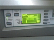 |
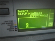 |
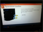 |
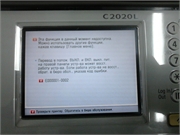 |
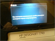 |
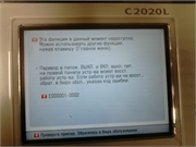 |
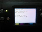 |
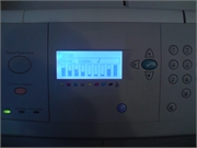 |
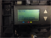 |
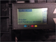 |
 |
 |
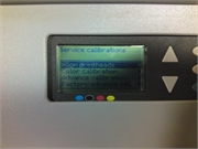 |
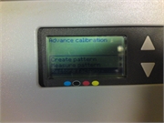 |
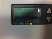 |
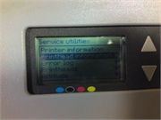 |
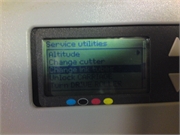 |
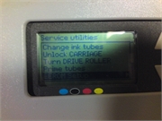 |
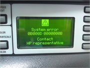 |
Если вы столкнулись с такими проблемами, свяжитесь с нами по телефонам : 8 ( 499 ) 720 — 60 — 20
Консультация специалиста : 8 ( 925 ) 090 — 60 — 50
Либо заполните форму заявки о неисправности вашего аппарата
Будем рады Вам помочь!
Для навигации по сайту Вы можете писать в онлайн чат, наши консультанты с удовольствием Вам помогут.
Вернуться в главное меню 
На панели управления HP DesignJet 10, 20, 30, 50, 70, 90, 100, 110, 120, 130 всего 3 кнопки, так что способ выполнения ряда сервисных команд не очевиден и не интуитивен.

1. Отмена. 2. Включение. 3. Ввод.
Для выполнения сервисных команд необходимо зажать кнопку «Включение». Затем, с зажатой клавишей, последовательно нажать несколько раз «Отмену» и «Ввод». Количество нажатий на две данных клавиши определяет функцию, которую станет исполнять принтер. После ввода комбинации клавишу «Включения» нужно отпустить.
|
Кол-во нажатий «Отмены» |
Кол-во нажатий «Ввода» | Запускаемая команда | |
| 0 | 1 | Usage Report | Печать основной информации |
| 0 | 4 | Information Pages | Печать подробной информации |
| 1 | 2 | NVM Contents Page | Печать сервисной информации |
| 0 | 3 | Printhead Alignment | Калибровка ПГ |
| 0 | 5 | Enable/Disable Buzzer | Включение/выключение динамика |
| 2 | 0 | Printhead Recovery 1 (Soft) | Быстрая очистка ПГ |
| 2 | 1 | Printhead Recovery 2 (Medium) | Стандартная очистка ПГ |
| 2 | 2 | Printhead Recovery 3 (Hard) | Глубокая прочистка ПГ |
| 2 | 3 | Transport Position | Каретка в позицию для переноса |
| 3 | 1 | Network Card Reset | Сброс сетевой карты |
Расшифровка команд
- Usage Report. Распечатка 1 страницы A4 со следующими данными: модель принтера, артикул, серийный номер, дата первого запуска, дата последнего запуска, общее количество израсходованных чернил, общее число распечатанных страниц.
- Information Pages. Распечатка 3 страниц с информацией о состоянии принтера и печатающей головки (ПГ), картриджей, сетевой карты (если есть).
- NVM Contents Page. Выгрузка данных памяти NVM, печатающей головки и картриджей (функция для сервисных инженеров, бесполезная для обычных пользователей).
- Printhead Alignment. Калибровка ПГ, распечатывает тестовую страницу с квадратами и чёрточками разных цветов.
- Enable/Disable Buzzer. Включение и выключение звуковых сигналов динамика на принтере.
- Printhead Recovery 1/2/3 (Soft/Medium/Hard). Запуск процедуры прочистки печатающей головки 1/2/3 (быстрая/средняя/глубокая).
- Transport Position. Перевод каретки в позицию для транспортировки (переноса) принтера.
- Network Card Reset. Сброс сетевой карты до заводских настроек.
Связаны со статьей
The most common error codes.
| Error | |
|---|---|
| 66:02:2 | Description: Vertical clipping. May happen when multi-pick occurs and two sheets are loaded together and they do not completely overlap. |
| 941:02:1 | Description: User selected Photo Paper and Max dpi, but the Color Calibration profile was obsolete or missing for Photo Paper and the selected print quality setting. |
| 11:11 | Description: Trailing Cable is badly connected. |
| 56:10 | Description: Error during the calibration of the motor encoder system or a problem finding the zero position on the Encoder Disc. |
| 94:02:8 | Description: User selected Coated Paper and Max dpi, but the Color Calibration profile was obsolete or missing for Coated Paper and the selected print quality setting. |
| 66:02:2 | Description: Vertical clipping. May happen when multi-pick occurs and two sheets are loaded together and they do not completely overlap. |
| 941:02:1 | Description: User selected Photo Paper and Max dpi, but the Color Calibration profile was obsolete or missing for Photo Paper and the selected print quality setting. |
| 11:11 | Description: Trailing Cable is badly connected. |
| 94:02:8 | Description: User selected Coated Paper and Max dpi, but the Color Calibration profile was obsolete or missing for Coated Paper and the selected print quality setting. |
| 56:10 | Description: Error during the calibration of the motor encoder system or a problem finding the zero position on the Encoder Disc. |