TECHNICAL BULLETIN
LTB00057NAS5
05 AUG 2014
SECTION: 204-06
Suspension Warning Lamp Illuminated – Diagnostic & Repair Procedure
AFFECTED VEHICLE RANGE:
Range Rover Sport (LS)
Model Year: 2006-2013
VIN: 6A901924-DA814822
MARKETS:
NAS
CONDITION SUMMARY:
Situation: The Dynamic Response system red warning lamp may be illuminated on the Instrument Cluster and Diagnostic Trouble Codes (DTC) C1119-62, C1119-09, and/or C1B11-62 may be stored, possibly indicating system contamination.
This Technical Bulletin provides a process for Retailers to correctly diagnose Dynamic Response system contamination, to identify if an actuator has failed, and to determine which parts may require replacement. A flushing procedure is provided to clean the affected parts that do not need to be replaced and ensure that the issue does not re-occur.
Action: Should a customer express concern, use SDD to establish which actuator is at fault and carry out the flush and repair procedure by following the Service Instruction outlined below.
PARTS:
| LR014592 | High pressure pipe repair kit – from 2010MY | Quantity: 1 |
| LR014593 | High pressure pipe front – from 2010MY | Quantity: 1 |
| LR014595 | Pump – from 2010MY | Quantity: 1 |
| LR024072 | Rear actuator – from 2010MY | Quantity: 1 |
| LR024073 | Rear actuator – up to 2010MY | Quantity: 1 |
| LR032958 | Front actuator – up to 2007MY | Quantity: 1 |
| LR032959 | Front actuator – from 2007MY | Quantity: 1 |
| RQB500393 | High pressure pipe front – up to 2010MY | Quantity: 1 |
| RQN000011 | Reservoir | Quantity: 1 |
| RVB000017 | Pump – up to 2010MY | Quantity: 1 |
| RVH500100 | Pressure Control Valve (PCV) | Quantity: 1 |
| RVH500110 | Valve block | Quantity: 1 |
| RVJ100010 | Valve block filter | Quantity: 1 |
TOOLS:
WARRANTY:
NOTE: Repair procedures are under constant review, and therefore times are subject to change; those quoted here must be taken as guidance only. Always refer to TOPIx to obtain the latest repair time.
NOTE: DDW requires the use of causal part numbers. Labor only claims must show the causal part number with a quantity of zero.
| DESCRIPTION | SRO | TIME (HOURS) | CONDITION CODE | CAUSAL PART |
|---|---|---|---|---|
| Dynamic Response system – Check using SDD – Replace pump – 4.2L / 5.0L V8 SC | 60.60.89/41 | 1.9 | 49 | RQK500110 |
| Dynamic Response system – Check using SDD – Replace pump – 4.4L / 5.0L V8 N/A | 60.60.89/41 | 1.8 | 49 | RQK500110 |
| Dynamic Response system – Pressure test using SDD – Replace valve block | 60.60.89/42 | 2.4 | 49 | RQK500110 |
| Dynamic Response system – Check using SDD – Replace front actuator; flush and bleed system | 60.60.89/43 | 4.2 | 49 | RQK500110 |
| Dynamic Response system – Check using SDD – Replace rear actuator; flush and bleed system | 60.60.89/44 | 5.9 | 49 | RQK500110 |
| Dynamic Response system – Check using SDD – Replace front actuator; replace high-pressure pipe front section; flush system – 4.2L / 5.0L V8 SC | 60.60.89/47 | 4.3 | 49 | RQK500110 |
| Dynamic Response system – Check using SDD – Replace front actuator; replace high-pressure pipe front section; flush system – 4.4L / 5.0L V8 N/A | 60.60.89/47 | 4.2 | 49 | RQK500110 |
| Pressure Control Valve – Renew | 60.60.23 | 0.4 | 49 | RQK500110 |
| Dynamic Response system – Pressure test | 60.90.20 | 0.4 | 49 | RQK500110 |
NOTE: Normal Warranty procedures apply.
SERVICE INSTRUCTION:
1. Connect the Jaguar Land Rover-approved Midtronics battery power supply to the vehicle battery.
2. Turn ignition ‘ON’ (engine not running).
3. Connect the Symptom Driven Diagnostics (SDD) system to the vehicle and begin a new session.
4. Follow the on-screen prompts, allowing SDD to read the VIN and identify the vehicle and initiating the data collect sequence.
5. Read and record all Diagnostic Trouble Codes (DTC).
- Follow the Service Instruction if any of the following DTC codes are present: C1119 62, C1119 09, C1B 1162.
6. CAUTION: If the Dynamic Response system reservoir is empty, pump damage is likely to have occurred.
Check the Dynamic Response system fluid level.
- If the level is correct, proceed to step 12.
- If the fluid is low, inspect system for leaks.
7. WARNING: Do not work on or under a vehicle supported only by a jack. Always support the vehicle on safety stands.
Raise and support the vehicle (see TOPIx Workshop Manual, section: 100-02).
8. Remove the engine under shield (see TOPIx Workshop Manual, section: 501-02).
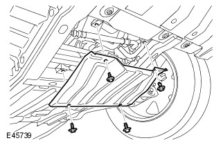
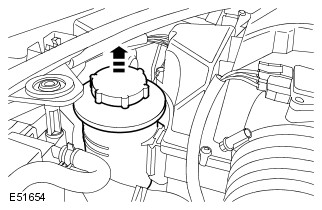
9. Remove the radiator access panel.
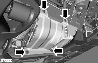
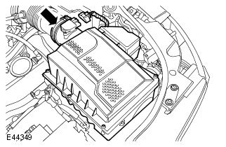
10. Remove the right-hand splash shield.
11. Inspect the Dynamic Response system for leaks.
12. Using SDD, perform the Dynamic Response system test.
- Select ‘Special Applications’.
- Select ‘Dynamic Response system Hydraulic Control – System Test’.
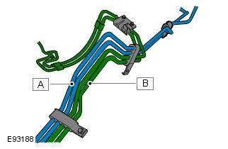
- Demand 50 Bar of pressure for up to five minutes or until the primary circuit pipes (A) are hot. Check pipe temperature under right-hand wheel arch.
- If 50 bar cannot be obtained then the Pressure Control Valve (PCV) in the valve block is faulty and requires replacement with the PCV service kit (see TOPIx Workshop Manual, Section: 204-06).
- Open Directional Control Valve 1 (DCV1) and check system pressure is still 50 Bar. Hold for two minutes. If pressure has dropped by over 5 Bar, this indicates a faulty actuator.
- Open Directional Control Valve 2 (DCV2) and check system pressure is still 50 Bar. Hold for two minutes. If pressure has dropped by over 5 Bar, this indicates a faulty actuator.
13. NOTE: If the temperature comparison test is not conclusive at this stage, follow the bulletin and if condition (B) is found at step 22, the front actuator requires replacement.
Confirm which actuator is faulty.
- If all four pipes in the front wheel arch area are hot and at a similar temperature, this indicates that the front actuator is faulty. Replace the front actuator (see TOPIx Workshop Manual, section 204-06).
- If the pipes in the rear wheel arch are hot, this indicates that the rear actuator is at fault. Replace the rear actuator (see TOPIx Workshop Manual, section 204-06).
- If the pressure has dropped but there is no increase in the actuator pipes temperature (B), and rear pipes, then the valve block requires replacement (see TOPIx Workshop Manual, section 204-06). There should be a corresponding DCV fault code logged.
14. If found faulty in step 12, install a new Pressure Control Valve (PCV) service kit (see TOPIx Workshop Manual, Section: 204-06). Once complete, check the valve block and reservoir filter for signs of debris (steps 15-22). Complete bleed process. If no debris found in reservoir of valve block filter. It will not be necessary to follow the other steps shown in this procedure.
15. Remove the valve block filter (see TOPIx Workshop Manual, Section: 204-06).
16. Inspect the valve block filter.
- Check filter for signs of distortion. A distorted filter indicates excessive system pressure.
- Replace the filter.
17. Release the Dynamic Response system reservoir.
- Release the clip.
- Tie the reservoir aside.
18. Disconnect the intake air resonator.
- Release the clip.
19. Remove the right-hand air cleaner assembly.
- Disconnect the right-hand Mass Air Flow (MAF) sensor electrical connectors.
20. Position container to collect fluid loss.
21. CAUTION: Before disconnecting or removing the components, make sure the area around the joint faces and connections is clean. Plug open connections to prevent contamination.
NOTE: Some fluid spillage is inevitable during this operation.
Remove the fluid reservoir.
- Disconnect the hoses from the fluid reservoir.
- Using a suitable tool clamp the hoses to prevent air ingress.
- Release the two clips.
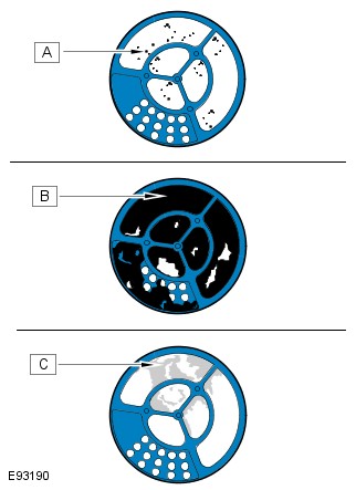
22. NOTE: A small number of particles is acceptable (A). The reservoir does not require replacement.
Inspect the reservoir fluid filter for signs of contamination.
- A small number of particles is acceptable (A). The reservoir does not require replacement.
- If the filter is lightly contaminated with grey metallic looking particles, this would indicate a pump failure. Discard the reservoir if this condition is found. Proceed to next step.
- If the filter is heavily contaminated with black particles and sludge (B), this would indicate an actuator internal piston seal failure. Discard the reservoir. Proceed to step 24.
23. If required, install a new Dynamic Response system pump. It will not be necessary to change any actuator if the pump is replaced.
24. NOTE: ‘A’: all AJV8 petrol engines; ‘B’: TDV8 diesel only.
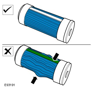
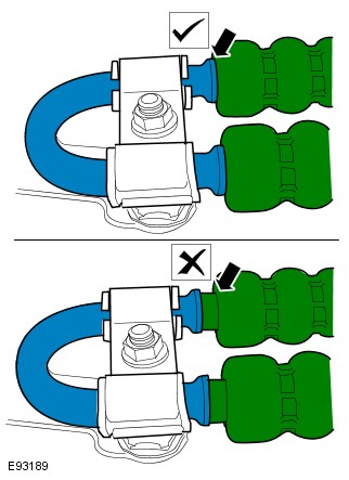
Inspect the high-pressure hose crimps for signs of movement.
- A = all AJV8 petrol engines
- B = TDV8 diesel only
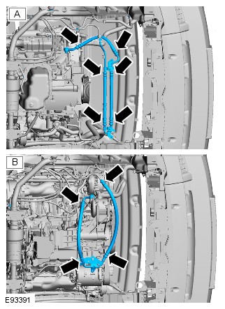
25. Any pipe assembly that shows signs of movement must be replaced.
- Any gap larger than 1mm is not acceptable.
26. Replace the hose assembly as follows.
- AJV8 petrol models the hose assembly shown in graphic E93391 [see step 24 (A)] must be replaced if required.
27. Install the fluid reservoir.
- Clean the component mating faces.
- Connect the hoses.
- Install the clips.
28. Remove the hose clamps.
29. NOTE: When installing the air cleaner, make sure the locating pegs fit securely into the grommets.
Install the right-hand air cleaner assembly.
- Connect the right-hand Mass Air Flow (MAF) sensor electrical connectors.
30. NOTE: It is not necessary to perform this step if the valve block or pump has been replaced.
Remove the contaminated fluid from the actuator, without the internal leak.
- Remove both wheels and tires (see TOPIx Workshop Manual, section 204-04).
- Disconnect both the stabilizer bar links from the stabilizer bar (see TOPIx Workshop Manual, section 204-06).
- Disconnect the Dynamic Response system fluid pipes from the actuator.
- Move the actuator bar arms in opposite directions to displace the fluid. Full movement in both directions of each arm must be performed, to ensure fluid from both sides of the piston is removed.
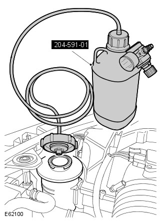
31. Install the special tool to the Dynamic Response system reservoir.
- Completely fill the reservoir with fluid.
- Make sure the pressure regulator on the special tool is turned OFF.
- Fill the special tool bottle approximately ¾ full with fluid.
- Connect the special tool to a suitable workshop air supply.
32. WARNING: Do not work on or under a vehicle supported only by a jack. Always support the vehicle on safety stands.
Raise and support the vehicle (see TOPIx Workshop Manual, section: 100-02).
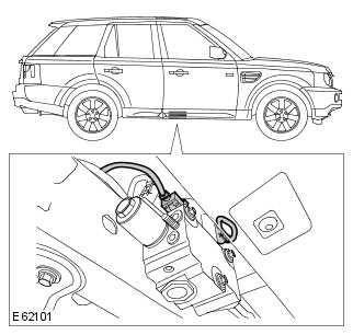
33. Disconnect the two valve block actuator control valve electrical connectors.
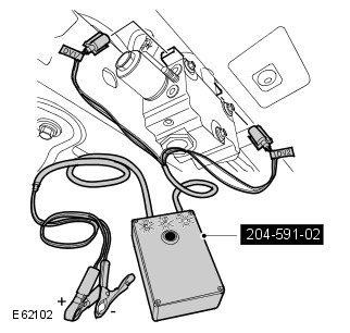
34. Connect the special tool electrical connectors to the valve block.
- Connect the special tool power supply leads to the vehicle battery.
35. Disconnect the Dynamic Response system fluid pipes from the actuator.
36. Using the special tool, open both actuator control valves.
37. Flush fluid through the front pipes until approximately 0.5 liter has been displaced.
38. CAUTION: The O-ring seals are to be reused unless damaged.
Connect the fluid lines to the actuator.
- Tighten the two bolts to 22Nm (16lbf. ft).
39. Repeat the flush process for the rear pipes.
- If the pipes have not been disconnected during step 30, disconnect the Dynamic Response system fluid pipes from the actuator.
- Flush fluid through the actuator until approximately 0.5 liter has been displaced.
40. CAUTION: It will not be necessary to replace any actuator if the pump has been replaced.
Install a new actuator and stabilizer bar (see TOPIx Workshop Manual, section: 204-06).
41. Bleed the Dynamic Response system (see TOPIx Workshop Manual section: 204-06).
42. Check and top up the Dynamic Response system fluid reservoir.
- Fill the reservoir to the mid-way mark between the ‘MAX’ and ‘MIN’ marks.
43. Install the radiator access panel.
- Tighten the bolts to 10Nm.
44. Install the right-hand splash shield.
45. Install the engine under shield (see TOPIx Workshop Manual, section: 501-02).
46. Clear diagnostic trouble codes (DTCs).
47. CAUTION: Only perform the road test if the pump or an actuator has been replaced.
If the pump or an actuator has been replaced, perform a 10 mile road test on twisty roads to exercise the system.
48. Install a new valve block filter (see TOPIx Workshop Manual, section: 204-06).
49. Check and top up the Dynamic Response system fluid reservoir.
- Fill the reservoir to the mid-way mark between the ‘MAX’ and ‘MIN’ marks.
LTB00057NAS5

![]()
Price Disclaimer

![]()
Price Disclaimer

![]()
Price Disclaimer
| keith63 Member Since: 02 Sep 2019  
|
Just had this pop up today on it’s own , but with message to turn engine off . i have checked Hydraulic Oil in reservoir, it looks a little low just below Half way , but thin and black.
|
Thu Jun 25 2020 5:40pm |
| RRSTDV8 Member Since: 13 Aug 2011 
|
When you say «just below half» do you mean the halfway line between the two marks at the top of the reservoir? Not halfway up the reservoir. 2012 SDV6 — it’s missing a couple of cylinders |
Thu Jun 25 2020 8:32pm |
| RRSTDV8 Member Since: 13 Aug 2011
|
Yes. There are three lines near the top of the reservoir that give the min and max fill levels with a middle line for good measure. A bottle of Cold Climate PAS fluid, top it up to middle line, run it and then see what the level is. Top up as necessary. 2012 SDV6 — it’s missing a couple of cylinders
|
Fri Jun 26 2020 7:39am |
You cannot post new topics in this forum
You cannot reply to topics in this forum
You cannot edit your posts in this forum
You cannot delete your posts in this forum
You cannot vote in polls in this forum
Site Copyright © 2005-2023 Futuranet Ltd & Martin Lewis
![]()

This procedure must be followed if any of the following codes are present: C1119 62, C1119 09, C1B 1162.
***********************************************************************************
********************************************************************************
2012 Land Rover Range Rover (LM) V8-5.0L Copyright ? 2013, ALLDATA 10.52SS Page 1
Vehicle: All Technical Service Bulletins
Diagnostic Procedure
DIAGNOSTIC PROCEDURE
CAUTION:
A Midtronics PSC-550 Vehicle Power Supply must be connected to the vehicle battery during diagnosis.
1. Connect the Midtronics PSC-550 Vehicle Power Supply to the vehicle battery.
2. Connect IDS to the vehicle and begin a new diagnostic session, by entering the correct VIN for the current vehicle.
3. Read and record diagnostic trouble codes.
NOTE:
This procedure must be followed if any of the following codes are present: C1119 62, C1119 09, C1B 1162.
CAUTION:
If the dynamic response reservoir is empty, pump damage is likely to have occurred.
4. Check the dynamic response fluid level.
WARNING:
Whenever working under a vehicle the vehicle must be supported with safety stands.
NOTE:
Global Technical Reference (GTR) lookup sequence is as follows:
GTR Home > NAS > LS Range Rover Sport > Service Information/ 2007 > Workshop Manuals > Bookmark «Body and Paint/501-02
Front End Body Panels» LINK «Engine Undershield (76.10.50)»
5. If the fluid is low perform the following system inspection for leaks:
^ Raise and support the vehicle.
^ Refer to GTR Section 501-02 and remove the engine shield.
^ Remove the radiator access panel. (Figure 1)
2012 Land Rover Range Rover (LM) V8-5.0L Copyright ? 2013, ALLDATA 10.52SS Page 2
^ Remove the right-hand (RH) splash shield. (Figure 2)
^ Inspect the dynamic response system for leaks.
6. If the fluid level is correct, use IDS to perform the following diagnostic response system test:
^ Select ‘Special Applications’.
^ Select ‘Dynamic Response Hydraulic Control — System Test’.
^ Demand 50 bar (725 psi) of pressure for up to five minutes or until the primary circuit pipes are hot. ([A] in Figure 3)
2012 Land Rover Range Rover (LM) V8-5.0L Copyright ? 2013, ALLDATA 10.52SS Page 3
^ Check pipe temperature under RH wheel arch.
^ If 50 bar (725 psi) cannot be obtained, * refer to GTR Workshop Manual section 204-06 (60.60.23) to replace the faulty Pressure Control
Valve (PCV) in the valve block*.
^ Open DCV1 and verify that system pressure is still 50 bar (725 psi).
^ Hold 50 bar (725 psi) pressure for two minutes.
^ If pressure has dropped by over 5 bar (72.5 psi), confirm in step 7 and replace the affected actuator.
^ Open DCV2 and verify that system pressure is still 50 bar (725 psi).
^ Hold 50 bar (725 psi) pressure for two minutes.
^ If pressure has dropped by over 5 bar (72.5 psi), confirm in step 7. The affected actuator will be replaced.
NOTE:
If the temperature comparison test is not conclusive at this stage, continued diagnosis revealing filter contamination (Condition B Figure 6)
may indicate that the front actuator requires replacement.
7. Confirm which actuator is faulty by observing the follow symptoms:
^ If all four pipes in the front wheel arch area are hot and at a similar temperature the front actuator is faulty.
^ If the pipes in the rear wheel arch are hot, the rear actuator is faulty.
^ If the pressure has dropped, but there is no increase in the actuator pipes and rear pipes temperature ([B] in Figure 3), the valve block is
faulty and requires replacement.
Popular posts from this blog
2010 Land Rover LR4 (LA) V8-5.0L Technical Service Bulletin # TECLTB003472 Date: 120806 Engine — MIL ON/DTC’s P003C/P003E Stored LTB00347NAS2 06 AUG 2012 *ISSUE 2 CHANGES ARE HIGHLIGHTED IN GRAY* SECTION: 303 Intermittent Engine MIL / DTC P003C / P003E Stored AFFECTED VEHICLE RANGE: CONDITION SUMMARY: Situation: On vehicles with the 5.0-liter naturally aspirated LR-V8 engine only, the engine Malfunction Indicator Lamp (MIL) may illuminate intermittently with Diagnostic Trouble Code (DTC) P003C and/or P003E stored in the Engine control module (ECM). Cause: This may be caused by the oil restrictor sealing rings and u-groove being out of tolerance. Action: In the event of a customer concern of the above, refer to the Repair Procedure outlined below to replace the oil restrictors. PARTS: LR011688……………..Oil restrictor Qty: 2 2010 Land Rover LR4 (LA) V8-5.0L Page 16 TOOLS: IDS with latest IDS-DVD and Calibration File; Land Rover-Approved Midtronics Vehicle Power Supply Refer t
*********************************************************************************** ******************************************************************************** 2012 Land Rover Range Rover (LM) V8-5.0L Copyright ? 2013, ALLDATA 10.52SS Page 1 Vehicle: All Technical Service Bulletins Suspension — Warning Lamp Illuminated (AMK Compressors Only) TECHNICAL BULLETIN LTB00452NAS2 16 NOV 2012 *ISSUE 2 CHANGES ARE HIGHLIGHTED IN GRAY* SECTION: 204-05 Air Suspension System Warning Lamp Illuminated — Vehicles Fitted with AMK Compressors Only AFFECTED VEHICLE RANGE: CONDITION SUMMARY: NOTE: This condition may exist on vehicles originally fitted with AMK compressors (listed below) as well as any vehicles updated as per Technical Bulletin LTB00420 or LTB00438. LR4 VIN: BA589535-CA603567 Range Rover Sport VIN: BA708098-CA725317 Range Rover VIN: BA356347-CA367232 Situation: On vehicles fitted with an AMK compressor only, the Air Suspension System warning lamp may be ill
ПРИМЕЧАНИЕ: Универсальные сканирующие приборы не могут считывать перечисленные коды или могут считывать только 5-значные коды. Сопоставьте 5 цифр со сканирующего прибора с первыми 5-ю цифрами указанного в перечне 7-значного кода, чтобы идентифицировать неисправность (последние 2 цифры дают дополнительную информацию, считываемую диагностической системой, одобренной изготовителем).
ПРИМЕЧАНИЕ: Периодически проявляющиеся неисправности могут вызывать регистрацию DTC, однако некоторые DTC могут быть стерты в цикле выключения-включения зажигания. Выполните дорожное испытание (если это безопасно), проверьте функциональные возможности системы и перед выключением зажигания выполните считывание всех кодов DTC.
Совсем забыл, после замены стабилизатора, заднего, загорелась ошибка C1119 и прочие, по давлению в системе.
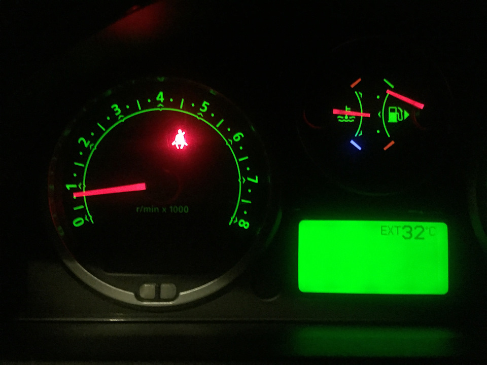
Красные качели появлялись после заводки авто.
Не знаю, косяк ли ремонтников, либо чего то свыше Но… Я третий, у кого после Московских чудесников, по восстановлению стабов, такое загорелось : /
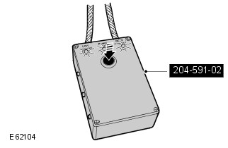
Разбираем блок клапанов, достаем регулятор
Полный размер
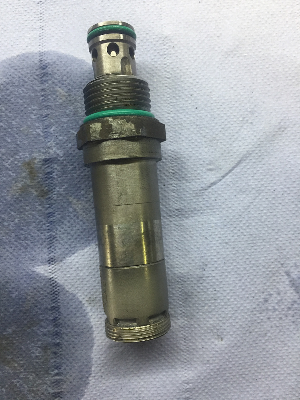
чистим, внутри стружка, правда мелкая, но влияет… Помыли, продули, и вуаля
Полный размер
проехал 8000, ничего не горит и как «отцы» ремонтники с форумов говорят, меня сразу блок в сборе, пффф
Всем удачи ребята
| keith63 Member Since: 02 Sep 2019
|
Just had this pop up today on it’s own , but with message to turn engine off . first long journey since Lock down .. and it has been so Hot 32 degs i have checked Hydraulic Oil in reservoir, it looks a little low just below Half way , but thin and black. is it an easy task to flush and replace this oil ? before i start to spend big money on replacing other bits ? |
Thu Jun 25 2020 5:40pm |
| RRSTDV8 Member Since: 13 Aug 2011
|
When you say «just below half» do you mean the halfway line between the two marks at the top of the reservoir? Not halfway up the reservoir. 2012 SDV6 — it’s missing a couple of cylinders 2008 TDV8 — it was a labour of love and is much missed
|
Thu Jun 25 2020 8:32pm |
| RRSTDV8 Member Since: 13 Aug 2011
|
Yes. There are three lines near the top of the reservoir that give the min and max fill levels with a middle line for good measure. A bottle of Cold Climate PAS fluid, top it up to middle line, run it and then see what the level is. Top up as necessary. 2012 SDV6 — it’s missing a couple of cylinders 2008 TDV8 — it was a labour of love and is much missed |
Fri Jun 26 2020 7:39am |
Posting Rules
You cannot post new topics in this forum
You cannot reply to topics in this forum
You cannot edit your posts in this forum
You cannot delete your posts in this forum
You cannot vote in polls in this forum
Site Copyright © 2005-2023 Futuranet Ltd & Martin Lewis
![]()
TECHNICAL BULLETIN
LTB00057NAS5
05 AUG 2014
SECTION: 204-06
Suspension Warning Lamp Illuminated – Diagnostic & Repair Procedure
AFFECTED VEHICLE RANGE:
Range Rover Sport (LS)
Model Year: 2006-2013
VIN: 6A901924-DA814822
MARKETS:
NAS
CONDITION SUMMARY:
Situation: The Dynamic Response system red warning lamp may be illuminated on the Instrument Cluster and Diagnostic Trouble Codes (DTC) C1119-62, C1119-09, and/or C1B11-62 may be stored, possibly indicating system contamination.
This Technical Bulletin provides a process for Retailers to correctly diagnose Dynamic Response system contamination, to identify if an actuator has failed, and to determine which parts may require replacement. A flushing procedure is provided to clean the affected parts that do not need to be replaced and ensure that the issue does not re-occur.
Action: Should a customer express concern, use SDD to establish which actuator is at fault and carry out the flush and repair procedure by following the Service Instruction outlined below.
PARTS:
| LR014592 | High pressure pipe repair kit – from 2010MY | Quantity: 1 |
| LR014593 | High pressure pipe front – from 2010MY | Quantity: 1 |
| LR014595 | Pump – from 2010MY | Quantity: 1 |
| LR024072 | Rear actuator – from 2010MY | Quantity: 1 |
| LR024073 | Rear actuator – up to 2010MY | Quantity: 1 |
| LR032958 | Front actuator – up to 2007MY | Quantity: 1 |
| LR032959 | Front actuator – from 2007MY | Quantity: 1 |
| RQB500393 | High pressure pipe front – up to 2010MY | Quantity: 1 |
| RQN000011 | Reservoir | Quantity: 1 |
| RVB000017 | Pump – up to 2010MY | Quantity: 1 |
| RVH500100 | Pressure Control Valve (PCV) | Quantity: 1 |
| RVH500110 | Valve block | Quantity: 1 |
| RVJ100010 | Valve block filter | Quantity: 1 |
TOOLS:
WARRANTY:
NOTE: Repair procedures are under constant review, and therefore times are subject to change; those quoted here must be taken as guidance only. Always refer to TOPIx to obtain the latest repair time.
NOTE: DDW requires the use of causal part numbers. Labor only claims must show the causal part number with a quantity of zero.
| DESCRIPTION | SRO | TIME (HOURS) | CONDITION CODE | CAUSAL PART |
|---|---|---|---|---|
| Dynamic Response system – Check using SDD – Replace pump – 4.2L / 5.0L V8 SC | 60.60.89/41 | 1.9 | 49 | RQK500110 |
| Dynamic Response system – Check using SDD – Replace pump – 4.4L / 5.0L V8 N/A | 60.60.89/41 | 1.8 | 49 | RQK500110 |
| Dynamic Response system – Pressure test using SDD – Replace valve block | 60.60.89/42 | 2.4 | 49 | RQK500110 |
| Dynamic Response system – Check using SDD – Replace front actuator; flush and bleed system | 60.60.89/43 | 4.2 | 49 | RQK500110 |
| Dynamic Response system – Check using SDD – Replace rear actuator; flush and bleed system | 60.60.89/44 | 5.9 | 49 | RQK500110 |
| Dynamic Response system – Check using SDD – Replace front actuator; replace high-pressure pipe front section; flush system – 4.2L / 5.0L V8 SC | 60.60.89/47 | 4.3 | 49 | RQK500110 |
| Dynamic Response system – Check using SDD – Replace front actuator; replace high-pressure pipe front section; flush system – 4.4L / 5.0L V8 N/A | 60.60.89/47 | 4.2 | 49 | RQK500110 |
| Pressure Control Valve – Renew | 60.60.23 | 0.4 | 49 | RQK500110 |
| Dynamic Response system – Pressure test | 60.90.20 | 0.4 | 49 | RQK500110 |
NOTE: Normal Warranty procedures apply.
SERVICE INSTRUCTION:
1. Connect the Jaguar Land Rover-approved Midtronics battery power supply to the vehicle battery.
2. Turn ignition ‘ON’ (engine not running).
3. Connect the Symptom Driven Diagnostics (SDD) system to the vehicle and begin a new session.
4. Follow the on-screen prompts, allowing SDD to read the VIN and identify the vehicle and initiating the data collect sequence.
5. Read and record all Diagnostic Trouble Codes (DTC).
- Follow the Service Instruction if any of the following DTC codes are present: C1119 62, C1119 09, C1B 1162.
6. CAUTION: If the Dynamic Response system reservoir is empty, pump damage is likely to have occurred.
Check the Dynamic Response system fluid level.
- If the level is correct, proceed to step 12.
- If the fluid is low, inspect system for leaks.
7. WARNING: Do not work on or under a vehicle supported only by a jack. Always support the vehicle on safety stands.
Raise and support the vehicle (see TOPIx Workshop Manual, section: 100-02).
8. Remove the engine under shield (see TOPIx Workshop Manual, section: 501-02).
9. Remove the radiator access panel.
10. Remove the right-hand splash shield.
11. Inspect the Dynamic Response system for leaks.
12. Using SDD, perform the Dynamic Response system test.
- Select ‘Special Applications’.
- Select ‘Dynamic Response system Hydraulic Control – System Test’.
- Demand 50 Bar of pressure for up to five minutes or until the primary circuit pipes (A) are hot. Check pipe temperature under right-hand wheel arch.
- If 50 bar cannot be obtained then the Pressure Control Valve (PCV) in the valve block is faulty and requires replacement with the PCV service kit (see TOPIx Workshop Manual, Section: 204-06).
- Open Directional Control Valve 1 (DCV1) and check system pressure is still 50 Bar. Hold for two minutes. If pressure has dropped by over 5 Bar, this indicates a faulty actuator.
- Open Directional Control Valve 2 (DCV2) and check system pressure is still 50 Bar. Hold for two minutes. If pressure has dropped by over 5 Bar, this indicates a faulty actuator.
13. NOTE: If the temperature comparison test is not conclusive at this stage, follow the bulletin and if condition (B) is found at step 22, the front actuator requires replacement.
Confirm which actuator is faulty.
- If all four pipes in the front wheel arch area are hot and at a similar temperature, this indicates that the front actuator is faulty. Replace the front actuator (see TOPIx Workshop Manual, section 204-06).
- If the pipes in the rear wheel arch are hot, this indicates that the rear actuator is at fault. Replace the rear actuator (see TOPIx Workshop Manual, section 204-06).
- If the pressure has dropped but there is no increase in the actuator pipes temperature (B), and rear pipes, then the valve block requires replacement (see TOPIx Workshop Manual, section 204-06). There should be a corresponding DCV fault code logged.
14. If found faulty in step 12, install a new Pressure Control Valve (PCV) service kit (see TOPIx Workshop Manual, Section: 204-06). Once complete, check the valve block and reservoir filter for signs of debris (steps 15-22). Complete bleed process. If no debris found in reservoir of valve block filter. It will not be necessary to follow the other steps shown in this procedure.
15. Remove the valve block filter (see TOPIx Workshop Manual, Section: 204-06).
16. Inspect the valve block filter.
- Check filter for signs of distortion. A distorted filter indicates excessive system pressure.
- Replace the filter.
17. Release the Dynamic Response system reservoir.
- Release the clip.
- Tie the reservoir aside.
18. Disconnect the intake air resonator.
- Release the clip.
19. Remove the right-hand air cleaner assembly.
- Disconnect the right-hand Mass Air Flow (MAF) sensor electrical connectors.
20. Position container to collect fluid loss.
21. CAUTION: Before disconnecting or removing the components, make sure the area around the joint faces and connections is clean. Plug open connections to prevent contamination.
NOTE: Some fluid spillage is inevitable during this operation.
Remove the fluid reservoir.
- Disconnect the hoses from the fluid reservoir.
- Using a suitable tool clamp the hoses to prevent air ingress.
- Release the two clips.
22. NOTE: A small number of particles is acceptable (A). The reservoir does not require replacement.
Inspect the reservoir fluid filter for signs of contamination.
- A small number of particles is acceptable (A). The reservoir does not require replacement.
- If the filter is lightly contaminated with grey metallic looking particles, this would indicate a pump failure. Discard the reservoir if this condition is found. Proceed to next step.
- If the filter is heavily contaminated with black particles and sludge (B), this would indicate an actuator internal piston seal failure. Discard the reservoir. Proceed to step 24.
23. If required, install a new Dynamic Response system pump. It will not be necessary to change any actuator if the pump is replaced.
24. NOTE: ‘A’: all AJV8 petrol engines; ‘B’: TDV8 diesel only.
Inspect the high-pressure hose crimps for signs of movement.
- A = all AJV8 petrol engines
- B = TDV8 diesel only
25. Any pipe assembly that shows signs of movement must be replaced.
- Any gap larger than 1mm is not acceptable.
26. Replace the hose assembly as follows.
- AJV8 petrol models the hose assembly shown in graphic E93391 [see step 24 (A)] must be replaced if required.
27. Install the fluid reservoir.
- Clean the component mating faces.
- Connect the hoses.
- Install the clips.
28. Remove the hose clamps.
29. NOTE: When installing the air cleaner, make sure the locating pegs fit securely into the grommets.
Install the right-hand air cleaner assembly.
- Connect the right-hand Mass Air Flow (MAF) sensor electrical connectors.
30. NOTE: It is not necessary to perform this step if the valve block or pump has been replaced.
Remove the contaminated fluid from the actuator, without the internal leak.
- Remove both wheels and tires (see TOPIx Workshop Manual, section 204-04).
- Disconnect both the stabilizer bar links from the stabilizer bar (see TOPIx Workshop Manual, section 204-06).
- Disconnect the Dynamic Response system fluid pipes from the actuator.
- Move the actuator bar arms in opposite directions to displace the fluid. Full movement in both directions of each arm must be performed, to ensure fluid from both sides of the piston is removed.
31. Install the special tool to the Dynamic Response system reservoir.
- Completely fill the reservoir with fluid.
- Make sure the pressure regulator on the special tool is turned OFF.
- Fill the special tool bottle approximately ¾ full with fluid.
- Connect the special tool to a suitable workshop air supply.
32. WARNING: Do not work on or under a vehicle supported only by a jack. Always support the vehicle on safety stands.
Raise and support the vehicle (see TOPIx Workshop Manual, section: 100-02).
33. Disconnect the two valve block actuator control valve electrical connectors.
34. Connect the special tool electrical connectors to the valve block.
- Connect the special tool power supply leads to the vehicle battery.
35. Disconnect the Dynamic Response system fluid pipes from the actuator.
36. Using the special tool, open both actuator control valves.
37. Flush fluid through the front pipes until approximately 0.5 liter has been displaced.
38. CAUTION: The O-ring seals are to be reused unless damaged.
Connect the fluid lines to the actuator.
- Tighten the two bolts to 22Nm (16lbf. ft).
39. Repeat the flush process for the rear pipes.
- If the pipes have not been disconnected during step 30, disconnect the Dynamic Response system fluid pipes from the actuator.
- Flush fluid through the actuator until approximately 0.5 liter has been displaced.
40. CAUTION: It will not be necessary to replace any actuator if the pump has been replaced.
Install a new actuator and stabilizer bar (see TOPIx Workshop Manual, section: 204-06).
41. Bleed the Dynamic Response system (see TOPIx Workshop Manual section: 204-06).
42. Check and top up the Dynamic Response system fluid reservoir.
- Fill the reservoir to the mid-way mark between the ‘MAX’ and ‘MIN’ marks.
43. Install the radiator access panel.
- Tighten the bolts to 10Nm.
44. Install the right-hand splash shield.
45. Install the engine under shield (see TOPIx Workshop Manual, section: 501-02).
46. Clear diagnostic trouble codes (DTCs).
47. CAUTION: Only perform the road test if the pump or an actuator has been replaced.
If the pump or an actuator has been replaced, perform a 10 mile road test on twisty roads to exercise the system.
48. Install a new valve block filter (see TOPIx Workshop Manual, section: 204-06).
49. Check and top up the Dynamic Response system fluid reservoir.
- Fill the reservoir to the mid-way mark between the ‘MAX’ and ‘MIN’ marks.
LTB00057NAS5
![]()
Price Disclaimer
![]()
Price Disclaimer
![]()
Price Disclaimer
Ошибки (коды ошибок) полученные от прибора, сканера требуют правильной интерпретации информации, дабы не тратить время и деньги на замену работающих элементов автомобиля.
Проблема зачастую кроется намного глубже чем кажется на первый взгляд. Это& вызвано теми обстоятельствами, что информационные сообщения содержат, как было выше сказано, косвенную информацию о нарушении работы системы.
Может быть полезным для решения вопроса по устранению неисправности у Land Rover Range Rover Sport:
Возможные причины: Неисправен датчик температуры охлаждающей жидкости двигателя; Жгут датчика температуры охлаждающей жидкости двигателя открыт или замкнут; Неисправность цепи датчика температуры охлаждающей жидкости двигателя.
Датчик температуры охлаждающей жидкости двигателя (ECT) содержит полупроводниковое устройство, которое изменяет сопротивление в зависимости от температуры (термистор). Датчик ECT устанавливается в головке цилиндров левого берега рядом с передней частью двигателя. Датчик ECT имеет сигнальную цепь и цепь заземления. Модуль управления силовым агрегатом (PCM) подает напряжение (около 5,0 вольт) на сигнальную цепь на датчик. PCM контролирует изменения этого напряжения, вызванные изменениями сопротивления датчика, для определения температуры охлаждающей жидкости двигателя. Когда охлаждающая жидкость двигателя холодная, сопротивление датчика (термистора) высокое, а напряжение сигнала РСМ только незначительно снижается через датчик к земле. PCM обнаруживает высокое напряжение сигнала (низкая температура). Когда охлаждающая жидкость двигателя теплая, сопротивление датчика низкое, а напряжение сигнала снижается в большей степени.
This procedure must be followed if any of the following codes are present: C1119 62, C1119 09, C1B 1162.
***********************************************************************************
********************************************************************************
2012 Land Rover Range Rover (LM) V8-5.0L Copyright ? 2013, ALLDATA 10.52SS Page 1
Vehicle: All Technical Service Bulletins
Diagnostic Procedure
DIAGNOSTIC PROCEDURE
CAUTION:
A Midtronics PSC-550 Vehicle Power Supply must be connected to the vehicle battery during diagnosis.
1. Connect the Midtronics PSC-550 Vehicle Power Supply to the vehicle battery.
2. Connect IDS to the vehicle and begin a new diagnostic session, by entering the correct VIN for the current vehicle.
3. Read and record diagnostic trouble codes.
NOTE:
This procedure must be followed if any of the following codes are present: C1119 62, C1119 09, C1B 1162.
CAUTION:
If the dynamic response reservoir is empty, pump damage is likely to have occurred.
4. Check the dynamic response fluid level.
WARNING:
Whenever working under a vehicle the vehicle must be supported with safety stands.
NOTE:
Global Technical Reference (GTR) lookup sequence is as follows:
GTR Home > NAS > LS Range Rover Sport > Service Information/ 2007 > Workshop Manuals > Bookmark «Body and Paint/501-02
Front End Body Panels» LINK «Engine Undershield (76.10.50)»
5. If the fluid is low perform the following system inspection for leaks:
^ Raise and support the vehicle.
^ Refer to GTR Section 501-02 and remove the engine shield.
^ Remove the radiator access panel. (Figure 1)
2012 Land Rover Range Rover (LM) V8-5.0L Copyright ? 2013, ALLDATA 10.52SS Page 2
^ Remove the right-hand (RH) splash shield. (Figure 2)
^ Inspect the dynamic response system for leaks.
6. If the fluid level is correct, use IDS to perform the following diagnostic response system test:
^ Select ‘Special Applications’.
^ Select ‘Dynamic Response Hydraulic Control — System Test’.
^ Demand 50 bar (725 psi) of pressure for up to five minutes or until the primary circuit pipes are hot. ([A] in Figure 3)
2012 Land Rover Range Rover (LM) V8-5.0L Copyright ? 2013, ALLDATA 10.52SS Page 3
^ Check pipe temperature under RH wheel arch.
^ If 50 bar (725 psi) cannot be obtained, * refer to GTR Workshop Manual section 204-06 (60.60.23) to replace the faulty Pressure Control
Valve (PCV) in the valve block*.
^ Open DCV1 and verify that system pressure is still 50 bar (725 psi).
^ Hold 50 bar (725 psi) pressure for two minutes.
^ If pressure has dropped by over 5 bar (72.5 psi), confirm in step 7 and replace the affected actuator.
^ Open DCV2 and verify that system pressure is still 50 bar (725 psi).
^ Hold 50 bar (725 psi) pressure for two minutes.
^ If pressure has dropped by over 5 bar (72.5 psi), confirm in step 7. The affected actuator will be replaced.
NOTE:
If the temperature comparison test is not conclusive at this stage, continued diagnosis revealing filter contamination (Condition B Figure 6)
may indicate that the front actuator requires replacement.
7. Confirm which actuator is faulty by observing the follow symptoms:
^ If all four pipes in the front wheel arch area are hot and at a similar temperature the front actuator is faulty.
^ If the pipes in the rear wheel arch are hot, the rear actuator is faulty.
^ If the pressure has dropped, but there is no increase in the actuator pipes and rear pipes temperature ([B] in Figure 3), the valve block is
faulty and requires replacement.
Popular posts from this blog
2010 Land Rover LR4 (LA) V8-5.0L Technical Service Bulletin # TECLTB003472 Date: 120806 Engine — MIL ON/DTC’s P003C/P003E Stored LTB00347NAS2 06 AUG 2012 *ISSUE 2 CHANGES ARE HIGHLIGHTED IN GRAY* SECTION: 303 Intermittent Engine MIL / DTC P003C / P003E Stored AFFECTED VEHICLE RANGE: CONDITION SUMMARY: Situation: On vehicles with the 5.0-liter naturally aspirated LR-V8 engine only, the engine Malfunction Indicator Lamp (MIL) may illuminate intermittently with Diagnostic Trouble Code (DTC) P003C and/or P003E stored in the Engine control module (ECM). Cause: This may be caused by the oil restrictor sealing rings and u-groove being out of tolerance. Action: In the event of a customer concern of the above, refer to the Repair Procedure outlined below to replace the oil restrictors. PARTS: LR011688……………..Oil restrictor Qty: 2 2010 Land Rover LR4 (LA) V8-5.0L Page 16 TOOLS: IDS with latest IDS-DVD and Calibration File; Land Rover-Approved Midtronics Vehicle Power Supply Refer t
*********************************************************************************** ******************************************************************************** 2012 Land Rover Range Rover (LM) V8-5.0L Copyright ? 2013, ALLDATA 10.52SS Page 1 Vehicle: All Technical Service Bulletins Suspension — Warning Lamp Illuminated (AMK Compressors Only) TECHNICAL BULLETIN LTB00452NAS2 16 NOV 2012 *ISSUE 2 CHANGES ARE HIGHLIGHTED IN GRAY* SECTION: 204-05 Air Suspension System Warning Lamp Illuminated — Vehicles Fitted with AMK Compressors Only AFFECTED VEHICLE RANGE: CONDITION SUMMARY: NOTE: This condition may exist on vehicles originally fitted with AMK compressors (listed below) as well as any vehicles updated as per Technical Bulletin LTB00420 or LTB00438. LR4 VIN: BA589535-CA603567 Range Rover Sport VIN: BA708098-CA725317 Range Rover VIN: BA356347-CA367232 Situation: On vehicles fitted with an AMK compressor only, the Air Suspension System warning lamp may be ill