Всем доброго времени суток!
Очередной лексус от которого все отбрыкнулись достался мне)))
Предыстория со слов клиента, периодически зажигается чек, раз в 1000 -1500 км… Особых условий для возникновения не обозначил, был у нескольких диагностов все обозначали ошибку по богатой смеси Банк1 (0172) Кто то ему приговорил все четыре лямбды, хотя их там две…(снизу) Кто то Маф сенсор.
При подключении по ошибкам Tech выдал P0172 богатая смесь банк 1 и Р0014 -Положение распредвала В — газораспределения с чрезмерным опережением или рабочие характеристики Банк 1.
Про вторую ошибку клинту ни где не сказали…
По параметрам не понравилось что нижние лямбды слишком долго не откликались, т.е. даже при перегазовке висели в нуле…
Хотя двигатель прогрет и работал уже наверное с полчаса… В последствии они всё таки откликнулись… Но как то вяло очень , и после ушли в богатую смесь и в ней же остались… Промыл Маф спиртиком не шибко помогло…. расход воздуха не понравился…
Правый блок по Лонгу 17,9 левый 9,4….
По поводу 0014 , троения нет, жалоб на поведение автомобиля со стороны клиент нет ни каких кроме чека…
Надо было лог записать, но чёт с дуру не сообразил… Отфоткал для собственного анализа и размышлений… Но , что то не пошло….
Почему нижние кислородники так долго висели в нулях…. ? Малость в ступор зашёл…
Буду признателен за подсказки!
Заранее спасибо с уважением Евгений!
5 237
Определение кода ошибки P0172 Lexus
Ошибка P0172 – блок управления двигателем определил, что в топливо-воздушной смеси автомобиля Lexus слишком много бензина. Для получения максимальной мощности двигателя Lexus и оптимального расхода топлива соотношение воздуха к топливу в смеси, подающейся в цилиндры двигателя, должно составлять около 14,7: 1.
Что означает ошибка P0172
Код ошибки P0172 Lexus указывает на то, что в выхлопных газах содержится слишком много бензина. Блок управления двигателем для контроля топливо-воздушной смеси использует:
- датчик массового расхода воздуха (MAF);
- датчики кислорода;
- датчик абсолютного давление в коллекторе (MAP).
Соотношение воздуха к топливу в смеси измеряется блоком управления на основании показаний датчиков кислорода, рассчитывая количество кислорода и окиси углерода в выхлопных газах. Самое оптимальное соотношение воздушно-топливной смеси это 14,7: 1. Это особое отношение было выбрано потому, что именно оно обеспечивает самую высокую мощность двигателя, при самом экономном потреблении топлива.
Блок управления имеет возможность корректировать соотношения воздушно-топливной смеси если она имеет состояние «богатая». Однако, если показатели коррекции выходят за установленные границы тогда и фиксируется ошибка P0172 Lexus Термин «богатый» в этом случае означает, что слишком много бензина и недостаточно кислорода.
Причины ошибки P0172?
- Загрязненный датчик массового расхода воздуха (MAF сенсор) увеличивает количество воздуха, поступающего в двигатель, что в свою очередь повышает подачу топлива
- Неисправный или плохо работающий датчик кислорода (лямбда-зонд)
- «Переливающая» топливная форсунка
- Неисправный регулятор топлива, который неправильно регулирует давление в топливной рампе
- Подсос воздуха во впускном или выпускном тракте
- Неисправность в системе охлаждения. «Застрявший» термостат или неисправный датчик температуры охлаждающей жидкости могут являться причиной P0172 ошибки
- Изношенные свечи зажигания автомобиля Lexus
Насколько серьезной является ошибка P0172 – слишком богатая смесь?
С этой ошибкой автомобиль не пройдет тест на экологичность выхлопа. Если содержание топлива в смеси очень велико, то из выхлопной трубы может идти черный дым. Кроме этого несгоревшее топливо может вывести из строя катализатор. И самое заметное – возросший расход топлива.
Симптомы неисправности — ошибка P0172
- На приборной панели Lexus загорится индикатор «Check engine»
- Увеличенный расход топлива
- Черный дым из выхлопной трубы
Как проводится диагностика кода ошибки P0172?
- Проверяется давление топлива в топливной рампе
- Используя световые индикаторы проверяются импульсы напряжения топливных форсунок
- Проверяются на герметичность вакуумные шланги
- Проверяется исправность датчика массового расхода воздуха и датчиков кислорода
- Проверяется проходимость выхлопной системы
Общие ошибки при диагностике кода P0172
В ходе диагностики могут не проверить датчик температуры охлаждающей жидкости и систему охлаждения. При холодном двигателе в топливную смесь добавляется больше топлива. Если датчик температуры охлаждающей жидкости выдает неправильные значения то, существует вероятность того, что блок управления двигателем может считать двигатель холодным и соответственно переобогащать смесь.
Что необходимо ремонтировать для устранения ошибки P0172?
- Ремонт не герметичности вакуумных шлангов
- Замена неисправной топливной форсунки, топливного насоса или регулятора давления топлива
- Замена забитого воздушного фильтра Lexus
- Замена термостата или датчика температуры охлаждающей жидкости
- Замена свечей зажигания
- Замена или очистка датчик массового расхода воздуха и датчиков кислорода
Дополнительные комментарии для ошибки P0172
Настоятельно рекомендуется, при диагностике ошибки, проверить состояние свечей зажигания и работу датчика температуры охлаждающей жидкости автомобиля .
Description
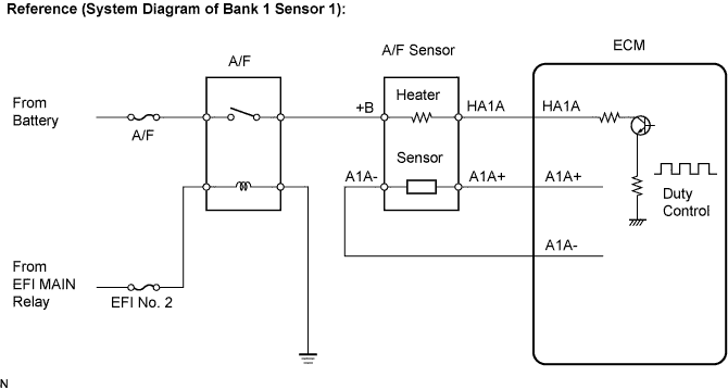
Wiring diagram
Inspection procedure
CHECK ANY OTHER DTCS OUTPUT (IN ADDITION TO DTC P0171, P0172, P0174 OR P0175)
CHECK PCV HOSE
CHECK AIR INDUCTION SYSTEM
PERFORM ACTIVE TEST BY INTELLIGENT TESTER (A/F CONTROL)
READ VALUE OF ENGINE COOLANT TEMPERATURE SENSOR (COOLANT TEMP)
READ VALUE OF INTAKE AIR FLOW METER (MAF)
CHECK FUEL PRESSURE (LOW PRESSURE SIDE)
CHECK FUEL PRESSURE SENSOR
CHECK FUEL PRESSURE (HIGH PRESSURE SIDE)
CHECK FOR EXHAUST GAS LEAKAGE
CHECK FOR SPARK AND IGNITION
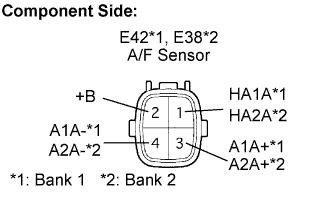
INSPECT AIR FUEL RATIO SENSOR (HEATER RESISTANCE)
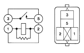
INSPECT A/F HTR RELAY
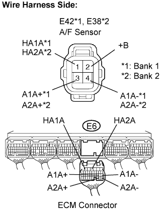
CHECK HARNESS AND CONNECTOR (A/F SENSOR — ECM)
REPLACE AIR FUEL RATIO SENSOR
PERFORM CONFIRMATION DRIVING PATTERN
CHECK WHETHER DTC OUTPUT RECURS (DTC P0171, P0172, P0174 OR P0175)
DTC P0171 System Too Lean (Bank 1)
DTC P0172 System Too Rich (Bank 1)
DTC P0174 System Too Lean (Bank 2)
DTC P0175 System Too Rich (Bank 2)
Description
The fuel trim is related to the feedback compensation value, not to the basic injection time. The fuel trim consists of both the short-term and the long-term fuel trims.
The short-term fuel trim is fuel compensation that is used to constantly maintain the air-fuel ratio at stoichiometric levels. The signal from the Air-Fuel Ratio (A/F) sensor indicates whether the air-fuel ratio is rich or lean compared to the stoichiometric ratio. This triggers a reduction in the fuel injection volume if the air-fuel ratio is rich and an increase in the fuel injection volume if it is lean.
factors such as individual engine differences, wear over time and changes in operating environment cause short-term fuel trim to vary from the central value. The long-term fuel trim, which controls overall fuel compensation, compensates for long-term deviations in the fuel trim from the central value caused by the short-term fuel trim compensation.
If both the short-term and long-term fuel trims are lean or rich beyond predetermined values, it is interpreted as a malfunction, and the ECM illuminates the MIL and sets a DTC.
| DTC No. | DTC Detection Condition | Trouble Area |
| P0171 P0174 |
With warm engine and stable air-fuel ratio feedback, fuel trim considerably in error to lean side (2 trip detection logic) |
|
| P0172 P0175 |
With warm engine and stable air-fuel ratio feedback, fuel trim considerably in error to rich side (2 trip detection logic) |
|
HINT:
- When DTC P0171 or P0174 is set, the actual air-fuel ratio is on the lean side. When DTC P0172 or P0175 is set, the actual air-fuel ratio is on the rich side.
- If the vehicle runs out of fuel, the air-fuel ratio is lean and DTC P0171 or P0174 may be set. The MIL is then illuminated.
- When the total of the short-term and long-term fuel trim values is within the malfunction threshold (and the engine coolant temperature is more than 75°C [167°F]), the system is functioning normally.
Wiring diagram
Refer to DTC P2195
Inspection procedure
HINT:
Intelligent tester only:
Malfunctioning areas can be identified by performing the A/F CONTROL function provided in the ACTIVE TEST. The A/F CONTROL function can help to determine whether the Air-Fuel Ratio (A/F) sensor, Heated Oxygen (HO2) sensor and other potential trouble areas are malfunctioning.
The following instructions describe how to conduct the A/F CONTROL operation using an intelligent tester.
- Connect the intelligent tester to the DLC3.
- Start the engine and turn the tester ON.
- Warm up the engine at engine speed of 2,500 rpm for approximately 90 seconds.
- On the tester, enter the following menus: Power train / Engine / Active Test / Control the Injection Volume for A/F Sensor.
- Perform the A/F CONTROL operation with the engine in an idling condition (press the RIGHT or LEFT button to change the fuel injection volume.)
- Monitor the output voltages of the A/F and HO2 sensors (AFS B1S1 and O2S B1S2 or AFS B2S1 and O2S B2S2) displayed on the tester.
HINT:
- The A/F CONTROL operation lowers the fuel injection volume by 12.5% or increases the injection volume by 25%.
- Each sensor reacts in accordance with increases and decreases in the fuel injection volume.
| Tester Display (Sensor) |
Injection Volume | Status | Voltage |
| AFS B1S1 or AFS B2S1 (A/F) |
+25 % | Rich | Less than 3.0 |
| AFS B1S1 or AFS B2S1 (A/F) |
-12.5 % | Lean | More than 3.35 |
| O2S B1S2 or O2S B2S2 (HO2) |
+25 % | Rich | More than 0.55 |
| O2S B1S2 or O2S B2S2 (HO2) |
-12.5 % | Lean | Less than 0.4 |
NOTICE:
The Air-Fuel Ratio (A/F) sensor has an output delay of a few seconds and the Heated Oxygen (HO2) sensor has a maximum output delay of approximately 20 seconds.
| Case | A/F Sensor (Sensor 1) Output Voltage |
HO2 Sensor (Sensor 2) Output Voltage |
Main Suspected Trouble Area | ||
| 1 | Injection Volume +25 % -12.5 % |
 |
Injection Volume +25 % -12.5 % |
 |
— |
| Output Voltage More than 3.35 V Less than 3.0 V |
 |
Output Voltage More than 0.55 V Less than 0.4 V |
 |
||
| 2 | Injection Volume +25 % -12.5 % |
 |
Injection Volume +25 % -12.5 % |
 |
|
| Output Voltage Almost no reaction |
 |
Output Voltage More than 0.55 V Less than 0.4 V |
 |
||
| 3 | Injection Volume +25 % -12.5 % |
 |
Injection Volume +25 % -12.5 % |
 |
|
| Output Voltage More than 3.35 V Less than 3.0 V |
 |
Output Voltage Almost no reaction |
 |
||
| 4 | Injection volume +25 % -12.5 % |
 |
Injection Volume +25 % -12.5 % |
 |
|
| Output Voltage Almost no reaction |
 |
Output Voltage Almost no reaction |
 |
- Following the A/F CONTROL procedure enables technicians to check and graph the voltage outputs of both the A/F and HO2 sensors.
- The following A/F Control procedure enables the technician to check and graph the voltage output of both the heated oxygen sensors. To display the graph, select the following menu items on the tester: View / Line Graph.
HINT:
- Read freeze frame data using the intelligent tester. Freeze frame data records the engine conditions when malfunctions are detected. When troubleshooting, freeze frame data can help determine if the vehicle was running or stopped, if the engine was warmed up or not, if the air-fuel ratio was lean or rich, and other data from the time the malfunction occurred .
- A low A/F sensor voltage could be caused by a rich air-fuel mixture. Check for conditions that would cause the engine to run rich.
- A high A/F sensor voltage could be caused by a rich air-fuel mixture. Check for conditions that would cause the engine to run lean.
1.CHECK ANY OTHER DTCS OUTPUT (IN ADDITION TO DTC P0171, P0172, P0174 OR P0175)
-
Connect the intelligent tester to the DLC3.
-
Turn the engine switch on (IG) and turn the tester ON.
-
Enter the following menus: Power train / Engine / DTC.
-
Read DTCs.
Result:
| Display (DTC output) | Proceed to |
| P0171, P0172, P0174 or P0175 | A |
| P0171, P0172, P0174 or P0175 and other DTCs | B |
HINT:
If any DTCs other than P0171, P0172, P0174 or P0175 are output, troubleshoot those DTCs first.
OK:
PCV hose is connected correctly and is not damaged.
|
REPAIR OR REPLACE PCV HOSE |
|
3.CHECK AIR INDUCTION SYSTEM
-
Check the air induction system for vacuum leakage.
OK:
No leakage from air induction system.
|
REPAIR OR REPLACE AIR INDUCTION SYSTEM |
|
4.PERFORM ACTIVE TEST BY INTELLIGENT TESTER (A/F CONTROL)
-
Connect the intelligent tester to the DLC3.
-
Start the engine and turn the tester ON.
-
Warm up the engine at an engine speed of 2,500 rpm for approximately 90 seconds.
-
On the tester, enter the following menus: Power train / Engine / Active Test / Control the Injection Volume for A/F Sensor.
-
Perform the A/F CONTROL operation with the engine in an idling condition (press the RIGHT or LEFT button to change the fuel injection volume).
-
Monitor the outputs voltages of A/F and HO2 sensors (AFS B1S1 and O2S B1S2 or AFS B2S1 and O2S B2S2) displayed on the tester.
HINT:
- The A/F CONTROL operation lowers the fuel injection volume by 12.5 % or increases the injection volume by 25 %.
- Each sensor reacts in accordance with increases and decreases in the fuel injection volume.
| Tester Display (Sensor) | Injection Volume | Status | Voltage |
| AFS B1S1 or AFS B2S1 (A/F) |
+25% | Rich | Less than 3.0 |
| AFS B1S1 or AFS B2S1 (A/F) |
-12.5% | Lean | More than 3.35 |
| O2S B1S2 or O2S B2S2 (HO2) |
+25% | Rich | More than 0.55 |
| O2S B1S2 or O2S B2S2 (HO2) |
-12.5% | Lean | Less than 0.4 |
Result:
| Status AFS B1S1 or AFS B2S1 |
Status O2S B1S2 or O2S B2S2 |
A/F Condition and A/F Sensor Condition |
Misfire | Suspected Trouble Area | Proceed to |
| Lean/Rich | Lean/Rich | Normal | — | — | C |
| Lean | Lean | Actual air-fuel ratio lean | May occur |
|
A |
| Rich | Rich | Actual air-fuel ratio rich | — |
|
A |
| Lean | Lean/Rich | A/F sensor malfunction | — |
|
B |
| Rich | Lean/Rich | A/F sensor malfunction | — |
|
B |
- Lean:
- During A/F CONTROL, the A/F sensor output voltage (AFS) is consistently more than 3.35 V, and the HO2 sensor output voltage (O2S) is consistently less than 0.4 V.
- Rich:
- During A/F CONTROL, the AFS is consistently less than 3.0 V, and the O2S is consistently more than 0.55 V.
5.READ VALUE OF ENGINE COOLANT TEMPERATURE SENSOR (COOLANT TEMP)
-
Connect the intelligent tester to the DLC3.
-
Turn the engine switch on (IG) and turn the tester ON.
-
Enter the following menus: Power train / Engine / Data List / Coolant Temp.
-
Read the COOLANT TEMP twice, when the engine is both cold and warmed up.
Standard:
With cold engine:
Same as ambient air temperature.
With warm engine:
Between 75 and 95°C (167 and 203°F)
|
REPLACE ENGINE COOLANT TEMPERATURE SENSOR |
|
6.READ VALUE OF INTAKE AIR FLOW METER (MAF)
-
Connect the intelligent tester to the DLC3.
-
Turn the engine switch on (IG) and turn the tester ON.
-
Enter the following menus: Power train / Engine / Data List / MAF and Coolant Temp.
-
Allow the engine to idle until the COOLANT TEMP reaches 75°C (167°F) or more.
-
Read the MAF with the engine in an idling condition and at an engine speed of 2,500 rpm.
Standard:
MAF while engine idling:
Between 2.1 g/s and 3.1 g/s (shift position: N, A/C: OFF).
MAF at an engine speed of 2,500 rpm:
Between 7.8 g/s and 11.4 g/s (shift position: N, A/C: OFF).
|
REPLACE MASS AIR FLOW METER |
|
7.CHECK FUEL PRESSURE (LOW PRESSURE SIDE)
-
Check the fuel pressure (low pressure side).
|
CHECK AND REPLACE FUEL PUMP, PRESSURE REGULATOR, FUEL PIPE LINE AND FILTER |
|
8.CHECK FUEL PRESSURE SENSOR
-
Connect the intelligent tester to the DLC3.
-
Turn the engine switch on (IG) and turn the tester ON.
-
Start the engine.
-
Enter the following menus: Power train / Engine / Data List / Fuel Press.
-
While revving the engine, check that the fuel pressure fluctuates.
OK:
Fuel pressure fluctuates.
|
REPLACE FUEL PRESSURE SENSOR |
|
9.CHECK FUEL PRESSURE (HIGH PRESSURE SIDE)
-
Check the fuel pressure (high pressure side).
|
CHECK AND REPLACE FUEL SYSTEM |
|
10.CHECK FOR EXHAUST GAS LEAKAGE
OK:
No gas leakage.
|
REPAIR OR REPLACE EXHAUST SYSTEM |
|
11.CHECK FOR SPARK AND IGNITION
HINT:
If the spark plugs or ignition system malfunctions, engine misfire may occur. The misfire count can be read using an intelligent tester. Enter the following menus: Power train / Engine / Data List / Cylinder #1 (to #6) Misfire Rate.
|
REPAIR OR REPLACE IGNITION SYSTEM |
|
12.INSPECT AIR FUEL RATIO SENSOR (HEATER RESISTANCE)
-
Disconnect the E42 or E38 A/F sensor connector.
Measure the resistance of the A/F sensor connector.
Standard resistance (Bank 1 sensor 1):
| Tester Connection | Condition | Specified Condition |
| HA1A (1) — +B (2) | 20°C (68°F) | 1.8 ? to 3.4 ? |
| HA1A (1) — A1A- (4) | — | 10 k? or higher |
Standard resistance (Bank 2 sensor 1):
| Tester Connection | Condition | Specified Condition |
| HA2A (1) — +B (2) | 20°C (68°F) | 1.8 ? to 3.4 ? |
| HA2A (1) — A2A- (4) | — | 10 k? or higher |
-
Reconnect the A/F sensor connector.
|
REPLACE AIR FUEL RATIO SENSOR |
|
-
Remove the A/F HTR relay from the engine room J/B and R/B No. 2.
-
Measure resistance of the A/F HTR relay.
Standard resistance:
| Tester Connection | Specified Condition |
| 3 — 5 | 10 k? or higher |
| 3 — 5 | Below 1 ? (when battery voltage applied to terminals 1 and 2) |
-
Reinstall the A/F HTR relay.
14.CHECK HARNESS AND CONNECTOR (A/F SENSOR — ECM)
-
Disconnect the E42 and E38 A/F sensor connector.
-
Turn the engine switch on (IG).
-
Measure the voltage between the +B terminal of the A/F sensor connector and body ground.
Standard voltage:
| Tester Connection | Specified Condition |
| +B (E42-2) — Body ground | 9 to 14 V |
| +B (E38-2) — Body ground | 9 to 14 V |
-
Turn the engine switch off.
-
Disconnect the E6 ECM connector.
-
Measure the resistance of the wire harness side connector.
Standard resistance (Check for open):
| Tester Connection | Specified Condition |
| HA1A (E42-1) — HA1A (E6-6) | Below 1 ? |
| A1A+ (E42-3) — A1A+ (E6-18) | Below 1 ? |
| A1A- (E42-4) — A1A- (E6-17) | Below 1 ? |
| HA2A (E38-1) — HA2A (E6-4) | Below 1 ? |
| A2A+ (E38-3) — A2A+ (E6-28) | Below 1 ? |
| A2A- (E38-4) — A2A- (E6-27) | Below 1 ? |
Standard resistance (Check for short):
| Tester Connection | Specified Condition |
| HA1A (E42-1) or HA1A (E6-6) — Body ground | 10 k? or higher |
| A1A+ (E42-3) or A1A+ (E6-18) — Body ground | 10 k? or higher |
| A1A- (E42-4) or A1A- (E6-17) — Body ground | 10 k? or higher |
| HA2A (E38-1) or HA2A (E6-4) — Body ground | 10 k? or higher |
| A2A+ (E38-3) or A2A+ (E6-28) — Body ground | 10 k? or higher |
| A2A- (E38-4) or A2A- (E6-27) — Body ground | 10 k? or higher |
-
Reconnect the ECM connector.
-
Reconnect the A/F sensor connector.
|
REPAIR OR REPLACE HARNESS OR CONNECTOR |
|
15.REPLACE AIR FUEL RATIO SENSOR
16.PERFORM CONFIRMATION DRIVING PATTERN
-
Connect the intelligent tester to the DLC3 (Procedure «A»).
-
Turn the engine switch on (IG) and turn the tester ON (Procedure «B»).
-
Clear DTCs (Procedure «C»).
-
Switch the ECM from normal mode to check mode using the tester (Procedure «D»).
-
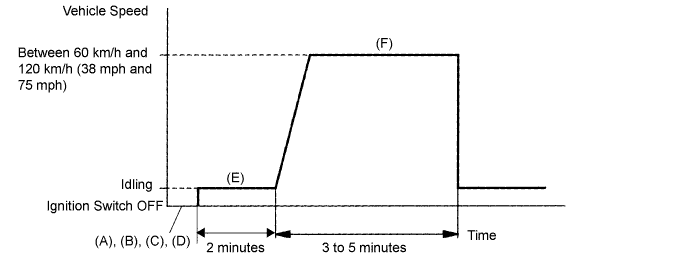
Start the engine and warm it up with all the accessories switched OFF (Procedure «E»).
-
Drive the vehicle at between 60 km/h and 120 km/h (38 mph and 75 mph) and at an engine speed of between 1,400 rpm and 3,200 rpm for 3 to 5 minutes (Procedure «F»).
HINT:
If the system is still malfunctioning, the MIL will be illuminated during step (f).
NOTICE:
If the conditions in this test are not strictly followed, no malfunction will be detected.
17.CHECK WHETHER DTC OUTPUT RECURS (DTC P0171, P0172, P0174 OR P0175)
-
On the intelligent tester, enter the following menus: Power train / Engine / DTC.
-
Read DTCS.
Result:
| Display (DTC output) | Proceed to |
| No output | A |
| P0171, P0172, P0174 or P0175 | B |
L-SB-0032-09
March 26, 2009
| Service Category | Engine/Hybrid System | ||
|---|---|---|---|
| Section | Engine Control | Market | USA |
Applicability
| YEAR(S) | MODEL(S) | ADDITIONAL INFORMATION |
|---|---|---|
| 2008 – 2009 | IS250 | Drive Type(s): 2WD, 4WD Engine(s): 4GR Transmission(s): 6MT, 6AT VDS(s): BK262, CK262 |
Introduction
Under certain driving conditions, some 2008 – 2009 model year IS250 vehicles with 4GR-FSE engines may exhibit a M.I.L. “ON” condition with one or both of the following Diagnostic Trouble Codes (DTCs):
- P0172 (System Too Rich [Bank 1])
- P0175 (System Too Rich [Bank 2])
The Engine Control Module (ECM) (SAE term: Powertrain Control Module/PCM) logic has been modified to reduce the possibility of this condition occurring. Refer to the following repair procedure to address customer concerns.
Warranty Information
| OP CODE | DESCRIPTION | TIME | OFP | T1 | T2 |
|---|---|---|---|---|---|
| EG9005 | Recalibrate ECM (PCM) Engine and Change Engine Oil & Oil Filter | 1.0 | 89661-##### | 8A | 99 |
- This repair is covered under the Lexus Federal Emissions Warranty. This warranty is in effect for 96 months or 80,000 miles, whichever occurs first, from the vehicles in-service date.
- Warranty application is limited to correction of a problem based upon a customer’s specific complaint.
Parts Information
| MODEL YEAR | DRIVETRAIN | TRANS | PREVIOUS PART NUMBER | CURRENT PART NUMBER | PART NAME | QTY |
|---|---|---|---|---|---|---|
| 2008/ 2009 | 2WD | – | 04152-YZZA3 |
Same | Element Kit, Oil Filter | 1 |
| AWD | – | 04152-YZZA2 | 04152-YZZA5 |
1 | ||
| – | – | – | N/A | 00451-00001-LBL | Authorized Modifications Label | 1 |
| 2WD | M/T | 89661-53B00 | 89661-53B01 | – | ||
| 2008 | A/T | 89661-53B10 | 89661-53B11 | Computer, Engine Control (ECM/PCM) | – | |
| AWD | 89661-53B20 | 89661-53B21 | – | |||
| 2009 | 2WD | M/T | 89661-53C40 | 89661-53C41 | – | |
| A/T | 89661-53C50 | 89661-53C51 | – | |||
| AWD | 89661-53C60 | 89661-53C61 | – |
- The ECM (PCM) should NOT be replaced as part of the repair procedure.
- Authorized Modification Labels may be ordered in packages of 25 from the Materials Distribution Center (MDC) through Dealer Daily – Dealer Support Materials Orders.
Calibration Identification Chart
| MODEL YEAR | DRIVETRAIN | TRANS | ECM (CPU) | PREVIOUS CALIBRATION ID | NEW CALIBRATION ID | VDS |
|---|---|---|---|---|---|---|
| M/T | Main | 35365000 | 35365100 | |||
| 2008 | 2WD | A/T | 35366000 | 35366100 | BK262 | |
| Sub | 55351000 | 55351100 | ||||
| AWD | A/T | Main | 35367000 | 35367100 | CK262 | |
| Sub | 55352000 | 55352100 | ||||
| 2009 | 2WD | M/T | Main | 35379000 | 35379100 | BK262 |
| A/T | 35380000 | 35380100 | ||||
| AWD | 35381000 | 35381100 | CK262 |
Required Tools & Equipment
| SPECIAL SERVICE TOOLS (SST’S) | PART NUMBER | QTY |
|---|---|---|
| GR8 Battery Diagnostic Station* | 00002-MCGR8 | 1 |
* Essential SST.
- Additional SSTs may be ordered by calling 1-800-933-8335.
- The GR8 Battery Diagnostic Station (P/N 00002-MCGR8) supersedes the Automatic Trickle Charger (P/N 00002-YA122-01) and Fast Battery Chargers (Associated P/N ASE6003 and Christie P/N CAPPDQ). P/N 00002-YA122-01, ASE6003, and CAPPDQ are now obsolete.
| REQUIRED EQUIPMENT | SUPPLIER | PART NUMBER | QTY |
|---|---|---|---|
| TIS Techstream*
NOTE: Software version 4.00.017 or later is required. |
ADE | TSUNT | 1 |
* Essential SST.
| REQUIRED MATERIAL | CLASSIFICATION | DRIVETRAIN | QUANTITY |
|---|---|---|---|
| Engine Oil | ILSAC GF-4 Multi-grade SAE 5W-30 | 2WD | 6.2 U.S. quarts (5.9 liters) |
| AWD | 6.3 U.S. quarts (6.0 liters) |
Repair Procedure
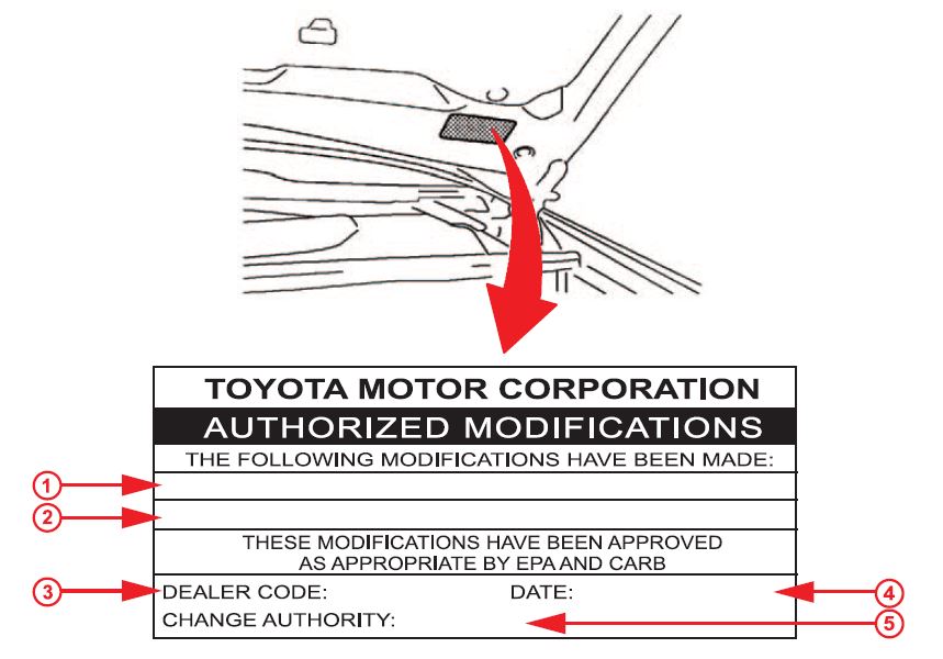
- Check for the Authorized Modifications Label affixed to the vehicle in the location shown in Figure 1. Confirm if the ECM (PCM) calibration has been updated. If the calibration ID listed is NOT the latest ECM (PCM) calibration — go to step 2.
Figure 1. Location of Authorized Modifications Label on 2008 IS 250
| 1 | Replacement ECM (PCM) Part Number (i.e., 89661-53B01) | 4 | Date Completed |
| 2 | New Calibration ID(s) (i.e., 35365100) | 5 | This TSIB Number |
| 3 | Dealer Code |
- Flash Reprogram the ECM (PCM).
- The GR8 Battery Diagnostic Station MUST be used in Power Supply Mode to maintain battery voltage at 13.5 volts while flash reprogramming the vehicle.
- For details on how to use the GR8 Battery Diagnostic Station, refer to the GR8 Instruction Manual located on the Technical Information System (TIS), Diagnostics – Battery.
Follow the procedures outlined in TSIB No. SS002-07, “Techstream ECU Flash Reprogramming Procedure”, and flash the ECM (PCM) with the NEW calibration file update.
- Install the Authorized Modifications Label.
- Using a permanent marker, enter the following information on the label:
- ECM part number [Refer to the Parts Information section for the CURRENT PART NUMBER]
- Calibration ID(s) [Refer to the Calibration Identification Chart for the NEW CALIBRATION ID]
- Dealer Code
- Repair Date
- Change Authority [This TSIB number]
- Affix the Authorized Modifications Label to the vehicle at the location shown in Figure 1. The Authorized Modifications Label is available through the MDC, P/N 00451-00001-LBL.
- Using a permanent marker, enter the following information on the label:
- Change the engine oil and filter.
Refer to TIS, applicable model year IS 250 Repair Manual:
- 2008 IS 250: Engine/Hybrid System – Lubrication – “4GR–FSE Lubrication: Oil and Oil Filter (for 4WD) / (for 2WD): Replacement”
- 2009 IS 250: Engine/Hybrid System – Lubrication – “4GR–FSE Lubrication: Oil and Oil Filter (for 4WD) / (for 2WD): Replacement”
- Test drive the vehicle to confirm proper vehicle operation.
L-SB-0032-09
J2534 Reprogramming
Approved J2534 Devices only provide reprogramming capabilities and do not support diagnostic scantool functions. For full diagnostic capabilities, please consider TIS Techstream or Techstream Lite
Toyota, Scion, and Lexus ECMs can be reprogrammed with the TIS Techstream, Techstream Lite, Diagnostic Tester, or can also be reprogrammed using a Toyota validated J2534 interface. Vehicle recalibration requires the use of the following:
- Toyota validated J2534 interface
- TIS Professional Level Subscription
- Toyota Calibration Update Wizard software (installed along with Techstream Software)
- Personal Computer running Microsoft Windows XP/2000 or later operating system
Toyota strongly recommends USING ONLY VALIDATED INTERFACE DEVICES that appear on this list.
Toyota works closely with J2534 interface manufacturers to ensure that their hardware works safely and efficiently with our products. Every device listed on this page has been thoroughly tested and validated on Toyota, Scion, and Lexus vehicles.
It is important to understand that only the specific devices, firmware, DLLs and APIs listed here have been tested by Toyota. We do not recommend use of any other J2534 device, firmware, DLL or API that is not listed here. Changes to J2534 hardware/software is outside of Toyota’s control; in some cases, changes made to device hardware/software can negatively impact reprogramming performance. Toyota makes every effort to continue to work with J2534 interface manufacturers to ensure continued product compatibility as our respective products evolve.
J2534 Approved Device Application Chart
| Supplier | Device Name | Version | CUW Version | Supported OS | ||
|---|---|---|---|---|---|---|
| Firmware* | DLL* | API* | ||||
| Bosch Diagnostics | Flasher LT-Import | 01.02.07 | 01.02.07 | 04.04 | 8.8 | B, C, D, E |
| Bosch Diagnostics | Flasher PRO | 01.09.18 | 01.09.18 | 04.04 | 8.8 | B, C, D, E |
| Bosch Diagnostics | Mastertech VCI | 13.0.75.27 | 2.0.75.27 | 04.04 | Testing in Progress | B, C, D, E |
| Dearborn Group | VSI-2534 |
1.112 | 2.05.22 | 04.04 | 8.10 | C, D |
| Drew Technologies | CarDAQ Plus |
01.09.18 | 01.09.18 | 04.04 | 8.8 | B, C, D, E |
| Drew Technologies | Mongoose MFC | 01.02.07 | 01.02.07 | 04.04 | 8.8 | B, C, D, E |
| Drew Technologies | Mongoose PRO | 1.1.12.0 | 1.1.12.0 | 04.04 | 8.16 | A, B, C, D |
| Snap-On | Pass Thru Pro II | 01.09.18 | 01.09.18 | 04.04 | 8.8 | B, C, D, E |
*Original validated firmware/DLL versions may be superceded by the device manufacturer. Contact the device manufacturer if you are unable to find the versions listed above.
Supported Operating Systems
| A | Windows 8 (32-bit; 64-bit) |
| B | Windows 7 (32-bit; 64-bit) |
| C | Windows VISTA Home Basic, Home Premium, Business, Ultimate |
| D | Windows XP Pro SP1 or later |
| E | Windows 2000 SP2 or later |
For more information about the J2534 devices listed above, click on the vendor names. To report compatibility problems with listed hardware/software, please contact the device manufacturer.
Obtaining Calibration Files
The Flash Reprogramming Calibration CD is no longer available.
ECU Calibrations are now available for download directly from TIS. A valid TIS Professional Level subscription is required to access Calibration files. These files are compatible with the above mentioned scantools and J2534 interfaces. The Calibration page, located on the Diagnostics tab in the TIS site, contains all the most current vehicle calibration files, applicable Service Bulletins, and instructions for use. Select the following link for step by step instructions to access this page.
Note: Calibration Update Software is now included in the Techstream Software Installer. A valid TIS Professional Level subscription is required to download and install Techstream Software.
https://techinfo.toyota.com
Price Disclaimer
Price Disclaimer
Коллеги, интересует у кого есть опыт с богатой смесью при большом значении ДМРВ на моторах серии GR.
Итак is250 почти «мой», диагностировал 2 месяца назад, была ошибка 0441 — неверный поток воздуха КПА. Тогда обратил внимание что коррекции fuel trim long по обоим блокам в «-«, где-то на уровне -10. Вроде проблем после сброса ошибок и адаптаций не было до того момента как несколько дней назад появилась Р0172 — богатая топливная смесь. В запуске и динамике никаких замечаний нет. Масложор отсутствует вообще, про компрессию можно не говорить. На горячем ДВС присутствует ощутимая вибрация на ХХ и в режиме Драйв (при ДТОЖ менее 70 град. данные дефекты не проявляются).
Что бросается в глаза:
На хх Коррекции long -26 и -20 соответственно банк 1 и банк 2, МАФ — 2,9-3,0 мг/сек — ХХ, 8,5-8,9 — при 2500 тыс.
В динамике: коррекции -16 и -10.
После сброса адаптации коррекции, очень быстро уходят в минус. При этом работа ДВС визуально никак не меняется
После профилактических промывок дросселя, мафа, замены воздушного фильтра (с удалением войлочного фильтра в крышке корпуса воздушного фильтра), проверки свечей (на предмет попадания масла в колодца), использования присадки в топливный бак, показания МАФ уползли уже за 3-3 мг/сек, коррекции при использовании присадки были -35/-30, после выработки топлива с присадкой -26/-20.
Обороты ХХ периодически не могут опуститься до 650об/мин, держатся в районе 750-800 при маф 3,4-4,2.
Напряжение АКБ 13,5-13,8В
Нагрузка расчетная 26% на ХХ, а вот по факту считает 17-20%.
Давление в рампе 4100 на ХХ, стабильно
Пропусков по цилиндрам нет ни при запуске, ни при максимальной нагрузке.
Расход в смешанном цикле — 16л, 9л — трасса,
МАФ при включенном зажигании — 0,48
Собственно вопросы:
«наелись» ШДК на обоих банках, что ЭБУ вызывает компенсацию смеси путем приоткрытия дросселя для добавки воздуха (похоже на бред)?
или маф все таки от старости умирает?
возможно ли подклинивание заслонок SCV в портах впускных клапанов, что вызывает увеличение потребляемого воздуха и худшее смесеобразование с итоговой богатой смесью?
Другие варианты не могу предположить.


