Два уровня ошибок: как в них разобраться
Для наглядности и удобства расшифровки кодов неисправностей обозначение ошибки состоит из двух частей, например: E15 CA559
, гдеE15 – это пользовательский код. Он указывает на отказ системы управления двигателем (снижение выходной мощности для защиты мотора), а СА559 – это код, который конкретно указывает на то, что общее давление в коллекторе слишком низкое. Помимо буквенно-циферного отображения ошибки, на мониторе выводится и ее расшифровка на русском языке: низкое давление в общей рейке Common Rail. Это сделано для того, чтобы помочь оператору на месте разобраться с неисправностью и устранить поломку.
При появлении на мониторе ошибки, указывающей на низкое давление дизтоплива в общей рейке топливного насоса, поиск и устранение неисправности следует начать с проверки фильтров и топливной рампы Common Rail на отсутствие утечек ДТ (дизтоплива). Обычно после очистки или замены топливных фильтров проблема исчезает, если же нет, то необходимо провести диагностику основного топливного насоса.
С помощью семи сегментной контрольной панели экскаватора Komatsu PC 400 оператор может провести самодиагностику, например, гидравлической системы на соответствие рабочим параметрам, заданным производителем техники. Подняв стрелу экскаватора до конечного положения можно проверить давление, при котором сработает предохранительный клапан, и сравнить его с табличным значением. Также проверяется давление масла, развиваемое гидравликой привода ковша в режиме наполнения. Cкриншот: https://www. youtube. com/watch? v=nnv4Xuc1GWE
Для этого выбирается соответствующий код (010, 011, 012 и т. д.) и проводится проверка систем и узлов. По ее результатам проводится регулировка предохранительных клапанов, проверка/замена уплотнителей гидроцилиндров и другое ТО.
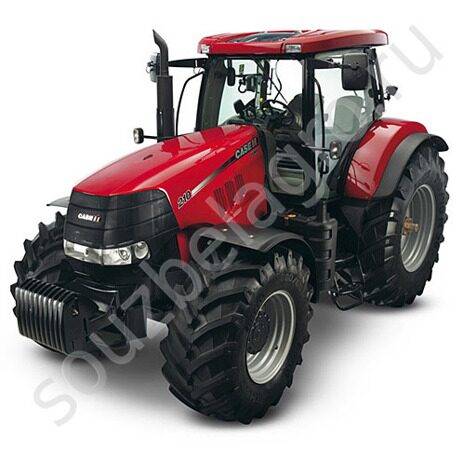
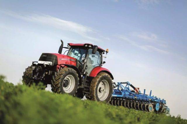
Case IH Puma 210 — трактор с полным приводом и блокировкой дифференциала. Передний мост включается автоматически, когда увеличивается нагрузка на буксирное устройство или когда колеса проскальзывают. Усовершенствованная передняя подвеска с механизмом гашения вибрации используется на всех моделях серии и может улучшить управляемость и комфорт. Уровень вибрации при установленном оборудовании остается минимальным независимо от характера оборудования. Демпфирование контролируется регенеративным клапанным механизмом и модернизированной батареей, что обеспечивает бесперебойную работу.
Подвеска также оснащена функцией самовыравнивания в автоматическом режиме с учетом нагрузки и условий. Передняя подвеска оснащена датчиком ускорения. Задние мосты изготовлены в США и отличаются повышенной прочностью.
Особенности эксплуатации
Производитель заявляет, что вся выпускаемая продукция отличается повышенным качеством и благодаря применению новейших технологий легко справляется с любыми задачами. Высокая эффективность достигается за счет сложнейших электронных систем, позволяющих контролировать работу.
Судя по отзывам владельцев, которые активно эксплуатируют технику Кейс, тракторы отличаются качеством и надежностью, поэтому первые несколько лет работают без ремонта. Однако, чтобы добиться такого результат необходимо следить за регулярностью и качеством проведения технического обслуживания. Трактора работают на дизельном топливе повышенного качества, а в качестве моторного масла нужно использовать CI-4 AKCELA MS1121.
Огромным достоинством новых тракторов является то, что они поступают в продажу уже с проведенной обкаткой. Также на предприятии перед отправкой в дилерскую сеть проводится калибровка и тестирование всех электронных систем.
Консервирование производится по всем правилам, описанным в инструкции по эксплуатации. Сначала трактор моется, сушится, а потом все детали и механизмы протираются промясленной тряпкой. Масло сливается, а контакты на свечах отсоединяются. После всех процедур трактор ставится в сухое место и накрывается чехлом.
Подвеска, ходовая часть, тормоза трактора
Ходовая часть у тракторов Case IH Puma 210 – полноприводная, с подключаемым передним мостом и функцией блокировки дифференциалов. Постоянно ведущими колёсами являются задние, а управляемыми – передние. Передний мост подключается автоматически – при начале пробуксовывания колёс, либо при значительном увеличении нагрузки на буксировочное устройство.
Снижения удельного давления на грунт можно добиться, если применять сдвоенные колёса на широкопрофильных пневматических шинах, размером 600/65R28 либо 710/70R38.

Благодаря конструкции шасси с очень компактной компоновкой рулевого управления, тракторам Case Puma 210 нужно меньше времени для разворотов по краям поля. Особенно полезно это при обработке пропашных культур. Передний мост Case IH спроектирован для максимальной прочности и долговечности конструкции.
Также на всех моделях доступна дополнительная активная подвеска переднего моста. Она позволяет увеличить комфорт при передвижении трактора и улучшить управление им. Гарантируется меньший уровень колебаний при движении на скорости с уже установленными навесными орудиями или при маневрировании с погрузчиком. Длина хода составляет 105 мм, а демпфирование управляется при помощи усовершенствованного аккумулятора и регенеративной системы клапанов, обеспечивая бо́льшую мягкость хода. Также подвеска оснащена функцией автоматического самовыравнивания, в зависимости от нагрузки.
Расположение и тип конечных передач: планетарные, встроенные в мост. Тип полуосей – фланец. Тип рабочих тормозов – многодисковые, в масляной ванне.
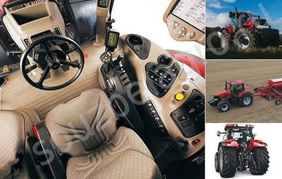
Кабина трактора Case Puma 210
Кабина тракторов семейства Case Puma, созданная с фирменной технологией Surround Vision позиционируется производителем как самая лучшая в классе кабина, причём заслуженно. Она сделана с учётом повышения производительности работы и обеспечения комфорта механизатора. Кабина оснащена остеклением суммарной площадью 5,87 квадратных метров (включая прозрачный люк в крыше).
Её основные характерные отличия – непревзойдённые углы обзора во все стороны, эргономичное расположение органов управления, детально выверенные по удобству для механизатора функции. Благодаря легкодоступным, регулируемым органам управления на подлокотнике длительная работа в поле получается гораздо менее утомительной.
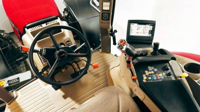
Все самые основные элементы управления трактора встроены в подлокотник сиденья механизатора, для мгновенного доступа (многофункциональная система Multicontroller). Туда же включен и дополнительный встроенный электрогидравлический джойстик, который обеспечивает эргономичную работу с погрузчиком
Правая передняя инструментальная панель, смонтированная на A-образной стойке, гарантирует удобный обзор важной рабочей информации для меньшей утомляемости
Технические характеристики Case Puma 210
- Разработчики – Case
- Годы производства – 2007-2010
- Тип двигателя – дизельный
- Мощность – 210 лошадиных сил
- Страны-производители – Австрия, Англия, Санкт-Валентин
- Семейство – Puma Series
- Емкость топливного бака – 439 л
- Тип подвески – трехточечная, грузоподъемностью 5800 кг и 7199 кг в зависимости от опции
- Шасси – полноприводное, 4×4 MFWD 4WD
- Рулевой механизм – гидростратический
- Тормозной механизм – дифференциальная гидравлика с мокрым диском
- Тормозной трейлер – гидравлический
- Кабина – классическая
- Электрические параметры: Земля – отрицательная; система зарядки – генератор; ампераж зарядки – 150
- Емкость батареи – 1300 amps, 12 Voltage
- Коробка передач – 18 передач переднего хода и 6 передач заднего хода. Бесступенчатая коробка CVT
- Параметры передних шин – 16/9R30
- Параметры задних шин – 20.8R42
- Масса (доставка) – 7125 кг
- Масса (в эксплуатационном режиме) – 8126 кг
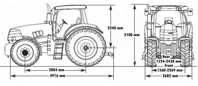
- Объем колесной базы – 2880 мм.
Гидравлическая система и задняя сцепка Case Puma 210
В стандартной комплектации доступно до четырёх механических клапанов, либо до 5-ти электронных дистанционных вентиля, также можно выбрать до 4-х электронных промежуточных клапанов. Задняя сцепка обеспечивает грузоподъёмность до 6016 килограммов.

Для сцепки также доступно кнопочное управление даже вне кабины, благодаря панели управления на крыле – для управления навесным оборудованием одной рукой.
Навесные агрегаты с гидравлическими моторами подключаются к бортовой гидравлике с помощью специальных быстроразъёмных штуцеров.
Трёхточечная навеска относится к категории 3 / 3N. Контроль усилия тяги – электронный, на нижнем рычаге. Стандартная грузоподъёмность навески – на расстоянии 610 мм позади точек крепления: 6016 килограммов. Тяговый брус поворотный, третьей категории.
Прицепной опрыскиватель 3200 литров, штанга 24 метра GASPARDO
Главной целью разработчиков новой серии тракторов PUMA было достижение еще большей эффективности. Большой ассортимент из 4 моделей мощностью от 165 до 210 л.с. дает возможность каждому растениеводческому или животноводческому хозяйству подобрать трактор оптимальной мощности. Трансмиссия с 18 передними и 6 задними передачами, силовым переключением и функцией Autoshift в стандартной комплектации зарекомендовала свою долговечность в полевых условиях.
На двигателя тракторов PUMA установлена система впрыска CommonRail с функцией PowerBoost, позволяющая справляться с неравномерными нагрузками, связанными с неровностями рельефа и другими факторами.
Наличие на тракторе Пума систем управления на разворотной полосе, автоматика включения ВОМ и малый радиус разворота, позволяет добываться высочайшей производительности при небольших затратах труда.
Характеристики тракторов Case PUMA 165, 180, 195, 210:
| Puma 165 | Puma 180 | Puma 195 | Puma 210 | |
| Двигатель | ||||
| Количество цилиндров | 6-Р | 6-Р | 6-Р | 6-Р |
| Объем двигателя, л | 6,75 | 6,75 | 6,75 | 6,75 |
| Номинальная мощность на ВОМ, кВт/л.с. | 123/165 | 134/180 | 145/195 | 157/210 |
| Максимальная мощность на ВОМ, кВт/л.с., при 1900-2000 об/мин | 132/180 | 147/200 | 156/212 | 164/223 |
| Номинальная частота вращения КВ, об/мин | 2200 | 2200 | 2200 | 2200 |
| Максимальный крутящий момент при 1400 об/мин, Н-м | 774 | 844 | 860 | 866 |
| Увеличение крутящего момента,% | 45 | 45 | 37 | 27 |
| Количество клапанов на цилиндр | 4 | 4 | 4 | 4 |
| Тип турбонаддува | стандарт, с промежуточным охлаждением | стандарт, с промежуточным охлаждением | стандарт, с промежуточным охлаждением | стандарт, с промежуточным охлаждением |
| Объем топливного бака, л | 405 | 405 | 405 | 405 |
| Трансмиссия | 18/6 с переключением под нагрузкой | 18/6 с переключением под нагрузкой | 18/6 с переключением под нагрузкой | 18/6 с переключением под нагрузкой |
| Стандартный генератор | 12 В/150 А | 12 В/150 А | 12 В/150 А | 12 В/150 А |
| Мосты ведущие | ||||
| Диаметр оси, мм | 105 | 105 | 105 | 105 |
| Длина заднего вала в стандартной поставке, мм | 2485 | 2485 | 2485 | 2485 |
| Длина заднего вала при специальном заказе, мм | 2489 или 3032 | 2489 или 3032 | 2489 или 3032 | 2489 или 3032 |
| Диапазон подстройки колеи переднего привода, мм | 1524-2235 | 1524-2235 | 1524-2235 | 1524-2235 |
| Колесная база, мм | 2884 | 2884 | 2884 | 2884 |
| Гидравлическая система | ||||
| Производительность стандартного насоса, л/мин. | 120 | 120 | 120 | 120 |
| Производительность опционного насоса, л/мин | 150 | 150 | 150 | 150 |
| Давление в гидросистеме, бар | 215 | 215 | 215 | 215 |
| Внешние гидрораспределители | 3 или 4 мех, от 3 до 5 гидравлические | 3 или 4 мех, от 3 до 5 гидравлические | 3 или 4 мех, от 3 до 5 гидравлические | 3 или 4 мех, от 3 до 5 гидравлические |
| Производительность насоса рулевого и служебного тракторов, л/мин | 66 | 66 | 66 | 66 |
| Навеска | ||||
| Тип навески | Трехточечная, категории II/IIIN | Трехточечная, категории II/IIIN | Трехточечная, категории II/IIIN | Трехточечная, категории II/IIIN |
| Грузоподъемность навески стандарт/опция, кг | 5800/7200 | 5800/7200 | 5800/7200 | 5800/7200 |
| Вал отбора мощности | ||||
| Частота вращения, об/мин | 540Е/1000 | 540Е/1000 | 540Е/1000 | 540Е/1000 |
| Тип вала | 1 3/8″ 21 шлиц; 1 3/8″ 6 шлиц; 1 3/4″ 20 шлиц | 1 3/8″ 21 шлиц; 1 3/8″ 6 шлиц; 1 3/4″ 20 шлиц | 1 3/8″ 21 шлиц; 1 3/8″ 6 шлиц; 1 3/4″ 20 шлиц | 1 3/8″ 21 шлиц; 1 3/8″ 6 шлиц; 1 3/4″ 20 шлиц |
| Вес | ||||
| Максимальный рабочий вес, кг | 12000 | 12000 | 12000 | 12000 |
| Сухой вес, кг | 7125 | 7125 | 7125 | 7125 |
| Размеры | ||||
| Длина, мм | 4840 | 4840 | 4840 | 4840 |
| Высота, мм | 3210 | 3210 | 3210 | 3210 |
| Шины передние | 480/70R30 | 480/70R30 | 480/70R30 | 480/70R30 |
| Шины задние | 580/70R42 | 580/70R42 | 580/70R42 | 580/70R42 |
| Радиус поворота при колесе 1829 мм (м) | 6,1 | 6,1 | 6,1 | 6,1 |
Трансмиссия Case Puma 210
Трактора Puma оснащаются в стандартной комплектации трансмиссией Semi Power Shift 18×6, обеспечивающей максимальную скорость движения в 40 км/час. Трансмиссия данного трактора также оборудована системой автоматического переключения передач в пределах, для работы в автоматическом режиме и поддержании оптимального диапазона работы двигателя. Начиная с седьмой передачи, коробка работает в автоматическом режиме. Наличие шести передач заднего хода частично компенсирует отсутствие реверсной функции.
В базовой комплектации трактора Puma 210 оснащены валами отбора мощности независимого типа, со скоростями вращения 540E / 1000 оборотов в минуту. Для обеспечения максимально возможной эффективности привод вала отбора мощности производится непосредственно от маховика дизельного двигателя.
Конструкцией многоступенчатой автоматической коробки переключения передач Power Shift TM допускается переключение скоростей без разрыва потока мощности. Данная особенность позволяет применять тяговые характеристики силового агрегата с максимально возможной эффективностью. Автоматика трансмиссии частично или полностью компенсирует те ошибки, которые может допустить механизатор при выборе нужного на данный момент рабочего либо транспортного скоростного режима трактора.
Как вариант, есть также трактор Case Puma 210 с коробкой переключения передач, оборудованной дополнительной 19-й скоростью. На ней трактор может ехать с транспортной скоростью уже на 40 км/час, а 50 км/час. Дополнительная 19-я передача при 1650 оборотах в минуту повышает топливную экономичность и производительность, а также снижает шум при передвижении на максимально предусмотренной скорости по дорогам.
Для механического привода навесного оборудования, переднего и заднего, используются механические приводы от валов отбора мощности.
Рабочие параметры
В модели «210» серии разработчики органично совместили возможность агрегатирования с широкозахватными сельхозорудиями, комфортабельную кабину и минимум техобслуживания. В конструкции применили:
- дизель с электронным управлением;
- надёжную трансмиссию;
- усиленную гидронавесную систему;
- проставки для сдваивания колёс.
Таблица № 1. Технические характеристики
Силовой агрегат
На трактор устанавливают рядный шестицилиндровый двигатель с водяным охлаждением.
- Он относится к силовым агрегатам последнего поколения.
- В конструкции предусмотрена единая топливная рампа и распределённая система впрыска под управлением электроники.
- По выбросам токсичных веществ в атмосферу итальянский FPT NEF L-6 соответствует нормам экологического стандарта Tier 3.
Электроника может автоматически форсировать двигатель, доведя его мощность до 242 л.с. Эта функция получила название Power Boost. Она включается при движении на 16 скорости и выше, а также превышении крутящего момента на валу отбора мощности 250 Н·м.
Таблица № 2. Характеристики двигателя
Силовая передача
- В базовой комплектации тракторы семейства Puma оборудуют трансмиссией Semi Power Shift 18×6 обеспечивающей скорость передвижения до 40 км/ч.
- Особенность КПП — автоматическое переключение передач. Начиная с 7 ступени, система сама будет оперировать скоростями. Эта функция поддерживает оптимальные обороты двигателя и исключает ошибки механизатора.
- Отсутствие реверса частично компенсировано шестью скоростями для движения назад.
Для моделей, которые предполагают задействовать в транспортных работах могут установить коробку с дополнительной 19 ступенью. В этом случае максимальная скорость трактора будет увеличена на 25% и составит 50 км/ч.
К тому же благодаря дополнительной передаче снижается потребление горючего, общий шумовой фон и вибрация в салоне.
Штатное оснащение модели включает двухскоростной вал отбора мощности. Привод навесных механизмов может вращаться с частотами 540 и 1000 об/мин. Крутящий момент на исполнительный орган снимают непосредственно с маховика двигателя.
Ходовая
«Пума»-210 — полноприводная модель с отключаемым передним мостом, на котором расположены управляющие колёса.
- Задние — постоянно ведущие с блокируемым дифференциалом.
- Передний мост включается в работу автоматически при пробуксовке приводных колёс либо при возрастании усилия на буксирующем устройстве.
- Конечные передачи планетарного типа встроены в мосты.
- Многодисковые тормоза работают в масляной ванне.
Гидронавесная система
На тракторе установлена гидравлика с компенсацией по производительности и давлению. Нагнетание рабочей жидкости происходит поршневым насосом с переменным расходом. В зависимости от исполнения производительность составляет — 113, 150, 170 л/мин. Управляют гидравлической системой электромеханическими золотниковыми распределителями.
Дополнительная информация! Регулировать положение навески можно снаружи аппарата. Для этого на заднем крыле размещена компактная панель управления.
Давление в гидросистеме обеспечивает грузоподъёмность на концах нижних тяг до 6016 кг. Контроль за нагрузкой осуществляет электроника благодаря тензодатчикам, размещённым в опорных точках.
Габариты
Сказать, что Puma 210 имеет скромные размеры, нельзя. Машину разрабатывали для выполнения энергоёмких работ, и конструкторы сделали всё, чтобы придать трактору как можно больший запас прочности.
Таблица № 3. Габариты Puma 210

JAZ/JAW125001 and After
Fault code list for: MX Magnum Tractor TG Series Tractor
![]()
Case-and-New-Holand-Fault-Codes.docx
Microsoft Word Document
26.8 KB
ENGINE
111 Engine Controller Failure — Hardware Failure
115 Engine Speed Sensor signal is failed (no signal at engine controller pin A17)
121 Engine Position Sensor signal is failed (no signal at engine controller pin A9)
122 Boost Pressure Sensor voltage is too high (engine controller pin A45)
123 Boost Pressure Sensor voltage is too low (engine controller pin A45)
124 Boost Pressure level has exceeded the warning limit.
131 Foot Throttle Position potentiometer voltage is too high (engine controller pin B30)
132 Foot Throttle Position potentiometer voltage is too low (engine controller pin B30)
135 Oil Pressure Sensor voltage is too high (engine controller pin A33)
141 Oil Pressure Sensor voltage is too low (engine controller pin A33)
143 Oil Pressure level has fallen below the warning limit.
144 Coolant Temperature Sensor voltage is too high (engine controller pin A23)
145 Coolant Temperature Sensor voltage is too low (engine controller pin A23)
146 Coolant Temperature level has exceeded the warning limit.
151 Coolant Temperature level has exceeded the warning limit.
153 Intake Manifold Temperature Sensor voltage is too high (engine controller pin A34)
154 Intake Manifold Temperature Sensor voltage is too low (engine controller pin A34)
155 Intake Manifold Temperature level has exceeded the warning limit.
211 Communications problem with Armrest, Instrumentation, or Transmission Controllers
234 Engine Speed has exceed the overspeed warning limit.
235 Engine Coolant Level is low. Add coolant fluid.
263 Fuel Temperature Sensor voltage is too high (engine controller pin A35)
265 Fuel Temperature Sensor voltage is too low (engine controller pin A35)
268 Fuel Pressure in pump is not changing with operating conditions.
271 Front Pumping Control Valve current is low during «click test» (pin A21)(open circuit)
272 Front Pumping Control Valve current is high (pin A21)(short circuit)
273 Rear Pumping Control Valve current is low during «click test» (pin A15)(open circuit)
274 Rear Pumping Control Valve current is high (pin A15)(short circuit)
275 Front Pumping element is failed
276 Injection Control Valve current is out of range (engine controller pin A7)(open or short)
277 Injection Control Valve is failed (engine controller pin A7)(open or short)
278 Fuel Lift Pump is failed (engine controller pin 11)
279 Injection Control Valve current is out of range (engine controller pin A7)(open or short)
281 Front Pumping element is failed
282 Rear Pumping element is failed
283 Engine Speed/Position Sensor supply voltage is too high (controller pin A8)
284 Engine Speed/Position Sensor supply voltage is too low (controller pin A8)
319 Real Time Clock in controller has lost power
328 Rear Pumping element is failed
329 CAPS Pump has an overpumping failure
352 5 Volt Sensor Supply voltage is too low (engine controller pin A10)
386 5 Volt Sensor Supply voltage is too high (engine controller pin A10)
387 Foot Throttle 5 Volt Supply voltage is too high (engine controller pin B29)
415 Oil Pressure level has fallen below the very low warning limit.
418 Water in Fuel sensor (optional) indicates the water in the fuel filter needs to be drained.
422 Engine Coolant Level Sensor (optional) is failed or the jumper plug is missing
429 Water in Fuel Sensor (optional) voltage is too low. (engine controller pin B40)
431 Foot Throttle Idle Validation Switches are both closed (engine controller pins B25, B26)
432 Foot Throttle position potentiometer and switches disagree.
433 Boost Pressure level disagrees with engine operation conditions (speed & power)
434 Unswitched 12 volt supply voltage disconnected without normal key off sequence.
441 Battery Voltage is too Low (less than 6 volts)
442 Battery Voltage is too High
443 Foot Throttle 5 Volt Supply voltage is too low (engine controller pin B29)
449 Fuel Pressure level has exceeded the warning limit.
451 Fuel Pressure Sensor voltage is too high (engine controller pin A46)
452 Fuel Pressure Sensor voltage is too low (engine controller pin A46)
456 Fuel Pressure in pump is not changing with operating conditions.
488 Intake Manifold Temperature level has exceeded the warning limit.
493 The Injection Control Identifier Circuit in the harness has failed.
539 The Injection Control Valve Transorb in the harness has failed. (open circuit)
551 Foot Throttle Idle Validation Switches are both open (engine controller pins B25, B26)
611 ECM detected engine initiated protection shutdown or keyed-off while above specific load limit
TRANS
11 Master Clutch Potentiometer Open Circuit or short to ground
12 Master Clutch Potentiometer Short to +12 Volts or short to 5 Vreff
24 None of the transmission clutches are calibrated
37 BOC switch open circuit or Neutral relay stuck open
38 Shuttled to reverse when no wheel speed signal was available
47 Clutch pedal bottom of clutch switch misadjusted
48 BOC switch or Neutral relay short circuit
50 Park Brake is powered off when in park
51 FNRP pod indicates Forward or Reverse is on, when Park is on
52 Park Brake is stuck on when commanded off
53 5 volt reference voltage too high
54 5 volt reference voltage too low
59 FNRP pod in illogical state (two positions on at same time)
60 FNRP pod in illogical state (in no position)
66 FNRP Pod Forward switch is shorted to ground or open circuit
67 FNRP Pod Forward switch is shorted to power
68 FNRP Pod Reverse switch is shorted to ground or open circuit
69 FNRP Pod Reverse switch is shorted to power
70 Battery voltage is too low for clutch solenoid operation
72 Transmission Oil Temperature is above 122 deg. C
76 Transmission Over Speed Warning
77 No signal from wheel speed sensor
78 Transmission regulated pressure accumulator is discharged
79 Engine RPM from the alternator is measured too high
80 Wheel speed sensor is measured too high
81 Transmission clutches are slipping
103 Odd clutch solenoid or its wiring failed open or shorted to ground
104 Even clutch solenoid or its wiring failed open or shorted to ground
105 C1-2 clutch solenoid or its wiring failed open or shorted to ground
106 C3-4 clutch solenoid or its wiring failed open or shorted to ground
107 C5-6 clutch solenoid or its wiring failed open or shorted to ground
108 Master clutch solenoid or its wiring failed open or shorted to ground
109 Low range clutch solenoid or its wiring failed open or shorted to ground
110 Mid range clutch solenoid or its wiring failed open or shorted to ground
111 High range clutch solenoid or its wiring failed open or shorted to ground
112 Reverse clutch solenoid or its wiring failed open or shorted to ground
113 Creeper clutch solenoid or its wiring failed open or shorted to ground
114 Even clutch solenoid coil or its wiring shorted to power
115 Odd clutch solenoid coil or its wiring shorted to power
116 C1-2 clutch solenoid coil or its wiring shorted to power
117 C3-4 clutch solenoid coil or its wiring shorted to power
118 C5-6 clutch solenoid coil or its wiring shorted to power
119 Master clutch solenoid coil or its wiring shorted to power
120 Low range clutch solenoid coil or its wiring shorted to power
121 Mid range clutch solenoid coil or its wiring shorted to power
122 High range clutch solenoid coil or its wiring shorted to power
123 Reverse clutch solenoid coil or its wiring shorted to power
124 Creeper clutch solenoid coil or its wiring shorted to power
125 Odd clutch is not calibrated 126 Even clutch is not calibrated
127 C1-2 clutch is not calibrated
128 C3-4 clutch is not calibrated
129 C5-6 clutch is not calibrated
130 Low range clutch is not calibrated
131 Mid range clutch is not calibrated
132 High range clutch is not calibrated
133 Reverse clutch is not calibrated
134 Master clutch is not calibrated
135 Communication lost with the armrest controller
136 Communication lost with the instrumentation controller
137 Front Suspension raise lock solenoid circuit shorted or open circuit
138 Front Suspension raise solenoid circuit shorted or open circuit
139 Front Suspension lower lock solenoid circuit shorted or open circuit
140 Front suspension position is above the expected absolute limit
141 Front suspension position is below the expected absolute limit
142 Front suspension travel range has not been calibrated
143 Front suspension position is above the upper suspension range
144 Front suspension position is below the lower suspension range
145 Front Suspension lower lock solenoid circuit shorted or open circuit
147 Regulated system pressure below 290 PSI
148 Backup alarm circuit shorted or open
ARM
19 Hand THROTTLE potentiometer is failed
29 Aux 1st remote valve LEVER potentiometer is failed
39 Aux 2nd remote valve LEVER potentiometer is failed
49 Aux 3rd remote valve LEVER potentiometer is failed
59 Aux 4th remote valve LEVER potentiometer is failed
69 HITCH POSITION command potentiometer is failed
79 HITCH LOAD command potentiometer is failed
89 Aux 1st remote valve FLOW potentiometer is failed
99 Aux 2nd remote valve FLOW potentiometer is failed
109 Aux 3rd remote valve FLOW potentiometer is failed
119 Aux 4th remote valve FLOW potentiometer is failed
129 Aux 5th remote valve FLOW potentiometer is failed
139 Aux remote valve TIMER potentiometer is failed
149 Hitch UPPER LIMIT potentiometer is failed
159 Hitch DROP RATE potentiometer is failed
169 Hitch TRAVEL potentiometer is failed
1019 Trans GEAR SELECTION switch is failed
1029 Aux 5th remote valve control switch is failed
1039 PTO switch is failed
1049 Hitch UP/DOWN switch is failed
1059 Hitch SLIP switch is failed
1069 MFD switch is failed
1079 DIFF LOCK switch is failed
1089 Programmable UP/DOWN switch is failed.
1099 Aux remote valve LIMIT SET switch is failed
1109 Hand Throttle IDLE VALIDATION switch is failed
1119 RECORD/PLAY switch is failed
8011 Battery Voltage is too Low
9011 Controller Memory Error — Loss of Hitch Position Command Calibration
9012 Controller Memory Error — Loss of Aux Remote Lever Calibrations
9013 Controller Memory Error — Loss of Throttle Calibrations
9014 Controller Memory Error — Loss of MFD switch Configuration
9015 Controller Memory Error — Loss of Trans switches Configuration
9021 Hitch position command potentiometer calibration results not acceptable
9031 Hand throttle potentiometer calibration results not acceptable
10091 Armrest Controller failure — 5 V regulator failure
12013 Communications Lost with Data Bus and ALL other controllers
12081 Loss of/unavailable Performance Monitor Display — RECORD/PLAY functionality disabled
65535 NO ERROR. Errors have not been cleared from factory.
PTO
1010 PTO ON/OFF switch is failed in the Armrest Controller
1016 PTO ON switch wire connection from Armrest to PTO failed Open Circuit
1017 PTO ON switch wire connection from Armrest to PTO failed Short Circuit
1030 Differential Lock Switch is failed in the Armrest Controller
1040 MFD Switch is failed in the Armrest Controller
1050 MFD Switch is failed in the Armrest Controller
1060 Differential Lock Switch is failed in the Armrest Controller
1110 Differential Lock Switch is failed in the Armrest Controller
1120 MFD Switch is failed in the Armrest Controller
3020 Engine Speed Sensor is failed in the Instrumentation Controller
6013 PTO Solenoid is failed open circuit or shorted to ground.
6019 PTO Solenoid Coil is failed short circuit or shorted to +12 volts
6084 Differential Lock Solenoid is failed Open or Short Circuit
6094 MFD Solenoid is failed Open or Short Circuit
7014 Brake Lamp Relay Solenoid is failed Open or Short Circuit
9061 The PTO Shaft Speed Sensor and the PTO Shaft Size Sensor connections are swapped.
9071 The PTO is receiving no frequency from the Shaft Size Sensor on a two speed PTO configuration.
9081 The PTO is receiving signals from the Shaft Size Sensor on a single speed PTO configuration.
10031 Controller Memory Error — Loss of PTO & Brake Lamp Configurations
10033 Battery Voltage is too Low
10035 PTO Controller Failure — ADC locked up
10061 PTO Solenoid Shorted to 12V or Internal Controller Relay failed closed.
54040 Hitch Raised Signal is failed in the Hitch Controller
54050 Wheel Slip Signal is failed in the Instrumentation Controller
54060 Ground Speed Signal is failed in the Instrumentation Controller
54070 Engine Hours Signal is failed in the Instrumentation Controller
54080 Transmission Oil Temperature Sensor is failed in the Instrumentation Controller
54090 Trailed Implement Raised Signal is failed in the Performance Controller.
54120 Communications Lost with Armrest Controller
54130 Communications Lost with Instrumentation Controller
54150 Communications Lost with Hitch Controller
54170 Communications Lost with Performance Controller
54211 PTO Clutch is Slipping Too Much
54221 PTO Shaft rotation is NOT detected when PTO engagement is attempted.
54241 PTO Shaft rotation is detected when the Engine is OFF.
54251 PTO Shaft rotation is detected when the PTO clutch is OFF.
54261 Engine Stalled when the PTO was running.
54272 PTO Shaft Overspeed Detected
54282 PTO Clutch has not reached lock up speed within 6 seconds of being turned ON
65535 NO ERROR. Errors have not been cleared from factory
ICU
1015 Seat Switch may be stuck closed.
3010 PTO Shaft Speed sensor is failed in PTO Controller
3020 Engine Speed sensor is failed in the Engine Controller
3022 Engine Overspeed Error
5010 Engine Oil Pressure sensor is failed in the Engine Controller
5011 Engine Oil Pressure sensor voltage is too low (open circuit, short to ground)
10031 Controller Memory Error — Loss of Engine Hours information
10032 Controller Memory Error — Loss of Vehicle Configuration information
10033 Controller Memory Error — Loss of Customer Configuration information
10034 Controller Memory Error: Loss of valid fuel table information.
10035 Controller Memory Error — Loss of Service information
10036 Controller Memory Error — Loss of Displayed Performance information
10037 Controller Memory Error — Loss of Implement Width information
10038 Controller Memory Error — Loss of Valid Remote Timer information.
11011 Fuel Level Sensor voltage is too low (open circuit, short to ground)
12011 Communications Lost with Armrest Controller
12021 Communications Lost with Auxiliary Controller
12031 Communications Lost with Hitch Controller
12043 Communications Lost with Data Bus and ALL other controllers
12051 Communications Lost with PTO Controller
12071 Communications Lost with Transmission Controller
12081 Communications Lost with Performance Controller
12091 Communications Lost with Engine Controller
12101 Communications Lost with Tractor ECU (Gateway) Controller
13010 Engine Coolant Temperature sensor is failed in the Engine Controller
13011 Engine Coolant Temperature sensor voltage is too low (short to ground)
13012 Engine Coolant Temperature sensor voltage is too high (open circuit, short to +V)
13021 Transmission Oil Temperature sensor voltage is too low (short to ground)
13022 Transmission Oil Temperature sensor voltage is too high (open circuit, short to +V)
13031 Hydraulic Oil Temperature sensor voltage is too low (short to ground)
13032 Hydraulic Oil Temperature sensor voltage is too high (open circuit, short to +V)
13040 Air to Air Intake Temperature sensor is failed in the Engine Controller
13044 When fuel shut off relay is latched, short is detected (mechanical engine tractors only)
13051 Air to Air Intake Temperature sensor voltage is too low (short to ground)
13052 Air to Air Intake Temperature sensor voltage is too high (open circuit, short to +V)
53001 Instrumentation Controller Configuration is Incorrect
53002 Air to Air Intake sensor does not match Tractor Model Configuration
53005 Engine Shutdown activated by Instrument Controller
65535 NO ERROR. Errors have not been cleared from factory.
AUX
1010 Aux remote valve EXTEND LIMIT SET switch is failed in the Armrest Controller
1020 Aux remote valve RETRACT LIMIT SET switch is failed in the Armrest Controller
1030 Aux 1st remote valve Timer Switch not available from Armrest due to bad Configuration
1040 Aux 2nd remote valve Timer Switch not available from Armrest due to bad Configuration
1050 Aux 3rd remote valve Timer Switch not available from Armrest due to bad Configuration
1060 Aux 4th remote valve Timer Switch not available from Armrest due to bad Configuration
1090 Aux 5th remote valve control switch (Extend) is failed in the Armrest Controller
1100 Aux 5th remote valve control switch (Retract) is failed in the Armrest Controller
8011 Battery Voltage is too Low
8012 Battery Voltage is too High
9009 Controller error — Driver calibrated offsets either out of range or checksum faulted.
9019 Controller memory or configuration error
9029 Controller memory or configuration error
11010 Aux 1st remote valve LEVER potentiometer is failed in the Armrest Controller
11020 Aux 2nd remote valve LEVER potentiometer is failed in the Armrest Controller
11030 Aux 3rd remote valve LEVER potentiometer is failed in the Armrest Controller
11040 Aux 4th remote valve LEVER potentiometer is failed in the Armrest Controller
11060 Aux 1st remote valve FLOW potentiometer is failed in the Armrest Controller
11070 Aux 2nd remote valve FLOW potentiometer is failed in the Armrest Controller
11080 Aux 3rd remote valve FLOW potentiometer is failed in the Armrest Controller
11090 Aux 4th remote valve FLOW potentiometer is failed in the Armrest Controller
11100 Aux 5th remote valve FLOW potentiometer is failed in the Armrest Controller
11110 Aux remote valve TIMER potentiometer is failed in the Armrest Controller
12011 Communications Lost with Armrest Controller
12041 Communications Lost with Instrumentation Controller
12081 Communications Lost with Performance Monitor Unit
51011 Aux Remote Controller failure — Valve Supply Relay Open
51012 Aux Remote Controller failure — Valve Supply Relay Voltage High
51029 Valve supply Voltage high before interlock relay is closed.
51031 Aux Remote Controller failure — Valve Current Enable Protection Low
51032 Aux Remote Controller failure — Valve Current Enable Protection High
51039 Aux Remote Controller failure — Valve Current Enable Protection Failed
51041 Aux Remote Controller failure — Valve Current Limit Protection Low
51042 Aux Remote Controller failure — Valve Current Limit Protection High
51049 Aux Remote Controller failure — Valve Current Limit Protection Failed
51053 Aux 1st Lower Coil solenoid shorted to 12 volts.
51054 Aux 1st Raise Coil solenoid shorted to 12 volts.
51055 Aux 1st Lower solenoid failed open or short circuit.
51056 Aux 1st Raise solenoid failed open or short circuit.
51063 Aux 2nd Lower Coil solenoid shorted to 12 volts.
51064 Aux 2nd Raise Coil solenoid shorted to 12 volts.
51065 Aux 2nd Lower solenoid failed open or short circuit.
51066 Aux 2nd Raise solenoid failed open or short circuit.
51073 Aux 3rd Lower Coil solenoid shorted to 12 volts.
51074 Aux 3rd Raise Coil solenoid shorted to 12 volts.
51075 Aux 3rd Lower solenoid failed open or short circuit.
51076 Aux 3rd Raise solenoid failed open or short circuit.
51083 Aux 4th Lower Coil solenoid shorted to 12 volts.
51084 Aux 4th Raise Coil solenoid shorted to 12 volts.
51085 Aux 4th Lower solenoid failed open or short circuit.
![]()
![]()
Case IH Magnum 235 — 340 Fault Codes DTC
Case IH Magnum 235 — 340 Fault Codes DTC
Case IH Magnum 235 — 340 Fult Codes DTC.
Adobe Acrobat Document
214.5 KB
Case IH Tractors, Farmall series Fault Codes DTC
TYPE CODE ERROR
ENG 111 Engine Controller Failure — Hardware Failure
ENG 115 Engine Speed Sensor (8.3, 9 Liter) or Cam Sensor (15 Liter) is failed
ENG 121 Engine Position Sensor (8.3, 9 Liter) or Crankshaft Sensor (15 Liter) is failed
ENG 122 Boost Pressure Sensor voltage is too high
ENG 123 Boost Pressure Sensor voltage is too low
ENG 124 Boost Pressure level has exceeded the warning limit.
ENG 131 Decelerator or Hand Throttle (STD cab) Position potentiometer voltage is too high
ENG 132 Decelerator or Hand Throttle (STD cab) Position potentiometer voltage is too low
ENG 133 Decelerator (STD cab) Position potentiometer voltage is too high
ENG 134 Decelerator (STD cab) Position potentiometer voltage is too low
ENG 135 Oil Pressure Sensor voltage is too high
ENG 141 Oil Pressure Sensor voltage is too low
ENG 143 Oil Pressure level has fallen below the warning limit.
ENG 144 Coolant Temperature Sensor voltage is too high
ENG 145 Coolant Temperature Sensor voltage is too low
ENG 146 Coolant Temperature level has exceeded the warning limit.
ENG 147 Frequency Throttle Signal shorted high
ENG 148 Frequency Throttle Signal shorted low
ENG 151 Coolant Temperature level has exceeded the warning limit.
ENG 153 Intake Manifold Temperature Sensor voltage is too high
ENG 154 Intake Manifold Temperature Sensor voltage is too low
ENG 155 Intake Manifold Temperature level has exceeded the warning limit.
ENG 187 Sensor Supply 2 Voltage is too low.
ENG 191 A/C clutch driver shorted to ground when ON.
ENG 211 Communications problem with Armrest, Instrumentation, or Transmission Controllers
ENG 212 Oil Temperature Sensor Voltage is too high
ENG 213 Oil Temperature Sensor Voltage is too low
ENG 214 Oil Temperature Sensor Voltage is above normal range
ENG 219 Oil Level — remote reservoir is too low. Add oil.
ENG 221 Ambient Air Pressure Sensor Voltage is too high
ENG 222 Ambient Air Pressure Sensor Voltage is too low
ENG 223 CORS — Burn Valve Solenoid is shorted either low or high
ENG 227 Sensor Supply 2 Voltage is too high.
ENG 234 Engine Speed has exceed the overspeed warning limit.
ENG 235 Engine Coolant Level is low. Add coolant fluid.
ENG 237 External Speed Multi Unit Sync Command Input Data Incorrect.
ENG 241 Vehicle Speed Signal lost
ENG 242 Vehicle Speed Signal intermittent / tampering
ENG 243 Error detected in exhaust brake relay
ENG 245 Fan Clutch Voltage too low
ENG 254 Fuel Shutoff Valve Voltage too low
ENG 255 Fuel Shutoff Valve Voltage too high
ENG 259 Fuel Shutoff Valve mechanically stuck open.
ENG 263 Fuel Temperature Sensor voltage is too high
ENG 265 Fuel Temperature Sensor voltage is too low
ENG 268 Fuel Pressure in pump is not changing with operating conditions.
ENG 271 Front Pumping Control Valve current is low during ñclick testî
ENG 272 Front Pumping Control Valve current is high
ENG 273 Rear Pumping Control Valve current is low during ñclick testî
ENG 274 Rear Pumping Control Valve current is high
ENG 275 Front Pumping element is failed
ENG 276 Injection Control Valve current is out of range
ENG 277 Injection Control Valve is failed
ENG 278 Fuel Lift Pump is failed
ENG 279 Injection Control Valve current is out of range
ENG 281 Front Pumping element is failed
ENG 282 Rear Pumping element is failed
ENG 283 Engine Speed/Position Sensor supply voltage is too high
ENG 284 Engine Speed/Position Sensor supply voltage is too low
ENG 285 J1939 Parameter was set to be multiplexed, but not received (timeout error)
ENG 286 J1939 Parameter was set to be multiplexed, but not available from all sources (config error)
ENG 287 Multiplexing throttle parameter and a data error was received — data invalid
ENG 288 Multiplexing remote throttle parameter and a data error was received — data invalid
ENG 293 Hydraulic Fan Hydraulic Oil Temperature Sensor Voltage is too high
ENG 294 Hydraulic Fan Hydraulic Oil Temperature Sensor Voltage is too low
ENG 295 Ambient Air Pressure data invalid
ENG 297 OEM Pressure Sensor Voltage is too high.
ENG 298 OEM Pressure Sensor Voltage is too low.
ENG 299 Engine Shutdown by other than keyswitch (i.e. via data bus command)
ENG 319 Real Time Clock in controller has lost power
ENG 328 Rear Pumping element is failed
ENG 329 CAPS Pump has an overpumping failure
ENG 338 Idle Shutdown Vehicle Accessory Relay Voltage is too high
ENG 339 Idle Shutdown Vehicle Accessory Relay Voltage is too low
ENG 341 All data written during powerdown cycle was lost (checksum error)
ENG 343 Engine Controller Failure — Hardware Failure
ENG 349 Measured Speed is too high.
ENG 352 5 Volt Sensor Supply voltage is too low
ENG 378 Front Fueling current is too low
ENG 379 Front fueling current is too high
ENG 381 Error detected in cold start relay 1
ENG 382 Error detected in cold start relay 2
ENG 385 5 Volt Sensor Supply voltage is too high
ENG 386 5 Volt Sensor Supply voltage is too high
ENG 387 Decelerator or Hand Throttle (STD cab) 5 Volt Supply voltage is too high
ENG 388 Engine Brake driver 1 circuit failure
ENG 392 Engine Brake driver 2 circuit failure
ENG 393 Engine Brake driver 3 circuit failure
ENG 394 Front Timing current is too low.
ENG 395 Front Timing current is too high.
ENG 396 Rear Fueling current is too low
ENG 397 Rear Fueling current is too high
ENG 398 Rear Timing current is too low
ENG 399 Rear Timing current is too high
ENG 412 J1708 data link cannot transmit
ENG 414 J1708 data link not fast enough
ENG 415 Oil Pressure level has fallen below the very low warning limit.
ENG 418 Water in Fuel sensor indicates the water in the fuel filter needs to be drained.
ENG 419 Boost Pressure data invalid
ENG 422 Engine Coolant Level Sensor (optional) is failed or the jumper plug is missing
ENG 426 J1939 data link cannot transmit
ENG 427 J1939 data link not fast enough
ENG 428 Water in Fuel Sensor voltage is too high.
ENG 429 Water in Fuel Sensor voltage is too low.
ENG 431 Hand Throttle (STD cab) Idle Validation Switches are both closed
ENG 432 Hand Throttle (STD cab) position potentiometer and switches disagree.
ENG 433 Boost Pressure level disagrees with engine operation conditions (speed & power)
ENG 434 Unswitched 12 volt supply voltage disconnected without normal key off sequence.
ENG 435 Oil Pressure data invalid
ENG 441 Battery Voltage is too Low (less than 6 volts)
ENG 442 Battery Voltage is too High
ENG 443 Decelerator or Hand Throttle (STD cab) 5 Volt Supply voltage is too low
ENG 444 Low voltage detected at OEM 5 volt supply
ENG 449 Fuel Pressure level has exceeded the warning limit.
ENG 451 Fuel Pressure Sensor voltage is too high
ENG 452 Fuel Pressure Sensor voltage is too low
ENG 456 Fuel Pressure in pump is not changing with operating conditions.
ENG 465 Wastegate 1 voltage is too high
ENG 466 Wastegate 1 voltage is too low
ENG 482 Fuel Pressure Sensor voltage low
ENG 483 Rear Bank Post Actuactor Pressure voltage high
ENG 484 Rear Bank Post Actuactor Pressure voltage low
ENG 485 Rear Fueling actuator overfueling
ENG 486 Rear Fueling actuator underfueling
ENG 488 Intake Manifold Temperature level has exceeded the warning limit.
ENG 489 Measured Speed Sensor data low
ENG 491 Wastegate 2 voltage is too high
ENG 492 Wastegate 2 voltage is too low
ENG 493 The Injection Control Identifier Circuit in the harness has failed.
ENG 496 Engine Speed / Position Sensor #2 supply is too low
ENG 524 Error detected on high speed governor droop selection switch
ENG 527 Cab pressurization/Ether relay coil circuit shorted high or open
ENG 529 Output B driver shorted high or open
ENG 539 The Injection Control Valve Transorb in the harness has failed. (open circuit)
ENG 546 Fuel Pressure sensor voltage is too high.
ENG 547 Fuel Pressure sensor voltage is too low.
ENG 551 Hand Throttle (STD cab) Idle Validation Switches are both open
ENG 553 Front fueling actuator overfueling
ENG 559 Front fueling actuator underfueling
ENG 581 Fuel inlet Pressure Sensor voltage is too high.
ENG 582 Fuel inlet Pressure Sensor voltage is too low.
ENG 583 Fuel Inlet Pressure Sensor voltageout of range high or low.
ENG 595 Turbo overspeed protection fault
ENG 596 Battery voltage is too high
ENG 597 Battery voltage is too low
ENG 598 Battery voltage is very low
ENG 599 Engine is being shutdown based on OEM input
ENG 611 ECM detected engine initiated protection shutdown or keyed-off while above specific load limit
ENG 697 Engine Controller internal temperature too high
ENG 698 Engine Controller internal temperature too low
ENG 731 Engine Speed / Position #2 — Mechanical misalignment.
ENG 753 Synchronization has been lost.
ENG 755 Front Bank injector is bad.
ENG 758 Rear Bank injector is bad
ENG 951 A power imbalance between the cylinders was detected by the controller hardware
ENG 983 Unused A/D input channel out of range.
ENG 1117 Battery voltage too low, or the controller was not allowed to power down correctly
ENG 1256 Control Module Identification Input State Error.
ENG 1257 Control Module Identification Input State Error.
ENG 2117 Engine Coolant Level is low. Add coolant fluid.
ENG 2186 Supply Voltage to the accelerator pedal position sensor too low.
ENG 2195 Auxiliary Equipment Sensor Input # 3 — Engine Protection Critical — Special Instructions.
ENG 2249 Injector Metering Rail 1 Fuel Pressure lower than commanded pressure.
ENG 2265 Electric Lift Pump for Engine Fuel Supply Voltage too high.
ENG 2266 Electric Lift Pump for Engine Fuel Supply Voltage too low.
ENG 2292 Fuel Inlet Meter Device higher than expected.
ENG 2293 Fuel Inlet Meter Device flow demand lower than expected.
ENG 2311 Electronic Fuel Injection Control Valve open or closed Circuit.
ENG 2321 Engine Crankshaft Speed / Position data invalid.
ENG 2322 Engine Camshaft Speed / Position Sensor data invalid.
ENG 2372 Engine Fuel Filter clogged error
ENG 2555 Intake Air Heater 1 Circuit Voltage too high.
ENG 2558 Auxiliary PWM Driver 1 Circuit Voltage too low.
ENG 2973 Intake Manifold 1 Pressure data invalid.
TRANS 11 Master Clutch Potentiometer Open Circuit or short to ground
TRANS 12 Master Clutch Potentiometer Short to +12 Volts or short to 5 Vreff
TRANS 24 None of the transmission clutches are calibrated
TRANS 37 BOC switch open circuit or Neutral relay stuck open
TRANS 38 Shuttled to reverse when no wheel speed signal was available
TRANS 47 Clutch pedal bottom of clutch switch misadjusted
TRANS 48 BOC switch or Neutral relay short circuit
TRANS 49 Auto Guidance Isolation valve driver Fault
TRANS 50 Park Brake is powered off when in park
TRANS 51 FNRP pod indicates Forward or Reverse is on, when Park is on
TRANS 52 Park Brake is stuck on when commanded off
TRANS 53 5 volt reference voltage too high
TRANS 54 5 volt reference voltage too low
TRANS 59 FNRP pod in illogical state (two positions on at same time)
TRANS 60 FNRP pod in illogical state (in no position)
TRANS 61 System pressure valve solenoid circuit is open circuit or shorted to ground
TRANS 62 System pressure solenoid is shorted to B+
TRANS 64 Transmission output Sped is too high (above 8200 RPM)
TRANS 65 Operator attempted a shuttle operation while out of the seat
TRANS 66 FNRP Pod Forward switch is shorted to ground or open circuit
TRANS 67 FNRP Pod Forward switch is shorted to power
TRANS 68 FNRP Pod Reverse switch is shorted to ground or open circuit
TRANS 69 FNRP Pod Reverse switch is shorted to power
TRANS 70 Battery voltage is too low for clutch solenoid operation
TRANS 72 Transmission Oil Temperature is above 122 deg. C
TRANS 73 Software is out of the calibration mode and the park brake request is still active.
TRANS 74 The park brake ON with gear is engaged — no park brake request from calibration.
TRANS 75 Engine speed from Inst Controller does not match the speed signal from the alternator.
TRANS 76 Engine speed from Eninge Controller does not match the speed signal from the alternator.
TRANS 77 No signal from wheel speed sensor
TRANS 78 Transmission regulated pressure accumulator is discharged
TRANS 79 Engine RPM from the alternator is measured too high
TRANS 80 Wheel speed sensor is measured too high
TRANS 81 Transmission clutches are slipping
TRANS 82 Creep Clutch is not calibrated
TRANS 83 Communications Lost with Engine Controller
TRANS 103 Odd clutch solenoid or its wiring failed open or shorted to ground
TRANS 104 Even clutch solenoid or its wiring failed open or shorted to ground
TRANS 105 C1-2 clutch solenoid or its wiring failed open or shorted to ground
TRANS 106 C3-4 clutch solenoid or its wiring failed open or shorted to ground
TRANS 107 C5-6 clutch solenoid or its wiring failed open or shorted to ground
TRANS 108 Master clutch solenoid or its wiring failed open or shorted to ground
TRANS 109 Low range clutch solenoid or its wiring failed open or shorted to ground
TRANS 110 Mid range clutch solenoid or its wiring failed open or shorted to ground
TRANS 111 High range clutch solenoid or its wiring failed open or shorted to ground
TRANS 112 Reverse clutch solenoid or its wiring failed open or shorted to ground
TRANS 113 Creeper clutch solenoid or its wiring failed open or shorted to ground
TRANS 114 Even clutch solenoid coil or its wiring shorted to power
TRANS 115 Odd clutch solenoid coil or its wiring shorted to power
TRANS 116 C1-2 clutch solenoid coil or its wiring shorted to power
TRANS 117 C3-4 clutch solenoid coil or its wiring shorted to power
TRANS 118 C5-6 clutch solenoid coil or its wiring shorted to power
TRANS 119 Master clutch solenoid coil or its wiring shorted to power
TRANS 120 Low range clutch solenoid coil or its wiring shorted to power
TRANS 121 Mid range clutch solenoid coil or its wiring shorted to power
TRANS 122 High range clutch solenoid coil or its wiring shorted to power
TRANS 123 Reverse clutch solenoid coil or its wiring shorted to power
TRANS 124 Creeper clutch solenoid coil or its wiring shorted to power
TRANS 125 Odd clutch is not calibrated
TRANS 126 Even clutch is not calibrated
TRANS 127 C1-2 clutch is not calibrated
TRANS 128 C3-4 clutch is not calibrated
TRANS 129 C5-6 clutch is not calibrated
TRANS 130 Low range clutch is not calibrated
TRANS 131 Mid range clutch is not calibrated
TRANS 132 High range clutch is not calibrated
TRANS 133 Reverse clutch is not calibrated
TRANS 134 Master clutch is not calibrated
TRANS 135 Communication lost with the armrest controller
TRANS 136 Communication lost with the instrumentation controller
TRANS 137 Front Suspension raise lock solenoid circuit shorted or open circuit
TRANS 138 Front Suspension raise solenoid circuit shorted or open circuit
TRANS 139 Front Suspension lower lock solenoid circuit shorted or open circuit
TRANS 140 Front suspension position is above the expected absolute limit
TRANS 141 Front suspension position is below the expected absolute limit
TRANS 142 Front suspension travel range has not been calibrated
TRANS 143 Front suspension position is above the upper suspension range
TRANS 144 Front suspension position is below the lower suspension range
TRANS 145 Front Suspension lower lock solenoid circuit shorted or open circuit
TRANS 146 Regulated system pressure low (below 100PSI / 689 KPA)
TRANS 147 Regulated system pressure below 290 PSI
TRANS 148 Backup alarm circuit shorted or open
TRANS 150 Front suspension pressure sensor rod side (DA-R) out of range high
TRANS 151 Front suspension pressure sensor rod side open circuit
TRANS 152 Front Suspension pressure control not able to increase pressure on the rod side
TRANS 153 Front Suspension pressure control not able to decrease pressure on the rod side
TRANS 154 Front Suspension Lock Valve Stuck on fault (suspension will not lock)
TRANS 155 Front Suspension Lock Valve is stuck of (suspension will not unlock)
TRANS 156 Lock valve was installed but removed
ARM 19 Hand THROTTLE potentiometer is failed
ARM 29 Aux 1st remote valve LEVER potentiometer is failed
ARM 39 Aux 2nd remote valve LEVER potentiometer is failed
ARM 49 Aux 3rd remote valve LEVER potentiometer is failed
ARM 59 Aux 4th remote valve LEVER potentiometer is failed
ARM 69 HITCH POSITION command potentiometer is failed
ARM 79 HITCH LOAD command potentiometer is failed
ARM 89 Aux 1st remote valve FLOW potentiometer is failed
ARM 99 Aux 2nd remote valve FLOW potentiometer is failed
ARM 109 Aux 3rd remote valve FLOW potentiometer is failed
ARM 119 Aux 4th remote valve FLOW potentiometer is failed
ARM 129 Aux 5th remote valve FLOW potentiometer is failed
ARM 139 Aux remote valve TIMER potentiometer is failed
ARM 149 Hitch UPPER LIMIT potentiometer is failed
ARM 159 Hitch DROP RATE potentiometer is failed
ARM 169 Hitch TRAVEL potentiometer is failed
ARM 1029 Aux 5th remote valve control switch is failed
ARM 1039 PTO switch is failed
ARM 1049 Hitch UP/DOWN switch is failed
ARM 1059 Hitch SLIP switch is failed
ARM 1069 MFD switch is failed
ARM 1079 DIFF LOCK switch is failed
ARM 1089 Programmable UP/DOWN switch is failed.
ARM 1099 Aux remote valve LIMIT SET switch is failed
ARM 1109 Hand Throttle IDLE VALIDATION switch is failed
ARM 1119 RECORD/PLAY switch is failed
ARM 1129 Invalid Configuration — Implement Depth Control switch is failed
ARM 1139 Engine Brake switch is failed
ARM 1149 Auto Field / Transport Switch is in an illogical state
ARM 8011 Battery Voltage is too Low
ARM 9011 Controller Memory Error — Loss of Hitch Position Command Calibration
ARM 9012 Controller Memory Error — Loss of Aux Remote Lever Calibrations
ARM 9013 Controller Memory Error — Loss of Throttle Calibrations
ARM 9014 Controller Memory Error — Loss of MFD switch Configuration
ARM 9015 Controller Memory Error — Loss of Trans switches Configuration
ARM 9021 Hitch position command potentiometer calibration results not acceptable
ARM 9031 Hand throttle potentiometer calibration results not acceptable
ARM 9041 Hitch DROP RATE potentiometer calibration value(s) are out of range
ARM 10091 Armrest Controller failure — 5 V regulator failure
ARM 12013 Communications Lost with Data Bus and ALL other controllers
ARM 12081 Loss of/unavailable Performance Monitor Display — RECORD/PLAY functionality disabled
CASE IH & NEW HOLLAND Tractor Fault Codes DTC
TMF 3 Hitch Raise Solenoid High Side Driver shorted to 12 volts.
TMF 4 Hitch Raise Solenoid Failed Open or Shorted to Ground.
TMF 5 Hitch Lower Solenoid Shorted to 12 volts.
TMF 6 Hitch Lower Solenoid High Side Driver circuit short to 12 volts.
TMF 7 Hitch Raise/Lower Solenoids Open or short to ground.
TMF 11 Communications Lost with Data Bus and ALL other controllers
TMF 12 Communication lost with the armrest controller
TMF 14 5 Volt Sensor Supply voltage is too high
TMF 15 5 Volt Sensor Supply voltage is too low
TMF 17 Hitch Position Command potentiometer failed in the Armrest controller
TMF 18 Hitch Rockshaft Position potentiometer is outside normal operating range.
TMF 19 Hitch Upper Limit potentiometer is failed in the Armrest Controller
TMF 21 Hitch Load Command potentiometer is failed in the Armrest Controller
TMF 22 Single draft pin sensor failed when configured for one draft pin sensor.
TMF 23 Two draft pin sensors failed when configured for two draft pins.
TMF 24 Communications Lost with Instrumentation Controller
TMF 25 Hitch Up/Down Switch failed in the Armrest controller
TMF 26 Fender UP and DOWN switch failure or both switches simultaneously pressed
TMF 28 Hitch Travel potentiometer is failed in the Armrest Controller
TMF 29 Hitch Drop Rate potentiometer is failed in the Armrest Controller
TMF 30 Right Draft Pin voltage is outside the normal operating range.
TMF 31 Left Draft Pin voltage is outside the normal operating range.
TMF 32 Ground Speed Signal is failed in the Instrumentation Controller
TMF 33 Hitch Slip Set Switch failed in the Armrest controller
TMF 34 Hitch Slip Select Switch failed in the Armrest controller
TMF 35 Slip Sensor (radar or wheel speed) is failed in the Instrumentation Controller
TMF 37 The ARU reports EDC Transport Lock is faulty or not available.
TMF 41 Draft pin(s) detected but the Armrest controller specified tractor without draft control.
TMF 42 Engine speed must be set above 1600 rpm during calibration of lower valve.
TMF 43 No Draft pin(s) detected but the Armrest controller specified tractor with draft control.
TMF 44 Hitch calibration aborted due to tractor movement.
TMF 45 Hitch calibration attempted when the engine is not running or engine speed signal is failed.
TMF 47 Raise Valve calibration value is too high. (valve problem)
TMF 48 Raise Valve calibration value is too low. (valve problem)
TMF 50 Hitch position at top of travel is not within specification during calibration
TMF 51 Lower Valve calibration value is too high. (valve problem)
TMF 52 Lower Valve calibration value is too low. (valve problem)
TMF 53 The time allowed for hitch calibration has expired
TMF 54 Hitch position at bottom of travel is not within specification during calibration
TMF 55 Hitch position range from top to bottom is not within spec during calibration
TMF 56 Hitch position range to position command range ratio is not within spec during calibration.
TMF 57 Right Draft Pin voltage is not within spec for ïno loadà condition during calibration
TMF 58 Left Draft Pin voltage is not within spec for ïno loadà condition during calibration
TMF 59 Both Draft Pin voltages are not within spec for ïno loadà condition during calibration
TMF 60 Draft pin connected to left vs right for single pin setup during calibration
TMF 61 The Hitch Calibration procedure must be performed.
TMF 62 Communications Lost with Performance Monitor Function
TMF 63 Controller 8 volt reference is too high (above 8.8 volts).
TMF 64 Controller 8 volt reference is too low (below 7.2 volts).
TMF 65 Battery Voltage is too Low
TMF 66 Battery Voltage is too Low
TMF 80 MFD fault condition in software.
TMF 81 MFD Solenoid is failed Open or Short Circuit
TMF 82 Differential Lock Solenoid is failed Open or Short Circuit
TMF 83 Brake Lamp Relay Solenoid is failed Open or Short Circuit
TMF 86 Wheel Slip Signal is failed in the Instrumentation Controller
TMF 87 Ground Speed Signal is failed in the Instrumentation Controller
TMF 88 Differential Lock Switch is failed in the Armrest Controller
TMF 89 Differential Lock Switch is failed in the Armrest Controller
TMF 90 Differential Lock Switch is failed in the Armrest Controller
TMF 92 MFD Switch is failed in the Armrest Controller
TMF 93 MFD Switch is failed in the Armrest Controller
TMF 94 Differential Lockout fault condition in software.
TMF 95 The steering angle sensor is above the expected operating range
TMF 96 The steering angle sensor is below the expected operating range
TMF 98 Battery Voltage is too Low
TMF 99 Battery Voltage is too Low
TMF 106 Aux 5th remote valve control switch (Extend) is failed in the Armrest Controller
TMF 107 Aux 5th remote valve control switch (Retract) is failed in the Armrest Controller
TMF 108 Aux 1st remote valve LEVER potentiometer is failed in the Armrest Controller
TMF 109 Aux 2nd remote valve LEVER potentiometer is failed in the Armrest Controller
TMF 110 Aux 3rd remote valve LEVER potentiometer is failed in the Armrest Controller
TMF 111 Aux 4th remote valve LEVER potentiometer is failed in the Armrest Controller
TMF 112 Aux 1st remote valve FLOW potentiometer is failed in the Armrest Controller
TMF 113 Aux 2nd remote valve FLOW potentiometer is failed in the Armrest Controller
TMF 114 Aux 3rd remote valve FLOW potentiometer is failed in the Armrest Controller
TMF 115 Aux 4th remote valve FLOW potentiometer is failed in the Armrest Controller
TMF 116 Aux 5th remote valve FLOW potentiometer is failed in the Armrest Controller
TMF 120 Electro Hydraulic Remote top link switch is stuck on.
TMF 123 Aux 1st Lower Coil solenoid shorted to 12 volts.
TMF 124 Aux 1st Lower solenoid failed open or short circuit.
TMF 125 Aux 1st Raise Coil solenoid shorted to 12 volts.
TMF 126 Aux 1st Raise solenoid failed open or short circuit.
TMF 127 Aux 2nd Lower Coil solenoid shorted to 12 volts.
TMF 128 Aux 2nd Lower solenoid failed open or short circuit.
TMF 129 Aux 2nd Raise Coil solenoid shorted to 12 volts.
TMF 130 Aux 2nd Raise solenoid failed open or short circuit.
TMF 131 Aux 3rd Lower Coil solenoid shorted to 12 volts.
TMF 132 Aux 3rd Lower solenoid failed open or short circuit.
TMF 133 Aux 3rd Raise Coil solenoid shorted to 12 volts.
TMF 134 Aux 3rd Raise solenoid failed open or short circuit.
TMF 135 Aux 4th Lower Coil solenoid shorted to 12 volts.
TMF 136 Aux 4th Lower solenoid failed open or short circuit.
TMF 137 Aux 4th Raise Coil solenoid shorted to 12 volts.
TMF 138 Aux 4th Raise solenoid failed open or short circuit.
TMF 139 Aux 5th Lower Coil solenoid shorted to 12 volts.
TMF 141 Aux 5th Raise Coil solenoid shorted to 12 volts.
TMF 142 Aux 5th Raise solenoid failed open or short circuit.
TMF 147 Implement feedback #1 out of range High
TMF 148 Implement feedback #1 out of range Low
TMF 149 Implement feedback #2 out of range High
TMF 150 Implement feedback #2 out of range Low
TMF 151 Communications Lost with Transmission Controller
TMF 152 Electro Hydraulic Remote top link switch voltage is short circuit.
TMF 153 Electro Hydraulic Remote top link switch data invalid
TMF 154 PTO switch interlock — Cab Switch and Fender switch on at the same time.
TMF 155 Auto PTO switch data failed in the Armrest controller.
TMF 156 Auto PTO switch stuck ON in Armrest Controller.
TMF 157 PTO remote fender switch short circuit.
TMF 158 PTO remote fender switch open circuit
TMF 159 PTO remote fender switch stuck ON.
TMF 160 PTO Clutch is Slipping Too Much
TMF 162 Engine Stalled when the PTO was running.
TMF 163 PTO Shaft rotation is detected when the PTO clutch is OFF.
TMF 164 PTO shaft speed has not been detected within 3.6 seconds of being turned ON.
TMF 165 PTO Shaft rotation is detected when the Engine is OFF.
TMF 166 PTO Driver is on and no current is sensed.
TMF 167 Current sensed when the PTO driver is off.
TMF 168 PTO ON/OFF switch is failed in the Armrest Controller
TMF 169 PTO ON/OFF switch is failed in the Armrest Controller
TMF 170 PTO ON/OFF switch is failed in the Armrest Controller
TMF 171 PTO software fault condition detected.
TMF 172 PTO Solenoid Circuit is failed shorted to 12 Volts when PTO is in the off state.
TMF 173 PTO Solenoid Circuit is failed shorted to ground when PTO is in the off state.
TMF 174 Current flowing in the PTO sense resistor when the high side is off.
TMF 175 PTO Clutch has not reached lock up speed within 6 seconds of being turned ON
TMF 178 PTO speed sensor has been changed.
TMF 179 The PTO is receiving no frequency from the Shaft Size Sensor on a two speed PTO
TMF 180 The PTO is receiving signals from the Shaft Size Sensor on a single speed PTO configuration.
INST 1015 Seat Switch may be stuck closed.
INST 1024 Trans oil filter switch shorted to ground on power up.
INST 1034 Hydraulic oil filter switch shorted to ground on power up.
INST 3010 PTO Shaft Speed sensor is failed in PTO Controller
INST 3020 Engine Speed sensor is failed in the Engine Controller
INST 3022 Engine Overspeed Error
INST 5010 Engine Oil Pressure sensor is failed in the Engine Controller
INST 5011 Engine Oil Pressure sensor voltage is too low (open circuit, short to ground)
INST 7024 Reversible Fan Control open circuit or shorted to ground.
INST 10031 Controller Memory Error — Loss of Engine Hours information
INST 10032 Controller Memory Error — Loss of Vehicle Configuration information
INST 10033 Controller Memory Error — Loss of Customer Configuration information
INST 10034 Controller Memory Error: Loss of valid fuel table information.
INST 10035 Controller Memory Error — Loss of Valid Radar Configuration information.
INST 10036 Controller Memory Error — Loss of Displayed Performance information
INST 10037 Controller Memory Error — Loss of Implement Width information
INST 10038 Controller Memory Error — Loss of Valid Remote Timer information.
INST 11011 Fuel Level Sensor voltage is too low (open circuit, short to ground)
INST 12011 Communications Lost with Armrest Controller
INST 12021 Communications Lost with Auxiliary Controller
INST 12031 Communications Lost with Hitch Controller
INST 12043 Communications Lost with Data Bus 1 and ALL other controllers
INST 12051 Communications Lost with PTO Controller
INST 12053 Communications Lost with Vehicle Data Bus 2.
INST 12071 Communications Lost with Transmission Controller
INST 12091 Communications Lost with Engine Controller
INST 12101 Communications Lost with Tractor ECU (Gateway) Controller
INST 12111 Communications Lost with Automatic Temperature Controller
INST 12121 Communications Lost with Color Perfomance Monitor
INST 13010 Engine Coolant Temperature sensor is failed in the Engine Controller
INST 13011 Engine Coolant Temperature sensor voltage is too low (short to ground)
INST 13012 Engine Coolant Temperature sensor voltage is too high (open circuit, short to +V)
INST 13021 Transmission Oil Temperature sensor voltage is too low (short to ground)
INST 13022 Transmission Oil Temperature sensor voltage is too high (open circuit, short to +V)
INST 13031 Hydraulic Oil Temperature sensor voltage is too low (short to ground)
INST 13032 Hydraulic Oil Temperature sensor voltage is too high (open circuit, short to +V)
INST 13040 Air to Air Intake Temperature sensor is failed in the Engine Controller
INST 13044 When fuel shut off relay is latched, short is detected (mechanical engine tractors only)
INST 13051 Air to Air Intake Temperature sensor voltage is too low (short to ground)
INST 13052 Air to Air Intake Temperature sensor voltage is too high (open circuit, short to +V)
INST 53001 Instrumentation Controller Configuration is Incorrect
INST 53002 Air to Air Intake sensor does not match Tractor Model Configuration
INST 53005 Engine Shutdown activated by Instrument Controller
INST 65535 NO ERROR. Errors have not been cleared from factory.
ATC 111 Cab sensor open or shorted to power
ATC 112 Cab sensor shorted to ground
ATC 115 Evaporator sensor open or shorted to power
ATC 116 Evaporator sensor shorted to ground
ATC 120 Blower speed select pot open/shorted to power
ATC 121 Temperature select pot open/shorted to power
ATC 122 Mode Select Pot Open Or Shorted To Power
ATC 125 High pressure switch (+) input shorted to power
ATC 126 High pressure switch (+) input shorted to ground
ATC 127 High pressure switch (-) input shorted to power
ATC 128 High pressure switch (-) input shorted to ground
ATC 129 High pressure cycling error (2 in 1 minute)
ATC 130 Low pressure switch (+) input shorted to power
ATC 131 Low pressure switch (+) input shorted to ground
ATC 132 Low pressure switch (-) input shorted to power
ATC 133 Low pressure switch (-) input shorted to ground
ATC 134 Low pressure switch open for > 1 minute
ATC 113 Outlet sensor open or shorted to power
ATC 114 Outlet sensor shorted to ground
ATC 117 Outside air sensor open or shorted to power
ATC 118 Outside air sensor shorted to ground
Hitch 1002 Raise hitch valve coil short to 12 volts or raise hitch valve coil circuit failure.
Hitch 1003 Open or Short to Ground raise hitch valve coil circuit failure.
Hitch 1004 Lower hitch valve coil short to 12 volts or lower hitch valve coil circuit failure.
Hitch 1005 Open or short to ground lower hitch valve coils.
Hitch 1006 EDC Low Side Driver stuck on failure.
Hitch 1007 Low side driver watchdog test failed.
Hitch 1008 Low side of raise solenoid connected permanently to GND
Hitch 1009 Low side of lower solenoid connected permanently to GND
Hitch 1011 TCU (Tractor Controller Unit) is disconnected from the CAN bus.
Hitch 1012 No communication with the ACM (Armrest Controller Module).
Hitch 1013 No communication with the ICP (Instrument Cluster Panel).
Hitch 1014 Five-volt reference is above the upper voltage limit.
Hitch 1015 Five-volt reference is below the lower voltage limit.
Hitch 1016 Not implemented
Hitch 1017 Position Command value received over the CAN data bus from the Armrest indicates Position Command potentiometer failed.
Hitch 1018 Hitch rockshaft position potentiometer open/short/misadjust or circuit failure.
Hitch 1019 Upper Limit value received from CAN data bus indicates failure condition.
Hitch 1021 Load Command value received from CAN data bus indicates failure condition.
Hitch 1022 Single draft pin sensor failed when configured for one draft pin sensor.(CCH Only)
Hitch 1023 Two draft pin sensors failed when configured for two draft pins.(CCH Only)
Hitch 1024 ICU CAN data bus signal lost.
Hitch 1025 Up/Down/Down Momentary switch value received from CAN data bus indicates switch failure.
Hitch 1026 Up/Down remote fender switch failure.
Hitch 1027 Not implemented
Hitch 1028 Travel Range potentiometer value received from CAN data bus indicates failure condition.
Hitch 1029 Drop Rate value received from CAN data bus indicates potentiometer failure condition.
Hitch 1030 Right draft pin voltage is outside the normal operating range.(CCH Only)
Hitch 1031 Left draft pin voltage is outside the normal operating range.(CCH Only)
Hitch 1032 Ground speed failure-value received from CAN data bus indicates failure condition.
Hitch 1033 Slip Limit Set Point received from CAN data bus indicates failure condition.
Hitch 1034 Slip Enable switch received from CAN data bus indicates failure condition.
Hitch 1035 The Percent slip received from ETC indicates failure condition.
Hitch 1036 The ARU reports EDC Inching Up switch faulty or not available.
Hitch 1037 The ARU reports EDC Inching Down switch faulty or not available.
Hitch 1065 The ARU specified tractor without draft control (position only hitch) but detected presence of draft pin(s).
Trans 2009 Seat switch open circuit
Trans 2010 Seat switch is shorted to the supply voltage B+ or 5 volt reference
Trans 2011 Clutch Pot Open Circuit or short to ground
Trans 2012 Clutch Potentiometer Short to +12 Volts or short to 5 Volt reference.
Trans 2024 none of the Transmission clutches are calibrated. This will be the condition when a new controller is installed on the tractor.
Trans 2037 Bottom of Clutch pedal switch open circuit or bottom of clutch relay is stuck open
Trans 2047 Clutch pedal bottom of clutch switch misadjusted.
Trans 2048 Bottom of Clutch pedal switch or the bottom of clutch relay are short circuit
Trans 2049 Trans
Trans 2054 5 volt reference voltage too low.
Trans 2055 No signal from wheel speed sensor.
Trans 2056 5 volt internal reference voltage too high.
Trans 2057 5 volt internal reference voltage too low.
Trans 2059 1) Switch inputs indicate shuttle lever is in both forward and neutral 2) Switch inputs indicate shuttle lever is in both reverse and neutral3) Switch inputs indicate shuttle lever is
in both forward and reverse. Cycle the shuttle lever which may free up stuck switches, or try driving the opposite direction.
Trans 2071 Forward switch input from the FNRP Pod is shorted to ground or is open circuit.
Trans 2072 Reverse switch input from the FNRP Pod is shorted to +12 Volts or the FNRP pod 5 Volt Reference.
Trans 2073 Reverse switch input from the FNRP Pod is shorted to ground or open circuit.
Trans 2074 FNR Not Park Switch low voltage fault
Trans 2075 FNR Not Park Switch high Voltage fault
Trans 2110 FNR Neutral Switch Low Voltage fault
Trans 2111 FNR Neutral Switch high Voltage fault
Trans 2326 The Engine RPM sourced from the alternator measured by the controller is excessively high.
Trans 2327 No engine RPM
Trans 2330 The Transmission output RPM speed, sourced from the sensor, measured by the controller is too high for the desired gear
Trans 2331 The transmission clutches are slipping
Trans 2342 Clutch Odd solenoid open circuit or short to ground.
Trans 2343 Clutch Even solenoid open circuit or short to ground.C33
Trans 2344 Clutch C1-2 solenoid open circuit or short to ground.
Trans 2345 Clutch C3-4 solenoid open circuit or short to ground.
Trans 2346 Clutch 5-6 solenoid open circuit or short to ground.
Trans 2374 Master Clutch solenoid open circuit or short to ground.
Trans 2347 Clutch Low Range solenoid open circuit or short to ground.
Trans 2348 110 Clutch Mid Range solenoid open circuit or short to ground.
Trans 2349 Clutch High Range solenoid open circuit or short to ground.
Trans 2350 Clutch reverse solenoid open circuit or short to ground.
Trans 2351 The creeper clutch solenoid is open circuit or short to ground
Trans 2353 Even Clutch Solenoid is shorted to +12 Volts, current sensed while driver is off.
Trans 2352 Odd Clutch Solenoid is shorted to +12 Volts, current sensed while driver is off.
Trans 2354 C1-2 Clutch Solenoid is shorted to +12 Volts, current sensed while driver is off..
Trans 2355 C3-4 Clutch Solenoid is shorted to +12 Volts, Current sensed while driver is off.
Trans 2356 C5-6 clutch Solenoid is shorted to +12 Volts, current sensed while driver isoff.
Trans 2357 Low clutch Solenoid is shorted to +12 Volts, current sensed while driver is off.
Trans 2358 Mid Clutch Solenoid is shorted to +12 Volts, Current sensed while driver is off.
Trans 2359 High Clutch Solenoid is shorted to +12 Volts, current sensed while driver is off.
Trans 2360 Reverse Clutch Solenoid is shorted to +12 Volts, current sensed while driver is off.
Trans 2361 The creeper clutch solenoid is shorted to +12 Volts, current sensed while the driver is off
Trans 2362 Master Clutch Solenoid is shorted to +12 Volts, current sensed while driver is off.
Trans 2363 The Odd Clutch is not calibrated
Trans 2364 Even Clutch not calibrated
Trans 2365 C1-2 Clutch not calibrated
Trans 2366 C3-4 Clutch not calibrated
Trans 2367 C5-6 Clutch not calibrated
Trans 2368 Low Range Clutch not calibrated
Trans 2369 Mid Range Clutch not calibrated
Trans 2370 High Clutch not calibrated
Trans 2371 Reverse Clutch not calibrated
Trans 2372 Creep Clutch is not calibrated
Trans 2373 Master Clutch not calibrated
Trans 2800 Auto Guidance Isolation valve driver Fault
Trans 2805 System pressure valve solenoid circuit is open circuit or shorted to ground
Trans 2806 System pressure solenoid is shorted to B+
Trans 2807 Transmission output rpm over speed
Trans 2809 The battery voltage is too low to permit operation of the clutch solenoids.
Trans 2811 Transmission Oil Temperature Hot
Trans 2812 Transmission Oil Temperature sensor short to B+ or open circuit
Trans 2813 Transmission oil temperature Sensor Short to Ground
Trans 2814 Integrated Control Panel off line
Trans 2815 Governor Engine RPM alternator engine RPM mismatch
Trans 2816 Transmission regulated pressure accumulator is flat
Trans 2817 Governor is offline CAN bus
Trans 2818 Communication lost with the Armrest Control Module(ACM)
Trans 2819 Communication lost with the instrumentation controller.
Trans 2820 System pressure low possible System pressure hydraulic pump failure or leak
Trans 2821 System Pressure Low fault
Trans 2850 The Park Brake is stuck on by no electrical power supplied when commanded on
Trans 2851 The Park Brake Driver has detected an over current or an open circuit condition
Trans 2852 The Park Brake is stuck on by no electrical power supplied to the solenoid when driver is commanded on. Possible service brake bottom brake switches open.
Trans 2055 No signal from wheel speed sensor.
Trans 2873 Software is out of the calibration mode and the park brake request is still active. If this fault is detected there is a bug in the software
Trans 2874 The park brakes commanded on and gear is engaged and there is no park brake request from calibration. If this fault is detected there is a bug in the software
Trans 2900 Torque sensor Gap is on the larger end of the tolerance (CCH Only)
Trans 2901 Signal received from the torque sensor is not in any fault range or normal range tolerance (CCH Only)
Trans 2902 Torque sensor has declared an internal fault tolerance (CCH Only)
Trans 2903 Torque sensor supply voltage below 4.8 volts tolerance (CCH Only)
Trans 2910 12VF1voltage supply is low. (possible blown fuse*)
Trans 2911 12VT1voltage supply is low. (possible blown fuse*)
Trans 2912 12VF2voltage supply is low. (possible blown fuse*)
Trans 2913 12VHvoltage supply is low. (possible blown fuse*)
Trans 2914 12VF3voltage supply is low. (possible blown fuse*)
Trans 2915 12VS1voltage supply is low. (possible blown fuse*)
Engine 3000 Unknown ECM Error Code Received
Engine 3999 Unknown ECM Error Code Received
Engine 3001 Foot Throttle Sensor -Signal Not Plausible
Engine 3002 Foot Throttle Sensor -Signal Above Range Max.
Engine 3003 Foot Throttle Sensor -Signal Below Range Min.
Engine 3004 Foot Throttle Sensor -No Signal -Error
Engine 3006 Coolant Temperature Sensor -Signal Not Plausible(Compared with Engine Oil Temperature)
Engine 3007 Coolant Temperature Sensor -Signal Above Range Max.
Engine 3008 Coolant Temperature Sensor -Signal Below Range Min.
Engine 3009 Coolant Temperature Sensor -(via CAN) No Signal
Engine 3010 Air Intake Temperature Sensor -Signal Above Range Max.
Engine 3011 Air Intake Temperature Sensor -Signal Above Range Min.
Engine 3012 Air Intake Temperature Sensor -(via CAN) No Signal
Engine 3015 Fuel Temperature Signal -Signal Above Range Max.
Engine 3016 Fuel Temperature Signal -Signal Below Range Min.
Engine 3019 Boost Pressure Sensor -Signal Above Range Max.
Engine 3021 Boost Pressure Sensor -(via CAN) No Signal
Engine 3022 Boost Pressure Sensor -Signal Not Plausible
Engine 3023 Atmospheric Pressure Sensor -Signal Not Plausible Compared with Boost Pressure
Engine 3024 Atmospheric Pressure Sensor -Signal Above Range Max.
Engine 3025 Atmospheric Pressure Sensor -Signal Below Range Min.
Engine 3028 Oil Pressure Too Low
Engine 3029 Oil Pressure Sensor _Short circuit to Battery
Engine 3030 Oil Pressure Sensor _Short circuit to Ground
Engine 3031 Oil Pressure Sensor -Hardware Error
Engine 3032 Oil Pressure Sensor -Value Too High
Engine 3033 Oil Temperature Sensor -Signal Not Plausible (Compared with Coolant Temperature)
Engine 3034 Oil Temperature Sensor -Signal Above Range Max.
Engine 3035 Oil Temperature Sensor -Signal Below Range Min.
Engine 3036 Oil Temperature Sensor -(via CAN) No Signal
Engine 3037 Boost Pressure Sensor -Signal Low
Engine 3038 Constant Engine RPM Activate / Select Switch _Short circuit to Ground
Engine 3039 Cruise Control Actuating Device -Evaluation Error
Engine 3043 Vehicle Speed Sensing -Hardware Conversion Error
Engine 3044 Vehicle Speed Sensing -Signal Above Range Max.
Engine 3045 Vehicle Speed Sensing -Signal Below Range Min.
Engine 3046 Vehicle Speed Sensing -Signal Not Plausible
Engine 3047 Main Relay 2 Failure _Short circuit to Battery
Engine 3048 Main Relay 2 Failure _Short circuit to Ground
Engine 3051 Battery Voltage to ECM too High
Engine 3052 Battery Voltage to ECM too Low
Engine 3053 Vehicle Speed Sensing (Tacho) -PWM Frequency Too High
Engine 3054 Vehicle Speed Sensing (Tacho) -PWM Average Frequency Above Limit
Engine 3055 Vehicle Speed Sensing (Tacho) -PWM Average Frequency Below Limit
Engine 3056 Vehicle Speed Sensing (Tacho) -Not Plausible
Engine 3057 Timeout of CAN Message High Resolution Wheel Speed
Engine 3058 Timeout of CAN Message Vehicle Dynamics Control Unit
Engine 3059 ECM After run was Interrupted
Engine 3060 Cylinder1 -Unclassifiable Error in Injector
Engine 3061 Cylinder1 -Injector Cable Short circuit (Low Side to Battery)
Engine 3062 Cylinder1 -Application Dependent
Engine 3063 Cylinder1 -Injector Cable Short circuit (High Side to Ground)
Engine 3064 Cylinder5 -Unclassifiable Error in Injector
Engine 3065 Cylinder5 -Injector Cable Short circuit (Low Side to Battery)
Engine 3066 Cylinder5 -Application Dependent
Engine 3067 Cylinder5 -Injector Cable Short circuit (High Side to Ground)
Engine 3068 Cylinder3 -Unclassifiable Error in Injector
Engine 3069 Cylinder3 -Injector Cable Short circuit (Low Side to Battery)
Engine 3070 Cylinder3 -Application Dependent
Engine 3071 Cylinder3 -Injector Cable Short circuit (High Side to Ground)
Engine 3072 Cylinder6 -Unclassifiable Error in Injector
Engine 3073 Cylinder6 -Injector Cable Short circuit (Low Side to Battery)
Engine 3074 Cylinder6 -Application Dependent
Engine 3075 Cylinder6 -Injector Cable Short circuit (High Side to Ground)
Engine 3076 Cylinder2 -Unclassifiable Error in Injector
Engine 3077 Cylinder2 -Injector Cable Short circuit (Low Side to Battery)
Engine 3078 Cylinder2 -Application Dependent
Engine 3079 Cylinder2 -Injector Cable Short circuit (High Side to Ground)
Engine 3080 Cylinder4 -Unclassifiable Error in Injector
Engine 3081 Cylinder4 -Injector Cable Short circuit (Low Side to Battery)
Engine 3082 Cylinder4 -Application Dependent
Engine 3083 Cylinder4 -Injector Cable Short circuit (High Side to Ground)
Engine 3088 Crankshaft Sensor -No Signal
Engine 3089 Crankshaft Sensor -Invalid Signal
Engine 3090 Camshaft Sensor -No Signal
Engine 3091 Camshaft Sensor -Invalid Signal
Engine 3092 Offset Between Camshaft and Crankshaft -Not Plausible
Engine 3093 Offset Between Camshaft and Crankshaft -Outside Boundaries
Engine 3095 Operating with Camshaft Sensor Only -Backup Mode
Engine 3096 Tier 3: ECM Bus Off on CAN A Tier 4a: ECM Bus Off on Vehicle CAN
Engine 3097 ECM Bus Off on Engine private CAN
Engine 3098 Timeout of CAN Message TSC1-TE (When Active)
Engine 3099 Timeout of CAN Message TSC1-TE (When Inactive)
Engine 3100 Timeout of CAN Message TSC1-AE (When Active)
Engine 3101 Timeout of CAN Message TSC1-AE (When Inactive)
Engine 3102 Rail Pressure Sensor CP3 -Signal Below Range Min.
Engine 3104 Rail Pressure Relief Valve -Open
Engine 3105 Rail Pressure Relief Valve -Pressure Shock Requested
Engine 3106 Rail Pressure Relief Valve -Did Not Open After Pressure Shock
Engine 3107 Metering Unit _Short circuit to Battery
Engine 3108 Metering Unit _Short circuit to Ground
Engine 3110 Rail Pressure Sensor Offset Monitoring -Value above Limit
Engine 3111 Rail Pressure Sensor Offset Monitoring -Value below Limit
Engine 3112 Rail Pressure Sensor CP3 -Signal Above Range Max.
Engine 3113 Main Relay 1 (High Pressure Pump -power supply to the fuel metering unit) -Short to Battery
Engine 3114 Main Relay 1 (High Pressure Pump -power supply to the fuel metering unit) Short to Ground
Engine 3117 PTO Twist Sensor -Out of Range
Engine 3118 ECM 12V Sensor Supply Voltage High
Engine 3119 ECM 12V Sensor Supply Voltage Low
Engine 3120 PTO Twist Sensor -Not Plausible
Engine 3121 PTO Twist Sensor -Open Circuit
Engine 3122 PTO Twist Sensor _Short circuit to Ground
Engine 3123 PTO Twist Sensor -Not Calibrated
Engine 3124 Hand Throttle -Channel 2 Above Range Max.
Engine 3125 Hand Throttle -Channel 2 Below Range Min.
Engine 3126 Hand Throttle -Channel 1 Signal Above Range Max.
Engine 3127 Hand Throttle -Channel 1 Signal Below Range Min.
Engine 3128 Hand Throttle -Channel Difference Error
Engine 3129 Hand Throttle -Idle Switch Closed Circuit
Engine 3130 Hand Throttle -Idle Switch Open Circuit
Engine 3131 Grid Heater Always Switched On
Engine 3133 Cold Start Lamp -No Load
Engine 3134 Cold Start Lamp _Short circuit to Battery
Engine 3135 Cold Start Lamp _Short circuit to Ground
Engine 3136 Cold Start Lamp -Excessive Temperature
Engine 3137 Metering Unit -Open Load
Engine 3138 Metering Unit -Temperature Too High
Engine 3139 Metering Unit Signal Range Check -Signal Too High
Engine 3140 Metering Unit Signal Range Check -Signal Too Low
Engine 3141 Fuel Flow Set point Too Low
Engine 3142 High Pressure Test -Test Active
Engine 3143 Grid Heater Switch Off Test (Voltage Drop Too High)
Engine 3144 Grid Heater Switch Off Test (Voltage Drop Too Low)
Engine 3145 Terminal 15 -No Signal
Engine 3146 Water Detected In Fuel
Engine 3147 Oil Temperature Too High
Engine 3148 Coolant Temperature Sensor Dynamic Test -Failure (Minimum Temperature Raise Not Reached)
Engine 3149 Coolant Temperature Sensor Test -Failure (Minimum Temperature Not Reached)
Engine 3150 System/Amber Warning Lamp _Short circuit to Battery
Engine 3151 System/Amber Warning Lamp _Short circuit to Ground
Engine 3152 System/Amber Warning Lamp -No Load
Engine 3153 System/Amber Warning Lamp -Excessive Temperature
Engine 3154 Grid Heater Relay _Short circuit to Battery
Engine 3155 Grid Heater Relay _Short circuit to Ground
Engine 3156 Grid Heater Relay -No Load
Engine 3157 ECM Not Detected on CAN bus
Engine 3158 Invalid ECM Checksum
Engine 3159 Invalid Engine Reference Torque
Engine 3160 Fan Actuator _Short circuit to Battery
Engine 3161 Fan Actuator _Short circuit to Ground
Engine 3162 Fan Actuator -Open Load
Engine 3163 Fan Actuator -Temperature Too High
Engine 3164 Fan Speed Sensor _Signal High
Engine 3165 Fan Speed Sensor -Signal Low
Engine 3166 Fuel Filter Heater Relay _Short circuit to Battery
Engine 3167 Fuel Filter Heater Relay _Short circuit to Ground
Engine 3168 Fuel Filter Heater Relay -Open Load
Engine 3169 Fuel Filter Heater Relay -Signal Not Plausible
Engine 3176 Set point of Metering Unit Not Plausible in Overrun
Engine 3177 Engine Over speed Detected
Engine 3178 Timeout of CAN Message BC2EDC1
Engine 3179 Timeout of CAN Message BC2EDC2
Engine 3180 Timeout of CAN Message VCM2EDC
Engine 3181 Rail Pressure Positive Deviation Too High Concerning Set point
Engine 3182 Timeout of CAN Message RxCCVS
Engine 3183 Timeout of CAN Message TSC1-VR (When Active)
Engine 3184 Timeout of CAN Message TSC1-VR (When Inactive)
Engine 3185 Timeout of CAN message TF
Engine 3186 Cylinder1 Warning -Fast Decay Error
Engine 3187 Cylinder1 Warning -Application Dependent
Engine 3188 Cylinder1 Warning -Injector Circuit Low
Engine 3189 Cylinder1 Warning -Current Level Error
Engine 3190 Cylinder2 Warning -Fast Decay Error
Engine 3191 Cylinder2Warning -Application Dependent
Engine 3192 Cylinder2 Warning -Open Load
Engine 3193 Cylinder2 Warning -Current Level Error
Engine 3194 Cylinder3 Warning -Fast Decay Error
Engine 3195 Cylinder3 Warning -Application Dependent
Engine 3196 Cylinder3 Warning -Open Load
Engine 3197 Cylinder3 Warning -Current Level Error
Engine 3198 Cylinder4 Warning -Fast Decay Error
Engine 3199 Cylinder4 Warning -Application Dependent
Engine 3200 Cylinder4 Warning -Open Load
Engine 3201 Cylinder4 Warning -Current Level Error
Engine 3202 Cylinder5 Warning -Fast Decay Error
Engine 3203 Cylinder5 Warning -Application Dependent
Engine 3204 Cylinder5 Warning -Open Load
Engine 3205 Cylinder5 Warning -Current Level Error
Engine 3206 Cylinder6 Warning -Fast Decay Error
Engine 3207 Cylinder6 Warning -Application Dependent
Engine 3208 Cylinder6 Warning -Open Load
Engine 3209 Cylinder6 Warning -Current Level Error
Engine 3210 Bank1 -General Short circuit on Injection Cable
Engine 3211 Bank1 -Injection Cable Short circuit Low Side to Ground
Engine 3212 Bank1 -Application Dependent
Engine 3213 Bank1 -Unclassifiable Error
Engine 3214 Bank1 Warning -Application Dependent
Engine 3215 Bank1 Warning -Application Dependent
Engine 3216 Bank1 Warning -Open Load
Engine 3217 Bank1 Warning -Unclassifiable Error
Engine 3218 Bank2-General Short circuit on Injection Cable
Engine 3219 Bank2 -Injection Cable Short circuit Low Side to Ground
Engine 3220 Bank2 -Application Dependent
Engine 3221 Bank2 -Unclassifiable Error
Engine 3222 Bank2 Warning -Application Dependent
Engine 3223 Bank2 Warning -Application Dependent
Engine 3224 Bank2 Warning -Open Load
Engine 3225 Bank2 Warning -Unclassifiable Error
Engine 3226 Messages SRA2EDC
Engine 3227 Injection Processor (CY33X) Error -Internal Reset / Clock Loss / Voltage Too Low
Engine 3228 Injection Processor (CY33X) Error -Unlocked / Initialization Failure
Engine 3229 Injection Processor (CY33X) Error -Injections Limited By Software
Engine 3230 Injection Processor (CY33X) Error -SPI Communication Failure
Engine 3231 Injection Processor Error -Internal Reset / Clock Loss / Voltage Too Low
Engine 3232 Injection Processor Error -Unlocked / Initialization Failure
Engine 3233 Injection Processor Error -Test Mode
Engine 3234 Injection Processor Error -SPI Communication Failure
Engine 3235 Number of Injections Limited -by Charge Balance
Engine 3236 Number of Injections Limited -by Quantity Balance
Engine 3237 Number of Injections Limited -by Software
Engine 3238 ECM Internal SPI Communication Error -CJ940
Engine 3239 ECM EEPROM -Read Operation Failure
Engine 3240 ECM EEPROM -Write Operation Failure
Engine 3241 ECM EEPROM -Default Value Used
Engine 3242 ECM (Locked) Recovery Occurred
Engine 3243 ECM (Suppressed) -Recovery Occurred
Engine 3244 ECU Recovery (Visible) -Recovery Occurred
Engine 3245 ECM Processor -Watchdog Not Plausible
Engine 3246 Shutoff Paths During Initialization -Watchdog
Engine 3247 Shutoff Paths During Initialization -Supply Voltage Too High
Engine 3248 Shutoff Paths During Initialization -Supply Voltage Too Low
Engine 3249 TPU Monitoring -Time Deviation between TPU and System Not Plausible
Engine 3250 Dataset -Variant Defect
Engine 3251 Dataset -Requested Variant Could Not Be Set
Engine 3252 Controller Watchdog -SPI Communication Failure
Engine 3253 ADC Monitoring -Reference Voltage Too High
Engine 3254 ADC Monitoring -Reference Voltage Too Low
Engine 3255 ADC Monitoring -Test Impulse Error
Engine 3256 ADC Monitoring -Queue Error
Engine 3257 Turbine Speed and Air Pressure Too High
Engine 3258 High Side Power -Short circuit to Battery
Engine 3259 High Side Power _Short circuit to Ground
Engine 3260 Low Side Power -Open Load
Engine 3261 Low Side Power -Short circuit to Battery of Excess Temperature
Engine 3262 Low Side Power _Short circuit to Ground
Engine 3263 ECM Bus Off on CAN C
Engine 3264 Immobilizer -Injection Disabled
Engine 3265 Overrun Monitoring -Injection Time Too Long
Engine 3266 Redundant Engine Speed in Overrun Monitoring -Speed Signal Not Plausible
Engine 3267 Main relay 3 _Short circuit to Battery
Engine 3268 Main relay 3 _Short circuit to Ground
Engine 3269 Grid Heater Switch On Test -Voltage Drop Too High
Engine 3270 Grid Heater Switch On Test -Voltage Drop Too Low
Engine 3271 Fuel Low Pressure Sensor -(via CAN) No Signal
Engine 3272 Fuel Low Pressure Sensor -Signal Above Range Max.
Engine 3273 Fuel Low Pressure Sensor -Signal Below Range Min.
Engine 3274 Fuel Low Pressure Sensor Dynamic Plausibility Test -Above Map
Engine 3275 Fuel Low Pressure Sensor Dynamic Plausibility Test -Below Map
Engine 3276 MIL Visualization Not Available for BC2EDC1
Engine 3277 Timeout of CAN Message Dashboard Display
Engine 3278 ECM Internal Supply Voltage Too High -CJ940 Above Limit
Engine 3279 ECM Internal Supply Voltage Too Low -CJ940 Below Limit
Engine 3280 Sensor Supply Voltage 1 -High
Engine 3281 Sensor Supply Voltage 1 — Low
Engine 3282 Timeout of CAN Message WSI (Wheel Speed Info)
Engine 3283 Sensor Supply Voltage 2 -High
Engine 3284 Sensor Supply Voltage 2 — Low
Engine 3285 Sensor Supply Voltage 3 -High
Engine 3286 Sensor Supply Voltage 3 — Low
Engine 3287 Turbo Compound Monitoring -No Signal
Engine 3288 Turbo Compound Monitoring -Signal High
Engine 3289 Turbo Compound Monitoring -Signal Low
Engine 3290 Turbo Compound Monitoring -Signal Not Plausible
Engine 3291 Cylinder 1 Specific Errors -No Signal
Engine 3292 Cylinder 1 Specific Errors -Signal Low
Engine 3293 Cylinder 1 BIP Search Failure -Too Many Unsuccessful Searched
Engine 3294 Cylinder 1 Specific Errors -Signal Not Plausible
Engine 3295 Cylinder 2 Specific Errors -No Signal
Engine 3296 Cylinder 2 Specific Errors -Signal Low
Engine 3298 Cylinder 2 Specific Errors -Signal Not Plausible
Engine 3299 Cylinder 3 Specific Errors -No Signal
Engine 3300 Cylinder 3 Specific Errors -Signal Low
Engine 3301 Cylinder 3 BIP Search Failure -Too Many Unsuccessful Searches — Rail Pressure Negative Deviation too High on Minimum Metering
Engine 3302 Cylinder 3 Specific Errors -Signal Not Plausible
Engine 3303 Cylinder 4 Specific Errors -No Signal
Engine 3304 Cylinder 4 Specific Errors -Signal Low
Engine 3305 Cylinder 4 BIP Search Failure -Too Many Unsuccessful Searches — Rail Pressure below Minimum Limit in Controlled Mode
Engine 3306 Cylinder 4 Specific Errors -Signal Not Plausible
Engine 3307 Cylinder 5 Specific Errors -No Signal
Engine 3308 Cylinder 5 Specific Errors -Signal Low
Engine 3309 Cylinder 5 BIP Search Failure -Too Many Unsuccessful Searches — Rail Pressure above Maximum Limit in Controlled Mode
Engine 3310 Cylinder 5 Specific Errors -Signal Not Plausible
Engine 3311 Cylinder 6 Specific Errors -No Signal
Engine 3312 Cylinder 6 Specific Errors -Signal Low
Engine 3313 Cylinder 6 BIP Search Failure -Too Many Unsuccessful Searches — Rail Pressure Drop Rate too High
Engine 3314 Cylinder 6 Specific Errors -Signal Not Plausible
Engine 3315 Minimum Number of Injections Not Reached -Stop Engine
Engine 3316 Minimum Number of Injections Not Reached -Stop Engine
Engine 3317 Minimum Number of Injections Not Reached -Stop Engine
Engine 3318 Minimum Number of Injections Not Reached -Stop Engine
Engine 3319 DM1DCU SPN2 message -Error in DCU active
Engine 3320 DM1DCU SPN3 message -Error in DCU active
Engine 3321 Timeout of CAN Message DM1DCU SPN4
Engine 3322 Timeout of CAN Message ERC1DR
Engine 3323 Timeout of CAN Message RxAMCONIv (Ambient Conditions)
Engine 3324 Timeout of CAN Message EBC1 (Electronic Brake Switch)
Engine 3325 Timeout of CAN Message ETC1 (Transmission)
Engine 3326 Timeout of CAN Message ETC2 (Transmission)
Engine 3327 Timeout of CAN Message TCO1 (Tachograph)
Engine 3328 Timeout of CAN Message TSC1-AR (When Inactive)
Engine 3329 Timeout of CAN Message TSC1-AR (When Active)
Engine 3330 Timeout of CAN Message TSC1-DE (When Inactive)
Engine 3331 Timeout of CAN Message TSC1-DE (When Active)
Engine 3332 Timeout of CAN Message TSC1-DR (When Inactive)
Engine 3333 Timeout of CAN Message TSC1-DR (When Active)
Engine 3334 Timeout of CAN message TSC1-PE Torque (When Active)
Engine 3335 Timeout of CAN message TSC1-PE Torque (When Inactive)
Engine 3336 Timeout of CAN Message TSC1-TR (When Inactive)
Engine 3337 Timeout of CAN Message TSC1-TR (When Active)
Engine 3338 Timeout of CAN message TSC1-VE Speed (When Inactive)
Engine 3339 Timeout of CAN message TSC1-VE Speed (When Active)
Engine 3340 Timeout of CAN Message Time Date
Engine 3341 Timeout of CAN Message HRVD (High Resolution Vehicle Distance)
Engine 3342 Power Stage Air Heater 2 Actuator -No Signal
Engine 3343 Power Stage Air Heater 2 Actuator -Signal High
Engine 3344 Power Stage Air Heater 2 Actuator -Signal Low
Engine 3345 Total Throttle Failure (Only applies to Dual Throttle Vehicles)
Engine 3346 Multiple State Switch
Engine 3347 Multiple State Switch
Engine 3348 Multiple State Switch
Engine 3349 Multiple State Switch
Engine 3350 Terminal 50 -Always On
Engine 3351 Engine Brake Decompression Valve -Open Load
Engine 3352 Engine Brake Decompression Valve _Short circuit to Battery
Engine 3353 Engine Brake Decompression Valve _Short circuit to Ground
Engine 3354 Main Relay 4 (Engine Brake Exhaust Valve) _Short circuit to Ground
Engine 3355 Main Relay 4 (Engine Brake Exhaust Valve) -Short to Battery or open load
Engine 3356 Cylinder Shutoff (Cylinder Balancing Disabled) -Shutoff Active
Engine 3357 Misfire in Multiple Cylinders -Too Many Misfires
Engine 3358 CAN Transmit Timeout
Engine 3359 TSC Demand Physically Implausible
Engine 3360 Driving Dynamic Control -Not Plausible
Engine 3361 ECM EEPROM -General Error
Engine 3362 Torque to Quantity Map -Not Plausible
Engine 3363 Atmospheric Pressure Sensor -Processed via ADC (no CAN Plausibility Performed)
Engine 3364 Foot Pedal 2 -Signal Too High
Engine 3365 Foot Pedal 2 -Signal Too Low
Engine 3366 Foot Pedal 2 -Signal Not Plausible Compared to Foot Pedal 1
Engine 3367 Coolant Temperature Test Failure
Engine 3368 Info: Torque Limitation due to OBD Performance Limiter by Legislation
Engine 3369 Torque Reduction due to Smoke Limitation
Engine 3370 Info: Torque Limitation due to Engine Protection (against Excessive Torque, Engine Over speed and Overheat)
Engine 3371 Info: Torque Limitation due to Fuel Quantity Limitation because of Injection System Errors
Engine 3372 Injection Quantity Adjustment failure -Invalid Adjustment Value
Engine 3373 Injection Quantity Adjustment failure -EEPROM Adjustment Value Not Readable
Engine 3374 Injection Quantity Adjustment failure -Invalid EEPROM Adjustment Value Checksum
Engine 3375 Constant Engine RPM Increase / Decrease Switch _Short circuit to Battery
Engine 3376 Engine Controller Software Does Not Support Power Management (Engine Power Management Option Enabled, but Engine Software Not Compatible)
Engine 3377 Constant Engine RPM Switch Detected but Option Not Enabled.
Engine 3380 Engine Fan Increase Speed Error (open or short circuit)
Engine 3381 Engine Fan Decrease Speed Error (open or short circuit)
Engine 3382 Fan Control Solenoid Short To 12Vr
Engine 3383 Fan Control Solenoid Open Or Short To GND
Engine 3384 Vistronic Engine Cooling Fan driver open or short circuit
Engine 3399 Engine Fuel Lift Pump relay driver over current fault
Engine 3513 SCR Catalyst not present _Relation of temperature behavior between both Catalyst Temperatures not plausible
Engine 3517 Ambient Air Temperature Sensor failure (of Humidity Sensor) -Signal too high
Engine 3518 Ambient Air Temperature Sensor failure (of Humidity Sensor) -Signal too low
Engine 3519 Ambient Air Temperature Sensor failure (of Humidity Sensor) -CAN Signal failure
Engine 3521 NOx Estimation failure -Estimated Nox signal not reliable
Engine 3528 NOx Sensor Plausibility failure -Signal not plausible
Engine 3529 NOx Sensor Failure -Open Load
Engine 3530 NOx Sensor Failure -Short Circuit
Engine 3532 NOx Sensor Failure -Sensor not ready in time
Engine 3533 CAN Message timeout Nox (from Nox Sensor) -CAN timeout
Engine 3537 CAN Message timeout DM1DCU (from DCU) -CAN timeout
Engine 3541 CAN Message timeout SCR1 (from DCU) -CAN timeout
Engine 3545 Info: SCR Dosing Valve Overheat Protection -Torque Limitation Level2 for SCR Protection active
Engine 3546 Info: SCR Dosing Valve Overheat Protection -Torque Limitation Level1 for SCR Protection active
Engine 3549 Humidity Sensor Signal Ratio failure -Signal Ratio above Limit
Engine 3550 Humidity Sensor Signal Ratio failure -Signal Ratio below Limit
Engine 3555 CAN Message timeout SCR2 (from DCU)-CAN timeout
Engine 3557 Info: Humidity Sensor possibly saturated with water droplets -Signal Ratio above Limit
Engine 3558 Info: Humidity Sensor possibly saturated with water droplets -Signal Ratio below Limit
Engine 3561 NOx value not plausible (After treatment plausibility)
Engine 3565 Urea quality and urea warning level 1
Engine 3569 urea quality and urea warning level 2
Engine 3573 urea quality and urea warning level 3
Engine 3577 DM1DCU SPN1 message -Error in DCU active
Engine 3581 Performance limit active due to either stage -Performance Limitation active
EHR 4135 Rear Remote No.3 -Spool Deflection Excessive
EHR 4136 Rear Remote No.3 -Open Center Position Not Reached
EHR 4137 Rear Remote No.3 -Manual Operation
EHR 4138 Rear Remote No.3 -Output Stage Faulty
EHR 4139 Rear Remote No.3 -Position Transducer Faulty
EHR 4140 Rear Remote No.3 -Spool Cannot be Brought Back to Neutral
EHR 4141 Rear Remote No.3 -Spool Not in Neutral When Switched On
EHR 4142 Rear Remote No.4 -No EHR Control Messages
EHR 4143 Rear Remote No.4 -Implausible EHR Control Messages
EHR 4144 Rear Remote No.4 -Checksum Verification Failure
EHR 4145 Rear Remote No.4 -Neutral Set point
EHR 4146 Rear Remote No.4 -Under Voltage
EHR 4147 Rear Remote No.4 -Over Voltage
EHR 4148 Rear Remote No.4 -Spool Deflection Too Short
EHR 4149 Rear Remote No.4 -Spool Deflection Excessive
EHR 4150 Rear Remote No.4 -Open Center Position Not Reached
EHR 4151 Rear Remote No.4 -Manual Operation
EHR 4152 Rear Remote No.4 -Output Stage Faulty
EHR 4153 Rear Remote No.4 -Position Transducer Faulty
EHR 4154 Rear Remote No.4 -Spool Cannot be Brought Back to Neutral
EHR 4155 Rear Remote No.4 -Spool Not in Neutral When Switched On
EHR 4156 Rear Remote No.5 -No EHR Control Messages
EHR 4157 Rear Remote No.5 -Implausible EHR Control Messages
EHR 4158 Rear Remote No.5 -Checksum Verification Failure
EHR 4159 Rear Remote No.5 -Neutral Set point
EHR 4160 Rear Remote No.5 -Under Voltage
EHR 4161 Rear Remote No.5 _Over Voltage
EHR 4162 Rear Remote No.5 -Spool Deflection Too Short
EHR 4163 Rear Remote No.5 -Spool Deflection Excessive
EHR 4164 Rear Remote No.5 -Open Center Position Not Reached
EHR 4165 Rear Remote No.5 -Manual Operation
EHR 4166 Rear Remote No.5 -Output Stage Faulty
EHR 4167 Rear Remote No.5 -Position Transducer Faulty
EHR 4168 Rear Remote No.5 -Spool Cannot be Brought Back to Neutral
EHR 4169 Rear Remote No.5 -Spool Not in Neutral When Switched On
EHR 4170 Rear Remote No.1 _Lever Not Calibrated
EHR 4173 Rear Remote No.2 -Lever Not Calibrated
EHR 4177 Rear Remote No.3 -Lever Not Calibrated
EHR 4180 Rear Remote No.4 -Lever Not Calibrated
EHR 4190 EHR 1 Offline Err
EHR 4191 EHR 2 Offline Err
EHR 4192 EHR 3 Offline Err
EHR 4193 EHR 4 Offline Err
EHR 4198 EHR 5 Offline Err
EHR 4216 Rear Remote No.1 -Valve Spool Not Calibrated
EHR 4217 Rear Remote No.2 -Valve Spool Not Calibrated
EHR 4218 Rear Remote No.3 -Valve Spool Not Calibrated
EHR 4219 Rear Remote No.4 -Valve Spool Not Calibrated
EHR 4220 Rear Remote No.5 -Valve Spool Not Calibrated
EHR 4301 Rear Remote No.6 -No EHR Control Messages
EHR 4302 Rear Remote No.6 -Implausible EHR Control Messages
EHR 4303 Rear Remote No.6 -Checksum Verification Failure
EHR 4304 Rear Remote No.6 -Neutral Set point
EHR 4305 Rear Remote No.6 -Under Voltage
EHR 4306 Rear Remote No.6 -Over Voltage
EHR 4307 Rear Remote No.6 -Spool Deflection Too Short
EHR 4308 Rear Remote No.6 -Spool Deflection Excessive
EHR 4309 Rear Remote No.6 -Open Center Position Not Reached
EHR 4310 Rear Remote No.6 -Manual Operation
EHR 4311 Rear Remote No.6 -Output Stage Faulty
EHR 4312 Rear Remote No.6 -Position Transducer Faulty
EHR 4313 Rear Remote No.6 -Spool Cannot be Brought Back to Neutral
EHR 4314 Rear Remote No.6 -Spool Not in Neutral When Switched On
EHR 4315 Rear Remote No.7 -No EHR Control Messages
EHR 4316 Rear Remote No.7 -Implausible EHR Control Messages
EHR 4317 Rear Remote No.7 -Checksum Verification Failure
EHR 4318 Rear Remote No.7 -Neutral Set point
EHR 4319 Rear Remote No.7 -Under Voltage
EHR 4320 Rear Remote No.7 -Over Voltage
EHR 4321 Rear Remote No.7 -Spool Deflection Too Short
EHR 4322 Rear Remote No.7 -Spool Deflection Excessive
EHR 4323 Rear Remote No.7 -Open Center Position Not Reached
EHR 4324 Rear Remote No.7 -Manual Operation
EHR 4325 Rear Remote No.7 -Output Stage Faulty
EHR 4326 Rear Remote No.7 -Position Transducer Faulty
EHR 4327 Rear Remote No.7 -Spool Cannot be Brought Back to Neutral
EHR 4328 Rear Remote No.7 -Spool Not in Neutral When Switched On
EHR 4329 Rear Remote No.8 -No EHR Control Messages
EHR 4330 Rear Remote No.8 -Implausible EHR Control Messages
EHR 4331 Rear Remote No.8 -Checksum Verification Failure
EHR 4332 Rear Remote No.8 -Neutral Set point
EHR 4333 Rear Remote No.8 -Under Voltage
EHR 4334 Rear Remote No.8 -Over Voltage
EHR 4335 Rear Remote No.8 -Spool Deflection Too Short
EHR 4336 Rear Remote No.8 -Spool Deflection Excessive
EHR 4337 Rear Remote No.8 -Open Center Position Not Reached
EHR 4338 Rear Remote No.8 -Manual Operation
EHR 4339 Rear Remote No.8 -Output Stage Faulty
EHR 4330 Rear Remote No.8 -Position Transducer Faulty
EHR 4341 Rear Remote No.8 -Spool Cannot be Brought Back to Neutral
EHR 4342 Rear Remote No.8 -Spool Not in Neutral When Switched On
EHR 4343 Rear Remote No.5 -Lever Not Calibrated
EHR 4344 Rear Remote No.6 -Lever Not Calibrated
EHR 4345 Rear Remote No.7 -Lever Not Calibrated
EHR 4346 Rear Remote No.8 -Lever Not Calibrated
EHR 4347 EHR 6 Offline Err
EHR 4348 EHR 7 Offline Err
EHR 4349 EHR 8 Offline Err
EHR 4350 Rear Remote No.6 -Valve Spool Not Calibrated
EHR 4351 Rear Remote No.7 -Valve Spool Not Calibrated
EHR 4352 Rear Remote No.8 -Valve Spool Not Calibrated
EHR 4353 EHR FB 1High Err
EHR 4354 EHR FB 1 Low Err
EHR 4355 EHR FB 3 High Err
EHR 4356 EHR FB 3 Low Err
EHR 4357 EHR Implement Lower Error
EHR 4358 EHR Implement Raise Error
Rear PTO 5001 PTO cab switch, or Auto PTO switch, or PTO remote fender switch is on during tractor power up.
Rear PTO 5002 PTO switch interlock
Rear PTO 5003 Auto PTO switch data is set to the error state(CCH Only)
Rear PTO 5004 Auto PTO switch stuck on condition(CCH Only)
Rear PTO 5005 PTO remote fender switch short(CCH Only)
Rear PTO 5006 PTO remote fender switch open(CCH Only)
Rear PTO 5007 PTO remote fender switch stuck on(CCH Only)
Rear PTO 5008 Both PTO On and Off switches are simultaneously on. One of the PTO switches is short to 12 volts.
Rear PTO 5009 PTO solenoid open circuit or shorted to ground or AD12vs2 voltage is low.
Rear PTO 5010 PTO solenoid circuit shorted to B+ when PTO is in the off state.
Rear PTO 5011 Driver is on and no current is sensed.
Rear PTO 5012 PTO clutch is slipping excessively for the duration of 5 seconds or longer.
Rear PTO 5013 Engine speed is too low for the PTO to be in the ïonà state.
Rear PTO 5014 PTO is commanded off but the PTO speed greater than zero.
Rear PTO 5015 The software has not detected PTO shaft speed for greater than 3 seconds since the PTO initial fill vale was commanded
Rear PTO 5016 PTO speed is detected when the PTO is in the off state without engine RPM.
Rear PTO 5017 PTO clutch did not lock up after 6 seconds of clutch motion.
Rear PTO 5018 PTO speed sensors wiring swapped (CCH Only)
Rear PTO 5019 PTO is configured as a two speed and no shaft size frequency was detected when the PTO was switched on. (CCH Only)
Rear PTO 5020 PTO is configured as a single speed and the shaft size frequency was detected when the PTO was switched on. Shaft size frequency input is only used for two speeds PTO.(CCH Only)
Rear PTO 5021 Auto PTO disabled(CCH Only)
Rear PTO 5022 PTO switch is in the on position when the engine is off.
Rear PTO 5023 PTO clutch lube solenoid circuit shorted to B+ when PTO is in the off state.(4WD Only)
Rear PTO 5024 PTO clutch lube solenoid open circuit or shorted to ground or +12 VF3 voltage is low.(4WD Only)
Rear PTO 5025 Rear PTO
Rear PTO 5027 Low side of PTO solenoid connected permanently to GND
Rear PTO 5028 Clutch speed sensor open or short to Vbat
Rear PTO 5029 Clutch speed sensor short to GND
Rear PTO 5030 Shaft size speed sensor open or short to Vbat(CCH Only)
Rear PTO 5031 Shaft size speed sensor short to GND(CCH Only)
Rear PTO 5032 12VF3voltage supply is low. (possible blown fuse*)
MFD/Diff Lock 6001 MFD (CCH) or Front Diff Lock (4WD) solenoid failed. Possible Failure modes: 1. Solenoid coil failed 2. Damaged wiring 3. Loose connector or bent pin 4. TCU Internal failure
MFD/Diff Lock 6002 Rear Diff Lock solenoid failed. Possible Failure modes: 1. Diff Lock solenoid coil failed 2. Damaged wiring 3. Loose connector or bent pin 4. TCU Internal failure
MFD/Diff Lock 6003 Brake light relay fault. 1. Short to 12 volts 2. Open circuit or short to ground.
MFD/Diff Lock 6004 CAN-BUS indicating Rear Diff Lock Switch failed in the armrest. Possible failure modes: 1. Rear Diff Lock Switch failed in Armrest2. Auto Diff Lock Switch failed in Armrest
(CCH Only) 3. Communication problems between the TCU controller and the Armrest controller
MFD/Diff Lock 6005 Rear Differential Lock and Auto Differential Lock (Only CCH):1. Diff Lock On and Auto Diff Lock switches are both active
MFD/Diff Lock 6006 CAN-BUS indicating MFD (CCH) or Front Diff Lock (4WD)Switch failed in the armrest. Possible failure modes: 1. MFD (CCH) or Front Diff Lock (4WD)failed in Armrest2. Auto MFD
Switch failed in Armrest, (CCH). 3. Communication problems between the TCU controller and the Armrest
MFD/Diff Lock 6007 Both MFD and Auto MFD switches active fault
MFD/Diff Lock 6008 Steering angle sensor above maximum voltage limit.
MFD/Diff Lock 6009 Steering angle sensor below minimum voltage limit.
MFD/Diff Lock 6010 12VS1voltage supply is low. (possible blown fuse*)
MFD/Diff Lock 6011 12VS2 voltage supply is low. (possible blown fuse*)
Front PTO 8001 Front PTO cab switch is on during tractor power up.
Front PTO 8002 Front PTO cab switch open
Front PTO 8003 Front PTO cab switch short
Front PTO 8004 Front PTO solenoid open circuit or shorted to ground or AD12VU2 voltage is low.
Front PTO 8005 Front PTO solenoid circuit shorted to B+ when Front PTO is in the off state.
Front PTO 8006 Low side driver is stuck on and no current is sensed.
Front PTO 8007 Front PTO switch is in the on position when the engine is off.
Front PTO 8010 12VU2voltage supply is low. (possible blown fuse*)
Front Suspension 10001 Front suspension Pump Not tank Valve solenoid is open circuit or shorted to ground
Front Suspension 10002 Front suspension rod Side Valve solenoid is open circuit or shorted to ground
Front Suspension 10003 Front suspension piston Side Valve solenoid is open circuit or shorted to ground
Front Suspension 10004 Front Suspension Position sensor out of Range High Error
Front Suspension 10005 Front Suspension Position sensor out of Range Low Error
Front Suspension 10006 Front suspension will not raise error
Front Suspension 10007 Front Suspension will not Lower error
Front Suspension 10008 Front Suspension Piston Pressure transducer range high error
Front Suspension 10009 Front Suspension Piston Pressure transducer range lower error
Front Suspension 10010 Front Suspension Rod Pressure transducer range high error
Front Suspension 10011 Front Suspension Rod Pressure transducer range lower error
Front Suspension 10012 Front suspension Rod side pressure will not raise error
Front Suspension 10013 Front suspension piston side pressure will not raise error
Front Suspension 10014 Front Suspension Not calibrated error
Front Suspension 10015 Front suspension Lock Valve Solenoid is open circuit or is shorted to ground.
Front Suspension 10016 FSUS_ENABLE_SW_ERR 10016
Front Suspension 10017 FSUS_ENABLE_SW_NA_ERR10017
Front Suspension 10018 Front Suspension Pump not tank Solenoid over current
Front Suspension 10019 Front Suspension rod Side Solenoid over current
Front Suspension 10020 Front Suspension piston Solenoid over current
Front Suspension 10021 Front Suspension lock out Solenoid over current
Front Suspension 10022 12VM voltage supply is low. (possible blown fuse*)
Front Suspension 10023 12VF3 voltage supply is low. (possible blown fuse*)
Front Suspension 10024 12VF1 voltage supply is low. (possible blown fuse*)
ICU 14002 Trans oil filter switch closed to ground on power up.
ICU 14003 Hyd oil filter switch closed to ground on power up.
ICU 14005 PTO shaft speed data is _ERROR_ or _NOT AVAILABLE_ state from PTO.
ICU 14006 GOV ENGINE speed data is _ERROR_ or _NOT AVAILABLE_ state from GOV.
ICU 14007 Engine Over speeding
ICU 14008 ENGINE oil pressure data is _ERROR_ or _NOT AVAILABLE_ state from GOV.
ICU 14009 Loss of valid ENGINE Hours
ICU 14010 PTO controller off line
ICU 14011 Communications Lost with Vehicle Data Bus 1 and ALL other controllers
ICU 14013 TRANSMISSION Off Line
ICU 14014 ENGINE coolant temperature data is _ERROR_ or _NOT AVAILABLE_ state from GOV.
ICU 14015 Engine Intake Air Temperature data is _ERROR|| or _NOT AVAILABLE|| state from GOV.
ICU 14016 Engine shutdown activated
ICU 14017 Fuel Level Sensor voltage out of range low.
ICU 14018 GOV Off Line
ICU 14019 ATC Off Line
Armrest 18001 Hand throttle #1 -voltage too low (New Holland Only)
Armrest 18002 Hand throttle #1 -voltage too high (New Holland Only)
Armrest 18003 Hand throttle #2 -voltage too low
Armrest 18004 Hand throttle #2 -voltage too high
Armrest 18005 Engine droop control -voltage too low
Armrest 18006 Engine droop control -voltage too high
Armrest 18007 Multi-function handle -switch error
Armrest 18008 Multi-function handle -voltage too low
Armrest 18009 Multi-function handle -voltage too high
Armrest 18010 Powershift throttle -voltage too low (Case IH)
Armrest 18011 Powershift throttle -voltage too high (Case IH)
Armrest 18012 CVT mode switch error
Armrest 18013 Multi-function handle -encoder position error
Armrest 18014 Rear hitch position control potentiometer -voltage too low
Armrest 18015 Rear hitch position control potentiometer -voltage too high
Armrest 18016 Rear hitch draft control potentiometer -voltage too low
Armrest 18017 Rear hitch draft control potentiometer -voltage too high
Armrest 18018 Rear hitch height limit potentiometer -voltage too low
Armrest 18019 Rear hitch height limit potentiometer -voltage too high
Armrest 18020 Rear hitch drop rate potentiometer -voltage too low
Armrest 18021 Rear hitch drop rate potentiometer -voltage too high
Armrest 18022 Rear hitch sensitivity control potentiometer -voltage too low
Armrest 18023 Rear hitch sensitivity control potentiometer -voltage too high
Armrest 18024 EHR flow encoder position error
Armrest 18025 Rear hitch slip control potentiometer -voltage too low
Armrest 18026 Rear hitch slip control potentiometer -voltage too high
Armrest 18027 EHR 5 lever position -voltage too low (not applicable to CCM/APH _it may indicate incorrect configuration of the ACM)
Armrest 18028 EHR 5 lever position -voltage too high (not applicable to CCM/APH _it may indicate incorrect configuration of the ACM)
Armrest 18029 EHR 6 lever position -voltage too low (not applicable to CCM/APH _it may indicate incorrect configuration of the ACM)
Armrest 18030 EHR 6 lever position -voltage too high (not applicable to CCM/APH _it may indicate incorrect configuration of the ACM)
Armrest 18031 Front hitch position / pressure control potentiometer -voltage too high
Armrest 18032 Front hitch position / pressure control potentiometer -voltage too low
Armrest 18033 Front hitch position / pressure mix potentiometer -voltage too high
Armrest 18034 Front hitch position / pressure mix potentiometer -voltage too low
Armrest 18035 Front hitch position height limit potentiometer -voltage too high
Armrest 18036 Front hitch position height limit potentiometer -voltage too low
Armrest 18037 Front hitch height limit enable switch error
Armrest 18038 Front hitch position drop rate potentiometer -voltage too high
Armrest 18039 Front hitch position drop rate potentiometer -voltage too low
Armrest 18040 EHR 1 lever position -voltage too low
Armrest 18041 EHR 1 lever position -voltage too high
Armrest 18042 EHR 2 lever position -voltage too low
Armrest 18043 EHR 2 lever position -voltage too high
Armrest 18044 EHR 3 lever position -voltage too low
Armrest 18045 EHR 3 lever position -voltage too high
Armrest 18046 EHR float control switch error
Armrest 18047 EHR 4 lever position -voltage too low
Armrest 18048 EHR 4 lever position -voltage too high
Armrest 18049 Joystick 1 X-axis position -voltage too low
Armrest 18050 Joystick 1 X-axis position -voltage too high
Armrest 18051 Joystick 1 Y-axis position -voltage too low
Armrest 18052 Joystick 1 Y-axis position -voltage too high
Armrest 18053 Joystick 1 proportional rocker switch -voltage too low
Armrest 18054 Joystick 1 proportional rocker switch -voltage too high
Armrest 18055 Joystick 2 X-axis position -voltage too low (not applicable to CCM/APH _it may indicate incorrect configuration of the ACM)
Armrest 18056 Joystick 2 X-axis position -voltage too high (not applicable to CCM/APH _it may indicate incorrect configuration of the ACM)
Armrest 18057 Joystick 2 Y-axis position -voltage too low (not applicable to CCM/APH _it may indicate incorrect configuration of the ACM)
Armrest 18058 Joystick 2 Y-axis position -voltage too high (not applicable to CCM/APH _it may indicate incorrect configuration of the ACM)
Armrest 18059 Joystick 2 proportional rocker switch -voltage too low (not applicable to CCM/APH _it may indicate incorrect configuration of the ACM)
Armrest 18060 Joystick 2 proportional rocker switch -voltage too high (not applicable to CCM/APH _it may indicate incorrect configuration of the ACM)
Armrest 18061 Reference voltage _short circuit to 0V
Armrest 18062 Reference voltage _short circuit to 12V
Armrest 18063 EEPROM fault
Armrest 18064 MFH communication error
Armrest 18065 MFH basic assurance test error
Armrest 18066 EHR 1 lever implausibility error
Armrest 18067 EHR 2 lever implausibility error
Armrest 18068 EHR 3 lever implausibility error
Armrest 18069 EHR 4 lever implausibility error
Armrest 18070 EHR 5 lever implausibility error (not applicable to CCM/APH _it may indicate incorrect configuration of the ACM)
Armrest 18071 EHR 6 lever implausibility error (not applicable to CCM/APH _it may indicate incorrect configuration of the ACM)
Armrest 18072 EDC mouse raise/work switch fault (NH Only)
DCU 19001 Battery voltage sensing (electrical) _signal high _P0563 Battery voltage evaluation above upper limit
DCU 19002 Battery voltage sensing (electrical) |signal low |P0562 Battery voltage evaluation below lower limit
DCU 19010 Temperature sensor after catalyst (electrical) _signal high _P042D Catalyst Temperature Sensor Circuit High
DCU 19011 Temperature sensor after catalyst (electrical) |signal low |P042C Catalyst Temperature Sensor Circuit Low
DCU 19019 Temperature sensor before catalyst (electrical) _signal high _P0428 Catalyst Temperature Sensor Circuit High
DCU 19020 Temperature sensor before catalyst (electrical) |signal low |P0427 Catalyst Temperature Sensor Circuit Low
DCU 19037 Sensor supply 2 (5V internal; for UREA pressure sensors) _Supply Voltage too high _P204D Reagent -pressure sensor -short circuit high
DCU 19038 Sensor supply 2 (5V internal; for UREA pressure sensors) |Supply voltage too low |P204C Reagent -pressure sensor -short circuit low
DCU 19046 UREA pressure sensor in box (electrical) |supply voltage error |P204A Reagent -pressure sensor -open circuit
DCU 19047 UREA pressure sensor in box (electrical) _signal high _P204D Reagent -pressure sensor -short circuit high
DCU 19048 UREA pressure sensor in box (electrical) |signal low |P204C Reagent -pressure sensor -short circuit low
DCU 19055 UREA Temperature sensor in box (electrical) _high signal _P2045 Reagent -temperature sensor of pump module -short circuit high
DCU 19056 UREA Temperature sensor in box (electrical) |signal low |P2044 Reagent -temperature sensor of pump module -short circuit low
DCU 19064 Voltage supply internal heaters 1 (UB1) electrical |Open circuit to UB1 |P20C5 Pump module — Internal heating -open circuit
DCU 19065 Voltage supply internal heaters 1 (UB1) electrical |Short to bat at UB1 with Key 15 off |P20C8 Pump module -Internal heating -short circuit high
DCU 19073 Voltage supply 2 -tube heaters (UB2) electrical |Short to bat at UB2 with Key 15 off |P20C4 Reagent -suction tube heating -short circuit high
DCU 19074 Voltage supply 2 -tube heaters (UB2) electrical |Open circuit to UB2 |P20C1 Reagent -suction tube heating -open circuit
DCU 19075 Voltage supply 2 -tube heaters (UB2) electrical |Short circuit to Ground UB2 |P20C3 Reagent — suction tube heating -short circuit low
DCU 19082 Voltage supply 3 -Coolant control valve and reverting valve (UB3) electrical |Short to bat at UB3 with Key 15 off |P20A3 Vent valve (Reductant Purge Control Valve) -short circuit high
DCU 19083 Voltage supply 3 -Coolant control valve and reverting valve (UB3) electrical |Open circuit to UB3 |P20A0 Vent valve (Reductant Purge Control Valve) -open circuit
DCU 19084 Voltage supply 3 -Coolant control valve and reverting valve (UB3) electrical |Short circuit to Ground UB3 |P20A2 Vent valve (Reductant Purge Control Valve) -short circuit low
DCU 19091 Monitoring VDD11 voltage -Dosing valve |supply voltage low |P0658 12 Volt supply for dosing module -below lower limit
DCU 19092 Monitoring VDD11 voltage-Dosing valve _supply voltage high _P0659 12 Volt supply for dosing module -above upper limit
DCU 19100 UREA level sensor (electrical) |supply voltage error |P203E Reductant Level Sensor -Circuit Intermittent/Erratic
DCU 19101 UREA level sensor (electrical) _signal high _P203D Reagent -tank level sensor -short circuit high
DCU 19102 UREA level sensor (electrical) |signal low |P203C Reagent -tank level sensor -short circuit low
DCU 19109 UREA Temperature sensor in Tank (electrical) _signal high _P205D Reagent -tank temperature sensor (temperature of the Reagent -solution in the tank) -short circuit high
DCU 19110 UREA Temperature sensor in Tank (electrical) |signal low |P205C Reagent -tank temperature sensor (temperature of the Reagent -solution in the tank) -short circuit low
DCU 19145 Dosing Valve (electrical) |short circuit to batt + |P2049 Reductant Injector -circuit high
DCU 19146 Dosing Valve (electrical) |short circuit to ground |P2048 Reductant Injector -circuit low
DCU 18147 Dosing Valve (electrical) |open load |P2047 Reductant Injector -circuit open
DCU 19148 Dosing Valve (electrical) |Dosing valve permanent ñONî (detection via fast decay) |P209B Reagent-dosing nozzle pressure too high
DCU 19154 UREA Pump speed |pump motor unplugged |P208B Reagent-pump not delivering
DCU 19155 UREA Pump speed _pump motor blocked _P208A Reagent-pump
DCU 19156 UREA Pump speed |pump overspeed |P208D Reagent-pump over speed
DCU 19157 UREA Pump speed |Hall sensors defect |P208B Reagent-pump not delivering
DCU 19163 Cooling control valve short circuit to UBat or open load |short circuit to battery |P20A3 Vent valve (Reductant Purge Control Valve) -short circuit high
DCU 19164 Cooling control valve short circuit to UBat or open load |Open load |P20A0 Vent valve (Reductant Purge Control Valve) -open circuit
DCU 19172 Cooling control valve short circuit to ground |short circuit to ground |P20A2 Vent valve (Reductant Purge Control Valve) -short circuit low
DCU 19181 Reverting valve (4-2way valve?) electrically |Short circuit to battery |P20A3 Vent valve (Reductant Purge Control Valve) -short circuit high
DCU 19182 Reverting valve (4-2way valve?) electrically |Short circuit to ground |P20A2 Vent valve (Reductant Purge Control Valve) -short circuit low
DCU 19183 Reverting valve (4-2way valve?) electrically |Open load |P20A0 Vent valve (Reductant Purge Control Valve) -open circuit
DCU 19262 Tank heating Valve |Short circuit to battery |P20B4 Reagent -tank heating valve -short circuit high
DCU 19263 Tank heating Valve |Short circuit to ground |P20B3 Reagent -tank heating valve -short circuit low
DCU 19264 Tank heating Valve |Open load |P20B1 Reagent -tank heating valve -open circuit
DCU 19289 Temperature after catalyst too low |Downstream catalyst temp -physical (Catalyst heating time failed) |P042B Catalyst Temperature Sensor Circuit Range/Performance
DCU 19298 UREA pressure too low at system start |UREA pressure too low at system start |P208B Reagent pump not delivering
DCU 19307 UREA pressure too high |Urea pressure not plausible (urea pressure too high) |P204B Reagent -pressure above threshold
DCU 19316 UREA Temperature in Pump Module out of range |Urea temperature box -physical (Urea Box Temp NOT OK: outside range) |P2043 Reagent-temperature sensor of pump module out of range
DCU 19325 UREA Temperature in Tank out of range |Urea temperature tank -physical (Urea Tank Temp NOT OK: outside range) |P205B Reagent -tank temperature sensor (temperature of the Reagent
-solution in the tank) out of range
DCU 19334 System frozen and not free in time _Defreezing Mode and Detection Errors (Inlet line defreezing failed) _P20C2 Reagent -suction tube heating -detection mode of heating
DCU 19335 System frozen and not free in time |Defreezing Mode and Detection Errors (pressure line defreezing failed) |P20BE Reagent -pressure tube heating -detection mode of heating
DCU 19336 System frozen and not free in time |Defreezing Mode and Detection Errors (pressure build-up in detection mode failed)|P20C5 Pump module -Internal heating -open circuit
DCU 19337 System frozen and not free in time |Defreezing Mode and Detection Errors (Back-flow line defreezing failed) |P20B9 Reagent -backflow tube heating -open circuit
DCU 19343 Coolant control valve mechanically |mechanical defective blocked open |P20A3 Vent valve (Reductant Purge Control Valve) -short circuit high
DCU 19344 Coolant control valve mechanically _mechanical defective blocked closed _P20A0 Vent valve (Reductant Purge Control Valve) -open circuit
DCU 19352 Reverting valve (4-2way valve?) mechanically |valve does not open |P20A0 Vent valve (Reductant Purge Control Valve) -open circuit
DCU 19361 Battery Voltage (actual value) |High battery voltage |P0562 Battery voltage evaluation -below lower limit
DCU 19362 Battery Voltage (actual value) _Low battery voltage _P0563 Battery voltage evaluation -above upper limit
DCU 19370 UREA pressure too low (in ñcommissioningî status) |Pump motor error during commissioning (pump not delivering) |P208B Reagent-pump not delivering
DCU 19379 UREA Temperature too low during commissioning |Temperatures not plausible during commissioning.
DCU 19415 Empty UREA Tank _urea tank empty _P203F Reagent -fluid level in tank -too low
DCU 19532 Back flow line clogged |P2063 Reagent -dosing valve -short circuit low
DCU 19541 Coolant control valve mechanically |Blocked closed |P20A1 Vent valve test plausibility test (startup)
DCU 19550 Pressure line blocked |pressure line blocked |P209B Reagent -dosing nozzle -pressure too high
DCU 19559 Low UREA level 1 (warning) -UREA level below Limit 1 -P203F Reagent -fluid level in tank -too low
DCU 19568 Low UREA level 2 (warning) -UREA level below Limit 2 -P203F Reagent -fluid level in tank -too low
DCU 19577 CAN receive frame E2SCR (Dosing, Exh gas flow, Exh gas temp, Error Suppression, Heater, Long Term failure) |SAE J1939 Check for CAN receive signal : (UREA quantity not in range)
|P0600
DCU 19578 CAN receive frame E2SCR (Dosing, Exh gas flow, Exh gas temp, Error Suppression, Heater, Long Term failure) |SAE J1939 Check for CAN receive signal : (Dosing status not in range)
|P0600 Serial Communication Link
DCU 19579 CAN receive frame E2SCR (Dosing, Exh gas flow, Exh gas temp, Error Suppression, Heater, Long Term failure) _timeout _P0600 Serial Communication Link
DCU 19580 CAN receive frame E2SCR (Dosing, Exh gas flow, Exh gas temp, Error Suppression, Heater, Long Term failure) |too many CAN messages |P0600 Serial Communication Link
DCU 19581 CAN receive frame E2SCR (Dosing, Exh gas flow, Exh gas temp, Error Suppression, Heater, Long Term failure) _SAE J1939 Check for CAN receive signal _P0600 Serial Communication Link
DCU 19595 CAN receive frame EEC1 (Driver demand, eng speed, eng torque) |SAE J1939 Check for CAN receive signal : (Engine torque not in range) |P0600 Serial Communication Link
DCU 19596 CAN receive frame EEC1 (Driver demand, eng speed, eng torque) |SAE J1939 Check for CAN receive signal : (Engine speed not in range) |P0600 Serial Communication Link
DCU 19597 CAN receive frame EEC1 (Driver demand, eng speed, eng torque) _timeout _P0600 Serial Communication Link
DCU 19598 CAN receive frame EEC1 (Driver demand, eng speed, eng torque) |too many CAN messages _ ïP0600 Serial Communication Link
DCU 19599 CAN receive frame EEC1 (Driver demand, eng speed, eng torque) |SAE J1939 Check for CAN receive signal : (Torque driver demand not in range) |P0600 Serial Communication Link
DCU 19604 CAN receive frame ET1 (Oil and Water temp engine) |SAE J1939 Check for CAN receive signal : (Oil temperature not in range) |P0600 Serial Communication Link
DCU 19605 CAN receive frame ET1 (Oil and Water temp engine) _timeout _P0600 Serial Communication Link
DCU 19606 CAN receive frame ET1 (Oil and Water temp engine) |too many CAN messages |P0600 Serial Communication Link
DCU 19607 CAN receive frame ET1 (Oil and Water temp engine) |SAE J1939 Check for CAN receive signal : (Water temperature not in range) |P0600 Serial Communication Link
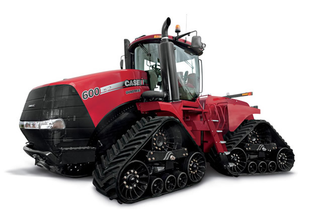
DCU 19649 UREA Tank level error (CAN message or electrical with real sensor) |Level over CAN: SAE J1939 no Signal available Level sensor connected directly: Sensor Supply error |P203A Reagent
-tank level sensor -open circuit
DCU 19650 UREA Tank level error (CAN message or electrical with real sensor) _Level over CAN: SAE J1939 Signal Not in Range Level sensor connected directly: SRC high _P203D Reagent -tank level
sensor -short circuit high
DCU 19651 UREA Tank level error (CAN message or electrical with real sensor) |Level over CAN: SAE J1939 Erroneous Signal Level sensor connected directly: SRC low |P203C Reagent -tank level
sensor — short circuit low
DCU 19676 Ambient Temperature: SAE J1939 Check for CAN receive signal : (Signal Range Check: Signal not in range / Erroneous Signal / Signal not available) |SAE J1939 Check for CAN receive
signal : (Ambient air temperature not in range) |P0600 Serial Communication Link
DCU 19677 Ambient Temperature: SAE J1939 Check for CAN receive signal : (Signal Range Check: Signal not in range / Erroneous Signal / Signal not available) _timeout _P0071 Ambient Air Temperature
Sensor Range/Performance
DCU 19678 Ambient Temperature: SAE J1939 Check for CAN receive signal : (Signal Range Check: Signal notin range / Erroneous Signal / Signal not available) |too many CAN messages |P0071 Ambient
Air Temperature Sensor Range/Performance
DCU 19679 Ambient Temperature: SAE J1939 Check for CAN receive signal : (Signal Range Check: Signal not in range / Erroneous Signal / Signal not available) |SAE J1939 Check for CAN receive
signal : (Barometric pressure not in range) |P0071 Ambient Air Temperature Sensor Range/Performance
DCU 19721 EEPROM / Checksum failures |EEPROM write error |P062F Internal Control Module EEPROM Error
DCU 19722 EEPROM / Checksum failures |No corresponding variant number error |P062F Internal Control Module EEPROM Error
DCU 19723 EEPROM / Checksum failures |EEPROM communication error |P062F Internal Control Module EEPROM Error
DCU 19724 EEPROM / Checksum failures _EEPROM Detection error OR A Codierwort error |P062F Internal Control Module EEPROM Error
DCU 19725 EEPROM / Checksum failures |Wrong EEPROM size |P062F Internal Control Module EEPROM Error
DCU 19730 Ignition ñonî signal K15 |digital input ignition ON not sensed during initialization |P2530 Ignition switch -plausibility error
DCU 19739 Main Relay opens too early / too late |main relay shut off too late |P0687 ECM/PCM Power Relay Control Circuit High
DCU 19740 Main Relay opens too early / too late |main relay short circuit |P0685 ECM/PCM Power Relay Control Circuit /Open
DCU 19741 Main Relay opens too early / too late |main relay open circuit |P0687 ECM/PCM Power Relay Control Circuit High
DCU 19742 Main Relay opens too early / too late _main relay shut off too early (before EEPROM update) _ P0685 ECM/PCM Power Relay Control Circuit /Open
DCU 19748 Too high UREA Temperature in Pump module or Leakage test failed (Emergency shut off) _over temperature detection (urea temp. in pump module) _P2043 Reagent -temperature sensor of pump
module -Out of range
DCU 19749 Too high UREA Temperature in Pump module or Leakage test failed (Emergency shut off) |urea leakage detection (static or dynamic) |P202D Dynamic urea leakage test -Leakage detected
DCU 19757 Group error path UREA injection control _Error belonging to group UREA Injection control _ P208B Reagent-pump -Not delivering
DCU 19766 Group error path Air control _Error belonging to group air control _P20A7 Compressed air regulation valve
DCU 19775 Group error path catalyst temperature _Error belonging to group catalyst temperature out of range _P0426 Plausibility of catalyst temperature sensors -Plausibility error (static)
DCU 19784 Group error path NOx exceeded _Error belonging to group NOx exceeded active _P2000 Nox Trap Efficiency Below Threshold
DCU 19793 Group error path UREA Tank empty _Error belonging to group UREA tank empty active _P203F Reagent -fluid level in tank -Too low
DCU 19999 Unknown DCU15 fault code
NEW HOLLAND ERROR CODES
NH 1002 Radar disconnected
NH 1003 Speed sensor error
NH 1004 Speed sensor signal too High
NH 1005 Speed sensor signal too High
NH 1006 Slip control potentiometer signal too low
NH 1007 Slip control potentiometer signal too High
NH 1008 Raise / work switch failure
NH 1009 Both external switches operated at the same time
NH 1010 Height limit potentiometer signal too low
NH 1011 Height limit potentiometer signal too high
NH 1012 Drop rate potentiometer signal too low
NH 1013 Drop rate potentiometer signal too high
NH 1014 R/H load sensing pin signal too low
NH 1015 R/H load sensing pin signal too high
NH 1016 L/H load sensing pin signal too low
NH 1017 L/H load sensing pin signal too high
NH 1018 Both load sensing pin disconnected
NH 1019 Load sensing pin voltage too low
NH 1020 Load sensing pin voltage too high
NH 1021 Position / draft control potentiometer too low
NH 1022 Position / draft control potentiometer too high
NH 1023 Control panel disconnected
NH 1024 Perform Hydraulic Lift Autocalibration
NH 1025 Mouse lift lever potentiometer signal too low
NH 1026 Mouse lift lever potentiometer signal too high
NH 1027 Maximum Lift arm position potentiometer too low
NH 1028 Maximum Lift arm position potentiometer too high
NH 1029 Hydraulic Control valve disconnected
NH 1030 Ground signal open circuit ( not used )
NH 1031 Chassis Harness Disconnected
NH 1032 Draft Load potentiometer shorted to +12v
NH 1033 Draft Load potentiometer open circuit
NH 1049 Wheel speed sensor open circuit
NH 1053 5 volt reference Short to +12v
NH 1054 5 volt reference Short to ground.
NH 1057 Module Failure ( not used )
NH 1059 5 volt reference Open circuit ( not used )
NH 1063 Lower solenoid open circuit
NH 1064 Raise solenoid open circuit
NH 1065 lower solenoid short circuit
NH 1066 Raise solenoid short circuit
NH 1067 EDC Hydraulic Valve supply too low
NH 1068 Height limit Calibration Error
NH 2001 ‘N’ — Shuttle too fast error
NH 2002 Flash N error
NH 2003 ‘CP’ — Clutch pedal required
NH 2004 ‘P’ — Handbrake error
NH 2005 Creeper selection error
NH 2011 Clutch Pedal Potentiometer Signal too Low
NH 2012 Clutch Pedal Potentiometer Signal too High
NH 2013 Up and Down buttons at same time
NH 2014 Switch 4 / 5 error ( not used )
NH 2015 HI / LO shift lever switches both closed
NH 2016 Creeper Solenoid Short circuit
NH 2021 Chassis Harness Error
NH 2024 Synchro clutches not calibrated
NH 2026 Engine speed too high
NH 2027 Engine speed too low
NH 2035 Dump solenoid circuit fault
NH 2036 Dump solenoid open circuit
NH 2037 Clutch Pedal switch open circuit
NH 2038 Clutch 4 solenoid short circuit
NH 2039 Clutch 4 solenoid open circuit
NH 2040 Clutch 3 solenoid short circuit
NH 2041 Clutch 3 solenoid open circuit
NH 2042 Clutch 2 solenoid short circuit
NH 2043 Clutch 2 solenoid open circuit
NH 2044 Clutch 1 solenoid short circuit
NH 2045 Clutch 1 solenoid open circuit
NH 2046 Fuse 12 open circuit ( not used )
NH 2047 Clutch pedal switch set too High
NH 2048 Clutch pedal switch set too Low
NH 2049 Wheel speed sensor short or open
NH 2051 Oil temperature sensor open circuit
NH 2052 Oil temperature sensor short circuit
NH 2053 5 Volt Potentiometer Supply too High
NH 2054 5 Volt Potentiometer Supply too Low
NH 2055 No signal from wheel speed sensor
NH 2056 Low Range switch open
NH 2057 High Range switch open
NH 2058 Seat switch closed for 25 hours
NH 2059 Shuttle Lever switch disagree
NH 2060 Synchro Fwd no longer engaged
NH 2061 F/R Synchro Potentiometer signal too high
NH 2062 F/R Synchro Potentiometer signal too low
NH 2063 Synchro not moving to forward
NH 2064 Synchro not moving to reverse
NH 2065 Forward solenoid open circuit
NH 2066 Reverse solenoid open circuit
NH 2067 Forward solenoid circuit fault
NH 2068 Reverse solenoid circuit fault
NH 2069 Synchro reverse no longer engaged
NH 2070 Voltage with lever in forward too high
NH 2071 Voltage with lever in forward too low
NH 2072 Voltage with lever in reverse too high
NH 2073 Voltage with lever in reverse too low
NH 2075 Flywheel Speed Sensor Frequency is too high
NH 2075 Any period is too short, under 400 microseconds
NH 2075 Any short period is longer than the corresponding long period
NH 2075 Damper angle is below 50 degrees or above 85 degrees
NH 2075 Calculated torque exceeds calibrated peak torque by more than 25%
NH 2075 No usable signals from the flywheel sensor, and ERPM is greater than 300
NH 2076 Flywheel Speed Sensor open circuit
NH 2077 Flywheel Speed Sensor short circuit
NH 2080 Synchro 4 no longer engaged
NH 2081 4/5 Synchro Potentiometer signal too high
NH 2082 4/5 Synchro Potentiometer signal too low
NH 2083 Synchro 4 engaged error
NH 2084 Synchro 5 engaged error
NH 2085 Synchro 4 solenoid open circuit
NH 2086 Synchro 5 solenoid open circuit
NH 2087 Synchro 4 solenoid short to 12v
NH 2088 Synchro 5 solenoid short to 12v
NH 2089 Synchro 5 no longer engaged
NH 2090 Output speed too high in creeper
NH 2091 C3 Clutch not calibrated
NH 2092 C4 Clutch not calibrated
NH 2093 High Clutch not calibrated
NH 2094 Low Clutch not calibrated
NH 2095 C1 Clutch not calibrated
NH 2096 C2 Clutch not calibrated
NH 2097 Clutch 5 not calibrated
NH 2098 C5 solenoid short to 12v
NH 2099 C5 open circuit
NH 2100 C5 dump solenoid short to 12v
NH 2101 C5 dump solenoid open circuit
NH 2124 Flywheel Torque Sensor not calibrated
NH 2199 Creeper option not enabled
NH 3001 Accelerator Pedal Signal — NOT PLAUSIBLE
NH 3002 Accelerator Pedal Signal — SOURCE HIGH
NH 3003 Accelerator Pedal Signal — SOURCE LOW
NH 3004 Accelerator Pedal Signal — NO SIGNAL
NH 3005 Accelerator Pedal Signal — ALL OTHER FAULTS
NH 3006 Coolant Temperature Signal — ABOVE NORMAL
NH 3007 Coolant Temperature Signal — SOURCE HIGH
NH 3008 Coolant Temperature Signal — SOURCE LOW
NH 3009 Coolant Temperature Signal — NO SIGNAL
NH 3010 Air (boost) Temperature Signal — SOURCE HIGH
NH 3011 Air (boost) Temperature Signal — SOURCE LOW
NH 3012 Air (boost) Temperature Signal — NO SIGNAL
NH 3014 Fuel Temperature Signal — ABOVE NORMAL
NH 3015 Fuel Temperature Signal — SOURCE HIGH
NH 3016 Fuel Temperature Signal — SOURCE LOW
NH 3017 Fuel Temperature Signal — NO SIGNAL
NH 3018 Boost Pressure Signal — ABOVE NORMAL
NH 3019 Boost Pressure Signal — SOURCE HIGH
NH 3020 Boost Pressure Signal — SOURCE LOW
NH 3021 Boost Pressure Signal — NO SIGNAL
NH 3022 Boost Pressure Signal — ALL OTHER FAULTS
NH 3023 Atmospheric Pressure Signal — ABOVE NORMAL
NH 3024 Atmospheric Pressure Signal — SOURCE HIGH
NH 3025 Atmospheric Pressure Signal — SOURCE LOW
NH 3026 Atmospheric Pressure Signal — NO SIGNAL
NH 3027 Oil Pressure Signal — ABOVE NORMAL
NH 3028 Oil Pressure Signal — BELOW NORMAL
NH 3029 Oil Pressure Signal — SOURCE HIGH
NH 3030 Oil Pressure Signal — SOURCE LOW
NH 3031 Oil Pressure Signal — NO SIGNAL
NH 3032 Oil Pressure Signal — ALL OTHER FAULTS
NH 3033 Oil Temperature Signal — ABOVE NORMAL
NH 3034 Oil Temperature Signal — SOURCE HIGH
NH 3035 Oil Temperature Signal — SOURCE LOW
NH 3036 Oil Temperature Signal — NO SIGNAL
NH 3037 Power stage Fuel filter heater — SOURCE HIGH
NH 3038 Power stage Fuel filter heater — SOURCE LOW
NH 3039 Power stage Fuel filter heater — NO SIGNAL
NH 3040 HS Power stage cold start heater relay — SOURCE HIGH
NH 3041 HS Power stage cold start heater relay — SOURCE LOW
NH 3042 HS Power stage cold start heater relay — NO SIGNAL
NH 3043 Adapt.cylinder balancing Cylinder 1 — SOURCE HIGH
NH 3044 Adapt.cylinder balancing Cylinder 5 — SOURCE HIGH
NH 3045 Adapt.cylinder balancing Cylinder 3 — SOURCE HIGH
NH 3046 Adapt.cylinder balancing Cylinder 6 — SOURCE HIGH
NH 3047 Adapt.cylinder balancing Cylinder 2 — SOURCE HIGH
NH 3048 Adapt.cylinder balancing Cylinder 4 — SOURCE HIGH
NH 3049 Battery voltage signal — ABOVE NORMAL
NH 3050 Battery voltage signal — BELOW NORMAL
NH 3051 Battery voltage signal — SOURCE HIGH
NH 3052 Battery voltage signal — SOURCE LOW
NH 3053 LS Power stage cold start lamp — SOURCE HIGH
NH 3054 LS Power stage cold start lamp — SOURCE LOW
NH 3055 LS Power stage cold start lamp — NO SIGNAL
NH 3056 Cold start heater monitoring — BELOW NORMAL
NH 3057 Cold start heater monitoring — NOT PLAUSIBLE
NH 3058 Cold start heater monitoring — SOURCE LOW
NH 3059 Cold start heater monitoring — NO SIGNAL
NH 3060 Injector solenoid valve Cylinder 1 — NOT PLAUSIBLE
NH 3061 Injector solenoid valve Cylinder 1 — SOURCE HIGH
NH 3062 Injector solenoid valve Cylinder 1 — SOURCE LOW
NH 3063 Injector solenoid valve Cylinder 1 — NO SIGNAL
NH 3064 Injector solenoid valve Cylinder 5 — NOT PLAUSIBLE
NH 3065 Injector solenoid valve Cylinder 5 — SOURCE HIGH
NH 3066 Injector solenoid valve Cylinder 5 — SOURCE LOW
NH 3067 Injector solenoid valve Cylinder 5 — NO SIGNAL
NH 3068 Injector solenoid valve Cylinder 3 — NOT PLAUSIBLE
NH 3069 Injector solenoid valve Cylinder 3 — SOURCE HIGH
NH 3070 Injector solenoid valve Cylinder 3 — SOURCE LOW
NH 3071 Injector solenoid valve Cylinder 3 — NO SIGNAL
NH 3072 Injector solenoid valve Cylinder 6 — NOT PLAUSIBLE
NH 3073 Injector solenoid valve Cylinder 6 — SOURCE HIGH
NH 3074 Injector solenoid valve Cylinder 6 — SOURCE LOW
NH 3075 Injector solenoid valve Cylinder 6 — NO SIGNAL
NH 3076 Injector solenoid valve Cylinder 2 — NOT PLAUSIBLE
NH 3077 Injector solenoid valve Cylinder 2 — SOURCE HIGH
NH 3078 Injector solenoid valve Cylinder 2 — SOURCE LOW
NH 3079 Injector solenoid valve Cylinder 2 — NO SIGNAL
NH 3080 Injector solenoid valve Cylinder 4 — NOT PLAUSIBLE
NH 3081 Injector solenoid valve Cylinder 4 — SOURCE HIGH
NH 3082 Injector solenoid valve Cylinder 4 — SOURCE LOW
NH 3083 Injector solenoid valve Cylinder 4 — NO SIGNAL
NH 3084 Injector Booster Voltage C1 — SOURCE HIGH
NH 3085 Injector Booster Voltage C1 — SOURCE LOW
NH 3086 Injector Booster Voltage C2 — SOURCE HIGH
NH 3087 Injector Booster Voltage C2 — SOURCE LOW
NH 3088 Increment speed signal — NOT PLAUSIBLE
NH 3089 Increment speed signal — SOURCE LOW
NH 3090 Segment speed signal — NOT PLAUSIBLE
NH 3091 Segment speed signal — SOURCE LOW
NH 3092 Engine Speed Sensing — NOT PLAUSIBLE
NH 3093 Engine Speed Sensing — SOURCE HIGH
NH 3094 Engine Speed Sensing — SOURCE LOW
NH 3095 Engine Speed Sensing — NO SIGNAL
NH 3096 CAN (A) Hardware — NO SIGNAL
NH 3097 CAN (B) Hardware — NO SIGNAL
NH 3098 CAN TSC1_TE Control — SOURCE LOW
NH 3099 CAN TSC1_TE Control — NO SIGNAL — CAN TE and CAN AE (Torque Request) error codes may be generated due to normal shutdown timing differences between the ECU and the XCM. If so, the actual
error code 3096 or 3097 should also be displayed.
NH 3100 CAN TSC1_AE Control — SOURCE LOW
NH 3101 CAN TSC1_AE Control — NO SIGNAL
NH 3102 Fuel pressure monitoring CP3 — ALL OTHER FAULTS
NH 3102 Possible Causes: • Low fuel supply to CP3 (filter restriction). • Low output from CP3 • CP3 PWM fault (Check PWM output in Atlas, min 3% at engine idle, max 24% at full load Above 24%
indicates excessive fuel leakage from the overpressure valve in the rail or Injector/transfer tube (remove the fuel return lines to check).
NH 3103 Fuel pressure signal — ABOVE NORMAL
NH 3104 Fuel pressure signal — SOURCE HIGH
NH 3105 Fuel pressure signal — SOURCE LOW
NH 3106 Fuel pressure signal — NO SIGNAL
NH 3107 CC HS Power stage 1 fuel press. Control — SOURCE HIGH
NH 3108 CC HS Power stage 1 fuel press. Control — SOURCE LOW
NH 3109 CC HS Power stage 1 fuel press. Control — NO SIGNAL
NH 3110 Monitoring of rail pressure relief valve — ABOVE NORMAL
NH 3111 Monitoring of rail pressure relief valve — BELOW NORMAL
NH 3112 Rail pressure Min / Max. error — SOURCE HIGH
NH 3113 Main relay defect — ABOVE NORMAL
NH 3114 Main relay defect — BELOW NORMAL
NH 3115 Main relay defect — NOT PLAUSIBLE
NH 3116 Main relay defect — SOURCE HIGH
NH 3117 ECU: Self Test Shutoff Paths ( Start Up ) — NOT PLAUSIBLE. Engine will derate to 1800 rpm.
NH 3117 Possible Causes: • ECU power failed when the engine was running or engine shut down process was incorrect.
NH 3118 Power supply for sensors — NOT PLAUSIBLE
NH 3119 Power supply for sensors — NO SIGNAL
NH 3120 Power supply for sensors — ALL OTHER FAULTS
NH 3121 PTO Torque sensor open circuit
NH 3122 PTO Torque sensor short circuit
NH 3123 PTO Torque not CAL error
NH 3124 Hand Throttle potentiometer 2 high error.
NH 3125 Hand Throttle potentiometer 2 Low error.
NH 3126 Hand Throttle potentiometer 1 high error.
NH 3127 Hand Throttle potentiometer 1 Low error.
NH 3128 Hand Throttle potentiometer diff. error.
NH 3129 Hand Throttle idle switch high error
NH 3130 Hand Throttle idle switch low error
NH 3131 ECU self test shutoff paths (start up)
NH 3132 CRPM Switch short
NH 4001 Signal of Aux-stick (AUX1) out of range low
NH 4002 Signal of Aux-stick (AUX1) out of range high
NH 4003 Signal from Remote Flow potentiometer 1 (AUX 1) out of range.
NH 4005 Signal of Aux-stick (AUX2) out of range low
NH 4006 Signal of Aux-stick (AUX2) out of range high
NH 4007 Signal from Remote Flow potentiometer 2 (AUX 2) out of range.
NH 4008 Signal from Remote valve 2 Timer Pot 1 out of range
NH 4009 Signal of Aux-stick (AUX3) out of range low
NH 4010 Signal of Aux-stick (AUX3) out of range high
NH 4011 Signal from Remote Flow potentiometer 3 (AUX 3) out of range.
NH 4015 Signal from Remote Flow potentiometer 4 (AUX 4) out of range.
NH 4016 Signal from Remote valve Timer potentiometer 1 out of range.
NH 4040 Supply Voltage too low
NH 4041 Supply Voltage too High
NH 4042 Arm Rest Module (ARU) CAN ‘Bus off’.
NH 4043 Controller Fault ( Register check)
NH 4044 Controller Fault (Flash Memory)
NH 4045 Controller Fault (Data Memory)
NH 4100 Remote No.1 No control Message Received
NH 4101 Remote No.1 Control Message not plausible
NH 4102 Remote No.1 EEPROM Error
NH 4103 Remote No.1 Switched to failsafe
NH 4104 Remote No.1 Under voltage
NH 4105 Remote No.1 Over voltage
NH 4106 Remote No.1 Spool movement to low
NH 4107 Remote No.1 Spool movement to high
NH 4108 Remote No.1 Float position not reached
NH 4109 Remote No.1 Manually operated
NH 4110 Remote No.1 Driver faulty
NH 4111 Remote No.1 potentiometer faulty.
NH 4112 Remote No.1 Unable to reach neutral
NH 4113 Remote No.1 Spool not in neutral at key on
NH 4114 Remote No.2 No control Message Received
NH 4115 Remote No.2 Control Message not plausible
NH 4116 Remote No.2 EEPROM Error
NH 4117 Remote No.2 Switched to failsafe
NH 4118 Remote No.2 Under voltage
NH 4119 Remote No.2 Over voltage
NH 4120 Remote No.2 Spool movement to low
NH 4121 Remote No.2 Spool movement to high
NH 4122 Remote No.2 Float position not reached
NH 4123 Remote No.2 Manually operated
NH 4124 Remote No.2 Driver faulty
NH 4125 Remote No.2 potentiometer faulty
NH 4126 Remote No.2 Unable to reach neutral
NH 4127 Remote No.2 Spool not in neutral at key on
NH 4128 Remote No.3 No control Message Received
NH 4129 Remote No.3 Control Message not plausible
NH 4130 Remote No.3 EEPROM Error
NH 4131 Remote No.3 Switched to failsafe
NH 4132 Remote No.3 Under voltage
NH 4133 Remote No.3 Over voltage
NH 4134 Remote No.3 Spool movement to low
NH 4135 Remote No.3 Spool movement to high
NH 4136 Remote No.3 Float position not reached
NH 4137 Remote No.3 Manually operated
NH 4138 Remote No.3 Driver faulty
NH 4139 Remote No.3 potentiometer faulty.
NH 4140 Remote No.3 Unable to reach neutral
NH 4141 Remote No.3 Spool not in neutral at key on
NH 4142 Remote No.4 No control Message Received
NH 4143 Remote No.4 Control Message not plausible
NH 4144 Remote No.4 EEPROM Error
NH 4145 Remote No.4 Switched to failsafe
NH 4146 Remote No.4 Under voltage
NH 4147 Remote No.4 Over voltage
NH 4148 Remote No.4 Spool movement to low
NH 4149 Remote No.4 Spool movement to high
NH 4150 Remote No.4 Float position not reached
NH 4151 Remote No.4 Manually operated
NH 4152 Remote No.4 Driver faulty
NH 4153 Remote No.4 potentiometer faulty.
NH 4154 Remote No.4 Unable to reach neutral
NH 4155 Remote No.4 Spool not in neutral at key on
NH 4156 Remote No.5 Spare
NH 4157 Remote No.5 Spare
NH 4158 Remote No.5 Spare
NH 4159 Remote No.5 Spare
NH 4160 Remote No.5 Spare
NH 4161 Remote No.5 Spare
NH 4162 Remote No.5 Spare
NH 4163 Remote No.5 Spare
NH 4164 Remote No.5 Spare
NH 4165 Remote No.5 Spare
NH 4166 Remote No.5 Spare
NH 4167 Remote No.5 Spare
NH 4168 Remote No.5 Spare
NH 4170 EHR Control No. 1 not calibrated
NH 4171 EHR Control No.1 open circuit
NH 4172 EHR Control No.1 short circuit
NH 4173 EHR Control No. 2 not calibrated
NH 4174 EHR Control No.2 open circuit
NH 4175 EHR Control No.2 short circuit
NH 4176 Timer Switch No.1 / No.2 not connected
NH 4177 EHR Control No. 3 not calibrated
NH 4178 EHR Control No.3 open circuit
NH 4179 EHR Control No.3 short circuit
NH 4180 EHR Control No. 4 not calibrated
NH 4181 EHR Control No.4 open circuit
NH 4182 EHR Control No.4 short circuit
NH 4183 Timer Switch No.3 / No.4 not connected
NH 4184 EHR Joystick potentiometer X open circuit.
NH 4185 EHR Joystick potentiometer X short circuit.
NH 4186 EHR Joystick potentiometer Y open circuit.
NH 4187 EHR Joystick potentiometer Y short circuit.
NH 4190 No communications from (EHR) No.1.
NH 4191 No communications from ( EHR) No.2.
NH 4192 No communications from ( EHR) No.3.
NH 4193 No communications from ( EHR) No. 4.
NH 4194 Motor mode No.1 switch faulty
NH 4195 Motor mode No.2 switch faulty
NH 4196 Motor mode No.3 switch faulty
NH 4197 Motor mode No. 4 switch faulty
NH 5001 Rear PTO Brake Solenoid stuck off
NH 5002 Rear PTO Brake Solenoid stuck on
NH 5003 Rear PTO Brake output open circuit
NH 5004 Rear PTO Brake driver over temperature ( not used )
NH 5005 Brake switch open circuit
NH 5007 Rear PTO Solenoid Stuck off
NH 5008 Rear PTO solenoid circuit overcurrent
NH 5024 Rear PTO not calibrated
NH 5027 Rear PTO speed sensor open circuit (not implemented)
NH 5033 Rear PTO cab N/C switch open circuit
NH 5034 Rear fender PTO switch open / short to ground.
NH 5035 Rear fender PTO switch input short to +12v
NH 5036 PTO failure to Start
NH 5037 Rear PTO cab N/O switch stuck closed
NH 5038 Cab & fender PTO switches operated in 2 sec
NH 5039 Incorrect voltage on fender PTO switch
NH 5040 Rear fender PTO switches reversed ( not used )
NH 5041 PTO disengaged due to assuasive load ( not used )
NH 5042 PTO Management switch shorted
NH 5099 Auto PTO mode not enabled
NH 6020 FWD switch error
NH 6021 FWD Solenoid Stuck on
NH 6022 FWD Solenoid Stuck off
NH 6023 FWD solenoid open circuit
NH 7014 Difflock switch error
NH 7015 Difflock Solenoid Stuck off
NH 7016 Difflock Solenoid Stuck on
NH 7017 Difflock solenoid open circuit
NH 7018 Difflock driver over temperature
NH 7024 Steering angle sensor not calibrated
NH 7031 Steering angle sensor out of Maximum range
NH 7032 Steering angle sensor out of Minimum range
NH 8007 Front PTO Solenoid Stuck on
NH 8008 Front PTO solenoid open circuit
NH 8024 Front PTO not calibrated
NH 8027 Front PTO speed sensor open circuit
NH 8033 Front PTO cab N/C switch open circuit
NH 8036 Front PTO failure to Start
NH 8037 Front PTO cab N/O switch stuck closed
NH 8099 Front PTO option not enabled
NH 9001 Front HPL (High Pressure Lift) Potentiometer open circuit.
NH 9002 Front HPL (High Pressure Lift) Potentiometer short circuit.
NH 10001 Upper lockout Solenoid error
NH 10002 Raise Solenoid error
NH 10003 Lower Solenoid error
NH 10004 Front Axle Potentiometer above threshold
NH 10005 Front Axle Potentiometer below threshold
NH 10007 Go up error, Suspension Unable to return to set point
NH 10008 Go down error, Suspension Unable to return to set point
NH 10009 Lower lockout Solenoid Error
NH 10024 Front Suspension not calibrated
NH 10099 Front Suspension mode not enabled
NH 14001 Rear PTO speed short to VCC or open circuit
NH 14002 Rear PTO speed short to Ground
NH 14011 Engine speed sensor short to VCC or open circuit
NH 14012 Engine speed sensor short to Ground
NH 14015 The ADIC 5 volt reference voltage is too low — below 4 volts
NH 14016 The ADIC 5 volt reference voltage is too high — above 6 volts
NH 14021 Radar Ground speed short to VCC or open circuit
NH 14022 Radar Ground speed short to Ground
NH 14031 Front PTO speed short to VCC or open circuit
NH 14032 Front PTO speed short to Ground
NH 14041 Engine coolant temp short to VCC or open circuit
NH 14042 Engine coolant temp short to Ground
NH 14051 Fuel level sensor short to VCC or open circuit
NH 14052 Fuel level sensor short to Ground
NH 14061 Air brake pressure short to VCC or option set but sensor not connected
NH 14071 Front Hitch Position short to 12 or 5 Volts
NH 14072 Front Hitch Position short to Ground or open circuit
NH 14081 Engine oil pressure short to 12 or 5 Volts
NH 14082 Engine oil pressure short to Ground or open circuit
NH 14091 Transmission output speed short to VCC or open circuit
NH 14092 Transmission output speed short to Ground
NH 14100 Air brake pressure not configured
NH 14101 Fuel contaminated sensor Not connected
NH 14200 EEPROM error
NH 14900 Transmission module missing (DA/DB/DE/DF).
NH 14901 Engine controller not present (EDC7)
NH 14902 Auxiliry (optional) Controller Module missing (DD/DH).
NH 14903 SCM controller missing (GA 12×12 only).
NH 14904 Arm Rest Module (ARU) missing. (Steyr 16×16 only)
NH 14905 KEYPAD missing
NH 14906 Fast Steer Controller (KA) missing.
NH 14907 DOG (Display Of Gears) missing.
NH 15001 Exceeding safe operating wheel speed (10 km/h) with system still enabled or still active. Error code not active fast steer lamp flashes instead.
NH 15002 Steering wheel control proximity sensor open circuit.
NH 15003 Steering wheel control proximity sensor short circuit.
NH 15006 Split valve LVDT open circuit.
NH 15007 Split valve LVDT short circuit.
NH 15008 Change valve Solenoid open circuit
NH 15009 Change valve Solenoid short circuit across
NH 15010 Safety switch Fail
NH 15011 Maximum engagement time (5 minutes) elapsed.
NH 15012 Split Valve spool stuck open
NH 15013 Change valve or Split valve spools Stuck closed.
NH 15014 Split Valve spool stuck in transition zone cant identify which steering mode the tractor is definitely in.
NH 15015 Cold oil, temperature below 5 degrees C. Error code not active fast steer lamp flashes instead.
NH 15024 System not calibrated.
Два уровня ошибок: как в них разобраться
Для наглядности и удобства расшифровки кодов неисправностей обозначение ошибки состоит из двух частей, например: E15 CA559
, гдеE15 – это пользовательский код. Он указывает на отказ системы управления двигателем (снижение выходной мощности для защиты мотора), а СА559 – это код, который конкретно указывает на то, что общее давление в коллекторе слишком низкое. Помимо буквенно-циферного отображения ошибки, на мониторе выводится и ее расшифровка на русском языке: низкое давление в общей рейке Common Rail. Это сделано для того, чтобы помочь оператору на месте разобраться с неисправностью и устранить поломку.
При появлении на мониторе ошибки, указывающей на низкое давление дизтоплива в общей рейке топливного насоса, поиск и устранение неисправности следует начать с проверки фильтров и топливной рампы Common Rail на отсутствие утечек ДТ (дизтоплива). Обычно после очистки или замены топливных фильтров проблема исчезает, если же нет, то необходимо провести диагностику основного топливного насоса.
С помощью семи сегментной контрольной панели экскаватора Komatsu PC 400 оператор может провести самодиагностику, например, гидравлической системы на соответствие рабочим параметрам, заданным производителем техники. Подняв стрелу экскаватора до конечного положения можно проверить давление, при котором сработает предохранительный клапан, и сравнить его с табличным значением. Также проверяется давление масла, развиваемое гидравликой привода ковша в режиме наполнения. Cкриншот: https://www. youtube. com/watch? v=nnv4Xuc1GWE
Для этого выбирается соответствующий код (010, 011, 012 и т. д.) и проводится проверка систем и узлов. По ее результатам проводится регулировка предохранительных клапанов, проверка/замена уплотнителей гидроцилиндров и другое ТО.
Case IH Puma 210 — трактор с полным приводом и блокировкой дифференциала. Передний мост включается автоматически, когда увеличивается нагрузка на буксирное устройство или когда колеса проскальзывают. Усовершенствованная передняя подвеска с механизмом гашения вибрации используется на всех моделях серии и может улучшить управляемость и комфорт. Уровень вибрации при установленном оборудовании остается минимальным независимо от характера оборудования. Демпфирование контролируется регенеративным клапанным механизмом и модернизированной батареей, что обеспечивает бесперебойную работу.
Подвеска также оснащена функцией самовыравнивания в автоматическом режиме с учетом нагрузки и условий. Передняя подвеска оснащена датчиком ускорения. Задние мосты изготовлены в США и отличаются повышенной прочностью.
Особенности эксплуатации
Производитель заявляет, что вся выпускаемая продукция отличается повышенным качеством и благодаря применению новейших технологий легко справляется с любыми задачами. Высокая эффективность достигается за счет сложнейших электронных систем, позволяющих контролировать работу.
Судя по отзывам владельцев, которые активно эксплуатируют технику Кейс, тракторы отличаются качеством и надежностью, поэтому первые несколько лет работают без ремонта. Однако, чтобы добиться такого результат необходимо следить за регулярностью и качеством проведения технического обслуживания. Трактора работают на дизельном топливе повышенного качества, а в качестве моторного масла нужно использовать CI-4 AKCELA MS1121.
Огромным достоинством новых тракторов является то, что они поступают в продажу уже с проведенной обкаткой. Также на предприятии перед отправкой в дилерскую сеть проводится калибровка и тестирование всех электронных систем.
Консервирование производится по всем правилам, описанным в инструкции по эксплуатации. Сначала трактор моется, сушится, а потом все детали и механизмы протираются промясленной тряпкой. Масло сливается, а контакты на свечах отсоединяются. После всех процедур трактор ставится в сухое место и накрывается чехлом.
Подвеска, ходовая часть, тормоза трактора
Ходовая часть у тракторов Case IH Puma 210 – полноприводная, с подключаемым передним мостом и функцией блокировки дифференциалов. Постоянно ведущими колёсами являются задние, а управляемыми – передние. Передний мост подключается автоматически – при начале пробуксовывания колёс, либо при значительном увеличении нагрузки на буксировочное устройство.
Снижения удельного давления на грунт можно добиться, если применять сдвоенные колёса на широкопрофильных пневматических шинах, размером 600/65R28 либо 710/70R38.
Благодаря конструкции шасси с очень компактной компоновкой рулевого управления, тракторам Case Puma 210 нужно меньше времени для разворотов по краям поля. Особенно полезно это при обработке пропашных культур. Передний мост Case IH спроектирован для максимальной прочности и долговечности конструкции.
Также на всех моделях доступна дополнительная активная подвеска переднего моста. Она позволяет увеличить комфорт при передвижении трактора и улучшить управление им. Гарантируется меньший уровень колебаний при движении на скорости с уже установленными навесными орудиями или при маневрировании с погрузчиком. Длина хода составляет 105 мм, а демпфирование управляется при помощи усовершенствованного аккумулятора и регенеративной системы клапанов, обеспечивая бо́льшую мягкость хода. Также подвеска оснащена функцией автоматического самовыравнивания, в зависимости от нагрузки.
Расположение и тип конечных передач: планетарные, встроенные в мост. Тип полуосей – фланец. Тип рабочих тормозов – многодисковые, в масляной ванне.
Кабина трактора Case Puma 210
Кабина тракторов семейства Case Puma, созданная с фирменной технологией Surround Vision позиционируется производителем как самая лучшая в классе кабина, причём заслуженно. Она сделана с учётом повышения производительности работы и обеспечения комфорта механизатора. Кабина оснащена остеклением суммарной площадью 5,87 квадратных метров (включая прозрачный люк в крыше).
Её основные характерные отличия – непревзойдённые углы обзора во все стороны, эргономичное расположение органов управления, детально выверенные по удобству для механизатора функции. Благодаря легкодоступным, регулируемым органам управления на подлокотнике длительная работа в поле получается гораздо менее утомительной.
Все самые основные элементы управления трактора встроены в подлокотник сиденья механизатора, для мгновенного доступа (многофункциональная система Multicontroller). Туда же включен и дополнительный встроенный электрогидравлический джойстик, который обеспечивает эргономичную работу с погрузчиком
Правая передняя инструментальная панель, смонтированная на A-образной стойке, гарантирует удобный обзор важной рабочей информации для меньшей утомляемости
Технические характеристики Case Puma 210
- Разработчики – Case
- Годы производства – 2007-2010
- Тип двигателя – дизельный
- Мощность – 210 лошадиных сил
- Страны-производители – Австрия, Англия, Санкт-Валентин
- Семейство – Puma Series
- Емкость топливного бака – 439 л
- Тип подвески – трехточечная, грузоподъемностью 5800 кг и 7199 кг в зависимости от опции
- Шасси – полноприводное, 4×4 MFWD 4WD
- Рулевой механизм – гидростратический
- Тормозной механизм – дифференциальная гидравлика с мокрым диском
- Тормозной трейлер – гидравлический
- Кабина – классическая
- Электрические параметры: Земля – отрицательная; система зарядки – генератор; ампераж зарядки – 150
- Емкость батареи – 1300 amps, 12 Voltage
- Коробка передач – 18 передач переднего хода и 6 передач заднего хода. Бесступенчатая коробка CVT
- Параметры передних шин – 16/9R30
- Параметры задних шин – 20.8R42
- Масса (доставка) – 7125 кг
- Масса (в эксплуатационном режиме) – 8126 кг
- Объем колесной базы – 2880 мм.
Гидравлическая система и задняя сцепка Case Puma 210
В стандартной комплектации доступно до четырёх механических клапанов, либо до 5-ти электронных дистанционных вентиля, также можно выбрать до 4-х электронных промежуточных клапанов. Задняя сцепка обеспечивает грузоподъёмность до 6016 килограммов.
Для сцепки также доступно кнопочное управление даже вне кабины, благодаря панели управления на крыле – для управления навесным оборудованием одной рукой.
Навесные агрегаты с гидравлическими моторами подключаются к бортовой гидравлике с помощью специальных быстроразъёмных штуцеров.
Трёхточечная навеска относится к категории 3 / 3N. Контроль усилия тяги – электронный, на нижнем рычаге. Стандартная грузоподъёмность навески – на расстоянии 610 мм позади точек крепления: 6016 килограммов. Тяговый брус поворотный, третьей категории.
Прицепной опрыскиватель 3200 литров, штанга 24 метра GASPARDO
Главной целью разработчиков новой серии тракторов PUMA было достижение еще большей эффективности. Большой ассортимент из 4 моделей мощностью от 165 до 210 л.с. дает возможность каждому растениеводческому или животноводческому хозяйству подобрать трактор оптимальной мощности. Трансмиссия с 18 передними и 6 задними передачами, силовым переключением и функцией Autoshift в стандартной комплектации зарекомендовала свою долговечность в полевых условиях.
На двигателя тракторов PUMA установлена система впрыска CommonRail с функцией PowerBoost, позволяющая справляться с неравномерными нагрузками, связанными с неровностями рельефа и другими факторами.
Наличие на тракторе Пума систем управления на разворотной полосе, автоматика включения ВОМ и малый радиус разворота, позволяет добываться высочайшей производительности при небольших затратах труда.
Характеристики тракторов Case PUMA 165, 180, 195, 210:
| Puma 165 | Puma 180 | Puma 195 | Puma 210 | |
| Двигатель | ||||
| Количество цилиндров | 6-Р | 6-Р | 6-Р | 6-Р |
| Объем двигателя, л | 6,75 | 6,75 | 6,75 | 6,75 |
| Номинальная мощность на ВОМ, кВт/л.с. | 123/165 | 134/180 | 145/195 | 157/210 |
| Максимальная мощность на ВОМ, кВт/л.с., при 1900-2000 об/мин | 132/180 | 147/200 | 156/212 | 164/223 |
| Номинальная частота вращения КВ, об/мин | 2200 | 2200 | 2200 | 2200 |
| Максимальный крутящий момент при 1400 об/мин, Н-м | 774 | 844 | 860 | 866 |
| Увеличение крутящего момента,% | 45 | 45 | 37 | 27 |
| Количество клапанов на цилиндр | 4 | 4 | 4 | 4 |
| Тип турбонаддува | стандарт, с промежуточным охлаждением | стандарт, с промежуточным охлаждением | стандарт, с промежуточным охлаждением | стандарт, с промежуточным охлаждением |
| Объем топливного бака, л | 405 | 405 | 405 | 405 |
| Трансмиссия | 18/6 с переключением под нагрузкой | 18/6 с переключением под нагрузкой | 18/6 с переключением под нагрузкой | 18/6 с переключением под нагрузкой |
| Стандартный генератор | 12 В/150 А | 12 В/150 А | 12 В/150 А | 12 В/150 А |
| Мосты ведущие | ||||
| Диаметр оси, мм | 105 | 105 | 105 | 105 |
| Длина заднего вала в стандартной поставке, мм | 2485 | 2485 | 2485 | 2485 |
| Длина заднего вала при специальном заказе, мм | 2489 или 3032 | 2489 или 3032 | 2489 или 3032 | 2489 или 3032 |
| Диапазон подстройки колеи переднего привода, мм | 1524-2235 | 1524-2235 | 1524-2235 | 1524-2235 |
| Колесная база, мм | 2884 | 2884 | 2884 | 2884 |
| Гидравлическая система | ||||
| Производительность стандартного насоса, л/мин. | 120 | 120 | 120 | 120 |
| Производительность опционного насоса, л/мин | 150 | 150 | 150 | 150 |
| Давление в гидросистеме, бар | 215 | 215 | 215 | 215 |
| Внешние гидрораспределители | 3 или 4 мех, от 3 до 5 гидравлические | 3 или 4 мех, от 3 до 5 гидравлические | 3 или 4 мех, от 3 до 5 гидравлические | 3 или 4 мех, от 3 до 5 гидравлические |
| Производительность насоса рулевого и служебного тракторов, л/мин | 66 | 66 | 66 | 66 |
| Навеска | ||||
| Тип навески | Трехточечная, категории II/IIIN | Трехточечная, категории II/IIIN | Трехточечная, категории II/IIIN | Трехточечная, категории II/IIIN |
| Грузоподъемность навески стандарт/опция, кг | 5800/7200 | 5800/7200 | 5800/7200 | 5800/7200 |
| Вал отбора мощности | ||||
| Частота вращения, об/мин | 540Е/1000 | 540Е/1000 | 540Е/1000 | 540Е/1000 |
| Тип вала | 1 3/8″ 21 шлиц; 1 3/8″ 6 шлиц; 1 3/4″ 20 шлиц | 1 3/8″ 21 шлиц; 1 3/8″ 6 шлиц; 1 3/4″ 20 шлиц | 1 3/8″ 21 шлиц; 1 3/8″ 6 шлиц; 1 3/4″ 20 шлиц | 1 3/8″ 21 шлиц; 1 3/8″ 6 шлиц; 1 3/4″ 20 шлиц |
| Вес | ||||
| Максимальный рабочий вес, кг | 12000 | 12000 | 12000 | 12000 |
| Сухой вес, кг | 7125 | 7125 | 7125 | 7125 |
| Размеры | ||||
| Длина, мм | 4840 | 4840 | 4840 | 4840 |
| Высота, мм | 3210 | 3210 | 3210 | 3210 |
| Шины передние | 480/70R30 | 480/70R30 | 480/70R30 | 480/70R30 |
| Шины задние | 580/70R42 | 580/70R42 | 580/70R42 | 580/70R42 |
| Радиус поворота при колесе 1829 мм (м) | 6,1 | 6,1 | 6,1 | 6,1 |
Трансмиссия Case Puma 210
Трактора Puma оснащаются в стандартной комплектации трансмиссией Semi Power Shift 18×6, обеспечивающей максимальную скорость движения в 40 км/час. Трансмиссия данного трактора также оборудована системой автоматического переключения передач в пределах, для работы в автоматическом режиме и поддержании оптимального диапазона работы двигателя. Начиная с седьмой передачи, коробка работает в автоматическом режиме. Наличие шести передач заднего хода частично компенсирует отсутствие реверсной функции.
В базовой комплектации трактора Puma 210 оснащены валами отбора мощности независимого типа, со скоростями вращения 540E / 1000 оборотов в минуту. Для обеспечения максимально возможной эффективности привод вала отбора мощности производится непосредственно от маховика дизельного двигателя.
Конструкцией многоступенчатой автоматической коробки переключения передач Power Shift TM допускается переключение скоростей без разрыва потока мощности. Данная особенность позволяет применять тяговые характеристики силового агрегата с максимально возможной эффективностью. Автоматика трансмиссии частично или полностью компенсирует те ошибки, которые может допустить механизатор при выборе нужного на данный момент рабочего либо транспортного скоростного режима трактора.
Как вариант, есть также трактор Case Puma 210 с коробкой переключения передач, оборудованной дополнительной 19-й скоростью. На ней трактор может ехать с транспортной скоростью уже на 40 км/час, а 50 км/час. Дополнительная 19-я передача при 1650 оборотах в минуту повышает топливную экономичность и производительность, а также снижает шум при передвижении на максимально предусмотренной скорости по дорогам.
Для механического привода навесного оборудования, переднего и заднего, используются механические приводы от валов отбора мощности.
Рабочие параметры
В модели «210» серии разработчики органично совместили возможность агрегатирования с широкозахватными сельхозорудиями, комфортабельную кабину и минимум техобслуживания. В конструкции применили:
- дизель с электронным управлением;
- надёжную трансмиссию;
- усиленную гидронавесную систему;
- проставки для сдваивания колёс.
Таблица № 1. Технические характеристики
Силовой агрегат
На трактор устанавливают рядный шестицилиндровый двигатель с водяным охлаждением.
- Он относится к силовым агрегатам последнего поколения.
- В конструкции предусмотрена единая топливная рампа и распределённая система впрыска под управлением электроники.
- По выбросам токсичных веществ в атмосферу итальянский FPT NEF L-6 соответствует нормам экологического стандарта Tier 3.
Электроника может автоматически форсировать двигатель, доведя его мощность до 242 л.с. Эта функция получила название Power Boost. Она включается при движении на 16 скорости и выше, а также превышении крутящего момента на валу отбора мощности 250 Н·м.
Таблица № 2. Характеристики двигателя
Силовая передача
- В базовой комплектации тракторы семейства Puma оборудуют трансмиссией Semi Power Shift 18×6 обеспечивающей скорость передвижения до 40 км/ч.
- Особенность КПП — автоматическое переключение передач. Начиная с 7 ступени, система сама будет оперировать скоростями. Эта функция поддерживает оптимальные обороты двигателя и исключает ошибки механизатора.
- Отсутствие реверса частично компенсировано шестью скоростями для движения назад.
Для моделей, которые предполагают задействовать в транспортных работах могут установить коробку с дополнительной 19 ступенью. В этом случае максимальная скорость трактора будет увеличена на 25% и составит 50 км/ч.
К тому же благодаря дополнительной передаче снижается потребление горючего, общий шумовой фон и вибрация в салоне.
Штатное оснащение модели включает двухскоростной вал отбора мощности. Привод навесных механизмов может вращаться с частотами 540 и 1000 об/мин. Крутящий момент на исполнительный орган снимают непосредственно с маховика двигателя.
Ходовая
«Пума»-210 — полноприводная модель с отключаемым передним мостом, на котором расположены управляющие колёса.
- Задние — постоянно ведущие с блокируемым дифференциалом.
- Передний мост включается в работу автоматически при пробуксовке приводных колёс либо при возрастании усилия на буксирующем устройстве.
- Конечные передачи планетарного типа встроены в мосты.
- Многодисковые тормоза работают в масляной ванне.
Гидронавесная система
На тракторе установлена гидравлика с компенсацией по производительности и давлению. Нагнетание рабочей жидкости происходит поршневым насосом с переменным расходом. В зависимости от исполнения производительность составляет — 113, 150, 170 л/мин. Управляют гидравлической системой электромеханическими золотниковыми распределителями.
Дополнительная информация! Регулировать положение навески можно снаружи аппарата. Для этого на заднем крыле размещена компактная панель управления.
Давление в гидросистеме обеспечивает грузоподъёмность на концах нижних тяг до 6016 кг. Контроль за нагрузкой осуществляет электроника благодаря тензодатчикам, размещённым в опорных точках.
Габариты
Сказать, что Puma 210 имеет скромные размеры, нельзя. Машину разрабатывали для выполнения энергоёмких работ, и конструкторы сделали всё, чтобы придать трактору как можно больший запас прочности.
Таблица № 3. Габариты Puma 210
![]()
![]()
Case IH Magnum 235 — 340 Fault Codes DTC
Case IH Magnum 235 — 340 Fault Codes DTC
Case IH Magnum 235 — 340 Fult Codes DTC.
Adobe Acrobat Document
214.5 KB
Case IH Tractors, Farmall series Fault Codes DTC
TYPE CODE ERROR
ENG 111 Engine Controller Failure — Hardware Failure
ENG 115 Engine Speed Sensor (8.3, 9 Liter) or Cam Sensor (15 Liter) is failed
ENG 121 Engine Position Sensor (8.3, 9 Liter) or Crankshaft Sensor (15 Liter) is failed
ENG 122 Boost Pressure Sensor voltage is too high
ENG 123 Boost Pressure Sensor voltage is too low
ENG 124 Boost Pressure level has exceeded the warning limit.
ENG 131 Decelerator or Hand Throttle (STD cab) Position potentiometer voltage is too high
ENG 132 Decelerator or Hand Throttle (STD cab) Position potentiometer voltage is too low
ENG 133 Decelerator (STD cab) Position potentiometer voltage is too high
ENG 134 Decelerator (STD cab) Position potentiometer voltage is too low
ENG 135 Oil Pressure Sensor voltage is too high
ENG 141 Oil Pressure Sensor voltage is too low
ENG 143 Oil Pressure level has fallen below the warning limit.
ENG 144 Coolant Temperature Sensor voltage is too high
ENG 145 Coolant Temperature Sensor voltage is too low
ENG 146 Coolant Temperature level has exceeded the warning limit.
ENG 147 Frequency Throttle Signal shorted high
ENG 148 Frequency Throttle Signal shorted low
ENG 151 Coolant Temperature level has exceeded the warning limit.
ENG 153 Intake Manifold Temperature Sensor voltage is too high
ENG 154 Intake Manifold Temperature Sensor voltage is too low
ENG 155 Intake Manifold Temperature level has exceeded the warning limit.
ENG 187 Sensor Supply 2 Voltage is too low.
ENG 191 A/C clutch driver shorted to ground when ON.
ENG 211 Communications problem with Armrest, Instrumentation, or Transmission Controllers
ENG 212 Oil Temperature Sensor Voltage is too high
ENG 213 Oil Temperature Sensor Voltage is too low
ENG 214 Oil Temperature Sensor Voltage is above normal range
ENG 219 Oil Level — remote reservoir is too low. Add oil.
ENG 221 Ambient Air Pressure Sensor Voltage is too high
ENG 222 Ambient Air Pressure Sensor Voltage is too low
ENG 223 CORS — Burn Valve Solenoid is shorted either low or high
ENG 227 Sensor Supply 2 Voltage is too high.
ENG 234 Engine Speed has exceed the overspeed warning limit.
ENG 235 Engine Coolant Level is low. Add coolant fluid.
ENG 237 External Speed Multi Unit Sync Command Input Data Incorrect.
ENG 241 Vehicle Speed Signal lost
ENG 242 Vehicle Speed Signal intermittent / tampering
ENG 243 Error detected in exhaust brake relay
ENG 245 Fan Clutch Voltage too low
ENG 254 Fuel Shutoff Valve Voltage too low
ENG 255 Fuel Shutoff Valve Voltage too high
ENG 259 Fuel Shutoff Valve mechanically stuck open.
ENG 263 Fuel Temperature Sensor voltage is too high
ENG 265 Fuel Temperature Sensor voltage is too low
ENG 268 Fuel Pressure in pump is not changing with operating conditions.
ENG 271 Front Pumping Control Valve current is low during ñclick testî
ENG 272 Front Pumping Control Valve current is high
ENG 273 Rear Pumping Control Valve current is low during ñclick testî
ENG 274 Rear Pumping Control Valve current is high
ENG 275 Front Pumping element is failed
ENG 276 Injection Control Valve current is out of range
ENG 277 Injection Control Valve is failed
ENG 278 Fuel Lift Pump is failed
ENG 279 Injection Control Valve current is out of range
ENG 281 Front Pumping element is failed
ENG 282 Rear Pumping element is failed
ENG 283 Engine Speed/Position Sensor supply voltage is too high
ENG 284 Engine Speed/Position Sensor supply voltage is too low
ENG 285 J1939 Parameter was set to be multiplexed, but not received (timeout error)
ENG 286 J1939 Parameter was set to be multiplexed, but not available from all sources (config error)
ENG 287 Multiplexing throttle parameter and a data error was received — data invalid
ENG 288 Multiplexing remote throttle parameter and a data error was received — data invalid
ENG 293 Hydraulic Fan Hydraulic Oil Temperature Sensor Voltage is too high
ENG 294 Hydraulic Fan Hydraulic Oil Temperature Sensor Voltage is too low
ENG 295 Ambient Air Pressure data invalid
ENG 297 OEM Pressure Sensor Voltage is too high.
ENG 298 OEM Pressure Sensor Voltage is too low.
ENG 299 Engine Shutdown by other than keyswitch (i.e. via data bus command)
ENG 319 Real Time Clock in controller has lost power
ENG 328 Rear Pumping element is failed
ENG 329 CAPS Pump has an overpumping failure
ENG 338 Idle Shutdown Vehicle Accessory Relay Voltage is too high
ENG 339 Idle Shutdown Vehicle Accessory Relay Voltage is too low
ENG 341 All data written during powerdown cycle was lost (checksum error)
ENG 343 Engine Controller Failure — Hardware Failure
ENG 349 Measured Speed is too high.
ENG 352 5 Volt Sensor Supply voltage is too low
ENG 378 Front Fueling current is too low
ENG 379 Front fueling current is too high
ENG 381 Error detected in cold start relay 1
ENG 382 Error detected in cold start relay 2
ENG 385 5 Volt Sensor Supply voltage is too high
ENG 386 5 Volt Sensor Supply voltage is too high
ENG 387 Decelerator or Hand Throttle (STD cab) 5 Volt Supply voltage is too high
ENG 388 Engine Brake driver 1 circuit failure
ENG 392 Engine Brake driver 2 circuit failure
ENG 393 Engine Brake driver 3 circuit failure
ENG 394 Front Timing current is too low.
ENG 395 Front Timing current is too high.
ENG 396 Rear Fueling current is too low
ENG 397 Rear Fueling current is too high
ENG 398 Rear Timing current is too low
ENG 399 Rear Timing current is too high
ENG 412 J1708 data link cannot transmit
ENG 414 J1708 data link not fast enough
ENG 415 Oil Pressure level has fallen below the very low warning limit.
ENG 418 Water in Fuel sensor indicates the water in the fuel filter needs to be drained.
ENG 419 Boost Pressure data invalid
ENG 422 Engine Coolant Level Sensor (optional) is failed or the jumper plug is missing
ENG 426 J1939 data link cannot transmit
ENG 427 J1939 data link not fast enough
ENG 428 Water in Fuel Sensor voltage is too high.
ENG 429 Water in Fuel Sensor voltage is too low.
ENG 431 Hand Throttle (STD cab) Idle Validation Switches are both closed
ENG 432 Hand Throttle (STD cab) position potentiometer and switches disagree.
ENG 433 Boost Pressure level disagrees with engine operation conditions (speed & power)
ENG 434 Unswitched 12 volt supply voltage disconnected without normal key off sequence.
ENG 435 Oil Pressure data invalid
ENG 441 Battery Voltage is too Low (less than 6 volts)
ENG 442 Battery Voltage is too High
ENG 443 Decelerator or Hand Throttle (STD cab) 5 Volt Supply voltage is too low
ENG 444 Low voltage detected at OEM 5 volt supply
ENG 449 Fuel Pressure level has exceeded the warning limit.
ENG 451 Fuel Pressure Sensor voltage is too high
ENG 452 Fuel Pressure Sensor voltage is too low
ENG 456 Fuel Pressure in pump is not changing with operating conditions.
ENG 465 Wastegate 1 voltage is too high
ENG 466 Wastegate 1 voltage is too low
ENG 482 Fuel Pressure Sensor voltage low
ENG 483 Rear Bank Post Actuactor Pressure voltage high
ENG 484 Rear Bank Post Actuactor Pressure voltage low
ENG 485 Rear Fueling actuator overfueling
ENG 486 Rear Fueling actuator underfueling
ENG 488 Intake Manifold Temperature level has exceeded the warning limit.
ENG 489 Measured Speed Sensor data low
ENG 491 Wastegate 2 voltage is too high
ENG 492 Wastegate 2 voltage is too low
ENG 493 The Injection Control Identifier Circuit in the harness has failed.
ENG 496 Engine Speed / Position Sensor #2 supply is too low
ENG 524 Error detected on high speed governor droop selection switch
ENG 527 Cab pressurization/Ether relay coil circuit shorted high or open
ENG 529 Output B driver shorted high or open
ENG 539 The Injection Control Valve Transorb in the harness has failed. (open circuit)
ENG 546 Fuel Pressure sensor voltage is too high.
ENG 547 Fuel Pressure sensor voltage is too low.
ENG 551 Hand Throttle (STD cab) Idle Validation Switches are both open
ENG 553 Front fueling actuator overfueling
ENG 559 Front fueling actuator underfueling
ENG 581 Fuel inlet Pressure Sensor voltage is too high.
ENG 582 Fuel inlet Pressure Sensor voltage is too low.
ENG 583 Fuel Inlet Pressure Sensor voltageout of range high or low.
ENG 595 Turbo overspeed protection fault
ENG 596 Battery voltage is too high
ENG 597 Battery voltage is too low
ENG 598 Battery voltage is very low
ENG 599 Engine is being shutdown based on OEM input
ENG 611 ECM detected engine initiated protection shutdown or keyed-off while above specific load limit
ENG 697 Engine Controller internal temperature too high
ENG 698 Engine Controller internal temperature too low
ENG 731 Engine Speed / Position #2 — Mechanical misalignment.
ENG 753 Synchronization has been lost.
ENG 755 Front Bank injector is bad.
ENG 758 Rear Bank injector is bad
ENG 951 A power imbalance between the cylinders was detected by the controller hardware
ENG 983 Unused A/D input channel out of range.
ENG 1117 Battery voltage too low, or the controller was not allowed to power down correctly
ENG 1256 Control Module Identification Input State Error.
ENG 1257 Control Module Identification Input State Error.
ENG 2117 Engine Coolant Level is low. Add coolant fluid.
ENG 2186 Supply Voltage to the accelerator pedal position sensor too low.
ENG 2195 Auxiliary Equipment Sensor Input # 3 — Engine Protection Critical — Special Instructions.
ENG 2249 Injector Metering Rail 1 Fuel Pressure lower than commanded pressure.
ENG 2265 Electric Lift Pump for Engine Fuel Supply Voltage too high.
ENG 2266 Electric Lift Pump for Engine Fuel Supply Voltage too low.
ENG 2292 Fuel Inlet Meter Device higher than expected.
ENG 2293 Fuel Inlet Meter Device flow demand lower than expected.
ENG 2311 Electronic Fuel Injection Control Valve open or closed Circuit.
ENG 2321 Engine Crankshaft Speed / Position data invalid.
ENG 2322 Engine Camshaft Speed / Position Sensor data invalid.
ENG 2372 Engine Fuel Filter clogged error
ENG 2555 Intake Air Heater 1 Circuit Voltage too high.
ENG 2558 Auxiliary PWM Driver 1 Circuit Voltage too low.
ENG 2973 Intake Manifold 1 Pressure data invalid.
TRANS 11 Master Clutch Potentiometer Open Circuit or short to ground
TRANS 12 Master Clutch Potentiometer Short to +12 Volts or short to 5 Vreff
TRANS 24 None of the transmission clutches are calibrated
TRANS 37 BOC switch open circuit or Neutral relay stuck open
TRANS 38 Shuttled to reverse when no wheel speed signal was available
TRANS 47 Clutch pedal bottom of clutch switch misadjusted
TRANS 48 BOC switch or Neutral relay short circuit
TRANS 49 Auto Guidance Isolation valve driver Fault
TRANS 50 Park Brake is powered off when in park
TRANS 51 FNRP pod indicates Forward or Reverse is on, when Park is on
TRANS 52 Park Brake is stuck on when commanded off
TRANS 53 5 volt reference voltage too high
TRANS 54 5 volt reference voltage too low
TRANS 59 FNRP pod in illogical state (two positions on at same time)
TRANS 60 FNRP pod in illogical state (in no position)
TRANS 61 System pressure valve solenoid circuit is open circuit or shorted to ground
TRANS 62 System pressure solenoid is shorted to B+
TRANS 64 Transmission output Sped is too high (above 8200 RPM)
TRANS 65 Operator attempted a shuttle operation while out of the seat
TRANS 66 FNRP Pod Forward switch is shorted to ground or open circuit
TRANS 67 FNRP Pod Forward switch is shorted to power
TRANS 68 FNRP Pod Reverse switch is shorted to ground or open circuit
TRANS 69 FNRP Pod Reverse switch is shorted to power
TRANS 70 Battery voltage is too low for clutch solenoid operation
TRANS 72 Transmission Oil Temperature is above 122 deg. C
TRANS 73 Software is out of the calibration mode and the park brake request is still active.
TRANS 74 The park brake ON with gear is engaged — no park brake request from calibration.
TRANS 75 Engine speed from Inst Controller does not match the speed signal from the alternator.
TRANS 76 Engine speed from Eninge Controller does not match the speed signal from the alternator.
TRANS 77 No signal from wheel speed sensor
TRANS 78 Transmission regulated pressure accumulator is discharged
TRANS 79 Engine RPM from the alternator is measured too high
TRANS 80 Wheel speed sensor is measured too high
TRANS 81 Transmission clutches are slipping
TRANS 82 Creep Clutch is not calibrated
TRANS 83 Communications Lost with Engine Controller
TRANS 103 Odd clutch solenoid or its wiring failed open or shorted to ground
TRANS 104 Even clutch solenoid or its wiring failed open or shorted to ground
TRANS 105 C1-2 clutch solenoid or its wiring failed open or shorted to ground
TRANS 106 C3-4 clutch solenoid or its wiring failed open or shorted to ground
TRANS 107 C5-6 clutch solenoid or its wiring failed open or shorted to ground
TRANS 108 Master clutch solenoid or its wiring failed open or shorted to ground
TRANS 109 Low range clutch solenoid or its wiring failed open or shorted to ground
TRANS 110 Mid range clutch solenoid or its wiring failed open or shorted to ground
TRANS 111 High range clutch solenoid or its wiring failed open or shorted to ground
TRANS 112 Reverse clutch solenoid or its wiring failed open or shorted to ground
TRANS 113 Creeper clutch solenoid or its wiring failed open or shorted to ground
TRANS 114 Even clutch solenoid coil or its wiring shorted to power
TRANS 115 Odd clutch solenoid coil or its wiring shorted to power
TRANS 116 C1-2 clutch solenoid coil or its wiring shorted to power
TRANS 117 C3-4 clutch solenoid coil or its wiring shorted to power
TRANS 118 C5-6 clutch solenoid coil or its wiring shorted to power
TRANS 119 Master clutch solenoid coil or its wiring shorted to power
TRANS 120 Low range clutch solenoid coil or its wiring shorted to power
TRANS 121 Mid range clutch solenoid coil or its wiring shorted to power
TRANS 122 High range clutch solenoid coil or its wiring shorted to power
TRANS 123 Reverse clutch solenoid coil or its wiring shorted to power
TRANS 124 Creeper clutch solenoid coil or its wiring shorted to power
TRANS 125 Odd clutch is not calibrated
TRANS 126 Even clutch is not calibrated
TRANS 127 C1-2 clutch is not calibrated
TRANS 128 C3-4 clutch is not calibrated
TRANS 129 C5-6 clutch is not calibrated
TRANS 130 Low range clutch is not calibrated
TRANS 131 Mid range clutch is not calibrated
TRANS 132 High range clutch is not calibrated
TRANS 133 Reverse clutch is not calibrated
TRANS 134 Master clutch is not calibrated
TRANS 135 Communication lost with the armrest controller
TRANS 136 Communication lost with the instrumentation controller
TRANS 137 Front Suspension raise lock solenoid circuit shorted or open circuit
TRANS 138 Front Suspension raise solenoid circuit shorted or open circuit
TRANS 139 Front Suspension lower lock solenoid circuit shorted or open circuit
TRANS 140 Front suspension position is above the expected absolute limit
TRANS 141 Front suspension position is below the expected absolute limit
TRANS 142 Front suspension travel range has not been calibrated
TRANS 143 Front suspension position is above the upper suspension range
TRANS 144 Front suspension position is below the lower suspension range
TRANS 145 Front Suspension lower lock solenoid circuit shorted or open circuit
TRANS 146 Regulated system pressure low (below 100PSI / 689 KPA)
TRANS 147 Regulated system pressure below 290 PSI
TRANS 148 Backup alarm circuit shorted or open
TRANS 150 Front suspension pressure sensor rod side (DA-R) out of range high
TRANS 151 Front suspension pressure sensor rod side open circuit
TRANS 152 Front Suspension pressure control not able to increase pressure on the rod side
TRANS 153 Front Suspension pressure control not able to decrease pressure on the rod side
TRANS 154 Front Suspension Lock Valve Stuck on fault (suspension will not lock)
TRANS 155 Front Suspension Lock Valve is stuck of (suspension will not unlock)
TRANS 156 Lock valve was installed but removed
ARM 19 Hand THROTTLE potentiometer is failed
ARM 29 Aux 1st remote valve LEVER potentiometer is failed
ARM 39 Aux 2nd remote valve LEVER potentiometer is failed
ARM 49 Aux 3rd remote valve LEVER potentiometer is failed
ARM 59 Aux 4th remote valve LEVER potentiometer is failed
ARM 69 HITCH POSITION command potentiometer is failed
ARM 79 HITCH LOAD command potentiometer is failed
ARM 89 Aux 1st remote valve FLOW potentiometer is failed
ARM 99 Aux 2nd remote valve FLOW potentiometer is failed
ARM 109 Aux 3rd remote valve FLOW potentiometer is failed
ARM 119 Aux 4th remote valve FLOW potentiometer is failed
ARM 129 Aux 5th remote valve FLOW potentiometer is failed
ARM 139 Aux remote valve TIMER potentiometer is failed
ARM 149 Hitch UPPER LIMIT potentiometer is failed
ARM 159 Hitch DROP RATE potentiometer is failed
ARM 169 Hitch TRAVEL potentiometer is failed
ARM 1029 Aux 5th remote valve control switch is failed
ARM 1039 PTO switch is failed
ARM 1049 Hitch UP/DOWN switch is failed
ARM 1059 Hitch SLIP switch is failed
ARM 1069 MFD switch is failed
ARM 1079 DIFF LOCK switch is failed
ARM 1089 Programmable UP/DOWN switch is failed.
ARM 1099 Aux remote valve LIMIT SET switch is failed
ARM 1109 Hand Throttle IDLE VALIDATION switch is failed
ARM 1119 RECORD/PLAY switch is failed
ARM 1129 Invalid Configuration — Implement Depth Control switch is failed
ARM 1139 Engine Brake switch is failed
ARM 1149 Auto Field / Transport Switch is in an illogical state
ARM 8011 Battery Voltage is too Low
ARM 9011 Controller Memory Error — Loss of Hitch Position Command Calibration
ARM 9012 Controller Memory Error — Loss of Aux Remote Lever Calibrations
ARM 9013 Controller Memory Error — Loss of Throttle Calibrations
ARM 9014 Controller Memory Error — Loss of MFD switch Configuration
ARM 9015 Controller Memory Error — Loss of Trans switches Configuration
ARM 9021 Hitch position command potentiometer calibration results not acceptable
ARM 9031 Hand throttle potentiometer calibration results not acceptable
ARM 9041 Hitch DROP RATE potentiometer calibration value(s) are out of range
ARM 10091 Armrest Controller failure — 5 V regulator failure
ARM 12013 Communications Lost with Data Bus and ALL other controllers
ARM 12081 Loss of/unavailable Performance Monitor Display — RECORD/PLAY functionality disabled
CASE IH & NEW HOLLAND Tractor Fault Codes DTC
TMF 3 Hitch Raise Solenoid High Side Driver shorted to 12 volts.
TMF 4 Hitch Raise Solenoid Failed Open or Shorted to Ground.
TMF 5 Hitch Lower Solenoid Shorted to 12 volts.
TMF 6 Hitch Lower Solenoid High Side Driver circuit short to 12 volts.
TMF 7 Hitch Raise/Lower Solenoids Open or short to ground.
TMF 11 Communications Lost with Data Bus and ALL other controllers
TMF 12 Communication lost with the armrest controller
TMF 14 5 Volt Sensor Supply voltage is too high
TMF 15 5 Volt Sensor Supply voltage is too low
TMF 17 Hitch Position Command potentiometer failed in the Armrest controller
TMF 18 Hitch Rockshaft Position potentiometer is outside normal operating range.
TMF 19 Hitch Upper Limit potentiometer is failed in the Armrest Controller
TMF 21 Hitch Load Command potentiometer is failed in the Armrest Controller
TMF 22 Single draft pin sensor failed when configured for one draft pin sensor.
TMF 23 Two draft pin sensors failed when configured for two draft pins.
TMF 24 Communications Lost with Instrumentation Controller
TMF 25 Hitch Up/Down Switch failed in the Armrest controller
TMF 26 Fender UP and DOWN switch failure or both switches simultaneously pressed
TMF 28 Hitch Travel potentiometer is failed in the Armrest Controller
TMF 29 Hitch Drop Rate potentiometer is failed in the Armrest Controller
TMF 30 Right Draft Pin voltage is outside the normal operating range.
TMF 31 Left Draft Pin voltage is outside the normal operating range.
TMF 32 Ground Speed Signal is failed in the Instrumentation Controller
TMF 33 Hitch Slip Set Switch failed in the Armrest controller
TMF 34 Hitch Slip Select Switch failed in the Armrest controller
TMF 35 Slip Sensor (radar or wheel speed) is failed in the Instrumentation Controller
TMF 37 The ARU reports EDC Transport Lock is faulty or not available.
TMF 41 Draft pin(s) detected but the Armrest controller specified tractor without draft control.
TMF 42 Engine speed must be set above 1600 rpm during calibration of lower valve.
TMF 43 No Draft pin(s) detected but the Armrest controller specified tractor with draft control.
TMF 44 Hitch calibration aborted due to tractor movement.
TMF 45 Hitch calibration attempted when the engine is not running or engine speed signal is failed.
TMF 47 Raise Valve calibration value is too high. (valve problem)
TMF 48 Raise Valve calibration value is too low. (valve problem)
TMF 50 Hitch position at top of travel is not within specification during calibration
TMF 51 Lower Valve calibration value is too high. (valve problem)
TMF 52 Lower Valve calibration value is too low. (valve problem)
TMF 53 The time allowed for hitch calibration has expired
TMF 54 Hitch position at bottom of travel is not within specification during calibration
TMF 55 Hitch position range from top to bottom is not within spec during calibration
TMF 56 Hitch position range to position command range ratio is not within spec during calibration.
TMF 57 Right Draft Pin voltage is not within spec for ïno loadà condition during calibration
TMF 58 Left Draft Pin voltage is not within spec for ïno loadà condition during calibration
TMF 59 Both Draft Pin voltages are not within spec for ïno loadà condition during calibration
TMF 60 Draft pin connected to left vs right for single pin setup during calibration
TMF 61 The Hitch Calibration procedure must be performed.
TMF 62 Communications Lost with Performance Monitor Function
TMF 63 Controller 8 volt reference is too high (above 8.8 volts).
TMF 64 Controller 8 volt reference is too low (below 7.2 volts).
TMF 65 Battery Voltage is too Low
TMF 66 Battery Voltage is too Low
TMF 80 MFD fault condition in software.
TMF 81 MFD Solenoid is failed Open or Short Circuit
TMF 82 Differential Lock Solenoid is failed Open or Short Circuit
TMF 83 Brake Lamp Relay Solenoid is failed Open or Short Circuit
TMF 86 Wheel Slip Signal is failed in the Instrumentation Controller
TMF 87 Ground Speed Signal is failed in the Instrumentation Controller
TMF 88 Differential Lock Switch is failed in the Armrest Controller
TMF 89 Differential Lock Switch is failed in the Armrest Controller
TMF 90 Differential Lock Switch is failed in the Armrest Controller
TMF 92 MFD Switch is failed in the Armrest Controller
TMF 93 MFD Switch is failed in the Armrest Controller
TMF 94 Differential Lockout fault condition in software.
TMF 95 The steering angle sensor is above the expected operating range
TMF 96 The steering angle sensor is below the expected operating range
TMF 98 Battery Voltage is too Low
TMF 99 Battery Voltage is too Low
TMF 106 Aux 5th remote valve control switch (Extend) is failed in the Armrest Controller
TMF 107 Aux 5th remote valve control switch (Retract) is failed in the Armrest Controller
TMF 108 Aux 1st remote valve LEVER potentiometer is failed in the Armrest Controller
TMF 109 Aux 2nd remote valve LEVER potentiometer is failed in the Armrest Controller
TMF 110 Aux 3rd remote valve LEVER potentiometer is failed in the Armrest Controller
TMF 111 Aux 4th remote valve LEVER potentiometer is failed in the Armrest Controller
TMF 112 Aux 1st remote valve FLOW potentiometer is failed in the Armrest Controller
TMF 113 Aux 2nd remote valve FLOW potentiometer is failed in the Armrest Controller
TMF 114 Aux 3rd remote valve FLOW potentiometer is failed in the Armrest Controller
TMF 115 Aux 4th remote valve FLOW potentiometer is failed in the Armrest Controller
TMF 116 Aux 5th remote valve FLOW potentiometer is failed in the Armrest Controller
TMF 120 Electro Hydraulic Remote top link switch is stuck on.
TMF 123 Aux 1st Lower Coil solenoid shorted to 12 volts.
TMF 124 Aux 1st Lower solenoid failed open or short circuit.
TMF 125 Aux 1st Raise Coil solenoid shorted to 12 volts.
TMF 126 Aux 1st Raise solenoid failed open or short circuit.
TMF 127 Aux 2nd Lower Coil solenoid shorted to 12 volts.
TMF 128 Aux 2nd Lower solenoid failed open or short circuit.
TMF 129 Aux 2nd Raise Coil solenoid shorted to 12 volts.
TMF 130 Aux 2nd Raise solenoid failed open or short circuit.
TMF 131 Aux 3rd Lower Coil solenoid shorted to 12 volts.
TMF 132 Aux 3rd Lower solenoid failed open or short circuit.
TMF 133 Aux 3rd Raise Coil solenoid shorted to 12 volts.
TMF 134 Aux 3rd Raise solenoid failed open or short circuit.
TMF 135 Aux 4th Lower Coil solenoid shorted to 12 volts.
TMF 136 Aux 4th Lower solenoid failed open or short circuit.
TMF 137 Aux 4th Raise Coil solenoid shorted to 12 volts.
TMF 138 Aux 4th Raise solenoid failed open or short circuit.
TMF 139 Aux 5th Lower Coil solenoid shorted to 12 volts.
TMF 141 Aux 5th Raise Coil solenoid shorted to 12 volts.
TMF 142 Aux 5th Raise solenoid failed open or short circuit.
TMF 147 Implement feedback #1 out of range High
TMF 148 Implement feedback #1 out of range Low
TMF 149 Implement feedback #2 out of range High
TMF 150 Implement feedback #2 out of range Low
TMF 151 Communications Lost with Transmission Controller
TMF 152 Electro Hydraulic Remote top link switch voltage is short circuit.
TMF 153 Electro Hydraulic Remote top link switch data invalid
TMF 154 PTO switch interlock — Cab Switch and Fender switch on at the same time.
TMF 155 Auto PTO switch data failed in the Armrest controller.
TMF 156 Auto PTO switch stuck ON in Armrest Controller.
TMF 157 PTO remote fender switch short circuit.
TMF 158 PTO remote fender switch open circuit
TMF 159 PTO remote fender switch stuck ON.
TMF 160 PTO Clutch is Slipping Too Much
TMF 162 Engine Stalled when the PTO was running.
TMF 163 PTO Shaft rotation is detected when the PTO clutch is OFF.
TMF 164 PTO shaft speed has not been detected within 3.6 seconds of being turned ON.
TMF 165 PTO Shaft rotation is detected when the Engine is OFF.
TMF 166 PTO Driver is on and no current is sensed.
TMF 167 Current sensed when the PTO driver is off.
TMF 168 PTO ON/OFF switch is failed in the Armrest Controller
TMF 169 PTO ON/OFF switch is failed in the Armrest Controller
TMF 170 PTO ON/OFF switch is failed in the Armrest Controller
TMF 171 PTO software fault condition detected.
TMF 172 PTO Solenoid Circuit is failed shorted to 12 Volts when PTO is in the off state.
TMF 173 PTO Solenoid Circuit is failed shorted to ground when PTO is in the off state.
TMF 174 Current flowing in the PTO sense resistor when the high side is off.
TMF 175 PTO Clutch has not reached lock up speed within 6 seconds of being turned ON
TMF 178 PTO speed sensor has been changed.
TMF 179 The PTO is receiving no frequency from the Shaft Size Sensor on a two speed PTO
TMF 180 The PTO is receiving signals from the Shaft Size Sensor on a single speed PTO configuration.
INST 1015 Seat Switch may be stuck closed.
INST 1024 Trans oil filter switch shorted to ground on power up.
INST 1034 Hydraulic oil filter switch shorted to ground on power up.
INST 3010 PTO Shaft Speed sensor is failed in PTO Controller
INST 3020 Engine Speed sensor is failed in the Engine Controller
INST 3022 Engine Overspeed Error
INST 5010 Engine Oil Pressure sensor is failed in the Engine Controller
INST 5011 Engine Oil Pressure sensor voltage is too low (open circuit, short to ground)
INST 7024 Reversible Fan Control open circuit or shorted to ground.
INST 10031 Controller Memory Error — Loss of Engine Hours information
INST 10032 Controller Memory Error — Loss of Vehicle Configuration information
INST 10033 Controller Memory Error — Loss of Customer Configuration information
INST 10034 Controller Memory Error: Loss of valid fuel table information.
INST 10035 Controller Memory Error — Loss of Valid Radar Configuration information.
INST 10036 Controller Memory Error — Loss of Displayed Performance information
INST 10037 Controller Memory Error — Loss of Implement Width information
INST 10038 Controller Memory Error — Loss of Valid Remote Timer information.
INST 11011 Fuel Level Sensor voltage is too low (open circuit, short to ground)
INST 12011 Communications Lost with Armrest Controller
INST 12021 Communications Lost with Auxiliary Controller
INST 12031 Communications Lost with Hitch Controller
INST 12043 Communications Lost with Data Bus 1 and ALL other controllers
INST 12051 Communications Lost with PTO Controller
INST 12053 Communications Lost with Vehicle Data Bus 2.
INST 12071 Communications Lost with Transmission Controller
INST 12091 Communications Lost with Engine Controller
INST 12101 Communications Lost with Tractor ECU (Gateway) Controller
INST 12111 Communications Lost with Automatic Temperature Controller
INST 12121 Communications Lost with Color Perfomance Monitor
INST 13010 Engine Coolant Temperature sensor is failed in the Engine Controller
INST 13011 Engine Coolant Temperature sensor voltage is too low (short to ground)
INST 13012 Engine Coolant Temperature sensor voltage is too high (open circuit, short to +V)
INST 13021 Transmission Oil Temperature sensor voltage is too low (short to ground)
INST 13022 Transmission Oil Temperature sensor voltage is too high (open circuit, short to +V)
INST 13031 Hydraulic Oil Temperature sensor voltage is too low (short to ground)
INST 13032 Hydraulic Oil Temperature sensor voltage is too high (open circuit, short to +V)
INST 13040 Air to Air Intake Temperature sensor is failed in the Engine Controller
INST 13044 When fuel shut off relay is latched, short is detected (mechanical engine tractors only)
INST 13051 Air to Air Intake Temperature sensor voltage is too low (short to ground)
INST 13052 Air to Air Intake Temperature sensor voltage is too high (open circuit, short to +V)
INST 53001 Instrumentation Controller Configuration is Incorrect
INST 53002 Air to Air Intake sensor does not match Tractor Model Configuration
INST 53005 Engine Shutdown activated by Instrument Controller
INST 65535 NO ERROR. Errors have not been cleared from factory.
ATC 111 Cab sensor open or shorted to power
ATC 112 Cab sensor shorted to ground
ATC 115 Evaporator sensor open or shorted to power
ATC 116 Evaporator sensor shorted to ground
ATC 120 Blower speed select pot open/shorted to power
ATC 121 Temperature select pot open/shorted to power
ATC 122 Mode Select Pot Open Or Shorted To Power
ATC 125 High pressure switch (+) input shorted to power
ATC 126 High pressure switch (+) input shorted to ground
ATC 127 High pressure switch (-) input shorted to power
ATC 128 High pressure switch (-) input shorted to ground
ATC 129 High pressure cycling error (2 in 1 minute)
ATC 130 Low pressure switch (+) input shorted to power
ATC 131 Low pressure switch (+) input shorted to ground
ATC 132 Low pressure switch (-) input shorted to power
ATC 133 Low pressure switch (-) input shorted to ground
ATC 134 Low pressure switch open for > 1 minute
ATC 113 Outlet sensor open or shorted to power
ATC 114 Outlet sensor shorted to ground
ATC 117 Outside air sensor open or shorted to power
ATC 118 Outside air sensor shorted to ground
Hitch 1002 Raise hitch valve coil short to 12 volts or raise hitch valve coil circuit failure.
Hitch 1003 Open or Short to Ground raise hitch valve coil circuit failure.
Hitch 1004 Lower hitch valve coil short to 12 volts or lower hitch valve coil circuit failure.
Hitch 1005 Open or short to ground lower hitch valve coils.
Hitch 1006 EDC Low Side Driver stuck on failure.
Hitch 1007 Low side driver watchdog test failed.
Hitch 1008 Low side of raise solenoid connected permanently to GND
Hitch 1009 Low side of lower solenoid connected permanently to GND
Hitch 1011 TCU (Tractor Controller Unit) is disconnected from the CAN bus.
Hitch 1012 No communication with the ACM (Armrest Controller Module).
Hitch 1013 No communication with the ICP (Instrument Cluster Panel).
Hitch 1014 Five-volt reference is above the upper voltage limit.
Hitch 1015 Five-volt reference is below the lower voltage limit.
Hitch 1016 Not implemented
Hitch 1017 Position Command value received over the CAN data bus from the Armrest indicates Position Command potentiometer failed.
Hitch 1018 Hitch rockshaft position potentiometer open/short/misadjust or circuit failure.
Hitch 1019 Upper Limit value received from CAN data bus indicates failure condition.
Hitch 1021 Load Command value received from CAN data bus indicates failure condition.
Hitch 1022 Single draft pin sensor failed when configured for one draft pin sensor.(CCH Only)
Hitch 1023 Two draft pin sensors failed when configured for two draft pins.(CCH Only)
Hitch 1024 ICU CAN data bus signal lost.
Hitch 1025 Up/Down/Down Momentary switch value received from CAN data bus indicates switch failure.
Hitch 1026 Up/Down remote fender switch failure.
Hitch 1027 Not implemented
Hitch 1028 Travel Range potentiometer value received from CAN data bus indicates failure condition.
Hitch 1029 Drop Rate value received from CAN data bus indicates potentiometer failure condition.
Hitch 1030 Right draft pin voltage is outside the normal operating range.(CCH Only)
Hitch 1031 Left draft pin voltage is outside the normal operating range.(CCH Only)
Hitch 1032 Ground speed failure-value received from CAN data bus indicates failure condition.
Hitch 1033 Slip Limit Set Point received from CAN data bus indicates failure condition.
Hitch 1034 Slip Enable switch received from CAN data bus indicates failure condition.
Hitch 1035 The Percent slip received from ETC indicates failure condition.
Hitch 1036 The ARU reports EDC Inching Up switch faulty or not available.
Hitch 1037 The ARU reports EDC Inching Down switch faulty or not available.
Hitch 1065 The ARU specified tractor without draft control (position only hitch) but detected presence of draft pin(s).
Trans 2009 Seat switch open circuit
Trans 2010 Seat switch is shorted to the supply voltage B+ or 5 volt reference
Trans 2011 Clutch Pot Open Circuit or short to ground
Trans 2012 Clutch Potentiometer Short to +12 Volts or short to 5 Volt reference.
Trans 2024 none of the Transmission clutches are calibrated. This will be the condition when a new controller is installed on the tractor.
Trans 2037 Bottom of Clutch pedal switch open circuit or bottom of clutch relay is stuck open
Trans 2047 Clutch pedal bottom of clutch switch misadjusted.
Trans 2048 Bottom of Clutch pedal switch or the bottom of clutch relay are short circuit
Trans 2049 Trans
Trans 2054 5 volt reference voltage too low.
Trans 2055 No signal from wheel speed sensor.
Trans 2056 5 volt internal reference voltage too high.
Trans 2057 5 volt internal reference voltage too low.
Trans 2059 1) Switch inputs indicate shuttle lever is in both forward and neutral 2) Switch inputs indicate shuttle lever is in both reverse and neutral3) Switch inputs indicate shuttle lever is
in both forward and reverse. Cycle the shuttle lever which may free up stuck switches, or try driving the opposite direction.
Trans 2071 Forward switch input from the FNRP Pod is shorted to ground or is open circuit.
Trans 2072 Reverse switch input from the FNRP Pod is shorted to +12 Volts or the FNRP pod 5 Volt Reference.
Trans 2073 Reverse switch input from the FNRP Pod is shorted to ground or open circuit.
Trans 2074 FNR Not Park Switch low voltage fault
Trans 2075 FNR Not Park Switch high Voltage fault
Trans 2110 FNR Neutral Switch Low Voltage fault
Trans 2111 FNR Neutral Switch high Voltage fault
Trans 2326 The Engine RPM sourced from the alternator measured by the controller is excessively high.
Trans 2327 No engine RPM
Trans 2330 The Transmission output RPM speed, sourced from the sensor, measured by the controller is too high for the desired gear
Trans 2331 The transmission clutches are slipping
Trans 2342 Clutch Odd solenoid open circuit or short to ground.
Trans 2343 Clutch Even solenoid open circuit or short to ground.C33
Trans 2344 Clutch C1-2 solenoid open circuit or short to ground.
Trans 2345 Clutch C3-4 solenoid open circuit or short to ground.
Trans 2346 Clutch 5-6 solenoid open circuit or short to ground.
Trans 2374 Master Clutch solenoid open circuit or short to ground.
Trans 2347 Clutch Low Range solenoid open circuit or short to ground.
Trans 2348 110 Clutch Mid Range solenoid open circuit or short to ground.
Trans 2349 Clutch High Range solenoid open circuit or short to ground.
Trans 2350 Clutch reverse solenoid open circuit or short to ground.
Trans 2351 The creeper clutch solenoid is open circuit or short to ground
Trans 2353 Even Clutch Solenoid is shorted to +12 Volts, current sensed while driver is off.
Trans 2352 Odd Clutch Solenoid is shorted to +12 Volts, current sensed while driver is off.
Trans 2354 C1-2 Clutch Solenoid is shorted to +12 Volts, current sensed while driver is off..
Trans 2355 C3-4 Clutch Solenoid is shorted to +12 Volts, Current sensed while driver is off.
Trans 2356 C5-6 clutch Solenoid is shorted to +12 Volts, current sensed while driver isoff.
Trans 2357 Low clutch Solenoid is shorted to +12 Volts, current sensed while driver is off.
Trans 2358 Mid Clutch Solenoid is shorted to +12 Volts, Current sensed while driver is off.
Trans 2359 High Clutch Solenoid is shorted to +12 Volts, current sensed while driver is off.
Trans 2360 Reverse Clutch Solenoid is shorted to +12 Volts, current sensed while driver is off.
Trans 2361 The creeper clutch solenoid is shorted to +12 Volts, current sensed while the driver is off
Trans 2362 Master Clutch Solenoid is shorted to +12 Volts, current sensed while driver is off.
Trans 2363 The Odd Clutch is not calibrated
Trans 2364 Even Clutch not calibrated
Trans 2365 C1-2 Clutch not calibrated
Trans 2366 C3-4 Clutch not calibrated
Trans 2367 C5-6 Clutch not calibrated
Trans 2368 Low Range Clutch not calibrated
Trans 2369 Mid Range Clutch not calibrated
Trans 2370 High Clutch not calibrated
Trans 2371 Reverse Clutch not calibrated
Trans 2372 Creep Clutch is not calibrated
Trans 2373 Master Clutch not calibrated
Trans 2800 Auto Guidance Isolation valve driver Fault
Trans 2805 System pressure valve solenoid circuit is open circuit or shorted to ground
Trans 2806 System pressure solenoid is shorted to B+
Trans 2807 Transmission output rpm over speed
Trans 2809 The battery voltage is too low to permit operation of the clutch solenoids.
Trans 2811 Transmission Oil Temperature Hot
Trans 2812 Transmission Oil Temperature sensor short to B+ or open circuit
Trans 2813 Transmission oil temperature Sensor Short to Ground
Trans 2814 Integrated Control Panel off line
Trans 2815 Governor Engine RPM alternator engine RPM mismatch
Trans 2816 Transmission regulated pressure accumulator is flat
Trans 2817 Governor is offline CAN bus
Trans 2818 Communication lost with the Armrest Control Module(ACM)
Trans 2819 Communication lost with the instrumentation controller.
Trans 2820 System pressure low possible System pressure hydraulic pump failure or leak
Trans 2821 System Pressure Low fault
Trans 2850 The Park Brake is stuck on by no electrical power supplied when commanded on
Trans 2851 The Park Brake Driver has detected an over current or an open circuit condition
Trans 2852 The Park Brake is stuck on by no electrical power supplied to the solenoid when driver is commanded on. Possible service brake bottom brake switches open.
Trans 2055 No signal from wheel speed sensor.
Trans 2873 Software is out of the calibration mode and the park brake request is still active. If this fault is detected there is a bug in the software
Trans 2874 The park brakes commanded on and gear is engaged and there is no park brake request from calibration. If this fault is detected there is a bug in the software
Trans 2900 Torque sensor Gap is on the larger end of the tolerance (CCH Only)
Trans 2901 Signal received from the torque sensor is not in any fault range or normal range tolerance (CCH Only)
Trans 2902 Torque sensor has declared an internal fault tolerance (CCH Only)
Trans 2903 Torque sensor supply voltage below 4.8 volts tolerance (CCH Only)
Trans 2910 12VF1voltage supply is low. (possible blown fuse*)
Trans 2911 12VT1voltage supply is low. (possible blown fuse*)
Trans 2912 12VF2voltage supply is low. (possible blown fuse*)
Trans 2913 12VHvoltage supply is low. (possible blown fuse*)
Trans 2914 12VF3voltage supply is low. (possible blown fuse*)
Trans 2915 12VS1voltage supply is low. (possible blown fuse*)
Engine 3000 Unknown ECM Error Code Received
Engine 3999 Unknown ECM Error Code Received
Engine 3001 Foot Throttle Sensor -Signal Not Plausible
Engine 3002 Foot Throttle Sensor -Signal Above Range Max.
Engine 3003 Foot Throttle Sensor -Signal Below Range Min.
Engine 3004 Foot Throttle Sensor -No Signal -Error
Engine 3006 Coolant Temperature Sensor -Signal Not Plausible(Compared with Engine Oil Temperature)
Engine 3007 Coolant Temperature Sensor -Signal Above Range Max.
Engine 3008 Coolant Temperature Sensor -Signal Below Range Min.
Engine 3009 Coolant Temperature Sensor -(via CAN) No Signal
Engine 3010 Air Intake Temperature Sensor -Signal Above Range Max.
Engine 3011 Air Intake Temperature Sensor -Signal Above Range Min.
Engine 3012 Air Intake Temperature Sensor -(via CAN) No Signal
Engine 3015 Fuel Temperature Signal -Signal Above Range Max.
Engine 3016 Fuel Temperature Signal -Signal Below Range Min.
Engine 3019 Boost Pressure Sensor -Signal Above Range Max.
Engine 3021 Boost Pressure Sensor -(via CAN) No Signal
Engine 3022 Boost Pressure Sensor -Signal Not Plausible
Engine 3023 Atmospheric Pressure Sensor -Signal Not Plausible Compared with Boost Pressure
Engine 3024 Atmospheric Pressure Sensor -Signal Above Range Max.
Engine 3025 Atmospheric Pressure Sensor -Signal Below Range Min.
Engine 3028 Oil Pressure Too Low
Engine 3029 Oil Pressure Sensor _Short circuit to Battery
Engine 3030 Oil Pressure Sensor _Short circuit to Ground
Engine 3031 Oil Pressure Sensor -Hardware Error
Engine 3032 Oil Pressure Sensor -Value Too High
Engine 3033 Oil Temperature Sensor -Signal Not Plausible (Compared with Coolant Temperature)
Engine 3034 Oil Temperature Sensor -Signal Above Range Max.
Engine 3035 Oil Temperature Sensor -Signal Below Range Min.
Engine 3036 Oil Temperature Sensor -(via CAN) No Signal
Engine 3037 Boost Pressure Sensor -Signal Low
Engine 3038 Constant Engine RPM Activate / Select Switch _Short circuit to Ground
Engine 3039 Cruise Control Actuating Device -Evaluation Error
Engine 3043 Vehicle Speed Sensing -Hardware Conversion Error
Engine 3044 Vehicle Speed Sensing -Signal Above Range Max.
Engine 3045 Vehicle Speed Sensing -Signal Below Range Min.
Engine 3046 Vehicle Speed Sensing -Signal Not Plausible
Engine 3047 Main Relay 2 Failure _Short circuit to Battery
Engine 3048 Main Relay 2 Failure _Short circuit to Ground
Engine 3051 Battery Voltage to ECM too High
Engine 3052 Battery Voltage to ECM too Low
Engine 3053 Vehicle Speed Sensing (Tacho) -PWM Frequency Too High
Engine 3054 Vehicle Speed Sensing (Tacho) -PWM Average Frequency Above Limit
Engine 3055 Vehicle Speed Sensing (Tacho) -PWM Average Frequency Below Limit
Engine 3056 Vehicle Speed Sensing (Tacho) -Not Plausible
Engine 3057 Timeout of CAN Message High Resolution Wheel Speed
Engine 3058 Timeout of CAN Message Vehicle Dynamics Control Unit
Engine 3059 ECM After run was Interrupted
Engine 3060 Cylinder1 -Unclassifiable Error in Injector
Engine 3061 Cylinder1 -Injector Cable Short circuit (Low Side to Battery)
Engine 3062 Cylinder1 -Application Dependent
Engine 3063 Cylinder1 -Injector Cable Short circuit (High Side to Ground)
Engine 3064 Cylinder5 -Unclassifiable Error in Injector
Engine 3065 Cylinder5 -Injector Cable Short circuit (Low Side to Battery)
Engine 3066 Cylinder5 -Application Dependent
Engine 3067 Cylinder5 -Injector Cable Short circuit (High Side to Ground)
Engine 3068 Cylinder3 -Unclassifiable Error in Injector
Engine 3069 Cylinder3 -Injector Cable Short circuit (Low Side to Battery)
Engine 3070 Cylinder3 -Application Dependent
Engine 3071 Cylinder3 -Injector Cable Short circuit (High Side to Ground)
Engine 3072 Cylinder6 -Unclassifiable Error in Injector
Engine 3073 Cylinder6 -Injector Cable Short circuit (Low Side to Battery)
Engine 3074 Cylinder6 -Application Dependent
Engine 3075 Cylinder6 -Injector Cable Short circuit (High Side to Ground)
Engine 3076 Cylinder2 -Unclassifiable Error in Injector
Engine 3077 Cylinder2 -Injector Cable Short circuit (Low Side to Battery)
Engine 3078 Cylinder2 -Application Dependent
Engine 3079 Cylinder2 -Injector Cable Short circuit (High Side to Ground)
Engine 3080 Cylinder4 -Unclassifiable Error in Injector
Engine 3081 Cylinder4 -Injector Cable Short circuit (Low Side to Battery)
Engine 3082 Cylinder4 -Application Dependent
Engine 3083 Cylinder4 -Injector Cable Short circuit (High Side to Ground)
Engine 3088 Crankshaft Sensor -No Signal
Engine 3089 Crankshaft Sensor -Invalid Signal
Engine 3090 Camshaft Sensor -No Signal
Engine 3091 Camshaft Sensor -Invalid Signal
Engine 3092 Offset Between Camshaft and Crankshaft -Not Plausible
Engine 3093 Offset Between Camshaft and Crankshaft -Outside Boundaries
Engine 3095 Operating with Camshaft Sensor Only -Backup Mode
Engine 3096 Tier 3: ECM Bus Off on CAN A Tier 4a: ECM Bus Off on Vehicle CAN
Engine 3097 ECM Bus Off on Engine private CAN
Engine 3098 Timeout of CAN Message TSC1-TE (When Active)
Engine 3099 Timeout of CAN Message TSC1-TE (When Inactive)
Engine 3100 Timeout of CAN Message TSC1-AE (When Active)
Engine 3101 Timeout of CAN Message TSC1-AE (When Inactive)
Engine 3102 Rail Pressure Sensor CP3 -Signal Below Range Min.
Engine 3104 Rail Pressure Relief Valve -Open
Engine 3105 Rail Pressure Relief Valve -Pressure Shock Requested
Engine 3106 Rail Pressure Relief Valve -Did Not Open After Pressure Shock
Engine 3107 Metering Unit _Short circuit to Battery
Engine 3108 Metering Unit _Short circuit to Ground
Engine 3110 Rail Pressure Sensor Offset Monitoring -Value above Limit
Engine 3111 Rail Pressure Sensor Offset Monitoring -Value below Limit
Engine 3112 Rail Pressure Sensor CP3 -Signal Above Range Max.
Engine 3113 Main Relay 1 (High Pressure Pump -power supply to the fuel metering unit) -Short to Battery
Engine 3114 Main Relay 1 (High Pressure Pump -power supply to the fuel metering unit) Short to Ground
Engine 3117 PTO Twist Sensor -Out of Range
Engine 3118 ECM 12V Sensor Supply Voltage High
Engine 3119 ECM 12V Sensor Supply Voltage Low
Engine 3120 PTO Twist Sensor -Not Plausible
Engine 3121 PTO Twist Sensor -Open Circuit
Engine 3122 PTO Twist Sensor _Short circuit to Ground
Engine 3123 PTO Twist Sensor -Not Calibrated
Engine 3124 Hand Throttle -Channel 2 Above Range Max.
Engine 3125 Hand Throttle -Channel 2 Below Range Min.
Engine 3126 Hand Throttle -Channel 1 Signal Above Range Max.
Engine 3127 Hand Throttle -Channel 1 Signal Below Range Min.
Engine 3128 Hand Throttle -Channel Difference Error
Engine 3129 Hand Throttle -Idle Switch Closed Circuit
Engine 3130 Hand Throttle -Idle Switch Open Circuit
Engine 3131 Grid Heater Always Switched On
Engine 3133 Cold Start Lamp -No Load
Engine 3134 Cold Start Lamp _Short circuit to Battery
Engine 3135 Cold Start Lamp _Short circuit to Ground
Engine 3136 Cold Start Lamp -Excessive Temperature
Engine 3137 Metering Unit -Open Load
Engine 3138 Metering Unit -Temperature Too High
Engine 3139 Metering Unit Signal Range Check -Signal Too High
Engine 3140 Metering Unit Signal Range Check -Signal Too Low
Engine 3141 Fuel Flow Set point Too Low
Engine 3142 High Pressure Test -Test Active
Engine 3143 Grid Heater Switch Off Test (Voltage Drop Too High)
Engine 3144 Grid Heater Switch Off Test (Voltage Drop Too Low)
Engine 3145 Terminal 15 -No Signal
Engine 3146 Water Detected In Fuel
Engine 3147 Oil Temperature Too High
Engine 3148 Coolant Temperature Sensor Dynamic Test -Failure (Minimum Temperature Raise Not Reached)
Engine 3149 Coolant Temperature Sensor Test -Failure (Minimum Temperature Not Reached)
Engine 3150 System/Amber Warning Lamp _Short circuit to Battery
Engine 3151 System/Amber Warning Lamp _Short circuit to Ground
Engine 3152 System/Amber Warning Lamp -No Load
Engine 3153 System/Amber Warning Lamp -Excessive Temperature
Engine 3154 Grid Heater Relay _Short circuit to Battery
Engine 3155 Grid Heater Relay _Short circuit to Ground
Engine 3156 Grid Heater Relay -No Load
Engine 3157 ECM Not Detected on CAN bus
Engine 3158 Invalid ECM Checksum
Engine 3159 Invalid Engine Reference Torque
Engine 3160 Fan Actuator _Short circuit to Battery
Engine 3161 Fan Actuator _Short circuit to Ground
Engine 3162 Fan Actuator -Open Load
Engine 3163 Fan Actuator -Temperature Too High
Engine 3164 Fan Speed Sensor _Signal High
Engine 3165 Fan Speed Sensor -Signal Low
Engine 3166 Fuel Filter Heater Relay _Short circuit to Battery
Engine 3167 Fuel Filter Heater Relay _Short circuit to Ground
Engine 3168 Fuel Filter Heater Relay -Open Load
Engine 3169 Fuel Filter Heater Relay -Signal Not Plausible
Engine 3176 Set point of Metering Unit Not Plausible in Overrun
Engine 3177 Engine Over speed Detected
Engine 3178 Timeout of CAN Message BC2EDC1
Engine 3179 Timeout of CAN Message BC2EDC2
Engine 3180 Timeout of CAN Message VCM2EDC
Engine 3181 Rail Pressure Positive Deviation Too High Concerning Set point
Engine 3182 Timeout of CAN Message RxCCVS
Engine 3183 Timeout of CAN Message TSC1-VR (When Active)
Engine 3184 Timeout of CAN Message TSC1-VR (When Inactive)
Engine 3185 Timeout of CAN message TF
Engine 3186 Cylinder1 Warning -Fast Decay Error
Engine 3187 Cylinder1 Warning -Application Dependent
Engine 3188 Cylinder1 Warning -Injector Circuit Low
Engine 3189 Cylinder1 Warning -Current Level Error
Engine 3190 Cylinder2 Warning -Fast Decay Error
Engine 3191 Cylinder2Warning -Application Dependent
Engine 3192 Cylinder2 Warning -Open Load
Engine 3193 Cylinder2 Warning -Current Level Error
Engine 3194 Cylinder3 Warning -Fast Decay Error
Engine 3195 Cylinder3 Warning -Application Dependent
Engine 3196 Cylinder3 Warning -Open Load
Engine 3197 Cylinder3 Warning -Current Level Error
Engine 3198 Cylinder4 Warning -Fast Decay Error
Engine 3199 Cylinder4 Warning -Application Dependent
Engine 3200 Cylinder4 Warning -Open Load
Engine 3201 Cylinder4 Warning -Current Level Error
Engine 3202 Cylinder5 Warning -Fast Decay Error
Engine 3203 Cylinder5 Warning -Application Dependent
Engine 3204 Cylinder5 Warning -Open Load
Engine 3205 Cylinder5 Warning -Current Level Error
Engine 3206 Cylinder6 Warning -Fast Decay Error
Engine 3207 Cylinder6 Warning -Application Dependent
Engine 3208 Cylinder6 Warning -Open Load
Engine 3209 Cylinder6 Warning -Current Level Error
Engine 3210 Bank1 -General Short circuit on Injection Cable
Engine 3211 Bank1 -Injection Cable Short circuit Low Side to Ground
Engine 3212 Bank1 -Application Dependent
Engine 3213 Bank1 -Unclassifiable Error
Engine 3214 Bank1 Warning -Application Dependent
Engine 3215 Bank1 Warning -Application Dependent
Engine 3216 Bank1 Warning -Open Load
Engine 3217 Bank1 Warning -Unclassifiable Error
Engine 3218 Bank2-General Short circuit on Injection Cable
Engine 3219 Bank2 -Injection Cable Short circuit Low Side to Ground
Engine 3220 Bank2 -Application Dependent
Engine 3221 Bank2 -Unclassifiable Error
Engine 3222 Bank2 Warning -Application Dependent
Engine 3223 Bank2 Warning -Application Dependent
Engine 3224 Bank2 Warning -Open Load
Engine 3225 Bank2 Warning -Unclassifiable Error
Engine 3226 Messages SRA2EDC
Engine 3227 Injection Processor (CY33X) Error -Internal Reset / Clock Loss / Voltage Too Low
Engine 3228 Injection Processor (CY33X) Error -Unlocked / Initialization Failure
Engine 3229 Injection Processor (CY33X) Error -Injections Limited By Software
Engine 3230 Injection Processor (CY33X) Error -SPI Communication Failure
Engine 3231 Injection Processor Error -Internal Reset / Clock Loss / Voltage Too Low
Engine 3232 Injection Processor Error -Unlocked / Initialization Failure
Engine 3233 Injection Processor Error -Test Mode
Engine 3234 Injection Processor Error -SPI Communication Failure
Engine 3235 Number of Injections Limited -by Charge Balance
Engine 3236 Number of Injections Limited -by Quantity Balance
Engine 3237 Number of Injections Limited -by Software
Engine 3238 ECM Internal SPI Communication Error -CJ940
Engine 3239 ECM EEPROM -Read Operation Failure
Engine 3240 ECM EEPROM -Write Operation Failure
Engine 3241 ECM EEPROM -Default Value Used
Engine 3242 ECM (Locked) Recovery Occurred
Engine 3243 ECM (Suppressed) -Recovery Occurred
Engine 3244 ECU Recovery (Visible) -Recovery Occurred
Engine 3245 ECM Processor -Watchdog Not Plausible
Engine 3246 Shutoff Paths During Initialization -Watchdog
Engine 3247 Shutoff Paths During Initialization -Supply Voltage Too High
Engine 3248 Shutoff Paths During Initialization -Supply Voltage Too Low
Engine 3249 TPU Monitoring -Time Deviation between TPU and System Not Plausible
Engine 3250 Dataset -Variant Defect
Engine 3251 Dataset -Requested Variant Could Not Be Set
Engine 3252 Controller Watchdog -SPI Communication Failure
Engine 3253 ADC Monitoring -Reference Voltage Too High
Engine 3254 ADC Monitoring -Reference Voltage Too Low
Engine 3255 ADC Monitoring -Test Impulse Error
Engine 3256 ADC Monitoring -Queue Error
Engine 3257 Turbine Speed and Air Pressure Too High
Engine 3258 High Side Power -Short circuit to Battery
Engine 3259 High Side Power _Short circuit to Ground
Engine 3260 Low Side Power -Open Load
Engine 3261 Low Side Power -Short circuit to Battery of Excess Temperature
Engine 3262 Low Side Power _Short circuit to Ground
Engine 3263 ECM Bus Off on CAN C
Engine 3264 Immobilizer -Injection Disabled
Engine 3265 Overrun Monitoring -Injection Time Too Long
Engine 3266 Redundant Engine Speed in Overrun Monitoring -Speed Signal Not Plausible
Engine 3267 Main relay 3 _Short circuit to Battery
Engine 3268 Main relay 3 _Short circuit to Ground
Engine 3269 Grid Heater Switch On Test -Voltage Drop Too High
Engine 3270 Grid Heater Switch On Test -Voltage Drop Too Low
Engine 3271 Fuel Low Pressure Sensor -(via CAN) No Signal
Engine 3272 Fuel Low Pressure Sensor -Signal Above Range Max.
Engine 3273 Fuel Low Pressure Sensor -Signal Below Range Min.
Engine 3274 Fuel Low Pressure Sensor Dynamic Plausibility Test -Above Map
Engine 3275 Fuel Low Pressure Sensor Dynamic Plausibility Test -Below Map
Engine 3276 MIL Visualization Not Available for BC2EDC1
Engine 3277 Timeout of CAN Message Dashboard Display
Engine 3278 ECM Internal Supply Voltage Too High -CJ940 Above Limit
Engine 3279 ECM Internal Supply Voltage Too Low -CJ940 Below Limit
Engine 3280 Sensor Supply Voltage 1 -High
Engine 3281 Sensor Supply Voltage 1 — Low
Engine 3282 Timeout of CAN Message WSI (Wheel Speed Info)
Engine 3283 Sensor Supply Voltage 2 -High
Engine 3284 Sensor Supply Voltage 2 — Low
Engine 3285 Sensor Supply Voltage 3 -High
Engine 3286 Sensor Supply Voltage 3 — Low
Engine 3287 Turbo Compound Monitoring -No Signal
Engine 3288 Turbo Compound Monitoring -Signal High
Engine 3289 Turbo Compound Monitoring -Signal Low
Engine 3290 Turbo Compound Monitoring -Signal Not Plausible
Engine 3291 Cylinder 1 Specific Errors -No Signal
Engine 3292 Cylinder 1 Specific Errors -Signal Low
Engine 3293 Cylinder 1 BIP Search Failure -Too Many Unsuccessful Searched
Engine 3294 Cylinder 1 Specific Errors -Signal Not Plausible
Engine 3295 Cylinder 2 Specific Errors -No Signal
Engine 3296 Cylinder 2 Specific Errors -Signal Low
Engine 3298 Cylinder 2 Specific Errors -Signal Not Plausible
Engine 3299 Cylinder 3 Specific Errors -No Signal
Engine 3300 Cylinder 3 Specific Errors -Signal Low
Engine 3301 Cylinder 3 BIP Search Failure -Too Many Unsuccessful Searches — Rail Pressure Negative Deviation too High on Minimum Metering
Engine 3302 Cylinder 3 Specific Errors -Signal Not Plausible
Engine 3303 Cylinder 4 Specific Errors -No Signal
Engine 3304 Cylinder 4 Specific Errors -Signal Low
Engine 3305 Cylinder 4 BIP Search Failure -Too Many Unsuccessful Searches — Rail Pressure below Minimum Limit in Controlled Mode
Engine 3306 Cylinder 4 Specific Errors -Signal Not Plausible
Engine 3307 Cylinder 5 Specific Errors -No Signal
Engine 3308 Cylinder 5 Specific Errors -Signal Low
Engine 3309 Cylinder 5 BIP Search Failure -Too Many Unsuccessful Searches — Rail Pressure above Maximum Limit in Controlled Mode
Engine 3310 Cylinder 5 Specific Errors -Signal Not Plausible
Engine 3311 Cylinder 6 Specific Errors -No Signal
Engine 3312 Cylinder 6 Specific Errors -Signal Low
Engine 3313 Cylinder 6 BIP Search Failure -Too Many Unsuccessful Searches — Rail Pressure Drop Rate too High
Engine 3314 Cylinder 6 Specific Errors -Signal Not Plausible
Engine 3315 Minimum Number of Injections Not Reached -Stop Engine
Engine 3316 Minimum Number of Injections Not Reached -Stop Engine
Engine 3317 Minimum Number of Injections Not Reached -Stop Engine
Engine 3318 Minimum Number of Injections Not Reached -Stop Engine
Engine 3319 DM1DCU SPN2 message -Error in DCU active
Engine 3320 DM1DCU SPN3 message -Error in DCU active
Engine 3321 Timeout of CAN Message DM1DCU SPN4
Engine 3322 Timeout of CAN Message ERC1DR
Engine 3323 Timeout of CAN Message RxAMCONIv (Ambient Conditions)
Engine 3324 Timeout of CAN Message EBC1 (Electronic Brake Switch)
Engine 3325 Timeout of CAN Message ETC1 (Transmission)
Engine 3326 Timeout of CAN Message ETC2 (Transmission)
Engine 3327 Timeout of CAN Message TCO1 (Tachograph)
Engine 3328 Timeout of CAN Message TSC1-AR (When Inactive)
Engine 3329 Timeout of CAN Message TSC1-AR (When Active)
Engine 3330 Timeout of CAN Message TSC1-DE (When Inactive)
Engine 3331 Timeout of CAN Message TSC1-DE (When Active)
Engine 3332 Timeout of CAN Message TSC1-DR (When Inactive)
Engine 3333 Timeout of CAN Message TSC1-DR (When Active)
Engine 3334 Timeout of CAN message TSC1-PE Torque (When Active)
Engine 3335 Timeout of CAN message TSC1-PE Torque (When Inactive)
Engine 3336 Timeout of CAN Message TSC1-TR (When Inactive)
Engine 3337 Timeout of CAN Message TSC1-TR (When Active)
Engine 3338 Timeout of CAN message TSC1-VE Speed (When Inactive)
Engine 3339 Timeout of CAN message TSC1-VE Speed (When Active)
Engine 3340 Timeout of CAN Message Time Date
Engine 3341 Timeout of CAN Message HRVD (High Resolution Vehicle Distance)
Engine 3342 Power Stage Air Heater 2 Actuator -No Signal
Engine 3343 Power Stage Air Heater 2 Actuator -Signal High
Engine 3344 Power Stage Air Heater 2 Actuator -Signal Low
Engine 3345 Total Throttle Failure (Only applies to Dual Throttle Vehicles)
Engine 3346 Multiple State Switch
Engine 3347 Multiple State Switch
Engine 3348 Multiple State Switch
Engine 3349 Multiple State Switch
Engine 3350 Terminal 50 -Always On
Engine 3351 Engine Brake Decompression Valve -Open Load
Engine 3352 Engine Brake Decompression Valve _Short circuit to Battery
Engine 3353 Engine Brake Decompression Valve _Short circuit to Ground
Engine 3354 Main Relay 4 (Engine Brake Exhaust Valve) _Short circuit to Ground
Engine 3355 Main Relay 4 (Engine Brake Exhaust Valve) -Short to Battery or open load
Engine 3356 Cylinder Shutoff (Cylinder Balancing Disabled) -Shutoff Active
Engine 3357 Misfire in Multiple Cylinders -Too Many Misfires
Engine 3358 CAN Transmit Timeout
Engine 3359 TSC Demand Physically Implausible
Engine 3360 Driving Dynamic Control -Not Plausible
Engine 3361 ECM EEPROM -General Error
Engine 3362 Torque to Quantity Map -Not Plausible
Engine 3363 Atmospheric Pressure Sensor -Processed via ADC (no CAN Plausibility Performed)
Engine 3364 Foot Pedal 2 -Signal Too High
Engine 3365 Foot Pedal 2 -Signal Too Low
Engine 3366 Foot Pedal 2 -Signal Not Plausible Compared to Foot Pedal 1
Engine 3367 Coolant Temperature Test Failure
Engine 3368 Info: Torque Limitation due to OBD Performance Limiter by Legislation
Engine 3369 Torque Reduction due to Smoke Limitation
Engine 3370 Info: Torque Limitation due to Engine Protection (against Excessive Torque, Engine Over speed and Overheat)
Engine 3371 Info: Torque Limitation due to Fuel Quantity Limitation because of Injection System Errors
Engine 3372 Injection Quantity Adjustment failure -Invalid Adjustment Value
Engine 3373 Injection Quantity Adjustment failure -EEPROM Adjustment Value Not Readable
Engine 3374 Injection Quantity Adjustment failure -Invalid EEPROM Adjustment Value Checksum
Engine 3375 Constant Engine RPM Increase / Decrease Switch _Short circuit to Battery
Engine 3376 Engine Controller Software Does Not Support Power Management (Engine Power Management Option Enabled, but Engine Software Not Compatible)
Engine 3377 Constant Engine RPM Switch Detected but Option Not Enabled.
Engine 3380 Engine Fan Increase Speed Error (open or short circuit)
Engine 3381 Engine Fan Decrease Speed Error (open or short circuit)
Engine 3382 Fan Control Solenoid Short To 12Vr
Engine 3383 Fan Control Solenoid Open Or Short To GND
Engine 3384 Vistronic Engine Cooling Fan driver open or short circuit
Engine 3399 Engine Fuel Lift Pump relay driver over current fault
Engine 3513 SCR Catalyst not present _Relation of temperature behavior between both Catalyst Temperatures not plausible
Engine 3517 Ambient Air Temperature Sensor failure (of Humidity Sensor) -Signal too high
Engine 3518 Ambient Air Temperature Sensor failure (of Humidity Sensor) -Signal too low
Engine 3519 Ambient Air Temperature Sensor failure (of Humidity Sensor) -CAN Signal failure
Engine 3521 NOx Estimation failure -Estimated Nox signal not reliable
Engine 3528 NOx Sensor Plausibility failure -Signal not plausible
Engine 3529 NOx Sensor Failure -Open Load
Engine 3530 NOx Sensor Failure -Short Circuit
Engine 3532 NOx Sensor Failure -Sensor not ready in time
Engine 3533 CAN Message timeout Nox (from Nox Sensor) -CAN timeout
Engine 3537 CAN Message timeout DM1DCU (from DCU) -CAN timeout
Engine 3541 CAN Message timeout SCR1 (from DCU) -CAN timeout
Engine 3545 Info: SCR Dosing Valve Overheat Protection -Torque Limitation Level2 for SCR Protection active
Engine 3546 Info: SCR Dosing Valve Overheat Protection -Torque Limitation Level1 for SCR Protection active
Engine 3549 Humidity Sensor Signal Ratio failure -Signal Ratio above Limit
Engine 3550 Humidity Sensor Signal Ratio failure -Signal Ratio below Limit
Engine 3555 CAN Message timeout SCR2 (from DCU)-CAN timeout
Engine 3557 Info: Humidity Sensor possibly saturated with water droplets -Signal Ratio above Limit
Engine 3558 Info: Humidity Sensor possibly saturated with water droplets -Signal Ratio below Limit
Engine 3561 NOx value not plausible (After treatment plausibility)
Engine 3565 Urea quality and urea warning level 1
Engine 3569 urea quality and urea warning level 2
Engine 3573 urea quality and urea warning level 3
Engine 3577 DM1DCU SPN1 message -Error in DCU active
Engine 3581 Performance limit active due to either stage -Performance Limitation active
EHR 4135 Rear Remote No.3 -Spool Deflection Excessive
EHR 4136 Rear Remote No.3 -Open Center Position Not Reached
EHR 4137 Rear Remote No.3 -Manual Operation
EHR 4138 Rear Remote No.3 -Output Stage Faulty
EHR 4139 Rear Remote No.3 -Position Transducer Faulty
EHR 4140 Rear Remote No.3 -Spool Cannot be Brought Back to Neutral
EHR 4141 Rear Remote No.3 -Spool Not in Neutral When Switched On
EHR 4142 Rear Remote No.4 -No EHR Control Messages
EHR 4143 Rear Remote No.4 -Implausible EHR Control Messages
EHR 4144 Rear Remote No.4 -Checksum Verification Failure
EHR 4145 Rear Remote No.4 -Neutral Set point
EHR 4146 Rear Remote No.4 -Under Voltage
EHR 4147 Rear Remote No.4 -Over Voltage
EHR 4148 Rear Remote No.4 -Spool Deflection Too Short
EHR 4149 Rear Remote No.4 -Spool Deflection Excessive
EHR 4150 Rear Remote No.4 -Open Center Position Not Reached
EHR 4151 Rear Remote No.4 -Manual Operation
EHR 4152 Rear Remote No.4 -Output Stage Faulty
EHR 4153 Rear Remote No.4 -Position Transducer Faulty
EHR 4154 Rear Remote No.4 -Spool Cannot be Brought Back to Neutral
EHR 4155 Rear Remote No.4 -Spool Not in Neutral When Switched On
EHR 4156 Rear Remote No.5 -No EHR Control Messages
EHR 4157 Rear Remote No.5 -Implausible EHR Control Messages
EHR 4158 Rear Remote No.5 -Checksum Verification Failure
EHR 4159 Rear Remote No.5 -Neutral Set point
EHR 4160 Rear Remote No.5 -Under Voltage
EHR 4161 Rear Remote No.5 _Over Voltage
EHR 4162 Rear Remote No.5 -Spool Deflection Too Short
EHR 4163 Rear Remote No.5 -Spool Deflection Excessive
EHR 4164 Rear Remote No.5 -Open Center Position Not Reached
EHR 4165 Rear Remote No.5 -Manual Operation
EHR 4166 Rear Remote No.5 -Output Stage Faulty
EHR 4167 Rear Remote No.5 -Position Transducer Faulty
EHR 4168 Rear Remote No.5 -Spool Cannot be Brought Back to Neutral
EHR 4169 Rear Remote No.5 -Spool Not in Neutral When Switched On
EHR 4170 Rear Remote No.1 _Lever Not Calibrated
EHR 4173 Rear Remote No.2 -Lever Not Calibrated
EHR 4177 Rear Remote No.3 -Lever Not Calibrated
EHR 4180 Rear Remote No.4 -Lever Not Calibrated
EHR 4190 EHR 1 Offline Err
EHR 4191 EHR 2 Offline Err
EHR 4192 EHR 3 Offline Err
EHR 4193 EHR 4 Offline Err
EHR 4198 EHR 5 Offline Err
EHR 4216 Rear Remote No.1 -Valve Spool Not Calibrated
EHR 4217 Rear Remote No.2 -Valve Spool Not Calibrated
EHR 4218 Rear Remote No.3 -Valve Spool Not Calibrated
EHR 4219 Rear Remote No.4 -Valve Spool Not Calibrated
EHR 4220 Rear Remote No.5 -Valve Spool Not Calibrated
EHR 4301 Rear Remote No.6 -No EHR Control Messages
EHR 4302 Rear Remote No.6 -Implausible EHR Control Messages
EHR 4303 Rear Remote No.6 -Checksum Verification Failure
EHR 4304 Rear Remote No.6 -Neutral Set point
EHR 4305 Rear Remote No.6 -Under Voltage
EHR 4306 Rear Remote No.6 -Over Voltage
EHR 4307 Rear Remote No.6 -Spool Deflection Too Short
EHR 4308 Rear Remote No.6 -Spool Deflection Excessive
EHR 4309 Rear Remote No.6 -Open Center Position Not Reached
EHR 4310 Rear Remote No.6 -Manual Operation
EHR 4311 Rear Remote No.6 -Output Stage Faulty
EHR 4312 Rear Remote No.6 -Position Transducer Faulty
EHR 4313 Rear Remote No.6 -Spool Cannot be Brought Back to Neutral
EHR 4314 Rear Remote No.6 -Spool Not in Neutral When Switched On
EHR 4315 Rear Remote No.7 -No EHR Control Messages
EHR 4316 Rear Remote No.7 -Implausible EHR Control Messages
EHR 4317 Rear Remote No.7 -Checksum Verification Failure
EHR 4318 Rear Remote No.7 -Neutral Set point
EHR 4319 Rear Remote No.7 -Under Voltage
EHR 4320 Rear Remote No.7 -Over Voltage
EHR 4321 Rear Remote No.7 -Spool Deflection Too Short
EHR 4322 Rear Remote No.7 -Spool Deflection Excessive
EHR 4323 Rear Remote No.7 -Open Center Position Not Reached
EHR 4324 Rear Remote No.7 -Manual Operation
EHR 4325 Rear Remote No.7 -Output Stage Faulty
EHR 4326 Rear Remote No.7 -Position Transducer Faulty
EHR 4327 Rear Remote No.7 -Spool Cannot be Brought Back to Neutral
EHR 4328 Rear Remote No.7 -Spool Not in Neutral When Switched On
EHR 4329 Rear Remote No.8 -No EHR Control Messages
EHR 4330 Rear Remote No.8 -Implausible EHR Control Messages
EHR 4331 Rear Remote No.8 -Checksum Verification Failure
EHR 4332 Rear Remote No.8 -Neutral Set point
EHR 4333 Rear Remote No.8 -Under Voltage
EHR 4334 Rear Remote No.8 -Over Voltage
EHR 4335 Rear Remote No.8 -Spool Deflection Too Short
EHR 4336 Rear Remote No.8 -Spool Deflection Excessive
EHR 4337 Rear Remote No.8 -Open Center Position Not Reached
EHR 4338 Rear Remote No.8 -Manual Operation
EHR 4339 Rear Remote No.8 -Output Stage Faulty
EHR 4330 Rear Remote No.8 -Position Transducer Faulty
EHR 4341 Rear Remote No.8 -Spool Cannot be Brought Back to Neutral
EHR 4342 Rear Remote No.8 -Spool Not in Neutral When Switched On
EHR 4343 Rear Remote No.5 -Lever Not Calibrated
EHR 4344 Rear Remote No.6 -Lever Not Calibrated
EHR 4345 Rear Remote No.7 -Lever Not Calibrated
EHR 4346 Rear Remote No.8 -Lever Not Calibrated
EHR 4347 EHR 6 Offline Err
EHR 4348 EHR 7 Offline Err
EHR 4349 EHR 8 Offline Err
EHR 4350 Rear Remote No.6 -Valve Spool Not Calibrated
EHR 4351 Rear Remote No.7 -Valve Spool Not Calibrated
EHR 4352 Rear Remote No.8 -Valve Spool Not Calibrated
EHR 4353 EHR FB 1High Err
EHR 4354 EHR FB 1 Low Err
EHR 4355 EHR FB 3 High Err
EHR 4356 EHR FB 3 Low Err
EHR 4357 EHR Implement Lower Error
EHR 4358 EHR Implement Raise Error
Rear PTO 5001 PTO cab switch, or Auto PTO switch, or PTO remote fender switch is on during tractor power up.
Rear PTO 5002 PTO switch interlock
Rear PTO 5003 Auto PTO switch data is set to the error state(CCH Only)
Rear PTO 5004 Auto PTO switch stuck on condition(CCH Only)
Rear PTO 5005 PTO remote fender switch short(CCH Only)
Rear PTO 5006 PTO remote fender switch open(CCH Only)
Rear PTO 5007 PTO remote fender switch stuck on(CCH Only)
Rear PTO 5008 Both PTO On and Off switches are simultaneously on. One of the PTO switches is short to 12 volts.
Rear PTO 5009 PTO solenoid open circuit or shorted to ground or AD12vs2 voltage is low.
Rear PTO 5010 PTO solenoid circuit shorted to B+ when PTO is in the off state.
Rear PTO 5011 Driver is on and no current is sensed.
Rear PTO 5012 PTO clutch is slipping excessively for the duration of 5 seconds or longer.
Rear PTO 5013 Engine speed is too low for the PTO to be in the ïonà state.
Rear PTO 5014 PTO is commanded off but the PTO speed greater than zero.
Rear PTO 5015 The software has not detected PTO shaft speed for greater than 3 seconds since the PTO initial fill vale was commanded
Rear PTO 5016 PTO speed is detected when the PTO is in the off state without engine RPM.
Rear PTO 5017 PTO clutch did not lock up after 6 seconds of clutch motion.
Rear PTO 5018 PTO speed sensors wiring swapped (CCH Only)
Rear PTO 5019 PTO is configured as a two speed and no shaft size frequency was detected when the PTO was switched on. (CCH Only)
Rear PTO 5020 PTO is configured as a single speed and the shaft size frequency was detected when the PTO was switched on. Shaft size frequency input is only used for two speeds PTO.(CCH Only)
Rear PTO 5021 Auto PTO disabled(CCH Only)
Rear PTO 5022 PTO switch is in the on position when the engine is off.
Rear PTO 5023 PTO clutch lube solenoid circuit shorted to B+ when PTO is in the off state.(4WD Only)
Rear PTO 5024 PTO clutch lube solenoid open circuit or shorted to ground or +12 VF3 voltage is low.(4WD Only)
Rear PTO 5025 Rear PTO
Rear PTO 5027 Low side of PTO solenoid connected permanently to GND
Rear PTO 5028 Clutch speed sensor open or short to Vbat
Rear PTO 5029 Clutch speed sensor short to GND
Rear PTO 5030 Shaft size speed sensor open or short to Vbat(CCH Only)
Rear PTO 5031 Shaft size speed sensor short to GND(CCH Only)
Rear PTO 5032 12VF3voltage supply is low. (possible blown fuse*)
MFD/Diff Lock 6001 MFD (CCH) or Front Diff Lock (4WD) solenoid failed. Possible Failure modes: 1. Solenoid coil failed 2. Damaged wiring 3. Loose connector or bent pin 4. TCU Internal failure
MFD/Diff Lock 6002 Rear Diff Lock solenoid failed. Possible Failure modes: 1. Diff Lock solenoid coil failed 2. Damaged wiring 3. Loose connector or bent pin 4. TCU Internal failure
MFD/Diff Lock 6003 Brake light relay fault. 1. Short to 12 volts 2. Open circuit or short to ground.
MFD/Diff Lock 6004 CAN-BUS indicating Rear Diff Lock Switch failed in the armrest. Possible failure modes: 1. Rear Diff Lock Switch failed in Armrest2. Auto Diff Lock Switch failed in Armrest
(CCH Only) 3. Communication problems between the TCU controller and the Armrest controller
MFD/Diff Lock 6005 Rear Differential Lock and Auto Differential Lock (Only CCH):1. Diff Lock On and Auto Diff Lock switches are both active
MFD/Diff Lock 6006 CAN-BUS indicating MFD (CCH) or Front Diff Lock (4WD)Switch failed in the armrest. Possible failure modes: 1. MFD (CCH) or Front Diff Lock (4WD)failed in Armrest2. Auto MFD
Switch failed in Armrest, (CCH). 3. Communication problems between the TCU controller and the Armrest
MFD/Diff Lock 6007 Both MFD and Auto MFD switches active fault
MFD/Diff Lock 6008 Steering angle sensor above maximum voltage limit.
MFD/Diff Lock 6009 Steering angle sensor below minimum voltage limit.
MFD/Diff Lock 6010 12VS1voltage supply is low. (possible blown fuse*)
MFD/Diff Lock 6011 12VS2 voltage supply is low. (possible blown fuse*)
Front PTO 8001 Front PTO cab switch is on during tractor power up.
Front PTO 8002 Front PTO cab switch open
Front PTO 8003 Front PTO cab switch short
Front PTO 8004 Front PTO solenoid open circuit or shorted to ground or AD12VU2 voltage is low.
Front PTO 8005 Front PTO solenoid circuit shorted to B+ when Front PTO is in the off state.
Front PTO 8006 Low side driver is stuck on and no current is sensed.
Front PTO 8007 Front PTO switch is in the on position when the engine is off.
Front PTO 8010 12VU2voltage supply is low. (possible blown fuse*)
Front Suspension 10001 Front suspension Pump Not tank Valve solenoid is open circuit or shorted to ground
Front Suspension 10002 Front suspension rod Side Valve solenoid is open circuit or shorted to ground
Front Suspension 10003 Front suspension piston Side Valve solenoid is open circuit or shorted to ground
Front Suspension 10004 Front Suspension Position sensor out of Range High Error
Front Suspension 10005 Front Suspension Position sensor out of Range Low Error
Front Suspension 10006 Front suspension will not raise error
Front Suspension 10007 Front Suspension will not Lower error
Front Suspension 10008 Front Suspension Piston Pressure transducer range high error
Front Suspension 10009 Front Suspension Piston Pressure transducer range lower error
Front Suspension 10010 Front Suspension Rod Pressure transducer range high error
Front Suspension 10011 Front Suspension Rod Pressure transducer range lower error
Front Suspension 10012 Front suspension Rod side pressure will not raise error
Front Suspension 10013 Front suspension piston side pressure will not raise error
Front Suspension 10014 Front Suspension Not calibrated error
Front Suspension 10015 Front suspension Lock Valve Solenoid is open circuit or is shorted to ground.
Front Suspension 10016 FSUS_ENABLE_SW_ERR 10016
Front Suspension 10017 FSUS_ENABLE_SW_NA_ERR10017
Front Suspension 10018 Front Suspension Pump not tank Solenoid over current
Front Suspension 10019 Front Suspension rod Side Solenoid over current
Front Suspension 10020 Front Suspension piston Solenoid over current
Front Suspension 10021 Front Suspension lock out Solenoid over current
Front Suspension 10022 12VM voltage supply is low. (possible blown fuse*)
Front Suspension 10023 12VF3 voltage supply is low. (possible blown fuse*)
Front Suspension 10024 12VF1 voltage supply is low. (possible blown fuse*)
ICU 14002 Trans oil filter switch closed to ground on power up.
ICU 14003 Hyd oil filter switch closed to ground on power up.
ICU 14005 PTO shaft speed data is _ERROR_ or _NOT AVAILABLE_ state from PTO.
ICU 14006 GOV ENGINE speed data is _ERROR_ or _NOT AVAILABLE_ state from GOV.
ICU 14007 Engine Over speeding
ICU 14008 ENGINE oil pressure data is _ERROR_ or _NOT AVAILABLE_ state from GOV.
ICU 14009 Loss of valid ENGINE Hours
ICU 14010 PTO controller off line
ICU 14011 Communications Lost with Vehicle Data Bus 1 and ALL other controllers
ICU 14013 TRANSMISSION Off Line
ICU 14014 ENGINE coolant temperature data is _ERROR_ or _NOT AVAILABLE_ state from GOV.
ICU 14015 Engine Intake Air Temperature data is _ERROR|| or _NOT AVAILABLE|| state from GOV.
ICU 14016 Engine shutdown activated
ICU 14017 Fuel Level Sensor voltage out of range low.
ICU 14018 GOV Off Line
ICU 14019 ATC Off Line
Armrest 18001 Hand throttle #1 -voltage too low (New Holland Only)
Armrest 18002 Hand throttle #1 -voltage too high (New Holland Only)
Armrest 18003 Hand throttle #2 -voltage too low
Armrest 18004 Hand throttle #2 -voltage too high
Armrest 18005 Engine droop control -voltage too low
Armrest 18006 Engine droop control -voltage too high
Armrest 18007 Multi-function handle -switch error
Armrest 18008 Multi-function handle -voltage too low
Armrest 18009 Multi-function handle -voltage too high
Armrest 18010 Powershift throttle -voltage too low (Case IH)
Armrest 18011 Powershift throttle -voltage too high (Case IH)
Armrest 18012 CVT mode switch error
Armrest 18013 Multi-function handle -encoder position error
Armrest 18014 Rear hitch position control potentiometer -voltage too low
Armrest 18015 Rear hitch position control potentiometer -voltage too high
Armrest 18016 Rear hitch draft control potentiometer -voltage too low
Armrest 18017 Rear hitch draft control potentiometer -voltage too high
Armrest 18018 Rear hitch height limit potentiometer -voltage too low
Armrest 18019 Rear hitch height limit potentiometer -voltage too high
Armrest 18020 Rear hitch drop rate potentiometer -voltage too low
Armrest 18021 Rear hitch drop rate potentiometer -voltage too high
Armrest 18022 Rear hitch sensitivity control potentiometer -voltage too low
Armrest 18023 Rear hitch sensitivity control potentiometer -voltage too high
Armrest 18024 EHR flow encoder position error
Armrest 18025 Rear hitch slip control potentiometer -voltage too low
Armrest 18026 Rear hitch slip control potentiometer -voltage too high
Armrest 18027 EHR 5 lever position -voltage too low (not applicable to CCM/APH _it may indicate incorrect configuration of the ACM)
Armrest 18028 EHR 5 lever position -voltage too high (not applicable to CCM/APH _it may indicate incorrect configuration of the ACM)
Armrest 18029 EHR 6 lever position -voltage too low (not applicable to CCM/APH _it may indicate incorrect configuration of the ACM)
Armrest 18030 EHR 6 lever position -voltage too high (not applicable to CCM/APH _it may indicate incorrect configuration of the ACM)
Armrest 18031 Front hitch position / pressure control potentiometer -voltage too high
Armrest 18032 Front hitch position / pressure control potentiometer -voltage too low
Armrest 18033 Front hitch position / pressure mix potentiometer -voltage too high
Armrest 18034 Front hitch position / pressure mix potentiometer -voltage too low
Armrest 18035 Front hitch position height limit potentiometer -voltage too high
Armrest 18036 Front hitch position height limit potentiometer -voltage too low
Armrest 18037 Front hitch height limit enable switch error
Armrest 18038 Front hitch position drop rate potentiometer -voltage too high
Armrest 18039 Front hitch position drop rate potentiometer -voltage too low
Armrest 18040 EHR 1 lever position -voltage too low
Armrest 18041 EHR 1 lever position -voltage too high
Armrest 18042 EHR 2 lever position -voltage too low
Armrest 18043 EHR 2 lever position -voltage too high
Armrest 18044 EHR 3 lever position -voltage too low
Armrest 18045 EHR 3 lever position -voltage too high
Armrest 18046 EHR float control switch error
Armrest 18047 EHR 4 lever position -voltage too low
Armrest 18048 EHR 4 lever position -voltage too high
Armrest 18049 Joystick 1 X-axis position -voltage too low
Armrest 18050 Joystick 1 X-axis position -voltage too high
Armrest 18051 Joystick 1 Y-axis position -voltage too low
Armrest 18052 Joystick 1 Y-axis position -voltage too high
Armrest 18053 Joystick 1 proportional rocker switch -voltage too low
Armrest 18054 Joystick 1 proportional rocker switch -voltage too high
Armrest 18055 Joystick 2 X-axis position -voltage too low (not applicable to CCM/APH _it may indicate incorrect configuration of the ACM)
Armrest 18056 Joystick 2 X-axis position -voltage too high (not applicable to CCM/APH _it may indicate incorrect configuration of the ACM)
Armrest 18057 Joystick 2 Y-axis position -voltage too low (not applicable to CCM/APH _it may indicate incorrect configuration of the ACM)
Armrest 18058 Joystick 2 Y-axis position -voltage too high (not applicable to CCM/APH _it may indicate incorrect configuration of the ACM)
Armrest 18059 Joystick 2 proportional rocker switch -voltage too low (not applicable to CCM/APH _it may indicate incorrect configuration of the ACM)
Armrest 18060 Joystick 2 proportional rocker switch -voltage too high (not applicable to CCM/APH _it may indicate incorrect configuration of the ACM)
Armrest 18061 Reference voltage _short circuit to 0V
Armrest 18062 Reference voltage _short circuit to 12V
Armrest 18063 EEPROM fault
Armrest 18064 MFH communication error
Armrest 18065 MFH basic assurance test error
Armrest 18066 EHR 1 lever implausibility error
Armrest 18067 EHR 2 lever implausibility error
Armrest 18068 EHR 3 lever implausibility error
Armrest 18069 EHR 4 lever implausibility error
Armrest 18070 EHR 5 lever implausibility error (not applicable to CCM/APH _it may indicate incorrect configuration of the ACM)
Armrest 18071 EHR 6 lever implausibility error (not applicable to CCM/APH _it may indicate incorrect configuration of the ACM)
Armrest 18072 EDC mouse raise/work switch fault (NH Only)
DCU 19001 Battery voltage sensing (electrical) _signal high _P0563 Battery voltage evaluation above upper limit
DCU 19002 Battery voltage sensing (electrical) |signal low |P0562 Battery voltage evaluation below lower limit
DCU 19010 Temperature sensor after catalyst (electrical) _signal high _P042D Catalyst Temperature Sensor Circuit High
DCU 19011 Temperature sensor after catalyst (electrical) |signal low |P042C Catalyst Temperature Sensor Circuit Low
DCU 19019 Temperature sensor before catalyst (electrical) _signal high _P0428 Catalyst Temperature Sensor Circuit High
DCU 19020 Temperature sensor before catalyst (electrical) |signal low |P0427 Catalyst Temperature Sensor Circuit Low
DCU 19037 Sensor supply 2 (5V internal; for UREA pressure sensors) _Supply Voltage too high _P204D Reagent -pressure sensor -short circuit high
DCU 19038 Sensor supply 2 (5V internal; for UREA pressure sensors) |Supply voltage too low |P204C Reagent -pressure sensor -short circuit low
DCU 19046 UREA pressure sensor in box (electrical) |supply voltage error |P204A Reagent -pressure sensor -open circuit
DCU 19047 UREA pressure sensor in box (electrical) _signal high _P204D Reagent -pressure sensor -short circuit high
DCU 19048 UREA pressure sensor in box (electrical) |signal low |P204C Reagent -pressure sensor -short circuit low
DCU 19055 UREA Temperature sensor in box (electrical) _high signal _P2045 Reagent -temperature sensor of pump module -short circuit high
DCU 19056 UREA Temperature sensor in box (electrical) |signal low |P2044 Reagent -temperature sensor of pump module -short circuit low
DCU 19064 Voltage supply internal heaters 1 (UB1) electrical |Open circuit to UB1 |P20C5 Pump module — Internal heating -open circuit
DCU 19065 Voltage supply internal heaters 1 (UB1) electrical |Short to bat at UB1 with Key 15 off |P20C8 Pump module -Internal heating -short circuit high
DCU 19073 Voltage supply 2 -tube heaters (UB2) electrical |Short to bat at UB2 with Key 15 off |P20C4 Reagent -suction tube heating -short circuit high
DCU 19074 Voltage supply 2 -tube heaters (UB2) electrical |Open circuit to UB2 |P20C1 Reagent -suction tube heating -open circuit
DCU 19075 Voltage supply 2 -tube heaters (UB2) electrical |Short circuit to Ground UB2 |P20C3 Reagent — suction tube heating -short circuit low
DCU 19082 Voltage supply 3 -Coolant control valve and reverting valve (UB3) electrical |Short to bat at UB3 with Key 15 off |P20A3 Vent valve (Reductant Purge Control Valve) -short circuit high
DCU 19083 Voltage supply 3 -Coolant control valve and reverting valve (UB3) electrical |Open circuit to UB3 |P20A0 Vent valve (Reductant Purge Control Valve) -open circuit
DCU 19084 Voltage supply 3 -Coolant control valve and reverting valve (UB3) electrical |Short circuit to Ground UB3 |P20A2 Vent valve (Reductant Purge Control Valve) -short circuit low
DCU 19091 Monitoring VDD11 voltage -Dosing valve |supply voltage low |P0658 12 Volt supply for dosing module -below lower limit
DCU 19092 Monitoring VDD11 voltage-Dosing valve _supply voltage high _P0659 12 Volt supply for dosing module -above upper limit
DCU 19100 UREA level sensor (electrical) |supply voltage error |P203E Reductant Level Sensor -Circuit Intermittent/Erratic
DCU 19101 UREA level sensor (electrical) _signal high _P203D Reagent -tank level sensor -short circuit high
DCU 19102 UREA level sensor (electrical) |signal low |P203C Reagent -tank level sensor -short circuit low
DCU 19109 UREA Temperature sensor in Tank (electrical) _signal high _P205D Reagent -tank temperature sensor (temperature of the Reagent -solution in the tank) -short circuit high
DCU 19110 UREA Temperature sensor in Tank (electrical) |signal low |P205C Reagent -tank temperature sensor (temperature of the Reagent -solution in the tank) -short circuit low
DCU 19145 Dosing Valve (electrical) |short circuit to batt + |P2049 Reductant Injector -circuit high
DCU 19146 Dosing Valve (electrical) |short circuit to ground |P2048 Reductant Injector -circuit low
DCU 18147 Dosing Valve (electrical) |open load |P2047 Reductant Injector -circuit open
DCU 19148 Dosing Valve (electrical) |Dosing valve permanent ñONî (detection via fast decay) |P209B Reagent-dosing nozzle pressure too high
DCU 19154 UREA Pump speed |pump motor unplugged |P208B Reagent-pump not delivering
DCU 19155 UREA Pump speed _pump motor blocked _P208A Reagent-pump
DCU 19156 UREA Pump speed |pump overspeed |P208D Reagent-pump over speed
DCU 19157 UREA Pump speed |Hall sensors defect |P208B Reagent-pump not delivering
DCU 19163 Cooling control valve short circuit to UBat or open load |short circuit to battery |P20A3 Vent valve (Reductant Purge Control Valve) -short circuit high
DCU 19164 Cooling control valve short circuit to UBat or open load |Open load |P20A0 Vent valve (Reductant Purge Control Valve) -open circuit
DCU 19172 Cooling control valve short circuit to ground |short circuit to ground |P20A2 Vent valve (Reductant Purge Control Valve) -short circuit low
DCU 19181 Reverting valve (4-2way valve?) electrically |Short circuit to battery |P20A3 Vent valve (Reductant Purge Control Valve) -short circuit high
DCU 19182 Reverting valve (4-2way valve?) electrically |Short circuit to ground |P20A2 Vent valve (Reductant Purge Control Valve) -short circuit low
DCU 19183 Reverting valve (4-2way valve?) electrically |Open load |P20A0 Vent valve (Reductant Purge Control Valve) -open circuit
DCU 19262 Tank heating Valve |Short circuit to battery |P20B4 Reagent -tank heating valve -short circuit high
DCU 19263 Tank heating Valve |Short circuit to ground |P20B3 Reagent -tank heating valve -short circuit low
DCU 19264 Tank heating Valve |Open load |P20B1 Reagent -tank heating valve -open circuit
DCU 19289 Temperature after catalyst too low |Downstream catalyst temp -physical (Catalyst heating time failed) |P042B Catalyst Temperature Sensor Circuit Range/Performance
DCU 19298 UREA pressure too low at system start |UREA pressure too low at system start |P208B Reagent pump not delivering
DCU 19307 UREA pressure too high |Urea pressure not plausible (urea pressure too high) |P204B Reagent -pressure above threshold
DCU 19316 UREA Temperature in Pump Module out of range |Urea temperature box -physical (Urea Box Temp NOT OK: outside range) |P2043 Reagent-temperature sensor of pump module out of range
DCU 19325 UREA Temperature in Tank out of range |Urea temperature tank -physical (Urea Tank Temp NOT OK: outside range) |P205B Reagent -tank temperature sensor (temperature of the Reagent
-solution in the tank) out of range
DCU 19334 System frozen and not free in time _Defreezing Mode and Detection Errors (Inlet line defreezing failed) _P20C2 Reagent -suction tube heating -detection mode of heating
DCU 19335 System frozen and not free in time |Defreezing Mode and Detection Errors (pressure line defreezing failed) |P20BE Reagent -pressure tube heating -detection mode of heating
DCU 19336 System frozen and not free in time |Defreezing Mode and Detection Errors (pressure build-up in detection mode failed)|P20C5 Pump module -Internal heating -open circuit
DCU 19337 System frozen and not free in time |Defreezing Mode and Detection Errors (Back-flow line defreezing failed) |P20B9 Reagent -backflow tube heating -open circuit
DCU 19343 Coolant control valve mechanically |mechanical defective blocked open |P20A3 Vent valve (Reductant Purge Control Valve) -short circuit high
DCU 19344 Coolant control valve mechanically _mechanical defective blocked closed _P20A0 Vent valve (Reductant Purge Control Valve) -open circuit
DCU 19352 Reverting valve (4-2way valve?) mechanically |valve does not open |P20A0 Vent valve (Reductant Purge Control Valve) -open circuit
DCU 19361 Battery Voltage (actual value) |High battery voltage |P0562 Battery voltage evaluation -below lower limit
DCU 19362 Battery Voltage (actual value) _Low battery voltage _P0563 Battery voltage evaluation -above upper limit
DCU 19370 UREA pressure too low (in ñcommissioningî status) |Pump motor error during commissioning (pump not delivering) |P208B Reagent-pump not delivering
DCU 19379 UREA Temperature too low during commissioning |Temperatures not plausible during commissioning.
DCU 19415 Empty UREA Tank _urea tank empty _P203F Reagent -fluid level in tank -too low
DCU 19532 Back flow line clogged |P2063 Reagent -dosing valve -short circuit low
DCU 19541 Coolant control valve mechanically |Blocked closed |P20A1 Vent valve test plausibility test (startup)
DCU 19550 Pressure line blocked |pressure line blocked |P209B Reagent -dosing nozzle -pressure too high
DCU 19559 Low UREA level 1 (warning) -UREA level below Limit 1 -P203F Reagent -fluid level in tank -too low
DCU 19568 Low UREA level 2 (warning) -UREA level below Limit 2 -P203F Reagent -fluid level in tank -too low
DCU 19577 CAN receive frame E2SCR (Dosing, Exh gas flow, Exh gas temp, Error Suppression, Heater, Long Term failure) |SAE J1939 Check for CAN receive signal : (UREA quantity not in range)
|P0600
DCU 19578 CAN receive frame E2SCR (Dosing, Exh gas flow, Exh gas temp, Error Suppression, Heater, Long Term failure) |SAE J1939 Check for CAN receive signal : (Dosing status not in range)
|P0600 Serial Communication Link
DCU 19579 CAN receive frame E2SCR (Dosing, Exh gas flow, Exh gas temp, Error Suppression, Heater, Long Term failure) _timeout _P0600 Serial Communication Link
DCU 19580 CAN receive frame E2SCR (Dosing, Exh gas flow, Exh gas temp, Error Suppression, Heater, Long Term failure) |too many CAN messages |P0600 Serial Communication Link
DCU 19581 CAN receive frame E2SCR (Dosing, Exh gas flow, Exh gas temp, Error Suppression, Heater, Long Term failure) _SAE J1939 Check for CAN receive signal _P0600 Serial Communication Link
DCU 19595 CAN receive frame EEC1 (Driver demand, eng speed, eng torque) |SAE J1939 Check for CAN receive signal : (Engine torque not in range) |P0600 Serial Communication Link
DCU 19596 CAN receive frame EEC1 (Driver demand, eng speed, eng torque) |SAE J1939 Check for CAN receive signal : (Engine speed not in range) |P0600 Serial Communication Link
DCU 19597 CAN receive frame EEC1 (Driver demand, eng speed, eng torque) _timeout _P0600 Serial Communication Link
DCU 19598 CAN receive frame EEC1 (Driver demand, eng speed, eng torque) |too many CAN messages _ ïP0600 Serial Communication Link
DCU 19599 CAN receive frame EEC1 (Driver demand, eng speed, eng torque) |SAE J1939 Check for CAN receive signal : (Torque driver demand not in range) |P0600 Serial Communication Link
DCU 19604 CAN receive frame ET1 (Oil and Water temp engine) |SAE J1939 Check for CAN receive signal : (Oil temperature not in range) |P0600 Serial Communication Link
DCU 19605 CAN receive frame ET1 (Oil and Water temp engine) _timeout _P0600 Serial Communication Link
DCU 19606 CAN receive frame ET1 (Oil and Water temp engine) |too many CAN messages |P0600 Serial Communication Link
DCU 19607 CAN receive frame ET1 (Oil and Water temp engine) |SAE J1939 Check for CAN receive signal : (Water temperature not in range) |P0600 Serial Communication Link
DCU 19649 UREA Tank level error (CAN message or electrical with real sensor) |Level over CAN: SAE J1939 no Signal available Level sensor connected directly: Sensor Supply error |P203A Reagent
-tank level sensor -open circuit
DCU 19650 UREA Tank level error (CAN message or electrical with real sensor) _Level over CAN: SAE J1939 Signal Not in Range Level sensor connected directly: SRC high _P203D Reagent -tank level
sensor -short circuit high
DCU 19651 UREA Tank level error (CAN message or electrical with real sensor) |Level over CAN: SAE J1939 Erroneous Signal Level sensor connected directly: SRC low |P203C Reagent -tank level
sensor — short circuit low
DCU 19676 Ambient Temperature: SAE J1939 Check for CAN receive signal : (Signal Range Check: Signal not in range / Erroneous Signal / Signal not available) |SAE J1939 Check for CAN receive
signal : (Ambient air temperature not in range) |P0600 Serial Communication Link
DCU 19677 Ambient Temperature: SAE J1939 Check for CAN receive signal : (Signal Range Check: Signal not in range / Erroneous Signal / Signal not available) _timeout _P0071 Ambient Air Temperature
Sensor Range/Performance
DCU 19678 Ambient Temperature: SAE J1939 Check for CAN receive signal : (Signal Range Check: Signal notin range / Erroneous Signal / Signal not available) |too many CAN messages |P0071 Ambient
Air Temperature Sensor Range/Performance
DCU 19679 Ambient Temperature: SAE J1939 Check for CAN receive signal : (Signal Range Check: Signal not in range / Erroneous Signal / Signal not available) |SAE J1939 Check for CAN receive
signal : (Barometric pressure not in range) |P0071 Ambient Air Temperature Sensor Range/Performance
DCU 19721 EEPROM / Checksum failures |EEPROM write error |P062F Internal Control Module EEPROM Error
DCU 19722 EEPROM / Checksum failures |No corresponding variant number error |P062F Internal Control Module EEPROM Error
DCU 19723 EEPROM / Checksum failures |EEPROM communication error |P062F Internal Control Module EEPROM Error
DCU 19724 EEPROM / Checksum failures _EEPROM Detection error OR A Codierwort error |P062F Internal Control Module EEPROM Error
DCU 19725 EEPROM / Checksum failures |Wrong EEPROM size |P062F Internal Control Module EEPROM Error
DCU 19730 Ignition ñonî signal K15 |digital input ignition ON not sensed during initialization |P2530 Ignition switch -plausibility error
DCU 19739 Main Relay opens too early / too late |main relay shut off too late |P0687 ECM/PCM Power Relay Control Circuit High
DCU 19740 Main Relay opens too early / too late |main relay short circuit |P0685 ECM/PCM Power Relay Control Circuit /Open
DCU 19741 Main Relay opens too early / too late |main relay open circuit |P0687 ECM/PCM Power Relay Control Circuit High
DCU 19742 Main Relay opens too early / too late _main relay shut off too early (before EEPROM update) _ P0685 ECM/PCM Power Relay Control Circuit /Open
DCU 19748 Too high UREA Temperature in Pump module or Leakage test failed (Emergency shut off) _over temperature detection (urea temp. in pump module) _P2043 Reagent -temperature sensor of pump
module -Out of range
DCU 19749 Too high UREA Temperature in Pump module or Leakage test failed (Emergency shut off) |urea leakage detection (static or dynamic) |P202D Dynamic urea leakage test -Leakage detected
DCU 19757 Group error path UREA injection control _Error belonging to group UREA Injection control _ P208B Reagent-pump -Not delivering
DCU 19766 Group error path Air control _Error belonging to group air control _P20A7 Compressed air regulation valve
DCU 19775 Group error path catalyst temperature _Error belonging to group catalyst temperature out of range _P0426 Plausibility of catalyst temperature sensors -Plausibility error (static)
DCU 19784 Group error path NOx exceeded _Error belonging to group NOx exceeded active _P2000 Nox Trap Efficiency Below Threshold
DCU 19793 Group error path UREA Tank empty _Error belonging to group UREA tank empty active _P203F Reagent -fluid level in tank -Too low
DCU 19999 Unknown DCU15 fault code
NEW HOLLAND ERROR CODES
NH 1002 Radar disconnected
NH 1003 Speed sensor error
NH 1004 Speed sensor signal too High
NH 1005 Speed sensor signal too High
NH 1006 Slip control potentiometer signal too low
NH 1007 Slip control potentiometer signal too High
NH 1008 Raise / work switch failure
NH 1009 Both external switches operated at the same time
NH 1010 Height limit potentiometer signal too low
NH 1011 Height limit potentiometer signal too high
NH 1012 Drop rate potentiometer signal too low
NH 1013 Drop rate potentiometer signal too high
NH 1014 R/H load sensing pin signal too low
NH 1015 R/H load sensing pin signal too high
NH 1016 L/H load sensing pin signal too low
NH 1017 L/H load sensing pin signal too high
NH 1018 Both load sensing pin disconnected
NH 1019 Load sensing pin voltage too low
NH 1020 Load sensing pin voltage too high
NH 1021 Position / draft control potentiometer too low
NH 1022 Position / draft control potentiometer too high
NH 1023 Control panel disconnected
NH 1024 Perform Hydraulic Lift Autocalibration
NH 1025 Mouse lift lever potentiometer signal too low
NH 1026 Mouse lift lever potentiometer signal too high
NH 1027 Maximum Lift arm position potentiometer too low
NH 1028 Maximum Lift arm position potentiometer too high
NH 1029 Hydraulic Control valve disconnected
NH 1030 Ground signal open circuit ( not used )
NH 1031 Chassis Harness Disconnected
NH 1032 Draft Load potentiometer shorted to +12v
NH 1033 Draft Load potentiometer open circuit
NH 1049 Wheel speed sensor open circuit
NH 1053 5 volt reference Short to +12v
NH 1054 5 volt reference Short to ground.
NH 1057 Module Failure ( not used )
NH 1059 5 volt reference Open circuit ( not used )
NH 1063 Lower solenoid open circuit
NH 1064 Raise solenoid open circuit
NH 1065 lower solenoid short circuit
NH 1066 Raise solenoid short circuit
NH 1067 EDC Hydraulic Valve supply too low
NH 1068 Height limit Calibration Error
NH 2001 ‘N’ — Shuttle too fast error
NH 2002 Flash N error
NH 2003 ‘CP’ — Clutch pedal required
NH 2004 ‘P’ — Handbrake error
NH 2005 Creeper selection error
NH 2011 Clutch Pedal Potentiometer Signal too Low
NH 2012 Clutch Pedal Potentiometer Signal too High
NH 2013 Up and Down buttons at same time
NH 2014 Switch 4 / 5 error ( not used )
NH 2015 HI / LO shift lever switches both closed
NH 2016 Creeper Solenoid Short circuit
NH 2021 Chassis Harness Error
NH 2024 Synchro clutches not calibrated
NH 2026 Engine speed too high
NH 2027 Engine speed too low
NH 2035 Dump solenoid circuit fault
NH 2036 Dump solenoid open circuit
NH 2037 Clutch Pedal switch open circuit
NH 2038 Clutch 4 solenoid short circuit
NH 2039 Clutch 4 solenoid open circuit
NH 2040 Clutch 3 solenoid short circuit
NH 2041 Clutch 3 solenoid open circuit
NH 2042 Clutch 2 solenoid short circuit
NH 2043 Clutch 2 solenoid open circuit
NH 2044 Clutch 1 solenoid short circuit
NH 2045 Clutch 1 solenoid open circuit
NH 2046 Fuse 12 open circuit ( not used )
NH 2047 Clutch pedal switch set too High
NH 2048 Clutch pedal switch set too Low
NH 2049 Wheel speed sensor short or open
NH 2051 Oil temperature sensor open circuit
NH 2052 Oil temperature sensor short circuit
NH 2053 5 Volt Potentiometer Supply too High
NH 2054 5 Volt Potentiometer Supply too Low
NH 2055 No signal from wheel speed sensor
NH 2056 Low Range switch open
NH 2057 High Range switch open
NH 2058 Seat switch closed for 25 hours
NH 2059 Shuttle Lever switch disagree
NH 2060 Synchro Fwd no longer engaged
NH 2061 F/R Synchro Potentiometer signal too high
NH 2062 F/R Synchro Potentiometer signal too low
NH 2063 Synchro not moving to forward
NH 2064 Synchro not moving to reverse
NH 2065 Forward solenoid open circuit
NH 2066 Reverse solenoid open circuit
NH 2067 Forward solenoid circuit fault
NH 2068 Reverse solenoid circuit fault
NH 2069 Synchro reverse no longer engaged
NH 2070 Voltage with lever in forward too high
NH 2071 Voltage with lever in forward too low
NH 2072 Voltage with lever in reverse too high
NH 2073 Voltage with lever in reverse too low
NH 2075 Flywheel Speed Sensor Frequency is too high
NH 2075 Any period is too short, under 400 microseconds
NH 2075 Any short period is longer than the corresponding long period
NH 2075 Damper angle is below 50 degrees or above 85 degrees
NH 2075 Calculated torque exceeds calibrated peak torque by more than 25%
NH 2075 No usable signals from the flywheel sensor, and ERPM is greater than 300
NH 2076 Flywheel Speed Sensor open circuit
NH 2077 Flywheel Speed Sensor short circuit
NH 2080 Synchro 4 no longer engaged
NH 2081 4/5 Synchro Potentiometer signal too high
NH 2082 4/5 Synchro Potentiometer signal too low
NH 2083 Synchro 4 engaged error
NH 2084 Synchro 5 engaged error
NH 2085 Synchro 4 solenoid open circuit
NH 2086 Synchro 5 solenoid open circuit
NH 2087 Synchro 4 solenoid short to 12v
NH 2088 Synchro 5 solenoid short to 12v
NH 2089 Synchro 5 no longer engaged
NH 2090 Output speed too high in creeper
NH 2091 C3 Clutch not calibrated
NH 2092 C4 Clutch not calibrated
NH 2093 High Clutch not calibrated
NH 2094 Low Clutch not calibrated
NH 2095 C1 Clutch not calibrated
NH 2096 C2 Clutch not calibrated
NH 2097 Clutch 5 not calibrated
NH 2098 C5 solenoid short to 12v
NH 2099 C5 open circuit
NH 2100 C5 dump solenoid short to 12v
NH 2101 C5 dump solenoid open circuit
NH 2124 Flywheel Torque Sensor not calibrated
NH 2199 Creeper option not enabled
NH 3001 Accelerator Pedal Signal — NOT PLAUSIBLE
NH 3002 Accelerator Pedal Signal — SOURCE HIGH
NH 3003 Accelerator Pedal Signal — SOURCE LOW
NH 3004 Accelerator Pedal Signal — NO SIGNAL
NH 3005 Accelerator Pedal Signal — ALL OTHER FAULTS
NH 3006 Coolant Temperature Signal — ABOVE NORMAL
NH 3007 Coolant Temperature Signal — SOURCE HIGH
NH 3008 Coolant Temperature Signal — SOURCE LOW
NH 3009 Coolant Temperature Signal — NO SIGNAL
NH 3010 Air (boost) Temperature Signal — SOURCE HIGH
NH 3011 Air (boost) Temperature Signal — SOURCE LOW
NH 3012 Air (boost) Temperature Signal — NO SIGNAL
NH 3014 Fuel Temperature Signal — ABOVE NORMAL
NH 3015 Fuel Temperature Signal — SOURCE HIGH
NH 3016 Fuel Temperature Signal — SOURCE LOW
NH 3017 Fuel Temperature Signal — NO SIGNAL
NH 3018 Boost Pressure Signal — ABOVE NORMAL
NH 3019 Boost Pressure Signal — SOURCE HIGH
NH 3020 Boost Pressure Signal — SOURCE LOW
NH 3021 Boost Pressure Signal — NO SIGNAL
NH 3022 Boost Pressure Signal — ALL OTHER FAULTS
NH 3023 Atmospheric Pressure Signal — ABOVE NORMAL
NH 3024 Atmospheric Pressure Signal — SOURCE HIGH
NH 3025 Atmospheric Pressure Signal — SOURCE LOW
NH 3026 Atmospheric Pressure Signal — NO SIGNAL
NH 3027 Oil Pressure Signal — ABOVE NORMAL
NH 3028 Oil Pressure Signal — BELOW NORMAL
NH 3029 Oil Pressure Signal — SOURCE HIGH
NH 3030 Oil Pressure Signal — SOURCE LOW
NH 3031 Oil Pressure Signal — NO SIGNAL
NH 3032 Oil Pressure Signal — ALL OTHER FAULTS
NH 3033 Oil Temperature Signal — ABOVE NORMAL
NH 3034 Oil Temperature Signal — SOURCE HIGH
NH 3035 Oil Temperature Signal — SOURCE LOW
NH 3036 Oil Temperature Signal — NO SIGNAL
NH 3037 Power stage Fuel filter heater — SOURCE HIGH
NH 3038 Power stage Fuel filter heater — SOURCE LOW
NH 3039 Power stage Fuel filter heater — NO SIGNAL
NH 3040 HS Power stage cold start heater relay — SOURCE HIGH
NH 3041 HS Power stage cold start heater relay — SOURCE LOW
NH 3042 HS Power stage cold start heater relay — NO SIGNAL
NH 3043 Adapt.cylinder balancing Cylinder 1 — SOURCE HIGH
NH 3044 Adapt.cylinder balancing Cylinder 5 — SOURCE HIGH
NH 3045 Adapt.cylinder balancing Cylinder 3 — SOURCE HIGH
NH 3046 Adapt.cylinder balancing Cylinder 6 — SOURCE HIGH
NH 3047 Adapt.cylinder balancing Cylinder 2 — SOURCE HIGH
NH 3048 Adapt.cylinder balancing Cylinder 4 — SOURCE HIGH
NH 3049 Battery voltage signal — ABOVE NORMAL
NH 3050 Battery voltage signal — BELOW NORMAL
NH 3051 Battery voltage signal — SOURCE HIGH
NH 3052 Battery voltage signal — SOURCE LOW
NH 3053 LS Power stage cold start lamp — SOURCE HIGH
NH 3054 LS Power stage cold start lamp — SOURCE LOW
NH 3055 LS Power stage cold start lamp — NO SIGNAL
NH 3056 Cold start heater monitoring — BELOW NORMAL
NH 3057 Cold start heater monitoring — NOT PLAUSIBLE
NH 3058 Cold start heater monitoring — SOURCE LOW
NH 3059 Cold start heater monitoring — NO SIGNAL
NH 3060 Injector solenoid valve Cylinder 1 — NOT PLAUSIBLE
NH 3061 Injector solenoid valve Cylinder 1 — SOURCE HIGH
NH 3062 Injector solenoid valve Cylinder 1 — SOURCE LOW
NH 3063 Injector solenoid valve Cylinder 1 — NO SIGNAL
NH 3064 Injector solenoid valve Cylinder 5 — NOT PLAUSIBLE
NH 3065 Injector solenoid valve Cylinder 5 — SOURCE HIGH
NH 3066 Injector solenoid valve Cylinder 5 — SOURCE LOW
NH 3067 Injector solenoid valve Cylinder 5 — NO SIGNAL
NH 3068 Injector solenoid valve Cylinder 3 — NOT PLAUSIBLE
NH 3069 Injector solenoid valve Cylinder 3 — SOURCE HIGH
NH 3070 Injector solenoid valve Cylinder 3 — SOURCE LOW
NH 3071 Injector solenoid valve Cylinder 3 — NO SIGNAL
NH 3072 Injector solenoid valve Cylinder 6 — NOT PLAUSIBLE
NH 3073 Injector solenoid valve Cylinder 6 — SOURCE HIGH
NH 3074 Injector solenoid valve Cylinder 6 — SOURCE LOW
NH 3075 Injector solenoid valve Cylinder 6 — NO SIGNAL
NH 3076 Injector solenoid valve Cylinder 2 — NOT PLAUSIBLE
NH 3077 Injector solenoid valve Cylinder 2 — SOURCE HIGH
NH 3078 Injector solenoid valve Cylinder 2 — SOURCE LOW
NH 3079 Injector solenoid valve Cylinder 2 — NO SIGNAL
NH 3080 Injector solenoid valve Cylinder 4 — NOT PLAUSIBLE
NH 3081 Injector solenoid valve Cylinder 4 — SOURCE HIGH
NH 3082 Injector solenoid valve Cylinder 4 — SOURCE LOW
NH 3083 Injector solenoid valve Cylinder 4 — NO SIGNAL
NH 3084 Injector Booster Voltage C1 — SOURCE HIGH
NH 3085 Injector Booster Voltage C1 — SOURCE LOW
NH 3086 Injector Booster Voltage C2 — SOURCE HIGH
NH 3087 Injector Booster Voltage C2 — SOURCE LOW
NH 3088 Increment speed signal — NOT PLAUSIBLE
NH 3089 Increment speed signal — SOURCE LOW
NH 3090 Segment speed signal — NOT PLAUSIBLE
NH 3091 Segment speed signal — SOURCE LOW
NH 3092 Engine Speed Sensing — NOT PLAUSIBLE
NH 3093 Engine Speed Sensing — SOURCE HIGH
NH 3094 Engine Speed Sensing — SOURCE LOW
NH 3095 Engine Speed Sensing — NO SIGNAL
NH 3096 CAN (A) Hardware — NO SIGNAL
NH 3097 CAN (B) Hardware — NO SIGNAL
NH 3098 CAN TSC1_TE Control — SOURCE LOW
NH 3099 CAN TSC1_TE Control — NO SIGNAL — CAN TE and CAN AE (Torque Request) error codes may be generated due to normal shutdown timing differences between the ECU and the XCM. If so, the actual
error code 3096 or 3097 should also be displayed.
NH 3100 CAN TSC1_AE Control — SOURCE LOW
NH 3101 CAN TSC1_AE Control — NO SIGNAL
NH 3102 Fuel pressure monitoring CP3 — ALL OTHER FAULTS
NH 3102 Possible Causes: • Low fuel supply to CP3 (filter restriction). • Low output from CP3 • CP3 PWM fault (Check PWM output in Atlas, min 3% at engine idle, max 24% at full load Above 24%
indicates excessive fuel leakage from the overpressure valve in the rail or Injector/transfer tube (remove the fuel return lines to check).
NH 3103 Fuel pressure signal — ABOVE NORMAL
NH 3104 Fuel pressure signal — SOURCE HIGH
NH 3105 Fuel pressure signal — SOURCE LOW
NH 3106 Fuel pressure signal — NO SIGNAL
NH 3107 CC HS Power stage 1 fuel press. Control — SOURCE HIGH
NH 3108 CC HS Power stage 1 fuel press. Control — SOURCE LOW
NH 3109 CC HS Power stage 1 fuel press. Control — NO SIGNAL
NH 3110 Monitoring of rail pressure relief valve — ABOVE NORMAL
NH 3111 Monitoring of rail pressure relief valve — BELOW NORMAL
NH 3112 Rail pressure Min / Max. error — SOURCE HIGH
NH 3113 Main relay defect — ABOVE NORMAL
NH 3114 Main relay defect — BELOW NORMAL
NH 3115 Main relay defect — NOT PLAUSIBLE
NH 3116 Main relay defect — SOURCE HIGH
NH 3117 ECU: Self Test Shutoff Paths ( Start Up ) — NOT PLAUSIBLE. Engine will derate to 1800 rpm.
NH 3117 Possible Causes: • ECU power failed when the engine was running or engine shut down process was incorrect.
NH 3118 Power supply for sensors — NOT PLAUSIBLE
NH 3119 Power supply for sensors — NO SIGNAL
NH 3120 Power supply for sensors — ALL OTHER FAULTS
NH 3121 PTO Torque sensor open circuit
NH 3122 PTO Torque sensor short circuit
NH 3123 PTO Torque not CAL error
NH 3124 Hand Throttle potentiometer 2 high error.
NH 3125 Hand Throttle potentiometer 2 Low error.
NH 3126 Hand Throttle potentiometer 1 high error.
NH 3127 Hand Throttle potentiometer 1 Low error.
NH 3128 Hand Throttle potentiometer diff. error.
NH 3129 Hand Throttle idle switch high error
NH 3130 Hand Throttle idle switch low error
NH 3131 ECU self test shutoff paths (start up)
NH 3132 CRPM Switch short
NH 4001 Signal of Aux-stick (AUX1) out of range low
NH 4002 Signal of Aux-stick (AUX1) out of range high
NH 4003 Signal from Remote Flow potentiometer 1 (AUX 1) out of range.
NH 4005 Signal of Aux-stick (AUX2) out of range low
NH 4006 Signal of Aux-stick (AUX2) out of range high
NH 4007 Signal from Remote Flow potentiometer 2 (AUX 2) out of range.
NH 4008 Signal from Remote valve 2 Timer Pot 1 out of range
NH 4009 Signal of Aux-stick (AUX3) out of range low
NH 4010 Signal of Aux-stick (AUX3) out of range high
NH 4011 Signal from Remote Flow potentiometer 3 (AUX 3) out of range.
NH 4015 Signal from Remote Flow potentiometer 4 (AUX 4) out of range.
NH 4016 Signal from Remote valve Timer potentiometer 1 out of range.
NH 4040 Supply Voltage too low
NH 4041 Supply Voltage too High
NH 4042 Arm Rest Module (ARU) CAN ‘Bus off’.
NH 4043 Controller Fault ( Register check)
NH 4044 Controller Fault (Flash Memory)
NH 4045 Controller Fault (Data Memory)
NH 4100 Remote No.1 No control Message Received
NH 4101 Remote No.1 Control Message not plausible
NH 4102 Remote No.1 EEPROM Error
NH 4103 Remote No.1 Switched to failsafe
NH 4104 Remote No.1 Under voltage
NH 4105 Remote No.1 Over voltage
NH 4106 Remote No.1 Spool movement to low
NH 4107 Remote No.1 Spool movement to high
NH 4108 Remote No.1 Float position not reached
NH 4109 Remote No.1 Manually operated
NH 4110 Remote No.1 Driver faulty
NH 4111 Remote No.1 potentiometer faulty.
NH 4112 Remote No.1 Unable to reach neutral
NH 4113 Remote No.1 Spool not in neutral at key on
NH 4114 Remote No.2 No control Message Received
NH 4115 Remote No.2 Control Message not plausible
NH 4116 Remote No.2 EEPROM Error
NH 4117 Remote No.2 Switched to failsafe
NH 4118 Remote No.2 Under voltage
NH 4119 Remote No.2 Over voltage
NH 4120 Remote No.2 Spool movement to low
NH 4121 Remote No.2 Spool movement to high
NH 4122 Remote No.2 Float position not reached
NH 4123 Remote No.2 Manually operated
NH 4124 Remote No.2 Driver faulty
NH 4125 Remote No.2 potentiometer faulty
NH 4126 Remote No.2 Unable to reach neutral
NH 4127 Remote No.2 Spool not in neutral at key on
NH 4128 Remote No.3 No control Message Received
NH 4129 Remote No.3 Control Message not plausible
NH 4130 Remote No.3 EEPROM Error
NH 4131 Remote No.3 Switched to failsafe
NH 4132 Remote No.3 Under voltage
NH 4133 Remote No.3 Over voltage
NH 4134 Remote No.3 Spool movement to low
NH 4135 Remote No.3 Spool movement to high
NH 4136 Remote No.3 Float position not reached
NH 4137 Remote No.3 Manually operated
NH 4138 Remote No.3 Driver faulty
NH 4139 Remote No.3 potentiometer faulty.
NH 4140 Remote No.3 Unable to reach neutral
NH 4141 Remote No.3 Spool not in neutral at key on
NH 4142 Remote No.4 No control Message Received
NH 4143 Remote No.4 Control Message not plausible
NH 4144 Remote No.4 EEPROM Error
NH 4145 Remote No.4 Switched to failsafe
NH 4146 Remote No.4 Under voltage
NH 4147 Remote No.4 Over voltage
NH 4148 Remote No.4 Spool movement to low
NH 4149 Remote No.4 Spool movement to high
NH 4150 Remote No.4 Float position not reached
NH 4151 Remote No.4 Manually operated
NH 4152 Remote No.4 Driver faulty
NH 4153 Remote No.4 potentiometer faulty.
NH 4154 Remote No.4 Unable to reach neutral
NH 4155 Remote No.4 Spool not in neutral at key on
NH 4156 Remote No.5 Spare
NH 4157 Remote No.5 Spare
NH 4158 Remote No.5 Spare
NH 4159 Remote No.5 Spare
NH 4160 Remote No.5 Spare
NH 4161 Remote No.5 Spare
NH 4162 Remote No.5 Spare
NH 4163 Remote No.5 Spare
NH 4164 Remote No.5 Spare
NH 4165 Remote No.5 Spare
NH 4166 Remote No.5 Spare
NH 4167 Remote No.5 Spare
NH 4168 Remote No.5 Spare
NH 4170 EHR Control No. 1 not calibrated
NH 4171 EHR Control No.1 open circuit
NH 4172 EHR Control No.1 short circuit
NH 4173 EHR Control No. 2 not calibrated
NH 4174 EHR Control No.2 open circuit
NH 4175 EHR Control No.2 short circuit
NH 4176 Timer Switch No.1 / No.2 not connected
NH 4177 EHR Control No. 3 not calibrated
NH 4178 EHR Control No.3 open circuit
NH 4179 EHR Control No.3 short circuit
NH 4180 EHR Control No. 4 not calibrated
NH 4181 EHR Control No.4 open circuit
NH 4182 EHR Control No.4 short circuit
NH 4183 Timer Switch No.3 / No.4 not connected
NH 4184 EHR Joystick potentiometer X open circuit.
NH 4185 EHR Joystick potentiometer X short circuit.
NH 4186 EHR Joystick potentiometer Y open circuit.
NH 4187 EHR Joystick potentiometer Y short circuit.
NH 4190 No communications from (EHR) No.1.
NH 4191 No communications from ( EHR) No.2.
NH 4192 No communications from ( EHR) No.3.
NH 4193 No communications from ( EHR) No. 4.
NH 4194 Motor mode No.1 switch faulty
NH 4195 Motor mode No.2 switch faulty
NH 4196 Motor mode No.3 switch faulty
NH 4197 Motor mode No. 4 switch faulty
NH 5001 Rear PTO Brake Solenoid stuck off
NH 5002 Rear PTO Brake Solenoid stuck on
NH 5003 Rear PTO Brake output open circuit
NH 5004 Rear PTO Brake driver over temperature ( not used )
NH 5005 Brake switch open circuit
NH 5007 Rear PTO Solenoid Stuck off
NH 5008 Rear PTO solenoid circuit overcurrent
NH 5024 Rear PTO not calibrated
NH 5027 Rear PTO speed sensor open circuit (not implemented)
NH 5033 Rear PTO cab N/C switch open circuit
NH 5034 Rear fender PTO switch open / short to ground.
NH 5035 Rear fender PTO switch input short to +12v
NH 5036 PTO failure to Start
NH 5037 Rear PTO cab N/O switch stuck closed
NH 5038 Cab & fender PTO switches operated in 2 sec
NH 5039 Incorrect voltage on fender PTO switch
NH 5040 Rear fender PTO switches reversed ( not used )
NH 5041 PTO disengaged due to assuasive load ( not used )
NH 5042 PTO Management switch shorted
NH 5099 Auto PTO mode not enabled
NH 6020 FWD switch error
NH 6021 FWD Solenoid Stuck on
NH 6022 FWD Solenoid Stuck off
NH 6023 FWD solenoid open circuit
NH 7014 Difflock switch error
NH 7015 Difflock Solenoid Stuck off
NH 7016 Difflock Solenoid Stuck on
NH 7017 Difflock solenoid open circuit
NH 7018 Difflock driver over temperature
NH 7024 Steering angle sensor not calibrated
NH 7031 Steering angle sensor out of Maximum range
NH 7032 Steering angle sensor out of Minimum range
NH 8007 Front PTO Solenoid Stuck on
NH 8008 Front PTO solenoid open circuit
NH 8024 Front PTO not calibrated
NH 8027 Front PTO speed sensor open circuit
NH 8033 Front PTO cab N/C switch open circuit
NH 8036 Front PTO failure to Start
NH 8037 Front PTO cab N/O switch stuck closed
NH 8099 Front PTO option not enabled
NH 9001 Front HPL (High Pressure Lift) Potentiometer open circuit.
NH 9002 Front HPL (High Pressure Lift) Potentiometer short circuit.
NH 10001 Upper lockout Solenoid error
NH 10002 Raise Solenoid error
NH 10003 Lower Solenoid error
NH 10004 Front Axle Potentiometer above threshold
NH 10005 Front Axle Potentiometer below threshold
NH 10007 Go up error, Suspension Unable to return to set point
NH 10008 Go down error, Suspension Unable to return to set point
NH 10009 Lower lockout Solenoid Error
NH 10024 Front Suspension not calibrated
NH 10099 Front Suspension mode not enabled
NH 14001 Rear PTO speed short to VCC or open circuit
NH 14002 Rear PTO speed short to Ground
NH 14011 Engine speed sensor short to VCC or open circuit
NH 14012 Engine speed sensor short to Ground
NH 14015 The ADIC 5 volt reference voltage is too low — below 4 volts
NH 14016 The ADIC 5 volt reference voltage is too high — above 6 volts
NH 14021 Radar Ground speed short to VCC or open circuit
NH 14022 Radar Ground speed short to Ground
NH 14031 Front PTO speed short to VCC or open circuit
NH 14032 Front PTO speed short to Ground
NH 14041 Engine coolant temp short to VCC or open circuit
NH 14042 Engine coolant temp short to Ground
NH 14051 Fuel level sensor short to VCC or open circuit
NH 14052 Fuel level sensor short to Ground
NH 14061 Air brake pressure short to VCC or option set but sensor not connected
NH 14071 Front Hitch Position short to 12 or 5 Volts
NH 14072 Front Hitch Position short to Ground or open circuit
NH 14081 Engine oil pressure short to 12 or 5 Volts
NH 14082 Engine oil pressure short to Ground or open circuit
NH 14091 Transmission output speed short to VCC or open circuit
NH 14092 Transmission output speed short to Ground
NH 14100 Air brake pressure not configured
NH 14101 Fuel contaminated sensor Not connected
NH 14200 EEPROM error
NH 14900 Transmission module missing (DA/DB/DE/DF).
NH 14901 Engine controller not present (EDC7)
NH 14902 Auxiliry (optional) Controller Module missing (DD/DH).
NH 14903 SCM controller missing (GA 12×12 only).
NH 14904 Arm Rest Module (ARU) missing. (Steyr 16×16 only)
NH 14905 KEYPAD missing
NH 14906 Fast Steer Controller (KA) missing.
NH 14907 DOG (Display Of Gears) missing.
NH 15001 Exceeding safe operating wheel speed (10 km/h) with system still enabled or still active. Error code not active fast steer lamp flashes instead.
NH 15002 Steering wheel control proximity sensor open circuit.
NH 15003 Steering wheel control proximity sensor short circuit.
NH 15006 Split valve LVDT open circuit.
NH 15007 Split valve LVDT short circuit.
NH 15008 Change valve Solenoid open circuit
NH 15009 Change valve Solenoid short circuit across
NH 15010 Safety switch Fail
NH 15011 Maximum engagement time (5 minutes) elapsed.
NH 15012 Split Valve spool stuck open
NH 15013 Change valve or Split valve spools Stuck closed.
NH 15014 Split Valve spool stuck in transition zone cant identify which steering mode the tractor is definitely in.
NH 15015 Cold oil, temperature below 5 degrees C. Error code not active fast steer lamp flashes instead.
NH 15024 System not calibrated.
Два уровня ошибок: как в них разобраться
Для наглядности и удобства расшифровки кодов неисправностей обозначение ошибки состоит из двух частей, например: E15 CA559
, гдеE15 – это пользовательский код. Он указывает на отказ системы управления двигателем (снижение выходной мощности для защиты мотора), а СА559 – это код, который конкретно указывает на то, что общее давление в коллекторе слишком низкое. Помимо буквенно-циферного отображения ошибки, на мониторе выводится и ее расшифровка на русском языке: низкое давление в общей рейке Common Rail. Это сделано для того, чтобы помочь оператору на месте разобраться с неисправностью и устранить поломку.
При появлении на мониторе ошибки, указывающей на низкое давление дизтоплива в общей рейке топливного насоса, поиск и устранение неисправности следует начать с проверки фильтров и топливной рампы Common Rail на отсутствие утечек ДТ (дизтоплива). Обычно после очистки или замены топливных фильтров проблема исчезает, если же нет, то необходимо провести диагностику основного топливного насоса.
С помощью семи сегментной контрольной панели экскаватора Komatsu PC 400 оператор может провести самодиагностику, например, гидравлической системы на соответствие рабочим параметрам, заданным производителем техники. Подняв стрелу экскаватора до конечного положения можно проверить давление, при котором сработает предохранительный клапан, и сравнить его с табличным значением. Также проверяется давление масла, развиваемое гидравликой привода ковша в режиме наполнения. Cкриншот: https://www. youtube. com/watch? v=nnv4Xuc1GWE
Для этого выбирается соответствующий код (010, 011, 012 и т. д.) и проводится проверка систем и узлов. По ее результатам проводится регулировка предохранительных клапанов, проверка/замена уплотнителей гидроцилиндров и другое ТО.
Case IH Puma 210 — трактор с полным приводом и блокировкой дифференциала. Передний мост включается автоматически, когда увеличивается нагрузка на буксирное устройство или когда колеса проскальзывают. Усовершенствованная передняя подвеска с механизмом гашения вибрации используется на всех моделях серии и может улучшить управляемость и комфорт. Уровень вибрации при установленном оборудовании остается минимальным независимо от характера оборудования. Демпфирование контролируется регенеративным клапанным механизмом и модернизированной батареей, что обеспечивает бесперебойную работу.
Подвеска также оснащена функцией самовыравнивания в автоматическом режиме с учетом нагрузки и условий. Передняя подвеска оснащена датчиком ускорения. Задние мосты изготовлены в США и отличаются повышенной прочностью.
Особенности эксплуатации
Производитель заявляет, что вся выпускаемая продукция отличается повышенным качеством и благодаря применению новейших технологий легко справляется с любыми задачами. Высокая эффективность достигается за счет сложнейших электронных систем, позволяющих контролировать работу.
Судя по отзывам владельцев, которые активно эксплуатируют технику Кейс, тракторы отличаются качеством и надежностью, поэтому первые несколько лет работают без ремонта. Однако, чтобы добиться такого результат необходимо следить за регулярностью и качеством проведения технического обслуживания. Трактора работают на дизельном топливе повышенного качества, а в качестве моторного масла нужно использовать CI-4 AKCELA MS1121.
Огромным достоинством новых тракторов является то, что они поступают в продажу уже с проведенной обкаткой. Также на предприятии перед отправкой в дилерскую сеть проводится калибровка и тестирование всех электронных систем.
Консервирование производится по всем правилам, описанным в инструкции по эксплуатации. Сначала трактор моется, сушится, а потом все детали и механизмы протираются промясленной тряпкой. Масло сливается, а контакты на свечах отсоединяются. После всех процедур трактор ставится в сухое место и накрывается чехлом.
Подвеска, ходовая часть, тормоза трактора
Ходовая часть у тракторов Case IH Puma 210 – полноприводная, с подключаемым передним мостом и функцией блокировки дифференциалов. Постоянно ведущими колёсами являются задние, а управляемыми – передние. Передний мост подключается автоматически – при начале пробуксовывания колёс, либо при значительном увеличении нагрузки на буксировочное устройство.
Снижения удельного давления на грунт можно добиться, если применять сдвоенные колёса на широкопрофильных пневматических шинах, размером 600/65R28 либо 710/70R38.
Благодаря конструкции шасси с очень компактной компоновкой рулевого управления, тракторам Case Puma 210 нужно меньше времени для разворотов по краям поля. Особенно полезно это при обработке пропашных культур. Передний мост Case IH спроектирован для максимальной прочности и долговечности конструкции.
Также на всех моделях доступна дополнительная активная подвеска переднего моста. Она позволяет увеличить комфорт при передвижении трактора и улучшить управление им. Гарантируется меньший уровень колебаний при движении на скорости с уже установленными навесными орудиями или при маневрировании с погрузчиком. Длина хода составляет 105 мм, а демпфирование управляется при помощи усовершенствованного аккумулятора и регенеративной системы клапанов, обеспечивая бо́льшую мягкость хода. Также подвеска оснащена функцией автоматического самовыравнивания, в зависимости от нагрузки.
Расположение и тип конечных передач: планетарные, встроенные в мост. Тип полуосей – фланец. Тип рабочих тормозов – многодисковые, в масляной ванне.
Кабина тракторов семейства Case Puma, созданная с фирменной технологией Surround Vision позиционируется производителем как самая лучшая в классе кабина, причём заслуженно. Она сделана с учётом повышения производительности работы и обеспечения комфорта механизатора. Кабина оснащена остеклением суммарной площадью 5,87 квадратных метров (включая прозрачный люк в крыше).
Её основные характерные отличия – непревзойдённые углы обзора во все стороны, эргономичное расположение органов управления, детально выверенные по удобству для механизатора функции. Благодаря легкодоступным, регулируемым органам управления на подлокотнике длительная работа в поле получается гораздо менее утомительной.
Все самые основные элементы управления трактора встроены в подлокотник сиденья механизатора, для мгновенного доступа (многофункциональная система Multicontroller). Туда же включен и дополнительный встроенный электрогидравлический джойстик, который обеспечивает эргономичную работу с погрузчиком
Правая передняя инструментальная панель, смонтированная на A-образной стойке, гарантирует удобный обзор важной рабочей информации для меньшей утомляемости
Технические характеристики Case Puma 210
- Разработчики – Case
- Годы производства – 2007-2010
- Тип двигателя – дизельный
- Мощность – 210 лошадиных сил
- Страны-производители – Австрия, Англия, Санкт-Валентин
- Семейство – Puma Series
- Емкость топливного бака – 439 л
- Тип подвески – трехточечная, грузоподъемностью 5800 кг и 7199 кг в зависимости от опции
- Шасси – полноприводное, 4×4 MFWD 4WD
- Рулевой механизм – гидростратический
- Тормозной механизм – дифференциальная гидравлика с мокрым диском
- Тормозной трейлер – гидравлический
- Кабина – классическая
- Электрические параметры: Земля – отрицательная; система зарядки – генератор; ампераж зарядки – 150
- Емкость батареи – 1300 amps, 12 Voltage
- Коробка передач – 18 передач переднего хода и 6 передач заднего хода. Бесступенчатая коробка CVT
- Параметры передних шин – 16/9R30
- Параметры задних шин – 20.8R42
- Масса (доставка) – 7125 кг
- Масса (в эксплуатационном режиме) – 8126 кг
- Объем колесной базы – 2880 мм.
Гидравлическая система и задняя сцепка Case Puma 210
В стандартной комплектации доступно до четырёх механических клапанов, либо до 5-ти электронных дистанционных вентиля, также можно выбрать до 4-х электронных промежуточных клапанов. Задняя сцепка обеспечивает грузоподъёмность до 6016 килограммов.
Для сцепки также доступно кнопочное управление даже вне кабины, благодаря панели управления на крыле – для управления навесным оборудованием одной рукой.
Навесные агрегаты с гидравлическими моторами подключаются к бортовой гидравлике с помощью специальных быстроразъёмных штуцеров.
Трёхточечная навеска относится к категории 3 / 3N. Контроль усилия тяги – электронный, на нижнем рычаге. Стандартная грузоподъёмность навески – на расстоянии 610 мм позади точек крепления: 6016 килограммов. Тяговый брус поворотный, третьей категории.
Прицепной опрыскиватель 3200 литров, штанга 24 метра GASPARDO
Главной целью разработчиков новой серии тракторов PUMA было достижение еще большей эффективности. Большой ассортимент из 4 моделей мощностью от 165 до 210 л.с. дает возможность каждому растениеводческому или животноводческому хозяйству подобрать трактор оптимальной мощности. Трансмиссия с 18 передними и 6 задними передачами, силовым переключением и функцией Autoshift в стандартной комплектации зарекомендовала свою долговечность в полевых условиях.
На двигателя тракторов PUMA установлена система впрыска CommonRail с функцией PowerBoost, позволяющая справляться с неравномерными нагрузками, связанными с неровностями рельефа и другими факторами.
Наличие на тракторе Пума систем управления на разворотной полосе, автоматика включения ВОМ и малый радиус разворота, позволяет добываться высочайшей производительности при небольших затратах труда.
Характеристики тракторов Case PUMA 165, 180, 195, 210:
| Puma 165 | Puma 180 | Puma 195 | Puma 210 | |
| Двигатель | ||||
| Количество цилиндров | 6-Р | 6-Р | 6-Р | 6-Р |
| Объем двигателя, л | 6,75 | 6,75 | 6,75 | 6,75 |
| Номинальная мощность на ВОМ, кВт/л.с. | 123/165 | 134/180 | 145/195 | 157/210 |
| Максимальная мощность на ВОМ, кВт/л.с., при 1900-2000 об/мин | 132/180 | 147/200 | 156/212 | 164/223 |
| Номинальная частота вращения КВ, об/мин | 2200 | 2200 | 2200 | 2200 |
| Максимальный крутящий момент при 1400 об/мин, Н-м | 774 | 844 | 860 | 866 |
| Увеличение крутящего момента,% | 45 | 45 | 37 | 27 |
| Количество клапанов на цилиндр | 4 | 4 | 4 | 4 |
| Тип турбонаддува | стандарт, с промежуточным охлаждением | стандарт, с промежуточным охлаждением | стандарт, с промежуточным охлаждением | стандарт, с промежуточным охлаждением |
| Объем топливного бака, л | 405 | 405 | 405 | 405 |
| Трансмиссия | 18/6 с переключением под нагрузкой | 18/6 с переключением под нагрузкой | 18/6 с переключением под нагрузкой | 18/6 с переключением под нагрузкой |
| Стандартный генератор | 12 В/150 А | 12 В/150 А | 12 В/150 А | 12 В/150 А |
| Мосты ведущие | ||||
| Диаметр оси, мм | 105 | 105 | 105 | 105 |
| Длина заднего вала в стандартной поставке, мм | 2485 | 2485 | 2485 | 2485 |
| Длина заднего вала при специальном заказе, мм | 2489 или 3032 | 2489 или 3032 | 2489 или 3032 | 2489 или 3032 |
| Диапазон подстройки колеи переднего привода, мм | 1524-2235 | 1524-2235 | 1524-2235 | 1524-2235 |
| Колесная база, мм | 2884 | 2884 | 2884 | 2884 |
| Гидравлическая система | ||||
| Производительность стандартного насоса, л/мин. | 120 | 120 | 120 | 120 |
| Производительность опционного насоса, л/мин | 150 | 150 | 150 | 150 |
| Давление в гидросистеме, бар | 215 | 215 | 215 | 215 |
| Внешние гидрораспределители | 3 или 4 мех, от 3 до 5 гидравлические | 3 или 4 мех, от 3 до 5 гидравлические | 3 или 4 мех, от 3 до 5 гидравлические | 3 или 4 мех, от 3 до 5 гидравлические |
| Производительность насоса рулевого и служебного тракторов, л/мин | 66 | 66 | 66 | 66 |
| Навеска | ||||
| Тип навески | Трехточечная, категории II/IIIN | Трехточечная, категории II/IIIN | Трехточечная, категории II/IIIN | Трехточечная, категории II/IIIN |
| Грузоподъемность навески стандарт/опция, кг | 5800/7200 | 5800/7200 | 5800/7200 | 5800/7200 |
| Вал отбора мощности | ||||
| Частота вращения, об/мин | 540Е/1000 | 540Е/1000 | 540Е/1000 | 540Е/1000 |
| Тип вала | 1 3/8″ 21 шлиц; 1 3/8″ 6 шлиц; 1 3/4″ 20 шлиц | 1 3/8″ 21 шлиц; 1 3/8″ 6 шлиц; 1 3/4″ 20 шлиц | 1 3/8″ 21 шлиц; 1 3/8″ 6 шлиц; 1 3/4″ 20 шлиц | 1 3/8″ 21 шлиц; 1 3/8″ 6 шлиц; 1 3/4″ 20 шлиц |
| Вес | ||||
| Максимальный рабочий вес, кг | 12000 | 12000 | 12000 | 12000 |
| Сухой вес, кг | 7125 | 7125 | 7125 | 7125 |
| Размеры | ||||
| Длина, мм | 4840 | 4840 | 4840 | 4840 |
| Высота, мм | 3210 | 3210 | 3210 | 3210 |
| Шины передние | 480/70R30 | 480/70R30 | 480/70R30 | 480/70R30 |
| Шины задние | 580/70R42 | 580/70R42 | 580/70R42 | 580/70R42 |
| Радиус поворота при колесе 1829 мм (м) | 6,1 | 6,1 | 6,1 | 6,1 |
Трансмиссия Case Puma 210
Трактора Puma оснащаются в стандартной комплектации трансмиссией Semi Power Shift 18×6, обеспечивающей максимальную скорость движения в 40 км/час. Трансмиссия данного трактора также оборудована системой автоматического переключения передач в пределах, для работы в автоматическом режиме и поддержании оптимального диапазона работы двигателя. Начиная с седьмой передачи, коробка работает в автоматическом режиме. Наличие шести передач заднего хода частично компенсирует отсутствие реверсной функции.
В базовой комплектации трактора Puma 210 оснащены валами отбора мощности независимого типа, со скоростями вращения 540E / 1000 оборотов в минуту. Для обеспечения максимально возможной эффективности привод вала отбора мощности производится непосредственно от маховика дизельного двигателя.
Конструкцией многоступенчатой автоматической коробки переключения передач Power Shift TM допускается переключение скоростей без разрыва потока мощности. Данная особенность позволяет применять тяговые характеристики силового агрегата с максимально возможной эффективностью. Автоматика трансмиссии частично или полностью компенсирует те ошибки, которые может допустить механизатор при выборе нужного на данный момент рабочего либо транспортного скоростного режима трактора.
Как вариант, есть также трактор Case Puma 210 с коробкой переключения передач, оборудованной дополнительной 19-й скоростью. На ней трактор может ехать с транспортной скоростью уже на 40 км/час, а 50 км/час. Дополнительная 19-я передача при 1650 оборотах в минуту повышает топливную экономичность и производительность, а также снижает шум при передвижении на максимально предусмотренной скорости по дорогам.
Для механического привода навесного оборудования, переднего и заднего, используются механические приводы от валов отбора мощности.
Рабочие параметры
В модели «210» серии разработчики органично совместили возможность агрегатирования с широкозахватными сельхозорудиями, комфортабельную кабину и минимум техобслуживания. В конструкции применили:
- дизель с электронным управлением;
- надёжную трансмиссию;
- усиленную гидронавесную систему;
- проставки для сдваивания колёс.
Таблица № 1. Технические характеристики
Силовой агрегат
На трактор устанавливают рядный шестицилиндровый двигатель с водяным охлаждением.
- Он относится к силовым агрегатам последнего поколения.
- В конструкции предусмотрена единая топливная рампа и распределённая система впрыска под управлением электроники.
- По выбросам токсичных веществ в атмосферу итальянский FPT NEF L-6 соответствует нормам экологического стандарта Tier 3.
Электроника может автоматически форсировать двигатель, доведя его мощность до 242 л.с. Эта функция получила название Power Boost. Она включается при движении на 16 скорости и выше, а также превышении крутящего момента на валу отбора мощности 250 Н·м.
Таблица № 2. Характеристики двигателя
Силовая передача
- В базовой комплектации тракторы семейства Puma оборудуют трансмиссией Semi Power Shift 18×6 обеспечивающей скорость передвижения до 40 км/ч.
- Особенность КПП — автоматическое переключение передач. Начиная с 7 ступени, система сама будет оперировать скоростями. Эта функция поддерживает оптимальные обороты двигателя и исключает ошибки механизатора.
- Отсутствие реверса частично компенсировано шестью скоростями для движения назад.
Для моделей, которые предполагают задействовать в транспортных работах могут установить коробку с дополнительной 19 ступенью. В этом случае максимальная скорость трактора будет увеличена на 25% и составит 50 км/ч.
К тому же благодаря дополнительной передаче снижается потребление горючего, общий шумовой фон и вибрация в салоне.
Штатное оснащение модели включает двухскоростной вал отбора мощности. Привод навесных механизмов может вращаться с частотами 540 и 1000 об/мин. Крутящий момент на исполнительный орган снимают непосредственно с маховика двигателя.
Ходовая
«Пума»-210 — полноприводная модель с отключаемым передним мостом, на котором расположены управляющие колёса.
- Задние — постоянно ведущие с блокируемым дифференциалом.
- Передний мост включается в работу автоматически при пробуксовке приводных колёс либо при возрастании усилия на буксирующем устройстве.
- Конечные передачи планетарного типа встроены в мосты.
- Многодисковые тормоза работают в масляной ванне.
Гидронавесная система
На тракторе установлена гидравлика с компенсацией по производительности и давлению. Нагнетание рабочей жидкости происходит поршневым насосом с переменным расходом. В зависимости от исполнения производительность составляет — 113, 150, 170 л/мин. Управляют гидравлической системой электромеханическими золотниковыми распределителями.
Дополнительная информация! Регулировать положение навески можно снаружи аппарата. Для этого на заднем крыле размещена компактная панель управления.
Давление в гидросистеме обеспечивает грузоподъёмность на концах нижних тяг до 6016 кг. Контроль за нагрузкой осуществляет электроника благодаря тензодатчикам, размещённым в опорных точках.
Габариты
Сказать, что Puma 210 имеет скромные размеры, нельзя. Машину разрабатывали для выполнения энергоёмких работ, и конструкторы сделали всё, чтобы придать трактору как можно больший запас прочности.
Таблица № 3. Габариты Puma 210
Компания Case была основана в 1842 году и выпускала молотилки, но официальное признание в качестве производителя тракторов получила только в 1905 году, когда мир увидел агрегат с двигателем внутреннего сгорания. Для того, чтобы бренд был более узнаваем, руководство компании приняло решение в качестве ведущего цвета использовать красный.
Развитие производства шло в ногу со временем, поэтому можно с уверенностью сказать, что трактора Кейс одни из самых современных и модернизированных. Благодаря использованию передовых технологий на протяжении всего существования компании, продукция завоевала популярность среди потребителей. Бурный рост компании прослеживался на протяжении всех лет существования, при этом не останавливаясь на достигнутом, а расширяя направления.

Заметного расширения дилерской сети компания достигла к концу 80-х, когда вся европейская часть мира интересовалась проблемами механизации сельского хозяйства. Широкий модельный ряд позволяет приобрести трактор Кейс для любого вида работ, а огромное их преимущество в том, что к нему можно подключить различное навесное оборудование и от этого функциональность только увеличивается.
Трактора разделены на серии, каждая из которых отличается мощностью двигателя и другими техническими характеристиками. Основным предназначением является применение в сельском хозяйстве, так как силовой агрегат позволяет обрабатывать большие участки полей.
Модельный ряд тракторов Case
В отличие от других производителей компания Case решила быть оригинальной и дала следующие названия своим сериям: Farmall, Maxxum, Puma, Magnum, Steiger.
Выделяют следующие достоинства техники Кейс:

Case Steiger
Трактора, которые принадлежат этой серии, отличаются повышенными техническими характеристиками и предназначены для использования в условиях повышенной сложности. В связи с этим, конструктора предусмотрели выпуск каждой модели в колесном (Стайгер) и гусеничном варианте (Quadtrac). Мощность этих тракторов составляет от 335 до 600 л. с., но из-за встроенной системы, управляющей работой двигателя, ее можно увеличить до 10%. А это существенно скажется на производительности трактора. Колесная база удлинена, но, не смотря на это, радиус разворота составляет до 6 м.
На фото представлены примеры техники.
Case Magnum
Трактора из этой серии самые востребованные на сельскохозяйственном рынке, потому как в них удачно сочетаются способность выполнять различные маневры при высокой мощности. Это достоинство стало возможным благодаря использованию особенной конструкции передних мостов. Двигателя имеют в запасе от 257 до 340 лошадок, причем автоматические системы могут повышать мощность до 30 %. Несмотря на внушительные габариты, трактор разворачивается всего на 5 м.
Еще одной особенностью тракторов Кейс Магнум является гидравлическая система, которая позволяет поднимать до 10 т. различных грузов. Оператор может не волноваться на счет точности установки любого груза, так как за все отвечает автоматическая система позиционирования. Трактор имеет автоматическую коробку передач и может разгоняться до 40 км/ч.
Модельный ряд серии Кейс Магнум включает: 250, 280, 310, 340, 380 CVT.
На фото представлены примеры техники.
Case Puma
Облегченные колесные трактора из серии Пума имеют мощность двигателя от 142 до 224 л. с. Наиболее эффективны в малых и средних сельских хозяйствах. Их используют для работ в садах, полях, на животноводческих фермах и для транспортировки грузов. Для того, чтобы увеличить функциональность трактора, к нему подключают различное оборудование. Эффективность использования навески достигается благодаря 4-х скоростному ВОМ. В этой конструкции управление валом отбора мощности не представляет ничего сложного, потому как он управляется автоматизированной системой.
Современная система контроля впрыска двигателя следит за экономичностью расхода топлива. Плавное переключение скоростей достигает при помощи трансмиссии нового поколения Full Powershif. Трактор Кейс Пума разгоняется до 50 км/ч., причем он автоматически переходит из полевого режима в дорожный и обратно.
Модельный ряд серии Кейс Пума состоит из модификаций: 140, 155, 180, 210, 225.
На фото представлены примеры техники.
Case Maxxum
Чтобы не перечислять все достоинства тракторов серии Максум, достаточно выделить главные: маневренность, универсальность, экономичность и многофункциональность. Повышенный комфорт в кабине позволяет оператору не уставать в течении рабочего дня. Повышенная звукоизоляция и удобство расположения органов управления делает кабину лучшей в своем классе. Мощность двигателя у этой серии может варьироваться от 112 до 141 л. с. при этом расход топлива экономиться автоматически.
Для крепления навесного оборудования используется трехточечная сцепка, благодаря которой применение машины становится более удобным. Мощная гидравлическая система отлично справляется с любой поставленной задачей. Грузоподъемность трактора составляет от 5 до 7 т.
Модельный ряд серии Кейс Максум составляют модификации: 110, 125, 140.
На фото представлены примеры техники.
Особенности эксплуатации
Производитель заявляет, что вся выпускаемая продукция отличается повышенным качеством и благодаря применению новейших технологий легко справляется с любыми задачами. Высокая эффективность достигается за счет сложнейших электронных систем, позволяющих контролировать работу.
Судя по отзывам владельцев, которые активно эксплуатируют технику Кейс, тракторы отличаются качеством и надежностью, поэтому первые несколько лет работают без ремонта. Однако, чтобы добиться такого результат необходимо следить за регулярностью и качеством проведения технического обслуживания. Трактора работают на дизельном топливе повышенного качества, а в качестве моторного масла нужно использовать CI-4 AKCELA MS1121.

Огромным достоинством новых тракторов является то, что они поступают в продажу уже с проведенной обкаткой. Также на предприятии перед отправкой в дилерскую сеть проводится калибровка и тестирование всех электронных систем.
Консервирование производится по всем правилам, описанным в инструкции по эксплуатации. Сначала трактор моется, сушится, а потом все детали и механизмы протираются промясленной тряпкой. Масло сливается, а контакты на свечах отсоединяются. После всех процедур трактор ставится в сухое место и накрывается чехлом.
Неисправности техники Case
Так как машины снабжены большим количеством электронных систем, то в случае отказа какой-либо системы, лучше всего обратиться в сервисный центр. Владельцы жалуются, что мало подробной информации о том, как выполнять ремонт техники Кейс, но для ее ремонта требуется только специальные квалифицированные знания, которыми обладают только специалисты в сервисных центрах.
Видео обзор тракторов Case
Ниже представлен видео обзор трактора Кейс MX135
Видео обзор, посвященный трактору Case JX
Отзывы владельцев
 Алексей:
Купил американский трактор Кейс Магнум за 54 000 евро. Деньги стоит немалые, но окупается полностью, так как заменяет 2 МТЗ. Очень нравится, что при своей мощи, он очень экономичный. Хочется особо отметить в своем отзыве удобную кабину и облегченное управление. Сложности возникают только на начальном этапе, когда видишь перед собой всю эту электронику и пытаешься в ней разобраться. Но это только вначале.
Колёсный сельхозуниверсал Case IH Puma 210 — это аппарат европейского класса, разработанный для выполнения широкого круга задач в фермерском, коммунальном хозяйствах, на производстве и в строительстве. Стильный, но в то же время хищный контур универсала, с первого взгляда приковывает внимание своим изяществом и мощью.
Область применения
Трактор «Кейс Пума» принадлежит к линейке колёсной техники среднего мощностного класса. В основе разработки лежит идея создания универсальной машины для выполнения энергоёмких работ в сельском хозяйстве. Аграрии задействуют Case 210 при весенней подготовке почвы, севе/уборке урожая, заготовке кормов и доставке грузов.
Совместно с прицепами Case 210 применяют для транспортировки грузов.

Рабочие параметры
В модели «210» серии разработчики органично совместили возможность агрегатирования с широкозахватными сельхозорудиями, комфортабельную кабину и минимум техобслуживания. В конструкции применили:
Таблица № 1. Технические характеристики
| Параметр | Значение |
| Производитель | Австрия, Англия, Санкт-Валентин |
| Дизель | FPT NEF L-6 |
| Мощность, л. с. (кВт) | 213 (156,6) |
| Скорость, км/ч | 40 (50 при дополнительной комплектации) |
| Колёсная формула | 4×4 |
Силовой агрегат
На трактор устанавливают рядный шестицилиндровый двигатель с водяным охлаждением.
Электроника может автоматически форсировать двигатель, доведя его мощность до 242 л. с. Эта функция получила название Power Boost. Она включается при движении на 16 скорости и выше, а также превышении крутящего момента на валу отбора мощности 250 Н·м.
Таблица № 2. Характеристики двигателя
| Наименование | Значение |
| Частота вращения коленвала, об/мин | 2000 |
| Объём цилиндров, л | 6,72 |
| Максимальный крутящий момент, Н·м | 984 |
| Диаметр цилиндра/ход поршня, мм | 104/132 |
| Тип системы питания | High Pressure Common Rail |

Силовая передача
Для моделей, которые предполагают задействовать в транспортных работах могут установить коробку с дополнительной 19 ступенью. В этом случае максимальная скорость трактора будет увеличена на 25% и составит 50 км/ч.
К тому же благодаря дополнительной передаче снижается потребление горючего, общий шумовой фон и вибрация в салоне.
Штатное оснащение модели включает двухскоростной вал отбора мощности. Привод навесных механизмов может вращаться с частотами 540 и 1000 об/мин. Крутящий момент на исполнительный орган снимают непосредственно с маховика двигателя.
Ходовая
«Пума»-210 — полноприводная модель с отключаемым передним мостом, на котором расположены управляющие колёса.
Гидронавесная система
На тракторе установлена гидравлика с компенсацией по производительности и давлению. Нагнетание рабочей жидкости происходит поршневым насосом с переменным расходом. В зависимости от исполнения производительность составляет — 113, 150, 170 л/мин. Управляют гидравлической системой электромеханическими золотниковыми распределителями.
Дополнительная информация! Регулировать положение навески можно снаружи аппарата. Для этого на заднем крыле размещена компактная панель управления.
Давление в гидросистеме обеспечивает грузоподъёмность на концах нижних тяг до 6016 кг. Контроль за нагрузкой осуществляет электроника благодаря тензодатчикам, размещённым в опорных точках.
Габариты
Сказать, что Puma 210 имеет скромные размеры, нельзя. Машину разрабатывали для выполнения энергоёмких работ, и конструкторы сделали всё, чтобы придать трактору как можно больший запас прочности.
Таблица № 3. Габариты Puma 210
| Наименование | Значение |
| Вес без утяжелителей, кг | 7300 |
| Предельно допустимая масса, кг | 13000 |
| База, мм | 2884 |
| Типоразмер колёс передних/задних | 600×65R28; 710×70R38 |
| Габариты Д×Ш×В, мм | 5000×2682×3100 |

Компоновка
Машина сконструирована так, чтобы обеспечить доступ для обслуживания или ремонта ко всем узлам и механизмам.
Кабина у «Пумы» продолжает преемственность технологии Surround Vision.
Исполнения
Линейка техники Case IH Puma представлена аппаратами с разными двигателями, конструкционной массой и тяговыми характеристиками. Всего под брендом «Пума» выпускают пять исполнений с силовыми агрегатами 140, 155, 180, 210, 225 л. с., которые имеют соответствующие индексы после основного обозначения.
Вариативность позволит заказчику выбрать аппарат, соответствующий его нуждам.
Плюсы, минусы
Многофункциональный трактор спроектирован с большим запасом прочности, в нём всё продумано до мельчайших деталей. Но универсальность и электроника определили главный минус Case IH Puma — высокую цену. Однако надёжность, экономичность и производительность нивелируют этот недостаток.
Дополнительная информация! Механики указывают на сложности с обслуживанием кондиционера и системы обогрева. Связано это с тем, что они размещены за продольной балкой полурамы трактора.
Среди плюсов механизаторы выделяют следующие нюансы.
Цена, аналоги
Новый трактор можно купить за 5,6 млн. руб. Однако цена привязана к курсу валют и может колебаться в большую или меньшую сторону. Кроме того, сумма зависит от комплектации и оснащения модели.
На вторичном рынке «Пума»-210 будет стоить в два раза меньше. На цену также влияет общее состояние техники и наличие дополнительного оборудования.
Среди схожих тракторов других производителей можно выделить седьмую серию John Deere, некоторые аппараты New Holland. Из бюджетной техники — харьковский ХТЗ-17221 и минские машины из последних разработок.

Отзывы
Николай, 45 лет: «В нашем хозяйстве на Puma-210 возложены энергоёмкие работы. К нему мы цепляем широкозахватные производительные механизмы, которые он тянет без труда. В течение гарантийного срока сломался генератор. Его заменили в сервисном центре. После завершения гарантии с обслуживанием справляемся сами».
Евгений, 52 года: «Работа «Пумы» с 210-сильным мотором заменяет несколько аппаратов классом ниже. В первое время сложно было привыкнуть к управлению. Немного смущает требовательность к качеству топлива и высокая цена запчастей».
Видео
Европейские тракторы занимают особое место в технопарках аграриев и других предприятий. В основной массе — это универсалы, имеющие запас прочности, предназначенные для решения энергоёмких задач.
Комфортная кабина и эргономичное расположение органов управления облегчают механизаторам работу.
Коды ошибок спецтехники

Оказываем услуги по диагностике спецтехники, с определением и подробным описанием кодов ошибок, составлением диагностической карты и дальнейшим ремонтом.
Диагностика кодов ошибок
Если у вас на спецтехнике загорелась лампа неисправности чек энжин (Check Engine) и появились какие-то сбои в работе техники, могут сбои не появиться совсем или проявляться периодически. Но в любом случае при обращении в нашу компанию, наш автоэлектрик-диагност проведет электронное обследование причины появления ошибки, расшифрует коды, напишет рекомендации и предложит устранение обнаруженной неисправности. Считываем и производим диагностику коды ошибок с дальнейшим устранением на следующих моделях спецтехники:
Модельный ряд

Здравствуйте! На электропогрузчике Yole ERP20VF LWW появилась ошибка 12820 не могли б Вы подсказать, что за ошибка? Спасибо!
какой двигатель стоит? марка
Здравствуйте! На электропогрузчике марка STILL R 2020 2004г появилась ошибка 198 на табло не могли б Вы подсказать, что за ошибка? Спасибо!
LuiGong clg 888 погрузчик, скажите пожалуйста через 200 метров выскакивает на табло 89и ключ, после этого задняя не включается. Скажите пожалуйста описание ошибки.
Здравствуйте код ошибки D0422 bobkat TL-470, что означает эта ошибка.
Нужен сканер для дорожной спец техники!
Здравствуйте на погрузчике чтз ПК 30 выскакивает 35 и ключ но Погрузчик работает в чем причина не подскажите
Здравствуйте на асфальтоукладчике volvo p7820c выскочила ошибка code 13001 и не выдвигает я плита, не могли ли подсказать в чём причина
На погрузчике xcmg LW 500FM не горит панель приборов, в чем может быть причина можете подсказать? Появилась после прикурки акумулятора.
Здравствуйте на электропогрузчике MANITOU ME 320 вылезла ошибка 114 что делать?
На бульдозер komatsu d155ax-6 вылезли ошибки»E 03 DFAFKA, E 04 2302 LH, E 02 DDTSLH, E 03 CA 1632″помогите пожалуйста.
Здравствуйте такая проблема airman pdw500 сварочный генератор не выдаёт напряжение встает в защиту загорается ошибка е06 не могу найти не где расшифровку ошибок на него что можете подсказать.
Здравствуйте на погрузчике загорелись ошибки
IN-14 EESAV ERORRE L
IN-15 EEERA ERORRE H
В чем причина?
Добрый день. Подскажите плиз, код ошибки 002164.9 на холланде б115б, что означает?
Steering Wheel Position
Здравствуйте. У меня на экскаваторе jcb 160 выбивает на бортовой системе 118 HYD PMP ПОДСКАЖИТЕ ПОЖАЛУЙСТА ЧТО ДЕЛАТЬ.
Добрый день на конусной дробилке выдаёт ошибку c0003 и мигают кнопки interlock в чем может быть причина за ранее спасибо
Здравствуйте. На эксковаторе фиат кобелко выбило ошибку 29 ченж оил. Стоит ивековский мотор. Что это значит
Подскажите пожалуйста, экскаватор Case WX200, код ошибки fault 001 и fault 019,что делать?
Салам алейкум кто знает на фронтальной пагрузчике ашибка C200F
Здравствуйте у меня на катке hamm на грунтовом выскакивает ошибка er9 что это означает и как её устроить подскажите пожалуйста…
Ошибка связи с педалью акселератора. Есть и другая инфа, а также запчасти и сервис YALE.
На погрузчике nissan выдаёт ошибку F-34 не подскажите что это такое?
смотрите топливные фильтра. как ведет себя техника?
Скажите а по какой причине загорается датчик стоп и идёт отсчёт на погрузчике case sr 220
Здравствуйте! Terex tlb 840 пишет:
Errors
6049.07
SPN. FMI
Подскажите пожалуйста что это значит.
Добрый день. На автопогрузчике Doosan BR14JW на экране появляется F2 что это за ошибка?
Каток HAMM 90 выдает ошибку 016, подскажите, что означает, найти нигде не могу
Здравствуйте подскажите пожалуйста на болансировочной машинеNordnerg 4523c ошибка error 6 как её устронить и что значет?
На погрузчике Yale GDP30TK появилась ошибка err CO30, не подскажете что за неполадки??
нужно проводить диагностику неисправности. вызывайте нас, приедем. уточните только какой двигатель стоит
подскажите пожалуйста выдает ошибку 33 что э то
Здравствуйте. Техника какая?
Каток HAMM HD+120 Высвечивается ошибка S_97 и F_3
нужно проводить диагностику неисправности. вызывайте нас, приедем. уточните только какой двигатель стоит
Здравствуйте на погруссике volvo L350F вадаёт ошипку PSVD1-11 ПОДСКАЖИТЕ
как устранить ошибку Е301 на комбайне NEW HOLLAND сs 6090
только одним способом. приглашаете нашего специалиста, приезжаем, диагностируем, выявляем проблему. если проблема в электрике — устраняем.
Каток Bomag 217d, ошибка 8981,что означает?
Здравствуйте. У меня такой вопрос. Спецтехника кейс максум мх140 не работает передний скорость. Сингнал и в прибор скоросте мегает книга
каток hamm ошибка 21
EMERGENCY STOP solenoid (NOT-STOP) orfront vibration solenoidShort-circuit, line rupture
Добрый день, на электропогрузчике NICHIYU FB18 высветилась ошибка D33, не подскажите что это?
Добрый день. Какая серия погрузчика?
Здравствуйте. Эта ошибка связанна с неисправностью трансмиссии. Более подробно, об этой ошибке информацию можно определить, только через диагностический интерфейс
Здравствуйте. Причин по которой возникает эта ошибка, может быть много. Это может быть связанно с питанием, так-же проблемы могут быть в КАН. Не исключена так-же неисправность самих блоков управления. Проверьте предохранители. Для более конкретного ответа, нужна диагностика неисправности.
нужна таблица кодов неисправности каток ХАММ 3412 двигатель ДОЙЦ, как можно заполучить. На данный момент интересуют такие коды как: 253 212 228 зарание спасибо
Здравствуйте! По кодам ошибок Deutz:
212 — повышенное давление в топливной рампе
228 — недостоверный сигнал блока управления
253 код ошибки отсутствует, есть 235 — внутренняя ошибка блока управления
Код 253 — The pressure relief valve (PRV) has reached the number of allowed activations (Клапан сброса давления (PRV) достиг количества разрешенных активаций)
Вот вопрос, как эти коды сбросить?
Здравствуйте. Если это активная ошибка, ее нужно сначала устранить, затем она перейдет в сохраненные (историю). Сохраненные ошибки сбрасываются с помощью диагностического оборудования или по истечению определенного времени — сами. Коды ошибок нужны для помощи в поиске неисправности, в случае с активными ошибками нужно искать причину. В вашем случае, предполагаю, по каким-то причинам электроника пытается сбросить давление и включает клапан, он или не срабатывает по электрическим или механическим причинам. Необходимо эти причины найти и устранить.
Погрузчик тойота газ бензин заводская установка двигатель 4y ecs. Нет выхода для диагностики. Горит ошибка E c4-5. Работает только на газе. На бензине только стартер вращается.
Здравствуйте подскажите пожалуйста на катке Hamm 3520. Ошибка 90 в чем проблема. Заранее спасибо.
Здравствуйте кму unic 344 код ошибки 73 скажите что это
Здраствуйте на тероксе 995 погрузчик экскаватор выдал ошибку 6048,07 и не заводится
Здравствуйте. По указанному коду нет никакой информации. Вы верно указали код? Можем сделать диагностику и определить неисправность
Трактор terrion код ошибки т-85?
Здравствуйте. В данный момент нет возможности оперативно ответить на ваш вопрос. Постараюсь в ближайшее время вытащить коды ошибок трактора Террион из диагностической программы и расшифровать код неисправности.
Добрый день. Подскажите расшифровку кодов ошибок ALARM ON MOD1/0 и MOD8/1
Здравствуйте. На какой технике появились эти ошибки?
Здравствуйте. На катке HAMM 3412 при включении зажигания на индикаторах (скорость, обороты и частота) загораются символы 03 03 03. Потом они гаснут. Что это может быть?
Здравствуйте. Скорее всего это коды самопроверки. А в работе катка нет никаких проблем?
Через 3 минуты после запуска он глохнет
Надо проводить диагностику неисправности и выявлять причину, а по этим символам никакой информации дать не могу. Только с выездом на место сможем определить причину.
Проверь косу под воздушным фильтром, там есть 3 места где коса перетирается. И фишка которая идет с этой косы на косу двигателя(там возможно переломились провода)…
kfge20d погрузчик мицубиси
код ошибки F36
подскажите пожалуйста
Здравствуйте. Далгат, к сожалению, по кодам ошибок мы Вам помочь не сможем. Необходимо подключать соответствующий диагностический сканер и смотреть.
Здравствуйте у меня на экскаватора MM 30SR, отказались работать джойстики, скажите есть ли возможность сбросить ошибки, отключение АКБ не помогает.
Здравствуйте. У Вас текущая активная ошибка. Нужно искать причину неисправности и устранять ее. Только после этого восстановиться работа джойстика. Где территориально находится техника?
На атокране LIEBHERR LTM 1050-3.1 — ЕКТ на дисплее пишет ошибку — 170, подскажите пожалуйста в чем проблема
Здравствуйте Александр подскажите пожалуйста Маниту 10180 выскакивает ошибка А: 536
Здравствуйте. По Маниту у нас пока нет распечатанных мануалов. Описание ошибок активируется только при подключении диагностического сканера к системе.
Расшифруйте код ошибки er 42 на экскаватор Вольво
Александр, Добрый день. Есть погрузчик Locust L-903. Yanmar 4TN98-ZNWI, 2013 г. в.
С недавнего времени при прогретом двигателе начинают плавать обороты и двигатель не развивает обороты, ни на холодную ни на горячую. Под нагрузкой из трубы валит черный дым в очень большом количестве.
Еще из признаков, мне непонятных, в фильтре отстойнике почернело топливо. Похоже и в баке такая же ситуация.
Встроенная система диагностики выдает ошибку 1-3 (одно длинное свечение и три моргания лампы сервиса)
Топливо точно нормальное, только газпромнефть.
Из проделанных работ: чистка клапана егр, регулировка клапанов, регулировка давления в топливной системе. На форсунках до регулировки было давление — 240. Отрегулировали до 210. ТНВД не трогали.
Проблема в том, что до нас на нем кто-то делал капиталку. Замена колец, сальников и т. д.
Изначально была оторвана коса проводов на клапан егр. Восстановили, почистили, ошибка ушла. Обороты стали набираться отлично, тяга была на высоте, протестировали большими кучами снега и отдали. Но через месяц ситуация повторилась и усугубилась. Сейчас также нет тяги и дымит черным, при прогретом двигателе плавают обороты. Помогите, пожалуйста, если не сложно мыслью или советом. Мы вам точно конкурентами не будем, территориально находимся в Тюменской области.
На катке Bomag bw 216d появляется ошибка 5140, 5100 и глохнет двигатель. Подскажите пожалуйста с чем это может быть связано
Здравствуйте. В любом случае нужно делать полную диагностику неисправности. Причины могут быть как механические, так и связанные с электрикой, электроникой.
День добрый, грунтовый каток AMMANN ASC 170, ошибка SPN 105 FMI 16. Пишет INTAKE MAN1 AIR TEMP HIGH.
Здравствуйте. Неисправность отражается на работе катка? Для точного выяснения причины необходима диагностика. Возможна техника работает в аварийном режиме
Подскажите не работает электронная педаль газа в кабине libherr 1050-3.1 поменяли новую. прописали, ни кого эффекта. где может неисправность?
Здравствуйте. Эта неисправность не из-за педали газа. Ответ на ваш вопрос можно дать только после проведения диагностики. Причин этой неисправности может быть много
Здравствуйте, подскажите, пожалуйста, расшифровку кода ошибки E 46 на погрузчике Митсубиси FB16NT 2006 года в. Спасибо!
DOOSAN DX300LCA Код ошибки 7.0. Подскажите пожалуйста что означает?
Здравствуйте. Для выяснение причины необходимо провести диагностику, в распечатке такой ошибки нет
Здравствуйте. Ошибка 05 — неисправность программирования системы, более подробной информации в мануалах нет. Для точного ответа нужно проводить диагностику
Александр, добрый день. На вилочном погрузчике caterpiller DP18NT загорается код ошибки F16 и при этом моргает лампочка температуры масла двигателя. подскажите расшифровку кода ошибки, и возможные неисправности.
Заранее благодарю.
Александр, добрый вечер у меня jungheinrich 2011 года. На табло выскакивает ERR 0802 после 0304 не могли бы вы подсказать в чём причина поломки. Заранее спасибо.
Здравствуйте. По данной технике описание ошибок специализируется, только после подключения диагностического интерфейса. Отдельного описания кодов ошибок нет.
Здравствуйте. Подскажите Электропогрузчик коматсу VO15M230 не едет ни вперед ни назад. На схеме светодиод выдает ошибку 13 или31. С чего начать искать.
Здравствуйте. Устранение любой неисправности начинается с диагностики. Нужно провести диагностику и после выявления — устранить.
Здравствуйте. Так ошибка 13 и 31 дайте пожалуйста расшифровку этих ошибок
Срочно подскажите пожалуста. На эксковаторе JCB 220.выбивает ошибку ENGP1093.если можете подскажите
Здравствуйте. Нужно проводить диагностику неисправности. Файл интерактивной проверки идеализируется только после подключения и ввода кода дилера.
Срочно подскажите пожалуста. На экскаваторе liebherr 914.выбивает ошибку E 006,E 013,E443.если можете подскажите
Здравствуйте. Отправим в личку.
Здравствуйте! Не могу на форум написать!! выручайте! ВИлочный электропогрузчик ТОЙОТА 7fb10 горит ошибка С2-3 и демо режим. как выйти из него и что за ошибка?? Уже голову сломали весь погрузчик облазили
Здравствуйте. Отправим информацию в личку
Добрый день. На минипогрузчике мустанг 2066 двигатель yanmar 4tnv98-znms горит чек 1 длинный 3 коротких Помогите продиагностировать. Техника находится в ростовской области (согласен на платную консультацию). Спасибо
На вилочном электропогрузчике caterpillar ep16cpnt горит ошибка #A9. Все работает но не дает скорости больше 5 км в час. Что это может быть?
Здравствуйте! подскажите что означает код ошибки SE2301-07? на гусеничном экскаваторе volvo EC250D?
Здравствуйте. Экскаватор-погрузчик CASE выдает коды ошибок: 65588, 65590. Что эти ошибки означают.
Здравствуйте. Чтобы ответить на вопрос — нужно проводить диагностику, свободных мануалов с расшифровкой кодов нет
Здравствуйте выходит ошибка на электропогрузчике Dalian
Alarm 37 on node 2 подскажите пожалуйста что может быть
Здравствуйте ошибка hyster RS45-31CH
Не переключаются передачи
Единственная ошибка e_con
Здравствуйте.
Миниэкскаватор мицубиси (CAT) выдает ошибку r05 при этом отключается рукоять подскажите пожалуйста где проблема заранее спасибо
Здравствуйте. Причин может быть много — дистанционно трудно понять. Нужно проводить диагностику на месте.
Источники:
https://proogorod. com/selhoztekhnika/traktory/obzor-traktorov-case
https://traktorwork. ru/obzory/case-210.html
https://auto-elektric. ru/kompyuternaya-diagnostika-gruzovyh-avtomobiley/oshst711/

Все машины Комацу рассчитаны на работу с заданными производителем параметрами давления в гидравлической системе и двигателе. Фильтры топливной и гидравлической систем в нормальном состоянии пропускают плюс-минус достаточный для исправной работы техники объем рабочей жидкости.
Уже на начальном этапе засорения фильтрующих элементов в гидравлики экскаватора снижается его мощность и производительность, вплоть до полной остановки. Чтобы отследить работоспособность узлов и систем и своевременно провести ТО машины, предусмотрена электронная система обнаружения и кодирования неисправностей. На примере экскаватора Komatsu PC 400 разберемся с кодированием ошибок при использовании техники Комацу, их значением и способам устранения.
Два уровня ошибок: как в них разобраться
Для наглядности и удобства расшифровки кодов неисправностей обозначение ошибки состоит из двух частей, например: E15 CA559, где E15 – это пользовательский код. Он указывает на отказ системы управления двигателем (снижение выходной мощности для защиты мотора), а СА559 – это код, который конкретно указывает на то, что общее давление в коллекторе слишком низкое. Помимо буквенно-циферного отображения ошибки, на мониторе выводится и ее расшифровка на русском языке: низкое давление в общей рейке Common Rail. Это сделано для того, чтобы помочь оператору на месте разобраться с неисправностью и устранить поломку.
При появлении на мониторе ошибки, указывающей на низкое давление дизтоплива в общей рейке топливного насоса, поиск и устранение неисправности следует начать с проверки фильтров и топливной рампы Common Rail на отсутствие утечек ДТ (дизтоплива). Обычно после очистки или замены топливных фильтров проблема исчезает, если же нет, то необходимо провести диагностику основного топливного насоса.
С помощью семи сегментной контрольной панели экскаватора Komatsu PC 400 оператор может провести самодиагностику, например, гидравлической системы на соответствие рабочим параметрам, заданным производителем техники. Подняв стрелу экскаватора до конечного положения можно проверить давление, при котором сработает предохранительный клапан, и сравнить его с табличным значением. Также проверяется давление масла, развиваемое гидравликой привода ковша в режиме наполнения. Cкриншот: https://www. youtube. com/watch? v=nnv4Xuc1GWE
Для этого выбирается соответствующий код (010, 011, 012 и т. д.) и проводится проверка систем и узлов. По ее результатам проводится регулировка предохранительных клапанов, проверка/замена уплотнителей гидроцилиндров и другое ТО.
Деление ошибок на механические и электрические
Коды ошибок подразделяются на две группы, в зависимости от систем, в которых происходят сбои, а именно: механические или относящиеся к работе электрооборудования техники. В случае с диагностированием ошибки E15 CA559 она относится к механической системе экскаватора и устраняется путем обслуживания топливной системы. Эта неисправность обнаруживается на основе сигналов, получаемых от датчика давления топлива.
Например, ошибка E0E DAFRMC относится к электрооборудованию машины. Такой код появится на мониторе в случае, когда стартер крутит коленчатый вал мотора, но двигатель при этом не запускается. Ошибка указывает на нарушение соединения в электрической цепи, разъеме или замыкании на массу, из-за чего отсутствует связь монитора с промежуточными контроллерами.
Поскольку монитор служит как для отображения информации, так и управления контроллерами, то такая ошибка будет критической при пуске мотора. В основном, проблема решается после диагностики и устранения неисправностей в электрической цепи. Реже, проблема возникает из-за выхода из строя самого монитора в результате короткого замыкания проводки или попадания внутрь него жидкости.
В некоторых случаях появление ошибок, связанных с электрооборудованием может быть не связано с нарушением функциональных возможностей техники и их можно удалять через сервисное меню и продолжать работу. Такие ошибки всплывают в результате кратковременного нарушения соединения в разъемах, блоках с предохранителями, при случайном обрыве контакта или наезде на неровности дороги. Часто обнулением такой ошибки все и ограничивается.
Действия оператора при появлении ошибки
Не всегда увидев расшифровку ошибки, оператор способен разобраться, где находится необходимый датчик или узел, и что с ним дальше делать. Как правило, вместе с кодом ошибки высвечивается и номер телефона сервисной службы, по которому он может позвонить и сообщить о проблеме.
Дубляж ошибок в Komtrax
Если оператор долгое время управляет машиной и игнорирует появившуюся ошибку, то специалисты сервисной службы могут через систему Komtrax обнаружить такое несоответствие правилам эксплуатации и задать вопросы о причинах неправильного использования экскаватора. Оператор всегда должен реагировать на появление кода ошибки и разобраться, устранить причины поломки вместе со специалистами сервисной службы.
Особенно важно придерживаться этого правила собственнику машины в гарантийный период работы экскаватора. Допустим, высветился код низкого давления масла, после чего работа экскаватора продолжалась еще в течение нескольких часов, и двигатель вышел из строя. Поскольку все нарушения фиксируются в системе Komtrax, то на основании этих данных в гарантийном ремонте мотора будет отказано из-за нарушения правил эксплуатации.
Благодаря этой системе сервисная служба принимает меры по превентивному обслуживанию экскаватора, когда, предположим, машина уже отработала 500 часов, а масло в моторе не заменили. Специалист звонит собственнику и предлагает провести ТО для поддержания техники в работоспособном состоянии.
Вся информация о ТО, ошибках, заменах запчастей и ремонтах хранится в Komtrax и при перепродаже техники новый владелец может отследить, где машина работала, сколько часов наработки, что менялось. То есть новый собственник экскаватора получает машину со 100 % прозрачной историей и дальнейшей бесплатной фиксацией рабочих параметров в системе Komtrax (в течение 10 лет от ее общего срока эксплуатации).
Колёсный сельхозуниверсал Case IH Puma 210 — это аппарат европейского класса, разработанный для выполнения широкого круга задач в фермерском, коммунальном хозяйствах, на производстве и в строительстве. Стильный, но в то же время хищный контур универсала, с первого взгляда приковывает внимание своим изяществом и мощью.
Область применения
Трактор «Кейс Пума» принадлежит к линейке колёсной техники среднего мощностного класса. В основе разработки лежит идея создания универсальной машины для выполнения энергоёмких работ в сельском хозяйстве. Аграрии задействуют Case 210 при весенней подготовке почвы, севе/уборке урожая, заготовке кормов и доставке грузов.
Совместно с прицепами Case 210 применяют для транспортировки грузов.
Рабочие параметры
В модели «210» серии разработчики органично совместили возможность агрегатирования с широкозахватными сельхозорудиями, комфортабельную кабину и минимум техобслуживания. В конструкции применили:
Таблица № 1. Технические характеристики
| Параметр | Значение |
| Производитель | Австрия, Англия, Санкт-Валентин |
| Дизель | FPT NEF L-6 |
| Мощность, л. с. (кВт) | 213 (156,6) |
| Скорость, км/ч | 40 (50 при дополнительной комплектации) |
| Колёсная формула | 4×4 |
Силовой агрегат
На трактор устанавливают рядный шестицилиндровый двигатель с водяным охлаждением.
Электроника может автоматически форсировать двигатель, доведя его мощность до 242 л. с. Эта функция получила название Power Boost. Она включается при движении на 16 скорости и выше, а также превышении крутящего момента на валу отбора мощности 250 Н·м.
Таблица № 2. Характеристики двигателя
| Наименование | Значение |
| Частота вращения коленвала, об/мин | 2000 |
| Объём цилиндров, л | 6,72 |
| Максимальный крутящий момент, Н·м | 984 |
| Диаметр цилиндра/ход поршня, мм | 104/132 |
| Тип системы питания | High Pressure Common Rail |
Силовая передача
Для моделей, которые предполагают задействовать в транспортных работах могут установить коробку с дополнительной 19 ступенью. В этом случае максимальная скорость трактора будет увеличена на 25% и составит 50 км/ч.
К тому же благодаря дополнительной передаче снижается потребление горючего, общий шумовой фон и вибрация в салоне.
Штатное оснащение модели включает двухскоростной вал отбора мощности. Привод навесных механизмов может вращаться с частотами 540 и 1000 об/мин. Крутящий момент на исполнительный орган снимают непосредственно с маховика двигателя.
Ходовая
«Пума»-210 — полноприводная модель с отключаемым передним мостом, на котором расположены управляющие колёса.
Гидронавесная система
На тракторе установлена гидравлика с компенсацией по производительности и давлению. Нагнетание рабочей жидкости происходит поршневым насосом с переменным расходом. В зависимости от исполнения производительность составляет — 113, 150, 170 л/мин. Управляют гидравлической системой электромеханическими золотниковыми распределителями.
Дополнительная информация! Регулировать положение навески можно снаружи аппарата. Для этого на заднем крыле размещена компактная панель управления.
Давление в гидросистеме обеспечивает грузоподъёмность на концах нижних тяг до 6016 кг. Контроль за нагрузкой осуществляет электроника благодаря тензодатчикам, размещённым в опорных точках.
Габариты
Сказать, что Puma 210 имеет скромные размеры, нельзя. Машину разрабатывали для выполнения энергоёмких работ, и конструкторы сделали всё, чтобы придать трактору как можно больший запас прочности.
Таблица № 3. Габариты Puma 210
| Наименование | Значение |
| Вес без утяжелителей, кг | 7300 |
| Предельно допустимая масса, кг | 13000 |
| База, мм | 2884 |
| Типоразмер колёс передних/задних | 600×65R28; 710×70R38 |
| Габариты Д×Ш×В, мм | 5000×2682×3100 |
Компоновка
Машина сконструирована так, чтобы обеспечить доступ для обслуживания или ремонта ко всем узлам и механизмам.
Кабина у «Пумы» продолжает преемственность технологии Surround Vision.
Исполнения
Линейка техники Case IH Puma представлена аппаратами с разными двигателями, конструкционной массой и тяговыми характеристиками. Всего под брендом «Пума» выпускают пять исполнений с силовыми агрегатами 140, 155, 180, 210, 225 л. с., которые имеют соответствующие индексы после основного обозначения.
Вариативность позволит заказчику выбрать аппарат, соответствующий его нуждам.
Плюсы, минусы
Многофункциональный трактор спроектирован с большим запасом прочности, в нём всё продумано до мельчайших деталей. Но универсальность и электроника определили главный минус Case IH Puma — высокую цену. Однако надёжность, экономичность и производительность нивелируют этот недостаток.
Дополнительная информация! Механики указывают на сложности с обслуживанием кондиционера и системы обогрева. Связано это с тем, что они размещены за продольной балкой полурамы трактора.
Среди плюсов механизаторы выделяют следующие нюансы.
Цена, аналоги
Новый трактор можно купить за 5,6 млн. руб. Однако цена привязана к курсу валют и может колебаться в большую или меньшую сторону. Кроме того, сумма зависит от комплектации и оснащения модели.
На вторичном рынке «Пума»-210 будет стоить в два раза меньше. На цену также влияет общее состояние техники и наличие дополнительного оборудования.
Среди схожих тракторов других производителей можно выделить седьмую серию John Deere, некоторые аппараты New Holland. Из бюджетной техники — харьковский ХТЗ-17221 и минские машины из последних разработок.
Отзывы
Николай, 45 лет: «В нашем хозяйстве на Puma-210 возложены энергоёмкие работы. К нему мы цепляем широкозахватные производительные механизмы, которые он тянет без труда. В течение гарантийного срока сломался генератор. Его заменили в сервисном центре. После завершения гарантии с обслуживанием справляемся сами».
Евгений, 52 года: «Работа «Пумы» с 210-сильным мотором заменяет несколько аппаратов классом ниже. В первое время сложно было привыкнуть к управлению. Немного смущает требовательность к качеству топлива и высокая цена запчастей».
Видео
Европейские тракторы занимают особое место в технопарках аграриев и других предприятий. В основной массе — это универсалы, имеющие запас прочности, предназначенные для решения энергоёмких задач.
Комфортная кабина и эргономичное расположение органов управления облегчают механизаторам работу.
Источники:
https://www. komek. ru/staty/chto-oznachayut-kody-oshibok-ekskavatora-komatsu/
https://traktorwork. ru/obzory/case-210.html
![]()
![]()
Case IH Magnum 235 — 340 Fault Codes DTC
Case IH Magnum 235 — 340 Fault Codes DTC
Case IH Magnum 235 — 340 Fult Codes DTC.
Adobe Acrobat Document
214.5 KB
Case IH Tractors, Farmall series Fault Codes DTC
TYPE CODE ERROR
ENG 111 Engine Controller Failure — Hardware Failure
ENG 115 Engine Speed Sensor (8.3, 9 Liter) or Cam Sensor (15 Liter) is failed
ENG 121 Engine Position Sensor (8.3, 9 Liter) or Crankshaft Sensor (15 Liter) is failed
ENG 122 Boost Pressure Sensor voltage is too high
ENG 123 Boost Pressure Sensor voltage is too low
ENG 124 Boost Pressure level has exceeded the warning limit.
ENG 131 Decelerator or Hand Throttle (STD cab) Position potentiometer voltage is too high
ENG 132 Decelerator or Hand Throttle (STD cab) Position potentiometer voltage is too low
ENG 133 Decelerator (STD cab) Position potentiometer voltage is too high
ENG 134 Decelerator (STD cab) Position potentiometer voltage is too low
ENG 135 Oil Pressure Sensor voltage is too high
ENG 141 Oil Pressure Sensor voltage is too low
ENG 143 Oil Pressure level has fallen below the warning limit.
ENG 144 Coolant Temperature Sensor voltage is too high
ENG 145 Coolant Temperature Sensor voltage is too low
ENG 146 Coolant Temperature level has exceeded the warning limit.
ENG 147 Frequency Throttle Signal shorted high
ENG 148 Frequency Throttle Signal shorted low
ENG 151 Coolant Temperature level has exceeded the warning limit.
ENG 153 Intake Manifold Temperature Sensor voltage is too high
ENG 154 Intake Manifold Temperature Sensor voltage is too low
ENG 155 Intake Manifold Temperature level has exceeded the warning limit.
ENG 187 Sensor Supply 2 Voltage is too low.
ENG 191 A/C clutch driver shorted to ground when ON.
ENG 211 Communications problem with Armrest, Instrumentation, or Transmission Controllers
ENG 212 Oil Temperature Sensor Voltage is too high
ENG 213 Oil Temperature Sensor Voltage is too low
ENG 214 Oil Temperature Sensor Voltage is above normal range
ENG 219 Oil Level — remote reservoir is too low. Add oil.
ENG 221 Ambient Air Pressure Sensor Voltage is too high
ENG 222 Ambient Air Pressure Sensor Voltage is too low
ENG 223 CORS — Burn Valve Solenoid is shorted either low or high
ENG 227 Sensor Supply 2 Voltage is too high.
ENG 234 Engine Speed has exceed the overspeed warning limit.
ENG 235 Engine Coolant Level is low. Add coolant fluid.
ENG 237 External Speed Multi Unit Sync Command Input Data Incorrect.
ENG 241 Vehicle Speed Signal lost
ENG 242 Vehicle Speed Signal intermittent / tampering
ENG 243 Error detected in exhaust brake relay
ENG 245 Fan Clutch Voltage too low
ENG 254 Fuel Shutoff Valve Voltage too low
ENG 255 Fuel Shutoff Valve Voltage too high
ENG 259 Fuel Shutoff Valve mechanically stuck open.
ENG 263 Fuel Temperature Sensor voltage is too high
ENG 265 Fuel Temperature Sensor voltage is too low
ENG 268 Fuel Pressure in pump is not changing with operating conditions.
ENG 271 Front Pumping Control Valve current is low during ñclick testî
ENG 272 Front Pumping Control Valve current is high
ENG 273 Rear Pumping Control Valve current is low during ñclick testî
ENG 274 Rear Pumping Control Valve current is high
ENG 275 Front Pumping element is failed
ENG 276 Injection Control Valve current is out of range
ENG 277 Injection Control Valve is failed
ENG 278 Fuel Lift Pump is failed
ENG 279 Injection Control Valve current is out of range
ENG 281 Front Pumping element is failed
ENG 282 Rear Pumping element is failed
ENG 283 Engine Speed/Position Sensor supply voltage is too high
ENG 284 Engine Speed/Position Sensor supply voltage is too low
ENG 285 J1939 Parameter was set to be multiplexed, but not received (timeout error)
ENG 286 J1939 Parameter was set to be multiplexed, but not available from all sources (config error)
ENG 287 Multiplexing throttle parameter and a data error was received — data invalid
ENG 288 Multiplexing remote throttle parameter and a data error was received — data invalid
ENG 293 Hydraulic Fan Hydraulic Oil Temperature Sensor Voltage is too high
ENG 294 Hydraulic Fan Hydraulic Oil Temperature Sensor Voltage is too low
ENG 295 Ambient Air Pressure data invalid
ENG 297 OEM Pressure Sensor Voltage is too high.
ENG 298 OEM Pressure Sensor Voltage is too low.
ENG 299 Engine Shutdown by other than keyswitch (i.e. via data bus command)
ENG 319 Real Time Clock in controller has lost power
ENG 328 Rear Pumping element is failed
ENG 329 CAPS Pump has an overpumping failure
ENG 338 Idle Shutdown Vehicle Accessory Relay Voltage is too high
ENG 339 Idle Shutdown Vehicle Accessory Relay Voltage is too low
ENG 341 All data written during powerdown cycle was lost (checksum error)
ENG 343 Engine Controller Failure — Hardware Failure
ENG 349 Measured Speed is too high.
ENG 352 5 Volt Sensor Supply voltage is too low
ENG 378 Front Fueling current is too low
ENG 379 Front fueling current is too high
ENG 381 Error detected in cold start relay 1
ENG 382 Error detected in cold start relay 2
ENG 385 5 Volt Sensor Supply voltage is too high
ENG 386 5 Volt Sensor Supply voltage is too high
ENG 387 Decelerator or Hand Throttle (STD cab) 5 Volt Supply voltage is too high
ENG 388 Engine Brake driver 1 circuit failure
ENG 392 Engine Brake driver 2 circuit failure
ENG 393 Engine Brake driver 3 circuit failure
ENG 394 Front Timing current is too low.
ENG 395 Front Timing current is too high.
ENG 396 Rear Fueling current is too low
ENG 397 Rear Fueling current is too high
ENG 398 Rear Timing current is too low
ENG 399 Rear Timing current is too high
ENG 412 J1708 data link cannot transmit
ENG 414 J1708 data link not fast enough
ENG 415 Oil Pressure level has fallen below the very low warning limit.
ENG 418 Water in Fuel sensor indicates the water in the fuel filter needs to be drained.
ENG 419 Boost Pressure data invalid
ENG 422 Engine Coolant Level Sensor (optional) is failed or the jumper plug is missing
ENG 426 J1939 data link cannot transmit
ENG 427 J1939 data link not fast enough
ENG 428 Water in Fuel Sensor voltage is too high.
ENG 429 Water in Fuel Sensor voltage is too low.
ENG 431 Hand Throttle (STD cab) Idle Validation Switches are both closed
ENG 432 Hand Throttle (STD cab) position potentiometer and switches disagree.
ENG 433 Boost Pressure level disagrees with engine operation conditions (speed & power)
ENG 434 Unswitched 12 volt supply voltage disconnected without normal key off sequence.
ENG 435 Oil Pressure data invalid
ENG 441 Battery Voltage is too Low (less than 6 volts)
ENG 442 Battery Voltage is too High
ENG 443 Decelerator or Hand Throttle (STD cab) 5 Volt Supply voltage is too low
ENG 444 Low voltage detected at OEM 5 volt supply
ENG 449 Fuel Pressure level has exceeded the warning limit.
ENG 451 Fuel Pressure Sensor voltage is too high
ENG 452 Fuel Pressure Sensor voltage is too low
ENG 456 Fuel Pressure in pump is not changing with operating conditions.
ENG 465 Wastegate 1 voltage is too high
ENG 466 Wastegate 1 voltage is too low
ENG 482 Fuel Pressure Sensor voltage low
ENG 483 Rear Bank Post Actuactor Pressure voltage high
ENG 484 Rear Bank Post Actuactor Pressure voltage low
ENG 485 Rear Fueling actuator overfueling
ENG 486 Rear Fueling actuator underfueling
ENG 488 Intake Manifold Temperature level has exceeded the warning limit.
ENG 489 Measured Speed Sensor data low
ENG 491 Wastegate 2 voltage is too high
ENG 492 Wastegate 2 voltage is too low
ENG 493 The Injection Control Identifier Circuit in the harness has failed.
ENG 496 Engine Speed / Position Sensor #2 supply is too low
ENG 524 Error detected on high speed governor droop selection switch
ENG 527 Cab pressurization/Ether relay coil circuit shorted high or open
ENG 529 Output B driver shorted high or open
ENG 539 The Injection Control Valve Transorb in the harness has failed. (open circuit)
ENG 546 Fuel Pressure sensor voltage is too high.
ENG 547 Fuel Pressure sensor voltage is too low.
ENG 551 Hand Throttle (STD cab) Idle Validation Switches are both open
ENG 553 Front fueling actuator overfueling
ENG 559 Front fueling actuator underfueling
ENG 581 Fuel inlet Pressure Sensor voltage is too high.
ENG 582 Fuel inlet Pressure Sensor voltage is too low.
ENG 583 Fuel Inlet Pressure Sensor voltageout of range high or low.
ENG 595 Turbo overspeed protection fault
ENG 596 Battery voltage is too high
ENG 597 Battery voltage is too low
ENG 598 Battery voltage is very low
ENG 599 Engine is being shutdown based on OEM input
ENG 611 ECM detected engine initiated protection shutdown or keyed-off while above specific load limit
ENG 697 Engine Controller internal temperature too high
ENG 698 Engine Controller internal temperature too low
ENG 731 Engine Speed / Position #2 — Mechanical misalignment.
ENG 753 Synchronization has been lost.
ENG 755 Front Bank injector is bad.
ENG 758 Rear Bank injector is bad
ENG 951 A power imbalance between the cylinders was detected by the controller hardware
ENG 983 Unused A/D input channel out of range.
ENG 1117 Battery voltage too low, or the controller was not allowed to power down correctly
ENG 1256 Control Module Identification Input State Error.
ENG 1257 Control Module Identification Input State Error.
ENG 2117 Engine Coolant Level is low. Add coolant fluid.
ENG 2186 Supply Voltage to the accelerator pedal position sensor too low.
ENG 2195 Auxiliary Equipment Sensor Input # 3 — Engine Protection Critical — Special Instructions.
ENG 2249 Injector Metering Rail 1 Fuel Pressure lower than commanded pressure.
ENG 2265 Electric Lift Pump for Engine Fuel Supply Voltage too high.
ENG 2266 Electric Lift Pump for Engine Fuel Supply Voltage too low.
ENG 2292 Fuel Inlet Meter Device higher than expected.
ENG 2293 Fuel Inlet Meter Device flow demand lower than expected.
ENG 2311 Electronic Fuel Injection Control Valve open or closed Circuit.
ENG 2321 Engine Crankshaft Speed / Position data invalid.
ENG 2322 Engine Camshaft Speed / Position Sensor data invalid.
ENG 2372 Engine Fuel Filter clogged error
ENG 2555 Intake Air Heater 1 Circuit Voltage too high.
ENG 2558 Auxiliary PWM Driver 1 Circuit Voltage too low.
ENG 2973 Intake Manifold 1 Pressure data invalid.
TRANS 11 Master Clutch Potentiometer Open Circuit or short to ground
TRANS 12 Master Clutch Potentiometer Short to +12 Volts or short to 5 Vreff
TRANS 24 None of the transmission clutches are calibrated
TRANS 37 BOC switch open circuit or Neutral relay stuck open
TRANS 38 Shuttled to reverse when no wheel speed signal was available
TRANS 47 Clutch pedal bottom of clutch switch misadjusted
TRANS 48 BOC switch or Neutral relay short circuit
TRANS 49 Auto Guidance Isolation valve driver Fault
TRANS 50 Park Brake is powered off when in park
TRANS 51 FNRP pod indicates Forward or Reverse is on, when Park is on
TRANS 52 Park Brake is stuck on when commanded off
TRANS 53 5 volt reference voltage too high
TRANS 54 5 volt reference voltage too low
TRANS 59 FNRP pod in illogical state (two positions on at same time)
TRANS 60 FNRP pod in illogical state (in no position)
TRANS 61 System pressure valve solenoid circuit is open circuit or shorted to ground
TRANS 62 System pressure solenoid is shorted to B+
TRANS 64 Transmission output Sped is too high (above 8200 RPM)
TRANS 65 Operator attempted a shuttle operation while out of the seat
TRANS 66 FNRP Pod Forward switch is shorted to ground or open circuit
TRANS 67 FNRP Pod Forward switch is shorted to power
TRANS 68 FNRP Pod Reverse switch is shorted to ground or open circuit
TRANS 69 FNRP Pod Reverse switch is shorted to power
TRANS 70 Battery voltage is too low for clutch solenoid operation
TRANS 72 Transmission Oil Temperature is above 122 deg. C
TRANS 73 Software is out of the calibration mode and the park brake request is still active.
TRANS 74 The park brake ON with gear is engaged — no park brake request from calibration.
TRANS 75 Engine speed from Inst Controller does not match the speed signal from the alternator.
TRANS 76 Engine speed from Eninge Controller does not match the speed signal from the alternator.
TRANS 77 No signal from wheel speed sensor
TRANS 78 Transmission regulated pressure accumulator is discharged
TRANS 79 Engine RPM from the alternator is measured too high
TRANS 80 Wheel speed sensor is measured too high
TRANS 81 Transmission clutches are slipping
TRANS 82 Creep Clutch is not calibrated
TRANS 83 Communications Lost with Engine Controller
TRANS 103 Odd clutch solenoid or its wiring failed open or shorted to ground
TRANS 104 Even clutch solenoid or its wiring failed open or shorted to ground
TRANS 105 C1-2 clutch solenoid or its wiring failed open or shorted to ground
TRANS 106 C3-4 clutch solenoid or its wiring failed open or shorted to ground
TRANS 107 C5-6 clutch solenoid or its wiring failed open or shorted to ground
TRANS 108 Master clutch solenoid or its wiring failed open or shorted to ground
TRANS 109 Low range clutch solenoid or its wiring failed open or shorted to ground
TRANS 110 Mid range clutch solenoid or its wiring failed open or shorted to ground
TRANS 111 High range clutch solenoid or its wiring failed open or shorted to ground
TRANS 112 Reverse clutch solenoid or its wiring failed open or shorted to ground
TRANS 113 Creeper clutch solenoid or its wiring failed open or shorted to ground
TRANS 114 Even clutch solenoid coil or its wiring shorted to power
TRANS 115 Odd clutch solenoid coil or its wiring shorted to power
TRANS 116 C1-2 clutch solenoid coil or its wiring shorted to power
TRANS 117 C3-4 clutch solenoid coil or its wiring shorted to power
TRANS 118 C5-6 clutch solenoid coil or its wiring shorted to power
TRANS 119 Master clutch solenoid coil or its wiring shorted to power
TRANS 120 Low range clutch solenoid coil or its wiring shorted to power
TRANS 121 Mid range clutch solenoid coil or its wiring shorted to power
TRANS 122 High range clutch solenoid coil or its wiring shorted to power
TRANS 123 Reverse clutch solenoid coil or its wiring shorted to power
TRANS 124 Creeper clutch solenoid coil or its wiring shorted to power
TRANS 125 Odd clutch is not calibrated
TRANS 126 Even clutch is not calibrated
TRANS 127 C1-2 clutch is not calibrated
TRANS 128 C3-4 clutch is not calibrated
TRANS 129 C5-6 clutch is not calibrated
TRANS 130 Low range clutch is not calibrated
TRANS 131 Mid range clutch is not calibrated
TRANS 132 High range clutch is not calibrated
TRANS 133 Reverse clutch is not calibrated
TRANS 134 Master clutch is not calibrated
TRANS 135 Communication lost with the armrest controller
TRANS 136 Communication lost with the instrumentation controller
TRANS 137 Front Suspension raise lock solenoid circuit shorted or open circuit
TRANS 138 Front Suspension raise solenoid circuit shorted or open circuit
TRANS 139 Front Suspension lower lock solenoid circuit shorted or open circuit
TRANS 140 Front suspension position is above the expected absolute limit
TRANS 141 Front suspension position is below the expected absolute limit
TRANS 142 Front suspension travel range has not been calibrated
TRANS 143 Front suspension position is above the upper suspension range
TRANS 144 Front suspension position is below the lower suspension range
TRANS 145 Front Suspension lower lock solenoid circuit shorted or open circuit
TRANS 146 Regulated system pressure low (below 100PSI / 689 KPA)
TRANS 147 Regulated system pressure below 290 PSI
TRANS 148 Backup alarm circuit shorted or open
TRANS 150 Front suspension pressure sensor rod side (DA-R) out of range high
TRANS 151 Front suspension pressure sensor rod side open circuit
TRANS 152 Front Suspension pressure control not able to increase pressure on the rod side
TRANS 153 Front Suspension pressure control not able to decrease pressure on the rod side
TRANS 154 Front Suspension Lock Valve Stuck on fault (suspension will not lock)
TRANS 155 Front Suspension Lock Valve is stuck of (suspension will not unlock)
TRANS 156 Lock valve was installed but removed
ARM 19 Hand THROTTLE potentiometer is failed
ARM 29 Aux 1st remote valve LEVER potentiometer is failed
ARM 39 Aux 2nd remote valve LEVER potentiometer is failed
ARM 49 Aux 3rd remote valve LEVER potentiometer is failed
ARM 59 Aux 4th remote valve LEVER potentiometer is failed
ARM 69 HITCH POSITION command potentiometer is failed
ARM 79 HITCH LOAD command potentiometer is failed
ARM 89 Aux 1st remote valve FLOW potentiometer is failed
ARM 99 Aux 2nd remote valve FLOW potentiometer is failed
ARM 109 Aux 3rd remote valve FLOW potentiometer is failed
ARM 119 Aux 4th remote valve FLOW potentiometer is failed
ARM 129 Aux 5th remote valve FLOW potentiometer is failed
ARM 139 Aux remote valve TIMER potentiometer is failed
ARM 149 Hitch UPPER LIMIT potentiometer is failed
ARM 159 Hitch DROP RATE potentiometer is failed
ARM 169 Hitch TRAVEL potentiometer is failed
ARM 1029 Aux 5th remote valve control switch is failed
ARM 1039 PTO switch is failed
ARM 1049 Hitch UP/DOWN switch is failed
ARM 1059 Hitch SLIP switch is failed
ARM 1069 MFD switch is failed
ARM 1079 DIFF LOCK switch is failed
ARM 1089 Programmable UP/DOWN switch is failed.
ARM 1099 Aux remote valve LIMIT SET switch is failed
ARM 1109 Hand Throttle IDLE VALIDATION switch is failed
ARM 1119 RECORD/PLAY switch is failed
ARM 1129 Invalid Configuration — Implement Depth Control switch is failed
ARM 1139 Engine Brake switch is failed
ARM 1149 Auto Field / Transport Switch is in an illogical state
ARM 8011 Battery Voltage is too Low
ARM 9011 Controller Memory Error — Loss of Hitch Position Command Calibration
ARM 9012 Controller Memory Error — Loss of Aux Remote Lever Calibrations
ARM 9013 Controller Memory Error — Loss of Throttle Calibrations
ARM 9014 Controller Memory Error — Loss of MFD switch Configuration
ARM 9015 Controller Memory Error — Loss of Trans switches Configuration
ARM 9021 Hitch position command potentiometer calibration results not acceptable
ARM 9031 Hand throttle potentiometer calibration results not acceptable
ARM 9041 Hitch DROP RATE potentiometer calibration value(s) are out of range
ARM 10091 Armrest Controller failure — 5 V regulator failure
ARM 12013 Communications Lost with Data Bus and ALL other controllers
ARM 12081 Loss of/unavailable Performance Monitor Display — RECORD/PLAY functionality disabled
CASE IH & NEW HOLLAND Tractor Fault Codes DTC
TMF 3 Hitch Raise Solenoid High Side Driver shorted to 12 volts.
TMF 4 Hitch Raise Solenoid Failed Open or Shorted to Ground.
TMF 5 Hitch Lower Solenoid Shorted to 12 volts.
TMF 6 Hitch Lower Solenoid High Side Driver circuit short to 12 volts.
TMF 7 Hitch Raise/Lower Solenoids Open or short to ground.
TMF 11 Communications Lost with Data Bus and ALL other controllers
TMF 12 Communication lost with the armrest controller
TMF 14 5 Volt Sensor Supply voltage is too high
TMF 15 5 Volt Sensor Supply voltage is too low
TMF 17 Hitch Position Command potentiometer failed in the Armrest controller
TMF 18 Hitch Rockshaft Position potentiometer is outside normal operating range.
TMF 19 Hitch Upper Limit potentiometer is failed in the Armrest Controller
TMF 21 Hitch Load Command potentiometer is failed in the Armrest Controller
TMF 22 Single draft pin sensor failed when configured for one draft pin sensor.
TMF 23 Two draft pin sensors failed when configured for two draft pins.
TMF 24 Communications Lost with Instrumentation Controller
TMF 25 Hitch Up/Down Switch failed in the Armrest controller
TMF 26 Fender UP and DOWN switch failure or both switches simultaneously pressed
TMF 28 Hitch Travel potentiometer is failed in the Armrest Controller
TMF 29 Hitch Drop Rate potentiometer is failed in the Armrest Controller
TMF 30 Right Draft Pin voltage is outside the normal operating range.
TMF 31 Left Draft Pin voltage is outside the normal operating range.
TMF 32 Ground Speed Signal is failed in the Instrumentation Controller
TMF 33 Hitch Slip Set Switch failed in the Armrest controller
TMF 34 Hitch Slip Select Switch failed in the Armrest controller
TMF 35 Slip Sensor (radar or wheel speed) is failed in the Instrumentation Controller
TMF 37 The ARU reports EDC Transport Lock is faulty or not available.
TMF 41 Draft pin(s) detected but the Armrest controller specified tractor without draft control.
TMF 42 Engine speed must be set above 1600 rpm during calibration of lower valve.
TMF 43 No Draft pin(s) detected but the Armrest controller specified tractor with draft control.
TMF 44 Hitch calibration aborted due to tractor movement.
TMF 45 Hitch calibration attempted when the engine is not running or engine speed signal is failed.
TMF 47 Raise Valve calibration value is too high. (valve problem)
TMF 48 Raise Valve calibration value is too low. (valve problem)
TMF 50 Hitch position at top of travel is not within specification during calibration
TMF 51 Lower Valve calibration value is too high. (valve problem)
TMF 52 Lower Valve calibration value is too low. (valve problem)
TMF 53 The time allowed for hitch calibration has expired
TMF 54 Hitch position at bottom of travel is not within specification during calibration
TMF 55 Hitch position range from top to bottom is not within spec during calibration
TMF 56 Hitch position range to position command range ratio is not within spec during calibration.
TMF 57 Right Draft Pin voltage is not within spec for ïno loadà condition during calibration
TMF 58 Left Draft Pin voltage is not within spec for ïno loadà condition during calibration
TMF 59 Both Draft Pin voltages are not within spec for ïno loadà condition during calibration
TMF 60 Draft pin connected to left vs right for single pin setup during calibration
TMF 61 The Hitch Calibration procedure must be performed.
TMF 62 Communications Lost with Performance Monitor Function
TMF 63 Controller 8 volt reference is too high (above 8.8 volts).
TMF 64 Controller 8 volt reference is too low (below 7.2 volts).
TMF 65 Battery Voltage is too Low
TMF 66 Battery Voltage is too Low
TMF 80 MFD fault condition in software.
TMF 81 MFD Solenoid is failed Open or Short Circuit
TMF 82 Differential Lock Solenoid is failed Open or Short Circuit
TMF 83 Brake Lamp Relay Solenoid is failed Open or Short Circuit
TMF 86 Wheel Slip Signal is failed in the Instrumentation Controller
TMF 87 Ground Speed Signal is failed in the Instrumentation Controller
TMF 88 Differential Lock Switch is failed in the Armrest Controller
TMF 89 Differential Lock Switch is failed in the Armrest Controller
TMF 90 Differential Lock Switch is failed in the Armrest Controller
TMF 92 MFD Switch is failed in the Armrest Controller
TMF 93 MFD Switch is failed in the Armrest Controller
TMF 94 Differential Lockout fault condition in software.
TMF 95 The steering angle sensor is above the expected operating range
TMF 96 The steering angle sensor is below the expected operating range
TMF 98 Battery Voltage is too Low
TMF 99 Battery Voltage is too Low
TMF 106 Aux 5th remote valve control switch (Extend) is failed in the Armrest Controller
TMF 107 Aux 5th remote valve control switch (Retract) is failed in the Armrest Controller
TMF 108 Aux 1st remote valve LEVER potentiometer is failed in the Armrest Controller
TMF 109 Aux 2nd remote valve LEVER potentiometer is failed in the Armrest Controller
TMF 110 Aux 3rd remote valve LEVER potentiometer is failed in the Armrest Controller
TMF 111 Aux 4th remote valve LEVER potentiometer is failed in the Armrest Controller
TMF 112 Aux 1st remote valve FLOW potentiometer is failed in the Armrest Controller
TMF 113 Aux 2nd remote valve FLOW potentiometer is failed in the Armrest Controller
TMF 114 Aux 3rd remote valve FLOW potentiometer is failed in the Armrest Controller
TMF 115 Aux 4th remote valve FLOW potentiometer is failed in the Armrest Controller
TMF 116 Aux 5th remote valve FLOW potentiometer is failed in the Armrest Controller
TMF 120 Electro Hydraulic Remote top link switch is stuck on.
TMF 123 Aux 1st Lower Coil solenoid shorted to 12 volts.
TMF 124 Aux 1st Lower solenoid failed open or short circuit.
TMF 125 Aux 1st Raise Coil solenoid shorted to 12 volts.
TMF 126 Aux 1st Raise solenoid failed open or short circuit.
TMF 127 Aux 2nd Lower Coil solenoid shorted to 12 volts.
TMF 128 Aux 2nd Lower solenoid failed open or short circuit.
TMF 129 Aux 2nd Raise Coil solenoid shorted to 12 volts.
TMF 130 Aux 2nd Raise solenoid failed open or short circuit.
TMF 131 Aux 3rd Lower Coil solenoid shorted to 12 volts.
TMF 132 Aux 3rd Lower solenoid failed open or short circuit.
TMF 133 Aux 3rd Raise Coil solenoid shorted to 12 volts.
TMF 134 Aux 3rd Raise solenoid failed open or short circuit.
TMF 135 Aux 4th Lower Coil solenoid shorted to 12 volts.
TMF 136 Aux 4th Lower solenoid failed open or short circuit.
TMF 137 Aux 4th Raise Coil solenoid shorted to 12 volts.
TMF 138 Aux 4th Raise solenoid failed open or short circuit.
TMF 139 Aux 5th Lower Coil solenoid shorted to 12 volts.
TMF 141 Aux 5th Raise Coil solenoid shorted to 12 volts.
TMF 142 Aux 5th Raise solenoid failed open or short circuit.
TMF 147 Implement feedback #1 out of range High
TMF 148 Implement feedback #1 out of range Low
TMF 149 Implement feedback #2 out of range High
TMF 150 Implement feedback #2 out of range Low
TMF 151 Communications Lost with Transmission Controller
TMF 152 Electro Hydraulic Remote top link switch voltage is short circuit.
TMF 153 Electro Hydraulic Remote top link switch data invalid
TMF 154 PTO switch interlock — Cab Switch and Fender switch on at the same time.
TMF 155 Auto PTO switch data failed in the Armrest controller.
TMF 156 Auto PTO switch stuck ON in Armrest Controller.
TMF 157 PTO remote fender switch short circuit.
TMF 158 PTO remote fender switch open circuit
TMF 159 PTO remote fender switch stuck ON.
TMF 160 PTO Clutch is Slipping Too Much
TMF 162 Engine Stalled when the PTO was running.
TMF 163 PTO Shaft rotation is detected when the PTO clutch is OFF.
TMF 164 PTO shaft speed has not been detected within 3.6 seconds of being turned ON.
TMF 165 PTO Shaft rotation is detected when the Engine is OFF.
TMF 166 PTO Driver is on and no current is sensed.
TMF 167 Current sensed when the PTO driver is off.
TMF 168 PTO ON/OFF switch is failed in the Armrest Controller
TMF 169 PTO ON/OFF switch is failed in the Armrest Controller
TMF 170 PTO ON/OFF switch is failed in the Armrest Controller
TMF 171 PTO software fault condition detected.
TMF 172 PTO Solenoid Circuit is failed shorted to 12 Volts when PTO is in the off state.
TMF 173 PTO Solenoid Circuit is failed shorted to ground when PTO is in the off state.
TMF 174 Current flowing in the PTO sense resistor when the high side is off.
TMF 175 PTO Clutch has not reached lock up speed within 6 seconds of being turned ON
TMF 178 PTO speed sensor has been changed.
TMF 179 The PTO is receiving no frequency from the Shaft Size Sensor on a two speed PTO
TMF 180 The PTO is receiving signals from the Shaft Size Sensor on a single speed PTO configuration.
INST 1015 Seat Switch may be stuck closed.
INST 1024 Trans oil filter switch shorted to ground on power up.
INST 1034 Hydraulic oil filter switch shorted to ground on power up.
INST 3010 PTO Shaft Speed sensor is failed in PTO Controller
INST 3020 Engine Speed sensor is failed in the Engine Controller
INST 3022 Engine Overspeed Error
INST 5010 Engine Oil Pressure sensor is failed in the Engine Controller
INST 5011 Engine Oil Pressure sensor voltage is too low (open circuit, short to ground)
INST 7024 Reversible Fan Control open circuit or shorted to ground.
INST 10031 Controller Memory Error — Loss of Engine Hours information
INST 10032 Controller Memory Error — Loss of Vehicle Configuration information
INST 10033 Controller Memory Error — Loss of Customer Configuration information
INST 10034 Controller Memory Error: Loss of valid fuel table information.
INST 10035 Controller Memory Error — Loss of Valid Radar Configuration information.
INST 10036 Controller Memory Error — Loss of Displayed Performance information
INST 10037 Controller Memory Error — Loss of Implement Width information
INST 10038 Controller Memory Error — Loss of Valid Remote Timer information.
INST 11011 Fuel Level Sensor voltage is too low (open circuit, short to ground)
INST 12011 Communications Lost with Armrest Controller
INST 12021 Communications Lost with Auxiliary Controller
INST 12031 Communications Lost with Hitch Controller
INST 12043 Communications Lost with Data Bus 1 and ALL other controllers
INST 12051 Communications Lost with PTO Controller
INST 12053 Communications Lost with Vehicle Data Bus 2.
INST 12071 Communications Lost with Transmission Controller
INST 12091 Communications Lost with Engine Controller
INST 12101 Communications Lost with Tractor ECU (Gateway) Controller
INST 12111 Communications Lost with Automatic Temperature Controller
INST 12121 Communications Lost with Color Perfomance Monitor
INST 13010 Engine Coolant Temperature sensor is failed in the Engine Controller
INST 13011 Engine Coolant Temperature sensor voltage is too low (short to ground)
INST 13012 Engine Coolant Temperature sensor voltage is too high (open circuit, short to +V)
INST 13021 Transmission Oil Temperature sensor voltage is too low (short to ground)
INST 13022 Transmission Oil Temperature sensor voltage is too high (open circuit, short to +V)
INST 13031 Hydraulic Oil Temperature sensor voltage is too low (short to ground)
INST 13032 Hydraulic Oil Temperature sensor voltage is too high (open circuit, short to +V)
INST 13040 Air to Air Intake Temperature sensor is failed in the Engine Controller
INST 13044 When fuel shut off relay is latched, short is detected (mechanical engine tractors only)
INST 13051 Air to Air Intake Temperature sensor voltage is too low (short to ground)
INST 13052 Air to Air Intake Temperature sensor voltage is too high (open circuit, short to +V)
INST 53001 Instrumentation Controller Configuration is Incorrect
INST 53002 Air to Air Intake sensor does not match Tractor Model Configuration
INST 53005 Engine Shutdown activated by Instrument Controller
INST 65535 NO ERROR. Errors have not been cleared from factory.
ATC 111 Cab sensor open or shorted to power
ATC 112 Cab sensor shorted to ground
ATC 115 Evaporator sensor open or shorted to power
ATC 116 Evaporator sensor shorted to ground
ATC 120 Blower speed select pot open/shorted to power
ATC 121 Temperature select pot open/shorted to power
ATC 122 Mode Select Pot Open Or Shorted To Power
ATC 125 High pressure switch (+) input shorted to power
ATC 126 High pressure switch (+) input shorted to ground
ATC 127 High pressure switch (-) input shorted to power
ATC 128 High pressure switch (-) input shorted to ground
ATC 129 High pressure cycling error (2 in 1 minute)
ATC 130 Low pressure switch (+) input shorted to power
ATC 131 Low pressure switch (+) input shorted to ground
ATC 132 Low pressure switch (-) input shorted to power
ATC 133 Low pressure switch (-) input shorted to ground
ATC 134 Low pressure switch open for > 1 minute
ATC 113 Outlet sensor open or shorted to power
ATC 114 Outlet sensor shorted to ground
ATC 117 Outside air sensor open or shorted to power
ATC 118 Outside air sensor shorted to ground
Hitch 1002 Raise hitch valve coil short to 12 volts or raise hitch valve coil circuit failure.
Hitch 1003 Open or Short to Ground raise hitch valve coil circuit failure.
Hitch 1004 Lower hitch valve coil short to 12 volts or lower hitch valve coil circuit failure.
Hitch 1005 Open or short to ground lower hitch valve coils.
Hitch 1006 EDC Low Side Driver stuck on failure.
Hitch 1007 Low side driver watchdog test failed.
Hitch 1008 Low side of raise solenoid connected permanently to GND
Hitch 1009 Low side of lower solenoid connected permanently to GND
Hitch 1011 TCU (Tractor Controller Unit) is disconnected from the CAN bus.
Hitch 1012 No communication with the ACM (Armrest Controller Module).
Hitch 1013 No communication with the ICP (Instrument Cluster Panel).
Hitch 1014 Five-volt reference is above the upper voltage limit.
Hitch 1015 Five-volt reference is below the lower voltage limit.
Hitch 1016 Not implemented
Hitch 1017 Position Command value received over the CAN data bus from the Armrest indicates Position Command potentiometer failed.
Hitch 1018 Hitch rockshaft position potentiometer open/short/misadjust or circuit failure.
Hitch 1019 Upper Limit value received from CAN data bus indicates failure condition.
Hitch 1021 Load Command value received from CAN data bus indicates failure condition.
Hitch 1022 Single draft pin sensor failed when configured for one draft pin sensor.(CCH Only)
Hitch 1023 Two draft pin sensors failed when configured for two draft pins.(CCH Only)
Hitch 1024 ICU CAN data bus signal lost.
Hitch 1025 Up/Down/Down Momentary switch value received from CAN data bus indicates switch failure.
Hitch 1026 Up/Down remote fender switch failure.
Hitch 1027 Not implemented
Hitch 1028 Travel Range potentiometer value received from CAN data bus indicates failure condition.
Hitch 1029 Drop Rate value received from CAN data bus indicates potentiometer failure condition.
Hitch 1030 Right draft pin voltage is outside the normal operating range.(CCH Only)
Hitch 1031 Left draft pin voltage is outside the normal operating range.(CCH Only)
Hitch 1032 Ground speed failure-value received from CAN data bus indicates failure condition.
Hitch 1033 Slip Limit Set Point received from CAN data bus indicates failure condition.
Hitch 1034 Slip Enable switch received from CAN data bus indicates failure condition.
Hitch 1035 The Percent slip received from ETC indicates failure condition.
Hitch 1036 The ARU reports EDC Inching Up switch faulty or not available.
Hitch 1037 The ARU reports EDC Inching Down switch faulty or not available.
Hitch 1065 The ARU specified tractor without draft control (position only hitch) but detected presence of draft pin(s).
Trans 2009 Seat switch open circuit
Trans 2010 Seat switch is shorted to the supply voltage B+ or 5 volt reference
Trans 2011 Clutch Pot Open Circuit or short to ground
Trans 2012 Clutch Potentiometer Short to +12 Volts or short to 5 Volt reference.
Trans 2024 none of the Transmission clutches are calibrated. This will be the condition when a new controller is installed on the tractor.
Trans 2037 Bottom of Clutch pedal switch open circuit or bottom of clutch relay is stuck open
Trans 2047 Clutch pedal bottom of clutch switch misadjusted.
Trans 2048 Bottom of Clutch pedal switch or the bottom of clutch relay are short circuit
Trans 2049 Trans
Trans 2054 5 volt reference voltage too low.
Trans 2055 No signal from wheel speed sensor.
Trans 2056 5 volt internal reference voltage too high.
Trans 2057 5 volt internal reference voltage too low.
Trans 2059 1) Switch inputs indicate shuttle lever is in both forward and neutral 2) Switch inputs indicate shuttle lever is in both reverse and neutral3) Switch inputs indicate shuttle lever is
in both forward and reverse. Cycle the shuttle lever which may free up stuck switches, or try driving the opposite direction.
Trans 2071 Forward switch input from the FNRP Pod is shorted to ground or is open circuit.
Trans 2072 Reverse switch input from the FNRP Pod is shorted to +12 Volts or the FNRP pod 5 Volt Reference.
Trans 2073 Reverse switch input from the FNRP Pod is shorted to ground or open circuit.
Trans 2074 FNR Not Park Switch low voltage fault
Trans 2075 FNR Not Park Switch high Voltage fault
Trans 2110 FNR Neutral Switch Low Voltage fault
Trans 2111 FNR Neutral Switch high Voltage fault
Trans 2326 The Engine RPM sourced from the alternator measured by the controller is excessively high.
Trans 2327 No engine RPM
Trans 2330 The Transmission output RPM speed, sourced from the sensor, measured by the controller is too high for the desired gear
Trans 2331 The transmission clutches are slipping
Trans 2342 Clutch Odd solenoid open circuit or short to ground.
Trans 2343 Clutch Even solenoid open circuit or short to ground.C33
Trans 2344 Clutch C1-2 solenoid open circuit or short to ground.
Trans 2345 Clutch C3-4 solenoid open circuit or short to ground.
Trans 2346 Clutch 5-6 solenoid open circuit or short to ground.
Trans 2374 Master Clutch solenoid open circuit or short to ground.
Trans 2347 Clutch Low Range solenoid open circuit or short to ground.
Trans 2348 110 Clutch Mid Range solenoid open circuit or short to ground.
Trans 2349 Clutch High Range solenoid open circuit or short to ground.
Trans 2350 Clutch reverse solenoid open circuit or short to ground.
Trans 2351 The creeper clutch solenoid is open circuit or short to ground
Trans 2353 Even Clutch Solenoid is shorted to +12 Volts, current sensed while driver is off.
Trans 2352 Odd Clutch Solenoid is shorted to +12 Volts, current sensed while driver is off.
Trans 2354 C1-2 Clutch Solenoid is shorted to +12 Volts, current sensed while driver is off..
Trans 2355 C3-4 Clutch Solenoid is shorted to +12 Volts, Current sensed while driver is off.
Trans 2356 C5-6 clutch Solenoid is shorted to +12 Volts, current sensed while driver isoff.
Trans 2357 Low clutch Solenoid is shorted to +12 Volts, current sensed while driver is off.
Trans 2358 Mid Clutch Solenoid is shorted to +12 Volts, Current sensed while driver is off.
Trans 2359 High Clutch Solenoid is shorted to +12 Volts, current sensed while driver is off.
Trans 2360 Reverse Clutch Solenoid is shorted to +12 Volts, current sensed while driver is off.
Trans 2361 The creeper clutch solenoid is shorted to +12 Volts, current sensed while the driver is off
Trans 2362 Master Clutch Solenoid is shorted to +12 Volts, current sensed while driver is off.
Trans 2363 The Odd Clutch is not calibrated
Trans 2364 Even Clutch not calibrated
Trans 2365 C1-2 Clutch not calibrated
Trans 2366 C3-4 Clutch not calibrated
Trans 2367 C5-6 Clutch not calibrated
Trans 2368 Low Range Clutch not calibrated
Trans 2369 Mid Range Clutch not calibrated
Trans 2370 High Clutch not calibrated
Trans 2371 Reverse Clutch not calibrated
Trans 2372 Creep Clutch is not calibrated
Trans 2373 Master Clutch not calibrated
Trans 2800 Auto Guidance Isolation valve driver Fault
Trans 2805 System pressure valve solenoid circuit is open circuit or shorted to ground
Trans 2806 System pressure solenoid is shorted to B+
Trans 2807 Transmission output rpm over speed
Trans 2809 The battery voltage is too low to permit operation of the clutch solenoids.
Trans 2811 Transmission Oil Temperature Hot
Trans 2812 Transmission Oil Temperature sensor short to B+ or open circuit
Trans 2813 Transmission oil temperature Sensor Short to Ground
Trans 2814 Integrated Control Panel off line
Trans 2815 Governor Engine RPM alternator engine RPM mismatch
Trans 2816 Transmission regulated pressure accumulator is flat
Trans 2817 Governor is offline CAN bus
Trans 2818 Communication lost with the Armrest Control Module(ACM)
Trans 2819 Communication lost with the instrumentation controller.
Trans 2820 System pressure low possible System pressure hydraulic pump failure or leak
Trans 2821 System Pressure Low fault
Trans 2850 The Park Brake is stuck on by no electrical power supplied when commanded on
Trans 2851 The Park Brake Driver has detected an over current or an open circuit condition
Trans 2852 The Park Brake is stuck on by no electrical power supplied to the solenoid when driver is commanded on. Possible service brake bottom brake switches open.
Trans 2055 No signal from wheel speed sensor.
Trans 2873 Software is out of the calibration mode and the park brake request is still active. If this fault is detected there is a bug in the software
Trans 2874 The park brakes commanded on and gear is engaged and there is no park brake request from calibration. If this fault is detected there is a bug in the software
Trans 2900 Torque sensor Gap is on the larger end of the tolerance (CCH Only)
Trans 2901 Signal received from the torque sensor is not in any fault range or normal range tolerance (CCH Only)
Trans 2902 Torque sensor has declared an internal fault tolerance (CCH Only)
Trans 2903 Torque sensor supply voltage below 4.8 volts tolerance (CCH Only)
Trans 2910 12VF1voltage supply is low. (possible blown fuse*)
Trans 2911 12VT1voltage supply is low. (possible blown fuse*)
Trans 2912 12VF2voltage supply is low. (possible blown fuse*)
Trans 2913 12VHvoltage supply is low. (possible blown fuse*)
Trans 2914 12VF3voltage supply is low. (possible blown fuse*)
Trans 2915 12VS1voltage supply is low. (possible blown fuse*)
Engine 3000 Unknown ECM Error Code Received
Engine 3999 Unknown ECM Error Code Received
Engine 3001 Foot Throttle Sensor -Signal Not Plausible
Engine 3002 Foot Throttle Sensor -Signal Above Range Max.
Engine 3003 Foot Throttle Sensor -Signal Below Range Min.
Engine 3004 Foot Throttle Sensor -No Signal -Error
Engine 3006 Coolant Temperature Sensor -Signal Not Plausible(Compared with Engine Oil Temperature)
Engine 3007 Coolant Temperature Sensor -Signal Above Range Max.
Engine 3008 Coolant Temperature Sensor -Signal Below Range Min.
Engine 3009 Coolant Temperature Sensor -(via CAN) No Signal
Engine 3010 Air Intake Temperature Sensor -Signal Above Range Max.
Engine 3011 Air Intake Temperature Sensor -Signal Above Range Min.
Engine 3012 Air Intake Temperature Sensor -(via CAN) No Signal
Engine 3015 Fuel Temperature Signal -Signal Above Range Max.
Engine 3016 Fuel Temperature Signal -Signal Below Range Min.
Engine 3019 Boost Pressure Sensor -Signal Above Range Max.
Engine 3021 Boost Pressure Sensor -(via CAN) No Signal
Engine 3022 Boost Pressure Sensor -Signal Not Plausible
Engine 3023 Atmospheric Pressure Sensor -Signal Not Plausible Compared with Boost Pressure
Engine 3024 Atmospheric Pressure Sensor -Signal Above Range Max.
Engine 3025 Atmospheric Pressure Sensor -Signal Below Range Min.
Engine 3028 Oil Pressure Too Low
Engine 3029 Oil Pressure Sensor _Short circuit to Battery
Engine 3030 Oil Pressure Sensor _Short circuit to Ground
Engine 3031 Oil Pressure Sensor -Hardware Error
Engine 3032 Oil Pressure Sensor -Value Too High
Engine 3033 Oil Temperature Sensor -Signal Not Plausible (Compared with Coolant Temperature)
Engine 3034 Oil Temperature Sensor -Signal Above Range Max.
Engine 3035 Oil Temperature Sensor -Signal Below Range Min.
Engine 3036 Oil Temperature Sensor -(via CAN) No Signal
Engine 3037 Boost Pressure Sensor -Signal Low
Engine 3038 Constant Engine RPM Activate / Select Switch _Short circuit to Ground
Engine 3039 Cruise Control Actuating Device -Evaluation Error
Engine 3043 Vehicle Speed Sensing -Hardware Conversion Error
Engine 3044 Vehicle Speed Sensing -Signal Above Range Max.
Engine 3045 Vehicle Speed Sensing -Signal Below Range Min.
Engine 3046 Vehicle Speed Sensing -Signal Not Plausible
Engine 3047 Main Relay 2 Failure _Short circuit to Battery
Engine 3048 Main Relay 2 Failure _Short circuit to Ground
Engine 3051 Battery Voltage to ECM too High
Engine 3052 Battery Voltage to ECM too Low
Engine 3053 Vehicle Speed Sensing (Tacho) -PWM Frequency Too High
Engine 3054 Vehicle Speed Sensing (Tacho) -PWM Average Frequency Above Limit
Engine 3055 Vehicle Speed Sensing (Tacho) -PWM Average Frequency Below Limit
Engine 3056 Vehicle Speed Sensing (Tacho) -Not Plausible
Engine 3057 Timeout of CAN Message High Resolution Wheel Speed
Engine 3058 Timeout of CAN Message Vehicle Dynamics Control Unit
Engine 3059 ECM After run was Interrupted
Engine 3060 Cylinder1 -Unclassifiable Error in Injector
Engine 3061 Cylinder1 -Injector Cable Short circuit (Low Side to Battery)
Engine 3062 Cylinder1 -Application Dependent
Engine 3063 Cylinder1 -Injector Cable Short circuit (High Side to Ground)
Engine 3064 Cylinder5 -Unclassifiable Error in Injector
Engine 3065 Cylinder5 -Injector Cable Short circuit (Low Side to Battery)
Engine 3066 Cylinder5 -Application Dependent
Engine 3067 Cylinder5 -Injector Cable Short circuit (High Side to Ground)
Engine 3068 Cylinder3 -Unclassifiable Error in Injector
Engine 3069 Cylinder3 -Injector Cable Short circuit (Low Side to Battery)
Engine 3070 Cylinder3 -Application Dependent
Engine 3071 Cylinder3 -Injector Cable Short circuit (High Side to Ground)
Engine 3072 Cylinder6 -Unclassifiable Error in Injector
Engine 3073 Cylinder6 -Injector Cable Short circuit (Low Side to Battery)
Engine 3074 Cylinder6 -Application Dependent
Engine 3075 Cylinder6 -Injector Cable Short circuit (High Side to Ground)
Engine 3076 Cylinder2 -Unclassifiable Error in Injector
Engine 3077 Cylinder2 -Injector Cable Short circuit (Low Side to Battery)
Engine 3078 Cylinder2 -Application Dependent
Engine 3079 Cylinder2 -Injector Cable Short circuit (High Side to Ground)
Engine 3080 Cylinder4 -Unclassifiable Error in Injector
Engine 3081 Cylinder4 -Injector Cable Short circuit (Low Side to Battery)
Engine 3082 Cylinder4 -Application Dependent
Engine 3083 Cylinder4 -Injector Cable Short circuit (High Side to Ground)
Engine 3088 Crankshaft Sensor -No Signal
Engine 3089 Crankshaft Sensor -Invalid Signal
Engine 3090 Camshaft Sensor -No Signal
Engine 3091 Camshaft Sensor -Invalid Signal
Engine 3092 Offset Between Camshaft and Crankshaft -Not Plausible
Engine 3093 Offset Between Camshaft and Crankshaft -Outside Boundaries
Engine 3095 Operating with Camshaft Sensor Only -Backup Mode
Engine 3096 Tier 3: ECM Bus Off on CAN A Tier 4a: ECM Bus Off on Vehicle CAN
Engine 3097 ECM Bus Off on Engine private CAN
Engine 3098 Timeout of CAN Message TSC1-TE (When Active)
Engine 3099 Timeout of CAN Message TSC1-TE (When Inactive)
Engine 3100 Timeout of CAN Message TSC1-AE (When Active)
Engine 3101 Timeout of CAN Message TSC1-AE (When Inactive)
Engine 3102 Rail Pressure Sensor CP3 -Signal Below Range Min.
Engine 3104 Rail Pressure Relief Valve -Open
Engine 3105 Rail Pressure Relief Valve -Pressure Shock Requested
Engine 3106 Rail Pressure Relief Valve -Did Not Open After Pressure Shock
Engine 3107 Metering Unit _Short circuit to Battery
Engine 3108 Metering Unit _Short circuit to Ground
Engine 3110 Rail Pressure Sensor Offset Monitoring -Value above Limit
Engine 3111 Rail Pressure Sensor Offset Monitoring -Value below Limit
Engine 3112 Rail Pressure Sensor CP3 -Signal Above Range Max.
Engine 3113 Main Relay 1 (High Pressure Pump -power supply to the fuel metering unit) -Short to Battery
Engine 3114 Main Relay 1 (High Pressure Pump -power supply to the fuel metering unit) Short to Ground
Engine 3117 PTO Twist Sensor -Out of Range
Engine 3118 ECM 12V Sensor Supply Voltage High
Engine 3119 ECM 12V Sensor Supply Voltage Low
Engine 3120 PTO Twist Sensor -Not Plausible
Engine 3121 PTO Twist Sensor -Open Circuit
Engine 3122 PTO Twist Sensor _Short circuit to Ground
Engine 3123 PTO Twist Sensor -Not Calibrated
Engine 3124 Hand Throttle -Channel 2 Above Range Max.
Engine 3125 Hand Throttle -Channel 2 Below Range Min.
Engine 3126 Hand Throttle -Channel 1 Signal Above Range Max.
Engine 3127 Hand Throttle -Channel 1 Signal Below Range Min.
Engine 3128 Hand Throttle -Channel Difference Error
Engine 3129 Hand Throttle -Idle Switch Closed Circuit
Engine 3130 Hand Throttle -Idle Switch Open Circuit
Engine 3131 Grid Heater Always Switched On
Engine 3133 Cold Start Lamp -No Load
Engine 3134 Cold Start Lamp _Short circuit to Battery
Engine 3135 Cold Start Lamp _Short circuit to Ground
Engine 3136 Cold Start Lamp -Excessive Temperature
Engine 3137 Metering Unit -Open Load
Engine 3138 Metering Unit -Temperature Too High
Engine 3139 Metering Unit Signal Range Check -Signal Too High
Engine 3140 Metering Unit Signal Range Check -Signal Too Low
Engine 3141 Fuel Flow Set point Too Low
Engine 3142 High Pressure Test -Test Active
Engine 3143 Grid Heater Switch Off Test (Voltage Drop Too High)
Engine 3144 Grid Heater Switch Off Test (Voltage Drop Too Low)
Engine 3145 Terminal 15 -No Signal
Engine 3146 Water Detected In Fuel
Engine 3147 Oil Temperature Too High
Engine 3148 Coolant Temperature Sensor Dynamic Test -Failure (Minimum Temperature Raise Not Reached)
Engine 3149 Coolant Temperature Sensor Test -Failure (Minimum Temperature Not Reached)
Engine 3150 System/Amber Warning Lamp _Short circuit to Battery
Engine 3151 System/Amber Warning Lamp _Short circuit to Ground
Engine 3152 System/Amber Warning Lamp -No Load
Engine 3153 System/Amber Warning Lamp -Excessive Temperature
Engine 3154 Grid Heater Relay _Short circuit to Battery
Engine 3155 Grid Heater Relay _Short circuit to Ground
Engine 3156 Grid Heater Relay -No Load
Engine 3157 ECM Not Detected on CAN bus
Engine 3158 Invalid ECM Checksum
Engine 3159 Invalid Engine Reference Torque
Engine 3160 Fan Actuator _Short circuit to Battery
Engine 3161 Fan Actuator _Short circuit to Ground
Engine 3162 Fan Actuator -Open Load
Engine 3163 Fan Actuator -Temperature Too High
Engine 3164 Fan Speed Sensor _Signal High
Engine 3165 Fan Speed Sensor -Signal Low
Engine 3166 Fuel Filter Heater Relay _Short circuit to Battery
Engine 3167 Fuel Filter Heater Relay _Short circuit to Ground
Engine 3168 Fuel Filter Heater Relay -Open Load
Engine 3169 Fuel Filter Heater Relay -Signal Not Plausible
Engine 3176 Set point of Metering Unit Not Plausible in Overrun
Engine 3177 Engine Over speed Detected
Engine 3178 Timeout of CAN Message BC2EDC1
Engine 3179 Timeout of CAN Message BC2EDC2
Engine 3180 Timeout of CAN Message VCM2EDC
Engine 3181 Rail Pressure Positive Deviation Too High Concerning Set point
Engine 3182 Timeout of CAN Message RxCCVS
Engine 3183 Timeout of CAN Message TSC1-VR (When Active)
Engine 3184 Timeout of CAN Message TSC1-VR (When Inactive)
Engine 3185 Timeout of CAN message TF
Engine 3186 Cylinder1 Warning -Fast Decay Error
Engine 3187 Cylinder1 Warning -Application Dependent
Engine 3188 Cylinder1 Warning -Injector Circuit Low
Engine 3189 Cylinder1 Warning -Current Level Error
Engine 3190 Cylinder2 Warning -Fast Decay Error
Engine 3191 Cylinder2Warning -Application Dependent
Engine 3192 Cylinder2 Warning -Open Load
Engine 3193 Cylinder2 Warning -Current Level Error
Engine 3194 Cylinder3 Warning -Fast Decay Error
Engine 3195 Cylinder3 Warning -Application Dependent
Engine 3196 Cylinder3 Warning -Open Load
Engine 3197 Cylinder3 Warning -Current Level Error
Engine 3198 Cylinder4 Warning -Fast Decay Error
Engine 3199 Cylinder4 Warning -Application Dependent
Engine 3200 Cylinder4 Warning -Open Load
Engine 3201 Cylinder4 Warning -Current Level Error
Engine 3202 Cylinder5 Warning -Fast Decay Error
Engine 3203 Cylinder5 Warning -Application Dependent
Engine 3204 Cylinder5 Warning -Open Load
Engine 3205 Cylinder5 Warning -Current Level Error
Engine 3206 Cylinder6 Warning -Fast Decay Error
Engine 3207 Cylinder6 Warning -Application Dependent
Engine 3208 Cylinder6 Warning -Open Load
Engine 3209 Cylinder6 Warning -Current Level Error
Engine 3210 Bank1 -General Short circuit on Injection Cable
Engine 3211 Bank1 -Injection Cable Short circuit Low Side to Ground
Engine 3212 Bank1 -Application Dependent
Engine 3213 Bank1 -Unclassifiable Error
Engine 3214 Bank1 Warning -Application Dependent
Engine 3215 Bank1 Warning -Application Dependent
Engine 3216 Bank1 Warning -Open Load
Engine 3217 Bank1 Warning -Unclassifiable Error
Engine 3218 Bank2-General Short circuit on Injection Cable
Engine 3219 Bank2 -Injection Cable Short circuit Low Side to Ground
Engine 3220 Bank2 -Application Dependent
Engine 3221 Bank2 -Unclassifiable Error
Engine 3222 Bank2 Warning -Application Dependent
Engine 3223 Bank2 Warning -Application Dependent
Engine 3224 Bank2 Warning -Open Load
Engine 3225 Bank2 Warning -Unclassifiable Error
Engine 3226 Messages SRA2EDC
Engine 3227 Injection Processor (CY33X) Error -Internal Reset / Clock Loss / Voltage Too Low
Engine 3228 Injection Processor (CY33X) Error -Unlocked / Initialization Failure
Engine 3229 Injection Processor (CY33X) Error -Injections Limited By Software
Engine 3230 Injection Processor (CY33X) Error -SPI Communication Failure
Engine 3231 Injection Processor Error -Internal Reset / Clock Loss / Voltage Too Low
Engine 3232 Injection Processor Error -Unlocked / Initialization Failure
Engine 3233 Injection Processor Error -Test Mode
Engine 3234 Injection Processor Error -SPI Communication Failure
Engine 3235 Number of Injections Limited -by Charge Balance
Engine 3236 Number of Injections Limited -by Quantity Balance
Engine 3237 Number of Injections Limited -by Software
Engine 3238 ECM Internal SPI Communication Error -CJ940
Engine 3239 ECM EEPROM -Read Operation Failure
Engine 3240 ECM EEPROM -Write Operation Failure
Engine 3241 ECM EEPROM -Default Value Used
Engine 3242 ECM (Locked) Recovery Occurred
Engine 3243 ECM (Suppressed) -Recovery Occurred
Engine 3244 ECU Recovery (Visible) -Recovery Occurred
Engine 3245 ECM Processor -Watchdog Not Plausible
Engine 3246 Shutoff Paths During Initialization -Watchdog
Engine 3247 Shutoff Paths During Initialization -Supply Voltage Too High
Engine 3248 Shutoff Paths During Initialization -Supply Voltage Too Low
Engine 3249 TPU Monitoring -Time Deviation between TPU and System Not Plausible
Engine 3250 Dataset -Variant Defect
Engine 3251 Dataset -Requested Variant Could Not Be Set
Engine 3252 Controller Watchdog -SPI Communication Failure
Engine 3253 ADC Monitoring -Reference Voltage Too High
Engine 3254 ADC Monitoring -Reference Voltage Too Low
Engine 3255 ADC Monitoring -Test Impulse Error
Engine 3256 ADC Monitoring -Queue Error
Engine 3257 Turbine Speed and Air Pressure Too High
Engine 3258 High Side Power -Short circuit to Battery
Engine 3259 High Side Power _Short circuit to Ground
Engine 3260 Low Side Power -Open Load
Engine 3261 Low Side Power -Short circuit to Battery of Excess Temperature
Engine 3262 Low Side Power _Short circuit to Ground
Engine 3263 ECM Bus Off on CAN C
Engine 3264 Immobilizer -Injection Disabled
Engine 3265 Overrun Monitoring -Injection Time Too Long
Engine 3266 Redundant Engine Speed in Overrun Monitoring -Speed Signal Not Plausible
Engine 3267 Main relay 3 _Short circuit to Battery
Engine 3268 Main relay 3 _Short circuit to Ground
Engine 3269 Grid Heater Switch On Test -Voltage Drop Too High
Engine 3270 Grid Heater Switch On Test -Voltage Drop Too Low
Engine 3271 Fuel Low Pressure Sensor -(via CAN) No Signal
Engine 3272 Fuel Low Pressure Sensor -Signal Above Range Max.
Engine 3273 Fuel Low Pressure Sensor -Signal Below Range Min.
Engine 3274 Fuel Low Pressure Sensor Dynamic Plausibility Test -Above Map
Engine 3275 Fuel Low Pressure Sensor Dynamic Plausibility Test -Below Map
Engine 3276 MIL Visualization Not Available for BC2EDC1
Engine 3277 Timeout of CAN Message Dashboard Display
Engine 3278 ECM Internal Supply Voltage Too High -CJ940 Above Limit
Engine 3279 ECM Internal Supply Voltage Too Low -CJ940 Below Limit
Engine 3280 Sensor Supply Voltage 1 -High
Engine 3281 Sensor Supply Voltage 1 — Low
Engine 3282 Timeout of CAN Message WSI (Wheel Speed Info)
Engine 3283 Sensor Supply Voltage 2 -High
Engine 3284 Sensor Supply Voltage 2 — Low
Engine 3285 Sensor Supply Voltage 3 -High
Engine 3286 Sensor Supply Voltage 3 — Low
Engine 3287 Turbo Compound Monitoring -No Signal
Engine 3288 Turbo Compound Monitoring -Signal High
Engine 3289 Turbo Compound Monitoring -Signal Low
Engine 3290 Turbo Compound Monitoring -Signal Not Plausible
Engine 3291 Cylinder 1 Specific Errors -No Signal
Engine 3292 Cylinder 1 Specific Errors -Signal Low
Engine 3293 Cylinder 1 BIP Search Failure -Too Many Unsuccessful Searched
Engine 3294 Cylinder 1 Specific Errors -Signal Not Plausible
Engine 3295 Cylinder 2 Specific Errors -No Signal
Engine 3296 Cylinder 2 Specific Errors -Signal Low
Engine 3298 Cylinder 2 Specific Errors -Signal Not Plausible
Engine 3299 Cylinder 3 Specific Errors -No Signal
Engine 3300 Cylinder 3 Specific Errors -Signal Low
Engine 3301 Cylinder 3 BIP Search Failure -Too Many Unsuccessful Searches — Rail Pressure Negative Deviation too High on Minimum Metering
Engine 3302 Cylinder 3 Specific Errors -Signal Not Plausible
Engine 3303 Cylinder 4 Specific Errors -No Signal
Engine 3304 Cylinder 4 Specific Errors -Signal Low
Engine 3305 Cylinder 4 BIP Search Failure -Too Many Unsuccessful Searches — Rail Pressure below Minimum Limit in Controlled Mode
Engine 3306 Cylinder 4 Specific Errors -Signal Not Plausible
Engine 3307 Cylinder 5 Specific Errors -No Signal
Engine 3308 Cylinder 5 Specific Errors -Signal Low
Engine 3309 Cylinder 5 BIP Search Failure -Too Many Unsuccessful Searches — Rail Pressure above Maximum Limit in Controlled Mode
Engine 3310 Cylinder 5 Specific Errors -Signal Not Plausible
Engine 3311 Cylinder 6 Specific Errors -No Signal
Engine 3312 Cylinder 6 Specific Errors -Signal Low
Engine 3313 Cylinder 6 BIP Search Failure -Too Many Unsuccessful Searches — Rail Pressure Drop Rate too High
Engine 3314 Cylinder 6 Specific Errors -Signal Not Plausible
Engine 3315 Minimum Number of Injections Not Reached -Stop Engine
Engine 3316 Minimum Number of Injections Not Reached -Stop Engine
Engine 3317 Minimum Number of Injections Not Reached -Stop Engine
Engine 3318 Minimum Number of Injections Not Reached -Stop Engine
Engine 3319 DM1DCU SPN2 message -Error in DCU active
Engine 3320 DM1DCU SPN3 message -Error in DCU active
Engine 3321 Timeout of CAN Message DM1DCU SPN4
Engine 3322 Timeout of CAN Message ERC1DR
Engine 3323 Timeout of CAN Message RxAMCONIv (Ambient Conditions)
Engine 3324 Timeout of CAN Message EBC1 (Electronic Brake Switch)
Engine 3325 Timeout of CAN Message ETC1 (Transmission)
Engine 3326 Timeout of CAN Message ETC2 (Transmission)
Engine 3327 Timeout of CAN Message TCO1 (Tachograph)
Engine 3328 Timeout of CAN Message TSC1-AR (When Inactive)
Engine 3329 Timeout of CAN Message TSC1-AR (When Active)
Engine 3330 Timeout of CAN Message TSC1-DE (When Inactive)
Engine 3331 Timeout of CAN Message TSC1-DE (When Active)
Engine 3332 Timeout of CAN Message TSC1-DR (When Inactive)
Engine 3333 Timeout of CAN Message TSC1-DR (When Active)
Engine 3334 Timeout of CAN message TSC1-PE Torque (When Active)
Engine 3335 Timeout of CAN message TSC1-PE Torque (When Inactive)
Engine 3336 Timeout of CAN Message TSC1-TR (When Inactive)
Engine 3337 Timeout of CAN Message TSC1-TR (When Active)
Engine 3338 Timeout of CAN message TSC1-VE Speed (When Inactive)
Engine 3339 Timeout of CAN message TSC1-VE Speed (When Active)
Engine 3340 Timeout of CAN Message Time Date
Engine 3341 Timeout of CAN Message HRVD (High Resolution Vehicle Distance)
Engine 3342 Power Stage Air Heater 2 Actuator -No Signal
Engine 3343 Power Stage Air Heater 2 Actuator -Signal High
Engine 3344 Power Stage Air Heater 2 Actuator -Signal Low
Engine 3345 Total Throttle Failure (Only applies to Dual Throttle Vehicles)
Engine 3346 Multiple State Switch
Engine 3347 Multiple State Switch
Engine 3348 Multiple State Switch
Engine 3349 Multiple State Switch
Engine 3350 Terminal 50 -Always On
Engine 3351 Engine Brake Decompression Valve -Open Load
Engine 3352 Engine Brake Decompression Valve _Short circuit to Battery
Engine 3353 Engine Brake Decompression Valve _Short circuit to Ground
Engine 3354 Main Relay 4 (Engine Brake Exhaust Valve) _Short circuit to Ground
Engine 3355 Main Relay 4 (Engine Brake Exhaust Valve) -Short to Battery or open load
Engine 3356 Cylinder Shutoff (Cylinder Balancing Disabled) -Shutoff Active
Engine 3357 Misfire in Multiple Cylinders -Too Many Misfires
Engine 3358 CAN Transmit Timeout
Engine 3359 TSC Demand Physically Implausible
Engine 3360 Driving Dynamic Control -Not Plausible
Engine 3361 ECM EEPROM -General Error
Engine 3362 Torque to Quantity Map -Not Plausible
Engine 3363 Atmospheric Pressure Sensor -Processed via ADC (no CAN Plausibility Performed)
Engine 3364 Foot Pedal 2 -Signal Too High
Engine 3365 Foot Pedal 2 -Signal Too Low
Engine 3366 Foot Pedal 2 -Signal Not Plausible Compared to Foot Pedal 1
Engine 3367 Coolant Temperature Test Failure
Engine 3368 Info: Torque Limitation due to OBD Performance Limiter by Legislation
Engine 3369 Torque Reduction due to Smoke Limitation
Engine 3370 Info: Torque Limitation due to Engine Protection (against Excessive Torque, Engine Over speed and Overheat)
Engine 3371 Info: Torque Limitation due to Fuel Quantity Limitation because of Injection System Errors
Engine 3372 Injection Quantity Adjustment failure -Invalid Adjustment Value
Engine 3373 Injection Quantity Adjustment failure -EEPROM Adjustment Value Not Readable
Engine 3374 Injection Quantity Adjustment failure -Invalid EEPROM Adjustment Value Checksum
Engine 3375 Constant Engine RPM Increase / Decrease Switch _Short circuit to Battery
Engine 3376 Engine Controller Software Does Not Support Power Management (Engine Power Management Option Enabled, but Engine Software Not Compatible)
Engine 3377 Constant Engine RPM Switch Detected but Option Not Enabled.
Engine 3380 Engine Fan Increase Speed Error (open or short circuit)
Engine 3381 Engine Fan Decrease Speed Error (open or short circuit)
Engine 3382 Fan Control Solenoid Short To 12Vr
Engine 3383 Fan Control Solenoid Open Or Short To GND
Engine 3384 Vistronic Engine Cooling Fan driver open or short circuit
Engine 3399 Engine Fuel Lift Pump relay driver over current fault
Engine 3513 SCR Catalyst not present _Relation of temperature behavior between both Catalyst Temperatures not plausible
Engine 3517 Ambient Air Temperature Sensor failure (of Humidity Sensor) -Signal too high
Engine 3518 Ambient Air Temperature Sensor failure (of Humidity Sensor) -Signal too low
Engine 3519 Ambient Air Temperature Sensor failure (of Humidity Sensor) -CAN Signal failure
Engine 3521 NOx Estimation failure -Estimated Nox signal not reliable
Engine 3528 NOx Sensor Plausibility failure -Signal not plausible
Engine 3529 NOx Sensor Failure -Open Load
Engine 3530 NOx Sensor Failure -Short Circuit
Engine 3532 NOx Sensor Failure -Sensor not ready in time
Engine 3533 CAN Message timeout Nox (from Nox Sensor) -CAN timeout
Engine 3537 CAN Message timeout DM1DCU (from DCU) -CAN timeout
Engine 3541 CAN Message timeout SCR1 (from DCU) -CAN timeout
Engine 3545 Info: SCR Dosing Valve Overheat Protection -Torque Limitation Level2 for SCR Protection active
Engine 3546 Info: SCR Dosing Valve Overheat Protection -Torque Limitation Level1 for SCR Protection active
Engine 3549 Humidity Sensor Signal Ratio failure -Signal Ratio above Limit
Engine 3550 Humidity Sensor Signal Ratio failure -Signal Ratio below Limit
Engine 3555 CAN Message timeout SCR2 (from DCU)-CAN timeout
Engine 3557 Info: Humidity Sensor possibly saturated with water droplets -Signal Ratio above Limit
Engine 3558 Info: Humidity Sensor possibly saturated with water droplets -Signal Ratio below Limit
Engine 3561 NOx value not plausible (After treatment plausibility)
Engine 3565 Urea quality and urea warning level 1
Engine 3569 urea quality and urea warning level 2
Engine 3573 urea quality and urea warning level 3
Engine 3577 DM1DCU SPN1 message -Error in DCU active
Engine 3581 Performance limit active due to either stage -Performance Limitation active
EHR 4135 Rear Remote No.3 -Spool Deflection Excessive
EHR 4136 Rear Remote No.3 -Open Center Position Not Reached
EHR 4137 Rear Remote No.3 -Manual Operation
EHR 4138 Rear Remote No.3 -Output Stage Faulty
EHR 4139 Rear Remote No.3 -Position Transducer Faulty
EHR 4140 Rear Remote No.3 -Spool Cannot be Brought Back to Neutral
EHR 4141 Rear Remote No.3 -Spool Not in Neutral When Switched On
EHR 4142 Rear Remote No.4 -No EHR Control Messages
EHR 4143 Rear Remote No.4 -Implausible EHR Control Messages
EHR 4144 Rear Remote No.4 -Checksum Verification Failure
EHR 4145 Rear Remote No.4 -Neutral Set point
EHR 4146 Rear Remote No.4 -Under Voltage
EHR 4147 Rear Remote No.4 -Over Voltage
EHR 4148 Rear Remote No.4 -Spool Deflection Too Short
EHR 4149 Rear Remote No.4 -Spool Deflection Excessive
EHR 4150 Rear Remote No.4 -Open Center Position Not Reached
EHR 4151 Rear Remote No.4 -Manual Operation
EHR 4152 Rear Remote No.4 -Output Stage Faulty
EHR 4153 Rear Remote No.4 -Position Transducer Faulty
EHR 4154 Rear Remote No.4 -Spool Cannot be Brought Back to Neutral
EHR 4155 Rear Remote No.4 -Spool Not in Neutral When Switched On
EHR 4156 Rear Remote No.5 -No EHR Control Messages
EHR 4157 Rear Remote No.5 -Implausible EHR Control Messages
EHR 4158 Rear Remote No.5 -Checksum Verification Failure
EHR 4159 Rear Remote No.5 -Neutral Set point
EHR 4160 Rear Remote No.5 -Under Voltage
EHR 4161 Rear Remote No.5 _Over Voltage
EHR 4162 Rear Remote No.5 -Spool Deflection Too Short
EHR 4163 Rear Remote No.5 -Spool Deflection Excessive
EHR 4164 Rear Remote No.5 -Open Center Position Not Reached
EHR 4165 Rear Remote No.5 -Manual Operation
EHR 4166 Rear Remote No.5 -Output Stage Faulty
EHR 4167 Rear Remote No.5 -Position Transducer Faulty
EHR 4168 Rear Remote No.5 -Spool Cannot be Brought Back to Neutral
EHR 4169 Rear Remote No.5 -Spool Not in Neutral When Switched On
EHR 4170 Rear Remote No.1 _Lever Not Calibrated
EHR 4173 Rear Remote No.2 -Lever Not Calibrated
EHR 4177 Rear Remote No.3 -Lever Not Calibrated
EHR 4180 Rear Remote No.4 -Lever Not Calibrated
EHR 4190 EHR 1 Offline Err
EHR 4191 EHR 2 Offline Err
EHR 4192 EHR 3 Offline Err
EHR 4193 EHR 4 Offline Err
EHR 4198 EHR 5 Offline Err
EHR 4216 Rear Remote No.1 -Valve Spool Not Calibrated
EHR 4217 Rear Remote No.2 -Valve Spool Not Calibrated
EHR 4218 Rear Remote No.3 -Valve Spool Not Calibrated
EHR 4219 Rear Remote No.4 -Valve Spool Not Calibrated
EHR 4220 Rear Remote No.5 -Valve Spool Not Calibrated
EHR 4301 Rear Remote No.6 -No EHR Control Messages
EHR 4302 Rear Remote No.6 -Implausible EHR Control Messages
EHR 4303 Rear Remote No.6 -Checksum Verification Failure
EHR 4304 Rear Remote No.6 -Neutral Set point
EHR 4305 Rear Remote No.6 -Under Voltage
EHR 4306 Rear Remote No.6 -Over Voltage
EHR 4307 Rear Remote No.6 -Spool Deflection Too Short
EHR 4308 Rear Remote No.6 -Spool Deflection Excessive
EHR 4309 Rear Remote No.6 -Open Center Position Not Reached
EHR 4310 Rear Remote No.6 -Manual Operation
EHR 4311 Rear Remote No.6 -Output Stage Faulty
EHR 4312 Rear Remote No.6 -Position Transducer Faulty
EHR 4313 Rear Remote No.6 -Spool Cannot be Brought Back to Neutral
EHR 4314 Rear Remote No.6 -Spool Not in Neutral When Switched On
EHR 4315 Rear Remote No.7 -No EHR Control Messages
EHR 4316 Rear Remote No.7 -Implausible EHR Control Messages
EHR 4317 Rear Remote No.7 -Checksum Verification Failure
EHR 4318 Rear Remote No.7 -Neutral Set point
EHR 4319 Rear Remote No.7 -Under Voltage
EHR 4320 Rear Remote No.7 -Over Voltage
EHR 4321 Rear Remote No.7 -Spool Deflection Too Short
EHR 4322 Rear Remote No.7 -Spool Deflection Excessive
EHR 4323 Rear Remote No.7 -Open Center Position Not Reached
EHR 4324 Rear Remote No.7 -Manual Operation
EHR 4325 Rear Remote No.7 -Output Stage Faulty
EHR 4326 Rear Remote No.7 -Position Transducer Faulty
EHR 4327 Rear Remote No.7 -Spool Cannot be Brought Back to Neutral
EHR 4328 Rear Remote No.7 -Spool Not in Neutral When Switched On
EHR 4329 Rear Remote No.8 -No EHR Control Messages
EHR 4330 Rear Remote No.8 -Implausible EHR Control Messages
EHR 4331 Rear Remote No.8 -Checksum Verification Failure
EHR 4332 Rear Remote No.8 -Neutral Set point
EHR 4333 Rear Remote No.8 -Under Voltage
EHR 4334 Rear Remote No.8 -Over Voltage
EHR 4335 Rear Remote No.8 -Spool Deflection Too Short
EHR 4336 Rear Remote No.8 -Spool Deflection Excessive
EHR 4337 Rear Remote No.8 -Open Center Position Not Reached
EHR 4338 Rear Remote No.8 -Manual Operation
EHR 4339 Rear Remote No.8 -Output Stage Faulty
EHR 4330 Rear Remote No.8 -Position Transducer Faulty
EHR 4341 Rear Remote No.8 -Spool Cannot be Brought Back to Neutral
EHR 4342 Rear Remote No.8 -Spool Not in Neutral When Switched On
EHR 4343 Rear Remote No.5 -Lever Not Calibrated
EHR 4344 Rear Remote No.6 -Lever Not Calibrated
EHR 4345 Rear Remote No.7 -Lever Not Calibrated
EHR 4346 Rear Remote No.8 -Lever Not Calibrated
EHR 4347 EHR 6 Offline Err
EHR 4348 EHR 7 Offline Err
EHR 4349 EHR 8 Offline Err
EHR 4350 Rear Remote No.6 -Valve Spool Not Calibrated
EHR 4351 Rear Remote No.7 -Valve Spool Not Calibrated
EHR 4352 Rear Remote No.8 -Valve Spool Not Calibrated
EHR 4353 EHR FB 1High Err
EHR 4354 EHR FB 1 Low Err
EHR 4355 EHR FB 3 High Err
EHR 4356 EHR FB 3 Low Err
EHR 4357 EHR Implement Lower Error
EHR 4358 EHR Implement Raise Error
Rear PTO 5001 PTO cab switch, or Auto PTO switch, or PTO remote fender switch is on during tractor power up.
Rear PTO 5002 PTO switch interlock
Rear PTO 5003 Auto PTO switch data is set to the error state(CCH Only)
Rear PTO 5004 Auto PTO switch stuck on condition(CCH Only)
Rear PTO 5005 PTO remote fender switch short(CCH Only)
Rear PTO 5006 PTO remote fender switch open(CCH Only)
Rear PTO 5007 PTO remote fender switch stuck on(CCH Only)
Rear PTO 5008 Both PTO On and Off switches are simultaneously on. One of the PTO switches is short to 12 volts.
Rear PTO 5009 PTO solenoid open circuit or shorted to ground or AD12vs2 voltage is low.
Rear PTO 5010 PTO solenoid circuit shorted to B+ when PTO is in the off state.
Rear PTO 5011 Driver is on and no current is sensed.
Rear PTO 5012 PTO clutch is slipping excessively for the duration of 5 seconds or longer.
Rear PTO 5013 Engine speed is too low for the PTO to be in the ïonà state.
Rear PTO 5014 PTO is commanded off but the PTO speed greater than zero.
Rear PTO 5015 The software has not detected PTO shaft speed for greater than 3 seconds since the PTO initial fill vale was commanded
Rear PTO 5016 PTO speed is detected when the PTO is in the off state without engine RPM.
Rear PTO 5017 PTO clutch did not lock up after 6 seconds of clutch motion.
Rear PTO 5018 PTO speed sensors wiring swapped (CCH Only)
Rear PTO 5019 PTO is configured as a two speed and no shaft size frequency was detected when the PTO was switched on. (CCH Only)
Rear PTO 5020 PTO is configured as a single speed and the shaft size frequency was detected when the PTO was switched on. Shaft size frequency input is only used for two speeds PTO.(CCH Only)
Rear PTO 5021 Auto PTO disabled(CCH Only)
Rear PTO 5022 PTO switch is in the on position when the engine is off.
Rear PTO 5023 PTO clutch lube solenoid circuit shorted to B+ when PTO is in the off state.(4WD Only)
Rear PTO 5024 PTO clutch lube solenoid open circuit or shorted to ground or +12 VF3 voltage is low.(4WD Only)
Rear PTO 5025 Rear PTO
Rear PTO 5027 Low side of PTO solenoid connected permanently to GND
Rear PTO 5028 Clutch speed sensor open or short to Vbat
Rear PTO 5029 Clutch speed sensor short to GND
Rear PTO 5030 Shaft size speed sensor open or short to Vbat(CCH Only)
Rear PTO 5031 Shaft size speed sensor short to GND(CCH Only)
Rear PTO 5032 12VF3voltage supply is low. (possible blown fuse*)
MFD/Diff Lock 6001 MFD (CCH) or Front Diff Lock (4WD) solenoid failed. Possible Failure modes: 1. Solenoid coil failed 2. Damaged wiring 3. Loose connector or bent pin 4. TCU Internal failure
MFD/Diff Lock 6002 Rear Diff Lock solenoid failed. Possible Failure modes: 1. Diff Lock solenoid coil failed 2. Damaged wiring 3. Loose connector or bent pin 4. TCU Internal failure
MFD/Diff Lock 6003 Brake light relay fault. 1. Short to 12 volts 2. Open circuit or short to ground.
MFD/Diff Lock 6004 CAN-BUS indicating Rear Diff Lock Switch failed in the armrest. Possible failure modes: 1. Rear Diff Lock Switch failed in Armrest2. Auto Diff Lock Switch failed in Armrest
(CCH Only) 3. Communication problems between the TCU controller and the Armrest controller
MFD/Diff Lock 6005 Rear Differential Lock and Auto Differential Lock (Only CCH):1. Diff Lock On and Auto Diff Lock switches are both active
MFD/Diff Lock 6006 CAN-BUS indicating MFD (CCH) or Front Diff Lock (4WD)Switch failed in the armrest. Possible failure modes: 1. MFD (CCH) or Front Diff Lock (4WD)failed in Armrest2. Auto MFD
Switch failed in Armrest, (CCH). 3. Communication problems between the TCU controller and the Armrest
MFD/Diff Lock 6007 Both MFD and Auto MFD switches active fault
MFD/Diff Lock 6008 Steering angle sensor above maximum voltage limit.
MFD/Diff Lock 6009 Steering angle sensor below minimum voltage limit.
MFD/Diff Lock 6010 12VS1voltage supply is low. (possible blown fuse*)
MFD/Diff Lock 6011 12VS2 voltage supply is low. (possible blown fuse*)
Front PTO 8001 Front PTO cab switch is on during tractor power up.
Front PTO 8002 Front PTO cab switch open
Front PTO 8003 Front PTO cab switch short
Front PTO 8004 Front PTO solenoid open circuit or shorted to ground or AD12VU2 voltage is low.
Front PTO 8005 Front PTO solenoid circuit shorted to B+ when Front PTO is in the off state.
Front PTO 8006 Low side driver is stuck on and no current is sensed.
Front PTO 8007 Front PTO switch is in the on position when the engine is off.
Front PTO 8010 12VU2voltage supply is low. (possible blown fuse*)
Front Suspension 10001 Front suspension Pump Not tank Valve solenoid is open circuit or shorted to ground
Front Suspension 10002 Front suspension rod Side Valve solenoid is open circuit or shorted to ground
Front Suspension 10003 Front suspension piston Side Valve solenoid is open circuit or shorted to ground
Front Suspension 10004 Front Suspension Position sensor out of Range High Error
Front Suspension 10005 Front Suspension Position sensor out of Range Low Error
Front Suspension 10006 Front suspension will not raise error
Front Suspension 10007 Front Suspension will not Lower error
Front Suspension 10008 Front Suspension Piston Pressure transducer range high error
Front Suspension 10009 Front Suspension Piston Pressure transducer range lower error
Front Suspension 10010 Front Suspension Rod Pressure transducer range high error
Front Suspension 10011 Front Suspension Rod Pressure transducer range lower error
Front Suspension 10012 Front suspension Rod side pressure will not raise error
Front Suspension 10013 Front suspension piston side pressure will not raise error
Front Suspension 10014 Front Suspension Not calibrated error
Front Suspension 10015 Front suspension Lock Valve Solenoid is open circuit or is shorted to ground.
Front Suspension 10016 FSUS_ENABLE_SW_ERR 10016
Front Suspension 10017 FSUS_ENABLE_SW_NA_ERR10017
Front Suspension 10018 Front Suspension Pump not tank Solenoid over current
Front Suspension 10019 Front Suspension rod Side Solenoid over current
Front Suspension 10020 Front Suspension piston Solenoid over current
Front Suspension 10021 Front Suspension lock out Solenoid over current
Front Suspension 10022 12VM voltage supply is low. (possible blown fuse*)
Front Suspension 10023 12VF3 voltage supply is low. (possible blown fuse*)
Front Suspension 10024 12VF1 voltage supply is low. (possible blown fuse*)
ICU 14002 Trans oil filter switch closed to ground on power up.
ICU 14003 Hyd oil filter switch closed to ground on power up.
ICU 14005 PTO shaft speed data is _ERROR_ or _NOT AVAILABLE_ state from PTO.
ICU 14006 GOV ENGINE speed data is _ERROR_ or _NOT AVAILABLE_ state from GOV.
ICU 14007 Engine Over speeding
ICU 14008 ENGINE oil pressure data is _ERROR_ or _NOT AVAILABLE_ state from GOV.
ICU 14009 Loss of valid ENGINE Hours
ICU 14010 PTO controller off line
ICU 14011 Communications Lost with Vehicle Data Bus 1 and ALL other controllers
ICU 14013 TRANSMISSION Off Line
ICU 14014 ENGINE coolant temperature data is _ERROR_ or _NOT AVAILABLE_ state from GOV.
ICU 14015 Engine Intake Air Temperature data is _ERROR|| or _NOT AVAILABLE|| state from GOV.
ICU 14016 Engine shutdown activated
ICU 14017 Fuel Level Sensor voltage out of range low.
ICU 14018 GOV Off Line
ICU 14019 ATC Off Line
Armrest 18001 Hand throttle #1 -voltage too low (New Holland Only)
Armrest 18002 Hand throttle #1 -voltage too high (New Holland Only)
Armrest 18003 Hand throttle #2 -voltage too low
Armrest 18004 Hand throttle #2 -voltage too high
Armrest 18005 Engine droop control -voltage too low
Armrest 18006 Engine droop control -voltage too high
Armrest 18007 Multi-function handle -switch error
Armrest 18008 Multi-function handle -voltage too low
Armrest 18009 Multi-function handle -voltage too high
Armrest 18010 Powershift throttle -voltage too low (Case IH)
Armrest 18011 Powershift throttle -voltage too high (Case IH)
Armrest 18012 CVT mode switch error
Armrest 18013 Multi-function handle -encoder position error
Armrest 18014 Rear hitch position control potentiometer -voltage too low
Armrest 18015 Rear hitch position control potentiometer -voltage too high
Armrest 18016 Rear hitch draft control potentiometer -voltage too low
Armrest 18017 Rear hitch draft control potentiometer -voltage too high
Armrest 18018 Rear hitch height limit potentiometer -voltage too low
Armrest 18019 Rear hitch height limit potentiometer -voltage too high
Armrest 18020 Rear hitch drop rate potentiometer -voltage too low
Armrest 18021 Rear hitch drop rate potentiometer -voltage too high
Armrest 18022 Rear hitch sensitivity control potentiometer -voltage too low
Armrest 18023 Rear hitch sensitivity control potentiometer -voltage too high
Armrest 18024 EHR flow encoder position error
Armrest 18025 Rear hitch slip control potentiometer -voltage too low
Armrest 18026 Rear hitch slip control potentiometer -voltage too high
Armrest 18027 EHR 5 lever position -voltage too low (not applicable to CCM/APH _it may indicate incorrect configuration of the ACM)
Armrest 18028 EHR 5 lever position -voltage too high (not applicable to CCM/APH _it may indicate incorrect configuration of the ACM)
Armrest 18029 EHR 6 lever position -voltage too low (not applicable to CCM/APH _it may indicate incorrect configuration of the ACM)
Armrest 18030 EHR 6 lever position -voltage too high (not applicable to CCM/APH _it may indicate incorrect configuration of the ACM)
Armrest 18031 Front hitch position / pressure control potentiometer -voltage too high
Armrest 18032 Front hitch position / pressure control potentiometer -voltage too low
Armrest 18033 Front hitch position / pressure mix potentiometer -voltage too high
Armrest 18034 Front hitch position / pressure mix potentiometer -voltage too low
Armrest 18035 Front hitch position height limit potentiometer -voltage too high
Armrest 18036 Front hitch position height limit potentiometer -voltage too low
Armrest 18037 Front hitch height limit enable switch error
Armrest 18038 Front hitch position drop rate potentiometer -voltage too high
Armrest 18039 Front hitch position drop rate potentiometer -voltage too low
Armrest 18040 EHR 1 lever position -voltage too low
Armrest 18041 EHR 1 lever position -voltage too high
Armrest 18042 EHR 2 lever position -voltage too low
Armrest 18043 EHR 2 lever position -voltage too high
Armrest 18044 EHR 3 lever position -voltage too low
Armrest 18045 EHR 3 lever position -voltage too high
Armrest 18046 EHR float control switch error
Armrest 18047 EHR 4 lever position -voltage too low
Armrest 18048 EHR 4 lever position -voltage too high
Armrest 18049 Joystick 1 X-axis position -voltage too low
Armrest 18050 Joystick 1 X-axis position -voltage too high
Armrest 18051 Joystick 1 Y-axis position -voltage too low
Armrest 18052 Joystick 1 Y-axis position -voltage too high
Armrest 18053 Joystick 1 proportional rocker switch -voltage too low
Armrest 18054 Joystick 1 proportional rocker switch -voltage too high
Armrest 18055 Joystick 2 X-axis position -voltage too low (not applicable to CCM/APH _it may indicate incorrect configuration of the ACM)
Armrest 18056 Joystick 2 X-axis position -voltage too high (not applicable to CCM/APH _it may indicate incorrect configuration of the ACM)
Armrest 18057 Joystick 2 Y-axis position -voltage too low (not applicable to CCM/APH _it may indicate incorrect configuration of the ACM)
Armrest 18058 Joystick 2 Y-axis position -voltage too high (not applicable to CCM/APH _it may indicate incorrect configuration of the ACM)
Armrest 18059 Joystick 2 proportional rocker switch -voltage too low (not applicable to CCM/APH _it may indicate incorrect configuration of the ACM)
Armrest 18060 Joystick 2 proportional rocker switch -voltage too high (not applicable to CCM/APH _it may indicate incorrect configuration of the ACM)
Armrest 18061 Reference voltage _short circuit to 0V
Armrest 18062 Reference voltage _short circuit to 12V
Armrest 18063 EEPROM fault
Armrest 18064 MFH communication error
Armrest 18065 MFH basic assurance test error
Armrest 18066 EHR 1 lever implausibility error
Armrest 18067 EHR 2 lever implausibility error
Armrest 18068 EHR 3 lever implausibility error
Armrest 18069 EHR 4 lever implausibility error
Armrest 18070 EHR 5 lever implausibility error (not applicable to CCM/APH _it may indicate incorrect configuration of the ACM)
Armrest 18071 EHR 6 lever implausibility error (not applicable to CCM/APH _it may indicate incorrect configuration of the ACM)
Armrest 18072 EDC mouse raise/work switch fault (NH Only)
DCU 19001 Battery voltage sensing (electrical) _signal high _P0563 Battery voltage evaluation above upper limit
DCU 19002 Battery voltage sensing (electrical) |signal low |P0562 Battery voltage evaluation below lower limit
DCU 19010 Temperature sensor after catalyst (electrical) _signal high _P042D Catalyst Temperature Sensor Circuit High
DCU 19011 Temperature sensor after catalyst (electrical) |signal low |P042C Catalyst Temperature Sensor Circuit Low
DCU 19019 Temperature sensor before catalyst (electrical) _signal high _P0428 Catalyst Temperature Sensor Circuit High
DCU 19020 Temperature sensor before catalyst (electrical) |signal low |P0427 Catalyst Temperature Sensor Circuit Low
DCU 19037 Sensor supply 2 (5V internal; for UREA pressure sensors) _Supply Voltage too high _P204D Reagent -pressure sensor -short circuit high
DCU 19038 Sensor supply 2 (5V internal; for UREA pressure sensors) |Supply voltage too low |P204C Reagent -pressure sensor -short circuit low
DCU 19046 UREA pressure sensor in box (electrical) |supply voltage error |P204A Reagent -pressure sensor -open circuit
DCU 19047 UREA pressure sensor in box (electrical) _signal high _P204D Reagent -pressure sensor -short circuit high
DCU 19048 UREA pressure sensor in box (electrical) |signal low |P204C Reagent -pressure sensor -short circuit low
DCU 19055 UREA Temperature sensor in box (electrical) _high signal _P2045 Reagent -temperature sensor of pump module -short circuit high
DCU 19056 UREA Temperature sensor in box (electrical) |signal low |P2044 Reagent -temperature sensor of pump module -short circuit low
DCU 19064 Voltage supply internal heaters 1 (UB1) electrical |Open circuit to UB1 |P20C5 Pump module — Internal heating -open circuit
DCU 19065 Voltage supply internal heaters 1 (UB1) electrical |Short to bat at UB1 with Key 15 off |P20C8 Pump module -Internal heating -short circuit high
DCU 19073 Voltage supply 2 -tube heaters (UB2) electrical |Short to bat at UB2 with Key 15 off |P20C4 Reagent -suction tube heating -short circuit high
DCU 19074 Voltage supply 2 -tube heaters (UB2) electrical |Open circuit to UB2 |P20C1 Reagent -suction tube heating -open circuit
DCU 19075 Voltage supply 2 -tube heaters (UB2) electrical |Short circuit to Ground UB2 |P20C3 Reagent — suction tube heating -short circuit low
DCU 19082 Voltage supply 3 -Coolant control valve and reverting valve (UB3) electrical |Short to bat at UB3 with Key 15 off |P20A3 Vent valve (Reductant Purge Control Valve) -short circuit high
DCU 19083 Voltage supply 3 -Coolant control valve and reverting valve (UB3) electrical |Open circuit to UB3 |P20A0 Vent valve (Reductant Purge Control Valve) -open circuit
DCU 19084 Voltage supply 3 -Coolant control valve and reverting valve (UB3) electrical |Short circuit to Ground UB3 |P20A2 Vent valve (Reductant Purge Control Valve) -short circuit low
DCU 19091 Monitoring VDD11 voltage -Dosing valve |supply voltage low |P0658 12 Volt supply for dosing module -below lower limit
DCU 19092 Monitoring VDD11 voltage-Dosing valve _supply voltage high _P0659 12 Volt supply for dosing module -above upper limit
DCU 19100 UREA level sensor (electrical) |supply voltage error |P203E Reductant Level Sensor -Circuit Intermittent/Erratic
DCU 19101 UREA level sensor (electrical) _signal high _P203D Reagent -tank level sensor -short circuit high
DCU 19102 UREA level sensor (electrical) |signal low |P203C Reagent -tank level sensor -short circuit low
DCU 19109 UREA Temperature sensor in Tank (electrical) _signal high _P205D Reagent -tank temperature sensor (temperature of the Reagent -solution in the tank) -short circuit high
DCU 19110 UREA Temperature sensor in Tank (electrical) |signal low |P205C Reagent -tank temperature sensor (temperature of the Reagent -solution in the tank) -short circuit low
DCU 19145 Dosing Valve (electrical) |short circuit to batt + |P2049 Reductant Injector -circuit high
DCU 19146 Dosing Valve (electrical) |short circuit to ground |P2048 Reductant Injector -circuit low
DCU 18147 Dosing Valve (electrical) |open load |P2047 Reductant Injector -circuit open
DCU 19148 Dosing Valve (electrical) |Dosing valve permanent ñONî (detection via fast decay) |P209B Reagent-dosing nozzle pressure too high
DCU 19154 UREA Pump speed |pump motor unplugged |P208B Reagent-pump not delivering
DCU 19155 UREA Pump speed _pump motor blocked _P208A Reagent-pump
DCU 19156 UREA Pump speed |pump overspeed |P208D Reagent-pump over speed
DCU 19157 UREA Pump speed |Hall sensors defect |P208B Reagent-pump not delivering
DCU 19163 Cooling control valve short circuit to UBat or open load |short circuit to battery |P20A3 Vent valve (Reductant Purge Control Valve) -short circuit high
DCU 19164 Cooling control valve short circuit to UBat or open load |Open load |P20A0 Vent valve (Reductant Purge Control Valve) -open circuit
DCU 19172 Cooling control valve short circuit to ground |short circuit to ground |P20A2 Vent valve (Reductant Purge Control Valve) -short circuit low
DCU 19181 Reverting valve (4-2way valve?) electrically |Short circuit to battery |P20A3 Vent valve (Reductant Purge Control Valve) -short circuit high
DCU 19182 Reverting valve (4-2way valve?) electrically |Short circuit to ground |P20A2 Vent valve (Reductant Purge Control Valve) -short circuit low
DCU 19183 Reverting valve (4-2way valve?) electrically |Open load |P20A0 Vent valve (Reductant Purge Control Valve) -open circuit
DCU 19262 Tank heating Valve |Short circuit to battery |P20B4 Reagent -tank heating valve -short circuit high
DCU 19263 Tank heating Valve |Short circuit to ground |P20B3 Reagent -tank heating valve -short circuit low
DCU 19264 Tank heating Valve |Open load |P20B1 Reagent -tank heating valve -open circuit
DCU 19289 Temperature after catalyst too low |Downstream catalyst temp -physical (Catalyst heating time failed) |P042B Catalyst Temperature Sensor Circuit Range/Performance
DCU 19298 UREA pressure too low at system start |UREA pressure too low at system start |P208B Reagent pump not delivering
DCU 19307 UREA pressure too high |Urea pressure not plausible (urea pressure too high) |P204B Reagent -pressure above threshold
DCU 19316 UREA Temperature in Pump Module out of range |Urea temperature box -physical (Urea Box Temp NOT OK: outside range) |P2043 Reagent-temperature sensor of pump module out of range
DCU 19325 UREA Temperature in Tank out of range |Urea temperature tank -physical (Urea Tank Temp NOT OK: outside range) |P205B Reagent -tank temperature sensor (temperature of the Reagent
-solution in the tank) out of range
DCU 19334 System frozen and not free in time _Defreezing Mode and Detection Errors (Inlet line defreezing failed) _P20C2 Reagent -suction tube heating -detection mode of heating
DCU 19335 System frozen and not free in time |Defreezing Mode and Detection Errors (pressure line defreezing failed) |P20BE Reagent -pressure tube heating -detection mode of heating
DCU 19336 System frozen and not free in time |Defreezing Mode and Detection Errors (pressure build-up in detection mode failed)|P20C5 Pump module -Internal heating -open circuit
DCU 19337 System frozen and not free in time |Defreezing Mode and Detection Errors (Back-flow line defreezing failed) |P20B9 Reagent -backflow tube heating -open circuit
DCU 19343 Coolant control valve mechanically |mechanical defective blocked open |P20A3 Vent valve (Reductant Purge Control Valve) -short circuit high
DCU 19344 Coolant control valve mechanically _mechanical defective blocked closed _P20A0 Vent valve (Reductant Purge Control Valve) -open circuit
DCU 19352 Reverting valve (4-2way valve?) mechanically |valve does not open |P20A0 Vent valve (Reductant Purge Control Valve) -open circuit
DCU 19361 Battery Voltage (actual value) |High battery voltage |P0562 Battery voltage evaluation -below lower limit
DCU 19362 Battery Voltage (actual value) _Low battery voltage _P0563 Battery voltage evaluation -above upper limit
DCU 19370 UREA pressure too low (in ñcommissioningî status) |Pump motor error during commissioning (pump not delivering) |P208B Reagent-pump not delivering
DCU 19379 UREA Temperature too low during commissioning |Temperatures not plausible during commissioning.
DCU 19415 Empty UREA Tank _urea tank empty _P203F Reagent -fluid level in tank -too low
DCU 19532 Back flow line clogged |P2063 Reagent -dosing valve -short circuit low
DCU 19541 Coolant control valve mechanically |Blocked closed |P20A1 Vent valve test plausibility test (startup)
DCU 19550 Pressure line blocked |pressure line blocked |P209B Reagent -dosing nozzle -pressure too high
DCU 19559 Low UREA level 1 (warning) -UREA level below Limit 1 -P203F Reagent -fluid level in tank -too low
DCU 19568 Low UREA level 2 (warning) -UREA level below Limit 2 -P203F Reagent -fluid level in tank -too low
DCU 19577 CAN receive frame E2SCR (Dosing, Exh gas flow, Exh gas temp, Error Suppression, Heater, Long Term failure) |SAE J1939 Check for CAN receive signal : (UREA quantity not in range)
|P0600
DCU 19578 CAN receive frame E2SCR (Dosing, Exh gas flow, Exh gas temp, Error Suppression, Heater, Long Term failure) |SAE J1939 Check for CAN receive signal : (Dosing status not in range)
|P0600 Serial Communication Link
DCU 19579 CAN receive frame E2SCR (Dosing, Exh gas flow, Exh gas temp, Error Suppression, Heater, Long Term failure) _timeout _P0600 Serial Communication Link
DCU 19580 CAN receive frame E2SCR (Dosing, Exh gas flow, Exh gas temp, Error Suppression, Heater, Long Term failure) |too many CAN messages |P0600 Serial Communication Link
DCU 19581 CAN receive frame E2SCR (Dosing, Exh gas flow, Exh gas temp, Error Suppression, Heater, Long Term failure) _SAE J1939 Check for CAN receive signal _P0600 Serial Communication Link
DCU 19595 CAN receive frame EEC1 (Driver demand, eng speed, eng torque) |SAE J1939 Check for CAN receive signal : (Engine torque not in range) |P0600 Serial Communication Link
DCU 19596 CAN receive frame EEC1 (Driver demand, eng speed, eng torque) |SAE J1939 Check for CAN receive signal : (Engine speed not in range) |P0600 Serial Communication Link
DCU 19597 CAN receive frame EEC1 (Driver demand, eng speed, eng torque) _timeout _P0600 Serial Communication Link
DCU 19598 CAN receive frame EEC1 (Driver demand, eng speed, eng torque) |too many CAN messages _ ïP0600 Serial Communication Link
DCU 19599 CAN receive frame EEC1 (Driver demand, eng speed, eng torque) |SAE J1939 Check for CAN receive signal : (Torque driver demand not in range) |P0600 Serial Communication Link
DCU 19604 CAN receive frame ET1 (Oil and Water temp engine) |SAE J1939 Check for CAN receive signal : (Oil temperature not in range) |P0600 Serial Communication Link
DCU 19605 CAN receive frame ET1 (Oil and Water temp engine) _timeout _P0600 Serial Communication Link
DCU 19606 CAN receive frame ET1 (Oil and Water temp engine) |too many CAN messages |P0600 Serial Communication Link
DCU 19607 CAN receive frame ET1 (Oil and Water temp engine) |SAE J1939 Check for CAN receive signal : (Water temperature not in range) |P0600 Serial Communication Link
DCU 19649 UREA Tank level error (CAN message or electrical with real sensor) |Level over CAN: SAE J1939 no Signal available Level sensor connected directly: Sensor Supply error |P203A Reagent
-tank level sensor -open circuit
DCU 19650 UREA Tank level error (CAN message or electrical with real sensor) _Level over CAN: SAE J1939 Signal Not in Range Level sensor connected directly: SRC high _P203D Reagent -tank level
sensor -short circuit high
DCU 19651 UREA Tank level error (CAN message or electrical with real sensor) |Level over CAN: SAE J1939 Erroneous Signal Level sensor connected directly: SRC low |P203C Reagent -tank level
sensor — short circuit low
DCU 19676 Ambient Temperature: SAE J1939 Check for CAN receive signal : (Signal Range Check: Signal not in range / Erroneous Signal / Signal not available) |SAE J1939 Check for CAN receive
signal : (Ambient air temperature not in range) |P0600 Serial Communication Link
DCU 19677 Ambient Temperature: SAE J1939 Check for CAN receive signal : (Signal Range Check: Signal not in range / Erroneous Signal / Signal not available) _timeout _P0071 Ambient Air Temperature
Sensor Range/Performance
DCU 19678 Ambient Temperature: SAE J1939 Check for CAN receive signal : (Signal Range Check: Signal notin range / Erroneous Signal / Signal not available) |too many CAN messages |P0071 Ambient
Air Temperature Sensor Range/Performance
DCU 19679 Ambient Temperature: SAE J1939 Check for CAN receive signal : (Signal Range Check: Signal not in range / Erroneous Signal / Signal not available) |SAE J1939 Check for CAN receive
signal : (Barometric pressure not in range) |P0071 Ambient Air Temperature Sensor Range/Performance
DCU 19721 EEPROM / Checksum failures |EEPROM write error |P062F Internal Control Module EEPROM Error
DCU 19722 EEPROM / Checksum failures |No corresponding variant number error |P062F Internal Control Module EEPROM Error
DCU 19723 EEPROM / Checksum failures |EEPROM communication error |P062F Internal Control Module EEPROM Error
DCU 19724 EEPROM / Checksum failures _EEPROM Detection error OR A Codierwort error |P062F Internal Control Module EEPROM Error
DCU 19725 EEPROM / Checksum failures |Wrong EEPROM size |P062F Internal Control Module EEPROM Error
DCU 19730 Ignition ñonî signal K15 |digital input ignition ON not sensed during initialization |P2530 Ignition switch -plausibility error
DCU 19739 Main Relay opens too early / too late |main relay shut off too late |P0687 ECM/PCM Power Relay Control Circuit High
DCU 19740 Main Relay opens too early / too late |main relay short circuit |P0685 ECM/PCM Power Relay Control Circuit /Open
DCU 19741 Main Relay opens too early / too late |main relay open circuit |P0687 ECM/PCM Power Relay Control Circuit High
DCU 19742 Main Relay opens too early / too late _main relay shut off too early (before EEPROM update) _ P0685 ECM/PCM Power Relay Control Circuit /Open
DCU 19748 Too high UREA Temperature in Pump module or Leakage test failed (Emergency shut off) _over temperature detection (urea temp. in pump module) _P2043 Reagent -temperature sensor of pump
module -Out of range
DCU 19749 Too high UREA Temperature in Pump module or Leakage test failed (Emergency shut off) |urea leakage detection (static or dynamic) |P202D Dynamic urea leakage test -Leakage detected
DCU 19757 Group error path UREA injection control _Error belonging to group UREA Injection control _ P208B Reagent-pump -Not delivering
DCU 19766 Group error path Air control _Error belonging to group air control _P20A7 Compressed air regulation valve
DCU 19775 Group error path catalyst temperature _Error belonging to group catalyst temperature out of range _P0426 Plausibility of catalyst temperature sensors -Plausibility error (static)
DCU 19784 Group error path NOx exceeded _Error belonging to group NOx exceeded active _P2000 Nox Trap Efficiency Below Threshold
DCU 19793 Group error path UREA Tank empty _Error belonging to group UREA tank empty active _P203F Reagent -fluid level in tank -Too low
DCU 19999 Unknown DCU15 fault code
NEW HOLLAND ERROR CODES
NH 1002 Radar disconnected
NH 1003 Speed sensor error
NH 1004 Speed sensor signal too High
NH 1005 Speed sensor signal too High
NH 1006 Slip control potentiometer signal too low
NH 1007 Slip control potentiometer signal too High
NH 1008 Raise / work switch failure
NH 1009 Both external switches operated at the same time
NH 1010 Height limit potentiometer signal too low
NH 1011 Height limit potentiometer signal too high
NH 1012 Drop rate potentiometer signal too low
NH 1013 Drop rate potentiometer signal too high
NH 1014 R/H load sensing pin signal too low
NH 1015 R/H load sensing pin signal too high
NH 1016 L/H load sensing pin signal too low
NH 1017 L/H load sensing pin signal too high
NH 1018 Both load sensing pin disconnected
NH 1019 Load sensing pin voltage too low
NH 1020 Load sensing pin voltage too high
NH 1021 Position / draft control potentiometer too low
NH 1022 Position / draft control potentiometer too high
NH 1023 Control panel disconnected
NH 1024 Perform Hydraulic Lift Autocalibration
NH 1025 Mouse lift lever potentiometer signal too low
NH 1026 Mouse lift lever potentiometer signal too high
NH 1027 Maximum Lift arm position potentiometer too low
NH 1028 Maximum Lift arm position potentiometer too high
NH 1029 Hydraulic Control valve disconnected
NH 1030 Ground signal open circuit ( not used )
NH 1031 Chassis Harness Disconnected
NH 1032 Draft Load potentiometer shorted to +12v
NH 1033 Draft Load potentiometer open circuit
NH 1049 Wheel speed sensor open circuit
NH 1053 5 volt reference Short to +12v
NH 1054 5 volt reference Short to ground.
NH 1057 Module Failure ( not used )
NH 1059 5 volt reference Open circuit ( not used )
NH 1063 Lower solenoid open circuit
NH 1064 Raise solenoid open circuit
NH 1065 lower solenoid short circuit
NH 1066 Raise solenoid short circuit
NH 1067 EDC Hydraulic Valve supply too low
NH 1068 Height limit Calibration Error
NH 2001 ‘N’ — Shuttle too fast error
NH 2002 Flash N error
NH 2003 ‘CP’ — Clutch pedal required
NH 2004 ‘P’ — Handbrake error
NH 2005 Creeper selection error
NH 2011 Clutch Pedal Potentiometer Signal too Low
NH 2012 Clutch Pedal Potentiometer Signal too High
NH 2013 Up and Down buttons at same time
NH 2014 Switch 4 / 5 error ( not used )
NH 2015 HI / LO shift lever switches both closed
NH 2016 Creeper Solenoid Short circuit
NH 2021 Chassis Harness Error
NH 2024 Synchro clutches not calibrated
NH 2026 Engine speed too high
NH 2027 Engine speed too low
NH 2035 Dump solenoid circuit fault
NH 2036 Dump solenoid open circuit
NH 2037 Clutch Pedal switch open circuit
NH 2038 Clutch 4 solenoid short circuit
NH 2039 Clutch 4 solenoid open circuit
NH 2040 Clutch 3 solenoid short circuit
NH 2041 Clutch 3 solenoid open circuit
NH 2042 Clutch 2 solenoid short circuit
NH 2043 Clutch 2 solenoid open circuit
NH 2044 Clutch 1 solenoid short circuit
NH 2045 Clutch 1 solenoid open circuit
NH 2046 Fuse 12 open circuit ( not used )
NH 2047 Clutch pedal switch set too High
NH 2048 Clutch pedal switch set too Low
NH 2049 Wheel speed sensor short or open
NH 2051 Oil temperature sensor open circuit
NH 2052 Oil temperature sensor short circuit
NH 2053 5 Volt Potentiometer Supply too High
NH 2054 5 Volt Potentiometer Supply too Low
NH 2055 No signal from wheel speed sensor
NH 2056 Low Range switch open
NH 2057 High Range switch open
NH 2058 Seat switch closed for 25 hours
NH 2059 Shuttle Lever switch disagree
NH 2060 Synchro Fwd no longer engaged
NH 2061 F/R Synchro Potentiometer signal too high
NH 2062 F/R Synchro Potentiometer signal too low
NH 2063 Synchro not moving to forward
NH 2064 Synchro not moving to reverse
NH 2065 Forward solenoid open circuit
NH 2066 Reverse solenoid open circuit
NH 2067 Forward solenoid circuit fault
NH 2068 Reverse solenoid circuit fault
NH 2069 Synchro reverse no longer engaged
NH 2070 Voltage with lever in forward too high
NH 2071 Voltage with lever in forward too low
NH 2072 Voltage with lever in reverse too high
NH 2073 Voltage with lever in reverse too low
NH 2075 Flywheel Speed Sensor Frequency is too high
NH 2075 Any period is too short, under 400 microseconds
NH 2075 Any short period is longer than the corresponding long period
NH 2075 Damper angle is below 50 degrees or above 85 degrees
NH 2075 Calculated torque exceeds calibrated peak torque by more than 25%
NH 2075 No usable signals from the flywheel sensor, and ERPM is greater than 300
NH 2076 Flywheel Speed Sensor open circuit
NH 2077 Flywheel Speed Sensor short circuit
NH 2080 Synchro 4 no longer engaged
NH 2081 4/5 Synchro Potentiometer signal too high
NH 2082 4/5 Synchro Potentiometer signal too low
NH 2083 Synchro 4 engaged error
NH 2084 Synchro 5 engaged error
NH 2085 Synchro 4 solenoid open circuit
NH 2086 Synchro 5 solenoid open circuit
NH 2087 Synchro 4 solenoid short to 12v
NH 2088 Synchro 5 solenoid short to 12v
NH 2089 Synchro 5 no longer engaged
NH 2090 Output speed too high in creeper
NH 2091 C3 Clutch not calibrated
NH 2092 C4 Clutch not calibrated
NH 2093 High Clutch not calibrated
NH 2094 Low Clutch not calibrated
NH 2095 C1 Clutch not calibrated
NH 2096 C2 Clutch not calibrated
NH 2097 Clutch 5 not calibrated
NH 2098 C5 solenoid short to 12v
NH 2099 C5 open circuit
NH 2100 C5 dump solenoid short to 12v
NH 2101 C5 dump solenoid open circuit
NH 2124 Flywheel Torque Sensor not calibrated
NH 2199 Creeper option not enabled
NH 3001 Accelerator Pedal Signal — NOT PLAUSIBLE
NH 3002 Accelerator Pedal Signal — SOURCE HIGH
NH 3003 Accelerator Pedal Signal — SOURCE LOW
NH 3004 Accelerator Pedal Signal — NO SIGNAL
NH 3005 Accelerator Pedal Signal — ALL OTHER FAULTS
NH 3006 Coolant Temperature Signal — ABOVE NORMAL
NH 3007 Coolant Temperature Signal — SOURCE HIGH
NH 3008 Coolant Temperature Signal — SOURCE LOW
NH 3009 Coolant Temperature Signal — NO SIGNAL
NH 3010 Air (boost) Temperature Signal — SOURCE HIGH
NH 3011 Air (boost) Temperature Signal — SOURCE LOW
NH 3012 Air (boost) Temperature Signal — NO SIGNAL
NH 3014 Fuel Temperature Signal — ABOVE NORMAL
NH 3015 Fuel Temperature Signal — SOURCE HIGH
NH 3016 Fuel Temperature Signal — SOURCE LOW
NH 3017 Fuel Temperature Signal — NO SIGNAL
NH 3018 Boost Pressure Signal — ABOVE NORMAL
NH 3019 Boost Pressure Signal — SOURCE HIGH
NH 3020 Boost Pressure Signal — SOURCE LOW
NH 3021 Boost Pressure Signal — NO SIGNAL
NH 3022 Boost Pressure Signal — ALL OTHER FAULTS
NH 3023 Atmospheric Pressure Signal — ABOVE NORMAL
NH 3024 Atmospheric Pressure Signal — SOURCE HIGH
NH 3025 Atmospheric Pressure Signal — SOURCE LOW
NH 3026 Atmospheric Pressure Signal — NO SIGNAL
NH 3027 Oil Pressure Signal — ABOVE NORMAL
NH 3028 Oil Pressure Signal — BELOW NORMAL
NH 3029 Oil Pressure Signal — SOURCE HIGH
NH 3030 Oil Pressure Signal — SOURCE LOW
NH 3031 Oil Pressure Signal — NO SIGNAL
NH 3032 Oil Pressure Signal — ALL OTHER FAULTS
NH 3033 Oil Temperature Signal — ABOVE NORMAL
NH 3034 Oil Temperature Signal — SOURCE HIGH
NH 3035 Oil Temperature Signal — SOURCE LOW
NH 3036 Oil Temperature Signal — NO SIGNAL
NH 3037 Power stage Fuel filter heater — SOURCE HIGH
NH 3038 Power stage Fuel filter heater — SOURCE LOW
NH 3039 Power stage Fuel filter heater — NO SIGNAL
NH 3040 HS Power stage cold start heater relay — SOURCE HIGH
NH 3041 HS Power stage cold start heater relay — SOURCE LOW
NH 3042 HS Power stage cold start heater relay — NO SIGNAL
NH 3043 Adapt.cylinder balancing Cylinder 1 — SOURCE HIGH
NH 3044 Adapt.cylinder balancing Cylinder 5 — SOURCE HIGH
NH 3045 Adapt.cylinder balancing Cylinder 3 — SOURCE HIGH
NH 3046 Adapt.cylinder balancing Cylinder 6 — SOURCE HIGH
NH 3047 Adapt.cylinder balancing Cylinder 2 — SOURCE HIGH
NH 3048 Adapt.cylinder balancing Cylinder 4 — SOURCE HIGH
NH 3049 Battery voltage signal — ABOVE NORMAL
NH 3050 Battery voltage signal — BELOW NORMAL
NH 3051 Battery voltage signal — SOURCE HIGH
NH 3052 Battery voltage signal — SOURCE LOW
NH 3053 LS Power stage cold start lamp — SOURCE HIGH
NH 3054 LS Power stage cold start lamp — SOURCE LOW
NH 3055 LS Power stage cold start lamp — NO SIGNAL
NH 3056 Cold start heater monitoring — BELOW NORMAL
NH 3057 Cold start heater monitoring — NOT PLAUSIBLE
NH 3058 Cold start heater monitoring — SOURCE LOW
NH 3059 Cold start heater monitoring — NO SIGNAL
NH 3060 Injector solenoid valve Cylinder 1 — NOT PLAUSIBLE
NH 3061 Injector solenoid valve Cylinder 1 — SOURCE HIGH
NH 3062 Injector solenoid valve Cylinder 1 — SOURCE LOW
NH 3063 Injector solenoid valve Cylinder 1 — NO SIGNAL
NH 3064 Injector solenoid valve Cylinder 5 — NOT PLAUSIBLE
NH 3065 Injector solenoid valve Cylinder 5 — SOURCE HIGH
NH 3066 Injector solenoid valve Cylinder 5 — SOURCE LOW
NH 3067 Injector solenoid valve Cylinder 5 — NO SIGNAL
NH 3068 Injector solenoid valve Cylinder 3 — NOT PLAUSIBLE
NH 3069 Injector solenoid valve Cylinder 3 — SOURCE HIGH
NH 3070 Injector solenoid valve Cylinder 3 — SOURCE LOW
NH 3071 Injector solenoid valve Cylinder 3 — NO SIGNAL
NH 3072 Injector solenoid valve Cylinder 6 — NOT PLAUSIBLE
NH 3073 Injector solenoid valve Cylinder 6 — SOURCE HIGH
NH 3074 Injector solenoid valve Cylinder 6 — SOURCE LOW
NH 3075 Injector solenoid valve Cylinder 6 — NO SIGNAL
NH 3076 Injector solenoid valve Cylinder 2 — NOT PLAUSIBLE
NH 3077 Injector solenoid valve Cylinder 2 — SOURCE HIGH
NH 3078 Injector solenoid valve Cylinder 2 — SOURCE LOW
NH 3079 Injector solenoid valve Cylinder 2 — NO SIGNAL
NH 3080 Injector solenoid valve Cylinder 4 — NOT PLAUSIBLE
NH 3081 Injector solenoid valve Cylinder 4 — SOURCE HIGH
NH 3082 Injector solenoid valve Cylinder 4 — SOURCE LOW
NH 3083 Injector solenoid valve Cylinder 4 — NO SIGNAL
NH 3084 Injector Booster Voltage C1 — SOURCE HIGH
NH 3085 Injector Booster Voltage C1 — SOURCE LOW
NH 3086 Injector Booster Voltage C2 — SOURCE HIGH
NH 3087 Injector Booster Voltage C2 — SOURCE LOW
NH 3088 Increment speed signal — NOT PLAUSIBLE
NH 3089 Increment speed signal — SOURCE LOW
NH 3090 Segment speed signal — NOT PLAUSIBLE
NH 3091 Segment speed signal — SOURCE LOW
NH 3092 Engine Speed Sensing — NOT PLAUSIBLE
NH 3093 Engine Speed Sensing — SOURCE HIGH
NH 3094 Engine Speed Sensing — SOURCE LOW
NH 3095 Engine Speed Sensing — NO SIGNAL
NH 3096 CAN (A) Hardware — NO SIGNAL
NH 3097 CAN (B) Hardware — NO SIGNAL
NH 3098 CAN TSC1_TE Control — SOURCE LOW
NH 3099 CAN TSC1_TE Control — NO SIGNAL — CAN TE and CAN AE (Torque Request) error codes may be generated due to normal shutdown timing differences between the ECU and the XCM. If so, the actual
error code 3096 or 3097 should also be displayed.
NH 3100 CAN TSC1_AE Control — SOURCE LOW
NH 3101 CAN TSC1_AE Control — NO SIGNAL
NH 3102 Fuel pressure monitoring CP3 — ALL OTHER FAULTS
NH 3102 Possible Causes: • Low fuel supply to CP3 (filter restriction). • Low output from CP3 • CP3 PWM fault (Check PWM output in Atlas, min 3% at engine idle, max 24% at full load Above 24%
indicates excessive fuel leakage from the overpressure valve in the rail or Injector/transfer tube (remove the fuel return lines to check).
NH 3103 Fuel pressure signal — ABOVE NORMAL
NH 3104 Fuel pressure signal — SOURCE HIGH
NH 3105 Fuel pressure signal — SOURCE LOW
NH 3106 Fuel pressure signal — NO SIGNAL
NH 3107 CC HS Power stage 1 fuel press. Control — SOURCE HIGH
NH 3108 CC HS Power stage 1 fuel press. Control — SOURCE LOW
NH 3109 CC HS Power stage 1 fuel press. Control — NO SIGNAL
NH 3110 Monitoring of rail pressure relief valve — ABOVE NORMAL
NH 3111 Monitoring of rail pressure relief valve — BELOW NORMAL
NH 3112 Rail pressure Min / Max. error — SOURCE HIGH
NH 3113 Main relay defect — ABOVE NORMAL
NH 3114 Main relay defect — BELOW NORMAL
NH 3115 Main relay defect — NOT PLAUSIBLE
NH 3116 Main relay defect — SOURCE HIGH
NH 3117 ECU: Self Test Shutoff Paths ( Start Up ) — NOT PLAUSIBLE. Engine will derate to 1800 rpm.
NH 3117 Possible Causes: • ECU power failed when the engine was running or engine shut down process was incorrect.
NH 3118 Power supply for sensors — NOT PLAUSIBLE
NH 3119 Power supply for sensors — NO SIGNAL
NH 3120 Power supply for sensors — ALL OTHER FAULTS
NH 3121 PTO Torque sensor open circuit
NH 3122 PTO Torque sensor short circuit
NH 3123 PTO Torque not CAL error
NH 3124 Hand Throttle potentiometer 2 high error.
NH 3125 Hand Throttle potentiometer 2 Low error.
NH 3126 Hand Throttle potentiometer 1 high error.
NH 3127 Hand Throttle potentiometer 1 Low error.
NH 3128 Hand Throttle potentiometer diff. error.
NH 3129 Hand Throttle idle switch high error
NH 3130 Hand Throttle idle switch low error
NH 3131 ECU self test shutoff paths (start up)
NH 3132 CRPM Switch short
NH 4001 Signal of Aux-stick (AUX1) out of range low
NH 4002 Signal of Aux-stick (AUX1) out of range high
NH 4003 Signal from Remote Flow potentiometer 1 (AUX 1) out of range.
NH 4005 Signal of Aux-stick (AUX2) out of range low
NH 4006 Signal of Aux-stick (AUX2) out of range high
NH 4007 Signal from Remote Flow potentiometer 2 (AUX 2) out of range.
NH 4008 Signal from Remote valve 2 Timer Pot 1 out of range
NH 4009 Signal of Aux-stick (AUX3) out of range low
NH 4010 Signal of Aux-stick (AUX3) out of range high
NH 4011 Signal from Remote Flow potentiometer 3 (AUX 3) out of range.
NH 4015 Signal from Remote Flow potentiometer 4 (AUX 4) out of range.
NH 4016 Signal from Remote valve Timer potentiometer 1 out of range.
NH 4040 Supply Voltage too low
NH 4041 Supply Voltage too High
NH 4042 Arm Rest Module (ARU) CAN ‘Bus off’.
NH 4043 Controller Fault ( Register check)
NH 4044 Controller Fault (Flash Memory)
NH 4045 Controller Fault (Data Memory)
NH 4100 Remote No.1 No control Message Received
NH 4101 Remote No.1 Control Message not plausible
NH 4102 Remote No.1 EEPROM Error
NH 4103 Remote No.1 Switched to failsafe
NH 4104 Remote No.1 Under voltage
NH 4105 Remote No.1 Over voltage
NH 4106 Remote No.1 Spool movement to low
NH 4107 Remote No.1 Spool movement to high
NH 4108 Remote No.1 Float position not reached
NH 4109 Remote No.1 Manually operated
NH 4110 Remote No.1 Driver faulty
NH 4111 Remote No.1 potentiometer faulty.
NH 4112 Remote No.1 Unable to reach neutral
NH 4113 Remote No.1 Spool not in neutral at key on
NH 4114 Remote No.2 No control Message Received
NH 4115 Remote No.2 Control Message not plausible
NH 4116 Remote No.2 EEPROM Error
NH 4117 Remote No.2 Switched to failsafe
NH 4118 Remote No.2 Under voltage
NH 4119 Remote No.2 Over voltage
NH 4120 Remote No.2 Spool movement to low
NH 4121 Remote No.2 Spool movement to high
NH 4122 Remote No.2 Float position not reached
NH 4123 Remote No.2 Manually operated
NH 4124 Remote No.2 Driver faulty
NH 4125 Remote No.2 potentiometer faulty
NH 4126 Remote No.2 Unable to reach neutral
NH 4127 Remote No.2 Spool not in neutral at key on
NH 4128 Remote No.3 No control Message Received
NH 4129 Remote No.3 Control Message not plausible
NH 4130 Remote No.3 EEPROM Error
NH 4131 Remote No.3 Switched to failsafe
NH 4132 Remote No.3 Under voltage
NH 4133 Remote No.3 Over voltage
NH 4134 Remote No.3 Spool movement to low
NH 4135 Remote No.3 Spool movement to high
NH 4136 Remote No.3 Float position not reached
NH 4137 Remote No.3 Manually operated
NH 4138 Remote No.3 Driver faulty
NH 4139 Remote No.3 potentiometer faulty.
NH 4140 Remote No.3 Unable to reach neutral
NH 4141 Remote No.3 Spool not in neutral at key on
NH 4142 Remote No.4 No control Message Received
NH 4143 Remote No.4 Control Message not plausible
NH 4144 Remote No.4 EEPROM Error
NH 4145 Remote No.4 Switched to failsafe
NH 4146 Remote No.4 Under voltage
NH 4147 Remote No.4 Over voltage
NH 4148 Remote No.4 Spool movement to low
NH 4149 Remote No.4 Spool movement to high
NH 4150 Remote No.4 Float position not reached
NH 4151 Remote No.4 Manually operated
NH 4152 Remote No.4 Driver faulty
NH 4153 Remote No.4 potentiometer faulty.
NH 4154 Remote No.4 Unable to reach neutral
NH 4155 Remote No.4 Spool not in neutral at key on
NH 4156 Remote No.5 Spare
NH 4157 Remote No.5 Spare
NH 4158 Remote No.5 Spare
NH 4159 Remote No.5 Spare
NH 4160 Remote No.5 Spare
NH 4161 Remote No.5 Spare
NH 4162 Remote No.5 Spare
NH 4163 Remote No.5 Spare
NH 4164 Remote No.5 Spare
NH 4165 Remote No.5 Spare
NH 4166 Remote No.5 Spare
NH 4167 Remote No.5 Spare
NH 4168 Remote No.5 Spare
NH 4170 EHR Control No. 1 not calibrated
NH 4171 EHR Control No.1 open circuit
NH 4172 EHR Control No.1 short circuit
NH 4173 EHR Control No. 2 not calibrated
NH 4174 EHR Control No.2 open circuit
NH 4175 EHR Control No.2 short circuit
NH 4176 Timer Switch No.1 / No.2 not connected
NH 4177 EHR Control No. 3 not calibrated
NH 4178 EHR Control No.3 open circuit
NH 4179 EHR Control No.3 short circuit
NH 4180 EHR Control No. 4 not calibrated
NH 4181 EHR Control No.4 open circuit
NH 4182 EHR Control No.4 short circuit
NH 4183 Timer Switch No.3 / No.4 not connected
NH 4184 EHR Joystick potentiometer X open circuit.
NH 4185 EHR Joystick potentiometer X short circuit.
NH 4186 EHR Joystick potentiometer Y open circuit.
NH 4187 EHR Joystick potentiometer Y short circuit.
NH 4190 No communications from (EHR) No.1.
NH 4191 No communications from ( EHR) No.2.
NH 4192 No communications from ( EHR) No.3.
NH 4193 No communications from ( EHR) No. 4.
NH 4194 Motor mode No.1 switch faulty
NH 4195 Motor mode No.2 switch faulty
NH 4196 Motor mode No.3 switch faulty
NH 4197 Motor mode No. 4 switch faulty
NH 5001 Rear PTO Brake Solenoid stuck off
NH 5002 Rear PTO Brake Solenoid stuck on
NH 5003 Rear PTO Brake output open circuit
NH 5004 Rear PTO Brake driver over temperature ( not used )
NH 5005 Brake switch open circuit
NH 5007 Rear PTO Solenoid Stuck off
NH 5008 Rear PTO solenoid circuit overcurrent
NH 5024 Rear PTO not calibrated
NH 5027 Rear PTO speed sensor open circuit (not implemented)
NH 5033 Rear PTO cab N/C switch open circuit
NH 5034 Rear fender PTO switch open / short to ground.
NH 5035 Rear fender PTO switch input short to +12v
NH 5036 PTO failure to Start
NH 5037 Rear PTO cab N/O switch stuck closed
NH 5038 Cab & fender PTO switches operated in 2 sec
NH 5039 Incorrect voltage on fender PTO switch
NH 5040 Rear fender PTO switches reversed ( not used )
NH 5041 PTO disengaged due to assuasive load ( not used )
NH 5042 PTO Management switch shorted
NH 5099 Auto PTO mode not enabled
NH 6020 FWD switch error
NH 6021 FWD Solenoid Stuck on
NH 6022 FWD Solenoid Stuck off
NH 6023 FWD solenoid open circuit
NH 7014 Difflock switch error
NH 7015 Difflock Solenoid Stuck off
NH 7016 Difflock Solenoid Stuck on
NH 7017 Difflock solenoid open circuit
NH 7018 Difflock driver over temperature
NH 7024 Steering angle sensor not calibrated
NH 7031 Steering angle sensor out of Maximum range
NH 7032 Steering angle sensor out of Minimum range
NH 8007 Front PTO Solenoid Stuck on
NH 8008 Front PTO solenoid open circuit
NH 8024 Front PTO not calibrated
NH 8027 Front PTO speed sensor open circuit
NH 8033 Front PTO cab N/C switch open circuit
NH 8036 Front PTO failure to Start
NH 8037 Front PTO cab N/O switch stuck closed
NH 8099 Front PTO option not enabled
NH 9001 Front HPL (High Pressure Lift) Potentiometer open circuit.
NH 9002 Front HPL (High Pressure Lift) Potentiometer short circuit.
NH 10001 Upper lockout Solenoid error
NH 10002 Raise Solenoid error
NH 10003 Lower Solenoid error
NH 10004 Front Axle Potentiometer above threshold
NH 10005 Front Axle Potentiometer below threshold
NH 10007 Go up error, Suspension Unable to return to set point
NH 10008 Go down error, Suspension Unable to return to set point
NH 10009 Lower lockout Solenoid Error
NH 10024 Front Suspension not calibrated
NH 10099 Front Suspension mode not enabled
NH 14001 Rear PTO speed short to VCC or open circuit
NH 14002 Rear PTO speed short to Ground
NH 14011 Engine speed sensor short to VCC or open circuit
NH 14012 Engine speed sensor short to Ground
NH 14015 The ADIC 5 volt reference voltage is too low — below 4 volts
NH 14016 The ADIC 5 volt reference voltage is too high — above 6 volts
NH 14021 Radar Ground speed short to VCC or open circuit
NH 14022 Radar Ground speed short to Ground
NH 14031 Front PTO speed short to VCC or open circuit
NH 14032 Front PTO speed short to Ground
NH 14041 Engine coolant temp short to VCC or open circuit
NH 14042 Engine coolant temp short to Ground
NH 14051 Fuel level sensor short to VCC or open circuit
NH 14052 Fuel level sensor short to Ground
NH 14061 Air brake pressure short to VCC or option set but sensor not connected
NH 14071 Front Hitch Position short to 12 or 5 Volts
NH 14072 Front Hitch Position short to Ground or open circuit
NH 14081 Engine oil pressure short to 12 or 5 Volts
NH 14082 Engine oil pressure short to Ground or open circuit
NH 14091 Transmission output speed short to VCC or open circuit
NH 14092 Transmission output speed short to Ground
NH 14100 Air brake pressure not configured
NH 14101 Fuel contaminated sensor Not connected
NH 14200 EEPROM error
NH 14900 Transmission module missing (DA/DB/DE/DF).
NH 14901 Engine controller not present (EDC7)
NH 14902 Auxiliry (optional) Controller Module missing (DD/DH).
NH 14903 SCM controller missing (GA 12×12 only).
NH 14904 Arm Rest Module (ARU) missing. (Steyr 16×16 only)
NH 14905 KEYPAD missing
NH 14906 Fast Steer Controller (KA) missing.
NH 14907 DOG (Display Of Gears) missing.
NH 15001 Exceeding safe operating wheel speed (10 km/h) with system still enabled or still active. Error code not active fast steer lamp flashes instead.
NH 15002 Steering wheel control proximity sensor open circuit.
NH 15003 Steering wheel control proximity sensor short circuit.
NH 15006 Split valve LVDT open circuit.
NH 15007 Split valve LVDT short circuit.
NH 15008 Change valve Solenoid open circuit
NH 15009 Change valve Solenoid short circuit across
NH 15010 Safety switch Fail
NH 15011 Maximum engagement time (5 minutes) elapsed.
NH 15012 Split Valve spool stuck open
NH 15013 Change valve or Split valve spools Stuck closed.
NH 15014 Split Valve spool stuck in transition zone cant identify which steering mode the tractor is definitely in.
NH 15015 Cold oil, temperature below 5 degrees C. Error code not active fast steer lamp flashes instead.
NH 15024 System not calibrated.
Case Puma 210 – легкий внедорожный трактор, достаточно популярный на российском и мировом рынке. Данная модель востребована за счет невысокой цены и сбалансированным характеристикам. Трактор можно использовать по назначению в разных сферах, включая строительную и сельскохозяйственную деятельность. Модель Кейс Пума 210 наделена передовыми техническими приспособлениями, которые до сих пор актуальны, не смотря на тот факт, что выпуск данного трактора уже давно завершен. Рассмотрим возможности и характеристики этой весьма удачной модели, а также отзывы покупателей.
Описание и назначение
Case Puma 210 – самодвижущаяся машина, предназначенная для сельскохозяйственных, дорожно-строительных и землеройных работ. Техника демонстрирует высокую производительность при выполнении сложных операций в труднодоступных условиях. В частности, этому способствует возможность подключения навесного оборудования, которое позволяет повысить функциональность и тем самым увеличить производительность труда. Например, это могут быть прицепные, навесные или стационарные машины-орудия. Трактор не отличается разгонной динамикой, и скорее наоборот рассчитан на преодоление внедорожных участков – благодаря мотору с большим крутящим моментом и прекрасными тяговыми характеристиками. Модель Кейс Пума 210 получила различные навесные опции, в том числе навесное или полунавесное оборудование строительного или хозяйственного назначения – к примеру, приспособления для бурения. Таким образом, одноименный трактор наделен классными функциональными возможностями, и за счет этого обладает потенциалом не хуже, чем у конкурентов.
Предназначен для выполнения основных сельскохозяйственных работ: пахоты, культивации, боронования, посева и транспортных работ.
Двигатель.
Двигателели тракторов серии Puma представляют собой развития машиностроительных технологий корпорации Case IH.
Особенностями этих двигателей являются:
Кроме этого на двигатели возможна установка механизмов технологии Selective Catalytic Reduction (SCR), которая позволяет уменьшить реактивность продуктов сгорания до норм Tier 4a. А также систем Efficient Power и Engine Power Management, которые позволяют уменьшить расход топлива приблизительно на 14% и добавить 38 лошадиных сил мощности.
Гидравлическая система.
Производительность гидронасосов трактора Puma позволяет навешивать на него погрузчик и в зависимости от выбраных опций колеблется от 105 до 170 л/мин.
Трансмиссия.
Выпускаютмя модели как с механической так и с гидромеханической трансмиссией.
Тракторы комплектуются механическими трансмиссиями с 18 передними и 6 задними скоростями, позволяющими развивать скорость до 40 км/ч. В стандартной комплектации трансмиссии поддерживают функцию Autoshift, основой которой служит система датчиков, укрепленных на маховом колесе и позволяющих определять как текущую скорость двигателя, так и нагрузку на валу. Наряду с информацией о путевой скорости эти данные позволяют системе управления трансмиссии устанавливать оптимальную передачу. Трансмиссии с опцией EconoGear оснащаются дополнительной 19-й скоростью, максимальная скорость движения на которой достигает 50 км/ч. Получаемая таким образом экономия на топливе может достигать 11%.
Гидромеханическая трансмиссия Continuously variable transmission позволяет развивать скорость до 50 км/ч или до 40 км/ч в исполнении ECO.
Кабина.
Кабина, созданная по технологии SurroundVision предоставляет оператору удобное рабочее место с хорошим обзором во всех направлениях.
Надежная конструкция подвески кабины состоит из диагональных тяг для поперечной стабилизации и массивных резиновых блоков, размещенных в опорных точках для гашения вибраций и снижения уровня шумов внутри кабины. Возможно дополнительное установление системы подвески Smart Suspension, которая автоматически подстраивает жёсткость и скорость демпфирования к характеру неровностей рельефа, что улучшает плавность хода и повышает стабильность трактора на высоких скоростях в транспортном режиме.
Информационная панель с устанавливаемым по требованию заказчика монитором производительности позволяет получать необходимую информацию.
Органы управления собраны в панель, объединенную с правым подлокотником. Данная панель может включать многофункциональный электрогидравлический рычаг для управления погрузчиком.
Технические характеристики Case Puma 210
Технические характеристики
Технические характеристики Кейс Пума 210 сбалансированы под российские условия эксплуатации.
Топливный бак — 405 литров. Максимальная скорость — 40 / 50 км/час (в зависимости от типа трансмиссии).
Сухая масса – 7740 кг. Максимальная масса (с навесным оборудованием) – 12 000 кг. Максимальная грузоподъемность – 8647 кг.
Двигатель
Case IH Puma 210 — самая мощная модель в линейке производителя. На данной машине установлен 4-тактный шестицилиндровый дизельный двигатель FPT NEF L-6.
Достоинства силового агрегата:

Трактор прекрасно справляется со всеми сельскохозяйственными работами
Функция Power Boost активируется во время транспортировки или буксировки (с 16 скоростей), а также при использовании вала отбора мощности (более 250 Нм). Она увеличивает мощность силового агрегата до 242 л. с., что позволяет выполнять тяжелые строительные и аграрные работы (вспашку целинных земель, работу с тяжелым оборудованием и пр.).
Благодаря компьютерному управлению впрыском и сгоранием топлива двигатель FPT NEF L-6 демонстрирует высочайшую эффективность.
Трансмиссия
Для трактора была разработана оригинальная многоступенчатая автоматическая коробка передач Power Shift TM, которая позволяет изменять скорость без прерывания потока мощности. Благодаря этому оператор может использовать потенциал двигателя с максимальной эффективностью. Case IH Puma 210 имеет 2 коробки передач с одинаковым дизайном, различающиеся по количеству скоростей (18 передних и 4 задних или 19 передних и 4 задних). Для последнего варианта максимальная транспортная скорость достигает 50 км / ч. Большое количество скоростей обратного хода частично смягчает отсутствие реверса. Начиная с шестерни 7, коробка передач работает в автоматическом режиме.
Шасси
Шасси – полноприводное, 4×4 MFWD 4WD. Это позволяет использовать трактор на пересеченной местности, бездорожье, лесных дорогах, в сложных условиях. Шасси IH Puma 210 отличается высокой проходимостью. Аналогичное свойство достигается за счет использования одинарных или сдвоенных пневматических шин с широким профилем.
Кабина
Среди достоинств кабины необходимо отметить превосходную обзорность, удобные функции и эргономичное расположение основных устройств управления. Кабина Case IH Puma 210 считается лучшей в своем классе. Панорамное остекление и прозрачным люк на крыше обеспечивает отличное наблюдение за рабочими органами. Общая площадь остекления составляет 5,87 кв. м.
Органы управления трактором установлены на подлокотнике кресла и представлены многофункциональной системой Multicontroller. Также имеется электрогидравлический джойстик для работы с погрузчиком. Приборная панель установлена на специальной А-образной стойке и обеспечивает постоянный доступ оператора к важной информации (модель не имеет отдельной приборной панели, устройства смонтированы на стойке). Шума при работе в салоне практически не слышно (по показателю шумоизоляции трактор сопоставим с легковым автомобилем). Также в кабине установлен дополнительный сервисный терминал AFS 600 — большой сенсорный дисплей. Такие решения позволяют оператору работать длительное время с минимальной усталостью.
Устройство и эксплуатация
Прицепной опрыскиватель 3200 литров, штанга 24 метра GASPARDO — 3 135 000 руб.

Главной целью разработчиков новой серии тракторов PUMA было достижение еще большей эффективности. Большой ассортимент из 4 моделей мощностью от 165 до 210 л. с. дает возможность каждому растениеводческому или животноводческому хозяйству подобрать трактор оптимальной мощности. Трансмиссия с 18 передними и 6 задними передачами, силовым переключением и функцией Autoshift в стандартной комплектации зарекомендовала свою долговечность в полевых условиях.

На двигателя тракторов PUMA установлена система впрыска CommonRail с функцией PowerBoost, позволяющая справляться с неравномерными нагрузками, связанными с неровностями рельефа и другими факторами.
Наличие на тракторе Пума систем управления на разворотной полосе, автоматика включения ВОМ и малый радиус разворота, позволяет добываться высочайшей производительности при небольших затратах труда.
Case Puma 210: технические характеристики
Колёсный сельхозуниверсал Case IH Puma 210 — это аппарат европейского класса, разработанный для выполнения широкого круга задач в фермерском, коммунальном хозяйствах, на производстве и в строительстве. Стильный, но в то же время хищный контур универсала, с первого взгляда приковывает внимание своим изяществом и мощью.
Область применения
Трактор «Кейс Пума» принадлежит к линейке колёсной техники среднего мощностного класса. В основе разработки лежит идея создания универсальной машины для выполнения энергоёмких работ в сельском хозяйстве. Аграрии задействуют Case 210 при весенней подготовке почвы, севе/уборке урожая, заготовке кормов и доставке грузов.
Совместно с прицепами Case 210 применяют для транспортировки грузов.
Рабочие параметры
В модели «210» серии разработчики органично совместили возможность агрегатирования с широкозахватными сельхозорудиями, комфортабельную кабину и минимум техобслуживания. В конструкции применили:
Таблица № 1. Технические характеристики
Силовой агрегат
На трактор устанавливают рядный шестицилиндровый двигатель с водяным охлаждением.
Электроника может автоматически форсировать двигатель, доведя его мощность до 242 л. с. Эта функция получила название Power Boost. Она включается при движении на 16 скорости и выше, а также превышении крутящего момента на валу отбора мощности 250 Н·м.
Таблица № 2. Характеристики двигателя
Силовая передача
Для моделей, которые предполагают задействовать в транспортных работах могут установить коробку с дополнительной 19 ступенью. В этом случае максимальная скорость трактора будет увеличена на 25% и составит 50 км/ч.
К тому же благодаря дополнительной передаче снижается потребление горючего, общий шумовой фон и вибрация в салоне.
Штатное оснащение модели включает двухскоростной вал отбора мощности. Привод навесных механизмов может вращаться с частотами 540 и 1000 об/мин. Крутящий момент на исполнительный орган снимают непосредственно с маховика двигателя.
Ходовая
«Пума»-210 — полноприводная модель с отключаемым передним мостом, на котором расположены управляющие колёса.
Гидронавесная система
На тракторе установлена гидравлика с компенсацией по производительности и давлению. Нагнетание рабочей жидкости происходит поршневым насосом с переменным расходом. В зависимости от исполнения производительность составляет — 113, 150, 170 л/мин. Управляют гидравлической системой электромеханическими золотниковыми распределителями.
Дополнительная информация! Регулировать положение навески можно снаружи аппарата. Для этого на заднем крыле размещена компактная панель управления.
Давление в гидросистеме обеспечивает грузоподъёмность на концах нижних тяг до 6016 кг. Контроль за нагрузкой осуществляет электроника благодаря тензодатчикам, размещённым в опорных точках.
Габариты
Сказать, что Puma 210 имеет скромные размеры, нельзя. Машину разрабатывали для выполнения энергоёмких работ, и конструкторы сделали всё, чтобы придать трактору как можно больший запас прочности.
Таблица № 3. Габариты Puma 210
Компоновка
Машина сконструирована так, чтобы обеспечить доступ для обслуживания или ремонта ко всем узлам и механизмам.
Кабина у «Пумы» продолжает преемственность технологии Surround Vision.
Исполнения
Линейка техники Case IH Puma представлена аппаратами с разными двигателями, конструкционной массой и тяговыми характеристиками. Всего под брендом «Пума» выпускают пять исполнений с силовыми агрегатами 140, 155, 180, 210, 225 л. с., которые имеют соответствующие индексы после основного обозначения.
Вариативность позволит заказчику выбрать аппарат, соответствующий его нуждам.
Плюсы, минусы
Многофункциональный трактор спроектирован с большим запасом прочности, в нём всё продумано до мельчайших деталей. Но универсальность и электроника определили главный минус Case IH Puma — высокую цену. Однако надёжность, экономичность и производительность нивелируют этот недостаток.
Дополнительная информация! Механики указывают на сложности с обслуживанием кондиционера и системы обогрева. Связано это с тем, что они размещены за продольной балкой полурамы трактора.
Среди плюсов механизаторы выделяют следующие нюансы.
Цена, аналоги
Новый трактор можно купить за 5,6 млн. руб. Однако цена привязана к курсу валют и может колебаться в большую или меньшую сторону. Кроме того, сумма зависит от комплектации и оснащения модели.
На вторичном рынке «Пума»-210 будет стоить в два раза меньше. На цену также влияет общее состояние техники и наличие дополнительного оборудования.
Среди схожих тракторов других производителей можно выделить седьмую серию John Deere, некоторые аппараты New Holland. Из бюджетной техники — харьковский ХТЗ-17221 и минские машины из последних разработок.
Отзывы
Николай, 45 лет: «В нашем хозяйстве на Puma-210 возложены энергоёмкие работы. К нему мы цепляем широкозахватные производительные механизмы, которые он тянет без труда. В течение гарантийного срока сломался генератор. Его заменили в сервисном центре. После завершения гарантии с обслуживанием справляемся сами».
Евгений, 52 года: «Работа «Пумы» с 210-сильным мотором заменяет несколько аппаратов классом ниже. В первое время сложно было привыкнуть к управлению. Немного смущает требовательность к качеству топлива и высокая цена запчастей».
Видео
Европейские тракторы занимают особое место в технопарках аграриев и других предприятий. В основной массе — это универсалы, имеющие запас прочности, предназначенные для решения энергоёмких задач.
Комфортная кабина и эргономичное расположение органов управления облегчают механизаторам работу.
Трактор Case Puma 210.Технические характеристики.
 Трактор Puma 210 CASE предназначен для использования на предприятиях животноводческого и растениеводческого комплекса и способен выполнять большое количество работ вспомогательного и транспортного характера, в том числе трактор используется для выполнения тяжелых пропашных работ.
Отличительной особенностью трактора Case Puma 210 является оптимальное сочетание в его конструкции таких характеристик как мощность и маневренность. Также здесь установлена хорошо зарекомендовавшая себя КПП PowerShiftTM, обладающая необходимым для работы диапазоном передач. Кабина трактора, площадь остекления которой составляет 5,45 м2, позволяет контролировать пространство по всей окружности. К тому же кабина имеет хорошую шумоизоляцию до 70 ДБ, комплектация кабины Deluxe. К достоинствам этого трактора также стоит отнести и входящие в его состав мощные прицепные и навесные устройства, высоко производительную гидросистему и задний ВОМ с регулируемой частотой вращения.
Сердцем этого трактора является его турбированный двигатель с интеркулером модели FPT NEF L-6 стандарта Tier III. Этот двигатель в своем распоряжении имеет 6-ть цилиндров и его рабочий объем составляет 6,728 л. Номинальное значение мощности двигателя составляет 212 л. с. или 156 кВт. Максимально возможный показатель мощности равен 230 л. с. или 170 кВт. Крутящий момент двигателя может доходить до значения в 984 Нм. Входящая в состав двигателя топливная система типа High Pressure Common Rail обладает функцией PowerBoost, что позволяет двигателю компенсировать неравномерность нагрузок, возникающую из-за неровностей рельефа и т. п. Запас топлива трактора равен 440 л.
Установленная здесь КПП обладает 18-ю передачами, которые обеспечиваю движение машины вперед и 4-мя передачами, предназначенными для движения трактора в обратном направлении. Особенностями коробки являются ее силовое переключение и наличие функции Autoshift, что позволяет этому механизму проработать достаточно долго даже в полевых условиях.
Гидросистема трактора Case Puma 210 имеет от 3-х до 4-х пар механических гидровыводов и производительность установленного здесь насоса составляет 120 л/мин, опционально может быть установлен насос производительностью 150 л/мин, а количество гидровыводов может вырасти до 3-5 и вместо механических в этом случае будут установлены электрогидравлические выводы.
На тракторе может быть установлена задняя навеска следующих категорий: II/III, IIIN, тяговый брус трактора III категории. Грузоподъемность задней навески в базовой комплектации составляет 4,626 т, опционально она может доходить до 6,078 т. Частота с которой вращается ВОМ равна 540 или 1000 об/мин.
Вес этого трактора при отсутствии балластов составляет 8,496 т, при этом длина машины равна 5,6 м, ее ширина составляет 2,49 м, а высота трактора равна 3,1 м. В этом случае передние колеса трактора одинарные, размер покрышек 16.9R30, задние колеса, сдвоенные, с покрышками размера 20.8R42.
Купить трактор Case Puma 210 2009 года выпуска можно примерно за 3,8-4 млн. рублей.
Трактор Case Puma 210 технические характеристики и подробная информация
Case Puma 210 – легкий внедорожный трактор, достаточно популярный на российском и мировом рынке. Данная модель востребована за счет невысокой цены и сбалансированным характеристикам. Трактор можно использовать по назначению в разных сферах, включая строительную и сельскохозяйственную деятельность. Модель Кейс Пума 210 наделена передовыми техническими приспособлениями, которые до сих пор актуальны, не смотря на тот факт, что выпуск данного трактора уже давно завершен. Рассмотрим возможности и характеристики этой весьма удачной модели, а также отзывы покупателей.
Навигация по статье
Описание и назначение
Case Puma 210 – самодвижущаяся машина, предназначенная для сельскохозяйственных, дорожно-строительных и землеройных работ. Техника демонстрирует высокую производительность при выполнении сложных операций в труднодоступных условиях. В частности, этому способствует возможность подключения навесного оборудования, которое позволяет повысить функциональность и тем самым увеличить производительность труда. Например, это могут быть прицепные, навесные или стационарные машины-орудия. Трактор не отличается разгонной динамикой, и скорее наоборот рассчитан на преодоление внедорожных участков – благодаря мотору с большим крутящим моментом и прекрасными тяговыми характеристиками. Модель Кейс Пума 210 получила различные навесные опции, в том числе навесное или полунавесное оборудование строительного или хозяйственного назначения – к примеру, приспособления для бурения. Таким образом, одноименный трактор наделен классными функциональными возможностями, и за счет этого обладает потенциалом не хуже, чем у конкурентов.
Технические характеристики Case Puma 210
Устройство и эксплуатация
Видео Case Puma 210
Цена Case Puma 210
Средняя цена на трактор Case Puma 210 составляет в среднем 3 миллиона рублей. Стоимость указана за поддержанный экземпляр 2007-2010 годов.
Трактор Case IH Puma 155-210 л. с.
Основные характеристики


Главная цель разработчиков новой тракторов Puma – эффективность. Весенние и осенние полевые работы, транспортировка опрыскивателей или больших сенозаготовительных машин в летние месяцы-в любом деле тракторы Puma проявят свою выдающуюся дельную мощность и экономичность. Трансмиссия с 18 передними и 6 задними передачами, силовым переключением и функцей Autoshift в стандартной комплектации зарекомендовала свою долговечность в полевых условиях. Двигатели тракторов Puma оснащены системой впрыска CommonRail с функцией PowerBoost, что позволяет справляться с неравномерными нагрузками, обуславливаемыми неровностями рельефа и другими факторами, усложняющими работу. Малый радиус разворота, позволят Вам добиться при использовании трактора Puma 155 высочайшей производительности при небольших затратах труда.
Приспособляемость

Производительность
Расширенные возможности управления. Снижение утомляемости

Основными отличиями кабины трактора Puma являются непревзойденные углы обзора, эргономичное расположение органов управления, удобные для оператора функции.
Лучшая в классе кабина с технологией Surround Vision создана с учетом повышения производительности работы и комфорта оператора и оснащена остеклением площадью 5,87 кв. метра.
Благодаря легкодоступным, регулируемым органам управления на подлокотнике длительная работа в поле не будет более такой утомительной. Основные элементы управления трактора встроены в подлокотник сиденья для мгновенного доступа.
Упрощенное техническое обслуживание тракторов серии Puma
Тракторы Puma обеспечивают непревзойденно простой доступ для техобслуживания. Конструкция тракторов Puma позволяет легко выполнять обслуживание оборудование и защищать инвестиции независимо от того, контролируете вы основные показатели производительности трактора в кабине или проверяете фильтры и уровни жидкости с уровня земли.
Источники:
https://grandfart. ru/avtomarki/case-puma. html
https://tym-tractor. ru/bez-rubriki/case-puma-210-tehnicheskie-harakteristiki. html
Коды ошибок трактора кейс пума 210
Компания Case была основана в 1842 году и выпускала молотилки, но официальное признание в качестве производителя тракторов получила только в 1905 году, когда мир увидел агрегат с двигателем внутреннего сгорания. Для того, чтобы бренд был более узнаваем, руководство компании приняло решение в качестве ведущего цвета использовать красный.
Развитие производства шло в ногу со временем, поэтому можно с уверенностью сказать, что трактора Кейс одни из самых современных и модернизированных. Благодаря использованию передовых технологий на протяжении всего существования компании, продукция завоевала популярность среди потребителей. Бурный рост компании прослеживался на протяжении всех лет существования, при этом не останавливаясь на достигнутом, а расширяя направления.
Заметного расширения дилерской сети компания достигла к концу 80-х, когда вся европейская часть мира интересовалась проблемами механизации сельского хозяйства. Широкий модельный ряд позволяет приобрести трактор Кейс для любого вида работ, а огромное их преимущество в том, что к нему можно подключить различное навесное оборудование и от этого функциональность только увеличивается.
Трактора разделены на серии, каждая из которых отличается мощностью двигателя и другими техническими характеристиками. Основным предназначением является применение в сельском хозяйстве, так как силовой агрегат позволяет обрабатывать большие участки полей.
Модельный ряд тракторов Case
В отличие от других производителей компания Case решила быть оригинальной и дала следующие названия своим сериям: Farmall, Maxxum, Puma, Magnum, Steiger.
Выделяют следующие достоинства техники Кейс:
Case Steiger
Трактора, которые принадлежат этой серии, отличаются повышенными техническими характеристиками и предназначены для использования в условиях повышенной сложности. В связи с этим, конструктора предусмотрели выпуск каждой модели в колесном (Стайгер) и гусеничном варианте (Quadtrac). Мощность этих тракторов составляет от 335 до 600 л. с., но из-за встроенной системы, управляющей работой двигателя, ее можно увеличить до 10%. А это существенно скажется на производительности трактора. Колесная база удлинена, но, не смотря на это, радиус разворота составляет до 6 м.
На фото представлены примеры техники.
Case Magnum
Трактора из этой серии самые востребованные на сельскохозяйственном рынке, потому как в них удачно сочетаются способность выполнять различные маневры при высокой мощности. Это достоинство стало возможным благодаря использованию особенной конструкции передних мостов. Двигателя имеют в запасе от 257 до 340 лошадок, причем автоматические системы могут повышать мощность до 30 %. Несмотря на внушительные габариты, трактор разворачивается всего на 5 м.
Еще одной особенностью тракторов Кейс Магнум является гидравлическая система, которая позволяет поднимать до 10 т. различных грузов. Оператор может не волноваться на счет точности установки любого груза, так как за все отвечает автоматическая система позиционирования. Трактор имеет автоматическую коробку передач и может разгоняться до 40 км/ч.
Модельный ряд серии Кейс Магнум включает: 250, 280, 310, 340, 380 CVT.
На фото представлены примеры техники.
Case Puma
Облегченные колесные трактора из серии Пума имеют мощность двигателя от 142 до 224 л. с. Наиболее эффективны в малых и средних сельских хозяйствах. Их используют для работ в садах, полях, на животноводческих фермах и для транспортировки грузов. Для того, чтобы увеличить функциональность трактора, к нему подключают различное оборудование. Эффективность использования навески достигается благодаря 4-х скоростному ВОМ. В этой конструкции управление валом отбора мощности не представляет ничего сложного, потому как он управляется автоматизированной системой.
Современная система контроля впрыска двигателя следит за экономичностью расхода топлива. Плавное переключение скоростей достигает при помощи трансмиссии нового поколения Full Powershif. Трактор Кейс Пума разгоняется до 50 км/ч., причем он автоматически переходит из полевого режима в дорожный и обратно.
Модельный ряд серии Кейс Пума состоит из модификаций: 140, 155, 180, 210, 225.
На фото представлены примеры техники.
Case Maxxum
Чтобы не перечислять все достоинства тракторов серии Максум, достаточно выделить главные: маневренность, универсальность, экономичность и многофункциональность. Повышенный комфорт в кабине позволяет оператору не уставать в течении рабочего дня. Повышенная звукоизоляция и удобство расположения органов управления делает кабину лучшей в своем классе. Мощность двигателя у этой серии может варьироваться от 112 до 141 л. с. при этом расход топлива экономиться автоматически.
Для крепления навесного оборудования используется трехточечная сцепка, благодаря которой применение машины становится более удобным. Мощная гидравлическая система отлично справляется с любой поставленной задачей. Грузоподъемность трактора составляет от 5 до 7 т.
Модельный ряд серии Кейс Максум составляют модификации: 110, 125, 140.
На фото представлены примеры техники.
Особенности эксплуатации
Производитель заявляет, что вся выпускаемая продукция отличается повышенным качеством и благодаря применению новейших технологий легко справляется с любыми задачами. Высокая эффективность достигается за счет сложнейших электронных систем, позволяющих контролировать работу.
Судя по отзывам владельцев, которые активно эксплуатируют технику Кейс, тракторы отличаются качеством и надежностью, поэтому первые несколько лет работают без ремонта. Однако, чтобы добиться такого результат необходимо следить за регулярностью и качеством проведения технического обслуживания. Трактора работают на дизельном топливе повышенного качества, а в качестве моторного масла нужно использовать CI-4 AKCELA MS1121.
Огромным достоинством новых тракторов является то, что они поступают в продажу уже с проведенной обкаткой. Также на предприятии перед отправкой в дилерскую сеть проводится калибровка и тестирование всех электронных систем.
Консервирование производится по всем правилам, описанным в инструкции по эксплуатации. Сначала трактор моется, сушится, а потом все детали и механизмы протираются промясленной тряпкой. Масло сливается, а контакты на свечах отсоединяются. После всех процедур трактор ставится в сухое место и накрывается чехлом.
Неисправности техники Case
Так как машины снабжены большим количеством электронных систем, то в случае отказа какой-либо системы, лучше всего обратиться в сервисный центр. Владельцы жалуются, что мало подробной информации о том, как выполнять ремонт техники Кейс, но для ее ремонта требуется только специальные квалифицированные знания, которыми обладают только специалисты в сервисных центрах.
Видео обзор тракторов Case
Ниже представлен видео обзор трактора Кейс MX135
Видео обзор, посвященный трактору Case JX
Отзывы владельцев
Алексей:
Купил американский трактор Кейс Магнум за 54 000 евро. Деньги стоит немалые, но окупается полностью, так как заменяет 2 МТЗ. Очень нравится, что при своей мощи, он очень экономичный. Хочется особо отметить в своем отзыве удобную кабину и облегченное управление. Сложности возникают только на начальном этапе, когда видишь перед собой всю эту электронику и пытаешься в ней разобраться. Но это только вначале.
Тракторы Кейс (Case) — характеристики моделей
Если проанализировать рынок тракторной техники, можно определить одного из явных лидеров сельскохозяйственной сферы — компанию Case IH, штаб компании располагается в США, а производство налажено в нескольких странах мира.
Основное направление бренда — производство тракторной техники и навесного оборудования к ней, за долгие годы работы компания получила идеальную репутацию в США и Европейском рынке. К основным преимуществам тракторов Кейс можно отнести отличную производительность, большой ассортимент моделей и высокая надежность.

В зависимости от выбранного навесного оборудования вы получаете не только трактор для сельского хозяйства, но и отличного помощника в перевозке груза и других важных задач. Большая часть моделей имеет явную особенность — обеспечить отличное давление на грунт и устойчивость техники помогает система двойных колес.
Также для лучшей эффективности все модели комплектуются современной подвеской, поэтому возможно удобное движение как по полям, так и дорогам общего пользования. Работает сам бренд со второй половины 19 века, поэтому за долгие годы успел выпустить огромное количество моделей и их модификаций. Для сельского хозяйства можно подобрать оптимальную модель, доступны простые компактные тракторы и большие профессиональные машины.
Преимущества тракторов Case
Тракторы Кейс создаются по самым современным технологиям, все узлы и агрегаты тщательно проверяются. Запас мощности двигателя и ресурс работы на достойном уровне, покупатель может заказать из огромного количества навесного оборудования.
К преимуществам тракторов можно также отнести:

В Европе тракторы американского бренда особенно востребованы, поэтому их можно встретить в огромном количестве на полях.
Недостатки тракторов
Основным минусом тракторов Кейс для российского пользователя считается высокая цена, на порядок дороже китайских или отечественных производителей. Например, для мелкого хозяйства или владельцам небольшой территории поля трактор будет не по карману.
Также следует понимать, что конструкция управляется современной электроникой, поэтому требуется определенные навыки и тщательное своевременное обслуживание. Вся техника бренда Кейс комплектуется колесным ходом, отсутствуют гусеничные модели. Некоторые фермеры видят в этом недостаток, но проходимость и эффективность колесных тракторов всегда на высоком уровне.

Особенности конструкции
Все конструктивные особенности тракторов создаются компанией Case на собственных заводах, также двигатели в большинстве моделей турбированные на дизельном топливе. Система управления достаточно продвинутая, есть возможность точно руководить трансмиссией и гидравлической системой, из-за чего для работы тракторов доступно множество режимов.
В основе техники Кейс лежит многодисковая муфта сцепления, обязательно применяют «мокрого типа», работают только в масляной ванне и имеют огромный безотказный ресурс. Трансмиссию тракторов делают таким образом, что при переключении скоростей отсутствует разрыв мощности.
Такой особенностью наделена каждая модель. Основная нагрузка трактора приходиться на переднюю ось, из-за этого проходимость техники на высоком уровне, а масса трактора распределяется правильно. Сдвоенные колеса отлично выравнивают общее давление на грунт.

Модельный ряд тракторов Case
На данный момент ассортимент насчитывает достаточно много моделей, разумеется характеристики тракторов Кейс также разные. Наиболее простыми, но довольно популярными являются модели с мощностью от 55 до 110 лошадок, имеют небольшие габариты и доступны для малого хозяйства. Учитывая простой класс и малую мощность, модели 55-110 л. с. комплектуются открытой кабиной.
Из популярных моделей малой мощности обязательно отмечаем линейку Quantum NV и Quantum C. Первая серия представлена компактной техникой, особенно актуальна для использования в садах, виноградниках, на маленьких полях и огородах.

Самые простые модели линейки оснащены длиной 1,1 метра. Все модели имеют двигатель собственной разработки, создавался специально для точной эксплуатации. При правильном использовании можно достичь рабочей скорости от 300 м/сек. Линейка Quantum NV представлена моделями 65V (двигатель 64 л. с.), 75V (75 л. с.) и 75N (75 л. с.).
Самые популярные модели
Сегодня выбрать тракторы американского бренда можно из десятков моделей и их модификаций, классифицируют их по сериям и мощности двигателя. Но существует несколько самых популярных моделей, которые пользуются спросом в России.
Трактора Case Puma
Одно из лучших решений от производителя, серия тракторов отлично сочетает мощность, размеры и маневренность всех моделей Пума. Особенностью тракторов можно назвать двигатель, управляемый полностью от электроники, например если нагрузка на трактор будет выше оптимальной, электроника увеличит мощность еще до плюс 47 л. с.

Для управления используются бесступенчатые и обычные механические трансмиссии, есть возможность устанавливать мощность двигателя. Особенно положительно оценивают плавный запуск BOM.
Для удобной настройки навесного оборудования на крыльях устанавливаются специальные кнопки и рычаги, после подключения навесного оборудования настройка будет простой и точной. На трактор кейс Пума цена варьируется в зависимости от выбранной модели, например за Case Puma 210 придется отдать около 100 000 долларов.
Трактор Кейс Пума 210
Модель получила двигатель мощностью 213 л. с. или 157 кВт, неплохой крутящий момент насчитывает 984 Нм. Для управления применима автоматическая трансмиссия на 18 передач вперед и 6 назад. Для полного разворота трактору потребуется 6,1 метр, в стандартном варианте грузоподъемность задней навески составит 8 647 кг.

Самым мощным в линейке Пума считается трактор Case Puma 220, имеет мощность двигателя 224 л. с. или 165 кВт, крутящий момент вырос до 1025 Нм. В новинке уже применяется бесступенчатая коробка, а грузоподъемность задней навески находиться в пределах 10,4 тонны.
Тракторы Кейс Стайгер
Безусловно, самой мощной серией в ассортименте производителя считается трактора Steiger & Quadrtrac, где самой мощной считается модель на 600 л. с. Данный трактор уже долгие годы является рекордсменом по количеству вспашки за 1 сутки. Эффективность такой техники на высоком уровне, не зря тракторы имеют множество положительных отзывов.

Case STX 600
Самая мощная модель с двигателем на 608 л. с. или 447 кВт, имеет невероятный показатель крутящего момента — 2 848 Нм. Все модели серии Страйгер оборудованы автоматической коробкой передач, вперед доступно 16 скоростей, назад 2 скорости. Для полноценного разворота такой огромной машине достаточно 5,7 метра, гидронасос способен работать с производительностью 159 л/сутки.

Модели STX 500, STX 535 и STX 600 получили одинаковую грузоподъемность задней навески — максимально 8 900 кг. Маленьким трактор назвать нельзя, его длина составила 7,6 метра, ширина 3,04 метра, высота 3,96 метра. Модель STX 600 получила итоговый вес 29 937 кг.
Видео
Источники:
https://proogorod. com/selhoztekhnika/traktory/obzor-traktorov-case
https://traktorspec. ru/traktora/traktory-kejs-case-harakteristiki-modelej. html
Case Puma 210 – легкий внедорожный трактор, достаточно популярный на российском и мировом рынке. Данная модель востребована за счет невысокой цены и сбалансированным характеристикам. Трактор можно использовать по назначению в разных сферах, включая строительную и сельскохозяйственную деятельность. Модель Кейс Пума 210 наделена передовыми техническими приспособлениями, которые до сих пор актуальны, не смотря на тот факт, что выпуск данного трактора уже давно завершен. Рассмотрим возможности и характеристики этой весьма удачной модели, а также отзывы покупателей.
Описание и назначение
Case Puma 210 – самодвижущаяся машина, предназначенная для сельскохозяйственных, дорожно-строительных и землеройных работ. Техника демонстрирует высокую производительность при выполнении сложных операций в труднодоступных условиях. В частности, этому способствует возможность подключения навесного оборудования, которое позволяет повысить функциональность и тем самым увеличить производительность труда. Например, это могут быть прицепные, навесные или стационарные машины-орудия. Трактор не отличается разгонной динамикой, и скорее наоборот рассчитан на преодоление внедорожных участков – благодаря мотору с большим крутящим моментом и прекрасными тяговыми характеристиками. Модель Кейс Пума 210 получила различные навесные опции, в том числе навесное или полунавесное оборудование строительного или хозяйственного назначения – к примеру, приспособления для бурения. Таким образом, одноименный трактор наделен классными функциональными возможностями, и за счет этого обладает потенциалом не хуже, чем у конкурентов.
Предназначен для выполнения основных сельскохозяйственных работ: пахоты, культивации, боронования, посева и транспортных работ.
Двигатель.
Двигателели тракторов серии Puma представляют собой развития машиностроительных технологий корпорации Case IH.
Особенностями этих двигателей являются:
Кроме этого на двигатели возможна установка механизмов технологии Selective Catalytic Reduction (SCR), которая позволяет уменьшить реактивность продуктов сгорания до норм Tier 4a. А также систем Efficient Power и Engine Power Management, которые позволяют уменьшить расход топлива приблизительно на 14% и добавить 38 лошадиных сил мощности.
Гидравлическая система.
Производительность гидронасосов трактора Puma позволяет навешивать на него погрузчик и в зависимости от выбраных опций колеблется от 105 до 170 л/мин.
Трансмиссия.
Выпускаютмя модели как с механической так и с гидромеханической трансмиссией.
Тракторы комплектуются механическими трансмиссиями с 18 передними и 6 задними скоростями, позволяющими развивать скорость до 40 км/ч. В стандартной комплектации трансмиссии поддерживают функцию Autoshift, основой которой служит система датчиков, укрепленных на маховом колесе и позволяющих определять как текущую скорость двигателя, так и нагрузку на валу. Наряду с информацией о путевой скорости эти данные позволяют системе управления трансмиссии устанавливать оптимальную передачу. Трансмиссии с опцией EconoGear оснащаются дополнительной 19-й скоростью, максимальная скорость движения на которой достигает 50 км/ч. Получаемая таким образом экономия на топливе может достигать 11%.
Гидромеханическая трансмиссия Continuously variable transmission позволяет развивать скорость до 50 км/ч или до 40 км/ч в исполнении ECO.
Кабина.
Кабина, созданная по технологии SurroundVision предоставляет оператору удобное рабочее место с хорошим обзором во всех направлениях.
Надежная конструкция подвески кабины состоит из диагональных тяг для поперечной стабилизации и массивных резиновых блоков, размещенных в опорных точках для гашения вибраций и снижения уровня шумов внутри кабины. Возможно дополнительное установление системы подвески Smart Suspension, которая автоматически подстраивает жёсткость и скорость демпфирования к характеру неровностей рельефа, что улучшает плавность хода и повышает стабильность трактора на высоких скоростях в транспортном режиме.
Информационная панель с устанавливаемым по требованию заказчика монитором производительности позволяет получать необходимую информацию.
Органы управления собраны в панель, объединенную с правым подлокотником. Данная панель может включать многофункциональный электрогидравлический рычаг для управления погрузчиком.
Технические характеристики Case Puma 210
Технические характеристики
Технические характеристики Кейс Пума 210 сбалансированы под российские условия эксплуатации.
Топливный бак — 405 литров. Максимальная скорость — 40 / 50 км/час (в зависимости от типа трансмиссии).
Сухая масса – 7740 кг. Максимальная масса (с навесным оборудованием) – 12 000 кг. Максимальная грузоподъемность – 8647 кг.
Двигатель
Case IH Puma 210 — самая мощная модель в линейке производителя. На данной машине установлен 4-тактный шестицилиндровый дизельный двигатель FPT NEF L-6.
Достоинства силового агрегата:
Трактор прекрасно справляется со всеми сельскохозяйственными работами
Функция Power Boost активируется во время транспортировки или буксировки (с 16 скоростей), а также при использовании вала отбора мощности (более 250 Нм). Она увеличивает мощность силового агрегата до 242 л. с., что позволяет выполнять тяжелые строительные и аграрные работы (вспашку целинных земель, работу с тяжелым оборудованием и пр.).
Благодаря компьютерному управлению впрыском и сгоранием топлива двигатель FPT NEF L-6 демонстрирует высочайшую эффективность.
Трансмиссия
Для трактора была разработана оригинальная многоступенчатая автоматическая коробка передач Power Shift TM, которая позволяет изменять скорость без прерывания потока мощности. Благодаря этому оператор может использовать потенциал двигателя с максимальной эффективностью. Case IH Puma 210 имеет 2 коробки передач с одинаковым дизайном, различающиеся по количеству скоростей (18 передних и 4 задних или 19 передних и 4 задних). Для последнего варианта максимальная транспортная скорость достигает 50 км / ч. Большое количество скоростей обратного хода частично смягчает отсутствие реверса. Начиная с шестерни 7, коробка передач работает в автоматическом режиме.
Шасси
Шасси – полноприводное, 4×4 MFWD 4WD. Это позволяет использовать трактор на пересеченной местности, бездорожье, лесных дорогах, в сложных условиях. Шасси IH Puma 210 отличается высокой проходимостью. Аналогичное свойство достигается за счет использования одинарных или сдвоенных пневматических шин с широким профилем.
Кабина
Среди достоинств кабины необходимо отметить превосходную обзорность, удобные функции и эргономичное расположение основных устройств управления. Кабина Case IH Puma 210 считается лучшей в своем классе. Панорамное остекление и прозрачным люк на крыше обеспечивает отличное наблюдение за рабочими органами. Общая площадь остекления составляет 5,87 кв. м.
Органы управления трактором установлены на подлокотнике кресла и представлены многофункциональной системой Multicontroller. Также имеется электрогидравлический джойстик для работы с погрузчиком. Приборная панель установлена на специальной А-образной стойке и обеспечивает постоянный доступ оператора к важной информации (модель не имеет отдельной приборной панели, устройства смонтированы на стойке). Шума при работе в салоне практически не слышно (по показателю шумоизоляции трактор сопоставим с легковым автомобилем). Также в кабине установлен дополнительный сервисный терминал AFS 600 — большой сенсорный дисплей. Такие решения позволяют оператору работать длительное время с минимальной усталостью.
Устройство и эксплуатация
Прицепной опрыскиватель 3200 литров, штанга 24 метра GASPARDO — 3 135 000 руб.
Главной целью разработчиков новой серии тракторов PUMA было достижение еще большей эффективности. Большой ассортимент из 4 моделей мощностью от 165 до 210 л. с. дает возможность каждому растениеводческому или животноводческому хозяйству подобрать трактор оптимальной мощности. Трансмиссия с 18 передними и 6 задними передачами, силовым переключением и функцией Autoshift в стандартной комплектации зарекомендовала свою долговечность в полевых условиях.
На двигателя тракторов PUMA установлена система впрыска CommonRail с функцией PowerBoost, позволяющая справляться с неравномерными нагрузками, связанными с неровностями рельефа и другими факторами.
Наличие на тракторе Пума систем управления на разворотной полосе, автоматика включения ВОМ и малый радиус разворота, позволяет добываться высочайшей производительности при небольших затратах труда.
Case Puma 210: технические характеристики
Европейский универсал «Пума»-210: описание конструкции, характеристики, отзывы
Колёсный сельхозуниверсал Case IH Puma 210 — это аппарат европейского класса, разработанный для выполнения широкого круга задач в фермерском, коммунальном хозяйствах, на производстве и в строительстве. Стильный, но в то же время хищный контур универсала, с первого взгляда приковывает внимание своим изяществом и мощью.
Область применения
Трактор «Кейс Пума» принадлежит к линейке колёсной техники среднего мощностного класса. В основе разработки лежит идея создания универсальной машины для выполнения энергоёмких работ в сельском хозяйстве. Аграрии задействуют Case 210 при весенней подготовке почвы, севе/уборке урожая, заготовке кормов и доставке грузов.
Совместно с прицепами Case 210 применяют для транспортировки грузов.
Рабочие параметры
В модели «210» серии разработчики органично совместили возможность агрегатирования с широкозахватными сельхозорудиями, комфортабельную кабину и минимум техобслуживания. В конструкции применили:
Таблица № 1. Технические характеристики
Силовой агрегат
На трактор устанавливают рядный шестицилиндровый двигатель с водяным охлаждением.
Электроника может автоматически форсировать двигатель, доведя его мощность до 242 л. с. Эта функция получила название Power Boost. Она включается при движении на 16 скорости и выше, а также превышении крутящего момента на валу отбора мощности 250 Н·м.
Таблица № 2. Характеристики двигателя
Силовая передача
Для моделей, которые предполагают задействовать в транспортных работах могут установить коробку с дополнительной 19 ступенью. В этом случае максимальная скорость трактора будет увеличена на 25% и составит 50 км/ч.
К тому же благодаря дополнительной передаче снижается потребление горючего, общий шумовой фон и вибрация в салоне.
Штатное оснащение модели включает двухскоростной вал отбора мощности. Привод навесных механизмов может вращаться с частотами 540 и 1000 об/мин. Крутящий момент на исполнительный орган снимают непосредственно с маховика двигателя.
Ходовая
«Пума»-210 — полноприводная модель с отключаемым передним мостом, на котором расположены управляющие колёса.
Гидронавесная система
На тракторе установлена гидравлика с компенсацией по производительности и давлению. Нагнетание рабочей жидкости происходит поршневым насосом с переменным расходом. В зависимости от исполнения производительность составляет — 113, 150, 170 л/мин. Управляют гидравлической системой электромеханическими золотниковыми распределителями.
Дополнительная информация! Регулировать положение навески можно снаружи аппарата. Для этого на заднем крыле размещена компактная панель управления.
Давление в гидросистеме обеспечивает грузоподъёмность на концах нижних тяг до 6016 кг. Контроль за нагрузкой осуществляет электроника благодаря тензодатчикам, размещённым в опорных точках.
Габариты
Сказать, что Puma 210 имеет скромные размеры, нельзя. Машину разрабатывали для выполнения энергоёмких работ, и конструкторы сделали всё, чтобы придать трактору как можно больший запас прочности.
Таблица № 3. Габариты Puma 210
Компоновка
Машина сконструирована так, чтобы обеспечить доступ для обслуживания или ремонта ко всем узлам и механизмам.
Кабина у «Пумы» продолжает преемственность технологии Surround Vision.
Исполнения
Линейка техники Case IH Puma представлена аппаратами с разными двигателями, конструкционной массой и тяговыми характеристиками. Всего под брендом «Пума» выпускают пять исполнений с силовыми агрегатами 140, 155, 180, 210, 225 л. с., которые имеют соответствующие индексы после основного обозначения.
Вариативность позволит заказчику выбрать аппарат, соответствующий его нуждам.
Плюсы, минусы
Многофункциональный трактор спроектирован с большим запасом прочности, в нём всё продумано до мельчайших деталей. Но универсальность и электроника определили главный минус Case IH Puma — высокую цену. Однако надёжность, экономичность и производительность нивелируют этот недостаток.
Дополнительная информация! Механики указывают на сложности с обслуживанием кондиционера и системы обогрева. Связано это с тем, что они размещены за продольной балкой полурамы трактора.
Среди плюсов механизаторы выделяют следующие нюансы.
Цена, аналоги
Новый трактор можно купить за 5,6 млн. руб. Однако цена привязана к курсу валют и может колебаться в большую или меньшую сторону. Кроме того, сумма зависит от комплектации и оснащения модели.
На вторичном рынке «Пума»-210 будет стоить в два раза меньше. На цену также влияет общее состояние техники и наличие дополнительного оборудования.
Среди схожих тракторов других производителей можно выделить седьмую серию John Deere, некоторые аппараты New Holland. Из бюджетной техники — харьковский ХТЗ-17221 и минские машины из последних разработок.
Отзывы
Николай, 45 лет: «В нашем хозяйстве на Puma-210 возложены энергоёмкие работы. К нему мы цепляем широкозахватные производительные механизмы, которые он тянет без труда. В течение гарантийного срока сломался генератор. Его заменили в сервисном центре. После завершения гарантии с обслуживанием справляемся сами».
Евгений, 52 года: «Работа «Пумы» с 210-сильным мотором заменяет несколько аппаратов классом ниже. В первое время сложно было привыкнуть к управлению. Немного смущает требовательность к качеству топлива и высокая цена запчастей».
Видео
Европейские тракторы занимают особое место в технопарках аграриев и других предприятий. В основной массе — это универсалы, имеющие запас прочности, предназначенные для решения энергоёмких задач.
Комфортная кабина и эргономичное расположение органов управления облегчают механизаторам работу.
Трактор Case Puma 210.Технические характеристики.
Трактор Puma 210 CASE предназначен для использования на предприятиях животноводческого и растениеводческого комплекса и способен выполнять большое количество работ вспомогательного и транспортного характера, в том числе трактор используется для выполнения тяжелых пропашных работ.
Отличительной особенностью трактора Case Puma 210 является оптимальное сочетание в его конструкции таких характеристик как мощность и маневренность. Также здесь установлена хорошо зарекомендовавшая себя КПП PowerShiftTM, обладающая необходимым для работы диапазоном передач. Кабина трактора, площадь остекления которой составляет 5,45 м2, позволяет контролировать пространство по всей окружности. К тому же кабина имеет хорошую шумоизоляцию до 70 ДБ, комплектация кабины Deluxe. К достоинствам этого трактора также стоит отнести и входящие в его состав мощные прицепные и навесные устройства, высоко производительную гидросистему и задний ВОМ с регулируемой частотой вращения.
Сердцем этого трактора является его турбированный двигатель с интеркулером модели FPT NEF L-6 стандарта Tier III. Этот двигатель в своем распоряжении имеет 6-ть цилиндров и его рабочий объем составляет 6,728 л. Номинальное значение мощности двигателя составляет 212 л. с. или 156 кВт. Максимально возможный показатель мощности равен 230 л. с. или 170 кВт. Крутящий момент двигателя может доходить до значения в 984 Нм. Входящая в состав двигателя топливная система типа High Pressure Common Rail обладает функцией PowerBoost, что позволяет двигателю компенсировать неравномерность нагрузок, возникающую из-за неровностей рельефа и т. п. Запас топлива трактора равен 440 л.
Установленная здесь КПП обладает 18-ю передачами, которые обеспечиваю движение машины вперед и 4-мя передачами, предназначенными для движения трактора в обратном направлении. Особенностями коробки являются ее силовое переключение и наличие функции Autoshift, что позволяет этому механизму проработать достаточно долго даже в полевых условиях.
Гидросистема трактора Case Puma 210 имеет от 3-х до 4-х пар механических гидровыводов и производительность установленного здесь насоса составляет 120 л/мин, опционально может быть установлен насос производительностью 150 л/мин, а количество гидровыводов может вырасти до 3-5 и вместо механических в этом случае будут установлены электрогидравлические выводы.
На тракторе может быть установлена задняя навеска следующих категорий: II/III, IIIN, тяговый брус трактора III категории. Грузоподъемность задней навески в базовой комплектации составляет 4,626 т, опционально она может доходить до 6,078 т. Частота с которой вращается ВОМ равна 540 или 1000 об/мин.
Вес этого трактора при отсутствии балластов составляет 8,496 т, при этом длина машины равна 5,6 м, ее ширина составляет 2,49 м, а высота трактора равна 3,1 м. В этом случае передние колеса трактора одинарные, размер покрышек 16.9R30, задние колеса, сдвоенные, с покрышками размера 20.8R42.
Купить трактор Case Puma 210 2009 года выпуска можно примерно за 3,8-4 млн. рублей.
Трактор Case Puma 210 технические характеристики и подробная информация
Case Puma 210 – легкий внедорожный трактор, достаточно популярный на российском и мировом рынке. Данная модель востребована за счет невысокой цены и сбалансированным характеристикам. Трактор можно использовать по назначению в разных сферах, включая строительную и сельскохозяйственную деятельность. Модель Кейс Пума 210 наделена передовыми техническими приспособлениями, которые до сих пор актуальны, не смотря на тот факт, что выпуск данного трактора уже давно завершен. Рассмотрим возможности и характеристики этой весьма удачной модели, а также отзывы покупателей.
Навигация по статье
Описание и назначение
Case Puma 210 – самодвижущаяся машина, предназначенная для сельскохозяйственных, дорожно-строительных и землеройных работ. Техника демонстрирует высокую производительность при выполнении сложных операций в труднодоступных условиях. В частности, этому способствует возможность подключения навесного оборудования, которое позволяет повысить функциональность и тем самым увеличить производительность труда. Например, это могут быть прицепные, навесные или стационарные машины-орудия. Трактор не отличается разгонной динамикой, и скорее наоборот рассчитан на преодоление внедорожных участков – благодаря мотору с большим крутящим моментом и прекрасными тяговыми характеристиками. Модель Кейс Пума 210 получила различные навесные опции, в том числе навесное или полунавесное оборудование строительного или хозяйственного назначения – к примеру, приспособления для бурения. Таким образом, одноименный трактор наделен классными функциональными возможностями, и за счет этого обладает потенциалом не хуже, чем у конкурентов.
Технические характеристики Case Puma 210
Устройство и эксплуатация
Видео Case Puma 210
Цена Case Puma 210
Средняя цена на трактор Case Puma 210 составляет в среднем 3 миллиона рублей. Стоимость указана за поддержанный экземпляр 2007-2010 годов.
Трактор Case IH Puma 155-210 л. с.
Основные характеристики
Главная цель разработчиков новой тракторов Puma – эффективность. Весенние и осенние полевые работы, транспортировка опрыскивателей или больших сенозаготовительных машин в летние месяцы-в любом деле тракторы Puma проявят свою выдающуюся дельную мощность и экономичность. Трансмиссия с 18 передними и 6 задними передачами, силовым переключением и функцей Autoshift в стандартной комплектации зарекомендовала свою долговечность в полевых условиях. Двигатели тракторов Puma оснащены системой впрыска CommonRail с функцией PowerBoost, что позволяет справляться с неравномерными нагрузками, обуславливаемыми неровностями рельефа и другими факторами, усложняющими работу. Малый радиус разворота, позволят Вам добиться при использовании трактора Puma 155 высочайшей производительности при небольших затратах труда.
Приспособляемость
Производительность
Расширенные возможности управления. Снижение утомляемости
Основными отличиями кабины трактора Puma являются непревзойденные углы обзора, эргономичное расположение органов управления, удобные для оператора функции.
Лучшая в классе кабина с технологией Surround Vision создана с учетом повышения производительности работы и комфорта оператора и оснащена остеклением площадью 5,87 кв. метра.
Благодаря легкодоступным, регулируемым органам управления на подлокотнике длительная работа в поле не будет более такой утомительной. Основные элементы управления трактора встроены в подлокотник сиденья для мгновенного доступа.
Упрощенное техническое обслуживание тракторов серии Puma
Тракторы Puma обеспечивают непревзойденно простой доступ для техобслуживания. Конструкция тракторов Puma позволяет легко выполнять обслуживание оборудование и защищать инвестиции независимо от того, контролируете вы основные показатели производительности трактора в кабине или проверяете фильтры и уровни жидкости с уровня земли.
Источники:
https://grandfart. ru/avtomarki/case-puma. html
https://tym-tractor. ru/bez-rubriki/case-puma-210-tehnicheskie-harakteristiki. html

If a DTC error occurs on the driver’s on-board computer, an error is displayed that the driver himself, after eliminating the defect, can delete using the on-board buttons. And everything would
be fine, if not for one BUT. The manufacturer has set a counter for the number of DTC resets by the driver himself. Number them 50 times. Next, the unit puts the engine into emergency operation
and requires a trip to the service to eliminate the cause and reset the counter (in some cases, the replacement of the computer). It is no longer possible to work on such a tractor.

Number Fuse / Amp / Diagram
1 / 15 Ignition
2 / 10 Radio / Bow / Interior lamps
3 / 30 Auxiliary implement power
4 / 20 Additional electrical inputs
5 / 5 Horn
6 / 20 Email flashlight
7 / 20 Universal switch
8 / 5 Service tools
9 / 10 ICU / PMU monitor
10 / 10 VT CDU
11 / 30 Motor controller
12 / 10 Cigarette lighter
13 / 10 Add. email input 1
14 / 10 Add. email input 2
15 / 30 Work light, rear
16 / 30 Work light, front
17 / 10 Work light blocking
18 / 5 Pulsed light lamp
19 / 15 Seat adjustment
20 / 10 Solenoids PTO / starter
21 / 7.5 Differential locks — rear, front
22 / 10 Motor controller
23 / 5 Axle lube timing switch
24 / 5 Transfer Ф0 to С0
25 / 5 Microprocessor B+ ATS, temperature mode
26 / 30 B+ PBX module, temperature mode
27 / 10 Cold start
28 / 1 Diode, rear differential lock
1002 — Short circuit to 12 V or malfunction of the winding circuit of the hitch lift valve
1003 — Hitch lift solenoid: open circuit or short to ground
1004 — Short to 12 V winding of the hitch lowering valve
1005 — Hitch lowering valve winding — short to ground or open circuit
1006 — Sticking of the low voltage exciter of electronic traction control due to its failure
1007 — Error checking the low voltage exciter control module
1008 — The low voltage side of the lift solenoid is connected to ground
1009 — The low voltage side of the lowering solenoid is connected to ground
1011 — The tractor control unit is disconnected from the CAN bus
1012 — Loss of communication with the armrest controller
1013 — Loss of communication with the instrument controller
1014 — Reference voltage 5 V exceeds the upper limit
1015 — Reference voltage 5 V below the lower limit
1017 — Failure of the hitch position control potentiometer
1018 — The signal of the balancer axis position potentiometer is outside the normal operating range
1019 — Failure of the upper limit potentiometer
1021 — Failure of the load potentiometer
1024 — Loss of communication with the instrument controller
1025 — Failure of the switch to raise / lower the hitch
1026 — Failure of the lift / lower switch on the wing
1028 — Motion control potentiometer failure
1029 — Failure of the lowering speed adjustment potentiometer
1032 — Invalid movement speed. The value received from the data bus indicates the presence of a malfunction
1033 — Failure of the slip setting switch
1034 — Failure of the slip enable switch
1035 — Invalid slip percentage
1036 — The armrest controller has signaled a malfunction of the slow-lift switch
1037 — Failure of the switch for slow lowering thrust
1065 — The armrest controller has determined that the tractor is not equipped with a traction control system, but has detected traction contacts
1066 — Too low engine speed to calibrate the lower hitch
1067 — The possibility of adjusting the thrust is provided, but the sensor (s) of the thrust contact could not be detected
1068 — Traction adjustment calibration aborted due to tractor movement
1069 — Electronic traction control calibration aborted due to low engine speed
1071 — Pulse width modulation (PWM) rise threshold too high during calibration
1072 — Pulse width modulation (PWM) rise threshold too low during calibration
1074 — The hitch potentiometer signal is out of the expected range at the maximum raised position of the hitch
1075 — The threshold for lowering the hitch valve during calibration is too high
1076 — Too low value of the lower threshold PWM
1077 — The operator did not respond to the calibration procedure for electronic traction control
1078 — The hitch is not in the minimum lowered position
1079 — The range of positions of the hitch does not meet the specification
1080 — The ratio of the range of positions of the hitch and the range of position control commands does not correspond to the allowable limits
1085 — Requires calibration of the electronic traction control system
1086 — No communication with performance monitoring monitor (instrument controller)
1087 — Reference voltage 8 V above 8.8 V
1088 — Reference voltage 8 V below 7.2 V
1089 — Supply voltage 12VH1 to the windings of lifting and lowering the hitch below 8 V
14002 — The oil filter sensor in the gearbox closes to ground when the power is turned on
14003 — The hydraulic oil filter sensor closes to ground when the power is turned on
14005 — PTO Shaft Speed Sensor Error
14006 — GOV engine governor speed error
14007 — Engine speed limit exceeded
14008 — Engine oil pressure sensor error
14009 — Lost engine hours data
14010 — PTO controller disconnected from the network
14011 — Complete loss of communication
14013 — The gearbox is disconnected from the network
14014 — Engine coolant temperature sensor error
14015 — Engine Intake Air Temperature Sensor Error
14016 — Engine shutdown procedure activated
14017 — The voltage of the fuel level sensor is below the acceptable range
14018 — GOV module is offline
14019 — The automatic temperature control system is disconnected from the network
14020 — Loss of CAN messages sent by the auxiliary steering system controller
14021 — Assisted steering present, but no CAN messages received
15500 — Low pressure of the primary steering system — the auxiliary steering system is working
15501 — High pressure of the auxiliary steering system when the pump is not running
15502 — Low pressure of the primary steering system — the auxiliary steering system is faulty
15510 — Increased voltage of the pressure sensor of the primary steering system
15512 — Undervoltage pressure sensor primary steering system
15520 — Error checking the pressure of the pump of the auxiliary control system
15530 — Increased voltage of the pressure sensor of the auxiliary steering system
15532 — Undervoltage of the pressure sensor of the auxiliary steering system
15540 — Break in the electrical circuit of the bypass electromagnet of the auxiliary steering system
15544 — Short circuit to + BAT solenoid of the bypass valve of the auxiliary control system
15550 — Short to ground solenoid bypass auxiliary steering system
15552 — Short to + BAT auxiliary steering pump relay
15553 — Open circuit pump drive relay
15554 — Short to ground of the auxiliary steering pump relay
15560 — VF3 Voltage Monitor
15580 — Pressure in the auxiliary steering system is not created
15590 — Equipment of the auxiliary steering system was not detected
15591 — Battery voltage is not enough to start the auxiliary steering pump
15592 — Battery voltage is not enough to start the auxiliary steering pump
15994 — The engine is running and the crankshaft rotation input is constantly high
18007 — Multifunction lever — switch error
18010 — Powershift throttle — voltage too low
18011 — Powershift throttle — voltage too high
18012 — Rotor variator mode switch (CVT) error
18015 — Rear hitch position control potentiometer — voltage too high
18016 — Rear hitch traction control potentiometer — voltage too low
18017 — Rear hitch traction control potentiometer — voltage too high
18018 — Rear hitch height limit potentiometer — voltage too low
18019 — Rear hitch height limit potentiometer — voltage too high
18020 — Rear hitch quick lowering potentiometer — voltage too low
18021 — Potentiometer for quick lowering of the rear hitch — voltage too high
18022 — Rear hitch sensitivity adjustment potentiometer — voltage too low
18023 — Rear hitch sensitivity adjustment potentiometer — voltage too high
18024 — EHR encoder position error (remote control valve)
18025 — Rear hitch slip adjustment potentiometer — voltage too low
18026 — Rear hitch slip adjustment potentiometer — voltage too high
18027 — EHR lever position (remote control valve) 5 — voltage too low
18028 — EHR lever position (remote control valve) 5 — voltage too high
18029 — EHR lever position (remote control valve) 6 — voltage too low
18030 — EHR lever position (remote control valve) 6 — voltage too high
18040 — EHR lever position (remote control valve) 1 — voltage too low
18041 — EHR lever position (remote control valve) 1 — voltage too high
18042 — EHR lever position (remote control valve) 2 — voltage too low
18043 — EHR lever position (remote control valve) 2 — voltage too high
18044 — EHR lever position (remote control valve) 3 — voltage too low
18045 — EHR lever position (remote control valve) 3 — voltage too high
18046 — EHR side swing control switch error (remote control valve)
18047 — EHR lever position (remote control valve) 4 — voltage too low
18048 — EHR lever position (remote control valve) 4 — voltage too high
18049 — Control lever 1, X axis — Undervoltage
18050 — Control lever 1, X axis — voltage too high
18051 — Control lever 1, Y axis — voltage too low
18052 — Control lever 1, Y axis — voltage too high
18053 — Control lever 1, proportional rocker switch — voltage too low
18054 — Control lever 1, proportional rocker switch — voltage too high
18055 — Control lever 2, X axis — voltage too low
18056 — Control lever 2, X axis — voltage too high
18057 — Control lever 2, Y axis — voltage too low
18058 — Control lever 2, Y axis — voltage too high
18059 — Control lever 2, proportional rocker switch — voltage too low
18060 — Control lever 2, proportional rocker switch — voltage too high
18061 — Reference voltage — short to 0 V
18062 — Reference voltage — short to 12 V
18063 — EEPROM error
18064 — Communication error multifunction lever (MFH)
18065 — Error basic control check multifunction lever (MFH)
18066 — Lever implausibility error (remote control valve) 1
18067 — Lever implausibility error (remote control valve) 2
18068 — Lever implausibility error (remote control valve) 3
18069 — Lever implausibility error (remote control valve) 4
18070 — Lever implausibility error (remote control valve) 5
18071 — Lever implausibility error (remote control valve) 6
18072 — Malfunction of the EDC mouse lift / work switch
19001 — Reading battery voltage (electrical) — high signal value — according to the battery voltage P0563, the upper limit value has been exceeded
19002 — Reading the battery voltage (electric) — low signal value — according to the battery voltage P0562, the lower limit value is not reached
19010 — Temperature sensor after the converter (electric)
19011 — Temperature sensor after the converter (electric)
19019 — Temperature sensor in front of the converter (electrical) — high signal value — high value on the temperature sensor circuit of the converter P0428
19020 — Temperature sensor in front of the converter (electrical) — low signal value — low value on the temperature sensor circuit of the converter P0427
19037 — Sensor power 2 (internal circuit 5 V, urea pressure sensors) — supply voltage too high — reagent P204D — pressure sensor — short circuit to high voltage source
19038 — Sensor power 2 (internal circuit 5 V, urea pressure sensors) — supply voltage too low — P204C reagent — pressure sensor — short circuit to low voltage source
19046 — Urea pressure sensor in the block (electrical) — supply voltage malfunction — Reagent P204A — pressure sensor — open circuit
19047 — Urea pressure sensor in the block (electrical) — high signal level — Reagent P204D — pressure sensor — short to high voltage source
19048 — Urea pressure sensor in the block (electrical) — low signal level — Reagent P204C — pressure sensor — short to low voltage source
19055 — Urea pressure sensor in the block (electrical) — high signal level — reagent P2045 — pump module temperature sensor — short to high voltage source
19056 — Urea pressure sensor in the block (electrical) — low signal level — reagent P2044 — pump module temperature sensor — short to low voltage source
19064 — Supply voltage for internal heaters 1 (UB1), electric. — open circuit UB1 — pump module P20C5 — internal heating — open circuit
19065 — Supply voltage for internal heaters 1 (UB1), electric. — short circuit to battery power at UB1, key 15 in the Off position — pump module P20C8 — internal heating — short circuit to high
voltage source
19073 — Supply voltage 2 — tubular heaters (UB2), electric. — short to battery power with UB2 and key 15 off — reagent P20C4 — suction pipe heating — short to high voltage source
19074 — Supply voltage 2 — tubular heaters (UB2), electric. — open circuit UB2 — Reagent P20C1 — suction pipe heating — open circuit
19075 — Supply voltage 2 — tubular heaters (UB2), electric. — short to ground UB2 — Reagent P20C3 — suction pipe heating — open circuit
19082 — Supply voltage 3 — coolant control valve and reversing mechanism valve (UB3), electric. — short to battery UB3 with key 15 in «off» position
19083 — Supply voltage 3 — coolant control valve and reversing valve (UB3), electric. — open circuit UB3 — Vapor removal valve P20A0 (air reductor control valve) — open circuit
19084 — Supply voltage 3 — coolant control valve and reversing mechanism valve (UB3), electric. — short to ground UB3 — Vapor removal valve P20A2 (air reductor control valve) — short to low
voltage source
19091 — Voltage control VDD11 / VDD25 — dosing valve / pump motor — low supply voltage VD11 — P0659, 12 V voltage supply for dosing module — lower limit value not reached
19092 — Voltage control VDD11 / VDD25 — dosing valve / pump motor — high supply voltage VD11 — P0658, 12 V voltage supply for dosing module — lower limit value exceeded
19100 — Urea level sensor (electrical) — supply voltage error — reducing agent level sensor P203E — unreliable / unstable circuit
19101 — Urea level sensor (electrical) — high signal level — reagent P203D — tank level sensor — short to high voltage source
19102 — Urea level sensor (electrical) — low signal level — reagent P203C — tank level sensor — short to low voltage source
19109 — Urea temperature sensor in the tank (electrical) — high signal level — reagent P205D — tank temperature sensor (reagent temperature — solution in the tank) — short to high voltage source
19110 — Urea temperature sensor in the tank (electrical) — low signal — reagent P205C — tank temperature sensor (reagent temperature — solution in the tank) — short to low voltage source
19145 — Dosing valve (electrical) — short to positive battery terminal — Reductant injector P2049 — short to high voltage source
19146 — Dosing valve (electrical) — short to ground — reductant injector P2048 — short to low voltage source
19147 — Dosing valve (electric)
19148 — Dosing valve (electric) — dosing valve is constantly on (revealed as a result of the output of a quick-disappearing error) — reagent P209B — pressure in the dosing valve nozzle is too
high
19154 — Urea pump speed — pump motor disconnected — Pump does not supply reagent P208B
19155 — Urea pump speed — pump motor blocking — reagent pump P208A
19156 — Urea pump speed — exceeding the permissible pump speed — exceeding the permissible frequency of the reagent pump P208D
19157 — The speed of the urea pump — the Hall sensor is faulty — The pump does not supply the reagent P208B
19163 — Short circuit of the cooling control valve to battery voltage (UBat) or open load — short to battery — vapor valve P20A3 (reductant purge control valve) — short to high voltage source
19164 — Short circuit of the cooling control valve to battery voltage or open load — open load — vapor valve P20A0 (air restorer control valve) — open circuit
19181 — Reversing valve (4-2 way valve) electric — short to battery — P20A3 evacuation valve (air reductor control valve) — short to high voltage
19182 — Reversing valve (4-2 way valve), electric — short circuit to ground — vapor valve P20A2 (air reductor control valve) — short circuit to low voltage source
19183 — Reversing valve (4-2 way valve) electric — open load — vapor recovery valve P20A3 (air reductor control valve) — open circuit
19262 — Tank heating valve — Short circuit to battery — Reagent P20B4 — tank heating valve — short to high voltage source
19263 — Tank heating valve — short to ground — reagent P20B3 — tank heating valve — short to low voltage source
19264 — Tank heating valve — Open load — Reagent P20B1 — Tank heating valve — open load
19265 — Tank heating valve — short to ground — reagent P20B3 — tank heating valve — short to low voltage source
19289 — Temperature too low at the outlet of the converter — temperature after the converter — physical. P042B (catalyst heating time error) — P042B converter temperature sensor circuit
range/performance
19298 — UREA pressure too low when starting the system
19307 — Urea pressure too high — Urea pressure not reliable (urea pressure too high) — Reagent P204B — Pressure above limit value
19316 — UREA temperature in the pump assembly is out of range
19325 — The temperature of the UREA in the tank is out of range
19334 — The system froze and did not release in time — heating and fault detection mode (malfunction of inlet pipeline heating) — Reagent P20C2 — suction pipe heating — heating detection mode
19335 — The system froze and did not release in time — heating and fault detection mode (malfunction of inlet pipeline heating) — Reagent P20BE — pipe heating under pressure — heating detection
mode
19336 — The system froze and did not release in time — heating mode and fault detection (pressurization error in detection mode) — Reagent P20C5 — internal heating — open circuit
19337 — The system froze and did not release in time — heating mode and fault detection (backflow pipeline heating error) — Reagent P20B9 — return flow pipe heating — open circuit
19343 — Coolant control valve, mechanical — stuck open — vapor valve P20A3 (reductant purge control valve) — short to high voltage
19344 — Coolant control valve, mechanical — stuck closed — P20A0 vapor valve (reductant purge control valve) — open circuit
19352 — Reversing valve (4-2 way valve) mechanical — valve does not open — vapor recovery valve P20A0 (air reductor control valve) — open circuit
19361 — DCU 24 V battery / Power supply — Voltage too high
19362 — DCU 24 V battery / Power supply — Voltage too low
19370 — Urea pressure too low (during commissioning) — pump motor error during commissioning (pump does not provide the required flow) — Reagent P208B — pump does not provide the required flow
19379 — Urea temperature during commissioning is too low — temperature values during commissioning are not reliable
19415 — Empty urea tank — empty urea tank — Reagent P203F — liquid level in the tank is too low
19514 — Urea tank temperature sensor — Out of range
19532 — Clogged return flow line — reagent P2063 — dosing valve — short to low voltage source
19541 — Mechanical blockage of the coolant control valve — Verification of the reliability of the operation of the P20A1 vapor valve (at start-up)
19550 — Discharge line blockage — discharge line blockage — reagent P209B — dosing nozzle — pressure too high
19559 — Low level of UREA 1 (warning)
19568 — Low level of urea 2 (warning) — the level of urea is below the value «Limit 2» — reagent P203F — liquid level in the tank is too low
19577 — CAN receive, E2SCR frame (dosing, exhaust gas volume, exhaust gas temperature, suspension error, heater, long failure) — SAE J1939 check for CAN signal reception: (urea quality out of
range) — serial communication channel P0600
19578 — CAN Receive, E2SCR frame (dosing, exhaust gas volume, exhaust gas temperature, suspension error, heater, long failure) — SAE J1939 check for CAN signal reception: (dosing out of range) —
P0600 serial communication channel
19579 — CAN reception, E2SCR frame (dosing, exhaust gas volume, exhaust gas temperature, suspension error, heater, long failure) — timeout — serial communication channel P0600
19580 — CAN reception, E2SCR frame (dosing, exhaust gas volume, exhaust gas temperature, suspension error, heater, long failure) — too many CAN messages — serial communication channel P0600
19581 — CAN Receive, E2SCR frame (dosing, exhaust gas volume, exhaust gas temperature, suspension error, heater, long failure) — SAE J1939 check for CAN signal reception — P0600 serial
communication channel
19595 — Receiving CAN, frame EEC1 (driver request, engine speed, engine torque) — SAE J1939 check for receiving a CAN signal: (engine torque out of range) — serial communication channel P0600
19596 — Receiving CAN, frame EEC1 (driver request, engine speed, engine torque) — SAE J1939 check for receiving a CAN signal: (engine speed out of range) — serial communication channel P0600
19597 — Receiving CAN, frame EEC1 (driver request, engine speed, engine torque) — timeout — serial communication channel P0600
19598 — Receiving CAN, frame EEC1 (driver request, engine speed, engine torque) — too many CAN messages — serial communication channel P0600
19599 — Receiving CAN, frame EEC1 (driver request, engine speed, engine torque) — SAE J1939 check for receiving a CAN signal: (driver requested torque out of range) — serial communication channel
P0600
19604 — Receiving CAN, frame ET1 (water and engine oil temperature) — checking SAE J1939 for receiving a CAN signal: (oil temperature out of range) — serial communication channel P0600
19605 — Receiving CAN, frame ET1 (water and engine oil temperature) — timeout — serial communication channel P0600
19606 — Receiving CAN, frame ET1 (water and engine oil temperature) — too many CAN messages — serial communication channel P0600
19607 — Receiving CAN, frame ET1 (water and engine oil temperature) — checking SAE J1939 for receiving a CAN signal: (water temperature out of range) — serial communication channel P0600
19649 — Level error in the urea tank (CAN message or electrical with a real sensor) — level above CAN: SAE J1939 signal is not available, the level sensor is connected directly: sensor power
supply error — reagent P203A — tank level sensor — open circuit
19650 — Urea tank level error (CAN message or electrical failure with real sensor) — level above CAN: SAE J1939 signal out of range, level sensor connected directly: SRC high. — reagent P203D —
tank level sensor — short to high voltage source
19651 — Urea tank level error (CAN message or electrical failure with real sensor) — level above CAN: SAE J1939 signal out of range, level sensor connected directly: SRC high. — reagent P203C —
tank level sensor — short to low voltage source
19676 — Ambient temperature: SAE J1939 check to receive CAN signal: (signal range check: signal out of range / signal error / signal not available) — SAE J1939 check to receive CAN signal:
(ambient air temperature out of range) — serial communication channel P0600
19677 — Ambient temperature: SAE J1939 check to receive a CAN signal: (signal range check: signal out of range / signal error / signal unavailable) — timeout — ambient temperature sensor range
P0071
19678 — Ambient temperature: SAE J1939 check to receive a CAN signal: (signal range check: signal out of range / signal error / signal unavailable) — too many CAN messages — ambient temperature
sensor range / operation P0071
19679 — Ambient temperature: SAE J1939 test for CAN signal: (signal range test: signal out of range / signal error / signal not available) — SAE J1939 test for CAN signal: (barometric pressure
out of range) — temperature sensor range / operation P0071 Ambient Air
19721 — EEPROM / Checksum error — EEPROM write error — Error internal control module EEPROM P062F
19722 — EEPROM / Checksum Error — Error in the absence of appropriate options — Error in the internal control module EEPROM P062F
19723 — EEPROM / Checksum error — EEPROM communication error — Error internal control module EEPROM P062F
19724 — EEPROM / Checksum Errors — EEPROM detection error or codierwort error — P062F control module EEPROM internal error
19725 — EEPROM / Checksum Errors — Incorrect EEPROM Size — P062F Control Module EEPROM Internal Error
19730 — Ignition switch signal K15 — during initialization, it was not possible to read the digital input signal for switching on the ignition — ignition lock P2530 — plausibility error
19739 — The main relay opens too early / too late — the main relay turns off too late — a high value in the control circuit of the ECM / PCM power relay P0687
19740 — Main relay opens too early / too late — short circuit of the main relay — open circuit / power relay control circuit ECM / PCM P0685
19741 — Main relay opens too early / too late — open circuit of the main relay — high value in the control circuit of the ECM / PCM power relay P0687
19742 — Main relay opens too early / too late — main relay turns off too early (before updating EEPROM) — open circuit / control circuit of the ECM / PCM power relay P0685
19748 — The temperature of the urea in the pump assembly is too high or a leak test error (emergency shutdown) — an excess of temperature was detected (urea temperature in the pump assembly) —
reagent P2043 — temperature sensor of the pump assembly — out of range
19749 — The temperature of the urea in the pump module is too high or leaks were detected during the test (emergency shutdown) — urea leak detection (static or dynamic test) — dynamic urea leak
test P202D — leak detected
19757 — Urea injection control group error channel — the error belongs to the urea injection control group — pump for P208B — does not supply
19766 — Air control group error channel — the error belongs to the air control group — compressed air control valve P20A7
19775 — Catalyst temperature group error channel — the error belongs to the catalytic converter temperature error group — the neutralizer temperature sensors are unreliable P0426 — plausibility
error (during static check)
19784 — NOx excess group error channel — the error belongs to the group of active NOx excess errors — the performance of the NOx trap is below the threshold value P2000
19793 — Group error channel of an empty urea tank — the error belongs to the group of active errors of an empty urea tank — reagent P203F — liquid level in the tank is too low
19802 — Invalid temperature data in the urea tank, taking into account the temperature of the pump unit — temp. via CAN bus: SAE J1939 timeout, temperature sensor directly connected: high. SRC —
serial communication channel P0600
19803 — Invalid temperature data in the urea tank, taking into account the temperature of the pump unit — temp. via CAN bus: too many SAE J1939 messages, temperature sensor directly connected:
high. SRC — serial communication channel P0600
19804 — Invalid temperature data in the urea tank, taking into account the temperature of the pump unit — temp. via CAN bus: SAE J1939 signal error — P205A reagent — tank temperature sensor
(reagent temperature — tank solution) — open circuit
19805 — Temperature in the UREA tank — open circuit
19806 — Temperature sensor in the UREA tank — short circuit
19807 — Invalid temperature data in the urea tank, taking into account the temperature of the pump unit — high. SRC: Urea Temperature Diagnostic Too High — P205B Reagent — Tank Temperature Sensor
(Reagent Temperature — Tank Solution) — Out of Range
19808 — Invalid temperature data in the urea tank, taking into account the temperature of the pump unit — low. SRC: Urea Temperature Diagnostic Too Low — P205B Reagent — Tank Temperature Sensor
(Reagent Temperature — Tank Solution) — Out of Range
19813 — Urea pressure is too low during operation or dosing of the urea system
19817 — Reliability of sticking of the urea dosing valve (UDV) — reagent P202F — dosing valve — blocked (only sticking in the closed position)
19818 — Urea dosing valve (UDV) sticking plausibility — dynamic check for urea leaks P202D — leak detected
19822 — Error — unknown sticking position of the urea dosing valve (UDV) — dynamic check for urea leaks P202D — leak detected
19999 — The Dosing Control Unit (DCU) motor fault was not translated to the CNH module. Check engine control unit (ECU) trouble codes using the EASY tool.
2009 — Seat switch circuit open
2010 — Short circuit of the seat switch to the power source + BAT or reference voltage 5V
2011 — Short to ground or open circuit in the clutch unit.
2012 — Short circuit of the clutch potentiometer to 12V or short circuit to the reference voltage of 5V
2024 — All couplings are not calibrated
2037 — An open circuit in the lower part of the clutch pedal or the lower part of the clutch relay is stuck in the open position
2047 — Incorrect adjustment of the lower part of the clutch pedal of the clutch switch
2048 — Short circuit in the lower part of the clutch pedal switch or the lower part of the clutch relay
2053 — 5 V reference voltage too high
2054 — Too low reference voltage 5 V
2055 — No wheel speed sensor signal
2056 — Too high internal reference voltage 5 V
2057 — Too low internal reference voltage 5 V
2059 — Lever sensor mismatch
2070 — Increased voltage lever position sensor to move forward
2071 — Short to ground or open in the lever position sensor circuit to move forward
2072 — Lever position sensor for backward movement — voltage too high
2073 — Lever position sensor for backward movement — Short to ground or open circuit
2074 — Undervoltage of the FNR lever position sensor other than parking
2075 — Increased voltage of the FNR lever position sensor other than parking
2110 — FNR neutral position sensor — undervoltage
2111 — FNR neutral position sensor — overvoltage
2112 — Sticking axle oil pressure switch
2113 — Low axle oil pressure
2114 — Critical low axle oil pressure
2158 — Critically low pressure in the system
2159 — Open circuit in the pressure converter circuit of the system
2160 — Short circuit of the system pressure transducer to a reference voltage of 5 V or + BAT
2308 — Reverse not allowed
2326 — High readings of the engine speed sensor
2327 — No engine speed sensor signal
2330 — Too high speed at the output of the gearbox for the selected gear
2331 — Clutch slip error
2342 — Short to ground or open circuit in the 1F clutch solenoid valve circuit
2343 — Short to ground or open in the clutch solenoid valve circuit 1M
2344 — Short to ground or open circuit in the 1R clutch solenoid valve circuit
2345 — Short to ground or open in the 2F clutch solenoid valve circuit
2346 — Short to ground or open in the 2R clutch solenoid valve circuit
2347 — Short to ground or open in the 4F clutch solenoid valve circuit
2348 — Short to ground or open in the 4R clutch solenoid valve circuit
2349 — Short to ground or open in the 5F clutch solenoid valve circuit
2350 — Short to ground or open in the 5R clutch solenoid valve circuit
2351 — Short circuit of the clutch solenoid valve 1F to a +12 V voltage source when the drive is off
2352 — Short circuit of the 1M clutch solenoid valve to a +12 V voltage source when the drive is off
2353 — Short circuit of the 1R clutch solenoid valve to a +12 V voltage source when the drive is off
2354 — Short circuit of the 2F clutch solenoid valve to a +12 V voltage source when the drive is off
2355 — Short circuit of the 2R clutch solenoid valve to a +12 V voltage source when the drive is off
2356 — Short circuit of the 4F clutch solenoid valve to a +12 V voltage source when the drive is off
2357 — Short circuit of the 4R clutch solenoid valve to a +12 V voltage source when the drive is off
2358 — Short circuit of the 5F clutch solenoid valve to a +12 V voltage source when the drive is off
2359 — Short circuit of the 5R clutch solenoid valve to a +12 V voltage source when the drive is off
2363 — Coupling 1M not calibrated
2364 — Clutch 1F not calibrated
2365 — Coupling 1R not calibrated
2366 — Clutch 2F not calibrated
2367 — Coupling 2R not calibrated
2368 — Clutch 4F not calibrated
2369 — Coupling 4R not calibrated
2370 — Clutch 5F not calibrated
2371 — Coupling 5R not calibrated
2372 — Engine stop — shift the gearbox to neutral
2379 — Malfunction of the three-speed shaft speed sensor
2380 — Three-speed shaft speed sensor is OK
2381 — Open circuit or short circuit to + BAT 5th gear shaft speed sensor
2382 — Short to ground of the 5th gear shaft speed sensor
2383 — Open circuit or short circuit to + BAT 4th gear shaft speed sensor
2384 — Short to ground of the 4th gear shaft speed sensor
2385 — Open circuit or short circuit to + BAT 3rd gear shaft speed sensor
2386 — Short to ground of the 3rd gear shaft speed sensor
2387 — Open circuit or short circuit to + BAT 1st gear shaft speed sensor
2388 — Short to ground of the 1st gear shaft speed sensor
2509 — The battery voltage is too low to operate the clutch solenoid valves
2576 — The 4F clutch lubrication solenoid drive has detected an open circuit or short circuit
2577 — The model is outside the range of the control system
2578 — The received model does not match the controller
2601 — Low supply voltage 12VF1
2602 — Low supply voltage 12VT1
2603 — Low supply voltage 12VF2
2604 — Low supply voltage 12VH
2605 — Low supply voltage 12VS1
2807 — Overspeed at the output of the gearbox
2808 — Attempt to shift gears in the absence of an operator in the seat
2811 — High transmission oil temperature
2812 — Short to + BAT or an open in the transmission oil temperature sensor circuit
2813 — Short to ground of the transmission oil temperature sensor
2814 — Built-in control panel is disconnected from the network
2817 — Regulator off, CAN bus
2818 — Loss of communication with the armrest control module (ACM)
2819 — Loss of communication with the instrument control unit (ICU)
2821 — Low pressure in the gearbox
2822 — The pressure in the system is above the allowable range
2824 — High hydraulic oil temperature
2825 — Open circuit or short circuit to + BAT hydraulic oil temperature sensor
2826 — Short to ground hydraulic oil temperature sensor
2849 — The parking brake actuator has detected an open circuit
2850 — No power to the parking brake when commanded on
2851 — The parking brake actuator has detected an overcurrent or open circuit
2852 — No power to the parking brake when commanded on
2873 — The software is not in calibration mode, the parking brake request is still active
2874 — A signal has been received to turn on the parking brake, and the gear is engaged without a calibration request
3004 — Engine throttle handle error received on CAN bus
3006 — Coolant temperature sensor — The signal is invalid
3007 — Coolant temperature signal — signal above the maximum range value
3008 — Coolant temperature signal — signal below the minimum range value
3010 — Intake air temperature sensor — Signal above the maximum range value
3011 — Intake air temperature sensor — Signal above the minimum range value
3015 — Fuel temperature sensor voltage too high
3016 — Fuel temperature sensor — Signal below the minimum allowable value
3019 — Discharge pressure sensor — Signal above the maximum range value
3022 — Discharge pressure sensor — the signal is unreliable
3028 — Too low oil pressure
3029 — Oil pressure sensor — Short to battery
3030 — Oil pressure sensor — Short to ground
3031 — An open in the oil pressure sensor circuit or the sensor is disabled
3032 — Oil Pressure Sensor — Value Too High
3033 — Oil temperature sensor — The signal is unreliable (compared to the coolant temperature signal)
3034 — Oil temperature sensor — Signal above the maximum range value
3035 — Fuel temperature sensor — signal below the minimum allowable value
3037 — Discharge pressure sensor — Low signal
3060 — Cylinder 1 — not classified malfunction in the nozzle
3061 — Cylinder 1 — Short circuit in the injector wire (low voltage circuit to battery)
3063 — Cylinder 1 — Injector wire short circuit (high voltage side to ground)
3064 — Cylinder 5 — Unclassifiable injector malfunction
3065 — Cylinder 5 — Short circuit in the injector wire (low voltage circuit to battery)
3067 — Cylinder 5 — injector wire short circuit (high voltage side to ground)
3068 — Cylinder 3 — not classified error in the injector
3069 — Cylinder 3 — injector wire short circuit (low voltage side to battery)
3071 — Cylinder 3 — injector wire short circuit (high voltage side to ground)
3072 — Cylinder 6 — not classified malfunction in the injector
3073 — Cylinder 6 — injector wire short circuit (low voltage side to battery)
3075 — Cylinder 6 — injector wire short circuit (high voltage side to ground)
3076 — Cylinder 2 — not classified malfunction in the injector
3077 — Cylinder 2 — injector wire short circuit (low voltage side to battery)
3079 — Cylinder 2 — injector wire short circuit (high voltage side to ground)
3080 — Cylinder 4 — not classified malfunction in the injector
3081 — Cylinder 4 — injector wire short circuit (low voltage side to battery)
3083 — Cylinder 4 — injector wire short circuit (high voltage side to ground)
3088 — Crankshaft sensor — no signal
3089 — Crankshaft sensor — incorrect signal
3090 — Camshaft sensor — no signal
3091 — Camshaft sensor — incorrect signal
3093 — Displacement of the camshaft relative to the crankshaft — out of range
3095 — Work only with a camshaft sensor — standby mode
3102 — Main pressure sensor CP3 — signal below the minimum allowable value
3104 — Safety valve on the fuel rail — Opening
3105 — Safety valve on the fuel rail — pressure surge request
3107 — Fuel flow meter — short to battery
3108 — Fuel flow meter — short to ground
3110 — Rail pressure sensor monitoring — Signal above the set range
3111 — Monitoring the pressure sensor in the line — the signal is below the minimum allowable value
3112 — Main pressure sensor CP3 — signal above the maximum allowable value
3137 — Flow meter — open load
3138 — Measuring unit — Temperature too high
3141 — The set value of fuel consumption on the flow meter is lower than the calculated limit
3142 — High pressure test — test in progress
3147 — Oil temperature is excessively high
3148 — Dynamic coolant temperature sensor test — malfunction
3176 — The set value of the flow meter does not correspond to reality in case of overflow.
3177 — Motor overspeed detected
3188 — Cylinder 1 warning — open load
3192 — Cylinder 2 warning — open load
3196 — Cylinder 3 warning — open load
3200 — Cylinder 4 warning — open load
3204 — Cylinder 5 warning — open load
3208 — Cylinder 6 Warning — Open Load
3210 — Row 1 — General short to injector wire
3211 — Row 1 — Short circuit of the injector wire (low voltage side to ground)
3213 — Series 1 — non-classifiable malfunction
3218 — Row 2 — general short circuit in the injector wire
3219 — Row 2 — short circuit of the injector wire (low voltage side to ground)
3221 — Series 2 — non-classifiable malfunction
3227 — Injection processor error — Internal reset / Loss of synchronization / Voltage too low
3228 — Injection processor error — Unlock / initialization error
3229 — Injection processor error — injection is limited by software
3230 — Injection processor error — SPI bus data transfer error
3231 — Injection processor error — Internal reset / Loss of synchronization / Voltage too low
3232 — Injection processor error — unlock / initialization error
3233 — Injection processor error — test mode
3234 — Injection processor error — SPI bus data transfer error
3238 — CJ940 processor communication error
3239 — EEPROM engine ECU — read operation error
3240 — Engine controller EEPROM — Faulty write operation
3241 — Engine controller EEPROM — Default value used
3242 — Engine controller recovery has occurred (locked)
3243 — Engine controller recovery (restrained) — Recovery has occurred
3244 — Engine controller recovery (visible) — Recovery has occurred
3245 — Engine controller — control module not reliable
3246 — Shutdown routes during initialization — control module
3247 — Malfunction of shutdown routes during initialization — Overvoltage supply
3248 — Shutdown routes during initialization — Undervoltage supply
3249 — Time Processor (TPU) Monitoring — Unreliable discrepancy between TPU time and system time
3252 — Controller control module — SPI communication failure
3265 — Runaway protection system — Injection time too long
3266 — Excessive engine speed during runaway monitoring
3297 — High positive rail pressure deviation and high fuel consumption setpoint
3301 — Too high negative pressure deviation in the fuel rail according to the minimum flow meter
3305 — The pressure in the fuel rail is below the minimum limit in controlled mode
3309 — The pressure in the fuel rail is above the maximum limit in controller mode
3313 — Too intense pressure drop in the fuel rail.
3316 — The minimum number of injections has not been reached — Stop the engine
3319 — Error detected by the dosing control unit (DCU): urea level in the tank is below 5%
3320 — Error detected by the dosing control unit (DCU): urea level in the tank is below 10%
3321 — The fault code in the DCU is active.
3322 — The fault code in the DCU is active.
3358 — Failure of the auxiliary CAN bus of the electronic engine control unit (ECU) (the engine controller cannot transmit data to sensors or sensors to the CAN bus)
3367 — Coolant temperature check error
3368 — Reflects torque limitation due to performance limitation
3369 — Torque reduction due to engine smoke limitation
3370 — Torque limitation due to engine protection (against overtorque, against exceeding the permissible engine speed and against engine overheating)
3371 — Torque limitation due to fuel volume limitation due to injection system errors
3385 — Viscous fan drive electromagnetic circuit — open circuit or short to ground
3512 — Monitoring the status of the dosing control unit (DCU) — DCU is not ready on time
3517 — Malfunction of the ambient temperature sensor (humidity sensor) — signal level too high
3518 — Malfunction of the ambient temperature sensor (humidity sensor) — signal level too low
3521 — Nitrogen oxide estimation error — unreliable nitrogen oxide estimation signal
3528 — Nitrogen oxide sensor reliability error — invalid signal
3529 — Nitrogen oxide sensor malfunction — open load
3530 — Nitrogen oxide sensor malfunction — short circuit
3532 — Nitrogen oxide sensor malfunction — the sensor was not ready on time
3533 — Nitrogen oxide CAN message timed out (from nitrogen oxide sensor) — CAN timeout
3541 — CAN bus message not received from the dosing control unit (DCU)
3545 — SCR dosing valve overheating protection — torque level limit 2 to activate SCR protection
3546 — The protection against overheating of the nozzle of the selective catalytic reduction (SCR) system has worked, see other fault codes
3555 — CAN bus message not received from dosing control unit (DCU)
3561 — Invalid value for nitrogen oxides (after processing validation)
3565 — Urea quality and urea level warnings 1
3569 — Urea quality and urea level warnings 2
3577 — Dosing control unit (DCU) error detected: urea tank empty
3581 — Protection by selective catalytic reduction (SCR), limited refueling, see other trouble codes.
3585 — Engine shutdown (after the idle phase)
3593 — Low quality reagent
3594 — Torque limitation due to selective catalytic reduction (SCR)
3599 — There is no oxidizing converter error channel — the heating efficiency of the catalyst is below the threshold value
3602 — Incorrect ratio between the readings of the temperature sensors of the catalytic converter
3609 — Urea quality and urea level warnings 4
3611 — Neutralizer Efficiency — Medium (Level 1)
3612 — The efficiency of the catalytic converter is below the second expected threshold level of nitrogen oxides
3615 — EVGT initialization error
3616 — Torque limitation due to turbocharging protection system due to operation at high altitude
3617 — Urea quality and urea level warnings 9
3618 — Emergency start time has expired and shutdown has begun
3619 — Urea quality and urea level warnings 7
3620 — Urea quality and urea level warnings 8
3621 — Urea quality and urea level warnings 5
3623 — NOx sensor deviation signal (removal of NOx sensor determined)
3624 — Crankcase pressure sensor — voltage exceeds the upper limit
3625 — Crankcase pressure sensor — voltage below the lower limit
3626 — Invalid crankcase pressure sensor signal
3627 — Checking the physical range of the crankcase pressure sensor (exceeds the upper limit value)
3628 — Checking the physical range of the crankcase pressure sensor
3629 — Validation of the pressure sensor in the crankcase when the ignition is turned on
3630 — Fuel in oil, new oil should be added
3631 — Fuel in oil sensor plausibility error
3632 — Fuel in oil, valve signal reliability error
3633 — Fuel in oil, delay in the expected response to a decrease in torque (as a result of detecting fuel in oil)
3634 — Fuel in oil, delay in filling new oil
3635 — High pressure fuel in oil
3638 — Torque limit due to NTC
3640 — Turbine speed sensor
3641 — Turbine speed sensor
3642 — Turbine speed sensor
3643 — Turbine speed sensor
3644 — The EDC drive relay troubleshooting circuit powers the NOX sensor and turbocharger drive
3645 — The EDC actuator relay troubleshooting circuit powers the NOX sensor and turbocharger actuator
3646 — Multi-signal defects in the pressure supercharger regulator (PCR)
3647 — Excess boost pressure control
3648 — EVGT Excess boost pressure control
3999 — An engine control unit (ECU) error has not been converted to the CNH module. Check ECU trouble codes using the EASY tool.
4004 — ACM module (GARU) is not connected to the network
4005 — Calibration of levers when power is applied is not performed
4100 — Rear remote control valve No. 1 — control message not received
4101 — Rear remote control valve No. 1 control message is unreliable
4102 — Rear remote control valve No. 1 — EEPROM error
4103 — Rear remote control valve No. 1 — switched to «safe mode»
4104 — Rear remote control valve No. 1 — voltage drop below normal
4105 — Rear remote control valve No. 1 — voltage increase above normal
4106 — Rear remote control valve No. 1 — spool movement too small
4107 — Rear remote control valve No. 1 — too much movement of the spool
4108 — Rear remote control valve No. 1 — floating position not reached
4109 — Rear Remote Control Valve #1 — Manually Operated
4110 — Rear remote control valve No. 1 — drive is faulty
4111 — Rear remote control valve No. 1 — internal position sensor is faulty
4112 — Rear remote control valve No. 1 — it is impossible to reach the neutral position
4113 — Rear remote control valve No. 1 — the spool is not in the neutral position when the ignition is turned on
4114 — Rear remote control valve No. 2 — control message not received
4115 — Rear remote control valve No. 2 — control message is unreliable
4116 — Rear remote control valve No. 2 — EEPROM error
4117 — Rear remote control valve No. 2 — switched to «safe mode»
4118 — Rear remote control valve No. 2 — voltage drop below normal
4119 — Rear remote control valve No. 2 — voltage increase above normal
4120 — Rear remote control valve No. 2 — spool movement too small
4121 — Rear remote control valve No. 2 — spool movement too large
4122 — Rear remote control valve No. 2 — swing position not reached
4123 — Rear remote control valve No. 2 — operated manually
4124 — Rear remote control valve No. 2 — drive is faulty
4125 — Rear remote control valve No. 2 — internal position sensor is faulty
4126 — Rear remote control valve No. 2 — it is impossible to turn on the neutral
4127 — Rear remote control valve No. 2 — the spool is not in the neutral position when the ignition is turned on
4128 — Rear remote control valve No. 3 — control message not received
4129 — Rear remote control valve No. 3 — control message is unreliable
4130 — Rear remote control valve No. 3 — EEPROM error
4131 — Rear remote control valve No. 3 — there is no command to switch to neutral when power is applied
4132 — Rear remote control valve No. 3 — voltage drop below normal
4133 — Rear remote control valve No. 3 — voltage increase above normal
4134 — Rear remote control valve No. 3 — spool movement too small
4135 — Rear remote control valve No. 3 — too much spool movement
4136 — Rear remote control valve No. 3 — swing position not reached
4137 — Rear remote control valve No. 3 — operated manually
4138 — Rear remote control valve No. 3 — drive is faulty
4139 — Rear remote control valve No. 3 — internal position sensor is faulty
4140 — Rear remote control valve No. 3 — unable to turn on the neutral
4141 — Rear remote control valve No. 3 — the spool is not in the neutral position when the ignition is turned on
4142 — Rear remote control valve No. 4 — control message not received
4143 — Rear remote control valve No. 4 — control message is unreliable
4144 — Rear remote control valve No. 4 — EEPROM error
4145 — Rear remote control valve No. 4 — did not receive a command to turn on the neutral when the power was turned on
4146 — Rear remote control valve No. 4 — voltage drop below normal
4147 — Rear remote control valve No. 4 — voltage increase above normal
4148 — Rear remote control valve No. 4 — spool movement too small
4149 — Rear remote control valve No. 4 — spool movement too large
4150 — Rear remote control valve No. 4 — swing position not reached
4151 — Rear remote control valve No. 4 — manual control
4152 — Rear remote control valve No. 4 — faulty drive
4153 — Rear remote control valve No. 4 — internal position sensor is faulty
4154 — Rear remote control valve No. 4 — unable to turn on the neutral
4155 — Rear remote control valve No. 4 — the spool is not in the neutral position when the ignition is turned on
4156 — Rear remote control valve No. 5 — control message not received
4157 — Rear remote control valve No. 5 — control message is unreliable
4158 — Rear remote control valve No. 5 — EEPROM error
4159 — Rear remote control valve No. 5 — there is no command to switch to neutral when power is applied
4160 — Rear remote control valve No. 5 — voltage drop below normal
4161 — Rear remote control valve No. 5 — voltage increase above normal
4162 — Rear remote control valve No. 5 — spool movement too small
4163 — Rear remote control valve No. 5 — spool movement too large
4164 — Rear remote control valve No. 5 — swing position not reached
4165 — Rear Remote Control Valve #5 — Manually Operated
4166 — Rear remote control valve No. 5 — faulty drive
4167 — Rear remote control valve No. 5 — internal position sensor is faulty
4168 — Rear remote control valve No. 5 — it is impossible to turn on the neutral
4169 — Rear remote control valve No. 5 — the spool is not in the neutral position when the ignition is turned on
4170 — Rear remote control valve No. 1 — not calibrated
4173 — Rear remote control valve No. 2 — not calibrated
4177 — Rear remote control valve No. 3 — not calibrated
4180 — Rear remote control valve No. 4 — not calibrated
4190 — Rear remote control valve No. 1 — no communication
4191 — Rear remote control valve No. 2 — no communication
4192 — Rear remote control valve No. 3 — no communication
4193 — Rear remote control valve No. 4 — no communication
4198 — Rear remote control valve No. 5 — no communication
4216 — Rear remote control valve No. 1 — spool not calibrated
4217 — Rear remote control valve No. 2 — spool not calibrated
4218 — Rear remote control valve No. 3 — spool not calibrated
4219 — Rear remote control valve No. 4 — spool not calibrated
4220 — Rear remote control valve No. 5 — spool not calibrated
4301 — Rear remote control valve No. 6 — control message not received
4302 — Rear remote control valve No. 6 — control message is unreliable
4303 — Rear remote control valve No. 6 — EEPROM error
4304 — Rear remote control valve No. 6 — the command for neutral was not received when power was applied
4305 — Rear remote control valve No. 6 — undervoltage
4306 — Rear remote control valve No. 6 — overvoltage
4307 — Rear remote control valve No. 6 — spool movement too small
4308 — Rear remote control valve No. 6 — spool movement too large
4309 — Rear remote control valve No. 6 — swing position not reached
4310 — Rear remote control valve No. 6 — operated manually
4311 — Rear remote control valve No. 6 — drive is faulty
4312 — Rear remote control valve No. 6 — internal position sensor defective
4313 — Rear remote control valve No. 6 — unable to turn on the neutral
4314 — Rear remote control valve No. 6 — the spool is not in the neutral position when the ignition is turned on
4315 — Rear remote control valve No. 7 — control message not received
4316 — Rear remote control valve No. 7 — control message is unreliable
4317 — Rear remote control valve No. 7 — EEPROM error
4318 — Rear remote control valve No. 7 — there is no command to switch to neutral when power is applied
4319 — Rear remote control valve No. 7 — voltage drop below normal
4320 — Rear remote control valve No. 7 — voltage increase above normal
4321 — Rear remote control valve No. 7 — spool movement too small
4322 — Rear remote control valve No. 7 — spool movement too large
4323 — Rear remote control valve No. 7 — swing position not reached
4324 — Rear remote control valve No. 7 — operated manually
4325 — Rear remote control valve No. 7 — drive is faulty
4326 — Rear remote control valve No. 7 — internal position sensor defective
4327 — Rear remote control valve No. 7 — it is impossible to turn on the neutral
4328 — Rear remote control valve No. 7 — the spool is not in the neutral position when the ignition is turned on
4329 — Rear remote control valve No. 8 — control message not received
4330 — Rear remote control valve No. 8 — control message is unreliable
4331 — Rear remote control valve No. 8 — EEPROM error
4332 — Rear remote control valve No. 8 — there is no command to switch to neutral when power is applied
4333 — Rear remote control valve No. 8 — voltage drop below normal
4334 — Rear remote control valve No. 8 — voltage increase above normal
4335 — Rear remote control valve No. 8 — spool movement too small
4336 — Rear remote control valve No. 8 — spool movement too large
4337 — Rear remote control valve No. 8 — swing position not reached
4338 — No. 8 Remote Control Rear Valve — Manually Operated
4339 — Rear remote control valve No. 8 — drive is faulty
4340 — Rear remote control valve No. 8 — internal position sensor is faulty
4341 — Rear remote control valve No. 8 — it is impossible to turn on the neutral
4342 — Rear remote control valve No. 8 — the spool is not in the neutral position when the ignition is turned on
4343 — Rear remote control valve No. 5 — not calibrated
4344 — Rear remote control valve No. 6 — not calibrated
4345 — Rear remote control valve No. 7 — not calibrated
4346 — Rear remote control valve No. 8 — not calibrated
4347 — Rear remote control valve No. 6 — no communication
4348 — Rear remote control valve No. 7 — no communication
4349 — Rear remote control valve No. 8 — no communication
4350 — Rear remote control valve No. 6 — spool not calibrated
4351 — Rear remote control valve No. 7 — spool not calibrated
4352 — Rear remote control valve No. 8 — spool not calibrated
4353 — Short circuit EHR FB 1 to a high voltage source
4354 — EHR FB 1 valve, short to low voltage source
4355 — EHR FB 3 valve, short to high voltage source
4356 — EHR FB 3 valve, short to low voltage source
4357 — EHR valve, attachment lowering error
4358 — EHR valve, attachment lifting error
5001 — After turning on the power of the tractor, a switch was detected
5002 — PTO switch lock
5008 — At the same time, the PTO activation and deactivation switches are turned on; in one of the PTO switches, there is a short circuit to the 12 V supply circuit
5009 — Open circuit or short circuit of the PTO solenoid valve
5010 — Short circuit to + BAT in the PTO solenoid valve circuit when the PTO is off
5011 — Drive enabled but no current detected
5012 — Excessive slippage of the PTO clutch for 5 seconds or more
5013 — Too low engine speed to turn on the PTO
5014 — A command was given to turn off the PTO, but the PTO speed is above zero
5015 — The software does not determine the speed of the PTO shaft within 3 seconds after the command is given to the PTO initial load valve
5016 — PTO rotation detected with PTO off and engine off
5017 — PTO clutch is not locked after 6 seconds of clutch movement
5022 — When the engine is off, the PTO switch is in the «on» position (On)
5023 — Short circuit to + BAT in the circuit of the PTO clutch lubrication solenoid valve when the PTO is off
5024 — Open circuit or short circuit of the PTO clutch lubrication solenoid valve to ground
5025 — Diagnostic error of the drive control module on the low pressure side of the PTO
5026 — Too low voltage supply 12 V to the PTO
5027 — Short circuit of the low pressure side of the PTO solenoid valve to ground
5028 — Open circuit or short circuit to + BAT clutch speed sensor
5029 — Short to ground of the clutch speed sensor
5032 — Low supply voltage 12VF3
6001 — Failure of the front differential lock solenoid valve
6002 — Failure of the rear differential lock solenoid valve
6003 — Stop lamp relay failure
6004 — Failure of the rear differential lock switch
6006 — Failure of the front differential lock switch
6010 — Low voltage supply 12VS1
6011 — Low voltage supply 12VS2
6012 — The voltage of the pressure sensor in the steering system is above the maximum allowable limit
6013 — The voltage of the pressure sensor in the steering system is below the minimum allowable limit
ATC 122 — Rupture or short circuit to the power supply of the mode selection potentiometer
ATC 125 — Short to high pressure switch power supply (+)
ATC 127 — Short to power supply switch high pressure (-)
ATC 128 — Short to ground high pressure switch (-)
ATC 129 — High pressure switch cycling error (2 times per minute)
ATC 130 — Short to low pressure switch power supply (+)
ATC 131 — Short to ground of the low pressure switch (+)
ATC 132 — Short to power supply of the low pressure switch (-)
ATC 133 — Short to ground of the low pressure switch (-)
ATC 134 — Low pressure switch open for more than 1 minute
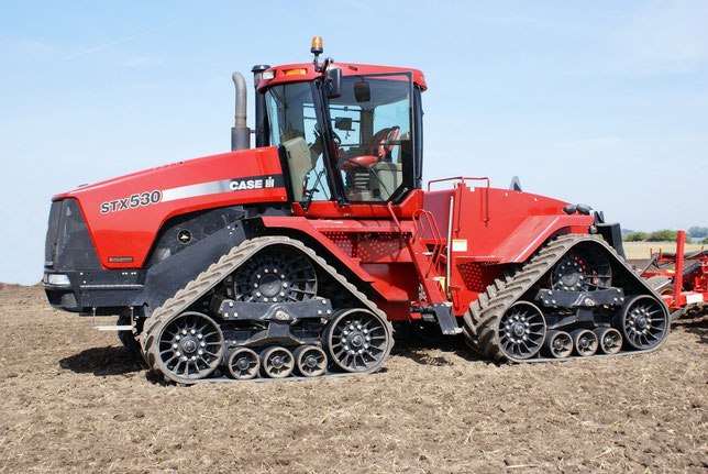
![]()
CASE STX Steiger 350/400/450/500/550/600 Fault Codes list [PDF, ENG, 231 KB]
CASE STX Steiger 350 Fault Codes List PD
Adobe Acrobat Document
231.2 KB
1002 — Short circuit to 12 V or malfunction of the winding chain of the lift valve
hitch
1003 — Electromagnet lifting hitch: open circuit or short circuit to ground
1004 — Short to 12 V windings of the valve of lowering of a coupling device
1005 — Winding of the lowering valve of the coupling device — short to ground or
chain termination
1006 — Stimulation of the exciter of low voltage electronic traction control in view of
his refusal
1007 — Error checking low voltage exciter control module
1008 — The low-voltage side of the lifting electromagnet is connected to the «mass»
1009 — The low-voltage side of the lowering solenoid is connected to the «mass»
1011 — The tractor control unit is disconnected from the CAN bus
1012 — Loss of communication with the armrest controller
1013 — Loss of communication with the instrument controller
1014 — Reference voltage 5 V exceeds the upper permissible limit
1015 — Reference voltage 5 V below the lower limit
1017 — Faulty position control potentiometer
1018 — The balance axle potentiometer signal is outside the normal range
working range
1019 — Failure of top-end potentiometer
1021 — Load potentiometer failure
1024 — Loss of communication with the instrument controller
1025 — Failure of the hoisting / lowering switch
1026 — Failure of the lift / lower switch on the wing
1028 — Failure of motion control potentiometer
1029 — Failure of the lowering speed adjustment potentiometer
1032 — Wrong driving speed. The value obtained from the data bus indicates
malfunction
1033 — Failure of the slip adjustment switch
1034 — Failure of the slip-on switch
1035 — Incorrect percentage of slippage
1036 — The armrest controller signaled a malfunction of the slow switch
lifting traction
1037 — Failure of the slow-down switch
1065 — The armrest controller determined that the tractor is not equipped with a system
traction control, but found traction contacts
1066 — Engine speed too low to calibrate the lower coupling
devices
1067 — The possibility of adjusting the thrust is provided, but the thrust contact sensor (s)
could not be detected
1068 — Throttle adjustment calibration interrupted due to tractor movement
1069 — Calibration of electronic traction control interrupted due to low speed
the engine
1071 — Pulse width modulation (PWM) growth threshold during calibration too
tall
1072 — Pulse width modulation (PWM) growth threshold during calibration too
low
1074 — The clutch potentiometer signal is outside the expected range when
the maximum raised position of the coupling device
1075 — Throttle lowering valve response threshold during calibration
too high
1076 — PWM lower threshold is too low
1077 — The operator did not respond to the electronic traction control calibration procedure
1078 — The coupler is not in the minimum lowered position
1079 — The range of the hitch is not in accordance with the specification
1080 — Ratio of hitch and range of commands
position control does not meet the allowable limits
1085 — Calibration of electronic traction control system required
1086 — There is no communication with the performance monitor (instrumentation controller)
1087 — Reference voltage 8 V above 8,8 V
1088 — Reference voltage 8 V below 7.2 V
1089 — Supply of voltage 12VH1 to the towing and lowering windings of the coupling device
below 8 V
14002 — The oil filter sensor in the gearbox is closed to earth when it is switched on
supply
14003 — The oil filter sensor of the hydraulic system closes to ground when
power on
14005 — Faulty shaft speed sensor error
14006 — Engine speed error GOV
14007 — Engine speed limit exceeded
14008 — Engine oil pressure sensor error
14009 — Engine operating hours lost
14010 — The IOM controller is disconnected from the network
14011 — Total loss of communication
14013 — The gearbox is disconnected from the mains
14014 — Engine coolant temperature sensor error
14015 — Engine Inlet Air Temperature Sensor Error
14016 — Engine shutdown procedure activated
14017 — The fuel level sensor voltage is below the permissible range
14018 — The GOV is disconnected from the network
14019 — The automatic temperature control system is disconnected from the network
14020 — Loss of CAN messages sent by the auxiliary system controller
steering system
14021 — Auxiliary steering is present, but no CAN messages received
15500 — Low pressure primary steering system — auxiliary
steering system works
15501 — High pressure assist steering system when
idle pump
15502 — Low pressure primary steering system — auxiliary
the steering system is faulty
15510 — Increased pressure of the primary steering system pressure sensor
management
15512 — Undervoltage of the pressure sensor of the primary steering system
management
15520 — Error in checking the pressure of the auxiliary control pump
15530 — Increased voltage of the auxiliary steering system pressure sensor
management
15532 — Undervoltage of the auxiliary steering system pressure sensor
management
15540 — Auxiliary system bypass electrical circuit rupture
steering system
15544 — Short circuit to + BAT of the solenoid of the bypass valve
auxiliary control system
15550 — Short circuit to the «mass» of the auxiliary system bypass solenoid
steering system
15552 — Short circuit to + BAT of the pump relay of the auxiliary steering system
management
15553 — Open circuit of the pump drive relay
15554 — Short to ground of the auxiliary pump relay of the steering pump
15560 — Voltage monitoring device VF3
15580 — No pressure was produced in the assist steering system
15590 — No auxiliary steering system equipment found
15591 — The battery voltage is insufficient to start the auxiliary pump
steering systems
15592 — The battery voltage is insufficient to start the auxiliary pump
steering systems
15994 — The engine is running, and the crankshaft rotation input signal is constantly
high level
18007 — Multi-function lever — switch error
18010 — Throttle valve Powershift — too low voltage
18011 — Throttle valve Powershift — too high voltage
18012 — Rotor variator speed switch error (CVT)
18015 — Rear position adjustment potentiometer — too
high voltage
18016 — Backward linkage traction control potentiometer — too low
voltage
18017 — Rear traction control potentiometer — too high
voltage
18018 — Rear linkage potentiometer — too low
voltage
18019 — Rear hitch height potentiometer — too high
voltage
18020 — Quick-lowering potentiometer for rear hitch — too low
voltage
18021 — Potentiometer for quick lowering of the rear hitch — too high
voltage
18022 — Rear suspension adjustment potentiometer —
Too low voltage
18023 — Rear suspension adjustment potentiometer —
too high a voltage
18024 — Error of position of the code flow sensor EHR (remote valve
management)
18025 — Back wheel slip adjustment potentiometer —
Too low voltage
18026 — Rear linkage slip adjustment potentiometer —
too high a voltage
18027 — EHR lever position (remote control valve) 5 — too low
voltage
18028 — EHR lever position (remote control valve) 5 — too high
voltage
18029 — EHR lever position (remote control valve) 6 — too low
voltage
18030 — EHR lever position (remote control valve) 6 — too high
voltage
18040 — EHR lever position (remote control valve) 1 — too low
voltage
18041 — EHR lever position (remote control valve) 1 — too high
voltage
18042 — EHR lever position (remote control valve) 2 — too low
voltage
18043 — EHR lever position (remote control valve) 2 — too high
voltage
18044 — EHR lever position (remote control valve) 3 — too low
voltage
18045 — EHR lever position (remote control valve) 3 — too high
voltage
18046 — Error of lateral swing control switch EHR (remote valve
management)
18047 — EHR lever position (remote control valve) 4 — too low
voltage
18048 — EHR lever position (remote control valve) 4 — too high
voltage
18049 — Control lever 1, X axis — Undervoltage
18050 — Control lever 1, X axis — too high voltage
18051 — Control lever 1, Y axis too low voltage
18052 — Control lever 1, Y axis too high voltage
18053 — Control lever 1, proportional rocker switch — too low
voltage
18054 — Control lever 1, proportional rocker switch — too
high voltage
18055 — Control lever 2, X axis too low voltage
18056 — Control lever 2, X axis too high voltage
18057 — Control lever 2, Y axis too low voltage
18058 — Control lever 2, Y axis too high voltage
18059 — Control lever 2, proportional rocker switch — too low
voltage
18060 — Control lever 2, proportional rocker switch — too
high voltage
18061 — Reference voltage — short circuit to 0 V
18062 — Reference voltage — short circuit to 12 V
18063 — EEPROM error
18064 — Multifunction lever communication error (MFH)
18065 — Basic check error of multifunction lever (MFH)
18066 — Error of lever invalidation (remote control valve) 1
18067 — Error of lever invalidation (remote control valve) 2
18068 — Error of lever invalidation (remote control valve) 3
18069 — Error of lever invalidation (remote control valve) 4
18070 — Error of lever invalidation (remote control valve) 5
18071 — Failed lever invalid signal (remote control valve) 6
18072 — EDC Mouse Up / Malfunction Switch Malfunction
19001 — Reading battery voltage (electrical) — high signal value — by
the battery voltage rating P0563 is exceeded the upper limit value
19002 — Reading battery voltage (electrical) — low signal value — by
battery voltage estimation P0562 the lower limit value is not reached
19010 — Temperature sensor after neutralizer (electrical)
19011 — Temperature sensor after neutralizer (electrical)
19019 — Temperature sensor in front of the neutralizer (electrical) — high signal value
— high value on the circuit of the neutralizer temperature sensor P0428
19020 — Temperature sensor before neutralizer (electric) — low signal value —
Low value on the circuit of the neutralizer temperature sensor P0427
19037 — Supply of sensor 2 (internal 5 V circuit, urea pressure sensors) — too
high supply voltage — reagent P204D — pressure sensor — short circuit on
high voltage source
19038 — Supply of sensor 2 (internal 5 V circuit, urea pressure sensors) — too
low supply voltage — reagent P204C — pressure sensor — short to low voltage source
19046 — Urea pressure sensor in the unit (electrical) — voltage failure
power supply — Reagent P204A — pressure sensor — open circuit
19047 — Urea pressure sensor in the unit (electrical) — high signal level — Reagent
P204D — pressure sensor — short to high voltage source
19048 — Urea pressure sensor in the unit (electrical) — low signal level — Reagent
P204C — pressure sensor — short to low voltage source
19055 — Urea pressure sensor in the unit (electrical) — high signal level — reagent
P2045 — Pump module temperature sensor — short to high voltage source
19056 — Urea pressure sensor in the unit (electrical) — low signal level — reagent
P2044 — Pump module temperature sensor — short to low voltage source
19064 — Supply voltage of internal heaters 1 (UB1), electric. — breaking the circuit UB1
— pump module P20C5 — internal heating — chain breaking
19065 — Supply voltage of internal heaters 1 (UB1), electric. — a short
short circuit for power supply of the battery at UB1, switch 15 in position Off — module
pump P20C8 — internal heating — short circuit to a high source
stresses
19073 — Supply voltage 2 — tubular heaters (UB2), electric. — closure on
battery power with UB2 and disconnected key 15 — reagent P20C4 — preheating
suction pipe — short to high voltage source
19074 — Supply voltage 2 — tubular heaters (UB2), electric. — open circuit UB2 —
Reagent P20C1 — preheating the suction pipe — breaking the chain
19075 — Supply voltage 2 — tubular heaters (UB2), electric. — closure on
«mass» UB2 — Reagent P20C3 — preheating the suction pipe — breaking the chain
19082 — Supply voltage 3 — coolant control valve and valve
reversing mechanism (UB3), electric. — short to battery UB3 with key 15
in the «off» position (off) — P20A3 vapor escape valve (control valve
Air conditioner) — short circuit to a high voltage source
19083 — Supply voltage 3 — coolant control valve and valve
reversing mechanism (UB3), electric. — open circuit UB3 — Vapor extraction valve P20A0
(the control valve of the air-reducing agent) — breaking the chain
19084 — Supply voltage 3 — coolant control valve and valve
reversing mechanism (UB3), electric. — short circuit to earth «UB3 — tap valve
vapor P20A2 (control valve of the air conditioner) — short to the source
low voltage
19091 — Voltage monitoring VDD11 / VDD25 — Dosing valve / pump motor
— low supply voltage VD11 — P0659, supply voltage 12 V for the module
dosing — the lower limit value is not reached
19092 — Voltage monitoring VDD11 / VDD25 — Dosing valve / pump motor
— high supply voltage VD11 — P0658, supply voltage 12 V for the module
dosing — the lower limit value has been exceeded
19100 — Urea level sensor (electrical) — supply voltage error — level sensor
P203E — unreliable / unstable circuit
19101 — Urea level sensor (electrical) — high signal level — P203D reagent —
level sensor in the tank — short to high voltage source
19102 — Urea level sensor (electrical) — low signal level — P203C reagent —
level sensor in the tank — short to low voltage source
19109 — Urea temperature sensor in the tank (electrical) — high signal level —
reagent P205D — temperature sensor in the tank (reagent temperature — solution in the tank) —
short circuit to a high voltage source
19110 — Urea temperature sensor in the tank (electric) — low signal level — reagent
P205C — temperature sensor in the tank (reagent temperature — solution in the tank) — short
short to low voltage
19145 — Dosing valve (electrical) — short to positive terminal
battery — Rejector nozzle P2049 — short to high voltage source
19146 — Dosing valve (electrical) — short circuit to earth — injector
P2048 — short to low voltage source
19147 — Dosing valve (electrical)
19148 — Dosing valve (electrical) — metering valve permanently on
(detected as a result of the output of a rapidly disappearing error) — reagent P209B — pressure in
dosing valve nozzle too high
19154 — Urea pump speed — the pump motor is disconnected — The pump does not feed
reagent P208B
19155 — Speed of the urea pump — blocking of the pump motor — pump
reagent P208A
19156 — Urea pump speed — permissible speed exceeded
pump — exceeding the permissible frequency of the pump of the reagent P208D
19157 — Urea pump speed — Hall sensor defective — The pump does not feed
reagent P208B
19163 — Short circuit of the cooling control valve for voltage
battery (UBat) or open load — short to battery — tap valve
vapor P20A3 (control valve purge reductant) — short circuit to
high voltage source
19164 — Short circuit of the cooling control valve for voltage
battery or open load — open load — vapor outlet valve P20A0
(control valve of the air conditioner) — open circuit
19181 — Reversing valve (4-2-way valve) Electric. — short circuit to
battery — vapor outlet valve P20A3 (control valve of the air reducer) —
short circuit to a high voltage source
19182 — Reversing valve (4-2-way valve), electric. — short circuit to
«mass» — the vapor outlet valve P20A2 (control valve of the air reducer) —
short to low voltage source
19183 — The reversing valve (4-2-way valve) electric. — open load —
the vapor outlet valve P20A3 (control valve of the air reducer) — an open circuit
19262 — Tank heating valve — Short to battery — Reagent P20B4 —
tank heating valve — short to high voltage source
19263 — Tank heating valve — short circuit to earth — reagent P20B3 — valve
tank heating — short to low voltage source
19264 — Tank heating valve — Open load — Reagent P20B1 — Tank heating valve
— open load
19265 — Tank heating valve — short circuit to earth — reagent P20B3 — valve
tank heating — short to low voltage source
19289 — The temperature at the outlet of the neutralizer is too low — the temperature after
neutralizer — physical. (error of the neutralizer heating time) — range / operation
P042B Neutralizer Temperature Sensor Circuit
19298 — Urea pressure too low when starting the system
19307 — Urea pressure too high — Urea pressure not reliable
(urea pressure too high) — Reagent P204B — Pressure above the limit
meanings
19316 — The temperature of the URE in the pump unit is outside the permissible range
range
19325 — The temperature of the URE in the tank is outside the permissible range
19334 — The system froze and was not released on time — the heating and determination mode
malfunctions (failure of heating of the inlet pipeline) — Reagent P20C2 —
heating of the suction pipe — heating detection mode
19335 — The system froze and was not released on time — the heating and detection mode
faults (failure to heat the intake manifold) — Reagent P20BE —
heating of the pipe under pressure — the mode of determining the heating
19336 — The system froze and was not released on time — the heating and detection mode
faults (pressure error in the detection mode) — Reagent P20C5 —
internal heating — chain breaking
19337 — The system froze and was not released on time — the heating and detection mode
faults (error of heating the pipeline with a reverse flow) — Reagent P20B9 —
Reheating tube — breaking the circuit
19343 — The control valve of a cooling liquid, механич. — stuck in the open
position — the vapor outlet valve P20A3 (control valve purging the reducing agent) —
short circuit to a high voltage source
19344 — The control valve of a cooling liquid, механич. — stalled in a closed
position — the vapor outlet valve P20A0 (blowdown purge control valve) —
chain termination
19352 — Reversing valve (4-2-way valve) mechanical. — the valve does not open —
the vapor outlet valve P20A0 (control valve of the air reducer) — an open circuit
19361 — DCU 24 V battery / Power supply — Too high voltage
19362 — DCU 24 V battery / Power supply — Too low voltage
19370 — Urea pressure too low (during commissioning) — error
pump motor during commissioning (the pump does not provide the required supply) —
Reagent P208B — pump does not provide the required supply
19379 — Urea during commissioning too low — values
The temperatures during commissioning are not reliable
19415 — Empty urea tank — empty urea tank — P203F reagent — liquid level in
the tank is too low
19514 — Urea temperature sensor in the tank — Out of range
19532 — Backflow line obstruction — P2063 reagent — dosing valve — short
short to low voltage
19541 — Mechanical blocking of the coolant control valve —
Check of validity of operation of the valve of tap of steams P20A1 (at start)
19550 — Discharge line obstruction — discharge line obstruction — P209B reagent — metering
nozzle — too high pressure
19559 — Low level of Uterine 1 (warning)
19568 — Low urea level 2 (warning) — level of urea below the value
«Limit 2» — reagent P203F — liquid level in the tank — too low
19577 — Reception CAN, frame E2SCR (dosing, exhaust volume, temperature
exhaust, suspension error, heater, long failure) — check SAE J1939
to receive the CAN signal: (urea quality out of range) — the channel is serial
connection P0600
19578 — Reception CAN, frame E2SCR (dosing, volume of exhaust gases, temperature
exhaust, suspension error, heater, long failure) — check SAE J1939
to receive a CAN signal: (dosing outside the range) — serial communication channel
P0600
19579 — Reception CAN, frame E2SCR (dosing, volume of exhaust gases, temperature
Exhaust gas, suspension error, heater, long failure) — time out — channel
serial communication P0600
19580 — Reception CAN, frame E2SCR (dosing, exhaust volume, temperature
Exhaust gas, suspension error, heater, long failure) — too much
messages CAN — Serial communication channel P0600
19581 — Reception CAN, frame E2SCR (dosing, volume of exhaust gases, temperature
exhaust, suspension error, heater, long failure) — check SAE J1939
to receive CAN signal — serial communication channel P0600
19595 — Reception CAN, frame EEC1 (driver request, engine speed, torque
engine) — check SAE J1939 for receiving CAN signal: (engine torque
out of range) — Serial communication channel P0600
19596 — Reception CAN, frame EEC1 (driver request, engine speed, torque
engine) — check SAE J1939 for receiving CAN signal: (engine speed out of range) — serial communication channel P0600
19597 — Reception CAN, frame EEC1 (driver request, engine speed, torque
motor) — timeout — serial communication channel P0600
19598 — Reception CAN, frame EEC1 (driver request, engine speed, torque
motor) — too many CAN messages — Serial communication channel P0600
19599 — Reception CAN, frame EEC1 (driver request, engine speed, torque
engine) — check SAE J1939 for receiving CAN signal: (requested by the driver
torque out of range) — Serial communication channel P0600
19604 — Reception CAN, frame ET1 (temperature of water and engine oil) — check SAE J1939 on
receiving CAN signal: (oil temperature out of range) — serial communication channel
P0600
19605 — Reception CAN, frame ET1 (temperature of water and engine oil) — time out — channel
serial communication P0600
19606 — Reception CAN, frame ET1 (temperature of water and engine oil) — too much
messages CAN — Serial communication channel P0600
19607 — Reception CAN, frame ET1 (temperature of water and engine oil) — check SAE J1939
to receive a CAN signal: (water temperature out of range) — channel serial
connection P0600
19649 — Level error in the urea tank (CAN message or electric with this
sensor) — level above CAN: SAE J1939 signal not available, level sensor connected
directly: sensor supply error — reagent P203A — level sensor in the tank — open circuit
19650 — Urea tank level error (CAN message or electrical malfunction with
real sensor) — level above CAN: SAE J1939 signal out of range, level sensor
connected directly: SRC high. — reagent P203D — tank level sensor — short circuit to
high voltage source
19651 — Urea tank level error (CAN message or electrical malfunction with
real sensor) — level above CAN: SAE J1939 signal out of range, level sensor
connected directly: SRC high. — reagent P203C — tank level sensor — short circuit to
low voltage source
19676 — Ambient temperature: Check SAE J1939 for receiving CAN signal:
(Checking the signal range: signal out of range / signal error / signal not available)
— check SAE J1939 for receiving CAN signal: (ambient temperature outside
range) — Serial communication channel P0600
19677 — Ambient temperature: SAE J1939 for receiving CAN signal:
(Checking the signal range: signal out of range / signal error / signal not available)
— time-out — range of operation of the ambient temperature sensor P0071
19678 — Ambient temperature: SAE J1939 for receiving CAN signal:
(Checking the signal range: signal out of range / signal error / signal not available)
— too many CAN messages — ambient temperature sensor range / operation
air P0071
19679 — Ambient temperature: check SAE J1939 for receiving CAN signal:
(Checking the signal range: signal out of range / signal error / signal not available)
— check SAE J1939 for receiving CAN signal: (barometric pressure out of range)
— range / operation of the ambient temperature sensor P0071
19721 — EEPROM / Checksum error — Write error EEPROM — Error
internal control module EEPROM P062F
19722 — EEPROM / Checksum error — Error of absence of corresponding
options — Error of the internal control module EEPROM P062F
19723 — EEPROM / Checksum error — EEPROM communication error — Internal error
control module EEPROM P062F
19724 — EEPROM / Checksum Errors — EEPROM detection error or error
codierwort — P062F internal control module EEPROM error
19725 — EEPROM / Checksum Errors — Invalid EEPROM Size — P062F
internal error of the control module EEPROM
19730 — Ignition ON signal K15 — during the initialization, it was not possible to read
digital ignition switch input signal — ignition switch P2530 — error
authenticity
19739 — Main relay opens too soon / too late — main relay
off too late — high value in the power relay control loop
ECM / PCM P0687
19740 — Main relay opens too soon / too late — short circuit
main relay — open circuit / control loop of the ECM / PCM power relay P0685
19741 — Main relay opens too soon / too late — main circuit break
relay — high value in the control loop of the ECM / PCM power relay P0687
19742 — Main relay opens too soon / too late — main relay
it turns off too early (before updating the EEPROM) — open circuit / control loop
Power relays ECM / PCM P0685
19748 — The urea temperature in the pump unit is too high or the check error is
tightness (emergency shutdown) — temperature exceeded (temp.
urea in the pump unit) — Reagent P2043 — Pump unit temperature sensor — Outside
allowable range
19749 — The urea temperature in the pump module is too high or there are leaks in
During the test (emergency shutdown) — detection of a leakage of urea (static or
dynamic test) — dynamic check for urea leakage P202D — leakage
detected
19757 — Channel of group error of urea injection control — error belongs to
urea injection control group — pump for P208B — does not supply
19766 — Air control group error channel — the error belongs to the group
air control valve — P20A7 compressed air control valve
19775 — The group error channel of the neutralizer temperature — the error belongs to
group of errors in the temperature of the neutralizer — inaccuracy of the temperature sensors
neutralizer P0426 — reliability error (with static check)
19784 — Group error channel for exceeding NOx — the error belongs to the group of active
errors of NOx level exceeding — NOx trapper performance below threshold
P2000 values
19793 — Group error channel of empty urea tank — error belongs to group
active errors of the empty urea tank — reagent P203F — liquid level in the tank —
too low
19802 — Inaccurate temperature data in the urea tank taking into account the temperature
pumping unit — temp. on the CAN bus: SAE J1939 timeout, the temperature sensor is connected
directly: high. SRC — serial communication channel P0600
19803 — Unreliable temperature data in the urea tank taking into account the temperature
pumping unit — temp. CAN bus: too many SAE messages J1939, sensor
The temperature is directly connected: high. SRC — serial communication channel P0600
19804 — Inaccurate temperature data in a urea tank taking into account the temperature
pumping unit — temp. on the CAN bus: signal error SAE J1939 — reagent P205A — sensor
temperature in the tank (reagent temperature — solution in the tank) — open circuit
19805 — Temperature in a tank with a urea — an open circuit
19806 — Temperature sensor in a tank with a urea — short circuit
19807 — Inaccurate temperature data in the urea tank taking into account the temperature
pumping unit — high. SRC: too high diagnostic temperature value
urea — reagent P205B — temperature sensor in the tank (reagent temperature — solution in
tank) — out of range
19808 — Inaccurate temperature data in the urea tank taking into account the temperature
pumping unit — low. SRC: The diagnostic temperature is too low
urea — reagent P205B — temperature sensor in the tank (reagent temperature — solution in
tank) — out of range
19813 — Urea pressure too low during operation or dosage of the system
urea
19817 — Reliability of sticking of the urea dispenser valve (UDV) — reagent P202F —
Dosing valve — blocked (only sticking in the closed position)
19818 — Reliability of sticking of the urea dosing valve (UDV) — dynamic
urea leakage test P202D — leak detected
19822 — Error — unknown position of sticking of the urea dispenser valve (UDV) —
dynamic check for urea leakage P202D — leak detected
19999 — The DCU motor was not malfunctioning
is converted into a CNH module. Refer to the fault codes of the engine control unit (ECU)
using the EASY tool.
2009 — Open circuit of the seat switch
2010 — Short-circuit of the seat switch to the power supply + BAT or reference
voltage 5V
2011 — Short to earth or an open in the clutch chain.
2012 — Short-circuit of the coupler potentiometer by 12V or short circuit on
5V reference voltage
2024 — All couplings are not calibrated
2037 — Clutch lower link circuit open or lower coupling clutch relay
jammed in the open position
2047 — Incorrect adjustment of the lower part of the clutch pedal of the clutch switch
2048 — Short circuit of the lower part of the clutch pedal switch or
the lower part of the clutch relay
2053 — Too high reference voltage 5 V
2054 — Too low reference voltage 5 V
2055 — Wheel speed sensor signal missing
2056 — Internal reference voltage too high 5 V
2057 — Internal reference voltage too low 5 V
2059 — Lever of the lever sensor mismatch
2070 — Increased voltage of the lever position sensor for forward movement
2071 — Short to ground or an open in the chain of the lever position sensor for movement
forward
2072 — Lever position sensor for reverse movement — too high voltage
2073 — Lever position sensor for reverse travel — Short to ground or
break in the chain
2074 — Undervoltage of the lever position sensor FNR, other than parking
2075 — Increased voltage of the lever position sensor FNR, other than parking
2110 — Neutral position sensor FNR — Undervoltage
2111 — Neutral position sensor FNR — overvoltage
2112 — Lubrication of the oil pressure switch in the axle
2113 — Low oil pressure in the axle
2114 — Critical low oil pressure in the axle
2158 — Critical low system pressure
2159 — Open circuit in the system pressure transmitter circuit
2160 — Short-circuit of the system pressure transducer to a reference voltage of 5 V
or + BAP
2308 — Reverse switching is not permitted
2326 — High reading of the engine speed sensor
2327 — There is no signal from the engine speed sensor
2330 — The gearbox output speed too high for the selected
transfer of
2331 — Coupling slippage error
2342 — Short to earth or an open in the clutch solenoid valve circuit
1F
2343 — Short to earth or an open in the clutch solenoid valve circuit
1M
2344 — Short to earth or an open in the solenoid valve circuit of the 1R coupler
2345 — Short to earth or an open in the solenoid valve circuit of the 2F clutch
2346 — Short to earth or an open in the solenoid valve circuit of the 2R clutch
2347 — Short to earth or an open in the 4F clutch solenoid valve circuit
2348 — Short to earth or an open in the 4R solenoid valve circuit
2349 — Short to ground or an open in the 5F solenoid valve circuit
2350 — Short to earth or an open in the 5R solenoid valve circuit
2351 — Short-circuit of the solenoid valve of the clutch 1F to the +12 V power supply with the drive switched off
2352 — Short-circuit of the solenoid valve of the 1M clutch to a +12 V source with the drive switched off
2353 — Short-circuit of the solenoid valve of the 1R clutch to the +12 V power supply with the drive switched off
2354 — Short-circuit of the solenoid valve of the clutch 2F to the +12 V voltage source with the drive switched off
2355 — Short-circuit of the solenoid valve of the clutch 2R to the +12 V voltage source with the drive switched off
2356 — Short-circuit of the solenoid valve of the clutch 4F to the +12 V source with the drive switched off
2357 — Short-circuit of the solenoid valve of the 4R clutch to the +12 V source with the drive switched off
2358 — Short-circuit of the solenoid valve of the coupling 5F to the +12 V power supply with the drive switched off
2359 — Short-circuit of the solenoid valve of the 5R clutch to the +12 V source with the drive switched off
2363 — 1M coupling not calibrated
2364 — 1F coupling not calibrated
2365 — 1R coupling not calibrated
2366 — Coupling 2F not calibrated
2367 — The 2R coupling is not calibrated
2368 — 4F coupling not calibrated
2369 — The 4R coupling is not calibrated
2370 — 5F coupling not calibrated
2371 — 5R coupling not calibrated
2372 — Engine stop — change gearbox to neutral
2379 — Malfunction of the three-speed shaft speed sensor
2380 — Three-speed shaft speed sensor is serviceable
2381 — Open circuit or short circuit to + BAT of the 5th gear speed sensor
2382 — Short circuit to earth of the 5th gear speed sensor
2383 — Open circuit or short circuit to + BAT of the 4th gear speed sensor
2384 — Short circuit to earth of the 4th gear speed sensor
2385 — Open circuit or short circuit to + BAT of the 3rd gear speed sensor
2386 — Short to ground on the 3rd gear speed sensor
2387 — Open circuit or short circuit to + BAT of the 1st gear speed sensor
2388 — Short circuit to earth of the 1st gear speed sensor
2509 — Battery voltage too low to trip
Coupling solenoid valves
2576 — The drive of the lubricant supply solenoid to the 4F coupler detected a chain break or
short circuit
2577 — The model is outside the range of the control system
2578 — The resulting model does not match the controller
2601 — Low supply voltage 12VF1
2602 — Low power supply voltage 12VT1
2603 — Low power supply voltage 12VF2
2604 — Low power supply voltage 12VH
2605 — Low power supply voltage 12VS1
2807 — Excess of speed at the output of the gearbox
2808 — Attempted gear shift in the absence of an operator on the seat
2811 — High temperature transmission oil
2812 — Short to + BAT or an open in the temperature sensor circuit
transmission oil
2813 — Short circuit to earth of the transmission oil temperature sensor
2814 — The integrated control panel is disconnected from the network
2817 — Regulator off, CAN bus
2818 — Loss of communication with the armrest control module (ACM)
2819 — Loss of communication with the Instrument Control Unit (ICU)
2821 — Low pressure in the gearbox
2822 — System pressure is above the permissible range
2824 — High temperature hydraulic oil
2825 — Open circuit or short circuit to + BAT of the hydraulic temperature sensor
oils
2826 — Hydraulic oil temperature sensor short circuit
2849 — The parking brake actuator detects a chain break
2850 — There is no power to the parking brake with the on command
2851 — The parking brake actuator has detected a current overload or an open in the circuit
2852 — There is no power to the parking brake with the on command
2873 — The software is not in calibration mode, still active
parking brake request
2874 — A signal has come to turn on the parking brake, and the gear is engaged without
request for calibration
3004 — Error in the throttle control lever on the CAN bus
the engine
3006 — Coolant temperature sensor — The signal is not valid
3007 — Coolant temperature signal — signal above the maximum value
range
3008 — Coolant temperature signal — signal below the minimum value
range
3010 — Intake Air Temperature Sensor — Signal above maximum value
range
3011 — Intake Air Temperature Sensor — Signal above minimum value
range
3015 — Fuel temperature sensor voltage too high
3016 — Fuel temperature sensor — Signal below the minimum allowable value
3019 — Discharge pressure sensor — Signal above maximum range value
3022 — Discharge pressure sensor — Signal not valid
3028 — Oil pressure too low
3029 — Oil pressure switch — Short to battery
3030 — Oil pressure switch — Short to earth
3031 — Open in the oil pressure sensor circuit or the sensor is disconnected
3032 — Oil pressure switch — Too high value
3033 — Oil temperature sensor — The signal is invalid (compared to the signal
coolant temperature)
3034 — Oil temperature sensor — Signal above maximum range value
3035 — Fuel temperature sensor — signal below the minimum allowable value
3037 — Discharge pressure sensor — Low signal
3060 — Cylinder 1 — non-classified malfunction in the injector
3061 — Cylinder 1 — Short circuit in the injector wire (low voltage circuit to battery)
3063 — Cylinder 1 — Short circuit of the injector wire (high-side side to ground)
3064 — Cylinder 5 — Unclassified injector fault
3065 — Cylinder 5 — Short circuit in the injector wire (low voltage circuit to battery)
3067 — Cylinder 5 — short circuit of the injector wire (high voltage side to ground)
3068 — Cylinder 3 — Uncategorized error in the injector
3069 — Cylinder 3 — short circuit of the injector wire (low voltage side to battery)
3071 — Cylinder 3 — short-circuit of the injector wire (high-side side to ground)
3072 — Cylinder 6 — non-classified malfunction in the injector
3073 — Cylinder 6 — short circuit of the injector wire (low-side side on
battery)
3075 — Cylinder 6 — short circuit of the injector wire (high voltage side on
«mass»)
3076 — Cylinder 2 — non-classified malfunction in the injector
3077 — Cylinder 2 — short circuit of the injector wire (low voltage side to battery)
3079 — Cylinder 2 — short-circuit of the injector wire (high-side side to ground)
3080 — Cylinder 4 — non-classified malfunction in the injector
3081 — Cylinder 4 — short circuit of the injector wire (low voltage side to battery)
3083 — Cylinder 4 — short-circuit of the injector wire (high-side side to ground)
3088 — Crankshaft sensor — no signal
3089 — Crankshaft sensor — incorrect signal
3090 — Camshaft sensor — no signal
3091 — Camshaft sensor — incorrect signal
3093 — Camshaft offset relative to crankshaft — out of range
3095 — Operation with camshaft sensor only — standby mode
3102 — Mains pressure sensor CP3 — signal below the minimum allowable value
3104 — Safety valve on the fuel rail —
Opening
3105 — Safety valve on the fuel rail — pressure surge request
3107 — Fuel flow meter — short to battery
3108 — Fuel flowmeter — short to ground
3110 — Monitoring of the rail pressure sensor — Signal above the set range
3111 — Monitoring of the pressure sensor in the pipeline — signal below the minimum allowable value
3112 — Mains pressure sensor CP3 — signal above the maximum permissible value
3137 — Flowmeter — open load
3138 — Measuring unit — The temperature is too high
3141 — The set flow rate of the flowmeter is lower than the design limit
3142 — High pressure test — check performed
3147 — The oil temperature is excessively high
3148 — Dynamic test of the coolant temperature sensor — malfunction
3176 — The set value of the flowmeter does not correspond to the actual value when overrun.
3177 — Motor speed exceeded
3188 — Cylinder 1, warning — open load
3192 — Cylinder 2, warning — open load
3196 — Cylinder 3, warning — open load
3200 — Cylinder 4, warning — open load
3204 — Cylinder 5, warning — open load
3208 — Cylinder 6 Warning — open load
3210 — Row 1 — General short circuit to the injector wire
3211 — Row 1 — Short-circuit of injector wire (low-side side to ground)
3213 — Row 1 — Uncategorized malfunction
3218 — Row 2 — total short circuit in the injector wire
3219 — Row 2 — short circuit of the injector wire (low-side side to ground)
3221 — Row 2 — Uncategorized malfunction
3227 — Injection processor error — Internal reset / Loss of synchronization / Voltage too low
3228 — Injection processor error — Unlock / initialize error
3229 — Injection processor error — injection is limited to software
3230 — Injection processor error — SPI bus data error
3231 — Injection processor error — Internal reset / Loss of synchronization / Voltage too low
3232 — Injection processor error — unlock / initialize error
3233 — Injection processor error — test mode
3234 — Injection processor error — SPI bus data error
3238 — Communication error of the CJ940 processor
3239 — EEPROM Engine ECU — Read operation error
3240 — EEPROM of the motor controller — Fault in the write operation
3241 — Motor controller EEPROM — The default value is used
3242 — The motor controller has been restored (blocked)
3243 — Restoration of the engine controller (restrained) — Recovery occurred
3244 — Engine controller recovery (visible) — Recovery occurred
3245 — Motor controller — not reliable control module
3246 — Trip routes during initialization — monitoring module
3247 — Malfunction of trip routes during initialization — Increased supply voltage
3248 — Trip routes during initialization — Reduced supply voltage
3249 — Monitoring of the TPU (TPU) — Unreliable discrepancy between TPU time and system time
3252 — Controller Controller Module — SPI communication failure
3265 — Anti-spill protection system — Injection time too long
3266 — Excessive engine speed during run monitoring
3297 — High positive pressure deviation in the rail and high fuel consumption setpoint
3301 — Too high minus pressure deviation in the fuel rail by the minimum flowmeter
3305 — The pressure in the distribution rail is below the minimum limit in controlled mode
3309 — The pressure in the rail is above the maximum limit in controller mode
3313 — Too much pressure drop in the rail.
3316 — Minimum number of injections not reached — Stop the engine
3319 — DTC control error detected: Urea level in the tank below 5%
3320 — A bug of the dosing control unit (DCU) has been detected: the urea level in the tank is below 10%
3321 — A fault code in the DCU is active.
3322 — A fault code in the DCU is active.
3358 — Failure of the CAN auxiliary bus of the engine-ECU (the engine controller can not transmit data to the sensors or sensors — to the CAN bus)
3367 — Error checking coolant temperature
3368 — Reflects the torque limit due to the limitation
productivity
3369 — Torque reduction due to engine smoke restriction
3370 — Torque limit due to engine protection (against torque, against exceeding the permissible engine speed and against engine overheating)
3371 — Torque limit due to the limitation of fuel volume due to errors in the injection system
3385 — Electromagnetic circuit for a viscous fan drive — open circuit or short to ground
3512 — Control of the status of the DCU — The DCU is not ready on time
3517 — Ambient temperature sensor fault (humidity sensor) — Signal level too high
3518 — Ambient temperature sensor (humidity sensor) malfunction — Signal level is too low
3521 — Nitric oxide estimation error — unreliable nitric oxide estimation signal
3528 — Sensitivity error of the nitrogen oxide sensor — unreliable signal
3529 — Nitrogen oxide sensor failure — open load
3530 — Nitrogen oxide sensor fault — short circuit
3532 — Nitrogen oxide sensor failure — sensor was not ready on time
3533 — CAN message waiting time for nitrogen oxides (from nitrogen oxide sensor) — CAN timeout
3541 — No CAN bus message received from the dosing control unit (DCU)
3545 — Protection against overheating of the dispensing valve SCR — limiting the level of torque 2 to activate protection SCR
3546 — Protection against overheating of the selective catalytic neutralization nozzle (SCR) has tripped, see other fault codes
3555 — No CAN bus message received from the dosing control unit (DCU)
3561 — Unreliable value for nitrogen oxides (after reliability of treatment)
3565 — Urea quality and Urea level warnings 1
3569 — Urea quality and urea level warnings 2
3577 — A bug of the dosing control unit (DCU) is detected: the urea tank is empty
3581 — Protection through selective catalytic neutralization (SCR), limited refueling, see other fault codes.
3585 — Engine shutdown (after idling phase)
3593 — Poor quality of reagent
3594 — Torque limitation due to selective catalytic
neutralization (SCR)
3599 — There is no oxidation catalyst error channel — the catalyst warming efficiency is below the threshold value
3602 — Wrong relationship between temperature sensor readings
catalytic converter
3609 — Urea quality and urea level warnings 4
3611 — Neutralizer efficiency — medium (level 1)
3612 — The efficiency of the catalytic converter is lower than the second assumed threshold level of nitrogen oxides
3615 — Initialization failed EVGT
3616 — Torque limit due to turbo protection system due to reason
work at high altitude
3617 — Urea quality and urea level warnings 9
3618 — The emergency start time has elapsed, and the stop is started
3619 — Urea quality and urea level warnings 7
3620 — Urea quality and urea level warnings 8
3621 — Urea quality and urea level warnings 5
3623 — NOx sensor deflection signal (detection of NOx sensor determined)
3624 — Crankcase pressure sensor — Voltage exceeds the upper limit value
3625 — Crankcase pressure sensor — voltage below the lower limit value
3626 — Inaccurate signal from the crankcase pressure sensor
3627 — Checking the physical range of the crankcase pressure sensor (exceeds the upper limit value)
3628 — Checking the physical range of the crankcase pressure sensor
3629 — Checking the reliability of the crankcase pressure sensor when the ignition is switched on
3630 — Fuel in oil, fill with new oil
3631 — Failure of fuel sensor in oil
3632 — Fuel in oil, error of valve signal reliability
3633 — Fuel in oil, delay in the expected response to the reduction in torque (as a result of detection of fuel in oil)
3634 — Fuel in oil, delay filling of new oil
3635 — High fuel pressure in oil
3638 — Torque limit due to negative temperature coefficient
3640 — Turbine speed sensor
3641 — Turbine speed sensor
3642 — Turbine speed sensor
3643 — Turbine speed sensor
3644 — Electrical fault finding circuit of the EDC relay of the drive supplies the NOX sensor and the turbocharger drive
3645 — Electrical fault finding circuit of the EDC relay of the drive supplies the NOX sensor and the turbocharger drive
3646 — Multi-signal faults in the pressure regulator (PCR)
3647 — Supercharging pressure control
3648 — EVGT Supercharging pressure control
3999 — The error of the engine control unit (ECU) has not been converted to the CNH module. Refer to the fault memory of the computer using the EASY tool.
4004 — The ACM (GARU) module is not connected to the network
4005 — Calibration of levers when power is not applied
4100 — Rear remote control valve No. 1 — Control message not received
4101 — Rear remote control valve No. 1 control message is not valid
4102 — Rear remote control valve No. 1 — EEPROM error
4103 — Rear remote control valve No. 1 — switched to «safe mode»
4104 — Rear remote control valve No. 1 — voltage drop below normal
4105 — Rear remote control valve No. 1 — overvoltage
4106 — Rear remote control valve No. 1 — Spool travel too small
4107 — Rear remote control valve No. 1 — Spool travel too large
4108 — Rear remote control valve No. 1 — Floating position not reached
4109 — Remote control valve # 1 — operated manually
4110 — Rear remote control valve No. 1 — defective drive
4111 — Rear remote control valve No. 1 — internal position sensor defective
4112 — Rear Remote Control Valve No. 1 — Neutral position can not be reached
4113 — Rear remote control valve No. 1 — the valve is not in neutral when the ignition is switched on
4114 — Rear remote control valve No. 2 — no control message received
4115 — Rear remote control valve No. 2 — control message is not valid
4116 — Rear remote control valve No. 2 — EEPROM error
4117 — Rear remote control valve No. 2 — switched to «safe mode»
4118 — Rear remote control valve No. 2 — voltage drop below normal
4119 — Rear remote control valve No. 2 — overvoltage
4120 — Rear remote control valve No. 2 — Spool travel too small
4121 — Rear remote control valve No. 2 — Spool travel too large
4122 — Remote control rear valve No. 2 — swing position not reached
4123 — Rear remote control valve No. 2 — operated manually
4124 — Rear remote control valve No. 2 — defective drive
4125 — Rear remote control valve No. 2 — internal position sensor defective
4126 — Remote control rear valve No. 2 — can not turn on the neutral
4127 — Rear remote control valve No. 2 — the valve is not in neutral when the ignition is switched on
4128 — Rear remote control valve No. 3 — Control message not received
4129 — Rear remote control valve No. 3 — control message is not reliable
4130 — Rear remote control valve No. 3 — EEPROM error
4131 — Rear remote control valve No. 3 — No command to switch to neutral when power is applied
4132 — Rear remote control valve No. 3 — voltage drop below normal
4133 — Rear remote control valve No. 3 — overvoltage
4134 — Rear remote control valve No. 3 — too small displacement of the spool
4135 — Rear remote control valve No. 3 — too large displacement of the spool
4136 — Rear remote control valve No. 3 — Swing position not reached
4137 — Rear remote control valve No. 3 — manually operated
4138 — Rear remote control valve No. 3 — defective drive
4139 — Rear remote control valve No. 3 — internal position sensor defective
4140 — Rear remote control valve No. 3 — Can not turn on the neutral
4141 — Rear remote control valve No. 3 — the valve is not in neutral when the ignition is switched on
4142 — Rear remote control valve No. 4 — no control message received
4143 — Rear remote control valve No. 4 — control message is not reliable
4144 — Rear remote control valve No. 4 — EEPROM error
4145 — Remote control valve No. 4 — did not receive a command to turn on the neutral when the power was turned on
4146 — Rear remote control valve No. 4 — voltage drop below normal
4147 — Rear remote control valve No. 4 — overvoltage
4148 — Rear remote control valve No. 4 — Spool travel too small
4149 — Rear remote control valve No. 4 — Spool slide too large
4150 — Rear remote control valve No. 4 — swing position not reached
4151 — Rear remote control valve No. 4 — manual operation
4152 — Rear remote control valve No. 4 — defective drive
4153 — Rear remote control valve No. 4 — internal position sensor defective
4154 — Rear remote control valve No. 4 — can not turn on the neutral
4155 — Rear remote control valve No. 4 — the valve is not in neutral when the ignition is switched on
4156 — Rear remote control valve No. 5 — no control message received
4157 — Rear remote control valve No. 5 — control message is not valid
4158 — Rear remote control valve No. 5 — EEPROM error
4159 — Rear remote control valve No. 5 — No command to switch to neutral when power is applied
4160 — Rear remote control valve No. 5 — voltage drop below normal
4161 — Rear remote control valve No. 5 — overvoltage
4162 — Rear remote control valve No. 5 — Spool travel too small
4163 — Rear remote control valve No. 5 — Spool travel too large
4164 — Rear remote control valve No. 5 — Swing position not reached
4165 — Rear remote control valve No. 5 — manually operated
4166 — Rear remote control valve No. 5 — defective drive
4167 — Rear remote control valve No. 5 — internal position sensor defective
4168 — Rear remote control valve No. 5 — can not turn on the neutral
4169 — Rear remote control valve No. 5 — the valve is not in neutral when the ignition is switched on
4170 — Rear remote control valve No. 1 — not calibrated
4173 — Rear remote control valve No. 2 — not calibrated
4177 — Rear remote control valve No. 3 — not calibrated
4180 — Rear remote control valve No. 4 — not calibrated
4190 — Rear remote control valve No. 1 — no connection
4191 — Rear remote control valve No. 2 — no communication
4192 — Rear remote control valve No. 3 — no connection
4193 — Rear remote control valve No. 4 — no connection
4198 — Rear remote control valve No. 5 — no connection
4216 — Rear remote control valve No. 1 — the spool is not calibrated
4217 — Rear remote control valve No. 2 — the spool is not calibrated
4218 — Rear remote control valve No. 3 — the spool is not calibrated
4219 — Rear remote control valve No. 4 — the spool is not calibrated
4220 — Rear remote control valve No. 5 — the spool is not calibrated
4301 — Rear remote control valve No. 6 — no control message received
4302 — Rear remote control valve No. 6 — control message is not reliable
4303 — Rear remote control valve No. 6 — EEPROM error
4304 — Remote control rear valve No. 6 — no command for neutral at power supply
4305 — Rear remote control valve No. 6 — undervoltage
4306 — Rear remote control valve No. 6 — overvoltage
4307 — Rear remote control valve No. 6 — Spool travel too small
4308 — Rear remote control valve No. 6 — Spool travel too large
4309 — Rear remote control valve No. 6 — Swing position not reached
4310 — Rear remote control valve No. 6 — manually operated
4311 — Rear remote control valve No. 6 — defective drive
4312 — Rear remote control valve No. 6 — internal position sensor defective
4313 — Rear remote control valve No. 6 — Can not turn on the neutral
4314 — Rear remote control valve No. 6 — the valve is not in neutral when the ignition is switched on
4315 — Rear remote control valve No. 7 — Control message not received
4316 — Rear remote control valve No. 7 — control message is not valid
4317 — Rear remote control valve No. 7 — EEPROM error
4318 — Rear remote control valve No. 7 — No command to switch to neutral when power is applied
4319 — Rear remote control valve No. 7 — voltage drop below normal
4320 — Rear remote control valve No. 7 — overvoltage
4321 — Rear remote control valve No. 7 — Spool travel too small
4322 — Rear remote control valve No. 7 — Spool travel too large
4323 — Rear remote control valve No. 7 — Swing position not reached
4324 — Rear remote control valve No. 7 — manually operated
4325 — Rear remote control valve No. 7 — defective drive
4326 — Rear remote control valve No. 7 — internal position sensor defective
4327 — Rear remote control valve No. 7 — can not turn on the neutral
4328 — Rear remote control valve No. 7 — the valve is not in neutral when the ignition is switched on
4329 — Remote control remote control valve No. 8 — no control message received
4330 — Rear remote control valve No. 8 — control message is not valid
4331 — Rear remote control valve No. 8 — EEPROM error
4332 — Rear remote control valve No. 8 — No command to switch to neutral when power is applied
4333 — Rear remote control valve No. 8 — voltage drop below normal
4334 — Rear remote control valve No. 8 — overvoltage
4335 — Rear remote control valve No. 8 — Spool travel too small
4336 — Rear remote control valve No. 8 — Spool travel too large
4337 — Rear remote control valve No. 8 — Swing position not reached
4338 — Rear remote control valve No. 8 — manually operated
4339 — Rear remote control valve No. 8 — defective drive
4340 — Rear remote control valve No. 8 — internal position sensor defective
4341 — Rear remote control valve No. 8 — can not turn on the neutral
4342 — Rear remote control valve No. 8 — the valve is not in neutral when the ignition is switched on
4343 — Rear remote control valve No. 5 — not calibrated
4344 — Remote control remote control valve No. 6 — not calibrated
4345 — Rear remote control valve No. 7 — not calibrated
4346 — Rear remote control valve No. 8 — not calibrated
4347 — Rear remote control valve No. 6 — no connection
4348 — Rear remote control valve No. 7 — no connection
4349 — Rear remote control valve No. 8 — no connection
4350 — Rear remote control valve No. 6 — the spool is not calibrated
4351 — Rear remote control valve No. 7 — the spool is not calibrated
4352 — Rear remote control valve No. 8 — the spool is not calibrated
4353 — Short-circuit EHR FB 1 to high voltage source
4354 — EHR FB 1 valve, short to low voltage source
4355 — EHR FB 3 valve, short to high voltage source
4356 — EHR FB 3 valve, short to low voltage source
4357 — EHR valve, attachment lowering error
4358 — EHR valve, attachment error
5001 — After switching on the tractor power, a switch
5002 — IOM switch interlock
5008 — Simultaneously the IOM activation and deactivation switches are turned on; in one of the MOM switches, a short to the 12 V supply circuit
5009 — Open in the circuit or short circuit of the solenoid valve PTO to «mass»
5010 — Short circuit to + BAT in the solenoid valve PTO circuit with MOM off
5011 — Drive switched on, but no current detected
5012 — Excessive slippage of the MOM coupling for 5 seconds or more
5013 — Engine speed too low to turn on the PTO
5014 — A command was given to turn off the PTO, but the PTO speed is above zero
5015 — The software does not determine the speed of the MOM shaft within 3 seconds after the command is given to the IOM initial load valve
5016 — PTO rotation detected with PTO off and engine off
5017 — MOM coupling not locked after 6 seconds of coupling movement
5022 — With the engine switched off, the PTO switch is in the «on» position
5023 — Short to + BAT in the solenoid valve circuit of the MOM coupling lubricant when the PTO is switched off
5024 — Open circuit or short circuit of the solenoid valve of the MOM coupling lubricant to «earth»
5025 — Diagnosis of the drive monitoring module on the low pressure side of the PTO
5026 — Supply voltage too low 12 V to PTO
5027 — Short-circuit of low-pressure side of solenoid valve PTO to «ground»
5028 — Open circuit or short circuit to + BAT of the clutch speed sensor
5029 — Short to earth of the clutch speed sensor
5032 — Low power supply voltage 12VF3
6001 — Failure of the front differential lock solenoid valve
6002 — Differential lock solenoid valve failure
6003 — Stop lamp relay failure
6004 — Failure of rear differential lock switch
6006 — Failure of the front differential lock switch
6010 — Low power supply voltage 12VS1
6011 — Low power supply voltage 12VS2
6012 — Pressure of the pressure sensor in the steering system above the maximum permissible limit
6013 — Pressure of the pressure sensor in the steering system below the minimum permissible limit
ATC 122 — Open or short to the power supply of the mode selection potentiometer
ATC 125 — Short to high-pressure switch power supply (+)
ATC 127 — Short to high-pressure switch power supply (-)
ATC 128 — Short to ground of the high pressure switch (-)
ATC 129 — High pressure switch cyclic error (2 times per minute)
ATC 130 — Short to the power supply of the low pressure switch (+)
ATC 131 — Short to ground of the low pressure switch (+)
ATC 132 — Short to low-pressure switch power supply (-)
ATC 133 — Short to ground of the low pressure switch (-)
ATC 134 — Low pressure switch open for more than 1 minute
SECTION 5
When a fault occurs, the multi-function display
shows on the upper section an error code (for
instance # 7004), at the same time two lamps one
yellow (2) and one red (3) light up; according to the
fault they can light up either singularly or together.
According to the fault seriousness, also an acoustic
warning can be released.
RED
The persons safety and/or the
+
operation of the machine’s
CONTINUOUS
main assemblies are endan-
SOUND
gered.
Fault
safety of persons and for
YELLOW
machine operation.
+
These
cleared as soon as possible.
SINGLE
In
the
SOUND
though, the full machine func-
tionality remains unchanged.
S
WARNING
The serious faults have to be cleared immediately.
Shut off the machine immediately.
Beyond the error code, in the lower section of the
multi-function display, appears a short explanation
of the error code.
In some particular cases, some faults can occur
concurrently.
In such a case, the relevant error codes are indi-
cated, by alternating one after the other in the usual
visualization.
5-2
Serious fault
insignificant
for
the
faults
have
to
be
majority
of
cases
S
Copyright ©
ERROR CODE
Error explanation
(rows of 25 digits)
1
JAZ/JAW125001 and After
Fault code list for: MX Magnum Tractor TG Series Tractor
![]()
Case-and-New-Holand-Fault-Codes.docx
Microsoft Word Document
26.8 KB
ENGINE
111 Engine Controller Failure — Hardware Failure
115 Engine Speed Sensor signal is failed (no signal at engine controller pin A17)
121 Engine Position Sensor signal is failed (no signal at engine controller pin A9)
122 Boost Pressure Sensor voltage is too high (engine controller pin A45)
123 Boost Pressure Sensor voltage is too low (engine controller pin A45)
124 Boost Pressure level has exceeded the warning limit.
131 Foot Throttle Position potentiometer voltage is too high (engine controller pin B30)
132 Foot Throttle Position potentiometer voltage is too low (engine controller pin B30)
135 Oil Pressure Sensor voltage is too high (engine controller pin A33)
141 Oil Pressure Sensor voltage is too low (engine controller pin A33)
143 Oil Pressure level has fallen below the warning limit.
144 Coolant Temperature Sensor voltage is too high (engine controller pin A23)
145 Coolant Temperature Sensor voltage is too low (engine controller pin A23)
146 Coolant Temperature level has exceeded the warning limit.
151 Coolant Temperature level has exceeded the warning limit.
153 Intake Manifold Temperature Sensor voltage is too high (engine controller pin A34)
154 Intake Manifold Temperature Sensor voltage is too low (engine controller pin A34)
155 Intake Manifold Temperature level has exceeded the warning limit.
211 Communications problem with Armrest, Instrumentation, or Transmission Controllers
234 Engine Speed has exceed the overspeed warning limit.
235 Engine Coolant Level is low. Add coolant fluid.
263 Fuel Temperature Sensor voltage is too high (engine controller pin A35)
265 Fuel Temperature Sensor voltage is too low (engine controller pin A35)
268 Fuel Pressure in pump is not changing with operating conditions.
271 Front Pumping Control Valve current is low during «click test» (pin A21)(open circuit)
272 Front Pumping Control Valve current is high (pin A21)(short circuit)
273 Rear Pumping Control Valve current is low during «click test» (pin A15)(open circuit)
274 Rear Pumping Control Valve current is high (pin A15)(short circuit)
275 Front Pumping element is failed
276 Injection Control Valve current is out of range (engine controller pin A7)(open or short)
277 Injection Control Valve is failed (engine controller pin A7)(open or short)
278 Fuel Lift Pump is failed (engine controller pin 11)
279 Injection Control Valve current is out of range (engine controller pin A7)(open or short)
281 Front Pumping element is failed
282 Rear Pumping element is failed
283 Engine Speed/Position Sensor supply voltage is too high (controller pin A8)
284 Engine Speed/Position Sensor supply voltage is too low (controller pin A8)
319 Real Time Clock in controller has lost power
328 Rear Pumping element is failed
329 CAPS Pump has an overpumping failure
352 5 Volt Sensor Supply voltage is too low (engine controller pin A10)
386 5 Volt Sensor Supply voltage is too high (engine controller pin A10)
387 Foot Throttle 5 Volt Supply voltage is too high (engine controller pin B29)
415 Oil Pressure level has fallen below the very low warning limit.
418 Water in Fuel sensor (optional) indicates the water in the fuel filter needs to be drained.
422 Engine Coolant Level Sensor (optional) is failed or the jumper plug is missing
429 Water in Fuel Sensor (optional) voltage is too low. (engine controller pin B40)
431 Foot Throttle Idle Validation Switches are both closed (engine controller pins B25, B26)
432 Foot Throttle position potentiometer and switches disagree.
433 Boost Pressure level disagrees with engine operation conditions (speed & power)
434 Unswitched 12 volt supply voltage disconnected without normal key off sequence.
441 Battery Voltage is too Low (less than 6 volts)
442 Battery Voltage is too High
443 Foot Throttle 5 Volt Supply voltage is too low (engine controller pin B29)
449 Fuel Pressure level has exceeded the warning limit.
451 Fuel Pressure Sensor voltage is too high (engine controller pin A46)
452 Fuel Pressure Sensor voltage is too low (engine controller pin A46)
456 Fuel Pressure in pump is not changing with operating conditions.
488 Intake Manifold Temperature level has exceeded the warning limit.
493 The Injection Control Identifier Circuit in the harness has failed.
539 The Injection Control Valve Transorb in the harness has failed. (open circuit)
551 Foot Throttle Idle Validation Switches are both open (engine controller pins B25, B26)
611 ECM detected engine initiated protection shutdown or keyed-off while above specific load limit
TRANS
11 Master Clutch Potentiometer Open Circuit or short to ground
12 Master Clutch Potentiometer Short to +12 Volts or short to 5 Vreff
24 None of the transmission clutches are calibrated
37 BOC switch open circuit or Neutral relay stuck open
38 Shuttled to reverse when no wheel speed signal was available
47 Clutch pedal bottom of clutch switch misadjusted
48 BOC switch or Neutral relay short circuit
50 Park Brake is powered off when in park
51 FNRP pod indicates Forward or Reverse is on, when Park is on
52 Park Brake is stuck on when commanded off
53 5 volt reference voltage too high
54 5 volt reference voltage too low
59 FNRP pod in illogical state (two positions on at same time)
60 FNRP pod in illogical state (in no position)
66 FNRP Pod Forward switch is shorted to ground or open circuit
67 FNRP Pod Forward switch is shorted to power
68 FNRP Pod Reverse switch is shorted to ground or open circuit
69 FNRP Pod Reverse switch is shorted to power
70 Battery voltage is too low for clutch solenoid operation
72 Transmission Oil Temperature is above 122 deg. C
76 Transmission Over Speed Warning
77 No signal from wheel speed sensor
78 Transmission regulated pressure accumulator is discharged
79 Engine RPM from the alternator is measured too high
80 Wheel speed sensor is measured too high
81 Transmission clutches are slipping
103 Odd clutch solenoid or its wiring failed open or shorted to ground
104 Even clutch solenoid or its wiring failed open or shorted to ground
105 C1-2 clutch solenoid or its wiring failed open or shorted to ground
106 C3-4 clutch solenoid or its wiring failed open or shorted to ground
107 C5-6 clutch solenoid or its wiring failed open or shorted to ground
108 Master clutch solenoid or its wiring failed open or shorted to ground
109 Low range clutch solenoid or its wiring failed open or shorted to ground
110 Mid range clutch solenoid or its wiring failed open or shorted to ground
111 High range clutch solenoid or its wiring failed open or shorted to ground
112 Reverse clutch solenoid or its wiring failed open or shorted to ground
113 Creeper clutch solenoid or its wiring failed open or shorted to ground
114 Even clutch solenoid coil or its wiring shorted to power
115 Odd clutch solenoid coil or its wiring shorted to power
116 C1-2 clutch solenoid coil or its wiring shorted to power
117 C3-4 clutch solenoid coil or its wiring shorted to power
118 C5-6 clutch solenoid coil or its wiring shorted to power
119 Master clutch solenoid coil or its wiring shorted to power
120 Low range clutch solenoid coil or its wiring shorted to power
121 Mid range clutch solenoid coil or its wiring shorted to power
122 High range clutch solenoid coil or its wiring shorted to power
123 Reverse clutch solenoid coil or its wiring shorted to power
124 Creeper clutch solenoid coil or its wiring shorted to power
125 Odd clutch is not calibrated 126 Even clutch is not calibrated
127 C1-2 clutch is not calibrated
128 C3-4 clutch is not calibrated
129 C5-6 clutch is not calibrated
130 Low range clutch is not calibrated
131 Mid range clutch is not calibrated
132 High range clutch is not calibrated
133 Reverse clutch is not calibrated
134 Master clutch is not calibrated
135 Communication lost with the armrest controller
136 Communication lost with the instrumentation controller
137 Front Suspension raise lock solenoid circuit shorted or open circuit
138 Front Suspension raise solenoid circuit shorted or open circuit
139 Front Suspension lower lock solenoid circuit shorted or open circuit
140 Front suspension position is above the expected absolute limit
141 Front suspension position is below the expected absolute limit
142 Front suspension travel range has not been calibrated
143 Front suspension position is above the upper suspension range
144 Front suspension position is below the lower suspension range
145 Front Suspension lower lock solenoid circuit shorted or open circuit
147 Regulated system pressure below 290 PSI
148 Backup alarm circuit shorted or open
ARM
19 Hand THROTTLE potentiometer is failed
29 Aux 1st remote valve LEVER potentiometer is failed
39 Aux 2nd remote valve LEVER potentiometer is failed
49 Aux 3rd remote valve LEVER potentiometer is failed
59 Aux 4th remote valve LEVER potentiometer is failed
69 HITCH POSITION command potentiometer is failed
79 HITCH LOAD command potentiometer is failed
89 Aux 1st remote valve FLOW potentiometer is failed
99 Aux 2nd remote valve FLOW potentiometer is failed
109 Aux 3rd remote valve FLOW potentiometer is failed
119 Aux 4th remote valve FLOW potentiometer is failed
129 Aux 5th remote valve FLOW potentiometer is failed
139 Aux remote valve TIMER potentiometer is failed
149 Hitch UPPER LIMIT potentiometer is failed
159 Hitch DROP RATE potentiometer is failed
169 Hitch TRAVEL potentiometer is failed
1019 Trans GEAR SELECTION switch is failed
1029 Aux 5th remote valve control switch is failed
1039 PTO switch is failed
1049 Hitch UP/DOWN switch is failed
1059 Hitch SLIP switch is failed
1069 MFD switch is failed
1079 DIFF LOCK switch is failed
1089 Programmable UP/DOWN switch is failed.
1099 Aux remote valve LIMIT SET switch is failed
1109 Hand Throttle IDLE VALIDATION switch is failed
1119 RECORD/PLAY switch is failed
8011 Battery Voltage is too Low
9011 Controller Memory Error — Loss of Hitch Position Command Calibration
9012 Controller Memory Error — Loss of Aux Remote Lever Calibrations
9013 Controller Memory Error — Loss of Throttle Calibrations
9014 Controller Memory Error — Loss of MFD switch Configuration
9015 Controller Memory Error — Loss of Trans switches Configuration
9021 Hitch position command potentiometer calibration results not acceptable
9031 Hand throttle potentiometer calibration results not acceptable
10091 Armrest Controller failure — 5 V regulator failure
12013 Communications Lost with Data Bus and ALL other controllers
12081 Loss of/unavailable Performance Monitor Display — RECORD/PLAY functionality disabled
65535 NO ERROR. Errors have not been cleared from factory.
PTO
1010 PTO ON/OFF switch is failed in the Armrest Controller
1016 PTO ON switch wire connection from Armrest to PTO failed Open Circuit
1017 PTO ON switch wire connection from Armrest to PTO failed Short Circuit
1030 Differential Lock Switch is failed in the Armrest Controller
1040 MFD Switch is failed in the Armrest Controller
1050 MFD Switch is failed in the Armrest Controller
1060 Differential Lock Switch is failed in the Armrest Controller
1110 Differential Lock Switch is failed in the Armrest Controller
1120 MFD Switch is failed in the Armrest Controller
3020 Engine Speed Sensor is failed in the Instrumentation Controller
6013 PTO Solenoid is failed open circuit or shorted to ground.
6019 PTO Solenoid Coil is failed short circuit or shorted to +12 volts
6084 Differential Lock Solenoid is failed Open or Short Circuit
6094 MFD Solenoid is failed Open or Short Circuit
7014 Brake Lamp Relay Solenoid is failed Open or Short Circuit
9061 The PTO Shaft Speed Sensor and the PTO Shaft Size Sensor connections are swapped.
9071 The PTO is receiving no frequency from the Shaft Size Sensor on a two speed PTO configuration.
9081 The PTO is receiving signals from the Shaft Size Sensor on a single speed PTO configuration.
10031 Controller Memory Error — Loss of PTO & Brake Lamp Configurations
10033 Battery Voltage is too Low
10035 PTO Controller Failure — ADC locked up
10061 PTO Solenoid Shorted to 12V or Internal Controller Relay failed closed.
54040 Hitch Raised Signal is failed in the Hitch Controller
54050 Wheel Slip Signal is failed in the Instrumentation Controller
54060 Ground Speed Signal is failed in the Instrumentation Controller
54070 Engine Hours Signal is failed in the Instrumentation Controller
54080 Transmission Oil Temperature Sensor is failed in the Instrumentation Controller
54090 Trailed Implement Raised Signal is failed in the Performance Controller.
54120 Communications Lost with Armrest Controller
54130 Communications Lost with Instrumentation Controller
54150 Communications Lost with Hitch Controller
54170 Communications Lost with Performance Controller
54211 PTO Clutch is Slipping Too Much
54221 PTO Shaft rotation is NOT detected when PTO engagement is attempted.
54241 PTO Shaft rotation is detected when the Engine is OFF.
54251 PTO Shaft rotation is detected when the PTO clutch is OFF.
54261 Engine Stalled when the PTO was running.
54272 PTO Shaft Overspeed Detected
54282 PTO Clutch has not reached lock up speed within 6 seconds of being turned ON
65535 NO ERROR. Errors have not been cleared from factory
ICU
1015 Seat Switch may be stuck closed.
3010 PTO Shaft Speed sensor is failed in PTO Controller
3020 Engine Speed sensor is failed in the Engine Controller
3022 Engine Overspeed Error
5010 Engine Oil Pressure sensor is failed in the Engine Controller
5011 Engine Oil Pressure sensor voltage is too low (open circuit, short to ground)
10031 Controller Memory Error — Loss of Engine Hours information
10032 Controller Memory Error — Loss of Vehicle Configuration information
10033 Controller Memory Error — Loss of Customer Configuration information
10034 Controller Memory Error: Loss of valid fuel table information.
10035 Controller Memory Error — Loss of Service information
10036 Controller Memory Error — Loss of Displayed Performance information
10037 Controller Memory Error — Loss of Implement Width information
10038 Controller Memory Error — Loss of Valid Remote Timer information.
11011 Fuel Level Sensor voltage is too low (open circuit, short to ground)
12011 Communications Lost with Armrest Controller
12021 Communications Lost with Auxiliary Controller
12031 Communications Lost with Hitch Controller
12043 Communications Lost with Data Bus and ALL other controllers
12051 Communications Lost with PTO Controller
12071 Communications Lost with Transmission Controller
12081 Communications Lost with Performance Controller
12091 Communications Lost with Engine Controller
12101 Communications Lost with Tractor ECU (Gateway) Controller
13010 Engine Coolant Temperature sensor is failed in the Engine Controller
13011 Engine Coolant Temperature sensor voltage is too low (short to ground)
13012 Engine Coolant Temperature sensor voltage is too high (open circuit, short to +V)
13021 Transmission Oil Temperature sensor voltage is too low (short to ground)
13022 Transmission Oil Temperature sensor voltage is too high (open circuit, short to +V)
13031 Hydraulic Oil Temperature sensor voltage is too low (short to ground)
13032 Hydraulic Oil Temperature sensor voltage is too high (open circuit, short to +V)
13040 Air to Air Intake Temperature sensor is failed in the Engine Controller
13044 When fuel shut off relay is latched, short is detected (mechanical engine tractors only)
13051 Air to Air Intake Temperature sensor voltage is too low (short to ground)
13052 Air to Air Intake Temperature sensor voltage is too high (open circuit, short to +V)
53001 Instrumentation Controller Configuration is Incorrect
53002 Air to Air Intake sensor does not match Tractor Model Configuration
53005 Engine Shutdown activated by Instrument Controller
65535 NO ERROR. Errors have not been cleared from factory.
AUX
1010 Aux remote valve EXTEND LIMIT SET switch is failed in the Armrest Controller
1020 Aux remote valve RETRACT LIMIT SET switch is failed in the Armrest Controller
1030 Aux 1st remote valve Timer Switch not available from Armrest due to bad Configuration
1040 Aux 2nd remote valve Timer Switch not available from Armrest due to bad Configuration
1050 Aux 3rd remote valve Timer Switch not available from Armrest due to bad Configuration
1060 Aux 4th remote valve Timer Switch not available from Armrest due to bad Configuration
1090 Aux 5th remote valve control switch (Extend) is failed in the Armrest Controller
1100 Aux 5th remote valve control switch (Retract) is failed in the Armrest Controller
8011 Battery Voltage is too Low
8012 Battery Voltage is too High
9009 Controller error — Driver calibrated offsets either out of range or checksum faulted.
9019 Controller memory or configuration error
9029 Controller memory or configuration error
11010 Aux 1st remote valve LEVER potentiometer is failed in the Armrest Controller
11020 Aux 2nd remote valve LEVER potentiometer is failed in the Armrest Controller
11030 Aux 3rd remote valve LEVER potentiometer is failed in the Armrest Controller
11040 Aux 4th remote valve LEVER potentiometer is failed in the Armrest Controller
11060 Aux 1st remote valve FLOW potentiometer is failed in the Armrest Controller
11070 Aux 2nd remote valve FLOW potentiometer is failed in the Armrest Controller
11080 Aux 3rd remote valve FLOW potentiometer is failed in the Armrest Controller
11090 Aux 4th remote valve FLOW potentiometer is failed in the Armrest Controller
11100 Aux 5th remote valve FLOW potentiometer is failed in the Armrest Controller
11110 Aux remote valve TIMER potentiometer is failed in the Armrest Controller
12011 Communications Lost with Armrest Controller
12041 Communications Lost with Instrumentation Controller
12081 Communications Lost with Performance Monitor Unit
51011 Aux Remote Controller failure — Valve Supply Relay Open
51012 Aux Remote Controller failure — Valve Supply Relay Voltage High
51029 Valve supply Voltage high before interlock relay is closed.
51031 Aux Remote Controller failure — Valve Current Enable Protection Low
51032 Aux Remote Controller failure — Valve Current Enable Protection High
51039 Aux Remote Controller failure — Valve Current Enable Protection Failed
51041 Aux Remote Controller failure — Valve Current Limit Protection Low
51042 Aux Remote Controller failure — Valve Current Limit Protection High
51049 Aux Remote Controller failure — Valve Current Limit Protection Failed
51053 Aux 1st Lower Coil solenoid shorted to 12 volts.
51054 Aux 1st Raise Coil solenoid shorted to 12 volts.
51055 Aux 1st Lower solenoid failed open or short circuit.
51056 Aux 1st Raise solenoid failed open or short circuit.
51063 Aux 2nd Lower Coil solenoid shorted to 12 volts.
51064 Aux 2nd Raise Coil solenoid shorted to 12 volts.
51065 Aux 2nd Lower solenoid failed open or short circuit.
51066 Aux 2nd Raise solenoid failed open or short circuit.
51073 Aux 3rd Lower Coil solenoid shorted to 12 volts.
51074 Aux 3rd Raise Coil solenoid shorted to 12 volts.
51075 Aux 3rd Lower solenoid failed open or short circuit.
51076 Aux 3rd Raise solenoid failed open or short circuit.
51083 Aux 4th Lower Coil solenoid shorted to 12 volts.
51084 Aux 4th Raise Coil solenoid shorted to 12 volts.
51085 Aux 4th Lower solenoid failed open or short circuit.
![]()
![]()
Case IH Magnum 235 — 340 Fault Codes DTC
Case IH Magnum 235 — 340 Fault Codes DTC
Case IH Magnum 235 — 340 Fult Codes DTC.
Adobe Acrobat Document
214.5 KB
Case IH Tractors, Farmall series Fault Codes DTC
TYPE CODE ERROR
ENG 111 Engine Controller Failure — Hardware Failure
ENG 115 Engine Speed Sensor (8.3, 9 Liter) or Cam Sensor (15 Liter) is failed
ENG 121 Engine Position Sensor (8.3, 9 Liter) or Crankshaft Sensor (15 Liter) is failed
ENG 122 Boost Pressure Sensor voltage is too high
ENG 123 Boost Pressure Sensor voltage is too low
ENG 124 Boost Pressure level has exceeded the warning limit.
ENG 131 Decelerator or Hand Throttle (STD cab) Position potentiometer voltage is too high
ENG 132 Decelerator or Hand Throttle (STD cab) Position potentiometer voltage is too low
ENG 133 Decelerator (STD cab) Position potentiometer voltage is too high
ENG 134 Decelerator (STD cab) Position potentiometer voltage is too low
ENG 135 Oil Pressure Sensor voltage is too high
ENG 141 Oil Pressure Sensor voltage is too low
ENG 143 Oil Pressure level has fallen below the warning limit.
ENG 144 Coolant Temperature Sensor voltage is too high
ENG 145 Coolant Temperature Sensor voltage is too low
ENG 146 Coolant Temperature level has exceeded the warning limit.
ENG 147 Frequency Throttle Signal shorted high
ENG 148 Frequency Throttle Signal shorted low
ENG 151 Coolant Temperature level has exceeded the warning limit.
ENG 153 Intake Manifold Temperature Sensor voltage is too high
ENG 154 Intake Manifold Temperature Sensor voltage is too low
ENG 155 Intake Manifold Temperature level has exceeded the warning limit.
ENG 187 Sensor Supply 2 Voltage is too low.
ENG 191 A/C clutch driver shorted to ground when ON.
ENG 211 Communications problem with Armrest, Instrumentation, or Transmission Controllers
ENG 212 Oil Temperature Sensor Voltage is too high
ENG 213 Oil Temperature Sensor Voltage is too low
ENG 214 Oil Temperature Sensor Voltage is above normal range
ENG 219 Oil Level — remote reservoir is too low. Add oil.
ENG 221 Ambient Air Pressure Sensor Voltage is too high
ENG 222 Ambient Air Pressure Sensor Voltage is too low
ENG 223 CORS — Burn Valve Solenoid is shorted either low or high
ENG 227 Sensor Supply 2 Voltage is too high.
ENG 234 Engine Speed has exceed the overspeed warning limit.
ENG 235 Engine Coolant Level is low. Add coolant fluid.
ENG 237 External Speed Multi Unit Sync Command Input Data Incorrect.
ENG 241 Vehicle Speed Signal lost
ENG 242 Vehicle Speed Signal intermittent / tampering
ENG 243 Error detected in exhaust brake relay
ENG 245 Fan Clutch Voltage too low
ENG 254 Fuel Shutoff Valve Voltage too low
ENG 255 Fuel Shutoff Valve Voltage too high
ENG 259 Fuel Shutoff Valve mechanically stuck open.
ENG 263 Fuel Temperature Sensor voltage is too high
ENG 265 Fuel Temperature Sensor voltage is too low
ENG 268 Fuel Pressure in pump is not changing with operating conditions.
ENG 271 Front Pumping Control Valve current is low during ñclick testî
ENG 272 Front Pumping Control Valve current is high
ENG 273 Rear Pumping Control Valve current is low during ñclick testî
ENG 274 Rear Pumping Control Valve current is high
ENG 275 Front Pumping element is failed
ENG 276 Injection Control Valve current is out of range
ENG 277 Injection Control Valve is failed
ENG 278 Fuel Lift Pump is failed
ENG 279 Injection Control Valve current is out of range
ENG 281 Front Pumping element is failed
ENG 282 Rear Pumping element is failed
ENG 283 Engine Speed/Position Sensor supply voltage is too high
ENG 284 Engine Speed/Position Sensor supply voltage is too low
ENG 285 J1939 Parameter was set to be multiplexed, but not received (timeout error)
ENG 286 J1939 Parameter was set to be multiplexed, but not available from all sources (config error)
ENG 287 Multiplexing throttle parameter and a data error was received — data invalid
ENG 288 Multiplexing remote throttle parameter and a data error was received — data invalid
ENG 293 Hydraulic Fan Hydraulic Oil Temperature Sensor Voltage is too high
ENG 294 Hydraulic Fan Hydraulic Oil Temperature Sensor Voltage is too low
ENG 295 Ambient Air Pressure data invalid
ENG 297 OEM Pressure Sensor Voltage is too high.
ENG 298 OEM Pressure Sensor Voltage is too low.
ENG 299 Engine Shutdown by other than keyswitch (i.e. via data bus command)
ENG 319 Real Time Clock in controller has lost power
ENG 328 Rear Pumping element is failed
ENG 329 CAPS Pump has an overpumping failure
ENG 338 Idle Shutdown Vehicle Accessory Relay Voltage is too high
ENG 339 Idle Shutdown Vehicle Accessory Relay Voltage is too low
ENG 341 All data written during powerdown cycle was lost (checksum error)
ENG 343 Engine Controller Failure — Hardware Failure
ENG 349 Measured Speed is too high.
ENG 352 5 Volt Sensor Supply voltage is too low
ENG 378 Front Fueling current is too low
ENG 379 Front fueling current is too high
ENG 381 Error detected in cold start relay 1
ENG 382 Error detected in cold start relay 2
ENG 385 5 Volt Sensor Supply voltage is too high
ENG 386 5 Volt Sensor Supply voltage is too high
ENG 387 Decelerator or Hand Throttle (STD cab) 5 Volt Supply voltage is too high
ENG 388 Engine Brake driver 1 circuit failure
ENG 392 Engine Brake driver 2 circuit failure
ENG 393 Engine Brake driver 3 circuit failure
ENG 394 Front Timing current is too low.
ENG 395 Front Timing current is too high.
ENG 396 Rear Fueling current is too low
ENG 397 Rear Fueling current is too high
ENG 398 Rear Timing current is too low
ENG 399 Rear Timing current is too high
ENG 412 J1708 data link cannot transmit
ENG 414 J1708 data link not fast enough
ENG 415 Oil Pressure level has fallen below the very low warning limit.
ENG 418 Water in Fuel sensor indicates the water in the fuel filter needs to be drained.
ENG 419 Boost Pressure data invalid
ENG 422 Engine Coolant Level Sensor (optional) is failed or the jumper plug is missing
ENG 426 J1939 data link cannot transmit
ENG 427 J1939 data link not fast enough
ENG 428 Water in Fuel Sensor voltage is too high.
ENG 429 Water in Fuel Sensor voltage is too low.
ENG 431 Hand Throttle (STD cab) Idle Validation Switches are both closed
ENG 432 Hand Throttle (STD cab) position potentiometer and switches disagree.
ENG 433 Boost Pressure level disagrees with engine operation conditions (speed & power)
ENG 434 Unswitched 12 volt supply voltage disconnected without normal key off sequence.
ENG 435 Oil Pressure data invalid
ENG 441 Battery Voltage is too Low (less than 6 volts)
ENG 442 Battery Voltage is too High
ENG 443 Decelerator or Hand Throttle (STD cab) 5 Volt Supply voltage is too low
ENG 444 Low voltage detected at OEM 5 volt supply
ENG 449 Fuel Pressure level has exceeded the warning limit.
ENG 451 Fuel Pressure Sensor voltage is too high
ENG 452 Fuel Pressure Sensor voltage is too low
ENG 456 Fuel Pressure in pump is not changing with operating conditions.
ENG 465 Wastegate 1 voltage is too high
ENG 466 Wastegate 1 voltage is too low
ENG 482 Fuel Pressure Sensor voltage low
ENG 483 Rear Bank Post Actuactor Pressure voltage high
ENG 484 Rear Bank Post Actuactor Pressure voltage low
ENG 485 Rear Fueling actuator overfueling
ENG 486 Rear Fueling actuator underfueling
ENG 488 Intake Manifold Temperature level has exceeded the warning limit.
ENG 489 Measured Speed Sensor data low
ENG 491 Wastegate 2 voltage is too high
ENG 492 Wastegate 2 voltage is too low
ENG 493 The Injection Control Identifier Circuit in the harness has failed.
ENG 496 Engine Speed / Position Sensor #2 supply is too low
ENG 524 Error detected on high speed governor droop selection switch
ENG 527 Cab pressurization/Ether relay coil circuit shorted high or open
ENG 529 Output B driver shorted high or open
ENG 539 The Injection Control Valve Transorb in the harness has failed. (open circuit)
ENG 546 Fuel Pressure sensor voltage is too high.
ENG 547 Fuel Pressure sensor voltage is too low.
ENG 551 Hand Throttle (STD cab) Idle Validation Switches are both open
ENG 553 Front fueling actuator overfueling
ENG 559 Front fueling actuator underfueling
ENG 581 Fuel inlet Pressure Sensor voltage is too high.
ENG 582 Fuel inlet Pressure Sensor voltage is too low.
ENG 583 Fuel Inlet Pressure Sensor voltageout of range high or low.
ENG 595 Turbo overspeed protection fault
ENG 596 Battery voltage is too high
ENG 597 Battery voltage is too low
ENG 598 Battery voltage is very low
ENG 599 Engine is being shutdown based on OEM input
ENG 611 ECM detected engine initiated protection shutdown or keyed-off while above specific load limit
ENG 697 Engine Controller internal temperature too high
ENG 698 Engine Controller internal temperature too low
ENG 731 Engine Speed / Position #2 — Mechanical misalignment.
ENG 753 Synchronization has been lost.
ENG 755 Front Bank injector is bad.
ENG 758 Rear Bank injector is bad
ENG 951 A power imbalance between the cylinders was detected by the controller hardware
ENG 983 Unused A/D input channel out of range.
ENG 1117 Battery voltage too low, or the controller was not allowed to power down correctly
ENG 1256 Control Module Identification Input State Error.
ENG 1257 Control Module Identification Input State Error.
ENG 2117 Engine Coolant Level is low. Add coolant fluid.
ENG 2186 Supply Voltage to the accelerator pedal position sensor too low.
ENG 2195 Auxiliary Equipment Sensor Input # 3 — Engine Protection Critical — Special Instructions.
ENG 2249 Injector Metering Rail 1 Fuel Pressure lower than commanded pressure.
ENG 2265 Electric Lift Pump for Engine Fuel Supply Voltage too high.
ENG 2266 Electric Lift Pump for Engine Fuel Supply Voltage too low.
ENG 2292 Fuel Inlet Meter Device higher than expected.
ENG 2293 Fuel Inlet Meter Device flow demand lower than expected.
ENG 2311 Electronic Fuel Injection Control Valve open or closed Circuit.
ENG 2321 Engine Crankshaft Speed / Position data invalid.
ENG 2322 Engine Camshaft Speed / Position Sensor data invalid.
ENG 2372 Engine Fuel Filter clogged error
ENG 2555 Intake Air Heater 1 Circuit Voltage too high.
ENG 2558 Auxiliary PWM Driver 1 Circuit Voltage too low.
ENG 2973 Intake Manifold 1 Pressure data invalid.
TRANS 11 Master Clutch Potentiometer Open Circuit or short to ground
TRANS 12 Master Clutch Potentiometer Short to +12 Volts or short to 5 Vreff
TRANS 24 None of the transmission clutches are calibrated
TRANS 37 BOC switch open circuit or Neutral relay stuck open
TRANS 38 Shuttled to reverse when no wheel speed signal was available
TRANS 47 Clutch pedal bottom of clutch switch misadjusted
TRANS 48 BOC switch or Neutral relay short circuit
TRANS 49 Auto Guidance Isolation valve driver Fault
TRANS 50 Park Brake is powered off when in park
TRANS 51 FNRP pod indicates Forward or Reverse is on, when Park is on
TRANS 52 Park Brake is stuck on when commanded off
TRANS 53 5 volt reference voltage too high
TRANS 54 5 volt reference voltage too low
TRANS 59 FNRP pod in illogical state (two positions on at same time)
TRANS 60 FNRP pod in illogical state (in no position)
TRANS 61 System pressure valve solenoid circuit is open circuit or shorted to ground
TRANS 62 System pressure solenoid is shorted to B+
TRANS 64 Transmission output Sped is too high (above 8200 RPM)
TRANS 65 Operator attempted a shuttle operation while out of the seat
TRANS 66 FNRP Pod Forward switch is shorted to ground or open circuit
TRANS 67 FNRP Pod Forward switch is shorted to power
TRANS 68 FNRP Pod Reverse switch is shorted to ground or open circuit
TRANS 69 FNRP Pod Reverse switch is shorted to power
TRANS 70 Battery voltage is too low for clutch solenoid operation
TRANS 72 Transmission Oil Temperature is above 122 deg. C
TRANS 73 Software is out of the calibration mode and the park brake request is still active.
TRANS 74 The park brake ON with gear is engaged — no park brake request from calibration.
TRANS 75 Engine speed from Inst Controller does not match the speed signal from the alternator.
TRANS 76 Engine speed from Eninge Controller does not match the speed signal from the alternator.
TRANS 77 No signal from wheel speed sensor
TRANS 78 Transmission regulated pressure accumulator is discharged
TRANS 79 Engine RPM from the alternator is measured too high
TRANS 80 Wheel speed sensor is measured too high
TRANS 81 Transmission clutches are slipping
TRANS 82 Creep Clutch is not calibrated
TRANS 83 Communications Lost with Engine Controller
TRANS 103 Odd clutch solenoid or its wiring failed open or shorted to ground
TRANS 104 Even clutch solenoid or its wiring failed open or shorted to ground
TRANS 105 C1-2 clutch solenoid or its wiring failed open or shorted to ground
TRANS 106 C3-4 clutch solenoid or its wiring failed open or shorted to ground
TRANS 107 C5-6 clutch solenoid or its wiring failed open or shorted to ground
TRANS 108 Master clutch solenoid or its wiring failed open or shorted to ground
TRANS 109 Low range clutch solenoid or its wiring failed open or shorted to ground
TRANS 110 Mid range clutch solenoid or its wiring failed open or shorted to ground
TRANS 111 High range clutch solenoid or its wiring failed open or shorted to ground
TRANS 112 Reverse clutch solenoid or its wiring failed open or shorted to ground
TRANS 113 Creeper clutch solenoid or its wiring failed open or shorted to ground
TRANS 114 Even clutch solenoid coil or its wiring shorted to power
TRANS 115 Odd clutch solenoid coil or its wiring shorted to power
TRANS 116 C1-2 clutch solenoid coil or its wiring shorted to power
TRANS 117 C3-4 clutch solenoid coil or its wiring shorted to power
TRANS 118 C5-6 clutch solenoid coil or its wiring shorted to power
TRANS 119 Master clutch solenoid coil or its wiring shorted to power
TRANS 120 Low range clutch solenoid coil or its wiring shorted to power
TRANS 121 Mid range clutch solenoid coil or its wiring shorted to power
TRANS 122 High range clutch solenoid coil or its wiring shorted to power
TRANS 123 Reverse clutch solenoid coil or its wiring shorted to power
TRANS 124 Creeper clutch solenoid coil or its wiring shorted to power
TRANS 125 Odd clutch is not calibrated
TRANS 126 Even clutch is not calibrated
TRANS 127 C1-2 clutch is not calibrated
TRANS 128 C3-4 clutch is not calibrated
TRANS 129 C5-6 clutch is not calibrated
TRANS 130 Low range clutch is not calibrated
TRANS 131 Mid range clutch is not calibrated
TRANS 132 High range clutch is not calibrated
TRANS 133 Reverse clutch is not calibrated
TRANS 134 Master clutch is not calibrated
TRANS 135 Communication lost with the armrest controller
TRANS 136 Communication lost with the instrumentation controller
TRANS 137 Front Suspension raise lock solenoid circuit shorted or open circuit
TRANS 138 Front Suspension raise solenoid circuit shorted or open circuit
TRANS 139 Front Suspension lower lock solenoid circuit shorted or open circuit
TRANS 140 Front suspension position is above the expected absolute limit
TRANS 141 Front suspension position is below the expected absolute limit
TRANS 142 Front suspension travel range has not been calibrated
TRANS 143 Front suspension position is above the upper suspension range
TRANS 144 Front suspension position is below the lower suspension range
TRANS 145 Front Suspension lower lock solenoid circuit shorted or open circuit
TRANS 146 Regulated system pressure low (below 100PSI / 689 KPA)
TRANS 147 Regulated system pressure below 290 PSI
TRANS 148 Backup alarm circuit shorted or open
TRANS 150 Front suspension pressure sensor rod side (DA-R) out of range high
TRANS 151 Front suspension pressure sensor rod side open circuit
TRANS 152 Front Suspension pressure control not able to increase pressure on the rod side
TRANS 153 Front Suspension pressure control not able to decrease pressure on the rod side
TRANS 154 Front Suspension Lock Valve Stuck on fault (suspension will not lock)
TRANS 155 Front Suspension Lock Valve is stuck of (suspension will not unlock)
TRANS 156 Lock valve was installed but removed
ARM 19 Hand THROTTLE potentiometer is failed
ARM 29 Aux 1st remote valve LEVER potentiometer is failed
ARM 39 Aux 2nd remote valve LEVER potentiometer is failed
ARM 49 Aux 3rd remote valve LEVER potentiometer is failed
ARM 59 Aux 4th remote valve LEVER potentiometer is failed
ARM 69 HITCH POSITION command potentiometer is failed
ARM 79 HITCH LOAD command potentiometer is failed
ARM 89 Aux 1st remote valve FLOW potentiometer is failed
ARM 99 Aux 2nd remote valve FLOW potentiometer is failed
ARM 109 Aux 3rd remote valve FLOW potentiometer is failed
ARM 119 Aux 4th remote valve FLOW potentiometer is failed
ARM 129 Aux 5th remote valve FLOW potentiometer is failed
ARM 139 Aux remote valve TIMER potentiometer is failed
ARM 149 Hitch UPPER LIMIT potentiometer is failed
ARM 159 Hitch DROP RATE potentiometer is failed
ARM 169 Hitch TRAVEL potentiometer is failed
ARM 1029 Aux 5th remote valve control switch is failed
ARM 1039 PTO switch is failed
ARM 1049 Hitch UP/DOWN switch is failed
ARM 1059 Hitch SLIP switch is failed
ARM 1069 MFD switch is failed
ARM 1079 DIFF LOCK switch is failed
ARM 1089 Programmable UP/DOWN switch is failed.
ARM 1099 Aux remote valve LIMIT SET switch is failed
ARM 1109 Hand Throttle IDLE VALIDATION switch is failed
ARM 1119 RECORD/PLAY switch is failed
ARM 1129 Invalid Configuration — Implement Depth Control switch is failed
ARM 1139 Engine Brake switch is failed
ARM 1149 Auto Field / Transport Switch is in an illogical state
ARM 8011 Battery Voltage is too Low
ARM 9011 Controller Memory Error — Loss of Hitch Position Command Calibration
ARM 9012 Controller Memory Error — Loss of Aux Remote Lever Calibrations
ARM 9013 Controller Memory Error — Loss of Throttle Calibrations
ARM 9014 Controller Memory Error — Loss of MFD switch Configuration
ARM 9015 Controller Memory Error — Loss of Trans switches Configuration
ARM 9021 Hitch position command potentiometer calibration results not acceptable
ARM 9031 Hand throttle potentiometer calibration results not acceptable
ARM 9041 Hitch DROP RATE potentiometer calibration value(s) are out of range
ARM 10091 Armrest Controller failure — 5 V regulator failure
ARM 12013 Communications Lost with Data Bus and ALL other controllers
ARM 12081 Loss of/unavailable Performance Monitor Display — RECORD/PLAY functionality disabled
CASE IH & NEW HOLLAND Tractor Fault Codes DTC
TMF 3 Hitch Raise Solenoid High Side Driver shorted to 12 volts.
TMF 4 Hitch Raise Solenoid Failed Open or Shorted to Ground.
TMF 5 Hitch Lower Solenoid Shorted to 12 volts.
TMF 6 Hitch Lower Solenoid High Side Driver circuit short to 12 volts.
TMF 7 Hitch Raise/Lower Solenoids Open or short to ground.
TMF 11 Communications Lost with Data Bus and ALL other controllers
TMF 12 Communication lost with the armrest controller
TMF 14 5 Volt Sensor Supply voltage is too high
TMF 15 5 Volt Sensor Supply voltage is too low
TMF 17 Hitch Position Command potentiometer failed in the Armrest controller
TMF 18 Hitch Rockshaft Position potentiometer is outside normal operating range.
TMF 19 Hitch Upper Limit potentiometer is failed in the Armrest Controller
TMF 21 Hitch Load Command potentiometer is failed in the Armrest Controller
TMF 22 Single draft pin sensor failed when configured for one draft pin sensor.
TMF 23 Two draft pin sensors failed when configured for two draft pins.
TMF 24 Communications Lost with Instrumentation Controller
TMF 25 Hitch Up/Down Switch failed in the Armrest controller
TMF 26 Fender UP and DOWN switch failure or both switches simultaneously pressed
TMF 28 Hitch Travel potentiometer is failed in the Armrest Controller
TMF 29 Hitch Drop Rate potentiometer is failed in the Armrest Controller
TMF 30 Right Draft Pin voltage is outside the normal operating range.
TMF 31 Left Draft Pin voltage is outside the normal operating range.
TMF 32 Ground Speed Signal is failed in the Instrumentation Controller
TMF 33 Hitch Slip Set Switch failed in the Armrest controller
TMF 34 Hitch Slip Select Switch failed in the Armrest controller
TMF 35 Slip Sensor (radar or wheel speed) is failed in the Instrumentation Controller
TMF 37 The ARU reports EDC Transport Lock is faulty or not available.
TMF 41 Draft pin(s) detected but the Armrest controller specified tractor without draft control.
TMF 42 Engine speed must be set above 1600 rpm during calibration of lower valve.
TMF 43 No Draft pin(s) detected but the Armrest controller specified tractor with draft control.
TMF 44 Hitch calibration aborted due to tractor movement.
TMF 45 Hitch calibration attempted when the engine is not running or engine speed signal is failed.
TMF 47 Raise Valve calibration value is too high. (valve problem)
TMF 48 Raise Valve calibration value is too low. (valve problem)
TMF 50 Hitch position at top of travel is not within specification during calibration
TMF 51 Lower Valve calibration value is too high. (valve problem)
TMF 52 Lower Valve calibration value is too low. (valve problem)
TMF 53 The time allowed for hitch calibration has expired
TMF 54 Hitch position at bottom of travel is not within specification during calibration
TMF 55 Hitch position range from top to bottom is not within spec during calibration
TMF 56 Hitch position range to position command range ratio is not within spec during calibration.
TMF 57 Right Draft Pin voltage is not within spec for ïno loadà condition during calibration
TMF 58 Left Draft Pin voltage is not within spec for ïno loadà condition during calibration
TMF 59 Both Draft Pin voltages are not within spec for ïno loadà condition during calibration
TMF 60 Draft pin connected to left vs right for single pin setup during calibration
TMF 61 The Hitch Calibration procedure must be performed.
TMF 62 Communications Lost with Performance Monitor Function
TMF 63 Controller 8 volt reference is too high (above 8.8 volts).
TMF 64 Controller 8 volt reference is too low (below 7.2 volts).
TMF 65 Battery Voltage is too Low
TMF 66 Battery Voltage is too Low
TMF 80 MFD fault condition in software.
TMF 81 MFD Solenoid is failed Open or Short Circuit
TMF 82 Differential Lock Solenoid is failed Open or Short Circuit
TMF 83 Brake Lamp Relay Solenoid is failed Open or Short Circuit
TMF 86 Wheel Slip Signal is failed in the Instrumentation Controller
TMF 87 Ground Speed Signal is failed in the Instrumentation Controller
TMF 88 Differential Lock Switch is failed in the Armrest Controller
TMF 89 Differential Lock Switch is failed in the Armrest Controller
TMF 90 Differential Lock Switch is failed in the Armrest Controller
TMF 92 MFD Switch is failed in the Armrest Controller
TMF 93 MFD Switch is failed in the Armrest Controller
TMF 94 Differential Lockout fault condition in software.
TMF 95 The steering angle sensor is above the expected operating range
TMF 96 The steering angle sensor is below the expected operating range
TMF 98 Battery Voltage is too Low
TMF 99 Battery Voltage is too Low
TMF 106 Aux 5th remote valve control switch (Extend) is failed in the Armrest Controller
TMF 107 Aux 5th remote valve control switch (Retract) is failed in the Armrest Controller
TMF 108 Aux 1st remote valve LEVER potentiometer is failed in the Armrest Controller
TMF 109 Aux 2nd remote valve LEVER potentiometer is failed in the Armrest Controller
TMF 110 Aux 3rd remote valve LEVER potentiometer is failed in the Armrest Controller
TMF 111 Aux 4th remote valve LEVER potentiometer is failed in the Armrest Controller
TMF 112 Aux 1st remote valve FLOW potentiometer is failed in the Armrest Controller
TMF 113 Aux 2nd remote valve FLOW potentiometer is failed in the Armrest Controller
TMF 114 Aux 3rd remote valve FLOW potentiometer is failed in the Armrest Controller
TMF 115 Aux 4th remote valve FLOW potentiometer is failed in the Armrest Controller
TMF 116 Aux 5th remote valve FLOW potentiometer is failed in the Armrest Controller
TMF 120 Electro Hydraulic Remote top link switch is stuck on.
TMF 123 Aux 1st Lower Coil solenoid shorted to 12 volts.
TMF 124 Aux 1st Lower solenoid failed open or short circuit.
TMF 125 Aux 1st Raise Coil solenoid shorted to 12 volts.
TMF 126 Aux 1st Raise solenoid failed open or short circuit.
TMF 127 Aux 2nd Lower Coil solenoid shorted to 12 volts.
TMF 128 Aux 2nd Lower solenoid failed open or short circuit.
TMF 129 Aux 2nd Raise Coil solenoid shorted to 12 volts.
TMF 130 Aux 2nd Raise solenoid failed open or short circuit.
TMF 131 Aux 3rd Lower Coil solenoid shorted to 12 volts.
TMF 132 Aux 3rd Lower solenoid failed open or short circuit.
TMF 133 Aux 3rd Raise Coil solenoid shorted to 12 volts.
TMF 134 Aux 3rd Raise solenoid failed open or short circuit.
TMF 135 Aux 4th Lower Coil solenoid shorted to 12 volts.
TMF 136 Aux 4th Lower solenoid failed open or short circuit.
TMF 137 Aux 4th Raise Coil solenoid shorted to 12 volts.
TMF 138 Aux 4th Raise solenoid failed open or short circuit.
TMF 139 Aux 5th Lower Coil solenoid shorted to 12 volts.
TMF 141 Aux 5th Raise Coil solenoid shorted to 12 volts.
TMF 142 Aux 5th Raise solenoid failed open or short circuit.
TMF 147 Implement feedback #1 out of range High
TMF 148 Implement feedback #1 out of range Low
TMF 149 Implement feedback #2 out of range High
TMF 150 Implement feedback #2 out of range Low
TMF 151 Communications Lost with Transmission Controller
TMF 152 Electro Hydraulic Remote top link switch voltage is short circuit.
TMF 153 Electro Hydraulic Remote top link switch data invalid
TMF 154 PTO switch interlock — Cab Switch and Fender switch on at the same time.
TMF 155 Auto PTO switch data failed in the Armrest controller.
TMF 156 Auto PTO switch stuck ON in Armrest Controller.
TMF 157 PTO remote fender switch short circuit.
TMF 158 PTO remote fender switch open circuit
TMF 159 PTO remote fender switch stuck ON.
TMF 160 PTO Clutch is Slipping Too Much
TMF 162 Engine Stalled when the PTO was running.
TMF 163 PTO Shaft rotation is detected when the PTO clutch is OFF.
TMF 164 PTO shaft speed has not been detected within 3.6 seconds of being turned ON.
TMF 165 PTO Shaft rotation is detected when the Engine is OFF.
TMF 166 PTO Driver is on and no current is sensed.
TMF 167 Current sensed when the PTO driver is off.
TMF 168 PTO ON/OFF switch is failed in the Armrest Controller
TMF 169 PTO ON/OFF switch is failed in the Armrest Controller
TMF 170 PTO ON/OFF switch is failed in the Armrest Controller
TMF 171 PTO software fault condition detected.
TMF 172 PTO Solenoid Circuit is failed shorted to 12 Volts when PTO is in the off state.
TMF 173 PTO Solenoid Circuit is failed shorted to ground when PTO is in the off state.
TMF 174 Current flowing in the PTO sense resistor when the high side is off.
TMF 175 PTO Clutch has not reached lock up speed within 6 seconds of being turned ON
TMF 178 PTO speed sensor has been changed.
TMF 179 The PTO is receiving no frequency from the Shaft Size Sensor on a two speed PTO
TMF 180 The PTO is receiving signals from the Shaft Size Sensor on a single speed PTO configuration.
INST 1015 Seat Switch may be stuck closed.
INST 1024 Trans oil filter switch shorted to ground on power up.
INST 1034 Hydraulic oil filter switch shorted to ground on power up.
INST 3010 PTO Shaft Speed sensor is failed in PTO Controller
INST 3020 Engine Speed sensor is failed in the Engine Controller
INST 3022 Engine Overspeed Error
INST 5010 Engine Oil Pressure sensor is failed in the Engine Controller
INST 5011 Engine Oil Pressure sensor voltage is too low (open circuit, short to ground)
INST 7024 Reversible Fan Control open circuit or shorted to ground.
INST 10031 Controller Memory Error — Loss of Engine Hours information
INST 10032 Controller Memory Error — Loss of Vehicle Configuration information
INST 10033 Controller Memory Error — Loss of Customer Configuration information
INST 10034 Controller Memory Error: Loss of valid fuel table information.
INST 10035 Controller Memory Error — Loss of Valid Radar Configuration information.
INST 10036 Controller Memory Error — Loss of Displayed Performance information
INST 10037 Controller Memory Error — Loss of Implement Width information
INST 10038 Controller Memory Error — Loss of Valid Remote Timer information.
INST 11011 Fuel Level Sensor voltage is too low (open circuit, short to ground)
INST 12011 Communications Lost with Armrest Controller
INST 12021 Communications Lost with Auxiliary Controller
INST 12031 Communications Lost with Hitch Controller
INST 12043 Communications Lost with Data Bus 1 and ALL other controllers
INST 12051 Communications Lost with PTO Controller
INST 12053 Communications Lost with Vehicle Data Bus 2.
INST 12071 Communications Lost with Transmission Controller
INST 12091 Communications Lost with Engine Controller
INST 12101 Communications Lost with Tractor ECU (Gateway) Controller
INST 12111 Communications Lost with Automatic Temperature Controller
INST 12121 Communications Lost with Color Perfomance Monitor
INST 13010 Engine Coolant Temperature sensor is failed in the Engine Controller
INST 13011 Engine Coolant Temperature sensor voltage is too low (short to ground)
INST 13012 Engine Coolant Temperature sensor voltage is too high (open circuit, short to +V)
INST 13021 Transmission Oil Temperature sensor voltage is too low (short to ground)
INST 13022 Transmission Oil Temperature sensor voltage is too high (open circuit, short to +V)
INST 13031 Hydraulic Oil Temperature sensor voltage is too low (short to ground)
INST 13032 Hydraulic Oil Temperature sensor voltage is too high (open circuit, short to +V)
INST 13040 Air to Air Intake Temperature sensor is failed in the Engine Controller
INST 13044 When fuel shut off relay is latched, short is detected (mechanical engine tractors only)
INST 13051 Air to Air Intake Temperature sensor voltage is too low (short to ground)
INST 13052 Air to Air Intake Temperature sensor voltage is too high (open circuit, short to +V)
INST 53001 Instrumentation Controller Configuration is Incorrect
INST 53002 Air to Air Intake sensor does not match Tractor Model Configuration
INST 53005 Engine Shutdown activated by Instrument Controller
INST 65535 NO ERROR. Errors have not been cleared from factory.
ATC 111 Cab sensor open or shorted to power
ATC 112 Cab sensor shorted to ground
ATC 115 Evaporator sensor open or shorted to power
ATC 116 Evaporator sensor shorted to ground
ATC 120 Blower speed select pot open/shorted to power
ATC 121 Temperature select pot open/shorted to power
ATC 122 Mode Select Pot Open Or Shorted To Power
ATC 125 High pressure switch (+) input shorted to power
ATC 126 High pressure switch (+) input shorted to ground
ATC 127 High pressure switch (-) input shorted to power
ATC 128 High pressure switch (-) input shorted to ground
ATC 129 High pressure cycling error (2 in 1 minute)
ATC 130 Low pressure switch (+) input shorted to power
ATC 131 Low pressure switch (+) input shorted to ground
ATC 132 Low pressure switch (-) input shorted to power
ATC 133 Low pressure switch (-) input shorted to ground
ATC 134 Low pressure switch open for > 1 minute
ATC 113 Outlet sensor open or shorted to power
ATC 114 Outlet sensor shorted to ground
ATC 117 Outside air sensor open or shorted to power
ATC 118 Outside air sensor shorted to ground
Hitch 1002 Raise hitch valve coil short to 12 volts or raise hitch valve coil circuit failure.
Hitch 1003 Open or Short to Ground raise hitch valve coil circuit failure.
Hitch 1004 Lower hitch valve coil short to 12 volts or lower hitch valve coil circuit failure.
Hitch 1005 Open or short to ground lower hitch valve coils.
Hitch 1006 EDC Low Side Driver stuck on failure.
Hitch 1007 Low side driver watchdog test failed.
Hitch 1008 Low side of raise solenoid connected permanently to GND
Hitch 1009 Low side of lower solenoid connected permanently to GND
Hitch 1011 TCU (Tractor Controller Unit) is disconnected from the CAN bus.
Hitch 1012 No communication with the ACM (Armrest Controller Module).
Hitch 1013 No communication with the ICP (Instrument Cluster Panel).
Hitch 1014 Five-volt reference is above the upper voltage limit.
Hitch 1015 Five-volt reference is below the lower voltage limit.
Hitch 1016 Not implemented
Hitch 1017 Position Command value received over the CAN data bus from the Armrest indicates Position Command potentiometer failed.
Hitch 1018 Hitch rockshaft position potentiometer open/short/misadjust or circuit failure.
Hitch 1019 Upper Limit value received from CAN data bus indicates failure condition.
Hitch 1021 Load Command value received from CAN data bus indicates failure condition.
Hitch 1022 Single draft pin sensor failed when configured for one draft pin sensor.(CCH Only)
Hitch 1023 Two draft pin sensors failed when configured for two draft pins.(CCH Only)
Hitch 1024 ICU CAN data bus signal lost.
Hitch 1025 Up/Down/Down Momentary switch value received from CAN data bus indicates switch failure.
Hitch 1026 Up/Down remote fender switch failure.
Hitch 1027 Not implemented
Hitch 1028 Travel Range potentiometer value received from CAN data bus indicates failure condition.
Hitch 1029 Drop Rate value received from CAN data bus indicates potentiometer failure condition.
Hitch 1030 Right draft pin voltage is outside the normal operating range.(CCH Only)
Hitch 1031 Left draft pin voltage is outside the normal operating range.(CCH Only)
Hitch 1032 Ground speed failure-value received from CAN data bus indicates failure condition.
Hitch 1033 Slip Limit Set Point received from CAN data bus indicates failure condition.
Hitch 1034 Slip Enable switch received from CAN data bus indicates failure condition.
Hitch 1035 The Percent slip received from ETC indicates failure condition.
Hitch 1036 The ARU reports EDC Inching Up switch faulty or not available.
Hitch 1037 The ARU reports EDC Inching Down switch faulty or not available.
Hitch 1065 The ARU specified tractor without draft control (position only hitch) but detected presence of draft pin(s).
Trans 2009 Seat switch open circuit
Trans 2010 Seat switch is shorted to the supply voltage B+ or 5 volt reference
Trans 2011 Clutch Pot Open Circuit or short to ground
Trans 2012 Clutch Potentiometer Short to +12 Volts or short to 5 Volt reference.
Trans 2024 none of the Transmission clutches are calibrated. This will be the condition when a new controller is installed on the tractor.
Trans 2037 Bottom of Clutch pedal switch open circuit or bottom of clutch relay is stuck open
Trans 2047 Clutch pedal bottom of clutch switch misadjusted.
Trans 2048 Bottom of Clutch pedal switch or the bottom of clutch relay are short circuit
Trans 2049 Trans
Trans 2054 5 volt reference voltage too low.
Trans 2055 No signal from wheel speed sensor.
Trans 2056 5 volt internal reference voltage too high.
Trans 2057 5 volt internal reference voltage too low.
Trans 2059 1) Switch inputs indicate shuttle lever is in both forward and neutral 2) Switch inputs indicate shuttle lever is in both reverse and neutral3) Switch inputs indicate shuttle lever is
in both forward and reverse. Cycle the shuttle lever which may free up stuck switches, or try driving the opposite direction.
Trans 2071 Forward switch input from the FNRP Pod is shorted to ground or is open circuit.
Trans 2072 Reverse switch input from the FNRP Pod is shorted to +12 Volts or the FNRP pod 5 Volt Reference.
Trans 2073 Reverse switch input from the FNRP Pod is shorted to ground or open circuit.
Trans 2074 FNR Not Park Switch low voltage fault
Trans 2075 FNR Not Park Switch high Voltage fault
Trans 2110 FNR Neutral Switch Low Voltage fault
Trans 2111 FNR Neutral Switch high Voltage fault
Trans 2326 The Engine RPM sourced from the alternator measured by the controller is excessively high.
Trans 2327 No engine RPM
Trans 2330 The Transmission output RPM speed, sourced from the sensor, measured by the controller is too high for the desired gear
Trans 2331 The transmission clutches are slipping
Trans 2342 Clutch Odd solenoid open circuit or short to ground.
Trans 2343 Clutch Even solenoid open circuit or short to ground.C33
Trans 2344 Clutch C1-2 solenoid open circuit or short to ground.
Trans 2345 Clutch C3-4 solenoid open circuit or short to ground.
Trans 2346 Clutch 5-6 solenoid open circuit or short to ground.
Trans 2374 Master Clutch solenoid open circuit or short to ground.
Trans 2347 Clutch Low Range solenoid open circuit or short to ground.
Trans 2348 110 Clutch Mid Range solenoid open circuit or short to ground.
Trans 2349 Clutch High Range solenoid open circuit or short to ground.
Trans 2350 Clutch reverse solenoid open circuit or short to ground.
Trans 2351 The creeper clutch solenoid is open circuit or short to ground
Trans 2353 Even Clutch Solenoid is shorted to +12 Volts, current sensed while driver is off.
Trans 2352 Odd Clutch Solenoid is shorted to +12 Volts, current sensed while driver is off.
Trans 2354 C1-2 Clutch Solenoid is shorted to +12 Volts, current sensed while driver is off..
Trans 2355 C3-4 Clutch Solenoid is shorted to +12 Volts, Current sensed while driver is off.
Trans 2356 C5-6 clutch Solenoid is shorted to +12 Volts, current sensed while driver isoff.
Trans 2357 Low clutch Solenoid is shorted to +12 Volts, current sensed while driver is off.
Trans 2358 Mid Clutch Solenoid is shorted to +12 Volts, Current sensed while driver is off.
Trans 2359 High Clutch Solenoid is shorted to +12 Volts, current sensed while driver is off.
Trans 2360 Reverse Clutch Solenoid is shorted to +12 Volts, current sensed while driver is off.
Trans 2361 The creeper clutch solenoid is shorted to +12 Volts, current sensed while the driver is off
Trans 2362 Master Clutch Solenoid is shorted to +12 Volts, current sensed while driver is off.
Trans 2363 The Odd Clutch is not calibrated
Trans 2364 Even Clutch not calibrated
Trans 2365 C1-2 Clutch not calibrated
Trans 2366 C3-4 Clutch not calibrated
Trans 2367 C5-6 Clutch not calibrated
Trans 2368 Low Range Clutch not calibrated
Trans 2369 Mid Range Clutch not calibrated
Trans 2370 High Clutch not calibrated
Trans 2371 Reverse Clutch not calibrated
Trans 2372 Creep Clutch is not calibrated
Trans 2373 Master Clutch not calibrated
Trans 2800 Auto Guidance Isolation valve driver Fault
Trans 2805 System pressure valve solenoid circuit is open circuit or shorted to ground
Trans 2806 System pressure solenoid is shorted to B+
Trans 2807 Transmission output rpm over speed
Trans 2809 The battery voltage is too low to permit operation of the clutch solenoids.
Trans 2811 Transmission Oil Temperature Hot
Trans 2812 Transmission Oil Temperature sensor short to B+ or open circuit
Trans 2813 Transmission oil temperature Sensor Short to Ground
Trans 2814 Integrated Control Panel off line
Trans 2815 Governor Engine RPM alternator engine RPM mismatch
Trans 2816 Transmission regulated pressure accumulator is flat
Trans 2817 Governor is offline CAN bus
Trans 2818 Communication lost with the Armrest Control Module(ACM)
Trans 2819 Communication lost with the instrumentation controller.
Trans 2820 System pressure low possible System pressure hydraulic pump failure or leak
Trans 2821 System Pressure Low fault
Trans 2850 The Park Brake is stuck on by no electrical power supplied when commanded on
Trans 2851 The Park Brake Driver has detected an over current or an open circuit condition
Trans 2852 The Park Brake is stuck on by no electrical power supplied to the solenoid when driver is commanded on. Possible service brake bottom brake switches open.
Trans 2055 No signal from wheel speed sensor.
Trans 2873 Software is out of the calibration mode and the park brake request is still active. If this fault is detected there is a bug in the software
Trans 2874 The park brakes commanded on and gear is engaged and there is no park brake request from calibration. If this fault is detected there is a bug in the software
Trans 2900 Torque sensor Gap is on the larger end of the tolerance (CCH Only)
Trans 2901 Signal received from the torque sensor is not in any fault range or normal range tolerance (CCH Only)
Trans 2902 Torque sensor has declared an internal fault tolerance (CCH Only)
Trans 2903 Torque sensor supply voltage below 4.8 volts tolerance (CCH Only)
Trans 2910 12VF1voltage supply is low. (possible blown fuse*)
Trans 2911 12VT1voltage supply is low. (possible blown fuse*)
Trans 2912 12VF2voltage supply is low. (possible blown fuse*)
Trans 2913 12VHvoltage supply is low. (possible blown fuse*)
Trans 2914 12VF3voltage supply is low. (possible blown fuse*)
Trans 2915 12VS1voltage supply is low. (possible blown fuse*)
Engine 3000 Unknown ECM Error Code Received
Engine 3999 Unknown ECM Error Code Received
Engine 3001 Foot Throttle Sensor -Signal Not Plausible
Engine 3002 Foot Throttle Sensor -Signal Above Range Max.
Engine 3003 Foot Throttle Sensor -Signal Below Range Min.
Engine 3004 Foot Throttle Sensor -No Signal -Error
Engine 3006 Coolant Temperature Sensor -Signal Not Plausible(Compared with Engine Oil Temperature)
Engine 3007 Coolant Temperature Sensor -Signal Above Range Max.
Engine 3008 Coolant Temperature Sensor -Signal Below Range Min.
Engine 3009 Coolant Temperature Sensor -(via CAN) No Signal
Engine 3010 Air Intake Temperature Sensor -Signal Above Range Max.
Engine 3011 Air Intake Temperature Sensor -Signal Above Range Min.
Engine 3012 Air Intake Temperature Sensor -(via CAN) No Signal
Engine 3015 Fuel Temperature Signal -Signal Above Range Max.
Engine 3016 Fuel Temperature Signal -Signal Below Range Min.
Engine 3019 Boost Pressure Sensor -Signal Above Range Max.
Engine 3021 Boost Pressure Sensor -(via CAN) No Signal
Engine 3022 Boost Pressure Sensor -Signal Not Plausible
Engine 3023 Atmospheric Pressure Sensor -Signal Not Plausible Compared with Boost Pressure
Engine 3024 Atmospheric Pressure Sensor -Signal Above Range Max.
Engine 3025 Atmospheric Pressure Sensor -Signal Below Range Min.
Engine 3028 Oil Pressure Too Low
Engine 3029 Oil Pressure Sensor _Short circuit to Battery
Engine 3030 Oil Pressure Sensor _Short circuit to Ground
Engine 3031 Oil Pressure Sensor -Hardware Error
Engine 3032 Oil Pressure Sensor -Value Too High
Engine 3033 Oil Temperature Sensor -Signal Not Plausible (Compared with Coolant Temperature)
Engine 3034 Oil Temperature Sensor -Signal Above Range Max.
Engine 3035 Oil Temperature Sensor -Signal Below Range Min.
Engine 3036 Oil Temperature Sensor -(via CAN) No Signal
Engine 3037 Boost Pressure Sensor -Signal Low
Engine 3038 Constant Engine RPM Activate / Select Switch _Short circuit to Ground
Engine 3039 Cruise Control Actuating Device -Evaluation Error
Engine 3043 Vehicle Speed Sensing -Hardware Conversion Error
Engine 3044 Vehicle Speed Sensing -Signal Above Range Max.
Engine 3045 Vehicle Speed Sensing -Signal Below Range Min.
Engine 3046 Vehicle Speed Sensing -Signal Not Plausible
Engine 3047 Main Relay 2 Failure _Short circuit to Battery
Engine 3048 Main Relay 2 Failure _Short circuit to Ground
Engine 3051 Battery Voltage to ECM too High
Engine 3052 Battery Voltage to ECM too Low
Engine 3053 Vehicle Speed Sensing (Tacho) -PWM Frequency Too High
Engine 3054 Vehicle Speed Sensing (Tacho) -PWM Average Frequency Above Limit
Engine 3055 Vehicle Speed Sensing (Tacho) -PWM Average Frequency Below Limit
Engine 3056 Vehicle Speed Sensing (Tacho) -Not Plausible
Engine 3057 Timeout of CAN Message High Resolution Wheel Speed
Engine 3058 Timeout of CAN Message Vehicle Dynamics Control Unit
Engine 3059 ECM After run was Interrupted
Engine 3060 Cylinder1 -Unclassifiable Error in Injector
Engine 3061 Cylinder1 -Injector Cable Short circuit (Low Side to Battery)
Engine 3062 Cylinder1 -Application Dependent
Engine 3063 Cylinder1 -Injector Cable Short circuit (High Side to Ground)
Engine 3064 Cylinder5 -Unclassifiable Error in Injector
Engine 3065 Cylinder5 -Injector Cable Short circuit (Low Side to Battery)
Engine 3066 Cylinder5 -Application Dependent
Engine 3067 Cylinder5 -Injector Cable Short circuit (High Side to Ground)
Engine 3068 Cylinder3 -Unclassifiable Error in Injector
Engine 3069 Cylinder3 -Injector Cable Short circuit (Low Side to Battery)
Engine 3070 Cylinder3 -Application Dependent
Engine 3071 Cylinder3 -Injector Cable Short circuit (High Side to Ground)
Engine 3072 Cylinder6 -Unclassifiable Error in Injector
Engine 3073 Cylinder6 -Injector Cable Short circuit (Low Side to Battery)
Engine 3074 Cylinder6 -Application Dependent
Engine 3075 Cylinder6 -Injector Cable Short circuit (High Side to Ground)
Engine 3076 Cylinder2 -Unclassifiable Error in Injector
Engine 3077 Cylinder2 -Injector Cable Short circuit (Low Side to Battery)
Engine 3078 Cylinder2 -Application Dependent
Engine 3079 Cylinder2 -Injector Cable Short circuit (High Side to Ground)
Engine 3080 Cylinder4 -Unclassifiable Error in Injector
Engine 3081 Cylinder4 -Injector Cable Short circuit (Low Side to Battery)
Engine 3082 Cylinder4 -Application Dependent
Engine 3083 Cylinder4 -Injector Cable Short circuit (High Side to Ground)
Engine 3088 Crankshaft Sensor -No Signal
Engine 3089 Crankshaft Sensor -Invalid Signal
Engine 3090 Camshaft Sensor -No Signal
Engine 3091 Camshaft Sensor -Invalid Signal
Engine 3092 Offset Between Camshaft and Crankshaft -Not Plausible
Engine 3093 Offset Between Camshaft and Crankshaft -Outside Boundaries
Engine 3095 Operating with Camshaft Sensor Only -Backup Mode
Engine 3096 Tier 3: ECM Bus Off on CAN A Tier 4a: ECM Bus Off on Vehicle CAN
Engine 3097 ECM Bus Off on Engine private CAN
Engine 3098 Timeout of CAN Message TSC1-TE (When Active)
Engine 3099 Timeout of CAN Message TSC1-TE (When Inactive)
Engine 3100 Timeout of CAN Message TSC1-AE (When Active)
Engine 3101 Timeout of CAN Message TSC1-AE (When Inactive)
Engine 3102 Rail Pressure Sensor CP3 -Signal Below Range Min.
Engine 3104 Rail Pressure Relief Valve -Open
Engine 3105 Rail Pressure Relief Valve -Pressure Shock Requested
Engine 3106 Rail Pressure Relief Valve -Did Not Open After Pressure Shock
Engine 3107 Metering Unit _Short circuit to Battery
Engine 3108 Metering Unit _Short circuit to Ground
Engine 3110 Rail Pressure Sensor Offset Monitoring -Value above Limit
Engine 3111 Rail Pressure Sensor Offset Monitoring -Value below Limit
Engine 3112 Rail Pressure Sensor CP3 -Signal Above Range Max.
Engine 3113 Main Relay 1 (High Pressure Pump -power supply to the fuel metering unit) -Short to Battery
Engine 3114 Main Relay 1 (High Pressure Pump -power supply to the fuel metering unit) Short to Ground
Engine 3117 PTO Twist Sensor -Out of Range
Engine 3118 ECM 12V Sensor Supply Voltage High
Engine 3119 ECM 12V Sensor Supply Voltage Low
Engine 3120 PTO Twist Sensor -Not Plausible
Engine 3121 PTO Twist Sensor -Open Circuit
Engine 3122 PTO Twist Sensor _Short circuit to Ground
Engine 3123 PTO Twist Sensor -Not Calibrated
Engine 3124 Hand Throttle -Channel 2 Above Range Max.
Engine 3125 Hand Throttle -Channel 2 Below Range Min.
Engine 3126 Hand Throttle -Channel 1 Signal Above Range Max.
Engine 3127 Hand Throttle -Channel 1 Signal Below Range Min.
Engine 3128 Hand Throttle -Channel Difference Error
Engine 3129 Hand Throttle -Idle Switch Closed Circuit
Engine 3130 Hand Throttle -Idle Switch Open Circuit
Engine 3131 Grid Heater Always Switched On
Engine 3133 Cold Start Lamp -No Load
Engine 3134 Cold Start Lamp _Short circuit to Battery
Engine 3135 Cold Start Lamp _Short circuit to Ground
Engine 3136 Cold Start Lamp -Excessive Temperature
Engine 3137 Metering Unit -Open Load
Engine 3138 Metering Unit -Temperature Too High
Engine 3139 Metering Unit Signal Range Check -Signal Too High
Engine 3140 Metering Unit Signal Range Check -Signal Too Low
Engine 3141 Fuel Flow Set point Too Low
Engine 3142 High Pressure Test -Test Active
Engine 3143 Grid Heater Switch Off Test (Voltage Drop Too High)
Engine 3144 Grid Heater Switch Off Test (Voltage Drop Too Low)
Engine 3145 Terminal 15 -No Signal
Engine 3146 Water Detected In Fuel
Engine 3147 Oil Temperature Too High
Engine 3148 Coolant Temperature Sensor Dynamic Test -Failure (Minimum Temperature Raise Not Reached)
Engine 3149 Coolant Temperature Sensor Test -Failure (Minimum Temperature Not Reached)
Engine 3150 System/Amber Warning Lamp _Short circuit to Battery
Engine 3151 System/Amber Warning Lamp _Short circuit to Ground
Engine 3152 System/Amber Warning Lamp -No Load
Engine 3153 System/Amber Warning Lamp -Excessive Temperature
Engine 3154 Grid Heater Relay _Short circuit to Battery
Engine 3155 Grid Heater Relay _Short circuit to Ground
Engine 3156 Grid Heater Relay -No Load
Engine 3157 ECM Not Detected on CAN bus
Engine 3158 Invalid ECM Checksum
Engine 3159 Invalid Engine Reference Torque
Engine 3160 Fan Actuator _Short circuit to Battery
Engine 3161 Fan Actuator _Short circuit to Ground
Engine 3162 Fan Actuator -Open Load
Engine 3163 Fan Actuator -Temperature Too High
Engine 3164 Fan Speed Sensor _Signal High
Engine 3165 Fan Speed Sensor -Signal Low
Engine 3166 Fuel Filter Heater Relay _Short circuit to Battery
Engine 3167 Fuel Filter Heater Relay _Short circuit to Ground
Engine 3168 Fuel Filter Heater Relay -Open Load
Engine 3169 Fuel Filter Heater Relay -Signal Not Plausible
Engine 3176 Set point of Metering Unit Not Plausible in Overrun
Engine 3177 Engine Over speed Detected
Engine 3178 Timeout of CAN Message BC2EDC1
Engine 3179 Timeout of CAN Message BC2EDC2
Engine 3180 Timeout of CAN Message VCM2EDC
Engine 3181 Rail Pressure Positive Deviation Too High Concerning Set point
Engine 3182 Timeout of CAN Message RxCCVS
Engine 3183 Timeout of CAN Message TSC1-VR (When Active)
Engine 3184 Timeout of CAN Message TSC1-VR (When Inactive)
Engine 3185 Timeout of CAN message TF
Engine 3186 Cylinder1 Warning -Fast Decay Error
Engine 3187 Cylinder1 Warning -Application Dependent
Engine 3188 Cylinder1 Warning -Injector Circuit Low
Engine 3189 Cylinder1 Warning -Current Level Error
Engine 3190 Cylinder2 Warning -Fast Decay Error
Engine 3191 Cylinder2Warning -Application Dependent
Engine 3192 Cylinder2 Warning -Open Load
Engine 3193 Cylinder2 Warning -Current Level Error
Engine 3194 Cylinder3 Warning -Fast Decay Error
Engine 3195 Cylinder3 Warning -Application Dependent
Engine 3196 Cylinder3 Warning -Open Load
Engine 3197 Cylinder3 Warning -Current Level Error
Engine 3198 Cylinder4 Warning -Fast Decay Error
Engine 3199 Cylinder4 Warning -Application Dependent
Engine 3200 Cylinder4 Warning -Open Load
Engine 3201 Cylinder4 Warning -Current Level Error
Engine 3202 Cylinder5 Warning -Fast Decay Error
Engine 3203 Cylinder5 Warning -Application Dependent
Engine 3204 Cylinder5 Warning -Open Load
Engine 3205 Cylinder5 Warning -Current Level Error
Engine 3206 Cylinder6 Warning -Fast Decay Error
Engine 3207 Cylinder6 Warning -Application Dependent
Engine 3208 Cylinder6 Warning -Open Load
Engine 3209 Cylinder6 Warning -Current Level Error
Engine 3210 Bank1 -General Short circuit on Injection Cable
Engine 3211 Bank1 -Injection Cable Short circuit Low Side to Ground
Engine 3212 Bank1 -Application Dependent
Engine 3213 Bank1 -Unclassifiable Error
Engine 3214 Bank1 Warning -Application Dependent
Engine 3215 Bank1 Warning -Application Dependent
Engine 3216 Bank1 Warning -Open Load
Engine 3217 Bank1 Warning -Unclassifiable Error
Engine 3218 Bank2-General Short circuit on Injection Cable
Engine 3219 Bank2 -Injection Cable Short circuit Low Side to Ground
Engine 3220 Bank2 -Application Dependent
Engine 3221 Bank2 -Unclassifiable Error
Engine 3222 Bank2 Warning -Application Dependent
Engine 3223 Bank2 Warning -Application Dependent
Engine 3224 Bank2 Warning -Open Load
Engine 3225 Bank2 Warning -Unclassifiable Error
Engine 3226 Messages SRA2EDC
Engine 3227 Injection Processor (CY33X) Error -Internal Reset / Clock Loss / Voltage Too Low
Engine 3228 Injection Processor (CY33X) Error -Unlocked / Initialization Failure
Engine 3229 Injection Processor (CY33X) Error -Injections Limited By Software
Engine 3230 Injection Processor (CY33X) Error -SPI Communication Failure
Engine 3231 Injection Processor Error -Internal Reset / Clock Loss / Voltage Too Low
Engine 3232 Injection Processor Error -Unlocked / Initialization Failure
Engine 3233 Injection Processor Error -Test Mode
Engine 3234 Injection Processor Error -SPI Communication Failure
Engine 3235 Number of Injections Limited -by Charge Balance
Engine 3236 Number of Injections Limited -by Quantity Balance
Engine 3237 Number of Injections Limited -by Software
Engine 3238 ECM Internal SPI Communication Error -CJ940
Engine 3239 ECM EEPROM -Read Operation Failure
Engine 3240 ECM EEPROM -Write Operation Failure
Engine 3241 ECM EEPROM -Default Value Used
Engine 3242 ECM (Locked) Recovery Occurred
Engine 3243 ECM (Suppressed) -Recovery Occurred
Engine 3244 ECU Recovery (Visible) -Recovery Occurred
Engine 3245 ECM Processor -Watchdog Not Plausible
Engine 3246 Shutoff Paths During Initialization -Watchdog
Engine 3247 Shutoff Paths During Initialization -Supply Voltage Too High
Engine 3248 Shutoff Paths During Initialization -Supply Voltage Too Low
Engine 3249 TPU Monitoring -Time Deviation between TPU and System Not Plausible
Engine 3250 Dataset -Variant Defect
Engine 3251 Dataset -Requested Variant Could Not Be Set
Engine 3252 Controller Watchdog -SPI Communication Failure
Engine 3253 ADC Monitoring -Reference Voltage Too High
Engine 3254 ADC Monitoring -Reference Voltage Too Low
Engine 3255 ADC Monitoring -Test Impulse Error
Engine 3256 ADC Monitoring -Queue Error
Engine 3257 Turbine Speed and Air Pressure Too High
Engine 3258 High Side Power -Short circuit to Battery
Engine 3259 High Side Power _Short circuit to Ground
Engine 3260 Low Side Power -Open Load
Engine 3261 Low Side Power -Short circuit to Battery of Excess Temperature
Engine 3262 Low Side Power _Short circuit to Ground
Engine 3263 ECM Bus Off on CAN C
Engine 3264 Immobilizer -Injection Disabled
Engine 3265 Overrun Monitoring -Injection Time Too Long
Engine 3266 Redundant Engine Speed in Overrun Monitoring -Speed Signal Not Plausible
Engine 3267 Main relay 3 _Short circuit to Battery
Engine 3268 Main relay 3 _Short circuit to Ground
Engine 3269 Grid Heater Switch On Test -Voltage Drop Too High
Engine 3270 Grid Heater Switch On Test -Voltage Drop Too Low
Engine 3271 Fuel Low Pressure Sensor -(via CAN) No Signal
Engine 3272 Fuel Low Pressure Sensor -Signal Above Range Max.
Engine 3273 Fuel Low Pressure Sensor -Signal Below Range Min.
Engine 3274 Fuel Low Pressure Sensor Dynamic Plausibility Test -Above Map
Engine 3275 Fuel Low Pressure Sensor Dynamic Plausibility Test -Below Map
Engine 3276 MIL Visualization Not Available for BC2EDC1
Engine 3277 Timeout of CAN Message Dashboard Display
Engine 3278 ECM Internal Supply Voltage Too High -CJ940 Above Limit
Engine 3279 ECM Internal Supply Voltage Too Low -CJ940 Below Limit
Engine 3280 Sensor Supply Voltage 1 -High
Engine 3281 Sensor Supply Voltage 1 — Low
Engine 3282 Timeout of CAN Message WSI (Wheel Speed Info)
Engine 3283 Sensor Supply Voltage 2 -High
Engine 3284 Sensor Supply Voltage 2 — Low
Engine 3285 Sensor Supply Voltage 3 -High
Engine 3286 Sensor Supply Voltage 3 — Low
Engine 3287 Turbo Compound Monitoring -No Signal
Engine 3288 Turbo Compound Monitoring -Signal High
Engine 3289 Turbo Compound Monitoring -Signal Low
Engine 3290 Turbo Compound Monitoring -Signal Not Plausible
Engine 3291 Cylinder 1 Specific Errors -No Signal
Engine 3292 Cylinder 1 Specific Errors -Signal Low
Engine 3293 Cylinder 1 BIP Search Failure -Too Many Unsuccessful Searched
Engine 3294 Cylinder 1 Specific Errors -Signal Not Plausible
Engine 3295 Cylinder 2 Specific Errors -No Signal
Engine 3296 Cylinder 2 Specific Errors -Signal Low
Engine 3298 Cylinder 2 Specific Errors -Signal Not Plausible
Engine 3299 Cylinder 3 Specific Errors -No Signal
Engine 3300 Cylinder 3 Specific Errors -Signal Low
Engine 3301 Cylinder 3 BIP Search Failure -Too Many Unsuccessful Searches — Rail Pressure Negative Deviation too High on Minimum Metering
Engine 3302 Cylinder 3 Specific Errors -Signal Not Plausible
Engine 3303 Cylinder 4 Specific Errors -No Signal
Engine 3304 Cylinder 4 Specific Errors -Signal Low
Engine 3305 Cylinder 4 BIP Search Failure -Too Many Unsuccessful Searches — Rail Pressure below Minimum Limit in Controlled Mode
Engine 3306 Cylinder 4 Specific Errors -Signal Not Plausible
Engine 3307 Cylinder 5 Specific Errors -No Signal
Engine 3308 Cylinder 5 Specific Errors -Signal Low
Engine 3309 Cylinder 5 BIP Search Failure -Too Many Unsuccessful Searches — Rail Pressure above Maximum Limit in Controlled Mode
Engine 3310 Cylinder 5 Specific Errors -Signal Not Plausible
Engine 3311 Cylinder 6 Specific Errors -No Signal
Engine 3312 Cylinder 6 Specific Errors -Signal Low
Engine 3313 Cylinder 6 BIP Search Failure -Too Many Unsuccessful Searches — Rail Pressure Drop Rate too High
Engine 3314 Cylinder 6 Specific Errors -Signal Not Plausible
Engine 3315 Minimum Number of Injections Not Reached -Stop Engine
Engine 3316 Minimum Number of Injections Not Reached -Stop Engine
Engine 3317 Minimum Number of Injections Not Reached -Stop Engine
Engine 3318 Minimum Number of Injections Not Reached -Stop Engine
Engine 3319 DM1DCU SPN2 message -Error in DCU active
Engine 3320 DM1DCU SPN3 message -Error in DCU active
Engine 3321 Timeout of CAN Message DM1DCU SPN4
Engine 3322 Timeout of CAN Message ERC1DR
Engine 3323 Timeout of CAN Message RxAMCONIv (Ambient Conditions)
Engine 3324 Timeout of CAN Message EBC1 (Electronic Brake Switch)
Engine 3325 Timeout of CAN Message ETC1 (Transmission)
Engine 3326 Timeout of CAN Message ETC2 (Transmission)
Engine 3327 Timeout of CAN Message TCO1 (Tachograph)
Engine 3328 Timeout of CAN Message TSC1-AR (When Inactive)
Engine 3329 Timeout of CAN Message TSC1-AR (When Active)
Engine 3330 Timeout of CAN Message TSC1-DE (When Inactive)
Engine 3331 Timeout of CAN Message TSC1-DE (When Active)
Engine 3332 Timeout of CAN Message TSC1-DR (When Inactive)
Engine 3333 Timeout of CAN Message TSC1-DR (When Active)
Engine 3334 Timeout of CAN message TSC1-PE Torque (When Active)
Engine 3335 Timeout of CAN message TSC1-PE Torque (When Inactive)
Engine 3336 Timeout of CAN Message TSC1-TR (When Inactive)
Engine 3337 Timeout of CAN Message TSC1-TR (When Active)
Engine 3338 Timeout of CAN message TSC1-VE Speed (When Inactive)
Engine 3339 Timeout of CAN message TSC1-VE Speed (When Active)
Engine 3340 Timeout of CAN Message Time Date
Engine 3341 Timeout of CAN Message HRVD (High Resolution Vehicle Distance)
Engine 3342 Power Stage Air Heater 2 Actuator -No Signal
Engine 3343 Power Stage Air Heater 2 Actuator -Signal High
Engine 3344 Power Stage Air Heater 2 Actuator -Signal Low
Engine 3345 Total Throttle Failure (Only applies to Dual Throttle Vehicles)
Engine 3346 Multiple State Switch
Engine 3347 Multiple State Switch
Engine 3348 Multiple State Switch
Engine 3349 Multiple State Switch
Engine 3350 Terminal 50 -Always On
Engine 3351 Engine Brake Decompression Valve -Open Load
Engine 3352 Engine Brake Decompression Valve _Short circuit to Battery
Engine 3353 Engine Brake Decompression Valve _Short circuit to Ground
Engine 3354 Main Relay 4 (Engine Brake Exhaust Valve) _Short circuit to Ground
Engine 3355 Main Relay 4 (Engine Brake Exhaust Valve) -Short to Battery or open load
Engine 3356 Cylinder Shutoff (Cylinder Balancing Disabled) -Shutoff Active
Engine 3357 Misfire in Multiple Cylinders -Too Many Misfires
Engine 3358 CAN Transmit Timeout
Engine 3359 TSC Demand Physically Implausible
Engine 3360 Driving Dynamic Control -Not Plausible
Engine 3361 ECM EEPROM -General Error
Engine 3362 Torque to Quantity Map -Not Plausible
Engine 3363 Atmospheric Pressure Sensor -Processed via ADC (no CAN Plausibility Performed)
Engine 3364 Foot Pedal 2 -Signal Too High
Engine 3365 Foot Pedal 2 -Signal Too Low
Engine 3366 Foot Pedal 2 -Signal Not Plausible Compared to Foot Pedal 1
Engine 3367 Coolant Temperature Test Failure
Engine 3368 Info: Torque Limitation due to OBD Performance Limiter by Legislation
Engine 3369 Torque Reduction due to Smoke Limitation
Engine 3370 Info: Torque Limitation due to Engine Protection (against Excessive Torque, Engine Over speed and Overheat)
Engine 3371 Info: Torque Limitation due to Fuel Quantity Limitation because of Injection System Errors
Engine 3372 Injection Quantity Adjustment failure -Invalid Adjustment Value
Engine 3373 Injection Quantity Adjustment failure -EEPROM Adjustment Value Not Readable
Engine 3374 Injection Quantity Adjustment failure -Invalid EEPROM Adjustment Value Checksum
Engine 3375 Constant Engine RPM Increase / Decrease Switch _Short circuit to Battery
Engine 3376 Engine Controller Software Does Not Support Power Management (Engine Power Management Option Enabled, but Engine Software Not Compatible)
Engine 3377 Constant Engine RPM Switch Detected but Option Not Enabled.
Engine 3380 Engine Fan Increase Speed Error (open or short circuit)
Engine 3381 Engine Fan Decrease Speed Error (open or short circuit)
Engine 3382 Fan Control Solenoid Short To 12Vr
Engine 3383 Fan Control Solenoid Open Or Short To GND
Engine 3384 Vistronic Engine Cooling Fan driver open or short circuit
Engine 3399 Engine Fuel Lift Pump relay driver over current fault
Engine 3513 SCR Catalyst not present _Relation of temperature behavior between both Catalyst Temperatures not plausible
Engine 3517 Ambient Air Temperature Sensor failure (of Humidity Sensor) -Signal too high
Engine 3518 Ambient Air Temperature Sensor failure (of Humidity Sensor) -Signal too low
Engine 3519 Ambient Air Temperature Sensor failure (of Humidity Sensor) -CAN Signal failure
Engine 3521 NOx Estimation failure -Estimated Nox signal not reliable
Engine 3528 NOx Sensor Plausibility failure -Signal not plausible
Engine 3529 NOx Sensor Failure -Open Load
Engine 3530 NOx Sensor Failure -Short Circuit
Engine 3532 NOx Sensor Failure -Sensor not ready in time
Engine 3533 CAN Message timeout Nox (from Nox Sensor) -CAN timeout
Engine 3537 CAN Message timeout DM1DCU (from DCU) -CAN timeout
Engine 3541 CAN Message timeout SCR1 (from DCU) -CAN timeout
Engine 3545 Info: SCR Dosing Valve Overheat Protection -Torque Limitation Level2 for SCR Protection active
Engine 3546 Info: SCR Dosing Valve Overheat Protection -Torque Limitation Level1 for SCR Protection active
Engine 3549 Humidity Sensor Signal Ratio failure -Signal Ratio above Limit
Engine 3550 Humidity Sensor Signal Ratio failure -Signal Ratio below Limit
Engine 3555 CAN Message timeout SCR2 (from DCU)-CAN timeout
Engine 3557 Info: Humidity Sensor possibly saturated with water droplets -Signal Ratio above Limit
Engine 3558 Info: Humidity Sensor possibly saturated with water droplets -Signal Ratio below Limit
Engine 3561 NOx value not plausible (After treatment plausibility)
Engine 3565 Urea quality and urea warning level 1
Engine 3569 urea quality and urea warning level 2
Engine 3573 urea quality and urea warning level 3
Engine 3577 DM1DCU SPN1 message -Error in DCU active
Engine 3581 Performance limit active due to either stage -Performance Limitation active
EHR 4135 Rear Remote No.3 -Spool Deflection Excessive
EHR 4136 Rear Remote No.3 -Open Center Position Not Reached
EHR 4137 Rear Remote No.3 -Manual Operation
EHR 4138 Rear Remote No.3 -Output Stage Faulty
EHR 4139 Rear Remote No.3 -Position Transducer Faulty
EHR 4140 Rear Remote No.3 -Spool Cannot be Brought Back to Neutral
EHR 4141 Rear Remote No.3 -Spool Not in Neutral When Switched On
EHR 4142 Rear Remote No.4 -No EHR Control Messages
EHR 4143 Rear Remote No.4 -Implausible EHR Control Messages
EHR 4144 Rear Remote No.4 -Checksum Verification Failure
EHR 4145 Rear Remote No.4 -Neutral Set point
EHR 4146 Rear Remote No.4 -Under Voltage
EHR 4147 Rear Remote No.4 -Over Voltage
EHR 4148 Rear Remote No.4 -Spool Deflection Too Short
EHR 4149 Rear Remote No.4 -Spool Deflection Excessive
EHR 4150 Rear Remote No.4 -Open Center Position Not Reached
EHR 4151 Rear Remote No.4 -Manual Operation
EHR 4152 Rear Remote No.4 -Output Stage Faulty
EHR 4153 Rear Remote No.4 -Position Transducer Faulty
EHR 4154 Rear Remote No.4 -Spool Cannot be Brought Back to Neutral
EHR 4155 Rear Remote No.4 -Spool Not in Neutral When Switched On
EHR 4156 Rear Remote No.5 -No EHR Control Messages
EHR 4157 Rear Remote No.5 -Implausible EHR Control Messages
EHR 4158 Rear Remote No.5 -Checksum Verification Failure
EHR 4159 Rear Remote No.5 -Neutral Set point
EHR 4160 Rear Remote No.5 -Under Voltage
EHR 4161 Rear Remote No.5 _Over Voltage
EHR 4162 Rear Remote No.5 -Spool Deflection Too Short
EHR 4163 Rear Remote No.5 -Spool Deflection Excessive
EHR 4164 Rear Remote No.5 -Open Center Position Not Reached
EHR 4165 Rear Remote No.5 -Manual Operation
EHR 4166 Rear Remote No.5 -Output Stage Faulty
EHR 4167 Rear Remote No.5 -Position Transducer Faulty
EHR 4168 Rear Remote No.5 -Spool Cannot be Brought Back to Neutral
EHR 4169 Rear Remote No.5 -Spool Not in Neutral When Switched On
EHR 4170 Rear Remote No.1 _Lever Not Calibrated
EHR 4173 Rear Remote No.2 -Lever Not Calibrated
EHR 4177 Rear Remote No.3 -Lever Not Calibrated
EHR 4180 Rear Remote No.4 -Lever Not Calibrated
EHR 4190 EHR 1 Offline Err
EHR 4191 EHR 2 Offline Err
EHR 4192 EHR 3 Offline Err
EHR 4193 EHR 4 Offline Err
EHR 4198 EHR 5 Offline Err
EHR 4216 Rear Remote No.1 -Valve Spool Not Calibrated
EHR 4217 Rear Remote No.2 -Valve Spool Not Calibrated
EHR 4218 Rear Remote No.3 -Valve Spool Not Calibrated
EHR 4219 Rear Remote No.4 -Valve Spool Not Calibrated
EHR 4220 Rear Remote No.5 -Valve Spool Not Calibrated
EHR 4301 Rear Remote No.6 -No EHR Control Messages
EHR 4302 Rear Remote No.6 -Implausible EHR Control Messages
EHR 4303 Rear Remote No.6 -Checksum Verification Failure
EHR 4304 Rear Remote No.6 -Neutral Set point
EHR 4305 Rear Remote No.6 -Under Voltage
EHR 4306 Rear Remote No.6 -Over Voltage
EHR 4307 Rear Remote No.6 -Spool Deflection Too Short
EHR 4308 Rear Remote No.6 -Spool Deflection Excessive
EHR 4309 Rear Remote No.6 -Open Center Position Not Reached
EHR 4310 Rear Remote No.6 -Manual Operation
EHR 4311 Rear Remote No.6 -Output Stage Faulty
EHR 4312 Rear Remote No.6 -Position Transducer Faulty
EHR 4313 Rear Remote No.6 -Spool Cannot be Brought Back to Neutral
EHR 4314 Rear Remote No.6 -Spool Not in Neutral When Switched On
EHR 4315 Rear Remote No.7 -No EHR Control Messages
EHR 4316 Rear Remote No.7 -Implausible EHR Control Messages
EHR 4317 Rear Remote No.7 -Checksum Verification Failure
EHR 4318 Rear Remote No.7 -Neutral Set point
EHR 4319 Rear Remote No.7 -Under Voltage
EHR 4320 Rear Remote No.7 -Over Voltage
EHR 4321 Rear Remote No.7 -Spool Deflection Too Short
EHR 4322 Rear Remote No.7 -Spool Deflection Excessive
EHR 4323 Rear Remote No.7 -Open Center Position Not Reached
EHR 4324 Rear Remote No.7 -Manual Operation
EHR 4325 Rear Remote No.7 -Output Stage Faulty
EHR 4326 Rear Remote No.7 -Position Transducer Faulty
EHR 4327 Rear Remote No.7 -Spool Cannot be Brought Back to Neutral
EHR 4328 Rear Remote No.7 -Spool Not in Neutral When Switched On
EHR 4329 Rear Remote No.8 -No EHR Control Messages
EHR 4330 Rear Remote No.8 -Implausible EHR Control Messages
EHR 4331 Rear Remote No.8 -Checksum Verification Failure
EHR 4332 Rear Remote No.8 -Neutral Set point
EHR 4333 Rear Remote No.8 -Under Voltage
EHR 4334 Rear Remote No.8 -Over Voltage
EHR 4335 Rear Remote No.8 -Spool Deflection Too Short
EHR 4336 Rear Remote No.8 -Spool Deflection Excessive
EHR 4337 Rear Remote No.8 -Open Center Position Not Reached
EHR 4338 Rear Remote No.8 -Manual Operation
EHR 4339 Rear Remote No.8 -Output Stage Faulty
EHR 4330 Rear Remote No.8 -Position Transducer Faulty
EHR 4341 Rear Remote No.8 -Spool Cannot be Brought Back to Neutral
EHR 4342 Rear Remote No.8 -Spool Not in Neutral When Switched On
EHR 4343 Rear Remote No.5 -Lever Not Calibrated
EHR 4344 Rear Remote No.6 -Lever Not Calibrated
EHR 4345 Rear Remote No.7 -Lever Not Calibrated
EHR 4346 Rear Remote No.8 -Lever Not Calibrated
EHR 4347 EHR 6 Offline Err
EHR 4348 EHR 7 Offline Err
EHR 4349 EHR 8 Offline Err
EHR 4350 Rear Remote No.6 -Valve Spool Not Calibrated
EHR 4351 Rear Remote No.7 -Valve Spool Not Calibrated
EHR 4352 Rear Remote No.8 -Valve Spool Not Calibrated
EHR 4353 EHR FB 1High Err
EHR 4354 EHR FB 1 Low Err
EHR 4355 EHR FB 3 High Err
EHR 4356 EHR FB 3 Low Err
EHR 4357 EHR Implement Lower Error
EHR 4358 EHR Implement Raise Error
Rear PTO 5001 PTO cab switch, or Auto PTO switch, or PTO remote fender switch is on during tractor power up.
Rear PTO 5002 PTO switch interlock
Rear PTO 5003 Auto PTO switch data is set to the error state(CCH Only)
Rear PTO 5004 Auto PTO switch stuck on condition(CCH Only)
Rear PTO 5005 PTO remote fender switch short(CCH Only)
Rear PTO 5006 PTO remote fender switch open(CCH Only)
Rear PTO 5007 PTO remote fender switch stuck on(CCH Only)
Rear PTO 5008 Both PTO On and Off switches are simultaneously on. One of the PTO switches is short to 12 volts.
Rear PTO 5009 PTO solenoid open circuit or shorted to ground or AD12vs2 voltage is low.
Rear PTO 5010 PTO solenoid circuit shorted to B+ when PTO is in the off state.
Rear PTO 5011 Driver is on and no current is sensed.
Rear PTO 5012 PTO clutch is slipping excessively for the duration of 5 seconds or longer.
Rear PTO 5013 Engine speed is too low for the PTO to be in the ïonà state.
Rear PTO 5014 PTO is commanded off but the PTO speed greater than zero.
Rear PTO 5015 The software has not detected PTO shaft speed for greater than 3 seconds since the PTO initial fill vale was commanded
Rear PTO 5016 PTO speed is detected when the PTO is in the off state without engine RPM.
Rear PTO 5017 PTO clutch did not lock up after 6 seconds of clutch motion.
Rear PTO 5018 PTO speed sensors wiring swapped (CCH Only)
Rear PTO 5019 PTO is configured as a two speed and no shaft size frequency was detected when the PTO was switched on. (CCH Only)
Rear PTO 5020 PTO is configured as a single speed and the shaft size frequency was detected when the PTO was switched on. Shaft size frequency input is only used for two speeds PTO.(CCH Only)
Rear PTO 5021 Auto PTO disabled(CCH Only)
Rear PTO 5022 PTO switch is in the on position when the engine is off.
Rear PTO 5023 PTO clutch lube solenoid circuit shorted to B+ when PTO is in the off state.(4WD Only)
Rear PTO 5024 PTO clutch lube solenoid open circuit or shorted to ground or +12 VF3 voltage is low.(4WD Only)
Rear PTO 5025 Rear PTO
Rear PTO 5027 Low side of PTO solenoid connected permanently to GND
Rear PTO 5028 Clutch speed sensor open or short to Vbat
Rear PTO 5029 Clutch speed sensor short to GND
Rear PTO 5030 Shaft size speed sensor open or short to Vbat(CCH Only)
Rear PTO 5031 Shaft size speed sensor short to GND(CCH Only)
Rear PTO 5032 12VF3voltage supply is low. (possible blown fuse*)
MFD/Diff Lock 6001 MFD (CCH) or Front Diff Lock (4WD) solenoid failed. Possible Failure modes: 1. Solenoid coil failed 2. Damaged wiring 3. Loose connector or bent pin 4. TCU Internal failure
MFD/Diff Lock 6002 Rear Diff Lock solenoid failed. Possible Failure modes: 1. Diff Lock solenoid coil failed 2. Damaged wiring 3. Loose connector or bent pin 4. TCU Internal failure
MFD/Diff Lock 6003 Brake light relay fault. 1. Short to 12 volts 2. Open circuit or short to ground.
MFD/Diff Lock 6004 CAN-BUS indicating Rear Diff Lock Switch failed in the armrest. Possible failure modes: 1. Rear Diff Lock Switch failed in Armrest2. Auto Diff Lock Switch failed in Armrest
(CCH Only) 3. Communication problems between the TCU controller and the Armrest controller
MFD/Diff Lock 6005 Rear Differential Lock and Auto Differential Lock (Only CCH):1. Diff Lock On and Auto Diff Lock switches are both active
MFD/Diff Lock 6006 CAN-BUS indicating MFD (CCH) or Front Diff Lock (4WD)Switch failed in the armrest. Possible failure modes: 1. MFD (CCH) or Front Diff Lock (4WD)failed in Armrest2. Auto MFD
Switch failed in Armrest, (CCH). 3. Communication problems between the TCU controller and the Armrest
MFD/Diff Lock 6007 Both MFD and Auto MFD switches active fault
MFD/Diff Lock 6008 Steering angle sensor above maximum voltage limit.
MFD/Diff Lock 6009 Steering angle sensor below minimum voltage limit.
MFD/Diff Lock 6010 12VS1voltage supply is low. (possible blown fuse*)
MFD/Diff Lock 6011 12VS2 voltage supply is low. (possible blown fuse*)
Front PTO 8001 Front PTO cab switch is on during tractor power up.
Front PTO 8002 Front PTO cab switch open
Front PTO 8003 Front PTO cab switch short
Front PTO 8004 Front PTO solenoid open circuit or shorted to ground or AD12VU2 voltage is low.
Front PTO 8005 Front PTO solenoid circuit shorted to B+ when Front PTO is in the off state.
Front PTO 8006 Low side driver is stuck on and no current is sensed.
Front PTO 8007 Front PTO switch is in the on position when the engine is off.
Front PTO 8010 12VU2voltage supply is low. (possible blown fuse*)
Front Suspension 10001 Front suspension Pump Not tank Valve solenoid is open circuit or shorted to ground
Front Suspension 10002 Front suspension rod Side Valve solenoid is open circuit or shorted to ground
Front Suspension 10003 Front suspension piston Side Valve solenoid is open circuit or shorted to ground
Front Suspension 10004 Front Suspension Position sensor out of Range High Error
Front Suspension 10005 Front Suspension Position sensor out of Range Low Error
Front Suspension 10006 Front suspension will not raise error
Front Suspension 10007 Front Suspension will not Lower error
Front Suspension 10008 Front Suspension Piston Pressure transducer range high error
Front Suspension 10009 Front Suspension Piston Pressure transducer range lower error
Front Suspension 10010 Front Suspension Rod Pressure transducer range high error
Front Suspension 10011 Front Suspension Rod Pressure transducer range lower error
Front Suspension 10012 Front suspension Rod side pressure will not raise error
Front Suspension 10013 Front suspension piston side pressure will not raise error
Front Suspension 10014 Front Suspension Not calibrated error
Front Suspension 10015 Front suspension Lock Valve Solenoid is open circuit or is shorted to ground.
Front Suspension 10016 FSUS_ENABLE_SW_ERR 10016
Front Suspension 10017 FSUS_ENABLE_SW_NA_ERR10017
Front Suspension 10018 Front Suspension Pump not tank Solenoid over current
Front Suspension 10019 Front Suspension rod Side Solenoid over current
Front Suspension 10020 Front Suspension piston Solenoid over current
Front Suspension 10021 Front Suspension lock out Solenoid over current
Front Suspension 10022 12VM voltage supply is low. (possible blown fuse*)
Front Suspension 10023 12VF3 voltage supply is low. (possible blown fuse*)
Front Suspension 10024 12VF1 voltage supply is low. (possible blown fuse*)
ICU 14002 Trans oil filter switch closed to ground on power up.
ICU 14003 Hyd oil filter switch closed to ground on power up.
ICU 14005 PTO shaft speed data is _ERROR_ or _NOT AVAILABLE_ state from PTO.
ICU 14006 GOV ENGINE speed data is _ERROR_ or _NOT AVAILABLE_ state from GOV.
ICU 14007 Engine Over speeding
ICU 14008 ENGINE oil pressure data is _ERROR_ or _NOT AVAILABLE_ state from GOV.
ICU 14009 Loss of valid ENGINE Hours
ICU 14010 PTO controller off line
ICU 14011 Communications Lost with Vehicle Data Bus 1 and ALL other controllers
ICU 14013 TRANSMISSION Off Line
ICU 14014 ENGINE coolant temperature data is _ERROR_ or _NOT AVAILABLE_ state from GOV.
ICU 14015 Engine Intake Air Temperature data is _ERROR|| or _NOT AVAILABLE|| state from GOV.
ICU 14016 Engine shutdown activated
ICU 14017 Fuel Level Sensor voltage out of range low.
ICU 14018 GOV Off Line
ICU 14019 ATC Off Line
Armrest 18001 Hand throttle #1 -voltage too low (New Holland Only)
Armrest 18002 Hand throttle #1 -voltage too high (New Holland Only)
Armrest 18003 Hand throttle #2 -voltage too low
Armrest 18004 Hand throttle #2 -voltage too high
Armrest 18005 Engine droop control -voltage too low
Armrest 18006 Engine droop control -voltage too high
Armrest 18007 Multi-function handle -switch error
Armrest 18008 Multi-function handle -voltage too low
Armrest 18009 Multi-function handle -voltage too high
Armrest 18010 Powershift throttle -voltage too low (Case IH)
Armrest 18011 Powershift throttle -voltage too high (Case IH)
Armrest 18012 CVT mode switch error
Armrest 18013 Multi-function handle -encoder position error
Armrest 18014 Rear hitch position control potentiometer -voltage too low
Armrest 18015 Rear hitch position control potentiometer -voltage too high
Armrest 18016 Rear hitch draft control potentiometer -voltage too low
Armrest 18017 Rear hitch draft control potentiometer -voltage too high
Armrest 18018 Rear hitch height limit potentiometer -voltage too low
Armrest 18019 Rear hitch height limit potentiometer -voltage too high
Armrest 18020 Rear hitch drop rate potentiometer -voltage too low
Armrest 18021 Rear hitch drop rate potentiometer -voltage too high
Armrest 18022 Rear hitch sensitivity control potentiometer -voltage too low
Armrest 18023 Rear hitch sensitivity control potentiometer -voltage too high
Armrest 18024 EHR flow encoder position error
Armrest 18025 Rear hitch slip control potentiometer -voltage too low
Armrest 18026 Rear hitch slip control potentiometer -voltage too high
Armrest 18027 EHR 5 lever position -voltage too low (not applicable to CCM/APH _it may indicate incorrect configuration of the ACM)
Armrest 18028 EHR 5 lever position -voltage too high (not applicable to CCM/APH _it may indicate incorrect configuration of the ACM)
Armrest 18029 EHR 6 lever position -voltage too low (not applicable to CCM/APH _it may indicate incorrect configuration of the ACM)
Armrest 18030 EHR 6 lever position -voltage too high (not applicable to CCM/APH _it may indicate incorrect configuration of the ACM)
Armrest 18031 Front hitch position / pressure control potentiometer -voltage too high
Armrest 18032 Front hitch position / pressure control potentiometer -voltage too low
Armrest 18033 Front hitch position / pressure mix potentiometer -voltage too high
Armrest 18034 Front hitch position / pressure mix potentiometer -voltage too low
Armrest 18035 Front hitch position height limit potentiometer -voltage too high
Armrest 18036 Front hitch position height limit potentiometer -voltage too low
Armrest 18037 Front hitch height limit enable switch error
Armrest 18038 Front hitch position drop rate potentiometer -voltage too high
Armrest 18039 Front hitch position drop rate potentiometer -voltage too low
Armrest 18040 EHR 1 lever position -voltage too low
Armrest 18041 EHR 1 lever position -voltage too high
Armrest 18042 EHR 2 lever position -voltage too low
Armrest 18043 EHR 2 lever position -voltage too high
Armrest 18044 EHR 3 lever position -voltage too low
Armrest 18045 EHR 3 lever position -voltage too high
Armrest 18046 EHR float control switch error
Armrest 18047 EHR 4 lever position -voltage too low
Armrest 18048 EHR 4 lever position -voltage too high
Armrest 18049 Joystick 1 X-axis position -voltage too low
Armrest 18050 Joystick 1 X-axis position -voltage too high
Armrest 18051 Joystick 1 Y-axis position -voltage too low
Armrest 18052 Joystick 1 Y-axis position -voltage too high
Armrest 18053 Joystick 1 proportional rocker switch -voltage too low
Armrest 18054 Joystick 1 proportional rocker switch -voltage too high
Armrest 18055 Joystick 2 X-axis position -voltage too low (not applicable to CCM/APH _it may indicate incorrect configuration of the ACM)
Armrest 18056 Joystick 2 X-axis position -voltage too high (not applicable to CCM/APH _it may indicate incorrect configuration of the ACM)
Armrest 18057 Joystick 2 Y-axis position -voltage too low (not applicable to CCM/APH _it may indicate incorrect configuration of the ACM)
Armrest 18058 Joystick 2 Y-axis position -voltage too high (not applicable to CCM/APH _it may indicate incorrect configuration of the ACM)
Armrest 18059 Joystick 2 proportional rocker switch -voltage too low (not applicable to CCM/APH _it may indicate incorrect configuration of the ACM)
Armrest 18060 Joystick 2 proportional rocker switch -voltage too high (not applicable to CCM/APH _it may indicate incorrect configuration of the ACM)
Armrest 18061 Reference voltage _short circuit to 0V
Armrest 18062 Reference voltage _short circuit to 12V
Armrest 18063 EEPROM fault
Armrest 18064 MFH communication error
Armrest 18065 MFH basic assurance test error
Armrest 18066 EHR 1 lever implausibility error
Armrest 18067 EHR 2 lever implausibility error
Armrest 18068 EHR 3 lever implausibility error
Armrest 18069 EHR 4 lever implausibility error
Armrest 18070 EHR 5 lever implausibility error (not applicable to CCM/APH _it may indicate incorrect configuration of the ACM)
Armrest 18071 EHR 6 lever implausibility error (not applicable to CCM/APH _it may indicate incorrect configuration of the ACM)
Armrest 18072 EDC mouse raise/work switch fault (NH Only)
DCU 19001 Battery voltage sensing (electrical) _signal high _P0563 Battery voltage evaluation above upper limit
DCU 19002 Battery voltage sensing (electrical) |signal low |P0562 Battery voltage evaluation below lower limit
DCU 19010 Temperature sensor after catalyst (electrical) _signal high _P042D Catalyst Temperature Sensor Circuit High
DCU 19011 Temperature sensor after catalyst (electrical) |signal low |P042C Catalyst Temperature Sensor Circuit Low
DCU 19019 Temperature sensor before catalyst (electrical) _signal high _P0428 Catalyst Temperature Sensor Circuit High
DCU 19020 Temperature sensor before catalyst (electrical) |signal low |P0427 Catalyst Temperature Sensor Circuit Low
DCU 19037 Sensor supply 2 (5V internal; for UREA pressure sensors) _Supply Voltage too high _P204D Reagent -pressure sensor -short circuit high
DCU 19038 Sensor supply 2 (5V internal; for UREA pressure sensors) |Supply voltage too low |P204C Reagent -pressure sensor -short circuit low
DCU 19046 UREA pressure sensor in box (electrical) |supply voltage error |P204A Reagent -pressure sensor -open circuit
DCU 19047 UREA pressure sensor in box (electrical) _signal high _P204D Reagent -pressure sensor -short circuit high
DCU 19048 UREA pressure sensor in box (electrical) |signal low |P204C Reagent -pressure sensor -short circuit low
DCU 19055 UREA Temperature sensor in box (electrical) _high signal _P2045 Reagent -temperature sensor of pump module -short circuit high
DCU 19056 UREA Temperature sensor in box (electrical) |signal low |P2044 Reagent -temperature sensor of pump module -short circuit low
DCU 19064 Voltage supply internal heaters 1 (UB1) electrical |Open circuit to UB1 |P20C5 Pump module — Internal heating -open circuit
DCU 19065 Voltage supply internal heaters 1 (UB1) electrical |Short to bat at UB1 with Key 15 off |P20C8 Pump module -Internal heating -short circuit high
DCU 19073 Voltage supply 2 -tube heaters (UB2) electrical |Short to bat at UB2 with Key 15 off |P20C4 Reagent -suction tube heating -short circuit high
DCU 19074 Voltage supply 2 -tube heaters (UB2) electrical |Open circuit to UB2 |P20C1 Reagent -suction tube heating -open circuit
DCU 19075 Voltage supply 2 -tube heaters (UB2) electrical |Short circuit to Ground UB2 |P20C3 Reagent — suction tube heating -short circuit low
DCU 19082 Voltage supply 3 -Coolant control valve and reverting valve (UB3) electrical |Short to bat at UB3 with Key 15 off |P20A3 Vent valve (Reductant Purge Control Valve) -short circuit high
DCU 19083 Voltage supply 3 -Coolant control valve and reverting valve (UB3) electrical |Open circuit to UB3 |P20A0 Vent valve (Reductant Purge Control Valve) -open circuit
DCU 19084 Voltage supply 3 -Coolant control valve and reverting valve (UB3) electrical |Short circuit to Ground UB3 |P20A2 Vent valve (Reductant Purge Control Valve) -short circuit low
DCU 19091 Monitoring VDD11 voltage -Dosing valve |supply voltage low |P0658 12 Volt supply for dosing module -below lower limit
DCU 19092 Monitoring VDD11 voltage-Dosing valve _supply voltage high _P0659 12 Volt supply for dosing module -above upper limit
DCU 19100 UREA level sensor (electrical) |supply voltage error |P203E Reductant Level Sensor -Circuit Intermittent/Erratic
DCU 19101 UREA level sensor (electrical) _signal high _P203D Reagent -tank level sensor -short circuit high
DCU 19102 UREA level sensor (electrical) |signal low |P203C Reagent -tank level sensor -short circuit low
DCU 19109 UREA Temperature sensor in Tank (electrical) _signal high _P205D Reagent -tank temperature sensor (temperature of the Reagent -solution in the tank) -short circuit high
DCU 19110 UREA Temperature sensor in Tank (electrical) |signal low |P205C Reagent -tank temperature sensor (temperature of the Reagent -solution in the tank) -short circuit low
DCU 19145 Dosing Valve (electrical) |short circuit to batt + |P2049 Reductant Injector -circuit high
DCU 19146 Dosing Valve (electrical) |short circuit to ground |P2048 Reductant Injector -circuit low
DCU 18147 Dosing Valve (electrical) |open load |P2047 Reductant Injector -circuit open
DCU 19148 Dosing Valve (electrical) |Dosing valve permanent ñONî (detection via fast decay) |P209B Reagent-dosing nozzle pressure too high
DCU 19154 UREA Pump speed |pump motor unplugged |P208B Reagent-pump not delivering
DCU 19155 UREA Pump speed _pump motor blocked _P208A Reagent-pump
DCU 19156 UREA Pump speed |pump overspeed |P208D Reagent-pump over speed
DCU 19157 UREA Pump speed |Hall sensors defect |P208B Reagent-pump not delivering
DCU 19163 Cooling control valve short circuit to UBat or open load |short circuit to battery |P20A3 Vent valve (Reductant Purge Control Valve) -short circuit high
DCU 19164 Cooling control valve short circuit to UBat or open load |Open load |P20A0 Vent valve (Reductant Purge Control Valve) -open circuit
DCU 19172 Cooling control valve short circuit to ground |short circuit to ground |P20A2 Vent valve (Reductant Purge Control Valve) -short circuit low
DCU 19181 Reverting valve (4-2way valve?) electrically |Short circuit to battery |P20A3 Vent valve (Reductant Purge Control Valve) -short circuit high
DCU 19182 Reverting valve (4-2way valve?) electrically |Short circuit to ground |P20A2 Vent valve (Reductant Purge Control Valve) -short circuit low
DCU 19183 Reverting valve (4-2way valve?) electrically |Open load |P20A0 Vent valve (Reductant Purge Control Valve) -open circuit
DCU 19262 Tank heating Valve |Short circuit to battery |P20B4 Reagent -tank heating valve -short circuit high
DCU 19263 Tank heating Valve |Short circuit to ground |P20B3 Reagent -tank heating valve -short circuit low
DCU 19264 Tank heating Valve |Open load |P20B1 Reagent -tank heating valve -open circuit
DCU 19289 Temperature after catalyst too low |Downstream catalyst temp -physical (Catalyst heating time failed) |P042B Catalyst Temperature Sensor Circuit Range/Performance
DCU 19298 UREA pressure too low at system start |UREA pressure too low at system start |P208B Reagent pump not delivering
DCU 19307 UREA pressure too high |Urea pressure not plausible (urea pressure too high) |P204B Reagent -pressure above threshold
DCU 19316 UREA Temperature in Pump Module out of range |Urea temperature box -physical (Urea Box Temp NOT OK: outside range) |P2043 Reagent-temperature sensor of pump module out of range
DCU 19325 UREA Temperature in Tank out of range |Urea temperature tank -physical (Urea Tank Temp NOT OK: outside range) |P205B Reagent -tank temperature sensor (temperature of the Reagent
-solution in the tank) out of range
DCU 19334 System frozen and not free in time _Defreezing Mode and Detection Errors (Inlet line defreezing failed) _P20C2 Reagent -suction tube heating -detection mode of heating
DCU 19335 System frozen and not free in time |Defreezing Mode and Detection Errors (pressure line defreezing failed) |P20BE Reagent -pressure tube heating -detection mode of heating
DCU 19336 System frozen and not free in time |Defreezing Mode and Detection Errors (pressure build-up in detection mode failed)|P20C5 Pump module -Internal heating -open circuit
DCU 19337 System frozen and not free in time |Defreezing Mode and Detection Errors (Back-flow line defreezing failed) |P20B9 Reagent -backflow tube heating -open circuit
DCU 19343 Coolant control valve mechanically |mechanical defective blocked open |P20A3 Vent valve (Reductant Purge Control Valve) -short circuit high
DCU 19344 Coolant control valve mechanically _mechanical defective blocked closed _P20A0 Vent valve (Reductant Purge Control Valve) -open circuit
DCU 19352 Reverting valve (4-2way valve?) mechanically |valve does not open |P20A0 Vent valve (Reductant Purge Control Valve) -open circuit
DCU 19361 Battery Voltage (actual value) |High battery voltage |P0562 Battery voltage evaluation -below lower limit
DCU 19362 Battery Voltage (actual value) _Low battery voltage _P0563 Battery voltage evaluation -above upper limit
DCU 19370 UREA pressure too low (in ñcommissioningî status) |Pump motor error during commissioning (pump not delivering) |P208B Reagent-pump not delivering
DCU 19379 UREA Temperature too low during commissioning |Temperatures not plausible during commissioning.
DCU 19415 Empty UREA Tank _urea tank empty _P203F Reagent -fluid level in tank -too low
DCU 19532 Back flow line clogged |P2063 Reagent -dosing valve -short circuit low
DCU 19541 Coolant control valve mechanically |Blocked closed |P20A1 Vent valve test plausibility test (startup)
DCU 19550 Pressure line blocked |pressure line blocked |P209B Reagent -dosing nozzle -pressure too high
DCU 19559 Low UREA level 1 (warning) -UREA level below Limit 1 -P203F Reagent -fluid level in tank -too low
DCU 19568 Low UREA level 2 (warning) -UREA level below Limit 2 -P203F Reagent -fluid level in tank -too low
DCU 19577 CAN receive frame E2SCR (Dosing, Exh gas flow, Exh gas temp, Error Suppression, Heater, Long Term failure) |SAE J1939 Check for CAN receive signal : (UREA quantity not in range)
|P0600
DCU 19578 CAN receive frame E2SCR (Dosing, Exh gas flow, Exh gas temp, Error Suppression, Heater, Long Term failure) |SAE J1939 Check for CAN receive signal : (Dosing status not in range)
|P0600 Serial Communication Link
DCU 19579 CAN receive frame E2SCR (Dosing, Exh gas flow, Exh gas temp, Error Suppression, Heater, Long Term failure) _timeout _P0600 Serial Communication Link
DCU 19580 CAN receive frame E2SCR (Dosing, Exh gas flow, Exh gas temp, Error Suppression, Heater, Long Term failure) |too many CAN messages |P0600 Serial Communication Link
DCU 19581 CAN receive frame E2SCR (Dosing, Exh gas flow, Exh gas temp, Error Suppression, Heater, Long Term failure) _SAE J1939 Check for CAN receive signal _P0600 Serial Communication Link
DCU 19595 CAN receive frame EEC1 (Driver demand, eng speed, eng torque) |SAE J1939 Check for CAN receive signal : (Engine torque not in range) |P0600 Serial Communication Link
DCU 19596 CAN receive frame EEC1 (Driver demand, eng speed, eng torque) |SAE J1939 Check for CAN receive signal : (Engine speed not in range) |P0600 Serial Communication Link
DCU 19597 CAN receive frame EEC1 (Driver demand, eng speed, eng torque) _timeout _P0600 Serial Communication Link
DCU 19598 CAN receive frame EEC1 (Driver demand, eng speed, eng torque) |too many CAN messages _ ïP0600 Serial Communication Link
DCU 19599 CAN receive frame EEC1 (Driver demand, eng speed, eng torque) |SAE J1939 Check for CAN receive signal : (Torque driver demand not in range) |P0600 Serial Communication Link
DCU 19604 CAN receive frame ET1 (Oil and Water temp engine) |SAE J1939 Check for CAN receive signal : (Oil temperature not in range) |P0600 Serial Communication Link
DCU 19605 CAN receive frame ET1 (Oil and Water temp engine) _timeout _P0600 Serial Communication Link
DCU 19606 CAN receive frame ET1 (Oil and Water temp engine) |too many CAN messages |P0600 Serial Communication Link
DCU 19607 CAN receive frame ET1 (Oil and Water temp engine) |SAE J1939 Check for CAN receive signal : (Water temperature not in range) |P0600 Serial Communication Link
DCU 19649 UREA Tank level error (CAN message or electrical with real sensor) |Level over CAN: SAE J1939 no Signal available Level sensor connected directly: Sensor Supply error |P203A Reagent
-tank level sensor -open circuit
DCU 19650 UREA Tank level error (CAN message or electrical with real sensor) _Level over CAN: SAE J1939 Signal Not in Range Level sensor connected directly: SRC high _P203D Reagent -tank level
sensor -short circuit high
DCU 19651 UREA Tank level error (CAN message or electrical with real sensor) |Level over CAN: SAE J1939 Erroneous Signal Level sensor connected directly: SRC low |P203C Reagent -tank level
sensor — short circuit low
DCU 19676 Ambient Temperature: SAE J1939 Check for CAN receive signal : (Signal Range Check: Signal not in range / Erroneous Signal / Signal not available) |SAE J1939 Check for CAN receive
signal : (Ambient air temperature not in range) |P0600 Serial Communication Link
DCU 19677 Ambient Temperature: SAE J1939 Check for CAN receive signal : (Signal Range Check: Signal not in range / Erroneous Signal / Signal not available) _timeout _P0071 Ambient Air Temperature
Sensor Range/Performance
DCU 19678 Ambient Temperature: SAE J1939 Check for CAN receive signal : (Signal Range Check: Signal notin range / Erroneous Signal / Signal not available) |too many CAN messages |P0071 Ambient
Air Temperature Sensor Range/Performance
DCU 19679 Ambient Temperature: SAE J1939 Check for CAN receive signal : (Signal Range Check: Signal not in range / Erroneous Signal / Signal not available) |SAE J1939 Check for CAN receive
signal : (Barometric pressure not in range) |P0071 Ambient Air Temperature Sensor Range/Performance
DCU 19721 EEPROM / Checksum failures |EEPROM write error |P062F Internal Control Module EEPROM Error
DCU 19722 EEPROM / Checksum failures |No corresponding variant number error |P062F Internal Control Module EEPROM Error
DCU 19723 EEPROM / Checksum failures |EEPROM communication error |P062F Internal Control Module EEPROM Error
DCU 19724 EEPROM / Checksum failures _EEPROM Detection error OR A Codierwort error |P062F Internal Control Module EEPROM Error
DCU 19725 EEPROM / Checksum failures |Wrong EEPROM size |P062F Internal Control Module EEPROM Error
DCU 19730 Ignition ñonî signal K15 |digital input ignition ON not sensed during initialization |P2530 Ignition switch -plausibility error
DCU 19739 Main Relay opens too early / too late |main relay shut off too late |P0687 ECM/PCM Power Relay Control Circuit High
DCU 19740 Main Relay opens too early / too late |main relay short circuit |P0685 ECM/PCM Power Relay Control Circuit /Open
DCU 19741 Main Relay opens too early / too late |main relay open circuit |P0687 ECM/PCM Power Relay Control Circuit High
DCU 19742 Main Relay opens too early / too late _main relay shut off too early (before EEPROM update) _ P0685 ECM/PCM Power Relay Control Circuit /Open
DCU 19748 Too high UREA Temperature in Pump module or Leakage test failed (Emergency shut off) _over temperature detection (urea temp. in pump module) _P2043 Reagent -temperature sensor of pump
module -Out of range
DCU 19749 Too high UREA Temperature in Pump module or Leakage test failed (Emergency shut off) |urea leakage detection (static or dynamic) |P202D Dynamic urea leakage test -Leakage detected
DCU 19757 Group error path UREA injection control _Error belonging to group UREA Injection control _ P208B Reagent-pump -Not delivering
DCU 19766 Group error path Air control _Error belonging to group air control _P20A7 Compressed air regulation valve
DCU 19775 Group error path catalyst temperature _Error belonging to group catalyst temperature out of range _P0426 Plausibility of catalyst temperature sensors -Plausibility error (static)
DCU 19784 Group error path NOx exceeded _Error belonging to group NOx exceeded active _P2000 Nox Trap Efficiency Below Threshold
DCU 19793 Group error path UREA Tank empty _Error belonging to group UREA tank empty active _P203F Reagent -fluid level in tank -Too low
DCU 19999 Unknown DCU15 fault code
NEW HOLLAND ERROR CODES
NH 1002 Radar disconnected
NH 1003 Speed sensor error
NH 1004 Speed sensor signal too High
NH 1005 Speed sensor signal too High
NH 1006 Slip control potentiometer signal too low
NH 1007 Slip control potentiometer signal too High
NH 1008 Raise / work switch failure
NH 1009 Both external switches operated at the same time
NH 1010 Height limit potentiometer signal too low
NH 1011 Height limit potentiometer signal too high
NH 1012 Drop rate potentiometer signal too low
NH 1013 Drop rate potentiometer signal too high
NH 1014 R/H load sensing pin signal too low
NH 1015 R/H load sensing pin signal too high
NH 1016 L/H load sensing pin signal too low
NH 1017 L/H load sensing pin signal too high
NH 1018 Both load sensing pin disconnected
NH 1019 Load sensing pin voltage too low
NH 1020 Load sensing pin voltage too high
NH 1021 Position / draft control potentiometer too low
NH 1022 Position / draft control potentiometer too high
NH 1023 Control panel disconnected
NH 1024 Perform Hydraulic Lift Autocalibration
NH 1025 Mouse lift lever potentiometer signal too low
NH 1026 Mouse lift lever potentiometer signal too high
NH 1027 Maximum Lift arm position potentiometer too low
NH 1028 Maximum Lift arm position potentiometer too high
NH 1029 Hydraulic Control valve disconnected
NH 1030 Ground signal open circuit ( not used )
NH 1031 Chassis Harness Disconnected
NH 1032 Draft Load potentiometer shorted to +12v
NH 1033 Draft Load potentiometer open circuit
NH 1049 Wheel speed sensor open circuit
NH 1053 5 volt reference Short to +12v
NH 1054 5 volt reference Short to ground.
NH 1057 Module Failure ( not used )
NH 1059 5 volt reference Open circuit ( not used )
NH 1063 Lower solenoid open circuit
NH 1064 Raise solenoid open circuit
NH 1065 lower solenoid short circuit
NH 1066 Raise solenoid short circuit
NH 1067 EDC Hydraulic Valve supply too low
NH 1068 Height limit Calibration Error
NH 2001 ‘N’ — Shuttle too fast error
NH 2002 Flash N error
NH 2003 ‘CP’ — Clutch pedal required
NH 2004 ‘P’ — Handbrake error
NH 2005 Creeper selection error
NH 2011 Clutch Pedal Potentiometer Signal too Low
NH 2012 Clutch Pedal Potentiometer Signal too High
NH 2013 Up and Down buttons at same time
NH 2014 Switch 4 / 5 error ( not used )
NH 2015 HI / LO shift lever switches both closed
NH 2016 Creeper Solenoid Short circuit
NH 2021 Chassis Harness Error
NH 2024 Synchro clutches not calibrated
NH 2026 Engine speed too high
NH 2027 Engine speed too low
NH 2035 Dump solenoid circuit fault
NH 2036 Dump solenoid open circuit
NH 2037 Clutch Pedal switch open circuit
NH 2038 Clutch 4 solenoid short circuit
NH 2039 Clutch 4 solenoid open circuit
NH 2040 Clutch 3 solenoid short circuit
NH 2041 Clutch 3 solenoid open circuit
NH 2042 Clutch 2 solenoid short circuit
NH 2043 Clutch 2 solenoid open circuit
NH 2044 Clutch 1 solenoid short circuit
NH 2045 Clutch 1 solenoid open circuit
NH 2046 Fuse 12 open circuit ( not used )
NH 2047 Clutch pedal switch set too High
NH 2048 Clutch pedal switch set too Low
NH 2049 Wheel speed sensor short or open
NH 2051 Oil temperature sensor open circuit
NH 2052 Oil temperature sensor short circuit
NH 2053 5 Volt Potentiometer Supply too High
NH 2054 5 Volt Potentiometer Supply too Low
NH 2055 No signal from wheel speed sensor
NH 2056 Low Range switch open
NH 2057 High Range switch open
NH 2058 Seat switch closed for 25 hours
NH 2059 Shuttle Lever switch disagree
NH 2060 Synchro Fwd no longer engaged
NH 2061 F/R Synchro Potentiometer signal too high
NH 2062 F/R Synchro Potentiometer signal too low
NH 2063 Synchro not moving to forward
NH 2064 Synchro not moving to reverse
NH 2065 Forward solenoid open circuit
NH 2066 Reverse solenoid open circuit
NH 2067 Forward solenoid circuit fault
NH 2068 Reverse solenoid circuit fault
NH 2069 Synchro reverse no longer engaged
NH 2070 Voltage with lever in forward too high
NH 2071 Voltage with lever in forward too low
NH 2072 Voltage with lever in reverse too high
NH 2073 Voltage with lever in reverse too low
NH 2075 Flywheel Speed Sensor Frequency is too high
NH 2075 Any period is too short, under 400 microseconds
NH 2075 Any short period is longer than the corresponding long period
NH 2075 Damper angle is below 50 degrees or above 85 degrees
NH 2075 Calculated torque exceeds calibrated peak torque by more than 25%
NH 2075 No usable signals from the flywheel sensor, and ERPM is greater than 300
NH 2076 Flywheel Speed Sensor open circuit
NH 2077 Flywheel Speed Sensor short circuit
NH 2080 Synchro 4 no longer engaged
NH 2081 4/5 Synchro Potentiometer signal too high
NH 2082 4/5 Synchro Potentiometer signal too low
NH 2083 Synchro 4 engaged error
NH 2084 Synchro 5 engaged error
NH 2085 Synchro 4 solenoid open circuit
NH 2086 Synchro 5 solenoid open circuit
NH 2087 Synchro 4 solenoid short to 12v
NH 2088 Synchro 5 solenoid short to 12v
NH 2089 Synchro 5 no longer engaged
NH 2090 Output speed too high in creeper
NH 2091 C3 Clutch not calibrated
NH 2092 C4 Clutch not calibrated
NH 2093 High Clutch not calibrated
NH 2094 Low Clutch not calibrated
NH 2095 C1 Clutch not calibrated
NH 2096 C2 Clutch not calibrated
NH 2097 Clutch 5 not calibrated
NH 2098 C5 solenoid short to 12v
NH 2099 C5 open circuit
NH 2100 C5 dump solenoid short to 12v
NH 2101 C5 dump solenoid open circuit
NH 2124 Flywheel Torque Sensor not calibrated
NH 2199 Creeper option not enabled
NH 3001 Accelerator Pedal Signal — NOT PLAUSIBLE
NH 3002 Accelerator Pedal Signal — SOURCE HIGH
NH 3003 Accelerator Pedal Signal — SOURCE LOW
NH 3004 Accelerator Pedal Signal — NO SIGNAL
NH 3005 Accelerator Pedal Signal — ALL OTHER FAULTS
NH 3006 Coolant Temperature Signal — ABOVE NORMAL
NH 3007 Coolant Temperature Signal — SOURCE HIGH
NH 3008 Coolant Temperature Signal — SOURCE LOW
NH 3009 Coolant Temperature Signal — NO SIGNAL
NH 3010 Air (boost) Temperature Signal — SOURCE HIGH
NH 3011 Air (boost) Temperature Signal — SOURCE LOW
NH 3012 Air (boost) Temperature Signal — NO SIGNAL
NH 3014 Fuel Temperature Signal — ABOVE NORMAL
NH 3015 Fuel Temperature Signal — SOURCE HIGH
NH 3016 Fuel Temperature Signal — SOURCE LOW
NH 3017 Fuel Temperature Signal — NO SIGNAL
NH 3018 Boost Pressure Signal — ABOVE NORMAL
NH 3019 Boost Pressure Signal — SOURCE HIGH
NH 3020 Boost Pressure Signal — SOURCE LOW
NH 3021 Boost Pressure Signal — NO SIGNAL
NH 3022 Boost Pressure Signal — ALL OTHER FAULTS
NH 3023 Atmospheric Pressure Signal — ABOVE NORMAL
NH 3024 Atmospheric Pressure Signal — SOURCE HIGH
NH 3025 Atmospheric Pressure Signal — SOURCE LOW
NH 3026 Atmospheric Pressure Signal — NO SIGNAL
NH 3027 Oil Pressure Signal — ABOVE NORMAL
NH 3028 Oil Pressure Signal — BELOW NORMAL
NH 3029 Oil Pressure Signal — SOURCE HIGH
NH 3030 Oil Pressure Signal — SOURCE LOW
NH 3031 Oil Pressure Signal — NO SIGNAL
NH 3032 Oil Pressure Signal — ALL OTHER FAULTS
NH 3033 Oil Temperature Signal — ABOVE NORMAL
NH 3034 Oil Temperature Signal — SOURCE HIGH
NH 3035 Oil Temperature Signal — SOURCE LOW
NH 3036 Oil Temperature Signal — NO SIGNAL
NH 3037 Power stage Fuel filter heater — SOURCE HIGH
NH 3038 Power stage Fuel filter heater — SOURCE LOW
NH 3039 Power stage Fuel filter heater — NO SIGNAL
NH 3040 HS Power stage cold start heater relay — SOURCE HIGH
NH 3041 HS Power stage cold start heater relay — SOURCE LOW
NH 3042 HS Power stage cold start heater relay — NO SIGNAL
NH 3043 Adapt.cylinder balancing Cylinder 1 — SOURCE HIGH
NH 3044 Adapt.cylinder balancing Cylinder 5 — SOURCE HIGH
NH 3045 Adapt.cylinder balancing Cylinder 3 — SOURCE HIGH
NH 3046 Adapt.cylinder balancing Cylinder 6 — SOURCE HIGH
NH 3047 Adapt.cylinder balancing Cylinder 2 — SOURCE HIGH
NH 3048 Adapt.cylinder balancing Cylinder 4 — SOURCE HIGH
NH 3049 Battery voltage signal — ABOVE NORMAL
NH 3050 Battery voltage signal — BELOW NORMAL
NH 3051 Battery voltage signal — SOURCE HIGH
NH 3052 Battery voltage signal — SOURCE LOW
NH 3053 LS Power stage cold start lamp — SOURCE HIGH
NH 3054 LS Power stage cold start lamp — SOURCE LOW
NH 3055 LS Power stage cold start lamp — NO SIGNAL
NH 3056 Cold start heater monitoring — BELOW NORMAL
NH 3057 Cold start heater monitoring — NOT PLAUSIBLE
NH 3058 Cold start heater monitoring — SOURCE LOW
NH 3059 Cold start heater monitoring — NO SIGNAL
NH 3060 Injector solenoid valve Cylinder 1 — NOT PLAUSIBLE
NH 3061 Injector solenoid valve Cylinder 1 — SOURCE HIGH
NH 3062 Injector solenoid valve Cylinder 1 — SOURCE LOW
NH 3063 Injector solenoid valve Cylinder 1 — NO SIGNAL
NH 3064 Injector solenoid valve Cylinder 5 — NOT PLAUSIBLE
NH 3065 Injector solenoid valve Cylinder 5 — SOURCE HIGH
NH 3066 Injector solenoid valve Cylinder 5 — SOURCE LOW
NH 3067 Injector solenoid valve Cylinder 5 — NO SIGNAL
NH 3068 Injector solenoid valve Cylinder 3 — NOT PLAUSIBLE
NH 3069 Injector solenoid valve Cylinder 3 — SOURCE HIGH
NH 3070 Injector solenoid valve Cylinder 3 — SOURCE LOW
NH 3071 Injector solenoid valve Cylinder 3 — NO SIGNAL
NH 3072 Injector solenoid valve Cylinder 6 — NOT PLAUSIBLE
NH 3073 Injector solenoid valve Cylinder 6 — SOURCE HIGH
NH 3074 Injector solenoid valve Cylinder 6 — SOURCE LOW
NH 3075 Injector solenoid valve Cylinder 6 — NO SIGNAL
NH 3076 Injector solenoid valve Cylinder 2 — NOT PLAUSIBLE
NH 3077 Injector solenoid valve Cylinder 2 — SOURCE HIGH
NH 3078 Injector solenoid valve Cylinder 2 — SOURCE LOW
NH 3079 Injector solenoid valve Cylinder 2 — NO SIGNAL
NH 3080 Injector solenoid valve Cylinder 4 — NOT PLAUSIBLE
NH 3081 Injector solenoid valve Cylinder 4 — SOURCE HIGH
NH 3082 Injector solenoid valve Cylinder 4 — SOURCE LOW
NH 3083 Injector solenoid valve Cylinder 4 — NO SIGNAL
NH 3084 Injector Booster Voltage C1 — SOURCE HIGH
NH 3085 Injector Booster Voltage C1 — SOURCE LOW
NH 3086 Injector Booster Voltage C2 — SOURCE HIGH
NH 3087 Injector Booster Voltage C2 — SOURCE LOW
NH 3088 Increment speed signal — NOT PLAUSIBLE
NH 3089 Increment speed signal — SOURCE LOW
NH 3090 Segment speed signal — NOT PLAUSIBLE
NH 3091 Segment speed signal — SOURCE LOW
NH 3092 Engine Speed Sensing — NOT PLAUSIBLE
NH 3093 Engine Speed Sensing — SOURCE HIGH
NH 3094 Engine Speed Sensing — SOURCE LOW
NH 3095 Engine Speed Sensing — NO SIGNAL
NH 3096 CAN (A) Hardware — NO SIGNAL
NH 3097 CAN (B) Hardware — NO SIGNAL
NH 3098 CAN TSC1_TE Control — SOURCE LOW
NH 3099 CAN TSC1_TE Control — NO SIGNAL — CAN TE and CAN AE (Torque Request) error codes may be generated due to normal shutdown timing differences between the ECU and the XCM. If so, the actual
error code 3096 or 3097 should also be displayed.
NH 3100 CAN TSC1_AE Control — SOURCE LOW
NH 3101 CAN TSC1_AE Control — NO SIGNAL
NH 3102 Fuel pressure monitoring CP3 — ALL OTHER FAULTS
NH 3102 Possible Causes: • Low fuel supply to CP3 (filter restriction). • Low output from CP3 • CP3 PWM fault (Check PWM output in Atlas, min 3% at engine idle, max 24% at full load Above 24%
indicates excessive fuel leakage from the overpressure valve in the rail or Injector/transfer tube (remove the fuel return lines to check).
NH 3103 Fuel pressure signal — ABOVE NORMAL
NH 3104 Fuel pressure signal — SOURCE HIGH
NH 3105 Fuel pressure signal — SOURCE LOW
NH 3106 Fuel pressure signal — NO SIGNAL
NH 3107 CC HS Power stage 1 fuel press. Control — SOURCE HIGH
NH 3108 CC HS Power stage 1 fuel press. Control — SOURCE LOW
NH 3109 CC HS Power stage 1 fuel press. Control — NO SIGNAL
NH 3110 Monitoring of rail pressure relief valve — ABOVE NORMAL
NH 3111 Monitoring of rail pressure relief valve — BELOW NORMAL
NH 3112 Rail pressure Min / Max. error — SOURCE HIGH
NH 3113 Main relay defect — ABOVE NORMAL
NH 3114 Main relay defect — BELOW NORMAL
NH 3115 Main relay defect — NOT PLAUSIBLE
NH 3116 Main relay defect — SOURCE HIGH
NH 3117 ECU: Self Test Shutoff Paths ( Start Up ) — NOT PLAUSIBLE. Engine will derate to 1800 rpm.
NH 3117 Possible Causes: • ECU power failed when the engine was running or engine shut down process was incorrect.
NH 3118 Power supply for sensors — NOT PLAUSIBLE
NH 3119 Power supply for sensors — NO SIGNAL
NH 3120 Power supply for sensors — ALL OTHER FAULTS
NH 3121 PTO Torque sensor open circuit
NH 3122 PTO Torque sensor short circuit
NH 3123 PTO Torque not CAL error
NH 3124 Hand Throttle potentiometer 2 high error.
NH 3125 Hand Throttle potentiometer 2 Low error.
NH 3126 Hand Throttle potentiometer 1 high error.
NH 3127 Hand Throttle potentiometer 1 Low error.
NH 3128 Hand Throttle potentiometer diff. error.
NH 3129 Hand Throttle idle switch high error
NH 3130 Hand Throttle idle switch low error
NH 3131 ECU self test shutoff paths (start up)
NH 3132 CRPM Switch short
NH 4001 Signal of Aux-stick (AUX1) out of range low
NH 4002 Signal of Aux-stick (AUX1) out of range high
NH 4003 Signal from Remote Flow potentiometer 1 (AUX 1) out of range.
NH 4005 Signal of Aux-stick (AUX2) out of range low
NH 4006 Signal of Aux-stick (AUX2) out of range high
NH 4007 Signal from Remote Flow potentiometer 2 (AUX 2) out of range.
NH 4008 Signal from Remote valve 2 Timer Pot 1 out of range
NH 4009 Signal of Aux-stick (AUX3) out of range low
NH 4010 Signal of Aux-stick (AUX3) out of range high
NH 4011 Signal from Remote Flow potentiometer 3 (AUX 3) out of range.
NH 4015 Signal from Remote Flow potentiometer 4 (AUX 4) out of range.
NH 4016 Signal from Remote valve Timer potentiometer 1 out of range.
NH 4040 Supply Voltage too low
NH 4041 Supply Voltage too High
NH 4042 Arm Rest Module (ARU) CAN ‘Bus off’.
NH 4043 Controller Fault ( Register check)
NH 4044 Controller Fault (Flash Memory)
NH 4045 Controller Fault (Data Memory)
NH 4100 Remote No.1 No control Message Received
NH 4101 Remote No.1 Control Message not plausible
NH 4102 Remote No.1 EEPROM Error
NH 4103 Remote No.1 Switched to failsafe
NH 4104 Remote No.1 Under voltage
NH 4105 Remote No.1 Over voltage
NH 4106 Remote No.1 Spool movement to low
NH 4107 Remote No.1 Spool movement to high
NH 4108 Remote No.1 Float position not reached
NH 4109 Remote No.1 Manually operated
NH 4110 Remote No.1 Driver faulty
NH 4111 Remote No.1 potentiometer faulty.
NH 4112 Remote No.1 Unable to reach neutral
NH 4113 Remote No.1 Spool not in neutral at key on
NH 4114 Remote No.2 No control Message Received
NH 4115 Remote No.2 Control Message not plausible
NH 4116 Remote No.2 EEPROM Error
NH 4117 Remote No.2 Switched to failsafe
NH 4118 Remote No.2 Under voltage
NH 4119 Remote No.2 Over voltage
NH 4120 Remote No.2 Spool movement to low
NH 4121 Remote No.2 Spool movement to high
NH 4122 Remote No.2 Float position not reached
NH 4123 Remote No.2 Manually operated
NH 4124 Remote No.2 Driver faulty
NH 4125 Remote No.2 potentiometer faulty
NH 4126 Remote No.2 Unable to reach neutral
NH 4127 Remote No.2 Spool not in neutral at key on
NH 4128 Remote No.3 No control Message Received
NH 4129 Remote No.3 Control Message not plausible
NH 4130 Remote No.3 EEPROM Error
NH 4131 Remote No.3 Switched to failsafe
NH 4132 Remote No.3 Under voltage
NH 4133 Remote No.3 Over voltage
NH 4134 Remote No.3 Spool movement to low
NH 4135 Remote No.3 Spool movement to high
NH 4136 Remote No.3 Float position not reached
NH 4137 Remote No.3 Manually operated
NH 4138 Remote No.3 Driver faulty
NH 4139 Remote No.3 potentiometer faulty.
NH 4140 Remote No.3 Unable to reach neutral
NH 4141 Remote No.3 Spool not in neutral at key on
NH 4142 Remote No.4 No control Message Received
NH 4143 Remote No.4 Control Message not plausible
NH 4144 Remote No.4 EEPROM Error
NH 4145 Remote No.4 Switched to failsafe
NH 4146 Remote No.4 Under voltage
NH 4147 Remote No.4 Over voltage
NH 4148 Remote No.4 Spool movement to low
NH 4149 Remote No.4 Spool movement to high
NH 4150 Remote No.4 Float position not reached
NH 4151 Remote No.4 Manually operated
NH 4152 Remote No.4 Driver faulty
NH 4153 Remote No.4 potentiometer faulty.
NH 4154 Remote No.4 Unable to reach neutral
NH 4155 Remote No.4 Spool not in neutral at key on
NH 4156 Remote No.5 Spare
NH 4157 Remote No.5 Spare
NH 4158 Remote No.5 Spare
NH 4159 Remote No.5 Spare
NH 4160 Remote No.5 Spare
NH 4161 Remote No.5 Spare
NH 4162 Remote No.5 Spare
NH 4163 Remote No.5 Spare
NH 4164 Remote No.5 Spare
NH 4165 Remote No.5 Spare
NH 4166 Remote No.5 Spare
NH 4167 Remote No.5 Spare
NH 4168 Remote No.5 Spare
NH 4170 EHR Control No. 1 not calibrated
NH 4171 EHR Control No.1 open circuit
NH 4172 EHR Control No.1 short circuit
NH 4173 EHR Control No. 2 not calibrated
NH 4174 EHR Control No.2 open circuit
NH 4175 EHR Control No.2 short circuit
NH 4176 Timer Switch No.1 / No.2 not connected
NH 4177 EHR Control No. 3 not calibrated
NH 4178 EHR Control No.3 open circuit
NH 4179 EHR Control No.3 short circuit
NH 4180 EHR Control No. 4 not calibrated
NH 4181 EHR Control No.4 open circuit
NH 4182 EHR Control No.4 short circuit
NH 4183 Timer Switch No.3 / No.4 not connected
NH 4184 EHR Joystick potentiometer X open circuit.
NH 4185 EHR Joystick potentiometer X short circuit.
NH 4186 EHR Joystick potentiometer Y open circuit.
NH 4187 EHR Joystick potentiometer Y short circuit.
NH 4190 No communications from (EHR) No.1.
NH 4191 No communications from ( EHR) No.2.
NH 4192 No communications from ( EHR) No.3.
NH 4193 No communications from ( EHR) No. 4.
NH 4194 Motor mode No.1 switch faulty
NH 4195 Motor mode No.2 switch faulty
NH 4196 Motor mode No.3 switch faulty
NH 4197 Motor mode No. 4 switch faulty
NH 5001 Rear PTO Brake Solenoid stuck off
NH 5002 Rear PTO Brake Solenoid stuck on
NH 5003 Rear PTO Brake output open circuit
NH 5004 Rear PTO Brake driver over temperature ( not used )
NH 5005 Brake switch open circuit
NH 5007 Rear PTO Solenoid Stuck off
NH 5008 Rear PTO solenoid circuit overcurrent
NH 5024 Rear PTO not calibrated
NH 5027 Rear PTO speed sensor open circuit (not implemented)
NH 5033 Rear PTO cab N/C switch open circuit
NH 5034 Rear fender PTO switch open / short to ground.
NH 5035 Rear fender PTO switch input short to +12v
NH 5036 PTO failure to Start
NH 5037 Rear PTO cab N/O switch stuck closed
NH 5038 Cab & fender PTO switches operated in 2 sec
NH 5039 Incorrect voltage on fender PTO switch
NH 5040 Rear fender PTO switches reversed ( not used )
NH 5041 PTO disengaged due to assuasive load ( not used )
NH 5042 PTO Management switch shorted
NH 5099 Auto PTO mode not enabled
NH 6020 FWD switch error
NH 6021 FWD Solenoid Stuck on
NH 6022 FWD Solenoid Stuck off
NH 6023 FWD solenoid open circuit
NH 7014 Difflock switch error
NH 7015 Difflock Solenoid Stuck off
NH 7016 Difflock Solenoid Stuck on
NH 7017 Difflock solenoid open circuit
NH 7018 Difflock driver over temperature
NH 7024 Steering angle sensor not calibrated
NH 7031 Steering angle sensor out of Maximum range
NH 7032 Steering angle sensor out of Minimum range
NH 8007 Front PTO Solenoid Stuck on
NH 8008 Front PTO solenoid open circuit
NH 8024 Front PTO not calibrated
NH 8027 Front PTO speed sensor open circuit
NH 8033 Front PTO cab N/C switch open circuit
NH 8036 Front PTO failure to Start
NH 8037 Front PTO cab N/O switch stuck closed
NH 8099 Front PTO option not enabled
NH 9001 Front HPL (High Pressure Lift) Potentiometer open circuit.
NH 9002 Front HPL (High Pressure Lift) Potentiometer short circuit.
NH 10001 Upper lockout Solenoid error
NH 10002 Raise Solenoid error
NH 10003 Lower Solenoid error
NH 10004 Front Axle Potentiometer above threshold
NH 10005 Front Axle Potentiometer below threshold
NH 10007 Go up error, Suspension Unable to return to set point
NH 10008 Go down error, Suspension Unable to return to set point
NH 10009 Lower lockout Solenoid Error
NH 10024 Front Suspension not calibrated
NH 10099 Front Suspension mode not enabled
NH 14001 Rear PTO speed short to VCC or open circuit
NH 14002 Rear PTO speed short to Ground
NH 14011 Engine speed sensor short to VCC or open circuit
NH 14012 Engine speed sensor short to Ground
NH 14015 The ADIC 5 volt reference voltage is too low — below 4 volts
NH 14016 The ADIC 5 volt reference voltage is too high — above 6 volts
NH 14021 Radar Ground speed short to VCC or open circuit
NH 14022 Radar Ground speed short to Ground
NH 14031 Front PTO speed short to VCC or open circuit
NH 14032 Front PTO speed short to Ground
NH 14041 Engine coolant temp short to VCC or open circuit
NH 14042 Engine coolant temp short to Ground
NH 14051 Fuel level sensor short to VCC or open circuit
NH 14052 Fuel level sensor short to Ground
NH 14061 Air brake pressure short to VCC or option set but sensor not connected
NH 14071 Front Hitch Position short to 12 or 5 Volts
NH 14072 Front Hitch Position short to Ground or open circuit
NH 14081 Engine oil pressure short to 12 or 5 Volts
NH 14082 Engine oil pressure short to Ground or open circuit
NH 14091 Transmission output speed short to VCC or open circuit
NH 14092 Transmission output speed short to Ground
NH 14100 Air brake pressure not configured
NH 14101 Fuel contaminated sensor Not connected
NH 14200 EEPROM error
NH 14900 Transmission module missing (DA/DB/DE/DF).
NH 14901 Engine controller not present (EDC7)
NH 14902 Auxiliry (optional) Controller Module missing (DD/DH).
NH 14903 SCM controller missing (GA 12×12 only).
NH 14904 Arm Rest Module (ARU) missing. (Steyr 16×16 only)
NH 14905 KEYPAD missing
NH 14906 Fast Steer Controller (KA) missing.
NH 14907 DOG (Display Of Gears) missing.
NH 15001 Exceeding safe operating wheel speed (10 km/h) with system still enabled or still active. Error code not active fast steer lamp flashes instead.
NH 15002 Steering wheel control proximity sensor open circuit.
NH 15003 Steering wheel control proximity sensor short circuit.
NH 15006 Split valve LVDT open circuit.
NH 15007 Split valve LVDT short circuit.
NH 15008 Change valve Solenoid open circuit
NH 15009 Change valve Solenoid short circuit across
NH 15010 Safety switch Fail
NH 15011 Maximum engagement time (5 minutes) elapsed.
NH 15012 Split Valve spool stuck open
NH 15013 Change valve or Split valve spools Stuck closed.
NH 15014 Split Valve spool stuck in transition zone cant identify which steering mode the tractor is definitely in.
NH 15015 Cold oil, temperature below 5 degrees C. Error code not active fast steer lamp flashes instead.
NH 15024 System not calibrated.
![]()
![]()
Case IH Magnum 235 — 340 Fault Codes DTC
Case IH Magnum 235 — 340 Fault Codes DTC
Case IH Magnum 235 — 340 Fult Codes DTC.
Adobe Acrobat Document
214.5 KB
Case IH Tractors, Farmall series Fault Codes DTC
TYPE CODE ERROR
ENG 111 Engine Controller Failure — Hardware Failure
ENG 115 Engine Speed Sensor (8.3, 9 Liter) or Cam Sensor (15 Liter) is failed
ENG 121 Engine Position Sensor (8.3, 9 Liter) or Crankshaft Sensor (15 Liter) is failed
ENG 122 Boost Pressure Sensor voltage is too high
ENG 123 Boost Pressure Sensor voltage is too low
ENG 124 Boost Pressure level has exceeded the warning limit.
ENG 131 Decelerator or Hand Throttle (STD cab) Position potentiometer voltage is too high
ENG 132 Decelerator or Hand Throttle (STD cab) Position potentiometer voltage is too low
ENG 133 Decelerator (STD cab) Position potentiometer voltage is too high
ENG 134 Decelerator (STD cab) Position potentiometer voltage is too low
ENG 135 Oil Pressure Sensor voltage is too high
ENG 141 Oil Pressure Sensor voltage is too low
ENG 143 Oil Pressure level has fallen below the warning limit.
ENG 144 Coolant Temperature Sensor voltage is too high
ENG 145 Coolant Temperature Sensor voltage is too low
ENG 146 Coolant Temperature level has exceeded the warning limit.
ENG 147 Frequency Throttle Signal shorted high
ENG 148 Frequency Throttle Signal shorted low
ENG 151 Coolant Temperature level has exceeded the warning limit.
ENG 153 Intake Manifold Temperature Sensor voltage is too high
ENG 154 Intake Manifold Temperature Sensor voltage is too low
ENG 155 Intake Manifold Temperature level has exceeded the warning limit.
ENG 187 Sensor Supply 2 Voltage is too low.
ENG 191 A/C clutch driver shorted to ground when ON.
ENG 211 Communications problem with Armrest, Instrumentation, or Transmission Controllers
ENG 212 Oil Temperature Sensor Voltage is too high
ENG 213 Oil Temperature Sensor Voltage is too low
ENG 214 Oil Temperature Sensor Voltage is above normal range
ENG 219 Oil Level — remote reservoir is too low. Add oil.
ENG 221 Ambient Air Pressure Sensor Voltage is too high
ENG 222 Ambient Air Pressure Sensor Voltage is too low
ENG 223 CORS — Burn Valve Solenoid is shorted either low or high
ENG 227 Sensor Supply 2 Voltage is too high.
ENG 234 Engine Speed has exceed the overspeed warning limit.
ENG 235 Engine Coolant Level is low. Add coolant fluid.
ENG 237 External Speed Multi Unit Sync Command Input Data Incorrect.
ENG 241 Vehicle Speed Signal lost
ENG 242 Vehicle Speed Signal intermittent / tampering
ENG 243 Error detected in exhaust brake relay
ENG 245 Fan Clutch Voltage too low
ENG 254 Fuel Shutoff Valve Voltage too low
ENG 255 Fuel Shutoff Valve Voltage too high
ENG 259 Fuel Shutoff Valve mechanically stuck open.
ENG 263 Fuel Temperature Sensor voltage is too high
ENG 265 Fuel Temperature Sensor voltage is too low
ENG 268 Fuel Pressure in pump is not changing with operating conditions.
ENG 271 Front Pumping Control Valve current is low during ñclick testî
ENG 272 Front Pumping Control Valve current is high
ENG 273 Rear Pumping Control Valve current is low during ñclick testî
ENG 274 Rear Pumping Control Valve current is high
ENG 275 Front Pumping element is failed
ENG 276 Injection Control Valve current is out of range
ENG 277 Injection Control Valve is failed
ENG 278 Fuel Lift Pump is failed
ENG 279 Injection Control Valve current is out of range
ENG 281 Front Pumping element is failed
ENG 282 Rear Pumping element is failed
ENG 283 Engine Speed/Position Sensor supply voltage is too high
ENG 284 Engine Speed/Position Sensor supply voltage is too low
ENG 285 J1939 Parameter was set to be multiplexed, but not received (timeout error)
ENG 286 J1939 Parameter was set to be multiplexed, but not available from all sources (config error)
ENG 287 Multiplexing throttle parameter and a data error was received — data invalid
ENG 288 Multiplexing remote throttle parameter and a data error was received — data invalid
ENG 293 Hydraulic Fan Hydraulic Oil Temperature Sensor Voltage is too high
ENG 294 Hydraulic Fan Hydraulic Oil Temperature Sensor Voltage is too low
ENG 295 Ambient Air Pressure data invalid
ENG 297 OEM Pressure Sensor Voltage is too high.
ENG 298 OEM Pressure Sensor Voltage is too low.
ENG 299 Engine Shutdown by other than keyswitch (i.e. via data bus command)
ENG 319 Real Time Clock in controller has lost power
ENG 328 Rear Pumping element is failed
ENG 329 CAPS Pump has an overpumping failure
ENG 338 Idle Shutdown Vehicle Accessory Relay Voltage is too high
ENG 339 Idle Shutdown Vehicle Accessory Relay Voltage is too low
ENG 341 All data written during powerdown cycle was lost (checksum error)
ENG 343 Engine Controller Failure — Hardware Failure
ENG 349 Measured Speed is too high.
ENG 352 5 Volt Sensor Supply voltage is too low
ENG 378 Front Fueling current is too low
ENG 379 Front fueling current is too high
ENG 381 Error detected in cold start relay 1
ENG 382 Error detected in cold start relay 2
ENG 385 5 Volt Sensor Supply voltage is too high
ENG 386 5 Volt Sensor Supply voltage is too high
ENG 387 Decelerator or Hand Throttle (STD cab) 5 Volt Supply voltage is too high
ENG 388 Engine Brake driver 1 circuit failure
ENG 392 Engine Brake driver 2 circuit failure
ENG 393 Engine Brake driver 3 circuit failure
ENG 394 Front Timing current is too low.
ENG 395 Front Timing current is too high.
ENG 396 Rear Fueling current is too low
ENG 397 Rear Fueling current is too high
ENG 398 Rear Timing current is too low
ENG 399 Rear Timing current is too high
ENG 412 J1708 data link cannot transmit
ENG 414 J1708 data link not fast enough
ENG 415 Oil Pressure level has fallen below the very low warning limit.
ENG 418 Water in Fuel sensor indicates the water in the fuel filter needs to be drained.
ENG 419 Boost Pressure data invalid
ENG 422 Engine Coolant Level Sensor (optional) is failed or the jumper plug is missing
ENG 426 J1939 data link cannot transmit
ENG 427 J1939 data link not fast enough
ENG 428 Water in Fuel Sensor voltage is too high.
ENG 429 Water in Fuel Sensor voltage is too low.
ENG 431 Hand Throttle (STD cab) Idle Validation Switches are both closed
ENG 432 Hand Throttle (STD cab) position potentiometer and switches disagree.
ENG 433 Boost Pressure level disagrees with engine operation conditions (speed & power)
ENG 434 Unswitched 12 volt supply voltage disconnected without normal key off sequence.
ENG 435 Oil Pressure data invalid
ENG 441 Battery Voltage is too Low (less than 6 volts)
ENG 442 Battery Voltage is too High
ENG 443 Decelerator or Hand Throttle (STD cab) 5 Volt Supply voltage is too low
ENG 444 Low voltage detected at OEM 5 volt supply
ENG 449 Fuel Pressure level has exceeded the warning limit.
ENG 451 Fuel Pressure Sensor voltage is too high
ENG 452 Fuel Pressure Sensor voltage is too low
ENG 456 Fuel Pressure in pump is not changing with operating conditions.
ENG 465 Wastegate 1 voltage is too high
ENG 466 Wastegate 1 voltage is too low
ENG 482 Fuel Pressure Sensor voltage low
ENG 483 Rear Bank Post Actuactor Pressure voltage high
ENG 484 Rear Bank Post Actuactor Pressure voltage low
ENG 485 Rear Fueling actuator overfueling
ENG 486 Rear Fueling actuator underfueling
ENG 488 Intake Manifold Temperature level has exceeded the warning limit.
ENG 489 Measured Speed Sensor data low
ENG 491 Wastegate 2 voltage is too high
ENG 492 Wastegate 2 voltage is too low
ENG 493 The Injection Control Identifier Circuit in the harness has failed.
ENG 496 Engine Speed / Position Sensor #2 supply is too low
ENG 524 Error detected on high speed governor droop selection switch
ENG 527 Cab pressurization/Ether relay coil circuit shorted high or open
ENG 529 Output B driver shorted high or open
ENG 539 The Injection Control Valve Transorb in the harness has failed. (open circuit)
ENG 546 Fuel Pressure sensor voltage is too high.
ENG 547 Fuel Pressure sensor voltage is too low.
ENG 551 Hand Throttle (STD cab) Idle Validation Switches are both open
ENG 553 Front fueling actuator overfueling
ENG 559 Front fueling actuator underfueling
ENG 581 Fuel inlet Pressure Sensor voltage is too high.
ENG 582 Fuel inlet Pressure Sensor voltage is too low.
ENG 583 Fuel Inlet Pressure Sensor voltageout of range high or low.
ENG 595 Turbo overspeed protection fault
ENG 596 Battery voltage is too high
ENG 597 Battery voltage is too low
ENG 598 Battery voltage is very low
ENG 599 Engine is being shutdown based on OEM input
ENG 611 ECM detected engine initiated protection shutdown or keyed-off while above specific load limit
ENG 697 Engine Controller internal temperature too high
ENG 698 Engine Controller internal temperature too low
ENG 731 Engine Speed / Position #2 — Mechanical misalignment.
ENG 753 Synchronization has been lost.
ENG 755 Front Bank injector is bad.
ENG 758 Rear Bank injector is bad
ENG 951 A power imbalance between the cylinders was detected by the controller hardware
ENG 983 Unused A/D input channel out of range.
ENG 1117 Battery voltage too low, or the controller was not allowed to power down correctly
ENG 1256 Control Module Identification Input State Error.
ENG 1257 Control Module Identification Input State Error.
ENG 2117 Engine Coolant Level is low. Add coolant fluid.
ENG 2186 Supply Voltage to the accelerator pedal position sensor too low.
ENG 2195 Auxiliary Equipment Sensor Input # 3 — Engine Protection Critical — Special Instructions.
ENG 2249 Injector Metering Rail 1 Fuel Pressure lower than commanded pressure.
ENG 2265 Electric Lift Pump for Engine Fuel Supply Voltage too high.
ENG 2266 Electric Lift Pump for Engine Fuel Supply Voltage too low.
ENG 2292 Fuel Inlet Meter Device higher than expected.
ENG 2293 Fuel Inlet Meter Device flow demand lower than expected.
ENG 2311 Electronic Fuel Injection Control Valve open or closed Circuit.
ENG 2321 Engine Crankshaft Speed / Position data invalid.
ENG 2322 Engine Camshaft Speed / Position Sensor data invalid.
ENG 2372 Engine Fuel Filter clogged error
ENG 2555 Intake Air Heater 1 Circuit Voltage too high.
ENG 2558 Auxiliary PWM Driver 1 Circuit Voltage too low.
ENG 2973 Intake Manifold 1 Pressure data invalid.
TRANS 11 Master Clutch Potentiometer Open Circuit or short to ground
TRANS 12 Master Clutch Potentiometer Short to +12 Volts or short to 5 Vreff
TRANS 24 None of the transmission clutches are calibrated
TRANS 37 BOC switch open circuit or Neutral relay stuck open
TRANS 38 Shuttled to reverse when no wheel speed signal was available
TRANS 47 Clutch pedal bottom of clutch switch misadjusted
TRANS 48 BOC switch or Neutral relay short circuit
TRANS 49 Auto Guidance Isolation valve driver Fault
TRANS 50 Park Brake is powered off when in park
TRANS 51 FNRP pod indicates Forward or Reverse is on, when Park is on
TRANS 52 Park Brake is stuck on when commanded off
TRANS 53 5 volt reference voltage too high
TRANS 54 5 volt reference voltage too low
TRANS 59 FNRP pod in illogical state (two positions on at same time)
TRANS 60 FNRP pod in illogical state (in no position)
TRANS 61 System pressure valve solenoid circuit is open circuit or shorted to ground
TRANS 62 System pressure solenoid is shorted to B+
TRANS 64 Transmission output Sped is too high (above 8200 RPM)
TRANS 65 Operator attempted a shuttle operation while out of the seat
TRANS 66 FNRP Pod Forward switch is shorted to ground or open circuit
TRANS 67 FNRP Pod Forward switch is shorted to power
TRANS 68 FNRP Pod Reverse switch is shorted to ground or open circuit
TRANS 69 FNRP Pod Reverse switch is shorted to power
TRANS 70 Battery voltage is too low for clutch solenoid operation
TRANS 72 Transmission Oil Temperature is above 122 deg. C
TRANS 73 Software is out of the calibration mode and the park brake request is still active.
TRANS 74 The park brake ON with gear is engaged — no park brake request from calibration.
TRANS 75 Engine speed from Inst Controller does not match the speed signal from the alternator.
TRANS 76 Engine speed from Eninge Controller does not match the speed signal from the alternator.
TRANS 77 No signal from wheel speed sensor
TRANS 78 Transmission regulated pressure accumulator is discharged
TRANS 79 Engine RPM from the alternator is measured too high
TRANS 80 Wheel speed sensor is measured too high
TRANS 81 Transmission clutches are slipping
TRANS 82 Creep Clutch is not calibrated
TRANS 83 Communications Lost with Engine Controller
TRANS 103 Odd clutch solenoid or its wiring failed open or shorted to ground
TRANS 104 Even clutch solenoid or its wiring failed open or shorted to ground
TRANS 105 C1-2 clutch solenoid or its wiring failed open or shorted to ground
TRANS 106 C3-4 clutch solenoid or its wiring failed open or shorted to ground
TRANS 107 C5-6 clutch solenoid or its wiring failed open or shorted to ground
TRANS 108 Master clutch solenoid or its wiring failed open or shorted to ground
TRANS 109 Low range clutch solenoid or its wiring failed open or shorted to ground
TRANS 110 Mid range clutch solenoid or its wiring failed open or shorted to ground
TRANS 111 High range clutch solenoid or its wiring failed open or shorted to ground
TRANS 112 Reverse clutch solenoid or its wiring failed open or shorted to ground
TRANS 113 Creeper clutch solenoid or its wiring failed open or shorted to ground
TRANS 114 Even clutch solenoid coil or its wiring shorted to power
TRANS 115 Odd clutch solenoid coil or its wiring shorted to power
TRANS 116 C1-2 clutch solenoid coil or its wiring shorted to power
TRANS 117 C3-4 clutch solenoid coil or its wiring shorted to power
TRANS 118 C5-6 clutch solenoid coil or its wiring shorted to power
TRANS 119 Master clutch solenoid coil or its wiring shorted to power
TRANS 120 Low range clutch solenoid coil or its wiring shorted to power
TRANS 121 Mid range clutch solenoid coil or its wiring shorted to power
TRANS 122 High range clutch solenoid coil or its wiring shorted to power
TRANS 123 Reverse clutch solenoid coil or its wiring shorted to power
TRANS 124 Creeper clutch solenoid coil or its wiring shorted to power
TRANS 125 Odd clutch is not calibrated
TRANS 126 Even clutch is not calibrated
TRANS 127 C1-2 clutch is not calibrated
TRANS 128 C3-4 clutch is not calibrated
TRANS 129 C5-6 clutch is not calibrated
TRANS 130 Low range clutch is not calibrated
TRANS 131 Mid range clutch is not calibrated
TRANS 132 High range clutch is not calibrated
TRANS 133 Reverse clutch is not calibrated
TRANS 134 Master clutch is not calibrated
TRANS 135 Communication lost with the armrest controller
TRANS 136 Communication lost with the instrumentation controller
TRANS 137 Front Suspension raise lock solenoid circuit shorted or open circuit
TRANS 138 Front Suspension raise solenoid circuit shorted or open circuit
TRANS 139 Front Suspension lower lock solenoid circuit shorted or open circuit
TRANS 140 Front suspension position is above the expected absolute limit
TRANS 141 Front suspension position is below the expected absolute limit
TRANS 142 Front suspension travel range has not been calibrated
TRANS 143 Front suspension position is above the upper suspension range
TRANS 144 Front suspension position is below the lower suspension range
TRANS 145 Front Suspension lower lock solenoid circuit shorted or open circuit
TRANS 146 Regulated system pressure low (below 100PSI / 689 KPA)
TRANS 147 Regulated system pressure below 290 PSI
TRANS 148 Backup alarm circuit shorted or open
TRANS 150 Front suspension pressure sensor rod side (DA-R) out of range high
TRANS 151 Front suspension pressure sensor rod side open circuit
TRANS 152 Front Suspension pressure control not able to increase pressure on the rod side
TRANS 153 Front Suspension pressure control not able to decrease pressure on the rod side
TRANS 154 Front Suspension Lock Valve Stuck on fault (suspension will not lock)
TRANS 155 Front Suspension Lock Valve is stuck of (suspension will not unlock)
TRANS 156 Lock valve was installed but removed
ARM 19 Hand THROTTLE potentiometer is failed
ARM 29 Aux 1st remote valve LEVER potentiometer is failed
ARM 39 Aux 2nd remote valve LEVER potentiometer is failed
ARM 49 Aux 3rd remote valve LEVER potentiometer is failed
ARM 59 Aux 4th remote valve LEVER potentiometer is failed
ARM 69 HITCH POSITION command potentiometer is failed
ARM 79 HITCH LOAD command potentiometer is failed
ARM 89 Aux 1st remote valve FLOW potentiometer is failed
ARM 99 Aux 2nd remote valve FLOW potentiometer is failed
ARM 109 Aux 3rd remote valve FLOW potentiometer is failed
ARM 119 Aux 4th remote valve FLOW potentiometer is failed
ARM 129 Aux 5th remote valve FLOW potentiometer is failed
ARM 139 Aux remote valve TIMER potentiometer is failed
ARM 149 Hitch UPPER LIMIT potentiometer is failed
ARM 159 Hitch DROP RATE potentiometer is failed
ARM 169 Hitch TRAVEL potentiometer is failed
ARM 1029 Aux 5th remote valve control switch is failed
ARM 1039 PTO switch is failed
ARM 1049 Hitch UP/DOWN switch is failed
ARM 1059 Hitch SLIP switch is failed
ARM 1069 MFD switch is failed
ARM 1079 DIFF LOCK switch is failed
ARM 1089 Programmable UP/DOWN switch is failed.
ARM 1099 Aux remote valve LIMIT SET switch is failed
ARM 1109 Hand Throttle IDLE VALIDATION switch is failed
ARM 1119 RECORD/PLAY switch is failed
ARM 1129 Invalid Configuration — Implement Depth Control switch is failed
ARM 1139 Engine Brake switch is failed
ARM 1149 Auto Field / Transport Switch is in an illogical state
ARM 8011 Battery Voltage is too Low
ARM 9011 Controller Memory Error — Loss of Hitch Position Command Calibration
ARM 9012 Controller Memory Error — Loss of Aux Remote Lever Calibrations
ARM 9013 Controller Memory Error — Loss of Throttle Calibrations
ARM 9014 Controller Memory Error — Loss of MFD switch Configuration
ARM 9015 Controller Memory Error — Loss of Trans switches Configuration
ARM 9021 Hitch position command potentiometer calibration results not acceptable
ARM 9031 Hand throttle potentiometer calibration results not acceptable
ARM 9041 Hitch DROP RATE potentiometer calibration value(s) are out of range
ARM 10091 Armrest Controller failure — 5 V regulator failure
ARM 12013 Communications Lost with Data Bus and ALL other controllers
ARM 12081 Loss of/unavailable Performance Monitor Display — RECORD/PLAY functionality disabled
CASE IH & NEW HOLLAND Tractor Fault Codes DTC
TMF 3 Hitch Raise Solenoid High Side Driver shorted to 12 volts.
TMF 4 Hitch Raise Solenoid Failed Open or Shorted to Ground.
TMF 5 Hitch Lower Solenoid Shorted to 12 volts.
TMF 6 Hitch Lower Solenoid High Side Driver circuit short to 12 volts.
TMF 7 Hitch Raise/Lower Solenoids Open or short to ground.
TMF 11 Communications Lost with Data Bus and ALL other controllers
TMF 12 Communication lost with the armrest controller
TMF 14 5 Volt Sensor Supply voltage is too high
TMF 15 5 Volt Sensor Supply voltage is too low
TMF 17 Hitch Position Command potentiometer failed in the Armrest controller
TMF 18 Hitch Rockshaft Position potentiometer is outside normal operating range.
TMF 19 Hitch Upper Limit potentiometer is failed in the Armrest Controller
TMF 21 Hitch Load Command potentiometer is failed in the Armrest Controller
TMF 22 Single draft pin sensor failed when configured for one draft pin sensor.
TMF 23 Two draft pin sensors failed when configured for two draft pins.
TMF 24 Communications Lost with Instrumentation Controller
TMF 25 Hitch Up/Down Switch failed in the Armrest controller
TMF 26 Fender UP and DOWN switch failure or both switches simultaneously pressed
TMF 28 Hitch Travel potentiometer is failed in the Armrest Controller
TMF 29 Hitch Drop Rate potentiometer is failed in the Armrest Controller
TMF 30 Right Draft Pin voltage is outside the normal operating range.
TMF 31 Left Draft Pin voltage is outside the normal operating range.
TMF 32 Ground Speed Signal is failed in the Instrumentation Controller
TMF 33 Hitch Slip Set Switch failed in the Armrest controller
TMF 34 Hitch Slip Select Switch failed in the Armrest controller
TMF 35 Slip Sensor (radar or wheel speed) is failed in the Instrumentation Controller
TMF 37 The ARU reports EDC Transport Lock is faulty or not available.
TMF 41 Draft pin(s) detected but the Armrest controller specified tractor without draft control.
TMF 42 Engine speed must be set above 1600 rpm during calibration of lower valve.
TMF 43 No Draft pin(s) detected but the Armrest controller specified tractor with draft control.
TMF 44 Hitch calibration aborted due to tractor movement.
TMF 45 Hitch calibration attempted when the engine is not running or engine speed signal is failed.
TMF 47 Raise Valve calibration value is too high. (valve problem)
TMF 48 Raise Valve calibration value is too low. (valve problem)
TMF 50 Hitch position at top of travel is not within specification during calibration
TMF 51 Lower Valve calibration value is too high. (valve problem)
TMF 52 Lower Valve calibration value is too low. (valve problem)
TMF 53 The time allowed for hitch calibration has expired
TMF 54 Hitch position at bottom of travel is not within specification during calibration
TMF 55 Hitch position range from top to bottom is not within spec during calibration
TMF 56 Hitch position range to position command range ratio is not within spec during calibration.
TMF 57 Right Draft Pin voltage is not within spec for ïno loadà condition during calibration
TMF 58 Left Draft Pin voltage is not within spec for ïno loadà condition during calibration
TMF 59 Both Draft Pin voltages are not within spec for ïno loadà condition during calibration
TMF 60 Draft pin connected to left vs right for single pin setup during calibration
TMF 61 The Hitch Calibration procedure must be performed.
TMF 62 Communications Lost with Performance Monitor Function
TMF 63 Controller 8 volt reference is too high (above 8.8 volts).
TMF 64 Controller 8 volt reference is too low (below 7.2 volts).
TMF 65 Battery Voltage is too Low
TMF 66 Battery Voltage is too Low
TMF 80 MFD fault condition in software.
TMF 81 MFD Solenoid is failed Open or Short Circuit
TMF 82 Differential Lock Solenoid is failed Open or Short Circuit
TMF 83 Brake Lamp Relay Solenoid is failed Open or Short Circuit
TMF 86 Wheel Slip Signal is failed in the Instrumentation Controller
TMF 87 Ground Speed Signal is failed in the Instrumentation Controller
TMF 88 Differential Lock Switch is failed in the Armrest Controller
TMF 89 Differential Lock Switch is failed in the Armrest Controller
TMF 90 Differential Lock Switch is failed in the Armrest Controller
TMF 92 MFD Switch is failed in the Armrest Controller
TMF 93 MFD Switch is failed in the Armrest Controller
TMF 94 Differential Lockout fault condition in software.
TMF 95 The steering angle sensor is above the expected operating range
TMF 96 The steering angle sensor is below the expected operating range
TMF 98 Battery Voltage is too Low
TMF 99 Battery Voltage is too Low
TMF 106 Aux 5th remote valve control switch (Extend) is failed in the Armrest Controller
TMF 107 Aux 5th remote valve control switch (Retract) is failed in the Armrest Controller
TMF 108 Aux 1st remote valve LEVER potentiometer is failed in the Armrest Controller
TMF 109 Aux 2nd remote valve LEVER potentiometer is failed in the Armrest Controller
TMF 110 Aux 3rd remote valve LEVER potentiometer is failed in the Armrest Controller
TMF 111 Aux 4th remote valve LEVER potentiometer is failed in the Armrest Controller
TMF 112 Aux 1st remote valve FLOW potentiometer is failed in the Armrest Controller
TMF 113 Aux 2nd remote valve FLOW potentiometer is failed in the Armrest Controller
TMF 114 Aux 3rd remote valve FLOW potentiometer is failed in the Armrest Controller
TMF 115 Aux 4th remote valve FLOW potentiometer is failed in the Armrest Controller
TMF 116 Aux 5th remote valve FLOW potentiometer is failed in the Armrest Controller
TMF 120 Electro Hydraulic Remote top link switch is stuck on.
TMF 123 Aux 1st Lower Coil solenoid shorted to 12 volts.
TMF 124 Aux 1st Lower solenoid failed open or short circuit.
TMF 125 Aux 1st Raise Coil solenoid shorted to 12 volts.
TMF 126 Aux 1st Raise solenoid failed open or short circuit.
TMF 127 Aux 2nd Lower Coil solenoid shorted to 12 volts.
TMF 128 Aux 2nd Lower solenoid failed open or short circuit.
TMF 129 Aux 2nd Raise Coil solenoid shorted to 12 volts.
TMF 130 Aux 2nd Raise solenoid failed open or short circuit.
TMF 131 Aux 3rd Lower Coil solenoid shorted to 12 volts.
TMF 132 Aux 3rd Lower solenoid failed open or short circuit.
TMF 133 Aux 3rd Raise Coil solenoid shorted to 12 volts.
TMF 134 Aux 3rd Raise solenoid failed open or short circuit.
TMF 135 Aux 4th Lower Coil solenoid shorted to 12 volts.
TMF 136 Aux 4th Lower solenoid failed open or short circuit.
TMF 137 Aux 4th Raise Coil solenoid shorted to 12 volts.
TMF 138 Aux 4th Raise solenoid failed open or short circuit.
TMF 139 Aux 5th Lower Coil solenoid shorted to 12 volts.
TMF 141 Aux 5th Raise Coil solenoid shorted to 12 volts.
TMF 142 Aux 5th Raise solenoid failed open or short circuit.
TMF 147 Implement feedback #1 out of range High
TMF 148 Implement feedback #1 out of range Low
TMF 149 Implement feedback #2 out of range High
TMF 150 Implement feedback #2 out of range Low
TMF 151 Communications Lost with Transmission Controller
TMF 152 Electro Hydraulic Remote top link switch voltage is short circuit.
TMF 153 Electro Hydraulic Remote top link switch data invalid
TMF 154 PTO switch interlock — Cab Switch and Fender switch on at the same time.
TMF 155 Auto PTO switch data failed in the Armrest controller.
TMF 156 Auto PTO switch stuck ON in Armrest Controller.
TMF 157 PTO remote fender switch short circuit.
TMF 158 PTO remote fender switch open circuit
TMF 159 PTO remote fender switch stuck ON.
TMF 160 PTO Clutch is Slipping Too Much
TMF 162 Engine Stalled when the PTO was running.
TMF 163 PTO Shaft rotation is detected when the PTO clutch is OFF.
TMF 164 PTO shaft speed has not been detected within 3.6 seconds of being turned ON.
TMF 165 PTO Shaft rotation is detected when the Engine is OFF.
TMF 166 PTO Driver is on and no current is sensed.
TMF 167 Current sensed when the PTO driver is off.
TMF 168 PTO ON/OFF switch is failed in the Armrest Controller
TMF 169 PTO ON/OFF switch is failed in the Armrest Controller
TMF 170 PTO ON/OFF switch is failed in the Armrest Controller
TMF 171 PTO software fault condition detected.
TMF 172 PTO Solenoid Circuit is failed shorted to 12 Volts when PTO is in the off state.
TMF 173 PTO Solenoid Circuit is failed shorted to ground when PTO is in the off state.
TMF 174 Current flowing in the PTO sense resistor when the high side is off.
TMF 175 PTO Clutch has not reached lock up speed within 6 seconds of being turned ON
TMF 178 PTO speed sensor has been changed.
TMF 179 The PTO is receiving no frequency from the Shaft Size Sensor on a two speed PTO
TMF 180 The PTO is receiving signals from the Shaft Size Sensor on a single speed PTO configuration.
INST 1015 Seat Switch may be stuck closed.
INST 1024 Trans oil filter switch shorted to ground on power up.
INST 1034 Hydraulic oil filter switch shorted to ground on power up.
INST 3010 PTO Shaft Speed sensor is failed in PTO Controller
INST 3020 Engine Speed sensor is failed in the Engine Controller
INST 3022 Engine Overspeed Error
INST 5010 Engine Oil Pressure sensor is failed in the Engine Controller
INST 5011 Engine Oil Pressure sensor voltage is too low (open circuit, short to ground)
INST 7024 Reversible Fan Control open circuit or shorted to ground.
INST 10031 Controller Memory Error — Loss of Engine Hours information
INST 10032 Controller Memory Error — Loss of Vehicle Configuration information
INST 10033 Controller Memory Error — Loss of Customer Configuration information
INST 10034 Controller Memory Error: Loss of valid fuel table information.
INST 10035 Controller Memory Error — Loss of Valid Radar Configuration information.
INST 10036 Controller Memory Error — Loss of Displayed Performance information
INST 10037 Controller Memory Error — Loss of Implement Width information
INST 10038 Controller Memory Error — Loss of Valid Remote Timer information.
INST 11011 Fuel Level Sensor voltage is too low (open circuit, short to ground)
INST 12011 Communications Lost with Armrest Controller
INST 12021 Communications Lost with Auxiliary Controller
INST 12031 Communications Lost with Hitch Controller
INST 12043 Communications Lost with Data Bus 1 and ALL other controllers
INST 12051 Communications Lost with PTO Controller
INST 12053 Communications Lost with Vehicle Data Bus 2.
INST 12071 Communications Lost with Transmission Controller
INST 12091 Communications Lost with Engine Controller
INST 12101 Communications Lost with Tractor ECU (Gateway) Controller
INST 12111 Communications Lost with Automatic Temperature Controller
INST 12121 Communications Lost with Color Perfomance Monitor
INST 13010 Engine Coolant Temperature sensor is failed in the Engine Controller
INST 13011 Engine Coolant Temperature sensor voltage is too low (short to ground)
INST 13012 Engine Coolant Temperature sensor voltage is too high (open circuit, short to +V)
INST 13021 Transmission Oil Temperature sensor voltage is too low (short to ground)
INST 13022 Transmission Oil Temperature sensor voltage is too high (open circuit, short to +V)
INST 13031 Hydraulic Oil Temperature sensor voltage is too low (short to ground)
INST 13032 Hydraulic Oil Temperature sensor voltage is too high (open circuit, short to +V)
INST 13040 Air to Air Intake Temperature sensor is failed in the Engine Controller
INST 13044 When fuel shut off relay is latched, short is detected (mechanical engine tractors only)
INST 13051 Air to Air Intake Temperature sensor voltage is too low (short to ground)
INST 13052 Air to Air Intake Temperature sensor voltage is too high (open circuit, short to +V)
INST 53001 Instrumentation Controller Configuration is Incorrect
INST 53002 Air to Air Intake sensor does not match Tractor Model Configuration
INST 53005 Engine Shutdown activated by Instrument Controller
INST 65535 NO ERROR. Errors have not been cleared from factory.
ATC 111 Cab sensor open or shorted to power
ATC 112 Cab sensor shorted to ground
ATC 115 Evaporator sensor open or shorted to power
ATC 116 Evaporator sensor shorted to ground
ATC 120 Blower speed select pot open/shorted to power
ATC 121 Temperature select pot open/shorted to power
ATC 122 Mode Select Pot Open Or Shorted To Power
ATC 125 High pressure switch (+) input shorted to power
ATC 126 High pressure switch (+) input shorted to ground
ATC 127 High pressure switch (-) input shorted to power
ATC 128 High pressure switch (-) input shorted to ground
ATC 129 High pressure cycling error (2 in 1 minute)
ATC 130 Low pressure switch (+) input shorted to power
ATC 131 Low pressure switch (+) input shorted to ground
ATC 132 Low pressure switch (-) input shorted to power
ATC 133 Low pressure switch (-) input shorted to ground
ATC 134 Low pressure switch open for > 1 minute
ATC 113 Outlet sensor open or shorted to power
ATC 114 Outlet sensor shorted to ground
ATC 117 Outside air sensor open or shorted to power
ATC 118 Outside air sensor shorted to ground
Hitch 1002 Raise hitch valve coil short to 12 volts or raise hitch valve coil circuit failure.
Hitch 1003 Open or Short to Ground raise hitch valve coil circuit failure.
Hitch 1004 Lower hitch valve coil short to 12 volts or lower hitch valve coil circuit failure.
Hitch 1005 Open or short to ground lower hitch valve coils.
Hitch 1006 EDC Low Side Driver stuck on failure.
Hitch 1007 Low side driver watchdog test failed.
Hitch 1008 Low side of raise solenoid connected permanently to GND
Hitch 1009 Low side of lower solenoid connected permanently to GND
Hitch 1011 TCU (Tractor Controller Unit) is disconnected from the CAN bus.
Hitch 1012 No communication with the ACM (Armrest Controller Module).
Hitch 1013 No communication with the ICP (Instrument Cluster Panel).
Hitch 1014 Five-volt reference is above the upper voltage limit.
Hitch 1015 Five-volt reference is below the lower voltage limit.
Hitch 1016 Not implemented
Hitch 1017 Position Command value received over the CAN data bus from the Armrest indicates Position Command potentiometer failed.
Hitch 1018 Hitch rockshaft position potentiometer open/short/misadjust or circuit failure.
Hitch 1019 Upper Limit value received from CAN data bus indicates failure condition.
Hitch 1021 Load Command value received from CAN data bus indicates failure condition.
Hitch 1022 Single draft pin sensor failed when configured for one draft pin sensor.(CCH Only)
Hitch 1023 Two draft pin sensors failed when configured for two draft pins.(CCH Only)
Hitch 1024 ICU CAN data bus signal lost.
Hitch 1025 Up/Down/Down Momentary switch value received from CAN data bus indicates switch failure.
Hitch 1026 Up/Down remote fender switch failure.
Hitch 1027 Not implemented
Hitch 1028 Travel Range potentiometer value received from CAN data bus indicates failure condition.
Hitch 1029 Drop Rate value received from CAN data bus indicates potentiometer failure condition.
Hitch 1030 Right draft pin voltage is outside the normal operating range.(CCH Only)
Hitch 1031 Left draft pin voltage is outside the normal operating range.(CCH Only)
Hitch 1032 Ground speed failure-value received from CAN data bus indicates failure condition.
Hitch 1033 Slip Limit Set Point received from CAN data bus indicates failure condition.
Hitch 1034 Slip Enable switch received from CAN data bus indicates failure condition.
Hitch 1035 The Percent slip received from ETC indicates failure condition.
Hitch 1036 The ARU reports EDC Inching Up switch faulty or not available.
Hitch 1037 The ARU reports EDC Inching Down switch faulty or not available.
Hitch 1065 The ARU specified tractor without draft control (position only hitch) but detected presence of draft pin(s).
Trans 2009 Seat switch open circuit
Trans 2010 Seat switch is shorted to the supply voltage B+ or 5 volt reference
Trans 2011 Clutch Pot Open Circuit or short to ground
Trans 2012 Clutch Potentiometer Short to +12 Volts or short to 5 Volt reference.
Trans 2024 none of the Transmission clutches are calibrated. This will be the condition when a new controller is installed on the tractor.
Trans 2037 Bottom of Clutch pedal switch open circuit or bottom of clutch relay is stuck open
Trans 2047 Clutch pedal bottom of clutch switch misadjusted.
Trans 2048 Bottom of Clutch pedal switch or the bottom of clutch relay are short circuit
Trans 2049 Trans
Trans 2054 5 volt reference voltage too low.
Trans 2055 No signal from wheel speed sensor.
Trans 2056 5 volt internal reference voltage too high.
Trans 2057 5 volt internal reference voltage too low.
Trans 2059 1) Switch inputs indicate shuttle lever is in both forward and neutral 2) Switch inputs indicate shuttle lever is in both reverse and neutral3) Switch inputs indicate shuttle lever is
in both forward and reverse. Cycle the shuttle lever which may free up stuck switches, or try driving the opposite direction.
Trans 2071 Forward switch input from the FNRP Pod is shorted to ground or is open circuit.
Trans 2072 Reverse switch input from the FNRP Pod is shorted to +12 Volts or the FNRP pod 5 Volt Reference.
Trans 2073 Reverse switch input from the FNRP Pod is shorted to ground or open circuit.
Trans 2074 FNR Not Park Switch low voltage fault
Trans 2075 FNR Not Park Switch high Voltage fault
Trans 2110 FNR Neutral Switch Low Voltage fault
Trans 2111 FNR Neutral Switch high Voltage fault
Trans 2326 The Engine RPM sourced from the alternator measured by the controller is excessively high.
Trans 2327 No engine RPM
Trans 2330 The Transmission output RPM speed, sourced from the sensor, measured by the controller is too high for the desired gear
Trans 2331 The transmission clutches are slipping
Trans 2342 Clutch Odd solenoid open circuit or short to ground.
Trans 2343 Clutch Even solenoid open circuit or short to ground.C33
Trans 2344 Clutch C1-2 solenoid open circuit or short to ground.
Trans 2345 Clutch C3-4 solenoid open circuit or short to ground.
Trans 2346 Clutch 5-6 solenoid open circuit or short to ground.
Trans 2374 Master Clutch solenoid open circuit or short to ground.
Trans 2347 Clutch Low Range solenoid open circuit or short to ground.
Trans 2348 110 Clutch Mid Range solenoid open circuit or short to ground.
Trans 2349 Clutch High Range solenoid open circuit or short to ground.
Trans 2350 Clutch reverse solenoid open circuit or short to ground.
Trans 2351 The creeper clutch solenoid is open circuit or short to ground
Trans 2353 Even Clutch Solenoid is shorted to +12 Volts, current sensed while driver is off.
Trans 2352 Odd Clutch Solenoid is shorted to +12 Volts, current sensed while driver is off.
Trans 2354 C1-2 Clutch Solenoid is shorted to +12 Volts, current sensed while driver is off..
Trans 2355 C3-4 Clutch Solenoid is shorted to +12 Volts, Current sensed while driver is off.
Trans 2356 C5-6 clutch Solenoid is shorted to +12 Volts, current sensed while driver isoff.
Trans 2357 Low clutch Solenoid is shorted to +12 Volts, current sensed while driver is off.
Trans 2358 Mid Clutch Solenoid is shorted to +12 Volts, Current sensed while driver is off.
Trans 2359 High Clutch Solenoid is shorted to +12 Volts, current sensed while driver is off.
Trans 2360 Reverse Clutch Solenoid is shorted to +12 Volts, current sensed while driver is off.
Trans 2361 The creeper clutch solenoid is shorted to +12 Volts, current sensed while the driver is off
Trans 2362 Master Clutch Solenoid is shorted to +12 Volts, current sensed while driver is off.
Trans 2363 The Odd Clutch is not calibrated
Trans 2364 Even Clutch not calibrated
Trans 2365 C1-2 Clutch not calibrated
Trans 2366 C3-4 Clutch not calibrated
Trans 2367 C5-6 Clutch not calibrated
Trans 2368 Low Range Clutch not calibrated
Trans 2369 Mid Range Clutch not calibrated
Trans 2370 High Clutch not calibrated
Trans 2371 Reverse Clutch not calibrated
Trans 2372 Creep Clutch is not calibrated
Trans 2373 Master Clutch not calibrated
Trans 2800 Auto Guidance Isolation valve driver Fault
Trans 2805 System pressure valve solenoid circuit is open circuit or shorted to ground
Trans 2806 System pressure solenoid is shorted to B+
Trans 2807 Transmission output rpm over speed
Trans 2809 The battery voltage is too low to permit operation of the clutch solenoids.
Trans 2811 Transmission Oil Temperature Hot
Trans 2812 Transmission Oil Temperature sensor short to B+ or open circuit
Trans 2813 Transmission oil temperature Sensor Short to Ground
Trans 2814 Integrated Control Panel off line
Trans 2815 Governor Engine RPM alternator engine RPM mismatch
Trans 2816 Transmission regulated pressure accumulator is flat
Trans 2817 Governor is offline CAN bus
Trans 2818 Communication lost with the Armrest Control Module(ACM)
Trans 2819 Communication lost with the instrumentation controller.
Trans 2820 System pressure low possible System pressure hydraulic pump failure or leak
Trans 2821 System Pressure Low fault
Trans 2850 The Park Brake is stuck on by no electrical power supplied when commanded on
Trans 2851 The Park Brake Driver has detected an over current or an open circuit condition
Trans 2852 The Park Brake is stuck on by no electrical power supplied to the solenoid when driver is commanded on. Possible service brake bottom brake switches open.
Trans 2055 No signal from wheel speed sensor.
Trans 2873 Software is out of the calibration mode and the park brake request is still active. If this fault is detected there is a bug in the software
Trans 2874 The park brakes commanded on and gear is engaged and there is no park brake request from calibration. If this fault is detected there is a bug in the software
Trans 2900 Torque sensor Gap is on the larger end of the tolerance (CCH Only)
Trans 2901 Signal received from the torque sensor is not in any fault range or normal range tolerance (CCH Only)
Trans 2902 Torque sensor has declared an internal fault tolerance (CCH Only)
Trans 2903 Torque sensor supply voltage below 4.8 volts tolerance (CCH Only)
Trans 2910 12VF1voltage supply is low. (possible blown fuse*)
Trans 2911 12VT1voltage supply is low. (possible blown fuse*)
Trans 2912 12VF2voltage supply is low. (possible blown fuse*)
Trans 2913 12VHvoltage supply is low. (possible blown fuse*)
Trans 2914 12VF3voltage supply is low. (possible blown fuse*)
Trans 2915 12VS1voltage supply is low. (possible blown fuse*)
Engine 3000 Unknown ECM Error Code Received
Engine 3999 Unknown ECM Error Code Received
Engine 3001 Foot Throttle Sensor -Signal Not Plausible
Engine 3002 Foot Throttle Sensor -Signal Above Range Max.
Engine 3003 Foot Throttle Sensor -Signal Below Range Min.
Engine 3004 Foot Throttle Sensor -No Signal -Error
Engine 3006 Coolant Temperature Sensor -Signal Not Plausible(Compared with Engine Oil Temperature)
Engine 3007 Coolant Temperature Sensor -Signal Above Range Max.
Engine 3008 Coolant Temperature Sensor -Signal Below Range Min.
Engine 3009 Coolant Temperature Sensor -(via CAN) No Signal
Engine 3010 Air Intake Temperature Sensor -Signal Above Range Max.
Engine 3011 Air Intake Temperature Sensor -Signal Above Range Min.
Engine 3012 Air Intake Temperature Sensor -(via CAN) No Signal
Engine 3015 Fuel Temperature Signal -Signal Above Range Max.
Engine 3016 Fuel Temperature Signal -Signal Below Range Min.
Engine 3019 Boost Pressure Sensor -Signal Above Range Max.
Engine 3021 Boost Pressure Sensor -(via CAN) No Signal
Engine 3022 Boost Pressure Sensor -Signal Not Plausible
Engine 3023 Atmospheric Pressure Sensor -Signal Not Plausible Compared with Boost Pressure
Engine 3024 Atmospheric Pressure Sensor -Signal Above Range Max.
Engine 3025 Atmospheric Pressure Sensor -Signal Below Range Min.
Engine 3028 Oil Pressure Too Low
Engine 3029 Oil Pressure Sensor _Short circuit to Battery
Engine 3030 Oil Pressure Sensor _Short circuit to Ground
Engine 3031 Oil Pressure Sensor -Hardware Error
Engine 3032 Oil Pressure Sensor -Value Too High
Engine 3033 Oil Temperature Sensor -Signal Not Plausible (Compared with Coolant Temperature)
Engine 3034 Oil Temperature Sensor -Signal Above Range Max.
Engine 3035 Oil Temperature Sensor -Signal Below Range Min.
Engine 3036 Oil Temperature Sensor -(via CAN) No Signal
Engine 3037 Boost Pressure Sensor -Signal Low
Engine 3038 Constant Engine RPM Activate / Select Switch _Short circuit to Ground
Engine 3039 Cruise Control Actuating Device -Evaluation Error
Engine 3043 Vehicle Speed Sensing -Hardware Conversion Error
Engine 3044 Vehicle Speed Sensing -Signal Above Range Max.
Engine 3045 Vehicle Speed Sensing -Signal Below Range Min.
Engine 3046 Vehicle Speed Sensing -Signal Not Plausible
Engine 3047 Main Relay 2 Failure _Short circuit to Battery
Engine 3048 Main Relay 2 Failure _Short circuit to Ground
Engine 3051 Battery Voltage to ECM too High
Engine 3052 Battery Voltage to ECM too Low
Engine 3053 Vehicle Speed Sensing (Tacho) -PWM Frequency Too High
Engine 3054 Vehicle Speed Sensing (Tacho) -PWM Average Frequency Above Limit
Engine 3055 Vehicle Speed Sensing (Tacho) -PWM Average Frequency Below Limit
Engine 3056 Vehicle Speed Sensing (Tacho) -Not Plausible
Engine 3057 Timeout of CAN Message High Resolution Wheel Speed
Engine 3058 Timeout of CAN Message Vehicle Dynamics Control Unit
Engine 3059 ECM After run was Interrupted
Engine 3060 Cylinder1 -Unclassifiable Error in Injector
Engine 3061 Cylinder1 -Injector Cable Short circuit (Low Side to Battery)
Engine 3062 Cylinder1 -Application Dependent
Engine 3063 Cylinder1 -Injector Cable Short circuit (High Side to Ground)
Engine 3064 Cylinder5 -Unclassifiable Error in Injector
Engine 3065 Cylinder5 -Injector Cable Short circuit (Low Side to Battery)
Engine 3066 Cylinder5 -Application Dependent
Engine 3067 Cylinder5 -Injector Cable Short circuit (High Side to Ground)
Engine 3068 Cylinder3 -Unclassifiable Error in Injector
Engine 3069 Cylinder3 -Injector Cable Short circuit (Low Side to Battery)
Engine 3070 Cylinder3 -Application Dependent
Engine 3071 Cylinder3 -Injector Cable Short circuit (High Side to Ground)
Engine 3072 Cylinder6 -Unclassifiable Error in Injector
Engine 3073 Cylinder6 -Injector Cable Short circuit (Low Side to Battery)
Engine 3074 Cylinder6 -Application Dependent
Engine 3075 Cylinder6 -Injector Cable Short circuit (High Side to Ground)
Engine 3076 Cylinder2 -Unclassifiable Error in Injector
Engine 3077 Cylinder2 -Injector Cable Short circuit (Low Side to Battery)
Engine 3078 Cylinder2 -Application Dependent
Engine 3079 Cylinder2 -Injector Cable Short circuit (High Side to Ground)
Engine 3080 Cylinder4 -Unclassifiable Error in Injector
Engine 3081 Cylinder4 -Injector Cable Short circuit (Low Side to Battery)
Engine 3082 Cylinder4 -Application Dependent
Engine 3083 Cylinder4 -Injector Cable Short circuit (High Side to Ground)
Engine 3088 Crankshaft Sensor -No Signal
Engine 3089 Crankshaft Sensor -Invalid Signal
Engine 3090 Camshaft Sensor -No Signal
Engine 3091 Camshaft Sensor -Invalid Signal
Engine 3092 Offset Between Camshaft and Crankshaft -Not Plausible
Engine 3093 Offset Between Camshaft and Crankshaft -Outside Boundaries
Engine 3095 Operating with Camshaft Sensor Only -Backup Mode
Engine 3096 Tier 3: ECM Bus Off on CAN A Tier 4a: ECM Bus Off on Vehicle CAN
Engine 3097 ECM Bus Off on Engine private CAN
Engine 3098 Timeout of CAN Message TSC1-TE (When Active)
Engine 3099 Timeout of CAN Message TSC1-TE (When Inactive)
Engine 3100 Timeout of CAN Message TSC1-AE (When Active)
Engine 3101 Timeout of CAN Message TSC1-AE (When Inactive)
Engine 3102 Rail Pressure Sensor CP3 -Signal Below Range Min.
Engine 3104 Rail Pressure Relief Valve -Open
Engine 3105 Rail Pressure Relief Valve -Pressure Shock Requested
Engine 3106 Rail Pressure Relief Valve -Did Not Open After Pressure Shock
Engine 3107 Metering Unit _Short circuit to Battery
Engine 3108 Metering Unit _Short circuit to Ground
Engine 3110 Rail Pressure Sensor Offset Monitoring -Value above Limit
Engine 3111 Rail Pressure Sensor Offset Monitoring -Value below Limit
Engine 3112 Rail Pressure Sensor CP3 -Signal Above Range Max.
Engine 3113 Main Relay 1 (High Pressure Pump -power supply to the fuel metering unit) -Short to Battery
Engine 3114 Main Relay 1 (High Pressure Pump -power supply to the fuel metering unit) Short to Ground
Engine 3117 PTO Twist Sensor -Out of Range
Engine 3118 ECM 12V Sensor Supply Voltage High
Engine 3119 ECM 12V Sensor Supply Voltage Low
Engine 3120 PTO Twist Sensor -Not Plausible
Engine 3121 PTO Twist Sensor -Open Circuit
Engine 3122 PTO Twist Sensor _Short circuit to Ground
Engine 3123 PTO Twist Sensor -Not Calibrated
Engine 3124 Hand Throttle -Channel 2 Above Range Max.
Engine 3125 Hand Throttle -Channel 2 Below Range Min.
Engine 3126 Hand Throttle -Channel 1 Signal Above Range Max.
Engine 3127 Hand Throttle -Channel 1 Signal Below Range Min.
Engine 3128 Hand Throttle -Channel Difference Error
Engine 3129 Hand Throttle -Idle Switch Closed Circuit
Engine 3130 Hand Throttle -Idle Switch Open Circuit
Engine 3131 Grid Heater Always Switched On
Engine 3133 Cold Start Lamp -No Load
Engine 3134 Cold Start Lamp _Short circuit to Battery
Engine 3135 Cold Start Lamp _Short circuit to Ground
Engine 3136 Cold Start Lamp -Excessive Temperature
Engine 3137 Metering Unit -Open Load
Engine 3138 Metering Unit -Temperature Too High
Engine 3139 Metering Unit Signal Range Check -Signal Too High
Engine 3140 Metering Unit Signal Range Check -Signal Too Low
Engine 3141 Fuel Flow Set point Too Low
Engine 3142 High Pressure Test -Test Active
Engine 3143 Grid Heater Switch Off Test (Voltage Drop Too High)
Engine 3144 Grid Heater Switch Off Test (Voltage Drop Too Low)
Engine 3145 Terminal 15 -No Signal
Engine 3146 Water Detected In Fuel
Engine 3147 Oil Temperature Too High
Engine 3148 Coolant Temperature Sensor Dynamic Test -Failure (Minimum Temperature Raise Not Reached)
Engine 3149 Coolant Temperature Sensor Test -Failure (Minimum Temperature Not Reached)
Engine 3150 System/Amber Warning Lamp _Short circuit to Battery
Engine 3151 System/Amber Warning Lamp _Short circuit to Ground
Engine 3152 System/Amber Warning Lamp -No Load
Engine 3153 System/Amber Warning Lamp -Excessive Temperature
Engine 3154 Grid Heater Relay _Short circuit to Battery
Engine 3155 Grid Heater Relay _Short circuit to Ground
Engine 3156 Grid Heater Relay -No Load
Engine 3157 ECM Not Detected on CAN bus
Engine 3158 Invalid ECM Checksum
Engine 3159 Invalid Engine Reference Torque
Engine 3160 Fan Actuator _Short circuit to Battery
Engine 3161 Fan Actuator _Short circuit to Ground
Engine 3162 Fan Actuator -Open Load
Engine 3163 Fan Actuator -Temperature Too High
Engine 3164 Fan Speed Sensor _Signal High
Engine 3165 Fan Speed Sensor -Signal Low
Engine 3166 Fuel Filter Heater Relay _Short circuit to Battery
Engine 3167 Fuel Filter Heater Relay _Short circuit to Ground
Engine 3168 Fuel Filter Heater Relay -Open Load
Engine 3169 Fuel Filter Heater Relay -Signal Not Plausible
Engine 3176 Set point of Metering Unit Not Plausible in Overrun
Engine 3177 Engine Over speed Detected
Engine 3178 Timeout of CAN Message BC2EDC1
Engine 3179 Timeout of CAN Message BC2EDC2
Engine 3180 Timeout of CAN Message VCM2EDC
Engine 3181 Rail Pressure Positive Deviation Too High Concerning Set point
Engine 3182 Timeout of CAN Message RxCCVS
Engine 3183 Timeout of CAN Message TSC1-VR (When Active)
Engine 3184 Timeout of CAN Message TSC1-VR (When Inactive)
Engine 3185 Timeout of CAN message TF
Engine 3186 Cylinder1 Warning -Fast Decay Error
Engine 3187 Cylinder1 Warning -Application Dependent
Engine 3188 Cylinder1 Warning -Injector Circuit Low
Engine 3189 Cylinder1 Warning -Current Level Error
Engine 3190 Cylinder2 Warning -Fast Decay Error
Engine 3191 Cylinder2Warning -Application Dependent
Engine 3192 Cylinder2 Warning -Open Load
Engine 3193 Cylinder2 Warning -Current Level Error
Engine 3194 Cylinder3 Warning -Fast Decay Error
Engine 3195 Cylinder3 Warning -Application Dependent
Engine 3196 Cylinder3 Warning -Open Load
Engine 3197 Cylinder3 Warning -Current Level Error
Engine 3198 Cylinder4 Warning -Fast Decay Error
Engine 3199 Cylinder4 Warning -Application Dependent
Engine 3200 Cylinder4 Warning -Open Load
Engine 3201 Cylinder4 Warning -Current Level Error
Engine 3202 Cylinder5 Warning -Fast Decay Error
Engine 3203 Cylinder5 Warning -Application Dependent
Engine 3204 Cylinder5 Warning -Open Load
Engine 3205 Cylinder5 Warning -Current Level Error
Engine 3206 Cylinder6 Warning -Fast Decay Error
Engine 3207 Cylinder6 Warning -Application Dependent
Engine 3208 Cylinder6 Warning -Open Load
Engine 3209 Cylinder6 Warning -Current Level Error
Engine 3210 Bank1 -General Short circuit on Injection Cable
Engine 3211 Bank1 -Injection Cable Short circuit Low Side to Ground
Engine 3212 Bank1 -Application Dependent
Engine 3213 Bank1 -Unclassifiable Error
Engine 3214 Bank1 Warning -Application Dependent
Engine 3215 Bank1 Warning -Application Dependent
Engine 3216 Bank1 Warning -Open Load
Engine 3217 Bank1 Warning -Unclassifiable Error
Engine 3218 Bank2-General Short circuit on Injection Cable
Engine 3219 Bank2 -Injection Cable Short circuit Low Side to Ground
Engine 3220 Bank2 -Application Dependent
Engine 3221 Bank2 -Unclassifiable Error
Engine 3222 Bank2 Warning -Application Dependent
Engine 3223 Bank2 Warning -Application Dependent
Engine 3224 Bank2 Warning -Open Load
Engine 3225 Bank2 Warning -Unclassifiable Error
Engine 3226 Messages SRA2EDC
Engine 3227 Injection Processor (CY33X) Error -Internal Reset / Clock Loss / Voltage Too Low
Engine 3228 Injection Processor (CY33X) Error -Unlocked / Initialization Failure
Engine 3229 Injection Processor (CY33X) Error -Injections Limited By Software
Engine 3230 Injection Processor (CY33X) Error -SPI Communication Failure
Engine 3231 Injection Processor Error -Internal Reset / Clock Loss / Voltage Too Low
Engine 3232 Injection Processor Error -Unlocked / Initialization Failure
Engine 3233 Injection Processor Error -Test Mode
Engine 3234 Injection Processor Error -SPI Communication Failure
Engine 3235 Number of Injections Limited -by Charge Balance
Engine 3236 Number of Injections Limited -by Quantity Balance
Engine 3237 Number of Injections Limited -by Software
Engine 3238 ECM Internal SPI Communication Error -CJ940
Engine 3239 ECM EEPROM -Read Operation Failure
Engine 3240 ECM EEPROM -Write Operation Failure
Engine 3241 ECM EEPROM -Default Value Used
Engine 3242 ECM (Locked) Recovery Occurred
Engine 3243 ECM (Suppressed) -Recovery Occurred
Engine 3244 ECU Recovery (Visible) -Recovery Occurred
Engine 3245 ECM Processor -Watchdog Not Plausible
Engine 3246 Shutoff Paths During Initialization -Watchdog
Engine 3247 Shutoff Paths During Initialization -Supply Voltage Too High
Engine 3248 Shutoff Paths During Initialization -Supply Voltage Too Low
Engine 3249 TPU Monitoring -Time Deviation between TPU and System Not Plausible
Engine 3250 Dataset -Variant Defect
Engine 3251 Dataset -Requested Variant Could Not Be Set
Engine 3252 Controller Watchdog -SPI Communication Failure
Engine 3253 ADC Monitoring -Reference Voltage Too High
Engine 3254 ADC Monitoring -Reference Voltage Too Low
Engine 3255 ADC Monitoring -Test Impulse Error
Engine 3256 ADC Monitoring -Queue Error
Engine 3257 Turbine Speed and Air Pressure Too High
Engine 3258 High Side Power -Short circuit to Battery
Engine 3259 High Side Power _Short circuit to Ground
Engine 3260 Low Side Power -Open Load
Engine 3261 Low Side Power -Short circuit to Battery of Excess Temperature
Engine 3262 Low Side Power _Short circuit to Ground
Engine 3263 ECM Bus Off on CAN C
Engine 3264 Immobilizer -Injection Disabled
Engine 3265 Overrun Monitoring -Injection Time Too Long
Engine 3266 Redundant Engine Speed in Overrun Monitoring -Speed Signal Not Plausible
Engine 3267 Main relay 3 _Short circuit to Battery
Engine 3268 Main relay 3 _Short circuit to Ground
Engine 3269 Grid Heater Switch On Test -Voltage Drop Too High
Engine 3270 Grid Heater Switch On Test -Voltage Drop Too Low
Engine 3271 Fuel Low Pressure Sensor -(via CAN) No Signal
Engine 3272 Fuel Low Pressure Sensor -Signal Above Range Max.
Engine 3273 Fuel Low Pressure Sensor -Signal Below Range Min.
Engine 3274 Fuel Low Pressure Sensor Dynamic Plausibility Test -Above Map
Engine 3275 Fuel Low Pressure Sensor Dynamic Plausibility Test -Below Map
Engine 3276 MIL Visualization Not Available for BC2EDC1
Engine 3277 Timeout of CAN Message Dashboard Display
Engine 3278 ECM Internal Supply Voltage Too High -CJ940 Above Limit
Engine 3279 ECM Internal Supply Voltage Too Low -CJ940 Below Limit
Engine 3280 Sensor Supply Voltage 1 -High
Engine 3281 Sensor Supply Voltage 1 — Low
Engine 3282 Timeout of CAN Message WSI (Wheel Speed Info)
Engine 3283 Sensor Supply Voltage 2 -High
Engine 3284 Sensor Supply Voltage 2 — Low
Engine 3285 Sensor Supply Voltage 3 -High
Engine 3286 Sensor Supply Voltage 3 — Low
Engine 3287 Turbo Compound Monitoring -No Signal
Engine 3288 Turbo Compound Monitoring -Signal High
Engine 3289 Turbo Compound Monitoring -Signal Low
Engine 3290 Turbo Compound Monitoring -Signal Not Plausible
Engine 3291 Cylinder 1 Specific Errors -No Signal
Engine 3292 Cylinder 1 Specific Errors -Signal Low
Engine 3293 Cylinder 1 BIP Search Failure -Too Many Unsuccessful Searched
Engine 3294 Cylinder 1 Specific Errors -Signal Not Plausible
Engine 3295 Cylinder 2 Specific Errors -No Signal
Engine 3296 Cylinder 2 Specific Errors -Signal Low
Engine 3298 Cylinder 2 Specific Errors -Signal Not Plausible
Engine 3299 Cylinder 3 Specific Errors -No Signal
Engine 3300 Cylinder 3 Specific Errors -Signal Low
Engine 3301 Cylinder 3 BIP Search Failure -Too Many Unsuccessful Searches — Rail Pressure Negative Deviation too High on Minimum Metering
Engine 3302 Cylinder 3 Specific Errors -Signal Not Plausible
Engine 3303 Cylinder 4 Specific Errors -No Signal
Engine 3304 Cylinder 4 Specific Errors -Signal Low
Engine 3305 Cylinder 4 BIP Search Failure -Too Many Unsuccessful Searches — Rail Pressure below Minimum Limit in Controlled Mode
Engine 3306 Cylinder 4 Specific Errors -Signal Not Plausible
Engine 3307 Cylinder 5 Specific Errors -No Signal
Engine 3308 Cylinder 5 Specific Errors -Signal Low
Engine 3309 Cylinder 5 BIP Search Failure -Too Many Unsuccessful Searches — Rail Pressure above Maximum Limit in Controlled Mode
Engine 3310 Cylinder 5 Specific Errors -Signal Not Plausible
Engine 3311 Cylinder 6 Specific Errors -No Signal
Engine 3312 Cylinder 6 Specific Errors -Signal Low
Engine 3313 Cylinder 6 BIP Search Failure -Too Many Unsuccessful Searches — Rail Pressure Drop Rate too High
Engine 3314 Cylinder 6 Specific Errors -Signal Not Plausible
Engine 3315 Minimum Number of Injections Not Reached -Stop Engine
Engine 3316 Minimum Number of Injections Not Reached -Stop Engine
Engine 3317 Minimum Number of Injections Not Reached -Stop Engine
Engine 3318 Minimum Number of Injections Not Reached -Stop Engine
Engine 3319 DM1DCU SPN2 message -Error in DCU active
Engine 3320 DM1DCU SPN3 message -Error in DCU active
Engine 3321 Timeout of CAN Message DM1DCU SPN4
Engine 3322 Timeout of CAN Message ERC1DR
Engine 3323 Timeout of CAN Message RxAMCONIv (Ambient Conditions)
Engine 3324 Timeout of CAN Message EBC1 (Electronic Brake Switch)
Engine 3325 Timeout of CAN Message ETC1 (Transmission)
Engine 3326 Timeout of CAN Message ETC2 (Transmission)
Engine 3327 Timeout of CAN Message TCO1 (Tachograph)
Engine 3328 Timeout of CAN Message TSC1-AR (When Inactive)
Engine 3329 Timeout of CAN Message TSC1-AR (When Active)
Engine 3330 Timeout of CAN Message TSC1-DE (When Inactive)
Engine 3331 Timeout of CAN Message TSC1-DE (When Active)
Engine 3332 Timeout of CAN Message TSC1-DR (When Inactive)
Engine 3333 Timeout of CAN Message TSC1-DR (When Active)
Engine 3334 Timeout of CAN message TSC1-PE Torque (When Active)
Engine 3335 Timeout of CAN message TSC1-PE Torque (When Inactive)
Engine 3336 Timeout of CAN Message TSC1-TR (When Inactive)
Engine 3337 Timeout of CAN Message TSC1-TR (When Active)
Engine 3338 Timeout of CAN message TSC1-VE Speed (When Inactive)
Engine 3339 Timeout of CAN message TSC1-VE Speed (When Active)
Engine 3340 Timeout of CAN Message Time Date
Engine 3341 Timeout of CAN Message HRVD (High Resolution Vehicle Distance)
Engine 3342 Power Stage Air Heater 2 Actuator -No Signal
Engine 3343 Power Stage Air Heater 2 Actuator -Signal High
Engine 3344 Power Stage Air Heater 2 Actuator -Signal Low
Engine 3345 Total Throttle Failure (Only applies to Dual Throttle Vehicles)
Engine 3346 Multiple State Switch
Engine 3347 Multiple State Switch
Engine 3348 Multiple State Switch
Engine 3349 Multiple State Switch
Engine 3350 Terminal 50 -Always On
Engine 3351 Engine Brake Decompression Valve -Open Load
Engine 3352 Engine Brake Decompression Valve _Short circuit to Battery
Engine 3353 Engine Brake Decompression Valve _Short circuit to Ground
Engine 3354 Main Relay 4 (Engine Brake Exhaust Valve) _Short circuit to Ground
Engine 3355 Main Relay 4 (Engine Brake Exhaust Valve) -Short to Battery or open load
Engine 3356 Cylinder Shutoff (Cylinder Balancing Disabled) -Shutoff Active
Engine 3357 Misfire in Multiple Cylinders -Too Many Misfires
Engine 3358 CAN Transmit Timeout
Engine 3359 TSC Demand Physically Implausible
Engine 3360 Driving Dynamic Control -Not Plausible
Engine 3361 ECM EEPROM -General Error
Engine 3362 Torque to Quantity Map -Not Plausible
Engine 3363 Atmospheric Pressure Sensor -Processed via ADC (no CAN Plausibility Performed)
Engine 3364 Foot Pedal 2 -Signal Too High
Engine 3365 Foot Pedal 2 -Signal Too Low
Engine 3366 Foot Pedal 2 -Signal Not Plausible Compared to Foot Pedal 1
Engine 3367 Coolant Temperature Test Failure
Engine 3368 Info: Torque Limitation due to OBD Performance Limiter by Legislation
Engine 3369 Torque Reduction due to Smoke Limitation
Engine 3370 Info: Torque Limitation due to Engine Protection (against Excessive Torque, Engine Over speed and Overheat)
Engine 3371 Info: Torque Limitation due to Fuel Quantity Limitation because of Injection System Errors
Engine 3372 Injection Quantity Adjustment failure -Invalid Adjustment Value
Engine 3373 Injection Quantity Adjustment failure -EEPROM Adjustment Value Not Readable
Engine 3374 Injection Quantity Adjustment failure -Invalid EEPROM Adjustment Value Checksum
Engine 3375 Constant Engine RPM Increase / Decrease Switch _Short circuit to Battery
Engine 3376 Engine Controller Software Does Not Support Power Management (Engine Power Management Option Enabled, but Engine Software Not Compatible)
Engine 3377 Constant Engine RPM Switch Detected but Option Not Enabled.
Engine 3380 Engine Fan Increase Speed Error (open or short circuit)
Engine 3381 Engine Fan Decrease Speed Error (open or short circuit)
Engine 3382 Fan Control Solenoid Short To 12Vr
Engine 3383 Fan Control Solenoid Open Or Short To GND
Engine 3384 Vistronic Engine Cooling Fan driver open or short circuit
Engine 3399 Engine Fuel Lift Pump relay driver over current fault
Engine 3513 SCR Catalyst not present _Relation of temperature behavior between both Catalyst Temperatures not plausible
Engine 3517 Ambient Air Temperature Sensor failure (of Humidity Sensor) -Signal too high
Engine 3518 Ambient Air Temperature Sensor failure (of Humidity Sensor) -Signal too low
Engine 3519 Ambient Air Temperature Sensor failure (of Humidity Sensor) -CAN Signal failure
Engine 3521 NOx Estimation failure -Estimated Nox signal not reliable
Engine 3528 NOx Sensor Plausibility failure -Signal not plausible
Engine 3529 NOx Sensor Failure -Open Load
Engine 3530 NOx Sensor Failure -Short Circuit
Engine 3532 NOx Sensor Failure -Sensor not ready in time
Engine 3533 CAN Message timeout Nox (from Nox Sensor) -CAN timeout
Engine 3537 CAN Message timeout DM1DCU (from DCU) -CAN timeout
Engine 3541 CAN Message timeout SCR1 (from DCU) -CAN timeout
Engine 3545 Info: SCR Dosing Valve Overheat Protection -Torque Limitation Level2 for SCR Protection active
Engine 3546 Info: SCR Dosing Valve Overheat Protection -Torque Limitation Level1 for SCR Protection active
Engine 3549 Humidity Sensor Signal Ratio failure -Signal Ratio above Limit
Engine 3550 Humidity Sensor Signal Ratio failure -Signal Ratio below Limit
Engine 3555 CAN Message timeout SCR2 (from DCU)-CAN timeout
Engine 3557 Info: Humidity Sensor possibly saturated with water droplets -Signal Ratio above Limit
Engine 3558 Info: Humidity Sensor possibly saturated with water droplets -Signal Ratio below Limit
Engine 3561 NOx value not plausible (After treatment plausibility)
Engine 3565 Urea quality and urea warning level 1
Engine 3569 urea quality and urea warning level 2
Engine 3573 urea quality and urea warning level 3
Engine 3577 DM1DCU SPN1 message -Error in DCU active
Engine 3581 Performance limit active due to either stage -Performance Limitation active
EHR 4135 Rear Remote No.3 -Spool Deflection Excessive
EHR 4136 Rear Remote No.3 -Open Center Position Not Reached
EHR 4137 Rear Remote No.3 -Manual Operation
EHR 4138 Rear Remote No.3 -Output Stage Faulty
EHR 4139 Rear Remote No.3 -Position Transducer Faulty
EHR 4140 Rear Remote No.3 -Spool Cannot be Brought Back to Neutral
EHR 4141 Rear Remote No.3 -Spool Not in Neutral When Switched On
EHR 4142 Rear Remote No.4 -No EHR Control Messages
EHR 4143 Rear Remote No.4 -Implausible EHR Control Messages
EHR 4144 Rear Remote No.4 -Checksum Verification Failure
EHR 4145 Rear Remote No.4 -Neutral Set point
EHR 4146 Rear Remote No.4 -Under Voltage
EHR 4147 Rear Remote No.4 -Over Voltage
EHR 4148 Rear Remote No.4 -Spool Deflection Too Short
EHR 4149 Rear Remote No.4 -Spool Deflection Excessive
EHR 4150 Rear Remote No.4 -Open Center Position Not Reached
EHR 4151 Rear Remote No.4 -Manual Operation
EHR 4152 Rear Remote No.4 -Output Stage Faulty
EHR 4153 Rear Remote No.4 -Position Transducer Faulty
EHR 4154 Rear Remote No.4 -Spool Cannot be Brought Back to Neutral
EHR 4155 Rear Remote No.4 -Spool Not in Neutral When Switched On
EHR 4156 Rear Remote No.5 -No EHR Control Messages
EHR 4157 Rear Remote No.5 -Implausible EHR Control Messages
EHR 4158 Rear Remote No.5 -Checksum Verification Failure
EHR 4159 Rear Remote No.5 -Neutral Set point
EHR 4160 Rear Remote No.5 -Under Voltage
EHR 4161 Rear Remote No.5 _Over Voltage
EHR 4162 Rear Remote No.5 -Spool Deflection Too Short
EHR 4163 Rear Remote No.5 -Spool Deflection Excessive
EHR 4164 Rear Remote No.5 -Open Center Position Not Reached
EHR 4165 Rear Remote No.5 -Manual Operation
EHR 4166 Rear Remote No.5 -Output Stage Faulty
EHR 4167 Rear Remote No.5 -Position Transducer Faulty
EHR 4168 Rear Remote No.5 -Spool Cannot be Brought Back to Neutral
EHR 4169 Rear Remote No.5 -Spool Not in Neutral When Switched On
EHR 4170 Rear Remote No.1 _Lever Not Calibrated
EHR 4173 Rear Remote No.2 -Lever Not Calibrated
EHR 4177 Rear Remote No.3 -Lever Not Calibrated
EHR 4180 Rear Remote No.4 -Lever Not Calibrated
EHR 4190 EHR 1 Offline Err
EHR 4191 EHR 2 Offline Err
EHR 4192 EHR 3 Offline Err
EHR 4193 EHR 4 Offline Err
EHR 4198 EHR 5 Offline Err
EHR 4216 Rear Remote No.1 -Valve Spool Not Calibrated
EHR 4217 Rear Remote No.2 -Valve Spool Not Calibrated
EHR 4218 Rear Remote No.3 -Valve Spool Not Calibrated
EHR 4219 Rear Remote No.4 -Valve Spool Not Calibrated
EHR 4220 Rear Remote No.5 -Valve Spool Not Calibrated
EHR 4301 Rear Remote No.6 -No EHR Control Messages
EHR 4302 Rear Remote No.6 -Implausible EHR Control Messages
EHR 4303 Rear Remote No.6 -Checksum Verification Failure
EHR 4304 Rear Remote No.6 -Neutral Set point
EHR 4305 Rear Remote No.6 -Under Voltage
EHR 4306 Rear Remote No.6 -Over Voltage
EHR 4307 Rear Remote No.6 -Spool Deflection Too Short
EHR 4308 Rear Remote No.6 -Spool Deflection Excessive
EHR 4309 Rear Remote No.6 -Open Center Position Not Reached
EHR 4310 Rear Remote No.6 -Manual Operation
EHR 4311 Rear Remote No.6 -Output Stage Faulty
EHR 4312 Rear Remote No.6 -Position Transducer Faulty
EHR 4313 Rear Remote No.6 -Spool Cannot be Brought Back to Neutral
EHR 4314 Rear Remote No.6 -Spool Not in Neutral When Switched On
EHR 4315 Rear Remote No.7 -No EHR Control Messages
EHR 4316 Rear Remote No.7 -Implausible EHR Control Messages
EHR 4317 Rear Remote No.7 -Checksum Verification Failure
EHR 4318 Rear Remote No.7 -Neutral Set point
EHR 4319 Rear Remote No.7 -Under Voltage
EHR 4320 Rear Remote No.7 -Over Voltage
EHR 4321 Rear Remote No.7 -Spool Deflection Too Short
EHR 4322 Rear Remote No.7 -Spool Deflection Excessive
EHR 4323 Rear Remote No.7 -Open Center Position Not Reached
EHR 4324 Rear Remote No.7 -Manual Operation
EHR 4325 Rear Remote No.7 -Output Stage Faulty
EHR 4326 Rear Remote No.7 -Position Transducer Faulty
EHR 4327 Rear Remote No.7 -Spool Cannot be Brought Back to Neutral
EHR 4328 Rear Remote No.7 -Spool Not in Neutral When Switched On
EHR 4329 Rear Remote No.8 -No EHR Control Messages
EHR 4330 Rear Remote No.8 -Implausible EHR Control Messages
EHR 4331 Rear Remote No.8 -Checksum Verification Failure
EHR 4332 Rear Remote No.8 -Neutral Set point
EHR 4333 Rear Remote No.8 -Under Voltage
EHR 4334 Rear Remote No.8 -Over Voltage
EHR 4335 Rear Remote No.8 -Spool Deflection Too Short
EHR 4336 Rear Remote No.8 -Spool Deflection Excessive
EHR 4337 Rear Remote No.8 -Open Center Position Not Reached
EHR 4338 Rear Remote No.8 -Manual Operation
EHR 4339 Rear Remote No.8 -Output Stage Faulty
EHR 4330 Rear Remote No.8 -Position Transducer Faulty
EHR 4341 Rear Remote No.8 -Spool Cannot be Brought Back to Neutral
EHR 4342 Rear Remote No.8 -Spool Not in Neutral When Switched On
EHR 4343 Rear Remote No.5 -Lever Not Calibrated
EHR 4344 Rear Remote No.6 -Lever Not Calibrated
EHR 4345 Rear Remote No.7 -Lever Not Calibrated
EHR 4346 Rear Remote No.8 -Lever Not Calibrated
EHR 4347 EHR 6 Offline Err
EHR 4348 EHR 7 Offline Err
EHR 4349 EHR 8 Offline Err
EHR 4350 Rear Remote No.6 -Valve Spool Not Calibrated
EHR 4351 Rear Remote No.7 -Valve Spool Not Calibrated
EHR 4352 Rear Remote No.8 -Valve Spool Not Calibrated
EHR 4353 EHR FB 1High Err
EHR 4354 EHR FB 1 Low Err
EHR 4355 EHR FB 3 High Err
EHR 4356 EHR FB 3 Low Err
EHR 4357 EHR Implement Lower Error
EHR 4358 EHR Implement Raise Error
Rear PTO 5001 PTO cab switch, or Auto PTO switch, or PTO remote fender switch is on during tractor power up.
Rear PTO 5002 PTO switch interlock
Rear PTO 5003 Auto PTO switch data is set to the error state(CCH Only)
Rear PTO 5004 Auto PTO switch stuck on condition(CCH Only)
Rear PTO 5005 PTO remote fender switch short(CCH Only)
Rear PTO 5006 PTO remote fender switch open(CCH Only)
Rear PTO 5007 PTO remote fender switch stuck on(CCH Only)
Rear PTO 5008 Both PTO On and Off switches are simultaneously on. One of the PTO switches is short to 12 volts.
Rear PTO 5009 PTO solenoid open circuit or shorted to ground or AD12vs2 voltage is low.
Rear PTO 5010 PTO solenoid circuit shorted to B+ when PTO is in the off state.
Rear PTO 5011 Driver is on and no current is sensed.
Rear PTO 5012 PTO clutch is slipping excessively for the duration of 5 seconds or longer.
Rear PTO 5013 Engine speed is too low for the PTO to be in the ïonà state.
Rear PTO 5014 PTO is commanded off but the PTO speed greater than zero.
Rear PTO 5015 The software has not detected PTO shaft speed for greater than 3 seconds since the PTO initial fill vale was commanded
Rear PTO 5016 PTO speed is detected when the PTO is in the off state without engine RPM.
Rear PTO 5017 PTO clutch did not lock up after 6 seconds of clutch motion.
Rear PTO 5018 PTO speed sensors wiring swapped (CCH Only)
Rear PTO 5019 PTO is configured as a two speed and no shaft size frequency was detected when the PTO was switched on. (CCH Only)
Rear PTO 5020 PTO is configured as a single speed and the shaft size frequency was detected when the PTO was switched on. Shaft size frequency input is only used for two speeds PTO.(CCH Only)
Rear PTO 5021 Auto PTO disabled(CCH Only)
Rear PTO 5022 PTO switch is in the on position when the engine is off.
Rear PTO 5023 PTO clutch lube solenoid circuit shorted to B+ when PTO is in the off state.(4WD Only)
Rear PTO 5024 PTO clutch lube solenoid open circuit or shorted to ground or +12 VF3 voltage is low.(4WD Only)
Rear PTO 5025 Rear PTO
Rear PTO 5027 Low side of PTO solenoid connected permanently to GND
Rear PTO 5028 Clutch speed sensor open or short to Vbat
Rear PTO 5029 Clutch speed sensor short to GND
Rear PTO 5030 Shaft size speed sensor open or short to Vbat(CCH Only)
Rear PTO 5031 Shaft size speed sensor short to GND(CCH Only)
Rear PTO 5032 12VF3voltage supply is low. (possible blown fuse*)
MFD/Diff Lock 6001 MFD (CCH) or Front Diff Lock (4WD) solenoid failed. Possible Failure modes: 1. Solenoid coil failed 2. Damaged wiring 3. Loose connector or bent pin 4. TCU Internal failure
MFD/Diff Lock 6002 Rear Diff Lock solenoid failed. Possible Failure modes: 1. Diff Lock solenoid coil failed 2. Damaged wiring 3. Loose connector or bent pin 4. TCU Internal failure
MFD/Diff Lock 6003 Brake light relay fault. 1. Short to 12 volts 2. Open circuit or short to ground.
MFD/Diff Lock 6004 CAN-BUS indicating Rear Diff Lock Switch failed in the armrest. Possible failure modes: 1. Rear Diff Lock Switch failed in Armrest2. Auto Diff Lock Switch failed in Armrest
(CCH Only) 3. Communication problems between the TCU controller and the Armrest controller
MFD/Diff Lock 6005 Rear Differential Lock and Auto Differential Lock (Only CCH):1. Diff Lock On and Auto Diff Lock switches are both active
MFD/Diff Lock 6006 CAN-BUS indicating MFD (CCH) or Front Diff Lock (4WD)Switch failed in the armrest. Possible failure modes: 1. MFD (CCH) or Front Diff Lock (4WD)failed in Armrest2. Auto MFD
Switch failed in Armrest, (CCH). 3. Communication problems between the TCU controller and the Armrest
MFD/Diff Lock 6007 Both MFD and Auto MFD switches active fault
MFD/Diff Lock 6008 Steering angle sensor above maximum voltage limit.
MFD/Diff Lock 6009 Steering angle sensor below minimum voltage limit.
MFD/Diff Lock 6010 12VS1voltage supply is low. (possible blown fuse*)
MFD/Diff Lock 6011 12VS2 voltage supply is low. (possible blown fuse*)
Front PTO 8001 Front PTO cab switch is on during tractor power up.
Front PTO 8002 Front PTO cab switch open
Front PTO 8003 Front PTO cab switch short
Front PTO 8004 Front PTO solenoid open circuit or shorted to ground or AD12VU2 voltage is low.
Front PTO 8005 Front PTO solenoid circuit shorted to B+ when Front PTO is in the off state.
Front PTO 8006 Low side driver is stuck on and no current is sensed.
Front PTO 8007 Front PTO switch is in the on position when the engine is off.
Front PTO 8010 12VU2voltage supply is low. (possible blown fuse*)
Front Suspension 10001 Front suspension Pump Not tank Valve solenoid is open circuit or shorted to ground
Front Suspension 10002 Front suspension rod Side Valve solenoid is open circuit or shorted to ground
Front Suspension 10003 Front suspension piston Side Valve solenoid is open circuit or shorted to ground
Front Suspension 10004 Front Suspension Position sensor out of Range High Error
Front Suspension 10005 Front Suspension Position sensor out of Range Low Error
Front Suspension 10006 Front suspension will not raise error
Front Suspension 10007 Front Suspension will not Lower error
Front Suspension 10008 Front Suspension Piston Pressure transducer range high error
Front Suspension 10009 Front Suspension Piston Pressure transducer range lower error
Front Suspension 10010 Front Suspension Rod Pressure transducer range high error
Front Suspension 10011 Front Suspension Rod Pressure transducer range lower error
Front Suspension 10012 Front suspension Rod side pressure will not raise error
Front Suspension 10013 Front suspension piston side pressure will not raise error
Front Suspension 10014 Front Suspension Not calibrated error
Front Suspension 10015 Front suspension Lock Valve Solenoid is open circuit or is shorted to ground.
Front Suspension 10016 FSUS_ENABLE_SW_ERR 10016
Front Suspension 10017 FSUS_ENABLE_SW_NA_ERR10017
Front Suspension 10018 Front Suspension Pump not tank Solenoid over current
Front Suspension 10019 Front Suspension rod Side Solenoid over current
Front Suspension 10020 Front Suspension piston Solenoid over current
Front Suspension 10021 Front Suspension lock out Solenoid over current
Front Suspension 10022 12VM voltage supply is low. (possible blown fuse*)
Front Suspension 10023 12VF3 voltage supply is low. (possible blown fuse*)
Front Suspension 10024 12VF1 voltage supply is low. (possible blown fuse*)
ICU 14002 Trans oil filter switch closed to ground on power up.
ICU 14003 Hyd oil filter switch closed to ground on power up.
ICU 14005 PTO shaft speed data is _ERROR_ or _NOT AVAILABLE_ state from PTO.
ICU 14006 GOV ENGINE speed data is _ERROR_ or _NOT AVAILABLE_ state from GOV.
ICU 14007 Engine Over speeding
ICU 14008 ENGINE oil pressure data is _ERROR_ or _NOT AVAILABLE_ state from GOV.
ICU 14009 Loss of valid ENGINE Hours
ICU 14010 PTO controller off line
ICU 14011 Communications Lost with Vehicle Data Bus 1 and ALL other controllers
ICU 14013 TRANSMISSION Off Line
ICU 14014 ENGINE coolant temperature data is _ERROR_ or _NOT AVAILABLE_ state from GOV.
ICU 14015 Engine Intake Air Temperature data is _ERROR|| or _NOT AVAILABLE|| state from GOV.
ICU 14016 Engine shutdown activated
ICU 14017 Fuel Level Sensor voltage out of range low.
ICU 14018 GOV Off Line
ICU 14019 ATC Off Line
Armrest 18001 Hand throttle #1 -voltage too low (New Holland Only)
Armrest 18002 Hand throttle #1 -voltage too high (New Holland Only)
Armrest 18003 Hand throttle #2 -voltage too low
Armrest 18004 Hand throttle #2 -voltage too high
Armrest 18005 Engine droop control -voltage too low
Armrest 18006 Engine droop control -voltage too high
Armrest 18007 Multi-function handle -switch error
Armrest 18008 Multi-function handle -voltage too low
Armrest 18009 Multi-function handle -voltage too high
Armrest 18010 Powershift throttle -voltage too low (Case IH)
Armrest 18011 Powershift throttle -voltage too high (Case IH)
Armrest 18012 CVT mode switch error
Armrest 18013 Multi-function handle -encoder position error
Armrest 18014 Rear hitch position control potentiometer -voltage too low
Armrest 18015 Rear hitch position control potentiometer -voltage too high
Armrest 18016 Rear hitch draft control potentiometer -voltage too low
Armrest 18017 Rear hitch draft control potentiometer -voltage too high
Armrest 18018 Rear hitch height limit potentiometer -voltage too low
Armrest 18019 Rear hitch height limit potentiometer -voltage too high
Armrest 18020 Rear hitch drop rate potentiometer -voltage too low
Armrest 18021 Rear hitch drop rate potentiometer -voltage too high
Armrest 18022 Rear hitch sensitivity control potentiometer -voltage too low
Armrest 18023 Rear hitch sensitivity control potentiometer -voltage too high
Armrest 18024 EHR flow encoder position error
Armrest 18025 Rear hitch slip control potentiometer -voltage too low
Armrest 18026 Rear hitch slip control potentiometer -voltage too high
Armrest 18027 EHR 5 lever position -voltage too low (not applicable to CCM/APH _it may indicate incorrect configuration of the ACM)
Armrest 18028 EHR 5 lever position -voltage too high (not applicable to CCM/APH _it may indicate incorrect configuration of the ACM)
Armrest 18029 EHR 6 lever position -voltage too low (not applicable to CCM/APH _it may indicate incorrect configuration of the ACM)
Armrest 18030 EHR 6 lever position -voltage too high (not applicable to CCM/APH _it may indicate incorrect configuration of the ACM)
Armrest 18031 Front hitch position / pressure control potentiometer -voltage too high
Armrest 18032 Front hitch position / pressure control potentiometer -voltage too low
Armrest 18033 Front hitch position / pressure mix potentiometer -voltage too high
Armrest 18034 Front hitch position / pressure mix potentiometer -voltage too low
Armrest 18035 Front hitch position height limit potentiometer -voltage too high
Armrest 18036 Front hitch position height limit potentiometer -voltage too low
Armrest 18037 Front hitch height limit enable switch error
Armrest 18038 Front hitch position drop rate potentiometer -voltage too high
Armrest 18039 Front hitch position drop rate potentiometer -voltage too low
Armrest 18040 EHR 1 lever position -voltage too low
Armrest 18041 EHR 1 lever position -voltage too high
Armrest 18042 EHR 2 lever position -voltage too low
Armrest 18043 EHR 2 lever position -voltage too high
Armrest 18044 EHR 3 lever position -voltage too low
Armrest 18045 EHR 3 lever position -voltage too high
Armrest 18046 EHR float control switch error
Armrest 18047 EHR 4 lever position -voltage too low
Armrest 18048 EHR 4 lever position -voltage too high
Armrest 18049 Joystick 1 X-axis position -voltage too low
Armrest 18050 Joystick 1 X-axis position -voltage too high
Armrest 18051 Joystick 1 Y-axis position -voltage too low
Armrest 18052 Joystick 1 Y-axis position -voltage too high
Armrest 18053 Joystick 1 proportional rocker switch -voltage too low
Armrest 18054 Joystick 1 proportional rocker switch -voltage too high
Armrest 18055 Joystick 2 X-axis position -voltage too low (not applicable to CCM/APH _it may indicate incorrect configuration of the ACM)
Armrest 18056 Joystick 2 X-axis position -voltage too high (not applicable to CCM/APH _it may indicate incorrect configuration of the ACM)
Armrest 18057 Joystick 2 Y-axis position -voltage too low (not applicable to CCM/APH _it may indicate incorrect configuration of the ACM)
Armrest 18058 Joystick 2 Y-axis position -voltage too high (not applicable to CCM/APH _it may indicate incorrect configuration of the ACM)
Armrest 18059 Joystick 2 proportional rocker switch -voltage too low (not applicable to CCM/APH _it may indicate incorrect configuration of the ACM)
Armrest 18060 Joystick 2 proportional rocker switch -voltage too high (not applicable to CCM/APH _it may indicate incorrect configuration of the ACM)
Armrest 18061 Reference voltage _short circuit to 0V
Armrest 18062 Reference voltage _short circuit to 12V
Armrest 18063 EEPROM fault
Armrest 18064 MFH communication error
Armrest 18065 MFH basic assurance test error
Armrest 18066 EHR 1 lever implausibility error
Armrest 18067 EHR 2 lever implausibility error
Armrest 18068 EHR 3 lever implausibility error
Armrest 18069 EHR 4 lever implausibility error
Armrest 18070 EHR 5 lever implausibility error (not applicable to CCM/APH _it may indicate incorrect configuration of the ACM)
Armrest 18071 EHR 6 lever implausibility error (not applicable to CCM/APH _it may indicate incorrect configuration of the ACM)
Armrest 18072 EDC mouse raise/work switch fault (NH Only)
DCU 19001 Battery voltage sensing (electrical) _signal high _P0563 Battery voltage evaluation above upper limit
DCU 19002 Battery voltage sensing (electrical) |signal low |P0562 Battery voltage evaluation below lower limit
DCU 19010 Temperature sensor after catalyst (electrical) _signal high _P042D Catalyst Temperature Sensor Circuit High
DCU 19011 Temperature sensor after catalyst (electrical) |signal low |P042C Catalyst Temperature Sensor Circuit Low
DCU 19019 Temperature sensor before catalyst (electrical) _signal high _P0428 Catalyst Temperature Sensor Circuit High
DCU 19020 Temperature sensor before catalyst (electrical) |signal low |P0427 Catalyst Temperature Sensor Circuit Low
DCU 19037 Sensor supply 2 (5V internal; for UREA pressure sensors) _Supply Voltage too high _P204D Reagent -pressure sensor -short circuit high
DCU 19038 Sensor supply 2 (5V internal; for UREA pressure sensors) |Supply voltage too low |P204C Reagent -pressure sensor -short circuit low
DCU 19046 UREA pressure sensor in box (electrical) |supply voltage error |P204A Reagent -pressure sensor -open circuit
DCU 19047 UREA pressure sensor in box (electrical) _signal high _P204D Reagent -pressure sensor -short circuit high
DCU 19048 UREA pressure sensor in box (electrical) |signal low |P204C Reagent -pressure sensor -short circuit low
DCU 19055 UREA Temperature sensor in box (electrical) _high signal _P2045 Reagent -temperature sensor of pump module -short circuit high
DCU 19056 UREA Temperature sensor in box (electrical) |signal low |P2044 Reagent -temperature sensor of pump module -short circuit low
DCU 19064 Voltage supply internal heaters 1 (UB1) electrical |Open circuit to UB1 |P20C5 Pump module — Internal heating -open circuit
DCU 19065 Voltage supply internal heaters 1 (UB1) electrical |Short to bat at UB1 with Key 15 off |P20C8 Pump module -Internal heating -short circuit high
DCU 19073 Voltage supply 2 -tube heaters (UB2) electrical |Short to bat at UB2 with Key 15 off |P20C4 Reagent -suction tube heating -short circuit high
DCU 19074 Voltage supply 2 -tube heaters (UB2) electrical |Open circuit to UB2 |P20C1 Reagent -suction tube heating -open circuit
DCU 19075 Voltage supply 2 -tube heaters (UB2) electrical |Short circuit to Ground UB2 |P20C3 Reagent — suction tube heating -short circuit low
DCU 19082 Voltage supply 3 -Coolant control valve and reverting valve (UB3) electrical |Short to bat at UB3 with Key 15 off |P20A3 Vent valve (Reductant Purge Control Valve) -short circuit high
DCU 19083 Voltage supply 3 -Coolant control valve and reverting valve (UB3) electrical |Open circuit to UB3 |P20A0 Vent valve (Reductant Purge Control Valve) -open circuit
DCU 19084 Voltage supply 3 -Coolant control valve and reverting valve (UB3) electrical |Short circuit to Ground UB3 |P20A2 Vent valve (Reductant Purge Control Valve) -short circuit low
DCU 19091 Monitoring VDD11 voltage -Dosing valve |supply voltage low |P0658 12 Volt supply for dosing module -below lower limit
DCU 19092 Monitoring VDD11 voltage-Dosing valve _supply voltage high _P0659 12 Volt supply for dosing module -above upper limit
DCU 19100 UREA level sensor (electrical) |supply voltage error |P203E Reductant Level Sensor -Circuit Intermittent/Erratic
DCU 19101 UREA level sensor (electrical) _signal high _P203D Reagent -tank level sensor -short circuit high
DCU 19102 UREA level sensor (electrical) |signal low |P203C Reagent -tank level sensor -short circuit low
DCU 19109 UREA Temperature sensor in Tank (electrical) _signal high _P205D Reagent -tank temperature sensor (temperature of the Reagent -solution in the tank) -short circuit high
DCU 19110 UREA Temperature sensor in Tank (electrical) |signal low |P205C Reagent -tank temperature sensor (temperature of the Reagent -solution in the tank) -short circuit low
DCU 19145 Dosing Valve (electrical) |short circuit to batt + |P2049 Reductant Injector -circuit high
DCU 19146 Dosing Valve (electrical) |short circuit to ground |P2048 Reductant Injector -circuit low
DCU 18147 Dosing Valve (electrical) |open load |P2047 Reductant Injector -circuit open
DCU 19148 Dosing Valve (electrical) |Dosing valve permanent ñONî (detection via fast decay) |P209B Reagent-dosing nozzle pressure too high
DCU 19154 UREA Pump speed |pump motor unplugged |P208B Reagent-pump not delivering
DCU 19155 UREA Pump speed _pump motor blocked _P208A Reagent-pump
DCU 19156 UREA Pump speed |pump overspeed |P208D Reagent-pump over speed
DCU 19157 UREA Pump speed |Hall sensors defect |P208B Reagent-pump not delivering
DCU 19163 Cooling control valve short circuit to UBat or open load |short circuit to battery |P20A3 Vent valve (Reductant Purge Control Valve) -short circuit high
DCU 19164 Cooling control valve short circuit to UBat or open load |Open load |P20A0 Vent valve (Reductant Purge Control Valve) -open circuit
DCU 19172 Cooling control valve short circuit to ground |short circuit to ground |P20A2 Vent valve (Reductant Purge Control Valve) -short circuit low
DCU 19181 Reverting valve (4-2way valve?) electrically |Short circuit to battery |P20A3 Vent valve (Reductant Purge Control Valve) -short circuit high
DCU 19182 Reverting valve (4-2way valve?) electrically |Short circuit to ground |P20A2 Vent valve (Reductant Purge Control Valve) -short circuit low
DCU 19183 Reverting valve (4-2way valve?) electrically |Open load |P20A0 Vent valve (Reductant Purge Control Valve) -open circuit
DCU 19262 Tank heating Valve |Short circuit to battery |P20B4 Reagent -tank heating valve -short circuit high
DCU 19263 Tank heating Valve |Short circuit to ground |P20B3 Reagent -tank heating valve -short circuit low
DCU 19264 Tank heating Valve |Open load |P20B1 Reagent -tank heating valve -open circuit
DCU 19289 Temperature after catalyst too low |Downstream catalyst temp -physical (Catalyst heating time failed) |P042B Catalyst Temperature Sensor Circuit Range/Performance
DCU 19298 UREA pressure too low at system start |UREA pressure too low at system start |P208B Reagent pump not delivering
DCU 19307 UREA pressure too high |Urea pressure not plausible (urea pressure too high) |P204B Reagent -pressure above threshold
DCU 19316 UREA Temperature in Pump Module out of range |Urea temperature box -physical (Urea Box Temp NOT OK: outside range) |P2043 Reagent-temperature sensor of pump module out of range
DCU 19325 UREA Temperature in Tank out of range |Urea temperature tank -physical (Urea Tank Temp NOT OK: outside range) |P205B Reagent -tank temperature sensor (temperature of the Reagent
-solution in the tank) out of range
DCU 19334 System frozen and not free in time _Defreezing Mode and Detection Errors (Inlet line defreezing failed) _P20C2 Reagent -suction tube heating -detection mode of heating
DCU 19335 System frozen and not free in time |Defreezing Mode and Detection Errors (pressure line defreezing failed) |P20BE Reagent -pressure tube heating -detection mode of heating
DCU 19336 System frozen and not free in time |Defreezing Mode and Detection Errors (pressure build-up in detection mode failed)|P20C5 Pump module -Internal heating -open circuit
DCU 19337 System frozen and not free in time |Defreezing Mode and Detection Errors (Back-flow line defreezing failed) |P20B9 Reagent -backflow tube heating -open circuit
DCU 19343 Coolant control valve mechanically |mechanical defective blocked open |P20A3 Vent valve (Reductant Purge Control Valve) -short circuit high
DCU 19344 Coolant control valve mechanically _mechanical defective blocked closed _P20A0 Vent valve (Reductant Purge Control Valve) -open circuit
DCU 19352 Reverting valve (4-2way valve?) mechanically |valve does not open |P20A0 Vent valve (Reductant Purge Control Valve) -open circuit
DCU 19361 Battery Voltage (actual value) |High battery voltage |P0562 Battery voltage evaluation -below lower limit
DCU 19362 Battery Voltage (actual value) _Low battery voltage _P0563 Battery voltage evaluation -above upper limit
DCU 19370 UREA pressure too low (in ñcommissioningî status) |Pump motor error during commissioning (pump not delivering) |P208B Reagent-pump not delivering
DCU 19379 UREA Temperature too low during commissioning |Temperatures not plausible during commissioning.
DCU 19415 Empty UREA Tank _urea tank empty _P203F Reagent -fluid level in tank -too low
DCU 19532 Back flow line clogged |P2063 Reagent -dosing valve -short circuit low
DCU 19541 Coolant control valve mechanically |Blocked closed |P20A1 Vent valve test plausibility test (startup)
DCU 19550 Pressure line blocked |pressure line blocked |P209B Reagent -dosing nozzle -pressure too high
DCU 19559 Low UREA level 1 (warning) -UREA level below Limit 1 -P203F Reagent -fluid level in tank -too low
DCU 19568 Low UREA level 2 (warning) -UREA level below Limit 2 -P203F Reagent -fluid level in tank -too low
DCU 19577 CAN receive frame E2SCR (Dosing, Exh gas flow, Exh gas temp, Error Suppression, Heater, Long Term failure) |SAE J1939 Check for CAN receive signal : (UREA quantity not in range)
|P0600
DCU 19578 CAN receive frame E2SCR (Dosing, Exh gas flow, Exh gas temp, Error Suppression, Heater, Long Term failure) |SAE J1939 Check for CAN receive signal : (Dosing status not in range)
|P0600 Serial Communication Link
DCU 19579 CAN receive frame E2SCR (Dosing, Exh gas flow, Exh gas temp, Error Suppression, Heater, Long Term failure) _timeout _P0600 Serial Communication Link
DCU 19580 CAN receive frame E2SCR (Dosing, Exh gas flow, Exh gas temp, Error Suppression, Heater, Long Term failure) |too many CAN messages |P0600 Serial Communication Link
DCU 19581 CAN receive frame E2SCR (Dosing, Exh gas flow, Exh gas temp, Error Suppression, Heater, Long Term failure) _SAE J1939 Check for CAN receive signal _P0600 Serial Communication Link
DCU 19595 CAN receive frame EEC1 (Driver demand, eng speed, eng torque) |SAE J1939 Check for CAN receive signal : (Engine torque not in range) |P0600 Serial Communication Link
DCU 19596 CAN receive frame EEC1 (Driver demand, eng speed, eng torque) |SAE J1939 Check for CAN receive signal : (Engine speed not in range) |P0600 Serial Communication Link
DCU 19597 CAN receive frame EEC1 (Driver demand, eng speed, eng torque) _timeout _P0600 Serial Communication Link
DCU 19598 CAN receive frame EEC1 (Driver demand, eng speed, eng torque) |too many CAN messages _ ïP0600 Serial Communication Link
DCU 19599 CAN receive frame EEC1 (Driver demand, eng speed, eng torque) |SAE J1939 Check for CAN receive signal : (Torque driver demand not in range) |P0600 Serial Communication Link
DCU 19604 CAN receive frame ET1 (Oil and Water temp engine) |SAE J1939 Check for CAN receive signal : (Oil temperature not in range) |P0600 Serial Communication Link
DCU 19605 CAN receive frame ET1 (Oil and Water temp engine) _timeout _P0600 Serial Communication Link
DCU 19606 CAN receive frame ET1 (Oil and Water temp engine) |too many CAN messages |P0600 Serial Communication Link
DCU 19607 CAN receive frame ET1 (Oil and Water temp engine) |SAE J1939 Check for CAN receive signal : (Water temperature not in range) |P0600 Serial Communication Link
DCU 19649 UREA Tank level error (CAN message or electrical with real sensor) |Level over CAN: SAE J1939 no Signal available Level sensor connected directly: Sensor Supply error |P203A Reagent
-tank level sensor -open circuit
DCU 19650 UREA Tank level error (CAN message or electrical with real sensor) _Level over CAN: SAE J1939 Signal Not in Range Level sensor connected directly: SRC high _P203D Reagent -tank level
sensor -short circuit high
DCU 19651 UREA Tank level error (CAN message or electrical with real sensor) |Level over CAN: SAE J1939 Erroneous Signal Level sensor connected directly: SRC low |P203C Reagent -tank level
sensor — short circuit low
DCU 19676 Ambient Temperature: SAE J1939 Check for CAN receive signal : (Signal Range Check: Signal not in range / Erroneous Signal / Signal not available) |SAE J1939 Check for CAN receive
signal : (Ambient air temperature not in range) |P0600 Serial Communication Link
DCU 19677 Ambient Temperature: SAE J1939 Check for CAN receive signal : (Signal Range Check: Signal not in range / Erroneous Signal / Signal not available) _timeout _P0071 Ambient Air Temperature
Sensor Range/Performance
DCU 19678 Ambient Temperature: SAE J1939 Check for CAN receive signal : (Signal Range Check: Signal notin range / Erroneous Signal / Signal not available) |too many CAN messages |P0071 Ambient
Air Temperature Sensor Range/Performance
DCU 19679 Ambient Temperature: SAE J1939 Check for CAN receive signal : (Signal Range Check: Signal not in range / Erroneous Signal / Signal not available) |SAE J1939 Check for CAN receive
signal : (Barometric pressure not in range) |P0071 Ambient Air Temperature Sensor Range/Performance
DCU 19721 EEPROM / Checksum failures |EEPROM write error |P062F Internal Control Module EEPROM Error
DCU 19722 EEPROM / Checksum failures |No corresponding variant number error |P062F Internal Control Module EEPROM Error
DCU 19723 EEPROM / Checksum failures |EEPROM communication error |P062F Internal Control Module EEPROM Error
DCU 19724 EEPROM / Checksum failures _EEPROM Detection error OR A Codierwort error |P062F Internal Control Module EEPROM Error
DCU 19725 EEPROM / Checksum failures |Wrong EEPROM size |P062F Internal Control Module EEPROM Error
DCU 19730 Ignition ñonî signal K15 |digital input ignition ON not sensed during initialization |P2530 Ignition switch -plausibility error
DCU 19739 Main Relay opens too early / too late |main relay shut off too late |P0687 ECM/PCM Power Relay Control Circuit High
DCU 19740 Main Relay opens too early / too late |main relay short circuit |P0685 ECM/PCM Power Relay Control Circuit /Open
DCU 19741 Main Relay opens too early / too late |main relay open circuit |P0687 ECM/PCM Power Relay Control Circuit High
DCU 19742 Main Relay opens too early / too late _main relay shut off too early (before EEPROM update) _ P0685 ECM/PCM Power Relay Control Circuit /Open
DCU 19748 Too high UREA Temperature in Pump module or Leakage test failed (Emergency shut off) _over temperature detection (urea temp. in pump module) _P2043 Reagent -temperature sensor of pump
module -Out of range
DCU 19749 Too high UREA Temperature in Pump module or Leakage test failed (Emergency shut off) |urea leakage detection (static or dynamic) |P202D Dynamic urea leakage test -Leakage detected
DCU 19757 Group error path UREA injection control _Error belonging to group UREA Injection control _ P208B Reagent-pump -Not delivering
DCU 19766 Group error path Air control _Error belonging to group air control _P20A7 Compressed air regulation valve
DCU 19775 Group error path catalyst temperature _Error belonging to group catalyst temperature out of range _P0426 Plausibility of catalyst temperature sensors -Plausibility error (static)
DCU 19784 Group error path NOx exceeded _Error belonging to group NOx exceeded active _P2000 Nox Trap Efficiency Below Threshold
DCU 19793 Group error path UREA Tank empty _Error belonging to group UREA tank empty active _P203F Reagent -fluid level in tank -Too low
DCU 19999 Unknown DCU15 fault code
NEW HOLLAND ERROR CODES
NH 1002 Radar disconnected
NH 1003 Speed sensor error
NH 1004 Speed sensor signal too High
NH 1005 Speed sensor signal too High
NH 1006 Slip control potentiometer signal too low
NH 1007 Slip control potentiometer signal too High
NH 1008 Raise / work switch failure
NH 1009 Both external switches operated at the same time
NH 1010 Height limit potentiometer signal too low
NH 1011 Height limit potentiometer signal too high
NH 1012 Drop rate potentiometer signal too low
NH 1013 Drop rate potentiometer signal too high
NH 1014 R/H load sensing pin signal too low
NH 1015 R/H load sensing pin signal too high
NH 1016 L/H load sensing pin signal too low
NH 1017 L/H load sensing pin signal too high
NH 1018 Both load sensing pin disconnected
NH 1019 Load sensing pin voltage too low
NH 1020 Load sensing pin voltage too high
NH 1021 Position / draft control potentiometer too low
NH 1022 Position / draft control potentiometer too high
NH 1023 Control panel disconnected
NH 1024 Perform Hydraulic Lift Autocalibration
NH 1025 Mouse lift lever potentiometer signal too low
NH 1026 Mouse lift lever potentiometer signal too high
NH 1027 Maximum Lift arm position potentiometer too low
NH 1028 Maximum Lift arm position potentiometer too high
NH 1029 Hydraulic Control valve disconnected
NH 1030 Ground signal open circuit ( not used )
NH 1031 Chassis Harness Disconnected
NH 1032 Draft Load potentiometer shorted to +12v
NH 1033 Draft Load potentiometer open circuit
NH 1049 Wheel speed sensor open circuit
NH 1053 5 volt reference Short to +12v
NH 1054 5 volt reference Short to ground.
NH 1057 Module Failure ( not used )
NH 1059 5 volt reference Open circuit ( not used )
NH 1063 Lower solenoid open circuit
NH 1064 Raise solenoid open circuit
NH 1065 lower solenoid short circuit
NH 1066 Raise solenoid short circuit
NH 1067 EDC Hydraulic Valve supply too low
NH 1068 Height limit Calibration Error
NH 2001 ‘N’ — Shuttle too fast error
NH 2002 Flash N error
NH 2003 ‘CP’ — Clutch pedal required
NH 2004 ‘P’ — Handbrake error
NH 2005 Creeper selection error
NH 2011 Clutch Pedal Potentiometer Signal too Low
NH 2012 Clutch Pedal Potentiometer Signal too High
NH 2013 Up and Down buttons at same time
NH 2014 Switch 4 / 5 error ( not used )
NH 2015 HI / LO shift lever switches both closed
NH 2016 Creeper Solenoid Short circuit
NH 2021 Chassis Harness Error
NH 2024 Synchro clutches not calibrated
NH 2026 Engine speed too high
NH 2027 Engine speed too low
NH 2035 Dump solenoid circuit fault
NH 2036 Dump solenoid open circuit
NH 2037 Clutch Pedal switch open circuit
NH 2038 Clutch 4 solenoid short circuit
NH 2039 Clutch 4 solenoid open circuit
NH 2040 Clutch 3 solenoid short circuit
NH 2041 Clutch 3 solenoid open circuit
NH 2042 Clutch 2 solenoid short circuit
NH 2043 Clutch 2 solenoid open circuit
NH 2044 Clutch 1 solenoid short circuit
NH 2045 Clutch 1 solenoid open circuit
NH 2046 Fuse 12 open circuit ( not used )
NH 2047 Clutch pedal switch set too High
NH 2048 Clutch pedal switch set too Low
NH 2049 Wheel speed sensor short or open
NH 2051 Oil temperature sensor open circuit
NH 2052 Oil temperature sensor short circuit
NH 2053 5 Volt Potentiometer Supply too High
NH 2054 5 Volt Potentiometer Supply too Low
NH 2055 No signal from wheel speed sensor
NH 2056 Low Range switch open
NH 2057 High Range switch open
NH 2058 Seat switch closed for 25 hours
NH 2059 Shuttle Lever switch disagree
NH 2060 Synchro Fwd no longer engaged
NH 2061 F/R Synchro Potentiometer signal too high
NH 2062 F/R Synchro Potentiometer signal too low
NH 2063 Synchro not moving to forward
NH 2064 Synchro not moving to reverse
NH 2065 Forward solenoid open circuit
NH 2066 Reverse solenoid open circuit
NH 2067 Forward solenoid circuit fault
NH 2068 Reverse solenoid circuit fault
NH 2069 Synchro reverse no longer engaged
NH 2070 Voltage with lever in forward too high
NH 2071 Voltage with lever in forward too low
NH 2072 Voltage with lever in reverse too high
NH 2073 Voltage with lever in reverse too low
NH 2075 Flywheel Speed Sensor Frequency is too high
NH 2075 Any period is too short, under 400 microseconds
NH 2075 Any short period is longer than the corresponding long period
NH 2075 Damper angle is below 50 degrees or above 85 degrees
NH 2075 Calculated torque exceeds calibrated peak torque by more than 25%
NH 2075 No usable signals from the flywheel sensor, and ERPM is greater than 300
NH 2076 Flywheel Speed Sensor open circuit
NH 2077 Flywheel Speed Sensor short circuit
NH 2080 Synchro 4 no longer engaged
NH 2081 4/5 Synchro Potentiometer signal too high
NH 2082 4/5 Synchro Potentiometer signal too low
NH 2083 Synchro 4 engaged error
NH 2084 Synchro 5 engaged error
NH 2085 Synchro 4 solenoid open circuit
NH 2086 Synchro 5 solenoid open circuit
NH 2087 Synchro 4 solenoid short to 12v
NH 2088 Synchro 5 solenoid short to 12v
NH 2089 Synchro 5 no longer engaged
NH 2090 Output speed too high in creeper
NH 2091 C3 Clutch not calibrated
NH 2092 C4 Clutch not calibrated
NH 2093 High Clutch not calibrated
NH 2094 Low Clutch not calibrated
NH 2095 C1 Clutch not calibrated
NH 2096 C2 Clutch not calibrated
NH 2097 Clutch 5 not calibrated
NH 2098 C5 solenoid short to 12v
NH 2099 C5 open circuit
NH 2100 C5 dump solenoid short to 12v
NH 2101 C5 dump solenoid open circuit
NH 2124 Flywheel Torque Sensor not calibrated
NH 2199 Creeper option not enabled
NH 3001 Accelerator Pedal Signal — NOT PLAUSIBLE
NH 3002 Accelerator Pedal Signal — SOURCE HIGH
NH 3003 Accelerator Pedal Signal — SOURCE LOW
NH 3004 Accelerator Pedal Signal — NO SIGNAL
NH 3005 Accelerator Pedal Signal — ALL OTHER FAULTS
NH 3006 Coolant Temperature Signal — ABOVE NORMAL
NH 3007 Coolant Temperature Signal — SOURCE HIGH
NH 3008 Coolant Temperature Signal — SOURCE LOW
NH 3009 Coolant Temperature Signal — NO SIGNAL
NH 3010 Air (boost) Temperature Signal — SOURCE HIGH
NH 3011 Air (boost) Temperature Signal — SOURCE LOW
NH 3012 Air (boost) Temperature Signal — NO SIGNAL
NH 3014 Fuel Temperature Signal — ABOVE NORMAL
NH 3015 Fuel Temperature Signal — SOURCE HIGH
NH 3016 Fuel Temperature Signal — SOURCE LOW
NH 3017 Fuel Temperature Signal — NO SIGNAL
NH 3018 Boost Pressure Signal — ABOVE NORMAL
NH 3019 Boost Pressure Signal — SOURCE HIGH
NH 3020 Boost Pressure Signal — SOURCE LOW
NH 3021 Boost Pressure Signal — NO SIGNAL
NH 3022 Boost Pressure Signal — ALL OTHER FAULTS
NH 3023 Atmospheric Pressure Signal — ABOVE NORMAL
NH 3024 Atmospheric Pressure Signal — SOURCE HIGH
NH 3025 Atmospheric Pressure Signal — SOURCE LOW
NH 3026 Atmospheric Pressure Signal — NO SIGNAL
NH 3027 Oil Pressure Signal — ABOVE NORMAL
NH 3028 Oil Pressure Signal — BELOW NORMAL
NH 3029 Oil Pressure Signal — SOURCE HIGH
NH 3030 Oil Pressure Signal — SOURCE LOW
NH 3031 Oil Pressure Signal — NO SIGNAL
NH 3032 Oil Pressure Signal — ALL OTHER FAULTS
NH 3033 Oil Temperature Signal — ABOVE NORMAL
NH 3034 Oil Temperature Signal — SOURCE HIGH
NH 3035 Oil Temperature Signal — SOURCE LOW
NH 3036 Oil Temperature Signal — NO SIGNAL
NH 3037 Power stage Fuel filter heater — SOURCE HIGH
NH 3038 Power stage Fuel filter heater — SOURCE LOW
NH 3039 Power stage Fuel filter heater — NO SIGNAL
NH 3040 HS Power stage cold start heater relay — SOURCE HIGH
NH 3041 HS Power stage cold start heater relay — SOURCE LOW
NH 3042 HS Power stage cold start heater relay — NO SIGNAL
NH 3043 Adapt.cylinder balancing Cylinder 1 — SOURCE HIGH
NH 3044 Adapt.cylinder balancing Cylinder 5 — SOURCE HIGH
NH 3045 Adapt.cylinder balancing Cylinder 3 — SOURCE HIGH
NH 3046 Adapt.cylinder balancing Cylinder 6 — SOURCE HIGH
NH 3047 Adapt.cylinder balancing Cylinder 2 — SOURCE HIGH
NH 3048 Adapt.cylinder balancing Cylinder 4 — SOURCE HIGH
NH 3049 Battery voltage signal — ABOVE NORMAL
NH 3050 Battery voltage signal — BELOW NORMAL
NH 3051 Battery voltage signal — SOURCE HIGH
NH 3052 Battery voltage signal — SOURCE LOW
NH 3053 LS Power stage cold start lamp — SOURCE HIGH
NH 3054 LS Power stage cold start lamp — SOURCE LOW
NH 3055 LS Power stage cold start lamp — NO SIGNAL
NH 3056 Cold start heater monitoring — BELOW NORMAL
NH 3057 Cold start heater monitoring — NOT PLAUSIBLE
NH 3058 Cold start heater monitoring — SOURCE LOW
NH 3059 Cold start heater monitoring — NO SIGNAL
NH 3060 Injector solenoid valve Cylinder 1 — NOT PLAUSIBLE
NH 3061 Injector solenoid valve Cylinder 1 — SOURCE HIGH
NH 3062 Injector solenoid valve Cylinder 1 — SOURCE LOW
NH 3063 Injector solenoid valve Cylinder 1 — NO SIGNAL
NH 3064 Injector solenoid valve Cylinder 5 — NOT PLAUSIBLE
NH 3065 Injector solenoid valve Cylinder 5 — SOURCE HIGH
NH 3066 Injector solenoid valve Cylinder 5 — SOURCE LOW
NH 3067 Injector solenoid valve Cylinder 5 — NO SIGNAL
NH 3068 Injector solenoid valve Cylinder 3 — NOT PLAUSIBLE
NH 3069 Injector solenoid valve Cylinder 3 — SOURCE HIGH
NH 3070 Injector solenoid valve Cylinder 3 — SOURCE LOW
NH 3071 Injector solenoid valve Cylinder 3 — NO SIGNAL
NH 3072 Injector solenoid valve Cylinder 6 — NOT PLAUSIBLE
NH 3073 Injector solenoid valve Cylinder 6 — SOURCE HIGH
NH 3074 Injector solenoid valve Cylinder 6 — SOURCE LOW
NH 3075 Injector solenoid valve Cylinder 6 — NO SIGNAL
NH 3076 Injector solenoid valve Cylinder 2 — NOT PLAUSIBLE
NH 3077 Injector solenoid valve Cylinder 2 — SOURCE HIGH
NH 3078 Injector solenoid valve Cylinder 2 — SOURCE LOW
NH 3079 Injector solenoid valve Cylinder 2 — NO SIGNAL
NH 3080 Injector solenoid valve Cylinder 4 — NOT PLAUSIBLE
NH 3081 Injector solenoid valve Cylinder 4 — SOURCE HIGH
NH 3082 Injector solenoid valve Cylinder 4 — SOURCE LOW
NH 3083 Injector solenoid valve Cylinder 4 — NO SIGNAL
NH 3084 Injector Booster Voltage C1 — SOURCE HIGH
NH 3085 Injector Booster Voltage C1 — SOURCE LOW
NH 3086 Injector Booster Voltage C2 — SOURCE HIGH
NH 3087 Injector Booster Voltage C2 — SOURCE LOW
NH 3088 Increment speed signal — NOT PLAUSIBLE
NH 3089 Increment speed signal — SOURCE LOW
NH 3090 Segment speed signal — NOT PLAUSIBLE
NH 3091 Segment speed signal — SOURCE LOW
NH 3092 Engine Speed Sensing — NOT PLAUSIBLE
NH 3093 Engine Speed Sensing — SOURCE HIGH
NH 3094 Engine Speed Sensing — SOURCE LOW
NH 3095 Engine Speed Sensing — NO SIGNAL
NH 3096 CAN (A) Hardware — NO SIGNAL
NH 3097 CAN (B) Hardware — NO SIGNAL
NH 3098 CAN TSC1_TE Control — SOURCE LOW
NH 3099 CAN TSC1_TE Control — NO SIGNAL — CAN TE and CAN AE (Torque Request) error codes may be generated due to normal shutdown timing differences between the ECU and the XCM. If so, the actual
error code 3096 or 3097 should also be displayed.
NH 3100 CAN TSC1_AE Control — SOURCE LOW
NH 3101 CAN TSC1_AE Control — NO SIGNAL
NH 3102 Fuel pressure monitoring CP3 — ALL OTHER FAULTS
NH 3102 Possible Causes: • Low fuel supply to CP3 (filter restriction). • Low output from CP3 • CP3 PWM fault (Check PWM output in Atlas, min 3% at engine idle, max 24% at full load Above 24%
indicates excessive fuel leakage from the overpressure valve in the rail or Injector/transfer tube (remove the fuel return lines to check).
NH 3103 Fuel pressure signal — ABOVE NORMAL
NH 3104 Fuel pressure signal — SOURCE HIGH
NH 3105 Fuel pressure signal — SOURCE LOW
NH 3106 Fuel pressure signal — NO SIGNAL
NH 3107 CC HS Power stage 1 fuel press. Control — SOURCE HIGH
NH 3108 CC HS Power stage 1 fuel press. Control — SOURCE LOW
NH 3109 CC HS Power stage 1 fuel press. Control — NO SIGNAL
NH 3110 Monitoring of rail pressure relief valve — ABOVE NORMAL
NH 3111 Monitoring of rail pressure relief valve — BELOW NORMAL
NH 3112 Rail pressure Min / Max. error — SOURCE HIGH
NH 3113 Main relay defect — ABOVE NORMAL
NH 3114 Main relay defect — BELOW NORMAL
NH 3115 Main relay defect — NOT PLAUSIBLE
NH 3116 Main relay defect — SOURCE HIGH
NH 3117 ECU: Self Test Shutoff Paths ( Start Up ) — NOT PLAUSIBLE. Engine will derate to 1800 rpm.
NH 3117 Possible Causes: • ECU power failed when the engine was running or engine shut down process was incorrect.
NH 3118 Power supply for sensors — NOT PLAUSIBLE
NH 3119 Power supply for sensors — NO SIGNAL
NH 3120 Power supply for sensors — ALL OTHER FAULTS
NH 3121 PTO Torque sensor open circuit
NH 3122 PTO Torque sensor short circuit
NH 3123 PTO Torque not CAL error
NH 3124 Hand Throttle potentiometer 2 high error.
NH 3125 Hand Throttle potentiometer 2 Low error.
NH 3126 Hand Throttle potentiometer 1 high error.
NH 3127 Hand Throttle potentiometer 1 Low error.
NH 3128 Hand Throttle potentiometer diff. error.
NH 3129 Hand Throttle idle switch high error
NH 3130 Hand Throttle idle switch low error
NH 3131 ECU self test shutoff paths (start up)
NH 3132 CRPM Switch short
NH 4001 Signal of Aux-stick (AUX1) out of range low
NH 4002 Signal of Aux-stick (AUX1) out of range high
NH 4003 Signal from Remote Flow potentiometer 1 (AUX 1) out of range.
NH 4005 Signal of Aux-stick (AUX2) out of range low
NH 4006 Signal of Aux-stick (AUX2) out of range high
NH 4007 Signal from Remote Flow potentiometer 2 (AUX 2) out of range.
NH 4008 Signal from Remote valve 2 Timer Pot 1 out of range
NH 4009 Signal of Aux-stick (AUX3) out of range low
NH 4010 Signal of Aux-stick (AUX3) out of range high
NH 4011 Signal from Remote Flow potentiometer 3 (AUX 3) out of range.
NH 4015 Signal from Remote Flow potentiometer 4 (AUX 4) out of range.
NH 4016 Signal from Remote valve Timer potentiometer 1 out of range.
NH 4040 Supply Voltage too low
NH 4041 Supply Voltage too High
NH 4042 Arm Rest Module (ARU) CAN ‘Bus off’.
NH 4043 Controller Fault ( Register check)
NH 4044 Controller Fault (Flash Memory)
NH 4045 Controller Fault (Data Memory)
NH 4100 Remote No.1 No control Message Received
NH 4101 Remote No.1 Control Message not plausible
NH 4102 Remote No.1 EEPROM Error
NH 4103 Remote No.1 Switched to failsafe
NH 4104 Remote No.1 Under voltage
NH 4105 Remote No.1 Over voltage
NH 4106 Remote No.1 Spool movement to low
NH 4107 Remote No.1 Spool movement to high
NH 4108 Remote No.1 Float position not reached
NH 4109 Remote No.1 Manually operated
NH 4110 Remote No.1 Driver faulty
NH 4111 Remote No.1 potentiometer faulty.
NH 4112 Remote No.1 Unable to reach neutral
NH 4113 Remote No.1 Spool not in neutral at key on
NH 4114 Remote No.2 No control Message Received
NH 4115 Remote No.2 Control Message not plausible
NH 4116 Remote No.2 EEPROM Error
NH 4117 Remote No.2 Switched to failsafe
NH 4118 Remote No.2 Under voltage
NH 4119 Remote No.2 Over voltage
NH 4120 Remote No.2 Spool movement to low
NH 4121 Remote No.2 Spool movement to high
NH 4122 Remote No.2 Float position not reached
NH 4123 Remote No.2 Manually operated
NH 4124 Remote No.2 Driver faulty
NH 4125 Remote No.2 potentiometer faulty
NH 4126 Remote No.2 Unable to reach neutral
NH 4127 Remote No.2 Spool not in neutral at key on
NH 4128 Remote No.3 No control Message Received
NH 4129 Remote No.3 Control Message not plausible
NH 4130 Remote No.3 EEPROM Error
NH 4131 Remote No.3 Switched to failsafe
NH 4132 Remote No.3 Under voltage
NH 4133 Remote No.3 Over voltage
NH 4134 Remote No.3 Spool movement to low
NH 4135 Remote No.3 Spool movement to high
NH 4136 Remote No.3 Float position not reached
NH 4137 Remote No.3 Manually operated
NH 4138 Remote No.3 Driver faulty
NH 4139 Remote No.3 potentiometer faulty.
NH 4140 Remote No.3 Unable to reach neutral
NH 4141 Remote No.3 Spool not in neutral at key on
NH 4142 Remote No.4 No control Message Received
NH 4143 Remote No.4 Control Message not plausible
NH 4144 Remote No.4 EEPROM Error
NH 4145 Remote No.4 Switched to failsafe
NH 4146 Remote No.4 Under voltage
NH 4147 Remote No.4 Over voltage
NH 4148 Remote No.4 Spool movement to low
NH 4149 Remote No.4 Spool movement to high
NH 4150 Remote No.4 Float position not reached
NH 4151 Remote No.4 Manually operated
NH 4152 Remote No.4 Driver faulty
NH 4153 Remote No.4 potentiometer faulty.
NH 4154 Remote No.4 Unable to reach neutral
NH 4155 Remote No.4 Spool not in neutral at key on
NH 4156 Remote No.5 Spare
NH 4157 Remote No.5 Spare
NH 4158 Remote No.5 Spare
NH 4159 Remote No.5 Spare
NH 4160 Remote No.5 Spare
NH 4161 Remote No.5 Spare
NH 4162 Remote No.5 Spare
NH 4163 Remote No.5 Spare
NH 4164 Remote No.5 Spare
NH 4165 Remote No.5 Spare
NH 4166 Remote No.5 Spare
NH 4167 Remote No.5 Spare
NH 4168 Remote No.5 Spare
NH 4170 EHR Control No. 1 not calibrated
NH 4171 EHR Control No.1 open circuit
NH 4172 EHR Control No.1 short circuit
NH 4173 EHR Control No. 2 not calibrated
NH 4174 EHR Control No.2 open circuit
NH 4175 EHR Control No.2 short circuit
NH 4176 Timer Switch No.1 / No.2 not connected
NH 4177 EHR Control No. 3 not calibrated
NH 4178 EHR Control No.3 open circuit
NH 4179 EHR Control No.3 short circuit
NH 4180 EHR Control No. 4 not calibrated
NH 4181 EHR Control No.4 open circuit
NH 4182 EHR Control No.4 short circuit
NH 4183 Timer Switch No.3 / No.4 not connected
NH 4184 EHR Joystick potentiometer X open circuit.
NH 4185 EHR Joystick potentiometer X short circuit.
NH 4186 EHR Joystick potentiometer Y open circuit.
NH 4187 EHR Joystick potentiometer Y short circuit.
NH 4190 No communications from (EHR) No.1.
NH 4191 No communications from ( EHR) No.2.
NH 4192 No communications from ( EHR) No.3.
NH 4193 No communications from ( EHR) No. 4.
NH 4194 Motor mode No.1 switch faulty
NH 4195 Motor mode No.2 switch faulty
NH 4196 Motor mode No.3 switch faulty
NH 4197 Motor mode No. 4 switch faulty
NH 5001 Rear PTO Brake Solenoid stuck off
NH 5002 Rear PTO Brake Solenoid stuck on
NH 5003 Rear PTO Brake output open circuit
NH 5004 Rear PTO Brake driver over temperature ( not used )
NH 5005 Brake switch open circuit
NH 5007 Rear PTO Solenoid Stuck off
NH 5008 Rear PTO solenoid circuit overcurrent
NH 5024 Rear PTO not calibrated
NH 5027 Rear PTO speed sensor open circuit (not implemented)
NH 5033 Rear PTO cab N/C switch open circuit
NH 5034 Rear fender PTO switch open / short to ground.
NH 5035 Rear fender PTO switch input short to +12v
NH 5036 PTO failure to Start
NH 5037 Rear PTO cab N/O switch stuck closed
NH 5038 Cab & fender PTO switches operated in 2 sec
NH 5039 Incorrect voltage on fender PTO switch
NH 5040 Rear fender PTO switches reversed ( not used )
NH 5041 PTO disengaged due to assuasive load ( not used )
NH 5042 PTO Management switch shorted
NH 5099 Auto PTO mode not enabled
NH 6020 FWD switch error
NH 6021 FWD Solenoid Stuck on
NH 6022 FWD Solenoid Stuck off
NH 6023 FWD solenoid open circuit
NH 7014 Difflock switch error
NH 7015 Difflock Solenoid Stuck off
NH 7016 Difflock Solenoid Stuck on
NH 7017 Difflock solenoid open circuit
NH 7018 Difflock driver over temperature
NH 7024 Steering angle sensor not calibrated
NH 7031 Steering angle sensor out of Maximum range
NH 7032 Steering angle sensor out of Minimum range
NH 8007 Front PTO Solenoid Stuck on
NH 8008 Front PTO solenoid open circuit
NH 8024 Front PTO not calibrated
NH 8027 Front PTO speed sensor open circuit
NH 8033 Front PTO cab N/C switch open circuit
NH 8036 Front PTO failure to Start
NH 8037 Front PTO cab N/O switch stuck closed
NH 8099 Front PTO option not enabled
NH 9001 Front HPL (High Pressure Lift) Potentiometer open circuit.
NH 9002 Front HPL (High Pressure Lift) Potentiometer short circuit.
NH 10001 Upper lockout Solenoid error
NH 10002 Raise Solenoid error
NH 10003 Lower Solenoid error
NH 10004 Front Axle Potentiometer above threshold
NH 10005 Front Axle Potentiometer below threshold
NH 10007 Go up error, Suspension Unable to return to set point
NH 10008 Go down error, Suspension Unable to return to set point
NH 10009 Lower lockout Solenoid Error
NH 10024 Front Suspension not calibrated
NH 10099 Front Suspension mode not enabled
NH 14001 Rear PTO speed short to VCC or open circuit
NH 14002 Rear PTO speed short to Ground
NH 14011 Engine speed sensor short to VCC or open circuit
NH 14012 Engine speed sensor short to Ground
NH 14015 The ADIC 5 volt reference voltage is too low — below 4 volts
NH 14016 The ADIC 5 volt reference voltage is too high — above 6 volts
NH 14021 Radar Ground speed short to VCC or open circuit
NH 14022 Radar Ground speed short to Ground
NH 14031 Front PTO speed short to VCC or open circuit
NH 14032 Front PTO speed short to Ground
NH 14041 Engine coolant temp short to VCC or open circuit
NH 14042 Engine coolant temp short to Ground
NH 14051 Fuel level sensor short to VCC or open circuit
NH 14052 Fuel level sensor short to Ground
NH 14061 Air brake pressure short to VCC or option set but sensor not connected
NH 14071 Front Hitch Position short to 12 or 5 Volts
NH 14072 Front Hitch Position short to Ground or open circuit
NH 14081 Engine oil pressure short to 12 or 5 Volts
NH 14082 Engine oil pressure short to Ground or open circuit
NH 14091 Transmission output speed short to VCC or open circuit
NH 14092 Transmission output speed short to Ground
NH 14100 Air brake pressure not configured
NH 14101 Fuel contaminated sensor Not connected
NH 14200 EEPROM error
NH 14900 Transmission module missing (DA/DB/DE/DF).
NH 14901 Engine controller not present (EDC7)
NH 14902 Auxiliry (optional) Controller Module missing (DD/DH).
NH 14903 SCM controller missing (GA 12×12 only).
NH 14904 Arm Rest Module (ARU) missing. (Steyr 16×16 only)
NH 14905 KEYPAD missing
NH 14906 Fast Steer Controller (KA) missing.
NH 14907 DOG (Display Of Gears) missing.
NH 15001 Exceeding safe operating wheel speed (10 km/h) with system still enabled or still active. Error code not active fast steer lamp flashes instead.
NH 15002 Steering wheel control proximity sensor open circuit.
NH 15003 Steering wheel control proximity sensor short circuit.
NH 15006 Split valve LVDT open circuit.
NH 15007 Split valve LVDT short circuit.
NH 15008 Change valve Solenoid open circuit
NH 15009 Change valve Solenoid short circuit across
NH 15010 Safety switch Fail
NH 15011 Maximum engagement time (5 minutes) elapsed.
NH 15012 Split Valve spool stuck open
NH 15013 Change valve or Split valve spools Stuck closed.
NH 15014 Split Valve spool stuck in transition zone cant identify which steering mode the tractor is definitely in.
NH 15015 Cold oil, temperature below 5 degrees C. Error code not active fast steer lamp flashes instead.
NH 15024 System not calibrated.
Case ih magnum
Кубический кейс Pelican 0340 Protector Cube Case с поропластом черный 0340-000-110E отличает жесткий тип конструкции и большие размеры.
Pelican 0340 Protector Cube Case предназначен для перевозки чувствительного оборудования и других грузов, нуждающихся в усиленной защите во время транспортировки.
Кубический кейс Pelican 0340 с поропластом относится к серии крупногабаритных кейсов Pelican линейки Protector Cube Case.
Кейс Pelican Protector 0340 изготовлен в США в соответствии с техническими требованиями к военному оборудованию. Корпус Pelican Protector 0340 сделан из жесткого литого полипропилена и является непроницаемым для воды, пыли и любых других загрязнений.
Сертификаты Pelican Protector 0340:
Двигатель
Штатный силовой агрегат трактора Магнум 340-й модели — шестицилиндровый 340-сильный дизель FPT Cursor 9 Tier II объемом 8,7 литра. В режиме Power BOOST возможно увеличение мощности до 389 л. с.
Стабильности показателя крутящего момента 1671 Нм с 40%-м запасом, способствует турбонаддув со встроенным контуром охлаждения сжатого воздуха, а также топливная система марки High Pressure Common Rail с электронным контролем впрыска. Автономность работы тракторного агрегата на удаленных участках обеспечивает топливный бак емкостью 765 литров.
Ходовая часть
Возможности полноприводной схемы ходовой части наиболее эффективно реализуются с помощью двухрежимного электронного подключения переднего моста, а также ручной или автоматической блокировки механизма дифференциала заднего.
Диапазон изменения колеи задних и передних колес соответственно 1,560-2,256 и 1,470-2,294 м. Регулировка производится при работе трактора в междурядьях или при эксплуатации на крутосклонном рельефе.

Case 340 в работе
Обзор трактора CASE IH Magnum 340
Новый, ещё более мощный двигатель трактора Кейс 340 в сочетании с надёжной трансмиссией Full PowerShift TM позволяют этому монстру с лёгкостью справляться со всевозможными полевыми и транспортными работами. При этом он гораздо мощнее, чем трактор John Deere 8430.

Фото CASE IH Magnum 340
Просторная и комфортная кабина трактора с отличным круговым обзором и эргономичным исполнением органов контроля и управления предлагает оператору наивысший уровень удобства и безопасности.
Трактор Magnum-340 может комплектоваться системой управления, контроля и учёта с установкой цветного сенсорного дисплея AFS Pro 700, которая переводит работу с трактором на качественно новый уровень.

Фото кабины трактора CASE Magnum 340
Преимущества и недостатки
Весь тракторный ассортимент компании Case IH характеризуется высокой надежностью, экономичностью и долговечностью при эксплуатации в сложных и даже экстремальных условиях.
Характерный недостаток элитной тракторной техники — это ее высокая стоимость в значительной степени недоступная для мелкого и даже среднего фермерского бизнеса.
Многие отечественные покупатели ставят производителям в упрек отсутствие информации по тестированию и ремонту компьютерной оснастки. Значительная часть простоев дорогих машин — следствие сбоев и глюков цифрового оборудования, неизбежных при отсутствии квалифицированного обслуживания.
Отзывы владельцев
Два трактора Магнум 340 производства известной качеством выпускаемой продукции компании Case IH приобрели для обновления парка агрофирмы зимой позапрошлого 2020 года. За прошедшее время новая техника в значительной степени компенсировала вложенные средства экономией рабочего времени и ГСМ, отсутствием вынужденных простоев. Существенные опасения вызывает отсутствие специалистов по обслуживанию компьютерного и другого электронного оборудования, относительно бедный ассортимент запасных частей, а также инертность сервисных служб. Павел
Покупка подержанного Магнума 340-й модели обошлась мне в 55 тысяч евро. Машина в принципе надежная, а главное экономичная в плане расхода ГСМ. На вспашке один Магнум при 23%-й экономии топлива успешно заменяет два трактора, гусеничный Т-75 и колесный универсал МТЗ-82К. Владимир Викторович
Трактор Case IH Magnum 340 — сочетание мощности с широким функционалом

На мировом тракторном рынке продукция компании CASE IH котируется на одном уровне с качественными и мощными машинами брендов Джон Дир и Нью Холланд. Весь ассортимент этого производителя по качеству, эксплуатационным возможностям и продолжительности ресурса отвечают рекомендациям действующих стандартов.
Мощный колесный трактор CASE IH Magnum 340 изначально ориентирован на выполнение масштабных и трудоемких сельскохозяйственных работ разных уровней сложности. Превосходные тягово-сцепные параметры трактора определяют его применение с производительным широкозахватным прицепным и навесным оборудованием разного назначения.
трактор Case IH Magnum 340
Конструкционные особенности
В его конструкцию заложена возможность работы в соответствии с рекомендациями нулевых, минимальных и классических земледельческих технологий. По мнению многих владельцев и специалистов, трактор Магнум 340 в своей мощностной категории на сегодняшний день является одним из лучших.
Эксплуатационные возможности этой модели повышены за счет:
Стабильной производительности трактора способствует высокий уровень автоматизации и компьютеризации работы всех систем, в частности, электронного контроля работы силовой установки. Вся важная информация отображается на расположенном в поле зрения оператора цветном дисплее.
Предоставляется возможность активации рабочих узлов навесного оборудования с помощью двухскоростного 540 и 1000 об/ в минуту, механизма отбора мощности. Навесные агрегаты с приводом от гидромоторов подключаются к гидросистеме трактора через двойные выводы с обратными клапанами.
С учетом особенностей запланированной работы, предусмотрена установка спаренных колес с широкопрофильными пневматиками низкого давления, навеска балластных грузов, а также возможность изменения колеи ходовой части.
Кейс Магнум 340 в целом характеризуется экономичным расходом ГСМ и расходных материалов, сервисным и ремонтным доступом к основным узлам и механизмам, унификацией многих запчастей и целых агрегатов с фирменными прототипами.
Ходовая часть
Возможности полноприводной схемы ходовой части наиболее эффективно реализуются с помощью двухрежимного электронного подключения переднего моста, а также ручной или автоматической блокировки механизма дифференциала заднего.
Диапазон изменения колеи задних и передних колес соответственно 1,560-2,256 и 1,470-2,294 м. Регулировка производится при работе трактора в междурядьях или при эксплуатации на крутосклонном рельефе.
Гидравлика
Бортовая гидросистема отличается от аналогов высокой, до 282 литра/мин производительностью гидронасоса, позволяющей увеличить грузоподъемность механизма навески IVN/III до 10 тонн. Для буксировки тяжелых прицепов по пересеченной местности или сложному микрорельефу трактор оборудован тяговым брусом 5-й категории.
Цена Магнума 340 — нового и бэушного
Стоимость бэушных тракторов марки Магнум 340-й модели с достаточно большим остатком межремонтного ресурса находится в пределах 60-80 тысяч евро.
Magnum 340 в работе
Отзывы владельцев
Два трактора Магнум 340 производства известной качеством выпускаемой продукции компании Case IH приобрели для обновления парка агрофирмы зимой позапрошлого 2020 года.
За прошедшее время новая техника в значительной степени компенсировала вложенные средства экономией рабочего времени и ГСМ, отсутствием вынужденных простоев.
Существенные опасения вызывает отсутствие специалистов по обслуживанию компьютерного и другого электронного оборудования, относительно бедный ассортимент запасных частей, а также инертность сервисных служб. Павел
Покупка подержанного Магнума 340-й модели обошлась мне в 55 тысяч евро. Машина в принципе надежная, а главное экономичная в плане расхода ГСМ. На вспашке один Магнум при 23%-й экономии топлива успешно заменяет два трактора, гусеничный Т-75 и колесный универсал МТЗ-82К. Владимир Викторович
Case Magnum 340 описание
Гидравлическая система с максимальной грузоподъемностью 10 580 кг оснащается стандартным насосом с расходом 166 л/мин, насосом с высоким расходом 228 л/мин или двумя насосами переменной производительности 282 л/мин для самых крупных орудий. Тягово-сцепное устройство со стандартным электронным силовым регулятором. Можно отрегулировать максимальную степень проскальзывания с учетом применения, используя ограничение проскальзывания, а также свести к минимуму подпрыгивание во время транспортировки с установленным орудием за счет управления движением сцепки.
— Подробная схему узла с пронумерованными запчастями и далее перечень каталожных номеров к этим запчастям
Трактор CASE Magnum 340
Трактор CASE IH Magnum 340 – это надежная и универсальная сельскохозяйственная машина, которая предназначена для работы с широкозахватными агрегатами по классической, минимальной и нулевой технологиям. Модель Магнум-340 спроектирована с целью удовлетворения потребностей самых взыскательных пользователей работающих в полях.
Большинство экспертов, фермеров и сельхозпроизводителей называют трактора серии Magnum, торговой компании Case IH, лучшими в своём классе. Серия Magnum представлена тракторами от 225 до 335 л. с.
Обзор трактора CASE IH Magnum 340
Новый, ещё более мощный двигатель трактора Кейс 340 в сочетании с надёжной трансмиссией Full PowerShift TM позволяют этому монстру с лёгкостью справляться со всевозможными полевыми и транспортными работами. При этом он гораздо мощнее, чем трактор John Deere 8430.
Фото CASE IH Magnum 340
Просторная и комфортная кабина трактора с отличным круговым обзором и эргономичным исполнением органов контроля и управления предлагает оператору наивысший уровень удобства и безопасности.
Трактор Magnum-340 может комплектоваться системой управления, контроля и учёта с установкой цветного сенсорного дисплея AFS Pro 700, которая переводит работу с трактором на качественно новый уровень.

Фото кабины трактора CASE Magnum 340
Дистанционная гидравлическая система данной модели трактора Кейс в сочетании с навесным устройством и двухскоростным валом отбора мощности на 540 и 1000 об/мин гарантирует возможность агрегатирования трактора с широким спектром сельскохозяйственных орудий, например, таких как прицепной комбайн.
Существующая возможность установки спаренных колёс, балластных грузов и изменения ширины колеи обеспечивает выполнение работы с различным междурядьем, а также оптимально распределить нагрузку на передний и задний мост трактора.
Доступ к точкам смазки и обслуживания Магнума 340 максимально упрощён, что позволяет снизить время на проведение сервисных операций до минимума.
Также его можно задействовать в посевных работах с применением овощной сеялки.
Технические характеристики CASE Magnum 340
Модель трактора
| МX 340 (США) | |
| Двигатель | IVECO 6-ти цилиндровый |
| Объем двигателя, см 3 | 8700 |
| Номинальная мощность, л. с. | 340 |
| Номинальный режим двигателя, об/мин. | 2000 |
| Максимальная мощность, л. с. | 374 |
| Номинальная мощность PowerBoost при 2000 об/мин., л. с. | 375 |
| Максимальная мощность PowerBoost при 1800 об/мин., л. с. | 389 |
| Запас крутящего момента, % | 35 |
| Режим при максимальном крутящем моменте, об/мин. | 1800 |
| Емкость топливного бака, л | 635 |
| Топливная система | Pressure-Flow Compensating |
| Сепаратор топлива | установлено |
| Трансмиссия | Power Shift |
| Число передач для движения вперед | 18 |
| Число передач для движения назад | 4 |
| Максимальная скорость при движении вперед, км/ч | 40 |
| Полная блокировка переднего дифференциала | установлено |
| Включение блокировки дифференциала | автомат./ручное |
| Гидросистема | насос переменной производительности с замкнутымцентром и датчиком нагрузки |
| Производительность насоса, л/мин. | 282 |
| Максимальное усилие подъема, кг | 8051 |
| Размеры | |
| База, мм | 3055 |
| Длина, включая балласт и задний подъемник, мм | 5950 |
| Полная ширина без спарки, мм | 3050 |
| Полная высота, мм | 3265 |
| Колеса передние спаренные | 16.9R30 (420-90R30) |
| Колеса задние спаренные | 20.8R42 (520-85R42) |
| Масса | |
| Масса с максимальным балластом, кг | 18 000 |
| Кабина | |
| Объём кабины, м 3 | 3,1 |
| Параметры стёкол кабины, м 2 | 6,85 |
| Климат-контроль | стандартно |
Видео обзор трактора Case IH 340
Технические характеристики Case Magnum 340
| Экостандарт | Tier 2B |
| Мощность двигателя при 2000 об/мин | 340 л. с. |
| Макс. мощность двигателя при 1800 об/мин ISO / ECE R120 | 375 л. с. |
| Количество цилиндров | 6 |
| Колесная база — Powershift | 3050 мм |
| Стандартный вес | 13458 кг |
Case Magnum 340 видео
Отзывы о Case Magnum 340
Как одно из достоинств этой машины можно отметить ее достаточно просторную и удобную кабину, остекление которой позволяет иметь оператору круговой обзор. Как и все остальные кабины тракторов Case в данном случае также особое внимание уделено безопасности оператора.
Трансмиссия трактора многорежимная с ручным или автоматическим управлением. В последнем варианте выбор оптимальной передачи определяется уровнем тягово-сцепных нагрузок.
Гидравлическая система машины общая с гидравликой КПП и имеет следующие особенности:
Кейс магнум 340 технические характеристики Ссылка на основную публикацию
Трактор Case IH Magnum 340.Технические характеристики.

Трактор Case IH Magnum 340 может быть использован для выполнения работ сельскохозяйственной направленности, в частности, для подготовки почвы к посеву и т. п. Кроме этого, трактор с успехом может решать задачи транспортного характера.
Как одно из достоинств этой машины можно отметить ее достаточно просторную и удобную кабину, остекление которой позволяет иметь оператору круговой обзор. Как и все остальные кабины тракторов Case в данном случае также особое внимание уделено безопасности оператора.
При необходимости трактор Case IH Magnum 340 может быть укомплектован различными дополнительными системами, среди которых есть система управления и система учета, последняя подразумевает установку сенсорного дисплея AFS модели Pro 700.
Кроме всего прочего, колеса трактора могут быть сдвоены, также на трактор могут быть навешены дополнительные балластные грузы. Все это вместе с регулируемой шириной колее позволяет работать на полях с различной шириной междурядий и наиболее рационально распределять нагрузку.

Обслуживание трактора упрощено за счет облегчения доступа к основным контрольным точкам.
Характеристики трактора Case IH Magnum 340. Сердцем этого трактора является его двигатель модели FPT Cursor 9 Tier II, в конструкции которого реализована схема работы с турбонагнетателем и последующим охлаждением впускного воздуха. В своем распоряжении двигатель имеет 6-ть цилиндров общим объемом 8,7 л. При этом номинальная мощность этого агрегата составляет 340 л. с. или 253 кВт. Максимальное значение мощности составляет 374 л. с. или 279 кВт. С использование Power BOOST мощность двигателя возрастает до значения в 389 л. с. или 290 кВт. Максимальное значение крутящего момента двигателя в 1671 Нм зафиксировано при значении величины оборотов в 1400-1600 об/мин. Двигатель оборудован топливной системой High Pressure Common Rail. Запас топлива составляет 635 л. Максимальная скорость, развиваемая трактором, достигает значения в 40 км/ч.

Трансмиссия трактора Full Power Shift обеспечивает осуществление переключения передач без разрыва мощности. КПП трактора обладает 18-ью передачами для движения вперед и еще 4-мя передачами, предназначенными для осуществления движения в обратном направлении. Управление трансмиссией может осуществляться как в ручном режиме, так и в автоматическом, при этом в последнем случае переключение передач происходит в зависимости нагрузки на двигатель.
Этот трактор полноприводной и для осуществления управления приводом переднего моста используется электронное управление, которое может работать в двух режимах, а именно в принудительном и автоматическом.
Электронное управление используется и для осуществления блокировки дифференциала заднего моста, при этом управление также может осуществляться в двух режимах, автоматическом и принудительном.
Трактор Case IH Magnum 340 имеет 5 пар гидровыходов и линию обратного слива рабочей жидкости. Установленная здесь навеска относится к IVN/III категории, а установленный здесь тяговый брус относится V категории. Насос гидросистемы способен перекачивать до 282 л жидкости за минуту, а грузоподъемность навески составляет 8,57 т. Двухскоростной ВОМ трактора работает со скоростями 540 или 100 об/мин, а это дает возможность использовать совместно с трактором большое количество сельхоз орудий.
Длина Case IH Magnum 340 составляет 6,4 м, его высота равна 3,4 м, а ширина трактора составляет 3,1 м. Ширина колеи переднего моста регулируется в пределах 1560-2256 мм, а заднего моста 1470-2294 мм. Сдвоенные передние колеса обуты в шины 16.9R30, задние сдвоенные колеса обуты в шины 20.8R42. Весит трактор 10,864 т.
Обзор тракторов Case (Кейс). Обслуживание. Неисправности, возникающие в процессе эксплуатации
Компания Case была основана в 1842 году и выпускала молотилки, но официальное признание в качестве производителя тракторов получила только в 1905 году, когда мир увидел агрегат с двигателем внутреннего сгорания. Для того, чтобы бренд был более узнаваем, руководство компании приняло решение в качестве ведущего цвета использовать красный.
Развитие производства шло в ногу со временем, поэтому можно с уверенностью сказать, что трактора Кейс одни из самых современных и модернизированных. Благодаря использованию передовых технологий на протяжении всего существования компании, продукция завоевала популярность среди потребителей. Бурный рост компании прослеживался на протяжении всех лет существования, при этом не останавливаясь на достигнутом, а расширяя направления.
Заметного расширения дилерской сети компания достигла к концу 80-х, когда вся европейская часть мира интересовалась проблемами механизации сельского хозяйства. Широкий модельный ряд позволяет приобрести трактор Кейс для любого вида работ, а огромное их преимущество в том, что к нему можно подключить различное навесное оборудование и от этого функциональность только увеличивается.
Трактора разделены на серии, каждая из которых отличается мощностью двигателя и другими техническими характеристиками. Основным предназначением является применение в сельском хозяйстве, так как силовой агрегат позволяет обрабатывать большие участки полей.
Модельный ряд тракторов Case
В отличие от других производителей компания Case решила быть оригинальной и дала следующие названия своим сериям: Farmall, Maxxum, Puma, Magnum, Steiger.
Выделяют следующие достоинства техники Кейс:
Case Steiger
Трактора, которые принадлежат этой серии, отличаются повышенными техническими характеристиками и предназначены для использования в условиях повышенной сложности. В связи с этим, конструктора предусмотрели выпуск каждой модели в колесном (Стайгер) и гусеничном варианте (Quadtrac). Мощность этих тракторов составляет от 335 до 600 л. с., но из-за встроенной системы, управляющей работой двигателя, ее можно увеличить до 10%. А это существенно скажется на производительности трактора. Колесная база удлинена, но, не смотря на это, радиус разворота составляет до 6 м.
На фото представлены примеры техники.
Case Magnum
Трактора из этой серии самые востребованные на сельскохозяйственном рынке, потому как в них удачно сочетаются способность выполнять различные маневры при высокой мощности. Это достоинство стало возможным благодаря использованию особенной конструкции передних мостов. Двигателя имеют в запасе от 257 до 340 лошадок, причем автоматические системы могут повышать мощность до 30 %. Несмотря на внушительные габариты, трактор разворачивается всего на 5 м.
Еще одной особенностью тракторов Кейс Магнум является гидравлическая система, которая позволяет поднимать до 10 т. различных грузов. Оператор может не волноваться на счет точности установки любого груза, так как за все отвечает автоматическая система позиционирования. Трактор имеет автоматическую коробку передач и может разгоняться до 40 км/ч.
Модельный ряд серии Кейс Магнум включает: 250, 280, 310, 340, 380 CVT.
На фото представлены примеры техники.
Case Puma
Облегченные колесные трактора из серии Пума имеют мощность двигателя от 142 до 224 л. с. Наиболее эффективны в малых и средних сельских хозяйствах. Их используют для работ в садах, полях, на животноводческих фермах и для транспортировки грузов. Для того, чтобы увеличить функциональность трактора, к нему подключают различное оборудование. Эффективность использования навески достигается благодаря 4-х скоростному ВОМ. В этой конструкции управление валом отбора мощности не представляет ничего сложного, потому как он управляется автоматизированной системой.
Современная система контроля впрыска двигателя следит за экономичностью расхода топлива. Плавное переключение скоростей достигает при помощи трансмиссии нового поколения Full Powershif. Трактор Кейс Пума разгоняется до 50 км/ч., причем он автоматически переходит из полевого режима в дорожный и обратно.
Модельный ряд серии Кейс Пума состоит из модификаций: 140, 155, 180, 210, 225.
На фото представлены примеры техники.
Case Maxxum
Чтобы не перечислять все достоинства тракторов серии Максум, достаточно выделить главные: маневренность, универсальность, экономичность и многофункциональность. Повышенный комфорт в кабине позволяет оператору не уставать в течении рабочего дня. Повышенная звукоизоляция и удобство расположения органов управления делает кабину лучшей в своем классе. Мощность двигателя у этой серии может варьироваться от 112 до 141 л. с. при этом расход топлива экономиться автоматически.
Для крепления навесного оборудования используется трехточечная сцепка, благодаря которой применение машины становится более удобным. Мощная гидравлическая система отлично справляется с любой поставленной задачей. Грузоподъемность трактора составляет от 5 до 7 т.
Модельный ряд серии Кейс Максум составляют модификации: 110, 125, 140.
На фото представлены примеры техники.
Особенности эксплуатации
Производитель заявляет, что вся выпускаемая продукция отличается повышенным качеством и благодаря применению новейших технологий легко справляется с любыми задачами. Высокая эффективность достигается за счет сложнейших электронных систем, позволяющих контролировать работу.
Судя по отзывам владельцев, которые активно эксплуатируют технику Кейс, тракторы отличаются качеством и надежностью, поэтому первые несколько лет работают без ремонта. Однако, чтобы добиться такого результат необходимо следить за регулярностью и качеством проведения технического обслуживания. Трактора работают на дизельном топливе повышенного качества, а в качестве моторного масла нужно использовать CI-4 AKCELA MS1121.
Огромным достоинством новых тракторов является то, что они поступают в продажу уже с проведенной обкаткой. Также на предприятии перед отправкой в дилерскую сеть проводится калибровка и тестирование всех электронных систем.
Консервирование производится по всем правилам, описанным в инструкции по эксплуатации. Сначала трактор моется, сушится, а потом все детали и механизмы протираются промясленной тряпкой. Масло сливается, а контакты на свечах отсоединяются. После всех процедур трактор ставится в сухое место и накрывается чехлом.
Неисправности техники Case
Так как машины снабжены большим количеством электронных систем, то в случае отказа какой-либо системы, лучше всего обратиться в сервисный центр. Владельцы жалуются, что мало подробной информации о том, как выполнять ремонт техники Кейс, но для ее ремонта требуется только специальные квалифицированные знания, которыми обладают только специалисты в сервисных центрах.
Видео обзор тракторов Case
Ниже представлен видео обзор трактора Кейс MX135
Видео обзор, посвященный трактору Case JX
Отзывы владельцев
Алексей:
Купил американский трактор Кейс Магнум за 54 000 евро. Деньги стоит немалые, но окупается полностью, так как заменяет 2 МТЗ. Очень нравится, что при своей мощи, он очень экономичный. Хочется особо отметить в своем отзыве удобную кабину и облегченное управление. Сложности возникают только на начальном этапе, когда видишь перед собой всю эту электронику и пытаешься в ней разобраться. Но это только вначале.
Источники:
https://zapchasti-isuzu. ru/marki-specavto/traktor-case-ih-magnum-340.html
https://proogorod. com/selhoztekhnika/traktory/obzor-traktorov-case
![]()
CASE STX Steiger 350/400/450/500/550/600 Fault Codes list [PDF, ENG, 231 KB]
CASE STX Steiger 350 Fault Codes List PD
Adobe Acrobat Document
231.2 KB
1002 — Short circuit to 12 V or malfunction of the winding chain of the lift valve
hitch
1003 — Electromagnet lifting hitch: open circuit or short circuit to ground
1004 — Short to 12 V windings of the valve of lowering of a coupling device
1005 — Winding of the lowering valve of the coupling device — short to ground or
chain termination
1006 — Stimulation of the exciter of low voltage electronic traction control in view of
his refusal
1007 — Error checking low voltage exciter control module
1008 — The low-voltage side of the lifting electromagnet is connected to the «mass»
1009 — The low-voltage side of the lowering solenoid is connected to the «mass»
1011 — The tractor control unit is disconnected from the CAN bus
1012 — Loss of communication with the armrest controller
1013 — Loss of communication with the instrument controller
1014 — Reference voltage 5 V exceeds the upper permissible limit
1015 — Reference voltage 5 V below the lower limit
1017 — Faulty position control potentiometer
1018 — The balance axle potentiometer signal is outside the normal range
working range
1019 — Failure of top-end potentiometer
1021 — Load potentiometer failure
1024 — Loss of communication with the instrument controller
1025 — Failure of the hoisting / lowering switch
1026 — Failure of the lift / lower switch on the wing
1028 — Failure of motion control potentiometer
1029 — Failure of the lowering speed adjustment potentiometer
1032 — Wrong driving speed. The value obtained from the data bus indicates
malfunction
1033 — Failure of the slip adjustment switch
1034 — Failure of the slip-on switch
1035 — Incorrect percentage of slippage
1036 — The armrest controller signaled a malfunction of the slow switch
lifting traction
1037 — Failure of the slow-down switch
1065 — The armrest controller determined that the tractor is not equipped with a system
traction control, but found traction contacts
1066 — Engine speed too low to calibrate the lower coupling
devices
1067 — The possibility of adjusting the thrust is provided, but the thrust contact sensor (s)
could not be detected
1068 — Throttle adjustment calibration interrupted due to tractor movement
1069 — Calibration of electronic traction control interrupted due to low speed
the engine
1071 — Pulse width modulation (PWM) growth threshold during calibration too
tall
1072 — Pulse width modulation (PWM) growth threshold during calibration too
low
1074 — The clutch potentiometer signal is outside the expected range when
the maximum raised position of the coupling device
1075 — Throttle lowering valve response threshold during calibration
too high
1076 — PWM lower threshold is too low
1077 — The operator did not respond to the electronic traction control calibration procedure
1078 — The coupler is not in the minimum lowered position
1079 — The range of the hitch is not in accordance with the specification
1080 — Ratio of hitch and range of commands
position control does not meet the allowable limits
1085 — Calibration of electronic traction control system required
1086 — There is no communication with the performance monitor (instrumentation controller)
1087 — Reference voltage 8 V above 8,8 V
1088 — Reference voltage 8 V below 7.2 V
1089 — Supply of voltage 12VH1 to the towing and lowering windings of the coupling device
below 8 V
14002 — The oil filter sensor in the gearbox is closed to earth when it is switched on
supply
14003 — The oil filter sensor of the hydraulic system closes to ground when
power on
14005 — Faulty shaft speed sensor error
14006 — Engine speed error GOV
14007 — Engine speed limit exceeded
14008 — Engine oil pressure sensor error
14009 — Engine operating hours lost
14010 — The IOM controller is disconnected from the network
14011 — Total loss of communication
14013 — The gearbox is disconnected from the mains
14014 — Engine coolant temperature sensor error
14015 — Engine Inlet Air Temperature Sensor Error
14016 — Engine shutdown procedure activated
14017 — The fuel level sensor voltage is below the permissible range
14018 — The GOV is disconnected from the network
14019 — The automatic temperature control system is disconnected from the network
14020 — Loss of CAN messages sent by the auxiliary system controller
steering system
14021 — Auxiliary steering is present, but no CAN messages received
15500 — Low pressure primary steering system — auxiliary
steering system works
15501 — High pressure assist steering system when
idle pump
15502 — Low pressure primary steering system — auxiliary
the steering system is faulty
15510 — Increased pressure of the primary steering system pressure sensor
management
15512 — Undervoltage of the pressure sensor of the primary steering system
management
15520 — Error in checking the pressure of the auxiliary control pump
15530 — Increased voltage of the auxiliary steering system pressure sensor
management
15532 — Undervoltage of the auxiliary steering system pressure sensor
management
15540 — Auxiliary system bypass electrical circuit rupture
steering system
15544 — Short circuit to + BAT of the solenoid of the bypass valve
auxiliary control system
15550 — Short circuit to the «mass» of the auxiliary system bypass solenoid
steering system
15552 — Short circuit to + BAT of the pump relay of the auxiliary steering system
management
15553 — Open circuit of the pump drive relay
15554 — Short to ground of the auxiliary pump relay of the steering pump
15560 — Voltage monitoring device VF3
15580 — No pressure was produced in the assist steering system
15590 — No auxiliary steering system equipment found
15591 — The battery voltage is insufficient to start the auxiliary pump
steering systems
15592 — The battery voltage is insufficient to start the auxiliary pump
steering systems
15994 — The engine is running, and the crankshaft rotation input signal is constantly
high level
18007 — Multi-function lever — switch error
18010 — Throttle valve Powershift — too low voltage
18011 — Throttle valve Powershift — too high voltage
18012 — Rotor variator speed switch error (CVT)
18015 — Rear position adjustment potentiometer — too
high voltage
18016 — Backward linkage traction control potentiometer — too low
voltage
18017 — Rear traction control potentiometer — too high
voltage
18018 — Rear linkage potentiometer — too low
voltage
18019 — Rear hitch height potentiometer — too high
voltage
18020 — Quick-lowering potentiometer for rear hitch — too low
voltage
18021 — Potentiometer for quick lowering of the rear hitch — too high
voltage
18022 — Rear suspension adjustment potentiometer —
Too low voltage
18023 — Rear suspension adjustment potentiometer —
too high a voltage
18024 — Error of position of the code flow sensor EHR (remote valve
management)
18025 — Back wheel slip adjustment potentiometer —
Too low voltage
18026 — Rear linkage slip adjustment potentiometer —
too high a voltage
18027 — EHR lever position (remote control valve) 5 — too low
voltage
18028 — EHR lever position (remote control valve) 5 — too high
voltage
18029 — EHR lever position (remote control valve) 6 — too low
voltage
18030 — EHR lever position (remote control valve) 6 — too high
voltage
18040 — EHR lever position (remote control valve) 1 — too low
voltage
18041 — EHR lever position (remote control valve) 1 — too high
voltage
18042 — EHR lever position (remote control valve) 2 — too low
voltage
18043 — EHR lever position (remote control valve) 2 — too high
voltage
18044 — EHR lever position (remote control valve) 3 — too low
voltage
18045 — EHR lever position (remote control valve) 3 — too high
voltage
18046 — Error of lateral swing control switch EHR (remote valve
management)
18047 — EHR lever position (remote control valve) 4 — too low
voltage
18048 — EHR lever position (remote control valve) 4 — too high
voltage
18049 — Control lever 1, X axis — Undervoltage
18050 — Control lever 1, X axis — too high voltage
18051 — Control lever 1, Y axis too low voltage
18052 — Control lever 1, Y axis too high voltage
18053 — Control lever 1, proportional rocker switch — too low
voltage
18054 — Control lever 1, proportional rocker switch — too
high voltage
18055 — Control lever 2, X axis too low voltage
18056 — Control lever 2, X axis too high voltage
18057 — Control lever 2, Y axis too low voltage
18058 — Control lever 2, Y axis too high voltage
18059 — Control lever 2, proportional rocker switch — too low
voltage
18060 — Control lever 2, proportional rocker switch — too
high voltage
18061 — Reference voltage — short circuit to 0 V
18062 — Reference voltage — short circuit to 12 V
18063 — EEPROM error
18064 — Multifunction lever communication error (MFH)
18065 — Basic check error of multifunction lever (MFH)
18066 — Error of lever invalidation (remote control valve) 1
18067 — Error of lever invalidation (remote control valve) 2
18068 — Error of lever invalidation (remote control valve) 3
18069 — Error of lever invalidation (remote control valve) 4
18070 — Error of lever invalidation (remote control valve) 5
18071 — Failed lever invalid signal (remote control valve) 6
18072 — EDC Mouse Up / Malfunction Switch Malfunction
19001 — Reading battery voltage (electrical) — high signal value — by
the battery voltage rating P0563 is exceeded the upper limit value
19002 — Reading battery voltage (electrical) — low signal value — by
battery voltage estimation P0562 the lower limit value is not reached
19010 — Temperature sensor after neutralizer (electrical)
19011 — Temperature sensor after neutralizer (electrical)
19019 — Temperature sensor in front of the neutralizer (electrical) — high signal value
— high value on the circuit of the neutralizer temperature sensor P0428
19020 — Temperature sensor before neutralizer (electric) — low signal value —
Low value on the circuit of the neutralizer temperature sensor P0427
19037 — Supply of sensor 2 (internal 5 V circuit, urea pressure sensors) — too
high supply voltage — reagent P204D — pressure sensor — short circuit on
high voltage source
19038 — Supply of sensor 2 (internal 5 V circuit, urea pressure sensors) — too
low supply voltage — reagent P204C — pressure sensor — short to low voltage source
19046 — Urea pressure sensor in the unit (electrical) — voltage failure
power supply — Reagent P204A — pressure sensor — open circuit
19047 — Urea pressure sensor in the unit (electrical) — high signal level — Reagent
P204D — pressure sensor — short to high voltage source
19048 — Urea pressure sensor in the unit (electrical) — low signal level — Reagent
P204C — pressure sensor — short to low voltage source
19055 — Urea pressure sensor in the unit (electrical) — high signal level — reagent
P2045 — Pump module temperature sensor — short to high voltage source
19056 — Urea pressure sensor in the unit (electrical) — low signal level — reagent
P2044 — Pump module temperature sensor — short to low voltage source
19064 — Supply voltage of internal heaters 1 (UB1), electric. — breaking the circuit UB1
— pump module P20C5 — internal heating — chain breaking
19065 — Supply voltage of internal heaters 1 (UB1), electric. — a short
short circuit for power supply of the battery at UB1, switch 15 in position Off — module
pump P20C8 — internal heating — short circuit to a high source
stresses
19073 — Supply voltage 2 — tubular heaters (UB2), electric. — closure on
battery power with UB2 and disconnected key 15 — reagent P20C4 — preheating
suction pipe — short to high voltage source
19074 — Supply voltage 2 — tubular heaters (UB2), electric. — open circuit UB2 —
Reagent P20C1 — preheating the suction pipe — breaking the chain
19075 — Supply voltage 2 — tubular heaters (UB2), electric. — closure on
«mass» UB2 — Reagent P20C3 — preheating the suction pipe — breaking the chain
19082 — Supply voltage 3 — coolant control valve and valve
reversing mechanism (UB3), electric. — short to battery UB3 with key 15
in the «off» position (off) — P20A3 vapor escape valve (control valve
Air conditioner) — short circuit to a high voltage source
19083 — Supply voltage 3 — coolant control valve and valve
reversing mechanism (UB3), electric. — open circuit UB3 — Vapor extraction valve P20A0
(the control valve of the air-reducing agent) — breaking the chain
19084 — Supply voltage 3 — coolant control valve and valve
reversing mechanism (UB3), electric. — short circuit to earth «UB3 — tap valve
vapor P20A2 (control valve of the air conditioner) — short to the source
low voltage
19091 — Voltage monitoring VDD11 / VDD25 — Dosing valve / pump motor
— low supply voltage VD11 — P0659, supply voltage 12 V for the module
dosing — the lower limit value is not reached
19092 — Voltage monitoring VDD11 / VDD25 — Dosing valve / pump motor
— high supply voltage VD11 — P0658, supply voltage 12 V for the module
dosing — the lower limit value has been exceeded
19100 — Urea level sensor (electrical) — supply voltage error — level sensor
P203E — unreliable / unstable circuit
19101 — Urea level sensor (electrical) — high signal level — P203D reagent —
level sensor in the tank — short to high voltage source
19102 — Urea level sensor (electrical) — low signal level — P203C reagent —
level sensor in the tank — short to low voltage source
19109 — Urea temperature sensor in the tank (electrical) — high signal level —
reagent P205D — temperature sensor in the tank (reagent temperature — solution in the tank) —
short circuit to a high voltage source
19110 — Urea temperature sensor in the tank (electric) — low signal level — reagent
P205C — temperature sensor in the tank (reagent temperature — solution in the tank) — short
short to low voltage
19145 — Dosing valve (electrical) — short to positive terminal
battery — Rejector nozzle P2049 — short to high voltage source
19146 — Dosing valve (electrical) — short circuit to earth — injector
P2048 — short to low voltage source
19147 — Dosing valve (electrical)
19148 — Dosing valve (electrical) — metering valve permanently on
(detected as a result of the output of a rapidly disappearing error) — reagent P209B — pressure in
dosing valve nozzle too high
19154 — Urea pump speed — the pump motor is disconnected — The pump does not feed
reagent P208B
19155 — Speed of the urea pump — blocking of the pump motor — pump
reagent P208A
19156 — Urea pump speed — permissible speed exceeded
pump — exceeding the permissible frequency of the pump of the reagent P208D
19157 — Urea pump speed — Hall sensor defective — The pump does not feed
reagent P208B
19163 — Short circuit of the cooling control valve for voltage
battery (UBat) or open load — short to battery — tap valve
vapor P20A3 (control valve purge reductant) — short circuit to
high voltage source
19164 — Short circuit of the cooling control valve for voltage
battery or open load — open load — vapor outlet valve P20A0
(control valve of the air conditioner) — open circuit
19181 — Reversing valve (4-2-way valve) Electric. — short circuit to
battery — vapor outlet valve P20A3 (control valve of the air reducer) —
short circuit to a high voltage source
19182 — Reversing valve (4-2-way valve), electric. — short circuit to
«mass» — the vapor outlet valve P20A2 (control valve of the air reducer) —
short to low voltage source
19183 — The reversing valve (4-2-way valve) electric. — open load —
the vapor outlet valve P20A3 (control valve of the air reducer) — an open circuit
19262 — Tank heating valve — Short to battery — Reagent P20B4 —
tank heating valve — short to high voltage source
19263 — Tank heating valve — short circuit to earth — reagent P20B3 — valve
tank heating — short to low voltage source
19264 — Tank heating valve — Open load — Reagent P20B1 — Tank heating valve
— open load
19265 — Tank heating valve — short circuit to earth — reagent P20B3 — valve
tank heating — short to low voltage source
19289 — The temperature at the outlet of the neutralizer is too low — the temperature after
neutralizer — physical. (error of the neutralizer heating time) — range / operation
P042B Neutralizer Temperature Sensor Circuit
19298 — Urea pressure too low when starting the system
19307 — Urea pressure too high — Urea pressure not reliable
(urea pressure too high) — Reagent P204B — Pressure above the limit
meanings
19316 — The temperature of the URE in the pump unit is outside the permissible range
range
19325 — The temperature of the URE in the tank is outside the permissible range
19334 — The system froze and was not released on time — the heating and determination mode
malfunctions (failure of heating of the inlet pipeline) — Reagent P20C2 —
heating of the suction pipe — heating detection mode
19335 — The system froze and was not released on time — the heating and detection mode
faults (failure to heat the intake manifold) — Reagent P20BE —
heating of the pipe under pressure — the mode of determining the heating
19336 — The system froze and was not released on time — the heating and detection mode
faults (pressure error in the detection mode) — Reagent P20C5 —
internal heating — chain breaking
19337 — The system froze and was not released on time — the heating and detection mode
faults (error of heating the pipeline with a reverse flow) — Reagent P20B9 —
Reheating tube — breaking the circuit
19343 — The control valve of a cooling liquid, механич. — stuck in the open
position — the vapor outlet valve P20A3 (control valve purging the reducing agent) —
short circuit to a high voltage source
19344 — The control valve of a cooling liquid, механич. — stalled in a closed
position — the vapor outlet valve P20A0 (blowdown purge control valve) —
chain termination
19352 — Reversing valve (4-2-way valve) mechanical. — the valve does not open —
the vapor outlet valve P20A0 (control valve of the air reducer) — an open circuit
19361 — DCU 24 V battery / Power supply — Too high voltage
19362 — DCU 24 V battery / Power supply — Too low voltage
19370 — Urea pressure too low (during commissioning) — error
pump motor during commissioning (the pump does not provide the required supply) —
Reagent P208B — pump does not provide the required supply
19379 — Urea during commissioning too low — values
The temperatures during commissioning are not reliable
19415 — Empty urea tank — empty urea tank — P203F reagent — liquid level in
the tank is too low
19514 — Urea temperature sensor in the tank — Out of range
19532 — Backflow line obstruction — P2063 reagent — dosing valve — short
short to low voltage
19541 — Mechanical blocking of the coolant control valve —
Check of validity of operation of the valve of tap of steams P20A1 (at start)
19550 — Discharge line obstruction — discharge line obstruction — P209B reagent — metering
nozzle — too high pressure
19559 — Low level of Uterine 1 (warning)
19568 — Low urea level 2 (warning) — level of urea below the value
«Limit 2» — reagent P203F — liquid level in the tank — too low
19577 — Reception CAN, frame E2SCR (dosing, exhaust volume, temperature
exhaust, suspension error, heater, long failure) — check SAE J1939
to receive the CAN signal: (urea quality out of range) — the channel is serial
connection P0600
19578 — Reception CAN, frame E2SCR (dosing, volume of exhaust gases, temperature
exhaust, suspension error, heater, long failure) — check SAE J1939
to receive a CAN signal: (dosing outside the range) — serial communication channel
P0600
19579 — Reception CAN, frame E2SCR (dosing, volume of exhaust gases, temperature
Exhaust gas, suspension error, heater, long failure) — time out — channel
serial communication P0600
19580 — Reception CAN, frame E2SCR (dosing, exhaust volume, temperature
Exhaust gas, suspension error, heater, long failure) — too much
messages CAN — Serial communication channel P0600
19581 — Reception CAN, frame E2SCR (dosing, volume of exhaust gases, temperature
exhaust, suspension error, heater, long failure) — check SAE J1939
to receive CAN signal — serial communication channel P0600
19595 — Reception CAN, frame EEC1 (driver request, engine speed, torque
engine) — check SAE J1939 for receiving CAN signal: (engine torque
out of range) — Serial communication channel P0600
19596 — Reception CAN, frame EEC1 (driver request, engine speed, torque
engine) — check SAE J1939 for receiving CAN signal: (engine speed out of range) — serial communication channel P0600
19597 — Reception CAN, frame EEC1 (driver request, engine speed, torque
motor) — timeout — serial communication channel P0600
19598 — Reception CAN, frame EEC1 (driver request, engine speed, torque
motor) — too many CAN messages — Serial communication channel P0600
19599 — Reception CAN, frame EEC1 (driver request, engine speed, torque
engine) — check SAE J1939 for receiving CAN signal: (requested by the driver
torque out of range) — Serial communication channel P0600
19604 — Reception CAN, frame ET1 (temperature of water and engine oil) — check SAE J1939 on
receiving CAN signal: (oil temperature out of range) — serial communication channel
P0600
19605 — Reception CAN, frame ET1 (temperature of water and engine oil) — time out — channel
serial communication P0600
19606 — Reception CAN, frame ET1 (temperature of water and engine oil) — too much
messages CAN — Serial communication channel P0600
19607 — Reception CAN, frame ET1 (temperature of water and engine oil) — check SAE J1939
to receive a CAN signal: (water temperature out of range) — channel serial
connection P0600
19649 — Level error in the urea tank (CAN message or electric with this
sensor) — level above CAN: SAE J1939 signal not available, level sensor connected
directly: sensor supply error — reagent P203A — level sensor in the tank — open circuit
19650 — Urea tank level error (CAN message or electrical malfunction with
real sensor) — level above CAN: SAE J1939 signal out of range, level sensor
connected directly: SRC high. — reagent P203D — tank level sensor — short circuit to
high voltage source
19651 — Urea tank level error (CAN message or electrical malfunction with
real sensor) — level above CAN: SAE J1939 signal out of range, level sensor
connected directly: SRC high. — reagent P203C — tank level sensor — short circuit to
low voltage source
19676 — Ambient temperature: Check SAE J1939 for receiving CAN signal:
(Checking the signal range: signal out of range / signal error / signal not available)
— check SAE J1939 for receiving CAN signal: (ambient temperature outside
range) — Serial communication channel P0600
19677 — Ambient temperature: SAE J1939 for receiving CAN signal:
(Checking the signal range: signal out of range / signal error / signal not available)
— time-out — range of operation of the ambient temperature sensor P0071
19678 — Ambient temperature: SAE J1939 for receiving CAN signal:
(Checking the signal range: signal out of range / signal error / signal not available)
— too many CAN messages — ambient temperature sensor range / operation
air P0071
19679 — Ambient temperature: check SAE J1939 for receiving CAN signal:
(Checking the signal range: signal out of range / signal error / signal not available)
— check SAE J1939 for receiving CAN signal: (barometric pressure out of range)
— range / operation of the ambient temperature sensor P0071
19721 — EEPROM / Checksum error — Write error EEPROM — Error
internal control module EEPROM P062F
19722 — EEPROM / Checksum error — Error of absence of corresponding
options — Error of the internal control module EEPROM P062F
19723 — EEPROM / Checksum error — EEPROM communication error — Internal error
control module EEPROM P062F
19724 — EEPROM / Checksum Errors — EEPROM detection error or error
codierwort — P062F internal control module EEPROM error
19725 — EEPROM / Checksum Errors — Invalid EEPROM Size — P062F
internal error of the control module EEPROM
19730 — Ignition ON signal K15 — during the initialization, it was not possible to read
digital ignition switch input signal — ignition switch P2530 — error
authenticity
19739 — Main relay opens too soon / too late — main relay
off too late — high value in the power relay control loop
ECM / PCM P0687
19740 — Main relay opens too soon / too late — short circuit
main relay — open circuit / control loop of the ECM / PCM power relay P0685
19741 — Main relay opens too soon / too late — main circuit break
relay — high value in the control loop of the ECM / PCM power relay P0687
19742 — Main relay opens too soon / too late — main relay
it turns off too early (before updating the EEPROM) — open circuit / control loop
Power relays ECM / PCM P0685
19748 — The urea temperature in the pump unit is too high or the check error is
tightness (emergency shutdown) — temperature exceeded (temp.
urea in the pump unit) — Reagent P2043 — Pump unit temperature sensor — Outside
allowable range
19749 — The urea temperature in the pump module is too high or there are leaks in
During the test (emergency shutdown) — detection of a leakage of urea (static or
dynamic test) — dynamic check for urea leakage P202D — leakage
detected
19757 — Channel of group error of urea injection control — error belongs to
urea injection control group — pump for P208B — does not supply
19766 — Air control group error channel — the error belongs to the group
air control valve — P20A7 compressed air control valve
19775 — The group error channel of the neutralizer temperature — the error belongs to
group of errors in the temperature of the neutralizer — inaccuracy of the temperature sensors
neutralizer P0426 — reliability error (with static check)
19784 — Group error channel for exceeding NOx — the error belongs to the group of active
errors of NOx level exceeding — NOx trapper performance below threshold
P2000 values
19793 — Group error channel of empty urea tank — error belongs to group
active errors of the empty urea tank — reagent P203F — liquid level in the tank —
too low
19802 — Inaccurate temperature data in the urea tank taking into account the temperature
pumping unit — temp. on the CAN bus: SAE J1939 timeout, the temperature sensor is connected
directly: high. SRC — serial communication channel P0600
19803 — Unreliable temperature data in the urea tank taking into account the temperature
pumping unit — temp. CAN bus: too many SAE messages J1939, sensor
The temperature is directly connected: high. SRC — serial communication channel P0600
19804 — Inaccurate temperature data in a urea tank taking into account the temperature
pumping unit — temp. on the CAN bus: signal error SAE J1939 — reagent P205A — sensor
temperature in the tank (reagent temperature — solution in the tank) — open circuit
19805 — Temperature in a tank with a urea — an open circuit
19806 — Temperature sensor in a tank with a urea — short circuit
19807 — Inaccurate temperature data in the urea tank taking into account the temperature
pumping unit — high. SRC: too high diagnostic temperature value
urea — reagent P205B — temperature sensor in the tank (reagent temperature — solution in
tank) — out of range
19808 — Inaccurate temperature data in the urea tank taking into account the temperature
pumping unit — low. SRC: The diagnostic temperature is too low
urea — reagent P205B — temperature sensor in the tank (reagent temperature — solution in
tank) — out of range
19813 — Urea pressure too low during operation or dosage of the system
urea
19817 — Reliability of sticking of the urea dispenser valve (UDV) — reagent P202F —
Dosing valve — blocked (only sticking in the closed position)
19818 — Reliability of sticking of the urea dosing valve (UDV) — dynamic
urea leakage test P202D — leak detected
19822 — Error — unknown position of sticking of the urea dispenser valve (UDV) —
dynamic check for urea leakage P202D — leak detected
19999 — The DCU motor was not malfunctioning
is converted into a CNH module. Refer to the fault codes of the engine control unit (ECU)
using the EASY tool.
2009 — Open circuit of the seat switch
2010 — Short-circuit of the seat switch to the power supply + BAT or reference
voltage 5V
2011 — Short to earth or an open in the clutch chain.
2012 — Short-circuit of the coupler potentiometer by 12V or short circuit on
5V reference voltage
2024 — All couplings are not calibrated
2037 — Clutch lower link circuit open or lower coupling clutch relay
jammed in the open position
2047 — Incorrect adjustment of the lower part of the clutch pedal of the clutch switch
2048 — Short circuit of the lower part of the clutch pedal switch or
the lower part of the clutch relay
2053 — Too high reference voltage 5 V
2054 — Too low reference voltage 5 V
2055 — Wheel speed sensor signal missing
2056 — Internal reference voltage too high 5 V
2057 — Internal reference voltage too low 5 V
2059 — Lever of the lever sensor mismatch
2070 — Increased voltage of the lever position sensor for forward movement
2071 — Short to ground or an open in the chain of the lever position sensor for movement
forward
2072 — Lever position sensor for reverse movement — too high voltage
2073 — Lever position sensor for reverse travel — Short to ground or
break in the chain
2074 — Undervoltage of the lever position sensor FNR, other than parking
2075 — Increased voltage of the lever position sensor FNR, other than parking
2110 — Neutral position sensor FNR — Undervoltage
2111 — Neutral position sensor FNR — overvoltage
2112 — Lubrication of the oil pressure switch in the axle
2113 — Low oil pressure in the axle
2114 — Critical low oil pressure in the axle
2158 — Critical low system pressure
2159 — Open circuit in the system pressure transmitter circuit
2160 — Short-circuit of the system pressure transducer to a reference voltage of 5 V
or + BAP
2308 — Reverse switching is not permitted
2326 — High reading of the engine speed sensor
2327 — There is no signal from the engine speed sensor
2330 — The gearbox output speed too high for the selected
transfer of
2331 — Coupling slippage error
2342 — Short to earth or an open in the clutch solenoid valve circuit
1F
2343 — Short to earth or an open in the clutch solenoid valve circuit
1M
2344 — Short to earth or an open in the solenoid valve circuit of the 1R coupler
2345 — Short to earth or an open in the solenoid valve circuit of the 2F clutch
2346 — Short to earth or an open in the solenoid valve circuit of the 2R clutch
2347 — Short to earth or an open in the 4F clutch solenoid valve circuit
2348 — Short to earth or an open in the 4R solenoid valve circuit
2349 — Short to ground or an open in the 5F solenoid valve circuit
2350 — Short to earth or an open in the 5R solenoid valve circuit
2351 — Short-circuit of the solenoid valve of the clutch 1F to the +12 V power supply with the drive switched off
2352 — Short-circuit of the solenoid valve of the 1M clutch to a +12 V source with the drive switched off
2353 — Short-circuit of the solenoid valve of the 1R clutch to the +12 V power supply with the drive switched off
2354 — Short-circuit of the solenoid valve of the clutch 2F to the +12 V voltage source with the drive switched off
2355 — Short-circuit of the solenoid valve of the clutch 2R to the +12 V voltage source with the drive switched off
2356 — Short-circuit of the solenoid valve of the clutch 4F to the +12 V source with the drive switched off
2357 — Short-circuit of the solenoid valve of the 4R clutch to the +12 V source with the drive switched off
2358 — Short-circuit of the solenoid valve of the coupling 5F to the +12 V power supply with the drive switched off
2359 — Short-circuit of the solenoid valve of the 5R clutch to the +12 V source with the drive switched off
2363 — 1M coupling not calibrated
2364 — 1F coupling not calibrated
2365 — 1R coupling not calibrated
2366 — Coupling 2F not calibrated
2367 — The 2R coupling is not calibrated
2368 — 4F coupling not calibrated
2369 — The 4R coupling is not calibrated
2370 — 5F coupling not calibrated
2371 — 5R coupling not calibrated
2372 — Engine stop — change gearbox to neutral
2379 — Malfunction of the three-speed shaft speed sensor
2380 — Three-speed shaft speed sensor is serviceable
2381 — Open circuit or short circuit to + BAT of the 5th gear speed sensor
2382 — Short circuit to earth of the 5th gear speed sensor
2383 — Open circuit or short circuit to + BAT of the 4th gear speed sensor
2384 — Short circuit to earth of the 4th gear speed sensor
2385 — Open circuit or short circuit to + BAT of the 3rd gear speed sensor
2386 — Short to ground on the 3rd gear speed sensor
2387 — Open circuit or short circuit to + BAT of the 1st gear speed sensor
2388 — Short circuit to earth of the 1st gear speed sensor
2509 — Battery voltage too low to trip
Coupling solenoid valves
2576 — The drive of the lubricant supply solenoid to the 4F coupler detected a chain break or
short circuit
2577 — The model is outside the range of the control system
2578 — The resulting model does not match the controller
2601 — Low supply voltage 12VF1
2602 — Low power supply voltage 12VT1
2603 — Low power supply voltage 12VF2
2604 — Low power supply voltage 12VH
2605 — Low power supply voltage 12VS1
2807 — Excess of speed at the output of the gearbox
2808 — Attempted gear shift in the absence of an operator on the seat
2811 — High temperature transmission oil
2812 — Short to + BAT or an open in the temperature sensor circuit
transmission oil
2813 — Short circuit to earth of the transmission oil temperature sensor
2814 — The integrated control panel is disconnected from the network
2817 — Regulator off, CAN bus
2818 — Loss of communication with the armrest control module (ACM)
2819 — Loss of communication with the Instrument Control Unit (ICU)
2821 — Low pressure in the gearbox
2822 — System pressure is above the permissible range
2824 — High temperature hydraulic oil
2825 — Open circuit or short circuit to + BAT of the hydraulic temperature sensor
oils
2826 — Hydraulic oil temperature sensor short circuit
2849 — The parking brake actuator detects a chain break
2850 — There is no power to the parking brake with the on command
2851 — The parking brake actuator has detected a current overload or an open in the circuit
2852 — There is no power to the parking brake with the on command
2873 — The software is not in calibration mode, still active
parking brake request
2874 — A signal has come to turn on the parking brake, and the gear is engaged without
request for calibration
3004 — Error in the throttle control lever on the CAN bus
the engine
3006 — Coolant temperature sensor — The signal is not valid
3007 — Coolant temperature signal — signal above the maximum value
range
3008 — Coolant temperature signal — signal below the minimum value
range
3010 — Intake Air Temperature Sensor — Signal above maximum value
range
3011 — Intake Air Temperature Sensor — Signal above minimum value
range
3015 — Fuel temperature sensor voltage too high
3016 — Fuel temperature sensor — Signal below the minimum allowable value
3019 — Discharge pressure sensor — Signal above maximum range value
3022 — Discharge pressure sensor — Signal not valid
3028 — Oil pressure too low
3029 — Oil pressure switch — Short to battery
3030 — Oil pressure switch — Short to earth
3031 — Open in the oil pressure sensor circuit or the sensor is disconnected
3032 — Oil pressure switch — Too high value
3033 — Oil temperature sensor — The signal is invalid (compared to the signal
coolant temperature)
3034 — Oil temperature sensor — Signal above maximum range value
3035 — Fuel temperature sensor — signal below the minimum allowable value
3037 — Discharge pressure sensor — Low signal
3060 — Cylinder 1 — non-classified malfunction in the injector
3061 — Cylinder 1 — Short circuit in the injector wire (low voltage circuit to battery)
3063 — Cylinder 1 — Short circuit of the injector wire (high-side side to ground)
3064 — Cylinder 5 — Unclassified injector fault
3065 — Cylinder 5 — Short circuit in the injector wire (low voltage circuit to battery)
3067 — Cylinder 5 — short circuit of the injector wire (high voltage side to ground)
3068 — Cylinder 3 — Uncategorized error in the injector
3069 — Cylinder 3 — short circuit of the injector wire (low voltage side to battery)
3071 — Cylinder 3 — short-circuit of the injector wire (high-side side to ground)
3072 — Cylinder 6 — non-classified malfunction in the injector
3073 — Cylinder 6 — short circuit of the injector wire (low-side side on
battery)
3075 — Cylinder 6 — short circuit of the injector wire (high voltage side on
«mass»)
3076 — Cylinder 2 — non-classified malfunction in the injector
3077 — Cylinder 2 — short circuit of the injector wire (low voltage side to battery)
3079 — Cylinder 2 — short-circuit of the injector wire (high-side side to ground)
3080 — Cylinder 4 — non-classified malfunction in the injector
3081 — Cylinder 4 — short circuit of the injector wire (low voltage side to battery)
3083 — Cylinder 4 — short-circuit of the injector wire (high-side side to ground)
3088 — Crankshaft sensor — no signal
3089 — Crankshaft sensor — incorrect signal
3090 — Camshaft sensor — no signal
3091 — Camshaft sensor — incorrect signal
3093 — Camshaft offset relative to crankshaft — out of range
3095 — Operation with camshaft sensor only — standby mode
3102 — Mains pressure sensor CP3 — signal below the minimum allowable value
3104 — Safety valve on the fuel rail —
Opening
3105 — Safety valve on the fuel rail — pressure surge request
3107 — Fuel flow meter — short to battery
3108 — Fuel flowmeter — short to ground
3110 — Monitoring of the rail pressure sensor — Signal above the set range
3111 — Monitoring of the pressure sensor in the pipeline — signal below the minimum allowable value
3112 — Mains pressure sensor CP3 — signal above the maximum permissible value
3137 — Flowmeter — open load
3138 — Measuring unit — The temperature is too high
3141 — The set flow rate of the flowmeter is lower than the design limit
3142 — High pressure test — check performed
3147 — The oil temperature is excessively high
3148 — Dynamic test of the coolant temperature sensor — malfunction
3176 — The set value of the flowmeter does not correspond to the actual value when overrun.
3177 — Motor speed exceeded
3188 — Cylinder 1, warning — open load
3192 — Cylinder 2, warning — open load
3196 — Cylinder 3, warning — open load
3200 — Cylinder 4, warning — open load
3204 — Cylinder 5, warning — open load
3208 — Cylinder 6 Warning — open load
3210 — Row 1 — General short circuit to the injector wire
3211 — Row 1 — Short-circuit of injector wire (low-side side to ground)
3213 — Row 1 — Uncategorized malfunction
3218 — Row 2 — total short circuit in the injector wire
3219 — Row 2 — short circuit of the injector wire (low-side side to ground)
3221 — Row 2 — Uncategorized malfunction
3227 — Injection processor error — Internal reset / Loss of synchronization / Voltage too low
3228 — Injection processor error — Unlock / initialize error
3229 — Injection processor error — injection is limited to software
3230 — Injection processor error — SPI bus data error
3231 — Injection processor error — Internal reset / Loss of synchronization / Voltage too low
3232 — Injection processor error — unlock / initialize error
3233 — Injection processor error — test mode
3234 — Injection processor error — SPI bus data error
3238 — Communication error of the CJ940 processor
3239 — EEPROM Engine ECU — Read operation error
3240 — EEPROM of the motor controller — Fault in the write operation
3241 — Motor controller EEPROM — The default value is used
3242 — The motor controller has been restored (blocked)
3243 — Restoration of the engine controller (restrained) — Recovery occurred
3244 — Engine controller recovery (visible) — Recovery occurred
3245 — Motor controller — not reliable control module
3246 — Trip routes during initialization — monitoring module
3247 — Malfunction of trip routes during initialization — Increased supply voltage
3248 — Trip routes during initialization — Reduced supply voltage
3249 — Monitoring of the TPU (TPU) — Unreliable discrepancy between TPU time and system time
3252 — Controller Controller Module — SPI communication failure
3265 — Anti-spill protection system — Injection time too long
3266 — Excessive engine speed during run monitoring
3297 — High positive pressure deviation in the rail and high fuel consumption setpoint
3301 — Too high minus pressure deviation in the fuel rail by the minimum flowmeter
3305 — The pressure in the distribution rail is below the minimum limit in controlled mode
3309 — The pressure in the rail is above the maximum limit in controller mode
3313 — Too much pressure drop in the rail.
3316 — Minimum number of injections not reached — Stop the engine
3319 — DTC control error detected: Urea level in the tank below 5%
3320 — A bug of the dosing control unit (DCU) has been detected: the urea level in the tank is below 10%
3321 — A fault code in the DCU is active.
3322 — A fault code in the DCU is active.
3358 — Failure of the CAN auxiliary bus of the engine-ECU (the engine controller can not transmit data to the sensors or sensors — to the CAN bus)
3367 — Error checking coolant temperature
3368 — Reflects the torque limit due to the limitation
productivity
3369 — Torque reduction due to engine smoke restriction
3370 — Torque limit due to engine protection (against torque, against exceeding the permissible engine speed and against engine overheating)
3371 — Torque limit due to the limitation of fuel volume due to errors in the injection system
3385 — Electromagnetic circuit for a viscous fan drive — open circuit or short to ground
3512 — Control of the status of the DCU — The DCU is not ready on time
3517 — Ambient temperature sensor fault (humidity sensor) — Signal level too high
3518 — Ambient temperature sensor (humidity sensor) malfunction — Signal level is too low
3521 — Nitric oxide estimation error — unreliable nitric oxide estimation signal
3528 — Sensitivity error of the nitrogen oxide sensor — unreliable signal
3529 — Nitrogen oxide sensor failure — open load
3530 — Nitrogen oxide sensor fault — short circuit
3532 — Nitrogen oxide sensor failure — sensor was not ready on time
3533 — CAN message waiting time for nitrogen oxides (from nitrogen oxide sensor) — CAN timeout
3541 — No CAN bus message received from the dosing control unit (DCU)
3545 — Protection against overheating of the dispensing valve SCR — limiting the level of torque 2 to activate protection SCR
3546 — Protection against overheating of the selective catalytic neutralization nozzle (SCR) has tripped, see other fault codes
3555 — No CAN bus message received from the dosing control unit (DCU)
3561 — Unreliable value for nitrogen oxides (after reliability of treatment)
3565 — Urea quality and Urea level warnings 1
3569 — Urea quality and urea level warnings 2
3577 — A bug of the dosing control unit (DCU) is detected: the urea tank is empty
3581 — Protection through selective catalytic neutralization (SCR), limited refueling, see other fault codes.
3585 — Engine shutdown (after idling phase)
3593 — Poor quality of reagent
3594 — Torque limitation due to selective catalytic
neutralization (SCR)
3599 — There is no oxidation catalyst error channel — the catalyst warming efficiency is below the threshold value
3602 — Wrong relationship between temperature sensor readings
catalytic converter
3609 — Urea quality and urea level warnings 4
3611 — Neutralizer efficiency — medium (level 1)
3612 — The efficiency of the catalytic converter is lower than the second assumed threshold level of nitrogen oxides
3615 — Initialization failed EVGT
3616 — Torque limit due to turbo protection system due to reason
work at high altitude
3617 — Urea quality and urea level warnings 9
3618 — The emergency start time has elapsed, and the stop is started
3619 — Urea quality and urea level warnings 7
3620 — Urea quality and urea level warnings 8
3621 — Urea quality and urea level warnings 5
3623 — NOx sensor deflection signal (detection of NOx sensor determined)
3624 — Crankcase pressure sensor — Voltage exceeds the upper limit value
3625 — Crankcase pressure sensor — voltage below the lower limit value
3626 — Inaccurate signal from the crankcase pressure sensor
3627 — Checking the physical range of the crankcase pressure sensor (exceeds the upper limit value)
3628 — Checking the physical range of the crankcase pressure sensor
3629 — Checking the reliability of the crankcase pressure sensor when the ignition is switched on
3630 — Fuel in oil, fill with new oil
3631 — Failure of fuel sensor in oil
3632 — Fuel in oil, error of valve signal reliability
3633 — Fuel in oil, delay in the expected response to the reduction in torque (as a result of detection of fuel in oil)
3634 — Fuel in oil, delay filling of new oil
3635 — High fuel pressure in oil
3638 — Torque limit due to negative temperature coefficient
3640 — Turbine speed sensor
3641 — Turbine speed sensor
3642 — Turbine speed sensor
3643 — Turbine speed sensor
3644 — Electrical fault finding circuit of the EDC relay of the drive supplies the NOX sensor and the turbocharger drive
3645 — Electrical fault finding circuit of the EDC relay of the drive supplies the NOX sensor and the turbocharger drive
3646 — Multi-signal faults in the pressure regulator (PCR)
3647 — Supercharging pressure control
3648 — EVGT Supercharging pressure control
3999 — The error of the engine control unit (ECU) has not been converted to the CNH module. Refer to the fault memory of the computer using the EASY tool.
4004 — The ACM (GARU) module is not connected to the network
4005 — Calibration of levers when power is not applied
4100 — Rear remote control valve No. 1 — Control message not received
4101 — Rear remote control valve No. 1 control message is not valid
4102 — Rear remote control valve No. 1 — EEPROM error
4103 — Rear remote control valve No. 1 — switched to «safe mode»
4104 — Rear remote control valve No. 1 — voltage drop below normal
4105 — Rear remote control valve No. 1 — overvoltage
4106 — Rear remote control valve No. 1 — Spool travel too small
4107 — Rear remote control valve No. 1 — Spool travel too large
4108 — Rear remote control valve No. 1 — Floating position not reached
4109 — Remote control valve # 1 — operated manually
4110 — Rear remote control valve No. 1 — defective drive
4111 — Rear remote control valve No. 1 — internal position sensor defective
4112 — Rear Remote Control Valve No. 1 — Neutral position can not be reached
4113 — Rear remote control valve No. 1 — the valve is not in neutral when the ignition is switched on
4114 — Rear remote control valve No. 2 — no control message received
4115 — Rear remote control valve No. 2 — control message is not valid
4116 — Rear remote control valve No. 2 — EEPROM error
4117 — Rear remote control valve No. 2 — switched to «safe mode»
4118 — Rear remote control valve No. 2 — voltage drop below normal
4119 — Rear remote control valve No. 2 — overvoltage
4120 — Rear remote control valve No. 2 — Spool travel too small
4121 — Rear remote control valve No. 2 — Spool travel too large
4122 — Remote control rear valve No. 2 — swing position not reached
4123 — Rear remote control valve No. 2 — operated manually
4124 — Rear remote control valve No. 2 — defective drive
4125 — Rear remote control valve No. 2 — internal position sensor defective
4126 — Remote control rear valve No. 2 — can not turn on the neutral
4127 — Rear remote control valve No. 2 — the valve is not in neutral when the ignition is switched on
4128 — Rear remote control valve No. 3 — Control message not received
4129 — Rear remote control valve No. 3 — control message is not reliable
4130 — Rear remote control valve No. 3 — EEPROM error
4131 — Rear remote control valve No. 3 — No command to switch to neutral when power is applied
4132 — Rear remote control valve No. 3 — voltage drop below normal
4133 — Rear remote control valve No. 3 — overvoltage
4134 — Rear remote control valve No. 3 — too small displacement of the spool
4135 — Rear remote control valve No. 3 — too large displacement of the spool
4136 — Rear remote control valve No. 3 — Swing position not reached
4137 — Rear remote control valve No. 3 — manually operated
4138 — Rear remote control valve No. 3 — defective drive
4139 — Rear remote control valve No. 3 — internal position sensor defective
4140 — Rear remote control valve No. 3 — Can not turn on the neutral
4141 — Rear remote control valve No. 3 — the valve is not in neutral when the ignition is switched on
4142 — Rear remote control valve No. 4 — no control message received
4143 — Rear remote control valve No. 4 — control message is not reliable
4144 — Rear remote control valve No. 4 — EEPROM error
4145 — Remote control valve No. 4 — did not receive a command to turn on the neutral when the power was turned on
4146 — Rear remote control valve No. 4 — voltage drop below normal
4147 — Rear remote control valve No. 4 — overvoltage
4148 — Rear remote control valve No. 4 — Spool travel too small
4149 — Rear remote control valve No. 4 — Spool slide too large
4150 — Rear remote control valve No. 4 — swing position not reached
4151 — Rear remote control valve No. 4 — manual operation
4152 — Rear remote control valve No. 4 — defective drive
4153 — Rear remote control valve No. 4 — internal position sensor defective
4154 — Rear remote control valve No. 4 — can not turn on the neutral
4155 — Rear remote control valve No. 4 — the valve is not in neutral when the ignition is switched on
4156 — Rear remote control valve No. 5 — no control message received
4157 — Rear remote control valve No. 5 — control message is not valid
4158 — Rear remote control valve No. 5 — EEPROM error
4159 — Rear remote control valve No. 5 — No command to switch to neutral when power is applied
4160 — Rear remote control valve No. 5 — voltage drop below normal
4161 — Rear remote control valve No. 5 — overvoltage
4162 — Rear remote control valve No. 5 — Spool travel too small
4163 — Rear remote control valve No. 5 — Spool travel too large
4164 — Rear remote control valve No. 5 — Swing position not reached
4165 — Rear remote control valve No. 5 — manually operated
4166 — Rear remote control valve No. 5 — defective drive
4167 — Rear remote control valve No. 5 — internal position sensor defective
4168 — Rear remote control valve No. 5 — can not turn on the neutral
4169 — Rear remote control valve No. 5 — the valve is not in neutral when the ignition is switched on
4170 — Rear remote control valve No. 1 — not calibrated
4173 — Rear remote control valve No. 2 — not calibrated
4177 — Rear remote control valve No. 3 — not calibrated
4180 — Rear remote control valve No. 4 — not calibrated
4190 — Rear remote control valve No. 1 — no connection
4191 — Rear remote control valve No. 2 — no communication
4192 — Rear remote control valve No. 3 — no connection
4193 — Rear remote control valve No. 4 — no connection
4198 — Rear remote control valve No. 5 — no connection
4216 — Rear remote control valve No. 1 — the spool is not calibrated
4217 — Rear remote control valve No. 2 — the spool is not calibrated
4218 — Rear remote control valve No. 3 — the spool is not calibrated
4219 — Rear remote control valve No. 4 — the spool is not calibrated
4220 — Rear remote control valve No. 5 — the spool is not calibrated
4301 — Rear remote control valve No. 6 — no control message received
4302 — Rear remote control valve No. 6 — control message is not reliable
4303 — Rear remote control valve No. 6 — EEPROM error
4304 — Remote control rear valve No. 6 — no command for neutral at power supply
4305 — Rear remote control valve No. 6 — undervoltage
4306 — Rear remote control valve No. 6 — overvoltage
4307 — Rear remote control valve No. 6 — Spool travel too small
4308 — Rear remote control valve No. 6 — Spool travel too large
4309 — Rear remote control valve No. 6 — Swing position not reached
4310 — Rear remote control valve No. 6 — manually operated
4311 — Rear remote control valve No. 6 — defective drive
4312 — Rear remote control valve No. 6 — internal position sensor defective
4313 — Rear remote control valve No. 6 — Can not turn on the neutral
4314 — Rear remote control valve No. 6 — the valve is not in neutral when the ignition is switched on
4315 — Rear remote control valve No. 7 — Control message not received
4316 — Rear remote control valve No. 7 — control message is not valid
4317 — Rear remote control valve No. 7 — EEPROM error
4318 — Rear remote control valve No. 7 — No command to switch to neutral when power is applied
4319 — Rear remote control valve No. 7 — voltage drop below normal
4320 — Rear remote control valve No. 7 — overvoltage
4321 — Rear remote control valve No. 7 — Spool travel too small
4322 — Rear remote control valve No. 7 — Spool travel too large
4323 — Rear remote control valve No. 7 — Swing position not reached
4324 — Rear remote control valve No. 7 — manually operated
4325 — Rear remote control valve No. 7 — defective drive
4326 — Rear remote control valve No. 7 — internal position sensor defective
4327 — Rear remote control valve No. 7 — can not turn on the neutral
4328 — Rear remote control valve No. 7 — the valve is not in neutral when the ignition is switched on
4329 — Remote control remote control valve No. 8 — no control message received
4330 — Rear remote control valve No. 8 — control message is not valid
4331 — Rear remote control valve No. 8 — EEPROM error
4332 — Rear remote control valve No. 8 — No command to switch to neutral when power is applied
4333 — Rear remote control valve No. 8 — voltage drop below normal
4334 — Rear remote control valve No. 8 — overvoltage
4335 — Rear remote control valve No. 8 — Spool travel too small
4336 — Rear remote control valve No. 8 — Spool travel too large
4337 — Rear remote control valve No. 8 — Swing position not reached
4338 — Rear remote control valve No. 8 — manually operated
4339 — Rear remote control valve No. 8 — defective drive
4340 — Rear remote control valve No. 8 — internal position sensor defective
4341 — Rear remote control valve No. 8 — can not turn on the neutral
4342 — Rear remote control valve No. 8 — the valve is not in neutral when the ignition is switched on
4343 — Rear remote control valve No. 5 — not calibrated
4344 — Remote control remote control valve No. 6 — not calibrated
4345 — Rear remote control valve No. 7 — not calibrated
4346 — Rear remote control valve No. 8 — not calibrated
4347 — Rear remote control valve No. 6 — no connection
4348 — Rear remote control valve No. 7 — no connection
4349 — Rear remote control valve No. 8 — no connection
4350 — Rear remote control valve No. 6 — the spool is not calibrated
4351 — Rear remote control valve No. 7 — the spool is not calibrated
4352 — Rear remote control valve No. 8 — the spool is not calibrated
4353 — Short-circuit EHR FB 1 to high voltage source
4354 — EHR FB 1 valve, short to low voltage source
4355 — EHR FB 3 valve, short to high voltage source
4356 — EHR FB 3 valve, short to low voltage source
4357 — EHR valve, attachment lowering error
4358 — EHR valve, attachment error
5001 — After switching on the tractor power, a switch
5002 — IOM switch interlock
5008 — Simultaneously the IOM activation and deactivation switches are turned on; in one of the MOM switches, a short to the 12 V supply circuit
5009 — Open in the circuit or short circuit of the solenoid valve PTO to «mass»
5010 — Short circuit to + BAT in the solenoid valve PTO circuit with MOM off
5011 — Drive switched on, but no current detected
5012 — Excessive slippage of the MOM coupling for 5 seconds or more
5013 — Engine speed too low to turn on the PTO
5014 — A command was given to turn off the PTO, but the PTO speed is above zero
5015 — The software does not determine the speed of the MOM shaft within 3 seconds after the command is given to the IOM initial load valve
5016 — PTO rotation detected with PTO off and engine off
5017 — MOM coupling not locked after 6 seconds of coupling movement
5022 — With the engine switched off, the PTO switch is in the «on» position
5023 — Short to + BAT in the solenoid valve circuit of the MOM coupling lubricant when the PTO is switched off
5024 — Open circuit or short circuit of the solenoid valve of the MOM coupling lubricant to «earth»
5025 — Diagnosis of the drive monitoring module on the low pressure side of the PTO
5026 — Supply voltage too low 12 V to PTO
5027 — Short-circuit of low-pressure side of solenoid valve PTO to «ground»
5028 — Open circuit or short circuit to + BAT of the clutch speed sensor
5029 — Short to earth of the clutch speed sensor
5032 — Low power supply voltage 12VF3
6001 — Failure of the front differential lock solenoid valve
6002 — Differential lock solenoid valve failure
6003 — Stop lamp relay failure
6004 — Failure of rear differential lock switch
6006 — Failure of the front differential lock switch
6010 — Low power supply voltage 12VS1
6011 — Low power supply voltage 12VS2
6012 — Pressure of the pressure sensor in the steering system above the maximum permissible limit
6013 — Pressure of the pressure sensor in the steering system below the minimum permissible limit
ATC 122 — Open or short to the power supply of the mode selection potentiometer
ATC 125 — Short to high-pressure switch power supply (+)
ATC 127 — Short to high-pressure switch power supply (-)
ATC 128 — Short to ground of the high pressure switch (-)
ATC 129 — High pressure switch cyclic error (2 times per minute)
ATC 130 — Short to the power supply of the low pressure switch (+)
ATC 131 — Short to ground of the low pressure switch (+)
ATC 132 — Short to low-pressure switch power supply (-)
ATC 133 — Short to ground of the low pressure switch (-)
ATC 134 — Low pressure switch open for more than 1 minute