Как экзап связан с датчиком падения???? Я отрубал ошибку экзап просто отрезав провод от блока управления двс, и мот при падение нормально глох.
Сергей Богданов
17.05.2019
Марк, а вот зрен знает как он связан, но факт фактом.
Сергей, от ошибки можно избавится поставив обманку
Сергей Богданов
17.05.2019
Тимур, поподробнее можно пожалуйста
Сергей, покупается обманка, подключается в родные разъёмы экзапа, EBU видит её как родной экзап и не выдаёт ошибку
Сергей Богданов
17.05.2019
Тимур, так, а где такой девайс купить можно?
Сергей, у меня можно, я её купил, но не пригодилась, она новая, в упаковке, даже не разу не подключал

Сергей, не надо там не каких обманок, два провода вытащить и не какой ошибки
Всеволод, ну это варварский способ
since princess and gixxie have expressed interest on how to remove the set valve, and since this error occurs frequently with 06-07 gsxrs, i figured i would post the most detailed instructions on how to remove the valve and be free of the dreaded fi light!
this is the tutorial i used back in january and have done 2 other bikes besides my own since then. i have also added some to this since the guy who originally did this tutorial took some unnecessary steps. hope this helps!
SET Valve removal — 07 Suzuki GSX-R 600 Removing the SET valve will give you a bit more throaty exhaust note.
Its also said to give about 2 horsepower, and this was verified with a dyno. You results may vary of course, however I did notice a bit of a difference in sound and it feels a bit quicker, but its probably just wishful thinking.
Wiring
Remove the seat. You will need to remove the passage seat later so you can do it now if you want to.

Remove cross bracket. This is optional but makes it easier to work on.

Use a flathead to release both cable harnesses. Apply slight pressure and push towards the back of the bike. A second screwdriver can be used to help pry, dont twist them though as youll score or break the connector retaining tabs.


Pull out both harnesses, the grey one is not needed but pulling it out makes the black harness easier to work with.

Locate pin 30, bottom row, 5th from the left. Yes 5th from the left. Black with brown stripe and green dots. Pin 29 (to the right of it) is also black with a brown stripe and green dots. Don’t touch it!

Cut the wire to pin 30. Cut it far enough up that you can reconnect it later if needed. Like for warranty claims. ![]() EDIT: YOU CAN PULL THE PIN OUT, YOU DO NOT NEED TO CUT IT
EDIT: YOU CAN PULL THE PIN OUT, YOU DO NOT NEED TO CUT IT

Tape the ends with high quality electrical tape. Do not use el-cheapo tape as it will not hold for long. I always use 3M electrical tape. You can also use crimp on connectors made for ending a wire lead.

Reconnect both harnesses, be sure they are secure; things quit working if they come undone.
Freeing up the cables
Remove the right side fairing bolt and pop the fairing out of the middle rubber grommet

The goal, the SET cable

Loosen the bolts holding the cable ends in place.

Once loosened, disconnect them. It can be a real pain as there isnt much play. In hindsight, its probably easier to disconnect the ends from the servo first so free up this end. ![]()

Prop up the tank. (Prop tool is in the trunk if you didnt already know that)

Cut the cable tie holding the cables in place. Once you remove the cables, replace the cable tie with a new one. Its there for a reason. ![]() EDIT: YOU DO NOT NEED TO CUT THE ZIP TIE
EDIT: YOU DO NOT NEED TO CUT THE ZIP TIE

You can pull the cables out now, or wait until you have removed the servo.

Control servo
Remove the passenger seat if you haven’t done so already.
Rather than removing the entire rear fairing, I choose to remove only the side that I needed to in order to get to the servo. Either way will work. I’ve never removed the entire rear fairing so I’m not sure how much easier, if any, it is to remove just the side.
Remove the 4 plastic fairing retainers.
To remove these, push the middle in, it should «pop» in about 1/4 of an inch.


Retainer pushed in

Retainer removed and still pushed in

Retainer “reset†and ready to re-assemble.

Remove the bolt inside the “trunkâ€.

The rear side fairing should come off pretty easy now; I just laid it over the top of the bike.
Remove the two bolts holding the servo motor on.

Disconnect the two wiring connectors.

Pull the cables out if you haven’t done so already.
Admire parts of your bike on the ground…

Put the rear faring back together.
Put the right side fairing back together if you haven’t already.
Put the cross member above the wiring harness back on.
Put the seats on and of course the tank.
Enjoy!
Edited by mrmako777
-
14th February, 2010, 07:06 PM
#1
 2002 Suzuki Gsxr 600 93c56 help!
Hello,I am looking for information on how to read and write to a 93c56.My 2002 suzuki gsxr600 has a faulty speedo, it has failed.I bough a replacement speedo however the mileage is incorrect.I am curious how to hook up to the 93c56 chip?and what do I need to read and write the correct data to it?Any help would help me out alot.
Last edited by AudiS4; 27th February, 2011 at 06:35 PM.
-
14th February, 2010, 07:21 PM
#2
hello yuo ani prog for eeprom i send the photo for test point
-
15th February, 2010, 06:19 PM
#3
So any program for eeproms?What else do I need like a eeprom programmer?I dont want to remvoed the 93c46 from the board.I woudl jsut liek to read from it and write to it.Anyone have any pictures?of this process?and what each leg pin out is?
-
15th February, 2010, 09:39 PM
#4
Banned
Maybe this will help you.
-
16th February, 2010, 10:27 AM
#5
Top Poster
Originally Posted by tachonow
Maybe this will help you.
Yeah, yeah, GSXR k2 has eeprom 93c46 placed under the display, you have to remove the display to be eigble to read eeprom, with some programmer.
-
16th February, 2010, 01:13 PM
#6
Ok thanks guys,any idea how i can hook up to it? to read it?Cable?pins?and what program to use to read it?and write to it?
-
16th February, 2010, 08:52 PM
#7
Banned
Originally Posted by AudiS4
Ok thanks guys,any idea how i can hook up to it? to read it?Cable?pins?and what program to use to read it?and write to it?
If you dont have knowledge on this problems try to find somebody whos able to make this job profi if you dont want to buy another speedo for your Suzuki.
-
17th February, 2010, 12:11 AM
#8
I do have some of the knowledge.I know it needs 12v to pin 1 and ground to pin2.I believe the quarts crystal has to be jumped.My question is.Do i have to removed the 93c46 chip or can i find a clip that will clip onto the chip leads.and be able to read out all the data.
-
17th February, 2010, 09:34 PM
#9
Banned
Originally Posted by AudiS4
I do have some of the knowledge.I know it needs 12v to pin 1 and ground to pin2.I believe the quarts crystal has to be jumped.My question is.Do i have to removed the 93c46 chip or can i find a clip that will clip onto the chip leads.and be able to read out all the data.
My friend I have sent you a pdf file with all you need. If your dash is not the same also that photo can help you if you say that you have some knowledge. For more infos post a photo with your pcb dash.
-
19th February, 2010, 03:29 AM
#10
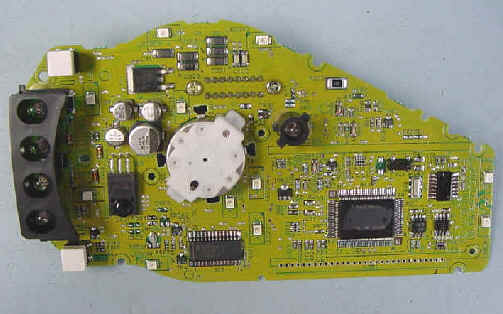
this is what my pcb looks like
-
19th February, 2010, 09:02 AM
#11
Originally Posted by AudiS4
this is what my pcb looks like
Mate ..Unless you have a spare eeprom and a back up file …you should always remove ….Then you won’t be back asking for a good dump ….
-
23rd March, 2010, 05:54 AM
#12
I do have a calculator. I also plan on making a dump file before I burn.The pdf file you have attached is for 97 and 98 gsxr 600.Mine is a 2002.Can nayone confirm if this is stil the same chip??Can anyone tell me if this will do the job?
http://cgi.ebay.com/24Cxx-93Cxx-and-…#ht_2322wt_935Last edited by AudiS4; 23rd March, 2010 at 06:15 AM.
-
23rd March, 2010, 07:20 AM
#13
-
23rd March, 2010, 12:17 PM
#14
If I dont want to remove th chip from the board can i use a soic dip clip to clip onto the chip and connect to the programmer?or its a must to remove??
-
23rd March, 2010, 12:36 PM
#15
Originally Posted by AudiS4
If I dont want to remove th chip from the board can i use a soic dip clip to clip onto the chip and connect to the programmer?or its a must to remove??
You can clip this one but it is not wise. If you do shortcut the chrystal first, and double check if the clip is right connected.


Suzuki GSX-R 600 motorcycles have engines, which are made up of many different parts.
These parts must work together in order for the engine to function. A problem with one of the
parts can make the engine not run. There are many different parts that make up an engine.
The following suzuki gsx-r 600 faults are the list of some of the parts of a motorcycle engine.
Checking the fault code is one of the most overlooked aspects of maintaining Suzuki GSX-R 600 motorcycle. Many people don’t think about it until something goes wrong. A clogged afuel pump. Now that you know how to stay visible on your bike, and how to stay safe on your Suzuki GSX-R 600 bike, it’s important that you know what you need. When you’re on a bike, the weather is often a factor. Here are a few tips that will help you protect yourself the next time you take your motorcycle out on the road.
Suzuki GSX-R 600 Faults :
Another drawback that may occur along with your bike engine could be a blown gasket. this will cause your engine to overheat and presumably crack the cylinder heads. during this case, it’s best to require your Suzuki GSX-R 600 bike to an expert mechanic to possess it verified. Another common drawback is with the carburettor. The carburettor is that the a part of your bike that mixes air and fuel to make the combustion required to power the engine.
Prior to diagnosis using the mode selection switch or SDS, perform the following visual inspections. The reason for
visual inspection is that mechanical failures (such as oil leakage) cannot be displayed on the screen with the use of
mode selection switch or SDS.
- Engine oil level and leakage.
- Engine coolant level and leakage.
- Fuel level and leakage.
- Clogged air cleaner element.
- Battery condition.
- Throttle cable play.
- Vacuum hose looseness, bend and disconnection.
- Broken fuse.
- Fl indicator light operation.
- Each warning indicator light operation.
- Combination meter operation.
- Exhaust gas leakage and noise.
- Each coupler disconnection.
- Clogged radiator fins.
| Malfunction Code |
Detected Item | Detected Failure Condition | Check For |
|---|---|---|---|
| COO | NO FAULT | — | — |
| C11 | CMP sensor | The signal does not reach ECM for 3 sec. or more, after receiving the starter signal. | CMP sensor wiring and mechanical parts CMP sensor, intake cam pin, wiring/coupler connection |
| P0340 | |||
| C12 | CKP sensor | The signal does not reach ECM for 3 sec. or more, after receiving the starter signal. | CKP sensor wiring and mechanical parts CKP sensor, lead wire/coupler connection |
| P0335 | |||
| C13 | IAP sensor | The sensor should produce following voltage. 0.5 V 5 Sensor voltage < 4.85 V In other than the above range, C13 (P0105) is indicated. |
IAP sensor, lead wire/coupler connection |
| P0105 | 21 | Sensor voltage is higher than specified value. | IAP sensor circuit shorted to VCC or ground circuit open |
| L | Sensor voltage is lower than specified value. | IAP sensor circuit open or shorted to ground or VCC circuit open | |
| C14 | TP sensor | The sensor should produce following voltage. 0.2 V 5 Sensor voltage < 4.8 V In other than the above range, C14 (P0120) is indicated. |
TP sensor, lead wire/coupler connection |
| P0120 | 2 | Sensor voltage is higher than specified value. | TP sensor circuit shorted to VCC or ground circuit open |
| L | Sensor voltage is lower than specified value. | TP sensor circuit open or shorted to ground or VCC circuit open | |
| C15 | ECT sensor indicated. |
The sensor voltage should be the following. 0.15 V 5 Sensor voltage < 4.85 V In other than the above range, C15 (P0115) is i |
ECT sensor, lead wire/coupler connection |
| P0115 | Sensor voltage is higher than specified value. | ECT sensor circuit open or ground circuit open | |
| L | Sensor voltage is lower than specified value. | ECT sensor circuit shorted to ground | |
| C21 | IAT sensor indicated. |
The sensor voltage should be the following. 0.15 V 5 Sensor voltage < 4.85 V In other than the above range, C21 (P0110) is i |
IAT sensor, lead wire/coupler connection |
| P0110 | 1=7 | Sensor voltage is higher than specified value. | IAT sensor circuit open or ground circuit open |
| L | Sensor voltage is lower than specified value. | IAT sensor circuit shorted to ground | |
| C22 | AP sensor | The sensor voltage should be the following. 0.5 V 5 Sensor voltage < 4.85 V In other than the above range, C22 (P1450) is indicated. |
AP sensor, lead wire/coupler connection |
| P1450 | I= | Sensor voltage is higher than specified value. | AP sensor circuit shorted to VCC or ground circuit open |
| L | Sensor voltage is lower than specified value. | AP sensor circuit open or shorted to ground or VCC circuit open | |
| C23 | TO sensor | The sensor voltage should be the following for 2 sec. and more, after ignition switch is turned ON. 0.2 V 5 Sensor voltage < 4.8 V In other than the above value, C23 (P1651) is indicated. |
TO sensor, lead wire/coupler connection |
| P1651 | Sensor voltage is higher than specified value. | TO sensor circuit shorted to VCC or ground circuit open | |
| L | Sensor voltage is lower than specified value. | TO sensor circuit open or shorted to ground or VCC circuit open | |
| C24/C25 C26/C27 |
Ignition signal | CKP sensor (pick-up coil) signal is produced, but signal from ignition coil is interrupted 8 times or more continuously. In this case, the code C24 (P0351), C25 (P0352), C26 (P0353) or C27 (P0354) is indicated. | Ignition coil, wiring/coupler connection, power supply from the battery |
| P0351/P0352 P0353/P0354 |
|||
| C28 | STV actuator | When no actuator control signal is supplied from the ECM, communication signal does not reach ECM or operation voltage does not STVA motor, lead wire/coupler reach STVA motor, C28 (P1655) is indicated. connection STVA can not operate properly or its motor locked. |
|
| P1655 | |||
| C29 | The sensor should produce following voltage. 0.15 V 5 Sensor voltage < 4.85 V STP sensor, lead wire/coupler In other than the above range, C29 (P1654) is connection indicated. |
||
| P1654 | H | STP sensor Sensor voltage is higher than specified value. |
STP sensor circuit shorted to VCC or ground circuit open |
| L | Sensor voltage is lower than specified value. | STP sensor circuit open or shorted to ground or VCC circuit open | |
| C31 | Gear position signal | Gear position signal voltage should be higher than the following for 3 seconds and more. Gear position sensor voltage 0.6 V If lower than the above value, C31 (P0705) is indicated. |
GP switch, wiring/coupler connection, gearshift cam, etc. |
| P0705 | |||
| C32/C33 C34/C35 |
Primary fuel injector | CKP sensor (pickup coil) signal is produced, but fuel injector signal is interrupted 4 times or more continuously. In this case, the code C32 (P0201), C33 (P0202), C34 (P0203) or C35 (P0204) is indicated. | Primary fuel injector, wiring/ coupler connection, power supply to the injector |
| P0201/P0202 P0203/P0204 |
|||
| C36/C37 C38/C39 |
Secondary fuel injector | Some failure exists in the fuel injector signal in a high load, high revolution condition. In this case, the code C36 (P1764), C37 (P1765), C38 (P1766) or C39 (P1767) is indicated. | Secondary fuel injector, wiring/ coupler connection, power supply to the injector |
| P1764/P1765 P1766/P1767 |
|||
| C40/P0505 | ISC valve | The circuit voltage of motor drive is unusual. | ISC valve circuit open or shorted to ground Power source circuit open |
| C40/P0506 | Idle speed is lower than the desired idle speed. | Air passage clogged ISC valve is fixed ISC valve preset position is incorrect |
|
| C40/P0507 | Idle speed is higher than the desired idle speed. | ISC valve hose connection ISC valve is fixed ISC valve preset position is incorrect |
|
| C41 | FP relay | No voltage is applied to the fuel pump, although fuel pump relay is turned ON, or voltage is applied to fuel pump although fuel pump relay is turned OFF. | Fuel pump relay, lead wire/ coupler connection, power source to fuel pump relay and fuel injectors |
| P0230 | H | Voltage is applied to fuel pump although fuel pump relay is turned OFF. | Fuel pump relay switch circuit shorted to power source Fuel pump relay (switch side) |
| No voltage is applied to the fuel pump, p, although fuel pump relay is turned ON. | Fuel shortpump relay circuit open or Fuel pump relay (coil side) |
||
| C41/P2505 | ECM/PCM power input signal | No voltage is applied to the ECM. | Lead wire/coupler connection of ECM terminal to fuel fuse |
| C42 | Ignition switch | Ignition switch signal is not input to the ECM. * When the I.D. agreement is not verified. * ECM does not receive communication signal from the immobilizer antenna. |
Ignition switch, lead wire/ coupler, etc. * Immobilizer/anti-theft system |
| P1650 | |||
| C44/P0130 | H02 sensor | H02 sensor output voltage is not input to ECM during engine operation and running condition. (Sensor voltage > 1.0 V) C44 (P0130) is indicated. |
H02 sensor is circuit open or shorted to the power source |
| C44/P0135 | The Heater can not operate so that heater operation voltage is not supply to the oxygen heater circuit, C44 (P0135) is indicated. | Heated circuit open or shorted to ground Battery voltage supply to the H02 sensor |
|
| C46 | EXCV actuator | EXCVA position sensor produces following voltage. 0.1 V 5 sensor voltage < 4.9 V In other than the above range, C46 (P1675) is indicated. When no actuator control signal is supplied from the ECM, communication signal does not reach ECM or operation voltage does not reach EXCVA motor, C46 (P1658) is indicated. EXCVA can not operate. |
EXCVA, EXCVA lead wire/ coupler |
| P1657 | 2 | EXCVA position sensor voltage is higher than specified value. | EXCVA position sensor circuit shorted to VCC or ground circuit open |
| L | EXCVA position sensor voltage is lower than specified value. | EXCVA position sensor circuit open or shorted to ground or VCC circuit open | |
| P1658 | When no operation voltage reaches EXCVA motor, C46 (P1658) is indicated. EXCVA motor can not be operated. wire/coupler |
EXCVA, EXCVA motor lead | |
| C49 | PAIR control solenoid valve | PAIR control solenoid valve voltage is not input to ECM. | PAIR control solenoid valve, lead wire/coupler connection |
| P1656 | |||
| C60 | Cooling fan relay | Cooling fan relay signal is not input to ECM. | Cooling fan relay, lead wire/ coupler connection |
| PO480 | |||
| C62 | EVAP system purge control solenoid valve (E-33 only) | EVAP system purge control solenoid valve voltage is not input to ECM. | EVAP system purge control solenoid valve, lead wire/ coupler connection |
| PO443 | |||
| C91 | Vehicle speed sensor | Combination meter does not receive signal from the vehicle speed sensor for more than 6 sec. when the motorcycle is running. ECM does not receive signal from the vehicle speed sensor for more than 6 sec. when the motorcycle is running. Failure in communication between ECM and combination meter with reference to vehicle speed. |
Speed sensor and combination meter wiring/coupler connection between ECM and combination meter |
| P0500 | |||
| C93 | Steering damper solenoid valve | Steering damper control current does not flow to the solenoid valve. With IG turned ON, ECM detects a failure of internal circuit element. Solenoid current does not converge to the target value. Battery voltage is 10 V or below with the engine running. |
Steering damper solenoid valve circuit interrupter element shorted, feedback current convergence failure, low battery voltage |
| P1769 | H | Steering damper control current is higher than specified value. An abnormal current is detected during the vehicle standstill. Solenoid current is 0.7 A or above. |
Steering damper solenoid valve circuit shorted to VCC |
| L | Steering damper control current is lower than specified value. With IG turned ON, ECM detects a discontinuity. An abnormal current is detected during the vehicle standstill. |
Steering damper solenoid valve circuit open or shorted |
Suzuki GSX-R 600 Motorcycle Problems :
- Suzuki gsx-r 600 after fire
- Suzuki gsx-r 600 air cleaner clogged, poorly sealed, or missing
- Suzuki gsx-r 600 air cleaner element clogged
- Suzuki gsx-r 600 air duct loose
- Suzuki gsx-r 600 air suction valve trouble
- Suzuki gsx-r 600 air switching valve trouble
- Suzuki gsx-r 600 backfiring when deceleration
- Suzuki gsx-r 600 cracked or obstructed intake air pressure sensor
- Suzuki gsx-r 600 crankshaft sensor trouble
- Suzuki gsx-r 600 eCU ground and power supply trouble
- Suzuki gsx-r 600 eCU trouble
- Suzuki gsx-r 600 engine overheating — Water temperature sensor or crankshaft sensor trouble
- Suzuki gsx-r 600 engine stalls easily
- Suzuki gsx-r 600 engine vacuum not synchronizing
- Suzuki gsx-r 600 exhaust Smokes Excessively
- Suzuki gsx-r 600 firing incorrect
- Suzuki gsx-r 600 fuel filter clogged
- Suzuki gsx-r 600 fuel injector clogged
- Suzuki gsx-r 600 fuel injector O-ring damage
- Suzuki gsx-r 600 fuel injector trouble
- Suzuki gsx-r 600 fuel line clogged
- Suzuki gsx-r 600 fuel poor quality or incorrect
- Suzuki gsx-r 600 fuel pressure regulator trouble
- Suzuki gsx-r 600 fuel pressure too low or too high
- Suzuki gsx-r 600 fuel pump bearings may wear. Replace the fuel pump
- Suzuki gsx-r 600 fuel pump not operating
- Suzuki gsx-r 600 fuel pump operates intermittently and often DFI fuse blows
- Suzuki gsx-r 600 fuel pump relay trouble
- Suzuki gsx-r 600 fuel pump trouble
- Suzuki gsx-r 600 fuel/air mixture incorrect
- Suzuki gsx-r 600 fuel/air mixture incorrect
- Suzuki gsx-r 600 gear position sensor, starter lockout or side stand switch trouble
- Suzuki gsx-r 600 inspect and repair or replace
- Suzuki gsx-r 600 intake air pressure sensor trouble
- Suzuki gsx-r 600 intake air temperature sensor trouble
- Suzuki gsx-r 600 intake air temperature sensor trouble
- Suzuki gsx-r 600 intermittent any DFI fault and its recovery
- Suzuki gsx-r 600 little fuel in tank
- Suzuki gsx-r 600 main throttle sensor trouble
- Suzuki gsx-r 600 no or little fuel in tank
- Suzuki gsx-r 600 poor acceleration
- Suzuki gsx-r 600 spark plug burned or gap maladjusted
- Suzuki gsx-r 600 spark plug dirty, broken or gap maladjusted
- Suzuki gsx-r 600 spark plug incorrect
- Suzuki gsx-r 600 spark weak
- Suzuki gsx-r 600 stick coil shorted or not in good contact
- Suzuki gsx-r 600 stick coil trouble
- Suzuki gsx-r 600 subthrottle sensor trouble
- Suzuki gsx-r 600 subthrottle valve actuator trouble
- Suzuki gsx-r 600 throttle body assy dust seal damage
- Suzuki gsx-r 600 throttle body assy holder loose
- Suzuki gsx-r 600 throttle valves will not fully open
- Suzuki gsx-r 600 unstable (rough) idling
- Suzuki gsx-r 600 unstable fuel pressure
- Suzuki gsx-r 600 vacuum hose
- Suzuki gsx-r 600 vehicle-down sensor trouble
- Suzuki gsx-r 600 water or foreign matter in fuel Change fuel
- Suzuki gsx-r 600 water temperature sensor trouble
The electrical system includes the battery, the charging system, the starters, and the charging system. It is also possible that the electrical system can fail due to a problem with the generator. A good place to start Suzuki GSX-R 600 troubleshooting the electrical system is to check the engine parts. For example, it is possible that the electrical system can fail due to a problem with the generator. A good place to start troubleshooting the electrical system is to check the engine parts.

Suzuki Motors was a transformation of the original Suzuki Loom Works company in 1954, after the textile industry in Japan collapsed. The motorcycle arm of the company rapidly developed powerful and small engines, and today is known for powerhouse motorcycles like the Hayabusa and the GSX-R1000R.
Check other Suzuki fault codes.
These abbreviations, and the accompanying list of trouble codes, can be a
great start when your Suzuki check engine light comes on. As mentioned
above, if you are not comfortable with electrical diagnostic work, a dealership or qualified
technician can offer assistance. Please keep in mind that even though you have the ability to
clear a DTC using the onboard diagnostic feature, you shouldn’t clear the code prior to your
service appointment. Let the technician view and clear the codes as they troubleshoot the issue.
Suzuki and logo are registered trademarks of Suzuki. We are fan of MOTORCYCLES ! We love them.
1A-112 Engine General Information and Diagnosis:
Detected Condition
The operation signal does not reach the
EXCV actuator.
EXCVA position sensor voltage low or
C46
high
0.1 V ≤ Sensor voltage < 4.9 V
(without the above range)
EXCVA can not operate properly.
Sensor voltage is higher than specified
H
value.
P1657
Sensor voltage is lower than specified
L
value.
The operation signal does not reach the
P1658
EXCVA motor.
EXCVA can not operate properly.
Wiring Diagram
EXCVA
Troubleshooting
CAUTION
!
When using the multi-circuit tester, do not strongly touch the terminal of the ECM coupler with a
needle pointed tester probe to prevent terminal damage.
NOTE
After repairing the trouble, clear the DTC using SDS tool. Refer to «Use of SDS Diagnosis Reset
Procedures (Page 1A-15)».
Gr
P
B
Y
W
ECM coupler (Harness side)
1
2
3
4
5
6
7
8
9 10 11 12
13 14 15 16 17 18 19 20 21 22 23 24
25 26 27 28 29 30 31 32 33 34 35 36
Possible Cause
• EXCVA maladjusted.
• EXCVA circuit open or short.
• EXCVA motor malfunction.
• EXCVA position sensor malfunction.
• EXCVA position sensor circuit shorted to VCC or ground
circuit open.
• EXCVA position sensor circuit open or shorted to ground
or VCC circuit open.
• EXCVA motor circuit open or short.
• EXCVA motor malfunction.
B/R
R/B
R
Y
B/Br
37 38 39 40 41 42 43 44 45 46 47 48
49 50 51 52 53 54 55 56 57 58 59 60
61 62 63 64 65 66 67 68 69 70 71 72
B837H11104032
ECM
1
EXCVA
13
EXCVA
7
VCC
14
EXCVAS
E2
35
I837H1110096-02
I837H1110007-02