-
Catalog
-
Sign In
-
Contacts
-
Forum
-
Eng
- Error Codes
- Konica-Minolta
- bizhub C224
- Code C3425
- Code: C3425
- Description: Fusing warm-up trouble
• Detected temperature of the heating roller temperature sensor (TEMS) does not go up a given range of temperature even after a lapse of given period of time at warm up. • The warm-up is not completed even after the set period of time has elapsed after the warm-up is started. • Less than the predetermined temperature of the heating roller temperature sensor (TEMS), even after a predetermined period of time after warm-up is complete. - Remedy: 1 Check the fusing unit for correct installation (whether it is secured in position). 2 Check the open/close operation of the right door. 3 Check the fusing unit, DCPU and PRCB for proper connection and correct or change as necessary. 4 Replace the fusing unit. 5 Replace PRCB. 6 Replace DCPU.
 Thanks: 0
 Likes: 0
 Dislikes: 0
-
09-16-2016
#1

Trusted Tech
50+ Posts
- Rep Power
- 22
C454e Error Code C3425
C454e with error code C3425, preform trouble reset after replacing the fuser unit and the code continues to return. According to the service manual relevant parts are fuser, DC Power Supply and PRCB. Replaced the DC Power Supply, could this really be the PRCB? The customer was running copies and noticed the toner was not fusing, it would wipe right off. Then it gave the trouble code…any thoughts?
-
09-17-2016
#2
Re: C454e Error Code C3425
there is a board that controls the fuser replace it. DCPU
-
09-20-2016
#3
Trusted Tech
50+ Posts
- Rep Power
- 22
Re: C454e Error Code C3425
I replaced the fuser, DC power supply and the PRCB…C3425 remains. Any thoughts? Initially the customer reported toner was smudging off the paper (not fusing) and then the machine threw an fuser error. Replaced the fuser, reset code and then the C3425 began.
-
09-21-2016
#4
Re: C454e Error Code C3425
Can you run the machine at all? If you run it is the fuser warm? Maybe the coil unit, although I don’t think I’ve ever replaced one on any machine.
-
09-21-2016
#5
Trusted Tech
50+ Posts
- Rep Power
- 22
Re: C454e Error Code C3425
The machine does not run at all. After resetting the trouble code and rebooting the machine the code comes up within the first few seconds of warm up.
-
09-21-2016
#6
Re: C454e Error Code C3425
replace the coil now that you did everything else
-
09-21-2016
#7
Re: C454e Error Code C3425
Originally Posted by copierwhisper
The machine does not run at all. After resetting the trouble code and rebooting the machine the code comes up within the first few seconds of warm up.
Also check and clean the Heating Roller Temperature Sensor that’s located under the coil.
-
09-22-2016
#8
Re: C454e Error Code C3425
-
09-22-2016
#9
Re: C454e Error Code C3425
Originally Posted by Woxner
he did replace the fuser
The heat roller temp sensor isn’t located in the fuser.
-
01-30-2018
#10
Junior Member
- Rep Power
- 0
Re: C454e Error Code C3425
If the problem is coil, how to fix it, there is another way to fix the coil
? All we must change it. Thx once again


Bookmarks
Bookmarks
Posting Permissions

- You may not post new threads
- You may not post replies
- You may not post attachments
- You may not edit your posts
- BB code is On
- Smilies are On
- [IMG] code is On
- [VIDEO] code is On
- HTML code is Off
Forum Rules


С0000
Main Motor malfunction
Ошибка главного двигателя
162/210/163/211
C0070
Toner Replenishing Motor malfunction
Проблема с вращением банки тонера
162/210/163/211
223/283/363/423
224Е/284Е/364Е/454Е/554Е
Решение
C0202
C0204
C0206
C0208
Elevator Failure Tray 1/2/3/4
Проблема с подъемом бумаги лоток 1/2/3/4
162/210/163/211
Решение
C0211
C0204
C0206
C0208
Bypass Lifting Motion Failure
Проблема с подъемом бумаги лотка ручной подачи
165/185/195/215
222/282/362/223/283/363/423
224Е/284Е/364Е/454Е/554Е
227/287/367
С220/С280/С360
С224/С284/С364/С454/С554
С224Е/С284Е/С364Е/С454Е/С554Е
C227/C287/C367
C258/C308/C368/C458/C558/C658
C0320
LU-202m, LU-202XL fan abnormalitye
Ошибка вентилятора кассеты LU-202m, LU-202XL
AccurioPress C2060/C2070/C2070P
C3070/C3080/C3080P
C05хх
Fusing temperature failure
Проблема с температурой узла закрепления
162/210/163/211
Решение
C0F32
Faulty ATDC Sensor
Ошибка концентрации тонера
162/210/163/211
Решение
C133D
ROM check error
Проблема с платой EEPROM
162/210/163/211
C2152
Transfer belt pressure welding alienation
Проблема с узлом ленты переноса
С220/С280/С360
С224/С284/С364/С454/С554
С224Е/С284Е/С364Е/С454Е/С554Е
C227/C287/C367
C258/C308/C368/C458/C558/C658
C2241
C2242
C2243
C2244
Drum motor abnormality Y/M/C/K
Ошибка мотора барабана Y/M/C/K
PRO/PRESS
C6000L/C6000/C7000/C7000P/C70hc
C1060L/C1060/C1070/C1070P
Accurio Press C2060/C2070/C2070P
C3070/C3080/C3080P
Решение
C2253
C2254
Color PC motor`s failure
Ошибка привода барабанов
227/287/367
С220/С280/С360
С224/С284/С364/С454/С554
С224Е/С284Е/С364Е/С454Е/С554Е
C227/C287/C367
C258/C308/C368/C458/C558/C658
Решение
C2351
Fusing cooling fan motor malfunction
Ошибка главного вентилятора охлаждения
164/165/185/195
215/222/282/362
C2411
C2412
C2413
C2414
Developing unit C/M/Y/K new article release
Ошибка определения нового блока проявки
227/287/367
С220/С280/С360
С224/С284/С364/С454/С554
С224Е/С284Е/С364Е/С454Е/С554Е
C227/C287/C367
C258/C308/C368/C458/C558/C658
C2551
C2552
C2553
C2554
C2555
C2556
C2557
C2558
Abnormally low toner density C/M/Y/K
Ошибка концентрации тонера в блоке проявки
165/185/195/215
227/287/367
С220/С280/С360
С224/С284/С364/С454/С554
С224Е/С284Е/С364Е/С454Е/С554Е
C227/C287/C367
C258/C308/C368/C458/C558/C658
C2654
EEPROM Failure
Проблема с платой EEPROM
222/282/362
C2A11
C2A12
C2A13
C2A1
Drum unit C/M/Y/K new release failure
Ошибка определения нового блока барабана
С220/С280/С360
С224/С284/С364/С454/С554
С224Е/С284Е/С364Е/С454Е/С554Е
C227/C287/C367
C258/C308/C368/C458/C558/C658
C3201
C3202
Fusing motor failure
Ошибка мотора привода узла закрепления
224Е/284Е/364Е/454Е/554Е
С220/С280/С360
С224/С284/С364/С454/С554
С224Е/С284Е/С364Е/С454Е/С554Е
C258/C308/C368/C458/C558/C658
C34хх
C37хх
C38хх
C39хх
Fusing temperature failure
Проблема с температурой узла закрепления
164/165/185/195/215
221/282/362/223/283/363/423
224Е/284Е/364Е/454Е/554Е
227/287/367
С220/С280/С360
С224/С284/С364/С454/С554
С224Е/С284Е/С364Е/С454Е/С554Е
C227/C287/C367
C258/C308/C368/C458/C558/C658
Решение
C3508
Fusing high temperature abnormality
Повышенная температура узла фиксации
PRO/PRESS C6000L/C6000/C7000/C7000P/C70hc
C1060L/C1060/C1070/C1070P
Accurio Press C2060/C2070/C2070P
C3070/C3080/C3080P
Решение
C3924
Fusing sensor wire breaks detection
Проблема с термистором узла фиксации
C452/C552/C652
C451/C550/C650
C4101
Polygon Motor Failure
Проблема с блоком лазера
164/185/195/215
222/282/362/223/283/363/423
224Е/284Е/364Е/454Е/554Е
227/287/367
С220/С280/С360
С224/С284/С364/С454/С554
С224Е/С284Е/С364Е/С454Е/С554Е
C227/C287/C367
C258/C308/C368/C458/C558/C658
C4661
C4662
C4663
Color registration correction abnormality Y/M/C
Ошибка регистрации цветов Y/M/C
PRO C6000L/C6000/C7000/C7000P/C70hc
C1060L/C1060/C1070/C1070P
Решение
C5102
C5103
Main Motor malfunction
Ошибка главного двигателя
164/165/185/195/2
222/282/362/223/283/363/4
224Е/284Е/364Е/454Е/55
С220/С280/С3
С224/С284/С364/С454/С5
С224Е/С284Е/С364Е/С454Е/С554Е
C5370
MFP control board cooling fan motor`s failure to turn
Ошибка включения вентилятора платы MFP
223/283/363/423
224E/284E/364E/454E/554E
227/287/367
С220/С280/С360
С224/С284/С364/С454/С554
С224Е/С284Е/С364Е/С454Е/С554Е
C258/C308/C368/C458/C558/C658
C6755
CIS Gain adjustment abnormality
Ошибка настройки модуля CIS
AccurioPress C2060/C2070
C3070/C3080
C8001
DF communication error
Ошибка коммуникации с автоподатчиком
AccurioPress C2060/C2070
C3070/C3080
C9401
C9402
IR exposure lump malfunction
Проблема с узлом сканера
164/165/185/195/215
222/282/362/223/283/363/423
224Е/284Е/364Е/454Е/554Е
227/287/367
C227/C287/C367
C258/C308/C368/C458/C558/C658
CC151
Flash ROM error
Проблема с платой EEPROM
164/165/185/195/215
226/287/367
C227/C287/C367
C258/C308/C368/C458/C558/C658
CC163
CC164
CC165
ROM contents error
Ошибка программного обеспечения аппарата
С220/С280/С360
С224/С284/С364/С454/С554
С224Е/С284Е/С364Е/С454Е/С554Е
CD004
HDD error
Ошибка жесткого диска
222/282/362
227/287/367
C227/C287/C367
C258/C308/C368/C458/C558/C658
CD0xx
Hard disk error
Проблема с жестким диском
223/283/363/423
224Е/284Е/364Е/454Е/554Е
227/287/367
С220/С280/С360
С224/С284/С364/С454/С554
С224Е/С284Е/С364Е/С454Е/С554Е
C227/C287/C367
C258/C308/C368/C458/C558/C658
Решение
CD3xx
NVRAM data error
Проблема с платой NVRAM
165/185/195/215
222/282/362/223/283/363/423
224Е/284Е/364Е/454Е/554Е
С220/С280/С360
С224/С284/С364/С454/С554
С224Е/С284Е/С364Е/С454Е/С554Е
C227/C287/C367
C258/C308/C368/C458/C558/C658
CE020
Browser abnormality detection
Внезапное выключение браузера
AccurioPress C2060/C2070/C2070P
C3070/C3080/C3080P
CE301
Referring incorrect memory
Ошибка обработки данных (ошибка памяти)
224E/284E/364E/454E/554E
227/287/367
С224/С284/С364/С454/С554
С224Е/С284Е/С364Е/С454Е/С554Е
C258/C308/C368/C458/C558/C658
P-5
PRT/IR ERROR
C200/C203/C220/C224/C250
C252/C253/C258/C284
C277/C287/C257i
C300/C308/C352/C350/C353
C360/C364/C368
C450/C451/C452/C454/C458
C550/C552/C554/C558
C650/C652/C654/C658/C659/C754/C759
C224E/C284E/C364E/C454E
C554E/C654E/C754E
C250P/C252P/C352P
C353P/C450P
C250i/C300i/C360i
C450i/C550i/C650i
C3300i/C3320i/C3350i
C4000i/C4050i
Решение
P-6
P-7
P-8
P-9
C/M/Y/K Imaging Unit failure
C200/C203/C220/C224/C250
C252/C253/C258/C284
C277/C287/C257i
C300/C308/C352/C350/C353
C360/C364/C368
C450/C451/C452/C454/C458
C550/C552/C554/C558
C650/C652/C654/C658/C659
C754/C759
C224E/C284E/C364E/C454E
C554E/C654E/C754E
C250P/C252P/C352P
C353P/C450P
C250i/C300i/C360i
C450i/C550i/C650i
C3300i/C3320i/C3350i
C4000i/C4050i
Решение
P-21
C224e/C224/C220/C652/C200/C203/C227/C250/C250i/C257i/C250P
C252/C252P/C253/C258/C280/C284/C284e/C287/C300/C300i/C308 C352/C350/C352P/C353/C353P/C360/C360i/C364/C364e/C368
C450/C450P/C450i/C451/C452/C454/C454e/C458/C550/C550i/C552 C554/C554e/C558/C650/C650i/C654/C654e/C658/C659/C754 C754e/C759
C3300i/C3320i/C3350i/C4000i/C4050i
Решение
P-28
C224e/C224/C220/C652/C200/C203/C227/C250/C250i/C257i/C250P
C252/C252P/C253/C258/C280/C284/C284e/C287/C300/C300i/C308 C352/C350/C352P/C353/C353P/C360/C360i/C364/C364e/C368
C450/C450P/C450i/C451/C452/C454/C454e/C458/C550/C550i/C552 C554/C554e/C558/C650/C650i/C654/C654e/C658/C659/C754 C754e/C759
Решение
Если вы не нашли на этой странице ваш код ошибки, то нажмите на кнопку «Запросить код ошибки», которая находится под этим текстом, заполните данные, после этого мы отправим информацию на указанную вами электронную почту, а также возможно, что мы добавим вашу ошибку в наш список.
Инфа сотка
-
Bizhub hack
Серия подсказок «bizhub hack» сделает ваше общение с техникой Konica Minolta …
-
5партнер на связи
Компания Пятый партнер не ушла с Российского рынка и продолжает работать. …
-
5partner награды в 2022
Очередной год подряд самый большой объем продаж оборудования Konica Minolta …
-
C4065 vs C7090
В этой статье мы наглядно покажем чем отличается профессиональная модель …
-
-
-
C257i офис в цвете
Konica Minolta в 2021 году выпустила очередной хит цветной офисной бюджетной …
-
-
-
-
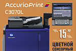
C3070L vs C6085
В этой статье мы наглядно покажем чем отличается профессиональная модель …
-
-
-
-
-
-
-
-
-
-
-
-
-
-
-
-
-


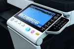


When your bizhub MFP has issues, many times you will be presented with an error code. Unfortunately, the error code does not give you much information as to what the problem actually is. The machine’s CPU performs a self-diagnostics function that, on detecting a malfunction, gives the corresponding malfunction code on the control panel. Each code corresponds to a particular issue that the machine is experiencing. Below is an example of what the machine will display on the main screen when a trouble code is found by the Konica Minolta bizhub C364e.

Many trouble codes can be reset. Sometimes, an acute issue might happen that will generate a code even when there is not a recurring issue. For certain trouble codes, the machine will attempt to automatically clear the issue by rebooting itself. Other times, it will be necessary for a user to manually take action to clear the trouble code. This can be done by taking the following two steps.
- Opening/closing the front door
- Turning main power switch OFF/ON (not sub power switch)
If these two steps are taken and the trouble code remains, further action will be needed eliminate the problem that is causing the trouble code. In some circumstances, users will be able to take steps to fix the problem. In other cases, you will need to contact a trained service technician to preform the required maintenance to fix the underlying problem. To help you understand the potential problems the Konica Minolta bizhub C364e might be experiencing, below is a list of the most common Trouble Codes with descriptions as well as a complete list of Trouble Codes for your reference.
Common Trouble Codes
| Error Code | Description | Action |
|---|---|---|
| C0202 | Tray 1 feeder up/down abnormality | Usually paper has fallen behind the tray |
| C0204 | Tray 2 feeder up/down abnormality | |
| C0206 | Tray 3 lift-up failure | |
| C0208 | Tray 4 lift-up failure | |
| C0210 | LCT lift failure | |
| C0211 | Manual feed up/down abnormality | |
| C0214 | LCT shift failure | |
| CD004 | HDD Issue | Reformat or replace the hard drive. |
| CD010 | ||
| CD012 | ||
| C3101 | Fuser Issue | If trouble reset does not clear the trouble code, replace the fuser. |
| C3201, C3202 | ||
| C3302 | ||
| C3425 | ||
| C3722, C3725, C3726 | ||
| C3825, C3826 | ||
| C3922, C3925, C3926 | ||
| CE301 | Memory Issue | Restart from the main power switch. |
C364e Trouble Codes
| Error Code | Description |
|---|---|
| C0002 | Paper feed communication error |
| C0106 | Tray 3/LCT paper feed motor turning at abnormal timing |
| C0107 | Tray 3/LCT vertical transport motor turning at abnormal timing |
| C0108 | Tray 4 paper feed motor turning at abnormal timing |
| C0109 | Tray 4 vertical transport motor turning at abnormal timing |
| C0202 | Tray 1 feeder up/down abnormality |
| C0204 | Tray 2 feeder up/down abnormality |
| C0206 | Tray 3 lift-up failure |
| C0208 | Tray 4 lift-up failure |
| C0210 | LCT lift failure |
| C0211 | Manual feed up/down abnormality |
| C0214 | LCT shift failure |
| C1004 | FNS communication error |
| C1081 | SD communication error |
| C1102 | Main tray up/down motor drive malfunction |
| C1103 | Alignment plate motor/Fr malfunction |
| C1105 | Bundle eject motor drive malfunction |
| C1106 | Stapler movement motor malfunction |
| C1109 | Stapler motor drive malfunction |
| C1112 | Stapler motor malfunction |
| C1113 | Center-staple lead edge stopper motor malfunction |
| C1114 | Center-staple front adjust drive motor malfunction |
| C1115 | Center-staple knife drive motor malfunction |
| C1132 | Punch drive motor malfunction |
| C1140 | Alignment plate motor/Rr malfunction |
| C1141 | Paddle motor drive malfunction |
| C1144 | Pre-eject drive motor malfunction |
| C1145 | Trailing edge stopper motor malfunction |
| C1156 | Center-staple paddle roller motor malfunction (trailing edge) |
| C1182 | Shift motor drive malfunction |
| C1184 | Paper discharge control motor malfunction |
| C1195 | Paper discharge control motor malfunction |
| C1196 | Center fold roller motor malfunction |
| C1197 | Tri-folding guide motor malfunction |
| C11A1 | Exit roller pressure/ retraction malfunction |
| C11A2 | Accommodation roller pressure/ retraction malfunction |
| C11E1 | Paper exit switching drive malfunction |
| C1402 | FS nonvolatile memory error |
| C2152 | Transfer belt pressure welding alienation |
| C2253, C2254 | PC motor failure to turn |
| C2255, C2256 | Developing motor failure to turn |
| C2355 | Transfer belt cleaner cooling fan failure to turn |
| C2411, C2412, C2413, C2414 | Developing unit new article release |
| C2551, C2553, C2555, C2557 | Abnormally low toner density detected TCR sensor |
| C2552, C2554, C2556, C2558 | Abnormally high toner density detected TCR sensor |
| C2559, C255A, C255B, C255C | TCR sensor adjustment failure |
| C2561, C2562, C2563, C2564 | TCR sensor failure |
| C2650 | Main backup media access error |
| C2A11, C2A12, C2A13, C2A14 | Drum unit new release failure |
| C3101 | Fusing roller separation failure |
| C3201, C3202 | Fusing motor failure to turn |
| C3302 | Paper cooling fan failure to turn |
| C3425 | Fusing warm-up trouble |
| C3722, C3725, C3726 | Fusing abnormally high temperature detection |
| C3825, C3826 | Fusing abnormally low temperature detection |
| C3922, C3925, C3926 | Fusing sensor wire breaks detection |
| C4091 | I/F communication error |
| C4101 | Polygon motor rotation trouble |
| C4501 | Laser malfunction |
| C4801 | Main unit board failure |
| C4802 | Main unit backup data miscompare |
| C5102, C5103 | Transport motor failure to turn |
| C5351 | Power supply cooling fan motor failure to turn |
| C5354 | Ozone fan failure to turn |
| C5355 | Toner bottle cooling fan failure to turn |
| C5370 | Machine rear side cooling fan failure to turn |
| C5372 | MFP control board CPU temperature failure |
| C5501 | AC signal abnormality |
| C5601 | Engine control malfunction |
| C5603 | Expansion control board communication error |
| C6001 | DF related configuration error 1 |
| C6002 | DF related configuration error 2 |
| C6102, C6103 | Drive system home sensor malfunction |
| C6104, C6105 | Back side cleaning home sensor abnormality |
| C6704 | Image input time out |
| C6751 | CCD clamp/gain adjustment failure |
| C6752 | ASIC clock input error (front side) |
| C6753 | ASIC clock input error (back side) |
| C6754, C6755 | CIS clamp adjustment failure |
| C6756 | CCD power-supply voltage malfunction |
| C6901, C6902, C6903 | DSC board mount failure 1 |
| C6911, C6912, C6913 | DSC board mount failure 2 |
| C6F01 | Scanner sequence trouble 1 |
| C8101 | Before reading pressure welding alienation mechanism trouble |
| C8107 | Glass cleaning mechanism trouble |
| C8302 | Cooling fan trouble |
| C8401 | Data flash failure |
| C9401, C9402 | Exposure LED lighting failure |
| C9403, C9404 | CIS LED lighting failure |
| CA051, CA052, CA053 | Standard controller configuration failure |
| CC140 | Trouble related to security |
| CC151, CC152 | ROM contents error upon startup |
| CC155 | Finisher ROM error |
| CC156 | DF ROM error |
| CC159, CC15A | ROM contents error upon startup (DSC1), ROM contents error upon startup (DSC2) |
| CC15B | Flash ROM error (saddle) |
| CC15C | Engine Flash ROM writing error |
| CC163 | ROM contents error (PRT) |
| CC164 | ROM contents error (MSC) |
| CC165 | ROM contents error (DF) |
| CC170, CC171, CC172, CC173, CC174, CC180, CC181, CC182, CC183, CC184, CC185, CC186 | Dynamic link error during starting |
| CC190 | Outline font load error |
| CC191 | Setting parameter load error (LDR) |
| CC211 | Authentication device general error |
| CC212 | User validation error |
| CC213 | Card information setting error |
| CC214 | User information deletion error |
| CC216 | Acquisition failure of the number of trials/Initialize error of number of authentication |
| CD002 | JOB RAM save error |
| CD004, CD00F, CD020 | Hard disk access error (connection failure) |
| CD010 | Hard disk unformat |
| CD011 | Hard disk out of specifications mounted |
| CD012 | Mount error due to hard disk being unformatted |
| CD030 | Hard disk management information reading error |
| CD041, CD042, CD043, CD044, CD045, CD046 | HDD command execution error |
| CD047, CD048, CD049, CD04A, CD04B | HDD SCSI library error |
| CD110 | Wireless LAN destination initialization error |
| CD201, CD202, CD203 | File memory mounting error |
| CD211, CD212 | PCI-SDRAM DMA operation failure |
| CD241, CD242 | Encryption ASIC setting error |
| CD252 | No relay circuit boards for IC-414 mounting at IC-414 mount setting |
| CD261 | USB host board failure |
| CD262 | Extension network adapter installation error |
| CD271 | i-Option activated and additional memory not installed |
| CD272 | i-Option activated and additional memory and HDD not installed |
| CD3## | Nonvolatile data error |
| CD370 | Nonvolatile data multiple errors |
| CD390 | Nonvolatile data checksum error |
| CD3A0 | Counter error |
| CD401, CD402, CD403, CD404, CD405, CD406, CD407, CD411, CD412, CD413 | NACK command incorrect |
| CD601, CD602, CD603 | Trouble related to security |
| CDC## | Trouble related to security |
| CDF50, CDF70, CDFA0 | ASIC image error |
| CDF51, CDF71, CDFA1 | ASIC image error |
| CE001, CE003, CE004, CE005, CE006, CE007 | Abnormal message queue |
| CE002 | Message and method parameter failure |
| CE101 | Browser finish detected |
| CE201 | Transmission operation log storage fault |
| CE301, CE302, CE303, CE304, CE305 | Referring incorrect memory |
| CED01 | The authentication application information does not exist in the hard disk/SSD board in the enhanced server authentication state. |
| CEEE1 | MFP board malfunction |
| CEEE2 | Scanner section malfunction |
| CEEE3 | Printer control board malfunction |
– Compatible Printer model: Konica-Minolta bizhub 754e
– Konica-Minolta bizhub 754e Error Codes with quick guides:
- Code: C0002
- Description: Paper feed communication error When the paper feed/transport drive board (PFTDB) is receiving data, a communication error is detected.
- Causes: • Paper feed/transport drive board (PFTDB) • Printer control board (PRCB)
- Troubleshooting Guides: 1 Turn OFF the main power switch, disconnect and then connect the power cord. Wait for 10 sec. or more after connect the power cord, and turn ON the main power switch. 2 Rewrite the firmware. 3 PFTDB ICP3 conduction check 4 PRCB ICP16 conduction check 5 Replace PFTDB 6 Replace PRCB
- Code: C0104
- Description: Tray 3/4 feeder transportation motor failure to turn. The lock signal remains HIGH for a predetermined continuous period of time while the motor is turning.
- Causes: • LCC transport motor (M25) • Paper feed/transport drive board (PFTDB) • Printer control board (PRCB)
- Troubleshooting Guides: 1 Check the connector between M25-PFTDB CN17 for proper connection and correct as necessary. 2 Check the connector of M25 for proper drive coupling and correct as necessary. 3 M25 operation check PFTDB CN17-1 to 7 11-X 4 Replace M25 5 PFTDB ICP6 conduction check 6 Replace PFTDB 7 Replace PRCB
- Code: C0105
- Description: Tray 3/4 feeder transportation motor turning at abnormal timing. The lock signal remains LOW for a predetermined continuous period of time while the motor remains stationary.
- Causes: • LCC transport motor (M25) • Paper feed/transport drive board (PFTDB) • Printer control board (PRCB)
- Troubleshooting Guides: 1 Check the connector between M25-PFTDB CN17 for proper connection and correct as necessary. 2 Check the connector of M25 for proper drive coupling and correct as necessary. 3 M25 operation check PFTDB CN17-1 to 7 11-X 4 Replace M25 5 PFTDB ICP6 conduction check 6 Replace PFTDB 7 Replace PRCB
- Code: C0202
- Description: Tray 1 feeder up/down abnormality. The tray 1 upper limit sensor (PS6) is not blocked even after the lapse of a given period of time after the lifting motion has been started.
- Causes: • Tray 1 upper limit sensor (PS6) • Tray 1 lift-up motor (M6) • Paper feed/transport drive board (PFTDB) • Printer control board (PRCB)
- Troubleshooting Guides: 1 Check the connector between M6-PFTDB CN27 for proper connection and correct as necessary. 2 Check the connector of M6 for proper drive coupling and correct as necessary. 3 Check the connector between PS6-relay CN145- PFTDB CN15 for proper connection and correct as necessary. 4 PS6 I/O check, sensor check PFTDB CN15-3 (ON) 1-P 5 M6 operation check PFTDB CN27-10 to 11 2 to 3-X 6 Replace M6 7 Replace PFTDB 8 PRCB ICP10 conduction check 9 Replace PRCB
- Code: C0204
- Description: Tray 2 feeder up/down abnormality. The tray 2 upper limit sensor is not blocked even after the lapse of a given period of time after the lifting motion has been started.
- Causes: • Tray 2 upper limit sensor (PS14) • Tray 2 lift-up motor (M8) • Paper feed/transport drive board (PFTDB) • Printer control board (PRCB)
- Troubleshooting Guides: 1 Check the connector between M8-PFTDB CN26 for proper connection and correct as necessary. 2 Check the connector of M8 for proper drive coupling and correct as necessary. 3 Check the connector between PS14-relay CN155BPFTDB CN14 for proper connection and correct as necessary. 4 PS14 I/O check, sensor check PFTDB CN14-9 (ON) 4-P 5 M8 operation check PFTDB CN26-10 to 11 4-X 6 Replace M8 7 PFTDB ICP10 conduction check 8 Replace PFTDB 9 Replace PRCB
- Code: C0206
- Description: Tray 3 feeder up/down abnormality. The tray 3 upper limit sensor is not blocked even after the lapse of a given period of time after the lifting motion has been started.
- Causes: • Tray 3 upper limit sensor (PS22) • Tray 3 lift-up motor (M23) • Paper feed/transport drive board (PFTDB) • Printer control board (PRCB)
- Troubleshooting Guides: 1 Check the connector between M23-PFTDB CN18 for proper connection, and correct as necessary. 2 Check the connector of M23 for proper drive coupling and correct as necessary. 3 Check the connectors between PS22-relay CN193- relay CN113B-PFTDB CN20 for proper connection, and correct as necessary. 4 PS22 I/O check, sensor check PFTDB CN20-6 (ON) 6-X 5 M23 operation check PFTDB CN18-3 to 4 9-X 6 Replace M23 7 PFTDB ICP7 conduction check 8 Replace PFTDB 9 Replace PRCB
- Code: C0208
- Description: Tray 4 feeder up/down abnormality. The tray 4 upper limit sensor is not blocked even after the lapse of a given period of time after the lifting motion has been started.
- Causes: • Tray 4 upper limit sensor (PS27) • Tray 4 lift-up motor (M24) • Paper feed/transport drive board (PFTDB) • Printer control board (PRCB)
- Troubleshooting Guides: 1 Check the connector between M24-PFTDB CN18 for proper connection and correct as necessary. 2 Check the connector of M24 for proper drive coupling and correct as necessary. 3 Check the connector between PS27-relay CN194-relay CN121B-PFTDB CN22 for proper connection and correct as necessary. 4 PS27 I/O check, sensor check PFTDB CN22-6 (ON) 8-X 5 M24 operation check PFTDB CN18-1 to 2 9-X 6 Replace M24 7 PFTDB ICP8 conduction check 8 Replace PFTDB 9 Replace PRCB
- Code: C0216
- Description: LCT up/down abnormality. The upper limit sensor (PS2) is not blocked even after the set period of time has elapsed after the paper lift-up operation began.
- Causes: • Upper limit sensor (PS2) • Lift-up motor (M1) • LU drive board (LUDB)
- Troubleshooting Guides: When LU-204 is installed: 1 Check the connector between M1-LCDB CN3 for proper connection, and correct as necessary. 2 Check the connector of M1 for proper drive coupling and correct as necessary. 3 Check the connectors between PS2-relay CN406- LCDB CN5 for proper connection, and correct as necessary. 4 PS2 I/O check, sensor check LUDB CN5-3 (ON) LU-204 4-G 5 M1 operation check LUDB CN3-4 (ON) LU-204 3-G 6 Replace M1 7 LUDB ICP2 conduction check 8 Replace LUDB. When LU-301 is installed: 1 Check the connector between M1-LCDB CN3 for proper connection, and correct as necessary. 2 Check the connector of M1 for proper drive coupling and correct as necessary. 3 Check the connectors between PS2-relay CN3-LCDB CN5 for proper connection, and correct as necessary. 4 PS2 I/O check, sensor check LUDB CN5-3 (ON) LU-301 4-G 5 M1 operation check LUDB CN3-4 (ON) LU-301 3-G 6 Replace M1 7 LUDB ICP2 conduction check 8 Replace LUDB
- Code: C0301
- Description: Suction fan’s failure to turn The fan lock signal remains HIGH for a predetermined continuous period of time while the fan is turning.
- Causes: • Suction fan (FM1) • Paper feed/transport drive board (PFTDB)
- Troubleshooting Guides: 1 Check the connector between FM1-relay CN278-relay CN271B-PFTDB CN10 for proper connection and correct as necessary. 2 Check the fan for possible overload and correct as necessary. 3 FM1 operation check PFTDB CN10-3 (REM) PFTDB CN10-5 (LOCK) 5-P 4 Replace FM1 5 PFTDB ICP2 conduction check 6 Replace PFTDB
- Code: C0351
- Description: Paper cooling fan/in’s failure to turn The fan lock signal remains HIGH for a predetermined continuous period of time while the fan is turning.
- Causes: • Paper cooling fan/in (FM13) • Printer control board (PRCB)
- Troubleshooting Guides: 1 Check the connector between FM13-relay CN325- PRCB CN1 for proper connection and correct as necessary. 2 Check the fan for possible overload and correct as necessary. 3 FM13 operation check PRCB CN1-11 (LOCK) 7-K 4 Replace FM13 5 Replace PRCB
- Code: C1003
- Description: PK communication error <When FS-535+PK-521 is installed> When a communication error is detected between the FS control board (FSCB) and the punch control board (PKCB).
- Causes: • Punch control board (PKCB) • FS control board (FSCB)
- Troubleshooting Guides: 1 Turn OFF the main power switch, disconnect and then connect the power cord. Wait for 10 sec. or more after connect the power cord, and turn ON the main power switch. 2 Rewrite the firmware. 3 Replace PKCB 4 Replace FSCB
- Code: C1004
- Description: FNS communication error When the FS control board (FSCB) is receiving data, a communication error is detected.
- Causes: FS control board (FSCB)
- Troubleshooting Guides: 1 Turn OFF the main power switch, disconnect and then connect the power cord. Wait for 10 sec. or more after connect the power cord, and turn ON the main power switch. 2 Rewrite the firmware. 3 Replace FSCB (FS-534/FS-535)
- Code: C1005
- Description: ZU communication error. When the ZU control board (ZUCB) is receiving data, a communication error is detected.
- Causes: ZU control board (ZUCB)
- Troubleshooting Guides: 1 Turn OFF the main power switch, disconnect and then connect the power cord. Wait for 10 sec. or more after connect the power cord, and turn ON the main power switch. 2 Rewrite the firmware. 3 Replace ZUCB
- Code: C1080
- Description: RU communication error When the RU control board (RUCB) is receiving data, a communication error is detected.
- Causes: RU control board (RUCB)
- Troubleshooting Guides: 1 Turn OFF the main power switch, disconnect and then connect the power cord. Wait for 10 sec. or more after connect the power cord, and turn ON the main power switch. 2 Rewrite the firmware. 3 Replace RUCB
- Code: C1081
- Description: SD communication error When a communication error is detected between the FS control board (FSCB) and the SD drive board (SDDB).
- Causes: • SD drive board (SDDB) • FS control board (FSCB)
- Troubleshooting Guides: 1 Turn OFF the main power switch, disconnect and then connect the power cord. Wait for 10 sec. or more after connect the power cord, and turn ON the main power switch. 2 Rewrite the firmware. 3 Replace SDDB (SD-511/SD-512) 4 Replace FSCB. (FS-534/FS-535)
- Code: C1102
- Description: Main tray up/down motor’s drive malfunction <When FS-534 is installed> • While the exit tray is being lifted, the main tray upper position sensor (PS26/PS27) is not blocked and the main tray upper position detect switch (SW2) is not turned ON, even after the main tray up/down motor (M11) turns by the set number of times. • While the exit tray is being lowered, the main tray full detection sensor (PS29) is not blocked after the set period of time has elapsed after the main tray up/down motor (M11) is turned ON. <When FS-535 is installed> • The main tray upper limit sensor (PS44/PS45) is turned ON even after the set period of time has elapsed while the main tray up/down motor (M5) is energized. • The staple paper exit top surface sensor (PS7) is unblocked even after the set period of time has elapsed while the main tray up/down motor (M5) is energized.
- Causes: <When FS-534 is installed> • Main tray up/down motor (M11) • Main tray upper position sensor/R (PS26) • Main tray upper position sensor/F (PS27) • Main tray full detection sensor (PS29) • Main tray upper position detect switch (SW2) • FS control board (FSCB) <When FS-535 is installed> • Main tray up/down motor (M5) • Main tray upper limit sensor/in (PS44) • Main tray upper limit sensor/out (PS45) • Staple paper exit top surface sensor (PS7) • FS control board (FSCB)
- Troubleshooting Guides: When FS-534 is installed: 1 Check the motor and sensor connectors for proper connection, and correct as necessary. 2 Check the connector of M11 for proper drive coupling, and correct as necessary. 3 PS26 I/O check, sensor check FSCB J14<A>-5 (ON) FS-534 2-C 4 PS27 I/O check, sensor check FSCB J14<B>-8 (ON) FS-534 3-C 5 PS29 I/O check, sensor check FSCB J14<A>-8 (ON) FS-534 4-C 6 SW2 operation check FSCB J10-1 to 2 FS-534 8-K 7 M11 operation check FSCB J9<A>-9 to 10 FS-534 10-C to D 8 Replace M11 9 Replace FSCB. When FS-535 is installed: 1 Check the motor and sensor connectors for proper connection, and correct as necessary. 2 Check the connector of M5 for proper drive coupling, and correct as necessary. 3 PS44 I/O check, sensor check FSCB CN24-2 (ON) FS-535 8-L 4 PS45 I/O check, sensor check FSCB CN18-1 to 3 FS-535 13-D 5 PS7 I/O check, sensor check FSCB CN23-15 (ON) FS-535 13-L 6 M5 operation check FSCB CN22-1 to 11 FS-535 5-L 7 Replace M5 8 FSCB ICP1 conduction check 9 Replace FSCB
- Code: C1103
- Description: Alignment plate motor/Fr’s malfunction. <When FS-534 is installed> • The alignment plate/F home sensor (PS12) is not unblocked after the set period of time has elapsed after the plate drive starts from the home position. • The alignment plate/F home sensor (PS12) is not blocked after the set period of time has elapsed after the alignment motor/front (M7) is turned ON to return the plate to the home position, • The alignment plate/F does not reach the specified position within the set period of time.<When FS-535 is installed> The alignment plate motor home sensor/Fr (PS17) is not blocked even after the set period of time has elapsed while the Alignment plate motor/Fr (M11) is energized.
- Causes: <When FS-534 is installed> • Alignment motor/Front (M7) • Alignment plate/F home sensor (PS12) • FS control board (FSCB) <When FS-535 is installed> • Alignment plate motor/Fr (M11) • Alignment plate motor home sensor/F (PS17) • FS control board (FSCB)
- Troubleshooting Guides: When FS-534 is installed: 1 Check the connector between M7-FSCB J4 for proper connection and correct as necessary. 2 Check the connector of M7 for proper drive coupling, and correct as necessary. 3 Check the connector between PS12-FSCB J4 for proper connection and correct as necessary. 4 PS12 I/O check, sensor check FSCB J4<B>-4 (ON) FS-534 13-C 5 M7 operation check FSCB J4<A>-5 to 8 FS-534 11-C to D 6 Replace M7 7 Replace FSCB. When FS-535 is installed: 1 Check the connector between M11-FSCB CN19 for proper connection and correct as necessary. 2 Check the connector of M11 for proper drive coupling, and correct as necessary. 3 Check the connector between PS17-FSCB CN20 for proper connection and correct as necessary. 4 PS17 I/O check, sensor check FSCB CN20-6 (ON) FS-535 12-D 5 M11 operation check FSCB CN19-1 to 4 FS-535 10-D 6 Replace M11 7 FSCB ICP4 conduction check 8 Replace FSCB
- Code: C1104
- Description: Exit roller motor’s malfunction. <When FS-535 is installed> Even after a predetermined period of time has elapsed since the exit roller motor (M4) starts operation, the lock signal is not set to L (turning).
- Causes: • Exit roller motor (M4) • FS control board (FSCB)
- Troubleshooting Guides: 1 Check the connector between M4-FSCB CN18 for proper connection and correct as necessary. 2 Check the connector of M4 for proper drive coupling, and correct as necessary. 3 M4 operation check FSCB CN18-4 to 11 FS-535 14-D 4 Replace M4 5 FSCB ICP14 conduction check 6 Replace FSCB
- Code: C1105
- Description: Bundle eject motor’s drive malfunction (When FS-534 is installed) Paper output roller motor’s drive malfunction (When FS-535 is installed) Detection timing <When FS-534 is installed> • The gripper home position sensor (PS18) does not block even after the set period of time has elapsed after the gripper position detection sensor (PS19) unblocked. • The gripper position detection sensor (PS19) does not block even after the set period of time has elapsed after it unblock • The gripper position detection sensor (PS19) does not block even after the set period of time has elapsed after the gripper home position sensor (PS18) unblocked. • The gripper home position sensor (PS18) does not block even after the set period of time has elapsed after the bundle eject motor (M10) unblocked. • The gripper home position sensor (PS18) and the gripper position detection sensor (PS19) are blocked at the same time. <When FS-535 is installed> The paper output roller home sensor (PS10) is not blocked or unblocked even after the set period of time has elapsed after the paper output roller motor (M6) is turned ON.
- Causes: <When FS-534 is installed> • Bundle eject motor (M10) • Gripper home position sensor (PS18) • Gripper position detection sensor (PS19) • FS control board (FSCB) <When FS-535 is installed> • Paper output roller motor (M6) • Paper output roller home sensor (PS10) • FS control board (FSCB)
- Troubleshooting Guides: When FS-534 is installed: 1 Check the motor and sensor connectors for proper connection, and correct as necessary. 2 Check the connector of M10 for proper drive coupling, and correct as necessary. 3 PS18 I/O check, sensor check FSCB J13-13 (ON) FS-534 7-C 4 PS19 I/O check, sensor check FSCB J12-3 (ON) FS-534 7-C 5 M10 operation check FSCB J13-1 to 2 FS-534 8-C to D 6 Replace M10 7 Replace FSCB. When FS-535 is installed: 1 Check the connector between M6-FSCB CN60 for proper connection and correct as necessary. 2 Check the connector of M6 for proper drive coupling, and correct as necessary. 3 Check the connector between PS10-relay CN211- FSCB CN21 for proper connection and correct as necessary. 4 PS10 I/O check, sensor check FSCB CN21-3 (ON) FS-535 6-L 5 M6 operation check FSCB CN60-9 to 12 FS-535 16-D 6 Replace M6 7 FSCB ICP19 conduction check 8 Replace FSCB
- Code: C1106
- Description: Stapler movement motor’s malfunction. Detection timing <When FS-534 is installed> • The stapler home position sensor (Rear) (PS23) is not blocked or unblocked even after the set period of time has elapsed after the side stapler movement motor (M13) turned ON. • The stapler does not reach the specified position within the set period of time. <When FS-535 is installed> The stapler position sensor/1/2/3/4 (PS50/PS/51/PS52/PS53) is blocked or unblocked even after the set period of time has elapsed after the stapler movement motor (M13) is turned ON.
- Causes: <When FS-534 is installed> • Side stapler movement motor (M13) • Stapler home position sensor (Rear) (PS23) • FS control board (FSCB) <When FS-535 is installed> • Stapler movement motor (M13) • Stapler position sensor/1 (PS50) • Stapler position sensor/2 (PS51) • Stapler position sensor/3 (PS52) • Stapler position sensor/4 (PS53) • FS control board (FSCB)
- Troubleshooting Guides: When FS-534 is installed: 1 Check the connector between M13-relay CN3-FSCB J11 for proper connection, and correct as necessary. 2 Check the connector of M13 for proper drive coupling, and correct as necessary. 3 Check the connector between PS23-relay CN3-FSCB J11 for proper connection, and correct as necessary. 4 PS23 I/O check, sensor check FSCB J11<B>-3 (ON) FS-534 4-C 5 M13 operation check FSCB J11<A>-1 to 4 FS-534 4-C to D 6 Replace M13 7 Replace FSCB. When FS-535 is installed: 1 Check the motor and sensor connectors for proper connection, and correct as necessary. 2 Check the connector of M13 for proper drive coupling, and correct as necessary. 3 PS50 I/O check, sensor check FSCB CN23-3 (ON) FS-535 11 to 12-L 4 PS51 I/O check, sensor check FSCB CN23-6 (ON) FS-535 12-L 5 PS52 I/O check, sensor check FSCB CN23-9 (ON) FS-535 12-L 6 PS53 I/O check, sensor check FSCB CN23-12 (ON) FS-535 12-L 7 M13 operation check FSCB CN15-3 to 8 FS-535 8-D 8 Replace M13 9 FSCB ICP18 conduction check 10 Replace FSCB
- Code: C1109
- Description: Stapler motor’s drive malfunction. Detection timing <When FS-534 is installed> • The stapler home position sensor (Rear) (PS23) is not blocked or unblocked even after the set period of time has elapsed after the stapler motor (M14) turned ON. • The stapler position sensor (Center) (PS24) is blocked, when the stapler motor (M14) is running. <When FS-535 is installed> The home sensor in the staple unit does not turn ON even after the set period of time has elapsed after the stapler motor (M14) turned ON, and the home sensor in the staple unit does not turn ON even after the set period of time has elapsed after the stapler motor (M14) drives to the reverse direction.
- Causes: <When FS-534 is installed> • Stapler home position sensor (Rear) (PS23) • Stapler unit • Stapler position sensor (Center) (PS24) • FS control board (FSCB) <When FS-535 is installed> • Stapler unit • Stapler motor (M14) • FS control board (FSCB)
- Troubleshooting Guides: When FS-534 is installed: 1 Check the connector between the stapler unit-relay CN4-FSCB J11 for proper connection and correct as necessary. 2 Check the connector of the stapler unit for proper drive coupling, and correct as necessary. 3 Check the connector between PS23-relay CN3-FSCB J11 for proper connection and correct as necessary. 4 Check the connector between PS24-relay CN3-FSCB J11 for proper connection and correct as necessary. 5 PS23 I/O check, sensor check FSCB J11<B>-3 (ON) FS-534 4-C 6 PS24 I/O check, sensor check FSCB J11<B>-6 (ON) FS-534 4 to 5-C 7 Replace the stapler unit 8 Replace FSCB. When FS-535 is installed: 1 Check the connector between M14-FSCB CN15 for proper connection and correct as necessary. 2 Check the connector of M14 for proper drive coupling, and correct as necessary. 3 Replace the stapler unit 4 M14 operation check FSCB CN15-1 to 2 FS-535 8 to 9-D 5 Replace M14 6 FSCB ICP10 conduction check 7 Replace FSCB
- Code: C1112
- Description: Stapler motor’s malfunction Detection timing <When FS-534+SD-511 is installed> <When FS-535+SD-512 is installed> • The stapler home sensor is not turned ON even after the set period of time has elapsed while the stapler motor is energized. • The stapler home sensor is not turned OFF even after the set period of time has elapsed after the stapler home sensor is turned ON.
- Causes: <When FS-534+SD-511 is installed> <When FS-535+SD-512 is installed> • Staple unit • SD drive board (SDDB) • FS control board (FSCB)
- Troubleshooting Guides: When FS-534+SD-511 is installed: 1 Check the connector between the staple unit-SDDB J4 for proper connection and correct as necessary. 2 Check the connector of the staple unit for proper drive coupling and correct as necessary. 3 Replace the staple unit 4 Replace SDDB 5 Replace FSCB. When FS-535+SD-512 is installed: 1 Check the connector between the staple unit-SDDB J4 for proper connection and correct as necessary. 2 Check the connector of the staple unit for proper drive coupling and correct as necessary. 3 Replace the stapler unit 4 Replace SDDB 5 Replace FSCB
- Code: C1113
- Description: Stopper drive motor’s malfunction Detection timing <When FS-534+SD-511 is installed> <When FS-535+SD-512 is installed> The stopper home sensor (PS6) is not blocked or unblocked even after the set period of time has elapsed after the stopper drive motor (M4) is turned ON.
- Causes: <When FS-534+SD-511 is installed> <When FS-535+SD-512 is installed> • Stopper drive motor (M4) • Stopper home sensor (PS6) • SD drive board (SDDB) • FS control board (FSCB)
- Troubleshooting Guides: When FS-534+SD-511 is installed: 1 Check the connector between M4-SDDB J10 for proper connection, and correct as necessary. 2 Check the connector of M4 for proper drive coupling, and correct as necessary. 3 Check the connector between PS6-SDDB J10 for proper connection, and correct as necessary. 4 PS6 I/O check, sensor check SDDB J10-5 (ON) SD-511 2-G 5 M4 operation check SDDB J10-6 to 9 SD-511 1 to 2-F to G 6 Replace M4 7 Replace SDDB 8 Replace FSCB. When FS-535+SD-512 is installed: 1 Check the connector between M4-SDDB J10 for proper connection, and correct as necessary. 2 Check the connector of M4 for proper drive coupling, and correct as necessary. 3 Check the connector between PS6-SDDB J10 for proper connection, and correct as necessary. 4 PS6 I/O check, sensor check SDDB J10-5 (ON) SD-512 1-G 5 M4 operation check SDDB J10-6 to 9 SD-512 1-F to G 6 Replace M4 7 Replace SDDB 8 Replace FSCB
- Code: C1114
- Description: Alignment motor’s malfunction Detection timing <When FS-534+SD-511 is installed> <When FS-535+SD-512 is installed> The alignment home sensor (PS4) is not blocked or unblocked even after the set period of time has elapsed after the alignment motor (M3) is turned ON.
- Causes: <When FS-534+SD-511 is installed> <When FS-535+SD-512 is installed> • Alignment motor (M3) • Alignment home sensor (PS4) • SD drive board (SDDB) • FS control board (FSCB)
- Troubleshooting Guides: When FS-534+SD-511 is installed: 1 Check the connector between M3-relay CN10-SDDB J7 for proper connection, and correct as necessary. 2 Check the connector of M3 for proper drive coupling, and correct as necessary. 3 Check the connector between PS4-relay CN10-SDDB J7 for proper connection, and correct as necessary. 4 PS4 I/O check, sensor check SDDB J7-6 (ON) SD-511 6-F 5 M3 operation check SDDB J7-7 to 10 SD-511 5-F to G 6 Replace M3 7 Replace SDDB 8 Replace FSCB. When FS-535+SD-512 is installed Step Action Control signal Location of electrical components 1 Check the connector between M3-relay CN10-SDDB J7 for proper connection, and correct as necessary. 2 Check the connector of M3 for proper drive coupling, and correct as necessary. 3 Check the connector between PS4-relay CN10-SDDB J7 for proper connection, and correct as necessary. 4 PS4 I/O check, sensor check SDDB J7-6 (ON) SD-512 5-G 5 M3 operation check SDDB J7-7 to 10 SD-512 5-F to G 6 Replace M3 7 Replace SDDB 8 Replace FSCB
- Code: C1115
- Description: Center fold knife motor’s malfunction Detection timing <When FS-534+SD-511 is installed> The center fold knife home sensor (PS8) is not blocked or unblocked even after the set period of time has elapsed after the center fold knife motor (M9) is turned ON. <When FS-535+SD-512 is installed> The center fold home sensor (PS8) is not blocked even after the set period of time has elapsed while the center fold knife motor (M9) is energized.
- Causes: <When FS-534+SD-511 is installed> • Center fold knife motor (M9) • Center fold knife home sensor (PS8) • SD drive board (SDDB) • FS control board (FSCB) <When FS-535+SD-512 is installed> • Center fold knife motor (M9) • Center fold home sensor (PS8) • SD drive board (SDDB) • FS control board (FSCB)
- Troubleshooting Guides: When FS-534+SD-511 is installed: 1 Check the connector between M9-SDDB J11 for proper connection, and correct as necessary. 2 Check the connector of M9 for proper drive coupling, and correct as necessary. 3 Check the connector between PS8-relay CN10-SDDB J7 for proper connection, and correct as necessary. 4 PS8 I/O check, sensor check SDDB J7-3 (ON) SD-511 6-G 5 M9 operation check SDDB J11-11 to 20 SD-511 1 to 2-B 6 Replace M9 7 Replace SDDB 8 Replace FSCB. When FS-535+SD-512 is installed: 1 Check the connector between M9-SDDB J11 for proper connection, and correct as necessary. 2 Check the connector of M9 for proper drive coupling, and correct as necessary. 3 Check the connector between PS8-relay CN10-SDDB J7 for proper connection, and correct as necessary. 4 PS8 I/O check, sensor check SDDB J7-3 (ON) SD-512 5-G 5 M9 operation check SDDB CN11-11 to 20 SD-512 1-B 6 Replace M9 7 Replace SDDB 8 Replace FSCB
- Code: C1124
- Description: Sheet feeder up/down drive failure (lower) <When FS-535+PI-505 is installed> The tray upper limit sensor /Lw (PS209) or tray lower limit sensor /Lw (PS210) are not turned ON even after the set period of time has elapsed after the tray lift motor /Lw (M202) is energized.
- Causes: • Tray lift motor /Lw (M202) • Tray upper limit sensor /Lw (PS209) • Tray lower limit sensor /Lw (PS210) • PI drive board (PIDB) • FS control board (FSCB)
- Troubleshooting Guides: 1 Check the connector between M202-relay CN206- PIDB CN56 for proper connection, and correct as necessary. 2 Check the connector of M202 for proper drive coupling, and correct as necessary. 3 Check the connector between PS209-relay CN237- PIDB CN53<A> for proper connection, and correct as necessary. 4 Check the connector between PS210-relay CN236- PIDB CN53<A> for proper connection, and correct as necessary. 5 PS209 I/O check, sensor check PIDB CN53<A>-8 (ON) PI-505 8-C to D 6 PS210 I/O check, sensor check PIDB CN53<A>-11 (ON) PI-505 9-C to D 7 M202 operation check PIDB CN56-5 to 6 PI-505 7-C to D 8 Replace M202 9 PIDB ICP2 conduction check 10 Replace PIDB 11 Replace FSCB
- Code: C1125
- Description: Sheet feeder up/down drive failure (upper) <When FS-535+PI-505 is installed> The tray lower limit sensor /Up (PS205) or tray upper limit sensor /Up (PS204) are not turned ON even after the set period of time has elapsed after the tray lift motor /Up (M201) is energized.
- Causes: • Tray lift motor /Up (M201) • Tray upper limit sensor /Up (PS204) • Tray lower limit sensor /Up (PS205) • PI drive board (PIDB) • FS control board (FSCB)
- Troubleshooting Guides: 1 Check the connector between M201-relay CN203- PIDB CN54 for proper connection, and correct as necessary. 2 Check the connector of M201 for proper drive coupling, and correct as necessary. 3 Check the connector between PS204-relay CN235- PIDB CN55 for proper connection, and correct as necessary. 4 Check the connector between PS205-relay CN235- PIDB CN55 for proper connection, and correct as necessary. 5 PS204 I/O check, sensor check PIDB CN55-8 (ON) PI-505 5-C to D 6 PS205 I/O check, sensor check PIDB CN55-7 (ON) PI-505 6-C to D 7 M201 operation check PIDB CN54-7 to 8 PI-505 4-C to D 8 Replace M201 9 PIDB ICP2 conduction check 10 Replace PIDB 11 Replace FSCB
- Code: C1127
- Description: Punch oscillating motor’s drive malfunction <When FS-535+PK-521 is installed> The PK punch home sensor (PS303) is not turned ON even after the set period of time has elapsed while the punch oscillating motor (M302) is energized.
- Causes: • Punch oscillating motor (M302) • PK punch home sensor (PS303) • Punch control board (PKCB) • FS control board (FSCB)
- Troubleshooting Guides: 1 Check the connector between M302-relay CN342- relay CN341-PKCB CN37 for proper connection, and correct as necessary. 2 Check the connector of M302 for proper drive coupling, and correct as necessary. 3 Check the connector between PS303-relay CN342- relay CN341-PKCB CN34 for proper connection, and correct as necessary. 4 PS303 I/O check, sensor check PKCB CN37-2 (ON) PK-521 5-C 5 M302 operation check PKCB CN34-1 to 6 PK-521 5-C 6 Replace M302 7 Replace PKCB 8 Replace FSCB
- Code: C1130
- Description: 1st stopper motor’s drive malfunction Detection timing <When FS-535+ZU-606 is installed> The 1st folding stopper home sensor (PS603) is not turned ON even after the set period of time has elapsed after the 1st stopper motor (M602) starts searching home position.
- Causes: • 1st stopper motor (M602) • 1st folding stopper home sensor (PS603) • ZU control board (ZUCB)
- Troubleshooting Guides: 1 Check the connector between M602-relay CN30- ZUCB CN15 for proper connection, and correct as necessary. 2 Check the connector of M602 for proper drive coupling, and correct as necessary. 3 Check the connector between PS603-relay CN636- ZUCB CN4 for proper connection, and correct as necessary. 4 PS603 I/O check, sensor check ZUCB CN4-11 (ON) ZU-606 5-C 5 M602 operation check ZUCB CN15-4 to 6 ZU-606 3-C 6 Replace M602 7 ZUCB ICP7 conduction check 8 Replace ZUCB
- Code: C1131
- Description: 2nd stopper motor’s drive malfunction Detection timing <When FS-535+ZU-606 is installed> The 2nd stopper home sensor (PS604) is not turned ON even after the set period of time has elapsed after the 2nd stopper motor (M603) starts searching home position.
- Causes: • 2nd folding stopper motor (M603) • 2nd folding stopper home sensor (PS604) • ZU control board (ZUCB)
- Troubleshooting Guides: 1 Check the connector between M603-relay CN675- relay CN30-ZUCB CN15 for proper connection, and correct as necessary. 2 Check the connector of M603 for proper drive coupling, and correct as necessary. 3 Check the connectors between PS604-relay CN674- relay CN636-ZUCB CN4 for proper connection, and correct as necessary. 4 PS604 I/O check, sensor check ZUCB CN4-5 (ON) ZU-606 4 to 5-C 5 M603 operation check ZUCB CN15-7 to 12 ZU-606 4-C 6 Replace M603 7 ZUCB ICP6 conduction check 8 Replace ZUCB
- Code: C1132
- Description: Punch drive motor’s malfunction Detection timing <When FS-534+PK-520 is installed> The punch home sensor (PS1) is not blocked or unblocked even after the set period of time has elapsed while the punch drive motor (M1) is energized. <When FS-535+PK-521 is installed> The PK punch home sensor/2 (PS301) is not blocked or unblocked even after the set period of time has elapsed while the punch drive motor (M301) is energized.
- Causes: <When FS-534+PK-520 is installed> • Punch drive motor (M1) • Punch home sensor (PS1) • FS control board (FSCB) <When FS-535+PK-521 is installed> • Punch drive motor (M301) • PK punch home sensor/2 (PS301) • Punch control board (PKCB) • FS control board (FSCB)
- Troubleshooting Guides: When FS-534+PK-520 is installed: 1 Check the connector between M1-relay CN351-FSCB J7 for proper connection, and correct as necessary. 2 Check the connector of M1 for proper drive coupling, and correct as necessary. 3 Check the connector between PS1-FSCB J7 for proper connection, and correct as necessary. 4 PS1 I/O check, sensor check FSCB J7-5 (ON) FS-534 (PK-520) 7-K 5 M1 operation check FSCB J7-7 to 8 FS-534 (PK-520) 7-K 6 Replace M1 7 Replace FSCB. When FS-535+PK-521 is installed: 1 Check the connector between M301-relay CN351- PKCB CN35 for proper connection, and correct as necessary. 2 Check the connector of M301 for proper drive coupling, and correct as necessary. 3 Check the connector between PS301-PKCB CN36 for proper connection, and correct as necessary. 4 PS301 I/O check, sensor check PKCB CN36-5 (ON) PK-521 3-C 5 M301 operation check PKCB CN35-1 to 3 PK-521 2-C 6 Replace M301 7 Replace PKCB 8 Replace FSCB
- Code: C1133
- Description: Punch shift motor’s drive malfunction Detection timing <When FS-535+ZU-606 is installed> The punch shift home sensor (PS605) is not turned ON, or is not turned OFF after it is turned ON, even after the set period of time has elapsed after the punch shift motor (M605) starts searching its home position.
- Causes: • Punch shift motor (M605) • Punch shift home sensor (PS605) • ZU control board (ZUCB)
- Troubleshooting Guides: 1 Check the connector between M605-ZUCB CN5 for proper connection, and correct as necessary. 2 Check the connector of M605 for proper drive coupling, and correct as necessary. 3 Check the connector between PS605-ZUCB CN3 for proper connection, and correct as necessary. 4 PS605 I/O check, sensor check ZUCB CN3-2 (ON) ZU-606 6-C 5 M605 operation check ZUCB CN5-1 to 6 ZU-606 2-C 6 Replace M605 7 ZUCB ICP5 conduction check 8 Replace ZUCB
- Code: C1134
- Description: Main motor cooling fan’s drive malfunction <When FS-535+ZU-606 is installed> Even after the set period of time has elapsed after the main motor cooling fan (FM601) is turned ON, the FM601 EM signal is faulty and the fan is turned OFF; the signal is faulty after each of the following three trials.
- Causes: • Main motor cooling fan (FM601) • ZU control board (ZUCB)
- Troubleshooting Guides: 1 Check the connector between FM601-relay CN653- ZUCB CN11 for proper connection, and correct as necessary. 2 Check the fan for possible overload and correct as necessary. 3 FM601 operation check ZUCB CN11-11 (DRV) ZU-606 8 to 9-C 4 Replace FM601 5 ZUCB ICP8 conduction check 6 Replace ZUCB
- Code: C1135
- Description: Punch motor’s drive malfunction <When FS-535+ZU-606 is installed> The punch motor (M604) is not turned OFF even after the set period of time has elapsed after it is turned ON.
- Causes: • Punch motor (M604)
- Troubleshooting Guides: 1 Check the connector between M604-relay CN644- relay CN638-ZUCB CN11 for proper connection, and correct as necessary. 2 Check the connector of M604 for proper drive coupling, and correct as necessary. 3 M604 operation check ZUCB CN11-2 (DRV) ZU-606 7-C 4 Replace M604 5 ZUCB ICP10 conduction check 6 Replace ZUCB
- Code: C1136
- Description: Punch switchover motor’s drive malfunction Detection timing <When FS-535+ZU-606 is installed> The punch switchover switch (MS601) is not turned OFF from the ON position, or not turned ON from the OFF position, even after the set period of time has elapsed after the punch switchover motor (M608) is turned ON.
- Causes: • Punch switchover motor (M608) • Punch switchover switch (MS601) • ZU control board (ZUCB)
- Troubleshooting Guides: 1 Check the connector between M608-relay CN633- relay CN638-ZUCB CN11 for proper connection, and correct as necessary. 2 Check the connector of M608 for proper drive coupling, and correct as necessary. 3 Check the connector between MS601-relay CN633- relay CN638-ZUCB CN11 for proper connection, and correct as necessary. 4 MS601 I/O check, sensor check ZUCB CN11-9 ZU-606 8-C 5 M608 operation check ZUCB CN11-8 (DRV) ZU-606 7 to 8-C 6 Replace M608 7 ZUCB ICP9 conduction check 8 Replace ZUCB
- Code: C1140
- Description: Alignment plate motor/Rr’s malfunction Detection timing <When FS-534 is installed> The alignment plate/R home sensor (PS13) is not blocked or unblocked even after the set period of time has elapsed while the alignment motor/Rr (M8) is energized. <When FS-535 is installed> The alignment plate motor home sensor/Rr (PS18) is not blocked even after the set period of time has elapsed while the alignment plate motor/Rr (M12) is energized.
- Causes: <When FS-534 is installed> • Alignment motor/Rear (M8) • Alignment plate/R home sensor (PS13) • FS control board (FSCB) <When FS-535 is installed> • Alignment plate motor/Rr (M12) • Alignment plate motor home sensor/Rr (PS18) • FS control board (FSCB)
- Troubleshooting Guides: When FS-534 is installed: 1 Check the connector between M8-FSCB J12 for proper connection, and correct as necessary. 2 Check the connector of M8 for proper drive coupling, and correct as necessary. 3 Check the connector between PS13-FSCB J9 for proper connection, and correct as necessary. 4 PS13 I/O check, sensor check FSCB J9<B>-9 (ON) FS-534 9-C 5 M8 operation check FSCB J12-13 to 16 FS-534 5 to 6-C to D 6 Replace M8 7 Replace FSCB. When FS-535 is installed: 1 Check the connector between M12-FSCB CN19 for proper connection, and correct as necessary. 2 Check the connector of M12 for proper drive coupling, and correct as necessary. 3 Check the connector between PS18-FSCB CN20 for proper connection, and correct as necessary. 4 PS18 I/O check, sensor check FSCB CN20-3 (ON) FS-535 11-D 5 M12 operation check FSCB CN19-5 to 8 FS-535 10-D 6 Replace M12 7 Replace FSCB
- Code: C1141
- Description: Paddle motor’s drive malfunction Detection timing <When FS-534 is installed> The upper paddle homeposition detection sensor (PS14) is not blocked or unblocked even after the set period of time has elapsed while the FNS paddle motor (M5) is turning. <When FS-535 is installed> Even after a predetermined period of time has elapsed since the paddle motor (M16) starts operation, the lock signal is not set to L (turning).
- Causes: <When FS-534 is installed> • FNS paddle motor (M5) • Upper paddle home position detection sensor (PS14) • FS control board (FSCB) <When FS-535 is installed> • Paddle motor (M16) • FS control board (FSCB)
- Troubleshooting Guides: When FS-534 is installed: 1 Check the connector between M5-FSCB J4 for proper connection, and correct as necessary. 2 Check the connector of M5 for proper drive coupling, and correct as necessary. 3 Check the connector between PS14-FSCB J4 for proper connection, and correct as necessary. 4 PS14 I/O check, sensor check FSCB J4<B>-7 (ON) FS-534 13-C 5 M5 operation check FSCB J4<A>-5 to 8 FS-534 12-C to D 6 Replace M5 7 Replace FSCB. When FS-535 is installed: 1 Check the connector between M16-relay CN211-FSCB CN21 for proper connection, and correct as necessary. 2 Check the connector of M16 for proper drive coupling, and correct as necessary. 3 M16 operation check FSCB CN21-7 to 14 FS-535 7-L 4 Replace M16 5 FSCB ICP13 conduction check 6 Replace FSCB
- Code: C1142
- Description: Trailing paddle up/down motor’s malfunction Detection timing <When FS-535 is installed> The trail edge paddle home sensor (PS20) is not blocked or unblocked even after the set period of time has elapsed after the trail edge paddle up/down motor (M15) is turned ON.
- Causes: • Trail edge paddle up/down motor (M15) • Trail edge paddle home sensor (PS20) • FS control board (FSCB)
- Troubleshooting Guides: 1 Check the connector between M15-relay CN122-FSCB CN12 for proper connection, and correct as necessary. 2 Check the connector of M15 for proper drive coupling, and correct as necessary. 3 Check the connector between PS20-FSCB CN50 for proper connection, and correct as necessary. 4 PS20 I/O check, sensor check FSCB CN50-6 (ON) FS-535 17-D 5 M15 operation check FSCB CN12-5 to 8 FS-535 5-D 6 Replace M15 7 Replace FSCB
- Code: C1143
- Description: Leading edge paddle up/down motor’s malfunction <When FS-535 is installed> The leading edge paddle home sensor (PS16) is not blocked or unblocked even after the set period of time has elapsed after the leading edge paddle up/down motor (M18) is turned ON.
- Causes: • Leading edge paddle up/down motor (M18) • Leading edge paddle home sensor (PS16) • FS control board (FSCB)
- Troubleshooting Guides: 1 Check the connector between M18-relay CN243-FSCB CN24 for proper connection, and correct as necessary. 2 Check the connector of M18 for proper drive coupling, and correct as necessary. 3 Check the connector between PS16-relay CN243- FSCB CN24 for proper connection, and correct as necessary. 4 PS16 I/O check, sensor check FSCB CN24-16 (ON) FS-535 9-L 5 M8 operation check FSCB CN24-17 to 20 FS-535 9-L 6 Replace M18 7 Replace FSCB
- Code: C1144
- Description: Pre-eject drive motor’s malfunction (When FS-534 is installed) Stacker plate drive motor’s malfunction (When FS-535 is installed) Detection timing <When FS-534 is installed> • The pre-eject home sensor (PS21) is not blocked or unblocked even after the set period of time has elapsed after the pre-eject drive motor (M9) is turned ON. • The pre-eject away sensor (PS22) is not blocked or unblocked even after the set period of time has elapsed after the pre-eject drive motor (M9) is turned ON. <When FS-535 is installed> The stacker plate home sensor (PS11) is not blocked or unblocked even after the set period of time has elapsed while the stacker plate drive motor (M17) is energized.
- Causes: <When FS-534 is installed> • Pre-eject drive motor (M9) • Pre-eject home sensor (PS21) • Pre-eject away sensor (PS22) • FS control board (FSCB) <When FS-535 is installed> • Stacker plate drive motor (M17) • Stacker plate home sensor (PS11) • FS control board (FSCB)
- Troubleshooting Guides: When FS-534 is installed: 1 Check the connector between M9-relay CN7<A>- FSCB J13 for proper connection, and correct as necessary. 2 Check the connector of M9 for proper drive coupling, and correct as necessary. 3 Check the connector between PS21-relay CN8-relay CN7<B>-FSCB J12 for proper connection, and correct as necessary. 4 Check the connector between PS22-relay CN8-relay CN7<B>-FSCB J12 for proper connection, and correct as necessary. 5 PS21 I/O check, sensor check FSCB J12-6 (ON) FS-534 6-C 6 PS22 I/O check, sensor check FSCB J12-9 (ON) FS-534 6-C 7 M9 operation check FSCB J13-3 to 4 FS-534 8-C to D 8 Replace M9 9 Replace FSCB. When FS-535 is installed: 1 Check the connector between M17-relay CN233-FSCB CN23 for proper connection, and correct as necessary. 2 Check the connector of M17 for proper drive coupling, and correct as necessary. 3 Check the connector between PS11-FSCB CN20 for proper connection, and correct as necessary. 4 PS11 I/O check, sensor check FSCB CN20-12 (ON) FS-535 12-D 5 M17 operation check FSCB CN23-19 to 20 FS-535 13-L 6 Replace M17 7 FSCB ICP9 conduction check 8 Replace FSCB
- Code: C1145
- Description: Trailing edge stopper motor’s malfunction Detection timing <When FS-534 is installed> The trailing edge stopper home position detection sensor (PS20) is not blocked or unblocked even after the set period of time has elapsed after the trailing edge stopper motor (M6) is turned ON. <When FS-535 is installed> • The trailing edge stopper home sensor (PS22) is not blocked or unblocked even after the set period of time has elapsed after the trailing edge stopper motor (M19) is turned ON. • The trailing edge stopper standby sensor/1 (PS23) is not blocked or unblocked even after the set period of time has elapsed after trailing edge stopper motor (M19) is turned ON. • The trailing edge stopper standby sensor/2 (PS42) is not blocked or unblocked even after the set period of time has elapsed after the trailing edge stopper motor (M19) is turned ON.
- Causes: <When FS-534 is installed> • Trailing edge stopper motor (M6) • Trailing edge stopper home position detection sensor (PS20) • FS control board (FSCB) <When FS-535 is installed> • Trailing edge stopper motor (M19) • Trailing edge stopper home sensor (PS22) • Trailing edge stopper standby sensor/1 (PS23) • Trailing edge stopper standby sensor/2 (PS42) • FS control board (FSCB)
- Troubleshooting Guides: When FS-534 is installed: 1 Check the connector between M6-FSCB J5 for proper connection, and correct as necessary. 2 Check the connector of M6 for proper drive coupling, and correct as necessary. 3 Check the connector between PS20-relay CN22-FSCB J5 for proper connection, and correct as necessary. 4 PS20 I/O check, sensor check FSCB J5-9 (ON) FS-534 9-K 5 M6 operation check FSCB J5-13 to 16 FS-534 9-K 6 Replace M6 7 Replace FSCB. When FS-535 is installed: 1 Check the motor and sensor connectors for proper connection, and correct as necessary. 2 Check the connector of M19 for proper drive coupling, and correct as necessary. 3 PS22 I/O check, sensor check FSCB CN20-15 (ON) FS-535 13-D 4 PS23 I/O check, sensor check FSCB CN20-18 (ON) FS-535 13-D 5 PS42 I/O check, sensor check FSCB CN20-9 (ON) FS-535 12-D 6 M19 operation check FSCB CN19-9 to 12 FS-535 11-D 7 Replace M19 8 Replace FSCB
- Code: C1152
- Description: Paper transport belt motor’s malfunction Detection timing <When FS-535+SD-512 is installed> Even after a predetermined period of time has elapsed since the paper transport belt motor (M34) starts operation, the lock signal is not set to L (turning).
- Causes: • Paper transport belt motor (M34) • SD drive board (SDDB) • FS control board (FSCB)
- Troubleshooting Guides: 1 Check the connectors between M34-relay CN1-FSCB CN42 for proper connection, and correct as necessary. 2 Check the connector of M34 for proper drive coupling, and correct as necessary. 3 M34 operation check SDDB CN1-1 to 11 SD-512 7-D 4 Replace M34 5 FSCB ICP12 conduction check 6 Replace SDDB 7 Replace FSCB

Solve Konica-Minolta bizhub 754e Error codes
- Code: C1156
- Description: SD paddle motor’s malfunction (trailing edge) <When FS-534+SD-511 is installed> The paddle home sensor (PS5) is not blocked or unblocked even after the set period of time has elapsed while the SD paddle motor (M7) is energized. <When FS-535+SD-512 is installed> The paddle home sensor (PS5) is not blocked or unblocked even after the set period of time has elapsed while the SD paddle motor (M7) is energized.
- Causes: <When FS-534+SD-511 is installed> • SD paddle motor (M7) • Paddle home sensor (PS5) • SD drive board (SDDB) • FS control board (FSCB) <When FS-535+SD-512 is installed> • SD paddle motor (M7) • Paddle home sensor (PS5) • SD drive board (SDDB) • FS control board (FSCB)
- Troubleshooting Guides: When FS-534+SD-511 is installed: 1 Check the connector between M7-SDDB J8 for proper connection, and correct as necessary. 2 Check the connector of M7 for proper drive coupling, and correct as necessary. 3 Check the connector between PS5-SDDB J8 for proper connection, and correct as necessary. 4 PS5 I/O check, sensor check SDDB J8-3 (ON) SD-511 3 to 4-G 5 M7 operation check SDDB J8-4 to 7 SD-511 3-F to G 6 Replace M7 7 Replace SDDB 8 Replace FSCB. When FS-535+SD-512 is installed: 1 Check the connector between M7-SDDB J8 for proper connection, and correct as necessary. 2 Check the connector of M7 for proper drive coupling, and correct as necessary. 3 Check the connector between PS5-SDDB J8 for proper connection, and correct as necessary. 4 PS5 I/O check, sensor check SDDB J8-3 (ON) SD-512 3-G 5 M7 operation check SDDB J8-4 to 7 SD-512 3-F to G 6 Replace M7 7 Replace SDDB 8 Replace FSCB
- Code: C1184
- Description: Paper discharge control motor’s malfunction <When FS-534 is installed> The paper delivery control sensor (PS28) is not blocked or unblocked even after the set period of time has elapsed while the paper receiving control motor (M12) is energized.
- Causes: • Paper receiving control motor (M12) • Paper delivery control sensor (PS28) • FS control board (FSCB)
- Troubleshooting Guides: 1 Check the connector between M12-relay CN1-FRCB J14 for proper connection, and correct as necessary. 2 Check the connector of M12 for proper drive coupling, and correct as necessary. 3 Check the connector between PS28-relay CN1-FRCB J14 for proper connection, and correct as necessary. 4 PS28 I/O check, sensor check FSCB J14<B>-3 (ON) FS-534 2 to 3-C 5 M12 operation check FSCB J14<A>-9 to 12 FS-534 2-C to D 6 Replace M12 7 Replace FSCB
- Code: C1195
- Description: Paper discharge control motor’s malfunction (When FS-534+SD-511 is installed) Paper receiving guide control motor’s malfunction (When FS-535+SD-512 is installed) Detection timing <When FS-534+SD-511 is installed> The curl cover detection sensor (PS2) is not blocked or unblocked even after the set period of time has elapsed after the paper discharge control motor (M2) is turned ON. <When FS-535+SD-512 is installed> The paper receiving guide home sensor (PS2) is not blocked or unblocked even after the set period of time has elapsed after the paper receiving guide control motor (M2) is turned ON.
- Causes: <When FS-534+SD-511 is installed> • Paper discharge control motor (M2) • Curl cover detection sensor (PS2) • SD drive board (SDDB) • FS control board (FSCB) <When FS-535+SD-512 is installed> • Paper receiving guide control motor (M2) • Paper receiving guide home sensor (PS2) • SD drive board (SDDB) • FS control board (FSCB)
- Troubleshooting Guides: When FS-534+SD-511 is installed: 1 Check the connector between M2-relay CN3-relay CN2-SDDB J5 for proper connection, and correct as necessary. 2 Check the connector of M2 for proper drive coupling, and correct as necessary. 3 Check the connector between PS2-relay CN3-relay CN2-SDDB J5 for proper connection, and correct as necessary. 4 PS2 I/O check, sensor check SDDB J5-3 (ON) SD-511 3-B 5 M2 operation check SDDB J5-4 to 7 SD-511 3-B 6 Replace M2 7 Replace SDDB. 8 Replace FSCB. When FS-535+SD-512 is installed: 1 Check the connector between M2-relay CN3-relay CN2-SDDB J5 for proper connection, and correct as necessary. 2 Check the connector of M2 for proper drive coupling, and correct as necessary. 3 Check the connector between PS2-relay CN3-relay CN2-SDDB J5 for proper connection, and correct as necessary. 4 PS2 I/O check, sensor check SDDB J5-3 (ON) SD-512 3-B 5 M2 operation check SDDB J5-4 to 7 SD-512 2-B 6 Replace M2 7 Replace SDDB 8 Replace FSCB
- Code: C1196
- Description: Center fold roller motor’s malfunction (When FS-534+SD-511 is installed) Tri-fold guide motor’s malfunction (When FS-535+SD-512 is installed) Detection timing <When FS-534+SD-511 is installed> The guide home sensor (PS7) is not blocked or unblocked even after the set period of time has elapsed after the center fold roller motor (M6) is turned ON. <When FS-535+SD-512 is installed> The tri-fold guide home sensor (PS7) is not not blocked or unblocked even after the set period of time has elapsed after the tri-fold guide motor (M6) is turned ON.
- Causes: <When FS-534+SD-511 is installed> • Center fold roller motor (M8) • Guide home sensor (PS7) • SD drive board (SDDB) • FS control board (FSCB) <When FS-535+SD-512 is installed> • Tri-fold guide motor (M6) • Tri-fold guide home sensor (PS7) • SD drive board (SDDB) • FS control board (FSCB)
- Troubleshooting Guides: When FS-534+SD-511 is installed: 1 Check the connector between M8-SDDB J8 for proper connection, and correct as necessary. 2 Check the connector of M8 for proper drive coupling, and correct as necessary. 3 Check the connector between PS7-SDDB J9 for proper connection, and correct as necessary. 4 PS7 I/O check, sensor check SDDB J9-6 (ON) SD-511 4-G 5 M8 operation check SDDB J8-11 to 14 SD-511 2 to 3-F to G 6 Replace M8 7 Replace SDDB 8 Replace FSCB. When FS-535+SD-512 is installed: 1 Check the connector between M6-SDDB J9 for proper connection, and correct as necessary. 2 Check the connector of M6 for proper drive coupling, and correct as necessary. 3 Check the connector between PS7-SDDB J9 for proper connection, and correct as necessary. 4 PS7 I/O check, sensor check SDDB J9-6 (ON) SD-512 4-G 5 M6 operation check SDDB J9-7 to 10 SD-512 3-F to G 6 Replace M6 7 Replace SDDB 8 Replace FSCB
- Code: C1197
- Description: Tri-folding guide motor’s malfunction (When FS-534+SD-511 is installed) Center fold change motor’s malfunction (When FS-535+SD-512 is installed) Detection timing <When FS-534+SD-511 is installed> The tri-folding gate home sensor (PS11) is not blocked or unblocked even after the set period of time has elapsed while the tri-folding guide motor (M6) is energized. <When FS-535+SD-512 is installed> The center fold change gate home sensor (PS11) is not blocked or unblocked even after the set period of time has elapsed while the center fold change motor (M8) is energized.
- Causes: <When FS-534+SD-511 is installed> • Tri-folding guide motor (M6) • Tri-folding gate home sensor (PS11) • SD drive board (SDDB) • FS control board (FSCB) <When FS-535+SD-512 is installed> • Center fold change motor (M8) • Center fold change gate home sensor (PS11) • SD drive board (SDDB) • FS control board (FSCB)
- Troubleshooting Guides: When FS-534+SD-511 is installed: 1 Check the connector between M6-SDDB J9 for proper connection, and correct as necessary. 2 Check the connector of M6 for proper drive coupling, and correct as necessary. 3 Check the connector between PS11-SDDB J8 for proper connection, and correct as necessary. 4 PS11 I/O check, sensor check SDDB J8-10 (ON) SD-511 3-G 5 M6 operation check SDDB J9-7 to 10 SD-511 4-F to G 6 Replace M6 7 Replace SDDB 8 Replace FSCB. When FS-535+SD-512 is installed: 1 Check the connector between M8-SDDB J8 for proper connection, and correct as necessary. 2 Check the connector of M8 for proper drive coupling, and correct as necessary. 3 Check the connector between PS11-SDDB J8 for proper connection, and correct as necessary. 4 PS11 I/O check, sensor check SDDB J8-10 (ON) SD-512 2-G 5 M8 operation check SDDB J8-11 to 14 SD-512 2-F to G 6 Replace M8 7 Replace SDDB 8 Replace FSCB
- Code: C11A2
- Description: Receiving roller pressure/ retraction motor’s malfunction. Detection timing <When FS-534 is installed> The receiving roller retraction sensor (PS11) is not blocked or unblocked even after the set period of time has elapsed after the receiving roller retraction motor (M4) is turned ON.
- Causes: • Receiving roller retraction motor (M4) • Receiving roller retraction sensor (PS11) • FS control board (FSCB)
- Troubleshooting Guides: 1 Check the connector between M4-FSCB J4 for proper connection, and correct as necessary. 2 Check the connector of M4 for proper drive coupling, and correct as necessary. 3 Check the connector between PS11-FSCB J4 for proper connection, and correct as necessary. 4 PS11 I/O check, sensor check FSCB J4<B>-16 (ON) FS-534 13-C 5 M4 operation check FSCB J4<A>-1 to 4 FS-534 11-C to D 6 Replace M4 7 Replace FSCB
- Code: C11C5
- Description: Paper size detect board failure. Detection timing <When FS-535+PK-521 is installed> The size of a transported paper is not detected, causing no punch operation.
- Causes: Paper size detect board (PSDTB)
- Troubleshooting Guides: 1 Check the sensor part of PSDTB, to clean if it is dirty. 2 Check the connector between PSDTB-PKCB CN38 for proper connection, and correct as necessary. – PK-521 4-E 3 Replace PSDTB
- Code: C11E1
- Description: Paper exit switching drive malfunction <When FS-534 is installed> The exchange folded paper output sensor (PS30) is not blocked or unblocked even after the set period of time has elapsed after the FNS entry transport motor (M2) is turned ON.
- Causes: • FNS entry transport motor (M2) • Exchange folded paper output sensor (PS30) • FS control board (FSCB)
- Troubleshooting Guides: 1 Check the connector between M2-FSCB J9 for proper connection, and correct as necessary. 2 Check the connector of M2 for proper drive coupling, and correct as necessary. 3 Check the connector between PS30-FSCB J4 for proper connection, and correct as necessary. 4 PS30 I/O check, sensor check FSCB J4<A>-15 (ON) FS-534 12-C 5 M2 operation check FSCB J9<A>-1 to 4 FS-534 10 to 11-B to C 6 Replace M2 7 Replace FSCB
- Code: C2101
- Description: Charge cleaning motor/K’s malfunction During backward and return movement of the cleaner material, the charging cleaner home sensor is not blocked after a predetermined period of time has elapsed.
- Causes: • Drum unit • Charging cleaner home sensor (PS43) • Charging cleaner return sensor (PS44) • Charge cleaning motor/K (M15) • PH relay board (PHRYB) • Printer control board (PRCB)
- Troubleshooting Guides: 1 Check the drum unit for proper connection and correct as necessary. 2 Check the connector between M15-PHRYB CN12 for proper connection, and correct as necessary. 3 Check the M15 connector for proper connection and correct as necessary. 4 Check the connector between PS43-PHRYB CN2 for proper connection, and correct as necessary. 5 Check the connector between PS44-PHRYB CN2 for proper connection, and correct as necessary. 6 PS43 I/O check, sensor check PHRYB CN2-5 (ON) 10-B 7 PS44 I/O check, sensor check PHRYB CN2-8 (ON) 11-B 8 M15 operation check PHRYB CN12-1 to 2 9-B 9 Replace drum unit 10 Replace M15 11 PHRYB ICP1 conduction check 12 Replace PHRYB 13 Replace PRCB
- Code: C2151
- Description: Secondary transfer roller pressure welding alienation • The 2nd transfer pressure sensor (PS50) doesn’t unblock (retracting) even after the lapse of a given period of time after the 2nd transfer pressure motor (M3) has started rotating during the 2nd image transfer roller is retracting. • The 2nd transfer pressure sensor (PS50) doesn’t block (pressuring) even after the lapse of a given period of time after the 2nd transfer pressure motor (M3) has started rotating during the 2nd image transfer roller is pressuring.
- Causes: • 2nd transfer pressure sensor (PS50) • 2nd transfer pressure motor (M3) • Paper feed/transport drive board (PFTDB) • Printer control board (PRCB)
- Troubleshooting Guides: 1 Check the connector between M3-relay CN271BPFTDB CN10 for proper connection and correct as necessary. 2 Check the connector of M3 for proper drive coupling and correct as necessary. 3 Check the connector between PS50-relay CN271APFTDB CN3 for proper connection and correct as necessary. 4 PS50 I/O check, sensor check PFTDB CN3-9 (ON) 5-P 5 M3 operation check PFTDB CN10-1 to 2 5-P 6 Replace M3 7 PFTDB ICP16 conduction check 8 Replace PFTDB 9 Replace PRCB
- Code: C2152
- Description: Transfer belt pressure welding alienation • At the completion of transfer belt pressure/retraction operations, the 1st transfer pressure sensor/K (PS51) is not in the status corresponding to each of the transfer belt pressure/retraction operations. See the table below. • Even after a predetermined period of time has elapsed since the transfer belt starts pressure/retraction operation, the 1st transfer pressure sensor/K (PS51) is not in the status corresponding to each of the transfer belt pressure/retraction operations. See the table below.
- Causes: • Transfer belt unit • 1st transfer pressure sensor/K (PS51) • 1st transfer pressure motor (M21) • Printer control board (PRCB)
- Troubleshooting Guides: 1 Check the connector between M21-relay CN428- PRCB CN4 for proper connection and correct as necessary. 2 Check the connector of M21 for proper drive coupling and correct as necessary. 3 Check the transfer roller pressure gear of the transfer belt unit for proper engagement and the roller for rolling operation, and correct any faulty motion. 4 Check the connector between PS51-relay CN297- PRCB CN6 for proper connection and correct as necessary. 5 PS51 I/O check, sensor check PRCB CN6-1 (ON) 22-C 6 M21 operation check PRCB CN4-5 to 8 3 to 4-K 7 Replace M21 8 Replace the transfer belt unit. 9 PRCB ICP5 or ICP24 conduction check 10 Replace PRCB
- Code: C2163
- Description: PC charge malfunction. When electrostatic charge output is ON, electrostatic charge leak detection system continues to detect leaks for a predetermined period of time.
- Causes: • Drum unit • High voltage unit/1 (HV1) • Printer control board (PRCB)
- Troubleshooting Guides: 1 Check the drum unit for proper connection and correct as necessary. 2 Check the HV1 connector for proper connection and correct as necessary. 3 Check the PRCB connector for proper connection and correct as necessary. 4 Replace the drum unit 5 Replace HV1 6 Replace PRCB
- Code: C2204
- Description: Waste toner transport motor’s failure to turn. The waste toner lock sensor (PS23) continues to be blocked or unblocked for a predetermined period of time when the motor is turning.
- Causes: • Waste toner lock sensor (PS23) • Waste toner transport motor (M20) • PH relay board (PHRYB) • Printer control board (PRCB)
- Troubleshooting Guides: 1 Clean the PS23 if it has toner or paper dust, etc. 2 Change the waste toner box. 3 Check the connector between M20-PHRYB CN12 for proper connection and correct as necessary. 4 Check the connector of M20 for proper drive coupling and correct as necessary. 5 Check the connector between PS23-PRCB CN502 for proper connection and correct as necessary. 6 PS23 I/O check, sensor check PRCB CN502-6 (ON) 17-C 7 M20 operation check PHRYB CN12-3 to 6 9-B 8 Replace M20 9 PHRYB ICP1 conduction check 10 Replace PHRYB 11 PRCB ICP15 conduction check 12 Replace PRCB
- Code: C2257
- Description: Cleaning brush motor’s failure to turn The motor lock signal remains HIGH for a predetermined continuous period of time while the motor is turning.
- Causes: • Transfer belt unit (cleaner unit) • Cleaning brush motor (M38) • Printer control board (PRCB)
- Troubleshooting Guides: 1 Check the connector between M38-PRCB CN39 for proper connection and correct as necessary. 2 Check the M38 connector for proper drive coupling and correct as necessary. 3 Check the cleaner unit gear of the transfer belt unit for rotation and correct any faulty rotation. 4 M38 operation check PRCB CN39-1 to 7 20-K 5 Replace M38 6 Replace the transfer belt unit. 7 PRCB ICP8 conduction check 8 Replace PRCB
- Code: C2258
- Description: Cleaning brush motor’s turning at abnormal timing The motor lock signal remains LOW for a predetermined continuous period of time while the motor remains stationary.
- Causes: • Transfer belt unit (cleaner unit) • Cleaning brush motor (M38) • Printer control board (PRCB)
- Troubleshooting Guides: 1 Check the connector between M38-PRCB CN39 for proper connection and correct as necessary. 2 Check the M38 connector for proper drive coupling and correct as necessary. 3 Check the cleaner unit gear of the transfer belt unit for rotation and correct any faulty rotation. 4 M38 operation check PRCB CN39-1 to 7 20-K 5 Replace M38 6 Replace the transfer belt unit. 7 PRCB ICP8 conduction check 8 Replace PRCB
- Code: C2259
- Description: Developing motor/K’s failure to turn The motor lock signal remains HIGH for a predetermined continuous period of time while the motor is turning.
- Causes: • Developing unit • Developing motor/K (M19) • Printer control board (PRCB)
- Troubleshooting Guides: 1 Check the connector between M19-PRCB CN21 for proper connection and correct as necessary. 2 Check the M19 connector for proper drive coupling and correct as necessary. 3 M19 operation check PRCB CN21-15 to 19 16-K 4 Replace M19 5 Replace the developing unit. 6 PRCB ICP6 conduction check 7 Replace PRCB
- Code: C225A
- Description: Developing motor/K’s turning at abnormal timing The motor lock signal remains LOW for a predetermined continuous period of time while the motor remains stationary.
- Causes: • Developing unit • Developing motor/K (M19) • Printer control board (PRCB)
- Troubleshooting Guides: 1 Check the connector between M19-PRCB CN21 for proper connection and correct as necessary. 2 Check the M19 connector for proper drive coupling and correct as necessary. 3 M19 operation check PRCB CN21-15 to 19 16-K 4 Replace M19 5 Replace the developing unit. 6 PRCB ICP6 conduction check 7 Replace PRCB
- Code: C225B
- Description: PC motor/K’s failure to turn The motor lock signal remains HIGH for a predetermined continuous period of time while the motor is turning.
- Causes: • PC motor/K (M18) • Printer control board (PRCB)
- Troubleshooting Guides: 1 Check the connector between M18-PRCB CN21 for proper connection and correct as necessary. 2 Check the M18 connector for proper drive coupling and correct as necessary. 3 M18 operation check PRCB CN21-13 (LOCK) PRCB CN21-10 (REM) 16-K 4 Replace M18 5 PRCB ICP6 or ICP18 conduction check 6 Replace PRCB
- Code: C225C
- Description: PC motor/K’s turning at abnormal timing The motor lock signal remains LOW for a predetermined continuous period of time while the motor remains stationary.
- Causes: • PC motor/K (M18) • Printer control board (PRCB)
- Troubleshooting Guides: 1 Check the connector between M18-PRCB CN21 for proper connection and correct as necessary. 2 Check the M18 connector for proper drive coupling and correct as necessary. 3 M18 operation check PRCB CN21-13 (LOCK) PRCB CN21-10 (REM) 16-K 4 Replace M18 5 PRCB ICP6 or ICP18 conduction check 6 Replace PRCB
- Code: C2350
- Description: Toner suction fan’s failure to turn The fan lock signal remains HIGH for a predetermined continuous period of time while the fan is turning.
- Causes: • Toner suction fan (FM7) • Printer control board (PRCB)
- Troubleshooting Guides: 1 Check the connectors between FM7-relay CN326- PRCB CN2 for proper connection, and correct as necessary. 2 Check the fan for possible overload and correct as necessary. 3 FM7 operation check PRCB CN2-4 (DRIVE) PRCB CN2-6 (LOCK) 2-K 4 Replace FM7 5 Replace PRCB
- Code: C2353
- Description: IU cooling fan’s failure to turn The fan lock signal remains HIGH for a predetermined continuous period of time while the fan is turning.
- Causes: • IU cooling fan (FM15) • PH relay board (PHRYB) • Printer control board (PRCB)
- Troubleshooting Guides: 1 Check the connectors between FM15-relay CN707- PHRYB CN13 for proper connection, and correct as necessary. 2 Check the fan for possible overload and correct as necessary. 3 FM15 operation check PHRYB CN5-1 (DRIVE) PHRYB CN5-3 (LOCK) 7-B 4 Replace FM15 5 PHRYB ICP1 conduction check 6 Replace PHRYB 7 Replace PRCB
- Code: C2414
- Description: Developing unit new release failure The status with the new unit is not cleared after the new developing unit is set.
- Causes: • Developing unit • Printer control board (PRCB)
- Troubleshooting Guides: 1 Reinstall developing unit 2 Replace the developing unit 3 Replace PRCB
- Code: C2557
- Description: Abnormally low toner density detected black TCR sensor When sampling data is determined in TC ratio calculation control, TCR sensor output is higher than a predetermined value for a predetermined number of times in a row even though there is toner in the sub hopper.
- Causes: • Developing unit • Toner cartridge • Toner empty sensor/K (PZS/K) • Toner supply motor/K (M12) • Toner cartridge motor /CK (M14) • Printer control board (PRCB)
- Troubleshooting Guides: 1 Perform image troubleshooting procedure if image density is low. 2 Check the connector between M12-relay CN258- PRCB CN3 for proper connection, and correct as necessary. 3 Check the connector between M14-relay CN321-relay CN428-PRCB CN4 for proper connection, and correct as necessary. 4 Check the connector of M12 and M14 for proper drive coupling and correct as necessary. 5 M12 operation check (At this time, developing/drum unit must be noninstallation.) PRCB CN3-1 to 4 23-C 6 M14 operation check PRCB CN4-1 to 4 3-K 7 Replace M12 and M14 8 Reinstall developing unit 9 Reinstall toner cartridge 10 If the toner empty sensor and its surroundings inside the sub hopper are dirtied with toner, clean them. 11 Replace the developing unit 12 PRCB ICP23 or ICP24 conduction check 13 Replace PRCB.
- Code: C2558
- Description: Abnormally high toner density detected black TCR sensor The TC ratio of the toner determined by the toner replenishment control is detected to be the predetermined value or over for consecutive times.
- Causes: • Developing unit • Toner cartridge • Sub hopper unit • Printer control board (PRCB)
- Troubleshooting Guides: 1 Reinstall developing unit 2 Reinstall toner cartridge 3 Replace the developing unit 4 Replace PRCB 5 Replace the sub hopper unit
- Code: C255C
- Description: Black TCR sensor adjustment failure TCR sensor automatic adjustment does not function properly, failing to adjust to an appropriate value.
- Causes: • Developing unit • Printer control board (PRCB)
- Troubleshooting Guides: 1 Reinstall the developing unit 2 Replace the developing unit 3 PRCB ICP23 or ICP24 conduction check 4 Replace PRCB
- Code: C2564
- Description: Black TCR sensor failure Alarm signals for a TCR sensor is detected more than the predetermined number of times. This detection is used for detecting disconnection of TCR sensor connector.
- Causes: • Developing unit • PH relay board (PHRYB) • Printer control board (PRCB)
- Troubleshooting Guides: 1 Reinstall the developing unit 2 Check the harness from developing unit to PHRYB CN2 for proper connection and correct as necessary. • CN2: Developing unit 3 Replace the developing unit 4 PHRYB ICP2 or ICP5 conduction check 5 Replace PHRYB 6 Replace PRCB
- Code: C2650
- Description: Main backup media access error • The re-written data, which has been read out, checked and founded as error, is read out again and found as error. • The error was found when reading out the counter value. • MFP detects that the SSD board is not mounted.
- Causes: • SSD board (SSDB) • MFP board (MFPB) • Printer control board (PRCB)
- Troubleshooting Guides: 1 Check the connector from SSDB to MFPB for proper connection and correct as necessary. 2 Check the harness from MFPB to PRCB for proper connection and correct as necessary. 3 Replace MFPB 4 Replace PRCB 1. When the finisher or job separator has been installed, remove it once. 2. Check that the trouble code “C4802” appears and then display service mode. 3. Call the Enhanced Security to the screen. 4. Touch [Engine Data Backup]. 5. Touch [Engine Data Reflect mode], and press the Start key. 6. Select [Yes], and press the Start key again. 7. Check that the result “OK” appears. 8. Turn OFF the main power switch and turn it ON again more than 10 seconds after. 9. Update the PRCB firmware. 10. Make the specified readjustments. 5 If the above actions do not solve the problem, contact KM.
- Code: C2A14
- Description: Drum unit new release failure The status with the new unit is not cleared after the new drum unit is set.
- Causes: • Drum unit • Printer control board (PRCB)
- Troubleshooting Guides: 1 Clean the connection between the drum unit and the developing unit if dirty. 2 Reinstall the drum unit 3 Check the harness for proper connection and correct as necessary. 4 Replace the drum unit 5 Replace PRCB
- Code: C2A24
- Description: Toner cartridge new release failure The status with the new cartridge is not cleared after the new toner cartridge is set.
- Causes: • Toner cartridge • Printer control board (PRCB)
- Troubleshooting Guides: 1 Clean the connection between the toner cartridge and the machine if dirty. 2 Reinstall the toner cartridge 3 Check the harness for proper connection and correct as necessary. 4 Replace the toner cartridge 5 Replace PRCB
- Code: C3101
- Description: Fusing pressure roller separation failure • The fusing pressure home sensor (PS55) is not turned OFF (retracted state) even after the set period of time after the fusing pressure roller retraction operation is started. • The fusing pressure home sensor (PS55) is not OFF (retracted state) when the fusing pressure roller retraction operation is completed. • The fusing pressure home sensor (PS55) is not turned ON (pressed state) after the set period of time after the fusing pressure roller pressure operation is started. • The fusing pressure home sensor (PS55) is not ON (pressed state) when the fusing pressure roller pressure operation is completed.
- Causes: • Fusing pressure home sensor (PS55) • Fusing pressure motor (M29) • Printer control board (PRCB) • Fusing unit
- Troubleshooting Guides: 1 Check the connector between M29-PRCB CN29 for proper connection and correct as necessary. 2 Check the connector of M29 for proper drive coupling and correct as necessary. 3 Check the connector between PS55-PRCB CN17 for proper connection and correct as necessary. 4 PS55 I/O check, sensor check 5 M29 operation check PRCB CN29-1 to 4 8-K 6 Replace M29 7 Replace the fusing unit 8 PRCB ICP15 or ICP25 conduction check 9 Replace PRCB
- Code: C3102
- Description: Heating roller failure to turn. During any state other than printing operation , the hard latch signal from one or both of the heating roller rotation latch detection 1 and the heating roller rotation latch detection 2 is turned ON.
- Causes: • Heating roller rotation sensor (PS56) • Fusing motor (M30) • Printer control board (PRCB) • Fusing unit
- Troubleshooting Guides: 1 Check the fusing unit for proper installation and correct as necessary. 2 Check the connector between M30-PRCB CN30 for proper connection and correct as necessary. 3 Check the connector of M30 for proper drive coupling and correct as necessary. 4 PS56 I/O check, sensor check 5 M30 operation check PRCB CN30-4 (REM) PRCB CN30-7 (LOCK) 4-K 6 PRCB ICP15 conduction check 7 Replace M30 8 Replace the fusing unit 9 Replace PRCB
- Code: C3201
- Description: Fusing motor’s failure to turn. The motor lock signal remains HIGH for a predetermined continuous period of time while the motor is turning.
- Causes: • Fusing motor (M30) • Printer control board (PRCB)
- Troubleshooting Guides: 1 Check the connector between M30-PRCB CN30for proper connection and correct as necessary. 2 Check the loading status of the fusing unit drive, and correct the error as necessary. 3 M30 operation check PRCB CN30-4 (REM) PRCB CN30-7 (LOCK) 4-K 4 Replace M30 5 PRCB ICP9 conduction check 6 Replace PRCB
- Code: C3202
- Description: Fusing motor’s turning at abnormal timing. The motor lock signal remains LOW for a predetermined continuous period of time while the motor remains stationary.
- Causes: • Fusing motor (M30) • Printer control board (PRCB)
- Troubleshooting Guides: 1 Check the connector between M30-PRCB CN30for proper connection and correct as necessary. 2 Check the loading status of the fusing unit drive, and correct the error as necessary. 3 M30 operation check PRCB CN30-4 (REM) PRCB CN30-7 (LOCK) 4-K 4 Replace M30 5 PRCB ICP9 conduction check 6 Replace PRCB
- Code: C3303
- Description: Paper cooling fan/out’s failure to turn The fan lock signal remains HIGH for a predetermined continuous period of time while the fan is turning.
- Causes: • Paper cooling fan/out (FM2) • Printer control board (PRCB)
- Troubleshooting Guides: 1 Check the connector between FM2-relay CN323- PRCB CN1 for proper connection and correct as necessary. 2 Check the fan for possible overload and correct as necessary. 3 FM2 operation check PRCB CN1-3 (DRIVE) PRCB CN1-5 (LOCK) 7-K 4 Replace FM2 5 Replace PRCB
- Code: C3305
- Description: Switchback paper cooling fan/1’s failure to turn The fan lock signal remains HIGH for a predetermined continuous period of time while the fan is turning.
- Causes: • Switchback paper cooling fan/1 (FM4) • Paper feed/transport drive board (PFTDB)
- Troubleshooting Guides: 1 Check the connector between FM4-relay CN282Arelay CN280-relay CN279-relay CN271B-PFTDB CN10 for proper connection and correct as necessary. 2 Check the fan for possible overload and correct as necessary. 3 FM4 operation check PFTDB CN10-11 (LOCK) 6-P 4 Replace FM4 5 PFTDB ICP9 conduction check 6 Replace PFTDB
- Code: C3425
- Description: Fusing warm-up trouble After warm-up operation starts, the heating roller temperature sensor/4 does not detect a temperature as high as a predetermined one though a predetermined period of time has elapsed.
- Causes: • Fusing unit • Heating roller temperature sensor/4 (TEMS4) • IH power supply (IHPU) • Noise filter (NF1) • Printer control board (PRCB)
- Troubleshooting Guides: 1 Check the fusing unit for correct installation (whether it is secured in position). 2 Check the open/close operation of the upper right door. 3 Check the fusing unit, IHPU, NF1 and PRCB for proper connection and correct or change as necessary. 4 Replace the fusing unit 5 Replace IHPU 6 Replace PRCB 7 Replace NF1
- Code: C3722
- Description: Fusing abnormally high temperature detection (Edge of the heating roller) • The heating roller thermistor/3 continues to detect a temperature higher than a predetermined one for a predetermined period of time. • The hard protection signal at the edges of the heating side remains OFF for a predetermined continuous period of time.
- Causes: • Fusing unit • Heating roller thermistor/3 (TH3) • IH power supply (IHPU) • Noise filter (NF1) • Printer control board (PRCB)
- Troubleshooting Guides: 1 Check the fusing unit for correct installation (whether it is secured in position). 2 Check the open/close operation of the upper right door. 3 Check the fusing unit, IHPU, NF1 and PRCB for proper connection and correct or change as necessary. 4 Replace the fusing unit 5 Replace IHPU 6 Replace PRCB 7 Replace NF1
- Code: C3725
- Description: Fusing abnormally high temperature detection (Center of the heating roller) The heating roller temperature sensor/4 continues to detect a temperature higher than a predetermined one for a predetermined period of time.
- Causes: • Fusing unit • Heating roller temperature sensor/4 (TEMS4) • IH power supply (IHPU) • Noise filter (NF1) • Printer control board (PRCB)
- Troubleshooting Guides: 1 Check the fusing unit for correct installation (whether it is secured in position). 2 Check the open/close operation of the upper right door. 3 Check the fusing unit, IHPU, NF1 and PRCB for proper connection and correct or change as necessary. 4 Replace the fusing unit 5 Replace IHPU 6 Replace PRCB 7 Replace NF1
- Code: C3726
- Description: Fusing abnormally high temperature detection (Middle of the heating roller) The heating roller thermistor/2 continues to detect a temperature higher than a predetermined one for a predetermined period of time.
- Causes: • Fusing unit • Heating roller thermistor/2 (TH2) • IH power supply (IHPU) • Noise filter (NF1) • Printer control board (PRCB)
- Troubleshooting Guides: 1 Check the fusing unit for correct installation (whether it is secured in position). 2 Check the open/close operation of the upper right door. 3 Check the fusing unit, IHPU, NF1 and PRCB for proper connection and correct or change as necessary. 4 Replace the fusing unit 5 Replace IHPU 6 Replace PRCB 7 Replace NF1
- Code: C3822
- Description: Fusing abnormally low temperature detection (Edge of the heating roller) The heating roller thermistor/3 continues to detect a temperature lower than a predetermined one for a predetermined period of time.
- Causes: • Fusing unit • Heating roller thermistor/3 (TH3) • IH power supply (IHPU) • Noise filter (NF1) • Printer control board (PRCB)
- Troubleshooting Guides: 1 Check the fusing unit for correct installation (whether it is secured in position). 2 Check the open/close operation of the upper right door. 3 Check the fusing unit, IHPU, NF1 and PRCB for proper connection and correct or change as necessary. 4 Replace the fusing unit 5 Replace IHPU 6 Replace PRCB 7 Replace NF1
- Code: C3825
- Description: Fusing abnormally low temperature detection (Main of the heating roller) The heating roller temperature sensor/4 continues to detect a temperature lower than a predetermined one for a predetermined period of time.
- Causes: • Fusing unit • Heating roller temperature sensor/4 (TEMS4) • IH power supply (IHPU) • Noise filter (NF1) • Printer control board (PRCB)
- Troubleshooting Guides: 1 Check the fusing unit for correct installation (whether it is secured in position). 2 Check the open/close operation of the upper right door. 3 Check the fusing unit, IHPU, NF1 and PRCB for proper connection and correct or change as necessary. 4 Replace the fusing unit 5 Replace IHPU 6 Replace PRCB 7 Replace NF1
- Code: C3903
- Description: Thermostat tripping During warm-up, the thermostat tripping detection signal continues to be H for the set period of time.
- Causes: • Fusing unit • Heating roller thermostat (TS1) • IH power supply (IHPU) • Noise filter (NF1) • Printer control board (PRCB)
- Troubleshooting Guides: 1 Check the fusing unit for correct installation (whether it is secured in position). 2 Check the open/close operation of the upper right door. 3 Check the fusing unit, IHPU, NF1 and PRCB for proper connection and correct or change as necessary. 4 Replace the fusing unit 5 Replace IHPU 6 Replace PRCB 7 Replace NF1
- Code: C3922
- Description: • Fusing sensor wire breaks detection (Edge of the heating roller) • Fusing unit for incorrect marketing area (The fusing unit for incorrect marketing area is installed) After a predetermined period of time after the warm-up stage is started, the heating roller thermistor/3 voltage does not change by predetermined steps within a predetermined period of time.
- Causes: • Fusing unit • Heating roller thermistor/3 (TH3) • IH power supply (IHPU) • Noise filter (NF1) • Printer control board (PRCB)
- Troubleshooting Guides: 1 Check the fusing unit for correct installation (whether it is secured in position). 2 Check the open/close operation of the upper right door. 3 Check the fusing unit, IHPU, NF1 and PRCB for proper connection and correct or change as necessary. 4 Check the marketing area of the fusing unit. If the marketing area is incorrect, replace the fusing unit for proper marketing area. 5 Replace the fusing unit 6 Replace IHPU 7 Replace PRCB 8 Replace NF1
- Code: C3925
- Description: Fusing sensor wire breaks detection (Center of the heating roller) After a predetermined period of time after the warm-up stage is started, the heating roller temperature sensor/4 voltage does not change by predetermined steps within a predetermined period of time.
- Causes: • Fusing unit • Heating roller temperature sensor/4 (TEMS4) • IH power supply (IHPU) • Noise filter (NF1) • Printer control board (PRCB)
- Troubleshooting Guides: 1 Check the fusing unit for correct installation (whether it is secured in position). 2 Check the open/close operation of the upper right door. 3 Check the fusing unit, IHPU, NF1 and PRCB for proper connection and correct or change as necessary. 4 Check the marketing area of the fusing unit. If the marketing area is incorrect, replace the fusing unit for proper marketing area. 5 Replace the fusing unit 6 Replace IHPU 7 Replace PRCB 8 Replace NF1
- Code: C3926
- Description: • Fusing sensor wire breaks detection (Middle of the heating roller) • Fusing unit for incorrect marketing area (The fusing unit for incorrect marketing area is installed) After a predetermined period of time after the warm-up stage is started, the heating roller thermistor/2 voltage does not change by predetermined steps within a predetermined time.
- Causes: • Fusing unit • Heating roller thermistor/2 (TH2) • IH power supply (IHPU) • Noise filter (NF1) • Printer control board (PRCB)
- Troubleshooting Guides: 1 Check the fusing unit for correct installation (whether it is secured in position). 2 Check the open/close operation of the upper right door. 3 Check the fusing unit, IHPU, NF1 and PRCB for proper connection and correct or change as necessary. 4 Check the marketing area of the fusing unit. If the marketing area is incorrect, replace the fusing unit for proper marketing area. 5 Replace the fusing unit 6 Replace IHPU 7 Replace PRCB 8 Replace NF1
- Code: C392A
- Description: Heating roller temperature sensor/4 contamination (Center of the heating roller) While checking the contamination on the heating roller temperature sensor/4, detected temperature of the heating roller thermistor/1 exceeded the detected temperature of the heating roller temperature sensor/4 for over the predetermined value for the predetermined period of time.
- Causes: • Fusing unit • Heating roller temperature sensor/4 (TEMS4) • Heating roller thermistor/1 (TH1) • IH power supply (IHPU) • DC power supply (DCPU) • Printer control board (PRCB)
- Troubleshooting Guides: 1 Wipe the TEMS4 clean of dirt if any. <Cleaning procedure> • Clear away a dirt or a foreign object on the sensor with a cotton swab. • When a dirt is left even if you cleaned the sensor by above procedure, clear away a dirt or a foreign object on the sensor using a cotton swab dampened with the alcohol. And, wipe off the sensor with a dry cotton swab afterwards. 2 Check the TEMS4 for installed position and proper connector connection. 3 Check the TH1 for installed position and proper connector connection. 4 Check the connection of the fusing unit. 5 Check the fusing unit, IHPU, PRCB and DCPU for proper connection and correct or change as necessary. 6 Replace the fusing unit 7 Replace PRCB
- Code: C3B02
- Description: • IH malfunction (CPU) • IH power supply for incorrect marketing area (The IH power supply for incorrect marketing area is installed) A failure in communication with the fusing CPU continues for a predetermined period of time.
- Causes: • Fusing unit • IH coil unit (IHC) • IH power supply (IHPU) • IH magnetic erasing board (IHMEB) • Noise filter (NF1) • Printer control board (PRCB)
- Troubleshooting Guides: 1 Check the fusing unit for correct installation (whether it is secured in position). 2 Check the open/close operation of the upper right door. 3 Check the fusing unit, IHC, IHPU, IHMEB, NF1 and PRCB for proper connection and correct or change as necessary. 4 Check the marketing area of IHPU. If the marketing area is incorrect, replace IHPU for proper marketing area. 5 Replace the fusing unit 6 Replace IHC 7 Replace IHPU 8 Replace IHMEB 9 PRCB ICP15 conduction check 10 Replace PRCB 11 Replace NF1
- Code: C3B03
- Description: IH malfunction (monitor) • Though the IH heater is ON, this status cannot be detected mechanically. (IH heater operation failure) • Though the IH heater is OFF, mechanically, the ON status is detected. (Malfunction of IH heater operation)
- Causes: • Fusing unit • IH coil unit (IHC) • IH magnetic erasing board (IHMEB) • Noise filter (NF1) • Printer control board (PRCB)
- Troubleshooting Guides: 1 Check the fusing unit for correct installation (whether it is secured in position). 2 Check the open/close operation of the upper right door. 3 Check the fusing unit, IHC, IHPU, IHMEB, NF1 and PRCB for proper connection and correct or change as necessary. 4 Check the marketing area of IHPU. If the marketing area is incorrect, replace IHPU for proper marketing area. 5 Replace the fusing unit 6 Replace IHC 7 Replace IHPU 8 Replace IHMEB 9 PRCB ICP15 conduction check 10 Replace PRCB 11 Replace NF1
- Code: C3B07
- Description: • IH input power error • Fusing unit for incorrect marketing area (The fusing unit for incorrect marketing area is installed) • IH power supply for incorrect marketing area (The IH power supply for incorrect marketing area is installed) Detection timing • While the IH heater was ON, input power stayed at the high voltage power detection value or over for more than the predetermined period of time. • While the IH heater was ON, input power was at the low power detection value or under for more than the predetermined period of time. • While the IH heater was ON, input power was at the high voltage detection value or over for more than the predetermined period of time. • While the IH heater was ON, input power was below the low voltage detection value or under for more than the predetermined period of time. • While the IH heater was ON, inverter power stayed at the upper limit value or over for more than the predetermined period of time. • While the IH heater was ON, output voltage halt was detected.
- Causes: • Fusing unit • IH coil unit (IHC) • IH power supply (IHPU) • Noise filter (NF1) • Printer control board (PRCB)
- Troubleshooting Guides: 1 Check the connection of the fusing unit. 2 Check the fusing unit, IHC, IHPU, NF1 and PRCB for proper connection and correct or change as necessary. 3 Check the marketing area of the fusing unit. If the marketing area is incorrect, replace the fusing unit for proper marketing area. 4 Check the marketing area of IHPU. If the marketing area is incorrect, replace IHPU for proper marketing area. 5 Replace IHC 6 Replace IHPU 7 Replace PRCB 8 Replace NF1
- Code: C3B08
- Description: IH input voltage error • While the IH heater was ON, input power was at the high voltage detection value or over for more than the predetermined period of time. • While the IH heater was ON, input voltage was at the low power detection value or under for more than the predetermined period of time
- Causes: • IH coil unit (IHC) • IH power supply (IHPU) • Noise filter (NF1) • Printer control board (PRCB)
- Troubleshooting Guides: 1 Check the connection of the fusing unit. 2 Check the fusing unit, IHC, IHPU, NF1 and PRCB for proper connection and correct or change as necessary. 3 Check the marketing area of the fusing unit. If the marketing area is incorrect, replace the fusing unit for proper marketing area. 4 Check the marketing area of IHPU. If the marketing area is incorrect, replace IHPU for proper marketing area. 5 Replace IHC 6 Replace IHPU 7 Replace PRCB 8 Replace NF1
- Code: C4002
- Description: PH communication error When the PH relay board (PHRYB) is receiving data, a communication error is detected.
- Causes: • PH relay board (PHRYB) • Printer control board (PRCB)
- Troubleshooting Guides: 1 Turn OFF the main power switch, disconnect and then connect the power cord. Wait for 10 sec. or more after connect the power cord, and turn ON the main power switch. 2 PRCB ICP17 conduction check 3 Replace PRCB 4 PHRYB ICP2 conduction check 5 Replace PHRYB
- Code: C4101
- Description: Polygon motor’s rotation trouble • The polygon motor fails to turn stably even after the lapse of a given period of time after activating the polygon motor. • Motor lock signal detects HIGH for a given period time consecutively during the polygon motor is rotating.
- Causes: • PH unit • PH relay board (PHRYB) • Printer control board (PRCB)
- Troubleshooting Guides: 1 Check the connector between the PH unit-PHRYB CN14 for proper connection and correct as necessary. 2 Replace the PH unit 3 PHRYB ICP1 or ICP4 conduction check 4 Replace PHRYB 5 Replace PRCB
- Code: C4301
- Description: PH cooling fan’s failure to turn The fan lock signal remains HIGH for a predetermined continuous period of time while the fan is turning.
- Causes: • PH cooling fan (FM14) • PH relay board (PHRYB) • Printer control board (PRCB)
- Troubleshooting Guides: 1 Check the connector between FM14-relay CN202- PHRYB CN12 for proper connection and correct as necessary. 2 Check the fan for possible overload and correct as necessary. 3 FM14 operation check PHRYB CN12-8 (DRIVE) PHRYB CN12-9 (LOCK) 9-B 4 Replace FM14 5 PHRYB ICP1 conduction check 6 Replace PHRYB 7 Replace PRCB
- Code: C4501
- Description: Laser malfunction • SOS signal is not detected even after the lapse of a given period of time after staring the laser output. • SOS signal is not detected for a given period of time during printing or IDC sensor adjustment.
- Causes: • PH unit • PH relay board (PHRYB) • Printer control board (PRCB)
- Troubleshooting Guides: 1 Check the connector between the PH unit-PHRYB CN16 for proper connection and correct as necessary. 2 Replace the PH unit 3 PHRYB ICP3 conduction check 4 Replace PHRYB 5 Replace PRCB
- Code: C4801
- Description: Main unit board failure MFP detects simultaneous replacement of multiple boards.
- Causes: • SSD board (SSDB) • Printer control board (PRCB)
- Troubleshooting Guides: 1 Reinstall the old PRCB. 2 If the above actions do not solve the problem, contact KM.
- Code: C4802
- Description: Main unit backup data miscompare The replacement of the printer control board is detected.
- Causes: Printer control board (PRCB)
- Troubleshooting Guides: 1 1. When the finisher or job separator has been installed, remove it once. 2. Call the Enhanced Security in Service Mode to the screen. 3. Touch [Engine Data Backup]. 4. Touch [Engine Data Reflect mode], and press the Start key. 5. Select [Yes], and press the Start key again. 6. Check that the result “OK” appears. 7. Turn OFF the main power switch and turn it ON again more than 10 seconds after. 2 Update the PRCB firmware. 3 If the above actions do not solve the problem, contact KM.
- Code: C5104
- Description: Transfer belt motor’s failure to turn The motor lock signal remains HIGH for a predetermined continuous period of time while the motor is turning.
- Causes: • Transfer belt unit • Transfer belt motor (M1) • Printer control board (PRCB)
- Troubleshooting Guides: 1 Check the connector between M1-PRCB CN21 for proper connection and correct as necessary. 2 Check the transfer belt for proper drive coupling and correct as necessary. 3 Check the drive gear of the transfer belt unit for rotation and correct any faulty rotation. 4 M1 operation check PRCB CN21-3 (REM) PRCB CN21-6 (LOCK) 17-K 5 Replace M1 6 Replace the transfer belt unit. 7 PRCB ICP7 or ICP18 conduction check 8 Replace PRCB
- Code: C5105
- Description: Transfer belt motor’s turning at abnormal timing The motor lock signal remains LOW for a predetermined continuous period of time while the motor remains stationary.
- Causes: • Transfer belt unit • Transfer belt motor (M1) • Printer control board (PRCB)
- Troubleshooting Guides: 1 Check the connector between M1-PRCB CN21 for proper connection and correct as necessary. 2 Check the transfer belt for proper drive coupling and correct as necessary. 3 Check the drive gear of the transfer belt unit for rotation and correct any faulty rotation. 4 M1 operation check PRCB CN21-3 (REM) PRCB CN21-6 (LOCK) 17-K 5 Replace M1 6 Replace the transfer belt unit. 7 PRCB ICP7 or ICP18 conduction check 8 Replace PRCB
- Code: C5304
- Description: IH power supply cooling fan’s failure to turn The fan lock signal remains HIGH for a predetermined continuous period of time while the fan is turning.
- Causes: • IH power supply cooling fan (FM10) • Printer control board (PRCB)
- Troubleshooting Guides: 1 Check the connector between FM10-relay CN293- PRCB CN5 for proper connection and correct as necessary. 2 Check the fan for possible overload and correct as necessary. 3 FM10 operation check PRCB CN5-1 (DRIVE) PRCB CN5-3 (LOCK) 9-K 4 Replace FM10 5 PRCB ICP24 conduction check 6 Replace PRCB
- Code: C5306
- Description: IH coil cooling fan’s failure to turn The fan lock signal remains HIGH for a predetermined continuous period of time while the fan is turning.
- Causes: • IH coil cooling fan (FM3) • Printer control board (PRCB)
- Troubleshooting Guides: 1 Check the connector between FM3-relay CN324- PRCB CN2 for proper connection and correct as necessary. 2 Check the fan for possible overload and correct as necessary. 3 FM3 operation check PRCB CN2-7 (DRIVE) PRCB CN2-9 (LOCK) 3-K 4 Replace FM3 5 Replace PRCB
- Code: C5351
- Description: DC power supply cooling fan’s failure to turn The fan lock signal remains HIGH for a predetermined continuous period of time while the fan is turning.
- Causes: • DC power supply cooling fan (FM9) • DC power supply (DCPU) • Printer control board (PRCB)
- Troubleshooting Guides: 1 Check the connector between FM9-relay CN333- PRCB CN38 for proper connection and correct as necessary. 2 Check the fan for possible overload and correct as necessary. 3 FM9 operation check PRCB CN38-1 (DRIVE) PRCB CN38-3 (LOCK) 19-K 4 Replace FM9 5 PRCB ICP3 conduction check 6 Replace DCPU 7 Replace PRCB
- Code: C5354
- Description: Ozone ventilation fan’s failure to turn The fan lock signal remains HIGH for a predetermined continuous period of time while the fan is turning.
- Causes: • Ozone ventilation fan motor (FM6) • Printer control board (PRCB)
- Troubleshooting Guides: 1 Check the connector between FM6-relay CN322- PRCB CN1 for proper connection and correct as necessary. 2 Check the fan for possible overload and correct as necessary. 3 FM6 operation check PRCB CN1-6 (DRIVE) PRCB CN1-8 (LOCK) 7-K 4 Replace FM6 5 Replace PRCB
- Code: C5370
- Description: MFP control board cooling fan’s failure to turn The fan lock signal remains HIGH for a predetermined continuous period of time while the fan is turning.
- Causes: • MFP control board cooling fan (FM17) • MFP board (MFPB)
- Troubleshooting Guides: 1 Check the connector between FM17-MFPB PJ26 for proper connection and correct as necessary. 2 Check the fan for possible overload and correct as necessary. 3 FM17 operation check MFPB PJ26-3 (LOCK) 21-O 4 Replace FM17 5 Replace MFPB
- Code: C5372
- Description: MFP control board CPU temperature failure Temperature failure of CPU on the MFP board was detected.
- Causes: • CPU cooling fan (FM104) • MFP board (MFPB)
- Troubleshooting Guides: 1 Reboot the machine. 2 Check the connector between FM104-MFPB PJ20 for proper connection and correct as necessary. 3 Check the fan for possible overload and correct as necessary. 4 FM104 operation check MFPB PJ20 17-S 5 Replace FM104 6 Replace MFPB
- Code: C5601
- Description: Engine control error The port monitor control detects engine control error.
- Causes: Printer control board (PRCB)
- Troubleshooting Guides: 1 Check the connectors of the printer control board (PRCB) for proper connection, and correct as necessary. 2 Rewrite the firmware. 3 Replace PRCB
- Code: C6001
- Description: DF related configuration error 1 Inconsistency in the configuration with the installed DF is detected on the main body.
- Causes: • DF control board (DFCB) • Dual scan image processing board (DSIPB) • MFP board (MFPB)
- Troubleshooting Guides: 1 Check the type of the installed DF and replace it if it is a wrong one. 2 Correct the harness connection between DFCB and DSIPB if faulty. 3 Correct the harness connection between DSIPB and MFPB if faulty. 4 Replace DFCB 5 Replace DSIPB 6 Replace MFPB
- Code: C6002
- Description: DF related configuration error 2 Inconsistency in the configuration with the installed DF is detected on the DF.
- Causes: • DF control board (DFCB) • Dual scan image processing board (DSIPB)
- Troubleshooting Guides: 1 Check the type of the installed DF and replace it if it is a wrong one. 2 Correct the harness connection between DFCB and DSIPB if faulty. 3 Check the connectors of the dual scan image processing board (DSIPB) for proper connection, and correct as necessary. (Direction of the point of contact and connection state of the flat cable in particular)
- Code: C6102
- Description: Drive system home sensor malfunction • The scanner home sensor is unable to detect the scanner located at its home position. • The scanner home sensor is unable to detect a scanner even when the scanner motor has been driven to move the scanner over the maximum travelling distance. • The scanner home sensor detects the scanner when the scanner has moved the maximum travelling distance from the position, at which it blocks the scanner home sensor.
- Causes: • Scanner home sensor (PS201) • Scanner motor (M201) • Scanner drive board (SCDB) • MFP board (MFPB)
- Troubleshooting Guides: 1 Correct or change the scanner drive (pulley, gear, belt) if it is faulty. 2 Correct the scanner motor set screw if loose. 3 Adjust [Image Position Leading Edge] and [Sub Scan Zoom Adj.]. 4 Check the PS201, M201, SCDB and MFPB connector for proper connection and correct as necessary. 5 PS201 I/O check, sensor check SCDB PJ6-3 (ON) 17-V 6 M201 operation check SCDB PJ4-1 to 6 17-V 7 Replace SCDB 8 Replace MFPB
- Code: C6103
- Description: Slider over running The scanner home sensor detects the scanner at its home position during a period of time that begins with the time when a pre-scan command and a scan preparation command are executed and ends when a home return command is executed.
- Causes: • Scanner home sensor (PS201) • Scanner motor (M201) • Scanner drive board (SCDB) • MFP board (MFPB)
- Troubleshooting Guides: 1 Correct or change the scanner drive (pulley, gear, belt) if it is faulty. 2 Correct the scanner motor set screw if loose. 3 Adjust [Image Position Leading Edge] and [Sub Scan Zoom Adj.]. 4 Check the PS201, M201, SCDB and MFPB connector for proper connection and correct as necessary. 5 PS201 I/O check, sensor check SCDB PJ6-3 (ON) 17-V 6 M201 operation check SCDB PJ4-1 to 6 17-V 7 Replace SCDB 8 Replace MFPB
- Code: C6104
- Description: Back side cleaning home sensor abnormality (initial) • The back side cleaning home sensor (PS9) does not change from H to L even after the lapse of a given period of time after the home position detecting operation is started at the initial operation. • The back side cleaning home sensor (PS9) does not change from L to H even after the lapse of a given period of time after the home position detecting operation is started at the initial operation.
- Causes: • Back side cleaning home sensor (PS9) • Back side cleaning motor (M7) • DF control board (DFCB)
- Troubleshooting Guides: 1 Check the connector between M7-relay CN119-DFCB CN6 for proper connection, and correct as necessary. 2 Check the connector of M7 for proper drive coupling, and correct as necessary. 3 PS9 I/O check, sensor check DFCB CN3-11 (ON) DF-702 6-C 4 M7 operation check DFCB CN6-5 to 8 DF-702 7-C 5 Replace M7 6 DFCB ICP4 conduction check 7 Replace DFCB
- Code: C6105
- Description: Back side cleaning home sensor abnormality (normal) At the time of operation other than the initial operation, the back side cleaning home sensor (PS9) error is detected.
- Causes: • Back side cleaning home sensor (PS9) • Back side cleaning motor (M7) • DF control board (DFCB)
- Troubleshooting Guides: 1 Check the connector between M7-relay CN119-DFCB CN6 for proper connection, and correct as necessary. 2 Check the connector of M7 for proper drive coupling, and correct as necessary. 3 PS9 I/O check, sensor check DFCB CN3-11 (ON) DF-702 6-C 4 M7 operation check DFCB CN6-5 to 8 DF-702 7-C 5 Replace M7 6 DFCB ICP4 conduction check 7 Replace DFCB
- Code: C6704
- Description: Image input time out Image data is not input from the scanner to the MFP board (MFPB).
- Causes: • MFP board (MFPB) • CCD board (CCDB)
- Troubleshooting Guides: 1 Select [Service Mode] -> [State Confirmation] -> [Memory/HDD Adj.] -> [Memory Bus Check] -> [Scanner->Memory], and conduct the memory bus function. 2 Check the connectors between scanner section and MFPB for proper connection and correct as necessary. 3 Replace MFPB 4 Replace the CCD unit
- Code: C6751
- Description: CCD clamp/gain adjustment failure • The adjustment value is 0 or 255 during a CCD clamp adjustment. • The peak value of the output data is 64 or less during a CCD gain adjustment.
- Causes: • LED exposure unit (LA201) • CCD board (CCDB) • MFP board (MFPB)
- Troubleshooting Guides: 1 Correct the harness connection between CCDB and MFPB if faulty. 2 Check for possible extraneous light and correct as necessary. 3 Clean the lens, mirrors, CCD surface, and shading sheet if dirty 4 Correct reflective mirror of the scanner if faulty, or change scanner mirror. 5 Replace the CCD unit 6 Replace MFPB
- Code: C6752
- Description: ASIC clock input error (front side) When starting the machine, verification on reading and writing the predetermined value for image processing ASIC on CCD board was conducted, and verification failure was detected.
- Causes: • CCD board (CCDB) • MFP board (MFPB)
- Troubleshooting Guides: 1 Correct the harness connection of CCDB if faulty. 2 Replace the CCD unit 3 Replace MFPB
- Code: C6753
- Description: ASIC clock input error (back side) When starting the machine, verification on reading and writing the predetermined value for image processing ASIC on dual scan image processing board was conducted, and verification failure was detected.
- Causes: • Dual scan image processing board (DSIPB) • CIS module (CIS) • MFP board (MFPB)
- Troubleshooting Guides: 1 Correct the harness connection between DF and DSIPB if faulty. 2 Correct the harness connection between DSIPB and MFPB if faulty. 3 Replace CIS 4 Replace DSIPB 5 Replace MFPB
- Code: C6754
- Description: CIS clamp adjustment failure After the gain adjustment is performed at the start-up, the CIS clamp adjustment value is too high or too low.
- Causes: • CIS module (CIS) • Dual scan image processing board (DSIPB) • DF power supply (DFPU) • MFP board (MFPB)
- Troubleshooting Guides: 1 Correct the harness connection between CIS and DSIPB if faulty. 2 Correct the harness connection between CIS and DFPU if faulty. 3 Check for possible extraneous light and correct as necessary. 4 Clean the back side reading glass and the shading sheet if dirty. 5 Replace CIS 6 Replace DSIPB 7 Replace DFPU 8 Replace MFPB
- Code: C6755
- Description: CIS gain adjustment failure After the gain adjustment is performed at the start-up, the peak value of the output data is lower than a given value.
- Causes: • CIS module (CIS) • Dual scan image processing board (DSIPB) • DF power supply (DFPU) • MFP board (MFPB)
- Troubleshooting Guides: 1 Correct the harness connection between CIS and DSIPB if faulty. 2 Correct the harness connection between CIS and DFPU if faulty. 3 Check for possible extraneous light and correct as necessary. 4 Clean the back side reading glass and the shading sheet if dirty. 5 Replace CIS 6 Replace DSIPB 7 Replace DFPU 8 Replace MFPB
- Code: C6756
- Description: CCD power-supply voltage malfunction Power is not supplied to CCD after the lapse of a given period of time after the main power switch is turned ON or the machine recovers from the sleep mode.
- Causes: • CCD board (CCDB) • Scanner drive board (SCDB) • DC power supply (DCPU)
- Troubleshooting Guides: 1 Correct the harness connection between CCDB and SCDB if faulty. 2 Correct the harness connection between SCDB and DCPU if faulty. 3 Replace the CCD unit 4 Replace SCDB 5 Replace DCPU
- Code: C6901
- Description: DSC board mount failure 1 When MFP detects that DSC board/1 (front side) is not properly installed.
- Causes: • DSC board/1 (DSCB/1; SC-508) • MFP board (MFPB)
- Troubleshooting Guides: 1 Correct the harness connection of DSCB/1 if faulty. 2 Replace the DSCB/1 3 Replace MFPB
- Code: C6902, C6903
- Description: DSC Bus check NG1-1, DSC Bus check NG1-2. When DSC bus check (front side) detects an error.
- Causes: • DSC board/1 (DSCB/1; SC-508) • MFP board (MFPB)
- Troubleshooting Guides: 1 Correct the harness connection of DSCB/1 if faulty. 2 Replace the DSCB/1 3 Replace MFPB
- Code: C6911
- Description: DSC board mount failure 2. When MFP detects that DSC board/2 (back side) is not properly installed.
- Causes: • DSC board/2 (DSCB/2; SC-508) • Dual scan image processing board (DSIPB) • MFP board (MFPB)
- Troubleshooting Guides: 1 Correct the harness connection of DSCB/2 if faulty. 2 Correct the harness connection of DSIPB if faulty. 3 Replace DSCB/2 4 Replace DSIPB 5 Replace MFPB
- Code: C6912, C6913
- Description: DSC Bus check NG2-1, DSC Bus check NG2-2 When DSC bus check (back side) detects an error.
- Causes: • DSC board/2 (DSCB/2; SC-508) • Dual scan image processing board (DSIPB) • MFP board (MFPB)
- Troubleshooting Guides: 1 Correct the harness connection of DSCB/2 if faulty. 2 Correct the harness connection of DSIPB if faulty. 3 Replace DSCB/2 4 Replace DSIPB 5 Replace MFPB
- Code: C6F01
- Description: Scanner sequence trouble 1 The original transport interval becomes shorter than the predetermined value due to an original transport control error in original reading in DF.
- Causes: • MFP board (MFPB) • DF control board (DFCB)
- Troubleshooting Guides: 1 Correct the harness connection between main body and DF if faulty. 2 Replace DFCB 3 Replace MFPB
- Code: C8101
- Description: Before reading pressure/retraction alienation mechanism • During a pressure motion being performed, the before read sensor (PS6) output does not change from H to L. • During a retraction motion being performed, the before read sensor (PS6) output does not change from L to H.
- Causes: • Reading roller pressure/retraction motor (M6) • Before read sensor (PS6) • DF control board (DFCB)
- Troubleshooting Guides: 1 Check the connector between M6-DFCB CN4 for proper connection, and correct as necessary. 2 Check the connector of M6 for proper drive coupling, and correct as necessary. 3 Check the connector between PS6-DFCB CN9 for proper connection, and correct as necessary. 4 PS6 I/O check, sensor check DFCB CN9-5 (ON) DF-702 3-C 5 M6 operation check DFCB CN4-20 (ON) DF-702 10-C 6 Replace M6 7 DFCB ICP9 conduction check 8 Replace DFCB
- Code: C8103
- Description: Lift up mechanism trouble (Upward movement) The lift up upper sensor (PS2) is not unblocked after a lapse of a given time after the lift-up motor (M5) moves up (is turned forward).
- Causes: • Lift-up motor (M5) • Lift-up upper sensor (PS2) • DF control board (DFCB)
- Troubleshooting Guides: 1 Check the connector between M5-DFCB CN11 for proper connection, and correct as necessary. 2 Check the connector of M5 for proper drive coupling, and correct as necessary. 3 Check the connectors between PS2-relay CN110- DFCB CN5 for proper connection, and correct as necessary. 4 PS2 I/O check, sensor check DFCB CN5-3 (ON) DF-702 10-C 5 M5 operation check DFCB CN11-4 to 7 DF-702 13-C 6 Replace M5 7 DFCB ICP13 conduction check 8 Replace DFCB
- Code: C8106
- Description: Lift up mechanism failure (Downward movement) The lift up lower sensor (PS3) is not blocked after a lapse of a given time after the lift-up motor (M5) goes down (is turned backward).
- Causes: • Lift-up motor (M5) • Lift-up lower sensor (PS3) • DF control board (DFCB)
- Troubleshooting Guides: 1 Check the connector between M5-DFCB CN11 for proper connection, and correct as necessary. 2 Check the connector of M5 for proper drive coupling, and correct as necessary. 3 Check the connector between PS3-DFCB CN12 for proper connection, and correct as necessary. 4 PS3 I/O check, sensor check DFCB CN12-12 (ON) DF-702 12-C 5 M5 operation check DFCB CN11-4 to 7 DF-702 13-C 6 Replace M5 7 DFCB ICP13 conduction check 8 Replace DFCB
- Code: C8107
- Description: Glass cleaning mechanism trouble The front side cleaning home sensor (PS18) is not unblocked after the set period of time has elapsed after the front side cleaning motor (M8) is turned ON.
- Causes: • Front side cleaning motor (M8) • Front side cleaning home sensor (PS18) • DF control board (DFCB)
- Troubleshooting Guides: 1 Check the connector between M8-DFCB CN6 for proper connection and correct as necessary. 2 Check the connector between PS18-DFCB CN3 for proper connection and correct as necessary. 3 Check the connector of M8 for proper drive coupling, and correct as necessary. 4 PS18 I/O check, sensor check DFCB CN3-6 (ON) DF-702 6-C 5 M8 operation check DFCB CN6-1 to 4 DF-702 7-C 6 Replace M8 7 Replace DFCB
- Code: C8302
- Description: Take-up cooling fan’s failure. While the motor is running, the fan lock signal remains HIGH for a predetermined number of times in a row.
- Causes: • Take-up cooling fan (FM1) • DF control board (DFCB)
- Troubleshooting Guides: 1 Check the connector of FM1-DFCB CN9 for proper connection and correct as necessary. 2 Check the fan for possible overload and correct as necessary. 3 FM1 operation check DFCB CN9-9 (LOCK) DF-702 4-C 4 Replace FM1 5 DFCB ICP5 conduction check 6 Replace DFCB
- Code: C8401
- Description: Data flash failure Data flash does not access normally
- Causes: DF control board (DFCB)
- Troubleshooting Guides: 1 Turn OFF the main power switch, disconnect and then connect the power cord. Wait for 10 sec. or more after connect the power cord, and turn ON the main power switch. 2 Check the DFCB connector for proper connection and correct as necessary. 3 Rewrite the firmware. 4 Replace DFCB
- Code: C9401
- Description: Exposure LED lighting failure • The output from the CCD sensor is a predetermined value or less during CCD sensor gain adjustment. • The wrong model of firmware is detected in the MFP board when the main power switch is turned ON. • The machine type information (Machine, Type) registered to the machine differs from the actual machine type.
- Causes: • LED exposure unit (LA201) • Flat cable (LED exposure unit) • CCD board (CCDB) • Scanner drive board (SCDB) • MFP board (MFPB)
- Troubleshooting Guides: 1 Check the machine type information registered and reenter as necessary. 2 Check the connection between SCDB and LA201, and correct if necessary. 3 Check the connection between SCDB and MFPB, and correct if necessary. 4 Check that the connection between CCDB and MFPB, and correct if necessary. 5 Replace the LED exposure unit 6 Replace the CCD unit 7 SCDB F1 conduction check 8 Replace SCDB 9 Replace MFPB
- Code: C9402
- Description: Exposure LED lighting abnormally The average output value of the CCD sensor with the scanner at its standby position is a predetermined value or more at the end of a scan job.
- Causes: • LED exposure unit (LA201) • Flat cable (LED exposure unit) • CCD board (CCDB) • Scanner drive board (SCDB) • MFP board (MFPB)
- Troubleshooting Guides: 1 Check the machine type information registered and reenter as necessary. 2 Check the connection between SCDB and LA201, and correct if necessary. 3 Check the connection between SCDB and MFPB, and correct if necessary. 4 Check that the connection between CCDB and MFPB, and correct if necessary. 5 Replace the LED exposure unit 6 Replace the CCD unit 7 SCDB F1 conduction check 8 Replace SCDB 9 Replace MFPB
- Code: C9403
- Description: CIS LED lighting failure At the CIS gain adjustment, the machine detected that the output of the CIS LED is lower than the specified value.
- Causes: • CIS module (CIS) • DF power supply (DFPU) • Dual scan image processing board (DSIPB) • MFP board (MFPB)
- Troubleshooting Guides: 1 Correct the harness connection between CIS and DSIPB if faulty. 2 Correct the harness connection between CIS and DFPU if faulty. 3 Replace CIS 4 Replace DFPU 5 Replace DSIPB 6 Replace MFPB
- Code: C9404
- Description: CIS LED lighting abnormally After a scan job is completed, the machine detected that the average output of the CIS LED is greater than the specified value.
- Causes: • CIS module (CIS) • DF power supply (DFPU) • Dual scan image processing board (DSIPB) • MFP board (MFPB)
- Troubleshooting Guides: 1 Correct the harness connection between CIS and DSIPB if faulty. 2 Correct the harness connection between CIS and DFPU if faulty. 3 Replace CIS 4 Replace DFPU 5 Replace DSIPB 6 Replace MFPB
- Code: CA051
- Description: Standard controller configuration failure The controller of the MFP board (MFPB) is faulty.
- Causes: MFP board (MFPB)
- Troubleshooting Guides: 1 Check to see if [Service Mode] -> [System 2] -> [Image Controller Setting] has been set to “Controller 0.” If changing the setting, turn OFF the main power switch and turn it ON again after 10 seconds or more. 2 Check the connectors of MFPB for proper connection and correct as necessary. 3 Replace MFPB
- Code: CA052
- Description: Controller hardware error A controller hardware error is detected in the network interface.
- Causes: MFP board (MFPB)
- Troubleshooting Guides: 1 Check to see if [Service Mode] -> [System 2] -> [Image Controller Setting] has been set to “Controller 0.” If changing the setting, turn OFF the main power switch and turn it ON again after 10 seconds or more. 2 Check the connectors of MFPB for proper connection and correct as necessary. 3 Replace MFPB
- Code: CA053
- Description: Controller start failure A controller start failure is detected in the controller interface.
- Causes: MFP board (MFPB)
- Troubleshooting Guides: 1 Check to see if [Service Mode] -> [System 2] -> [Image Controller Setting] has been set to “Controller 0.” If changing the setting, turn OFF the main power switch and turn it ON again after 10 seconds or more. 2 Check the connectors of MFPB for proper connection and correct as necessary. 3 Replace MFPB
- Code: CC001
- Description: Vendor connection failure It is detected that communications with the vendor are interrupted for a given period of time or more with ‘Installed’ selected for the setting of vendor installation.
- Causes: • Printer control board (PRCB) • MFP board (MFPB) • Coin vendor (Japan) • Coin vendor kit (North America, Europe)
- Troubleshooting Guides: 1 Check the connector between vendor connector CN381-PRCB CN33 for proper connection and correct as necessary. 2 Check the connector between PRCB CN34-MFPB PJ03 for proper connection and correct as necessary. 3 Replace MFPB 4 Replace PRCB 5 Replace the vendor
- Code: CC151 … CC153
- Description: ROM contents error upon startup (MSC), ROM contents error upon startup (scanner), ROM contents error upon startup (PRT)
- Causes:
- Troubleshooting Guides: 1 Check the ROM version. 2 Rewrite the firmware. 3 Replace the appropriate board. MSC: MFP board (MFPB) IR: MFP board (MFPB) PRT: Printer control board (PRCB)
- Code: CC155
- Description: Finisher ROM error Data of flash ROM of the finishing options is determined to be faulty when the power is turned ON.
- Causes: FS control board (FSCB)
- Troubleshooting Guides: 1 Turn OFF the main power switch, disconnect and then connect the power cord. Wait for 10 sec. or more after connect the power cord, and turn ON the main power switch. 2 Rewrite the firmware. 3 Replace FSCB (FS-534/FS-535)
- Code: CC156
- Description: DF ROM error. Upgrade of the firmware has not been successful.
- Causes: DF control board (DFCB)
- Troubleshooting Guides: 1 Turn OFF the main power switch, disconnect and then connect the power cord. Wait for 10 sec. or more after connect the power cord, and turn ON the main power switch. 2 Rewrite the firmware. 3 Replace DFCB
- Code: CC157
- Description: Finisher ROM error (RU) When a communication error is detected between the main body and the horizontal transport unit.
- Causes: • RU control board (RUCB) • FS control board (FSCB)
- Troubleshooting Guides: 1 Turn OFF the main power switch, disconnect and then connect the power cord. Wait for 10 sec. or more after connect the power cord, and turn ON the main power switch. 2 Rewrite the firmware. 3 Replace RUCB 4 Replace FSCB
- Code: CC158
- Description: Finisher ROM error (ZU) Data of flash ROM of the z-folding unit is determined to be faulty when the power is turned ON.
- Causes: ZU control board (ZUCB)
- Troubleshooting Guides: 1 Turn OFF the main power switch, disconnect and then connect the power cord. Wait for 10 sec. or more after connect the power cord, and turn ON the main power switch. 2 Rewrite the firmware. 3 Replace ZUCB
- Code: CC159, CC15A
- Description: ROM contents error upon startup (DSC1), ROM contents error upon startup (DSC2). A fault is detected in a sequence of ROM contents check of the DSC board during starting.
- Causes: • DSC board/1 (DSCB/1; SC-508) • DSC board/2 (DSCB/2; SC-508)
- Troubleshooting Guides: 1 Check DSCB/1 or DSCB/2 connector for proper connection and correct as necessary. 2 Turn OFF the main power switch, disconnect and then connect the power cord. Wait for 10 sec. or more after connect the power cord, and turn ON the main power switch. 3 Rewrite the firmware. 4 Replace DSCB/1 or DSCB/2
- Code: CC15B
- Description: Finisher ROM error (SD) <When FS-534+SD-511 is installed, When FS-535+SD-512 is installed> Data of flash ROM of the saddle unit is determined to be faulty when the main power switch is turned ON.
- Causes: SD drive board (SDDB)
- Troubleshooting Guides: 1 Turn OFF the main power switch, disconnect and then connect the power cord. Wait for 10 sec. or more after connect the power cord, and turn ON the main power switch. 2 Rewrite the firmware. 3 Replace SDDB(SD-511/SD-512)
- Code: CC163
- Description: ROM contents error (PRT) The wrong model of firmware is detected in the engine during the initial connection to the engine is being checked.
- Causes: • SSD board (SSDB) • Printer control board (PRCB)
- Troubleshooting Guides: 1 Rewrite the firmware. 2 Replace PRCB 1. Turn OFF the main power switch and replace the current PRCB with a new one. 2. Update the PRCB firmware. 3. After completing the firmware update, turn OFF and ON the main power switch and check to see that warm-up is started. 4. When the trouble cannot be solved, reinstall the removed PRCB to the original board. NOTE • When taking the above steps, check whether PRCB is defective or not without replacing the SSDB. 3 If the above actions do not solve the problem, contact KM.
- Code: CC164
- Description: ROM contents error (MSC) • The wrong model of firmware is detected in the MFP board when the main power switch is turned ON. • The machine type information (Machine, Type) registered to the machine differs from the actual machine type.
- Causes: • Printer control board (PRCB) • MFP board (MFPB)
- Troubleshooting Guides: 1 Check the ROM version. 2 Check the machine type information registered and reenter as necessary. For details the machine information, see “J.2.4 Entering the machine type information”. 3 Rewrite the firmware. 4 Replace the corresponding board. 5 When not reviving even if the above-mentioned procedure is done, contact the responsible people of KM.
- Code: CC165
- Description: ROM contents error (DF) When the power is turned ON, DF control board or firmware error is detected.
- Causes: DF control board (DFCB)
- Troubleshooting Guides: 1 Turn OFF the main power switch, disconnect and then connect the power cord. Wait for 10 sec. or more after connect the power cord, and turn ON the main power switch. 2 Rewrite the firmware. 3 Replace DFCB
- Code: CC166
- Description: ROM error (i-Option) • In the environment in which the searchable PDF function or the web browser function is being used, firmware is not installed in the hard disk that has replaced an old one. • In the environment in which the searchable PDF function or the web browser function is being used, firmware is not installed after Physical Format was performed of the hard disk.
- Causes: Hard disk • OCR (Character Recognition): Searchable PDF function • Web browser function
- Troubleshooting Guides: 1 Rewrite the firmware. 2 Replace the hard disk.
- Code: CC170 … CC186
- Description: Dynamic link error during starting (AP0) Dynamic link error during starting (AP1) Dynamic link error during starting (AP2) Dynamic link error during starting (AP3) Dynamic link error during starting (AP4) Dynamic link error during starting (LDR) Dynamic link error during starting (IBR) Dynamic link error during starting (IID) Dynamic link error during starting (IPF) Dynamic link error during starting (IMY) Dynamic link error during starting (SPF) Dynamic link error during starting (OAP) Detection timing A dynamic link error occurs in the program on the MFP board due to an insufficient memory space available, a ROM fault, or other reason when the main power switch is turned ON.
- Causes: MFP board (MFPB)
- Troubleshooting Guides: 1 If the malfunction code ‘CC172’ has occurred, access [Service Mode] -> [System 2] -> [Image Controller Setting] and check to see if ‘Controller 1,’ ‘Controller 2,’ ‘Controller 3,’ or ‘Others’ is set for [Image Controller Setting]. If any of these is set, select ‘Controller 0.’ 2 If the malfunction code ‘CC180’ has occurred, check to install the appropriate loadable device driver for an authentication unit which is installed to the MFP. When the appropriate loadable device driver is not installed, reinstall the appropriate loadable device driver. 3 Replace MFPB 4 When not reviving even if the above-mentioned procedure is done, contact the responsible people of KM.
- Code: CC190
- Description: Outline font load error An error occurred while loading the outline font.
- Causes: • MFP board (MFPB) • Hard disk
- Troubleshooting Guides: 1 Check the connector between the hard disk-MFPB PJ11 for proper connection and correct as necessary. 2 Format the hard disk. 3 Replace the hard disk. 4 Replace MFPB
- Code: CC191
- Description: Setting parameter load error (LDR) Detection timing Upon startup, the processing of the loadable device driver setting data file failed. • RAM disk file creation failed. • Reading from the flash ROM failed. • An error occurred in API of the authentication module.
- Causes: MFP board (MFPB)
- Troubleshooting Guides: 1 Turn OFF the main power switch, wait for 10 sec. or more, and turn ON the main power switch. 2 Reinstall the loadable device driver. 3 Rewrite the firmware. 4 Replace MFPB
- Code: CC211
- Description: Authentication device general error When using the authentication device, authentication data is not to meet the specifications.RAM disk file creation failed.
- Causes: • MFP board (MFPB) • Authentication device
- Troubleshooting Guides: 1 Check the USB cable for proper connection and correct as necessary. 2 Turn OFF the main power switch, wait for 10 sec. or more, and turn ON the main power switch.
- Code: CC212
- Description: User validation error • An error occurred while validating the user authentication information. • The loadable device driver is not successfully installed.
- Causes: • MFP board (MFPB) • Authentication device
- Troubleshooting Guides: 1 When this trouble code is generated after installing the loadable device driver, check to see if there is any file other than loadable device driver in USB memory used. If there is any file, reinstall the loadable device driver. 2 Check the USB cable for proper connection and correct as necessary. 3 Turn OFF the main power switch, wait for 10 sec. or more, and turn ON the main power switch. 4 Re-register the user authentication information. 5 Replace authentication device.
- Code: CC213
- Description: • User registration error • Card information setting error Detection timing • IC card advanced settings data is not correct when starting-up the authentication device. • Authentication information data is not correct when starting-up the authentication device. • IC card advanced settings data is not correct when setting the IC card advanced settings. • Authentication information data is not correct when setting the IC card advanced settings. • IC card advanced settings data is not correct when registering the authentication information. • Authentication information data is not correct when registering the authentication information. • IC card advanced settings data is not correct when editing the authentication information. • Authentication information data is not correct when editing the authentication information.
- Causes: • MFP board (MFPB) • Authentication device
- Troubleshooting Guides: 1 Check the USB cable for proper connection and correct as necessary. 2 Turn OFF the main power switch, wait for 10 sec. or more, and turn ON the main power switch. 3 Reset the authentication settings. (card type, IC card advanced settings, and etc.) 4 Re-register the user authentication information.
- Code: CC214
- Description: User information deletion error The deletion of the user information is uncompleted.
- Causes: • MFP board (MFPB) • Authentication device
- Troubleshooting Guides: 1 Check the USB cable for proper connection and correct as necessary. 2 Turn OFF the main power switch, wait for 10 sec. or more, and turn ON the main power switch.
- Code: CC216
- Description: Acquisition failure of the number of trials/Initialize error of number of authentication An error occurred during user authentication using optional authentication unit AU-102.
- Causes: • MFP board (MFPB) • Authentication device
- Troubleshooting Guides: 1 Check the USB cable for proper connection and correct as necessary. 2 Turn OFF the main power switch, wait for 10 sec. or more, and turn ON the main power switch. 3 Reset the number of authentication trials.
- Code: CD002
- Description: JOB RAM save error The error in save of job data to the memory/ hard disk and its read error are detected.
- Causes: • MFP board (MFPB) • Hard disk
- Troubleshooting Guides: 1 Check the connector between the hard disk-MFPB PJ11 for proper connection and correct as necessary. 2 Format the hard disk. 3 Replace the hard disk 4 Replace MFPB
- Code: CD004
- Description: Hard disk access error (connection failure) Unable to communicate between the hard disk and printer control board (PRCB).
- Causes: • MFP board (MFPB) • Hard disk
- Troubleshooting Guides: 1 Check the connector between the hard disk-MFPB PJ11 for proper connection and correct as necessary. 2 Reinstall the hard disk. 3 Replace the hard disk 4 Replace MFPB
- Code: CD00F
- Description: Hard disk data transfer error Data transfer from the hard disk is faulty.
- Causes: • MFP board (MFPB) • Hard disk
- Troubleshooting Guides: 1 Check the connector between the hard disk-MFPB PJ11 for proper connection and correct as necessary. 2 Reinstall the hard disk. 3 Replace the hard disk 4 Replace MFPB
- Code: CD010
- Description: Hard disk unformat Unformatted hard disk is connected.
- Causes: • MFP board (MFPB) • Hard disk
- Troubleshooting Guides: 1 Select [Service Mode] -> [State Confirmation] -> [Memory/HDD Adj.] -> [HDD Format], and conduct the HDD format function. 2 Replace the hard disk 3 Replace MFPB
- Code: CD011
- Description: Hard disk out of specifications mounted A hard disk that falls outside the specifications is connected.
- Causes: Hard disk
- Troubleshooting Guides: 1 Check the hard disk specifications. 2 Replace the hard disk.
- Code: CD012
- Description: Mount error due to hard disk being unformatted • The hard disk is not logically formatted after the whole data in the hard disk has been deleted by overwriting. • The hard disk that has replaced an old one is not logically formatted.
- Causes: Hard disk
- Troubleshooting Guides: 1 Logically format the hard disk and then upgrade the firmware. 2 Replace the hard disk.
- Code: CD020
- Description: Hard disk verify error The data abnormality is detected by the hard disk verify check.
- Causes: • MFP board (MFPB) • Hard disk
- Troubleshooting Guides: 1 Check the connector between the hard disk-MFPB PJ11 for proper connection and correct as necessary. 2 Reinstall the hard disk. 3 Replace the hard disk 4 Replace MFPB
- Code: CD030
- Description: Hard disk management information reading error The machine fails to read administrative information data saved in the hard disk.
- Causes: Hard disk
- Troubleshooting Guides: 1 Check the connector between the hard disk-MFPB PJ11 for proper connection and correct as necessary. 2 Logically format the hard disk. 3 Physically format the hard disk. 4 Replace the hard disk.
- Code: CD041 … CD046
- Description: HDD command execution error The error occurred inside the hard disk.
- Causes: Hard disk
- Troubleshooting Guides: 1 Check the hard disk specifications. 2 Format the hard disk. 3 Replace the hard disk.
- Code: CD047 … CD04B
- Description: HDD SCSI library error The error occurred inside the hard disk.
- Causes: Hard disk
- Troubleshooting Guides: 1 Check the hard disk specifications. 2 Format the hard disk. 3 Replace the hard disk.
- Code: CD201 … CD203
- Description: File memory mounting error. Memory capacity discrepancy. Memory capacity discrepancy 2
- Causes: • MFP board (MFPB) • MEMB/1 (MEMB/1) • MEMB/2 (MEMB/2; UK-204)
- Troubleshooting Guides: 1 Check to see if MEMB/1 or MEMB/2 is installed correctly. 2 Replace MEMB/1 or MEMB/2 3 Replace MFPB
- Code: CD211
- Description: PCI-SDRAM DMA operation failure Hardware related to the transfer of memory image of the printer control board (PRCB) fails to respond.
- Causes: MFP board (MFPB)
- Troubleshooting Guides: 1 Replace MFPB
- Code: CD212
- Description: Compression/extraction timeout detection Hardware related to the BTC compression function of the printer control board (PRCB) fails to respond.
- Causes: MFP board (MFPB)
- Troubleshooting Guides: 1 Replace MFPB
- Code: CD241, CD242
- Description: Encryption ASIC error. Encryption ASIC mounting error
- Causes: MFP board (MFPB)
- Troubleshooting Guides: 1 Check the MFP board connector for proper connection and correct as necessary. 2 Replace MFPB
- Code: CD261
- Description: USB host board failure • When a failure is detected in USB host board included in the local interface kit. • Non-standard USB device is connected.
- Causes: • MFP board (MFPB) • USB host board (EK-604)
- Troubleshooting Guides: 1 Check the operation with another USB device. 2 Check the USB host board connector for proper connection and correct as necessary. 3 Replace the USB host board. 4 Replace MFPB.
- Code: CD271
- Description: i-Option activated and additional memory not installed While the i-Option is activated, the additional memory included in UK-204 is not installed.
- Causes: • MFP board (MFPB) • Memory board/2 (MEMB/2; UK-204)
- Troubleshooting Guides: 1 Check MEMB/2 for proper connection and correct as necessary. 2 Replace MEMB/2 3 Replace MFPB
- Code: CD272
- Description: i-Option activated and additional memory and HDD not installed While the i-Option is activated, the additional memory included in UK-204 and the hard disk are not installed.
- Causes: • MFP board (MFPB) • Hard disk • Memory board/2 (MEMB/2; UK-204)
- Troubleshooting Guides: 1 Check MEMB/2 for proper connection and correct as necessary. 2 Access [Service Mode] -> [System 2] -> [HDD] and check to see if “Installed” is selected. 3 Replace MEMB/2 4 Replace the hard disk 5 Replace MFPB
- Code: CD291
- Description: CCD parameter mismatch The CCD unit is combined with wrong firmware.
- Causes: • CCD unit • MFP firmware
- Troubleshooting Guides: 1 Reinstall the MFP firmware.
- Code: CD370
- Description: Nonvolatile data multiple errors. Multiple errors (Over 5) are detected by the abnormal check of each nonvolatile data.
- Causes:
- Troubleshooting Guides: • Trouble code [C-D370] will be displayed when multiple errors (over 5) of nonvolatile data are detected, which can be restored with one restoration command. • Data backup will be automatically performed every hour. Backup can also be performed manually with the following setting. [Service Mode] -> [Enhanced Security] -> [Memory Data Backup] 1. When a trouble caused by nonvolatile data error occurs, the screen below appears. 2. Select [Yes]. 3. The screen will be shifted to the data restoration screen to perform data restoration. NOTE • When the restoration is performed in a short time, data restoration screen may not be displayed. 4. Check the message which indicates that the data restoration was successfully conducted. Turn OFF the main power switch and turn it ON again more than 10 seconds after. NOTE • In case it failed to restore data, return to the trouble code screen.
- Code: CD390
- Description: Nonvolatile data checksum error C-D390 code is normally shown when the MFP board is replaced with a new one.
- Causes:
- Troubleshooting Guides: 1 Wait until “Recover Data” appears. (MFP will reboot maximum 2 times by itself, it may take 5 minutes.) Touch the “Recover Data” button and follow the instructions that appear on the control panel to restore (backup) data.
- Code: CD3A0
- Description: Counter error. The total counter values provided by the MFP board and the SSD board are different.
- Causes: • MFP board (MFPB) • SSD board (SSDB)
- Troubleshooting Guides: 1 If this error occurs temporarily due to the use of the board removed from another machine, reinstall the original board. 2 Replace the current MFPB with a new one.
- Code: CD401 … CD413
- Description: NACK command incorrect ACK command incorrect Checksum error Receiving packet incorrect Receiving packet analysis error ACK receiving timeout Retransmission timeout Touch panel board error Touch panel type mismatch Electrostatic touch panel operation mode error Detection timing When abnormality is found in the communication of controller.
- Causes: MFP board (MFPB)
- Troubleshooting Guides: 1 Check whether there is a strong electromagnetic noise source near the main body. 2 Check the connectors on MFPB for proper connection and correct as necessary. 3 Replace MFPB
- Code: CDF50, CDF70, CDFA0
- Description: ASIC image version failure ASIC image access failure ASIC image error Detection timing Communication error is detected between the MFP board (MFPB) and the CCD board (CCDB).
- Causes: • MFP board (MFPB) • CCD board (CCDB)
- Troubleshooting Guides: 1 Check the connector between MFPB and CCDB for proper connection, and correct as necessary. 2 Update the firmware. 3 Replace CCDB 4 Replace MFPB
- Code: CDF51, CDF71, CDFA1
- Description: ASIC image version failure (back side) ASIC image access failure (back side) ASIC image error (back side) Detection timing: Communication error is detected between the MFP board (MFPB) and the dual scan image processing board (DSIPB).
- Causes: • MFP board (MFPB) • Dual scan image processing board (DSIPB)
- Troubleshooting Guides: 1 Check the connector between MFPB and DSIPB for proper connection, and correct as necessary. 2 Update the firmware. 3 Replace DSIPB 4 Replace MFPB
- Code: CE001 … CE007
- Description: Abnormal message queue Task error Event error Memory access error Header access error DIMM initialize error
- Causes: MFP board (MFPB)
- Troubleshooting Guides: 1 Check the connectors on MFPB for proper connection and correct as necessary. 2 Replace MFPB
- Code: CE002
- Description: Message and method parameter failure. MFP board (MFPB) is faulty.
- Causes: • MFP board (MFPB) • Hard disk
- Troubleshooting Guides: 1 Turn OFF the main power switch and turn it ON again, and conduct the following setting. [Service Mode] -> [System 1] -> [Initialization] -> [Clear All Data]. 2 Format hard disk 3 Replace the hard disk. 4 Replace MFPB
- Code: CE101
- Description: Browser finish detected. • The browser is automatically recovered (restarted) after the main body detected that the browser (separate process) has stopped with fault. • When the “Malfunction finish is detected over predetermined number of times” or “the browser task process is except in idle (printing, etc)”.
- Causes: MFP board (MFPB)
- Troubleshooting Guides: 1 Check the connectors on MFPB for proper connection and correct as necessary. 2 Replace MFPB.
- Code: CE201
- Description: Transmission operation log storage fault. When the transmission log storage failed, it repeats retrial until transmission operation log is stored. The trouble is detected when the retrial failed for predetermined number of times.
- Causes: MFP board (MFPB)
- Troubleshooting Guides: 1 Check the connectors on MFPB for proper connection and correct as necessary. 2 Replace MFPB.
- Code: CE301 … CE305
- Description: Referring incorrect memory Incorrect command Finished due to error inside Qt library Finished due to error outside Qt library Program forced to stop. Detection timing Error occurred with the process inside the MFP controller
- Causes: MFP board (MFPB)
- Troubleshooting Guides: 1 Check the connectors on MFPB for proper connection and correct as necessary. 2 Replace MFPB 3 Acquire the debug logs in [Service Mode] -> [Debug Settings] and analyze them.
- Code: CED01
- Description: The authentication application information does not exist in the hard disk/SSD board in the enhanced server authentication state. With “Enhanced Server Authentication” set, no authentication application registration information is found in the hard disk or the SSD board (SSDB).
- Causes: • SSD board (SSDB) • Hard disk
- Troubleshooting Guides: 1 Turn OFF the main power switch, wait for 10 sec. or more, and turn ON the main power switch. 2 Check the connector from MFPB to Hard disk for proper connection and correct as necessary. 3 Check the connector from SSDB to MFPB for proper connection and correct as necessary. 4 Logically format the hard disk. 5 Replace the hard disk 6 If the above actions do not solve the problem, contact KM.
- Code: CEEE1
- Description: MFP board malfunction. MFP board (MFPB) is faulty
- Causes: MFP board (MFPB)
- Troubleshooting Guides: 1 Check the connectors on MFPB for proper connection and correct as necessary. 2 Replace MFPB
- Code: CEEE2
- Description: Scanner section malfunction. A scanner part is faulty.
- Causes: • LED exposure unit (LU201) • CCD board (CCDB) • Scanner drive board (SCDB)
- Troubleshooting Guides: 1 Correct the connector connection between CCDB and SCDB if faulty. 2 Replace SCDB 3 Replace CCDB
- Code: CEEE3
- Description: Printer control board malfunction. Printer control board (PRCB) is faulty.
- Causes: Printer control board (PRCB)
- Troubleshooting Guides: 1 Check the PRCB connector for proper connection and correct as necessary. 2 Replace PRCB
- Code: CF001 … CFFE7
- Description: Abort code
- Causes: • MFP board (MFPB) • Memory board/1 (MEMB/1) • Memory board/2 (MEMB/2) • Dual scan image processing board (DSIPB) • DSC board/1 (DSCB/1: Security kit SC-508) • DSC board/2 (DSCB/2: Security kit SC-508) • Hard disk (HDD)
- Troubleshooting Guides: 1 Main power switch Turn OFF and ON the main power switch, and check if the Abort code appears again. NO When not reappearing, continuous use is carried out, and it is checked whether an abort code occurs. 2 Connector connection Check the connector for proper connection and correct as necessary. • MFP board (MFPB) • Memory board/1 (Standard memory: MEMB/1) • Memory board/2 (Expansion memory: MEMB/2) • Dual scan image processing board (DSIPB) • DSC board/1 (DSCB/1: SC-508) • DSC board/2 (DSCB/2: SC-508) • Hard disc (HDD) NO It will correct, if connector connection has abnormalities. 3 Firmware Update the firmware to the latest version, and check if the Abort code appears again. NO After conducting firmware updating, check the firmware version No. and confirm that the firmware has been normally updated. 4 Memory Check Conduct the following setting. [Service Mode] -> [State Confirmation] -> [Memory/ HDD Adj.] -> [Memory Check] -> [Rough Check]. NO When ‘NG’ is displayed, replace the appropriate memory or PWB. • WORK0: Standard memory (MEMB/1) • WORK1: Expansion memory (MEMB/2) • FILE0,1: MFP board (MFPB) • FILE2,3: not used • FILE4,5: Dual scan image processing board (DSIPB) 5 HDD R/W Check Conduct the following setting. [Service Mode] -> [State Confirmation] -> [Memory/ HDD Adj.] -> [HDD R/W Check]. NO When ‘NG’ is displayed, replace the hard disk (HDD). 6 JPEG Check Conduct the following setting. [Service Mode] -> [State Confirmation] -> [Memory/ HDD Adj.] -> [JPEG Check]. NO When ‘NG’ is displayed, Check the MFPB. 7 MFP board Replace MFPB NO Other electric parts indicated to Component of abort code list are replaceed.
– Get more error code list with quick guide to fix printer product, click here
– About get help with reseting Epson inkpad or others, click here
– Get more information about Epson XP 15000 troubleshooting, click here
– Buy cheap key of Epson WIC Reset Tool, CLICK HERE
– Key Epson Adjustment Program, CLICK HERE
– Download Epson printer driver, CLICK HERE
– Download Epson XP-6100 Driver, Firmware and Manuals, CLICK HERE
Contact us to get support with Konica-Minolta bizhub 754e Error case
Telegram: https://t.me/hyperaktiv
Facebook: https://www.facebook.com/dngnm/
Or click here to get more ways.