Step 1 – Solve Packet Tracer Buffer Full Error
Is Packet Tracer Buffer Full Error appearing? Would you like to safely and quickly eliminate Packet Tracer Buffer which additionally can lead to a blue screen of death?
When you manually edit your Windows Registry trying to take away the invalid packet tracer buffer full problem keys you’re taking a authentic chance. Unless you’ve got been adequately trained and experienced you’re in danger of disabling your computer system from working at all. You could bring about irreversible injury to your whole operating system. As very little as just 1 misplaced comma can preserve your Pc from even booting every one of the way by!
Troubleshooting error overlaps en packet tracer Windows XP, Vista, 7, 8 & 10
Simply because this chance is so higher, we hugely suggest that you make use of a trusted registry cleaner plan like CCleaner (Microsoft Gold Partner Licensed). This system will scan and then fix any Packet Tracer Buffer Full Error complications.
Registry cleaners automate the entire procedure of finding invalid registry entries and missing file references (including the Full error) likewise as any broken hyperlinks inside of your registry.
Issue with packet tracer 6.1 full
Backups are made immediately prior to each and every scan providing you with the choice of undoing any changes with just one click. This protects you against doable damaging your pc. Another advantage to these registry cleaners is that repaired registry errors will strengthen the speed and performance of one’s procedure drastically.
- https://sites.google.com/site/tvccwarnproject2012/packet-tracer
- http://angsila.cs.buu.ac.th/~54660138/%BB%D53/887230/Cisco%20Packet%20Tracer%205.3/help/default/faqTroubleShoot.htm
- http://www.lammle.com/discussion/archive/index.php/t-6013.html
- https://www.reddit.com/r/ccna/comments/1ljslx/issue_with_cisco_packet_tracer_buffer_full_before/
Cautionary Note: Yet again, for those who are not an state-of-the-art consumer it’s very encouraged that you simply refrain from editing your Windows Registry manually. If you make even the smallest error within the Registry Editor it can result in you some serious issues that may even call for a brand new set up of Windows. Not all difficulties attributable to incorrect Registry Editor use are solvable.
Fixed: packet tracer español full
Symptoms of Packet Tracer Buffer Full Error
“Packet Tracer Buffer Full Error” appears and crashes the energetic method window.
Your Personal computer routinely crashes with Packet Tracer Buffer Full Error when running the exact same system.
“Packet Tracer Buffer Full Error” is shown.
Windows operates sluggishly and responds little by little to mouse or keyboard input.
Your computer periodically “freezes” for the number of seconds in a time.
Will cause of Packet Tracer Buffer Full Error
Corrupt obtain or incomplete set up of Windows Operating System software program.
Corruption in Windows registry from a new Windows Operating System-related application adjust (install or uninstall).
Virus or malware infection which has corrupted Windows method documents or Windows Operating System-related application data files.
Another method maliciously or mistakenly deleted Windows Operating System-related files.
Mistakes this sort of as “Packet Tracer Buffer Full Error” can be brought about by several different elements, so it really is important that you troubleshoot every of the achievable brings about to forestall it from recurring.
Simply click the beginning button.
Variety “command” inside the lookup box… Will not hit ENTER nonetheless!
Although keeping CTRL-Shift in your keyboard, hit ENTER.
You’re going to be prompted that has a authorization dialog box.
Click on Of course.
A black box will open having a blinking cursor.
Variety “regedit” and hit ENTER.
Within the Registry Editor, choose the packet tracer buffer full problem connected key (eg. Windows Operating System) you wish to back again up.
Within the File menu, choose Export.
Inside the Preserve In list, pick out the folder in which you wish to save the Windows Operating System backup key.
Inside the File Title box, sort a reputation for the backup file, these types of as “Windows Operating System Backup”.
From the Export Vary box, ensure that “Selected branch” is selected.
Click on Help you save.
The file is then saved by using a .reg file extension.
You now use a backup within your error overlaps en packet tracer related registry entry.
Solution to your cisco packet tracer full problem
There are actually some manual registry editing measures that can not be talked about in this article due to the high chance involved for your laptop or computer method. If you want to understand more then check out the links below.
Additional Measures:
One. Conduct a Thorough Malware Scan
There’s a probability the Buffer Packet Full Tracer Error error is relevant to some variety of walware infection. These infections are malicious and ready to corrupt or damage and possibly even delete your ActiveX Control Error files. Also, it’s attainable that your Packet Tracer Buffer Full Error is actually connected to some element of that malicious plan itself.
2. Clean packet tracer full version Disk Cleanup
The a lot more you employ your computer the extra it accumulates junk files. This comes from surfing, downloading packages, and any sort of usual computer system use. When you don’t clean the junk out occasionally and keep your program clean, it could turn into clogged and respond slowly. That is when you can encounter an Full error because of possible conflicts or from overloading your hard drive.
Once you clean up these types of files using Disk Cleanup it could not just remedy Packet Tracer Buffer Full Error, but could also create a dramatic change in the computer’s efficiency.
Tip: While ‘Disk Cleanup’ is definitely an excellent built-in tool, it even now will not completely clean up Packet Tracer discovered on your PC. There are numerous programs like Chrome, Firefox, Microsoft Office and more, that cannot be cleaned with ‘Disk Cleanup’.
Since the Disk Cleanup on Windows has its shortcomings it is extremely encouraged that you use a specialized sort of challenging drive cleanup and privacy safety application like CCleaner. This system can clean up your full pc. If you run this plan after each day (it could be set up to run instantly) you are able to be assured that your Pc is generally clean, often operating speedy, and always absolutely free of any Buffer error associated with your temporary files.
How Disk Cleanup can help packet tracer 6.2 full
1. Click your ‘Start’ Button.
2. Style ‘Command’ into your search box. (no ‘enter’ yet)
3. When holding down in your ‘CTRL-SHIFT’ important go ahead and hit ‘Enter’.
4. You will see a ‘permission dialogue’ box.
5. Click ‘Yes’
6. You will see a black box open up plus a blinking cursor.
7. Variety in ‘cleanmgr’. Hit ‘Enter’.
8. Now Disk Cleanup will start calculating the amount of occupied disk space you will be able to reclaim.
9. Now a ‘Disk Cleanup dialogue box’ seems. There will be a series of checkboxes for you personally to pick. Generally it will likely be the ‘Temporary Files’ that consider up the vast majority of your disk area.
10. Verify the boxes that you want cleaned. Click ‘OK’.
How to repair packet tracer 6.2 full download
3. System Restore can also be a worthwhile device if you ever get stuck and just desire to get back to a time when your computer system was working ideal. It will work without affecting your pics, paperwork, or other crucial information. You can discover this option with your User interface.
Packet Tracer
Manufacturer
Device
Operating System
Packet Tracer Buffer Full Error
4 out of
5
based on
35 ratings.

Дело в том, что в этой программе надо нажать на кнопку «симуляция», какие пакеты (STP, ICMP, DSP и прочая, там длиный-длинный список) куда летают по линиям связи. Если они летают туда-сюда очень долго и их количество переваливает за лимит (за какой-понятия не имею), то такое вот окно появляется:
—————————
Буфер переполнен — Packet Tracer
—————————
Было достигнуто максимальное количество событий.
Вы можете очистить список событий и продолжить с того места,
на котором вы остановились, или выбрать фильтры для просмотра предыдущих событий.
—————————
Очистка списка событий Просмотреть предыдущие события
—————————
Что очень плохо. Если уж так им необходимо, дабы меня не отвлекать, могли бы сделать настройки по умолчанию- сбрасывать события (читай: прекращать текущий показ летающих пакетов и начинать его заново)
+++++++++++++++++++++++++++++++++++++++++++++++
Но само по себе переполнение буфера- это полбеды. Такая ситуация: я хочу понаблюдать за пакетами DHCP, а остальные мне даром не нужны, они просто зря мельтешат. Я отключаю их показ (в частности, показ CDP, DTP, STP). И тут что происходит: Packet Tracer их ВООБЩЕ не показывает (что мне и нужно), но учитывать учитывает! Следовательно они, невидимые переполняют буфер, о котором я говорил. Дурацкая совершенно ситуация: не видно ни одного пакета, но через секунду-другую буфер всё ж таки переполняется и появляется надпись (см. выше)
Что же делать? Решения мне видятся такими:
1) Очищать переполненный буфер по умолчанию
2) Увеличить буфер
3) Сделать так, чтобы пакеты, исключённые из показа не заполняли буфер
И да, в настройках Cisco Packet Tracer я не нашёл ни одного из решений. ЧЯДНТ? Спасибо, кто откликнется.
Добавлено через 53 минуты
Виноват, всё ж таки я нашёл как очищать буфер. Если что будет непонятно, спрошу здесь.

Contents
- 1 How To Fix Bufer Full Issue In Cisco Packet Tracer
- 2 How To Fix Bufer Full Issue In Cisco Packet Tracer
- 2.1 Conclusion
- 2.1.1 Related image with how to fix bufer full issue in cisco packet tracer
- 2.1.2 Related image with how to fix bufer full issue in cisco packet tracer
- 2.1 Conclusion
Welcome to our blog, your gateway to the ever-evolving realm of How To Fix Bufer Full Issue In Cisco Packet Tracer. With a commitment to providing comprehensive and engaging content, we delve into the intricacies of How To Fix Bufer Full Issue In Cisco Packet Tracer and explore its impact on various industries and aspects of society. Join us as we navigate this exciting landscape, discover emerging trends, and delve into the cutting-edge developments within How To Fix Bufer Full Issue In Cisco Packet Tracer. Subscribers solutions 1-9k updated year watch subject 3 studio videos tracer on action this preferences 1 full share preferences in the- 000 148 subscribe ago 240 my views buffer packet
How To Fix Bufer Full Issue In Cisco Packet Tracer Youtube
How To Fix Bufer Full Issue In Cisco Packet Tracer Youtube
50 9 packet tracer 6.0.1 buffer full sheehan95 beginner options 03 28 2014 11:00 am edited 03 03 2019 07:19 am hey, i’m experiencing an issue with packet tracer 6.0.1. when i try to send any packet over my network i recieve a «buffer full» error after so many hops. How to fix bufer full issue in cisco packet tracer networktutor 2.21k subscribers subscribe 1 share save 12 views 6 hours ago in this video i will show you how to fix bufer full issue in cisco.

Packet Tracer Troubleshooting Connectivity Issues Youtube
Packet Tracer Troubleshooting Connectivity Issues Youtube
1 1 comment best add a comment baconlayer • 2 yr. ago i got the fix. a kind user over on david bombal’s discord server had me try this: options > preferences > miscellaneous > check the option «buffer filtered events only» packet tracer runs like a champ now. more posts you may like r ccna join • 17 days ago jeremy’s it lab is all you need! 143. 0:00 1:48 packet tracer: preferences full buffer action solutions studio 240 subscribers subscribe 3 share 1.9k views 1 year ago preferences watch my updated videos on this subject in the. Packet tracer buffer full and won’t clear. networking linus tech tips when trying to run a simulation every time i get a buffer full, the clear and reset do nothing. this happens on connections which are fine and ones i am trying to test. does anyone know a fix? jump to content everywhere this forum this topic topics status updates blog entries. Issue with cisco packet tracer (buffer full before full event list appears according to assignment) hey r ccna, as the title says i’m having issues with the mentioned piece of software.
How To Fix Bufer Full Issue In Cisco Packet Tracer
How To Fix Bufer Full Issue In Cisco Packet Tracer
in this video i will show you how to fix bufer full issue in cisco packet tracer. watch my updated videos on this subject in the link below: packettracer #cisco the simulation buffer full action feature allows you to set the preferred action that packet tracer will perform dica rápida para você que está com o erro buffer full após o teste de pdu (protocol data unit unidade de dados de protocolo). packet tracer file (pt version 7.1) : goo.gl ectwjc get the packet tracer course for only $10 by clicking here: step to work with packet tracer configure rip visit my new channel : goo.gl mbrmgn visit our website : telusko cisco #ccna #ios. 10.3.5 packet tracer troubleshoot default gateway issues for any assistance whatsapp: 918078212814 visit our website: how to configure nat and pat on our cisoc ios devices? its actually really easy once you have a general understanding how welcome to my course at udemy cisco network security packet tracer activities guide link: 10.4.3 packet tracer basic device configuration for any assistance whatsapp: 918078212814 visit our website:
Conclusion
Taking everything into consideration, there is no doubt that post offers helpful information regarding How To Fix Bufer Full Issue In Cisco Packet Tracer. Throughout the article, the writer illustrates an impressive level of expertise on the topic. Especially, the discussion of Z stands out as particularly informative. Thanks for taking the time to the post. If you need further information, feel free to contact me through email. I look forward to hearing from you. Moreover, below are some similar content that you may find helpful:
Packet Tracer is a fund and flexible software program which help us Cisco Certified Network Associate (CCNA) studies. Packet Tracer allows network behavior, build network models and ask “what if” questions..
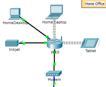
Home Office
Central

Branch

For Help Pages


Workspaces and Modes
Packet Tracer has two workspaces (Logical and Physical) and two modes (Realtime and Simulation). Upon startup, you are in the Logical Workspace in Realtime Mode. You can build your network and see it run in real time in this configuration. You can switch to Simulation Mode to run controlled networking scenarios. You can also switch to the Physical Workspace to arrange the physical aspects (such as the location) of your devices.
Setting Preferences
You can customize your Packet Tracer experience by setting your own preferences. From the Menu Bar, select Options > Preferences (or simply press Ctrl + R) to view the program settings.
Under the Interface panel, you can toggle the Animation, Sound, and Show Link Lights settings to suit the performance of your system and your preferences. You can also manage information clutter with the Show Device Labels, Always Show Port Labels, and Show Port Labels When Mouse Over settings. Also, you can also toggle Show QoS Stamps on Packets shown in Simulation Mode and Enable Cable Length Effects. The Enable Auto Cable option allows you to toggle the Automatic Connection when connecting devices. The Show Device Dialog Taskbar option allows you to toggle the taskbar that is displayed at the bottom of the workspace which organizes currently opened device dialogs. The Logging feature allows the program to capture all Cisco IOS commands that you enter and export them to a text file (refer to the “Configuring Devices” page for more information). The Simulation – Buffer Full Action feature allows you to set the preferred action that Packet Tracer will perform. You can set the action to Prompt if you want to be prompted when the Simulation buffer is full. At the prompt, you can either Clear Event List or View Previous Events. Alternatively, you can set the action to either Auto Clear Event List to allow Packet Tracer to automatically clear the Event List when the buffer is full or you can set the action to Auto View Previous Events to automatically view the previous events. The Enable Screen Reader Support accessibility feature reads out all the titles and descriptions of the visible window that has the focus. Lastly, you can also change the base language of the program by choosing from the Languages list and then pressing the Change Language button.

Under the Administrative panel, you can disable access to a particular interface such as the Interface tab and the Multiuser menu using the Interface Locking feature. In order settings and configurations to apply globally for every user on the machine, you need to click on the Write button to save the PT.conf file to the Packet Tracer installation folder. Optionally, you may change the User Folder to a different location which is where your own settings, configurations, save files, and device templates are stored. Additionally, you can set a Password to prevent others from tampering with these preferences. Note that the password is case-sensitive.

Setting a User Profile
You can set your user profile for activity assessment and Multiuser identification. From the Menu Bar, select Options > User Profile to view the User Profile dialog. In the User Profile dialog, you can enter your Name, E-Mail, and any Additional Info about yourself that you may want to share.
Algorithm Settings
The Algorithms Settings dialog allows the user to make configurations that are otherwise not available in IOS. It also allows tweaking of algorithm settings to make visualization of certain algorithm/protocol behaviors more easily viewable.
CBAC Half-Open Session Multiplier: If the number of half-open CBAC sessions multiplied by this number exceeds the configured max half-open session count, new sessions would not be opened.
TCP Maximum Number of Connections: If the number of connections in SYN-RECEIVED state exceeds this number, any new connections would be rejected.
TCP Maximum Number of Opened Sessions: If the number of connections exceeds this number, any new connections would be rejected.
TCP Maximum Retransmission Timeout in Milliseconds : If a TCP connection does not receive an acknowledgement to a segment it transmitted in this number, it would retransmit the segment.
Switching Storm Control Multiplier: If the bandwidth percentage of broadcast frames used multiplied by this number exceeds the configured threshold, the broadcast frame would be dropped.
My First Packet Tracer Lab
Introduction
Welcome to Packet Tracer. Research has shown that users who master a few basic tasks when first starting to use Packet Tracer get much more out of the software. This lab is designed to familiarize a user with Packet Tracer’s features. This activity should take approximately 30 minutes to complete. Use these directions to go through the lab yourself, or view the animated tutorial version of the lab.
Important Terminology
- ICMP ping: command consisting of an echo request message from one device to another, and the returning echo reply.
- IP address: 32-bit address assigned to devices as identification in the network.
- Ethernet: one of the most common LAN standards for hardware, communication and cabling.
- Fast Ethernet Interface: 100 Mbps Ethernet port. In Packet Tracer, a GUI may be used to configure such interfaces.
- OSI model: 7-layer framework for looking at network protocols and devices, consisting of the application, presentation, session, transport, network, data link, and physical layers.
- PDU: protocol data unit, a grouping of data appropriate to a given layer in the OSI model.
- Packets: OSI Layer 3 protocol data units. Represented by envelopes in Packet Tracer Simulation Mode.
- Device Tables: includes ARP, switching, and routing tables. They contain information regarding the devices and protocols in the network.
- ARP Table: Address Resolution Protocol (ARP) table, stores pairings of IP Addresses and Ethernet MAC addresses.
- Scenario: one topology with a set of PDUs placed in the network to be sent at specific times. Using different scenarios, experiment with different combinations of packets using the same base topology.
I. Viewing Help and Tutorials (View Tutorial)
- Launch Packet Tracer.
- Open the help content by clicking Help > Contents on the Menu bar. You can also click the question mark on the Main toolbar. Another option is the F1 shortcut key.
- The menu will always be visible on the left side of the window while browsing through the help files. Skim through the help sections to get an idea of the functionality of Cisco Packet Tracer.
- The What’s New section under Introduction provides an overview of features that have been added to Packet Tracer.
- Pay close attention to the Interface Overview section under Getting Started to familiarize yourself quickly to the Packet Tracer interface.
- Browse the Tutorials section as well.
- Open the Interface Overview tutorial to learn the basics of the Packet Tracer graphical user interface. Note: Some browsers may prevent the tutorial from playing. Configure your browser to allow active content to enable the viewing of the tutorial.
- When the first caption appears, as shown below, click the Pause button in the playback controls.

- Click the Forward button to skip to the next caption. Then click Pause again. Click the Back button to view the previous caption.
- Continue viewing the tutorial by pressing the Play button. Parts of the tutorial can also be skipped by dragging the slider to the right. If needed, click the Rewind button to restart the tutorial.
- Click Exit to close the tutorial window. Close the help content as well.
Congratulations on learning more about resources that will help you get the most out of Packet Tracer.
II. Creating a First Network (View Tutorial)
- Start creating a network by first selecting the End Devices. Add a Generic PC and a Generic Server to the workspace.
- Under Connections, select the Copper Straight-through cable (solid black line) and connect the devices with it. The red lights on the link indicate that the connection is not working. Now, use the Delete tool to remove the Copper Straight-through cable, and use a Copper Cross-over cable (dashed line) instead. The lights should turn green at this point. If the mouse pointer is held over either devices, the link status will be shown as “Up.” The network should look similar to this:

- Click on the PC. While paying attention to the link lights, turn the power on, off, and on again. Follow the same steps for the server. The link lights turn red when the device is off. This means that the link is down or is not working. The link lights turn green when the device is turned back on.
- Try all three ways to learn about the devices. First, mouse over the devices to see basic configuration information about them. Second, click on each device with the Select tool to show the device configuration window, which provides several ways to configure the device. Third, use the Inspect tool to view the tables the network device will build as it learns about the network around it. In this example, open the ARP table. Since the devices have not been configured yet, the ARP tables are empty. Always remember to close the windows after viewing them or they will clutter the workspace.
- Open the PC configuration window and change the settings using the Config tab. Change the display name to Client and set the DNS server to 192.168.0.105. Under Interface, click FastEthernet and set the IP address as 192.168.0.110. Packet Tracer automatically calculates other parameters. Make sure that the Port Status box is checked. For future reference, note that other Ethernet interface settings, such as bandwidth, duplex, MAC address, and subnet mask can be modified using this window.
- Go to the Desktop Tab and click on IP Configuration. Notice that the IP address, subnet mask and DNS server can be changed here as well.
- Open the Server configuration window and go to the Config tab. Change the display name to Web Server. Click FastEthernet and set the IP address as 192.168.0.105. Make sure that the Port Status is also on. Click DNS and set the domain name as http://www.firstlab.com. Set the IP address as 192.168.0.105 and click Add. Finally, check to make sure that the service for DNS is on.
- Reposition the network devices by dragging them to a new location. Add a network description by using the “i” button on the upper right corner. Then add some text labels within the Logical Workspace by using the Place Note tool.
- Load a background grid using the Set Tiled Background button.
- Save your work using the File > Save As option and create a meaningful filename.
Congratulations on creating your first network.
III. Sending Simple Test Messages in Realtime Mode (View Tutorial)
- Start by opening the file saved in the last section.
- Notice that the file opens in Realtime Mode. Use the Add Simple PDU tool to send a simple one-time ping message, called an echo request, to the server. The server responds with an echo reply because all devices have properly configured IP address settings.
- Scroll up and down the User Created Packet Window to see the different capabilities of this ping message, including an indication that the ping was successful.
- Toggle the PDU List Window to see a larger display of this message. One or more of these messages can be saved as a scenario. Scenario 0 is displayed when starting. Label this first scenario with an “i” note. Different scenarios allow the use of the same topology for experiments with different groupings of user created packets.
- Click New to create a new scenario. New scenarios will initially be blank.
- Add two packets using the Simple PDU tool, a PDU from the PC to the Server and a different PDU from the Server to the PC. Then add an “i” note describing the scenario, to complete Scenario 1. An example is shown below:

- Several scenarios can be saved with a single network. Alternate between Scenario 0 and 1.
- Now, remove Scenario 0 using the Delete button.
- Scenario 1 is now visible. Go to the last column in the User Created Packet Window and double-click (delete) to remove a PDU.
- Delete the whole scenario. Notice that the scenario list went back to the default Scenario 0.
Congratulations on being able to send and organize simple test messages in Realtime Mode.
IV. Establishing a Web Server Connection Using the PC’s Web Browser (View Tutorial)
- Open the file saved from the previous section.
- Click on the PC to view the configuration window.
- Select the Desktop tab, and then click Web Browser. Type in http://www.firstlab.com as the URL and click the Go button. The Packet Tracer welcome page, shown below, appears, indicating that the web connection has been successfully established.
- Clear the URL, type www and click Go. Since the address entered is not complete, a “Host Name Unresolved” message appears.
- Type 192.168.0.105 as the URL entry and click on Go. Notice that the Packet Tracer welcome page appears again. This is because the Server IP address can also be used to establish a web connection.
- Close the window and try the same steps in Simulation Mode. In this mode, the user controls time, so the network can be viewed running at a slower pace, allowing observation of the paths packets take and inspection of packets in detail (packet tracing!).
- Select the PC again and go to the Web Browser in the Desktop tab. Type http://www.firstlab.com as the URL again and click Go. The welcome page should not appear right away.
- Switch to the main interface of Packet Tracer without closing the PC configuration window. Notice that a DNS packet is added to the event list.
- Click Auto Capture/Play or repeatedly click the Capture/Forward button until the HTTP packet appears on the PC. Go back to the PC configuration window. The Packet Tracer welcome page is now shown.
- Close the PC configuration window.
Congratulations on successfully establishing a web server connection.
V. Capturing Events and Viewing Animations in Simulation Mode (View Tutorial)
- Open the previously saved file.
- In Realtime Mode, send a simple PDU from the PC to the Server.
- Delete the PDU by using the method learned in the previous section.
- Switch to Simulation Mode.
- Click Edit Filters and click All/None to uncheck all fields. Then click ICMP to only view ICMP packets in the animation.
- Add a simple PDU from the PC to the Server. Notice that the newly created PDU is added to the User Created PDU List. This packet has been captured as the first event in the event list and a new packet icon (envelope) appears in the workspace. The eye icon to the left of the event list indicates that this packet is currently displayed.
- Click the Capture/Forward button once. This simulates a network sniffing program, capturing the next event that occurs on the network. Note that after clicking Capture/Forward, the packet in the workspace moves from one device to another (this is the ICMP echo request message from the PC to the Server). Another event is added in the event list – this reflects the change in the workspace. The first time through an animation, the meaning of the Capture/Forward is capture; after resetting the simulation, the meaning is forward.
- Adjust the speed of the animation by dragging the Play Speed slider to the right making it go faster. Dragging the speed slider in the opposite direction (to the left) will slow down the animation.
- Click the Capture/Forward button a second time. This captures the next network event (this is the echo reply from the Server to the PC, shown as successful with a green check mark on the envelope).
- Click Capture/Forward button again. The Server has already sent an echo reply to the PC therefore, there are no more ICMP events left to capture.

Congratulations on successfully capturing events and viewing animations in Simulation Mode.
VI. Looking Inside Packets in Simulation Mode (View Tutorial)
- Continuing from the last activity, click Reset Simulation. This clears the entries in the event list except for the original packet.
- Select the packet envelope on the workspace to show the PDU Information window like the one shown in the screenshot below. This window contains the OSI Model tab, which shows how the packet is processed at each layer of the OSI model by the current device. Close this window, noting that this packet is indicated in the event list by the eye icon. The whole row in the event list is also highlighted. Clicking on the color square in the Info column is equivalent to clicking directly on the packet envelope (try it!).

- Use the Next Layer and Previous Layer buttons to see details of the packet processing at the relevant OSI layers. Note that only the Out Layers can be viewed in the case of this original echo request message.
- Click on the Outbound PDU Details tab. This tab shows exactly what makes up the PDU headers. It is organized into header type and the individual fields in each header.
- Close the PDU Information window. Click on Capture/Forward button once.
- Click on the packet in the workspace again to open the PDU Information window. Notice that this time, information regarding both the In Layers and Out Layers can be viewed.
- Click on the Inbound PDU Details tab. This shows the details of the inbound echo request packet from the PC to the Server. The Outbound PDU Details tab, shows similar information, but for the echo reply packet from the Server to the PC.
- Click on Reset Simulation again. Now click on Auto Capture/Play. The echo request and echo reply are automatically captured. Click on the Back Button to rewind the animation one step at a time. Now click on the Capture/Forward button to forward the packet through the animation. Note the change in the event list and the workspace. Remember that at any time, a PDU Information Window can be opened by clicking directly on the envelope on the workspace, or by clicking the Info column in the Event List.
- Click on the Back Button twice to rewind the animation. Now click Auto Capture/Play and the packet animation will automatically occur.
Congratulations on being able to manipulate the Play Controls and PDU Information Window to understand more about packet processing details.
VII. Viewing Device Tables and Resetting the Network (View Tutorial)
- Open the file saved from the previous section.
- Open the ARP Tables for both devices by clicking them with the Inspect tool. The ARP tables always appear on the same spot. Reposition them to make them both visible. You can also resize the tables for better viewing.
- In Realtime Mode, send a simple PDU from the PC to the Server. Notice that the ARP tables are filled in automatically, as shown he

- Delete the PDU using the method covered in the previous sections. Notice that the entries in the ARP tables are NOT cleared. ARP entries for both devices have already been learned. Deleting the user created PDUs does not reset events what has already occurred in the network.
- Click Power Cycle Devices. ARP tables are cleared because the Power Cycle Devices button turns the devices off and back on again therefore, losing temporary information like the ARP table entries.
- Go to Simulation Mode. In the event list filters, make sure that ICMP and ARP are checked so that you can view ICMP and ARP packets in the animation.
- Create a new simple PDU from the Server to the PC.
- Notice that since the devices were power cycled earlier, the ARP tables are empty. ARP request packets need to be issued before the ICMP ping packets, so that the devices in the network can learn about each other. Click on Auto Capture/Play to watch the animation.
- Click Reset Simulation. Notice that even though the event list is cleared (except for the user created PDU), the ARP tables remain full. Click Auto Capture/Play. This time, since the ARP tables are full, there are no new ARP packets issued.
- Click Power Cycle Devices. Doing so will empty the tables. Notice that new ARP request packets appear automatically in the event list.
Congratulations! You can now view device tables, reset a simulation, and reset the network.
VIII. Reviewing Your New Skills
- Single-clicking on the Delete button removes the entire scenario including all the PDUs associated with it.
- Double-clicking on (delete) in the far right column in the PDU List window deletes individual PDUs.
- The Reset Simulation button clears all entries in the Event List, except for User Created PDUs, and allows the animation to restart. This, however, does not reset the device tables.
- The Power Cycle Devices button turns all of the devices in the network off and on so the tables that the devices built are lost along with configurations and other information not saved.
- Saving work periodically prevents lost configurations and state changes in the network.
Congratulations on being ready to build and analyze many different networks in Packet Tracer! Be aware that there are many other features that were not covered in this lab. To learn more, please view the other available tutorials and review the help files. Have Fun!


In my previous blogpost, I have discussed how students are able to exploit Packet Tracer to cheat their exams. You may have to read the article first before you continue, the article explains how the Packet Tracer software can be exploited and gives advice on how to prevent such techniques. The point is that Cisco, the company behind the Packet Tracer software, just doesn’t seem to care at all how good or bad the software is secured.
My previous blogpost on Packet Tracer has been sent to Cisco, and at the time of writing, there wasn’t any response. So this leaves educational institutions with a big problem, a problem that can only be solved by the original software developers (Cisco)?
No, Thanks to reverse engineering, we can figure out how the Packet Tracer software works, and then modify the Packet Tracer binary to work in a way we want! The goal of this article is to improve Packet Tracer by making it more secure without the need for its source code.
NOTE: Cisco has responded to me after I had written this article. I had someone more professional help me the second time I contacted Cisco.
My Story
Unfortunately, I have recently been expelled from school for developing a Packet Tracer Password Recovery tool, the school considered that my tool was an attempt to fraud exams. Not only my own exams, but they also accused me of helping thousands of other students to fraud their exams. Even tho there was no proof of me actually using the software on any exam… They then asked me the following question, «Can Packet Tracer still be used to provide a fair exam?», and the answer to that question is… well… you will able to answer yourself after reading the whole article.
The Plan
With that question in mind, using the original Packet Tracer software was a no go, the software has no obfuscation, no anti-debugging, no nothing (not even ASLR). To improve the security of the software, we have to implement all of those features so we can prevent as much hacks as possible in the future. Sounds impossible without the source code? well, how about developing a DLL that gets called by Packet Tracer at startup? or a loader that manually maps Packet Tracer into memory and then scans memory regions to check if anyone attempted to modify code?
Those are all great ideas, they greatly improve security but there is one thing that’s missing, there is no key component that forces a student to use the modified version… There must be something that forces a student to use our own specific version of Packet Tracer… and that should be… the file format! Yes, with the .pka file format, we can force students to use a specific version. Any of you boomers remember Packet Tracer version 5? Good luck using version 5 .pka files in the new version 7. Spoiler alert, when you do, Packet Tracer throws an error, showing that your .pka file format is outdated.
The Actual Plan
So what we have to do is figure out how a .pka file works exactly and create our own version. It is important for us that we can unpack the original .pka file so we can then re-pack an existing .pka file to our own format. Once we have our own format, we have to patch our secure version of Packet Tracer and replace the original unpacking algorithm with our custom one. The replacement of the algorithm can be done by modifying the original algorithm just enough so it will no longer accept original .pka files.
We can go all crazy here by using a custom DLL to hook the original algorithm and use a more complex algorithm, but for today I will just show a basic, ‘good enough’ example.
The benefit is that our ‘magic’ algorithm is private, and the software containing the magical algorithm is only handed out to students of the educational institution.
Therefore making it impossible for students to use existing tools that target the original version of packet tracer.
Not only do we prevent public known tools (for example), but we can also reduce the lifetime of new tools by regularly updating the ‘magic’ algorithm to force a cat and mouse game between educators and students.
NOTE: Version 7.3 and above have ASLR enabled, this research was done on version 7.2.1.
Reversing the activity file format (.pka)
First things first, before we can start implementing our own magic algorithm, we need to reverse-engineer the current algorithm that is used to encode/decode the .pka file format. Thanks to my previous blog post I already have a good knowledge of what Packet Tracer is made of. One of the noticeable things is that it uses the Qt5 framework to handle strings and files.
Looking for ‘File’
The first thing I did was throw the Packet Tracer binary into IDA and look at the import table, mainly looking for the Qt5 import functions. While doing that, I made use of IDA’s search feature so it will only show me a list of functions that contain a given string in their name. Since I know that Packet Tracer will use some kind of function to read the .pka file, I simply started looking for functions containing «Open», «Read», «Stream», «File», etc in their name.
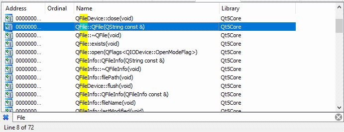
Looking into all of those functions will be time-consuming, have a look at the image above to get an idea of how many results I got. Therefore I am only interested in the constructors of a given class, because, all I want to know (for now) is if Packet Tracer is actually using that class or not. Packet Tracer has to call the constructor at least once to create the object, therefore I did a quick xref to find out if the function was used by Packet Tracer. Now I should have an idea of which classes Packet Tracer is using, and it’s time to fire up Cheat Engine.
Once Cheat Engine is open, it’s time to breakpoint the constructor functions and load in a .pka file. My breakpoints are placed on all variants of the QFile::File function, time to load in a .pka file and see what happens.
Let’s not waste too much time here, after my breakpoint got triggered I checked the stack and wrote down three functions that are coming from the Packet Tracer base image. I then threw them all three into IDA to have a quick look at what they do, and based on their Qt5 function calls and string references, it seems that the two of them were used to warn the user that he may lose progress in his current file by loading in the new .pka file. That means we can throw those two in the garbage and focus on the one we have left.
Single steps
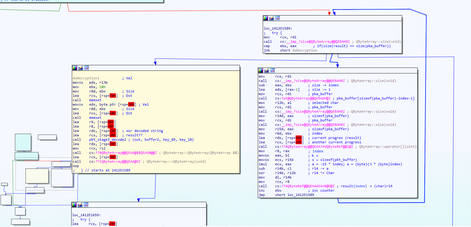
Alright, back to the one function that has the real sauce in it, I opened the function in IDA and breakpoint the start of the function in Cheat Engine. By looking at the IDA graph I can have a better look at the control flow while I single-step through the assembly code using Cheat Engine debugger. The below image shows the control flow of the function we are analyzing.
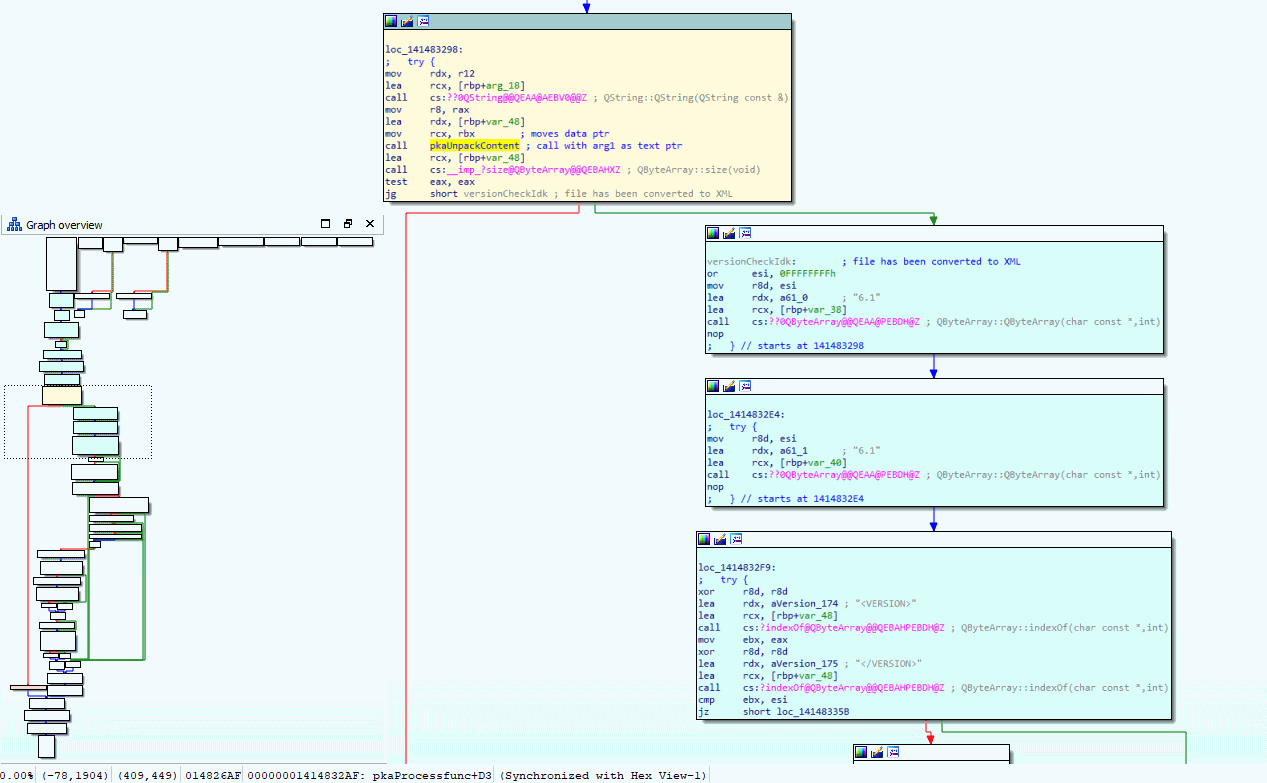
Have a close look at the yellow block, it calls the constructor to create a Qt5 string, then calls an unknown function (spoiler alert, its pkaUnpackContent), calls to get the size of a QByteArray object, and then jumps to the blue blocks if the size is not zero. Looking a bit further in the blue blocks you can see it is referring to string <VERSION> and </VERSION>, so to me, it looks like the XML got unpacked at that point. Spoiler alert, I gave the ‘unknown’ function the name ‘pkaUnpackContent’ so you may have already guessed the magic happens in there.
But the real question is not where it happens, it is how it happens! To figure these out, let’s have a look at the function pkaUnpackContent in IDA’s graph view.
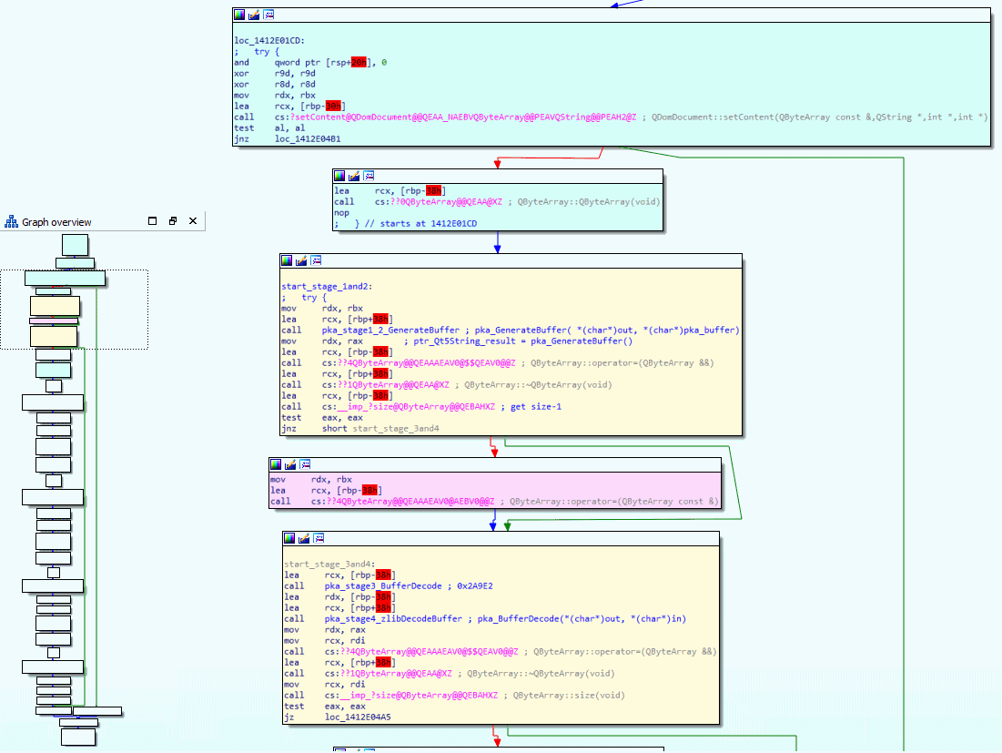
Again, I have analyzed the function and cut out the boring stuff. You can see the full control flow for pkaUnpackContent in the lower-left corner and then the useful blocks are zoomed into. I debugged the function by single-stepping through it and then watching which arguments get feed into the function and what comes out of it by keeping a close look at the buffer holding the raw .pka bytes, I then noticed that the buffer changed after it executed the yellow blocks in the above screenshot. Oh and because the two yellow blocks you see are responsible for doing the four stages of decoding, meaning we got again a little step closer to our goal. So close that we can almost see the stages.
The Stages of Decoding
After single stepping and keeping a close eye on the heap, we have managed to find multiple functions that are responsible for manipulating data that was originally coming from the raw .pka file. Therefore I will go into each function in greater detail and describe how I reversed every single assembly instruction of them, or at least, the instructions that are relevant to the decoding process. Below is the list of stages that we will be looking into.
- Stage 1: Reverse Xor
- Stage 2: Pump it up
- Stage 3: Another Xor
- Stage 4: Decompressing
Oh and… I have found a GitHub repository online that was capable of unpacking version 5.x of the file format. According to that repository they only used stage 1 and stage 4 of the above encoding/decoding stages in version 5.x. This means that Cisco is actually taking action against people like me, which is a good thing to see!
Stage 1: Reverse Xor
Alright, if you remember the last screenshot, you will see that there is a function named pka_stage1_2_GenerateBuffer, and you probably guessed it, it is responsible for decoding both stage 1 and 2 of the buffer. The control flow of the image is shown below
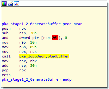
There is not much going on here, other than passing a few hardcoded arguments to another function call. I have named the function that gets called pka_loopDecryptedBuffer, the control flow of that function can be found in the image below.
Now have a look at the two pink blocks (mouseover/tap image to zoom in), surprise surprise, it seems to be a loop, and if you look at the end of the second pink block, you also able to see an XOR assembly instruction. The two pink blocks are the first stage of decoding, they do XOR, starting with the last byte in the array while using the length of the buffer to create the key. Please have a good look at the two pink blocks and take a deep look at the assembly instruction before you continue reading.
Think you understand what’s going on? then it is time to show you my C# code that I wrote to re-create the reverse XOR decoding. The below function unpackStageOne should give you a better understanding of what the assembly xor was doing.
private bool unpackStageOne()
{
	byte k = (byte)this.Buffer.Length;
	int s = this.Buffer.Length;
	for (int i = 0; i < this.Buffer.Length; i++)
	{
		byte ch = this.Buffer[this.Buffer.Length - i - 1];
		byte a = (byte)(k * (byte)i);
		byte c = (byte)(this.Buffer.Length - a);
		c ^= ch;
		this.Buffer[i] = c;
	}
	return true;
}
Stage 2: Pump it up
Stage 2 is a bit different. What happens here is Packet Tracer is using a library called Crypto++ to pump the buffer through a pipeline with the TwoFish filter, which basically means it is decrypting it using the TwoFish block cipher algorithm.
The algorithm gets invoked with a key and an initialization vector, have a look at the table below for the key/IV you need.
| Action | File Info | Key | IV |
|---|---|---|---|
| Decrypt Encrypt |
Packet Tracer Acticity (.pta) | ABABABABABABABABABABABABABABABAB |
CDCDCDCDCDCDCDCDCDCDCDCDCDCDCDCD |
| Decrypt Encrypt |
PKC Files (.pkc) | ABABABABABABABABABABABABABABABAB |
23232323232323232323232323232323 |
| Decrypt Encrypt |
Log Files | ABABABABABABABABABABABABABABABAB |
BEBEBEBEBEBEBEBEBEBEBEBEBEBEBEBE |
| Decrypt Encrypt |
Log Files | BABABABABABABABABABABABABABABABA |
BEBEBEBEBEBEBEBEBEBEBEBEBEBEBEBE |
| Decrypt Encrypt |
Packet Tracer Saves | 89898989898989898989898989898989 |
10101010101010101010101010101010 |
| Decrypt Encrypt |
Unknown_1 | 12121212121212121212121212121212 |
FEFEFEFEFEFEFEFEFEFEFEFEFEFEFEFE |
| Decrypt Encrypt |
Unknown_2 | F1F1F1F1F1F1F1F1F1F1F1F1F1F1F1F1 |
1F1F1F1F1F1F1F1F1F1F1F1F1F1F1F1F |
NOTE: Extracted from PacketTracer v7.2.1
For the code, I have forked a TwoFish C# implementation from github and used it like this:
public bool unpackStageTwo()
{
	// We use the 'Packet Tracer Saves' key, which works on .pka, .pkt and a few more I guess.
	Twofish twofish = new Twofish()
	{
		Mode = System.Security.Cryptography.CipherMode.CBC,
		Key = new byte[] { 0x89, 0x89, 0x89, 0x89, 0x89, 0x89, 0x89, 0x89, 0x89, 0x89, 0x89, 0x89, 0x89, 0x89, 0x89, 0x89 },
		IV = new byte[] { 0x10, 0x10, 0x10, 0x10, 0x10, 0x10, 0x10, 0x10, 0x10, 0x10, 0x10, 0x10, 0x10, 0x10, 0x10, 0x10 }
	};

	ICryptoTransform decrypt = twofish.CreateDecryptor();
	System.IO.MemoryStream msD = new System.IO.MemoryStream();
	CryptoStream cryptostreamDecr = new CryptoStream(msD, decrypt, CryptoStreamMode.Write);

	cryptostreamDecr.Write(this.Buffer, 0, this.Buffer.Length);
	cryptostreamDecr.Close();

	byte[] tmp = msD.GetBuffer();
	Console.WriteLine(tmp.Length);
	for (int i = 0; i < this.Buffer.Length; i++)
		this.Buffer[i] = tmp[i];

	return true;
}
Stage 3: Another Xor
Stage 3 is located in the second yellow block that was found in the pkaUnpackContent() when we were single-step debugging.
Our pka_stage3_BufferDecode() function is a bit similar to stage 1 reverse XOR decoding, except this time it is not in reverse.
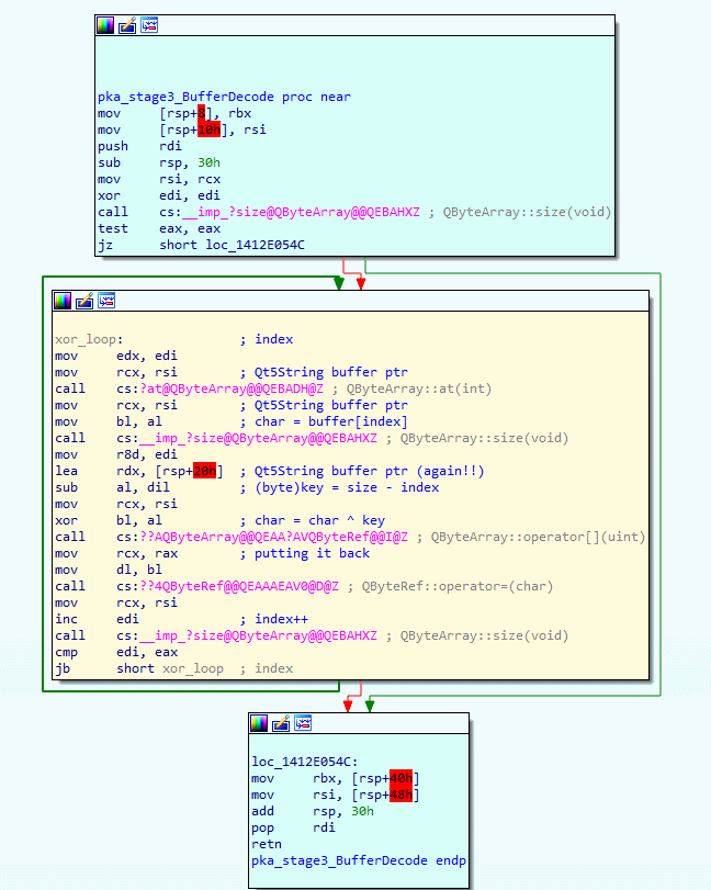
Since the XOR decoding is similar to the stage1 reverse XOR decoding, I won’t go into any detail.
Feel free to pause for a brief moment and have a good look at the yellow block where the XOR decoding happens.
Once again, this XOR decoding loop iterates through all bytes of the buffer, this time from start to end, and uses the length as key.
The below code is my C# version of the stage 3 XOR decoding, have a close look at the code to get a better understanding of what the above assembly code was doing exactly.
private bool unpackStageThree()
{
	for (int i = 0; i < this.Buffer.Length; i++)
	{
		byte ch = this.Buffer[i];
		byte key = (byte)(this.Buffer.Length - i);
		ch ^= key;
		this.Buffer[i] = ch;
	}
	return true;
}
Stage 4: Decompressing
Okay, I am not gonna lie, I did look into the Github repository that unpacked the file format for version 5.x. The Github repo stated that the first 4 bytes of the buffer indicated the length of the unzipped content, and that zlib was used to unzip the remaining buffer. In my defense, zlib has multiple formats. So I actually had to find the magic bytes myself and check which type of zlib was used. According to this list of file signatures from Wikipedia, I figured that my magic bytes «78 9C« stands for zlib ‘Default Compression’.
After looking that up it was just a matter of googling for a C# NuGet to find a C# library that has all of the functionality I need from zlib to do the default compression. The C# function I created for unpackStageFour(), which decompresses and serializes the decompressed XML string to an object is shown below.
private bool unpackStageFour()
{
	this.XmlContent = new byte[(this.Buffer[0] * 0x1000000) + (this.Buffer[1] * 0x10000) + (this.Buffer[2] * 0x100) + (this.Buffer[3] * 0x1)]; // first 4 bytes are size
	var zlibdata = this.Buffer.ToList();
	zlibdata.RemoveRange(0, 4);

	// check for zlib 'Default Compression (no preset dictionary)'
	if (zlibdata[0] != 0x78 && zlibdata[1] != 0x9C)
		return false; // invalid header - https://en.wikipedia.org/wiki/List_of_file_signatures

	InflaterInputStream inflate = new InflaterInputStream(new MemoryStream(zlibdata.ToArray()));
	inflate.Read(this.XmlContent, 0, this.XmlContent.Length);

	// patch invalid character 0x03
	for (int i = 0; i < this.XmlContent.Length; i++)
		if (this.XmlContent[i] < 0x09)
			this.XmlContent[i] = 0x3F; // ASCII questionmark

	this.xmlSerializer = new XmlSerializer(typeof(PACKETTRACER5_ACTIVITY));
	this.Content = (PACKETTRACER5_ACTIVITY)this.xmlSerializer.Deserialize(new MemoryStream(this.XmlContent));
	return true;
}
Also note that I ‘patch invalid character 0x03’ since the C# XmlSerializer doesn’t like that character, therefore I simply replace that character with 0x3F, which is the question mark character in the ASCII table.
It’s an XML!
Finally, we have reached plain text, which seems to be XML. This explains why Packet Tracer was referring to the strings <VERSION> and </VERSION> right after it successfully unpacked the file data. From now on we can use the C# functions we have made to fully unpack our original .pka files.
Custom algorithm
Now that we completely understand how Packet Tracer unpacks the .pka file type, we can start modifying the algorithm just enough to have custom .pka file versions. To keep it simple, I will simply modify stage 1 and replace the Xor key with a hardcoded key. This also means we have to re-pack our existing .pka files to convert them to our new format, I will create a tool that unpacks our existing .pka files and packs then using the slightly modified algorithm.
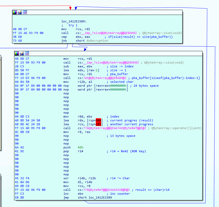
Patching original algorithm
Time to patch the stuff in IDA, in the image below you can see I have replaced a bunch of instructions with NOP and then pushed the XOR key (0x42) into the r14 register. Since we hardcode the XOR key we no longer need the function calls that obtain the size of the array, this means we can clean up a little bit of space. Have a close look and you can see that I have removed a total of 37 bytes, this may not sound like a lot, but know that setting our hardcoded XOR key costs only 4 bytes. This means there is plenty of room to make a more complex XOR algorithm, but for now, let’s keep it simple and stick to the hardcoded XOR key example.
After that’s done I decided to give it a go, and… it crashed. When I start Packet Tracer, I am greeted with an error message, so I decided to throw the original Packet Tracer binary into x64dbg so I can breakpoint stage 1 of the unpacking algorithm. It turns out that the function is called at startup, I get exactly 83 hit counts on the breakpoint, which seems like Packet Tracer is unpacking 83 files at startup?
After analyzing the files that got unpacked I figured out that Packet Tracer uses this algorithm for more than just .pka files, basically all files with the .ptd and .pts extension that are located in the Packet Tracer directory get unpacked and loaded into memory using the same unpacking algorithm at startup.
This makes my job a little harder, it means we not only have to re-pack our .pka files, but also a bunch of other files that come with the installation of Packet Tracer.
Fear not, because my set of tools to automatically do this is located on GitHub.
Re-packing pka files
Finally, we have to re-pack our existing .pts, .ptd and .pka files.
When we don’t convert the .pts and .ptd files that are located in the Packet Tracer directory, we get the crash I just described.
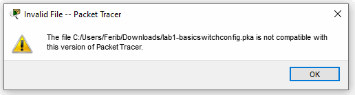
When a user uses a .pka file that is either, not re-packed to our current version or tries to use our re-packed .pka file in the original (and more vulnerable) Packet Tracer then this error will show up.
The result
You may have got a little confused with what we have done so far, therefore I created a visual representation of what I have achieved in my PoC.
Have a look at the image below, on the left side you will see the original flow of Packet Tracer, and on the right side is our patched version.
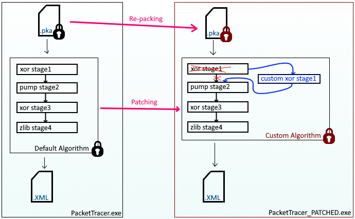
The purple lines represent the following actions that come from my PkaWizard toolset:
- Re-packing functionality is used to convert an original .pka file to a custom encoded version (or vise versa)
- Patching functionality is used to patch a custom algorithm inside an original PacketTracer binary (or vise versa)
Last but not least, a visual demonstration of my PkaWizard toolset.
- 00:04 — Original Packet Tracer using original file while opening original .pka
- 00:25 — Patched Packet Tracer using original files
- 00:44 — Patched Packet Tracer using patched files
- 00:52 — Patched Packet Tracer opening original .pka
- 01:14 — Patched Packet Tracer opening custom .pka
Conclusion
Nothing is 100% secure, especially when it is all client-side on a device that is not owned by you. The best way to prevent fraud using such tools is to update the software frequently, making it more time consuming for others to break it. Reversing the whole unpacking tool took me about 10 hours of works, which, may not sound that bad, but do know that people with such a skillset are charging over 100$ hourly rates. But yeah, I am just a bored college student that got a few extra months of vacation, waiting for the new school year to begin ;).
Download
For those who didn’t find a link yet, here is the GitHub link to my PkaWizard project.
Consider giving a star to pump my dopamine levels for a split second!