Мало того, что OBD2 ошибки работы двигателя или других электронных систем автомобиля не всегда на прямую указывают на неработающий элемент, но и в разных марках и моделях автомобилей одна и таже ошибка может возникать как следствие неисправности абсолютно разных элементов электронной системы.
Мы надеемся, с Вашей помощью, сформировать причино-следственную связь возникновения той или иной OBD2 ошибки у конкретного автомобиля (марка и модель). Как показал опыт если рассматривать определенную марка-модель автомобиля, то в подавляющем большинстве случаев причина ошибки одна и также.
Если ошибка указывает на неверные параметры (высокие или низкие значения) какого нибудь из датчиков или анализаторов, то вероятней всего этот элемент исправен, а проблему надо искать так сказать «выше по течению», в элементах работу которых анализирует датчик или зонд.
Если ошибка указывает на постоянно открытый или закрытый клапан, то тут надо подойти к решению вопроса с умом, а не менять бездумно этот элемент. Причин может быть несколько: клапан засорен, клапан заклинил, на клапан приходит неверный сигнал от других неисправных узлов.
Ошибки работы двигателя OBD2 и других систем автомобиля не всегда на прямую указывают на неработающий элемент. Сама по себе ошибка является косвенными данными о неисправности в системе, в некотором смысле подсказкой, и только в редких случаях прямым указанием на неисправный элемент, датчик или деталь. Ошибки (коды ошибок) полученные от прибора, сканера требуют правильной интерпретации информации, дабы не тратить время и деньги на замену работающих элементов автомобиля. Проблема зачастую кроется намного глубже чем кажется на первый взгляд. Это вызвано теми обстоятельствами, что информационные сообщения содержат, как было выше сказано, косвенную информацию о шарушении работы системы.
Вот пару общих примеров. Если ошибка указывает на неверные параметры (высокие или низкие значения) какого нибудь из датчиков или анализаторов, то вероятней всего этот элемент исправен, так как он анализирует (выдает некие параметры или значения), а проблему надо искать так сказать «выше по течению», в элементах работу которых анализирует датчик или зонд.
Если ошибка указывает на постоянно открытый или закрытый клапан, то тут надо подойти к решению вопроса с умом, а не менять бездумно этот элемент. Причин может быть несколько: клапан засорен, клапан заклинил, на клапан приходит неверный сигнал от других неисправных узлов.
Еще один момент который хотелось бы отметить — это специфика той или иной марки и модели. Поэтому узнав ошибку работы двигателя или дрогой системы Вашего автомобиля не спешите делать поспешных решений, а подойдите к вопросу комплексно.
Электронный блок управления двигателем (ЭБУ) и подсоединенные к нему устройства отличаются прочностью конструкции и в своей основе надежнее соединительных проводов и разъемов.
ПЕРЕД тем, как проверять или заменять электрические устройства необходимо убедиться в том, что установлены соответствующие провода и разъемы, и что они нормально функционируют. Во многих случаях электрические неисправности легко устраняются путем выявления неисправных проводов,
разъемов или точек заземления. Перед выполнением работ необходимо разъединить электрическую систему, отсоединив аккумулятор. Ознакомьтесь с соответствующей документацией машины, где приведена правильная процедура.
1 ЖГУТ ЭЛЕКТРОПРОВОДКИ- визуально осмотрите соединительные провода и разъемы на предмет следов повреждений.
Проверьте следующие аспекты:
a Потертые провода- периодические короткие замыкания.
b Порезанные провода- разомкнутые цепи. Вероятной причиной является попадание проводов в механические механизмы машины.
c Оборванные провода — разомкнутые цепи. Вероятной причиной является неправильная прокладка или увязка проводов без их достаточной слабины для движений машины.
d Оплавленные провода — периодические короткие замыкания. Вероятной причиной является контакт с турбокомпрессором или выхлопной системой.
2 РАЗЪЕМЫ -Визуально осмотрите соответствующие разъемы. Проверьте следующие аспекты:
a Соединение- периодические короткие замыкания. Убедитесь в том, что разъемы правильно соединены, а их стопорные механизмы зафиксированы.
b Повреждение- периодическое размыкание цепи или короткие замыкания. Осмотрите разъемы на предмет признаков физического повреждения (например, сломанных корпусов или стопорных фиксаторов). При контакте с горячей выхлопной системой или турбокомпрессором разъемы могут также оплавиться. Разъедините разъемы и осмотрите штыревые контакты на предмет повреждений (например, корродированных, погнутых или сломанных штыревых контактов). ЗАПРЕЩАЕТСЯ ПРИКАСАТЬСЯ к штыревым контактам разъема на электронном блоке управления двигателем (ЭБУ). Сломанные разъемы подлежат замене.
c Загрязнение- периодическое размыкание цепи или короткие замыкания. Разъедините разъемы и осмотрите их внутреннюю часть на предмет загрязнения (обычно водой, маслом или гидравлической жидкостью). При необходимости очистите штыревые контакты разъема и розетку ватной палочкой или подобным предметом. ЗАПРЕЩАЕТСЯ ПРИКАСАТЬСЯ к штыревым контактам разъема на электронном блоке управления двигателем (ЭБУ). При явных признаках загрязнения водой разъемам необходимо дать полностью высохнуть перед их соединением. Внимательно осмотрите все уплотнительные элементы на предмет следов загрязнения или повреждений.
3 Точки заземления- найдите точки заземления на двигателе и машине. Убедитесь в правильности подсоединения клемм проводов.
Коды неисправностей — структура
Структура кодов неисправностей, также известных как «Диагностические коды неисправностей» (DTC), была стандартизована и представлена 7-значным кодом для всех дорожных и внедорожных машин и транспортных средств. Согласно стандарту (называемому J2012), все коды неисправностей должны соответствовать приведенной ниже структуре.
1-й символ — определяет систему транспортного средства (например, Р = силовая передача, С = шасси, U = сеть)
2-й и 3-й символы — определяют подсистему (трансмиссия, CAN-сеть, тормоза и т.п.)
4-й и 5-й символы — определяют конкретный компонент, цепь или неисправность (например, реле стартера)
6-й и 7-й символы — называются «байтами типов неисправностей» (FTB) и указывают на конкретную неисправность (например, 11 = короткое замыкание на землю). Полный перечень приведен в пункте «Номера FTB» ниже.
Некоторые специальные коды неисправностей определяются международным стандартом, а другие могут определяться отдельными производителями транспортных средств.
В зависимости от спецификации машины, существует несколько способов доступа и отображения кодов неисправностей, которые регистрируются ЭБУ двигателя:
Дисплей на основе CAN-шины
Машина может быть оснащена дисплеем на основе CAN-шины. На таком дисплее могут отображаться все зарегистрированные коды, например, P0047. Будут отображены все зарегистрированные коды. У оператора может быть возможность стереть журнал регистрации кодов неисправностей. Более подробная информация приведена в соответствующей документации машины.
Компьютер, подсоединенный к CAN-шине
Доступ к зарегистрированным кодам ошибок может быть обеспечен с помощью подходящего ноутбука, на котором установлено соответствующее диагностическое программное обеспечение, например, средство для диагностики двигателей JCB 444 Engine Diagnostics. Компьютер должен быть подсоединен к гнезду CAN-шины машины с помощью переходника для передачи данных (DLA).
После подсоединения можно отобразить все зарегистрированные коды. У инженера также есть возможность стереть журнал регистрации кодов неисправностей.
Номера байтов типов неисправностей (FTB)
- 00 Нет информации о подтипе
- 02 Общая неисправность с сигналом
- 04 Внутренняя неисправность системы (ЭБУ)
- 07 Механическая неисправность
- 05 Неисправность программирования системы
- 09 Неисправность компонента
- 11 Короткое замыкание на землю (SC2G)
- 12 Короткое замыкание на аккумулятор (SC2VBAT)
- 13 Разомкнутая цепь (ОС)
- 16 Напряжение цепи ниже допустимого порогового значения
- 17 Напряжение цепи выше допустимого порогового значения
- 18 Ток цепи ниже допустимого порогового значения
- 19 Ток цепи выше допустимого порогового значения
- 1A Сопротивление цепи выше допустимого порогового значения
- 1B Сопротивление цепи ниже допустимого порогового значения
- 1C Напряжение цепи вне допустимого диапазона
- 1F Прерывистая работа цепи
- 23 Постоянно низкий сигнал
- 24 Постоянно высокий сигнал
- 26 Скорость изменения сигнала ниже допустимого порогового значения
- 27 Скорость изменения сигнала выше допустимого порогового значения
- 29 Недействительный сигнал
- 2F Неустойчивый сигнал
- 31 Нет сигнала (пропущен/отсутствует)
- 36 Слишком низкая частота сигнала
- 37 Слишком высокая частота сигнала
- 38 Неправильная частота сигнала
- 45 Неисправность памяти программ
- 46 Неисправность калибровки / памяти параметров
- 47 Неисправность системы самоконтроля / микроконтроллера / микропроцессора
- 4B Превышение температуры
- 54 Нет калибровки
- 64 Неисправность приемлемости сигнала
- 62 Неисправность сравнения сигналов
- 72 Исполнительный механизм залип в открытом состоянии
- 73 Исполнительный механизм залип в закрытом состоянии
- 71 Исполнительный механизм залип
- 81 Полученные данные сети содержат ошибку
- 85 Сигнал превышает допустимый диапазон
- 86 Недействительный сигнал CAN
- 88 ШИНА выключена
- 9A Условия работы компонента или системы
- 92 Производительность или неправильная работа
- 96 Неисправность компонента или внутренняя неисправность
- 97 Работа компонента или системы затруднена или заблокирована
- 98 Превышение температуры компонента или системы
При обнаружении неисправности ЭБУ определяет серьезность неисправности и может принять меры по защите двигателя или машины от потециального повреждения.
ЭБУ может предпринять одно из четырех следующих действий:
Бездействие
ЭБУ принял решение об отсутствии непосредственного риска для двигателя или машины и о том, что двигатель работает в штатном режиме.Тем не менее, при ближайшей возможности следует принять меры по устранению неисправности.
Режим пониженного крутящего момента:
Выходная мощность двигателя понижена с целью снижения напряжений и температуры двигателя, и сведения к минимуму его повреждений. Машины следует остановить при ближайшей возможности для предотвращения дальнейших повреждений.
Аварийный режим передвижения до места проведения ремонтных работ:
Выходная мощность двигателя ограничена и снижена скорость вращения двигателя с целью снижения напряжений и температуры двигателя, и сведения к минимуму его повреждений.Машины следует остановить при ближайшей возможности для предотвращения дальнейших повреждений.
Глушение двигателя/отложенное глушение двигателя
ЭБУ двигателя автоматически глушит двигатель для предотвращения его приближающегося отказа.
Коды неисправностей — числовой перечень
• Нажмите на код неисправности, чтобы перейти к информации о конкретном устройстве и процедуре поиска неисправности
P0001 Цепь управления регулятора объема топлива разомкнута
P0002 Диапазон/рабочие характеристики цепи управления регулятора объема топлива
P0003 Низкий сигнал цепи управления регулятора объема топлива
P0004 Высокий сигнал цепи управления регулятора объема топлива
P0016 Взаимосвязь положения коленвала и положения распредвала
P0087 Слишком низкое давление в топливной магистрали/системе
P0088 Слишком высокое давление в топливной магистрали/системе
P0089 Рабочие характеристики регулятора 1 давления топлива
P0090 Цепь управления регулятора 1 давления топлива разомкнута
P0091 Низкий сигнал цепи управления регулятора 1 давления топлива
P0092 Высокий сигнал цепи управления регулятора 1 давления топлива
P0095 Цепь датчика 2 температуры всасываемого воздуха
P0096 Диапазон/рабочие характеристики цепи датчика 2 температуры всасываемого воздуха
P0097 Низкий сигнал цепи датчика 2 температуры всасываемого воздуха
P0098 Высокий сигнал цепи датчика 2 температуры всасываемого воздуха
P0099 Прерывистый/неустойчивый сигнал цепи датчика 2 температуры всасываемого воздуха
P0105 Цепь абсолютного давления в коллекторе/барометрического давления
P0106 Диапазон/рабочие характеристики цепи абсолютного давления в коллекторе/барометрического давления
P0110 Цепь датчика 1 температуры всасываемого воздуха
P0111 Низкий сигнал цепи датчика 1 температуры всасываемого воздуха
P0124 Высокий сигнал цепи датчика 1 температуры всасываемого воздуха
P0113 Высокий сигнал цепи датчика 1 температуры всасываемого воздуха
P0115 Цепь 1 датчика температуры охлаждающей жидкости двигателя
P0116 Диапазон/рабочие характеристики цепи 1 датчика температуры охлаждающей жидкости
двигателя
P0117 Низкий сигнал цепи 1 датчика температуры охлаждающей жидкости двигателя
P0118 Высокий сигнал цепи 1 датчика температуры охлаждающей жидкости двигателя
P0120 Цепь «А» датчика/переключателя положения дросселя/педали
P0121 Диапазон/рабочие характеристики цепи «А» датчика/переключателя положения дросселя/педали
P0180 Цепь «А» датчика температуры топлива
P0181 Диапазон/рабочие характеристики цепи «А» датчика температуры топлива
P0182 Низкий сигнал цепи «А» датчика температуры топлива
P0183 Высокий сигнал цепи «А» датчика температуры топлива
P0190 Цепь «А» датчика давления топлива в магистрали
P0191 Диапазон/рабочие характеристики цепи «А» датчика давления топлива в магистрали
P0192 Низкий сигнал цепи «А» датчика давления топлива в магистрали
P0193 Высокий сигнал цепи «А» датчика давления топлива в магистрали
P0194 Прерывистый/неустойчивый сигнал цепи «А» датчика давления топлива в магистрали
P0200 Цепь инжектора разомкнута
P0201 Цепь инжектора разомкнута — 1-й цилиндр
P0202 Цепь инжектора разомкнута — 2-й цилиндр
P0203 Цепь инжектора разомкнута — 3-й цилиндр
P0204 Цепь инжектора разомкнута — 4-й цилиндр
P0205 Цепь инжектора разомкнута — 5-й цилиндр
P0206 Цепь инжектора разомкнута — 6-й цилиндр
P0218 Состояние превышения температуры трансмиссионной жидкости
P0220 Цепь «В» датчика/переключателя положения дросселя/педали
P0236 Диапазон/рабочие характеристики цепи «А» датчика наддува турбокомпрессора/нагнетателя
P0252 Диапазон/рабочие характеристики «А» дозатора топлива топливного насоса (кулачок/ротор/инжектор)
P0253 Низкий сигнал «А» устройства дозирования топлива топливного насоса высокого давления
(распредвал/ротор/инжектор)
P0254 Высокий сигнал «А» дозатора топлива топливного насоса (кулачок/ротор/инжектор)
P0261 Низкий сигнал цепи инжектора 1-го цилиндра
P0262 Высокий сигнал цепи инжектора 1-го цилиндра
P0263 Вклад/балансировка 1-го цилиндра
P0264 Низкий сигнал цепи инжектора 2-го цилиндра
P0265 Высокий сигнал цепи инжектора 2-го цилиндра
P0266 Вклад/балансировка 2-го цилиндра
P0267 Низкий сигнал цепи инжектора 3-го цилиндра
P0268 Высокий сигнал цепи инжектора 3-го цилиндра
P0269 Вклад/балансировка 3-го цилиндра
P0270 Низкий сигнал цепи инжектора 4-го цилиндра
P0271 Высокий сигнал цепи инжектора 4-го цилиндра
P0272 Вклад/балансировка 4-го цилиндра
P0273 Низкий сигнал цепи инжектора 5-го цилиндра
P0274 Высокий сигнал цепи инжектора 5-го цилиндра
P0275 Вклад/балансировка 6-го цилиндра
P0276 Низкий сигнал цепи инжектора 6-го цилиндра
P0277 Высокий сигнал цепи инжектора 6-го цилиндра
P0278 Вклад/балансировка 6-го цилиндра
P029A Балансировка 1-го цилиндра выработкой топлива находится на максимальном предельном
значении
P029B Балансировка 1-го цилиндра выработкой топлива находится на минимальном предельном
значении
P029E Балансировка 2-го цилиндра выработкой топлива находится на максимальном предельном
значении
P029F Балансировка 2-го цилиндра выработкой топлива находится на минимальном предельном
значении
P02A2 Балансировка 3-го цилиндра выработкой топлива находится на максимальном предельном
значении
P02A3 Балансировка 3-го цилиндра выработкой топлива находится на минимальном предельном
значении
P02A6 Балансировка 4-го цилиндра выработкой топлива находится на максимальном предельном
значении
P02A7 Балансировка 4-го цилиндра выработкой топлива находится на минимальном предельном
значении
P02A8 Балансировка 5-го цилиндра выработкой топлива находится на максимальном предельном
значении
P02A9 Балансировка 5-го цилиндра выработкой топлива находится на минимальном предельном
значении
P02A10 Балансировка 6-го цилиндра выработкой топлива находится на максимальном предельном
значении
P02A11 Балансировка 6-го цилиндра выработкой топлива находится на минимальном предельном
значении
P02EE Диапазон/рабочие характеристики цепи инжектора 1-го цилиндра
P02EF Диапазон/рабочие характеристики цепи инжектора 2-го цилиндра
P02F0 Диапазон/рабочие характеристики цепи инжектора 3-го цилиндра
P02F1 Диапазон/рабочие характеристики цепи инжектора 4-го цилиндра
P02F2 Диапазон/рабочие характеристики цепи инжектора 5-го цилиндра
P02F3 Диапазон/рабочие характеристики цепи инжектора 6-го цилиндра
P0335 Цепь «А» датчика положения коленвала
P0340 Цепь «А» датчика положения распредвала
P0341 Диапазон/рабочие характеристики цепи «А» датчика положения распредвала
P0371 Чрезмерное число импульсов «А» сигнала высокого разрешения временных меток
P0372 Слишком малое число импульсов «А» сигнала высокого разрешения временных меток
P0374 Отсутствие импульсов «А» сигнала высокого разрешения временных меток
P0500 «А» датчика скорости транспортного средства
P0501 Диапазон/рабочие характеристики «А» датчика скорости транспортного средства
P0503 Прерывистый/неустойчивый/высокий сигнал «А» датчика скорости транспортного средства
P0520 Цепь управления светоиндикатором низкого давления масла
P0521 Диапазон/рабочие характеристики датчика/переключателя давления моторного масла
P0522 Высокое давление масла
P0523 Низкое давление масла
P0560 Напряжение системы
P0562 Низкое напряжение системы
P0563 Высокое напряжение системы
P0566 Сигнал «выключенного» («Off») круиз-контроля
P0567 Сигнал «возобновления работы» («Resume») круиз-контроля
P0569 Сигнал «движения накатом» («Coast») круиз-контроля
P0570 Сигнал «ускорения» («Accelerate») круиз-контроля
P0575 Входная цепь круиз-контроля
P0602 Ошибка программирования модуля управления
P0603 Ошибка дежурной памяти (КАМ) внутреннего модуля управления
P0604 Ошибка оперативной памяти (RАМ) внутреннего модуля управления
P0605 Ошибка постоянного запоминающего устройства (RОМ) внутреннего модуля управления
P0606 Функциональная неисправность системы безопасности
P0607 Функциональная неисправность системы безопасности
P060A Функциональная неисправность системы безопасности
P060B Функциональная неисправность системы безопасности
P0612 Управляющая цепь реле скорости вращения двигателя
P0615 Цепь реле стартера
P0616 Низкий сигнал цепи реле стартера
P0617 Высокий сигнал цепи реле стартера
P061B Функциональная неисправность системы безопасности
P061C Функциональная неисправность системы безопасности
P061E Функциональная неисправность системы безопасности
P0627 Глобальная неисправность топливоподкачивающего насоса — разомкнутая цепь
P0628 Глобальная неисправность топливоподкачивающего насоса — короткое замыкание на землю
P0629 Глобальная неисправность топливоподкачивающего насоса — короткое замыкание на аккумулятор
P062B Функциональная неисправность системы безопасности
P062D Рабочие характеристики цепи управления топливным инжектором
P062E Рабочие характеристики цепи управления топливным инжектором
P062F Ошибка EEPROM внутреннего модуля управления
P0630 VIN-код не запрограммирован или несовместим — ECM/PCM
P0641 Цепь «А» эталонного напряжения датчика разомкнута
P0650 Цепь управления светоиндикатора неисправности (MIL)
P0651 Цепь «B» эталонного напряжения датчика разомкнута
P0655 Неисправность светоиндикатора проверки двигателя (CEL)
P0656 Выходная цепь датчика уровня топлива
P0668 Низкий сигнал цепи «А» датчика внутренней температуры PCM/ECM/TCM
P0669 Высокий сигнал цепи «А» датчика внутренней температуры PCM/ECM/TCM
P0685 Цепь управления реле мощности ECM/PCM разомкнута
P0697 Цепь «C» эталонного напряжения датчика разомкнута
P1101 Положительная неисправность ошибки регулирования давления в магистрали
P1102 Отрицательная неисправность ошибки регулирования давления в магистрали
P1103 Неисправность давления в магистрали
P1104 Неисправность обновления инжектора
P1105 Неисправность обновления инжектора
P1106 Неисправность обновления инжектора
P1107 Неисправность обновления инжектора
P1108 Неисправность обновления инжектора
P1109 Неисправность обновления инжектора
P110A Неисправность обновления инжектора
P110B Неисправность обновления инжектора
P1500 Неисправность ножного дросселя/педали — аварийный режим передвижения до места проведения ремонтных работ
P1501 Неисправность ножного дросселя/педали — режим пониженного крутящего момента
P1503 Неисправность ручного дросселя — аварийный режим передвижения до места проведения
ремонтных работ
P1504 Неисправность ручного дросселя — режим пониженного крутящего момента
P1506 Глобальная неисправность дросселя/педали — аварийный режим передвижения до места
проведения ремонтных работ
P1509 Ошибка обмена данными CAN-шины с TSC
P1602 Глобальная цепь управления реле стартера
P1603 Функциональная неисправность системы безопасности
P1604 Функциональная неисправность системы безопасности
P1605 Функциональная неисправность системы безопасности
P1606 Функциональная неисправность системы безопасности
P2120 Неисправность канала 1 сигнала ручной педали
P2125 Неисправность канала 2 сигнала ручной педали
P2135 Сопоставление напряжения «А»/»В» датчика/переключателя положения дросселя/педали
P2138 Неисправность сопоставления сигнала ручной педали
P2147 Неисправность (прекращение подачи) источника напряжения инжектора
P2148 Неисправность (прекращение подачи) источника напряжения инжектора
P2226 Цепь «А» датчика барометрического давления
P2228 Низкий сигнал цепи «А» датчика барометрического давления
P2229 Высокий сигнал цепи «А» датчика барометрического давления
P2264 Цепь датчика наличия воды в топливе
P2265 Диапазон/рабочие характеристики цепи датчика наличия воды в топливе
P2266 Низкий сигнал цепи датчика наличия воды в топливе
P2267 Высокий сигнал цепи датчика наличия воды в топливе
P2269 Состояние наличия воды в топливе
P250B Диапазон/рабочие характеристики цепи датчика уровня моторного масла
P256A Цепь датчика/переключателя селектора скорости вращения двигателя на холостом ходу
разомкнута
P256B Диапазон/рабочие характеристики датчика/переключателя селектора скорости вращения
двигателя на холостом ходу
P256C Низкий сигнал датчика/переключателя селектора скорости вращения двигателя на холостом ходу
P256D Высокий сигнал датчика/переключателя селектора скорости вращения двигателя на холостом ходу
U0001 Высокоскоростная CAN-шина передачи данных
U0073 Шина А передачи данных модуля управления выключена
U0100 Обрыв связи с ECM/PCM «A»
U0121 Обрыв связи с модулем управления противоблокировочной тормозной системой (ABS)
U0401 От ECM/PCM «A» получены недействительные данные
U3FFF DTC SAE не существует — потребуются данные конкретного производителя

![]()
JCB 3CX_4CX_214_214e_215_217 PDF Service
Adobe Acrobat Document
37.4 MB
![]()
JCB Fastrac Service Manual PDF.pdf
Adobe Acrobat Document
544.8 KB
![]()
JCB 3CX_4CX Wiring Diagrams.pdf
Adobe Acrobat Document
10.7 MB
JCB Common Rail Fuel Codes
The electronic engine control unit (ECU) and devices connected to it are distinguished by their robust construction and are basically more reliable than connecting wires and
connectors.
BEFORE checking or replacing electrical devices, make sure that the appropriate wires and connectors are installed and that they are functioning properly. In many cases, electrical faults are
easily fixed by identifying faulty wires,
connectors or ground points. Before performing work, it is necessary to disconnect the electrical system by disconnecting the battery. Check the relevant machine documentation for the correct
procedure.
1 ELECTRICAL WIRING HARNESS — Visually inspect the connecting wires and connectors for signs of damage.
Check out the following aspects:
a Shabby wires — periodic short circuits.
b Cut wires — open circuits. A likely cause is the ingress of wires into the mechanical mechanisms of the machine.
c Broken wires — open circuits. The probable cause is incorrect laying or linking of wires without enough slack for the machine to move.
d Flamed wires — periodic short circuits. A likely cause is contact with the turbocharger or exhaust system.
2 CONNECTORS — Visually inspect the corresponding connectors. Check out the following aspects:
a Connection — Periodic short circuits. Make sure that the connectors are correctly connected and that their locking mechanisms are locked.
b Damage — intermittent open circuit or short circuit. Inspect the connectors for signs of physical damage (such as broken housings or retainer clips). Upon contact with a hot exhaust system or
turbocharger, the connectors may also melt. Disconnect the connectors and inspect the pin contacts for damage (e.g., corroded, bent, or broken pin contacts). DO NOT TOUCH the pin contacts of the
connector on the electronic engine control unit (ECU). Broken connectors must be replaced.
c Pollution — intermittent open circuit or short circuit. Disconnect the connectors and inspect their interior for contamination (usually water, oil, or hydraulic fluid). If necessary, clean the
pin pins of the connector and the socket with a cotton swab or similar object. DO NOT TOUCH the pin contacts of the connector on the electronic engine control unit (ECU). If there are clear signs
of water contamination, the connectors must be allowed to dry completely before connecting. Carefully inspect all sealing elements for signs of contamination or damage.
3 Ground Points — Locate the ground points on the engine and machine. Make sure the wire terminals are connected correctly.
Fault Codes — Structure
The structure of the DTCs, also known as Diagnostic Trouble Codes (DTCs), has been standardized and represented by a 7-digit code for all road and off-road vehicles and vehicles. According to the
standard (called J2012), all DTCs must follow the structure below.
1st character — defines the vehicle system (e.g. P = power train, C = chassis, U = network)
2nd and 3rd characters — define the subsystem (transmission, CAN network, brakes, etc.)
4th and 5th symbols — identify a specific component, circuit or fault (e.g. starter relay)
6th and 7th characters — are called “fault type bytes” (FTB) and indicate a specific fault (for example, 11 = short circuit to ground). For a complete listing, see FTB Numbers below.
Some special fault codes are defined by an international standard, while others can be determined by individual vehicle manufacturers.
Depending on the specification of the machine, there are several ways to access and display fault codes that are recorded by the engine ECU:
CAN Bus Display
The machine can be equipped with a CAN-bus based display. Such a display may show all registered codes, for example, P0047. All registered codes will be displayed. The operator may be able to
erase the fault code log. For more information, see the relevant machine documentation.
Computer connected to CAN bus
Access to the registered error codes can be provided using a suitable laptop on which the appropriate diagnostic software is installed, for example, the engine diagnostic tool JCB 444 Engine
Diagnostics. The computer must be connected to the machine’s CAN bus socket using a data transfer adapter (DLA).
After connecting, all registered codes can be displayed. The engineer also has the opportunity to erase the fault code log.
Fault Byte Number (FTB) Numbers
- 00 No subtype information
- 02 General fault with signal
- 04 Internal system fault (ECU)
- 07 Mechanical failure
- 05 System programming failure
- 09 Component malfunction
- 11 Short to ground (SC2G)
- 12 Battery short circuit (SC2VBAT)
- 13 Open circuit (OS)
- 16 Circuit voltage below acceptable threshold
- 17 Circuit voltage above acceptable threshold
- 18 Circuit current below acceptable threshold
- 19 Circuit current above acceptable threshold
- 1A Circuit Resistance Above Threshold
- 1B Circuit resistance below acceptable threshold
- 1C Circuit voltage out of range
- 1F Intermittent circuit
- 23 Constantly low signal
- 24 Constantly high signal
- 26 Rate of change of signal below acceptable threshold value
- 27 The rate of change of the signal is above an acceptable threshold value
- 29 Invalid signal
- 2F Volatile Signal
- 31 No signal (skipped / missing)
- 36 Signal frequency too low
- 37 Signal frequency too high
- 38 Wrong signal frequency
- 45 Program memory failure
- 46 Calibration / parameter memory failure
- 47 Malfunction of self-monitoring system / microcontroller / microprocessor
- 4B temperature rise
- 54 No calibration
- 64 Malfunction of signal acceptability
- 62 Signal comparison failure
- 72 Actuator stuck open
- 73 Actuator stuck closed
- 71 Actuator stuck
- 81 Received network data contains error
- 85 Signal out of range
- 86 Invalid CAN signal
- 88 BUS OFF
- 9A Operating conditions for a component or system
- 92 Performance or malfunction
- 96 Component malfunction or internal malfunction
- 97 Component or system is obstructed or blocked
- 98 Temperature rise of a component or system
If a malfunction is detected, the computer determines the severity of the malfunction and can take measures to protect the engine or machine from potential damage.
An ECU can take one of four of the following actions:
Inaction
The computer has decided that there is no direct risk to the engine or machine and that the engine is operating normally. Nevertheless, measures should be taken to rectify the malfunction as soon
as possible.
Low Torque Mode:
The engine output is reduced in order to reduce the voltage and temperature of the engine, and to minimize its damage. Machines should be stopped at the earliest opportunity to prevent further
damage.
Emergency mode of movement to the place of repair work:
Engine output is limited and engine speed is reduced to reduce engine voltage and temperature, and to minimize damage to the engine. Stop the machine as soon as possible to prevent further
damage.
Engine muffling / delayed engine muffling
The engine control unit automatically shuts off the engine to prevent an impending failure.
Fault Codes — Numeric List
• Click on the DTC to go to the specific device information and troubleshooting procedure.
P0001 The control circuit of the fuel volume regulator is open
P0002 Range / Performance of the fuel volume regulator control circuit
P0003 Low signal of the control circuit of the fuel volume regulator
P0004 High signal volume control circuit of the fuel volume regulator
P0016 Relationship between the position of the crankshaft and the position of the camshaft
P0087 Too low pressure in the fuel line / system
P0088 Too high pressure in the fuel line / system
P0089 Fuel Pressure Regulator 1 Performance
P0090 The control circuit of the fuel pressure regulator 1 is open
P0091 Low signal control circuit of the fuel pressure regulator 1
P0092 High signal of the control circuit of the fuel pressure regulator 1
P0095 Intake Air Temperature Sensor 2 Circuit
P0096 Intake Air Temperature Sensor 2 Range / Performance
P0097 Low signal circuit intake air temperature sensor 2
P0098 High Intake Air Temperature Sensor 2 Circuit
P0099 Intermittent / erratic intake air temperature sensor 2 circuit
P0105 Manifold Absolute Pressure / Barometric Pressure Circuit
P0106 Range / Performance of the manifold absolute pressure / barometric pressure circuit
P0110 Intake Air Temperature Sensor 1 Circuit
P0111 Low signal circuit intake air temperature sensor 1
P0124 High signal circuit intake air temperature sensor 1
P0113 High signal circuit intake air temperature sensor 1
P0115 Circuit 1, engine coolant temperature sensor
P0116 Range / Performance of circuit 1 of the coolant temperature sensor
engine
P0117 Low signal circuit 1 of the engine coolant temperature sensor
P0118 High signal circuit 1 temperature sensor engine coolant
P0120 Throttle / Pedal Position Sensor / Switch A Circuit
P0121 Range / Performance of “A” Sensor / Throttle / Pedal Position Switch
P0180 Circuit «A» fuel temperature sensor
P0181 Range / Performance of the fuel temperature sensor circuit «A»
P0182 Low signal circuit A «fuel temperature sensor
P0183 High signal circuit «A» fuel temperature sensor
P0190 Circuit «A» of the fuel pressure sensor in the highway
P0191 Range / Performance of circuit “A” of the fuel pressure sensor in the line
P0192 Low signal circuit «A» of the fuel pressure sensor in the highway
P0193 High signal circuit «A» of the fuel pressure sensor in the highway
P0194 Intermittent / unstable signal of the circuit «A» of the fuel pressure sensor in the highway
P0200 Injector circuit open
P0201 Injector circuit open — 1st cylinder
P0202 Injector circuit open — 2nd cylinder
P0203 Injector circuit open — 3rd cylinder
P0204 Injector circuit open — 4th cylinder
P0205 Injector circuit open — 5th cylinder
P0206 Injector circuit open — 6th cylinder
P0218 Transmission Fluid Over Temperature
P0220 Circuit «B» of the sensor / switch throttle / pedal position
P0236 Range / Performance of circuit “A” of turbocharger / supercharger boost sensor
P0252 Range / Performance «A» of the fuel pump fuel meter (cam / rotor / injector)
P0253 Low signal “A” of the fuel metering device of the high pressure fuel pump
(camshaft / rotor / injector)
P0254 High signal «A» fuel metering pump fuel (cam / rotor / injector)
P0261 Low signal of the injector circuit of the 1st cylinder
P0262 High signal injector circuit 1 cylinder
P0263 Deposit / balancing of the 1st cylinder
P0264 Low signal of the injector circuit of the 2nd cylinder
P0265 High signal circuit injector 2nd cylinder
P0266 contribution / balancing of the 2nd cylinder
P0267 Low signal of the injector circuit of the 3rd cylinder
P0268 High signal circuit injector 3rd cylinder
P0269 Contribution / balancing of the 3rd cylinder
P0270 Injector 4 Low Signal
P0271 High signal injector circuit 4th cylinder
P0272 Deposit / balancing of the 4th cylinder
P0273 Low signal of the injector circuit of the 5th cylinder
P0274 High signal injector circuit 5th cylinder
P0275 Contribution / balancing of the 6th cylinder
P0276 Low signal of the injector circuit of the 6th cylinder
P0277 High signal circuit injector 6th cylinder
P0278 Contribution / balancing of the 6th cylinder
P029A The balancing of the 1st cylinder by fuel production is at the maximum limit
meaning
P029B The balancing of the 1st cylinder by fuel production is at the minimum limit
meaning
P029E The balancing of the 2nd cylinder by fuel production is at the maximum limit
meaning
P029F The balancing of the 2nd cylinder by fuel production is at the minimum limit
meaning
P02A2 The balancing of the 3rd cylinder by fuel production is at the maximum limit
meaning
P02A3 The balancing of the 3rd cylinder by fuel production is at the minimum limit
meaning
P02A6 Balancing of the 4th cylinder by fuel production is at the maximum limit
meaning
P02A7 Balancing of the 4th cylinder with fuel production is at the minimum limit
meaning
P02A8 Balancing of the 5th cylinder by fuel production is at the maximum limit
meaning
P02A9 Balancing of the 5th cylinder by fuel production is at the minimum limit
meaning
P02A10 The balancing of the 6th cylinder by fuel production is at the maximum limit
meaning
P02A11 The balancing of the 6th cylinder by fuel production is at the minimum limit
meaning
P02EE Range 1 / Injector Circuit Performance
P02EF Range / Performance of the Injector Chain of the 2nd Cylinder
P02F0 Range / Performance of the injector circuit of the 3rd cylinder
P02F1 Range / Performance 4 Injector Circuit
P02F2 Range / Performance 5th Injector Circuit
P02F3 Range / Performance 6th Injector Circuit
P0335 Circuit «A» crankshaft position sensor
P0340 Circuit «A» camshaft position sensor
P0341 Range / Performance of the camshaft position sensor circuit «A»
P0371 Excessive number of pulses «A» signal high-resolution time stamps
P0372 Too low number of pulses «A» signal high-resolution time stamps
P0374 No pulse «A» signal high-resolution time stamps
P0500 «A» vehicle speed sensor
P0501 Range / Performance «A» of the vehicle speed sensor
P0503 Intermittent / unstable / high signal «A» of the vehicle speed sensor
P0520 Low oil pressure warning light control circuit
P0521 Range / Performance of the engine oil pressure sensor / switch
P0522 High oil pressure
P0523 Low oil pressure
P0560 System Voltage
P0562 System Low Voltage
P0563 System High Voltage
P0566 Signal «off» («Off») cruise control
P0567 Cruise Control Resume Signal
P0569 Cruise control “Coast” signal
P0570 Cruise Control Accelerate Signal
P0575 Cruise Control Input Circuit
P0602 Control Module Programming Error
P0603 Standby memory error (CAM) of the internal control module
P0604 RAM error (RAM) of the internal control module
P0605 Read-only memory error (ROM) of the internal control module
P0606 Functional malfunction of the security system
P0607 Functional malfunction of the security system
P060A Functional Security Malfunction
P060B Functional malfunction of the security system
P0612 Control circuit of the engine speed relay
P0615 Starter Relay Circuit
P0616 Starter Relay Circuit Low
P0617 Starter Relay Circuit High
P061B Functional malfunction of the security system
P061C Functional malfunction of the security system
P061E Functional malfunction of the security system
P0627 Global Fuel Pump Malfunction — Open Circuit
P0628 Global fuel pump malfunction — short to ground
P0629 Global fuel pump malfunction — short to battery
P062B Functional malfunction of the security system
P062D Fuel Injector Control Circuit Performance
P062E Fuel Injector Control Performance
P062F EEPROM error of the internal control module
P0630 VIN code not programmed or incompatible — ECM / PCM
P0641 Circuit «A» of the reference voltage of the sensor is open
P0650 Malfunction Indicator Light (MIL) Control Circuit
P0651 Circuit «B» of the reference voltage of the sensor is open
P0655 Malfunction of the engine test indicator light (CEL)
P0656 output circuit of the fuel level sensor
P0668 PCM / ECM / TCM Internal Temperature Sensor Circuit A Low
P0669 High signal circuit «A» internal temperature sensor PCM / ECM / TCM
P0685 ECM / PCM power relay control circuit open
P0697 Circuit «C» of the reference voltage of the sensor is open
P1101 Positive malfunction of a pressure control error in the line
P1102 Negative malfunction of a pressure control error in the line
P1103 Malfunction of pressure in the line
P1104 Injector Update Failure
P1105 Injector Update Failure
P1106 Injector Update Failure
P1107 Injector Update Failure
P1108 Injector Update Failure
P1109 Injector Update Failure
P110A Injector Update Failure
P110B Injector Update Failure
P1500 Faulty foot choke / pedal — emergency mode of movement to the place of repair work
P1501 Foot Choke / Pedal Failure — Low Torque
P1503 Faulty hand throttle — emergency mode of movement to the venue
repair work
P1504 Manual Throttle Malfunction — Low Torque
P1506 Global Throttle / Pedal Failure — Emergency Travel Mode
repair work
P1509 CAN bus communication error with TSC
P1602 Global Starter Relay Control Circuit
P1603 Functional malfunction of the security system
P1604 Functional malfunction of the security system
P1605 Functional malfunction of the security system
P1606 Functional malfunction of the security system
P2120 Fault channel 1 signal hand pedal
P2125 Malfunction of channel 2 of a signal of a manual pedal
P2135 «A» / «B» Voltage Matching of Throttle / Pedal Position Sensor / Switch
P2138 Hand pedal signal mapping failure
P2147 Malfunction (cutoff) of the injector voltage source
P2148 Malfunction (cutoff) of the injector voltage source
P2226 Chain «A» of the barometric pressure sensor
P2228 Low signal circuit «A» barometric pressure sensor
P2229 High signal circuit «A» barometric pressure sensor
P2264 Sensor circuit for water in the fuel
P2265 Range / Performance of the fuel water sensor circuit
P2266 Low fuel water sensor circuit signal
P2267 High fuel water sensor circuit signal
P2269 State of water in the fuel
P250B Range / Performance Engine Oil Level Sensor Circuit
P256A Idling Sensor / Switch Circuit
open
P256B Range / Performance Sensor / Switch Selector Speed
engine idling
P256C Engine Idle Selector Sensor / Switch Low
P256D High Idle Sensor / Selector Speed Sensor Signal
U0001 High speed CAN data bus
U0073 Bus A of the control module data transmission is off
U0100 Communication failure with ECM / PCM «A»
U0121 Lost Communication With Anti-Lock Brake System (ABS) Control Module
U0401 Invalid data received from ECM / PCM «A»
U3FFF DTC SAE does not exist — specific manufacturer data required
JCB Product Support Laptop Based Diagnostic Tool Manual Download
JCB Diagnostic Trouble Codes Download
JCB flash codes list Download
JCB JS-Excavator’s Fault Codes List Download
JCB v8+ Electrical Error Fault codes v1-07 Download
Troubleshooting/fault code,error kode JCB Excavator JS 200 JS 210 JS 220 JS 240 JS 260 Download
Livelink is a monitoring system that allows you to check the condition of equipment from anywhere in the world.
A special adapter connects to the equipment and transmits data to the JCB site via satellites and the cellular network, so that at any time, wherever you are, you can go to the site and find out
the current state of the observed JCB equipment.
In the GENERAL category, you can view help information, DLA adapter settings, Servicemaster program manual, as well as additional programs for diagnostics of
engines, transmissions and hydrostatic systems of such machines as FASTRAC T4 tractors, TELETRUK LPG loaders, Loadall 532H-537H telehandlers.
In order to start diagnostics or other procedures, you need to select the type of equipment from the corresponding category.
And then select the desired procedure from the available ones. For most types of equipment, in addition to diagnostics, you can configure the blocks, download new firmware and updates, view the
service history, decode error codes, do various tests, detailed help is also available in which you can see the location of components and wiring diagrams.
Please note that the list of available options for different types and models of equipment is different!
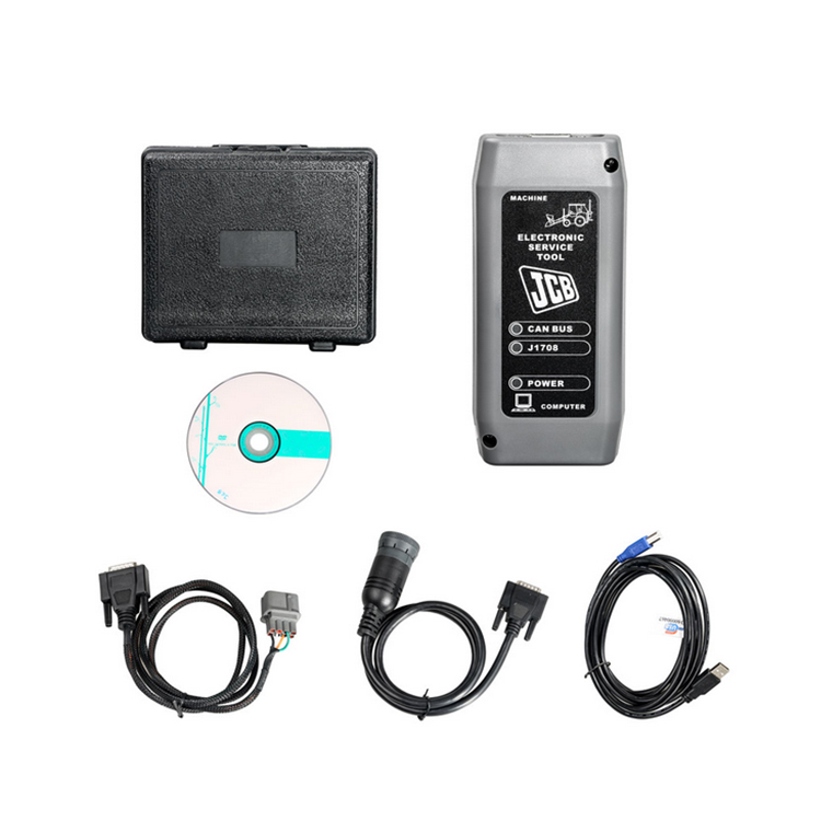
JCB Diagnostic Kit (DLA) is a multifunctional dealer scanner that reads diagnostic trouble codes, ranking them according to the degree of need for service on JCB equipment.
Main functional features:
reads fault codes and ranks them in order of importance.
calibrates, parameters and programs ECM units.
carries out a reset of service intervals.
Compatible with Jcb Service Master 2 software.
works with CAN protocol in OBD II system.
supplied with instructions for operation, repair and diagnostics of JCB equipment and engines Isuzu, Deutz, Cummins.
JCB Diagnostic Kit (DLA) Applicability
JCB agricultural machinery
Fastrac tractors (2000-3000, 3000 2 Series, 3000 Series 3, 7000-Series, 8250-Series 1, 8250 3 Series, 8000-Series 3).
Telescopic handlers (2007 -, 2007 +).
Wheeled backhoe loaders (Large, Large 2012+, Compact).
JC construction machinery
Backhoe loaders, tracked excavators (JS / JZ, JZ70).
Wheeled excavators, compact excavators (Mini / Midi) (801-8065, 8080-8085).
Telescopic handlers (2007 -, 2007 +).
Skidsteer loaders (Robot and others).
Telescopic handlers Teletrucks.
Wheeled backhoe loaders (Large, Large 2012+, Compact).
Frontal loaders.
Vibrating rollers.
Rough terrain forklifts.
JCB engines
JCB Dieselmax (MPS, OEM Base, G Drive).
JCB Ecomax (MPS, OEM Base, G Drive).
Equipment
JCB Diagnostic Kit (DLA) scanner.
USB cable.
DB9 cable.
9-pin adapter for German equipment.
8-pin cable.
JCB ServiceMaster 2 v10.3.1 software.
JCB Compact Service Manuals v50 [2011] (S1, S2, S3, S4, S5).
|
Tracked & Wheeled Excavators |
Extracted fromVersion 145 |
No of Error Codes in list 978 |
|
J1939 |
In Use? |
Reviewed/ |
Diagnostic Trouble |
Machine Reaction |
Extended Fault Text (Datalogger/Diagnostic Tools) |
|
0x00 |
Y |
55 |
P0001 |
Torque Reduction |
IMV driver fault is detected |
|
0x00 |
Y |
55 |
P0002 |
Torque Reduction |
Rail Pressure Negative Control Error During ‘IMV-Only’ control. PID controller not able to stabilise the |
|
0x00 |
Y |
55 |
P0002 |
Torque Reduction |
Rail pressure control error (pressure error too high). |
|
0x00 |
Y |
55 |
P0002 |
Delayed Engine Stop |
Rail Pressure Positive Control Error During ‘IMV-Only’ control. PID controller not able to stabilise the |
|
0x00 |
Y |
55 |
P0002 |
Torque Reduction |
Rail pressure control error (pressure error too low). |
|
0x00 |
Y |
55 |
P0003 |
Rail pressure control feedback low error |
|
|
0x00 |
Y |
55 |
P0003 |
Torque Reduction |
IMV driver fault is detected |
|
0x00 |
Y |
55 |
P0004 |
Torque Reduction |
IMV driver fault is detected |
|
0x00 |
Y |
55 |
P0004 |
Torque Reduction |
Rail pressure control feedback high error |
|
0x00 |
Y |
124 |
P0016 |
Cam Sensor Phase Shift |
|
|
0x00 |
Y |
124 |
P0045 |
VNT Control Fault |
|
|
0x00 |
Y |
124 |
P0045 |
Turbo EVRV Fault |
|
|
0x3D |
Y |
114 |
P0070-81 |
CAN bus message error from engine ECU |
|
|
0x3D |
Y |
114 |
P0070-87 |
CAN bus message error from engine ECU |
|
|
0x3D |
Y |
114 |
P0071-87 |
CAN bus message error for environment temperature from engine ECU |
|
|
0x00 |
Y |
55 |
P007A |
Torque Reduction |
TMAP (Intake Manifold 1 temp) Temperature Element sensor fault (ADC) |
|
0x00 |
Y |
55 |
P007C |
Torque Reduction |
TMAP (Intake Manifold 1 temp) Temperature Element sensor low fault |
|
0x00 |
Y |
55 |
P007D |
Torque Reduction |
TMAP (Intake Manifold 1 temp) Temperature Element sensor high fault |
|
0x00 |
Y |
55 |
P007E |
Torque Reduction |
TMAP (Intake Manifold 1 temp) Temperature Element sensor noise fault |
|
0x00 |
Y |
114 |
P0087 |
Torque Reduction |
Rail Pressure Control Error Positive |
|
0x00 |
Y |
55 |
P0087 |
Rail Pressure build low fault |
|
|
0x00 |
Y |
114 |
P0087 |
Rail Pressure build normal fault |
|
|
0x00 |
Y |
114 |
P0087 |
Torque Reduction_Delayed Engine Stop |
RPC Variable Limit Capacity (VLC) Torque reduction clamped |
|
0x00 |
Y |
124 |
P0087 |
Torque Reduction_Delayed Engine Stop |
Pressure Limiter Open |
|
0x00 |
Y |
114 |
P0087 |
Torque Reduction |
RPC Variable Limit Capacity (VLC) Torque reduction above its threshold |
|
0x00 |
Y |
114 |
P0088 |
Torque Reduction |
Rail pressure control error during HPV control (over max calibrated system pressure) |
|
0x00 |
Y |
114 |
P0088 |
Torque Reduction |
Rail pressure control error during IMV control (over max calibrated system pressure) |
|
0x00 |
Y |
55 |
P0088 |
Torque Reduction |
Rail pressure control undefined error (over max calibrated system pressure) |
|
0x00 |
Y |
114 |
P0088 |
Rail Pressure Control Error Negative |
|
|
0x00 |
Y |
124 |
P0088 |
Torque Reduction |
C/Rail pressure exceeds hi upper limit3 |
|
0x00 |
Y |
114 |
P0088 |
Rail Pressure overpressure timeout |
|
|
0x00 |
Y |
124 |
P0088 |
Torque Reduction |
Common Rail Pressure Rise㸦 1st Stage㸧 |
|
0x00 |
Y |
114 |
P0089 |
Rail Pressure control error |
|
|
0x00 |
Y |
114 |
P0089 |
Rail Pressure Negative Control Error During ‘HPV-Only’ control. PID controller not able to stabilise the |
|
0x00 |
Y |
114 |
P0089 |
Rail Pressure Positive Control Error During ‘HPV-Only’ control. PID controller not able to stabilise the |
|
|
0x00 |
Y |
55 |
P0089 |
Rail Pressure Negative Control Error During ‘IC & HMV’ control. PID controller not able to stabilise the |
|
|
0x00 |
Y |
114 |
P0089 |
Rail Pressure Positive Control Error During ‘IC & HMV’ control. PID controller not able to stabilise the |
|
|
0x00 |
Y |
114 |
P0089 |
Torque Reduction |
Rail Pressure Negative Control Error During ‘RVD-Only’ control. PID controller not able to stabilise the |
|
0x00 |
Y |
114 |
P0089 |
Delayed Engine Stop |
Rail Pressure Positive Control Error During ‘RVD-Only’ control. PID controller not able to stabilise the |
|
0x00 |
Y |
114 |
P0089 |
Torque Reduction |
Check that HPV is not stuck during IMV regulation. |
|
0x00 |
Y |
114 |
P0089 |
Torque Reduction |
HPV open loop slope fault detected |
|
0x00 |
Y |
124 |
P0089 |
Common Rail Pressure Fault (Excess Feed) |
|
|
0x00 |
Y |
55 |
P0090 |
Torque Reduction |
HPV driver in ECU fault detected |
|
0x00 |
Y |
55 |
P0091 |
Torque Reduction |
Check HPV regulation control trim low |
|
0x00 |
Y |
114 |
P0091 |
Torque Reduction |
Check HPV hardware current control trim low |
|
0x00 |
Y |
114 |
P0091 |
Torque Reduction |
HPV current feedback low fault detected |
|
0x00 |
Y |
124 |
P0091 |
Torque Reduction |
SCV Low Voltage Fault |
|
0x00 |
Y |
114 |
P0091 |
Torque Reduction |
HPV driver in ECU fault detected |
|
0x00 |
Y |
55 |
P0092 |
Torque Reduction |
Check HPV regulation control trim high. |
|
0x00 |
Y |
124 |
P0092 |
Torque Reduction_Delayed Engine Stop |
SCV High Voltage Fault |
|
0x00 |
Y |
114 |
P0092 |
Torque Reduction |
Check HPV hardware current control trim high |
|
0x00 |
Y |
114 |
P0092 |
Torque Reduction_Delayed Engine Stop |
HPV current feedback high fault detected |
|
0x00 |
Y |
114 |
P0092 |
Torque Reduction_Delayed Engine Stop |
HPV driver in ECU fault detected |
|
0x00 |
Y |
124 |
P0093 |
Common Rail Pressure Fall (No Feed) |
|
|
0x00 |
Y |
124 |
P0093 |
Common Rail Pressure Fault (Lack of Feed 2) |
|
|
0x00 |
Y |
55 |
P0095 |
Torque Reduction |
Intake manifold temperature (M2) signal sensor ADC fault (Intake Manifold 2 temp) |
|
0x00 |
Y |
55 |
P0096 |
Torque Reduction |
Intake manifold temperature sensor (M2) signal noise fault (Intake Manifold 2 temp) |
|
0x00 |
Y |
55 |
P0096 |
Torque Reduction |
Intake manifold temperature sensor (M2) signal plausibility fault (Intake Manifold 2 temp) |
|
0x00 |
Y |
55 |
P0097 |
Torque Reduction |
Intake manifold temperature sensor (M2) signal low fault (Intake Manifold 2 temp) |
|
0x00 |
Y |
55 |
P0098 |
Torque Reduction |
Intake manifold temperature sensor (M2) signal high signal fault (Intake Manifold 2 temp) |
|
0x3D |
Y |
114 |
P00B7-87 |
T4F Inducement |
CAN bus message error for coolant sensor from engine ECU |
|
0x00 |
Y |
55 |
P0100 |
Torque Reduction |
AMF High Side Driver fault Short Circuit To Ground (SC2G) |
|
0x00 |
Y |
114 |
P0100 |
Torque Reduction |
AMF fault (global). Set if plau, grad or electrical flt is present |
|
0x00 |
Y |
114 |
P0100 |
Torque Reduction |
AMF High Side Driver fault (Global |
|
0x00 |
Y |
114 |
P0100 |
Torque Reduction |
AMF High Side Driver fault Open Circuit (OC) Or Short Circuit to Battery (SC2VBAT) |
|
0x00 |
Y |
114 |
P0100 |
Torque Reduction |
AMF High Side Driver fault Short Circuit (SC) |
|
0x00 |
Y |
114 |
P0100 |
Torque Reduction |
AMF electrical sensor fault (ADC) |
|
0x00 |
Y |
124 |
P0101 |
MAF Sensor Fault |
|
|
0x00 |
Y |
124 |
P0102 |
Torque Reduction |
MAF Low Voltage Fault |
|
0x00 |
Y |
55 |
P0102 |
Torque Reduction |
AMF electrical sensor low fault |
|
0x00 |
Y |
124 |
P0103 |
Torque Reduction |
MAF High Voltage Fault |
|
0x00 |
Y |
55 |
P0103 |
Torque Reduction |
AMF electrical sensor high fault |
|
0x00 |
Y |
55 |
P0105 |
Torque Reduction |
Intake Manifold Absolute Pressure (MAP) sensor global fault |
|
0x00 |
Y |
55 |
P0106 |
Torque Reduction |
Intake Manifold Absolute Pressure (MAP) sensor signal drift low fault |
|
0x00 |
Y |
55 |
P0106 |
Torque Reduction |
Intake Manifold Absolute Pressure (MAP) sensor signal drift high fault |
|
0x00 |
Y |
55 |
P0106 |
Torque Reduction |
Intake Manifold Absolute Pressure (MAP) sensor signal plausibility fault |
|
0x00 |
Y |
55 |
P0106 |
Torque Reduction |
Intake Manifold Absolute Pressure (MAP) sensor signal plausibility high fault |
|
0x00 |
Y |
55 |
P0106 |
Torque Reduction |
Intake Manifold Absolute Pressure (MAP) sensor signal plausibility low fault |
|
0x00 |
Y |
124 |
P0107 |
Boost Pressure Sensor Fault 㸦 Low Voltage Fault |
|
|
0x00 |
Y |
124 |
P0108 |
Boost Pressure Sensor Fault 㸦 High Voltage Fault㸧 |
|
|
0x00 |
Y |
55 |
P0110 |
Torque Reduction |
Inlet Air Temperature (IAT) sensor signal ADC fault detected |
|
0x00 |
Y |
124 |
P0112 |
Torque Reduction |
Inlet Air Temperature (IAT) sensor signal low fault detected |
|
0x00 |
Y |
124 |
P0113 |
Torque Reduction |
Inlet Air Temperature (IAT) sensor signal high fault detected |
|
0x00 |
Y |
55 |
P0115 |
Torque Reduction |
Coolant sensor signal fault |
|
0x00 |
Y |
55 |
P0116 |
Coolant sensor fault (plausibility) |
|
|
0x00 |
Y |
124 |
P0116 |
Torque Reduction |
Coolant temperature sensor performance invalid |
|
0x00 |
Y |
55 |
P0117 |
Coolant sensor signal low fault |
|
|
0x00 |
Y |
124 |
P0117 |
Coolant temperature sensor signal too low |
|
|
0x00 |
Y |
124 |
P0118 |
Coolant sensor signal high fault |
|
|
0x00 |
Y |
124 |
P0122 |
Intake Throttle Position Low Voltage Fault |
|
|
0x00 |
Y |
124 |
P0123 |
Intake Throttle Position High Voltage Fault |
|
|
0x3D |
Y |
114 |
P0129-87 |
Erroneous signal for Barometric Pressure. |
|
|
0x3D |
Y |
114 |
P0129-87 |
CAN bus message error for environment pressure from engine ECU |
|
|
0x00 |
Y |
55 |
P0133 |
Wide Range Air Fuel control (WRAF) fault: Response |
|
|
0x00 |
Y |
55 |
P0180 |
Torque Reduction |
Fuel temperature ADC fault |
|
J1939 |
In Use? |
Added |
Diagnostic Trouble |
Machine Reaction |
Extended Fault Text (Datalogger/Diagnostic Tools) |
|
0x00 |
Y |
124 |
P0181 |
Torque Reduction |
Fuel Temperature Sensor Fault |
|
0x00 |
Y |
55 |
P0181 |
Torque Reduction |
Fuel temperature sensor gradient fault |
|
0x3D |
Y |
114 |
P0181-87 |
CAN bus message error for fuel temperature from engine ECU |
|
|
0x00 |
Y |
124 |
P0182 |
Torque Reduction |
Fuel temperature sensor low fault |
|
0x00 |
Y |
124 |
P0183 |
Torque Reduction |
Fuel temperature sensor high fault |
|
0x00 |
Y |
55 |
P0190 |
Torque Reduction_Limp Home (Idle Only) |
Rail Pressure Sensor signal grad fault |
|
0x00 |
Y |
55 |
P0191 |
Torque Reduction_Limp Home (Idle Only) |
Rail Pressure Sensor fault. Above maximum threshold (out of range at key-on) |
|
0x00 |
Y |
55 |
P0191 |
Torque Reduction_Limp Home (Idle Only) |
Rail Pressure Sensor fault. Below minimum threshold (out of range at key-on) |
|
0x00 |
Y |
55 |
P0191 |
Torque Reduction_Limp Home (Idle Only) |
Rail Pressure Sensor fault. Exceeds threshold (out of range at key-on) |
|
0x00 |
Y |
124 |
P0192 |
Torque Reduction_Limp Home (Idle Only) |
Rail Pressure Sensor signal low fault |
|
0x00 |
Y |
124 |
P0193 |
Torque Reduction_Limp Home (Idle Only) |
Rail Pressure Sensor signal high fault |
|
0x00 |
Y |
55 |
P0194 |
Torque Reduction_Limp Home (Idle Only)_Delayed |
Rail Pressure Sensor signal drop fault |
|
0x00 |
Y |
55 |
P0195 |
Torque Reduction |
Oil temperature sensor signal global fault |
|
0x00 |
Y |
114 |
P0195 |
Torque Reduction |
Oil temperature sensor signal external voltage (V-Ref) fault |
|
0x00 |
Y |
55 |
P0196 |
Torque Reduction |
Oil temperature sensor signal plausability fault |
|
0x00 |
Y |
55 |
P0196 |
Torque Reduction |
Oil temperature sensor signal gradient fault |
|
0x3D |
Y |
114 |
P0196-87 |
CAN bus message error for oil temperature from engine ECU |
|
|
0x00 |
Y |
55 |
P0197 |
Torque Reduction |
Oil temperature sensor signal low fault |
|
0x00 |
Y |
55 |
P0198 |
Torque Reduction |
Oil temperature sensor signal high fault |
|
0x00 |
Y |
55 |
P0201 |
Injector 2 Open Circuit fault (OC) |
|
|
0x00 |
Y |
55 |
P0201 |
Injector in Cylinder 1 Short Circuit HSD to LSD |
|
|
0x00 |
Y |
124 |
P0201 |
Injector in Cylinder 1 Open Circuit fault (OC) |
|
|
0x00 |
Y |
124 |
P0202 |
Injector 1 Open Circuit fault (OC) |
|
|
0x00 |
Y |
55 |
P0202 |
Injector in Cylinder 2 Short Circuit HSD to LSD |
|
|
0x00 |
Y |
88 |
P0202 |
Injector in Cylinder 2 Open Circuit fault (OC) |
|
|
0x00 |
Y |
124 |
P0203 |
Injector 3 Open Circuit fault (OC) |
|
|
0x00 |
Y |
55 |
P0203 |
Injector in Cylinder 3 Short Circuit HSD to LSD |
|
|
0x00 |
Y |
88 |
P0203 |
Injector in Cylinder 3 Open Circuit fault (OC) |
|
|
0x00 |
Y |
124 |
P0204 |
Injector 0 Open Circuit fault (OC) |
|
|
0x00 |
Y |
55 |
P0204 |
Injector in Cylinder 4 Short Circuit HSD to LSD |
|
|
0x00 |
Y |
88 |
P0204 |
Injector in Cylinder 4 Open Circuit fault (OC) |
|
|
0x00 |
Y |
124 |
P0205 |
Injector in Cylinder 5 Open Circuit fault (OC) |
|
|
0x00 |
Y |
88 |
P0205 |
Injector in Cylinder 5 Short Circuit HSD to LSD |
|
|
0x00 |
Y |
124 |
P0206 |
Injector in Cylinder 6 Open Circuit fault (OC) |
|
|
0x00 |
Y |
88 |
P0206 |
Injector in Cylinder 6 Short Circuit HSD to LSD |
|
|
0x00 |
Y |
124 |
P0217 |
Torque Reduction |
Coolant temperature exceeds upper limit |
|
0x00 |
Y |
124 |
P0219 |
Torque Reduction |
Engine overspeed condition |
|
0x00 |
Y |
124 |
P0234 |
Torque Reduction |
Turbo Over Boost |
|
0x00 |
Y |
55 |
P0235 |
Torque Reduction |
Boosted air pressure sensor fault: ADC |
|
0x00 |
Y |
55 |
P0237 |
Torque Reduction |
Boosted air pressure sensor low fault |
|
0x00 |
Y |
55 |
P0238 |
Torque Reduction |
Boosted air pressure sensor high fault |
|
0x00 |
Y |
55 |
P0252 |
Torque Reduction |
Rail pressure control error (IMV current trim drift). |
|
0x00 |
Y |
114 |
P0252 |
Torque Reduction |
Rail pressure control error (IMV current trim drift). |
|
0x00 |
Y |
114 |
P0252 |
Torque Reduction |
Rail pressure control error (IMV current trim drift). |
|
0x00 |
Y |
114 |
P0252 |
Torque Reduction |
Rail pressure control error (IMV current trim drift). |
|
0x00 |
Y |
114 |
P0252 |
Torque Reduction |
Rail pressure control error (IMV current trim drift). |
|
0x00 |
Y |
55 |
P0253 |
Torque Reduction_Delayed Engine Stop |
Rail pressure control by the IMV. Occurs at high fuel delivery for low (negative) current trim |
|
0x00 |
Y |
55 |
P0254 |
Torque Reduction_Delayed Engine Stop |
Rail pressure control fault by the IMV. Occurs at high fuel delivery for high (positive) current trim |
|
0x00 |
Y |
55 |
P0261 |
Torque Reduction |
Injector and wiring harness resistance too high/low (inj 2) |
|
0x00 |
Y |
55 |
P0261 |
Torque Reduction |
Injector and wiring harness resistance too high/low (inj 2) |
|
0x00 |
Y |
55 |
P0262 |
Torque Reduction |
Injector and wiring harness resistance drop (Inj 2) |
|
0x00 |
Y |
55 |
P0262 |
Torque Reduction |
Injector and wiring harness resistance drop (Inj 2) |
|
0x00 |
Y |
55 |
P0263 |
Torque Reduction |
Cylinder balancing fault injector 2 stuck closed |
|
0x00 |
Y |
55 |
P0264 |
Torque Reduction |
Injector and wiring harness resistance too high/low (inj 1) |
|
0x00 |
Y |
55 |
P0264 |
Torque Reduction |
Injector and wiring harness resistance too high/low (inj 1) |
|
0x00 |
Y |
55 |
P0265 |
Torque Reduction |
Injector and wiring harness resistance drop (Inj 1) |
|
0x00 |
Y |
55 |
P0265 |
Torque Reduction |
Injector and wiring harness resistance drop (Inj 1) |
|
0x00 |
Y |
55 |
P0266 |
Torque Reduction |
Cylinder balancing fault injector 1 stuck closed |
|
0x00 |
Y |
55 |
P0267 |
Torque Reduction |
Injector and wiring harness resistance too high/low (inj 3) |
|
0x00 |
Y |
55 |
P0267 |
Torque Reduction |
Injector and wiring harness resistance too high/low (inj 3) |
|
0x00 |
Y |
55 |
P0268 |
Torque Reduction |
Injector and wiring harness resistance drop (Inj 3) |
|
0x00 |
Y |
55 |
P0268 |
Torque Reduction |
Injector and wiring harness resistance drop (Inj 3) |
|
0x00 |
Y |
55 |
P0269 |
Torque Reduction |
Cylinder balancing fault injector 3 stuck closed |
|
0x00 |
Y |
55 |
P0270 |
Torque Reduction |
Injector drift fault detection on Injector 2. Fault which is set when the Injector 2 MDP trim exceeds the |
|
0x00 |
Y |
55 |
P0270 |
Torque Reduction |
Injector drift fault detection on Injector 2. Fault which is set when Injector 2 MDP trim exceeds the |
|
0x00 |
Y |
55 |
P0271 |
Torque Reduction |
Injector and wiring harness resistance drop (Inj 0) |
|
0x00 |
Y |
55 |
P0271 |
Torque Reduction |
Injector and wiring harness resistance drop (Inj 0) |
|
0x00 |
Y |
55 |
P0272 |
Torque Reduction |
Cylinder balancing fault injector 0 stuck closed |
|
0x00 |
Y |
88 |
P0273 |
Injector and wiring harness resistance too high/low (inj 1) |
|
|
0x00 |
Y |
88 |
P0273 |
Injector and wiring harness resistance too high/low (inj 1) |
|
|
0x00 |
Y |
88 |
P0274 |
Injector and wiring harness resistance drop (Inj 1) |
|
|
0x00 |
Y |
88 |
P0274 |
Injector and wiring harness resistance drop (Inj 1) |
|
|
0x00 |
Y |
88 |
P0275 |
Cylinder balancing fault injector 1 stuck closed |
|
|
0x00 |
Y |
88 |
P0276 |
Injector and wiring harness resistance too high/low (inj 3) |
|
|
0x00 |
Y |
88 |
P0276 |
Injector and wiring harness resistance too high/low (inj 3) |
|
|
0x00 |
Y |
88 |
P0277 |
Injector and wiring harness resistance drop (Inj 3) |
|
|
0x00 |
Y |
88 |
P0277 |
Injector and wiring harness resistance drop (Inj 3) |
|
|
0x00 |
Y |
88 |
P0278 |
Cylinder balancing fault injector 3 stuck closed |
|
|
0x00 |
Y |
124 |
P0299 |
Torque Reduction |
Turbo Low Boost |
|
0x00 |
Y |
55 |
P029A |
Injector drift fault detection on Injector 3. Fault which is set when the Injector 3 MDP trim exceeds the |
|
|
0x00 |
Y |
55 |
P029A |
Injector drift fault detection on Injector 2. Fault which is set when the Injector 2 MDP trim exceeds the |
|
|
0x00 |
Y |
55 |
P029A |
Injector drift fault detection on Injector 2. Fault which is set when Injector 2 MDP trim exceeds the |
|
|
0x00 |
Y |
55 |
P029B |
Fault which is set when the Injector 3 absolute MDP value is below a calibrated threshold |
|
|
0x00 |
Y |
55 |
P029B |
Injector drift fault detection on Injector 2. Fault which is set when Injector 2 MDP trim exceeds the |
|
|
0x00 |
Y |
55 |
P029B |
Injector drift fault detection on Injector 2. Fault which is set when Injector 2 MDP trim exceeds the |
|
|
0x00 |
Y |
55 |
P029B |
Injector drift fault detection on Injector 2. Fault which is set when Injector 2 MDP trim exceeds the |
|
J1939 |
In Use? |
Added |
Diagnostic Trouble |
Machine Reaction |
Extended Fault Text (Datalogger/Diagnostic Tools) |
|
0x00 |
Y |
55 |
P029E |
Injector drift fault detection on Injector 1. Fault which is set when the Injector 1 MDP trim exceeds the |
|
|
0x00 |
Y |
55 |
P029E |
Injector drift fault detection on Injector 1. Fault which is set when the Injector 1 MDP trim exceeds the |
|
|
0x00 |
Y |
55 |
P029E |
Injector drift fault detection on Injector 1. Fault which is set when Injector 1 MDP trim exceeds the |
|
|
0x00 |
Y |
55 |
P029F |
Fault which is set when the Injector 2 absolute MDP value is below a calibrated threshold |
|
|
0x00 |
Y |
55 |
P029F |
Injector drift fault detection on Injector 1. Fault which is set when Injector 1 MDP trim exceeds the |
|
|
0x00 |
Y |
55 |
P029F |
Injector drift fault detection on Injector 1. Fault which is set when Injector 1 MDP trim exceeds the |
|
|
0x00 |
Y |
55 |
P029F |
Injector drift fault detection on Injector 1. Fault which is set when Injector 1 MDP trim exceeds the |
|
|
0x00 |
Y |
55 |
P02A2 |
Injector drift fault detection on Injector 2. Fault which is set when the Injector 2 MDP trim exceeds the |
|
|
0x00 |
Y |
55 |
P02A2 |
Injector drift fault detection on Injector 2. Fault which is set when the Injector 2 MDP trim exceeds the |
|
|
0x00 |
Y |
55 |
P02A2 |
Injector drift fault detection on Injector 2. Fault which is set when Injector 2 MDP trim exceeds the |
|
|
0x00 |
Y |
55 |
P02A3 |
Fault which is set when the Injector 4 absolute MDP value is below a calibrated threshold |
|
|
0x00 |
Y |
55 |
P02A3 |
Injector drift fault detection on Injector 3. Fault which is set when Injector 3 MDP trim exceeds the |
|
|
0x00 |
Y |
55 |
P02A3 |
Injector drift fault detection on Injector 3. Fault which is set when Injector 3 MDP trim exceeds the |
|
|
0x00 |
Y |
55 |
P02A3 |
Injector drift fault detection on Injector 3. Fault which is set when Injector 3 MDP trim exceeds the |
|
|
0x00 |
Y |
55 |
P02A6 |
Injector drift fault detection on Injector 0. Fault which is set when the Injector 0 MDP trim exceeds the |
|
|
0x00 |
Y |
55 |
P02A6 |
Injector drift fault detection on Injector 0. Fault which is set when the Injector 0 MDP trim exceeds the |
|
|
0x00 |
Y |
55 |
P02A6 |
Injector drift fault detection on Injector 0. Fault which is set when Injector 0 MDP trim exceeds the |
|
|
0x00 |
Y |
55 |
P02A7 |
Fault which is set when the Injector 1 absolute MDP value is below a calibrated threshold |
|
|
0x00 |
Y |
55 |
P02A7 |
Injector drift fault detection on Injector 0. Fault which is set when Injector 0 MDP trim exceeds the |
|
|
0x00 |
Y |
55 |
P02A7 |
Injector drift fault detection on Injector 0. Fault which is set when Injector 0 MDP trim exceeds the |
|
|
0x00 |
Y |
55 |
P02A7 |
Injector drift fault detection on Injector 0. Fault which is set when Injector 0 MDP trim exceeds the |
|
|
0x00 |
Y |
88 |
P02AA |
Injector drift fault detection on Injector 1. Fault which is set when the Injector 1 MDP trim exceeds the |
|
|
0x00 |
Y |
88 |
P02AA |
Injector drift fault detection on Injector 1. Fault which is set when the Injector 1 MDP trim exceeds the |
|
|
0x00 |
Y |
88 |
P02AA |
Injector drift fault detection on Injector 1. Fault which is set when Injector 1 MDP trim exceeds the |
|
|
0x00 |
Y |
88 |
P02AB |
Fault which is set when the Injector 1 absolute MDP value is below a calibrated threshold |
|
|
0x00 |
Y |
88 |
P02AB |
Injector drift fault detection on Injector 1. Fault which is set when Injector 1 MDP trim exceeds the |
|
|
0x00 |
Y |
88 |
P02AB |
Injector drift fault detection on Injector 1. Fault which is set when Injector 1 MDP trim exceeds the |
|
|
0x00 |
Y |
88 |
P02AB |
Injector drift fault detection on Injector 1. Fault which is set when Injector 1 MDP trim exceeds the |
|
|
0x00 |
Y |
88 |
P02AE |
Injector drift fault detection on Injector 3. Fault which is set when the Injector 3 MDP trim exceeds the |
|
|
0x00 |
Y |
88 |
P02AE |
Injector drift fault detection on Injector 3. Fault which is set when the Injector 3 MDP trim exceeds the |
|
|
0x00 |
Y |
88 |
P02AE |
Injector drift fault detection on Injector 3. Fault which is set when Injector 3 MDP trim exceeds the |
|
|
0x00 |
Y |
88 |
P02AF |
Fault which is set when the Injector 3 absolute MDP value is below a calibrated threshold |
|
|
0x00 |
Y |
88 |
P02AF |
Injector drift fault detection on Injector 3. Fault which is set when Injector 3 MDP trim exceeds the |
|
|
0x00 |
Y |
88 |
P02AF |
Injector drift fault detection on Injector 3. Fault which is set when Injector 3 MDP trim exceeds the |
|
|
0x00 |
Y |
88 |
P02AF |
Injector drift fault detection on Injector 3. Fault which is set when Injector 3 MDP trim exceeds the |
|
|
0x3D |
Y |
114 |
P0321-87 |
CAN bus message error for engine speed from engine ECU |
|
|
0x00 |
Y |
55 |
P0325 |
Accelerometer fault (signal/noise ratio too low in idle) |
|
|
0x00 |
Y |
94 |
P0330 |
Knock Sensor 1 Circuit |
|
|
0x00 |
Y |
124 |
P0335 |
Crank Sensor Fault 㸦 No Signal㸧 |
|
|
0x00 |
Y |
55 |
P0335 |
Crankshaft Position Sensor «A» Circuit |
|
|
0x00 |
Y |
114 |
P0335 |
Crank signal overspeed fault |
|
|
0x00 |
Y |
124 |
P0336 |
Torque Reduction |
Crank Sensor Fault 㸦 Signal Fault㸧 |
|
0x00 |
Y |
55 |
P0340 |
Torque Reduction |
Cam signal last learnt value is outside of limits |
|
0x00 |
Y |
124 |
P0340 |
Torque Reduction |
G Sensor Fault (No Signal) |
|
0x00 |
Y |
55 |
P0341 |
Torque Reduction |
Cam signal drift higher than threshold |
|
0x00 |
Y |
124 |
P0341 |
Torque Reduction |
G Sensor Fault (Abnormal Signal㸧 |
|
0x00 |
Y |
55 |
P0341 |
Camshaft Position Sensor A Circuit Range / Performance |
|
|
0x00 |
Y |
55 |
P0341 |
Torque Reduction |
Cam signal lost (no Cam signal seen in 2 Crank rotations) |
|
0x00 |
Y |
55 |
P0341 |
Torque Reduction |
Cam signal fault (missing event within the expected window) |
|
0x00 |
Y |
55 |
P0341 |
Cam signal fault (overspeed detected) |
|
|
0x3D |
Y |
114 |
P0350-02 |
Error monitoring for system protection based on ignition switch input |
|
|
0x00 |
Y |
55 |
P0371 |
Torque Reduction |
Crank signal is too close to the previous one |
|
0x00 |
Y |
55 |
P0372 |
Torque Reduction |
Elapsed time between CPS events is too high |
|
0x00 |
Y |
55 |
P0374 |
Torque Reduction |
Crank signal lost (no CPS signal seen in 1 Cam rotation) |
|
0x00 |
Y |
124 |
P0380 |
Glow Plug/Heater Circuit «A» |
|
|
0x00 |
Y |
55 |
P0380 |
Glow Plug/Heater Circuit «A» |
|
|
0x00 |
Y |
124 |
P0381 |
Glow Plug Fault |
|
|
0x00 |
Y |
55 |
P0383 |
Glow Plug Control Module Control Circuit Low |
|
|
0x00 |
Y |
55 |
P0384 |
Glow Plug Control Module Control Circuit High |
|
|
0x00 |
Y |
55 |
P0400 |
Torque Reduction / T4F Inducement |
EGR flow reached its limit |
|
0x00 |
Y |
124 |
P0401 |
EGR Gas flow Fault |
|
|
0x00 |
Y |
124 |
P0404 |
EGR Valve Control Fault |
|
|
0x00 |
Y |
124 |
P0404 |
EGR Open Defective |
|
|
0x00 |
Y |
94 |
P0404 |
Exhaust Gas Recirculation «A» Control Circuit Range/Performance |
|
|
0x00 |
Y |
55 |
P0405 |
Exhaust Gas Recirculation Sensor «A» Circuit Low |
|
|
0x00 |
Y |
55 |
P0406 |
Exhaust Gas Recirculation Sensor «A» Circuit High |
|
|
0x00 |
Y |
124 |
P0409 |
EGR Position Sensor Fault 㸦 Brushless Specification㸧 |
|
|
0x00 |
Y |
124 |
P041C |
Manifold Temperature Sensor Fault 㸦 High Voltage |
|
|
0x00 |
Y |
124 |
P041D |
Manifold Temperature Sensor Fault 㸦 Low Voltage Fault㸧 |
|
|
0x00 |
Y |
124 |
P0426 |
DPF Exhaust Temperature 1 High |
|
|
0x00 |
Y |
124 |
P0426 |
DPF Exhaust Temperature 1Low |
|
|
0x00 |
Y |
124 |
P0427 |
Exhaust Temperature Sensor 1Low Voltage Fault |
|
|
0x00 |
Y |
124 |
P0428 |
Exhaust Temperature Sensor 1High Voltage Fault |
|
|
0x00 |
Y |
124 |
P042B |
DPF Exhaust Temperature 2 High |
|
|
0x00 |
Y |
124 |
P042B |
DPF Exhaust Temperature 2 Low |
|
|
0x00 |
Y |
124 |
P042C |
Exhaust Temperature Sensor 2 Low Voltage Fault |
|
|
0x00 |
Y |
124 |
P042D |
Exhaust Temperature Sensor 2 High Voltage Fault |
|
|
0x00 |
Y |
94 |
P046D |
Exhaust Gas Recirculation Sensor «A» Circuit Intermittent/Erratic |
|
|
0x00 |
Y |
55 |
P0470 |
Torque Reduction |
Exhaust manifold pressure (P3) signal ADC fault |
|
0x00 |
Y |
55 |
P0472 |
Torque Reduction |
Exhaust manifold pressure (P3) signal low fault |
|
0x00 |
Y |
55 |
P0472 |
Torque Reduction |
Exhaust manifold pressure (P3) signal drifted low |
|
0x00 |
Y |
55 |
P0473 |
Torque Reduction |
Exhaust manifold pressure (P3) signal high fault |
|
0x00 |
Y |
55 |
P0473 |
Torque Reduction |
Exhaust manifold pressure (P3) signal drifted high |
|
0x00 |
Y |
124 |
P0512 |
Starter Switch Fault |
|
|
0x00 |
Y |
55 |
P0520 |
Low oil pressure Lamp/Gauge drive open circuit (OC) |
|
|
0x00 |
Y |
55 |
P0520 |
Low oil pressure Lamp/Gauge drive short circuit (SC) |
|
|
0x00 |
Y |
55 |
P0520 |
Low oil pressure Lamp/Gauge drive short circuit to ground (SC2GND) |
|
|
0x00 |
Y |
55 |
P0520 |
Low oil pressure Lamp/Gauge drive short circuit to battery voltage (SC2VBATT) |
|
|
0x00 |
Y |
55 |
P0521 |
Oil pressure sensor signal global fault |
|
|
0x00 |
Y |
124 |
P0522 |
None |
Engine Oil Pressure Sensor Fault (Low Voltage Fault) |
|
0x00 |
Y |
88 |
P0522 |
Torque Reduction |
Oil Pressure Signal Out of Range High |
|
0x00 |
Y |
55 |
P0522 |
High Oil Pressure During Engine Running |
|
|
0x00 |
Y |
55 |
P0523 |
Low Oil Pressure During Engine Running |
|
|
0x27 |
Y |
91 |
P0523 |
Low Oil Pressure During Engine Running |
|
|
0x00 |
Y |
124 |
P0523 |
Engine Oil Pressure Sensor Fault (High Voltage Fault) |
|
|
0x00 |
Y |
88 |
P0523 |
Torque Reduction |
Oil Pressure Signal Out of Range Low |
|
0x00 |
Y |
88 |
P0523 |
Low Oil Pressure During Engine Running |
|
|
0x00 |
Y |
55 |
P0544 |
Torque Reduction |
Turbo in temperature fault |
|
0x00 |
Y |
55 |
P0545 |
Torque Reduction |
Turbo in temperature count low fault |
|
0x00 |
Y |
55 |
P0546 |
Torque Reduction |
Turbo in temperature count high fault |
|
0x00 |
Y |
124 |
P0560 |
12V Power Supply Voltage Fault |
|
|
0x00 |
Y |
55 |
P0562 |
Torque Reduction |
Battery voltage monitoring signal low fault |
|
0x00 |
Y |
124 |
P0562 |
Torque Reduction |
System Power Supply Low Voltage Fault |
|
0x3D |
Y |
114 |
P0562-16 |
Low battery voltage |
|
|
0x3D |
Y |
114 |
P0562-02 |
Fault due to low or high battery voltage supply to DCU |
|
|
0x00 |
Y |
55 |
P0563 |
Torque Reduction |
Battery voltage monitoring signal high fault |
|
0x00 |
Y |
124 |
P0563 |
Torque Reduction |
System Power Supply High Voltage Fault |
|
0x3D |
Y |
114 |
P0563-17 |
High battery voltage |
|
|
0x00 |
Y |
124 |
P0601 |
Torque Reduction |
ROM Fault |
|
0x00 |
Y |
124 |
P0602 |
Limp Home (Idle Only) |
QR Code Error |
|
0x00 |
Y |
114 |
P0602 |
Limp Home (Idle Only) |
C2I data not programmed |
|
0x00 |
Y |
55 |
P0602 |
Limp Home (Idle Only) |
C2I data not programmed |
|
0x00 |
Y |
114 |
P0602 |
Limp Home (Idle Only) |
C2I data not programmed |
|
0x00 |
Y |
114 |
P0602 |
Limp Home (Idle Only) |
C2I data not programmed |
|
0x00 |
Y |
114 |
P0602 |
Limp Home (Idle Only)_Engine Stop |
RAM corruption affecting Injector C2I data |
|
0x00 |
Y |
114 |
P0602 |
Functional Safety Fault |
|
|
0x00 |
Y |
55 |
P0602 |
Limp Home (Idle Only) |
Functional Safety Fault |
|
0x00 |
Y |
55 |
P0603 |
Engine Stop |
ECU memory integrity fault (data / cal integrity) |
|
0x00 |
Y |
55 |
P0604 |
Engine Stop |
ECU memory integrity fault (RAM integrity) |
|
0x00 |
Y |
124 |
P0604 |
Engine Stop |
RAM Fault |
|
0x00 |
Y |
55 |
P0605 |
Engine Stop |
ECU memory integrity fault (code integrity) |
|
0x00 |
Y |
55 |
P0606 |
Engine Stop |
Functional Safety Fault |
|
0x00 |
Y |
55 |
P0606 |
Engine Stop |
Functional Safety Fault |
|
0x00 |
Y |
55 |
P0606 |
Engine Stop |
Functional Safety Fault |
|
0x00 |
Y |
55 |
P0606 |
Engine Stop |
Functional Safety Fault |
|
0x00 |
Y |
55 |
P0606 |
Engine Stop |
Functional Safety Fault |
|
0x00 |
Y |
124 |
P0606 |
Engine Stop |
CPU Fault |
|
0x00 |
Y |
124 |
P0606 |
Engine Stop |
CPU Monitoring IC Fault |
|
0x00 |
Y |
55 |
P0606 |
Engine Stop |
Functional Safety Fault |
|
0x3D |
Y |
114 |
P0606-02 |
Peripheral monitoring error on DCU |
|
|
0x00 |
Y |
55 |
P0607 |
Engine Stop |
Functional Safety Fault |
|
0x00 |
Y |
55 |
P0607 |
Torque Reduction |
Throttle H-Bridge driver in ECU fault: Over temperature |
|
0x00 |
Y |
55 |
P060A |
Engine Stop |
Functional Safety Fault |
|
0x00 |
Y |
55 |
P060A |
Engine Stop |
Functional Safety Fault |
|
0x00 |
Y |
55 |
P060A |
Engine Stop |
Functional Safety Fault |
|
0x00 |
Y |
55 |
P060A |
Engine Stop |
Functional Safety Fault |
|
0x00 |
Y |
55 |
P060A |
Engine Stop |
Functional Safety Fault |
|
0x00 |
Y |
55 |
P060A |
Engine Stop |
Functional Safety Fault |
|
0x00 |
Y |
55 |
P060A |
Engine Stop |
Functional Safety Fault |
|
0x00 |
Y |
55 |
P060A |
Engine Stop |
Functional Safety Fault |
|
0x3D |
Y |
114 |
P060A-00 |
Monitoring error on DCU |
|
|
0x00 |
Y |
124 |
P060B |
A/D Conversion Fault |
|
|
0x00 |
Y |
55 |
P060B |
Limp Home (Idle Only)_Engine Stop |
ADC circuit fault (Global) |
|
0x00 |
Y |
55 |
P060B |
Torque Reduction |
HPV current feedback ADC fault detected |
|
0x00 |
Y |
55 |
P060B |
Internal Control Module A/D Processing Performance |
|
|
0x00 |
Y |
55 |
P060B |
Torque Reduction |
Functional Safety Fault |
|
SA (hex) |
In Use? |
Added |
Code |
Machine Reaction |
Extended Fault Text (Datalogger/Diagnostic Tools) |
|
0x00 |
Y |
55 |
P060B |
Torque Reduction |
Functional Safety Fault |
|
0x00 |
Y |
55 |
P060B |
Torque Reduction |
Functional Safety Fault |
|
0x00 |
Y |
55 |
P060C |
Engine Stop |
Functional Safety Fault |
|
0x00 |
Y |
55 |
P060C |
Engine Stop |
Functional Safety Fault |
|
0x00 |
Y |
55 |
P060C |
Engine Stop |
Functional Safety Fault |
|
0x00 |
Y |
55 |
P060C |
Engine Stop |
Functional Safety Fault |
|
0x00 |
Y |
55 |
P060C |
Engine Stop |
Functional Safety Fault |
|
0x00 |
Y |
55 |
P060C |
Engine Stop |
Functional Safety Fault |
|
0x00 |
Y |
55 |
P060C |
Engine Stop |
Functional Safety Fault |
|
0x00 |
Y |
55 |
P060C |
Engine Stop |
Functional Safety Fault |
|
0x00 |
Y |
55 |
P060C |
Engine Stop |
Functional Safety Fault |
|
0x3D |
Y |
114 |
P060C-00 |
DCU software reset performed |
|
|
0x3D |
Y |
114 |
P060C-41 |
T4F Inducement |
DCU software reset performed |
|
0x3D |
Y |
114 |
P060C-94 |
DCU software reset performed |
|
|
0x3D |
Y |
114 |
P060C-68 |
DCU software reset performed |
|
|
0x00 |
Y |
55 |
P060D |
Engine Stop |
Functional Safety Fault |
|
0x00 |
Y |
55 |
P060D |
Engine Stop |
Functional Safety Fault |
|
0x00 |
Y |
55 |
P060D |
Torque Reduction |
Functional Safety Fault |
|
0x00 |
Y |
55 |
P060D |
Torque Reduction |
Functional Safety Fault |
|
0x00 |
Y |
55 |
P060E |
Torque Reduction |
Functional Safety Fault |
|
0x00 |
Y |
55 |
P0612 |
Fuel Injector Control Module Relay Control |
|
|
0x00 |
Y |
55 |
P0612 |
Fuel Injector Control Module Relay Control |
|
|
0x00 |
Y |
55 |
P0612 |
Fuel Injector Control Module Relay Control |
|
|
0x00 |
Y |
55 |
P0612 |
Fuel Injector Control Module Relay Control |
|
|
0x00 |
Y |
124 |
P0615 |
Starter Relay Circuit |
|
|
0x00 |
Y |
55 |
P061A |
Functional Safety Fault |
|
|
0x00 |
Y |
55 |
P061B |
Torque Reduction |
Functional Safety Fault |
|
0x00 |
Y |
55 |
P061C |
Functional Safety Fault |
|
|
0x00 |
Y |
55 |
P061E |
Functional Safety Fault |
|
|
0x00 |
Y |
55 |
P061E |
Functional Safety Fault |
|
|
0x00 |
Y |
55 |
P0627 |
Torque Reduction |
Lift pump global fault |
|
0x00 |
Y |
55 |
P0628 |
Torque Reduction |
Lift pump global fault |
|
0x00 |
Y |
55 |
P0629 |
Torque Reduction |
Lift pump global fault |
|
0x00 |
Y |
55 |
P062B |
Torque Reduction |
Functional Safety Fault |
|
0x00 |
Y |
55 |
P062B |
Torque Reduction |
Functional Safety Fault |
|
0x00 |
Y |
55 |
P062B |
Torque Reduction |
Functional Safety Fault |
|
0x00 |
Y |
55 |
P062B |
Torque Reduction |
Functional Safety Fault |
|
0x00 |
Y |
55 |
P062B |
Torque Reduction |
Functional Safety Fault |
|
0x00 |
Y |
55 |
P062B |
Torque Reduction |
Functional Safety Fault |
|
0x00 |
Y |
55 |
P062B |
Torque Reduction |
Functional Safety Fault |
|
0x00 |
Y |
55 |
P062B |
Torque Reduction |
Functional Safety Fault |
|
0x00 |
Y |
55 |
P062B |
Torque Reduction |
Functional Safety Fault |
|
0x00 |
Y |
55 |
P062B |
Torque Reduction |
Functional Safety Fault |
|
0x00 |
Y |
55 |
P062B |
Torque Reduction |
Functional Safety Fault |
|
0x00 |
Y |
55 |
P062D |
Delayed Engine Stop |
Injector Bank 0 fault shorted to ground (SC2VBAT) |
|
0x00 |
Y |
55 |
P062D |
Delayed Engine Stop |
Injector Bank 0 fault shorted to ground (SC2GND) |
|
0x00 |
Y |
55 |
P062E |
Delayed Engine Stop |
Injector Bank 1 fault shorted to ground (SC2VBAT) |
|
0x00 |
Y |
55 |
P062E |
Delayed Engine Stop |
Injector Bank 1 fault shorted to ground (SC2GND) |
|
0x00 |
Y |
55 |
P062F |
Torque Reduction_Limp Home (Idle Only) |
ECU non volatile memory fault |
|
0x00 |
Y |
114 |
P062F |
Torque Reduction_Limp Home (Idle Only) |
ECU non volatile memory fault (C2I, MDP) |
|
0x00 |
Y |
114 |
P062F |
Torque Reduction_Limp Home (Idle Only) |
ECU non volatile memory fault (RP, PL, STE) |
|
0x00 |
Y |
114 |
P062F |
Torque Reduction_Limp Home (Idle Only) |
ECU non volatile memory fault (WDOG) |
|
0x00 |
Y |
114 |
P062F |
Torque Reduction_Limp Home (Idle Only) |
ECU non volatile memory fault (CAN, KW) |
|
0x00 |
Y |
114 |
P062F |
Torque Reduction_Limp Home (Idle Only) |
ECU non volatile memory fault (SMC) |
|
0x00 |
Y |
114 |
P062F |
Torque Reduction_Limp Home (Idle Only) |
ECU non volatile memory fault (ICV, Inj Cnt) |
|
0x00 |
Y |
114 |
P062F |
Torque Reduction_Limp Home (Idle Only) |
ECU non volatile memory fault (FM) |
|
0x00 |
Y |
114 |
P062F |
Torque Reduction_Limp Home (Idle Only) |
ECU non volatile memory fault (APP) |
|
0x00 |
Y |
55 |
P0630 |
VIN Not Programmed or Incompatible — ECM/PCM |
|
|
0x00 |
Y |
124 |
P0638 |
Intake Throttle Fault |
|
|
0x00 |
Y |
55 |
P0641 |
Torque Reduction_Limp Home (Idle Only)_Delayed |
ECU Internal 5V Supply 1 fault |
|
0x00 |
Y |
124 |
P0641 |
Torque Reduction_Limp Home (Idle Only)_Delayed |
5V Power Supply-1, Supply-6 Voltage Fault |
|
0x00 |
Y |
55 |
P0641 |
Torque Reduction_Limp Home (Idle Only)_Delayed |
ECU Internal 5V Supply 1 fault |
|
0x00 |
Y |
124 |
P0650 |
Check Engine Lamp Fault |
|
|
0x00 |
Y |
55 |
P0651 |
Torque Reduction_Limp Home (Idle Only)_Delayed |
ECU Internal 5V Supply 2 fault |
|
0x00 |
Y |
124 |
P0651 |
Torque Reduction_Limp Home (Idle Only)_Delayed |
5V Power Supply-2 Voltage Fault |
|
0x00 |
Y |
124 |
P0651 |
Torque Reduction_Limp Home (Idle Only)_Delayed |
5V Power Supply-5 Voltage Fault |
|
0x00 |
Y |
55 |
P0651 |
Torque Reduction_Limp Home (Idle Only)_Delayed |
ECU Internal 5V Supply 2 fault |
|
0x3D |
Y |
114 |
P0658-14 |
Short circuit to ground of actuator relay 1 |
|
|
0x3D |
Y |
114 |
P0659-12 |
Short circuit to battery of actuator relay 1 |
|
|
0x00 |
Y |
55 |
P0668 |
Torque Reduction |
ECU internal temperature sensor low fault |
|
0x00 |
Y |
55 |
P0669 |
Torque Reduction |
ECU internal temperature sensor high fault |
|
0x00 |
Y |
55 |
P0685 |
Main ECU relay stuck |
|
|
0x00 |
Y |
55 |
P0685 |
Main relay unexpected low state |
|
|
0x00 |
Y |
124 |
P0685 |
Main Relay System Fault (Open) |
|
|
0x00 |
Y |
124 |
P0687 |
Main Relay System Fault (Close) |
|
|
0x00 |
Y |
55 |
P0697 |
Sensor Reference Voltage «C» Circuit/Open |
|
|
0x00 |
Y |
124 |
P0697 |
5V Power Supply-3 Voltage Fault |
|
|
0x00 |
Y |
55 |
P0697 |
Torque Reduction_Limp Home (Idle Only)_Delayed |
ECU Internal 5V Supply 2 auxillary fault |
|
0x00 |
Y |
55 |
P0697 |
Torque Reduction_Limp Home (Idle Only)_Delayed |
ECU Internal 5V Supply 2 auxillary fault |
|
0X3D |
Y |
114 |
P06A7-00 |
T4F Inducement |
Sensor supply monitoring error through DCU |
|
0x17 |
Y |
55 |
P06B8 |
None |
Data logger memory full |
|
0x00 |
Y |
124 |
P1062 |
PCV 1 Feedback Fault |
|
|
0x00 |
Y |
124 |
P1063 |
PCV 2 Feedback Fault |
|
|
0x00 |
Y |
124 |
P1093 |
Common Rail Pressure Fault (Lack of Feed) |
|
|
0x00 |
Y |
124 |
P1093 |
Common Rail Pressure Fault (Lack of Feed 1) |
|
|
0x00 |
Y |
55 |
P1101 |
Rail Pressure Control Error Positive fault |
|
|
0x00 |
Y |
55 |
P1102 |
Rail Pressure Control Error Negative fault |
|
|
0x00 |
Y |
55 |
P1103 |
Rail Pressure Fault detected — not able to maintain pressure after a stop and start request |
|
|
0x00 |
Y |
55 |
P1104 |
Torque Reduction |
Fault which is set when no MDP updates occur on Injector 3 due to environmental conditions (as |
|
0x00 |
Y |
55 |
P1105 |
Torque Reduction |
Fault which is set when no MDP updates occur on Injector 3 due to a fault within the update strategy |
|
J1939 |
In Use? |
Reviewed/ |
Diagnostic Trouble |
Machine Reaction |
Extended Fault Text (Datalogger/Diagnostic Tools) |
|
0x00 |
Y |
55 |
P1106 |
Torque Reduction |
Fault which is set when no MDP updates occur on Injector 2 due to environmental conditions (as |
|
0x00 |
Y |
55 |
P1107 |
Torque Reduction |
Fault which is set when no MDP updates occur on Injector 2 due to a fault within the update strategy |
|
0x00 |
Y |
55 |
P1108 |
Torque Reduction |
Fault which is set when no MDP updates occur on Injector 4 due to environmental conditions (as |
|
0x00 |
Y |
55 |
P1109 |
Torque Reduction |
Fault which is set when no MDP updates occur on Injector 4 due to a fault within the update strategy |
|
0x00 |
Y |
55 |
P110A |
Torque Reduction |
Fault which is set when no MDP updates occur on Injector 1 due to environmental conditions (as |
|
0x00 |
Y |
55 |
P110B |
Torque Reduction |
Fault which is set when no MDP updates occur on Injector 1 due to a fault within the update strategy |
|
0x12 |
Y |
81 |
P110C |
Throttle Response may be slow |
Throttle Actuator Temperature Warning |
|
0x12 |
Y |
81 |
P110D |
Engine will only idle |
Throttle Actuator Hardware Fault |
|
0x12 |
Y |
81 |
P110E |
Engine my stay at existing speed or idle |
Throttle Actuator Obstruction Fault |
|
0x12 |
Y |
81 |
P110F |
Engine will only idle |
Throttle Actuator Calibration Fault |
|
0x00 |
Y |
124 |
P1112 |
Boost Temperature Sensor Fault (Low Voltage Fault) |
|
|
0x00 |
Y |
124 |
P1113 |
Boost Temperature Sensor Fault (High Voltage Fault) |
|
|
0x00 |
Y |
124 |
P1261 |
Charge Circuit Fault 㸦 Bank 1㸧 |
|
|
0x00 |
Y |
124 |
P1262 |
Charge Circuit Fault 㸦 Bank 2㸧 |
|
|
0x00 |
Y |
124 |
P1293 |
Fuel Filter Clogging Sensor Fault (Low Voltage Fault) |
|
|
0x00 |
Y |
124 |
P1294 |
Fuel Filter Clogging Sensor Fault (High Voltage Fault) |
|
|
0x3D |
Y |
114 |
P1400-00 |
Errorneous signal from override switch |
|
|
0x3D |
Y |
114 |
P1401-00 |
CAN bus message error from override switch |
|
|
0x3D |
Y |
114 |
P1402-00 |
CAN bus off error from override switch |
|
|
0x00 |
Y |
124 |
P1404 |
EGR Close Defective |
|
|
0x00 |
Y |
124 |
P1404 |
EGR Zero Position Fault |
|
|
0x00 |
Y |
124 |
P140A |
EGR 2 Valve Control Fault |
|
|
0x00 |
Y |
124 |
P140B |
EGR 2 Position Sensor Fault |
|
|
0x00 |
Y |
124 |
P140C |
EGR 2 Zero Position Fault |
|
|
0x00 |
Y |
124 |
P1455 |
DPF PM Over 2 |
|
|
0x00 |
Y |
124 |
P1471 |
DPF Regeneration Defective |
|
|
0x00 |
Y |
124 |
P1500 |
Torque Reduction_Limp Home (Idle Only) |
Starter Deterioration Warning |
|
0x00 |
Y |
55 |
P1509 |
CAN communication Error on TSC |
|
|
0x00 |
Y |
55 |
P1603 |
Functional Safety Fault |
|
|
0x00 |
Y |
55 |
P1604 |
Functional Safety Fault |
|
|
0x00 |
Y |
55 |
P1605 |
Functional Safety Fault |
|
|
0x00 |
Y |
55 |
P1606 |
Functional Safety Fault |
|
|
0x00 |
Y |
124 |
P1621 |
EEPROM Fault, HDEEPROM Fault |
|
|
0x00 |
Y |
124 |
P1655 |
5V Power Supply-4 Voltage Fault |
|
|
0x00 |
Y |
124 |
P1669 |
DPF Lamp Fault |
|
|
0x3D |
Y |
114 |
P2000-00 |
T4F Inducement |
Actual average conversion efficiency is below the threshold |
|
0x3D |
Y |
114 |
P2000-02 |
T4F Inducement |
Actual average conversion efficiency is below the threshold |
|
0x3D |
Y |
114 |
P2000-04 |
T4F Inducement |
Actual average conversion efficiency is below the threshold |
|
0x3D |
Y |
114 |
P2000-06 |
Actual average conversion efficiency is below the threshold |
|
|
0x3D |
Y |
114 |
P202A-13 |
Open load error of DEF tank heater actuator powerstage |
|
|
0x3D |
Y |
114 |
P202B-14 |
Error for short to ground of DEF tank heater actuator powerstage |
|
|
0x3D |
Y |
114 |
P202C-15 |
Error for short to battery of DEF tank heater actuator powerstage |
|
|
0x3D |
Y |
114 |
P202E-00 |
T4F Inducement |
Error on dosing valve short circuit |
|
0x3D |
Y |
114 |
P202E-02 |
T4F Inducement |
Error on dosing valve plausibility |
|
0x3D |
Y |
114 |
P202E-16 |
T4F Inducement |
Error on dosing valve plausibility at low voltage |
|
0x3D |
Y |
114 |
P202E-4B |
T4F Inducement |
Error on dosing valve driver overtemperature |
|
0x3D |
Y |
114 |
P202E-12 |
T4F Inducement |
Error on dosing valve short circuit to battery |
|
0x3D |
Y |
114 |
P202E-13 |
T4F Inducement |
Error on dosing valve short circuit to battery on high side or open load |
|
0x3D |
Y |
114 |
P202E-14 |
T4F Inducement |
Error on dosing valve short to ground or open circuit |
|
0x00 |
Y |
124 |
P2032 |
EGR Gas Temperature Sensor Low Voltage Fault |
|
|
0x00 |
Y |
124 |
P2033 |
EGR Gas Temperature Sensor High Voltage Fault |
|
|
0x3D |
Y |
114 |
P203B-81 |
T4F Inducement |
CAN bus message error from headunit |
|
0x3D |
Y |
114 |
P203B-87 |
T4F Inducement |
CAN bus off error from headunit |
|
0x3D |
Y |
114 |
P203B-86 |
CAN bus message error for tank level from head unit |
|
|
0x3D |
Y |
114 |
P203B-16 |
Error on tank level plausibility |
|
|
0x3D |
Y |
114 |
P203B-00 |
Tank level signal error |
|
|
0x3D |
Y |
114 |
P203B-15 |
DEF tank level signal is above maximum voltage limit |
|
|
0x3D |
Y |
114 |
P203B-14 |
DEF tank level signal is below minimum voltage limit |
|
|
0x3D |
Y |
114 |
P203B-22 |
T4F Inducement |
Tank head unit level physical signal above maximum limit |
|
0x3D |
Y |
114 |
P203F-7B |
DEF tank level low and empty |
|
|
0x3D |
Y |
114 |
P203F-68 |
DEF tank level low and below warning threshold |
|
|
0x3D |
Y |
114 |
P203F-21 |
T4F Inducement |
DEF tank head unit level physical signal below minimum limit |
|
0x3D |
Y |
114 |
P2043-81 |
CAN bus message error from head unit |
|
|
0x3D |
Y |
114 |
P2043-87 |
CAN bus off error from head unit |
|
|
0x3D |
Y |
114 |
P2043-86 |
DEF temperature message error from head unit |
|
|
0x3D |
Y |
114 |
P204B-29 |
T4F Inducement |
Error on pressure line & dosing valve while monitoring for blockage |
|
0x3D |
Y |
114 |
P204B-02 |
T4F Inducement |
Error while monitoring the stabilisation of pressure |
|
0x3D |
Y |
114 |
P204B-00 |
T4F Inducement |
Error while monitoring of pressure buildup |
|
0x3D |
Y |
114 |
P204B-61 |
T4F Inducement |
Error on rate of pressure reduction |
|
0x3D |
Y |
114 |
P204B-26 |
Measured value of pressure sensor above the tolerable limit |
|
|
0x3D |
Y |
114 |
P204B-17 |
Measured value of pressure sensor below the tolerable limit |
|
|
0x3D |
Y |
114 |
P204B-16 |
Pump pressure signal below the minimum voltage limit |
|
|
0x3D |
Y |
114 |
P204C-16 |
T4F Inducement |
Pump pressure signal below the minimum voltage limit |
|
0x3D |
Y |
114 |
P204C-21 |
Error for pump pressure physical signal below lower limit |
|
|
0x3D |
Y |
114 |
P204D-17 |
T4F Inducement |
Pump pressure signal above the maximum voltage limit |
|
0x3D |
Y |
114 |
P204F-06 |
Error to detect the clogged filter |
|
|
0x3D |
Y |
114 |
P204F-7A |
T4F Inducement |
Error to detect leakage during no dose |
|
0X00 |
Y |
140 |
P204F |
Inducement Repeat Offence Active |
|
|
0x3D |
Y |
114 |
P205B-00 |
T4F Inducement |
Error to indicate overheating of DEF tank |
|
0x3D |
Y |
114 |
P205B-06 |
T4F Inducement |
Error in increase of DEF tank temperature |
|
0x3D |
Y |
114 |
P205B-17 |
T4F Inducement |
DEF tank head unit temperature physical signal above maximum limit |
|
0x3D |
Y |
114 |
P205B-16 |
DEF tank head unit temperature physical signal below minimum limit |
|
|
0x3D |
Y |
114 |
P205B-24 |
T4F Inducement |
Error on tank temperature sensor plausibility exceeds maximum threshold |
|
0x3D |
Y |
114 |
P205B-23 |
T4F Inducement |
Error on tank temperature sensor plausibility below minimum threshold |
|
0x3D |
Y |
114 |
P205C-16 |
DEF tank temperature signal voltage below minimum limit |
|
|
0x3D |
Y |
114 |
P205D-17 |
DEF tank temperature signal voltage above maximum limit |
|
|
0x3D |
Y |
114 |
P205E-87 |
CAN bus message error for DEF tank temperature from head unit |
|
|
0x3D |
Y |
114 |
P205E-81 |
T4F Inducement |
DEF tank temperature signal error on CAN |
|
0x3D |
Y |
114 |
P207F-87 |
T4F Inducement |
DEF quality message error from head unit |
|
0x3D |
Y |
114 |
P207F-86 |
DEF concentration message error from head unit |
|
|
0x3D |
Y |
114 |
P207F-00 |
DEF quality error during refill conditiion |
|
|
0x00 |
Y |
55 |
P2080 |
Torque Reduction |
Turbo in temperature count noise fault |
|
0x3D |
Y |
114 |
P208A-31 |
Supply module pump feedback error |
|
|
0x3D |
Y |
114 |
P208A-13 |
T4F Inducement |
Open load error of supply module pump motor |
|
0x3D |
Y |
114 |
P208B-61 |
Error on supply module pump speed deviation |
|
|
0x3D |
Y |
114 |
P208B-02 |
T4F Inducement |
Error on supply module pump speed permanent deviation |
|
0x3D |
Y |
114 |
P208B-4B |
T4F Inducement |
Over temperature error of supply module pump motor |
|
0x3D |
Y |
114 |
P208B-22 |
T4F Inducement |
Supply module internal duty cycle in invalid range |
|
J1939 |
In Use? |
Added |
Diagnostic Trouble |
Machine Reaction |
Extended Fault Text (Datalogger/Diagnostic Tools) |
|
0x3D |
Y |
114 |
P208B-21 |
T4F Inducement |
Supply module internal duty cycle below min range |
|
0x3D |
Y |
114 |
P208B-85 |
T4F Inducement |
Supply module motor speed duty cycle above maximum range |
|
0x3D |
Y |
114 |
P208B-84 |
T4F Inducement |
Supply module motor speed duty cycle below minimum range |
|
0x3D |
Y |
114 |
P208C-14 |
T4F Inducement |
Short circuit to ground error of supply module pump motor |
|
0x3D |
Y |
114 |
P208D-13 |
T4F Inducement |
Short circuit to battery error of supply module pump motor |
|
0x3D |
Y |
114 |
P209F-4B |
Error for overtemperature of DEF tank heater actuator powerstage |
|
|
0x3D |
Y |
114 |
P20A0-13 |
Open load error of backflow pump actuator powerstage |
|
|
0x3D |
Y |
114 |
P20A1-4B |
Error for over temperature of backflow pump actuator powerstage |
|
|
0x3D |
Y |
114 |
P20A2-14 |
Error for short to ground of backflow pump actuator powerstage |
|
|
0x3D |
Y |
114 |
P20A3-13 |
Error for short to battery of backflow pump actuator powerstage |
|
|
0x3D |
Y |
114 |
P20AD-06 |
Error on supply module temperature |
|
|
0x3D |
Y |
114 |
P20AD-92 |
T4F Inducement |
Error on supply module temperature cold start |
|
0x3D |
Y |
114 |
P20AD-22 |
T4F Inducement |
Supply module temperature duty cycle above maximum range |
|
0x3D |
Y |
114 |
P20AD-21 |
T4F Inducement |
Supply module temperature duty cycle below minimum range |
|
0x3D |
Y |
114 |
P20B5-13 |
Open load error of supply module heater actuator powerstage |
|
|
0x3D |
Y |
114 |
P20B6-4B |
Error for overtemperature of supply module heater actuator powerstage |
|
|
0x3D |
Y |
114 |
P20B6-22 |
T4F Inducement |
Supply module heater temperature duty cycle above maximum range |
|
0x3D |
Y |
114 |
P20B6-21 |
T4F Inducement |
Supply module heater temperature duty cycle below minimum range |
|
0x3D |
Y |
114 |
P20B7-14 |
Error for short to ground of supply module heater actuator powerstage |
|
|
0x3D |
Y |
114 |
P20B8-15 |
Error for short to battery of supply module heater actuator powerstage |
|
|
0x3D |
Y |
114 |
P20B9-00 |
Error for open load on heater relay of backflow line |
|
|
0x3D |
Y |
114 |
P20B9-13 |
Open load error of DEF backflowline heater actuator powerstage |
|
|
0x3D |
Y |
114 |
P20BA-4B |
Error for overtemperature of DEF backflowline heater actuator powerstage |
|
|
0x3D |
Y |
114 |
P20BB-00 |
Error for short to ground or open load on heater relay of backflow line |
|
|
0x3D |
Y |
114 |
P20BB-14 |
Error for short to ground of DEF backflowline heater actuator powerstage |
|
|
0x3D |
Y |
114 |
P20BC-15 |
Error for short to battery of DEF backflowline heater actuator powerstage |
|
|
0x3D |
Y |
114 |
P20BD-00 |
Error for open load on heater relay of pressure line |
|
|
0x3D |
Y |
114 |
P20BD-13 |
Error for open load on heater relay of pressure line |
|
|
0x3D |
Y |
114 |
P20BE-00 |
T4F Inducement |
Error on supply module heater |
|
0x3D |
Y |
114 |
P20BE-02 |
T4F Inducement |
Error on supply module heater temperature sensor |
|
0x3D |
Y |
114 |
P20BE-05 |
Error on supply module heater temperature cold start |
|
|
0x3D |
Y |
114 |
P20BE-93 |
T4F Inducement |
Error on pressure line to perform afterrun |
|
0x3D |
Y |
114 |
P20BE-13 |
Error on realys for short to battery |
|
|
0x3D |
Y |
114 |
P20BE-4B |
Error for overtemperature of DEF pressureline heater actuator powerstage |
|
|
0x3D |
Y |
114 |
P20BF-00 |
Error for short to ground or open load on heater relay of pressure line |
|
|
0x3D |
Y |
114 |
P20BF-14 |
Error for short to ground of DEF pressureline heater actuator powerstage |
|
|
0x3D |
Y |
114 |
P20C0-15 |
Error for short to battery of DEF pressureline heater actuator powerstage |
|
|
0x3D |
Y |
114 |
P20C1-00 |
Error for open load on heater relay of suction line |
|
|
0x3D |
Y |
114 |
P20C1-13 |
Error for open load on heater relay of suction line |
|
|
0x3D |
Y |
114 |
P20C2-4B |
Error for overtemperature of DEF suctionline heater actuator powerstage |
|
|
0x3D |
Y |
114 |
P20C3-00 |
Error for short to ground or open load on heater relay of suction line |
|
|
0x3D |
Y |
114 |
P20C3-14 |
Error for short to ground or open load on heater relay of suction line |
|
|
0x3D |
Y |
114 |
P20C4-15 |
Error for short to battery of DEF suctionline heater actuator powerstage |
|
|
0x3D |
Y |
114 |
P20E8-84 |
T4F Inducement |
Underpressure error in metering control state |
|
0x3D |
Y |
114 |
P20E9-85 |
Overpressure error in metering control state |
|
|
0x3D |
Y |
114 |
P20E9-00 |
T4F Inducement |
Overpressure error regardless of supply module state |
|
0x3D |
Y |
114 |
P20EA-72 |
DCU relay early opening |
|
|
0x3D |
Y |
114 |
P20EB-71 |
DCU relay stuck |
|
|
0x00 |
Y |
55 |
P2100 |
Torque Reduction / T4F Inducement |
Throttle H-Bridge driver in ECU fault: OC |
|
0x00 |
Y |
55 |
P2100 |
Torque Reduction / T4F Inducement |
Throttle H-Bridge driver in ECU fault: Undervoltage |
|
0x00 |
Y |
55 |
P2101 |
Torque Reduction |
Throttle H-Bridge driver in ECU fault: Current limited |
|
0x00 |
Y |
55 |
P2101 |
Torque Reduction |
Throttle H-Bridge driver in ECU fault: Current reduced |
|
0x00 |
Y |
55 |
P2101 |
Torque Reduction |
Throttle H-Bridge driver in ECU fault: SC |
|
0x00 |
Y |
55 |
P2102 |
Torque Reduction / T4F Inducement |
Throttle H-Bridge driver in ECU fault: SC2G |
|
0x00 |
Y |
55 |
P2103 |
Torque Reduction / T4F Inducement |
Throttle H-Bridge driver in ECU fault: SC2VBATT |
|
0x00 |
Y |
55 |
P2119 |
Torque Reduction |
Throttle learning position fault S0 |
|
0x00 |
Y |
55 |
P2119 |
Torque Reduction |
Throttle learning position fault S1 |
|
0x00 |
Y |
55 |
P2119 |
Torque Reduction |
Throttle learning position fault S2 |
|
0x00 |
Y |
55 |
P2119 |
Torque Reduction |
Throttle learning position fault S3 |
|
0x00 |
Y |
124 |
P2122 |
Accelerator Sensor 1 Fault (Low Voltage Fault) |
|
|
0x00 |
Y |
124 |
P2123 |
Accelerator Sensor 1 Fault (High Voltage Fault) |
|
|
0x00 |
Y |
124 |
P2127 |
Accelerator Sensor 2 Fault (Low Voltage Fault) |
|
|
0x00 |
Y |
124 |
P2128 |
Accelerator Sensor 2 Fault (High Voltage Fault) |
|
|
0x00 |
Y |
124 |
P2138 |
Torque Reduction_Limp Home (Idle Only) |
Hand pedal signal corrolation fault |
|
0x00 |
Y |
55 |
P2146 |
injector supply voltage faulty |
|
|
0x00 |
Y |
124 |
P2146 |
Injection Nozzle Common 1 Drive System Fault |
|
|
0x00 |
Y |
55 |
P2147 |
injector supply voltage faulty |
|
|
0x00 |
Y |
124 |
P2149 |
Injection Nozzle Common 2 Drive System Fault |
|
|
0x3D |
Y |
114 |
P219D-13 |
Open load error of DEF heater relay actuator powerstage |
|
|
0x3D |
Y |
114 |
P219D-4B |
Error for overtemperature of DEF heater relay actuator powerstage |
|
|
0x3D |
Y |
114 |
P219E-13 |
Error for short to battery of DEF heater relay actuator powerstage |
|
|
0x3D |
Y |
114 |
P219F-14 |
Error for short to ground of DEF heater relay actuator powerstage |
|
|
0x3D |
Y |
114 |
P21A9-12 |
Short circuit to battery of actuator relay 4 |
|
|
0x3D |
Y |
114 |
P21AB-14 |
T4F Inducement |
Short circuit to ground of actuator relay 4 |
|
0x3D |
Y |
114 |
P2200-13 |
Upstream NOx sensor open circuit |
|
|
0x3D |
Y |
114 |
P2200-94 |
Upstream NOx sensor self diagnostic abort |
|
|
0x3D |
Y |
114 |
P2200-05 |
Upstream NOx sensor self diagnostic |
|
|
0x3D |
Y |
114 |
P2200-63 |
Upstream NOx sensor self diagnostic timeout |
|
|
0x3D |
Y |
114 |
P2200-02 |
Upstream NOx sensor short circuit to gnd or batt |
|
|
0x3D |
Y |
114 |
P2200-61 |
Invalid signal from upstream NOx sensor after heater release |
|
|
0x3D |
Y |
114 |
P2200-12 |
Lambda signal above maximum limit for upstream NOx sensor |
|
|
0x3D |
Y |
114 |
P2200-11 |
Lambda signal below minimum for upstream NOx sensor |
|
|
0x3D |
Y |
114 |
P2200-00 |
Upstream NOx sensor wire diagnosis-error in voltage supply |
|
|
0x3D |
Y |
114 |
P2201-13 |
Downstream NOx sensor open circuit |
|
|
0x3D |
Y |
114 |
P2201-97 |
Downstream NOx sensor self diagnostic abort |
|
|
0x3D |
Y |
114 |
P2201-06 |
Downstream NOx sensor self diagnostic |
|
|
0x3D |
Y |
114 |
P2201-63 |
Downstream NOx sensor self diagnostic timeout |
|
|
0x3D |
Y |
114 |
P2201-1C |
Downstream NOx sensor short circuit to gnd or batt |
|
|
0x3D |
Y |
114 |
P2201-61 |
Invalid signal from downstream NOx sensor after heater release |
|
|
0x3D |
Y |
114 |
P2201-12 |
Lambda signal above maximum limit for downstream NOx sensor |
|
|
0x3D |
Y |
114 |
P2201-11 |
Lambda signal below minimum limit for downstream NOx sensor |
|
|
0x3D |
Y |
114 |
P2201-00 |
Downstream NOx sensor wire diagnosis-error in voltage supply |
|
|
0x3D |
Y |
114 |
P2201-17 |
Downstream NOx offset max error detection |
|
|
0x3D |
Y |
114 |
P2201-16 |
Downstream NOx offset min error detection |
|
|
0x3D |
Y |
114 |
P2202-00 |
Upstream NOx sensor reading below minimum threshold |
|
|
0x3D |
Y |
114 |
P2202-16 |
Downstream NOx sensor reading below minimum threshold |
|
|
0x3D |
Y |
114 |
P2203-00 |
Upstream NOx sensor reading exceeds above maximum threshold |
|
|
0x3D |
Y |
114 |
P2203-17 |
Downstream NOx sensor reading exceeds abbove maximum threshold |
|
|
0x3D |
Y |
114 |
P2208-00 |
Downstream NOx sensor heater not available |
|
|
0x3D |
Y |
114 |
P2208-02 |
Downstream NOx sensor heater not heated quickly |
|
|
0x3D |
Y |
114 |
P2209-00 |
Upstream NOx sensor heater not available |
|
|
0x3D |
Y |
114 |
P2209-02 |
Upstream NOx sensor heater not heated quickly |
|
|
0x00 |
Y |
124 |
P2227-00 |
Baro Sensor Fault |
|
J1939 |
In Use? |
Reviewed/ |
Diagnostic Trouble |
Machine Reaction |
Extended Fault Text (Datalogger/Diagnostic Tools) |
|
0x00 |
Y |
124 |
P2228 |
Torque Reduction |
Atmosp sensor low fault |
|
0x00 |
Y |
124 |
P2229 |
Torque Reduction |
Atmosp sensor high fault |
|
0x00 |
Y |
55 |
P2264 |
Torque Reduction |
Water in fuel sensor feedback signal ADC fault |
|
0x17 |
Y |
55 |
P2264 |
Torque Reduction |
Water in fuel sensor feedback signal ADC fault |
|
0x00 |
Y |
55 |
P2265 |
Torque Reduction |
Water in fuel sensor feedback signal 1 plausability fault |
|
0x00 |
Y |
114 |
P2265 |
Torque Reduction |
Water in fuel sensor feedback signal 2 plausability fault |
|
0x00 |
Y |
55 |
P2266 |
Torque Reduction |
Water in fuel sensor feedback signal low fault |
|
0x00 |
Y |
55 |
P2267 |
Torque Reduction |
Water in fuel sensor feedback signal high fault |
|
0x00 |
Y |
55 |
P2269 |
Torque Reduction |
Water in fuel sensor feedback signal setting fault |
|
0x27 |
Y |
55 |
P2280 |
Loss of Power |
ENGINE AIR FILTER BLOCKED [C027-SENSOR: AIR FILTER RESTRICTION] |
|
0x00 |
Y |
124 |
P2295 |
PCV 2 Drive System Open Circuit or Grand Short Circuit |
|
|
0x00 |
Y |
124 |
P2296 |
PCV 2 Drive System +B Short Circuit |
|
|
0x3D |
Y |
114 |
P2413-87 |
T4F Inducement |
Impeded egr fault data or bus off for egr faults from engine ECU |
|
0x3D |
Y |
114 |
P2413-86 |
CAN bus message error from engine ECU |
|
|
0x3D |
Y |
114 |
P2413-81 |
CAN bus message error for EGR faults from engine |
|
|
0x00 |
Y |
55 |
P2428 |
Exhaust Gas Temperature Too High |
|
|
0x3D |
Y |
114 |
P2428-17 |
Exhaust catalyst temperature T4 physical signal above maximum limit |
|
|
0x3D |
Y |
114 |
P242B-17 |
Error on catalyst temperature sensor plausibility above max threshold |
|
|
0x3D |
Y |
114 |
P242B-16 |
Error on catalyst temperature sensor plausibility below min threshold |
|
|
0x3D |
Y |
114 |
P242B-00 |
T4F Inducement |
Error on SCR catalyst upstream temperature sensor static plausibility |
|
0x3D |
Y |
114 |
P242B-23 |
Exhaust catalyst temperature T4 physical signal below minimum limit |
|
|
0x3D |
Y |
114 |
P242C-16 |
T4F Inducement |
Exhaust catalyst temperature T4 voltage signal below minimum limit |
|
0x3D |
Y |
114 |
P242D-17 |
Exhaust catalyst temperature T4 voltage signal above maximum limit |
|
|
0x00 |
Y |
124 |
P242F |
DPF PM Over |
|
|
0x00 |
Y |
124 |
P2452 |
DPF Differential Pressure Low |
|
|
0x00 |
Y |
124 |
P2453 |
DPF Differential Pressure High |
|
|
0x00 |
Y |
124 |
P2454 |
Differential Pressure Sensor Low Voltage Fault |
|
|
0x00 |
Y |
124 |
P2455 |
Differential Pressure Sensor High Voltage Fault |
|
|
0x00 |
Y |
124 |
P2456 |
Differential Pressure Sensor Zero Position Learning Fault |
|
|
0x00 |
Y |
124 |
P2458 |
DPF Regeneration Timeout Excess Frequency |
|
|
0x3D |
Y |
114 |
P2502-87 |
CAN bus message error for power management from engine ECU |
|
|
0x00 |
Y |
55 |
P250B |
Engine will only idle |
Engine Oil Level Low at Key On |
|
0x00 |
Y |
114 |
P250B |
Oil level sensor signal global fault |
|
|
0x00 |
Y |
124 |
P2527 |
EVRV Vacuum Sensor Low Voltage Fault |
|
|
0x00 |
Y |
124 |
P2528 |
EVRV Vacuum Sensor High Voltage Fault |
|
|
0x00 |
Y |
55 |
P256A |
Engine Idle Speed Selector Sensor/Switch Circuit/Open |
|
|
0x00 |
Y |
124 |
P256A |
Idle Speed Up-Down Switch Fault |
|
|
0x00 |
Y |
55 |
P256B |
Engine Idle Speed Selector Sensor/Switch Range/Performance |
|
|
0x00 |
Y |
55 |
P256B |
Engine Idle Speed Selector Sensor/Switch Range/Performance |
|
|
0x00 |
Y |
55 |
P256B |
Engine Idle Speed Selector Sensor/Switch Range/Performance |
|
|
0x00 |
Y |
55 |
P256B |
Engine Idle Speed Selector Sensor/Switch Range/Performance |
|
|
0x00 |
Y |
55 |
P256B |
Engine Idle Speed Selector Sensor/Switch Range/Performance |
|
|
0x00 |
Y |
55 |
P256C |
Engine Idle Speed Selector Sensor/Switch Circuit Low |
|
|
0x00 |
Y |
55 |
P256D |
Engine Idle Speed Selector Sensor/Switch Circuit High |
|
|
0x3D |
Y |
114 |
P2670-14 |
T4F Inducement |
Short circuit to ground of actuator relay 2 |
|
0x3D |
Y |
114 |
P2671-12 |
Short circuit to battery of actuator relay 2 |
|
|
0x3D |
Y |
114 |
P2685-14 |
T4F Inducement |
Short circuit to ground of actuator relay 3 |
|
0x3D |
Y |
114 |
P2686-12 |
Short circuit to battery of actuator relay 3 |
|
|
0x3D |
Y |
114 |
P2A00-00 |
Upstream NOx sensor not mounted or loose |
|
|
0x3D |
Y |
114 |
P2A01-00 |
Downstream NOx sensor not mounted or loose |
|
|
0x00 |
Y |
114 |
P2BA7-7B |
0x7B — Low Fluid Level |
Level Warning Requested |
|
0x00 |
Y |
114 |
P2BA7-94 |
0x94 — Unexpected Operation |
Level Level1 Requested |
|
0x00 |
Y |
114 |
P2BA7-92 |
0x92 — Performance Or Incorrect Operation |
Level Level1 Enacted |
|
0x00 |
Y |
114 |
P2BA7-F0 |
0xF0 — Unallocated (JCB Controlled) |
Level Level2 Requested |
|
0x00 |
Y |
114 |
P2BA7-68 |
0x68 — Event Information |
Level Level2 Enacted |
|
0x00 |
Y |
114 |
P2BA7-F1 |
0xF1 — Unallocated (JCB Controlled) |
Level Level3 Requested |
|
0x00 |
Y |
114 |
P2BA7-9A |
0x9A — Component Or System Operating Conditions |
Level Level3 Enacted |
|
0x00 |
Y |
114 |
P2BA8-00 |
0x00 — No Sub Type Information |
Interruption Warning Requested |
|
0x00 |
Y |
114 |
P2BA8-94 |
0x94 — Unexpected Operation |
Interruption Level1 Requested |
|
0x00 |
Y |
114 |
P2BA8-92 |
0x92 — Performance Or Incorrect Operation |
Interruption Level1 Enacted |
|
0x00 |
Y |
114 |
P2BA8-F0 |
0xF0 — Unallocated (JCB Controlled) |
Interruption Level2 Requested |
|
0x00 |
Y |
114 |
P2BA8-68 |
0x68 — Event Information |
Interruption Level2 Enacted |
|
0x00 |
Y |
114 |
P2BA8-F1 |
0xF1 — Unallocated (JCB Controlled) |
Interruption Level3 Requested |
|
0x00 |
Y |
114 |
P2BA8-9A |
0x9A — Component Or System Operating Conditions |
Interruption Level3 Enacted |
|
0x00 |
Y |
114 |
P2BA9-00 |
0x00 — No Sub Type Information |
Quality Warning Requested |
|
0x00 |
Y |
114 |
P2BA9-94 |
0x94 — Unexpected Operation |
Quality Level1 Requested |
|
0x00 |
Y |
114 |
P2BA9-92 |
0x92 — Performance Or Incorrect Operation |
Quality Level1 Enacted |
|
0x00 |
Y |
114 |
P2BA9-F0 |
0xF0 — Unallocated (JCB Controlled) |
Quality Level2 Requested |
|
0x00 |
Y |
114 |
P2BA9-68 |
0x68 — Event Information |
Quality Level2 Enacted |
|
0x00 |
Y |
114 |
P2BA9-F1 |
0xF1 — Unallocated (JCB Controlled) |
Quality Level3 Requested |
|
0x00 |
Y |
114 |
P2BA9-9A |
0x9A — Component Or System Operating Conditions |
Quality Level3 Enacted |
|
0x00 |
Y |
114 |
P2BAA-00 |
0x00 — No Sub Type Information |
Consumption Warning Requested |
|
0x00 |
Y |
114 |
P2BAA-94 |
0x94 — Unexpected Operation |
Consumption Level1 Requested |
|
0x00 |
Y |
114 |
P2BAA-92 |
0x92 — Performance Or Incorrect Operation |
Consumption Level1 Enacted |
|
0x00 |
Y |
114 |
P2BAA-F0 |
0xF0 — Unallocated (JCB Controlled) |
Consumption Level2 Requested |
|
0x00 |
Y |
114 |
P2BAA-68 |
0x68 — Event Information |
Consumption Level2 Enacted |
|
0x00 |
Y |
114 |
P2BAA-F1 |
0xF1 — Unallocated (JCB Controlled) |
Consumption Level3 Requested |
|
0x00 |
Y |
114 |
P2BAA-9A |
0x9A — Component Or System Operating Conditions |
Consumption Level3 Enacted |
|
0x00 |
Y |
114 |
P2BAB-00 |
0x00 — No Sub Type Information |
EGR Warning Requested |
|
0x00 |
Y |
114 |
P2BAB-94 |
0x94 — Unexpected Operation |
EGR Level1 Requested |
|
0x00 |
Y |
114 |
P2BAB-92 |
0x92 — Performance Or Incorrect Operation |
EGR Level1 Enacted |
|
0x00 |
Y |
114 |
P2BAB-F0 |
0xF0 — Unallocated (JCB Controlled) |
EGR Level2 Requested |
|
0x00 |
Y |
114 |
P2BAB-68 |
0x68 — Event Information |
EGR Level2 Enacted |
|
0x00 |
Y |
114 |
P2BAB-F1 |
0xF1 — Unallocated (JCB Controlled) |
EGR Level3 Requested |
|
0x00 |
Y |
114 |
P2BAB-9A |
0x9A — Component Or System Operating Conditions |
EGR Level3 Enacted |
|
0x3D |
Y |
114 |
P2BAD-17 |
Exceeded the limit value of long term adaptation factor |
|
|
0x3D |
Y |
114 |
P2BAD-16 |
Undershoot the limit value of long term adaptation factor |
|
|
0x3D |
Y |
114 |
P2BAD-00 |
Inducement override active |
|
|
0x3D |
Y |
114 |
P2BAD-92 |
Inducement level 1 is active due to repeat offense error |
|
|
0x3D |
Y |
114 |
P2BAD-68 |
Inducement level 2 is active due to repeat offense error |
|
|
0x3D |
Y |
114 |
P2BAD-9A |
Inducement level 3 is active due to repeat offense error |
|
|
0x00 |
Y |
114 |
P2BAE-00 |
0x00 — No Sub Type Information |
Driver Warning for System tampering |
|
0x00 |
Y |
114 |
P2BAE-94 |
0x94 — Unexpected Operation |
System Tampering Level 1 Requested |
|
0x00 |
Y |
114 |
P2BAE-92 |
0x92 — Performance Or Incorrect Operation |
System Tampering Level 1 Enacted |
|
0x00 |
Y |
114 |
P2BAE-F0 |
0xF0 — Unallocated (JCB Controlled) |
System Tampering Level 2 Requested |
|
0x00 |
Y |
114 |
P2BAE-68 |
0x68 — Event Information |
System Tampering Level 2 Enacted |
|
0x00 |
Y |
114 |
P2BAE-F1 |
0xF1 — Unallocated (JCB Controlled) |
System Tampering Level 3 Requested |
|
0x00 |
Y |
114 |
P2BAE-9A |
0x9A — Component Or System Operating Conditions |
System Tampering Level 3 Enacted |
|
0x27 |
Y |
91 |
P3300 |
Engine will not Crank |
Starter Motor Engagement Protection |
|
0x27 |
Y |
91 |
P3301 |
Engine will not Crank |
Starter Motor Overheat Protection |
|
0x27 |
Y |
91 |
P3302 |
Engine will not Crank |
Starter Motor Overrun Protection |
|
0x3D |
Y |
114 |
P3401-87 |
Excessive ambient/operating temperature error for aftertreatment 1 SCR catalyst DEF property |
|
|
0x3D |
Y |
114 |
P3402-87 |
Concentration too high for aftertreatment 1 SCR catalyst DEF properties |
|
J1939 |
In Use? |
Added |
Diagnostic Trouble |
Machine Reaction |
Extended Fault Text (Datalogger/Diagnostic Tools) |
|
0x3D |
Y |
114 |
P3403-87 |
Concentration too low for aftertreatment 1 SCR catalyst DEF properties |
|
|
0x3D |
Y |
114 |
P3404-87 |
Excessive ambient/operating temperature error for aftertreatment 1 SCR catalyst DEF property |
|
|
0x3D |
Y |
114 |
P3405-87 |
Temperature too high for aftertreatment 1 SCR catalyst DEF properties |
|
|
0x3D |
Y |
114 |
P3406-87 |
Temperature too low for aftertreatment 1 SCR catalyst DEF properties |
|
|
0x3D |
Y |
114 |
P3407-87 |
Sensor open circuit error aftertreatment1 SCR catalyst DEF temperature |
|
|
0x3D |
Y |
114 |
P3408-87 |
Sensor short circuit error aftertreatment1 SCR catalyst DEF temperature |
|
|
0x3D |
Y |
114 |
P3409-87 |
Excessive ambient/operating level error for aftertreatment 1 SCR catalyst DEF property |
|
|
0x3D |
Y |
114 |
P3410-87 |
Level too high for aftertreatment 1 SCR catalyst DEF properties |
|
|
0x3D |
Y |
114 |
P3411-87 |
Level too low for aftertreatment 1 SCR catalyst DEF properties |
|
|
0x3D |
Y |
114 |
P3412-87 |
Tank level open circuit error aftertreatment1 SCR catalyst DEF temperature |
|
|
0x3D |
Y |
114 |
P3413-87 |
Tank level short circuit error aftertreatment1 SCR catalyst DEF temperature |
|
|
0x3D |
Y |
114 |
P3414-87 |
Errorneous signal for engine boost pressure |
|
|
0x3D |
Y |
114 |
P3415-87 |
Data length error for IC1 frame |
|
|
0x3D |
Y |
114 |
P3416-87 |
Time out error for IC1 frame |
|
|
0x3D |
Y |
114 |
P3417-87 |
Erroneous signal for intake manifold temperature |
|
|
0x3D |
Y |
114 |
P3418-87 |
Erroneous signal for operating mode request |
|
|
0x3D |
Y |
114 |
P3419-87 |
Error for particulate inlet pressure |
|
|
0x3D |
Y |
114 |
P3420-87 |
Data length error for PROSCR3 frame received for regeneration |
|
|
0x3D |
Y |
114 |
P3421-87 |
Timeout error for PROSCR3 frame received for regeneration |
|
|
0x3D |
Y |
114 |
P3422-87 |
Erroneous signal for soot load message |
|
|
0x3D |
Y |
114 |
P3423-87 |
Erroneous signal for engine exhaust gas temperature. |
|
|
0x00 |
Y |
140 |
P3424 |
SCR partially blocked (overloaded) |
|
|
0x00 |
Y |
140 |
P3425 |
T4F Inducement |
SCR fully blocked (plugged) |
|
0x32 |
Y |
66 |
B0300 |
Low Flow Proportional Hydraulics inhibited |
The HECU has determined that there is a Low Flow thumbwheel voltage high fault condition; |
|
0x32 |
Y |
66 |
B0301 |
Low Flow Proportional Hydraulics inhibited |
The HECU has determined that there is a High Flow thumbwheel voltage low fault condition, |
|
0x32 |
Y |
66 |
B0302 |
Low Flow Proportional Hydraulics inhibited |
The HECU has determined that there is a High Flow thumbwheel voltage high fault condition, |
|
0x32 |
Y |
66 |
B0303 |
Low Flow Proportional Hydraulics inhibited |
The HECU has determined that there is a High Flow thumbwheel voltage low fault condition, |
|
0x17 |
Y |
66 |
B1002 |
None |
Alternator Not Charging |
|
0x17 |
Y |
66 |
B1002 |
None |
Alternator Excitation Open Circuit |
|
0x27 |
Y |
66 |
B105A |
Machine Impaired Function — Loss of Throttle Control |
SENSOR VOLTAGE HIGH [C015-ECU: MACHINE CONTROL (MECU)] |
|
0x27 |
Y |
66 |
B105B |
Machine Impaired Function — Loss of Throttle Control |
SENSOR VOLTAGE HIGH [C015-ECU: MACHINE CONTROL (MECU)] |
|
0x32 |
Y |
66 |
B105C |
Machine Impaired Function — Loss of Auxiliary Control |
SENSOR VOLTAGE HIGH [C153-ECU: HYDRAULIC CONTROL (HECU)] |
|
0x32 |
Y |
66 |
B105D |
Machine Impaired Function — Loss of Auxiliary Control |
SENSOR VOLTAGE LOW [C153-ECU: HYDRAULIC CONTROL (HECU)] |
|
0x27 |
Y |
66 |
B1300 |
Idle Speed only until Key Cycle |
Voltage Above Normal [C094-POTENTIOMETER — POWER BAND SELECT] |
|
0x27 |
Y |
66 |
B1301 |
Idle Speed only until Key Cycle |
Voltage Below Normal [C094-POTENTIOMETER — POWER BAND SELECT] |
|
0x27 |
Y |
66 |
B1302 |
Machine Controls Isolated |
FAULT CONDITION [C122-SWITCH: CONTROLS ENABLE] |
|
0x27 |
Y |
122 |
B1303 |
Machine will Crank but not run |
Fuel Lift Pump Relay Short Circuit |
|
0x27 |
Y |
122 |
B1304 |
Machine will Crank but not run |
Fuel Lift Pump Relay OpenCircuit |
|
0x27 |
Y |
66 |
B1307 |
NO ACTION |
SHORT CIRCUIT [C059-LIGHT: INTERIOR ILLUMINATION] |
|
0x27 |
Y |
66 |
B1308 |
NO ACTION |
OPEN CIRCUIT/BULB FAIL [C059-LIGHT: INTERIOR ILLUMINATION] |
|
0x28 |
Y |
66 |
B1309 |
NO ACTION |
Sevice Interval Due/Elapsed |
|
0x28 |
Y |
66 |
B130A |
NO ACTION |
Supplementary Service Interval Due/Elapsed |
|
0x27 |
Y |
66 |
B1543 |
Engine will de-rate |
Coolant Temperature High (Critical Level) |
|
0x27 |
Y |
66 |
B1546 |
No Effect |
Coolant Temperature High (Operator Level) |
|
0x32 |
Y |
66 |
C0300 |
Low Flow Proportional Hydraulics inhibited |
The HECU has determined that there is a short circuit fault condition for the Low Flow A Solenoid |
|
0x32 |
Y |
66 |
C0301 |
Low Flow Proportional Hydraulics inhibited |
The HECU has determined that there is an open circuit fault condition for the Low Flow A Solenoid |
|
0x32 |
Y |
66 |
C0302 |
Low Flow Proportional Hydraulics inhibited |
The HECU has determined that there is a short circuit fault condition for the Low Flow B Solenoid |
|
0x32 |
Y |
66 |
C0303 |
Low Flow Proportional Hydraulics inhibited |
The HECU has determined that there is an open circuit fault condition for the Low Flow B Solenoid |
|
0x32 |
Y |
66 |
C0304 |
High Flow Proportional Hydraulics inhibited |
The HECU has determined that there is a short circuit fault condition for the High Flow A Solenoid |
|
0x32 |
Y |
66 |
C0305 |
High Flow Proportional Hydraulics inhibited |
The HECU has determined that there is an open circuit fault condition for the High Flow A Solenoid |
|
0x32 |
Y |
66 |
C0306 |
High Flow Proportional Hydraulics inhibited |
The HECU has determined that there is a short circuit fault condition for the High Flow B Solenoid |
|
0x32 |
Y |
66 |
C0307 |
High Flow Proportional Hydraulics inhibited |
The HECU has determined that there is an open circuit fault condition for the High Flow B Solenoid |
|
0x32 |
Y |
66 |
C0308 |
Quick Hitch Operation Inhibited |
The HECU has determined that there is a short circuit fault condition for the Quick Hitch solenoid |
|
0x32 |
Y |
66 |
C0309 |
Quick Hitch Operation Inhibited |
The HECU has determined that there is an open circuit fault condition for the Quick Hitch solenoid |
|
0x32 |
Y |
66 |
C030A |
Quick Hitch Operation Inhibited |
The HECU has determined that there is a short circuit fault condition for the Quick Hitch Boom |
|
0x32 |
Y |
66 |
C030B |
Quick Hitch Operation Inhibited |
The HECU has determined that there is an open circuit fault condition for the Quick Hitch Boom |
|
0x32 |
Y |
66 |
C030C |
Super High Flow Operation Inhibited |
The HECU has determined that there is a short circuit fault condition for the Merge Flow A solenoid |
|
0x32 |
Y |
66 |
C030D |
Super High Flow Operation Inhibited |
The HECU has determined that there is an open circuit fault condition for the Merge Flow A solenoid |
|
0x32 |
Y |
66 |
C030E |
Super High Flow Operation Inhibited |
The HECU has determined that there is a short circuit fault condition for the Merge Flow B solenoid |
|
0x32 |
Y |
66 |
C030F |
Super High Flow Operation Inhibited |
The HECU has determined that there is an open circuit fault condition for the Merge Flow B solenoid |
|
0x32 |
Y |
97 |
C0310 |
Advanced Tool Select Inhibited |
The HECU has determined that there is a short circuit fault condition for the Low Flow ARV |
|
0x32 |
Y |
97 |
C0311 |
Advanced Tool Select Inhibited |
The HECU has determined that there is an open circuit fault condition for the Low Flow ARV |
|
0x32 |
Y |
97 |
C0312 |
Advanced Tool Select Inhibited |
The HECU has determined that there is a short circuit fault condition for the High Flow ARV |
|
0x32 |
Y |
97 |
C0313 |
Advanced Tool Select Inhibited |
The HECU has determined that there is an open circuit fault condition for the High Flow ARV |
|
0x27 |
Y |
66 |
C0314 |
2 Direction Hi-Flow Auxiliary Hydraulics Inhibited |
The MECU has determined that there is a short circuit fault condition for the Auxiliary Mode |
|
0x27 |
Y |
66 |
C0315 |
2 Direction Hi-Flow Auxiliary Hydraulics Inhibited |
The MECU has determined that there is an open circuit fault condition for the Auxiliary Mode |
|
0x32 |
Y |
66 |
C0316 |
Machine will operate in ISO Control Pattern Only |
The HECU has determined that there is a short circuit fault condition for the ISO Controls changeover |
|
0x32 |
Y |
66 |
C0317 |
Machine will operate in ISO Control Pattern Only |
The HECU has determined that there is an open circuit fault condition for the ISO Controls changeover |
|
0x32 |
Y |
66 |
C0318 |
Arm Limiter Function will not work |
The HECU has determined that there is a short circuit fault condition for the Arm Limiter Solenoid |
|
0x32 |
Y |
66 |
C0319 |
Arm Limiter Function will not work |
The HECU has determined that there is an open circuit fault condition for the Arm Limiter Solenoid |
|
0x32 |
Y |
105 |
C031A |
Low Flow Proportional Hydraulics inhibited |
The HECU is unable to achieve target current/pressure when operating the Low Flow A Solenoid |
|
0x32 |
Y |
105 |
C031B |
Low Flow Proportional Hydraulics inhibited |
The HECU is unable to achieve target current/pressure when operating the Low Flow B Solenoid |
|
0x32 |
Y |
105 |
C031C |
High Flow Proportional Hydraulics inhibited |
The HECU is unable to achieve target current/pressure when operating the High Flow A Solenoid |
|
0x32 |
Y |
105 |
C031D |
High Flow Proportional Hydraulics inhibited |
The HECU is unable to achieve target current/pressure when operating the High Flow B Solenoid |
|
0x32 |
Y |
105 |
C031E |
Low Flow Proportional Hydraulics inhibited |
The Low Flow Pressure Transducer output is Out of Range Low |
|
0x32 |
Y |
105 |
C031F |
Low Flow Proportional Hydraulics inhibited |
The Low Flow Pressure Transducer output is Out of Range High |
|
0x32 |
Y |
105 |
C0320 |
High Flow Proportional Hydraulics inhibited |
The High Flow Pressure Transducer output is Out of Range Low |
|
0x32 |
Y |
105 |
C0321 |
High Flow Proportional Hydraulics inhibited |
The High Flow Pressure Transducer output is Out of Range High |
|
0x32 |
Y |
105 |
C0322 |
Low Flow Proportional Hydraulics inhibited |
The Low Flow Pilot Pressure Transducer output is Out of Range Low |
|
0x32 |
Y |
105 |
C0323 |
Low Flow Proportional Hydraulics inhibited |
The Low Flow Pilot Pressure Transducer output is Out of Range High |
|
J1939 |
In Use? |
Added |
Diagnostic Trouble |
Machine Reaction |
Extended Fault Text (Datalogger/Diagnostic Tools) |
|
0x32 |
Y |
105 |
C0324 |
High Flow Proportional Hydraulics inhibited |
The High Flow Pilot Pressure Transducer output is Out of Range Low |
|
0x32 |
Y |
105 |
C0325 |
High Flow Proportional Hydraulics inhibited |
The High Flow Pilot Pressure Transducer output is Out of Range High |
|
0x32 |
Y |
107 |
C0326 |
Hammer Operation inhibited |
The HECU has determined that there is a short circuit fault condition for the Hammer Speed Regulator |
|
0x32 |
Y |
107 |
C0327 |
Hammer Operation inhibited |
The HECU has determined that there is an open circuit fault condition for the Hammer Speed |
|
0x27 |
Y |
66 |
C101D |
No Effect on Performance |
Fuel Level Low Alarm |
|
0x27 |
Y |
66 |
C101E |
No Effect on Performance |
Fuel Level Empty Alarm |
|
0x27 |
Y |
66 |
C101F |
No Effect on Performance |
Fuel Level Sensor Short Circuit |
|
0x27 |
Y |
66 |
C1020 |
No Effect on Performance |
Fuel Level Sensor Open Circuit |
|
0x27 |
Y |
66 |
C1021 |
No Effect on Performance |
Engine Coolant Level Low |
|
0x27 |
Y |
66 |
C1023 |
Machine will de-rate |
Hydraulic Oil Temperature High Alarm |
|
0x27 |
Y |
66 |
C1024 |
No Effect on Performance |
Hydraulic Oil Temperature Sensor Open Circuit |
|
0x27 |
Y |
66 |
C1025 |
T4F Inducement |
Battery Voltage High Fault Condition |
|
0x27 |
Y |
66 |
C1026 |
T4F Inducement |
Battery Voltage Low Fault Condition |
|
0x27 |
Y |
66 |
C1027 |
Alternator Voltage High Fault Condition |
|
|
0x27 |
Y |
66 |
C1028 |
Alternator Voltage Low Fault Condition |
|
|
0x27 |
Y |
66 |
C1029 |
No Effect on Performance |
Ambient Air Temperature Sensor Short Circuit |
|
0x27 |
Y |
66 |
C102A |
No Effect on Performance |
Ambient Air Temperature Sensor Open Circuit |
|
0x27 |
Y |
66 |
C102B |
Fan will run at 100% |
Cooling Fan Solenoid Fault Condition |
|
0x27 |
Y |
66 |
C102C |
Fan will run at 100% |
Cooling Fan Solenoid Short Circuit |
|
0x27 |
Y |
66 |
C102D |
Fan will run at 100% |
Cooling Fan Solenoid Open Circuit |
|
0x27 |
Y |
66 |
C1032 |
Machine will de-rate |
Hydraulic Oil Temperature Critical Alarm |
|
0x27 |
Y |
66 |
C1035 |
No Effect on Performance |
Hydraulic Oil Temperature Sensor Short Circuit |
|
0x27 |
Y |
66 |
C1300 |
Feature will not work as intended |
SHORT CIRCUIT [C052-SOLENOID: 2 STAGE MRV] |
|
0x27 |
Y |
66 |
C1301 |
Feature will not work as intended |
OPEN CIRCUIT [C052-SOLENOID: 2 STAGE MRV] |
|
0x27 |
Y |
66 |
C1303 |
Machine will be limited to 1 Speed |
SHORT CIRCUIT [C048-SOLENOID: TRAVEL SPEED] |
|
0x27 |
Y |
66 |
C1304 |
Machine will be limited to 1 Speed |
OPEN CIRCUIT [C048-SOLENOID: TRAVEL SPEED] |
|
0x27 |
Y |
66 |
C1305 |
Feature will not work as intended |
SHORT CIRCUIT [C047-SOLENOID: MAX FLOW CONTROL] |
|
0x27 |
Y |
66 |
C1306 |
Feature will not work as intended |
OPEN CIRCUIT [C047-SOLENOID: MAX FLOW CONTROL] |
|
0x27 |
Y |
97 |
C1307 |
Machine Controls will be Isolated |
OPEN CIRCUIT [C051-SOLENOID: CONTROLS ENABLE] |
|
0x27 |
Y |
97 |
C1308 |
Machine Controls will be Isolated |
SHORT CIRCUIT [C051-SOLENOID: CONTROLS ENABLE] |
|
0x27 |
Y |
66 |
C1309 |
Swing will be locked in position at moment of failure |
SHORT CIRCUIT [C050-SOLENOID: SWING LOCK] |
|
0x27 |
Y |
66 |
C130A |
Swing will be locked in position at moment of failure |
OPEN CIRCUIT [C050-SOLENOID: SWING LOCK] |
|
0x27 |
Y |
66 |
C130B |
Swing will be locked in position at moment of failure |
SHORT CIRCUIT [C053-SOLENOID: SWING PARK BRAKE] |
|
0x27 |
Y |
66 |
C130C |
Swing will be locked in position at moment of failure |
OPEN CIRCUIT [C053-SOLENOID: SWING PARK BRAKE] |
|
0x27 |
Y |
66 |
C130D |
Swing will be locked in position at moment of failure |
SHORT CIRCUIT [C049-SOLENOID: SWING SHUT-OFF] |
|
0x27 |
Y |
66 |
C130E |
Swing will be locked in position at moment of failure |
OPEN CIRCUIT [C049-SOLENOID: SWING SHUT-OFF] |
|
0x27 |
Y |
66 |
C130F |
Feature will not work as intended |
SHORT CIRCUIT [C091-SOLENOID: BOOM PRIORITY] |
|
0x27 |
Y |
66 |
C1310 |
Feature will not work as intended |
OPEN CIRCUIT [C091-SOLENOID: BOOM PRIORITY] |
|
0x27 |
Y |
66 |
C1311 |
Feature will not work as intended |
SHORT CIRCUIT [C041-ALARM: TRAVEL] |
|
0x27 |
Y |
66 |
C1312 |
Feature will not work as intended |
OPEN CIRCUIT [C041-ALARM: TRAVEL] |
|
0x27 |
Y |
66 |
C1313 |
Feature will not work as intended |
SHORT CIRCUIT [C100-R5 REFUELLING PUMP RELAY] |
|
0x27 |
Y |
66 |
C1314 |
Feature will not work as intended |
OPEN CIRCUIT [C100-R5 REFUELLING PUMP RELAY] |
|
0x27 |
Y |
79 |
C1316 |
Machine Controls will be Isolated |
Pilot Pressure Transducer Voltage above Normal |
|
0x27 |
Y |
79 |
C1317 |
Machine Controls will be Isolated |
Pilot Pressure Transducer Voltage below Normal |
|
0x27 |
Y |
97 |
C1318 |
Warning Only |
Controls Enable Pressure Out of Range |
|
0x27 |
Y |
79 |
C131A |
Machine Controls will be Isolated |
Lever Lock Switches Plausibility Error |
|
0x31 |
Y |
88 |
C1321 |
Foot Brake performance reduced |
Brake Accumulator Pressure Low |
|
0x31 |
Y |
74 |
C1322 |
Transmission Drive Isolated |
Both forward & reverse inputs are active |
|
0x31 |
Y |
74 |
C1323 |
No Action |
Vref shorted to battery |
|
0x31 |
Y |
74 |
C1324 |
No Action |
Vref shorted to ground |
|
0x31 |
Y |
74 |
C1325 |
Brake Accumulator Low Warning Permanently ON |
Brake accumulator sensor shorted to battery |
|
0x31 |
Y |
74 |
C1326 |
Brake Accumulator Low Warning Permanently ON |
Brake accumulator sensor shorted to ground |
|
0x31 |
Y |
74 |
C1327 |
Highway Mode not available |
Swing rotation sensor shorted to battery |
|
0x31 |
Y |
74 |
C1328 |
Highway Mode not available |
Swing rotation sensor shorted to ground |
|
0x31 |
Y |
74 |
C1329 |
Only Reverse direction available |
Forward drive output open-circuited |
|
0x31 |
Y |
74 |
C132A |
Only Reverse direction available |
Forward drive output short-circuited |
|
0x31 |
Y |
74 |
C132B |
Only Forward direction available |
Reverse drive output open-circuited |
|
0x31 |
Y |
74 |
C132C |
Only Forward direction available |
Reverse drive output short-circuited |
|
0x31 |
Y |
74 |
C132D |
No LH Turn Signals |
Left turn indicator output open-circuited |
|
0x31 |
Y |
74 |
C132E |
No LH Turn Signals |
Left turn indicator output short-circuited |
|
0x31 |
Y |
74 |
C132F |
No RH Turn Signals |
Right turn indicator output open-circuited |
|
0x31 |
Y |
74 |
C1330 |
No RH Turn Signals |
Right turn indicator output short-circuited |
|
0x31 |
Y |
74 |
C1331 |
No Rear Fog Lights |
Rear fog lights output open-circuited |
|
0x31 |
Y |
74 |
C1332 |
No Rear Fog Lights |
Rear fog lights output short-circuited |
|
0x31 |
Y |
74 |
C1333 |
No Reverse Lights |
Reverse lights output open-circuited |
|
0x31 |
Y |
74 |
C1334 |
No Reverse Lights |
Reverse lights output short-circuited |
|
0x31 |
Y |
74 |
C1335 |
Creep Speed unavailable |
Pump 1 output open-circuited |
|
0x31 |
Y |
74 |
C1336 |
Creep Speed unavailable |
Pump 1 output short-circuited |
|
0x31 |
Y |
74 |
C1339 |
Front LH stabilizer/dozer will stay in current position |
Front LH stabilizer/dozer output open-circuited |
|
0x31 |
Y |
74 |
C133A |
Front LH stabilizer/dozer will stay in current position |
Front LH stabilizer/dozer output short-circuited |
|
0x31 |
Y |
74 |
C133B |
Front RH stabilizer will stay in current position |
Front RH stabilizer output open-circuited |
|
0x31 |
Y |
74 |
C133C |
Front RH stabilizer will stay in current position |
Front RH stabilizer output short-circuited |
|
0x31 |
Y |
74 |
C133D |
Rear LH stabilizer/dozer will stay in current position |
Rear LH stabilizer/dozer output open-circuited |
|
0x31 |
Y |
74 |
C133E |
Rear LH stabilizer/dozer will stay in current position |
Rear LH stabilizer/dozer output short-circuited |
|
0x31 |
Y |
74 |
C133F |
Rear RH stabilizer will stay in current position |
Rear RH stabilizer output open-circuited |
|
0x31 |
Y |
74 |
C1340 |
Rear RH stabilizer will stay in current position |
Rear RH stabilizer output short-circuited |
|
0x31 |
Y |
74 |
C1341 |
No Switch Warning for Hazard Sw |
Hazard LED output open-circuited |
|
0x31 |
Y |
74 |
C1342 |
No Switch Warning for Hazard Sw |
Hazard LED output short-circuited |
|
0x31 |
Y |
74 |
C1343 |
High speed not available |
M1 output open-circuited |
|
0x31 |
Y |
74 |
C1344 |
High speed not available |
M1 output short-circuited |
|
0x31 |
Y |
74 |
C1345 |
Creep and Mid Speed not available |
M2 output open-circuited |
|
0x31 |
Y |
74 |
C1346 |
Creep and Mid Speed not available |
M2 output short-circuited |
|
0x31 |
Y |
74 |
C1347 |
No Brake Lights |
Brake light output open-circuited |
|
0x31 |
Y |
74 |
C1348 |
No Brake Lights |
Brake light output short-circuited |
|
0x31 |
Y |
74 |
C1349 |
Axle will not oscillate and remain in place |
Axle lock output open-circuited |
|
0x31 |
Y |
74 |
C134A |
Axle will not oscillate and remain in place |
Axle lock output short-circuited |
|
0x31 |
Y |
74 |
C134B |
Dig End will be isolated |
Dig end enable output open-circuited |
|
0x31 |
Y |
74 |
C134C |
Dig End will be isolated |
Dig end enable output short-circuited |
|
0x31 |
Y |
74 |
C134D |
Machine will not drive |
Drive enable output open-circuited |
|
0x31 |
Y |
74 |
C134E |
Machine will not drive |
Drive enable output short-circuited |
|
0x31 |
Y |
74 |
C134F |
Warning Only |
Revolver no longer aligned (when in travel mode) |
|
0x31 |
Y |
74 |
C1350 |
Creep speed disabled due to transmission output fault. |
Creep speed disabled due to transmission output fault. |
|
0x31 |
Y |
74 |
C1351 |
Slow speed disabled due to transmission output fault. |
Slow speed disabled due to transmission output fault. |
|
0x31 |
Y |
74 |
C1352 |
Fast speed disabled due to transmission output fault. |
Fast speed disabled due to transmission output fault. |
|
0x31 |
Y |
74 |
C1353 |
Travel speed disabled due to transmission output fault. |
Travel speed disabled due to transmission output fault. |
|
0x31 |
Y |
92 |
C1354 |
Brake System Charging before drive |
Brake Accumulator Pressure Low at Key On |
|
0x31 |
Y |
93 |
C1355 |
None |
Door Open while Cab Raised |
|
0x27 |
Y |
122 |
C1356 |
Load assist during Regen not active |
Regen Load Assist Solenoid Short Circuit |
|
0x27 |
Y |
122 |
C1357 |
Load assist during Regen not active |
Regen Load Assist Solenoid Open Circuit |
|
0x00 |
Y |
124 |
U0002 |
ISO-CAN Bus Fault |
|
|
0x3D |
Y |
114 |
U0029-88 |
CAN bus off error 250kbps |
|
SA (hex) |
In Use? |
Added |
g |
Machine Reaction |
Extended Fault Text (Datalogger/Diagnostic Tools) |
|
0x3D |
Y |
114 |
U0029-87 |
CAN bus off error 250kbps |
|
|
0x00 |
Y |
124 |
U0073 |
CAN Bus Fault |
|
|
0x00 |
Y |
124 |
U0101 |
CAN Timeout Fault |
|
|
0x3D |
Y |
114 |
U0105-87 |
CAN bus message error for fuel qnty from engine ECU |
|
|
0x00 |
Y |
66 |
U010A |
Torque Reduction |
Lost Communication With Exhaust Gas Recirculation Control Module «A» |
|
0x00 |
Y |
66 |
U010C |
Lost Communication With Turbocharger/Supercharger Control Module «A |
|
|
0x00 |
Y |
114 |
U0110 |
T4F Inducement |
Inducement BAM TO |
|
0x00 |
Y |
114 |
U0110 |
T4F Inducement |
Engine rating TO |
|
0x00 |
Y |
124 |
U0110 |
VNT Timeout Fault |
|
|
0x3D |
Y |
114 |
U0401-86 |
T4F Inducement |
CAN bus message error from engine ECU |
|
0x3D |
Y |
114 |
U0401-81 |
T4F Inducement |
CAN bus message error from engine ECU |
|
0x3D |
Y |
114 |
U0401-87 |
T4F Inducement |
CAN bus off error from engine ECU |
|
0x3D |
Y |
114 |
U0401-81 |
T4F Inducement |
CAN bus message error from engine ECU |
|
0x3D |
Y |
114 |
U0401-87 |
T4F Inducement |
CAN bus off error from engine ECU |
|
0x3D |
Y |
114 |
U0401-81 |
T4F Inducement |
CAN bus message error from engine ECU |
|
0x3D |
Y |
114 |
U0401-87 |
T4F Inducement |
CANbus off error from engine ECU |
|
0x3D |
Y |
114 |
U0401-61 |
CAN bus message error for modelled NOx from engine ECU |
|
|
0x3D |
Y |
114 |
U0401-81 |
T4F Inducement |
CAN bus message error from engine ECU |
|
0x3D |
Y |
114 |
U0401-87 |
T4F Inducement |
CAN bus off error from engine ECU |
|
0x00 |
Y |
94 |
U040B |
Invalid Data Received From Exhaust Gas Recirculation Control Module «A» |
|
|
0x00 |
Y |
94 |
U040B |
Invalid Data Received From Exhaust Gas Recirculation Control Module «A» |
|
|
0x00 |
Y |
94 |
U040B |
Invalid Data Received From Exhaust Gas Recirculation Control Module «A» |
|
|
0x00 |
Y |
94 |
U040B |
Invalid Data Received From Exhaust Gas Recirculation Control Module «A» |
|
|
0x00 |
Y |
94 |
U040B |
Torque Reduction |
Invalid Data Received From Exhaust Gas Recirculation Control Module «A» |
|
0x00 |
Y |
94 |
U040B |
Torque Reduction / T4F Inducement |
CAN communication error: EGR overtemperature |
|
0x00 |
Y |
94 |
U040B |
Torque Reduction / T4F Inducement |
CAN communication error: EGR overtemperature |
|
0x00 |
Y |
94 |
U040D |
Invalid Data Received From Turbocharger/Supercharger Control Module «A» |
|
|
0x00 |
Y |
94 |
U040D |
Torque Reduction / T4F Inducement |
Invalid Data Received From Turbocharger/Supercharger Control Module «A» |
|
0x00 |
Y |
94 |
U040D |
Invalid Data Received From Turbocharger/Supercharger Control Module «A» |
|
|
0x00 |
Y |
94 |
U040D |
Torque Reduction / T4F Inducement |
Invalid Data Received From Turbocharger/Supercharger Control Module «A» |
|
0x00 |
Y |
94 |
U040D |
Invalid Data Received From Turbocharger/Supercharger Control Module «A» |
|
|
0x00 |
Y |
94 |
U040D |
Torque Reduction / T4F Inducement |
Invalid Data Received From Turbocharger/Supercharger Control Module «A» |
|
0x00 |
Y |
140 |
U040F |
T4F Inducement |
Engine rating mismatch |
|
0x00 |
Y |
124 |
U0410 |
VNT Communication Fault |
|
|
0x3D |
Y |
114 |
U059E-81 |
T4F Inducement |
CAN bus message error from upstream NOx sensor |
|
0x3D |
Y |
114 |
U059E-87 |
T4F Inducement |
CAN bus off error from upstream NOx sensor |
|
0x3D |
Y |
114 |
U059E-29 |
CAN bus message error from upstream NOx sensor |
|
|
0x3D |
Y |
114 |
U059E-86 |
CAN bus message error from upstream NOx sensor |
|
|
0x3D |
Y |
114 |
U059E-9A |
CAN bus message error for heater ratio from upstream NOx sensor |
|
|
0x3D |
Y |
114 |
U059E-62 |
CAN bus message error for NH3 level from upstream NOx sensor |
|
|
0x3D |
Y |
114 |
U059E-02 |
CAN bus message error for NO2 level from upstream NOx sensor |
|
|
0x3D |
Y |
114 |
U059E-93 |
CAN bus message error for NOx level from upstream NOx sensor |
|
|
0x3D |
Y |
114 |
U059E-94 |
CAN bus message error for O2 level from upstream NOx sensor |
|
|
0x3D |
Y |
114 |
U059E-97 |
CAN bus message error for NOx signal status from upstream NOx sensor |
|
|
0x3D |
Y |
114 |
U059E-08 |
CAN bus message error for O2 signal status from upstream NOx sensor |
|
|
0x3D |
Y |
114 |
U059E-84 |
CAN bus message error for power signal status from upstream NOx sensor |
|
|
0x3D |
Y |
114 |
U059E-00 |
CAN bus message error for temp signal status from downstream NOx sensor |
|
|
0x3D |
Y |
114 |
U059F-81 |
T4F Inducement |
CAN bus message error from downstream NOx sensor |
|
0x3D |
Y |
114 |
U059F-87 |
T4F Inducement |
CAN bus off error from downstream NOx sensor |
|
0x3D |
Y |
114 |
U059F-29 |
CAN bus message error from downstream NOx sensor |
|
|
0x3D |
Y |
114 |
U059F-86 |
CAN bus message error from downstream NOx sensor |
|
|
0x3D |
Y |
114 |
U059F-9A |
CAN bus message error for heater ratio from downstream NOx sensor |
|
|
0x3D |
Y |
114 |
U059F-62 |
CAN bus message error for NH3 level from downstream NOx sensor |
|
|
0x3D |
Y |
114 |
U059F-02 |
CAN bus message error for NO2 level from downstream NOx sensor |
|
|
0x3D |
Y |
114 |
U059F-93 |
CAN bus message error for NOx level from downstream NOx sensor |
|
|
0x3D |
Y |
114 |
U059F-94 |
CAN bus message error for O2 level from downstream NOx sensor |
|
|
0x3D |
Y |
114 |
U059F-97 |
CAN bus message error for NOx signal status from downstream NOx sensor |
|
|
0x3D |
Y |
114 |
U059F-08 |
CAN bus message error for O2 signal status from downstream NOx sensor |
|
|
0x3D |
Y |
114 |
U059F-84 |
CAN bus message error for power signal status from downstream NOx sensor |
|
|
0x3D |
Y |
114 |
U059F-00 |
CAN bus message error for temp signal status from upstream NOx sensor |
|
|
0x32 |
Y |
66 |
U1100 |
NONE |
DATALOGS FULL |
|
0x27 |
Y |
66 |
U1300 |
Machine Immobilised |
ECU BINDING FAULT |
|
0x12 |
Y |
79 |
U1308 |
Engine Idle |
MECU has lost CAN Communication with Throttle Actuator |
|
0x82 |
Y |
66 |
U1800 |
Machine Immobilised |
ECU BINDING FAULT |
|
0x4A |
Y |
88 |
U1900 |
N/A |
LiveLink — Vehicle Battery Voltage Below Normal |
|
0x4A |
Y |
88 |
U1901 |
N/A |
LiveLink — Internal Voltage Below Normal |
|
0x4A |
Y |
88 |
U1904 |
N/A |
LiveLink — ECU Above Temperature Threshold |
|
0x4A |
Y |
88 |
U1905 |
N/A |
LiveLink — ECU Below Temperature Threshold |
|
0x4A |
Y |
88 |
U1906 |
N/A |
LiveLink — Accelerometer Internal Failure |
|
0x4A |
Y |
88 |
U1907 |
N/A |
LiveLink — Modem Jammed |
|
0x4A |
Y |
88 |
U1908 |
N/A |
LiveLink — GPS Antenna Not OK |
|
0x4A |
Y |
88 |
U1909 |
N/A |
LiveLink — No Comms with GPS Module |
|
0x4A |
Y |
88 |
U190A |
N/A |
LiveLink — SIM Card Failure |
|
0x4A |
Y |
88 |
U190B |
N/A |
LiveLink — No Comms with GSM Module |
|
0x4A |
Y |
88 |
U190C |
N/A |
LiveLink — GSM Network Registration Failure |
|
0x00 |
Y |
124 |
U2106 |
CAN Timeout Fault |
- Коды ошибок спецтехники JCB
- Коды ошибок двигателя JCB (Isuzu 4HK, 6HK)
- Истории из практики ремонта JCB
При возникновении неисправности на технике, информационный дисплей EMS сразу отображает на экране ошибки, при этом зуммер (сигнализатор) начинает пищать. Для отключения зуммера нужно нажать на кнопку ACK на мониторе JCB.
Подробное описание ошибок электронных блоков управления гидравлики ECU1 728/29900 728/35700 728/29900 728/35700 и блока электроники ECUW 728/35800 728/18500 728/15500 JCB.
Коды ошибок JCB (гидравлики и электроники)
| Коды ошибок |
Надпись на дисплее монитора | Описание неисправности |
| 101 | CRANK | ЭБУ1 не обнаруживает сигнал от коленвала. |
| 102 | FUEL | Цепь датчика топлива разомкнута |
| 103 | EN TMP | Цепь датчика температуры двигателя разомкнута. |
| 104 | HYD TMP | Цепь датчика температуры гидравлической жидкости разомкнута. |
| 105 | SET PT | Цепь потенциометра заданного положения дроссельной заслонки разомкнута. |
| 106 | SENS PT | Цепь потенциометра фактического положения дроссельной заслонки разомкнута. |
| 107 | OIL SW | Датчик давления масла выдает сигнал наличия давления при отключенном двигателе. |
| 108 | FLYWHEEL | Датчик карданной передачи выдает сигнал оборотов двигателя при отключенном |
| 109 | ALT | Генератор выдает сигнал наличия напряжения при отключенном двигателе. |
| 110 | THR SOL | Цепь электромагнитного клапана дроссельной заслонки разомкнута. Обнаруживается только при отключенном двигателе. |
| 111 | BOOM SP | Цепь регулирования малой скорости стрелы разомкнута. |
| 113 | MAX FLW | Цепь электромагнитного клапана максимального расхода разомкнута. Для машин JS200W данная ошибка может быть обнаружена тольк |
| 115 | BOOM | Цепь электромагнитного клапана приоритета разомкнута |
| 116 | FL PMP | Цепь выходного контура насоса дозаправки разомкнута. |
| 117 | HORN | Цепь выходного контура клаксона разомкнута. |
| 118 | HYD PMP | Цепь гидравлического насоса разомкнута. Поскольку клапан является пропорциональным, ошибка обнаруживается только при отключенном двигателе |
| 119 | SLW LCK | Цепь электромагнитного клапана блокиратора стрелы разомкнута. |
| 120 | HYD FAN | Цепь выходного контура вентилятора гидросистемы разомкнута. Обнаруживается только при отключенном двигателе |
| 121 | SLW BRK | Цепь электромагнитного клапана разблокировки стрелы разомкнута |
| 122 | SLW ST | Цепь электромагнитного клапана отключения стрелы разомкнута. |
| 127 | TL CHNG | Цепь электромагнитного клапана переключения скорости движения разомкнута. |
| 128 | WASHER | Цепь двигателя омывателя разомкнута. |
| 129 | DOZER | Цепь электромагнитного клапана отвала разомкнута. |
| 130 | GRB CW | Цепь электромагнитного клапана вращения грейфера по часовой стрелке разомкнута. |
| 131 | GRB CCW | Цепь электромагнитного клапана вращения грейфера против часовой стрелки разомкнута. |
| 132 | LW FLOW | Цепь электромагнитного клапана низкого расхода разомкнута. |
| 133 | ISOL | Цепь электромагнитного клапана гидроизолятора разомкнута. |
| 135 | 2 STAGE | Цепь предохранительного электромагнитного клапана ступени 2 разомкнута. |
| 136 | QK HTCH | Цепь электромагнитного клапана быстрой сцепки разомкнута. |
| 138 | HAMMER | Цепь электромагнитного клапана молота разомкнута. |
| 139 | CUSHION | Цепь электромагнитного клапана твердой/мягкой подушки разомкнута. |
| 142 | ENG SD | Цепь выходного контура отключения двигателя разомкнута. |
| 143 | GLW PLG | Цепь выходного контура свечей накаливания разомкнута. |
| 156 | TL FLW3 | Цепь электромагнитного клапана расхода 3 движения разомкнута. |
| 157 | TL FLW2 | Цепь электромагнитного клапана расхода 2 движения разомкнута. |
| 158 | GR CHNG | Цепь электромагнитного клапана М2 или переключения передач разомкнута. |
| 159 | BRKE LT | Цепь выходного контура лампы тормоза разомкнута. |
| 160 | AXLE LK | Цепь электромагнитного клапана блокировки моста разомкнута. |
| 161 | STAB UP | Цепь электромагнитного клапана подъема стабилизатора разомкнута. |
| 162 | STAB DIN | Цепь электромагнитного клапана опускания стабилизатора разомкнута. |
| 163 | STAB LH | Цепь электромагнитного клапана левого стабилизатора разомкнута. |
| 164 | STAB RH | Цепь электромагнитного клапана правого стабилизатора разомкнута. |
| 165 | CRUISE | Цепь электромагнитного клапана круиз-контроля разомкнута. |
| 166 | DIG ISL | Цепь электромагнитного клапана изолятора режущей кромки разомкнута. |
| 167 | PRK BK | Цепь электромагнитного клапана М1 или стояночного тормоза разомкнута. |
| 168 | DRV ISL | Цепь электромагнитного клапана изолятора привода разомкнута. |
| 202 | FUEL | Короткое замыкание цепи датчика уровня топлива. |
| 203 | EN TMP | Короткое замыкание цепи датчика температуры двигателя. |
| 204 | HYD TMP | Короткое замыкание цепи датчика температуры гидравлической жидкости. |
| 205 | SET PT | Короткое замыкание цепи потенциометра заданного положения дроссельной заслонки. |
| 206 | SENS PT | Короткое замыкание цепи потенциометра фактического положения дроссельной заслонки. |
| 210 | THR SOL | Короткое замыкание цепи электромагнитного клапана дроссельной заслонки. Обнаруживается только при отключенном двигателе. |
| 211 | BOOM SP | Короткое замыкание цепи регулирования малой скорости стрелы. |
| 212 | INT LT | Короткое замыкание цепи внутреннего освещения. |
| 213 | MAX FLW | Короткое замыкание цепи электромагнитного клапана максимального расхода. Для машин JS200W данная ошибка может быть обнаружена только при отключенном двигателе, т. к. на этих машинах имеется пропорциональный клапан. |
| 214 | BEACON | Короткое замыкание цепи маячка. |
| 215 | BOOM PR | Короткое замыкание цепи электромагнитного клапана приоритета. |
| 216 | FL PMP | Короткое замыкание цепи электромагнитного клапана насоса дозаправки. |
| 217 | HORN | Короткое замыкание цепи клаксона. |
| 218 | HYD PMP | Короткое замыкание цепи гидравлического насоса. Поскольку клапан является пропорциональным, ошибка обнаруживается только при отключенном двигателе. |
| 218 | HYD PMP | Короткое замыкание цепи гидравлического насоса. Поскольку клапан является пропорциональным, ошибка обнаруживается только при отключенном двигателе. |
| 219 | SLW LCK | Короткое замыкание цепи электромагнитного клапана блокиратора стрелы. 220 HYD FAN Короткое замыкание цепи электромагнитного клапана вентилятора гидросистемы |
| 220 | HYD FAN | Короткое замыкание цепи электромагнитного клапана вентилятора гидросистемы. Обнаруживается только при отключенном двигателе. |
| 221 | SLW BRK | Короткое замыкание цепи электромагнитного клапана разблокировки стрелы. |
| 222 | SLW ST | Короткое замыкание цепи электромагнитного клапана отключения стрелы. |
| 223 | LW WIPR | Короткое замыкание цепи нижнего стеклоочистителя. |
| 224 | WIPER | Короткое замыкание цепи стеклоочистителя. |
| 225 | LH CAB LT | Короткое замыкание цепи рабочего освещения стрелы. |
| 226 | RH CAB LT | Короткое замыкание цепи рабочего освещения инструментального ящика. |
| 227 | TL CHNG | Короткое замыкание цепи электромагнитного клапана переключения скорости движения. |
| 228 | WASHER | Короткое замыкание цепи двигателя омывателя. |
| 229 | DOZER | Короткое замыкание цепи электромагнитного клапана отвала. |
| 230 | GRB CW | Короткое замыкание цепи электромагнитного клапана вращения грейфера по часовой стрелке. |
| 231 | GRB CCW | Короткое замыкание цепи электромагнитного клапана вращения грейфера против часовой стрелки. |
| 232 | LW FLOW | Короткое замыкание цепи электромагнитного клапана низкого расхода. |
| 233 | ISOL | Короткое замыкание цепи электромагнитного клапана изолятора. |
| 234 | EMG STP | Короткое замыкание цепи электромагнитного клапана аварийной остановки. |
| 235 | 2 STAGE | Короткое замыкание цепи предохранительного электромагнитного клапана ступени 2. |
| 236 | QK HTCH | Короткое замыкание цепи электромагнитного клапана быстрой сцепки. |
| 237 | TL ALRM | Короткое замыкание цепи сигнализации трогания с места. |
| 238 | HAMMER | Короткое замыкание цепи электромагнитного клапана молота. |
| 239 | CUSHION | Короткое замыкание цепи электромагнитного клапана твердой/мягкой подушки. |
| 240 | BOOM LT | Короткое замыкание цепи рабочего освещения стрелы. |
| 241 | ENG SD | Короткое замыкание цепи электромагнитного клапана остановки двигателя. |
| 242 | ENG SD | Короткое замыкание цепи электромагнитного клапана остановки двигателя. |
| 243 | GLW PLG | Короткое замыкание цепи свечей накаливания. |
| 244 | CNT LT | Короткое замыкание цепи рабочего освещения противовеса. |
| 244 | LH IND | Короткое замыкание цепи индикатора левого поворота. |
| 245 | LH IND | Короткое замыкание цепи индикатора левого поворота. |
| 246 | LH SIDE | Короткое замыкание цепи левого бокового освещения. |
| 247 | LH FOG | Короткое замыкание цепи левой противотуманной фары. |
| 248 | LH MAIN | Короткое замыкание цепи левой фары дальнего света. |
| 249 | LH DIP | Короткое замыкание цепи левой фары ближнего света. |
| 250 | RH IND | Короткое замыкание цепи индикатора правого поворота. |
| 251 | RH SIDE | Короткое замыкание цепи правого бокового освещения. |
| 252 | RH FOG | Короткое замыкание цепи правой противотуманной фары. |
| 253 | RRH MAIN | Короткое замыкание цепи правой фары дальнего света. |
| 254 | RH DIP | Короткое замыкание цепи правой фары ближнего света. |
| 255 | HZD LED | Короткое замыкание цепи светодиода опасности. |
| 256 | TL FLW3 | Короткое замыкание цепи электромагнитного клапана расхода 3 движения. |
| 257 | TL FLW2 | Короткое замыкание цепи электромагнитного клапана расхода 2 движения. |
| 258 | GR CHNG | Короткое замыкание цепи электромагнитного клапана М2 или переключения передач. |
| 259 | BRKE LT | Короткое замыкание цепи выходного контура лампы тормоза. |
| 260 | AXLE LK | Короткое замыкание цепи электромагнитного клапана блокировки моста. |
| 261 | STAB UP | Короткое замыкание цепи электромагнитного клапана подъема стабилизатора. |
| 262 | STAB DIN | Короткое замыкание цепи электромагнитного клапана опускания стабилизатора. |
| 263 | STAB LH | Короткое замыкание цепи электромагнитного клапана левого стабилизатора. |
| 264 | STAB RH | Короткое замыкание цепи электромагнитного клапана правого стабилизатора. |
| 265 | CRUISE | Короткое замыкание цепи электромагнитного клапана круиз-контроля. |
| 266 | DIG ISL | Короткое замыкание цепи электромагнитного клапана изолятора режущей кромки. |
| 267 | PRK BK | Короткое замыкание цепи электромагнитного клапана М1 или стояночного тормоза. |
| 268 | DRV ISL | Короткое замыкание цепи электромагнитного клапана изолятора привода. |
| 300 | EC1 CAN | Прервана связь ЭБУ1 с шиной CAN. |
| 301 | ECW CAN | Прервана связь ECUW с шиной CAN. |
| 302 | THRT CAL | Разница между точкам максимальной и минимальной калибровки для циферблатного потенциометра дроссельной заслонки меньше 100 точек A/D. |
| 304 | THRT CAL | Положение циферблатного потенциометра изменено более, чем на 10%, но двигатель продолжает работать в положении холостого хода. Данное состояние должно длиться не менее 15 секунд, чтобы быть зафиксированным. Данная ошибка не существует на машинах с EEC (Electronic Engine Controller — блок электронного управления двигателем).. |
Коды ошибок Двигателя JCB (Isuzu 4HK, 6HK)
| DTC Коды ошибок | Описание DTC (ошибки) |
| P0016 | Несоответствие показаний датчиков положения коленчатого и распределительного валов |
| P0045 | Несоответствие показаний датчиков положения коленчатого и распределительного валов |
| P0079 | Низкий уровень сигнала в цепи электромагнитного клапана управления заслонкой выпускного тракта |
| P0080 | Высокий уровень сигнала в цепи электромагнитного клапана управления заслонкой выпускного тракта |
| P0087 | Низкое давление в топливораспределительной магистрапи/системе подачи топлива |
| P0088 | Высокое давление в топливораспределительной магистрали/системе подачи топлива (первый этап) |
| P0089 | Неисправность регулятора давления топлива |
| P0091 | Низкий уровень сигнала в цепи регулятора давления топлива |
| P0092 | Высокий уровень сигнала в цепи регулятора давления топлива |
| P0093 | Утечка в системе подачи топлива |
| P0101 | Неверный сигнал или неисправность в цепи датчика массового расхода воздуха |
| P0102 | Низкий уровень сигнала на входе датчика массового расхода воздуха |
| P0103 | Высокий уровень сигнала на входе датчика массового расхода воздуха |
| P0107 | Низкий уровень сигнала на входе датчика абсолютного давления, расположенного во впускном коллекторе |
| P0108 | Высокий уровень сигнала на входе датчика абсолютного давления, расположенного во впускном коллекторе |
| P0112 | Низкий уровень сигнала в цепи датчика температуры воздуха на впуске |
| P0113 | Высокий уровень сигнала в цепи датчика температуры воздуха на впуске |
| P0116 | Неверный сигнал или неисправность в цепи датчика температуры охлаждающей жидкости |
| P0117 | Низкий уровень сигнала в цепи датчика температуры охлаждающей жидкости |
| P0118 | Высокий уровень сигнала в цепи датчика температуры охлаждающей жидкости |
| P0122 | Низкий уровень сигнала в цепи датчика положения дроссельной заслонки |
| P0123 | Высокий уровень сигнала в цепи датчика положения дроссельной заслонки |
| P0182 | Короткое замыкание цепи потенциометра фактического положения дроссельной заслонки. |
| P0183 | Низкий уровень сигнала в цепи датчика температуры топлива |
| P0192 | Низкий уровень сигнала в цепи датчика давления топлива |
| P0193 | Высокий уровень сигнала в цепи датчика давления топлива |
| P0201 | Обрыв в цепи форсунки первого цилиндра |
| P0202 | Обрыв в цепи форсунки второго цилиндра |
| P0203 | Обрыв в цепи форсунки третьего цилиндра |
| P0204 | Обрыв в цепи форсунки четвертого цилиндра |
| P0217 | Превышение температуры охлаждающей жидкости |
| P0219 | Превьпиение частоты вращения коленчатого вала двигателя |
| P0234 | Превышение давления наддува |
| P0299 | Недостаточное давление наддува |
| P0335 | Неисправность в цепи датчика положения коленчатого вала |
| P0336 | Неверный сигнал или неисправность в цепи датчика положения коленчатого вала |
| P0340 | Неисправность в цепи датчика положения распределительного вала |
| P0341 | Неверный сигнал или неисправность в цепи датчика положения распределительного вала |
| P0380 | Неисправность в цепи свечей накаливания |
| P0381 | Неисправность в цепи контрольной лампы системы предпускового подогрева |
| P0401 | Недостаточное количество рециркулируемых газов |
| P0404 | Неверный сигнал или неисправность в цепи управления системы EGR. |
| P0409 | Неисправность в цепи датчика положения клапана EGR |
| P0426 | Неверный сигнал или неисправность в цепи датчика № 1 температуры отработавших газов |
| P0427 | Низкий уровень сигнала в цепи датчика № 1 температуры отработавших газов |
| P0428 | Высокий уровень сигнала в цепи датчика № 1 температуры отработавших газов |
| P042B | Неверный сигнал или неисправность в цепи датчика № 2 температуры отработавших газов |
| P042C | Низкий уровень сигнала в цепи датчика № 2 температуры отработавших газов |
| P042D | Высокий уровень сигнала в цепи датчика № 2 температуры отработавших газов |
| P0477 | Низкий уровень сигнала в цепи управления заслонкой выпускного тракта |
| P0478 | Высокий уровень сигнала в цепи клапана управления давлением выпуска отработавших газов |
| P0487 | Система рециркуляции отработавших газов (EGR), управление положением заслонки — неисправность электрической цепи |
| P0500 | Неисправность датчика скорости |
| P0502 | Короткое замыкание цепи электромагнитного клапана молота. |
| P0503 | Низкий уровень на входе датчика скорости |
| P0560 | Неверное напряжение в бортовой сети |
| P0563 | Высокое напряжение в бортовой сети |
| P0601 | Ошибка контрольной суммы внутреннего ОЗУ блока управления |
| P0602 | Ошибка программирования блока управления |
| P0604 | Ошибка внутреннего ОЗУ блока управления |
| P0606 | Неисправность процессора ЕСМ |
| P060B | Неисправность в цепи внутреннего аналого-цифрового преобразователя блока управления |
| P0633 | Иммобилайзер не запрограммирован |
| P0638 | Неверный сигнал или неисправность в цепи управления приводом дроссельной заслонки |
| P0641 | Неисправность в цепи опорного напряжения датчика № 1 |
| P0650 | Неисправность в цепи управления контрольной лампой «Проверь двигатель» |
| P0651 | Неисправность в цепи опорного напряжения датчика № 2 |
| P0685 | Обрыв в цепи управления реле электропитания ЕСМ |
| P0687 | Высокий уровень сигнала в цепи управления реле электропитания ЕСМ |
| P0697 | Неисправность в цепи опорного напряжения датчика № 3 |
| P1093 | Недостаточное давление топлива. |
| P1261 | Положительное напряжение цепей управления форсунками группы № 1 |
| P1262 | Положительное напряжение цепей управления форсунками группы № 2 |
| P1404 | Неверное положение клапана системы ЕСК (ошибка закрытого положения) |
| P1455 | Чрезмерное содержание твердых частиц в сажевом фильтре |
| P1471 | Недостаточная степень регенерации сажевого фильтра |
| P161B | Короткое замыкание цепи электромагнитного клапана подъема стабилизатора. |
| P1621 | Неверный ответный сигнал иммобилайзера |
| P1664 | Цепь управления индикатором сервисного обслуживания |
| P1669 | Цепь управления контрольной лампой сажевого фильтра |
| P2122 | Низкий уровень сигнала на входе датчика положения педали акселератора № 1 |
| P2123 | Высокий уровень сигнала на входе датчика положения педали акселератора № 1 |
| P2127 | Низкий уровень сигнала на входе датчика положения педали акселерагора № 2 |
| P2128 | Высокий уровень сигнала на входе датчика положения педали акселерагора № 2 |
| P2138 | Несоответствие показаний датчиков положения педали акселератора № 1и №2 |
| P2146 | Цепь подачи напряжения на форсунки группы № 1 |
| P2149 | Цепь подачи напряжения на форсунки группы № 2 |
| P2227 | Неверный сигнал или неисправность в цепи датчика атмосферного давления |
| P2228 | Низкий уровень сигнала в цепи датчика атмосферного давления |
| P2229 | Высокий уровень сигнала в цепи датчика атмосферного давления |
| P242F | Засорение сажевого фильтра |
| P2452 | Неисправность в цепи дифференциального манометра |
| P2453 | Неверный сигнал или неисправность в цепи дифференциального манометра |
| P2454 | Низкий уровень сигнала в цепи дифференциального манометра |
| P2455 | Высокий уровень сигнала в цепи дифференциального манометра |
| P2456 | Неверная инициализация дифференциального манометра |
| P2458 | Превышение длительности регенерации дифференциального манометра |
| P253A | Неисправность в цепи датчика механизма отбора мощности |
| P256A | Неисправность в цепи регулятора оборотов холостого хода |
| U0073 | Отключение шины обмена данными блока управления |
| U0101 | Обрыв соединения с блоком управления коробкой передач (ТСМ) |
| U0110 | Обрыв соединения с блоком управления турбонагнетателем с изменяемой геометрией |
| U0167 | Обрыв соединения с блоком управления иммобилайзера |
Наша бригада опытных специалистов диагностов и электронщиков всегда готова помочь вам. Мы производим выездную диагностику и ремонт электрики JCB оперативно, качественно с гарантией. Так же мы осуществляем сложный ремонт электроники, блоков управления, контроллеров.
Звоните и записывайтесь! Мы рады Вам помочь! +7 (917) 555-000-5
Истории из практики ремонта JCB
Читать далее. JCB глохнет…
Читать далее. JCB не включается режим…
Читать далее. JCB горят ошибки P0340, поменяли…
Читать далее. JCB не работает крабовый ход, нужно…
![]()
JCB 3CX_4CX_214_214e_215_217 PDF Service
Adobe Acrobat Document
37.4 MB
![]()
JCB Fastrac Service Manual PDF.pdf
Adobe Acrobat Document
544.8 KB
![]()
JCB 3CX_4CX Wiring Diagrams.pdf
Adobe Acrobat Document
10.7 MB
JCB Common Rail Fuel Codes
The electronic engine control unit (ECU) and devices connected to it are distinguished by their robust construction and are basically more reliable than connecting wires and
connectors.
BEFORE checking or replacing electrical devices, make sure that the appropriate wires and connectors are installed and that they are functioning properly. In many cases, electrical faults are
easily fixed by identifying faulty wires,
connectors or ground points. Before performing work, it is necessary to disconnect the electrical system by disconnecting the battery. Check the relevant machine documentation for the correct
procedure.
1 ELECTRICAL WIRING HARNESS — Visually inspect the connecting wires and connectors for signs of damage.
Check out the following aspects:
a Shabby wires — periodic short circuits.
b Cut wires — open circuits. A likely cause is the ingress of wires into the mechanical mechanisms of the machine.
c Broken wires — open circuits. The probable cause is incorrect laying or linking of wires without enough slack for the machine to move.
d Flamed wires — periodic short circuits. A likely cause is contact with the turbocharger or exhaust system.
2 CONNECTORS — Visually inspect the corresponding connectors. Check out the following aspects:
a Connection — Periodic short circuits. Make sure that the connectors are correctly connected and that their locking mechanisms are locked.
b Damage — intermittent open circuit or short circuit. Inspect the connectors for signs of physical damage (such as broken housings or retainer clips). Upon contact with a hot exhaust system or
turbocharger, the connectors may also melt. Disconnect the connectors and inspect the pin contacts for damage (e.g., corroded, bent, or broken pin contacts). DO NOT TOUCH the pin contacts of the
connector on the electronic engine control unit (ECU). Broken connectors must be replaced.
c Pollution — intermittent open circuit or short circuit. Disconnect the connectors and inspect their interior for contamination (usually water, oil, or hydraulic fluid). If necessary, clean the
pin pins of the connector and the socket with a cotton swab or similar object. DO NOT TOUCH the pin contacts of the connector on the electronic engine control unit (ECU). If there are clear signs
of water contamination, the connectors must be allowed to dry completely before connecting. Carefully inspect all sealing elements for signs of contamination or damage.
3 Ground Points — Locate the ground points on the engine and machine. Make sure the wire terminals are connected correctly.
Fault Codes — Structure
The structure of the DTCs, also known as Diagnostic Trouble Codes (DTCs), has been standardized and represented by a 7-digit code for all road and off-road vehicles and vehicles. According to the
standard (called J2012), all DTCs must follow the structure below.
1st character — defines the vehicle system (e.g. P = power train, C = chassis, U = network)
2nd and 3rd characters — define the subsystem (transmission, CAN network, brakes, etc.)
4th and 5th symbols — identify a specific component, circuit or fault (e.g. starter relay)
6th and 7th characters — are called “fault type bytes” (FTB) and indicate a specific fault (for example, 11 = short circuit to ground). For a complete listing, see FTB Numbers below.
Some special fault codes are defined by an international standard, while others can be determined by individual vehicle manufacturers.
Depending on the specification of the machine, there are several ways to access and display fault codes that are recorded by the engine ECU:
CAN Bus Display
The machine can be equipped with a CAN-bus based display. Such a display may show all registered codes, for example, P0047. All registered codes will be displayed. The operator may be able to
erase the fault code log. For more information, see the relevant machine documentation.
Computer connected to CAN bus
Access to the registered error codes can be provided using a suitable laptop on which the appropriate diagnostic software is installed, for example, the engine diagnostic tool JCB 444 Engine
Diagnostics. The computer must be connected to the machine’s CAN bus socket using a data transfer adapter (DLA).
After connecting, all registered codes can be displayed. The engineer also has the opportunity to erase the fault code log.
Fault Byte Number (FTB) Numbers
- 00 No subtype information
- 02 General fault with signal
- 04 Internal system fault (ECU)
- 07 Mechanical failure
- 05 System programming failure
- 09 Component malfunction
- 11 Short to ground (SC2G)
- 12 Battery short circuit (SC2VBAT)
- 13 Open circuit (OS)
- 16 Circuit voltage below acceptable threshold
- 17 Circuit voltage above acceptable threshold
- 18 Circuit current below acceptable threshold
- 19 Circuit current above acceptable threshold
- 1A Circuit Resistance Above Threshold
- 1B Circuit resistance below acceptable threshold
- 1C Circuit voltage out of range
- 1F Intermittent circuit
- 23 Constantly low signal
- 24 Constantly high signal
- 26 Rate of change of signal below acceptable threshold value
- 27 The rate of change of the signal is above an acceptable threshold value
- 29 Invalid signal
- 2F Volatile Signal
- 31 No signal (skipped / missing)
- 36 Signal frequency too low
- 37 Signal frequency too high
- 38 Wrong signal frequency
- 45 Program memory failure
- 46 Calibration / parameter memory failure
- 47 Malfunction of self-monitoring system / microcontroller / microprocessor
- 4B temperature rise
- 54 No calibration
- 64 Malfunction of signal acceptability
- 62 Signal comparison failure
- 72 Actuator stuck open
- 73 Actuator stuck closed
- 71 Actuator stuck
- 81 Received network data contains error
- 85 Signal out of range
- 86 Invalid CAN signal
- 88 BUS OFF
- 9A Operating conditions for a component or system
- 92 Performance or malfunction
- 96 Component malfunction or internal malfunction
- 97 Component or system is obstructed or blocked
- 98 Temperature rise of a component or system
If a malfunction is detected, the computer determines the severity of the malfunction and can take measures to protect the engine or machine from potential damage.
An ECU can take one of four of the following actions:
Inaction
The computer has decided that there is no direct risk to the engine or machine and that the engine is operating normally. Nevertheless, measures should be taken to rectify the malfunction as soon
as possible.
Low Torque Mode:
The engine output is reduced in order to reduce the voltage and temperature of the engine, and to minimize its damage. Machines should be stopped at the earliest opportunity to prevent further
damage.
Emergency mode of movement to the place of repair work:
Engine output is limited and engine speed is reduced to reduce engine voltage and temperature, and to minimize damage to the engine. Stop the machine as soon as possible to prevent further
damage.
Engine muffling / delayed engine muffling
The engine control unit automatically shuts off the engine to prevent an impending failure.
Fault Codes — Numeric List
• Click on the DTC to go to the specific device information and troubleshooting procedure.
P0001 The control circuit of the fuel volume regulator is open
P0002 Range / Performance of the fuel volume regulator control circuit
P0003 Low signal of the control circuit of the fuel volume regulator
P0004 High signal volume control circuit of the fuel volume regulator
P0016 Relationship between the position of the crankshaft and the position of the camshaft
P0087 Too low pressure in the fuel line / system
P0088 Too high pressure in the fuel line / system
P0089 Fuel Pressure Regulator 1 Performance
P0090 The control circuit of the fuel pressure regulator 1 is open
P0091 Low signal control circuit of the fuel pressure regulator 1
P0092 High signal of the control circuit of the fuel pressure regulator 1
P0095 Intake Air Temperature Sensor 2 Circuit
P0096 Intake Air Temperature Sensor 2 Range / Performance
P0097 Low signal circuit intake air temperature sensor 2
P0098 High Intake Air Temperature Sensor 2 Circuit
P0099 Intermittent / erratic intake air temperature sensor 2 circuit
P0105 Manifold Absolute Pressure / Barometric Pressure Circuit
P0106 Range / Performance of the manifold absolute pressure / barometric pressure circuit
P0110 Intake Air Temperature Sensor 1 Circuit
P0111 Low signal circuit intake air temperature sensor 1
P0124 High signal circuit intake air temperature sensor 1
P0113 High signal circuit intake air temperature sensor 1
P0115 Circuit 1, engine coolant temperature sensor
P0116 Range / Performance of circuit 1 of the coolant temperature sensor
engine
P0117 Low signal circuit 1 of the engine coolant temperature sensor
P0118 High signal circuit 1 temperature sensor engine coolant
P0120 Throttle / Pedal Position Sensor / Switch A Circuit
P0121 Range / Performance of “A” Sensor / Throttle / Pedal Position Switch
P0180 Circuit «A» fuel temperature sensor
P0181 Range / Performance of the fuel temperature sensor circuit «A»
P0182 Low signal circuit A «fuel temperature sensor
P0183 High signal circuit «A» fuel temperature sensor
P0190 Circuit «A» of the fuel pressure sensor in the highway
P0191 Range / Performance of circuit “A” of the fuel pressure sensor in the line
P0192 Low signal circuit «A» of the fuel pressure sensor in the highway
P0193 High signal circuit «A» of the fuel pressure sensor in the highway
P0194 Intermittent / unstable signal of the circuit «A» of the fuel pressure sensor in the highway
P0200 Injector circuit open
P0201 Injector circuit open — 1st cylinder
P0202 Injector circuit open — 2nd cylinder
P0203 Injector circuit open — 3rd cylinder
P0204 Injector circuit open — 4th cylinder
P0205 Injector circuit open — 5th cylinder
P0206 Injector circuit open — 6th cylinder
P0218 Transmission Fluid Over Temperature
P0220 Circuit «B» of the sensor / switch throttle / pedal position
P0236 Range / Performance of circuit “A” of turbocharger / supercharger boost sensor
P0252 Range / Performance «A» of the fuel pump fuel meter (cam / rotor / injector)
P0253 Low signal “A” of the fuel metering device of the high pressure fuel pump
(camshaft / rotor / injector)
P0254 High signal «A» fuel metering pump fuel (cam / rotor / injector)
P0261 Low signal of the injector circuit of the 1st cylinder
P0262 High signal injector circuit 1 cylinder
P0263 Deposit / balancing of the 1st cylinder
P0264 Low signal of the injector circuit of the 2nd cylinder
P0265 High signal circuit injector 2nd cylinder
P0266 contribution / balancing of the 2nd cylinder
P0267 Low signal of the injector circuit of the 3rd cylinder
P0268 High signal circuit injector 3rd cylinder
P0269 Contribution / balancing of the 3rd cylinder
P0270 Injector 4 Low Signal
P0271 High signal injector circuit 4th cylinder
P0272 Deposit / balancing of the 4th cylinder
P0273 Low signal of the injector circuit of the 5th cylinder
P0274 High signal injector circuit 5th cylinder
P0275 Contribution / balancing of the 6th cylinder
P0276 Low signal of the injector circuit of the 6th cylinder
P0277 High signal circuit injector 6th cylinder
P0278 Contribution / balancing of the 6th cylinder
P029A The balancing of the 1st cylinder by fuel production is at the maximum limit
meaning
P029B The balancing of the 1st cylinder by fuel production is at the minimum limit
meaning
P029E The balancing of the 2nd cylinder by fuel production is at the maximum limit
meaning
P029F The balancing of the 2nd cylinder by fuel production is at the minimum limit
meaning
P02A2 The balancing of the 3rd cylinder by fuel production is at the maximum limit
meaning
P02A3 The balancing of the 3rd cylinder by fuel production is at the minimum limit
meaning
P02A6 Balancing of the 4th cylinder by fuel production is at the maximum limit
meaning
P02A7 Balancing of the 4th cylinder with fuel production is at the minimum limit
meaning
P02A8 Balancing of the 5th cylinder by fuel production is at the maximum limit
meaning
P02A9 Balancing of the 5th cylinder by fuel production is at the minimum limit
meaning
P02A10 The balancing of the 6th cylinder by fuel production is at the maximum limit
meaning
P02A11 The balancing of the 6th cylinder by fuel production is at the minimum limit
meaning
P02EE Range 1 / Injector Circuit Performance
P02EF Range / Performance of the Injector Chain of the 2nd Cylinder
P02F0 Range / Performance of the injector circuit of the 3rd cylinder
P02F1 Range / Performance 4 Injector Circuit
P02F2 Range / Performance 5th Injector Circuit
P02F3 Range / Performance 6th Injector Circuit
P0335 Circuit «A» crankshaft position sensor
P0340 Circuit «A» camshaft position sensor
P0341 Range / Performance of the camshaft position sensor circuit «A»
P0371 Excessive number of pulses «A» signal high-resolution time stamps
P0372 Too low number of pulses «A» signal high-resolution time stamps
P0374 No pulse «A» signal high-resolution time stamps
P0500 «A» vehicle speed sensor
P0501 Range / Performance «A» of the vehicle speed sensor
P0503 Intermittent / unstable / high signal «A» of the vehicle speed sensor
P0520 Low oil pressure warning light control circuit
P0521 Range / Performance of the engine oil pressure sensor / switch
P0522 High oil pressure
P0523 Low oil pressure
P0560 System Voltage
P0562 System Low Voltage
P0563 System High Voltage
P0566 Signal «off» («Off») cruise control
P0567 Cruise Control Resume Signal
P0569 Cruise control “Coast” signal
P0570 Cruise Control Accelerate Signal
P0575 Cruise Control Input Circuit
P0602 Control Module Programming Error
P0603 Standby memory error (CAM) of the internal control module
P0604 RAM error (RAM) of the internal control module
P0605 Read-only memory error (ROM) of the internal control module
P0606 Functional malfunction of the security system
P0607 Functional malfunction of the security system
P060A Functional Security Malfunction
P060B Functional malfunction of the security system
P0612 Control circuit of the engine speed relay
P0615 Starter Relay Circuit
P0616 Starter Relay Circuit Low
P0617 Starter Relay Circuit High
P061B Functional malfunction of the security system
P061C Functional malfunction of the security system
P061E Functional malfunction of the security system
P0627 Global Fuel Pump Malfunction — Open Circuit
P0628 Global fuel pump malfunction — short to ground
P0629 Global fuel pump malfunction — short to battery
P062B Functional malfunction of the security system
P062D Fuel Injector Control Circuit Performance
P062E Fuel Injector Control Performance
P062F EEPROM error of the internal control module
P0630 VIN code not programmed or incompatible — ECM / PCM
P0641 Circuit «A» of the reference voltage of the sensor is open
P0650 Malfunction Indicator Light (MIL) Control Circuit
P0651 Circuit «B» of the reference voltage of the sensor is open
P0655 Malfunction of the engine test indicator light (CEL)
P0656 output circuit of the fuel level sensor
P0668 PCM / ECM / TCM Internal Temperature Sensor Circuit A Low
P0669 High signal circuit «A» internal temperature sensor PCM / ECM / TCM
P0685 ECM / PCM power relay control circuit open
P0697 Circuit «C» of the reference voltage of the sensor is open
P1101 Positive malfunction of a pressure control error in the line
P1102 Negative malfunction of a pressure control error in the line
P1103 Malfunction of pressure in the line
P1104 Injector Update Failure
P1105 Injector Update Failure
P1106 Injector Update Failure
P1107 Injector Update Failure
P1108 Injector Update Failure
P1109 Injector Update Failure
P110A Injector Update Failure
P110B Injector Update Failure
P1500 Faulty foot choke / pedal — emergency mode of movement to the place of repair work
P1501 Foot Choke / Pedal Failure — Low Torque
P1503 Faulty hand throttle — emergency mode of movement to the venue
repair work
P1504 Manual Throttle Malfunction — Low Torque
P1506 Global Throttle / Pedal Failure — Emergency Travel Mode
repair work
P1509 CAN bus communication error with TSC
P1602 Global Starter Relay Control Circuit
P1603 Functional malfunction of the security system
P1604 Functional malfunction of the security system
P1605 Functional malfunction of the security system
P1606 Functional malfunction of the security system
P2120 Fault channel 1 signal hand pedal
P2125 Malfunction of channel 2 of a signal of a manual pedal
P2135 «A» / «B» Voltage Matching of Throttle / Pedal Position Sensor / Switch
P2138 Hand pedal signal mapping failure
P2147 Malfunction (cutoff) of the injector voltage source
P2148 Malfunction (cutoff) of the injector voltage source
P2226 Chain «A» of the barometric pressure sensor
P2228 Low signal circuit «A» barometric pressure sensor
P2229 High signal circuit «A» barometric pressure sensor
P2264 Sensor circuit for water in the fuel
P2265 Range / Performance of the fuel water sensor circuit
P2266 Low fuel water sensor circuit signal
P2267 High fuel water sensor circuit signal
P2269 State of water in the fuel
P250B Range / Performance Engine Oil Level Sensor Circuit
P256A Idling Sensor / Switch Circuit
open
P256B Range / Performance Sensor / Switch Selector Speed
engine idling
P256C Engine Idle Selector Sensor / Switch Low
P256D High Idle Sensor / Selector Speed Sensor Signal
U0001 High speed CAN data bus
U0073 Bus A of the control module data transmission is off
U0100 Communication failure with ECM / PCM «A»
U0121 Lost Communication With Anti-Lock Brake System (ABS) Control Module
U0401 Invalid data received from ECM / PCM «A»
U3FFF DTC SAE does not exist — specific manufacturer data required
Ошибки JCB: расшифровка кодов неисправностей и экспертные рекомендации
При эксплуатации машин JCB иногда возникают различные ошибки и неисправности. Для удобства в диагностике и ремонте таких проблем была разработана система кодов, которые указывают на различные неисправности в технике. Понимание значений этих кодов неисправностей jcb поможет операторам и сервисным инженерам быстро определить и устранить причину неисправности.
При возникновении неисправности на технике, информационный дисплей EMS сразу отображает на экране ошибки, при этом зуммер (сигнализатор) начинает пищать. Для отключения зуммера нужно нажать на кнопку ACK на мониторе JCB. Когда возникает неисправность на оборудовании, информационный экран EMS немедленно показывает ошибку, в то время как сигнализатор начинает издавать звуковой сигнал. Чтобы отключить сигнализатор, необходимо нажать на кнопку ACK на мониторе JCB.
Вот об этом и поговорим сегодня.
- Коды ошибок двигателя JCB
- Коды ошибок гидравлики и электроники JCB
Коды ошибок двигателя JCB
Коды ошибок Двигателя JCB отвечают за состояние и работу двигателя машины. Каждый код представляет собой уникальный идентификатор определенной неисправности или проблемы, которая может возникнуть в работе двигателя.
| DTC Коды ошибок | Описание DTC (ошибки) |
| P0016 | Несоответствие показаний датчиков положения коленчатого и распределительного валов |
| P0045 | Несоответствие показаний датчиков положения коленчатого и распределительного валов |
| P0079 | Низкий уровень сигнала в цепи электромагнитного клапана управления заслонкой выпускного тракта |
| P0080 | Высокий уровень сигнала в цепи электромагнитного клапана управления заслонкой выпускного тракта |
| P0087 | Низкое давление в топливораспределительной магистрапи/системе подачи топлива |
| P0088 | Высокое давление в топливораспределительной магистрали/системе подачи топлива (первый этап) |
| P0089 | Неисправность регулятора давления топлива |
| P0091 | Низкий уровень сигнала в цепи регулятора давления топлива |
| P0092 | Высокий уровень сигнала в цепи регулятора давления топлива |
| P0093 | Утечка в системе подачи топлива |
| P0101 | Неверный сигнал или неисправность в цепи датчика массового расхода воздуха |
| P0102 | Низкий уровень сигнала на входе датчика массового расхода воздуха |
| P0103 | Высокий уровень сигнала на входе датчика массового расхода воздуха |
| P0107 | Низкий уровень сигнала на входе датчика абсолютного давления, расположенного во впускном коллекторе |
| P0108 | Высокий уровень сигнала на входе датчика абсолютного давления, расположенного во впускном коллекторе |
| P0112 | Низкий уровень сигнала в цепи датчика температуры воздуха на впуске |
| P0113 | Высокий уровень сигнала в цепи датчика температуры воздуха на впуске |
| P0116 | Неверный сигнал или неисправность в цепи датчика температуры охлаждающей жидкости |
| P0117 | Низкий уровень сигнала в цепи датчика температуры охлаждающей жидкости |
| P0118 | Высокий уровень сигнала в цепи датчика температуры охлаждающей жидкости |
| P0122 | Низкий уровень сигнала в цепи датчика положения дроссельной заслонки |
| P0123 | Высокий уровень сигнала в цепи датчика положения дроссельной заслонки |
| P0182 | Короткое замыкание цепи потенциометра фактического положения дроссельной заслонки. |
| P0183 | Низкий уровень сигнала в цепи датчика температуры топлива |
| P0192 | Низкий уровень сигнала в цепи датчика давления топлива |
| P0193 | Высокий уровень сигнала в цепи датчика давления топлива |
| P0201 | Обрыв в цепи форсунки первого цилиндра |
| P0202 | Обрыв в цепи форсунки второго цилиндра |
| P0203 | Обрыв в цепи форсунки третьего цилиндра |
| P0204 | Обрыв в цепи форсунки четвертого цилиндра |
| P0217 | Превышение температуры охлаждающей жидкости |
| P0219 | Превьпиение частоты вращения коленчатого вала двигателя |
| P0234 | Превышение давления наддува |
| P0299 | Недостаточное давление наддува |
| P0335 | Неисправность в цепи датчика положения коленчатого вала |
| P0336 | Неверный сигнал или неисправность в цепи датчика положения коленчатого вала |
| P0340 | Неисправность в цепи датчика положения распределительного вала |
| P0341 | Неверный сигнал или неисправность в цепи датчика положения распределительного вала |
| P0380 | Неисправность в цепи свечей накаливания |
| P0381 | Неисправность в цепи контрольной лампы системы предпускового подогрева |
| P0401 | Недостаточное количество рециркулируемых газов |
| P0404 | Неверный сигнал или неисправность в цепи управления системы EGR. |
| P0409 | Неисправность в цепи датчика положения клапана EGR |
| P0426 | Неверный сигнал или неисправность в цепи датчика № 1 температуры отработавших газов |
| P0427 | Низкий уровень сигнала в цепи датчика № 1 температуры отработавших газов |
| P0428 | Высокий уровень сигнала в цепи датчика № 1 температуры отработавших газов |
| P042B | Неверный сигнал или неисправность в цепи датчика № 2 температуры отработавших газов |
| P042C | Низкий уровень сигнала в цепи датчика № 2 температуры отработавших газов |
| P042D | Высокий уровень сигнала в цепи датчика № 2 температуры отработавших газов |
| P0477 | Низкий уровень сигнала в цепи управления заслонкой выпускного тракта |
| P0478 | Высокий уровень сигнала в цепи клапана управления давлением выпуска отработавших газов |
| P0487 | Система рециркуляции отработавших газов (EGR), управление положением заслонки — неисправность электрической цепи |
| P0500 | Неисправность датчика скорости |
| P0502 | Короткое замыкание цепи электромагнитного клапана молота. |
| P0503 | Низкий уровень на входе датчика скорости |
| P0560 | Неверное напряжение в бортовой сети |
| P0563 | Высокое напряжение в бортовой сети |
| P0601 | Ошибка контрольной суммы внутреннего ОЗУ блока управления |
| P0602 | Ошибка программирования блока управления |
| P0604 | Ошибка внутреннего ОЗУ блока управления |
| P0606 | Неисправность процессора ЕСМ |
| P060B | Неисправность в цепи внутреннего аналого-цифрового преобразователя блока управления |
| P0633 | Иммобилайзер не запрограммирован |
| P0638 | Неверный сигнал или неисправность в цепи управления приводом дроссельной заслонки |
| P0641 | Неисправность в цепи опорного напряжения датчика № 1 |
| P0650 | Неисправность в цепи управления контрольной лампой «Проверь двигатель» |
| P0651 | Неисправность в цепи опорного напряжения датчика № 2 |
| P0685 | Обрыв в цепи управления реле электропитания ЕСМ |
| P0687 | Высокий уровень сигнала в цепи управления реле электропитания ЕСМ |
| P0697 | Неисправность в цепи опорного напряжения датчика № 3 |
| P1093 | Недостаточное давление топлива. |
| P1261 | Положительное напряжение цепей управления форсунками группы № 1 |
| P1262 | Положительное напряжение цепей управления форсунками группы № 2 |
| P1404 | Неверное положение клапана системы ЕСК (ошибка закрытого положения) |
| P1455 | Чрезмерное содержание твердых частиц в сажевом фильтре |
| P1471 | Недостаточная степень регенерации сажевого фильтра |
| P161B | Короткое замыкание цепи электромагнитного клапана подъема стабилизатора. |
| P1621 | Неверный ответный сигнал иммобилайзера |
| P1664 | Цепь управления индикатором сервисного обслуживания |
| P1669 | Цепь управления контрольной лампой сажевого фильтра |
| P2122 | Низкий уровень сигнала на входе датчика положения педали акселератора № 1 |
| P2123 | Высокий уровень сигнала на входе датчика положения педали акселератора № 1 |
| P2127 | Низкий уровень сигнала на входе датчика положения педали акселерагора № 2 |
| P2128 | Высокий уровень сигнала на входе датчика положения педали акселерагора № 2 |
| P2138 | Несоответствие показаний датчиков положения педали акселератора № 1и №2 |
| P2146 | Цепь подачи напряжения на форсунки группы № 1 |
| P2149 | Цепь подачи напряжения на форсунки группы № 2 |
| P2227 | Неверный сигнал или неисправность в цепи датчика атмосферного давления |
| P2228 | Низкий уровень сигнала в цепи датчика атмосферного давления |
| P2229 | Высокий уровень сигнала в цепи датчика атмосферного давления |
| P242F | Засорение сажевого фильтра |
| P2452 | Неисправность в цепи дифференциального манометра |
| P2453 | Неверный сигнал или неисправность в цепи дифференциального манометра |
| P2454 | Низкий уровень сигнала в цепи дифференциального манометра |
| P2455 | Высокий уровень сигнала в цепи дифференциального манометра |
| P2456 | Неверная инициализация дифференциального манометра |
| P2458 | Превышение длительности регенерации дифференциального манометра |
| P253A | Неисправность в цепи датчика механизма отбора мощности |
| P256A | Неисправность в цепи регулятора оборотов холостого хода |
| U0073 | Отключение шины обмена данными блока управления |
| U0101 | Обрыв соединения с блоком управления коробкой передач (ТСМ) |
| U0110 | Обрыв соединения с блоком управления турбонагнетателем с изменяемой геометрией |
| U0167 | Обрыв соединения с блоком управления иммобилайзера |
В заключение, при возникновении ошибок JCB необходимо обратиться к экспертам и сервисным инженерам, которые помогут правильно расшифровать коды ошибок и принять меры для устранения неисправностей. Соблюдение регулярного обслуживания и технического обслуживания JCB также снизит вероятность возникновения проблем и ошибок в работе машины.
Коды ошибок гидравлики и электроники JCB
Группа кодов ошибок гидравлики и электроники JCB отвечает за состояние гидрооборудования и электронных систем машины. Эти коды представляют собой цифровые значения, которые дают информацию о возможных проблемах.
| Коды ошибок |
Надпись на дисплее монитора | Описание неисправности |
| 101 | CRANK | ЭБУ1 не обнаруживает сигнал от коленвала |
| 102 | FUEL | Цепь датчика топлива разомкнута |
| 103 | EN TMP | Цепь датчика температуры двигателя разомкнута. |
| 104 | HYD TMP | Цепь датчика температуры гидравлической жидкости разомкнута. |
| 105 | SET PT | Цепь потенциометра заданного положения дроссельной заслонки разомкнута. |
| 106 | SENS PT | Цепь потенциометра фактического положения дроссельной заслонки разомкнута. |
| 107 | OIL SW | Датчик давления масла выдает сигнал наличия давления при отключенном двигателе. |
| 108 | FLYWHEEL | Датчик карданной передачи выдает сигнал оборотов двигателя при отключенном |
| 109 | ALT | Генератор выдает сигнал наличия напряжения при отключенном двигателе. |
| 110 | THR SOL | Цепь электромагнитного клапана дроссельной заслонки разомкнута. Обнаруживается только при отключенном двигателе. |
| 111 | BOOM SP | Цепь регулирования малой скорости стрелы разомкнута. |
| 113 | MAX FLW | Цепь электромагнитного клапана максимального расхода разомкнута. |
| 115 | BOOM | Цепь электромагнитного клапана приоритета разомкнута |
| 116 | FL PMP | Цепь выходного контура насоса дозаправки разомкнута. |
| 117 | HORN | Цепь выходного контура клаксона разомкнута. |
| 118 | HYD PMP | Цепь гидравлического насоса разомкнута. Поскольку клапан пропорциональный, ошибка обнаруживается только при отключенном двигателе |
| 119 | SLW LCK | Цепь электромагнитного клапана блокиратора стрелы разомкнута. |
| 120 | HYD FAN | Цепь выходного контура вентилятора гидросистемы разомкнута. Обнаруживается только при отключенном двигателе |
| 121 | SLW BRK | Цепь электромагнитного клапана разблокировки стрелы разомкнута |
| 122 | SLW ST | Цепь электромагнитного клапана отключения стрелы разомкнута. |
| 127 | TL CHNG | Цепь электромагнитного клапана переключения скорости движения разомкнута. |
| 128 | WASHER | Цепь двигателя омывателя разомкнута. |
| 129 | DOZER | Цепь электромагнитного клапана отвала разомкнута. |
| 130 | GRB CW | Цепь электромагнитного клапана вращения грейфера по часовой стрелке разомкнута. |
| 131 | GRB CCW | Цепь электромагнитного клапана вращения грейфера против часовой стрелки разомкнута. |
| 132 | LW FLOW | Цепь электромагнитного клапана низкого расхода разомкнута. |
| 133 | ISOL | Цепь электромагнитного клапана гидроизолятора разомкнута. |
| 135 | 2 STAGE | Цепь предохранительного электромагнитного клапана ступени 2 разомкнута. |
| 136 | QK HTCH | Цепь электромагнитного клапана быстрой сцепки разомкнута. |
| 138 | HAMMER | Цепь электромагнитного клапана молота разомкнута. |
| 139 | CUSHION | Цепь электромагнитного клапана твердой/мягкой подушки разомкнута. |
| 142 | ENG SD | Цепь выходного контура отключения двигателя разомкнута. |
| 143 | GLW PLG | Цепь выходного контура свечей накаливания разомкнута. |
| 156 | TL FLW3 | Цепь электромагнитного клапана расхода 3 движения разомкнута. |
| 157 | TL FLW2 | Цепь электромагнитного клапана расхода 2 движения разомкнута. |
| 158 | GR CHNG | Цепь электромагнитного клапана М2 или переключения передач разомкнута. |
| 159 | BRKE LT | Цепь выходного контура лампы тормоза разомкнута. |
| 160 | AXLE LK | Цепь электромагнитного клапана блокировки моста разомкнута. |
| 161 | STAB UP | Цепь электромагнитного клапана подъема стабилизатора разомкнута. |
| 162 | STAB DIN | Цепь электромагнитного клапана опускания стабилизатора разомкнута. |
| 163 | STAB LH | Цепь электромагнитного клапана левого стабилизатора разомкнута. |
| 164 | STAB RH | Цепь электромагнитного клапана правого стабилизатора разомкнута. |
| 165 | CRUISE | Цепь электромагнитного клапана круиз-контроля разомкнута. |
| 166 | DIG ISL | Цепь электромагнитного клапана изолятора режущей кромки разомкнута. |
| 167 | PRK BK | Цепь электромагнитного клапана М1 или стояночного тормоза разомкнута. |
| 168 | DRV ISL | Цепь электромагнитного клапана изолятора привода разомкнута. |
| 202 | FUEL | Короткое замыкание цепи датчика уровня топлива. |
| 203 | EN TMP | Короткое замыкание цепи датчика температуры двигателя. |
| 204 | HYD TMP | Короткое замыкание цепи датчика температуры гидравлической жидкости. |
| 205 | SET PT | Короткое замыкание цепи потенциометра заданного положения дроссельной заслонки. |
| 206 | SENS PT | Короткое замыкание цепи потенциометра фактического положения дроссельной заслонки. |
| 210 | THR SOL | Короткое замыкание цепи электромагнитного клапана дроссельной заслонки. Обнаруживается только при отключенном двигателе. |
| 211 | BOOM SP | Короткое замыкание цепи регулирования малой скорости стрелы. |
| 212 | INT LT | Короткое замыкание цепи внутреннего освещения. |
| 213 | MAX FLW | Короткое замыкание цепи электромагнитного клапана максимального расхода. Для машин JS200W данная ошибка может быть обнаружена только при отключенном двигателе, т. к. на этих машинах имеется пропорциональный клапан. |
| 214 | BEACON | Короткое замыкание цепи маячка. |
| 215 | BOOM PR | Короткое замыкание цепи электромагнитного клапана приоритета. |
| 216 | FL PMP | Короткое замыкание цепи электромагнитного клапана насоса дозаправки. |
| 217 | HORN | Короткое замыкание цепи клаксона. |
| 218 | HYD PMP | Короткое замыкание цепи гидравлического насоса. Поскольку клапан пропорциональный, ошибка обнаруживается только при отключенном двигателе. |
| 218 | HYD PMP | Короткое замыкание цепи гидравлического насоса. Поскольку клапан пропорциональный, ошибка обнаруживается только при отключенном двигателе. |
| 219 | SLW LCK | Короткое замыкание цепи электромагнитного клапана блокиратора стрелы. 220 HYD FAN Короткое замыкание цепи электромагнитного клапана вентилятора гидросистемы |
| 220 | HYD FAN | Короткое замыкание цепи электромагнитного клапана вентилятора гидросистемы. Обнаруживается только при отключенном двигателе. |
| 221 | SLW BRK | Короткое замыкание цепи электромагнитного клапана разблокировки стрелы. |
| 222 | SLW ST | Короткое замыкание цепи электромагнитного клапана отключения стрелы. |
| 223 | LW WIPR | Короткое замыкание цепи нижнего стеклоочистителя. |
| 224 | WIPER | Короткое замыкание цепи стеклоочистителя. |
| 225 | LH CAB LT | Короткое замыкание цепи рабочего освещения стрелы. |
| 226 | RH CAB LT | Короткое замыкание цепи рабочего освещения инструментального ящика. |
| 227 | TL CHNG | Короткое замыкание цепи электромагнитного клапана переключения скорости движения. |
| 228 | WASHER | Короткое замыкание цепи двигателя омывателя. |
| 229 | DOZER | Короткое замыкание цепи электромагнитного клапана отвала. |
| 230 | GRB CW | Короткое замыкание цепи электромагнитного клапана вращения грейфера по часовой стрелке. |
| 231 | GRB CCW | Короткое замыкание цепи электромагнитного клапана вращения грейфера против часовой стрелки. |
| 232 | LW FLOW | Короткое замыкание цепи электромагнитного клапана низкого расхода. |
| 233 | ISOL | Короткое замыкание цепи электромагнитного клапана изолятора. |
| 234 | EMG STP | Короткое замыкание цепи электромагнитного клапана аварийной остановки. |
| 235 | 2 STAGE | Короткое замыкание цепи предохранительного электромагнитного клапана ступени 2. |
| 236 | QK HTCH | Короткое замыкание цепи электромагнитного клапана быстрой сцепки. |
| 237 | TL ALRM | Короткое замыкание цепи сигнализации трогания с места. |
| 238 | HAMMER | Короткое замыкание цепи электромагнитного клапана молота. |
| 239 | CUSHION | Короткое замыкание цепи электромагнитного клапана твердой/мягкой подушки. |
| 240 | BOOM LT | Короткое замыкание цепи рабочего освещения стрелы. |
| 241 | ENG SD | Короткое замыкание цепи электромагнитного клапана остановки двигателя. |
| 242 | ENG SD | Короткое замыкание цепи электромагнитного клапана остановки двигателя. |
| 243 | GLW PLG | Короткое замыкание цепи свечей накаливания. |
| 244 | CNT LT | Короткое замыкание цепи рабочего освещения противовеса. |
| 244 | LH IND | Короткое замыкание цепи индикатора левого поворота. |
| 245 | LH IND | Короткое замыкание цепи индикатора левого поворота. |
| 246 | LH SIDE | Короткое замыкание цепи левого бокового освещения. |
| 247 | LH FOG | Короткое замыкание цепи левой противотуманной фары. |
| 248 | LH MAIN | Короткое замыкание цепи левой фары дальнего света. |
| 249 | LH DIP | Короткое замыкание цепи левой фары ближнего света. |
| 250 | RH IND | Короткое замыкание цепи индикатора правого поворота. |
| 251 | RH SIDE | Короткое замыкание цепи правого бокового освещения. |
Также могут существовать другие коды, которые связаны с обслуживанием и управлением гидравлики и электронных систем машины. Но важно понимать, что некоторые коды неисправностей могут обнаруживаться только при отключенном двигателе или в определенных условиях работы машины. Поэтому, чтобы получить полную информацию о возникшей ошибке, необходимо обратиться к официальной документации и руководству по обслуживанию JCB.

Мало того, что OBD2 ошибки работы двигателя или других электронных систем автомобиля не всегда на прямую указывают на неработающий элемент, но и в разных марках и моделях автомобилей одна и таже ошибка может возникать как следствие неисправности абсолютно разных элементов электронной системы.
Мы надеемся, с Вашей помощью, сформировать причино-следственную связь возникновения той или иной OBD2 ошибки у конкретного автомобиля (марка и модель). Как показал опыт если рассматривать определенную марка-модель автомобиля, то в подавляющем большинстве случаев причина ошибки одна и также.
Если ошибка указывает на неверные параметры (высокие или низкие значения) какого нибудь из датчиков или анализаторов, то вероятней всего этот элемент исправен, а проблему надо искать так сказать «выше по течению», в элементах работу которых анализирует датчик или зонд.
Если ошибка указывает на постоянно открытый или закрытый клапан, то тут надо подойти к решению вопроса с умом, а не менять бездумно этот элемент. Причин может быть несколько: клапан засорен, клапан заклинил, на клапан приходит неверный сигнал от других неисправных узлов.
Ошибки работы двигателя OBD2 и других систем автомобиля не всегда на прямую указывают на неработающий элемент. Сама по себе ошибка является косвенными данными о неисправности в системе, в некотором смысле подсказкой, и только в редких случаях прямым указанием на неисправный элемент, датчик или деталь. Ошибки (коды ошибок) полученные от прибора, сканера требуют правильной интерпретации информации, дабы не тратить время и деньги на замену работающих элементов автомобиля. Проблема зачастую кроется намного глубже чем кажется на первый взгляд. Это вызвано теми обстоятельствами, что информационные сообщения содержат, как было выше сказано, косвенную информацию о шарушении работы системы.
Вот пару общих примеров. Если ошибка указывает на неверные параметры (высокие или низкие значения) какого нибудь из датчиков или анализаторов, то вероятней всего этот элемент исправен, так как он анализирует (выдает некие параметры или значения), а проблему надо искать так сказать «выше по течению», в элементах работу которых анализирует датчик или зонд.
Если ошибка указывает на постоянно открытый или закрытый клапан, то тут надо подойти к решению вопроса с умом, а не менять бездумно этот элемент. Причин может быть несколько: клапан засорен, клапан заклинил, на клапан приходит неверный сигнал от других неисправных узлов.
Еще один момент который хотелось бы отметить — это специфика той или иной марки и модели. Поэтому узнав ошибку работы двигателя или дрогой системы Вашего автомобиля не спешите делать поспешных решений, а подойдите к вопросу комплексно.