


 Добрый день,может у кого- было подобное,возникает следующая ситуация с аппаратом, замятие бумаги в автоподатчике в районе регистрации, либо на выходе,когда лист почти весь вышел, Jam 9000,9110,либо 9410.При этом ролики захвата,подхвата, тормозной поменяны,прочищен тракт прохождения бумаги, проверены датчики, заменил клатчи захвата и регистрации,были загнуты в узле регистрации майларки,выправил их.Иногда автоподатчик может отработать без заминов, особенно при включении.Затем периодически возникают замины. Счетчик 136625 страниц
-

Alex12
- Увидел чернила
-

- Сайт

![]()
![]() Alex12 » Вт июл 28, 2020 12:34 pm
Alex12 » Вт июл 28, 2020 12:34 pm
Goldwater писал(а):Есть два варианта решения проблемы: японский подороже но побыстрее и русский подешевле но подольше.
Оба начинаются с обязательного обновления прошивки.
Вам который?
Прошивка не помогла, рассмотрю оба варианта.
-
Alex12
- Увидел чернила
-
- Сайт
![]()
-
-
Kyocera FS-1120d индикатор «Нет бумаги»
vs-dos в форуме Принтеры, МФУ, факсы, копиры формата A4
- 11
- 15427
СТРОНЦИЙ

Вт ноя 02, 2021 2:24 pm
-
Kyocera FS-1120d индикатор «Нет бумаги»
-
-
[SCANNER ERROR] Lamp Error Kyocera FS-1016
мастерчип в форуме Принтеры, МФУ, факсы, копиры формата A4
- 3
- 6736
Усатый Полосатый
Вс окт 28, 2018 11:08 pm
-
[SCANNER ERROR] Lamp Error Kyocera FS-1016
-
-
Kyocera 1035 «бледная» печать
srMax в форуме Принтеры, МФУ, факсы, копиры формата A4
- 2
- 14198
srMax
Пт янв 23, 2015 2:49 pm
-
Kyocera 1035 «бледная» печать
-
-
Kyocera Ecosys M2635dn «поворот» изображения
Искатель в форуме Принтеры, МФУ, факсы, копиры формата A4
- 10
- 6312
MatrixAgent
Ср апр 08, 2020 5:18 am
-
Kyocera Ecosys M2635dn «поворот» изображения
-
-
Стирание вала ведущей шестерни в «печке» Kyocera M2035dn
Грецкий орех в форуме Принтеры, МФУ, факсы, копиры формата A4
- 12
- 3777
СТРОНЦИЙ
Пн дек 13, 2021 3:35 pm
-
Стирание вала ведущей шестерни в «печке» Kyocera M2035dn
Вернуться в Принтеры, МФУ, копиры формата A3
Кто сейчас на форуме
Сейчас этот форум просматривают: нет зарегистрированных пользователей и гости: 10
Code
0000
Initial jam
0100
Secondary feeding timeout
0101
Wait for ready of print-process
package
0104
Wait for ready of conveying
package
0105
Driving prevention
0106
Paper feeding request for
duplex printing time out
0107
Wait for ready of fuser pack-
age
0110
Rear cover open
0111
Top cover open
0120
Receiving a duplex paper
feeding request while paper is
empty
0121
Exceeding number of duplex
pages circulated
0501
No paper feed of jam
0502
0503
0504
0505
0508
0509
Contents
The power is turned on when a sensor in the con-
veying system is on.
Secondary paper feed request given by the con-
troller is unreachable.
Process package won’t become ready.
Conveying package won’t become ready.
A drive does not stop.
Paper feeding request for duplex printing given by
the controller is unreachable.
Fuser package won’t become ready.
The rear cover is opened during printing.
The top cover is opened during printing.
Paper feed request was received from the duplex
section despite the absence of paper in the
duplex section.
The controller issued the duplex section a request
for more pages than the duplex print cycle con-
tains.
The registration sensor 1 (RS1)*1 or sensor 3
(RS3)*2 does not turn on during paper feed from
cassette 1.
PF feed sensor 1 (PFFS1) does not turn on dur-
ing paper feed from cassette 2.
PF feed sensor 2 (PFFS2) does not turn on dur-
ing paper feed from cassette 3.
PF feed sensor 3 (PFFS3) does not turn on dur-
ing paper feed from cassette 4.
PF feed sensor 4 (PFFS4) does not turn on dur-
ing paper feed from cassette 5.
The registration sensor 1 (RS1)*1 or sensor 3
(RS3)*2 does not turn on during paper feed from
duplex section.
The registration sensor 1 (RS1)*1 or sensor 3
(RS3)*2 does not turn on during paper feed from
MP tray.
Conditions
1-4-3
2NM/2NX/2NY/2NZ/2P0/2P6
Jam
location*
H
H
H
H
H
B
—
I
—
—
I
I
1
2
3
4
5
I
Добрый день,может у кого- было подобное,возникает следующая ситуация с аппаратом, замятие бумаги в автоподатчике в районе регистрации, либо на выходе,когда лист почти весь вышел, Jam 9000,9110,либо 9410.При этом ролики захвата,подхвата, тормозной поменяны,прочищен тракт прохождения бумаги, проверены датчики, заменил клатчи захвата и регистрации,были загнуты в узле регистрации майларки,выправил их.Иногда автоподатчик может отработать без заминов, особенно при включении.Затем периодически возникают замины. Счетчик 136625 страниц
-
Alex12
- Увидел чернила
-
- Сайт
![]()
![]() Alex12 » Вт июл 28, 2020 12:34 pm
Alex12 » Вт июл 28, 2020 12:34 pm
Goldwater писал(а):Есть два варианта решения проблемы: японский подороже но побыстрее и русский подешевле но подольше.
Оба начинаются с обязательного обновления прошивки.
Вам который?
Прошивка не помогла, рассмотрю оба варианта.
-
Alex12
- Увидел чернила
-
- Сайт
![]()
-
- [SCANNER ERROR] Lamp Error Kyocera FS-1016
мастерчип в форуме Принтеры, МФУ, факсы, копиры формата A4
- 3
- 6431
Усатый Полосатый
Вс окт 28, 2018 11:08 pm
- [SCANNER ERROR] Lamp Error Kyocera FS-1016
-
- Kyocera 1035 «бледная» печать
srMax в форуме Принтеры, МФУ, факсы, копиры формата A4
- 2
- 13540
srMax
Пт янв 23, 2015 2:49 pm
- Kyocera 1035 «бледная» печать
-
- Kyocera FS-1120d индикатор «Нет бумаги»
vs-dos в форуме Принтеры, МФУ, факсы, копиры формата A4
- 11
- 14579
СТРОНЦИЙ
Вт ноя 02, 2021 2:24 pm
- Kyocera FS-1120d индикатор «Нет бумаги»
-
- Kyocera Ecosys M2635dn «поворот» изображения
Искатель в форуме Принтеры, МФУ, факсы, копиры формата A4
- 10
- 5742
MatrixAgent
Ср апр 08, 2020 5:18 am
- Kyocera Ecosys M2635dn «поворот» изображения
-
- Стирание вала ведущей шестерни в «печке» Kyocera M2035dn
Грецкий орех в форуме Принтеры, МФУ, факсы, копиры формата A4
- 12
- 2898
СТРОНЦИЙ
Пн дек 13, 2021 3:35 pm
- Стирание вала ведущей шестерни в «печке» Kyocera M2035dn
Вернуться в Принтеры, МФУ, копиры формата A3
Кто сейчас на форуме
Сейчас этот форум просматривают: нет зарегистрированных пользователей и гости: 16
Все современные копировальные аппараты, мфу и принтеры Kyocera имеют возможность диагностировать все узлы устройства в режиме запуска и во время работы аппарата. По этому, если во время включения или во время работы произошел сбой, то техника Kyocera сможет сообщить о наличии ошибки.
В большинстве случаев у аппаратов Kyocera код ошибки отображается на дисплее, в остальных случаях тип ошибки зависит от последовательности и количества миганий индикаторов.
Если Ваш копировальный аппарат, МФУ или принтер Kyocera выдал на дисплее некий код, то узнать причину, описание возникновения ошибки, а так же в каком узле аппарата стоит искать проблему, Вы можете в этом разделе выбрав интересующую модель из списка.
Но диагностика не решит проблему сбоя аппарата, для этого лучше обратиться к профессиональным и опытным сервисным специалистам компании Kyomart! Позвоните нам по телефону
8 (343) 288-23-45 или отправьте запрос на электронную почту: sales@kyomart.ru , и мы обязательно свяжемся с Вами в кратчайшие сроки.
| Код ошибки | Описание ошибки | Причина ошибки |
|---|---|---|
| 0030 | FAX control PWB system error Processing with the fax software was disabled due to a hardware problem. |
Defective FAX control PWB. |
| 0060 | Engine PWB type error | Defective engine sub PCB. |
| 0070 | FAX control PWB incompatible detection error Abnormal detection of FAX control PWB incompatibility In the initial communication with the FAX control PWB, any normal communication command is not transmitted. |
Defective FAX software Defective FAX control PWB. |
| 0100 | Backup memory device error | Defective flash memory. |
| 0120 | MAC address data error For data in which the MAC address is invalid. |
Defective main PWB. Defective flash memory. Defective engine PWB. |
| 0130 | Backup memory read/write error (main PWB) | Defective flash memory. Defective main PWB. |
| 0140 | Backup memory data error (main PWB) | Defective flash memory. Defective main PWB. |
| 0150 | Backup memory read/write error (engine PWB) Detecting engine PWB EEPROM communication error. |
Improper installation engine PWB EEPROM. Defective engine PWB. Device damage of EEPROM. |
| 0160 | Backup memory data error (engine PWB) | Defective flash memory. Defective engine PWB. |
| 0170 | Billing counting error A checksum error is detected in the main and engine backup memories for the billing counters. |
Data damage of EEPROM. Defective PWB. |
| 0180 | Machine number mismatch Machine number of main and engine does not match. |
Data damage of EEPROM. |
| 0320 | I/O CPU communication error A communication error is detected 10 times in succession. |
Defective PWB. |
| 0630 | DMA error DMA transmission of image data does not complete within the specified period of time. | Poor contact in the connector terminals. Defective main PWB. |
| 0800 | Image processing error JAM05 is detected twice. |
Defective main PWB. |
| 0830 | FAX control PWB flash program area checksum error A checksum error occurred with the program of the FAX control PWB. |
Defective FAX software. Defective FAX control PWB. |
| 0840 | Faults of RTC The time is judged to go back based on the comparison of the RTC time and the current time or five years or more have passed. |
The battery is disconnected from the main PWB. Defective main PWB. |
| 0870 | FAX control PWB to main PWB high capacity data transfer error High-capacity data transfer between the FAX control PWB and the main PWB of the machine was not normally performed even if the data transfer was retried the specified times. |
Improper installation FAX control PWB. Defective FAX control PWB or main PWB. |
| 0920 | Fax file system error The backup data is not retained for file system abnormality of flash memory of the FAX control PWB. |
Defective FAX control PWB. |
| 1010 | Lift motor error After cassette 1 is inserted, lift sensor does not turn on within 12 s. This error is detected four times successively. |
Defective bottom plate elevation mechanism in the cassette. Defective connector cable or poor contact in the connector. Defective drive transmission system of the lift motor. Defective lift motor. Defective engine PWB. |
| 1020 | PF lift motor error (paper feeder) After cassette 2 is inserted, PF lift sensor 1 does not turn on within 12 s. This error is detected four times successively. |
Defective bottom plate elevation mechanism in the cassette. Defective connector cable or poor contact in the connector. Defective drive transmission system of the PF lift motor 1. Defective PF lift motor 1. Defective PF main PWB. |
| 1030 | PF lift motor error (paper feeder) After cassette 3 is inserted, PF lift sensor 2 does not turn on within 12 s. This error is detected four times successively. |
Defective bottom plate elevation mechanism in the cassette. Defective connector cable or poor contact in the connector. Defective drive transmission system of the PF lift motor 2. Defective PF lift motor 2. Defective PF main PWB. |
| 1800 | Paper feeder communication error A communication error is detected 10 times in succession. |
Improper installation paper feeder. Defective connector cable or poor contact in the connector. Defective engine PWB. Defective PF main PWB. |
| 1900 | Paper feeder EEPROM error When writing the data, the write data and the read data is not continuously in agreement 5 times. |
Defective PF main PWB. Device damage of EEPROM. |
| 2000 | Main motor steady-state error Stable OFF is detected for 1 s continuously after main motor stabilized. |
Defective connector cable or poor contact in the connector. Defective drive transmission system of the main motor. Defective main motor. Defective engine PWB. |
| 2010 | Main motor drive error The main motor is not stabilized within 2 s after driving starts. |
Defective connector cable or poor contact in the connector. Defective drive transmission system of the main motor. Defective main motor. Defective engine PWB. |
| 2600 | PF drive motor error (paper feeder) When the PF drive motor is driven, error signal is detected continuously for 1 s. |
Defective connector cable or poor contact in the connector. Defective drive transmission system of the PF drive motor. Defective PF drive motor. Defective PF main PWB. |
| 3100 | ISU home position error The home position is not correct when the power is turned on or at the start of copying using the table. |
Defective connector cable or poor contact in the connector. Defective home position sensor. Defective ISU motor. Defective CCD PWB. Defective engine PWB. |
| 3200 | Exposure lamp error When input value at the time of exposure lamp illumination does not exceed the threshold value between 5 s. |
Defective connector cable or poor contact in the connector. Defective exposure lamp. Defective CCD PWB. Defective main PWB. |
| 3500 | Communication error between scanner and ASIC An error code is detected 3 times in succession. |
Defective connector cable or poor contact in the connector. Defective CCD PWB. Defective main PWB. |
| 3600 | Scanner sequence error | Defective main PWB or engine PWB. |
| 4000 | Polygon motor synchronization error The polygon motor is not stabilized within 10 s after driving starts. |
Defective connector cable or poor contact in the connector. Defective polygon motor. Defective engine PWB. |
| 4010 | Polygon motor steady-state error Stable OFF is detected for 1 s continuously after polygon motor stabilized. |
Defective connector cable or poor contact in the connector. Defective polygon motor. Defective engine PWB. |
| 4100 | BD initialization error BD is not detected within 1 s after polygon motor stabilized. |
Defective connector cable or poor contact in the connector. Defective APC PWB. Defective BD PWB. Defective main PWB. |
| 4700 | VIDEO ASIC device error | Defective connector cable or poor contact in the connector. Defective main PWB or engine PWB. |
| 6000 | Broken fuser heater wire The detected temperature of fuser thermistor does not reach the specified temperature (ready indication temperature) after the fuser heater has been turned on continuously for 60 s in warming up. The fusing temperature at 7 seconds and 20 seconds since fuser temperature control has occurred differs by 43°C/109.4°F or less. |
Defective connector cable or poor contact in the connector. Deformed connector pin. Defective triac. Fuser thermostat triggered. Broken fuser heater wire. Defective engine PWB. |
| 6000 6020 6030 6050 |
Broken fuser heater wire Abnormally high fuser thermistor temperature Broken fuser thermistor wire Abnormally low fuser thermistor temperature |
Deformed connector pin. Defective triac. |
| 6020 | Abnormally high fuser thermistor temperature The fuser thermistor detects a temperature higher than 230°C/446°F continuously for 40 ms. High fuser temperature signal detects a temperature of 255°C/491°F continuously for 40 ms. |
Deformed connector pin. Defective triac. Shorted fuser thermistor. Defective engine PWB. |
| 6030 | Broken fuser thermistor wire A/D value of the fuser thermistor exceeds 251 bit continuously for 7 s during warming up. |
Defective connector cable or poor contact in the connector. Deformed connector pin. Defective triac. Defective fuser thermistor. Defective engine PWB |
| 6050 | Abnormally low fuser thermistor temperature As the stable temperature has reached the second time, the decrease in the fuser thermistor temperature of 60°C/140°F or greater is detected for one second. |
Deformed connector pin. Defective triac. Defective fuser thermistor Defective fuser heater. Defective engine PWB. |
| 6400 | Zero-cross signal error While fuser heater control is performed, the zero-cross signal is not input within 3 s. |
Defective connector cable or poor contact in the connector Defective power source PWB or engine PWB. |
| 7800 | Broken external thermistor wire The thermistor output value is 0.3 V or less. |
Defective connector cable or poor contact in the connector. Defective temperature sensor. |
| 7810 | Short-circuited external thermistor wire The thermistor output value is 3 V or more. |
Defective connector cable or poor contact in the connector. Defective temperature sensor. |
| 7900 | Drum unit EEPROM error No response is issued from the device in reading/writing for 5 ms or more and this problem is repeated five times successively. Mismatch of reading data from two locations occurs eight times successively. Mismatch between writing data and reading data occurs eight times successively. |
Defective connector cable or poor contact in the connector. Defective drum unit. |
| 7910 | Developer unit EEPROM error No response is issued from the device in reading/writing for 5 ms or more and this problem is repeated five times successively. Mismatch of reading data from two locations occurs eight times successively. Mismatch between writing data and reading data occurs eight times successively. |
Defective connector cable or poor contact in the connector. Defective developer unit. |
| 8030 | Tray upper limit detection problem (document finisher) When the tray elevation motor raises a tray, the ON status of the tray upper limit sensor is detected. |
Defective connector cable or poor contact in the connector. Defective tray upper limit sensor, paper surface sensor 1/2. Defective DF main PWB. |
| 8040 | Belt problem (document finisher) The belt sensor does not turn on/off within specified time of the belt solenoid turning on. |
Defective connector cable or poor contact in the connector. Defective belt sensor. Defective belt solenoid. Defective DF main PWB. |
| 8140 | Tray elevation motor problem (document finisher) The tray low limit sensor or paper surface sensor 1/2 cannot be detected to be on within 10 s since the tray elevation motor is activated. |
Defective connector cable or poor contact in the connector. Defective connector cable or poor contact in the connector. The tray elevation motor malfunctions. Defective tray lower limit sensor, paper surface sensor 1/2. Defective DF main PWB. |
| 8210 | Stapler problem (document finisher) Jam 7012 or 7023 is indicated. |
Defective connector cable of staple or poor contact in the connector. The stapler is blocked with a staple. The stapler is broken Defective DF main PWB. |
| 8320 | Adjustment motor 2 problem (document finisher) The adjustment sensor 2 does not turn on/off within specified time of the adjustment motor 2 turning on. |
Defective connector cable or poor contact in the connector. Defective adjustment sensor 2. Defective adjustment motor 2. Defective DF main PWB. |
| 8330 | Adjustment motor 1 problem (document finisher) The adjustment sensor 1 does not turn on/off within specified time of the adjustment motor 1 turning on. |
Defective connector cable or poor contact in the connector. Defective adjustment sensor 1. Defective adjustment motor 1. |
| 8350 | Roller motor problem (document finisher) The roller sensor does not turn on/off within specified time of the roller motor turning on. |
Defective DF main PWB. Defective connector cable or poor contact in the connector. Defective roller sensor. Defective roller motor. Defective DF main PWB. |
| 8360 | Slide motor problem (document finisher) The slide sensor does not turn on/off within specified time of the slide motor turning on. |
Defective connector cable or poor contact in the connector. Defective slide sensor. Defective slide motor. Defective DF main PWB. |
| 8460 | EEPROM problem (document finisher) Reading from or writing to EEPROM cannot be performed. |
Defective EEPROM or DF main PWB. |
| 8800 | Document finisher communication error A communication error is detected 10 times in succession. |
Defective connector cable or poor contact in the connector Defective DF main PWB. Defective engine PWB. |
| 8830 | Bridge communication error (document finisher) A communication error is detected 10 times in succession. |
Defective connector cable or poor contact in the connector. Defective bridge PWB. Defective engine PWB. |
| 8990 | Document finisher communication error | Defective connector cable or poor contact in the connector. Defective DF main PWB. Defective bridge PWB. |
| 9000 | Document processor communication error A communication error is detected 10 times in succession. |
Defective connector cable or poor contact in the connector. Defective DP main PWB. |
| 9060 | DP EEPROM error Read and write data does not match. Data in the specified area of the backup memory does not match the specified values. | Defective DP main PWB. Device damage of EEPROM. |
| 9500 | BRU communication error | IPU PWB error |
| 9510 | BRU PWB error | IPU PWB error |
| 9520 | BRU PWB data error | IPU PWB error |
| F000 | Main PWB — operation panel PWB communication error | Defective main PWB. Defective operation panel PWB. |
| F010 | Main PWB checksum error | Defective main PWB. |
| F040 | Main PWB — print engine communication error | Defective main PWB. Defective engine PWB. |
| F050 | Print engine ROM checksum error | Defective engine PWB. |
 Если с аппаратом Kyocera TASKalfa 1800, Kyocera TASKalfa 2200 произошла проблема, откроется следующий экран с уведомлением.
• Индикатор [Внимание] на панели управления горит или мигает.
• На дисплее сообщений панели управления аппарата появилось сообщение об ошибке.
Если индикатор [Внимание] горит или мигает и на дисплее сообщений панели управления аппарата появилось сообщение об ошибке, проверьте KYOCERA Client Tool или Монитор состояния.
ПРИМЕЧАНИЕ Если индикаторы постоянно горят и мигают не так, как описано выше, вероятно, произошла ошибка службы. Выключите питание, отсоедините шнур питания и вставьте его обратно, после чего включите питание. Это может помочь сбросить ошибку. Если ошибка не исчезает, свяжитесь со своим представителем сервисной службы (тел. в Минске +375 17 291-28-24)
Ниже описаны неполадки, которые не могут быть устранены пользователем
|
Дисплей сообщений |
Описание |
Меры устранения |
|
Бункер отраб тонера перепол. или не уст. |
Бункер для отработанного тонера установлен неправильно |
Установите Бункер для отработанного тонера должным образом |
|
Бункер для отработанного тонера заполнен |
Замените бункер отработанного тонера |
|
|
Встряхните картр. с тонером |
Тонер слежался |
Откройте переднюю крышку аппарата и вытяните контейнер с тонером. Сильно встряхните контейнер с тонером и установите его на место |
|
Вызовите сервисный персонал. |
В аппарате произошла ошибка |
Обратите внимание на код ошибки, отображаемый в дисплее сообщений, и свяжитесь с представителем сервисной службы (тел. в Минске +375 17 291-28-24) |
|
Выньте бумагу с внутреннего лотка |
Извлеките бумагу из внутреннего лотка. Нажмите клавишу [OK], чтобы возобновить печать |
|
|
Добавьте тонер |
Закончился тонер |
Замените контейнер с тонером TK-4105 |
|
Загрузите бумагу в кассету # |
↑↓ (отображается попеременно) |
Загрузите бумагу. Нажмите клавишу [OK] и перейдите к следующему шагу. • Для выбора другого устройства подачи выберите [Выберите бумагу]. • Для печати на бумаге, в настоящее время находящейся в устройстве подачи, выберите [Продолж. без изм.] |
|
Загрузите бумагу в универсальный лоток |
↑↓ (отображается попеременно) |
Загрузите бумагу. Нажмите клавишу [OK] и перейдите к следующему шагу. • Для выбора другого устройства подачи выберите [Выберите бумагу]. • Для печати на бумаге, в настоящее время находящейся в устройстве подачи, выберите [Продолж. без изм.] |
|
Закройте автоподатчик оригиналов |
Открыт автоподатчик оригиналов |
Откройте и закройте автоподатчик оригиналов |
|
Закройте крышку автопод. оригиналов |
Открыта верхняя крышка автоподатчика оригиналов |
Откройте и закройте крышку автоподатчика оригинало |
|
Закройте переднюю крышку |
Открыта передняя крышка |
Откройте и закройте переднюю крышку |
|
Закройте правую крышку # |
Открыта какая-либо крышка |
Откройте и закройте крышку, обозначенную на экране |
|
Замятие бумаги. (DP) |
В автоподатчике произошло замятие бумаги. |
См. Устранение замятия бумаги в Руководстве по эксплуатации и извлеките замятую бумагу |
|
Замените МК |
Необходимо производить замену деталей комплекта техобслуживания MK-4105 (ремкомплекта) каждые 150 000 страниц печати. |
Данная операция должна производиться специалистом. Обратитесь к представителю сервисной службы (тел. в Минске +375 17 291-28-24) |
|
Замятие |
Произошло замятие бумаги в кассете или универсальном лотке |
См. Устранение замятия бумаги и извлеките замятую бумагу |
|
Извлеките оригиналы из автоподатчика |
Для продолжения работы необходимо извлечь оригиналы из автоподатчика оригиналов |
Извлеките оригиналы из автоподатчика оригиналов |
|
Кабель USB был отключен |
Кабель USB не подключен |
Нажмите клавишу [OK] и подключите кабель USB |
|
ПК выключен |
Нажмите клавишу [OK] и включите ПК |
|
|
Не удается найти KYOCERA Client Tool |
Нажмите клавишу [OK] и откройте KYOCERA Client Tool на ПК |
|
|
Макс. к-во сканируемых страниц |
Превышен предел сканирования |
Дальнейшее сканирование невозможно. Задание отменено. Нажмите клавишу [OK] |
|
Мало тонера. (Зам., когда законч.) |
Скоро понадобится заменить контейнер с тонером |
Получите новый контейнер с тонером TK-4105. |
|
Не оригинальный тонер |
Установлен контейнер с тонером не марки Kyocera |
Производитель не несет ответственности за повреждения, вызванные использованием неоригинального тонера. Мы рекомендуем использовать исключительно оригинальные контейнеры с тонером TK-4105. . |
|
Неверный ид. уч. зап. Задание отменено |
Указан неверный идентификатор учетной записи при внешней обработке задания. Задание отменено |
Нажмите клавишу [OK] |
|
Невозможна двусторонняя печать на этой бумаге |
Не возможна печать на бумаге выбранного формата или типа |
Нажмите клавишу [OK] и перейдите к следующему шагу: |
|
Недостаточно памяти. Невозможно начать выполнение задания |
Невозможно начать выполнение задания |
Повторите попытку позже |
|
Ограничено алгоритмом учета заданий(Печать) |
Задание отменено, поскольку его выполнение ограничено функцией учета заданий |
Нажмите клавишу [OK] |
|
Ограничено алгоритмом учета заданий(Сканер) |
Задание отменено, поскольку его выполнение ограничено функцией учета заданий |
Нажмите клавишу [OK] |
|
Очистите сканер |
Произошло загрязнение сканера |
Очистите щелевое стекло с помощью чистящей салфетки, поставляемой вместе с автоподатчиком оригиналов. |
|
Ошибка. Выключить |
— |
Отключите и снова включите аппарат с помощью выключателя питания |
|
Память переполнена |
Невозможно продолжить выполнение задания из-за отсутствия свободной памяти |
Измените разрешение печати с Быстр1200 до 600 dpi. См. Printer Driver User Guide |
|
Память сканера переполнена |
Дальнейшее сканирование невозможно из-за нехватки памяти сканера. |
Для отмены задания нажмите [OK] |
|
Перезагрузка печати. Задание отменено |
Предупреждение. Недостаточно памяти принтера. Задание отменено |
Нажмите клавишу [OK] |
|
Превышено ограничение учета заданий |
Превышено число распечаток из-за ограничения алгоритмом учета заданий. Достигнут предел печати |
Это задание отменено. Нажмите клавишу [OK] |
|
Уст.другую кассету |
Выбрано «Сдвиг» |
Для использования сдвига необходимо загрузить в другой лоток бумагу такого же формата, что и в выбранном устройстве подачи, но в другой ориентации |
|
Установите все оригиналы обратно и нажмите клавишу [Старт]. |
Возникает при печати двусторонних документов в режиме ручной двусторонней печати |
Извлеките оригиналы из автоподатчика оригиналов, расположите их в первоначальном порядке и положите обратно. Нажмите клавишу [OK], чтобы возобновить печать. Для отмены задания нажмите [Стоп] |
|
Установлен неизвестный тонер. ПК |
Региональная спецификация контейнера с тонером не соответствует спецификации аппарата |
Установите оригинальный контейнер с тонером Замените контейнер с тонером TK-4105 |
Item No.
U000
No.
(7)
Paper Jam
cont.
Log
Items
6813: Front adjustment plate operation OFF error
6903: Rear adjustment plate operation ON error
6913: Rear adjustment plate operation OFF error
7013: Staple operation error
7023: Staple initialoperation error
7913: Sequence error 1 (operation prohibited)
7923: Sequence error 2 (initialoperation error)
7933: Sequence error 3 (Error in the reception of backup data)
7943: Sequence error 4 (standby)
7953: Sequence error 5 (Error in between copies)
9000: No original feed
9001: DP original conveying jam
9004: DP original swichback jam
9010: DP open
9011: DP top cover open
9110: DP paper feed sensor stay jam
9200: DP registration sensor non arrival jam
9400: DP timing sensor non arrival jam
9410: DP timing sensor stay jam
(b) Detail of paper source (Hexadecimal)
00: MP tray
01: Cassette 1
02: Cassette 2 (paper feeder 1)
03: Cassette 3 (paper feeder 2)
04 to 09: Reserved
(c) Detail of paper size (Hexadecimal)
00: (Not specified)
01: Monarch
02: Business
03: International DL
04: International C5
05: Executive
06: Letter-R
86: Letter-E
07: Legal
08: A4R
88: A4E
09: B5R
89: B5E
0A: A3
Description
Description
0B: B4
0C: Ledger
0D: A5R
0E: A6
0F: B6
10: Commercial #9
11: Commercial #6
12: ISO B5
13: Custom size
1E: C4
1F: Postcard
20: Reply-paid post-
card
21: Oficio II
1-3-11
2MW/2MX
22: Special 1
23: Special 2
24: A3 wide
25: Ledger wide
26: Full bleed paper
(12 x
27: 8K
28: 16K-R
A8: 16K-E
32: Statement-R
B2: Statement-E
33: Folio
34: Western type 2
35: Western type 4
Замятие, зажёвывание бумаги в принтерах Kyocera FS-1035MFP/1035MFP/DP-1135/1135MFP/M2035/FS-1030MFP/1130MFP, ошибки 501 и 518, а так же разбор проблем, которые могут возникнуть сразу после замены роликов.
Сегодня мы с вами разберём причины замятия бумаги в некоторых принтерах Kyocera, поговорим о способах устранения данной проблемы и некоторых важных нюансах, о которых стоит знать любому, кто хочет провести ремонт своего принетра результативно и качественно.
Сразу к делу: если принтер Kyocera заминает или зажёвывает бумагу (Ошибка 501), то в подавляющем большинстве случаев причина в износе роликов захвата и/или отделения (сепарации) бумаги. В таком случае ролики нужно заменить. Обычно эти ролики изнашиваются почти одновременно, поэтому менять следует сразу и ролики захвата, и ролик сеперации. В этой статье я расскажу и покажу как это сделать.
Начнём с того, что вынем из принтера лоток для бумаги. Затем принтер нужно поставить «на дыбы», чтобы с областью над лотком было удобно работать. 
Теперь нам хорошо видны ролики захвата бумаги. 
Чтобы заменить ролики, нам нужно снять пластиковую колодку, в которой они нахоятся. Для этого просто отщёлкиваем колодку снизу, как показано на фото.

Сверху колодка держится на двух зацепах, с ними нужно быть аккуратным, чтобы ни в коем случае не сломать их.
После извлечения колодки просто отжимаем пластик вбок и получаем возможность вынуть ролики.


Оригинальные ролики продаются сразу со втулками, на которых они находятся. Если же вы приобрели совместимые ролики, то у вас в комплекте будут только резинки, и вам придётся самостоятельно стягивать со втулок старые и надевать на их место новые. Но делать так я крайне не рекомендую, и чуть дальше я подробно расскажу — почему.
Установив новые ролики, можем смело вернуть пластиковую колодку на место, процесс её установки ничем не отличается от снятия.
Далее в нашем списке ролик отделения бумаги, он находится в самом лотке, и тоже в пластиковой колодке. 
Чтобы снять его, нужно отогнуть пластик этой колодки с одной из сторон. 
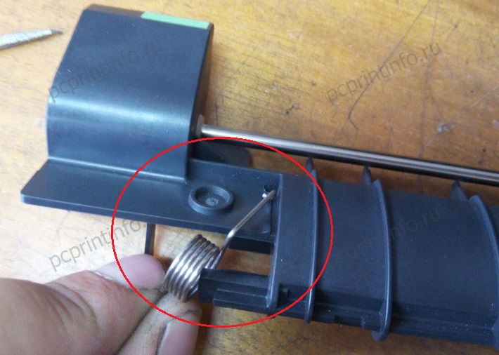
Обратите внимание, что под колодкой с роликом находится пружина, терять её ни в коем случае нельзя. 
А вот выступ на самой колодке, которым в эту пружину нужно будет попасть при установке деталей на место. 
Сам ролик извлекается из колодки и заменяется на новый аналогично предыдущим.
Установив все ролики и колодки на место, возвращаем принтер в нормальное положение и вставляем обратно лоток.
На этом замена роликов закончена, это решит проблему с ошибкой 501.
А теперь немного о совместимых роликах и ошибке 518, которая может возникнуть у вас сразу после установки новеньких роликов стороннего производителя.
Компания, в которой я работаю, довльно активно занимается ремонтом принетров, а износ роликов — самая распостранённая проблема печатающей техники Kyocera. И мы перепробовали довольно много различных совместимых роликов, от самых дешёвых, до близких к оригинальным по цене. И ни одни не работали как надо. Либо материал резинок оказывался слишком некачественным и они стирались за несколько тысяч страниц, либо размер самих резинок чуть-чуть не совпадал с оригинальным. К слову, средний срок службы оригинальных роликов около 60-70 тысяч листов. Хотя у некоторых они «бегают» и сотни тысяч. Были и случаи износа оригиналов за 40 тысяч листов, но это большая редкость. 

Казалось бы, пол миллиметра разницы в размере — мелочь, но на деле это приводило к серьёзным проблемам со всё тем же замятием бумаги, только на этот раз с оишбкой 518. Её, и все прочие ошибки, можно посмотреть в журнале событий принтера.

Причина в том, что из-за неверного диаметра совместимых роликов листы бумаги протягивались чуть дальше чем должны, попадая в «поле зрения» датчика прохода бумаги слишком рано. Особенно быстро и часто с данной проблемой будут сталкиваться те, кто печатает дуплексом (на обеих сторонах листа). Поэтому крайне рекомендую к установке только оригинальные ролики Kyocera.
Источник
Ошибка Jam 4220 в МФУ Kyocera Ecosys M2035
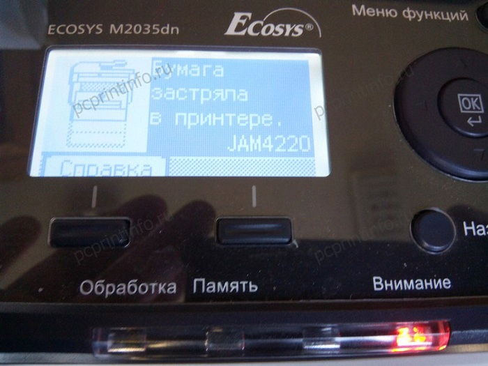
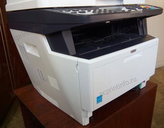
Доброго времени суток! Дорогие друзья! Сегодня речь пойдет об ошибке Jam 4220. На примере МФУ Kyocera Ecosys M2035 вы увидите, где расположен датчик вызывающий данную ошибку. И в каких ситуациях, помимо реального замятия, может появиться эта ошибка.
Именно в аппарате M2035, ошибку вызывает датчик, расположенный на выходе бумаги из термоузла (в других принтерах, возможно, это может быть и другой датчик).
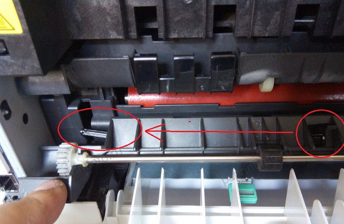
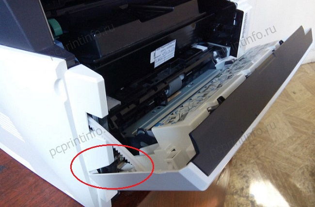
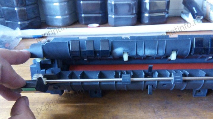
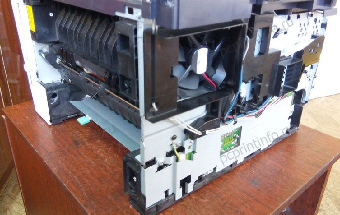
Первым делом проверьте МФУ на наличие замятой бумаги. Для этого откройте заднюю крышку.

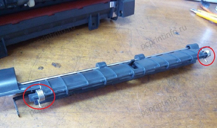
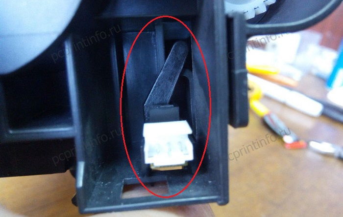
В нижней части вы увидите термоузел, у которого есть возможность отодвинуть шторку и заглянуть вовнутрь. Как раз на этой шторке находится датчик успешного прохождения бумаги из печи. Если бумага застряла и оставила лапку датчика в сдвинутом состоянии, то при включении или окончания распечатки листа, МФУ видит проблему и отображает ошибку.

Как вы видите на фото, никакой бумаги у меня не застряло, значит, проблема может быть в лапке датчика (сломался, проблема с пружинкой), в самом датчике (засорился, сломался), или в контактах подходящих к датчику.
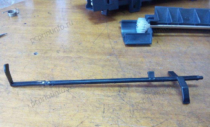
В моем случае лапка датчика была лопнута. Ну что ж, я буду её клеить. Чтобы снять эту лапку, мне понадобится снять термоузел. Если вам нужно подробно посмотреть, как снять печь, то перейдите на статью об ошибке C6000, здесь покажу вкратце.
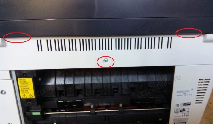
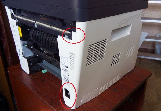
Снимаем заднюю крышку, сняв её с защелок.
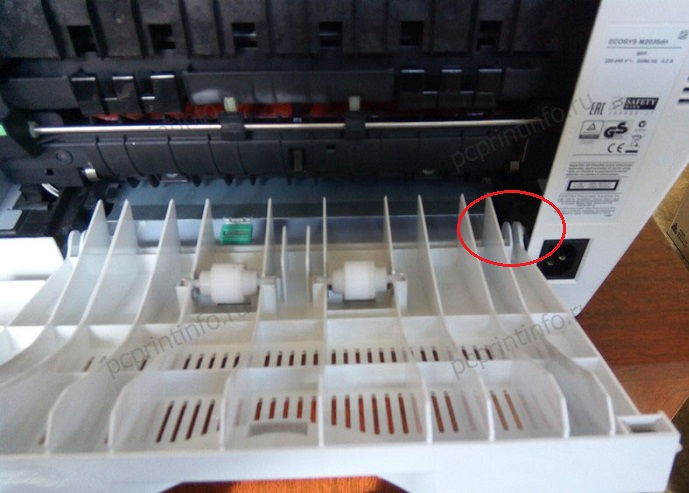
Далее снимем небольшую пластиковую планку сверху, держится она на болтике и двух защелках.
Теперь мы можем снять левую боковую крышку, но для удобства разбора, я сниму ещё и переднюю дверцу.
У боковой крышки с задней стороны есть две защелки, отгибаем и сдвигаем крышку.
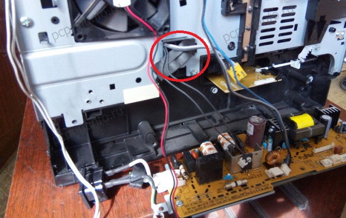
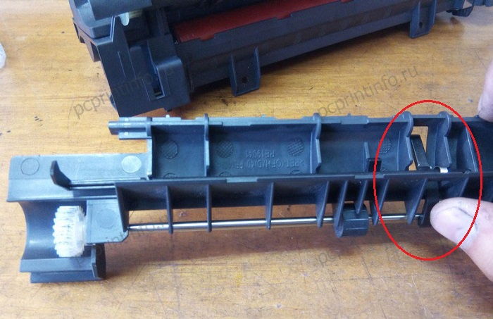
Под крышкой доберемся до контактов термоузла. Снимаем большую пластиковую направляющую, и откручиваем высоковольтную плату снизу.

С этой платы отключаем все контакты и убираем её в сторону.
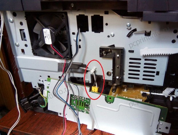
На термоузел идут два контакта, освобождаем их от прокладки.
Теперь мы можем окрутить термоузел с задней стороны.

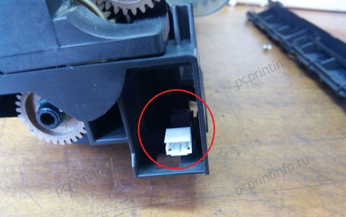
Аккуратно вытягиваем его и отключаем контакт с левой стороны. Это и есть тот контакт, который соединяет датчик со всей системой.

Итак, снимаем шторку с термоузла (чтобы снять, откройте шторку сильнее обычного).
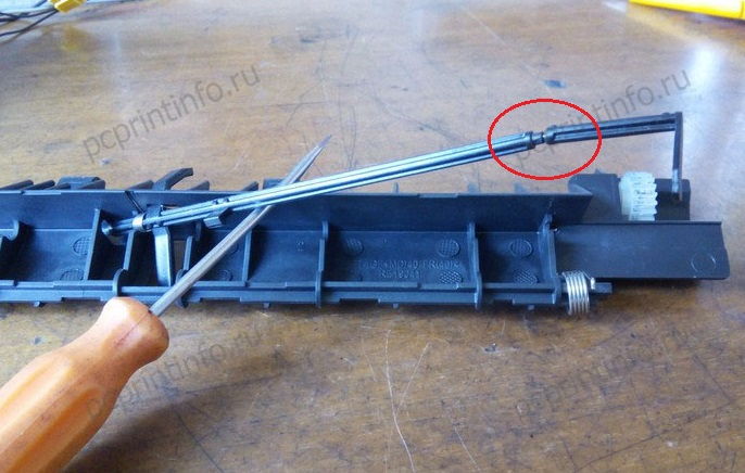
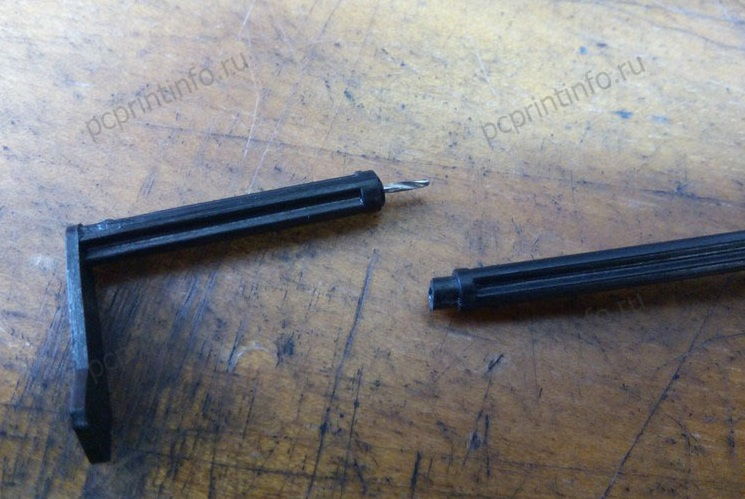
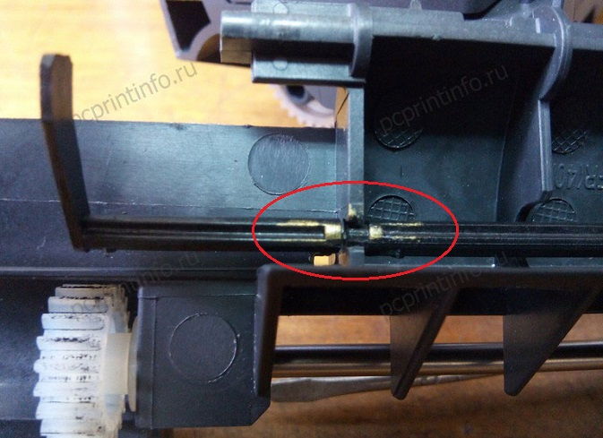
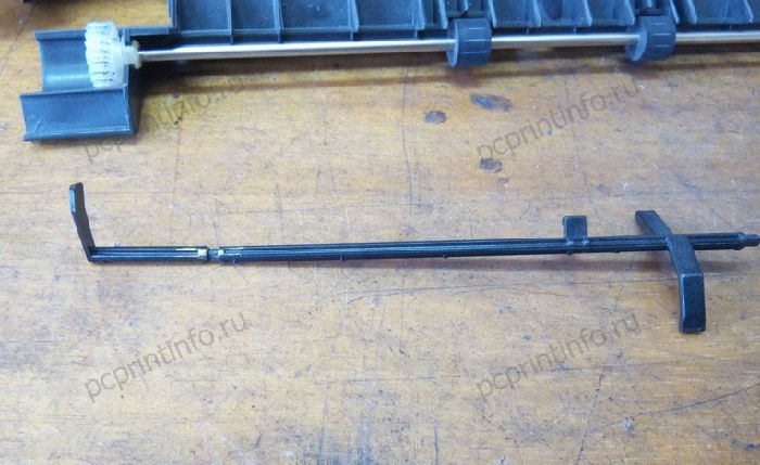
Смотрим на лапку датчика. Сейчас вы видите уже мои наброски, то есть до того как фотографировать я уже снял печь. Тогда часть лапки вообще лежала в стороне (хорошо хоть не выпала с аппарата), а сейчас я уже подобрал внутренний стержень (маленький кусочек от сверла), но пока не склеивал его, так как решил написать статью.
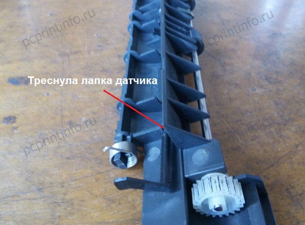
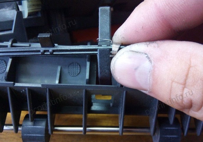
Я сразу же сниму с лапки пружину, чтобы в дальнейшем не потерять её нечаянно. Кстати об этой пружине я писал в начале, если она выпадет с посадочного места, то не будет прижимать лапку в нужном направлении, и аппарат незамедлительно выдаст вам ошибку Jam 4220.


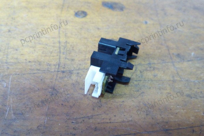
Теперь я покажу вам сам датчик.
Находится он сбоку термоузла и держится на трех защелках. В целях профилактики я сниму его и тщательно продую.
Далее нам нужно понять, в каком положении клеить две части лапки, для этого я нажеулю стержень и соберу термоузел, предварительно сняв со шторки пружины.
В собранном состоянии ставлю лапку, в нужное положение, отгибаю шторку и закрашиваю две части лапки в местах будущего склеивания.
Теперь мы понимаем, в каком положении склеивать.
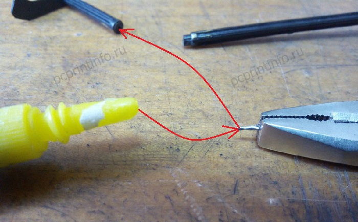
Для таких целей у меня припасено несколько тюбиков суперклея. Наносим его стержень и вставляем стержень в лапку, затем наносим на другую сторону и скрепляем.

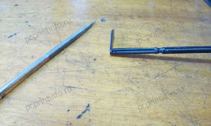
В месте склеивания остался клей, который может мешать свободному ходу лапки. Я прошелся надфилем и убрал лишнее. Ждем пару минут, пока засохнет клей и собираем все детали.
На лапку надеваем пружину и ставим лапку на место, на фото видно, как лучше завести лапку в пазы.

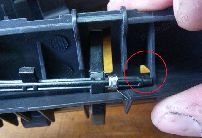
Теперь понажимаем на лапку, она должна ходить свободно.

Вставляем пружины в шторку, а шторку в термоузел.

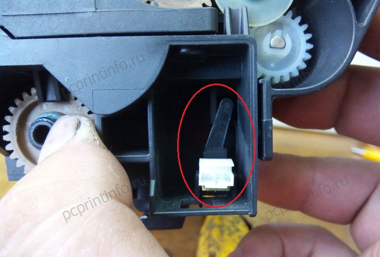
Для полной уверенности проверьте, чтобы лапка перекрывала датчик.
Подключаем контакт к датчику, и устанавливаем печь, предварительно подсунув два контакта в отверстие.

Подключаем высоковольтную плату, закручиваем её и ставим на место направляющую. Обратите внимание, высоковольтная плата должна быть подключена к плате внутри МФУ. С внутренней стороны высоковольтной платы находится штекер. Если плата не подключится должным образом, ваш аппарат не включится. Наглядно вы можете увидеть в статье про ошибку C6000.
Вставляем боковую стенку и переднюю крышку, а затем лоток с бумагой и пластиковую планку с задней стороны.

Завершаем сборку, надев заднюю крышку.
Вставляем шнур питания, включаем МФУ. Аппарат готов к копированию и печати. Ошибка Jam 4220 исправлена.
Комментарии
Такая ошибка уже на 2 машинах. Постоянно, с периодичностью 10-50 листов. Менял весь термоузел в сборе, блоки барабана и проявки — результата нет. У обоих на счётчике около 100 000 отпечатков.
а если ошибка JAM4020 замятие бумаги, датчик цел по крайней мере визуально, лапка цела как быть? внутри бумаги нет, под картриджем под прозрачной пластинкой тоже нет… как быть ребят?
я бы с удовольствием узнал как можно пофиксить пружинку на лапке. все с этим датчиком хорошо и с лапкой тоже — кроме пружинки. имею несколько аппаратов 2035 2535 и 2040, но только на 2040 эта пружинка очень уж слабенькая. Есть ли у вас опыт ее приведения в порядок?
Скажите пожалуйста, какой партномер детали, на которой стоит эта самая лапка? Деталь та самая, которую из аппарата извлекли. У меня эта деталь лопнула по центру у флажка прохождения бумаги, теперь постоянно пишет что бумага застряла.
Я могу ошибаться, но у этой детали скорее всего нет партномера, так как отдельно она не продается. Попробуйте пропаять трещину, кстати в некоторых случаях 3d ручка неплохо помогает, или хотя бы пластик для 3d ручек и паяльник.
Добавить комментарий Отменить ответ
Этот сайт использует Akismet для борьбы со спамом. Узнайте как обрабатываются ваши данные комментариев.
Источник
 Thanks: 0
 Likes: 0
 Dislikes: 0
-
02-07-2020
#1
JAM9110 TASKalfa2551ci
Hello,
I have Jam9110 or J9001 on Document Feeder. Its on Taskalfa 2551ci, and DF is DF-773.
i changed two clutch and actuator because they were defective. I still didn’t get the solution. The Jam still appears just after the white plastic sensor, when the DF is raised. So, it passes the white plastic and stops at the entrance to the output section of the Document Feeder. I did the service three times on this machine, and I saw that the paper-pulling erasers, as they pull the paper where Jam appears, the pulleys should rotate in the other direction. Will I solve the problem if I replace the Servo motor? Thank you in advance.
Tags for this Thread
Bookmarks
Bookmarks

Posting Permissions

- You may not post new threads
- You may not post replies
- You may not post attachments
- You may not edit your posts
- BB code is On
- Smilies are On
- [IMG] code is On
- [VIDEO] code is On
- HTML code is Off
Forum Rules
Code
0000
Initial jam
0100
Secondary feeding timeout
0101
Wait for ready of print-process
package
0104
Wait for ready of conveying
package
0105
Driving prevention
0106
Paper feeding request for
duplex printing time out
0107
Wait for ready of fuser pack-
age
0110
Rear cover open
0111
Top cover open
0120
Receiving a duplex paper
feeding request while paper is
empty
0121
Exceeding number of duplex
pages circulated
0501
No paper feed of jam
0502
0503
0504
0505
0508
0509
Contents
The power is turned on when a sensor in the con-
veying system is on.
Secondary paper feed request given by the con-
troller is unreachable.
Process package won’t become ready.
Conveying package won’t become ready.
A drive does not stop.
Paper feeding request for duplex printing given by
the controller is unreachable.
Fuser package won’t become ready.
The rear cover is opened during printing.
The top cover is opened during printing.
Paper feed request was received from the duplex
section despite the absence of paper in the
duplex section.
The controller issued the duplex section a request
for more pages than the duplex print cycle con-
tains.
The registration sensor 1 (RS1)*1 or sensor 3
(RS3)*2 does not turn on during paper feed from
cassette 1.
PF feed sensor 1 (PFFS1) does not turn on dur-
ing paper feed from cassette 2.
PF feed sensor 2 (PFFS2) does not turn on dur-
ing paper feed from cassette 3.
PF feed sensor 3 (PFFS3) does not turn on dur-
ing paper feed from cassette 4.
PF feed sensor 4 (PFFS4) does not turn on dur-
ing paper feed from cassette 5.
The registration sensor 1 (RS1)*1 or sensor 3
(RS3)*2 does not turn on during paper feed from
duplex section.
The registration sensor 1 (RS1)*1 or sensor 3
(RS3)*2 does not turn on during paper feed from
MP tray.
Conditions
1-4-3
2NM/2NX/2NY/2NZ/2P0/2P6
Jam
location*
H
H
H
H
H
B
—
I
—
—
I
I
1
2
3
4
5
I
Добрый день,может у кого- было подобное,возникает следующая ситуация с аппаратом, замятие бумаги в автоподатчике в районе регистрации, либо на выходе,когда лист почти весь вышел, Jam 9000,9110,либо 9410.При этом ролики захвата,подхвата, тормозной поменяны,прочищен тракт прохождения бумаги, проверены датчики, заменил клатчи захвата и регистрации,были загнуты в узле регистрации майларки,выправил их.Иногда автоподатчик может отработать без заминов, особенно при включении.Затем периодически возникают замины. Счетчик 136625 страниц
-
Alex12
- Увидел чернила
-
- Сайт
![]()
![]() Alex12 » Вт июл 28, 2020 12:34 pm
Alex12 » Вт июл 28, 2020 12:34 pm
Goldwater писал(а):Есть два варианта решения проблемы: японский подороже но побыстрее и русский подешевле но подольше.
Оба начинаются с обязательного обновления прошивки.
Вам который?
Прошивка не помогла, рассмотрю оба варианта.
-
Alex12
- Увидел чернила
-
- Сайт
![]()
-
- [SCANNER ERROR] Lamp Error Kyocera FS-1016
мастерчип в форуме Принтеры, МФУ, факсы, копиры формата A4
- 3
- 6431
Усатый Полосатый
Вс окт 28, 2018 11:08 pm
- [SCANNER ERROR] Lamp Error Kyocera FS-1016
-
- Kyocera 1035 «бледная» печать
srMax в форуме Принтеры, МФУ, факсы, копиры формата A4
- 2
- 13540
srMax
Пт янв 23, 2015 2:49 pm
- Kyocera 1035 «бледная» печать
-
- Kyocera FS-1120d индикатор «Нет бумаги»
vs-dos в форуме Принтеры, МФУ, факсы, копиры формата A4
- 11
- 14579
СТРОНЦИЙ
Вт ноя 02, 2021 2:24 pm
- Kyocera FS-1120d индикатор «Нет бумаги»
-
- Kyocera Ecosys M2635dn «поворот» изображения
Искатель в форуме Принтеры, МФУ, факсы, копиры формата A4
- 10
- 5742
MatrixAgent
Ср апр 08, 2020 5:18 am
- Kyocera Ecosys M2635dn «поворот» изображения
-
- Стирание вала ведущей шестерни в «печке» Kyocera M2035dn
Грецкий орех в форуме Принтеры, МФУ, факсы, копиры формата A4
- 12
- 2898
СТРОНЦИЙ
Пн дек 13, 2021 3:35 pm
- Стирание вала ведущей шестерни в «печке» Kyocera M2035dn
Вернуться в Принтеры, МФУ, копиры формата A3
Кто сейчас на форуме
Сейчас этот форум просматривают: нет зарегистрированных пользователей и гости: 16
Все современные копировальные аппараты, мфу и принтеры Kyocera имеют возможность диагностировать все узлы устройства в режиме запуска и во время работы аппарата. По этому, если во время включения или во время работы произошел сбой, то техника Kyocera сможет сообщить о наличии ошибки.
В большинстве случаев у аппаратов Kyocera код ошибки отображается на дисплее, в остальных случаях тип ошибки зависит от последовательности и количества миганий индикаторов.
Если Ваш копировальный аппарат, МФУ или принтер Kyocera выдал на дисплее некий код, то узнать причину, описание возникновения ошибки, а так же в каком узле аппарата стоит искать проблему, Вы можете в этом разделе выбрав интересующую модель из списка.
Но диагностика не решит проблему сбоя аппарата, для этого лучше обратиться к профессиональным и опытным сервисным специалистам компании Kyomart! Позвоните нам по телефону
8 (343) 288-23-45 или отправьте запрос на электронную почту: sales@kyomart.ru , и мы обязательно свяжемся с Вами в кратчайшие сроки.
| Код ошибки | Описание ошибки | Причина ошибки |
|---|---|---|
| 0030 | FAX control PWB system error Processing with the fax software was disabled due to a hardware problem. |
Defective FAX control PWB. |
| 0060 | Engine PWB type error | Defective engine sub PCB. |
| 0070 | FAX control PWB incompatible detection error Abnormal detection of FAX control PWB incompatibility In the initial communication with the FAX control PWB, any normal communication command is not transmitted. |
Defective FAX software Defective FAX control PWB. |
| 0100 | Backup memory device error | Defective flash memory. |
| 0120 | MAC address data error For data in which the MAC address is invalid. |
Defective main PWB. Defective flash memory. Defective engine PWB. |
| 0130 | Backup memory read/write error (main PWB) | Defective flash memory. Defective main PWB. |
| 0140 | Backup memory data error (main PWB) | Defective flash memory. Defective main PWB. |
| 0150 | Backup memory read/write error (engine PWB) Detecting engine PWB EEPROM communication error. |
Improper installation engine PWB EEPROM. Defective engine PWB. Device damage of EEPROM. |
| 0160 | Backup memory data error (engine PWB) | Defective flash memory. Defective engine PWB. |
| 0170 | Billing counting error A checksum error is detected in the main and engine backup memories for the billing counters. |
Data damage of EEPROM. Defective PWB. |
| 0180 | Machine number mismatch Machine number of main and engine does not match. |
Data damage of EEPROM. |
| 0320 | I/O CPU communication error A communication error is detected 10 times in succession. |
Defective PWB. |
| 0630 | DMA error DMA transmission of image data does not complete within the specified period of time. | Poor contact in the connector terminals. Defective main PWB. |
| 0800 | Image processing error JAM05 is detected twice. |
Defective main PWB. |
| 0830 | FAX control PWB flash program area checksum error A checksum error occurred with the program of the FAX control PWB. |
Defective FAX software. Defective FAX control PWB. |
| 0840 | Faults of RTC The time is judged to go back based on the comparison of the RTC time and the current time or five years or more have passed. |
The battery is disconnected from the main PWB. Defective main PWB. |
| 0870 | FAX control PWB to main PWB high capacity data transfer error High-capacity data transfer between the FAX control PWB and the main PWB of the machine was not normally performed even if the data transfer was retried the specified times. |
Improper installation FAX control PWB. Defective FAX control PWB or main PWB. |
| 0920 | Fax file system error The backup data is not retained for file system abnormality of flash memory of the FAX control PWB. |
Defective FAX control PWB. |
| 1010 | Lift motor error After cassette 1 is inserted, lift sensor does not turn on within 12 s. This error is detected four times successively. |
Defective bottom plate elevation mechanism in the cassette. Defective connector cable or poor contact in the connector. Defective drive transmission system of the lift motor. Defective lift motor. Defective engine PWB. |
| 1020 | PF lift motor error (paper feeder) After cassette 2 is inserted, PF lift sensor 1 does not turn on within 12 s. This error is detected four times successively. |
Defective bottom plate elevation mechanism in the cassette. Defective connector cable or poor contact in the connector. Defective drive transmission system of the PF lift motor 1. Defective PF lift motor 1. Defective PF main PWB. |
| 1030 | PF lift motor error (paper feeder) After cassette 3 is inserted, PF lift sensor 2 does not turn on within 12 s. This error is detected four times successively. |
Defective bottom plate elevation mechanism in the cassette. Defective connector cable or poor contact in the connector. Defective drive transmission system of the PF lift motor 2. Defective PF lift motor 2. Defective PF main PWB. |
| 1800 | Paper feeder communication error A communication error is detected 10 times in succession. |
Improper installation paper feeder. Defective connector cable or poor contact in the connector. Defective engine PWB. Defective PF main PWB. |
| 1900 | Paper feeder EEPROM error When writing the data, the write data and the read data is not continuously in agreement 5 times. |
Defective PF main PWB. Device damage of EEPROM. |
| 2000 | Main motor steady-state error Stable OFF is detected for 1 s continuously after main motor stabilized. |
Defective connector cable or poor contact in the connector. Defective drive transmission system of the main motor. Defective main motor. Defective engine PWB. |
| 2010 | Main motor drive error The main motor is not stabilized within 2 s after driving starts. |
Defective connector cable or poor contact in the connector. Defective drive transmission system of the main motor. Defective main motor. Defective engine PWB. |
| 2600 | PF drive motor error (paper feeder) When the PF drive motor is driven, error signal is detected continuously for 1 s. |
Defective connector cable or poor contact in the connector. Defective drive transmission system of the PF drive motor. Defective PF drive motor. Defective PF main PWB. |
| 3100 | ISU home position error The home position is not correct when the power is turned on or at the start of copying using the table. |
Defective connector cable or poor contact in the connector. Defective home position sensor. Defective ISU motor. Defective CCD PWB. Defective engine PWB. |
| 3200 | Exposure lamp error When input value at the time of exposure lamp illumination does not exceed the threshold value between 5 s. |
Defective connector cable or poor contact in the connector. Defective exposure lamp. Defective CCD PWB. Defective main PWB. |
| 3500 | Communication error between scanner and ASIC An error code is detected 3 times in succession. |
Defective connector cable or poor contact in the connector. Defective CCD PWB. Defective main PWB. |
| 3600 | Scanner sequence error | Defective main PWB or engine PWB. |
| 4000 | Polygon motor synchronization error The polygon motor is not stabilized within 10 s after driving starts. |
Defective connector cable or poor contact in the connector. Defective polygon motor. Defective engine PWB. |
| 4010 | Polygon motor steady-state error Stable OFF is detected for 1 s continuously after polygon motor stabilized. |
Defective connector cable or poor contact in the connector. Defective polygon motor. Defective engine PWB. |
| 4100 | BD initialization error BD is not detected within 1 s after polygon motor stabilized. |
Defective connector cable or poor contact in the connector. Defective APC PWB. Defective BD PWB. Defective main PWB. |
| 4700 | VIDEO ASIC device error | Defective connector cable or poor contact in the connector. Defective main PWB or engine PWB. |
| 6000 | Broken fuser heater wire The detected temperature of fuser thermistor does not reach the specified temperature (ready indication temperature) after the fuser heater has been turned on continuously for 60 s in warming up. The fusing temperature at 7 seconds and 20 seconds since fuser temperature control has occurred differs by 43°C/109.4°F or less. |
Defective connector cable or poor contact in the connector. Deformed connector pin. Defective triac. Fuser thermostat triggered. Broken fuser heater wire. Defective engine PWB. |
| 6000 6020 6030 6050 |
Broken fuser heater wire Abnormally high fuser thermistor temperature Broken fuser thermistor wire Abnormally low fuser thermistor temperature |
Deformed connector pin. Defective triac. |
| 6020 | Abnormally high fuser thermistor temperature The fuser thermistor detects a temperature higher than 230°C/446°F continuously for 40 ms. High fuser temperature signal detects a temperature of 255°C/491°F continuously for 40 ms. |
Deformed connector pin. Defective triac. Shorted fuser thermistor. Defective engine PWB. |
| 6030 | Broken fuser thermistor wire A/D value of the fuser thermistor exceeds 251 bit continuously for 7 s during warming up. |
Defective connector cable or poor contact in the connector. Deformed connector pin. Defective triac. Defective fuser thermistor. Defective engine PWB |
| 6050 | Abnormally low fuser thermistor temperature As the stable temperature has reached the second time, the decrease in the fuser thermistor temperature of 60°C/140°F or greater is detected for one second. |
Deformed connector pin. Defective triac. Defective fuser thermistor Defective fuser heater. Defective engine PWB. |
| 6400 | Zero-cross signal error While fuser heater control is performed, the zero-cross signal is not input within 3 s. |
Defective connector cable or poor contact in the connector Defective power source PWB or engine PWB. |
| 7800 | Broken external thermistor wire The thermistor output value is 0.3 V or less. |
Defective connector cable or poor contact in the connector. Defective temperature sensor. |
| 7810 | Short-circuited external thermistor wire The thermistor output value is 3 V or more. |
Defective connector cable or poor contact in the connector. Defective temperature sensor. |
| 7900 | Drum unit EEPROM error No response is issued from the device in reading/writing for 5 ms or more and this problem is repeated five times successively. Mismatch of reading data from two locations occurs eight times successively. Mismatch between writing data and reading data occurs eight times successively. |
Defective connector cable or poor contact in the connector. Defective drum unit. |
| 7910 | Developer unit EEPROM error No response is issued from the device in reading/writing for 5 ms or more and this problem is repeated five times successively. Mismatch of reading data from two locations occurs eight times successively. Mismatch between writing data and reading data occurs eight times successively. |
Defective connector cable or poor contact in the connector. Defective developer unit. |
| 8030 | Tray upper limit detection problem (document finisher) When the tray elevation motor raises a tray, the ON status of the tray upper limit sensor is detected. |
Defective connector cable or poor contact in the connector. Defective tray upper limit sensor, paper surface sensor 1/2. Defective DF main PWB. |
| 8040 | Belt problem (document finisher) The belt sensor does not turn on/off within specified time of the belt solenoid turning on. |
Defective connector cable or poor contact in the connector. Defective belt sensor. Defective belt solenoid. Defective DF main PWB. |
| 8140 | Tray elevation motor problem (document finisher) The tray low limit sensor or paper surface sensor 1/2 cannot be detected to be on within 10 s since the tray elevation motor is activated. |
Defective connector cable or poor contact in the connector. Defective connector cable or poor contact in the connector. The tray elevation motor malfunctions. Defective tray lower limit sensor, paper surface sensor 1/2. Defective DF main PWB. |
| 8210 | Stapler problem (document finisher) Jam 7012 or 7023 is indicated. |
Defective connector cable of staple or poor contact in the connector. The stapler is blocked with a staple. The stapler is broken Defective DF main PWB. |
| 8320 | Adjustment motor 2 problem (document finisher) The adjustment sensor 2 does not turn on/off within specified time of the adjustment motor 2 turning on. |
Defective connector cable or poor contact in the connector. Defective adjustment sensor 2. Defective adjustment motor 2. Defective DF main PWB. |
| 8330 | Adjustment motor 1 problem (document finisher) The adjustment sensor 1 does not turn on/off within specified time of the adjustment motor 1 turning on. |
Defective connector cable or poor contact in the connector. Defective adjustment sensor 1. Defective adjustment motor 1. |
| 8350 | Roller motor problem (document finisher) The roller sensor does not turn on/off within specified time of the roller motor turning on. |
Defective DF main PWB. Defective connector cable or poor contact in the connector. Defective roller sensor. Defective roller motor. Defective DF main PWB. |
| 8360 | Slide motor problem (document finisher) The slide sensor does not turn on/off within specified time of the slide motor turning on. |
Defective connector cable or poor contact in the connector. Defective slide sensor. Defective slide motor. Defective DF main PWB. |
| 8460 | EEPROM problem (document finisher) Reading from or writing to EEPROM cannot be performed. |
Defective EEPROM or DF main PWB. |
| 8800 | Document finisher communication error A communication error is detected 10 times in succession. |
Defective connector cable or poor contact in the connector Defective DF main PWB. Defective engine PWB. |
| 8830 | Bridge communication error (document finisher) A communication error is detected 10 times in succession. |
Defective connector cable or poor contact in the connector. Defective bridge PWB. Defective engine PWB. |
| 8990 | Document finisher communication error | Defective connector cable or poor contact in the connector. Defective DF main PWB. Defective bridge PWB. |
| 9000 | Document processor communication error A communication error is detected 10 times in succession. |
Defective connector cable or poor contact in the connector. Defective DP main PWB. |
| 9060 | DP EEPROM error Read and write data does not match. Data in the specified area of the backup memory does not match the specified values. | Defective DP main PWB. Device damage of EEPROM. |
| 9500 | BRU communication error | IPU PWB error |
| 9510 | BRU PWB error | IPU PWB error |
| 9520 | BRU PWB data error | IPU PWB error |
| F000 | Main PWB — operation panel PWB communication error | Defective main PWB. Defective operation panel PWB. |
| F010 | Main PWB checksum error | Defective main PWB. |
| F040 | Main PWB — print engine communication error | Defective main PWB. Defective engine PWB. |
| F050 | Print engine ROM checksum error | Defective engine PWB. |
Если с аппаратом Kyocera TASKalfa 1800, Kyocera TASKalfa 2200 произошла проблема, откроется следующий экран с уведомлением.
• Индикатор [Внимание] на панели управления горит или мигает.
• На дисплее сообщений панели управления аппарата появилось сообщение об ошибке.
Если индикатор [Внимание] горит или мигает и на дисплее сообщений панели управления аппарата появилось сообщение об ошибке, проверьте KYOCERA Client Tool или Монитор состояния.
ПРИМЕЧАНИЕ Если индикаторы постоянно горят и мигают не так, как описано выше, вероятно, произошла ошибка службы. Выключите питание, отсоедините шнур питания и вставьте его обратно, после чего включите питание. Это может помочь сбросить ошибку. Если ошибка не исчезает, свяжитесь со своим представителем сервисной службы (тел. в Минске +375 17 291-28-24)
Ниже описаны неполадки, которые не могут быть устранены пользователем
|
Дисплей сообщений |
Описание |
Меры устранения |
|
Бункер отраб тонера перепол. или не уст. |
Бункер для отработанного тонера установлен неправильно |
Установите Бункер для отработанного тонера должным образом |
|
Бункер для отработанного тонера заполнен |
Замените бункер отработанного тонера |
|
|
Встряхните картр. с тонером |
Тонер слежался |
Откройте переднюю крышку аппарата и вытяните контейнер с тонером. Сильно встряхните контейнер с тонером и установите его на место |
|
Вызовите сервисный персонал. |
В аппарате произошла ошибка |
Обратите внимание на код ошибки, отображаемый в дисплее сообщений, и свяжитесь с представителем сервисной службы (тел. в Минске +375 17 291-28-24) |
|
Выньте бумагу с внутреннего лотка |
Извлеките бумагу из внутреннего лотка. Нажмите клавишу [OK], чтобы возобновить печать |
|
|
Добавьте тонер |
Закончился тонер |
Замените контейнер с тонером TK-4105 |
|
Загрузите бумагу в кассету # |
↑↓ (отображается попеременно) |
Загрузите бумагу. Нажмите клавишу [OK] и перейдите к следующему шагу. • Для выбора другого устройства подачи выберите [Выберите бумагу]. • Для печати на бумаге, в настоящее время находящейся в устройстве подачи, выберите [Продолж. без изм.] |
|
Загрузите бумагу в универсальный лоток |
↑↓ (отображается попеременно) |
Загрузите бумагу. Нажмите клавишу [OK] и перейдите к следующему шагу. • Для выбора другого устройства подачи выберите [Выберите бумагу]. • Для печати на бумаге, в настоящее время находящейся в устройстве подачи, выберите [Продолж. без изм.] |
|
Закройте автоподатчик оригиналов |
Открыт автоподатчик оригиналов |
Откройте и закройте автоподатчик оригиналов |
|
Закройте крышку автопод. оригиналов |
Открыта верхняя крышка автоподатчика оригиналов |
Откройте и закройте крышку автоподатчика оригинало |
|
Закройте переднюю крышку |
Открыта передняя крышка |
Откройте и закройте переднюю крышку |
|
Закройте правую крышку # |
Открыта какая-либо крышка |
Откройте и закройте крышку, обозначенную на экране |
|
Замятие бумаги. (DP) |
В автоподатчике произошло замятие бумаги. |
См. Устранение замятия бумаги в Руководстве по эксплуатации и извлеките замятую бумагу |
|
Замените МК |
Необходимо производить замену деталей комплекта техобслуживания MK-4105 (ремкомплекта) каждые 150 000 страниц печати. |
Данная операция должна производиться специалистом. Обратитесь к представителю сервисной службы (тел. в Минске +375 17 291-28-24) |
|
Замятие |
Произошло замятие бумаги в кассете или универсальном лотке |
См. Устранение замятия бумаги и извлеките замятую бумагу |
|
Извлеките оригиналы из автоподатчика |
Для продолжения работы необходимо извлечь оригиналы из автоподатчика оригиналов |
Извлеките оригиналы из автоподатчика оригиналов |
|
Кабель USB был отключен |
Кабель USB не подключен |
Нажмите клавишу [OK] и подключите кабель USB |
|
ПК выключен |
Нажмите клавишу [OK] и включите ПК |
|
|
Не удается найти KYOCERA Client Tool |
Нажмите клавишу [OK] и откройте KYOCERA Client Tool на ПК |
|
|
Макс. к-во сканируемых страниц |
Превышен предел сканирования |
Дальнейшее сканирование невозможно. Задание отменено. Нажмите клавишу [OK] |
|
Мало тонера. (Зам., когда законч.) |
Скоро понадобится заменить контейнер с тонером |
Получите новый контейнер с тонером TK-4105. |
|
Не оригинальный тонер |
Установлен контейнер с тонером не марки Kyocera |
Производитель не несет ответственности за повреждения, вызванные использованием неоригинального тонера. Мы рекомендуем использовать исключительно оригинальные контейнеры с тонером TK-4105. . |
|
Неверный ид. уч. зап. Задание отменено |
Указан неверный идентификатор учетной записи при внешней обработке задания. Задание отменено |
Нажмите клавишу [OK] |
|
Невозможна двусторонняя печать на этой бумаге |
Не возможна печать на бумаге выбранного формата или типа |
Нажмите клавишу [OK] и перейдите к следующему шагу: |
|
Недостаточно памяти. Невозможно начать выполнение задания |
Невозможно начать выполнение задания |
Повторите попытку позже |
|
Ограничено алгоритмом учета заданий(Печать) |
Задание отменено, поскольку его выполнение ограничено функцией учета заданий |
Нажмите клавишу [OK] |
|
Ограничено алгоритмом учета заданий(Сканер) |
Задание отменено, поскольку его выполнение ограничено функцией учета заданий |
Нажмите клавишу [OK] |
|
Очистите сканер |
Произошло загрязнение сканера |
Очистите щелевое стекло с помощью чистящей салфетки, поставляемой вместе с автоподатчиком оригиналов. |
|
Ошибка. Выключить |
— |
Отключите и снова включите аппарат с помощью выключателя питания |
|
Память переполнена |
Невозможно продолжить выполнение задания из-за отсутствия свободной памяти |
Измените разрешение печати с Быстр1200 до 600 dpi. См. Printer Driver User Guide |
|
Память сканера переполнена |
Дальнейшее сканирование невозможно из-за нехватки памяти сканера. |
Для отмены задания нажмите [OK] |
|
Перезагрузка печати. Задание отменено |
Предупреждение. Недостаточно памяти принтера. Задание отменено |
Нажмите клавишу [OK] |
|
Превышено ограничение учета заданий |
Превышено число распечаток из-за ограничения алгоритмом учета заданий. Достигнут предел печати |
Это задание отменено. Нажмите клавишу [OK] |
|
Уст.другую кассету |
Выбрано «Сдвиг» |
Для использования сдвига необходимо загрузить в другой лоток бумагу такого же формата, что и в выбранном устройстве подачи, но в другой ориентации |
|
Установите все оригиналы обратно и нажмите клавишу [Старт]. |
Возникает при печати двусторонних документов в режиме ручной двусторонней печати |
Извлеките оригиналы из автоподатчика оригиналов, расположите их в первоначальном порядке и положите обратно. Нажмите клавишу [OK], чтобы возобновить печать. Для отмены задания нажмите [Стоп] |
|
Установлен неизвестный тонер. ПК |
Региональная спецификация контейнера с тонером не соответствует спецификации аппарата |
Установите оригинальный контейнер с тонером Замените контейнер с тонером TK-4105 |
Item No.
U000
No.
(7)
Paper Jam
cont.
Log
Items
6813: Front adjustment plate operation OFF error
6903: Rear adjustment plate operation ON error
6913: Rear adjustment plate operation OFF error
7013: Staple operation error
7023: Staple initialoperation error
7913: Sequence error 1 (operation prohibited)
7923: Sequence error 2 (initialoperation error)
7933: Sequence error 3 (Error in the reception of backup data)
7943: Sequence error 4 (standby)
7953: Sequence error 5 (Error in between copies)
9000: No original feed
9001: DP original conveying jam
9004: DP original swichback jam
9010: DP open
9011: DP top cover open
9110: DP paper feed sensor stay jam
9200: DP registration sensor non arrival jam
9400: DP timing sensor non arrival jam
9410: DP timing sensor stay jam
(b) Detail of paper source (Hexadecimal)
00: MP tray
01: Cassette 1
02: Cassette 2 (paper feeder 1)
03: Cassette 3 (paper feeder 2)
04 to 09: Reserved
(c) Detail of paper size (Hexadecimal)
00: (Not specified)
01: Monarch
02: Business
03: International DL
04: International C5
05: Executive
06: Letter-R
86: Letter-E
07: Legal
08: A4R
88: A4E
09: B5R
89: B5E
0A: A3
Description
Description
0B: B4
0C: Ledger
0D: A5R
0E: A6
0F: B6
10: Commercial #9
11: Commercial #6
12: ISO B5
13: Custom size
1E: C4
1F: Postcard
20: Reply-paid post-
card
21: Oficio II
1-3-11
2MW/2MX
22: Special 1
23: Special 2
24: A3 wide
25: Ledger wide
26: Full bleed paper
(12 x
27: 8K
28: 16K-R
A8: 16K-E
32: Statement-R
B2: Statement-E
33: Folio
34: Western type 2
35: Western type 4
Замятие, зажёвывание бумаги в принтерах Kyocera FS-1035MFP/1035MFP/DP-1135/1135MFP/M2035/FS-1030MFP/1130MFP, ошибки 501 и 518, а так же разбор проблем, которые могут возникнуть сразу после замены роликов.
Сегодня мы с вами разберём причины замятия бумаги в некоторых принтерах Kyocera, поговорим о способах устранения данной проблемы и некоторых важных нюансах, о которых стоит знать любому, кто хочет провести ремонт своего принетра результативно и качественно.
Сразу к делу: если принтер Kyocera заминает или зажёвывает бумагу (Ошибка 501), то в подавляющем большинстве случаев причина в износе роликов захвата и/или отделения (сепарации) бумаги. В таком случае ролики нужно заменить. Обычно эти ролики изнашиваются почти одновременно, поэтому менять следует сразу и ролики захвата, и ролик сеперации. В этой статье я расскажу и покажу как это сделать.
Начнём с того, что вынем из принтера лоток для бумаги. Затем принтер нужно поставить «на дыбы», чтобы с областью над лотком было удобно работать.
Теперь нам хорошо видны ролики захвата бумаги.
Чтобы заменить ролики, нам нужно снять пластиковую колодку, в которой они нахоятся. Для этого просто отщёлкиваем колодку снизу, как показано на фото.
Сверху колодка держится на двух зацепах, с ними нужно быть аккуратным, чтобы ни в коем случае не сломать их.
После извлечения колодки просто отжимаем пластик вбок и получаем возможность вынуть ролики.
Оригинальные ролики продаются сразу со втулками, на которых они находятся. Если же вы приобрели совместимые ролики, то у вас в комплекте будут только резинки, и вам придётся самостоятельно стягивать со втулок старые и надевать на их место новые. Но делать так я крайне не рекомендую, и чуть дальше я подробно расскажу — почему.
Установив новые ролики, можем смело вернуть пластиковую колодку на место, процесс её установки ничем не отличается от снятия.
Далее в нашем списке ролик отделения бумаги, он находится в самом лотке, и тоже в пластиковой колодке.
Чтобы снять его, нужно отогнуть пластик этой колодки с одной из сторон.
Обратите внимание, что под колодкой с роликом находится пружина, терять её ни в коем случае нельзя.
А вот выступ на самой колодке, которым в эту пружину нужно будет попасть при установке деталей на место.
Сам ролик извлекается из колодки и заменяется на новый аналогично предыдущим.
Установив все ролики и колодки на место, возвращаем принтер в нормальное положение и вставляем обратно лоток.
На этом замена роликов закончена, это решит проблему с ошибкой 501.
А теперь немного о совместимых роликах и ошибке 518, которая может возникнуть у вас сразу после установки новеньких роликов стороннего производителя.
Компания, в которой я работаю, довльно активно занимается ремонтом принетров, а износ роликов — самая распостранённая проблема печатающей техники Kyocera. И мы перепробовали довольно много различных совместимых роликов, от самых дешёвых, до близких к оригинальным по цене. И ни одни не работали как надо. Либо материал резинок оказывался слишком некачественным и они стирались за несколько тысяч страниц, либо размер самих резинок чуть-чуть не совпадал с оригинальным. К слову, средний срок службы оригинальных роликов около 60-70 тысяч листов. Хотя у некоторых они «бегают» и сотни тысяч. Были и случаи износа оригиналов за 40 тысяч листов, но это большая редкость.
Казалось бы, пол миллиметра разницы в размере — мелочь, но на деле это приводило к серьёзным проблемам со всё тем же замятием бумаги, только на этот раз с оишбкой 518. Её, и все прочие ошибки, можно посмотреть в журнале событий принтера.
Причина в том, что из-за неверного диаметра совместимых роликов листы бумаги протягивались чуть дальше чем должны, попадая в «поле зрения» датчика прохода бумаги слишком рано. Особенно быстро и часто с данной проблемой будут сталкиваться те, кто печатает дуплексом (на обеих сторонах листа). Поэтому крайне рекомендую к установке только оригинальные ролики Kyocera.
Источник
Ошибка Jam 4220 в МФУ Kyocera Ecosys M2035
Доброго времени суток! Дорогие друзья! Сегодня речь пойдет об ошибке Jam 4220. На примере МФУ Kyocera Ecosys M2035 вы увидите, где расположен датчик вызывающий данную ошибку. И в каких ситуациях, помимо реального замятия, может появиться эта ошибка.
Именно в аппарате M2035, ошибку вызывает датчик, расположенный на выходе бумаги из термоузла (в других принтерах, возможно, это может быть и другой датчик).
Первым делом проверьте МФУ на наличие замятой бумаги. Для этого откройте заднюю крышку.
В нижней части вы увидите термоузел, у которого есть возможность отодвинуть шторку и заглянуть вовнутрь. Как раз на этой шторке находится датчик успешного прохождения бумаги из печи. Если бумага застряла и оставила лапку датчика в сдвинутом состоянии, то при включении или окончания распечатки листа, МФУ видит проблему и отображает ошибку.
Как вы видите на фото, никакой бумаги у меня не застряло, значит, проблема может быть в лапке датчика (сломался, проблема с пружинкой), в самом датчике (засорился, сломался), или в контактах подходящих к датчику.
В моем случае лапка датчика была лопнута. Ну что ж, я буду её клеить. Чтобы снять эту лапку, мне понадобится снять термоузел. Если вам нужно подробно посмотреть, как снять печь, то перейдите на статью об ошибке C6000, здесь покажу вкратце.
Снимаем заднюю крышку, сняв её с защелок.
Далее снимем небольшую пластиковую планку сверху, держится она на болтике и двух защелках.
Теперь мы можем снять левую боковую крышку, но для удобства разбора, я сниму ещё и переднюю дверцу.
У боковой крышки с задней стороны есть две защелки, отгибаем и сдвигаем крышку.
Под крышкой доберемся до контактов термоузла. Снимаем большую пластиковую направляющую, и откручиваем высоковольтную плату снизу.
С этой платы отключаем все контакты и убираем её в сторону.
На термоузел идут два контакта, освобождаем их от прокладки.
Теперь мы можем окрутить термоузел с задней стороны.
Аккуратно вытягиваем его и отключаем контакт с левой стороны. Это и есть тот контакт, который соединяет датчик со всей системой.
Итак, снимаем шторку с термоузла (чтобы снять, откройте шторку сильнее обычного).
Смотрим на лапку датчика. Сейчас вы видите уже мои наброски, то есть до того как фотографировать я уже снял печь. Тогда часть лапки вообще лежала в стороне (хорошо хоть не выпала с аппарата), а сейчас я уже подобрал внутренний стержень (маленький кусочек от сверла), но пока не склеивал его, так как решил написать статью.
Я сразу же сниму с лапки пружину, чтобы в дальнейшем не потерять её нечаянно. Кстати об этой пружине я писал в начале, если она выпадет с посадочного места, то не будет прижимать лапку в нужном направлении, и аппарат незамедлительно выдаст вам ошибку Jam 4220.
Теперь я покажу вам сам датчик.
Находится он сбоку термоузла и держится на трех защелках. В целях профилактики я сниму его и тщательно продую.
Далее нам нужно понять, в каком положении клеить две части лапки, для этого я нажеулю стержень и соберу термоузел, предварительно сняв со шторки пружины.
В собранном состоянии ставлю лапку, в нужное положение, отгибаю шторку и закрашиваю две части лапки в местах будущего склеивания.
Теперь мы понимаем, в каком положении склеивать.
Для таких целей у меня припасено несколько тюбиков суперклея. Наносим его стержень и вставляем стержень в лапку, затем наносим на другую сторону и скрепляем.
В месте склеивания остался клей, который может мешать свободному ходу лапки. Я прошелся надфилем и убрал лишнее. Ждем пару минут, пока засохнет клей и собираем все детали.
На лапку надеваем пружину и ставим лапку на место, на фото видно, как лучше завести лапку в пазы.
Теперь понажимаем на лапку, она должна ходить свободно.
Вставляем пружины в шторку, а шторку в термоузел.
Для полной уверенности проверьте, чтобы лапка перекрывала датчик.
Подключаем контакт к датчику, и устанавливаем печь, предварительно подсунув два контакта в отверстие.
Подключаем высоковольтную плату, закручиваем её и ставим на место направляющую. Обратите внимание, высоковольтная плата должна быть подключена к плате внутри МФУ. С внутренней стороны высоковольтной платы находится штекер. Если плата не подключится должным образом, ваш аппарат не включится. Наглядно вы можете увидеть в статье про ошибку C6000.
Вставляем боковую стенку и переднюю крышку, а затем лоток с бумагой и пластиковую планку с задней стороны.
Завершаем сборку, надев заднюю крышку.
Вставляем шнур питания, включаем МФУ. Аппарат готов к копированию и печати. Ошибка Jam 4220 исправлена.
Комментарии
Такая ошибка уже на 2 машинах. Постоянно, с периодичностью 10-50 листов. Менял весь термоузел в сборе, блоки барабана и проявки — результата нет. У обоих на счётчике около 100 000 отпечатков.
а если ошибка JAM4020 замятие бумаги, датчик цел по крайней мере визуально, лапка цела как быть? внутри бумаги нет, под картриджем под прозрачной пластинкой тоже нет… как быть ребят?
я бы с удовольствием узнал как можно пофиксить пружинку на лапке. все с этим датчиком хорошо и с лапкой тоже — кроме пружинки. имею несколько аппаратов 2035 2535 и 2040, но только на 2040 эта пружинка очень уж слабенькая. Есть ли у вас опыт ее приведения в порядок?
Скажите пожалуйста, какой партномер детали, на которой стоит эта самая лапка? Деталь та самая, которую из аппарата извлекли. У меня эта деталь лопнула по центру у флажка прохождения бумаги, теперь постоянно пишет что бумага застряла.
Я могу ошибаться, но у этой детали скорее всего нет партномера, так как отдельно она не продается. Попробуйте пропаять трещину, кстати в некоторых случаях 3d ручка неплохо помогает, или хотя бы пластик для 3d ручек и паяльник.
Добавить комментарий Отменить ответ
Этот сайт использует Akismet для борьбы со спамом. Узнайте как обрабатываются ваши данные комментариев.
Источник
- Code: 0030
- Description: FAX control PWB system error
Processing with the fax software was disabled due to a hardware problem. - Causes: Defective FAX control PWB.
- Remedy: Replace the fax control PWB and check for correct operation.
- Code: 0060
- Description: Illegal engine PWB type
The engine main PWB and the engine sub PWB are incompatible. - Causes: Defective engine sub PWB.
- Remedy: Replace the engine PWB and check for correct operation.
- Code: 0070
- Description: FAX control PWB incompatible detection error
Abnormal detection of FAX control PWB incompatibility In the initial communication with the FAX control PWB, any normal communication command is not transmitted. - Causes: Defective FAX software.
Defective FAX control PWB. - Remedy: Defective FAX software. Install the fax software.
Defective FAX control PWB. Replace the fax control PWB and check for correct operation.
- Code: 0100
- Description: Backup memory device error
- Causes: Defective flash memory.
Defective main PWB. - Remedy: Defective flash memory. Replace the main PWB and check for correct operation.
Defective main PWB. Replace the main PWB and check for correct operation.
- Code: 0120
- Description: MAC address data error
For data in which the MAC address is invalid. - Causes: Defective flash memory
Defective engine PWB. - Remedy: Defective flash memory. Replace the main PWB and check for correct operation.e 1-5-46).
- Code: 0150
- Description: Backup memory read/write error (engine PWB)
No response is issued from the device in reading/writing for 5 ms or more and this problem is repeated 5 times successively. Mismatch of reading data from 2 locations occurs 8 times successively. Mismatch between writing data and reading data occurs 8 times successively. - Causes: Improper installation EEPROM.
Device damage of EEPROM. - Remedy: Improper installation EEPROM. Check the installation of the EEPROM and remedy if necessary.
Defective engine PWB. Replace the engine PWB and check for correct operation.
Device damage of EEPROM. Contact the Service Administrative Division.
- Code: 0160
- Description: Backup memory data error (engine PWB)
Reading data from EEPROM is abnormal. - Causes: Data damage of EEPROM.
- Remedy: Contact the Service Administrative Division.
- Code: 0170
- Description: Billing counting error
A checksum error is detected in the main and engine backup memories for the billing counters. - Causes: Data damage of EEPROM.
Defective PWB. - Remedy: Data damage of EEPROM. Contact the Service Administrative Division.
Defective PWB. Replace the main PWB or the engine PWB and check for correct operation.
- Code: 0180
- Description: Machine number mismatch
Machine number of main and engine does not match. - Causes: Data damage of EEPROM.
- Remedy: Contact the Service Administrative Division.
- Code: 0620
- Description: FAX image DIMM error
DIMM is not installed correctly. DIMM cannot be accessed. - Causes: DIMM installed incorrectly.
Defective main PWB. - Remedy: DIMM installed incorrectly. Check if the DIMM is inserted into the socket on the main PWB correctly.
Defective main PWB. Replace the main PWB and check for correct operation.
- Code: 0630
- Description: DMA error
DMA transmission of image data does not complete within the specified period of time. - Causes: Poor contact in the connector terminals.
Defective main PWB. - Remedy: Poor contact in the connector terminals. Check the connection the signal cable for CIS and the main PWB, and the continuity across the connector terminals. Repair or replace if necessary.
Defective main PWB. Replace the main PWB and check for correct operation.
- Code: 0640
- Description: Hard disk error
The hard disk cannot be accessed. - Causes: Defective hard disk.
Defective main PWB. - Remedy: Defective connector cable or poor contact in the connector. Reinsert the connector. Also check for continuity within the connector cable. If none, replace the cable.
Defective hard disk. Run U024 (HDD formatting) without turning the power off to initialize the hard disk. Replace the hard disk drive and check for correct operation if the problem is still detected after initialization.
Defective main PWB. Replace the main PWB and check for correct operation.
- Code: 0650
- Description: FAX image DIMM check error
Improper DIMM is installed. - Causes: DIMM installed incorrectly.
Defective main PWB. - Remedy: DIMM installed incorrectly. Check if the DIMM is inserted into the socket on the main PWB correctly.
DIMM of another machine is installed. Perform maintenance mode U671 (RECOVERY FAX DIMM).
Defective main PWB. Replace the main PWB and check for correct operation.
- Code: 0800
- Description: Image processing error
JAM010X is detected twice. - Causes: Defective main PWB.
- Remedy: Replace the main PWB and check for correct operation.
- Code: 0830
- Description: FAX control PWB flash program area checksum error
A checksum error occurred with the program of the FAX control PWB. - Causes: Defective FAX software.
Defective FAX control PWB. - Remedy: Defective FAX software. Install the fax software.
Defective FAX control PWB. Replace the fax control PWB and check for correct operation.
- Code: 0840
- Description: Faults of RTC
The time is judged to go back based on the comparison of the RTC time and the current time or five years or more have passed. - Causes: The battery is disconnected from the main PWB
Defective main PWB. - Remedy: The battery is disconnected from the main PWB. Check visually and remedy if necessary
Defective main PWB. Replace the main PWB and check for correct operation.
- Code: 0870
- Description: FAX control PWB to main PWB high capacity data transfer error
High-capacity data transfer between the FAX control PWB and the main PWB of the machine was not normally performed even if the data transfer was retried the specified times - Causes: Improper installation FAX control PWB.
Defective FAX control PWB or main PWB. - Remedy: Improper installation FAX control PWB. Reinstall the FAX control PWB.
Defective FAX control PWB or main PWB. Replace the FAX control PWB or main PWB and check for correct operation.
- Code: 0920
- Description: Fax file system error
The backup data is not retained for file system abnormality of flash memory of the FAX control PWB. - Causes: Defective FAX control PWB.
- Remedy: Replace the fax control PWB and check for correct operation.
- Code: 0970
- Description: 12 V power down detect Power is disconnected during sleeping.
- Causes: Defective power source PWB.
- Remedy: Replace the power source PWB and check for correct operation.
- Code: 0980
- Description: 24 V power down detect 24V disconnection signal is detected for 1 s and 12V disconnection signal is not detected.
- Causes: Defective power source PWB.
- Remedy: Replace the power source PWB and check for correct operation.
- Code: 1000
- Description: MP lift motor error
After the MP lift motor is driven, the ON status of MP lift sensors 1 and 2 cannot be detected for 3 s. - Causes: Defective MP plate elevation mechanism.
Defective connector cable or poor contact in the connector.
Defective drive transmission system of motor.
Defective MP lift motor.
Defective engine PWB. - Remedy: Defective MP plate elevation mechanism. Check to see if the MP plate can move smoothly and repair it if any problem is found.
Defective connector cable or poor contact in the connector. Reinsert the connector. Also check for continuity within the connector cable. If none, replace the cable. MP lift motor and relay PWB (YC3) Relay PWB (YC12) and feed PWB 1 (YC17) Feed PWB 1 (YC1) and engine PWB (YC6)
Defective drive transmission system of motor. Check if the gears rotate smoothly. If not, grease the bushes and gears. Check for broken gears and replace if any.
Defective MP lift motor. Replace the MP lift motor.
Defective engine PWB. Replace the engine PWB and check for correct operation.
- Code: 1010
- Description: Lift motor 1 error
After cassette 1 is inserted, lift sensor 1 does not turn on within 12 s. This error is detected 5 times successively. The lock signal of the motor is detected continuously for 1 s. This error is detected 5 times successively. - Causes: Defective bottom plate elevation mechanism in the cassette.
Defective connector cable or poor contact in the connector.
Defective drive transmission system of motor.
Defective lift motor 1.
Defective engine PWB. - Remedy: Defective bottom plate elevation mechanism in the cassette. Check to see if the bottom plate can move smoothly and repair it if any problem is found.
Defective connector cable or poor contact in the connector. Reinsert the connector. Also check for continuity within the connector cable. If none, replace the cable. Lift motor 1 and feed PWB 2 (YC3) Feed PWB 2 (YC1) and engine PWB (YC4)
Defective drive transmission system of motor. Check if the gears rotate smoothly. If not, grease the bushes and gears. Check for broken gears and replace if any.
Defective lift motor 1. Replace the lift motor 1.
Defective engine PWB. Replace the engine PWB and check for correct operation.
- Code: 1020
- Description: Lift motor 2 error
After cassette 2 is inserted, lift sensor 2 does not turn on within 12 s. This error is detected 5 times successively. The lock signal of the motor is detected continuously for 1 s. This error is detected 5 times successively. - Causes: Defective bottom plate elevation mechanism in the cassette.
Defective connector cable or poor contact in the connector.
Defective drive transmission system of motor.
Defective lift motor 2.
Defective engine PWB. - Remedy: Defective bottom plate elevation mechanism in the cassette. Check to see if the bottom plate can move smoothly and repair it if any problem is found.
Defective connector cable or poor contact in the connector. Reinsert the connector. Also check for continuity within the connector cable. If none, replace the cable. Lift motor 2 and feed PWB 2 (YC3) Feed PWB 2 (YC1) and engine PWB (YC4)
Defective drive transmission system of motor. Check if the gears rotate smoothly. If not, grease the bushes and gears. Check for broken gears and replace if any.
Defective lift motor 2. Replace the lift motor 2.
Defective engine PWB. Replace the engine PWB and check for correct operation.
- Code: 1050
- Description: SM lift motor error (side multi tray)
After cassette 5 is inserted, SM lift sensor does not turn on within 12 s. This error is detected 5 times successively. (Time to detect is 2 seconds at the second time and later.) During driving the motor, the lift overcurrent protective monitor signal is detected for 1 s or more 5 times successively. However, the first 1 s after motor is turned on is excluded from detection. - Causes: Defective bottom plate elevation mechanism in the cassette.
Defective connector cable or poor contact in the connector.
Defective drive transmission system of motor
Defective SM lift motor.
Defective SM main PWB. - Remedy: Defective bottom plate elevation mechanism in the cassette. Check to see if the bottom plate can move smoothly and repair it if any problem is found.
Defective connector cable or poor contact in the connector. Reinsert the connector. Also check for continuity within the connector cable. If none, replace the cable. SM lift motor and SM main PWB (YC5)
Defective drive transmission system of motor. Check if the gears rotate smoothly. If not, grease the bushes and gears. Check for broken gears and replace if any.
Defective SM lift motor. Replace the SM lift motor.
Defective SM main PWB. Replace the SM main PWB (Refer to the service manual for the paper feeder).
- Code: 1060
- Description: PF lift motor 1 error (side paper feeder)
After cassette 6 is inserted, PF lift sensor 1 does not turn on within 12 s. This error is detected 5 times successively. (Time to detect is 2 seconds at the second time and later.) During driving the motor, the lift overcurrent protective monitor signal is detected for 1 s or more 5 times successively. However, the first 1 s after motor is turned on is excluded from detection. : The lift over-current protection monitor signal has been detected for 200ms or longer where LFC is installed. - Causes: Defective bottom plate elevation mechanism in the cassette.
Defective connector cable or poor contact in the connector.
Defective drive transmission system of motor.
Defective PF lift motor 1.
Defective PF main PWB. - Remedy: Defective bottom plate elevation mechanism in the cassette. Check to see if the bottom plate can move smoothly and repair it if any problem is found.
Defective connector cable or poor contact in the connector. Reinsert the connector. Also check for continuity within the connector cable. If none, replace the cable. PF lift motor 1 and PF main PWB (YC7)
Defective drive transmission system of motor. Check if the gears rotate smoothly. If not, grease the bushes and gears. Check for broken gears and replace if any.
Defective PF lift motor 1. Replace the PF lift motor 1.
Defective PF main PWB. Replace the PF main PWB (Refer to the service manual for the paper feeder).
- Code: 1070
- Description: PF lift motor 2 error (side paper feeder)
After cassette 7 is inserted, PF lift sensor 2 does not turn on within 12 s. This error is detected 5 times successively. (Time to detect is 2 seconds at the second time and later.) During driving the motor, the lift overcurrent protective monitor signal is detected for 1 s or more 5 times successively. However, the first 1 s after motor is turned on is excluded from detection. : The lift over-current protection monitor signal has been detected for 200ms or longer where LFC is installed. - Causes: Defective bottom plate elevation mechanism in the cassette.
Defective connector cable or poor contact in the connector.
Defective drive transmission system of motor.
Defective PF lift motor 2.
Defective PF main PWB. - Remedy: Defective bottom plate elevation mechanism in the cassette. Check to see if the bottom plate can move smoothly and repair it if any problem is found.
Defective connector cable or poor contact in the connector. Reinsert the connector. Also check for continuity within the connector cable. If none, replace the cable. PF lift motor 2 and PF main PWB (YC7)
Defective drive transmission system of motor. Check if the gears rotate smoothly. If not, grease the bushes and gears. Check for broken gears and replace if any.
Defective PF lift motor 2. Replace the PF lift motor 2.
Defective PF main PWB. Replace the PF main PWB (Refer to the service manual for the paper feeder).
- Code: 1100
- Description: PF lift motor 1 error
After cassette 3 is inserted, PF lift sensor 1 does not turn on within 23 s. This error is detected 5 times successively. (Time to detect is 2 seconds at the second time and later.) During driving the motor, the lift overcurrent protective monitor signal is detected for 200 ms or more 5 times successively. However, the first 1 s after PF lift motor 1 is turned on is excluded from detection. - Causes: Defective connector cable or poor contact in the connector.
Defective drive transmission system of motor.
Defective PF lift motor 1.
Defective PF main PWB. - Remedy: Defective connector cable or poor contact in the connector. Reinsert the connector. Also check for continuity within the connector cable. If none, replace the cable. PF lift motor 1 and PF main PWB (YC7)
Defective drive transmission system of motor. Check if the gears rotate smoothly. If not, grease the bushes and gears. Check for broken gears and replace if any.
Defective PF lift motor 1. Replace the PF lift motor 1.
Defective PF main PWB. Replace the PF main PWB.
- Code: 1110
- Description: PF lift motor 2 error
After cassette 4 is inserted, PF lift sensor 2 does not turn on within 23 s. This error is detected 5 times successively. (Time to detect is 2 seconds at the second time and later.) During driving the motor, the lift overcurrent protective monitor signal is detected for 200 ms or more 5 times successively. However, the first 1 s after PF lift motor 2 is turned on is excluded from detection. - Causes: Defective connector cable or poor contact in the connector.
Defective drive transmission system of motor.
Defective PF lift motor 2.
Defective PF main PWB. - Remedy: Defective connector cable or poor contact in the connector. Reinsert the connector. Also check for continuity within the connector cable. If none, replace the cable. PF lift motor 2 and PF main PWB (YC7)
Defective drive transmission system of motor. Check if the gears rotate smoothly. If not, grease the bushes and gears. Check for broken gears and replace if any.
Defective PF lift motor 2. Replace the PF lift motor 2.
Defective PF main PWB. Replace the PF main PWB.
- Code: 1140
- Description: SD lift motor error (side deck)
After cassette 5 is inserted, SD lift sensor does not turn on within 30 s. The lock signal of the motor is detected continuously for 200 ms. - Causes: Defective connector cable or poor contact in the connector.
Defective drive transmission system of motor.
Defective SD lift motor.
Defective SD main PWB. - Remedy: Defective connector cable or poor contact in the connector. Reinsert the connector. Also check for continuity within the connector cable. If none, replace the cable. SD lift motor and SD main PWB (YC8)
Defective drive transmission system of motor. Check if the gears rotate smoothly. If not, grease the bushes and gears. Check for broken gears and replace if any.
Defective SD lift motor. Replace the SD lift motor.
Defective SD main PWB. Replace the SD main PWB (Refer to the service manual for the paper feeder).
- Code: 1250
- Description: SM multi feed sensor communication error (side multi tray)
A communication error is detected 3 times in succession. - Causes: Improper installation side multi tray.
Defective connector cable or poor contact in the connector.
Defective engine PWB.
Defective SM main PWB. - Remedy: Improper installation side multi tray. Follow installation instruction carefully again.
Defective connector cable or poor contact in the connector. Reinsert the connector. Also check for continuity within the connector cable. If none, replace the cable. SM main PWB (YC1) and engine PWB (YC19)
Defective engine PWB. Replace the engine PWB and check for correct operation.
Defective SM main PWB. Replace the SM main PWB (Refer to the service manual for the paper feeder).
- Code: 1350
- Description: SM multi feed sensor error (side multi tray)
The SM multi feed sensor has detected multi feeding 5 times successively. - Causes: Defective connector cable or poor contact in the connector.
Defective SM multi feed sensor.
Defective SM main PWB. - Remedy: Defective connector cable or poor contact in the connector. Reinsert the connector. Also check for continuity within the connector cable. If none, replace the cable. SM multi feed sensor and SM main PWB (YC11)
Defective SM multi feed sensor. Replace the SM multi feed sensor.
Defective SM main PWB. Replace the SM main PWB (Refer to the service manual for the paper feeder).
- Code: 1410
- Description: BR decurler motor error
The BR decurler sensor won’t turn on or off when it was activated for 400 steps (3 times in succession). - Causes: Defective connector cable or poor contact in the connector.
Defective drive transmission system of motor.
Defective BR decurler motor.
Defective BR main PWB.
Defective engine PWB. - Remedy: Defective connector cable or poor contact in the connector. Reinsert the connector. Also check for continuity within the connector cable. If none, replace the cable. BR decurler motor and BR main PWB (YC5) BR main PWB (YC2) and engine PWB (YC20)
Defective drive transmission system of motor. Check if the gears rotate smoothly. If not, grease the bushes and gears. Check for broken gears and replace if any.
Defective BR decurler motor. Replace the BR decurler motor.
Defective BR main PWB. Replace the BR main PWB and check for correct operation.
Defective engine PWB. Replace the engine PWB and check for correct operation.
- Code: 1450
- Description: SM multi feed sensor backup error (side multi tray)
When writing the data, read and write data does not match 3 times in succession. Deleting a block has failed three times in a row. Writing won’t complete in 200 ms after writing has commenced. - Causes: Defective connector cable or poor contact in the connector.
Defective SM multi feed sensor.
Defective SM main PWB. - Remedy: Defective connector cable or poor contact in the connector. Reinsert the connector. Also check for continuity within the connector cable. If none, replace the cable. SM multi feed sensor and SM main PWB (YC11)
Defective SM multi feed sensor. Replace the SM multi feed sensor.
Defective SM main PWB. Replace the SM main PWB (Refer to the service manual for the paper feeder).
- Code: 1720
- Description: Paper feeder incompatible detection error
The paper feeder has been installed with a device to which it is incompatible. - Causes: The paper feeder is installed with a device to which it is incompatible.
- Remedy: The paper feeder must be installed with the devices to which it is compatible.
- Code: 1800
- Description: Paper feeder communication error
A communication error from paper feeder is detected 10 times in succession. - Causes: Improper installation paper feeder.
Defective connector cable or poor contact in the connector.
Defective engine PWB.
Defective PF main PWB. - Remedy: Improper installation paper feeder. Follow installation instruction carefully again.
Defective connector cable or poor contact in the connector. Reinsert the connector. Also check for continuity within the connector cable. If none, replace the cable. PF main PWB (YC13) and engine PWB (YC19)
Defective engine PWB. Replace the engine PWB and check for correct operation.
Defective PF main PWB. Replace the PF main PWB.
- Code: 1810
- Description: Side multi tray communication error
A communication error from paper feeder is detected 10 times in succession. - Causes: Improper installation side multi tray.
Defective connector cable or poor contact in the connector.
Defective engine PWB.
Defective SM main PWB. - Remedy: Improper installation side multi tray. Follow installation instruction carefully again.
Defective connector cable or poor contact in the connector. Reinsert the connector. Also check for continuity within the connector cable. If none, replace the cable. SM main PWB (YC1) and engine PWB (YC19)
Defective engine PWB. Replace the engine PWB and check for correct operation.
Defective SM main PWB. Replace the SM main PWB (Refer to the service manual for the paper feeder).
- Code: 1820
- Description: Side paper feeder communication error
A communication error from paper feeder is detected 10 times in succession. - Causes: Improper installation side paper feeder.
Defective connector cable or poor contact in the connector.
Defective engine PWB.
Defective SM main PWB.
Defective PF main PWB. - Remedy: Improper installation side paper feeder. Follow installation instruction carefully again.
Defective connector cable or poor contact in the connector. Reinsert the connector. Also check for continuity within the connector cable. If none, replace the cable. PF main PWB (YC13) and SM main PWB (YC4) SM main PWB (YC1) and engine PWB (YC19)
Defective engine PWB. Replace the engine PWB and check for correct operation.
Defective SM main PWB. Replace the SM main PWB (Refer to the service manual for the paper feeder).
Defective PF main PWB. Replace the PF main PWB (Refer to the service manual for the paper feeder).
- Code: 1900
- Description: Paper feeder EEPROM error
When writing the data, read and write data does not match 3 times in succession. - Causes: Defective PF main PWB.
Device damage of EEPROM. - Remedy: Defective PF main PWB. Replace the PF main PWB (Refer to the service manual for the paper feeder).
Device damage of EEPROM. Contact the Service Administrative Division.
- Code: 1910
- Description: Side multi tray EEPROM error
When writing the data, read and write data does not match 3 times in succession. - Causes: Defective SM main PWB.
Device damage of EEPROM. - Remedy: Defective SM main PWB. Replace the SM main PWB (Refer to the service manual for the paper feeder).
Device damage of EEPROM. Contact the Service Administrative Division.
- Code: 1920
- Description: Side paper feeder EEPROM error
When writing the data, read and write data does not match 3 times in succession. - Causes: Defective PF main PWB.
Device damage of EEPROM. - Remedy: Defective PF main PWB. Replace the PF main PWB (Refer to the service manual for the paper feeder).
Device damage of EEPROM. Contact the Service Administrative Division.
- Code: 2101
- Description: Developer motor error
After developer motor is driven, the ready signal does not turn to L within 2 s. After developer motor is stabilized, the ready signal is at the H level for 1 s continuously. - Causes: Defective connector cable or poor contact in the connector.
Defective drive transmission system of motor.
Defective developer motor.
Defective engine PWB. - Remedy: Defective connector cable or poor contact in the connector. Reinsert the connector. Also check for continuity within the connector cable. If none, replace the cable. Developer motor and feed PWB 1 (YC8) Feed PWB 1 (YC2) and engine PWB (YC5)
Defective drive transmission system of motor. Check if the gears rotate smoothly. If not, grease the bushes and gears. Check for broken gears and replace if any.
Defective developer motor. Replace the developer motor.
Defective engine PWB. Replace the engine PWB and check for correct operation.
- Code: 2201
- Description: Drum motor steady-state error
The ready signal won’t turn to L in 2 seconds after the drum motor is started. After drum motor is stabilized, the ready signal is at the H level for 5 s continuously. The device won’t engage in ready state in 60 minutes after warming-up has began. - Causes: Defective connector cable or poor contact in the connector.
Defective drive transmission system of motor.
Defective drum motor.
Defective engine PWB. - Remedy: Defective connector cable or poor contact in the connector. Reinsert the connector. Also check for continuity within the connector cable. If none, replace the cable. Drum motor and feed PWB 1 (YC9) Feed PWB 1 (YC2) and engine PWB (YC5)
Defective drive transmission system of motor. Check if the gears rotate smoothly. If not, grease the bushes and gears. Check for broken gears and replace if any.
Defective drum motor. Replace the drum motor.
Defective engine PWB. Replace the engine PWB and check for correct operation.
- Code: 2300
- Description: Fuser motor error
After fuser motor is driven, the ready signal does not turn to L within 2 s. After fuser motor is stabilized, the ready signal is at the H level for 1 s continuously. - Causes: Defective connector cable or poor contact in the connector.
Defective drive transmission system of motor.
Defective fuser motor.
Defective engine PWB. - Remedy: Defective connector cable or poor contact in the connector. Reinsert the connector. Also check for continuity within the connector cable. If none, replace the cable. Fuser motor and feed PWB 1 (YC18) Feed PWB 1 (YC1) and engine PWB (YC6)
Defective drive transmission system of motor. Check if the gears rotate smoothly. If not, grease the bushes and gears. Check for broken gears and replace if any.
Defective fuser motor. Replace the fuser motor.
Defective engine PWB. Replace the engine PWB and check for correct operation.
- Code: 2500
- Description: Paper feed motor error
After paper feed motor is driven, the ready signal does not turn to L within 2 s. After paper feed motor is stabilized, the ready signal is at the H level for 1 s continuously. - Causes: Defective connector cable or poor contact in the connector.
Defective drive transmission system of motor.
Defective paper feed motor.
Defective engine PWB. - Remedy: Defective connector cable or poor contact in the connector. Reinsert the connector. Also check for continuity within the connector cable. If none, replace the cable. Paper feed motor and feed PWB 2 (YC2) Feed PWB 2 (YC1) and engine PWB (YC4)
Defective drive transmission system of motor. Check if the gears rotate smoothly. If not, grease the bushes and gears. Check for broken gears and replace if any.
Defective paper feed motor. Replace the paper feed motor.
Defective engine PWB. Replace the engine PWB and check for correct operation.
- Code: 2550
- Description: Transfer motor error
After transfer motor is driven, the ready signal does not turn to L within 2 s. After transfer motor is stabilized, the ready signal is at the H level for 1 s continuously. - Causes: Defective connector cable or poor contact in the connector.
Defective drive transmission system of motor.
Defective fuser motor.
Defective engine PWB. - Remedy: Defective connector cable or poor contact in the connector. Reinsert the connector. Also check for continuity within the connector cable. If none, replace the cable. Transfer motor and relay PWB (YC6) Relay PWB (YC5) and feed PWB 1 (YC13) Feed PWB 1 (YC1) and engine PWB (YC6)
Defective drive transmission system of motor. Check if the gears rotate smoothly. If not, grease the bushes and gears. Check for broken gears and replace if any.
Defective fuser motor. Replace the fuser motor.
Defective engine PWB. Replace the engine PWB and check for correct operation.
- Code: 2600
- Description: PF paper feed motor error
After PF paper feed motor is driven, the ready signal does not turn to L within 2 s. - Causes: Defective connector cable or poor contact in the connector.
Defective drive transmission system of motor.
Defective PF paper feed motor.
Defective PF main PWB. - Remedy: Defective connector cable or poor contact in the connector. Reinsert the connector. Also check for continuity within the connector cable. If none, replace the cable. PF paper feed motor and PF main PWB (YC16)
Defective drive transmission system of motor. Check if the gears rotate smoothly. If not, grease the bushes and gears. Check for broken gears and replace if any.
Defective PF paper feed motor. Replace the PF paper feed motor.
Defective PF main PWB. Replace the PF main PWB.
- Code: 2610
- Description: PF paper feed motor error (paper feeder)
After PF paper feed motor is driven, the ready signal does not turn to L within 2 s. - Causes: Defective connector cable or poor contact in the connector.
Defective drive transmission system of motor.
Defective PF paper feed motor.
Defective PF main PWB. - Remedy: Defective connector cable or poor contact in the connector. Reinsert the connector. Also check for continuity within the connector cable. If none, replace the cable. PF paper feed motor and PF main PWB (YC16)
Defective drive transmission system of motor. Check if the gears rotate smoothly. If not, grease the bushes and gears. Check for broken gears and replace if any.
Defective PF paper feed motor. Replace the PF paper feed motor.
Defective PF main PWB. Replace the PF main PWB (Refer to the service manual for the paper feeder).
- Code: 2640
- Description: SD paper feed motor error (side deck)
After SD paper feed motor is driven, the ready signal does not turn to L within 2 s. - Causes: Defective connector cable or poor contact in the connector.
Defective drive transmission system of motor.
Defective SD paper feed motor.
Defective SD main PWB. - Remedy: Defective connector cable or poor contact in the connector. Reinsert the connector. Also check for continuity within the connector cable. If none, replace the cable. SD paper feed motor and SD main PWB (YC16)
Defective drive transmission system of motor. Check if the gears rotate smoothly. If not, grease the bushes and gears. Check for broken gears and replace if any.
Defective SD paper feed motor. Replace the SD paper feed motor.
Defective SD main PWB. Replace the SD main PWB (Refer to the service manual for the paper feeder).
- Code: 2650
- Description: SM paper feed motor error (side multi tray)
After SM paper feed motor is driven, the ready signal does not turn to L within 2 s. - Causes: Defective connector cable or poor contact in the connector.
Defective drive transmission system of motor.
Defective SM paper feed motor.
Defective SM main PWB. - Remedy: Defective connector cable or poor contact in the connector. Reinsert the connector. Also check for continuity within the connector cable. If none, replace the cable. SM paper feed motor and SM main PWB (YC5)
Defective drive transmission system of motor. Check if the gears rotate smoothly. If not, grease the bushes and gears. Check for broken gears and replace if any.
Defective SM paper feed motor. Replace the SM paper feed motor.
Defective SM main PWB. Replace the SM main PWB (Refer to the service manual for the paper feeder).
- Code: 2660
- Description: PF paper feed motor error (side large capacity feeder)
After PF paper feed motor is driven, the ready signal does not turn to L within 2 s. - Causes: Defective connector cable or poor contact in the connector.
Defective drive transmission system of motor.
Defective PF paper feed motor.
Defective PF main PWB. - Remedy: Defective connector cable or poor contact in the connector. Reinsert the connector. Also check for continuity within the connector cable. If none, replace the cable. PF paper feed motor and PF main PWB (YC16)
Defective drive transmission system of motor. Check if the gears rotate smoothly. If not, grease the bushes and gears. Check for broken gears and replace if any.
Defective PF paper feed motor. Replace the PF paper feed motor.
Defective PF main PWB. Replace the PF main PWB (Refer to the service manual for the paper feeder).
- Code: 2670
- Description: PF paper feed motor error (side paper feeder)
After PF paper feed motor is driven, the ready signal does not turn to L within 2 s. - Causes: Defective connector cable or poor contact in the connector.
Defective drive transmission system of motor.
Defective PF paper feed motor.
Defective PF main PWB. - Remedy: Defective connector cable or poor contact in the connector. Reinsert the connector. Also check for continuity within the connector cable. If none, replace the cable. PF paper feed motor and PF main PWB (YC16)
Defective drive transmission system of motor. Check if the gears rotate smoothly. If not, grease the bushes and gears. Check for broken gears and replace if any.
Defective PF paper feed motor. Replace the PF paper feed motor.
Defective PF main PWB. Replace the PF main PWB (Refer to the service manual for the paper feeder).
- Code: 3100
- Description: Scanner carriage error
The home position is not correct when the power is turned on or at the start of copying using the table. - Causes: Defective connector cable or poor contact in the connector.
Defective home position sensor.
Defective scanner motor.
Defective ISC PWB.
Defective main PWB. - Remedy: Defective connector cable or poor contact in the connector. Reinsert the connector. Also check for continuity within the connector cable. If none, replace the cable. Home position sensor and ISC PWB (YC8) Scanner motor and ISC PWB (YC5) ISC PWB (YC3) and main PWB (YC11)
Defective home position sensor. Replace the home position sensor.
Defective scanner motor. Replace the scanner motor.
Defective ISC PWB. Replace the ISC PWB and check for correct operation.
The scanner mirror frame is being locked after setup. Check whether the scanner mirror frame has been unlocked and unlock if necessary.
Defective main PWB. Replace the main PWB and check for correct operation.
- Code: 3200
- Description: Exposure lamp error
When input value at the time of LED lamp PWB illumination does not exceed the threshold value between 5 s. - Causes: Defective connector cable or poor contact in the connector.
Defective LED lamp PWB.
Defective ISC PWB.
Defective main PWB. - Remedy: Defective connector cable or poor contact in the connector. Reinsert the connector. Also check for continuity within the connector cable. If none, replace the cable. LED lamp PWB and ISC PWB (YC6) CCD PWB (YC2) and ISC PWB (YC9) ISC PWB (YC3) and main PWB (YC11)
Defective LED lamp PWB. Replace the LED lamp PWB and check for correct operation.
Defective ISC PWB. Replace the ISC PWB and check for correct operation.
Defective CCD PWB. Replace the ISU and check for correct operation.
Defective main PWB. Replace the main PWB and check for correct operation.
- Code: 3210
- Description: CIS lamp error
When input value at the time of CIS illumination does not exceed the threshold value between 5 s. - Causes: Defective connector cable or poor contact in the connector.
Defective CIS.
Defective DPSHD PWB.
Defective DP relay PWB. - Remedy: Defective connector cable or poor contact in the connector. Reinsert the connector. Also check for continuity within the connector cable. If none, replace the cable. CIS and DPSHD PWB (YC2) DPSHD PWB (YC3) and DP relay PWB (YC2)
Defective CIS. Replace the CIS and check for correct operation.
Defective DPSHD PWB. Replace the DPSHD PWB and check for correct operation.
Defective DP relay PWB. Replace the DP relay PWB and check for correct operation.
- Code: 3300
- Description: Optical system (AGC) error
After AGC, correct input is not obtained at CCD. - Causes: Defective connector cable or poor contact in the connector.
Defective exposure lamp
Defective CCD PWB.
Defective ISC PWB.
Defective main PWB. - Remedy: Defective connector cable or poor contact in the connector. Reinsert the connector. Also check for continuity within the connector cable. If none, replace the cable. LED lamp PWB and ISC PWB (YC6) CCD PWB (YC2) and ISC PWB (YC9) ISC PWB (YC3) and main PWB (YC11)
Defective LED lamp PWB. Replace the LED lamp PWB and check for correct operation.
Defective ISC PWB. Replace the ISC PWB and check for correct operation.
Defective CCD PWB. Replace the ISU and check for correct operation.
Defective main PWB. Replace the main PWB and check for correct operation.
- Code: 3310
- Description: CIS AGC error After AGC, correct input is not obtained at CIS.
- Causes: Defective CIS.
Defective DPSHD PWB.
Defective DP relay PWB. - Remedy: Defective connector cable or poor contact in the connector. Reinsert the connector. Also check for continuity within the connector cable. If none, replace the cable. CIS and DPSHD PWB (YC2) DPSHD PWB (YC3) and DP relay PWB (YC2)
Defective CIS. Replace the CIS and check for correct operation.
Defective DPSHD PWB. Replace the DPSHD PWB and check for correct operation.
Defective DP relay PWB. Replace the DP relay PWB and check for correct operation.
- Code: 3500
- Description: Communication error between scanner and ASIC
An error code is detected. - Causes: Defective connector cable or poor contact in the connector.
Defective ISC PWB.
Defective main PWB. - Remedy: Defective connector cable or poor contact in the connector. Reinsert the connector. Also check for continuity within the connector cable. If none, replace the cable. ISC PWB (YC3) and main PWB (YC11)
Defective ISC PWB. Replace the ISC PWB and check for correct operation.
Defective main PWB. Replace the main PWB and check for correct operation.
- Code: 3600
- Description: Scanner sequence error
- Causes: Defective ISC PWB.
- Remedy: Replace the ISC PWB and check for correct operation.
- Code: 3700
- Description: Scanner device error
- Causes: CCD connector inserted incorrectly.
- Remedy: Reinsert the image scanner unit connector if necessary.
- Code: 3800
- Description: AFE error
When writing the data, read and write data does not match 3 times in succession. No response is received in 100 ms from AEF. - Causes: Defective ISC PWB.
- Remedy: Replace the ISC PWB and check for correct operation.
- Code: 3900
- Description: Backup memory read/write error (ISC PWB)
Read and write data does not match. - Causes: Defective backup memory or PWB.
- Remedy: Replace the ISC PWB and check for correct operation.
- Code: 4001
- Description: Polygon motor synchronization error
After polygon motor is driven, the ready signal does not turn to L within 30 s. The polygon motor speed won’t stabilize within 10 s. - Causes: Defective connector cable or poor contact in the connector.
Defective polygon motor.
Defective engine PWB. - Remedy: Defective connector cable or poor contact in the connector. Reinsert the connector. Also check for continuity within the connector cable. If none, replace the cable. Polygon motor and engine PWB (YC15)
Defective polygon motor. Replace the laser scanner unit.
Defective engine PWB. Replace the engine PWB and check for correct operation.
- Code: 4011
- Description: Polygon motor steady-state error
After polygon motor is stabilized, the ready signal is at the H level for 15 s continuously. - Causes: Defective connector cable or poor contact in the connector.
Defective polygon motor.
Defective engine PWB. - Remedy: Defective connector cable or poor contact in the connector. Reinsert the connector. Also check for continuity within the connector cable. If none, replace the cable. Polygon motor and engine PWB (YC15)
Defective polygon motor. Replace the laser scanner unit.
Defective engine PWB. Replace the engine PWB and check for correct operation.
- Code: 4101
- Description: BD initialization error
After polygon motor is driven, ASIC detects a BD error for 1 s. - Causes: Defective connector cable or poor contact in the connector.
Defective PD PWB.
Defective engine PWB. - Remedy: Defective connector cable or poor contact in the connector. Reinsert the connector. Also check for continuity within the connector cable. If none, replace the cable. Laser scanner unit and LSU relay PWB (YC3) LSU relay PWB (YC2) and engine PWB (YC11)
Defective PD PWB. Replace the laser scanner unit.
Defective engine PWB. Replace the engine PWB and check for correct operation.
- Code: 4201
- Description: BD steady-state error
The BD signal is not detected. - Causes: Defective connector cable or poor contact in the connector.
Defective PD PWB.
Defective engine PWB. - Remedy: Defective connector cable or poor contact in the connector. Reinsert the connector. Also check for continuity within the connector cable. If none, replace the cable. Laser scanner unit and LSU relay PWB (YC3) LSU relay PWB (YC2) and engine PWB (YC11)
Defective PD PWB. Replace the laser scanner unit.
Defective engine PWB. Replace the engine PWB and check for correct operation.
- Code: 5101
- Description: Main high-voltage error
Measure the inflowing current when Vpp is varied in 3 steps and verify if the difference of the currents of 0 and step 2 is less than 42 (51 if lower high-voltage board). - Causes: Defective connector cable or poor contact in the connector.
Defective high voltage PWB
Defective engine PWB. - Remedy: Improper installation charger roller unit. Reinstall the charger roller unit.
Defective connector cable or poor contact in the connector. Reinsert the connector. Also check for continuity within the connector cable. If none, replace the cable. High voltage PWB (YC2) and engine PWB (YC16)
Defective high voltage PWB. Replace the high voltage PWB and check for correct operation.
Defective engine PWB. Replace the engine PWB and check for correct operation.
- Code: 6000
- Description: Broken fuser heater wire
Fuser thermistor 1 does not reach 100° C/212 °F even after 30 s during warming up. The detected temperature of fuser thermistor 1 does not reach the specified temperature (ready indication temperature) for 30 s in warming up after reached to 100° C/212 °F. A temperature of less than 80°C/176 °F was observed at the fuser thermistor when the temperature at the fuser thermistor 1 reached 100°C/ 212 °F after warming up. - Causes: Defective connector cable or poor contact in the connector.
Deformed connector pin.
Defective triac.
Fuser thermostat triggered.
Defective fuser heater.
Defective engine PWB. - Remedy: Defective connector cable or poor contact in the connector. Reinsert the connector. Also check for continuity within the connector cable. If none, replace the cable. Power source PWB (YC3) and fuser IH PWB (YC1) Fuser IH PWB (YC4) and engine PWB (YC26)
Fuser thermostat triggered. Replace the fuser unit.
Defective fuser IH. Replace the fuser unit.
Defective engine PWB. Replace the engine PWB and check for correct operation.
- Code: 6020
- Description: Abnormally high fuser thermistor 1 temperature
Fuser thermistor 1 detects a temperature higher than 240°C/464°F for 1 s. - Causes: Deformed connector pin.
Defective triac.
Shorted fuser thermistor 1.
Defective engine PWB. - Remedy: Shorted fuser thermistor 1. Replace the fuser unit.
Defective engine PWB. Replace the engine PWB and check for correct operation.
- Code: 6030
- Description: Broken fuser thermistor 1 wire
Input from fuser thermistor 1 is 984 or more (A/D value) continuously for 1 s. Except, the A/D value in the differential output won’t change by 4 or more when it was turned on for 10 seconds in a low-temperature environment. - Causes: Defective connector cable or poor contact in the connector.
Deformed connector pin.
Defective triac.
Broken fuser thermistor 1 wire.
Fuser thermostat triggered.
Defective fuser heater.
Defective engine PWB. - Remedy: Defective connector cable or poor contact in the connector. Reinsert the connector. Also check for continuity within the connector cable. If none, replace the cable. Fuser unit and engine PWB (YC26)
Broken fuser thermistor 1 wire. Replace the fuser unit.
Fuser thermostat triggered. Replace the fuser unit.
Defective fuser IH. Replace the fuser unit.
Defective engine PWB. Replace the engine PWB and check for correct operation.
- Code: 6040
- Description: Fuser heater error
Input from fuser thermistor 1 is abnormal value continuously for 1 s. - Causes: Defective connector cable or poor contact in the connector.
Deformed connector pin.
Defective triac.
Broken fuser thermistor 1 wire.
Defective fuser heater.
Defective engine PWB. - Remedy: Defective connector cable or poor contact in the connector. Reinsert the connector. Also check for continuity within the connector cable. If none, replace the cable. Fuser unit and engine PWB (YC26)
Broken fuser thermistor 1 wire. Replace the fuser unit.
Defective fuser IH. Replace the fuser unit.
Defective engine PWB. Replace the engine PWB and check for correct operation.
- Code: 6050
- Description: Abnormally low fuser thermistor 1 temperature
Fuser thermistor 1 detects a temperature lower than 100°C/212°F for 1 s after warming up. - Causes: Deformed connector pin.
Defective triac.
Defective fuser thermistor 1.
Defective fuser heater.
Defective engine PWB. - Remedy: Defective fuser thermistor 1. Replace the fuser unit.
Defective fuser IH. Replace the fuser unit.
Defective engine PWB. Replace the engine PWB and check for correct operation.
- Code: 6100
- Description: Broken fuser heater wire
Fuser thermistor 5 won’t reach the reference temperature in 480 s after shifting to low power mode. - Causes: Defective connector cable or poor contact in the connector.
Deformed connector pin.
Defective triac.
Broken fuser thermistor 5 wire.
Defective engine PWB. - Remedy: Defective connector cable or poor contact in the connector. Reinsert the connector. Also check for continuity within the connector cable. If none, replace the cable. Fuser unit and engine PWB (YC26)
Broken fuser thermistor 5 wire. Replace the fuser unit.
Defective engine PWB. Replace the engine PWB and check for correct operation.
- Code: 6120
- Description: Abnormally high fuser thermistor 5 temperature
Fuser thermistor 5 detects a temperature higher than 190C/374F for 1 s. - Causes: Deformed connector pin.
Defective triac.
Shorted fuser thermistor 5.
Defective engine PWB. - Remedy: Shorted fuser thermistor 5. Replace the fuser unit.
Defective engine PWB. Replace the engine PWB and check for correct operation.
- Code: 6130
- Description: Broken fuser thermistor 5 wire
Input from fuser thermistor 5 is 992 or more (A/D value) continuously for 60 s. - Causes: Defective connector cable or poor contact in the connector.
Deformed connector pin.
Defective triac.
Broken fuser thermistor 5 wire.
Defective fuser IH.
Defective engine PWB. - Remedy: Defective connector cable or poor contact in the connector. Reinsert the connector. Also check for continuity within the connector cable. If none, replace the cable. Fuser unit and engine PWB (YC26)
Broken fuser thermistor 5 wire. Replace the fuser unit.
Defective fuser IH. Replace the fuser unit.
Defective engine PWB. Replace the engine PWB and check for correct operation.
- Code: 6150
- Description: Abnormally low fuser thermistor 5 temperature
Fuser thermistor 5 detects a temperature lower than 30C/ 86F for 1 s after warming up. - Causes: Deformed connector pin.
Defective triac.
Defective fuser thermistor 5.
Defective fuser IH.
Defective engine PWB. - Remedy: Defective fuser thermistor 5. Replace the fuser unit.
Defective fuser IH. Replace the fuser unit.
Defective engine PWB. Replace the engine PWB and check for correct operation.
- Code: 6200
- Description: Broken fuser edge heater wire
Fuser thermistor 2 does not reach 100° C/212 °F even after 60 s during warming up. The detected temperature of fuser thermistor 2 does not reach the specified temperature (ready indication temperature) for 420 s in warming up after reached to 100° C/212 °F. - Causes: Defective connector cable or poor contact in the connector.
Deformed connector pin.
Defective triac.
Fuser thermostat triggered.
Defective fuser IH.
Defective engine PWB. - Remedy: Defective connector cable or poor contact in the connector. Reinsert the connector. Also check for continuity within the connector cable. If none, replace the cable. Power source PWB (YC3) and fuser IH PWB (YC1) Fuser IH PWB (YC4) and engine PWB (YC26)
Fuser thermostat triggered. Replace the fuser unit.
Defective fuser IH. Replace the fuser unit.
Defective engine PWB. Replace the engine PWB and check for correct operation.
- Code: 6220
- Description: Abnormally high fuser thermistor 2 temperature
Fuser thermistor 2 detects a temperature higher than 240C/464F for 1 s. - Causes: Deformed connector pin.
Defective triac.
Shorted fuser thermistor 2.
Defective engine PWB. - Remedy: Shorted fuser thermistor 2. Replace the fuser unit.
Defective engine PWB. Replace the engine PWB and check for correct operation.
- Code: 6230
- Description: Broken fuser thermistor 2 wire
The Input signal from the fuser thermistor 2 is 992 or more (A/D) continuously for 1 second during the temperature detected by the fuser thermistor 1 is 100 deg-C or more. - Causes: Defective connector cable or poor contact in the connector.
Deformed connector pin.
Defective triac.
Broken fuser thermistor 2 wire.
Fuser thermostat triggered.
Defective fuser IH.
Defective engine PWB. - Remedy: Defective connector cable or poor contact in the connector. Reinsert the connector. Also check for continuity within the connector cable. If none, replace the cable. Fuser unit and engine PWB (YC26)
Broken fuser thermistor 2 wire. Replace the fuser unit.
Fuser thermostat triggered. Replace the fuser unit.
Defective fuser IH. Replace the fuser unit.
Defective engine PWB. Replace the engine PWB and check for correct operation.
- Code: 6250
- Description: Abnormally low fuser thermistor 2 temperature
Fuser thermistor 2 detects a temperature lower than 100C/212F for 1 s during ready or print. - Causes: Deformed connector pin.
Defective triac.
Defective fuser thermistor 2.
Defective fuser IH.
Defective engine PWB. - Remedy: Defective fuser thermistor 2. Replace the fuser unit.
Defective fuser IH. Replace the fuser unit.
Defective engine PWB. Replace the engine PWB and check for correct operation.
- Code: 6320
- Description: Abnormally high fuser thermistor 3 temperature
Fuser thermistor 3 detects a temperature higher than 215C/419F for 1 s. - Causes: Deformed connector pin.
Defective triac.
Shorted fuser thermistor 3.
Defective engine PWB. - Remedy: Shorted fuser thermistor 3. Replace the fuser unit.
Defective engine PWB. Replace the engine PWB and check for correct operation.
- Code: 6330
- Description: Broken fuser thermistor 3 wire
Fuser thermistor 3 detects a temperature lower than 20C/ 68F continuously for 1 s - Causes: Defective connector cable or poor contact in the connector.
Deformed connector pin.
Defective triac.
Broken fuser thermistor 3 wire.
Fuser thermostat triggered.
Defective fuser IH.
Defective engine PWB. - Remedy: Defective connector cable or poor contact in the connector. Reinsert the connector. Also check for continuity within the connector cable. If none, replace the cable. Fuser unit and engine PWB (YC26)
Broken fuser thermistor 3 wire. Replace the fuser unit.
Fuser thermostat triggered. Replace the fuser unit.
Defective fuser IH. Replace the fuser unit.
Defective engine PWB. Replace the engine PWB and check for correct operation.
- Code: 6520
- Description: Abnormally high fuser thermistor 4 temperature
Fuser thermistor 4 detects a temperature higher than 215C/419F for 1 s. - Causes: Deformed connector pin.
Defective triac.
Shorted fuser thermistor 4.
Defective engine PWB. - Remedy: Shorted fuser thermistor 4. Replace the fuser unit.
Defective engine PWB. Replace the engine PWB and check for correct operation.
- Code: 6530
- Description: Broken fuser thermistor 4 wire
Fuser thermistor 4 detects a temperature lower than 20C/ 68F continuously for 1 s - Causes: Defective connector cable or poor contact in the connector.
Deformed connector pin
Defective triac.
Broken fuser thermistor 4 wire.
Fuser thermostat triggered.
Defective fuser IH.
Defective engine PWB. - Remedy: Defective connector cable or poor contact in the connector. Reinsert the connector. Also check for continuity within the connector cable. If none, replace the cable. Fuser unit and engine PWB (YC26)
Broken fuser thermistor 4 wire. Replace the fuser unit.
Fuser thermostat triggered. Replace the fuser unit.
Defective fuser IH. Replace the fuser unit.
Defective engine PWB. Replace the engine PWB and check for correct operation.
- Code: 6600
- Description: Fuser belt rotation error
A belt rotating pulse is not received for 1 second. (Engine CPU) - Causes: Defective connector cable or poor contact in the connector.
Defective fuser belt sensor.
Defective engine PWB. - Remedy: Defective connector cable or poor contact in the connector. Reinsert the connector. Also check for continuity within the connector cable. If none, replace the cable. Fuser unit and engine PWB (YC26)
Defective fuser belt sensor. Replace the fuser belt sensor.
Defective engine PWB. Replace the engine PWB and check for correct operation.
- Code: 6610
- Description: Fuser release motor error
When the fuser release motor is driven, the fuser release sensor does not turn on/off for 5 s. - Causes: Defective connector cable or poor contact in the connector.
Defective drive transmission system of motor.
Defective fuser release motor.
Defective engine PWB. - Remedy: Defective connector cable or poor contact in the connector. Reinsert the connector. Also check for continuity within the connector cable. If none, replace the cable. Fuser unit and engine PWB (YC26)
Defective drive transmission system of motor. Check if the gears rotate smoothly. If not, grease the bushes and gears. Check for broken gears and replace if any.
Defective fuser release motor. Replace the fuser release motor.
Defective engine PWB. Replace the engine PWB and check for correct operation.
- Code: 6620
- Description: IH core motor error
When the IH core motor is driven, the IH core sensor does not turn off for 5 s. - Causes: Defective connector cable or poor contact in the connector.
Defective drive transmission system of motor.
Defective IH core motor.
Defective eject PWB.
Defective front PWB.
Defective engine PWB. - Remedy: Defective connector cable or poor contact in the connector. Reinsert the connector. Also check for continuity within the connector cable. If none, replace the cable. IH core motor and eject PWB (YC4) Eject PWB (YC1) and front PWB (YC10) Front PWB (YC9) and engine PWB (YC9)
Defective drive transmission system of motor. Check if the gears rotate smoothly. If not, grease the bushes and gears. Check for broken gears and replace if any.
Defective IH core motor. Replace the IH core motor.
Defective eject PWB. Replace the eject PWB and check for correct operation.
Defective front PWB. Replace the front PWB and check for correct operation.
Defective engine PWB. Replace the engine PWB and check for correct operation.
- Code: 6710
- Description: Fuser IH PWB CPU reset error
Watch doc timer has been overflowed. - Causes: Defective connector cable or poor contact in the connector.
Defective fuser IH PWB.
Defective engine PWB. - Remedy: Defective connector cable or poor contact in the connector. Reinsert the connector. Also check for continuity within the connector cable. If none, replace the cable. Fuser IH PWB (YC4) and engine PWB (YC26)
Defective fuser IH PWB. Replace the fuser IH PWB and check for correct operation.
Defective engine PWB. Replace the engine PWB and check for correct operation.
- Code: 6720
- Description: Fuser IH belt rotation error
A belt rotating pulse is not received for 2 s. - Causes: Defective connector cable or poor contact in the connector.
Defective fuser belt sensor.
Defective fuser IH PWB.
Defective engine PWB. - Remedy: Defective connector cable or poor contact in the connector. Reinsert the connector. Also check for continuity within the connector cable. If none, replace the cable. Fuser unit and engine PWB (YC26)
Defective fuser belt sensor. Replace the fuser belt sensor.
Defective fuser IH PWB. Replace the fuser IH PWB and check for correct operation.
Defective engine PWB. Replace the engine PWB and check for correct operation.
- Code: 6730
- Description: Abnormally high fuser IH PWB temperature 1
The input detect temperature is greater than 105°C/221 °F. - Causes: Defective connector cable or poor contact in the connector.
Defective fuser IH PWB.
Defective engine PWB. - Remedy: Defective connector cable or poor contact in the connector. Reinsert the connector. Also check for continuity within the connector cable. If none, replace the cable. Fuser IH PWB (YC4) and engine PWB (YC26)
Defective fuser IH PWB. Replace the fuser IH PWB and check for correct operation.
Defective engine PWB. Replace the engine PWB and check for correct operation.
- Code: 6740
- Description: Abnormally high fuser IH PWB temperature 2
The input detect temperature is greater than 105°C/221 °F. - Causes: Defective connector cable or poor contact in the connector.
Defective fuser IH PWB.
Defective engine PWB. - Remedy: Defective connector cable or poor contact in the connector. Reinsert the connector. Also check for continuity within the connector cable. If none, replace the cable. Fuser IH PWB (YC4) and engine PWB (YC26)
Defective fuser IH PWB. Replace the fuser IH PWB and check for correct operation.
Defective engine PWB. Replace the engine PWB and check for correct operation.
- Code: 6750
- Description: Fuser IH output over-current error
The output current is greater than 75A for 10 ms in succession. - Causes: Defective connector cable or poor contact in the connector.
Defective fuser IH PWB.
Defective engine PWB. - Remedy: Defective connector cable or poor contact in the connector. Reinsert the connector. Also check for continuity within the connector cable. If none, replace the cable. Fuser IH PWB (YC4) and engine PWB (YC26)
Defective fuser IH PWB. Replace the fuser IH PWB and check for correct operation.
Defective engine PWB. Replace the engine PWB and check for correct operation.
- Code: 6760
- Description: Fuser IH input over-current error
The input current is greater than 20A for 100 ms in succession. - Causes: Defective connector cable or poor contact in the connector.
Defective fuser IH PWB.
Defective engine PWB. - Remedy: Defective connector cable or poor contact in the connector. Reinsert the connector. Also check for continuity within the connector cable. If none, replace the cable. Fuser IH PWB (YC4) and engine PWB (YC26)
Defective fuser IH PWB. Replace the fuser IH PWB and check for correct operation.
Defective engine PWB. Replace the engine PWB and check for correct operation.
- Code: 6770
- Description: Fuser IH low electric power error
The preset power is less than 0.6 times of it for 120 ms in succession. - Causes: Defective connector cable or poor contact in the connector.
Defective fuser IH PWB.
Defective engine PWB. - Remedy: Defective connector cable or poor contact in the connector. Reinsert the connector. Also check for continuity within the connector cable. If none, replace the cable. Fuser IH PWB (YC4) and engine PWB (YC26)
Defective fuser IH PWB. Replace the fuser IH PWB and check for correct operation.
Defective engine PWB. Replace the engine PWB and check for correct operation.
- Code: 6780
- Description: Fuser IH input over-voltage error
The input voltage is greater than 140V for 200 ms in succession. - Causes: Defective connector cable or poor contact in the connector.
Defective fuser IH PWB.
Defective engine PWB. - Remedy: Defective connector cable or poor contact in the connector. Reinsert the connector. Also check for continuity within the connector cable. If none, replace the cable. Fuser IH PWB (YC4) and engine PWB (YC26)
Defective fuser IH PWB. Replace the fuser IH PWB and check for correct operation.
Defective engine PWB. Replace the engine PWB and check for correct operation.
- Code: 6900
- Description: Fuser belt cooling fan error
When the fuser front or rear fan motor is driven, alarm signal is detected for 5 s continuously. - Causes: Defective connector cable or poor contact in the connector.
Defective fuser front or rear fan motor.
Defective engine PWB. - Remedy: Defective connector cable or poor contact in the connector. Reinsert the connector. Also check for continuity within the connector cable. If none, replace the cable. Fuser front fan motor and front PWB (YC4) Front PWB (YC3) and engine PWB (YC7) Fuser rear fan motor and engine PWB (YC26)
Defective fuser front or rear fan motor. Replace the fuser front or rear fan motor.
Defective engine PWB. Replace the engine PWB and check for correct operation.
- Code: 6940
- Description: IH fan motor error
When the IH fan motor is driven, the alarm signal is detected for 5 s continuously. - Causes: Defective connector cable or poor contact in the connector.
Defective IH fan motor.
Defective engine PWB. - Remedy: Defective connector cable or poor contact in the connector. Reinsert the connector. Also check for continuity within the connector cable. If none, replace the cable. IH fan motor and feed PWB 1 (YC11) Feed PWB 1 (YC2) and engine PWB (YC5)
Defective IH fan motor. Replace the IH fan motor.
Defective engine PWB. Replace the engine PWB and check for correct operation.
- Code: 6950
- Description: Fuser IH PWB communication error
No response is received in 30 ms since a command is sent to IHCPU. A checksum error is detected 10 times in succession. - Causes: Defective connector cable or poor contact in the connector.
Defective fuser IH PWB.
Defective engine PWB. - Remedy: Defective connector cable or poor contact in the connector. Reinsert the connector. Also check for continuity within the connector cable. If none, replace the cable. Fuser IH PWB (YC4) and engine PWB (YC26)
Defective fuser IH PWB. Replace the fuser IH PWB and check for correct operation.
Defective engine PWB. Replace the engine PWB and check for correct operation.
- Code: 6990
- Description: Fuser power supply incompatibility Information won’t match between the engine backup and the fuser IH PWB.
- Causes: Defective fuser IH PWB.
Defective engine PWB. - Remedy: Defective fuser IH PWB. Replace the fuser IH PWB and check for correct operation.
Defective engine PWB. Replace the engine PWB and check for correct operation.
- Code: 7001
- Description: Toner motor error
During the toner motor is driven, an event in which a locking was detected for 5 times in 200 ms intervals has occurred in 30 sets. - Causes: Defective connector cable or poor contact in the connector.
Defective toner motor.
Defective engine PWB. - Remedy: Defective connector cable or poor contact in the connector. Reinsert the connector. Also check for continuity within the connector cable. If none, replace the cable. Toner motor and engine PWB (YC27)
Defective toner motor. Replace the toner motor.
Defective engine PWB. Replace the engine PWB and check for correct operation.
- Code: 7101
- Description: Toner sensor error
Sensor output value of 60 or less or 944 or more continued for 3 s. - Causes: Defective connector cable or poor contact in the connector.
Defective toner sensor.
Defective engine PWB. - Remedy: Defective connector cable or poor contact in the connector. Reinsert the connector. Also check for continuity within the connector cable. If none, replace the cable. Toner sensor and front PWB (YC7) Front PWB (YC2) and engine PWB (YC8)
Defective toner sensor. Replace developer unit.
Defective engine PWB. Replace the engine PWB and check for correct operation.
- Code: 7200
- Description: Broken outer temperature sensor wire
The sensor input sampling is greater than 230. - Causes: Defective connector cable or poor contact in the connector.
Defective outer temperature sensor.
Defective engine PWB. - Remedy: Defective connector cable or poor contact in the connector. Reinsert the connector. Also check for continuity within the connector cable. If none, replace the cable. Outer temperature sensor and front PWB (YC8) Front PWB (YC2) and engine PWB (YC8)
Defective outer temperature sensor. Replace outer temperature sensor.
Defective engine PWB. Replace the engine PWB and check for correct operation.
- Code: 7210
- Description: Short-circuited outer temperature sensor
The sensor input sampling is less than 69. - Causes: Defective connector cable or poor contact in the connector.
Defective outer temperature sensor.
Defective engine PWB. - Remedy: Defective connector cable or poor contact in the connector. Reinsert the connector. Also check for continuity within the connector cable. If none, replace the cable. Outer temperature sensor 2 and front PWB (YC8) Front PWB (YC2) and engine PWB (YC8)
Defective outer temperature sensor. Replace outer temperature sensor.
Defective engine PWB. Replace the engine PWB and check for correct operation.
- Code: 7221
- Description: Broken LSU thermistor wire
The sensor input sampling is greater than 230. - Causes: Defective connector cable or poor contact in the connector.
Defective LSU thermistor.
Defective engine PWB. - Remedy: Defective connector cable or poor contact in the connector. Reinsert the connector. Also check for continuity within the connector cable. If none, replace the cable. Laser scanner unit and LSU relay PWB (YC3) LSU relay PWB (YC2) and engine PWB (YC11)
Defective LSU thermistor. Replace the laser scanner unit.
Defective engine PWB. Replace the engine PWB and check for correct operation.
- Code: 7231
- Description: Short-circuited LSU thermistor
The sensor input sampling is less than 69. - Causes: Defective connector cable or poor contact in the connector.
Defective LSU thermistor.
Defective engine PWB. - Remedy: Defective connector cable or poor contact in the connector. Reinsert the connector. Also check for continuity within the connector cable. If none, replace the cable. Laser scanner unit and LSU relay PWB (YC3) LSU relay PWB (YC2) and engine PWB (YC11)
Defective LSU thermistor. Replace the laser scanner unit.
Defective engine PWB. Replace the engine PWB and check for correct operation.
- Code: 7241
- Description: Broken developer thermistor wire
The sensor input sampling is greater than 230. - Causes: Defective connector cable or poor contact in the connector.
Defective developer thermistor.
Defective engine PWB. - Remedy: Defective connector cable or poor contact in the connector. Reinsert the connector. Also check for continuity within the connector cable. If none, replace the cable. Developer unit and front PWB (YC7) Front PWB (YC2) and engine PWB (YC8)
Defective developer thermistor. Replace developer unit.
Defective engine PWB. Replace the engine PWB and check for correct operation.
- Code: 7251
- Description: Short-circuited developer thermistor
The sensor input sampling is less than 69. - Causes: Defective connector cable or poor contact in the connector.
Defective developer thermistor.
Defective engine PWB. - Remedy: Defective connector cable or poor contact in the connector. Reinsert the connector. Also check for continuity within the connector cable. If none, replace the cable. Developer unit and front PWB (YC7) Front PWB (YC2) and engine PWB (YC8)
Defective developer thermistor. Replace developer unit.
Defective engine PWB. Replace the engine PWB and check for correct operation.
- Code: 7301
- Description: Toner hopper motor error
When the toner hopper motor is driven, toner hopper sensor does not turn on within 200 ms. This error is detected 15 times successively. - Causes: Defective connector cable or poor contact in the connector.
Defective drive transmission system of motor.
Defective toner hopper sensor.
Defective toner hopper motor.
Defective engine PWB. - Remedy: Defective connector cable or poor contact in the connector. Reinsert the connector. Also check for continuity within the connector cable. If none, replace the cable. Toner hopper motor and front PWB (YC5) Front PWB (YC3) and engine PWB (YC7)
Defective drive transmission system of motor. Check if the gears rotate smoothly. If not, grease the bushes and gears. Check for broken gears and replace if any.
Defective toner hopper sensor. Replace the toner hopper sensor.
Defective toner hopper motor. Replace the toner hopper motor.
Defective engine PWB. Replace the engine PWB and check for correct operation.
- Code: 7401
- Description: Developer unit type mismatch error
Absence of the developer unit is detected. - Causes: Defective connector cable or poor contact in the connector.
Different type of the developer unit is installed. - Remedy: Defective connector cable or poor contact in the connector. Reinsert the connector. Also check for continuity within the connector cable. If none, replace the cable. Developer unit and front PWB (YC7) Front PWB (YC2) and engine PWB (YC8)
Different type of the developer unit is installed. Install the correct developer unit.
- Code: 7411
- Description: Drum unit type mismatch error
Absence of the drum unit is detected. - Causes: Defective connector cable or poor contact in the connector.
Different type of the drum unit is installed. - Remedy: Defective connector cable or poor contact in the connector. Reinsert the connector. Also check for continuity within the connector cable. If none, replace the cable. Drum unit and front PWB (YC6) Front PWB (YC2) and engine PWB (YC8)
Different type of the drum unit is installed. Install the correct drum unit.
- Code: 7460
- Description: Developer shutter error
Power is turned on while the developer shutter is locked. - Causes: The developer shutter has been locked.
Defective connector cable or poor contact in the connector. - Remedy: The developer shutter has been locked. Release the developer shutter.
Defective connector cable or poor contact in the connector. Reinsert the connector. Also check for continuity within the connector cable. If none, replace the cable. Developer shutter sensor and front PWB (YC4) Front PWB (YC3) and engine PWB (YC7)
- Code: 7601
- Description: ID sensor error Dark potential error
FrontDarkP and FrontDarkS are greater than 0.80V. Light potential error FrontBrightS is smaller than FrontDarkS. FrontBrightP is smaller than FrontDarkP + 0.5V - Causes: Defective connector cable or poor contact in the connector.
Defective engine PWB. - Remedy: Defective connector cable or poor contact in the connector. Reinsert the connector. Also check for continuity within the connector cable. If none, replace the cable. ID sensor and relay PWB (YC10) Relay PWB (YC1) and feed PWB 1 (YC14) Feed PWB 1 (YC2) and engine PWB (YC5)
Defective engine PWB. Replace the engine PWB and check for correct operation.
- Code: 7602
- Description: ID sensor error
Dark potential error RearDarkP and RearDarkS are greater than 0.80V. Light potential error RearBrightS is smaller than RearDarkS. RearBrightP is smaller than RearDarkP + 0.5V. - Causes: Defective connector cable or poor contact in the connector.
Defective engine PWB. - Remedy: Defective connector cable or poor contact in the connector. Reinsert the connector. Also check for continuity within the connector cable. If none, replace the cable. ID sensor and relay PWB (YC10) Relay PWB (YC1) and feed PWB 1 (YC14) Feed PWB 1 (YC2) and engine PWB (YC5)
Defective engine PWB. Replace the engine PWB and check for correct operation.
- Code: 7800
- Description: Broken outer temperature sensor wire
The device did not respond for more than 5 ms during reading, in 5 times. - Causes: Defective connector cable or poor contact in the connector.
Defective outer temperature sensor.
Defective engine PWB. - Remedy: Defective connector cable or poor contact in the connector. Reinsert the connector. Also check for continuity within the connector cable. If none, replace the cable. Outer temperature sensor and front PWB (YC8) Front PWB (YC2) and engine PWB (YC8)
Defective outer temperature sensor. Replace outer temperature sensor.
Defective engine PWB. Replace the engine PWB and check for correct operation.
- Code: 7901
- Description: Drum EEPROM error
No response is issued from the device in reading/writing for 5 ms or more and this problem is repeated five times successively. Mismatch of reading data from two locations occurs 8 times successively. Mismatch between writing data and reading data occurs 8 times successively. - Causes: Defective connector cable or poor contact in the connector.
Defective drum PWB. - Remedy: Defective connector cable or poor contact in the connector. Reinsert the connector. Also check for continuity within the connector cable. If none, replace the cable. Drum PWB and front PWB (YC6) Front PWB (YC2) and engine PWB (YC8)
Defective drum PWB. Replace the drum unit.
- Code: 7911
- Description: Developer unit EEPROM error
No response is issued from the device in reading/writing for 5 ms or more and this problem is repeated five times successively. Mismatch of reading data from two locations occurs 8 times successively. Mismatch between writing data and reading data occurs 8 times successively. - Causes: Defective connector cable or poor contact in the connector.
Defective developer unit. - Remedy: Defective connector cable or poor contact in the connector. Reinsert the connector. Also check for continuity within the connector cable. If none, replace the cable. Developer unit and front PWB (YC7) Front PWB (YC2) and engine PWB (YC8)
Defective developer unit. Replace the developer unit.
- Code: 7941
- Description: Laser scanner unit EEPROM error
Mismatch of reading data from two locations occurs 8 times successively. Mismatch between writing data and reading data occurs 8 times successively. - Causes: Defective connector cable or poor contact in the connector.
Defective APC PWB. - Remedy: Defective connector cable or poor contact in the connector. Reinsert the connector. Also check for continuity within the connector cable. If none, replace the cable. APC PWB and LSU relay PWB (YC3) LSU relay PWB (YC2) and engine PWB (YC11)
Defective APC PWB. Replace the laser scanner unit.
- Code: 8000
- Description: Finisher incompatible detection error
The finisher has been installed with a device to which it is incompatible. - Causes: The finisher is installed with a device to which it is incompatible.
- Remedy: The finisher must be installed with the devices to which it is compatible.
- Code: 8010
- Description: Punch motor error 1
When the punch motor is driven, punch home position sensor does not turn on within 200 ms. - Causes: Defective connector cable or poor contact in the connector.
Defective punch home position sensor.
Defective punch motor.
Defective PWB. - Remedy: Defective connector cable or poor contact in the connector. Reinsert the connector. Also check for continuity within the connector cable. If none, replace the cable. Punch motor and punch PWB (YC4) Punch home position sensor and punch PWB (YC8) Punch PWB (YC1) and DF main PWB (YC7)
Defective punch home position sensor. Replace the punch home position sensor.
Defective punch motor. Replace the punch motor.
Defective PWB. Replace the punch PWB or DF main PWB and check for correct operation.
- Code: 8020
- Description: Punch motor error 2
Home position is not obtained in 3 seconds after home position is initialized or in standby. - Causes: Defective connector cable or poor contact in the connector.
Defective punch motor.
Defective PWB. - Remedy: Defective connector cable or poor contact in the connector. Reinsert the connector. Also check for continuity within the connector cable. If none, replace the cable. Punch motor and punch PWB (YC4) Punch PWB (YC1) and DF main PWB (YC7)
Defective punch motor. Replace the punch motor.
Defective PWB. Replace the punch PWB or DF main PWB and check for correct operation.
- Code: 8030
- Description: Punch motor error 3
Home position does not turn from On to Off in 50 ms after home position has been initialized. - Causes: Defective connector cable or poor contact in the connector.
Defective punch motor.
Defective PWB. - Remedy: Defective connector cable or poor contact in the connector. Reinsert the connector. Also check for continuity within the connector cable. If none, replace the cable. Punch motor and punch PWB (YC4) Punch PWB (YC1) and DF main PWB (YC7)
Defective punch motor. Replace the punch motor.
Defective PWB. Replace the punch PWB or DF main PWB and check for correct operation.
- Code: 8090
- Description: DF paddle motor error
When the DF paddle motor is driven, DF paddle sensor does not turn on within 1 s. - Causes: Defective connector cable or poor contact in the connector.
Defective DF paddle sensor.
Defective DF paddle motor.
Defective DF main PWB. - Remedy: Defective connector cable or poor contact in the connector. Reinsert the connector. Also check for continuity within the connector cable. If none, replace the cable. DF paddle motor and DF main PWB (YC15) DF paddle sensor and DF main PWB (YC22)
Defective DF paddle sensor. Replace the DF paddle sensor.
Defective DF paddle motor. Replace the DF paddle motor.
Defective DF main PWB. Replace the DF main PWB and check for correct operation.
- Code: 8100
- Description: DF eject release motor error
When the DF eject release motor is driven, DF bundle discharge sensor does not turn on within 1 s. - Causes: Defective connector cable or poor contact in the connector.
Defective DF bundle discharge sensor.
Defective DF eject release motor.
Defective DF main PWB. - Remedy: Defective connector cable or poor contact in the connector. Reinsert the connector. Also check for continuity within the connector cable. If none, replace the cable. DF eject release motor and DF main PWB (YC12) DF bundle discharge sensor and DF main PWB (YC22)
Defective DF bundle discharge sensor. Replace the DF bundle discharge sensor.
Defective DF eject release motor. Replace the DF eject release motor.
Defective DF main PWB. Replace the DF main PWB and check for correct operation.
- Code: 8110
- Description: DF shift motor 1 error (4000-sheet finisher)
When the DF shift motor 1 is driven, DF shift sensor 1 does not turn on within 160 ms. - Causes: Defective connector cable or poor contact in the connector.
Defective DF shift sensor 1.
Defective DF shift motor 1.
Defective DF main PWB. - Remedy: Defective connector cable or poor contact in the connector. Reinsert the connector. Also check for continuity within the connector cable. If none, replace the cable. DF shift motor 1 and DF main PWB (YC14) DF shift sensor 1 and DF main PWB (YC23)
Defective DF shift sensor 1. Replace the DF shift sensor 1.
Defective DF shift motor 1. Replace the DF shift motor 1.
Defective DF main PWB. Replace the DF main PWB and check for correct operation.
- Code: 8120
- Description: DF shift motor 2 error (4000-sheet finisher)
When the DF shift motor 2 is driven, DF shift sensor 2 does not turn on within 160 ms. - Causes: Defective connector cable or poor contact in the connector.
Defective DF shift sensor 2.
Defective DF shift motor 2.
Defective DF main PWB. - Remedy: Defective connector cable or poor contact in the connector. Reinsert the connector. Also check for continuity within the connector cable. If none, replace the cable. DF shift motor 2 and DF main PWB (YC14) DF shift sensor 2 and DF main PWB (YC23)
Defective DF shift sensor 2. Replace the DF shift sensor 2.
Defective DF shift motor 2. Replace the DF shift motor 2.
Defective DF main PWB. Replace the DF main PWB and check for correct operation.
- Code: 8130
- Description: DF shift release motor error (4000-sheet finisher) When the DF shift release motor is driven, DF shift release sensor does not turn on within 1 s.
- Causes: Defective connector cable or poor contact in the connector.
Defective DF shift release sensor.
Defective DF shift release motor.
Defective DF main PWB. - Remedy: Defective connector cable or poor contact in the connector. Reinsert the connector. Also check for continuity within the connector cable. If none, replace the cable. DF shift release motor and DF main PWB (YC14) DF shift release sensor and DF main PWB (YC23)
Defective DF shift release sensor. Replace the DF shift release sensor.
Defective DF shift release motor. Replace the DF shift release motor.
Defective DF main PWB. Replace the DF main PWB and check for correct operation.
- Code: 8140
- Description: DF tray motor error 1
When the main tray has started ascending, DF tray sensor 1 or DF tray upper surface sensor does not turn on within 20 s. - Causes: Defective connector cable or poor contact in the connector.
Defective sensor.
Defective DF tray motor.
Defective DF main PWB. - Remedy: Defective connector cable or poor contact in the connector. Reinsert the connector. Also check for continuity within the connector cable. If none, replace the cable. DF tray motor and DF main PWB (YC16) DF tray sensor 1 and DF main PWB (YC22) DF tray upper surface sensor and DF main PWB (YC21, YC13)
Defective sensor. Replace DF tray sensor 1 or DF tray upper surface sensor.
Defective DF tray motor. Replace the DF tray motor.
Defective DF main PWB. Replace the DF main PWB and check for correct operation.
- Code: 8150
- Description: DF tray motor error 2
When the main tray has descended, DF tray sensor 1 or DF tray upper surface sensor does not turn off within 5s. - Causes: Defective connector cable or poor contact in the connector.
Defective sensor.
Defective DF tray motor.
Defective DF main PWB. - Remedy: Defective connector cable or poor contact in the connector. Reinsert the connector. Also check for continuity within the connector cable. If none, replace the cable. DF tray motor and DF main PWB (YC16) DF tray sensor 1 and DF main PWB (YC22) DF tray upper surface sensor and DF main PWB (YC21, YC13)
Defective sensor. Replace DF tray sensor 1 or DF tray upper surface sensor.
Defective DF tray motor. Replace the DF tray motor.
Defective DF main PWB. Replace the DF main PWB and check for correct operation.
- Code: 8160
- Description: DF tray motor error 3
When the main tray has descended, DF tray sensor 3 does not turn on within 20 s. - Causes: Defective connector cable or poor contact in the connector.
Defective DF tray sensor 3.
Defective DF tray motor.
Defective DF main PWB. - Remedy: Defective connector cable or poor contact in the connector. Reinsert the connector. Also check for continuity within the connector cable. If none, replace the cable. DF tray motor and DF main PWB (YC16) DF tray sensor 3 and DF main PWB (YC23)
Defective DF tray sensor 3. Replace DF tray sensor 3.
Defective DF tray motor. Replace the DF tray motor.
Defective DF main PWB. Replace the DF main PWB and check for correct operation.
- Code: 8170
- Description: DF side registration motor 1 error 1
When initial operation, DF side registration sensor 1 does not turn on within 3 s. - Causes: Defective connector cable or poor contact in the connector.
Defective DF side registration sensor 1.
Defective DF side registration motor 1.
Defective DF main PWB. - Remedy: Defective connector cable or poor contact in the connector. Reinsert the connector. Also check for continuity within the connector cable. If none, replace the cable. DF side registration motor 1 and DF main PWB (YC15) DF side registration sensor 1 and DF main PWB (YC22)
Defective DF side registration sensor 1. Replace DF side registration sensor 1.
Defective DF side registration motor 1. Replace DF side registration motor 1.
Defective DF main PWB. Replace the DF main PWB and check for correct operation.
- Code: 8180
- Description: DF side registration motor 1 error 2
JAM6810 is detected twice. - Causes: Defective connector cable or poor contact in the connector.
Defective DF side registration sensor 1.
Defective DF side registration motor 1.
Defective DF main PWB. - Remedy: Defective connector cable or poor contact in the connector. Reinsert the connector. Also check for continuity within the connector cable. If none, replace the cable. DF side registration motor 1 and DF main PWB (YC15) DF side registration sensor 1 and DF main PWB (YC22)
Defective DF side registration sensor 1. Replace DF side registration sensor 1.
Defective DF side registration motor 1. Replace DF side registration motor 1.
Defective DF main PWB. Replace the DF main PWB and check for correct operation.
- Code: 8190
- Description: DF side registration motor 2 error 1
When initial operation, DF side registration sensor 2 does not turn on within 3 s. - Causes: Defective connector cable or poor contact in the connector.
Defective DF side registration sensor 2.
Defective DF side registration motor 2.
Defective DF main PWB. - Remedy: Defective connector cable or poor contact in the connector. Reinsert the connector. Also check for continuity within the connector cable. If none, replace the cable. DF side registration motor 2 and DF main PWB (YC15) DF side registration sensor 2 and DF main PWB (YC22)
Defective DF side registration sensor 2. Replace DF side registration sensor 2.
Defective DF side registration motor 2. Replace DF side registration motor 2.
Defective DF main PWB. Replace the DF main PWB and check for correct operation.
- Code: 8200
- Description: DF side registration motor 2 error 2
JAM6910 is detected twice. - Causes: Defective connector cable or poor contact in the connector.
Defective DF side registration sensor 2.
Defective DF side registration motor 2.
Defective DF main PWB. - Remedy: Defective connector cable or poor contact in the connector. Reinsert the connector. Also check for continuity within the connector cable. If none, replace the cable. DF side registration motor 2 and DF main PWB (YC15) DF side registration sensor 2 and DF main PWB (YC22)
Defective DF side registration sensor 2. Replace DF side registration sensor 2.
Defective DF side registration motor 2. Replace DF side registration motor 2.
Defective DF main PWB. Replace the DF main PWB and check for correct operation.
- Code: 8210
- Description: DF slide motor error
When initial operation, DF staple sensor does not turn on within 3 s. - Causes: Defective connector cable or poor contact in the connector.
Defective DF staple sensor.
Defective DF slide motor.
Defective DF main PWB. - Remedy: Defective connector cable or poor contact in the connector. Reinsert the connector. Also check for continuity within the connector cable. If none, replace the cable. DF slide motor and DF main PWB (YC12) DF staple sensor and DF main PWB (YC22)
Defective DF staple sensor. Replace the DF staple sensor.
Defective DF slide motor. Replace the DF slide motor.
Defective DF main PWB. Replace the DF main PWB and check for correct operation.
- Code: 8230
- Description: DF staple motor error 1
Staple JAM (DF) has been detected twice in a row. (The home position could not be detected in 600 ms since the motor was driven after jam was detected twice.) - Causes: Defective connector cable or poor contact in the connector.
Defective DF staple sensor.
Defective DF staple motor.
Defective DF main PWB. - Remedy: Defective connector cable or poor contact in the connector. Reinsert the connector. Also check for continuity within the connector cable. If none, replace the cable. Staple unit and DF main PWB (YC17)
Defective DF staple sensor. Defective DF staple motor. Replace the staple unit.
Defective DF main PWB. Replace the DF main PWB and check for correct operation.
- Code: 8240
- Description: DF staple motor error 2
Staple JAM (DF) has been detected twice in a row. (The second JAM detection condition fullfilled with a lock detection signal maintained 1 V for 500 ms continuously, while the stapler motor was driven.) - Causes: Defective connector cable or poor contact in the connector.
Defective DF staple motor.
Defective DF main PWB. - Remedy: Defective connector cable or poor contact in the connector. Reinsert the connector. Also check for continuity within the connector cable. If none, replace the cable. Staple unit and DF main PWB (YC17)
Defective DF staple motor. Replace the staple unit.
Defective DF main PWB. Replace the DF main PWB and check for correct operation.
- Code: 8250
- Description: DF tray motor error 4
The lock signal of the motor is detected continuously for 10 s. - Causes: Defective connector cable or poor contact in the connector.
Defective DF tray motor.
Defective DF main PWB. - Remedy: Defective connector cable or poor contact in the connector. Reinsert the connector. Also check for continuity within the connector cable. If none, replace the cable. DF tray motor and DF main PWB (YC16) DF tray sensor 3 and DF main PWB (YC23)
Defective DF tray motor. Replace the DF tray motor.
Defective DF main PWB. Replace the DF main PWB and check for correct operation.
- Code: 8300
- Description: Center-folding unit communication error (4000-sheet finisher)
Communication with the center-folding unit is not possible. - Causes: Defective connector cable or poor contact in the connector.
Defective CF set sensor.
Defective PWB. - Remedy: Defective connector cable or poor contact in the connector. Reinsert the connector. Also check for continuity within the connector cable. If none, replace the cable. CF main PWB (YC7) and DF main PWB (YC9)
Defective CF set sensor. Replace the CF set sensor.
Defective PWB. Replace the CF main PWB or the DF main PWB and check for correct operation.
- Code: 8310
- Description: CF side registration motor 2 error (4000-sheet finisher)
When initial operation, CF side registration sensor 2 does not turn on within 1 s. - Causes: Defective connector cable or poor contact in the connector.
Defective CF side registration sensor 2.
Defective CF side registration motor 2.
Defective CF main PWB. - Remedy: Defective connector cable or poor contact in the connector. Reinsert the connector. Also check for continuity within the connector cable. If none, replace the cable. CF side registration motor 2 and CF main PWB (YC10) CF side registration sensor 2 and CF main PWB (YC20)
Defective CF side registration sensor 2. Replace CF side registration sensor 2.
Defective CF side registration motor 2. Replace CF side registration motor 2.
Defective CF main PWB. Replace the CF main PWB and check for correct operation.
- Code: 8320
- Description: CF adjustment motor error (4000-sheet finisher)
When initial operation, CF adjustment sensor does not turn on within 2.5 s. - Causes: Defective connector cable or poor contact in the connector.
Defective CF adjustment sensor 1, 2.
Defective CF adjustment motor 1, 2.
Defective CF main PWB. - Remedy: Defective connector cable or poor contact in the connector. Reinsert the connector. Also check for continuity within the connector cable. If none, replace the cable. CF adjustment motor 1, 2 and CF main PWB (YC10) CF adjustment sensor 1, 2 and CF main PWB (YC20)
Defective CF adjustment sensor 1, 2. Replace CF adjustment sensor 1, 2.
Defective CF adjustment motor 1, 2. Replace CF adjustment motor 1, 2.
Defective CF main PWB. Replace the CF main PWB and check for correct operation.
- Code: 8330
- Description: CF blade motor error (4000-sheet finisher)
When initial operation, CF blade sensor does not turn on within 3 s. - Causes: Defective connector cable or poor contact in the connector.
Defective CF blade sensor.
Defective CF blade motor.
Defective CF main PWB. - Remedy: Defective connector cable or poor contact in the connector. Reinsert the connector. Also check for continuity within the connector cable. If none, replace the cable. CF blade motor and CF main PWB (YC15) CF blade sensor and CF main PWB (YC20)
Defective CF blade sensor. Replace the CF blade sensor.
Defective CF blade motor. Replace the CF blade motor.
Defective CF main PWB. Replace the CF main PWB and check for correct operation.
- Code: 8340
- Description: CF staple motor error 1 (4000-sheet finisher)
Staple JAM (Folding unit) has been detected twice in a row. (The home position could not be detected in 600 ms since the motor was driven after jam was detected twice.) - Causes: Defective connector cable or poor contact in the connector.
Defective CF staple sensor.
Defective CF staple motor.
Defective CF main PWB. - Remedy: Defective connector cable or poor contact in the connector. Reinsert the connector. Also check for continuity within the connector cable. If none, replace the cable. CF staple unit and CF main PWB (YC13)
Defective CF staple sensor. Defective CF staple motor. Replace the CF staple unit.
Defective CF main PWB. Replace the CF main PWB and check for correct operation.
- Code: 8350
- Description: CF side registration motor 1 error (4000-sheet finisher)
When initial operation, CF side registration sensor 1 does not turn on within 1 s. - Causes: Defective connector cable or poor contact in the connector.
Defective CF side registration sensor 1.
Defective CF side registration motor 1.
Defective CF main PWB - Remedy: Defective connector cable or poor contact in the connector. Reinsert the connector. Also check for continuity within the connector cable. If none, replace the cable. CF side registration motor 1 and CF main PWB (YC10) CF side registration sensor 1 and CF main PWB (YC20)
Defective CF side registration sensor 1. Replace CF side registration sensor 1.
Defective CF side registration motor 1. Replace CF side registration motor 1.
Defective CF main PWB. Replace the CF main PWB and check for correct operation.
- Code: 8360
- Description: CF main motor error (4000-sheet finisher)
During driving the motor, lock signal is detected for 1 s continuously - Causes: Defective connector cable or poor contact in the connector.
Defective CF main motor.
Defective CF main PWB. - Remedy: Defective connector cable or poor contact in the connector. Reinsert the connector. Also check for continuity within the connector cable. If none, replace the cable. CF main motor and CF main PWB (YC16)
Defective CF main motor. Replace the CF main motor.
Defective CF main PWB. Replace the CF main PWB and check for correct operation.
- Code: 8370
- Description: CF staple motor error 2 (4000-sheet finisher)
Staple JAM (DF) has been detected twice in a row. (The home position could not be detected in 600 ms since the motor was driven after jam was detected twice.) - Causes: Defective connector cable or poor contact in the connector.
Defective CF staple motor.
Defective CF main PWB. - Remedy: Defective connector cable or poor contact in the connector. Reinsert the connector. Also check for continuity within the connector cable. If none, replace the cable. CF staple unit and CF main PWB (YC13)
Defective CF staple motor. Replace the CF staple unit.
Defective CF main PWB. Replace the CF main PWB and check for correct operation.
- Code: 8410
- Description: Punch slide motor error 1
The punch slide sensor won’t turn On when home position has been moved by 30 mm. - Causes: Defective connector cable or poor contact in the connector.
Defective slide sensor.
Defective punch slide motor.
Defective PWB. - Remedy: Defective connector cable or poor contact in the connector. Reinsert the connector. Also check for continuity within the connector cable. If none, replace the cable. Punch slide motor and punch PWB (YC3) Punch slide sensor and punch PWB (YC6) Punch PWB (YC1) and DF main PWB (YC7)
Defective slide sensor. Replace the punch slide sensor.
Defective punch slide motor. Replace the punch slide motor.
Defective PWB. Replace the punch PWB or DF main PWB and check for correct operation.
- Code: 8420
- Description: Punch slide motor error 2
In detection of paper edges, the paper edge cannot be detected in 30 mm move. - Causes: Defective connector cable or poor contact in the connector.
Defective punch slide motor.
Defective PWB. - Remedy: Defective connector cable or poor contact in the connector. Reinsert the connector. Also check for continuity within the connector cable. If none, replace the cable. Punch slide motor and punch PWB (YC3) Punch PWB (YC1) and DF main PWB (YC7)
Defective punch slide motor. Replace the punch slide motor.
Defective PWB. Replace the punch PWB or DF main PWB and check for correct operation.
- Code: 8430
- Description: Punch unit communication error
Communication failed to be established after the punch unit was hooked up. - Causes: Defective connector cable or poor contact in the connector.
Defective PWB. - Remedy: Defective connector cable or poor contact in the connector. Reinsert the connector. Also check for continuity within the connector cable. If none, replace the cable. Punch PWB (YC1) and DF main PWB (YC7)
Defective PWB. Replace the punch PWB or the DF main PWB and check for correct operation.
- Code: 8500
- Description: Mailbox communication error (4000-sheet finisher)
Communication failed to be established after the mailbox was hooked up. - Causes: Defective connector cable or poor contact in the connector.
Defective PWB. - Remedy: Defective connector cable or poor contact in the connector. Reinsert the connector. Also check for continuity within the connector cable. If none, replace the cable. MB main PWB (YC3) and DF main PWB (YC6)
Defective PWB. Replace the MB main PWB or the DF main PWB and check for correct operation.
- Code: 8510
- Description: MB conveying motor error 1 (4000-sheet finisher)
When initial operation, MB home position sensor does not turn on within 5 s. - Causes: Defective connector cable or poor contact in the connector.
Defective MB home position sensor.
Defective MB conveying motor.
Defective MB main PWB. - Remedy: Defective connector cable or poor contact in the connector. Reinsert the connector. Also check for continuity within the connector cable. If none, replace the cable. MB conveying motor and MB main PWB (YC5) MB home position sensor and MB main PWB (YC2)
Defective MB home position sensor. Replace the MB home position sensor.
Defective MB conveying motor. Replace the MB conveying motor.
Defective MB main PWB. Replace the MB main PWB and check for correct operation.
- Code: 8520
- Description: MB conveying motor error 2 (4000-sheet finisher)
When standby operation, MB home position sensor does not turn off within 1 s. - Causes: Defective connector cable or poor contact in the connector.
Defective MB home position sensor.
Defective MB conveying motor
Defective MB main PWB. - Remedy: Defective connector cable or poor contact in the connector. Reinsert the connector. Also check for continuity within the connector cable. If none, replace the cable. MB conveying motor and MB main PWB (YC5) MB home position sensor and MB main PWB (YC2)
Defective MB home position sensor. Replace the MB home position sensor.
Defective MB conveying motor. Replace the MB conveying motor.
Defective MB main PWB. Replace the MB main PWB and check for correct operation.
- Code: 8800
- Description: Document finisher communication error
Communication failed to be established after the document finisher was hooked up. - Causes: Defective connector cable or poor contact in the connector.
Defective PWB. - Remedy: Defective connector cable or poor contact in the connector. Reinsert the connector. Also check for continuity within the connector cable. If none, replace the cable. DF main PWB (YC4) and engine PWB (YC18)
Defective PWB. Replace the DF main PWB or the engine PWB and check for correct operation.
- Code: 8900
- Description: Document finisher backup error
Read and write data does not match 3 times in succession. - Causes: Defective connector cable or poor contact in the connector.
Improper installation EEPROM.
Defective DF main PWB. - Remedy: Defective connector cable or poor contact in the connector. Reinsert the connector. Also check for continuity within the connector cable. If none, replace the cable. DF main PWB (YC4) and engine PWB (YC18)
Improper installation EEPROM. Check the installation of the EEPROM and remedy if necessary.
Defective DF main PWB. Replace the DF main PWB and check for correct operation.
- Code: 8930
- Description: Center-folding unit backup error (4000-sheet finisher)
Read and write data does not match 3 times in succession. - Causes: Defective connector cable or poor contact in the connector.
Improper installation EEPROM.
Defective CF main PWB. - Remedy: Defective connector cable or poor contact in the connector. Reinsert the connector. Also check for continuity within the connector cable. If none, replace the cable. CF main PWB (YC7) and DF main PWB (YC9)
Improper installation EEPROM. Check the installation of the EEPROM and remedy if necessary.
Defective CF main PWB. Replace the CF main PWB and check for correct operation.
- Code: 9000
- Description: Document processor communication error
Communication with the document processor is not possible. - Causes: Defective connector cable or poor contact in the connector
Defective PWB. - Remedy: Defective connector cable or poor contact in the connector. Reinsert the connector. Also check for continuity within the connector cable. If none, replace the cable. DP main PWB (YC1) and ISC PWB (YC12) ISC PWB (YC3) and main PWB (YC11)
Defective PWB. Replace the DP main PWB or the ISC PWB and check for correct operation.
- Code: 9010
- Description: Coin vender communication error
A communication error from coin vender is detected 10 times in succession. - Causes: Defective connector cable or poor contact in the connector.
Data setup failure.
Defective coin vender control PWB.
Defective PWB. - Remedy: Defective connector cable or poor contact in the connector. Reinsert the connector. Also check for continuity within the connector cable. If none, replace the cable.
Data setup failure. Set maintenance mode U206 to off when a coin vender is not installed.
Defective coin vender control PWB. Replace the coin vender control PWB.
Defective PWB. Replace the main PWB and check for correct operation.
- Code: 9040
- Description: DP lift motor going up error
When the DP lift motor is driven, DP lift sensor 1 does not turn on within 2 s. - Causes: Defective connector cable or poor contact in the connector.
Defective DP lift sensor 1.
Defective DP lift motor.
Defective DP main PWB. - Remedy: Defective connector cable or poor contact in the connector. Reinsert the connector. Also check for continuity within the connector cable. If none, replace the cable. DP lift motor and DP main PWB (YC5) DP lift sensor 1 and DP main PWB (YC4)
Defective DP lift sensor 1. Replace the DP lift sensor 1.
Defective DP lift motor. Replace the DP lift motor.
Defective DP main PWB. Replace the DP main PWB and check for correct operation.
- Code: 9050
- Description: DP lift motor going down error
When the DP lift motor is driven, DP lift sensor 2 does not turn on within 2 s. - Causes: Defective connector cable or poor contact in the connector.
Defective DP lift sensor 2.
Defective DP lift motor.
Defective DP main PWB. - Remedy: Defective connector cable or poor contact in the connector. Reinsert the connector. Also check for continuity within the connector cable. If none, replace the cable. DP lift motor and DP main PWB (YC5) DP lift sensor 2 and DP main PWB (YC2)
Defective DP lift sensor 2. Replace the DP lift sensor 2.
Defective DP lift motor. Replace the DP lift motor.
Defective DP main PWB. Replace the DP main PWB and check for correct operation.
- Code: 9060
- Description: DP EEPROM error
Mismatch of reading data from two locations occurs 3 times successively. Mismatch between writing data and reading data occurs 3 times successively. - Causes: Defective DP main PWB.
Device damage of EEPROM. - Remedy: Defective DP main PWB. Replace the DP main PWB and check for correct operation.
Device damage of EEPROM. Contact the Service Administrative Division.
- Code: 9070
- Description: Communication error between DP and SHD
A communication error is detected. - Causes: Defective connector cable or poor contact in the connector.
Defective DPSHD PWB. - Remedy: Defective connector cable or poor contact in the connector. Reinsert the connector. Also check for continuity within the connector cable. If none, replace the cable. DPSHD PWB (YC1) and DP main PWB (YC10)
Defective DPSHD PWB. Replace the DPSHD PWB and check for correct operation.
- Code: 9080
- Description: LED fault detection
When the power supply is turned on, the peak value of LED is 80hex or less. - Causes: Defective connector cable or poor contact in the connector.
Defective CIS
Defective DPSHD PWB. - Remedy: Defective connector cable or poor contact in the connector. Reinsert the connector. Also check for continuity within the connector cable. If none, replace the cable. CIS and DPSHD PWB (YC1) DPSHD PWB (YC1) and DP main PWB (YC10)
Defective CIS. Replace CIS and check for correct operation.
Defective DPSHD PWB. Replace the DPSHD PWB and check for correct operation.
- Code: 9100
- Description: Coin vender control PWB error
Communication error has been detected at the coin mec of the coin vender control PWB. - Causes: Defective coin vender control PWB.
- Remedy: Replace the coin mec.
- Code: 9110
- Description: Coin vender error
Communication error has been detected in connection with the coin mec and the rejector. - Causes: Rejector installed incorrectly.
Defective rejector. - Remedy: Rejector installed incorrectly. Check the rejector is properly installed and, if not, perform the corrective action.
Defective rejector. Replace the rejector.
- Code: 9120
- Description: Sensor error in coin vender change (Yen 10)
Change is empty despite change is enough. - Causes: Coin jam in the change tube
Poor contact in the connector.
Defective change empty sensor.
Defective coin vender control PWB. - Remedy: Coin jam in the change tube Check visually and remedy.
Poor contact in the connector. Check if the change empty sensor is intact.
Defective change empty sensor. Replace the coin mec.
Defective coin vender control PWB. Replace the coin mec.
- Code: 9130
- Description: Sensor error in coin vender change (Yen 50)
Change is empty despite change is enough. - Causes: Coin jam in the change tube
Poor contact in the connector.
Defective change empty sensor.
Defective coin vender control PWB. - Remedy: Coin jam in the change tube Check visually and remedy.
Poor contact in the connector. Check if the change empty sensor is intact.
Defective change empty sensor. Replace the coin mec.
Defective coin vender control PWB. Replace the coin mec.
- Code: 9140
- Description: Sensor error in coin vender change (Yen 100)
Change is empty despite change is enough. - Causes: Coin jam in the change tube
Poor contact in the connector.
Defective change empty sensor.
Defective coin vender control PWB. - Remedy: Coin jam in the change tube Check visually and remedy.
Poor contact in the connector. Check if the change empty sensor is intact.
Defective change empty sensor. Replace the coin mec.
Defective coin vender control PWB. Replace the coin mec.
- Code: 9150
- Description: Sensor error in coin vender change (Yen 500)
Change is empty despite change is enough. - Causes: Coin jam in the change tube
Poor contact in the connector.
Defective change empty sensor.
Defective coin vender control PWB. - Remedy: Coin jam in the change tube Check visually and remedy.
Poor contact in the connector. Check if the change empty sensor is intact.
Defective change empty sensor. Replace the coin mec.
Defective coin vender control PWB. Replace the coin mec.
- Code: 9160
- Description: Coin vender pay-out error
Coin is paid out despite the pay-out motor is determined not active. - Causes: Defective pay-out motor.
- Remedy: Replace the coin mec.
- Code: 9170
- Description: Coin vender pay-out sensor error
Coin is paid out despite the pay-out motor is determined not active. - Causes: Change jam at the pay-out.
Defective pay-out motor.
Defective pay-out sensor. - Remedy: Change jam at the pay-out. Check visually and remedy.
Defective pay-out motor. Replace the coin mec.
Defective pay-out sensor. Replace the coin mec.
- Code: 9200
- Description: DP multi feed sensor communication error
A communication error is detected 3 times in succession. - Causes: Defective connector cable or poor contact in the connector.
Defective PWB. - Remedy: Defective connector cable or poor contact in the connector. Reinsert the connector. Also check for continuity within the connector cable. If none, replace the cable. DP main PWB (YC1) and ISC PWB (YC12) ISC PWB (YC3) and main PWB (YC11)
Defective PWB. Replace the DP main PWB or the ISC PWB and check for correct operation.
- Code: 9210
- Description: DP multi feed sensor error
The DP multi feed sensor has signaled the presence of paper for 10 ms continuously. - Causes: Defective connector cable or poor contact in the connector.
Defective DP multi feed sensor.
Defective DP main PWB. - Remedy: Defective connector cable or poor contact in the connector. Reinsert the connector. Also check for continuity within the connector cable. If none, replace the cable. DP multi feed sensor and DP main PWB (YC11)
Defective DP multi feed sensor. Replace the DP multi feed sensor.
Defective DP main PWB. Replace the DP main PWB and check for correct operation.
- Code: 9220
- Description: DP multi feed sensor backup error
When writing the data, read and write data does not match 3 times in succession. - Causes: Defective connector cable or poor contact in the connector.
Defective DP multi feed sensor.
Defective DP main PWB. - Remedy: Defective connector cable or poor contact in the connector. Reinsert the connector. Also check for continuity within the connector cable. If none, replace the cable. DP multi feed sensor and DP main PWB (YC11)
Defective DP multi feed sensor. Replace the DP multi feed sensor.
Defective DP main PWB. Replace the DP main PWB and check for correct operation.
- Code: 9500, 9510, 9520
- Description: Contact the Service Administrative Division.
- Causes:
- Remedy: Contact the Service Administrative Division.
- Code: F000
- Description: Communication error between main PWB and operation PWB
- Causes: Defective main PWB.
Defective operation PWB. - Remedy: Defective main PWB. Turn the main power switch off/on to restart the machine. If the error is not resolved, replace main PWB.
Defective operation PWB. Replace the operation PWB and check for correct operation.
- Code: F010
- Description: Main PWB checksum error
- Causes: Defective main PWB.
- Remedy: Turn the main power switch off/on to restart the machine. If the error is not resolved, replace main PWB.
- Code: F040
- Description: Communication error between main PWB and print engine
- Causes: Defective main PWB.
Defective engine PWB. - Remedy: Defective main PWB. Turn the main power switch off/on to restart the machine. If the error is not resolved, replace main PWB.
Defective engine PWB. Replace the engine PWB and check for correct operation.
- Code: F041
- Description: Communication error between main PWB and scanner engine
- Causes: Defective main PWB.
Defective ISC PWB. - Remedy: Defective main PWB. Turn the main power switch off/on to restart the machine. If the error is not resolved, replace main PWB.
Defective ISC PWB. Replace the ISC PWB and check for correct operation.
- Code: F050
- Description: Print engine ROM checksum error
- Causes: Defective engine PWB.
- Remedy: Defective engine software. Install the engine software.
Defective engine PWB. Turn the main power switch off/on to restart the machine. If the error is not resolved, replace engine PWB.
- Code: F051
- Description: Scanner engine ROM checksum error
- Causes: Defective ISC PWB.
- Remedy: Defective Scanner software. Install the Scanner software.
Defective ISC PWB. Turn the main power switch off/on to restart the machine. If the error is not resolved, replace ISC PWB.
- Code: F278
- Description: Power supply in drive system error
- Causes: Main power switch was turned off without using the power key, or a power failure has occurred.
- Remedy: Turn on power. (To switch off power, first press the power key until the main power indicator goes off, then turn the main power switch off.)