Functionality
The meanings of the messages listed below differ from those given in the «Diagnostics
Manual»:
10631
10631
10631
10631
PLC alarm messages are specially configured for the «Manual Machine Plus» system in the
shipped version of the «Manual Machine Plus» software.
The following list of PLC alarm messages applies, unless the machine manufacturer has
defined an alternative or additional list of errors.
700000
700001
700002
700003
700004
700005
700006
700007
700008
700009
700010
700011
700012
700013
700014
700015
700016
700017
700018
700019
700020
Manual Machine Plus (Turning)
Programming and Operating Manual, 12/2012, 6FC5398-3DP10-0BA0
-X limit stop reached
+X limit stop reached
-Z limit stop reached
+Z limit stop reached
Tool clamping timeout
Spindle being braked
Operation not allowed: chuck unclamped
Gear stage change timeout
No gear stage signal
Drives not ready
Chuck operation not allowed: spindle/prog. running
Cooling motor overload
Coolant level too low
Lubricating motor overload
5
99
|
|
Ремонт SINUMERIK 808D
 Компания «Кернел» производит ремонт ЧПУ с 2002 года. За это время мы накопили колоссальный опыт в том числе опыт в ремонте SINUMERIK 808D такого известного производителя как SIEMENS. Ремонт подобной промышленной электроники ответственное и сложное занятие, требующие максимальной отдачи, профессионализма и максимально полной материальной базе.
Ремонт SINUMERIK 808D в производится как в сервисном центре, так и с выездом специалиста на территорию заказчика. SINUMERIK 808D является крайне сложной промышленной электроникой соответственно ремонт SINUMERIK 808D можно доверить только настоящим профессионалам своего дела с богатым опытом работы в данном направлении.
Все специалисты нашего сервисного центра имеют высшее техническое образование, огромный опыт и максимально полную материальную базу включая новейшее высокотехнологичное диагностическое оборудование благодаря чему ремонт SINUMERIK 808D проходит максимально эффективно.
 Инженеры сервисного центра уделяют максимальное внимание к качеству исполнения ремонта, программирования и настройке ЧПУ, не зависимо от производителя данного промышленного оборудования. Именно поэтому мы смело даем гарантию на ремонт SINUMERIK 808D и замененные в процессе ремонта компоненты шесть месяцев.
Особое внимание заслуживает тот факт, что ремонт SINUMERIK 808D в производится исключительно с использованием оригинальных запасных частей, на компонентном уровне с применением высокотехнологичного оборудования, квалифицированным персоналом с инженерным образованием.
Если на вашем производстве появились проблемы с ЧПУ SINUMERIK 808D, которые вы не можете решить самостоятельно, мы всегда рады вам помочь. Обращайтесь в сервисный центр «Кернел». Специалисты нашей компании в минимальные сроки проведут глубокую диагностику ЧПУ и последующий ремонт SINUMERIK 808D в . Оставьте аявку на ремонт ЧПУ используя форму на сайте.
Ошибки SINUMERIK 808D
Сообщения об ошибках SINUMERIK 808D и обработка ошибок
При возникновении ошибок при выполнении циклов выдается сигнал и выполнение цикла прерывается. Кроме того, сообщения циклов выводятся в строке сообщений СЧПУ. Эти сообщения не прерывают выполнение программы. Ошибки с их действием и сообщениями в строке сообщений СЧПУ описаны совместно с описанием конкретных циклов.
Обработка ошибок SINUMERIK 808D в циклах
В циклах генерируются сообщения об ошибках с номерами от 61000 до 62999. Диапазон номеров, в свою очередь, снова делится в соответствии с реакциями на ошибки и критериями отмены. Текст ошибки, который отображается вместе с номером ошибки, предоставляет более подробную информацию о причине ошибки.
|
Номер ошибки |
Критерий сброса |
Реакция на ошибку |
|
61000 … 61999 |
NC_RESET |
Подготовка кадра в СЧПУ прервана |
|
62000 … 62999 |
Кнопка сброса |
Прерывается подготовка кадра; цикл может быть продолжен нажатием следующей клавиши на MCP после удаления ошибки: |
Обзор ошибок циклов SINUMERIK 808D
Номера ошибок классифицируются следующим образом:
|
6 |
_ |
Х |
_ |
_ |
- X=0 Общие ошибки циклов
- X=1 Ошибки, возникшие при сверлении, фрезеровании
- X=6 Ошибки, возникшие в циклах токарной обработки
Сообщения циклов SINUMERIK 808D
Сообщения циклов выводятся в строке сообщений СЧПУ. Эти сообщения не прерывают выполнение программы. Сообщения предоставляют информацию относительно поведения циклов хода обработки и, как правило, хранятся за пределами рабочей операции или до конца цикла. Пример сообщения: «Глубина: в соответствии со значением относительной глубины» для всех циклов сверления.
Все ошибки SINUMERIK 808D описаны в руководстве пользователя, которое вы можете скачать с нашего сайта в удобном формате- pdf.
Скачать руководство пользователя (диагностика) SINUMERIK 808D мануал.pdf
Устранение причины ошибки и ее сброс на станке оснащенным системой ЧПУ позволит в кратчайшие сроки возобновить работу. К сожалению не все ошибки можно исправить самостоятельно, некоторые ошибки SINUMERIK 808D возможно исправить только в специализированных сервисных центрах.
SINUMERIK 808D программирование
 На ряду с ремонтом, специалисты сервисного центра «Кернел» выполняют программирование SINUMERIK 808D и настройку параметров системы ЧПУ. Подобную услугу мы оказываем не только на территории сервисного центра, также инженер компании может выполнить программирование SINUMERIK 808D на территории заказчика.
Настройка параметров, программирование SINUMERIK 808D является заключительным звеном в процессе ремонта ЧПУ и требует профессионального подхода. Именно финальный этап программирования SINUMERIK 808D наглядно покажет качество выполненного ремонта SINUMERIK 808D.
К слову, мы уделяем особое внимание качеству и смело даем гарантию на все выполненные ремонтно-восстановительные работы шесть месяцев, гарантия так же распространяется на запасные части, которые были заменены в процессе ремонта.
Хочется обратить внимание на то, что мы стараемся провести ремонт и программирование SINUMERIK 808D в максимально сжатые сроки, тем самым минимизируем простой дорогостоящего промышленного оборудования.
Дополнительно можно скачать руководство по программированию SINUMERIK 808D в формате- pdf
Скачать руководство пользователя (программирование) SINUMERIK 808D мануал.pdf
SINUMERIK 808D ввод в эксплуатацию
 Инженеры сервисного центра «Кернел» не только выполняют качественный ремонт SINUMERIK 808D и программирование ЧПУ в . Так же мы предоставляем услугу запуска в эксплуатацию оборудования от стадии проектирования до выпуска первой продукции.
Именно этап запуска в эксплуатацию SINUMERIK 808D отвечает за долгий и безаварийный процесс работы промышленного оборудования, тем самым позволяя получить максимальную прибыль и сэкономить на незапланированном ремонте.
По-настоящему качественный ввод в эксплуатацию SINUMERIK 808D может выполнить только высококвалифицированный специалист с богатым опытом работы в данном направлении. Найти подобного специалиста достаточно сложно, но, если вы обращаетесь в наш сервисный центр вам не придется об этом думать.
В нашей команде работают исключительно профессионалы своего дела, а за время существования нашей компании мы ввели в эксплуатацию не одну сотню систем ЧПУ в том числе и SINUMERIK 808D, с каждым разом получая и накапливая драгоценный опыт.
О SINUMERIK 808D
SINUMERIK 808D объединяет в себе качественно сконфигурированную систему ЧПУ предназначенную для работы на фрезерных и токарных станках.
Пример сборки для токарной обработки с помощью SINUMERIK 808D ADVANCED T
|
Описание |
Колл-во |
Артикул |
|
SINUMERIK CNC |
||
|
SINUMERIK 808D ADVANCED T PPU 160.3 vertical, English layout |
1 |
6FC5370-2BT03-0AA0 |
|
SINUMERIK 808D MCP vertical, with handwheel slot, English layout |
1 |
6FC5303-0AF35-3AA0 |
|
Stabilized power supply, SITOP PSU200M 24 V DC, 5 A |
1 |
6EP1333-3BA10 |
|
RS422 (TTL) incremental encoder, 1024 S/R |
1 |
6FX2001-2EB02 |
|
Spring disk coupling, shaft diameter 6 mm/6 mm |
1 |
6FX2001-7KF10 |
|
Clamp strap for encoders with Synchro flange |
3 |
6FX2001-7KP01 |
|
Pre-assembled bus cable PPU 160.3 – SINAMICS V70, length 5 m |
1 |
6FC5548-0BA20-1AF0 |
|
Pre-assembled bus cable SINAMICS V70 – SINAMICS V70, length 0.25 m |
2 |
6FC5548-0BA20-1AA2 |
|
Pre-assembled signal cable PPU 160.3 – handwheel, length 1 m |
1 |
6FX8002-2BB01-1AB0 |
|
Pre-assembled signal cable PPU 160.3 – incremental spindle encoder (TTL), length 5 m |
1 |
6FX8002-2CD01-1AF0 |
|
SINAMICS V70 |
||
|
SINAMICS V70, Irated 3.0 A |
1 |
6SL3210-5DE13-5UA0 |
|
SINAMICS V70, Irated 5.3 A |
1 |
6SL3210-5DE17-8UA0 |
|
SINAMICS V70 spindle1), Irated 19.6 A |
1 |
6SL3210-5DE22-0UA0 |
|
Pre-assembled signal cable SINAMICS V70 – absolute encoder in SIMOTICS S-1FL6 feed motor, length 5 m |
2 |
6FX3002-2DB10-1AF0 |
|
Pre-assembled power cable 4 × 1.5 mm2 |
2 |
6FX3002-5CL02-1AF0 |
|
Pre-assembled power cable 4 × 2.5 mm2 |
1 |
6FX3002-5CL12-1AF0 |
|
Pre-assembled brake cable SINAMICS V70 – brake in SIMOTICS S-1FL6 feed motor with holding brake, length 5 m |
1 |
6FX3002-5BL03-1AF0 |
|
Pre-assembled signal cable SINAMICS V70 – incremental encoder in M-1PH1, length 5 m |
1 |
6FX3002-2CT30-1AF0 |
|
Power cable 4 × 4 mm2, sold by the meter, (optional)2) SINAMICS V70 – SIMOTICS M-1PH1 main spindle motor, length 30 m |
1 |
6FX5008-1BB31-1DA0 |
|
SIMOTICS motors |
||
|
SIMOTICS S-1FL6 feed motor, 4 Nm, 2000 rpm, absolute encoder, plain shaft, without holding brake |
1 |
1FL6061-1AC61-2LG1 |
|
SIMOTICS S-1FL6 feed motor, 11 Nm, 2000 rpm, absolute encoder, plain shaft, with holding brake |
1 |
1FL6066-1AC61-2LH1 |
|
SIMOTICS M-1PH1 main spindle spindle motor, 53 Nm, 1000 rpm, incremental encoder, plain shaft |
1 |
1PH1105-1LD10-0GA0 |
Пример сборки для фрезерования с помощью SINUMERIK 808D ADVANCED M
|
Описание |
Колл-во |
Артикул |
|
SINUMERIK CNC |
||
|
SINUMERIK 808D ADVANCED M PPU 161.3 horizontal, English layout |
1 |
6FC5370-2AM03-0AA0 |
|
SINUMERIK 808D MCP horizontal, English layout |
1 |
6FC5303-0AF35-0AA0 |
|
Electronic handwheel, with front plate 120 mm × 120 mm, with setting wheel, 5 V DC, RS 422 |
1 |
6FC9320-5DB01 |
|
Terminal strip converter 50-pole |
1 |
6EP5406-5AA00 |
|
Cable set, 50-pole ribbon cable, with insulation displacement connectors, 50-pole |
1 |
6EP5306-5BG00 |
|
Stabilized power supply, SITOP PSU200M 24 V DC, 5 A |
1 |
6EP1333-3BA10 |
|
Pre-assembled bus cable PPU 161.3 – SINAMICS V70, length 5 m |
1 |
6FC5548-0BA20-1AF0 |
|
Pre-assembled bus cable SINAMICS V70 – SINAMICS V70, length 0.25 m |
2 |
6FC5548-0BA20-1AA2 |
|
Pre-assembled signal cable PPU 161.3 – handwheel, length 1 m |
1 |
6FX8002-2BB01-1AB0 |
|
Pre-assembled signal cable PPU 161.3 – incremental spindle encoder (TTL), length 7 m |
1 |
6FX8002-2CD01-1AH0 |
|
SINAMICS V70 |
||
|
SINAMICS V70, Irated 4.6 A |
2 |
6SL3210-5DE16-0UA0 |
|
SINAMICS V70, Irated 7.8 A |
1 |
6SL3210-5DE21-0UA0 |
|
SINAMICS V70 spindle1), Irated 19.6 A |
1 |
6SL3210-5DE22-0UA0 |
|
Pre-assembled signal cable SINAMICS V70 – incremental encoder in SIMOTICS S-1FL6 feed motor, length 10 m |
3 |
6FX3002-2CT12-1BA0 |
|
Pre-assembled power cable 4 × 2.5 mm2 |
3 |
6FX3002-5CL12-1BA0 |
|
Pre-assembled signal cable SINAMICS V70 – brake in SIMOTICS S-1FL6 feed motor, length 10 m |
1 |
6FX3002-5BL03-1BA0 |
|
Pre-assembled signal cable SINAMICS V70 – incremental encoder in M-1PH1, length 10 m |
1 |
6FX3002-2CT30-1BA0 |
|
Power cable 4 × 4 mm2, sold by the meter, (optional)2) SINAMICS V70 – SIMOTICS M-1PH1 main spindle motor, length 30 m |
1 |
6FX5008-1BB31-1DA0 |
|
SIMOTICS motors |
||
|
SIMOTICS S-1FL6 feed motor, 8 Nm, 2000 rpm, incremental encoder, plain shaft, without holding brake |
2 |
1FL6064-1AC61-2AG1 |
|
SIMOTICS S-1FL6 feed motor, 15 Nm, 2000 rpm, incremental encoder, plain shaft, with holding brake |
1 |
1FL6067-1AC61-2AH1 |
|
SIMOTICS M-1PH1 main spindle motor, 48 Nm, 1500 rpm, incremental encoder, plain shaft |
1 |
1PH1105-1LF12-0GA0 |
 1) Выбор тормозного резистора см. В приводе шпинделя SINAMICS V70.
2) Перечисленные выше 30-метровые силовые кабели (необработанные) можно выбрать для использования с двигателями 1PH1. Вы должны собрать кабель питания с разъемами самостоятельно. Вы также можете выбрать сторонний кабель питания в соответствии с конфигурацией системы.
SINUMERIK 808D выполнен в двух вариантах:
- Горизонтальное исполнение (SINUMERIK 808D PPU 261.3/PPU 281.3);
- Вертикальное исполнение (SINUMERIK 808D PPU 260.3/PPU 280.3).
SINUMERIK 808D это моноблочная система ЧПУ, объединяющая в одном устройстве все компоненты СЧПУ:
- ЧПУ, PLC, HMI;
- полная клавиатура СЧПУ;
- регулятор для 6 приводов.
Двигатели могут подключаться напрямую через DRIVE-CLiQ к цифровой приводной системе. В комбинации с модульным исполнением приводной системы SINAMICS S120 получается простая и надежная конструкция с минимальным объемом межкомпонентных соединений.
Обзор соединений SINUMERIK 808D


Точно подобранный набор функций системы ЧПУ для стандартных токарных и фрезерных станков отвечает всем требованиям мелко- и крупносерийного производства. Специально подобранные системные параметры для токарной и фрезерной технологии позволяют значительно сократить расходы на ввод станка в эксплуатацию.
Моноблочная система ЧПУ крепится с задней стороны с помощью специальных элементов, входящих в объем поставки.
Линейка промышленной электроники, которую восстанавливают специалисты сервисного центра «Кернел» не имеет ограничений, мы выполняем качественный ремонт промышленной электроники и оборудования абсолютно любых производителей не зависимо от года выпуска и наличия технической документации.
Ниже приведен далеко не полный список ЧПУ SINUMERIK 808D ремонт которых предлагает наш сервисный центр.
|
6FC5370-2BM03-0AA0 6FC5370-2BM03-0CA0 6FC5370-2BT03-0AA0 6FC5370-2BT03-0CA0 |
6FC5370-3BM03-0AA0 6FC5370-3BM03-0CA0 6FC5370-3BT03-0AA0 6FC5370-3BT03-0CA0 |
|
6FC5303-0AF35-0AA0 SINUMERIK 808D Machine control panel 6FC5303-0AF35-2AA0 SINUMERIK 808D Machine control panel vertical 6FC5303-0AF35-3AA0 SINUMERIK 808D Machine control panel vertical |
Оставить заявку на ремонт или программирование SINUMERIK 808D
Оставить заявку на ремонт или программирования SINUMERIK 808D в можно с помощью специальной формы, которая вызывается нажатием одноименной кнопки в верхней части страницы. Все вопросы, связанные с ремонтом SINUMERIK 808D в вы можете задать нашим менеджерам. Связаться с ними можно несколькими способами:

- Заказав обратный звонок (кнопка в правом нижнем углу сайта)
- Посредством чата (кнопка расположена с левой стороны сайта)
- Позвонив по номеру телефона: +7(8482) 79-78-54; +7(917) 121-53-01
- Написав на электронную почту: 89171215301@mail.ru
Вот далеко не полный список производителей промышленной электроники и оборудования, ремонтируемой в нашей компании.
- Manuals
- Brands
- Siemens Manuals
- Control Unit
- SINUMERIK 808D
- Diagnostic manual
-
Contents
-
Table of Contents
-
Bookmarks
Quick Links
T able of contents
Tables
Figures
SINUMERIK
SINUMERIK 808D ADVANCED
Diagnostics Manual
Diagnostics Manual
08/2013
6FC5398-6DP10-0BA1
Preface
Introduction
Operating in the «SYSTEM»
area
SINUMERIK 808D
ADVANCED alarms
System responses
SINAMICS V70 alarms
Data backup
Updating software
Appendix A
1
2
3
4
5
6
7
A
Related Manuals for Siemens SINUMERIK 808D ADVANCED
Summary of Contents for Siemens SINUMERIK 808D ADVANCED
-
Page 1
T able of contents Tables Figures 1 Introduction Operating in the «SYSTEM» 2 SINUMERIK area SINUMERIK 808D 3 SINUMERIK 808D ADVANCED ADVANCED alarms Diagnostics Manual 4 System responses 5 SINAMICS V70 alarms Diagnostics Manual 6 Data backup 7 Updating software A … -
Page 2
Note the following: WARNING Siemens products may only be used for the applications described in the catalog and in the relevant technical documentation. If products and components from other manufacturers are used, these must be recommended or approved by Siemens. Proper transport, storage, installation, assembly, commissioning, operation and maintenance are required to ensure that the products operate safely and without any problems. -
Page 3: Table Of Contents
Configuring the Ethernet connection ………………46 2.12 Defining the maintenance planner………………… 52 2.13 Alarm display ……………………..53 SINUMERIK 808D ADVANCED alarms ………………..55 System error alarms ……………………55 NCK alarms ……………………..55 Drive alarms ……………………..333 PLC alarms……………………..342 Cycle alarms……………………..346…
-
Page 4
Table of contents PLC user alarms ……………………434 System responses ………………………435 System reactions to SINUMERIK alarms …………….435 Cancel criteria for alarms………………….438 SINAMICS V70 alarms ……………………..439 Overview of alarms ……………………439 Common faults and alarms…………………. 441 Data backup ……………………….453 Overview of internal/external data backup……………. -
Page 5: Preface
Preface Applicable products This manual is applicable to the following control systems: Control system Software version SINUMERIK 808D ADVANCED T (Turning) V4.6 SINUMERIK 808D ADVANCED M (Milling) V4.6 Documentation components and target groups Component Recommended target group User documentation Programming and Operating Manual (Turning)
-
Page 6
EC Declaration of Conformity The EC Declaration of Conformity for the EMC Directive can be found on the Internet at http:/ /support.automation.siemens.com Here, enter the number 15257461 as the search term or contact your local Siemens office. Diagnostics Manual Diagnostics Manual, 08/2013, 6FC5398-6DP10-0BA1… -
Page 7: Introduction
Introduction Structure of the Diagnostics Manual NCK / PLC alarms The descriptions for the alarms can be found in the chapters: • NCK alarms (Page 55) • Drive alarms (Page 333) • PLC alarms (Page 342) • Cycle alarms (Page 346) •…
-
Page 8: Alarm Number Ranges
Introduction 1.2 Alarm number ranges Action list The actions described in the NCK alarm texts («Action %…») are explained in the following Chapter: See Chapter: Cancel criteria for alarms (Page 438) Specification «%» The specification «%» represents variables for an online parameter that is replaced on the control with a corresponding value.
-
Page 9: Operating In The «System» Area
Operating in the «SYSTEM» area Operating area overview Softkey functions Press the keys on the PPU to enter the following operating area. This operating area includes functions required for parameterizing and analyzing the NCK, the PLC and the drive. The start screen displays the machine configuration data and softkeys available.
-
Page 10: Setting Start-Up Function
Operating in the «SYSTEM» area 2.2 Setting start-up function An extended horizontal softkey bar can be accessed via this key on the PPU. Two extended horizontal softkeys are provided: Views the service information Defines the maintenance planner Setting start-up function Functionality This softkey allows you to choose the NC, PLC, and drive start-up modes.
-
Page 11
Operating in the «SYSTEM» area 2.2 Setting start-up function Selecting a PLC restart mode Proceed through the following steps to select a PLC restart mode: Select the desired operating area. Press this softkey. Press this softkey to open the window for selecting the PLC start-up mode. -
Page 12: Setting System Machine Data
Operating in the «SYSTEM» area 2.3 Setting system machine data Select all drives or one specific drive using the cursor keys. Press this softkey to confirm your selection. The selected drive(s) will restart in the mode selected. Setting system machine data Machine data structure Any changes in the machine data have a substantial influence on the machine.
-
Page 13
2.3 Setting system machine data Setting basic machine data The SINUMERIK 808D ADVANCED provides two easy-to-use data lists for beginner users. You can use the basic data list for quick access of common NC data and drive data. Setting basic NC data In the basic NC data list, the general, axis, and channel MD are integrated in one screen. -
Page 14
Operating in the «SYSTEM» area 2.3 Setting system machine data Setting basic drive data Several common drive parameters are provided in the basic drive data list. Proceed through the following steps to set the basic drive data: Select the desired operating area. Enter the window of basic drive data through the following softkey operations: →… -
Page 15
Operating in the «SYSTEM» area 2.3 Setting system machine data Setting machine data in expert list All machine data are divided into five groups described as follows. Setting general machine data Select the desired operating area. Enter the window of general machine data through the following softkey operations: →… -
Page 16
Operating in the «SYSTEM» area 2.3 Setting system machine data Setting channel-specific machine data Select the desired operating area. Enter the window of channel-specific machine data through the following softkey operations: → → Locate the machine data which you desire to set. You can also search for an MD using the following softkeys: Searches for the desired number or the name (or a part of the name) of the machine data… -
Page 17
Operating in the «SYSTEM» area 2.3 Setting system machine data Setting axis-specific machine data Select the desired operating area. Enter the window of axis-specific machine data through the following softkey operations: → → Locate the machine data which you desire to set. You can also search for an MD using the following softkeys: Searches for the desired number or the name (or a part of the name) of the machine data… -
Page 18
Operating in the «SYSTEM» area 2.3 Setting system machine data Setting drive machine data Select the desired operating area. Enter the window of drive machine data through the following softkey operations: → → Locate the machine data which you desire to set. You can also search for an MD using the following softkeys: Searches for the desired number or the name (or a part of the name) of the machine data… -
Page 19
To learn more functions regarding the servo trace, refer to the Section «Servo trace (Page 40)». References You can find a description of the machine data in the following manufacturers’ documents: SINUMERIK 808D ADVANCED Parameter Manual SINUMERIK 808D ADVANCED Function Manual Diagnostics Manual Diagnostics Manual, 08/2013, 6FC5398-6DP10-0BA1… -
Page 20: Configuring The Drive System
Operating in the «SYSTEM» area 2.4 Configuring the drive system Configuring the drive system Pressing this softkey opens the drive system configuration window where you can configure the connected drives and motors. Before starting the drive and motor configuration, you must ensure the Drive Bus addresses are properly set (p0918) via the drive BOPs according to the instructions in the window above.
-
Page 21
Operating in the «SYSTEM» area 2.4 Configuring the drive system Press this softkey to enter the motor configuration window. Select the right motor ID according to the motor rating plate with the cursor keys. Press this softkey to confirm your selection. The selected motor information then displays in the drive list. -
Page 22: Plc Diagnostics
Operating in the «SYSTEM» area 2.5 PLC diagnostics PLC diagnostics Functionality A PLC user program consists to a large degree of logical operations to realize safety functions and to support process sequences. These logical operations include the linking of various contacts and relays. As a rule, the failure of a single contact or relay results in a failure of the whole system/installation.
-
Page 23: Screen Layout
Operating in the «SYSTEM» area 2.5 PLC diagnostics ⑥ ⑬ Displays the list of cross references Displays all symbolic identifiers used in the selected network ⑦ Displays the logic and graphic information of the selected program block 2.5.1 Screen layout Legend Display Meaning…
-
Page 24: Operating Options
Operating in the «SYSTEM» area 2.5 PLC diagnostics 2.5.2 Operating options In addition to the softkeys and the navigation keys, this area provides still further key combinations. Hot keys The cursor keys move the focus over the PLC user program. When reaching the window borders, it is scrolled automatically.
-
Page 25
Operating in the «SYSTEM» area 2.5 PLC diagnostics Key combination Action To the last field of the subroutine Opens the previous program block in the same window Opens the next program block in the same window The function of the Select key depends on the position of the input focus. -
Page 26
Operating in the «SYSTEM» area 2.5 PLC diagnostics Searching for operands In big programs, you can use the search function to quickly reach the desired positions. To search for operands, follow these steps: Use this softkey to switch between the absolute and symbolic representation of the operands. -
Page 27: Displaying Information On The Program Blocks
Operating in the «SYSTEM» area 2.5 PLC diagnostics 2.5.3 Displaying information on the program blocks Functionality You can display any logical and graphical information of a program block in the program windows. The program block is one of the components of the PLC user program. Logic information The logics in the ladder diagram (LAD) display the following: •…
-
Page 28: Displaying Cross-References
Operating in the «SYSTEM» area 2.5 PLC diagnostics Select the desired program block and press this softkey to open it. After the selected program block is opened, you can press the following softkeys to switch the display information. Further softkeys are available in the program block window as follows: Displays additional information of the selected program block Displays the table of local variables of the selected…
-
Page 29: Setting The Hmi Display
Operating in the «SYSTEM» area 2.6 Setting the HMI display Setting the HMI display 2.6.1 Setting the date and time At delivery, the system date and time remain at the factory settings, and thus you must manually modify the date and time in the window as follows. Operating sequence Select the desired operating area on the PPU.
-
Page 30: Adjusting The Screen Brightness
Operating in the «SYSTEM» area 2.6 Setting the HMI display 2.6.2 Adjusting the screen brightness You can open the window for adjusting the brightness of the HMI screen through the following operations: → → Press this softkey to increase the brightness of the HMI screen. Press this softkey to decrease the brightness of the HMI screen.
-
Page 31: Managing The System Data
Operating in the «SYSTEM» area 2.7 Managing the system data Managing the system data Overview By pressing this softkey in the system data management operating area, you can enter the window as follows: Three folders and one file are available in this window. You can import/export the subfolders or single files in this window for backup or other customized purposes.
-
Page 32
You can import/export the subfolders or single files in this window for backup or other customized purposes. For more information, refer to the SINUMERIK 808D ADVANCED Function Manual and SINUMERIK 808D ADVANCED Commissioning Manual. Managing the NCK/PLC data Select this folder and press the key to enter. -
Page 33: Creating Commissioning Archives
Operating in the «SYSTEM» area 2.8 Creating commissioning archives Creating commissioning archives Functionality Pressing this softkey allows you to create or restore a start-up or series start-up archive in the following window. Operating sequence Select the desired operating area on the PPU. Press this horizontal softkey to open the start-up archive window.
-
Page 34: Optimizing Drive Performance
Operating in the «SYSTEM» area 2.9 Optimizing drive performance Press this softkey to confirm and the archive information dialog opens. Specify the properties of the archive and press this softkey to start creating the archive file in the selected folder. Optimizing drive performance The control system provides facilities to optimize the performance of each connected drive by automatically modifying the control loop parameters.
-
Page 35
Operating in the «SYSTEM» area 2.9 Optimizing drive performance Press this softkey to return to the main screen of drive optimization. Press this softkey to enter the preparation screen before the optimization. Switch to «JOG» mode, and use the axis traversing keys to move the axis to a safe position. -
Page 36: Viewing The Service Info
Operating in the «SYSTEM» area 2.10 Viewing the service info Views the optimization results of the previous axis Returns to the main screen of drive optimization. In this case, you may optimize the drive again with either new measurements or last measurement results. 2.10 Viewing the service info You can view the service information through the following operations:…
-
Page 37: Action Log
Operating in the «SYSTEM» area 2.10 Viewing the service info 2.10.1 Action log Overview The action log function is provided for service events. The contents of the action log file can only be accessed through a system password on the HMI. Viewing the action log Select the desired operating area.
-
Page 38
Operating in the «SYSTEM» area 2.10 Viewing the service info Settings for the message sending Proceed through the following steps to configure the settings for the message sending: Select the desired operating area. Press this key to view the extended softkeys. Open the service message window through the following softkey operations: →… -
Page 39: Data Backup
Operating in the «SYSTEM» area 2.10 Viewing the service info Press this softkey to save the settings and return to the service message main screen. Press this softkey to cancel and return to the service message main screen. Note To transfer messages via the RS232 interface, the communication settings from the following are used: →…
-
Page 40: Servo Trace
Operating in the «SYSTEM» area 2.10 Viewing the service info 2.10.3 Servo trace Overview An oscilloscope function is provided for the purpose of optimizing the drives. This enables the following graphical representations: • velocity setpoint • contour violation • following error •…
-
Page 41
Operating in the «SYSTEM» area 2.10 Viewing the service info To analyze the result, you can perform the following operations: • Changing and scaling the abscissa and ordinate values • Measuring a value using the horizontal or vertical marker • Measuring the abscissa and ordinate values as a difference between two markers •… -
Page 42: Version/Hmi Details
Operating in the «SYSTEM» area 2.10 Viewing the service info Press this softkey to return after you set the desired marker steps. If the trace exceeds the current screen, press + cursor movement. When a marker reaches the margin of the diagram, the grid automatically appears in the horizontal or vertical direction.
-
Page 43
Operating in the «SYSTEM» area 2.10 Viewing the service info This window displays the version numbers and the date of creation of the individual CNC components. ① ③ Displays the operator programs with the Activates the licensed optional functions version numbers ②… -
Page 44
Press this softkey to open the dialog for entering the license key Enter the license key in the following dialog: Press this softkey to confirm. Activating the options The following optional functions can be purchased for the SINUMERIK 808D ADVANCED control system. • Additional axes •… -
Page 45
For the other options, press the following key to select: Press this softkey to restart the NCK, so that the licensed options are activated. Reference SINUMERIK 808D ADVANCED Function Manual SINUMERIK 808D ADVANCED Commissioning Manual Diagnostics Manual Diagnostics Manual, 08/2013, 6FC5398-6DP10-0BA1… -
Page 46: Configuring The Ethernet Connection
With the tool Access MyMachine P2P (AMM) installed on your PC/PG, you can enable the Ethernet connection between a SINUMERIK 808D ADVANCED control system and a PC/PG. This tool is available in the SINUMERIK 808D ADVANCED Toolbox and is supported by Windows XP/Vista/Win 7.
-
Page 47
Operating in the «SYSTEM» area 2.11 Configuring the Ethernet connection Select the direct connection option in the following dialog and then click this button. An attempt is made to establish a direct connection. If you have not established any authentication data, the following dialog appears: Select the log-on details and enter the corresponding password or alternatively select a key file in the dialog. -
Page 48
Operating in the «SYSTEM» area 2.11 Configuring the Ethernet connection Enter the main screen of the service control options through the following softkey operations: → Press this softkey to enter the window for the network configuration. Note: make sure the following vertical softkey is not selected: Configure the network as required in the following window: You can configure the DHCP with the following key: Note: if you select «No»… -
Page 49
Operating in the «SYSTEM» area 2.11 Configuring the Ethernet connection Select the new network connection option in the following dialog: This dialog can also be called with the button from the toolbar. The dialog for setting the new network connection appears. Assign the parameters for a new network connection in this dialog: Select the following button to save the settings: Select the following button and the AMM tool connects to the control… -
Page 50
Operating in the «SYSTEM» area 2.11 Configuring the Ethernet connection Creating and connecting a network drive Proceed as follows to create and connect a network drive: Share a directory on your local disk on your PC/PG. Select the desired operating area on the PPU. Press this key to view the extended softkeys. -
Page 51
Operating in the «SYSTEM» area 2.11 Configuring the Ethernet connection Press this softkey to establish the server connection and assign the local shared directory to the network drive. You can disconnect a selected network drive using the following softkey: After you connect a network drive successfully, you may open it directly on the PPU using the following softkey either in the system data management operating area or in the program management operating area:… -
Page 52: Defining The Maintenance Planner
Operating in the «SYSTEM» area 2.12 Defining the maintenance planner 2.12 Defining the maintenance planner Overview This part introduces how to define the maintenance planner. You can enter the maintenance planner main screen through the following operations: → → The maintenance planner window displays the position, task description, interval, first warning time, number of warnings, etc.
-
Page 53: Alarm Display
Operating in the «SYSTEM» area 2.13 Alarm display 2.13 Alarm display Softkey functions Press this key on the PPU to open the alarm window. You can check the NC and drive alarms using the softkeys. PLC alarms are not sorted. ①…
-
Page 54
Operating in the «SYSTEM» area 2.13 Alarm display Diagnostics Manual Diagnostics Manual, 08/2013, 6FC5398-6DP10-0BA1… -
Page 55: Sinumerik 808D Advanced Alarms
This alarm is also caused by PLC stop. (PLC stop with programming tool, PLC stop by commissioning switch, PLC stop by alarm) If none of these cases applies, place a support request with the error text under: http://www.siemens.com/automation/ support-request Program Switch control OFF — ON.
-
Page 56
$MN_PLC_RUNNINGUP_TIMEOUT must be checked and adapted to the first OB1 cycle. — Determine the cause of error in the PLC (loop or stop in the user program) and eliminate it. Place a support request with the error text under: http://www.siemens.com/automation/support-request Program Switch control OFF — ON. -
Page 57
SINUMERIK 808D ADVANCED alarms 3.2 NCK alarms 2900 Reboot is delayed Definitions: This alarm indicates a delayed reboot. This alarm only occurs when reboot was carried out by the HMI and MD10088 $MN_REBOOT_DELAY_TIME was set greater than zero. The alarm can be suppressed with MD11410 $MN_SUPPRESS_ALARM_MASK Bit 20. -
Page 58
SINUMERIK 808D ADVANCED alarms 3.2 NCK alarms Definitions: Only axes that have been activated in the channel by MD20070 $MC_AXCONF_MACHAX_USED [kx]=m may be declared as geometry axes, transformation axes or orientation axes in MD20050 $MC_AXCONF_GEOAX_ASSIGN_TAB [gx]=k. This also applies to MD22420 $MC_FGROUP_DEFAULT_AXES (gx: Geometry axis index, kx: Channel axis index, k: Channel axis no., m: Machine axis no.). -
Page 59
SINUMERIK 808D ADVANCED alarms 3.2 NCK alarms Example: — CHANDATA(2) — $MC_AXCONF_MACHAX_USED[0] = 7 — $MC_AXCONF_MACHAX_USED[1] = 8 — $MC_AXCONF_MACHAX_USED[2] = 0 — $MC_AXCONF_MACHAX_USED[3] = 3 — $MC_AXCONF_MACHAX_USED[4] = 2 — $MC_AXCONF_MACHAX_USED[5] = 0 — $MC_AXCONF_MACHAX_USED[6] = 1 — $MC_AXCONF_MACHAX_USED[7] = 0 This channel uses the five machine axes 1, 2, 3, 8, 7, i.e. -
Page 60
SINUMERIK 808D ADVANCED alarms 3.2 NCK alarms Definitions: When determining a name in the NCK tables (arrays) for: machine axes, Euler angles, direction vectors, normal vectors, interpolation parameters and intermediate point coordinates, one of the following syntax rules for the identifier… -
Page 61
SINUMERIK 808D ADVANCED alarms 3.2 NCK alarms Program Switch control OFF — ON. Continuation: 4020 Identifier %1 used several times in machine data %2 Parameters: %1 = String: Name of identifier %2 = String: MD identifier Definitions: When determining a name in the NCK tables (arrays) for: machine axes, Euler angles, direction vectors, normal vectors, interpolation parameters and intermediate point coordinates, an identifier has been used that already exists in the control. -
Page 62
SINUMERIK 808D ADVANCED alarms 3.2 NCK alarms 4032 [Channel %1: ] Wrong identifier for facing axis in %2 Parameters: %1 = Channel number %2 = String: MD identifier Definitions: According to the axis configuration in MD20150 $MC_GCODE_RESET_VALUES or MD20100 $MC_DIAMETER_AX_DEF, a facing axis identifier is expected at the specified location. -
Page 63
SINUMERIK 808D ADVANCED alarms 3.2 NCK alarms Definitions: Renaming of an NC code was not possible for one of the following reasons: — The old identifier does not exist — The new identifier lies in another type range. NC codes/keywords can be reconfigured via machine data as long as the type range is not abandoned. -
Page 64
SINUMERIK 808D ADVANCED alarms 3.2 NCK alarms Remedy: Restart the control. Program Switch control OFF — ON. Continuation: 4070 Normalizing machine data has been changed Definitions: The control uses internal physical units (mm, degrees, s, for paths, velocities, acceleration, etc.). During programming or data storage, some of these values are input and output using different units (rev./min, m/s2, etc.). -
Page 65
SINUMERIK 808D ADVANCED alarms 3.2 NCK alarms Definitions: On executing a TOA file or when writing data from the part program an attempt has been made to write data with a higher protection level than the access authorization currently set in the control. The data in question have not been written and program execution is continued without hindrance. -
Page 66
SINUMERIK 808D ADVANCED alarms 3.2 NCK alarms 2. MD10910 $MN_INDEX_AX_POS_TAB_1 or MD10930 $MN_INDEX_AX_POS_TAB_2: the contents of the displayed tables are incorrect. — The entered positions must be arranged in increasing size. — A particular position must not be set more than once. -
Page 67
SINUMERIK 808D ADVANCED alarms 3.2 NCK alarms 4112 Servo cycle changed to %1 ms Parameters: %1 = String (new servo cycle time) Definitions: For PROFIBUS/PROFINET only: MD10060 $POSCTRL_SYSCLOCK_TIME_RATIO has been modified because of the modified DP cycle in the SDB (MD10050 $SYSCLOCK_CYCLE_TIME). -
Page 68
SINUMERIK 808D ADVANCED alarms 3.2 NCK alarms MD10718 $MN_M_NO_FCT_CYCLE_PAR contains an invalid array index of MD10715 $MN_M_NO_FCT_CYCLE[n]. Currently, the values 0 to 9 are permissible. The affected machine data is reset to the default value -1. This deactivates the function. -
Page 69
SINUMERIK 808D ADVANCED alarms 3.2 NCK alarms 4180 Invalid M function number assigned to enable ASUP Definitions: An invalid M function number has been assigned for activation of ASUP. An illegal M number has been assigned in MD10804 $MN_EXTERN_M_NO_SET_INT or MD10806 $MN_EXTERN_M_NO_DISABLE_INT for the configuration of the M number range for activation/deactivation of the interrupt program. -
Page 70
SINUMERIK 808D ADVANCED alarms 3.2 NCK alarms NC Start disable in this channel. Interface signals are set. Alarm display. NC Stop on alarm. Remedy: Check the specified machine data and create a unique assignment of M auxiliary function numbers. Program Switch control OFF — ON. -
Page 71
SINUMERIK 808D ADVANCED alarms 3.2 NCK alarms Remedy: Please inform the authorized personnel/service department. Remove rotary axis declaration for this machine axis. For this purpose, the geometry axis index for the displayed geometry axis must be determined by means of MD20060 $MC_AXCONF_GEOAX_NAME_TAB. -
Page 72
SINUMERIK 808D ADVANCED alarms 3.2 NCK alarms 4225 [Channel %1: ] Axis %2 declaration as rotary axis missing Parameters: %1 = Channel number %2 = Axis name, axis number Definitions: The modulo functionality requires a rotary axis (positions in [deg]). -
Page 73
SINUMERIK 808D ADVANCED alarms 3.2 NCK alarms Interface signals are set. Alarm display. NC Stop on alarm. Remedy: Please inform the authorized personnel/service department. Correct machine data. Activate required inputs/outputs via MDs: MD10350 $MN_FASTIO_DIG_NUM_INPUTS MD10360 $MN_FASTIO_DIG_NUM_OUTPUTS MD10300 $MN_FASTIO_ANA_NUM_INPUTS MD10310 $MN_FASTIO_ANA_NUM_OUTPUTS Activation of fast inputs/outputs does not require the corresponding hardware configuration to be available at the control. -
Page 74
SINUMERIK 808D ADVANCED alarms 3.2 NCK alarms 4282 Hardware of external NCK outputs assigned repeatedly Definitions: Several outputs have been configured on the same hardware byte. Reaction: NC not ready. Channel not ready. NC Start disable in this channel. Interface signals are set. -
Page 75
SINUMERIK 808D ADVANCED alarms 3.2 NCK alarms 4340 [Channel %1: ] Block %2 invalid transformation type in transformation no. %3 Parameters: %1 = Channel number %2 = Block number, label %3 = Transformation number Definitions: An invalid, i.e. undefined number was entered in one of the machine data $MC_TRAFO_TYPE_..This alarm also occurs if a certain type of transformation is only impossible on the type of control used (e.g. -
Page 76
SINUMERIK 808D ADVANCED alarms 3.2 NCK alarms Reaction: Correction block is reorganized. Interface signals are set. Alarm display. NC Stop on alarm at block end. Remedy: Set valid machine data. Program Clear alarm with the RESET key. Restart part program… -
Page 77
SINUMERIK 808D ADVANCED alarms 3.2 NCK alarms Definitions: MD2..$MC_TRAFO_AXIS_IN_… contains an invalid entry. The following causes for the error are possible: — The entry refers to a channel axis which does not exist. — The entry is zero (no axis) but the transformation needs the relevant axis as a channel axis. -
Page 78
SINUMERIK 808D ADVANCED alarms 3.2 NCK alarms 77. The 3rd linear axis is not perpendicular to the rotary axis and the first geometry axis. 78. More than one additional linear axis was defined. 79. Illegal kinematic chain element type (e.g. manual rotary axis). -
Page 79
SINUMERIK 808D ADVANCED alarms 3.2 NCK alarms Definitions: A machine data has been altered that configures the buffered memory. If the NCK powers up with the altered data, this will lead to reorganization of the buffered memory and thus to the loss of all buffered user data (part programs, tool data, GUD, leadscrew error compensation, …) -
Page 80
SINUMERIK 808D ADVANCED alarms 3.2 NCK alarms Remedy: H numbers must be assigned only once in a TO unit. Then, MD10890, $MN_EXTERN_TOOLPROG_MODE, bit 3 can be set = 0 and a restart can be performed. Program Clear alarm with the Delete key or NC START. -
Page 81
SINUMERIK 808D ADVANCED alarms 3.2 NCK alarms Definitions: The handwheel input for handwheel %1 requested through MD11352 $MN_HANDWHEEL_INPUT is not available for 802D sl, 828D sl, 808D systems. A maximum of 2 handwheels can be directly linked to 802D sl, 828D sl, 808D systems. -
Page 82
SINUMERIK 808D ADVANCED alarms 3.2 NCK alarms Reaction: Interface signals are set. Alarm display. Remedy: Set machine date MD11351 $MN_HANDWHEEL_MODULE = 1 for the corresponding handwheel. Program Switch control OFF — ON. Continuation: 4641 Invalid handwheel input for handwheel %1… -
Page 83
SINUMERIK 808D ADVANCED alarms 3.2 NCK alarms Definitions: Data management has detected an error during ramp-up. The specified data block may not have been created. The error number specifies the type of error. An error number >100000 indicates a fatal system error. Other error numbers indicate that the user memory area provided is too small. -
Page 84
SINUMERIK 808D ADVANCED alarms 3.2 NCK alarms Reaction: NC not ready. Channel not ready. NC Start disable in this channel. Interface signals are set. Alarm display. NC Stop on alarm. Remedy: Correct the machine data or undo the changes made. -
Page 85
There is no interference with any NCK functions. It shows that the NCK has less free user memory available than specified by Siemens for this control variant. The value of the actually available free user memory can also be taken from the MD18050 $MN_INFO_FREE_MEM_DYNAMIC, MD18060 $MN_INFO_FREE_MEMS_STATIC. -
Page 86
SINUMERIK 808D ADVANCED alarms 3.2 NCK alarms 6437 [Channel %1: ] Block %2 Command ‘%3’ cannot be programmed. Function ‘%4’ is activated. Parameters: %1 = Channel number %2 = Block number, label %3 = Programmed command %4 = Function identifier Definitions: The command cannot be programmed as the specified function is active. -
Page 87
SINUMERIK 808D ADVANCED alarms 3.2 NCK alarms 6520 The value of the machine data %1%2 is too low Parameters: %1 = String: MD identifier %2 = If required, index: MD array Definitions: The MD18370 $MN_MM_PROTOC_NUM_FILES specifies the number of protocol files for the protocol users. -
Page 88
Clear alarm with the Delete key or NC START. Continuation: 6583 NC system memory full Definitions: The DRAM file system of the system area (Siemens) is full. The order cannot be executed. Reaction: Alarm display. Remedy: Delete or unload files (e.g. parts programs) Program Clear alarm with the Delete key or NC START. -
Page 89
Alarm display. Remedy: Modify definition files /_N_DEF_DIR/_N_MACCESS_DEF or /_N_DEF_DIR/_N_UACCESS_DEF-CESS_ DEF. Please see the Siemens Programming Guide or the OEM documentation for the language commands permissible for the relevant system configurations. Program Clear alarm with the RESET key. Restart part program… -
Page 90
SINUMERIK 808D ADVANCED alarms 3.2 NCK alarms Remedy: Please inform the authorized personnel/service department. Do not use rapid interrupt inputs or contact the machine manufacturer with a view to retrofitting this option! Program Clear alarm with the RESET key. Restart part program… -
Page 91
SINUMERIK 808D ADVANCED alarms 3.2 NCK alarms Remedy: Please inform the authorized personnel/service department. — Purchase option — Reset the activation of ‘Advanced Surface’ functionality (MD20606 $MC_PREPDYN_SMOOTHING_ON and/or MD20443 $MC_LOOKAH_FFORM) Program Switch control OFF — ON. Continuation: 8030 [Channel %1: ] Block %2 option ‘interpolation of more than %3 axes’ not set… -
Page 92
3.2 NCK alarms Remedy: Please inform the authorized personnel/service department. For retrofitting the option, please refer to your machine manufacturer or to a sales representative of SIEMENS AG, A&D MC. Program Clear alarm with the Delete key or NC START. -
Page 93
One ore more options were activated, that are not licensed by the license key entered. Reaction: Alarm display. Remedy: Generate a new license key on the internet at http://www.siemens.com/automation/licence and enter it in the operating area «Setup», function (HSK) «Licenses».. Program Clear alarm with the Delete key or NC START. -
Page 94
Reaction: Alarm display. Remedy: Generate a new license key via the Internet at http://www.siemens.com/automation/license and enter in the operating area «Startup», function (HSK) «Licenses». Enter a valid license key in the operating area «Startup», function (HSK) «Licenses». Activate an additional test period… -
Page 95
SINUMERIK 808D ADVANCED alarms 3.2 NCK alarms Reaction: Interpreter stop NC Start disable in this channel. Interface signals are set. Alarm display. NC Stop on alarm. Remedy: Modify part program. Program Clear alarm with the RESET key. Restart part program… -
Page 96
SINUMERIK 808D ADVANCED alarms 3.2 NCK alarms Program Clear alarm with NC START or RESET key and continue the program. Continuation: 10204 [Channel %1: ] User action not possible without reference point (internal action=%2<ALNX>) Parameters: %1 = Channel number %2 = internal action number/internal action name… -
Page 97
SINUMERIK 808D ADVANCED alarms 3.2 NCK alarms Remedy: NC-Start Program Clear alarm with NC START or RESET key and continue the program. Continuation: 10225 [Channel %1: ] command denied Parameters: %1 = Channel number Definitions: The channel has received a command that cannot be executed. -
Page 98
SINUMERIK 808D ADVANCED alarms 3.2 NCK alarms Definitions: This alarm occurs only when several blocks with G33 follow in succession. The block end velocity in the specified block is zero, although a further thread cutting block follows. The reasons for this can be, for instance:… -
Page 99
SINUMERIK 808D ADVANCED alarms 3.2 NCK alarms Remedy: Check and correct the part program (analyze whether motion beyond block boundaries is appropriate here). Prevent block change by means of the keyword WAITP for axes or WAITS for spindles until the positioning axes or positioning spindles have also reached their target position. -
Page 100
SINUMERIK 808D ADVANCED alarms 3.2 NCK alarms 10630 [Channel %1: ] Block %2 axis %3 at working area limit %4 Parameters: %1 = Channel number %2 = Block number, label %3 = Axis, spindle number %4 = String (+ or -) Definitions: The specified axis violates the working area limitation. -
Page 101
SINUMERIK 808D ADVANCED alarms 3.2 NCK alarms Program Alarm display showing cause of alarm disappears. No further operator action necessary. Continuation: 10634 [Channel %1: ] Axis %2, tool radius compensation is inactive for type %3 working area limitation, reason: The tool is not oriented parallel to the axis. -
Page 102
SINUMERIK 808D ADVANCED alarms 3.2 NCK alarms Remedy: The tool radius compensation for working area limitations in JOG mode cannot be taken into account wihout an active tool. Program Clear alarm with the Delete key or NC START. Continuation: 10650… -
Page 103
SINUMERIK 808D ADVANCED alarms 3.2 NCK alarms 13: Slave axis grouping 3 Program Switch control OFF — ON. Continuation: 10652 [Channel %1: ] Axis %2 gantry warning threshold exceeded Parameters: %1 = Channel number %2 = Axis Definitions: The gantry following axis has exceeded the warning limit specified in MD37110 $MA_GANTRY_POS_TOL_WARNING. -
Page 104
SINUMERIK 808D ADVANCED alarms 3.2 NCK alarms Program Alarm display showing cause of alarm disappears. No further operator action necessary. Continuation: 10656 [Channel %1: ] Axis %2 gantry slave axis dynamically overloaded Parameters: %1 = Channel number %2 = Axis Definitions: The indicated gantry slave axis is dynamically overloaded, i.e. -
Page 105
SINUMERIK 808D ADVANCED alarms 3.2 NCK alarms Remedy: Error ID: — 30XX => assign all gantry axes to the current channel, for example via axis exchange. — 40XX => set all axes of the gantry group to the same axis state, for example assign all axes to the NC program, or assign all axes to the PLC. -
Page 106
SINUMERIK 808D ADVANCED alarms 3.2 NCK alarms 10703 [Channel %1: ] Channel-specific protection zone %2 violated during manual mode Parameters: %1 = Channel number %2 = Protection zone number Definitions: The workpiece-related channel-specific protection zone has been violated. Note that another tool-related protection zone is still active. -
Page 107
SINUMERIK 808D ADVANCED alarms 3.2 NCK alarms 10720 [Channel %1: ] Block %3 axis %2 software limit switch %4 Parameters: %1 = Channel number %2 = Axis name, spindle number %3 = Block number, label %4 = String (+ or -) Definitions: The path programmed for the axis violates the currently valid software limit switch. -
Page 108
SINUMERIK 808D ADVANCED alarms 3.2 NCK alarms Definitions: The path programmed for the axis violates the currently valid software limit switch. The alarm is activated when preparing the part program block. This alarm is issued instead of alarm 10720 if bit 11=1 in the MD11411 $MN_ENABLE_ALARM_MASK. Alarm 10722 offers an expanded diagnostics option for the software limit switch violation. -
Page 109
SINUMERIK 808D ADVANCED alarms 3.2 NCK alarms Definitions: This alarm is generated if it is determined during block preparation that the programmed path of the axis violates the working area limitation. If bit 11=0 in machine data MD11411$MN_ENABLE_ALARM_MASK, this alarm is issued instead of alarm 10732. If bit 11 is set in machine dataMD11411 $MN_ENABLE_ALARM_MASK, an expanded diagnostics option is offered for the software limit switch violation. -
Page 110
SINUMERIK 808D ADVANCED alarms 3.2 NCK alarms 10733 [Channel %1: ] Block %5 axis %2 working area limitation violated, residual distance: %6 %3<ALUN> Parameters: %1 = Channel number %2 = Axis name, spindle number %3 = Unit of distance %4 = Block number, label|residual distance Definitions: The motion planned for the axis violates the currently active working area limitation. -
Page 111
SINUMERIK 808D ADVANCED alarms 3.2 NCK alarms Remedy: Determine the cause of the offset from the initial or target position. The REPOS command is executed at the end of an ASUB or system ASUB. See also cross reference from ASUBs. -
Page 112
SINUMERIK 808D ADVANCED alarms 3.2 NCK alarms Definitions: An attempt has been made to activate a WAB motion before a previously activated WAB motion was terminated. Reaction: Correction block is reorganized. Local alarm reaction. Interface signals are set. Alarm display. -
Page 113
SINUMERIK 808D ADVANCED alarms 3.2 NCK alarms 10747 [Channel %1: ] Block %2 retraction direction not defined for WAB Parameters: %1 = Channel number %2 = Block number, label Definitions: In a WAB retraction block with quarter circle or semi-circle (G248 or G348), the end point in the machining plane was not programmed, and either G143 or G140 without tool radius compensation is active. -
Page 114
SINUMERIK 808D ADVANCED alarms 3.2 NCK alarms Definitions: The «Bottleneck detection» (calculation of intersection for the following compensated traversing blocks) has not been able to calculate a point of intersection for the reviewed number of traversing blocks. It is therefore possible that one of the equidistant paths violates the workpiece contour. -
Page 115
SINUMERIK 808D ADVANCED alarms 3.2 NCK alarms 10754 [Channel %1: ] Block %2 deselection of the tool radius compensation only possible in linear block Parameters: %1 = Channel number %2 = Block number, label Definitions: Deselection of tool radius compensation with G40 can only be performed in blocks where the G function G00 (rapid traverse) or G01 (feed) is active. -
Page 116
SINUMERIK 808D ADVANCED alarms 3.2 NCK alarms NC Stop on alarm at block end. Remedy: Place deselection of the CRC such that the programmed end point comes to rest outside the compensation circle around the last active compensation point. The following possibilities are available:… -
Page 117
SINUMERIK 808D ADVANCED alarms 3.2 NCK alarms Reaction: Correction block is reorganized. Local alarm reaction. Interface signals are set. Alarm display. NC Stop on alarm at block end. Remedy: Do not use splines or polynomials when writing the contour section, but straight lines and circles instead. Divide up the tool piece geometry and deselect the cutter radius compensation between the various sections. -
Page 118
SINUMERIK 808D ADVANCED alarms 3.2 NCK alarms Remedy: — Modify part program — Modify machine data — Check whether SBL2 is activated. With SBL2, a block is generated from each part program line which can lead to exceeding the maximum permissible number of empty blocks between two traversing blocks. -
Page 119
SINUMERIK 808D ADVANCED alarms 3.2 NCK alarms 10770 [Channel %1: ] Block %2 change of corner type due to change of orientation with active tool radius compensation Parameters: %1 = Channel number %2 = Block number, label Definitions: The type of a corner (inside or outside corner) depends not only on the programmed path but also on the tool orientation. -
Page 120
SINUMERIK 808D ADVANCED alarms 3.2 NCK alarms 10778 [Channel %1: ] Block %2 preprocessing stop with active tool radius compensation Parameters: %1 = Channel number %2 = Block number, label Definitions: If a preprocessing stop is detected with active tool radius compensation (either programmed by the user or generated… -
Page 121
SINUMERIK 808D ADVANCED alarms 3.2 NCK alarms Alarm display. NC Stop on alarm at block end. Remedy: Modify part program. Program Clear alarm with NC START or RESET key and continue the program. Continuation: 10784 [Channel %1: ] Block %2 illegal tool for tool radius compensation with constraint… -
Page 122
SINUMERIK 808D ADVANCED alarms 3.2 NCK alarms 10792 [Channel %1: ] Block %2 illegal interpolation type during linear programming with angles Parameters: %1 = Channel number %2 = Block number, label Definitions: Only spline or linear interpolation is permitted for programming two straight lines with angle specification. Circular or polynomial interpolation is not allowed. -
Page 123
SINUMERIK 808D ADVANCED alarms 3.2 NCK alarms Definitions: During programming of a straight line, both positions of the active plane and an angle were specified (the position of the end point is over-specified), or the position of the programmed coordinate cannot be reached with the specified angle. -
Page 124
SINUMERIK 808D ADVANCED alarms 3.2 NCK alarms For the definition the MD 20090 $MC_SPIND_DEF_MASTER_SPIND is available for the default or the keyword SETMS in the part program, thus allowing each spindle of the channel to be redefined as master spindle. -
Page 125
SINUMERIK 808D ADVANCED alarms 3.2 NCK alarms 10861 [Channel %1: ] Block %3 velocity of positioning axis %2 is zero Parameters: %1 = Channel number %2 = Axis %3 = Block number, label Definitions: No axis velocity has been programmed and the positioning velocity set in the machine data is zero. -
Page 126
SINUMERIK 808D ADVANCED alarms 3.2 NCK alarms Reaction: Correction block is reorganized. Local alarm reaction. Interface signals are set. Alarm display. NC Stop on alarm. Remedy: Check the NC program for correct tool selection and correct it, if required; then continue the NC program with NC start. -
Page 127
SINUMERIK 808D ADVANCED alarms 3.2 NCK alarms Local alarm reaction. Interface signals are set. Alarm display. Remedy: Modify part program such that the number of dummy blocks is reduced. Program Clear alarm with NC START or RESET key and continue the program. -
Page 128
SINUMERIK 808D ADVANCED alarms 3.2 NCK alarms 10891 [Channel %1: ] Block %2 multiplicity of node is greater than its order Parameters: %1 = Channel number %2 = Block number, label Definitions: In the B spline the distance between nodes PL (node = point on spline at which 2 polynomials meet) has been programmed with zero too often in succession (i.e. -
Page 129
SINUMERIK 808D ADVANCED alarms 3.2 NCK alarms Local alarm reaction. NC Start disable in this channel. Interface signals are set. Alarm display. Remedy: Modify part program. Program Clear alarm with the RESET key. Restart part program Continuation: 10912 [Channel %1: ] Block %2 preprocessing and main run might not be synchronized… -
Page 130
SINUMERIK 808D ADVANCED alarms 3.2 NCK alarms 10915 [Channel %1: ] Block %2 Preparation problem in LookAhead (Identifier %3, Details %4) Parameters: %1 = Channel number %2 = Block number, label %3 = Error code %4 = Error details Definitions: The NCK was incorrectly parameterized (under certain circumstances, the parameterized memory is not sufficient), which is why LookAhead can no longer be operated in the expansion mode. -
Page 131
SINUMERIK 808D ADVANCED alarms 3.2 NCK alarms NC Start disable in this channel. Interface signals are set. Alarm display. Remedy: The errors listed above must be corrected in the subroutine for the stock removal contour. Program Clear alarm with the RESET key. Restart part program… -
Page 132
SINUMERIK 808D ADVANCED alarms 3.2 NCK alarms Definitions: The calculation of the arc length function could not be performed to the required accuracy. Reaction: Alarm display. Warning display. Remedy: The calculation of the arc length function could not be performed to the required accuracy during active polynomial interpolation. -
Page 133
SINUMERIK 808D ADVANCED alarms 3.2 NCK alarms 12000 [Channel %1: ] Block %2 address %3 programmed repeatedly Parameters: %1 = Channel number %2 = Block number, label %3 = Source string of the address Definitions: Most addresses (address types) may only be programmed once in an NC block, so that the block information remains unambiguous (e.g. -
Page 134
SINUMERIK 808D ADVANCED alarms 3.2 NCK alarms Definitions: In polynomial interpolation, polynomials must not be greater than the 3rd degree (refer to Programming Guide). f(p) = a0 + a1 p + a2 p2 + a3 p3 The coefficients a0 (the starting points) are identical to the end points of the preceding block and need not be programmed. -
Page 135
SINUMERIK 808D ADVANCED alarms 3.2 NCK alarms Definitions: The G functions that can be used in the part program are divided into groups that are syntax defining or non-syntax defining. Only one G function may be programmed from each G group. The functions within a group are mutually preclusive. -
Page 136
SINUMERIK 808D ADVANCED alarms 3.2 NCK alarms 12090 [Channel %1: ] Block %2 unexpected parameter %3 Parameters: %1 = Channel number %2 = Block number, label %3 = Disallowed parameters in the text Definitions: The programmed function has been predefined; no parameters are allowed in its call. The first unexpected parameter is displayed. -
Page 137
SINUMERIK 808D ADVANCED alarms 3.2 NCK alarms G92: Spindle speed limitation with v constant STARTFIFO, STOPFIFO: Control of preprocessing buffer E.g. G4 F1000 M100: no M function allowed in the G4 block. Reaction: Correction block is reorganized. Interface signals are set. -
Page 138
SINUMERIK 808D ADVANCED alarms 3.2 NCK alarms Reaction: Correction block is reorganized. Interface signals are set. Alarm display. Remedy: Press the NC Stop key and select the function «Correction block» with the softkey PROGRAM CORRECT. The correction pointer positions on the incorrect block. -
Page 139
SINUMERIK 808D ADVANCED alarms 3.2 NCK alarms 22 Frequency [Hz] 23 Voltage [V] 24 Current [A] 25 Temperature [degrees Celsius] 26 Angle [degrees] 27 KV [ 1000/min ] 28 Linear or angluar position [mm|deg or inch|deg] 29 Cutting velocity [m/min; feet/min] 30 Peripheral velocity [m/s;… -
Page 140
SINUMERIK 808D ADVANCED alarms 3.2 NCK alarms Reaction: Correction block is reorganized. Interface signals are set. Alarm display. Remedy: If access protection in the part program and on the OPI needs to be set to diffferent levels, only the language commands APWP, APWB, APRP and APRB may be used. -
Page 141
SINUMERIK 808D ADVANCED alarms 3.2 NCK alarms 12190 [Channel %1: ] Block %2 variable of type ARRAY has too many dimensions Parameters: %1 = Channel number %2 = Block number, label Definitions: Array with variables of type STRING may be no more than 1-dimensional, and with all other variables no more than 2-dimensional. -
Page 142
SINUMERIK 808D ADVANCED alarms 3.2 NCK alarms Definitions: — In the definition of a STRING type variable, an attempt has been made to initialize more than 200 characters. — In an allocation, it has been found that the string does not fit the given variable. -
Page 143
SINUMERIK 808D ADVANCED alarms 3.2 NCK alarms Definitions: Only 1 tool orientation can be programmed per DIN block. This can either be defined via the 3 Euler angles, or the end points of the axes, or through direction vectors. Reaction: Correction block is reorganized. -
Page 144
SINUMERIK 808D ADVANCED alarms 3.2 NCK alarms Reaction: Correction block is reorganized. Interface signals are set. Alarm display. Remedy: IPerform initialization in separate block in the execution part of the program: DEF FRAME LOCFRAME LOCFRAME = CTRANS(X,200) When using for axis variables:… -
Page 145
SINUMERIK 808D ADVANCED alarms 3.2 NCK alarms Remedy: Press the NC Stop key and select the function «Correction block» with the softkey PROGRAM CORRECT. The correction pointer positions on the incorrect block. Define the required variable in the definition part of the program (possibly in the calling program if it is to be a global variable). -
Page 146
SINUMERIK 808D ADVANCED alarms 3.2 NCK alarms Reaction: Correction block is reorganized. Interface signals are set. Alarm display. Remedy: Press the NC Stop key and select the function «Correction block» with the softkey PROGRAM CORRECT. The correction pointer positions on the incorrect block. -
Page 147
SINUMERIK 808D ADVANCED alarms 3.2 NCK alarms 12340 [Channel %1: ] Block %2 number of parameters too high %3 Parameters: %1 = Channel number %2 = Block number, label %3 = Source string Definitions: When calling a function or a procedure (predefined or user-defined) more parameters were transferred than defined. -
Page 148
SINUMERIK 808D ADVANCED alarms 3.2 NCK alarms 12370 [Channel %1: ] Block %2 range of values %3 not permissible Parameters: %1 = Channel number %2 = Block number, label %3 = Source string Definitions: A variable has been initialized with a value range outside an initialization block. The definition of program-global variables is allowed only in special initialization blocks. -
Page 149
SINUMERIK 808D ADVANCED alarms 3.2 NCK alarms Reaction: Correction block is reorganized. Interface signals are set. Alarm display. Remedy: Press the NC Stop key and select the function «Correction block» with the softkey PROGRAM CORRECT. The correction pointer positions on the incorrect block. -
Page 150
SINUMERIK 808D ADVANCED alarms 3.2 NCK alarms Alarm display. Remedy: Press the NC Stop key and select the function «Correction block» with the softkey PROGRAM CORRECT. The correction pointer positions on the incorrect block. The symbol to be created or the target of program jumps (label) must conform to the system specifications, that means the name must begin with 2 letters (but the 1st sign must not be «$») and may be up to a maximum of 32 characters. -
Page 151
SINUMERIK 808D ADVANCED alarms 3.2 NCK alarms 12460 [Channel %1: ] Block %2 maximum number of symbols exceeded with %3 Parameters: %1 = Channel number %2 = Block number, label %3 = Source string Definitions: The max. number of variable definitions (GUD, LUD), macro definitions, cycle programs and/or cycle parameters (PROC instruction) that the controller’s data management system is able to handle has been exceeded. -
Page 152
SINUMERIK 808D ADVANCED alarms 3.2 NCK alarms Definitions: A non-allowed G function number (parameter 3) has been programmed for a G group with indirect G code programming. Only the G function numbers indicated in the Programming Guide «Fundamentals», Section 12.3 «List of G functions/Path conditions»… -
Page 153
SINUMERIK 808D ADVANCED alarms 3.2 NCK alarms Remedy: Press the NC Stop key and select the function «Correction block» with the softkey PROGRAM CORRECT. The correction pointer positions on the incorrect block. — Use the REDEF instruction only in the INITIAL_INI block… -
Page 154
SINUMERIK 808D ADVANCED alarms 3.2 NCK alarms N … Reaction: Correction block is reorganized. Interface signals are set. Alarm display. Remedy: Press the NC Stop key and select the function «Correction block» with the softkey PROGRAM CORRECT. The correction pointer positions on the incorrect block. -
Page 155
SINUMERIK 808D ADVANCED alarms 3.2 NCK alarms Definitions: The maximum internal block length after translator processing must not exceed 256 characters. After editing, for example, several macros in the block or a multiple nesting, this limit can be exceeded. Reaction: Correction block is reorganized. -
Page 156
SINUMERIK 808D ADVANCED alarms 3.2 NCK alarms 12553 [Channel %1: ] Block %2 name %3 option/function is not active Parameters: %1 = Channel number %2 = Block number, label %3 = Source symbol Definitions: The option (if MD10711 $MN_NC_LANGUAGE_CONFIGURATION = 1) or the NC function (if MD10711 $MN_NC_LANGUAGE_CONFIGURATION = 3) related to this language command is not active. -
Page 157
SINUMERIK 808D ADVANCED alarms 3.2 NCK alarms 12556 [Channel %1: ] Block %2 name %3 Name is already known Parameters: %1 = Channel number %2 = Block number, label %3 = Source symbol Definitions: The name of the symbol to be created is part of the NC language scope and therefore already known. Although the NC function is not active, this name can no longer be used for GUDs, macros and PROC definitions. -
Page 158
SINUMERIK 808D ADVANCED alarms 3.2 NCK alarms 12571 [Channel %1: ] Block %2 %3 not permissible for motion synchronous action Parameters: %1 = Channel number %2 = Block number, label %3 = Source symbol Definitions: The predefined subprogram %3 specified here is not allowed in a block with motion synchronous action. It may only be contained in a «normal»… -
Page 159
SINUMERIK 808D ADVANCED alarms 3.2 NCK alarms 12581 [Channel %1: ] Block %2 invalid read access to %3 while in motion synchronous action Parameters: %1 = Channel number %2 = Block number, label %3 = Source symbol Definitions: In a motion synchronous action, the displayed variable must not be entered as a variable that is to be read online, i.e. -
Page 160
SINUMERIK 808D ADVANCED alarms 3.2 NCK alarms 12584 [Channel %1: ] Block %2 variable %3 cannot be read synchronously with motion Parameters: %1 = Channel number %2 = Block number, label %3 = Source symbol Definitions: In motion synchronous actions on the left side of the compare operation, only special variables are allowed as input variables of SYNFCT and as input variables for PUTFTOCF. -
Page 161
SINUMERIK 808D ADVANCED alarms 3.2 NCK alarms 12587 [Channel %1: ] Block %2 motion synchronous action: operation/function %3 not allowed Parameters: %1 = Channel number %2 = Block number %3 = Operator/function Definitions: The specified function / operator is not permissible for logic operations of real-time variables in motion synchronous actions. -
Page 162
SINUMERIK 808D ADVANCED alarms 3.2 NCK alarms Definitions: The number of global user data blocks is defined in MD18118 $MN_MM_NUM_GUD_MODULES. Here, _N_SGUD_DEF corresponds to block 1, _N_MGUD_DEF corresponds to block 2, _N_UGUD_DEF corresponds to block 3, _N_GUD4_DEF corresponds to block 4 etc. -
Page 163
SINUMERIK 808D ADVANCED alarms 3.2 NCK alarms 12630 [Channel %1: ] Block %2 skip ID/label in control structure not allowed Parameters: %1 = Channel number %2 = Block number Definitions: Blocks with control structures (FOR, ENDIF, etc.) cannot be concealed and must not contain any labels. -
Page 164
The programmed language element is not allowed or unknown in external language mode. Only the language elements from Siemens mode which are used for subprogram calls (except for Lxx) and the language constructs for program repetition with REPEAT (UNTIL) are allowed. -
Page 165
SINUMERIK 808D ADVANCED alarms 3.2 NCK alarms 12722 [Channel %1: ] Block %2 multiple ISO_2/3 macro or cycle calls in the block Parameters: %1 = Channel number %2 = Block number, label Definitions: A mixture of cycle and macro calls are programmed in a block, e.g. cycle calls with G81 — G89 together with an M macro in the block or a G65/G66 macro call together with M macros in the block. -
Page 166
SINUMERIK 808D ADVANCED alarms 3.2 NCK alarms 12730 [Channel %1: ] Block %2 no valid transformation machine data parameterized Parameters: %1 = Channel number %2 = Block number, label Definitions: The machine data MD24100 $MC_TRAFO_TYPE_1, MD24110 $MC_TRAFO_AXES_IN_1[1], MD24210 $MC_TRAFO_AXES_IN_2[1] are incorrectly set for G07.1, G12.1. -
Page 167
SINUMERIK 808D ADVANCED alarms 3.2 NCK alarms Remedy: — correct ISOPRINT command — within an ISOPRINT command, only format instructions of the same type %m.nP or %.nP may be applied Program Clear alarm with NC START or RESET key and continue the program. -
Page 168
SINUMERIK 808D ADVANCED alarms 3.2 NCK alarms 14004 [Channel %1: ] Program %2 cannot be started because of a channel-specific start disable Parameters: %1 = Channel number %2 = (path with program name) Definitions: The selected program %2 in channel%1 cannot be executed because the channel-specific start disable is set for this channel. -
Page 169
SINUMERIK 808D ADVANCED alarms 3.2 NCK alarms Definitions: Program %3 cannot be executed because it has been disabled by another application, for example the HMI Editor. Background: Program %3 is on an external data carrier (CF card, network drive, USB device), and should be executed from there in EES mode (Execution from External Storage). -
Page 170
For interrupt routines, two additional program levels can be used. This means that the total number of program levels is increased to 18. The program levels are jointly used by user programs and Siemens cycles and/or Siemens applications such as ShopMill and ShopTurn. -
Page 171
SINUMERIK 808D ADVANCED alarms 3.2 NCK alarms Definitions: In a subroutine call the programmed number of passes P is zero or negative. Reaction: Correction block is reorganized. Interface signals are set. Alarm display. Remedy: Program number of passes between 1 and 9 999. -
Page 172
Interface signals are set. Alarm display. Remedy: Modify parts program. Please see the Siemens Progamming Guide or OEM documentation for the language commands permissible for the relevant system configuration. Program Clear alarm with NC START or RESET key and continue the program. -
Page 173
SINUMERIK 808D ADVANCED alarms 3.2 NCK alarms Definitions: — An illegal parameter value was specified in a function or procedure call. — An illegal number of actual parameters was programmed in a function or procedure call. Reaction: Correction block is reorganized. -
Page 174
SINUMERIK 808D ADVANCED alarms 3.2 NCK alarms 14025 [Channel %1: ] Block %2 motion synchronous action: illegal modal ID Parameters: %1 = Channel number %2 = Block number, label Definitions: In modal motion synchronous actions an illegal ID number has been assigned. -
Page 175
SINUMERIK 808D ADVANCED alarms 3.2 NCK alarms 14030 [Channel %1: ] Block %2 combine OSCILL and POSP during oscillation with infeedmotion Parameters: %1 = Channel number %2 = Block number, label Definitions: When oscillating controlled by synchronized actions, the assignment of oscillating and infeed axis (OSCILL) as well as the definition of the infeed (POSP) must be carried out in one NC block. -
Page 176
SINUMERIK 808D ADVANCED alarms 3.2 NCK alarms Definitions: With involute interpolation, the end point of the involute must be outside the basic circle. The programmed center point / radius or end point must be adapted accordingly. Reaction: Correction block is reorganized. -
Page 177
SINUMERIK 808D ADVANCED alarms 3.2 NCK alarms An alarm message is issued if the difference between the circle radii is either — greater than the value in the MD21000 $MC_CIRCLE_ERROR_CONST (for small radii, if the programmed radius is smaller than the quotient of the machine data MD21000 $MC_CIRCLE_ERROR_CONST divided by MD21010… -
Page 178
SINUMERIK 808D ADVANCED alarms 3.2 NCK alarms Definitions: For calculating arithmetic expressions in NC blocks, an operand stack with a fixed set size is used. With very complex expressions, this stack can overflow. This may also occur with extensive expressions in synchronized actions. -
Page 179
SINUMERIK 808D ADVANCED alarms 3.2 NCK alarms 14065 [channel %1: ] block %2 error in SPRINT/ISOPRINT command: error code %4 information %3 Parameters: %1 = Channel number %2 = Block number, label %3 = Additional information %4 = Error code… -
Page 180
SINUMERIK 808D ADVANCED alarms 3.2 NCK alarms Program Clear alarm with the RESET key. Restart part program Continuation: 14070 [Channel %1: ] Block %2 memory for variables not sufficient for subroutine call Parameters: %1 = Channel number %2 = Block number, label… -
Page 181
SINUMERIK 808D ADVANCED alarms 3.2 NCK alarms 14085 [Channel %1: ] Block %2 instruction not allowed Parameters: %1 = Channel number %2 = Block number, label Definitions: The instruction ‘TML()’ may only be used in the subprogram, which replaces the T command. -
Page 182
SINUMERIK 808D ADVANCED alarms 3.2 NCK alarms Program Clear alarm with the RESET key. Restart part program Continuation: 14092 [Channel %1: ] Block %2 axis %3 is wrong axis type Parameters: %1 = Channel number %2 = Block number, label… -
Page 183
SINUMERIK 808D ADVANCED alarms 3.2 NCK alarms Definitions: The polynomial degree in the polynomial interpolation is based on the number of programmed coefficients for an axis. The maximum possible polynomial degree is 3, i.e. the axes are according to the function:… -
Page 184
SINUMERIK 808D ADVANCED alarms 3.2 NCK alarms 14097 [Channel %1: ] Block %2 string cannot be converted to AXIS type Parameters: %1 = Channel number %2 = Block number, label Definitions: The called function AXNAME — conversion of the transferred parameters of the STRING type to an axis name (return value) of the AXIS type — has not found this axis identifier in the machine data. -
Page 185
SINUMERIK 808D ADVANCED alarms 3.2 NCK alarms Remedy: Modify part program. Program Clear alarm with NC START or RESET key and continue the program. Continuation: 14103 [Channel %1: ] Block %2 error %3 when calling function CORRTRAFO. Parameters: %1 = Channel number… -
Page 186
SINUMERIK 808D ADVANCED alarms 3.2 NCK alarms Interface signals are set. Alarm display. Remedy: Reduce the number of initialization values. Program Clear alarm with the RESET key. Restart part program Continuation: 14140 [Channel %1: ] Block %2 position programming without transformation not allowed… -
Page 187
SINUMERIK 808D ADVANCED alarms 3.2 NCK alarms 14159 [Channel %1: ] Block %2 more than two angles programmed with ROTS or AROTS Parameters: %1 = Channel number %2 = Block number, label Definitions: Frame rotations are described using space angles with the language commands ROTS or AROTS. A maximum of two angles can be programmed. -
Page 188
SINUMERIK 808D ADVANCED alarms 3.2 NCK alarms 3Tool length offset components have been programmed in one block with both TOFF and TOFFL. 4An index must be declared when a tool length offset is programmed with TOFF, the form TOFF=..is not permissible. -
Page 189
SINUMERIK 808D ADVANCED alarms 3.2 NCK alarms Definitions: A D word and H word have been programmed simultaneously. Reaction: Correction block is reorganized. Local alarm reaction. Interface signals are set. Alarm display. NC Stop on alarm at block end. Remedy: Modify part program. -
Page 190
SINUMERIK 808D ADVANCED alarms 3.2 NCK alarms Program Clear alarm with NC START or RESET key and continue the program. Continuation: 14210 [Channel %1: ] Block %2 polar angle too large Parameters: %1 = Channel number %2 = Block number, label… -
Page 191
SINUMERIK 808D ADVANCED alarms 3.2 NCK alarms Program Clear alarm with NC START or RESET key and continue the program. Continuation: 14270 [Channel %1: ] Block %2 pole programmed incorrectly Parameters: %1 = Channel number %2 = Block number, label Definitions: When defining the pole, an axis was programmed that does not belong to the selected processing level. -
Page 192
SINUMERIK 808D ADVANCED alarms 3.2 NCK alarms Alarm display. Remedy: Modify part program. Program Clear alarm with NC START or RESET key and continue the program. Continuation: 14320 [Channel %3: ] Axis %4: handwheel %1 used twice (%2) Parameters: %1 = Handwheel number… -
Page 193
SINUMERIK 808D ADVANCED alarms 3.2 NCK alarms Remedy: Please inform the authorized personnel/service department. Modify part program; program defined transformations only. Check MD24… $MC_TRAFO_TYPE_… (assigns the transformation to the part program operation). Program Clear alarm with the RESET key. Restart part program… -
Page 194
SINUMERIK 808D ADVANCED alarms 3.2 NCK alarms Reaction: Correction block is reorganized. Interface signals are set. Alarm display. Remedy: Please inform the authorized personnel/service department. Modify part program or machine data. Only with active «OEM transformation» compile cycle: Reference the axes included in the transformation before selecting transformation. -
Page 195
SINUMERIK 808D ADVANCED alarms 3.2 NCK alarms — An attempt was made to remove a geometry axis with the same name as one of the channel axes from the geometry axis grouping. Reaction: Correction block is reorganized. Interface signals are set. -
Page 196
SINUMERIK 808D ADVANCED alarms 3.2 NCK alarms ENDPROC 4. Subroutine structure with keyword and subroutine name (with parameter transfer «call-by-reference»): PROC UPNAME (Typ1 VARNAME1, Typ2 VARNAME2, …) ENDPROC Program Clear alarm with NC START or RESET key and continue the program. -
Page 197
SINUMERIK 808D ADVANCED alarms 3.2 NCK alarms 14601 [Channel %1: ] Block %2 reload buffer could not be deleted Parameters: %1 = Channel number %2 = Block number, label Definitions: The reload buffer for «execute from external» could not be deleted. Possible cause: — HMI/PLC communication was not terminated. -
Page 198
SINUMERIK 808D ADVANCED alarms 3.2 NCK alarms Remedy: — Cancel program with reset. — Correct program on HMI or PC. — Restart reloading (possibly with block search and interrupt location). Program Clear alarm with the RESET key. Restart part program… -
Page 199
If the runtime error occurred as the result of a temporary excessive load on the system (e.g. in the HMI area or in OEM applications) error-free execution is possible on repeating the program or operator action. Otherwise, place a support request with the error text under: http://www.siemens.com/automation/support-request Program Switch control OFF — ON. -
Page 200
SINUMERIK 808D ADVANCED alarms 3.2 NCK alarms 101: Error on selection of tool length compensation 102: Error on selection of transformation 103: Error on selection of synchronized spindle 104: Error on selection of work offset 105: Error after WRITE lock on the selected program Particularly when tool management is active, it is possible that a tool on the spindle or the toolholder is disabled but still needs to be activated. -
Page 201
SINUMERIK 808D ADVANCED alarms 3.2 NCK alarms 14712 [Channel %1: ] Error selecting JOG Retract: error code %4 info %3 Parameters: %1 = Channel number %2 = Is not used %3 = Additional information %4 = Error code Definitions: An error occurred on the selection of JOG Retract, which is described in more detail by the error code (parameter%4):… -
Page 202
SINUMERIK 808D ADVANCED alarms 3.2 NCK alarms Definitions: Processing of motion-synchronous actions requires resources that are configured using MD28060 $MC_MM_IPO_BUFFER_SIZE, MD28070 $MC_MM_NUM_BLOCKS_IN_PREP, MD28251 $MC_MM_NUM_SAFE_SYNC_ELEMENTS, MD28250 $MC_MM_NUM_SYNC_ELEMENTS, and MD28253 $MC_MM_NUM_SYNC_STRINGS. If these resources are insufficient for the execution of the part program, then this alarm is issued. -
Page 203
SINUMERIK 808D ADVANCED alarms 3.2 NCK alarms 14756 [Channel %1: ] Block %2 motion synchronous action: %3 wrong value Parameters: %1 = Channel number %2 = Block number, line number %3 = Synact ID Definitions: Illegal value. Reaction: NC Start disable in this channel. -
Page 204
SINUMERIK 808D ADVANCED alarms 3.2 NCK alarms Program Clear alarm with NC START or RESET key and continue the program. Continuation: 14760 [Channel %1: ] Block %2 auxiliary function of a group programmed repeatedly Parameters: %1 = Channel number %2 = Block number, label Definitions: The M and H functions can be divided up as required over machine data in groups in any variation. -
Page 205
SINUMERIK 808D ADVANCED alarms 3.2 NCK alarms Definitions: A maximum of 5 auxiliary functions of type «M» may be entered in an NC block. The upper limit is the total of programmed and implicitely generated M auxiliary functions. Implicit auxiliary functions M19 and M70 are generated, if in MD35035 $MA_SPIND_FUNCTION_MASK, bit 19 has been set for M19 and/or bit 20 for M70. -
Page 206
SINUMERIK 808D ADVANCED alarms 3.2 NCK alarms SynSpi option Repos option Spline option Involute option Poly option Compress option Masl option ExtLang or ExtLanguage option not activated TechCycle option Liftfast option ProgAccel option AllAsupSynact option CmdAxSpind option Mea2 option ProgAnaOut option… -
Page 207
SINUMERIK 808D ADVANCED alarms 3.2 NCK alarms Masl option ExtLang or ExtLanguage option not activated TechCycle option Liftfast option ProgAccel option AllAsupSynact option CmdAxSpind option Mea2 option ProgAnaOut option OptAaTOff option MachineMaintenance option PathFeedSAInput option ElecTransfer option Cut3D option CDA option… -
Page 208
SINUMERIK 808D ADVANCED alarms 3.2 NCK alarms 14790 [Channel %1: ] Block %2 axis %3 programmed by PLC Parameters: %1 = Channel number %2 = Block number, label %3 = Axis Definitions: In the NC block, an axis has been programmed that is already being traversed by the PLC. -
Page 209
SINUMERIK 808D ADVANCED alarms 3.2 NCK alarms Reaction: Correction block is reorganized. Interface signals are set. Alarm display. Remedy: Adjust the value range in accordance with the Programming Guide. Program Clear alarm with NC START or RESET key and continue the program. -
Page 210
SINUMERIK 808D ADVANCED alarms 3.2 NCK alarms Program Clear alarm with NC START or RESET key and continue the program. Continuation: 14840 [Channel %1: ] Block %2 incorrect value range for constant cutting speed Parameters: %1 = Channel number %2 = Block number, label… -
Page 211
SINUMERIK 808D ADVANCED alarms 3.2 NCK alarms Interface signals are set. Alarm display. Remedy: Select an appropriate tool prior to the SVC instruction. Program Clear alarm with NC START or RESET key and continue the program. Continuation: 14862 [Channel %1: ] Block %2 SVC has been programmed, but the radius of the active tool… -
Page 212
SINUMERIK 808D ADVANCED alarms 3.2 NCK alarms Program Clear alarm with NC START or RESET key and continue the program. Continuation: 14920 [Channel %1: ] Block %2 intermediate point of circle incorrect Parameters: %1 = Channel number %2 = Block number, label… -
Page 213
SINUMERIK 808D ADVANCED alarms 3.2 NCK alarms 15110 [Channel %1: ] Block %2 REORG not possible Parameters: %1 = Channel number %2 = Block number, label Definitions: In order to synchronize the preprocessing run and the main run with REORG, the control accesses modification data which are maintained in a logfile. -
Page 214
Please load a suitable archive file before continuing machining to avoid subsequent problems. Please inform the authorized personnel/service department. File /_N_MPF_DIR/_N_SIEMDIAGMEMPF_MPF contains information that may help Siemens for error diagnostics. Program Clear alarm with the RESET key. Restart part program… -
Page 215
SINUMERIK 808D ADVANCED alarms 3.2 NCK alarms 15165 [Channel %1: ] Block %2 error when translating or interpreting ASUB %3 Parameters: %1 = Channel number %2 = Block number, label %3 = String Definitions: At part program start and at start of an ASUB under Reset condition, the relevant data of all the ASUBs that can be… -
Page 216
Interface signals are set. Alarm display. Remedy: The restore file ‘restoreafs.inm’ was not executed. The file lies on the CF Card under /siemens/sinumerik/sys_cach/ nck/ Remedy: Copy ‘restoreafs.inm’ via HMI to /_N_SYF_DIR/_N_RESTOREAFS_INM before the next restart, and then delete or rename the file on the CF card to prevent the restore file being executed at every restart. -
Page 217
%3 = Path and file name of the modified SIEMENS cycle Definitions: When executing a SIEMENS cycle modified by the user, a cycle alarm was output with SETAL() (see follow-up alarm in the alarm output). Since the SIEMENS cycle was modified by the user (e.g. machine manufacturer), the cause for the cycle alarm must be determined / eliminated by the user who modified the cycle. -
Page 218
SINUMERIK 808D ADVANCED alarms 3.2 NCK alarms Program Clear alarm with the RESET key. Restart part program Continuation: 15187 [Channel %1: ] Error during execution of PROGEVENT file %3. Parameters: %1 = Channel number %2 = Is not used %3 = PROGEVENT file name Definitions: An error has occurred on executing PROGEVENT. -
Page 219
SINUMERIK 808D ADVANCED alarms 3.2 NCK alarms Definitions: The following deadlock has been found in the interpreter: Memory is needed for calling a subroutine. The module memory is, however, empty and there is no prospect of module memory becoming free again by executing the preprocessing/main run queue, because this queue is empty. -
Page 220
SINUMERIK 808D ADVANCED alarms 3.2 NCK alarms Program Clear alarm with the Delete key or NC START. Continuation: 15340 [Channel %1: ] Block %2 invalid label as search target Parameters: %1 = Channel number %2 = Block number, label Definitions: Syntax error! A label must have at least 2 but no more than 32 characters, and the first two characters must be alphabetic or underscore characters. -
Page 221
SINUMERIK 808D ADVANCED alarms 3.2 NCK alarms Remedy: Find search destination in which the axes are programmed using an absolute reference. Deactivate adding of the accumulated search position with SD42444 $SC_TARGET_BLOCK_INCR_PROG = FALSE. Use search run with calculation «at contour». -
Page 222
Definitions: A SETAL command has been programmed with a cycle alarm number smaller than 60 000 or greater than 69 999. Alarm reaction of Siemens standard cycles: Nos. 61 000 -61 999: Interpreter stop; delete with Reset Nos. 62 000 — 62 999: Compensation block; delete with NC Start Reaction: NC Start disable in this channel. -
Page 223
SINUMERIK 808D ADVANCED alarms 3.2 NCK alarms Program Clear alarm with the RESET key. Restart part program Continuation: 15810 [Channel %1: ] Block %2 wrong array dimension for CONTPRON/CONTDCON Parameters: %1 = Channel number %2 = Block number, label Definitions: The number of columns for the array created for CONTPRON/CONTDCON does not conform to the current programming guide. -
Page 224
SINUMERIK 808D ADVANCED alarms 3.2 NCK alarms 15950 [Channel %1: ] Block %2 no traverse motion programmed Parameters: %1 = Channel number %2 = Block number, label Definitions: Measure with deletion of distance-to-go In the part program, no axis or a traversing path of zero has been programmed with the command MEAS (measure with deletion of distance-to-go). -
Page 225
SINUMERIK 808D ADVANCED alarms 3.2 NCK alarms 16010 [Channel %1: ] Block %2 machining stop after lift fast Parameters: %1 = Channel number %2 = Block number, label Definitions: LIFTFAST without interrupt routine (ASUB) has been programmed. The channel is stopped after the lift motion has been carried out. -
Page 226
SINUMERIK 808D ADVANCED alarms 3.2 NCK alarms Overview of reactions of common programming to LIFTFAST: Axis | Synact | Reaction to LIFTFAST —————————————— Path | | STOP + LIFTFAST | STOP + LIFTFAST | non-modal | STOP + LIFTFAST | modal | STOP + LIFTFAST | stati. -
Page 227
SINUMERIK 808D ADVANCED alarms 3.2 NCK alarms Interface signals are set. Alarm display. Remedy: Assign the axes/spindles that are to be repositioned to the channel via GET command prior to the REPOS command. Example: GET(A); assign the A axis to the channel REPOSL A;… -
Page 228
SINUMERIK 808D ADVANCED alarms 3.2 NCK alarms 16200 [Channel %1: ] Block %2 spline and polynominal interpolation not available Parameters: %1 = Channel number %2 = Block number, label Definitions: The spline and polynomial interpolation are options that are not contained in the basic version of the control. -
Page 229
SINUMERIK 808D ADVANCED alarms 3.2 NCK alarms 16420 [Channel %1: ] Block %2 axis %3 programmed repeatedly Parameters: %1 = Channel number %2 = Block number, label %3 = Axis name, spindle number Definitions: It is not allowed to program an axis more than once. -
Page 230
SINUMERIK 808D ADVANCED alarms 3.2 NCK alarms 16510 [Channel %1: ] Block %2 no facing axis for diameter programming available Parameters: %1 = Channel number %2 = Block number, label Definitions: Diameter programming has been activated although no transverse axis with diameter programming has been applied. -
Page 231
SINUMERIK 808D ADVANCED alarms 3.2 NCK alarms 16679 [Channel %1: ] Block %2 Motion synchronized action: %3 Slave spindle/axis %4 not available Parameters: %1 = Channel number %2 = Block number, line number %3 = Synact ID %4 = Axis name, spindle number Definitions: A coupling was switched-in or switched-out, where the slave spindle/axis is presently not available. -
Page 232
SINUMERIK 808D ADVANCED alarms 3.2 NCK alarms Definitions: In the applied function (G74, reference point approach), the spindle must be stationary. Reaction: Correction block is reorganized. Interface signals are set. Alarm display. Remedy: Program M5 or SPOS/SPOSA in front of the defective block in the part program. -
Page 233
SINUMERIK 808D ADVANCED alarms 3.2 NCK alarms Remedy: — check circle programming or — assign pitch parameter to the axis with the longest traversing distance. Program Clear alarm with NC START or RESET key and continue the program. Continuation: 16740… -
Page 234
SINUMERIK 808D ADVANCED alarms 3.2 NCK alarms Remedy: Procedure for automatically engaging the suitable gear stage prior to thread cutting: * Program the spindle speed (S) in a G331 block without axis motions and prior to thread cutting, e.g. G331 S1000. -
Page 235
SINUMERIK 808D ADVANCED alarms 3.2 NCK alarms Definitions: No Stop is needed for the programmed function. A Stop is necessary after SPOSA or after M5 if the next block is to be loaded only after a spindle stop. Reaction: Correction block is reorganized. -
Page 236
SINUMERIK 808D ADVANCED alarms 3.2 NCK alarms Definitions: The following spindle/axis has not been written in the part program. Reaction: NC Start disable in this channel. Interface signals are set. Alarm display. NC Stop on alarm. Remedy: Modify part program. -
Page 237
SINUMERIK 808D ADVANCED alarms 3.2 NCK alarms 16775 [Channel %1: ] Block %2 motion synchronous action: %3 axis %4 no measuring system available Parameters: %1 = Channel number %2 = Block number, line number %3 = Synact ID %4 = Axis name, spindle number… -
Page 238
SINUMERIK 808D ADVANCED alarms 3.2 NCK alarms 16810 [Channel %1: ] Block %2 traverse instruction ACP for axis %3 not allowed Parameters: %1 = Channel number %2 = Block number, label %3 = Axis name, spindle number Definitions: The keyword ACP (Absolute Coordinate Positive) is only allowed for «modulo axes». It causes approach of the programmed absolute position in the specified direction. -
Page 239
SINUMERIK 808D ADVANCED alarms 3.2 NCK alarms Program Clear alarm with the Delete key or NC START. Continuation: 16904 [Channel %1: ] Program control: action %2<ALNX> not allowed in the current state Parameters: %1 = Channel number %2 = Action number/action name Definitions: The operation (program, JOG, block search, reference point, etc.) cannot be started or continued in the current status. -
Page 240
SINUMERIK 808D ADVANCED alarms 3.2 NCK alarms 16909 [Channel %1: ] Action %2<ALNX> not allowed in current mode Parameters: %1 = Channel number %2 = Action number/action name Definitions: A different operating mode must be activated for the activated function. -
Page 241
SINUMERIK 808D ADVANCED alarms 3.2 NCK alarms 16915 [Channel %1: ] Action %2<ALNX> not allowed in the current block Parameters: %1 = Channel number %2 = Action number/action name Definitions: If traversing blocks are interrupted by asynchronous subroutines, then it must be possible for the interrupted program to continue (reorganization of block processing) after termination of the asynchronous subroutine. -
Page 242
SINUMERIK 808D ADVANCED alarms 3.2 NCK alarms Program Clear alarm with the RESET key. Restart part program Continuation: 16923 [Channel %1: ] Program control: action %2<ALNX> not allowed in the current state Parameters: %1 = Channel number %2 = Action number/action name Definitions: The current processing cannot be stopped since a preprocessing process is active. -
Page 243
SINUMERIK 808D ADVANCED alarms 3.2 NCK alarms Definitions: A program interrupt has been activated in a non REORG capable block. Examples of possible program interrupts in this case: — Traversing to fixed stop — Vdi channel delete distance-to-go — Vdi axial delete distance-to-go… -
Page 244
SINUMERIK 808D ADVANCED alarms 3.2 NCK alarms 16932 [Channel %1: ] Conflict when activating user data type %2 Parameters: %1 = Channel number %2 = Data type Definitions: The «activate user data» function (PI service _N_SETUDT) modifies a data block (tool offset, settable work offset or base frame) which is also written by the NC blocks in preparation. -
Page 245
SINUMERIK 808D ADVANCED alarms 3.2 NCK alarms Program Clear alarm with the Delete key or NC START. Continuation: 16936 [Channel %1: ] Action %2<ALNX> not possible due to active dry run Parameters: %1 = Channel number %2 = Action number/action name Definitions: This action is not allowed as dry run feedrate is currently active. -
Page 246
SINUMERIK 808D ADVANCED alarms 3.2 NCK alarms Definitions: Reorganization events are waiting for the end of a gear change. The alarm is displayed during the waiting period. Reaction: Alarm display. Warning display. Remedy: Alarm is suppressed by means of MD11411 $MN_ENABLE_ALARM_MASK bit 1 = 0. -
Page 247
SINUMERIK 808D ADVANCED alarms 3.2 NCK alarms Definitions: The action in the 2nd parameter was rejected, since an asynchronous subprogram is currently active. Currently, only the integrated search run is rejected with this alarm. The integrated search run is activated, if search run is triggered in the Stop program state. -
Page 248
SINUMERIK 808D ADVANCED alarms 3.2 NCK alarms 16946 [Channel %1: ] Start via START is not allowed Parameters: %1 = Channel ID Definitions: This alarm is active with «Group Serupro» only. «Group Serupro» is activated by means of MD10708 $MN_SERUPRO_MASK, Bit 2 and enables the retrace support of entire channel groups during block search. -
Page 249
SINUMERIK 808D ADVANCED alarms 3.2 NCK alarms 16951 [Channel %1: ] Search run in a protected program section. Parameters: %1 = Channel number Definitions: A part programmer can define protected part program sections with the language commands IPTRLOCK and IPTRUNLOCK. Every search run in these program sections will then be acknowledged with alarm 16951. In other words: When the alarm appears, the user has started a search run (Serupro type) and the search target lies in a protected area. -
Page 250
SINUMERIK 808D ADVANCED alarms 3.2 NCK alarms Definitions: In a program area (stop delay area) that is bracketed with DELAYFSTON and DELAYFSTOF, a program command was used that causes a stop. No commands other than G4 are permissible that might cause a stop even though only shortly. -
Page 251
SINUMERIK 808D ADVANCED alarms 3.2 NCK alarms Definitions: The function (2nd parameter) must not be activated during simulation search. Reaction: Alarm display. Remedy: Wait for search end. Program Clear alarm with the Delete key or NC START. Continuation: 16960 [Channel %1: ] Action %2<ALNX> prohibited during EXECUTE PROGRAM AREA. -
Page 252
SINUMERIK 808D ADVANCED alarms 3.2 NCK alarms Remedy: Eliminate pending alarms. Program Switch control OFF — ON. Continuation: 16966 [Channel %1: ] Action %2<ALNX> prohibited during Jog Retract Parameters: %1 = Channel number %2 = Action number/action name Definitions: The function (2nd parameter) must not be activated during Jog Retract. -
Page 253
SINUMERIK 808D ADVANCED alarms 3.2 NCK alarms — If the alarm occurs while writing one of the parameters $TC_MDP1/$TC_MDP2/$TC_MLSR, check whether machine data MD18077 $MN_MM_NUM_DIST_REL_PER_MAGLOC / MD18076$MN_MM_NUM_LOCS_WITH_DISTANCE has been set correctly. MD18077 $MN_MM_NUM_DIST_REL_PER_MAGLOC defines the number of different Index1 statements that may be made for an Index2 value. -
Page 254
SINUMERIK 808D ADVANCED alarms 3.2 NCK alarms Definitions: General: Read or write access has been programmed to an array variable with an illegal 1st array index. The valid array indices must lie within the defined array size and the absolute limits (0 — 32,766). -
Page 255
SINUMERIK 808D ADVANCED alarms 3.2 NCK alarms 17040 [Channel %1: ] Block %2 illegal axis index Parameters: %1 = Channel number %2 = Block number, label Definitions: A read or write access has been programmed to an axial variable in which the axis name cannot be unambiguously imaged on a machine axis. -
Page 256
SINUMERIK 808D ADVANCED alarms 3.2 NCK alarms Program Clear alarm with the RESET key. Restart part program Continuation: 17060 [Channel %1: ] Block %2 requested data area too large Parameters: %1 = Channel number %2 = Block number, label Definitions: The maximum memory space of 8 KB available for a symbol has been exceeded. -
Page 257
SINUMERIK 808D ADVANCED alarms 3.2 NCK alarms 17090 [Channel %1: ] Block %2 %3 value exceeds upper limit Parameters: %1 = Channel number %2 = Block number, label %3 = MD Definitions: An attempt was made to write into a machine data with a value greater than the defined upper limit. -
Page 258
SINUMERIK 808D ADVANCED alarms 3.2 NCK alarms 17120 [Channel %1: ] Block %2 analog input no. %3 not activated Parameters: %1 = Channel number %2 = Block number, label %3 = Input number Definitions: An attempt has been made by means of the system variable $A_INA[n] to read an analog input n that has not been activated by the MD10300 $MN_FASTIO_ANA_NUM_INPUTS. -
Page 259
SINUMERIK 808D ADVANCED alarms 3.2 NCK alarms 17160 [Channel %1: ] Block %2 no tool selected Parameters: %1 = Channel number %2 = Block number, label Definitions: An attempt has been made to access the current tool offset data via the system variables:… -
Page 260
SINUMERIK 808D ADVANCED alarms 3.2 NCK alarms 17181 [Channel %1: ] Block %2 T no.= %3, D no.= %4 not existing Parameters: %1 = Channel number %2 = Block number, label %3 = T number %4 = D number Definitions: A programmed D number was not recognized by the NC. -
Page 261
SINUMERIK 808D ADVANCED alarms 3.2 NCK alarms Alarm display. Remedy: Check tool call in the NC part program: — Correct tool number T.. programmed? — Tool parameters P1 — P25 defined? The dimensions of the tool edge must have been entered previously either through the operator panel or through the V.24 interface. -
Page 262
SINUMERIK 808D ADVANCED alarms 3.2 NCK alarms Definitions: In the displayed block, a tool holder that is not defined is accessed. Reaction: Correction block is reorganized. Interface signals are set. Alarm display. Remedy: Check the programming of the tool holder in the NC program. -
Page 263
SINUMERIK 808D ADVANCED alarms 3.2 NCK alarms 17270 [Channel %1: ] Block %2 call-by-reference: illegal variable Parameters: %1 = Channel number %2 = Block number, label Definitions: Machine data and system variables must not be transferred as call-by-reference parameters. Reaction: Correction block is reorganized. -
Page 264
SINUMERIK 808D ADVANCED alarms 3.2 NCK alarms 17502 [Channel %1: ] Block %2 indexing axis %3 with Hirth tooth system stop is delayed Parameters: %1 = Channel number %2 = Block number, label %3 = Axis name Definitions: For the indexing axis, the ‘Hirth tooth system’ function is activated and the override has been set to 0 or another stop condition (e.g. -
Page 265
SINUMERIK 808D ADVANCED alarms 3.2 NCK alarms Or, an attempt is made with a MOV movement to travel to a position outside the permitted area. Reaction: Interpreter stop NC Start disable in this channel. Interface signals are set. Alarm display. -
Page 266
SINUMERIK 808D ADVANCED alarms 3.2 NCK alarms Remedy: Deselect the transformation with TRAFOOF ahead of time or remove the action from the part program block Program Clear alarm with NC START or RESET key and continue the program. Continuation: 17620… -
Page 267
SINUMERIK 808D ADVANCED alarms 3.2 NCK alarms Program Clear alarm with NC START or RESET key and continue the program. Continuation: 17800 [Channel %1: ] Block %2 illegally coded position programmed Parameters: %1 = Channel number %2 = Block number, label Definitions: The position number n specified with the keyword FP=n is not permissible. -
Page 268
SINUMERIK 808D ADVANCED alarms 3.2 NCK alarms Program Clear alarm with the Delete key or NC START. Continuation: 17813 [Channel %1: ] Axis %2 fixed-point approach in JOG and override motion active Parameters: %1 = Channel number %2 = Axis name, spindle number… -
Page 269
SINUMERIK 808D ADVANCED alarms 3.2 NCK alarms Definitions: A ‘JOG to position’ has been requested for an axis. This is not possible because: Reason 1: The axis is involved in the active transformation. Reason 2: The axis is a following axis in an active coupling. -
Page 270
SINUMERIK 808D ADVANCED alarms 3.2 NCK alarms NC Start disable in this channel. Interface signals are set. Alarm display. NC Stop on alarm. Remedy: Modify SD43320 $SA_JOG_POSITION or indexing positions. Program Clear alarm with the RESET key. Restart part program… -
Page 271
SINUMERIK 808D ADVANCED alarms 3.2 NCK alarms Definitions: At this point, the block context calls for a machine axis. This is the case with: — G74 (reference point approach) — G75 (fixed point approach) — PRESETON/PRESETONS on GANTRY synchronous axis… -
Page 272
SINUMERIK 808D ADVANCED alarms 3.2 NCK alarms 11: Contour definition incorrect or frame activated. 12: Other, not further specified errors. Reaction: Correction block is reorganized. Interface signals are set. Alarm display. Remedy: Please inform the authorized personnel/service department. Modify definition of the protection zone and check MD. -
Page 273
SINUMERIK 808D ADVANCED alarms 3.2 NCK alarms 18003 [Channel %1: ] Block %2 channel-specific protection zone %3 cannot be activated. Error code %4 Parameters: %1 = Channel number %2 = Block number, label %3 = Number of the channel-specific protection zone… -
Page 274
SINUMERIK 808D ADVANCED alarms 3.2 NCK alarms Remedy: — Modify the protection zone definition or do not simultaneously activate protection zones that have different orientations. — Check machine data and modify the protection zone definition if necessary. Program Clear alarm with NC START or RESET key and continue the program. -
Page 275
SINUMERIK 808D ADVANCED alarms 3.2 NCK alarms Definitions: Allocation of a fine shift to settable frames or the basic frame is not possible since MD18600 $MN_MM_FRAME_FINE_TRANS is not equal to 1. Reaction: Interpreter stop Interface signals are set. Alarm display. -
Page 276
SINUMERIK 808D ADVANCED alarms 3.2 NCK alarms Definitions: It is not allowed to change the geometry axis assignment because the current frame contains rotations. Reaction: Interpreter stop NC Start disable in this channel. Interface signals are set. Alarm display. NC Stop on alarm. -
Page 277
SINUMERIK 808D ADVANCED alarms 3.2 NCK alarms Remedy: Please inform the authorized personnel/service department. There are 3 possible causes of error: 1. The value entered in MD34030 $MA_REFP_MAX_CAM_DIST is too small. Determine the maximum possible distance from the beginning of reference motion up to the reduction cam and compare with the value in MD34030 $MA_REFP_MAX_CAM_DIST, increase the value in the MD if necessary. -
Page 278
SINUMERIK 808D ADVANCED alarms 3.2 NCK alarms 20003 [Channel %1: ] Axis %2 measuring system error Parameters: %1 = Channel number %2 = Axis name, spindle number Definitions: In a measuring system with distance-coded reference marks, the distance between two adjacent markers has been found to be more than twice the value entered in MD34300 $MA_ENC_REFP_MARKER_DIST. -
Page 279
SINUMERIK 808D ADVANCED alarms 3.2 NCK alarms Remedy: Please inform the authorized personnel/service department. Check the possible reasons for termination: — Servo enable missing: NC/PLC interface signal DB380x DBX2.1 (Servo enable) — Measuring system switchover: NC/PLC interface signal DB380x DBX1.5 / 1.6 (Position measuring system 1/2) — Traversing key + or — missing: NC/PLC interface signal DB380x DBX4.7 / 4.6 (Traversing keys plus/minus) -
Page 280
SINUMERIK 808D ADVANCED alarms 3.2 NCK alarms Definitions: When setting MD34200 $MA_ENC_REFP_MODE = 6 the 2nd encoder must first be referenced. Reaction: NC Start disable in this channel. Interface signals are set. Alarm display. NC Stop on alarm. Remedy: Modify referencing mode MD34200 $MA_ENC_REFP_MODE or reference 2nd encoder. -
Page 281
SINUMERIK 808D ADVANCED alarms 3.2 NCK alarms Program Clear alarm with the Delete key or NC START. Continuation: 20054 [Channel %1: ] Axis %2 wrong index for indexing axis in JOG mode Parameters: %1 = Channel number %2 = Axis name, spindle number Definitions: 1. -
Page 282
SINUMERIK 808D ADVANCED alarms 3.2 NCK alarms Local alarm reaction. Channel not ready. NC Start disable in this channel. Interface signals are set. Alarm display. NC Stop on alarm. Remedy: Please inform the authorized personnel/service department. — Correct the part program or — Specify the correct feed for PLC axes at the VDI interface, — Specify feed for oscillating axes in the SD43740 $SA_OSCILL_VELO. -
Page 283
SINUMERIK 808D ADVANCED alarms 3.2 NCK alarms 20062 [Channel %1: ] Axis %2 already active Parameters: %1 = Channel number %2 = Axis name, spindle number Definitions: The displayed axis is already traversing as a machine axis. Therefore, it cannot be operated as a geometry axis. -
Page 284
SINUMERIK 808D ADVANCED alarms 3.2 NCK alarms Remedy: Please inform the authorized personnel/service department. Specify smaller target position. Modify MD for SW limit switch. Possibly activate another SW limit switch. Retract axis via JOG. Program Alarm display showing cause of alarm disappears. No further operator action necessary. -
Page 285
SINUMERIK 808D ADVANCED alarms 3.2 NCK alarms Remedy: Please inform the authorized personnel/service department. Check the indexing axis number given by the PLC and correct this if necessary. If the indexing axis number is correct and the alarm results from an indexing position table that has been set too short, check the machine data for indexing axis declaration. -
Page 286
SINUMERIK 808D ADVANCED alarms 3.2 NCK alarms 20085 [Channel %1: ] Contour handwheel: traverse direction or overtravel of beginning of block not allowed Parameters: %1 = Channel number Definitions: Travel takes place on the path with the contour handwheel in the opposite direction to the programmed travel direction and the starting point of the path has been reached at the start of the block. -
Page 287
SINUMERIK 808D ADVANCED alarms 3.2 NCK alarms Alarm display. Remedy: Please inform the authorized personnel/service department. Check and correct the characteristic data in the compensation table ($AN_CEC_OUTPUT_AXIS and $AN_CEC_MULT_BY_TABLE). If the error cannot be found, the alarm can be suppressed by switching off the compensation in the axis ($MA_CEC_ENABLE) or the tables, ($SN_CEC_TABLE_ENABLE). -
Page 288
SINUMERIK 808D ADVANCED alarms 3.2 NCK alarms Interface signals are set. Alarm display. NC Stop on alarm. Remedy: SETM(): use marker in valid value range; do not set the marker again. CLEARM(): use marker in valid value range. Program Clear alarm with the RESET key. Restart part program… -
Page 289
SINUMERIK 808D ADVANCED alarms 3.2 NCK alarms 20144 [Channel %1: ] Block %2 motion synchronous action: %3 system variable cannot be accessed Parameters: %1 = Channel number %2 = Block number, line number %3 = Synact ID Definitions: When using system variables, it is assumed that a read/write operation can access the required data successfully. In accesses to encoder actual values or digital I/Os, the result depends on the availability of the corresponding hardware components. -
Page 290
SINUMERIK 808D ADVANCED alarms 3.2 NCK alarms — MEASA was programmed in a synchronized action — Measurement is already active — Programming error (see alarm 21701) Reaction: NC Start disable in this channel. Interface signals are set. Alarm display. NC Stop on alarm. -
Page 291
SINUMERIK 808D ADVANCED alarms 3.2 NCK alarms Interface signals are set. Alarm display. Remedy: Please inform the authorized personnel/service department. Increase the number of the R variables or reduce the FIFO elements. MD28050 $MC_MM_NUM_R_PARAM = MD28262 $MC_START_AC_FIFO + MD28260 $MC_NUM_AC_FIFO *… -
Page 292
SINUMERIK 808D ADVANCED alarms 3.2 NCK alarms 20308 [Channel %1: ] Manual traverse in the SZS coodinate system is not possible Parameters: %1 = Channel number %2 = Axis name, spindle number Definitions: Manual traverse in the SZS coodinate system is not possible in JOG Retract mode. -
Page 293
SINUMERIK 808D ADVANCED alarms 3.2 NCK alarms 21610 [Channel %1: ] Axis %2 encoder %3 frequency exceeded Parameters: %1 = Channel number %2 = Axis name, spindle number %3 = String (encoder number) Definitions: The maximum permissible frequency of the currently active encoder (axis-specific interface signal DB380x DBX1.5 / 1.6 (position measuring system 1/2)) in the axis-specific MD36300 $MA_ENC_FREQ_LIMIT [n] (n … -
Page 294
SINUMERIK 808D ADVANCED alarms 3.2 NCK alarms NC Stop on alarm. Remedy: Please inform the authorized personnel/service department. Check the interface signals DB380x DBX2.1 (Servo enable), DB380x DBX4001.7 (Pulse enable), check the drive signals DB390x DBX4001.7 (Pulses enabled), DB390x DBX4001.5 (Drive ready) for example with the PLC status display in the DIAGNOSTICS operating area. -
Page 295
SINUMERIK 808D ADVANCED alarms 3.2 NCK alarms 21616 [Channel %1: ] Block %2 overlaid motion active at transformation switchover Parameters: %1 = Channel number %2 = Block number, label Definitions: The overlaid motion in the BCS changes its significance because of the transformation change and can therefore lead to undesired axis movements. -
Page 296
SINUMERIK 808D ADVANCED alarms 3.2 NCK alarms Remedy: Modify part program. Change the incorrectly specified tool length compensation. Note: RESET alone is not enough if transformation also remains active during RESET. Program Clear alarm with the RESET key. Restart part program… -
Page 297
SINUMERIK 808D ADVANCED alarms 3.2 NCK alarms 21665 [Channel %1: ] $AA_TOFF cleared Parameters: %1 = Channel number Definitions: If the tool position is changed with RESET and $AA_TOFF is active during RESET, the position offset ($AA_TOFF) is cleared. Reaction: Correction block is reorganized. -
Page 298
SINUMERIK 808D ADVANCED alarms 3.2 NCK alarms Definitions: Measurement level 2 (MEASA, MEAWA, MEAC). There is an error in the programmed measurement task. Possible causes: — Invalid measurement mode — Invalid probe — Invalid encoder — Invalid number of measurement signal edges… -
Page 299
SINUMERIK 808D ADVANCED alarms 3.2 NCK alarms NC Stop on alarm. Remedy: — Check probe — Check start positioning for measuring — Check program Program Clear alarm with the RESET key. Restart part program Continuation: 21740 Output value at analog output no. %1 has been limited Parameters: %1 = No. -
Page 300
SINUMERIK 808D ADVANCED alarms 3.2 NCK alarms 22000 [Channel %1: ] Block %2 Spindle %3 Gear stage change in %4 not possible Parameters: %1 = Channel number %2 = Block number, label %3 = Spindle number %4 = Gear stage… -
Page 301
SINUMERIK 808D ADVANCED alarms 3.2 NCK alarms Remedy: The gear stage is to be set prior to the corresponding machining step. If it is necessary, however, to change the gear stage within one of the above mentioned functions, this function must be switched off for the time of the gear stage change. -
Page 302
SINUMERIK 808D ADVANCED alarms 3.2 NCK alarms Definitions: The gear stage required for axis mode has not been installed. A gear stage has been configured in MD35014 $MA_GEAR_STEP_USED_IN_AXISMODE, in which the spindle is to be in axis mode. This gear stage is checked whenever the spindle is switched into axis mode. The configured gear stage is compared with the gear stage output by the PLC (NC/PLC interface signal DB380x DBX2000.0 — .2 (Actual… -
Page 303
SINUMERIK 808D ADVANCED alarms 3.2 NCK alarms Definitions: — An oriented spindle stop (SPOS/SPOSA) has been programmed or the position control of the spindle was switched on with SPCON but no spindle encoder has been defined. — When switching on the position control, the spindle speed is greater than the limiting speed of the measuring system. -
Page 304
SINUMERIK 808D ADVANCED alarms 3.2 NCK alarms Definitions: In the case of SPOS/SPOSA with an absolute encoder, only the referencing mode MD34200 $MA_ENC_REFP_MODE = 2 is supported! SPOS/SPOSA does not support MD34200 $MA_ENC_REFP_MODE = 6 at all! Reaction: NC Start disable in this channel. -
Page 305
SINUMERIK 808D ADVANCED alarms 3.2 NCK alarms Definitions: The configured zero marker search velocity is too high. The encoder limit frequency is exceeded for the active measuring system. Reaction: NC Start disable in this channel. Interface signals are set. Alarm display. -
Page 306
SINUMERIK 808D ADVANCED alarms 3.2 NCK alarms Definitions: The thread cutting axis has been stopped while a thread block was active. The stop can be caused by VDI signals that cause the feed to be interrupted. Reaction: NC Start disable in this channel. -
Page 307
SINUMERIK 808D ADVANCED alarms 3.2 NCK alarms Program Clear alarm with the Delete key or NC START. Continuation: 22272 [channel %1: ] block %2 axis %3 thread cutting: block length %4 too short for predefined thread pitch Parameters: %1 = Channel number… -
Page 308
SINUMERIK 808D ADVANCED alarms 3.2 NCK alarms — Error code 13 : DB380x DBX5006.2 (Spindle start counterclockwise rotation; — Error code 14 : DB380x DBX5006.4 (Spindle positioning). Reaction: NC Start disable in this channel. Interface signals are set. Alarm display. -
Page 309
SINUMERIK 808D ADVANCED alarms 3.2 NCK alarms Remedy: Remedy conflict. Program Clear alarm with the Delete key or NC START. Continuation: 22296 [Channel %1: ] Spindle %2 Error on gear stage change (cause: error code %3) Parameters: %1 = Channel number… -
Page 310
SINUMERIK 808D ADVANCED alarms 3.2 NCK alarms 22321 [Channel %1: ] Axis %2 PRESET not allowed during traverse motion Parameters: %1 = Channel number %2 = Block number, label Definitions: A preset command was sent from the HMI or PLC while an axis was traveling in JOG mode. -
Page 311
SINUMERIK 808D ADVANCED alarms 3.2 NCK alarms Program Clear alarm with the Delete key or NC START. Continuation: 25000 Axis %1 hardware fault of active encoder Parameters: %1 = Axis name, spindle number Definitions: The signals of the currently active position actual value encoder (NC/PLC interface signal DB380x DBX1.5 = 1 (Position measuring system 1) or DB380x DBX1.6 = 1 (Position measuring system 2)) are missing, do not have the… -
Page 312
SINUMERIK 808D ADVANCED alarms 3.2 NCK alarms NC Stop on alarm. Channel not ready. Remedy: Please inform the authorized personnel/service department. Check the measuring system in accordance with the instructions given by the measuring device manufacturer. Monitoring can be switched off by setting MD36310 $MA_ENC_ZERO_MONITORING[n] to 100 (n = encoder number: 1,2). -
Page 313
SINUMERIK 808D ADVANCED alarms 3.2 NCK alarms 25021 Axis %1 zero mark monitoring of passive encoder Parameters: %1 = Axis name, spindle number Definitions: Monitoring relates to the encoder that is not used by the position control. (NC-PLC interface signal DB380x DBX1.5 = 0 (Position measuring system 1) or DB380x DBX1.6 = 0 (Position measuring system 2)) -
Page 314
SINUMERIK 808D ADVANCED alarms 3.2 NCK alarms Interface signals are set. Alarm display. NC Stop on alarm. Channel not ready. Remedy: Please inform the authorized personnel/service department. — Check the speed setpoint cable (bus cable). — Check the actual values and direction of position control. -
Page 315
SINUMERIK 808D ADVANCED alarms 3.2 NCK alarms Definitions: The NCK calculates for each interpolation point (setpoint) of an axis the actual value that should result based on an internal model. If this calculated actual value and the true machine actual value differ by a larger amount than given in the MD36400 $MA_CONTOUR_TOL, then the program is canceled and the alarm message is issued. -
Page 316
SINUMERIK 808D ADVANCED alarms 3.2 NCK alarms A static offset can be added to the speed setpoint in the MD36720 $MA_DRIFT_VALUE. This is not included in the drift monitoring because it acts like a voltage work offset. Reaction: Alarm display. -
Page 317
SINUMERIK 808D ADVANCED alarms 3.2 NCK alarms 25105 Axis %1 measuring systems differ considerably Parameters: %1 = Axis name, spindle number Definitions: The two measuring systems differ considerably, i.e. the cyclically monitored actual value difference between the two measuring systems is greater than the associated tolerance value set in the machine data MD36510 $MA_ENC_DIFF_TOL. -
Page 318
SINUMERIK 808D ADVANCED alarms 3.2 NCK alarms Definitions: For PROFIdrive: The drive signals a serious fault which prevents the drive from being ready. The exact cause of the fault can be found by evaluating the additionally output drive alarms (It may be necessary to activate these diagnostic alarms by parameterizing the MDs DRIVE_FUNCTION_MASK, PROFIBUS_ALARM_ACCESS etc): Alarms 380500 and 380501 (or the corresponding alarm numbers implemented on the HMI side). -
Page 319
SINUMERIK 808D ADVANCED alarms 3.2 NCK alarms Definitions: The clamped axis has been pushed out of its setpoint position. The permissible difference is defined in the axis-specific MD36050 $MA_CLAMP_POS_TOL. Clamping an axis is activated with the axis-specific interface signal DB380x DBX2.3 (Clamping process active). -
Page 320
SINUMERIK 808D ADVANCED alarms 3.2 NCK alarms * In the case of rotary absolue encoders behind the gears (and activer traversing range extension in accordance with $MA_ENC_ABS_BUFFERING): Absolute position format (in Gx_XIST2) is complete/sufficient for position reconstruction via PowerOff in accordance with the following condition: $MA_ENC_RESOL*$MA_ENC_PULSE_MULT*$MA_ENC_ABS_TURNS_MODULO must not be smaller than 2**32. -
Page 321
SINUMERIK 808D ADVANCED alarms 3.2 NCK alarms Program Switch control OFF — ON. Continuation: 26005 Axis %1 parameterization error: output rating Parameters: %1 = Axis name, spindle number Definitions: For analog drives: The output evaluation of the analog speed setpoint set in the MD32250 $MA_RATED_OUTVAL or in MD 32260 $MA_RATED_VELO is zero. -
Page 322
SINUMERIK 808D ADVANCED alarms 3.2 NCK alarms 26014 Axis %1 machine data %2 invalid value Parameters: %1 = Axis name, spindle number %2 = String: MD identifier Definitions: Machine data includes a value that is not valid. Reaction: NC not ready. -
Page 323
SINUMERIK 808D ADVANCED alarms 3.2 NCK alarms Interface signals are set. Alarm display. NC Stop on alarm. Remedy: Repeat entry with correct value and then Reset. Program Restart part program.Clear alarm with the RESET key in all channels of this mode group. Restart part program. -
Page 324
SINUMERIK 808D ADVANCED alarms 3.2 NCK alarms NC Stop on alarm. Channel not ready. Remedy: Please inform the authorized personnel/service department. Rectify hardware error, replace encoder if necessary. Program Switch control OFF — ON. Continuation: 26022 Axis %1 encoder %2 measurement with simulated encoder not possible… -
Page 325
SINUMERIK 808D ADVANCED alarms 3.2 NCK alarms Alarm display. NC Stop on alarm. Remedy: — Set P2038 = 1 or — Set P0922 = 100…199 or — Set bit 15 of MD13070 $MN_DRIVE_FUNCTION_MASK (note the boundary conditions, see above) and execute a Power ON in each case. -
Page 326
Another possible cause is that a synchronized action needs to be finished before the path interpolation continues. The alarm is only output if MD11400 $MN_TRACE_SELECT = ‘H400’. The alarm output is normally suppressed. — MD11400 $MN_TRACE_SELECT has SIEMENS password protection. Reaction: Alarm display. -
Page 327
SINUMERIK 808D ADVANCED alarms 3.2 NCK alarms The path interpolation stops abruptly at the end of the block indicated in the message (regenerative stop). Alarm 21620 is often triggered as a follow-up alarm. If not, the path continues after the block change. -
Page 328
SINUMERIK 808D ADVANCED alarms 3.2 NCK alarms Definitions: Axis cannot be made a PLC-controlled axis. For the time being, the axis cannot be controlled at any state from the PLC. Reaction: Interface signals are set. Alarm display. Remedy: Use Release or Waitp to make the axis a neutral one. -
Page 329
SINUMERIK 808D ADVANCED alarms 3.2 NCK alarms 26081 [Channel %1: ] Axis trigger of axis %2 was activated, but axis is not PLC-controlled Parameters: %1 = Channel %2 = Axis, spindle Definitions: The axis trigger for single axis was initiated. However, the axis is not PLC-controlled at the trigger time (therefore no single axis) or the position became invalid. -
Page 330
SINUMERIK 808D ADVANCED alarms 3.2 NCK alarms Program Clear alarm with the RESET key. Restart part program Continuation: 26102 Axis %1 drive %2 sign of life missing Parameters: %1 = Axis name, spindle number %2 = Drive number Definitions: For PROFIdrive only: The sign-of-life cell is no longer being updated by the drive. -
Page 331
SINUMERIK 808D ADVANCED alarms 3.2 NCK alarms Alarm display. NC Stop on alarm. Remedy: Possible causes: — MD 30240 $MA_ENC_TYPE not equal to 0 as a result of an oversight; the encoder should actually be simulated (= 0). — MD 30220 $MA_ENC_MODULE_NR entered incorrectly, i.e. the logical drive numbers were transposed and an invalid value is stored for this drive in MD 13050 $MN_DRIVE_LOGIC_ADDRESS (see next paragraph), or a drive number which does not exist on the bus was entered (check the number for slaves, for example). -
Page 332
SINUMERIK 808D ADVANCED alarms 3.2 NCK alarms Definitions: With $AA_ESR_ENABLE[Achse] = 1 axis exchange not permitted. Reaction: Interpreter stop NC Start disable in this channel. Interface signals are set. Alarm display. NC Stop on alarm. Remedy: Set $AA_ESR_ENABLE[axis] = 0 before axis exchange. -
Page 333: Drive Alarms
NC Start disable in this channel. Interface signals are set. Alarm display. NC Stop on alarm. Remedy: Place a support request with the error text under: http://www.siemens.com/automation/support-request Program Switch control OFF — ON. Continuation: 300406 Problem in the non-cyclic communication for basic address %1, additional information…
-
Page 334
SINUMERIK 808D ADVANCED alarms 3.3 Drive alarms Remedy: — Please inform the authorized personnel/service department. — Create more space in the file system. It is normally sufficient to delete 2 NC programs or to free 4 — 8 Kbytes of memory. -
Page 335
SINUMERIK 808D ADVANCED alarms 3.3 Drive alarms Definitions: An error occurred during startup of the PROFIBUS/PROFINET master. Overview: Cause of the error, Par 1, Par 2, Par 3: — 01 = DPM version, DPM version, DPA version, — — 02 = DPM ramp-up timeout, DPM actual value status, DPM setpoint value status, —… -
Page 336
SINUMERIK 808D ADVANCED alarms 3.3 Drive alarms 380003 PROFIBUS/PROFINET: Operating error, reason %1 parameter %2 %3 %4. Parameters: %1 = Cause of the error %2 = Parameter 1 %3 = Parameter 2 %4 = Parameter 3 Definitions: An operating error occurred on the PROFIBUS/PROFINET in cyclic mode. -
Page 337
— 05 = Source is not present. SDB source: — 99 = Passive file system: _N_SDB_DIR — 100 = CF card: /siemens/sinumerik/sdb/… — 101 = CF card: /addon/sinumerik/sdb/… — 102 = CF card: /oem/sinumerik/sdb/… — 103 = CF card: /user/sinumerik/sdb/… -
Page 338
SINUMERIK 808D ADVANCED alarms 3.3 Drive alarms Definitions: The generation of the PROFIBUS/PROFINET in the SDB does not conform to the configuration specifications of the NC in use. Overview: Cause of the error, par 1: — 01 = SDB contains slave/device without diagnostics slot, slave/device address… -
Page 339
SINUMERIK 808D ADVANCED alarms 3.3 Drive alarms If no inconsistencies can be found in the parameters, compare these machine data with the configuration in SDB (STEP 7 project). In particular, check that the lengths configured for the individual slots do not result in area overlaps. -
Page 340
SINUMERIK 808D ADVANCED alarms 3.3 Drive alarms Remedy: Enter correct base addresses in the machine data: — For length=1: Correct machine data MN_HW_ASSIGN_DIG_FASTIN. — For length=2: Correct machine data MN_HW_ASSIGN_ANA_FASTIN. — NCK restart If the error cannot be eliminated by this procedure, please make a note of the error text and contact the control system manufacturer. -
Page 341
SINUMERIK 808D ADVANCED alarms 3.3 Drive alarms Program Alarm display showing cause of alarm disappears. No further operator action necessary. Continuation: 380076 PROFIBUS/PROFINET: No DO1 message frame: Bus %2 slave/device %1 Parameters: %1 = Slave/device address %2 = Number of the affected bus… -
Page 342: Plc Alarms
With this alarm, internal alarm states are displayed that, in conjunction with the transferred error text, provide information about the cause and location of the error. Reaction: PLC Stop Remedy: Notify Siemens of this error together with the error message. Program Switch control OFF — ON. Continuation: Diagnostics Manual…
-
Page 343
With this alarm, internal alarm states are displayed that, in conjunction with the transferred error number, provide information on the cause and location of the error. Reaction: PLC Stop Remedy: Report this error to Siemens along with the type number. Program Switch control OFF — ON. Continuation: 400003… -
Page 344
SINUMERIK 808D ADVANCED alarms 3.4 PLC alarms 400008 Programming tool — version is not compatible %1 %2 Parameters: %1 = Programming tool version Definitions: This version is not compatible with the product level of the controller. Reaction: PLC Stop Remedy: Translate the user program using a suitable programming tool version and load in the control. -
Page 345
SINUMERIK 808D ADVANCED alarms 3.4 PLC alarms Program Switch control OFF — ON. Continuation: 400017 PLC TOOLMAN: missing table in DB9900 Definitions: The PLC TOOLMAN cannot find one of the tables 9900, 9901 or 9902. Reaction: PLC Stop Remedy: Create the missing table(s). -
Page 346: Cycle Alarms
SINUMERIK 808D ADVANCED alarms 3.5 Cycle alarms 400024 Dynamically managed memory used up, area %1 Definitions: Memory overflow in area corresponding to memory area identification %1= 1xx: dynamic RAM, xx refers to internal RAM class %1= 2: MMF (user project)
-
Page 347
SINUMERIK 808D ADVANCED alarms 3.5 Cycle alarms 61002 %[[Channel %1: ] Block %2: %]Type of machining incorrectly defined Parameters: %1 = Channel number %2 = Block number, label Definitions: Remedy: Modify VARI parameter. 61003 %[[Channel %1: ] Block %2: %]No feed programmed in cycle… -
Page 348
SINUMERIK 808D ADVANCED alarms 3.5 Cycle alarms 61010 [Channel %1: ] Block %2: Finishing allowance too large Parameters: %1 = Channel number %2 = Block number, label Definitions: The finishing allowance for the base is greater than the total depth. -
Page 349
SINUMERIK 808D ADVANCED alarms 3.5 Cycle alarms 61018 [Channel %1: ] Block %2: function %4 not executable with NCK Parameters: %1 = Channel number %2 = Block number, label channel number Definitions: Remedy: 61019 %[[Channel %1: ] Block %2: %]Parameter %4 incorrectly defined… -
Page 350
SINUMERIK 808D ADVANCED alarms 3.5 Cycle alarms Remedy: 61025 [Channel %1: ] Block %2: Check tool carrier position Parameters: %1 = Channel number %2 = Block number, label channel number Definitions: Remedy: 61026 [Channel %1: ] Block %2: Cycle cannot be executed with NC function %4. -
Page 351
SINUMERIK 808D ADVANCED alarms 3.5 Cycle alarms Remedy: 61033 [Channel %1: ] Block %2: Incorrect file type: %4 Parameters: %1 = Channel number %2 = Block number, label Definitions: Remedy: 61034 [Channel %1: ] Block %2: File is full: %4… -
Page 352
SINUMERIK 808D ADVANCED alarms 3.5 Cycle alarms 61041 [Channel %1: ] Block %2: Line range too large: %4 Parameters: %1 = Channel number %2 = Block number, label Definitions: Remedy: 61042 [Channel %1: ] Block %2: Program name %4 illegal… -
Page 353
SINUMERIK 808D ADVANCED alarms 3.5 Cycle alarms Definitions: Remedy: Part program (main program) not found in specified job list in respective channel. Check name and contents of job list. 61047 [Channel %1: ] Block %2: Label name %4 too long… -
Page 354
SINUMERIK 808D ADVANCED alarms 3.5 Cycle alarms 61054 [Channel %1: ] Block %2: Programs started from various job lists: %4 Parameters: %1 = Channel number %2 = Block number, label Definitions: Programs from various job lists were started simultaneously. This is illegal. All programs must be assigned to the same job list. -
Page 355
SINUMERIK 808D ADVANCED alarms 3.5 Cycle alarms 61062 %[[Channel %1: ] Block %2: %]Axis position %4incorrectly programmed Parameters: %1 = Channel number %2 = Block number, label Definitions: Remedy: Check the last programmed axis position 61063 %[[Channel %1: ] Block %2: %]Tool at magazine location %4 is not a multitool… -
Page 356
SINUMERIK 808D ADVANCED alarms 3.5 Cycle alarms 61102 %[[Channel %1: ] Block %2: %]No spindle direction programmed Parameters: %1 = Channel number %2 = Block number, label Definitions: Remedy: Parameter SDIR (or SDR in CYCLE840) must be programmed. 61103 [Channel %1: ] Block %2: Number of holes is zero… -
Page 357
SINUMERIK 808D ADVANCED alarms 3.5 Cycle alarms Remedy: — Change milling direction. — During pocket machining (CYCLE63), the selected milling direction must match the milling direction of centering/ rough drilling. 61110 [Channel %1: ] Block %2: Finishing allowance at the base is greater than the depth… -
Page 358
SINUMERIK 808D ADVANCED alarms 3.5 Cycle alarms Definitions: The radius of the active tool is negative or zero. Remedy: Modify radius. 61118 [Channel %1: ] Block %2: Length or width = 0 Parameters: %1 = Channel number %2 = Block number, label Definitions: The length or width of the milling area is illegal. -
Page 359
SINUMERIK 808D ADVANCED alarms 3.5 Cycle alarms 61126 [Channel %1: ] Block %2: Thread length too short Parameters: %1 = Channel number %2 = Block number, label Definitions: Remedy: Program lower spindle speed or raise reference point (reference plane). 61127… -
Page 360
SINUMERIK 808D ADVANCED alarms 3.5 Cycle alarms 61133 [Channel %1: ] Block %2: 3rd parallel axis parameter incorrect, check axis name or GUD _SCW_N[] Parameters: %1 = Channel number %2 = Block number, label Definitions: Remedy: 61134 [Channel %1: ] Block %2: Rotary axis parameters incorrect, check values for rotary… -
Page 361
SINUMERIK 808D ADVANCED alarms 3.5 Cycle alarms 61140 [Channel %1: ] Block %2: Main spindle is not set up correctly Parameters: %1 = Channel number %2 = Block number, label Definitions: Remedy: Check the set up of the main spindle. -
Page 362
SINUMERIK 808D ADVANCED alarms 3.5 Cycle alarms 61147 [Channel %1: ] Block %2: Transformation not active: %4 Parameters: %1 = Channel number %2 = Block number, label Definitions: Remedy: The stated transformation is not active. You have to activate the transformation before you can use it. -
Page 363
SINUMERIK 808D ADVANCED alarms 3.5 Cycle alarms Remedy: Error causes: 1. Error code = A -> no tool or no cutting edge (D1..) active 2. Error code = B -> swivel «no» and swivel «direct», swivel plane «additive» not permitted 3. -
Page 364
SINUMERIK 808D ADVANCED alarms 3.5 Cycle alarms Remedy: Reduce plane infeed or slot width, or use milling cutter with larger diameter 61161 [Channel %1: ] Block %2: Centering diameter or tool parameter (diameter, tip angle) are incorrect Parameters: %1 = Channel number… -
Page 365
SINUMERIK 808D ADVANCED alarms 3.5 Cycle alarms 61168 [Channel %1: ] Block %2: Incorrect machining plane: %4 Parameters: %1 = Channel number %2 = Block number, label Definitions: Remedy: The machining plane is incorrect. Program correct machining plane. 61169 [Channel %1: ] Block %2: Spindle incorrectly programmed… -
Page 366
SINUMERIK 808D ADVANCED alarms 3.5 Cycle alarms 61176 [Channel %1: ] Block %2: text length programmed too small Parameters: %1 = Channel number %2 = Block number, label Definitions: The text length (_DF) in the engraving cycle is too short. This means that the text for engraving is longer than the specified text length. -
Page 367
SINUMERIK 808D ADVANCED alarms 3.5 Cycle alarms Remedy: Swivel CYCLE800: Check transfer parameter _FR. Value range 0 to 8 61184 [Channel %1: ] Block %2: No solution possible with current input angle values Parameters: %1 = Channel number %2 = Block number, label Definitions: The surface defined via the input angle cannot be processed with the machine. -
Page 368
SINUMERIK 808D ADVANCED alarms 3.5 Cycle alarms Remedy: Swivel mode direct: check the input values of the rotary axes or commissioning for swivel CYCLE800. Check angular range of rotary axes in swivel data record n: Rotary axis 1: $TC_CARR30[n], $TC_CARR32[n]… -
Page 369
SINUMERIK 808D ADVANCED alarms 3.5 Cycle alarms 61195 [Channel %1: ] Block %2: Aligning a turning tool is only possible with active turning tool Parameters: %1 = Channel number %2 = Block number, label Definitions: Aligning turning tools is only possible with one active turning tool. -
Page 370
SINUMERIK 808D ADVANCED alarms 3.5 Cycle alarms Definitions: No technology cycle was programmed in the machining block. Remedy: Program a technology block. 61203 [Channel %1: ] Block %2: No position cycle Parameters: %1 = Channel number %2 = Block number, label Definitions: No positioning cycle was programmed in the machining block. -
Page 371
SINUMERIK 808D ADVANCED alarms 3.5 Cycle alarms Remedy: Repeat block search. 61211 [Channel %1: ] Block %2: Absolute reference missing Parameters: %1 = Channel number %2 = Block number, label Definitions: An incremental indication was made, but the absolute reference is unknown. -
Page 372
SINUMERIK 808D ADVANCED alarms 3.5 Cycle alarms 61219 [Channel %1: ] Block %2: Tool radius too large Parameters: %1 = Channel number %2 = Block number, label Definitions: The tool radius is too large for machining. Remedy: Select a suitable tool. -
Page 373
SINUMERIK 808D ADVANCED alarms 3.5 Cycle alarms 61227 [Channel %1: ] Block %2: Target position cannot be reached: %4 Parameters: %1 = Channel number %2 = Block number, label Definitions: The target position of the approach motion is outside the software limit switch. This situation may arise from swiveling or coordinate rotations. -
Page 374
%2 = Block number, label Definitions: The direction of the next machining is unknown. Remedy: Please contact the responsible Siemens regional office. 61239 [Channel %1: ] Block %2: Tool change point lies within retraction area! Parameters: %1 = Channel number… -
Page 375
SINUMERIK 808D ADVANCED alarms 3.5 Cycle alarms 61241 [Channel %1: ] Block %2: Retraction plane not defined for this machining direction Parameters: %1 = Channel number %2 = Block number, label Definitions: No retraction plane has been defined for the selected machining direction. -
Page 376
SINUMERIK 808D ADVANCED alarms 3.5 Cycle alarms 61249 [Channel %1: ] Block %2: Number of edges too small Parameters: %1 = Channel number %2 = Block number, label Definitions: The number of edges is too small. Remedy: Increase number of edges. -
Page 377
SINUMERIK 808D ADVANCED alarms 3.5 Cycle alarms 61257 [Channel %1: ] Block %2: incomplete setup of counterspindle Parameters: %1 = Channel number %2 = Block number, label Definitions: Setup of the counterspindle is incomplete. Remedy: The following machine and setting data must be set for the counterspindle:… -
Page 378
SINUMERIK 808D ADVANCED alarms 3.5 Cycle alarms 61264 [Channel %1: ] Block %2: Chained ShopTurn program blocks not permissible in subprogram on pos. pattern Parameters: %1 = Channel number %2 = Block number, label Definitions: If a subroutine is called from a position pattern, the subroutine itself must not include a position pattern. -
Page 379
SINUMERIK 808D ADVANCED alarms 3.5 Cycle alarms 61272 %[[Channel %1: ] Block %2: %]Insertion depth too small Parameters: %1 = Channel number %2 = Block number, label Definitions: Insertion depth on chamfering too small. Remedy: Increase the insertion depth. 61273… -
Page 380
SINUMERIK 808D ADVANCED alarms 3.5 Cycle alarms 61280 [Channel %1: ] Block %2: %4- Mirroring missing in work offset for counterspindle Parameters: %1 = Channel number %2 = Block number, label Definitions: The work offset for counterspindle machining does not have Z mirroring. -
Page 381
SINUMERIK 808D ADVANCED alarms 3.5 Cycle alarms 61288 [Channel %1: ] Block %2: Main spindle not set up Parameters: %1 = Channel number %2 = Block number, label Definitions: Remedy: Set up main spindle in MD52206 $MCS_AXIS_USAGE. 61289 [Channel %1: ] Block %2: Counterspindle not set up… -
Page 382
SINUMERIK 808D ADVANCED alarms 3.5 Cycle alarms 61296 [Channel %1: ] Block %2: Blank programmed incorrectly Parameters: %1 = Channel number %2 = Block number, label Definitions: The blank has been programmed incorrectly. Remedy: Correct the blank. 61297 [Channel %1: ] Block %2: Reference for incremental retraction plane missing… -
Page 383
SINUMERIK 808D ADVANCED alarms 3.5 Cycle alarms Remedy: For 840D sl — up to SW 2.6 SP1 and for 828D — up to SW 4.3: — Check setpoint value and parameter _TSA For 840D sl — as from SW 2.7 and for 828D — as from SW 4.4:… -
Page 384
SINUMERIK 808D ADVANCED alarms 3.5 Cycle alarms 61309 [Channel %1: ] Block %2: Check probe type Parameters: %1 = Channel number %2 = Block number, label Definitions: Remedy: Measurement of workpiece: Check tool type of measuring probe in TOOLMAN. When measuring workpiece milling, it is preferred to use tool types 710, 712, 713 or 714. But a type 1xy can also be used. -
Page 385
SINUMERIK 808D ADVANCED alarms 3.5 Cycle alarms Measure tool: Tool type impermissible for calibration (adjustment) of the tool probe. 61315 [Channel %1: ] Block %2: Check position of cutting edge Parameters: %1 = Channel number %2 = Block number, label Definitions: When measuring the workpiece in turning, cutting edge positions 7 and 8 are allowed for probe type 580. -
Page 386
SINUMERIK 808D ADVANCED alarms 3.5 Cycle alarms 61321 [Channel %1: ] Block %2: Check WO memory number Parameters: %1 = Channel number %2 = Block number, label Definitions: Remedy: For 840D sl — up to SW 2.6 SP1 and for 828D — up to SW 4.3: — Check parameter _KNUM For 840D sl — as from SW 2.7 and for 828D — as from SW 4.4:… -
Page 387
SINUMERIK 808D ADVANCED alarms 3.5 Cycle alarms — Check the actual pre-position of the workpiece probe with reference to the entered inner or outer measurement. 61327 [Channel %1: ] Block %2: Program reset required Parameters: %1 = Channel number %2 = Block number, label Definitions: NC reset required. -
Page 388
SINUMERIK 808D ADVANCED alarms 3.5 Cycle alarms Definitions: Remedy: Parameter _CALNUM is too large, reduce it to a permissible value For 840D sl — up to SW 1.x: — Increase the maximum value of _CVAL[2] in GUD6 For 840D sl/828D — as from SW 2.5:… -
Page 389
SINUMERIK 808D ADVANCED alarms 3.5 Cycle alarms Remedy: For 840D sl — up to SW 1.x: Check parameter _SPEED[0] in GUD6 For 840D sl/828D — as from SW 2.5: Check setting data 55630 $SCS_MEA_FEED_RAPID_IN_PERCENT For 840D sl/828D — as from SW 4.4: Check setting data 55632 $SCS_MEA_FEED_RAPID_IN_PERCENT… -
Page 390
SINUMERIK 808D ADVANCED alarms 3.5 Cycle alarms Remedy: For 840D sl — up to SW 2.6 SP1 and for 828D — up to SW 4.3: : — Parameter _SETV[0] or _SETV[1] is empty or less than 0. For 840D sl — as from SW 2.7 and for 828D — as from SW 4.4: : — Parameter X1 or X2 is empty or less than 0. -
Page 391
SINUMERIK 808D ADVANCED alarms 3.5 Cycle alarms Remedy: Check parameter _PROTNAME[1] 61353 [Channel %1: ] Block %2: Path for logfile not found Parameters: %1 = Channel number %2 = Block number, label channel number Definitions: The specified directory does not exist or the specified path is incorrect. -
Page 392
SINUMERIK 808D ADVANCED alarms 3.5 Cycle alarms Definitions: Cycle CYCLE106 was called by an incorrect parameter. Remedy: Check cycle call for CYCLE106, specifically the call parameter. 61361 [Channel %1: ] Block %2: Variable cannot be recorded Parameters: %1 = Channel number… -
Page 393
SINUMERIK 808D ADVANCED alarms 3.5 Cycle alarms 61367 [channel %1: ] block %2: parameters %4 are identical Parameters: %1 = Channel number %2 = Block number, label channel number Definitions: Remedy: For 840D sl — up to SW 2.6 SP1 and for 828D — up tp SW 4.3: — Specify different positions for the relevant points of _SETV[0…7]… -
Page 394
SINUMERIK 808D ADVANCED alarms 3.5 Cycle alarms Definitions: Remedy: — Check configuration/parameterization of the spindle axis — If the intention to use a 3D workpiece probe at a «non-SPOS capable spindle», then check the setting of MD 52207 $MCS_AXIS_USAGE_ATTRIB[n], bit 9 (also see Commissioning instructions,… -
Page 395
SINUMERIK 808D ADVANCED alarms 3.5 Cycle alarms Remedy: Check the following machine or setting data: 51781 $MNS_MEA_T_PROBE_THICKNESS[n] 61381 [Channel %1: ] Block %2: Coupling the spindle position with coordinate rotation around Z not executable Parameters: %1 = Channel number %2 = Block number, label channel number Definitions: The alarm relates to the cross-measuring tasks measuring cycle function «Coupling of spindle position with coordinate… -
Page 396
SINUMERIK 808D ADVANCED alarms 3.5 Cycle alarms Definitions: Remedy: For 840D sl — up to SW 2.6 SP1 and for 828D — up to SW 4.3: — Check parameter _DLNUM For 840D sl — as from SW 2.7 and for 828D — as from SW 4.4: — Check parameter DL Check the number of the sum offset and that of the setup offset. -
Page 397
SINUMERIK 808D ADVANCED alarms 3.5 Cycle alarms 61414 [Channel %1: ] Block %2 : distortion of triangle over limit Parameters: %1 = Channel number %2 = Block number, label channel number Definitions: Remedy: Check the setpoint and actual values 61415… -
Page 398
SINUMERIK 808D ADVANCED alarms 3.5 Cycle alarms 61420 [Channel %1: ] Block %2: Check calibration of multi/mono probes. Parameters: %1 = Channel number %2 = Block number, label channel number Definitions: Remedy: The workpiece probe must be calibrated according to its type and use. -
Page 399
SINUMERIK 808D ADVANCED alarms 3.5 Cycle alarms 61425 [Channel %1: ] Block %2: Parameter for measuring axis rotary axis 1 or 2 incorrect — Error code: %4 Parameters: %1 = Channel number %2 = Block number, label channel number Definitions:… -
Page 400
SINUMERIK 808D ADVANCED alarms 3.5 Cycle alarms 4. Error code = D -> Rotary axis 1 not rotated for the 2nd or 3rd measurement with reference to the 1st measurement- > see parameter_OVR[60 to 62] 61430 [Channel %1: ] Block %2: Kinematic vectors not computed — Error code: %4… -
Page 401
SINUMERIK 808D ADVANCED alarms 3.5 Cycle alarms Definitions: Remedy: For 840D sl — up to SW 2.6 SP1 and for 828D — up to SW 4.3: — Check the value in the parameter advance angle _INCA! — If 3-point measurement is selected, _INCA must not be greater/less than +/-120°, and with 4-point measurement _INCA must not be greater/less than +/-90°. -
Page 402
SINUMERIK 808D ADVANCED alarms 3.5 Cycle alarms 61503 [Channel %1: ] Block %2: tool nose radius compensation left or right Parameters: %1 = Channel number %2 = Block number, label channel number Definitions: Remedy: A tool offset value has to be programmed… -
Page 403
SINUMERIK 808D ADVANCED alarms 3.5 Cycle alarms 61511 [Channel %1: ] Block %2: Incorrect shoulder position or tool edge D1/D2 Parameters: %1 = Channel number %2 = Block number, label channel number Definitions: Remedy: 61512 [Channel %1: ] Block %2: Incorrect longitudinal position… -
Page 404
SINUMERIK 808D ADVANCED alarms 3.5 Cycle alarms 61520 [Channel %1: ] Block %2: Additional offsets not set Parameters: %1 = Channel number %2 = Block number, label channel number Definitions: Remedy: Set MD18094 MM_NUM_CC_TDA_PARAM=10 61521 [Channel %1: ] Block %2: Current grinding wheel too wide… -
Page 405
SINUMERIK 808D ADVANCED alarms 3.5 Cycle alarms 61529 [Channel %1: ] Block %2: Dimensional notation INCH programmed Parameters: %1 = Channel number %2 = Block number, label channel number Definitions: Remedy: Basic system MD $MN_SCALING_SYSTEM_IS_METRIC does not correspond to programmed G command (G group 13). -
Page 406
SINUMERIK 808D ADVANCED alarms 3.5 Cycle alarms 61543 [Channel %1: ] Block %2: Incorrect dresser selected when selecting the dresser coordinate system Parameters: %1 = Channel number %2 = Block number, label channel number Definitions: Remedy: A dresser number >0 and <4 must be selected… -
Page 407
SINUMERIK 808D ADVANCED alarms 3.5 Cycle alarms 61556 [Channel %1: ] Block %2: Impossible chamfer and radius of left edge of wheel Parameters: %1 = Channel number %2 = Block number, label channel number Definitions: Remedy: Check values in grinding wheel data… -
Page 408
SINUMERIK 808D ADVANCED alarms 3.5 Cycle alarms 61564 %[[Channel %1: ] Block %2: %]Feed insertion is smaller than or equal to zero Parameters: %1 = Channel number %2 = Block number, label channel number Definitions: Remedy: Check values in grinding wheel data… -
Page 409
SINUMERIK 808D ADVANCED alarms 3.5 Cycle alarms 61605 [Channel %1: ] Block %2: Contour incorrectly programmed Parameters: %1 = Channel number %2 = Block number, label Definitions: Illegal relief cut element detected. Remedy: Check contour program. 61606 [Channel %1: ] Block %2: Error during contour preparation… -
Page 410
SINUMERIK 808D ADVANCED alarms 3.5 Cycle alarms — It is not permissible that rotation is active. If required, deselect thread synchronization. 61613 [Channel %1: ] Block %2: Undercut position incorrectly defined Parameters: %1 = Channel number %2 = Block number, label… -
Page 411
SINUMERIK 808D ADVANCED alarms 3.5 Cycle alarms 61620 [Channel %1: ] Block %2: %4-Mirroring for the linear axis of the counter spindle not permitted Parameters: %1 = Channel number %2 = Block number, label Definitions: It is not permissible that the linear axis of the counterspindle machining has Z mirroring. -
Page 412
SINUMERIK 808D ADVANCED alarms 3.5 Cycle alarms 61700 %[[Channel %1: ] Block %2: %]Name of program to be generated is missing Parameters: %1 = Channel number %2 = Block number, label Definitions: Remedy: — Check parameter PRG 61701 %[[Channel %1: ] Block %2: %]Contour %4 does not exist… -
Page 413
SINUMERIK 808D ADVANCED alarms 3.5 Cycle alarms 61708 %[[Channel %1: ] Block %2: %]Too many contours specified Parameters: %1 = Channel number %2 = Block number, label Definitions: Remedy: — Check number of contours — Max. two contours (machined part and blank contours) — Min. -
Page 414
SINUMERIK 808D ADVANCED alarms 3.5 Cycle alarms 61731 %[[Channel %1: ] Block %2: %]Unable to determine contour direction Parameters: %1 = Channel number %2 = Block number, label Definitions: Remedy: — Check contours — Check whether the contour starting point exists… -
Page 415
SINUMERIK 808D ADVANCED alarms 3.5 Cycle alarms Remedy: — Check cutting edge position in tool management 61739 %[[Channel %1: ] Block %2: %]Blank must be closed contour Parameters: %1 = Channel number %2 = Block number, label Definitions: Remedy: — Check whether the blank contour is closed… -
Page 416
SINUMERIK 808D ADVANCED alarms 3.5 Cycle alarms Definitions: Remedy: — Check if two-channel cutting is active simultaneously in more than two channels. — Two channels only may be active simultaneously: a guide and a following channel. 61747 %[[channel %1: ] block %2: %]Incorrect guide channel for two-channel cutting (%4) -
Page 417
SINUMERIK 808D ADVANCED alarms 3.5 Cycle alarms 61754 %[[channel %1: ] block %2: %]Tool radii must have same size for rough cutting Parameters: %1 = Channel number %2 = Block number, label Definitions: Remedy: — Check if tool radii have the same size in guide and following channel. -
Page 418
SINUMERIK 808D ADVANCED alarms 3.5 Cycle alarms 61802 [Channel %1: ] Block %2: Wrong axis type Parameters: %1 = Channel number %2 = Block number, label Definitions: The programmed axis is assigned to a spindle Remedy: 61803 [Channel %1: ] Block %2: Programmed axis not available… -
Page 419
SINUMERIK 808D ADVANCED alarms 3.5 Cycle alarms 61810 [Channel %1: ] Block %2: ISO G code not possible Parameters: %1 = Channel number %2 = Block number, label Definitions: In the call block an impermissible ISO axis name was programmed. -
Page 420
SINUMERIK 808D ADVANCED alarms 3.5 Cycle alarms Definitions: Remedy: 61819 [Channel %1: ] Block %2: Risk of collision on retraction: tool violates programmed contour Parameters: %1 = Channel number %2 = Block number, label Definitions: With G70 in ISO mode, the contour is violated during retraction to the starting point. -
Page 421
SINUMERIK 808D ADVANCED alarms 3.5 Cycle alarms Remedy: 52212 $MCS_FUNCTION_MASK_TECH Bit 6: work offset value WO cannot be entered as absolute value (ShopTurn). 61857 [Channel %1: ] Block %2: No rotary axis to accept a blank has been set up… -
Page 422
SINUMERIK 808D ADVANCED alarms 3.5 Cycle alarms 61864 [Channel %1: ] Block %2: The selection, tailstock yes/no must be identical in all channels Parameters: %1 = Channel number %2 = Block number, label Definitions: The selection, tailstock yes/no in the program header must be identical in all channels. -
Page 423
SINUMERIK 808D ADVANCED alarms 3.5 Cycle alarms Remedy: — Check contour call — Check whether the contours exist in the program storage (workpieces, subroutines or part programs) 61902 %[[Channel %1: ] Block %2: %]Label %4 not existing in the pocket contour… -
Page 424
SINUMERIK 808D ADVANCED alarms 3.5 Cycle alarms 61910 %[[Channel %1: ] Block %2: %]Error in the blank contour %4 Parameters: %1 = Channel number %2 = Block number, label Definitions: Remedy: — Check programming of the blank contour 61911 %[[Channel %1: ] Block %2: %]Error in island contour %4… -
Page 425
SINUMERIK 808D ADVANCED alarms 3.5 Cycle alarms 61918 %[[Channel %1: ] Block %2: %]Cut. radius for residual mach. must be smaller than cut. radius for ref. tool Parameters: %1 = Channel number %2 = Block number, label Definitions: Remedy: — Check cutter radius for residual machining which must be smaller than cutter radius for reference tool ! -
Page 426
SINUMERIK 808D ADVANCED alarms 3.5 Cycle alarms Remedy: — Modify contour programming 61935 %[[Channel %1: ] Block %2: %]Programming of inch/metric measuring system not allowed here Parameters: %1 = Channel number %2 = Block number, label Definitions: Remedy: — Modify contour programming… -
Page 427
SINUMERIK 808D ADVANCED alarms 3.5 Cycle alarms 61942 %[[Channel %1: ] Block %2: %]Helix violates contour Parameters: %1 = Channel number %2 = Block number, label Definitions: Remedy: — Check helix radius and reduce in size, if possible 61943 %[[Channel %1: ] Block %2: %]Approach/retract motion violates contour… -
Page 428
SINUMERIK 808D ADVANCED alarms 3.5 Cycle alarms Definitions: Remedy: — Check programming of the island/pocket contour 61950 %[[Channel %1: ] Block %2: %]No residual material available Parameters: %1 = Channel number %2 = Block number, label Definitions: Remedy: 61951 %[[Channel %1: ] Block %2: %]Cutter radius for residual material too large… -
Page 429
SINUMERIK 808D ADVANCED alarms 3.5 Cycle alarms Definitions: Remedy: 62103 [Channel %1: ] Block %2: No finishing allowance programmed Parameters: %1 = Channel number %2 = Block number, label Definitions: No finishing allowance is programmed, although it is necessary for this machining. -
Page 430
SINUMERIK 808D ADVANCED alarms 3.5 Cycle alarms 62181 [Channel %1: ] Block %2: Set rotary axis %4 [deg] Parameters: %1 = Channel number %2 = Block number, label Definitions: Sample display of the swivel angle to be set for a manual rotary axis in CYCLE800: 62181 «Set rotary axis B: 32.5 [grd]»… -
Page 431
SINUMERIK 808D ADVANCED alarms 3.5 Cycle alarms 62200 [Channel %1: ] Block %2: Start spindle Parameters: %1 = Channel number %2 = Block number, label Definitions: Stop prior to thread machining, as the spindle is in stop position. Remedy: Start the tool spindle before machining the thread. -
Page 432
SINUMERIK 808D ADVANCED alarms 3.5 Cycle alarms 62306 [Channel %1: ] Block %2: Permissible measuring difference exceeded Parameters: %1 = Channel number %2 = Block number, label channel number Definitions: Remedy: The difference between actual and setpoint value is larger than tolerance parameter _TDIF, tool data are not corrected. -
Page 433
SINUMERIK 808D ADVANCED alarms 3.5 Cycle alarms Definitions: Remedy: Check _PROTFORM[0] in the program. 62314 [Channel %1: ] Block %2: Traverse path limitation via software end position, collision detection activated, continue with NC START / cancel with RESET. Parameters: %1 = Channel number… -
Page 434: Plc User Alarms
SINUMERIK 808D ADVANCED alarms 3.6 PLC user alarms Remedy: Measurement of the individual edges shows that the specified number of edges lies outside the dimensional difference. A decision has to be made: whether or not one can continue working with this tool.
-
Page 435: System Responses
System responses System reactions to SINUMERIK alarms Identifier COMPBLOCKWITHREORG Effects Block preparation has detected an error, which can be rectified by modifying the program. Reorganization is performed after a program modification. • Correction block with reorganization. Identifier COMPENSATIONBLOCK Effects Block preparation has detected an error, which can be rectified by modifying the program. •…
-
Page 436
System responses 4.1 System reactions to SINUMERIK alarms Identifier NOREADY | BAGREACTIONVIEW Effects Mode group ready off: Active fast braking (i.e. with maximum braking current) of the drives in this mode group, the controller enable of the NC axes involved is deleted. •… -
Page 437
System responses 4.1 System reactions to SINUMERIK alarms Identifier SHOWALARMAUTO Effects The alarm is displayed whenever bit 0 of machine data ENABLE_ALARM_MASK is set. The reaction should be set whenever an alarm should only occur during automatic mode without manual operation by the user. -
Page 438: Cancel Criteria For Alarms
System responses 4.2 Cancel criteria for alarms Cancel criteria for alarms Identifier CANCELCLEAR Effects The alarm is cleared in any channel when the Cancel key is pressed. It is also cleared by the Start part program key. • Clear the alarm with the «ALARM CANCEL» key or with the «CYCLE START» key. Identifier CLEARHIMSELF Effects…
-
Page 439: Sinamics V70 Alarms
SINAMICS V70 alarms Overview of alarms Differences between faults and alarms The differences between faults and alarms are as follows: Type Description Faults What happens when a fault occurs? • If the servo motor is running, it stops running. • If the servo motor is not running, it cannot run.
-
Page 440
SINAMICS V70 alarms 5.1 Overview of alarms Fault acknowledgements The acknowledgement methods for faults are specified as follows: Acknowledgement Description POWER ON The fault is acknowledged by a POWER ON (switch servo drive off and on again). NOTE: If this action has not eliminated the fault cause, the fault is displayed again immediately after power-on. -
Page 441: Common Faults And Alarms
SINAMICS V70 alarms 5.2 Common faults and alarms Status indicator Color Status Description Communication with CNC is not active Green Flash at 0.5 Hz Communication with CNC is active Flash at 2 Hz SD card operating (read or write) Continuously lit Communication with CNC is in error Common faults and alarms This section lists common faults and alarms that may occur on the SINAMICS V70.
-
Page 442
SINAMICS V70 alarms 5.2 Common faults and alarms Fault Cause Remedy F1018: Booting has been Module booting was interrupted several • Carry out a POWER ON (power off/on). interrupted several times times. As a consequence, the module After switching on, the module reboots from boots with the factory setting. -
Page 443
SINAMICS V70 alarms 5.2 Common faults and alarms Fault Cause Remedy F7011: Motor • • Motor overloaded Reduce the motor load. overtemperature • • Motor ambient temperature too high Check the ambient temperature and the Reaction: OFF2 motor ventilation. • Wire breakage or sensor not connected •… -
Page 444
SINAMICS V70 alarms 5.2 Common faults and alarms Fault Cause Remedy F7412: Commutation angle An incorrect commutation angle was • If the encoder mounting was changed, re- incorrect (motor model) detected that can result in a positive adjust the encoder. coupling in the speed controller. -
Page 445
SINAMICS V70 alarms 5.2 Common faults and alarms Fault Cause Remedy F7452: Following error too The difference between the position Check the causes and resolve. high setpoint position actual value (following error dynamic model) is greater than the Reaction: OFF1 tolerance. -
Page 446
SINAMICS V70 alarms 5.2 Common faults and alarms Fault Cause Remedy F7995: Pole position The pole position identification routine was Contact the Hotline. identification not successful unsuccessful. Reaction: OFF2 Acknowledgement: IMMEDIATELY • F30001: Power unit: The power unit has detected an Check the motor data — if required, carry out Overcurrent overcurrent condition. -
Page 447
SINAMICS V70 alarms 5.2 Common faults and alarms Fault Cause Remedy F30011: Line phase failure in At the power unit, the DC link voltage ripple • Check the main circuit fuses. main circuit has exceeded the permissible limit value. • Check whether a single-phase load is Reaction: OFF2 Possible causes:… -
Page 448
SINAMICS V70 alarms 5.2 Common faults and alarms Fault Cause Remedy F30036: Internal The temperature inside the drive converter • Check whether the fan is running. overtemperature has exceeded the permissible temperature • Check the fan elements. limit. Reaction: OFF2 •… -
Page 449
SINAMICS V70 alarms 5.2 Common faults and alarms Fault Cause Remedy F52980: Absolute encoder The servo motor with absolute encoder is The servo motor will be automatically motor changed changed. Actual motor ID is different from configured after the acknowledgement of this commissioned motor ID. -
Page 450
SINAMICS V70 alarms 5.2 Common faults and alarms A1032: All parameters The parameters of an individual drive object Save all parameters. must be saved were saved, although there is still no backup of all drive system parameters. The saved object-specific parameters are not loaded the next time that the system powers For the system to successfully power up, all of the parameters must have been completely… -
Page 451
SINAMICS V70 alarms 5.2 Common faults and alarms A7991: Motor data The motor data ident. routine is activated. The alarm automatically disappears after the identification activated motor data identification routine has been The motor data identification routine is carried successfully completed. out at the next power-on command. -
Page 452
SINAMICS V70 alarms 5.2 Common faults and alarms Diagnostics Manual Diagnostics Manual, 08/2013, 6FC5398-6DP10-0BA1… -
Page 453: Data Backup
Data backup Overview of internal/external data backup You can back up user data internally or externally on the control system. Note Archiving/data backup It is recommended that you regularly back up the internal SINUMERIK memory on a USB stick. You can transfer the backed up data to the SINUMERIK later on. In this way you can restore the previous status of the unit.
-
Page 454
Data backup 6.2 Internal data backup Note While making an internal data backup, you must neither operate nor turn off the control system. Loading internally backed-up data To load the internally backed-up data, proceed as follows: Select the desired operating area. Open the window for selecting the start up modes. -
Page 455: External Data Backup
Data backup 6.3 External data backup External data backup 6.3.1 External data backup in a data archive Operating sequence Select the desired operating area. Press this softkey to open the window for creating or restoring a start-up archive. There are three options for creating a data archive: ①…
-
Page 456
Data backup 6.3 External data backup ① The following takes option as an example, and the name of the data archive is «arc_series.arc» by default. You can use your favourite name for it. Select your desired folder and press the following key to open it: Press this softkey to confirm and the archive information dialog opens. -
Page 457: External Data Backup Of Files
Data backup 6.3 External data backup 6.3.2 External data backup of files Operating sequence Select the desired operating area. Press this horizontal softkey to open the system data window. Three folders and one file are available in this window. Select a desired folder and press this key to open it. Select the file that you desire to back up, and press this softkey.
-
Page 458: External Data Backup In Case Of Backlight Failure
To enable the RS232 communication between a controller and a PC/PG, you must have the RS232 communication tool SinuComPCIN installed on your PC/PG. You can get this tool from the SINUMERIK 808D ADVANCED Toolbox. Data transferring with an RS232 cable and communication settings Proceed as follows to transfer data via the RS232 interface: Connect the control system with the PC/PG using an RS232 cable.
-
Page 459
Data backup 6.3 External data backup Use this key to set the values in the following window as required: Press this softkey to save your settings. If desired, you can press the following softkey to reset the settings to defaults: Return to the RS232 main screen. -
Page 460: External Data Backup Through The Ethernet Interface
Ethernet connection between a controller and a PC/PG (refer to Section «Configuring the Ethernet connection (Page 46)»). This tool is available in the SINUMERIK 808D ADVANCED Toolbox and is supported by Windows XP/Vista/Win 7. For more information about the AMM tool, refer to the SINUMERIK 808D ADVANCED Commissioning Manual.
-
Page 461
Data backup 6.3 External data backup Operating sequence: Open the main screen of the AMM tool on your PC. Select a desired file to be backed up (for example, Test.mpf) from the NC file system. Copy the program file with the toolbar button , keyboard shortcuts (Ctrl + C), or from the context menu. -
Page 462: Loading Externally Backed-Up Data
Data backup 6.3 External data backup Operating sequence: Select the desired operating area on the PPU. Navigate to the NC file that you desire to back up, and copy it to the buffer memory on the control system with this softkey. Press this softkey to view the network drive(s) created.
-
Page 463
Data backup 6.3 External data backup Loading separate files Select the desired operating area. Press this softkey to open the system data window. Press a softkey according to the backup path of the file. Find the file backed up and press this softkey. For the RS232 directory, press the following softkey instead: Press this softkey. -
Page 464
Data backup 6.3 External data backup Diagnostics Manual Diagnostics Manual, 08/2013, 6FC5398-6DP10-0BA1… -
Page 465: Updating Software
Updating software You can update the control system using a USB stick connected via the USB interface at the front of the control system. Note You must back up the data of the control system (NC/PLC/HMI) before you start the update! For information about the data back-up, see section «Data backup (Page 453)».
-
Page 466
Updating software The update process has been completed when these two error messages appear. Press this key or the key combination below to clear the alarms. → Diagnostics Manual Diagnostics Manual, 08/2013, 6FC5398-6DP10-0BA1… -
Page 467
Appendix A List of abbreviations Abbreviation Source of abbreviation Meaning ASCII American Standard Code for Information American coding standard for the exchange of Interchange information AUTO Operating mode «Automatic» ASUP Asynchronous subprogram AUXFU Auxiliary Function Auxiliary function Binary file Computerized Numerical Control Computerized numerical control Central Processing Unit Central processing unit… -
Page 468
Appendix A Abbreviation Source of abbreviation Meaning Ladder Diagram Ladder diagram Light Emitting Diode Light emitting diode Local User Data Local user data Machine Control Panel Machine control panel Machine Data Machine data Manual Data Automatic Manual input Machine Coordinate System Machine coordinate system Main Program File Main program (NC part program) -
Page 469
Appendix A Abbreviation Source of abbreviation Meaning Smooth approach and retraction Work Workpiece coordinate system Tool Tool Tool Length Compensation Tool length compensation Tool Change Tool change Tool Management Tool management Diagnostics Manual Diagnostics Manual, 08/2013, 6FC5398-6DP10-0BA1… -
Page 470
Appendix A Diagnostics Manual Diagnostics Manual, 08/2013, 6FC5398-6DP10-0BA1… -
Page 471: Index
Index System reactions to SINUMERIK alarms, 435 Cancel criteria for alarms, 438 update the control system, 465 Uploading backed-up data, 462 Data Backup Internal, 453 External data backup of files, 457 General information about faults and alarms Differences between faults and alarms, 439 Fault acknowledgements, 440 Fault reactions, 439 List of abbreviations, 467…
-
Page 472
Index Diagnostics Manual Diagnostics Manual, 08/2013, 6FC5398-6DP10-0BA1…
|
|
Ремонт SINUMERIK 808D
Компания «Кернел» производит ремонт ЧПУ с 2002 года. За это время мы накопили колоссальный опыт в том числе опыт в ремонте SINUMERIK 808D такого известного производителя как SIEMENS. Ремонт подобной промышленной электроники ответственное и сложное занятие, требующие максимальной отдачи, профессионализма и максимально полной материальной базе.
Ремонт SINUMERIK 808D в производится как в сервисном центре, так и с выездом специалиста на территорию заказчика. SINUMERIK 808D является крайне сложной промышленной электроникой соответственно ремонт SINUMERIK 808D можно доверить только настоящим профессионалам своего дела с богатым опытом работы в данном направлении.
Все специалисты нашего сервисного центра имеют высшее техническое образование, огромный опыт и максимально полную материальную базу включая новейшее высокотехнологичное диагностическое оборудование благодаря чему ремонт SINUMERIK 808D проходит максимально эффективно.
Инженеры сервисного центра уделяют максимальное внимание к качеству исполнения ремонта, программирования и настройке ЧПУ, не зависимо от производителя данного промышленного оборудования. Именно поэтому мы смело даем гарантию на ремонт SINUMERIK 808D и замененные в процессе ремонта компоненты шесть месяцев.
Особое внимание заслуживает тот факт, что ремонт SINUMERIK 808D в производится исключительно с использованием оригинальных запасных частей, на компонентном уровне с применением высокотехнологичного оборудования, квалифицированным персоналом с инженерным образованием.
Если на вашем производстве появились проблемы с ЧПУ SINUMERIK 808D, которые вы не можете решить самостоятельно, мы всегда рады вам помочь. Обращайтесь в сервисный центр «Кернел». Специалисты нашей компании в минимальные сроки проведут глубокую диагностику ЧПУ и последующий ремонт SINUMERIK 808D в . Оставьте аявку на ремонт ЧПУ используя форму на сайте.
Ошибки SINUMERIK 808D
Сообщения об ошибках SINUMERIK 808D и обработка ошибок
При возникновении ошибок при выполнении циклов выдается сигнал и выполнение цикла прерывается. Кроме того, сообщения циклов выводятся в строке сообщений СЧПУ. Эти сообщения не прерывают выполнение программы. Ошибки с их действием и сообщениями в строке сообщений СЧПУ описаны совместно с описанием конкретных циклов.
Обработка ошибок SINUMERIK 808D в циклах
В циклах генерируются сообщения об ошибках с номерами от 61000 до 62999. Диапазон номеров, в свою очередь, снова делится в соответствии с реакциями на ошибки и критериями отмены. Текст ошибки, который отображается вместе с номером ошибки, предоставляет более подробную информацию о причине ошибки.
|
Номер ошибки |
Критерий сброса |
Реакция на ошибку |
|
61000 … 61999 |
NC_RESET |
Подготовка кадра в СЧПУ прервана |
|
62000 … 62999 |
Кнопка сброса |
Прерывается подготовка кадра; цикл может быть продолжен нажатием следующей клавиши на MCP после удаления ошибки: |
Обзор ошибок циклов SINUMERIK 808D
Номера ошибок классифицируются следующим образом:
|
6 |
_ |
Х |
_ |
_ |
- X=0 Общие ошибки циклов
- X=1 Ошибки, возникшие при сверлении, фрезеровании
- X=6 Ошибки, возникшие в циклах токарной обработки
Сообщения циклов SINUMERIK 808D
Сообщения циклов выводятся в строке сообщений СЧПУ. Эти сообщения не прерывают выполнение программы. Сообщения предоставляют информацию относительно поведения циклов хода обработки и, как правило, хранятся за пределами рабочей операции или до конца цикла. Пример сообщения: «Глубина: в соответствии со значением относительной глубины» для всех циклов сверления.
Все ошибки SINUMERIK 808D описаны в руководстве пользователя, которое вы можете скачать с нашего сайта в удобном формате- pdf.
Скачать руководство пользователя (диагностика) SINUMERIK 808D мануал.pdf
Устранение причины ошибки и ее сброс на станке оснащенным системой ЧПУ позволит в кратчайшие сроки возобновить работу. К сожалению не все ошибки можно исправить самостоятельно, некоторые ошибки SINUMERIK 808D возможно исправить только в специализированных сервисных центрах.
SINUMERIK 808D программирование
На ряду с ремонтом, специалисты сервисного центра «Кернел» выполняют программирование SINUMERIK 808D и настройку параметров системы ЧПУ. Подобную услугу мы оказываем не только на территории сервисного центра, также инженер компании может выполнить программирование SINUMERIK 808D на территории заказчика.
Настройка параметров, программирование SINUMERIK 808D является заключительным звеном в процессе ремонта ЧПУ и требует профессионального подхода. Именно финальный этап программирования SINUMERIK 808D наглядно покажет качество выполненного ремонта SINUMERIK 808D.
К слову, мы уделяем особое внимание качеству и смело даем гарантию на все выполненные ремонтно-восстановительные работы шесть месяцев, гарантия так же распространяется на запасные части, которые были заменены в процессе ремонта.
Хочется обратить внимание на то, что мы стараемся провести ремонт и программирование SINUMERIK 808D в максимально сжатые сроки, тем самым минимизируем простой дорогостоящего промышленного оборудования.
Дополнительно можно скачать руководство по программированию SINUMERIK 808D в формате- pdf
Скачать руководство пользователя (программирование) SINUMERIK 808D мануал.pdf
SINUMERIK 808D ввод в эксплуатацию
Инженеры сервисного центра «Кернел» не только выполняют качественный ремонт SINUMERIK 808D и программирование ЧПУ в . Так же мы предоставляем услугу запуска в эксплуатацию оборудования от стадии проектирования до выпуска первой продукции.
Именно этап запуска в эксплуатацию SINUMERIK 808D отвечает за долгий и безаварийный процесс работы промышленного оборудования, тем самым позволяя получить максимальную прибыль и сэкономить на незапланированном ремонте.
По-настоящему качественный ввод в эксплуатацию SINUMERIK 808D может выполнить только высококвалифицированный специалист с богатым опытом работы в данном направлении. Найти подобного специалиста достаточно сложно, но, если вы обращаетесь в наш сервисный центр вам не придется об этом думать.
В нашей команде работают исключительно профессионалы своего дела, а за время существования нашей компании мы ввели в эксплуатацию не одну сотню систем ЧПУ в том числе и SINUMERIK 808D, с каждым разом получая и накапливая драгоценный опыт.
О SINUMERIK 808D
SINUMERIK 808D объединяет в себе качественно сконфигурированную систему ЧПУ предназначенную для работы на фрезерных и токарных станках.
Пример сборки для токарной обработки с помощью SINUMERIK 808D ADVANCED T
|
Описание |
Колл-во |
Артикул |
|
SINUMERIK CNC |
||
|
SINUMERIK 808D ADVANCED T PPU 160.3 vertical, English layout |
1 |
6FC5370-2BT03-0AA0 |
|
SINUMERIK 808D MCP vertical, with handwheel slot, English layout |
1 |
6FC5303-0AF35-3AA0 |
|
Stabilized power supply, SITOP PSU200M 24 V DC, 5 A |
1 |
6EP1333-3BA10 |
|
RS422 (TTL) incremental encoder, 1024 S/R |
1 |
6FX2001-2EB02 |
|
Spring disk coupling, shaft diameter 6 mm/6 mm |
1 |
6FX2001-7KF10 |
|
Clamp strap for encoders with Synchro flange |
3 |
6FX2001-7KP01 |
|
Pre-assembled bus cable PPU 160.3 – SINAMICS V70, length 5 m |
1 |
6FC5548-0BA20-1AF0 |
|
Pre-assembled bus cable SINAMICS V70 – SINAMICS V70, length 0.25 m |
2 |
6FC5548-0BA20-1AA2 |
|
Pre-assembled signal cable PPU 160.3 – handwheel, length 1 m |
1 |
6FX8002-2BB01-1AB0 |
|
Pre-assembled signal cable PPU 160.3 – incremental spindle encoder (TTL), length 5 m |
1 |
6FX8002-2CD01-1AF0 |
|
SINAMICS V70 |
||
|
SINAMICS V70, Irated 3.0 A |
1 |
6SL3210-5DE13-5UA0 |
|
SINAMICS V70, Irated 5.3 A |
1 |
6SL3210-5DE17-8UA0 |
|
SINAMICS V70 spindle1), Irated 19.6 A |
1 |
6SL3210-5DE22-0UA0 |
|
Pre-assembled signal cable SINAMICS V70 – absolute encoder in SIMOTICS S-1FL6 feed motor, length 5 m |
2 |
6FX3002-2DB10-1AF0 |
|
Pre-assembled power cable 4 × 1.5 mm2 |
2 |
6FX3002-5CL02-1AF0 |
|
Pre-assembled power cable 4 × 2.5 mm2 |
1 |
6FX3002-5CL12-1AF0 |
|
Pre-assembled brake cable SINAMICS V70 – brake in SIMOTICS S-1FL6 feed motor with holding brake, length 5 m |
1 |
6FX3002-5BL03-1AF0 |
|
Pre-assembled signal cable SINAMICS V70 – incremental encoder in M-1PH1, length 5 m |
1 |
6FX3002-2CT30-1AF0 |
|
Power cable 4 × 4 mm2, sold by the meter, (optional)2) SINAMICS V70 – SIMOTICS M-1PH1 main spindle motor, length 30 m |
1 |
6FX5008-1BB31-1DA0 |
|
SIMOTICS motors |
||
|
SIMOTICS S-1FL6 feed motor, 4 Nm, 2000 rpm, absolute encoder, plain shaft, without holding brake |
1 |
1FL6061-1AC61-2LG1 |
|
SIMOTICS S-1FL6 feed motor, 11 Nm, 2000 rpm, absolute encoder, plain shaft, with holding brake |
1 |
1FL6066-1AC61-2LH1 |
|
SIMOTICS M-1PH1 main spindle spindle motor, 53 Nm, 1000 rpm, incremental encoder, plain shaft |
1 |
1PH1105-1LD10-0GA0 |
Пример сборки для фрезерования с помощью SINUMERIK 808D ADVANCED M
|
Описание |
Колл-во |
Артикул |
|
SINUMERIK CNC |
||
|
SINUMERIK 808D ADVANCED M PPU 161.3 horizontal, English layout |
1 |
6FC5370-2AM03-0AA0 |
|
SINUMERIK 808D MCP horizontal, English layout |
1 |
6FC5303-0AF35-0AA0 |
|
Electronic handwheel, with front plate 120 mm × 120 mm, with setting wheel, 5 V DC, RS 422 |
1 |
6FC9320-5DB01 |
|
Terminal strip converter 50-pole |
1 |
6EP5406-5AA00 |
|
Cable set, 50-pole ribbon cable, with insulation displacement connectors, 50-pole |
1 |
6EP5306-5BG00 |
|
Stabilized power supply, SITOP PSU200M 24 V DC, 5 A |
1 |
6EP1333-3BA10 |
|
Pre-assembled bus cable PPU 161.3 – SINAMICS V70, length 5 m |
1 |
6FC5548-0BA20-1AF0 |
|
Pre-assembled bus cable SINAMICS V70 – SINAMICS V70, length 0.25 m |
2 |
6FC5548-0BA20-1AA2 |
|
Pre-assembled signal cable PPU 161.3 – handwheel, length 1 m |
1 |
6FX8002-2BB01-1AB0 |
|
Pre-assembled signal cable PPU 161.3 – incremental spindle encoder (TTL), length 7 m |
1 |
6FX8002-2CD01-1AH0 |
|
SINAMICS V70 |
||
|
SINAMICS V70, Irated 4.6 A |
2 |
6SL3210-5DE16-0UA0 |
|
SINAMICS V70, Irated 7.8 A |
1 |
6SL3210-5DE21-0UA0 |
|
SINAMICS V70 spindle1), Irated 19.6 A |
1 |
6SL3210-5DE22-0UA0 |
|
Pre-assembled signal cable SINAMICS V70 – incremental encoder in SIMOTICS S-1FL6 feed motor, length 10 m |
3 |
6FX3002-2CT12-1BA0 |
|
Pre-assembled power cable 4 × 2.5 mm2 |
3 |
6FX3002-5CL12-1BA0 |
|
Pre-assembled signal cable SINAMICS V70 – brake in SIMOTICS S-1FL6 feed motor, length 10 m |
1 |
6FX3002-5BL03-1BA0 |
|
Pre-assembled signal cable SINAMICS V70 – incremental encoder in M-1PH1, length 10 m |
1 |
6FX3002-2CT30-1BA0 |
|
Power cable 4 × 4 mm2, sold by the meter, (optional)2) SINAMICS V70 – SIMOTICS M-1PH1 main spindle motor, length 30 m |
1 |
6FX5008-1BB31-1DA0 |
|
SIMOTICS motors |
||
|
SIMOTICS S-1FL6 feed motor, 8 Nm, 2000 rpm, incremental encoder, plain shaft, without holding brake |
2 |
1FL6064-1AC61-2AG1 |
|
SIMOTICS S-1FL6 feed motor, 15 Nm, 2000 rpm, incremental encoder, plain shaft, with holding brake |
1 |
1FL6067-1AC61-2AH1 |
|
SIMOTICS M-1PH1 main spindle motor, 48 Nm, 1500 rpm, incremental encoder, plain shaft |
1 |
1PH1105-1LF12-0GA0 |
1) Выбор тормозного резистора см. В приводе шпинделя SINAMICS V70.
2) Перечисленные выше 30-метровые силовые кабели (необработанные) можно выбрать для использования с двигателями 1PH1. Вы должны собрать кабель питания с разъемами самостоятельно. Вы также можете выбрать сторонний кабель питания в соответствии с конфигурацией системы.
SINUMERIK 808D выполнен в двух вариантах:
- Горизонтальное исполнение (SINUMERIK 808D PPU 261.3/PPU 281.3);
- Вертикальное исполнение (SINUMERIK 808D PPU 260.3/PPU 280.3).
SINUMERIK 808D это моноблочная система ЧПУ, объединяющая в одном устройстве все компоненты СЧПУ:
- ЧПУ, PLC, HMI;
- полная клавиатура СЧПУ;
- регулятор для 6 приводов.
Двигатели могут подключаться напрямую через DRIVE-CLiQ к цифровой приводной системе. В комбинации с модульным исполнением приводной системы SINAMICS S120 получается простая и надежная конструкция с минимальным объемом межкомпонентных соединений.
Обзор соединений SINUMERIK 808D
Точно подобранный набор функций системы ЧПУ для стандартных токарных и фрезерных станков отвечает всем требованиям мелко- и крупносерийного производства. Специально подобранные системные параметры для токарной и фрезерной технологии позволяют значительно сократить расходы на ввод станка в эксплуатацию.
Моноблочная система ЧПУ крепится с задней стороны с помощью специальных элементов, входящих в объем поставки.
Линейка промышленной электроники, которую восстанавливают специалисты сервисного центра «Кернел» не имеет ограничений, мы выполняем качественный ремонт промышленной электроники и оборудования абсолютно любых производителей не зависимо от года выпуска и наличия технической документации.
Ниже приведен далеко не полный список ЧПУ SINUMERIK 808D ремонт которых предлагает наш сервисный центр.
|
6FC5370-2BM03-0AA0 6FC5370-2BM03-0CA0 6FC5370-2BT03-0AA0 6FC5370-2BT03-0CA0 |
6FC5370-3BM03-0AA0 6FC5370-3BM03-0CA0 6FC5370-3BT03-0AA0 6FC5370-3BT03-0CA0 |
|
6FC5303-0AF35-0AA0 SINUMERIK 808D Machine control panel 6FC5303-0AF35-2AA0 SINUMERIK 808D Machine control panel vertical 6FC5303-0AF35-3AA0 SINUMERIK 808D Machine control panel vertical |
Оставить заявку на ремонт или программирование SINUMERIK 808D
Оставить заявку на ремонт или программирования SINUMERIK 808D в можно с помощью специальной формы, которая вызывается нажатием одноименной кнопки в верхней части страницы. Все вопросы, связанные с ремонтом SINUMERIK 808D в вы можете задать нашим менеджерам. Связаться с ними можно несколькими способами:
- Заказав обратный звонок (кнопка в правом нижнем углу сайта)
- Посредством чата (кнопка расположена с левой стороны сайта)
- Позвонив по номеру телефона: +7(8482) 79-78-54; +7(917) 121-53-01
- Написав на электронную почту: 89171215301@mail.ru
Вот далеко не полный список производителей промышленной электроники и оборудования, ремонтируемой в нашей компании.
Sinumerik 808D, коническая резьба – ошибка энкодера (026030)
При попытке выполнить коническую резьбу (разные диаметры DM1 и DM2),
Sinumerik выдает ошибку
026030 Axis MX1 encoder 1 absolute position lost
после ошибки ось Х нужно повторно реферировать.
Ошибка появляется при реальной работе и при симуляции.
При выполнении других программ (например, продольная резьба), ошибок нет.
В чем может быть проблема?
Если бы была реальная проблема с энкодером,
то эта ошибка появлялась бы всегда, при выполнении любых программ, но ошибка появляется только при программе – коническая резьба.
В прикреплении видео, когда появляется ошибка и программа.
Токарный станок на базе Sinumerik 808D Adv. (после модернизации, модернизацию делали сами)
PPU 161.2 6FC5370-2AT02-0AA0
Две оси X и Z управляются через привода
Sinamics V70 6SL3210-5DE21-4UA0 и
мотор 1FL6 (1FL6092-1AC61-0LG1, с абсолютным энкодером)
управление по DRIVE BUS)
Шпиндель (старый привод DC), управление по аналоговому заданию 0..10В, есть инкрементный энкодер.

Изменено 22.12.2018 13:52 пользователем __engineer__
- Назад
- 1
- 2
- 3
- 4
- Вперёд
- Страница 1 из 4
Рекомендованные сообщения
111wer
1
-
- Жалоба
- Рассказать
Здравствуйте, на станке чпу LITZ-1200A, стойка Siemens Sinumerik 802D sl выскочила ошибка 700001: Ошибка в устройстве смазки, code=%D. В книге по станку написано: переменные данные VD16001004 , 0= Настройка таймера насоса устройства смазки, положение 16000000.1.
Двигатели не работают, я так понимаю, что эта критическая ошибка запрещает движение моторов?
Правильно ли я понимаю, что:
1.эта переменная находится в PLC?
2. Получить доступ к PLC можно только посредство ПК?
3. Какой провод для соединения использовать: RJ-45, RS232c&
4. Какое ПО использовать и где его найти?
5.Как исправить данную ошибку, т.е нужно найти переменную VD16001004, как ее найти и изменить значение?
Столкнулся с ЧПУ впервые(станок не запускался полтора года), если кто может помочь советами, ссылками поделитесь пожалуйста.
Спасибо
- Цитата
Ссылка на сообщение
Поделиться на других сайтах
![]()
vl_cnc
78
-
- Жалоба
- Рассказать
3 часа назад, 111wer сказал:
Здравствуйте, на станке чпу LITZ-1200A, стойка Siemens Sinumerik 802D sl выскочила ошибка 700001: Ошибка в устройстве смазки, code=%D. В книге по станку написано: переменные данные VD16001004 , 0= Настройка таймера насоса устройства смазки, положение 16000000.1.
Двигатели не работают, я так понимаю, что эта критическая ошибка запрещает движение моторов?
Правильно ли я понимаю, что:
1.эта переменная находится в PLC?
2. Получить доступ к PLC можно только посредство ПК?
3. Какой провод для соединения использовать: RJ-45, RS232c&
4. Какое ПО использовать и где его найти?
5.Как исправить данную ошибку, т.е нужно найти переменную VD16001004, как ее найти и изменить значение?
Столкнулся с ЧПУ впервые(станок не запускался полтора года), если кто может помочь советами, ссылками поделитесь пожалуйста.
Спасибо
У Вас не работает система смазки. Вот её и нужно найти на станке — емкость с маслом, обычно литров 5 объёмом. Проблемы могут быть в следующем — низкий уровень масла (долить), не создаётся нужное давление в системе смазки ( не работает насос, забился всасывающий фильтр, утечка в системе). В ЧПУ пока лезть не надо.
Ссылка на сообщение
Поделиться на других сайтах
111wer
1
- Автор
-
- Жалоба
- Рассказать
Это который лубрикатор? На нем давление 1,2. А сколько должно быть?
Ссылка на сообщение
Поделиться на других сайтах
![]()
vl_cnc
78
-
- Жалоба
- Рассказать
2 часа назад, 111wer сказал:
Это который лубрикатор? На нем давление 1,2. А сколько должно быть?
Всё , касающееся системы смазки, может варьироваться от модели станка и производителя. Есть несколько алгоритмов работы и контроля смазки. В какой момент у Вас появляется ошибка? Сбрасывается или висит постоянно? Схемы есть на станок? Можете даже по проводам проверить, какие есть датчики в системе, и как они срабатывают.
Наиболее распространённый и простой принцип работы смазки — после включения насоса в течении определенного времени (устанавливается таймером), должен сработать датчик давления, или выдаст ошибку. Есть варианты и посложнее.
- Цитата
Ссылка на сообщение
Поделиться на других сайтах

andrey2147
121
-
- Жалоба
- Рассказать
14 часа назад, 111wer сказал:
Это который лубрикатор? На нем давление 1,2. А сколько должно быть?
примерно более 8
- Цитата
Ссылка на сообщение
Поделиться на других сайтах
Ander
103
-
- Жалоба
- Рассказать
На бачке с маслом (у меня 2 литра, 5-литровых даже не видел) должна быть кнопка принудительного включения насоса. Если при её включении давление в смазке повышается (у меня до 10 атм.), то проводка 90% в порядке. 10% на мелкие протечки — из-за них на днище станка остаётся масло, заметное невооружённым взглядом, которое плавает в эмульсии.
В автоматическом режиме насос отключается при достижении заданного давления за определённое время. Если он не в порядке, давление не нагнетается, выдаётся ошибка, стоп станок.
Параметр времени работы лубрикатора можно найти с помощью поиска «lubricator». Их там немного, можно легко разобраться.
Изменено 26 января 2020 пользователем Ander
- Цитата
Ссылка на сообщение
Поделиться на других сайтах
111wer
1
- Автор
-
- Жалоба
- Рассказать
21 час назад, vl_cnc сказал:
Всё , касающееся системы смазки, может варьироваться от модели станка и производителя. Есть несколько алгоритмов работы и контроля смазки. В какой момент у Вас появляется ошибка? Сбрасывается или висит постоянно? Схемы есть на станок? Можете даже по проводам проверить, какие есть датчики в системе, и как они срабатывают.
Наиболее распространённый и простой принцип работы смазки — после включения насоса в течении определенного времени (устанавливается таймером), должен сработать датчик давления, или выдаст ошибку. Есть варианты и посложнее.
ошибка появляется постоянно, после сброса появляется сразу, насос работает тоже постоянно.
2 часа назад, Ander сказал:
На бачке с маслом (у меня 2 литра, 5-литровых даже не видел) должна быть кнопка принудительного включения насоса. Если при её включении давление в смазке повышается (у меня до 10 атм.), то проводка 90% в порядке. 10% на мелкие протечки — из-за них на днище станка остаётся масло, заметное невооружённым взглядом, которое плавает в эмульсии.
В автоматическом режиме насос отключается при достижении заданного давления за определённое время. Если он не в порядке, давление не нагнетается, выдаётся ошибка, стоп станок.
Параметр времени работы лубрикатора можно найти с помощью поиска «lubricator». Их там немного, можно легко разобраться.
Попробуем найти может где сечет воздух, раз давление никакое. И датчики проверим.
А параметр времени редактируется с помощью ПК в PLC?
9 часов назад, andrey2147 сказал:
примерно более 8
Значит точно где-то сечет воздух
Спасибо за советы. Уже есть, что смотреть)
- Цитата
Ссылка на сообщение
Поделиться на других сайтах
111wer
1
- Автор
-
- Жалоба
- Рассказать
Проверили давление, установили в нужном диапазоне(больше 6) для лубрификатора. Воздух тоже починили. Но ошибка та же самая.
Подскажите, где может находится этот таймер насоса и как он выглядит? Это датчик какой? Ошибка после сброса появляется сразу, значит он шлет постоянно ноль, верно?
Изменено 27 января 2020 пользователем 111wer
- Цитата
Ссылка на сообщение
Поделиться на других сайтах
Ander
103
-
- Жалоба
- Рассказать
Таймер (станочная программа) отсчитывает время работы двигателя насоса. Прозвоните (смотреть по схеме) питание двигателя, бывает, команда не доходит до двигателя. Проверьте цепь управления контактором (это, который подключает двигатель к напряжению), она включает контактор при подаче команды от станочного компьютера.
- Цитата
Ссылка на сообщение
Поделиться на других сайтах
![]()
vl_cnc
78
-
- Жалоба
- Рассказать
1 час назад, 111wer сказал:
Проверили давление, установили в нужном диапазоне(больше 6) для лубрификатора. Воздух тоже починили. Но ошибка та же самая.
Подскажите, где может находится этот таймер насоса и как он выглядит? Это датчик какой? Ошибка после сброса появляется сразу, значит он шлет постоянно ноль, верно?
Каким образом повысили давление смазки? Воздух при чем? Датчик давления смазки нашли, проверили его срабатывание? Еще есть какие-то ошибки на экране? Выкладывали бы фото — было бы понятнее.
- Цитата
Ссылка на сообщение
Поделиться на других сайтах
Anat2015
293
-
- Жалоба
- Рассказать
Только что, vl_cnc сказал:
Воздух при чем?
Довольно распространены пневмо-гидравлические устройства смазки. Воздухом давят на смазку и получают давление в смазочной магистрали. Частенько бывает, что проглядят момент, когда смазка заканчивается (а за станком смотреть надо, это аксиома), воздух попадает в смазочную магистраль.
Вот тут то и начинаются проблемы с удалением воздуха.
Лубрикатор, как тут выражаются, сфотографировать бы надо…
Изменено 27 января 2020 пользователем Anat2015
- Цитата
Ссылка на сообщение
Поделиться на других сайтах

boomeeeer
185
-
- Жалоба
- Рассказать
Мне кажется гадать можно бесконечно. А вот если выгрузить со станка бэкап, то можно со 100% уверенностью отследить и сказать, что формирует сигнал V16000000.1, который в данной стойке ответственнен за вызов сообщения об ошибке 700001 о котором и был вопрос.
- Цитата
Ссылка на сообщение
Поделиться на других сайтах
111wer
1
- Автор
-
- Жалоба
- Рассказать
2 часа назад, Ander сказал:
Таймер (станочная программа) отсчитывает время работы двигателя насоса. Прозвоните (смотреть по схеме) питание двигателя, бывает, команда не доходит до двигателя. Проверьте цепь управления контактором (это, который подключает двигатель к напряжению), она включает контактор при подаче команды от станочного компьютера.
Питание 2 контакта, подается 220 в, крутит 15 минут потом пауза, потом опять крутит. Контактор идет по питанию получается? Будем его искать.
1 час назад, Anat2015 сказал:
Довольно распространены пневмо-гидравлические устройства смазки. Воздухом давят на смазку и получают давление в смазочной магистрали. Частенько бывает, что проглядят момент, когда смазка заканчивается (а за станком смотреть надо, это аксиома), воздух попадает в смазочную магистраль.
Вот тут то и начинаются проблемы с удалением воздуха.
Лубрикатор, как тут выражаются, сфотографировать бы надо…
ЛУбрикатор CESA Type Resistance Electric Lubricator(так на нем написано), я не знаю как правильно профессионалы называют его. Возможно и проглядели. Не признаются.
1 час назад, boomeeeer сказал:
Мне кажется гадать можно бесконечно. А вот если выгрузить со станка бэкап, то можно со 100% уверенностью отследить и сказать, что формирует сигнал V16000000.1, который в данной стойке ответственнен за вызов сообщения об ошибке 700001 о котором и был вопрос.
бекап выгрузили в архиве в приложении( если это то), и фото лубрикатора.
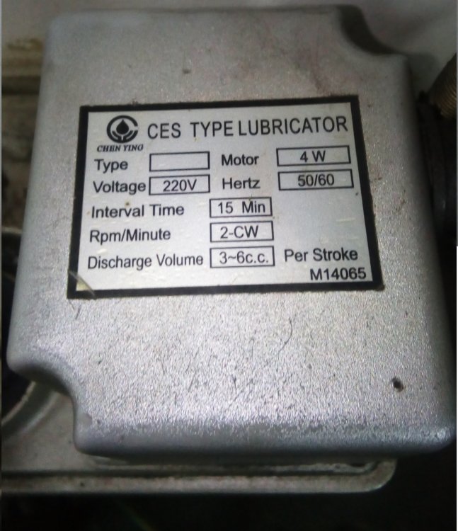
В архиве все что со станка скачали., точнее с флешки станка.
Прошу прощения,если что-то не так делаю, начальство просило посмотреть станок (я программист, но с ЧПУ не знаком), который специалисты смотрели несколько раз и не смогли решить проблему.
Подскажите программу, с помощью которой можно просмотреть PLC (я так понял это типа ОС).
ffff.rar
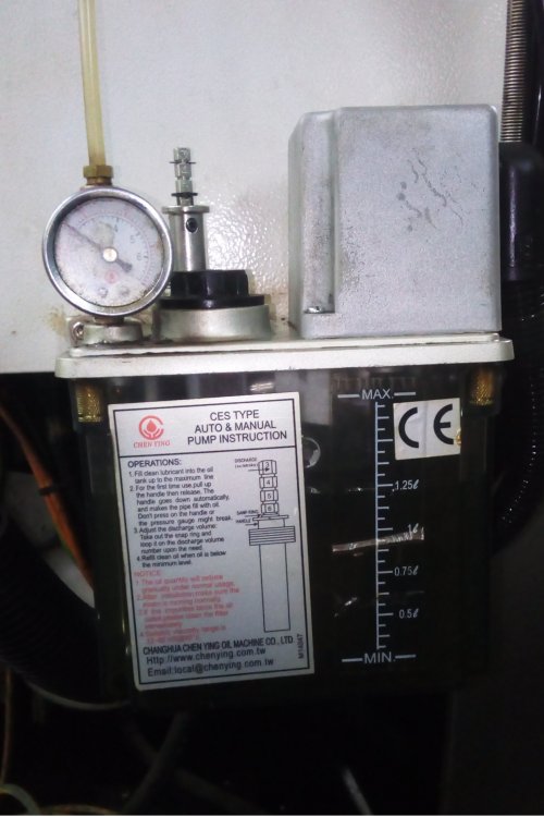
А вот это собственно ошибка из первого поста
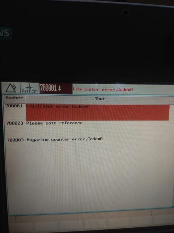
- Цитата
Ссылка на сообщение
Поделиться на других сайтах
![]()
vl_cnc
78
-
- Жалоба
- Рассказать
10 часов назад, Anat2015 сказал:
Довольно распространены пневмо-гидравлические устройства смазки. Воздухом давят на смазку и получают давление в смазочной магистрали. Частенько бывает, что проглядят момент, когда смазка заканчивается (а за станком смотреть надо, это аксиома), воздух попадает в смазочную магистраль.
Вот тут то и начинаются проблемы с удалением воздуха.
Лубрикатор, как тут выражаются, сфотографировать бы надо…
Такой тип смазки называется смазка масляным туманом, и используется для смазки шпинделя ( ни разу не видел для направляющих), которая включается только при запуске шпинделя. И хотя в ошибке не уточняется, о какой именно смазке идёт речь, похоже на проблему именно со смазкой направляющих. Судя по фото, она стандартная.
- Цитата
Ссылка на сообщение
Поделиться на других сайтах
Anat2015
293
-
- Жалоба
- Рассказать
1 час назад, vl_cnc сказал:
Такой тип смазки называется смазка масляным туманом
Извиняюсь, нет. Устройство состоит из стакана, в котором находится консистентная смазка. Управление смазкой идет пневмораспределителем, который подает воздух в стакан.
Нюансы конструкции не помню (могу сфотографировать), но давление воздуха преобразуется в давление густой смазки, которая смазывает необходимые узлы (в основном, конечно, редукторы и т.д.). Т.е. устройство состоит из двух частей: пневматической и гидравлической. Если забыть о пополнении консистентной смазки, воздух попадает в гидравлическую часть, ну и дальше — все, как в автомобиле, когда тормозуха засосет воздух, прокачивать надо.
Не уверен, что именно такое устройство стоит на данном станке, чисто для информации.
Ну, да, на фото типичный бачок с насосом и маслом.
Насколько я знаю, на 802Dsl можно на экран выводить ладдер и там все хорошо видно будет, в чем проблема.
По этому вопросу: на манометре давление в норме, а какое давление на датчике? Срабатывает ли он? Обычно датчики стоят в конце смазочной цепи, чтобы давление надежно появилось в самых дальних точках. Магистраль где-нибудь засорилась, на манометре — все хорошо, а на датчике давления нет…
Изменено 28 января 2020 пользователем Anat2015
- Цитата
Ссылка на сообщение
Поделиться на других сайтах
111wer
1
- Автор
-
- Жалоба
- Рассказать
4 минуты назад, Anat2015 сказал:
Извиняюсь, нет. Устройство состоит из стакана, в котором находится консистентная смазка. Управление смазкой идет пневмораспределителем, который подает воздух в стакан.
Нюансы конструкции не помню (могу сфотографировать), но давление воздуха преобразуется в давление густой смазки, которая смазывает необходимые узлы (в основном, конечно, редукторы и т.д.). Т.е. устройство состоит из двух частей: пневматической и гидравлической. Если забыть о пополнении консистентной смазки, воздух попадает в гидравлическую часть, ну и дальше — все, как в автомобиле, когда тормозуха засосет воздух, прокачивать надо.
Не уверен, что именно такое устройство стоит на данном станке, чисто для информации.
Ну, да, на фото типичный бачок с насосом и маслом.
Насколько я знаю, на 802Dsl можно на экран выводить ладдер и там все хорошо видно будет, в чем проблема.
Станок простоял около полугода, скорее всего Вы правы. Как прокачивать систему?
- Цитата
Ссылка на сообщение
Поделиться на других сайтах
111wer
1
- Автор
-
- Жалоба
- Рассказать
На манометре нормальное давление, а датчик под станком, как он выглядит?
- Цитата
Ссылка на сообщение
Поделиться на других сайтах
boomeeeer
185
-
- Жалоба
- Рассказать
13 часа назад, 111wer сказал:
В архиве все что со станка скачали., точнее с флешки станка.
Прошу прощения,если что-то не так делаю, начальство просило посмотреть станок (я программист, но с ЧПУ не знаком), который специалисты смотрели несколько раз и не смогли решить проблему.
Подскажите программу, с помощью которой можно просмотреть PLC (я так понял это типа ОС).
ffff.rar
К сожалению не получилось открыть Ваш файл. Не знаю почему, другие архивы, которые у меня имеются от 802Dsl спокойно открываются. Если только напрямую к ЧПУшке компом подключаться и выкачивать проект электроавтоматики. Вот вам софт. Кабель там на коленке спаять можно за 5 минут.
Programming_Tool_PLC802.zip
- Цитата
Ссылка на сообщение
Поделиться на других сайтах
![]()
vl_cnc
78
-
- Жалоба
- Рассказать
2 часа назад, Anat2015 сказал:
Извиняюсь, нет. Устройство состоит из стакана, в котором находится консистентная смазка. Управление смазкой идет пневмораспределителем, который подает воздух в стакан.
Нюансы конструкции не помню (могу сфотографировать), но давление воздуха преобразуется в давление густой смазки, которая смазывает необходимые узлы (в основном, конечно, редукторы и т.д.). Т.е. устройство состоит из двух частей: пневматической и гидравлической. Если забыть о пополнении консистентной смазки, воздух попадает в гидравлическую часть, ну и дальше — все, как в автомобиле, когда тормозуха засосет воздух, прокачивать надо.
С такими сталкиваться не приходилось)
В данном случае обычная смазка — подаётся питание на мотор и он вращает механизм выдержки времени (15 мин) , затем происходит впрыск смазки, величина которого регулируется стопорами на металлическом стержне возле манометра. По моему, внутри такого юнита отсутствует датчик давления. Поэтому ошибка контроля работы смазки может формироваться по следующим условиям — датчик давления установлен где-то дальше в системе (как писали выше), не срабатывает датчик уровня смазки в бачке, или же контроль работы по блок-контактам реле или контактора, включающего смазку.
Судя по фото, электросхемы к станку имеются, можно всё найти.
12 часа назад, 111wer сказал:
Прошу прощения,если что-то не так делаю, начальство просило посмотреть станок (я программист, но с ЧПУ не знаком), который специалисты смотрели несколько раз и не смогли решить проблему.
Стандартная ситуация — работу электронщика переложить на кого-нибудь.
- Цитата
Ссылка на сообщение
Поделиться на других сайтах
Anat2015
293
-
- Жалоба
- Рассказать
3 часа назад, 111wer сказал:
а датчик под станком, как он выглядит?
Не обязательно его искать, если есть эл.схема, то просто, включая вручную контактор двигателя насоса смазки, мультиметром в эл.шкафу проверить срабатывание контакта датчика давления, наверное и время засечь, через которое он срабатывает (если срабатывает) после включения насоса.
Есть более простой способ это увидеть на экране ЧПУ, но боюсь, что вам это трудновато будет сделать. Ищите грамотного электронщика.
- Цитата
Ссылка на сообщение
Поделиться на других сайтах
- Назад
- 1
- 2
- 3
- 4
- Вперёд
- Страница 1 из 4
Присоединяйтесь к обсуждению
Вы можете опубликовать сообщение сейчас, а зарегистрироваться позже.
Если у вас есть аккаунт, войдите в него для написания от своего имени.
Примечание: вашему сообщению потребуется утверждение модератора, прежде чем оно станет доступным.
Functionality
The meanings of the messages listed below differ from those given in the «Diagnostics
Manual»:
10631
10631
10631
10631
PLC alarm messages are specially configured for the «Manual Machine Plus» system in the
shipped version of the «Manual Machine Plus» software.
The following list of PLC alarm messages applies, unless the machine manufacturer has
defined an alternative or additional list of errors.
700000
700001
700002
700003
700004
700005
700006
700007
700008
700009
700010
700011
700012
700013
700014
700015
700016
700017
700018
700019
700020
Manual Machine Plus (Turning)
Programming and Operating Manual, 12/2012, 6FC5398-3DP10-0BA0
-X limit stop reached
+X limit stop reached
-Z limit stop reached
+Z limit stop reached
Tool clamping timeout
Spindle being braked
Operation not allowed: chuck unclamped
Gear stage change timeout
No gear stage signal
Drives not ready
Chuck operation not allowed: spindle/prog. running
Cooling motor overload
Coolant level too low
Lubricating motor overload
5
99
|
|
Ремонт SINUMERIK 808D
Компания «Кернел» производит ремонт ЧПУ с 2002 года. За это время мы накопили колоссальный опыт в том числе опыт в ремонте SINUMERIK 808D такого известного производителя как SIEMENS. Ремонт подобной промышленной электроники ответственное и сложное занятие, требующие максимальной отдачи, профессионализма и максимально полной материальной базе.
Ремонт SINUMERIK 808D в производится как в сервисном центре, так и с выездом специалиста на территорию заказчика. SINUMERIK 808D является крайне сложной промышленной электроникой соответственно ремонт SINUMERIK 808D можно доверить только настоящим профессионалам своего дела с богатым опытом работы в данном направлении.
Все специалисты нашего сервисного центра имеют высшее техническое образование, огромный опыт и максимально полную материальную базу включая новейшее высокотехнологичное диагностическое оборудование благодаря чему ремонт SINUMERIK 808D проходит максимально эффективно.
Инженеры сервисного центра уделяют максимальное внимание к качеству исполнения ремонта, программирования и настройке ЧПУ, не зависимо от производителя данного промышленного оборудования. Именно поэтому мы смело даем гарантию на ремонт SINUMERIK 808D и замененные в процессе ремонта компоненты шесть месяцев.
Особое внимание заслуживает тот факт, что ремонт SINUMERIK 808D в производится исключительно с использованием оригинальных запасных частей, на компонентном уровне с применением высокотехнологичного оборудования, квалифицированным персоналом с инженерным образованием.
Если на вашем производстве появились проблемы с ЧПУ SINUMERIK 808D, которые вы не можете решить самостоятельно, мы всегда рады вам помочь. Обращайтесь в сервисный центр «Кернел». Специалисты нашей компании в минимальные сроки проведут глубокую диагностику ЧПУ и последующий ремонт SINUMERIK 808D в . Оставьте аявку на ремонт ЧПУ используя форму на сайте.
Ошибки SINUMERIK 808D
Сообщения об ошибках SINUMERIK 808D и обработка ошибок
При возникновении ошибок при выполнении циклов выдается сигнал и выполнение цикла прерывается. Кроме того, сообщения циклов выводятся в строке сообщений СЧПУ. Эти сообщения не прерывают выполнение программы. Ошибки с их действием и сообщениями в строке сообщений СЧПУ описаны совместно с описанием конкретных циклов.
Обработка ошибок SINUMERIK 808D в циклах
В циклах генерируются сообщения об ошибках с номерами от 61000 до 62999. Диапазон номеров, в свою очередь, снова делится в соответствии с реакциями на ошибки и критериями отмены. Текст ошибки, который отображается вместе с номером ошибки, предоставляет более подробную информацию о причине ошибки.
|
Номер ошибки |
Критерий сброса |
Реакция на ошибку |
|
61000 … 61999 |
NC_RESET |
Подготовка кадра в СЧПУ прервана |
|
62000 … 62999 |
Кнопка сброса |
Прерывается подготовка кадра; цикл может быть продолжен нажатием следующей клавиши на MCP после удаления ошибки: |
Обзор ошибок циклов SINUMERIK 808D
Номера ошибок классифицируются следующим образом:
|
6 |
_ |
Х |
_ |
_ |
- X=0 Общие ошибки циклов
- X=1 Ошибки, возникшие при сверлении, фрезеровании
- X=6 Ошибки, возникшие в циклах токарной обработки
Сообщения циклов SINUMERIK 808D
Сообщения циклов выводятся в строке сообщений СЧПУ. Эти сообщения не прерывают выполнение программы. Сообщения предоставляют информацию относительно поведения циклов хода обработки и, как правило, хранятся за пределами рабочей операции или до конца цикла. Пример сообщения: «Глубина: в соответствии со значением относительной глубины» для всех циклов сверления.
Все ошибки SINUMERIK 808D описаны в руководстве пользователя, которое вы можете скачать с нашего сайта в удобном формате- pdf.
Скачать руководство пользователя (диагностика) SINUMERIK 808D мануал.pdf
Устранение причины ошибки и ее сброс на станке оснащенным системой ЧПУ позволит в кратчайшие сроки возобновить работу. К сожалению не все ошибки можно исправить самостоятельно, некоторые ошибки SINUMERIK 808D возможно исправить только в специализированных сервисных центрах.
SINUMERIK 808D программирование
На ряду с ремонтом, специалисты сервисного центра «Кернел» выполняют программирование SINUMERIK 808D и настройку параметров системы ЧПУ. Подобную услугу мы оказываем не только на территории сервисного центра, также инженер компании может выполнить программирование SINUMERIK 808D на территории заказчика.
Настройка параметров, программирование SINUMERIK 808D является заключительным звеном в процессе ремонта ЧПУ и требует профессионального подхода. Именно финальный этап программирования SINUMERIK 808D наглядно покажет качество выполненного ремонта SINUMERIK 808D.
К слову, мы уделяем особое внимание качеству и смело даем гарантию на все выполненные ремонтно-восстановительные работы шесть месяцев, гарантия так же распространяется на запасные части, которые были заменены в процессе ремонта.
Хочется обратить внимание на то, что мы стараемся провести ремонт и программирование SINUMERIK 808D в максимально сжатые сроки, тем самым минимизируем простой дорогостоящего промышленного оборудования.
Дополнительно можно скачать руководство по программированию SINUMERIK 808D в формате- pdf
Скачать руководство пользователя (программирование) SINUMERIK 808D мануал.pdf
SINUMERIK 808D ввод в эксплуатацию
Инженеры сервисного центра «Кернел» не только выполняют качественный ремонт SINUMERIK 808D и программирование ЧПУ в . Так же мы предоставляем услугу запуска в эксплуатацию оборудования от стадии проектирования до выпуска первой продукции.
Именно этап запуска в эксплуатацию SINUMERIK 808D отвечает за долгий и безаварийный процесс работы промышленного оборудования, тем самым позволяя получить максимальную прибыль и сэкономить на незапланированном ремонте.
По-настоящему качественный ввод в эксплуатацию SINUMERIK 808D может выполнить только высококвалифицированный специалист с богатым опытом работы в данном направлении. Найти подобного специалиста достаточно сложно, но, если вы обращаетесь в наш сервисный центр вам не придется об этом думать.
В нашей команде работают исключительно профессионалы своего дела, а за время существования нашей компании мы ввели в эксплуатацию не одну сотню систем ЧПУ в том числе и SINUMERIK 808D, с каждым разом получая и накапливая драгоценный опыт.
О SINUMERIK 808D
SINUMERIK 808D объединяет в себе качественно сконфигурированную систему ЧПУ предназначенную для работы на фрезерных и токарных станках.
Пример сборки для токарной обработки с помощью SINUMERIK 808D ADVANCED T
|
Описание |
Колл-во |
Артикул |
|
SINUMERIK CNC |
||
|
SINUMERIK 808D ADVANCED T PPU 160.3 vertical, English layout |
1 |
6FC5370-2BT03-0AA0 |
|
SINUMERIK 808D MCP vertical, with handwheel slot, English layout |
1 |
6FC5303-0AF35-3AA0 |
|
Stabilized power supply, SITOP PSU200M 24 V DC, 5 A |
1 |
6EP1333-3BA10 |
|
RS422 (TTL) incremental encoder, 1024 S/R |
1 |
6FX2001-2EB02 |
|
Spring disk coupling, shaft diameter 6 mm/6 mm |
1 |
6FX2001-7KF10 |
|
Clamp strap for encoders with Synchro flange |
3 |
6FX2001-7KP01 |
|
Pre-assembled bus cable PPU 160.3 – SINAMICS V70, length 5 m |
1 |
6FC5548-0BA20-1AF0 |
|
Pre-assembled bus cable SINAMICS V70 – SINAMICS V70, length 0.25 m |
2 |
6FC5548-0BA20-1AA2 |
|
Pre-assembled signal cable PPU 160.3 – handwheel, length 1 m |
1 |
6FX8002-2BB01-1AB0 |
|
Pre-assembled signal cable PPU 160.3 – incremental spindle encoder (TTL), length 5 m |
1 |
6FX8002-2CD01-1AF0 |
|
SINAMICS V70 |
||
|
SINAMICS V70, Irated 3.0 A |
1 |
6SL3210-5DE13-5UA0 |
|
SINAMICS V70, Irated 5.3 A |
1 |
6SL3210-5DE17-8UA0 |
|
SINAMICS V70 spindle1), Irated 19.6 A |
1 |
6SL3210-5DE22-0UA0 |
|
Pre-assembled signal cable SINAMICS V70 – absolute encoder in SIMOTICS S-1FL6 feed motor, length 5 m |
2 |
6FX3002-2DB10-1AF0 |
|
Pre-assembled power cable 4 × 1.5 mm2 |
2 |
6FX3002-5CL02-1AF0 |
|
Pre-assembled power cable 4 × 2.5 mm2 |
1 |
6FX3002-5CL12-1AF0 |
|
Pre-assembled brake cable SINAMICS V70 – brake in SIMOTICS S-1FL6 feed motor with holding brake, length 5 m |
1 |
6FX3002-5BL03-1AF0 |
|
Pre-assembled signal cable SINAMICS V70 – incremental encoder in M-1PH1, length 5 m |
1 |
6FX3002-2CT30-1AF0 |
|
Power cable 4 × 4 mm2, sold by the meter, (optional)2) SINAMICS V70 – SIMOTICS M-1PH1 main spindle motor, length 30 m |
1 |
6FX5008-1BB31-1DA0 |
|
SIMOTICS motors |
||
|
SIMOTICS S-1FL6 feed motor, 4 Nm, 2000 rpm, absolute encoder, plain shaft, without holding brake |
1 |
1FL6061-1AC61-2LG1 |
|
SIMOTICS S-1FL6 feed motor, 11 Nm, 2000 rpm, absolute encoder, plain shaft, with holding brake |
1 |
1FL6066-1AC61-2LH1 |
|
SIMOTICS M-1PH1 main spindle spindle motor, 53 Nm, 1000 rpm, incremental encoder, plain shaft |
1 |
1PH1105-1LD10-0GA0 |
Пример сборки для фрезерования с помощью SINUMERIK 808D ADVANCED M
|
Описание |
Колл-во |
Артикул |
|
SINUMERIK CNC |
||
|
SINUMERIK 808D ADVANCED M PPU 161.3 horizontal, English layout |
1 |
6FC5370-2AM03-0AA0 |
|
SINUMERIK 808D MCP horizontal, English layout |
1 |
6FC5303-0AF35-0AA0 |
|
Electronic handwheel, with front plate 120 mm × 120 mm, with setting wheel, 5 V DC, RS 422 |
1 |
6FC9320-5DB01 |
|
Terminal strip converter 50-pole |
1 |
6EP5406-5AA00 |
|
Cable set, 50-pole ribbon cable, with insulation displacement connectors, 50-pole |
1 |
6EP5306-5BG00 |
|
Stabilized power supply, SITOP PSU200M 24 V DC, 5 A |
1 |
6EP1333-3BA10 |
|
Pre-assembled bus cable PPU 161.3 – SINAMICS V70, length 5 m |
1 |
6FC5548-0BA20-1AF0 |
|
Pre-assembled bus cable SINAMICS V70 – SINAMICS V70, length 0.25 m |
2 |
6FC5548-0BA20-1AA2 |
|
Pre-assembled signal cable PPU 161.3 – handwheel, length 1 m |
1 |
6FX8002-2BB01-1AB0 |
|
Pre-assembled signal cable PPU 161.3 – incremental spindle encoder (TTL), length 7 m |
1 |
6FX8002-2CD01-1AH0 |
|
SINAMICS V70 |
||
|
SINAMICS V70, Irated 4.6 A |
2 |
6SL3210-5DE16-0UA0 |
|
SINAMICS V70, Irated 7.8 A |
1 |
6SL3210-5DE21-0UA0 |
|
SINAMICS V70 spindle1), Irated 19.6 A |
1 |
6SL3210-5DE22-0UA0 |
|
Pre-assembled signal cable SINAMICS V70 – incremental encoder in SIMOTICS S-1FL6 feed motor, length 10 m |
3 |
6FX3002-2CT12-1BA0 |
|
Pre-assembled power cable 4 × 2.5 mm2 |
3 |
6FX3002-5CL12-1BA0 |
|
Pre-assembled signal cable SINAMICS V70 – brake in SIMOTICS S-1FL6 feed motor, length 10 m |
1 |
6FX3002-5BL03-1BA0 |
|
Pre-assembled signal cable SINAMICS V70 – incremental encoder in M-1PH1, length 10 m |
1 |
6FX3002-2CT30-1BA0 |
|
Power cable 4 × 4 mm2, sold by the meter, (optional)2) SINAMICS V70 – SIMOTICS M-1PH1 main spindle motor, length 30 m |
1 |
6FX5008-1BB31-1DA0 |
|
SIMOTICS motors |
||
|
SIMOTICS S-1FL6 feed motor, 8 Nm, 2000 rpm, incremental encoder, plain shaft, without holding brake |
2 |
1FL6064-1AC61-2AG1 |
|
SIMOTICS S-1FL6 feed motor, 15 Nm, 2000 rpm, incremental encoder, plain shaft, with holding brake |
1 |
1FL6067-1AC61-2AH1 |
|
SIMOTICS M-1PH1 main spindle motor, 48 Nm, 1500 rpm, incremental encoder, plain shaft |
1 |
1PH1105-1LF12-0GA0 |
1) Выбор тормозного резистора см. В приводе шпинделя SINAMICS V70.
2) Перечисленные выше 30-метровые силовые кабели (необработанные) можно выбрать для использования с двигателями 1PH1. Вы должны собрать кабель питания с разъемами самостоятельно. Вы также можете выбрать сторонний кабель питания в соответствии с конфигурацией системы.
SINUMERIK 808D выполнен в двух вариантах:
- Горизонтальное исполнение (SINUMERIK 808D PPU 261.3/PPU 281.3);
- Вертикальное исполнение (SINUMERIK 808D PPU 260.3/PPU 280.3).
SINUMERIK 808D это моноблочная система ЧПУ, объединяющая в одном устройстве все компоненты СЧПУ:
- ЧПУ, PLC, HMI;
- полная клавиатура СЧПУ;
- регулятор для 6 приводов.
Двигатели могут подключаться напрямую через DRIVE-CLiQ к цифровой приводной системе. В комбинации с модульным исполнением приводной системы SINAMICS S120 получается простая и надежная конструкция с минимальным объемом межкомпонентных соединений.
Обзор соединений SINUMERIK 808D
Точно подобранный набор функций системы ЧПУ для стандартных токарных и фрезерных станков отвечает всем требованиям мелко- и крупносерийного производства. Специально подобранные системные параметры для токарной и фрезерной технологии позволяют значительно сократить расходы на ввод станка в эксплуатацию.
Моноблочная система ЧПУ крепится с задней стороны с помощью специальных элементов, входящих в объем поставки.
Линейка промышленной электроники, которую восстанавливают специалисты сервисного центра «Кернел» не имеет ограничений, мы выполняем качественный ремонт промышленной электроники и оборудования абсолютно любых производителей не зависимо от года выпуска и наличия технической документации.
Ниже приведен далеко не полный список ЧПУ SINUMERIK 808D ремонт которых предлагает наш сервисный центр.
|
6FC5370-2BM03-0AA0 6FC5370-2BM03-0CA0 6FC5370-2BT03-0AA0 6FC5370-2BT03-0CA0 |
6FC5370-3BM03-0AA0 6FC5370-3BM03-0CA0 6FC5370-3BT03-0AA0 6FC5370-3BT03-0CA0 |
|
6FC5303-0AF35-0AA0 SINUMERIK 808D Machine control panel 6FC5303-0AF35-2AA0 SINUMERIK 808D Machine control panel vertical 6FC5303-0AF35-3AA0 SINUMERIK 808D Machine control panel vertical |
Оставить заявку на ремонт или программирование SINUMERIK 808D
Оставить заявку на ремонт или программирования SINUMERIK 808D в можно с помощью специальной формы, которая вызывается нажатием одноименной кнопки в верхней части страницы. Все вопросы, связанные с ремонтом SINUMERIK 808D в вы можете задать нашим менеджерам. Связаться с ними можно несколькими способами:
- Заказав обратный звонок (кнопка в правом нижнем углу сайта)
- Посредством чата (кнопка расположена с левой стороны сайта)
- Позвонив по номеру телефона: +7(8482) 79-78-54; +7(917) 121-53-01
- Написав на электронную почту: 89171215301@mail.ru
Вот далеко не полный список производителей промышленной электроники и оборудования, ремонтируемой в нашей компании.
|
|
Ремонт SINUMERIK 808D
Компания «Кернел» производит ремонт ЧПУ с 2002 года. За это время мы накопили колоссальный опыт в том числе опыт в ремонте SINUMERIK 808D такого известного производителя как SIEMENS. Ремонт подобной промышленной электроники ответственное и сложное занятие, требующие максимальной отдачи, профессионализма и максимально полной материальной базе.
Ремонт SINUMERIK 808D в производится как в сервисном центре, так и с выездом специалиста на территорию заказчика. SINUMERIK 808D является крайне сложной промышленной электроникой соответственно ремонт SINUMERIK 808D можно доверить только настоящим профессионалам своего дела с богатым опытом работы в данном направлении.
Все специалисты нашего сервисного центра имеют высшее техническое образование, огромный опыт и максимально полную материальную базу включая новейшее высокотехнологичное диагностическое оборудование благодаря чему ремонт SINUMERIK 808D проходит максимально эффективно.
Инженеры сервисного центра уделяют максимальное внимание к качеству исполнения ремонта, программирования и настройке ЧПУ, не зависимо от производителя данного промышленного оборудования. Именно поэтому мы смело даем гарантию на ремонт SINUMERIK 808D и замененные в процессе ремонта компоненты шесть месяцев.
Особое внимание заслуживает тот факт, что ремонт SINUMERIK 808D в производится исключительно с использованием оригинальных запасных частей, на компонентном уровне с применением высокотехнологичного оборудования, квалифицированным персоналом с инженерным образованием.
Если на вашем производстве появились проблемы с ЧПУ SINUMERIK 808D, которые вы не можете решить самостоятельно, мы всегда рады вам помочь. Обращайтесь в сервисный центр «Кернел». Специалисты нашей компании в минимальные сроки проведут глубокую диагностику ЧПУ и последующий ремонт SINUMERIK 808D в . Оставьте аявку на ремонт ЧПУ используя форму на сайте.
Ошибки SINUMERIK 808D
Сообщения об ошибках SINUMERIK 808D и обработка ошибок
При возникновении ошибок при выполнении циклов выдается сигнал и выполнение цикла прерывается. Кроме того, сообщения циклов выводятся в строке сообщений СЧПУ. Эти сообщения не прерывают выполнение программы. Ошибки с их действием и сообщениями в строке сообщений СЧПУ описаны совместно с описанием конкретных циклов.
Обработка ошибок SINUMERIK 808D в циклах
В циклах генерируются сообщения об ошибках с номерами от 61000 до 62999. Диапазон номеров, в свою очередь, снова делится в соответствии с реакциями на ошибки и критериями отмены. Текст ошибки, который отображается вместе с номером ошибки, предоставляет более подробную информацию о причине ошибки.
|
Номер ошибки |
Критерий сброса |
Реакция на ошибку |
|
61000 … 61999 |
NC_RESET |
Подготовка кадра в СЧПУ прервана |
|
62000 … 62999 |
Кнопка сброса |
Прерывается подготовка кадра; цикл может быть продолжен нажатием следующей клавиши на MCP после удаления ошибки: |
Обзор ошибок циклов SINUMERIK 808D
Номера ошибок классифицируются следующим образом:
|
6 |
_ |
Х |
_ |
_ |
- X=0 Общие ошибки циклов
- X=1 Ошибки, возникшие при сверлении, фрезеровании
- X=6 Ошибки, возникшие в циклах токарной обработки
Сообщения циклов SINUMERIK 808D
Сообщения циклов выводятся в строке сообщений СЧПУ. Эти сообщения не прерывают выполнение программы. Сообщения предоставляют информацию относительно поведения циклов хода обработки и, как правило, хранятся за пределами рабочей операции или до конца цикла. Пример сообщения: «Глубина: в соответствии со значением относительной глубины» для всех циклов сверления.
Все ошибки SINUMERIK 808D описаны в руководстве пользователя, которое вы можете скачать с нашего сайта в удобном формате- pdf.
Скачать руководство пользователя (диагностика) SINUMERIK 808D мануал.pdf
Устранение причины ошибки и ее сброс на станке оснащенным системой ЧПУ позволит в кратчайшие сроки возобновить работу. К сожалению не все ошибки можно исправить самостоятельно, некоторые ошибки SINUMERIK 808D возможно исправить только в специализированных сервисных центрах.
SINUMERIK 808D программирование
На ряду с ремонтом, специалисты сервисного центра «Кернел» выполняют программирование SINUMERIK 808D и настройку параметров системы ЧПУ. Подобную услугу мы оказываем не только на территории сервисного центра, также инженер компании может выполнить программирование SINUMERIK 808D на территории заказчика.
Настройка параметров, программирование SINUMERIK 808D является заключительным звеном в процессе ремонта ЧПУ и требует профессионального подхода. Именно финальный этап программирования SINUMERIK 808D наглядно покажет качество выполненного ремонта SINUMERIK 808D.
К слову, мы уделяем особое внимание качеству и смело даем гарантию на все выполненные ремонтно-восстановительные работы шесть месяцев, гарантия так же распространяется на запасные части, которые были заменены в процессе ремонта.
Хочется обратить внимание на то, что мы стараемся провести ремонт и программирование SINUMERIK 808D в максимально сжатые сроки, тем самым минимизируем простой дорогостоящего промышленного оборудования.
Дополнительно можно скачать руководство по программированию SINUMERIK 808D в формате- pdf
Скачать руководство пользователя (программирование) SINUMERIK 808D мануал.pdf
SINUMERIK 808D ввод в эксплуатацию
Инженеры сервисного центра «Кернел» не только выполняют качественный ремонт SINUMERIK 808D и программирование ЧПУ в . Так же мы предоставляем услугу запуска в эксплуатацию оборудования от стадии проектирования до выпуска первой продукции.
Именно этап запуска в эксплуатацию SINUMERIK 808D отвечает за долгий и безаварийный процесс работы промышленного оборудования, тем самым позволяя получить максимальную прибыль и сэкономить на незапланированном ремонте.
По-настоящему качественный ввод в эксплуатацию SINUMERIK 808D может выполнить только высококвалифицированный специалист с богатым опытом работы в данном направлении. Найти подобного специалиста достаточно сложно, но, если вы обращаетесь в наш сервисный центр вам не придется об этом думать.
В нашей команде работают исключительно профессионалы своего дела, а за время существования нашей компании мы ввели в эксплуатацию не одну сотню систем ЧПУ в том числе и SINUMERIK 808D, с каждым разом получая и накапливая драгоценный опыт.
О SINUMERIK 808D
SINUMERIK 808D объединяет в себе качественно сконфигурированную систему ЧПУ предназначенную для работы на фрезерных и токарных станках.
Пример сборки для токарной обработки с помощью SINUMERIK 808D ADVANCED T
|
Описание |
Колл-во |
Артикул |
|
SINUMERIK CNC |
||
|
SINUMERIK 808D ADVANCED T PPU 160.3 vertical, English layout |
1 |
6FC5370-2BT03-0AA0 |
|
SINUMERIK 808D MCP vertical, with handwheel slot, English layout |
1 |
6FC5303-0AF35-3AA0 |
|
Stabilized power supply, SITOP PSU200M 24 V DC, 5 A |
1 |
6EP1333-3BA10 |
|
RS422 (TTL) incremental encoder, 1024 S/R |
1 |
6FX2001-2EB02 |
|
Spring disk coupling, shaft diameter 6 mm/6 mm |
1 |
6FX2001-7KF10 |
|
Clamp strap for encoders with Synchro flange |
3 |
6FX2001-7KP01 |
|
Pre-assembled bus cable PPU 160.3 – SINAMICS V70, length 5 m |
1 |
6FC5548-0BA20-1AF0 |
|
Pre-assembled bus cable SINAMICS V70 – SINAMICS V70, length 0.25 m |
2 |
6FC5548-0BA20-1AA2 |
|
Pre-assembled signal cable PPU 160.3 – handwheel, length 1 m |
1 |
6FX8002-2BB01-1AB0 |
|
Pre-assembled signal cable PPU 160.3 – incremental spindle encoder (TTL), length 5 m |
1 |
6FX8002-2CD01-1AF0 |
|
SINAMICS V70 |
||
|
SINAMICS V70, Irated 3.0 A |
1 |
6SL3210-5DE13-5UA0 |
|
SINAMICS V70, Irated 5.3 A |
1 |
6SL3210-5DE17-8UA0 |
|
SINAMICS V70 spindle1), Irated 19.6 A |
1 |
6SL3210-5DE22-0UA0 |
|
Pre-assembled signal cable SINAMICS V70 – absolute encoder in SIMOTICS S-1FL6 feed motor, length 5 m |
2 |
6FX3002-2DB10-1AF0 |
|
Pre-assembled power cable 4 × 1.5 mm2 |
2 |
6FX3002-5CL02-1AF0 |
|
Pre-assembled power cable 4 × 2.5 mm2 |
1 |
6FX3002-5CL12-1AF0 |
|
Pre-assembled brake cable SINAMICS V70 – brake in SIMOTICS S-1FL6 feed motor with holding brake, length 5 m |
1 |
6FX3002-5BL03-1AF0 |
|
Pre-assembled signal cable SINAMICS V70 – incremental encoder in M-1PH1, length 5 m |
1 |
6FX3002-2CT30-1AF0 |
|
Power cable 4 × 4 mm2, sold by the meter, (optional)2) SINAMICS V70 – SIMOTICS M-1PH1 main spindle motor, length 30 m |
1 |
6FX5008-1BB31-1DA0 |
|
SIMOTICS motors |
||
|
SIMOTICS S-1FL6 feed motor, 4 Nm, 2000 rpm, absolute encoder, plain shaft, without holding brake |
1 |
1FL6061-1AC61-2LG1 |
|
SIMOTICS S-1FL6 feed motor, 11 Nm, 2000 rpm, absolute encoder, plain shaft, with holding brake |
1 |
1FL6066-1AC61-2LH1 |
|
SIMOTICS M-1PH1 main spindle spindle motor, 53 Nm, 1000 rpm, incremental encoder, plain shaft |
1 |
1PH1105-1LD10-0GA0 |
Пример сборки для фрезерования с помощью SINUMERIK 808D ADVANCED M
|
Описание |
Колл-во |
Артикул |
|
SINUMERIK CNC |
||
|
SINUMERIK 808D ADVANCED M PPU 161.3 horizontal, English layout |
1 |
6FC5370-2AM03-0AA0 |
|
SINUMERIK 808D MCP horizontal, English layout |
1 |
6FC5303-0AF35-0AA0 |
|
Electronic handwheel, with front plate 120 mm × 120 mm, with setting wheel, 5 V DC, RS 422 |
1 |
6FC9320-5DB01 |
|
Terminal strip converter 50-pole |
1 |
6EP5406-5AA00 |
|
Cable set, 50-pole ribbon cable, with insulation displacement connectors, 50-pole |
1 |
6EP5306-5BG00 |
|
Stabilized power supply, SITOP PSU200M 24 V DC, 5 A |
1 |
6EP1333-3BA10 |
|
Pre-assembled bus cable PPU 161.3 – SINAMICS V70, length 5 m |
1 |
6FC5548-0BA20-1AF0 |
|
Pre-assembled bus cable SINAMICS V70 – SINAMICS V70, length 0.25 m |
2 |
6FC5548-0BA20-1AA2 |
|
Pre-assembled signal cable PPU 161.3 – handwheel, length 1 m |
1 |
6FX8002-2BB01-1AB0 |
|
Pre-assembled signal cable PPU 161.3 – incremental spindle encoder (TTL), length 7 m |
1 |
6FX8002-2CD01-1AH0 |
|
SINAMICS V70 |
||
|
SINAMICS V70, Irated 4.6 A |
2 |
6SL3210-5DE16-0UA0 |
|
SINAMICS V70, Irated 7.8 A |
1 |
6SL3210-5DE21-0UA0 |
|
SINAMICS V70 spindle1), Irated 19.6 A |
1 |
6SL3210-5DE22-0UA0 |
|
Pre-assembled signal cable SINAMICS V70 – incremental encoder in SIMOTICS S-1FL6 feed motor, length 10 m |
3 |
6FX3002-2CT12-1BA0 |
|
Pre-assembled power cable 4 × 2.5 mm2 |
3 |
6FX3002-5CL12-1BA0 |
|
Pre-assembled signal cable SINAMICS V70 – brake in SIMOTICS S-1FL6 feed motor, length 10 m |
1 |
6FX3002-5BL03-1BA0 |
|
Pre-assembled signal cable SINAMICS V70 – incremental encoder in M-1PH1, length 10 m |
1 |
6FX3002-2CT30-1BA0 |
|
Power cable 4 × 4 mm2, sold by the meter, (optional)2) SINAMICS V70 – SIMOTICS M-1PH1 main spindle motor, length 30 m |
1 |
6FX5008-1BB31-1DA0 |
|
SIMOTICS motors |
||
|
SIMOTICS S-1FL6 feed motor, 8 Nm, 2000 rpm, incremental encoder, plain shaft, without holding brake |
2 |
1FL6064-1AC61-2AG1 |
|
SIMOTICS S-1FL6 feed motor, 15 Nm, 2000 rpm, incremental encoder, plain shaft, with holding brake |
1 |
1FL6067-1AC61-2AH1 |
|
SIMOTICS M-1PH1 main spindle motor, 48 Nm, 1500 rpm, incremental encoder, plain shaft |
1 |
1PH1105-1LF12-0GA0 |
1) Выбор тормозного резистора см. В приводе шпинделя SINAMICS V70.
2) Перечисленные выше 30-метровые силовые кабели (необработанные) можно выбрать для использования с двигателями 1PH1. Вы должны собрать кабель питания с разъемами самостоятельно. Вы также можете выбрать сторонний кабель питания в соответствии с конфигурацией системы.
SINUMERIK 808D выполнен в двух вариантах:
- Горизонтальное исполнение (SINUMERIK 808D PPU 261.3/PPU 281.3);
- Вертикальное исполнение (SINUMERIK 808D PPU 260.3/PPU 280.3).
SINUMERIK 808D это моноблочная система ЧПУ, объединяющая в одном устройстве все компоненты СЧПУ:
- ЧПУ, PLC, HMI;
- полная клавиатура СЧПУ;
- регулятор для 6 приводов.
Двигатели могут подключаться напрямую через DRIVE-CLiQ к цифровой приводной системе. В комбинации с модульным исполнением приводной системы SINAMICS S120 получается простая и надежная конструкция с минимальным объемом межкомпонентных соединений.
Обзор соединений SINUMERIK 808D
Точно подобранный набор функций системы ЧПУ для стандартных токарных и фрезерных станков отвечает всем требованиям мелко- и крупносерийного производства. Специально подобранные системные параметры для токарной и фрезерной технологии позволяют значительно сократить расходы на ввод станка в эксплуатацию.
Моноблочная система ЧПУ крепится с задней стороны с помощью специальных элементов, входящих в объем поставки.
Линейка промышленной электроники, которую восстанавливают специалисты сервисного центра «Кернел» не имеет ограничений, мы выполняем качественный ремонт промышленной электроники и оборудования абсолютно любых производителей не зависимо от года выпуска и наличия технической документации.
Ниже приведен далеко не полный список ЧПУ SINUMERIK 808D ремонт которых предлагает наш сервисный центр.
|
6FC5370-2BM03-0AA0 6FC5370-2BM03-0CA0 6FC5370-2BT03-0AA0 6FC5370-2BT03-0CA0 |
6FC5370-3BM03-0AA0 6FC5370-3BM03-0CA0 6FC5370-3BT03-0AA0 6FC5370-3BT03-0CA0 |
|
6FC5303-0AF35-0AA0 SINUMERIK 808D Machine control panel 6FC5303-0AF35-2AA0 SINUMERIK 808D Machine control panel vertical 6FC5303-0AF35-3AA0 SINUMERIK 808D Machine control panel vertical |
Оставить заявку на ремонт или программирование SINUMERIK 808D
Оставить заявку на ремонт или программирования SINUMERIK 808D в можно с помощью специальной формы, которая вызывается нажатием одноименной кнопки в верхней части страницы. Все вопросы, связанные с ремонтом SINUMERIK 808D в вы можете задать нашим менеджерам. Связаться с ними можно несколькими способами:
- Заказав обратный звонок (кнопка в правом нижнем углу сайта)
- Посредством чата (кнопка расположена с левой стороны сайта)
- Позвонив по номеру телефона:
- +7(8482) 79-78-54;
- +7(8482) 55-96-39;
- +7(917) 121-53-01
- Написав на электронную почту: 89171215301@mail.ru
Вот далеко не полный список производителей промышленной электроники и оборудования, ремонтируемой в нашей компании.
-
Page 1: Table Of Contents
Preface Fundamental Geometrical Principles Fundamental Principles of NC Programming Creating an NC program SINUMERIK Tool change SINUMERIK 828D Tool offsets Fundamentals Spindle motion Feed control Programming Manual Geometry settings Motion commands Tool radius compensation Path action Coordinate transformations (frames) Auxiliary function outputs…
- Page 2
Note the following: WARNING Siemens products may only be used for the applications described in the catalog and in the relevant technical documentation. If products and components from other manufacturers are used, these must be recommended or approved by Siemens. Proper transport, storage, installation, assembly, commissioning, operation and maintenance are required to ensure that the products operate safely and without any problems. -
Page 3: Preface
● Researching documentation online Information on DOConCD and direct access to the publications in DOConWeb. ● Compiling individual documentation on the basis of Siemens contents with the My Documentation Manager (MDM), refer to http://www.siemens.com/mdm. My Documentation Manager provides you with a range of features for generating your own machine documentation.
- Page 4
Technical Support If you have any questions, please contact our hotline: Europe / Africa Phone +49 (0) 911 895 7222 +49 (0) 911 895 7223 Internet http://www.siemens.de/automation/support-request America Phone +1 423 262 2522 +1 423 262 2200 E-mail mailto:techsupport.sea@siemens.com Asia/Pacific… - Page 5
Availability of the described NC language elements All NC language elements described in the manual are available for the SINUMERIK 840D sl. The availability regarding SINUMERIK 828D can be found in table «Operations: Availability for SINUMERIK 828D (Page 503)». Fundamentals… - Page 6
Preface Fundamentals Programming Manual, 07/2010, 6FC5398-1BP40-0BA0… - Page 7
Table of contents Preface …………………………3 Fundamental Geometrical Principles ………………….. 13 Workpiece positions……………………13 1.1.1 Workpiece coordinate systems ………………..13 1.1.2 Cartesian coordinates ……………………15 1.1.3 Polar coordinates …………………….18 1.1.4 Absolute dimensions……………………19 1.1.5 Incremental dimension…………………….21 Working planes ……………………..23 Zero points and reference points ………………..25 Coordinate systems ……………………27 1.4.1 Machine coordinate system (MCS)………………..27… - Page 8
Table of contents Tool offsets ………………………… 67 General information about the tool offsets ……………… 67 Tool length compensation ………………….68 Tool radius compensation ………………….69 Tool compensation memory………………….70 Tool types………………………. 72 5.5.1 General information about the tool types ………………72 5.5.2 Milling tools …………………….. - Page 9
Table of contents Geometry settings……………………..159 Settable work offset (G54 to G57, G505 to G599, G53, G500, SUPA, G153) ……159 Selection of the working plane (G17/G18/G19) ……………..165 Dimensions ……………………..169 8.3.1 Absolute dimensions (G90, AC)………………..169 8.3.2 Incremental dimensions (G91, IC) …………………172 8.3.3 Absolute and incremental dimensions for turning and milling (G90/G91) ………175 8.3.4… - Page 10
Table of contents 9.13 Tapping with compensating chuck (G63)……………… 275 9.14 Fast retraction for thread cutting (LFON, LFOF, DILF, ALF, LFTXT, LFWP, LFPOS, POLF, POLFMASK, POLFMLIN)………………..277 9.15 Chamfer, rounding (CHF, CHR, RND, RNDM, FRC, FRCM) ……….. 282 Tool radius compensation……………………289 10.1 Tool radius compensation (G40, G41, G42, OFFN) ………….. - Page 11
Table of contents Supplementary commands ……………………401 14.1 Output messages (MSG) ………………….401 14.2 Writing string in OPI variable (WRTPR)………………403 14.3 Working area limitation ………………….404 14.3.1 Working area limitation in BCS (G25/G26, WALIMON, WALIMOF)……….404 14.3.2 Working area limitation in WCS/SZS (WALCS0 … WALCS10)……….408 14.4 Reference point approach (G74) ………………..411 14.5… - Page 12
Table of contents Tables…………………………457 16.1 Instructions ……………………..457 16.2 Operations: Availability for SINUMERIK 828D…………….503 16.3 Addresses ……………………..524 16.4 G function groups……………………533 16.5 Predefined subroutine calls………………….. 551 16.6 Predefined subroutine calls in motion-synchronous actions…………. 566 16.7 Predefined functions ……………………. 567 Appendix………………………… -
Page 13: Fundamental Geometrical Principles
Fundamental Geometrical Principles Workpiece positions 1.1.1 Workpiece coordinate systems In order that the machine or the control can work with the positions specified in the NC program, these specifications have to be made in a reference system that can be transferred to the directions of motion of the machine axes.
- Page 14
Fundamental Geometrical Principles 1.1 Workpiece positions Figure 1-2 Workpiece coordinate system for turning The workpiece zero (W) is the origin of the workpiece coordinate system. Sometimes it is advisable or even necessary to work with negative position specifications. For this reason, positions that are to the left of the zero point are assigned a negative sign («-«). -
Page 15: Cartesian Coordinates
Fundamental Geometrical Principles 1.1 Workpiece positions 1.1.2 Cartesian coordinates The axes in the coordinate system are assigned dimensions. In this way, it is possible to clearly describe every point in the coordinate system and therefore every workpiece position through the direction (X, Y and Z) and three numerical values The workpiece zero always has the coordinates X0, Y0, and Z0.
-
Page 16: Fundamental Geometrical Principles
Fundamental Geometrical Principles 1.1 Workpiece positions Example: Workpiece positions for turning With lathes, one plane is sufficient to describe the contour: Points P1 to P4 have the following coordinates: Position Coordinates X25 Z-7.5 X40 Z-15 X40 Z-25 X60 Z-35 Fundamentals Programming Manual, 07/2010, 6FC5398-1BP40-0BA0…
- Page 17
Fundamental Geometrical Principles 1.1 Workpiece positions Example: Workpiece positions for milling For milling, the feed depth must also be described, i.e. the third coordinate (in this case Z) must also be assigned a numerical value. Points P1 to P3 have the following coordinates: Position Coordinates X10 Y45 Z-5… -
Page 18: Polar Coordinates
Fundamental Geometrical Principles 1.1 Workpiece positions 1.1.3 Polar coordinates Polar coordinates can be used instead of Cartesian coordinates to describe workpiece positions. This is useful when a workpiece or part of a workpiece has been dimensioned with radius and angle. The point from which the dimensioning starts is called the «pole». Position specifications in the form of polar coordinates Polar coordinates are made up of the polar radius and the polar angle.
-
Page 19: Absolute Dimensions
Fundamental Geometrical Principles 1.1 Workpiece positions 1.1.4 Absolute dimensions Position specifications in absolute dimensions With absolute dimensions, all the position specifications refer to the currently valid zero point. Applied to tool movement this means: the position, to which the tool is to travel. Example: Turning In absolute dimensions, the following position specifications result for points P1 to P4: Position…
- Page 20
Fundamental Geometrical Principles 1.1 Workpiece positions Example: Milling In absolute dimensions, the following position specifications result for points P1 to P3: Position Position specification in absolute dimensions X20 Y35 X50 Y60 X70 Y20 Fundamentals Programming Manual, 07/2010, 6FC5398-1BP40-0BA0… -
Page 21: Incremental Dimension
Fundamental Geometrical Principles 1.1 Workpiece positions 1.1.5 Incremental dimension Position specifications in incremental dimensions In production drawings, the dimensions often do not refer to a zero point, but to another workpiece point. So that these dimensions do not have to be converted, they can be specified in incremental dimensions.
- Page 22
Fundamental Geometrical Principles 1.1 Workpiece positions Example: Milling The position specifications for points P1 to P3 in incremental dimensions are: In incremental dimensions, the following position specifications result for points P1 to P3: Position Position specification in incremental The specification refers to: dimensions X20 Y35 Zero point… -
Page 23: Working Planes
Fundamental Geometrical Principles 1.2 Working planes Working planes An NC program must contain information about the plane in which the work is to be performed. Only then can the control unit calculate the correct tool offsets during the execution of the NC program. The specification of the working plane is also relevant for certain types of circular-path programming and polar coordinates.
- Page 24
Fundamental Geometrical Principles 1.2 Working planes Programming of the working planes The working planes are defined in the NC program with the G commands follows: G command Working plane Infeed direction Abscissa Ordinate Applicate Fundamentals Programming Manual, 07/2010, 6FC5398-1BP40-0BA0… -
Page 25: Zero Points And Reference Points
Fundamental Geometrical Principles 1.3 Zero points and reference points Zero points and reference points Various zero points and reference points are defined on an NC machine: Zero points Machine zero The machine zero defines the machine coordinate system (MCS). All other reference points refer to the machine zero.
- Page 26
Fundamental Geometrical Principles 1.3 Zero points and reference points Zero points for milling Fundamentals Programming Manual, 07/2010, 6FC5398-1BP40-0BA0… -
Page 27: Coordinate Systems
Fundamental Geometrical Principles 1.4 Coordinate systems Coordinate systems A distinction is made between the following coordinate systems: ● Machine coordinate system (MCS) (Page 27) with the machine zero M ● Basic coordinate system (BCS) (Page 30) ● Basic zero system (BZS) (Page 32) ●…
- Page 28
Fundamental Geometrical Principles 1.4 Coordinate systems Three-finger rule The orientation of the coordinate system relative to the machine depends on the machine type. The axis directions follow the so-called «three-finger rule» of the right hand (according to DIN 66217). Seen from in front of the machine, the middle finger of the right hand points in the opposite direction to the infeed of the main spindle. - Page 29
Fundamental Geometrical Principles 1.4 Coordinate systems Position of the coordinate system in different machine types The position of the coordinate system resulting from the «three-finger rule» can have a different orientation for different machine types. Here are a few examples: Fundamentals Programming Manual, 07/2010, 6FC5398-1BP40-0BA0… -
Page 30: Basic Coordinate System (Bcs)
Fundamental Geometrical Principles 1.4 Coordinate systems 1.4.2 Basic coordinate system (BCS) The basic coordinate system (BCS) consists of three mutually perpendicular axes (geometry axes) as well as other special axes, which are not interrelated geometrically. Machine tools without kinematic transformation BCS and MCS always coincide when the BCS can be mapped onto the MCS without kinematic transformation (e.g.
- Page 31
Fundamental Geometrical Principles 1.4 Coordinate systems Machine tools with kinematic transformation BCS and MCS do not coincide when the BCS is mapped onto the MCS with kinematic transformation (e.g. 5-axis transformation, TRANSMIT/TRACYL/TRAANG). On such machines the machine axes and geometry axes must have different names. Figure 1-7 Kinematic transformation between the MCS and BCS Machine kinematics… -
Page 32: Basic Zero System (Bzs)
Fundamental Geometrical Principles 1.4 Coordinate systems 1.4.3 Basic zero system (BZS) The basic zero system (BZS) is the basic coordinate system with a basic offset. Basic offset The basic offset describes the coordinate transformation between BCS and BZS. It can be used, for example, to define the palette window zero.
-
Page 33: Settable Zero System (Szs)
Fundamental Geometrical Principles 1.4 Coordinate systems 1.4.4 Settable zero system (SZS) Settable zero offset The «settable zero system» (SZS) results from the basic zero system (BZS) through the settable zero offset. Settable zero offsets are activated in the NC program with the G commands as follows: G505 G599…
-
Page 34: Workpiece Coordinate System (Wcs)
Fundamental Geometrical Principles 1.4 Coordinate systems 1.4.5 Workpiece coordinate system (WCS) The geometry of a workpiece is described in the workpiece coordinate system (WCS). In other words, the data in the NC program refer to the workpiece coordinate system. The workpiece coordinate system is always a Cartesian coordinate system and assigned to a specific workpiece.
-
Page 35: Fundamental Principles Of Nc Programming
Fundamental Principles of NC Programming Note DIN 66025 is the guideline for NC programming. Name of an NC program Rules for program names Each NC program has a different name; the name can be chosen freely during program creation, taking the following conditions into account: ●…
-
Page 36: Fundamental Principles Of
Fundamental Principles of NC Programming 2.1 Name of an NC program Files in punch tape format Externally created program files that are read into the NC via the RS-232-C must be present in punch tape format. The following additional rules apply for the name of a file in punch tape format: ●…
-
Page 37: Structure And Contents Of An Nc Program
Fundamental Principles of NC Programming 2.2 Structure and contents of an NC program Structure and contents of an NC program 2.2.1 Blocks and block components Blocks An NC program consists of a sequence of NC blocks. Each block contains the data for the execution of a step in the workpiece machining.
-
Page 38: Programming Manual
Fundamental Principles of NC Programming 2.2 Structure and contents of an NC program Elements of the NC high-level language As the command set according to DIN 66025 is no longer adequate for the programming of complex machining sequences in modern machine tools, it has been extended by the elements of the NC high-level language.
-
Page 39: Block Rules
Fundamental Principles of NC Programming 2.2 Structure and contents of an NC program Effectiveness of commands Commands are either modal or non-modal: ● Modal Modal commands retain their validity with the programmed value (in all following blocks) until: – A new value is programmed under the same command –…
- Page 40
Fundamental Principles of NC Programming 2.2 Structure and contents of an NC program Block length A block can contain a maximum of 512 characters (including the comment and end-of-block character «L «). Note Three blocks of up to 66 characters each are normally displayed in the current block display on the screen. -
Page 41: Value Assignments
Fundamental Principles of NC Programming 2.2 Structure and contents of an NC program 2.2.3 Value assignments Values can be assigned to the addresses. The following rules apply: ● An «=» sign must be inserted between the address and the value if: –…
-
Page 42: Comments
Fundamental Principles of NC Programming 2.2 Structure and contents of an NC program 2.2.4 Comments To make an NC program easier to understand, comments can be added to the NC blocks. A comment is at the end of a block and is separated from the program section of the NC block by a semicolon («;»).
-
Page 43: Skipping Blocks
Fundamental Principles of NC Programming 2.2 Structure and contents of an NC program 2.2.5 Skipping blocks NC blocks, which are not to be executed in every program pass (e.g. execute a trial program run), can be skipped. Programming Blocks, which are to be skipped are marked with an oblique «/» in front of the block number. Several consecutive blocks can also be skipped.
- Page 44
Fundamental Principles of NC Programming 2.2 Structure and contents of an NC program Skip levels Blocks can be assigned to skip levels (max. 10), which can be activated via the user interface. Programming is performed by assigning a forward slash, followed by the number of the skip level. -
Page 45: Creating An Nc Program
Creating an NC program Basic procedure The programming of the individual operation steps in the NC language generally represents only a small proportion of the work in the development of an NC program. Programming of the actual instructions should be preceded by the planning and preparation of the operation steps.
-
Page 46: Creating An Nc Program
Creating an NC program 3.1 Basic procedure 3. Create a machining plan Define all machining operations step-by-step, e.g. – Rapid traverse movements for positioning – Tool change – Define the machining plane – Retraction for checking – Switch spindle, coolant on/off –…
-
Page 47: Available Characters
Creating an NC program 3.2 Available characters Available characters The following characters are available for writing NC programs: ● Upper-case characters: A, B, C, D, E, F, G, H, I, J, K, L, M, N,(O),P, Q, R, S, T, U, V, W, X, Y, Z ●…
- Page 48
Creating an NC program 3.2 Available characters NOTICE Take care to differentiate between the letter «O» and the digit «0». Note No distinction is made between upper and lower-case characters (exception: tool call). Note Non-printable special characters are treated like blanks. Fundamentals Programming Manual, 07/2010, 6FC5398-1BP40-0BA0… -
Page 49: Program Header
Creating an NC program 3.3 Program header Program header The NC blocks that are placed in front of the actual motion blocks for the machining of the workpiece contour, are called the program header. The program header contains information/statements regarding: ●…
- Page 50
Creating an NC program 3.3 Program header Program header for milling The following example shows the typical structure of an NC program header for milling: Program code Comment N10 T=»SF12″ ; Alternative: T123 N20 M6 ; Trigger tool change N30 D1 ;… -
Page 51: Program Examples
Creating an NC program 3.4 Program examples Program examples 3.4.1 Example 1: First programming steps Program example 1 is to be used to perform and test the first programming steps on the NC. Procedure 1. Create a new part program (name) 2.
-
Page 52: Example 2: Nc Program For Turning
Creating an NC program 3.4 Program examples 3.4.2 Example 2: NC program for turning Program example 2 is intended for the machining of a workpiece on a lathe. It contains radius programming and tool radius compensation. Note In order that the program can run on the machine, the machine data must have been set appropriately (→…
- Page 53
Creating an NC program 3.4 Program examples Program example 2 Program code Comment N5 G0 G53 X280 Z380 D0 ; Starting point N10 TRANS X0 Z250 ; Zero offset N15 LIMS=4000 ; Speed limitation (G96) N20 G96 S250 M3 ; Select constant cutting rate N25 G90 T1 D1 M8 ;… -
Page 54: Example 3: Nc Program For Milling
Creating an NC program 3.4 Program examples 3.4.3 Example 3: NC program for milling Program example 3 is intended for the machining of a workpiece on a vertical milling machine. It contains surface and side milling as well as drilling. Note In order that the program can run on the machine, the machine data must have been set appropriately (→…
- Page 55
Creating an NC program 3.4 Program examples Figure 3-3 Top view Program example 3 Program code Comment N10 T=»PF60″ Preselection of the tool with name PF60. N20 M6 Load the tool into the spindle. N30 S2000 M3 M8 Speed, direction of rotation, cooling on. - Page 56
Creating an NC program 3.4 Program examples Program code Comment N130 G1 G40 Y-72 F3000 Deselection of the milling tool radius compensation. N140 G0 Z200 M5 M9 Retraction of the milling tool, spindle + cooling off. N150 T=»SF10″ Preselection of the tool with name SF10. -
Page 57: Tool Change
Tool change Tool change method In chain, rotary-plate and box magazines, a tool change normally takes place in two stages: 1. The tool is sought in the magazine with the T command. 2. The tool is then loaded into the spindle with the M command. In circular magazines on turning machines, the T command carries out the entire tool change, that is, locates and inserts the tool.
-
Page 58: Tool Change Without Tool Management
Tool change 4.1 Tool change without tool management Tool change without tool management 4.1.1 Tool change with T command Function There is a direct tool change when the T command is programmed. Application For turning machines with circular magazine. Syntax Tool selection: T<number>…
-
Page 59: Tool Change With M6
Tool change 4.1 Tool change without tool management 4.1.2 Tool change with M6 Function The tool is selected when the command is programmed. The tool only becomes active with (including tool offset). Application For milling machines with chain, rotary-plate or box magazines. Syntax Tool selection: T<number>…
-
Page 60: Tool Change
Tool change 4.1 Tool change without tool management Example Program code Comment N10 T1 M6 ; Loading of tool T1. N20 D1 ; Selection of tool length compensation. N30 G1 X10 … ; Machining with T1. N70 T5 ; Preselection of tool T5. N80 …
-
Page 61: Tool Change With Tool Management (Option)
Tool change 4.2 Tool change with tool management (option) Tool change with tool management (option) Tool management The optional «Tool management» function ensures that at any given time the correct tool is in the correct location and that the data assigned to the tool are up to date. It also allows fast tool changes and avoids both scrap by monitoring the tool service life and machine downtimes by using spare tools.
- Page 62
Tool change 4.2 Tool change with tool management (option) Significance Command for tool change and activation of the tool offset The following specifications are possible: Number of the magazine location <location> Name of tool <name> Note: The correct notation (upper/lower case) must be observed when programming a tool name. - Page 63
Tool change 4.2 Tool change with tool management (option) The following tool call is programmed in the NC program: N10 T=1 The call is processed as follows: 1. Magazine location 1 is considered and the tool identifier determined. 2. The tool management recognizes that this tool is blocked and therefore cannot be used. 3. -
Page 64: Tool Change With M6 With Active Tool Management (Option)
Tool change 4.2 Tool change with tool management (option) 4.2.2 Tool change with M6 with active tool management (option) Function The tool is selected when the command is programmed. The tool only becomes active with (including tool offset). Application For milling machines with chain, rotary-plate or box magazines. Syntax Tool selection: T=<location>…
- Page 65
Tool change 4.2 Tool change with tool management (option) Note If the selected magazine location is not occupied in a tool magazine, the command acts as . The selection of the next occupied magazine location can be used to position the empty location. -
Page 66: Behavior With Faulty T Programming
Tool change 4.3 Behavior with faulty T programming Behavior with faulty T programming The behavior with faulty T programming depends on the configuration of the machine: MD22562 TOOL_CHANGE_ERROR_MODE Value Meaning Basic setting! With the T programming, a check is made immediately as to whether the NCK recognizes the T number.
-
Page 67: Tool Offsets
Tool offsets General information about the tool offsets Workpiece dimensions are programmed directly (e.g. according to the production drawing). Therefore, tool data such as milling tool diameter, cutting edge position of the turning tool (counterclockwise/clockwise turning tool) and tool length does not have to be taken into consideration when creating the program.
-
Page 68: Tool Length Compensation
Tool offsets 5.2 Tool length compensation Tool length compensation The tool length compensation compensates for the differences in length between the tools used. The tool length is the distance between the toolholder reference point and the tool tip: This length is measured and entered in the tool compensation memory of the control together with definable wear values.
-
Page 69: Tool Radius Compensation
Tool offsets 5.3 Tool radius compensation Tool radius compensation The contour and tool path are not identical. The milling tool or cutting edge center must travel along a path that is equidistant from the contour. To do this, the control requires data about the tool form (radius) from the tool compensation memory.
-
Page 70: Tool Compensation Memory
Tool offsets 5.4 Tool compensation memory Tool compensation memory The following data must be available in the tool compensation memory of the control for each tool edge: ● Tool type ● Cutting edge position ● Tool geometry variables (length, radius) This data is entered as tool parameters (max.
- Page 71
Tool offsets 5.4 Tool compensation memory Tool geometry variables (length, radius) The tool geometry variables consist of several components (geometry, wear). The control computes the components to a certain dimension (e.g. overall length 1, total radius). The respective overall dimension becomes effective when the compensation memory is activated. -
Page 72: Tool Types
Tool offsets 5.5 Tool types Tool types 5.5.1 General information about the tool types Tools are divided into tool types. Each tool type is assigned a 3-digit number. The first digit assigns the tool type to one of the following groups depending on the technology used: Tool type Tool group Milling tools…
- Page 73
Tool offsets 5.5 Tool types Tool parameters The following figures provide an overview of which tool parameters (DP…) for milling tools are entered in the compensation memory: Fundamentals Programming Manual, 07/2010, 6FC5398-1BP40-0BA0… -
Page 74: Drills
Tool offsets 5.5 Tool types Note Brief description of the tool parameters can be found on the user interface. For further information, see: References: Function Manual, Basic Functions; Tool Offset (W1) 5.5.3 Drills The following tool types are available in the «Drills» group: Twist drill Drill Boring bar…
-
Page 75: Grinding Tools
Tool offsets 5.5 Tool types Note Brief description of the tool parameters can be found on the user interface. For further information, see: References: Function Manual, Basic Functions; Tool Offset (W1) 5.5.4 Grinding tools The following tool types are available in the «Grinding tools» group: Surface grinding wheel Surface grinding wheel with monitoring Surface grinding wheel without monitoring without base dimension (TOOLMAN)
- Page 76
Tool offsets 5.5 Tool types Tool parameters The following figure provides an overview of which tool parameters (DP…) for grinding tools are entered in the compensation memory: Note Brief description of the tool parameters can be found on the user interface. For further information, see: References: Function Manual, Basic Functions;… -
Page 77: Turning Tools
Tool offsets 5.5 Tool types 5.5.5 Turning tools The following tool types are available in the «Turning tools» group: Roughing tool Finishing tool Plunge cutter Parting tool Threading tool Button tool / forming tool (TOOLMAN) Rotary drill (ECOCUT) Probe with cutting edge position parameters Tool parameters The following figures provide an overview of which tool parameters (DP…) for turning tools are entered in the compensation memory:…
- Page 78
Tool offsets 5.5 Tool types Note Brief description of the tool parameters can be found on the user interface. For further information, see: References: Function Manual, Basic Functions; Tool Offset (W1) Fundamentals Programming Manual, 07/2010, 6FC5398-1BP40-0BA0… -
Page 79: Special Tools
Tool offsets 5.5 Tool types 5.5.6 Special tools The following tool types are available in the «Special tools» group: Slotting saw 3D probe Edge probe Stop Tool parameters The following figure provides an overview of which tool parameters (DP…) for «Slotting saw» tool type are entered in the compensation memory: Note Brief description of the tool parameters can be found on the user interface.
-
Page 80: Chaining Rule
Tool offsets 5.5 Tool types 5.5.7 Chaining rule The geometry tool length compensations, wear and base dimension can be chained for both the left and the right tool nose radius compensation, i.e. if the tool length compensations are changed for the left cutting edge, then the values are also automatically entered for the right cutting edge and vice versa.
-
Page 81: Tool Offset Call (D)
Tool offsets 5.6 Tool offset call (D) Tool offset call (D) Function Cutting edges 1 to 8 (with active TOOLMAN 12) of a tool can be assigned different tool offset data records (e.g. different offset values for the left and right cutting edge of a grooving tool). Activation of the offset data (including the data for the tool length compensation) of a special cutting edge is performed by calling the D number.
- Page 82
Tool offsets 5.6 Tool offset call (D) Significance Command for the activation of an offset data record for the active tool The tool length compensation is applied with the first programmed traverse of the associated length compensation axis. Notice: A tool length compensation can also take effect without D programming, when the automatic activation of a tool edge has been configured for the tool change (→… - Page 83
Tool offsets 5.6 Tool offset call (D) Type of D programming The type of D programming is defined via machine data. This can be done as follows: ● D number = cutting edge number D numbers ranging from 1 to max. 12 are available for every tool T<number> or T=»Name»… -
Page 84: Tool Offsets
Tool offsets 5.6 Tool offset call (D) Example 2: Different offset values for the left and right cutting edge of a grooving tool N10 T2 N20 G0 X35 Z-20 N30 G1 D1 X10 N40… D6 Z-5 Fundamentals Programming Manual, 07/2010, 6FC5398-1BP40-0BA0…
-
Page 85: Change In The Tool Offset Data
Tool offsets 5.7 Change in the tool offset data Change in the tool offset data Effectiveness A change in the tool offset data takes effect the next time the T or D number is programmed. Set tool offset data to be active immediately The following machine data can be used to specify that entered tool offset data takes effect immediately: MD9440 $MM_ACTIVATE_SEL_USER…
-
Page 86: Programmable Tool Offset (Toffl, Toff, Toffr)
Tool offsets 5.8 Programmable tool offset (TOFFL, TOFF, TOFFR) Programmable tool offset (TOFFL, TOFF, TOFFR) Function The user can use the commands to modify the effective tool length or TOFFL TOFF TOFFR the effective tool radius in the NC program, without changing the tool offset data stored in the compensation memory.
- Page 87
Tool offsets 5.8 Programmable tool offset (TOFFL, TOFF, TOFFR) Significance Command for the compensation of the effective tool length TOFFL can be programmed with or without index: TOFFL • Without index: TOFFL= The programmed offset value is applied in the same direction as the tool length component L1 stored in the compensation memory. - Page 88
Tool offsets 5.8 Programmable tool offset (TOFFL, TOFF, TOFFR) Further syntax rules ● The tool length can be changed simultaneously in all three components. However, commands of the group and commands of the TOFFL TOFFL[1..3] TOFF[<geometry axis>] may not be used simultaneously in one block. may also not be written simultaneously in one block. - Page 89
Tool offsets 5.8 Programmable tool offset (TOFFL, TOFF, TOFFR) Example 2: Negative tool length offset The active tool is a drill with length L1 = 100 mm. The active plane is , i.e. the drill points in the Y direction. The effective drill length is to be decreased by 1 mm. - Page 90
Tool offsets 5.8 Programmable tool offset (TOFFL, TOFF, TOFFR) Further information Applications The «Programmable tool offset» function is especially interesting for ball mills and milling tools with corner radii as these are often calculated in the CAM system to the ball center instead of the ball tip. -
Page 91: Spindle Motion
Spindle motion Spindle speed (S), direction of spindle rotation (M3, M4, M5) Function The spindle speed and direction of rotation values set the spindle in rotary motion and provide the conditions for chip removal. Figure 6-1 Spindle motion during turning Other spindles may be available in addition to the main spindle (e.g.
- Page 92
Spindle motion 6.1 Spindle speed (S), direction of spindle rotation (M3, M4, M5) Significance Spindle speed in rpm for the master spindle S… Spindle speed in rpm for spindle <n> S<n>=… Note: The speed specified with applies to the master spindle. S0=…… - Page 93
Spindle motion 6.1 Spindle speed (S), direction of spindle rotation (M3, M4, M5) Example S1 is the master spindle, S2 is the second spindle. The part is to be machined from two sides. To do this, it is necessary to divide the operations into steps. After the cut-off point, the synchronizing device (S2) takes over machining of the workpiece after the cut off. - Page 94
Spindle motion 6.1 Spindle speed (S), direction of spindle rotation (M3, M4, M5) Example: Program code Comment N10 G1 F500 X70 Y20 S270 M3 ; The spindle ramps up to 270 rpm, then the movements are executed in X and Y. N100 G0 Z150 M5 ;… -
Page 95: Cutting Rate (Svc)
Spindle motion 6.2 Cutting rate (SVC) Cutting rate (SVC) Function As an alternative to the spindle speed, the tool cutting rate, which is more commonly used in practice, can be programmed for milling operations. The control uses the radius of the active tool to calculate the effective spindle speed from the programmed tool cutting rate: S = (SVC * 1000) / (R * 2π)
- Page 96
Spindle motion 6.2 Cutting rate (SVC) Syntax SVC[<n>]=<value> Note In the block with , the tool radius must be known; in other words, a corresponding tool including a tool offset data record must be active or selected in the block. There is no fixed sequence for selection during programming in the same block. -
Page 97: Spindle Motion
Spindle motion 6.2 Cutting rate (SVC) Note The tool paths of «standard tools» generated e.g. using CAD systems which already take the tool radius into account and only contain the deviation from the standard tool in the tool nose radius are not supported in conjunction with programming.
- Page 98
Spindle motion 6.2 Cutting rate (SVC) Example 4: Assumptions: Master or tool change is determined by the toolholder. MD20124 $MC_TOOL_MANAGEMENT_TOOLHOLDER > 1 In the event of a tool change the old tool offset is retained. A tool offset for the new tool is only activated when is programmed: MD20270 $MC_CUTTING_EDGE_DEFAULT = — 2… - Page 99
Spindle motion 6.2 Cutting rate (SVC) Example 5: Assumptions: Spindles are toolholders at the same time: MD20124 $MC_TOOL_MANAGEMENT_TOOLHOLDER = 0 In the event of a tool change tool offset data record D4 is selected automatically. MD20270 $MC_CUTTING_EDGE_DEFAULT = 4 Program code Comment N10 $TC_MPP1[9998,1]=2 ;… - Page 100
Spindle motion 6.2 Cutting rate (SVC) Further information Tool radius The following tool offset data (associated with the active tool) affect the tool radius when: ● $TC_DP6 (radius — geometry) ● $TC_DP15 (radius — wear) ● $TC_SCPx6 (offset for $TC_DP6) ●… -
Page 101: Constant Cutting Rate (G96/G961/G962, G97/G971/G972, G973, Lims, Scc)
Spindle motion 6.3 Constant cutting rate (G96/G961/G962, G97/G971/G972, G973, LIMS, SCC) Constant cutting rate (G96/G961/G962, G97/G971/G972, G973, LIMS, SCC) Function When the «Constant cutting rate» function is active, the spindle speed is modified as a function of the respective workpiece diameter so that the cutting rate S in m/min or ft/min remains constant at the tool edge.
- Page 102
Spindle motion 6.3 Constant cutting rate (G96/G961/G962, G97/G971/G972, G973, LIMS, SCC) Significance Constant cutting rate with feedrate type G95: ON G95 is activated automatically with G96. If G95 has not been activated previously, a new feedrate value will have to be specified when G96 is F… - Page 103
Spindle motion 6.3 Constant cutting rate (G96/G961/G962, G97/G971/G972, G973, LIMS, SCC) Examples Example 1: Activating the constant cutting rate with speed limitation Program code Comment N10 SETMS (3) N20 G96 S100 LIMS=2500 ; Constant cutting rate = 100 m/min, max. speed 2,500 rpm N60 G96 G90 X0 Z10 F8 S100 LIMS=444 ;… - Page 104
Spindle motion 6.3 Constant cutting rate (G96/G961/G962, G97/G971/G972, G973, LIMS, SCC) Further information Calculation of the spindle speed The ENS position of the face axis (radius) is the basis for calculating the spindle speed from the programmed cutting rate. Note Frames between WCS and SZS (e.g. - Page 105
Spindle motion 6.3 Constant cutting rate (G96/G961/G962, G97/G971/G972, G973, LIMS, SCC) Deactivating the constant cutting rate (G97/G971/G973) After , the control interprets an S value as a spindle speed in rpm again. If you do G97/G971 not specify a new spindle speed, the last speed set with is retained. - Page 106
Spindle motion 6.3 Constant cutting rate (G96/G961/G962, G97/G971/G972, G973, LIMS, SCC) Program code Comment N05 G95 F0.1 N10 GEOAX(1, X1) ; Channel axis X1 becomes first geometry axis. N20 SCC[X1] ; X1 and implicitly the first geometry axis (X) becomes the reference axis for G96/G961/G962. -
Page 107: Constant Grinding Wheel Peripheral Speed (Gwpson, Gwpsof)
Spindle motion 6.4 Constant grinding wheel peripheral speed (GWPSON, GWPSOF) Constant grinding wheel peripheral speed (GWPSON, GWPSOF) Function The «Constant grinding wheel peripheral speed (GWPS)» function is used to set the grinding wheel speed so that, taking account of the current radius, the grinding wheel peripheral speed remains constant.
- Page 108
Spindle motion 6.4 Constant grinding wheel peripheral speed (GWPSON, GWPSOF) Example A constant grinding wheel peripheral speed is to be used for grinding tools T1 and T5. T1 is the active tool. Program code Comment N20 T1 D1 ; Select T1 and D1. N25 S1=1000 M1=3 ;… -
Page 109: Programmable Spindle Speed Limitation (G25, G26)
Spindle motion 6.5 Programmable spindle speed limitation (G25, G26) Programmable spindle speed limitation (G25, G26) Function The minimum and maximum spindle speeds defined in the machine and setting data can be modified by means of a part program command. Programmed spindle speed limitations are possible for all spindles of the channel. CAUTION A spindle speed limitation programmed with overwrites the speed limits in the…
- Page 110
Spindle motion 6.5 Programmable spindle speed limitation (G25, G26) Fundamentals Programming Manual, 07/2010, 6FC5398-1BP40-0BA0… -
Page 111: Feed Control
Feed control Feedrate (G93, G94, G95, F, FGROUP, FL, FGREF) Function These commands are used in the NC program to set the feedrates for all axes involved in the machining sequence. Syntax G93/G94/G95 F… FGROUP(<axis1>,<axis2>, etc.) FGREF[<rotary axis>]=<reference radius> FL[<axis>]=<value> Significance Inverse-time feedrate (in rpm) Linear feedrate (in mm/min, inch/min or °/min)
-
Page 112: Feed Control
Feed control 7.1 Feedrate (G93, G94, G95, F, FGROUP, FL, FGREF) Examples Example 1: Mode of operation of FGROUP The following example is intended to demonstrate the effect of on the path and path FGROUP feedrate. The variable contains the time of the block start in seconds. It can only be $AC_TIME used in synchronized actions.
- Page 113
Feed control 7.1 Feedrate (G93, G94, G95, F, FGROUP, FL, FGREF) Example 2: Traverse synchronized axes with limit velocity FL The path velocity of the path axes is reduced if the synchronized axis Z reaches the limit velocity. Program code N10 G0 X0 Y0 N20 FGROUP(X) N30 G1 X1000 Y1000 G94 F1000 FL[Y]=500… - Page 114
Feed control 7.1 Feedrate (G93, G94, G95, F, FGROUP, FL, FGREF) Further information Feedrate for path axes (F) The path feedrate is generally composed of the individual speed components of all geometry axes participating in the movement and refers to the center point of the cutter or the tip of the turning tool. - Page 115
Feed control 7.1 Feedrate (G93, G94, G95, F, FGROUP, FL, FGREF) Note If the path lengths vary greatly from block to block, a new value should be specified in each block with . When machining with rotary axes, the feedrate can also be specified in degrees/min. - Page 116
Feed control 7.1 Feedrate (G93, G94, G95, F, FGROUP, FL, FGREF) Change FGROUP The setting made with can be changed: FGROUP 1. By reprogramming : e.g. FGROUP FGROUP(X,Y,Z) 2. By programming without a specific axis: FGROUP FGROUP() In accordance with , the initial setting in the machine data applies: Geometry FGROUP() axes are now once again traversed in the path axis grouping. - Page 117
Feed control 7.1 Feedrate (G93, G94, G95, F, FGROUP, FL, FGREF) Traverse rotary axes with path velocity F (FGREF) For machining operations, in which the tool or the workpiece or both are moved by a rotary axis, the effective machining feedrate is to be interpreted as a path feed in the usual way by reference to the F value. - Page 118
Feed control 7.1 Feedrate (G93, G94, G95, F, FGROUP, FL, FGREF) CAUTION evaluation also works if only rotary axes are programmed in the block. The normal FGREF value interpretation as degree/min applies in this case only if the radius reference corresponds to the default: FGREF… - Page 119
Feed control 7.1 Feedrate (G93, G94, G95, F, FGROUP, FL, FGREF) Path reference factors for orientation axes with FGREF With orientation axes the mode of operation of the factors is dependent upon FGREF[] whether the change in the orientation of the tool is implemented by means of rotary axis or vector interpolation. -
Page 120: Traversing Positioning Axes (Pos, Posa, Posp, Fa, Waitp, Waitmc)
Feed control 7.2 Traversing positioning axes (POS, POSA, POSP, FA, WAITP, WAITMC) Traversing positioning axes (POS, POSA, POSP, FA, WAITP, WAITMC) Function Positioning axes are traversed independently of the path axes at a separate, axis-specific feedrate. There are no interpolation commands. The commands are used to POSA POSP…
- Page 121
Feed control 7.2 Traversing positioning axes (POS, POSA, POSP, FA, WAITP, WAITMC) Significance Move positioning axis to specified position POSA have the same functionality but differ in their block change POSA behavior: delays the enabling of the NC block until the position has been •… - Page 122
Feed control 7.2 Traversing positioning axes (POS, POSA, POSP, FA, WAITP, WAITMC) Wait for a positioning axis to be traversed WAITP The subsequent blocks are not processed until the specified positioning axis programmed in a previous NC block with has reached its end POSA position (with exact stop fine). - Page 123
Feed control 7.2 Traversing positioning axes (POS, POSA, POSP, FA, WAITP, WAITMC) Example 2: Wait for end of travel with WAITP Pallet feed equipment Axis U: Pallet store Transport of workpiece pallet to working area Axis V: Transfer line to a gauging station where spot checks are carried out to assist the process Program code Comment… -
Page 124: Position-Controlled Spindle Operation (Spcon, Spcof)
Feed control 7.3 Position-controlled spindle operation (SPCON, SPCOF) Position-controlled spindle operation (SPCON, SPCOF) Function Position-controlled spindle mode may be advisable in some cases, e.g. in conjunction with large-pitch thread cutting with , where better quality can be achieved. NC command is used to switch over to position-controlled spindle mode. SPCON Note requires a maximum of 3 interpolation cycles.
-
Page 125: Positioning Spindles (Spos, Sposa, M19, M70, Waits)
Feed control 7.4 Positioning spindles (SPOS, SPOSA, M19, M70, WAITS) Positioning spindles (SPOS, SPOSA, M19, M70, WAITS) Function can be used to set spindles to specific angular positions, e.g. during tool SPOS SPOSA change. induce a temporary switchover to position-controlled mode until the next SPOS SPOSA Positioning in axis mode…
- Page 126
Feed control 7.4 Positioning spindles (SPOS, SPOSA, M19, M70, WAITS) Conditions The spindle to be positioned must be capable of operation in position-controlled mode. Syntax Position spindle: SPOS=<value> SPOS[<n>]=<value> SPOSA=<value> SPOSA[<n>]=<value> M<n>=19 Switch spindle over to axis mode: M<n>=70 Define end-of-motion criterion: FINEA FINEA[S<n>] COARSEA… - Page 127
Feed control 7.4 Positioning spindles (SPOS, SPOSA, M19, M70, WAITS) Significance Set spindle to specified angle SPOS SPOSA have the same functionality but differ in their block SPOS SPOSA change behavior: delays the enabling of the NC block until the position has been •… - Page 128
Feed control 7.4 Positioning spindles (SPOS, SPOSA, M19, M70, WAITS) Motion end when «Exact stop fine» reached FINEA Motion end when «Exact stop coarse» reached COARSEA End of motion on reaching «interpolator stop» IPOENDA Spindle for which the programmed end-of-motion criterion is to be S<n>… - Page 129
Feed control 7.4 Positioning spindles (SPOS, SPOSA, M19, M70, WAITS) Note With incremental dimensions , spindle positioning can take place over several IC(<value>) revolutions. Note If position control was activated with prior to , this remains active until SPCON SPOS SPCOF issued. - Page 130
Feed control 7.4 Positioning spindles (SPOS, SPOSA, M19, M70, WAITS) Example 2: Spindle positioning in axis mode Program variant 1: Program code Comment N10 M3 S500 N90 SPOS[2]=0 ; Position control on, spindle 2 positioned to 0, axis mode can be used in the next block. N100 X50 C180 ;… - Page 131
Feed control 7.4 Positioning spindles (SPOS, SPOSA, M19, M70, WAITS) Example 3: Drill cross holes in turned part Cross holes are to be drilled in this turned part. The running drive spindle (master spindle) is stopped at zero degrees and then successively turned through 90°, stopped and so on. Program code Comment .. - Page 132
Feed control 7.4 Positioning spindles (SPOS, SPOSA, M19, M70, WAITS) Further information Positioning with SPOSA The block step enable or program execution is not affected by SPOSA. The spindle positioning can be performed during execution of subsequent NC blocks. The program moves onto the next block if all the functions (except for spindle) programmed in the current block have reached their block end criterion. - Page 133
Feed control 7.4 Positioning spindles (SPOS, SPOSA, M19, M70, WAITS) Position spindle from rotation (M3/M4) When is active, the spindle comes to a standstill at the programmed value. There is no difference between dimensioning. In both cases, rotation continues in the direction selected by until the absolute end position is reached. -
Page 134: Feedrate For Positioning Axes/Spindles (Fa, Fpr, Fpraon, Fpraof)
Feed control 7.5 Feedrate for positioning axes/spindles (FA, FPR, FPRAON, FPRAOF) Feedrate for positioning axes/spindles (FA, FPR, FPRAON, FPRAOF) Function Positioning axes such as workpiece transport systems, tool turrets and end supports are traversed independently of path and synchronized axes. A separate feedrate is therefore defined for each positioning axis.
- Page 135
Feed control 7.5 Feedrate for positioning axes/spindles (FA, FPR, FPRAON, FPRAOF) Significance Feedrate for the specified positioning axis or positioning speed FA[…]=… (axial feedrate) for the specified spindle Unit: mm/min or inch/min or deg/min Range of values: … 999 999.999 mm/min, deg/min …… - Page 136
Feed control 7.5 Feedrate for positioning axes/spindles (FA, FPR, FPRAON, FPRAOF) Examples Example 1: Synchronous spindle coupling With synchronous spindle coupling, the positioning speed of the following spindle can be programmed independently of the master spindle, e.g. for positioning operations. Program code Comment FA[S2]=100… - Page 137
Feed control 7.5 Feedrate for positioning axes/spindles (FA, FPR, FPRAON, FPRAOF) Further information FA[…] The feedrate type is always . When is active, the unit is metric/inches according to the default setting in the machine data. can be used to modify the unit in the G700 G710 program. -
Page 138: Programmable Feedrate Override (Ovr, Ovrrap, Ovra)
Feed control 7.6 Programmable feedrate override (OVR, OVRRAP, OVRA) Programmable feedrate override (OVR, OVRRAP, OVRA) Function The velocity of path/positioning axes and spindles can be modified in the NC program. Syntax OVR=<value> OVRRAP=<value> OVRA[<axis>]=<value> OVRA[SPI(<n>)]=<value> OVRA[S<n>]=<value> Significance Feedrate modification for path feedrate F Feedrate modification for rapid traverse velocity OVRRAP Feedrate modification for positioning feedrate…
- Page 139
Feed control 7.6 Programmable feedrate override (OVR, OVRRAP, OVRA) Examples Example 1: Set feedrate override: 80% Program code Comment N10 … F1000 N20 OVR=50 ; The programmed path feedrate F1000 is changed in F400 (1000 * 0.8 * 0.5). Example 2: Program code Comment N10 OVRRAP=5… -
Page 140: Programmable Acceleration Override (Acc) (Option)
Feed control 7.7 Programmable acceleration override (ACC) (option) Programmable acceleration override (ACC) (option) Function In critical program sections, it may be necessary to limit the acceleration to below the maximum values, e.g. to prevent mechanical vibrations from occurring. The programmable acceleration override can be used to modify the acceleration for each path axis or spindle via a command in the NC program.
- Page 141
Feed control 7.7 Programmable acceleration override (ACC) (option) Example Program code Comment N50 ACC[X]=80 ; The axis slide in the X direction should only be traversed with 80% acceleration. N60 ACC[SPI(1)]=50 ; Spindle 1 should only accelerate or brake with 50% of the acceleration capacity. -
Page 142: Feedrate With Handwheel Override (Fd, Fda)
Feed control 7.8 Feedrate with handwheel override (FD, FDA) Feedrate with handwheel override (FD, FDA) Function commands can be used to traverse axes with handwheels during execution of the part program. The programmed settings for traversing the axes are then overlaid with the handwheel pulses evaluated as path or velocity defaults.
- Page 143
Feed control 7.8 Feedrate with handwheel override (FD, FDA) Syntax FD=<velocity> FDA[<axis>]=<velocity> Significance Path feedrate and enabling of velocity override FD=<velocity> with handwheel <velocity>: • Value = 0: Not allowed! • Value ≠ 0: Path velocity Axial feedrate FDA[<axis>]=<velocity> <velocity>: •… - Page 144
Feed control 7.8 Feedrate with handwheel override (FD, FDA) Further information Traverse path axes with velocity override (FD=<velocity>) The following conditions must be met for the part program block in which path velocity override is programmed: ● Path command active ●… - Page 145
Feed control 7.8 Feedrate with handwheel override (FD, FDA) Example: Program code Description N20 POS[V]=90 FDA[V]=0 Target position = 90 mm, axial feedrate = 0 mm/min and path override with handwheel. Velocity of axis V at start of block = 0 mm/min. Path and speed defaults are set using handwheel pulses Direction of movement, travel velocity The axes follow the path set by the handwheel in the direction of the sign. -
Page 146: Feedrate Optimization For Curved Path Sections (Cftcp, Cfc, Cfin)
Feed control 7.9 Feedrate optimization for curved path sections (CFTCP, CFC, CFIN) Feedrate optimization for curved path sections (CFTCP, CFC, CFIN) Function With activated offset mode G41/G42, the programmed feedrate for the milling cutter radius initially refers to the milling cutter center path (see the chapter titled «Coordinate transformations (frames)»).
- Page 147
Feed control 7.9 Feedrate optimization for curved path sections (CFTCP, CFC, CFIN) Example In this example, the contour is first produced with -corrected feedrate. During finishing, the cutting base is also machined with CFIN This prevents the cutting base being damaged at the outside radii by a feedrate that is too high. - Page 148
Feed control 7.9 Feedrate optimization for curved path sections (CFTCP, CFC, CFIN) Further information Constant feedrate on contour with CFC The feedrate is reduced for inside radii and increased for outside radii. This ensures a constant speed at the tool edge and thus at the contour. -
Page 149: Several Feedrate Values In One Block (F, St, Sr, Fma, Sta, Sra)
Feed control 7.10 Several feedrate values in one block (F, ST, SR, FMA, STA, SRA) 7.10 Several feedrate values in one block (F, ST, SR, FMA, STA, SRA) Function The «Multiple feedrates in one block» function can be used to activate different feedrate values for an NC block, a dwell time or a retraction motion-synchronously, dependent on external digital and/or analog inputs.
- Page 150
Feed control 7.10 Several feedrate values in one block (F, ST, SR, FMA, STA, SRA) FMA[2,<axis>]=… to The axial feedrate is programmed under the FMA[7,<axis>]=… address and remains valid during the absence of an input signal. In addition to the axial feedrate up to 6 further feedrates per axis can be programmed in the block with… - Page 151
Feed control 7.10 Several feedrate values in one block (F, ST, SR, FMA, STA, SRA) Examples Example 1: Path motion Program code Comment F7=1000 ; 7 corresponds to input bit 7 F2=20 ; 2 corresponds to input bit 2 ST=1 ;… -
Page 152: Non-Modal Feedrate (Fb)
Feed control 7.11 Non-modal feedrate (FB) 7.11 Non-modal feedrate (FB) Function The «Non-modal feedrate» function can be used to define a separate feedrate for a single block. After this block, the previous modal feedrate is active again. Syntax FB=<value> Significance Feedrate for current block only The programmed value must be greater than zero.
-
Page 153: Tooth Feedrate (G95 Fz)
Feed control 7.12 Tooth feedrate (G95 FZ) 7.12 Tooth feedrate (G95 FZ) Function Primarily for milling operations, the tooth feedrate, which is more commonly used in practice, can be programmed instead of the revolutional feedrate: The control uses the $TC_DPNT (number of teeth) tool parameter associated with the active tool offset data record to calculate the effective revolutional feedrate for each traversing block from the programmed tooth feedrate.
- Page 154
Feed control 7.12 Tooth feedrate (G95 FZ) Syntax G95 FZ… Note In the block, can be programmed together or in isolation. There is no fixed programmed sequence. Significance Type of feedrate: Revolutional feedrate in mm/rev or inch/rev (dependent upon G700 G710 see «Feedrate (G93, G94, G95, F, FGROUP, FL, FGREF) (Page 111)»… - Page 155
Feed control 7.12 Tooth feedrate (G95 FZ) Examples Example 1: Milling cutter with 5 teeth ($TC_DPNE = 5) Program code Comment N10 G0 X100 Y50 N20 G1 G95 FZ=0.02 ; Tooth feedrate 0.02 mm/tooth N30 T3 D1 ; Load tool and activate tool offset data record. M40 M3 S200 ;… - Page 156
Feed control 7.12 Tooth feedrate (G95 FZ) Example 4: Subsequent tool change Program code Comment N10 G0 X50 Y5 N20 G1 G95 FZ=0.03 ; Tooth feedrate 0.03 mm/tooth N30 M6 T11 D1 ; Load tool with e.g. 7 teeth ($TC_DPNT = 7). N30 M3 S100 N40 X30 ;… - Page 157
Feed control 7.12 Tooth feedrate (G95 FZ) Further information Changing between G93, G94 and G95 can also be programmed when is not active, although it will have no effect and is deleted when is selected. In other words, when changing between , and , in the same way as with… - Page 158
Feed control 7.12 Tooth feedrate (G95 FZ) ● Without preprocessing stop in the part program via system variables: $P_FZ Programmed tooth feedrate $P_F_TYPE Programmed path feedrate type Value: Significance: mm/min mm/rev inch/min inch/rev mm/tooth inch/tooth Note is not active, the $P_FZ and $AC_FZ variables will always return a value of zero. Fundamentals Programming Manual, 07/2010, 6FC5398-1BP40-0BA0… -
Page 159: Geometry Settings
Geometry settings Settable work offset (G54 to G57, G505 to G599, G53, G500, SUPA, G153) Function The workpiece zero in relation to the zero point of the basic coordinate system is set up by the settable zero offset ( ) in all axes. G505 G599 In this way it is possible to call zero points program-wide per G command (e.g.
- Page 160
Geometry settings 8.1 Settable work offset (G54 to G57, G505 to G599, G53, G500, SUPA, G153) Turning: Note During turning, for example, the offset value for returning of the chuck is entered in G54. Syntax Activating settable zero offset: G505 G599 Deactivating settable zero offset: G500… - Page 161
Geometry settings 8.1 Settable work offset (G54 to G57, G505 to G599, G53, G500, SUPA, G153) Meaning Call of the 1st to 4th settable zero offset (ZO) Call of the 5th to 99th settable zero offset G505 G599 Deactivation of the current settable zero offset G500 =zero frame: Deactivation of the settable zero… - Page 162
Geometry settings 8.1 Settable work offset (G54 to G57, G505 to G599, G53, G500, SUPA, G153) Example Three workpieces that are arranged on a pallet in accordance with the zero offset values are to be machined in succession. The machining sequence is programmed in subroutine L47. - Page 163
Geometry settings 8.1 Settable work offset (G54 to G57, G505 to G599, G53, G500, SUPA, G153) Further information Setting offset values On the operator panel or universal interface, enter the following values in the internal control zero offset table: ● Coordinates for the offset ●… - Page 164
Geometry settings 8.1 Settable work offset (G54 to G57, G505 to G599, G53, G500, SUPA, G153) In the next NC block with a programmed movement, all of the positional parameters and thus the tool movements refer to the workpiece zero, which is now valid. Note With the four available zero offsets, it is possible (e.g. -
Page 165: Selection Of The Working Plane (G17/G18/G19)
Geometry settings 8.2 Selection of the working plane (G17/G18/G19) Selection of the working plane (G17/G18/G19) Function The specification of the working plane, in which the desired contour is to be machined also defines the following functions: ● The plane for tool radius compensation ●…
- Page 166
Geometry settings 8.2 Selection of the working plane (G17/G18/G19) Meaning Working plane X/Y Infeed direction Z, plane selection 1st — 2nd geometry axis Working plane Z/X Infeed direction Y, plane selection 3rd — 1st geometry axis Working plane Y/Z Infeed direction X, plane selection 2nd — 3rd geometry axis Note In the default setting, G17 (X/Y plane) is defined for milling and G18 (Z/X plane) is defined for turning. - Page 167
Geometry settings 8.2 Selection of the working plane (G17/G18/G19) Further information General It is recommended that the working plane G17 to G19 be selected at the start of the program. In the default setting, the Z/X plane is preset for turning G18. Turning: The control requires the specification of the working plane for the calculation of the direction of rotation (see circular interpolation G2/G3). - Page 168
Geometry settings 8.2 Selection of the working plane (G17/G18/G19) Milling: Note The tool length components can be calculated according to the rotated working planes with the functions for «Tool length compensation for orientable tools». The compensation plane is selected with CUT2D, CUT2DF. For further information on this and for the description of the available calculation methods,see Chapter «Tool radius compensation (Page 289)». -
Page 169: Dimensions
Geometry settings 8.3 Dimensions Dimensions The basis of most NC programs is a workpiece drawing with specific dimensions. These dimensions can be: ● In absolute dimensions or in incremental dimensions ● In millimeters or inches ● In radius or diameter (for turning) Specific programming commands are available for the various dimension options so that the data from a dimension drawing can be transferred directly (without conversion) to the NC program.
- Page 170
Geometry settings 8.3 Dimensions Examples Example 1: Milling Program code Comment N10 G90 G0 X45 Y60 Z2 T1 S2000 M3 ; Absolute dimension input, in rapid traverse to position XYZ, tool selection, spindle on with clockwise direction of rotation. N20 G1 Z-5 F500 ;… - Page 171
Geometry settings 8.3 Dimensions Example 2: Turning Program code Comment N5 T1 D1 S2000 M3 ; Loading of tool T1, spindle on with clockwise direction of rotation. N10 G0 G90 X11 Z1 ; Absolute dimension input, in rapid traverse to position XZ. N20 G1 Z-15 F0.2 ;… -
Page 172: Incremental Dimensions (G91, Ic)
Geometry settings 8.3 Dimensions 8.3.2 Incremental dimensions (G91, IC) Function With incremental dimensions, the position specification refers to the last point approached, i.e. the programming in incremental dimensions describes by how much the tool is to be traversed. Modal incremental dimensions Modal incremental dimensions are activated with the command.
- Page 173
Geometry settings 8.3 Dimensions G91 extension For certain applications, such as scratching, it is necessary that only the programmed distance is traversed in incremental dimensions. The active zero offset or tool length compensation is not traversed. This behavior can be set separately for the active zero offset and tool length compensation via the following setting data: SD42440 $SC_FRAME_OFFSET_INCR_PROG (zero offsets in frames) SD42442 $SC_TOOL_OFFSET_INCR_PROG (tool length compensations) -
Page 174: Geometry Settings
Geometry settings 8.3 Dimensions Note For information on the input of the circle center point coordinates I and J, see Section «Circular interpolation». Example 2: Turning Program code Comment N5 T1 D1 S2000 M3 ; Loading of tool T1, spindle on with clockwise direction of rotation.
-
Page 175: Absolute And Incremental Dimensions For Turning And Milling (G90/G91)
Geometry settings 8.3 Dimensions Example 3: Incremental dimensions without traversing of the active zero offset Settings: ● G54 contains an offset in X of 25 ● SD42440 $SC_FRAME_OFFSET_INCR_PROG = 0 Program code Comment N10 G90 G0 G54 X100 N20 G1 G91 X10 ;…
- Page 176
Geometry settings 8.3 Dimensions Turning: Note On conventional turning machines, it is usual to consider incremental traversing blocks in the transverse axis as radius values, while diameter specifications apply for the reference dimensions. This conversion for is performed using the commands DIAMON DIAMOF DIAM90… -
Page 177: Absolute Dimension For Rotary Axes (Dc, Acp, Acn)
Geometry settings 8.3 Dimensions 8.3.4 Absolute dimension for rotary axes (DC, ACP, ACN) Function The non-modal and -independent commands are available for the positioning of rotary axes in absolute dimensions. differ in the basic approach strategy: Syntax <rotary axis>=DC(<value>) <rotary axis>=ACP(<value>) <rotary axis>=ACN(<value>) Significance Identifier of the rotary axis that is to be traversed (e.g.
- Page 178
Geometry settings 8.3 Dimensions Note The positive direction of rotation (clockwise or counterclockwise) is set in the machine data. Note The traversing range between 0° and 360° must be set in the machine data (modulo behavior) for positioning with direction specification ( must be programmed to traverse modulo rotary axes more than 360°… - Page 179
Geometry settings 8.3 Dimensions Example Milling on a rotary table The tool is stationary, the table turns to 270° in a clockwise direction to produce a circular groove. Program code Comment N10 SPOS=0 ; Spindle in position control N20 G90 G0 X-20 Y0 Z2 T1 ;… -
Page 180: Inch Or Metric Dimensions (G70/G700, G71/G710)
Geometry settings 8.3 Dimensions 8.3.5 Inch or metric dimensions (G70/G700, G71/G710) Function The following G functions can be used to switch between the metric measuring system and the inch measuring system. Syntax G700 G710 Significance Activation of the inch measuring system The inch measuring system is used to read and write geometric data in units of length.
- Page 181
Geometry settings 8.3 Dimensions Example Changeover between inch system and metric system The parameterized basic system is metric: MD10240 $MN_SCALING_SYSTEM_IS_METRIC = TRUE Program code Comment N10 G0 G90 X20 Y30 Z2 S2000 M3 T1 ; X=20 mm, Y=30 mm, Z=2 mm, F=rapid traverse mm/min N20 G1 Z-5 F500 ;… - Page 182
Geometry settings 8.3 Dimensions Further information G70/G71 With active, only the following geometric data is interpreted in the relevant measuring system: ● Position data ( , …) ● Circular-path programming: – Interpolation point coordinates ( – Interpolation parameters ( – Circle radius ( ●… -
Page 183: Channel-Specific Diameter/Radius Programming (Diamon, Diam90, Diamof, Diamcycof)
Geometry settings 8.3 Dimensions 8.3.6 Channel-specific diameter/radius programming (DIAMON, DIAM90, DIAMOF, DIAMCYCOF) Function ① During turning, the dimensions for the transverse axis can be specified in the diameter ( ② or in the radius ( So that the dimensions from a technical drawing can be transferred directly (without conversion) to the NC program, channel-specific diameter or radius programming is activated using the modal commands , and…
- Page 184
Geometry settings 8.3 Dimensions Significance Command for the activation of the independent channel-specific diameter DIAMON programming The effect of is independent of the programmed dimensions mode DIAMON (absolute dimensions or incremental dimensions • for G90: Dimensions in the diameter • for G91: Dimensions in the diameter Command for the activation of the dependent channel-specific diameter DIAM90… - Page 185
Geometry settings 8.3 Dimensions Example Program code Comment N10 G0 X0 Z0 ; Approach starting point. N20 DIAMOF ; Diameter programming off. N30 G1 X30 S2000 M03 F0.7 ; X axis = transverse axis, radius programming active; traverse to radius position X30. N40 DIAMON ;… -
Page 186: Axis-Specific Diameter/Radius Programming (Diamona, Diam90A, Diamofa, Diacycofa, Diamchana, Diamchan, Dac, Dic, Rac, Ric)
Geometry settings 8.3 Dimensions 8.3.7 Axis-specific diameter/radius programming (DIAMONA, DIAM90A, DIAMOFA, DIACYCOFA, DIAMCHANA, DIAMCHAN, DAC, DIC, RAC, RIC) Function In addition to channel-specific diameter programming, the axis-specific diameter programming function enables the modal or non-modal dimensions and display in the diameter for one or more axes.
- Page 187
Geometry settings 8.3 Dimensions Meaning Modal axis-specific diameter programming Command for the activation of the independent axis-specific diameter DIAMONA programming The effect of is independent of the programmed dimensions DIAMONA mode ( • for G90, AC: Dimensions in the diameter •… - Page 188
Geometry settings 8.3 Dimensions Acceptance of the channel-specific diameter/radius programming With the command, the specified axis accepts the DIAMCHANA DIAMCHANA[<axis>] channel status of the diameter/radius programming and is then assigned to the channel-specific diameter/radius programming. With the command, all axes permitted for the axis-specific DIAMCHAN DIAMCHAN diameter programming accept the channel status of the diameter/radius… - Page 189
Geometry settings 8.3 Dimensions Examples Example 1: Modal axis-specific diameter/radius programming X is the transverse axis in the channel, axis-specific diameter programming is permitted for Y. Program code Comment N10 G0 X0 Z0 DIAMON ; Channel-specific diameter programming active for X. N15 DIAMOF ;… - Page 190
Geometry settings 8.3 Dimensions Further information Diameter values (DIAMONA/DIAM90A) The diameter values apply for the following data: ● Actual value display of the transverse axis in the workpiece coordinate system ● JOG mode: Increments for incremental dimensions and handwheel travel ●… -
Page 191: Position Of Workpiece For Turning
Geometry settings 8.4 Position of workpiece for turning Position of workpiece for turning Axis identifiers The two geometry axes perpendicular to one another are usually called: Longitudinal axis = Z axis (abscissa) Transverse axis = X axis (ordinate) Workpiece zero Whereas the machine zero is permanently defined, the workpiece zero can be freely selected on the longitudinal axis.
- Page 192
Geometry settings 8.4 Position of workpiece for turning Transverse axis Generally the dimensions for the transverse axis are diameter specifications (double path dimension compared to other axes): The geometry axis that is to serve as transverse axis is defined in the machine data (→… -
Page 193: Motion Commands
Motion commands General information about the travel commands Contour elements The programmed workpiece contour can be made up of the following contour elements: ● Straight lines ● Circular arcs ● Helical curves (through overlaying of straight lines and circular arcs) Travel commands The following travel commands are available for the creation of these contour elements: ●…
- Page 194
Motion commands General information about the travel commands Workpiece contour The motion blocks produce the workpiece contour when performed in succession: Figure 9-1 Motion blocks for turning Figure 9-2 Motion blocks for milling NOTICE Before machining, the workpiece must be positioned in such a way that the tool or workpiece cannot be damaged. -
Page 195: Travel Commands With Cartesian Coordinates (G0, G1, G2, G3, X
Motion commands Travel commands with Cartesian coordinates (G0, G1, G2, G3, X…, Y…, Z…) Travel commands with Cartesian coordinates (G0, G1, G2, G3, X…, Y…, Z…) Function The position specified in the NC block with Cartesian coordinates can be approached with rapid traverse motion , linear interpolation or circular interpolation…
-
Page 196: Motion Commands
Motion commands Travel commands with Cartesian coordinates (G0, G1, G2, G3, X…, Y…, Z…) Example Program code Comment N10 G17 S400 M3 ; Selection of the working plane, spindle clockwise N20 G0 X40 Y-6 Z2 ; Approach of the starting position specified with Cartesian coordinates in rapid traverse N30 G1 Z-3 F40 ;…
-
Page 197: Travel Commands With Polar Coordinates
Motion commands Travel commands with polar coordinates Travel commands with polar coordinates 9.3.1 Reference point of the polar coordinates (G110, G111, G112) Function The point from which the dimensioning starts is called the pole. The pole can be specified in Cartesian or polar coordinates. The reference point for the pole coordinates is clearly defined with the G110 G112…
- Page 198
Motion commands Travel commands with polar coordinates Note It is possible to switch block-by-block in the NC program between polar and Cartesian dimensions. It is possible to return directly to the Cartesian system by using Cartesian coordinate identifiers (X…, Y…, Z…). The defined pole is moreover retained up to program end. -
Page 199: Travel Commands With Polar Coordinates (G0, G1, G2, G3, Ap, Rp)
Motion commands Travel commands with polar coordinates 9.3.2 Travel commands with polar coordinates (G0, G1, G2, G3, AP, RP) Function Travel commands with polar coordinates are useful when the dimensions of a workpiece or part of the workpiece are measured from a central point and the dimensions are specified in angles and radii (e.g.
- Page 200
Motion commands Travel commands with polar coordinates Meaning Command for the activation of rapid traverse motion Command for the activation of linear interpolation Command for the activation of clockwise circular interpolation Command for the activation of counter-clockwise circular interpolation Polar angle Angle between the polar radius and the horizontal axis of the working plane (e.g. - Page 201
Motion commands Travel commands with polar coordinates Note The polar coordinates refer to the pole specified with and apply in the working G110 G112 plane selected with Note The 3rd geometry axis, which lies perpendicular to the working plane, can also be specified in Cartesian coordinates (see the following diagram). - Page 202
Motion commands Travel commands with polar coordinates General conditions ● No Cartesian coordinates such as interpolation parameters, axis addresses, etc. may be programmed for the selected working plane in NC blocks with polar end point coordinates. ● If a pole has not been defined with , then the zero point of the current G110 G112… - Page 203
Motion commands Travel commands with polar coordinates Example Creation of a drilling pattern The positions of the holes are specified in polar coordinates. Each hole is machined with the same production sequence: Rough-drilling, drilling as dimensioned, reaming … The machining sequence is stored in the subroutine. -
Page 204: Rapid Traverse Movement (G0, Rtlion, Rtliof)
Motion commands Rapid traverse movement (G0, RTLION, RTLIOF) Rapid traverse movement (G0, RTLION, RTLIOF) Function Rapid traverse motion is used: ● For rapid positioning of the tool ● To travel around the workpiece ● To approach tool change points ● To retract the tool Non-linear interpolation is activated with the part program command , linear RTLIOF…
- Page 205
Motion commands Rapid traverse movement (G0, RTLION, RTLIOF) Examples Example 1: Milling Program code Comment N10 G90 S400 M3 ; Absolute dimension input, spindle clockwise N20 G0 X30 Y20 Z2 ; Approach of the starting position N30 G1 Z-5 F1000G1 ;… - Page 206
Motion commands Rapid traverse movement (G0, RTLION, RTLIOF) Example 2: Turning Program code Comment N10 G90 S400 M3 ; Absolute dimension input, spindle clockwise N20 G0 X25 Z5 ; Approach of the starting position N30 G1 G94 Z0 F1000G1 ; Feed of the tool N40 G95 Z-7.5 F0.2 N50 X60 Z-35 ;… - Page 207
Motion commands Rapid traverse movement (G0, RTLION, RTLIOF) Further information Rapid traverse velocity The tool movement programmed with is executed at the highest traversing speed (rapid traverse). The rapid traverse speed is defined separately for each axis in machine data. If the rapid traverse movement is executed simultaneously on several axes, the rapid traverse speed is determined by the axis, which requires the most time for its section of the path. - Page 208
Motion commands Rapid traverse movement (G0, RTLION, RTLIOF) Linear interpolation applies in the following cases: ● For a G-code combination with that does not permit positioning axis motion (e.g. ● For a combination of with ● When the compressor is active ●… -
Page 209: Linear Interpolation (G1)
Motion commands Linear interpolation (G1) Linear interpolation (G1) Function With the tool travels on paraxial, inclined or straight lines arbitrarily positioned in space. Linear interpolation permits machining of 3D surfaces, grooves, etc. Milling: Syntax G1 X… Y… Z … F… G1 AP=……
- Page 210
Motion commands Linear interpolation (G1) Note is modal. Spindle speed and spindle direction must be specified for the machining. Axis groups, for which path feedrate applies, can be defined with . You will find more FGROUP information in the «Path behavior» section. Examples Example 1: Machining of a groove (milling) The tool travels from the starting point to the… - Page 211
Motion commands Linear interpolation (G1) Example 2: Machining of a groove (turning) Program code Comment N10 G17 S400 M3 ; Selection of the working plane, spindle clockwise N20 G0 X40 Y-6 Z2 ; Approach of the starting position N30 G1 Z-3 F40 ;… -
Page 212: Circular Interpolation
Motion commands Circular interpolation Circular interpolation 9.6.1 Circular interpolation types (G2/G3, …) Possibilities of programming circular movements The control provides a range of different ways to program circular movements. This allows you to implement almost any type of drawing dimension directly. The circular movement is described by the: ●…
- Page 213
Motion commands Circular interpolation Significance Circular interpolation, clockwise Circular interpolation, counterclockwise Circular interpolation through intermediate point Circle with tangential transition defines the circle End point in Cartesian coordinates X Y Z Circle center point in Cartesian coordinates in X, Y, Z I J K direction Circle radius… - Page 214
Motion commands Circular interpolation Examples Example 1: Milling The following program lines contain an example for each circular-path programming possibility. The necessary dimensions are shown in the production drawing on the right. Program code Comment N10 G0 G90 X133 Y44.48 S800 M3 ;… - Page 215
Motion commands Circular interpolation Example 2: Turning Program code Comment N..N120 G0 X12 Z0 N125 G1 X40 Z-25 F0.2 N130 G3 X70 Y-75 I-3.335 K-29.25 ; Circle end point, center point in incremental dimensions N130 G3 X70 Y-75 I=AC(33.33) K=AC(-54.25) ;… -
Page 216: Circular Interpolation With Center Point And End Point (G2/G3, X
Motion commands Circular interpolation 9.6.2 Circular interpolation with center point and end point (G2/G3, X… Y… Z…, I… J… K…) Function Circular interpolation enables machining of full circles or arcs. The circular movement is described by: ● The end point in Cartesian coordinates X, Y, Z and ●…
- Page 217
Motion commands Circular interpolation Note are modal. The default settings absolute and incremental dimensions are only valid for the circle end point. Per default, the center point coordinates are entered in incremental dimensions in relation to the circle starting point. You can program the absolute center point dimensions in relation to the workpiece zero block-by-block with: . - Page 218
Motion commands Circular interpolation Example 2: Turning Center point data using incremental dimensions N120 G0 X12 Z0 N125 G1 X40 Z-25 F0.2 N130 G3 X70 Z-75 I-3.335 K-29.25 N135 G1 Z-95 Center point data using absolute dimensions N120 G0 X12 Z0 N125 G1 X40 Z-25 F0.2 N130 G3 X70 Z-75 I=AC(33.33) K=AC(-54.25) N135 G1 Z-95… - Page 219
Motion commands Circular interpolation Further information Indication of working plane The control needs the working plane parameter ( ) to calculate the direction of rotation for the circle ( is clockwise or is counter-clockwise). It is advisable to specify the working plane generally. Exception: You can also machine circles outside the selected working plane (not with arc angle and helix parameters). -
Page 220: Circular Interpolation With Radius And End Point (G2/G3, X
Motion commands Circular interpolation 9.6.3 Circular interpolation with radius and end point (G2/G3, X… Y… Z…/ I… J… K…, Function The circular motion is described by the: ● Circle radius ● End point in Cartesian coordinates In addition to the circle radius, you must also specify the leading sign +/– to indicate whether the traversing angle is to be greater than or less than 180°.
- Page 221
Motion commands Circular interpolation Examples Example 1: Milling Program code N10 G0 X67.5 Y80.511 N20 G3 X17.203 Y38.029 CR=34.913 F500 Fundamentals Programming Manual, 07/2010, 6FC5398-1BP40-0BA0… - Page 222
Motion commands Circular interpolation Example 2: Turning Program code N125 G1 X40 Z-25 F0.2 N130 G3 X70 Z-75 CR=30 N135 G1 Z-95 Fundamentals Programming Manual, 07/2010, 6FC5398-1BP40-0BA0… -
Page 223: Circular Interpolation With Opening Angle And Center Point
Motion commands Circular interpolation 9.6.4 Circular interpolation with opening angle and center point (G2/G3, X… Y… Z…/ I… J… K…, AR) Function The circular movement is described by: ● The opening angle AR = and ● The end point in Cartesian coordinates X, Y, Z or ●…
- Page 224
Motion commands Circular interpolation Examples Example 1: Milling Program code N10 G0 X67.5 Y80.211 N20 G3 X17.203 Y38.029 AR=140.134 F500 N20 G3 I–17.5 J–30.211 AR=140.134 F500 Fundamentals Programming Manual, 07/2010, 6FC5398-1BP40-0BA0… - Page 225
Motion commands Circular interpolation Example 2: Turning 54.25 54.25 Program code N125 G1 X40 Z-25 F0.2 N130 G3 X70 Z-75 AR=135.944 N130 G3 I-3.335 K-29.25 AR=135.944 N130 G3 I=AC(33.33) K=AC(-54.25) AR=135.944 N135 G1 Z-95 Fundamentals Programming Manual, 07/2010, 6FC5398-1BP40-0BA0… -
Page 226: Circular Interpolation With Polar Coordinates (G2/G3, Ap, Rp)
Motion commands Circular interpolation 9.6.5 Circular interpolation with polar coordinates (G2/G3, AP, RP) Function The circular movement is described by: ● The polar angle AP=… ● The polar radius RP=… The following rule applies: ● The pole lies at the circle center. ●…
- Page 227
Motion commands Circular interpolation Examples Example 1: Milling Program code N10 G0 X67.5 Y80.211 N20 G111 X50 Y50 N30 G3 RP=34.913 AP=200.052 F500 Fundamentals Programming Manual, 07/2010, 6FC5398-1BP40-0BA0… - Page 228
Motion commands Circular interpolation Example 2: Turning 54.25 54.25 Program code N125 G1 X40 Z-25 F0.2 N130 G111 X33.33 Z-54.25 N135 G3 RP=30 AP=142.326 N140 G1 Z-95 Fundamentals Programming Manual, 07/2010, 6FC5398-1BP40-0BA0… -
Page 229: Circular Interpolation With Intermediate Point And End Point
Motion commands Circular interpolation 9.6.6 Circular interpolation with intermediate point and end point (CIP, X… Y… Z…, I1… J1… K1…) Function can be used to program arcs. These arcs can also be inclined in space. In this case, you describe the intermediate and end points with three coordinates. The circular movement is described by: ●…
- Page 230
Motion commands Circular interpolation Meaning Circular interpolation through intermediate point End point in Cartesian coordinates. These specifications depend on X Y Z the travel commands G90/G91 or …=AC(…)/…=IC(..) Circle center point in Cartesian coordinates (in X, Y, Z direction) I1= J1= K1= The identifiers have the following meanings: Coordinate of the circle center point in the X direction Coordinates of the circle center point in the Y direction… - Page 231
Motion commands Circular interpolation Examples Example 1: Milling In order to machine an inclined circular groove, a circle is described by specifying the intermediate point with three interpolation parameters, and the end point with 3 coordinates. Program code Comment N10 G0 G90 X130 Y60 S800 M3 ;… - Page 232
Motion commands Circular interpolation Example 2: Turning Program code N125 G1 X40 Z-25 F0.2 N130 CIP X70 Z-75 I1=IC(26.665) K1=IC(-29.25) N130 CIP X70 Z-75 I1=93.33 K1=-54.25 N135 G1 Z-95 Fundamentals Programming Manual, 07/2010, 6FC5398-1BP40-0BA0… -
Page 233: Circular Interpolation With Tangential Transition (Ct, X
Motion commands Circular interpolation 9.6.7 Circular interpolation with tangential transition (CT, X… Y… Z…) Function The Tangential transition function is an expansion of the circle programming. The circle is defined by: ● The start and end point and ● The tangent direction at the start point. The G code produces an arc that lies at a tangent to the contour element programmed previously.
- Page 234
Motion commands Circular interpolation Significance Circle with tangential transition End point in Cartesian coordinates X… Y… Z… Note is modal. As a rule, the circle is clearly defined by the tangent direction as well as the starting point and end point. Examples Example 1: Milling Milling a circular arc with CT directly after… - Page 235
Motion commands Circular interpolation Example 2: Turning Program code Comment N110 G1 X23.293 Z0 F10 N115 X40 Z-30 F0.2 N120 CT X58.146 Z-42 ; Circular-path programming with tangential transition. N125 G1 X70 Further information Splines In the case of splines, the tangential direction is defined by the straight line through the last two points. - Page 236
Motion commands Circular interpolation Position of the circle plane The position of the circle plane depends on the active plane (G17-G19). If the tangent of the previous block does not lie in the active plane, its projection in the active plane is used. -
Page 237: Helical Interpolation (G2/G3, Turn)
Motion commands Helical interpolation (G2/G3, TURN) Helical interpolation (G2/G3, TURN) Function The helical interpolation enables, for example, the production of threads or oil grooves. With helical interpolation, two motions are superimposed and executed in parallel: ● A plane circular motion on which ●…
- Page 238
Motion commands Helical interpolation (G2/G3, TURN) Note are modal. The circular motion is performed in those axes that are defined by the specification of the working plane. Example Program code Comment N10 G17 G0 X27.5 Y32.99 Z3 Approach of the starting position. - Page 239
Motion commands Helical interpolation (G2/G3, TURN) Further information Sequence of motions 1. Approach starting point 2. Execute the full circles programmed with TURN= 3. Approach circle end position, e.g. as part rotation. 4. Execute steps 2 and 3 across the infeed depth. The pitch, with which the helix is to be machined is calculated from the number of full circles plus the programmed circle end position (executed across the infeed depth). -
Page 240: Involute Interpolation (Invcw, Invccw)
Motion commands Involute interpolation (INVCW, INVCCW) Involute interpolation (INVCW, INVCCW) Function The involute of the circle is a curve traced out from the end point on a «piece of string» unwinding from the curve. Involute interpolation allows trajectories along an involute. It is executed in the plane in which the basic circle is defined and runs from the programmed starting point to the programmed end point.
- Page 241
Motion commands Involute interpolation (INVCW, INVCCW) Meaning Command to travel on an involute in clockwise direction INVCW Command to travel on an involute in counterclockwise INVCCW direction Direct programming of the end point in Cartesian coordinates X… Y… Z… Interpolation parameters for the description of the center point I… - Page 242
Motion commands Involute interpolation (INVCW, INVCCW) Indirect programming of the end point through specification of an opening angle NOTICE With the indirect programming of the end point through specification of an opening angle , the sign of the angle must be taken into account, as a sign change would result in another involute and therefore another path. - Page 243
Motion commands Involute interpolation (INVCW, INVCCW) Supplementary conditions ● Both the starting point and the end point must be outside the area of the basic circle of the involute (circle with radius CR around the center point specified by I, J, K). If this condition is not satisfied, an alarm is generated and the program processing is aborted. - Page 244
Motion commands Involute interpolation (INVCW, INVCCW) Examples Example 1: Counterclockwise involute from the starting point to the programmed end point and back again as clockwise involute Program code Comment N10 G1 X10 Y0 F5000 ; Approach of the starting position. N15 G17 ;… - Page 245
Motion commands Involute interpolation (INVCW, INVCCW) Example 2: Counterclockwise involute with indirect programming of the end point through specification of an opening angle Program code Comment N10 G1 X10 Y0 F5000 ; Approach of the starting position. N15 G17 ; Selection of the X/Y plane as working plane. -
Page 246: Contour Definitions
Motion commands Contour definitions Contour definitions 9.9.1 General information about contour definitions Function The contour definition programming is used for the quick input of simple contours. Programmable are contour definitions with one, two, three or more points with the transition elements chamfer or rounding, through specification of Cartesian coordinates and/or angles.
-
Page 247: Contour Definitions: One Straight Line (Ang)
Motion commands Contour definitions 9.9.2 Contour definitions: One straight line (ANG) Note In the following description it is assumed that • G18 is active (⇒ active working plane is the Z/X plane). (However, the programming of contour definitions is also possible without restrictions with G17 or G19.) •…
-
Page 248: Contour Definitions: Two Straight Lines (Ang)
Motion commands Contour definitions Significance End point coordinate in the X direction X… End point coordinate in the Z direction Z… Identifier for the angle programming The specified value (angle) refers to the abscissa of the active working plane (Z axis with Example Program code Comment…
- Page 249
Motion commands Contour definitions Function The end point of the first straight line can be programmed by specifying the Cartesian coordinates or by specifying the angle of the two straight lines. The end point of the second straight line must always be programmed with Cartesian coordinates. The intersection of the two straight lines can be designed as a corner, curve or chamfer. - Page 250
Motion commands Contour definitions 2. Programming of the end point of the first straight line by specifying the coordinates ● Corner as transition between the straight lines: X… Z… X… Z… ● Rounding as transition between the straight lines: X… Z… RND=… X…… - Page 251
Motion commands Contour definitions Identifier for the programming of a chamfer CHR=… The specified value corresponds to the width of the chamfer in the direction of motion: Coordinates in the X direction X… Coordinates in the Z direction Z… Note For further information on the programming of a chamfer or rounding, see «Chamfer, rounding (CHF, CHR, RND, RNDM, FRC, FRCM) (Page 282)». -
Page 252: Contour Definitions: Three Straight Line (Ang)
Motion commands Contour definitions 9.9.4 Contour definitions: Three straight line (ANG) Note In the following description it is assumed that: • G18 is active (⇒ active working plane is the Z/X plane). (However, the programming of contour definitions is also possible without restrictions with G17 or G19.) •…
- Page 253
Motion commands Contour definitions ANG1: Angle of the first straight line ANG2: Angle of the second straight line X1, Z1: Start coordinates of the first straight line X2, Z2: End point coordinates of the first straight line or start coordinates of the second straight line X3, Z3: End point coordinates of the second straight line or start coordinates of the third straight line… - Page 254
Motion commands Contour definitions 2. Programming of the end point of the first straight line by specifying the coordinates ● Corner as transition between the straight lines: X… Z… X… Z… X… Z… ● Rounding as transition between the straight lines: X…… - Page 255
Motion commands Contour definitions Identifier for programming a chamfer CHR=… The specified value corresponds to the width of the chamfer in the direction of motion: Coordinates in the X direction X… Coordinates in the Z direction Z… Note For further information on the programming of a chamfer or rounding, see «Chamfer, rounding (CHF, CHR, RND, RNDM, FRC, FRCM)». -
Page 256: Contour Definitions: End Point Programming With Angle
Motion commands Contour definitions 9.9.5 Contour definitions: End point programming with angle Function If the address letter A appears in an NC block, either none, one or both of the axes in the active plane may also be programmed. Number of programmed axes ●…
-
Page 257: Thread Cutting With Constant Lead (G33)
Motion commands 9.10 Thread cutting with constant lead (G33) 9.10 Thread cutting with constant lead (G33) 9.10.1 Thread cutting with constant lead (G33, SF) Function Threads with constant lead can be machined with ③ ● Cylinder thread ② ● Face thread ①…
- Page 258
Motion commands 9.10 Thread cutting with constant lead (G33) Multiple thread Multiple thread (thread with offset cuts) can be machined by specifying a starting point offset. The programming is performed in the block at address Note If no starting point offset is specified, the «starting angle for thread» defined in the setting data is used. - Page 259
Motion commands 9.10 Thread cutting with constant lead (G33) Direction of rotation of the thread The direction of rotation of the thread is determined by the direction of rotation of the spindle: ● Clockwise with produces a right-hand thread ● Counterclockwise with produces a left-hand thread Syntax Cylinder thread:… - Page 260
Motion commands 9.10 Thread cutting with constant lead (G33) Examples Example 1: Double cylinder thread with 180° starting point offset Program code Comment N10 G1 G54 X99 Z10 S500 F100 M3 ; Work offset, approach starting point, activate spindle. N20 G33 Z-100 K4 ;… - Page 261
Motion commands 9.10 Thread cutting with constant lead (G33) Example 2: Tapered thread with angle less than 45° Program code Comment N10 G1 X50 Z0 S500 F100 M3 ; Approach starting point, activate spindle. N20 G33 X110 Z-60 K4 ; Tapered thread: End point in X and Z, specification of thread lead with K… - Page 262
Motion commands 9.10 Thread cutting with constant lead (G33) Further information Feedrate for thread cutting with G33 From the programmed spindle speed and the thread lead, the control calculates the required feedrate with which the turning tool is traversed over the thread length in the longitudinal and/or transverse direction. - Page 263
Motion commands 9.10 Thread cutting with constant lead (G33) Face thread The face thread is described by: ● Thread diameter (preferably in the X direction) ● Thread lead (preferably with Fundamentals Programming Manual, 07/2010, 6FC5398-1BP40-0BA0… - Page 264
Motion commands 9.10 Thread cutting with constant lead (G33) Tapered thread The tapered thread is described by: ● End point in the longitudinal and transverse direction (taper contour) ● Thread lead The taper contour is entered in Cartesian coordinates X, Y, Z in absolute or incremental dimensions — preferentially in the X and Z direction for machining on turning machines. -
Page 265: Programmable Run-In And Run-Out Paths (Dits, Dite)
Motion commands 9.10 Thread cutting with constant lead (G33) 9.10.2 Programmable run-in and run-out paths (DITS, DITE) Function commands can be used to program the path ramp for acceleration and DITS DITE braking, providing a means of adapting the feedrate accordingly if the tool run-in/run-out is too short: ●…
- Page 266
Motion commands 9.10 Thread cutting with constant lead (G33) Significance Define thread run-in path DITS Define thread run-out path DITE Value specification for the run-in/run-out path <value> Range of values: -1, 0, … n Note Only paths, and not positions, are programmed with DITS DITE Note… - Page 267
Motion commands 9.10 Thread cutting with constant lead (G33) Further information If the run-in and/or run-out path is very short, the acceleration of the thread axis is higher than the configured value. This causes an acceleration overload on the axis. Alarm 22280 («Programmed run-in path too short») is then issued for the thread run-in (with the appropriate configuration in MD11411 $MN_ENABLE_ALARM_MASK). -
Page 268: Thread Cutting With Increasing Or Decreasing Lead (G34, G35)
Motion commands 9.11 Thread cutting with increasing or decreasing lead (G34, G35) 9.11 Thread cutting with increasing or decreasing lead (G34, G35) Function With the commands , the functionality has been extended with the option of programming a change in the thread lead at address .
- Page 269
Motion commands 9.11 Thread cutting with increasing or decreasing lead (G34, G35) Example Program code Comment N1608 M3 S10 ; Spindle on. N1609 G0 G64 Z40 X216 ; Approach starting point. N1610 G33 Z0 K100 SF=R14 ; Thread cutting with constant lead (100 mm/rev) N1611 G35 Z-200 K100 F17.045455 ;… -
Page 270: Tapping Without Compensating Chuck (G331, G332)
Motion commands 9.12 Tapping without compensating chuck (G331, G332) 9.12 Tapping without compensating chuck (G331, G332) Precondition With regard to technology, tapping without compensating chuck requires a position- controlled spindle with position measuring system. Function Tapping without compensating chuck is programmed using the commands.
- Page 271
Motion commands 9.12 Tapping without compensating chuck (G331, G332) Syntax SPOS=<value> G331 S… G331 X… Y… Z… I… J… K… G332 X… Y… Z… I… J… K… ● ) only has to be programmed prior to tapping: SPOS – For threads requiring multiple machining operations for their production –… - Page 272
Motion commands 9.12 Tapping without compensating chuck (G331, G332) Note Second gear-stage data record To achieve effective adaptation of spindle speed and motor torque and be able to accelerate faster, a second gear-stage data record for two further configurable switching thresholds (maximum speed and minimum speed) can be preset in axis-specific machine data deviating from the first gear step data record and also independent of these speed switching thresholds. - Page 273
Motion commands 9.12 Tapping without compensating chuck (G331, G332) The appropriate gear stage for the programmed spindle speed with is determined S500 on the basis of the first gear-stage data record. The programmed drilling speed S800 output in the current gear stage and, if necessary, is limited to the maximum speed of the gear stage. - Page 274
Motion commands 9.12 Tapping without compensating chuck (G331, G332) Example 5: Gear stage cannot be changed → monitoring of gear stage If the spindle speed is programmed in addition to the geometry in the block when using G331 the second gear-stage data record, if the speed is not within the preset speed range (defined by the maximum and minimum speed thresholds) of the active gear stage, it will not be possible to change gear stages, because the path motion of the spindle and the infeed axis (axes) would not be retained. -
Page 275: Tapping With Compensating Chuck (G63)
Motion commands 9.13 Tapping with compensating chuck (G63) 9.13 Tapping with compensating chuck (G63) Function With you can tap a compensating chuck. The following are programmed: ● Drilling depth in Cartesian coordinates ● Spindle speed and direction ● Feedrate The chuck compensates for any deviations occurring in the path. Retraction movement Programming also with , but with spindle rotation in the opposite direction.
- Page 276
Motion commands 9.13 Tapping with compensating chuck (G63) Meaning Tapping with compensating chuck Drilling depth (end point) in Cartesian coordinates X… Y… Z… Note is non-modal. After a block with programmed , the last interpolation command programmed ( etc.) is reactivated. Feedrate Note The programmed feed must match the ratio of the speed to the thread lead of the tap. -
Page 277: Fast Retraction For Thread Cutting (Lfon, Lfof, Dilf, Alf, Lftxt, Lfwp, Lfpos, Polf, Polfmask, Polfmlin)
Motion commands 9.14 Fast retraction for thread cutting (LFON, LFOF, DILF, ALF, LFTXT, LFWP, LFPOS, POLF, POLFMASK, POLFMLIN) 9.14 Fast retraction for thread cutting (LFON, LFOF, DILF, ALF, LFTXT, LFWP, LFPOS, POLF, POLFMASK, POLFMLIN) Function The «Fast retraction for thread cutting (G33)» function can be used to interrupt thread cutting without causing irreparable damage in the following circumstances: ●…
- Page 278
Motion commands 9.14 Fast retraction for thread cutting (LFON, LFOF, DILF, ALF, LFTXT, LFWP, LFPOS, POLF, POLFMASK, POLFMLIN) Significance Enable fast retraction for thread cutting ( LFON Disable fast retraction for thread cutting ( LFOF Define length of retraction path DILF= The value preset during MD configuration (MD21200 $MC_LIFTFAST_DIST) can be modified in the part program by… - Page 279
Motion commands 9.14 Fast retraction for thread cutting (LFON, LFOF, DILF, ALF, LFTXT, LFWP, LFPOS, POLF, POLFMASK, POLFMLIN) Retraction of the axis declared using to the absolute LFPOS POLFMASK POLFMLIN axis position programmed with POLF Release of axes for independent POLFMASK (<axis 1 name>,<axis 1 name>, etc.) retraction to absolute position… - Page 280
Motion commands 9.14 Fast retraction for thread cutting (LFON, LFOF, DILF, ALF, LFTXT, LFWP, LFPOS, POLF, POLFMASK, POLFMLIN) Examples Example 1: Enable fast retraction for thread cutting Program code Comment N55 M3 S500 G90 G18 ; Active machining plane ; Approach of the starting position N65 MSG («thread cutting») ;… - Page 281
Motion commands 9.14 Fast retraction for thread cutting (LFON, LFOF, DILF, ALF, LFTXT, LFWP, LFPOS, POLF, POLFMASK, POLFMLIN) Example 3: Fast retraction to absolute retraction position Path interpolation of X is suppressed in the event of a stop and a motion executed to position POLF[X] at maximum velocity instead. -
Page 282: Chamfer, Rounding (Chf, Chr, Rnd, Rndm, Frc, Frcm)
Motion commands 9.15 Chamfer, rounding (CHF, CHR, RND, RNDM, FRC, FRCM) 9.15 Chamfer, rounding (CHF, CHR, RND, RNDM, FRC, FRCM) Function Contour corners within the active working plane can be executed as roundings or chamfers. For optimum surface quality, a separate feedrate can be programmed for chamfering/ rounding.
- Page 283
Motion commands 9.15 Chamfer, rounding (CHF, CHR, RND, RNDM, FRC, FRCM) Significance Chamfer the contour corner CHF=… Length of the chamfer (unit corresponding to G70/G71) <value> Chamfer the contour corner CHR=… Width of the chamfer in the original direction of motion (unit <value>… - Page 284
Motion commands 9.15 Chamfer, rounding (CHF, CHR, RND, RNDM, FRC, FRCM) Note FRC/FRCM FRC/FRCM has no effect if a chamfer is traversed with G0; the command can be programmed according to the F value without error message. FRC is only effective if a chamfer/rounding is programmed in the block or if RNDM has been activated. - Page 285
Motion commands 9.15 Chamfer, rounding (CHF, CHR, RND, RNDM, FRC, FRCM) Programming can be performed in two ways: ● Programming with CHR Program code N30 G1 Z… CHR=2 FRC=100 N40 G1 X… ● Programming with CHF Program code N30 G1 Z… CHF=2(cosα*2) FRC=100 N40 G1 X…… - Page 286
Motion commands 9.15 Chamfer, rounding (CHF, CHR, RND, RNDM, FRC, FRCM) Example 3: Rounding between straight line and circle The RND function can be used to insert a circle contour element with tangential connection between the linear and circle contours in any combination. •… - Page 287
Motion commands 9.15 Chamfer, rounding (CHF, CHR, RND, RNDM, FRC, FRCM) Example 5: Apply technology from following block or previous block ● MD20201 Bit 0 = 0: Derived from following block (default setting!) Program code Comment N10 G0 X0 Y0 G17 F100 G94 N20 G1 X10 CHF=2 ;… - Page 288
Motion commands 9.15 Chamfer, rounding (CHF, CHR, RND, RNDM, FRC, FRCM) Fundamentals Programming Manual, 07/2010, 6FC5398-1BP40-0BA0… -
Page 289: Tool Radius Compensation
Tool radius compensation 10.1 Tool radius compensation (G40, G41, G42, OFFN) Function When tool radius compensation (TRC) is active, the control automatically calculates the equidistant tool paths for various tools. Syntax G0/G1 X… Y… Z… G41/G42 [OFFN=<value>] G40 X… Y… Z… Fundamentals Programming Manual, 07/2010, 6FC5398-1BP40-0BA0…
- Page 290
Tool radius compensation 10.1 Tool radius compensation (G40, G41, G42, OFFN) Significance Activate TRC with machining direction left of the contour. Activate TRC with machining direction right of the contour. Allowance on the programmed contour (normal contour offset) OFFN=<value> (optional), e.g. to generate equidistant paths for rough finishing. Deactivate TRC. -
Page 291: Tool Radius Compensation
Tool radius compensation 10.1 Tool radius compensation (G40, G41, G42, OFFN) Example 2: «Conventional» procedure based on the example of milling «Conventional» procedure: 1. Tool call 2. Change tool. 3. Activate working plane and tool radius compensation. Program code Comment N10 G0 Z100 ;…
- Page 292
Tool radius compensation 10.1 Tool radius compensation (G40, G41, G42, OFFN) Example 3: Turning Program code Comment … N20 T1 D1 ; Only tool length compensation is activated. N30 G0 X100 Z20 ; X100 Z20 is approached without compensation. N40 G42 X20 Z1 ;… - Page 293
Tool radius compensation 10.1 Tool radius compensation (G40, G41, G42, OFFN) Example 4: Turning Program code Comment N5 G0 G53 X280 Z380 D0 ; Starting point N10 TRANS X0 Z250 ; Zero offset N15 LIMS=4000 ; Speed limitation (G96) N20 G96 S250 M3 ;… - Page 294
Tool radius compensation 10.1 Tool radius compensation (G40, G41, G42, OFFN) Program code Comment N90 X52 Z-63 N95 G0 G40 G97 X100 Z50 M9 ; Deselect tool radius compensation and approach tool change location N100 T2 D2 ; Call tool and select offset N105 G96 S210 M3 ;… - Page 295
Tool radius compensation 10.1 Tool radius compensation (G40, G41, G42, OFFN) Machining direction (G41/G42) From this information, the control detects the direction, in which the tool path is to be displaced. Note A negative offset value has the same significance as a change of offset side ( ↔… - Page 296
Tool radius compensation 10.1 Tool radius compensation (G40, G41, G42, OFFN) Tool length compensation The wear parameter assigned to the diameter axis on tool selection can be defined as the diameter value using an MD. This assignment is not automatically altered when the plane is subsequently changed. - Page 297
Tool radius compensation 10.1 Tool radius compensation (G40, G41, G42, OFFN) Change in compensation direction (G41 ↔ G42) A change in compensation direction ( ↔ ) can be programmed without an intermediate Changing the working plane The working plane ( ) cannot be changed if is active. - Page 298
Tool radius compensation 10.1 Tool radius compensation (G40, G41, G42, OFFN) In the case of linear movements, the tool travels along an inclined path between the starting point and end point: Circular interpolation produces spiral movements. Changing the tool radius The change can be made e.g. -
Page 299: Contour Approach And Retraction (Norm, Kont, Kontc, Kontt)
Tool radius compensation 10.2 Contour approach and retraction (NORM, KONT, KONTC, KONTT) 10.2 Contour approach and retraction (NORM, KONT, KONTC, KONTT) Function If tool radius compensation is active ( ), the command can NORM KONT KONTC KONTT be used to adapt the tool’s approach and retract paths to the required contour profile or blank form.
- Page 300
Tool radius compensation 10.2 Contour approach and retraction (NORM, KONT, KONTC, KONTT) Example KONTC The full circle is approached beginning at the circle center point. The direction and curvature radius at the block end point of the approach block are identical to the values of the next circle. - Page 301
Tool radius compensation 10.2 Contour approach and retraction (NORM, KONT, KONTC, KONTT) At the same time as the curvature is being adapted to the circular path of the full circle, traversing is performed from Z60 to the plane of the circle Z0: Figure 10-2 3D representation. - Page 302
Tool radius compensation 10.2 Contour approach and retraction (NORM, KONT, KONTC, KONTT) 2. Retract: The tool is perpendicular to the last compensated path end point and then moves (irrespective of the preset approach angle programmed for the travel movement) directly in a straight line to the next uncompensated position, e.g. - Page 303
Tool radius compensation 10.2 Contour approach and retraction (NORM, KONT, KONTC, KONTT) Approach/Retraction with KONT Prior to the approach the tool can be located in front of or behind the contour. The path tangent at the starting point serves as a separation line: Accordingly, two scenarios need to be distinguished where approach/retraction with KONT concerned:… - Page 304
Tool radius compensation 10.2 Contour approach and retraction (NORM, KONT, KONTC, KONTT) In both cases ( ), the following approach path is generated: G450 G451 A straight line is drawn from the uncompensated approach point. This line is a tangent to a circle with circle radius = tool radius. - Page 305
Tool radius compensation 10.2 Contour approach and retraction (NORM, KONT, KONTC, KONTT) Differences between KONTC and KONTT The figure below shows the differences in approach/retraction behavior between KONTT . A circle with a radius of 20 mm about the center point at X0 Y-40 is compensated with KONTC a tool with an external radius of 20 mm. -
Page 306: Compensation At The Outside Corners (G450, G451, Disc)
Tool radius compensation 10.3 Compensation at the outside corners (G450, G451, DISC) 10.3 Compensation at the outside corners (G450, G451, DISC) Function With tool radius compensation activated ( ), command can be used to G450 G451 define the course of the compensated tool path when traveling around outside corners: With the tool center point travels With G451 the tool center point approaches…
- Page 307
Tool radius compensation 10.3 Compensation at the outside corners (G450, G451, DISC) Significance is used to travel around workpiece corners on a circular path. G450 G450 Flexible programming of the circular path with G450 (optional) DISC Type: <value> Range of values: 0, 1, 2 to 100 Significance: Transition circle Intersection of the equidistant paths… - Page 308
Tool radius compensation 10.3 Compensation at the outside corners (G450, G451, DISC) Program code Comment N10 G17 T1 G0 X35 Y0 Z0 F500 ; Starting conditions N20 G1 Z-5 ; Feed in tool. N30 G41 KONT G450 X10 Y10 ; Activate TRC with KONT approach/retract mode and corner behavior G450. - Page 309
Tool radius compensation 10.3 Compensation at the outside corners (G450, G451, DISC) Traversing behavior When is activated and with acute contour angles and high values, the tool is lifted G450 DISC off the contour at the corners. In the case of contour angles equal to or greater than 120°, there is uniform travel around the contour: When is activated and with acute contour angles, superfluous non-cutting tool paths… -
Page 310: Smooth Approach And Retraction
Tool radius compensation 10.4 Smooth approach and retraction 10.4 Smooth approach and retraction 10.4.1 Approach and retraction (G140 to G143, G147, G148, G247, G248, G347, G348, G340, G341, DISR, DISCL, FAD, PM, PR) Function The SAR (Smooth Approach and Retraction) function is used to achieve a tangential approach to the start point of a contour, regardless of the position of the start point.
- Page 311
Tool radius compensation 10.4 Smooth approach and retraction Significance Approach and retraction direction dependent on the current compensation G140 side (basic setting) Approach from the left or retraction to the left G141 Approach from the right or retraction to the right G142 Approach and retraction direction dependent on the relative position of the G143… - Page 312
Tool radius compensation 10.4 Smooth approach and retraction Example ● Smooth approach (block N20 activated) ● Approach with quadrant (G247) ● Approach direction not programmed, G140 applies, i.e. TRC is active (G41) ● Contour offset OFFN=5 (N10) ● Current tool radius=10, and so the effective compensation radius for TRC=15, the radius of the SAR contour =25, with the result that the radius of the tool center path is equal to DISR=10 ●… - Page 313
Tool radius compensation 10.4 Smooth approach and retraction Program code Comment $TC_DP1[1,1]=120 ; Tool definition T1/D1 $TC_DP6[1,1]=10 ; Radius N10 G0 X0 Y0 Z20 G64 D1 T1 OFFN=5 ; (P0app) N20 G41 G247 G341 Z0 DISCL=AC(7) DISR=10 F1500 FAD=200 ; Approach (P3app) N30 G1 X30 Y-10 ;… - Page 314
Tool radius compensation 10.4 Smooth approach and retraction Selecting the approach and retraction direction Use the tool radius compensation (G140, basic setting) to determine the approach and retraction direction with positive tool radius: ● G41 active → approach from left ●… - Page 315
Tool radius compensation 10.4 Smooth approach and retraction Motion steps between start point and end point (G340 and G341). The approach characteristic from P to P is shown in the figure below: In cases which include the position of the active plane G17 to G19 (circular plane, helical axis, infeed motion perpendicular to the active plane), any active rotating FRAME is taken into account. - Page 316
Tool radius compensation 10.4 Smooth approach and retraction Distance of the point from the machining plane (DISCL) (see figure when selecting approach/retraction contour) If the position of point P is to be specified by an absolute reference on the axis perpendicular to the circle plane, the value must be programmed in the form DISCL=AC(…). - Page 317
Tool radius compensation 10.4 Smooth approach and retraction N30/N40 can be replaced by: Program code Comment N30 G41 G147 DISCL=3 DISR=13 X40 Y-10 Z0 F1000 Program code Comment N30 G41 G147 DISCL=3 DISR=13 F1000 N40 G1 X40 Y-10 Z0 Fundamentals Programming Manual, 07/2010, 6FC5398-1BP40-0BA0… - Page 318
Tool radius compensation 10.4 Smooth approach and retraction ● Programming during retraction – For an SAR block without programmed geometry axis, the contour ends in P . The position in the axes that form the machining plane are obtained from the retraction contour. - Page 319
Tool radius compensation 10.4 Smooth approach and retraction Approach and retraction velocities ● Velocity of the previous block (G0): All motions from P up to P are executed at this velocity, i.e. the motion parallel to the machining plane and the part of the infeed motion up to the safety clearance. ●… - Page 320
Tool radius compensation 10.4 Smooth approach and retraction During retraction, the roles of the modally active feedrate from the previous block and the programmed feedrate value in the SAR block are reversed, i.e. the actual retraction contour is traversed with the old feedrate and a new speed programmed with the F word applies from up to P Fundamentals Programming Manual, 07/2010, 6FC5398-1BP40-0BA0… -
Page 321: Approach And Retraction With Enhanced Retraction Strategies (G460, G461, G462)
Tool radius compensation 10.4 Smooth approach and retraction Reading positions Points P and P can be read in the WCS as a system variable during approach. ● $P_APR: reading P (initial point) ● $P_AEP: reading P (contour starting point) ● $P_APDV: read whether $P_APR and $P_AEP contain valid data 10.4.2 Approach and retraction with enhanced retraction strategies (G460, G461, G462)
- Page 322
Tool radius compensation 10.4 Smooth approach and retraction Syntax G460 G461 G462 Significance As previously (activation of the collision detection for the approach and retraction G460 block) Insertion of a circle in the TRC block, if it is not possible to have an intersection G461 whose center point is in the end point of the uncorrected block, and whose radius is the same as the tool radius. - Page 323
Tool radius compensation 10.4 Smooth approach and retraction Example 2: Approach with G461 Program code Comment N10 $TC_DP1[1,1]=120 ; Milling tool type N20 $TC_DP6[1,1]=10 ; Tool radius N30 X0 Y0 F10000 T1 D1 N40 Y20 N50 G42 X50 Y5 G461 N60 Y0 F600 N70 X30 N80 X20 Y-5… - Page 324
Tool radius compensation 10.4 Smooth approach and retraction G462 If no intersection is possible between the last TRC block and a preceding block, a straight line is inserted, on retraction with G462 (initial setting), at the end point of the last block with tool radius compensation (the block is extended by its end tangent). -
Page 325: Collision Monitoring (Cdon, Cdof, Cdof2)
Tool radius compensation 10.5 Collision monitoring (CDON, CDOF, CDOF2) 10.5 Collision monitoring (CDON, CDOF, CDOF2) Function With the collision detection and active tool radius compensation, the tool paths are monitored through look-ahead contour calculation. This Look Ahead function allows possible collisions to be detected in advance and permits the control to actively avoid them.
- Page 326
Tool radius compensation 10.5 Collision monitoring (CDON, CDOF, CDOF2) Note The number of NC blocks that are included in the collision detection, can be set via machine data. Example Milling on the center point path with standard tool The NC program describes the center point path of a standard tool. The contour for a tool that is actually used results in undersize, which is shown unrealistically large to demonstrate the geometric relationships in the following figure. - Page 327
Tool radius compensation 10.5 Collision monitoring (CDON, CDOF, CDOF2) Further information Program test To avoid program stops, the tool with the largest radius from the range of used tools should always be used during the program test. Examples of compensation motions for critical machining situations The following examples show critical machining situations that are detected by the control and compensated through modified tool paths. - Page 328
Tool radius compensation 10.5 Collision monitoring (CDON, CDOF, CDOF2) Example 3: Tool radius too large for internal machining In such cases, the contours are machined only as much as is possible without causing a contour violation. References Function Manual, Basic Functions; Tool Offset (W1), Chapter: «Collision detection and bottleneck detection»… -
Page 329: Tool Compensation (Cut2D, Cut2Df)
Tool radius compensation 10.6 2D tool compensation (CUT2D, CUT2DF) 10.6 2D tool compensation (CUT2D, CUT2DF) Function With CUT2D or CUT2DF you define how the tool radius compensation is to act or to be interpreted when machining in inclined planes. Tool length compensation The tool length compensation generally always refers to the fixed, non-rotated working plane.
- Page 330
Tool radius compensation 10.6 2D tool compensation (CUT2D, CUT2DF) Further information Tool radius compensation, CUT2D As for many applications, tool length compensation and tool radius compensation are calculated in the fixed working plane specified with G17 to G19. Example of G17 (X/Y plane): Tool radius compensation is active in the non-rotated X/Y plane, tool length compensation in the Z direction. - Page 331
Tool radius compensation 10.6 2D tool compensation (CUT2D, CUT2DF) Tool radius compensation, CUT2DF In this case, it is possible to arrange the tool orientation perpendicular to the inclined working plane on the machine. If a frame containing a rotation is programmed, the compensation plane is also rotated with CUT2DF. -
Page 332: Keep Tool Radius Compensation Constant (Cutconon, Cutconof)
Tool radius compensation 10.7 Keep tool radius compensation constant (CUTCONON, CUTCONOF) 10.7 Keep tool radius compensation constant (CUTCONON, CUTCONOF) Function The «Keep tool radius compensation constant» function is used to suppress tool radius compensation for a number of blocks, whereby a difference between the programmed and the actual tool center path traveled set up by tool radius compensation in the previous blocks is retained as the compensation.
- Page 333
Tool radius compensation 10.7 Keep tool radius compensation constant (CUTCONON, CUTCONOF) Example Program code Comment ; Definition of tool d1. N20 $TC_DP1[1,1] = 110 ; Type N30 $TC_DP6[1,1]= 10. ; Radius N50 X0 Y0 Z0 G1 G17 T1 D1 F10000 N70 X20 G42 NORM N80 X30 N90 Y20… - Page 334
Tool radius compensation 10.7 Keep tool radius compensation constant (CUTCONON, CUTCONOF) Further information Tool radius compensation is normally active before the compensation suppression and is still active when the compensation suppression is deactivated again. In the last traversing block before , the offset point in the block end point is approached. -
Page 335: Tools With A Relevant Cutting Edge Position
Tool radius compensation 10.8 Tools with a relevant cutting edge position 10.8 Tools with a relevant cutting edge position In the case of tools with a relevant tool point direction (turning and grinding tools – tool types 400–599; see chapter «Sign evaluation wear»), a change from G40 to G41/G42 or vice-versa is treated as a tool change.
- Page 336
Tool radius compensation 10.8 Tools with a relevant cutting edge position ● In circle blocks and in motion blocks containing rational polynomials with a denominator degree > 4, it is not permitted to change a tool with active tool radius compensation in cases where the distance between the tool edge center point and the tool edge reference point changes. -
Page 337: Path Action
Path action 11.1 Exact stop (G60, G9, G601, G602, G603) Function In exact stop traversing mode, all path axes and special axes involved in the traversing motion that are not traversed modally, are decelerated at the end of each block until they come to a standstill.
- Page 338
Path action 11.1 Exact stop (G60, G9, G601, G602, G603) Significance Command for activation of the modal exact stop Command for activation of the non-modal exact stop Command for activation of the exact stop criterion «Exact stop fine» G601 Command for activation of the exact stop criterion «Exact stop coarse» G602 Command for activation of the exact stop criterion «Interpolator end»… - Page 339
Path action 11.1 Exact stop (G60, G9, G601, G602, G603) Further information G60, G9 generates the exact stop in the current block, in the current block and in all following blocks. Continuous-path-mode commands are used to deactivate G641 G645 G601, G602 The movement is decelerated and stopped briefly at the corner point. - Page 340
Path action 11.1 Exact stop (G60, G9, G601, G602, G603) G603 The block change is initiated when the control has calculated a set velocity of zero for the axes involved. At this point, the actual value lags behind by a proportionate factor depending on the dynamic response of the axes and the path velocity. -
Page 341: Auxiliary Function Outputs
Path action 11.2 Continuous-path mode (G64, G641, G642, G643, G644, G645, ADIS, ADISPOS) 11.2 Continuous-path mode (G64, G641, G642, G643, G644, G645, ADIS, ADISPOS) Function In continuous-path mode, the path velocity at the end of the block (for the block change) is not decelerated to a level which would permit the fulfillment of an exact stop criterion.
- Page 342
Path action 11.2 Continuous-path mode (G64, G641, G642, G643, G644, G645, ADIS, ADISPOS) Meaning Continuous-path mode with reduced velocity as per the overload factor Continuous-path mode with smoothing as per distance criterion G641 Distance criterion with for path functions , etc. ADIS=… - Page 343
Path action 11.2 Continuous-path mode (G64, G641, G642, G643, G644, G645, ADIS, ADISPOS) Note Rounding cannot be used as a substitute for smoothing ( ). The user should not make any assumptions with respect to the appearance of the contour within the rounding area. The type of rounding can depend on dynamic conditions, e.g. -
Page 344: Path Action
Path action 11.2 Continuous-path mode (G64, G641, G642, G643, G644, G645, ADIS, ADISPOS) Program code Comment N05DIAMOF ; Radius as dimension. N10 G17 T1 G41 G0 X10 Y10 Z2 S300 M3 ; Approach starting position, activate spindle, path compensation. N20 G1 Z-7 F8000 ;…
- Page 345
Path action 11.2 Continuous-path mode (G64, G641, G642, G643, G644, G645, ADIS, ADISPOS) Note The extent of smoothing of the contour transitions depends on the feedrate and the overload factor. The overload factor can be set in MD32310 $MA_MAX_ACCEL_OVL_FACTOR. Setting MD20490 $MC_IGNORE_OVL_FACTOR_FOR_ADIS means that block transitions will always be rounded irrespective of the set overload factor. - Page 346
Path action 11.2 Continuous-path mode (G64, G641, G642, G643, G644, G645, ADIS, ADISPOS) LookAhead predictive velocity control In continuous-path mode the control automatically determines the velocity control for several NC blocks in advance. This enables acceleration and deceleration across multiple blocks with almost tangential transitions. - Page 347
Path action 11.2 Continuous-path mode (G64, G641, G642, G643, G644, G645, ADIS, ADISPOS) Program code Comment N10 G641 ADIS=0.5 G1 X… Y… ; The rounding block must begin no more than 0.5 mm before the programmed end of the block and must finish 0.5 mm after the end of the block. - Page 348
Path action 11.2 Continuous-path mode (G64, G641, G642, G643, G644, G645, ADIS, ADISPOS) Smoothing with contour and orientation tolerance with G642/G643 MD20480 $MC_SMOOTHING_MODE can be used to configure rounding with G642 G643 so that instead of the axis-specific tolerances, a contour tolerance and an orientation tolerance can be applied. - Page 349
Path action 11.2 Continuous-path mode (G64, G641, G642, G643, G644, G645, ADIS, ADISPOS) No intermediate rounding blocks An intermediate rounding block is not inserted in the following cases: ● The axis stops between the two blocks. This occurs when: – The following block contains an auxiliary function output before the movement. –… - Page 350
Path action 11.2 Continuous-path mode (G64, G641, G642, G643, G644, G645, ADIS, ADISPOS) ● The block does not contain traversing motion (zero block). This occurs when: – Synchronized actions are active. Normally, the interpreter eliminates zero blocks. However, if synchronous actions are active, this zero block is included and also executed. -
Page 351: Coordinate Transformations (Frames)
Coordinate transformations (frames) 12.1 Frames Frame The frame is a self-contained arithmetic rule that transforms one Cartesian coordinate system into another Cartesian coordinate system. Basic frame (basic offset) The basic frame describes coordinate transformation from the basic coordinate system (BCS) to the basic zero system (BZS) and has the same effect as settable frames. See Basic coordinate system (BCS) (Page 30).
- Page 352
Coordinate transformations (frames) 12.1 Frames Programmable frames Sometimes it is useful or necessary to move the originally selected workpiece coordinate system (or the «settable zero system») to another position within an NC program and, if required, to rotate it, mirror it and/or scale it. This can be achieved using programmable frames. -
Page 353: Frame Instructions
Coordinate transformations (frames) 12.2 Frame instructions 12.2 Frame instructions Function The operations for programmable frames apply in the current NC program. They function as either additive or substitute elements: ● Substitute operation Deletes all previously programmed frame operations. The reference is provided by the last settable work offset called (G54 to G57, G505 to G599).
- Page 354
Coordinate transformations (frames) 12.2 Frame instructions Applications ● Offset the zero point to any position on the workpiece. ● Align the coordinate axes by rotating parallel to the desired working plane. Advantages In one setting: ● Inclined surfaces can be machined ●… - Page 355
Coordinate transformations (frames) 12.2 Frame instructions Meaning Workpiece coordinate system offset in the direction of the TRANS/ATRANS specified geometry axis or axes Workpiece coordinate system rotation: ROT/AROT • By linking individual rotations around the specified geometry axis or axes • Around the angle in the current working plane RPL=… - Page 356
Coordinate transformations (frames) 12.2 Frame instructions Range of values: The angles of rotation are only defined unambiguously in the following ranges: With RPY -180 ≤ ≤ notation: < < -180 ≤ ≤ With Euler angle: ≤ < -180 ≤ ≤ -180 ≤… -
Page 357: Programmable Zero Offset
Coordinate transformations (frames) 12.3 Programmable zero offset 12.3 Programmable zero offset 12.3.1 Zero offset (TRANS, ATRANS) Function can be used to program work offsets for all path and positioning axes in the TRANS ATRANS direction of the axis specified in each case. This means that it is possible to work with changing zero points, e.g.
-
Page 358: Coordinate Transformations (Frames)
Coordinate transformations (frames) 12.3 Programmable zero offset Examples Example 1: Milling With this workpiece, the illustrated shapes recur several times in the same program. The machining sequence for this shape is stored in a subroutine. Work offset is used to set the workpiece zeros required in each case and then call the subprogram.
- Page 359
Coordinate transformations (frames) 12.3 Programmable zero offset Example 2: Turning Program code Comment N..N10 TRANS X0 Z150 ; Absolute offset N15 L20 ; Subroutine call N20 TRANS X0 Z140 (or ATRANS Z-10) ; Absolute offset N25 L20 ; Subroutine call N30 TRANS X0 Z130 (or ATRANS Z-10) ;… - Page 360
Coordinate transformations (frames) 12.3 Programmable zero offset Further information TRANS X… Y… Z… Translation through the offset values programmed in the specified axis directions (path, synchronized axes and positioning axes). The reference is provided by the last settable work offset called (G54 to G57, G505 to G599). NOTICE command resets all frame components of the previously activated programmable TRANS… -
Page 361: Axial Zero Offset (G58, G59)
Coordinate transformations (frames) 12.3 Programmable zero offset ATRANS X… Y… Z… Translation through the offset values programmed in the specified axis directions. The currently set or last programmed zero point is used as the reference. 12.3.2 Axial zero offset (G58, G59) Function The G58 and G59 functions can be used to substitute translation components of the programmable work offset with specific axes:…
- Page 362
Coordinate transformations (frames) 12.3 Programmable zero offset Conditions The G58 and G59 functions can only be used if fine offset has been configured (MD24000 $MC_FRAME_ADD_COMPONENTS = 1). Syntax G58 X… Y… Z… A… G59 X… Y… Z… A… Note Each of the substitute operations has to be programmed in a separate NC block. - Page 363
Coordinate transformations (frames) 12.3 Programmable zero offset Further information The absolute translation component is modified by the following commands: ● TRANS ● G58 ● CTRANS ● CFINE ● $P_PFRAME[X,TR] The additive translation component is modified by the following commands: ● ATRANS ●… -
Page 364: Programmable Rotation (Rot, Arot, Rpl)
Coordinate transformations (frames) 12.4 Programmable rotation (ROT, AROT, RPL) 12.4 Programmable rotation (ROT, AROT, RPL) Function can be used to rotate the workpiece coordinate system around each of the three AROT geometry axes X, Y, Z or through an angle RPL in the selected working plane G17 to G19 (or around the perpendicular infeed axis).
- Page 365
Coordinate transformations (frames) 12.4 Programmable rotation (ROT, AROT, RPL) Examples Example 1: Rotation in the plane With this workpiece, the shapes shown recur in a program. In addition to the zero offset, rotations have to be performed, as the shapes are not arranged paraxially. Program code Comment N10 G17 G54… - Page 366
Coordinate transformations (frames) 12.4 Programmable rotation (ROT, AROT, RPL) Example 2: Spatial rotation In this example, paraxial and inclined workpiece surfaces are to be machined in a clamping. Condition: The tool must be aligned perpendicular to the inclined surface in the rotated Z direction. - Page 367
Coordinate transformations (frames) 12.4 Programmable rotation (ROT, AROT, RPL) Example 3: Multi-face machining In this example, identical shapes are machined in two workpiece surfaces perpendicular to one another via subroutines. In the new coordinate system on the right-hand workpiece surface, infeed direction, working plane and the zero point have been set up as on the top surface. - Page 368
Coordinate transformations (frames) 12.4 Programmable rotation (ROT, AROT, RPL) Program code Comment N40 AROT Y90 ; Rotation of the coordinate system around Y AROT Y90 N50 AROT Z90 ; Rotation of the coordinate system around Z AROT Z90 N60 L10 ;… - Page 369
Coordinate transformations (frames) 12.4 Programmable rotation (ROT, AROT, RPL) Note See «Rotation in space» for more information. Plane change WARNING If you program a change of plane (G17 to G19) after a rotation, the angles of rotation programmed for the relevant axes are retained and continue to apply in the new working plane. - Page 370
Coordinate transformations (frames) 12.4 Programmable rotation (ROT, AROT, RPL) Note can be used to program a new rotation to be added to existing frames. AROT AROT X… Y… Z… Rotation through the angle values programmed in the axis direction parameters. The center of rotation is the currently set or last programmed zero point. - Page 371
Coordinate transformations (frames) 12.4 Programmable rotation (ROT, AROT, RPL) Direction of rotation The following is defined as the positive direction of rotation: The view in the direction of the positive coordinate axis and clockwise rotation. Order of rotation Up to 3 geometry axes can be rotated simultaneously in one NC block. The sequence in which the rotations are to be executed is defined using machine data (MD10600 $MN_FRAME_ANGLE_INPUT_MODE): ●… - Page 372
Coordinate transformations (frames) 12.4 Programmable rotation (ROT, AROT, RPL) RPY notation (the default setting) results in the following sequence: 1. Rotation around the 3rd geometry axis (Z) 2. Rotation around the 2nd geometry axis (Y) 3. Rotation around the 1st geometry axis (X) This order applies if the geometry axes are programmed in a single block. - Page 373
Coordinate transformations (frames) 12.4 Programmable rotation (ROT, AROT, RPL) Value range with Euler angle The angles are defined uniquely only within the following value ranges: Rotation around 1st geometry axis: 0° ≤ X ≤ +180° Rotation around 2nd geometry axis: -180° ≤ Y ≤ +180° Rotation around 3rd geometry axis: -180°… -
Page 374: Programmable Frame Rotations With Solid Angles (Rots, Arots, Crots)
Coordinate transformations (frames) 12.5 Programmable frame rotations with solid angles (ROTS, AROTS, CROTS) 12.5 Programmable frame rotations with solid angles (ROTS, AROTS, CROTS) Function Orientations in space can be defined by programming frame rotations with solid angles. The commands are available for this purpose. behave in ROTS AROTS…
-
Page 375: Programmable Scale Factor (Scale, Ascale)
Coordinate transformations (frames) 12.6 Programmable scale factor (SCALE, ASCALE) 12.6 Programmable scale factor (SCALE, ASCALE) Function can be used to program up or down scale factors for all path, synchronized, SCALE ASCALE and positioning axes in the direction of the axes specified in each case. This makes it possible, therefore, to take geometrically similar shapes or different shrinkage allowances into account in the programming.
- Page 376
Coordinate transformations (frames) 12.6 Programmable scale factor (SCALE, ASCALE) Program code Comment N10 G17 G54 ; Working plane X/Y, workpiece zero N20 TRANS X15 Y15 ; Absolute offset N30 L10 ; Machine large pocket N40 TRANS X40 Y20 ; Absolute offset N50 AROT RPL=35 ;… - Page 377
Coordinate transformations (frames) 12.6 Programmable scale factor (SCALE, ASCALE) ASCALE X… Y… Z… command is used to program scale changes to be added to existing frames. In ASCALE this case, the last valid scale factor is multiplied by the new one. The currently set or last programmed coordinate system is used as the reference for the scale change. - Page 378
Coordinate transformations (frames) 12.6 Programmable scale factor (SCALE, ASCALE) Different scale factors CAUTION Please take great care when using different scale factors! Circular interpolations can, for example, only be scaled using identical factors. Note However, different scale factors can be used specifically to program distorted circles. Fundamentals Programming Manual, 07/2010, 6FC5398-1BP40-0BA0… -
Page 379: Programmable Mirroring (Mirror, Amirror)
Coordinate transformations (frames) 12.7 Programmable mirroring (MIRROR, AMIRROR) 12.7 Programmable mirroring (MIRROR, AMIRROR) Function can be used to mirror workpiece shapes on coordinate axes. All traversing MIRROR AMIRROR movements programmed after the mirror call (e.g. in the subprogram) are executed with mirroring.
- Page 380
Coordinate transformations (frames) 12.7 Programmable mirroring (MIRROR, AMIRROR) Program code Comment N10 G17 G54 ; Working plane X/Y, workpiece zero N20 L10 ; Machine first contour at top right N30 MIRROR X0 ; Mirror X axis (the direction is changed in X) N40 L10 ;… - Page 381
Coordinate transformations (frames) 12.7 Programmable mirroring (MIRROR, AMIRROR) Further information MIRROR X… Y… Z… The mirror is programmed by means of an axial change of direction in the selected working plane. Example: Working plane G17 X/Y The mirror (on the Y axis) requires a direction change in X and, accordingly, is programmed with . - Page 382
Coordinate transformations (frames) 12.7 Programmable mirroring (MIRROR, AMIRROR) AMIRROR X… Y… Z… A mirror image, which is to be added to an existing transformation, is programmed with . The currently set or last programmed coordinate system is used as the reference. AMIRROR Deactivate mirroring For all axes:… - Page 383
Coordinate transformations (frames) 12.7 Programmable mirroring (MIRROR, AMIRROR) The same applies to the direction of circle rotation (G2/G3 or G3/G2). Note If you program an additive rotation with after , you may have to work with AROT MIRROR reversed directions of rotation (positive/negative or negative/positive). Mirrors on the geometry axes are converted automatically by the control into rotations and, where appropriate, mirrors on the mirror axis specified in the machine data. -
Page 384: Frame Generation According To Tool Orientation (Toframe, Torot, Parot)
Coordinate transformations (frames) 12.8 Frame generation according to tool orientation (TOFRAME, TOROT, PAROT) 12.8 Frame generation according to tool orientation (TOFRAME, TOROT, PAROT) Function generates a rectangular frame whose Z axis coincides with the current tool TOFRAME orientation. This means that the user can retract the tool in the Z direction without risk of collision (e.g.
- Page 385
Coordinate transformations (frames) 12.8 Frame generation according to tool orientation (TOFRAME, TOROT, PAROT) Syntax TOFRAME/TOFRAMEZ/TOFRAMEY/TOFRAMEX TOROTOF TOROT/TOROTZ/TOROTY/TOROTX TOROTOF PAROT PAROTOF Significance Align the Z axis of the workpiece coordinate system parallel to the TOFRAME workpiece orientation by rotating the frame TOFRAMEZ TOFRAME Align the Y axis of the workpiece coordinate system parallel to the… - Page 386
Coordinate transformations (frames) 12.8 Frame generation according to tool orientation (TOFRAME, TOROT, PAROT) Note command ensures consistent programming with active orientable toolholders for TOROT each kinematic type. Just as in the situation for rotatable toolholders, can be used to activate a rotation of PAROT the work table. - Page 387
Coordinate transformations (frames) 12.8 Frame generation according to tool orientation (TOFRAME, TOROT, PAROT) Separate system frame for TOFRAME or TOROT The frames resulting from can be written in a separate system frame TOFRAME TOROT $P_TOOLFRAME. For this purpose, bit 3 must be enabled in machine data MD28082 $MC_MM_SYSTEM_FRAME_MASK. -
Page 388: Deselect Frame (G53, G153, Supa, G500)
Coordinate transformations (frames) 12.9 Deselect frame (G53, G153, SUPA, G500) 12.9 Deselect frame (G53, G153, SUPA, G500) Function When executing certain processes, such as approaching the tool change point, various frame components have to be defined and suppressed at different times. Settable frames can either be deactivated modally or suppressed non-modally.
-
Page 389: Deselecting Overlaid Movements (Drfof, Corrof)
Coordinate transformations (frames) 12.10 Deselecting overlaid movements (DRFOF, CORROF) 12.10 Deselecting overlaid movements (DRFOF, CORROF) Function The additive work offsets set by means of handwheel traversal (DRF offsets) and the position offsets programmed using system variable $AA_OFF[<axis>] can be deselected using the part program commands DRFOF CORROF…
- Page 390
Coordinate transformations (frames) 12.10 Deselecting overlaid movements (DRFOF, CORROF) Examples Example 1: Axial deselection of a DRF offset (1) A DRF offset is generated in the X axis by DRF handwheel traversal. No DRF offsets are operative for any other axes in the channel. Program code Comment N10 CORROF(X,»DRF») - Page 391
Coordinate transformations (frames) 12.10 Deselecting overlaid movements (DRFOF, CORROF) Example 4: Axial deselection of a DRF offset and a $AA_OFF position offset (1) A DRF offset is generated in the X axis by DRF handwheel traversal. No DRF offsets are operative for any other axes in the channel. - Page 392
Coordinate transformations (frames) 12.10 Deselecting overlaid movements (DRFOF, CORROF) Further information $AA_OFF_VAL Once the position offset has been deselected by means of $AA_OFF, system variable $AA_OFF_VAL (integrated distance of axis override) for the corresponding axis will equal zero. $AA_OFF in JOG mode In JOG mode too, if $AA_OFF changes, the position offset will be interpolated as an overlaid movement if this function has been enabled via machine data MD 36750 $MA_AA_OFF_MODE. -
Page 393: Auxiliary Function Outputs
Auxiliary function outputs Function The auxiliary function output sends information to the PLC indicating when the NC program needs the PLC to perform specific switching operations on the machine tool. The auxiliary functions are output, together with their parameters, to the PLC interface. The values and signals must be processed by the PLC user program.
- Page 394
Auxiliary function outputs Properties Important properties of the auxiliary function are shown in the following overview table: Function Address extension Value Explanations Maximum number per Meaning Range Range Type Meaning block 0 … 99 Function The address extension is 0 for the range between 0 (implicit) and 99. - Page 395
Auxiliary function outputs Further information Number of function outputs per NC block Up to 10 function outputs can be programmed in one NC block. Auxiliary functions can also be output from the action component of synchronized actions. References: Function Manual, Synchronized Actions Grouping The functions described can be grouped together. - Page 396
Auxiliary function outputs CAUTION Function outputs in continuous-path mode Function outputs before the traversing movements interrupt the continuous-path mode ) and generate an exact stop for the previous block. G641 Function outputs after the traversing movements interrupt the continuous-path mode ) and generate an exact stop for the current block. -
Page 397: M Functions
Auxiliary function outputs 13.1 M functions 13.1 M functions Function The M functions initiate switching operations, such as «Coolant ON/OFF» and other functions on the machine. Syntax M<value> M[<address extension>] = <value> Significance Address for the programming of the M functions. The extended address notation applies for some M <address extension>…
- Page 398
Auxiliary function outputs 13.1 M functions M function Meaning Gear stage 5 Spindle is switched to axis mode NOTICE Extended address notation cannot be used for the functions marked with *. The commands are always issued after the traversing movement. M functions defined by the machine manufacturer All free M function numbers can be used by the machine manufacturer, e.g. - Page 399
Auxiliary function outputs 13.1 M functions Note Only use this function in special cases as, for example, the chronological alignment is changed in combination with other function outputs. Further information about the predefined M commands Programmed stop: M0 The machining is stopped in the NC block with . - Page 400
Auxiliary function outputs 13.1 M functions Fundamentals Programming Manual, 07/2010, 6FC5398-1BP40-0BA0… -
Page 401: Supplementary Commands
Supplementary commands 14.1 Output messages (MSG) Function Using the function, you can output any character string from the part program as MSG() message to the operator. Syntax MSG(«<Message text>»[,<Execution>]) MSG () Meaning Keyword for the programming of a message text. Any character string to be displayed as message.
-
Page 402: Supplementary Commands
Supplementary commands 14.1 Output messages (MSG) Examples Example 1: Output/delete message Program code Comment N10 G91 G64 F100 Continuous-path mode N20 X1 Y1 N… X… Y… N20 MSG («Machining part 1») The message is first output with N30. Continuous-path mode is kept. N30 X…
-
Page 403: Writing String In Opi Variable (Wrtpr)
Supplementary commands 14.2 Writing string in OPI variable (WRTPR) 14.2 Writing string in OPI variable (WRTPR) Function Using the function, you can write any character string from the part program into the WRTPR() OPI variable progProtText. Syntax WRTPR(<character string>[,<execution>]) Meaning Function to output a character string.
-
Page 404: Working Area Limitation
Supplementary commands 14.3 Working area limitation 14.3 Working area limitation 14.3.1 Working area limitation in BCS (G25/G26, WALIMON, WALIMOF) Function limits the working area (working field, working space) in which the tool can traverse. The areas outside the working area limitations defined with are inhibited for any tool motion.
- Page 405
Supplementary commands 14.3 Working area limitation The working area limitation for all validated axes must be programmed with the WALIMON command. The command deactivates the working area limitation. is the WALIMOF WALIMON default setting. Therefore, it only has to be programmed if the working area limitation has been disabled beforehand. - Page 406
Supplementary commands 14.3 Working area limitation Example Using the working area limitation , the working area of a lathe is limited so that the surrounding devices and equipment – such as revolver, measuring station, etc. – are protected against damage. Default setting: WALIMON Program code… - Page 407
Supplementary commands 14.3 Working area limitation Further information Reference point at the tool When tool length compensation is active, the tip of the tool is monitored as reference point, otherwise it is the toolholder reference point. Consideration of the tool radius must be activated separately. This is done using channel- specific machine data: MD21020 $MC_WORKAREA_WITH_TOOL_RADIUS If the tool reference point lies outside the working area defined by the working area limitation… -
Page 408: Working Area Limitation In Wcs/Szs (Walcs0
Supplementary commands 14.3 Working area limitation 14.3.2 Working area limitation in WCS/SZS (WALCS0 … WALCS10) Function In addition to the working area limitation with (see «Working area limitation in BCS WALIMON (G25/G26, WALIMON, WALIMOF) (Page 404)») there is an additional working area limitation that is activated using the G commands .
- Page 409
Supplementary commands 14.3 Working area limitation Meaning The working area limitations of the individual axes are set and the reference frame (WCS or SZS), in which the working area limits are to be effective, activated with , by WALCS1 WALCS10 writing to channel-specific system variables: System variable Meaning… - Page 410
Supplementary commands 14.3 Working area limitation Example Three axes are defined in the channel: X, Y and Z A working area limitation group No. 2 is to be defined and then activated in which the axes are to be limited in the WCS acc. to the following specifications: ●… -
Page 411: Reference Point Approach (G74)
Supplementary commands 14.4 Reference point approach (G74) 14.4 Reference point approach (G74) Function When the machine has been powered up (where incremental position measuring systems are used), all of the axis slides must approach their reference mark. Only then can traversing movements be programmed.
-
Page 412: Fixed-Point Approach (G75, G751)
Supplementary commands 14.5 Fixed-point approach (G75, G751) 14.5 Fixed-point approach (G75, G751) Function The non-modal command can be used to move axes individually and independently G751 of one another to fixed points in the machine space, e.g. to tool change points, loading points, pallet change points, etc.
- Page 413
Supplementary commands 14.5 Fixed-point approach (G75, G751) Conditions The following conditions must be satisfied to approach fixed points with G751 ● The fixed-point coordinates must have been calculated exactly and written to machine data. ● The fixed points must be located within the valid traversing range (→ note the software limit switch limits!) ●… - Page 414
Supplementary commands 14.5 Fixed-point approach (G75, G751) Note The following applies for : Axes which are to only approach the fixed point without first G751 moving to an intermediate point cannot be programmed. Note The value of the address must not be greater than the number of fixed points specified for each programmed axis (MD30610 $MA_NUM_FIX_POINT_POS). - Page 415
Supplementary commands 14.5 Fixed-point approach (G75, G751) Example 2: G751 Position X20 Z30 is to be approached first, followed by the fixed machine axis position 2. Program code Comment … N40 G751 X20 Z30 FP=2 ; Position X20 Z30 is approached first in rapid traverse as a path. - Page 416
Supplementary commands 14.5 Fixed-point approach (G75, G751) Working area limitation in the workpiece coordinate system/SZS Coordinate-system-specific working area limitation ( ) is not effective in the WALCS0 WALCS10 block with . The destination point is monitored as the starting point of the following G751 block. -
Page 417: Travel To Fixed Stop (Fxs, Fxst, Fxsw)
Supplementary commands 14.6 Travel to fixed stop (FXS, FXST, FXSW) 14.6 Travel to fixed stop (FXS, FXST, FXSW) Function The «Travel to fixed stop» function can be used to establish defined forces for clamping workpieces, such as those required for tailstocks, quills and grippers. The function can also be used for the approach of mechanical reference points.
- Page 418
Supplementary commands 14.6 Travel to fixed stop (FXS, FXST, FXSW) Significance Command for activation and deactivation of the «Travel to fixed stop» function Activate function FXS[<axis>]=1 Deactivate function FXS=[<axis>]=0 Optional command for setting the clamping torque FXST Specified as % of the maximum drive torque Optional command for setting the window width for the fixed stop FXSW monitoring… - Page 419
Supplementary commands 14.6 Travel to fixed stop (FXS, FXST, FXSW) CAUTION It is not permissible to program a new position for an axis if the «Travel to fixed stop» function has already been activated for an axis/spindle. Spindles must be switched to position-controlled mode before the function is selected. Deactivate travel to fixed stop: FXS[<axis>] = 0 Deselection of the function triggers a preprocessing stop. - Page 420
Supplementary commands 14.6 Travel to fixed stop (FXS, FXST, FXSW) Further information Rise ramp A rate of rise ramp for the new torque limit can be defined in MD to prevent any abrupt changes to the torque limit setting (e.g. insertion of a quill). Alarm suppression The fixed stop alarm can be suppressed for applications by the part program by masking the alarm in a machine data item and activating the new MD setting with NEW_CONF. - Page 421
Supplementary commands 14.6 Travel to fixed stop (FXS, FXST, FXSW) Supplementary conditions ● Measurement with deletion of distance-to-go «Measure with deletion of distance-to-go» ( command) and «Travel to fixed stop» MEAS cannot be programmed at the same time in one block. Exception: One function acts on a path axis and the other on a positioning axis or both act on positioning axes. -
Page 422: Acceleration Behavior
Supplementary commands 14.7 Acceleration behavior 14.7 Acceleration behavior 14.7.1 Acceleration mode (BRISK, BRISKA, SOFT, SOFTA, DRIVE, DRIVEA) Function The following part program commands are available for programming the current acceleration mode: ● BRISK BRISKA The single axes or the path axes traverse with maximum acceleration until the programmed feedrate is reached (acceleration without jerk limitation).
- Page 423
Supplementary commands 14.7 Acceleration behavior Figure 14-2 Path velocity curve with DRIVE Syntax BRISK BRISKA(<axis1>,<axis2>,…) SOFT SOFTA(<axis1>,<axis2>,…) DRIVE DRIVEA(<axis1>,<axis2>,…) Significance Command for activating the «acceleration without jerk BRISK limitation» for the path axes. Command for activating the «acceleration without jerk BRISKA limitation»… - Page 424
Supplementary commands 14.7 Acceleration behavior Supplementary conditions Changing acceleration mode during machining If the acceleration mode is changed in a part program during machining ( ↔ ), then BRISK SOFT there is a block change with exact stop at the end of the block during the transition even with continuous-path mode. -
Page 425: Sinumerik 828D
• Function Manual, Special Functions; Axis Couplings (M3) • Function Manual, Extended Functions; Synchronous Spindle (S3) Note Availability for SINUMERIK 828D The VELOLIMA, ACCLIMA and JERKLIMA functions can only be used with SINUMERIK 828D in conjunction with the «coupled motion» function! Syntax VELOLIMA(<axis>)=<value> ACCLIMA(<axis>)=<value> JERKLIMA(<axis>)=<value>…
- Page 426
Supplementary commands 14.7 Acceleration behavior Examples Example 1: Correction of the dynamics limits for a following axis (AX4) Program code Comment VELOLIMA[AX4]=75 ; Limits correction to 75% of the maximum axial velocity stored in the machine data ACCLIMA[AX4]=50 ; Limits correction to 50% of the maximum axial acceleration stored in the machine data JERKLIMA[AX4]=50 ;… -
Page 427: Activation Of Technology-Specific Dynamic Values (Dynnorm, Dynpos, Dynrough, Dynsemifin, Dynfinish)
Supplementary commands 14.7 Acceleration behavior 14.7.3 Activation of technology-specific dynamic values (DYNNORM, DYNPOS, DYNROUGH, DYNSEMIFIN, DYNFINISH) Function Using the «Technology» G group, the appropriate dynamic response can be activated for five varying technological machining steps. Dynamic values and G commands can be configured and are, therefore, dependent on machine data settings (→…
- Page 428
Supplementary commands 14.7 Acceleration behavior Significance G command for activating normal dynamic response DYNNORM G command for activating the dynamic response for positioning mode, DYNPOS tapping G command for activating the dynamic response for roughing DYNROUGH G command for activating the dynamic response for finishing DYNSEMIFIN G command for activating the dynamic response for smooth-finishing DYNFINISH… -
Page 429: Traversing With Feedforward Control, Ffwon, Ffwof
Supplementary commands 14.8 Traversing with feedforward control, FFWON, FFWOF 14.8 Traversing with feedforward control, FFWON, FFWOF Function The feedforward control reduces the velocity-dependent overtravel when contouring towards zero. Traversing with feedforward control permits higher path accuracy and thus improved machining results. Syntax FFWON FFWOF…
-
Page 430: Contour Accuracy, Cprecon, Cprecof
Supplementary commands 14.9 Contour accuracy, CPRECON, CPRECOF 14.9 Contour accuracy, CPRECON, CPRECOF Function In machining operations without feedforward control ( ), errors may occur on curved FFWON contours as a result of velocity-related differences between setpoint and actual positions. The programmable contour accuracy function makes it possible to store a maximum CPRECON permissible contour violation in the NC program which must never be overshot.
-
Page 431: Dwell Time (G4)
Supplementary commands 14.10 Dwell time (G4) 14.10 Dwell time (G4) Function can be used to program a «dwell time» between two NC blocks during which workpiece machining is interrupted. Note interrupts continuous-path mode. Application For example, for relief cutting. Syntax G4 F…/S<n>=…
- Page 432
Supplementary commands 14.10 Dwell time (G4) Significance Activate dwell time The dwell time is programmed in seconds at address F… The dwell time is programmed in spindle revolutions at address S<n>=… The numeric extension indicates the number of the spindle to which <n>… -
Page 433: Internal Preprocessing Stop
Supplementary commands 14.11 Internal preprocessing stop 14.11 Internal preprocessing stop Function The control generates an internal preprocessing stop on access to machine status data ($A…). The following block is not executed until all preprocessed and saved blocks have been executed in full. The previous block is stopped in exact stop (as Example Program code Comments…
- Page 434
Supplementary commands 14.11 Internal preprocessing stop Fundamentals Programming Manual, 07/2010, 6FC5398-1BP40-0BA0… -
Page 435: Other Information
Other information 15.1 Axes Axis types A distinction is made between the following types of axes when programming: ● Machine axes ● Channel axes ● Geometry axes ● Special axes ● Path axes ● Synchronized axes ● Positioning axes ● Command axes (motion-synchronous actions) ●…
-
Page 436: Other Information
Other information 15.1 Axes Behavior of programmed axis types Geometry, synchronized and positioning axes are programmed. ● Path axes traverse with feedrate F in accordance with the programmed travel commands. ● Synchronized axes traverse synchronously to path axes and take the same time to traverse as all path axes.
-
Page 437: Main Axes/Geometry Axes
Other information 15.1 Axes 15.1.1 Main axes/Geometry axes The main axes define a right-angled, right-handed coordinate system. Tool movements are programmed in this coordinate system. In NC technology, the main axes are called geometry axes. This term is also used in this Programming Guide.
-
Page 438: Special Axes
Other information 15.1 Axes 15.1.2 Special axes In contrast to the geometry axes, no geometrical relationship is defined between the special axes. Typical special axes are: ● Tool revolver axes ● Swivel table axes ● Swivel head axes ● Loader axes Axis identifier On a turning machine with circular magazine, for example: ●…
-
Page 439: Machine Axes
Other information 15.1 Axes 15.1.4 Machine axes Machine axes are the axes physically existing on a machine. The movements of axes can still be assigned by transformations (TRANSMIT, TRACYL, or TRAORI) to the machine axes. If transformations are intended for the machine, different axis names must be specified during the commissioning (machine manufacturer).
-
Page 440: Positioning Axes
Other information 15.1 Axes 15.1.7 Positioning axes Positioning axes are interpolated separately; in other words, each positioning axis has its own axis interpolator and its own feedrate. Positioning axes do not interpolate with the path axes. Positioning axes are traversed by the NC program or the PLC. If an axis is to be traversed simultaneously by the NC program and the PLC, an error message appears.
-
Page 441: Synchronized Axes
Other information 15.1 Axes 15.1.8 Synchronized axes Synchronized axes traverse synchronously to the path from the start position to the programmed end position. The feedrate programmed in applies to all the path axes programmed in the block, but does not apply to synchronized axes. Synchronized axes take the same time as the path axes to traverse.
-
Page 442: Link Axes
Other information 15.1 Axes 15.1.11 Link axes Link axes are axes, which are physically connected to another NCU and whose position is controlled from this NCU. Link axes can be assigned dynamically to channels of another NCU. Link axes are non-local axes from the perspective of a specific NCU. The axis container concept is used for the dynamic modification of the assignment to an NCU.
-
Page 443: Lead Link Axes
Other information 15.1 Axes Axis container An axis container is a circular buffer data structure, in which local axes and/or link axes are assigned to channels. The entries in the circular buffer can be shifted cyclically. In addition to the direct reference to local axes or link axes, the link axis configuration in the logical machine axis image also allows references to axis containers.
- Page 444
Other information 15.1 Axes NCUs that are dependent on the leading link axis can utilize the following coupling relationships with it: ● Master value (setpoint, actual master value, simulated master value) ● Coupled motion ● Tangential correction ● Electronic gear (ELG) ●… - Page 445
Other information 15.1 Axes System variables The following system variables can be used in conjunction with the channel axis identifier of the leading link axis: System variables Significance $AA_LEAD_SP Simulated master value — position $AA_LEAD_SV Simulated master value — velocity If these system variables are updated by the home NCU of the master axis, the new values are also transferred to any other NCUs, which wish to control slave axes as a function of this master axis. -
Page 446: From Travel Command To Machine Movement
Other information 15.2 From travel command to machine movement 15.2 From travel command to machine movement The relationship between the programmed axis movements (travel commands) and the resulting machine movements is illustrated in the following figure: Fundamentals Programming Manual, 07/2010, 6FC5398-1BP40-0BA0…
-
Page 447: Path Calculation
Other information 15.3 Path calculation 15.3 Path calculation The path calculation determines the distance to be traversed in a block, taking into account all offsets and compensations. In general: Distance = setpoint — actual value + zero offset (ZO) + tool offset (TO) If a new zero offset and a new tool offset are programmed in a new program block, the following applies: ●…
-
Page 448: Addresses
Other information 15.4 Addresses 15.4 Addresses Fixed and settable addresses Addresses can be divided into two groups: ● Fixed addresses These addresses are permanently set, i.e. the address characters cannot be changed. ● Settable addresses The machine manufacturer may assign another name to these addresses via machine data.
- Page 449
Other information 15.4 Addresses SPOS=… Spindle position Fixed SPOS[n]=… SPOSA=… Spindle position across block boundary Fixed SPOSA[n Q… Axis Settable R0=… to Rn=… — R parameter, n can be set via MD Fixed (standard 0 — 99) R… — Axis Settable Round the contour corner Fixed… - Page 450
Other information 15.4 Addresses Modal/non-modal addresses Modal addresses remain valid with the programmed value (in all subsequent blocks) until a new value is programmed at the same address. Non-modal addresses only apply in the block, in which they were programmed. Example: Program code Comment… - Page 451
Other information 15.4 Addresses Extended address notation Extended address notation enables a larger number of axes and spindles to be organized in a system. An extended address consists of a numeric extension and an arithmetic expression assigned with an «=» character. The numeric extension has one or two digits and is always positive. The extended address notation is only permitted for the following direct addresses: Address Meaning… -
Page 452: Identifiers
Other information 15.5 Identifiers 15.5 Identifiers The commands according to DIN 66025 are supplemented with so-called identifiers by the NC high-level language. Identifiers can stand for: ● System variables ● User-defined variables ● Subroutines ● Keywords ● Jump markers ● Macros Note Identifiers must be unique.
- Page 453
Note Users should select identifiers, which either begin with «U» (User) or contain underscores, as these identifiers are not used by the system, compile cycles or SIEMENS cycles. Further reservations are: ● The identifier «RL» is reserved for conventional turning machines. -
Page 454: Constants
Other information 15.6 Constants 15.6 Constants Integer constants An integer constant is an integer value with or without sign, e.g. a value assignment to an address. Examples: X10.25 Assignment of the value +10.25 to address X X-10.25 Assignment of the value -10.25 to address X X0.25 Assignment of the value +0.25 to address X X.25…
- Page 455
Other information 15.6 Constants Binary constants Constants can also be interpreted in binary format. In this case, only the digits «0» and «1» are used. Binary constants are enclosed in single quotation marks and start with the letter «B», followed by the binary value. - Page 456
Other information 15.6 Constants Fundamentals Programming Manual, 07/2010, 6FC5398-1BP40-0BA0… -
Page 457: Tables
Tables 16.1 Instructions Legend: Effectiveness of the operation: modal non-modal Reference to the document containing the detailed description of the operation: PGsl Programming Manual, Fundamentals PGAsl Programming Manual, Job Planning BNMsl Programming Manual Measuring Cycles BHDsl Operating Manual, Turning BHFsl Operating Manual, Milling FB1 ( ) Function Manual, Basic Functions (with the alphanumeric abbreviation of the corresponding…
- Page 458
Tables 16.1 Instructions Operation Meaning Description see PGAsl <= Comparison operator, less than or equal PGAsl Assignment operator PGAsl >= Comparison operator, greater than or equal to PGAsl Operator for division PGsl Block is skipped (1st skip level) … Block is skipped (8th skip level) Skipping blocks (Page 43) …… - Page 459
Tables 16.1 Instructions Operation Meaning Description see PGAsl, FB1(K2) ADDFRAME Inclusion and possible activation of a measured frame PGsl ADIS Rounding clearance for path functions G1, G2, G3, … Continuous-path mode (G64, G641, G642, G643, G644, G645, ADIS, ADISPOS) (Page 341) PGsl ADISPOS Rounding clearance for rapid traverse… - Page 460
Tables 16.1 Instructions Operation Meaning Description see PGsl AROTS Programmable frame rotations with solid angles Programmable frame rotations with solid angles (ROTS, AROTS, CROTS) (Page 374) PGAsl Macro definition PGsl ASCALE Programmable scaling Programmable scale factor (SCALE, ASCALE) (Page 375) PGAsl ASIN Arithmetic function, arc sine… - Page 461
Tables 16.1 Instructions Operation Meaning Description see PGAsl Tool orientation: Surface normal vector for end of block PGAsl B_AND Bit AND PGAsl B_OR Bit OR PGAsl B_NOT Bit negation PGAsl B_XOR Bit exclusive OR PGAsl BAUTO Definition of the first spline section by means of the next 3 points PGAsl BLOCK… - Page 462
Tables 16.1 Instructions Operation Meaning Description see PGAsl Absolute position approach PGAsl CACN Absolute approach of the value listed in the table in negative direction PGAsl CACP Absolute approach of the value listed in the table in positive direction PGAsl CALCDAT Calculates radius and center point of circle from 3 or 4 points… - Page 463
Tables 16.1 Instructions Operation Meaning Description see PGAsl CHAR Data type: ASCII character PGAsl CHECKSUM Forms the checksum over an array as a fixed-length STRING PGsl Chamfer; value = length of chamfer Chamfer, rounding (CHF, CHR, RND, RNDM, FRC, FRCM) (Page 282) CHKDM Uniqueness check within a magazine PGAsl… - Page 464
Tables 16.1 Instructions Operation Meaning Description see PGAsl Cosine (trigon. function) PGAsl COUPDEF Definition ELG group/synchronous spindle group PGAsl COUPDEL Delete ELG group PGAsl COUPOF ELG group/synchronous spindle pair ON PGAsl COUPOFS Deactivate ELG group/synchronous spindle pair with stop of following spindle PGAsl COUPON… - Page 465
Tables 16.1 Instructions Operation Meaning Description see PGsl Circle with tangential transition Circular interpolation with tangential transition (CT, X… Y… Z…) (Page 233) PGAsl CTAB Define following axis position according to leading axis position from curve table PGAsl CTABDEF Table definition ON PGAsl CTABDEL Clear curve table… - Page 466
Tables 16.1 Instructions Operation Meaning Description see PGAsl CTABSEG Number of curve segments already used in the memory PGAsl CTABSEGID Number of the curve segments used by the curve table with number n PGAsl CTABSEV Returns the final value of the following axis of a segment of the curve table PGAsl CTABSSV… - Page 467
Tables 16.1 Instructions Operation Meaning Description see PGAsl CUT3DFS 3D tool offset face milling with constant tool orientation independent of active frame PGsl CUTCONOF Constant radius compensation OFF Keep tool radius compensation constant (CUTCONON, CUTCONOF) (Page 332) PGsl CUTCONON Constant radius compensation ON Keep tool radius compensation constant (CUTCONON, CUTCONOF) (Page 332) PGAsl… - Page 468
Tables 16.1 Instructions Operation Meaning Description see PGAsl DIAM90 Diameter programming for G90, radius programming for G91 Channel-specific diameter/radius programming (DIAMON, DIAM90, DIAMOF, DIAMCYCOF) (Page 183) PGsl DIAM90A Axis-specific modal diameter programming for G90 and AC, radius Axis-specific diameter/radius programming programming for G91 and IC (DIAMONA, DIAM90A, DIAMOFA, DIACYCOFA, DIAMCHANA, DIAMCHAN, DAC, DIC, RAC, RIC) - Page 469
Tables 16.1 Instructions Operation Meaning Description see PGAsl DISABLE Interrupt OFF PGsl DISC Transition circle overshoot tool radius compensation Compensation at the outside corners (G450, G451, DISC) (Page 306) PGsl DISCL Clearance between the end point of the fast infeed motion and the machining Approach and retraction (G140 to G143, G147, G148, plane G247, G248, G347, G348, G340, G341, DISR, DISCL,… - Page 470
Tables 16.1 Instructions Operation Meaning Description see PGsl DYNPOS Dynamic response for positioning mode, tapping Activation of technology-specific dynamic values (DYNNORM, DYNPOS, DYNROUGH, DYNSEMIFIN, DYNFINISH) (Page 427) PGsl DYNROUGH Dynamic response for roughing Activation of technology-specific dynamic values (DYNNORM, DYNPOS, DYNROUGH, DYNSEMIFIN, DYNFINISH) (Page 427) PGsl DYNSEMIFIN… - Page 471
Tables 16.1 Instructions Operation Meaning Description see ENDPROC End line of program with start line PROC PGAsl ENDWHILE End line of WHILE loop PGAsl ETAN Tangential transition to next traversing block at spline begin PGAsl EVERY Execute synchronized action on transition of condition from FALSE to TRUE PGAsl… - Page 472
Tables 16.1 Instructions Operation Meaning Description see PGsl Axis feedrate for handwheel override Feedrate with handwheel override (FD, FDA) (Page 142) PGAsl FENDNORM Corner deceleration OFF PGsl FFWOF Feedforward control OFF Traversing with feedforward control, FFWON, FFWOF (Page 429) PGsl FFWON Feedforward control ON Traversing with feedforward control, FFWON, FFWOF… - Page 473
Tables 16.1 Instructions Operation Meaning Description see PGAsl FOCOF Deactivate travel with limited torque/force PGAsl FOCON Activate travel with limited torque/force PGAsl Counter loop with fixed number of passes PGsl Fixed point: Number of fixed point to be approached Fixed-point approach (G75, G751) (Page 412) PGAsl Feedrate characteristic programmed via a polynomial… - Page 474
Tables 16.1 Instructions Operation Meaning Description see PGsl Linear interpolation with rapid traverse (rapid traverse motion) Rapid traverse movement (G0, RTLION, RTLIOF) (Page 204) PGsl Linear interpolation with feedrate (linear interpolation) Linear interpolation (G1) (Page 209) PGsl Circular interpolation clockwise Circular interpolation types (G2/G3, …) (Page 212) PGsl Circular interpolation counter-clockwise… - Page 475
Tables 16.1 Instructions Operation Meaning Description see PGsl Tool radius compensation left of contour Tool radius compensation (G40, G41, G42, OFFN) (Page 289) PGsl Tool radius compensation right of contour Tool radius compensation (G40, G41, G42, OFFN) (Page 289) PGsl Suppression of current work offset (non-modal) Settable work offset (G54 to G57, G505 to G599, G53,… - Page 476
Tables 16.1 Instructions Operation Meaning Description see PGsl Absolute dimensions Absolute dimensions (G90, AC) (Page 169) PGsl Incremental dimensions Incremental dimensions (G91, IC) (Page 172) PGsl Inverse-time feedrate rpm Feedrate (G93, G94, G95, F, FGROUP, FL, FGREF) (Page 111) PGsl Linear feedrate F in mm/min or inch/min and degree/min Feedrate (G93, G94, G95, F, FGROUP, FL, FGREF) - Page 477
Tables 16.1 Instructions Operation Meaning Description see PGsl G147 Soft approach with straight line Approach and retraction (G140 to G143, G147, G148, G247, G248, G347, G348, G340, G341, DISR, DISCL, FAD, PM, PR) (Page 310) PGsl G148 Soft retraction with straight line Approach and retraction (G140 to G143, G147, G148, G247, G248, G347, G348, G340, G341, DISR, DISCL, FAD, PM, PR) (Page 310) - Page 478
Tables 16.1 Instructions Operation Meaning Description see PGsl G451 Intersection of equidistances Compensation at the outside corners (G450, G451, DISC) (Page 306) PGsl G460 Activation of collision detection for the approach and retraction block Approach and retraction with enhanced retraction strategies (G460, G461, G462) (Page 321) PGsl G461… - Page 479
Tables 16.1 Instructions Operation Meaning Description see PGsl G710 Metric dimensions for geometric and technological specifications (lengths, Inch or metric dimensions (G70/G700, G71/G710) feedrate) (Page 180) G751 Approach fixed point via intermediate PGsl point Fixed-point approach (G75, G751) (Page 412) PGAsl G810 , …,… - Page 480
Tables 16.1 Instructions Operation Meaning Description see GETT Get T number for tool name FB1(W1) GETTCOR Read out tool lengths and/or tool length components FB1(W1) GETTENV Read T, D and DL numbers PGAsl GOTO Jump operation first forward then backward (direction initially to end of program and then to beginning of program) PGAsl… - Page 481
Tables 16.1 Instructions Operation Meaning Description see PGAsl Introduction of a conditional jump in the part program/technology cycle PGAsl INDEX Define index of character in input string PGAsl INIPO Initialization of variables at POWER ON PGAsl INIRE Initialization of variables at reset PGAsl INICF Initialization of variables at NewConfig… - Page 482
Tables 16.1 Instructions Operation Meaning Description see PGAsl ISOCALL Indirect call of a program programmed in an ISO language PGAsl ISVAR Check whether the transfer parameter contains a variable declared in the NC PGsl Interpolation parameters Circular interpolation with center point and end point (G2/G3, X… - Page 483
Tables 16.1 Instructions Operation Meaning Description see PGsl LFOF Fast retraction for thread cutting OFF Fast retraction for thread cutting (LFON, LFOF, DILF, ALF, LFTXT, LFWP, LFPOS, POLF, POLFMASK, POLFMLIN) (Page 277) PGsl LFON Fast retraction for thread cutting ON Fast retraction for thread cutting (LFON, LFOF, DILF, ALF, LFTXT, LFWP, LFPOS, POLF, POLFMASK, POLFMLIN) (Page 277) - Page 484
Tables 16.1 Instructions Operation Meaning Description see PGsl Spindle stop M functions (Page 397) PGsl Tool change M functions (Page 397) PGsl End of subprogram M functions (Page 397) PGsl Spindle positioning to the position entered in SD43240 M functions (Page 397) PGsl End of program, same effect as M2 M functions (Page 397) - Page 485
Tables 16.1 Instructions Operation Meaning Description see PGAsl MEAW Measurement with touch-trigger probe without deletion of distance-to-go PGAsl MEAWA Measurement without deletion of distance-to-go PGAsl Access to frame data: Mirroring PGAsl MINDEX Define index of character in input string PGAsl MINVAL Smaller value of two variables (arithm. - Page 486
Tables 16.1 Instructions Operation Meaning Description see PGAsl NUMBER Convert input string to number PGAsl OEMIPO1 OEM interpolation 1 PGAsl OEMIPO2 OEM interpolation 2 PGAsl Keyword in CASE branch PGsl OFFN Allowance on the programmed contour Tool radius compensation (G40, G41, G42, OFFN) (Page 289) OMA1 OEM address 1… - Page 487
Tables 16.1 Instructions Operation Meaning Description see PGAsl ORIPATH Tool orientation in relation to path PGAsl ORIPATHS Tool orientation in relation to path, blips in the orientation characteristic are smoothed PGAsl ORIPLANE Interpolation in a plane (corresponds to ORIVECT), large-radius circular interpolation PGAsl ORIRESET Initial tool orientation with up to… - Page 488
Tables 16.1 Instructions Operation Meaning Description see PGAsl OSCTRL Oscillation options PGAsl Smoothing of tool orientation by specifying smoothing distance with SD PGAsl Oscillation end position PGAsl OSNSC Oscillating: Number of spark-out cycles PGAsl OSOF Tool orientation smoothing OFF PGAsl OSP1 Oscillating: Left reversal point PGAsl… - Page 489
Tables 16.1 Instructions Operation Meaning Description see PGsl PAROTOF Deactivate frame rotation in relation to workpiece Frame generation according to tool orientation (TOFRAME, TOROT, PAROT) (Page 384) PGAsl PCALL Call subprograms with absolute path and parameter transfer PGAsl PDELAYOF Punching with delay OFF PGAsl PDELAYON Punching with delay ON… - Page 490
Tables 16.1 Instructions Operation Meaning Description see PGAsl Punching ON PGAsl PONS Punching ON in interpolation cycle PGsl Position axis Traversing positioning axes (POS, POSA, POSP, FA, WAITP, WAITMC) (Page 120) PGsl POSA Position axis across block boundary Traversing positioning axes (POS, POSA, POSP, FA, WAITP, WAITMC) (Page 120) POSM Position magazine… - Page 491
Tables 16.1 Instructions Operation Meaning Description see PGAsl QECLRNOF Quadrant error compensation learning PGAsl QECLRNON Quadrant error compensation learning PGsl Fast additional (auxiliary) function output Auxiliary function outputs (Page 393) PGAsl R… Arithmetic parameter also as settable address identifier and with numerical extension PGsl Absolute non-modal axis-specific radius… - Page 492
Tables 16.1 Instructions Operation Meaning Description see PGAsl RESET Reset technology cycle RESETMON Language command for setpoint activation PGAsl End of subprogram PGsl Relative non-modal axis-specific radius programming PGAsl RINDEX Define index of character in input string PGAsl Repositioning to start of block PGAsl Repositioning to end of block PGAsl… - Page 493
Tables 16.1 Instructions Operation Meaning Description see PGsl RTLIOF G0 without linear interpolation (single- axis interpolation) Rapid traverse movement (G0, RTLION, RTLIOF) (Page 204) PGsl RTLION G0 with linear interpolation Rapid traverse movement (G0, RTLION, RTLIOF) (Page 204) PGsl Spindle speed (with G4, G96/G961 different Spindle speed (S), direction of spindle rotation (M3, M4, significance) - Page 494
Tables 16.1 Instructions Operation Meaning Description see PGsl SETMS(n) Set spindle n as master spindle Spindle speed (S), direction of spindle rotation (M3, M4, M5) (Page 91) SETMTH Set master toolholder number SETPIECE Set piece number for all tools assigned to the spindle SETTA Activate tool from wear group… - Page 495
Tables 16.1 Instructions Operation Meaning Description see FB2(N4) SPIF1 Fast NCK inputs/outputs for punching/nibbling byte 1 FB2(N4) SPIF2 Fast NCK inputs/outputs for punching/nibbling byte 2 PGAsl SPLINEPATH Define spline grouping PGAsl Number of path sections per block PGAsl SPOF Stroke OFF, nibbling, punching OFF PGsl SPOS… - Page 496
Tables 16.1 Instructions Operation Meaning Description see PGAsl STOPFIFO Stop machining; fill preprocessing memory until STARTFIFO is detected, preprocessing memory is full or end of program PGAsl STOPRE Preprocessing stop until all prepared blocks in main run are executed PGAsl STOPREOF Revoke preprocessing stop PGAsl… - Page 497
Tables 16.1 Instructions Operation Meaning Description see PGAsl TANG Definition of axis grouping tangential correction PGAsl TANGDEL Deletion of definition of axis grouping tangential correction PGAsl TANGOF Tangential correction OFF PGAsl TANGON Tangential correction ON Tool selection/tool change irrespective of tool status PGAsl TCARR Request toolholder (number «m») - Page 498
Tables 16.1 Instructions Operation Meaning Description see PGAsl TOFFOF Deactivate online tool offset PGAsl TOFFON Activate online tool length offset PGsl TOFFR Tool radius offset Programmable tool offset (TOFFL, TOFF, TOFFR) (Page 86) PGsl TOFRAME Align the Z axis of the workpiece coordinate system parallel to the Frame generation according to tool orientation workpiece orientation by rotating the… - Page 499
Tables 16.1 Instructions Operation Meaning Description see PGAsl TOWBCS Wear values in basic coordinate system (BCS) PGAsl TOWKCS Wear values in the coordinate system of the tool head for kinetic transformation (differs from machine coordinate system through tool rotation) PGAsl TOWMCS Wear values in machine coordinate system… - Page 500
Tables 16.1 Instructions Operation Meaning Description see PGAsl Upper limit value of variables PGAsl UNLOCK Enable synchronized action with ID (continue technology cycle) PGAsl UNTIL Condition for end of REPEAT loop PGAsl UPATH Path reference for FGROUP axes is curve parameter PGAsl Keyword: Type of parameter transfer PGAsl… - Page 501
Tables 16.1 Instructions Operation Meaning Description see PGsl WALCS4 Workpiece coordinate system working area limitation group 4 active Working area limitation in WCS/SZS (WALCS0 … WALCS10) (Page 408) PGsl WALCS5 Workpiece coordinate system working area limitation group 5 active Working area limitation in WCS/SZS (WALCS0 … WALCS10) (Page 408) PGsl WALCS6… - Page 502
Tables 16.1 Instructions Operation Meaning Description see PGsl Axis name Travel commands with Cartesian coordinates (G0, G1, G2, G3, X…, Y…, Z…) (Page 195) PGsl Axis name Travel commands with Cartesian coordinates (G0, G1, G2, G3, X…, Y…, Z…) (Page 195) Fundamentals Programming Manual, 07/2010, 6FC5398-1BP40-0BA0… -
Page 503: Operations: Availability For Sinumerik 828D
Tables 16.2 Operations: Availability for SINUMERIK 828D 16.2 Operations: Availability for SINUMERIK 828D Operation 828D control version PPU240.2 / 241.2 PPU260.2 / 261.2 PPU280.2 / 281.2 basic T basic M Turning Milling Turning Milling ● ● ● ● ● ●…
- Page 504
Tables 16.2 Operations: Availability for SINUMERIK 828D Operation 828D control version PPU240.2 / 241.2 PPU260.2 / 261.2 PPU280.2 / 281.2 basic T basic M Turning Milling Turning Milling APRP ● ● ● ● ● ● ● ● ● ● ●… - Page 505
Tables 16.2 Operations: Availability for SINUMERIK 828D Operation 828D control version PPU240.2 / 241.2 PPU260.2 / 261.2 PPU280.2 / 281.2 basic T basic M Turning Milling Turning Milling BSPLINE ○ ○ ○ BTAN ○ ○ ○ ● ● ● ●… - Page 506
Tables 16.2 Operations: Availability for SINUMERIK 828D Operation 828D control version PPU240.2 / 241.2 PPU260.2 / 261.2 PPU280.2 / 281.2 basic T basic M Turning Milling Turning Milling COMPLETE ● ● ● ● ● ● COMPOF ○ ○ ○ COMPON ○… - Page 507
Tables 16.2 Operations: Availability for SINUMERIK 828D Operation 828D control version PPU240.2 / 241.2 PPU260.2 / 261.2 PPU280.2 / 281.2 basic T basic M Turning Milling Turning Milling CTABMSEG CTABNO CTABNOMEM CTABPERIOD CTABPOL CTABPOLID CTABSEG CTABSEGID CTABSEV CTABSSV CTABTEP CTABTEV… - Page 508
Tables 16.2 Operations: Availability for SINUMERIK 828D Operation 828D control version PPU240.2 / 241.2 PPU260.2 / 261.2 PPU280.2 / 281.2 basic T basic M Turning Milling Turning Milling DELDL ● ● ● ● ● ● DELDTG ● ● ● ●… - Page 509
Tables 16.2 Operations: Availability for SINUMERIK 828D Operation 828D control version PPU240.2 / 241.2 PPU260.2 / 261.2 PPU280.2 / 281.2 basic T basic M Turning Milling Turning Milling EGOFC EGOFS EGON EGONSYN EGONSYNE ELSE ● ● ● ● ● ●… - Page 510
Tables 16.2 Operations: Availability for SINUMERIK 828D Operation 828D control version PPU240.2 / 241.2 PPU260.2 / 261.2 PPU280.2 / 281.2 basic T basic M Turning Milling Turning Milling FILEINFO ● ● ● ● ● ● FILESIZE ● ● ● ●… - Page 511
Tables 16.2 Operations: Availability for SINUMERIK 828D Operation 828D control version PPU240.2 / 241.2 PPU260.2 / 261.2 PPU280.2 / 281.2 basic T basic M Turning Milling Turning Milling ● ● ● ● ● ● ● ● ● ● ● ●… - Page 512
Tables 16.2 Operations: Availability for SINUMERIK 828D Operation 828D control version PPU240.2 / 241.2 PPU260.2 / 261.2 PPU280.2 / 281.2 basic T basic M Turning Milling Turning Milling G248 ● ● ● ● ● ● G290 ● ● ● ●… - Page 513
Tables 16.2 Operations: Availability for SINUMERIK 828D Operation 828D control version PPU240.2 / 241.2 PPU260.2 / 261.2 PPU280.2 / 281.2 basic T basic M Turning Milling Turning Milling GETACTT ● ● ● ● ● ● GETACTTD ● ● ● ●… - Page 514
Tables 16.2 Operations: Availability for SINUMERIK 828D Operation 828D control version PPU240.2 / 241.2 PPU260.2 / 261.2 PPU280.2 / 281.2 basic T basic M Turning Milling Turning Milling ● ● ● ● ● ● IPOBRKA ● ● ● ● ●… - Page 515
Tables 16.2 Operations: Availability for SINUMERIK 828D Operation 828D control version PPU240.2 / 241.2 PPU260.2 / 261.2 PPU280.2 / 281.2 basic T basic M Turning Milling Turning Milling ● ● ● ● ● ● ● ● ● ● ● ●… - Page 516
Tables 16.2 Operations: Availability for SINUMERIK 828D Operation 828D control version PPU240.2 / 241.2 PPU260.2 / 261.2 PPU280.2 / 281.2 basic T basic M Turning Milling Turning Milling NEWCONF ● ● ● ● ● ● NEWT ● ● ● ●… - Page 517
Tables 16.2 Operations: Availability for SINUMERIK 828D Operation 828D control version PPU240.2 / 241.2 PPU260.2 / 261.2 PPU280.2 / 281.2 basic T basic M Turning Milling Turning Milling ORISON ● ● ● ● ● ● ORIVECT ● ● ● ●… - Page 518
Tables 16.2 Operations: Availability for SINUMERIK 828D Operation 828D control version PPU240.2 / 241.2 PPU260.2 / 261.2 PPU280.2 / 281.2 basic T basic M Turning Milling Turning Milling POLFA ● ● ● ● ● ● POLFMASK ● ● ● ●… - Page 519
Tables 16.2 Operations: Availability for SINUMERIK 828D Operation 828D control version PPU240.2 / 241.2 PPU260.2 / 261.2 PPU280.2 / 281.2 basic T basic M Turning Milling Turning Milling REPOSL ● ● ● ● ● ● REPOSQ ● ● ● ●… - Page 520
Tables 16.2 Operations: Availability for SINUMERIK 828D Operation 828D control version PPU240.2 / 241.2 PPU260.2 / 261.2 PPU280.2 / 281.2 basic T basic M Turning Milling Turning Milling SETMTH ● ● ● ● ● ● SETPIECE ● ● ● ●… - Page 521
Tables 16.2 Operations: Availability for SINUMERIK 828D Operation 828D control version PPU240.2 / 241.2 PPU260.2 / 261.2 PPU280.2 / 281.2 basic T basic M Turning Milling Turning Milling STOPREOF ● ● ● ● ● ● STRING ● ● ● ●… - Page 522
Tables 16.2 Operations: Availability for SINUMERIK 828D Operation 828D control version PPU240.2 / 241.2 PPU260.2 / 261.2 PPU280.2 / 281.2 basic T basic M Turning Milling Turning Milling TOFRAMEY ● ● ● ● ● ● TOFRAMEZ ● ● ● ●… - Page 523
Tables 16.2 Operations: Availability for SINUMERIK 828D Operation 828D control version PPU240.2 / 241.2 PPU260.2 / 261.2 PPU280.2 / 281.2 basic T basic M Turning Milling Turning Milling WAITM WAITMC WAITP ● ● ● ● ● ● WAITS ● ●… -
Page 524: Addresses
Tables 16.3 Addresses 16.3 Addresses List of addresses The list of addresses consists of: ● Address letters ● Fixed addresses ● Fixed addresses with axis expansion ● Settable addresses Address letters The following address letters are available: Letter Meaning Numeric extension Settable address identifier Settable address identifier…
- Page 525
Tables 16.3 Addresses Letter Meaning Numeric extension Settable address identifier Start character and separator for file transfer Main block number Skip identifier Available fixed addresses Axis Address type Modal/ G70/ G700/ G90/ CIC, Data type identifier non- G710 ACN, CAC, modal CDC, CACN,… - Page 526
Tables 16.3 Addresses Fixed addresses with axis expansion Axis Address type Modal/ G70/ G700/ G90/ CIC, Data type identifier non- G710 ACN, CAC, modal CDC, CACN, CACP AX: Axis Variable axis Real identifier Variable Real Interpola- interpolation tion para- parameter meter POS: Positioning… - Page 527
Tables 16.3 Addresses Axis Address type Modal/ G70/ G700/ G90/ CIC, Data type identifier non- G710 ACN, CAC, modal CDC, CACN, CACP OST1: Stopping time Real Oscillating at left reversal time 1 point (oscillation) OST2: Stopping time Real Oscillating at right time 2 reversal point (oscillation) - Page 528
Tables 16.3 Addresses Axis Address type Modal/ G70/ G700/ G90/ CIC, Data type identifier non- G710 ACN, CAC, modal CDC, CACN, CACP FXST: Torque limit Real Fixed stop for travel to torque fixed stop FXSW: Monitoring Real Fixed stop window for window travel to fixed stop… - Page 529
Tables 16.3 Addresses Axis identifier Address Modal/ G70/ G700/ G90/ CIC, Max. Data type type non- G710 ACN, CAC, num- modal CDC, CACN, CACP A7, B7, C7 Interme- Real standardized diate orien- vector tation com- ponent LEAD: Lead angle Real Lead angle THETA: Third Angle of… - Page 530
Tables 16.3 Addresses Axis identifier Address Modal/ G70/ G700/ G90/ CIC, Max. Data type type non- G710 ACN, CAC, num- modal CDC, CACN, CACP Starting Real Spindle offset point offset for thread cutting DISR: Distance for Real without Distance for reposition- sign repositioning… - Page 531
Tables 16.3 Addresses Axis identifier Address Modal/ G70/ G700/ G90/ CIC, Max. Data type type non- G710 ACN, CAC, num- modal CDC, CACN, CACP Nibbling/punching SPN: Number of Stroke/punch path number sections per block SPP: Length of a Real Stroke/punch path section path Grinding… - Page 532
Tables 16.3 Addresses Axis identifier Address Modal/ G70/ G700/ G90/ CIC, Max. Data type type non- G710 ACN, CAC, num- modal CDC, CACN, CACP Feed for Real without radius and sign chamfer FRCM Feed for Real without radius and sign chamfer, modal OEM addresses… -
Page 533: G Function Groups
If no function from the group is programmed with modal G functions, the default setting, which can be changed in the machine data (MD20150 $MN_$MC_GCODE_RESET_VALUES), applies: SAG Default setting Siemens AG Default setting Machine Manufacturer (see machine manufacturer’s specifications) The G function is not valid for NCU571.
- Page 534
Tables 16.4 G function groups Group 1: Modally valid motion commands G function Meaning MD20150 Rapid traverse Linear interpolation (linear interpolation) Circular interpolation clockwise Circular interpolation counterclockwise Circular interpolation through intermediate point ASPLINE Akima spline BSPLINE B-spline CSPLINE Cubic spline POLY Polynomial interpolation Thread cutting with constant lead… - Page 535
Tables 16.4 G function groups Group 2: Non-modally valid motions, dwell time G function Significance MD20150 Dwell time preset Tapping without synchronization Reference point approach with synchronization Fixed-point approach REPOSL Linear repositioning REPOSQ Repositioning in a quadrant REPOSH Repositioning in semicircle REPOSA Linear repositioning with all axes REPOSQA… - Page 536
Tables 16.4 G function groups G111 Polar programming relative to origin of current workpiece coordinate system G112 Pole programming relative to the last valid pole Programmable offset, absolute axial substitution Programmable offset, additive axial substitution ROTS Rotation with solid angle AROTS Additive rotation with solid angle Group 4: FIFO… - Page 537
Tables 16.4 G function groups Group 8: Settable zero offset G function Significance MD20150 G500 Deactivation of adjustable work offset (G54 to G57, G505 to G599) 1st Settable zero offset 2nd adjustable work offset 3rd adjustable work offset 4th adjustable work offset G505 5th adjustable work offset G599… - Page 538
Tables 16.4 G function groups Group 11: Exact stop, non-modal G function Significance MD20150 Exact stop Group 12: Block change criteria at exact stop (G60/G9) G function Significance MD20150 G601 Block change at exact stop fine G602 Block change at exact stop coarse G603 Block change at IPO — end of block Group 13: Workpiece measuring inch/metric… - Page 539
Tables 16.4 G function groups G971 Constant cutting rate and type of feedrate as for G94 G942 Freeze linear feedrate and constant cutting rate or spindle speed G952 Freeze revolutional feedrate and constant cutting rate or spindle speed G962 Linear feedrate or revolutional feedrate and constant cutting rate G972 Freeze linear feedrate or revolutional feedrate and… - Page 540
Tables 16.4 G function groups Group 19: Curve transition at beginning of spline G function Significance MD20150 BNAT Natural transition to first spline block BTAN Tangential transition to first spline block BAUTO Definition of the first spline section by means of the next 3 points Group 20: Curve transition at end of spline G function… - Page 541
Tables 16.4 G function groups Group 23: Collision monitoring at inside contours G function Significance MD20150 CDOF Collision detection OFF CDON Collision detection ON CDOF2 Collision detection OFF (currently only for CUT3DC) Group 24: Feedforward control G function Significance MD20150 FFWOF Feedforward control OFF FFWON… - Page 542
Tables 16.4 G function groups Group 28: Working area limitation G function Significance MD20150 WALIMON Working area limitation ON WALIMOF Working area limitation OFF Group 29: Radius/diameter programming G function Significance MD20150 DIAMOF Modal channel-specific diameter programming OFF Deactivation activates channel-specific radius programming. - Page 543
Tables 16.4 G function groups Group 31: OEM G function group G function Significance MD20150 G810 OEM G function G811 OEM G function G812 OEM G function G813 OEM G function G814 OEM G function G815 OEM G function G816 OEM G function G817 OEM G function… - Page 544
Tables 16.4 G function groups Group 34: Tool orientation smoothing G function Significance MD20150 OSOF Tool orientation smoothing OFF Continuous tool orientation smoothing Tool orientation smoothing at end of block OSSE Tool orientation smoothing at start and end of block Block-internal smoothing with specification of path length Block-internal smoothing with specification of angular… - Page 545
Tables 16.4 G function groups Group 39: Programmable contour accuracy G function Significance MD20150 CPRECOF Programmable contour precision OFF CPRECON Programmable contour precision ON Group 40: Tool radius compensation constant G function Significance MD20150 CUTCONOF Constant tool radius compensation OFF CUTCONON Constant tool radius compensation ON Group 41: Interruptible thread cutting… - Page 546
Tables 16.4 G function groups Group 44: SAR path segmentation G function Significance MD20150 G340 Spatial approach block; in other words, infeed depth and approach in plane in one block G341 Start with infeed on perpendicular axis (Z), then approach in plane Group 45: Path reference for FGROUP axes G function Significance… - Page 547
Tables 16.4 G function groups Group 49: Point-to-point motion G function Significance MD20150 Path motion Point-to-point motion (synchronized axis motion) PTPG0 Point-to-point motion only with G0, otherwise path motion CP Group 50: Orientation programming G function Significance MD20150 ORIEULER Orientation angle via Euler angle ORIRPY Orientation angle via RPY angle (rotation sequence XYZ) - Page 548
Tables 16.4 G function groups Group 52: Frame rotation in relation to workpiece G function Significance MD20150 PAROTOF Frame rotation in relation to workpiece OFF PAROT Frame rotation in relation to workpiece ON The workpiece coordinate system is aligned on the workpiece. - Page 549
Tables 16.4 G function groups Group 55: Rapid traverse with/without linear interpolation G function Significance MD20150 RTLION Rapid traverse motion with linear interpolation ON RTLIOF Rapid traverse motion with linear interpolation OFF Rapid traverse motion is achieved with single-axis interpolation. Group 56: Inclusion of tool wear G function Significance… - Page 550
Tables 16.4 G function groups Group 60: Working area limitation G function Significance MD20150 WALCS0 Workpiece coordinate system working area limitation WALCS1 WCS working area limitation group 1 active WALCS2 WCS working area limitation group 2 active WALCS3 WCS working area limitation group 3 active WALCS4 WCS working area limitation group 4 active WALCS5… -
Page 551: Predefined Subroutine Calls
Tables 16.5 Predefined subroutine calls 16.5 Predefined subroutine calls 1. Coordinate system Keyword / 1st parameter 2nd parameter 3rd-15th 4th-16th Explanation subroutine parameter parameter identifier PRESETON AXIS*: REAL: 3th-15th 4th-16th Sets the actual value for programmed Axis identifier Preset offset parameter parameter axes.
- Page 552
Tables 16.5 Predefined subroutine calls 3. Coupled motion Keyword / 1st parameter Explanation subroutine param. param. param. param. param. identifier TANG AXIS: Axis AXIS: AXIS: REAL: CHAR: CHAR Preparatory statement for the name Leading Leading Coupling Option: Optimi- definition of a tangential following axis axis 1 axis 2… - Page 553
Tables 16.5 Predefined subroutine calls 6. Revolutional feedrate Keyword / 1st parameter 2nd parameter Explanation subroutine identifier FPRAON AXIS: Axis, for which AXIS: Axis/spindle, from Feedrate per revolution axial ON: Axial revolutional feedrate is which revolutional feedrate revolutional feedrate ON. activated is derived. - Page 554
Tables 16.5 Predefined subroutine calls 7. Transformations Keyword / 1st parameter 2nd parameter Explanation subroutine identifier TRACYL REAL: Working INT: Number Cylinder: Peripheral surface transformation diameter of the trans- Several transformations can be set per channel. The transformation formation number specifies which transformation is to be activated. If the second parameter is omitted, the transformation group defined in the MD is activated. - Page 555
Tables 16.5 Predefined subroutine calls 9. Grinding Keyword / 1st parameter Explanation subroutine identifier GWPSON INT: Spindle Grinding wheel peripheral speed ON: Constant grinding wheel peripheral speed ON. number If the spindle number is not programmed, then grinding wheel peripheral speed is selected for the spindle of the active tool. - Page 556
Tables 16.5 Predefined subroutine calls 11. Execute table Keyword / 1st parameter Explanation subroutine identifier EXECTAB REAL [ 11]: Execute table: Execute an element from a motion table. Element from motion table 12. Protection zones Keyword / 1st parameter 2nd parameter 3rd parameter 4th parameter 5th parameter… - Page 557
Tables 16.5 Predefined subroutine calls NPROT INT: Number of INT: Option REAL: Offset of REAL: Offset of REAL: Offset of Machine- the protection protection zone protection zone protection zone specific 0: Protection zone in 1st geometry in 2nd geometry in 3rd geometry protection zone OFF axis… - Page 558
Tables 16.5 Predefined subroutine calls 16. Function definition Keyword / 1st parameter 2nd parameter 3rd parameter 4th-7th Explanation subroutine parameter identifier FCTDEF INT: Function REAL: Lower REAL: Upper REAL: Define polynomial. This is number limit value limit value Coefficients evaluated in SYFCT or a0 –… - Page 559
Tables 16.5 Predefined subroutine calls WAITM # INT: Marker INT: Wait: Wait for a marker to be numbers Channel reached in other channels. The numbers program waits until the WAITM 1 — 10 with the relevant marker has or STRING: been reached in the other Channel channel. - Page 560
Tables 16.5 Predefined subroutine calls The SPI function can also be used to program a spindle instead of an axis: GET(SPI(1)) #) The keyword is not valid for NCU571. ** Acknowledgement mode: Commands are acknowledged on request from the executing component (channel, NC, etc.). - Page 561
Tables 16.5 Predefined subroutine calls 22. Alarms Keyword / Explanation subroutine parameter parameter identifier SETAL INT: Alarm STRING: Set alarm: Sets alarm. A character string with up to four parameters can be number Character specified in addition to the alarm number. (cycle string The following predefined parameters are available:… - Page 562
Tables 16.5 Predefined subroutine calls POSM INT: Location no. INT: No. of the INT: INT: Position magazine for positioning magazine to Location Magazine be moved number of number of the internal the internal magazine magazine SETTIA VAR INT: Status = INT: Magazine INT: Wear Deactivate tool from wear group… - Page 563
Tables 16.5 Predefined subroutine calls COUPOF AXIS: AXIS: REAL: Block change is not enabled until Deselection Follow- Lead- this position has been crossed. of synchro- ing axis nous opera- axis or tion after following leading deactivation spindle spindle position (FS) (LS) been crossed. - Page 564
Tables 16.5 Predefined subroutine calls COUPON AXIS: AXIS: REAL:P The block change is enabled Activation Follow- Lead- according to the defined setting. with a ing axis Range of POS : 0 … 359.999 defined axis or degrees. angular following leading offset spindle spindle… - Page 565
Tables 16.5 Predefined subroutine calls 26. Structure statements in the STEP editor (editor-based program support) Keyword / 1st parameter 2nd parameter 3rd parameter Explanation subroutine identifier SEFORM STRING[128]: INT: level STRING[128]: Current section name for STEP section name icon editor Keyword / Explanation subroutine… -
Page 566: Predefined Subroutine Calls In Motion-Synchronous Actions
Tables 16.6 Predefined subroutine calls in motion-synchronous actions 16.6 Predefined subroutine calls in motion-synchronous actions 27. Synchronous procedures Keyword/ 1st parameter 2nd parameter 3rd parameter Explanation function identifier 5th parameter STOPREOF Stop preparation OFF: A synchronized action with a STOPREOF command causes a preprocessing stop after the next output block (= block for the main run).
-
Page 567: Predefined Functions
Tables 16.7 Predefined functions 16.7 Predefined functions Predefined functions Predefined functions are invoked by means of a function call. Function calls return a value. They can be included as an operand in an expression. 1. Coordinate system Keyword/ Result 1st parameter 2nd parameter Explanation function…
- Page 568
Tables 16.7 Predefined functions 2. Geometry functions Keyword/ Result 1st parameter 2nd parameter 3rd parameter Explanation function identifier CALCDAT BOOL: VAR REAL [,2]: INT: Number of VAR REAL [3]: CALCDAT: Calculate circle data Error status Table with input input points for Result: Calculates radius and center points (abscissa… - Page 569
Tables 16.7 Predefined functions 3. Axis functions Result 1st parameter 2nd parameter Explanation AXNAME AXIS: STRING [ ]: AXNAME: Get axis identifier Axis identifier Input string Converts the input string to an axis identifier. An alarm is generated if the input string does not contain a valid axis identifier. - Page 570
Tables 16.7 Predefined functions Result 1st par. 2nd par. 3rd par. 4th par. 5th par. 6th par. 7th par. 8th par. 9th par. SETTCOR INT: REAL: STRING: INT: INT: INT: STRING: INT: INT: INT: Status Offset Compo- Compo- Type of Index of Name of Int. - Page 571
Tables 16.7 Predefined functions 6. String functions Result 1st parameter 2nd parameter Explanation 3rd parameter ISNUMBER BOOL STRING Check whether the input string can be converted to a number. Result is TRUE if conversion is possible. ISVAR BOOL STRING Check whether the transfer parameter contains a variable known in the NC. - Page 572
Tables 16.7 Predefined functions Fundamentals Programming Manual, 07/2010, 6FC5398-1BP40-0BA0… -
Page 573: Appendix
Appendix List of abbreviations µC Micro Controller Output Automation system ASCII American Standard Code for Information Interchange ASIC Application Specific Integrated Circuit: User switching circuit ASUB Asynchronous subprogram AuxF Auxiliary function Job planning Operating mode Ready to run Binary Coded Decimals: Decimal numbers encoded In binary code Basic Coordinate System Binary files (Binary Files) BIOS…
- Page 574
Appendix A.1 List of abbreviations Direct Control: Movement of the rotary axis via the shortest path to the absolute position within one revolution Data Carrier Detect Dynamic Data Exchange Deutsche Industrie Norm (German Industry Standard) Data Input/Output: Data transfer display Directory: Directory Dynamic Link Library Data transmission equipment… - Page 575
Appendix A.1 List of abbreviations Human Machine Interface: Operator functionality of SINUMERIK for operation, programming and simulation. High-resolution Measuring System Hardware Input/Output Infeed/regenerative-feedback unit (power supply) of the SIMODRIVE 611digital Startup Drive module pulse enable IK (GD) Implicit communication (global data) Interpolative Compensation: Interpolatory compensation Interface Module Interconnection module Interface Module Receive: Interconnection module for receiving data… - Page 576
Appendix A.1 List of abbreviations Numerical Control: Numerical Control Numerical Control Kernel: NC kernel with block preparation, traversing range, etc. Numerical Control Unit: Hardware unit of the NCK Name for the operating system of the NCK NURBS Non-Uniform Rational B-Spline Organization block in the PLC Original Equipment Manufacturer Operator Panel… - Page 577
Appendix A.1 List of abbreviations Subprogram SRAM Static RAM (non-volatile) Serial Synchronous Interface: Synchronous serial interface Statement list Software System Files System files Tool Tool change Testing Data Active: Identifier for machine data Tool length compensation TNRC Tool Nose Radius Compensation Tool Offset: Tool offset Tool offset Tool Offset Active: Identifier (file type) for tool offsets… -
Page 578: Feedback On The Documentation
This document will be continuously improved with regard to its quality and ease of use. Please help us with this task by sending your comments and suggestions for improvement via e-mail or fax to: E-mail: mailto:docu.motioncontrol@siemens.com Fax: +49 9131 — 98 2176 Please use the fax form on the back of this page.
- Page 579
Appendix A.2 Feedback on the documentation Fundamentals Programming Manual, 07/2010, 6FC5398-1BP40-0BA0… -
Page 580: Documentation Overview
Appendix A.3 Documentation overview Documentation overview A.3.1 828D document tree Fundamentals Programming Manual, 07/2010, 6FC5398-1BP40-0BA0…
-
Page 581: Glossary
Glossary Absolute dimensions A destination for an axis movement is defined by a dimension that refers to the origin of the currently active coordinate system. See → Incremental dimension Acceleration with jerk limitation In order to optimize the acceleration response of the machine whilst simultaneously protecting the mechanical components, it is possible to switch over in the machining program between abrupt acceleration and continuous (jerk-free) acceleration.
- Page 582
Glossary Auxiliary functions Auxiliary functions enable → part programs to transfer → parameters to the → PLC, which then trigger reactions defined by the machine manufacturer. Axes In accordance with their functional scope, the CNC axes are subdivided into: ● Axes: interpolating path axes ●… - Page 583
Glossary Basic Coordinate System Cartesian coordinate system which is mapped by transformation onto the machine coordinate system. The programmer uses axis names of the basic coordinate system in the → part program. The basic coordinate system exists parallel to the → machine coordinate system if no →… - Page 584
Glossary See → NC Component of the NC for the implementation and coordination of communication. Compensation axis Axis with a setpoint or actual value modified by the compensation value Compensation memory Data range in the control, in which the tool offset data are stored. Compensation table Table containing interpolation points. - Page 585
Glossary Coordinate system See → Machine coordinate system, → Workpiece coordinate system Central processing unit, see → PLC C-Spline The C-Spline is the most well-known and widely used spline. The transitions at the interpolation points are continuous, both tangentially and in terms of curvature. 3rd order polynomials are used. - Page 586
Glossary Differential Resolver Function: NC function which generates an incremental zero offset in Automatic mode in conjunction with an electronic handwheel. Drive The drive is the unit of the CNC that performs the speed and torque control based on the settings of the NC. - Page 587
Glossary Finished-part contour Contour of the finished workpiece. See → Raw part. Fixed machine point Point that is uniquely defined by the machine tool, e.g. machine reference point. Fixed-point approach Machine tools can approach fixed points such as a tool change point, loading point, pallet change point, etc. - Page 588
Glossary High-speed digital inputs/outputs The digital inputs can be used for example to start fast CNC program routines (interrupt routines). The digital CNC outputs can be used to trigger fast, program-controlled switching functions (SINUMERIK 840D). HIGHSTEP Summary of programming options for → PLCs of the AS300/AS400 system. Identifier In accordance with DIN 66025, words are supplemented using identifiers (names) for variables (arithmetic variables, system variables, user variables), subroutines, key words,… - Page 589
Glossary Interpolatory compensation Interpolatory compensation is a tool that enables manufacturing-related leadscrew error and measuring system error compensations (SSFK, MSFK). Interrupt routine Interrupt routines are special → subroutines that can be started by events (external signals) in the machining process. A part program block which is currently being worked through is interrupted and the position of the axes at the point of interruption is automatically saved. - Page 590
Glossary Limit speed Maximum/minimum (spindle) speed: The maximum speed of a spindle can be limited by specifying machine data, the → PLC or → setting data. Linear axis In contrast to a rotary axis, a linear axis describes a straight line. Linear interpolation The tool travels along a straight line to the destination point while machining the workpiece. - Page 591
Glossary Macro techniques Grouping of a set of statements under a single identifier. The identifier represents the set of consolidated statements in the program. Main block A block prefixed by «:» introductory block, containing all the parameters required to start execution of a →… - Page 592
Glossary Numerical Control: Numerical control (NC) includes all components of machine tool control: → NCK, → PLC, HMI, → COM. Note A more correct term for SINUMERIK 840D controls would be: Computerized Numerical Control Numerical Control Kernel: Component of NC that executes the → part programs and basically coordinates the motion operations for the machine tool. - Page 593
Glossary Oriented tool retraction : If machining is interrupted (e.g. when a tool breaks), a program command can be RETTOOL used to retract the tool in a user-specified orientation by a defined distance. Overall reset In the event of an overall reset, the following memories of the → CPU are deleted: ●… - Page 594
Glossary PCIN data transfer program PCIN is an auxiliary program for sending and receiving CNC user data (e.g. part programs, tool offsets, etc.) via a serial interface. The PCIN program can run in MS-DOS on standard industrial PCs. Peripheral module I/O modules represent the link between the CPU and the process. - Page 595
Glossary Pre-coincidence Block change occurs already when the path distance approaches an amount equal to a specifiable delta of the end position. Program block Program blocks contain the main program and subroutines of → part programs. Programmable frames Programmable → frames enable dynamic definition of new coordinate system output points while the part program is being executed. - Page 596
Glossary Rapid traverse The highest traverse rate of an axis. For example, rapid traverse is used when the tool approaches the → workpiece contour from a resting position or when the tool is retracted from the workpiece contour. The rapid traverse velocity is set on a machine-specific basis using a machine data element. - Page 597
Glossary Setting data Data, which communicates the properties of the machine tool to the NC, as defined by the system software. Softkey A key, whose name appears on an area of the screen. The choice of soft keys displayed is dynamically adapted to the operating situation. - Page 598
Glossary Synchronized Actions 1. Auxiliary function output During workpiece machining, technological functions (→ auxiliary functions) can be output from the CNC program to the PLC. For example, these auxiliary functions are used to control additional equipment for the machine tool, such as quills, grabbers, clamping chucks, etc. - Page 599
Glossary TOA area The TOA area includes all tool and magazine data. By default, this area coincides with the → channel area with regard to the reach of the data. However, machine data can be used to specify that multiple channels share one → TOA unit so that common tool management data is then available to these channels. - Page 600
Glossary User memory All programs and data, such as part programs, subroutines, comments, tool offsets, and zero offsets/frames, as well as channel and program user data, can be stored in the shared CNC user memory. User Program User programs for the S7-300 automation systems are created using the programming language STEP 7. - Page 601
Glossary Working memory RAM is a work memory in the → CPU that the processor accesses when processing the application program. Workpiece Part to be made/machined by the machine tool. Workpiece contour Set contour of the → workpiece to be created or machined. Workpiece coordinate system The workpiece coordinate system has its starting point in the →… - Page 602
Glossary Fundamentals Programming Manual, 07/2010, 6FC5398-1BP40-0BA0… -
Page 603: Index
Index Address, 37 Adjustable, 528 Extended address, 451 Fixed addresses, 525 $AA_ACC, 141 modally effective, 450 $AA_FGREF, 118 non-modal, 450 $AA_FGROUP, 118 Value assignment, 41 $AA_OFF, 389 with axial extension, 450 $AC_F_TYPE, 157 With axis expansion, 526 $AC_FGROUP_MASK, 118 Address letters, 524 $AC_FZ, 157 Addresses, 448 $AC_S_TYPE, 100…
- Page 604
Index Axis With center and end points, 212, 216 Container, 443 With interpolation and end points, 212, 229 -types, 435 With opening angle and center point, 212, 223 Axis types With polar angle and polar radius, 212 Special axes, 438 With polar coordinates, 226 With radius and end point, 212, 220 With tangential transition, 212… - Page 605
Index CUT2D, 329 DITS, 265 CUT2DF, 329 DRFOF, 389 CUTCONOF, 332 Drill, 74 CUTCONON, 332 DRIVE, 422 Cutting edge DRIVEA, 422 Center point, 70 Dwell time, 431 Position, 70 DYNFINISH, 427 Radius, 70 DYNNORM, 427 Cutting edges DYNPOS, 427 Number of contour tools, 329 DYNROUGH, 427 Cutting rate, 95 DYNSEMIFIN, 427… - Page 606
Index Clamping torque, 419 G34, 268 Monitoring, 419 G340, 310 FL, 111 G341, 310 FMA, 149 G347, 310 FP, 412 G348, 310 FPR, 134 G35, 268 FPRAOF, 134 G4, 431 FPRAON, 134 G40, 289 Frame, 351 G41, 81, 289 Deselect, 388 G42, 81, 289 Mirroring, programmable, 379 G450, 306… - Page 607
Index G971, 101 G972, 101 K, 212, 216, 270 G973, 101 K…, 257, 268 Geometry Kinematic transformation, 30 Axes, 437 KONT, 299 Geometry axes, 30 KONTC, 299 Grinding tools, 75 KONTT, 299 Grinding wheel Peripheral speed, 107 GWPS, 75, 107 GWPSOF, 107 GWPSON, 107 Left-hand thread, 259… - Page 608
Index Messages, 401 POLFMLIN, 277 Milling tools, 72 POS, 120 MIRROR, 353 POSA, 120 MIRROR, 379 Position offset, 389 Modal, 39 Positioning axes, 440 Monitoring Positions Fixed stop, 418 Read, 321 MSG, 401 POSP, 120 PR, 310 Preprocessing stop Internal, 433 Program Names, 35 End, 39, 399… - Page 609
Index RPL, 364 Programmed, 399 RTLIOF, 204 Straight lines RTLION, 204 Interpolation, 209 SUPA, 159, 388 S-value Interpretation, 93 SVC, 95 S, 91, 107 Synchronized S1, 91 Axes, 441 S2, 91 System SCALE, 353, 375 -dependent availability, 5 Scale factor, 375 SZS, 33 SCC, 101 SD42440, 173… - Page 610
Index Offset, 86 Tool point X…, 195 Direction, relevant, 335 X2, 247 Tool radius compensation X3, 249 At outside corners, 306 CUT2D, 330 Toolholder -reference point, 25 Tooth feedrate, 153 Y…, 195 TOROT, 384 TOROTOF, 384 TOROTX, 384 TOROTY, 384 Z…, 195 TOROTZ, 384 Z1, 249, 252…
Myp1cBel_ru
%_N_MYPLC_UK_COM
;$PATH=/_N_MB_DIR
700000
0 0 «Приводы станка не
готовы»
700001
0 0 «Выключился защитный
автомат двигателя гидравлики»
700002
0 0 «Выключился некоторый
защитный автомат асинхронных двигателей»
700003
0 0 «Ошибка смазки
направляющей нижнего суппорта
«
700004
0 0 «Ошибка смазки
направляющей задней бабки»
700005
0 0 «Ошибка смазки
направляющей верхнего суппорта»
700006
0 0 «Ошибка смазочной
константы 14510[0] <200-990>»
700007
0 0 «Количество смазочных
впрысков вне диапазона 14510[1]
<1-5>»
700008
0 0 «Ошибка смазки блоков
люнета»
700009
0 0 «Ошибка смазочной
константы 14510[4] <60 — 990>»
700010
0 0 «Перемена зажимного
режима при M3/M4»
700011
0 0 «Старт главного
шпинделя и деталь не зажата»
700013
0 0 «Ошибка положения
зажимного цилиндра патрона при M3/M4»
700014
0 0 «Ошибка давления
зажимного цилиндра патрона при M3/M4»
700020
0 0 «Ошибка положения
пиноли задней бабки при M3/M4»
700021
0 0 «Ошибка давления
пиноли задней бабки при M3/M4»
700022
0 0 «Задняя бабка в левом
лимитном положении»
700023
0 0 «M62/M63/M64 и пиноль
задней бабки не задвинута»
700024
0 0 «Временной контроль
за функцией M62/M63/M64»
700025
0 0 «M66 — а шпиндель
работает»
700027
0 0 «Временной контроль
функции M65 или M66»
700032
0 0 «Сжатая кнопка C-STOP»
700033
0 0 «Станок выключен»
700034
0 0 «Аварийные выключатели
шунтированы»
700035 0 0 «Аварийное положение оси +X»
700036 0 0 «Аварийное положение оси -X»
700037 0 0 «Аварийное положение оси +Z»
700038 0 0 «Аварийное положение оси -Z»
700039 0 0 «Аварийное положение оси +W»
700040 0 0 «Аварийное положение оси -W»
700041
0 0 «Приводы блокированы
открытым кожухом»
700042
0 0 «Низкий уровень
гидравлического масла»
700043
0 0 «Загрязненный фильтр
гидравлического масла»
700044
0 0 «Низкий уровень
смазочного масла»
700045
0 0 «Низкий уровень
смазочного масла блоков люнета»
700046
0 0 «CNC не готова»
700047 0 0 «Корпус люнета не выдвинут
относительно обрабатываемой детали»
700048
0 0 «Сухари люнета
несовершенно разжаты»
700049
0 0 «Низкое зажимное
давление люнета»
700050
0 0 «Зажимной цилиндр
патрона в крайнем положении»
700051
0 0 «Низкое давление в
зажимном цилиндре патрона»
700052
0 0 «Пиноль задней бабки
в левом лимитном положении»
700053
0 0 «Низкое давление
пиноли задней бабки»
700054
0 0 «Корпус задней бабки
в левом крайнем положении»
700055
0 0 «Пиноль не задвинута
— корпус задней бабки нельзя перемещать»
700056
0 0 «Эталонируй оси или
после RESET позволено движение осей»
700059
0 0 «Старт цикла блокирован
положением зам. кнопки кожуха»
700060
0 0 «Инструментальная
головка не вышла в позицию»
700100
0 0 «Ошибка четности
кода позиции инструментальной головки»
700101
0 0 «Заданная позиция
инструментальной головки вне диапазона»
700103
0 0 «Функция люнета
ошибочная в отношении к его состоянию»
700104
0 0 «Ошибка давления
сухарей люнета при M3/M4»
700105
0 0 «Временной контроль
за арретированием инструментальной
головки»
700106
0 0 «Временной контроль
за вращением инструментальной головки»
700108
0 0 «Временной контроль
за функцией люнета «
700109
0 0 «M79, a шпиндель работает»
700110 0 0 «Ошибка управления кожухом»
700111
0 0 «Защитные рейки
кожуха были нажаты»
700112
0 0 «Временной контроль
за функцией M51 или M52»
700115 0 0 «Временной
контроль за функцией SPOS — установка
позиции главного шпинделя
«
700116 0 0 «Функции
М3 / М4 и режим оси С — активный»
700117
0 0 «Временной контроль
за функцией М14 или M15»
700118
0 0 «М14 — а ось С не
находится в эталонном положении»
700119
0 0 «M14 — а шпиндель не
ориентирован «
700120 0 0 «Временной контроль за
переключением — функция M41/M42»
700121
0 0 «M41/M42 — а главный
шпиндель находится в режиме оси C»
700125
0 0 «Временной контроль
за ориентацией инструментального
шпинделя»
700126
0 0 «Перегрузка двигателя
транспортера стружки»
700127
0 0 «Ошибка измерительного
щупа»
700132
0 0 «Слабая батарея щупа»
700134
0 0 «Стоп перемещения
осей переключателем»
700135
0 0 «Стоп перемещения
осей и шпинделя переключателем»
700136
0 0 «Действительная
скорость вращения главного шпинделя
слишком высока»
700138
0 0 «Не достигнуто
заданное число оборотов главного
шпинделя»
700139
0 0 «Действительные
обороты инструментального шпинделя
слишком высоки»
700141
0 0 «Заданная скорость
вращения инструментального шпинделя
не достигнута»
700143
0 0 «Стоп оборотов с
ручного переносного пульта»
700144
0 0 «Стоп подач с ручного
переносного пульта»
700145
0 0 «Двигатель оси С — в
промежуточном положении»
700146
1 0 «Не установлена
ступень переключения для главного
шпинделя»
700149
0 0 «Функция M2=3/M2=4 и
T-функции программированы в одном блоке»
M02
Соседние файлы в папке RUSTINA
- #
- #