Всем добрый день.
Сталкнулся с такой проблемой. Секс второй день.
Приехала сцепка, отцепили и загнали в бокс. Ошибок не было.
Сняли аккумы и поставили на зарядку.
На утро подогнули контакты в фишке левой фары на ближнем свете и больше ничего не делали, даже кабину не поднимали.
Поставили аккумы, повернули замок зажигания и очень удивились — 2 красных и 3 желтых ошибки. Стартер крутит но не заводится.
Красным — Oil pressure low и Configuration error
Желтым — EBS, Alternator warning и Engine warning.
VIC живой — Autocom его видит и ошибки сбрасывает, остаются активные:
1) 27201-19 — Выходной сигнал работы двигателя. Обрыв или короткое на землю.
2) 24201-19 — Сообщение CAN от ЭБУ двигателя. Обрыв или короткое на землю.
EBS видит 2 активные ошибки:
1) 4186 — Нет сообщения CAN EEC2 по положению педали акселератора.
2) 4166 — Нет сообщения CAN EEC1 по данным крутящего момента двигателя.
Иммоболайзер
1) 2-2 — ЭБУ двигателя нет связи с иммобилайзером.
Что делал:
1) Проверил предохранители, подкинул релюшки.
2) Осмотрел жгут от блоку управления двигателем — визуально целый, нигде не перетерт.
3) Отсоединил фишки с ЭБУ двигателем — нижняя была немного в масле. Промыли, продули. Верхняя фишка на мозгах двигателя была чистая (идет на кабину).
4) Отсоединили 2 фишки из под капота, которые приходят с ЭБУ двигателя и прозвонили сопротивлением кабель с обоих коцов — все контакты есть. Единственное не нашел на морде провод 4161 (на фишке ЭБУ двигателя), соотвественно его не проверил.
5) Сопротивление на CAN шине 126Ом.
Прошу направить в нужное русло — устал от секса..
VIC-3 Lite коды неисправностей основного модуля обработки данных DAF
Расшифровка диагностических кодов неисправностей основного модуля обработки данных.
12501-4
- Защита группы коробки передач:
— Переключение на более низкую передачу в нижнем диапазоне невозможно даже при низких скоростях. - — Обрыв или короткое замыкание на источник питания на контакте C46 ЭБУ.
12501-22
- Защита группы коробки передач:
— Переключение на более низкую передачу в нижнем диапазоне остается возможным даже при более высоких скоростях. - — Обрыв или короткое замыкание на источник питания на контакте C46 ЭБУ.
12701-21
- Входной сигнал ближнего света фар:
— Задние противотуманные фонари не работают;
— Омыватели фар не работают. - — Обрыв на контакте D32 ЭБУ.
12702-3
- Низкие обороты электродвигателя стеклоочистителя:
— Питание на реле G008 больше не подается;
— Очистители ветрового стекла не работают. - — Короткое замыкание на источник питания на контакте С50 ЭБУ.
12702-20
- Низкие обороты электродвигателя стеклоочистителя:
— Очистители ветрового стекла не работают. - — Обрыв или короткое замыкание на «массу» на контакте B50 ЭБУ.
12703-4
- Насос омывателя ветрового стекла:
— Очистители ветрового стекла не работают;
— Электродвигатель очистителя ветрового стекла работает с низкой скоростью, при этом подрулевой переключатель находится в положении 0. - — Короткое замыкание на «массу» на контакте D33 ЭБУ;
— Короткое замыкание на источник питания на контакте D33 ЭБУ.
— Обрыв на контакте D33 ЭБУ.
12704-4
- Электродвигатель омывателя фар:
— Электродвигатель очистителя фар не работает при включенном переключателе. - — Короткое замыкание на «массу» на контакте D33 ЭБУ.
12704-22
- Электродвигатель омывателя фар:
— Электродвигатель очистителя фар постоянно включен;
— Электродвигатель очистителя фар не работает при включенном переключателе. - — Короткое замыкание на источник питания на контакте D33 ЭБУ;
— Обрыв на контакте D33 ЭБУ.
13401-3
- Лампы указателя поворота, передние левые на грузовике.
- — Короткое замыкание на источник питания на контакте E09 ЭБУ.
13401-5
- Лампы указателя поворота, передние левые на грузовике:
— Левые указатели поворота на грузовике: не мигают спереди, мигают слишком часто сзади. - — Обрыв, короткое замыкание на источник питания или недостаточная нагрузка на контакте E09 ЭБУ.
13401-24
- Лампы указателя поворота, передние левые на грузовике:
— Левые указатели поворота на грузовике: не мигают спереди, мигают слишком часто сзади. - — Короткое замыкание на «массу» или чрезмерная нагрузка на контакте E09 ЭБУ.
13402-3
- Лампы указателя поворота, передние правые на грузовике.
- — Короткое замыкание на источник питания на контакте E08 ЭБУ.
13402-5
- Лампы указателя поворота, передние правые на грузовике:
— Правые указатели поворота на грузовике: не мигают спереди, мигают слишком часто сзади. - — Обрыв, короткое замыкание на источник питания или недостаточная нагрузка на контакте E08 ЭБУ.
13402-24
- Лампы указателя поворота, передние правые на грузовике:
— Правые указатели поворота на грузовике: не мигают спереди, мигают слишком часто сзади. - — Короткое замыкание на «массу» или чрезмерная нагрузка на контакте E08 ЭБУ.
13403-3
- Лампы указателя поворота, задние левые на грузовике.
- — Короткое замыкание на источник питания на контакте А07 ЭБУ.
13403-5
- Лампы указателя поворота, задние левые на грузовике:
— Левые указатели поворота на грузовике: не мигают сзади, мигают слишком часто спереди. - — Обрыв, короткое замыкание на источник питания или недостаточная нагрузка на контакте A07 ЭБУ.
13403-24
- Лампы указателя поворота, задние левые на грузовике:
— Левые указатели поворота на грузовике: не мигают сзади, мигают слишком часто спереди. - — Короткое замыкание на «массу» или чрезмерная нагрузка на контакте А07 ЭБУ.
13404-3
- Лампы указателя поворота, задние правые на грузовике.
- — Короткое замыкание на источник питания на контакте A08 ЭБУ.
13404-5
- Лампы указателя поворота, задние правые на грузовике:
— Правые указатели поворота на грузовике: не мигают сзади, мигают слишком часто спереди. - — Обрыв, короткое замыкание на источник питания или недостаточная нагрузка на контакте A08 ЭБУ.
13404-24
- Лампы указателя поворота, задние правые на грузовике:
— Правые указатели поворота на грузовике: не мигают сзади, мигают слишком часто спереди. - — Короткое замыкание на «массу» или чрезмерная нагрузка на контакте А08 ЭБУ.
13405-3
- Лампы указателя поворота, левые на прицепе.
- — Короткое замыкание на источник питания на контакте E07 ЭБУ.
13405-24
- Лампы указателя поворота, левые на прицепе:
— Левые указатели поворота на прицепе не работают. - — Короткое замыкание на «массу» или чрезмерная нагрузка на контакте E07 ЭБУ.
13406-3
- Лампы указателя поворота, правые на прицепе.
- — Короткое замыкание на источник питания на контакте E08 ЭБУ.
13406-24
- Лампы указателя поворота, правые на прицепе:
— Правые указатели поворота на прицепе не работают. - — Короткое замыкание на «массу» или чрезмерная нагрузка на контакте E08 ЭБУ.
20264-31
- Состояние износа муфты трансмиссии:
— Сцепление включается слишком долго при работающем двигателе и неподвижном автомобиле.
Данная неисправность возникает, когда следующие условия длятся более двух минут:
— Включена передача ASTronic Lite;
— Двигатель работает, и скорость автомобиля 0 км/ч. - — Коробка передач сохраняет ту же передачу, если автомобиль стоит на месте более длительное время. Порекомендуйте водителю переключать коробку передач ASTronic Lite в нейтральное положение вместо того, чтобы оставлять сцепление включенным, если автомобиль находится в неподвижном положении в течение долгого периода времени.
21301-3
- Датчик давления воздуха 1.
- — Короткое замыкание на источник питания на контакте D16 ЭБУ.
21301-20
- Датчик давления воздуха 1:
— Индикатор давления воздуха, контур 1, отсутствие показаний. - — Обрыв или короткое замыкание на «массу» на контакте D16 ЭБУ.
21301-23
- Датчик давления воздуха 1:
— Индикатор давления воздуха, контур 1, отсутствие показаний. - — Напряжение выходит за границы диапазона, значение напряжения 0-1 В на контакте D16 ЭБУ.
21301-25
- Датчик давления воздуха 1:
— Индикатор давления воздуха, контур 1, отсутствие показаний. - — Напряжение выходит за границы диапазона, значение напряжения 4-5 В на контакте D16 ЭБУ.
21302-3
- Датчик давления воздуха 2.
- — Короткое замыкание на источник питания на контакте D11 ЭБУ.
21302-20
- Датчик давления воздуха 2:
— Индикатор давления воздуха, контур 2, отсутствие показаний. - — Обрыв или короткое замыкание на «массу» на контакте D11 ЭБУ.
21302-23
- Датчик давления воздуха 2:
— Индикатор давления воздуха, контур 2, отсутствие показаний. - — Напряжение выходит за границы диапазона, значение напряжения 0-1 В на контакте D11 ЭБУ.
21302-25
- Датчик давления воздуха 2:
— Индикатор давления воздуха, контур 2, отсутствие показаний. - — Напряжение выходит за границы диапазона, значение напряжения 4-5 В на контакте D11 ЭБУ.
21303-3
- Подача, датчики давления воздуха +5 В:
— Индикаторы давления воздуха, контуры 1 и 2, отсутствие показаний. - — Короткое замыкание на источник питания на контакте D31 ЭБУ.
21303-4
- Подача, датчики давления воздуха +5 В:
— Подсветка щитка приборов мигает на DIP-4, невозможно считать коды неисправности. - — Короткое замыкание на «массу» на контакте D31 ЭБУ.
22002-4
- Задние противотуманные фонари выключаются:
— Задние противотуманные фонари не работают. - — Короткое замыкание на «массу» на контакте С40 ЭБУ.
22002-22
- Задние противотуманные фонари выключаются:
— Задние противотуманные фонари остаются гореть независимо от положения переключателя. - — Обрыв или короткое замыкание на источник питания на контакте С40 ЭБУ.
22901-22
- Датчик уровня охлаждающей жидкости.
22901-23
- Датчик уровня охлаждающей жидкости.
23801-4
- Управление регулятором яркости:
— Подсветка щитка приборов больше не регулируется. - — Короткое замыкание на «массу» на контакте D14 ЭБУ.
23801-5
- Управление регулятором яркости:
— Подсветка щитка приборов больше не регулируется. - — Обрыв или недостаточная нагрузка на контакте D14 ЭБУ.
23802-21
- Входные сигналы габаритных огней:
— Подсветка щитка приборов больше не регулируется. - — Обрыв на контакте C07 ЭБУ.
24201-19
- Связь по сети CAN – система двигателя (EEC1).
- — Ошибка связи по сети CAN:
— Обрыв цепи, короткое замыкание на «массу» или короткое замыкание на источник питания в проводке сети CAN.
24202-19
- Связь по сети CAN – система трансмиссии (ETC2).
- — Ошибка связи по сети CAN;
— Обрыв цепи, короткое замыкание на «массу» или короткое замыкание на источник питания в проводке сети CAN.
24203-19
- Связь по сети CAN – тормозная система (EBC1).
- — Ошибка связи по сети CAN;
— Обрыв цепи, короткое замыкание на «массу» или короткое замыкание на источник питания в проводке сети CAN.
24204-19
- Связь по сети CAN – система замедлителя (ERC1_DR).
- — Ошибка связи по сети CAN;
— Обрыв цепи, короткое замыкание на «массу» или короткое замыкание на источник питания в проводке сети CAN.
24205-19
- Связь по сети CAN – тахометр (TCO1).
- — Ошибка связи по сети CAN;
— Обрыв цепи, короткое замыкание на «массу» или короткое замыкание на источник питания в проводке сети CAN.
24206-19
- Соединение CAN система дополнительной обработки выбросов (уровень AdBlue).
- — Ошибка связи по сети CAN;
— Обрыв цепи, короткое замыкание на «массу» или короткое замыкание на источник питания в проводке сети CAN.
24207-19
- Связь по сети CAN — система подвески (ASC1_A).
- — Ошибка связи по сети CAN;
— Обрыв цепи, короткое замыкание на «массу» или короткое замыкание на источник питания в проводке сети CAN.
24208-19
- Соединение CAN TPI (состояние шин).
- — Ошибка связи по сети CAN;
— Обрыв цепи, короткое замыкание на «массу» или короткое замыкание на источник питания в проводке сети CAN.
24209-19
- Связь по сети CAN — переключатели на рулевом колесе (PropB_SW).
- — Ошибка связи по сети CAN;
— Обрыв цепи, короткое замыкание на «массу» или короткое замыкание на источник питания в проводке сети CAN.
24210-19
- Связь по сети CAN – подушка безопасности (цикл. DM1).
- — Ошибка связи по сети CAN;
— Обрыв цепи, короткое замыкание на «массу» или короткое замыкание на источник питания в проводке сети CAN.
24211-19
- Связь по сети CAN – система BBM (PropA_BBM в ENG).
- — Ошибка связи по сети CAN;
— Обрыв цепи, короткое замыкание на «массу» или короткое замыкание на источник питания в проводке сети CAN.
24212-19
- Связь по сети CAN – система BBM (PropA_BBM в ENG).
- — Ошибка связи по сети CAN;
— Обрыв цепи, короткое замыкание на «массу» или короткое замыкание на источник питания в проводке сети CAN.
24213-19
- Связь по сети CAN – система LDWA (отображение дорожного полотна впереди автомобиля).
- — Ошибка связи по сети CAN;
— Обрыв цепи, короткое замыкание на «массу» или короткое замыкание на источник питания в проводке сети CAN.
27201-4
- Выходной сигнал «Работа двигателя»:
— Отсутствует защита запуска при работающем двигателе, невозможно подать питание на реле G303/G372;
— Освещение не работает, невозможно подать питание на реле G301;
— Обогреватель кабины не выключен, питание на реле D871/D901 не подается. - — Короткое замыкание на «массу» на контакте С42 ЭБУ.
27201-19
- Выходной сигнал «Работа двигателя»:
— Сообщение CAN «Обороты двигателя» не поступает. - Питание на выход C42 не подается, поэтому:
— Освещение не работает;
— Обогреватель кабины не отключен.
30801-2
- Предупреждение VIC «Электропитание»:
— Внутреннее освещение не включено. - — Обрыв на контакте А02 ЭБУ.
30802-2
- Предупреждение VIC «Электропитание»:
— Задний противотуманный фонарь не включен;
— Выходной сигнал работы двигателя не активен;
— Загорается предупреждение желтого цвета «Центральный контроллер автомобиля». - — Обрыв на контакте А09 ЭБУ.
30803-2
- Предупреждение VIC «Электропитание»:
— Частый звук указателя поворота;
— Загорается предупреждение желтого цвета «Центральный контроллер автомобиля». - — Обрыв на контакте Е03 ЭБУ.
520192-4
- Выходной сигнал внутреннего освещения:
— Внутреннее освещение не включено. - — Короткое замыкание на «массу» на контакте А04 ЭБУ.
520196-4
- Выходной сигнал регулировки яркости щитка приборов.
- — Короткое замыкание на «массу» на контакте D4 ЭБУ.
520210-5
- Датчик температуры наружного воздуха:
— Температура на DIP отображается следующим образом: «—.- °C». - — Обрыв на контакте D13 ЭБУ;
— Обрыв на контакте D03 ЭБУ;
— Короткое замыкание на источник питания на контакте D13 ЭБУ;
— Короткое замыкание на источник питания на контакте D03 ЭБУ.
520210-6
- Датчик температуры наружного воздуха:
— Температура на DIP отображается следующим образом: «—.- °C». - — Короткое замыкание на «массу» на контакте D13 ЭБУ.
520212-5
- Проверка соединения CAN.
520213-4
- Датчик уровня топлива:
— Индикатор уровня топлива в нулевом положении. - — Короткое замыкание на «массу» на контакте D12 ЭБУ.
520213-22
- Датчик уровня топлива:
— Индикатор уровня топлива в нулевом положении. - — Обрыв или короткое замыкание на источник питания на контакте D12 ЭБУ;
— Обрыв соединения «массы» датчика уровня топлива.
520215-19
- Соединение CAN.
- — Сообщение об ошибке CAN, номер VIN от двигателя не получен.
520220-7
- Входные сигналы рукоятки:
— Сообщение о состоянии входного сигнала маловероятно. - — Сигнал неправдоподобен.
Всем добрый день.
Сталкнулся с такой проблемой. Секс второй день.
Приехала сцепка, отцепили и загнали в бокс. Ошибок не было.
Сняли аккумы и поставили на зарядку.
На утро подогнули контакты в фишке левой фары на ближнем свете и больше ничего не делали, даже кабину не поднимали.
Поставили аккумы, повернули замок зажигания и очень удивились — 2 красных и 3 желтых ошибки. Стартер крутит но не заводится.
Красным — Oil pressure low и Configuration error
Желтым — EBS, Alternator warning и Engine warning.
VIC живой — Autocom его видит и ошибки сбрасывает, остаются активные:
1) 27201-19 — Выходной сигнал работы двигателя. Обрыв или короткое на землю.
2) 24201-19 — Сообщение CAN от ЭБУ двигателя. Обрыв или короткое на землю.
EBS видит 2 активные ошибки:
1) 4186 — Нет сообщения CAN EEC2 по положению педали акселератора.
2) 4166 — Нет сообщения CAN EEC1 по данным крутящего момента двигателя.
Иммоболайзер
1) 2-2 — ЭБУ двигателя нет связи с иммобилайзером.
Что делал:
1) Проверил предохранители, подкинул релюшки.
2) Осмотрел жгут от блоку управления двигателем — визуально целый, нигде не перетерт.
3) Отсоединил фишки с ЭБУ двигателем — нижняя была немного в масле. Промыли, продули. Верхняя фишка на мозгах двигателя была чистая (идет на кабину).
4) Отсоединили 2 фишки из под капота, которые приходят с ЭБУ двигателя и прозвонили сопротивлением кабель с обоих коцов — все контакты есть. Единственное не нашел на морде провод 4161 (на фишке ЭБУ двигателя), соотвественно его не проверил.
5) Сопротивление на CAN шине 126Ом.
Прошу направить в нужное русло — устал от секса..
Работа КПП на DAF
Эффективность транспортировок различных грузов зависит от множества факторов (габариты фуры, маршрут, оптимизация загрузки, опыт исполнителей), но одним из самых главных является исправность и надежность всех механических узлов, в особенности силовой установки и коробки передач.
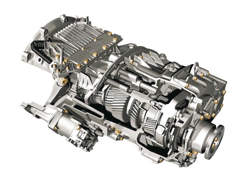
КПП DAF, производимые ZF Friedrichshafen AG (AS Tronic) или непосредственно DAF, отличаются высоким качеством сборки, компактностью, отличной ремонтопригодностью, малым весом, а также, благодаря регулярному совершенствованию узлов, прогрессивной эффективностью. Такие сложные устройства обладают разными алгоритмами работы и определенными особенностями.
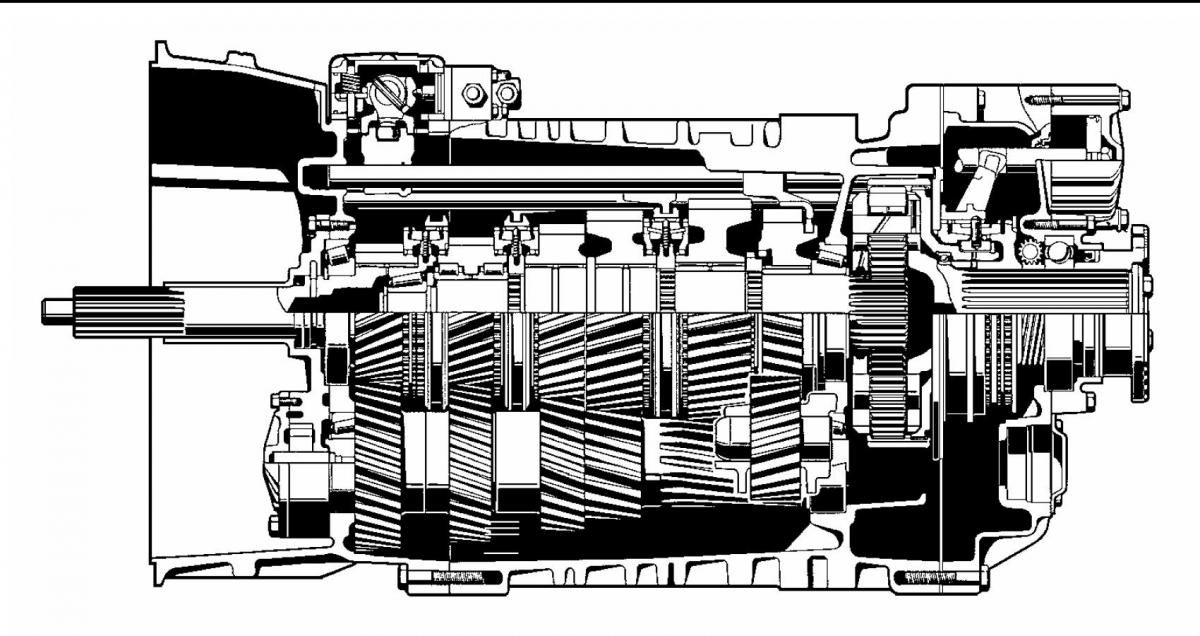
Устройство и принцип работы КПП ДАФ
Современные трансмиссии, применяемые в грузовиках ДАФ:
- механические – 16 скоростей с системой прямого привода;
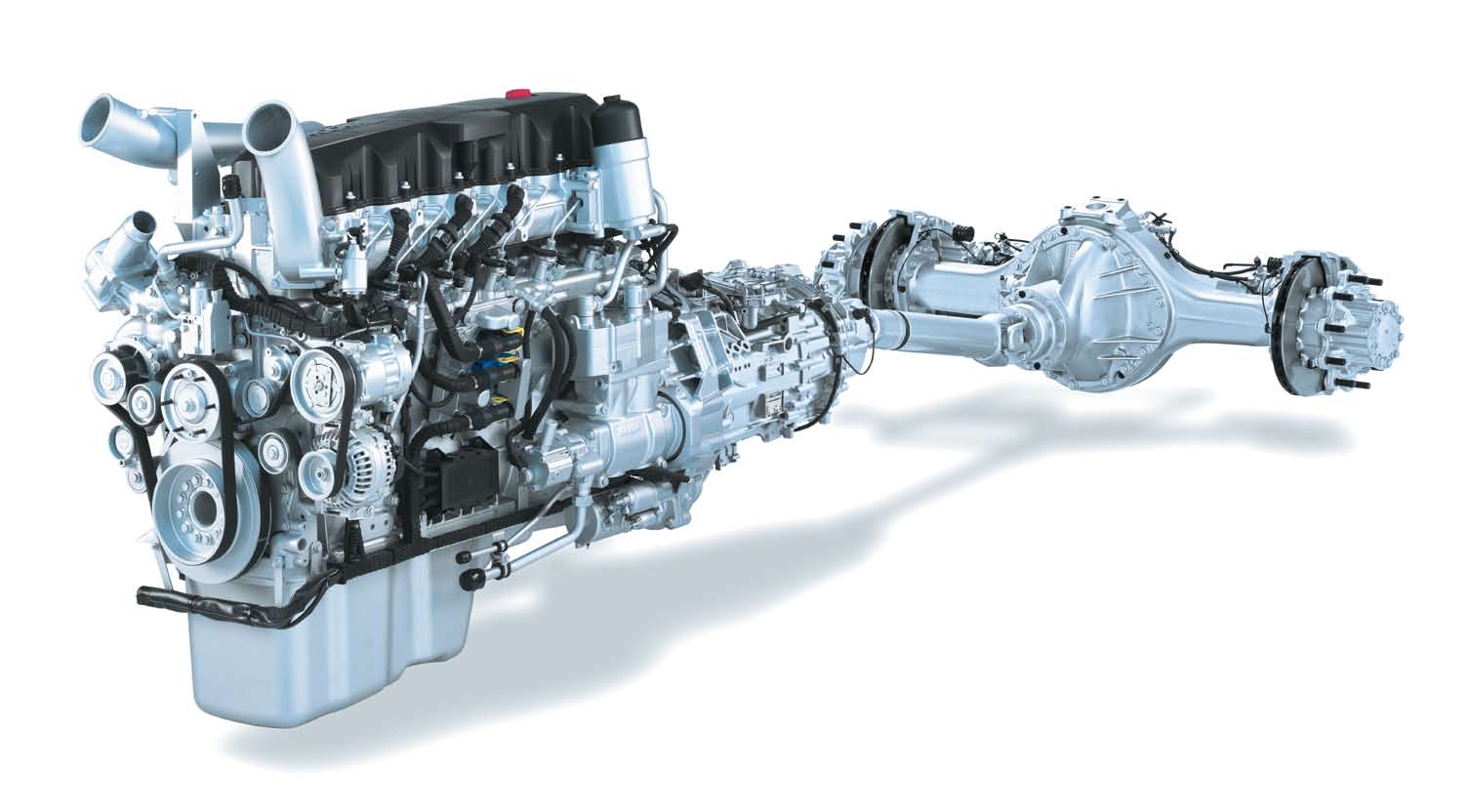
- автоматизированные – 12 или 16 передач с функцией передачи мощности на гипоидный задний мост, оснащенный механизмом блокировки дифференциала.
Некоторые модели, такие как пятипозиционная гидромеханическая МКПП, могут быть изготовлены на заказ. Хоть многие и предпочитают вручную управлять трансмиссией тягача, при нынешней плотности движения автоматические модели становятся все более выгодными. Переключение скоростей КПП ДАФ по схеме: пневматические переключающие цилиндры, управляемые соленоидами, приводят в действие вилки, при помощи которых задействуются кулисы.
АКПП DAF могут дополняться коробками отбора мощности, которые передают крутящий момент на привод дополнительного оборудования, интардерами, позволяющими замедлять автомобиль без использования тормозов, сервошифтом, синхронизированными демультипликатором и делителем для обеспечения пониженного или повышенного ряда передач, картером сцепления, а также устройствами, позволяющими использовать автомат как механику.
Коробка передач DAF AS Tronic использует комбинацию автоматического сухого сцепления и электронно-пневматической коробки с кулачковыми муфтами. Конструкция состоит из главного узла, группы исполнительных механизмов, рычага, модуля расширения, переключателя режимов движения, а также дисплея для отображения всех функций. В зависимости от количества передач блок может быть трех- или четырехступенчатым.
Основные особенности эксплуатации
Такие прогрессивные узлы включают в себя несколько датчиков для контроля над различными процессами и оптимизации работы трансмиссии:
- датчик давления;
- сенсор перемещения;
- датчик оборотов коленчатого и первичного вала.
Схема переключения передач ДАФ представлена двойным H либо каскадным. Переключатель (тумблер), расположенный на рычаге, позволяет выбирать быструю или медленную группу переднего делителя. Планетарные механизмы исключают деформацию валов.
Современные роботизированные 12-ступенчатые коробки передач ДАФ 105 XF обладают специальной системой, которая облегчает начало движения в гору после остановки ТС, а некоторые модели имеют 2 промежуточных вала. Синхронизация осуществляется через трансмиссионный тормоз и управление ДВС. Оперативное и легкое переключение передач на ДАФ 95 и других моделях обусловлено наличием пневматического усилителя.
Несмотря на совершенствование конструкций, во время эксплуатации детали любых коробок передач неизбежно подвергаются износу, а самые лучшие модели помимо достоинств наделены и некоторыми недостатками.
Плюсы и минусы КПП на DAF 95 и 105
- оптимальный подбор передач и существенная экономия топлива;
- дополнительная защита от поломок и подгорания сцепления;
- пониженная шумность функционирования и плавность начала движения;
- удобство и простота эксплуатации в тяжелых условиях;
- складной селектор;
- длительный ресурс сцепления.
- проблемы с датчиками выходного вала;
- чувствительность к качеству воздуха;
- сложность диагностики и ремонта.
Коробки ZF заправляются специальным маслом уникальной разработки для всесезонной эксплуатации. Оптимально подобранный состав смазывающей жидкости позволяет значительно увеличивать интервал замены при езде на дальние дистанции и/или при транспортировке грузов в тяжелых климатических условиях.
Возможные проблемы и их решение
Прогрессивная электроника способна информировать водителя о неисправностях различными диагностическими кодами. Ошибки трансмиссии ДАФ выводятся на желтом (некритичные неисправности) или красном фоне (опасные поломки).
Все неисправности узла можно разделить на 4 группы:
- электронные;
- механические;
- антифрикционные;
- пневматические.
Проблемы устраняются путем дефектовки или замены деталей, промывки и очистки элементов корпуса, а также замены масла. После внесения изменений в конструкцию АКПП важно корректировать и электронный блок управления. Использование современного оборудования позволяет оперативно осуществлять диагностику, демонтаж, разборку, сборку и установку сложного узла.
При всех нововведениях и инновационных технологиях рекомендации по обслуживанию коробок переключения передач ДАФ во многом остаются стандартными: своевременно менять масло, проверять работу радиатора, не допускать длительную буксировку, избегать агрессивной езды, прогревать трансмиссию и не включать режим парковки во время движения.
Источник
Ошибки на панели DAF 105: расшифровка, причины

Грузовые автомобили DAF славятся своей надежностью и безопасностью. Но даже у них случаются отклонения в работе, большую часть из которых диагностируют электронные блоки, имеющиеся в грузовом автомобиле. Информация о возникших проблемах выводится на центральный дисплей. И задача водителя – своевременно увидеть информационное сообщение и расшифровать его.
Ошибки на желтом и красном фоне
Во время передвижения ТС информационные сообщения выводятся на желтом или красном фоне.
- На желтом фоне. При отображении такой ошибки водитель должен заехать в ближайший сервис-центр. Передвигаться необходимо крайне осторожно.
- На красном фоне. Такая поломка является критичной. При появлении предупреждения на красном фоне продолжать поездку в период гарантии запрещено, в не гарантийный – нежелательно.
Расшифровка ошибок DAF XF 105 на красном фоне
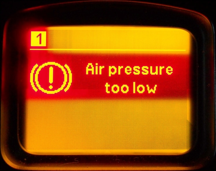
Air pressure too low – слишком низкое давление в пневмосистеме. Такой символ загорается, если давление в одном из тормозных контуров опускается ниже 5 бар. Остановить ТС и проверить герметичность пневмосистемы.
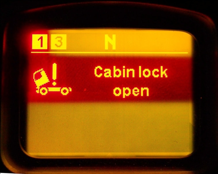
Cabin lock open – открыт замок кабины. Остановиться и закрыть его.
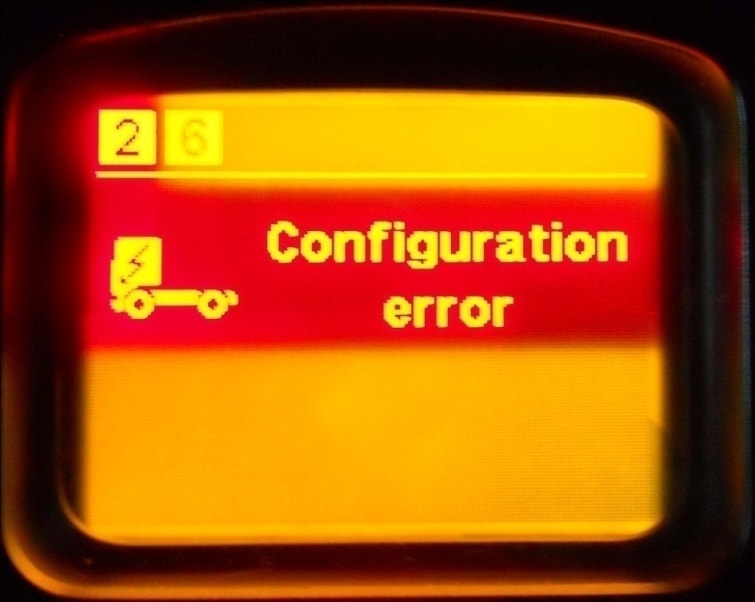
Configuration error – сбой конфигурации систем. Возможные причины появления этого предупреждения – выход из строя электроники VIC (интеллектуального центра грузовика, собирающего информацию для обеспечения функционирования грузовика), ошибка конфигурации, при которой номера шасси в электронике и модуля BBM не совпадают. Для устранения проблемы необходимо обратиться к специалистам.
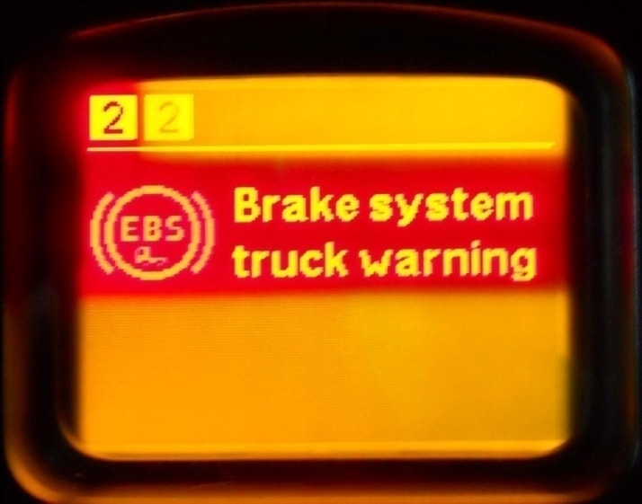
Brake system truck warning – существенная поломка тормозной системы EBS. Немедленно проверить ее состояние в условиях сервис-центра.
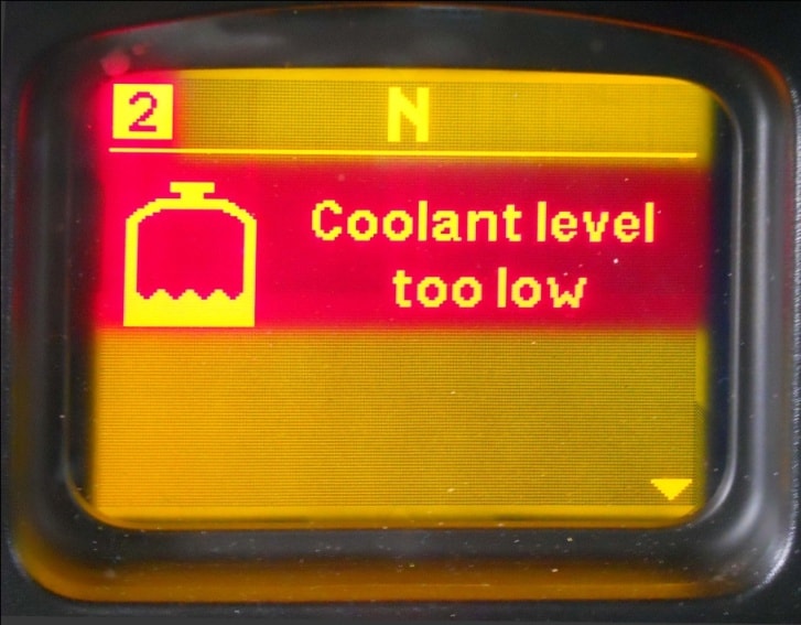
Coolant level too low – недостаточное количество охлаждающей жидкости. Остановиться, долить ОЖ до требуемого уровня, проверить герметичность системы охлаждения.
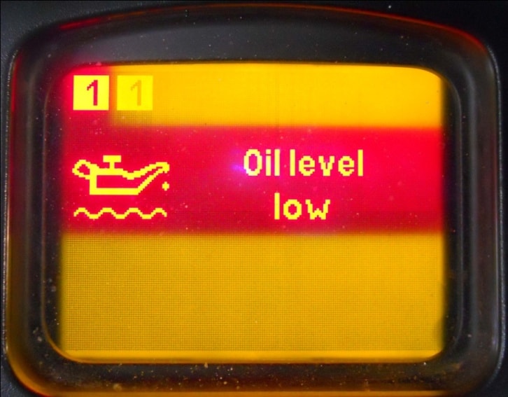
Oil level low – слишком низкий уровень масла. Остановить автомобиль, проверить уровень масла, залить его до необходимого уровня.
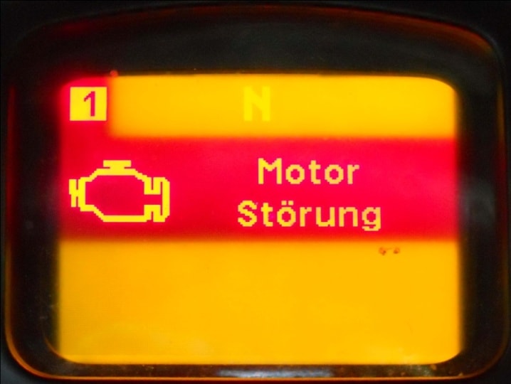
Motor Storung – ошибка в системе руководства двигателем, иммобилайзер заблокирован. Остановиться, выяснить причину самостоятельно или связаться с сервисным специалистом.
Наиболее распространенные ошибки на приборной панели DAF XF 105 на желтом фоне
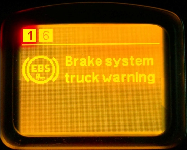
Brake system truck warning – некритичная проблема в тормозной системе EBS.
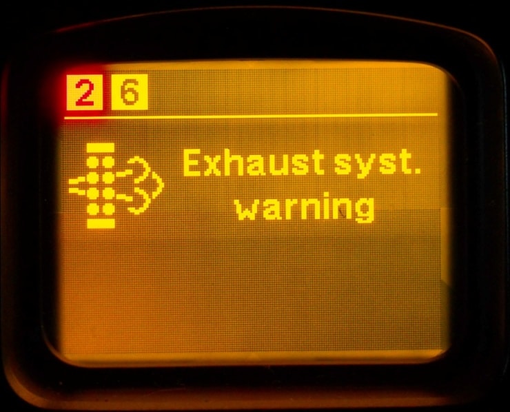
Exhaust syst. warning – неисправная система очистки отработанных газов. Мощность двигателя падает до 60 %. Проявление ошибки: снижение мощности двигателя можно активировать и выключить только на стоящем грузовике.
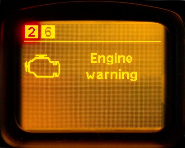
Engine warning – поломки в системе двигателя. В этом случае грузовик необходимо останавливать очень осторожно. Диагностика неисправности – в сервис-центре.
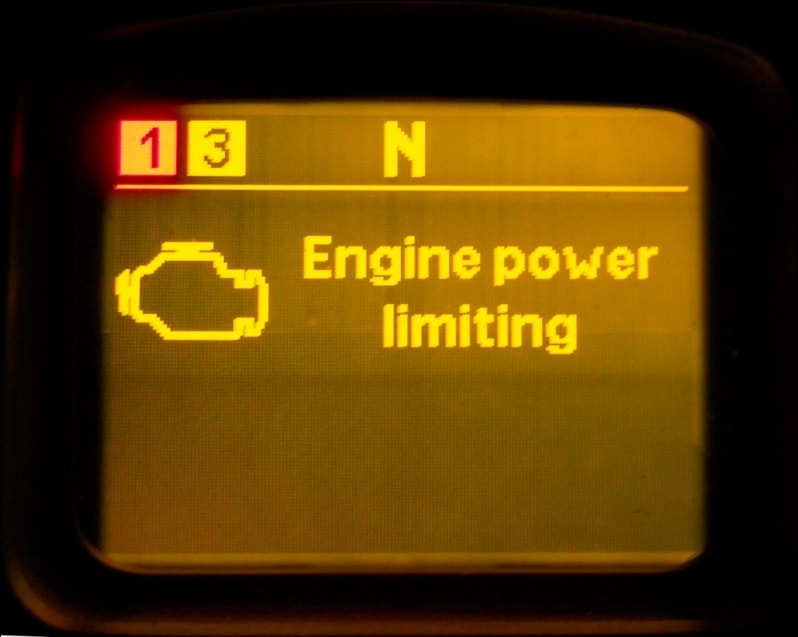
Engine power limiting – ограничение мощности двигателя.
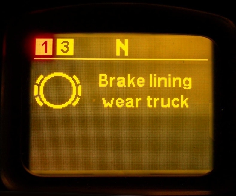
Brake lining wear truck – превышение допустимой степени износа колодок на одном или нескольких колесах.
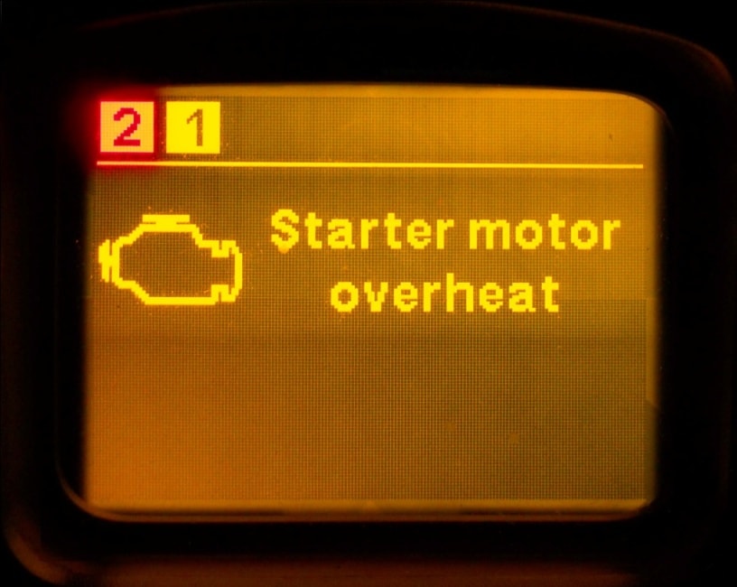
Starter motor overheat – нагрев стартера выше допустимых температур.
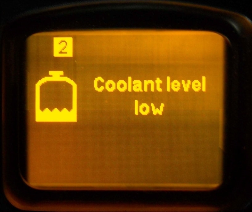
Coolant level low – уровень охлаждающей жидкости ниже допустимого. Остановиться и долить ОЖ до требуемого уровня.
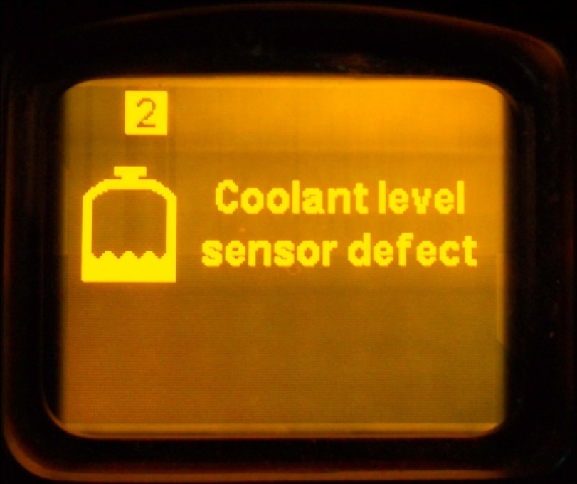
Coolant level sensor defect – поломка датчика, определяющего уровень охлаждающей жидкости.
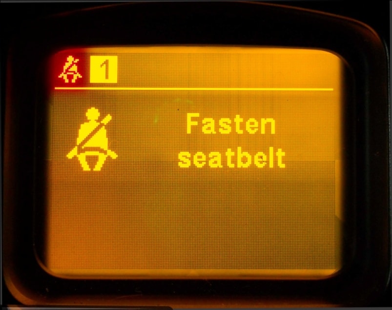
Fasten seatbelt – не пристегнуты ремни безопасности.
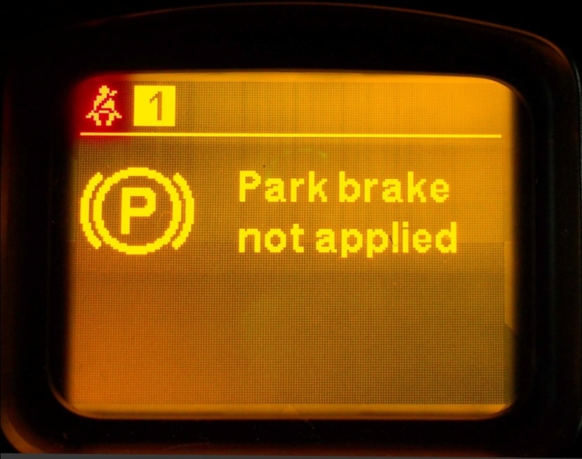
Park brake not applited – стояночный тормоз не активирован, а это означает, что грузовик не заторможен.
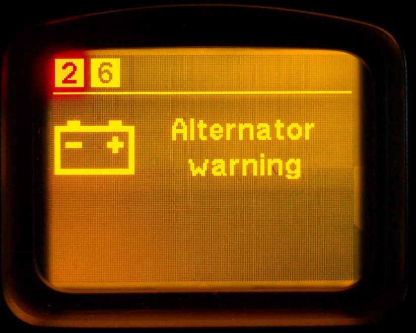
Alternator warning – генератор находится в нерабочем состоянии, зарядка отсутствует. При некорректной работе регулятора напряжения – недозарядка или перезарядка.
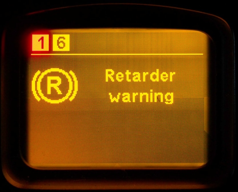
Retarder warning – трансмиссионный тормоз/интардер неисправен. Причины возникновения проблем в дополнительной тормозной системе – поломка датчика скорости, замыкание или обрыв CAN-шины, неисправность датчиков температуры, вентилятора охлаждения, электропроводки, низкий уровень охлаждающей жидкости. При появлении на панели этой ошибки необходимо проверить уровень ОЖ и состояние электрических разъемов. Если внешние проверки не дали результатов, рекомендуется обратиться к специалистам.
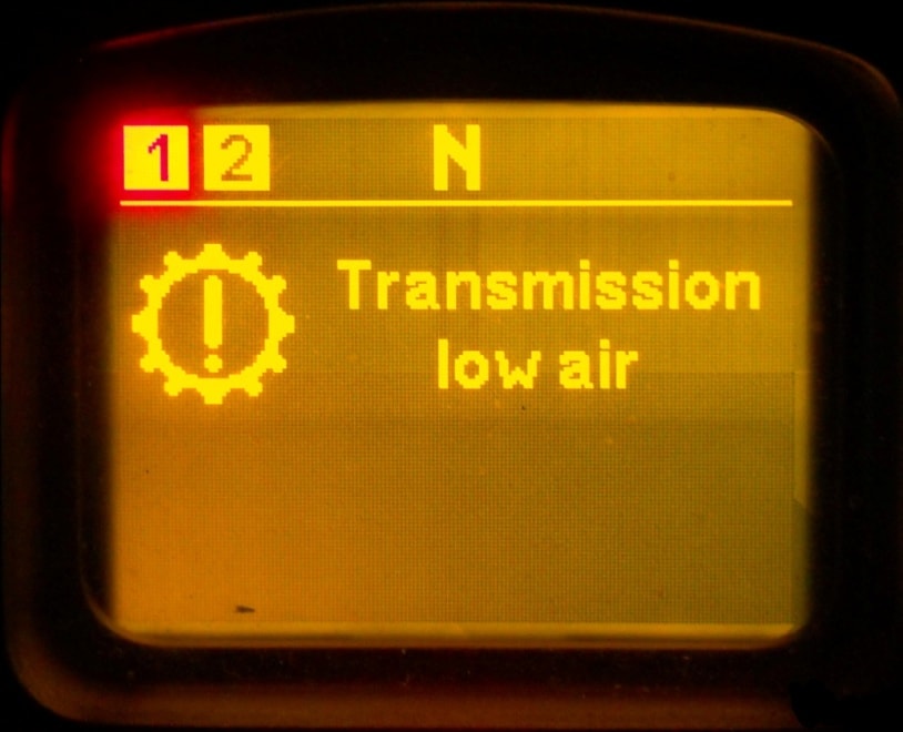
Transmission low air – слишком низкое давление воздуха в системе, управляющей коробкой ПП. При появлении такого предупреждения в красном цвете КП AS-Tronic остается на текущей передаче, а после остановки переходит в нейтральное положение, дальнейшее передвижение ТС становится невозможным.
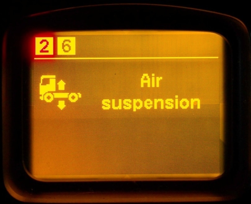
Air suspension – неисправная пневматическая подвеска.
Источник
Датчик кпп даф 105
Часовой пояс: UTC + 4 часа [ Летнее время ]
Проблема с АКПП в DAF 105 XF
| Страница 4 из 5 | [ Сообщений: 65 ] | На страницу Пред. 1 , 2 , 3 , 4 , 5 След. |
| Версия для печати | Пред. тема | След. тема |
| Автор | Сообщение | ||||||
|---|---|---|---|---|---|---|---|
| Anatoli | |||||||
|
Зарегистрирован: Вт июн 17, 2008 11:31 am |
|||||||
Зарегистрирован: Ср янв 29, 2014 4:23 am |
Неленивые вы,видать,парни.Стока работы и бабла ввалить..это любимая машина местного шейха? Датчик давления вместе с модулятором меняли?Новый модулятор со своей платой остался,или старую воткнули? |
||||||
|
Зарегистрирован: Чт сен 04, 2014 3:44 pm |
|||||||
|
Зарегистрирован: Чт ноя 24, 2011 6:13 pm |
|||||||
|
Зарегистрирован: Вт июл 04, 2017 4:24 pm |
|||||||
|
Зарегистрирован: Вт июл 04, 2017 4:24 pm |
Неленивые вы,видать,парни.Стока работы и бабла ввалить..это любимая машина местного шейха? Датчик давления вместе с модулятором меняли?Новый модулятор со своей платой остался,или старую воткнули? поменяли модулятор в месте с мозгами, прошили под ID шасси. и один фиг(( в общем кроется проблема в механической части. Машина уехала в рейс с этим косяком)) но по приезду будем снова колдовать. |
||||||
|
Зарегистрирован: Пн мар 27, 2017 7:07 pm |
3110: неправильный или отсутствующий внутренний сигнал CAN. 3147: установленный сзади блок диапазонов не переключается ни в повышенный, ни в пониженный диапазоны в течении определенного времени. 3108: внутренняя неисправность в сервоприводе (D955). Ругается на датчик положения рычага коробки передач или переключатель селектора(Е590). 3178: не в порядке предупредительная коммуникация CAN между всеми системами автомобиля. 3194: не распознаются сигналы скорости передней оси посредством сообщений шины CAN. 3111: не распознается сигнал «реального времени» (время/дата) посредством сообщений шины CAN. 3113: сигнал конфигурации интардера не распознается посредством сообщений шины CAN. 520: неправильный или отсутствующий сигнал текущего тормозного момента интардера посредством сообщений шины CAN. 3026: конфигурация двигателя не распознается посредством сообщений шины CAN вследствие проблем коммуникации с электронным блоком управления двигателем. 3033: Сигнал конфигурации тормоза двигателя не распознается посредством сообщений шины CAN вследствие проблем коммуникации с электронным блоком управления двигателем. 24206-19: не поступают сообщения CAN от электронного блока управления EAS вследствие проблем коммуникации. 24201-19: не поступают сообщения CAN от электронного блока управления двигателем вследствие проблем коммуникации. 24202-19: не поступают сообщения CAN от электронного блока управления трансмиссией вследствие проблем коммуникации. 520215-19 от автокома: линия CAN; связь с EDS, сбой при посылке сообщений по шине CAN. 520212-05 от автокома: связь мультиплексной шины СAN, разрыв цепи или слишком низкая нагрузка. В DCMI куча ошибок по связи CAN записанных в тот день: Одна активная ошибка по клапану(В192) двигательный тормоз. Его надо менять, с ошибкой уже 2 месяца ездят. |
||||||
|
Зарегистрирован: Пн мар 27, 2017 7:07 pm |
Всем добрый день. Мужики в общем проблема такая, DAF 105 2007 года. АКПП. при включении передачи в положения D. включается 2А. это при первом заводе машины, как только машину заглушил и завел. при включении D/ становится на механику 7М. и пока не стравишь воздух до 6 атмо. КПП не входит в автоматический режим. теперь что мы делали. Снимали АКПП 3 раз. Ребята у кого какие мысли? Что с ограничителем давления? Если речь идет об AS-TRONIC |
||||||
|
Зарегистрирован: Сб фев 25, 2017 10:55 pm |
|||||||
|
Зарегистрирован: Вт июн 17, 2008 11:31 am |
|||||||
|
Зарегистрирован: Сб фев 25, 2017 10:55 pm |
|||||||
|
Зарегистрирован: Вт июн 17, 2008 11:31 am |
|||||||
|
Зарегистрирован: Сб фев 25, 2017 10:55 pm |
|||||||
|
Зарегистрирован: Чт дек 27, 2012 9:42 pm |
|||||||
|
Зарегистрирован: Сб авг 18, 2012 11:32 am |
Часовой пояс: UTC + 4 часа [ Летнее время ] Кто сейчас на конференцииСейчас этот форум просматривают: нет зарегистрированных пользователей и гости: 11 Источник ➤ Adblock |

Все ошибки DAF CF, LF, XF, 85, 95, 105
Ошибки DAF по протоколу OBDI. Самодиагностика.
Ошибки DAF по протоколу OBDII
Топливная система и воздухоподача
P0000-P0099, P0100-P0199, P0200-P0299
Система зажигания
P0300-P0399
Контроль выбросов
P0400-P0499
Контроль скорости и холостого хода
P0500-P0599
Электронный блок управления (ЭБУ) и его подсистемы
P0600-P0699
Трансмиссия
P0700-P0799, P0800-P0899, P0900-P0999
Коды ошибок производителя DAF
4-2 — Сигнал скорости автомобиля отсутствует или маловероятен
84-10 — Сигнал скорости автомобиля — неправильное изменение частоты
84-18 — Сигнал скорости автомобиля — нарушение связи
91-2 — Педаль акселератора — сигнал отсутствует или маловероятен
91-3 — Педаль акселератора — слишком высокое напряжение на контакте
B9 91-4 — Педаль акселератора — слишком низкое напряжение на контакте
B9 91-19 — Педаль акселератора — ошибка связи в сети CAN (резервный)
97-3 — Короткое замыкание на источник питания на контакте A14 ЭБУ (резервный)
97-4 — Короткое замыкание на «массу» на контакте A14 ЭБУ (резервный)
97-15 — Слишком высокое напряжение на контакте A14 ЭБУ (резервный)
100-1 — Давление масла — слишком низкое давление
100-2 — Давление масла — маловероятное давление
102-2 — Относительное давление наддува — маловероятное давление
102-3 — Относительное давление наддува — слишком высокое напряжение на контакте A44 ЭБУ
102-4 — Относительное давление наддува — слишком низкое напряжение на контакте A44 ЭБУ
105-0 — Температура воздуха на впуске — слишком высокая температура, включена защита двигателя
105-2 — Температура воздуха на впуске — температура вне допустимых пределов при включенном зажигании
105-3 — Температура воздуха на впуске — короткое замыкание на источник питания или прерывание на контакте A23 ЭБУ
105-4 — Температура воздуха на впуске — слишком низкое напряжение на контакте A23 ЭБУ
105-10 — Температура воздуха на впуске — маловероятная температура
105-15 — Температура воздуха на впуске — слишком высокая температура
108-2 — Давление воздуха — маловероятное давление
108-3 — Давление воздуха — слишком высокое напряжение на контакте A33 ЭБУ
108 — 4 Давление воздуха — слишком низкое напряжение на контакте A33 ЭБУ
110-0 — Температура охлаждающей жидкости — слишком высокая температура, включена защита двигателя
110-2 — Температура охлаждающей жидкости — температура вне допустимых пределов при включенном зажигании
110-3 — Температура охлаждающей жидкости — короткое замыкание на источник питания или прерывание на контакте A15 ЭБУ
110-4 — Температура охлаждающей жидкости — короткое замыкание на «массу» на контакте A15 ЭБУ
110-15 — Температура охлаждающей жидкости — слишком высокая температура
111-1 — Слишком низкое напряжение на контакте B28 ЭБУ (резервный)
111-3 — Короткое замыкание на источник питания на контакте B28 ЭБУ (резервный)
111-4 — Короткое замыкание на «массу» на контакте B28 ЭБУ (резервный)
157-0 — Давление топлива — слишком высокое давление
157-3 — Давление топлива — короткое замыкание на источник питания или прерывание на контакте A25 ЭБУ
157-4 — Давление топлива — короткое замыкание на «массу» на контакте A25 ЭБУ
157-16 — Давление топлива — слишком высокое давление
157-18 — Давление топлива — слишком низкое давление
167-1 — Электропитание — слишком низкое напряжение на контакте C3 ЭБУ
167-16 — Электропитание — слишком высокое напряжение на контакте C3 ЭБУ
167-18 — Электропитание — слишком низкое напряжение на контакте C3 ЭБУ
168-16 — Электропитание — слишком высокое напряжение на контакте C3 ЭБУ
168-18 — Электропитание — слишком низкое напряжение на контакте C3 ЭБУ
190-0 — Частота вращения коленчатого вала двигателя — скорость двигателя слишком высока
190-2 — Частота вращения коленчатого вала двигателя — сигнал отсутствует или маловероятен
251-2 — Синхросигнал в реальном времени — сигнал отсутствует или маловероятен
411-11 — Автоматическое охлаждение — защита двигателя включена
558-2 — Педаль акселератора — сбой сигнала переключателя холостого хода педали акселератора
558-4 — Педаль акселератора — слишком низкое напряжение на контакте B1 и B11 ЭБУ
558-13 — Педаль акселератора — не откалибровано, вне допустимых пределов
612-2 — Сбой сигнала частоты вращения коленвала двигателя — сигнал отсутствует или маловероятен
625-9 — Иммобилайзер — впрыск заблокирован
627-2 — Электропитание — слишком низкое напряжение на контакте C3 ЭБУ
627-12 — Электропитание — внутренняя неисправность 1 — слишком низкое питание форсунки
629-12 — ЭБУ D317 — внутренняя неисправность 2
630-31 — ЭБУ D317 — внутренняя неисправность 3
633-31 — ЭБУ D317 — внутренняя неисправность 4
639-9 — Соединение CAN — отсутствие связи
639-13 — Соединение CAN — ошибка связи в сети CAN
647-4 — Короткое замыкание на «массу» на контакте B38 ЭБУ (резервный)
651-5 — Форсунка цилиндра No 1 — обрыв или короткое замыкание
651-7 — Форсунка цилиндра No 1 — механическая неисправность
652-5 — Форсунка цилиндра No 2 — обрыв или короткое замыкание
652-7 — Форсунка цилиндра No 2 — механическая неисправность
653-5 — Форсунка цилиндра No 3 — обрыв или короткое замыкание
653-7 — Форсунка цилиндра No 3 — механическая неисправность
654-5 — Форсунка цилиндра No 4 — обрыв или короткое замыкание
654-7 — Форсунка цилиндра No 4 — механическая неисправность
655-5 — Форсунка цилиндра No 5 — обрыв или короткое замыкание
655-7 — Форсунка цилиндра No 5 — механическая неисправность
656-5 — Форсунка цилиндра No 6 — обрыв или короткое замыкание
656-7 — Форсунка цилиндра No 6 — механическая неисправность
677-3 — Короткое замыкание на источник питания на контакте B49 ЭБУ (резервный)
677-4 — Резервный Короткое замыкание на «массу» на контакте B49 ЭБУ (резервный)
697-3 — Короткое замыкание на источник питания на контакте B48 ЭБУ (резервный)
697-4 — Короткое замыкание на «массу» на контакте B48 ЭБУ (резервный)
723-2 — Частота вращения распредвала двигателя — сигнал отсутствует или маловероятен 723-7 — Частота вращения распредвала двигателя — механическая неисправность
729-3 — Реле предпускового подогрева — короткое замыкание на источник питания или прерывание на контакте B40 или B42 ЭБУ
729-4 — Реле предпускового подогрева — короткое замыкание на «массу» на контакте B40 ЭБУ
974-3 — Дистанционный регулятор дроссельной заслонки — короткое замыкание на источник питания на контакте B21 или B26 или B32 ЭБУ
974-4 — Дистанционный регулятор дроссельной заслонки — короткое замыкание на «массу» на контакте B21 или B26 или B32 ЭБУ
974-19 — Дистанционный регулятор дроссельной заслонки — ошибка связи в сети CAN (резервный)
1072-4 — Тормоз двигателя — короткое замыкание на «массу» на контакте A22 ЭБУ
1188-7 — Перепускной клапан — механическая неисправность
1195-2 — Иммобилайзер — обнаружено вращение двигателя при включенном иммобилайзере
1322-31 — Несколько цилиндров — обнаружение перебоев в зажигании
1323-31 — Цилиндр No 1 — обнаружение перебоев в зажигании
1324-31 — Цилиндр No 2 — обнаружение перебоев в зажигании
1325-31 — Цилиндр No 3 — обнаружение перебоев в зажигании
1326-31 — Цилиндр No 4 — обнаружение перебоев в зажигании
1327-31 — Цилиндр No 5 — обнаружение перебоев в зажигании
1328-31 — Цилиндр No 6 — обнаружение перебоев в зажигании
1347-3 — Клапан управления топливным насосом — короткое замыкание на источник питания или прерывание на контакте A2 ЭБУ
1347-4 — Клапан управления топливным насосом — короткое замыкание на «массу» на контакте A2 ЭБУ
1761-1 — Уровень AdBlue — уровень слишком низкий
1761-2 — Уровень AdBlue — расход AdBlue маловероятен
1761-3 — Уровень AdBlue — слишком высокое напряжение на контакте A19 ЭБУ
1761-4 — Уровень AdBlue — слишком низкое напряжение на контакте A19 ЭБУ
1761-18 — Уровень AdBlue — низкий уровень
2623-3 — Короткое замыкание на источник питания на контакте B35 ЭБУ (резервный)
2623-4 — Короткое замыкание на «массу» на контакте B35 ЭБУ (резервный)
3031-2 — Температура AdBlue — маловероятная температура
3031-3 — Температура AdBlue — короткое замыкание на источник питания или прерывание на контакте A43 ЭБУ
3031-4 — Температура AdBlue — короткое замыкание на «массу» на контакте A43 ЭБУ
3050-0 — Температура каталитического нейтрализатора — слишком высокая температура каталитического нейтрализатора
3050-31 — Температура каталитического нейтрализатора — каталитический нейтрализатор не обнаружен
3241-2 — Температура каталитического нейтрализатора — маловероятная температура
3241-3 — Температура каталитического нейтрализатора — короткое замыкание на источник питания или прерывание на контакте A30 ЭБУ
3241 — 4 Температура каталитического нейтрализатора — слишком низкое напряжение на контакте A30 ЭБУ
3241-10 — Температура каталитического нейтрализатора — маловероятная температура
3241-15 — Температура каталитического нейтрализатора — слишком высокая температура
3241-31 — Температура каталитического нейтрализатора — датчики F765/F766 перепутаны
3249-2 — Температура каталитического нейтрализатора — маловероятная температура
3249-3 — Температура каталитического нейтрализатора — короткое замыкание на источник питания или прерывание на контакте A50 ЭБУ
3249-4 — Температура каталитического нейтрализатора — слишком низкое напряжение на контакте A50 ЭБУ
3249-10 — Температура каталитического нейтрализатора — маловероятная температура
3361-2 — Модуль дозирования системы дополнительной обработки выбросов (EAS) — внутренняя неисправность датчика температуры
3361-9 — Модуль дозирования системы дополнительной обработки выбросов (EAS) — отсутствие связи
3361-12 — Модуль дозирования системы дополнительной обработки выбросов (EAS) — внутренняя неисправность 6
3362-31 — Модуль дозирования системы дополнительной обработки выбросов (EAS) — загрязнение или сужение линий
3363-3 — Короткое замыкание на источник питания или прерывание на контакте A21 ЭБУ (резервный)
3363-4 — Короткое замыкание на «массу» на контакте A21 ЭБУ (резервный)
3363-16 — слишком высокое напряжение на контакте A21 ЭБУ (резервный)
3363-18 — слишком низкое напряжение на контакте A21 ЭБУ (резервный)
3489-3 — Клапан подачи воздуха модуля дозирования системы EAS — короткое замыкание на источник питания на контакте B35 модуля дозирования системы EAS
3489-4 — Клапан подачи воздуха модуля дозирования системы EAS — короткое замыкание на «массу» или прерывание на контакте B35 модуля дозирования системы EAS
3509-3 — Короткое замыкание на источник питания на контакте B21 ЭБУ (резервный)
3509-4 — Короткое замыкание на «массу» на контакте B21 ЭБУ (резервный)
3510-3 — Напряжение питания датчика 5 В — слишком высокое напряжение на контакте A37 ЭБУ
3510-4 — Напряжение питания датчика 5 В — слишком низкое напряжение на контакте A37 ЭБУ
3511-4 — Напряжение питания датчика 5 В — слишком низкое напряжение на контакте A16 ЭБУ
3512-3 — Напряжение питания датчика 5 В — слишком высокое напряжение на контакте B22 ЭБУ
3512-4 — Напряжение питания датчика 5 В — слишком низкое напряжение на контакте B22 ЭБУ
3513-3 — Напряжение питания датчика 5 В -слишком высокое напряжение на контакте B26 ЭБУ
3513-4 — Напряжение питания датчика 5 В — слишком низкое напряжение на контакте B26 ЭБУ
4354-3 — Линейный нагреватель AdBlue — слишком высокое напряжение на контакте B58 ЭБУ
4354-4 — Линейный нагреватель AdBlue — слишком низкое напряжение на контакте B58 ЭБУ
4360-2 — Датчик температуры отработавших газов до каталитического нейтрализатора — температура маловероятна (длительный период)
4360-3 — Датчик температуры отработавших газов до каталитического нейтрализатора — слишком высокое напряжение на контакте B50 ЭБУ (длительный период)
4360-4 — Датчик температуры отработавших газов до каталитического нейтрализатора — слишком низкое напряжение на контакте B50 ЭБУ (длительный период)
4363-3 — Датчик температуры отработавших газов после каталитического нейтрализатора — слишком высокое напряжение на контакте B09 ЭБУ (длительный период)
4363-4 — Датчик температуры отработавших газов после каталитического нейтрализатора — слишком низкое напряжение на контакте B09 ЭБУ (длительный период)
4363-15 — Датчик температуры отработавших газов после каталитического нейтрализатора — слишком высокая температура
4363-16 — Датчик температуры отработавших газов после каталитического нейтрализатора — слишком высокая температура
4794-31 — Температура каталитического нейтрализатора — каталитический нейтрализатор не обнаружен (длительный период)
| 8901. Здравствуйте, У меня англичанин CF85 0Е839666 можно ли на нем перенастроить фары на правую сторону или покупать новые правосторонние? (0Е839***) |
Здравствуйте, Вячеслав
Нельзя. Нужны новые.
| 8902. Подскажите почиму на DAF евро 3 загараеться EBS жолтым цветом,заменили передний левый датчик всеровно загораеться (XLRTE47XS0E733503(***) |
Здравствуйте, Николай
Ошибка может загораться из-за неисправности:
- Тахографа
- Датчиков скорости
- Проводки ЕБС
- Модуляторов ЕБС
- Клапанов ЕБС
- Педали тормоза.
Узнать точную причину можно с помощью компьютерного считывания ошибки.
| 8903. Здравствуйте! Такая проблема, при отрицательных температурах, на полную мощность не работает интардер. даф 95XF 2002г |
Здравствуйте, Дмитрий
Первое, что стоит проверить: соответствует ли масло в КПП требованиям ZF?
| 8904. Добрый день. Прошу сообщить, сколько заливается масла в ДВС, кпп, мост и антифриза в систему охлаждения (XLRTE85MC0E864***) |
Здравствуйте, Дмитрий
Двигатель: Примерно 37л.
КПП: Примерно 18.6л.
Редуктор: Примерно 23.5л.
Система охлаждения примерно 41л.
Примечание: После заправки необходимо убедиться, что уровень масла в агрегатах соответствует норме.
| 8905. пакажите как разбират кран распридлени тормозных сил.и заменит ремкоплект. паказат видо разборки крана (1339***) |
|

К сожалению, данная информация не предоставляется.
| 8906. Здравствуйте, пропал ближний свет справа на даф105 предохранители целые лампа тоже, каковы еще могут быть причины? Энергия к фаре не приходит, провод прозванивается, где копать? Мороз на улице( |
Здравствуйте, Ильдар
Похоже на неисправность электропроводки фары.
| 8907. Здравствуйте!что может быть,при нажатии на тормоз загорается красным ЕБС, желтая ошибка отсутствует,выключаеш зажигание ошибка пропадает,появляется не все время . (0Е672***) |
Здравствуйте, Сергей
В одном из кранов недостаточное давление воздуха. Скорее всего проблема в замершей в пневмосистеме влаге. Точный ответ можно будет дать после считывания ошибок компьютером.
| 8908. Можноли использовать масло total rubia 15w40 daf 95 E-2 (xlras47ws0e462***) |
Здравствуйте, Василий
При каких температурах планируется эксплуатация автомобиля?
| 8909. Можно увеличить мощность двигателя и цена вопроса? (0E636***) |
Здравствуйте, Анатолий
Официально нельзя.
| 8910. нерастормаживается.горит лампа АБС.горят стоп-сигналы. |
Здравствуйте, Сергей
Проверьте, не попало ли что-то под педаль (например коврик).
Если под педалью ничего нет, выяснить причину неисправности можно будет только после компьютерной диагностики.
| 8911. Подскажите пожалуйста, какая экономная скорость по тоннажу? Спасибо! (XLRTE47MS7E761***) |
Здравствуйте, Александр
Оптимальная скорость в вашем случае достигается при движении на высшей передаче, при этом обороты двигателя должны находиться в самом начале зеленой зоны.
| 8912. на стоянке кабина падает.подушки не сифонят.если это краны уровня пола то как только замена или можно по другому.как правильно очистить катализатор. спасибо. (XLRTE47MSOE912***) |
Здравствуйте, Владимир
Все же похоже на утечку в подушках. Если проблема в кране, то только замена.
| 8913. Подскажите пожалуйста,возможна ли установка турбины с евро 3 кат.номерGARRET GT4594S(1453029) на мой авто(евро 2) (XLRTE47S0E511***) |
Здравствуйте, Александр
К сожалению, такой информации нет.
| 8914. Добрый день. Подскажите пожалуйста какая комплектация и баки на машине ДАФ 95.360 АТИ XLRTE47WS0E374103. И еще, плохо расстормаживается ( не слышно как стравливается система) . в чем может быть причина. Спасибо. (XLRTE47WS0E374***) |
Здравствуйте, Александр
К сожалению информации по комплектации нет.
Плохое растормаживание может быть связано с неисправностью ускорительного клапана.
| 8915. пытаюсь установить на сепаратор подогрев, провода есть, но обрезаны, какое напряжение должно идти на подогрев? и не ужели он должен быть всегда включен ? подогрев-элемент купил , сказали оригинал , я понял что без термо выключателя, заранее спасибо (XLRTE47MSOE895***) |
Напряжение зависит от модели сепаратора. Обычно 24В.
В оригинальное напряжение подается постоянно. Термодатчик находится внутри нагревательного элемента.
| 8916. 17. Добрый день. Проскочили ошибки: 69 — ЭБУ двигателя заблокирован. 24201-19 27201-19 Подскажите пожалуйста на что обратить внимание и куда копать. (0E722***) Проводку снимали жгуты вскрывали и просматривали. С ней все ок. На сколько эта ошибка опасна? (0E722***) |
Здравствуйте, Владимир
Если проскочили и не горят постоянно, то неопасна.
| 8917. DAF XF 95 проблема с тормозами. после нескольких нажатий начинает стравливать воздух с главного тормозного. |
Здравствуйте, Саша
Уточните модификацию автомобиля (ВИН)
| 8918. Здравствуйте пожалуйста подскажите сколько залеваетсч масло картера DAF XF 95 2000 года спасибо?!!! (XFRAS47XSOE516***) |
Здравствуйте, Расим
Уточните, в какой агрегат вы собираетесь заливать масло?
| 8919. Доброго время суток подскажите пожалуста какой размер шин должен стоять с завода на данном автомобиле и какой обьем топлевных баков зарание спасибо (XLRTE47MSOEE885***) |
Здравствуйте, Олег
Передняя ось R22.5 385/55
Задняя ось — R22.5 315/70
| Бак: | 850л. | 430л. |
| 10см | 140л. | 70л. |
| 20см | 270л. | 140л. |
| 30см | 410л. | 210л. |
| 40см | 540л. | 280л. |
| 50см | 680л. | 340л. |
| 60см | 820л. | 410л. |
Примечание: данные значения являются ориентировочными. Для получения точных значений необходимо провести индивидуальную «проливку» баков.
| 8920. Где в Украине можно увеличить мощность двигателя. (0е733***) |
Здравствуйте, Андрей
К сожалению, такой информации нет.
| 8921. ДАФ 95. Загорается желтым символ аккумулятор. Поменяли щетки на генераторе. Желтым потухло. Через некоторое время загорелось опять желтым. В чем проблема? |
Здравствуйте, Юрий
Чтобы понять, в чем проблема сперва необходимо понять, какое напряжение при работающем двигателе?
| 8922. После замены топливных фильтров для прокачки залили в стакан фильтра уже литров 10 солярки а она куда то уходит |
Здравствуйте, Николай
Если топливный корпус не имеет трещин и в него установлен соответствующий фильтр (например, оригинальный), то топливо уходить не должно. Если с правильным фильтром топливно уходит, необходимо заменить корпус топливного фильтра.
| 8923. Дайте пожалуйста распечатку по баку (0E919***) |
Здравствуйте, Алексей
| Бак: | 800л. | 400л. |
| 10см | 140л. | 70л. |
| 20см | 270л. | 130л. |
| 30см | 410л. | 200л. |
| 40см | 550л. | 270л. |
| 50см | 680л. | 330л. |
| 60см | 820л. | 400л. |
Примечание: данные значения являются ориентировочными. Для получения точных значений необходимо провести индивидуальную «проливку» баков.
| 8924. турбина кидает масло в антиколлер авто даф 95 430 2005 года |
Турбину неисправна. Установка исправной турбины решит проблему.
| 8925. PTO-1 warning? (XLRTE47MS0E790***) |
Здравствуйте, Гахраман
В какой момент загорается ошибка?
| 8926. Привет,подскажите порядок работы цилиндров и зазоры клапанов? Спасибо. Даф ати 85 360 л.с. (0E403***) |
Здравствуйте, Сергей
К сожалению, мы не продеставляем такие данные.
| 8927. Подскажите пожалуйста при откручивании штуцера подачи топлива на насосе подкачки вывалился предположительно шарик (потерялся) какой диаметр этого шарика и чем можно заменить Спасибо (XLRAS47XS0E672***) |
Здравствуйте, Владимир
К сожалению, таких данных нет.
| 8928. можите перевірити чи це Е5 по він номеру (xlrte47msoe745***) |
| 8929. Доброе время суток! Подскажите пожалуйста сколько заливается тосола в радиатор в DAF 105.410 2007 года |
Здравствуйте, Анатолий
Емкость системы охлаждения зависит от комплектации автомобиля. Уточните ВИН.
| 8930. Здравствуйте! подскажите пожалуйста 95xf стал на морозе плохо заводиться, как будто не хватает топлива. может ли быть проблема в свече накаливания? где она находиться? (XLRTG47XS0E585***) |
Здравствуйте, Сергей
Может. Свеча находится на впускном коллекторе двигателя после интеркулера.
| 8931. Добрый день! DAF 95XF380 vinXLRTE47XS0E476033. Скажите пожалуйста, какие масла лить: 1. Двигатель. 2. КПП. 3. Мост. Таррировку баков и как правильно запускать двигатель (нажимать газ или нет) За ранее благодарен! (XLRTE47XS0E476***) |
Здравствуйте, Алексей
Двигатель: TOTAL Rubia Polytrafic 10w-40.
КПП: TOTAL Transmission TI 75w-80.
Редуктор: TOTAL Transmission Syn FE 75w-90.
| Бак: | 600л. |
| 10см | 120л. |
| 20см | 240л. |
| 30см | 350л. |
| 40см | 470л. |
| 50см | 590л. |
| 60см | 710л. |
Примечание: данные значения являются ориентировочными. Для получения точных значений необходимо провести индивидуальную «проливку» баков.
Нажимать газ необходимости нет.
| 8932. Как снять нижнею мягкую часть сиденья на Daf XF95.430 ? (XLRAS47XS4E657***) |
Здравствуйте, Олег
Необходимо поднять рукоятку впереди сидушки вверх и отверткой отвести зажим в сторону. После этого сидушка сдвинется вперед и снимется.
| 8933. Как правильно запускать двс в мороз зарание спасибо |
Здравствуйте, Василий
1. Включить зажигание;
2. Дождаться, пока погаснет сигнальная лампа свечи накала;
3. Запустить двигатель, не нажимая педали. Не допускать работу стартера более 30 секунд подряд.
| 8934. Добрый день подскажите на Даф XF95 постоянно горят стоп сигналы,в чем может быть причина? (0E717***) |
Здравствуйте, Максим
Проверьте, не мешает ли что-то возврату педали тормоза в исходное положение. Проблема также может быть в закисании оси педали тормоза.
| 8935. Добрый день. Купил датчик в бак с 105го Дафа.только не с главного бака а с добавочного.теперь стрелка показывает на оборот.когда полный бак стрелка показывает пустой.когда начинает заканчивается саляра показывает почти полный.а когда начинает моргать лампочка стрелка двигается с полного на ноль.как решить проблему??? Или нужно менять датчик? (ОН 655***) |
Здравствуйте, Виталик
Нужно менять датчик.
| 8936. Добрый день. Проскочили ошибки: 69 — ЭБУ двигателя заблокирован. 24201-19 27201-19 Подскажите пожалуйста на что обратить внимание и куда копать. (0E722***) |
Здравствуйте, Владимир
Стоит проверить состояние проводки в жгуте от кабины до двигателя.
| 8937. Здраствуйте скажите пожалуста масло фирмы Bizol допустимо для использовании на Daf xf 95 евро три 2005 |
Здравствуйте, Вадим
К сожалению, такой информации нет.
| 8938. дайте распечатку по баках .Спасибо (0E744***) |
Здравствуйте, Алексей
| Бак: | 850л. | 430л. |
| 10см | 140л. | 70л. |
| 20см | 270л. | 140л. |
| 30см | 410л. | 210л. |
| 40см | 540л. | 280л. |
| 50см | 680л. | 340л. |
| 60см | 820л. | 410л. |
Примечание: данные значения являются ориентировочными. Для получения точных значений необходимо провести индивидуальную «проливку» баков.
| 8939. Здравствуйте. Скажите пож., номера обоих лев/прав энергоаккумуляторов моего авто ? (0e563***) |
Здравствуйте, Иван
1364901 — Левый
1365120 — Правый
| 8940. Добрый день! Находу глохнет двигатель. Снова подкачав подкачкой заводиться , через несколько км опять глохнет, что может быть. Авто даф хф95 (XLRTE47XSOE671***) |
Здравствуйте, Сергей
Проблема может быть в:
- Попадании воздуха в топливную систему;
- Низком давлении топлива в топливной системе;
- Замерзании топлива.
Необходимо смотреть давление топлива.
| 8941. Здравствуйте, на даф цф при движении задним ходом произошла утечка воздуха,сошел весь воздух, нажимал на тормоз машина всё равно ехала, переключил АКПП на нейтраль она не отреагировала, и сейчас мотор не заводиться |
Здравствуйте, Иван
Предположительно, КПП осталась на передаче.
Попробуйте накачать в систеиму давление 10bar от другого автомобиля и попробуйте завести.
| 8942. Чем промыть систему охлаждения 95 даф после замены тепло обменника и как? |
Здравствуйте, Вадим
Необходимо добавить в систему охлаждения обезжиривающее средство 1675729, дать двигателю проработать и слить жидкость. Процедуру повторить несколько раз.
| 8943. DAF 105.510 2007года и DAF95.430 2005 года постоянно обрывает, примерно 500 -1000 км болты лучевой тяги. то одну, то другую сторону. Кроншейны крепежа сменили, сайлентблоки оригинальные ставлю, болты тоже по оригиналу. машина в дтп не была. не знали этой проблемы, пока один раз не оборвало и после этого пошло. Помогите пожалуйста. что это может быть. (0E770***) |
Здравствуйте, Руслан
Остается только попробовать использовать оригинальные болты и затянуть их требуемым крутящим моментом.
| 8944. Подскажите даф 105…На ходу тянет в право…И при резком торможении тянет в право…. Передок перебрали все новое кроме суппортов…Подводили не помогло….В чем проблема? |
Здравствуйте, Артем
Проблема может быть из-за перекоса заднего моста.
Тянет вправо при торможении — необходимо тщательно проверить состояние суппорта на предмет заклинивания.
| 8945. Здраствуйте, подскажите, пожалуйста, с конвеера даный автомобиль вышел с поршневой какого образца? Какая тарировка баков? Спасибо!!! (XLRTE17MS8E814***) |
Здравствуйте, Михаил
Изначально шла поршневая старого образца.
| Бак: | 995л. | 500л. |
| 10см | 140л. | 70л. |
| 20см | 280л. | 140л. |
| 30см | 430л. | 210л. |
| 40см | 570л. | 280л. |
| 50см | 710л. | 350л. |
| 60см | 850л. | 420л. |
Примечание: данные значения являются ориентировочными. Для получения точных значений необходимо провести индивидуальную «проливку» баков.
| 8946. Скажите пожалуйста тарировку бака xlrte47ms0e846380. Спасибо. (xlrte47ms0e846***) |
Здравствуйте, Алексей
| Бак: | 850л. |
| 10см | 140л. |
| 20см | 270л. |
| 30см | 410л. |
| 40см | 540л. |
| 50см | 680л. |
| 60см | 820л. |
Примечание: данные значения являются ориентировочными. Для получения точных значений необходимо провести индивидуальную «проливку» баков.
| 8947. Скажите на DAF XF-105.460 2009год. как часто нужно менять ремни, ролики. |
Здравствуйте, Михаил
Ремни меняются раз в два года. Ролики — по необходимости (проверяются при замене ремней)
| 8948. подскажите, какая резина стояла изначально? (XLRTE47VS0E844***) |
Здравствуйте, Алексей
Передняя ось R22.5 385/55
Задняя ось — R22.5 295/80
| 8949. Добрый день у меня Даф 105.460 простоял 4 дня перестал заводится все работает а стартер не крутит реле щелкает |
Здравствуйте, Павел
Уточните, какое именно реле щелкает?
Проверьте состояние короткого тонкого провода-перемычки на стартере (его видно без снятия стартера)
| 8950. Здравствуйте. После сброса воздуха давление падает до 6-7 баррелей если не использовать тормоза и потом набирает как положено до сброса. Интервал между сбросами 5-6 минут |
Здравствуйте, Абдулла
Значения низкие. Похоже на неисправность крана осушителя.

Расшифровка диагностических кодов неисправностей основного модуля обработки данных.
- Описание:
-
Защита кулисы коробки передач.
- Причина:
-
— Короткое замыкание на «массу», короткое замыкание на источник питания или обрыв питания на контакте B21 ЭБУ.
12401-4
- Описание:
-
Защита кулисы коробки передач.
- Причина:
-
— Короткое замыкание на «массу» на контакте B21 ЭБУ.
12401-20
- Описание:
-
Защита кулисы коробки передач.
- Причина:
-
— Короткое замыкание на «массу».
12401-22
- Описание:
-
Защита кулисы коробки передач.
- Причина:
-
— Короткое замыкание на источник питания или обрыв на контакте B21 ЭБУ.
12501-3
- Описание:
-
Защита группы коробки передач.
- Причина:
-
— Короткое замыкание на «массу», короткое замыкание на источник питания или обрыв питания на контакте B19 ЭБУ.
12501-4
- Описание:
-
Защита группы коробки передач:
— Переключение на более низкую передачу в нижнем диапазоне невозможно даже при низких скоростях.
- Причина:
-
— Короткое замыкание на «массу» на контакте B19 ЭБУ.
12501-20
- Описание:
-
Защита группы коробки передач.
- Причина:
-
— Короткое замыкание на «массу».
12501-22
- Описание:
-
Защита группы коробки передач:
— Переключение на более низкую передачу в нижнем диапазоне остается возможным даже при более высоких скоростях.
- Причина:
-
— Обрыв или короткое замыкание на источник питания на контакте B19 ЭБУ.
12701-21
- Описание:
-
Входной сигнал ближнего света фар:
— Задние противотуманные фонари не работают;
— Омыватели фар не работают.
- Причина:
-
— Обрыв на контакте C05 ЭБУ.
12702-3
- Описание:
-
Низкие обороты электродвигателя стеклоочистителя:
— Питание на реле G237 больше не подается;
— Очистители ветрового стекла не работают.
- Причина:
-
— Короткое замыкание на источник питания на контакте С50 ЭБУ.
12702-20
- Описание:
-
Низкие обороты электродвигателя стеклоочистителя:
— Очистители ветрового стекла не работают.
- Причина:
-
— Обрыв или короткое замыкание на «массу» на контакте B50 ЭБУ.
12703-4
- Описание:
-
Насос омывателя ветрового стекла:
— Очистители ветрового стекла не работают.
- Причина:
-
— Короткое замыкание на «массу» на контакте А01 ЭБУ.
12703-22
- Описание:
-
Насос омывателя ветрового стекла:
— Очистители ветрового стекла не работают;
— Электродвигатель очистителя ветрового стекла работает с низкой скоростью, при этом подрулевой переключатель находится в положении 0.
- Причина:
-
— Обрыв на контакте А01 ЭБУ;
— Короткое замыкание на источник питания на контакте А01 ЭБУ.
12704-4
- Описание:
-
Электродвигатель омывателя фар:
— Электродвигатель очистителя фар не работает при включенном переключателе.
- Причина:
-
— Короткое замыкание на «массу» на контакте С48 ЭБУ.
12704-22
- Описание:
-
Электродвигатель омывателя фар:
— Электродвигатель очистителя фар постоянно включен;
— Электродвигатель очистителя фар не работает при включенном переключателе.
- Причина:
-
— Короткое замыкание на источник питания на контакте С48 ЭБУ;
— Обрыв на контакте C48 ЭБУ.
13401-3
- Описание:
-
Лампы указателя поворота, передние левые на грузовике.
- Причина:
-
— Короткое замыкание на источник питания на контакте E09 ЭБУ.
13401-5
- Описание:
-
Лампы указателя поворота, передние левые на грузовике:
— Левые указатели поворотов на грузовике: не мигают спереди, мигают слишком часто сзади.
- Причина:
-
— Обрыв, короткое замыкание на источник питания или недостаточная нагрузка на контакте E09 ЭБУ.
13401-24
- Описание:
-
Лампы указателя поворота, передние левые на грузовике:
— Левые указатели поворотов на грузовике: не мигают спереди, мигают слишком часто сзади.
- Причина:
-
— Короткое замыкание на «массу» или чрезмерная нагрузка на контакте E09 ЭБУ.
13402-3
- Описание:
-
Лампы указателя поворота, передние правые на грузовике.
- Причина:
-
— Короткое замыкание на источник питания на контакте E08 ЭБУ.
13402-5
- Описание:
-
Лампы указателя поворота, передние правые на грузовике:
— Правые указатели поворотов на грузовике: не мигают спереди, мигают слишком часто сзади.
- Причина:
-
— Обрыв, короткое замыкание на источник питания или недостаточная нагрузка на контакте E08 ЭБУ.
13402-24
- Описание:
-
Лампы указателя поворота, передние правые на грузовике:
— Правые указатели поворотов на грузовике: не мигают спереди, мигают слишком часто сзади.
- Причина:
-
— Короткое замыкание на «массу» или чрезмерная нагрузка на контакте E08 ЭБУ.
13403-3
- Описание:
-
Лампы указателя поворота, задние левые на грузовике.
- Причина:
-
— Короткое замыкание на источник питания на контакте E07 ЭБУ.
13403-5
- Описание:
-
Лампы указателя поворота, задние левые на грузовике:
— Левые указатели поворотов на грузовике: не мигают сзади, мигают слишком часто спереди.
- Причина:
-
— Обрыв, короткое замыкание на источник питания или недостаточная нагрузка на контакте E07 ЭБУ.
13403-24
- Описание:
-
Лампы указателя поворота, задние левые на грузовике:
— Левые указатели поворотов на грузовике: не мигают сзади, мигают слишком часто спереди.
- Причина:
-
— Короткое замыкание на «массу» или чрезмерная нагрузка на контакте E07 ЭБУ.
13404-3
- Описание:
-
Лампы указателя поворота, задние правые на грузовике.
- Причина:
-
— Короткое замыкание на источник питания на контакте E04 ЭБУ.
13404-5
- Описание:
-
Лампы указателя поворота, задние правые на грузовике:
— Правые указатели поворотов на грузовике: не мигают сзади, мигают слишком часто спереди.
- Причина:
-
— Обрыв, короткое замыкание на источник питания или недостаточная нагрузка на контакте E04 ЭБУ.
13404-24
- Описание:
-
Лампы указателя поворота, задние правые на грузовике:
— Правые указатели поворотов на грузовике: не мигают сзади, мигают слишком часто спереди.
- Причина:
-
— Короткое замыкание на «массу» или чрезмерная нагрузка на контакте E04 ЭБУ.
13405-3
- Описание:
-
Лампы указателя поворота, левые на прицепе.
- Причина:
-
— Короткое замыкание на источник питания на контакте А07 ЭБУ.
13405-24
- Описание:
-
Лампы указателя поворота, левые на прицепе:
— Левые указатели поворотов на прицепе не работают.
- Причина:
-
— Короткое замыкание на «массу» или чрезмерная нагрузка на контакте А07 ЭБУ.
13406-3
- Описание:
-
Лампы указателя поворота, правые на прицепе.
- Причина:
-
— Короткое замыкание на источник питания на контакте A08 ЭБУ.
13406-24
- Описание:
-
Лампы указателя поворота, правые на прицепе:
— Правые указатели поворотов на прицепе не работают.
- Причина:
-
— Короткое замыкание на «массу» или чрезмерная нагрузка на контакте А08 ЭБУ.
21301-3
- Описание:
-
Датчик давления воздуха 1.
- Причина:
-
— Короткое замыкание на источник питания на контакте D16 ЭБУ.
21301-20
- Описание:
-
Датчик давления воздуха 1:
— Индикатор давления воздуха, контур 1, отсутствие показаний.
- Причина:
-
— Обрыв или короткое замыкание на «массу» на контакте D16 ЭБУ.
21301-23
- Описание:
-
Датчик давления воздуха 1:
— Индикатор давления воздуха, контур 1, отсутствие показаний.
- Причина:
-
— Напряжение выходит за границы диапазона, значение напряжения 0-1 В на контакте D16 ЭБУ.
21301-25
- Описание:
-
Датчик давления воздуха 1:
— Индикатор давления воздуха, контур 1, отсутствие показаний.
- Причина:
-
— Напряжение выходит за границы диапазона, значение напряжения 4-5 В на контакте D16 ЭБУ.
21302-3
- Описание:
-
Датчик давления воздуха 2.
- Причина:
-
— Короткое замыкание на источник питания на контакте D11 ЭБУ.
21302-20
- Описание:
-
Датчик давления воздуха 2:
— Индикатор давления воздуха, контур 2, отсутствие показаний.
- Причина:
-
— Обрыв или короткое замыкание на «массу» на контакте D11 ЭБУ.
21302-23
- Описание:
-
Датчик давления воздуха 2:
— Индикатор давления воздуха, контур 2, отсутствие показаний.
- Причина:
-
— Напряжение выходит за границы диапазона, значение напряжения 0-1 В на контакте D11 ЭБУ.
21302-25
- Описание:
-
Датчик давления воздуха 2:
— Индикатор давления воздуха, контур 2, отсутствие показаний.
- Причина:
-
— Напряжение выходит за границы диапазона, значение напряжения 4-5 В на контакте D11 ЭБУ.
21303-3
- Описание:
-
Подача, датчики давления воздуха +5 В:
— Индикаторы давления воздуха, контуры 1 и 2 отсутствие показаний.
- Причина:
-
— Короткое замыкание на источник питания на контакте D31 ЭБУ.
21303-4
- Описание:
-
Подача, датчики давления воздуха +5 В, подсветка щитка приборов мигает на DIP-4, невозможно считать коды неисправности.
- Причина:
-
— Короткое замыкание на «массу» на контакте D31 ЭБУ.
21901-4
- Описание:
-
Помощь при движении, листовая рессора.
- Причина:
-
— Короткое замыкание на «массу» на контакте B24 ЭБУ.
21901-22
- Описание:
-
Помощь при движении, листовая рессора.
- Причина:
-
— Короткое замыкание на источник питания или обрыв на контакте B24 ЭБУ.
22001-21
- Описание:
-
Состояние ближнего света фар.
- Причина:
-
— Обрыв на контакте C05 ЭБУ.
22002-4
- Описание:
-
Задние противотуманные фонари выключаются, задние противотуманные фонари не работают.
- Причина:
-
— Короткое замыкание на «массу» на контакте С40 ЭБУ.
22002-22
- Описание:
-
Задние противотуманные фонари выключаются, задние противотуманные фонари остаются гореть независимо от положения переключателя.
- Причина:
-
— Обрыв или короткое замыкание на источник питания на контакте С40 ЭБУ.
22901-22
- Описание:
-
Датчик уровня охлаждающей жидкости.
- Причина:
-
— Обрыв или короткое замыкание на источник питания на контакте B16 ЭБУ.
22901-23
- Описание:
-
Датчик уровня охлаждающей жидкости.
- Причина:
-
— Вне допустимого предела.
23801-4
- Описание:
-
Управление регулятором яркости, подсветка щитка приборов больше не регулируется.
- Причина:
-
— Короткое замыкание на «массу» на контакте D04 ЭБУ.
23801-5
- Описание:
-
Управление регулятором яркости, подсветка щитка приборов больше не регулируется.
- Причина:
-
— Обрыв или недостаточная нагрузка на контакте D04 ЭБУ.
23801-22
- Описание:
-
Управление регулятором яркости, подсветка щитка приборов больше не регулируется.
- Причина:
-
— Обрыв или короткое замыкание на источник питания на контакте D04 ЭБУ.
23802-21
- Описание:
-
Входные сигналы габаритных огней, подсветка щитка приборов больше не регулируется.
- Причина:
-
— Обрыв на контакте C07 ЭБУ.
24201-19
- Описание:
-
Связь по сети CAN – система двигателя (EEC1).
- Причина:
-
— Ошибка связи по сети CAN;
— Обрыв цепи, короткое замыкание на «массу» или короткое замыкание на источник питания в проводке сети CAN.
24202-19
- Описание:
-
Связь по сети CAN – система трансмиссии (ETC2).
- Причина:
-
— Ошибка связи по сети CAN;
— Обрыв цепи, короткое замыкание на «массу» или короткое замыкание на источник питания в проводке сети CAN.
24203-19
- Описание:
-
Связь по сети CAN – тормозная система (EBC1).
- Причина:
-
— Ошибка связи по сети CAN;
— Обрыв цепи, короткое замыкание на «массу» или короткое замыкание на источник питания в проводке сети CAN.
24204-19
- Описание:
-
Связь по сети CAN – система замедлителя (ERC1_DR).
- Причина:
-
— Ошибка связи по сети CAN;
— Обрыв цепи, короткое замыкание на «массу» или короткое замыкание на источник питания в проводке сети CAN.
24205-19
- Описание:
-
Связь по сети CAN – тахометр (TCO1).
- Причина:
-
— Ошибка связи по сети CAN;
— Обрыв цепи, короткое замыкание на «массу» или короткое замыкание на источник питания в проводке сети CAN.
24206-19
- Описание:
-
Соединение CAN, система дополнительной обработки выбросов (уровень AdBlue).
- Причина:
-
— Ошибка связи по сети CAN;
— Обрыв цепи, короткое замыкание на «массу» или короткое замыкание на источник питания в проводке сети CAN.
24207-19
- Описание:
-
Связь по сети CAN — система подвески (ASC1_A).
- Причина:
-
— Ошибка связи по сети CAN;
— Обрыв цепи, короткое замыкание на «массу» или короткое замыкание на источник питания в проводке сети CAN.
24209-19
- Описание:
-
Связь по сети CAN — переключатели на рулевом колесе (PropB_SW).
- Причина:
-
— Ошибка связи по сети CAN;
— Обрыв цепи, короткое замыкание на «массу» или короткое замыкание на источник питания в проводке сети CAN.
24210-19
- Описание:
-
Связь по сети CAN – подушка безопасности (цикл.DM1).
- Причина:
-
— Ошибка связи по сети CAN;
— Обрыв цепи, короткое замыкание на «массу» или короткое замыкание на источник питания в проводке сети CAN.
24211-19
- Описание:
-
Связь по сети CAN – система BBM (PropA_BBM в ENG).
- Причина:
-
— Ошибка связи по сети CAN;
— Обрыв цепи, короткое замыкание на «массу» или короткое замыкание на источник питания в проводке сети CAN.
24212-19
- Описание:
-
Связь по сети CAN – система BBM (PropA_BBM в ENG).
- Причина:
-
— Ошибка связи по сети CAN;
— Обрыв цепи, короткое замыкание на «массу» или короткое замыкание на источник питания в проводке сети CAN.
24213-19
- Описание:
-
Связь по сети CAN – система LDWA (Отображение дорожного полотна впереди автомобиля).
- Причина:
-
— Ошибка связи по сети CAN;
— Обрыв цепи, короткое замыкание на «массу» или короткое замыкание на источник питания в проводке сети CAN.
27201-3
- Описание:
-
Выходной сигнал «Работа двигателя».
- Причина:
-
— Короткое замыкание на источник питания или обрыв на контакте C42 ЭБУ.
27201-4
- Описание:
-
Выходной сигнал «Работа двигателя», отсутствует защита запуска при работающем двигателе, невозможно подать питание на реле G303/G372:
— Освещение для Швеции не работает;
— Невозможно подать питание на реле G301;
— Обогреватель кабины не выключен, питание на реле D871/D901 не подается.
- Причина:
-
— Короткое замыкание на «массу» на контакте С42 ЭБУ.
27201-19
- Описание:
-
Выходной сигнал «Работа двигателя», сообщение CAN «Обороты двигателя» не поступает.
- Причина:
-
Питание на выход C42 не подается, поэтому:
— Отсутствует защита запуска при работающем двигателе, невозможно подать питание на реле G303/G372;
— Освещение для Швеции не работает, невозможно подать питание на реле G301;
— Обогреватель кабины не выключен, питание на реле D871/D901 не подается.
27201-20
- Описание:
-
Выходной сигнал «Работа двигателя».
- Причина:
-
— Короткое замыкание на «массу» на контакте С42 ЭБУ.
30801-2
- Описание:
-
Предупреждение VIC «Электропитание», внутреннее освещение не включено.
- Причина:
-
— Обрыв на контакте А02 ЭБУ.
30802-2
- Описание:
-
Предупреждение VIC «Электропитание»:
— Задний противотуманный фонарь не включен;
— Выходной сигнал работы двигателя не активен;
— Загорается предупреждение желтого цвета «Центральный контроллер автомобиля».
- Причина:
-
— Обрыв на контакте А09 ЭБУ.
30803-2
- Описание:
-
Предупреждение VIC «Электропитание»:
— Частый звук указателя поворота;
— Загорается предупреждение желтого цвета «Центральный контроллер автомобиля».
- Причина:
-
— Обрыв на контакте Е03 ЭБУ.
520192-4
- Описание:
-
Выходной сигнал внутреннего освещения, внутреннее освещение не включено.
- Причина:
-
— Короткое замыкание на «массу» на контакте А04 ЭБУ.
520196-4
- Описание:
-
Выходной сигнал регулировки яркости щитка приборов.
- Причина:
-
— Короткое замыкание на «массу» на контакте D4 ЭБУ.
520200-3
- Описание:
-
Выходной сигнал стоп-сигнала:
— Стоп-сигнал включен;
— Стоп-сигналы не работают.
- Причина:
-
— Короткое замыкание на источник питания на контакте С51 ЭБУ.
520204-22
- Описание:
-
Чрезмерная скорость EMAS:
— Чрезмерная скорость EMAS не активна.
- Причина:
-
— Обрыв или короткое замыкание на источник питания на контакте С47 ЭБУ.
520204-4
- Описание:
-
Чрезмерная скорость EMAS:
— Чрезмерная скорость EMAS не активна.
- Причина:
-
— Короткое замыкание на «массу» на контакте С47 ЭБУ.
520208-3
- Описание:
-
Датчик распознавания прицепа:
— Загорается предупреждение желтого цвета «Отсутствие соединения ABS/EBS прицепа».
- Причина:
-
— Короткое замыкание на источник питания на контакте D27 ЭБУ.
520210-5
- Описание:
-
Датчик температуры наружного воздуха:
— Температура на DIP отображается следующим образом: «—.- °C».
- Причина:
-
— Обрыв на контакте D13 ЭБУ;
— Обрыв на контакте D03 ЭБУ;
— Короткое замыкание на источник питания на контакте D13 ЭБУ;
— Короткое замыкание на источник питания на контакте D03 ЭБУ.
520210-6
- Описание:
-
Датчик температуры наружного воздуха:
— Температура на DIP отображается следующим образом: «—.- °C».
- Причина:
-
— Короткое замыкание на «массу» на контакте D13 ЭБУ.
520212-5
- Описание:
-
Проверка соединения CAN.
- Причина:
-
— Обрыв на контакте D22 ЭБУ.
520213-22
- Описание:
-
Датчик уровня топлива, индикатор уровня топлива в нулевом положении.
- Причина:
-
— Обрыв или короткое замыкание на источник питания на контакте D12 ЭБУ;
— Обрыв на контакте D02 ЭБУ.
520213-4
- Описание:
-
Датчик уровня топлива, индикатор уровня топлива в нулевом положении.
- Причина:
-
— Короткое замыкание на «массу» на контакте D12 ЭБУ.
520214-22
- Описание:
-
Защита стартера, запуск автомобиля невозможен.
- Причина:
-
— Обрыв или короткое замыкание на источник питания на контакте C44 ЭБУ.
520214-14
- Описание:
-
Защита стартера.
- Причина:
-
— Защита от чрезмерных оборотов, если данная неисправность является предположительной (предупреждение на DIP-4), перед повторным запуском двигателя должно пройти не менее 15 минут.
520214-4
- Описание:
-
Защита стартера.
- Причина:
-
— Короткое замыкание на «массу» на контакте C44 ЭБУ.
520215-19
- Описание:
-
Соединение CAN.
- Причина:
-
— Сообщение об ошибке CAN, номер VIN от двигателя не получен.
520216-19
- Описание:
-
Соединение CAN.
- Причина:
-
— Сообщение об ошибке CAN, номер VIN от иммобилайзера не получен.
520217-4
- Описание:
-
Светодиодный индикатор функции HillStartAid (помощь при трогании на подъеме):
— Светодиодный индикатор функции HillStartAid (помощь при трогании на подъеме) не горит;
— Светодиодный индикатор функции HillStartAid (помощь при трогании на подъеме) постоянно горит.
- Причина:
-
— Короткое замыкание на «массу» на контакте B23 ЭБУ.
520218-7
- Описание:
-
Реле двойного аккумулятора замкнуто.
- Причина:
-
— Механическая ошибка.
520219-7
- Описание:
-
Реле двойного аккумулятора разомкнуто.
- Причина:
-
— Механическая ошибка.
520220-7
- Описание:
-
Входные сигналы рукоятки.
- Причина:
-
— Сигналы неправдоподобны.

DAF is a very reliable truck. But reliable cars also have breakdowns.
More malfunctions are recognized by control units (controllers) located in the car. The resulting malfunction is determined by the car computers and identified as a digital code
Fault codes DAF LF45IV, LF55IV, CF65IV, CF75 IV, CF85 IV, XF95, XF105 with comments
AGS lubrication system
AS TRONIC gearbox module
ACH-EW with electronic unit D901 preheater Eberspächer HYDRONIC 10 (liquid)
ACH-EA auxiliary heater Eberspächer D3LC (hair dryer)
ACH-EA autonomous heater AIRTRONIC (hairdryer)
ABS / ASR-D
ABS-D / ABS / ASR-E brake system
ABS-E braking system
ALS-S alarm
CDM
CDS-3 central door locking, version 3
DTCO Digital tachograph
DMCI engine management
EBS braking system
ECAS-3 air suspension control
ECAS-4 air suspension control
EAS Exhaust Gas Treatment
EBS-2 Electronic Braking System
EMAS electro-hydraulic steering system
OPBOUWERMODULE (BBM) body compatibility module
ALS-S alarm
IMMOBILISER
RAS-EC
UPEC injection control
VIC data processing module
VIC-2 data processing module
VIC-2 Lite data processing module
VIC-3 data processing module.
ZF-INTARDER EST 42 Retarder
IMMOBILISER
RAS-EC
UPEC injection control
VIC data processing module
VIC-2 data processing module
VIC-2 Lite data processing module
VIC-3 data processing module.
ZF-INTARDER EST 42 Retarder
![]()
DAF — Fault codes for engine control uni
Adobe Acrobat Document
265.1 KB
![]()
DAF LF 45, LF55, CF65, CF75, CF85, XF95
Adobe Acrobat Document
1.1 MB
|
|
Fault code description and possible causes |
|
|
01-33 |
The pressure sensor does not detect an increase in pressure during the pump cycle: — Insufficient amount of grease in the reservoir — Break in the connection in the main line of the lubrication system — Air in the system — Breakage of the pressure sensor — Open circuit at pin 2 of the electronic control unit |
— Oil does not flow to lubrication points — The display activates the AGS warning |
|
01-34 |
The sensor detects an increase in pressure before the start of the pump cycle : — Short circuit of the pressure sensor — Short to ground at terminal 2 of the electronic control unit |
— Oil does not flow to lubrication points |
|
02-03 |
Short circuit to supply power to the pump of the automatic lubrication system at terminal 4 of the electronic control unit |
— The pump remains permanently on — Grease spots Incorrect amount of oil is supplied |
|
02-05 |
Open circuit in the pump of the automatic lubrication system: — Open circuit at terminal 4 of the electronic control unit — Open circuit at terminal 9 of the electronic control unit |
— Oil does not flow to lubrication points |
|
03-04 |
Short to ground in AGS warning indicator : — Short to ground at terminal 5 of the electronic control unit |
— AGS warning not activated |
|
03-05 |
Open in AGS warning indicator : — Open circuit at terminal 5 of the electronic control unit |
— AGS warning not activated |
AS TRONIC
GEARBOX MODULE
ACH-EW WITH ELECTRONIC UNIT D901 PREHEATER EBERSPÄCHER HYDRONIC 10 (LIQUID)

HYDRONIC 10 (ACH-EW) with electronic unit D901. This electronic unit
can be recognized by the built-in cable with a connector.
Note
Applies to DAF XF95 with chassis numbers up to 0E621373, manufactured before July 2003
|
0-0 |
Internal communication failures in the electronic control unit ( D 901) due to a malfunction of the electronic control unit |
— Heating circ rer cabin does not start or work intermittently |
|
0-1 |
Internal communication failures in the electronic control unit ( D 901) due to a malfunction of the electronic control unit |
— Cab heater does not start or works intermittently |
|
1-0 |
Fault on starting ACH — EW , no flame detected during startup. The flame sensor value remains below 80 ° C, the voltage at control unit below 2.23 V: — Lack or insufficient fuel supply — Insufficient air supply — Clogged exhaust — Dirty or damaged igniter — Too high or too low sparking voltage |
— The cab heater does not start. After two unsuccessful starts, the cab heater turns off and generates a fault |
|
1-4 |
Too many starts without flame detection: — Lack or insufficient fuel supply — Insufficient air supply — Clogged exhaust — Dirty or damaged igniter — Too high or too low sparking voltage |
— The cab heater is turned off after 10 unsuccessful starts (20 start attempts) and the electronic control unit is blocked |
|
2-0 |
The flame often goes out during operation: — Lack or insufficient fuel supply — Insufficient air supply — Under voltage or overvoltage — Excessively high temperature of the flame sensor — Excessively high temperature of the overheating sensor — Defective combustion device — Dirty or damaged igniter
— |
— The cab heater does not work or emits smoke, giving off insufficient heat |
|
3-1 |
Too high voltage (above 30 V for 20 seconds) at the terminals A5 and Ab of the electronic control unit ( D 901) due to excessive battery |
— Malfunctions of the cab heater |
|
3-2 |
Too low voltage (below 20 V for 20 seconds) at terminals A5 and Ab of the electronic control unit ( D 901) due to insufficient power supply, |
— Malfunctions of the cab heater |
|
4-0 |
Flame alarm when turned on. The flame sensor value is higher than 80 ° С, despite the four-minute ventilation with cold air; the voltage at terminals 10 and 12 of the 18-pin connector from the bottom of the electronic |
— Cab heater does not start |
|
5-1 |
Short circuit of the flame sensor at the terminals 10 and 12 of the 18-pin connector from the bottom of the electronic control unit |
— Cab heater does not start or works intermittently |
|
5-2 |
Open circuit of the flame sensor at the terminals 10 and 12 of the 18-pin connector from the bottom of the electronic control unit |
— Cab heater does not start or works intermittently |
|
6-1 |
Short circuit in the coolant temperature sensor on pins 9 and 11 of the 18-pin connector from the bottom of the electronic control unit |
— Cab heater does not start or works intermittently |
|
6-2 |
Open circuit of the coolant temperature sensor at the terminals 9 and 11 of the 18-pin connector on the bottom of the electronic control unit |
— Cab heater does not start or works intermittently |
|
7-1 |
Short circuit in the fuel pump module with a level sensor (B122) at terminals A1 and A2 of the electronic control unit |
— Cab heater does not start or works intermittently |
|
7-2 |
Open circuit in the fuel pump module with a level sensor (122) at terminals A1 and A2 of the electronic control unit |
— Cab heater does not start or works intermittently |
|
8-3 |
Combustion device speed deviation: — Malfunction of the combustion device — Malfunction of the electronic unit (D901) |
— The cab heater during operation fails with a delay of 60 seconds |
|
9-1 |
Short circuit of the filament at terminals 3 and 4 of the 18-pin connector at the bottom of the electronic control unit |
— Cab heater does not start |
|
9-2 |
Open circuit of the filament at terminals 3 and 4 of the 18-pin connector from the bottom of the electronic control unit |
— Cab heater does not start |
|
10-0 |
Excessive rise in coolant temperature: — Poor fluid flow — Lack of coolant
— Using |
— Cab heater fails during operation |
|
10-4 |
The safety function ACH — EW is activated as a result of too much overheating. |
— The cab heater does not work. The electronic control unit is locked after three unsuccessful starts |
|
11-1 |
Short circuit in the coolant circulation pump at terminals 6 and 7 of the 18-pin connector at the bottom of the |
— Cab heater does not start or works intermittently |
|
11-2 |
Open circuit of the coolant circulation pump at the terminals 6 and 7 of the 18-pin connector on the bottom of the electronic control unit |
— Cab heater does not start or works intermittently |
|
13-1 |
Short circuit of the overheating sensor at terminals 5 and 8 of the 18-pin connector from the bottom of the electronic control unit |
— Cab heater does not start or works intermittently |
|
13-2 |
Open circuit of the overheating sensor at terminals 5 and 8 of the 18-pin connector from the bottom of the electronic control unit |
— Cab heater does not start or works intermittently |
|
13-3 |
Too large difference between the values of the overheating sensor and the coolant temperature sensor: — Poor fluid flow — Lack of coolant
— Using |
— Cab heater does not start or works intermittently |
|
15-1 |
Short circuit in the wiring » ACHEW enable signal » at terminal A9 of the electronic control |
— No detection alarm system in the cabin ( ALS — S ) |
|
0-0 |
Internal faults in the electronic control unit ( D 871): — Malfunction of the electronic control unit ( D 871) — Not enough voltage of the rechargeable battery |
— Cab heater does not start or malfunctions during operation |
|
0-1 |
Internal faults in the electronic control unit ( D 871): — Malfunction of the internal temperature sensor in the electronic control unit ( D 871) |
— Cab heater does not start or malfunctions during operation |
|
1-0 |
Failure to start ACN-EA, no flame detected during start: — Lack or insufficient fuel supply — Insufficient air supply — Clogged exhaust — Malfunction of the flame sensor ( F 626) — Damage to the strands of filament (B 168) |
— The cab heater does not start. After two unsuccessful launches the cab heater is switched off and a fault code is generated |
|
2-0 |
During operation, the flame often goes out: — Lack or insufficient fuel supply — Insufficient air supply — Clogged exhaust — Malfunction of the flame sensor ( F 626) |
— The cab heater does not work or emits smoke, giving off insufficient heat |
|
3-1 |
Too high voltage (above 30 V for 20 seconds) at terminal A5 of the electronic control unit ( D 871):
— |
— Cab heater malfunctions during operation |
|
3-2 |
Too low voltage (below 20 V for 20 seconds) at terminal A5 of the electronic control unit ( D 871): — Insufficient voltage generator and / storage battery — Open circuit at terminal A5 of the electronic control unit ( D 871) |
— Cab heater does not start |
|
4-0 |
Flame alarm when turned on: — Malfunction of the flame sensor ( F 626) — Malfunction of the electronic control unit ( D 871) |
— Cab heater does not start |
|
5-1 |
Short circuit to ground or to power supply at the terminals FW 1 and FW 2 of the electronic control unit ( D 871), flame |
— Cab heater does not start or malfunctions during operation |
|
5-2 |
Open on terminals FW 1 and / or FW 2 of the electronic control unit ( D 871), flame sensor ( F 626) |
— Cab heater does not start or malfunctions during operation |
|
6-1 |
Short circuit to ground or to power supply at terminals A8 and A13 of the electronic control unit ( D 871), temperature |
— Cab heater does not start or malfunctions during operation |
|
6-2 |
Open at terminals A8 and / or A13 of the electronic control unit ( D 871), temperature sensor ( F 509) |
— Cab heater does not start or malfunctions during operation |
|
7-1 |
A short to ground or to the power supply at terminals A ll and / or AZ of the electronic control unit ( D 871), a fuel pump with a Internal malfunction of the fuel pump with a level sensor (122) |
— Cab heater does not start |
|
7-2 |
Open at terminals 4 and / or 9 of the electronic control unit ( D 871), fuel pump with level sensor (B 122) Internal malfunction of the fuel pump with a level sensor (122) |
— Cab heater does not start |
|
8-1 |
Short circuit to ground or power supply at the terminals BM1 and BM2 of the electronic control unit ( D 871), fan (B305) Internal malfunction in the cab heater fan (V305) |
— Cab heater does not start |
|
8-2 |
Open at terminal VM1 and / or VM2 of the electronic control unit, fan (V305) Internal malfunction in the cab heater fan (V305) |
— Cab heater does not start |
|
8-3 |
Deviation of the fan speed of the cab heater (V305): — Blocking the fan (V305) — Lack of solenoid in the electric motor — Malfunction of the electronic control unit ( D 871) |
— Cab heater malfunctions during operation |
|
9-1 |
Short circuit to ground or to power supply at terminals A9 and / or AH of the electronic control unit ( D 871), filament (B |
— Cab heater does not start |
|
9-2 |
Open circuit at terminal A9 and / or A ll of the electronic control unit ( D 871), filament (B168) |
— Cab heater does not start |
|
10-0 |
The cab heater overheats too often: — Clogged hot air pipes — Malfunction of the overheating sensor ( F 627) — Insufficient air supply |
— Cab heater malfunctions during operation |
|
10-4 |
The ASN-EA safety function is activated as a result of too frequent overheating |
— The electronic control unit is locked |
|
12-1 |
Short circuit to ground or to power supply at terminals A8, A13, A7 and / or A14 of the electronic control unit Internal fault in the thermostat unit (E566) or timer unit (E581) |
— Cab heater does not start — The cab heater does not turn on or off when the desired temperature is reached |
|
12-2 |
Open at terminals 10 and / or 11 of the electronic control unit, block thermostat (E566) Internal fault in the thermostat unit (E566) or timer unit (E581) |
— Cab heater does not start — The cab heater does not turn on or off when the desired temperature is reached |
|
13-1 |
Short circuit to ground or power supply at the terminals UF 1 and UF 2 of the electronic control unit, overheating sensor |
— Cab heater does not start or malfunctions during operation |
|
13-2 |
Open at the terminals UF 1 and / or UF 2 of the electronic control unit, overheating sensor ( F 627) |
— Cab heater does not start or malfunctions during operation |
|
0-0 |
Internal faults in the electronic control unit ( D 871): — Faulty electronic control unit ( D 871) — Insufficient power rechargeable battery |
— Cab heater does not start or malfunctions during operation |
|
0-1 |
Internal faults in the electronic control unit ( D 871): — Faulty internal temperature sensor in the electronic unit control (D871) |
— Cab heater does not start or malfunctions during operation |
|
1-0 |
Failure to start ACN-EA, no flame was detected during the start-up period: — Lack or insufficient fuel supply — Insufficient air supply — Clogged exhaust — Damaged flame sensor (combination sensor F 691) — Damaged filament bulbs (V168) |
— Cab heater does not start or malfunctions during operation |
|
1-4 |
Too many unsuccessful start attempts (cutoff activation) |
— The cab heater does not start. The cab heater is switched off after more than 255 unsuccessful starts and the electronic unit is blocked. — The electronic unit is unlocked by erasing fault codes with the help of diagnostic equipment |
|
2-0 |
The flame often goes out during the heater operation : — Lack or insufficient fuel supply — Insufficient air supply — Clogged exhaust — Damaged flame sensor (combination sensor F 691) |
— The cab heater does not work or emits smoke, giving off insufficient heat quantity |
|
3-1 |
Voltage too high (above 30 in a 20 seconds) on the terminal 1 of the electronic control unit ( D 871):
— |
— Heater cab fails during operation |
|
3-2 |
Voltage is too low (below 20 in a period of 20 seconds) on the terminal 1 of the electronic control unit — Insufficient voltage generator and / storage battery — Open circuit at terminal 1 of the electronic control unit ( D 871) |
— Heater cab fails during operation |
|
4-0 |
Flame alarm when turned on: — Defective flame sensor (combination sensor F 691) — Faulty electronic control unit ( D 871) |
— Cab heater does not start or malfunctions during operation |
|
5-1 |
Short circuit to ground or power supply to the flame sensor (combined sensor F 691) at the terminals FF 1 and FF 2 of the electronic control unit ( D 871) |
— Cab heater does not start or malfunctions during operation |
|
5-2 |
Breakage of the flame sensor (combined sensor F 691) at the terminals FF 1 and / or FF 2 of the electronic control unit |
— Cab heater does not start or malfunctions during operation |
|
5-3 |
Flame sensor signal (combination sensor F 691) out of range |
— Cab heater does not start or malfunctions during operation |
|
6-1 |
Short circuit to ground or to power supply of the temperature sensor thermostat unit (E566) at terminal 13 and / or 10 of the electronic control unit ( D 871) |
— Cab heater does not start or malfunctions during operation |
|
6-2 |
Breakage of the temperature sensor of the thermostat unit (E566) at terminal 13 and / or 10 of the electronic control unit ( D 871) |
— Cab heater does not start or malfunctions during operation |
|
7-1 |
Short circuit to ground or to power supply in the fuel module pump with a level sensor (122) at terminals 4 and / or 9 of the electronic control unit (1) 871) Internal faults in the fuel pump module with sensor
level (B |
— Cab heater does not start |
|
7-2 |
Open at terminals 4 and / or 9 of the electronic control unit ( D 871), the fuel pump module with a level sensor (B122) |
— Cab heater does not start |
|
8-1 |
Internal malfunctions in the fuel pump module with a level sensor (122) Short to ground or to fan power supply cab heater (B305) at the terminals BM1 and BM2 of the electronic control unit ( D 871) Internal faults in the fan (V305) |
— Cab heater does not start |
|
8-2 |
Break of the cab heater fan (B305) at the terminals VM1 and / or BM2 electronic control unit ( D 871) Internal faults in the fan (V305) |
— Cab heater does not start |
|
8-3 |
Cab heater fan speed deviation : — Fan blocking — Lack of solenoid in the electric motor — Malfunction of the electronic control unit ( D 871) |
— Heater cab fails during operation |
|
9-1 |
Short to ground or power supply to filament (B 168) at the output of GS 1 and / or GS 2 of the electronic control unit ( D 871) |
— Heater cab fails during operation |
|
9-2 |
Broken filament (168) at terminal GS 1 and / or GS 2 of the electronic control unit ( D 871) |
— Heater cab fails during operation |
|
10-0 |
The cab heater overheats too often: — Hot air pipes clogged — Defective overheating sensor (combination sensor F 691) |
— Heater cab fails during operation |
|
10-4 |
The ASN-EA safety function is activated as a result of too frequent overheating |
— The electronic control unit is locked |
|
12-1 |
Short circuit to ground or to power supply to the thermostat unit (E566) at conclusions 10, 11 and / or 13 of the electronic control unit ( D 871) Internal malfunction of the thermostat unit (E566) or timer unit (E581) |
— Cab heater does not start — The cab heater does not turn on or does not turn off when reaching desired temperature |
|
12-2 |
Breakage of the thermostat unit ( F 566) at terminals 10 and / or 11 of the electronic control unit ( D 871) Internal malfunction of the thermostat unit (E566) or timer unit (E581) |
— Cab heater does not start — The cab heater does not turn on or does not turn off when reaching desired temperature |
|
13-1 |
Short circuit to ground or power supply to the overheating sensor (combined sensor F 691) at the terminals UF 1 and FF 2 of the electronic control unit ( D 871) |
— Cab heater does not start or malfunctions during operation |
|
13-2 |
Breakage of the overheating sensor (combined sensor F 691) at the terminals UF 1 and / or FF 2 of the electronic control unit |
— Cab heater does not start or malfunctions during operation |
|
13-3 |
The value of the combined sensor ( F 691) is out of the measuring range: — Clogged hot air pipes — Malfunction of the overheating sensor (combination sensor F 691) — Insufficient intake air flow — Malfunction of the flame sensor (combined sensor) |
— Cab heater does not start or malfunctions during operation |
|
1-1 |
With too low minimum value of wheel slip sensor signal ( F 512) |
— Too large a gap between the wheel slip sensor ring and the wheel slip sensor — Resistance to contact B 4 ECU ( D 850) — Resistance to contact B 5 ECU ( D 850) — Excessive wheel bearing play |
|
1-2 |
Deviation of wheel slip sensor signal ( F 512) |
— Wrong tire size — Lack of pole teeth of the wheel |
|
1-3 |
Short circuit to power supply wheel slip sensor ( F 512) |
— Short circuit to the power source on the contact B 4 ECU ( D 850) — Short circuit to the power source on the contact B 5 ECU ( D 850) |
|
1-4 |
Short circuit on «weight» wheel slip sensor ( F 512) |
— Short-circuit on «weight» on track B 4 ECU ( D 850) — Short-circuit on «weight» on track B 5 ECU ( D 850) |
|
1-5 |
Open circuit wheel slip sensor ( F 512) |
— Open circuit on track B 4 ECU ( D 850) — Open circuit on track B 5 ECU ( D 850) |
|
1-6 |
Wheel slip sensor short circuit ( F 512) |
— Short circuit in the wiring between contact B 4 and / or contact B 5 ECU ( D 850) |
|
1-7 |
Wrong sinusoidal wheel slip sensor signal ( F 512) |
— Deformation of the wheel slip sensor ring — Damage to the wheel slip sensor ring — Corrosion of the wheel slip sensor ring |
|
1-8 |
Deviation of the wheel slip sensor frequency ( F 512) |
— Slippage of the front left wheel |
|
1-9 |
Wiring connection of another wheel slip sensor at the wheel slip sensor connection points ( F 512) |
— Wrong wheel slip sensor on contacts B 4 and B 5 ECU ( D 850) |
|
1-10 |
Invalid wheel slip sensor signal frequency ( F 512) |
— Looseness of the sensor ring — Incorrect ECU assessment ( D 850) |
|
1-11 |
Invalid wheel slip sensor signal ( F 512) |
— Bad contact, contact B 4 ECU ( D 850) — Bad contact, contact B 5 ECU ( D 850) — Damage to the sensor ring |
|
1-12 |
Too high frequency of the wheel slip sensor signal ( F 512) |
— Bad contact, contact B 4 ECU ( D 850) — Bad contact, contact B 5 ECU ( D 850) |
|
2-1 |
Too low minimum value of the wheel slip sensor signal ( F 513) |
— Too large a gap between the wheel slip sensor ring and the wheel slip sensor — Resistance to contact C 4 ECU ( D 850) — Resistance to contact C 5 ECU ( D 850) — Excessive wheel bearing play |
|
2-2 |
Deviation of the wheel slip sensor signal ( F 513) |
— Wrong tire size — Lack of pole teeth of the wheel |
|
2-3 |
Short circuit to the power supply of the wheel slip sensor ( F 513) |
— Short circuit to the power source on the contact C 4 ECU ( D 850) — Short circuit to the power source on the contact C 5 ECU ( D 850) |
|
2-4 |
Short circuit on «weight» wheel slip sensor ( F 513) |
— Short-circuit on «weight» on track C 4 ECU ( D 850) — Short-circuit on «weight» on track C 5 ECU ( D 850) |
|
2-5 |
Open circuit wheel slip sensor ( F 513) |
— Open circuit on track C 4 ECU ( D 850) — Open circuit on track C 5 ECU ( D 850) |
|
2-6 |
Short circuit wheel slip sensor ( F 513) |
— Short circuit in the wiring between track C 4 and / or track C 5 ECU ( D 850) |
|
2-7 |
Wrong sinusoidal signal from sensor wheel slip ( F 513) |
— Deformation of the wheel slip sensor ring — Damage to the wheel slip sensor ring — Corrosion of the wheel slip sensor ring |
|
2-8 |
Deviation of the wheel slip sensor frequency ( F 513) |
— Slippage of the front right wheel |
|
2-9 |
Wiring connection of the other wheel slip sensor at the wheel slip sensor connection points ( F 513) |
— Wrong wheel slip sensor on contacts C 4 and C 5 ECU ( D 850) |
|
2-10 |
Invalid wheel slip sensor signal frequency ( F 513) |
— Looseness of the sensor ring — Incorrect ECU assessment ( D 850) |
|
2-11 |
Invalid wheel slip sensor signal ( F 513) |
— Bad contact, contact C 4 ECU ( D 850) — Bad contact, contact C 5 ECU ( D 850) — Damage to the sensor ring |
|
2-12 |
Too high frequency of the wheel slip sensor signal ( F 513) |
— Bad contact, contact C 4 ECU ( D 850) — Bad contact, contact C 5 ECU ( D 850) |
|
3-1 |
Too low minimum value of the wheel slip sensor signal ( F 514) |
— Too large a gap between the wheel slip sensor ring and the wheel slip sensor — Resistance to contact D 5 ECU ( D 850) — Resistance to contact D 6 ECU ( D 850) — Excessive wheel bearing play |
|
3-2 |
Deviation of the wheel slip sensor signal ( F 514) |
— Wrong tire size — Lack of pole teeth of the wheel |
|
3-3 |
Short circuit to power supply wheel slip sensor ( F 514) |
— Short circuit to the power source on the contact D 5 ECU ( D 850) — Short circuit to power supply on track D 6 ECU ( D 850) |
|
3-4 |
Short circuit on «weight» wheel slip sensor ( F 514) |
— Short-circuit on «weight» on track D 5 ECU ( D 850) — Short-circuit on «weight» on track D 6 ECU ( D 850) |
|
3-5 |
Open circuit wheel slip sensor ( F 514) |
— Open circuit on track D 5 ECU ( D 850) — Open circuit on track D 6 ECU ( D 850) |
|
3-6 |
Short circuit wheel slip sensor ( F 514) |
— Short circuit in the wiring between track D 5 and / or track D 6 ECU ( D 850) |
|
3-8 |
Deviation of the wheel slip sensor frequency ( F 514) |
— Slippage of the rear left wheel — Gear included in slippery conditions |
|
3-9 |
Wiring connection of another wheel slip sensor at the wheel slip sensor connection points ( F 514) |
— Wrong wheel slip sensor on contacts D 5 and D 6 ECU ( D 850) |
|
3-10 |
Invalid wheel slip sensor signal frequency ( F 514) |
— Looseness of the sensor ring — Incorrect ECU assessment ( D 850) |
|
3-11 |
Invalid wheel slip sensor signal ( F 514) |
— Bad contact, contact D 5 ECU ( D 850) — Bad contact, contact D 6 ECU ( D 850) — Damage to the sensor ring |
|
3-12 |
Too high frequency of the wheel slip sensor signal ( F 514) |
— Bad contact, contact D 6 ECU ( D 850) — Bad contact, contact D 6 ECU ( D 850) |
|
4-1 |
Too low minimum value of the wheel slip sensor signal ( F 515) |
— Too large a gap between the wheel slip sensor ring and the wheel slip sensor — Resistance to contact D 8 ECU ( D 850) — Resistance to contact D 9 ECU ( D 850) — Excessive wheel bearing play |
|
4-2 |
Deviation of the wheel slip sensor signal ( F 515) |
— Wrong tire size — Lack of pole teeth of the wheel |
|
4-3 |
Short circuit to power supply wheel slip sensor ( F 515) |
— Short circuit to the power source on the contact D 8 ECU ( D 850) — Short circuit to the power source on the contact D 9 ECU ( D 850). |
|
4-4 |
Short circuit on «weight» wheel slip sensor ( F 515) |
— Short-circuit on «weight» on track D 8 ECU ( D 850) — Short-circuit on «weight» on track D 9 ECU ( D 850). |
|
4-5 |
Open circuit wheel slip sensor ( F 515) |
— Open circuit on track D 8 ECU ( D 850) — Open circuit on track D 9 ECU ( D 850) |
|
4-6 |
Short circuit wheel slip sensor ( F 515) |
— Short circuit in the wiring between contact D 8 and / or contact D 9 ECU ( D 850) |
|
4-7 |
Wrong sinusoidal signal from the wheel slip sensor ( F 515) |
— Deformation of the wheel slip sensor ring — Damage to the wheel slip sensor ring — Corrosion of the wheel slip sensor ring |
|
4-8 |
Deviation of the wheel slip sensor frequency ( F 515) |
— Slippage of the rear right wheel — Gear included in slippery conditions |
|
4-9 |
Wiring connection of another wheel slip sensor at the wheel slip sensor connection points ( F 515) |
— Wrong wheel slip sensor on contacts D 8 and D 9 ECU ( D 850) |
|
4-10 |
Invalid wheel slip sensor signal frequency ( F 515) |
— Looseness of the sensor ring — Incorrect ECU assessment ( D 850) |
|
4-11 |
Invalid wheel slip sensor signal ( F 515) |
— Bad contact, contact D 8 ECU ( D 850) — Bad contact, contact D 9 ECU ( D 850) — Damage to the sensor ring |
|
4-12 |
Too high frequency of the wheel slip sensor signal ( F 515) |
— Bad contact, contact D 8 ECU ( D 850) — Bad contact, contact D 9 ECU ( D 850) |
|
7-1 |
Open circuit of the ABS valve ( D 256) |
— Open circuit on track B 1 ECU ( D 850) — Open circuit on track B 2 ECU ( D 850) — Open circuit on track B 3 ECU ( D 850) |
|
7-3 |
Short circuit to the power supply of the ABS valve ( B 256) |
— Short circuit to the power source on the contact B 1 ECU ( D 850) — Short circuit to the power source on the contact B 2 ECU ( D 850) |
|
7-5 |
Open circuit of the ABS valve ( B 256) |
— Open circuit on track B 1 ECU ( D 850) — Open circuit on track B 2 ECU ( D 850) |
|
7-6 |
Short circuit on «weight» of the ABS valve ( B 256) |
— Short-circuit on «weight» on track B 1 ECU ( D 850) — Short-circuit on «weight» on track B 2 ECU ( D 850) |
|
8-1 |
Open circuit of the ABS valve ( D 257) |
— Open circuit on track C 7 ECU ( D 850) — Open circuit on track C 8 ECU ( D 850) — Open circuit on track C 9 ECU ( D 850) |
|
8-3 |
Short circuit to the power supply of the ABS valve ( B 257) |
— Short circuit to the power source on the contact C 7 ECU ( D 850) — Short circuit to the power source on the contact C 8 ECU ( D 850) |
|
8-5 |
Open circuit of the ABS valve ( B 257) |
— Open circuit on track C 7 ECU ( D 850) — Open circuit on track C 8 ECU ( D 850) |
|
8-6 |
Short circuit on «weight» of the ABS valve ( B 257) |
— Short-circuit on «weight» on track C 7 ECU ( D 850) — Short-circuit on «weight» on track C 8 ECU ( D 850) |
|
9-1 |
Open circuit of the ABS valve ( D 258) |
— Open circuit on track D 1 ECU ( D 850) — Open circuit on track D 2 ECU ( D 850) — Open circuit on track D 3 ECU ( D 850) |
|
9-3 |
Short circuit to the power supply of the ABS valve ( B 258) |
— Short circuit to the power source on the contact D 1 ECU ( D 850) — Short circuit to the power source on the contact D 2 ECU ( D 850) |
|
9-5 |
Open circuit of the ABS valve ( B 258) |
— Open circuit on track D 2 ECU ( D 850) — Open circuit on track D 2 ECU ( D 850) |
|
9-6 |
Short circuit on «weight» of the ABS valve ( B 258) |
— Short-circuit on «weight» on track D 1 ECU ( D 850) — Short-circuit on «weight» on track D 2 ECU ( D 850) |
|
10-1 |
Open circuit of the ABS valve ( D 259) |
— Open circuit on track D 10 ECU ( D 850) — Open circuit on track D 11 ECU ( D 850) — Open circuit on track D 12 ECU ( D 850) |
|
10-3 |
Short circuit to the power supply of the ABS valve ( B 259) |
— Short circuit to the power source on the contact D 10 ECU ( D 850) — Short circuit to the power source on the contact D 11 ECU ( D 850) |
|
10-5 |
Open circuit of the ABS valve ( B 259) |
— Open circuit on track D 10 ECU ( D 850) — Open circuit on track D 11 ECU ( D 850) |
|
10-6 |
Short circuit on «weight» of the ABS valve ( B 259) |
— Short-circuit on «weight» on track D 10 ECU ( D 850) — Short-circuit on «weight» on track D 11 ECU ( D 850)
— Short circuit in the wiring to pin D 12 to the wiring to pin D 10 and / or D 11 ECU — Internal malfunction of the ABS valve ( B 259) |
|
14-3 |
Short circuit to the power supply of the ABS valves ( B 257, B 258) and / or |
— Short circuit to the power source on the contact C 9 ECU ( D 850) — Short circuit to the power source on the contact D 3 ECU ( D 850) — Short circuit to the power source on the contact D 4 ECU ( D 850) — Internal malfunction of the ASR valve ( B 237) — Internal malfunction of the ABS valve ( B 257) — Internal malfunction of the ABS valve ( B 258) |
|
14-4 |
Open circuit of the ABS valves ( B 257, B 258) and / or the ASR valve ( B 237) or the supply voltage |
— Rear axle fuse ( E 189) blown — Open circuit on track A 9 ECU ( D 850) — Supply voltage too low on track A 9 ECU ( D 850) |
|
14-5 |
Open circuit of the ABS valves ( B 257, B 258) and / or the ASR valve ( B 237) |
— Short circuit in the wiring between track C 9 and track C 7 ECU ( D 850) — Short circuit in the wiring between track C 9 and track C 8 ECU ( D 850) — Short circuit in the wiring between track D 3 and track D 1 ECU ( D 850) — Short circuit in the wiring between track D 3 and track D 2 ECU ( D 850) — Short circuit in the wiring between track D 4 and track D 7 ECU ( D 850) — Open circuit on track A 12 ECU ( D 850) — Internal malfunction of the ASR valve ( B 237) — Internal malfunction of the ABS valve ( B 257) — Internal malfunction of the ABS valve ( B 258) |
|
14-6 |
Short circuit on «weight» ABS valves ( B 257, B 258) and / or ASR valve ( B 237) |
— Short-circuit on «weight» on track C 9 ECU ( D 850) — Short-circuit on «weight» on track D 3 ECU ( D 850) — Short-circuit on «weight» on track D 4 ECU ( D 850) — Internal malfunction of the ASR valve ( B 237) — Internal malfunction of the ABS valve ( B 257) — Internal malfunction of the ABS valve ( B 258) |
|
15-3 |
Short circuit to the power supply of the ABS valves ( B 256, B 259) |
— Short circuit to the power source on the contact D 3 ECU ( D 850) — Short circuit to the power source on the contact D 12 ECU ( D 850) — Internal malfunction of the ABS valve ( B 256) — Internal malfunction of the ABS valve ( B 259) |
|
15-4 |
Too low supply voltage of the ABS valves ( B 256, B 259) |
— Front axle ABS fuse ( E 190) blown — Supply voltage too low on track A 8 ECU ( D 850) — Open circuit on track A 8 ECU ( D 850) |
|
15-5 |
Open circuit of the ABS valves ( B 256, B 259) in the ECU ( D 850) |
— Open circuit on track A 11 ECU ( D 850) — Short circuit in the wiring to pin B 3 to the wiring to pin B 1 and / or B 2 ECU ( D 850) — Short circuit in the wiring between track D 12 and track B 10 ECU ( D 850) — Short circuit in the wiring between track D 12 and track B 11 ECU ( D 850) — Internal malfunction of the ABS valve ( B 256) — Internal malfunction of the ABS valve ( B 259) |
|
15-6 |
Open circuit of the ABS valves ( B 256, B 259) in the ECU ( D 850) |
— Open circuit on track B 3 ECU ( D 850) — Open circuit on track B 12 ECU ( D 850) — Internal malfunction of the ABS valve ( B 256) — Internal malfunction of the ABS valve ( B 259) |
|
18-3 |
Short circuit to the power supply of the ASR valve ( B 237) |
— Short circuit to the power source on the contact B 16 ECU ( D 850) — Internal malfunction of the ASR valve ( B 237) |
|
18-5 |
Open circuit of the ASR valve ( B 237) |
— Open circuit on track D 4 and / or D 12 ECU ( D 850) — Internal malfunction of the ASR valve ( B 237) |
|
18-6 |
Short circuit on «weight» valve ASR ( B 237) |
— Short-circuit on «weight» on track D 7 ECU ( D 850) — Short-circuit on «weight» in the wiring between track D 4 and track D 7 ECU ( D 850) — Internal malfunction of the ASR valve ( B 237) |
|
231-2 |
Invalid vehicle speed signal |
— Internal malfunction in |
|
231-5 |
Lack of communication via V — CAN |
— Open circuit on track A 1 ECU ( D 850) — Short circuit to the power source on the contact A 1 ECU ( D 850) — Open circuit on track A 3 ECU ( D 850) — Short-circuit on «weight» on track A 3 ECU ( D 850) — Short circuit to the power source on track A 3 ECU ( D 850) |
|
231-6 |
Lack of communication via V — CAN |
— Short circuit to the power source on the contact A 1 ECU ( D 850) — Short circuit to the power source on track A 3 ECU ( D 850) — Short-circuit on «weight» on track A 3 ECU ( D 850) |
|
231-9 |
Lack of communication via V — CAN |
— Malfunction in the wiring V — CAN |
|
231-12 |
Lack of communication via V — CAN |
— Malfunction in the wiring V — CAN
— |
|
248-2 |
Invalid vehicle speed signal |
— Malfunction in the wiring V — CAN |
|
248-5 |
Lack of communication via V — CAN |
— Open circuit on track A 1 ECU ( D 850) — Open circuit on track A 3 ECU ( D 850) |
|
248-6 |
Lack of communication via V — CAN |
— Short circuit to the power source on the contact A 1 ECU ( D 850) — Short-circuit on «weight» on track A 3 ECU ( D 850) — Short circuit to the power source on track A 3 ECU ( D 850) |
|
248-9 |
Lack of communication via V — CAN |
— Malfunction in the wiring V — CAN |
|
248-12 |
Lack of communication via V — CAN |
— Malfunction in the wiring V — CAN
— |
|
251-2 |
Incorrect configuration |
— Internal ECU malfunction (D850) |
|
251-3 |
Computer supply voltage too high ( D 850) |
— Overvoltage on track A 8 and / or track A 9 ECU ( D 850) — Faulty generator or batteries |
|
253-12 |
Incorrect configuration |
— Internal ECU malfunction (D850) |
|
254-2 |
Internal ECU malfunction (D850) |
— Internal ECU malfunction (D850) |
|
254-5 |
Internal ECU malfunction (D850) |
— ECU connector not connected ( D 850) |
|
254-8 |
Excessive wheel slip, or too much wheel slip difference between the axles |
— Vehicle mounted test bench — Internal ECU malfunction ( D 850) |
|
254-9 |
The ABS valve is switched on by the ECU ( D 850) for too long |
— Internal ECU malfunction (D850) |
|
254-12 |
Internal ECU malfunction (D850) |
— Internal ECU malfunction (D850) |
|
1-1 |
Too low minimum value of the wheel speed signal ( F 512) at the terminals B12 and B15 of the electronic control unit: — Too large a gap between the impulse ring and the wheel speed sensor — Contact resistance at pin B12 and / or B15 |
— Deactivation of ABS on the front left wheel — Deactivation of ASR brake / motor control |
|
1-2 |
Deviation of the wheel speed sensor signal ( F 512) at the terminals B12 and B15 of the electronic control unit:
— |
— Deactivation of ABS on the front left wheel — Deactivation of ASR brake / motor control |
|
1-3 |
Short circuit to supply power to the wheel speed sensor ( F 512) at the terminals B12 and B15 of the electronic control unit |
— Deactivation of ABS on the front left wheel — Deactivation of ASR brake / motor control |
|
1-4 |
Short circuit to ground in the wheel speed sensor ( F 512) at the terminals B12 and B15 of the electronic control unit |
— Deactivation of ABS on the front left wheel — Deactivation of ASR brake / motor control |
|
1-5 |
Open in the wheel speed sensor ( F 512) at the terminals B12 and B15 of the electronic control unit |
— Deactivation of ABS on the front left wheel — Deactivation of ASR brake / motor control |
|
1-6 |
Short circuit in the wheel speed sensor ( F 512) at the terminals B12 and B15 of the electronic control unit |
— Deactivation of ABS on the front left wheel — Deactivation of ASR brake / motor control |
|
1-7 |
Wrong sinusoidal signal from the wheel speed sensor ( F 512) at the terminals B12 and B15 of the electronic control unit: — Deformation of the impulse disk of the wheel speed sensor — Damage to the impulse disk of the wheel speed sensor |
— Deactivation of ABS on the front left wheel — Deactivation of ASR brake / motor control |
|
1-8 |
Deviation of the signal frequency of the wheel sensor ( F 512) at the terminals B12 and B15 of the electronic control unit due to slipping of |
— Deactivation of ABS on the front left wheel — Deactivation of ASR brake / motor control |
|
1-9 |
The wiring of other sensors is connected to the terminals B12 and B15 of the electronic control unit , except for the front left |
— Deactivation of ABS on the front left wheel — Deactivation of ASR brake / motor control |
|
1-10 |
Unacceptable frequency of the wheel speed sensor signal ( F 512) at the terminals B12 and B15 of the electronic control unit: — Attenuation of the impulse disk — Erroneous assessment of the electronic control unit |
— Deactivation of ABS on the front left wheel — Deactivation of ASR brake / motor control |
|
1-12 |
Too high frequency of the wheel speed sensor signal ( F 512) at the terminals B12 and B15 of the electronic control unit due to |
— Deactivation of ABS on the front left wheel — Deactivation of ASR brake / motor control |
|
2-1 |
Too low minimum value of the wheel speed signal ( F 513) at the terminals B10 and B13 of the electronic control unit: — Too large a gap between the impulse ring and the wheel speed sensor — Contact resistance at terminal B10 and / or B13 |
— Deactivation of ABS on the front right wheel — Deactivation of ASR brake / motor control |
|
2-2 |
Deviation of the wheel speed sensor signal ( F 513) at the terminals B10 and B13 of the electronic control unit:
— |
— Deactivation of ABS on the front right wheel — Deactivation of ASR brake / motor control |
|
2-3 |
Short circuit to supply power to the wheel speed sensor ( F 513) at the terminals B 10 and B13 of the electronic control |
— Deactivation of ABS on the front right wheel — Deactivation of ASR brake / motor control |
|
2-4 |
Short to ground in the wheel speed sensor ( F 513) at the terminals B10 and B13 of the electronic control unit |
— Deactivation of ABS on the front right wheel — Deactivation of ASR brake / motor control |
|
2-5 |
Open in the wheel speed sensor ( F 513) at the terminals B10 and B13 of the electronic control unit |
— Deactivation of ABS on the front right wheel — Deactivation of ASR brake / motor control |
|
2-6 |
Short circuit in the wheel speed sensor ( F 513) at the terminals B 10 and B13 of the electronic control unit |
— Deactivation of ABS on the front right wheel — Deactivation of ASR brake / motor control |
|
2-7 |
Wrong sinusoidal signal from the wheel speed sensor ( F 513) at the terminals B10 and B13 of the electronic control unit: — Deformation of the impulse disk of the wheel speed sensor — Damage to the impulse disk of the wheel speed sensor |
— Deactivation of ABS on the front right wheel — Deactivation of ASR brake / motor control |
|
2-8 |
Deviation of the signal frequency of the wheel sensor ( F 513) at the terminals B10 and B13 of the electronic control unit due to slipping of |
— Deactivation of ABS on the front right wheel — Deactivation of ASR brake / motor control |
|
2-9 |
The wiring of other sensors is connected to the terminals B10 and B13 of the electronic control unit , except for the front right |
— Deactivation of ABS on the front right wheel — Deactivation of ASR brake / motor control |
|
2-10 |
Unacceptable frequency of the wheel speed sensor signal ( F 513) at the terminals B10 and B 13 of the electronic control unit: — Attenuation of the impulse disk — Erroneous assessment of the electronic control unit |
— Deactivation of ABS on the front right wheel — Deactivation of ASR brake / motor control |
|
2-12 |
Too high frequency of the wheel speed sensor signal ( F 513) at the terminals B10 and B13 of the electronic control unit due to |
— Deactivation of ABS on the front right wheel — Deactivation of ASR brake / motor control |
|
3-1 |
Too low minimum value of the wheel speed signal ( F 514) at the terminals B11 and B 14 of the electronic control unit: — Too large a gap between the impulse ring and the wheel speed sensor — Contact resistance at terminal B11 and / or B14 |
— Deactivation of ABS on the rear left wheel — Deactivation of ASR brake / motor control |
|
3-2 |
Deviation of the wheel speed sensor signal ( F 514) at the terminals B11 and B 14 of the electronic control unit:
— |
— Deactivation of ABS on the rear left wheel — Deactivation of ASR brake / motor control |
|
3-3 |
Short circuit to supply power to the wheel speed sensor ( F 514) at terminals B11 and B 14 of the electronic control unit |
— Deactivation of ABS on the rear left wheel — Deactivation of ASR brake / motor control |
|
3-4 |
Short to ground in the wheel speed sensor ( F 514) at the terminals B11 and B14 of the electronic control unit |
— Deactivation of ABS on the rear left wheel — Deactivation of ASR brake / motor control |
|
3-5 |
Open in the wheel speed sensor ( F 514) at the terminals B11 and B14 of the electronic control unit |
— Deactivation of ABS on the rear left wheel — Deactivation of ASR brake / motor control |
|
3-6 |
Short circuit in the wheel speed sensor ( F 514) at the terminals B11 and B 14 of the electronic control unit |
— Deactivation of ABS on the rear left wheel — Deactivation of ASR brake / motor control |
|
3-7 |
Wrong sinusoidal signal from the wheel speed sensor ( F 514) at the terminals B11 and B 14 of the electronic control unit: — Deformation of the impulse disk of the wheel speed sensor — Damage to the impulse disk of the wheel speed sensor |
— Deactivation of ABS on the rear left wheel — Deactivation of ASR brake / motor control |
|
3-8 |
Deviation of the signal frequency of the wheel sensor ( F 514) at the terminals B11 and B14 of the electronic control unit due to slipping of |
— Deactivation of ABS on the rear left wheel — Deactivation of ASR brake / motor control |
|
3-9 |
The wiring of other sensors is connected to the terminals B11 and B14 of the electronic control unit , except for the rear left |
— Deactivation of ABS on the rear left wheel — Deactivation of ASR brake / motor control |
|
3-10 |
Unacceptable frequency of the wheel speed sensor signal ( F 514) at the terminals B11 and B14 of the electronic control unit: — Attenuation of the impulse disk — Erroneous assessment of the electronic control unit |
— Deactivation of ABS on the rear left wheel — Deactivation of ASR brake / motor control |
|
3-12 |
Too high frequency of the wheel speed sensor signal ( F 514) at the terminals B11 and B14 of the electronic control unit due to |
— Deactivation of ABS on the rear left wheel — Deactivation of ASR brake / motor control |
|
4-1 |
Too low minimum value of the wheel speed signal ( F 515) at the terminals B17 and B18 of the electronic control unit: — Too large a gap between the impulse ring and the wheel speed sensor — Contact resistance at terminal B 17 and / or B18 |
— Deactivation of ABS on the rear right wheel — Deactivation of ASR brake / motor control |
|
4-2 |
Deviation of the wheel speed sensor signal ( F 515) at the terminals B17 and B18 of the electronic control unit:
— |
— Deactivation of ABS on the rear right wheel — Deactivation of ASR brake / motor control |
|
4-3 |
Short circuit to supply power to the wheel speed sensor ( F 515) at the terminals B17 and B18 of the electronic control unit |
— Deactivation of ABS on the rear right wheel — Deactivation of ASR brake / motor control |
|
4-4 |
Short circuit to ground in the wheel speed sensor ( F 515) at the terminals B17 and B18 of the electronic control unit |
— Deactivation of ABS on the rear right wheel — Deactivation of ASR brake / motor control |
|
4-5 |
Open in the wheel speed sensor ( F 515) at the terminals B17 and B18 of the electronic control unit |
— Deactivation of ABS on the rear right wheel — Deactivation of ASR brake / motor control |
|
4-6 |
Short circuit in the wheel speed sensor ( F 515) at the terminals B17 and B18 of the electronic control unit |
— Deactivation of ABS on the rear right wheel — Deactivation of ASR brake / motor control |
|
4-7 |
Wrong sinusoidal signal from the wheel speed sensor ( F 515) at the terminals B17 and B18 of the electronic control unit: — Deformation of the impulse disk of the wheel speed sensor — Damage to the impulse disk of the wheel speed sensor |
— Deactivation of ABS on the rear right wheel — Deactivation of ASR brake / motor control |
|
4-8 |
Deviation of the signal frequency of the wheel sensor ( F 515) at the terminals B17 and B18 of the electronic control unit due to slipping of |
— Deactivation of ABS on the rear right wheel — Deactivation of ASR brake / motor control |
|
4-9 |
The wiring of other sensors is connected to the terminals B17 and B18 of the electronic control unit , except for the rear right |
— Deactivation of ABS on the rear right wheel — Deactivation of ASR brake / motor control |
|
4-10 |
Unacceptable frequency of the wheel speed sensor signal ( F 515) at the terminals B17 and B18 of the electronic control unit: — Attenuation of the impulse disk — Erroneous assessment of the electronic control unit |
— Deactivation of ABS on the rear right wheel — Deactivation of ASR brake / motor control |
|
4-12 |
Too high frequency of the wheel speed sensor signal ( F 515) at the terminals B17 and B18 of the electronic control unit due to |
— Deactivation of ABS on the rear right wheel — Deactivation of ASR brake / motor control |
|
7-1 |
Open in the ABS valve (B256) at the terminals B6 and OT of the electronic control unit |
— Deactivation of ABS on the front left wheel |
|
7-3 |
Short circuit to supply power to the ABS valve (B256) at the terminals B6 and OT of the electronic control unit |
— Deactivation of ABS on front and rear wheels — Deactivation of ASR brake / motor control |
|
7-5 |
Open in the ABS valve (B256) at terminal B6 or OT of the electronic control unit |
— Deactivation of ABS on the front left wheel |
|
7-6 |
A short to ground in the ABS valve (V256) at terminal B6 or OT of the electronic control unit |
— Deactivation of ABS on the front left wheel |
|
8-1 |
Open in the ABS valve (B257) at the terminals B4 and B1 of the electronic control unit |
— Deactivation of ABS on the front right wheel |
|
8-3 |
Short circuit to supply power to the ABS valve (B257) at the terminals B4 and B1 of the electronic control unit |
— Deactivation of ABS on front and rear wheels — Deactivation of ASR brake / motor control |
|
8-5 |
Open in the ABS valve (B257) at terminal B4 or B1 of the electronic control unit |
— Deactivation of ABS on the front right wheel |
|
8-6 |
Short to ground in the ABS valve (B257) at terminal B4 or B1 of the electronic control unit |
— Deactivation of ABS on the front right wheel |
|
9-1 |
Open in the ABS valve (B258) at the terminals B5 and B2 of the electronic control unit |
— Deactivation of ABS on the rear left wheel |
|
9-3 |
Short circuit to supply power to the ABS valve (B258) at the terminals B5 and B2 of the electronic control unit |
— Deactivation of ABS on front and rear wheels — Deactivation of ASR brake / motor control |
|
9-5 |
Open in the ABS valve (B258) at terminal B5 or B2 of the electronic control unit |
— Deactivation of ABS on the rear left wheel |
|
9-6 |
Short to ground in the ABS valve (B258) at terminal B5 or B2 of the electronic control unit |
— Deactivation of ABS on the rear left wheel |
|
10-1 |
Open in the ABS valve (B259) at the terminals B9 and B8 of the electronic control unit |
— Deactivation of ABS on the rear right wheel |
|
10-3 |
Short circuit to supply power to the ABS valve (B259) at the terminals B9 and B8 of the electronic control unit |
— Deactivation of ABS on front and rear wheels — Deactivation of ASR brake / motor control |
|
10-5 |
Open in the ABS valve (B259) at terminal B9 or B8 of the electronic control unit |
— Deactivation of ABS on the rear right wheel |
|
10-6 |
Short to ground in the ABS valve (B259) at terminal B9 or B8 of the electronic control unit |
— Deactivation of ABS on the rear right wheel |
|
13-3 |
Short circuit on the power supply in the wire «off the exhaust brake with active ABS » at terminal A14 of the electronic control |
— Deactivation of «exhaust brake control» |
|
13-5 |
An open in the wire «off the exhaust brake with active ABS » at terminal A14 of the electronic control unit or a blown resistance (B402) in the |
— Deactivation of «exhaust brake control» |
|
13-6 |
Short to ground in the wire «off the exhaust brake with active ABS » at terminal A14 of the electronic control unit |
— Deactivation of «exhaust brake control» |
|
14-4 |
Open or too low voltage «Diagonal 1» at terminal A8 of the electronic control unit |
— Deactivation of ABS front and rear right wheels — Deactivation of ASR brake / motor control |
|
14-5 |
Open «Diagonal 1» at the terminals A4 and / or A9 of the electronic control unit |
— Deactivation of ABS front and rear right wheels — Deactivation of ASR brake / motor control |
|
18-3 |
Short circuit to supply power to the ASR valve (B237) at terminal B16 of the electronic control unit |
— Deactivating the ASR brake control |
|
18-5 |
Open in the ASR valve (B237) at terminal B7 and / or B16 of the electronic control unit |
— Deactivating the ASR brake control |
|
18-6 |
Short to ground in the ASR valve (B237) at terminal B7 and / or B16 of the electronic control unit |
— Deactivating the ASR brake control |
|
23-5 |
Open or short to ground in the ABS warning indicator at terminal A15 of the electronic control unit |
— |
|
231-5 |
There is no possibility of communication via the V — CAN bus at the outputs A1 and AZ of the electronic control unit due to open circuit |
— Deactivation of ASR brake / motor control |
|
231-6 |
There is no possibility of communication via the V — CAN bus at the outputs A1 and AZ of the electronic control unit due to a short circuit to ground |
— Deactivation of ASR brake / motor control |
|
231-9 |
CAN communication error at terminals A1 and AZ due to timeout |
— Deactivation of engine control ASR |
|
231-12 |
CAN communication error at terminals A1 and AZ due to internal failures in the electronic control unit |
— Deactivation of ABS front and rear wheels — Deactivation of ASR brake / motor control |
|
253-1 |
Incorrect ASR configuration : — Disconnected (or not fully connected) ASR components
— |
— Deactivation of ASR brake / motor control |
|
253-2 |
Incorrect ASR configuration due to internal faults in the electronic control unit |
— Deactivation of ASR brake / motor control |
|
253-12 |
Incorrect ASR configuration due to internal faults in the electronic control unit |
— Deactivation of ASR brake / motor control |
|
254-2 |
Internal malfunctions in the electronic control unit |
— Deactivation of ABS front and rear wheels — Deactivation of ASR brake / motor control |
|
254-5 |
Open in the center ground connection ( G 520) of the ABS valves |
— Deactivation of ABS front and rear wheels — Deactivation of ASR brake / motor control |
|
254-8 |
Increased slip due to the vehicle being on the diagnostic dynamometer |
— Deactivation of ABS front and rear wheels |
|
254-9 |
Too long activation of the ABS valve |
— Deactivation of ABS front and rear wheels during activity mistakes |
|
254-12 |
Internal malfunctions in the electronic control unit |
— Deactivation of ABS front and rear wheels — Deactivation of ASR brake / motor control |
17-19
Malfunctioning ECU at the output in CDS-3
— short circuit to power supply on contact B16 of the ALS-S unit
17-20
No signal to the siren due to:
— short circuit to ground
on contact B3 of the ALS-S block
17-98
Interruption of power supply to the ALS-S unit
— short circuit to ground
on pin A2 of ALS-S block
— Fuse E023 defective
33-81
The siren backup battery is discharged
-Internal error
33-97
Broken signal wire to the siren
— interruption on pin 1 (B338) of the siren
33-98
Interruption of power supply to the siren
— interruption on pin 2 (B338) of the siren
33-113
The siren does not work
-Internal malfunction in the siren unit B338
49-49
Cab interior control sensor
— short circuit to ground
49-65
Cab interior control sensor
— short circuit to ground
-Internal error
65-49
Trailer control sensor
— short circuit to ground
— short circuit to ground
on contact B4 of the ALS-S block
— short circuit to power supply on contact B4 of the ALS-S unit
— interruption on contact B4
block ALS-S
97-49
Cab lock sensor
— short circuit to ground
— interruption on contact B5
block ALS-S
— short circuit to power supply on contact B5 of the ALS-S unit
99-49
Trailer door control switch
— short circuit to ground
— short circuit to power supply on contact B6 of the ALS-S unit
— interruption on contact B6
block ALS-S
100-49
Driver’s door control switch
— short circuit to ground
— short circuit to power supply on contact B10 of the ALS-S unit
— short circuit to power on contact B11 of the ALS-S unit
100-50
Driver’s door control switch
-Short to power supply
100-65
Driver’s door control switch
-does not work
— Interrupt on pin A2
block ALS-S
-Short-circuit to power supply on pin B16 of the ALS-S unit
— Interrupt on pin B10
block ALS-S
— interruption on contact B16
block ALS-S
— short circuit to ground
on contact B16 of the ALS-S block
101-49
Co-driver door control switch
— short circuit to ground
— short circuit to power on contact B11 of the ALS-S unit
— short circuit to power supply on contact B10 of the ALS-S unit
101-50
Co-driver door control switch
-Short to power supply
113-49
Additional heater
-Fault at the input from the additional heater
— short circuit to power on contact B9 of the ALS-S unit
129-50
Control switch for disconnecting the sensor of the interior space of the cab
-Short to power supply
— short circuit to power on contact B13 of the ALS-S unit
130-50
Trailer Control Disable Control Switch
-Short to power supply
— short circuit to power supply on contact B2 of the ALS-S unit
Note: The unchanged state of the door lock switch (opening and closing the door) after turning the ignition on and off 8 times is considered by the system as unacceptable. This can lead to the
storage of several different DTCs in the electronic unit.
Flashing codes.
Additional information on features:
If the alarm system is triggered, the cause can be determined using the system indicator by reading the flashing code.
The indication is displayed for 30 seconds after the system is shut down with the «Close» button of the handheld transmitter.
Flashing code
Flashing code 3
-Definition, driver’s door
Flashing code 4
— Proximity switch for cab detection
Flashing code 5
-Power supply after ignition
Flashing code 6
-Monitoring the cargo space of the superstructure and trailer
Flashing code 8
-Monitoring the cargo space of the superstructure and trailer
Flashing code 9
-Open wire
Flashing code 10
-Definition, co-driver’s door
Flashing code 11
-Radar sensor, detection of penetration into the internal space
|
01-02 |
Internal communication failure due to CDM malfunction |
— Lack of communication with CDM |
|
02-12 |
Internal failure due to CDM failure |
— Lack of communication with CDM |
|
03-12 |
Internal failure due to CDM failure |
— Lack of communication with CDM |
|
04-12 |
Internal failure due to CDM failure |
— Lack of communication with CDM |
|
05-03 |
Too high voltage (above 36 V) at terminal A1 of the electronic control unit:
— |
— Lack of communication between the CDM of the semi-trailer and the CDM of the tractor — The control system is not receiving data |
|
05-04 |
Too low voltage (below 16 V) at terminal A1 of the electronic control unit: — Generator voltage too low — Open circuit at terminal A1 of the electronic control unit |
— Lack of communication between the CDM of the semi-trailer and the CDM of the tractor — The control system is not receiving data |
|
06-03 |
Too high voltage (above 36 V) at terminal A2 of the electronic control unit:
— |
— Lack of communication between the CDM of the semi-trailer and the CDM of the tractor — The control system is not receiving data |
|
07-09 |
Temporary V — CAN bus failures : — Open circuit at terminal A12 of the electronic control unit — Open circuit at terminal A09 of the electronic control unit — Short circuit in the CAN — H and CAN — L buses — Short circuit to power supply or ground in the CAN bus —Н— Short circuit on the power supply in the CAN bus — L |
— Lack of communication with CDM |
|
08-09 |
FMS — CAN malfunction : — Open circuit at the output of the WHO electronic control unit — Open circuit at terminal B06 of the electronic control unit — Short circuit in the CAN — H and CAN — L buses — Short to ground in the CAN bus — H — Short to ground in the CAN bus — L |
— The control system is not receiving data |
|
09-09 |
Malfunction of the V — CAN CAN — L bus due to a short to ground in CAN — L |
— No noticeable system limitations |
|
10-09 |
Failure of the CAN bus of the trailer due to a short circuit of CAN — H and CAN — L |
— Lack of communication with CDM |
|
32-09 |
CAN bus failures — L : — Open circuit at terminal C02 of the electronic control unit — Short circuit on supplying power to CAN — L |
— Lack of communication with CDM |
|
33-09 |
CAN bus failures — H : — Open circuit at terminal C03 of the electronic control unit |
— Lack of communication with CDM |
|
2-4 |
— Breakage of the drive of the lock of the central locking of doors from the side passenger (B200) at terminal 12 of the electronic control unit |
— The driver’s door cannot be remotely locked / unlocked — Passenger’s door cannot be remotely locked — The passenger door cannot be locked with the switch on the dashboard — The passenger door is not locked if the driver’s door is locked with a key — passenger door does not unlock switch on the instrument panel — The driver’s door is not locked if the passenger’s door is locked with a key |
|
2-4 |
— Breakage of the drive of the lock of the central locking of doors from the side passenger (B200) at terminal 14 of the electronic control unit |
— The driver’s door is not unlocked by the remote control |
|
2-4 |
— Breakage of the drive of the lock of the central locking of doors from the side driver (V 199) at terminal 15 of the electronic control unit |
— The driver’s door is not locked by the remote control — The passenger door is not locked by the remote control if the driver’s door is locked — The passenger door is unlocked if the driver’s door is locked with a key — The driver’s door is not locked if the passenger’s door is locked with a key |
|
3-6 |
Short to ground in terminal 2 of the electronic control unit |
— The alarm system is not activated by the remote control — The alarm system is not turned off by the remote control — Interior lighting does not respond to CDS -3 signal |
Diagnostic codes.
10-80
Internal ECU malfunction
This leads to the following symptoms:
-Lack of chassis height adjustment
10-82
Internal ECU malfunction due to:
-specific data
This leads to the following symptoms:
-Lack of chassis height adjustment
10-83
Internal ECU malfunction due to:
— parameter malfunctions
This leads to the following symptoms:
-Lack of chassis height adjustment
10-84
Internal ECU malfunction due to:
— calibration data of the height sensor
This leads to the following symptoms:
-Lack of chassis height adjustment
10-88
Internal ECU malfunction due to:
-wabco data
This leads to the following symptoms:
-Lack of chassis height adjustment
11-90
Power failure before turning on the ignition on track 5 of the ECU
This leads to the following symptoms:
-No noticeable system limitation
-Loss of communication with DAVIE
30-21
Short circuit to ground on the contact
21 ECU, 3/2-way valve, intake or exhaust air from the rear axle (B250)
This leads to the following symptoms:
-Lack of chassis height adjustment
-Remote control is possible
use to lower the chassis
(air release from cylinders)
30-24
Short circuit to power supply or open connection on track 21 of the ECU,
3/2-way valve for admitting or expelling air from the rear axle (B250)
This leads to the following symptoms:
-Lack of chassis height adjustment
-Remote control can be used to raise the landing gear (air inlet to the tanks)
31-21
Short to ground on pin 8
ECU, 2/2-way valve, left driven axle (B250)
This leads to the following symptoms:
-Lack of chassis height adjustment
— The system does not respond to remote control signals
31-24
Short circuit to power supply or open connection on track 8 of the ECU,
2/2-way valve, left driven axle (B250)
This leads to the following symptoms:
-Lack of chassis height adjustment
-The system does not respond to signals
remote control
32-21
Short circuit to ground on the contact
20 ECU, 2/2-way valve, right driven axle (B250)
This leads to the following symptoms:
-Lack of chassis height adjustment
-Normal level function when driving does not work
32-24
Short circuit to power supply or open connection on track 20 ECU,
2/2-way valve, right driven axle (B250)
This leads to the following symptoms:
-Normal level function when driving does not work
-Lack of chassis height adjustment
35-21
Short circuit to ground on the contact
10 ECU, 2/2-way valve, front axle (B166)
This leads to the following symptoms:
-Lack of chassis height adjustment
— The system does not respond to remote control signals
35-24
Short circuit to power supply or open connection on track 10 of the ECU,
2/2-way valve, front axle (B166) This causes the following symptoms:
-The height of the chassis on the front axle matches the rear axle
36-21
Short to ground in the internal valves of the relay
36-24
Short circuit to power supply or open connection in the internal valves of the relay
This leads to the following symptoms:
-Lack of chassis height adjustment
— The system does not respond to remote control signals
40-41
Short circuit to ground on the contact
19 ECU, left height sensor, driven axle
(F612)
This leads to the following symptoms:
-Lack of chassis height adjustment,
rear left
40-43
The value is out of range on track 19 ECU, left height sensor, driven axle (F612)
This leads to the following symptoms:
-Lack of chassis height adjustment
-Normal level function when driving does not work
40-44
Short circuit to power supply or open connection on track 19 ECU, left height sensor, driven axle (F612) This leads to the following symptoms:
-Lack of chassis height adjustment,
rear left
41-41
Short to ground on pin 7
ECU, right height sensor, driven axle
(F613)
This leads to the following symptoms:
-Lack of chassis height adjustment,
rear right side
41-43
The value is out of range on track 7 ECU, right height sensor, driven axle (F613)
This leads to the appearance of the following
signs:
-Lack of chassis height adjustment
— Normal level function while driving does not work
41-44
Short circuit to power supply or open connection on track 7 ECU, right height sensor, driven axle (F613) This leads to the following symptoms:
-Lack of chassis height adjustment,
rear right side
42-41
Short to ground on pin 6
ECU, height sensor, front axle (F614) This leads to the following symptoms:
-Lack of chassis height adjustment,
front axle
42-43
The value is out of range on track 6 of the ECU, height sensor, front axle (F614)
This leads to the appearance of the following
signs:
-Lack of chassis height adjustment
-Normal level function when driving does not work
42-44
Short circuit to power supply or open connection on track 6 ECU, height sensor, front axle (F614)
This leads to the appearance of the following
signs:
-Lack of chassis height adjustment,
front axle
55-44
Short circuit to power supply or open connection on track 12 ECU, speed signal
This leads to the appearance of the following
signs:
-Lack of chassis height adjustment
-ECAS responds immediately to changes in altitude (unstable control)
Code
malfunctions
Fault code description and possible causes
Symptoms
600-00
Centering pressure above 175 bar:
— Defective battery
— The accumulator valve does not switch (SP071)
— The driven axle is in the center position and no longer moves
600-01
Centering pressure too low:
— Leaks in the centering chain
— The accumulator bypass valve (SP041) does not switch
— The driven axle is in the center position and no longer moves
600-03
Internal malfunction of the pressure sensor of the centering circuit (PSY)
————————————————— —-
Short circuit to ground in the steering angle sensors (F687 and
F688) at terminal SZ of the electronic control unit
————————————————— —-
Open or short circuit to ground in pressure sensors (PSX and PSY) nav® ode D4 of the electronic control unit
————————————————— —-
Short to ground in the centering circuit pressure sensor (PSY) at terminal C9 of the electronic control unit
— The driven axle is in the center position and no longer moves
600-04
Internal malfunction of the pressure sensor of the centering circuit (PSY)
————————————————— —-
Short to power supply in the front axle steering angle sensor (F687) at terminal C14 of the electronic control unit
————————————————— —-
Short circuit to ground or power supply in the steering angle sensors (F687 and F688) at terminal SZ of the electronic control unit
————————————————— —-
Short circuit on the power supply in the sensor of the angle of rotation of the driven axle (F688) at terminal C12 of the electronic control unit
————————————————— —-
Short to ground or power supply in pressure sensors (PSX and PSY) at terminal D4 of the electronic control unit
————————————————— —-
Open or short circuit in the power supply in the pressure sensor centering circuit (PSY) at terminal C9 of the electronic control unit
————————————————— —-
Short circuit in the pressure sensor of the centering circuit (PSY) between the terminals C9 and D4 of the electronic control unit
————————————————— —-
Short circuit to the power supply in the steering circuit pressure sensor (PSX) at the CIO terminal of the electronic control unit
————————————————— —-
Open in pressure sensors (PSX and PSY) at terminal D3 of the electronic control unit
— The driven axle is in the center position and no longer moves
600-15
Centering pressure higher than 100 bar due to battery failure
— The driven axle is in the center position and no longer moves
600-16
Centering pressure higher than 60 bar due to battery failure
— The driven axle is in the center position and no longer moves
600-17
Centering pressure too low due to leaks in the centering
chains
— The driven axle is in the center position and no longer moves
600-18
The centering pressure is too low and the centering chain cannot be filled in time due to leaks
— The driven axle is in the center position and no longer moves
601-00
Pilot pressure too low at initial stage with safety
valve (SP201):
— The fluid flow is not controlled due to mechanical blockage
safety valve
— The driven axle is in the center position and no longer moves
601-01
The control pressure is too high and the safety valve (SP201) is not activated:
— The fluid flow is not controlled due to mechanical blockage
safety valve
— The driven axle is in the center position and no longer moves
601-03
Internal malfunction in the steering pressure sensor (PSX)
————————————————— —-
Short to power supply in the front axle steering angle sensor (F687) at terminal C14 of the electronic control unit
————————————————— —-
Short circuit to ground or power supply in the steering angle sensors (F687 and F688) at terminal SZ of the electronic control unit
————————————————— —-
Short circuit in the power supply to the steering angle sensor (F688) at terminal C12 of the electronic control unit
————————————————— —-
Short to ground or power supply in pressure sensors (PSX and PSY) at terminal D4 of the electronic control unit
————————————————— —-
Short to power supply in the centering circuit pressure sensor (PSY) at terminal C9 of the electronic control unit
————————————————— —-
Open or short circuit in the power supply in the steering circuit pressure sensor (PSX) at the output of the CU of the electronic control unit
Short circuit in pressure sensors (PSX and PSY) between terminals C10 and D4 of the electronic control unit
————————————————— —-
Open in pressure sensors (PSX and PSY) at terminal D3 of the electronic control unit
— The driven axle is in the center position and no longer moves
601-04
Internal malfunction in the steering pressure sensor (PSX)
————————————————— —-
Short to ground in the steering angle sensors (F687 and F688) at terminal SZ of the electronic control unit
————————————————— —-
Open or short to ground in the pressure sensors (PSX and PSY) at terminal D4 of the electronic control unit
————————————————— —-
A short to ground in the steering circuit pressure sensor (PSX) at the CIO terminal of the electronic control unit
— The driven axle is in the center position and no longer moves
601-15
Insufficient pressure regulation by overflow valve (SP201):
— The fluid flow is not controlled due to mechanical blockage
pressure relief valve (SP201)
— The driven axle is in the center position and no longer moves
601-16
Controlled pressure too low with active relief valve (SP051):
— The fluid flow is not controlled due to mechanical blockage
pressure control valve (SP201)
— The fluid flow is not controlled due to mechanical blockage
pressure relief valve (SP201)
— The driven axle is in the center position and no longer moves
601-17
Too high opening pressure of the bypass valve (SP201):
— The fluid flow is not controlled due to mechanical blockage
bypass valve (SP201)
— The driven axle is in the center position and no longer moves
601-18
Controlled pressure too high with inactive relief valve (SP051):
— The fluid flow is not controlled due to mechanical blockage
pressure relief valve (SP201)
— The connectors of the pressure sensor are reversed
— The driven axle is in the center position and no longer moves
603-10
The value of the speed dependent signal changes too quickly:
— Bad contact in the connection of the output of the AZ of the electronic control unit
— The driven axle is in the center position and no longer moves
603-12
The module is not functioning properly
— The driven axle is in the center position and no longer moves
603-16
Signal too high dependent on speed
— The driven axle is in the center position and no longer moves
603-18
Speed-dependent signal too low
— The driven axle is in the center position and no longer moves
603-31
Internal malfunction in the electronic unit MTSO (V525)
— The driven axle is in the center position and no longer moves
603-31
Internal malfunction in the electronic unit EBS (D880)
— The driven axle is in the center position and no longer moves
— EBS or ABS warning
603-31
Internal malfunction in the electronic unit VIC (D900)
— The driven axle is in the center position and no longer moves
603-31
Open, short to ground or power supply of the speed signal at terminal D12 of the electronic control unit
— The driven axle is in the center position and no longer moves
603-31
Breakage of the signal dependent on the vehicle speed at the AZ terminal of the electronic control unit
— The driven axle is in the center position and no longer moves
603-31
Short circuit to ground of the signal dependent on the vehicle speed at terminal AZ of the electronic control unit
— Steering the driven axle
604-03
Internal fault in the front axle steering angle sensor (F687)
— The driven axle is in the center position and no longer moves
604-03
Open or short to ground in the front axle steering angle sensor (F687) at terminal C14 of the electronic control unit
— The driven axle is in the center position and no longer moves
604-03
Open, short circuit to ground or to power supply in the angle sensors (F687 and F688) at terminal SZ of the electronic control unit
— The driven axle is in the center position and no longer moves
604-03
Short to ground in pressure sensors (PSX and PSY) at terminal D4 of the electronic control unit
— The driven axle is in the center position and no longer moves
604-04
Internal fault in the front steering angle sensor (F687)
————————————————— —-
Short circuit to supply power to the steering angle sensor (F687) at terminal C14 of the electronic control unit
————————————————— —-
Short circuit between terminals C14 and SZ of the electronic control unit
————————————————— —-
Short circuit to ground or power supply in the steering angle sensors (F687 and F688) at terminal SZ of the electronic control unit
————————————————— —-
Short circuit on the power supply in the sensor of the angle of rotation of the driven axle (F688) at terminal C12 of the electronic control unit
————————————————— —-
Short to ground or power supply in pressure sensors (PSX and PSY) at terminal D4 of the electronic control unit
————————————————— —-
Short to power supply in the centering circuit pressure sensor (PSY) at terminal C9 of the electronic control unit
————————————————— —-
Short circuit to the power supply in the steering circuit pressure sensor (PSX) at the CIO terminal of the electronic control unit
————————————————— —-
Open in the angle sensors (F687 and F688) at terminal C4 of the electronic control unit
— The driven axle is in the center position and no longer moves
604-10
Internal fault in the front axle steering angle sensor (F687)
————————————————— —-
Open, short circuit to ground or to power supply in the angle sensors (F687 and F688) at terminal SZ of the electronic control unit
————————————————— —-
Short to ground in pressure sensors (PSX and PSY) at terminal D4 of the electronic control unit
————————————————— —-
Open in the angle sensors (F687 and F688) at terminal C4 of the electronic unit
— The driven axle is in the center position and no longer moves
604-16
Incorrectly adjusted front axle steering angle sensor (F687)
————————————————— —-
Internal fault in the front axle steering angle sensor and no longer moves (F687)
— The driven axle is in the center position and no longer moves
604-18
Incorrectly adjusted front axle steering angle sensor (F687)
————————————————— —-
Internal fault in the front axle steering angle sensor and no longer moves (F687)
— The driven axle is in the center position and no longer moves
604-31
Incorrectly adjusted front axle steering angle sensor (F687)
————————————————— —-
Internal fault in the front axle steering angle sensor and no longer moves (F687)
— The driven axle is in the center position and no longer moves
605-02
Too large deviation of the angle of rotation of the driven axle relative to
central position:
— Malfunction of the steering angle sensor
— Incorrect adjustment of the steering angle sensor
— The driven axle is in the center position and no longer moves
605-03
Internal fault sensor angle of rotation of the driven axle (F688)
————————————————— —-
Open or short to ground in the steering angle sensors (F687 and F688) at terminal SZ of the electronic control unit
————————————————— —-
Open or short to ground in the sensor of the angle of rotation of the driven axle (F688) at terminal C12 of the electronic control unit
————————————————— —-
Short to ground in pressure sensors (PSX and PSY) at terminal D4 of the electronic control unit
— The driven axle is in the center position and no longer moves
605-04
Internal fault in the sensor of the angle of rotation of the driven axle (F688)
Short to power supply in the front axle steering angle sensor (F687) at terminal C14 of the electronic control unit
————————————————— —-
Short circuit to ground or power supply in the steering angle sensors (F687 and F688) at terminal SZ of the electronic control unit
————————————————— —-
Short circuit on the power supply in the sensor of the angle of rotation of the driven axle (F688) at terminal C12 of the electronic control unit
————————————————— —-
Short to ground or power supply in pressure sensors (PSX and PSY) at terminal D4 of the electronic control unit
————————————————— —-
Short to power supply in the centering circuit pressure sensor (PSY) at terminal C9 of the electronic control unit
————————————————— —-
Short circuit to the power supply in the steering circuit pressure sensor (PSX) at the CIO terminal of the electronic control unit
————————————————— —-
Open in the angle sensors (F687 and F688) at terminal C4 of the electronic control unit
— The driven axle is in the center position and no longer moves
605-10
Internal fault in the sensor of the angle of rotation of the driven axle (F688)
————————————————— —-
Short to power supply in the front axle steering angle sensor (F687) at terminal C14 of the electronic control unit
————————————————— —-
Open, short circuit to ground or to power supply in the angle sensors (F687 and F688) at terminal SZ of the electronic control unit
————————————————— —-
Open, short to ground or power supply in the sensor of the angle of rotation of the driven axle (F688) at terminal C12 of the electronic control unit
————————————————— —-
Short to ground or power supply in pressure sensors (PSX and PSY) at terminal D4 of the electronic control unit
————————————————— —-
Short to power supply in the centering circuit pressure sensor (PSY) at terminal C9 of the electronic control unit
————————————————— —-
Short circuit to the power supply in the steering circuit pressure sensor (PSX) navEode CU electronic control unit
————————————————— —-
Open in the angle sensors (F687 and F688) at terminal C4 of the electronic control unit
— The driven axle is in the center position and no longer moves
605-16
Internal fault in the sensor of the angle of rotation of the driven axle (F688)
————————————————— —-
Incorrectly adjusted the sensor of the angle of rotation of the driven axle (F688)
————————————————— —-
Short to power supply in the front axle steering angle sensor (F687) at terminal C14 of the electronic control unit
————————————————— —-
Short circuit to ground or to power supply in the steering angle sensors (F687 and F688) at terminal SZ of the electronic unit
management
————————————————— —-
Short circuit between terminals C12 and SZ of the electronic control unit
————————————————— —-
Short circuit on the power supply in the sensor of the angle of rotation of the driven axle (F688) at terminal C12 of the electronic control unit
————————————————— —-
Short to ground or power supply in pressure sensors (PSXh PSY) at terminal D4 of the electronic control unit
————————————————— —-
Short to power supply in the centering circuit pressure sensor (PSY) at terminal C9 of the electronic control unit
————————————————— —-
Short circuit to the power supply in the steering circuit pressure sensor (PSX) at the CIO terminal of the electronic control unit
————————————————— —-
Open in the angle sensors (F687 and F688) at terminal C4 of the electronic control unit
— The driven axle is in the center position and no longer moves
605-18
Internal fault in the sensor of the angle of rotation of the driven axle (F688)
————————————————— —-
Incorrectly adjusted the sensor of the angle of rotation of the driven axle (F688)
————————————————— —-
Open in the angle sensors (F687 and F688) at terminal SZ of the electronic control unit
————————————————— —-
Open or short to ground in the sensor of the angle of rotation of the driven axle (F688) at terminal C12 of the electronic control unit
— The driven axle is in the center position and no longer moves
605-31
The signal from the steering angle sensor (F688) does not change enough:
— Malfunction of the steering angle sensor
— The driven axle is in the center position and no longer moves
608-10
The difference between the required and the actual steering angle of the driven axle changes too often
— The driven axle is in the center position and no longer moves
608-31
The difference between the required and the actual steering angle of the driven axle is too high
— The driven axle is in the center position and no longer moves
609-02
Incorrect supply voltage at terminals Bl, B2 and / or A1 of the electronic control unit
————————————————— —-
Check valve circuit resistance (SP011) out of specification
— The driven axle is in the center position and no longer moves
609-03
Internal malfunction in the check valve (SP011)
————————————————— —-
Open or short to ground in the check valve (SP011) at terminal B16 of the electronic control unit
————————————————— —-
Open or short to ground in the check valve (SP011) at the output B17 of the electronic control unit
— The driven axle is in the center position and no longer moves
609-04
Short circuit to supply power to the bypass valve (SP201) at terminal B13 of the electronic control unit
————————————————— —-
Short circuit to supply power to the check valve (SP011) at terminal B16 of the electronic control unit
— The driven axle is in the center position and no longer moves
609-12
Internal malfunction in the check valve (SP011)
————————————————— —-
Open or short circuit in the power supply to the check valve (SP011) at terminal B16 of the electronic control unit
————————————————— —-
Open in the check valve (SP011) at terminal B17 of the electronic control unit
— The driven axle is in the center position and no longer moves
610-02
Internal malfunction in the relief valve (SP051)
————————————————— —-
Open, short to ground or power supply in the reset valve (SP051) at terminal B10 of the electronic control unit
————————————————— —-
Open or short to ground in the reset valve (SP051) at terminal B11 of the electronic control unit
— The driven axle is in the center position and no longer moves
610-03
Open, short to ground or power supply in the reset valve (SP051) at terminal B10 or B11 of the electronic control unit
— The driven axle is in the center position and no longer moves
610-12
Internal malfunction in the relief valve (SP051)
————————————————— —-
Open or short circuit to supply power to the reset valve (SP051) at terminal B10 of the electronic control unit
————————————————— —-
Open in the reset valve (SP051) at terminal B11 of the electronic control unit
— The driven axle is in the center position and no longer moves
611-02
Internal malfunction in the accumulator valve (SP071)
————————————————— —-
Open, short to ground or power supply in the battery valve (SP071) at terminal B7 of the electronic control unit
————————————————— —-
Open or short to ground in the battery valve (SP071) at terminal B8 of the electronic control unit
— The driven axle is in the center position and no longer moves
611-03
Open, short to ground or power supply in the battery valve (SP071) at terminal B7 or B8 of the electronic control unit
— The driven axle is in the center position and no longer moves
611-12
Open, short to ground or power supply in the battery valve (SP071) at terminal B7 of the electronic control unit
————————————————— —-
Open or short to ground in the battery valve (SP071) at terminal B8 of the electronic control unit
— The driven axle is in the center position and no longer moves
612-02
Internal malfunction in the fluid flow control valve block (V372)
————————————————— —-
Open, short to ground or power supply in the bypass valve (SP201) at terminal B13 of the electronic control unit
————————————————— —-
Open or short to ground in the bypass valve (SP201) at terminal B 14 of the electronic control unit
— The driven axle is in the center position and no longer moves
612-03
Short circuit to supply power to the bypass valve (SP201) at terminal B13 of the electronic control unit
————————————————— —-
Short circuit to supply power to the check valve (SP011) at terminal B16 of the electronic control unit
— The driven axle is in the center position and no longer moves
612-12
Internal malfunction in the fluid flow control valve block (V372)
————————————————— —-
Open or short to ground in the bypass valve (SP201) at terminal B13 of the electronic control unit
————————————————— —-
Open or short to ground in the bypass valve (SP201) at terminal B14 of the electronic control unit
— The driven axle is in the center position and no longer moves
612-31
Overflow valve (SP201)
— The driven axle is in the center position and no longer moves
613-03
Too low supply voltage at terminal A1 of the electronic control unit
— The driven axle is in the center position and no longer moves
613-04
Too high supply voltage at the terminals Bl, B2 and / or A1 of the electronic control unit
— The driven axle is in the center position and no longer moves
613-16
Too low supply voltage at the terminals Bl, B2 and / or A1 of the electronic control unit
————————————————— —-
Open circuit at terminal A1 of the electronic control unit
— The driven axle is in the center position and no longer moves
613-18
Too low supply voltage at the terminals Bl, B2 and / or A1 of the electronic control unit
— The driven axle is in the center position and no longer moves
614-02
Internal fault in the electronic control unit EMAS (D932)
— The driven axle is in the center position and no longer moves
614-16
Internal fault in the electronic control unit EMAS (D932)
— The driven axle is in the center position and no longer moves
614-18
Internal fault in the electronic control unit EMAS (D932)
————————————————— —-
Short to power supply in the front axle steering angle sensor (F687) at terminal C14 of the electronic control unit
————————————————— —-
Short circuit to ground or power supply in the steering angle sensors (F687 and F688) at terminal SZ of the electronic control unit
————————————————— —-
Short circuit on the power supply in the sensor of the angle of rotation of the driven axle (F688) at terminal C12 of the electronic control unit
————————————————— —-
Short to ground or power supply in pressure sensors (PSXh PSY) at terminal D4 of the electronic control unit
————————————————— —-
Short to power supply in the centering circuit pressure sensor (PSY) at terminal C9 of the electronic control unit
————————————————— —-
Short circuit to the power supply in the steering circuit pressure sensor (PSX) at the CIO terminal of the electronic control unit
— The driven axle is in the center position and no longer moves
615-16
Internal fault in the electronic control unit EMAS (D932)
— The driven axle is in the center position and no longer moves
615-18
Internal fault in the electronic control unit EMAS (D932)
— The driven axle is in the center position and no longer moves
616-03
Too low supply voltage at the terminals B1 and B2 of the electronic control unit
— The driven axle is in the center position and no longer moves
616-04
Too high supply voltage at the terminals Bl, B2 and / or A1 of the electronic control unit
— The driven axle is in the center position and no longer moves
616-16
Too low supply voltage at the terminals Bl, B2 and / or A1 of the electronic control unit
————————————————— —-
Short circuit to ground or open circuit at terminal B1 and / or B2 of the electronic control unit
— The driven axle is in the center position and no longer moves
616-18
Short circuit to ground or open circuit at terminal B1 and / or B2 of the electronic control unit
————————————————— —-
Too low supply voltage at the terminals Bl, B2 and / or A1 of the electronic control unit
— The driven axle is in the center position and no longer moves
617-31
Internal malfunction of the electronic control unit UPEC (D814)
————————————————— —-
Open, short to ground or power supply at terminal D17 of the electronic control unit
— The driven axle is in the center position and no longer moves
618-31
EMAS system not calibrated
— The driven axle is in the center position and no longer moves
620-10
Internal malfunction in the electronic control unit MTSO (V525)
————————————————— —-
Open, short to ground or power supply of the speed signal at terminal D12 of the electronic control unit
— The driven axle is in the center position and no longer moves
621-02
Battery Bypass Valve Circuit Resistance (SP041) Out of Specification
— The driven axle is in the center position and no longer moves
621-03
Internal malfunction of the accumulator bypass valve (SP041)
— The driven axle is in the center position and no longer moves
621-04
Short to power supply in the battery bypass valve (SP041) at terminal B4 of the electronic control unit
— The driven axle is in the center position and no longer moves
621-12
Internal malfunction of the accumulator bypass valve (SP041)
————————————————— —-
Open circuit, short circuit to ground or to power supply in the bypass
battery valve (SP041) at terminal B4 of the electronic control unit
————————————————— —-
Open or short to ground in the battery bypass valve (SP041) at terminal B5 of the electronic control unit
— The driven axle is in the center position and no longer moves
622-31
An open in the power supply (after turning on the ignition) at terminal A1 of the electronic control unit
— The driven axle is in the center position and no longer moves
— Communication with the diagnostic device is not possible
623-31
Possible air ingress into the EM AS system
— The driven axle is in the center position and no longer moves
624-31
EM AS system not calibrated
— The driven axle is in the center position and no longer moves
625-31
Internal fault in the electronic unit EMAS (D932)
— The driven axle is in the center position and no longer moves
626-31
The EM AS system is not completely calibrated due to incorrect
front axle steering angle sensor calibration (F687)
— The driven axle is in the center position and no longer moves
627-31
The EM AS system is not completely calibrated due to incorrect
Calibration of the sensor of the angle of rotation of the driven axle (F688)
— The driven axle is in the center position and no longer moves
628-31
The EM AS system is not completely calibrated due to incorrect
calibration of pressure sensors (PSX and PSY)
— The driven axle is in the center position and no longer moves
629-31
Internal UPEC failures (D814)
————————————————— —-
Open, short to ground or power supply of the engine speed signal at terminal D17 of the electronic unit
— The driven axle is in the center position and no longer moves
630-31
Short to power supply in the front axle steering angle sensor (F687) at terminal C14 of the electronic control unit
————————————————— —-
Short circuit to ground or power supply in the steering angle sensors (F687 and F688) at terminal SZ of the electronic control unit
————————————————— —-
Short circuit on the power supply in the sensor of the angle of rotation of the driven axle (F688) at terminal C12 of the electronic control unit
————————————————— —-
Short to ground or power supply in pressure sensors (PSX and PSY) at terminal D4 of the electronic control unit
————————————————— —-
Short circuit to ground or to power supply in the pressure sensor
centering circuit (PSY) at terminal C9 of the electronic control unit
————————————————— —-
Short circuit to the power supply in the steering circuit pressure sensor (PSX) at the CIO terminal of the electronic control unit
— The driven axle is in the center position and no longer moves
631-31
The rated pressure in the steering chain is not reached when the chain is to be energized:
— The fluid flow is not controlled due to mechanical blockage
bypass valve (SP201)
— The dump valve (SP051) does not turn off
— The driven axle is in the center position and no longer moves
632-31
The difference between the required and the actual angle is too great
rotation of the driven axle due to the check valve (SP011)
— The driven axle is in the center position and no longer moves
633-31
Too great a difference between the required and the actual steering angle of the driven axle:
— Loosening the steering angle sensor lever
— Faulty steering angle sensor
— The driven axle is in the center position and no longer moves
634-31
Internal fault in the electronic control unit EBS (D880)
— The driven axle is in the center position and no longer moves
— EBS or ABS warning
634-31
Internal malfunction in the electronic unit VIC (D900)
— The driven axle is in the center position and no longer moves
634-31
Short circuit to power supply depending on the vehicle speed signal at terminal AZ of the electronic control unit
— Steering the driven axle
635-31
Internal failures MTSO (B525)
— The driven axle is in the center position and no longer moves
Code
malfunctions
Fault code description and possible causes
Symptoms
11-1
Malfunction of internal communication in the electronic unit
management
— The engine does not start or stalls immediately after starting
11-2
Malfunction of internal communication in the electronic unit
management
— The engine does not start or stalls immediately after starting
12-1
Internal malfunction in the electronic control unit due to a defect in the EEPROM
— There are no noticeable restrictions in the UPEC system
13-1
Internal malfunction in the electronic control unit during the check procedure after the ignition is turned off
— There are no noticeable restrictions in the UPEC system
13-2
Internal malfunction in the electronic control unit during the check procedure after the ignition is turned off
— There are no noticeable restrictions in the UPEC system
13-4
Internal malfunction in the electronic control unit during the check procedure after the ignition is turned off
— There are no noticeable restrictions in the UPEC system
13-8
Internal malfunction in the electronic control unit during the check procedure after the ignition is turned off
— There are no noticeable restrictions in the UPEC system
14-1
Voltage is present at pin 15, but not at the terminals
ВЗ иВ4:
— Faulty relay G126
— Relay G126 is not activated
— No voltage is applied to relay G126
— Opening the connection at terminal B27
— Short circuit on the power supply at terminal B27
— The engine does not start or stalls immediately after starting
— Failures of communication with the diagnostic equipment, as a result of which the fault code cannot be read
— Several systems issue an error message in connection with the CAN bus
15-1
Internal malfunction in the electronic control unit
— There are no noticeable restrictions in the UPEC system
21-8
Voltage is present at terminals ВЗ and В4 in the absence of supply
voltage at terminal B15 of the electronic control unit:
— Faulty relay G126
— Short to ground in terminal B27
— Short circuit on the power supply at the output ВЗ and / or В4
— The engine does not start or stalls immediately after starting
— Failures of communication with the diagnostic equipment, as a result of which the DTC cannot be read
— Several systems issue an error message in connection with the CAN bus
22-1
Too high voltage (more than 30 V) at the terminals ВЗ, В4 and В15 of the electronic control unit:
— Excessive generator / battery voltage
— Inductive voltage of external components
— System response depends on voltage level
22-2
Too low voltage (less than 14 V) at the terminals VZ, B4 and B15
electronic control unit:
— Insufficient supply voltage, for example when starting the engine
— Contact resistance in the power supply circuit
— System response depends on voltage level
22-4
Malfunction of the internal power supply in the electronic unit
management
— System response depends on internal power supply failure
31-1
Short circuit on the power supply in the connections of the pump module, conclusions A24 and / or A25 of the electronic control unit
— The engine does not start or stalls immediately after starting
31-2
Short circuit to ground or open circuit in the pump module (131) on
output AZ5 of the electronic control unit, as a result of which it is disabled
first cylinder pump module
— The engine runs on five cylinders
— Drop in engine power output
31-2
Short to ground in the pump module connections, conclusions
A24 and / or A25 electronic control unit
— The engine does not start or stalls immediately after starting
31-2
Short circuit to supply power to the pump module (131) at terminal A35 of the electronic control unit
— The engine does not start or stalls immediately after starting
31-2
Open in the pump module (131) at terminal A24 of the electronic unit
control, as a result of which the injector pumps of the first, second and third cylinders are turned off
— The engine runs on three cylinders
— The engine does not develop power
31-4
The valve inside the pump (B131) does not close:
— Jammed valve
— Internal pollution
— Wear of internal components
— The engine runs on five cylinders
— Drop in engine power output
31-4
The valve inside the pump (B131) does not close quickly enough:
— Internal pollution
— Wear of internal components
— Drop in engine power output
31-8
The valve inside the pump (B131) does not open quickly enough:
— Mechanical faults
— Internal pollution
— There are no noticeable restrictions in the UPEC system
32-1
Short circuit to the power supply in the injector pump connections,
conclusions A24 and / or A25 of the electronic control unit
— The engine does not start or stalls immediately after starting
32-2
Short circuit to ground or open circuit in the pump module (135) in
output A26 of the electronic control unit, as a result of which it is disabled
fifth cylinder pump module
— The engine runs on five cylinders
— Drop in engine power output
32-2
Short to ground in the pump module connections, conclusions
A24 and / or A25 electronic control unit
— The engine does not start or stalls immediately after starting
32-2
Short circuit in the power supply of the pump module (135) at terminal A26 of the electronic control unit
— The engine does not start or stalls immediately after starting
32-2
Open in the pump module (135) at terminal A25 of the electronic unit
control, as a result of which the pumps of the fourth, fifth and sixth cylinders are turned off
— The engine runs on three cylinders
— The engine does not develop power
32-4
The valve inside the pump (B135) does not close:
— Jammed valve
— Internal pollution
— Wear of internal components
— The engine runs on five cylinders
— Drop in engine power output
32-4
The valve inside the pump (B135) does not close quickly enough:
— Internal pollution
— Wear of internal components
— Drop in engine power output
32-8
The valve inside the pump (B135) does not open quickly enough:
— Mechanical faults
— Internal pollution
— There are no noticeable restrictions in the UPEC system
33-1
Short circuit on the power supply in the connections of the pump module, conclusions A24 and / or A25 of the electronic control unit
— The engine does not start or stalls immediately after starting
33-2
Short circuit to ground or open circuit in the pump module (VIZ) in
output A34 of the electronic control unit, as a result of which it is disabled
third cylinder pump module
— The engine runs on five cylinders
— Drop in engine power output
33-2
Short to ground in the pump module connections, conclusions
A24 and / or A25 electronic control unit
— The engine does not start or stalls immediately after starting
33-2
Short circuit in the power supply of the pump module (133) at terminal A34 of the electronic control unit
— The engine does not start or stalls immediately after starting
33-2
Open in the pump module (133) at terminal A24 of the electronic unit
control, as a result of which the pumps of the first, second and
third cylinder
— The engine runs on three cylinders
— The engine does not develop power
33-4
The valve inside the pump (VIZ) does not open quickly enough:
— Mechanical faults
— Internal pollution
— The engine runs on five cylinders
— The engine does not develop power
33-4
The valve inside the pump (B 133) does not close quickly enough:
— Internal pollution
— Wear of internal components
— Drop in engine power output
33-8
The valve inside the pump (VIZ) does not open quickly enough:
— Mechanical faults
— Internal pollution
— There are no noticeable restrictions in the UPEC system
34-1
Short circuit on the power supply in the connections of the pump module, conclusions A24 and / or A25 of the electronic control unit
— The engine does not start or stalls immediately after starting
34-2
Short circuit to ground or open circuit in the pump module (136) in
output A27 of the electronic control unit, as a result of which it is disabled
sixth cylinder pump module
— The engine runs on five cylinders
— Drop in engine power output
34-2
Short to ground in the pump module connections, conclusions
A24 and / or A25 electronic control unit
— The engine does not start or stalls immediately after starting
34-2
Short circuit in the power supply of the pump module (136) at terminal A27 of the electronic control unit
— The engine does not start or stalls immediately after starting
34-2
Open in the pump module (136) at terminal A25 of the electronic unit
control, as a result of which the pumps of the fourth, fifth and sixth cylinders are turned off
— The engine runs on three cylinders
— The engine does not develop power
34-4
The valve inside the pump (B136) does not open quickly enough:
— Mechanical faults
— Internal pollution
— The engine runs on five cylinders
— The engine does not develop power
34-4
The valve inside the pump (B136) does not close quickly enough:
— Internal pollution
— Wear of internal components
— Drop in engine power output
34-8
The valve inside the pump (B136) does not open quickly enough:
— Mechanical faults
— Internal pollution
— There are no noticeable restrictions in the UPEC system
35-1
Short circuit to power supply in the pump module connections,
conclusions A24 and / or A25 of the electronic control unit
— The engine does not start or stalls immediately after starting
35-2
Short circuit to ground or open circuit in the pump module (132) in
the output of the AZZ of the electronic control unit, as a result of which it is disabled
second cylinder pump module
— The engine runs on five cylinders
— Drop in engine power output
35-2
Short to ground in the pump module connections, conclusions
A24 and / or A25 electronic control unit
— The engine does not start or stalls immediately after starting
35-2
Short circuit to the power supply of the pump module (132) at the output of the AZZ of the electronic control unit
— The engine does not start or stalls immediately after starting
35-2
Open in the pump module (132) at terminal A24 of the electronic unit
control, as a result of which the pumps of the first, second and
third cylinder
— The engine runs on three cylinders
— The engine does not develop power
35-4
The valve inside the pump (B132) does not open quickly enough:
— Mechanical faults
— Internal pollution
— The engine runs on five cylinders
— The engine does not develop power
35-4
The valve inside the pump (B136) does not close quickly enough:
— Internal pollution
— Wear of internal components
— Drop in engine power output
35-8
The valve inside the pump (132) does not open quickly enough:
— Mechanical faults
— Internal pollution
— There are no noticeable restrictions in the UPEC system
36-1
Short circuit to power supply in the pump module connections,
conclusions A24 and / or A25 of the electronic control unit
— The engine does not start or stalls immediately after starting
36-2
Short circuit to ground or open circuit in the pump module (134) in
output A28 of the electronic control unit, as a result of which it is disabled
fourth cylinder pump module
— The engine runs on five cylinders
— Drop in engine power output
36-2
Short to ground in the pump module connections, conclusions
A24 and / or A25 electronic control unit
— The engine does not start or stalls immediately after starting
36-2
Short circuit on the power supply of the pump module (134) at terminal A28 of the electronic control unit
— The engine does not start or stalls immediately after starting
36-2
Open in the pump module (134) at terminal A25 of the electronic unit
control, as a result of which the pumps of the fourth, fifth and sixth cylinders are turned off
— The engine runs on three cylinders
— The engine does not develop power
36-4
The valve inside the pump (B134) does not open quickly enough:
— Mechanical faults
— Internal pollution
— The engine runs on five cylinders
— The engine does not develop power
36-4
The valve inside the pump (B134) is not forgotten quickly enough:
— Internal pollution
— Wear of internal components
— Drop in engine power output
36-8
The valve inside the pump (B134) does not open quickly enough:
— Mechanical faults
— Internal pollution
— There are no noticeable restrictions in the UPEC system
41-1
Too low voltage level of the sinusoidal signal of the crankshaft sensor (F552) at the terminals A1 and A13 of the electronic control unit:
— Too large clearance between the flywheel and the crankshaft sensor
shaft
— Contact resistance at connection points
— Short circuit or open circuit
— There is no engine speed signal at terminal B5 of the electronic control unit
41-1
Excessive oscillation range of the sinusoidal signal of the sensor
crankshaft (F552) at terminal A1 of the electronic control unit:
— Irregularity of the flywheel circumference
— Incorrect installation of the flywheel
— There are no noticeable restrictions in the UPEC system
41-2
The voltage level of the sinusoidal signal of the camshaft sensor (F558) at the terminals A2 and A14 of the electronic control unit is too low:
— Too large a gap between the impulse disk and the camshaft sensor
— Contact resistance at connection points
— Short circuit or open circuit
— Long time to crank the crankshaft with the starter before starting the engine
41-2
Excessive oscillation range of the sinusoidal signal of the sensor
camshaft (F558) on the terminals A2 and A14 of the electronic
control unit:
— Irregularity of the impulse disk circumference
— Incorrect installation of the impulse disk
— Long time to crank the crankshaft with the starter before starting the engine
41-8
Incorrect or unacceptable sinusoidal signals from sensors
crankshaft (F552) and camshaft (F558):
— Contact resistance at connection points
— Faulty electronic control unit
— Open or short circuit of the crankshaft and camshaft sensors
— The engine does not start or stalls immediately after starting
42-1
There is no signal from the crankshaft sensor (F552) at terminals A1
and A13 electronic control unit:
— Bad connection / contact
— Sensor malfunction
— There is no engine speed signal at terminal B5 of the electronic control unit
42-2
Incorrect synchronization of signals from the crank and
camshafts:
— Attenuation of the impulse disk
— Incorrect setting of the fuel injection phases
— Signal disturbance caused by external influences
— The engine is cranked by the starter, but will not start
42-4
Missing or unacceptable sinusoidal sensor signal
crankshaft (F552):
— Open circuit at terminal A1 and / or A13 of the electronic control unit
— Short circuit to ground in terminal A1 of the electronic unit
management
— Short circuit on the power supply in terminal A1 of the electronic
control unit
— Short circuit between terminals A1 and A13 of the electronic control unit
— There is no engine speed signal at terminal B5 of the electronic control unit
42-8
Unacceptable sinusoidal signal from the crankshaft sensor (F552):
— No hole in the flywheel, for example due to a blockage
— There are no noticeable restrictions in the UPEC system
43-1
Open or short circuit / short circuit to power supply / short circuit to ground in the switchgear sensor
shaft (F558) at terminals A2 and / or A14 of the electronic control unit
— Long time to crank the crankshaft with the starter before starting the engine
43-2
Unacceptable sinusoidal signal from the camshaft sensor (F558):
— Attenuation of the impulse disk
— Long time to crank the crankshaft with the starter before starting the engine
43-4
Missing or unacceptable sinusoidal sensor signal
camshaft (F558):
— Open circuit at terminal A2 and / or A14 of the electronic control unit
— Short to ground in terminal A2 of the electronic unit
management
— Short circuit on the power supply in terminal A2 of the electronic
control unit
— Short circuit between terminals A2 and A14 of the electronic control unit
— Long time to crank the crankshaft with the starter before starting the engine
43-8
Erroneous or missing timing signal from the camshaft sensor (F558) under dynamic conditions:
— Contact resistance at the connection points of the distribution sensor
shaft
— Malfunction of the camshaft sensor
— Mechanical damage to the impulse disk or camshaft sensor
— Open circuit at terminal A14 of the electronic control unit
— The voltage level of the signal of the distribution sensor is too low
shaft
— Long time to crank the crankshaft with the starter before starting the engine
44-1
Excessive engine speed:
— Driving downhill
— Incorrect downshifting
— There are no noticeable restrictions in the UPEC system
45-1
Wrong signal from the coolant temperature sensor
(F566):
— Open circuit at terminal A22 and / or A5 of the electronic control unit
— The coolant temperature gauge does not work
— The electronic control unit switches to the original coolant temperature for emergency operation
45-2
Wrong signal from the coolant temperature sensor
(F566):
— Short to ground in terminal A22 of the electronic unit
management
— Short circuit between terminals A22 and A5 of the electronic control unit
— The coolant temperature gauge does not work
— The electronic control unit switches to the original coolant temperature for emergency operation
45-4
No signal from the coolant temperature sensor
(F566) due to internal malfunction of the electronic unit
management
— The coolant temperature gauge does not work
— The electronic control unit switches to the original coolant temperature for emergency operation
46-1
Incorrect boost pressure signal from boost pressure sensor /
air temperature (F649):
— Short circuit on the power supply at terminal A12 and / or A23
electronic control unit
— Drop in engine power output
— The electronic control unit switches to the initial value of the boost pressure for emergency operation
46-2
Incorrect boost pressure signal from boost pressure sensor /
air temperature (F649):
— Open circuit at terminals A23 and / or A12 of the electronic control unit
— Short circuit to ground in the terminals A23 and / or A12 electronic
control unit
— Drop in engine power output
— The electronic control unit switches to the initial value of the boost pressure for emergency operation
46-4
No boost pressure signal from boost pressure sensor /
air temperature (F649) due to internal fault
electronic control unit
— Drop in engine power output
— The electronic control unit switches to the initial value of the boost pressure for emergency operation
47-1
Incorrect air temperature signal from the pressure sensor
boost / air temperature (F649):
— Open circuit at terminals A21 and / or A17 of the electronic control unit
— The electronic control unit switches to the initial value of the intake air temperature for emergency operation
47-2
Incorrect air temperature signal from the pressure sensor
boost / air temperature (F649):
— Short to ground in terminal A21 of the electronic unit
management
— Short circuit between terminals A21 and A17 of the electronic control unit
— The electronic control unit switches to the initial value of the intake air temperature for emergency operation
47-4
No air temperature signal from the boost pressure sensor /
air temperature (F649) due to internal malfunction
electronic control unit
— The electronic control unit switches to the initial value of the intake air temperature for emergency operation
48-1
Incorrect signal from the fuel temperature sensor (F565):
— Open circuit at terminals A6 and / or A ll of the electronic control unit
— The electronic control unit switches to the initial value of the fuel temperature for emergency operation
48-2
Incorrect signal from the fuel temperature sensor (F565):
— Open circuit at terminals A6 and / or A ll of the electronic control unit
— The electronic control unit switches to the initial value of the fuel temperature for emergency operation
48-4
No signal from the fuel temperature sensor (F565) due to an internal malfunction of the electronic control unit
— The electronic control unit switches to the initial value nbsp; fuel temperature for emergency mode
51-1
Incorrect signal from the potentiometer of the accelerator pedal sensor (F672):
— Short circuit on the power supply in terminal B23 of the electronic
control unit
— Open circuit at terminal B35 of the electronic control unit
— Short circuit between terminals B16 and B23 of the electronic control unit
— Moisture in the connector connection
— Unclear response of the accelerator pedal
— The engine is running at high idle speed
51-2
Incorrect signal from the potentiometer of the accelerator pedal sensor (F672):
— Open circuit at terminals B16 and / or B23 of the electronic control unit
— Short circuit to ground in the terminals B16 and / or B23 electronic
control unit
— Short circuit between terminals B16 and B35 of the electronic control unit
— Short circuit between terminals B23 and B35 of the electronic control unit
— Moisture in the connector connection
— Unclear response of the accelerator pedal
— The engine is running at high idle speed
51-4
No signal from the potentiometer of the accelerator pedal sensor
(F672) due to internal malfunction of the electronic unit
management
— Unclear response of the accelerator pedal
— The engine is running at high idle speed
51-8
Conflict between the position of the idle switch and the output signal of the potentiometer of the accelerator pedal position sensor (F672):
— Short circuit on the power supply in terminal B16 of the electronic
control unit
— Short circuit between terminals B17 and B25 of the electronic control unit
— Short to ground in terminal B17 of the electronic unit
management
— Moisture in the connector connection
— No reaction to the accelerator pedals
— The engine is running at high idle speed
51-8
Conflict between the position of the idle switch and the output signal of the potentiometer of the accelerator pedal position sensor (F672):
— Open circuit at terminals B17 and / or B25 of the electronic control unit
— When you press the accelerator pedal, the engine speed increases from idle speed gradually
52-8
After turning on the ignition, the brake pedal was pressed several times.
times (20 times), while the accelerator pedal has been used all this time
— There are no noticeable restrictions in the UPEC system
53-1
Short circuit on the vehicle speed signal power supply
MTSO (B525) at terminal B29 of the electronic control unit
— Cruise control is not activated
— Various vehicle speed limiting functions are not activated
— The engine brake is activated while the vehicle is stationary
— The engine speed control function is not activated
53-2
Short circuit to ground of the vehicle speed signal MTSO (B525) at terminal B29 of the electronic control unit
— Cruise control is not activated
— Various vehicle speed limiting functions are not activated
— The engine brake is activated while the vehicle is stationary
— The engine speed control function is not activated
53-8
Unacceptable signal of vehicle speed MTSO (V525) at the output
В29 electronic control unit:
— Open circuit at terminal B29
— Excessive vehicle speed, for example due to incorrect
programming the K factor in MTSO
— Loosening of the impulse ring in the gearbox
— Cruise control is not activated
— Various vehicle speed limiting functions are not activated
— The engine brake is activated while the vehicle is stationary
— The engine speed control function is not activated
54-1
Too high voltage at the atmospheric pressure sensor in
electronic control unit due to internal faults
electronic control unit
— There are no noticeable restrictions in the UPEC system
54-2
Too low voltage at the atmospheric pressure sensor in
electronic control unit due to internal faults
electronic control unit
— There are no noticeable restrictions in the UPEC system
54-4
Internal malfunctions of the electronic control unit relative to the atmospheric pressure sensor
— There are no noticeable restrictions in the UPEC system
55-8
Too high frequency of the signal of the electronically controlled clutch
fan (V335) at the output of the VZO electronic control unit
due to mechanical blocking of the fan clutch
— There are no noticeable restrictions in the UPEC system
55-9
Unacceptable frequency of the electronically controlled speed signal
fan clutch (V335) at the output of the VZO electronic control unit relative to the engine speed:
— Open circuit at the output of the VZO
— Short circuit to power supply or to ground at the VZO output
— Fan dissipation
— Lack of voltage supply
— Reduced engine power (the coolant temperature may rise excessively, as a result of which
overheating protection activated)
56-1
ECM Detection of Unstable Operation
engine:
— Fuel leaks in the injector line of the first cylinder
— Damaged / clogged nozzle of the first cylinder
— Air in the fuel system
— Internal leaks of the pump module of the first cylinder
— Clogged piping of the nozzle of the first cylinder
— The pressure is too low to ignite the air-fuel
mixture in the first cylinder due to mechanical damage to the engine (valve landing, etc.)
— Unstable operation and drop in engine power
56-2
ECM Detection of Unstable Operation
engine:
— Fuel leaks in the fifth cylinder injector pipe
— Damaged / clogged fifth cylinder injector
— Air in the fuel system
— Internal leaks of the fifth cylinder pump module
— Clogged piping of the fifth cylinder injector
— The pressure is too low to ignite the air-fuel
mixture in the fifth cylinder due to mechanical damage to the engine (valve landing, etc.)
— Unstable operation and drop in engine power
56-3
ECM Detection of Unstable Operation
engine:
— Fuel leaks in the piping of the injectors of the first and fifth cylinders
— Damaged / clogged nozzles of the first and fifth cylinders
— Air in the fuel system
— Internal leaks of the pump modules of the first and fifth cylinders
— Clogged piping injectors of the first and fifth cylinders
— The pressure is too low to ignite the air-fuel
mixtures in the first and fifth cylinders due to mechanical damage
engine (valve landing, etc.)
— Unstable operation and drop in engine power
56-4
ECM Detection of Unstable Operation
engine:
— Fuel leaks in the pipe of the third cylinder injector
— Damaged / clogged nozzle of the third cylinder
— Air in the fuel system
— Internal leaks of the pump module of the third cylinder
— Clogged pipe injector of the third cylinder
— The pressure is too low to ignite the air-fuel
mixture in the third cylinder due to mechanical damage
engine (valve landing, etc.)
— Unstable operation and drop in engine power
56-5
ECM Detection of Unstable Operation
engine:
— Fuel leaks in the piping of the nozzles of the first and third
cylinders
— Damaged / clogged nozzles of the first and third cylinders
— Air in the fuel system
— Internal leaks of the pump modules of the first and third cylinders
— Clogged piping injectors of the first and third cylinders
— Too low pressure to ignite the air-fuel mixture in the first and third cylinders due to mechanical damage
engine (valve landing, etc.)
— Unstable operation and drop in engine power
56-6
ECM Detection of Unstable Operation
engine:
— Fuel leaks in the pipelines of the third and fifth injectors
cylinders
— Damaged / clogged nozzles of the third and fifth cylinders
— Air in the fuel system
— Internal leaks of the pump modules of the third and fifth cylinders
— Clogged piping injectors of the third and fifth cylinders
— The pressure is too low to ignite the air-fuel
mixtures in the third and fifth cylinders due to mechanical damage
engine (valve landing, etc.)
— Unstable operation and drop in engine power
56-7
ECM Detection of Unstable Operation
engine:
— Fuel leaks in the piping of the injectors of the first, third and fifth cylinders
— Damaged / clogged nozzles of the first, third and fifth cylinders
— Air in the fuel system
— Internal leaks of the pump modules of the first, third and fifth cylinders
— Clogged piping injectors of the first, third and fifth cylinders
— The pressure is too low to ignite the air-fuel
mixtures in the first, third and fifth cylinders due to mechanical
engine damage (valve seating, etc.)
— Unstable operation and drop in engine power
56-8
ECM Detection of Unstable Operation
engine:
— Fuel leaks in the pipeline of the injector of the sixth cylinder
— Damaged / clogged injector of the sixth cylinder
— Air in the fuel system
— Internal leaks of the sixth cylinder pump module
— Clogged piping of the sixth cylinder injector
— The pressure is too low to ignite the air-fuel
mixture in the sixth cylinder due to mechanical damage
engine (valve landing, etc.)
— Unstable operation and drop in engine power
56-9
ECM Detection of Unstable Operation
engine:
— Fuel leaks in the piping of the injectors of the first and sixth cylinders
— Damaged / clogged nozzles of the first and sixth cylinders
— Air in the fuel system
— Internal leaks of the pump module of the first and sixth cylinders
— Clogged piping injectors of the first and sixth cylinders
— The pressure is too low to ignite the air-fuel
mixtures in the first and sixth cylinders due to mechanical damage
engine (valve landing, etc.)
— Unstable operation and drop in engine power
56-10
ECM Detection of Unstable Operation
engine:
— Fuel leaks in the piping of the injectors of the fifth and sixth cylinders
— Damaged / clogged injectors of the fifth and sixth cylinders
— Air in the fuel system
— Internal leaks of the pump modules of the fifth and sixth cylinders
— Clogged piping injectors of the fifth and sixth cylinders
— The pressure is too low to ignite the air-fuel
mixtures in the fifth and sixth cylinders due to mechanical damage
engine (valve landing, etc.)
— Unstable operation and drop in engine power
56-11
ECM Detection of Unstable Operation
engine:
— Fuel leaks in the piping of the injectors of the first, fifth and sixth cylinders
— Damaged / clogged nozzles of the first, fifth and sixth cylinders
— Air in the fuel system
— Internal leaks of the pump modules of the first, fifth and sixth cylinders
— Clogged piping injectors of the first, fifth and sixth cylinders
— The pressure is too low to ignite the air-fuel
mixtures in the first, fifth and sixth cylinders due to mechanical
engine damage (valve seating, etc.)
— Unstable operation and drop in engine power
56-12
ECM Detection of Unstable Operation
engine:
— Fuel leaks in the pipelines of the third and sixth injectors
cylinders
— Damaged / clogged nozzles of the third and sixth cylinders
— Air in the fuel system
— Internal leaks of the pump modules of the third and sixth cylinders
— Clogged piping injectors of the third and sixth cylinders
— The pressure is too low to ignite the air-fuel
mixtures in the third and sixth cylinders due to mechanical damage
engine (valve landing, etc.)
— Unstable operation and drop in engine power
56-13
ECM Detection of Unstable Operation
engine:
— Fuel leaks in the piping of the injectors of the first, third and sixth cylinders
— Damaged / clogged nozzles of the first, third and sixth cylinders
— Air in the fuel system
— Internal leaks of the pump modules of the first, third and sixth cylinders
— Clogged piping of nozzles of the first, third and sixth
cylinders
— The pressure is too low to ignite the air-fuel
mixtures in the first, third and sixth cylinders due to mechanical
engine damage (valve seating, etc.)
— Unstable operation and drop in engine power
56-14
ECM Detection of Unstable Operation
engine:
— Fuel leaks in the piping of the injectors of the third, fifth and
sixth cylinder
— Damaged / clogged nozzles of the third, fifth and sixth cylinders
— Air in the fuel system
— Internal leaks of pump modules of the third, fifth and sixth cylinders
— Clogged piping injectors of the third, fifth and sixth cylinders
— The pressure is too low to ignite the air-fuel
mixtures in the third, fifth and sixth cylinders due to mechanical
engine damage (valve seating, etc.)
— Unstable operation and drop in engine power
56-15
ECM Detection of Unstable Operation
engine:
— Fuel leaks in the pipelines of the injectors of the first, third,
fifth and sixth cylinders
— Damaged / clogged injectors of the first, third, fifth and sixth cylinders
— Air in the fuel system
— Internal leaks of pump modules of the first, third, fifth and sixth cylinders
— Clogged piping injectors of the first, third, fifth and sixth cylinders
— The pressure is too low to ignite the air-fuel
mixtures in the first, third, fifth and sixth cylinders due to
mechanical damage to the engine (valve seating, etc.)
— Unstable operation and drop in engine power
57-1
ECM Detection of Unstable Operation
engine:
— Fuel leaks in the pipeline of the injector of the second cylinder
— Damaged / clogged nozzle of the second cylinder
— Air in the fuel system
— Internal leaks of the pump module of the second cylinder
— Clogged pipe injector of the second cylinder
— The pressure is too low to ignite the air-fuel
mixture in the second cylinder due to mechanical damage to the engine (valve landing, etc.)
— Unstable operation and drop in engine power
57-2
ECM Detection of Unstable Operation
engine:
— Fuel leaks in the pipe of the fourth cylinder injector
— Damaged / clogged nozzle of the fourth cylinder
— Air in the fuel system
— Internal leaks of the fourth cylinder pump module
— Clogged pipe injector of the fourth cylinder
— The pressure is too low to ignite the air-fuel
mixture in the fourth cylinder due to mechanical damage
engine (valve landing, etc.)
— Unstable operation and drop in engine power
57-3
ECM Detection of Unstable Operation
engine:
— Fuel leaks in the pipelines of the injectors of the second and fourth
cylinders
— Damaged / clogged nozzles of the second and fourth cylinders
— Air in the fuel system
— Internal leaks of the pump modules of the second and fourth cylinders — Clogged piping of the injectors of the second and fourth cylinders
— The pressure is too low to ignite the air-fuel
mixture in the second and fourth cylinders due to mechanical
engine damage (valve seating, etc.)
— Unstable operation and drop in engine power
61-8
Internal CAN faults in the electronic control unit
— System response depending on missing data V CAN
62-2
CAN messages are not received from the ABS / EBS control unit
regarding engine torque control due to
communication problems.
— There are no noticeable restrictions in the UPEC system
62-2
Communication problems via the V-CAN bus at pin B11
or B12 electronic control unit:
— Open circuit at terminals B11 or B12 of the electronic control unit
— Short circuit on the power supply in the terminals B11 or B12
electronic control unit
— The tachometer does not give readings
— The temperature gauge does not give readings
62-2
Communication problems via V-CAN bus at pin B12
electronic control unit:
— Short to ground in terminal B12 of the electronic unit
management
— The tachometer does not give readings
63-2
CAN messages are not received from the ABS / EBS control unit
regarding the engine braking function due to problems
communications.
— There are no noticeable restrictions in the UPEC system
63-2
Communication problems via V-CAN bus at the outputs
B11 or B12 electronic control unit:
— Open circuit at terminal B11 or B12 of the electronic control unit
— Short circuit on the power supply at the terminals B11 or B12
electronic control unit
— The tachometer does not give readings
— The temperature gauge does not give readings
63-2
Communication problems via V-CAN bus at pin B12
electronic control unit:
— Short to ground in terminal B12 of the electronic unit
management
— The tachometer does not give readings
65-2
CAN messages are not received from the transmission control unit
due to communication problems.
— There are no noticeable restrictions in the UPEC system
65-2
Communication problems via the V-CAN bus at the terminals B11 or B12 of the electronic control unit:
— Open circuit at terminals B11 or B12 of the electronic control unit
— Short circuit on the power supply at the terminals B11 or B12
electronic control unit
— The tachometer does not give readings
— The temperature gauge does not give readings
65-2
Communication problems via V-CAN bus at pin B12
electronic control unit:
— Short to ground in terminal B12 of the electronic unit
management
— The tachometer does not give readings
66-2
CAN messages are not received from the transmission control unit
due to communication problems.
— There are no noticeable restrictions in the UPEC system
66-2
Communication problems via the V-CAN bus at the terminals B11 or B12 of the electronic control unit:
— Open circuit at terminals B11 or B12 of the electronic control unit
— Short circuit on the power supply at the terminals B11 or B 12
electronic control unit
— The tachometer does not give readings
— The temperature gauge does not give readings
66-2
Communication problems via V-CAN bus at pin B12
electronic control unit:
— Short to ground in terminal B12 of the electronic unit
management
— The tachometer does not give readings
67-2
CAN messages are not received from the transmission control unit
due to communication problems
— There are no noticeable restrictions in the UPEC system
67-2
Communication problems via the V-CAN bus at the terminals B11 or B12 of the electronic control unit:
— Open circuit at terminals B11 or B12 of the electronic control unit
— Short circuit on the power supply at the terminals B11 or B12
electronic control unit
— The tachometer does not give readings
— The temperature gauge does not give readings
67-2
Communication problems via V-CAN bus at pin B12
electronic control unit:
— Short to ground in terminal B12 of the electronic unit
management
— The tachometer does not give readings
68-1
CAN messages are not received from the transmission control unit
due to communication problems.
— There are no noticeable restrictions in the UPEC system
68-1
Communication problems via the V-CAN bus at the terminals B11 or B12 of the electronic control unit:
— Open circuit at terminals B11 or B12 of the electronic control unit
— Short circuit on the power supply at the terminals B11 or B12
electronic control unit
— The tachometer does not give readings
— The temperature gauge does not give readings
68-1
Communication problems via V-CAN bus at pin B12
electronic control unit:
— Short to ground in terminal B12 of the electronic unit
management
— The tachometer does not give readings
69-1
Lack of communication with the immobilizer when the ignition is turned on or the immobilizer code does not match the UPEC code:
— Malfunction of the immobilizer
— The ignition key is not adjusted for the immobilizer
— The immobilizer is not coordinated with the UPEC control unit
— Voltage is present at pin B15, but not at the terminals
ВЗ and В4 electronic control unit
— The engine is cranked by the starter, but will not start
69-1
Communication problems via the V-CAN bus at the terminals B11 and / or B12 of the electronic control unit:
— Open circuit at terminals B11 and / or B12 of the electronic control unit
— Short circuit on the power supply at terminal B11 electronic
control unit
— The engine is cranked by the starter, but will not start
— Several systems issue error messages in connection with the CAN bus
69-1
Communication problems via V-CAN bus at pin 12
electronic control unit:
— Short to ground at terminal B12 of the electronic unit
management
— Several systems issue error messages in connection with the CAN bus
71-1
Short circuit to supply power to the preheating relay (G014) at terminal B10 of the electronic control unit
— The preheating function is not activated
71-2
Short circuit to ground of the preheating relay (G014)
at terminal B10 of the electronic control unit
— The preheating function is permanently activated
71-8
Open in the preheating relay (G014) at terminal B10 electronic
control unit
— The preheating function is not activated
73-1
Short circuit to supply power to the solenoid valve
exhaust brake (B192) at terminal B9 of the electronic control unit
— Exhaust brake is not activated
73-2
Short circuit to ground of the exhaust brake solenoid valve (B192) at terminal B9 of the electronic control unit
— Exhaust brake is permanently activated
73-2
No voltage is applied to the preheating relay, exhaust
brake and DEB due to blown fuse
— The preheating function is not activated
— Exhaust brake is not activated
— DEB is not activated
73-8
Open in the exhaust brake solenoid valve (192) on
terminal B9 of the electronic control unit
— Exhaust brake is not activated
74-1
Short circuit to power supply at the connection point of the indicator
stop DIP at pin B6 of the electronic control unit
— There are no noticeable restrictions in the UPEC system
74-2
Short to ground at the connection point of the DIP stop indicator at terminal B6 of the electronic control unit
— There are no noticeable restrictions in the UPEC system
74-8
Open at the connection point of the DIP stop indicator on the output
B6 electronic control unit
— There are no noticeable restrictions in the UPEC system
75-1
Short circuit in the supply of power to the DEB solenoid valve (B247) at terminal B18 of the electronic control unit
— Decreased braking power DEB
75-2
Short to ground of the DEB solenoid valve (B247) at terminal B18 of the electronic control unit
— DEB is permanently activated
— Unstable engine operation
75-8
Open in the DEB solenoid valve (B247) at terminal B18 of the electronic control unit
— Decrease in braking power DEB
77-1
Short circuit to supply power to the DEB solenoid valve (B248) at terminal A8 of the electronic control unit
— Decreased braking power DEB
77-2
Short to ground of the DEB solenoid valve (B248) at terminal A8 of the electronic control unit
— DEB is permanently activated
— Unstable engine operation
77-8
Open in the DEB solenoid valve (B248) at terminal A8 electronic
control unit
— Decrease in braking power DEB
78-1
Short circuit in the power supply of the electronically controlled fan clutch (B335) at terminal A9 of the electronic control unit
— Fan speed too high
78-2
Short circuit to ground of the electronically controlled fan clutch (B335) at terminal A9 of the electronic control unit
— Fan speed too low
78-8
The speed of the electronically controlled fan clutch is not controlled (VZ 35):
— Open circuit at terminals A9 and / or A16 of the electronic control unit
— Open circuit at terminals A9 and VZO of the electronic control unit
— Fan speed is no longer adjustable and increases to maximum
81-8
When the steering column switch is operating, several input signals are simultaneously sent to the electronic unit:
— Short circuit on the power supply at terminal B34 of the electronic
control unit
— The cruise control function is not activated
— The «RES» function of the steering column switch is overridden by the «Set +» function
81-8
When the steering column switch is operating, several input signals are simultaneously sent to the electronic unit:
— Short circuit on the power supply at terminal B32 electronic
control unit
— The cruise control function is not activated
— The «RES» function of the steering column switch is overridden by the «Set -» function
81-8
When the steering column switch is operating, several input signals are simultaneously sent to the electronic unit:
— Short circuit on the power supply at the output of the VZZ electronic
control unit
— The «RES» function of the steering column switch is not activated
81-8
When the steering column switch is operating, several input signals are simultaneously sent to the electronic unit:
— Short circuit on the power supply at terminal B24 electronic
control unit
— The cruise control function is not activated
— The function of monitoring the engine speed is not activated
82-4
Input signal from the proximity sensor of the clutch pedal (E575)
at terminal B20 of the electronic control unit continues to be present,
despite the fact that the car has already reached a certain speed:
— Proximity sensor malfunction
— Short circuit on the power supply at terminal B20
— Towing the car with the engine running
— The system does not respond to pressing the clutch pedal
83-1
Short circuit on the power supply at terminal B28 of the electronic control unit
— The engine speed / torque limiter is not activated
83-8
Unacceptable load on terminal B28 of the electronic control unit:
— Excessive contact resistance at the connection point
— The engine speed / torque limiter is not activated
12401-4
Gearbox backstage protection
-Interruption or short circuit to the power source on the contact C44 ECU
12501-4
Gearbox group protection
— Downshifting in the lower range is not possible even at low speeds
— Interruption or short circuit to the power source on the contact C44 ECU
12501-22
Gearbox group protection
Downshifting in the lower range remains possible even at higher speeds
-Interruption or short circuit to the power source on the contact C44 ECU
12701-21
Headlamp low beam input
-Rear fog lights do not work
-The headlight washers do not work
-Interruption on track D36 ECU
12702-3
Low rpm wiper motor
-Power supply to relay G008 is no longer supplied;
windshield wipers not working
-Short circuit to the power source on the contact C50 ECU
12702-20
Low rpm wiper motor
-Windscreen wipers not working
— Interruption or short-circuit on «weight» on track B50 ECU
12703-4
Windshield washer pump
-Windscreen wipers not working
-Short-circuit on «weight» on track D33 ECU
12703-22
Windshield washer pump
-Windscreen wipers not working
-Interruption on track D33 ECU
Windshield washer pump
-The windshield wiper motor runs at low speed with the steering column switch in position 0
-Short circuit to the power source on the contact D33 ECU
12704-4
Headlight washer motor
-The headlight wiper motor does not work when the switch is on
-Short-circuit on «weight» on track D33 ECU
12704-22
Headlight washer motor
-The electric motor of the headlight cleaner is constantly on
-Short circuit to the power source on the contact D33 ECU
Headlight washer motor
-The headlight wiper motor does not work when the switch is on
-Interruption on track D33 ECU
13401-3
Turn signal lamps, front left on truck
-Short circuit to the power source on the contact E09 ECU
13401-5
Turn signal lamps, front left on truck
-Left flashing lights on the truck: do not flash in the front, flash too often in the back
— Interruption, short circuit to the power supply or insufficient load on the contact E09 of the ECU
13401-24
Turn signal lamps, front left on truck
-Left flashing lights on the truck: do not flash in the front, flash too often in the back
-Short-circuit on «weight» or excessive load on track E09 ECU
13402-3
Turn signal lamps, front right on truck
-Short circuit to the power source on the contact E08 ECU
13402-5
Turn signal lamps, front right on truck
-Right beacons on truck: not
flash in the front, flash too often in the back
— Interruption, short circuit to the power supply or insufficient load on the contact E08 of the ECU
13402-24
Turn signal lamps, front right on truck
-Right flashing lights on the truck: do not flash in the front, flash too often in the back
-Short-circuit on «weight» or excessive load on track E08 ECU
13403-3
Turn signal lamps, rear left on truck
-Short circuit to the power source on the contact A07 ECU
13403-5
Turn signal lamps, rear left on truck
-Left flashing lights on the truck: do not flash at the back, flash too often at the front
— Interruption, short circuit to power supply or insufficient load on pin A07 of the ECU
13403-24
Turn signal lamps, rear left on truck
-Left flashing lights on the truck: do not flash at the back, flash too often at the front
-Short-circuit on «weight» or excessive load on track A07 ECU
13404-3
Turn signal lamps, rear right on truck
-Short circuit to the power source on the contact A08 ECU
13404-5
Turn signal lamps, rear right on truck
-Right flashing lights on the truck: do not flash at the back, flash too often at the front
— Interruption, short circuit to the power supply or insufficient load on the contact A08 of the ECU
13404-24
Turn signal lamps, rear right on truck
-Right beacons on truck: not
flashing in the back, flashing too often in the front
-Short-circuit on «weight» or excessive load on track A08 ECU
13405-3
Direction indicator lamps, left on the trailer
-Short circuit to the power source on the contact E07 ECU
13405-24
Direction indicator lamps, left on the trailer
-Left beacons on the trailer do not work
-Short-circuit on «weight» or excessive load on track E07 ECU
13406-3
Direction indicator lamps, right on the trailer
-Short circuit to the power source on the contact E08 ECU
13406-24
Direction indicator lamps, right on the trailer
-Right flashing lights on the trailer do not work
-Short circuit on «weight» or excessive load on track E08 ECU
20264-31
Transmission Clutch Wear Condition
-Clutch engages too long when the engine is running and the vehicle is stationary
This fault occurs when the following conditions last more than two minutes:
— AS Tronic Lite transmission is included
— the engine is running, and
— vehicle speed 0 km / h
-The gearbox maintains the same gear if the car is stationary for a longer time. Advise the driver to shift the AS Tronic Lite gearbox to neutral instead of leaving the clutch engaged when the
vehicle is stationary in
over a long period of time.
21301-3
Air pressure sensor 1
-Short circuit to the power source on the contact D16 ECU
21301-20
Air pressure sensor 1
-Air pressure indicator, circuit 1,
lack of evidence
— Interruption or short-circuit on «weight» on track D16 ECU
21301-23
Air pressure sensor 1
-Air pressure indicator, circuit 1,
lack of evidence
-Voltage is out of range; voltage value 0
-1 V on contact D16 ECU
21301-25
Air pressure sensor 1
-Air pressure indicator, circuit 1,
lack of evidence
-Voltage is out of range; voltage value 4
— 5 V on track D16 ECU
21302-3
Air pressure sensor 2
-Short circuit to the power source on the contact D11 ECU
21302-20
Air pressure sensor 2
-Air pressure indicator, circuit 2,
lack of evidence
— Interruption or short-circuit on «weight» on track D11 ECU
21302-23
Air pressure sensor 2
-Air pressure indicator, circuit 2,
lack of evidence
-Voltage is out of range; voltage value 0
— 1 V on track D11 ECU
21302-25
Air pressure sensor 2
-Air pressure indicator, circuit 2,
lack of evidence
-Voltage is out of range; voltage value 4
— 5 V on track D11 ECU
21303-3
Supply, air pressure sensors +5 V
-Air pressure indicators, circuits 1 and 2,
lack of evidence
-Short circuit to the power source on the contact D31 ECU
21303-4
Supply, air pressure sensors +5 V
-Illumination of the instrument panel flashes on DIP-4,
it is impossible to read codes of malfunctions
-Short-circuit on «weight» on track D31 ECU
21901-4
Drive assist, leaf spring
22002-4
Rear fog lights are off
-Rear fog lights do not work
-Short-circuit on «weight» on the contact C40 ECU
22002-22
Rear fog lights are off
-Rear fog lights remain lit regardless of switch position
-Interruption or short circuit to the power source on the contact C40 ECU
22901-22
Coolant level sensor
22901-23
Coolant level sensor
23801-4
Dimmer control
-The backlight of the instrument panel is no longer adjustable
-Short-circuit on «weight» on track D14 ECU
23801-5
Dimmer control
-The backlight of the instrument panel is no longer adjustable
— Interruption or insufficient load on track D14 of the ECU
23802-21
Side light input signals
-The backlight of the instrument panel is no longer adjustable
-Interruption on pin C07 ECU
24201-19
CAN Communication — Engine System (EEC1)
— CAN communication error
— Open circuit, short to ground or short to power in CAN wiring
24202-19
CAN Communication — Transmission System (ETC2)
— CAN communication error
— Open circuit, short to ground or short to power in CAN wiring
24203-19
CAN communication — brake system (EBC1)
— CAN communication error
— Open circuit, short to ground or short to power in CAN wiring
24204-19
CAN communication — retarder system
(ERC1_DR)
— CAN communication error
— Open circuit, short to ground or short to power in CAN wiring
24205-19
CAN communication — tachometer (TCO1)
— CAN communication error
— Open circuit, short to ground or short to power in CAN wiring
24206-19
CAN connection Πafter-treatment system (AdBlue level)
— CAN communication error
— Open circuit, short to ground or short to power in CAN wiring
24207-19
CAN Communication — Suspension System (ASC1_A)
— CAN communication error
— Open circuit, short to ground or short to power in CAN wiring
24208-19
CAN ΠTPI connection (bus status)
— CAN communication error
— Open circuit, short to ground or short to power in CAN wiring
24209-19
CAN Communication — Steering Wheel Switches (PropB_SW)
— CAN communication error
— Open circuit, short to ground or short to power in CAN wiring
24210-19
CAN communication — airbag (cyclic DM1)
— CAN communication error
— Open circuit, short to ground or short to power in CAN wiring
24211-19
CAN communication — BBM system (PropA_BBM in
ENG)
— CAN communication error
— Open circuit, short to ground or short to power in CAN wiring
24212-19
CAN communication — BBM system (PropA_BBM in
ENG)
— CAN communication error
— Open circuit, short to ground or short to power in CAN wiring
24213-19
CAN communication — LDWA system (Display of road surface in front of vehicle)
— CAN communication error
— Open circuit, short to ground or short to power in CAN wiring
27201-4
Output signal «Engine operation»
-There is no start protection when the engine is running; unable to energize relay G303 / G372
-Sweden lighting does not work;
unable to energize relay G301
-Cabin heater is not turned off; no power is supplied to the D871 / D901 relay
-Short circuit on «weight» on the contact C42 ECU
27201-19
Output signal «Engine operation»
-Message CAN «Engine speed» is not received
Output C42 is not powered,
therefore
-Sweden lighting does not work;
— cab heater is not switched off
30801-2
VIC warning «Power supply» ‘
-Interior lighting not included
-Interruption on track A02 ECU
30802-2
VIC warning «Power supply» ‘
-Rear fog light not included
-Output engine run not active
-Yellow warning lights up
«Central vehicle controller»
-Interruption on track A09 ECU
30803-2
VIC warning «Power supply» ‘
-Frequent turn signal sound
-Yellow warning lights up
«Central vehicle controller»
-Interruption on contact E03 ECU
520192-4
Indoor light output
-Interior lighting not included
-Short-circuit on «weight» on track A04 ECU
520196-4
Instrument panel brightness control output
-Short-circuit on «weight» on track D14 ECU
520200-3
Brake light output
-The brake light is on
-Stop lights do not work
-Short circuit to the power source on the contact C46 ECU
520210-5
Outside temperature sensor
-The temperature on the DIP is displayed as follows: —.-} C
-Interruption on track D13 ECU
-Interruption on track D03 ECU
-Short circuit to the power source on the contact D13 ECU
-Short circuit to the power source on the contact D03 ECU
520210-6
Outside temperature sensor
-The temperature on the DIP is displayed as follows: —.-} C
-Short-circuit on «weight» on track D13 ECU
520212-5
Checking the CAN connection
520213-4
Fuel level sensor
-Fuel level indicator in zero position
-Short-circuit on «weight» on track D12 ECU
520213-22
Fuel level sensor
-Fuel level indicator in zero position
-Interruption or short circuit to the power source on the contact D12 ECU
— Interruption of the «mass» connection
fuel level sensor
520215-19
CAN connection
-CAN error message, number
VIN not received from engine
520220-7
Handle inputs
-Input signal status message unlikely
-Signal implausible