|
error code |
cause |
Abatement |
|
211 |
Stop position does not fit the red line |
Check the main shaft of motor / encoder / belt motors Slide into position 100 ‘ |
|
212 |
The position of the needle being dropped |
Put on a posii to correct / position 100 ‘ |
|
221 |
The position of the frame to the right over the edge |
Movement back towards the left frame do not pass the limit |
|
222 |
The position of the frame to the left over the limit |
Movement back towards the right frame do not pass the limit |
|
223 |
Position the frame up over the limit |
Movement back frame downwardly do not pass the limit |
|
224 |
Position the frame down over the limit |
Back frame upward movement do not pass the limit |
|
225 |
Position frame + x-axis (right) passes the limit (for machine cap) |
Movement of the frame to the right place |
|
251 |
Lubricating oil in the tank runs out |
Refill the oil in the tank |
|
281 |
Time replace needle / color over 15detik |
Adjust the needle position manual / rotating motor |
|
291 |
Yarn breaking / broken needle |
Attach the yarn dang anti needle breakage |
|
293 |
Yarn lifeboat end / consumables |
Check or replace the lifeboat thread |
|
2B1 |
Not biased read diskette or tape design |
Check the data design (design order) |
|
2B2 |
Not in accordance with the format machines |
Check the data design (design order) |
|
2B3 |
Data is not entirely legible |
Check the data design (design order) |
|
2B4 |
The function code in the design wrong |
Check the data design (design order) |
|
2B5 |
Sequins data is not normal |
Check the data design (design order) |
|
2B6 |
Serial I / F is not installed |
Check the cable ssambungan in TFD |
|
2B7 |
Data sets unfinished or incomplete |
Perform a complete set of data |
|
2B8 |
Error when reading data buffer |
Check in setting reader TFD |
|
2B9 |
Time entering data can not enter |
Check the CPU card or card panel |
|
2BA |
Capacity memory exhausted |
Remove one of the main designs that are not needed |
|
2BB |
Stitch in time the data is already depleted |
Stop command repetition stitch |
|
2BC |
No. Design nothing in the machine’s memory |
Look up the correct design or re-record |
|
2BE |
In function of satin, boring, sequin yet in seting |
Setinglah first if the puncture would be used |
|
2C1 |
The time machine in star / stop panel is being used |
Cancel pengoprasian first panel |
|
2C2 |
One pengprasian setting panel |
Fix pengoprasian setting panel |
|
2C6 |
The machine is made the turn bobbin changer |
Machines do not run on time change bobbins |
|
2CB |
Design images are too large over the limit tract |
Adjust the machine capabilities (Width tract) |
|
2E3 |
Electricity is off when the engine is running (Including the use of emergencystop) |
Use pasilitas power resumes to return to the correct position |
|
311 |
Encoder does not respond + member 5detik Or belt motors dynamo defective / fox |
Check rotary encoder, check belt Dynamo or main shaft drivers |
|
312 |
Signal of encoder z no |
Check if the encoder lines replace damaged |
|
316 |
Dinamo is not the way |
Check the motor belt |
|
321 |
The frame can not move |
Check or replace the driver unit |
|
322 |
Frame x-axis is not the way |
Check or replace the driver unit |
|
323 |
Frame y-axis is not the way |
Check or replace the driver unit |
|
331 |
Bobbin charger is not normal |
Check / setting bobbin section Canger |
|
352 |
Sequins function is not normal |
Check or replace the card Sequins |
|
382 |
Color change is not moving |
Check the needle position sensor or replace the motor color change |
|
383 |
Signal to turn the color does not exist |
Check the potentiometer (position sensor needle) |
|
384 |
Replace the sensor signal no color |
Check the photo-interrupter |
|
3A1 |
Movers no thread cut signal |
Priksa join or replace the card |
|
3A6 |
The position is not correct thread cutter |
Check the position sensor thread cutter / movable knife |
|
3A8 |
Tread driver holding no signal |
Check head card |
|
3B5 |
Signal panel between CPU card and card, CPU card And inverter, or between CPU card, card join, and no head card |
Turn off the engine and check the cable connection Among these card_card |
|
3D1 |
Volt battery is weak |
Turn on the machine and then setting the parameters and input designs |
|
3D3 |
Power supply is not normal |
Check the cable connection or replace transformers |
|
3D4 |
Data check sum is not detected |
Change CPU cardnya |
|
3D5 |
A ram check sum data is not normal |
Reinstall the program if there are any engine system or fix the panel cardnya |
|
B01 |
Time to enter any type floppy format |
Reformat to type the correct capacity |
|
B02 |
Record diskette of the machine can not enter |
Try again if you keep guns could try to replace the use of other diskettes |
|
B03 |
Protect the diskette active |
Go to protect diketnya |
|
B04 |
Floppy was not installed in fdd |
Put a floppy |
|
BC1 |
The data unreadable floppy |
Replace with another designnya |
|
BC2 |
Time recording design to an existing machine the same |
Rename designnya |
|
BC4 |
Design that is recorded to a diskette no |
re-record |
|
BC5 |
The capacity of a floppy disk is full |
Wear new diskette |
|
C01 |
Problem about FDD |
Check the cord is damaged or if Fddnya replace with new. |
Code eror
Penyebabnya
Penanggulangannya
211
Stop posisi tidak pas garis merah
Periksa main shaft motor/encoder/belt motor
Geserkan ke posisi 100’
212
Posisi jarum sedang turun
Putarkan ke posii yang benar /posisi 100’
221
Posisi frame ke kanan melewati batas
Gerakan kembali frame kearah kiri
jangan melewati batasnya
222
Posisi frame ke kiri melewati batas
Gerakan kembali frame kearah kanan
jangan melewati batasnya
223
Posisi frame ke atas melewati batas
Gerakan kembali frame kearah bawah
jangan melewati batasnya
224
Posisi frame ke bawah melewati batas
Gerakan kembali frame kearah atas
jangan melewati batasnya
225
Posisi frame sumbu +x (kanan) melewati batasnya (untuk mesin topi)
Gerakan frame ke tempat yang benar
251
Minyak pelumas di tank habis
Isi kembali oli di tank
281
Waktu ganti jarum / warna lebih dari 15detik
Atur posisi jarum manual /memutarkan motor penggerak
291
Benang putus / jarum patah
Pasang benangnya dang anti jarum yang patahnya
293
Benang sekoci putus / habis
Periksa benang sekoci atau ganti
2B1
Tidak bias baca disket atau pita design
Periksa data design (design rusak)
2B2
Tidak sesuai dengan format mesin
Periksa data design (design rusak)
2B3
Data tidak terbaca seluruhnya
Periksa data design (design rusak)
2B4
Fungsi code pada design salah
Periksa data design (design rusak)
2B5
Data sequin tidak normal
Periksa data design (design rusak)
2B6
Serial I/F belum terpasang
Periksa ssambungan kabel di TFD
2B7
Data set belum selesai atau belum lengkap
Lakukan data set yang lengkap
2B8
Eror pada waktu buffer pembacaan data
Periksa di setting reader TFD
2B9
Waktu memasukan data tidak bisa masuk
Periksa CPU card atau panel card
2BA
Capasitas memori habis
Hapus salahsatu designs yang sudah tidak perlukan
2BB
Waktu data stitch di ulang sudah habis
Hentikan perintah pengulangan stitch
2BC
No Design tidak ada di memori mesin
Cari no design yang benar atau rekam ulang
2BE
Pada fungsi satin,boring,sequin belum di seting
Setinglah dulu kalau pungsi tersebut mau di gunakan
2C1
Waktu mesin di star / stop
panel sedang digunakan
Batalkan pengoprasian panel terlebih dahulu
2C2
Salah pengprasian seting panel
Perbaiki pengoprasian seting panel
2C6
Mesin sedang melakukan pergantian bobbin
changer
Mesin jangan di jalankan di waktu pergantian bobbin
2CB
Design gambar terlalu besar melewati batas bidangan
Sesuaikan dengan kemampuan mesin
(lebarnya bidangan)
2E3
Listrik mati ketika mesin sedang berjalan
(termasuk dengan penggunaan emergencystop)
Gunakan pasilitas power resume untuk mengembalikan ke posisi yang benar
311
Encoder tidak member respon +5detik
Atau belt motor dynamo rusak/rubah
Periksa rotary encoder,periksa belt
Dynamo atau main shaft drivernya
312
Signal dari encoder z tidak ada
Periksa jalur encodernya jika rusak ganti
316
Dinamo tidak jalan
Periksa belt motor
321
Frame tidak bisa bergerak
Periksa atau ganti driver unit
322
Frame x-axis tidak jalan
Periksa atau ganti driver unit
323
Frame y-axis tidak jalan
Periksa atau ganti driver unit
331
Bobbin charger tidak normal
Periksa/seting bagian bobbin canger
352
Fungsi sequin tidak normal
Periksa sequin card atau ganti
382
Color change tidak bergerak
Periksa Sensor posisi jarum
atau ganti motor color change
383
Signal untuk pergantian warna tidak ada
Periksa potensiometer(posisi sensor jarum)
384
Signal sensor ganti warna tidak ada
Periksa photo-interrupter
3A1
Penggerak potong benang tidak ada signal
Priksa atau ganti join card
3A6
Posisi pisau potong benang tidak benar
Periksa posisi sensor pemotong benang /movable knife
3A8
Tread holding driver tidak ada signal
Periksa head card
3B5
Signal antara CPU card dan panel card,CPU card
Dan inverter, atau di antara CPU card, join card, dan head card tidak ada
Matikan mesin dan periksa sambungan kabel
Di antara card_card tersebut
3D1
Volt battery lemah
Nyalakan mesin kemudian seting parameter dan masukan designs
3D3
Power supply tidak normal
Periksa sambungan kabel
atau ganti transformer
3D4
Data check sum tidak terdeteksi
Ganti CPU cardnya
3D5
A ram data check sum tidak normal
Install ulang program system mesinnya kalau masih ada atau perbaiki panel cardnya
B01
Waktu memasukan type format disket salah
Format ulang dengan type kapasitas yang benar
B02
Merekam disket dari mesin tidak bisa masuk
Coba lagi kalau tetap ngga bisa coba ganti pakai disket yang lainnya
B03
Protect disket aktif
Buka protect diketnya
B04
Disket tidak di pasang di fdd
Masukan disketnya
BC1
Data disket tidak terbaca
Ganti dengan designnya yang lain
BC2
Waktu merekam design ke mesin sudah ada yang sama
Ganti nama designnya
BC4
Design yang di rekam ke disket tidak ada
Rekam ulang
BC5
Kapasitas disket sudah penuh
Pakai disket yang baru
C01
Fdd ada masalah
Periksa kabelnya atau kalau Fddnya rusak ganti dengan yang baru.
Embroidery Machine Errors:
..Introduction..
Embroidery machines have revolutionized the art of needlework, allowing enthusiasts and professionals alike to create intricate and beautiful designs with ease. However, like any sophisticated piece of machinery, embroidery machines can encounter errors that may disrupt the creative process. In this blog, we will explore some common embroidery machine errors, their possible causes, and effective solutions to help you overcome these hurdles and ensure a smooth embroidery experience.
01
No 500-character function code when the data set
is set
Press RESET and set the data again.
02
Tajima tape complement error. ( The same +/—
numerics are entered in a single stitch data
Correct the tape
03
Data is involved in the tape-end code
Correct the tape
04
Improper function code position. Or, wrong
tape format was selected.
Correct the tape, or select the proper format.
06
Memory writing error
Expand memory capacity, or replace the memory card.
08
PTR tape signal trouble
Adjust the reader, or replace the unit
09
PTR motion is in disorder. Reader does not
read the tape for more than 5 seconds
Check the connection of the reader cable.
11
Data set incomplete
After properly setting the data, start again.
12
Excessive stitch back
Stitch back is possible up to 71 stitches for tape operation and
starting point for memory designs.
13
Prohibited forward ( When the offset is set)
Set the offset value to zero, or move the frame by a distance of the offset
and move the frame.
16
Tape format 5 is selected although no designs
are stored in memory.
Save design to memory
17
After 30 designs have been stored in memory,
tape format 2, or 4 was selected.
Only 30 designs can be stored in memory. Remove unnecessary designs.
18
After the data set, the number of that
design is erased.
Save the design to memory again.
19
Memory capacity shortage during editing.
Erase unnecessary designs.
30
Stop command by bar switch is given during
execution of mode 5, 6, offset, or home return
31
Stop command by bar switch is given
during color change
51
No stop position signal is output
Encoder or machine card trouble.
52
Frame limit switch activated.
Move the frame to its working area.
53
Stepping motor driver trouble (X, Y)
Check PMD drive units.
54
Left and right limits on the color change
are detected.
Check the machine card, and needle position card.
55
Color change takes over 5 seconds
Check machine card, BP card
56
Color change, half-turn cam signal trouble.
Check the needle position card and BP card.
Check for a mechanical bind in the color change system.
57
Needle position signal trouble
Check the needle position card.
Check for a mechanical bind in the color change system.
58
One turn of the main shaft motor takes over
5 seconds
59
The cap frame moves more than 75mm from
the cap frame zero point when searching
Inspect the photo interrupter
60
The embroidery space of the cap frame is
exceeded.
Move the cap frame to the correct start point or decrease the size
of the design.
211
A fixed position signal is not detected.
Main shaft Z signal)
Return the main shaft to the fixed position. Check the encoder signal
212
The needle bar is in a lowering position
Move up the needle bar by needle bar operation.
221
The frame has traveled left, exceeding the
position set by the frame limit
Move the frame manually so that the design fits in the embroidery area.
222
The frame has traveled right, exceeding the
position set by the frame limit
223
The frame has traveled up, exceeding the
position set by the frame limit
224
The frame has traveled down, exceeding the
position set by the frame limit
225
Travel outside the set embroidery area
( When the software frame limit is set, on cap machines)
226
Absolute origin limit (+X, -Y) detected
Correct the frame limit position(s)
228
Table up/down operation was attempted al-
though the frame was in the front-side position
Move the frame back to the rearmost end before moving the table up/down.
234
Faulty laser unit
Turn off the power and wait 5 seconds. Turn on the power again, if error 234
remains to check the laser unit. Check the chiller (cooling unit)
242
The-M-axis rotation range (+/—32 rotations) is
exceeded when using the M-axis manual rotation function
H position
Press the RESET key and then manually rotate the M-axis in the reverse direction.
Or, press the RESET key and then start the machine.
251
Low oil in the auto lube pump.
Add oil to the lubrication tank.
252
The status of the air valve (vacuum) does not
change
Check the air pressure supplied to the air valve.
253
The lower limit of the laser protection cover is not
detected
Check/replace the lower limit sensor, check/adjust the air pressure
254
The upper limit of the laser protection cover is not
detected.
Check/replace the upper limit sensor, check/adjust the air pressure
255
TLFD
A peripheral device is defective
Check the peripheral device and the connection to it.
255
CE
Manual frame travel or frame forward/back is
attempted when the Z-axis is not positioned at
Set the Z-axis to the H position
272
Manual nipple lifting is performed during
coiling embroidery
Press the RESET key
281
The target needle position is not detected
within 15 seconds after the start of the color change.
Turn the shaft of the color change box to check to see if the needle position
the display is correct. Correct display, action complete. Incorrect display, check color change sensor(s)
291
* Upper thread Breakage is detected
* Tension base card is faulty
* Check the upper/under thread
* Replace the tension base card
293
Under thread, breakage is detected
Check the bobbin thread
2B1
No response is received for 5 seconds since
the operation was started using a serial I/F
( Serial I/F device is not correctly connected)
* Check connection of serial device (TFD, PC, etc.)
* Repair or correct the design data
2B2
TAJIMA code complement error. Same + and
Correct the design data
2B3
Data exists in an end code
Correct the design data
2B4
Code format error (A stitch code does not
exist at the third character.)
Correct the design data
2B5
Reading error, stitch data over 5.1 mm
Correct data
2B6
The serial interface is not ready
Set the serial interface to the Communications mode.
2B7
The machine was started or framed forward
was performed although data was not input
Perform data set
2B8
When the pre-reading buffer becomes empty
During operation: Lower main shaft speed.
During frame forward operation: Wait until all of the design data is read.
2B9
Memory write error
Check the CPU or memory card. Replace if necessary
2BA
Memory capacity Exceeded
Delete unnecessary designs registered in memory
2BB
Frame back exceeded the allowable range
Do not perform further frame back
2BC
*No design is registered in memory
*An attempt was made to erase from memory the current design being embroidered
*An attempt was made to edit the data
(clean-upP.4-14) during embroidery
*Register design in memory
*To erase from memory a design currently being embroidered, either set another design data set for the same design
* Do not edit (cleanup) the design during embroidery
2BD
Either a stop code or end code is detected
before the 3rd stitch data.
Correct the design data
2BE
The start code and end code are not set to be a
pair in satin covers., sequin, and boring code
Set again to make the start code and the end code a pair if necessary.
2C1
The machine is started or frames forward/back
is executed during the setting of the panel
Do not attempt to operate the machine while performing settings on the panel
2C2
Incorrect option setting
Set correctly
2C2
TLFD
ON is set for both boring and laser units)
Set OFF for DSW2-2 boring device and turn on the power after turning it off once
2C3
«Pack» is not designated
Designate packed designs
2C4
The design stitch count is exceeded
Confirm the number of stitches in the design
2C5
An attempt was made to carry out a laser
processing during laser preheating
Wait until preheating is complete.
2C6
Machine operation was attempted, although
the bobbin changer was running
Do not operate the bobbin changer when the machine is running.
2CB
The design is too large to be displayed within
the designated software frame limit
Reduce the design to be within the designated software frame limit.
2CD
The power supply is turned OFF during the design
Rewrite data to the memory
2CE
Remote interlock activates
Reset the remote interlock
2CF
An immediate stop came in from an external
device
Check the external device or the connection to the external device.
(TMLG, connector joint 16 JH08
2D1
The initial setting of laser power is not complete.
Complete the initial setting of laser power. (Teaching)
2E3
The power supply has been interrupted during
embroidery
Turn ON the power and perform the «Power Resume» operation.
311
*Encoder A signal status does not change for
5 seconds
*Motor or belt failure
*Check the encoder and encoder signal lines
*Check the main shaft driver for excitation
Check the main motor and belt
312
Encoder z signal status does not change
for 5 seconds
*Check the encoder and encoder signal lines
313
Clutch stopper disengaged
Engage clutch stopper
314
Main shaft rotation failure
Check the encoder/encoder signal line, main motor, and belt.
Main breaker.
316
A main shaft driver error is detected
Replace the main shaft driver unit or main shaft motor
317
The take-up lever clutch has received an
abnormal signal
Check or replace the joint-25 card.
321
PMD failure
Check the driver and motor.
322
An X-axis pulse motor driver error signal is
detected
Replace the X-axis driver unit
323
A Y-axis pulse motor driver error signal is
detected
Replace the Y-axis driver unit
324
Frame feed output when the needle penetrates
the fabric
Decrease the machine’s operating speed. Check the rotary encoder and encoder
wiring.
32A
Hidden Error usually occurs when the ATH
functions.
Set parameter N-23 to 0 mm. If the problem continues install software version BD or later.
Change IMM card.
32F
Hidden Error
Make sure the machine has at least version BD or later.
If the problem persists, change the IMM card.
325
*Absolute origin could not be detected on the X
or Y axis
*Cap machine origin search error
*Find faulty origin sensor and adjust or replace it.
* Check cap origin sensor and harness
331
Bobbin Changer error
Check bobbin changer components.
341
CE/LE
D-axis origin error
341
LG
An M-axis base point signal is not detected
Replace the M-axis base point sensor or its harness.
342
An M-axis PMD abnormal signal is detected.
Check the mechanical parts related to the M-axis for abnormalities. Check/replace
the M-axis incremental encoder or M-axis drive assembly.
345
The M-axis clutch driver has received an
abnormal signal
Check/replace the joint-25 card.
346
The zig-zag PMD has received an abnormal
signal
Check the parts related to the zigzag swing mechanism. After adjustment, reset the
machine.
347
An M-axis PMD abnormal signal is detected
Check the parts related to the M-axis for abnormalities. After adjustment, press the
RESET key.
352
The sequin driver has issued abnormal signals
Check/replace the sequin card.
371
CE/LE
Needle height position error
Check the BP card and needle position card
371
LG
Either an upper or lower position signal cannot
be input
Adjust the nipple lifter. Check/replace the sensor.
372
CE
ZB Signal error
372
LG
The nipples do not move more than 1 second
Press the RESET key. Then check/replace the nipple lifting motor and/or the
nipple position sensor.
373
The nipple position sensor issued an abnormal
signal
Press the reset key. Then change the nipple stroke by using the keys from 1 to 5.
and the return key. Check/replace the nipple position sensor.
373
LE
No input to position sensors
374
Nipple sensor signal abnormality, both inputs
have signals
375
The Z-axis driver (Z-axis release solenoid) has
received an abnormal signal.
Check/replace the joint-25 card.
381
*The FX head needle position input data has
an error
*The FX head needle position signal is no input while the main shaft is rotating
* Set the number of needles in the system software correctly. Check/replace
color change sensor
*Check/replace color change sensor
382
The needle position signal status during
*Check the color change motor and power supply circuit
the color change does not change for 1 second more
*Check the potentiometer (Needle position sensor)
383
*Incorrect input of needle position
*No needle position signal is detected during the rotation of the main shaft
*Check the setting for the number of needles in the parameter settings
*Check the potentiometer (needle position sensor)
383
CE
Control error of the D-axis drive motor
Turn off the power, and then turn it on again. If code 383 is still displayed, replace
the head card of the corresponding CE head.
384
No 1 rotation signal is given while the main
shaft is running
Check color change sensor(s)
384
CE
Control error of the looper shaft drive
motor
Turn off the power, and then turn it on again. If code 384 is still displayed, replace
the head card of the corresponding CE head.
385
The lens does not move to the designated position
when lens switching
Check/adjust/replace: compressor pressure, sensor, sensor wiring, electromagnetic
valve & wiring, lens fulcrum axis, and shaft
385
CE
Z-axis operation failure
Adjust the Z-axis position of the corresponding head.
391
LE
Thread release input signal error
3A1
The thread trimming driver has issued abnormal
signals
Check the thread trimming drive card and/or the joint -21 card.
3A2
Thread trimming output time exceeded
Check/replace the joint card
3A6
Incorrect ATH movable knife retract position
Check the position of the ATH movable knife
3A8
A thread holding a driver error signal is detected.
Check the thread holding inverter LED. If red LED is lit, change the inverter.
If not, check the harness.
3B5
Communication error in the controller
Turn ON the power again
3B6
Communication problem
Check connection IDM and LM1 and LU1 cards.
3C1
The power switch was turned on in the state
the machine has been stopped by keeping the bar switch pressed to the left
Turn off the power switch, and then turn it on. If code 3C1 is still displayed, check
the bar switch and the switch harness.
3D1
There is an abnormality in a battery backup signal
Charge the battery by turning on the power of the machine. Check settings, parameters
IDM Card, and design settings.
3D1
CE
There is an abnormality in a battery backup signal
Charge the battery by turning on the power of the machine. Check master card
3D2
There is an abnormality in a battery backup signal
Charge the battery by turning on the power of the machine. Check settings, parameters
IMM Card, and design settings.
3D3
CE
There is an abnormality in a battery backup signal
Charge the battery by turning on the power of the machine. Check master card
3D3
NMI signal error
Check/replace IMM/IDM/joint/CPU and/or harnesses.
3D4
A ROM data checksum is abnormal
Replace the PROM
3D5
There is an abnormality in the RAM data
checksum
Reload data to memory, or check/replace the IDM2 card.
3D6
The program is abnormal or
CPU card
The software is not correctly installed.
Check the CPU card, IDM
Install software
3D7
There is an abnormality in the main shaft motor
speed control data
Check/replace the IDM or IMM card
3E2
The p24R power supply is abnormal
Check/replace the P24R AVR or capacitor. Check/replace joint-25 card.
3F1
CE-100
Improper tension (looseness) error
3F1
CE-600
Thread tension control failure
Adjust/replace the tension potentiometer
3F2
Improper tension (tightness) error
3F3
The thread tension release driver has received
an abnormal signal
Check/replace the joint-25 card.
B01
The floppy disk format has an error. The error
occurred during the read/write operation.
*Format the floppy disk, or use a newly formatted floppy disk
*Copy other designs to a new floppy disk and dispose of the old floppy disk.
B02
Floppy disk management information
has an error
Copy data from the floppy disk to a new floppy disk and dispose of the old floppy disk.
B03
The write-protect window of the floppy
disk is open
Close the write-protect window
B04
No floppy disk has been inserted
Insert a floppy disk
BC1
The selected design is not found on the floppy
disk or no design is registered on the disk
Select other design
BC2
The design number specified as the writing
destination already exists on the floppy disk
Change the design number
BC4
Design data was not correctly written from
Retry writing
the memory to the floppy disk
BC5
The available capacity of the floppy disk is not
sufficient
Use a floppy disk that has enough available capacity
Select the correct design number: 2DD 1 to 111, 2HD 1 to 223
C01
The FDD is disconnected or faulty
Check the FDD cable and connection. If there is no problem with the connection
then replace the FDD unit.
CE1
Communication speed set for the external de-
vice connected serially does not match the communication speed set for the machine.
Check the communication speed setting.
Temporary Stops
1B1
Stop due to frame stepping code
These stop codes are not caused by abnormality or failure. Continue operation by
pressing the START key or by conducting the frame back/forward operation, or pressing any operation key (except the manual frame travel keys)
1B2
Stop due to stop code
1B3
Stop due to end code 1
1B4
Stop due to thread trimming code
1B6
Stop due to automatic free setting offset code
1B5
Stop due to a sequin code.
Manually move the sequin device up/down and then start the machine.
1C1
The stop occurred because the bar switch was
pressed during frame stepping
Either start the machine or conduct the frame back/forward
1C2
Stop by manual ATH operation
Either start the machine or conduct the frame back/forward
1D1
Stop at the start of all-head embroidery due to
the stop setting
Restart the machine
1D2
Stop by the preset halt
Press the return key to reset the code number
OIL Halt for lubrication
Supply oil to the necessary parts, and press the return key to reset the code number.
|
|
#1 (permalink) |
|
Junior Member
|
Help! I was oiling the tajima this morning and unknowingly did something to casue an error. The error code is 211 and according to the book the «stop factor» is «a fixed position signal is not detected. (Main shaft Z signal)». The «corrective action is «return the main shaft to the fixed position». Any ideas as to how I can do this? Thanks |
|
|
#2 (permalink) |
|
Senior Member
|
on the side of your machine do you see a wheel with numbers on it? if so then turn that wheel to where the arrow is pointing to the numbers that are within the area marked in the color RED. |
|
|
#3 (permalink) |
|
Senior Member
|
first reset the error |
|
|
#4 (permalink) |
|
Junior Member
|
I fixed it. Just ran the ATH process and it picked up fine. |
|
|
#5 (permalink) |
|
Junior Member
|
Quote:
Originally Posted by rbforrest I fixed it. Just ran the ATH process and it picked up fine. Hi. Could you tell me how you ran the ATH process? I cannot make my machine do much right now and I have an order I have to get out by tomorrow. I’m really stressing it right now! Thanks! |
|
|
#6 (permalink) |
|
Senior Member
|
press D button till you will see M ATH. |
|
|
#7 (permalink) |
|
Junior Member
|
Man, that’s what I thought. It is not working for me. |
 thanks
|
|
#8 (permalink) |
|
Senior Member
|
try to do what Robert Young said and press SET. |
For {{#if:the Tajima TMFX machine info|the Tajima TMFX machine info|other uses}}, see Tajima TMEX & Tajima TMFX{{#if:|{{#if:|, [[:{{{3}}}]], {{#if:|[[:{{{4}}}]], and [[:{{{5}}}]]|and [[:{{{4}}}]]}}| and [[:{{{3}}}]]}}}}.
{{#invoke:Infobox|infobox}}
TMFX Electronics
The Tajima TMFX machine electronics consist of the main power box, control panel and various other small boards such as head cards and joint cards.
List of boards generally found on the Tajima TMFX models:
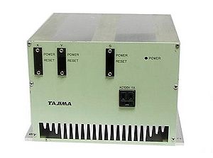
Power Box
Shown in picture. The TMFX Power Box houses the Tajima TMFX’s main power boards which include the 2 x DU-A, the S-card, and the Main card. All four boards are attached to the large heatsink chassis with screws and can be removed with T-handle 3.0mm hex keys. There is a large amount of heat sink compound normally on each board. There is an optional fan on the underside, generally on the four head and up. It is preferred that the entire power box is shipped when undergoing repairs.
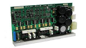
DU-A
Power and control of the X/Y motors. Successor to the DU-10 XY card used in earlier Tajima DC/HC models. There are two per machine. They have front switches to turn them on and off, there are LED colors in the front (behind a shaded screen) and will be green or orange. The control panel will automatically turn off some of the cards, temporarily, in a few situations such as a floppy read command. When a warning is triggered on any of the XY board sensors it will turn the light red and not allow any commands from there. On power up, the cards remain orange until the control panel activates them.
S-Card
Power and control of the main shaft motor. This is the largest motor on the machine. This is the only card that has an optional plug in the back, which are labeled 100V and 200V. If you have 110V power then either plug works but it is not recommended to mismatch; although the 200V only slightly leeches off of the main card’s ability to provide power to the rest of the system, if anything happens to the S-card then the main card will also be damaged. If you have 200V or more from your wall power, then you have no choice but to use the 200V plug; using the 100V plug with 200V wall input may damage the S-card.
Color change card
Power to the color change motor. Also reads the color change potentiometer and some solenoids.
Head card
One card per head. Detects thread break signals from the head assembly, and powers some solenoids. If one is bad, it can interfere with signals of all, including the color change card. When configuring the control panel, it also asks to pick a head card type 1 or type 2, and if the choice is wrong then all thread break signals will be wrong and erratic.
Control Panel
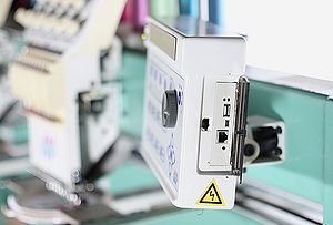
Tajima TMEX-C / TMFX Control Panel with optional FloppyToUSB installed
The TMFX Control Panel houses the Tajima TMFX’s main computer boards which include the control panel, LCD screen and Floppy Drive or FloppyToUSB unit. The Control Panel can be opened by hand from the back with the 2 flat head hand screws. It is preferred that the control panel when undergoing repairs on any of the Control Panel component.
Troubleshooting and Error Messages
The Tajima TMFX machine can produce the following error messages
- Tajima Error 211
- Main shaft not at fixed position. Spin manually or use the ATH function.
- Tajima Error 225
- Stitching outside of cap frame space.
- Tajima Error 281
- Color change cannot reach needle position. Check for bind. Check potentiometer.
- Tajima Error 291
- Thread break.
- Tajima Error 2B1
- Tape reader error. No reader is detected.
- Tajima Error 2B2
- Tape reader error. Data is corrupted.
- Tajima Error 2B3
- Tape reader error. End code data is incorrect.
- Tajima Error 2B4
- Tape reader error. Data is out of order. Please reset all units.
- Tajima Error 2B5
- Sequin data has an error.
- Tajima Error 2B6
- Tape reader error. No data coming in.
- Tajima Error 2B7
- Please load data first.
- Tajima Error 2B8
- Trying to run machine while data is still loading.
- Tajima Error 2B9
- Memory writing error. Try erasing all memory.
- Tajima Error 2BA
- Memory full. Erase designs.
- Tajima Error 2BB
- Cannot frame back any more.
- Tajima Error 2BC
- No data in memory here.
- Tajima Error 2C2
- Incorrect option, please change.
- Tajima Error 2CE
- Beam sensor is tripped, make sure both mirrors are aligned.
- Tajima Error 311
- Main motor not spinning. Check the S-card if it is active. Check main shaft if it is bound. This error generally requires circuit board repair of the S-Card, contact PLRElectronics for repair information
- Tajima Error 312
- Main shaft encoder giving incorrect signal. Check connections.
- Tajima Error 316
- The S-card is giving an error signal. Check card.
- Tajima Error 322
- The X-card is giving an error signal. Check card. This error generally requires circuit board repair of the X-Card, contact PLRElectronics for repair information
- Tajima Error 323
- The Y-card is giving an error signal. Check card. This error generally requires circuit board repair of the Y-Card, contact PLRElectronics for repair information
- Tajima Error 382
- Color change motor is not moving. Check for binds. Check connections.
- Tajima Error 383
- The color change location is not valid for running the head. Please check or re-center.
- Tajima Error 3D1
- Battery error. This error generally requires circuit board repair of the Control Panel, contact PLRElectronics for repair information
- Tajima Error 3D6
- CPU card detects problem with main program. Reinstall.
- Tajima Error B01
- Floppy disk format is not correct. Is the disk bad, or the floppy drive configured correctly?
- Tajima Error B02
- Floppy file system is not correct. Is the disk bad, or the floppy drive configured correctly?
- Tajima Error B03
- Floppy is marked as read-only.
- Tajima Error B04
- Floppy drive says no disk is inserted. Check drive configuration.
- Tajima Error BC1
- No Tajima designs found.
- Tajima Error BC2
- Cannot overwrite same name design.
- Tajima Error BC4
- Floppy write failed. Re-try.
- Tajima Error BC5
- Floppy disk is full.
- Tajima Error C01
- No response to floppy drive activation signal. Check drive configuration.
- Tajima Error 1B1
- Stop due to frame stepping.
- Tajima Error 1B2
- Stop due to stop code.
- Tajima Error 1B3
- Stop due to end of design.
- Tajima Error 1B4
- Stop due to thread trim.
- Tajima Error 1B5
- Stop due to sequin code.
- Tajima Error 1C1
- Stop due to stop button.
Tajima TMFX Card Identification
The following was taken from http://www.plrelectronics.com/lab/Tajima/Repair/index.php
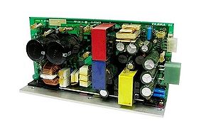
Tajima part number for the main TMFX power supply card, marked X-POWER card; Sticker varies: CX5601, CX5601000000, CX560101, CX5601010000, CX560102, CX5601020000, CX560103, CX5601030000, CX560104, CX5601040000, etc. Also marked MP138, or MP138-1, MP138-1-A, etc. This card will have two very large black capacitors on it, along with three colored transformers, and two thick cables soldered directly to the board, and usually a green colored large socket.
Tajima part number for the TMFX main shaft, main motor driver card, marked X-DUB, referred to as the S-card; Sticker varies: CX5602, CX5602000000, CX560201, CX5602010000, CX560202, CX5602020000, CX560207, CX5602070000, etc. Also marked MP137, or MP137-1, or MP137-2, or MP137-1-A, etc. This card will resemble the XY boards, but will have a large colored socket, usually RED.
Tajima part number for the TMFX XY driver boards (quantity 2), marked X-DUA (in the spirit of their older DU-8, DU-10 driver series, DU-A would the TMFX version.) Sticker varies: CX5603, CX5603000000, CX5603010000, CX5603020000, CX5603030000, CX5603040000, etc. Also marked MP136, or MP136-1, or MP136-2. There is another version of the card labeled CX5607, CX5607000000, CX5607020000, etc, and it is marked MP136-3. Each card is usually tuned for power output for either the X or Y motor; the X-motors are usually run with a lot less power than the Y motor, and adjustments are not only the external dial switch for users, but settings and components on the circuit board itself.
NOTE: the XY cards for the TMFX2, TMFX-II type of machines use a different connector and circuit board design for their XY cards.
TMFX Electronics Repairs
PLRElectronics specialized in repair of all the Tajima TMFX electronics. Generally it is much cheaper to have the Tajima electronics repaired rather than buying very expensive new boards.
USB Upgrade
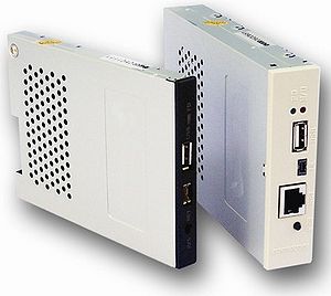
![External USB Embroidery Reader, Embroidery Black Box]](http://wiki.embroiderymachine.com/images/thumb/Tajima_usb_reader_small.jpg/300px-Tajima_usb_reader_small.jpg)
The USB Upgrade for the TMFX can be found at:
External Reader
The TMFX External Reader (Embroidery Black Box) can be purchased at: USB Flash Reader Embroidery Machine Transfer System
Internal Reader (Floppy to USB)
The TMFX (Floppy To USB) can be purchased at: Floppy To USB Upgrade
See also
- PLRElectronics — Tajima Repair — Electronic Repair and Troubleshooting for Tajima circuit boards
- Tajima Electronics
References
External links
- PLRElectronics — Tajima Repair — Electronic Repair and Troubleshooting for Tajima circuit boards