Что такое BER — Bit Error Rate?
Date:2016/4/5 15:56:57 Hits:
«Коэффициент ошибок по битам, BER используется для количественной оценки канала, несущего данные, путем подсчета частоты ошибок в строке данных. Он используется в телекоммуникациях, сетях и радиосистемах.Коэффициент битовых ошибок, BER — ключевой параметр, который используется при оценке систем, передающих цифровые данные из одного места в другое «. — Fmuser
Системы, для которых коэффициент битовых ошибок, BER применима включают ссылки радио данных, а также информационных систем волоконно-оптические, Ethernet, или любую систему, которая передает данные по сети той или иной форме, где шум, помехи, и дрожание фазы может вызвать ухудшение цифрового сигнал.Хотя есть некоторые различия в том, как эти системы работают и каким образом влияет скорость передачи в битах ошибки, основы скорости битовых ошибок сама по-прежнему то же самое.
Когда данные передаются по каналу передачи данных, существует вероятность ошибок, вводимых в систему. Если ошибки вводятся в данных, то целостность системы может быть поставлена под угрозу. В результате, необходимо оценить производительность системы, и коэффициент ошибок в битах, BER, обеспечивает идеальный способ, в котором это может быть достигнуто.
В отличие от многих других форм оценки, частота ошибок по битам, КОБ оценивает полный впритык производительность системы, включающей передатчик, приемник и среды между ними. Таким образом, частота появления ошибочных битов, КОБ позволяет реальная производительность системы в эксплуатацию, подлежащих испытанию, а не проверки составных частей и в надежде, что они будут работать удовлетворительно, когда на месте.
Бит ошибки скорости определения BER и основы
Как следует из названия, частота ошибочных битов определяется как скорость, при которой возникают ошибки в системе передачи. Это может быть непосредственно переведены в число ошибок, возникающих в строке заявленным количеством битов. Определение частоты появления ошибочных битов может быть переведена в простую формулу:
Если среда между передатчиком и приемником хорошо и соотношение сигнал-шум является высоким, то скорость битовых ошибок будет очень мала — возможно, незначительны и не имеющие какого-либо заметного влияния на общую систему Однако, если шум может быть обнаружен, то есть вероятность того, что частота появления ошибочных битов нужно будет рассмотреть.
Основными причинами деградации канала передачи данных и соответствующей частоты ошибок передачи в битах, BER шум и изменения в пути распространения (где используются сигнальные пути радио). Оба эффекта имеют случайный элемент к ним, шум следующий гауссовой функции вероятности в то время как модель распространения следует модели Рэлея. Это означает, что анализ характеристик канала, как правило, проводится с использованием методов статистического анализа.
Для волоконно-оптических систем, битовых ошибок в основном являются результатом несовершенства используемых компонентов, чтобы сделать ссылку. Они включают в себя оптический драйвер, приемник, разъемы и самого волокна. Ошибки в битах также могут быть введены в результате оптической дисперсии и затухания, которые могут присутствовать. Также шум может быть введен в самом оптическом приемнике. Как правило, они могут быть фотодиоды и усилители, которые должны реагировать на очень маленьких изменений, и в результате может быть высокий уровень шума, который присутствует.
Другим фактором, способствующим для битовых ошибок является любой Дрожание фазы, которые могут присутствовать в системе, так как это может изменить выборку данных Теа.
BER и Eb / No
Отношение сигнал-шум и Eb / No цифры не являются параметрами, которые в большей степени связаны с радиолиний и систем радиосвязи. С точки зрения этого, частота появления ошибочных битов, BER, также может быть определена в терминах вероятности ошибки или POE. Определения этого используются три других переменных. Они являются функция ошибки, ERF, энергия в один бит, ЭБ, и спектральная плотность мощности шума (что мощность шума в полосе частот Гц 1), №
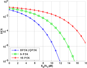
Следует отметить, что каждый тип модуляции имеет свое собственное значение функции ошибки. Это происходит потому, что каждый тип модуляции выполняет по-разному в присутствии шума. В частности, схемы более высокого порядка модуляции (к примеру 64QAM и т.д.), которые способны переносить более высокие скорости передачи данных, не столь надежными в присутствии шума. Меньшие форматы модуляции порядка (например, BPSK, QPSK и т.д.) предлагают более низкие скорости передачи данных, но являются более надежными.
Энергии на бит, ЭБ, может быть определена путем деления мощности несущей на скорости передачи данных и является мерой энергии с размерами джоулей. Нет это мощность на герц, и поэтому это имеет размерность мощности (джоулей в секунду), разделенное на секунды). Не Глядя на размеры отношение Eb / No все размеры компенсируют дать безразмерное отношение. Важно отметить, что РОЕ пропорционально Eb / No и является формой сигнала к шуму.
Факторы, влияющие на частоту появления ошибочных битов BER,
Это можно видеть из использования Eb / No, что частоты появления ошибочных битов, КОБ может зависеть от ряда факторов. Изменяя переменные, которыми можно управлять, можно оптимизировать систему, чтобы обеспечить уровень производительности, которые необходимы. Это, как правило, проводится в стадии проектирования системы передачи данных таким образом, что рабочие параметры могут быть скорректированы на начальных этапах проектирования концепции.
• Помехи: Уровни помех, присутствующих в системе, как правило, установлены под воздействием внешних факторов и не может быть изменен с помощью конструкции системы. Тем не менее, можно установить ширину полосы пропускания системы. За счет снижения пропускной способности уровень помех может быть уменьшено. Однако уменьшение полосы пропускания ограничивает пропускную способность данных, что может быть достигнуто.
• Увеличьте мощность передатчика: Кроме того, можно повысить уровень мощности системы таким образом, чтобы мощность на бит увеличивается. Это должно быть сбалансировано против факторов, включая уровни помех другим пользователям и влияние увеличения выходной мощности от размера усилителя мощности и общее энергопотребление и время автономной работы и т.д.
• Модуляция низшего порядка: схемы модуляции Низшие порядка могут быть использованы, но это за счет скорости передачи данных.
• Уменьшите пропускную способность: Другой подход, который может быть принят, чтобы уменьшить частоту появления ошибочных битов, чтобы уменьшить ширину полосы частот. Более низкие уровни шума будут получены, и, следовательно, соотношение сигнал-шум улучшится. Опять же это приводит к уменьшению пропускной способности данных достижимым.
Необходимо сбалансировать все имеющиеся факторы для достижения удовлетворительной скорости появления ошибочных битов. Обычно это не представляется возможным достичь всех требований и некоторые компромиссы необходимы. Тем не менее, даже с битовой частотой ошибок ниже того, что в идеале требуется, дополнительные компромиссы могут быть сделаны с точки зрения уровней коррекции ошибок, которые вводятся в передаваемые данные. Хотя более избыточные данные должны быть отправлены с более высокими уровнями коррекции ошибок, это может помочь замаскировать последствия любых битовых ошибок, которые возникают, тем самым улучшая общую частоту появления ошибок в битах.
Частота появления ошибочных битов BER является параметром, который дает прекрасную индикацию производительности линии передачи данных, таких как радио или волоконно-оптической системы. В качестве одного из основных параметров, представляющих интерес в любой линии передачи данных является количество ошибок, которые возникают, то коэффициент ошибок в битах является ключевым параметром. Знание BER также позволяет использовать другие особенности ссылки, такие как мощность и пропускную способность, и т.д., чтобы быть адаптированы для того, чтобы требуемые эксплуатационные характеристики, которые будут получены.
Оставить сообщение
Список сообщений
From Wikipedia, the free encyclopedia
In digital transmission, the number of bit errors is the numbers of received bits of a data stream over a communication channel that have been altered due to noise, interference, distortion or bit synchronization errors.
The bit error rate (BER) is the number of bit errors per unit time. The bit error ratio (also BER) is the number of bit errors divided by the total number of transferred bits during a studied time interval. Bit error ratio is a unitless performance measure, often expressed as a percentage.[1]
The bit error probability pe is the expected value of the bit error ratio. The bit error ratio can be considered as an approximate estimate of the bit error probability. This estimate is accurate for a long time interval and a high number of bit errors.
Example[edit]
As an example, assume this transmitted bit sequence:
1 1 0 0 0 1 0 1 1
and the following received bit sequence:
0 1 0 1 0 1 0 0 1,
The number of bit errors (the underlined bits) is, in this case, 3. The BER is 3 incorrect bits divided by 9 transferred bits, resulting in a BER of 0.333 or 33.3%.
Packet error ratio[edit]
The packet error ratio (PER) is the number of incorrectly received data packets divided by the total number of received packets. A packet is declared incorrect if at least one bit is erroneous. The expectation value of the PER is denoted packet error probability pp, which for a data packet length of N bits can be expressed as
 ,
,

assuming that the bit errors are independent of each other. For small bit error probabilities and large data packets, this is approximately

Similar measurements can be carried out for the transmission of frames, blocks, or symbols.
The above expression can be rearranged to express the corresponding BER (pe) as a function of the PER (pp) and the data packet length N in bits:
![{\displaystyle p_{e}=1-{\sqrt[{N}]{(1-p_{p})}}}](https://wikimedia.org/api/rest_v1/media/math/render/svg/f5d380e45b0451c45265e199221fae5bd5b84bf9)
Factors affecting the BER[edit]
In a communication system, the receiver side BER may be affected by transmission channel noise, interference, distortion, bit synchronization problems, attenuation, wireless multipath fading, etc.
The BER may be improved by choosing a strong signal strength (unless this causes cross-talk and more bit errors), by choosing a slow and robust modulation scheme or line coding scheme, and by applying channel coding schemes such as redundant forward error correction codes.
The transmission BER is the number of detected bits that are incorrect before error correction, divided by the total number of transferred bits (including redundant error codes). The information BER, approximately equal to the decoding error probability, is the number of decoded bits that remain incorrect after the error correction, divided by the total number of decoded bits (the useful information). Normally the transmission BER is larger than the information BER. The information BER is affected by the strength of the forward error correction code.
Analysis of the BER[edit]
The BER may be evaluated using stochastic (Monte Carlo) computer simulations. If a simple transmission channel model and data source model is assumed, the BER may also be calculated analytically. An example of such a data source model is the Bernoulli source.
Examples of simple channel models used in information theory are:
- Binary symmetric channel (used in analysis of decoding error probability in case of non-bursty bit errors on the transmission channel)
- Additive white Gaussian noise (AWGN) channel without fading.
A worst-case scenario is a completely random channel, where noise totally dominates over the useful signal. This results in a transmission BER of 50% (provided that a Bernoulli binary data source and a binary symmetrical channel are assumed, see below).

In a noisy channel, the BER is often expressed as a function of the normalized carrier-to-noise ratio measure denoted Eb/N0, (energy per bit to noise power spectral density ratio), or Es/N0 (energy per modulation symbol to noise spectral density).
For example, in the case of QPSK modulation and AWGN channel, the BER as function of the Eb/N0 is given by:
 .[2]
.[2]
People usually plot the BER curves to describe the performance of a digital communication system. In optical communication, BER(dB) vs. Received Power(dBm) is usually used; while in wireless communication, BER(dB) vs. SNR(dB) is used.
Measuring the bit error ratio helps people choose the appropriate forward error correction codes. Since most such codes correct only bit-flips, but not bit-insertions or bit-deletions, the Hamming distance metric is the appropriate way to measure the number of bit errors. Many FEC coders also continuously measure the current BER.
A more general way of measuring the number of bit errors is the Levenshtein distance.
The Levenshtein distance measurement is more appropriate for measuring raw channel performance before frame synchronization, and when using error correction codes designed to correct bit-insertions and bit-deletions, such as Marker Codes and Watermark Codes.[3]
Mathematical draft[edit]
The BER is the likelihood of a bit misinterpretation due to electrical noise  . Considering a bipolar NRZ transmission, we have
 for a «1» and
  for a «0». Each of
  and
and  has a period of
  .
.
Knowing that the noise has a bilateral spectral density  ,
,
is 
and is  .
.
Returning to BER, we have the likelihood of a bit misinterpretation  .
.
 and
and 
where  is the threshold of decision, set to 0 when
  .
.
We can use the average energy of the signal  to find the final expression :

±§
Bit error rate test[edit]
BERT or bit error rate test is a testing method for digital communication circuits that uses predetermined stress patterns consisting of a sequence of logical ones and zeros generated by a test pattern generator.
A BERT typically consists of a test pattern generator and a receiver that can be set to the same pattern. They can be used in pairs, with one at either end of a transmission link, or singularly at one end with a loopback at the remote end. BERTs are typically stand-alone specialised instruments, but can be personal computer–based. In use, the number of errors, if any, are counted and presented as a ratio such as 1 in 1,000,000, or 1 in 1e06.
Common types of BERT stress patterns[edit]
- PRBS (pseudorandom binary sequence) – A pseudorandom binary sequencer of N Bits. These pattern sequences are used to measure jitter and eye mask of TX-Data in electrical and optical data links.
- QRSS (quasi random signal source) – A pseudorandom binary sequencer which generates every combination of a 20-bit word, repeats every 1,048,575 words, and suppresses consecutive zeros to no more than 14. It contains high-density sequences, low-density sequences, and sequences that change from low to high and vice versa. This pattern is also the standard pattern used to measure jitter.
- 3 in 24 – Pattern contains the longest string of consecutive zeros (15) with the lowest ones density (12.5%). This pattern simultaneously stresses minimum ones density and the maximum number of consecutive zeros. The D4 frame format of 3 in 24 may cause a D4 yellow alarm for frame circuits depending on the alignment of one bits to a frame.
- 1:7 – Also referred to as 1 in 8. It has only a single one in an eight-bit repeating sequence. This pattern stresses the minimum ones density of 12.5% and should be used when testing facilities set for B8ZS coding as the 3 in 24 pattern increases to 29.5% when converted to B8ZS.
- Min/max – Pattern rapid sequence changes from low density to high density. Most useful when stressing the repeater’s ALBO feature.
- All ones (or mark) – A pattern composed of ones only. This pattern causes the repeater to consume the maximum amount of power. If DC to the repeater is regulated properly, the repeater will have no trouble transmitting the long ones sequence. This pattern should be used when measuring span power regulation. An unframed all ones pattern is used to indicate an AIS (also known as a blue alarm).
- All zeros – A pattern composed of zeros only. It is effective in finding equipment misoptioned for AMI, such as fiber/radio multiplex low-speed inputs.
- Alternating 0s and 1s — A pattern composed of alternating ones and zeroes.
- 2 in 8 – Pattern contains a maximum of four consecutive zeros. It will not invoke a B8ZS sequence because eight consecutive zeros are required to cause a B8ZS substitution. The pattern is effective in finding equipment misoptioned for B8ZS.
- Bridgetap — Bridge taps within a span can be detected by employing a number of test patterns with a variety of ones and zeros densities. This test generates 21 test patterns and runs for 15 minutes. If a signal error occurs, the span may have one or more bridge taps. This pattern is only effective for T1 spans that transmit the signal raw. Modulation used in HDSL spans negates the bridgetap patterns’ ability to uncover bridge taps.
- Multipat — This test generates five commonly used test patterns to allow DS1 span testing without having to select each test pattern individually. Patterns are: all ones, 1:7, 2 in 8, 3 in 24, and QRSS.
- T1-DALY and 55 OCTET — Each of these patterns contain fifty-five (55), eight bit octets of data in a sequence that changes rapidly between low and high density. These patterns are used primarily to stress the ALBO and equalizer circuitry but they will also stress timing recovery. 55 OCTET has fifteen (15) consecutive zeroes and can only be used unframed without violating one’s density requirements. For framed signals, the T1-DALY pattern should be used. Both patterns will force a B8ZS code in circuits optioned for B8ZS.
Bit error rate tester[edit]
A bit error rate tester (BERT), also known as a «bit error ratio tester»[4] or bit error rate test solution (BERTs) is electronic test equipment used to test the quality of signal transmission of single components or complete systems.
The main building blocks of a BERT are:
- Pattern generator, which transmits a defined test pattern to the DUT or test system
- Error detector connected to the DUT or test system, to count the errors generated by the DUT or test system
- Clock signal generator to synchronize the pattern generator and the error detector
- Digital communication analyser is optional to display the transmitted or received signal
- Electrical-optical converter and optical-electrical converter for testing optical communication signals
See also[edit]
- Burst error
- Error correction code
- Errored second
- Pseudo bit error ratio
- Viterbi Error Rate
References[edit]
- ^ Jit Lim (14 December 2010). «Is BER the bit error ratio or the bit error rate?». EDN. Retrieved 2015-02-16.
- ^
Digital Communications, John Proakis, Massoud Salehi, McGraw-Hill Education, Nov 6, 2007 - ^
«Keyboards and Covert Channels»
by Gaurav Shah, Andres Molina, and Matt Blaze (2006?) - ^ «Bit Error Rate Testing: BER Test BERT » Electronics Notes». www.electronics-notes.com. Retrieved 2020-04-11.
![]() This article incorporates public domain material from Federal Standard 1037C. General Services Administration. (in support of MIL-STD-188).
This article incorporates public domain material from Federal Standard 1037C. General Services Administration. (in support of MIL-STD-188).
External links[edit]
- QPSK BER for AWGN channel – online experiment
In digital transmission, the number of bit errors is the number of received bits of a data stream over a communication channel that has been altered due to noise, interference, distortion or bit synchronization errors.
The bit error rate or bit error ratio (BER) is the number of bit errors divided by the total number of transferred bits during a studied time interval. BER is a unitless performance measure, often expressed as a percentage.
The bit error probability pe is the expectation value of the BER. The BER can be considered as an approximate estimate of the bit error probability. This estimate is accurate for a long time interval and a high number of bit errors.
As an example, assume this transmitted bit sequence:
0 1 1 0 0 0 1 0 1 1,
and the following received bit sequence:
0 0 1 0 1 0 1 0 0 1,
The number of bit errors (the underlined bits) is in this case 3. The BER is 3 incorrect bits divided by 10 transferred bits, resulting in a BER of 0.3 or 30%.
Packet Error Rate
The packet error rate (PER) is the number of incorrectly received data packets divided by the total number of received packets. A packet is declared incorrect if at least one bit is erroneous. The expectation value of the PER is denoted packet error probability pp, which for a data packet length of N bits can be expressed as
p_p = 1 – (1 – p_e)^N,
assuming that the bit errors are independent of each other. For small bit error probabilities, this is approximately
p_p approx p_eN.
Similar measurements can be carried out for the transmission of frames, blocks, or symbols.
Factors affecting the BER
In a communication system, the receiver side BER may be affected by transmission channel noise, interference, distortion, bit synchronization problems, attenuation, wireless multipath fading, etc.
The BER may be improved by choosing a strong signal strength (unless this causes cross-talk and more bit errors), by choosing a slow and robust modulation scheme or line coding scheme, and by applying channel coding schemes such as redundant forward error correction codes.
The transmission BER is the number of detected bits that are incorrect before error correction, divided by the total number of transferred bits (including redundant error codes). The information BER, approximately equal to the decoding error probability, is the number of decoded bits that remain incorrect after the error correction, divided by the total number of decoded bits (the useful information). Normally the transmission BER is larger than the information BER. The information BER is affected by the strength of the forward error correction code.
Analysis of the BER

The BER may be analyzed using stochastic computer simulations. If a simple transmission channel model and data source model is assumed, the BER may also be calculated analytically. An example of such a data source model is the Bernoulli source.
Examples of such simple channel models are:
Binary symmetric channel (used in the analysis of decoding error probability in case of non-bursty bit errors on the transmission channel)
Additive white Gaussian noise (AWGN) channel without fading.
A worst-case scenario is a completely random channel, where noise totally dominates over the useful signal. This results in a transmission BER of 50% (provided that a Bernoulli binary data source and a binary symmetrical channel are assumed, see below).
In a noisy channel, the BER is often expressed as a function of the normalized carrier-to-noise ratio measure denoted Eb/N0, (energy per bit to noise power spectral density ratio), or Es/N0 (energy per modulation symbol to noise spectral density).
For example, in the case of QPSK modulation and AWGN channel, the BER as function of the Eb/N0 is given by: operatorname{BER}=frac{1}{2}operatorname{erfc}(sqrt{E_b/N_0}).
People usually plot the BER curves to describe the functionality of a digital communication system. In optical communication, BER(dB) vs. Received Power(dBm) is usually used; while in wireless communication, BER(dB) vs. SNR(dB) is used.
Measuring the bit error ratio helps people choose the appropriate forward error correction codes. Since most such codes correct only bit-flips, but not bit-insertions or bit-deletions, the Hamming distance metric is the appropriate way to measure the number of bit errors. Many FEC coders also continuously measure the current BER.
A more general way of measuring the number of bit errors is the Levenshtein distance. The Levenshtein distance measurement is more appropriate for measuring raw channel performance before frame synchronization, and when using error correction codes designed to correct bit-insertions and bit-deletions, such as Marker Codes and Watermark Codes.
Mathematical Draft

Bit Error Rate Test (BERT)
BERT or bit error rate test is a testing method for digital communication circuits that uses predetermined stress patterns consisting of a sequence of logical ones and zeros generated by a test pattern generator.
A BERT typically consists of a test pattern generator and a receiver that can be set to the same pattern. They can be used in pairs, with one at either end of a transmission link, or singularly at one end with a loopback at the remote end. BERTs are typically stand-alone specialised instruments but can be personal computer–based. In use, the number of errors, if any, are counted and presented as a ratio such as 1 in 1,000,000, or 1 in 1e06.
Common types of BERT stress patterns:
- PRBS (pseudorandom binary sequence) – A pseudorandom binary sequencer of N Bits. These pattern sequences are used to measure jitter and eye mask of TX-Data in electrical and optical data links.
- QRSS (Quasi-Random Signal Source) – A pseudorandom binary sequencer which generates every combination of a 20-bit word, repeats every 1,048,575 words, and suppresses consecutive zeros to no more than 14. It contains high-density sequences, low-density sequences, and sequences that change from low to high and vice versa. This pattern is also the standard pattern used to measure jitter.
- 3 in 24 – Pattern contains the longest string of consecutive zeros (15) with the lowest one’s density (12.5%). This pattern simultaneously stresses the minimum one’s density and the maximum number of consecutive zeros. The D4 frame format of 3 in 24 may cause a D4 Yellow Alarm for frame circuits depending on the alignment of one bit to a frame.
- 1:7 – Also referred to as “1 in 8”. It has only a single one in an 8-bit repeating sequence. This pattern stresses the minimum one’s density of 12.5% and should be used when testing facilities set for B8ZS coding as the 3 in 24 pattern increases to 29.5% when converted to B8ZS.
- Min/Max – Pattern rapid sequence changes from low density to high density. Most useful when stressing the repeater’s ALBO feature.
- All Ones (or Mark) – A pattern composed of ones only. This pattern causes the repeater to consume the maximum amount of power. If DC to the repeater is regulated properly, the repeater will have no trouble transmitting the long one’s sequence. This pattern should be used when measuring span power regulation. An unframed all one’s pattern is used to indicate an AIS (also known as a Blue Alarm).
- All Zeros – A pattern composed of zeros only. It is effective in finding equipment misoptioned for AMI, such as fiber/radio multiplex low-speed inputs.
- Alternating 0s and 1s – A pattern composed of alternating ones and zeroes.
- 2 in 8 – Pattern contains a maximum of four consecutive zeros. It will not invoke a B8ZS sequence because eight consecutive zeros are required to cause a B8ZS substitution. The pattern is effective in finding equipment misoptioned for B8ZS.
- Bridge tap – Bridge taps within a span can be detected by employing a number of test patterns with a variety of ones and zeros densities. This test generates 21 test patterns and runs for 15 minutes. If a signal error occurs, the span may have one or more bridge taps. This pattern is only effective for T1 spans that transmit the signal raw. Modulation used in HDSL spans negates the Bridge tap patterns’ ability to uncover bridge taps.
- Multipat – This test generates 5 commonly used test patterns to allow DS1 span testing without having to select each test pattern individually. Patterns are: All Ones, 1:7, 2 in 8, 3 in 24, and QRSS.
- T1-DALY and 55 OCTET – Each of these patterns contain fifty-five (55), eight bit octets of data in a sequence that changes rapidly between low and high density. These patterns are used primarily to stress the ALBO and equalizer circuitry but they will also stress timing recovery. 55 OCTET has fifteen (15) consecutive zeroes and can only be used unframed without violating one’s density requirements. For framed signals, the T1-DALY pattern should be used. Both patterns will force a B8ZS code in circuits optioned for B8ZS.
Testing Bit Rate Errors

A bit error rate tester (BERT), also known as a bit error ratio tester or bit error rate test solution (BERTs) is electronic test equipment used to test the quality of signal transmission of single components or complete systems.
The main building blocks of a BERT are:
- Pattern Generator, which transmits a defined test pattern to the DUT or test system
- Error detector connected to the DUT or test system, to count the errors generated by the DUT or test system
- Clock signal generator to synchronize the pattern generator and the error detector
- Digital communication analyser is optional to display the transmitted or received signal
- Electrical-optical converter and optical-electrical converter for testing optical communication signals

Терминалы Сбербанка бывают двух типов. Первые относятся к кассовым (POS-терминалы), они устанавливаются на кассах торговых точек, где принимаются к оплате банковские карты. Вторые называются платёжными, они похожи на банкоматы, но не обладают функцией выдачи наличных. В обоих видах терминалов Сбербанка нередко возникает ошибка 2000. Что делать в этом случае – расскажут пошаговые инструкции.

Всего возможны три ситуации, когда появляется данная ошибка:
- Случайная отмена покупки самим покупателем;
- В кассовом аппарате закончилась чековая лента;
- Случайное нажатие кнопки Отмена в платёжном терминале.
Для каждой ситуации есть своя инструкция.
Ошибка 2000 из-за отмены покупки
Оплата покупок в магазине включает четыре шага – продавец или кассир сканирует товар на кассе, подводит итог, предлагает установить карту в терминал или поднести карту к терминалу. На последнем шаге клиент вставляет карточку и вводит PIN-код (или подносит карту с беспроводным чипом).
Ошибка 2000 возникнет на кассе в том случае, если покупатель случайно нажмёт на терминале кнопку Отмена. В этом случае операция прервётся – если покупатель не планирует оплачивать покупку, сотрудник магазина проводит отмену в соответствии с требованиями кассовой дисциплины в торговой точке.
Ошибка 2000 из-за отсутствия ленты
POS-терминал и касса печатают по одному чеку каждый. Чек из терминала называется слипом, он лишь подтверждает успешное списание средств. Полноценный чек выдаёт кассовый аппарат. Ошибка 2000 появляется следующим способом:
- Клиент подносит карту к POS-терминалу или вставляет карту в него;
- Терминал проводит платёж через платёжную систему и банк, выдавая слип;
- Терминал отдаёт команду кассовому аппарату напечатать кассовый чек;
- При отсутствии чековой ленты касса отправляет в терминал ошибку, банк производит аннулирование операции.
Решение проблемы – установить в кассу чековую ленту. Иногда проблема решается устранением замятия ленты в аппарате.
Ошибка 2000 на платёжном терминале
Здесь всё просто – клиент вводит платёжную информацию, и случайно нажимает кнопку Отмена. Терминал выдаёт карту обратно, выводя на экран код 2000. Клиенту необходимо вставить карту в терминал и выполнить операцию заново – вводимые данные не сохраняются, поэтому придётся ввести их повторно.
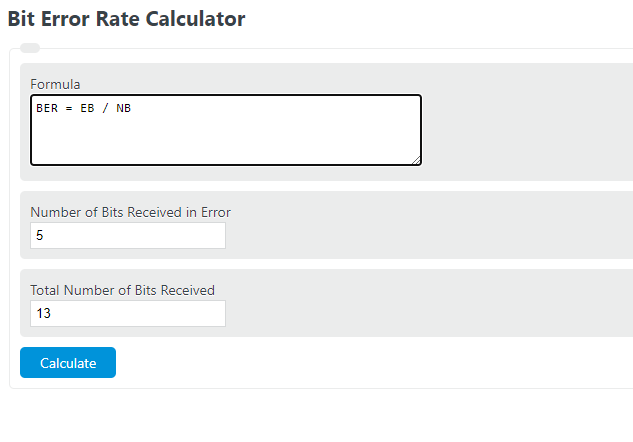
Enter the total number of bits received in error and the total number of bits received into the calculator to determine the bit error rate.
- Bandwidth Calculator
- Bandwidth Delay Product Calculator
- Video File Size Calculator
- E Value Calculator
- Packets Per Second Calculator
- Access Point Calculator
- Cost Per Network Drop Calculator
- Bits Per Time Calculator
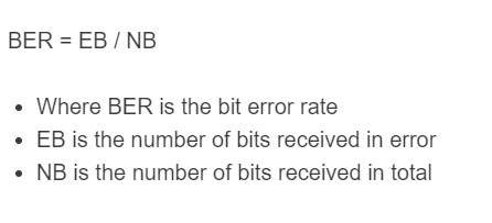
Bit Error Rate Formula
The following formula can be used to calculate a bit error rate.
- Where BER is the bit error rate
- EB is the number of bits received in error
- NB is the number of bits received in total
To calculate bit error rate, divide the number of bits in error by the total bits received.
Bit Error Rate Definition
A bit error rate is a measure of the quality of the digital transmission of a system. It’s defined as the ratio of bits received in error divided by the total number of bits received.
Bit Error Rate Example
How to calculate a bit error rate?
- First, determine the total number of bits.
Calculate the total number of bits received.
- Next, determine the number of errors.
Calculate the total number of bits received in error.
- Finally, calculate the bit error rate.
Calculate the bit error rate by divided the bit errors by total bits.
FAQ
What is a bit error rate?
A bit error rate is a ratio of the total number of bits received in error to the total number of bits.